JP2020073017A - Reel type game machine - Google Patents
Reel type game machine Download PDFInfo
- Publication number
- JP2020073017A JP2020073017A JP2020014248A JP2020014248A JP2020073017A JP 2020073017 A JP2020073017 A JP 2020073017A JP 2020014248 A JP2020014248 A JP 2020014248A JP 2020014248 A JP2020014248 A JP 2020014248A JP 2020073017 A JP2020073017 A JP 2020073017A
- Authority
- JP
- Japan
- Prior art keywords
- control board
- game
- main control
- gaming machine
- machine according
- Prior art date
- Legal status (The legal status is an assumption and is not a legal conclusion. Google has not performed a legal analysis and makes no representation as to the accuracy of the status listed.)
- Pending
Links
Images


Landscapes
- Game Rules And Presentations Of Slot Machines (AREA)
Abstract
Description
回胴式遊技機に関する。 Regarding a rotating body type game machine.
回胴式遊技機(スロットマシン)は、所定数の遊技メダルを投入後に遊技開始指示装置(スタートレバー)が操作されたことを契機として1ゲームが開始されて、複数の図柄が外周上に配置された複数列の回胴(リール)が回転動作し、当該回転動作を停止させるための回胴停止装置(ストップボタン)を駆使して回胴を停止させた結果、有効ライン上に所定の図柄の組合せ(例えば「777」等の入賞役)が並んだ場合には、通常遊技状態よりも遊技者にとって利益状態の高い特別遊技状態(通常時よりも小役等の抽選確率が上昇する遊技状態)に移行するタイプのものが一般的である。ここで、回胴式遊技機においては、遊技の興趣性を高めるための演出用の画像等が、リールの回転動作及び停止動作とシンクロした形で、液晶等のディスプレイ上にて表示される場合があり、回胴停止装置等を操作した際に、回胴上に表示された図柄とディスプレイ上に表示された演出用の画像等とを見比べながら、遊技の結果を予測して楽しむよう構成されているものが多い。 The spinning drum type gaming machine (slot machine) starts one game when a game start instruction device (start lever) is operated after inserting a predetermined number of game medals, and a plurality of symbols are arranged on the outer periphery. Rotation of multiple rows of rotating drums (reels) is performed, and as a result of stopping the rotating drums by making full use of the rotating drum stop device (stop button) for stopping the rotation operation, a predetermined pattern on the effective line. When a combination of (for example, a winning combination such as "777") is lined up, a special game state in which the player has a higher profit state than in the normal game state (a game state in which the lottery probability of a small win etc. is higher than in the normal state) ) Is generally the type that moves to. Here, in the case of a spinning-type gaming machine, an image for production for enhancing the interest of the game is displayed on a display such as a liquid crystal in a form synchronized with the rotation operation and the stop operation of the reel. There is, when operating the spinning body stop device, etc., while comparing the design displayed on the spinning body with the image for performance displayed on the display, it is configured to predict and enjoy the result of the game. There are many things.
また、近年の回胴式遊技機においては、回胴停止装置の操作態様(操作順番や操作タイミング)に応じて、入賞役の入賞有無や入賞役の種類が変化するよう構成され、遊技者にとって有利な入賞役が入賞するよう操作指示(ナビゲーション)を発してアシストするもの(いわゆるAT機)も多く登場している。このAT機においては、操作指示を発する状態(AT状態)と操作指示を発しない状態(非AT状態)とを有しており、AT状態が継続すればするほど、遊技者にとって有利となるような遊技性を備えている。 In recent years, the spinning-type gaming machines are configured so that the presence / absence of a winning combination and the type of winning combination are changed according to the operation mode (operation order or operation timing) of the spinning-roll stopping device. A lot of devices (so-called AT machines) that give operation instructions (navigation) and assist to win an advantageous winning combination have also appeared. This AT machine has a state of issuing an operation instruction (AT state) and a state of not issuing an operation instruction (non-AT state), and the more the AT state continues, the more advantageous it is to the player. It has excellent playability.
遊技者に著しく不利益な状態での遊技を継続させないことが望まれている。 It is desired not to continue the game in a state where the player is extremely disadvantageous.
本態様に係る回胴式遊技機は、
遊技が400回行われたときに少なくとも50回は再遊技役に当選するように設計され、
再遊技役が成立した遊技の次の遊技で賭け設定される遊技価値を「0」として算出した場合における、遊技が400回行われたときの出玉率は、1/3以上である
ことを特徴とする。
The rotating drum type gaming machine according to this aspect,
Designed to win the replay role at least 50 times when the game is played 400 times,
When the game value bet-set in the game next to the game in which the re-gaming combination is established is calculated as “0”, the payout rate when the game is played 400 times is 1/3 or more. Characterize.
本態様に係る回胴式遊技機によれば、遊技者に著しく不利益な状態での遊技を継続させないことができる、という効果を奏する。 According to the spinning drum type gaming machine of this aspect, it is possible to prevent the player from continuing the game in a significantly disadvantageous state.
はじめに、本明細書における各用語の意義について説明する。「乱数」とは、回胴式遊技機において何らかの遊技内容を決定するための抽選(電子計算機によるくじ)に使用される乱数であり、狭義の乱数の他に擬似乱数も含む(例えば、乱数としてはハード乱数、CPUを含む主制御チップによって生成された内蔵乱数、擬似乱数としてはソフト乱数)。例えば、遊技の結果に影響を与えるいわゆる「基本乱数」、具体的には、特別遊技に移
行するための特別役や入賞役(小役、再遊技役)と関連した「当選乱数」、等を挙げることができる。「CPU」とは、当業界において周知であるものと同義であり、使用されているアーキテクチャ(CISC、RISC、ビット数等)や処理性能等には何ら限定されない。「電断(電源断)」とは、遊技機に設けられた電源スイッチの操作実行有無に係らず、遊技機に供給される電源電圧が一定レベル以下となったことを指し、例えば、電源供給ユニットの破損や停電等による不測の事態による電源供給の遮断をも包含する。「ROM」とは、当業界において周知であるものと同義であり、情報を物理的に保持する(例えば、データ読み出し用の電流を与えた場合、導通する素子構成であれば「1」、導通しない素子構成であれば「0」となる)。RAMとは、当業界において周知であるものと同義であり、情報を電気的に保持する(例えば、データ読み出し用の電流を与えた場合、蓄電されていれば「1」、蓄電されていなければ「0」となる。尚、RAM内で保持されているデータの一部又はすべてに対して、電断時にはバックアップ電源が供給されるよう構成されていることが一般的である)。「遊技状態」とは、例えば、遊技メダルが獲得容易であり遊技者にとって有利な特別遊技状態(いわゆる大当り遊技であり、ボーナス遊技や第1種BB・第2種BB等と呼ばれるものが該当する)、再遊技役の当選率があらかじめ定められた値である通常遊技状態よりも再遊技役の当選率が高い(又は低い)状態である再遊技確率変動遊技状態(RT状態)、当選した役を入賞させるためのリールの停止順、停止位置を報知し得るAT(アシストタイム)中状態、前記RT状態とAT中状態とが複合したART(アシストリプレイタイム)状態、等が挙げられる。また、通常遊技状態においても、RT状態、AT中状態、ART中状態への移行抽選確率が異なる、高確率通常遊技状態、低確率通常遊技状態、等(本例では、抽選状態と称している)が挙げられる。また、遊技状態は複合しても問題ない{更に、これらの遊技状態や機能(例えば、AT中状態への移行抽選や、リールの停止順に係る報知指示の出力等)は、遊技進行を制御する主制御基板側ですべて実装してしまっても問題ない}。また、本例においては、ATに関する状態とRT状態とを個別に記載し、RT状態が「RT1」且つATに関する状態が「通常遊技状態」等と称しているが、RT状態とATに関する状態とを纏めてARTに関する状態としてARTに関する状態が「通常遊技状態」等と称してもよい。「当選役」とは、内部抽選により当選した条件装置の種類(又は、条件装置番号)である。「報知状態」とは、後述する押し順ナビを実行可能なATに関する状態であり、リール停止順によって入賞する役が相違しないために押し順ナビが実行されない条件装置が当選したゲームであっても、ATに関する状態が押し順ナビを実行可能な状態であれば「報知状態」とするよう構成している。「カウンタ値」とは「報知遊技実行可能数」とも称し、後述する、AT残りゲーム数もしくはATカウンタM60のカウンタ値である。例えば、「報知遊技実行可能数」が1以上(「0」となった当該遊技も含めても良い)である場合には後述する押し順ナビが実行され得る。また、「報知遊技実行可能数」として、小役(主に、押し順ベル役)が当選したことに基づいて得られる遊技媒体の差枚数(払出し枚数から投入枚数を引いた枚数)や、押し順ベル役の当選回数、を採用しても良い。また、「特殊報知状態」とは、ATに関する状態のうち遊技者に最も有利となる状態であり、本例では、「上乗せ特化状態」と称している。また、「特定条件」とは、ATカウンタ値を減算し得る条件であり、例えば、1ゲームが終了した、所定役(例えば、押し順ベル役)が当選した、等が特定条件となる。「第1種特別役物」とは、規定数ごとの入賞に係る図柄の組合せの数を増加させ、又は規定数ごとの入賞に係る条件装置が作動する確率を上昇させる役物で、あらかじめ定められた場合に作動し12回を超えない回数の遊技の結果が得られるまで作動を継続することができるものであり、RB(レギュラーボーナス)と称することがある。「第1種特別役物連続作動装置」とは、第1種特別役物を連続して作動させることができる装置で、特定の図柄の組合せが表示された場合に作動しあらかじめ定められた場合に作動を終了するものであり、BB(ビッグボーナス)や第1種BBと称することがある。「第2種特別役物」とは、役抽選の結果に拘らず入賞に係る条件装置を作動させることとなる役物で、あらかじめ定められた場合に作動し1回の遊技の結果が得られた場合に作動を終了するものであり、CB(チャレンジボーナス)と称することがある。「第2種特別役物
連続作動装置」とは、第2種特別役物を連続して作動させることができる装置で、特定の図柄の組合せが表示された場合に作動しあらかじめ定められた場合に作動を終了するものであり、MB(ミドルボーナス)や第2種BBと称することがある。「普通役物」とは、規定数毎の入賞に係る図柄の組合せの数を増加させ、又は、規定数毎の入賞に係る条件装置が作動する確率を上昇させる役物で、特定の図柄の組合せが表示された場合に作動し1回の遊技の結果が得られた場合に作動を終了することとされているものであり、SB(シングルボーナス)と称することがある。「オールJACINタイプ」とは、第1種BB役が入賞した場合にJACINしたものとみなし、第1種BBの実行中においては常にRB中とする構成である。より具体的には、1種BBの図柄組合せが停止表示した場合に、RBの図柄組合せが停止表示することなくRBが作動する。そしてRBの終了条件を満たした場合にはRBを終了させる。但し、1種BBの終了条件を満たしていない場合には、次遊技における賭け設定がなされる前に、再度、(RBの図柄組合せが停止表示することなく)RBが作動する。このように、RBを連続して作動させることができる1種BBを「オールJACINタイプ」と称する。尚、「オールJACINタイプ」では、RBの終了条件を満たす前に、1種BBの終了条件を満たした場合には、1種BBを終了させるとともに、RBも終了させる。また、「JACIN抽選タイプ」とは、第1種BBの実行時にて非RB中とRB中とを繰り返し実行する構成である。また、「無制御リール」とは、停止操作を行った後に実行され得る引込み制御が実行されない状態のリールであり、停止操作を受け付けたリール位置から停止し得る最も近いリール位置にて停止する状態のリールである。「オールCBタイプ」とは、第2種BBの実行時にて常にCB中となる構成である。より具体的には、2種BBの図柄組合せが停止表示した場合に、CBの図柄組合せが停止表示することなくCBが作動する。そしてCBの終了条件(1遊技の実行)を満たした場合にはCBを終了させる。但し、2種BBの終了条件を満たしていない場合には、次遊技における賭け設定がなされる前に、再度、(CBの図柄組合せが停止表示することなく)CBが作動する。このように、CBを連続して作動させることができる2種BBを「オールCBタイプ」と称する。尚、「オールCBタイプ」では、2種BBの終了条件を満たした場合には、2種BBを終了させるとともに、CBも終了させる。「CB移行抽選タイプ」とは、第2種BBの実行時にて非CB中とCB中とを繰り返し実行する構成である。「画像」とは、限定した場合を除き、静止画像および動画像を含むものであり、例えば、演出表示装置S40に表示される情報である。
First, the meaning of each term in this specification will be described. "Random number" is a random number used in lottery (lottery by electronic computer) for determining some game content in a spinning-type gaming machine, and includes pseudo-random numbers in addition to random numbers in a narrow sense (for example, as random numbers Is a hard random number, a built-in random number generated by a main control chip including a CPU, and a soft random number as a pseudo random number). For example, a so-called "basic random number" that influences the result of the game, specifically, a "winning random number" associated with a special role or a winning role (small role, re-playing role) for shifting to a special game, etc. Can be mentioned. The “CPU” has the same meaning as that well known in the art, and is not limited to the architecture (CISC, RISC, number of bits, etc.) and processing performance used. The "power cut" (power cut) means that the power supply voltage supplied to the gaming machine has fallen below a certain level regardless of whether or not the power switch provided on the gaming machine is operated, for example, power supply. It also includes interruption of power supply due to an unexpected situation such as damage to the unit or power failure. “ROM” has the same meaning as that well known in the art, and physically holds information (for example, “1” if the element configuration is conductive when a current for reading data is applied, conductive If the element configuration does not include "0"). The RAM has the same meaning as that well known in the art, and electrically holds information (for example, when a current for reading data is given, “1” is stored, if not stored, It becomes “0.” It is general that the backup power is supplied to a part or all of the data held in the RAM when the power is cut off). The "gaming state" is, for example, a special gaming state in which a game medal is easy to obtain and is advantageous to the player (so-called big hit game, which corresponds to a bonus game, a first type BB, a second type BB, etc.). ), The winning rate of the re-gaming combination is higher (or lower) than the normal gaming state where the winning rate of the re-gaming role is a predetermined value, the re-play probability variation gaming state (RT state), the winning combination The reel stop order for winning the prize, the AT (assist time) during which the stop position can be notified, the ART (assist replay time) state in which the RT state and the AT during state are combined, and the like can be mentioned. Further, even in the normal game state, the transition probability to the RT state, the AT state, and the ART state is different, the high-probability normal game state, the low-probability normal game state, etc. (referred to as a lottery state in this example. ) Is mentioned. Further, there is no problem even if the game states are combined (further, these game states and functions (for example, lottery for transition to AT state, output of notification instruction relating to reel stop order, etc.) control the game progress. There is no problem if all are mounted on the main control board side}. Further, in this example, the state regarding the AT and the RT state are individually described, and the state regarding the RT state is “RT1” and the state regarding the AT is called “normal gaming state”. As a state relating to ART, the state relating to ART may be collectively referred to as a “normal gaming state”. The “winning combination” is the type (or condition device number) of the condition device that is won by the internal lottery. The “notification state” is a state relating to an AT capable of executing a push-order navigation described later, and even if the condition device wins the condition device in which the push-order navigation is not executed because the winning combination is not different depending on the reel stop order. , If the state related to AT is a state in which push-order navigation can be executed, the "notification state" is set. The "counter value" is also referred to as "notifying game executable number", and is the AT remaining game number or the counter value of the AT counter M60, which will be described later. For example, when the “notifiable game executable number” is 1 or more (may include the game that has become “0”), the push-order navigation described below can be executed. Also, as the "number of informative game executable", the difference number of game media (the number of payouts minus the number of insertions) obtained based on the fact that a small winning combination (mainly, the pushing order Bell winning combination) is won, The number of wins for the forward bell role may be adopted. Further, the "special notification state" is the state that is most advantageous to the player among the states related to the AT, and is called the "additional specialized state" in this example. Further, the “specific condition” is a condition under which the AT counter value can be subtracted, and for example, the specific condition is that one game is finished, a predetermined winning combination (for example, a pushing order winning combination) is won, and the like. The "
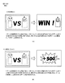
「特別遊技を実行可能な特別役に当選していることを示唆する演出」は、特別役に当選したことにより特別遊技を実行できることを示す演出であり、例えば、最終的に成功したことを示唆する演出などが挙げられる。具体的には、キャラクタが競い合うような対決演出などが実行されたときには、一方のキャラクタが勝利する画像が最終的に表示されて成功したことを示唆することができる。また、「特別遊技を実行可能な特別役に当選していないことを示唆する演出」は、特別役に当選していないことにより特別遊技を実行できないことを示す演出であり、例えば、最終的に失敗したことを示唆する演出などが挙げられる。具体的には、キャラクタが競い合うような対決演出などが実行されたときには、一方のキャラクタが敗北する画像が最終的に表示されて失敗したことを示唆することができる。 "The production that suggests that you have won the special role that can execute the special game" is the production that shows that you can execute the special game by winning the special role. For example, it suggests that you have succeeded in the end. There are examples of performances to do. Specifically, when a confrontation effect or the like in which the characters compete with each other is executed, it is possible to suggest that one of the characters has won and finally succeeded. In addition, "the effect that suggests that the special part that can execute the special game is not won" is an effect that indicates that the special game cannot be executed because the special part has not been won, and, for example, finally Examples include productions that suggest failure. Specifically, when a confrontation effect or the like in which the characters compete with each other is executed, it is possible to suggest that the image in which one character is defeated is finally displayed and fails.
尚、本実施形態は、あくまで一例であり、各手段が存在する場所や機能等、各種処理に関しての各ステップの順序、フラグのオン・オフのタイミング、各ステップの処理を担う手段名等に関し、以下の態様に限定されるものではない。また、上記した実施形態や変更例は、特定のものに対して適用されると限定的に解すべきでなく、どのような組み合わせであってもよい。例えば、ある実施形態についての変更例は、別の実施形態の変更例であると理解すべきであり、また、ある変更例と別の変更例が独立して記載されていたとしても、当該ある変更例と当該別の変更例を組み合わせたものも記載されていると理解すべきである。 Note that the present embodiment is merely an example, and the location and function of each means, the order of each step regarding various processes, the timing of turning flags on and off, the name of the means responsible for the processing of each step, and the like, It is not limited to the following modes. Further, the above-described embodiments and modified examples should not be limitedly understood to be applied to specific ones, and may be any combination. For example, modifications to one embodiment should be understood to be modifications of another embodiment, and even if one modification and another modification are described independently. It should be understood that a combination of the modification and the other modification is also described.
(本実施形態)
ここで、各構成要素について説明する前に、本実施形態に係る回胴式遊技機Pの特徴(概略)を説明する。以下、図面を参照しながら、各要素について詳述する。
(This embodiment)
Here, the features (outline) of the rotating-type gaming machine P according to the present embodiment will be described before describing each component. Hereinafter, each element will be described in detail with reference to the drawings.
尚、以下の実施形態におけるステップ番号、符号、手段名等は、他の実施形態におけるステップ番号、符号、手段名等と同一である場合があるが、これらはそれぞれ単独の実施形態におけるステップ番号、符号、手段名等であることを示している(例えば、本実施形態におけるステップ3402と本実施形態からの変更例1におけるステップ3402は、別の実施形態におけるステップ3402であるため、それぞれ単独で機能する処理である)。
Note that the step numbers, symbols, means names, etc. in the following embodiments may be the same as the step numbers, symbols, means names, etc. in other embodiments, but these are the step numbers in each individual embodiment, It is indicated by a code, a means name, etc. (for example,
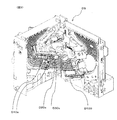
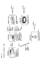
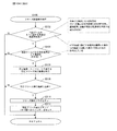
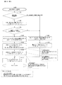
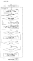
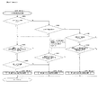
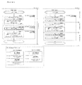
まず、図1(一部の構成については図2)を参照しながら、本実施形態に係る回胴式遊技機Pの前面側の基本構造を説明する。回胴式遊技機Pは、主に前扉(フロントドアとも称す)と、裏箱(キャビネット、基体とも称す)と裏箱内に設置されたリールユニット、ホッパ装置、電源供給ユニットE、主制御基板M(CPUMCを含む主制御チップCが搭載されている基板)、副制御基板S(CPUSCを含む副制御チップSCが搭載されている基板)で構成される。以下、これらを順に説明する。 First, with reference to FIG. 1 (FIG. 2 for a part of the configuration), a basic structure on the front surface side of the spinning-roller type gaming machine P according to the present embodiment will be described. The rotating body type game machine P mainly includes a front door (also referred to as a front door), a back box (also referred to as a cabinet or a base body), a reel unit installed in the back box, a hopper device, a power supply unit E, and a main control. A substrate M (a substrate on which the main control chip C including the CPUMC is mounted) and a sub-control substrate S (a substrate on which the sub-control chip SC including the CPUSC is mounted) are configured. Hereinafter, these will be described in order.
<前扉DU>
前扉DUは、遊技状態を視認可能にするための機構、遊技媒体の入力を可能にするための機構、リールユニットを操作するための機構、その他の機構等を含む。具体的には、遊技状態を視認可能にするための機構として、リール窓D160、投入数表示灯D210、操作状態表示灯D180、特別遊技状態表示装置D250、クレジット数表示装置D200、払出数表示装置(押し順表示装置)D270(押し順表示装置D270と称することもある)、ATカウンタ値表示装置D280、有利区間表示器YH等が取り付けられている。また、遊技媒体の投入や賭け数(ベット数)の入力を可能にするための機構として、メダル投入口D170、ベットボタンD220、投入された遊技媒体の払い出しを可能にするための機構として、精算ボタンD60が取り付けられている。そして、リールを操作するための機構として、スタートレバーD50、停止ボタンD40が取り付けられている。なお、本実施形態における回胴式遊技機は、スタートレバーD50、停止ボタンD40、メダル投入口D170、ベットボタンD220、精算ボタンD60、サブ入力ボタンSB等が取り付けられている遊技者側にせり出した形状の操作卓を備えている。以下、各要素について詳述する。
<Front door DU>
The front door DU includes a mechanism for making the game state visible, a mechanism for allowing the input of a game medium, a mechanism for operating the reel unit, and other mechanisms. Specifically, as a mechanism for making the game state visible, a reel window D160, an inserted number display lamp D210, an operation state display lamp D180, a special game state display device D250, a credit number display device D200, a payout number display device. (Pressing order display device) D270 (sometimes referred to as a pressing order display device D270), an AT counter value display device D280, an advantageous zone display YH, and the like are attached. Further, as a mechanism for allowing the insertion of the game medium and the input of the bet number (the number of bets), a medal slot D170, a bet button D220, and a mechanism for enabling the payout of the inserted game medium are settled. Button D60 is attached. A start lever D50 and a stop button D40 are attached as a mechanism for operating the reel. In addition, the spinning type gaming machine in the present embodiment is pushed out to the player side to which the start lever D50, the stop button D40, the medal slot D170, the bet button D220, the settlement button D60, the sub input button SB and the like are attached. Equipped with a shape operation console. Hereinafter, each element will be described in detail.
<遊技状態を視認可能にするための機構>
次に、遊技状態を視認可能にするための機構の要部について説明する。リール窓D160は、前扉DUの一部を構成する合成樹脂等によって形成された透明な部材であり、リール窓D160を通して遊技機枠内に設置されたリールユニットを視認可能に構成されている。また、投入数表示灯D210は、LEDによって構成されており、現在ベット(一の遊技を開始するために必要な遊技メダルを投入すること)されているメダル数と同数のLEDが点灯するよう構成されている。また、操作状態表示灯D180は、LEDによって構成されており、現在の操作状態(メダル受付可否状態、再遊技停止状態、遊技開始ウェイト状態等)に応じて点灯・消灯するよう構成されている。また、特別遊技状態表示装置D250は、7セグメントディスプレイによって構成されており、特別遊技中に払い出された払出数の総数が表示されるよう構成されている。尚、特別遊技状態表示装置D250を設けない構成としてもよく、そのように構成した場合には、後述する演出表示装置S40(第二情報表示部とも称することがある)にて当該払出数の総数を表示するよう構成することで遊技者は特別遊技中に払い出された払出数の総数を認識することができユーザーフレンドリーな遊技機とすることができる。また、クレジット数表示装置D200は、7
セグメントディスプレイによって構成されており、遊技者の持ちメダルとして遊技機内に貯留されているメダル数の総数(クレジット数)が表示されるよう構成されている。また、払出数表示装置(押し順表示装置)D270は、7セグメントディスプレイによって構成されており、現在払出されている遊技メダル数及びリール停止順(左停止ボタンD41、中停止ボタンD42、右停止ボタンD43の停止順)によって入賞する役が相違し得る条件装置{いわゆる押し順役(押し順あり役とも称することがある)であるが、入賞する役や停止表示される図柄組合せが相違した場合には、遊技者に付される利益率(払出枚数、その後のRT状態等)が異なり得るよう構成されているものが一般的である}が成立したゲームにて、遊技者に最も有利となるリール停止順を報知し得るよう構成されている(当該報知を押し順ナビと称することがある)。このように、払出数表示装置(押し順表示装置)D270は、現在払出されている遊技メダル数と遊技者に最も高利益となるリール停止順との2つの表示を実行し得るよう構成されており、実行されている表示が2つの表示のうちいずれであるかを遊技者が誤認しないような表示態様となっており、当該表示態様の詳細は後述することとする。また、ATカウンタ値表示装置D280は、ATに関する状態(詳細は後述する)のうち、押し順表示装置D270(第一情報表示部とも称することがある)に表示された押し順ナビ表示に従って遊技を進行した場合に保障されることとなる遊技者にとって有利なATに関する状態(本例では、押し順ナビ状態、報知遊技とも称することがあり詳細は後述する)に滞在し得るゲーム数を表示し得るよう構成されている。尚、ATカウンタ値表示装置D280を設けない構成としてもよく、そのように構成した場合には、AT中状態に滞在し得るゲーム数を演出表示装置S40にて表示するよう構成することで遊技者は当該有利なATに関する状態が保障されているゲーム数を認識することができユーザーフレンドリーな遊技機とすることができる。尚、払出数表示装置(押し順表示装置)D270は、払出数表示装置と押し順表示装置との2つの装置に分けるよう構成してもよい。
<Mechanism for making the game state visible>
Next, a main part of a mechanism for making the gaming state visible will be described. The reel window D160 is a transparent member that is formed of a synthetic resin or the like that forms a part of the front door DU, and is configured to allow the reel unit installed in the gaming machine frame to be viewed through the reel window D160. In addition, the inserted number display light D210 is configured by an LED, and is configured so that the same number of LEDs as the number of medals currently bet (inserting a game medal necessary to start one game) is turned on. Has been done. Further, the operation status indicator D180 is configured by an LED, and is configured to be turned on / off according to the current operation status (medal acceptance acceptance / rejection status, re-game stop status, game start wait status, etc.). Further, the special game state display device D250 is configured by a 7-segment display, and is configured to display the total number of payouts paid out during the special game. The special gaming state display device D250 may not be provided, and in such a configuration, the total number of payouts in the effect display device S40 (which may also be referred to as a second information display unit) described later. By configuring so as to display, the player can recognize the total number of payouts paid out during the special game, and can be a user-friendly gaming machine. Further, the credit amount display device D200 is 7
It is configured by a segment display, and is configured to display the total number of medals (the number of credits) accumulated in the gaming machine as medals possessed by the player. The payout amount display device (pushing order display device) D270 is composed of a 7-segment display, and the number of game medals currently paid out and the reel stop order (left stop button D41, middle stop button D42, right stop button). It is a condition device (a so-called pushing order winning combination (sometimes referred to as a pushing order winning combination)) in which the winning combination can be different depending on the stop order of D43), but when the winning combination and the symbol combination displayed in a stopped state are different. Is generally configured so that the profit rate given to the player (the number of payouts, the RT state thereafter, etc.) can be different}, the reel that is most advantageous to the player in the game It is configured to notify the stop order (the notification may be referred to as push order navigation). As described above, the payout amount display device (pushing order display device) D270 is configured so as to be able to execute two displays, that is, the number of game medals currently paid out and the reel stop order that is the highest profit for the player. The display mode is such that the player does not misidentify which of the two displays is being executed, and the details of the display mode will be described later. In addition, the AT counter value display device D280 plays the game according to the push-order navigation display displayed on the push-order display device D270 (which may also be referred to as the first information display unit) among the states related to the AT (details will be described later). It is possible to display the number of games that can be stayed in a state related to the AT that is guaranteed for the player when the game progresses (in this example, it may be referred to as a push-order navigation state or a notification game, which will be described later in detail). It is configured as follows. The AT counter value display device D280 may not be provided. In such a configuration, the player can be configured to display the number of games that can stay in the AT state on the effect display device S40. Can recognize the number of games in which the state related to the advantageous AT is guaranteed, and can be a user-friendly gaming machine. The payout amount display device (pushing order display device) D270 may be configured to be divided into two devices, that is, a payout amount display device and a push order display device.
また、有利区間表示器YHは、LEDによって構成されており、「有利区間」である場合には点灯し、「有利区間」でない場合には消灯するよう構成されている(点灯及び消灯タイミングについては後述する)。ここで、本例に係る回胴式遊技機においては、従来の回胴式遊技機と同様に、遊技メダルが獲得容易であり遊技者にとって有利な特別遊技状態(いわゆる大当り遊技であり、ボーナス遊技や第1種BB・第2種BB等と呼ばれるものが該当する)、再遊技役の当選率があらかじめ定められた値である通常遊技状態よりも再遊技役の当選率が高い(又は低い)状態である再遊技確率変動遊技状態(RT状態)、当選した役を入賞させるためのリールの停止順、停止位置を報知し得るAT(アシストタイム)中状態、前記RT状態とAT中状態とが複合したART(アシストリプレイタイム)状態、等を採り得るが、これらの「遊技状態」とは別に、「通常区間」、「待機区間」及び「有利区間」という3つの「遊技区間」のいずれかを設定可能となっている。尚、本例においては「待機区間」は設定しておらず、「通常区間」と「有利区間」とのいずれかの遊技区間を設定している。このうち、「有利区間」が他の「遊技区間」よりも、遊技者にとって相対的に有利となるものとして位置付けられており、例えば、「遊技状態」がAT中状態やART状態であることと「有利区間」とが対応付けされている。即ち、「遊技状態」がAT中状態やART状態であると、有利区間表示器YHが点灯するのであるが、後述するように、「遊技区間」の設定制御も「遊技状態」の設定制御と同様に、遊技進行を制御する主制御基板側で行われるため、有利区間表示器YHの点灯/消灯状況によって、遊技進行状況が遊技者にとって相対的に有利なものとなっているか否かが、嘘偽りなく遊技者に対して伝達可能となっている。尚、後述するように、「有利区間」が所定の上限ゲーム数(例えば、1500ゲーム)に達するまで継続すると「通常区間」が強制的に設定されるのであるが、その際には、残存するATに関する状態も強制的に終了させられる(AT中状態を維持するための情報がクリア・初期化される)ため、設定される「遊技区間」の変更が「遊技状態」の移行にも影響を与え得るものとなっており、それにより比較的設計自由度の高いAT中状態やART状態等の「遊技状態」によって、著しく射幸性が高
まってしまうことを自動的に抑制できるものとなっているのである。尚、上述したように、「有利区間」が所定の上限ゲーム数(例えば、1500ゲーム)に達するまで継続すると「通常区間」が強制的に設定される、即ち、「有利区間」が終了することとなるが、「有利区間」の終了条件はこれには限定されない。本例に係る回胴式遊技機における「有利区間」の終了条件は、「押し順役(押し順あり役)を構成する小役の中で、払出し枚数が最も多い小役を獲得可能な押し順ナビ1回の実行(例えば、押し順役を構成する小役として、7枚、3枚、1枚の小役がある場合、払出し枚数が最も多い7枚が獲得可能な押し順ナビであって、押し順により7枚、又は1枚が獲得可能な押し順役と、押し順により3枚が獲得可能な押し順役があれば、3枚が獲得可能な押し順ナビは、ここでいう押し順ナビには該当しない)」、又は、「BB、RB、MB、のいずれかに当選」を満たし、且つ、「任意の終了条件(40G1セットのループ抽選に非当選(AT)、固定32G経過(ガセ前兆)等)」、又は、「有利区間1500G」を満たすことが終了条件となっている。尚、押し順ベル役が存在しないような仕様(例:RT状態を移行するためのリプレイの押し順は存在するが、押し順によって払出し枚数が異なる小役が存在しない仕様)の場合には、「払出し枚数が最も多い小役を獲得可能な押し順ナビ1回」という有利区間を終了するための条件は除外される。また、本実施形態では、押し順役を構成する小役として11枚役に対応する小役と1枚役に対応する小役を含む小役により構成されているため、「払出し枚数が最も多い小役を獲得可能な押し順ナビ1回の実行」とは、11枚のメダルが獲得可能(11枚役が入賞可能)な押し順を報知することを指す。
Further, the advantageous zone indicator YH is configured by an LED, and is configured to be turned on when it is the “advantageous zone” and to be extinguished when it is not the “advantageous zone”. See below). Here, in the rotating body type gaming machine according to the present example, as in the case of the conventional rotating body type gaming machine, it is easy to obtain game medals and advantageous to the player in a special game state (so-called big hit game, bonus game And the
<遊技媒体の入力を可能にするための機構>
次に、遊技媒体の入力を可能にするための機構の要部について説明する。メダル投入口D170は、遊技メダルの投入口であり、メダル受付可能状態である状況下において当該投入口に投入された遊技メダルは遊技機内部へと誘導される。また、遊技機内部にはメダルの投入を検出するセンサとして、投入受付センサD10sと、第1投入センサD20sと、第2投入センサD30sと、が設けられており、遊技機内部へと誘導された遊技メダルが正常に投入されたと判断した場合に、投入されたメダルをベットされたメダルとして検出し得るよう構成されている。また、ベットボタンD220は、遊技者によって操作可能に構成されており、操作によって、貯留されているメダル(クレジットのメダル)をベットすることができるよう構成されている。また、精算ボタンD60は、遊技者によって操作可能に構成されており、操作によって、貯留されているメダル(クレジットのメダル)及び/又はベットされているメダルを遊技者に払い戻すことが可能となっている。尚、精算ボタンD60の操作によって払い戻された遊技メダルは、放出口D240に払い出されるよう構成されている。
<Mechanism for enabling input of game media>
Next, a main part of the mechanism for enabling the input of the game medium will be described. The medal insertion slot D170 is a game medal insertion slot, and the game medals inserted into the insertion slot under the condition that the medal can be received are guided to the inside of the gaming machine. In addition, as a sensor for detecting the insertion of medals, an insertion acceptance sensor D10s, a first insertion sensor D20s, and a second insertion sensor D30s are provided inside the gaming machine, and they are guided into the gaming machine. When it is determined that the game medal has been normally inserted, the inserted medal can be detected as a bet. Further, the bet button D220 is configured to be operable by the player, and is configured to bet a stored medal (credit medal) by operation. In addition, the settlement button D60 is configured to be operable by the player, and it is possible to refund the stored medals (credit medals) and / or bet medals to the player by the operation. There is. The game medals returned by the operation of the settlement button D60 are configured to be paid out to the outlet D240.
<リールユニットを操作するための機構>
次に、スタートレバーD50は、遊技者によって操作可能に構成されており、操作によってリールの動作を開始可能に構成されている。また、停止ボタンD40は、遊技者によって操作可能な左停止ボタンD41、中停止ボタンD42、右停止ボタンD43を備えており、夫々の停止ボタンを操作することによってリールの動作を順次停止可能に構成されている。
<Mechanism for operating reel unit>
Next, the start lever D50 is configured so that it can be operated by the player, and the operation of the reel can be started by the operation. The stop button D40 includes a left stop button D41, a middle stop button D42, and a right stop button D43 which can be operated by the player, and the reel operation can be sequentially stopped by operating each stop button. Has been done.
<前扉DUに設けられたその他の機構>
次に前扉DUに設けられたその他の機構の要部について図2の前扉DUを開いて回胴式遊技機Pの内部の構成を示した斜視図も参照しつつ説明する。前扉DUには、遊技の興趣性を高めるための機構として、予告演出や背景演出等の演出を表示するための演出表示装置S40、様々な点灯態様にて点灯し得る遊技効果ランプD26(不図示)、信号中継用の扉基板D、投入されたメダルの検出等を行なうメダルセレクタDS、サウンドを出力し得るスピーカS20、合成樹脂等によって形成された部材である、中パネル(中装飾パネル)、上パネルD130及び下パネルD140、等が設けられている。演出表示装置S4
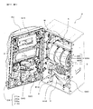
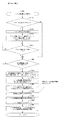
0は、上パネルに形成された透視領域を介して演出等を表示する表示部が視認可能となるように前扉DUの裏面側上部に取り付けられている。また、装飾ランプユニットD150及びLEDランプユニットS10は、回胴式遊技機Pの遊技の進行に応じて発光する発光源を有しており、下パネルD140を挟んで右側及び左側の各々に装飾ランプユニットD150が設けられ、上パネルD130を挟んで右側及び左側の各々にLEDランプユニットS10が設けられている。また、前扉DUの背面におけるリール窓D160の下方には、扉基板Dが取り付けられており、この扉基板Dには、前述した停止ボタンD40や、スタートレバーD50、精算ボタンD60等の入力信号が入力され、入力された信号を直接或いは加工して後述する主制御基板Mに出力する中継基板の機能を有している。また、メダル投入口D170に対応し、前扉DUの背面における扉基板Dの付近には、詳細後述するメダルセレクタDSが設けられており、メダル投入口D170から投入されたメダルの検出並びに簡易的な真贋を行ない、適正なメダルを後述するホッパH40に案内し、不適正なメダルを後述するメダル受け皿D230に返却する機能を有している。更に、扉基板Dの下方の左右にスピーカS20が夫々1つずつ設けられている。中パネルは、操作卓の上側、上パネルD130の下側の部分であり、前述したリール窓を含むパネル部分である。また、前述した操作卓D190に取り付けられているサブ入力ボタンSBとは、ボタン連打演出等に用いる部材であり、遊技者のサブ入力ボタンSBの操作により、ミニゲーム(例えば、「AT中状態」への突入の成否の演出)等の進行を実行し得るよう構成された部材である。なお、回胴式遊技機Pの前扉DUには、放出口D240から放出された遊技メダル(或いは単にメダルと呼ぶことがある)を受けるメダル受け皿D230、前扉DUの開閉状態を検出可能な扉スイッチD80が設けられている。また、前扉DUには鍵穴D260が設けられており、鍵穴D260の形状と整合するキー(ドアキー)を鍵穴D260に差し込む{加えて、所定の方向(例えば、時計回り)に捻る}ことで、前扉DUを開放し得るよう構成されている。更に、本実施形態においては、ドアキーを鍵穴D260に差し込む{加えて、所定の方向(例えば、反時計回り)に捻る}ことで、エラー状態(ドア開放エラー等)を解除し得るよう構成されている。
<Other mechanisms provided on front door DU>
Next, the main parts of other mechanisms provided in the front door DU will be described with reference to the perspective view showing the internal structure of the rotating body type gaming machine P by opening the front door DU in FIG. In the front door DU, as a mechanism for enhancing the interest of the game, a performance display device S40 for displaying a performance such as a notice performance or a background performance, and a game effect lamp D26 (not available) that can be lit in various lighting modes. (Illustrated), a door substrate D for signal relay, a medal selector DS for detecting inserted medals, a speaker S20 capable of outputting sound, a middle panel (medium decorative panel) which is a member formed of synthetic resin or the like. , An upper panel D130, a lower panel D140, and the like are provided. Performance display device S4
0 is attached to the upper part on the back surface side of the front door DU so that the display unit for displaying effects and the like can be visually recognized through the see-through area formed on the upper panel. Further, the decorative lamp unit D150 and the LED lamp unit S10 have a light emitting source that emits light in accordance with the progress of the game of the spinning-type gaming machine P, and the decorative lamps are provided on the right and left sides of the lower panel D140. A unit D150 is provided, and an LED lamp unit S10 is provided on each of the right side and the left side of the upper panel D130. A door board D is attached below the reel window D160 on the rear surface of the front door DU, and the door board D receives input signals such as the stop button D40, the start lever D50, and the adjustment button D60. Has a function of a relay board for directly or processing the inputted signal and outputting it to a main control board M described later. Further, a medal selector DS, which will be described in detail later, is provided near the door substrate D on the back surface of the front door DU, corresponding to the medal insertion slot D170. It has a function of performing genuine authentication, guiding a proper medal to a hopper H40 described later, and returning an invalid medal to a medal tray D230 described later. Further, one speaker S20 is provided on each of the left and right sides below the door substrate D. The middle panel is the upper part of the console and the lower part of the upper panel D130, and is the panel part including the reel window described above. Further, the sub-input button SB attached to the console D190 described above is a member used for a button repeated hit effect, etc., and is operated by the player's operation of the sub-input button SB. It is a member configured so as to be able to carry out the progress such as the effect of success or failure of entry into). In the front door DU of the rotating body type game machine P, it is possible to detect the open / closed state of the medal tray D230 for receiving the game medals (or sometimes simply referred to as medals) emitted from the outlet D240, and the front door DU. A door switch D80 is provided. Further, the front door DU is provided with a keyhole D260, and by inserting a key (door key) matching the shape of the keyhole D260 into the keyhole D260 (in addition, twisting in a predetermined direction (for example, clockwise)), It is configured so that the front door DU can be opened. Further, in the present embodiment, by inserting the door key into the keyhole D260 (in addition, twisting in a predetermined direction (for example, counterclockwise)), the error state (door opening error, etc.) can be released. There is.
次に裏箱(キャビネット、基体とも称す)並びに、裏箱内に設置される各装置について説明する。裏箱の略中央には、リール窓D160を介してその一部が視認可能となるようにリールユニットが取付られている。リールユニットは、リールM50とリールM50の駆動源(ステッピングモータ等)とを備えている。また、リールM50は、左リールM51、中リールM52、右リールM53を備えている。ここで、夫々のリール部は合成樹脂等により形成され、リール部の外周上(リール帯上)には複数の図柄が描かれている。そして、スタートレバーD50及び停止ボタンD40における各停止ボタンの操作に基づき、夫々のリール部の回転動作及び停止動作を可能とするよう構成されている。また、図示しないが、左リールM51、中リールM52及び右リールM53の内部にはLED(以下、リールバックライトと呼ぶことがある)が設けられており、LEDが点灯した際にはリール部外周を透過した光によって、リール部外周が点灯したように視認できるよう構成されている。また、リールM50の上方には、各リール(左リールM51、中リールM52、右リールM53)を駆動するための後述する回胴基板Kが格納されている。 Next, a back box (also referred to as a cabinet or a base body) and each device installed in the back box will be described. A reel unit is attached to approximately the center of the back box so that a part of the reel unit can be seen through the reel window D160. The reel unit includes a reel M50 and a drive source (stepping motor or the like) for the reel M50. The reel M50 includes a left reel M51, a middle reel M52, and a right reel M53. Here, each reel portion is formed of synthetic resin or the like, and a plurality of symbols are drawn on the outer circumference (on the reel band) of the reel portion. Then, based on the operation of each stop button of the start lever D50 and the stop button D40, the rotation operation and the stop operation of each reel portion are enabled. Although not shown, LEDs (hereinafter sometimes referred to as a reel backlight) are provided inside the left reel M51, the middle reel M52, and the right reel M53. It is configured such that the light that has passed through can be visually recognized as if the outer circumference of the reel portion is turned on. Further, above the reel M50, there is stored a below-described spinning drum substrate K for driving each reel (left reel M51, middle reel M52, right reel M53).
また、リールM50の上方には、遊技全体の制御を司る後述する主制御基板Mが格納され、リールM50の左方には、図1に示した演出表示装置S40、LEDランプユニットS10、スピーカS20等を用いて行われる各種演出の制御を司る後述する副制御基板Sが格納されている。なお、主制御基板Mには、後述する設定変更装置制御処理を実行するため(設定変更を行うため)に使用する設定キースイッチM20、設定値の変更やエラー解除等を実行し得る設定/リセットボタンM30が接続されている。図2において、設定キースイッチM20、設定/リセットボタンM30については何れも不図示としているが、主制御基板Mの基板上等の適宜位置に設けられていればよい(即ち、前扉DUを開かなければ人為的なアクセスが困難な位置に設けられていればよい)。 A main control board M, which will be described later, that controls the entire game is stored above the reel M50, and on the left side of the reel M50, the effect display device S40, the LED lamp unit S10, and the speaker S20 shown in FIG. A sub-control board S, which will be described later, that controls various effects performed by using the above is stored. The main control board M has a setting key switch M20 used to execute a setting change device control process (to change the setting) described later, and a setting / reset capable of changing a set value and releasing an error. Button M30 is connected. Although neither the setting key switch M20 nor the setting / reset button M30 is shown in FIG. 2, it may be provided at an appropriate position on the main control board M or the like (that is, the front door DU is opened). If it is not provided, it should be provided in a position where artificial access is difficult).
リールM50の下方には、投入された遊技メダルが集められるホッパH40や、遊技メダルを払い出すメダル払出装置Hが設けられており、回胴式遊技機P全体に電源を供給するための電源基板Eが格納されている。メダル払出装置Hから払い出された遊技メダルは、コインシュータD90を通って、放出口D240から払い出されるようになっている。また、電源基板E(電源供給ユニットEとも称することがある)の前面には、回胴式遊技機Pの電源を投入するための電源スイッチE10も設けられている。なお、メダル払出装置Hの詳細については後述する。 Below the reel M50, a hopper H40 for collecting the inserted game medals and a medal payout device H for paying out the game medals are provided, and a power supply board for supplying power to the entire spinning-roller type gaming machine P. E is stored. The game medals paid out from the medal payout device H pass through the coin shooter D90 and are paid out from the outlet D240. Further, a power switch E10 for turning on the power of the spinning-type gaming machine P is also provided on the front surface of the power board E (which may also be referred to as a power supply unit E). The details of the medal payout device H will be described later.
<メダルセレクタDS>
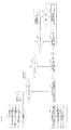
次に、メダルセレクタDSについて、図3を交えつつ詳細に説明する。図3は、回胴式遊技機P内部における、メダル投入口D170に投入された遊技メダルの経路(セレクタ)を示した斜視図である。メダルセレクタDSは、扉基板Dの付近にメダル投入口D170から投入された遊技メダルの通路となる投入受付センサD10sが設けられており、投入受付センサD10sの下方には、遊技メダルを放出口D240に導くためのコインシュータD90などが設けられている。投入受付センサD10sは、メダル投入口D170から投入された遊技メダルを主に寸法に基づいて選別し、規格寸法に適合した遊技メダルだけを受け入れる機能を有しており、この機能により適合しないと判断されたメダル(又は、その他の異物)は、ブロッカD100により放出口D240に払い戻されるよう構成されている。遊技者がスタートレバーD50を操作する前に(遊技メダルの投入が有効である状態にて)遊技メダルを投入すると、遊技メダルは投入受付センサD10sによって選別され、規格を満足しているものだけがホッパH40内に投入され、規格を満たしていないメダルは、コインシュータD90を通って、放出口D240に返却されるようになっている。これに対して、スタートレバーD50が操作された後に(遊技メダルの投入が有効でない状態にて)遊技メダルが投入された場合は、規格を満たしているか否かに拘らず、投入された遊技メダルはコインシュータD90を通って、放出口D240に返却される。また、投入受付センサD10sの内部(流路の奥)には、詳細後述するメダル投入に係るセンサが設けられており、寸法規格を満たして受け入れられた遊技メダルが通過すると、第1投入センサD20s及び第2投入センサD30sによって検出されて、その信号が後述する主制御基板Mに供給されるようになっている。
<Medal Selector DS>
Next, the medal selector DS will be described in detail with reference to FIG. FIG. 3 is a perspective view showing the path (selector) of the game medals inserted into the medal insertion slot D170 inside the rotating-type gaming machine P. The medal selector DS is provided with an insertion acceptance sensor D10s, which is a passage for game medals inserted from the medal insertion opening D170, near the door substrate D, and the game medal ejection opening D240 is provided below the insertion acceptance sensor D10s. Is provided with a coin shooter D90 or the like. The insertion acceptance sensor D10s has a function of mainly selecting the game medals inserted from the medal insertion slot D170 based on the size and accepting only the game medals that meet the standard size, and it is determined that the game medal does not match by this function. The formed medals (or other foreign matter) are configured to be returned to the outlet D240 by the blocker D100. If the player inserts a game medal before operating the start lever D50 (while the insertion of the game medal is valid), the game medal is selected by the insertion acceptance sensor D10s, and only those satisfying the standard are selected. The medals that are thrown into the hopper H40 and do not meet the standard are returned to the discharge port D240 through the coin shooter D90. On the other hand, when the game medal is inserted after the start lever D50 is operated (in the state where the insertion of the game medal is not valid), the inserted game medal is irrespective of whether the standard is satisfied or not. Is returned to the outlet D240 through the coin shooter D90. Further, inside the insertion receiving sensor D10s (inside the flow path), a sensor for inserting a medal, which will be described in detail later, is provided, and when a game medal that meets the dimensional standard and is received passes, the first insertion sensor D20s. Also, the signal is detected by the second closing sensor D30s and the signal is supplied to the main control board M described later.
次に、メダル投入に係るセンサについて詳述する。メダル投入口D170に投入された遊技メダルは、まず投入受付センサD10sを通過する。投入受付センサD10sは機械式のダブルセンサになっており、遊技メダルが通過することによって、2つの突起した機構が押下されることによりオンとなり遊技メダルが正常に通路を通過することができることとなる。また、このような構成により、遊技メダルではない異物(規格を満足していない異物であり、例えば、遊技メダルよりも径が小さいもの)が投入された場合には、2つの突起した機構が押下されない。このようなメダルは、起立した状態をメダルが維持できないため、通路を通過できず(メダルが倒れこむ)、前述したようにコインシュータD90を通って放出口D240に払い戻されることとなる。そのほかにも、投入受付センサD10sは、オンとなっている時間が所定時間以上連続した場合等にも、エラーであると判定し得る(その結果、ブロッカD100がオフとなり得る)よう構成されている。 Next, the sensor for inserting a medal will be described in detail. The game medal inserted into the medal insertion slot D170 first passes through the insertion acceptance sensor D10s. The loading acceptance sensor D10s is a mechanical double sensor, and when the game medal passes, the two protruding mechanisms are pressed to turn on and the game medal can normally pass through the passage. . Also, with such a configuration, when a foreign object that is not a game medal (for example, a foreign object that does not meet the standard and has a smaller diameter than the game medal) is inserted, the two protruding mechanisms are pressed. Not done. Such medals cannot pass through the passage (the medals fall down) because the medals cannot be maintained in an upright state, and as described above, the medals are returned to the discharge port D240 through the coin shooter D90. In addition, the input acceptance sensor D10s is configured to be able to determine that there is an error (as a result, the blocker D100 can be turned off) even when the on time continues for a predetermined time or more. .
遊技メダルがブロッカD100を正常に通過した場合に、通過直後に第1投入センサD20s及び第2投入センサD30sを通過することとなる。この投入センサ(第1投入センサD20s及び第2投入センサD30s)は2つのセンサで構成されており(遊技メダルの規格上の直径よりも小さい間隔で隣接配置されており)、夫々のセンサのオン・オフ状況(第1投入センサD20s及び第2投入センサD30sのオン・オフの組み合わせの遷移していく順序、等)及びオン・オフとなっている時間を監視することにより様々なエラーを検出可能に構成されている。 When the game medal normally passes through the blocker D100, it will pass through the first loading sensor D20s and the second loading sensor D30s immediately after passing. This insertion sensor (first insertion sensor D20s and second insertion sensor D30s) is composed of two sensors (adjacent to each other at a distance smaller than the standard diameter of the game medal), and each sensor is turned on. -Various errors can be detected by monitoring the off status (the transition sequence of the on / off combination of the first closing sensor D20s and the second closing sensor D30s, etc.) and the on / off time. Is configured.
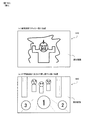
<メダル払出装置H>
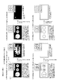
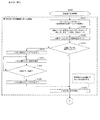
次に、図4のメダル払出装置Hの正面図及び上面図を用いてメダル払出装置Hを詳細に説明する。メダル払出装置Hは、クレジット(遊技機内部に電子的に貯留されている遊技メダル)又はベットされているメダル(遊技を開始するために投入されたメダル)が存在する状態で、精算ボタンが操作された、又は、入賞により遊技メダルが払い出される場合に作動することとなる。作動する場合には、まず、ホッパモータH80が駆動することにより、ディスク回転軸H50aを中心にディスクH50が回転する。回転によりメダル払出装置H内の遊技メダルは放出付勢手段H70を変位させて遊技メダル出口H60から放出口D240に向かって流下していくこととなる。尚、払出センサ(第1払出センサH10s及び第2払出センサH20s)は2つのセンサで構成されており、夫々のセンサのオン・オフ状況(第1払出センサH10s及び第2払出センサH20sのオン・オフの組み合わせの遷移していく順序、等)及びオン・オフとなっている時間を監視することにより様々なエラーを検出可能に構成されている。より具体的には、例えば、遊技メダル出口H60を正常に通過する際には、放出付勢手段H70の変位により、第1払出センサH10s=オフ・第2払出センサH20s=オフの状態から、第1払出センサH10s=オフ・第2払出センサH20s=オフ→第1払出センサH10s=オン・第2払出センサH20s=オフ→第1払出センサH10s=オン・第2払出センサH20s=オン→第1払出センサH10s=オフ・第2払出センサH20s=オン→第1払出センサH10s=オフ・第2払出センサH20s=オフ、というセンサ状態遷移となるため、このセンサ状態遷移と反する動きを検出した場合には、エラーとするよう構成することを例示することができる。
<Medal payout device H>
Next, the medal payout device H will be described in detail with reference to the front view and the top view of the medal payout device H of FIG. The medal payout device H operates the settlement button in a state where there are credits (game medals electronically stored in the game machine) or bets (medals inserted to start the game). It is operated when the game medals are paid out or paid out. When operating, the hopper motor H80 is first driven to rotate the disc H50 about the disc rotation axis H50a. The rotation causes the game medals in the medal payout device H to flow down from the game medal exit H60 toward the exit D240 by displacing the discharge urging means H70. The payout sensor (the first payout sensor H10s and the second payout sensor H20s) is composed of two sensors, and the on / off status of each sensor (the first payout sensor H10s and the second payout sensor H20s are on. Various errors can be detected by monitoring the transition sequence of off combinations, etc.) and the on / off time. More specifically, for example, when normally passing through the game medal exit H60, due to the displacement of the discharge urging means H70, the first payout sensor H10s = OFF, the second payout sensor H20s = OFF, First payout sensor H10s = OFF, second payout sensor H20s = OFF → first payout sensor H10s = ON, second payout sensor H20s = OFF → first payout sensor H10s = ON, second payout sensor H20s = ON → first payout Sensor H10s = off, second payout sensor H20s = on, first payout sensor H10s = off, second payout sensor H20s = off, so that a movement contrary to this sensor status transition is detected. , An error can be illustrated.
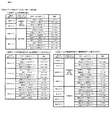
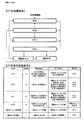
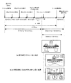
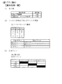
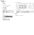
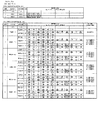
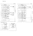
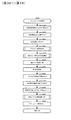
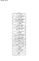
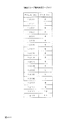
次に、図5は、本実施形態における、回胴式遊技機の基本仕様一覧である。本実施形態に係る回胴式遊技機は、規定数(1ゲームにてベットできる遊技メダルの最大枚数)が3枚、左リールM51、中リールM52及び右リールM53のコマ数はいずれも20コマ、入賞判定される有効ラインは「左リールM51上段、中リールM52中段、右リールM53下段」の1ラインとなっている。尚、最大払出枚数は11枚、最小払出枚数は1枚(入賞役と払出枚数との対応付けは後述)である。また、優先入賞順(引き込み優先順)は、「再遊技役→小役(ベル、スイカ、等)→ボーナス」となっており、例えば、再遊技役とボーナスが同時に成立している場合には、再遊技役となる図柄組み合わせが停止表示し且つボーナスは入賞不能である。また、ベルとスイカが成立している場合には、どちらも引き込める位置(入賞する停止位置まで4コマ以内の位置)で停止ボタンを押した場合には払出枚数が多い小役を優先して引きこむよう構成されている。尚、同図に示した構成はあくまで一例であり、各リールのコマ数を変更(例えば、21コマに変更)したり、有効ラインの構成を変更(例えば、横3ライン、斜め2ラインの5ラインに変更、左リールM51下段、中リールM52中段、右リールM53上段の1ラインに変更)しても何ら問題ない。また、特に押し順によって遊技者にとって異なる利益が付与される押し順小役が当選したときの引き込み制御としては、予め定められた正解の押し順で操作された場合には払出し枚数の多い小役を優先して引き込むように制御(枚数優先制御)しており、正解の押し順とは異なる不正解の押し順で操作された場合には停止表示可能な(停止操作から4コマ以内の位置に配置されている)図柄のうち入賞可能性を高める(入賞可能な複数図柄組合せのうち入賞する可能性が最も多くなる)図柄を引き込む制御(個数優先制御)を行っている。 Next, FIG. 5 is a list of basic specifications of the rotating body type gaming machine in the present embodiment. In the rotating body type gaming machine according to the present embodiment, the prescribed number (the maximum number of gaming medals that can be bet in one game) is 3, and the left reel M51, the middle reel M52, and the right reel M53 all have 20 pieces. The effective line for winning determination is one line of "upper left reel M51, middle reel M52, lower reel right M53". The maximum payout number is 11 and the minimum payout number is 1 (the winning combination and the payout number will be described later). In addition, the priority winning order (pull-in priority order) is “re-play combination → small combination (bell, watermelon, etc.) → bonus”. For example, when the re-play combination and bonus are established at the same time, , The symbol combination to be the re-game combination is stopped and displayed, and the bonus cannot be won. In addition, when the bell and watermelon are established, if you press the stop button at a position where both can be retracted (position within 4 frames to the winning stop position), the small winning combination with a large number of payouts will be given priority. It is configured to retract. The configuration shown in the figure is merely an example, and the number of frames of each reel is changed (for example, 21 frames), or the configuration of the effective line is changed (for example, horizontal 3 lines, diagonal 2 lines 5). There is no problem even if the line is changed to one line of the lower stage of the left reel M51, the middle stage of the middle reel M52, and the upper stage of the right reel M53. In addition, as a pull-in control when a push order small win is awarded, which gives different profits to the player depending on the push order, a small win with a large payout number when operated in a predetermined correct push order. Is controlled so as to be preferentially drawn in (number of sheets priority control), and when an incorrect answer pressing order different from the correct answer pressing order is operated, a stop display is possible (at a position within 4 frames from the stop operation). Among the symbols (arranged), the control of pulling in the symbols (the number-of-priorities control) for increasing the winning possibility (the highest possibility of winning among a plurality of winning symbol combinations) is performed.
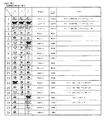
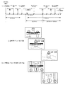
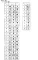
次に、図6は、本実施形態における、回胴式遊技機のリール配列一覧である。同図に示されるように、左リールM51、中リールM52及び右リールM53のコマ数はいずれも20コマ(0番〜19番)であり、図柄は「黒セブン」、「白セブン」、「羊」、「ブランク」、「ベル」、「リプレイA」、「リプレイB」、「スイカA」、「スイカB」、「チェリー」の10種類となっている。ここで、「ブランク」は、その他の図柄と同様に当
選役を構成する図柄組み合わせに含まれる図柄であり、当選役を構成しない図柄という意味ではなく、「ブランク」を含む当選役を構成する図柄組み合わせとしては、例えば、「スイカB・リプレイA・ブランク」で再遊技02となっている。尚、同図に示した構成はあくまで一例であり、図柄の種類を増減・変更しても何ら問題ない。
Next, FIG. 6 is a reel array list of the spinning drum type gaming machine in the present embodiment. As shown in the figure, the number of frames of each of the left reel M51, the middle reel M52, and the right reel M53 is 20 (0 to 19), and the symbols are "black seven", "white seven", " There are 10 types of sheep, “blank”, “bell”, “replay A”, “replay B”, “watermelon A”, “watermelon B”, and “cherry”. Here, "blank" is a symbol included in a symbol combination that constitutes a winning combination like other symbols, does not mean a symbol that does not constitute a winning symbol, but a symbol that constitutes a winning symbol including "blank". As a combination, for example, "Watermelon B / Replay A / Blank" is
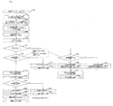
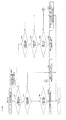
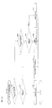
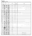
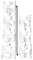
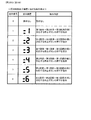
次に、図7〜図9は、本実施形態における図柄組み合わせ一覧1〜3である。本実施形態においては、夫々の条件装置に対して複数の図柄組み合わせが存在しており、後述するように、左リールM51、中リールM52及び右リールM53の停止順番や停止位置に応じて、いずれか一の図柄組み合わせが有効ライン(前述した1ライン)上に停止表示されるよう構成されている。尚、有効ライン上に同一種類の図柄が揃っていない場合にも遊技者から見ると有効ライン以外のライン上にて一列に同一の図柄が揃いやすく構成されている(スイカの場合には中段に横一直線に揃う等、リール上のいずれかに一直線にスイカ図柄が3つ揃うよう構成されている)。また、本実施形態においては、第1種BB役(いわゆる第1種特別役物に係る役物連続作動装置であるが、以下、単にBB役と呼ぶことがある)となる図柄組み合わせして、1種BB‐A(RB−Aを連続作動させ、264枚を超える払出で終了)となる「羊・羊・羊」と、1種BB‐B(RB−Bを連続作動させ、132枚を超える払出で終了)となる「黒セブン・黒セブン・黒セブン」と、1種BB‐C(RB−Bを連続作動させ、132枚を超える払出で終了)となる「白セブン・白セブン・白セブン」との3つの図柄組み合わせを有している。尚、本実施形態においては、第1種BB役が入賞し、BBが実行された(役物が作動した)場合には、当該BB実行中においては、BB中のすべてのゲームにおいて、1つの抽選テーブルを参照して、役物以外の当選役(小役、再遊技役)を抽選するよう構成されている(1回のBBの実行中において役抽選の際に参照するテーブルを切り替えない方式であり、以下、オールJACINタイプと呼ぶことがある)。尚、第1種BB役の形式に関しては、これには限定されず、1回のBBの実行中において役抽選の際に参照するテーブルを切り替え得るよう構成してもよい。また、RT状態が「RT1」である場合に14番〜16番に対応する再遊技04となる図柄組み合わせが停止表示されると、RT0に移行するよう構成されている(RT状態の詳細については後述する)。尚、「RT1」よりも「RT0」の方が遊技者に不利なRT状態であるため、「RT1」から「RT0」に移行することを転落すると称することがある。また、17番に対応する再遊技05となる図柄組み合わせが停止表示されると、左リールM51、中リールM52及び右リールM53の下段に「黒セブン」が停止表示され得ることとなり、18番に対応する再遊技05となる図柄組み合わせが停止表示されると、左リールM51、中リールM52及び右リールM53の下段に「白セブン」が停止表示され得ることとなる(詳細は後述することとする)。また、後述する「入賞‐A1」〜「入賞‐A6」の条件装置である押し順ベルが当選した場合には、遊技者にとって最も有利な押し順にてリールを停止させると、21番〜27番に対応する「入賞01」〜「入賞03」となる図柄組み合わせが停止表示され、11枚の遊技メダルが払い出される一方、遊技者にとって最も有利な押し順とは異なる押し順にてリールを停止させると、39番〜56番に対応する「入賞08」〜「入賞11」となる図柄組み合わせが停止表示され、1枚の遊技メダルが払い出されることとなる。尚、同図における「‐」はいずれの図柄が停止表示されてもよい旨を示しており、例えば、23番に対応する「ベル・‐・ベル」は左リールM51及び右リールM53の有効ライン上にベルが停止表示されれば中リールM52の有効ライン上にはどの図柄が停止表示されても11枚の遊技メダルが獲得できる。
Next, FIGS. 7 to 9 are symbol combination lists 1 to 3 in the present embodiment. In the present embodiment, a plurality of symbol combinations exist for each condition device, and as will be described later, depending on the stop order and stop position of the left reel M51, the middle reel M52, and the right reel M53, either The one symbol combination is configured to be stopped and displayed on the activated line (the above-mentioned one line). Even if the same type of symbols are not available on the activated line, it is easy for the player to see the same symbols in a line on lines other than the activated line. It is configured so that three watermelon symbols are aligned in a straight line on one of the reels, such as aligned in a horizontal line). In addition, in the present embodiment, a combination of symbols to be a first-class BB combination (a so-called first-class special accessory, which is a character continuous operation device, but may be simply referred to as a BB combination hereinafter), 1 type BB-A (RB-A is continuously operated and finished after paying out more than 264 sheets) and 1 type BB-B (RB-B is continuously operated, 132 sheets are "Black Seven / Black Seven / Black Seven" and "
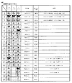
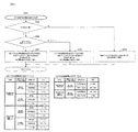
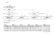
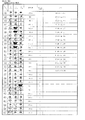
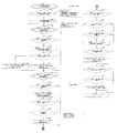
次に、図10は、本実施形態における条件装置一覧である。尚、同図においては、条件装置番号を当選番号と称しており、以降においても条件装置番号を当選番号と称することがある。本実施形態においては、再遊技役は再遊技‐A〜再遊技‐D3(当選番号1〜6)まで設けられており、左リールM51、中リールM52及び右リールM53の停止順番や停止位置に応じて、停止表示する再遊技役が相違し得るよう構成されている。ここで、本実施形態においては、最も右の列である「条件装置」の項目に図示されているように、
左リールM51、中リールM52及び右リールM53の停止順番や停止位置に応じて複数種類の条件装置が停止表示され得るよう構成されており、当該複数種類の条件装置のうち同一の当選番号となる条件装置を纏めて、右から3番目の列である「条件装置(名称)」の項目にて図示している。具体的には、例えば、当選番号1に対応する条件装置である「再遊技‐A」においては、左リールM51、中リールM52及び右リールM53の停止順番や停止位置に応じて、「再遊技01」、「再遊技02」、「再遊技03」の3種類の条件装置が停止表示され得るよう構成されている。尚、「条件装置(名称)」を単に条件装置を称することがある。また、「再遊技01」等の再遊技に関する条件装置を再遊技役と称することがあり、「入賞01」等の入賞することで遊技メダルが払い出される条件装置を小役と称することがあり、「1種BB‐A」等の停止表示されることによりBBが開始することとなる条件装置をBB役と称することがある。また、当選番号21〜23及び25〜27に当選した場合には、BB役と小役とが重複して当選することとなり、そのような場合には、当選した小役に対応する図柄が停止表示し得る位置にて左停止ボタンD41、中停止ボタンD42及び右停止ボタンD43を操作するとBB役に対応する図柄が停止表示せずに小役に対応する図柄が停止表示する一方、小役に対応する図柄が停止表示しない(引き込めない)位置にて左停止ボタンD41、中停止ボタンD42及び右停止ボタンD43を操作すると小役に対応する図柄が停止表示せずにBB役に対応する図柄が停止表示するよう構成されている。具体的には、例えば、当選番号21の条件装置である「1種BB‐B+入賞‐C」に当選した場合には、「入賞12」又は「入賞13」であるチェリーと、「1種BB‐B」である黒セブンとのいずれかが停止表示し得ることとなる。より具体的には、左リールM51→中リールM52→右リールM53の順番にリールを停止させる場合において、(1)第1停止にて左リールM51の上段に図柄番号0〜4番(図6のリール配列を参照)が位置している操作タイミングにて左停止ボタンD41を操作した場合には、左リールM51の上段に「入賞12」に対応する図柄番号4番が停止し、中リールM52及び右リールM53の停止位置に拘らず、「入賞12」が停止表示される。(2)第1停止にて左リールM51の上段に図柄番号5〜12番が位置している操作タイミングにて左停止ボタンD41を操作した場合には、左リールM51の上段に「入賞13」に対応する図柄番号6番、11番、又は16番が停止し、中リールM52及び右リールM53の停止位置に拘らず、「入賞13」が停止表示される。(3‐1)第1停止にて左リールM51の上段に図柄番号13〜19番が位置している操作タイミングにて左停止ボタンD41を操作した場合には、左リールM51の上段に「1種BB‐B」に対応する図柄番号17番又は19番が停止する。(3‐2)第2停止にて中リールM52の中段に図柄番号14〜18番が位置している操作タイミングにて中停止ボタンD42を操作した場合には、中リールM52の中段に「1種BB‐B」に対応する図柄番号18番が停止し、その後、第3停止にて右リールM53の下段に図柄番号13〜17番が位置している操作タイミングにて右停止ボタンD43を操作した場合には、右リールM53の下段に「1種BB‐B」に対応する図柄番号17番が停止し、BB役が停止表示されることとなる。(3‐3)第2停止にて中リールM52の中段に図柄番号19〜13番が位置している操作タイミングにて中停止ボタンD42を操作した場合には、中リールM52の中段に「1種BB‐B」に対応する図柄番号18番が停止できず、いずれの条件装置も停止表示されないこととなる。
Next, FIG. 10 is a list of conditional devices in the present embodiment. In the figure, the condition device number is referred to as a winning number, and the condition device number may hereinafter be referred to as a winning number. In the present embodiment, the re-gaming combination is provided from re-gaming-A to re-gaming-D3 (winning
It is configured such that a plurality of types of condition devices can be stopped and displayed according to the stop order or stop position of the left reel M51, the middle reel M52, and the right reel M53, and the same winning number is selected from the plurality of types of condition devices. The condition devices are collectively shown in the item “condition device (name)” in the third column from the right. Specifically, for example, in "replay-A" which is a condition device corresponding to the winning
次に、「役割」の項目には、「条件装置(名称)」がどのような役割となっているかを図示しており、当選番号1に対応する「通常リプレイ」は、停止ボタンの押し順に拘らず、RT状態が移行しない再遊技役が停止表示される再遊技に係る条件装置であり、当選番号2に対応する「逆押し白7揃いリプレイ」は、停止ボタンの押し順に拘らず、RT状態が移行しない再遊技役が停止表示される再遊技に係る条件装置であるが、逆押し(右リールM53→中リールM52→左リールM51の順にリールを停止させること)にて、右リールM53の図柄番号18〜2番の範囲、中リールM52の図柄番号9〜13番の範囲、左リールM51の図柄番号5〜10番の範囲が各リールの下段に位置している操作タイミ
ングにて停止ボタンを操作することにより、右リールM53、中リールM52及び左リールM51の下段に「白セブン」が停止表示され、遊技者から見ると白セブンが下段に揃っているように見えるよう構成されている。尚、再遊技‐Bに当選し、AT上乗せ抽選に当選したゲームにおいて、逆押しで「白セブン」を狙うよう指示する演出(詳細は後述する)を実行することにより、AT上乗せ抽選に当選した旨を遊技者に報知し得るよう構成されている。当選番号3に対応する「順押し黒7揃いリプレイ」は、停止ボタンの押し順に拘らず、RT状態が移行しない再遊技役が停止表示される再遊技に係る条件装置であるが、順押し(左リールM51→中リールM52→右リールM53の順にリールを停止させること)にて、左リールM51の図柄番号13〜19番の範囲、中リールM52の図柄番号14〜18番の範囲、右リールM53の図柄番号13〜17番の範囲が各リールの下段に位置している操作タイミングにて停止ボタンを操作することにより、左リールM51、中リールM52及び右リールM53の下段に「黒セブン」が停止表示され、遊技者から見ると黒セブンが下段に揃っているように見えるよう構成されている。尚、再遊技‐Cに当選し、AT上乗せ抽選に当選したゲームにおいて、順押しで「黒セブン」を狙うよう指示する演出(詳細は後述する)を実行することにより、AT上乗せ抽選に当選した旨を遊技者に報知し得るよう構成されている。
Next, in the “role” item, the role of the “condition device (name)” is illustrated, and the “normal replay” corresponding to the winning
また、当選番号4に対応する「RT維持RP1**(3択)」は第1停止リールを左リールM51と中リールM52と右リールM53とのいずれにするか(いずれの停止ボタンを操作するか)によって、停止表示される再遊技役が相違し得る条件装置であり、第1停止リールを左リールM51とした場合には、RT状態が移行しない再遊技01、再遊技02又は再遊技03が停止表示され、第1停止リールを中リールM52又は右リールM53とした場合には、RT状態が「RT1」から「RT0」に移行し得る再遊技04が停止表示される。また、当選番号5に対応する「RT維持RP*1*(3択)」は第1停止リールを左リールM51と中リールM52と右リールM53とのいずれにするか(いずれの停止ボタンを操作するか)によって、停止表示される再遊技役が相違し得る条件装置であり、第1停止リールを中リールM52とした場合には、RT状態が移行しない再遊技03が停止表示され、第1停止リールを左リールM51又は右リールM53とした場合には、RT状態が「RT1」から「RT0」に移行し得る再遊技04が停止表示される。また、当選番号6に対応する「RT維持RP**1(3択)」は第1停止リールを左リールM51と中リールM52と右リールM53とのいずれにするか(いずれの停止ボタンを操作するか)によって、停止表示される再遊技役が相違し得る条件装置であり、第1停止リールを右リールM53とした場合には、RT状態が移行しない再遊技01又は再遊技03が停止表示され、第1停止リールを左リールM51又は中リールM52とした場合には、RT状態が「RT1」から「RT0」に移行し得る再遊技04が停止表示される。
Further, in “RT maintenance RP1 ** (3 options)” corresponding to the winning
また、当選番号7〜12に対応する、「押し順ベル123」〜「押し順ベル321」は、リール停止順を6択のいずれとするかによって入賞する小役が相違し得る条件装置であり、例えば、「左リールM51:1、中リールM52:2、右リールM53:3」となっており「123」の場合「左リールM51→中リールM52→右リールM53」の押し順で停止させるという意味であり、例えば、「入賞A‐1」(当選番号7)の場合には、「123」=「左→中→右」の順に停止させる(押し順に正解する)と最大獲得枚数である11枚の遊技メダルが獲得できる「入賞01」となる図柄組み合わせが停止表示することとなる。尚、「押し順ベル123」の「123」等はその当選番号における最大獲得枚数を獲得可能な押し順(リール停止順)を示している。尚、最大獲得枚数を獲得可能な押し順以外の押し順にてリールを停止させた場合には、即ち、押し順に正解できないと1枚の払出となるよう構成されており、このように構成することで、「AT中状態」等のATに関する状態にて再遊技役の押し順やベルの押し順をナビ(押し順表示装置D270にて最高利益となる押し順を表示)し、「通常遊技状態」等のATに関する状態には押し順をナビしないという遊技者の利益率が異なる複数の遊技状態を創出することができる。尚、A
Tに関する状態については後述する。
Further, the "push
The state regarding T will be described later.
また、当選番号13に対応する、「共通ベル」は、入賞04〜入賞07のいずれが停止しても最大獲得枚数である11枚の遊技メダルが獲得できる、即ち、押し順に拘らず最大利益が獲得できる条件装置であり、押し順不問ベルと称することがある。また、当選番号15に対応する、「スイカA」は、平行ラインにスイカ(スイカAとスイカBのいずれか)が3つ揃いし易いよう構成されており、例えば、図9における60番の入賞14は各リール中段にスイカAが3つ揃いすることとなる。また、当選番号16に対応する、「スイカB」は、斜めラインにスイカ(スイカAとスイカBのいずれか)が3つ揃いし易いよう構成されており、例えば、図9における66番の入賞16は左リールM51上段にスイカB、中リールM52中段にスイカB、右リールM53下段にスイカAのように、斜め右下がりにスイカが3つ揃いすることとなる。また、当選番号17に対応する、「BB中弱レア小役(斜めベル揃い)」は、有効ライン上にベルが3つ揃いし得る条件装置であり、詳細は後述するが、BB中に当選することによってAT上乗せ抽選が実行される条件装置である。また、当選番号18に対応する、「BB中強レア小役(V字ベル揃い)」は、左リールM51上段、中リールM52中段、右リールM53上段にベルが停止表示され得る条件装置であり、詳細は後述するが、BB中に当選することによってAT上乗せ抽選が実行される条件装置である。
In addition, the "common bell" corresponding to the winning
次に、「ボーナス当選情報」の項目には、0〜3までの数値が当選番号毎に振り分けられている。本実施形態においては、ボーナス(BB役)が含まれない当選番号はボーナス当選情報を0とし、ボーナス(BB役)が含まれる当選番号として、1種BB‐Aが含まれる当選番号(19)のボーナス当選情報を1、1種BB‐Bが含まれる当選番号(20〜23)のボーナス当選情報を2、1種BB‐Cが含まれる当選番号(24〜27)のボーナス当選情報を3としている。ボーナス当選情報を主制御基板Mが記憶することによっていずれのBB成立の有無やいずれのBB役に当選したかに係る情報を記憶することができる。尚、ボーナス当選情報の詳細については後述する。
Next, in the item of "bonus winning information",
次に、「入賞・再遊技当選情報」の項目には、0〜18までの数値が当選番号毎に振り分けられている。本実施形態においては、再遊技役と小役とが含まれない当選番号(ハズレに対応する当選番号0とボーナスに対応する当選番号19・20・24)は入賞・再遊技当選情報を0とし、再遊技役又は小役が含まれる当選番号に対して1〜18入賞・再遊技当選情報を条件装置毎に振り分けている。入賞・再遊技当選情報を主制御基板Mが記憶することによっていずれの再遊技役又は小役に当選したかに係る情報を記憶することができる。尚、入賞・再遊技当選情報の詳細については後述する。
Next, in the item of "winning / re-game winning information", numerical values from 0 to 18 are distributed for each winning number. In the present embodiment, the winning numbers (winning
次に、「演出グループ番号」の項目には、0〜11までの数値が当選番号毎に振り分けられている。演出グループ番号を主制御基板M側から副制御基板S側に送信することによって、副制御基板S側が実行する演出を決定することができるよう構成されている。尚、演出グループ番号の詳細については後述する。 Next, in the item of "production group number", numerical values from 0 to 11 are assigned for each winning number. By transmitting the effect group number from the main control board M side to the sub control board S side, the effect to be executed by the sub control board S side can be determined. The details of the effect group number will be described later.
次に、「出玉グループ番号」の項目には、0〜13までの数値が当選番号毎に振り分けられている。出玉グループ番号を主制御基板Mが記憶し、当該記憶した出玉グループ番号をATに関する抽選(例えば、AT抽選、AT上乗せ抽選)を実行する際に使用することにより、ATに関する抽選処理を実行するためのプログラム、データ容量を削減することができる。尚、出玉グループ番号が0となる条件装置が当選してもAT抽選及びAT上乗せ抽選は実行されない。一方、出玉グループ番号が0でない条件装置が当選した場合には、AT抽選又はAT上乗せ抽選が実行され得ることとなる。尚、出玉グループ番号の詳細については後述する。また、出玉グループ番号が0となる条件装置が当選した場合にも、AT抽選又はAT上乗せ抽選が実行され得るよう構成してもよく、そのように構成した場
合には、出玉グループ番号が0となる条件装置が当選してAT抽選又はAT上乗せ抽選が実行された場合には、当該抽選結果がかならずハズレ(非当選)となるよう構成することが好適である。
Next, in the item “ball-out group number”, numerical values from 0 to 13 are distributed for each winning number. The main control board M stores the payout group number, and the stored payout group number is used when performing a lottery for AT (for example, AT lottery, AT additional lottery), thereby performing lottery processing for AT. It is possible to reduce the program and data capacity for doing so. Even if the condition device having the payout group number of 0 is won, the AT lottery and the AT additional lottery are not executed. On the other hand, when the condition device whose payout group number is not 0 is won, AT lottery or AT additional lottery can be executed. The details of the payout group number will be described later. Further, even when the condition device having a payout group number of 0 is won, the AT lottery or the AT additional lottery may be configured to be executed. In such a case, the payout group number is When the condition device that becomes 0 is won and the AT lottery or the AT addition lottery is executed, it is preferable that the lottery result is always lost (non-winning).
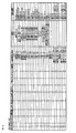
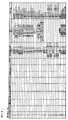
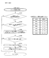
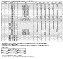
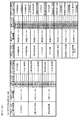
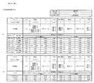
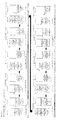
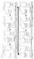
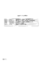
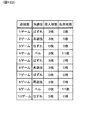
次に、図11は、本実施形態における小役、再遊技役に関する当選番号(条件装置番号、当選役とも称す)及びボーナス(BB、BB役とも称す)が役抽選手段により決定される抽選確率(当選率とも称する)を示す一覧である。同図においては、当選番号の当選率を図示している。 Next, FIG. 11 is a lottery probability in which the winning numbers (also referred to as condition device numbers and winning combinations) and bonuses (also referred to as BB and BB combinations) regarding the small winning combination and the re-playing combination in the present embodiment are determined by the winning combination lottery means. It is a list showing (also referred to as a winning rate). In the figure, the winning rate of the winning numbers is shown.
まず、BB未作動時である「RT0」、「RT1」及び「RT2」における抽選確率について詳述する。本実施形態においては、RT状態によって当選役(特に、再遊技役)の出現率(抽選確率)が相違し得るよう構成されており、「再遊技役」(すべての再遊技役を合計した出現率)は「RT1」の場合においてその他のRT状態よりも出現率が高くなっている。また、当選番号4〜6にて停止表示し得る「再遊技04」(いわゆる転落再遊技役であり、「RT1」であり且つボーナスが当選していない状況下において当該再遊技役に対応する図柄組合せが停止表示されると、以降「RT0」に移行することとなる)は「RT1」にて主に当選し、「RT0」においてはほぼ出現しないようになっている。尚、「RT2」においては、当選番号4〜6にて停止表示し得る「再遊技04」が出現し得ることとなるが、「再遊技04」が停止表示されてもRT状態は移行しない。尚、「RT1」において「再遊技04」が停止表示された場合には、「RT0」に移行した、即ち、RT状態が転落した旨を報知する演出である転落演出(例えば、演出表示装置S40に「残念」と表示)を実行し、「RT0」において「再遊技04」が停止表示された場合には、転落演出を実行しないよう構成してもよい。そのように構成することにより、「再遊技04」が停止表示されたにも拘らず、転落演出が実行されなかったことにより、BBに当選していることを認識することができ、遊技の興趣性を高めることができる。尚、そのように構成した場合には、「再遊技04」が停止表示されたことにより出力される効果音と「再遊技04」以外の再遊技役(例えば、RT状態が移行しない「再遊技01」)が停止表示されたことにより出力される効果音とが相違するよう構成してもよく、そのように構成することにより、「再遊技04」が停止表示されたことを遊技者が認識し易く構成することができる。また、押し順ナビが発生しないATに関する状態(例えば、「通常遊技状態」であり、非AT遊技状態と称することがある)である場合と押し順ナビが発生し得るATに関する状態(例えば、「AT中状態」であり、AT遊技状態と称することがある)である場合との両方の場合において「RT1」に滞在することがある。このとき、「RT1」から「RT0」へ移行(転落)する可能性がある当選番号が当選したとき、非AT遊技状態のときにはRT状態が転落する可能性があることを示す特殊な効果音をスタートレバーD50の操作に基づいて出力しないように構成されていても良い。これにより、非AT遊技状態においては「RT0」に転落する可能性があることを遊技者に悟らせることなく、遊技状態を移行させることが可能となる。一方、AT遊技状態のときにはRT状態が転落する可能性があることを示す特殊な効果音をスタートレバーの操作に基づいて出力する(且つ、RT状態が転落しない再遊技役が停止表示される押し順ナビを報知する)ように構成されていても良い。これにより、RT状態が転落しないよう遊技者は気を付けて、特殊な効果音が報知された以降の停止ボタンD40の操作を行なうことが可能となる。また、当選番号2又は3にて停止表示し得る「再遊技05」(AT状態にて停止表示された場合にAT上乗せ抽選に当選した旨を報知し得る再遊技役)は主に「RT1」で出現し、その他のRT状態ではほぼ出現しないようになっている。尚、これら再遊技役となる図柄組み合わせの停止表示に伴うRT状態に関する状態の遷移については後述する。また、後述するように、本実施形態においては、遊技者に最も有利となるリール停止順を報知する押し順ナビを押し順表示装置D270及び演出表示装置S40にて実行し得るよう構成されている。尚、当該抽選確率を適宜変更しても何ら問題ない。また、本実施形態においては、ボーナスは小役と重複し得るよう構成されており、スイカA、スイカB、チェリーの
一部と重複している。具体的には、当選番号21〜23及び当選番号25〜27がボーナスと小役とが重複している条件装置となっている。
First, the lottery probabilities in "RT0", "RT1", and "RT2" when the BB is not operating will be described in detail. In the present embodiment, the appearance rate (lottery probability) of the winning combination (particularly, the re-gaming combination) may be different depending on the RT state, and the "re-gaming combination" (the total appearance of all the re-gaming combinations) In the case of “RT1”, the appearance rate is higher than the other RT states. Also, the "
また、「RT2」である状況においては、BBに当選しており、且つ、BBが未作動である状況であるため、当選番号20及び24のBB役(小役とは重複していない単独のBB役であり、単独BB役、単独BBと称することがある)に当選した場合には、BB役の新たな当選は無効となり、小役の当選のみが有効となる。具体的には、例えば、「RT2」であり、且つ、1種BB‐Aに当選している(持ち越している)状況下、当選番号24の「1種BB‐C」に当選した場合には、当該当選番号24に係る1種BB‐Cは無効となる。即ち、当選番号0の「ハズレ」に当選した場合と同様の状況となる。尚、持ち越している1種BB‐Aは当選している状態が継続される。また、「RT2」である状況においては、BBに当選しており、且つ、BBが未作動である状況であるため、当選番号21〜23及び当選番号25〜27の小役とBB役とが重複している条件装置に当選した場合には、BB役の新たな当選は無効となり、小役の当選のみが有効となる。具体的には、例えば、「RT2」であり、且つ、1種BB‐Aに当選している(持ち越している)状況下、当選番号21の「1種BB‐B+入賞‐C」に当選した場合には、当該当選番号21に係る1種BB‐Bは無効となり、入賞‐Cのみが有効となる。即ち、当選番号14の「入賞‐C」に当選した場合と同様の状況となる。尚、持ち越している1種BB‐Aは当選している状態が継続される。尚、ボーナスとの重複は小役に限られるものでなく、再遊技役の一部とで重複していても良い。例えば、当選番号4〜6の再遊技役の一部でボーナス役と重複しても良い。このように、ボーナスがRT移行リプレイ(RT状態が移行し得る再遊技役)を含む条件装置とも重複するようにすることで、RT移行リプレイを含む条件装置が当選したときにもボーナスが当選する可能性があり、RT移行リプレイが停止表示されても、ボーナスの否定をしないこととなるため、遊技者に期待を持たせることが可能となる。なお、このように構成した場合には、RT移行リプレイが停止表示されてもRT状態は移行しないように制御する。これにより、遊技者はRT状態が移行(リプレイ確率が相対的に低いRT状態に移行)しているはずであるのにリプレイ確率が低確率になっていない(頻繁にリプレイに当選する)こと等から、ボーナスに当選している可能性が高いかもしれないといった遊技に関する興趣を高めることが可能となる。
Also, in the situation of “RT2”, since the BB has been won and the BB is inactive, the winning combination of the winning
次に、BB作動時である「1種BB‐A,B,C」における抽選確率について詳述する。本実施形態においては、BB作動中においては、当選番号13の「共通ベル」と当選番号17の「BB中弱レア小役(斜めベル揃い)」と当選番号18の「BB中強レア小役(V字ベル揃い)」との3つの小役が当選し得るよう構成されており、「AT中状態」にて当選したBBの作動中において「BB中弱レア小役(斜めベル揃い)」又は「BB中強レア小役(V字ベル揃い)」に当選した場合にはAT上乗せ抽選が実行されるよう構成されている(詳細は後述することとする)。
Next, the lottery probability in "1st class BB-A, B, C" during BB operation will be described in detail. In the present embodiment, during the BB operation, the winning
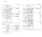
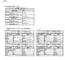
また、同図上段においては、設定値が1である場合の小役出現率を例示しており、共通ベル(当選番号13)においては、RT状態に拘らず出現率が一律となっているが、同図下段に示すように、共通ベルの出現率は設定値(本例では、6段階)によって相違するよう構成されている。具体的には、設定1における置数が3204、設定2における置数が3404、設定3における置数が3604、設定4における置数が3904、設定5における置数が4204、設定6における置数が4504、となっており、設定値が高くなる程出現率が高くなるよう構成されている。このように構成することにより、例えば、遊技者が共通ベルの出現回数(当選回数)を計測しながら遊技を進行した場合、共通ベルに頻繁に当選することにより、遊技している遊技機に係る設定値が相対的に高い設定値であることに期待を抱きながら遊技を進行することができる。また、設定値が高くなるほど1遊技当たりにおける期待値が高くなり、設定値が高くなるほど出玉率が高くなるように構成されている。なお、共通ベルの出現率は設定値によって相違するよう構成されているが、
当該共通ベルの当選によっては、後述するAT抽選、AT上乗せ抽選、及び、高確率状態移行抽選は実行されないので、ATに関する状態の移行抽選(ATに関する抽選とも称する。)には影響を及ぼさないよう構成されている。
Further, in the upper part of the figure, the small winning combination appearance rate when the set value is 1 is illustrated, and in the common bell (winning number 13), the appearance rate is uniform regardless of the RT state. As shown in the lower part of the figure, the appearance rate of the common bell is configured to differ depending on the set value (six stages in this example). Specifically, the set number is 3204, the set number is 3404, the set number is 3604, the set number is 3904, the set number is 4204, and the set number is 4204. Is 4504, and the higher the set value, the higher the appearance rate. With such a configuration, for example, when the player progresses the game while measuring the number of appearances (the number of winnings) of the common bell, the common bell is frequently won so that the gaming machine related to the gaming machine The game can be advanced while expecting that the set value is a relatively high set value. Further, the higher the set value, the higher the expected value per game, and the higher the set value, the higher the payout rate. Although the appearance rate of the common bell is configured to differ depending on the set value,
Depending on the winning of the common bell, the AT lottery, the AT addition lottery, and the high-probability state transition lottery, which will be described later, are not executed, so that the state transition lottery (also referred to as the AT lottery) will not be affected. It is configured.
また、同図中段は、押し順ナビあり時における期待値一覧である。同図においては、「AT中状態」等の押し順表示装置D270及び演出表示装置S40にて押し順ナビが実行され得る状態において押し順ナビが実行された場合に、当該ナビに従ってリールを停止させた場合の1遊技あたりの平均払出数(入賞した小役によって払い出される平均のメダル
の枚数であり、1ゲームで得られる遊技媒体の期待数とも称する)と、1遊技あたりのメ
ダル増減期待値(3枚ベットにて遊技した場合のメダル投入枚数に対するメダル払出枚数
の比率であり、1より大きい場合には期待値がプラスとなりメダルが増加していくこととなる一方、1より小さい場合には期待値がマイナスとなりメダルが減少していくこととなる)とを図示している。尚、1遊技あたりの平均払出数は、「再遊技役の置数の総和(当
選番号1〜6についての置数の総和)×再遊技役における払出枚数(3枚)+小役(11枚役)の置数(小役出現率)の総和(当選番号7〜16についての置数の総和)×小役(11枚役)における払出枚数(11枚)/すべての置数の総和(65536)」のようにして算出することができる。また、1遊技あたりのメダル増減期待値は、「1遊技あたりの平均払出数/1遊技あたりのメダル投入枚数(3枚)」のようにして算出することができる。尚、1ゲームあたりのメダル投入数(1ゲームを行う際の遊技媒体の投入数)は3枚となっており、1遊技あたりの平均払出数が3より大きい場合に1遊技あたりのメダル増減期待値が1より大きくなるよう構成されている。同図に示されるように、本実施形態においては、「RT1」が1遊技あたりのメダル増減期待値が相対的に最も大きくなっている。尚、同図における数値はボーナスによるメダルの増減は考慮していない。即ち、押し順ナビが発生する状況において遊技を進行した場合(最適操作態様で操作された場合、有利操作態様で操作された場合とも称す)、「RT1」ではメダルが増えていくこととなる。尚、「RT0」及び「RT2」においては、不図示であるが、押し順ナビが発生していない状況下においては、1遊技あたりのメダル増減期待値は1より小さい値となっており、メダルが減少していくこととなる。尚、本実施形態においては、「RT0」又は「RT2」においても押し順ナビあり時においては1遊技あたりのメダル増減期待値が1より大きくなっているが、これには限定されず、「RT0」又は「RT2」における押し順ナビあり時の1遊技あたりのメダル増減期待値が1より小さくなるよう構成してもよい。尚、再遊技役となる図柄組み合わせが停止表示した場合には実際には前回遊技における賭け枚数(3枚)が自動ベットされるが、本実施形態におけるメダル増減期待値を算出するにあたっては、メダル3枚の払出しと仮定して算出している。尚、1遊技を1ゲームと称することがある。
Further, the middle row of the figure is a list of expected values when there is a push-order navigation. In the figure, when the push-order navigation is executed in a state where the push-order navigation can be executed on the push-order display device D270 and the effect display device S40 such as "AT in progress", the reel is stopped according to the navigation. Average number of payouts per game (the average number of medals paid out by a winning small role, also called the expected number of game media obtained in one game) and the expected medal increase / decrease value per game ( It is the ratio of the number of medals paid out to the number of medals inserted when playing with 3 bets. If it is greater than 1, the expected value will be positive and the number of medals will increase. The value becomes negative and the medals decrease.) The average number of payouts per game is "the sum of the numbers of replay combinations (the total of the numbers of winning
また、各RT状態における、1遊技あたりの平均払出数は、RT状態が「RT0」の場合には3.511291504であり、RT状態が「RT1」の場合には4.737915039であり、RT状態が「RT2」の場合には3.67137146となっている。また、各RT状態における、1遊技あたりのメダル増減期待値は、RT状態が「RT0」の場合には1.170430501であり、RT状態が「RT1」の場合には1.579305013でありRT状態が「RT2」の場合には1.223790487となっており、押し順ナビあり時においては、RT状態が「RT1」の場合が遊技者にとって最も有利なRT状態となっている。尚、当該数値は設定1である場合の値となっている。尚、上記小役、再遊技役に関する当選番号及びボーナスの抽選確率はあくまで一例であり、例えば、BBが内部成立中となる「RT2」における1遊技あたりのメダル増減期待値(押し順ナビあり時のメダル増減期待値)が1未満となるよう構成してもよい。そのように構成することにより、押し順ナビが発生する状況且つ「RT2」である場合(BBが内部成立中である場合)に、ボーナスを揃えることができるゲームにてボーナスを揃えなかった場合にも、徐々に持ちメダルが減少していくこととなり、押し順ナビが発生する状況且つ「
RT2」である場合(BBが内部成立中である場合)に、ボーナスを揃えることができるゲームにて故意にボーナスを揃えないことにより持ちメダルを増加させていくような攻略を防止することができる。具体的には、「RT2」においてハズレとなる確率を、「RT2」において当選する全ての小役(入賞−A1〜入賞−I)の当選確率よりも高くなるように設計することが好ましく、そのように設計されるように再遊技役の当選確率を定めることが好ましい(再遊技役の当選確率を高く設計するとその分ハズレとなる確率が低くなってしまうため、再遊技役の当選確率が高くなり過ぎないように設計することが好ましい)。尚、本例の「RT2」においては、すべての小役を合算した当選確率は18784/65536であり、すべての再遊技の合算した当選確率は、12501/65536であり、ハズレとなる確率は、34251/65536となっており(図11参照)、ハズレとなる確率の方がすべての小役を合算した当選確率よりも高くなるように設計されている。
Further, the average payout number per game in each RT state is 3.511291504 when the RT state is “RT0”, and 4.737915039 when the RT state is “RT1”, and the RT state Is "RT2", the value is 3.67137146. The expected medal increase / decrease value per game in each RT state is 1.170430501 when the RT state is "RT0", and 1.579305013 when the RT state is "RT1". Is 2.237790487 when "RT2" is set, and when there is a push-order navigation, the RT state of "RT1" is the most advantageous RT state for the player. The numerical value is a value when the setting is 1. In addition, the winning numbers and the lottery probabilities of bonuses related to the small winning combination and the re-playing combination are merely examples, and for example, the expected medal increase / decrease value per game in "RT2" in which the BB is internally established (when there is a push order navigation). The expected medal increase / decrease value) may be less than 1. With such a configuration, when the push-order navigation occurs and the situation is "RT2" (when the BB is internally established), the bonus can not be aligned in the game in which the bonus can be aligned. However, the number of medals held will gradually decrease, and the situation where push order navigation occurs
In the case of "RT2" (when the BB is internally established), it is possible to prevent a strategy in which bonuses are intentionally not aligned in a game in which bonuses are aligned by increasing bonus medals. . Specifically, it is preferable to design the probability of losing in "RT2" to be higher than the winning probability of all the small winning combinations (winning-A1 to winning-I) in "RT2". It is preferable to set the winning probability of the re-gaming combination so that it is designed as follows. (If the winning probability of the re-gaming combination is designed to be high, the probability of losing is reduced accordingly, so the winning probability of the re-gaming combination is high. It is preferable to design so that it does not become too much). In addition, in "RT2" of this example, the winning probability of all small wins is 18784/65536, the winning probability of all replays is 12501/65536, and the probability of losing is 34251/65536 (see FIG. 11), and the probability of losing is designed to be higher than the winning probability of all small winning combinations.
また、図11に示すように、本実施形態においては、1種BB‐Aの出現率は、設定1〜設定6の全てについて同一の置数である40が割り当てられている。また、1種BB‐Cの出現率は、設定1〜設定6の全てについて同一の置数である160が割り当てられている。これに対して、1種BB‐Bの出現率は、設定1に対して160が割り当てられ、設定2に対して180が割り当てられ、設定3に対して200が割り当てられ、設定4に対して220が割り当てられ、設定5に対して240が割り当てられ、設定6に対して270が割り当てられている。即ち、1種BB‐Bの出現率は、設定値によって割り当てられている置数が異なっている。このように、1種BB‐A及び1種BB‐Cは、設定差のないBB(1種BB‐A、1種BB‐Cを設定差なしBB、設定差なしボーナスと称することがある)として機能し、1種BB‐Bは、設定差のあるBB(1種BB‐Bを設定差ありBB、設定差ありボーナスと称することがある)として機能する。また、1種BB‐A、1種BB‐Bと1種BB‐CのいずれもRT状態に拘らず(「RT0」と「RT1」とで)出現率は一律である。尚、1種BB‐A及び1種BB‐C(合算)の出現率は設定値に拘らず同一であるが、1種BB‐B(合算)の出現率は設定値によって相違する。尚、1種BB‐Bの出現率として合算した出現率は設定値が相違しても同一であるが、当選番号毎の出現率が設定値によって相違するよう構成してもよく、そのように構成した場合にも1種BB‐Bを設定差ありBBと称してもよい。
Further, as shown in FIG. 11, in the present embodiment, the appearance rate of the first-kind BB-A is assigned the
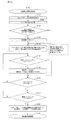
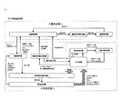
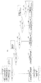
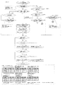
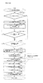
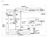
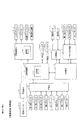
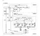
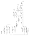
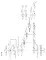
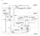
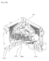
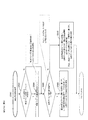
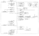
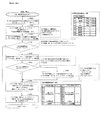
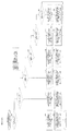
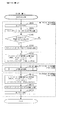
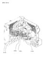
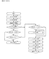
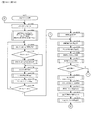
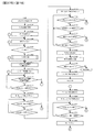
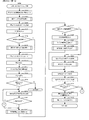
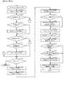
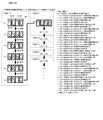
次に、図12のブロック図を参照しながら、本実施形態に係る回胴式遊技機Pの電気的な概略構成を説明する。はじめに、本実施形態に係る回胴式遊技機は、遊技の進行を制御する主制御基板Mを中心として、副制御基板S、扉基板D、回胴基板K、電源基板E、中継基板IN、設定キースイッチM20、設定/リセットボタンM30等がデータをやり取り可能に接続されて構成されている。尚、図中の実線部がデータのやり取りに関する動きを示したものであり、図中の破線部が電源供給ルートを示したものである。尚、電源供給ルートはこれに限られたものではなく、例えば電源基板Eから主制御基板を介さずに中継基板INや扉基板Dに電源を供給しても良い。 Next, with reference to the block diagram of FIG. 12, an electrical schematic configuration of the rotating body type gaming machine P according to the present embodiment will be described. First, the spinning drum type gaming machine according to the present embodiment is centered on the main control substrate M for controlling the progress of the game, the sub control substrate S, the door substrate D, the spinning drum substrate K, the power supply substrate E, the relay substrate IN, A setting key switch M20, a setting / reset button M30, etc. are connected so that data can be exchanged. The solid line part in the figure shows the movement relating to the exchange of data, and the broken line part in the figure shows the power supply route. The power supply route is not limited to this. For example, power may be supplied from the power supply board E to the relay board IN or the door board D without passing through the main control board.
主制御基板(主制御手段、主基板、メイン制御手段、メイン基板、主遊技部と称することがある)Mは、回胴式遊技機Pで行われる遊技全体の進行を司る基板である。主制御基板Mには、主制御チップCが搭載されており、主制御チップCには、CPUC100、内蔵ROMC110、内蔵RAMC120等がバスによって互いにデータをやり取り可能に接続されて搭載されている。そして、主制御基板Mは、前扉DUに搭載された扉基板Dから、スタートレバーD50等が操作されたことを示す信号等を受け取って、副制御基板Sや、扉基板D、回胴基板K等に向かって制御コマンド(あるいは制御信号)を出力することにより、これら各種基板の動作を制御している{例えば、副制御基板Sに向かって指示番号(押し順番号、指示情報、操作情報とも称する)を出力することにより、副制御基板Sは演出表示装置S40上で押し順ナビを実行することが可能となっている}。 The main control board (may be referred to as a main control means, a main board, a main control means, a main board, and a main game section) M is a board that controls the progress of the entire game played in the spinning-type gaming machine P. A main control chip C is mounted on the main control board M, and a CPU C100, a built-in ROMC110, a built-in RAMC120, etc. are mounted on the main control chip C so that data can be exchanged between them by a bus. Then, the main control board M receives a signal or the like indicating that the start lever D50 or the like has been operated from the door board D mounted on the front door DU, and then the sub-control board S, the door board D, or the rotating body board. The operation of these various boards is controlled by outputting a control command (or a control signal) to K or the like {for example, an instruction number (pushing order number, instruction information, operation information to the sub control board S). It is also possible for the sub-control board S to execute push-order navigation on the effect display device S40.
また、副制御基板(副制御手段、副基板、サブ制御手段、サブ基板、副遊技部と称することがある)Sにも、前述した主制御基板Mと同様に、副制御チップSCが搭載されており、副制御チップSCには、CPUSC100や、ROM、RAM等が設けられていて、バスによって互いにデータをやり取り可能に接続されて構成されている。また、副制御基板Sには、各種LEDランプS10、スピーカS20、演出表示装置S40、回胴バックライト(バックランプとも称する)S30等が接続されている。ここで回胴バックライトS30とは、左リールM51、中リールM52、右リールM53夫々の内部に設けられ、リールの表面に描かれた図柄を裏側から照らすライトである。副制御基板Sは、主制御基板Mから受け取った制御コマンドを解析して、各種LEDランプS10、スピーカS20、演出表示装置S40、回胴バックライトS30等にそれぞれ駆動信号を出力することにより、各種の演出を行っている。 Further, the sub-control board (sometimes referred to as sub-control means, sub-board, sub-control means, sub-board, sub-game section) S is also equipped with a sub-control chip SC, like the main control board M described above. The sub-control chip SC is provided with a CPU SC100, a ROM, a RAM, and the like, and is configured to be connected by a bus so that data can be exchanged with each other. In addition, various LED lamps S10, speakers S20, effect display device S40, and rotating body backlight (also referred to as a back lamp) S30 are connected to the sub-control board S. Here, the rotating body backlight S30 is a light provided inside each of the left reel M51, the middle reel M52, and the right reel M53, and illuminates the design drawn on the surface of the reel from the back side. The sub-control board S analyzes the control command received from the main control board M and outputs drive signals to various LED lamps S10, speakers S20, effect display device S40, rotating body backlight S30, etc. Is being directed.
扉基板Dには、前述した投入受付センサD10s、第1投入センサD20s、第2投入センサD30s、回転しているリールM50を停止するための停止ボタンD40、リールM50の回転を開始するためのスタートレバーD50、貯留されている遊技メダル(クレジット)や投入された遊技メダルを払い出して遊技を終了するための精算ボタンD60、遊技の状態を表示する各種の表示パネルD70{不図示であるが、前述した、投入数表示灯D210、操作状態表示灯D180、特別遊技状態表示装置D250、払出数表示装置(押し順表示装置)D270は、クレジット数表示装置D200、有利区間表示器YH、等の表示装置の集合体}、前扉の開閉判定やエラーの解除や設定値の変更を実行するための扉スイッチD80、投入された後に適合しないと判断された遊技メダル(又は、その他の異物)を放出口D240に払い戻すためのブロッカD100等が接続されている。また、この扉基板Dは、前述した主制御基板Mとデータをやり取り可能に接続されている。このため、前扉DUに設けられたスタートレバーD50や、停止ボタンD40、精算ボタンD60等を操作すると、扉基板Dを介して、操作に係る信号が主制御基板Mに供給されるようになっている。また、投入受付センサD10sが遊技メダルの通過を検出した信号も、扉基板Dを介して主制御基板Mに供給される。 On the door board D, the above-described closing acceptance sensor D10s, first closing sensor D20s, second closing sensor D30s, stop button D40 for stopping the rotating reel M50, and start for starting the rotation of the reel M50. Lever D50, accumulated game medals (credits), settlement button D60 for paying out the inserted game medals and ending the game, various display panels D70 for displaying the game state (not shown, but described above Also, the inserted number display lamp D210, the operation state display lamp D180, the special game state display device D250, the payout number display device (push order display device) D270, the credit number display device D200, the advantageous zone display device YH, etc. , The door switch D80 for executing the front door open / close determination, error cancellation, and setting value change. Game medals is determined to be incompatible (or other foreign) blocker D100 like to reimburse the outlet D240 and is connected after. The door board D is connected to the main control board M described above so that data can be exchanged. Therefore, when the start lever D50, the stop button D40, the adjustment button D60, etc. provided on the front door DU are operated, a signal related to the operation is supplied to the main control board M via the door board D. ing. Further, the signal that the insertion acceptance sensor D10s detects the passage of the game medal is also supplied to the main control board M via the door board D.
また、回胴基板Kには、リールM50を回転させるための回胴モータK10と、リールM50の回転位置を検出するための回胴センサK20等が接続されている。回胴基板Kは、当該回胴センサK20によって、リールM50の回転位置を検出しながら回胴モータK10を駆動することにより、リールM50を、決定された停止位置で停止させることが可能となっている。また、本実施形態の回胴式遊技機においては、回胴モータK10には、所謂ステップモータ(ステッピングモータ)が使用されている。尚、ステップモータは、リールM50が1回転するステップ数として、480ステップが設定されている。また、各リール(左リールM51、中リールM52、右リールM53)には略均一の大きさで所定数(例えば、20個)の図柄が設定されており、1図柄分に相当するステップ数としては、24ステップ(=480/20)が設定されている。尚、ステップ数、リール1周あたりの図柄の数は変更しても何ら問題ない。 Further, a spinning drum motor K10 for rotating the reel M50, a spinning drum sensor K20 for detecting the rotation position of the reel M50, and the like are connected to the spinning drum substrate K. The spinning drum board K can stop the reel M50 at the determined stop position by driving the spinning drum motor K10 while detecting the rotation position of the reel M50 by the spinning drum sensor K20. There is. Further, in the spinning drum type game machine of the present embodiment, a so-called stepping motor (stepping motor) is used as the spinning drum motor K10. In the step motor, 480 steps are set as the number of steps for the reel M50 to make one rotation. Further, each reel (left reel M51, middle reel M52, right reel M53) is set with a predetermined number (for example, 20) of symbols of substantially uniform size, and as a number of steps corresponding to one symbol. Is set to 24 steps (= 480/20). It should be noted that there is no problem even if the number of steps and the number of symbols per one turn of the reel are changed.
また、メダル払出装置Hは、中継基板INを介して、主制御基板Mに接続されており、主制御基板Mからの制御信号に基づいて、所定枚数(例えば、10枚)の遊技メダルを払い出す動作を行う。尚、メダル払出装置Hにはメダルが正常に払い出されたか否かの判定や払い出された遊技メダルの数の計測を実行する第1払出センサH10s及び第2払出センサH20sと、ディスクH50を回転させるためのホッパモータH80と、が接続されている。 In addition, the medal payout device H is connected to the main control board M via the relay board IN, and pays out a predetermined number (for example, 10) of game medals based on a control signal from the main control board M. Perform the action to put it out. The medal payout device H includes a first payout sensor H10s and a second payout sensor H20s for determining whether or not medals have been normally paid out and for measuring the number of game medals paid out, and a disc H50. A hopper motor H80 for rotating is connected.
これら各種制御基板、及び基板で消費される電力は、電源基板E(電源スイッチE10により電源供給の有無を制御する基板)から供給されている。図12では、電源基板Eか
ら電力が供給される様子を破線の矢印で表している。図示されているように、主制御基板Mおよび副制御基板Sには、電源基板Eから電力が直接供給されており、各種基板(扉基板D、回胴基板K、中継基板IN)には、主制御基板Mを介して電力が供給されている。電源基板Eには所定量(例えば、100V)の交流電圧が供給されており、この電力を規定電圧の直流電圧に変換した後、夫々の制御基板及び基板に供給している。
The various control boards and the power consumed by the boards are supplied from a power supply board E (a board that controls the presence / absence of power supply by a power switch E10). In FIG. 12, the manner in which electric power is supplied from the power supply board E is indicated by a dashed arrow. As shown in the figure, the main control board M and the sub-control board S are directly supplied with electric power from the power supply board E, and various boards (door board D, turning board K, relay board IN) Electric power is supplied through the main control board M. A predetermined amount (for example, 100 V) of an AC voltage is supplied to the power supply board E, and this power is converted to a DC voltage of a specified voltage and then supplied to the respective control boards and boards.
また、主制御基板Mには、後述する設定変更装置制御処理を実行するため(設定変更を行うため)に使用する設定キースイッチM20、設定値の変更やエラー解除等を実行し得る設定/リセットボタンM30、が接続されている。また、主制御基板Mは、リールM50(左リールM51、中リールM52、右リールM53)の回転や停止を制御するリール制御手段と、遊技者にとって有利なATに関する状態である「AT中状態」に移行するためのAT移行抽選を実行するAT抽選手段と、「AT中状態」に滞在可能なゲーム数であるAT残りゲーム数(又は、ATカウンタM60のカウンタ値)を増加させるAT上乗せ抽選を実行するAT上乗せ抽選手段と、を有している。 Further, on the main control board M, a setting key switch M20 used for executing a setting changing device control process described later (for changing a setting), a setting / reset capable of changing a set value, releasing an error, etc. Button M30 is connected. Further, the main control board M is a reel control means for controlling the rotation and stop of the reels M50 (left reel M51, middle reel M52, right reel M53), and an "AT mid state" which is a state relating to AT which is advantageous to the player. AT lottery means for executing the AT transition lottery for shifting to AT, and AT additional lottery for increasing the number of remaining AT games (or the counter value of the AT counter M60) which is the number of games that can be stayed in the "AT in progress" state. And an AT addition lottery means to be executed.
次に、図13〜33は、本実施形態における、主制御基板Mが行う一般的な処理の流れを示したフローチャートである。 Next, FIGS. 13 to 33 are flowcharts showing the flow of general processing performed by the main control board M in the present embodiment.
尚、フローチャートは主に、処理ステップ(長方形にて図示)、判断(ひし形にて図示)、流れ線(矢印)、開始・終了・復帰等を示す端子(角丸長方形にて図示)によって構成されている。また、処理ステップの内、別のフローチャートにて詳細を図示している場合、当該別のフローチャートを参照するものをサブルーチン(左右の線が二重線である長方形にて図示)として図示している。ここで、遊技機の開発段階においては、スペック違いの遊技機を同時に開発することも行われているが、本例においては、メイン側の処理内に、スペック違いの遊技機で実行するサブルーチン(通常は使用しないサブルーチン)を残さないよう構成しており、ノイズや不正行為によって、通常時には実行されない未使用サブルーチンに係る処理が実行されることを防止している。 The flow chart is mainly composed of processing steps (shown by rectangles), judgments (shown by diamonds), flow lines (arrows), terminals indicating start / end / return (shown by rounded rectangles). ing. Further, in the case where the details of the processing steps are shown in another flowchart, the reference to the other flowchart is shown as a subroutine (illustrated by a rectangle whose left and right lines are double lines). .. Here, in the game machine development stage, game machines with different specifications are also being developed at the same time, but in this example, a subroutine executed by the game machine with different specifications (in the processing on the main side, Subroutines that are not normally used) are not left, so that processing related to unused subroutines that are not normally executed is prevented from being executed due to noise or cheating.
まず、図13は、回胴式遊技機Pの電源を投入した後(或いはシステムリセットやユーザリセット時において)、主制御基板MのCPUC100にて初めて実行される処理の流れを示したフローチャートである。まず、ステップ1000で、回胴式遊技機Pの電源を投入した後、ステップ1002で、主制御基板MのCPUC100は、タイマ割り込みの初期設定を実行する(ここでは、タイマ割り込みが開始されるのではなくタイマ割り込みの種類をセットするのみであり、以降の処理において、タイマ割り込みが開始されると定期的に後述するタイマ割り込み時処理に係るフローチャートが実行される)。次に、ステップ1004で、主制御基板MのCPUC100は、主制御チップCの機能設定としてシリアル通信の設定(速度、データの長さ、データ送信方法の設定)等を実行する。次に、ステップ1006で、主制御基板MのCPUC100は、RAM領域の先頭アドレスからチェックサム領域直前のアドレスまでのチェックサムを算出する。次に、ステップ1008で、主制御基板MのCPUC100は、RAM領域をチェックし(例えば、当該算出したチェックサムとチェックサム領域に保持されているチェックサムデータとに基づき、電源断・電源断復帰により内蔵RAMC120に格納されているデータが正しく保持されているか否かをチェックし)、電源断復帰データを生成する。次に、ステップ1010で、主制御基板MのCPUC100は、設定キースイッチM20のスイッチ状態を確認する。次に、ステップ1014で、主制御基板MのCPUC100は、設定キースイッチM20がオフであるか否かを判定する。
First, FIG. 13 is a flow chart showing a flow of processing that is first executed by the CPU C100 of the main control board M after the power of the spinning-type gaming machine P is turned on (or at the time of system reset or user reset). .. First, at
ステップ1014でYesの場合、ステップ1016で、主制御基板MのCPUC100は、RAM内の電源断処理済みフラグのオン・オフ(ステップ1904でオンとなる)及び全RAMのチェックサム状態(ステップ1006でのチェック結果)を参照し、RA
M内の電源断復帰データは正常であるか否かを判定する。ステップ1016でYesの場合、ステップ1020で、主制御基板MのCPUC100は、決定された初期化範囲で、RAM領域の初期化を実行する。次に、ステップ1022で、主制御基板MのCPUC100は、電源断時の処理(ステップ1902)にて保存したスタックポインタに係るデータに基づき、スタックポインタを復帰する。次に、ステップ1036で、主制御基板MのCPUC100は、RAM領域内を参照し、RAM領域内の設定値に係るデータは正常範囲内(本例では、0〜5)であるか否かを判定する。ステップ1036でYesの場合、ステップ1038で、主制御基板MのCPUC100は、入力ポートの読み込みを実行する。次に、ステップ1040で、主制御基板MのCPUC100は、ステップ1002にてセットしたタイマ割り込みを開始する。次に、ステップ1042で、主制御基板MのCPUC100は、電源断処理済みフラグをオフにし、復帰したスタックポインタに従い電源断時の処理に復帰する。
If Yes in
It is determined whether the power-off recovery data in M is normal. If Yes in
また、ステップ1016でNoの場合、ステップ1024で、主制御基板MのCPUC100は、バックアップエラー表示をセットする(例えば、レジスタ領域内にエラー番号をセットする)。次に、ステップ1300で、主制御基板MのCPUC100は、後述する、復帰不可能エラー処理を実行する。
If No in
また、ステップ1036でNoの場合、ステップ1046で、主制御基板MのCPUC100は、設定値エラー表示(例えば、払出数表示装置D270に表示されることとなる)をセットする(例えば、レジスタ領域内にセットする)。次に、ステップ1300で、主制御基板MのCPUC100は、後述する復帰不可能エラー処理を実行する。
Further, in the case of No in
また、ステップ1014でNoの場合、ステップ1028で、主制御基板MのCPUC100は、RAM内の電源断処理済みフラグのオン・オフ(ステップ1904でオンとなる)及び全RAMのチェックサム状態(ステップ1006でのチェック結果)を参照し、RAM内の電源断復帰データは正常であるか否かを判定する。ステップ1028でYesの場合、ステップ1030で、主制御基板MのCPUC100は、RAMの初期化範囲をRAM内の設定値(設定値データ)を記憶する記憶領域を除く所定範囲に決定してセット(例えば、レジスタ領域内にセット)し、ステップ1034に移行する。RAMの初期化範囲に含まれない範囲は、設定値(設定値データ)を記憶する記憶領域のみには限定されず、「有利区間」の総累計ゲーム数、遊技区間の総累計(有利区間+通常区間)ゲーム数、「有利区間」の滞在割合を算出した結果、等もRAMの初期化範囲に含まれない範囲となっている。このように構成することにより、遊技における「有利区間」に滞在している比率(有利区間比率)を算出及び表示することができることとなる。また、有利区間比率の算出処理は、単位遊技が終了するタイミングで算出するよう構成されている。また、有利区間比率は、遊技機の電源が投入されると表示される(例えば、4桁の7セグメントディスプレイに表示される)。具体的な表示態様としては、「有利区間比率→6000ゲームあたりの連続役物比率→6000ゲームあたりの役物比率→累積の連続役物比率→累積の役物比率」の順に5秒間隔で繰り返し表示される。尚、連続役物比率とは「RBが作動している状態での払出し数/総払出し数」であり、役物比率とは「RB、CB、又はSBが作動している状態での払出し数/総払出し数」である。他方、ステップ1028でNoの場合、ステップ1032で、主制御基板MのCPUC100は、RAMの初期化範囲をRAM内の設定値(設定値データ)を記憶する記憶領域を含む特定範囲に決定してセット(例えば、レジスタ領域内にセット)し、ステップ1034に移行する。次に、ステップ1034で、主制御基板MのCPUC100は、ステップ1030又はステップ1032にて決定された初期化範囲で、RAM領域の初期化を実行する。次に、ステップ1100で、主制御基板MのCPUC100は、後述する、設定変更装置制御処理を実行する。
If No in
尚、不図示ではあるが、主制御基板Mが搭載する一時記憶領域(RAM領域等)の初期
値(処理開始時の値)は、特別遊技が実行される値とならないよう構成することが好適である(プログラムの処理開始直後に、ノイズや不正行為により、特別遊技の実行判定を行う処理を実行してしまった場合に特別遊技が誤って実行されることを防止するため)。また、不図示ではあるが、主制御基板MのRAM領域内に当選乱数等の乱数を記憶する場合には、専用の記憶領域を確保し、乱数に係る情報を記憶しているバイト内には当該乱数に係る情報のみを記憶する(各種タイマ値等、その他の情報を記憶しない)よう構成することが好適である(同じ1バイト内に記憶した別のデータを操作する際に、ノイズ等によって乱数に係る情報が書き換わってしまうことを防止するため)。
Although not shown, it is preferable that the initial value (the value at the time of processing start) of the temporary storage area (RAM area or the like) mounted on the main control board M is not set to the value at which the special game is executed. (To prevent the special game from being erroneously executed when the processing for determining the execution of the special game has been executed due to noise or cheating immediately after the start of the processing of the program). Further, although not shown, when storing random numbers such as winning random numbers in the RAM area of the main control board M, a dedicated storage area is secured, and in a byte storing information related to the random number. It is preferable to configure such that only information related to the random number is stored (various timer values and other information is not stored) (when operating other data stored in the same 1 byte, noise is generated. To prevent the information related to random numbers from being rewritten).
次に、図14は、図13におけるステップ1100のサブルーチンに係る、設定変更装置制御処理のフローチャートであり、設定変更モードとも称する。まず、ステップ1102で、主制御基板MのCPUC100は、スタックポインタをセットする(当該処理の先頭アドレスで初期化する)。次に、ステップ1104で、主制御基板MのCPUC100は、タイマ割り込みを起動する。次に、ステップ1106で、主制御基板MのCPUC100は、RAM領域内の設定値(設定値データ)は正常範囲内(本例では、0〜5)ではないか否かを判定する。尚、設定値(設定値データ)を1〜6で管理していた場合、RAMの初期化を実行し設定値が「0」となったときに「1」に戻す処理が必要となる。そこで、本例においては、設定値(設定値データ)の正常範囲を0〜5として管理することにより、RAMの初期化を実行した後の設定値(設定値データ)の補正処理(ステップ1106及びステップ1108の処理)を不要とすることができ、処理時間を短縮することや処理の容量を削減することが可能となる。ステップ1106でYesの場合、ステップ1108で、主制御基板MのCPUC100は、設定値(設定値データ)に所定値(例えば、0=遊技者にとって最も不利となる値)をセットし、ステップ1110に移行する。他方、ステップ1106でNoの場合にもステップ1110に移行する。次に、ステップ1110で、主制御基板MのCPUC100は、エラー表示LED(例えば、払出数表示装置D270)に設定変更装置作動(所謂、設定変更モード)中である旨(例えば、全セグメントを点灯させる「88」)を表示し、設定表示LED(不図示)に設定値を表示(設定値に係る表示はRAM内で保持している設定値(設定値データ)に1を加算した数値となっている)し、ステップ1112に移行する。尚、前述したように、払出数表示装置D270は押し順を報知する際にも使用される。そのように構成されているため、例えば、7セグLEDの一部に故障が発生している(点灯できないセグがある)ような場合において押し順を報知する際、誤った情報を報知することがあり得る。このような事態を防止するため、設定変更装置作動中において払出数表示装置D270に7セグメントを全点灯「88」させることにより、7セグメントが故障しているか否かが確認でき、遊技者に不利益等を与えることを防止できる。また、設定値(設定値データ)の表示に係る構成として、設定値を記憶する記憶領域における設定値(設定値データ)に1を加算したデータを記憶しておく設定値表示用のRAMの記憶領域を有し、当該記憶領域を参照して設定値を表示するよう構成しても良い。尚、不図示であるが、ステップ1110の処理を実行した後、副制御基板S側に設定変更モードに移行していることを示すコマンドを送信するための処理を実行している。
Next, FIG. 14 is a flowchart of the setting change device control process according to the subroutine of
次に、ステップ1112で、主制御基板MのCPUC100は、設定/リセットボタンM30がオフからオンに切り替わったか否かを判定する。ステップ1112でYesの場合、ステップ1114で、主制御基板MのCPUC100は、現在の設定値(設定値データ)に1を加算し(加算した結果設定値(設定値データ)が5を超過した場合には、設定値(設定値データ)は0となる)、ステップ1116に移行する。尚、ステップ1112でNoの場合にも、ステップ1116に移行する。次に、ステップ1116で、主制御基板MのCPUC100は、スタートレバーD50がオフからオンに切り替わったか否かを判定する。ステップ1116でNoの場合には、ステップ1112に移行し、ステップ1112〜ステップ1116の処理をループする。ステップ1116でYesの場合、ステ
ップ1118で、主制御基板MのCPUC100は、設定キースイッチM20がオンからオフに切り替わったか否かを判定する。ステップ1118でNoの場合には、ステップ1118の処理をループする。他方、ステップ1118でYesの場合、ステップ1120で、主制御基板MのCPUC100は、エラー表示LED(不図示)に設定変更装置の作動が終了した旨を表示し、設定表示LED(不図示)の設定値(設定値データ)の表示を消去し、ステップ1200の遊技進行制御処理に移行する。尚、不図示であるが、ステップ1120の処理を実行した後、副制御基板S側に設定変更モードを終了することを示すコマンドを送信するための処理を実行している。
Next, in step 1112, the CPU C100 of the main control board M determines whether or not the setting / reset button M30 has been switched from off to on. If Yes in step 1112, in
次に、図15は、図13におけるステップ1300の(及び他のフローチャートにおいて呼び出された)サブルーチンに係る、復帰不可能エラー処理のフローチャートである。まず、ステップ1302で、主制御基板MのCPUC100は、割り込みを禁止する(以降は、後述するタイマ割り込み時処理に係るフローチャートが実行されない)。次に、ステップ1304で、主制御基板MのCPUC100は、出力ポートアドレス及び出力ポート数をセットする。次に、ステップ1306で、主制御基板MのCPUC100は、出力ポート(本例では、0〜6であり、各種LEDへの表示出力や各種モータへの駆動出力)をオフにする。次に、ステップ1308で、主制御基板MのCPUC100は、次のポート出力アドレスをセットする(この繰り返しにより、各種LEDへの表示出力や各種モータへの駆動出力が順次停止される)。次に、ステップ1310で、主制御基板MのCPUC100は、各出力ポートへの出力が終了したか否かを判定する。ステップ1310でYesの場合には、ステップ1312で、主制御基板MのCPUC100は、セットされているエラー表示を実行し(本処理を実行する際には何らかのエラーが発生している)、当該処理の実行を繰り返し、電源電圧が低下することでリセット信号が入力されて終了する。(即ち、無限ループに突入するので、復帰を促す一切の操作を受け付けない)。尚、ステップ1310でNoの場合には、ステップ1306に移行する。尚、ステップ1306〜ステップ1310の処理は、LED・モータへの出力をクリアする処理である(但し、外部出力信号はクリアしないので、エラーに関する情報やエラー発生時における遊技進行状況等をホールコンピュータ側へ出力することは可能である)。
Next, FIG. 15 is a flowchart of the non-recoverable error processing according to the subroutine of step 1300 (and called in other flowcharts) in FIG. First, in step 1302, the CPU C100 of the main control board M prohibits interrupts (from now on, the flowchart relating to the timer interrupt process described later is not executed). Next, in step 1304, the CPU C100 of the main control board M sets the output port address and the number of output ports. Next, in
次に、図16は、図14におけるステップ1200のサブルーチンに係る、遊技進行制御処理(1枚目)のフローチャートである。まず、ステップ1202で、主制御基板MのCPUC100は、スタックポインタをセットする(当該処理の先頭アドレスで初期化する)。次に、ステップ1203で、主制御基板MのCPUC100は、当該ゲームに必要なRAM領域内のデータ(例えば、ベット上限数、入賞の有効ライン、等)をセットする。尚、ステップ1203は、前回の遊技で使用したデータ{例えば、条件装置番号(当選番号)、演出グループ番号、指示情報}をクリアするためのデータ(RAMのアドレスをクリアするための「0」のデータ)をRAMにセットする処理も含まれる。尚、条件装置番号、演出グループ番号、指示情報等はクリアせずに、次遊技が実行された際に選択された番号を上書きするように構成するようにしても良い。次に、ステップ1204で、主制御基板MのCPUC100は、当該ゲームにおけるRT状態(例えば、「RT0」等)をセットする(図27のステップ1704で決定したRT状態をセットする)。次に、ステップ1205で、主制御基板MのCPUC100は、ステップ1204でセットしたRT状態に関するコマンド(サブ側へのコマンド)をセットする。尚、RT状態をセットする処理は、図27のステップ1704にて実行してもよい。また、ステップ1704にてRT状態に関するコマンド(サブ側へのコマンド)をセットしても良い。また、RT状態をサブ側に送信する場合には常時送信する必要はなく、遊技区間が「有利区間」である場合にのみRT状態をサブ側に送信するよう構成してもよい。次に、ステップ1206で、主制御基板MのCPUC100は、当該ゲームにおけるATに関する状態(例えば、「AT中状態」等)をセットする(図21のステップ1420、ステップ1429、図22のステップ1435、ステップ1439、ステップ1443、図23のステップ1444‐3
、ステップ1444‐4で決定したATに関する状態をセットする)。次に、ステップ1207で、主制御基板MのCPUC100は、ステップ1206でセットしたATに関する状態に関するコマンド(サブ側へのコマンド)をセットする。また、ATに関する状態をセットする処理は、図21のステップ1416、ステップ1428、図22のステップ1438、図23のステップ1444‐1にて実行してもよい。また、ATに関する状態をサブ側に送信する場合には常時送信する必要はなく、遊技区間が「有利区間」である場合にのみATに関する状態をサブ側に送信するよう構成してもよい。次に、ステップ1208で、主制御基板MのCPUC100は、当該ゲームにおける遊技区間(例えば、「有利区間」等)をセットする(図31のステップ3510、ステップ3516、ステップ3520で決定した遊技区間をセットする)。次に、ステップ1208‐1で、主制御基板MのCPUC100は、ステップ1208でセットした遊技区間に関するコマンド(サブ側へのコマンド)をセットする。次に、ステップ1209で、主制御基板MのCPUC100は、メダル払出装置Hが遊技メダルで満杯ではないか否かを判定する。具体的には、メダル払出装置Hから溢れ出たメダルを格納するサブタンク(不図示)を備え、サブタンクに設けられた複数の満杯検知センサによる電流の導通/非導通にて判定する(メダルを介して電流が導通した場合には、満杯と判定する)。ステップ1209でYesの場合、ステップ1218に移行する。
Next, FIG. 16 is a flowchart of the game progress control process (first game) according to the subroutine of
, And sets the status regarding the AT determined in step 1444-4). Next, in
他方、ステップ1209でNoの場合、ステップ1210で、主制御基板MのCPUC100は、メダル満杯エラーフラグをオンにする(例えば、RAM領域のメダル満杯エラーフラグ領域内をオンに相当する値で更新する)。次に、ステップ1212で、主制御基板MのCPUC100は、メダル満杯エラーに対応したエラー番号の表示を7セグLED(例えば、貯留表示LED又は獲得枚数LED)で実行する。次に、ステップ1214で、主制御基板MのCPUC100は、メダル満杯エラーが解除されたか否か(例えば、サブタンクによる電流が非導通、且つ、設定/リセットボタンM30が押下されたか否か)を判定する。ステップ1214でYesの場合、ステップ1216で、主制御基板MのCPUC100は、メダル満杯エラーフラグをオフにし(例えば、RAM領域のメダル満杯エラーフラグ領域内をオフに相当する値で更新し)、ステップ1218に移行する。他方、ステップ1214でNoの場合には、ステップ1212に移行する。次に、ステップ1218で、主制御基板MのCPUC100は、メダル投入受付を許可し(再遊技役の次ゲームにおいては自動にて投入動作が実行されることとなる)、次の処理(ステップ1220の処理)に移行する。ここで、ステップ1218では、ブロッカD100のオン処理(メダル流路が形成する処理)を行う。具体的には、前回遊技で再遊技役が成立した場合には、現在の貯留数(クレジット)が所定値(本例では、50枚)未満であることを条件として、ブロッカD100のオン処理を実行する。換言すると、現在の貯留数(クレジット)が所定値である場合には、ブロッカD100のオン処理を実行しない。一方、前回遊技で再遊技役が成立しなかった場合には、一律にブロッカD100のオン処理を実行するようにしている。このように構成することにより、再遊技役が成立した場合であっても貯留数(クレジット)が所定値に達していない場合には、遊技メダルが投入できるように構成され、「RT1」等のRT状態よりも再遊技役の当選確率の高いRT状態(例えば、「RT1」)に滞在しているときや、見た目では再遊技役とは分かり辛い再遊技役(小役に見せかけた再遊技:無効ライン上にベル−ベル−ベルや、左リールにチェリーが停止した図柄組合せ)が停止した場合であっても、遊技者はリズム良く(違和感なく)遊技を行うことができる。
On the other hand, if No in
次に、図17は、図16におけるステップ1200のサブルーチンに係る、遊技進行制御処理(2枚目)のフローチャートである。まず、ステップ1220で、主制御基板MのCPUC100は、遊技メダルがベットされていない、又は貯蓄されていない(クレジットが存在していない)か否かを判定する。ステップ1220でYesの場合、ステップ1221で、主制御基板MのCPUC100は、設定値表示条件を充足している(例えば、
扉スイッチD80、設定キースイッチM20がすべてオンとなると当該条件を充足する)か否かを判定する。ステップ1221でYesの場合、ステップ1222で、主制御基板MのCPUC100は、設定表示LED(不図示だが、払出数表示装置D270、クレジット数表示装置D200、投入数表示灯D210としてもよい)に設定値を表示し(設定確認モードに移行し)、設定キースイッチM20がオフとなったことを条件にステップ1221に移行する。尚、設定変更モードの移行条件を満たしたときには、副制御基板S側に設定変更モードを開始することを示すコマンドを送信するための処理、設定変更モードの終了条件を満たしたときに設定変更モードを終了することを示すコマンドを送信するための処理を実行している。ステップ1220又はステップ1221でNoの場合、ステップ1224で、主制御基板MのCPUC100は、遊技メダルの投入及び精算に係る管理を実行する。次に、ステップ1225で、主制御基板MのCPUC100は、遊技メダルの受付可能枚数を確認する。次に、ステップ1226で、主制御基板MのCPUC100は、ブロッカD100がオンか否かを判定する。ステップ1226でYesの場合、ステップ1227で、主制御基板MのCPUC100は、第1投入センサD20s又は第2投入センサD30sがオンであるか否かを判定する(本実施形態においてはメダルの投入を検出するための投入センサを2つ有しており、第1投入センサD20s又は第2投入センサD30sがオンとなると、遊技メダルを1枚受け付けたと判定する)。ステップ1227でYesの場合、ステップ1230で、主制御基板MのCPUC100は、第1投入センサD20s及び第2投入センサD30sがオフであるか否かを判定する(第1投入センサD20s又は第2投入センサD30sがオンとなった後、第1投入センサD20s及び第2投入センサD30sがオフとなると、受け付けた1枚の遊技メダルが第1投入センサD20s及び第2投入センサD30sを通過したと判定する)。ステップ1230でYesの場合、ステップ1231で、主制御基板MのCPUC100は、1枚の正常な遊技メダルの投入を受け付けたと判定する。不図示であるが、ステップ1231の後、主制御基板MのCPUC100は、クレジットが上限数(本例では、50)、且つ、ベット数が最大数(本例では、3)であるか否かを判定し、Yesと判定した場合にはブロッカD100をオフ(メダル流路を形成しない状態)に制御する。尚、ステップ1230でNoの場合には、ステップ1230の処理を繰り返し、ステップ1226またはステップ1227でNoの場合には、ステップ1232に移行する。
Next, FIG. 17 is a flowchart of the game progress control process (second game) according to the subroutine of
When the door switch D80 and the setting key switch M20 are all turned on, it is determined whether or not the condition is satisfied. If Yes in
次に、ステップ1232で、主制御基板MのCPUC100は、精算ボタンD60の操作があったか否かを判定する。ステップ1232でYesの場合、ステップ1233で、主制御基板MのCPUC100は、クレジットの残り枚数又はベットされている遊技メダルが存在するか否かを判定する。ステップ1233でYesの場合、ステップ1234で、主制御基板MのCPUC100は、ホッパ駆動フラグ(RAM領域内のフラグであり、ホッパモータH80を駆動している際にオンとするフラグ)をオンにし、遊技メダル1枚の払出を実行する。次に、ステップ1236で、主制御基板MのCPUC100は、第1払出センサH10s又は第2払出センサH20sがオンであるか否かを判定する(本実施形態においてはメダルの払出を検出するための払出センサを2つ有しており、第1払出センサH10s又は第2払出センサH20sがオンとなると、遊技メダル1枚の払出動作が行われていると判定する)。ステップ1236でYesの場合、ステップ1247に移行する。ここで、フローチャート上には明記してはいないが、前回遊技が再遊技役であった場合にはクレジットの残り枚数のみが精算の対象となる。
Next, in
他方、ステップ1236でNoの場合、ステップ1241で、主制御基板MのCPUC100は、ホッパ駆動後(ステップ1234の処理のタイミング後)から所定時間(例えば、5秒)経過したか否かを判定する。具体的には、ホッパ駆動信号をホッパモータH80に送信している(ホッパモータH80が回転している)のにもかかわらず、メダルが払い出されていないと判定している状況が所定時間継続したか否かを判定する。ステップ1241でYesの場合、ステップ1242で、主制御基板MのCPUC100は、メダル
空エラーフラグをオンにする(例えば、メダル空エラーフラグ領域内をオンに相当する値で更新する)。次に、ステップ1244で、主制御基板MのCPUC100は、メダル空エラー表示を実行する。次に、ステップ1245で、主制御基板MのCPUC100は、メダル空エラーが解除されたか否か(例えば、設定/リセットボタンM30が押下されたか否か)を判定する。ステップ1245でYesの場合、ステップ1246で、主制御基板MのCPUC100は、メダル空エラーフラグをオフにし(例えば、RAM領域のメダル空エラーフラグ領域内をオフに相当する値で更新し)、ステップ1247に移行する。他方、ステップ1245でNoの場合、ステップ1244に移行する。
On the other hand, in the case of No in
次に、ステップ1247で、主制御基板MのCPUC100は、第1払出センサH10s及び第2払出センサH20sがオフであるか否かを判定する(第1払出センサH10s又は第2払出センサH20sがオンとなった後、第1払出センサH10s及び第2払出センサH20sがオフとなると、払出動作が行われていた1枚の遊技メダルの払出動作が完了したと判定する)。ステップ1247でYesの場合、ステップ1248で、主制御基板MのCPUC100は、ホッパ駆動フラグをオフにし、ステップ1233に移行する。尚、ステップ1241又はステップ1247でNoの場合には、ステップ1236に移行する。
Next, in
他方、ステップ1232又はステップ1233でNoの場合、ステップ1251で、主制御基板MのCPUC100は、スタートレバーD50が有効であり(例えば、ゲームを開始するための規定枚数の遊技メダルが投入された等)、且つ、当該スタートレバーD50の操作があったか否かを判定する。ステップ1251でYesの場合、ステップ1253で、主制御基板MのCPUC100は、RAM領域内の設定値は正常範囲内(本例では、0〜5)であるか否かを判定する。ステップ1253でYesの場合、ステップ1254で、主制御基板MのCPUC100は、乱数の取得、ブロッカD100をオフにする処理を実行した後に、次の処理(ステップ3600の処理)に移行する。他方、ステップ1253でNoの場合、ステップ1256で、主制御基板MのCPUC100は、設定値エラー表示をセットする(例えば、レジスタ領域内にエラー番号をセットする)。次に、ステップ1300で、主制御基板MのCPUC100は、復帰不可能エラー処理を実行する。尚、ステップ1251でNoの場合には、ステップ1220に移行する。
On the other hand, in the case of No in
次に、図18は、図16におけるステップ1200のサブルーチンに係る、遊技進行制御処理(3枚目)のフローチャートである。まず、ステップ3600で、主制御基板MのCPUC100は、後述する、内部抽選実行処理を実行する。次に、ステップ1259で、主制御基板MのCPUC100は、現在のATに関する状態はAT上乗せ抽選可能な状態であるか否かを判定する。ここで、本例においては、AT上乗せ抽選を実行可能なATに関する状態は、「AT中状態」、「上乗せ特化状態」、「特化前兆状態」、「有利BB状態」となっており、「有利BB内部中遊技」においては、ATカウンタ値が0より大きい状態となり得るがAT上乗せ抽選は実行しないよう構成されている。これは、「有利BB内部中遊技」において、遊技者が敢えてBBの図柄組合せを揃えさせないことの方が、遊技者にとって有利となってしまうことを防止するためである。尚、「有利BB内部中遊技」にてAT上乗せ抽選を実行し得るよう構成してもよく、そのように構成した場合には、「有利BB内部中遊技」にてAT上乗せ抽選に当選してもすぐには報知せずに、その後BBが終了したタイミングでAT上乗せ抽選に当選した旨、又は、ATゲーム数が上乗せされた後のAT残りゲーム数を報知するよう構成してもよい。
Next, FIG. 18 is a flowchart of the game progress control process (third game) related to the subroutine of
ステップ1259でYesの場合、ステップ1500で、主制御基板MのCPUC100は、後述する、ゲーム数上乗せ実行処理を実行し、ステップ1400に移行する。他方、ステップ1259でNoの場合にもステップ1400に移行する。このゲーム数上乗せ実行処理は、ATに関する状態に応じて異なる抽選テーブルを用いて抽選を実行すること
も可能であるが、設定値に応じては抽選確率が異ならない(同一の抽選テーブルを用いて抽選を実行する)ことが好適である。次に、ステップ1400で、主制御基板MのCPUC100は、後述する、AT状態移行制御処理を実行する。次に、ステップ1450で、主制御基板MのCPUC100は、後述する、条件装置番号管理処理を実行する。
If Yes in
ここで、本例におけるATに関する状態を列挙し詳述する(図30のAT状態遷移図でも示されている)。(1)「低確率状態」とは、ATに当選していない(「AT中状態」に移行する権利を獲得していない)状態であり、且つ、ボーナス役に当選していない状態である。尚、「低確率状態」とは、所謂「通常状態」であるため、「通常状態」と称することもある。(2)「通常BB内部中遊技」とは、「低確率状態」においてBB役に当選した、且つ、BB役が入賞していない、且つ、AT抽選に当選していない状態である。(3)「通常BB状態」とは、「低確率状態」においてBB役に当選し、且つ、AT抽選に当選していない状況にて、BB役に対応する図柄組合せが停止表示されたとき、又は、「通常BB内部中遊技」においてBB役に対応する図柄組合せが停止表示されたときに実行される状態である。(4)「高確率状態」とは、AT抽選に当選していない(「AT中状態」に移行する権利を獲得していない)状態であり、且つ、ボーナス役に当選していない状態であり、前述した「低確率状態」よりもATに当選し易い状態である。尚、後述するように、新たに「高確率状態」に移行した場合には高確保障ゲーム数が経過するまでは「低確率状態」に移行しないよう構成されている(5)「AT中状態」とは、AT(押し順ナビ)を行い、且つ、AT残りゲーム数(ATカウンタ値)の減算を行う状態である。尚、ATカウンタ値が0となっても、後述する継続抽選に当選した場合には、ATカウンタに所定値がセットされ、「AT中状態」が継続する(6)「特化前兆状態」とは、「AT中状態」よりもATゲーム数が相対的に上乗せされ易い状態である「上乗せ特化状態」に移行する権利を獲得している状態である。(7)「上乗せ特化状態」とは、「AT中状態」よりもATゲーム数が相対的に上乗せされ易い状態である。(8)「有利BB内部中遊技」とは、「高確率状態」、「AT中状態」、「特化前兆状態」又は「上乗せ特化状態」においてBB役に当選し、且つ、BB役が入賞していない状態である。(9)「待機BB内部中遊技」とは、「低確率状態」においてBB役に当選し、且つ、BB役によってAT抽選に当選しており、且つ、BB役が入賞していない状態である。(10)「有利BB状態」とは、「高確率状態」、「AT中状態」、「特化前兆状態」又は「上乗せ特化状態」においてBB役に当選しBB役に対応する図柄組合せが停止表示されたとき、又は、「有利BB内部中遊技」においてBB役に対応する図柄組合せが停止表示されたときに実行される状態、又は、「低確率状態」においてBB役に当選し、且つ、BB役によってAT抽選に当選しており、且つ、BB役に対応する図柄組合せが停止表示されたとき、又は、「待機BB内部中遊技」においてBB役に対応する図柄組み合わせが停止表示された時に実行される状態である。(12)「復活可否演出用状態」とは、ATカウンタ値が0となり、かつ、後述する継続抽選に非当選となった場合に移行するATに関する状態であり。「復活可否演出用状態」においては、後述する復活抽選が実行され、復活抽選に当選した場合には「AT中状態」に移行(ATカウンタに所定値がセットされる)し、復活抽選に非当選となった場合には「低確率状態」に移行することとなる。 Here, the states relating to the AT in this example will be listed and described in detail (also shown in the AT state transition diagram of FIG. 30). (1) The "low probability state" is a state in which the AT has not been won (the right to transition to the "AT in progress" has not been acquired), and the bonus combination has not been won. The “low probability state” is a so-called “normal state”, and thus may be referred to as a “normal state”. (2) "Normal BB inside game" is a state in which the BB combination has been won in the "low probability state", the BB combination has not been won, and the AT lottery has not been won. (3) "Normal BB state" means that when the winning combination for the BB combination in the "low probability state" has not been won for the AT lottery, and the symbol combination corresponding to the BB combination is stopped and displayed, Alternatively, it is a state that is executed when the symbol combination corresponding to the BB combination is stopped and displayed in the “normal BB inside game”. (4) "High probability state" is a state in which the player has not won the AT lottery (has not acquired the right to shift to the "AT in progress" state) and has not won the bonus role. In this state, it is easier to win the AT than in the above-mentioned “low probability state”. As will be described later, when a new "high-probability state" is entered, the "low-probability state" is not set until the number of high-secure obstacle games has passed (5) "AT in progress state". "Is a state in which AT (push order navigation) is performed and the AT remaining game number (AT counter value) is subtracted. Even if the AT counter value becomes 0, when the continuous lottery described later is won, a predetermined value is set in the AT counter and the “AT in progress” state continues (6) “Specialization omen state” Is a state in which the right to shift to the "add-on specialized state", which is a state in which the number of AT games is relatively easy to be added to the "AT in-state", has been acquired. (7) The "addition specialized state" is a state in which the number of AT games is relatively easily added to the "AT in progress state". (8) “Advantageous BB inside game” means winning the BB role in the “high probability state”, “AT in progress”, “special omen state” or “addition specialization state”, and the BB role is It is in a state where no prize has been won. (9) The "standby BB inside game" is a state in which the BB combination has been won in the "low probability state", and the BB combination has won the AT lottery, and the BB combination has not won. . (10) "Advantageous BB state" means a symbol combination that corresponds to the BB role that is won in the BB role in the "high probability state", the "AT in progress state", the "special omen state" or the "additional specialized state". When it is stopped or displayed, or when the symbol combination corresponding to the BB combination in the "advantageous BB inside game" is displayed as stopped, or in the "low probability state", winning the BB combination, and , When winning the AT lottery by the BB combination, and when the symbol combination corresponding to the BB combination is stopped and displayed, or the symbol combination corresponding to the BB combination is stopped and displayed in the "standby BB inside game". It is a state that is sometimes executed. (12) “Restorability production state” is a state related to the AT that is transferred when the AT counter value becomes 0 and the continuous lottery described below is not won. In the "recoverability production state", a revival lottery to be described later is executed, and when the revival lottery is won, the state shifts to "AT in progress" (the AT counter is set to a predetermined value) and the revival lottery If it is elected, it will move to the "low probability state".
次に、ステップ1550で、主制御基板MのCPUC100は、後述する、リール回転開始準備処理を実行する。次に、ステップ1260で、主制御基板MのCPUC100は、全リールの回転を開始し、ステップ1261‐1に移行する。次に、ステップ1261‐1で、主制御基板MのCPUC100は、引き込みポイント作成要求(回転している左リールM51、中リールM52、右リールM53の停止位置を決定するために要求され、停止順番や他のリールの停止位置に応じて適宜要求される)があったか否かを判定する。ステップ1261‐1でYesの場合、ステップ1262で、主制御基板MのCPUC100は、引き込みポイントを作成し、ステップ1263に移行する。他方、ステップ1261‐1でNoの場合にも、ステップ1263に移行する。このように、「BB内部中遊
技」においては、押し順ベルに当選したゲームにおいて、停止ボタンを11枚の払出となる正解の押し順にて停止させなかった(例えば、入賞‐A1の場合には停止ボタンを「左→中→右」の順で停止させなかった)場合(不正解の押し順にてリールを停止させた場合)にも、リールの停止制御によって11枚の払出となる図柄組み合わせが入賞するよう構成されている。次に、ステップ1263で、主制御基板MのCPUC100は、リール停止受付可否チェックを実行する。次に、ステップ1264で、主制御基板MのCPUC100は、いずれかの停止ボタン(左停止ボタンD41、中停止ボタンD42、右停止ボタンD43)の操作があったか否かを判定する。ステップ1264でYesの場合、ステップ1265で、主制御基板MのCPUC100は、操作があった停止ボタンに対応したリール(例えば、左停止ボタンD41には左リールM51が対応)の停止位置を決定し、ステップ1266に移行する。他方、ステップ1264でNoの場合にも、ステップ1266に移行する。次に、ステップ1266で、主制御基板MのCPUC100は、全リール停止チェック処理を実行する。次に、ステップ1267で、主制御基板MのCPUC100は、すべてのリール(左リールM51、中リールM52、右リールM53)が停止したか否かを判定する。ステップ1267でYesの場合、ステップ1268で、主制御基板MのCPUC100は、RAM内の図柄停止位置データと、内部当選役停止可能位置データとを比較する。次に、ステップ1269で、主制御基板MのCPUC100は、表示された図柄の組み合わせが正常であるか否かを判定する(内部抽選によって決定された入賞可能となる役と一致していなければ異常であると判定される)。ステップ1269でYesの場合にはステップ1274に移行する。他方、ステップ1269でNoの場合、ステップ1270で、主制御基板MのCPUC100は、表示判定エラー表示をセットする(例えば、レジスタ領域内にセットする)。次に、ステップ1300で、主制御基板MのCPUC100は、復帰不可能エラー処理を実行する。他方、ステップ1267でNoの場合、ステップ1261‐1に移行する。
Next, in
尚、本例に係る回胴式遊技機においては、リールの駆動状態に関する情報を記憶可能に構成されており、左リールM51、中リールM52、右リールM53のそれぞれに対する、加速状態中、定速回転中、停止中、減速状態中、等のリールの駆動状態に関する情報を記憶可能に構成されている。なお、停止中を示す情報は「0」、加速状態中を示す情報は「1」、定速回転中を示す情報は「2」、減速状態中を示す情報は「3」として記憶する。 In the spinning-roller type gaming machine according to the present embodiment, information about the driving state of the reels can be stored, and the left reel M51, the middle reel M52, and the right reel M53 are in an accelerating state, at a constant speed. Information about the drive state of the reel such as during rotation, during stop, during deceleration, etc. can be stored. The information indicating that the vehicle is stopped is stored as "0", the information indicating that the vehicle is accelerating is stored as "1", the information indicating that the vehicle is rotating at a constant speed is "2", and the information indicating that the vehicle is decelerating is stored as "3".
次に、ステップ1274で、主制御基板MのCPUC100は、入賞による遊技メダルの払出処理を実行する。次に、ステップ1275で、主制御基板MのCPUC100は、遊技メダルを払い出す入賞があったか否かを判定する{入賞によって獲得した遊技メダルが、クレジットの最大数(本例では、50)を超過した場合に、遊技メダルの払出が実行される}。ステップ1275でYesの場合、ステップ1276で、主制御基板MのCPUC100は、ホッパ駆動フラグ(ホッパモータH80を駆動している際にオンとするフラグ)をオンにし、遊技メダル1枚の払出を実行する。次に、ステップ1277で、主制御基板MのCPUC100は、第1払出センサH10s又は第2払出センサH20sがオンであるか否かを判定する(第1払出センサH10s又は第2払出センサH20sがオンとなると、遊技メダル1枚の払出動作が行われていると判定する)。ステップ1277でYesの場合にはステップ1286に移行する。
Next, in
他方、ステップ1277でNoの場合、ステップ1279で、主制御基板MのCPUC100は、ホッパ駆動後(ステップ1276の処理のタイミング後)から所定時間(例えば、5秒)経過したか否かを判定する。ステップ1279でYesの場合、ステップ1280で、主制御基板MのCPUC100は、メダル空エラーフラグをオンにする(例えば、RAM領域のメダル空エラーフラグ領域内をオンに相当する値で更新する)。次に、ステップ1281で、主制御基板MのCPUC100は、メダル空エラー表示を7セグLE
Dで実行する。次に、ステップ1282で、主制御基板MのCPUC100は、メダル空エラーが解除されたか否か(例えば、設定/リセットボタンM30が押下されたか否か)を判定する。ステップ1282でYesの場合、ステップ1283で、主制御基板MのCPUC100は、メダル空エラーフラグをオフにし(例えば、RAM領域のメダル空エラーフラグ領域内をオフに相当する値で更新し)、ステップ1286に移行する。他方、ステップ1282でNoの場合、ステップ1281に移行する。
On the other hand, in the case of No in
Run with D. Next, in
次に、ステップ1286で、主制御基板MのCPUC100は、第1払出センサH10s及び第2払出センサH20sがオフであるか否かを判定する(第1払出センサH10s又は第2払出センサH20sがオンとなった後、第1払出センサH10s及び第2払出センサH20sがオフとなると、払出動作が行われていた1枚の遊技メダルの払出動作が完了したと判定する)。ステップ1286でYesの場合、ステップ1288で、主制御基板MのCPUC100は、ホッパ駆動フラグをオフにし、ステップ1290に移行する。尚、ステップ1279又はステップ1286でNoの場合には、ステップ1277に移行する。次に、ステップ1290で、主制御基板MのCPUC100は、当該入賞(ステップ1275でYesとなった入賞)に対応した払出が完了したか否かを判定する。ステップ1290でYesの場合にはステップ3400に移行する。尚、ステップ1286でNoの場合には、ステップ1277に移行し、ステップ1275でNoの場合には、ステップ3400に移行し、ステップ1290でNoの場合には、ステップ1276に移行する。
Next, in
次に、ステップ3400で、主制御基板MのCPUC100は、後述する、残りゲーム数管理処理を実行する。次に、ステップ1700で、主制御基板MのCPUC100は、後述する、RT状態移行制御処理を実行する。次に、ステップ1750で、主制御基板MのCPUC100は、後述する、AT状態開始制御処理を実行する。次に、ステップ3500で、主制御基板MのCPUC100は、後述する、遊技区間移行制御処理を実行する。次に、ステップ1293で、主制御基板MのCPUC100は、遊技終了処理(例えば、ベット数のクリア、遊技状態の移行処理等)を実行し、次の処理(ステップ1202の処理)に移行する。
Next, in
次に、図19は、本実施形態における、図18のステップ3600のサブルーチンに係る、内部抽選実行処理のフローチャートである。まず、ステップ3602で、主制御基板MのCPUC100は、内部抽選テーブル(当選番号や取得した乱数と比較するための置数等が記憶されている、内部抽選を実行する際に用いるテーブル)をセットし、ステップ3604に移行する。次に、ステップ3604で、主制御基板MのCPUC100は、セットされている内部抽選テーブルアドレスに係る当選番号を取得する。尚、当選番号から入賞・再遊技当選情報を生成することができる。また、ボーナスと小役とが重複して当選したり、ボーナスと再遊技役とが重複して当選したりした場合には、当選番号から入賞・再遊技当選情報とボーナス当選情報との双方の当選情報を生成することができる。具体的な生成の処理については、後述する。次に、ステップ3606で、主制御基板MのCPUC100は、セットされている内部抽選テーブルアドレスに係る繰り返し回数を取得する。ここで、繰り返し回数とは、出玉グループ番号が同一であり、且つ、取得した乱数と比較するための置数が同一である連続した当選番号の数であり、主制御基板MのROMに予め記憶されている。例えば、出玉グループ番号2は、当選番号4〜12の9個の当選番号が含まれており、押し順再遊技役である当選番号4〜6の連続する3個については前記置数が同一となっており、押し順ベル役である当選番号7〜12の連続する6個については前記置数が同一となっているため、押し順再遊技役に係る繰り返し回数は3となり、押し順ベル役に係る繰り返し回数は6となる。尚、押し順再遊技役である当選番号4〜6を取得した際に用いる抽選テーブルと押し順ベル役である当選番号7〜12を取得した際に用いる抽選テーブルとは単一の抽選テーブルとして構成されている。次に、ステップ360
8で、主制御基板MのCPUC100は、セットされている内部抽選テーブルアドレスに係る出玉グループ番号を取得し、ステップ3610に移行する。
Next, FIG. 19 is a flowchart of the internal lottery execution processing according to the subroutine of
In 8, the CPU C100 of the main control board M acquires the payout group number associated with the set internal lottery table address, and proceeds to step 3610.
次に、ステップ3610で、主制御基板MのCPUC100は、設定値データを取得する。次に、ステップ3612で、主制御基板MのCPUC100は、指定アドレスデータを取得する。次に、ステップ3614で、主制御基板MのCPUC100は、内部抽選に当選したか否か(取得した乱数が今回検索した内部抽選テーブル内に存在したか否か)を判定する。ステップ3614でYesの場合には、内部抽選に当選したと判定したため、その後の内部抽選テーブルアドレスに関しては判定(抽選)を実行せずに、次の処理(ステップ1259の処理)に移行する。他方、ステップ3614でNoの場合、ステップ3616で、主制御基板MのCPUC100は、繰り返し回数を更新する。次に、ステップ3618で、主制御基板MのCPUC100は、残っている繰り返し回数があるか否かを判定する。ステップ3618でYesの場合、ステップ3610に移行し、残っている繰り返し回数がなくなる又は内部抽選に当選するまで、ステップ3610〜ステップ3618の処理を繰り返し実行する。尚、ステップ3618でNoの場合、ステップ3620で、主制御基板MのCPUC100は、内部抽選テーブルアドレスを更新(次の出玉グループ番号に係るアドレスに更新)し、ステップ3604に移行してステップ3604以降の処理を実行する。尚、内部抽選の具体的な処理については後述することとなる。
Next, in
次に、図20は、本実施形態における、図18のステップ1500のサブルーチンに係る、ゲーム数上乗せ実行処理のフローチャートである。まず、ステップ1502で、主制御基板MのCPUC100は、ATに関する状態は「AT中状態」、「特化前兆状態」又は「上乗せ特化状態」であるか否かを判定する。ステップ1502でYesの場合、ステップ1504で、主制御基板MのCPUC100は、当該ゲームに係る出玉グループ番号はAT中上乗せ役(「AT中状態」において、残りATゲーム数を上乗せし得る当選番号であり、本例では、再遊技‐B、再遊技‐C、入賞‐Dとなっている)に関する出玉グループ番号(本例では、1、3)であるか否かを判定する。ステップ1504でYesの場合にはステップ1514に移行する。また、ステップ1502でNoの場合、換言すると、ATに関する状態が有利BB状態であった場合、ステップ1512で、主制御基板MのCPUC100は、当該ゲームに関する出玉グループ番号はBB中上乗せ役(「有利BB状態」において、残りATゲーム数を上乗せし得る当選番号であり、本例では、入賞‐H、入賞‐I)に関する出玉グループ番号(本例では、5、6)であるか否かを判定する。ステップ1512でYesの場合には、ステップ1514に移行し、ステップ1512でNoの場合には、ステップ1518に移行する。また、ステップ1504でNoの場合、ステップ1506で、主制御基板MのCPUC100は、ATに関する状態は「上乗せ特化状態」であるか否かを判定する。ステップ1506でYesの場合、ステップ1508で、主制御基板MのCPUC100は、当該ゲームに関する出玉グループ番号は特化中上乗せ役(「上乗せ特化状態」において、残りATゲーム数を上乗せし得る且つ「AT中状態」においては残りATゲーム数を上乗せしない当選番号であり、本例では、再遊技‐A、再遊技‐D1〜D3、入賞‐A1〜A6となっている)に関する出玉グループ番号(本例では、2、13)であるか否かを判定する。ステップ1508でYesの場合、ステップ1514に移行する。尚、ステップ1506又はステップ1508でNoの場合にはステップ1518に移行する。
Next, FIG. 20 is a flowchart of the game number addition execution process according to the subroutine of
次に、ステップ1514で、主制御基板MのCPUC100は、当選時上乗せゲーム数抽選テーブルを参照し、当該ゲームに係る出玉グループ番号に基づいてAT上乗せゲーム数を決定する(例えば、欄外にて示す抽選テーブルにおいて、ラッチした乱数値がいずれの範囲内に収まっているか否かで判定する)。尚、AT上乗せゲーム数を決定することを、AT上乗せ抽選を実行するとも称する。次に、ステップ1516で、主制御基板MのCPUC100は、当該決定したAT上乗せゲーム数をATカウンタM60のカウンタ値に
加算し、当該加算後のATカウンタ値をATカウンタM60にセットする。次に、ステップ1517で、主制御基板MのCPUC100は、当該決定したAT上乗せゲーム数に係るコマンド(副制御基板S側へのコマンドであり、副制御基板Sは当該コマンドを受信することにより、ATゲーム数上乗せが実行されたか否かと上乗せゲーム数が何ゲームであるかを認識することができる)をセットし、ステップ1518に移行する。尚、ボーナスが含まれる当選番号(当選番号19〜27)に係る出玉グループ番号である、出玉グループ番号7〜11の場合にもATに関する抽選(AT抽選、AT上乗せ抽選)が実行され得る。
Next, in step 1514, the CPU C100 of the main control board M refers to the winning game number lottery table and determines the AT additional game number based on the payout group number related to the game (for example, outside the margin). In the lottery table shown, it is determined by which range the latched random number value is within. Note that determining the number of AT addition games is also referred to as executing AT addition lottery. Next, in
ここで、同図欄外にて示す抽選テーブルは、当選時上乗せゲーム数抽選テーブルの一例であり、本実施形態においては、押し順ナビが実行されるATに関する状態の一部(本例では、「AT中状態」、「特化前兆状態」、「上乗せ特化状態」、「有利BB状態」)にて当選時上乗せ役が当選した場合には、当該ゲームに係る出玉グループ番号に基づいて、AT上乗せゲーム数は「0」〜「300」が抽選によって決定され、当該決定された値がATカウンタM60のカウンタ値に加算されることとなる。尚、「0」が決定された場合にはAT残りゲーム数は増加しないこととなる(「0」が決定された場合には、AT上乗せ抽選に非当選と称することがある)。 Here, the lottery table shown outside the drawing is an example of the additional game number lottery table at the time of winning, and in the present embodiment, a part of the state related to the AT where the push-order navigation is executed (in this example, " In the "AT state", "precursor specialization state", "additional specialization state", "advantageous BB state"), when the additional player is elected at the time of winning, based on the payout group number related to the game, The number of games to be added to the AT is determined by lottery from “0” to “300”, and the determined value is added to the counter value of the AT counter M60. When "0" is determined, the number of remaining AT games is not increased (when "0" is determined, the AT additional lottery may be referred to as "non-win").
また、当選時上乗せ役に当選した場合のAT上乗せゲーム数の平均値(期待値)は、図示されるような値となっており、具体的な算出方法としては、当選役がスイカAである場合には、{置数(600)×AT上乗せゲーム数(0)+置数(100)×AT上乗せゲーム数(10)+置数(300)×AT上乗せゲーム数(30)+置数(24)×AT上乗せゲーム数(100)}/置数の総数(1024)=12.1(ゲーム)、のようにして算出することができる。 Further, the average value (expected value) of the number of AT additional games when the player wins the winning combination is a value as shown in the figure. As a specific calculation method, the winning combination is the watermelon A. In this case, {registration number (600) × AT addition game number (0) + registration number (100) × AT addition game number (10) + registration number (300) × AT addition game number (30) + registration number ( 24) × AT additional games (100)} / total number of copies (1024) = 12.1 (game).
次に、当選役が再遊技‐B又は再遊技‐Cである場合には、{置数(500)×AT上乗せゲーム数(0)+置数(200)×AT上乗せゲーム数(50)+置数(300)×AT上乗せゲーム数(100)+置数(24)×AT上乗せゲーム数(300)}/置数の総数(1024)=46.1(ゲーム)、のようにして算出することができる。 Next, when the winning combination is re-game-B or re-game-C, {registration number (500) × AT addition game number (0) + registration number (200) × AT addition game number (50) + Number of copies (300) x number of games added to AT (100) + number of games added to number (24) x number of games added to AT (300)} / total number of units registered (1024) = 46.1 (game) be able to.
次に、当選役が再遊技‐A又は再遊技‐D1〜D3、入賞‐A1〜A6である場合には、{置数(300)×AT上乗せゲーム数(10)+置数(600)×AT上乗せゲーム数(30)+置数(124)×AT上乗せゲーム数(50)}/置数の総数(1024)=26.61(ゲーム)、のようにして算出することができる。尚、当選役が再遊技‐A又は再遊技‐D1〜D3、入賞‐A1〜A6である場合にATゲーム数が上乗せされるのはATに関する状態が「上乗せ特化状態」である場合のみとなっている。 Next, when the winning combination is re-game-A or re-game-D1 to D3, winning-A1 to A6, {numerical value (300) × AT additional number of games (10) + numerical value (600) × The number of games to be added to the AT (30) + the number of games to be added (124) × the number of games to be added to the AT (50)} / the total number of games (1024) = 26.61 (game). If the winning combination is Re-Game-A or Re-Game-D1 to D3, and Win-A1 to A6, the AT game number will be added only when the state related to AT is the "addition specialization state". Has become.
次に、当選役がBB中弱レア役である場合には、{置数(800)×AT上乗せゲーム数(0)+置数(100)×AT上乗せゲーム数(10)+置数(100)×AT上乗せゲーム数(30)+置数(24)×AT上乗せゲーム数(100)}/置数の総数(1024)=6.3(ゲーム)、のようにして算出することができる。 Next, if the winning combination is a BB medium rare combination, {number of characters (800) x number of additional games AT (0) + number of additional numbers (100) x number of additional games AT (10) + number of registrations (100 ) × AT additional game number (30) + register number (24) × AT additional game number (100)} / total number of register numbers (1024) = 6.3 (game).
次に、当選役がBB中強レア役である場合には、{置数(300)×AT上乗せゲーム数(0)+置数(300)×AT上乗せゲーム数(30)+置数(400)×AT上乗せゲーム数(50)+置数(24)×AT上乗せゲーム数(300)}/置数の総数(1024)=35.4(ゲーム)、のようにして算出することができる。 Next, in the case where the winning combination is a BB medium strong rare combination, {numerical value (300) × AT additional game number (0) + register number (300) × AT additional game number (30) + register number (400) ) × AT additional game number (50) + register number (24) × AT additional game number (300)} / total number of register numbers (1024) = 35.4 (game).
尚、本実施形態においては、AT上乗せ抽選を実行した場合には、当選役の種類によってAT上乗せゲーム数の平均値が相違し得るよう構成されているが、設定値によってはAT上乗せゲーム数の平均値は相違しないよう構成されている。ここで、当選番号に基づい
てAT上乗せ抽選を実行するよう構成する場合には、例えば、当選番号7と当選番号8とでAT上乗せ抽選として同一の処理を実行する場合、当選番号が7であるか8であるかを判断する処理を実行しなければならないが、本実施形態のように、出玉グループ番号に基づいてAT上乗せ抽選を実行するよう構成することにより、当選番号7と当選番号8とでAT上乗せ抽選として同一の処理を実行する場合には、出玉グループ番号が2であるかを判断するのみで当選番号7と当選番号8とのいずれのAT上乗せ抽選に関する処理も実行することができることとなる。
In the present embodiment, when the AT addition lottery is executed, the average number of AT addition games may be different depending on the type of winning combination, but depending on the set value, the number of AT addition games may be changed. The average values are configured so that they do not differ. Here, in a case where the AT additional lottery is configured to be executed based on the winning number, for example, when the same process is executed as the AT additional lottery with the winning
フローチャートの説明に戻ると、次に、ステップ1518で、主制御基板MのCPUC100は、当該ゲームに係る当選番号(又は入賞・再遊技当選情報、又は出玉グループ番号、等で判断してもよい)は再遊技‐B(逆押しで停止させることによって無効ラインに白セブンが一直線になり得る再遊技である逆押し白7リプレイ)に関する当選番号であるか否かを判定する。ステップ1518でYesの場合、ステップ1520で、主制御基板MのCPUC100は、再遊技‐BによるATゲーム数上乗せがあったか否か、換言すると、再遊技‐Bに当選したことによるAT上乗せゲーム数は0ではなかったか否かを判定する。ステップ1520でYesの場合、ステップ1522で、主制御基板MのCPUC100は、逆押し指示コマンド(副制御基板S側へのコマンドであり、逆押し(「右→中→左」)にて無効ラインに白セブンを揃えるよう指示する演出を実行することとなる)をセットし、ステップ1526に移行する。他方、ステップ1520でNoの場合、ステップ1524で、主制御基板MのCPUC100は、逆押し回避コマンド(副制御基板S側へのコマンドであり、逆押し(「右→中→左」)以外の押し順を指示し、無効ラインに白セブンを揃えないようにする演出を実行することとなる)をセットし、ステップ1526に移行する。尚、ステップ1518でNoの場合にも、ステップ1526に移行する。次に、ステップ1526で、主制御基板MのCPUC100は、当該ゲームに係る当選番号(又は入賞・再遊技当選情報、又は出玉グループ番号、等で判断してもよい)は再遊技‐C(順押しで停止させることによって無効ラインに黒セブンが一直線になり得る再遊技である順押し黒7リプレイ)であるか否かを判定する。ステップ1526でYesの場合、ステップ1528で、主制御基板MのCPUC100は、再遊技‐CによるATゲーム数上乗せがあったか否か、換言すると、再遊技‐Cに当選したことによるAT上乗せゲーム数は0ではなかったか否かを判定する。ステップ1528でYesの場合、ステップ1530で、主制御基板MのCPUC100は、順押し指示コマンド(副制御基板S側へのコマンドであり、順押し(「左→中→右」)にて無効ラインに黒セブンを揃えるよう指示する演出を実行することとなる)をセットし、次の処理(ステップ1400の処理)に移行する。他方、ステップ1528でNoの場合、ステップ1532で、主制御基板MのCPUC100は、順押し回避コマンド(副制御基板S側へのコマンドであり、順押し(「左→中→右」)以外の押し順を指示し、無効ラインに黒セブンを揃えないようにする演出を実行することとなる)をセットし、次の処理(ステップ1400の処理)に移行する。尚、ステップ1526でNoの場合にも、次の処理(ステップ1400の処理)に移行する。尚、本実施形態においては、逆押し指示コマンド、逆押し回避コマンド、順押し指示コマンド、順押し回避コマンドを副制御基板Sに送信し、副制御基板Sがこれらコマンドを受信することによって、副制御基板S側にて押し順ナビに関する演出を実行し得るよう構成したが、これには限定されず、AT上乗せ抽選に当選した場合に、AT上乗せ抽選に当選した旨及びAT上乗せゲーム数に係るコマンド(例えば、ステップ1517の処理に係るAT上乗せゲーム数に係るコマンド)を副制御基板S側に送信し、副制御基板S側が当該コマンドを受信した場合に、副制御基板S側で押し順ナビに関する演出の実行タイミングや演出態様を決定するよう構成してもよい。一例としては、再遊技‐Bが当選した遊技であって、副制御基板S側で前記コマンドを受信したゲーム(ATゲーム数上乗せがあるゲーム)にて逆押しを指示する演出態様を選択して実行するよう構成してもよいし、副制御基板S側で前記コマンドを受信したゲームでは逆押しを指示する演出を実行せず、その後の所定条件(例えば、特定の再遊技役(例えば、再遊技‐B又はC)に当選した)を充
足したゲームにて無効ラインにて7揃いが可能な押し順を指示する演出を実行するよう構成してもよい。又は、再遊技‐Bが当選した遊技であって、副制御基板S側で前記コマンドを受信したゲーム(ATゲーム数の上乗せがあるゲーム)では、逆押しを指示する演出を実行せず、その後の所定条件(例えば、所定ゲーム数後(同時に連続演出を実行しても良く、その場合には連続演出の最終ゲーム)を充足したゲームにてATゲーム数上乗せ演出(演出表示装置S40にて表示されるAT残りゲーム数に係る表示が増加する演出であり、例えば、「+30G」と表示)を実行しても良い。尚、本例においては、演出表示装置S40においても、AT残りゲーム数に係る表示を表示し得るよう構成されており、当該表示と主制御基板側で記憶しているAT残りゲーム数とは同一であってもよいし、相違していてもよい。尚、再遊技‐Bが当選した遊技であって、副制御基板S側で前記コマンドを受信したゲーム(ATゲーム数の上乗せがあるゲーム)で、逆押しを指示する演出を実行せず、その後の所定条件を充足したゲームにてATゲーム数上乗せ演出を実行する場合の例としては、副制御基板S側でボーナスの当選を煽る特別な演出(例えば、所定の連続演出)を実行しているとき(ボーナス内部中では再遊技‐Bの当選確率が低い(0%も含む)ため、7揃いが可能な押し順を報知してしまうとボーナス当選していないことが遊技者に認識されてしまう)等、副制御基板S側が特別な演出を実行しているときが挙げられる。尚、主制御基板M側にてAT上乗せ抽選に当選し、AT残りゲーム数の上乗せがあったことを副制御基板S側が判断する情報としては、(1)AT残りゲーム数に関する情報をAT上乗せ抽選後に主制御基板M側から副制御基板S側に送信する。その後、副制御基板S側で、前回送信されたAT残りゲーム数に関する情報と今回送信されたAT残りゲーム数に関する情報との差分を算出し、AT上乗せ抽選で当選したAT上乗せゲーム数を把握する、(2)主制御基板M側のAT上乗せ抽選の結果として得られたAT上乗せゲーム数に関するコマンドを副制御基板S側に送信する。また、AT上乗せ抽選に当選しなかった場合には、AT上乗せ抽選に当選しなかった旨に係るコマンドを副制御基板S側に送信し、副制御基板S側が当該コマンドを受信した場合に、副制御基板S側で押し順ナビに関する演出の演出態様を決定するよう構成してもよい。一例としては、再遊技‐Bが当選した遊技であって、副制御基板S側で前記コマンドを受信したゲーム(ATゲーム数上乗せがなかったゲーム)にて中押し(第1停止として中停止ボタンを操作することであり、7揃いを回避する押し順)を指示する演出態様を選択して実行するよう構成してもよい。尚、主制御基板M側にてAT上乗せ抽選が実行されたが、AT残りゲーム数の上乗せがなかったことを副制御基板S側が判断する情報としては、(1)AT残りゲーム数に関する情報をAT上乗せ抽選後に主制御基板M側から副制御基板S側に送信する。その後、副制御基板S側で、前回送信されたAT残りゲーム数に関する情報と今回送信されたAT残りゲーム数に関する情報との差分を算出し、AT上乗せ抽選で当選したAT上乗せゲーム数を把握する(前回送信されたAT残りゲーム数に関する情報から今回送信されたAT残りゲーム数に関する情報を減算した値が1である場合にAT上乗せ抽選に当選しなかったと判断する)、(2)主制御基板M側のAT上乗せ抽選の結果としてAT上乗せゲーム数が0ゲームである旨に関するコマンドを副制御基板S側に送信する。
Returning to the description of the flowchart, next, in
次に、図21は、本実施形態における、図18のステップ1400のサブルーチンに係る、AT状態移行制御処理のフローチャート(1枚目)である。まず、ステップ1402で、主制御基板MのCPUC100は、現在のATに関する状態は、AT抽選を実行可能なATに関する状態であるか否かを判定する。尚、本実施形態においては、AT抽選を実行可能なATに関する状態は、「高確率状態」のみとなっており、「高確率状態」にてBBに当選することにより「有利BB内部中遊技」に移行し、その後BB役が入賞することにより、「有利BB状態」に移行し、実行されたBBが終了することにより、「AT中状態」に移行すると共に、ATカウンタにATゲーム数の初期値である50回がセットされることとなる。尚、「低確率状態」にてBBに当選しても、「通常BB内部中遊技」に移行して、その後「AT中状態」には移行しない。尚、これには限定されず、「通常遊技状態」にてBBに当選した場合にBB役を契機としてAT抽選に当選し得るよう構成しても
よい。そのように構成した場合には、「通常遊技状態」にてBBに当選した場合にBB役を契機としてAT抽選に当選した場合には、「有利BB内部中遊技」に移行し、その後BBを揃えることで「有利BB状態」に移行することとなる。尚、「通常遊技状態」にてBBに当選し、且つ、BBを揃えていない内部中の状態においては、遊技区間を「有利区間」としてもよいし、「待機区間」としてもよい。ステップ1402でYesの場合、ステップ1404で、主制御基板MのCPUC100は、当該ゲームに係る条件装置はAT抽選役(本例では、設定差なしBB役である第1種BB‐A又は第1種BB‐C)であるか否かを判定する。尚、本実施形態においては、設定差なしBB単独の当選番号(当選番号19、24)と設定差なしBBと小役が重複している当選番号(当選番号、25、26、27)とのいずれもがAT抽選役となっている。ステップ1404でYesの場合、ステップ1406で、主制御基板MのCPUC100は、次ゲーム以降のATに関する状態を「有利BB内部中遊技」に決定し、ステップ1410に移行する。また、ステップ1402又はステップ1404でNoの場合にも、ステップ1410に移行する。尚、本実施形態においてはATに関する状態が相違した場合にAT抽選に係るAT当選率(当選し得るか当選しないか)が相違するよう構成されているが、ATに関する状態が同一である場合には、設定値が相違してもAT抽選に係るAT当選率は同一となっている(「高確率状態」にてBBに当選した場合には設定値に拘らず必ずATに当選する=その後「AT中状態」に移行する)。
Next, FIG. 21 is a flowchart (first sheet) of the AT state transition control processing according to the subroutine of
次に、ステップ1410で、主制御基板MのCPUC100は、次ゲーム以降のATに関する状態が決定されていないか否かを判定する。ステップ1410でYesの場合、ステップ1412で、主制御基板MのCPUC100は、現在のATに関する状態は「低確率状態」であるか否かを判定する。ステップ1412でYesの場合、ステップ1414で、主制御基板MのCPUC100は、当該ゲームに係る条件装置は状態昇格役(当選することによって「低確率状態」から「高確率状態」に移行し得る小役であり、本例では、チェリー)であるか否かを判定する。ステップ1414でYesの場合、ステップ1416で、主制御基板MのCPUC100は、所定確率(本例では、1/2であり、設定値によって相違していなければ変更しても問題ない)にて当選する高確率状態移行抽選を実行する。次に、ステップ1418で、主制御基板MのCPUC100は、当該実行した高確率状態移行抽選に当選したか否かを判定する。ステップ1418でYesの場合、ステップ1420で、主制御基板MのCPUC100は、次ゲーム以降のATに関する状態を「高確率状態」に決定し、ステップ1430に移行する。
Next, in
また、ステップ1412でNoの場合、ステップ1424で、主制御基板MのCPUC100は、現在のATに関する状態は「高確率状態」であるか否かを判定する。ステップ1424でYesの場合、ステップ1426で、主制御基板MのCPUC100は、高確保障カウンタKHcのカウンタ値が1(高確保障最終ゲームであり、「高確率状態」となってから10ゲーム目)であるか否かを判定する。ステップ1426でYesの場合、ステップ1428で、主制御基板MのCPUC100は、低確率移行条件を充足しているか否かを判定する。ここで、本実施形態においては、ATに関する状態が「高確率状態」である場合には遊技区間が「有利区間」となっており、遊技区間が「有利区間」である場合には、押し順ナビが1回以上実行される、又は、所定ゲーム数(本例では、1500ゲーム)「有利区間」が継続することを充足しなければ「有利区間」が終了しないよう構成されている(即ち、低確率状態移行抽選に当選したとしても、押し順ナビが1回以上実行されていない等により低確率移行条件を充足していない場合には、「高確率状態」が終了しないよう構成されている)。尚、「有利区間」中にBB役が当選し、BBを実行した場合には、「有利区間」にて押し順ナビを1回も実行していなくても「有利区間」を任意のタイミングで終了し得るように構成されていてもよい。ステップ1428でYesの場合、ステップ1429で、主制御基板MのCPUC100は、次ゲーム以降のATに関する状態を「低確率状態」に決定し、ステップ1430に移行する。ここで、低確率移行条件は
、押し順ナビが1回実行されたことで充足する。尚、押し順役(リール停止順によって入賞する役が相違し、遊技者の利益率が相違する当選番号)として、最大払出枚数が8枚の役と最大払出枚数が11枚の役とを設けた場合には、最大払出枚数が多い最大払出枚数が11枚の役の押し順ナビが1回実行されたことを低確率移行条件としてもよい。尚、ステップ1410、ステップ1414、ステップ1418、ステップ1424、ステップ1426又はステップ1428でNoの場合にもステップ1430に移行する。このように、本実施形態においては、新たに「高確率状態」に移行した場合には、高確保障カウンタKHcに高確保障ゲームである10ゲームをセットし、当該カウンタ値が0となるまでは「低確率状態」に移行しないよう構成されている。尚、このような抽選方式はあくまで一例であり、例えば、「高確率状態」に移行してから10ゲーム間は低確率状態移行抽選を実行せず(「高確率状態」の滞在が保障される)、当該10ゲーム経過後から毎ゲームで所定の確率(例えば、1/20)で「高確率状態」から「低確率状態」に移行する抽選を実行するよう構成してもよい。尚、AT抽選役(低確AT抽選役、高確AT抽選役)、状態昇格役は、全設定値において同一の当選確率となっている。
If No in
次に、図22は、本実施形態における、図18のステップ1400のサブルーチンに係る、AT状態移行制御処理のフローチャート(2枚目)である。まず、ステップ1430で、主制御基板MのCPUC100は、現在のATに関する状態は「AT中状態」であるか否かを判定する。ステップ1430でYesの場合、ステップ1431で、主制御基板MのCPUC100は、ATカウンタM60のカウンタ値は所定値(本例では、4)以上であるか否か判定する。ここで、本実施形態においては、ATに関する状態が「AT中状態」である場合において、ATカウンタ値が4以上である、換言するとAT残りゲーム数が4ゲーム以上である場合においては、スイカBに当選した際の1/2の確率で「上乗せ特化状態」への移行権利を獲得し、「特化前兆状態」に移行し得る一方、ATに関する状態が「AT中状態」である場合において、ATカウンタ値が3以下である、換言するとAT残りゲーム数が3ゲーム以下である場合においては、スイカBに当選しても「上乗せ特化状態」への移行権利を獲得する抽選(特化状態移行抽選とも称することがある)を実行せず、「特化前兆状態」及び「上乗せ特化状態」に移行しないよう構成されている。尚、これには限定されず、ATカウンタ値が3以下である場合であっても、スイカBに当選して「上乗せ特化状態」への移行権利を獲得する抽選(特化状態移行抽選とも称することがある)を実行し得るよう構成してもよく、そのように構成し、ATカウンタ値が3以下である状況にてスイカBに当選して「上乗せ特化状態」への移行権利を獲得する抽選に当選した場合には、当該抽選に当選した次ゲームから「特化前兆状態」又は「上乗せ特化状態」となり得る(に移行し得る)よう構成してもよいし、ATカウンタ値が所定値(例えば、1又は0)となったときに「特化前兆状態」又は「上乗せ特化状態」となり得る(に移行し得る)よう構成してもよいし、当該抽選に当選した遊技から所定数の遊技の実行後に「特化前兆状態」又は「上乗せ特化状態」となり得る(に移行し得る)よう構成してもよい。また、「上乗せ特化状態」に移行する場合には、必ずしも「特化前兆状態」を経由する必要はなく、例えば、「AT中状態」から「上乗せ特化状態」に直接移行し得るよう構成してもよい。ステップ1431でYesの場合、ステップ1432で、主制御基板MのCPUC100は、当該ゲームに係る条件装置は特化移行役(「上乗せ特化状態」への移行権利を獲得する抽選を実行し得る小役であり、本例では、スイカB)であるか否かを判定する。ステップ1432でYesの場合、ステップ1433で、主制御基板MのCPUC100は、所定確率(本例では、1/2)で当選する特化状態移行抽選を実行する。次に、ステップ1434で、主制御基板MのCPUC100は、当該実行した特化状態移行抽選に当選したか否かを判定する。ステップ1434でYesの場合、ステップ1435で、主制御基板MのCPUC100は、次ゲーム以降のATに関する状態を「特化前兆状態」に決定し、ステップ1444‐1に移行する。他方、ステップ1431でNoの場合、ステップ1436で、主制御基板MのCPUC100は、ATカウンタM60のカウンタ値が1(ATカウンタ値が1の場合はAT最終ゲームとなる)であるか否かを判定する。
ステップ1436でYesの場合、ステップ1437で、主制御基板MのCPUC100は、所定確率(本例では、2/3)で当選する継続抽選を実行する。次に、ステップ1438で、主制御基板MのCPUC100は、当該実行した継続抽選に当選したか否かを判定する。ステップ1438でYesの場合、ステップ1439で、主制御基板MのCPUC100は、次ゲーム以降のATに関する状態を「AT中状態」に決定し、ステップ1444‐1に移行する(AT状態移行可能条件を充足するためATカウンタにAT初期ゲーム数(本例では、50)がセットされることになる)。他方、ステップ1438でNoの場合、ステップ1443で、主制御基板MのCPUC100は、次ゲーム以降のATに関する状態を「復活可否演出用状態」に決定し、ステップ1444‐1に移行する。尚、ステップ1430、ステップ1432、ステップ1434又はステップ1436でNoの場合にも、ステップ1444‐1に移行する。このように、本実施形態においては、AT最終ゲームにて継続抽選を実行し、継続抽選に当選した場合には、再度ATカウンタM60に初期値である50ゲームがセットされる。即ち、ATゲーム数上乗せを考慮しない場合、1セットあたり50ゲームのATが2/3でループし続ける遊技性となっている。尚、継続抽選の実行タイミングはAT最終ゲームには限定されず、例えば、ATの最初のゲーム(新たに「AT中状態」となった最初のゲームやATカウンタM60に初期値がセットされてから最初のゲーム)に継続抽選を実行するよう構成してもよい。そのように構成することにより、「AT中状態」にてすでに次回のセット(継続抽選の当選に係るAT)が実行されるか否か(ATが継続するか否か)が決定されているため、継続抽選に当選している場合と継続抽選に当選しなかった場合とでAT中の演出を相違させることができ、例えば、継続抽選に当選している場合には、ATカウンタM60のカウンタ値が1以上の状況(ATの実行途中)にてBGMを変更(歌が流れる、等)したり、継続抽選に当選していることが確定的となる演出を実行することができる。
Next, FIG. 22 is a flowchart (second sheet) of the AT state transition control process according to the subroutine of
If Yes in
次に、図23は、本実施形態における、図18のステップ1400のサブルーチンに係る、AT状態移行制御処理のフローチャート(3枚目)である。まず、ステップ1444‐1で、主制御基板MのCPUC100は、現在のATに関する状態は復活可否演出用状態であるか否かを判定する。ステップ1444‐1でYesの場合、ステップ1444‐2で、主制御基板MのCPUC100は、当該ゲームに関する条件装置は復活役(「復活可否演出用状態」にて当選することにより次回のゲームにて「AT中状態」に移行可能となる役、換言すると、ATを引き戻せる役)であるか否かを判定する。ここで、本実施形態においては復活役は、スイカA、スイカB、チェリー、ボーナス役(設定差なしBB役のみであり、設定差ありBB役は含まない)のいずれかが含まれている役となっており、当該ゲームに関する条件装置が復活役となった場合を、復活抽選に当選すると称している。ステップ1444‐2でYesの場合、ステップ1444‐3で、主制御基板MのCPUC100は、次ゲーム以降のATに関する状態を「AT中状態」に決定し、ステップ1445に移行する。ここで、AT状態移行可能条件を充足するためATカウンタにAT初期ゲーム数(本例では、50)がセットされることとなる。他方、ステップ1444‐2でNoの場合、ステップ1444‐4で、主制御基板MのCPUC100は、次ゲーム以降のATに関する状態を「低確率状態」に決定し、ステップ1445に移行する。尚、ステップ1441‐1でNoの場合にも、ステップ1445に移行する。このように、本実施形態においては、AT最終ゲームとなり、かつ、継続抽選に非当選となった場合においても「復活可否演出用状態」に移行し、当該「復活可否演出用状態」にて復活抽選に当選することができれば、次回のゲームから「AT中状態」に移行するよう構成されている。尚、「復活可否演出用状態」は「有利区間」となっているが、「AT中状態」におけるATに関する抽選(AT上乗せ抽選、継続抽選、等)は実行されず、復活抽選を実行可能に構成されており、「AT中状態」と「復活可否演出用状態」とではATに関する抽選の実行態様が相違している。
Next, FIG. 23 is a flowchart (third sheet) of the AT state transition control processing according to the subroutine of
次に、ステップ1445で、主制御基板MのCPUC100は、次ゲーム以降のATに
関する状態が決定されていないか否かを判定する。ステップ1445でYesの場合、ステップ1446で、主制御基板MのCPUC100は、ATに関する状態の移行条件を充足したか否かを判定する(例えば、図30にて示されるように、「特化前兆状態」にて前兆ゲーム数である10ゲームを消化した場合に充足する)。ステップ1446でYesの場合、ステップ1447で、主制御基板MのCPUC100は、次ゲーム以降のATに関する状態を決定し、ステップ1448に移行する(例えば、図30にて示されるように、「特化前兆状態」にて前兆ゲーム数を消化した場合には「上乗せ特化状態」に決定)。尚、ステップ1445又はステップ1446でNoの場合にも、ステップ1448に移行する。次に、ステップ1448で、主制御基板MのCPUC100は、高確保障カウンタ値コマンド(本例では、サブ側へのコマンドであり、現在の高確保障カウンタ値、換言すると、高確率状態が保障されている残りのゲーム数に係るコマンド)をセットし、ステップ1449‐1に移行する。次に、ステップ1449‐1で、主制御基板MのCPUC100は、次ゲーム以降のATに関する状態は「有利BB内部中遊技」に決定するか否かを判定する。ステップ1449‐1でYesの場合、ステップ1449‐2で、主制御基板MのCPUC100は、高確保障カウンタKHcのカウンタ値をゼロクリアし、次の処理(
ステップ1450の処理)に移行する。尚、ステップ1499‐1でNoの場合にも、次
の処理(ステップ1450の処理)に移行する。
Next, in step 1445, the CPU C100 of the main control board M determines whether or not the state relating to the AT after the next game has been determined. If Yes in step 1445, in step 1446, the
The process proceeds to step 1450). Even if No in step 1499-1, the process proceeds to the next process (process in step 1450).
尚、本実施形態においては、抽選状態によってAT当選率が相違するよう構成されており、「低確率状態」にてBB役(設定差なしBB役)に当選した場合にはAT移行抽選に当選しない(その後「AT中状態」に移行しない)一方、「高確率状態」にてBB役(設定差なしBB役)に当選した場合にはAT移行抽選に当選する(その後「AT中状態」に移行する)よう構成したが、これには限定されず、所定の条件装置である条件装置AをAT抽選役とし、「有利区間」であるATに関する状態として「高確率状態A」と「高確率状態B」とを有するよう構成した場合に、「高確率状態A」にて条件装置Aに当選した場合には1/10でAT移行抽選に当選し、「高確率状態B」にて条件装置Aに当選した場合には1/2でAT移行抽選に当選するよう構成してもよい。尚、AT移行抽選に当選した場合には、ATに関する状態として「AT中状態」へ移行するまでの準備状態である「AT準備状態」に移行し、その後所定の終了条件(例えば、「AT準備状態」に移行してから10ゲーム経過)を充足した場合に「AT中状態」に移行するよう構成してもよい。 In the present embodiment, the AT winning rate is configured to be different depending on the lottery state, and when the BB combination (the BB combination without setting difference) is won in the “low probability state”, the AT transfer lottery is won. No (there is no transition to the “AT in progress” state) On the other hand, if the BB role (the BB role with no setting difference) is won in the “high probability state”, the AT transition lottery is won (then in the “AT in progress state”). However, the present invention is not limited to this, and the condition device A, which is a predetermined condition device, is set as the AT lottery, and the “high probability state A” and the “high probability state” are set as the states regarding the AT which is the “advantageous section”. If the condition device A is won in the "high probability state A" when configured to have the "state B", the AT transition lottery is won by 1/10 in the "high probability state A", and the condition device is obtained in the "high probability state B". If you win A, you will get 1/2 AT transfer lottery It may be configured so as to be selected. In addition, when winning the AT transfer lottery, the AT-related state is shifted to the “AT preparation state” which is a preparation state until the state is changed to the “AT in progress state”, and then a predetermined ending condition (for example, “AT preparation”). It may be configured to shift to the "AT in progress state" when 10 games have elapsed since the shift to "state".
次に、図24は、本実施形態における、図18のステップ1450のサブルーチンに係る、条件装置番号管理処理のフローチャートである。まず、ステップ1451で、主制御基板MのCPUC100は、現在の遊技区間は「有利区間」であるか否かを判定する。ステップ1451でYesの場合、ステップ1452で、主制御基板MのCPUC100は、入賞・再遊技当選情報に係るコマンド(副制御基板S側のコマンドであり、例えば、当該ゲームに係る入賞・再遊技当選情報に係るコマンド)をセットする。次に、ステップ1454で、主制御基板MのCPUC100は、当該ゲームに係る条件装置は押し順あり役(押し順によって入賞する役が相違する条件装置であり、例えば、入賞‐A1等)であるか否かを判定する。ステップ1454でYesの場合、ステップ1458で、主制御基板MのCPUC100は、当該ゲームに係る入賞・再遊技当選情報に基づき、当該ゲーム中における指示番号(押し順番号とも称す)を決定し、指示番号を記憶するためのRAMアドレス(押し順ナビを表示するためRAMアドレスとは異なるアドレス)に記憶する。尚、指示番号とは押し順に係る情報であり、本例においては、主制御基板Mが決定し、副制御基板Sに送信されることとなる(詳細は後述する)。また、副制御基板Sは当該指示番号を受信することにより演出表示装置S40上で押し順ナビを表示することができることとなる。尚、押し順ナビを実行しない場合にも指示番号が決定(不図示であるが指示番号をクリアすることに基づいて指示番号が初期値となる)されるよう構成されている。尚、押し順当てゲームを実行する場合には、押し順当てゲーム専用の所定の指示番号(例えば、AX)を決定するよう構成してもよい。次に、ステップ1460で、主制御基板MのC
PUC100は、当該ゲームに係る指示番号に基づいて押し順表示装置D270にて押し順ナビ表示を実行する(主制御基板側の押し順ナビ表示の表示イメージは図34を参照)。次に、ステップ1466で、主制御基板MのCPUC100は、ステップ1458で決定した指示番号に係るコマンド(サブ側へのコマンド)をセット(例えば、レジスタ領域内にセット)し、ステップ1472に移行する(副制御基板側の押し順ナビ表示の表示イメージは図34を参照)。尚、本例では、押し順表示装置D270及び演出表示装置S40にて遊技者に最も高利益となるリールの停止順を表示することを押し順ナビ、押し順ナビ表示を表示する、等と称している。尚、本実施形態においては指示番号に基づいて押し順ナビを表示しており、例えば、「左→中→右」の押し順は押し順表示装置D270にて「=1」で表示するよう構成されており、押し順ベルの場合も押し順再遊技の場合もいずれも「=1」で表示するよう構成している。尚、これには限定されず、押し順ベルに係るゲームにて「左→中→右」の押し順ナビを押し順表示装置D270に表示する場合と、押し順再遊技に係るゲームにて「左→中→右」の押し順ナビを押し順表示装置D270に表示する場合とで異なる表示態様となるよう構成してもよい。即ち、押し順表示装置D270に表示される押し順ナビの表示態様の種類数は入賞・再遊技当選情報の種類数と同数となるよう構成してもよい。
Next, FIG. 24 is a flowchart of the conditional device number management process according to the subroutine of
The
また、ステップ1451又はステップ1454でNoの場合、ステップ1468で、主制御基板MのCPUC100は、当該ゲームの入賞・再遊技当選情報にマスク処理を実行し、マスク処理をした情報をRAMの所定アドレスに記憶する。ここで、当該ゲームに係る入賞・再遊技当選情報を副制御基板S側に送信した場合に、不正な行為により当該入賞・再遊技当選情報が認識されてしまうと、当該ゲームに係る高利益となる押し順(リール停止順)が認識されてしまうこととなる。そこで、本例においては、当該ゲームに係る入賞・再遊技当選情報にマスク処理{入賞・再遊技当選情報(特に押し順に係る情報)を秘匿的にする処理}を実行してから副制御基板Sに送信するよう構成することにより、高利益な押し順が認識できないよう構成している。尚、本実施形態における、マスク処理の方法としては、複数の入賞・再遊技当選情報(同様の役割を持った入賞・再遊技当選情報が好適であり、例えば、押し順によってRT状態が移行する再遊技役となる図柄組み合わせが停止表示し得る複数の入賞・再遊技当選情報)を1つの演出グループ番号(例えば、入賞・再遊技当選情報4〜6を演出グループ4とする等)として、演出グループ番号を副制御基板S側に送信するよう構成している。尚、マスク処理の方法としては、これには限定されず、例えば、設けられている入賞・再遊技当選情報(本例では、0〜18)の後に、新たにマスク処理後の入賞・再遊技当選情報を設けるよう構成してもよい。また、そのような場合にも、演出グループ番号のように既存の入賞・再遊技当選情報のうち複数の入賞・再遊技当選情報を1つの入賞・再遊技当選情報としてマスク処理後の入賞・再遊技当選情報を設けるよう構成することが望ましい(例えば、入賞・再遊技当選情報4〜6を、マスク処理後の入賞・再遊技当選情報である入賞・再遊技当選情報19(新たに設けた入賞・再遊技当選情報)とする等)。尚、主制御基板MにおけるATに関する状態等に基づき、操作情報(押し順ナビ)を報知する遊技であると判断した場合には、副制御基板S側に入賞・再遊技当選情報を送信し、操作情報を報知しない遊技では副制御基板S側に演出グループ番号を送信するようにしても良い。このように構成した場合、指示番号に係るコマンドを副制御基板S側に送信しても良いし、送信しないように構成しても良い。
Further, in the case of No in
次に、ステップ1470で、主制御基板MのCPUC100は、当該マスク処理を実行した後の演出グループ番号に係るコマンド(サブ側へのコマンド)をセット(例えば、レジスタ領域内にセット)し、ステップ1472に移行する。次に、ステップ1472で、主制御基板MのCPUC100は、ボーナス当選情報(ボーナスに当選したか否かがサブ側
で認識できることとなる)に係るコマンド(サブ側へのコマンド)をセット(例えば、レジ
スタ領域内にセット)し、次の処理(ステップ1550の処理)に移行する。尚、本実施形態においては、当選番号から入賞・再遊技当選情報とボーナス当選情報とを導出するよう
構成されているが、当該導出方法については後述することとする。また、同図下段に示すように、押し順ナビの表示例としては、「AT中状態」の場合には、(1)転落再遊技役が含まれる場合→転落再遊技役が停止表示されない押し順をナビ、(2)ベル(1枚役・11枚役)の場合→最も払出枚数が多くなる押し順をナビ、等のように構成されている。このように、本実施形態においては、遊技区間が「有利区間」である場合には、副制御基板S側に入賞・再遊技当選情報(当選役の種類と遊技者にとって最も有利な押し順とを特定できる番号)や指示番号(遊技者にとって最も有利な押し順を特定できる番号)を送信し得るよう構成されている一方、遊技区間が「通常区間」である場合には、副制御基板S側に演出グループ番号(当選役の概要のみ特定できる番号)を送信し得るよう構成されている。即ち、「有利区間」においては、押し順によって遊技の結果及び遊技者の利益が相違する入賞・再遊技当選情報を含めた、当該ゲームに係る入賞・再遊技当選情報をそのまま副制御基板S側に送信し得る一方、「有利区間」でない遊技区間においては、当該ゲームに係る入賞・再遊技当選情報は送信せずに、押し順によって遊技の結果及び遊技者の利益が相違する入賞・再遊技当選情報の場合には押し順に係る情報を秘匿した演出グループ番号を副制御基板S側に送信するよう構成されている。
Next, in
尚、遊技区間が「有利区間」でない場合等においては、主制御基板Mで決定された入賞・再遊技当選情報を副制御基板Sに送信する際にマスク処理を実行して演出グループ番号を決定し、当該演出グループ番号を副制御基板Sに送信するよう構成している。尚、演出グループ番号とは入賞・再遊技当選情報を、同様の役割となる当選役(例えば、転落再遊技役が含まれる再遊技役、押し順ベル、等)に係る入賞・再遊技当選情報をグループ化して、番号を振り分けたものである。当該ゲームに係る入賞・再遊技当選情報にマスク処理{入賞・再遊技当選情報(特に押し順に係る情報)を秘匿的にする処理}を実行してから副制御基板Sに送信するよう構成することにより、不正な行為により当該入賞・再遊技当選情報に係る情報が認識され、当該ゲームに係る高利益となる押し順(リール停止順)が認識されてしまう事態を防止している。 When the game section is not the “advantageous section” or the like, when transmitting the winning / replay winning information determined by the main control board M to the sub control board S, a mask process is executed to determine the effect group number. Then, the performance group number is transmitted to the sub-control board S. The production group number is the winning / replay winning information related to the winning / replaying winning information, which is related to the winning role having the same role (for example, the replaying role including the falling replaying role, the push order bell, etc.). Are grouped and numbered. It is configured to perform mask processing (processing for concealing winning / replaying winning information (especially information relating to the pressing order)) to winning / replaying winning information related to the game, and then transmitting it to the sub-control board S. As a result, it is possible to prevent a situation in which the information related to the winning / replay winning information is recognized due to an illegal act, and the pushing order (reel stop order) that is a high profit related to the game is recognized.
次に、図25は、本実施形態における、図18のステップ1550のサブルーチンに係る、リール回転開始準備処理のフローチャートである。まず、ステップ1552で、主制御基板MのCPUC100は、遊技間隔最小時間タイマM70(減算タイマ)のタイマ値が0であるか否かを判定する。ここで、遊技間隔最小時間タイマM70は、あるゲーム開始タイミング(リール回転開始タイミング)から次のゲーム開始タイミング(リール回転開始タイミング)までに担保されるべき時間(本例では、4.1秒)を計測するタイマである。ステップ1552でYesの場合、ステップ1554で、主制御基板MのCPUC100は、遊技間隔最小時間タイマM70のタイマ値に新たに最小時間(本例では、4.1秒)をセットしてスタートする。他方、ステップ1552でNoの場合、主制御基板MのCPUC100は、無限ループ処理を実行する。次に、ステップ1556で、主制御基板MのCPUC100は、終了したゲームに係るリール停止順に係る情報及び押し順に係る情報をクリアする。次に、ステップ1558で、主制御基板MのCPUC100は、終了したゲームに係るリール停止中に係る情報及び引き込みポイント作成要求をクリアする。次に、ステップ1560で、主制御基板MのCPUC100は、終了したゲームに係る図柄停止位置データを初期化する。次に、ステップ1562で、主制御基板MのCPUC100は、当該ゲームに係るリール回転開始待機時の出力要求をセットする。次に、ステップ1564で、主制御基板MのCPUC100は、当該ゲームに係るリール制御コマンドをセットする。換言すると、ステップ1562及びステップ1564の処理によって、副制御基板Sにリールが回転開始することを示すためのコマンドが送信可能となる。次に、ステップ1566で、主制御基板MのCPUC100は、RAM領域内に記憶されているリール駆動状態をリール停止状態からリール回転開始待機状態に更新し、次の処理(ステップ1260の処理)に移行する。
Next, FIG. 25 is a flowchart of the reel rotation start preparation process according to the subroutine of
次に、図26は、本実施形態における、図18のステップ3400のサブルーチンに係る、残りゲーム数管理処理のフローチャートである。まず、ステップ3402で、主制御基板MのCPUC100は、現在の遊技区間は「有利区間」であるか否かを判定する。尚、詳細は後述することとなるが、「有利区間」とは遊技区間のうちの1つであり、ATに関する状態が「AT中状態」である場合などの遊技者にとって有利である遊技の状況にてセットされ易い遊技区間となっている。ステップ3402でYesの場合、ステップ3404で、主制御基板MのCPUC100は、有利区間残りゲーム数カウンタYKc‐1(デクリメントカウンタであり、「有利区間」に滞在し得る最大ゲーム数である1500が初期値としてセットされ、「有利区間」である期間にて毎ゲーム減算され得るカウンタ)のカウンタ値を1減算する。
Next, FIG. 26 is a flowchart of the remaining game number management process according to the subroutine of
次に、ステップ3408で、主制御基板MのCPUC100は、現在のATに関する状態は「AT中状態」であるか否かを判定する。ステップ3408でYesの場合、ステップ3410で、主制御基板MのCPUC100は、ATカウンタ値を1減算する。次に、ステップ3412で、主制御基板MのCPUC100は、ATに関する状態が高確率状態であるか否かを判定する。ステップ3412でYesの場合、ステップ3414で、主制御基板MのCPUC100は、高確保障カウンタKHcのカウンタ値を1減算し、次の処理(ステップ1700の処理)に移行する。尚、ステップ3402、ステップ3408又はステップ3412でNoの場合にも、次の処理(ステップ1700の処理)に移行する。このように、本実施形態においては、押し順ナビが表示し得るATに関する状態として「AT中状態」である場合には、毎ゲームATカウンタ値が減算されるが、「有利BB状態」、「有利BB内部中遊技」、「特化前兆状態」又は「上乗せ特化状態」である場合には、ゲームが実行されてもATカウンタ値は減算されないよう構成されている。即ち、ATカウンタ値が残存している(1以上残っている)状況にて「AT中状態」から「特化前兆状態」に移行した場合には、ATカウンタ値を維持したまま、「AT中状態」→「特化前兆状態」→「上乗せ特化状態」と遷移(移行)することができるよう構成されている。尚、ATに関する状態が「AT中状態」であっても、その遊技でボーナス役を含む当選番号が決定された場合に、ATカウンタ値を1減算しないようにすることができる。このとき、例えば、主制御基板MのRAMに記憶されるATカウンタ値は減算しないが、副制御基板Sによって制御される演出表示装置S40に表示される残りATゲーム数は減算するように表示を制御しても良い。例えば、ATカウンタ値が「30」で、演出表示装置S40に表示されている残りAT残りゲーム数が「30」のときに遊技が実行され且つボーナスが当選した場合、ATカウンタ値は「30」を維持、又は当該遊技に係るAT上乗せ抽選により得られた値「α」を加算した値である「30+α」を記憶するが、スタートレバーD50の操作を契機に、演出表示装置S40に表示されているAT残りゲーム数として「29」、又はAT上乗せ抽選により得られた値「α」を加算した値である「29+α」を表示しても良い(尚、上乗せ抽選により得られた「α」は、当該遊技で報知せずに、当該遊技以降の特定の遊技(ボーナス遊技開始時、ボーナス遊技中、ボーナス遊技終了時、又はボーナス遊技終了後から所定の条件を満たした遊技)において「α」を報知しても良い)。そして、演出表示装置S40に表示されているAT残りゲーム数は、「有利BB内部中遊技」においても遊技毎に1ずつ減算し、ボーナス確定を示唆する演出(例えば、ボーナス確定画面)を出力するまでAT残りゲーム数が遊技毎に減算されるように構成することができる。このように構成することによって、「AT中状態」等の押し順ナビが実行され得る状態にてボーナスに当選した場合において、ボーナス当選を遊技者に直ぐに把握されないようにすることができる。つまり、ボーナス役を含む当選番号が決定された後に、ボーナスに当選したか否かを煽る複数遊技に亘る連続演出を演出表示装置S40等を用いて実行し、遊技の興趣を高めることができる。尚、ボーナス遊技が終了した後に演出表示装置S40に表示されるATの残りゲーム数は「30」又はAT上乗せ抽選の結果上乗せに当選し上乗せした結果を報知する場合は、「30」以上の値を表示するように制御するようにすることができる。尚、ATカウンタ値が「1」で、且つ演出表示装置S40に
表示されている残りATゲーム数が「1」のときに遊技が実行されボーナスが当選した場合、演出表示装置S40に表示されているAT残りゲーム数に係る表示は「0」となるが、この状態を維持したまま、ボーナスに当選したか否かを煽る複数遊技に亘る連続演出を実行し、ATカウンタ値が「1」で、演出表示装置S40に表示されているAT残りゲーム数が「1」のときに遊技が実行され且つAT上乗せ抽選が実行され得る当選番号(又は入賞・再遊技当選情報、又は出玉グループ番号)が当選し、且つ、AT上乗せ抽選に当選しなかった場合には、ATゲーム数が「0」となるとともに演出表示装置S40に表示されているATゲーム数は「0」となる。また、AT残りゲーム数が少ない場合には、AT残りゲーム数が多い場合よりも連続演出を実行する確率を低く(0%も含む)設定するように構成しても良い。
Next, in
次に、図27は、本実施形態における、図18のステップ1700のサブルーチンに係る、RT状態移行制御処理のフローチャートである。まず、ステップ1702で、主制御基板MのCPUC100は、当該ゲームにてRT状態移行可能条件が充足したか否かを判定する。ここで、本実施形態においては、RT状態移行可能条件は、RAMクリアの実行(RAMの初期化)、再遊技の停止表示(本例では、再遊技04の停止表示)、BBの当選・開始・終了にて充足し得るよう構成されている。ステップ1702でYesの場合、ステップ1704で、主制御基板MのCPUC100は、当該充足したRT状態移行可能条件に基づきRT状態移行可否及び次ゲーム以降のRT状態を決定し(図28のRT状態遷移図を参照)、次の処理(ステップ1750の処理)に移行する。尚、ステップ1702でNoの場合にも次の処理(ステップ1750の処理)に移行する。尚、本実施形態においては、全リールの停止後にRT状態移行制御処理を実行しているが、「RT1」に移行する場合には当該移行タイミングはレバーオン時に移行しても良い。RT状態を移行する(RT番号をRAMに記憶する)タイミングは、適宜定めることができる。
Next, FIG. 27 is a flowchart of the RT state transition control process according to the subroutine of
次に、図28は、本実施形態における、RT状態遷移図である。本実施形態においては、「RT0」〜「RT2」及び「1種BB‐A,B,C」の4つのRT状態が存在しており、図中の矢印に示される条件を満たすことによってRT状態が移行することとなる。RT状態の具体的な移行例としては、RT状態が「RT1」である場合に、RAM初期化が実行される、又は、再遊技04が停止表示された場合に「RT0」に移行する。再遊技04が停止表示とは、具体的には、RT状態が「RT1」である状況にて「再遊技‐D1」に当選した場合に、第一停止として左停止ボタンを操作した場合には、再遊技01〜03が停止表示し、RT状態として「RT1」が維持される。一方、RT状態が「RT1」である状況にて「再遊技‐D1」に当選した場合に、第一停止として中停止ボタン又は右停止ボタンを操作した場合には、再遊技04が停止表示し、RT状態は「RT1」から「RT0」に移行する。
Next, FIG. 28 is an RT state transition diagram in the present embodiment. In the present embodiment, there are four RT states "RT0" to "RT2" and "1st type BB-A, B, C", and the RT state is satisfied by satisfying the conditions shown by the arrows in the figure. Will be transferred. As a specific transition example of the RT state, when the RT state is “RT1”, RAM initialization is executed, or when the
また、RT状態が「RT0」又は「RT1」の場合に、BB役に当選し、当該当選したゲームにてBB役を入賞させない(1種BB‐A〜Cに係る条件装置が作動する)とRT状態が「RT2」に移行する。また、「RT2」にてBB役を入賞させる(1種BB‐A〜Cが作動する)と「1種BB‐A,B,C」に移行する。また、「1種BB‐A,B,C」にてBBが終了(1種BB‐A〜Cの作動が終了)すると「RT1」に移行する。尚、ATに関する状態が「低確率状態」である場合にBBに当選し、BBが終了した場合には、RT状態は遊技者にとって高利益な「RT1」に移行することとなるが、ATに関する状態は押し順ナビが発生しない状態であるため、「再遊技‐D1〜D3」に当選した際に不正解の押し順(第1停止が左ボタン、中ボタン、右ボタンの3択であり、3択のうち1つが正解の押し順であり再遊技04以外の再遊技が停止表示され、3択のうち2つが不正解の押し順であり再遊技04が停止表示される)にてリールを停止させることにより再遊技04が停止表示してしまい、「RT1」から「RT0」に移行することとなる。また、ATに関する状態が「高確率状態」、「AT中状態」、「特化前兆状態」又は「上乗せ
特化状態」である場合にBBに当選し、BBが終了した場合には、RT状態は遊技者にとって高利益な「RT1」に移行することとなると共に、ATに関する状態は押し順ナビが発生する状態であり、「再遊技‐D1〜D3」に当選した際にも、再遊技04が停止表示しない正解の押し順をナビしてくれるため、「RT1」を維持することができることとなる。
When the RT state is “RT0” or “RT1”, the BB combination is won, and the BB combination is not won in the winning game (the condition devices related to the first type BB-A to C are activated). The RT state shifts to "RT2". In addition, when the BB combination is won in "RT2" (the first type BB-A to C are activated), the process shifts to "first type BB-A, B, C". Further, when BB ends at “first type BB-A, B, C” (operations of first type BB-A to C end), the process proceeds to “RT1”. It should be noted that if the state regarding AT is “low probability state”, the player wins BB, and if the BB ends, the RT state shifts to “RT1”, which is highly profitable for the player. Since the state is a state where the push order navigation does not occur, when you win "replay-D1 to D3", the wrong order of pushing the order (the first stop is the left button, the middle button, the right button, One of the three choices is the correct answer push order and the replays other than the
次に、図29は、本実施形態における、図18のステップ1750のサブルーチンに係る、AT状態開始制御処理のフローチャートである。まず、ステップ1752で、主制御基板MのCPUC100は、当該ゲームにてAT状態移行可能条件が充足したか否かを判定する。尚、AT状態移行可能条件とは、例えば、(1)「高確率状態」にて当選した設定差なしBBが終了した場合、(2)継続抽選に当選した場合、(3)復活抽選に当選した場合に充足する。ステップ1752でYesの場合、ステップ1754で、主制御基板MのCPUC100は、新たに「AT前兆状態」に移行したことを契機として、AT初期ゲーム数(本例では、50であり、「AT中状態」に移行した後から減算が開始されるゲ
ーム数)をATカウンタM60にセットし、ステップ1756に移行する。尚、ステップ
1752でNoの場合にも、ステップ1756に移行する。次にステップ1756で、主制御基板MのCPUC100は、現在のATに関する状態は高確率状態ではないか否かを判定する。ステップ1756でYesの場合、ステップ1758で、主制御基板MのCPUC100は、次のゲームのATに関する状態は高確率状態であるか否かを判定する。ステップ1758でYesの場合、ステップ1760で、主制御基板MのCPUC100は、高確保障ゲーム数(本例では、10)を高確保障カウンタにセットし、次の処理(ステ
ップ3500の処理)に移行する。尚、ステップ1756又はステップ1758でNoの
場合にも、次の処理(ステップ3500の処理)に移行する。尚、「高確率状態」にてBBに当選し「有利BB内部中遊技」に移行した後、BBを入賞させることにより「有利BB状態」に移行し、当該「有利BB状態」にてATゲーム数が上乗せされた場合には、BBが終了し「有利BB状態」から「AT中状態」に移行した時点で、ATカウンタにセットされる初期値は50を超過していることとなる。具体的には、「有利BB状態」でATゲーム数が30ゲーム上乗せされた後、「AT中状態」に移行した場合には、ATカウンタに80(初期値50+上乗せ30)がセットされることになる。このとき、「有利BB状態」において30ゲーム上乗せされたことを遊技者に報知する演出を行った場合、「AT中状態」の開始時に、AT初期ゲーム数として80ゲームである旨を遊技者に報知するのが望ましいが、別の報知方法として、あえて、「有利BB状態」において30ゲーム上乗せされたことを遊技者に報知する演出を行わずに、「AT中状態」の開始時に初期値である50ゲームを遊技者に提示した後、AT中(例えば、「AT中状態」の開始直後や、演出表示装置S40におけるAT残りゲーム数が少ない状態)に30ゲーム上乗せされたことを遊技者に報知する演出を行う報知方法も考えられる。このようにすることで、遊技者は「有利BB状態」でATゲーム数上乗せが行われたのか、または、何ゲームのゲーム数上乗せが行われたのか、を明確に把握することができないため、AT中(押し順ナビが発生し得る状態)にて原因不明で突如発生する上乗せ演出に対する興趣を高めることができる。尚、本例においては、ステップ1754にてAT初期ゲーム数をATカウンタM60にセットするよう構成しているが、AT初期ゲーム数をセットする処理の実行タイミングは本例のものには限定されず、前述したステップ1400のAT状態移行制御処理を実行するタイミングにAT初期ゲーム数をATカウンタM60にセットするよう構成してもよい。また、ATカウンタM60にセットされたゲーム数(AT初期ゲーム数)は、BBが終了した後の遊技(ATに関する状態が「AT中状態」)になったときから減算されるよう構成されている(BB中には減算開始しない)。また、ATカウンタM60のカウンタ値は主制御基板MのRAMの記憶領域に記憶されるよう構成されている。
Next, FIG. 29 is a flowchart of the AT state start control processing according to the subroutine of
次に、図30は、本実施形態における、AT状態遷移図である。本実施形態においては、「低確率状態」、「通常BB内部中遊技」、「通常BB状態」、「高確率状態」、「A
T中状態」、「特化前兆状態」、「上乗せ特化状態」、「有利BB内部中遊技」、「有利BB状態」、「復活可否演出用状態」の10個のATに関する状態が存在しており、図中の矢印に示される条件を満たすことによってATに関する状態が移行することとなる。例えば、「AT中状態」にてスイカBに当選し、1/2で当選する特化状態移行抽選に当選した場合には「特化前兆状態」に移行する。また、「特化前兆状態」に移行してから10ゲームが経過(消化)した場合には「上乗せ特化状態」に移行するよう構成されている。尚、遊技区間としては、「低確率状態」、「通常BB内部中遊技」、「通常BB状態」の3つのATに関する状態が「通常区間」に設定され、「高確率状態」、「AT中状態」、「特化前兆状態」、「上乗せ特化状態」、「有利BB内部中遊技」、「有利BB状態」、「復活可否演出用状態」の7つのATに関する状態が「有利区間」に設定される。即ち、「有利区間」となる7つのATに関する状態を遷移(移行)していても、「通常区間」に設定せずに1500ゲーム経過した場合には「有利区間」は強制的に終了して「通常区間」に設定される。また、押し順ナビが表示される報知遊技状態である「AT中状態」、「特化前兆状態」又は「上乗せ特化状態」である場合に、再遊技04が停止表示された場合であっても、遊技状態は維持される。
Next, FIG. 30 is an AT state transition diagram in the present embodiment. In this embodiment, "low probability state", "normal BB inside medium game", "normal BB state", "high probability state", "A"
There are 10 AT-related states: "T state,""specialization omen state,""additional specialized state,""advantageous BB inside game,""advantageous BB state," and "recoverable / impossible production state." Therefore, when the condition shown by the arrow in the figure is satisfied, the state regarding AT is changed. For example, when the watermelon B is won in the “AT in progress” state and the special state transition lottery in which the winning is 1/2 is won, the state shifts to the “special omen state”. In addition, when 10 games have passed (digested) since the transition to the "specialization omen state", the "additional specialized state" is entered. In addition, as a game section, a state regarding three ATs of "low probability state", "normal BB inside medium game", and "normal BB state" is set to "normal section", and "high probability state" and "AT in progress" The status related to the seven ATs, namely, "status", "specialization warning status", "additional specialization status", "advantageous BB inside game", "advantageous BB status", and "resurrection possible / impossible production status" becomes "advantageous section". Is set. That is, even if the states regarding the seven ATs that are the “advantageous section” are transited (shifted), the “advantageous section” is forcibly ended when 1500 games have passed without setting the “normal section”. It is set to "normal section". Further, in the case where the
尚、前述したように、「AT中状態」である場合に、ATカウンタM60のカウンタ値が0であり且つ継続抽選非当選の場合には、「復活可否演出用状態」となる。「復活可否演出用状態」で復活抽選に当選した場合には、再び「AT中状態」に戻ることができる。一方、「復活可否演出用状態」で復活抽選に当選しなかった場合には、「低確率状態」に移行し、「有利区間」から「通常区間」になる。 As described above, in the “AT in progress” state, if the counter value of the AT counter M60 is 0 and the continuous lottery is not won, the “resurrection possible / impossible producing state” is set. In the case of winning the revival drawing in the “state for producing revival possibility”, it is possible to return to the “state during AT” again. On the other hand, if the revival lottery is not won in the "resurrection possibility production state", the "low probability state" is entered and the "advantageous section" is changed to the "normal section".
「高確率状態」にて設定差なしBB(1種BB‐A又は1種BB‐C)に当選し、設定差なしBBが作動し、「有利BB状態」が終了したときには、「AT中状態」に移行する。また、「AT中状態」に設定差なしBB(1種BB‐A又は1種BB‐C)に当選し、設定差なしBBが作動し、「有利BB状態」が終了したときにも、「AT中状態」に移行する。尚、「復活可否演出用状態」にて設定差なしBB(1種BB‐A又は1種BB‐C)に当選し、設定差なしBBが作動し、「有利BB状態」が終了したときにも「AT中状態」に移行する(復活抽選に当選するため)。尚、「復活可否演出用状態」にて設定差ありBB(1種BB‐B)に当選し、設定差ありBBが作動し、「有利BB状態」が終了したときには、設定差ありBBが単独のBB役に係る当選番号(当選番号20)であった場合にはBB終了後に「低確率状態」となり(設定差ありBB役を契機として復活抽選に当選しないため)、設定差ありBBがレア役と重複している当選番号(当選番号21〜23)であった場合にはBB終了後に「AT中状態」となる(レア役を契機として復活抽選に当選するため)。
When the BB with no setting difference (1st class BB-A or 1st class BB-C) is won in the "high probability state", the BB without setting difference is activated, and the "advantageous BB state" ends, the "AT in progress state" ". Also, when the BB with no setting difference (1st type BB-A or 1st type BB-C) is won in the “AT state”, the BB without setting difference is activated, and the “advantageous BB state” ends, “ It shifts to "AT state". When there is no setting difference BB (1st type BB-A or 1st type BB-C) in "Restorability production state", the setting no difference BB is activated and the "advantageous BB state" ends Also shifts to "AT in progress" (to win the resurrection lottery). In addition, when the BB with the setting difference (the 1st type BB-B) is won in the "Restorability production state", the BB with the setting difference is activated, and the "advantageous BB state" ends, the BB with the setting difference is independent. If it is a winning number (winning number 20) related to the BB combination, there is a "low probability state" after the BB ends (because the BB combination does not win the resurrection lottery triggered by the BB combination), and the BB with a setting difference is rare. If the winning numbers (winning
また、「有利区間」で且つ「高確率状態」である場合に設定差ありBB(1種BB‐B)に当選し、設定差ありBBが作動し、「有利BB状態」が終了したときには、「高確率状態」に移行する。 In addition, when there is a setting difference BB (1st class BB-B) in the case of “advantageous section” and “high probability state”, BB with setting difference operates, and when the “advantageous BB state” ends, Transition to "high probability state".
また、「有利BB状態」の終了後に移行するATに関する状態は、AT中(「AT中状態」、「特化前兆状態」、「上乗せ特化状態」)にて当選したBB終了後(設定差ありBBと設定差なしBBとのいずれも)には「AT中状態」、「特化前兆状態」又は「上乗せ特化状態」のうちBB当選時のATに関する状態に移行し、非AT中(「高確率状態」)にて当選した設定差なしBB終了後には、「AT中状態」に移行する。また、非AT中(「高確率状態」)にて当選した設定差ありBB終了後には、「高確率状態」に移行する。 In addition, the state related to the AT that shifts after the “advantageous BB state” is finished is the state after the BB won in the AT (“AT in progress state”, “Special omen state”, “Additional specialized state”) (setting difference). For both "Yes BB" and "No setting difference BB", the state is changed to a state related to AT at the time of winning BB among "AT in progress", "specialization omen state" or "additional specialization state", and is not in AT ( After there is no setting difference BB won in the "high probability state"), the state shifts to the "AT in progress state". In addition, after the BB with a setting difference that is won during non-AT (“high probability state”), the state shifts to “high probability state”.
尚、ATに関する状態は本実施形態のものには限定されず、例えば、「低確率状態」又は「高確率状態」にて所定の当選番号に当選することによってAT抽選が実行され、当該AT抽選に当選することにより「前兆状態」に移行し、16〜32ゲーム経過後に「AT
中状態」に移行するよう構成してもよいし、そのように構成した場合には、前記所定の条件装置に当選することによってAT抽選が実行され、当該AT抽選に当選しなかった場合には、「ガセ前兆状態」に移行し、16〜32ゲーム経過後に「低確率状態」又は「高確率状態」に移行するよう構成してもよい。また、遊技区間として「有利区間」とも「通常区間」とも異なる「待機区間」を設けてもよく、例えば、「チェリー」に当選することによってAT抽選が実行される遊技性とした場合に、BBとチェリーが重複した「BB+チェリー」に当選し、AT抽選に当選した場合には、「BB+チェリー」の「BB」が入賞するまでのBB内部中の状態を「待機区間」とするよう構成してもよい。このように、「待機区間」を設けることにより、「低確率状態」にてBBに当選、且つ、AT抽選に非当選である場合と、「低確率状態」にてBBに当選、且つ、AT抽選に当選している場合とで、BBの図柄組合せが揃うまで(有利区間表示器が点灯するまで)の期間においては、有利区間表示器YHが消灯しているため、AT抽選に当選しているか否かを遊技者に対して煽ることができる。また、「上乗せ特化状態」においてBBが当選した場合には、当該BB終了後に「上乗せ特化状態」が再開するよう構成してもよく、そのように構成した場合には、当該BB中は「上乗せ特化状態」において当選したBBとして「AT中状態」にて当選したBBとは異なるAT上乗せ抽選を実行する(例えば、「AT中状態」にて当選したBBよりもAT上乗せ抽選に当選し易い、ATゲーム数上乗せ1回あたりのゲーム数が相対的に多い)よう構成してもよい。また、「特化前兆状態」においてBBが当選した場合には、当該BB終了後に「上乗せ特化状態」に移行するよう構成してもよく、そのように構成した場合には、当該BB中は「上乗せ特化状態」において当選したBBと同様にAT上乗せ抽選が実行されるよう構成してもよい。
The AT-related state is not limited to that of the present embodiment. For example, the AT lottery is executed by winning a predetermined winning number in the “low-probability state” or the “high-probability state”. If you win the game, you will move to the “presence state”, and after 16 to 32 games have passed
It may be configured to shift to the "middle state", and in such a case, when the AT lottery is executed by winning the predetermined condition device, and when the AT lottery is not won , "Gaze warning state", and after 16 to 32 games have passed, the state may shift to "low probability state" or "high probability state". Further, as a game section, a "standby section" different from the "advantageous section" and the "normal section" may be provided, and for example, when the AT lottery is executed by winning "Cherry", BB is set. If you win "BB + Cherry" that overlaps with "Cherry" and win the AT lottery, the state inside the BB until "BB" of "BB + Cherry" wins is configured as "Standby section". May be. In this way, by providing the "standby section", the BB is won in the "low probability state" and the AT lottery is not won, and the BB is won in the "low probability state" and the AT is drawn. In the case of winning the lottery, until the BB symbol combination is complete (until the advantageous zone indicator lights up), the advantageous zone indicator YH is off, so win the AT lottery. It is possible to encourage the player whether or not there is. In addition, when the BB is elected in the "add-on specialized state", the "add-on specialized state" may be restarted after the end of the BB. In such a case, during the BB, As a BB won in the "addition specialized state", execute an AT addition lottery different from the BB won in the "AT in progress" (for example, win the AT addition lottery than the BB won in the "AT in progress") It is easy to play, and the number of games per AT game is relatively large). In addition, when the BB is elected in the “special omen state”, it may be configured to shift to the “additional specialized state” after the BB ends. In such a case, during the BB, The AT additional lottery may be executed in the same manner as the winning BB in the "addition specialized state".
次に、図31は、本実施形態における、図18のステップ3500のサブルーチンに係る、遊技区間移行制御処理のフローチャートである。はじめに、本実施形態においては、遊技の状態に係る区間として遊技区間を有しており、遊技区間としては、相対的に遊技者にとって低利益な「通常区間」と、相対的に遊技者にとって高利益な区間である「有利区間」と、の2つの遊技区間を有している。フローチャートの説明としては、まず、ステップ3508で、主制御基板MのCPUC100は、当該ゲームに係る遊技区間は「通常区間」であるか否かを判定する。ステップ3508でYesの場合、ステップ3510で、主制御基板MのCPUC100は、次ゲーム以降の遊技区間を現在のATに関する状態及び現在の遊技の状況に対応する遊技区間に決定し、ステップ3528に移行する。他方、ステップ3508でNoの場合、換言すると遊技区間が「有利区間」である場合、ステップ3514で、主制御基板MのCPUC100は、有利区間残りゲーム数カウンタYKc‐1のカウンタ値が0であるか否か、換言すると、「有利区間」が継続可能な最大ゲーム数に到達したか否かを判定する。ステップ3514でYesの場合、ステップ3515で、主制御基板MのCPUC100は、ATに関連する情報をすべてクリアする(それにより、ATカウンタ値が0となり、「特化前兆状態」の滞在ゲーム数といったものも0となる)。他方、ステップ3514でNoの場合、ステップ3518で、主制御基板MのCPUC100は、任意の有利区間終了条件を充足していないか否かを判定する。ここで、任意の有利区間終了条件とは、有利区間残りゲーム数カウンタYKc‐1のカウンタ値が0となった場合以外の「有利区間」の終了条件であり、例えば、ATカウンタ値が0となった場合や、押し順ナビが所定回数実行された場合等となっている。ステップ3518でNoの場合、即ち、任意の有利区間終了条件を充足した場合にはステップ3515に移行する。このように、本実施形態においては、「有利区間」が終了して次ゲーム以降に「通常区間」に設定する場合には、ATに関連する情報(AT継続ゲーム数、AT残りゲーム数、等に係る情報)をすべてクリアするので、以降の「通常区間」において再度「有利区間」となる際の条件が緩和されることがなくなる。尚、ステップ3515の処理(有利区間終了時の処理)によりクリアするATに関連する情報としては、有利区間残りゲーム数カウンタYKc‐1のカウンタ値、遊技状態を示すフラグ等がある。また、これらの情報は設定変更時のRAMクリアによってもクリアされることとなるが、設定変更時のRAMク
リアによっては、「役物連続作動装置(BB)に係る条件装置」や「RT状態」、「貯留枚数」等に係る情報もクリアするのに対し、ステップ3515の処理(有利区間終了時の処理)によっては、「役物連続作動装置(BB)に係る条件装置」や「RT状態」、「貯留枚数」等に係る情報はクリアされない。このように、設定変更時のRAMクリア範囲と「有利区間」終了時(例えば、ステップ3515の処理実行時)のクリア範囲は相違している。尚、設定変更時のRAMクリアによって、「役物連続作動装置(BB)に係る条件装置」や「RT状態」を保持するように構成していても良い。また、「有利区間」終了時にクリアする範囲のアドレスは連続している。このように「有利区間」終了時にクリアする範囲のアドレスを連続させることにより、クリア処理時にクリアする先頭アドレスと、クリアするアドレスの範囲を指定するという簡易的な処理でクリアすることができる。また、「有利区間」が終了した場合には、「有利区間」が終了した旨に係るコマンドを主制御基板Mから副制御基板Sに送信する。但し、副制御基板S側は当該コマンドを受信しても、「有利区間」であった旨や、「AT中状態」を何ゲーム実行したかに係る情報等の遊技履歴は消去しないよう構成されている。但し、設定変更時のRAMクリアを実行した場合には、副制御基板S側における、「有利区間」であった旨や、「AT中状態」を何ゲーム実行したかに係る情報等の遊技履歴も消去されることとなる。
Next, FIG. 31 is a flowchart of the game section shift control process according to the subroutine of
尚、有利区間残りゲーム数カウンタYKc‐1のカウンタ値が0となったために「有利区間」が終了した場合には、(1)現在のATに関する状態が「高確率状態」であった場合には、次ゲームにてATに関する状態が「低確率状態」となる、(2)現在のATに関する状態が「有利BB内部中遊技」であった場合には、次ゲームにてATに関する状態が「通常BB内部中遊技」となる、(3)現在のATに関する状態が「有利BB状態」であった場合には、次ゲームにてATに関する状態が「通常BB状態」となる、(4)現在のATに関する状態が「AT中状態」、「特化前兆状態」、「上乗せ特化状態」又は「復活可否演出用状態」であった場合には、次ゲームにてATに関する状態が「低確率状態」となるよう構成されている(ATに関連する情報がクリアされるため)。 When the "advantageous period" ends because the counter value of the advantageous period remaining game counter YKc-1 has become 0, (1) when the current AT-related state is the "high probability state" In the next game, the AT-related state becomes a "low probability state". (2) If the current AT-related state is "advantageous BB inside game", the AT-related state in the next game is " (3) If the current AT-related state is the "advantageous BB state", then the AT-related state is the "normal BB state" in the next game, (4) Present If the AT-related state is "AT in progress", "special omen state", "additional specialized state" or "resurrection possible / impossible production state", the AT-related state is "low probability" in the next game. State "(AT For relevant information is cleared).
次に、ステップ3516で、主制御基板MのCPUC100は、次ゲーム以降の遊技区間を「通常区間」に設定する。次に、ステップ3517で、主制御基板MのCPUC100は、「有利区間」が終了したため有利区間表示器YHを消灯し、ステップ3528に移行する。尚、「有利区間」が終了して「通常区間」に設定する際に有利区間表示器YHを消灯するよう構成されているが、詳細な消灯のタイミングは本実施形態のタイミングには限定されず、例えば、「有利区間」が終了して「通常区間」となるゲームに係る遊技メダル投入時に有利区間表示器YHを消灯するよう構成してもよい。換言すると、次遊技が開始可能となるスタートレバーD50が操作される前に有利区間表示器YHを消灯するように構成していれば良い。他方、ステップ3518でYesの場合、ステップ3520で、主制御基板MのCPUC100は、次ゲーム以降の遊技区間を「有利区間」に決定し、ステップ3528に移行する。 Next, in step 3516, the CPU C100 of the main control board M sets the game section after the next game to the “normal section”. Next, in step 3517, the CPU C100 of the main control board M turns off the advantageous zone indicator YH because the "advantageous zone" has ended, and proceeds to step 3528. Although the advantageous zone indicator YH is configured to be turned off when the "advantageous zone" ends and is set to the "normal zone", the detailed light-off timing is not limited to the timing of this embodiment. For example, the advantageous section indicator YH may be turned off at the time of inserting a game medal related to a game in which the “advantageous section” ends and becomes a “normal section”. In other words, it may be configured to turn off the advantageous section display YH before the start lever D50 that allows the next game to be started is operated. On the other hand, in the case of Yes in step 3518, in step 3520, the CPU C100 of the main control board M determines the game section after the next game as the “advantageous section”, and proceeds to step 3528.
次に、ステップ3528で、主制御基板MのCPUC100は、次ゲームにて新たに「有利区間」に設定することが決定した(「通常区間」から「有利区間」に設定することが決定した)か否かを判定する。ステップ3528でYesの場合、ステップ3530で、主制御基板MのCPUC100は、有利区間残りゲーム数カウンタYKc‐1に所定値をセットする。尚、当該有利区間残りゲーム数カウンタYKc‐1にセットする所定値は、すべての設定値において共通する固定の数値(本例では、1500)となっている。次に、ステップ3534で、主制御基板MのCPUC100は、有利区間表示器YHを点灯し、次の処理(ステップ1293の処理)に移行する。尚、ステップ3528でNoの場合にも、次の処理(ステップ1293の処理)に移行する。尚、本実施形態においては、ステップ3534のタイミングにて有利区間表示器YHの点灯処理を実行したが、有利区間表示器YHの点灯タイミングはこれには限定されず、有利区間表示器YHの点灯タイミン
グは新たに「有利区間」となる前のゲーム(「通常区間」のゲーム)におけるスタートレバーの操作タイミングから新たに「有利区間」となるゲームにおける遊技メダル投入可能となるタイミングまで(新たに「有利区間」となる前のゲームが再遊技に係るゲームであった場合には、新たに「有利区間」となるゲームにおけるスタートレバーの操作が有効となるタイミングまで)の期間にて適宜設定してもよい。
Next, in step 3528, the CPU C100 of the main control board M determines to newly set the “advantageous section” in the next game (it is determined to set the “normal section” to the “advantageous section”). It is determined whether or not. If Yes in step 3528, in
次に、図32は、本実施形態におけるステップ1600のサブルーチンに係る、タイマ割り込み時処理のフローチャートである。当該サブルーチンの処理は、ステップ1040又はステップ1104の処理にて、タイマ割り込みが開始された場合に実行開始され、以降、所定時間(本例では、Tとしているが、例えば、2ms程度の時間が設定される)を周期として定期的に実行されるよう構成されている。
Next, FIG. 32 is a flowchart of the timer interrupt process according to the subroutine of
まず、ステップ1602で、主制御基板MのCPUC100は、割り込み開始時の処理(例えば、CPUC100内のレジスタで保持されているデータの退避、電源断検知信号の入力ポートチェック等)を実行する。次に、ステップ1604で、主制御基板MのCPUC100は、現在(今回の割り込み処理にて)電源断を検知していないか否かを判定する。ステップ1604でNoの場合、ステップ1900で、主制御基板MのCPUC100は、後述する、電源断時処理を実行する。他方、ステップ1604でYesの場合、ステップ1606で、主制御基板MのCPUC100は、タイマ計測(ソフトウエアで管理する各種タイマの更新処理)を開始する。次に、ステップ1608で、主制御基板MのCPUC100は、入力ポートデータを生成して、当該データを記憶する(RAM領域内の各入力ポートデータの格納領域を更新する)。ここで、入力ポートデータとは、精算ボタンD60、スタートレバーD50、停止ボタンD40、扉スイッチD80、設定キースイッチM20、設定/リセットボタンM30、電源断検知信号、投入受付センサD10s、第1投入センサD20s、第2投入センサD30s、第1払出センサH10s、第2払出センサH20s、等の検出に係る情報である(即ち、これらの操作部材での操作有無やセンサ検知状態が、割り込み間隔Tでサンプリングされる)。
First, in
次に、ステップ1610で、主制御基板MのCPUC100は、RAM領域内の入力ポートデータを参照し、各入力ポートデータのサンプリング結果に応じて、扉スイッチフラグ、設定キースイッチフラグのオン・オフを切り替える(例えば、扉スイッチD80のスイッチ状態が複数回のサンプリングに亘って連続してオンである場合に、扉スイッチフラグをオンとすることで、ノイズの影響を受けることなく前扉DUが開状態であることを検出することもできる)。次に、ステップ1611で、主制御基板MのCPUC100は、全リール(左リールM51、中リールM52、右リールM53)の回胴駆動制御処理(リールM50の駆動の制御に係る処理)を実行する。次に、ステップ1612で、主制御基板MのCPUC100は、ATカウンタM60を参照し、当該カウンタ値が0より大きいか否かを判定する。ステップ1612でYesの場合、ステップ1613で、主制御基板MのCPUC100は、ATカウンタ値表示装置D280にてAT残りゲーム数(ATゲーム数)を表示し、ステップ1614に移行する。尚、ステップ1612でNoの場合にもステップ1614に移行する。尚、主制御基板Mで制御されるATカウンタ値表示装置D280を備えていない場合には、ステップ1612及びステップ1613の処理は不要である。次に、ステップ1614で、主制御基板MのCPUC100は、出力データを出力ポートに出力する。ここで、出力データとは、リールM50、ブロッカD100、等を駆動するためのデータである。次に、ステップ1616で、主制御基板MのCPUC100は、すべてのエラーフラグがオフ(不図示であるが、投入メダル逆流エラーフラグ、投入枚数エラーフラグ、投入メダル滞留エラーフラグ、投入異常エラーフラグ、払出異常エラーフラグ、払出メダル滞留エラーフラグ、扉スイッチフラグ、等のエラーに係るフラグが全てオフ)であるか否かを判定する。ステップ1616でYesの場合、ステップ1618で、主制御基板MのCPUC100は、エラー未検出コマンド(サブ側へのコマンド
であり、エラーが検出されていない旨に係るコマンド)をセットし(例えば、レジスタ領域内にセットし)、ステップ1622に移行する。他方、ステップ1616でNoの場合、ステップ1620で、主制御基板MのCPUC100は、エラー検出コマンド(サブ側へのコマンドであり、エラーが検出されている旨に係るコマンド)をセットし(例えば、レジスタ領域内にセットし)、ステップ1622に移行する。尚、ステップ1620においては、オンとなっているエラーフラグに対応したエラー(現在発生しているエラー)に係る情報がサブ側に送信されるよう構成されている。また、エラー未検出コマンドはエラーが発生していた状態からエラーが解除された場合にのみ(フラグがオフになったと判定された場合にのみ)セットしても良いし、エラー未検出のときには当該情報のセット処理を実行しなくても良い(ステップ1618が無くても良い)。更に、エラー検出コマンドはエラーが発生していない状態からエラーが発生した場合にのみセット処理を実行しても良いし、第1のエラー(例えば、投入メダル滞留エラー)が発生している状態から第2のエラー(例えば、払出メダル滞留エラー)のようにエラーの種類が変わった場合にセット処理を実行してもよい。
Next, in
次に、ステップ1622で、主制御基板MのCPUC100は、制御コマンド(サブ側のコマンド)を送信する(例えば、ステップ1618やステップ1620でレジスタ領域内にセットされている場合には、そのセットされた制御コマンドを送信することとなる)。ここで、副制御基板Sに送信するコマンドとして、スタートレバー操作タイミングに係るコマンド(スタートレバー操作直後に送信される)、第1リール停止受付タイミングに係るコマンド(第1停止として停止ボタンを操作した直後に送信される)、第2リール停止受付タイミングに係るコマンド(第2停止として停止ボタンを操作した直後に送信される)、第3リール停止受付タイミングに係るコマンド(第3停止として停止ボタンを操作した直後に送信される)、全リールが停止した直後に送信される)、停止表示図柄の停止タイミングに係るコマンド(表示図柄停止として停止ボタンを操作した直後に送信される)、入賞・再遊技当選情報に係るコマンド(スタートレバー操作直後に送信される(有利区間中に限る))、ボーナス当選情報に係るコマンド(スタートレバー操作直後に送信される)、RT状態に係るコマンド(全リールが停止してから次のゲームが開始されるまでの間に送信される)、ATに関する状態に係るコマンド(全リールが停止してから次のゲームが開始されるまでの間に送信される)、高確保障カウンタ値コマンド(スタートレバー操作直後に送信される)、AT残りゲーム数に係るコマンド(全リールが停止してから次のゲームが開始されるまでの間、又は、スタートレバー操作直後に送信される)、遊技区間に関するコマンド(全リールが停止してから次のゲームが開始されるまでの間に送信される)、等がある。次に、ステップ1624で、主制御基板MのCPUC100は、外部端子信号(回胴式遊技機Pから外部のホールコンピュータ等へ情報伝達するための信号であり、試験信号とも称することがある)を出力する。尚、当該外部信号にて出力されるエラーに係る情報としては、不図示であるが、ドア開放エラー、投入異常エラー、払出異常エラー、投入受付センサ滞留エラー、等が出力される。尚、ドア開放エラーは、前扉DUが開放されドアスイッチフラグがオンとなった場合にエラーとなるよう構成されており、投入受付センサ滞留エラーは投入受付センサが遊技メダルの滞留を検出した場合にエラーとなるよう構成されている。次に、ステップ1626で、主制御基板MのCPUC100は、LED(7セグLEDランプ、等)の出力データ(例えば、複数の7セグLEDユニットのうち、所定の7セグLEDユニットを点灯させ、7セグの所定のセグメントを点灯させる)を出力する(所謂、ダイナミック点灯)。次に、ステップ1628で、主制御基板MのCPUC100は、LEDの点灯態様(例えば、LEDの点灯色を変更)を実行する。尚、ステップ1628は実行されなくてもよい。次に、ステップ1630で、主制御基板MのCPUC100は、ソフト乱数管理処理(ソフトウエアで管理する乱数値の更新処理等)を実行する。次に、ステップ1632で、主制御基板MのCPUC100は、内部情報レジスタデータを取得する(内部情報レジスタには、乱数発生回路に異常が出ると異常フラグ用ビットが立つ領域が存在している)。次に、ステップ1634で、主制御
基板MのCPUC100は、乱数更新用クロックの周波数は正常であるか否か(当該周波数異常を示す異常フラグ用ビットが立っていないか否か)を判定する。具体的には、乱数更新用クロックの周波数が所定値を下回った場合に異常用フラグビットが立つ。ステップ1634でYesの場合、ステップ1636で、主制御基板MのCPUC100は、内蔵乱数の更新状態は正常であるか否か(当該更新状態異常を示す異常フラグ用ビットが立っていないか否か)を判定する。ステップ1636でYesの場合、ステップ1638で、主制御基板MのCPUC100は、割り込み終了処理を実行し、次の処理(ステップ1602の処理)に移行する。他方、ステップ1634又はステップ1636でNoの場合には、ステップ1640で、主制御基板MのCPUC100は、内蔵乱数エラー表示をセットする(例えば、レジスタ領域内にエラー番号をセットする)。次に、ステップ1300で、主制御基板MのCPUC100は、前述した、復帰不可能エラー処理を実行する。
Next, in
次に、図33は、図32におけるステップ1900のサブルーチンに係る、電源断時処理のフローチャートである。まず、ステップ1902で、主制御基板MのCPUC100は、スタックポインタを保存する。次に、ステップ1904で、主制御基板MのCPUC100は、電源断処理済みフラグをオンにする(例えば、RAM領域の電源断処理済みフラグ領域内をオンに相当する値で更新する)。次に、ステップ1906で、主制御基板MのCPUC100は、RAM領域の先頭アドレスからチェックサム領域直前アドレスまでのチェックサムを算出し、当該算出したチェックサムに基づく誤り検出用情報(例えば、当該算出したチェックサムにおける下位1バイト、或いは、その補数となるもの)をチェックサム領域にてセットする。次に、ステップ1912で、主制御基板MのCPUC100は、RAMの書き込みを禁止し、ステップ1914に移行する。次に、ステップ1914で、主制御基板MのCPUC100は、リセットを待機するための無限ループ処理を実行する。
Next, FIG. 33 is a flowchart of the power-off process according to the subroutine of
次に、図34は、本例に係る回胴式遊技機の押し順表示のイメージ図の一例を示したものである。図上の表は、実行される押し順ナビが示すリール停止順と指示番号(押し順に係る情報であり、本例においては、主制御基板Mが決定し、副制御基板Sに送信される)との対応を示す表である。例えば、押し順として、「中→右→左」を報知する場合の指示番号は、「A5」であることを示している。次に、図中左側は、押し順が「左→中→右」である場合(対応する指示番号は、「A1」)の押し順表示装置D270、有利区間表示器YH、及び演出表示装置S40に表示されるイメージを図示している。ここで、本例の押し順表示装置D270は、7セグメントの表示方式であり、払出数表示装置を兼ねている。また、メダルの払出が実行された場合に、当該払い出されたメダルの枚数は押し順表示装置D270にて2桁の数字で表示される。ここで、押し順ナビを実行する際にも、押し順表示装置D270の表示を2桁の数値で表示してしまうと、押し順表示装置D270における表示が、メダルの払出枚数であるか押し順ナビ表示であるかが判別困難になってしまう。そのため、メダルの払出枚数であるか押し順ナビ表示であるかの区別がつくように、押し順表示装置D270には、「=1」のように左側の桁には「=」を表示するよう構成することにより、押し順表示装置D270の表示が2桁の数値であった場合にはメダルの払出枚数の表示であり、押し順表示装置D270の表示として左側が「=」、右側が数字であった場合には押し順ナビの表示であると判別可能に構成し、遊技者の誤認を防ぐことができるように構成している。更に、押し順表示装置D270の右下部に備えられた、有利区間表示器YHにおいて、現在の遊技区間が、「有利区間」であることを示すランプが点灯している。同時に当該「有利区間」(又は、「AT中状態」)の残りゲーム数を示す「残り40ゲーム」の表示が演出表示装置S40上にて表示されている。また、図中右側が、押し順が「中→左→右」である場合(対応する指示番号は「A3」)の押し順表示装置D270及び演出表示装置S40に表示されるイメージを図示している。加えて、現在の遊技区間が「有利区間」であるため、有利区間表示器YHが点灯し、当該「有利区間」の残りゲーム数を示す「残り25ゲーム」の表示が演出表示装置S40上にて表示さ
れている。尚、押し順あり役(リール停止順によって停止表示される役が相違する条件装
置のうち、メダルの払出を伴う条件装置であり、例えば、ベル)と押し順あり再遊技役(リール停止順によって停止表示される役が相違する条件装置のうち、再遊技役に係る条件装置)の指示番号のセグメント表示を異なるものとしてもよいし、押し順表示装置D270
の表示方式は7セグメントに限定されるものではなく、例えば、LED表示器を用いて、指示番号に対応する点灯パターンに従い、複数のLEDを点灯させることで、指示を行うように構成してもよい。尚、クレジット数表示装置D200の右下部に、有利区間表示器YHを備える構成としてもよい。この場合の有利区間表示器YHを点灯させるタイミングは、精算ボタンD60の操作が有効となるまで、であることが好ましい。遊技者が遊技をやめる際は、クレジット数表示装置D200を視認してメダルが残っていないかを確認することになる。そして、メダルが残っていれば、精算ボタンD60が操作される。即ち、精算ボタンD60が有効となるまでに点灯させることで、次遊技から「有利区間」であるのに、誤って遊技をやめてしまうことを防止することができる、というユーザフレンドリーな遊技機とすることができる。
Next, FIG. 34 shows an example of an image diagram of a push order display of the spinning-roller type gaming machine according to the present embodiment. The table in the figure shows the reel stop order and the instruction number indicated by the push order navigation to be executed (information regarding the push order, in this example, the main control board M is determined and transmitted to the sub control board S). It is a table showing correspondence with. For example, the instruction number for notifying "middle → right → left" as the pressing order is "A5". Next, on the left side of the drawing, when the pressing order is “left → middle → right” (corresponding instruction number is “A1”), the pressing order display device D270, the advantageous zone display YH, and the effect display device S40. The image displayed in FIG. Here, the push order display device D270 of this example is a 7-segment display system, and also serves as a payout amount display device. Further, when the payout of medals is executed, the number of medals paid out is displayed as a two-digit number on the push-order display device D270. Here, even when executing the push order navigation, if the display of the push order display device D270 is displayed with a two-digit numerical value, the display on the push order display device D270 indicates whether the payout number of medals or the push order is displayed. It will be difficult to determine whether it is a navigation display. Therefore, in order to distinguish whether it is the payout number of medals or the push-order navigation display, the push-order display device D270 displays "=" in the left digit like "= 1". According to the configuration, when the display of the push order display device D270 is a two-digit numerical value, it is the display of the number of medals to be paid out. As the display of the push order display device D270, the left side is “=” and the right side is a number. If there is, it is configured to be able to determine that it is a push-order navigation display, and is configured to prevent the player from misidentifying. Furthermore, in the advantageous section display YH provided at the lower right of the push-order display device D270, a lamp indicating that the current game section is the "advantageous section" is lit. At the same time, a display of "40 remaining games" showing the number of remaining games of the "advantageous section" (or "AT in progress") is displayed on the effect display device S40. In addition, the right side of the drawing illustrates an image displayed on the press order display device D270 and the effect display device S40 when the press order is “middle → left → right” (corresponding instruction number is “A3”). There is. In addition, since the current game section is the "advantageous section", the advantageous section indicator YH is turned on and the "remaining 25 games" indicating the remaining number of games of the "advantageous section" is displayed on the effect display device S40. Is displayed. In addition, there is a pushing order (a condition device in which the winning combination is stopped and displayed depending on the reel stop order is a condition device involving payout of medals, such as a bell) Of the condition devices having different combinations displayed in a stopped state, the segment number display of the instruction number of the condition device relating to the re-play combination may be different, or the push order display device D270.
The display method is not limited to 7 segments, and for example, an LED indicator may be used to light a plurality of LEDs in accordance with a lighting pattern corresponding to an instruction number to give an instruction. Good. The advantageous section display YH may be provided at the lower right of the credit amount display device D200. In this case, it is preferable that the advantageous section display YH is turned on until the operation of the settlement button D60 becomes effective. When the player quits the game, he or she visually checks the credit amount display device D200 to check whether or not there are any medals remaining. Then, if the medal remains, the settlement button D60 is operated. That is, by turning on the adjustment button D60 until it becomes effective, the user-friendly gaming machine can prevent accidentally quitting the game even though it is the "advantageous section" from the next game. be able to.
また、有利区間表示器YHにおける遊技区間の報知態様は、本例には限定されず、2つの7セグメント両方の右下に有利区間表示器YHと同様の区間表示器を備える(区間表示器を2つ備える)構成としてもよく、そのように構成した場合には、左側の区間表示器が点灯した場合には、現在の遊技区間が「通常区間」である旨を報知し、他方、右側の区間表示器が点灯した場合には、現在の遊技区間が「有利区間」である旨を報知するよう構成してもよい。更に、区間表示器の点灯時における色彩や点灯態様によって、「通常区間」と「有利区間」を区別する(例えば、「通常区間」においては「緑」、「有利区間」においては「赤」としたり、「通常区間」においては点灯、「有利区間」においては「点滅」とする)よう構成してもよい。更には、「有利区間」における「AT中BB内部中遊技」、「AT中BB状態」、「AT前兆状態」、「AT中状態」等によって、区間表示器の表示態様を変更するよう構成してもよい。更に、現在の遊技区間が「待機区間」であることを、「通常区間」及び、「有利区間」と区別して認識できるよう構成してもよい。但し、「通常区間」と「有利区間」の区別については使用する区間表示器を異ならせる等、区別し易い態様とし、遊技者が現在の遊技区間が「有利区間」であるか否かを認識し易くすることが好ましい。 In addition, the mode of notifying the game section on the advantageous section indicator YH is not limited to this example, and a section indicator similar to the advantageous section indicator YH is provided at the lower right of both of the two 7 segments (the section indicator is It may be configured to include two), and in such a case, when the left section display is lit, the fact that the current game section is the “normal section” is notified, while the right section is displayed. When the section indicator lights up, it may be configured to notify that the current game section is the “advantageous section”. Furthermore, the "normal section" and the "advantageous section" are distinguished by the color and lighting mode when the section indicator is lit (for example, "green" in the "normal section" and "red" in the "advantageous section". Alternatively, the "normal section" may be turned on and the "advantageous section" may be "blinking". Furthermore, the display mode of the section indicator is configured to be changed according to "AT inside BB inside game", "AT BB state", "AT precursor state", "AT during state", etc. in the "advantageous zone". You may. Further, the fact that the current game section is the "standby section" may be recognized separately from the "normal section" and the "advantageous section". However, regarding the distinction between the "normal section" and the "advantageous section", the section indicator used is set to be an easily distinguishable mode, and the player recognizes whether or not the current gaming section is the "advantageous section". It is preferable to make it easy.
また、「有利区間」の残りゲーム数を示す演出表示装置S40上の表示については、例えば、「AT前兆状態」や「AT準備中」においては、当該「有利区間」の残りゲーム数を表示しない構成(遊技者にとって相対的に低利益な状態において、「有利区間」の残りゲーム数が減算されていくという、遊技者にとっての不利益を報知しない)としてもよい。但し、このように構成した場合であっても、区間表示器は点灯させ、遊技者に「有利区間」中である旨を報知することが好適である。同時に、区間表示器は、主制御基板M側が制御するよう構成すると共に、当該表示が、遊技者にとって視認容易な位置に区間表示器を設置するよう構成することが好ましい。 Regarding the display on the effect display device S40 indicating the number of remaining games in the “advantageous section”, for example, in the “AT precursory state” or “AT preparing”, the number of remaining games in the “advantageous section” is not displayed. The configuration may be adopted (in the state where the player has a relatively low profit, the disadvantage for the player that the number of remaining games in the “advantageous section” is subtracted is not notified). However, even in the case of such a configuration, it is preferable that the section display is turned on to notify the player that the "advantageous section" is in effect. At the same time, it is preferable that the section display is configured to be controlled by the main control board M side, and the section display is installed at a position where the display is easily visible to the player.
次に、図35〜図52を参照して、副制御基板S側で実行される制御処理を説明する。 Next, the control processing executed on the side of the sub control board S will be described with reference to FIGS. 35 to 52.
<サブ側プログラム開始処理>
はじめに、図35は、サブ側プログラム開始処理を示すサブルーチンである。このサブ側プログラム開始処理は、電源が投入されたことにより呼び出されて実行される。
<Sub program start processing>
First, FIG. 35 is a subroutine showing the sub-side program start processing. This sub-side program start processing is called and executed when the power is turned on.
まず、ステップ2002で、副制御基板SのCPUSCは、割り込みを禁止する。次に、ステップ2004で、副制御基板SのCPUSCは、CPUやRAMの初期化、チェックサムの算出等の各種の初期化処理を実行する。
First, in step 2002, the CPUSC of the sub control board S prohibits interruption. Next, in
次に、ステップ2008で、副制御基板SのCPUSCは、電源投入時に算出したチェックサム値と、電源断時に算出して記憶しているチェックサム値とが一致するか否かを判断する。ステップ2008でYesの場合、換言すると、ステップ2008の判断処理で、双方のチェックサム値が一致すると判別した場合には、ステップ2010で、副制御基板SのCPUSCは、後述する1コマンド処理の実行中に電源断が発生した状態から復帰した状態であるか否か、すなわち、完全復帰した状態であるか否かを判断する。
Next, in
ステップ2010でYesの場合、換言すると、完全復帰であると判別した場合には、ステップ2012で、副制御基板SのCPUSCは、割り込みを許可し、電源断が発生したときに実行をしていた1コマンド処理に処理を戻す。
In the case of Yes in
一方、ステップ2008でNoの場合、換言すると、前述したステップ2008の判断処理で、双方のチェックサム値が一致しないと判別した場合には、ステップ2014で、副制御基板SのCPUSCは、RAMクリアを実行する。尚、ステップ2014の処理を実行した後、又は、ステップ2010でNoの場合には、処理をサブメインループ処理に移行させる。
On the other hand, in the case of No in
<サブメインループ処理>
次に、図36は、サブメインループ処理を示すサブルーチンである。サブメインループ処理は、図35に示すサブ側プログラム開始処理が実行された後に、呼び出されて実行される。
<Sub-main loop processing>
Next, FIG. 36 is a subroutine showing the sub-main loop processing. The sub-main loop process is called and executed after the sub-side program start process shown in FIG. 35 is executed.
まず、ステップ2102で、副制御基板SのCPUSCは、ウォッチドッグタイマをクリアする。次に、ステップ2104で、副制御基板SのCPUSCは、ウォッチドッグタイマの作動を開始する。次に、ステップ2106で、副制御基板SのCPUSCは、割り込みを許可する。次に、ステップ2108で、副制御基板SのCPUSCは、コマンド受信処理を実行する。このコマンド受信処理は、主制御基板Mから送信された各種のコマンドを受信する処理である。
First, in
次に、ステップ2250で、副制御基板SのCPUSCは、後述する、1コマンド処理を実行する。この1コマンド処理は、主制御手段100からの制御コマンドに基づいて実行される処理である。具体的な処理は後述する。ステップ2110で、副制御基板SのCPUSCは、所定時間、例えば16msが経過したか否かを判断し、経過していないと判別したときには、ステップ2108に処理を戻す。一方、所定時間が経過していると判別したときには、ステップ2102に処理を戻す。なお、所定時間は、16msに限られず、処理に応じて適宜に変更することができる。
Next, in
<サブ側電源断処理>
次に、図37は、副制御基板S側で実行されるサブ側電源断処理を示すサブルーチンである。サブ側電源断処理は、副制御基板Sが電源断を検知したことにより開始される処理である。
<Sub-side power-off processing>
Next, FIG. 37 is a subroutine showing a sub-side power-off process executed on the sub-control board S side. The sub-side power-off process is a process started when the sub-control board S detects power-off.
まず、ステップ2202で、副制御基板SのCPUSCは、ウォッチドッグタイマを停止する。ステップ2204で、副制御基板SのCPUSCは、サブ側プログラム開始処理の実行中であるか否かを判定する。ステップ2204でYesの場合にはステップ2210に移行する。他方、ステップ2204でNoの場合、ステップ2206で、副制御基板SのCPUSCは、チェックサムを算出する。次に、ステップ2208で、副制御基板SのCPUSCは、各種データ(チェックサムの算出結果や、実行していたプログラムの番地等)を退避させ、ステップ2210に移行する。
First, in
次に、ステップ2210で、副制御基板SのCPUSCは、500msが経過したか否かを判定する。ここで、500msが経過していると判別したときには、電源断処理を終了する。他方、ステップ2210でNoの場合、ステップ2212で、副制御基板SのCPUSCは、電源が復帰したか否かを判定する。ステップ2212でYesの場合、ステップ2214で、副制御基板SのCPUSCは、瞬断発生回数を更新する。次に、ステップ2216で、副制御基板SのCPUSCは、ウォッチドッグタイマの作動を開始し、電源断時に実行していた処理に戻す。尚、ステップ2212の判断処理で、電源が復帰していないと判別した場合には、前述したステップ2210に処理を戻す。 Next, in step 2210, the CPUSC of the sub control board S determines whether or not 500 ms has elapsed. Here, when it is determined that 500 ms has elapsed, the power-off processing is ended. On the other hand, in the case of No in step 2210, in step 2212, the CPU SC of the sub control board S determines whether or not the power supply is restored. If Yes in step 2212, in step 2214, the CPUSC of the sub-control board S updates the number of times of instantaneous interruption. Next, in step 2216, the CPUSC of the sub-control board S starts the operation of the watchdog timer and returns to the processing that was being executed when the power was turned off. If it is determined in step 2212 that the power supply has not been restored, the process returns to step 2210 described above.
<1コマンド処理>
次に、図38は、図36のステップ2250の処理で呼び出されて実行される1コマンド処理を示すサブルーチンである。
<1 command processing>
Next, FIG. 38 is a subroutine showing the one-command process called and executed in the process of
次に、ステップ2252で、副制御基板SのCPUSCは、スタートレバーの操作タイミングではないか否かを判定する。ステップ2252でNoの場合、換言すると、スタートレバーの操作タイミングであると判別したときには、ステップ3000で、副制御基板SのCPUSCは、後述するスタートレバー操作時演出関連決定処理のサブルーチンを呼び出して実行する。次に、ステップ2300で、副制御基板SのCPUSCは、後述するスタートレバー操作時処理を実行し、次の処理(ステップ2110の処理)に移行する。
Next, in
次に、ステップ2252でYesの場合、換言すると、スタートレバーの操作タイミングでない場合には、副制御基板SのCPUSCは、ステップ2254で、第1リール停止受付タイミングではないか否かを判定する。ステップ2254でNoの場合、換言すると、第1リール停止受付タイミングである場合には、ステップ2500で、副制御基板SのCPUSCは、後述する第1回胴停止受付時処理のサブルーチンを呼び出して実行し、次の処理(ステップ2110の処理)に移行させる。
Next, in the case of Yes in
次に、ステップ2254でYesの場合、換言すると、第1リール停止受付タイミングでない場合には、ステップ2258で、副制御基板SのCPUSCは、第2リール停止受付タイミングではないか否かを判定する。ステップ2258でNoの場合、換言すると、第2リール停止受付タイミングである場合には、ステップ2550で、副制御基板SのCPUSCは、後述する第2回胴停止受付時処理のサブルーチンを呼び出して実行し、次の処理(ステップ2110の処理)に移行させる。
Next, in the case of Yes in
次に、ステップ2258でYesの場合、換言すると、第2リール停止受付タイミングでない場合には、ステップ2262で、副制御基板SのCPUSCは、第3リール停止受付タイミングではないか否かを判定する。ステップ2262でNoの場合、換言すると、第3リール停止受付タイミングである場合には、ステップ3200で、副制御基板SのCPUSCは、後述する第3回胴停止時演出関連決定処理のサブルーチンを呼び出して実行する。次に、ステップ2600で、副制御基板SのCPUSCは、後述する第3回胴停止受付時処理を実行し、次の処理(ステップ2110の処理)に移行させる。
Next, in the case of Yes in
次に、ステップ2262でYesの場合、換言すると、第3リール停止受付タイミングでない場合には、ステップ2266で、副制御基板SのCPUSCは、停止表示図柄の停止タイミングであるか否かを判定する。ステップ2266でYesの場合、換言すると、停止表示図柄の停止タイミングである場合には、ステップ2268で、副制御基板SのCPUSCは、停止表示図柄時処理(図示せず)を実行し、次の処理(ステップ2110の処理)に移行させる。他方、ステップ2266でNoの場合、換言すると、停止表示図柄の停止タイミングでない場合には、副制御基板SのCPUSCは、直ちに、次の処理(ステップ2110の処理)に移行させる。
Next, if Yes in
次に、図39は、図38のステップ3000の処理で呼び出されて実行されるスタートレバー操作時演出関連決定処理を示すサブルーチンである。まず、ステップ3002で、副制御基板SのCPUSCは、当該ゲームのATに関する状態は「高確率状態」であるか否かを判定する。ステップ3002でYesの場合、ステップ3004で、副制御基板SのCPUSCは、主制御基板M側から受信した高確保障カウンタ値コマンドに基づき、現時点で残っている高確保障ゲーム数(高確率状態があと何ゲーム保障されているか)を確認する。次に、ステップ3050で、副制御基板SのCPUSCは、後述するバトル演出実行可否決定処理のサブルーチンを呼び出して実行し、ステップ3006に移行する。次に、ステップ3006で、副制御基板SのCPUSCは、当該ゲームにおいてはバトル演出が実行されことが決定されているか否かを判定する。ステップ3006でYesの場合、ステップ3008で、副制御基板SのCPUSCは、現在の滞在ステージと、当該ゲームのATに関する状態と、次ゲームのATに関する状態と、現在の高確保障ゲーム数とに基づき、滞在ステージ決定テーブル(図41参照)を参照して、滞在ステージ移行抽選(滞在ステージを変更するか否かの抽選)を実行し、次の処理(ステップ2300の処理)に移行する。尚、ステップ3006でNoの場合にも、次の処理(ステップ2300の処理)に移行する。他方、ステップ3002でNoの場合、ステップ3010で、副制御基板SのCPUSCは、当該ゲームのATに関する状態は「低確率状態」であるか否かを判定する。ステップ3010でYesの場合、ステップ3012で、副制御基板SのCPUSCは、現在の滞在ステージと、当該ゲームのATに関する状態と、次ゲームのATに関する状態とに基づき、滞在ステージ決定テーブル(図41参照)を参照して、滞在ステージ移行抽選を実行し、次の処理(ステップ2300の処理)に移行する。他方、ステップ3010でNoの場合、ステップ3014で、副制御基板SのCPUSCは、当該ゲームのATに関する状態は「AT中状態」であるか否かを判定する。ステップ3014でYesの場合、ステップ3100で、副制御基板SのCPUSCは、後述するAT中演出決定処理のサブルーチンを呼び出して実行し、次の処理(ステップ2300の処理)に移行する。他方、ステップ3014でNoの場合、ステップ3016で、副制御基板SのCPUSCは、当該ゲームのATに関する状態は「復活可否演出用状態」であるか否かを判定する。ステップ3016でYesの場合、ステップ3150で、副制御基板SのCPUSCは、後述する復活可否演出決定処理のサブルーチンを呼び出して実行し、次の処理(ステップ2300の処理)に移行する。他方、ステップ3016でNoの場合、ステップ3018で、副制御基板SのCPUSCは、現在の滞在ステージと当該ゲームのATに関する状態と、次ゲームのATに関する状態とに基づき、予告演出及び滞在ステージを決定し、次の処理(ステップ2300の処理)に移行する。尚、滞在ステージとは演出表示装置S40にて表示される背景演出を主とした演出のことであり、常にいずれかの滞在ステージが設定されるよう構成されている。尚、滞在ステージが異なると、背景演出、予告演出、等の各種演出の傾向が相違することとなる。
Next, FIG. 39 is a subroutine showing a start lever operation time effect related determination process which is called and executed in the process of
次に、図40は、図39のステップ3050の処理で呼び出されて実行されるバトル演出実行可否決定処理を示すサブルーチンである。まず、ステップ3052で、副制御基板SのCPUSCは、高確保障ゲーム数は4以上であるか否かを判定する。ステップ3052でYesの場合、ステップ3054で、副制御基板SのCPUSCは、当該ゲームに係る条件装置はBB役であるか否かを判定する。ステップ3054でYesの場合、ステップ3056で、副制御基板SのCPUSCは、所定確率(本例では、1/2)で当選するバトル演出実行可否抽選(バトル演出(勝利)を実行するか否かの抽選)を実行する。次に、ステップ3058で、副制御基板SのCPUSCは、ステップ3056で実行したバトル演出実行可否抽選に当選したか否かを判定する。ステップ3058でYesの場合、ステップ3060で、副制御基板SのCPUSCは、当該ゲームに係る演出をバトル演出(勝利)に決定し、次の処理(ステップ3006の処理)に移行する。他方、ステップ3058でNoの場合、ステップ3062で、副制御基板SのCPUSCは、当該ゲームに
係る演出をバトル演出以外の演出に決定し、次の処理(ステップ3006の処理)に移行する。ここで、バトル演出とは、複数ゲームに亘って実行される連続演出であり、バトル演出に勝利する、即ち、バトル演出(勝利)が実行されることにより、BB役に当選した且つAT抽選に当選したことが確定的となるよう構成されている。尚、バトル演出に関する構成はこれには限定されず、AT抽選には当選していなくともBB役に当選している場合(BB終了後には「低確率状態」又は「高確率状態」に移行する)にバトル演出(勝利)を実行し得るよう構成してもよい。
Next, FIG. 40 is a subroutine showing a battle effect execution availability determination process which is called and executed in the process of
また、ステップ3054でNoの場合、副制御基板SのCPUSCは、当該ゲームに係る条件装置はレア役であるか否かを判定する。ここで、本例においては、レア役は、入賞-C(チェリー)、入賞-D(スイカA)及び入賞-E(スイカB)となっており、BB役
と重複して当選し得る役となっている。即ち、遊技者はレア役が停止表示されることにより、BB役と同時当選していることに期待感を抱くこととなるステップ3064でYesの場合、ステップ3066で、副制御基板SのCPUSCは、所定確率(本例では、1/3であり、ステップ3056における所定確率よりも低い確率となっている)で当選するガセバトル演出実行可否抽選(バトル演出(敗北)を実行するか否かの抽選)を実行する。次に、ステップ3068で、副制御基板SのCPUSCは、ステップ3066で実行したガセバトル演出実行可否抽選に当選したか否かを判定する。ステップ3068でYesの場合、ステップ3070で、副制御基板SのCPUSCは、当該ゲームに係る演出をバトル演出(敗北)に決定し、次の処理(ステップ3006の処理)に移行する。また、ステップ3052、ステップ3064又はステップ3068でNoの場合、ステップ3072で、副制御基板SのCPUSCは、当該ゲームに係る演出をバトル演出以外の演出に決定し、次の処理(ステップ3006の処理)に移行する。ここで、バトル演出(敗北)は「通常区間」であっても実行し得るよう構成してもよい。
Further, in the case of No in step 3054, the CPUSC of the sub control board S determines whether or not the condition device related to the game is a rare combination. Here, in this example, the rare roles are the prize-C (cherry), the prize-D (watermelon A) and the prize-E (watermelon B), which can be won in combination with the BB role. Is becoming That is, the player has an expectation that he / she is simultaneously winning the BB combination because the rare combination is stopped and displayed. If Yes in
このように、高確保障ゲーム数が所定数以上である場合、例えば4以上である場合に、複数ゲームに亘ってバトル演出のような連続演出を実行し得る一方、高確保障ゲーム数が所定数未満である場合、例えば、4未満である場合に、バトル演出のような連続演出を実行しないよう構成されているため、連続演出の実行途中であるにもかかわらず、「低確率状態」への移行(「通常区間」が設定されること)によって有利区間表示器YHが消灯することを防止でき、バトル演出が終了するまでの有利区間表示器YHの点灯を確保できる場合にのみバトル演出を実行することにより、遊技者のBB当選への期待感を損なうことがなく、ユーザーフレンドリーな遊技機とすることができる。 In this way, when the number of highly secured obstacle games is a predetermined number or more, for example, when it is four or more, continuous production such as battle production can be executed over a plurality of games, while the number of highly secured obstacle games is predetermined. When it is less than the number, for example, when it is less than 4, it is configured not to execute a continuous effect such as a battle effect. It is possible to prevent the advantageous section display YH from being extinguished due to the transition of (the normal section is set), and only when the lighting of the advantageous section display YH can be secured until the end of the battle production, the battle production is performed. By executing the game, the player's expectation for winning the BB can be maintained and the game machine can be made user-friendly.
また、レア役に当選しているときには、バトル演出(敗北)などの連続演出を実行し得るよう構成されているので、バトル演出の実行頻度を担保でき常に期待感を持って遊技を進行することができる。 In addition, since it is configured to be able to execute continuous production such as battle production (defeat) when winning a rare role, it is possible to secure the execution frequency of battle production and always proceed with a sense of expectation. You can
次に、図41は、滞在ステージ決定テーブルの一例である。尚、図41に示す滞在ステージ決定テーブルは、一部のみを抜粋したものである。図41に示す滞在ステージ決定テーブルは、当該ゲームが「低確率状態」であるときに使用するテーブルと、当該ゲームが「高確率状態」且つ高確保障ゲーム数が4以上であるときに使用するテーブルと、当該ゲームが「高確率状態」且つ高確保障ゲーム数が3以下であるときに使用するテーブルとの3種類からなる。 Next, FIG. 41 is an example of a stay stage determination table. The stay stage determination table shown in FIG. 41 is a partial excerpt. The stay stage determination table shown in FIG. 41 is used when the game is in the "low probability state" and is used when the game is in the "high probability state" and the number of high securing obstacle games is four or more. The table includes three types: a table and a table used when the game is in a “high-probability state” and the number of highly secure obstacles is three or less.
当該ゲームが「低確率状態」であるときに使用する滞在ステージ決定テーブルでは、現在の滞在ステージと、次ゲームのATに関する状態と、当骸ゲームの滞在ステージと、対応する置数との関係が規定されている。「低確率状態」である場合には、現在の滞在ステージとして、砂漠ステージと街ステージとの2種類の演出ステージからなり、移行するステージとしては、砂漠ステージと街ステージと会議室ステージと洞窟ステージとの4種類
の演出ステージからなる。次ゲームのATに関する状態として、「低確率状態」、「通常BB内部中遊技」と、「高確率状態」との3つの状態がある。
In the stay stage determination table used when the game is in the “low-probability state”, the relationship between the current stay stage, the state regarding the AT of the next game, the stay stage of the main body game, and the corresponding enumeration number is shown. It is prescribed. In the case of “low probability state”, the current staying stage is composed of two types of production stages, a desert stage and a town stage, and transition stages are a desert stage, a town stage, a conference room stage, and a cave stage. It consists of 4 kinds of performance stages. There are three states regarding the AT of the next game: a “low probability state”, a “normal BB inside medium game”, and a “high probability state”.
現在の滞在ステージが砂漠ステージであり次ゲームで「低確率状態」又は「通常BB内部中遊技」に移行する場合に当該ゲームで砂漠ステージが維持される場合の置数として0〜979が割り当てられている。また、現在の滞在ステージが砂漠ステージであり次ゲームで「低確率状態」又は「通常BB内部中遊技」に移行する場合に当該ゲームで砂漠ステージから街ステージに移行する場合の置数として980〜999が割り当てられている。
When the current stay stage is a desert stage and the game is to be transitioned to a "low probability state" or a "normal BB inside middle game", 0 to 979 is assigned as a number when the desert stage is maintained in the game. ing. In addition, when the current stay stage is the desert stage and the game shifts to the “low probability state” or the “normal BB inside middle game” in the next game, the number of
さらに、現在の滞在ステージが街ステージであり次ゲームで「低確率状態」又は「通常BB内部中遊技」に移行する場合に当該ゲームで街ステージから砂漠ステージに移行する場合の置数として0〜19が割り当てられている。現在の滞在ステージが街ステージであり次ゲームで「低確率状態」又は「通常BB内部中遊技」に移行する場合に当該ゲームで街ステージが維持される場合の置数として20〜999が割り当てられている。 Further, when the current stay stage is a town stage and the game shifts to the “low probability state” or the “normal BB inside middle game” in the next game, 0 to 0 is set as a number when the town stage shifts to the desert stage in the game. 19 are assigned. If the current stay stage is a town stage and the next game is to move to a “low probability state” or a “normal BB inside game”, 20 to 999 will be assigned as a number when the town stage is maintained in the game. ing.
また、現在の滞在ステージが砂漠ステージであり次ゲームで「高確率状態」に移行する場合に当該ゲームで砂漠ステージが維持される場合の置数として0〜249が割り当てられている。現在の滞在ステージが砂漠ステージであり次ゲームで「高確率状態」に移行する場合に当該ゲームで砂漠ステージから街ステージに移行する場合の置数として250〜499が割り当てられている。現在の滞在ステージが砂漠ステージであり次ゲームで「高確率状態」に移行する場合に当該ゲームで砂漠ステージから会議室ステージに移行する場合の置数として500〜749が割り当てられている。現在の滞在ステージが砂漠ステージであり次ゲームで「高確率状態」に移行する場合に当該ゲームで砂漠ステージから洞窟ステージに移行する場合の置数として750〜999が割り当てられている。 In addition, when the current stay stage is a desert stage, and when the desert stage is maintained in the game when the game shifts to the “high probability state” in the next game, 0 to 249 is assigned. When the current staying stage is the desert stage and the game shifts to the “high probability state” in the next game, 250 to 499 are assigned as the number of characters to shift from the desert stage to the town stage in the game. When the current stay stage is the desert stage, and when the game shifts to the “high probability state” in the next game, 500 to 749 is assigned as the number of characters to shift from the desert stage to the conference room stage in the game. When the current stay stage is the desert stage, and when the game shifts to the "high probability state" in the next game, 750 to 999 are assigned as the number of characters to shift from the desert stage to the cave stage in the game.
現在の滞在ステージが街ステージであり次ゲームで「高確率状態」に移行する場合に当該ゲームで街ステージから砂漠ステージに移行する場合の置数として0〜249が割り当てられている。現在の滞在ステージが街ステージであり次ゲームで「高確率状態」に移行する場合に当該ゲームで街ステージが維持される場合の置数として250〜499が割り当てられている。現在の滞在ステージが街ステージであり次ゲームで「高確率状態」に移行する場合に当該ゲームで街ステージから会議室ステージに移行する場合の置数として500〜749が割り当てられている。現在の滞在ステージが街ステージであり次ゲームで「高確率状態」に移行する場合に当該ゲームで街ステージから洞窟ステージに移行する場合の置数として750〜999が割り当てられている。 When the current stay stage is a town stage and the game shifts to the “high probability state” in the next game, 0 to 249 is assigned as the number of units to shift from the town stage to the desert stage in the game. When the current stay stage is a town stage, and the town stage is maintained in the game when the game stage shifts to the "high probability state" in the next game, 250 to 499 are assigned as the number of units. When the current stay stage is a town stage and the game shifts to the “high probability state” in the next game, 500 to 749 is assigned as the number of units to shift from the town stage to the conference room stage in the game. When the current stay stage is a town stage and the game shifts to the “high probability state” in the next game, 750 to 999 are assigned as the number of characters to shift from the town stage to the cave stage in the game.
当該ゲームが「高確率状態」且つ高確保障ゲーム数が4以上であるときに使用する滞在ステージ決定テーブルでは、現在の滞在ステージと、当骸ゲームの滞在ステージと、置数との関係が規定されている。現在の滞在ステージ及び移行するステージとして、砂漠ステージと街ステージと会議室ステージと洞窟ステージとの4種類の演出ステージからなる。 In the stay stage determination table used when the game is in the “high probability state” and the number of games with high securing obstacles is 4 or more, the relationship between the current stay stage, the stay stage of the main body game, and the number of games is defined. Has been done. The current stay stage and the transition stage are composed of four types of performance stages: a desert stage, a town stage, a conference room stage, and a cave stage.
現在の滞在ステージが砂漠ステージであり当該ゲームで砂漠ステージが維持される場合の置数として0〜879が割り当てられている。現在の滞在ステージが砂漠ステージであり当該ゲームで砂漠ステージから街ステージに移行する場合の置数として880〜929が割り当てられている。現在の滞在ステージが砂漠ステージであり当該ゲームで砂漠ステージから会議室ステージに移行する場合の置数として930〜959が割り当てられている。現在の滞在ステージが砂漠ステージであり当該ゲームで砂漠ステージから洞窟ステージに移行する場合の置数として960〜999が割り当てられている。 When the current stay stage is the desert stage and the desert stage is maintained in the game, 0 to 879 are assigned. The current staying stage is a desert stage, and 880 to 929 are assigned as the number of characters when the desert stage shifts to the town stage in the game. The current stay stage is the desert stage, and 930 to 959 are assigned as the number of characters when the desert stage shifts to the conference room stage in the game. The current stay stage is the desert stage, and 960 to 999 are assigned as the number of characters when the desert stage shifts to the cave stage in the game.
現在の滞在ステージが街ステージであり当該ゲームで街ステージから砂漠ステージに移行する場合の置数として0〜879が割り当てられている。現在の滞在ステージが街ステ
ージであり当該ゲームで街ステージが維持される場合の置数として880〜929が割り当てられている。現在の滞在ステージが街ステージであり当該ゲームで街ステージから会議室ステージに移行する場合の置数として930〜959が割り当てられている。現在の滞在ステージが街ステージであり当該ゲームで街ステージから洞窟ステージに移行する場合の置数として960〜999が割り当てられている。
The current stay stage is a town stage, and 0 to 879 is assigned as the number to be set when the town stage shifts to the desert stage in the game. The current stay stage is a town stage, and 880 to 929 are assigned as the number of characters when the town stage is maintained in the game. The current stay stage is a town stage, and 930 to 959 are assigned as the number of characters when the town stage shifts to the conference room stage in the game. The current staying stage is a town stage, and 960 to 999 are assigned as the number of characters when the town stage shifts to the cave stage in the game.
現在の滞在ステージが会議室ステージであり当該ゲームで会議室ステージから砂漠ステージに移行する場合の置数として0〜49が割り当てられている。現在の滞在ステージが会議室ステージであり当該ゲームで会議室ステージから街ステージに移行する場合の置数として50〜99が割り当てられている。現在の滞在ステージが会議室ステージであり当該ゲームで会議室ステージが維持される場合の置数として100〜949が割り当てられている。現在の滞在ステージが会議室ステージであり当該ゲームで会議室ステージから洞窟ステージに移行する場合の置数として950〜999が割り当てられている。 The current stay stage is the conference room stage, and 0 to 49 are assigned as the number of characters when the conference room stage is changed to the desert stage in the game. The current staying stage is the conference room stage, and 50 to 99 are assigned as the number of characters when the game room shifts from the conference room stage to the town stage. When the current stay stage is the conference room stage and the conference room stage is maintained in the game, 100 to 949 are allocated as the number of units. The current staying stage is the conference room stage, and 950 to 999 are assigned as the number of characters when the game room shifts from the conference room stage to the cave stage.
現在の滞在ステージが洞窟ステージであり当該ゲームで洞窟ステージから砂漠ステージに移行する場合の置数として0〜49が割り当てられている。現在の滞在ステージが洞窟ステージであり当該ゲームで洞窟ステージから街ステージに移行する場合の置数として50〜99が割り当てられている。現在の滞在ステージが洞窟ステージであり当該ゲームで洞窟ステージから会議室ステージに移行する場合の置数として100〜199が割り当てられている。現在の滞在ステージが洞窟ステージであり当該ゲームで洞窟ステージが維持される場合の置数として200〜999が割り当てられている。 The current staying stage is the cave stage, and 0 to 49 are assigned as the number of characters when the cave stage is changed to the desert stage in the game. The current stay stage is a cave stage, and 50 to 99 are assigned as the number of characters when the cave stage is changed to the town stage in the game. The current stay stage is the cave stage, and 100 to 199 are assigned as the number of characters when the cave stage is changed to the conference room stage in the game. The current staying stage is the cave stage, and 200 to 999 are assigned as the number of characters when the cave stage is maintained in the game.
当該ゲームが「高確率状態」且つ高確保障ゲーム数が3以下であるときに使用する滞在ステージ決定テーブルでは、現在の滞在ステージと、次ゲームのATに関する状態と、当骸ゲームの滞在ステージと、置数との関係が規定されている。現在の滞在ステージ及び移行するステージとして、砂漠ステージと街ステージと会議室ステージと洞窟ステージとの4種類の演出ステージからなる。次ゲームのATに関する状態として、「高確率状態」、「有利BB内部中遊技」と、「低確率状態」との3つの状態がある。 In the stay stage determination table used when the game is “high probability state” and the number of games with high securing obstacle is 3 or less, the present stay stage, the state regarding the AT of the next game, and the stay stage of the main body game , The relationship with the number is specified. The current stay stage and the transition stage are composed of four types of performance stages: a desert stage, a town stage, a conference room stage, and a cave stage. There are three states related to the AT in the next game: a "high probability state", an "advantageous BB inside game", and a "low probability state".
現在の滞在ステージが砂漠ステージであり次ゲームで「高確率状態」又は「有利BB内部中遊技」に移行する場合に当該ゲームで砂漠ステージが維持される場合の置数として0〜979が割り当てられている。現在の滞在ステージが砂漠ステージであり次ゲームで「高確率状態」又は「有利BB内部中遊技」に移行する場合に当該ゲームで砂漠ステージから街ステージに移行する場合の置数として980〜999が割り当てられている。 When the current stay stage is the desert stage and the next game moves to the “high probability state” or the “advantageous BB inside game”, 0 to 979 is allocated as the number when the desert stage is maintained in the game. ing. When the current staying stage is the desert stage and the game shifts to the “high probability state” or the “advantageous BB inside game” in the next game, 980 to 999 are registered as the number of symbols when shifting from the desert stage to the town stage in the game. It is assigned.
現在の滞在ステージが街ステージであり次ゲームで「高確率状態」又は「有利BB内部中遊技」に移行する場合に当該ゲームで街ステージから砂漠ステージに移行する場合の置数として0〜19が割り当てられている。現在の滞在ステージが街ステージであり次ゲームで「高確率状態」又は「有利BB内部中遊技」に移行する場合に当該ゲームで街ステージが維持される場合の置数として20〜999が割り当てられている。 If the current stay stage is a town stage and the game shifts to a "high probability state" or "advantageous BB inside game" in the next game, 0-19 is entered as the number of units to shift from the town stage to the desert stage in the game. It is assigned. If the current stay stage is a town stage and the next game is to shift to a “high probability state” or “advantageous BB inside game”, 20 to 999 will be allocated as a number when the town stage is maintained in the game. ing.
現在の滞在ステージが会議室ステージであり次ゲームで「高確率状態」又は「有利BB内部中遊技」に移行する場合に当該ゲームで会議室ステージから砂漠ステージに移行する場合の置数として0〜29が割り当てられている。現在の滞在ステージが会議室ステージであり次ゲームで「高確率状態」又は「有利BB内部中遊技」に移行する場合に当該ゲームで会議室ステージから街ステージに移行する場合の置数として30〜59が割り当てられている。現在の滞在ステージが会議室ステージであり次ゲームで「高確率状態」又は「有利BB内部中遊技」に移行する場合に当該ゲームで会議室ステージが維持される場合の置数として60〜999が割り当てられている。 When the current staying stage is the conference room stage and the game shifts to the “high probability state” or the “advantageous BB inside game” in the next game, 0 to 0 is set as the number when the conference room stage shifts to the desert stage in the game. 29 are assigned. When the current stay stage is the conference room stage and the next game shifts to the “high probability state” or “advantageous BB inside game”, the number of units to be transferred from the conference room stage to the town stage is 30 to 30 in the game. 59 are assigned. When the current staying stage is the conference room stage and the next game shifts to the “high probability state” or the “advantageous BB inside game”, 60 to 999 is registered as the number when the conference room stage is maintained in the game. It is assigned.
現在の滞在ステージが洞窟ステージであり次ゲームで「高確率状態」又は「有利BB内部中遊技」に移行する場合に当該ゲームで洞窟ステージから砂漠ステージに移行する場合の置数として0〜29が割り当てられている。現在の滞在ステージが洞窟ステージであり次ゲームで「高確率状態」又は「有利BB内部中遊技」に移行する場合に当該ゲームで洞窟ステージから街ステージに移行する場合の置数として30〜59が割り当てられている。現在の滞在ステージが洞窟ステージであり次ゲームで「高確率状態」又は「有利BB内部中遊技」に移行する場合に当該ゲームで洞窟ステージから会議室ステージに移行する場合の置数として60〜99が割り当てられている。現在の滞在ステージが洞窟ステージであり次ゲームで「高確率状態」又は「有利BB内部中遊技」に移行する場合に当該ゲームで洞窟ステージが維持される場合の置数として100〜999が割り当てられている。 If the current stay stage is a cave stage and the game shifts to "high probability state" or "advantageous BB inside game" in the next game, 0 to 29 is set as the number of symbols when shifting from the cave stage to the desert stage in the game. It is assigned. If the current staying stage is a cave stage and the game shifts to a "high probability state" or "advantageous BB inside game" in the next game, 30 to 59 are registered as the number of numbers to shift from the cave stage to the town stage in the game. It is assigned. When the current staying stage is a cave stage and the game shifts to a "high probability state" or "advantageous BB inside game" in the next game, the number of characters when moving from the cave stage to the conference room stage in the game is 60 to 99. Has been assigned. If the current staying stage is a cave stage and the next game shifts to "high probability state" or "advantageous BB inside game", 100 to 999 is allocated as a number when the cave stage is maintained in the game. ing.
現在の滞在ステージが砂漠ステージであり次ゲームで「低確率状態」に移行する場合に当該ゲームで砂漠ステージが維持される場合の置数として0〜499が割り当てられている。現在の滞在ステージが砂漠ステージであり次ゲームで「低確率状態」に移行する場合に当該ゲームで砂漠ステージから街ステージに移行する場合の置数として500〜999が割り当てられている。 When the current stay stage is the desert stage, and when the desert stage is maintained in the game when transitioning to the “low probability state” in the next game, 0 to 499 is assigned as the number of units. When the current stay stage is the desert stage, and when the game shifts to the “low probability state” in the next game, 500 to 999 are assigned as the number of characters to shift from the desert stage to the town stage in the game.
現在の滞在ステージが街ステージであり次ゲームで「低確率状態」に移行する場合に当該ゲームで街ステージから砂漠ステージに移行する場合の置数として0〜499が割り当てられている。現在の滞在ステージが街ステージであり次ゲームで「低確率状態」に移行する場合に当該ゲームで街ステージが維持される場合の置数として500〜999が割り当てられている。 When the current stay stage is a town stage, and when the game shifts to the “low probability state” in the next game, 0 to 499 is assigned as the number of units to shift from the town stage to the desert stage in the game. When the current stay stage is a town stage, and when the town stage is maintained in the game when the state shifts to the "low probability state" in the next game, 500 to 999 are assigned.
現在の滞在ステージが会議室ステージであり次ゲームで「低確率状態」に移行する場合に当該ゲームで会議室ステージから砂漠ステージに移行する場合の置数として0〜499が割り当てられている。現在の滞在ステージが会議室ステージであり次ゲームで「低確率状態」に移行する場合に当該ゲームで会議室ステージから街ステージに移行する場合の置数として500〜999が割り当てられている。 When the current stay stage is the conference room stage, and when the game shifts to the "low probability state" in the next game, 0 to 499 is assigned as the number of units to shift from the conference room stage to the desert stage in the game. When the current staying stage is the conference room stage, and when the game shifts to the "low probability state" in the next game, 500 to 999 are assigned as the number of characters to shift from the conference room stage to the town stage in the game.
現在の滞在ステージが洞窟ステージであり次ゲームで「低確率状態」に移行する場合に当該ゲームで洞窟ステージから砂漠ステージに移行する場合の置数として0〜499が割り当てられている。現在の滞在ステージが洞窟ステージであり次ゲームで低確率状態に移行する場合に当該ゲームで洞窟ステージから街ステージに移行する場合の置数として500〜999が割り当てられている。 When the current staying stage is a cave stage and the game shifts to the “low probability state” in the next game, 0 to 499 is assigned as the number of characters to shift from the cave stage to the desert stage in the game. When the current staying stage is a cave stage and a low probability state is entered in the next game, 500 to 999 are assigned as the number of characters to be entered from the cave stage to the town stage in the game.
このように、「低確率状態」であるときには、砂漠ステージ又は街ステージの2つのステージが選択され得る(図39のステップ3012)。一方、「高確率状態」であるときには、砂漠ステージ、街ステージ、会議室ステージ、洞窟ステージの4つのステージが選択され得る(図39のステップ3008)。換言すると、「有利区間」である場合には4つの滞在ステージが選択され得る一方、「通常区間」においては2つの滞在ステージが選択され得るよう構成されており、「通常区間」において選択され得る2の滞在ステージは、「有利区間」においても選択され得る。このように構成することで、AT抽選の当選に期待が持てない「通常区間」においても、「有利区間」における滞在ステージとなり得る滞在ステージを選択することにより、「通常区間」においても飽きることなく遊技機を進行することができる。また、「高確率状態」から「低確率状態」に移行する場合、即ち、「有利区間」から「通常区間」となる場合に、「有利区間」の段階で、「通常区間」で選択される演出ステージを選択しておくことで、「有利区間」から「通常区間」に移行することを遊技者に判別しにくくし、期待感を保って遊技を継続させることができる。
Thus, when in the "low probability state", two stages, the desert stage or the town stage, can be selected (
尚、「通常区間」で選択される演出ステージの一部が、「有利区間」で選択される演出
ステージと重複する(「通常区間」において選択され得るが「有利区間」では選択されない演出ステージを有する)ようにしてもよい。
A part of the performance stage selected in the "normal section" overlaps with the performance stage selected in the "advantageous section" (a performance stage that can be selected in the "normal section" but not selected in the "advantageous section" May be included).
また、高確保障ゲーム数が4以上であるときに使用する滞在ステージ決定テーブルと、高確保障ゲーム数が3以下であるときに使用する滞在ステージ決定テーブルとを相違させ、高確保障ゲーム数が少なくなった(3ゲーム以下になった)場合には、現在の滞在ステージよりも「有利区間」である期待度の高い滞在ステージへの移行(例えば、砂漠ステージ→会議室ステージ)をしないよう構成することにより、より期待度の高い滞在ステージに移行したにもかかわらず、少ないゲーム数にて「通常区間」なってしまい遊技者を落胆させることを防止することができる。尚、滞在ステージは「有利区間」である期待度が低い(「有利区間」にて選択され難い)ものから「砂漠ステージ、街ステージ、洞窟ステージ、会議室ステージ」の順になっている。 In addition, the stay stage determination table used when the number of high securement obstacle games is 4 or more and the stay stage determination table used when the number of high securement obstacle games is 3 or less are made different from each other. When the number of games is low (3 games or less), do not shift to a stay stage with a higher degree of expectation, which is an "advantageous section" than the current stay stage (for example, desert stage → conference room stage) With this configuration, it is possible to prevent the player from being discouraged by having a "normal section" with a small number of games despite the transition to the stay stage with higher expectations. The stay stages are in the order of "desirable section" with a low degree of expectation (hard to be selected in "advantageous section"), "desert stage, town stage, cave stage, conference room stage".
尚、滞在ステージの構成は本例のものには限定されず、滞在ステージによって示唆され得るものを、「有利区間」である期待度とAT抽選に当選している期待度とBBに当選している期待度を示唆し得るよう構成してもよい。一例としては、BB役やレア役に当選したゲームにて滞在ステージが移行し得るよう構成し(BB役によってAT抽選に当選した場合と単独レア役に当選してAT抽選が実行されていない場合とを含む)、移行した滞在ステージによってAT抽選に当選している期待度が相違するよう構成し、期待度が低い順に「砂漠ステージ、街ステージ、洞窟ステージ、会議室ステージ」の順に構成してもよいし、移行した滞在ステージによってBB役に当選している期待度が相違するよう構成し、期待度が低い順に「砂漠ステージ、街ステージ、洞窟ステージ、会議室ステージ」の順に構成してもよい(例えば、会議室ステージに移行した場合には、BB内部当選中又はAT抽選に当選していることが確定的となる、等)。 The structure of the stay stage is not limited to that of this example, and what can be suggested by the stay stage is the expectation level which is an "advantageous section", the expectation level winning the AT lottery and the BB. It may be configured so that it can indicate the degree of expectation. As an example, it is configured so that the stay stage can be changed in a game in which a BB role or a rare role has been won (when the AT lottery is won by the BB role and when the AT lottery is won by the single rare role. , And the expected degree of winning the AT lottery differs depending on the staying stage that has been moved, and the order of "desert stage, city stage, cave stage, conference room stage" is arranged in the descending order of expectation. It is also possible to configure so that the expected degree of winning the BB role varies depending on the transitioned stay stage, and it is configured in the order of "desert stage, town stage, cave stage, conference room stage" in order of low expectation. Good (for example, when moving to the meeting room stage, it becomes definite that the BB internal winning or the AT lottery has been won).
次に、図42は、図39のステップ3100の処理で呼び出されて実行されるAT中演出決定処理を示すサブルーチンである。まず、ステップ3102で、副制御基板SのCPUSCは、AT残りゲーム数は3ゲーム以下であるか否かを判定する。ステップ3102でYesの場合、ステップ3104で、副制御基板SのCPUSCは、AT最終ゲームであるか否かを判定する。ステップ3104でYesの場合、ステップ3106で、副制御基板SのCPUSCは、継続抽選に当選しているか否かを判定する。ステップ3106でYesの場合、ステップ3108で、副制御基板SのCPUSCは、当該ゲームに係る演出をAT継続煽り演出(成功)(ATが継続してATカウンタM60に初期値がセットされる、換言すると、次ゲームのATに関する状態が「AT中状態」となることを報知する演出)又はAT継続煽り演出(失敗)(ATが継続してATカウンタM60に初期値がセットされることが確定的とならず、次ゲームのATに関する状態が「AT中状態」又は「復活可否演出用状態」となることを報知する演出)に決定し、ステップ3126に移行する。ここで、継続抽選に当選している場合には、AT継続煽り演出(成功)対AT継続煽り演出(失敗)は、4対1の割合で決定する。即ち、本実施形態においては、継続抽選に当選している場合においても、AT継続煽り演出(失敗)が実行される場合があり、そのような場合には、次回のセットの最初のゲームに該当する次ゲームにおいて、復活演出(成功)が実行されることとなり、遊技者は恰も復活抽選に当選したかのように感じるよう構成されている(実際は継続抽選に当選しており、主制御基板M側の制御としてはAT継続煽り演出(成功)が実行された場合と同様)。このように構成することにより、「復活可否演出用状態」において復活抽選に当選することは稀であるが{1ゲームで2320/65536(設定1の場合)の抽選に当選}、継続演出に当選した場合にも復活演出(成功)を実行し得るよう構成することにより、復活演出が実行された場合に復活演出(成功)が実行される割合を高めることができ、遊技者は復活演出に期待感を高めることができる。
Next, FIG. 42 is a subroutine showing an in-AT effect determination process which is called and executed in the process of
また、ステップ3106でNoの場合、ステップ3110で、副制御基板SのCPUSCは、当該ゲームに係る演出をAT継続煽り演出(失敗)に決定し、ステップ3126に移行する。また、ステップ3104でNoの場合、ステップ3112で、副制御基板SのCPUSCは、当該ゲームに係る演出をAT終盤演出に決定し、ステップ3126に移行する。また、ステップ3102でNoの場合、ステップ3114で、副制御基板SのCPUSCは、AT継続煽り演出(失敗)が実行された次ゲームであるか否かを判定する。ステップ3114でYesの場合、ステップ3116で、副制御基板SのCPUSCは、当該ゲームに係る演出を復活演出(成功)(「復活可否演出用状態」にて実行される復活演出(成功)と同様の演出態様であり、本処理では「AT中状態」が継続していた旨に係る演出)に決定し、ステップ3126に移行する。他方、ステップ3114でNoの場合にも、ステップ3126に移行する。
In addition, in the case of No in
次に、ステップ3126で、副制御基板SのCPUSCは、当該ゲームにてATゲーム数上乗せがあったか否かを判定する。ステップ3126でYesの場合、ステップ3028で、副制御基板SのCPUSCは、当該ゲームに係る演出を上乗せ演出(AT残りゲーム数が上乗せされた旨を報知する演出であり、例えば、「+50GET」等)に決定し、次の処理(ステップ2300の処理)に移行する。他方、ステップ3126でNoの場合、副制御基板SのCPUSCは、当該ゲームに係る演出をAT中演出(「AT中状態」等のAT中に実行される演出)に決定し、次の処理(ステップ2300の処理)に移行する。
Next, in
次に、図43は、図39のステップ3150の処理で呼び出されて実行される復活可否演出決定処理を示すサブルーチンである。まず、ステップ3152で、副制御基板SのCPUSCは、復活抽選に当選したか否かを判定する。ステップ3152でYesの場合、ステップ3154で、副制御基板SのCPUSCは、当該ゲームに係る演出を復活演出(成功)(前述した、ステップ3116にて実行される演出と同様の演出態様であり、「復活可否演出用状態」にて復活抽選に当選した旨を報知する演出であり、次ゲームにて「AT中状態」に移行し、ATカウンタM60に初期値がセットされることとなる)に決定し、次の処理(ステップ2300の処理)に移行する。他方、ステップ3152でNoの場合、ステップ3156で、副制御基板SのCPUSCは、当該ゲームに係る演出を復活演出(失敗)(「復活可否演出用状態」にて復活抽選に非当選であった旨を報知する演出であり、次ゲームにて「低確率状態」に移行することとなる)に決定し、次の処理(ステップ2300の処理)に移行する。
Next, FIG. 43 is a subroutine showing a revival propriety effect determination process which is called and executed in the process of
尚、前述したように、「復活可否演出用状態」も有利区間となっている、即ち、「有利区間」であるAT最終ゲーム(「AT中状態」の最終ゲーム)にて継続抽選に当選しなかった場合にも、次ゲームである「復活可否演出用状態」においても「有利区間」を延長するよう構成されているため、遊技者は有利区間表示器YHが点灯しているか否かを確認しただけでは、復活演出が成功するか否かを判別することが困難となり、復活演出の結果に注目することとなる。また、前述したように「AT中状態」と「復活可否演出用状態」とではATに関する抽選の実行態様が相違している。即ち、復活演出(成功)が実行される継続抽選に当選した次ゲームと、復活演出(成功)が実行される復活抽選に当選したゲームと、ではATに関する抽選の実行態様が相違することとなる。 In addition, as described above, the "returnable / impossible production state" is also an advantageous section, that is, the continuous final lottery is won in the AT final game (the final game of the "AT in progress" state) which is the "advantageous section". Even if it is not, since the "advantageous section" is extended in the next game "recovery possibility production state", the player confirms whether or not the advantageous section indicator YH is lit. Only by doing so, it becomes difficult to determine whether or not the revival effect succeeds, and the result of the revival effect is focused on. Further, as described above, the execution mode of the lottery regarding the AT is different between the “AT in progress state” and the “resurrection possible / impossible state”. That is, the execution mode of the lottery related to the AT is different between the next game that wins the continuous lottery in which the revival effect (success) is executed and the game that wins the revival lottery in which the revival effect (success) is executed. .
尚、本実施形態においては、AT中状態が終了した次のゲームにて1ゲームの「復活可否演出用状態」に移行し、当該「復活可否演出用状態」にて復活抽選を実行するよう構成することで、復活演出(成功)の実行ゲームと復活演出(失敗)の実行ゲームとのいずれも「有利区間」とする、即ち、有利区間表示器YHを点灯するよう構成することで、演出の結果を確認せずともATが終了するか否かを判別できてしまうことを防止したが、このような構成としては、以下のように構成してもよい。
(1)復活抽選を実行する1ゲームにおいてもATに関する状態を「AT中状態」とし、復活抽選を実行する1ゲームにおいては復活フラグをオンにし、復活抽選を実行するゲーム以前のゲームにおいては復活フラグをオフにすることにより、ATに関する異なる抽選態様とする。
(2)復活抽選を実行しないよう構成し、主制御基板M側の制御ではあくまで継続抽選に当選するか否かで「AT中状態」が終了するか否かが決定するよう構成し、かつ、継続抽選の実行タイミングをAT最終ゲームよりも前のゲーム(AT最終ゲームの1ゲーム前、実行中のセットの最初のゲーム、等)とする。そのように構成し、AT最終ゲームにて副制御基板S側の演出として復活演出(成功)と復活演出(失敗)とが実行され得る。演出の一例としては、「AT最終ゲームの前ゲーム:AT継続煽り演出(成功)→AT最終ゲーム:次セットのATが開始される旨の演出」、「AT最終ゲームの前ゲーム:AT継続煽り演出(次ゲームに継続)→AT最終ゲーム:AT継続煽り演出(成功)」、「AT最終ゲームの前ゲーム:AT継続煽り演出(失敗)→AT最終ゲーム:復活演出(成功)」、「AT最終ゲームの前ゲーム:AT継続煽り演出(失敗)→AT最終ゲーム:復活演出(失敗)」、等が実行するよう構成してもよい。即ち、主制御基板M側では継続抽選に当選するか否かによって「AT中状態」が継続する(次セットが実行される)か否かを決定しており、副制御基板S側の演出にてAT継続煽り演出や復活演出を実行するよう構成してもよい。
(3)復活演出(成功)が実行されるゲームにて、所定のタイミングまで復活演出(失敗)と同様の演出態様にて演出を実行し、当該所定のタイミングから復活演出(成功)である旨を報知する、即ち、当該所定のタイミングにて遊技者にATが継続する旨を報知するよう構成してもよい。そのように構成した場合における、前記所定のタイミングとしては、
(1)復活演出(成功)が実行されるゲームに係るベットボタン操作タイミング(遊技メダル投入タイミング)であり、継続抽選に当選している場合に実行可能となる、
(2)復活演出(成功)が実行されるゲームに係るスタートレバー操作タイミングであり、スタートレバー操作タイミングとなった場合には復活演出(敗北)と同様の演出態様となる演出は実行されない、
(3)復活演出(成功)が実行されるゲームに係る第1停止となる停止ボタンを押下したタイミング(第1停止オンとなったタイミング)、
(4)復活演出(成功)が実行されるゲームに係る第1停止となる停止ボタンを押下した後停止ボタンを離したタイミング(第1停止オン→オフとなったタイミング)、
(5)復活演出(成功)が実行されるゲームに係る第2停止となる停止ボタンを押下したタイミング(第2停止オンとなったタイミング)、
(6)復活演出(成功)が実行されるゲームに係る第2停止となる停止ボタンを押下した後停止ボタンを離したタイミング(第2停止オン→オフとなったタイミング)、
(7)復活演出(成功)が実行されるゲームに係る第3停止となる停止ボタンを押下したタイミング(第3停止オンとなったタイミング)、
(8)復活演出(成功)が実行されるゲームに係る第3停止となる停止ボタンを押下した後停止ボタンを離したタイミング(第3停止オン→オフとなったタイミング)、
等としてもよいし、
(9)復活演出(成功)が実行されるゲームの次ゲームに係るベットボタン操作タイミング(遊技メダル投入タイミング)、
(10)復活演出(成功)が実行されるゲームの次ゲームに係るスタートレバー操作タイミング、
等としてもよい。また、上記の(1)〜(10)のような様々なタイミングのうちいずれのタイミングとするかを抽選によって決定するよう構成した場合には、第1停止となる停止ボタンを押下したタイミング以降において、継続抽選と復活抽選とのいずれにも当選していない場合にも有利区間表示器YHが継続して点灯しているため、遊技者は、第3停止となる停止ボタンを押下した後停止ボタンを離したタイミング、又は、復活演出が実行さ
れるゲームの次ゲームに係るスタートレバー操作タイミングまで、ATが継続することに期待感を抱きながら遊技をすることができる。
In addition, in the present embodiment, in the next game after the AT state is finished, the game is shifted to the “revival possibility production state” of one game, and the restoration lottery is executed in the “revival possibility production state”. By doing so, both the execution game of the revival effect (success) and the execution game of the revival effect (failure) are set as the “advantageous section”, that is, the advantageous section indicator YH is configured to be turned on. Although it has been prevented that it is possible to determine whether or not the AT ends without checking the result, such a configuration may be configured as follows.
(1) The state related to AT is set to "AT in progress" even in one game in which the resurrection lottery is executed, the resurrection flag is turned on in one game in which the resurrection lottery is executed, and it is reinstated in the game before the game in which the resurrection lottery is executed. By turning off the flag, a different lottery mode regarding the AT is set.
(2) The recovery lottery is configured not to be executed, and the control on the main control board M side is configured to determine whether or not the “AT in progress” is ended depending on whether or not to win the continuous lottery. The execution timing of the continuous lottery is a game before the AT final game (one game before the AT final game, the first game of the set being executed, etc.). With such a configuration, a revival effect (success) and a revival effect (failure) can be executed as effects on the sub-control board S side in the AT final game. As an example of the effect, "the game before the AT final game: AT continuation fueling effect (success)-> AT final game: the effect that the AT of the next set is started", "the game before the AT final game: AT continuation fueling" Production (continue to next game) → AT final game: AT continuation fan production (success) "," Previous game of AT final game: AT continuation fan production (failure) → AT final game: resurrection production (success) "," AT The game before the final game: AT continuation-induced production (failure) → AT final game: revival production (failure) ”may be executed. That is, on the side of the main control board M, it is determined whether or not the “AT in progress” continues (the next set is executed) depending on whether or not the continuous lottery is won. It may be configured to execute the AT continuation fueling effect and the revival effect.
(3) In the game in which the resurrection effect (success) is executed, the effect is executed in the same effect mode as the resurrection effect (failure) until a predetermined timing, and the effect is the resurrection effect (success) from the predetermined timing. May be informed, that is, the player may be informed that the AT will continue at the predetermined timing. In the case of such a configuration, as the predetermined timing,
(1) It is the bet button operation timing (game medal insertion timing) related to the game in which the revival effect (success) is executed, and can be executed when the continuous lottery is won.
(2) It is the start lever operation timing related to the game in which the revival effect (success) is executed, and when the start lever operation timing is reached, the effect that is the same as the revival effect (defeat) is not executed.
(3) Timing of pressing the stop button that is the first stop related to the game in which the revival effect (success) is executed (timing when the first stop is turned on),
(4) Timing of releasing the stop button after pressing the stop button which is the first stop related to the game in which the revival effect (success) is executed (first stop ON → OFF timing),
(5) Timing of pressing the stop button that is the second stop related to the game in which the revival effect (success) is executed (timing when the second stop is turned on),
(6) Timing of releasing the stop button after pressing the stop button that is the second stop related to the game in which the revival effect (success) is executed (second stop ON → OFF timing),
(7) Timing of pressing the stop button that is the third stop related to the game in which the revival effect (success) is executed (timing when the third stop is turned on),
(8) Timing when the stop button is released after pressing the stop button that is the third stop related to the game in which the revival effect (success) is executed (third stop ON → OFF timing),
Etc.,
(9) Bet button operation timing (game medal insertion timing) relating to the next game of the game in which the revival effect (success) is executed,
(10) Start lever operation timing relating to the next game of the game in which the revival effect (success) is executed,
And so on. Further, in the case where the lottery is used to determine which timing among the various timings (1) to (10) described above, the timing after the timing when the stop button for the first stop is pressed is set. Since the advantageous zone indicator YH is continuously lit even when neither the continuous lottery nor the resurrection lottery is won, the player presses the stop button which is the third stop and then the stop button. It is possible to play the game while having a sense of expectation that the AT will continue until the timing of releasing the button or the timing of operating the start lever related to the next game of the game in which the revival effect is executed.
<スタートレバー操作時処理>
次に、図44は、図38のステップ2300の処理で呼び出されて実行されるスタートレバー操作時処理を示すサブルーチンである。
<Processing when operating the start lever>
Next, FIG. 44 is a subroutine showing the start lever operation time process which is called and executed in the process of
次に、ステップ2302で、副制御基板SのCPUSCは、ATに関する状態がAT中状態であるか否かを判定する。ステップ2302でYesの場合、換言すれば、ATに関する状態がAT中状態である場合には、ステップ2350で、副制御基板SのCPUSCは、後述するスタートレバー操作時AT中処理を読み出して実行し、次の処理(ステップ2110の処理)に移行させる。
Next, in
次に、ステップ2302でNoの場合、換言すれば、ATに関する状態がAT中状態でない場合には、ステップ2304で、副制御基板SのCPUSCは、ATに関する状態が特化前兆状態であるか否かを判定する。ステップ2304でYesの場合、換言すれば、ATに関する状態が特化前兆状態である場合には、ステップ2400で、副制御基板SのCPUSCは、後述するスタートレバー操作時特化前兆処理を読み出して実行し、次の処理(ステップ2110の処理)に移行させる。
Next, in the case of No in
次に、ステップ2304でNoの場合、換言すれば、ATに関する状態が「特化前兆状態」でない場合には、ステップ2306で、副制御基板SのCPUSCは、ATに関する状態が「上乗せ特化状態」であるか否かを判定する。ステップ2306でYesの場合、換言すれば、ATに関する状態が「上乗せ特化状態」である場合には、ステップ2450で、副制御基板SのCPUSCは、後述するスタートレバー操作時上乗せ特化処理を読み出して実行し、次の処理(ステップ2110の処理)に移行させる。
Next, in the case of No in
次に、ステップ2306でNoの場合、換言すれば、ATに関する状態が「上乗せ特化状態」でない場合には、ステップ2307で、副制御基板SのCPUSCは、ATに関する状態は「有利BB内部中遊技」であるか否かを判定する。ステップ2307でYesの場合、換言すると、ATに関する状態は「有利BB内部中遊技」である場合には、ステップ2700で、副制御基板SのCPUSCは、スタートレバー操作時有利BB内部中処理のサブルーチンを呼び出して実行し、次の処理(ステップ2110の処理)に移行させる。
Next, in the case of No in
ステップ2307でNoの場合、換言すると、ATに関する状態は「有利BB内部中遊技」でない場合には、ステップ2308で、副制御基板SのCPUSCは、RT状態は、「RT1」であるか否かを判定する。ステップ2308でYesの場合、換言すれば、RT状態は、「RT1」である場合には、ステップ2310で、副制御基板SのCPUSCは、ATに関する状態は、押し順ナビなし(押し順ナビが発生しないATに関する状態であり、「低確率状態」、「通常BB内部中遊技」、「通常BB状態」等となっている)であるか否かを判定する。ステップ2310でYesの場合、換言すれば、ATに関する状態が押し順ナビなしである場合には、ステップ2312で、副制御基板SのCPUSCは、回避コマンドを受信したか否かを判定する。尚、前述したように、逆押し指示コマンド、逆押し回避コマンド、順押し指示コマンド、順押し回避コマンドを副制御基板S側が受信したことにより、押し順ナビに関する演出を実行し得る構成ではなく、AT上乗せ抽選に当選した場合に、主制御基板M側がAT上乗せ抽選に当選した旨及びAT上乗せゲーム数に係るコマンドを副制御基板S側に送信し、副制御基板S側が当該コマンドを受信した場合に、副制御基板S側で押し順ナビに関する演出の実行タイミングや演出態様を決定するよう構成してもよい。
In the case of No in
ステップ2312でYesの場合、換言すれば、回避コマンドを受信した場合には、ステップ2314で、副制御基板SのCPUSCは、押し順ナビ表示として成立を回避する画像を第1の数字表示態様グループで演出表示装置S40に表示し、次の処理(ステップ2110の処理)に移行させる。このように、本実施形態においては、「RT1」且つ「AT中状態」である状況からゲーム数が経過してATカウンタ値が0となることにより「RT1」且つ「低確率状態」に移行した場合に(再遊技04が停止表示される前に)、逆押し白7揃いリプレイ又は順押し黒7揃いリプレイに当選した場合には、ATゲーム数上乗せが発生しないため、白セブン又は黒セブンが一直線とならない押し順がナビされるよう構成されている。また、「RT1」且つ「AT中状態」である状況からゲーム数が経過してATカウンタ値が0となることにより「RT1」且つ「低確率状態」に移行した場合には、まだ「有利区間」とし、押し順ベルは押し順ナビは発生するが、押し順再遊技は押し順ナビが発生しないよう構成してもよい。
In the case of Yes in
副制御基板SのCPUSCは、ステップ2308でNoの場合、ステップ2310でNoの場合、ステップ2312でNoの場合には、ステップ2316で、ATに関する状態に基づき演出画像及び背景画像を表示し、次の処理(ステップ2110の処理)に移行させる。
The CPU SC of the sub-control board S displays the effect image and the background image based on the state regarding the AT in
<スタートレバー操作時AT中処理>
次に、図45は、図44のステップ2350の処理で呼び出されて実行されるスタートレバー操作時AT中処理を示すサブルーチンである。
<Processing during AT when operating the start lever>
Next, FIG. 45 is a subroutine showing the process during AT during start lever operation, which is called and executed in the process of
次に、副制御基板SのCPUSCは、ステップ2352で、当該ゲームに係る条件装置に関する情報を読出し、ステップ2354で、当該ゲームに係る入賞・再遊技当選情報を確認し、ステップ2356で、指示番号に係るコマンドを確認する。このように、「AT中状態」等の押し順ナビが実行され得るATに関する状態においては、主制御基板Mが入賞・再遊技当選情報に係るコマンドを副制御基板S側に送信し、「低確率状態」等の押し順ナビが実行されないATに関する状態(遊技区間が「通常区間」の場合も該当する)において演出グループ番号を送信する場合には、指示番号に係るコマンドを送信しなくても良い。さらにまた、主制御基板Mは、押し順ナビが実行され得るATに関する状態であっても押し順ナビが実行されないATに関する状態と同様に演出グループ番号を送信し、演出グループ番号と、指示番号に係るコマンドとに基づいて、押し順ベル(又は、押し順再遊技)が当選したこと、及び正解の押し順が把握できるように構成されていても良い。例えば、押し順ベル実行時の押し順ナビ表示と押し順再遊技の押し順ナビ表示とを同一の表示態様グループ(例えば、数字にて押し順を報知し、且つ、数字に係る表示色が同一)にて表示するように構成した場合に適用することができる。また、そのように構成した場合には、演出表示装置S40にて押し順ナビ実行時に、押し順ナビ表示とは異なる演出用画像(例えば、キャラクタ画像)を表示するよう構成し、押し順ベルに係る押し順ナビ実行時と押し順再遊技に係る押し順ナビ実行時とで異なる演出用画像を表示するよう構成してもよい。
Next, in
次に、ステップ2358で、副制御基板SのCPUSCは、当該ゲームの条件装置は押し順ベルであるか否かを判定する。ここで、押し順ベルは、前述した入賞‐A1〜入賞‐A6のいずれかとなっている。
Next, in
ステップ2358でYesの場合、換言すれば、当該ゲームの条件装置は押し順ベルである場合には、ステップ2360で、副制御基板SのCPUSCは、押し順ナビ表示として、押し順ベルの6択の押し順のうちの正解の押し順を示唆する画像を第1の数字表示態様グループで演出表示装置S40に表示する。押し順は、第一停止ボタン、第二停止ボタ
ン及び第三停止ボタンの各々を、左停止ボタンD41、中停止ボタンD42及び右停止ボタンD43に対応させた情報である。例えば、押し順ベルである入賞‐A1に当選した場合には、最大払出枚数を獲得可能な押し順である「左→中→右」に対応する押し順を示唆する数字を、円で囲った表示態様で表示する。
In the case of Yes in
次に、ステップ2358でNoの場合、換言すれば、当該ゲームの条件装置は押し順ベルでない場合には、ステップ2362で、副制御基板SのCPUSCは、当該ゲームの条件装置は押し順再遊技であるか否かを判定する。ここで、押し順再遊技は、再遊技‐D1〜D3のいずれかとなっている。
Next, in the case of No in
ステップ2362でYesの場合、換言すれば、当該ゲームの条件装置は押し順再遊技である場合には、ステップ2364で、副制御基板SのCPUSCは、押し順ナビ表示として、押し順再遊技の3択の押し順のうちの正解の押し順を示唆する画像を演出表示装置S40に表示する。ここで、押し順は、3択であるので、第一停止ボタンを、左停止ボタンD41、中停止ボタンD42又は右停止ボタンD43のいずれかに対応させる情報である。例えば、第一停止ボタンが左停止ボタンD41である場合には、数字の1のみが、押し順ナビ表示として表示される。
In the case of Yes in
ステップ2362でNoの場合、換言すれば、当該ゲームの条件装置は押し順再遊技である場合には、ステップ2366で、副制御基板SのCPUSCは、回避コマンドを受信したか否かを判定する。ここで、順押し回避コマンドと逆押し回避コマンドとを総称して回避コマンドと称している。ステップ2366でYesの場合、換言すれば、回避コマンドを受信した場合には、ステップ2368で、副制御基板SのCPUSCは、押し順ナビ表示として、成立を回避する画像を第1の数字表示態様グループで演出表示装置S40に表示する。
In the case of No in
次に、副制御基板SのCPUSCは、ステップ2366でNoの場合、前述したステップ2360、2364又は2368の処理を実行した後、ステップ2370で、AT中背景画像を演出表示装置S40に表示する。
Next, in the case of No in
次に、ステップ2372で、副制御基板SのCPUSCは、AT残りゲーム数が3ゲーム以下であるか否かを判定する。ステップ2372でYesの場合、換言すれば、AT残りゲーム数が3ゲーム以下である場合には、ステップS2374で、副制御基板SのCPUSCは、AT残りゲーム数を表示態様B(後述する表示態様Aよりも目立たない表示態様)で演出表示装置S40に表示する。
Next, in
次に、ステップ2376で、副制御基板SのCPUSCは、順押し指示コマンドを受信したか否かを判定する。ステップ2376で、Yesの場合、換言すれば、順押し指示コマンドを受信した場合には、ステップ2378で、副制御基板SのCPUSCは、押し順ナビ表示として、成立を回避する画像を第1の数字表示態様グループで演出表示装置S40に表示する。
Next, in
ステップ2376で、Noの場合、又はステップ2378の処理を実行した場合には、ステップ2380で、副制御基板SのCPUSCは、逆押し指示コマンドを受信したか否かを判定する。ステップ2380で、Yesの場合、換言すれば、逆押し指示コマンドを受信した場合には、ステップ2382で、副制御基板SのCPUSCは、押し順ナビ表示として、成立を回避する画像を第1の数字表示態様グループで演出表示装置S40に表示する。
If No in
副制御基板SのCPUSCは、ステップ2380で、Noの場合、又はステップ238
2の処理実行した場合には、次の処理(ステップ2110の処理)に移行させる。
The CPU SC of the sub-control board S determines No in
When the
ステップ2372でNoの場合、換言すれば、AT残りゲーム数が4ゲーム以上である場合には、ステップS2384で、副制御基板SのCPUSCは、AT残りゲーム数を表示態様A(前述した表示態様Bよりも目立つ表示態様)で演出表示装置S40に表示する。ここで、4ゲーム以上である場合には、表示態様Aで表示し、3ゲーム以下である場合には、表示態様Bで表示する。
In the case of No in
次に、ステップ2386で、副制御基板SのCPUSCは、順押し指示コマンドを受信したか否かを判定する。ステップ2386で、Yesの場合、換言すれば、順押し指示コマンドを受信した場合には、ステップ2388で、副制御基板SのCPUSCは、押し順ナビ表示として、「左→中→右」に対応する押し順を示唆する画像を矢印の画像で演出表示装置S40に表示する。
Next, in
ステップ2386で、Noの場合、又はステップ2388の処理実行した場合には、ステップ2390で、副制御基板SのCPUSCは、逆押し指示コマンドを受信したか否かを判定する。ステップ2390で、Yesの場合、換言すれば、逆押し指示コマンドを受信した場合には、ステップ2392で、副制御基板SのCPUSCは、押し順ナビ表示として、「右→中→左」に対応する押し順を示唆する画像を矢印の画像で演出表示装置S40に表示する。
If No in
副制御基板SのCPUSCは、ステップ2390で、Noの場合、又はステップ2392の処理実行した場合には、次の処理(ステップ2110の処理)に移行させる。このように、AT残りゲーム数が少ない場合、換言するとAT残りゲーム数の表示を表示態様Aよりも目立つ表示態様である表示態様Bにて表示している場合には、順押し指示コマンド又は逆押し指示コマンドを受信しても矢印の画像と共に「7を狙え!」と表示する演出を実行せず、白セブン及び黒セブンが無効ラインに停止表示しない押し順である中リールを第1停止リールとする押し順ナビを実行するよう構成した。このように構成することにより、AT残りゲーム数が少ない状況において、AT残りゲーム数が少ないことを遊技者に対して煽る表示態様である表示態様BにてAT残りゲーム数を表示している場合には、矢印の画像や「7を狙え!」の表示によって当該表示態様BのAT残りゲーム数の表示の視認性を妨げないよう構成することができる。同様に、演出表示装置S40に表示されているAT残りゲーム数が少ない状況にて「AT中状態」(押し順ナビが実行され得るATに関する状態)が継続するか否かを煽る連続演出(例えば、バトル演出)を実行するよう構成した場合にも、バトル演出の実行中は矢印の画像や「7を狙え!」が表示されないよう構成することで、バトル演出の視認性を妨げないよう構成することができる。また、このように構成することにより、演出表示装置S40におけるAT残りゲーム数が0となり且つバトル演出に敗北して「AT中状態」が終了する旨が表示された場合にも、当該バトル演出中に順押し指示コマンド又は逆押し指示コマンドを受信していた場合には、「AT中状態」が終了する旨が表示された以降のベットボタンD220の操作タイミング等にて順押し指示コマンド又は逆押し指示コマンドに基づく(順押し黒7リプレイ又は逆押し白7リプレイの当選に基づく)AT上乗せゲーム数を報知する、即ち、AT上乗せ抽選に当選したゲームではATゲーム数が上乗せされたことを報知せず、以降のタイミングにて当該ATゲーム数が上乗せされたことを報知するよう構成することができ、遊技の興趣性が高まることとなる。
If the determination at
<スタートレバー操作時特化前兆処理>
次に、図46は、図44のステップ2400の処理で呼び出されて実行されるスタートレバー操作時特化前兆処理を示すサブルーチンである。
<Special precursor processing when operating the start lever>
Next, FIG. 46 is a subroutine showing a start lever operation special indication process called and executed in the process of
次に、副制御基板SのCPUSCは、ステップ2402で、当該ゲームに係る条件装置に関する情報を読出し、ステップ2404で、当該ゲームに係る入賞・再遊技当選情報を確認し、ステップ2406で、指示番号に係るコマンドを確認する。このように、「AT中状態」等の押し順ナビが実行され得るATに関する状態においては、主制御基板Mが入賞・再遊技当選情報に係るコマンドを副制御基板S側に送信し、「低確率状態」等の押し順ナビが実行されないATに関する状態(遊技区間が「通常区間」の場合も該当する)において演出グループ番号を送信する場合には、指示番号に係るコマンドを送信しなくても良い。さらにまた、主制御基板Mは、押し順ナビが実行され得るATに関する状態であっても押し順ナビが実行されないATに関する状態と同様に演出グループ番号を送信し、演出グループ番号と、指示番号に係るコマンドとに基づいて、押し順ベル(又は、押し順再遊技)が当選したこと、及び正解の押し順が把握できるように構成されていても良い。
Next, in
次に、ステップ2408で、副制御基板SのCPUSCは、当該ゲームの条件装置は押し順ベルであるか否かを判定する。ここで、押し順ベルは、前述した入賞‐A1〜入賞‐A6のいずれかとなっている。
Next, in
ステップ2408でYesの場合、換言すれば、当該ゲームの条件装置は押し順ベルである場合には、ステップ2410で、副制御基板SのCPUSCは、押し順ナビ表示として、押し順ベルの6択の押し順のうちの正解の押し順を示唆する画像を第2の数字表示態様グループで演出表示装置S40に表示する。押し順は、第一停止ボタン、第二停止ボタン及び第三停止ボタンの各々を、左停止ボタンD41、中停止ボタンD42及び右停止ボタンD43に対応させた情報である。例えば、押し順ベルである入賞‐A2に当選した場合には、最大払出枚数を獲得可能な押し順である「左→右→中」に対応する押し順を示唆する数字を星印で囲った表示態様で表示する。前述した第1の数字表示態様グループ及び第2の数字表示態様グループは、押し順を示唆する数値を、互いに異なる表示態様グループで表示すればよく、例えば、第1の数字表示態様グループは、数字を青色で表示し、第2の数字表示態様グループは、数字を赤色で表示するなどにすることができる。
In the case of Yes in
次に、ステップ2408でNoの場合、換言すれば、当該ゲームの条件装置は押し順ベルでない場合には、副制御基板SのCPUSCは、ステップ2412で、当該ゲームの条件装置は押し順再遊技であるか否かを判定する。ここで、押し順再遊技は、再遊技‐D1〜D3のいずれかとなっている。
Next, in the case of No in
ステップ2412でYesの場合、換言すれば、当該ゲームの条件装置は押し順再遊技である場合には、ステップ2414で、副制御基板SのCPUSCは、押し順ナビ表示として、押し順再遊技の3択の押し順のうちの正解の押し順を示唆する画像を第2の数字表示態様グループで演出表示装置S40に表示する。ここで、押し順は、3択であるので、第一停止ボタンを、左停止ボタンD41、中停止ボタンD42又は右停止ボタンD43のいずれかに対応させる情報である。例えば、正解の押し順として第一停止ボタンが左停止ボタンD41である場合には、演出表示装置S40の中央より左下側に数字の「1」が表示され、第一停止ボタンが中停止ボタンD42である場合には、演出表示装置S40の中央下側に数字の「1」が表示され、第一停止ボタンが右停止ボタンD43である場合には、演出表示装置S40の中央より右下側に数字の「1」が、押し順ナビ表示として表示される。換言すると、演出表示装置S40における停止すべきリールに対応する停止ボタンD40に近い位置に押し順の情報が表示される。
In the case of Yes in
次に、ステップ2412でNoの場合、換言すれば、当該ゲームの条件装置は押し順再遊技でない場合には、ステップ2416で、副制御基板SのCPUSCは、順押し指示コマンドを受信したか否かを判断する。ステップ2416でYesの場合、換言すれば、順押し指示コマンドを受信した場合には、ステップ2418で、副制御基板SのCPUSC
は、押し順ナビ表示として、「左→中→右」に対応する押し順を示唆する画像を矢印の画像で演出表示装置S40に表示する。
Next, in the case of No in
Displays the image indicating the pressing order corresponding to “left → middle → right” as the pressing order navigation display on the effect display device S40 as an arrow image.
次に、ステップ2416でNoの場合、換言すれば、順押し指示コマンドを受信していない場合には、ステップ2420で、副制御基板SのCPUSCは、逆押し指示コマンドを受信したか否かを判断する。ステップ2420でYesの場合、換言すれば、逆押し指示コマンドを受信した場合には、ステップ2422で、副制御基板SのCPUSCは、押し順ナビ表示として、「右→中→左」に対応する押し順を示唆する画像を矢印の画像で演出表示装置S40に表示する。
Next, in the case of No in
次に、ステップ2420でNoの場合、換言すれば、逆押し指示コマンドを受信していない場合には、ステップ2424で、副制御基板SのCPUSCは、回避コマンドを受信したか否かを判断する。ここで、順押し回避コマンドと、逆押し回避コマンドとを総称して回避コマンドを称している。ステップ2424でYesの場合、換言すれば、回避コマンドを受信した場合には、ステップ2426で、副制御基板SのCPUSCは、押し順ナビ表示として、成立を回避する画像を第2の数字表示態様グループで演出表示装置S40に表示する。
Next, in the case of No in
次に、副制御基板SのCPUSCは、ステップ2410、2414、2418、2422、2426の処理を実行した場合、又は、ステップ2424でNoの場合には、ステップ2428で、AT中背景画像を演出表示装置S40に表示し、ステップS2430で、AT残りゲーム数を表示態様Aで演出表示装置S40に表示し、次の処理(ステップ2110の処理)に移行させる。
Next, when the CPU SC of the sub-control board S executes the processing of
<スタートレバー操作時上乗せ特化処理>
次に、図47は、図44のステップ2450の処理で呼び出されて実行されるスタートレバー操作時上乗せ特化処理を示すサブルーチンである。
<Special processing for adding when starting lever operation>
Next, FIG. 47 is a sub-routine showing the specialization processing for addition when the start lever is operated, which is called and executed in the processing of
次に、副制御基板SのCPUSCは、ステップ2452で、当該ゲームに係る条件装置に関する情報を読出し、ステップ2454で、当該ゲームに係る入賞・再遊技当選情報を確認し、ステップ2456で、指示番号に係るコマンドを確認する。このように、「AT中状態」等の押し順ナビが実行され得るATに関する状態においては、主制御基板Mが入賞・再遊技当選情報に係るコマンドを副制御基板S側に送信し、「低確率状態」等の押し順ナビが実行されないATに関する状態(遊技区間が「通常区間」の場合も該当する)において演出グループ番号を送信する場合には、指示番号に係るコマンドを送信しなくても良い。さらにまた、主制御基板Mは、押し順ナビが実行され得るATに関する状態であっても押し順ナビが実行されないATに関する状態と同様に演出グループ番号を送信し、演出グループ番号と、指示番号に係るコマンドとに基づいて、押し順ベル(又は、押し順再遊技)が当選したこと、及び正解の押し順が把握できるように構成されていても良い。
Next, in step 2452, the CPUSC of the sub-control board S reads out information regarding the condition device relating to the game, in
次に、ステップ2458で、副制御基板SのCPUSCは、当該ゲームの条件装置は押し順ベル又は共通ベルであるか否かを判定する。ここで、押し順ベルは、前述した入賞‐A1〜入賞‐A6、入賞‐Bのいずれかとなっている。
Next, in
ステップ2458でYesの場合、換言すれば、当該ゲームの条件装置は押し順ベル又は共通ベルである場合には、ステップ2460で、副制御基板SのCPUSCは、押し順ナビ表示として、押し順ベルの6択の押し順のうちの正解の押し順を示唆する画像を第1の数字表示態様グループで演出表示装置S40に表示する。押し順は、第一停止ボタン、第二停止ボタン及び第三停止ボタンの各々を、左停止ボタンD41、中停止ボタンD42及び右停止ボタンD43に対応させた情報である。例えば、押し順ベルである入賞‐A4
に当選した場合には、最大払出枚数を獲得可能な押し順である「右→左→中」に対応する押し順を示唆する数字を、星印で囲った表示態様で表示する。前述した第1の数字表示態様グループ及び第2の数字表示態様グループは、押し順を示唆する数値を、互いに異なる表示態様グループで表示すればよく、例えば、第1の数字表示態様グループは、数字を青色で表示し、第2の数字表示態様グループは、数字を赤色で表示するなどにすることができる。
If Yes in
In the case of winning, the number indicating the pressing order corresponding to the pressing order “Right → Left → Middle” that can obtain the maximum payout number is displayed in a display mode surrounded by an asterisk. In the above-described first numerical display mode group and second numerical display mode group, the numerical values suggesting the pressing order may be displayed in different display mode groups. For example, the first numerical display mode group is Can be displayed in blue, and the second number display mode group can display numbers in red.
次に、前述したステップ2458でNoの場合、換言すれば、当該ゲームの条件装置は押し順ベルでも共通ベルでもない場合には、ステップ2462で、副制御基板SのCPUSCは、当該ゲームの条件装置は押し順再遊技であるか否かを判定する。ここで、押し順再遊技は、再遊技‐D1〜D3のいずれかとなっている。
Next, in the case of No in
ステップ2462でYesの場合、換言すれば、当該ゲームの条件装置は押し順再遊技である場合には、ステップ2464で、副制御基板SのCPUSCは、押し順ナビ表示として、押し順再遊技の3択の押し順のうちの正解の押し順を示唆する画像を第1の数字表示態様グループで演出表示装置S40に表示する。ここで、押し順は、3択であるので、第一停止ボタンを、左停止ボタンD41、中停止ボタンD42又は右停止ボタンD43のいずれかに対応させた情報である。例えば、正解の押し順として第一停止ボタンが左停止ボタンD41である場合には、演出表示装置S40の中央より左下側に数字の「1」が表示され、第一停止ボタンが中停止ボタンD42である場合には、演出表示装置S40の中央下側に数字の「1」が表示され、第一停止ボタンが右停止ボタンD43である場合には、演出表示装置S40の中央より右下側に数字の「1」が、押し順ナビ表示として表示される。換言すると、停止すべきリールに対応するストップスイッチに近い位置に押し順の情報が表示される。
In the case of Yes in
次に、前述したステップ2462でNoの場合、換言すれば、当該ゲームの条件装置は押し順再遊技でない場合には、ステップ2466で、副制御基板SのCPUSCは、順押し指示コマンドを受信したか否かを判定する。ステップ2466でYesの場合、換言すれば、順押し指示コマンドを受信した場合には、ステップ2468で、副制御基板SのCPUSCは、押し順ナビ表示として、「左→中→右」に対応する押し順を示唆する画像を矢印の画像で演出表示装置S40に表示する。すなわち、押し順は、順押しであるので、第一停止ボタン、第二停止ボタン及び第三停止ボタンは、順に、左停止ボタンD41、中停止ボタンD42及び右停止ボタンD43であり、左から右に向く矢印の画像によって押し順を示唆することができる。
Next, in the case of No in
次に、前述したステップ2466でNoの場合、換言すれば、順押し指示コマンドを受信していない場合には、ステップ2470で、副制御基板SのCPUSCは、逆押し指示コマンドを受信したか否かを判定する。ステップ2470でYesの場合、換言すれば、逆押し指示コマンドを受信した場合には、ステップ2472で、副制御基板SのCPUSCは、押し順ナビ表示として、「右→中→左」に対応する押し順を示唆する画像を矢印の画像で演出表示装置S40に表示する。すなわち、押し順は、逆押しであるので、第一停止ボタン、第二停止ボタン及び第三停止ボタンは、順に、右停止ボタンD43、中停止ボタンD42及び左停止ボタンD41であり、右から左に向く矢印の画像によって押し順を示唆することができる。
Next, in the case of No in
次に、前述したステップ2470でNoの場合、換言すれば、逆押し指示コマンドを受信していない場合には、ステップ2474で、副制御基板SのCPUSCは、回避コマンドを受信したか否かを判定する。ステップ2474でYesの場合、換言すれば、回避コマンドを受信した場合には、ステップ2476で、副制御基板SのCPUSCは、押し順ナビ表示として、成立を回避する画像を第1の数字表示態様グループで演出表示装置S4
0に表示する。ここで、回避コマンドは、順押し回避コマンドと逆押し回避コマンドとの双方のコマンドを総称する。したがって、順押し回避コマンドを受信した場合でも、逆押し回避コマンドを受信した場合でも、ステップ2476の処理が実行される。例えば、順押し回避コマンドを受信した場合には、順押し「左→中→右」を回避するために、演出表示装置S40の中央より右下側に数字の「1」を表示して、第一停止ボタンが右停止ボタンD43であるかのような情報を、押し順ナビ表示として表示する。
Next, in the case of No in
Display at 0. Here, the avoidance command is a generic name for both the forward-push avoidance command and the reverse-push avoidance command. Therefore, the process of
次に、副制御基板SのCPUSCは、前述したステップ2460、2464、2468、2472、2476の処理を実行した場合、又は2474でNoの場合には、ステップ2480で、AT中背景画像を演出表示装置S40に表示し、ステップ2482で、AT残りゲーム数を表示態様Aで演出表示装置S40に表示し、次の処理(ステップ2110の処理)に移行させる。
Next, when the CPU SC of the sub-control board S executes the above-described processing of
<スタートレバー操作時有利BB内部中処理>
次に、図48は、図44のステップ2700の処理で呼び出されて実行されるスタートレバー操作時有利BB内部中処理を示すサブルーチンである。
<Advantageous BB internal processing when operating the start lever>
Next, FIG. 48 is a subroutine showing the internal processing during the advantageous BB during the start lever operation, which is called and executed in the processing of
次に、副制御基板SのCPUSCは、ステップ2702で、当該ゲームに係る条件装置に関する情報を読出し、ステップ2704で、当該ゲームに係る入賞・再遊技当選情報を確認し、ステップ2706で、指示番号に係るコマンドを確認する。このように、「AT中状態」等の押し順ナビが実行され得るATに関する状態においては、主制御基板Mが入賞・再遊技当選情報に係るコマンドを副制御基板S側に送信し、「低確率状態」等の押し順ナビが実行されないATに関する状態(遊技区間が「通常区間」の場合も該当する)において演出グループ番号を送信する場合には、指示番号に係るコマンドを送信しなくても良い。さらにまた、主制御基板Mは、押し順ナビが実行され得るATに関する状態であっても押し順ナビが実行されないATに関する状態と同様に演出グループ番号を送信し、演出グループ番号と、指示番号に係るコマンドとに基づいて、押し順ベル(又は、押し順再遊技)が当選したこと、及び正解の押し順が把握できるように構成されていても良い。
Next, in step 2702, the CPUSC of the sub-control board S reads out information relating to the condition device relating to the game, in step 2704, confirms the winning / replaying winning information relating to the game, and in
次に、ステップ2708で、副制御基板SのCPUSCは、有利BB内部中遊技に移行してから所定ゲーム(5ゲーム)が経過していないか否かを判定する。ステップ2708でYesの場合、換言すれば、有利BB内部中遊技に移行してから所定ゲーム(5ゲーム)が経過していない場合には、ステップ2710で、副制御基板SのCPUSCは、当該ゲームの条件装置は押し順ベル又は共通ベルであるか否かを判定する。ここで、押し順ベルは、前述した入賞‐A1〜入賞‐A6、入賞‐Bのいずれかとなっている。
Next, in
ステップ2710でYesの場合、換言すれば、当該ゲームの条件装置は押し順ベル又は共通ベルである場合には、ステップ2712で、副制御基板SのCPUSCは、押し順ナビ表示として、押し順ベルの6択の押し順のうちの正解の押し順を示唆する画像を第1の数字表示態様グループで演出表示装置S40に表示する。押し順は、第一停止ボタン、第二停止ボタン及び第三停止ボタンの各々を、左停止ボタンD41、中停止ボタンD42及び右停止ボタンD43に対応させた情報である。例えば、押し順ベルである入賞‐A4に当選した場合には、最大払出枚数を獲得可能な押し順である「右→左→中」に対応する押し順を示唆する数字を、星印で囲った表示態様で表示する。前述した第1の数字表示態様グループ及び第2の数字表示態様グループは、押し順を示唆する数値を、互いに異なる表示態様グループで表示すればよく、例えば、第1の数字表示態様グループは、数字を青色で表示し、第2の数字表示態様グループは、数字を赤色で表示するなどにすることができる。
If Yes in
次に、前述したステップ2710でNoの場合、換言すれば、当該ゲームの条件装置は
押し順ベルでも共通ベルでもない場合には、ステップ2714で、副制御基板SのCPUSCは、当該ゲームの条件装置は押し順再遊技であるか否かを判定する。ここで、押し順再遊技は、再遊技‐D1〜D3のいずれかとなっている。
Next, in the case of No in
ステップ2714でYesの場合、換言すれば、当該ゲームの条件装置は押し順再遊技である場合には、ステップ2716で、副制御基板SのCPUSCは、押し順ナビ表示として、押し順再遊技の3択の押し順のうちの正解の押し順を示唆する画像を第1の数字表示態様グループで演出表示装置S40に表示する。ここで、押し順は、3択であるので、第一停止ボタンを、左停止ボタンD41、中停止ボタンD42又は右停止ボタンD43のいずれかに対応させた情報である。例えば、正解の押し順として第一停止ボタンが左停止ボタンD41である場合には、演出表示装置S40の中央より左下側に数字の「1」が表示され、第一停止ボタンが中停止ボタンD42である場合には、演出表示装置S40の中央下側に数字の「1」が表示され、第一停止ボタンが右停止ボタンD43である場合には、演出表示装置S40の中央より右下側に数字の「1」が、押し順ナビ表示として表示される。換言すると、停止すべきリールに対応するストップスイッチに近い位置に押し順の情報が表示される。
In the case of Yes in
次に、前述したステップ2714でNoの場合、換言すれば、当該ゲームの条件装置は押し順再遊技でない場合には、ステップ2718で、副制御基板SのCPUSCは、7リプレイに関するコマンドを受信したか否かを判定する。ここで、順押し指示コマンドと逆押し指示コマンドと順押し回避コマンドと逆押し回避コマンドとを総称して7リプレイコマンドと称する。ステップ2718でYesの場合、換言すれば、7リプレイに関するコマンドを受信した場合には、ステップ2720で、副制御基板SのCPUSCは、押し順ナビ表示として、成立を回避する画像を第1の数字表示態様グループで演出表示装置S40に表示する。
Next, in the case of No in
次に、副制御基板SのCPUSCは、前述したステップ2712、2716、2720の処理を実行した場合、又はステップ2718でNoの場合には、ステップ2722で、AT中背景画像を演出表示装置S40に表示し、ステップS2724で、AT残りゲーム数を表示態様Aで演出表示装置S40に表示し、次の処理(ステップ2110の処理)に移行させる。
Next, if the CPU SC of the sub-control board S executes the above-described processing of
ステップ2708でNoの場合、換言すれば、有利BB内部中遊技に移行してから所定ゲーム(5ゲーム)が経過した場合には、ステップ2726で、副制御基板SのCPUSCは、演出表示装置S40にて、BBに当選していることを報知し(この処理では、押し順ナビは表示しない)、次の処理(ステップ2110の処理)に移行させる。
In the case of No in
<第1回胴停止受付時処理>
次に、図49は、図38のステップ2500の処理で呼び出されて実行される第1回胴停止受付時処理を示すサブルーチンである。
<Processing when the first trunk stop is accepted>
Next, FIG. 49 is a subroutine showing the first-time trunk stop acceptance process which is called and executed in the process of
次に、ステップ2502で、副制御基板SのCPUSCは、当該ゲームにおいて押し順ナビが表示中であるか否かを判定する。ステップ2502でYesの場合、換言すれば、押し順ナビが表示中である場合には、ステップ2504で、副制御基板SのCPUSCは、第1停止として正解の押し順に基づく停止ボタンの操作があるか否かを判定する。
Next, in
次に、ステップ2504でYesの場合、換言すれば、第1停止として正解の押し順に基づく停止ボタンの操作がある場合には、ステップ2506で、副制御基板SのCPUSCは、押し順ナビ表示における第1停止に係る表示を消去し、次の処理(ステップ2110の処理)に移行させる。
Next, in the case of Yes in
次に、ステップ2504でNoの場合、換言すれば、第1停止として正解の押し順に基づく停止ボタンの操作がない場合には、ステップ2508で、副制御基板SのCPUSCは、順押しナビ又は逆押しナビに係る押し順ナビの表示中であるか否かを判定する。ここで、7リプレイとは、順押し黒7揃いリプレイと逆押し白7揃いリプレイとの総称である。ステップ2508で、Yesの場合には、ステップ2510で、副制御基板SのCPUSCは、押し順ナビを暗転表示し(当該ゲーム中では暗転表示され続ける)、次の処理(ステップ2110の処理)に移行させる。
Next, in the case of No in
ステップ2508でNoの場合、換言すれば、7リプレイに係る押し順ナビの表示中でない場合には、ステップ2512で、副制御基板SのCPUSCは、押し順ナビ表示を全て消去し、押し順失敗演出を実行し、次の処理(ステップ2110の処理)に移行させる。
In the case of No in
<第2回胴停止受付時処理>
次に、図50は、図38のステップ2550の処理で呼び出されて実行される第2回胴停止受付時処理を示すサブルーチンである。
<Processing when the second trunk stop is received>
Next, FIG. 50 is a subroutine showing a second time cylinder stop acceptance time process which is called and executed in the process of
次に、ステップ2552で、副制御基板SのCPUSCは、当該ゲームにおいて押し順ナビが表示中であるか否かを判定する。ステップ2552でYesの場合、換言すると、押し順ナビが表示中である場合には、ステップ2554で、副制御基板SのCPUSCは、当該ゲームに係る条件装置は押し順ベルであるか否かを判定する。ステップ2554でYesの場合、換言すると、当該ゲームに係る条件装置は押し順ベルである場合には、ステップ2556で、副制御基板SのCPUSCは、第2停止として正解の押し順に基づく停止ボタンの操作があるか否かを判定する。
Next, in
次に、ステップ2556でYesの場合、換言すると、第2停止として正解の押し順に基づく停止ボタンの操作がある場合には、ステップ2558で、副制御基板SのCPUSCは、押し順ナビ表示における第2停止に係る表示を消去し、次の処理(ステップ2110の処理)に移行させる。
Next, in the case of Yes in step 2556, in other words, when there is an operation of the stop button based on the pressing order of the correct answer as the second stop, in
次に、ステップ2556でNoの場合、換言すると、第2停止として正解の押し順に基づく停止ボタンの操作がない場合には、ステップ2560で、副制御基板SのCPUSCは、押し順ナビ表示をすべて消去し、押し順失敗演出を実行し、次の処理(ステップ2110の処理)に移行させる。 Next, in the case of No in step 2556, in other words, if there is no operation of the stop button based on the correct pressing order as the second stop, in step 2560, the CPUSC of the sub control board S displays all the pressing order navigation displays. The deletion is performed, the press order failure effect is executed, and the process proceeds to the next process (process of step 2110).
次に、ステップ2552でNoの場合、換言すると、押し順ナビが表示中でない場合、又は、ステップ2554でNoの場合、換言すると、当該ゲームに係る条件装置は押し順ベルでない場合には、直ちに、次の処理(ステップ2110の処理)に移行させる。
Next, in the case of No in
<第3回胴停止時演出関連決定処理>
次に、図51は、図38のステップ3200の処理で呼び出されて実行される第3回胴停止時演出関連決定処理を示すサブルーチンである。
<Third torso stop effect related decision processing>
Next, FIG. 51 is a sub-routine showing the third-time-drum-stop-time-effect-related determination process that is called and executed in the process of
次に、ステップ3202で、副制御基板SのCPUSCは、BB役が入賞したか否かを判定する。ステップ3202でYesの場合、換言すると、BB役が入賞した場合には、ステップ3204で、副制御基板SのCPUSCは、非AT中(「低確率状態」又は「高確率状態」)に当選したBB役であるか否かを判定する。ステップ3204でYesの場合、換言すると、非AT中に当選したBB役である場合、ステップ3206で、副制御基板SのCPUSCは、非AT中BB開始演出決定テーブルを参照し、当該ゲームのATに
関する状態及びBB役に基づき、BB開始演出(BB役を入賞させると実行される演出)を決定して実行し、次の処理(ステップ2600の処理)に移行する。
Next, in
次に、ステップ3204でNoの場合、換言すると、AT中(「AT中状態」、「上乗せ特化状態」、「特化準備状態」又は「復活可否演出用状態」)に当選したBB役である場合、ステップ3208で、副制御基板SのCPUSCは、AT中BB開始演出決定テーブルを参照し、当該ゲームのATに関する状態及びBB役に基づき、BB開始演出を決定して実行し、次の処理(ステップ2600の処理)に移行させる。
Next, in the case of No in
次に、ステップ3202でNoの場合、換言すると、BB役が入賞しない場合、ステップ3210で、副制御基板SのCPUSCは、当該ゲームにて実行された演出に基づき演出を決定して実行し、次の処理(ステップ2600の処理)に移行させる。
Next, in the case of No in
図51の下左に示す非AT中BB開始演出決定テーブルは、非AT状態におけるBBの開始時点の演出を決定するためのテーブルである。非AT中BB開始演出決定テーブルは、BB役の種類とATに関する状態とBB開始演出の種類と確率(振分)との関係を規定するためのテーブルである。BB役の種類は、設定差ありBB(1種BB‐B)と、設定差なしBB(1種BB‐A及び1種BB‐C)との2種類である。ATに関する状態は、「通常BB内部中遊技」と、「有利BB内部中遊技」との2種類である。BB開始演出は、通常演出と高期待度演出とプレミア演出との3種類である(図54参照)。尚、非AT中にて当選したBBにおける、BB開始演出の種類によって、BB終了後に「AT中状態」に移行する期待度が相違するよう構成されており、期待度の低いものから「通常演出→高期待度演出→プレミア演出」の順になっている。 The BB start effect determination table during non-AT shown in the lower left of FIG. 51 is a table for determining the effect at the start time of the BB in the non-AT state. The non-AT BB start effect determination table is a table for defining the relationship between the type of BB combination, the state relating to the AT, the type of BB start effect, and the probability (distribution). There are two types of BB combination, BB with setting difference (1st type BB-B) and BB without setting difference (1st type BB-A and 1st type BB-C). There are two types of states related to the AT: "normal BB inside game" and "advantageous BB inside game". There are three types of BB start effects: normal effects, high-expectation effects, and premier effects (see FIG. 54). It should be noted that, in the BB won in the non-AT, the degree of expectation of transitioning to the "AT in progress" state after the end of the BB is configured to differ depending on the type of BB start effect. → Highly anticipated production → Premier production ”.
BB役が設定差ありBB(1種BB−B)であり、当該ゲームのATに関する状態が通常BB内部中遊技である場合に、BB開始演出が通常演出となる確率は、179/256である。BB役が設定差ありBB(1種BB−B)であり、当該ゲームのATに関する状態が「通常BB内部中遊技」である場合に、BB開始演出が高期待度演出となる確率は、77/256である。BB役が設定差ありBB(1種BB−B)であり、当該ゲームのATに関する状態が「通常BB内部中遊技」である場合に、BB開始演出がプレミア演出となる確率は、0/256である。 When the BB combination is BB with setting difference (1st class BB-B) and the state related to the AT of the game is the normal BB inside medium game, the probability that the BB start effect is the normal effect is 179/256. . When the BB combination is BB with setting difference (1st class BB-B), and the state related to the AT of the game is "normal BB inside game", the probability that the BB start effect is a high-expectation effect is 77. / 256. When the BB combination has a setting difference BB (1st class BB-B), and the state related to the AT of the game is "normal BB inside middle game", the probability that the BB start effect is the premier effect is 0/256. Is.
BB役が設定差ありBB(1種BB‐B)であり、当該ゲームのATに関する状態が「有利BB内部中遊技」である場合に、BB開始演出が通常演出となる確率は、179/256である。BB役が設定差ありBB(1種BB‐B)であり、当該ゲームのATに関する状態が「有利BB内部中遊技」である場合に、BB開始演出が高期待度演出となる確率は、77/256である。BB役が設定差ありBB(1種BB‐B)であり、当該ゲームのATに関する状態が「有利BB内部中遊技」である場合に、BB開始演出がプレミア演出となる確率は、0/256である。 When the BB combination is BB with setting difference (1 type BB-B), and the state related to the AT of the game is “advantageous BB inside game”, the probability that the BB start effect becomes the normal effect is 179/256. Is. If the BB combination is a BB with a setting difference (1st class BB-B), and the state related to the AT of the game is “advantageous BB inside game”, the probability that the BB start effect is a high-expectation effect is 77. / 256. If the BB combination is BB with setting difference (1st class BB-B), and the state related to the AT of the game is “advantageous BB inside game”, the probability that the BB start effect is the premier effect is 0/256. Is.
BB役が設定差なしBB(1種BB‐A及び1種BB‐C)であり、当該ゲームのATに関する状態が「通常BB内部中遊技」である場合に、BB開始演出が通常演出となる確率は、179/256である。BB役が設定差なしBB(1種BB‐A及び1種BB‐C)であり、当該ゲームのATに関する状態が「通常BB内部中遊技」である場合に、BB開始演出が高期待度演出となる確率は、77/256である。BB役が設定差なしBB(1種BB‐A及び1種BB‐C)であり、当該ゲームのATに関する状態が「通常BB内部中遊技」である場合に、BB開始演出がプレミア演出となる確率は、0/256である。 When the BB combination is BB with no setting difference (1st class BB-A and 1st class BB-C) and the state related to the AT of the game is "normal BB inside game", the BB start effect becomes the normal effect. The probability is 179/256. When the BB combination is BB with no setting difference (1st class BB-A and 1st class BB-C), and the state related to the AT of the game is "normal BB inside game", the BB start effect is a high-expectation effect. The probability of becoming is 77/256. If the BB combination is BB with no setting difference (1st class BB-A and 1st class BB-C), and the state related to the AT of the game is "normal BB inside middle game", the BB start effect becomes the premier effect. The probability is 0/256.
BB役が設定差なしBB(1種BB−A及び1種BB‐C)であり、当該ゲームのAT
に関する状態が「有利BB内部中遊技」である場合に、BB開始演出が通常演出となる確率は、67/256である。BB役が設定差なしBB(1種BB‐A及び1種BB‐C)であり、当該ゲームのATに関する状態が「有利BB内部中遊技」である場合に、BB開始演出が高期待度演出となる確率は、157/256である。BB役が設定差なしBB(1種BB‐A及び1種BB‐C)であり、当該ゲームのATに関する状態が「有利BB内部中遊技」である場合に、BB開始演出がプレミア演出となる確率は、32/256である。
The BB combination is BB with no setting difference (1st class BB-A and 1st class BB-C), and the AT of the game concerned.
When the state relating to is "advantageous BB inside game", the probability that the BB start effect becomes the normal effect is 67/256. When the BB combination is BB with no setting difference (1st class BB-A and 1st class BB-C), and the state related to the AT of the game is "advantageous BB inside game", the BB start effect is a high-expectation effect. The probability of becoming is 157/256. When the BB combination is BB with no setting difference (1st class BB-A and 1st class BB-C), and the state related to the AT of the game is "advantageous BB inside game", the BB start effect becomes the premier effect. The probability is 32/256.
「通常区間」であるときには、設定差なしBB(1種BB‐A及び1種BB‐C)に当選した場合でも、設定差ありBB(1種BB‐B)に当選した場合でも、プレミア演出が選択されることはなく、高期待度演出よりも通常演出が選択される可能性が高くなるように定められている。 When it is a "normal section", whether it is a BB with no setting difference (1st class BB-A and 1st class BB-C) or a BB with a setting difference (1st class BB-B) Is not selected, and the possibility that the normal effect is selected is higher than that of the high-expectation effect.
有利区間であっても、設定差ありBB(1種BB‐B)に当選した場合には、プレミア演出が選択されることはなく、高期待度演出よりも通常演出が選択される可能性が高くなるように定められている。 Even if it is an advantageous section, if a BB with a setting difference (1st class BB-B) is won, the premium effect is not selected, and the normal effect may be selected over the high-expectation effect. It is set to be high.
「有利区間」であり、設定差なしBB(1種BB‐A及び1種BB‐C)に当選した場合には、プレミア演出が選択される可能性がある。このように構成したことにより、プレミア演出が選択されることで、設定差なしBBに当選したことで、設定差なしBBが終了した後に「AT中状態」に移行することが確定していることを遊技者に示すことができる。また、「有利区間」であり、設定差なしBB(1種BB‐A及び1種BB‐C)に当選した場合には、通常演出よりも高期待度演出が選択される可能性が高くなる(通常演出が選択される可能性が低くなる)ように定められている。このようにすることで、遊技者は、BB開始演出を確認することによって、BB終了後にATが開始されるのか否かを推測することができ、ATの当選に期待感を抱くことができる。尚、「通常BB内部中遊技」にて入賞した設定差ありBB(1種BB‐B)に係るBB開始演出の振分と、「通常BB内部中遊技」にて入賞した設定差なしBB(1種BB‐A及び1種BB‐C)に係るBB開始演出の振分とは同一の振分となっている。尚、これには限定されず、「通常BB内部中遊技」にて入賞した設定差ありBB(1種BB‐B)に係るBB開始演出の振分と、「通常BB内部中遊技」にて入賞した設定差なしBB(1種BB‐A及び1種BB‐C)に係るBB開始演出の振分とを相違させてもよく、そのように構成することにより、設定差ありBBに関するBB開始演出であるか設定差なしBBに関するBB開始演出であるかによって振分が相違するよう構成することができる。 When it is the “advantageous section” and there is no setting difference BB (1st class BB-A and 1st class BB-C), the premium effect may be selected. With such a configuration, it is determined that the premium effect is selected, and that the BB with no setting difference is won, and that the state shifts to the “AT in progress” after the BB without setting difference is completed. Can be shown to the player. Also, if it is an "advantageous section" and there is no setting difference BB (1st class BB-A and 1st class BB-C), there is a higher possibility that a higher-expectation performance will be selected than the normal performance. (It is less likely that the normal effect is selected). By doing so, the player can infer whether or not the AT will be started after the BB ends by confirming the BB start effect, and can have a sense of expectation in winning the AT. It should be noted that there is a difference in setting that is won in the "normal BB inside middle game" and distribution of BB start effects related to BB (1st class BB-B) and no setting difference that is won in the "normal BB inside middle game" ( The allocation is the same as the allocation of the BB start effect according to the 1st type BB-A and the 1st type BB-C). However, the present invention is not limited to this, and the distribution of the BB start effect related to the BB (1st class BB-B) with the setting difference won in the "normal BB inside middle game" and the "normal BB inside middle game" It is possible to make a difference from the distribution of the BB start effect related to the winning BB with no setting difference (1st type BB-A and 1st type BB-C), and by doing so, the BB start relating to the BB with setting difference is started. The distribution can be configured to be different depending on whether it is a production or a BB start production related to the BB with no setting difference.
図51の下右に示すAT中BB開始演出決定テーブルは、AT中におけるBBの開始時点の演出を決定するためのテーブルである。AT中BB開始演出決定テーブルも、BB役の種類とATに関する状態とBB開始演出の種類と確率(振分)との関係を規定するためのテーブルである。BB役の種類は、設定差ありBB(1種BB‐B)と、設定差なしBB(1種BB‐A及び1種BB‐C)との2種類である。ATに関する状態は、「有利BB内部中遊技」との1種類である。BB開始演出は、上乗せ可能演出と上乗せ不可演出との2種類である。上乗せ可能演出はBBの実行中にAT上乗せ抽選が実行され得ることを示唆する演出であり、上乗せ不可演出はBBの実行中にAT上乗せ抽選が実行されないことを示唆する演出である。AT中に当選したBBについては、AT抽選に当選するか否かという要素がなく、BBの種類によってはAT上乗せ抽選が実行されるか否かが相違し得ることとなる。また、AT中においては、AT上乗せ抽選が実行されない設定差ありBBにおいても、遊技メダルが獲得できることとBB終了後には遊技者に有利なAT中となることにより、実行されるBBがAT上乗せ抽選が実行されるか否かを明確に報知するよう構成されている。以下、具体例を詳述する。 The in-AT BB start effect determination table shown on the lower right of FIG. 51 is a table for determining the effect at the start time of the BB in AT. The in-AT BB start effect determination table is also a table for defining the relationship between the type of BB combination, the state related to AT, the type of BB start effect, and the probability (distribution). There are two types of BB combination, BB with setting difference (1st type BB-B) and BB without setting difference (1st type BB-A and 1st type BB-C). The state regarding the AT is one type of "advantageous BB inside game". There are two types of BB start effects, that is, effects that can be added and effects that cannot be added. The add-on effect is an effect that suggests that the AT add-on lottery can be executed during the execution of the BB, and the add-on improper effect is an effect that suggests that the AT add-on lottery is not executed during the execution of the BB. For the BB won during AT, there is no element whether or not to win the AT lottery, and depending on the type of BB, whether or not the AT additional lottery is executed may be different. Also, even if there is a setting difference that the AT additional lottery is not executed during AT, the BB to be executed will be added to the AT by the fact that the game medal can be obtained and the player is in AT advantageous after the BB. It is configured to clearly inform whether or not is executed. Hereinafter, a specific example will be described in detail.
BB役が設定差ありBB(1種BB‐B)であり、当該ゲームのATに関する状態が「有利BB内部中遊技」である場合に、BB開始演出が上乗せ可能演出となる確率は、0/256であり、上乗せ可能演出が実行されることはない。BB役が設定差ありBB(1種BB‐B)であり、当該ゲームのATに関する状態が「有利BB内部中遊技」である場合に、BB開始演出が上乗せ不可演出となる確率は、256/256であり、必ず上乗せ不可演出が実行される。BB役が設定差なしBB(1種BB‐A及び1種BB‐C)であり、当該ゲームのATに関する状態が「有利BB内部中遊技」である場合に、BB開始演出が上乗せ可能演出となる確率は、256/256であり、必ず上乗せ可能演出が実行される。BB役が設定差なしBB(1種BB‐A及び1種BB‐C)であり、当該ゲームのATに関する状態が「有利BB内部中遊技」である場合に、BB開始演出が上乗せ不可演出となる確率は、0/256であり、上乗せ不可演出が実行されることはない。 If the BB combination is BB with setting difference (1st class BB-B) and the state related to the AT of the game is "advantageous BB inside game", the probability that the BB start effect can be added is 0 / Since it is 256, the effect that can be added is not executed. When the BB combination is BB with setting difference (1st class BB-B), and the state related to the AT of the game is “advantageous BB inside game”, the probability that the BB start effect is non-addable effect is 256 / 256, and the addition-prohibition effect is always executed. If the BB combination is BB with no setting difference (1st class BB-A and 1st class BB-C), and the state related to the AT of the game is "advantageous BB inside game", the BB start effect can be added. The probability of becoming is 256/256, and the additionable production is always executed. When the combination of BB is BB with no setting difference (1st class BB-A and 1st class BB-C), and the state related to the AT of the game is "advantageous BB inside game", the BB start effect is a non-addable effect. The probability of becoming is 0/256, and no additional improper effect is executed.
<第3回胴停止受付時処理>
次に、図52は、図38のステップ2600の処理で呼び出されて実行される第3回胴停止受付時処理を示すサブルーチンである。
<Processing at the time of the 3rd trunk stop acceptance>
Next, FIG. 52 is a subroutine showing a third time cylinder stop acceptance time process which is called and executed in the process of
次に、ステップ2602で、副制御基板SのCPUSCは、当該ゲームにおいて押し順ナビが表示中であるか否かを判定する。ステップ2602でYesの場合、換言すると、押し順ナビが表示中である場合には、ステップ2604で、副制御基板SのCPUSCは、当該ゲームに係る条件装置は押し順ベルであるか否かを判定する。ステップ2604でYesの場合、換言すると、当該ゲームに係る条件装置は押し順ベルである場合には、ステップ2606で、副制御基板SのCPUSCは、第3停止として正解の押し順に基づく停止ボタンの操作があるか否かを判定する。
Next, in
次に、ステップ2606でYesの場合、換言すると、第3停止として正解の押し順に基づく停止ボタンの操作がある場合には、ステップ2608で、副制御基板SのCPUSCは、押し順成功演出として演出表示装置S40にて「GET!」を表示する。他方、ステップ2606でNoの場合、換言すると、第3停止として正解の押し順に基づく停止ボタンの操作がない場合には、ステップ2610で、副制御基板SのCPUSCは、押し順成功演出の「GET!」を表示しない。
Next, in the case of Yes in
前述したステップ2602でNoの場合、換言すると、押し順ナビが表示中でない場合、ステップ2604でNoの場合、換言すると、当該ゲームに係る条件装置は押し順ベルでない場合、又は、ステップ2608若しくは2610の処理を実行した場合には、ステップ2612で、副制御基板SのCPUSCは、メイン側からAT上乗せゲーム数に係るコマンド(ステップ1517にてセットしたコマンド)を受信したか否かを判定する。尚、前述したように、主制御基板MがAT残りゲーム数を示すコマンドを副制御基板Sに送信し、副制御基板Sは前回受信したAT残りゲーム数を示すコマンドとの差分を算出することによりATゲーム数の上乗せが実行されたか否か及びAT上乗せゲーム数を判断し、AT上乗せゲーム数を表示可能に構成してもよい。
In the case of No in
次に、ステップ2612でYesの場合、換言すると、メイン側からATゲーム数に係るコマンドを受信した場合には、ステップ2614で、副制御基板SのCPUSCは、演出表示装置S40にてAT上乗せゲーム数を表示し、次の処理(ステップ2110の処理)に移行させる。他方、ステップ2612でNoの場合、換言すると、メイン側からATゲーム数に係るコマンドを受信していない場合には、ステップ2616で、副制御基板SのCPUSCは、演出表示装置S40にてAT上乗せゲーム数を表示せずに、次の処理(ステップ2110の処理)に移行させる。また、AT上乗せゲーム数の報知方法として、(1)上乗せゲーム数の全てを当該遊技で報知する、(2)上乗せゲーム数の一部を当該遊技で報知し、残りの遊技数を当該遊技以降の遊技で報知する、(3)当該遊技では上乗
せゲーム数を報知せず、当該遊技以降の遊技(例えば、7リプレイ当選時や、共通ベル当選時(本来上乗せされない役の当選時)や、複数遊技(連続演出)を実行した後や、演出表示装置S40の残り遊技数が「0」となった遊技、又は「0」となった遊技の次遊技のベットボタンD220操作、スタートレバーD50の操作)で報知したりすることができる。
Next, in the case of Yes in
なお、「上乗せ特化状態」にて共通ベルに当選した場合には、押し順ナビに従って停止させた場合であっても、AT上乗せゲーム数に関する表示をしない(共通ベルではAT上乗せ抽選をしていない)。 In addition, when the common bell is won in the "addition specialization state", the number of AT addition games is not displayed even if it is stopped according to the pushing order navigation. Absent).
次に、図53は、本例に係る回胴式遊技機の復活演出イメージ図の一例を示したものである。 Next, FIG. 53 shows an example of a revival effect image diagram of the rotating body type gaming machine according to the present embodiment.
継続抽選に当選し且つAT継続煽り演出(成功を示す演出)は、図53の上段に示すように変化する。まず、AT残りゲーム数が3ゲーム以下となったときに、AT終盤演出が発生する(図53の上段の左)。この例では、2種類のキャラクタがバトルする画像が演出として表示される。 The continuous winning lottery and AT continuous incitement effect (effect indicating success) changes as shown in the upper part of FIG. First, when the number of remaining AT games is 3 or less, the AT late game effect occurs (the upper left of FIG. 53). In this example, an image in which two types of characters battle is displayed as an effect.
次いでゲームが続き、AT最終ゲームとなり、継続抽選に当選しているため、AT継続煽り演出(成功)が実行される(図53の上段の中)。この例では、2種類のキャラクタのうちの主人公のキャラクタが勝利する画像が演出として表示される。次のゲームにて、次セットのATが開始される(図53の上段の右)。 Next, the game continues to become the AT final game, and since the player has won the continuous lottery, the AT continuous aspiration effect (success) is executed (in the upper part of FIG. 53). In this example, an image in which the main character of the two types of characters wins is displayed as an effect. In the next game, the AT of the next set is started (the upper right of FIG. 53).
また、継続演出に当選せず且つ復活抽選に当選する場合、又は、継続抽選に当選し且つAT継続煽り演出(失敗)が実行される場合は、図53の中段に示すように変化する。まず、AT残りゲーム数が3ゲーム以下となったときに、AT終盤演出が発生する(図53の中段の左)。この例では、2種類のキャラクタがバトルする画像が演出として表示される。 Further, when the continuous effect is not won and the revived lottery is won, or when the continuous lottery is won and the AT continuous twisting effect (failure) is executed, the state changes as shown in the middle part of FIG. 53. First, when the number of remaining AT games is three or less, an AT end game effect is generated (left in the middle of FIG. 53). In this example, an image in which two types of characters battle is displayed as an effect.
さらにゲームが続き、AT最終ゲームとなり、(1)継続抽選に当選しなかった場合には、AT継続煽り演出(失敗)が実行される(図53の中段の中)。この例では、2種類のキャラクタのうちの主人公のキャラクタが敗北する画像が演出として表示される。その後、AT最終ゲームの次のゲームにおいては、復活演出(成功)が実行される。尚、主制御基板M側の制御においては、継続抽選に当選したため、当該ゲームにおいては次回のセットが開始されており、次回のセットの最初のゲームとなっている。(2)継続抽選に非当選であった場合には、AT継続煽り演出(失敗)が実行され、その後、AT最終ゲームの次のゲームにおいては、継続抽選に当選していないため「復活可否演出用状態」となっており、復活抽選に当選したために復活演出(成功)が実行されることとなる。 Further, the game continues and becomes the AT final game, and if (1) the continuous lottery is not won, the AT continuous agitation effect (failure) is executed (in the middle part of FIG. 53). In this example, an image in which the main character of the two types of characters is defeated is displayed as an effect. After that, in the game next to the AT final game, a revival effect (success) is executed. In the control on the main control board M side, since the continuous lottery is won, the next set is started in this game, and the game is the first game in the next set. (2) If the continuous lottery is not won, the AT continuous fanning effect (failure) is executed, and then, in the game next to the AT final game, since the continuous lottery is not won, the “resurrection possibility production” It is in the "use state", and the revival effect (success) is executed because the revival lottery is won.
さらにまた、継続抽選に当選せず且つAT継続煽り演出(失敗)は、図53の下段に示すように変化する。まず、AT残りゲーム数が3ゲーム以下となったときに、AT終盤演出が発生する(図53の下段の左)。この例では、2種類のキャラクタがバトルする画像が演出として表示される。 Furthermore, the continuation lottery effect (failure) without winning the continuous lottery changes as shown in the lower part of FIG. First, when the number of remaining AT games is three or less, an AT end game effect is generated (the lower left of FIG. 53). In this example, an image in which two types of characters battle is displayed as an effect.
AT最終ゲームとなり継続抽選に当選しなかった場合には、AT継続煽り演出(失敗)が発生する。この例では、2種類のキャラクタのうちの主人公のキャラクタが敗北する画像が演出として表示される。AT最終ゲームの次のゲームでは復活演出(失敗)が発生する。 When it is the AT final game and the continuous lottery is not won, an AT continuous fanning effect (failure) occurs. In this example, an image in which the main character of the two types of characters is defeated is displayed as an effect. A revival effect (failure) occurs in the game following the AT final game.
次に、図54は、本例に係る回胴式遊技機のBB開始演出イメージ図の一例を示したも
のである。
Next, FIG. 54 shows an example of a BB start effect image diagram of the rotating body type gaming machine according to the present embodiment.
BBが終了した後にAT中となる期待度が通常のとき(BBが終了した後に非AT中となる場合よりもAT中となる場合に実行され難い)には、「BB開始」という通常の演出が実行される(図54の左)。BBが終了した後にAT中となる期待度が高い場合(BBが終了した後に非AT中となる場合よりもAT中となる場合に実行され易い)には、「Super BB開始」という高期待度の演出が実行され得る(図54の中)。BBが終了した後にAT中となることが確定している場合には、「Congratulations!!」というプレミア演出が実行され得る(図54の右)。 When the expectation of being in AT after BB ends is normal (it is more difficult to execute when in AT than in non-AT after BB ends), the normal production of "BB start" Is executed (left in FIG. 54). If there is a high expectation of being in AT after BB ends (it is more likely to be executed in AT than in non-AT after BB ends), the high expectation of "Super BB start" The effect can be executed (in FIG. 54). When it is determined that the vehicle will be in AT after BB ends, a premier effect of "Congratulations !!" can be executed (right in FIG. 54).
このようにBBが開始された時点で、BB終了後にAT中となる期待度を示すことで、BB遊技中における遊技者の期待感を高めることができる。特に、AT中となることが確定している場合にプレミア演出が実行されることで、期待感をさらに高めることができる。尚、このようなBB終了後にAT中となるか非AT中となるかを示唆する演出はBB役の入賞時に実行する態様には限定されず、例えば、BBの当選を演出表示装置S40にて報知してからBB役が入賞するまでの期間にて実行するよう構成してもよい。そのように構成することにより、BB役が入賞した際にどのBB役が入賞したか(停止表示態様)を確認することにより、BB終了後にAT中となるか否かを判別できてしまうことを防止することができる。 In this way, when the BB is started, it is possible to increase the expectation of the player during the BB game by indicating the degree of expectation of being in the AT after the BB is finished. In particular, the expectation can be further enhanced by executing the premium effect when it is determined that the vehicle is in AT. It should be noted that such an effect suggesting whether to be in AT or not in AT after the end of the BB is not limited to the mode executed at the time of winning the BB combination. It may be configured to be executed during the period from the notification to the winning of the BB combination. With such a configuration, by confirming which BB combination has won when the BB combination has won (stop display mode), it is possible to determine whether or not the BB combination is in AT after BB ends. Can be prevented.
以上のように構成することにより、本実施形態に係る回胴式遊技機によれば、「有利区間」において有利区間表示器YHが点灯するよう構成した遊技機において、遊技者にとって有利である期間を適切に報知可能に構成することができる。また、「復活可否演出用状態」を設けることにより、継続演出に当選し、その後復活演出(成功)が実行される場合においては、当該復活演出(成功)が実行されるゲームのATに関する状態は「AT中状態」であるため有利区間表示器YHが点灯しており、一方、継続演出に非当選となり、その後復活演出(失敗)が実行される場合においても、当該復活演出(失敗)が実行されるゲームのATに関する状態を「復活可否演出用状態」とし、当該ATに関する状態を「有利区間」とすることにより、有利区間表示器YHは点灯することとなる。このように構成することにより、復活演出を実行するゲームにて有利区間表示器YHを視認することにより、復活演出が成功するのか失敗するのかを認識し難いよう構成することができることとなり、遊技者にとって有利である期間を適切に報知可能に構成された遊技機において、興趣性の高い遊技機を担保することができる。 With the above-described configuration, according to the spinning-roller type gaming machine according to the present embodiment, in the gaming machine configured such that the advantageous zone indicator YH lights up in the "advantageous zone", a period that is advantageous to the player. Can be appropriately notified. In addition, by providing the "recovery possibility production state", when the continuous production is won and the revival production (success) is executed thereafter, the state regarding the AT of the game in which the revival production (success) is executed is Since the advantageous section indicator YH is lit because it is in the “AT state”, on the other hand, even when the continuation effect is not won and the revival effect (failure) is executed thereafter, the revival effect (failure) is executed. The advantageous section indicator YH is turned on by setting the state related to the AT of the game to be "recoverable / prohibited production state" and the state related to the AT to "advantageous section". With this configuration, by visually recognizing the advantageous section display YH in the game in which the revival effect is executed, it is possible to make it difficult to recognize whether the revival effect is successful or unsuccessful. In the gaming machine configured to be able to appropriately notify the period that is advantageous for the gaming machine, it is possible to secure the gaming machine with high interest.
尚、本例においては「高確率状態」にてBB役に当選した場合にAT抽選に当選し得るよう構成し、当該BB終了後には「AT中状態」に移行し得るよう構成したが、ATに関する構成は本例のものには限定されず、例えば、チェリー等のレア役にてAT抽選に当選し得る(BB役でなくとも当選し得る)よう構成し、AT抽選に当選した場合にはATに関する状態として「AT前兆状態」に移行し、「AT前兆状態」にて所定ゲーム数(例えば、10ゲーム)遊技をすることで「AT中状態」に移行するよう構成してもよい。 In this example, when the BB combination is won in the "high probability state", the AT lottery is won, and after the BB is finished, the "AT in progress" state can be entered. The configuration relating to this example is not limited to that of this example. For example, in a case where a rare role such as cherry can be won in the AT lottery (even if it is not a BB role) The AT-related state may be changed to the "AT-predictive state", and the game may be shifted to the "AT-at-progress state" by playing a predetermined number of games (for example, 10 games) in the "AT-predictive state".
(本実施形態からの変更例1)
本実施形態においては「有利区間」において有利区間表示器YHが点灯するよう構成した遊技機において、遊技の興趣性を担保する構成を例示したが、そのような構成は本実施形態の構成には限定されない。そこで、遊技の興趣性を担保する本実施形態とは異なる構成を本実施形態からの変更例1とし、以下、本実施形態からの変更点についてのみ詳述する。
(First modification from the present embodiment)
In the present embodiment, the gaming machine configured to turn on the advantageous zone indicator YH in the "advantageous zone" is exemplified as a configuration that ensures the interest of the game, but such a configuration is not included in the configuration of the present embodiment. Not limited. Therefore, a configuration different from that of the present embodiment that ensures the enjoyment of the game will be referred to as a first modification of the present embodiment, and only the points of change from the present embodiment will be described in detail below.
尚、以下の実施形態におけるステップ番号、符号、手段名等は、他の実施形態におけるステップ番号、符号、手段名等と同一である場合があるが、これらはそれぞれ単独の実施
形態におけるステップ番号、符号、手段名等であることを示している(例えば、本実施形態におけるステップ3402と本実施形態からの変更例1におけるステップ3402は、別の実施形態におけるステップ3402であるため、それぞれ単独で機能する処理である)。
Note that the step numbers, symbols, means names, etc. in the following embodiments may be the same as the step numbers, symbols, means names, etc. in other embodiments, but these are the step numbers in each individual embodiment, It is indicated by a code, a means name, etc. (for example,
はじめに、図55は、本実施形態からの変更例1における、図柄組み合わせ一覧4である。本実施形態からの変更例1では、本実施形態の図柄組み合わせ1〜67(図7〜図9参照)の他に68及び69の図柄組み合わせが加えられる。
First, FIG. 55 is a
68の図柄組み合わせは、「ブランク−羊−ブランク」である。この図柄組み合わせに対応する条件装置は、入賞18であり、払い出し枚数は、1枚であり、図柄組み合わせが揃うことで転落役として機能する。尚、左リールのブランクと、中リールの羊と、右リールのブランクと、は各リールに1つしか設けられていないため、入賞18が停止表示し得る条件装置に当選していても停止ボタンを操作する停止位置によっては入賞18が入賞しないことがある。具体的には、左リールは上段に10〜14番のときに左停止ボタンを操作すればブランクが停止し、中リールは中段に19〜3番のときに中停止ボタンを操作すれば羊が停止し、右リールは下段に3〜7番のときに右停止ボタンを操作すればブランクが停止して、入賞18が入賞することとなる。いずれかの停止ボタンを上記位置以外で操作した時点で入賞18は入賞しないこととなる。69の図柄組み合わせは、ベル−リプレイA−リプレイAである。この図柄組み合わせに対応する条件装置は、再遊技06であり、再遊技役として機能し、停止表示することで「RT1」へ移行(昇格)し得る。
The 68 symbol combinations are "blank-sheep-blank". The condition device corresponding to this symbol combination is the winning 18, the payout number is 1, and the symbol combination functions as a falling hand. Since only one reel is provided for each reel, a blank for the left reel, a sheep for the middle reel, and a blank for the right reel, even if you have won a condition device for which the winning 18 can be stopped and displayed, the stop button is selected. The
次に、図56は、本実施形態からの変更例1における、条件装置一覧である。尚、本実施形態の条件装置(図10参照)に対して、当選番号28〜31のみが相違する。以下では、本実施形態の条件装置と相違する当選番号28〜31について説明する。
Next, FIG. 56 is a condition device list in the first modification from the present embodiment. Note that only the winning
当選番号28については、ボーナス当選情報は0であり、入賞・再遊技当選情報は18であり、演出グループ番号は12であり、出玉グループ番号14であり、条件装置(名称)は入賞−Jであり、前述したように役割は転落役であり、条件装置は入賞18である。当選番号29については、ボーナス当選情報は0であり、入賞・再遊技当選情報は19であり、演出グループ番号は13であり、出玉グループ番号は15であり、条件装置(名称)は再遊技−E1であり、役割はRT昇格の3択(左)リプレイ役であり、条件装置は再遊技04、06である(左リールを第1停止とすることで再遊技06が停止表示することとなる)。当選番号30については、ボーナス当選情報は0であり、入賞・再遊技当選情報は20であり、演出グループ番号は13であり、出玉グループ番号は15であり、条件装置(名称)は再遊技−E2であり、役割はRT昇格の3択(中)リプレイ役であり、条件装置は再遊技01、04、06である(中リールを第1停止とすることで再遊技06が停止表示することとなる)。当選番号31については、ボーナス当選情報は0であり、入賞・再遊技当選情報は21であり、演出グループ番号は13であり、出玉グループ番号は15であり、条件装置(名称)は再遊技−E3であり、役割はRT昇格の3択(右)リプレイ役であり、条件装置は再遊技01、02、04、06である(右リールを第1停止とすることで再遊技06が停止表示することとなる)。
Regarding the winning
次に、図57は、本実施形態からの変更例1における、本実施形態における小役、再遊技役に関する当選番号(条件装置番号、当選役とも称す)及びボーナス(BB、BB役とも称す)が役抽選手段により決定される抽選確率(当選率とも称する)を示す一覧である。同図においては、当選番号の当選率を図示している。
Next, FIG. 57 is a winning number (also referred to as a condition device number or winning combination) and a bonus (also referred to as a BB or BB combination) regarding a small winning combination and a re-gaming winning combination in the present embodiment, in
本実施形態の抽選確率(図11参照)に対して、当選番号28〜31が追加されている点、「RT3」が追加されている点が相違する。以下では、本実施形態の抽選確率と相違
する点について説明する。
Differences from the lottery probability of this embodiment (see FIG. 11) are that winning
「RT3」では、再遊技D1〜D3の置数は1000であり、「RT1」では、再遊技D1〜D3の置数は10000であり、「RT3」における再遊技D1〜D3の当選確率は、「RT1」よりも低く規定されている。また、再遊技−E1〜E3は、「RT0」での置数が1であり、「RT1」では規定されておらず、「RT2」での置数が100である。このように、再遊技−E1〜E3は、「RT3」においてのみ当選し易くなっている。尚、「RT2」にて再遊技−E1〜E3に当選し、再遊技06が停止表示した場合にはRT状態は移行しないこととなるが、当該RT状態が移行しないことを認識した遊技者はボーナスに当選することを確信することとなる。 In "RT3", the number of replays D1 to D3 is 1000, in "RT1", the number of replays D1 to D3 is 10000, and the winning probabilities of the replays D1 to D3 in "RT3" are: It is specified to be lower than "RT1". Further, the replays-E1 to E3 have a register number of 1 at "RT0", are not defined in "RT1", and have a register number of 100 at "RT2". As described above, the replay games E1 to E3 are easy to win only in “RT3”. In addition, if the player wins the re-games-E1 to E3 in "RT2" and the re-game 06 is stopped and displayed, the RT state does not shift, but the player who recognizes that the RT state does not shift, You will be confident that you will win the bonus.
尚、「RT3」は、設定差ありBB(1種BB−B)の作動終了後に移行するRT状態である(図60参照)。これに対して、設定差なしBB(1種BB−A及び1種BB−C)は、本実施形態と同様に、設定差なしBBの作動終了後に「RT1」に移行する。このように、設定差ありBBと設定差なしBBと作動終了後に移行する遊技状態を変えることによって、BBの種類によってATに関して異なる処理を実行することができる。例えば、設定差なしBBの作動終了後に直ちに「AT中状態」に移行するのに対し、設定差ありBBの作動終了後に、一旦、「RT3」且つ「AT準備状態」に移行し、その後に、再遊技06が停止表示することによって「AT中状態」に移行するよう構成されている。
Note that "RT3" is an RT state that shifts after the operation of the BB with setting difference (the first type BB-B) is completed (see FIG. 60). On the other hand, the BB without setting difference (the first type BB-A and the first type BB-C) shifts to “RT1” after the operation of the BB without setting difference ends, as in the present embodiment. In this way, by changing the BB with the setting difference and the BB without the setting difference and the game state to be transferred after the operation is completed, it is possible to execute different processing regarding the AT depending on the type of the BB. For example, immediately after the operation of the BB with no setting difference ends, the state immediately shifts to the “AT in progress”, while after the operation of the BB with the setting difference ends, the state temporarily shifts to “RT3” and the “AT preparation state”, and thereafter, When the
次に、図58は、本実施形態からの変更例1における、図18のステップ1500のサブルーチンに係るゲーム数上乗せ実行処理に係るフローチャートである。本実施形態(図20参照)からの変更点は、ステップ1534(変1)、ステップ1535(変1)及びステップ1536(変1)であり、即ち、ステップ1502でATに関する状態は、有利BB状態又はAT準備状態である場合、ステップ1534(変1)で、主制御基板MのCPUC100は、ATに関する状態は有利BB状態であるか否かを判定する。ステップ1534(変1)でYesの場合、ステップ1535(変1)で、主制御基板MのCPUC100は、実行中のBBは第1種BB‐A又は第1種BB‐C(設定差なしBB)であるか否かを判定する。ステップ1535(変1)でYesの場合にはステップ1512に移行する。他方、ステップ1534(変1)又はステップ1535(変1)でNoの場合、ステップ1536(変1)で、主制御基板MのCPUC100は、当該ゲームに関する出玉グループ番号は準備中上乗せ役に関する出玉グループ番号であるか否かを判定する。ここで、AT中上乗せ役は、本例では、再遊技‐B、再遊技‐C、再遊技‐E1〜E3、入賞‐Dとなっている。ステップ1536(変1)でYesの場合、ステップ1514に移行する。他方、ステップ1536(変1)でNoの場合には、ステップ1518に移行する。このように、本実施形態からの変更例1においては、ATに関する状態が「有利BB状態」である場合においては、実行中のBBが設定差なしBBである場合にはBBの実行中にATゲーム数の上乗せが実行され得る一方、実行中のBBが設定差ありBBである場合にはBBの実行中にATゲーム数の上乗せが実行されないよう構成されている。
Next, FIG. 58 is a flowchart relating to the game number addition execution process according to the subroutine of
図58に示す当選時上乗せゲーム数抽選テーブルでは、再遊技−E1〜E3(出玉グループ番号15)が加えられている。乱数値が、0〜299に含まれる場合には、AT上乗せゲーム数として30ゲームが決定され、乱数値が、300〜989に含まれる場合には、AT上乗せゲーム数として50ゲームが決定され、乱数値が、990〜1023に含まれる場合には、AT上乗せゲーム数として300ゲームが決定される。このように、本実施形態からの変更例1においては、押し順ナビが発生する遊技状態において設定差ありBBに当選し、その後設定差ありBBの終了後に移行するRT状態である「RT3」において当選し易い再遊技役である再遊技―E1〜E3に当選し、正解の押し順にて停止ボタンを操作することにより再遊技06が停止表示された場合にはATゲーム数上乗せが実行されることとなり、このように構成することにより、設定差ありBBの当選を契機としてA
Tゲーム数上乗せを発生させることができる。
In the winning additional game lottery table shown in FIG. 58, replays-E1 to E3 (ball payout group number 15) are added. When the random number is included in 0 to 299, 30 games are determined as the AT addition game number, and when the random value is included in 300 to 989, 50 games are determined as the AT addition game number, When the random number value is included in 990 to 1023, 300 games are determined as the AT addition game number. As described above, in the modified example 1 from the present embodiment, in the RT state “RT3” which is the RT state in which the BB with the setting difference is won in the game state in which the pushing order navigation is generated, and the BB is subsequently set after the BB with the setting difference is completed. Re-game-E1 to E3, which are easy-to-win re-play combinations, and if the re-play 06 is stopped and displayed by operating the stop button in the order of pressing the correct answer, the AT game number addition is executed. With this configuration, when the BB with a setting difference is won,
It is possible to generate an additional number of T games.
次に、図59は、本実施形態からの変更例1における、図21のステップ1400のAT状態移行制御処理に係るフローチャート(3枚目)である。本実施形態からの変更点は、ステップ1444‐1(変1)〜ステップ1444‐4(変1)であり、即ち、ステップ1430で現在のATに関する状態はAT中状態ではない場合、ステップ1432で当該ゲームに係る条件装置は特化移行役(本例では、スイカB)ではない場合、ステップ1434で当該特化状態移行抽選に当選しなかった場合、ステップ1436でATカウンタ値が1(AT最終ゲーム)ではない場合、又はステップ1435、ステップ1439、ステップ1443の処理の後、ステップ1444‐1(変1)で、主制御基板MのCPUC100は、当該ゲームは有利BB状態の最終ゲームであるか否かを判定する。ステップ1444‐1(変1)でYesの場合、ステップ1444‐2(変1)で、主制御基板MのCPUC100は、実行中のBBは第1種BB‐B(設定差ありBB)であるか否かを判定する。ステップ1444‐2(変1)でYesの場合、ステップ1444‐3(変1)で、主制御基板MのCPUC100は、次ゲーム以降のATに関する状態を「AT準備状態」(押し順ナビが発生するATに関する状態にて設定差ありBBに当選した場合のBB終了後(有利BB状態となるBB終了後)に移行するATに関する状態)に決定し、ステップ1445に移行する。他方、ステップ1444‐2(変1)でNoの場合、換言すると、第1種BB‐A又はCの場合、ステップ1444‐4(変1)で、主制御基板MのCPUC100は、次ゲーム以降のATに関する状態を「AT中状態」に決定し、ステップ1445に移行する。このように、本実施形態からの変更例1においては、「有利BB状態」の終了後に移行するATに関する状態は、BBが設定差ありBBであるか設定差なしBBであるかによって相違し得るよう構成されている。
Next, FIG. 59 is a flowchart (third sheet) relating to the AT state transition control processing of
次に、図60は、本実施形態からの変更例1における、RT状態遷移図である。本実施形態からの変更例1においては、「RT0」〜「RT3」及び「1種BB‐A,B,C」の6つのRT状態が存在しており、図中の矢印に示される条件を満たすことによってRT状態が移行することとなる。本実施形態との違いは、「RT3」が存在することである。 Next, FIG. 60 is an RT state transition diagram in the first modification from the present embodiment. In the first modification from the present embodiment, there are six RT states of “RT0” to “RT3” and “1 type BB-A, B, C”, and the conditions indicated by the arrows in the figure are set. By satisfying, the RT state is shifted. The difference from this embodiment is that "RT3" is present.
RT状態が「RT0」、「RT1」又は「RT3」の場合に、BB役に当選し、当該当選したゲームにてBB役を入賞させない(1種BB‐A〜Cに係る条件装置が作動する)とRT状態が「RT2」に移行する。また、「RT2」にて1種BB‐A又は1種BB‐C(設定なしBB)が作動すると「1種BB‐A,C」に移行する。一方、「RT2」にて1種BB‐B(設定ありBB)が作動すると「1種BB‐B」に移行する。
When the RT state is “RT0”, “RT1” or “RT3”, the BB combination is won, and the BB combination is not won in the winning game (the condition devices related to the first type BB-A to C are activated). ) And the RT state shift to “RT2”. In addition, when the
また、「1種BB‐B」に係るBBが終了(1種BB‐Bの作動が終了)すると「RT3」に移行する。RT状態が「RT3」の場合に、再遊技04図柄が表示されると「RT0」に移行する。また、RT状態が「RT3」の場合に、再遊技06図柄が表示されると「RT1」に移行する。
Further, when the BB related to “first type BB-B” is completed (operation of the first type BB-B is completed), the process proceeds to “RT3”. When the RT state is "RT3" and the
RT状態が、「RT1」又は「RT3」の場合に、転落役である入賞18が停止表示すると「RT0」に移行する。
When the RT state is “RT1” or “RT3”, when the winning
尚、ATに関する状態が「低確率状態」である場合にBBに当選し、BBが終了した場合には、RT状態は遊技者にとって高利益な「RT1」に移行することとなるが、ATに関する状態は押し順ナビが発生しない状態であるため、「再遊技‐D1〜D3」に当選した際に不正解の押し順(第1停止が左ボタン、中ボタン、右ボタンの3択であり、3択のうち1つが正解の押し順であり再遊技04以外の再遊技が停止表示され、3択のうち2つが不正解の押し順であり再遊技04が停止表示される)にてリールを停止させることにより再遊技04が停止表示してしまい、「RT1」から「RT0」に移行することとなる。
また、ATに関する状態が「高確率状態」、「AT中状態」、「特化前兆状態」又は「上乗せ特化状態」である場合にBBに当選し、BBが終了した場合には、RT状態は遊技者にとって高利益な「RT1」に移行することとなると共に、ATに関する状態は押し順ナビが発生する状態であり、「再遊技‐D1〜D3」に当選した際にも、再遊技04が停止表示しない正解の押し順をナビしてくれるため、「RT1」を維持することができることとなる。
It should be noted that if the state regarding AT is “low probability state”, the player wins BB, and if the BB ends, the RT state shifts to “RT1”, which is highly profitable for the player. Since the state is a state where the push order navigation does not occur, when you win "replay-D1 to D3", the wrong order of pushing the order (the first stop is the left button, the middle button, the right button, One of the three choices is the correct answer push order and the replays other than the
If the state related to the AT is the “high probability state”, the “AT in progress”, the “prediction state of specialization”, or the “additional specialization state”, the BB is won, and if the BB ends, the RT state is selected. Will shift to “RT1” which is highly profitable for the player, and the state related to AT is a state where push-order navigation occurs, and even when “Replay-D1 to D3” is won, the
次に、図61は、本実施形態からの変更例1における、AT状態遷移図である。本実施形態においては、「低確率状態」、「通常BB内部中遊技」、「通常BB状態」、「高確率状態」、「AT中状態」、「特化前兆状態」、「上乗せ特化状態」、「有利BB内部中遊技」、「有利BB状態」、「AT準備状態」の10個のATに関する状態が存在しており、図中の矢印に示される条件を満たすことによってATに関する状態が移行することとなる。なお、本実施形態におけるAT状態遷移図とは異なり「復活可否演出用状態」は、存在しない。例えば、「AT中状態」にてスイカBに当選し、1/2で当選する特化状態移行抽選に当選した場合には「特化前兆状態」に移行する。また、「特化前兆状態」に移行してから10ゲームが経過(消化)した場合には「上乗せ特化状態」に移行するよう構成されている。尚、遊技区間としては、「低確率状態」、「通常BB内部中遊技」、「通常BB状態」の3つのATに関する状態が「通常区間」に設定され、「高確率状態」、「AT中状態」、「特化前兆状態」、「上乗せ特化状態」、「有利BB内部中遊技」、「有利BB状態」、「AT準備状態」の7つのATに関する状態が「有利区間」に設定される。即ち、「有利区間」となる6つのATに関する状態を遷移(移行)していても、「通常区間」に設定せずに1500ゲーム経過した場合には「有利区間」は強制的に終了して「通常区間」に設定される。また、押し順ナビが表示される報知遊技状態である「AT中状態」、「特化前兆状態」又は「上乗せ特化状態」である場合に、再遊技04が停止表示された場合であっても、遊技状態は維持される。
Next, FIG. 61 is an AT state transition diagram in the first modification from the present embodiment. In the present embodiment, "low probability state", "normal BB inside medium game", "normal BB state", "high probability state", "AT in progress", "special omen state", "addition specialization state" , "Advantageous BB inside game", "advantageous BB state", "AT preparation state", there are 10 AT-related states. It will be moved. It should be noted that unlike the AT state transition diagram in the present embodiment, there is no “restorability production state”. For example, when the watermelon B is won in the “AT in progress” state and the special state transition lottery in which the winning is 1/2 is won, the state shifts to the “special omen state”. In addition, when 10 games have passed (digested) since the transition to the "special omen state", the "addition specialized state" is entered. In addition, as a game section, a state regarding three ATs of "low probability state", "normal BB inside medium game", and "normal BB state" is set to "normal section", and "high probability state" and "AT in progress" "Advantageous section" is set for seven ATs, "state", "specialization omen state", "additional specialization state", "advantageous BB inside game", "advantageous BB state", and "AT preparation state". It That is, even if the state regarding the six ATs that are the “advantageous section” is transited (shifted), the “advantageous section” is forcibly ended when 1500 games have passed without setting the “normal section”. It is set to "normal section". Further, in the case where the
尚、ATに関する状態は本実施形態のものには限定されず、例えば、「低確率状態」又は「高確率状態」にて所定の当選番号に当選することによってAT抽選が実行され、当該AT抽選に当選することにより「前兆状態」に移行し、16〜32ゲーム経過後に「AT中状態」に移行するよう構成してもよいし、そのように構成した場合には、前記所定の条件装置に当選することによってAT抽選が実行され、当該AT抽選に当選しなかった場合には、「ガセ前兆状態」に移行し、16〜32ゲーム経過後に「低確率状態」又は「高確率状態」に移行するよう構成してもよい。また、遊技区間として「有利区間」とも「通常区間」とも異なる「待機区間」を設けてもよく、例えば、「チェリー」に当選することによってAT抽選が実行される遊技性とした場合に、BBとチェリーが重複した「BB+チェリー」に当選し、AT抽選に当選した場合には、「BB+チェリー」の「BB」が入賞するまでのBB内部中の状態を「待機区間」とするよう構成してもよい。このように、「待機区間」を設けることにより、「低確率状態」にてBBに当選、且つ、AT抽選に非当選である場合と、「低確率状態」にてBBに当選、且つ、AT抽選に当選している場合とで、BBの図柄組合せが揃うまで(有利区間表示器が点灯するまで)の期間においては、有利区間表示器YHが消灯しているため、AT抽選に当選しているか否かを遊技者に対して煽ることができる。また、「上乗せ特化状態」においてBBが当選した場合には、当該BB終了後に「上乗せ特化状態」が再開するよう構成してもよく、そのように構成した場合には、当該BB中は「上乗せ特化状態」において当選したBBとして「AT中状態」にて当選したBBとは異なるAT上乗せ抽選を実行する(例えば、「AT中状態」にて当選したBBよりもAT上乗せ抽選に当選し易い、ATゲーム数上乗せ1回あたりのゲーム数が相対的に多い)よう構成してもよい。また、「特化前兆状態」においてBBが当選した場合には、当該BB終了後に「上乗せ特化状態」に移行するよう構成してもよく、そのように構成した場合には、当該BB中は「上乗せ特化状態」において当選したBBと同様にAT上乗せ抽選が実行されるよう構成してもよい。 The AT-related state is not limited to that of the present embodiment. For example, the AT lottery is executed by winning a predetermined winning number in the “low-probability state” or the “high-probability state”. It may be configured to shift to the “predictive state” by winning, and transition to the “AT in progress” state after 16 to 32 games have passed. In such a configuration, the predetermined condition device is If the AT lottery is executed by winning, and if the AT lottery is not won, the state shifts to "Gasses omen state" and after 16 to 32 games, shifts to the "low probability state" or "high probability state". It may be configured to. Further, as a game section, a "standby section" different from the "advantageous section" and the "normal section" may be provided, and for example, when the AT lottery is executed by winning "Cherry", BB is set. If you win "BB + Cherry" that overlaps with "Cherry" and win the AT lottery, the state inside the BB until "BB" of "BB + Cherry" wins is configured as "Standby section". You may. In this way, by providing the "standby section", the BB is won in the "low probability state" and the AT lottery is not won, and the BB is won in the "low probability state" and the AT is drawn. In the case of winning the lottery, until the BB symbol combination is complete (until the advantageous zone indicator lights up), the advantageous zone indicator YH is off, so win the AT lottery. Whether or not there is a player can be encouraged. In addition, when the BB is elected in the "add-on specialized state", the "add-on specialized state" may be restarted after the end of the BB. In such a case, during the BB, As an BB won in the "addition specialized state", execute an AT addition lottery different from the BB won in the "AT in progress" state (for example, win the AT addition lottery than the BB won in the "AT in progress" state) It is easy to play, and the number of games per AT game is relatively large). In addition, when the BB is elected in the “special omen state”, it may be configured to shift to the “additional specialized state” after the BB ends. In such a case, during the BB, The AT additional lottery may be executed in the same manner as the winning BB in the "addition specialized state".
また、「AT中状態」で設定差ありBB(1種BB‐B)に当選して、設定差ありBBが作動し、その後「有利BB状態」が終了したときには、「RT3」且つ「AT準備状態」に移行する。「AT準備状態」で再遊技‐E1〜E3のいずれかに当選し昇格再遊技(再遊技06)が停止表示した場合には、「AT中状態」に移行する。このように、本実施形態からの変更例1においては、設定差ありBBの終了後と設定差なしBBの終了後とでは移行するRT状態が相違するよう構成されている。 In addition, when the BB with setting difference (1st class BB-B) is won in the “AT in progress” state, the BB with setting difference is activated, and then the “advantageous BB state” ends, “RT3” and “AT preparation” State. When the re-game-E1 to E3 is won in the "AT preparation state" and the promotion re-play (re-play 06) is stopped and displayed, the "AT-in-progress state" is entered. As described above, in the first modification from the present embodiment, the RT state to be shifted is different after the BB with the setting difference is finished and after the BB without the setting difference is finished.
次に、図62は、本実施形態からの変更例1における、図36のステップ2250のサブルーチンに係る1コマンド処理のフローチャートである。本実施形態からの変更点は、ステップ3000(変1)、ステップ3300(変1)、ステップ3350(変1)及びステップ3400(変1)であり、即ち、ステップ2252で副制御基板SのCPUSCはスタートレバー操作タイミングである場合、ステップ3000(変1)で、副制御基板SのCPUSCは、スタートレバー操作時演出関連決定処理を実行する。また、ステップ2254で副制御基板SのCPUSCは第1リール停止受付タイミングである場合、ステップ3300(変1)で、副制御基板SのCPUSCは、第1回胴停止時転落示唆表示処理を実行する。また、ステップ2258で副制御基板SのCPUSCは第2リール停止受付タイミングである場合、ステップ3350(変1)で、副制御基板SのCPUSCは、第2回胴停止時転落示唆表示処理を実行する。また、ステップ2262で副制御基板SのCPUSCは第3リール停止受付タイミングである場合、ステップ3400(変1)で、副制御基板SのCPUSCは、第3回胴停止時AT準備中演出決定処理を実行する。
Next, FIG. 62 is a flowchart of 1-command processing according to the subroutine of
次に、図63は、本実施形態からの変更例1における、図62(変1)のステップ3000(変1)のサブルーチンに係るスタートレバー操作時演出関連決定処理のフローチャートである。まず、ステップ3019で、副制御基板SのCPUSCは、当該ゲームのATに関する状態は押し順ナビを実行する状態であるか否かを判定する。ここで、押し順ナビありのATに関する状態とは、「AT中状態」、「特化前兆状態」、「上乗せ特化状態」、「AT前兆状態」、となっている。ステップ3019でYesの場合、ステップ3020で、副制御基板SのCPUSCは、当該ゲームに係る条件装置は転落役(入賞18が停止表示され得る条件装置である入賞‐J)ではないか否かを判定する。ステップ3020でYesの場合、ステップ3021で、副制御基板SのCPUSCは、当該ゲームのATに関する状態は「AT準備状態」であるか否かを判定する。ステップ3021でYesの場合、ステップ3250(変1)で、副制御基板SのCPUSCは、後述するレバー操作時AT準備中演出決定処理を実行し、次の処理(ステップ2300の処理)に移行する。他方、ステップ3019でNoの場合、ステップ3023で、副制御基板SのCPUSCは、当該ゲームのATに関する状態は有利BB状態であるか否かを判定する。ステップ3023でYesの場合、ステップ3024で、副制御基板SのCPUSCは、設定差ありBB(1種BB‐B)を実行中であるか否かを判定する。ステップ3024でYesの場合、ステップ3025で、副制御基板SのCPUSCは、当該ゲームはBBにおける1ゲーム目であるか否かを判定する。ステップ3025でYesの場合、ステップ3026で、副制御基板SのCPUSCは、当該ゲームにて実行する演出を宝箱獲得演出(BB終了後に移行するRT状態にてATゲーム数上乗せが実行されることを示唆する演出)に決定し、次の処理(ステップ2300の処理)に移行させる。他方、ステップ3023、ステップ3024、ステップ3025、ステップ3021でNoの場合、ステップ3027で、副制御基板SのCPUSCは、現在の滞在ステージと当該ゲームのATに関する状態と次ゲームのATに関する状態とに基づき、予告演出及び滞在ステージを決定し、次の処理(ステップ2300の処理)に移行させる。他方、ステップ3020でNoの場合、ステップ3022で、副制御基板SのCPUSCは、当該ゲームにて実行する演出を転落回避示唆表示(入賞18が停止表示した場合にRT状態が不利な状態に移行する旨を報知する表示)を表示する演出に決定し、次の処理(ステップ2300の処理)に移行させる。
Next, FIG. 63 is a flowchart of start lever operation time effect related determination processing according to the subroutine of step 3000 (variant 1) of FIG. 62 (variant 1) in the first modification from the present embodiment. First, in
尚、宝箱獲得演出は、以降のゲームにてATゲーム数上乗せが実行されることを示唆する演出であるが、BB終了後の「RT3」にて遊技者が押し順ナビを無視したことにより再遊技04が停止表示して「RT0」となる場合もあるため、宝箱獲得演出においては「○○ゲーム上乗せ!」等の具体的なATゲーム数上乗せが実行される旨は報知しないことが好適である。
Note that the treasure box acquisition effect is an effect that suggests that the number of AT games will be added in the subsequent games, but the player will ignore the push order navigation at "RT3" after the BB ends, Since the
次に、図64は、本実施形態からの変更例1における、図63(変1)のステップ3250(変1)のサブルーチンに係るレバー操作時AT準備中演出決定処理のフローチャートである。まず、ステップ3252で、副制御基板SのCPUSCは、当該ゲームに係る条件装置は再遊技E1〜E3であるか否かを判定する。ステップ3252でYesの場合、ステップ3254で、副制御基板SのCPUSCは、当該ゲームに係る演出を宝箱開放演出(ATゲーム数上乗せが実行されることを報知する演出)に決定し、次の処理(ステップ2300の処理)に移行する。他方、ステップ3252でNoの場合、ステップ3256で、副制御基板SのCPUSCは、当該ゲームに係る条件装置に基づき、当該ゲームに係る演出(「AT準備状態」における演出が適宜実行される)を決定し、次の処理(ステップ2300の処理)に移行する。
Next, FIG. 64 is a flowchart of a lever operation time AT preparation effect determination process according to the subroutine of step 3250 (variant 1) of FIG. 63 (variant 1) in the first modification from the present embodiment. First, in step 3252, the CPU SC of the sub control board S determines whether or not the condition device related to the game is the re-games E1 to E3. In the case of Yes in step 3252, in
次に、図65は、本実施形態からの変更例1における、図62(変1)のステップ3300(変1)のサブルーチンに係る第1回胴停止時転落示唆表示処理のフローチャートである。まず、ステップ3302で、副制御基板SのCPUSCは、転落回避示唆表示は表示中であるか否かを判定する。ステップ3302でYesの場合、ステップ3304で、副制御基板SのCPUSCは、第1停止となるリールが停止した時点で転落役がその後停止表示され得るか否かを判定する。例えば、第1停止が左リールである場合、有効ライン上に該当する上段に入賞18を構成するブランクが停止表示されているか否かを判定している(第1停止が中リールの場合には中段に羊が停止表示されているか、第1停止が右リールの場合には下段にブランクが停止表示されているかを判定する)。ステップ3304でYesの場合、ステップ3306で、主制御基板MのCPUC100は、転落回避示唆表示を継続して表示し、次の処理(ステップ2500の処理)に移行させる。他方、ステップ3304でNoの場合、ステップ3308で、主制御基板MのCPUC100は、転落回避示唆表示を消去し、次の処理(ステップ2500の処理)に移行する。尚、ステップ3302でNoの場合にも、次の処理(ステップ2500の処理)に移行する。このように、第1停止となるリールが停止した時点で、その後転落役が停止表示する可能性が無い場合には転落回避示唆表示はゲームの終了を待たずに消去されるよう構成されている。
Next, FIG. 65 is a flowchart of the first time trunk stop fall suggestion display process according to the subroutine of step 3300 (variant 1) of FIG. 62 (variant 1) in the first modification from the present embodiment. First, in step 3302, the CPUSC of the sub-control board S determines whether or not the fall avoidance suggestion display is being displayed. If Yes in step 3302, in step 3304, the CPUSC of the sub-control board S determines whether or not the falling combination can be stopped and displayed at the time when the reel that is the first stop is stopped. For example, when the first stop is the left reel, it is determined whether or not the blank constituting the winning 18 is stop-displayed in the upper stage corresponding to the activated line (when the first stop is the middle reel, It is determined whether the sheep is stopped and displayed in the middle row or the blank is stopped and displayed in the lower row when the first stop is the right reel). If Yes in step 3304, in
次に、図66は、本実施形態からの変更例1における、図62(変1)のステップ3350(変1)のサブルーチンに係る第2回胴停止時転落示唆表示処理のフローチャートである。まず、ステップ3352で、副制御基板SのCPUSCは、転落回避示唆表示は表示中であるか否かを判定する。ステップ3352でYesの場合、ステップ3304で、副制御基板SのCPUSCは、第2停止となるリールが停止した時点で転落役がその後停止表示され得るか否かを判定する。例えば、回転中のリールが左リールである場合、有効ライン上に該当する上段に入賞18を構成するブランクが第3停止として停止表示されることで入賞18が停止表示されるかを判定している(回転中のリールが中リールの場合には中段に羊が停止表示されることで入賞18が停止表示するか、回転中のリールが右リールの場合には下段にブランクが停止表示されることで入賞18が停止表示するかを判定する)。ステップ3354でYesの場合、ステップ3356で、副制御基板SのCPUSCは、転落回避示唆表示を継続して表示し、次の処理(ステップ2550の処理)に移行させる。他方、ステップ3354でNoの場合、ステップ3358で、副制御基板SのCPUSCは、転落回避示唆表示を消去し、次の処理(ステップ2550の処理)に移行する。尚、ステップ3352でNoの場合にも、次の処理(ステップ2550の処理)に移
行する。このように、第2停止となるリールが停止した時点で、その後転落役が停止表示する可能性が無い場合には転落回避示唆表示はゲームの終了を待たずに消去されるよう構成されている。このように、本実施形態からの変更例1においては、転落役が停止表示し得る入賞‐Jに当選した場合には、転落回避示唆表示が表示され得るよう構成されており、転落回避表示が表示されたゲームにおいては、第1停止又は第2停止の時点で転落役が停止表示しないことが確定的となった時点で転落回避示唆表示を消去するよう構成されている。
Next, FIG. 66 is a flowchart of the second time trunk stop fall suggestion display process according to the subroutine of step 3350 (variant 1) of FIG. 62 (variant 1) in the first modification from the present embodiment. First, in
次に、図67は、本実施形態からの変更例1における、図62(変1)のステップ3400(変1)のサブルーチンに係る第3回胴停止時AT準備中演出決定処理のフローチャートである。まず、ステップ3402で、副制御基板SのCPUSCは、当該ゲームに係る条件装置は再遊技D1〜D3であるか否かを判定する。ステップ3402でYesの場合、ステップ3404で、副制御基板SのCPUSCは、再遊技04が停止表示したか否かを判定する。ステップ3404でYesの場合、ステップ3406で、副制御基板SのCPUSCは、宝箱紛失演出(昇格再遊技が停止表示し難いRT状態(「RT0」)に移行する旨を報知する演出)を実行し、次の処理(ステップ2600の処理)に移行する。他方、ステップ3402でNoの場合、ステップ3410で、副制御基板SのCPUSCは、当該ゲームに係る条件装置は再遊技E1〜E3であるか否かを判定する。ステップ3410でYesの場合、ステップ3412で、副制御基板SのCPUSCは、再遊技06が停止表示したか否かを判定する。ステップ3412でYesの場合、ステップ3414で、副制御基板SのCPUSCは、宝箱開放上乗せ演出(再遊技‐E1〜E3が当選したゲームにて再遊技06が停止表示したことによりATゲーム数上乗せが実行されたことを報知する演出)を実行し、次の処理(ステップ2600の処理)に移行する。他方、ステップ3412でNoの場合、換言すると、再遊技04が停止表示した場合、ステップ3416で、副制御基板SのCPUSCは、宝箱爆発演出(再遊技‐E1〜E3が当選したことによりATゲーム数上乗せが実行されるが、RT状態が転落する(「RT0」に移行する)旨を報知する演出)を実行し、次の処理(ステップ2600の処理)に移行させる。尚、ステップ3404、又はステップ3410でNoの場合、ステップ3408で、副制御基板SのCPUSCは、停止表示結果に基づいて適宜演出を実行し、次の処理(ステップ2600の処理)に移行させる。
Next, FIG. 67 is a flowchart of the third time trunk OFF-time AT preparation effect determination process according to the subroutine of Step 3400 (Variation 1) of FIG. 62 (Variation 1) in
次に、図68は、本実施形態からの変更例1における、設定差ありBB入賞演出イメージ図である。 Next, FIG. 68 is a BB winning effect image diagram with setting differences in the first modification from the present embodiment.
最初に、設定差ありBBが開始したことにより設定差ありBB開始演出として、宝箱を獲得したことを示す演出が実行される(図68の上段の左)。ここでは、「BB開始!!」、「お宝 GET!!」という文字と、宝箱を示す画像とが表示される。 First, as the BB with setting difference starts, the effect indicating that the treasure box has been acquired is executed as the BB start effect with setting difference (left in the upper part of FIG. 68). Here, the characters "BB start!", "Otakara GET !!", and an image showing the treasure box are displayed.
次に、設定差ありBBに係るBBが終了することで、RT状態は「RT3」となり、「RT3」にて再遊技‐E1に当選することで、宝箱開放演出が実行される(図68の上段の中)。ここでは、宝箱から剣が出現する画像が表示される。さらに、本例では、第1停止として左リールをナビする画像も表示される。 Next, when the BB relating to the BB with the setting difference ends, the RT state becomes “RT3”, and the re-game-E1 is won at the “RT3”, whereby the treasure box opening effect is executed (in FIG. 68). (In the upper row). Here, the image in which the sword appears from the treasure box is displayed. Further, in this example, an image for navigating the left reel as the first stop is also displayed.
さらに、第1停止として左リールをナビする画像に従って操作することで、第1停止として左リールが停止し、再遊技06が停止表示された場合には、宝箱開放上乗せ演出が実行される(図68の上段の右)。ここでは、ATゲーム数が50ゲーム上乗せされたことを示す画像が表示される。その後、再遊技06が停止表示したことにより「AT中状態」且つ「RT1」へ移行する。ナビに従った操作をしたことで、遊技者に有利な「RT1」に移行させることができる。
Further, when the left reel is stopped as the first stop by operating the left reel as the first stop according to the image to be navigated, and the
一方、第1停止として左リールをナビする画像に従わずに操作することで、第1停止として左リール以外が停止し、再遊技04が停止表示された場合には、宝箱爆発演出が実行される(図68の中段の右)。ここでは、宝箱が爆発する画像が表示される。その後、「AT中状態」且つ「RT0」へ移行する。ナビに従わない操作をしたことで、ATゲーム数上乗せは実行されるが、RT状態は「RT1」よりも遊技者に不利な「RT0」に移行することになる。
On the other hand, if the left reel is stopped as the first stop by operating the left reel as the first stop without following the image for navigating, and the
さらに、「AT準備状態」且つ「RT3」にて、再遊技06が停止表示するよりも前に再遊技D1〜D3に当選し再遊技04が停止表示した場合には、宝箱紛失演出が発生する(図68の下段の中)。ここでは、宝箱が消える画像が表示される。このように、押し順ナビに従って遊技を進行していた場合には、再遊技‐E1〜E3に当選したゲームにて再遊技06が停止表示してATゲーム数上乗せが実行されると共に宝箱開放上乗せ演出が実行されることとなるが、ATゲーム数上乗せが実行される予定であったにも拘らず、押し順ナビに従わずに再遊技04が停止表示した場合には、宝箱紛失演出を実行して、その後のATゲーム数上乗せが実行されない旨を報知するよう構成されている。
Furthermore, in the "AT preparation state" and "RT3", when the re-game D1 to D3 is won and the
以上のように構成することにより、本実施形態からの変更例1においては、「有利BB状態」となる設定差ありBB役に係るBBの実行中にはATに関する抽選(特に、AT上乗せ抽選)は実行されないよう構成されているが、設定差ありBBの終了後に「RT3」に移行するよう構成し、「RT3」にて当選し易い再遊技E1〜E3の当選時に停止表示し得る昇格再遊技役である再遊技06が停止表示することにより、ATゲーム数上乗せが実行されるよう構成することにより、押し順ナビに従って遊技を進行すれば、「有利BB状態」となる設定差ありBBに当選する=昇格再遊技にてATゲーム数上乗せが実行される、という遊技性を実現でき、遊技の興趣性が高まることとなる。
With the above-described configuration, in the first modification from the present embodiment, the lottery regarding the AT (particularly, the AT additional lottery) is executed during the execution of the BB related to the BB combination having the setting difference of “advantageous BB state”. Is configured not to be executed, but it is configured to shift to "RT3" after the end of the BB due to the setting difference, and the promotion replay that can be stopped and displayed when the replays E1 to E3 that are easy to win at "RT3" are won
また、本実施形態からの変更例1においては、設定差なしBBの実行中においては入賞‐H又は入賞‐Iに当選することによりATゲーム数が上乗せされるよう構成されており、ATゲーム数の上乗せに当選した場合には、当該当選したゲームの第3停止となる停止ボタンの操作時にAT上乗せゲーム数を表示する、換言すると、ATゲーム数の上乗せが決定したタイミングよりも後のタイミングにてATゲーム数の上乗せに係る演出を実行するよう構成されている。他方、設定差ありBBの実行中においてはATゲーム数が上乗せされないよう構成されていると共に、ATゲーム数の上乗せに係る演出として宝箱獲得演出を実行するよう構成されている。また、設定差なしBBの終了後に移行する「AT準備状態」にて再遊技‐Eに当選することによってATゲーム数の上乗せに当選する、換言すると、ATゲーム数の上乗せに係る演出の実行よりも後のタイミングにてATゲーム数の上乗せが決定するよう構成されている。尚、上記のATゲーム数の上乗せに係る演出とは、遊技者がATゲーム数の上乗せが実行される又はATゲーム数の上乗せが実行されたことをはじめて認識する演出となっている。 Further, in the first modification from the present embodiment, the AT game number is configured to be added by winning the prize-H or the prize-I during execution of the setting difference BB. In the case of winning the addition of AT games, the number of AT addition games is displayed when the stop button that is the third stop of the winning game is operated, in other words, at a timing later than the timing when the addition of AT games is determined. It is configured to execute an effect related to the addition of the number of AT games. On the other hand, while the BB with setting difference is being executed, the AT game number is not added, and the treasure box acquisition effect is executed as an effect related to the addition of the AT game number. In addition, in the "AT preparation state" that is set after the end of BB without setting difference, the replay-E is won to win the addition of the AT game. Is also configured to determine the addition of the AT game number at a later timing. The above-mentioned effect relating to the addition of the number of AT games is an effect that the player recognizes for the first time that the addition of the number of AT games is executed or the addition of the number of AT games is executed.
(本実施形態からの変更例2)
本実施形態においてはBB開始演出として、BB終了後の「AT中状態」に移行する期待度を示唆する演出を実行し得るよう構成したが、BB開始演出として実行可能な演出態様は本実施形態のものには限定されない。そこで、本実施形態とは異なるBB開始演出の実行態様を本実施形態からの変更例2とし、以下、本実施形態からの変更点についてのみ詳述する。
(
In the present embodiment, the BB start effect is configured to be able to execute an effect that suggests the degree of expectation of shifting to the “AT in progress” state after the BB ends. It is not limited to those. Therefore, the execution mode of the BB start effect different from that of the present embodiment will be referred to as
尚、以下の実施形態におけるステップ番号、符号、手段名等は、他の実施形態におけるステップ番号、符号、手段名等と同一である場合があるが、これらはそれぞれ単独の実施形態におけるステップ番号、符号、手段名等であることを示している(例えば、本実施形態におけるステップ3402と本実施形態からの変更例1におけるステップ3402は、
別の実施形態におけるステップ3402であるため、それぞれ単独で機能する処理である)。
Note that the step numbers, symbols, means names, etc. in the following embodiments may be the same as the step numbers, symbols, means names, etc. in other embodiments, but these are the step numbers in each individual embodiment, It is indicated that it is a code, a means name, etc.
Since it is
はじめに、図69は、本実施形態からの変更例2における、図38のステップ3200のサブルーチンに係る第3回胴停止時演出関連決定処理のフローチャートである。まず、ステップ3212で、副制御基板SのCPUSCは、設定差ありBB役が入賞したか否かを判定する。ステップ3212でYesの場合、ステップ3214で、副制御基板SのCPUSCは、当該入賞した設定差ありBB役は非AT中に当選したBB役であるか否かを判定する。ステップ3214でYesの場合、ステップ3216で、副制御基板SのCPUSCは、設定値示唆演出決定テーブルを参照し、設定値に基づき、BB開始演出(BB役が入賞することで実行される演出)を決定して実行し、次の処理(ステップ2600の処理)に移行する。尚、ステップ3214でNo(すなわち、AT中)の場合、ステップ3218で、副制御基板SのCPUSCは、BB開始演出を祝福演出(AT中に当選した旨とBB中にAT上乗せ抽選が実行されない旨とを報知する演出)に決定して実行し、次の処理(ステップ2600の処理)に移行する。
First, FIG. 69 is a flowchart of the third time trunk stop time effect related determination process according to the subroutine of
他方、ステップ3212でNoの場合、ステップ3220で、副制御基板SのCPUSCは、非AT中に当選したBB役であるか否かを判定する。ステップ3220でYesの場合、ステップ3222で、副制御基板SのCPUSCは、BB開始演出をAT当選煽り演出(BB中にAT抽選が実行され得ることを報知する演出)に決定して実行し、次の処理(ステップ2600の処理)に移行する。他方、ステップ3220でNo(すなわち、AT中)の場合、ステップ3224で、副制御基板SのCPUSCは、BB開始演出をゲーム数上乗せ煽り演出(BB中にAT上乗せ抽選が実行され得ることを報知する演出)に決定して実行し、次の処理(ステップ2600の処理)に移行する。
On the other hand, in the case of No in step 3212, in
ここで、同図下段は、設定値示唆演出決定テーブルの構成図であり、設定値毎のBB開始演出としていずれの演出が実行されるかに係る置数振分を例示している。設定値示唆演出決定テーブルは、ボーナスが開始されるとき実行される演出(BB開始演出)の内容によって、設定されている設定値を遊技者に示唆できるようにするために規定されたテーブルであり、演出の内容毎に確率(振分)が規定されたテーブルである。 Here, the lower part of the figure is a configuration diagram of the set value suggestive effect determination table, and illustrates the numerical allocation for determining which effect is executed as the BB start effect for each set value. The set value suggestion effect determination table is a table defined to allow the player to be informed of the set value that has been set, depending on the contents of the effect (BB start effect) executed when the bonus is started. , A table in which a probability (distribution) is defined for each content of the effect.
設定1の場合には、演出内容は、羊とライオンと主人公と敵キャラとの4種類である。羊に対する当選確率は、50/256であり、ライオンに対する当選確率は、60/256であり、主人公に対する当選確率は、70/256であり、敵キャラに対する当選確率は、76/256である。このように規定することにより、設定1の場合には、羊、ライオン、主人公、敵キャラの順で実行される可能性が高くなる。 In the case of setting 1, there are four types of effect contents: sheep, lion, hero, and enemy character. The probability of winning the sheep is 50/256, the probability of winning the lion is 60/256, the probability of winning the main character is 70/256, and the probability of winning the enemy character is 76/256. By defining in this way, in the case of setting 1, there is a high possibility that the sheep, the lion, the hero, and the enemy character will be executed in this order.
設定2の場合も、演出内容は、羊とライオンと主人公と敵キャラとの4種類である。羊に対する当選確率は、55/256であり、ライオンに対する当選確率は、65/256であり、主人公に対する当選確率は、65/256であり、敵キャラに対する当選確率は、71/256である。設定2の場合には、羊、ライオン及び主人公、敵キャラの順で実行される可能性が高くなる。特に、設定2の場合には、ライオン及び主人公が実行される可能性が等しくなる。 Also in the case of setting 2, there are four types of effect contents: sheep, lion, hero, and enemy character. The winning probability for sheep is 55/256, the winning probability for lions is 65/256, the winning probability for heroes is 65/256, and the winning probability for enemy characters is 71/256. In the case of setting 2, there is a high possibility that the sheep, the lion, the main character, and the enemy character will be executed in that order. In particular, in the case of setting 2, the possibility that the lion and the main character will be executed becomes equal.
設定3の場合も、演出内容は、羊とライオンと主人公と敵キャラとの4種類である。羊に対する当選確率は、60/256であり、ライオンに対する当選確率は、68/256であり、主人公に対する当選確率は、60/256であり、敵キャラに対する当選確率は、68/256である。設定3の場合には、羊及び主人公、ライオン及び敵キャラの順で実行される可能性が高くなる。特に、設定3の場合には、羊及び主人公が実行される可能性が等しく、ライオン及び敵キャラが実行される可能性が等しくなる。 Also in the case of setting 3, there are four types of effect contents: sheep, lion, hero, and enemy character. The winning probability for sheep is 60/256, the winning probability for lions is 68/256, the winning probability for heroes is 60/256, and the winning probability for enemy characters is 68/256. In the case of setting 3, there is a high possibility that the sheep and the main character, the lion, and the enemy character will be executed in that order. In particular, in the case of setting 3, the sheep and the main character have the same possibility of being executed, and the lion and the enemy character have the same possibility of being executed.
設定4の場合も、演出内容は、羊とライオンと主人公と敵キャラとの4種類である。羊に対する当選確率は、65/256であり、ライオンに対する当選確率は、73/256であり、主人公に対する当選確率は、55/256であり、敵キャラに対する当選確率は、63/256である。このように規定することにより、設定4の場合には、主人公、敵キャラ、羊、ライオンの順で実行される可能性が高くなる。 Also in the case of setting 4, there are four types of effect contents: sheep, lion, hero, and enemy character. The winning probability for sheep is 65/256, the winning probability for lions is 73/256, the winning probability for heroes is 55/256, and the winning probability for enemy characters is 63/256. By defining in this way, in the case of setting 4, there is a high possibility that the main character, the enemy character, the sheep, and the lion will be executed in that order.
設定5の場合も、演出内容は、羊とライオンと主人公と敵キャラとの4種類である。羊に対する当選確率は、70/256であり、ライオンに対する当選確率は、80/256であり、主人公に対する当選確率は、50/256であり、敵キャラに対する当選確率は、56/256である。このように規定することにより、設定5の場合には、主人公、敵キャラ、羊、ライオンの順で実行される可能性が高くなる。 Also in the case of setting 5, there are four types of effect contents: sheep, lion, hero, and enemy character. The winning probability for sheep is 70/256, the winning probability for lions is 80/256, the winning probability for protagonists is 50/256, and the winning probability for enemy characters is 56/256. By defining in this way, in the case of setting 5, there is a high possibility that the main character, the enemy character, the sheep, and the lion will be executed in that order.
設定6の場合には、演出内容は、羊とライオンと主人公と敵キャラとの他に、宇宙人を含めた5種類である。羊に対する当選確率は、80/256であり、ライオンに対する当選確率は、90/256であり、主人公に対する当選確率は、40/256であり、敵キャラに対する当選確率は、44/256であり、宇宙人に対する当選確率は、2/256である。 In the case of setting 6, there are five types of effect contents including an alien in addition to a sheep, a lion, a hero, and an enemy character. The odds of winning a sheep are 80/256, the odds of winning a lion are 90/256, the odds of winning a hero are 40/256, and the odds of winning an enemy character are 44/256. The winning probability for a person is 2/256.
このように、BB開始演出として実行された場合の設定値が高い期待度は、期待度が低い順に「敵キャラ→主人公→ライオン→羊」の順になっており、設定6のみ宇宙人が表示され得るよう構成されている。このように構成することにより,BB開始演出として、宇宙人が表示された場合には設定6であることが確定的となる。 As described above, when the setting value is high when it is executed as the BB start effect, the order of descending the order of expectation is “enemy character → main character → lion → sheep”, and only the setting 6 displays the alien. Is configured to get. With this configuration, it is definite that the setting 6 is set when the alien is displayed as the BB start effect.
以上のように構成することにより、本実施形態からの変更例2に係る遊技機によれば、非AT中に当選した設定差なしBBが実行された場合には、BB終了後のATに関する状態として「AT中状態」に移行することがないため遊技者にとっては、せっかくBBに当選したにも拘らず恩恵が少ないため物足りなさを感じやすい。そこで、非AT中に当選した設定差なしBBに係るBB開始演出として設定値を示唆する演出を実行することにより、遊技者はどの状態でどのBBに当選しても損をした気分になり難くユーザーフレンドリーな遊技機とすることができる。 With the above configuration, according to the gaming machine of the second modification from the present embodiment, when the BB without setting difference executed in the non-AT is executed, the state related to the AT after the BB ends. As a result, since the player does not shift to the “AT in progress”, it is easy for the player to feel unsatisfactory because there is little benefit even though he or she wins the BB. Therefore, by executing an effect that suggests a set value as the BB start effect related to the setting-free BB that is won during the non-AT, it is difficult for the player to feel lost regardless of which state and which BB is won. It can be a user-friendly game machine.
尚、設定値を示唆する演出はBB役の入賞時以外のタイミングにて実行するよう構成してもよく、BBの実行途中、BBの終了時、AT中状態の開始時(AT1セットの開始時)、AT終了時、BBの当選を報知してからBB役入賞まで期間、等にて実行するよう構成してもよい。 The effect suggesting the set value may be executed at a timing other than when the winning of the BB combination is performed, during the execution of the BB, at the end of the BB, at the start of the AT in progress (at the start of the AT1 set). ), At the end of AT, it may be configured to be executed within a period from the notification of the winning of the BB to the winning of the BB role.
(本実施形態からの変更例3)
本実施形態からの変更例2においてはBB開始演出として、設定値を示唆する演出を実行し得るよう構成したが、このような演出の実行タイミングや演出態様は本実施形態からの変更例2の態様には限定されない、そこで、本実施形態からの変更例2とは異なる設定値を示唆する演出の実行態様を本実施形態からの変更例3とし、以下、本実施形態からの変更例2からの変更点についてのみ詳述する。
(
In the second modification from the present embodiment, the BB start effect is configured to be able to execute the effect suggesting the set value, but the execution timing and the effect mode of such an effect are the same as those in the second modification from the present embodiment. The present invention is not limited to the mode, and therefore, an execution mode of the effect that suggests a setting value different from that of the second modification from the present embodiment is referred to as a third modification from the present embodiment, and hereinafter, a second modification from the present embodiment. Only the changes will be described in detail.
尚、以下の実施形態におけるステップ番号、符号、手段名等は、他の実施形態におけるステップ番号、符号、手段名等と同一である場合があるが、これらはそれぞれ単独の実施形態におけるステップ番号、符号、手段名等であることを示している(例えば、本実施形態におけるステップ3402と本実施形態からの変更例1におけるステップ3402は、別の実施形態におけるステップ3402であるため、それぞれ単独で機能する処理である)。
Note that the step numbers, symbols, means names, etc. in the following embodiments may be the same as the step numbers, symbols, means names, etc. in other embodiments, but these are the step numbers in each individual embodiment, It is indicated by a code, a means name, etc. (for example,
はじめに、図70は、本実施形態からの変更例3における、図16におけるステップ1200のサブルーチンに係る、遊技進行制御処理(3枚目)のフローチャートである。本実施形態からの変更例2からの変更点は、ステップ3700(変3)であり、即ち、ステップ1500で、ゲーム数上乗せ実行処理を実行した後、又は、ステップ1259で現在のATに関する状態はAT上乗せ抽選可能な状態(「AT中状態」、「上乗せ特化状態」、「特化前兆状態」、「有利BB状態」)でなかった場合、ステップ3700(変3)で、主制御基板MのCPUMCは、後述するフリーズ抽選実行処理を実行し、ステップ1400に移行する。
First, FIG. 70 is a flowchart of the game progress control processing (third board) according to the subroutine of
次に、図71は、本実施形態からの変更例3における、図70におけるステップ3700(変3)のサブルーチンに係る、フリーズ抽選実行処理のフローチャートである。本フローチャートはフリーズ演出のうち特定のフリーズ演出の実行を決定するための処理を示しており、フリーズ演出が同図において示している演出のみであるということではなく、あくまでフリーズ演出の一例として図示している。 Next, FIG. 71 is a flowchart of the freeze lottery execution processing according to the subroutine of step 3700 (variant 3) in FIG. 70 in the third modification from the present embodiment. This flowchart shows the process for determining the execution of a specific freeze effect among freeze effects, and it is not an illustration that the freeze effects are only the effects shown in the figure, but it is shown as an example of freeze effects only. ing.
まず、ステップ3702で、主制御基板MのCPUMCは、当該ゲームの遊技区間は「通常区間」であるか否かを判定する。ステップ3702でYesの場合、ステップ3704で、主制御基板MのCPUMCは、当該ゲームに係る条件装置は共通ベルであるか否かを判定する。尚、本例における共通ベルはATに関する抽選が実行されず、かつ、設定値によって当選率が相違し得る条件装置となっている。ステップ3704でYesの場合、ステップ3706で、主制御基板MのCPUMCは、設定別フリーズ実行抽選テーブルを参照し、設定値に基づいて特定フリーズ実行抽選を実行し、ステップ3708の処理に移行する。次に、ステップ3708で、主制御基板MのCPUMCは、特定フリーズ実行抽選に当選したか否かを判定する。ステップ3708でYesの場合、ステップ3710で、主制御基板MのCPUMCは、フリーズ実行フラグ(オンとなることによりフリーズ演出が実行されるフラグ)をオンにする。次に、ステップ3712で、主制御基板MのCPUMCは、特定フリーズ実行コマンド(副制御基板S側へのコマンド)をセットし、次の処理(ステップ1400の処理)に移行する。尚、ステップ3702、ステップ3704、又はステップ3708でNoの場合にも、次の処理(ステップ1400の処理)に移行する。
First, in step 3702, the CPU MC of the main control board M determines whether or not the game section of the game is a “normal section”. If Yes in step 3702, in step 3704 the CPUMC of the main control board M determines whether or not the condition device related to the game is the common bell. The common bell in this example is a condition device in which the lottery related to the AT is not executed and the winning rate may differ depending on the set value. In the case of Yes in step 3704, in
図71の右側に示す設定別フリーズ実行抽選テーブルは、設定値毎に対応してフリーズが実行され得る当選確率を示すテーブルである。設定別フリーズ実行抽選テーブルは、図71のステップ3706の処理で参照されるテーブルである。
The setting-based freeze execution lottery table shown on the right side of FIG. 71 is a table showing the winning probability that the freeze can be executed corresponding to each set value. The setting-based freeze execution lottery table is a table referred to in the process of
設定値が設定1に設定されているときの当選確率は10/100であり、設定値が設定2に設定されているときの当選確率は12/100であり、設定値が設定3に設定されているときの当選確率は14/100であり、設定値が設定4に設定されているときの当選確率は16/100であり、設定値が設定5に設定されているときの当選確率は18/100であり、設定値が設定6に設定されているときの当選確率は20/100である。 The winning probability when the set value is set to 1 is 100/100, the winning probability when the set value is set to 2 is 12/100, and the set value is set to 3 The winning probability when the set value is set to 14 is 100, the winning probability when the set value is set to 4 is 16/100, and the winning probability when the set value is set to 5 is 18 / 100, and the winning probability when the setting value is set to setting 6 is 20/100.
このように当選確率を定めることにより、設定値が大きくなるに従ってフリーズ演出が実行されやすくなるように定められている。また、共通ベルが当選した場合のフリーズ演出の実行確率と、共通ベルの当選率とのいずれも設定値が高くなるほど高くなるよう構成されている。遊技者は、フリーズ演出が実行される傾向によって、設定値を推測することができる。特に、ステップ3702の判断処理によって、遊技区間が「通常区間」である場合にフリーズ演出が実行されるようにしている。このようにすることで、遊技者が所望する設定値の情報を演出によって提供できるようにして、遊技区間が「通常区間」である場合でも遊技に関心を持たせて遊技が単調になることを防止することができる。尚、本例
においては、共通ベルの当選時にフリーズ演出が発生し得るよう構成したが、これには限定されず、他の条件装置の当選時にフリーズ演出が発生し得るよう構成してもよい。
By determining the winning probability in this way, the freeze effect is more likely to be executed as the set value increases. Further, both the execution probability of the freeze effect when the common bell is won and the win rate of the common bell are configured to increase as the set value increases. The player can infer the set value by the tendency of the freeze effect being executed. In particular, the freeze effect is executed by the determination processing of step 3702 when the game section is the “normal section”. By doing so, it is possible to provide information on the setting value desired by the player by the effect, and even if the game section is the “normal section”, the game becomes monotonous with interest in the game. Can be prevented. In this example, the freezing effect can be generated when the common bell is won. However, the present invention is not limited to this, and the freezing effect may be generated when another condition device is won.
尚、本実施形態からの変更例3においては特定のフリーズ演出として「通常区間」においてのみ実行されるフリーズ演出を例示しているが、フリーズ演出の実行態様はこれには限定されず、特定のフリーズ演出とは異なるフリーズ演出を、「有利区間」にて実行し得るよう構成してもよいし、特定のフリーズ演出が「有利区間」においても実行され得る、かつ、特定のフリーズ演出は「有利区間」以外の遊技区間(「通常区間」)よりも「有利区間」の方が実行され易い(実行される確率が高い)よう構成してもよい。即ち、フリーズ演出として複数種類のフリーズ演出を実行可能に構成してもよいし、所定のフリーズ演出が複数種類の遊技区間にて実行され得るよう構成してもよいし、所定のフリーズ演出が複数種類の遊技区間にて実行され得るよう構成した場合における遊技区間毎の(所定のフリーズ演出の)実行確率を相違させてもよい。また、所定のフリーズ演出が複数種類のATに関する状態にて実行され得るよう構成した場合におけるATに関する状態毎の(所定のフリーズ演出の)実行確率を相違させてもよいし、所定のフリーズ演出が複数種類のRT状態にて実行され得るよう構成した場合におけるRT状態毎の(所定のフリーズ演出の)実行確率を相違させてもよい。また、フリーズ演出の実行態様としては、リールが回転開始可能となる最小時間経過から0.2秒間のみフリーズする演出態様(遅れと称することがある)としてもよいし、10秒間フリーズ(3秒間フリーズした後、リールが小刻みに震えたり逆方向に回転したりする)する演出態様としてもよい。 In addition, in the modification example 3 from the present embodiment, a freeze effect that is executed only in the “normal section” is illustrated as the specific freeze effect, but the execution mode of the freeze effect is not limited to this, and the specific freeze effect is not limited to this. A freeze effect different from the freeze effect may be configured to be executed in the “advantageous section”, a specific freeze effect may be executed in the “advantageous section”, and the specific freeze effect is “advantageous”. The "advantageous section" may be more easily executed (the probability of being executed is higher) than the game section other than the "section" ("normal section"). That is, a plurality of types of freeze effects may be configured to be executable as a freeze effect, a predetermined freeze effect may be configured to be executed in a plurality of types of game sections, or a plurality of predetermined freeze effects may be performed. The execution probabilities (of the predetermined freeze effect) may be different for each game section when the game sections are configured to be executed in different kinds of game sections. Further, when the predetermined freeze effect is configured to be executed in a state related to a plurality of types of ATs, the execution probabilities (of the predetermined freeze effect) may be different for each state related to the AT, or the predetermined freeze effect may be changed. The execution probabilities (of a predetermined freeze effect) may be different for each RT state in the case of being configured to be executed in a plurality of types of RT states. Further, the execution mode of the freeze effect may be an effect mode in which it freezes only for 0.2 seconds (sometimes referred to as a delay) from the lapse of the minimum time at which the reel can start rotating, or it may freeze for 10 seconds (freeze for 3 seconds). After that, the reel may quiver or rotate in the opposite direction).
次に、図72には、本実施形態からの変更例3における、図70のステップ1550のサブルーチンに係るリール回転開始準備処理のフローチャートである。本実施形態からの変更点は、ステップ1568(変3)〜ステップ1574(変3)であり、即ち、ステップ1568(変3)で、主制御基板MのCPUMCは、フリーズ実行フラグがオンであるか否かを判定する。ステップ1568でYesの場合、ステップ1570(変3)で、主制御基板MのCPUMCは、フリーズ実行フラグをオフにする。次に、ステップ1572(変3)で、主制御基板MのCPUMCは、フリーズ実行タイマFZt(減算タイマ)に、フリーズ実行時間(本例では、2秒)をセットしてスタートし、ステップ1574(変3)に移行する。次に、ステップ1574(変3)で、主制御基板MのCPUMCは、フリーズ実行タイマFZtのタイマ値が0であるか否かを判定する。ステップ1574でYesの場合、次の処理(ステップ1552の処理)に移行する。他方、ステップ1568(変3)でNoの場合にも、次の処理(ステップ1552の処理)に移行する。尚、ステップ1574(変3)でNoの場合、主制御基板MのCPUMCは、無限ループ処理を実行する。
Next, FIG. 72 is a flowchart of the reel rotation start preparation process according to the subroutine of
以上のように構成することにより、本実施形態からの変更例3においては、「通常区間」にてATに関する抽選を実行しない条件装置である共通ベルに当選することによってフリーズ演出が実行され得るよう構成した。そのように構成することにより、有利区間表示器YHが点灯しておらず、AT中となる期待度が相対的に低い「通常区間」においても、フリーズ演出の発生頻度によって設定されている設定値を推測することができ、「通常区間」における遊技に倦怠感を抱かずに遊技を進行することができることとなる。 With the configuration described above, in the third modification from the present embodiment, the freeze effect can be executed by winning the common bell which is the condition device that does not execute the lottery regarding the AT in the “normal section”. Configured. With such a configuration, even in the "normal section" in which the advantageous section indicator YH is not lit and the expectation of being in AT is relatively low, the set value set by the frequency of occurrence of the freeze effect is set. Therefore, the game can be advanced without feeling tired in the game in the “normal section”.
(第2実施形態)
本実施形態においては、遊技区間として「有利区間」と「通常区間」との2つの遊技区間を有するよう構成したが、遊技区間に関する構成は本実施形態の構成には限定されない。そこで、遊技区間の構成として本実施形態とは異なる構成を第2実施形態とし、以下本実施形態との相違点についてのみ詳述する。
(Second embodiment)
In the present embodiment, the game section is configured to have two game sections, an "advantageous section" and a "normal section", but the configuration relating to the game section is not limited to the configuration of the present embodiment. Therefore, as the configuration of the game section, a configuration different from the present embodiment will be referred to as a second embodiment, and only the differences from the present embodiment will be described in detail below.
尚、以下の実施形態におけるステップ番号、符号、手段名等は、他の実施形態における
ステップ番号、符号、手段名等と同一である場合があるが、これらはそれぞれ単独の実施形態におけるステップ番号、符号、手段名等であることを示している(例えば、本実施形態におけるステップ3402と本実施形態からの変更例1におけるステップ3402は、別の実施形態におけるステップ3402であるため、それぞれ単独で機能する処理である)。
Note that the step numbers, symbols, means names, etc. in the following embodiments may be the same as the step numbers, symbols, means names, etc. in other embodiments, but these are the step numbers in each individual embodiment, It is indicated by a code, a means name, etc. (for example,
尚、第2実施形態においては、小役としてチェリーAとチェリーBとを有しており、チェリーAは設定値によって当選確率が相違し得る小役であり、チェリーAが入賞し得る条当選番号として、BB役と重複していない「チェリーA」と、BB役と重複している「チェリーA+1種BB‐B」とを有している。尚、チェリーAを設定差ありレア役と称することがある。また、チェリーBは設定値によって当選確率が相違しない小役であり、チェリーBが入賞し得る条当選番号として、BB役と重複していない「チェリーB」と、BB役と重複している「チェリーB+1種BB‐A」と「チェリーB+1種BB‐C」とを有している。また、チェリーBに当選した場合には高確率状態移行抽選が実行され得るよう構成されている。尚、チェリーBを設定差なしレア役と称することがある。 In the second embodiment, the small winning combination includes cherry A and cherry B, and the cherry A is a small winning combination whose winning probability may differ depending on the set value, and the prize winning number that the cherry A can win. As a result, “cherry A” that does not overlap with the BB combination and “cherry A + 1 type BB-B” that overlaps with the BB combination are included. The cherry A may be referred to as a rare combination with a setting difference. In addition, cherry B is a small winning combination whose winning probabilities do not differ depending on the set value. As cherry-blossom winning numbers that cherry B can win, “cherry B” that does not overlap with BB winning and “Berry winning” overlap with BB winning. It has “cherry B + 1 type BB-A” and “cherry B + 1 type BB-C”. Further, when the cherry B is won, the high-probability state transition lottery can be executed. The cherry B may be referred to as a rare combination with no setting difference.
まず、図73は、第2実施形態における、AT状態遷移図である。第2実施形態においては、「低確率状態」、「通常BB内部中遊技」、「通常BB状態」、「待機BB内部中遊技」、「高確率状態」、「AT中状態」、「特化前兆状態」、「上乗せ特化状態」、「有利BB内部中遊技」、「有利BB状態」の10個のATに関する状態が存在しており、図中の矢印に示される条件を満たすことによってATに関する状態が移行することとなる。例えば、「AT中状態」にてスイカBに当選し、1/2で当選する特化状態移行抽選に当選した場合には「特化前兆状態」に移行する。また、「特化前兆状態」に移行してから10ゲームが経過(消化)した場合には「上乗せ特化状態」に移行するよう構成されている。尚、遊技区間としては、「低確率状態」、「通常BB内部中遊技」、「通常BB状態」の3つのATに関する状態が「通常区間」に設定され、「待機BB内部中遊技」が「待機区間」に設定され、「高確率状態」、「AT中状態」、「特化前兆状態」、「上乗せ特化状態」、「有利BB内部中遊技」、「有利BB状態」の6つのATに関する状態が「有利区間」に設定される。即ち、「有利区間」となる6つのATに関する状態を遷移(移行)していても、「通常区間」に設定せずに1500ゲーム経過した場合には「有利区間」は強制的に終了して「通常区間」に設定される。また、押し順ナビが表示される報知遊技状態である「AT中状態」、「特化前兆状態」又は「上乗せ特化状態」である場合に、再遊技04が停止表示された場合であっても、遊技状態は維持される。このように、第2実施形態においては、遊技区間として「待機区間」が新たに設けられている。
First, FIG. 73 is an AT state transition diagram in the second embodiment. In the second embodiment, "low probability state", "normal BB inside medium game", "normal BB state", "standby BB inside medium game", "high probability state", "AT medium state", "specialization" There are 10 AT-related states, “prediction state”, “additional specialized state”, “advantageous BB inside game”, and “advantageous BB state”, and the AT is satisfied by satisfying the conditions shown by arrows in the figure. The state will change. For example, when the watermelon B is won in the “AT in progress” state and the special state transition lottery in which the winning is 1/2 is won, the state shifts to the “special omen state”. In addition, when 10 games have passed (digested) since the transition to the "special omen state", the "addition specialized state" is entered. As the game section, three AT-related states of "low probability state", "normal BB inside middle game", and "normal BB state" are set to "normal section", and "standby BB inside middle game" is " It is set to "stand-by section" and has 6 ATs: "high probability state", "AT in progress", "special omen state", "addition specialization state", "advantageous BB inside game", and "advantageous BB state" Is set to the "advantageous zone". That is, even if the state regarding the six ATs that are the “advantageous section” is transited (shifted), the “advantageous section” is forcibly ended when 1500 games have passed without setting the “normal section”. It is set to "normal section". Further, in the case where the
「低確率状態」で、1種BB‐Cが当選した場合の1/5で、「待機BB内部中遊技」に移行する。「待機BB内部中遊技」で1種BB‐Cが作動することで、「有利BB状態」に移行する。また、「低確率状態」で、1種BB‐Aが当選した場合1/5で、「有利BB内部中遊技」に移行する。このように、「低確率状態」にて設定差なしBBに当選し、かつ、1/5で当選するAT抽選に当選した場合には、AT抽選に当選にかかるBB役が1種BB‐Aであるか1種BB‐Cであるかによって、移行するATに関する状態及び設定される遊技区間が相違するよう構成されている。
In the "low probability state", 1/5 of the case where the type BB-C is won, the process shifts to the "waiting BB inside medium game". When the 1st type BB-C operates in the "standby BB inside game", it shifts to the "advantageous BB state". In addition, in the "low probability state", if the first type BB-A is won, the game shifts to "advantageous BB inside game" with 1/5. In this way, if you win the BB with no setting difference in the “low probability state” and win the AT lottery that wins 1/5, there is only one BB role to win the AT lottery BB-A. It is configured such that the state regarding the AT to be transferred and the set game section are different depending on whether it is the
尚、ATに関する状態は本実施形態のものには限定されず、例えば、「低確率状態」又は「高確率状態」にて所定の当選番号に当選することによってAT抽選が実行され、当該AT抽選に当選することにより「前兆状態」に移行し、16〜32ゲーム経過後に「AT中状態」に移行するよう構成してもよいし、そのように構成した場合には、前記所定の条件装置に当選することによってAT抽選が実行され、当該AT抽選に当選しなかった場合には、「ガセ前兆状態」に移行し、16〜32ゲーム経過後に「低確率状態」又は「高確率状態」に移行するよう構成してもよい。また、遊技区間として「有利区間」とも「通常
区間」とも異なる「待機区間」として、例えば、「チェリー」に当選することによってAT抽選が実行される遊技性とした場合に、BBとチェリーが重複した「BB+チェリー」に当選し、AT抽選に当選した場合には、「BB+チェリー」の「BB」が入賞するまでのBB内部中の状態を「待機区間」とするよう構成してもよい。このように、「待機区間」を設けることにより、「低確率状態」にてBBに当選、且つ、AT抽選に非当選である場合と、「低確率状態」にてBBに当選、且つ、AT抽選に当選している場合とで、BBの図柄組合せが揃うまで(有利区間表示器が点灯するまで)の期間においては、有利区間表示器YHが消灯しているため、AT抽選に当選しているか否かを遊技者に対して煽ることができる。また、「上乗せ特化状態」においてBBが当選した場合には、当該BB終了後に「上乗せ特化状態」が再開するよう構成してもよく、そのように構成した場合には、当該BB中は「上乗せ特化状態」において当選したBBとして「AT中状態」にて当選したBBとは異なるAT上乗せ抽選を実行する(例えば、「AT中状態」にて当選したBBよりもAT上乗せ抽選に当選し易い、ATゲーム数上乗せ1回あたりのゲーム数が相対的に多い)よう構成してもよい。また、「特化前兆状態」においてBBが当選した場合には、当該BB終了後に「上乗せ特化状態」に移行するよう構成してもよく、そのように構成した場合には、当該BB中は「上乗せ特化状態」において当選したBBと同様にAT上乗せ抽選が実行されるよう構成してもよい。
The AT-related state is not limited to that of the present embodiment. For example, the AT lottery is executed by winning a predetermined winning number in the “low probability state” or the “high probability state”, and the AT lottery is performed. It may be configured to shift to the “predictive state” by winning, and to shift to the “AT in progress state” after 16 to 32 games have passed. In such a case, the predetermined condition device may be used. If the AT lottery is executed by winning, and if the AT lottery is not won, the state shifts to "Gasse sign state", and after 16 to 32 games, shifts to the "low probability state" or "high probability state". It may be configured to do so. Further, when the game section is a "stand-by section" different from the "advantageous section" and the "normal section", for example, if the AT lottery is executed by winning "cherry", BB and cherry overlap. When the player wins the “BB + Cherry” and wins the AT lottery, the state inside the BB until the “BB” of the “BB + Cherry” wins may be set as the “waiting section”. In this way, by providing the "standby section", the BB is won in the "low probability state" and the AT lottery is not won, and the BB is won in the "low probability state" and the AT is drawn. In the case of winning the lottery, until the BB symbol combination is complete (until the advantageous zone indicator lights up), the advantageous zone indicator YH is off, so win the AT lottery. It is possible to encourage the player whether or not there is. In addition, when the BB is elected in the "add-on specialized state", the "add-on specialized state" may be restarted after the end of the BB. In such a case, during the BB, As a BB won in the "addition specialized state", execute an AT addition lottery different from the BB won in the "AT in progress" (for example, win the AT addition lottery than the BB won in the "AT in progress") It is easy to play, and the number of games per AT game is relatively large). In addition, when the BB is elected in the “special omen state”, it may be configured to shift to the “additional specialized state” after the BB ends. In such a case, during the BB, The AT additional lottery may be executed in the same manner as the winning BB in the "addition specialized state".
図74は、第2実施形態における、図18のステップ3500のサブルーチンに係る遊技区間移行制御処理のフローチャートである。まず、ステップ3535で、主制御基板MのCPUMCは、当該ゲームに係る遊技区間は「通常区間」であるか否かを判定する。ステップ3535でYesの場合、ステップ3536で、主制御基板MのCPUMCは、当該ゲームにて1種BB‐Aに当選したか否かを判定する。ステップ3536でYesの場合、ステップ3537で、主制御基板MのCPUMCは、次ゲーム以降の遊技区間を「通常区間」に決定し、ステップ3554の処理に移行する。
FIG. 74 is a flowchart of the game section shift control process according to the subroutine of
また、ステップ3536でNoの場合、ステップ3538で、主制御基板MのCPUMCは、当該ゲームにて1種BB‐Cに当選したか否かを判定する。ステップ3538でYesの場合、ステップ3539で、主制御基板MのCPUMCは、次ゲーム以降の遊技区間を「待機区間」に決定し、ステップ3554の処理に移行する。尚、ステップ3538でNoの場合、ステップ3540で、主制御基板MのCPUMCは、次ゲーム以降の遊技区間を決定しているATに関する状態及び現在の遊技の状況に基づいて決定し、ステップ3554の処理に移行する。
Further, in the case of No in
他方、ステップ3535でNoの場合、ステップ3541で、主制御基板MのCPUMCは、当該ゲームに係る遊技区間は「待機区間」であるか否かを判定する。ステップ3541でYesの場合、ステップ3542で、主制御基板MのCPUMCは、BB作動したか否かを判定する。ステップ3542でYesの場合、ステップ3543で、主制御基板MのCPUMCは、次ゲーム以降の遊技区間を「有利区間」に決定し、ステップ3554の処理に移行する。尚、ステップ3542でNoの場合に、ステップ3544で、主制御基板MのCPUMCは、次ゲーム以降の遊技区間を「待機区間」に決定し、ステップ3554の処理に移行する。
On the other hand, in the case of No in
他方、ステップ3541でNoの場合、ステップ3545で、主制御基板MのCPUMCは、有利区間残りゲーム数カウンタYKc‐1のカウンタ値が0であるか否かを判定する。ステップ3545でYesの場合、ステップ3546に移行する。他方、ステップ3545でNoの場合、ステップ3549で、主制御基板MのCPUMCは、任意の有利区間終了条件を充足していないか否かを判定する。ステップ3549でNoの場合、ステップ3546に移行する。次に、ステップ3546で、主制御基板MのCPUMCは、ATに関連する情報をすべてクリアする。次に、ステップ3547で、主制御基板MのCPU
MCは、次ゲーム以降の遊技区間を通常区間に決定する。次に、ステップ3548で、主制御基板MのCPUMCは、有利区間表示器YHを消灯し、ステップ3554の処理に移行する。他方、ステップ3549でYesの場合、ステップ3552で、主制御基板MのCPUMCは、次ゲーム以降の遊技区間を有利区間に決定し、ステップ3554の処理に移行する。
On the other hand, if No in
The MC determines the game section after the next game as the normal section. Next, in
次に、ステップ3554で、主制御基板MのCPUMCは、次ゲームにて新たに「有利区間」に移行したか否かを判定する。ステップ3554でYesの場合、ステップ3556で、主制御基板MのCPUMCは、有利区間残りゲーム数カウンタYKc‐1に所定値(本例では、1500)をセットする。次に、ステップ3558で、主制御基板MのCPUMCは、有利区間表示器YHを点灯させて、次の処理(ステップ1293の処理)に移行する。尚、ステップ3554でNoの場合にも、次の処理(ステップ1293の処理)に移行する。
Next, in
次に、図75は、第2実施形態における、連続演出実行イメージ図である。 Next, FIG. 75 is a continuous production execution image diagram in the second embodiment.
図75は、第2実施形態に係る回胴式遊技機における、主制御基板側での遊技演出実行イメージ図である。 FIG. 75 is a game effect execution image diagram on the main control board side in the spinning-roller type gaming machine according to the second embodiment.
図75の第1段は、チェリーB(設定差なしレア役)と1種BB‐A(設定差なしボーナス)とに同時当選したときに演出表示装置S40に表示される演出の変化と、有利区間表示器YHの点灯及び消灯の変化を示すイメージ図である。尚、1種BB‐Aの当選によりAT抽選に当選した状態となる。尚、「低確率状態」にてチェリーBに当選することにより「高確率状態」に移行し得るよう構成されている。 The first row of FIG. 75 shows a change in the effect displayed on the effect display device S40 when the cherry B (rare combination without setting difference) and the first type BB-A (bonus without setting difference) are simultaneously won, and an advantage. It is an image figure which shows the change of lighting and light extinction of the area indicator YH. The winning of the AT lottery is achieved by winning the first type BB-A. It should be noted that, by winning the cherry tree B in the “low probability state”, it is possible to shift to the “high probability state”.
最初に、チェリーBと1種BB‐Aとに同時当選したことにより、ステージチェンジ演出として画面全体に稲妻が表示される演出が演出表示装置S40に表示されるとともに、有利区間表示器YHが点灯した状態となる(図75の第1段の最左の図)。
First, by simultaneously winning both Cherry B and
次に、ステージチェンジ演出が実行されたことにより滞在ステージとして「高確率状態」を示唆する夜ステージが設定され、主人公が歩いている画像が演出表示装置S40に表示されるとともに、有利区間表示器YHは点灯した状態を維持する(図75の第1段の左から2番目の図)。 Next, a night stage that suggests a "high probability state" is set as a stay stage by the execution of the stage change effect, an image of the main character walking is displayed on the effect display device S40, and the advantageous section indicator is displayed. YH maintains a lighted state (second figure from the left in the first row of FIG. 75).
次に、滞在ステージが夜ステージのまま、主人公がライオンに出会ってボーナスに当選している旨が報知されるとともに、有利区間表示器YHは点灯した状態を維持する(図75の第1段の右から2番目の図)。 Next, while the staying stage remains the night stage, it is notified that the hero meets the lion and wins the bonus, and the advantageous section display YH remains lit (the first stage in FIG. 75). (The second figure from the right).
最後に、1種BB‐Aの図柄組み合わせを揃えたことにより、BBが開始される画像が演出表示装置S40に表示されるとともに、有利区間表示器YHは点灯した状態を維持する(図75の第1段の最右の図)。 Finally, by aligning the symbol combinations of the 1st type BB-A, the image where the BB is started is displayed on the effect display device S40, and the advantageous section display YH is kept in the lighted state (in FIG. 75). (The rightmost figure in the first row).
図75の第2段は、チェリーB(設定差なしレア役)と1種BB‐C(設定差なしボーナス)とに同時当選したときに演出表示装置S40に表示される演出の変化と、有利区間表示器YHの点灯及び消灯の変化を示すイメージ図である。尚、1種BB‐Cの当選によりAT抽選に当選した状態となる。 The second row of FIG. 75 shows a change in the effect displayed on the effect display device S40 when the cherry B (rare part without setting difference) and the first type BB-C (bonus without setting difference) are simultaneously won, and an advantage. It is an image figure showing change of lighting and light extinction of section indicator YH. It is to be noted that the AT lottery is won by winning the first type BB-C.
次に、2つのキャラクタがバトルを展開している画像が演出表示装置S40に表示されるとともに、有利区間表示器YHは消灯した状態が維持される(図75の第2段の左から2番目の図)。 Next, an image in which the two characters are developing the battle is displayed on the effect display device S40, and the advantageous section display YH is maintained in the off state (second from the left in the second row in FIG. 75). Figure).
次に、一方のキャラクタが勝利した画像が演出表示装置S40に表示されるとともに、有利区間表示器YHは消灯した状態が維持される(図75の第2段の右から2番目の図)。 Next, an image in which one character wins is displayed on the effect display device S40, and the advantageous section display YH is maintained in the off state (second figure from the right in the second row of FIG. 75).
最後に、1種BB‐Cの図柄組み合わせを揃えたことにより、BBが開始される画像が演出表示装置S40に表示されるとともに、この時点で有利区間表示器YHは点灯した状態となる(図75の第2段の最右の図)。 Finally, by aligning the symbol combinations of the first type BB-C, the image in which BB is started is displayed on the effect display device S40, and the advantageous section display YH is turned on at this point (Fig. The rightmost figure of the second stage of 75).
チェリーBと1種BB‐Aとに同時当選した場合と、チェリーBと1種BB−Cとに同時当選した場合とで、有利区間表示器は、チェリーBと1種BB−Aとに同時当選した場合には、チェリーBと1種BB−Aとに同時当選した時点で点灯状態となり、「通常区間」(非有利区間)から「有利区間」となる。一方、チェリーBと1種BB−Cとに同時当選した場合には、チェリーBと1種BB−Cとに同時当選した時点では有利区間表示器は、消灯状態のままであり、1種BB−Cの図柄組み合わせを揃えたときに消灯状態から点灯状態に変化し、「待機区間」(非有利区間)から「有利区間」となる。 When the cherry B and the 1st class BB-A are simultaneously elected, and when the cherry B and the 1st class BB-C are simultaneously elected, the advantageous zone indicator is the cherry B and the 1st class BB-A. In the case of winning, when the cherry B and the first type BB-A are simultaneously won, the lighting state is set, and the “normal section” (non-advantageous section) is changed to the “advantageous section”. On the other hand, when the cherry B and the first type BB-C are simultaneously elected, the advantageous zone indicator remains in the off state at the time when the cherry B and the first type BB-C are simultaneously elected. When the symbol combinations of -C are aligned, the light-off state is changed to the lighted state, and the "standby section" (non-advantageous section) becomes the "advantageous section".
図75の第3段は、チェリーB(設定差なしレア役)の当選により「高確率状態」の移行抽選に当選したときに演出表示装置S40に表示される演出の変化と、有利区間表示器YHの点灯及び消灯の変化を示すイメージ図である。尚、「高確率状態」の移行抽選に当選することにより高確率状態に当選し「低確率状態」から「高確率状態」に移行することとなる。 In the third row of FIG. 75, the change in the effect displayed on the effect display device S40 when the "high probability state" transition lottery is won by winning the cherry B (rare part with no setting difference), and the advantageous section indicator. It is an image figure which shows the change of lighting and light extinction of YH. In addition, by winning the transition lottery of the "high probability state", the high probability state is won and the "low probability state" is changed to the "high probability state".
最初に、チェリーBに当選したことにより、ステージチェンジ演出として画面全体に稲妻が表示される演出が演出表示装置S40に表示されるとともに、有利区間表示器YHが点灯した状態となる(図75の第3段の最左の図)。 First, by winning the cherry B, the effect that the lightning is displayed on the entire screen is displayed as the stage change effect on the effect display device S40, and the advantageous section display YH is turned on (in FIG. 75). (The leftmost figure in the third row).
次に、ステージチェンジ演出が実行されたことにより滞在ステージとして高確率状態を示唆する夜ステージが設定され、主人公が歩いている画像が演出表示装置S40に表示されるとともに、有利区間表示器YHは点灯した状態を維持する(図75の第3段の左から2番目の図)。 Next, a night stage that suggests a high probability state is set as a stay stage by executing the stage change effect, an image of the main character walking is displayed on the effect display device S40, and the advantageous section display YH is The lighted state is maintained (second figure from the left in the third row in FIG. 75).
次に、滞在ステージとして高確率状態を示唆する夜ステージが設定されたまま、主人公が歩いている画像が演出表示装置S40に表示されるとともに、有利区間表示器YHは点灯した状態を維持する(図75の第3段の左から3番目の図)。 Next, while the night stage that suggests the high probability state is set as the stay stage, an image of the main character walking is displayed on the effect display device S40, and the advantageous section display YH remains lit ( (The third diagram from the left in the third row in FIG. 75).
次に、滞在ステージとして高確率状態を示唆する夜ステージが設定されたまま、主人公が歩いている画像が演出表示装置S40に表示されるとともに、有利区間表示器YHは点灯した状態を維持する(図75の第3段の左から4番目の図)。ボーナスに当選していないためボーナス当選に関する演出は実行されないこととなる。 Next, while the night stage that suggests the high probability state is set as the stay stage, an image of the main character walking is displayed on the effect display device S40, and the advantageous section display YH remains lit ( (The fourth diagram from the left in the third row in FIG. 75). Since the bonus has not been won, the effect regarding the bonus winning is not executed.
図75の第4段は、チェリーA(設定差ありレア役)の当選により演出表示装置S40に表示される演出の変化と、有利区間表示器YHの点灯及び消灯の変化を示すイメージ図である。尚、チェリーAに当選した場合には「高確率状態」の移行抽選は実行されないため「低確率状態」が維持される。 The fourth row of FIG. 75 is an image diagram showing a change in the effect displayed on the effect display device S40 when the cherry A (rare part with a setting difference) is won and a change in turning on and off of the advantageous zone display YH. When the cherry A is won, the “high probability state” transition lottery is not executed, so that the “low probability state” is maintained.
最初に、チェリーAに当選したことにより、2つのキャラクタがバトルを開始する画像が表示されるとともに、有利区間表示器YHは消灯した状態となる(図75の第4段の最左の図)。 First, by winning the cherry A, an image in which two characters start a battle is displayed, and the advantageous zone display YH is turned off (the leftmost diagram in the fourth row in FIG. 75). .
次に、2つのキャラクタがバトルを展開している画像が表示されるとともに、有利区間表示器YHは消灯した状態が維持される(図75の第4段の左から2番目の図)。 Next, the image in which the two characters are developing the battle is displayed, and the advantageous section display YH is maintained in the off state (second figure from the left in the fourth row in FIG. 75).
次に、主人公が敗北した画像が表示されるとともに、有利区間表示器YHは消灯した状態が維持される(図75の第4段の右から2番目の図)。 Next, the image in which the main character is defeated is displayed, and the advantageous section display YH is maintained in the off state (second figure from the right in the fourth row in FIG. 75).
最後に、主人公が敗北したことにより、滞在ステージとしてバトルが開始される前と同様であり「低確率状態」を示唆する昼ステージが表示され、主人公が歩いている画像が演出表示装置S40に表示されるとともに、有利区間表示器YHは消灯した状態が維持される(図75の第4段の最右の図)。 Finally, due to the defeat of the protagonist, the day stage is displayed, which is the same as before the battle was started as a stay stage and suggests a "low probability state", and an image of the protagonist walking is displayed on the effect display device S40. At the same time, the advantageous zone display YH is maintained in the off state (the rightmost diagram in the fourth row in FIG. 75).
このように、チェリーBの当選により「高確率状態」の移行抽選に当選した場合には、1ゲームで完結する演出であるステージチェンジ演出を実行して、チェリーが当選した時点で、有利区間表示器YHを点灯させる。また、1種BB‐Cが当選している場合には、バトル演出を実行して、BB役が入賞するまでは有利区間表示器YHを消灯させる。このように構成し、当選したとしても「高確率状態」に移行しない小役であるチェリーAに当選した場合にバトル演出を実行することにより、チェリーAの当選時にBB役と同時当選していることに期待感を持つことができる。しかしながら、以上の構成のみとした場合、チェリーBの当選時にステージチェンジ演出が実行された場合には、チェリーBがBB役と同時当選していないことが確定的となってしまう。そこで第2実施形態においては、1種BB‐A(チェリーBと同時当選している1種BB‐A)が当選している場合には、ステージチェンジ演出を実行し、次ゲーム以降(例えば、3ゲーム後)の夜ステージにおける演出によってBB役に当選している旨を報知するよう構成することによって、レア役に当選し、当該当選ゲームにて有利区間表示器が点灯した場合においても、BB役の当選に期待感を持つことができると共に、レア役に当選し、当該当選ゲームにて有利区間表示器が点灯し、その後BB役の当選が報知された場合には、BB役の当選とAT抽選当選とのどちらにも当選していることを認識できることとなり、より興趣性の高い遊技機とすることができる。尚、第2実施形態のような演出態様に構成する場合には、チェリーAとチェリーBとのどちらが入賞したのかを視覚的に判別し難いよう構成することが好適である(遊技者が視認した場合にチェリーAに当選した場合もチェリーBに当選した場合も同じチェリーに当選したと認識し易い)。尚、バトル演出をボーナス煽り演出と称することがあり、ステージチェンジ演出を報知状態煽り演出と称することがある。また、ボーナス煽り演出として1ゲームにてボーナスに当選しているか否かを報知する演出を実行してもよい。また、設定差なしレア役でATに当選し得るよう構成してもよく、そのように構成した場合には、「設定差なしレア役+BB役」に当選且つ設定差なしレア役にてAT抽選に当選したゲームにてステージチェンジ演出を実行し、その後ボーナスに当選している旨を報知するよう構成してもよい。
In this way, when the "high probability state" transition lottery is won by winning the cherry B, the stage change effect, which is the effect completed in one game, is executed, and when the cherry is won, the advantageous section is displayed. Turn on the container YH. Further, when the
尚、本例においては、ボーナスの当選有無を煽るボーナス煽り演出として複数ゲームに亘って実行されるバトル演出を実行し、ATの当選有無を煽るAT煽り演出として1ゲームにて完結するステージチェンジ演出を実行するよう構成したが、演出の実行態様は本例のものには限定されず、ボーナス煽り演出を1ゲームにて完結する演出としてもよいし、AT煽り演出を複数ゲームに亘って実行される演出としてもよい。また、本例においては、ボーナス煽り演出をボーナス当選ゲームにて実行開始するよう構成したが、ボーナス当選ゲームではボーナス煽り演出を実行せずに、次ゲーム以降からボーナス煽り演出が実行開始され得るよう構成してもよい。AT煽り演出についても同様に、AT当選ゲーム(または、高確率状態移行抽選当選ゲーム)ではAT煽り演出を実行せずに、次ゲーム以降からAT煽り演出が実行開始され得るよう構成してもよい。尚、「通常区間」から「有利区間」となることが新たに決定した場合には、ボーナス煽り演出やAT煽り演出が実行開始されていなくとも、当該新たに決定したゲームにて有利区間表示器YHは点灯することと
なる。
In this example, a battle effect that is executed over a plurality of games is executed as a bonus fueling effect that fuels whether or not a bonus is won, and a stage change performance that is completed in one game is an AT fueling effect that fuels whether or not an AT is won. However, the execution mode of the effect is not limited to that of this example, the bonus fan effect may be completed in one game, or the AT fan effect may be executed over a plurality of games. It may be a production. Further, in the present example, the bonus fanning effect is configured to start executing in the bonus winning game, but in the bonus winning game, the bonus fanning effect may be started from the next game without executing the bonus fanning effect. You may comprise. Similarly for the AT twisting effect, the AT twisting effect may be started from the next game onward without executing the AT twisting effect in the AT winning game (or the high probability state transition lottery winning game). . In addition, when it is newly determined that the "normal section" is changed to the "advantageous section", the advantageous section indicator is displayed in the newly determined game even if the bonus fanning effect or the AT fanning effect is not started. YH will light up.
以上のように構成することにより、第2実施形態に係る遊技機によれば、低確率状態において設定差なしBBに当選することによりAT抽選に当選し得るよう構成すると共に、AT抽選の当選時やBB役の当選時に連続演出としてバトル演出を実行する場合と1ゲームで完結する演出としてステージチェンジ演出を実行する場合とを有するよう構成した。そのように構成し、「低確率状態」にてAT抽選に当選した際のBB役が1種BB‐Aの場合には「有利区間」となり、1種BB‐Cの場合には「待機区間」となるよう構成することにより、「低確率状態」にて「1種BB‐A+チェリーB」に当選し且つAT抽選に当選した場合には、ステージチェンジ演出を実行するとともに当選した次ゲームから有利区間表示器YHが点灯し、「低確率状態」にて「1種BB‐C+チェリーB」に当選し且つAT抽選に当選した場合には、バトル演出を実行するとともに1種BB‐CとなるBB役が入賞した後に有利区間表示器YHが点灯することとなる。そのように構成することにより、バトル演出中に有利区間表示器YHが点灯していなくとも、BBとAT抽選とのいずれにも当選している可能性がありバトル演出(連続演出)の実行中における遊技者の期待感を損ねない演出の実行態様とすることができる。また、ステージチェンジ演出が実行された場合においても、BBの当選に期待感を持ち続けることができ、興趣性の高い遊技機を創出することができる。
With the above configuration, the gaming machine according to the second embodiment is configured to be able to win the AT lottery by winning the BB without setting difference in the low probability state, and at the time of winning the AT lottery. It is configured to have a case where a battle effect is executed as a continuous effect when a winning combination of BB and BB is won and a case where a stage change effect is executed as an effect completed in one game. With such a configuration, when the BB combination when winning the AT lottery in the "low probability state" is 1 type BB-A, it is an "advantageous section", and in the case of 1 type BB-C, it is a "standby section". When the "low probability state" wins "
<その他の変更例>
尚、本例においては、入賞することによって第1BBが実行される第1BB役と、入賞することによって遊技者にとって第1BBよりも低利益な第2BBが実行される第2BB役と、を有するよう構成してもよく、さらに、第1BB役と第2BB役とが重複当選し得るよう構成してもよい(「第1BB+第2BB」の役を設ける)。そのように構成し、「第1BB+第2BB」に当選した場合、高利益な第1BBの実行に対応する図柄組合せ(第1BB役)を停止表示可能とし、第1BBの実行が終了した後に、第2BBに対応する図柄組合せ(第2BB役)を停止表示可能としてもよい(第1BBの実行中においても第2BBに当選していることを持ち越す)。尚、「第1BB+第2BB」に当選した場合に、高利益な第1BBを先に実行することによって、例えば、遊技場の閉店時間が迫っている状況にて、「第1BB+第2BB」に当選した場合に、低利益な第2BBが先に実行され、当該第2BBの実行中に遊技場の閉店時間となってしまい、高利益な第1BBを実行できずに遊技を終了しなければならない事態を防止することができる。
<Other changes>
In this example, the first BB combination is executed by winning the first BB, and the second BB combination is executed by winning the second BB, which is lower profit for the player than the first BB. The winning combination may be configured such that the first BB combination and the second BB combination can be won in duplicate (providing a combination of “first BB + second BB”). When configured in such a manner and when winning “1st BB + 2nd BB”, it is possible to stop and display the symbol combination (the 1st BB combination) corresponding to the execution of the highly profitable 1st BB, and after the execution of the 1st BB ends, The symbol combination (second BB combination) corresponding to 2BB may be allowed to be stopped and displayed (the fact that the second BB is won is carried over even while the first BB is being executed). If you win "1BB + 2BB", you can win "1BB + 2BB" by running the profitable 1BB first, for example, in the situation that the closing time of the amusement park is approaching. In such a case, the low profit second BB is executed first, the game hall is closed during the execution of the second BB, and the high profit first BB cannot be executed, and the game must be ended. Can be prevented.
第1BBの作動が終了した後は、即時、第2BBの当選を報知してもよいし、潜伏させてから(報知しないまま所定ゲーム経過した後に)報知してもよい、当該潜伏させる構成を採用した場合には、第1BBの作動が終了した後の潜伏期間においては、再遊技の当選確率を高くするよう構成してもよい。また、潜伏させている時は、第2BBの当選可能性を示唆する演出を実行するよう構成してもよい(例えば、演出表示装置S40にて「BB連荘チャンスタイム!!」と表示する)。そのように構成した場合には、第1BBの終了後に第2BBが当選しない場合も設けなければ、演出発生=第2BBが当選していることが確定的となってしまうため、第1BBのみに当選し、その第1BBの作動が終了した後も、第2BBの当選可能性を示唆する演出を実行するよう構成することが好適である(第1BB終了後の演出態様は、上述したものと同様に、例えば、演出表示装置S40にて「BB連荘チャンスタイム!!」と表示する)。また、第1BBのみに当選し、その第1BBの作動が終了した後に、再度第1BBに当選した時であっても、第2BBの当選可能性を示唆する演出の実行を中止しないように構成してもよい。また、一旦、第2BBの当選をガセ報知した後、第1BBの当選を報知するよう構成してもよい(例えば、「BB連荘チャンスタイム!!」の表示→「残念」の表示→「第1BB当選中!!」等のように表示)。更に、AT中に重複当選し、第1BBの作動が終了した後に、第2BBを潜伏させている時は、演出表示装置S40では、AT準備中等を経てATに復帰させる(復帰後は演
出上の残り遊技数の減少等を行う)が、内部的な残り遊技数の減少等は引き続き、中断しておくよう構成してもよい。尚、第1BBと第2BBとが重複当選した場合、第1BBの作動開始から第2BBの作動終了するまでの払出枚数を累計して演出表示装置S40等にて表示するよう構成してもよい。
After the operation of the first BB is finished, the winning of the second BB may be notified immediately, or may be notified after the player has hidden (after a predetermined game has passed without notifying), and the hidden configuration is adopted. In that case, the winning probability of the re-game may be increased in the latent period after the operation of the first BB is completed. Further, when the game is hidden, an effect suggesting the possibility of winning the second BB may be executed (for example, "BB condominium chance time !!" is displayed on the effect display device S40). .. In such a case, if the second BB is not won after the end of the first BB, if it is not provided, it is definite that the occurrence of the production = the second BB is won. Therefore, only the first BB is won. However, it is preferable to configure to execute the effect suggesting the winning possibility of the second BB even after the operation of the first BB ends (the effect mode after the end of the first BB is the same as that described above. , For example, is displayed on the effect display device S40 as "BB condominium chance time !!". In addition, even if the player wins only the first BB and then wins the first BB again after the operation of the first BB ends, the execution of the effect suggesting the second BB may be won is not stopped. May be. Further, it may be configured such that the winning of the second BB is once notified, and then the winning of the first BB is notified (for example, the display of "BB condominium chance time!" → The display of "sorry" → "The second". (1BB is being won!) Etc.). Furthermore, when the second BB is hidden after the operation of the first BB is completed after the winning of multiple wins during the AT, the effect display device S40 returns to the AT after the AT is being prepared (after the return, the effect on the effect is reduced). Although the number of remaining games is reduced), the internal reduction of the number of remaining games may be continuously suspended. In addition, when the first BB and the second BB are won, the payout number from the start of the operation of the first BB to the end of the operation of the second BB may be accumulated and displayed on the effect display device S40 or the like.
尚、本例においては、
(1)第1BBと小役Aが重複当選した場合には、第1BBを優先して停止制御する。
(2)第1BBと小役Bが重複当選した場合には、小役Bを優先して停止制御する。
即ち、BB役よりも優先して停止制御する小役と、BB役の方が優先して停止制御する小役とを設けてもよい。
(3)第1BBと小役Aが重複当選した場合には、小役Aが入賞したとき、又は、小役Aに対応する図柄組合せのうち一部の図柄(例えば、第1停止時、第2停止時)が停止した場合には小役Aに対応する報知(小役Aが入賞できるような報知)を行う。
即ち、本来であれば小役Aよりも優先して停止制御する第1BB役を報知するものを、第1停止や第2停止の結果(第1停止や第2停止の実行後の停止態様)によって、第3停止をどの位置で停止させるかに拘らず第1BB役が入賞不可能である場合(小役Aは入賞可能である)には、小役Aに対応する報知を行う。また、遊技の結果として小役Aが入賞した場合には小役Aに対応する報知を行う。このように構成することによって、ゲームの途中で変化する様々な遊技の状況に応じて遊技者に最も有利な報知を実行することができると共に、演出表示装置S40等によって報知された内容と実際に入賞する役が矛盾してしまうことを防止することができる。
(4)第1BBと小役Bが重複当選した場合には、全リール回転中に小役Bに対応する報知を行う。
In this example,
(1) When the first BB and the small winning combination A are won, the first BB is preferentially stopped and controlled.
(2) When the first BB and the small winning combination B have been won, the small winning combination B is preferentially stopped and controlled.
That is, it is possible to provide a small winning combination whose stop control is prioritized over the BB winning combination and a small winning combination whose stop control is prioritized for the BB winning combination.
(3) When the first BB and the small winning combination A are won, when the small winning combination A wins, or some of the symbol combinations corresponding to the small winning combination A (for example, at the first stop, the first 2) (when stopped), the notification corresponding to the small winning combination A (notification that the small winning combination A can win) is given.
That is, what is originally notified of the first BB combination that is controlled to be stopped with priority over the small combination A is the result of the first stop or the second stop (a stop mode after execution of the first stop or the second stop). Accordingly, when the first BB combination is not winning (the small combination A can be won) regardless of the position where the third stop is stopped, the notification corresponding to the small combination A is performed. Further, when the small winning combination A wins as a result of the game, the notification corresponding to the small winning combination A is performed. With such a configuration, it is possible to execute the most advantageous notification to the player according to various game situations that change during the game, and the contents notified by the effect display device S40 etc. It is possible to prevent inconsistent winning roles.
(4) When the first BB and the small winning combination B are won, the notification corresponding to the small winning combination B is given during the rotation of all reels.
また、主制御基板Mにて制御する、停止表示された図柄(又は図柄組合せ)の番号を表示する表示器(7セグ等)を有するよう構成してもよい。そのように構成した場合に、演出表示装置S40では、停止表示された図柄(又は図柄組合せ)とは対応していない矛盾演出を行う。例えば、有効ライン上にリプレイ−リプレイ−リプレイの図柄組合せが停止しているときに、スイカが当選したときに出力される可能性が高い演出(例えば、ランプを緑色に光らせる)を実行する。 Further, the main control board M may be configured to include a display device (7 segment or the like) for displaying the number of the symbol (or symbol combination) stopped and displayed. In the case of such a configuration, the effect display device S40 performs an inconsistent effect that does not correspond to the symbol (or symbol combination) stopped and displayed. For example, when the symbol combination of replay-replay-replay is stopped on the activated line, an effect (for example, lighting a lamp in green) that is likely to be output when the watermelon is won is executed.
尚、本例においては、副制御基板S側から出力が可能な(入力はできない)イヤホンジャックを設け、以下のような特徴を有する構成としてもよい。
(1)遊技機のサブ入力ボタンによって、イヤホンジャックから出力される音量を複数段階から選択できる。
(2)イヤホンジャックを使用して遊技をしている場合においても、エラー発生時には、遊技機から予め定めた音量でエラー報知音が出力される(例えば、遊技機に設けたスピーカから出力される)。
(3)イヤホンジャックを使用して遊技をしている場合において、最大音量を選択しているときにおいても、イヤホンジャックから最大音量ではない所定の音量でエラー報知音が出力される。
In this example, an earphone jack capable of outputting (not inputting) from the side of the sub-control board S may be provided, and the configuration having the following features may be adopted.
(1) The volume output from the earphone jack can be selected from a plurality of stages by the sub input button of the gaming machine.
(2) Even when playing a game using the earphone jack, when an error occurs, an error notification sound is output from the gaming machine at a predetermined volume (for example, it is output from a speaker provided in the gaming machine. ).
(3) When playing a game using the earphone jack, the error notification sound is output from the earphone jack at a predetermined volume other than the maximum volume even when the maximum volume is selected.
また、AT中状態やBB実行中は、イヤホンジャックを使用して遊技をしている場合においても、遊技機から演出音が出力されるよう構成してもよい。また、イヤホンジャックを使用していない時用の音量と、イヤホンジャックを使用していない時用の音量を個別に記憶しておくよう構成してもよい。イヤホンが抜かれた場合であっても、すぐにはイヤホンジャックを使用している時用の音量はクリア(初期値に)しない構成としてもよい。例えば、10分間無操作であった時は、いずれの音量もクリア(初期値に)することとしてもよい。但し、イヤホンが挿されたままである時は、イヤホンジャックを使用している時用の音量はクリア(初期値に)しなくても良い。イヤホンジャックは、遊技の邪魔になら
ない箇所に設けられることが好ましい(例えば、イヤホンジャックにイヤホンを挿入している場合に、スタートレバーを操作しようとしてイヤホンコードが遊技者の腕に絡まないような箇所)。
In addition, during the AT state or during execution of the BB, the effect sound may be output from the gaming machine even when playing a game using the earphone jack. Also, the volume when not using the earphone jack and the volume when not using the earphone jack may be separately stored. Even if the earphone is pulled out, the volume for using the earphone jack may not be immediately cleared (to the initial value). For example, when there is no operation for 10 minutes, any volume may be cleared (to the initial value). However, when the earphone is still inserted, the volume for using the earphone jack does not have to be cleared (to the initial value). It is preferable that the earphone jack is provided at a place where it does not interfere with the game (for example, when the earphone is inserted in the earphone jack, the earphone cord is not entangled with the player's arm when trying to operate the start lever). ).
尚、本例においては、
(1)BB実行時において特定の枚数以上の獲得であった場合のBB終了後と、特定の枚数以下の獲得であった場合のBB終了後とで、再遊技役の当選確率が変動できるよう構成してもよい。
(2)再遊技役の当選確率が相対的に高いRT状態(例えば、RT1)が終了した場合に移行するRT状態を複数有していてもよい。例えば、「RT1」終了後に「RT0」に移行するよう構成してもよいし「RT3」(新たに設けたRT状態)に移行するよう構成してもよい。
(3)所定の役が入賞した場合にRT状態を移行する。即ちRT状態の移行を入賞との1
対1対応とせずに、条件装置や入賞に拘らず一定確率で移行する(例えば、毎ゲーム一定
確率でRT移行抽選を実行する)。
(4)0枚のRT移行目の搭載、0枚役の重複当選、0枚役の重複入賞を可能にする。即ち、どの押し順にて停止したとしても、どの位置で停止操作をおこなったとしても1枚以上の役が入賞しない役である0枚役を設け、当該0枚役の入賞によりRT状態が移行し得る、0枚役と7枚役との重複当選や0枚役Aと0枚役Bとの重複当選を可能に構成してもよい。尚、0枚役の重複当選時は、押し順により、RT移行する0枚役とRT移行しない0枚役のいずれかを入賞させるように構成してもよい。0枚役とBB役とを重複当選させ、0枚役を優先させて入賞させることも可能である。
In this example,
(1) When the BB is executed, the winning probability of the re-gaming combination can be changed between after the BB when the specific number is acquired or more and after the BB when the specific number is acquired or less. You may comprise.
(2) There may be a plurality of RT states to be transitioned to when the RT state (for example, RT1) in which the winning probability of the re-game combination is relatively high ends. For example, it may be configured to shift to "RT0" after the end of "RT1" or to shift to "RT3" (a newly provided RT state).
(3) The RT state is shifted when a predetermined winning combination is won. That is, the transition of the RT state is 1 with winning
Instead of being in a one-to-one correspondence, a transition is made with a certain probability regardless of the condition device or winning (for example, an RT transition lottery is executed with a certain probability for each game).
(4) It is possible to install the 0th RT transition, the double winning of the 0th winning combination, and the double winning of the 0th winning combination. In other words, no matter which press order is stopped, no matter which position is stopped, one or more winning combinations will not win. It may be possible to obtain a double winning combination of a 0-card combination and a 7-card combination or a double-winning of a 0-card combination A and a 0-card combination. It should be noted that, when a winning combination of 0 coins is won, one of the 0 coin winning combinations that shifts to RT and the 0 coin winning combination that does not shift to RT may be selected depending on the pushing order. It is also possible to win the 0-card combination and the BB-combination in duplicate, and to give priority to the 0-card combination.
尚、本例のように、押し順ベルの押し順が6択(「左→中→右」、「左→右→中」、「中→左→右」、「中→右→左」、「右→左→中」、「右→中→左」の6択)であり、押し順再遊技の押し順が3択(第1停止が左、中、右の3択)であるよう構成した場合には、押し順表示装置D270における押し順表示として、押し順ベルに係る押し順ナビ表示と押し順再遊技に係る押し順ナビ表示とが相違する、換言すると、6択の押し順ナビ表示と3択の押し順ナビ表示とが相違するよう構成してもよい。一例としては、6択に係る押し順表示として、「左→中→右」の場合には「=1」、「左→右→中」の場合には「=2」、「中→左→右」の場合には「=3」、「中→右→左」の場合には「=4」、「右→左→中」の場合には「=5」、「右→中→左」の場合には「=6」のように表示し、3択に係る押し順表示として、第1停止が左の場合には「=7」、第1停止が中の場合には「=8」、第1停止が右の場合には「=9」、のように表示するよう構成してもよい。 As in this example, the pressing order of the pressing order bell is 6 selections (“left → middle → right”, “left → right → middle”, “middle → left → right”, “middle → right → left”, "Right-> Left-Middle", "Right-Middle-Left" 6 choices), and the push-order re-game push order is 3 choices (first stop is left, middle, right 3 choices) In this case, the push order display on the push order display device D270 is different between the push order navigation display relating to the push order bell and the push order navigation display relating to the push order replay, in other words, the six-option push order navigation. The display and the three-order push-order navigation display may be different from each other. As an example, as a push-order display according to 6 options, "= 1" in the case of "left-> center-> right", "= 2" in the case of "left-> right-> center", and "center-> left->" “Right” is “= 3”, “middle → right → left” is “= 4”, “right → left → middle” is “= 5”, “right → middle → left” In the case of, it is displayed as “= 6”, and as the push order display according to the three options, “= 7” when the first stop is left, and “= 8” when the first stop is middle. , "= 9" when the first stop is on the right may be displayed.
尚、本例においては以下のように構成してもよい。
(1)「AT中状態」、「特化前兆状態」又は「上乗せ特化状態」にて連続して消化したゲーム数であるAT消化ゲーム数を演出表示装置にて表示可能に構成し、AT残りゲーム数が0となったことにより「AT中状態」から「通常遊技状態」に移行した後特定ゲーム以内に再度AT抽選に当選し「AT中状態」に移行した場合には、前回のAT消化ゲーム数を引き継いで加算していく一方、「有利区間」が所定ゲーム数(例えば、1500ゲーム)連続したことにより「AT中状態」から「通常遊技状態」に移行した後特定ゲーム以内に再度AT抽選に当選し「AT中状態」に移行した場合には、前回のAT消化ゲーム数を引き継がず、あらたに0ゲームからAT消化ゲーム数をカウントする。
(2)リールが回転を開始してから所定時間(例えば、30秒)停止ボタンを操作しなかった場合には、演出表示装置S40にてリールを停止することを促す表示(例えば、「リールを止めてください」と表示)するよう構成し、押し順ナビが発生しているゲームにてリールが回転を開始してから所定時間停止ボタンを操作しなかった場合には、(2‐1)演出表示装置S40における押し順ナビ表示とリールを停止することを促す表示との表示領域が重ならない、(2‐2)リールを停止することを促す表示が表示されない。
(3)押し順ナビが発生しているゲームにて電源を「オン→オフ→オン」とした場合には、リールの回転速度が定速となって停止ボタンの操作が有効となるよりも前のタイミングにて押し順ナビ(押し順表示装置D270における表示及び/又は演出表示装置S40における表示)が再表示される。
(4)或るATに関する状態と別のATに関する状態とでは、共通ベルが当選したゲームにて押し順ナビが発生する頻度が相違する、又は、押し順ナビが発生し得るATに関する状態である或るATに関する状態と、押し順ナビが発生し得るATに関する状態である別のATに関する状態とでは、共通ベルが当選したゲームにて押し順ナビが発生する頻度が相違する。
(5)最も再遊技の当選確率が高いRT状態(本例では「RT1」)である場合には、押し順ナビが発生するゲームの割合の方が押し順ナビが発生しないゲームの割合よりも高い。例えば、ベル役と再遊技役との合算当選率が1/2以上となっている。このように構成することにより、AT中に遊技者が飽きることなく遊技を進行することができる。
以上のように構成してもよい。
In this example, the following configuration may be adopted.
(1) The AT display game number, which is the number of games that are continuously consumed in the “AT in progress state”, the “special omen state”, or the “additional specialization state”, can be displayed on the effect display device, If the number of remaining games becomes 0 and the state is changed from "AT in progress" to "Normal game state", and if the player wins the AT lottery again within the specific game and shifts to "AT in progress", While continuing to add the number of digested games and adding it, the "advantageous section" continues for a predetermined number of games (for example, 1500 games), and after the "AT in progress" transitions to "normal game state" When the player wins the AT lottery and shifts to the “AT in progress” state, the previous AT exhausting game number is not taken over, and the AT exhausting game number is newly counted from 0 game.
(2) When the stop button is not operated for a predetermined time (for example, 30 seconds) after the reel starts rotating, a display for prompting to stop the reel on the effect display device S40 (for example, " If you do not operate the stop button for a predetermined time after the reel starts rotating in the game where the push order navigation is occurring, (2-1) Production The display areas of the push-order navigation display on the display device S40 and the display urging to stop the reels do not overlap, and (2-2) the display urging to stop the reels is not displayed.
(3) When the power is turned “ON → OFF → ON” in the game in which the push-order navigation is occurring, before the reel rotation speed becomes constant and the stop button operation becomes effective. The push order navigation (display on the push order display device D270 and / or display on the effect display device S40) is redisplayed at the timing of.
(4) The state related to a certain AT and the state related to another AT are different in the frequency with which push-order navigation occurs in the game in which the common bell is won, or with respect to an AT in which push-order navigation may occur. The frequency with which the push-order navigation occurs in the game in which the common bell is won is different between the state with respect to a certain AT and the state with respect to another AT that is a state in which the push-order navigation can occur.
(5) In the RT state (“RT1” in this example) in which the probability of winning the replay is the highest, the proportion of games in which push-order navigation occurs is greater than the proportion of games in which push-order navigation does not occur. high. For example, the total winning rate of the bell role and the re-game role is 1/2 or more. With such a configuration, the player can proceed with the game without getting tired during AT.
It may be configured as described above.
ここで、上述した遊技区間についての特徴点を以下に詳述することとする。 Here, the characteristic points of the above-mentioned game section will be described in detail below.
≪通常区間≫
(1)押し順ナビが押し順表示装置D270にて表示されない。
(2)押し順ナビが演出表示装置S40にて表示されない。
(3)押し順によって遊技者の利益率に差異が生じる条件装置に係るコマンド(信号)を主制御基板M側から副制御基板S側に送信しない。
(4)BBの内部当選中とBBの実行中を除いて「有利区間」への移行抽選を実行可能である。
≪Normal section≫
(1) The push order navigation is not displayed on the push order display device D270.
(2) The push order navigation is not displayed on the effect display device S40.
(3) The command (signal) relating to the condition device in which the profit rate of the player varies depending on the pushing order is not transmitted from the main control board M side to the sub control board S side.
(4) The lottery for shifting to the “advantageous section” can be executed except during the internal winning of the BB and the execution of the BB.
≪待機区間≫
(1)押し順ナビが押し順表示装置D270にて表示されない。
(2)押し順ナビが演出表示装置S40にて表示されない。
(3)押し順によって遊技者の利益率に差異が生じる条件装置に係るコマンド(信号)を主制御基板M側から副制御基板S側に送信しない。
(4)「有利区間」への移行抽選が実行されない。
(5)「待機状態」にてBBが入賞した後は、次ゲームから「有利区間」となる。
≪Standby section≫
(1) The push order navigation is not displayed on the push order display device D270.
(2) The push order navigation is not displayed on the effect display device S40.
(3) The command (signal) relating to the condition device in which the profit rate of the player varies depending on the pushing order is not transmitted from the main control board M side to the sub control board S side.
(4) The lottery for shifting to the "advantageous section" is not executed.
(5) After winning a BB in the "standby state", the "advantageous section" starts from the next game.
≪有利区間≫
(1)押し順ナビが押し順表示装置D270にて表示され得る。
(2)押し順ナビが演出表示装置S40にて表示され得る。
(3)押し順によって遊技者の利益率に差異が生じる条件装置に係るコマンド(信号)を主制御基板M側から副制御基板S側に送信され得る。
(4)「有利区間」の性能を変更する(例えば、ATに関する状態として「高確率状態」から「AT中状態」に移行する)抽選や、ATゲーム数上乗せ抽選等が実行され得る。
(5)「有利区間」中においては、有利区間表示器YHが常時点灯している。
(6)有利区間残りゲーム数カウンタYKc‐1のカウンタ値が0となった場合には、「有利区間」にてBB又は押し順ナビが1回以上実行されないと当該「有利区間」が基本的に終了しないよう構成されているが、例外として、「有利区間」が連続して所定ゲーム数(本例では、1500)継続した場合には「有利区間」にてBB及び押し順ナビが1回も実行されていなくとも当該「有利区間」が終了し得るよう構成されている。
(7)有利区間残りゲーム数カウンタYKc‐1の計測は「有利区間」におけるすべてのゲームにて実行される(例えば、BB実行中においても毎ゲームカウンタ値が加算されてゆく)。
≪Advantageous section≫
(1) The push order navigation can be displayed on the push order display device D270.
(2) The push-order navigation can be displayed on the effect display device S40.
(3) A command (signal) relating to a condition device that causes a difference in the profit rate of the player depending on the pressing order can be transmitted from the main control board M side to the sub control board S side.
(4) A lottery for changing the performance of the “advantageous section” (for example, shifting from the “high probability state” to the “AT in progress state” as a state related to AT), a lottery for increasing the number of AT games, or the like can be executed.
(5) During the "advantageous zone", the advantageous zone indicator YH is constantly lit.
(6) When the counter value of the advantageous section remaining game counter YKc-1 becomes 0, if the BB or the pushing order navigation is not executed at least once in the "advantageous section", the "advantageous section" is basically However, as an exception, if the "advantageous section" continues for a predetermined number of games (1500 in this example), BB and push-order navigation are performed once in the "advantageous section". It is configured such that the “advantageous section” can be ended even if the above is not executed.
(7) Measurement of the advantageous section remaining game number counter YKc-1 is executed in all games in the "advantageous section" (for example, the game counter value is added even during BB execution).
ここで、「有利区間」への設定抽選に係る特徴点を以下に詳述する。
(1)役抽選の結果に基づいて「有利区間」への設定の有無が決定され、ゲーム数の経過等では「有利区間」への設定の有無は決定されない。
(2)設定値によって抽選確率の異なる条件装置が成立した場合には、当該条件装置の成立では「有利区間」への設定抽選が実行されない。
(3)ある条件装置が成立して「有利区間」への設定抽選が実行される場合においては、設定値が相違しても当該抽選確率は同一となっている。
(4)設定値によって「有利区間」の性能が相違しない(例えば、強チェリーが成立した場合において、設定1では「高確率状態」に移行し、設定6では「AT中状態」に移行する、等、設定値によって相違することはない)。
(5)「有利区間」への設定抽選に当選した場合には、基本的に次ゲームから「有利区間」となる(「通常区間」にて成立したBB役にて「有利区間」への設定抽選に当選した場合には、次ゲームでは「待機区間」とすることができる)。
Here, the characteristic points related to the setting lottery for the "advantageous section" will be described in detail below.
(1) Whether or not the "advantageous section" is set is determined based on the result of the hand lottery, and whether or not the "advantageous section" is set is not determined when the number of games has passed.
(2) When a condition device having a different lottery probability depending on the set value is satisfied, the setting lottery for the "advantageous section" is not executed when the condition device is satisfied.
(3) When a certain condition device is satisfied and the setting lottery for the “advantageous section” is executed, the lottery probability is the same even if the setting values are different.
(4) The performance of the "advantageous section" does not differ depending on the set value (for example, when strong cherry is established, the setting 1 shifts to the "high probability state", and the setting 6 shifts to the "AT in progress state", Etc. does not differ depending on the set value).
(5) Setting to "Advantageous section" When you win the lottery, basically it becomes the "Advantageous section" from the next game. If you win the lottery, it can be a "standby section" in the next game).
ここで、「有利区間」の性能の変更に係る特徴点を以下に詳述する。
(1)設定値を参照して「有利区間」の性能を変更する抽選が実行されない(全設定値共通の条件として、所定ゲーム数が経過、所定の条件装置が成立、を条件としてもよい)。(2)設定値によって抽選確率の異なる条件装置が成立した場合には、当該条件装置の成立では「有利区間」の性能を変更する抽選が実行されない。ATゲーム数上乗せ抽選等も実行されない。
(3)BBが内部当選している場合には「有利区間」の性能を変更する抽選が実行されない。ATゲーム数上乗せ抽選等も実行されない。
(4)BB実行中において、当該実行されているBBの契機となったBB役の抽選確率が設定値によって相違する場合には、当該BB実行中においては「有利区間」の性能を変更する抽選が実行されない。ATゲーム数上乗せ抽選等も実行されない。
(5)BB実行中において、当該実行されているBBの契機となったBB役の抽選確率が設定値によって相違しない場合には、当該BB実行中においては「有利区間」の性能を変更する抽選が実行され得る。ATゲーム数上乗せ抽選等も実行され得る。
Here, the characteristic points related to the change in the performance of the “advantageous section” will be described in detail below.
(1) The lottery for changing the performance of the “advantageous section” with reference to the set value is not executed (the condition common to all the set values may be that a predetermined number of games have passed and a predetermined condition device is satisfied). .. (2) When a condition device having different lottery probabilities depending on the set value is satisfied, the lottery for changing the performance of the “advantageous section” is not executed when the condition device is satisfied. The number of AT games and the lottery are not executed.
(3) When the BB is internally won, the lottery for changing the performance of the “advantageous section” is not executed. The number of AT games and the lottery are not executed.
(4) If the lottery probability of the BB combination that triggered the BB being executed is different depending on the set value during the execution of the BB, the lottery that changes the performance of the “advantageous section” during the execution of the BB. Does not run. The number of AT games and the lottery are not executed.
(5) During execution of the BB, when the lottery probability of the BB combination that triggered the BB being executed does not differ depending on the set value, the lottery for changing the performance of the “advantageous section” during the execution of the BB. Can be performed. A lottery or the like in which the number of AT games is increased can also be executed.
また、本例に係る回胴式遊技機は以下の構成を適用してもよい。また、以下の構成を単独で適用してもよいし、複数の構成を組み合わせてもよい。 Further, the following configuration may be applied to the rotating body type gaming machine according to the present example. Further, the following configurations may be applied alone or a plurality of configurations may be combined.
<<ポイント1>>
(1)「有利区間」であるが「高確率状態」よりもAT抽選に当選し難いATに関する状態として「ガセ高確率状態」を有するよう構成する。
(2)連続演出は、少なくとも、所定G数以上の連続した遊技回数で構成する。
(3)AT抽選に100%で当選しない通常役とAT抽選に100%で当選する特殊役とを有しており、通常役を契機に連続演出を実行した場合且つAT抽選に当選していない場合に、当該連続演出中に特殊役に当選すると、連続演出途中であってもAT抽選に当選している旨を報知する演出を実行する(連続演出を差し替える)。
(4)高確保障ゲーム数の残りゲームが多い程、期待度(ボーナス当選の期待度、AT抽選当選の期待度)が高い連続演出を選択する確率が高く、高確保障ゲーム数の残りゲームが少ない程、期待度が低い連続演出を選択する確率が高い。
(5)高確保障ゲーム数の残りゲーム数が少ない程期待度(ボーナス当選の期待度、AT抽選当選の期待度)が高い1ゲーム完結の演出を選択する確率が高い。
(6)高確保障ゲーム数の残りゲーム数が所定値(例えば、4ゲーム)以下である場合、ハズレとなる連続演出は実行されないが、当りとなる連続演出(ボーナス当選、AT抽選当選)は実行され得る。換言すると、高確保障ゲーム数の残りゲーム数が所定値(例えば、4ゲーム)以下である場合、1ゲーム完結の演出はハズレの場合も当りの場合も実行され得るが、連続演出は当りの場合のみ実行され得る。
(7)有利区間の天井G数(1500ゲーム)まで所定値(4ゲーム)以下である場合、連続演出は実行されない。
(8)有利区間の天井G数まで所定値以下である場合と所定値より多い場合とで演出の選択傾向が相違する(連続演出の発生頻度、所定の演出の大当り期待度等)。
(9)「通常区間」におけるハズレの連続演出(例えば、敗北する演出)の途中で「有利区間」に新たに移行した場合、
(9‐1)連続演出を書き換える(「有利区間」移行ゲームにてステージチェンジ演出「振り向くとキャラがいてステチェン示唆セリフ」等)。連続演出(敗北)の途中にて演出が書き換えられる割合は、連続演出(勝利)の途中にて演出が書き換えられる割合よりも高い。
(9‐2)連続演出を最後まで実行した後に滞在ステージを変更する。連続演出の実行中に「有利区間」に移行した場合における、当該ゲームにて副制御基板S側で移行した旨を報知する割合と、連続演出を実行していない場合における、当該ゲームにて副制御基板S側で移行した旨を報知する割合とが相違する。
<<
(1) It is configured so as to have a “gase high probability state” as a state relating to an AT that is in the “advantageous section” but is more difficult to win the AT lottery than the “high probability state”.
(2) The continuous effect is composed of at least a predetermined number of G or more continuous games.
(3) There is a normal hand that does not win at 100% in the AT lottery and a special hand that wins at 100% in the AT lottery, and when the continuous effect is triggered by the normal hand and the AT lottery is not won. In this case, if a special winning combination is won during the continuous effect, an effect for notifying that the AT lottery has been won is executed even during the continuous effect (replacing the continuous effect).
(4) The higher the number of remaining games with high securing obstacles, the higher the probability of selecting continuous production with high expectation (expected degree of bonus winning, expected degree of AT lottery winning). The smaller the number, the higher the probability of selecting a continuous production with a low expectation.
(5) The smaller the number of remaining games in the number of high securing obstacles, the higher the probability of selecting an effect that completes one game with a higher degree of expectation (expected degree of bonus winning, expected degree of AT lottery winning).
(6) When the number of remaining games of the number of games with high security failure is less than or equal to a predetermined value (for example, 4 games), the continuous production that causes a loss is not executed, but the continuous production that becomes a win (bonus win, AT lottery win) Can be performed. In other words, when the number of remaining games of the high securing obstacle game number is less than or equal to a predetermined value (for example, 4 games), the effect of completing one game can be executed both in the case of a loss and in the case of winning, but in the continuous effect Can only be done if.
(7) When the number of ceiling Gs in the advantageous section (1500 games) is less than or equal to the predetermined value (4 games), the continuous effect is not executed.
(8) The selection tendency of effects differs depending on whether the number of ceilings G in the advantageous section is less than or equal to a predetermined value and when the number of ceilings G is more than the predetermined value (frequency of continuous effects, expected jackpot of predetermined effects, etc.).
(9) In the case of a new transition to the "advantageous section" in the middle of continuous production of loss in the "normal section" (for example, defeating production)
(9-1) Rewrite the continuous production (stage change production in the "advantageous section" transition game, "When you turn around, there is a character, and Stechen suggestive lines"). The rate at which the effect is rewritten during the continuous effect (defeat) is higher than the rate at which the effect is rewritten during the continuous effect (win).
(9-2) Change the stay stage after executing the continuous production to the end. The ratio of notifying that the sub-control board S has made a transition in the game in the case of shifting to the “advantageous section” during execution of the continuous effect, and the percentage of the sub-game in the game in case of not executing the continuous effect. The ratio of notifying that the control board S has moved is different.
<<ポイント2>>
(1)「通常区間」にて設定され得る滞在ステージ(ステージA群とする)を遊技者が選択可能に構成する。例えば、サブ入力ボタンの操作によって選択可能とする。
(2)滞在ステージA群の1:「有利区間」となるか否かの抽選結果を、当該ゲームでのスタートレバーON時に先告知、
滞在ステージA群の2:「有利区間」となるか否かの抽選結果を、当該ゲームの終了時(又は次ゲームベット時(再遊技停止表示時はスタートレバー操作時))に後告知。
(3)「有利区間」且つ滞在ステージA群以外に滞在ステージである状態から、「通常区間」となった場合には、滞在ステージA群から滞在ステージを選択する。「有利区間」且つ演出A群以外に滞在ステージである状態から、「通常区間」となった場合には、滞在ステージを維持する。
(4)有利区間表示器が消灯且つ滞在ステージA群のときのAT期待度と、有利区間表示器が消灯且つ滞在ステージA群以外のときのAT期待度とが相違する。例えば、AT期待度の低いものから「有利区間表示器が消灯且つ滞在ステージA群→有利区間表示器が点灯且つ滞在ステージA群→有利区間表示器が点灯且つ滞在ステージA群以外」
(5)「通常区間」から「有利区間」となったゲームでの演出(1G完結の演出と連続演出とを含む)を契機として滞在ステージの移行(滞在ステージA群→滞在ステージB群)が発生する割合と、「有利区間」から「通常区間」となったゲームでの演出を契機として滞在ステージの移行が発生する割合とが相違する。
<<
(1) A player can select a stay stage (stage A group) that can be set in the “normal section”. For example, it can be selected by operating the sub input button.
(2) In the stay stage A group 1: the lottery result of whether or not it becomes the “advantageous section” is announced in advance when the start lever is turned on in the game,
Stay Stage A Group 2: Announces the lottery result of whether or not it will be an "advantageous section" at the end of the game (or at the time of the next game bet (when the re-game stop is displayed, when the start lever is operated)).
(3) When the "normal section" is entered from the "advantageous section" and the stay stages other than the stay stage A group, the stay stage is selected from the stay stage A group. When the "normal section" is changed from the stay stage other than the "advantageous section" and the production group A, the stay stage is maintained.
(4) The AT expectation when the advantageous zone indicator is off and in the stay stage A group is different from the AT expectation when the advantage zone indicator is off and other than the stay stage A group. For example, from the one with a low AT expectation level, "the advantageous section indicator is off and the stay stage A group → the advantageous section indicator is on and the stay stage A group → the advantageous section indicator is on and the stay stage A group is not"
(5) The transition of the stay stage (the stay stage A group → the stay stage B group) is triggered by the production (including the 1G completed production and the continuous production) in the game in which the “normal section” is changed to the “advantageous section”. There is a difference between the rate of occurrence and the rate of transition of the stay stage triggered by the effect in the game from the “advantageous section” to the “normal section”.
<<ポイント3>>
(1)「有利区間」の保障ゲーム数(高確保障ゲーム数の残りゲーム数)が多い程、期待度(AT抽選に当選している期待度、ボーナスに当選している期待度)が高い滞在ステージを選択する確率が高く、「有利区間」の保障ゲーム数(高確保障ゲーム数の残りゲーム数)が少ない程、期待度(AT抽選に当選している期待度、ボーナスに当選している期待度)が高い滞在ステージを選択する確率が高い。
(2)「有利区間」の残り保障ゲームが所定値以下(4ゲーム以下)である場合、残り保障ゲーム数が少ない程、滞在ステージが移行する演出を選択する確率が低い。
(3)期待度(AT抽選に当選している期待度、ボーナスに当選している期待度)の高い滞在ステージに滞在していない状況で期待度の高い演出が選択された場合は、期待度(AT抽選に当選している期待度、ボーナスに当選している期待度)の高い滞在ステージに滞在している状況で期待度の高い演出が選択された場合よりも期待度(AT抽選に当選している期待度、ボーナスに当選している期待度)が高い。
<<
(1) The greater the number of guaranteed games (the number of remaining games in the number of highly secure obstacles) in the “advantageous section”, the higher the expectation (the expectation of winning the AT lottery and the expectation of winning the bonus) The higher the probability of selecting a stay stage and the smaller the number of guaranteed games in the "advantageous section" (the number of games remaining in the number of highly secure obstacles), the higher the degree of expectation (the degree of expectation in the AT lottery and the bonus There is a high probability that a stay stage with a high degree of expectation) will be selected.
(2) When the number of remaining guaranteed games in the “advantageous section” is less than or equal to a predetermined value (four or less games), the smaller the number of remaining guaranteed games, the lower the probability of selecting an effect in which the stay stage shifts.
(3) If a production with high expectations is selected without staying at a stay stage with high expectations (expectations of winning the AT lottery, expectations of winning the bonus), the expectations are high. (Expectation of winning the AT lottery, expectation of winning the bonus) Expectation level (winning in the AT lottery) is higher than when a production with high expectation is selected while staying in a stay stage with high The degree of expectation that they are doing, and the degree of expectation that they are winning the bonus) are high.
<<ポイント4>>
(1)「復活可否演出用状態」にてBBに当選した場合には、
(1‐1)BB中にAT上乗せ抽選を実行してもよいし、実行しないようにしてもよい。(1‐2)BB終了後に「AT中状態」に移行してもよいし、移行しないようにしてもよい。
(1‐3)BB中にAT上乗せ抽選を実行してもよいし、実行しないようにしてもよい。(1‐4)BB終了後に「AT中状態」に移行した場合には、AT残りゲーム数を「復活可否演出用状態」における1ゲーム分減算してもよいし、減算しなくともよい。
(2)「復活可否演出用状態」にてAT上乗せ抽選を実行してもよいし、実行しないようにしてもよい。AT上乗せ抽選を実行した場合、
(3)「復活可否演出用状態」にて逆押し白7揃いリプレイ又は順押し黒7揃いリプレイに当選した場合には回避ナビが発生し、復活演出(成功)を実行した後のタイミングにて上乗せゲーム数を報知する。
(4)「復活可否演出用状態」にて「有利区間」に移行し得る役に当選した場合には、次ゲームの開始タイミングで有利区間表示器が消灯する一方、「復活可否演出用状態」にて復活抽選に当選しなかった場合の次ゲームで「有利区間」に移行し得る役に当選した場合には、次ゲームの開始タイミングで有利区間表示器が点灯し得る。
(5)「復活可否演出用状態」では有利区間ではあるがAT上乗せ抽選が行われない仕様の場合、
(5‐1)「復活可否演出用状態」にてAT上乗せ抽選を実行し得る役(例えば、スイカA)に当選してもATゲーム数は上乗せされないが、復活演出(成功)を実行する1G(「AT中状態」)で上乗せし得る役(例えば、スイカA)に当選した場合ATゲーム数は上乗せされ得る。
(6)AT終盤の演出として「バトル演出3G+復活演出(失敗)1G」を実行する予定の場合において、復活演出実行ゲームにてボーナスに当選して復活演出(成功)が実行された場合のボーナス中においてはATゲーム数上乗せが発生しないが、バトル演出実行ゲーム(3Gのいずれか)にてボーナスに当選して復活演出(成功)が実行された場合のボーナス中においてはATゲーム数上乗せが発生し得る。また、ボーナス中の演出傾向が相違していてもよい。
<<
(1) If you win the BB in the "Restorability Approval State",
(1-1) The AT additional lottery may be executed during the BB, or may not be executed. (1-2) After the BB ends, the state may be changed to the “AT in progress state” or may not be changed.
(1-3) The AT addition lottery may be executed during the BB, or may not be executed. (1-4) When the state shifts to the “AT in progress” state after the BB ends, the number of remaining AT games may or may not be subtracted by one game in the “recoverability production state”.
(2) The AT addition lottery may or may not be executed in the “state for producing reproducibility”. If you carry out AT addition lottery,
(3) When the player presses the reverse push white 7 set replay or the forward push black 7 set replay in "Restorability production state", avoidance navigation occurs, and at the timing after executing the restoration effect (success) Notify the number of games to be added.
(4) If the winning combination that can be moved to the "advantageous section" in "Restorability production state", the advantageous section indicator goes off at the start timing of the next game, while "Restoration production state" In the case where the winning combination for winning the revival lottery is won in the next game, the advantageous period indicator can be turned on at the start timing of the next game.
(5) In the case of the "recovery possibility production state", it is an advantageous section but the AT addition lottery is not performed,
(5-1) Although the number of AT games is not increased even if the winning role (for example, watermelon A) that can execute the AT addition lottery in the "recoverability production state" is won, 1G that executes the recovery production (success) When the winning combination (eg, watermelon A) is won in (“AT in progress”), the number of AT games can be increased.
(6) When "Battle production 3G + Resurrection production (failure) 1G" is scheduled to be executed as the production at the end of AT, a bonus when the bonus is won in the revival production execution game and the revival production (success) is executed While the number of AT games does not increase, the number of AT games increases during the bonus when the bonus is won in the battle effect execution game (any of 3G) and the revival effect (success) is executed. You can Also, the performance tendency during the bonus may be different.
<<ポイント5>>
(1)「有利区間」であるATに関する状態として遊技状態Aと遊技状態Bとを有する場合、
(1‐1)AT上乗せ抽選の当選期待度は「遊技状態A>有利状態B」となる(遊技状態Aの方が遊技状態Bよりも相対的にATゲーム数が上乗せされ易い又はAT上乗せゲーム数が多い)。
(1‐2)遊技状態Aで役Xに当選したときに上乗せ可能な上乗せ数と、遊技状態Aで役Yに当選したときの上乗せ可能な上乗せ数は異なる。
(1‐3)遊技状態Bで役Xに当選したときに上乗せ可能な上乗せ数と、遊技状態Bで役Yに当選したときに上乗せ可能な上乗せ数は同じ。
<<
(1) In the case of having a gaming state A and a gaming state B as states relating to the AT, which is a “advantageous zone”,
(1-1) The expectation of winning the AT addition lottery is “gaming state A> advantageous state B” (the gaming state A is more likely to be added to the AT game number than the gaming state B or is the AT addition game) a lot).
(1-2) The number of additions that can be added when winning the combination X in the game state A and the number of additions that can be added when winning the combination Y in the game state A are different.
(1-3) The number of additions that can be added when winning the combination X in the game state B is the same as the number of additions that can be added when winning the combination Y in the game state B.
<<ポイント6>>
(1)転落回避示唆表示の表示態様を、スタートレバー操作時(A)と、第1停止後〜第2停止する前(B)と、第2停止後〜第3停止する前(C)とで相違させる。
(1‐1)転落回避示唆表示の表示態様は遊技者にとって目立たないものから「A<B<C」の順になっている。
(2)「AT中状態」且つ「RT1」の状態からATが終了した「低確率状態」且つ「RT1」となった場合において、押し順役に当選した場合に、押し順表示装置にて押し順ナビを表示するが、演出表示装置においては押し順ナビを表示しない(「???」と表示する)。
(3)転落回避示唆表示が表示されるゲームにて第3停止にて入賞18(転落役)が入賞
した場合には、第2停止後の表示態様と同一の表示態様にて表示を維持する。
(4)電源断から復帰した場合であり演出表示装置の表示に係る初期処理が完了していない状況にてスタートレバーを操作した場合には、演出表示装置の表示に係る初期処理の完了よりも前のタイミングにてスピーカからの音声(例えば、「左だっ!」)にて押し順ナビを実行する。
(5)「上乗せ特化状態」等の遊技者にとって高利益なATに関する状態であっても、転落役に当選した場合には、転落回避示唆演出が優先して表示される。
(6)「有利区間」にて転落役が入賞しても「有利区間」は維持される。
(7)転落役が押し順役(押し順によって停止表示するか否かが決定する)であるよう構成した場合において、転落役ではない押し順役(押し順ベル等)に当選し、押し順ナビが実行され、押し順ナビとは異なる押し順にて停止させた場合には、演出表示装置の表示が暗転し得る一方、転落役に当選した場合に押し順ナビとは異なる押し順にて停止させた場合には、演出表示装置の表示は暗転しない(もしくは、転落回避示唆演出の表示には暗転しない)。
<<
(1) The display modes of the fall avoidance suggestion display are: when the start lever is operated (A), after the first stop-before the second stop (B), and after the second stop-before the third stop (C). To make a difference.
(1-1) The display modes of the fall avoidance suggestion display are in the order of "A <B <C" from the one that is inconspicuous to the player.
(2) When the state of "AT in progress" and "RT1" changes to "low probability state" and "RT1" when AT ends, when the push order combination is won, the push order display device pushes. The forward navigation is displayed, but the push order navigation is not displayed (displayed as "???") on the effect display device.
(3) When a winning 18 (falling hand) is won at the third stop in the game in which the fall avoidance suggestion display is displayed, the display is maintained in the same display form as the display form after the second stop. .
(4) When the start lever is operated in the case where the power is turned off and the initial process related to the display on the effect display device is not completed, the initial process related to the display on the effect display device is more than completed. At the previous timing, the push order navigation is executed by the voice from the speaker (for example, "It's left!").
(5) Even if the player is in a state related to the AT, which is highly profitable for the player such as the "addition specialized state", when the winning combination is won, the falling avoidance suggestion effect is preferentially displayed.
(6) The "advantageous section" is maintained even if the falling hand is won in the "advantageous section".
(7) If the falling combination is configured to be a pushing combination (determining whether or not to stop and display depending on the pushing order), a winning push combination (pushing bell etc.) that is not a falling combination is won and the pushing order is selected. When the navigation is executed and the push order navigation is stopped in a different push order, the display on the effect display device may go dark, while when the winning combination is won, the push order navigation is stopped in a different push order. In the case of, the display of the effect display device does not go dark (or the display of the fall avoidance suggestion effect does not go dark).
<<ポイント7>>
(1)設定差ありBBに係るBB終了後に「RT3」且つ「AT準備状態」に移行するよう構成した場合(本実施形態からの変更例1と同様)。
(1‐1)「RT3」にて高確率で当選する役をに当選することによりAT上乗せ抽選に当選する(100%当選してもよいし、所定確率で当選してもよい)。
(1‐2)BB役の種類によってBB終了後に移行するRT状態を相違させ、いずれかのRT状態にて出現し易い役に応じてAT上乗せ抽選の実行態様(上乗せ抽選を実行する役、上乗せ抽選当選確率、AT上乗せゲーム数)を相違させる。
(1‐3)ボーナスA→RT1→昇格リプレイA→RT3(リプレイ確率高)、ボーナスB→RT2→昇格リプレイB→RT3、となるように構成し、昇格リプレイAと昇格リプレイBとで上乗せの当選率もしくは平均上乗せゲーム数が相違する。
(1‐4)ボーナスA→RT1、ボーナスB→RT2とし、且つ、昇格リプレイAと昇格リプレイBとを有している場合、RT1とRT2とで昇格リプレイAと昇格リプレイBとの当選確率が相違する。
(1‐5)ボーナスA→RT1、ボーナスB→RT2とし、夫々昇格リプレイと転落リプレイが当選し得るよう構成し、RT1とRT2で昇格リプレイと転落リプレイの当選確率が相違する。
(1‐6)設定差ありBB終了後に専用のRT状態に移行し(「RT3」且つ「AT準備状態」)、その後昇格リプレイを契機として「上乗せ特化状態」に移行する。
<<
(1) In the case where it is configured to shift to “RT3” and “AT preparation state” after BB related to BB with setting difference (similar to the first modification from the present embodiment).
(1-1) In the "RT3", a winning combination with a high probability is won to win the AT additional lottery (100% may be won or a certain probability may be won).
(1-2) Different RT states are set after the end of the BB depending on the type of BB combination, and an AT addition lottery execution mode depending on a combination that is likely to appear in any of the RT states (role to execute addition lottery, addition The lottery winning probability and the number of games added to AT) are made different.
(1-3) Bonus A → RT1 → Promotion Replay A → RT3 (High Replay Probability), Bonus B → RT2 → Promotion Replay B → RT3, and so on. The winning rate or the average number of additional games is different.
(1-4) When bonus A → RT1, bonus B → RT2, and promotion replay A and promotion replay B are provided, the winning probabilities of promotion replay A and promotion replay B between RT1 and RT2 are Be different.
(1-5) Bonus A → RT1 and Bonus B → RT2 are configured so that the promotion replay and the fall replay can be won respectively, and the winning probabilities of the promotion replay and the fall replay are different between RT1 and RT2.
(1-6) After the BB with setting difference is completed, the dedicated RT state is entered (“RT3” and “AT preparation state”), and then the promotion replay is used as a trigger to transition to the “addition specialized state”.
<<ポイント8>>
(1)1種BB‐B1と1種BB‐B2とを有しており、1種BB‐B1終了後には「RT3」に移行し、1種BB‐B2終了後には「RT4」に移行するよう構成した場合。
(1‐1)「RT3」と「RT4」とではAT上乗せ抽選の実行態様(上乗せ抽選を実行する役、上乗せ抽選当選確率、AT上乗せゲーム数)が相違する。
(1‐2)1種BB‐B1に係るBB開始演出と1種BB‐B2に係るBB開始演出とでは、演出傾向が異なる(期待度の高いBB開始演出の選択率が異なる)。
(2)「AT準備状態」且つ「RT3」にて再遊技06よりも先に再遊技04が停止表示した場合に「RT4」に移行し、宝箱紛失演出を実行しない。「RT4」においては「RT3」に昇格する再遊技役が当選する。また、「RT4」から「RT3」となった場合には、その後再遊技‐E1〜E3に当選しても宝箱開放上乗せ演出を実行しない。
(3)BB役を複数種類有しており、BB役を入賞させても遊技者からはどのBB役が入賞したかを見た目上判別し難いよう構成し、且つ、BBの種類によってBB終了後のRT状態を相違させ、昇格再遊技役に当選した際のAT上乗せ抽選の実行態様がRT状態によって相違する。そのように構成した場合には、BB中に実行される宝箱獲得演出の選択傾
向をBBの種類によって相違させる(金の宝箱を獲得、銀の宝箱を獲得、銅の宝箱を獲得、等の置数振分が相違する)。
<<
(1) It has one kind BB-B1 and one kind BB-B2, and shifts to “RT3” after the end of one kind BB-B1 and shifts to “RT4” after the end of one kind BB-B2 If configured as follows.
(1-1) "RT3" and "RT4" differ in the AT addition lottery execution mode (the role of executing the addition lottery, the addition lottery winning probability, the number of AT addition games).
(1-2) The production tendencies are different between the BB start production according to the
(2) When the re-game 04 is stopped and displayed before the re-game 06 in the "AT preparation state" and "RT3", the process moves to "RT4" and the treasure box loss effect is not executed. In “RT4”, the re-game player who is promoted to “RT3” wins. When "RT4" is changed to "RT3", the treasure box open addition effect is not executed even if the subsequent replays-E1 to E3 are won.
(3) It has a plurality of types of BB combinations, and even if a BB combination is won, it is difficult for the player to visually recognize which BB combination has won, and depending on the type of BB, after BB ends Different RT states, and the execution mode of the AT additional lottery when the promotion re-game combination is won is different depending on the RT state. In such a case, the selection tendency of the treasure box acquisition effect executed during BB is made different depending on the type of BB (gold treasure box, silver treasure box, bronze treasure box, etc.). The number distribution is different).
<<ポイント9>>
(1)AT中に当選した設定差ありBBに係るBB開始演出とAT中に当選した設定差なしBBに係る開始演出で同一の演出態様となる割合と、非AT中に当選した設定差ありBBに係るBB開始演出と非AT中に当選した設定差なしBBに係る開始演出で同一の演出態様となる割合とが相違する。
<<
(1) There is a setting difference won in AT There is no difference in the BB start effect related to BB and there is a difference in the setting effect won in AT. The BB start effect related to BB and the start effect related to BB in which there is no setting difference won during non-AT are different in the ratio of the same effect mode.
<<ポイント10>>
(1)「有利区間」で設定差ありBBに当選したときに設定値を示唆する演出が選択される確率よりも、「通常区間」で設定差なしBBに当選したときに設定値を示唆する演出が選択される確率の方が高い。
(2)非AT中に当選したBBでは、設定差に応じて異なるBB開始演出を選択するが、AT中に当選したBBでは、設定差に拘らず同じBB開始演出を選択する。
(3)AT中に当選した設定差ありBBとAT中に当選した設定差なしBBとでBB開始演出が同一の演出態様となる割合と、非AT中に当選した設定差ありBBと非AT中に当選した設定差なしBBとでBB開始演出が同一の演出態様となる割合が相違する。
<< Point 10 >>
(1) Suggest a set value when a BB with no setting difference is won in the “normal section” rather than a probability that an effect that suggests a set value is won when the BB with a setting difference is won in the “advantageous section” The probability that a performance is selected is higher.
(2) In the BB won during non-AT, different BB start effects are selected according to the setting difference, but in the BB won during AT, the same BB start effect is selected regardless of the setting difference.
(3) Proportion in which the BB start effect is the same effect mode between the BB with setting difference won during AT and the BB with no setting difference won during AT, and the BB with setting difference won during non-AT and the non-AT The proportions in which the BB start effects are in the same effect mode are different between the BB having no setting difference and being won.
<<ポイント11>>
(1)「設定差なし役(設定値によって当選率が相違しない役)+BB」当選時は、「設定差なし役」の当選時に実行可能な、「有利区間表示器点灯+演出B」を選択する確率よりも、「設定差あり役(設定値によって当選率が相違する役)」の当選時に実行可能な、「有利区間表示器消灯+演出A」を選択する確率の方が高い{「レア役+BB時」は、高確率状態への移行を煽る演出(例えば、高確率状態にて滞在し得る滞在ステージに移行する演出)よりも、BBの当選を煽う演出(例えば、バトル演出)の方が実行されやすい}。
(2)所定役(例えば、チェリー)に当選した場合に100%で高確率状態に移行するよう構成し、高確保障ゲーム数の振分を「50%→3G、40%→20G、10%→50G」のように振り分けて、3Gが選択された場合にはバトル敗北、その他の場合にはバトル勝利とする。また、バトル勝利した相手によって高確ゲーム数の長さ(20ゲームであるか50ゲームであるか)の期待度が異なる。また、上記の例の場合、高確20G目で継続可否を煽る演出(20ゲームであるか50ゲームであるかを煽る演出であり成功すると50ゲームであることが確定的となる)を実行する。
<< Point 11 >>
(1) "Winning combination with no setting difference (winning rate that does not differ depending on the set value) + BB" When winning, select "Advantageous zone indicator lighting + performance B" that can be executed when winning "No setting difference" The probability of selecting "Advantageous zone indicator off + production A" that can be executed when winning a "winning combination with different settings (winning rate depending on the setting value)" is higher than the probability of "Position + BB time" is a production (for example, a battle production) that fuels the winning of the BB, rather than a production (for example, a production that transitions to a stay stage where you can stay in a high probability state) that fuels the transition to the high probability state. Is easier to execute}.
(2) When a predetermined winning combination (for example, cherry) is won, it is configured to shift to a high probability state at 100%, and the distribution of the number of highly secure obstacle games is "50% → 3G, 40% → 20G, 10%. → 50G ”, the battle is lost when 3G is selected, and the battle is won otherwise. Further, the degree of expectation of the length of the highly accurate game number (whether it is 20 games or 50 games) differs depending on the opponent who has won the battle. Further, in the case of the above example, an effect that fuels whether or not continuation is possible at the high-precision 20G (an effect that fuels whether it is 20 games or 50 games and, if successful, is definitely 50 games) is executed. .
<<ポイント12>>
(1)「通常区間」において実行され得る所定のフリーズ演出を有しており、当該フリーズ演出は設定値によって発生確率が相違する。
(1‐1)「有利区間」においては、所定のフリーズ演出が実行されない。
(1‐2)「有利区間」よりも「通常区間」の方が所定のフリーズ演出が実行され易い。(1‐3)所定のフリーズ演出は設定差ありBB当選ゲームにて実行され得る。
(1‐4)所定のフリーズ演出は設定差ありBB入賞ゲームにて実行され得る。
(1‐5)所定のフリーズ演出はハズレ時に実行され得る。
<< Point 12 >>
(1) It has a predetermined freeze effect that can be executed in the “normal section”, and the occurrence probability of the freeze effect differs depending on the set value.
(1-1) In the "advantageous section", a predetermined freeze effect is not executed.
(1-2) The predetermined freeze effect is more easily executed in the “normal section” than in the “advantageous section”. (1-3) The predetermined freeze effect can be executed in the BB winning game with a setting difference.
(1-4) The predetermined freeze effect can be executed in the BB winning game with a setting difference.
(1-5) The predetermined freeze effect can be executed at the time of losing.
(まとめ)
尚、以上の実施例において示した構成に基づき、以下のような概念を抽出(列記)することができる。但し、以下に列記する概念はあくまで一例であり、これら列記した概念の結合や分離(上位概念化)は勿論のこと、以上の実施例において示した更なる構成に基づく概念を、これら概念に付加してもよい。
(Summary)
The following concepts can be extracted (listed) based on the configurations shown in the above embodiments. However, the concepts listed below are merely examples, and the concept based on the further configuration shown in the above embodiment is added to these concepts, as well as the combination and separation (conceptualization) of these listed concepts. You may.
本態様(A1)に係る回胴式遊技機は、
演出を表示可能な演出表示部
を備え、
所定の開始条件を充足した後から所定ゲーム数を上限として継続可能な遊技区間である有利区間と、有利区間以外の遊技区間である非有利区間と、を少なくとも有し、
有利区間に設定される遊技状態として、第1遊技状態を少なくとも有し、
新たに第1遊技状態となってから保障ゲーム数分のゲームが実行されるまでは、当該第1遊技状態が終了しないよう構成されており、
複数のゲームに亘って実行される演出である連続演出を演出表示部にて表示可能であり、
第1遊技状態である状況において、前記保障ゲーム数分のゲームが実行されるまでの残りのゲーム数が所定数以上であるゲームにおいては、前記連続演出を表示開始可能に構成されており、
第1遊技状態である状況において、前記保障ゲーム数分のゲームが実行されるまでの残りゲーム数が前記所定数未満であるゲームにおいては、前記連続演出を表示開始しないよう構成されている
ことを特徴とする回胴式遊技機である。
The rotating drum type gaming machine according to this aspect (A1),
Equipped with an effect display unit that can display effects,
At least an advantageous section that is a game section that can be continued with a predetermined number of games as an upper limit after satisfying a predetermined start condition, and a non-advantageous section that is a game section other than the advantageous section,
As a game state set in the advantageous section, at least a first game state,
It is configured such that the first gaming state does not end until the number of guaranteed games is executed after the game is newly placed in the first gaming state.
It is possible to display a continuous effect that is an effect executed over a plurality of games on the effect display unit,
In the first game state, in a game in which the number of remaining games until the number of guaranteed games is executed is equal to or more than a predetermined number, the continuous effect can be displayed.
In the first gaming state, in a game in which the number of games remaining until the number of guaranteed games is executed is less than the predetermined number, it is configured not to start displaying the continuous effect. It is a characteristic rotating-type gaming machine.
本態様(A2)に係る回胴式遊技機は、
演出を表示可能な演出表示部
を備え、
所定の開始条件を充足した後から所定ゲーム数を上限として継続可能な遊技区間である有利区間と、有利区間以外の遊技区間である非有利区間と、を少なくとも有し、
演出表示部に表示可能な演出ステージとして、第1の演出ステージと、前記第1の演出ステージとは演出傾向が異なる第2の演出ステージと、を少なくとも有しており、いずれかの演出ステージが設定されるよう構成されており、
前記非有利区間においては、前記第1の演出ステージが設定され得る一方、前記第2の演出ステージは設定されないよう構成されており、
前記有利区間においては、前記第1の演出ステージと前記第2の演出ステージとのいずれも設定され得るよう構成されている
ことを特徴とする回胴式遊技機である。
The rotating drum type gaming machine according to this aspect (A2),
Equipped with an effect display unit that can display effects,
At least an advantageous section that is a game section that can be continued with a predetermined number of games as an upper limit after satisfying a predetermined start condition, and a non-advantageous section that is a game section other than the advantageous section,
As a production stage that can be displayed on the production display unit, at least a first production stage and a second production stage having a production tendency different from that of the first production stage are included. Is configured to be set,
In the non-advantageous section, the first effect stage can be set, while the second effect stage is not set,
In the advantageous section, the spinning-reel type gaming machine is characterized in that both the first effect stage and the second effect stage can be set.
本態様(A3)に係る回胴式遊技機は、
遊技の進行を制御する主遊技部と、
演出を表示可能な演出表示部と、
演出表示部への演出の表示制御を行う副遊技部と
を備え、
所定の開始条件を充足した後から所定ゲーム数を上限として継続可能な遊技区間である有利区間と、有利区間以外の遊技区間である非有利区間と、を少なくとも有し、
有利区間に設定される遊技状態として、第1遊技状態を少なくとも有し、
新たに第1遊技状態となってから保障ゲーム数分のゲームが実行されるまでは、当該第1遊技状態が終了しないよう構成されており、
演出表示部に表示可能な演出ステージとして、第1の演出ステージと、前記第1の演出ステージとは演出傾向が異なる第2の演出ステージと、を少なくとも有しており、いずれかの演出ステージが設定されるよう構成されており、
前記第1の演出ステージが設定されている場合よりも前記第2の演出ステージが設定されている場合の方が、遊技者にとって有利な遊技状態である期待度が高くなるよう構成されており、
前記第1遊技状態である状況且つ前記第1の演出ステージが設定されている状況において、前記保障ゲーム数分のゲームが実行されるまでの残りのゲーム数が所定数以上である
ゲームにおいては、前記第2の演出ステージが新たに設定され得るよう構成されており、
前記第1遊技状態である状況且つ前記第1の演出ステージが設定されている状況において、前記保障ゲーム数分のゲームが実行されるまでの残りのゲーム数が所定数未満であるゲームにおいては、前記第2の演出ステージが新たに設定されないよう構成されている
ことを特徴とする回胴式遊技機である。
The rotating drum type gaming machine according to this aspect (A3),
A main game unit that controls the progress of the game,
A production display unit that can display productions,
Equipped with a sub-game unit that controls the display of effects on the effect display unit,
At least an advantageous section that is a game section that can be continued with a predetermined number of games as an upper limit after satisfying a predetermined start condition, and a non-advantageous section that is a game section other than the advantageous section,
As a game state set in the advantageous section, at least a first game state,
It is configured such that the first gaming state does not end until the number of guaranteed games is executed after the game is newly placed in the first gaming state.
As a production stage that can be displayed on the production display unit, at least a first production stage and a second production stage having a production tendency different from that of the first production stage are included. Is configured to be set,
It is configured such that the expectation that the gaming state is advantageous to the player is higher when the second effect stage is set than when the first effect stage is set,
In the situation where the game is in the first gaming state and the first effect stage is set, in a game in which the number of games remaining until the guaranteed number of games is executed is a predetermined number or more, The second stage is configured so that it can be newly set,
In a game in which the number of games remaining until the number of guaranteed games is executed is less than a predetermined number in the first game state and the first effect stage is set, The rotating-game machine is characterized in that the second effect stage is configured not to be newly set.
本態様(A4)に係る回胴式遊技機は、
複数のリールと、
複数のストップスイッチと、
情報を表示可能な情報表示部として、第1情報表示部と、第2情報表示部と
を備え、
所定の開始条件を充足した後から所定ゲーム数を上限として継続可能な遊技区間である有利区間と、有利区間以外の遊技区間である非有利区間と、を少なくとも有し、
前記有利区間である旨と前記非有利区間である旨とのいずれかを第1情報表示部に表示するように構成されており、
所定の条件を満たすことにより、報知状態に制御可能であり、
前記報知状態に制御されている状況下において、少なくとも役抽選手段により所定役が当選した遊技で、前記所定役に対応するストップスイッチの操作態様を特定可能な情報を第2情報表示部に表示し得るよう構成されており、
第2情報表示部に表示可能な演出として、前記有利区間の継続を示唆する継続演出を少なくとも有しており、
前記継続演出を実行可能なゲームにおいては、前記継続演出の実行有無に関わらず、第1情報表示部に前記有利区間である旨を表示するよう構成されている
ことを特徴とする回胴式遊技機である。
The rotating drum type gaming machine according to this aspect (A4),
Multiple reels,
Multiple stop switches,
As an information display unit capable of displaying information, a first information display unit and a second information display unit are provided,
At least an advantageous section that is a game section that can be continued with a predetermined number of games as an upper limit after satisfying a predetermined start condition, and a non-advantageous section that is a game section other than the advantageous section,
It is configured to display either the advantageous section or the non-advantageous section on the first information display unit,
By satisfying a predetermined condition, it is possible to control to the notification state,
In the game controlled by the combination lottery means, at least the game in which the predetermined combination is won by the combination lottery means displays information capable of specifying the operation mode of the stop switch corresponding to the predetermined combination on the second information display section. Is configured to obtain
As an effect that can be displayed on the second information display unit, at least a continuous effect that suggests continuation of the advantageous section is included,
In the game in which the continuous effect can be executed, the rotating body type game is configured to display that the advantageous section is in the first information display unit regardless of whether or not the continuous effect is executed. Is a machine.
本態様(A5)に係る回胴式遊技機は、
複数のリールと、
複数のストップスイッチと、
情報を表示可能な情報表示部として、第1情報表示部と、第2情報表示部と
を備え、
所定の開始条件を充足した後から所定ゲーム数を上限として継続可能な遊技区間である有利区間と、有利区間以外の遊技区間である非有利区間と、を少なくとも有し、
前記有利区間である旨と前記非有利区間である旨とのいずれかを第1情報表示部に表示するように構成されており、
所定の条件を満たすことにより、報知状態に制御可能であり、
前記報知状態に制御されている状況下において、少なくとも役抽選手段により所定役が当選した遊技で、前記所定役に対応するストップスイッチの操作態様を特定可能な情報を第2情報表示部に表示し得るよう構成されており、
第2情報表示部に表示可能な演出として、前記有利区間の継続を示唆する継続演出を少なくとも有しており、
前記継続演出を実行可能なゲームと前記継続演出を実行可能なゲームの1回前のゲームとでは、報知状態に関する抽選態様が異なるよう構成されている
ことを特徴とする回胴式遊技機である。
The rotating drum type gaming machine according to this aspect (A5),
Multiple reels,
Multiple stop switches,
As an information display unit capable of displaying information, a first information display unit and a second information display unit are provided,
At least an advantageous section that is a game section that can be continued with a predetermined number of games as an upper limit after satisfying a predetermined start condition, and a non-advantageous section that is a game section other than the advantageous section,
It is configured to display either the advantageous section or the non-advantageous section on the first information display unit,
By satisfying a predetermined condition, it is possible to control to the notification state,
In the game controlled by the combination lottery means, at least the game in which the predetermined combination is won by the combination lottery means displays information capable of specifying the operation mode of the stop switch corresponding to the predetermined combination on the second information display section. Is configured to obtain
As an effect that can be displayed on the second information display unit, at least a continuous effect that suggests continuation of the advantageous section is included,
A spinning-reel type gaming machine, characterized in that the game capable of executing the continuous effect and the game one time before the game capable of executing the continuous effect are configured to have different lottery modes regarding the notification state. .
本態様(A6)に係る回胴式遊技機は、
複数のリールと、
複数のストップスイッチと、
役抽選を行う役抽選手段と、
遊技の進行を制御する主遊技部と、
演出を表示可能な演出表示部と、
演出表示部への演出の表示制御を行う副遊技部と
を備え、
所定の条件を満たすことにより、報知状態に制御可能であり、
前記報知状態に制御されている状況下において、少なくとも役抽選手段により所定役が当選した遊技で、前記所定役に対応するストップスイッチの操作態様を特定可能な情報を演出表示部に表示し得るよう構成されており、
再遊技に関する遊技状態として、第1の再遊技状態と、第1の再遊技状態よりも再遊技役の当選確率が相対的に高い第2の再遊技状態と、を少なくとも有し、
前記第2の再遊技状態である状況下で特定役に係る特定の図柄組合せが停止表示されることで、前記第1の再遊技状態に移行するように構成され、
前記報知状態で且つ前記第2の再遊技状態である状況下で、前記特定役に当選したゲームでは、前記第2の再遊技状態の終了の可能性を示唆する終了示唆表示が表示可能であり、
前記終了示唆表示が表示されているゲームにて、前記特定の図柄組合せが停止表示しないことが確定した時点で前記終了示唆表示の表示を消去する
ことを特徴とする回胴式遊技機である。
The rotating drum type gaming machine according to this aspect (A6),
Multiple reels,
Multiple stop switches,
Role lottery means to perform role lottery,
A main game unit that controls the progress of the game,
A production display unit that can display productions,
Equipped with a sub-game unit that controls the display of effects on the effect display unit,
By satisfying a predetermined condition, it is possible to control to the notification state,
In a game in which at least a predetermined winning combination has been won by the winning combination lottery means under the condition of being controlled to the notification state, it is possible to display information capable of specifying the operation mode of the stop switch corresponding to the predetermined winning combination on the effect display section. Is configured,
At least a first re-gaming state and a second re-gaming state in which the winning probability of the re-gaming combination is relatively higher than the first re-gaming state, as the gaming state related to the re-gaming,
The specific symbol combination relating to the specific combination is stopped and displayed in the second replay state, so that the first replay state is entered,
In the notification state and the second re-playing state, in the game in which the specific combination is won, it is possible to display an end suggestion display that indicates the possibility of ending the second re-playing state. ,
In the game in which the end suggestion display is displayed, the display of the end suggestion display is erased when it is determined that the specific symbol combination is not stopped and displayed.
本態様(A7)に係る回胴式遊技機は、
複数のリールと、
複数のストップスイッチと
情報を表示可能な情報表示部と、
役抽選を行う役抽選手段と
を備え、
所定の条件を満たすことにより、報知状態に制御可能であり、
前記報知状態に制御されている状況下において、少なくとも役抽選手段により所定役が当選した遊技で、前記所定役に対応するストップスイッチの操作態様を特定可能な情報を情報表示部に表示し得るよう構成されており、
所定の開始条件を充足した後から所定ゲーム数を上限として継続可能な遊技区間である有利区間と、有利区間以外の遊技区間である非有利区間とを有し、
複数の設定値から一の設定値を選択可能であり、
選択した設定値が異なる場合においても当選確率が同一となる第1の特別役に係る一の図柄組合せが停止表示されることで第1の特別遊技状態へ移行し、
選択した設定値が異なる場合には当選確率が異なり得るように構成された第2の特別役に係る一の図柄組合せが停止表示されることで第2の特別遊技状態へ移行し、
再遊技に関する遊技状態として、再遊技役の当選確率が相対的に異なる複数の再遊技状態を少なくとも有し、
前記報知状態に制御されている状況で、前記第1の特別役に当選したことに基づいて、前記報知状態にて実行可能なゲームの数を増加させ得るように構成され、
前記報知状態に制御されている状況で、前記第2の特別役に当選したことに基づいて、前記報知状態にて実行可能なゲームの数を増加させ得ないように構成され、
前記第2の特別遊技状態が終了した後に実行される所定の再遊技状態においては前記報知状態にて実行可能なゲームの数を増加させ得るように構成されている
ことを特徴とする回胴式遊技機である。
The rotating drum type gaming machine according to this aspect (A7),
Multiple reels,
Information display section that can display multiple stop switches and information,
With a lottery means for performing a lottery,
By satisfying a predetermined condition, it is possible to control to the notification state,
In a situation where the predetermined combination is won by at least the combination lottery means under the condition of being controlled to the notification state, it is possible to display the information capable of specifying the operation mode of the stop switch corresponding to the predetermined combination on the information display unit. Is configured,
Having an advantageous section that is a game section that can be continued with a predetermined number of games as an upper limit after satisfying a predetermined start condition, and a non-advantageous section that is a game section other than the advantageous section,
It is possible to select one setting value from multiple setting values,
Even if the selected setting values are different, one symbol combination related to the first special combination having the same winning probability is stopped and displayed, whereby the first special game state is entered,
When the selected setting values are different, the one special symbol combination related to the second special combination configured so that the winning probability may be different is stopped and displayed, and the second special game state is entered,
As a game state related to the re-gaming, at least a plurality of re-gaming states in which the winning probability of the re-gaming role is relatively different,
It is configured so that the number of games that can be executed in the notification state can be increased based on the fact that the first special combination has been won in a state where the notification state is controlled.
It is configured so that the number of games that can be executed in the notification state cannot be increased based on the fact that the second special combination is won in a state where the notification state is controlled.
In a predetermined re-playing state that is executed after the second special game state is finished, the number of games that can be executed in the notification state can be increased. It is a game machine.
本態様(A8)に係る回胴式遊技機は、
複数のリールと、
複数のストップスイッチと
情報を表示可能な情報表示部と、
役抽選を行う役抽選手段と
を備え、
所定の条件を満たすことにより、報知状態に制御可能であり、
前記報知状態に制御されている状況下において、少なくとも役抽選手段により所定役が当選した遊技で、前記所定役に対応するストップスイッチの操作態様を特定可能な情報を情報表示部に表示し得るよう構成されており、
所定の開始条件を充足した後から所定ゲーム数を上限として継続可能な遊技区間である有利区間と、有利区間以外の遊技区間である非有利区間とを有し、
複数の設定値から一の設定値を選択可能であり、
選択した設定値が異なる場合においても当選確率が同一となる第1の特別役に係る一の図柄組合せが停止表示されることで第1の特別遊技状態へ移行し、
選択した設定値が異なる場合には当選確率が異なり得るように構成された第2の特別役に係る一の図柄組合せが停止表示されることで第2の特別遊技状態へ移行し、
再遊技に関する遊技状態として、再遊技役の当選確率が相対的に異なる複数の再遊技状態を少なくとも有し、
前記報知状態にて実行可能なゲームの数が増加することを示唆又は前記報知状態にて実行可能なゲームの数が増加したことを示唆する演出である報知状態増加示唆演出を実行可能に構成されており、
前記第1の特別遊技状態への移行に基づく報知状態増加示唆演出が実行される場合には、当該報知状態増加示唆演出の実行よりも前のタイミングにて、報知状態にて実行可能なゲームの数が増加することが決定されるよう構成されており、
前記第2の特別遊技状態への移行に基づく報知状態増加示唆演出が実行される場合には、当該報知状態増加示唆演出の実行よりも後のタイミングにて、報知状態にて実行可能なゲームの数が増加することが決定されるよう構成されている
ことを特徴とする回胴式遊技機である。
The rotating drum type gaming machine according to this aspect (A8),
Multiple reels,
Information display section that can display multiple stop switches and information,
With a lottery means for performing a lottery,
By satisfying a predetermined condition, it is possible to control to the notification state,
In a situation where the predetermined combination is won by at least the combination lottery means under the condition of being controlled to the notification state, it is possible to display the information capable of specifying the operation mode of the stop switch corresponding to the predetermined combination on the information display unit. Is configured,
Having an advantageous section that is a game section that can be continued with a predetermined number of games as an upper limit after satisfying a predetermined start condition, and a non-advantageous section that is a game section other than the advantageous section,
It is possible to select one setting value from multiple setting values,
Even if the selected setting values are different, one symbol combination related to the first special combination having the same winning probability is stopped and displayed, whereby the first special game state is entered,
When the selected setting values are different, the one special symbol combination related to the second special combination configured so that the winning probability may be different is stopped and displayed, and the second special game state is entered,
As a game state related to the re-gaming, at least a plurality of re-gaming states in which the winning probability of the re-gaming role is relatively different,
It is configured to be able to execute a notification state increase suggestive effect that is an effect that suggests that the number of games that can be executed in the notification state increases or that indicates that the number of games that can be executed in the notification state has increased. And
When the notification state increase suggestion effect based on the transition to the first special game state is executed, a game that can be executed in the notification state is executed at a timing before the execution of the notification state increase suggestion effect. Configured to determine that the number will increase,
When the notification state increase suggestion effect based on the transition to the second special game state is executed, the game that can be executed in the notification state is executed at a timing after the execution of the notification state increase suggestion effect. It is a spinning-roller type gaming machine characterized in that the number is determined to increase.
本態様(A9)に係る回胴式遊技機は、
複数のリールと、
複数のストップスイッチと
演出を表示可能な演出表示部と、
役抽選を行う役抽選手段と
を備え、
所定の条件を満たすことにより、報知状態に制御可能であり、
前記報知状態に制御されている状況下において、少なくとも役抽選手段により所定役が当選した遊技で、前記所定役に対応するストップスイッチの操作態様を特定可能な情報を演出表示部に表示し得るよう構成されており、
複数の設定値から一の設定値を選択可能であり、
選択した設定値が異なる場合においても当選確率が同一となる第1の特別役に係る一の図柄組合せが停止表示されることで第1の特別遊技状態へ移行するように構成され、
選択した設定値が異なる場合には当選確率が異なり得るように構成された第2の特別役に係る一の図柄組合せが停止表示されることで第2の特別遊技状態へ移行するように構成され、
特別遊技状態の終了後が報知状態となる期待度を示唆する演出である報知期待度示唆演出を、実行可能に構成されており、
前記報知期待度示唆演出の演出態様として、第1の演出態様と、前記第1の演出態様よりも特別遊技状態の終了後に報知状態となる期待度が相対的に高い第2の演出態様と、を少なくとも有しており、
前記第1の特別役に係る一の図柄組合せの停止表示に基づいて実行される前記報知期待度示唆演出と、前記第2の特別役に係る一の図柄組合せの停止表示に基づいて実行される前記報知期待度示唆演出とでは、前記第2の演出態様が実行される確率が相違するよう構成されている
ことを特徴とする回胴式遊技機である。
The rotating drum type gaming machine according to this aspect (A9),
Multiple reels,
A production display section that can display multiple stop switches and productions,
With a lottery means for performing a lottery,
By satisfying a predetermined condition, it is possible to control to the notification state,
In a game in which at least a predetermined winning combination has been won by the winning combination lottery means under the condition of being controlled to the notification state, it is possible to display information capable of specifying the operation mode of the stop switch corresponding to the predetermined winning combination on the effect display section. Is configured,
It is possible to select one setting value from multiple setting values,
Even if the selected setting values are different, it is configured to shift to the first special gaming state by stopping and displaying one symbol combination related to the first special combination having the same winning probability.
When the selected set values are different, one symbol combination related to the second special combination configured so that the winning probabilities may be different is stopped and displayed, and is configured to shift to the second special game state. ,
It is configured to be able to execute a notification expectation suggesting effect that is an effect that suggests the degree of expectation of being in the notification state after the end of the special game state,
As an effect mode of the notification expectation suggestion effect, a first effect mode, and a second effect mode in which the degree of expectation of being in the informed state after the end of the special game state is relatively higher than the first effect mode, Have at least
The notification expectation suggestive effect executed based on the stop display of the one symbol combination relating to the first special combination, and the stop display of the one symbol combination relating to the second special combination. The notification type expectation suggestion effect is configured to have a different probability that the second effect mode is executed, which is a spinning-roller type gaming machine.
本態様(A10)に係る回胴式遊技機は、
複数のリールと、
情報を表示可能な情報表示部と
を備え、
複数の設定値から一の設定値を選択可能であり、
選択した設定値が異なる場合においても当選確率が同一となる第1の特別役に係る一の図柄組合せが停止表示されることで第1の特別遊技状態へ移行するように構成され、
選択した設定値が異なる場合には当選確率が異なり得るように構成された第2の特別役に係る一の図柄組合せが停止表示されることで第2の特別遊技状態へ移行するように構成され、
選択されている設定値を示唆する演出である設定値示唆演出を実行可能に構成されており、
前記第2の特別遊技状態である場合の方が前記第1の特別遊技状態である場合よりも前記設定値示唆演出が実行され易いよう構成されている
ことを特徴とする回胴式遊技機である。
The rotating drum type gaming machine according to this aspect (A10),
Multiple reels,
With an information display unit capable of displaying information,
It is possible to select one setting value from multiple setting values,
Even if the selected setting values are different, it is configured to shift to the first special gaming state by stopping and displaying one symbol combination related to the first special combination having the same winning probability.
When the selected set values are different, one symbol combination related to the second special combination configured so that the winning probabilities may be different is stopped and displayed, and is configured to shift to the second special game state. ,
It is configured to be able to execute a set value suggestive effect that is an effect that suggests the selected set value,
A rotating type gaming machine characterized in that the set value suggesting effect is more easily executed in the second special game state than in the first special game state. is there.
本態様(A11)に係る回胴式遊技機は、
役抽選を行う役抽選手段と、
情報を表示可能な情報表示部として、第1情報表示部と、第2情報表示部と
を備え、
所定の開始条件を充足した後から所定ゲーム数を上限として継続可能な遊技区間である有利区間と、有利区間以外の遊技区間である非有利区間と、を少なくとも有し、
前記有利区間である旨と前記非有利区間である旨とのいずれかを第1情報表示部に表示するように構成されており、
特定役の当選を契機として前記報知状態に新たに制御可能であり、
前記報知状態に制御されている状況下において、少なくとも役抽選手段により所定役が当選した遊技で、前記所定役に対応するストップスイッチの操作態様を特定可能な情報を第2情報表示部に表示し得るよう構成されており、
複数の設定値から一の設定値を選択可能であり、
前記役抽選手段は、選択した設定値が異なる場合においても当選確率が同一となる所定役の当選であり特別遊技を実行可能な特別役とは重複当選していない当選である第1当選と、前記特別役と前記所定役との重複当選である第2当選と、を少なくとも決定し、
第2情報表示部に1又は複数ゲームに亘って表示可能な演出として、特別遊技の実行有無を報知する特別遊技煽り演出と、新たな報知状態への移行有無を示唆する報知状態煽り演出と、を少なくとも有しており、
前記非有利区間である状況で前記第1当選に決定した場合には、
当該当選したゲームにて前記第1情報表示部における表示を前記非有利区間である旨から前記有利区間である旨に変更し且つ当該当選したゲーム以降のゲームにて報知状態煽り演出を表示開始可能に構成されており、
前記非有利区間である状況で前記第2当選に決定した場合には、
当該当選したゲームにて前記第1情報表示部における表示を前記非有利区間である旨から前記有利区間である旨に変更し且つ当該当選したゲーム以降のゲームにて報知状態煽り演出を表示開始可能、又は、前記特別遊技が実行開始したゲームにて前記第1情報表示部における表示を前記非有利区間である旨から前記有利区間である旨に変更し且つ当該当選したゲームから当該特別遊技が実行開始したゲームまでのゲームにて特別遊技煽り演出を表示開始可能に構成されている
ことを特徴とする回胴式遊技機である。
The rotating drum type gaming machine according to this aspect (A11),
Role lottery means to perform role lottery,
As an information display unit capable of displaying information, a first information display unit and a second information display unit are provided,
At least an advantageous section that is a game section that can be continued with a predetermined number of games as an upper limit after satisfying a predetermined start condition, and a non-advantageous section that is a game section other than the advantageous section,
It is configured to display either the advantageous section or the non-advantageous section on the first information display unit,
It is possible to newly control the notification state when the winning of a specific role is triggered,
In the game controlled by the combination lottery means, at least the game in which the predetermined combination is won by the combination lottery means displays information capable of specifying the operation mode of the stop switch corresponding to the predetermined combination on the second information display section. Is configured to obtain
It is possible to select one setting value from multiple setting values,
The winning combination lottery means is a winning of a predetermined winning combination having the same winning probability even when the selected setting values are different, and a first winning that is a winning not overlapping with a special winning combination capable of executing a special game. At least a second winning, which is an overlapping winning of the special combination and the predetermined combination, is determined,
As an effect that can be displayed on the second information display unit over one or a plurality of games, a special game incentive effect that notifies the presence or absence of execution of a special game, and an informing state incentive effect that suggests whether or not a transition to a new informing state is present, Have at least
If the first win is decided in a situation where the section is not advantageous,
In the winning game, the display on the first information display unit can be changed from the non-advantageous section to the advantageous section, and the notification state agitation effect can be started to be displayed in the games after the winning game. Consists of
If the second win is decided in the situation where the section is not advantageous,
In the winning game, the display on the first information display unit can be changed from the non-advantageous section to the advantageous section, and the notification state agitation effect can be started to be displayed in the games after the winning game. Or, in the game in which the special game is started, the display on the first information display unit is changed from the non-advantageous section to the advantageous section, and the special game is executed from the winning game. A rotating-body type gaming machine, characterized in that it can be configured to start displaying a special game insulting effect in the games up to the started game.
本態様(A12)に係る回胴式遊技機は、
遊技の進行を制御する主遊技部と、
演出の表示制御を行う副遊技部と
を備え、
主遊技部は、
フリーズ演出を含む特殊演出を実行する特殊演出実行手段を備え、
複数の設定値から一の設定値を選択可能であり、
所定の開始条件を充足した後から所定ゲーム数を上限として継続可能な遊技区間である有利区間と、有利区間以外の遊技区間である非有利区間と、を少なくとも有し、
遊技区間が前記非有利区間である場合には、選択されている設定値に応じて所定の特殊演出が実行される確率が相違し得るよう構成されている
ことを特徴とする回胴式遊技機である。
The rotating drum type gaming machine according to this aspect (A12),
A main game unit that controls the progress of the game,
Equipped with a sub-game unit that performs display control of production,
The main game department is
Equipped with special effect execution means for executing special effects including freeze effects,
It is possible to select one setting value from multiple setting values,
At least an advantageous section that is a game section that can be continued with a predetermined number of games as an upper limit after satisfying a predetermined start condition, and a non-advantageous section that is a game section other than the advantageous section,
When the game section is the non-advantageous section, the probability that a predetermined special effect is executed may be different depending on the selected set value, and the rotating-roller type gaming machine is characterized. Is.
<<<<第3実施形態>>>>
ここで、各構成要素について説明する前に、第3実施形態に係る回胴式遊技機Pの特徴(概略)を説明する。以下、図面を参照しながら、各要素について詳述する。
<<<< Third Embodiment >>>>
Here, the features (outline) of the rotating-type gaming machine P according to the third embodiment will be described before describing each component. Hereinafter, each element will be described in detail with reference to the drawings.
まず、図76(一部の構成については図77)を参照しながら、第3実施形態に係る回胴式遊技機Pの前面側の基本構造を説明する。回胴式遊技機Pは、主に前扉(フロントドアとも称す)と、裏箱(キャビネット、基体とも称す)と裏箱内に設置されたリールユニット、ホッパ装置、電源供給ユニットE、主制御基板M(CPUMCを含む主制御チップCが搭載されている基板)、副制御基板S(CPUSCを含む副制御チップSCが搭載されている基板)で構成される。以下、これらを順に説明する。 First, with reference to FIG. 76 (FIG. 77 for a part of the configuration), the basic structure on the front surface side of the spinning-roller type gaming machine P according to the third embodiment will be described. The rotating body type game machine P mainly includes a front door (also referred to as a front door), a back box (also referred to as a cabinet or a base body), a reel unit installed in the back box, a hopper device, a power supply unit E, and a main control. A substrate M (a substrate on which the main control chip C including the CPUMC is mounted) and a sub-control substrate S (a substrate on which the sub-control chip SC including the CPUSC is mounted) are configured. Hereinafter, these will be described in order.
尚、以下の実施形態におけるステップ番号、符号、手段名等は、他の実施形態におけるステップ番号、符号、手段名等と同一である場合があるが、これらはそれぞれ単独の実施形態におけるステップ番号、符号、手段名等であることを示している(例えば、本実施形態におけるステップ3402と本実施形態からの変更例1におけるステップ3402は、別の実施形態におけるステップ3402であるため、それぞれ単独で機能する処理である)。
Note that the step numbers, symbols, means names, etc. in the following embodiments may be the same as the step numbers, symbols, means names, etc. in other embodiments, but these are the step numbers in each individual embodiment, It is indicated by a code, a means name, etc. (for example,
<前扉DU>
前扉DUは、遊技状態を視認可能にするための機構、遊技媒体の入力を可能にするための機構、リールユニットを操作するための機構、その他の機構等を含む。具体的には、遊技状態を視認可能にするための機構として、リール窓D160、投入数表示灯D210、操作状態表示灯D180、特別遊技状態表示装置D250、クレジット数表示装置D200、払出数表示装置(押し順表示装置)D270(押し順表示装置D270と称することもある)、ATカウンタ値表示装置D280、有利区間表示器YH等が取り付けられている。また、遊技媒体の投入や賭け数(ベット数)の入力を可能にするための機構として、メダル投入口D170、ベットボタンD220、投入された遊技媒体の払い出しを可能にするための機構として、精算ボタンD60が取り付けられている。そして、リールを操作するための機構として、スタートレバーD50、停止ボタンD40が取り付けられている。なお、第3実施形態における回胴式遊技機は、スタートレバーD50、停止ボタンD40、メダル投入口D170、ベットボタンD220、精算ボタンD60、サブ入力ボタンSB等が取り付けられている遊技者側にせり出した形状の操作卓を備えている。以下、各要素について詳述する。
<Front door DU>
The front door DU includes a mechanism for making the game state visible, a mechanism for allowing the input of a game medium, a mechanism for operating the reel unit, and other mechanisms. Specifically, as a mechanism for making the game state visible, a reel window D160, an inserted number display lamp D210, an operation state display lamp D180, a special game state display device D250, a credit number display device D200, a payout number display device. (Pressing order display device) D270 (sometimes referred to as a pressing order display device D270), an AT counter value display device D280, an advantageous zone display YH, and the like are attached. Further, as a mechanism for allowing the insertion of the game medium and the input of the bet number (the number of bets), a medal slot D170, a bet button D220, and a mechanism for enabling the payout of the inserted game medium are settled. Button D60 is attached. A start lever D50 and a stop button D40 are attached as a mechanism for operating the reel. In addition, the spinning type gaming machine according to the third embodiment is pushed out to the player side to which a start lever D50, a stop button D40, a medal slot D170, a bet button D220, a settlement button D60, a sub input button SB, etc. are attached. It is equipped with a console with a different shape. Hereinafter, each element will be described in detail.
<遊技状態を視認可能にするための機構>
次に、遊技状態を視認可能にするための機構の要部について説明する。リール窓D160は、前扉DUの一部を構成する合成樹脂等によって形成された透明な部材であり、リール窓D160を通して遊技機枠内に設置されたリールユニットを視認可能に構成されてい
る。また、投入数表示灯D210は、LEDによって構成されており、現在ベット(一の遊技を開始するために必要な遊技メダルを投入すること)されているメダル数と同数のLEDが点灯するよう構成されている。また、操作状態表示灯D180は、LEDによって構成されており、現在の操作状態(メダル受付可否状態、再遊技停止状態、遊技開始ウェイト状態等)に応じて点灯・消灯するよう構成されている。また、特別遊技状態表示装置D250は、7セグメントディスプレイによって構成されており、特別遊技中に払い出された払出数の総数が表示されるよう構成されている。尚、特別遊技状態表示装置D250を設けない構成としてもよく、そのように構成した場合には、後述する演出表示装置S40(第二情報表示部とも称することがある)にて当該払出数の総数を表示するよう構成することで遊技者は特別遊技中に払い出された払出数の総数を認識することができユーザーフレンドリーな遊技機とすることができる。また、クレジット数表示装置D200は、7セグメントディスプレイによって構成されており、遊技者の持ちメダルとして遊技機内に貯留されているメダル数の総数(クレジット数)が表示されるよう構成されている。また、払出数表示装置(押し順表示装置)D270は、7セグメントディスプレイによって構成されており、現在払出されている遊技メダル数及びリール停止順(左停止ボタンD41、中停止ボタンD42、右停止ボタンD43の停止順)によって入賞する役が相違し得る条件装置{いわゆる押し順役(押し順あり役とも称することがある)であるが、入賞する役や停止表示される図柄組合せが相違した場合には、遊技者に付される利益率(払出枚数、その後のRT状態等)が異なり得るよう構成されているものが一般的である}が成立したゲームにて、遊技者に最も有利となるリール停止順を報知し得るよう構成されている(当該報知を押し順ナビと称することがある)。このように、払出数表示装置(押し順表示装置)D270は、現在払出されている遊技メダル数と遊技者に最も高利益となるリール停止順との2つの表示を実行し得るよう構成されており、実行されている表示が2つの表示のうちいずれであるかを遊技者が誤認しないような表示態様となっており、当該表示態様の詳細は後述することとする。また、ATカウンタ値表示装置D280は、ATに関する状態(詳細は後述する)のうち、押し順表示装置D270(第一情報表示部とも称することがある)に表示された押し順ナビ表示に従って遊技を進行した場合に保障されることとなる遊技者にとって有利なATに関する状態(本例では、押し順ナビ状態、報知遊技とも称することがあり詳細は後述する)に滞在し得るゲーム数を表示し得るよう構成されている。尚、ATカウンタ値表示装置D280を設けない構成としてもよく、そのように構成した場合には、AT中状態に滞在し得るゲーム数を演出表示装置S40にて表示するよう構成することで遊技者は当該有利なATに関する状態が保障されているゲーム数を認識することができユーザーフレンドリーな遊技機とすることができる。尚、払出数表示装置(押し順表示装置)D270は、払出数表示装置と押し順表示装置との2つの装置に分けるよう構成してもよい。
<Mechanism for making the game state visible>
Next, a main part of a mechanism for making the gaming state visible will be described. The reel window D160 is a transparent member that is formed of a synthetic resin or the like that forms a part of the front door DU, and is configured to allow the reel unit installed in the gaming machine frame to be viewed through the reel window D160. In addition, the inserted number display light D210 is configured by an LED, and is configured so that the same number of LEDs as the number of medals currently bet (inserting a game medal necessary to start one game) is turned on. Has been done. Further, the operation status indicator D180 is configured by an LED, and is configured to be turned on / off according to the current operation status (medal acceptance acceptance / rejection status, re-game stop status, game start wait status, etc.). Further, the special game state display device D250 is configured by a 7-segment display, and is configured to display the total number of payouts paid out during the special game. The special gaming state display device D250 may not be provided, and in such a configuration, the total number of payouts in the effect display device S40 (which may also be referred to as a second information display unit) described later. By configuring so as to display, the player can recognize the total number of payouts paid out during the special game, and can be a user-friendly gaming machine. In addition, the credit amount display device D200 is configured by a 7-segment display, and is configured to display the total number of medals (the number of credits) accumulated in the gaming machine as medals owned by the player. The payout amount display device (pushing order display device) D270 is composed of a 7-segment display, and the number of game medals currently paid out and the reel stop order (left stop button D41, middle stop button D42, right stop button). It is a condition device (a so-called pushing order winning combination (sometimes referred to as a pushing order winning combination)) in which the winning combination can be different depending on the stop order of D43), but when the winning combination and the symbol combination displayed in a stopped state are different. Is generally configured so that the profit rate given to the player (the number of payouts, the RT state thereafter, etc.) can be different}, the reel that is most advantageous to the player in the game It is configured to notify the stop order (the notification may be referred to as push order navigation). As described above, the payout amount display device (pushing order display device) D270 is configured so as to be able to execute two displays, that is, the number of game medals currently paid out and the reel stop order that is the highest profit for the player. The display mode is such that the player does not misidentify which of the two displays is being executed, and the details of the display mode will be described later. In addition, the AT counter value display device D280 plays the game according to the push-order navigation display displayed on the push-order display device D270 (which may also be referred to as the first information display unit) among the states related to the AT (details will be described later). It is possible to display the number of games that can be stayed in a state related to the AT that is guaranteed for the player when the game progresses (in this example, it may be referred to as a push-order navigation state or a notification game, which will be described later in detail). It is configured as follows. The AT counter value display device D280 may not be provided. In such a configuration, the player can be configured to display the number of games that can stay in the AT state on the effect display device S40. Can recognize the number of games in which the state related to the advantageous AT is guaranteed, and can be a user-friendly gaming machine. The payout amount display device (pushing order display device) D270 may be configured to be divided into two devices, that is, a payout amount display device and a push order display device.
また、有利区間表示器YHは、LEDによって構成されており、「有利区間」である場合には点灯し、「有利区間」でない場合には消灯するよう構成されている(点灯及び消灯タイミングについては後述する)。ここで、本例に係る回胴式遊技機においては、従来の回胴式遊技機と同様に、遊技メダルが獲得容易であり遊技者にとって有利な特別遊技状態(いわゆる大当り遊技であり、ボーナス遊技や第1種BB・第2種BB等と呼ばれるものが該当する)、再遊技役の当選率があらかじめ定められた値である通常遊技状態よりも再遊技役の当選率が高い(又は低い)状態である再遊技確率変動遊技状態(RT状態)、当選した役を入賞させるためのリールの停止順、停止位置を報知し得るAT(アシストタイム)中状態、前記RT状態とAT中状態とが複合したART(アシストリプレイタイム)状態、等を採り得るが、これらの「遊技状態」とは別に、「通常区間」、「待機区間」及び「有利区間」という3つの「遊技区間」のいずれかを設定可能となっている。このうち、「有利区間」が他の「遊技区間」よりも、遊技者にとって相対的に有利となるものとして位置付けられており、例えば、「遊技状態」がAT中状態やART状態であることと「有利区間」とが対応付けされている。即ち、「遊技状態」がAT中状態やART状態であ
ると、有利区間表示器YHが点灯するのであるが、後述するように、「遊技区間」の設定制御も「遊技状態」の設定制御と同様に、遊技進行を制御する主制御基板側で行われるため、有利区間表示器YHの点灯/消灯状況によって、遊技進行状況が遊技者にとって相対的に有利なものとなっているか否かが、嘘偽りなく遊技者に対して伝達可能となっている。尚、後述するように、「有利区間」が所定の上限ゲーム数(例えば、1500ゲーム)に達するまで継続すると「通常区間」が強制的に設定されるのであるが、その際には、残存するATに関する状態も強制的に終了させられる(AT中状態を維持するための情報がクリア・初期化される)ため、設定される「遊技区間」の変更が「遊技状態」の移行にも影響を与え得るものとなっており、それにより比較的設計自由度の高いAT中状態やART状態等の「遊技状態」によって、著しく射幸性が高まってしまうことを自動的に抑制できるものとなっているのである。尚、上述したように、「有利区間」が所定の上限ゲーム数(例えば、1500ゲーム)に達するまで継続すると「通常区間」が強制的に設定される、即ち、「有利区間」が終了することとなるが、「有利区間」の終了条件はこれには限定されない。本例に係る回胴式遊技機における「有利区間」の終了条件は、「押し順役(押し順あり役)を構成する小役の中で、払出し枚数が最も多い小役を獲得可能な押し順ナビ1回の実行(例えば、押し順役を構成する小役として、7枚、3枚、1枚の小役がある場合、払出し枚数が最も多い7枚が獲得可能な押し順ナビであって、押し順により7枚、又は1枚が獲得可能な押し順役と、押し順により3枚が獲得可能な押し順役があれば、3枚が獲得可能な押し順ナビは、ここでいう押し順ナビには該当しない)」、又は、「BB、RB、MB、のいずれかに当選」を満たし、且つ、「任意の終了条件(40G1セットのループ抽選に非当選(AT)、固定32G経過(ガセ前兆)等)」、又は、「有利区間1500G」を満たすことが終了条件となっている。尚、押し順ベル役が存在しないような仕様(例:RT状態を移行するためのリプレイの押し順は存在するが、押し順によって払出し枚数が異なる小役が存在しない仕様)の場合には、「払出し枚数が最も多い小役を獲得可能な押し順ナビ1回」という有利区間を終了するための条件は除外される。また、第3実施形態では、押し順役を構成する小役として11枚役に対応する小役と1枚役に対応する小役を含む小役により構成されているため、「払出し枚数が最も多い小役を獲得可能な押し順ナビ1回の実行」とは、11枚のメダルが獲得可能(11枚役が入賞可能)な押し順を報知することを指す。
Further, the advantageous zone indicator YH is configured by an LED, and is configured to be turned on when it is the “advantageous zone” and to be extinguished when it is not the “advantageous zone”. See below). Here, in the rotating body type gaming machine according to the present example, as in the case of the conventional rotating body type gaming machine, it is easy to obtain game medals and advantageous to the player in a special game state (so-called big hit game, bonus game And the
<遊技媒体の入力を可能にするための機構>
次に、遊技媒体の入力を可能にするための機構の要部について説明する。メダル投入口D170は、遊技メダルの投入口であり、メダル受付可能状態である状況下において当該投入口に投入された遊技メダルは遊技機内部へと誘導される。また、遊技機内部にはメダルの投入を検出するセンサとして、投入受付センサD10sと、第1投入センサD20sと、第2投入センサD30sと、が設けられており、遊技機内部へと誘導された遊技メダルが正常に投入されたと判断した場合に、投入されたメダルをベットされたメダルとして検出し得るよう構成されている。また、ベットボタンD220は、遊技者によって操作可能に構成されており、操作によって、貯留されているメダル(クレジットのメダル)をベットすることができるよう構成されている。また、精算ボタンD60は、遊技者によって操作可能に構成されており、操作によって、貯留されているメダル(クレジットのメダル)及び/又はベットされているメダルを遊技者に払い戻すことが可能となっている。尚、精算ボタンD60の操作によって払い戻された遊技メダルは、放出口D240に払い出されるよう構成されている。
<Mechanism for enabling input of game media>
Next, a main part of the mechanism for enabling the input of the game medium will be described. The medal insertion slot D170 is a game medal insertion slot, and the game medals inserted into the insertion slot under the condition that the medal can be received are guided to the inside of the gaming machine. In addition, as a sensor for detecting the insertion of medals, an insertion acceptance sensor D10s, a first insertion sensor D20s, and a second insertion sensor D30s are provided inside the gaming machine, and they are guided into the gaming machine. When it is determined that the game medal has been normally inserted, the inserted medal can be detected as a bet. Further, the bet button D220 is configured to be operable by the player, and is configured to bet a stored medal (credit medal) by operation. In addition, the settlement button D60 is configured to be operable by the player, and it is possible to refund the stored medals (credit medals) and / or bet medals to the player by the operation. There is. The game medals returned by the operation of the settlement button D60 are configured to be paid out to the outlet D240.
<リールユニットを操作するための機構>
次に、スタートレバーD50は、遊技者によって操作可能に構成されており、操作によってリールの動作を開始可能に構成されている。また、停止ボタンD40は、遊技者によって操作可能な左停止ボタンD41、中停止ボタンD42、右停止ボタンD43を備えており、夫々の停止ボタンを操作することによってリールの動作を順次停止可能に構成され
ている。
<Mechanism for operating reel unit>
Next, the start lever D50 is configured so that it can be operated by the player, and the operation of the reel can be started by the operation. The stop button D40 includes a left stop button D41, a middle stop button D42, and a right stop button D43 which can be operated by the player, and the reel operation can be sequentially stopped by operating each stop button. Has been done.
<前扉DUに設けられたその他の機構>
次に前扉DUに設けられたその他の機構の要部について図77の前扉DUを開いて回胴式遊技機Pの内部の構成を示した斜視図も参照しつつ説明する。前扉DUには、遊技の興趣性を高めるための機構として、予告演出や背景演出等の演出を表示するための演出表示装置S40、様々な点灯態様にて点灯し得る遊技効果ランプD26(不図示)、信号中継用の扉基板D、投入されたメダルの検出等を行なうメダルセレクタDS、サウンドを出力し得るスピーカS20、合成樹脂等によって形成された部材である、中パネル(中装飾パネル)、上パネルD130及び下パネルD140、等が設けられている。演出表示装置S40は、上パネルに形成された透視領域を介して演出等を表示する表示部が視認可能となるように前扉DUの裏面側上部に取り付けられている。また、装飾ランプユニットD150及びLEDランプS10は、回胴式遊技機Pの遊技の進行に応じて発光する発光源を有しており、下パネルD140を挟んで右側及び左側の各々に装飾ランプユニットD150が設けられ、上パネルD130を挟んで右側及び左側の各々にLEDランプS10が設けられている。また、前扉DUの背面におけるリール窓D160の下方には、扉基板Dが取り付けられており、この扉基板Dには、前述した停止ボタンD40や、スタートレバーD50、精算ボタンD60等の入力信号が入力され、入力された信号を直接或いは加工して後述する主制御基板Mに出力する中継基板の機能を有している。また、メダル投入口D170に対応し、前扉DUの背面における扉基板Dの付近には、詳細後述するメダルセレクタDSが設けられており、メダル投入口D170から投入されたメダルの検出並びに簡易的な真贋を行ない、適正なメダルを後述するホッパH40に案内し、不適正なメダルを後述するメダル受け皿D230に返却する機能を有している。更に、扉基板Dの下方の左右にスピーカS20が夫々1つずつ設けられている。中パネルは、操作卓の上側、上パネルD130の下側の部分であり、前述したリール窓を含むパネル部分である。また、前述した操作卓D190に取り付けられているサブ入力ボタンSBとは、ボタン連打演出等に用いる部材であり、遊技者のサブ入力ボタンSBの操作により、ミニゲーム(例えば、「AT中状態」への突入の成否の演出)等の進行を実行し得るよう構成された部材である。なお、回胴式遊技機Pの前扉DUには、放出口D240から放出された遊技メダル(或いは単にメダルと呼ぶことがある)を受けるメダル受け皿D230、前扉DUの開閉状態を検出可能な扉スイッチD80が設けられている。また、前扉DUには鍵穴D260が設けられており、鍵穴D260の形状と整合するキー(ドアキー)を鍵穴D260に差し込む{加えて、所定の方向(例えば、時計回り)に捻る}ことで、前扉DUを開放し得るよう構成されている。更に、第3実施形態においては、ドアキーを鍵穴D260に差し込む{加えて、所定の方向(例えば、反時計回り)に捻る}ことで、エラー状態(ドア開放エラー等)を解除し得るよう構成されている。
<Other mechanisms provided on front door DU>
Next, the main parts of other mechanisms provided in the front door DU will be described with reference to the perspective view showing the internal configuration of the rotating body type gaming machine P by opening the front door DU in FIG. In the front door DU, as a mechanism for enhancing the interest of the game, a performance display device S40 for displaying a performance such as a notice performance or a background performance, and a game effect lamp D26 (not available) that can be lit in various lighting modes. (Illustrated), a door substrate D for signal relay, a medal selector DS for detecting inserted medals, a speaker S20 capable of outputting sound, a middle panel (medium decorative panel) which is a member formed of synthetic resin or the like. , An upper panel D130, a lower panel D140, and the like are provided. The effect display device S40 is attached to the upper portion on the back surface side of the front door DU so that the display unit for displaying effects and the like can be visually recognized through the see-through area formed on the upper panel. Further, the decorative lamp unit D150 and the LED lamp S10 have a light emitting source which emits light in accordance with the progress of the game of the spinning-type gaming machine P, and the decorative lamp unit is provided on each of the right side and the left side of the lower panel D140. D150 is provided, and LED lamps S10 are provided on the right and left sides of the upper panel D130. A door board D is attached below the reel window D160 on the rear surface of the front door DU, and the door board D receives input signals such as the stop button D40, the start lever D50, and the adjustment button D60. Has a function of a relay board for directly or processing the inputted signal and outputting it to a main control board M described later. Further, a medal selector DS, which will be described in detail later, is provided near the door substrate D on the back surface of the front door DU, corresponding to the medal insertion slot D170. It has a function of performing genuine authentication, guiding a proper medal to a hopper H40 described later, and returning an invalid medal to a medal tray D230 described later. Further, one speaker S20 is provided on each of the left and right sides below the door substrate D. The middle panel is the upper part of the console and the lower part of the upper panel D130, and is the panel part including the reel window described above. Further, the sub-input button SB attached to the console D190 described above is a member used for a button repeated hit effect, etc., and is operated by the player's operation of the sub-input button SB. It is a member configured so as to be able to carry out the progress such as the effect of success or failure of entry into). In the front door DU of the rotating body type game machine P, it is possible to detect the open / closed state of the medal tray D230 for receiving the game medals (or sometimes simply referred to as medals) emitted from the outlet D240, and the front door DU. A door switch D80 is provided. Further, the front door DU is provided with a keyhole D260, and by inserting a key (door key) matching the shape of the keyhole D260 into the keyhole D260 (in addition, twisting in a predetermined direction (for example, clockwise)), It is configured so that the front door DU can be opened. Further, in the third embodiment, the door key is inserted into the keyhole D260 (and is additionally twisted in a predetermined direction (for example, counterclockwise)) so that an error state (a door opening error or the like) can be released. ing.
次に裏箱(キャビネット、基体とも称す)並びに、裏箱内に設置される各装置について説明する。裏箱の略中央には、リール窓D160を介してその一部が視認可能となるようにリールユニットが取り付けられている。リールユニットは、リールM50とリールM50の駆動源(ステッピングモータ等)とを備えている。また、リールM50は、左リールM51、中リールM52、右リールM53を備えている。ここで、夫々のリール部は合成樹脂等により形成され、リール部の外周上(リール帯上)には複数の図柄が描かれている。そして、スタートレバーD50及び停止ボタンD40における各停止ボタンの操作に基づき、夫々のリール部の回転動作及び停止動作を可能とするよう構成されている。また、図示しないが、左リールM51、中リールM52及び右リールM53の内部にはLED(以下、リールバックライトと呼ぶことがある)が設けられており、LEDが点灯した際にはリール部外周を透過した光によって、リール部外周が点灯したように視認できるよう構成されている。また、リールM50の上方には、各リール(左リールM51、中リールM52、右リールM53)を駆動するための後述する回胴基板Kが格納されている。 Next, a back box (also referred to as a cabinet or a base body) and each device installed in the back box will be described. A reel unit is attached to approximately the center of the back box so that a part of the reel unit can be viewed through the reel window D160. The reel unit includes a reel M50 and a drive source (stepping motor or the like) for the reel M50. The reel M50 includes a left reel M51, a middle reel M52, and a right reel M53. Here, each reel portion is formed of synthetic resin or the like, and a plurality of symbols are drawn on the outer circumference (on the reel band) of the reel portion. Then, based on the operation of each stop button of the start lever D50 and the stop button D40, the rotation operation and the stop operation of each reel portion are enabled. Although not shown, LEDs (hereinafter sometimes referred to as a reel backlight) are provided inside the left reel M51, the middle reel M52, and the right reel M53. It is configured such that the light that has passed through can be visually recognized as if the outer circumference of the reel portion is turned on. Further, above the reel M50, there is stored a below-described spinning drum substrate K for driving each reel (left reel M51, middle reel M52, right reel M53).
また、リールM50の上方には、遊技全体の制御を司る後述する主制御基板Mが格納され、リールM50の左方には、図76に示した演出表示装置S40、LEDランプS10、スピーカS20等を用いて行われる各種演出の制御を司る後述する副制御基板Sが格納されている。なお、主制御基板Mには、後述する設定変更装置制御処理を実行するため(設定変更を行うため)に使用する設定キースイッチM20、設定値の変更やエラー解除等を実行し得る設定/リセットボタンM30が接続されている。図77において、設定キースイッチM20、設定/リセットボタンM30については何れも不図示としているが、主制御基板Mの基板上等の適宜位置に設けられていればよい(即ち、前扉DUを開かなければ人為的なアクセスが困難な位置に設けられていればよい)。 Further, above the reel M50, a main control board M, which will be described later, which controls the entire game is stored, and on the left side of the reel M50, the effect display device S40, the LED lamp S10, the speaker S20, etc. shown in FIG. A sub-control board S, which will be described later, that controls the various effects performed by using is stored. The main control board M has a setting key switch M20 used to execute a setting change device control process (to change the setting) described later, and a setting / reset capable of changing a set value and releasing an error. Button M30 is connected. In FIG. 77, neither the setting key switch M20 nor the setting / reset button M30 is shown, but it may be provided at an appropriate position on the board of the main control board M (that is, the front door DU is opened). If it is not provided, it may be provided in a position where artificial access is difficult).
リールM50の下方には、投入された遊技メダルが集められるホッパH40や、遊技メダルを払い出すメダル払出装置Hが設けられており、回胴式遊技機P全体に電源を供給するための電源基板Eが格納されている。メダル払出装置Hから払い出された遊技メダルは、コインシュータD90を通って、放出口D240から払い出されるようになっている。また、電源基板E(電源供給ユニットEとも称することがある)の前面には、回胴式遊技機Pの電源を投入するための電源スイッチE10も設けられている。なお、メダル払出装置Hの詳細については後述する。 Below the reel M50, a hopper H40 for collecting the inserted game medals and a medal payout device H for paying out the game medals are provided, and a power supply board for supplying power to the entire spinning-roller type gaming machine P. E is stored. The game medals paid out from the medal payout device H pass through the coin shooter D90 and are paid out from the outlet D240. Further, a power switch E10 for turning on the power of the spinning-type gaming machine P is also provided on the front surface of the power board E (which may also be referred to as a power supply unit E). The details of the medal payout device H will be described later.
<メダルセレクタDS>
次に、メダルセレクタDSについて、図78を交えつつ詳細に説明する。図78は、回胴式遊技機P内部における、メダル投入口D170に投入された遊技メダルの経路(セレクタ)を示した斜視図である。メダルセレクタDSは、扉基板Dの付近にメダル投入口D170から投入された遊技メダルの通路となる投入受付センサD10sが設けられており、投入受付センサD10sの下方には、遊技メダルを放出口D240に導くためのコインシュータD90などが設けられている。投入受付センサD10sは、メダル投入口D170から投入された遊技メダルを主に寸法に基づいて選別し、規格寸法に適合した遊技メダルだけを受け入れる機能を有しており、この機能により適合しないと判断されたメダル(又は、その他の異物)は、ブロッカD100により放出口D240に払い戻されるよう構成されている。遊技者がスタートレバーD50を操作する前に(遊技メダルの投入が有効である状態にて)遊技メダルを投入すると、遊技メダルは投入受付センサD10sによって選別され、規格を満足しているものだけがホッパH40内に投入され、規格を満たしていないメダルは、コインシュータD90を通って、放出口D240に返却されるようになっている。これに対して、スタートレバーD50が操作された後に(遊技メダルの投入が有効でない状態にて)遊技メダルが投入された場合は、規格を満たしているか否かに拘らず、投入された遊技メダルはコインシュータD90を通って、放出口D240に返却される。また、投入受付センサD10sの内部(流路の奥)には、詳細後述するメダル投入に係るセンサが設けられており、寸法規格を満たして受け入れられた遊技メダルが通過すると、第1投入センサD20s及び第2投入センサD30sによって検出されて、その信号が後述する主制御基板Mに供給されるようになっている。
<Medal Selector DS>
Next, the medal selector DS will be described in detail with reference to FIG. FIG. 78 is a perspective view showing the path (selector) of the game medals inserted into the medal insertion slot D170 inside the rotating body type gaming machine P. The medal selector DS is provided with an insertion acceptance sensor D10s, which is a passage for game medals inserted from the medal insertion opening D170, near the door substrate D, and the game medal ejection opening D240 is provided below the insertion acceptance sensor D10s. Is provided with a coin shooter D90 or the like. The insertion acceptance sensor D10s has a function of mainly selecting the game medals inserted from the medal insertion slot D170 based on the size and accepting only the game medals that meet the standard size, and it is determined that the game medal does not match by this function. The formed medals (or other foreign matter) are configured to be returned to the outlet D240 by the blocker D100. If the player inserts a game medal before operating the start lever D50 (while the insertion of the game medal is valid), the game medal is selected by the insertion acceptance sensor D10s, and only those satisfying the standard are selected. The medals that are thrown into the hopper H40 and do not meet the standard are returned to the discharge port D240 through the coin shooter D90. On the other hand, when the game medal is inserted after the start lever D50 is operated (in the state where the insertion of the game medal is not valid), the inserted game medal is irrespective of whether the standard is satisfied or not. Is returned to the outlet D240 through the coin shooter D90. Further, inside the insertion receiving sensor D10s (inside the flow path), a sensor for inserting a medal, which will be described in detail later, is provided, and when a game medal that meets the dimensional standard and is received passes, the first insertion sensor D20s. Also, the signal is detected by the second closing sensor D30s and the signal is supplied to the main control board M described later.
次に、メダル投入に係るセンサについて詳述する。メダル投入口D170に投入された遊技メダルは、まず投入受付センサD10sを通過する。投入受付センサD10sは機械式のダブルセンサになっており、遊技メダルが通過することによって、2つの突起した機構が押下されることによりオンとなり遊技メダルが正常に通路を通過することができることとなる。また、このような構成により、遊技メダルではない異物(規格を満足していない異物であり、例えば、遊技メダルよりも径が小さいもの)が投入された場合には、2つの突起した機構が押下されない。このようなメダルは、起立した状態をメダルが維持できないため、通路を通過できず(メダルが倒れこむ)、前述したようにコインシュータD90を通って放出口D240に払い戻されることとなる。そのほかにも、投入受付センサD
10sは、オンとなっている時間が所定時間以上連続した場合等にも、エラーであると判定し得る(その結果、ブロッカD100がオフとなり得る)よう構成されている。
Next, a sensor for inserting a medal will be described in detail. The game medal inserted into the medal insertion slot D170 first passes through the insertion acceptance sensor D10s. The loading acceptance sensor D10s is a mechanical double sensor, and when the game medal passes, the two protruding mechanisms are pressed to turn on and the game medal can normally pass through the passage. .. Also, with such a configuration, when a foreign object that is not a game medal (for example, a foreign object that does not meet the standard and has a smaller diameter than the game medal) is inserted, the two protruding mechanisms are pressed. Not done. Such medals cannot pass through the passage (the medals fall down) because the medals cannot be maintained in an upright state, and as described above, the medals are returned to the discharge port D240 through the coin shooter D90. In addition, the input acceptance sensor D
The 10s is configured to be able to determine that there is an error (as a result, the blocker D100 can be turned off) even when the on time continues for a predetermined time or more.
遊技メダルがブロッカD100を正常に通過した場合に、通過直後に第1投入センサD20s及び第2投入センサD30sを通過することとなる。この投入センサ(第1投入センサD20s及び第2投入センサD30s)は2つのセンサで構成されており(遊技メダルの規格上の直径よりも小さい間隔で隣接配置されており)、夫々のセンサのオン・オフ状況(第1投入センサD20s及び第2投入センサD30sのオン・オフの組み合わせの遷移していく順序、等)及びオン・オフとなっている時間を監視することにより様々なエラーを検出可能に構成されている。 When the game medal normally passes through the blocker D100, it will pass through the first loading sensor D20s and the second loading sensor D30s immediately after passing. This insertion sensor (first insertion sensor D20s and second insertion sensor D30s) is composed of two sensors (adjacent to each other at a distance smaller than the standard diameter of the game medal), and each sensor is turned on. -Various errors can be detected by monitoring the off status (the transition sequence of the on / off combination of the first closing sensor D20s and the second closing sensor D30s, etc.) and the on / off time. Is configured.
<メダル払出装置H>
次に、図79のメダル払出装置Hの正面図及び上面図を用いてメダル払出装置Hを詳細に説明する。メダル払出装置Hは、クレジット(遊技機内部に電子的に貯留されている遊技メダル)又はベットされているメダル(遊技を開始するために投入されたメダル)が存在する状態で、精算ボタンが操作された、又は、入賞により遊技メダルが払い出される場合に作動することとなる。作動する場合には、まず、ホッパモータH80が駆動することにより、ディスク回転軸H50aを中心にディスクH50が回転する。回転によりメダル払出装置H内の遊技メダルは放出付勢手段H70を変位させて遊技メダル出口H60から放出口D240に向かって流下していくこととなる。尚、払出センサ(第1払出センサH10s及び第2払出センサH20s)は2つのセンサで構成されており、夫々のセンサのオン・オフ状況(第1払出センサH10s及び第2払出センサH20sのオン・オフの組み合わせの遷移していく順序、等)及びオン・オフとなっている時間を監視することにより様々なエラーを検出可能に構成されている。より具体的には、例えば、遊技メダル出口H60を正常に通過する際には、放出付勢手段H70の変位により、第1払出センサH10s=オフ・第2払出センサH20s=オフの状態から、第1払出センサH10s=オフ・第2払出センサH20s=オフ→第1払出センサH10s=オン・第2払出センサH20s=オフ→第1払出センサH10s=オン・第2払出センサH20s=オン→第1払出センサH10s=オフ・第2払出センサH20s=オン→第1払出センサH10s=オフ・第2払出センサH20s=オフ、というセンサ状態遷移となるため、このセンサ状態遷移と反する動きを検出した場合には、エラーとするよう構成することを例示することができる。
<Medal payout device H>
Next, the medal payout device H will be described in detail with reference to the front view and the top view of the medal payout device H of FIG. 79. The medal payout device H operates the settlement button in a state where there are credits (game medals electronically stored in the game machine) or bets (medals inserted to start the game). It is operated when the game medals are paid out or paid out. When operating, the hopper motor H80 is first driven to rotate the disc H50 about the disc rotation axis H50a. The rotation causes the game medals in the medal payout device H to flow down from the game medal exit H60 toward the exit D240 by displacing the discharge urging means H70. The payout sensor (the first payout sensor H10s and the second payout sensor H20s) is composed of two sensors, and the on / off status of each sensor (the first payout sensor H10s and the second payout sensor H20s are on. Various errors can be detected by monitoring the transition sequence of off combinations, etc.) and the on / off time. More specifically, for example, when normally passing through the game medal exit H60, due to the displacement of the discharge urging means H70, the first payout sensor H10s = OFF, the second payout sensor H20s = OFF, First payout sensor H10s = OFF, second payout sensor H20s = OFF → first payout sensor H10s = ON, second payout sensor H20s = OFF → first payout sensor H10s = ON, second payout sensor H20s = ON → first payout Sensor H10s = off, second payout sensor H20s = on, first payout sensor H10s = off, second payout sensor H20s = off, so that a movement contrary to this sensor status transition is detected. , An error can be illustrated.
次に、図80は、第3実施形態における、回胴式遊技機の基本仕様一覧である。第3実施形態に係る回胴式遊技機は、規定数(1ゲームにてベットできる遊技メダルの最大枚数)が3枚、左リールM51、中リールM52及び右リールM53のコマ数はいずれも20コマ、入賞判定される有効ラインは「左リールM51上段、中リールM52中段、右リールM53下段」の1ラインとなっている。尚、最大払出枚数は11枚、最小払出枚数は1枚(入賞役と払出枚数との対応付けは後述)である。また、優先入賞順(引き込み優先順)は、「再遊技役→小役(ベル、スイカ、等)→ボーナス」となっており、例えば、再遊技役とボーナスが同時に成立している場合には、再遊技役となる図柄組み合わせが停止表示し且つボーナスは入賞不能である。また、ベルとスイカが成立している場合には、どちらも引き込める位置(入賞する停止位置まで4コマ以内の位置)で停止ボタンを押した場合には払出枚数が多い小役を優先して引きこむよう構成されている。尚、同図に示した構成はあくまで一例であり、各リールのコマ数を変更(例えば、21コマに変更)したり、有効ラインの構成を変更(例えば、横3ライン、斜め2ラインの5ラインに変更、左リールM51下段、中リールM52中段、右リールM53上段の1ラインに変更)しても何ら問題ない。また、特に押し順によって遊技者にとって異なる利益が付与される押し順小役が当選したときの引き込み制御としては、予め定められた正解の押し順で操作された場合には払出し枚数の多い小役を優先して引き込むように制御(枚数優先制御)しており、正
解の押し順とは異なる不正解の押し順で操作された場合には停止表示可能な(停止操作から4コマ以内の位置に配置されている)図柄のうち入賞可能性を高める(入賞可能な複数図柄組合せのうち入賞する可能性が最も多くなる)図柄を引き込む制御(個数優先制御)を行っている。
Next, FIG. 80 is a list of basic specifications of the rotating-type gaming machine according to the third embodiment. In the spinning-roller type gaming machine according to the third embodiment, the prescribed number (the maximum number of game medals that can be bet in one game) is 3, and the left reel M51, the middle reel M52, and the right reel M53 all have 20 pieces. The effective line for determining the top and the winning is one line of “upper left reel M51, middle reel M52, lower reel right M53”. The maximum payout number is 11 and the minimum payout number is 1 (the winning combination and the payout number will be described later). In addition, the priority winning order (pull-in priority order) is “re-play combination → small combination (bell, watermelon, etc.) → bonus”. For example, when the re-play combination and bonus are established at the same time, , The symbol combination to be the re-game combination is stopped and displayed, and the bonus cannot be won. In addition, when the bell and watermelon are established, if you press the stop button at a position where both can be retracted (position within 4 frames to the winning stop position), the small winning combination with a large number of payouts will be given priority. It is configured to retract. The configuration shown in the figure is merely an example, and the number of frames of each reel is changed (for example, 21 frames), or the configuration of the effective line is changed (for example, horizontal 3 lines, diagonal 2 lines 5). There is no problem even if the line is changed to one line of the lower stage of the left reel M51, the middle stage of the middle reel M52, and the upper stage of the right reel M53). In addition, as a pull-in control when a push order small win is awarded, which gives different profits to the player depending on the push order, a small win with a large payout number when operated in a predetermined correct push order. Is controlled so as to be preferentially drawn in (number of sheets priority control), and when an incorrect answer pressing order different from the correct answer pressing order is operated, a stop display is possible (at a position within 4 frames from the stop operation). Among the symbols (arranged), the control of pulling in the symbols (the number-of-priorities control) for increasing the winning possibility (the highest possibility of winning among a plurality of winning symbol combinations) is performed.
次に、図81は、第3実施形態における、回胴式遊技機のリール配列一覧である。同図に示されるように、左リールM51、中リールM52及び右リールM53のコマ数はいずれも20コマ(0番〜19番)であり、図柄は「黒セブン」、「白セブン」、「羊」、「ブランク」、「ベル」、「リプレイA」、「リプレイB」、「スイカA」、「スイカB」、「チェリー」の10種類となっている。ここで、「ブランク」は、その他の図柄と同様に当選役を構成する図柄組み合わせに含まれる図柄であり、当選役を構成しない図柄という意味ではなく、「ブランク」を含む当選役を構成する図柄組み合わせとしては、例えば、「スイカB・リプレイA・ブランク」で再遊技02となっている。尚、同図に示した構成はあくまで一例であり、図柄の種類を増減・変更しても何ら問題ない。
Next, FIG. 81 is a reel array list of the spinning drum type gaming machine in the third embodiment. As shown in the figure, the number of frames of each of the left reel M51, the middle reel M52, and the right reel M53 is 20 (0 to 19), and the symbols are "black seven", "white seven", " There are 10 types: "sheep", "blank", "bell", "replay A", "replay B", "watermelon A", "watermelon B", and "cherry". Here, "blank" is a symbol included in a symbol combination that constitutes a winning combination like other symbols, does not mean a symbol that does not constitute a winning symbol, but a symbol that constitutes a winning symbol including "blank". As a combination, for example, "Watermelon B / Replay A / Blank" is
次に、図82〜図85は、第3実施形態における図柄組み合わせ一覧1〜3である。第3実施形態においては、夫々の条件装置に対して複数の図柄組み合わせが存在しており、後述するように、左リールM51、中リールM52及び右リールM53の停止順番や停止位置に応じて、いずれか一の図柄組み合わせが有効ライン(前述した1ライン)上に停止表示されるよう構成されている。尚、有効ライン上に同一種類の図柄が揃っていない場合にも遊技者から見ると有効ライン以外のライン上にて一列に同一の図柄が揃いやすく構成されている(スイカの場合には中段に横一直線に揃う等、リール上のいずれかに一直線にスイカ図柄が3つ揃うよう構成されている)。また、第3実施形態においては、第1種BB役(いわゆる第1種特別役物に係る役物連続作動装置であるが、以下、単にBB役と呼ぶことがある)となる図柄組み合わせして、1種BB‐A(RB−Aを連続作動させ、264枚を超える払出で終了)となる「羊・羊・羊」と、1種BB‐B(RB−Bを連続作動させ、132枚を超える払出で終了)となる「黒セブン・黒セブン・黒セブン」と、1種BB‐C(RB−Bを連続作動させ、132枚を超える払出で終了)となる「白セブン・白セブン・白セブン」との3つの図柄組み合わせを有している。尚、第3実施形態においては、第1種BB役が入賞し、BBが実行された(役物が作動した)場合には、当該BB実行中においては、BB中のすべてのゲームにおいて、1つの抽選テーブルを参照して、役物以外の当選役(小役、再遊技役)を抽選するよう構成されている(1回のBBの実行中において役抽選の際に参照するテーブルを切り替えない方式であり、以下、オールJACINタイプと呼ぶことがある)。尚、第1種BB役の形式に関しては、これには限定されず、1回のBBの実行中において役抽選の際に参照するテーブルを切り替え得るよう構成してもよい。また、RT状態が「RT1」である場合に14番〜16番に対応する再遊技04となる図柄組み合わせが停止表示されると、RT0に移行するよう構成されている(RT状態の詳細については後述する)。尚、「RT1」よりも「RT0」の方が遊技者に不利なRT状態であるため、「RT1」から「RT0」に移行することを転落すると称することがある。また、17番に対応する再遊技05となる図柄組み合わせが停止表示されると、左リールM51、中リールM52及び右リールM53の下段に「黒セブン」が停止表示され得ることとなり、18番に対応する再遊技05となる図柄組み合わせが停止表示されると、左リールM51、中リールM52及び右リールM53の下段に「白セブン」が停止表示され得ることとなる(詳細は後述することとする)。また、後述する「入賞‐A1」〜「入賞‐A6」の条件装置である押し順ベルが当選した場合には、遊技者にとって最も有利な押し順にてリールを停止させると、21番〜27番に対応する「入賞01」〜「入賞03」となる図柄組み合わせが停止表示され、11枚の遊技メダルが払い出される一方、遊技者にとって最も有利な押し順とは異なる押し順にてリールを停止させると、39番〜56番に対応する「入賞08」〜「入賞11」となる図柄組み合わせが停止表示され、1枚の遊技メダルが払い出されることとなる。尚、同図における「‐」はいずれ
の図柄が停止表示されてもよい旨を示しており、例えば、23番に対応する「ベル・‐・ベル」は左リールM51及び右リールM53の有効ライン上にベルが停止表示されれば中リールM52の有効ライン上にはどの図柄が停止表示されても11枚の遊技メダルが獲得できる。また、39番〜56番に対応する「入賞08」〜「入賞11」は、「非RT」へ移行し得る図柄組み合わせ(押し順ベル溢し目やベル溢し役と称することがある)であり、RT状態が「RT0」、「RT1」、「RT3」又は「RT4」である場合に、「入賞08」〜「入賞11」となる図柄組み合わせが停止表示されると「非RT」へ移行する。
Next, FIGS. 82 to 85 are symbol combination lists 1 to 3 in the third embodiment. In the third embodiment, there are a plurality of symbol combinations for each condition device, and as will be described later, depending on the stop order and stop position of the left reel M51, the middle reel M52, and the right reel M53, Any one symbol combination is configured to be stopped and displayed on the activated line (the above-mentioned one line). Even if the same type of symbols are not available on the activated line, it is easy for the player to see the same symbols in a line on lines other than the activated line. It is configured so that three watermelon symbols are aligned in a straight line on one of the reels, such as aligned in a horizontal line). In addition, in the third embodiment, a combination of symbols to be a first-class BB combination (a so-called first-class special accessory, which is an accessory continuous operation device, but may be simply referred to as a BB combination hereinafter) 1 type BB-A (RB-A is continuously operated and finished with paying out more than 264 sheets) and "
図85の68番に対応する「再遊技06」は、RT1へ移行(昇格)し得る図柄組み合わせであり、RT状態が「RT0」や「RT4」である場合に、「再遊技06」となる図柄組み合わせが停止表示されると「RT1」へ移行(昇格)する。また、69番に対応する「再遊技07」は、「RT4」へ移行し得る図柄組み合わせであり、RT状態が「RT1」である場合に、「再遊技07」となる図柄組み合わせが停止表示されると「RT4」へ移行する。
The "
次に、図86は、第3実施形態における条件装置一覧である。尚、同図においては、条件装置番号を当選番号と称しており、以降においても条件装置番号を当選番号と称することがある。第3実施形態においては、再遊技役は再遊技‐A〜再遊技‐D3(当選番号1〜6)と再遊技‐E1〜E3(当選番号28〜30)と再遊技‐F1〜F3(当選番号31〜33)とが、設けられており、左リールM51、中リールM52及び右リールM53の停止順番や停止位置に応じて、停止表示する再遊技役が相違し得るよう構成されている。ここで、第3実施形態においては、最も右の列である「条件装置」の項目に図示されているように、左リールM51、中リールM52及び右リールM53の停止順番や停止位置に応じて複数種類の条件装置が停止表示され得るよう構成されており、当該複数種類の条件装置のうち同一の当選番号となる条件装置を纏めて、右から3番目の列である「条件装置(名称)」の項目にて図示している。具体的には、例えば、当選番号1に対応する条件装置である「再遊技‐A」においては、左リールM51、中リールM52及び右リールM53の停止順番や停止位置に応じて、「再遊技01」、「再遊技02」、「再遊技03」の3種類の条件装置が停止表示され得るよう構成されている。尚、「条件装置(名称)」を単に条件装置を称することがある。また、「再遊技01」等の再遊技に関する条件装置を再遊技役と称することがあり、「入賞01」等の入賞することで遊技メダルが払い出される条件装置を小役と称することがあり、「1種BB‐A」等の停止表示されることによりBBが開始することとなる条件装置をBB役と称することがある。また、当選番号21〜23及び25〜27に当選した場合には、BB役と小役とが重複して当選することとなり、そのような場合には、当選した小役に対応する図柄が停止表示し得る位置にて左停止ボタンD41、中停止ボタンD42及び右停止ボタンD43を操作するとBB役に対応する図柄が停止表示せずに小役に対応する図柄が停止表示する一方、小役に対応する図柄が停止表示しない(引き込めない)位置にて左停止ボタンD41、中停止ボタンD42及び右停止ボタンD43を操作すると小役に対応する図柄が停止表示せずにBB役に対応する図柄が停止表示するよう構成されている。具体的には、例えば、当選番号21の条件装置である「1種BB‐B+入賞‐C」に当選した場合には、「入賞12」又は「入賞13」であるチェリーと、「1種BB‐B」である黒セブンとのいずれかが停止表示し得ることとなる。より具体的には、左リールM51→中リールM52→右リールM53の順番にリールを停止させる場合において、(1)第1停止にて左リールM51の上段に図柄番号0〜4番(図81のリール配列を参照)が位置している操作タイミングにて左停止ボタンD41を操作した場合には、左リールM51の上段に「入賞12」に対応する図柄番号4番が停止し、中リールM52及び右リールM53の停止位置に拘らず、「入賞12」が停止表示される。(2)第1停止にて左リールM51の上段に図柄番号5〜12番が位置している操作タイミングにて左停止ボタンD41を操作した場合には、左リールM51の上段に「入賞13」に対応する図柄番号6番、11番、又は16番が停止し、中リールM52
及び右リールM53の停止位置に拘らず、「入賞13」が停止表示される。(3‐1)第1停止にて左リールM51の上段に図柄番号13〜19番が位置している操作タイミングにて左停止ボタンD41を操作した場合には、左リールM51の上段に「1種BB‐B」に対応する図柄番号17番又は19番が停止する。(3‐2)第2停止にて中リールM52の中段に図柄番号14〜18番が位置している操作タイミングにて中停止ボタンD42を操作した場合には、中リールM52の中段に「1種BB‐B」に対応する図柄番号18番が停止し、その後、第3停止にて右リールM53の下段に図柄番号13〜17番が位置している操作タイミングにて右停止ボタンD43を操作した場合には、右リールM53の下段に「1種BB‐B」に対応する図柄番号17番が停止し、BB役が停止表示されることとなる。(3‐3)第2停止にて中リールM52の中段に図柄番号19〜13番が位置している操作タイミングにて中停止ボタンD42を操作した場合には、中リールM52の中段に「1種BB‐B」に対応する図柄番号18番が停止できず、いずれの条件装置も停止表示されないこととなる。
Next, FIG. 86 is a list of conditional devices in the third embodiment. In the figure, the condition device number is referred to as a winning number, and the condition device number may hereinafter be referred to as a winning number. In the third embodiment, the re-game combination is re-game-A to re-game-D3 (winning
Also, regardless of the stop position of the right reel M53, "
次に、「役割」の項目には、「条件装置(名称)」がどのような役割となっているかを図示しており、当選番号1に対応する「通常リプレイ」は、停止ボタンの押し順に拘らず、RT状態が移行しない再遊技役が停止表示される再遊技に係る条件装置であり、当選番号2に対応する「逆押し白7揃いリプレイ」は、停止ボタンの押し順に拘らず、RT状態が移行しない再遊技役が停止表示される再遊技に係る条件装置であるが、逆押し(右リールM53→中リールM52→左リールM51の順にリールを停止させること)にて、右リールM53の図柄番号18〜2番の範囲、中リールM52の図柄番号9〜13番の範囲、左リールM51の図柄番号5〜10番の範囲が各リールの下段に位置している操作タイミングにて停止ボタンを操作することにより、右リールM53、中リールM52及び左リールM51の下段に「白セブン」が停止表示され、遊技者から見ると白セブンが下段に揃っているように見えるよう構成されている。尚、再遊技‐Bに当選し、AT上乗せ抽選に当選したゲームにおいて、逆押しで「白セブン」を狙うよう指示する演出(詳細は後述する)を実行することにより、AT上乗せ抽選に当選した旨を遊技者に報知し得るよう構成されている。当選番号3に対応する「順押し黒7揃いリプレイ」は、停止ボタンの押し順に拘らず、RT状態が移行しない再遊技役が停止表示される再遊技に係る条件装置であるが、順押し(左リールM51→中リールM52→右リールM53の順にリールを停止させること)にて、左リールM51の図柄番号13〜19番の範囲、中リールM52の図柄番号14〜18番の範囲、右リールM53の図柄番号13〜17番の範囲が各リールの下段に位置している操作タイミングにて停止ボタンを操作することにより、左リールM51、中リールM52及び右リールM53の下段に「黒セブン」が停止表示され、遊技者から見ると黒セブンが下段に揃っているように見えるよう構成されている。尚、再遊技‐Cに当選し、AT上乗せ抽選に当選したゲームにおいて、順押しで「黒セブン」を狙うよう指示する演出(詳細は後述する)を実行することにより、AT上乗せ抽選に当選した旨を遊技者に報知し得るよう構成されている。
Next, in the “role” item, the role of the “condition device (name)” is illustrated, and the “normal replay” corresponding to the winning
また、当選番号4に対応する「RT維持RP1**(3択)」は第1停止リールを左リールM51と中リールM52と右リールM53とのいずれにするか(いずれの停止ボタンを操作するか)によって、停止表示される再遊技役が相違し得る条件装置であり、第1停止リールを左リールM51とした場合には、RT状態が移行しない「再遊技01」、「再遊技02」又は「再遊技03」が停止表示され、第1停止リールを中リールM52又は右リールM53とした場合には、RT状態が「非RT」、「RT1」又は「RT3」から「RT0」に移行し得る「再遊技04」が停止表示される。また、当選番号5に対応する「RT維持RP*1*(3択)」は第1停止リールを左リールM51と中リールM52と右リールM53とのいずれにするか(いずれの停止ボタンを操作するか)によって、停止表示される再遊技役が相違し得る条件装置であり、第1停止リールを中リールM52とした場合には、RT状態が移行しない「再遊技03」が停止表示され、第1停止リールを左リ
ールM51又は右リールM53とした場合には、RT状態が「非RT」、「RT1」又は「RT3」から「RT0」に移行し得る「再遊技04」が停止表示される。また、当選番号6に対応する「RT維持RP**1(3択)」は第1停止リールを左リールM51と中リールM52と右リールM53とのいずれにするか(いずれの停止ボタンを操作するか)によって、停止表示される再遊技役が相違し得る条件装置であり、第1停止リールを右リールM53とした場合には、RT状態が移行しない「再遊技01」又は「再遊技03」が停止表示され、第1停止リールを左リールM51又は中リールM52とした場合には、RT状態が「非RT」、「RT1」又は「RT3」から「RT0」に移行し得る「再遊技04」が停止表示される。
Further, "RT maintenance RP1 ** (3 options)" corresponding to the winning
また、当選番号7〜12及び35〜40に対応する、「押し順ベル123」〜「押し順ベル321」は、リール停止順を6択のいずれとするかによって入賞する小役が相違し得る条件装置であり、例えば、「左リールM51:1、中リールM52:2、右リールM53:3」となっており「123」の場合「左リールM51→中リールM52→右リールM53」の押し順で停止させるという意味であり、例えば、「入賞A‐1」(当選番号7)の場合には、「123」=「左→中→右」の順に停止させる(押し順に正解する)と最大獲得枚数である11枚の遊技メダルが獲得できる「入賞01」となる図柄組み合わせが停止表示することとなる。尚、「押し順ベル123」の「123」等はその当選番号における最大獲得枚数を獲得可能な押し順(リール停止順)を示している。尚、最大獲得枚数を獲得可能な押し順以外の押し順にてリールを停止させた場合には、即ち、押し順に正解できないと1枚の払出となるよう構成されており、このように構成することで、「AT中状態」等のATに関する状態にて再遊技役の押し順やベルの押し順をナビ(押し順表示装置D270にて最高利益となる押し順を表示)し、「通常遊技状態」等のATに関する状態には押し順をナビしないという遊技者の利益率が異なる複数の遊技状態を創出することができる。尚、ATに関する状態については後述する。
In addition, in the “push
また、当選番号13に対応する、「共通ベル」は、入賞04〜入賞07のいずれが停止しても最大獲得枚数である11枚の遊技メダルが獲得できる、即ち、押し順に拘らず最大利益が獲得できる条件装置であり、押し順不問ベルと称することがある。また、当選番号15に対応する、「スイカA」は、平行ラインにスイカ(スイカAとスイカBのいずれか)が3つ揃いし易いよう構成されており、例えば、図84における60番の入賞14は各リール中段にスイカAが3つ揃いすることとなる。また、当選番号16に対応する、「スイカB」は、斜めラインにスイカ(スイカAとスイカBのいずれか)が3つ揃いし易いよう構成されており、例えば、図84における66番の入賞16は左リールM51上段にスイカB、中リールM52中段にスイカB、右リールM53下段にスイカAのように、斜め右下がりにスイカが3つ揃いすることとなる。また、当選番号17に対応する、「BB中弱レア小役(斜めベル揃い)」は、有効ライン上にベルが3つ揃いし得る条件装置であり、詳細は後述するが、BB中に当選することによってAT上乗せ抽選が実行される条件装置である。また、当選番号18に対応する、「BB中強レア小役(V字ベル揃い)」は、左リールM51上段、中リールM52中段、右リールM53上段にベルが停止表示され得る条件装置であり、詳細は後述するが、BB中に当選することによってAT上乗せ抽選が実行される条件装置である。
In addition, the "common bell" corresponding to the winning
また、当選番号28に対応する「RT昇格RP1**(3択)」は第1停止リールを左リールM51と中リールM52と右リールM53とのいずれにするか(いずれの停止ボタンを操作するか)によって、停止表示される再遊技役が相違し得る条件装置であり、第1停止リールを中リールM52又は右リールM53とした場合には、RT状態が移行しない「再遊技01」が停止表示され、第1停止リールを左リールM51とした場合には、RT状態が「RT0」又は「RT4」から「RT1」に移行し得る「再遊技06」が停止表示される。また、当選番号29に対応する「RT昇格RP*1*(3択)」は第1停止リー
ルを左リールM51と中リールM52と右リールM53とのいずれにするか(いずれの停止ボタンを操作するか)によって、停止表示される再遊技役が相違し得る条件装置であり、第1停止リールを左リールM51又は右リールM53とした場合には、RT状態が移行しない「再遊技01」又は「再遊技02」が停止表示され、第1停止リールを中リールM52とした場合には、RT状態が「RT0」又は「RT4」から「RT1」に移行し得る「再遊技06」が停止表示される。また、当選番号30に対応する「RT昇格RP**1(3択)」は第1停止リールを左リールM51と中リールM52と右リールM53とのいずれにするか(いずれの停止ボタンを操作するか)によって、停止表示される再遊技役が相違し得る条件装置であり、第1停止リールを左リールM51又は中リールM52とした場合には、RT状態が移行しない「再遊技01」、「再遊技02」又は「再遊技03」が停止表示され、第1停止リールを右リールM53とした場合には、RT状態が「RT0」又は「RT4」から「RT1」に移行し得る「再遊技06」が停止表示される。
In addition, in “RT promotion RP1 ** (3 choices)” corresponding to the winning
また、当選番号31に対応する「特化用移行RP1**(3択)」は第1停止リールを左リールM51と中リールM52と右リールM53とのいずれにするか(いずれの停止ボタンを操作するか)によって、停止表示される再遊技役が相違し得る条件装置であり、第1停止リールを中リールM52又は右リールM53とした場合には、RT状態が移行しない「再遊技01」が停止表示され、第1停止リールを左リールM51とした場合には、RT状態が「RT1」から「RT4」に移行し得る「再遊技07」が停止表示される。また、当選番号32に対応する「特化用移行RP*1*(3択)」は第1停止リールを左リールM51と中リールM52と右リールM53とのいずれにするか(いずれの停止ボタンを操作するか)によって、停止表示される再遊技役が相違し得る条件装置であり、第1停止リールを左リールM51又は右リールM53とした場合には、RT状態が移行しない「再遊技01」又は「再遊技02」が停止表示され、第1停止リールを中リールM52とした場合には、RT状態が「RT1」から「RT4」に移行し得る「再遊技07」が停止表示される。また、当選番号33に対応する「特化用移行RP**1(3択)」は第1停止リールを左リールM51と中リールM52と右リールM53とのいずれにするか(いずれの停止ボタンを操作するか)によって、停止表示される再遊技役が相違し得る条件装置であり、第1停止リールを左リールM51又は中リールM52とした場合には、RT状態が移行しない「再遊技01」、「再遊技02」又は「再遊技03」が停止表示され、第1停止リールを右リールM53とした場合には、RT状態が「RT1」から「RT4」に移行し得る「再遊技07」が停止表示される。
Further, in the “specialization shift RP1 ** (3 options)” corresponding to the winning
次に、「ボーナス当選情報」の項目には、0〜3までの数値が当選番号毎に振り分けられている。第3実施形態においては、ボーナス(BB役)が含まれない当選番号はボーナス当選情報を0とし、ボーナス(BB役)が含まれる当選番号として、1種BB‐Aが含まれる当選番号(19)のボーナス当選情報を1、1種BB‐Bが含まれる当選番号(20〜23)のボーナス当選情報を2、1種BB‐Cが含まれる当選番号(24〜27)のボーナス当選情報を3としている。ボーナス当選情報を主制御基板Mが記憶することによっていずれのBB成立の有無やいずれのBB役に当選したかに係る情報を記憶することができる。尚、ボーナス当選情報の詳細については後述する。
Next, in the item of "bonus winning information",
次に、「入賞・再遊技当選情報」の項目には、0〜24までの数値が当選番号毎に振り分けられている。第3実施形態においては、再遊技役と小役とが含まれない当選番号(ハズレに対応する当選番号0とボーナスに対応する当選番号19・20・24)は入賞・再遊技当選情報を0とし、再遊技役又は小役が含まれる当選番号に対して1〜24の入賞・再遊技当選情報を条件装置毎に振り分けている。入賞・再遊技当選情報を主制御基板Mが記憶することによっていずれの再遊技役又は小役に当選したかに係る情報を記憶することができる。尚、入賞・再遊技当選情報の詳細については後述する。
Next, in the item of "winning / re-game winning information", numerical values from 0 to 24 are distributed for each winning number. In the third embodiment, the winning number (winning
次に、「演出グループ番号」の項目には、0〜13までの数値が当選番号毎に振り分けられている。演出グループ番号を主制御基板M側から副制御基板S側に送信することによって、副制御基板S側が実行する演出を決定することができるよう構成されている。尚、演出グループ番号の詳細については後述する。 Next, in the item of "production group number", numerical values from 0 to 13 are distributed for each winning number. By transmitting the effect group number from the main control board M side to the sub control board S side, the effect to be executed by the sub control board S side can be determined. The details of the effect group number will be described later.
次に、「出玉グループ番号」の項目には、0〜17までの数値が当選番号毎に振り分けられている。出玉グループ番号を主制御基板Mが記憶し、当該記憶した出玉グループ番号をATに関する抽選(例えば、AT抽選、AT上乗せ抽選)を実行する際に使用することにより、ATに関する抽選処理を実行するためのプログラム、データ容量を削減することができる。尚、出玉グループ番号が0となる条件装置が当選してもAT抽選及びAT上乗せ抽選は実行されない。一方、出玉グループ番号が0でない条件装置が当選した場合には、AT抽選又はAT上乗せ抽選が実行され得ることとなる。尚、出玉グループ番号の詳細については後述する。また、出玉グループ番号が0となる条件装置が当選した場合にも、AT抽選又はAT上乗せ抽選が実行され得るよう構成してもよく、そのように構成した場合には、出玉グループ番号が0となる条件装置が当選してAT抽選又はAT上乗せ抽選が実行された場合には、当該抽選結果がかならずハズレ(非当選)となるよう構成することが好適である。 Next, in the item “ball-out group number”, numerical values from 0 to 17 are assigned for each winning number. The main control board M stores the payout group number, and the stored payout group number is used when performing a lottery for AT (for example, AT lottery, AT additional lottery), thereby performing lottery processing for AT. It is possible to reduce the amount of programs and data for doing so. Even if the condition device with the payout group number of 0 is won, the AT lottery and the AT additional lottery are not executed. On the other hand, when the condition device whose payout group number is not 0 is won, AT lottery or AT additional lottery can be executed. The details of the payout group number will be described later. Further, even when the condition device having a payout group number of 0 is won, the AT lottery or the AT additional lottery may be configured to be executed. In such a case, the payout group number is When the condition device that becomes 0 is won and the AT lottery or the AT addition lottery is executed, it is preferable that the lottery result is always lost (non-winning).
次に、図86は、第3実施形態における小役、再遊技役に関する当選番号(条件装置番号、当選役とも称す)及びボーナス(BB、BB役とも称す)が役抽選手段により決定される抽選確率(当選率とも称する)を示す一覧である。同図においては、当選番号の当選率を図示している。 Next, FIG. 86 is a lottery in which the winning numbers (also referred to as condition device numbers and winning combinations) and bonuses (also referred to as BB and BB winning combinations) regarding small winning combinations and re-playing combinations in the third embodiment are determined by the winning combination lottery means. It is a list showing a probability (also called a winning rate). In the figure, the winning rate of the winning numbers is shown.
まず、BB未作動時である「RT0」、「RT1」、「RT2」、「RT3」、「RT4」及び「非RT」における抽選確率について詳述する。第3実施形態においては、RT状態によって当選役(特に、再遊技役)の出現率(抽選確率)が相違し得るよう構成されており、「再遊技役」(すべての再遊技役を合計した出現率)は「RT1」の場合においてその他のRT状態よりも出現率が高くなっている。また、当選番号4〜6にて停止表示し得る「再遊技04」(いわゆる転落再遊技役であり、「RT1」であり且つボーナスが当選していない状況下において当該再遊技役に対応する図柄組合せが停止表示されると、以降「RT0」に移行することとなる)は、「RT1」で当選(出現)し易く、「RT0」、「RT2」及び「RT3」では、「RT1」よりも出現しにくく、「RT4」では、全く出現しないように構成されている。尚、「RT0」及び「RT2」においては、当選番号4〜6にて停止表示し得る「再遊技04」が出現し得ることとなるが、「再遊技04」が停止表示されてもRT状態は移行しない。尚、「RT1」において「再遊技04」が停止表示された場合には、「RT0」に移行した、即ち、RT状態が転落した旨を報知する演出である転落演出(例えば、演出表示装置S40に「残念」と表示)を実行し、「RT2」において「再遊技04」が停止表示された場合には、転落演出を実行しないよう構成してもよい。そのように構成することにより、「再遊技04」が停止表示されたにも拘らず、転落演出が実行されなかったことにより、BBに当選していることを認識することができ、遊技の興趣性を高めることができる。尚、そのように構成した場合には、「再遊技04」が停止表示されたことにより出力される効果音と「再遊技04」以外の再遊技役(例えば、RT状態が移行しない「再遊技01」)が停止表示されたことにより出力される効果音とが相違するよう構成してもよく、そのように構成することにより、「再遊技04」が停止表示されたことを遊技者が認識し易く構成することができる。また、押し順ナビが発生しないATに関する状態(例えば、「通常遊技状態」であり、非AT遊技状態と称することがある)である場合と押し順ナビが発生し得るATに関する状態(例えば、「AT中状態」であり、AT遊技状態と称することがある)である場合との両方の場合において「RT1」に滞在することがある。このとき、「RT1」から「RT0」へ移行(転落)する可能性がある当選番号が当選したとき、非AT遊技状態のときにはRT状態が転
落する可能性があることを示す特殊な効果音をスタートレバーD50の操作に基づいて出力しないように構成されていても良い。これにより、非AT遊技状態においては「RT0」に転落する可能性があることを遊技者に悟らせることなく、RT状態を移行させることが可能となる。一方、AT遊技状態のときにはRT状態が転落する可能性があることを示す特殊な効果音をスタートレバーの操作に基づいて出力する(且つ、RT状態が転落しない再遊技役が停止表示される押し順ナビを報知する)ように構成されていても良い。これにより、RT状態が転落しないよう遊技者は気を付けて、特殊な効果音が報知された以降の停止ボタンD40の操作を行なうことが可能となる。また、当選番号2又は3にて停止表示し得る「再遊技05」(AT状態にて停止表示された場合にAT上乗せ抽選に当選した旨を報知し得る再遊技役)は「RT1」で出現するようになっている。尚、これら再遊技役となる図柄組み合わせの停止表示に伴うRT状態に関する状態の遷移については後述する。また、後述するように、第3実施形態においては、遊技者に最も有利となるリール停止順を報知する押し順ナビを押し順表示装置D270及び演出表示装置S40にて実行し得るよう構成されている。尚、当該抽選確率を適宜変更しても何ら問題ない。また、第3実施形態においては、ボーナスは小役と重複し得るよう構成されており、スイカA(入賞−D)、スイカB(入賞−E)、チェリー(入賞−C)、再遊技(再遊技‐A)、押し順ベル(入賞‐A1〜A6)の一部と重複している。具体的には、当選番号21〜23、当選番号25〜27及び当選番号34〜40がボーナスと小役又は再遊技役とが重複している条件装置となっている。尚、「RT0」と「非RT」とでは、再遊技役の当選確率や当選する再遊技役の種類が類似したり重複したりするように構成しても良く、そのように構成した場合には、副制御基板S側で実行される演出傾向も類似するよう構成することにより、RAMクリア実行後に「非RT」となり、その後、全遊技を通して最も滞在比率が高いRT状態である「RT0」に移行する場合にも、遊技者は常に「RT0」に滞在しているように感じ易く、違和感なく遊技を進行することができることとなる。
First, the lottery probabilities in "RT0", "RT1", "RT2", "RT3", "RT4", and "non-RT" when the BB is not operated will be described in detail. In the third embodiment, the appearance rate (lottery probability) of the winning combination (particularly, the re-gaming combination) may be different depending on the RT state, and the “re-gaming combination” (all re-gaming combinations are summed up. In the case of “RT1”, the appearance rate is higher than the other RT states. Also, the "
また、「RT2」である状況においては、BBに当選しており、且つ、BBが未作動である状況であるため、当選番号20及び24のBB役(小役とは重複していない単独のBB役であり、単独BB役、単独BBと称することがある)に当選した場合には、BB役の新たな当選は無効となり、小役の当選のみが有効となる。具体的には、例えば、「RT2」であり、且つ、1種BB‐Aに当選している(持ち越している)状況下、当選番号24の「1種BB‐C」に当選した場合には、当該当選番号24に係る1種BB‐Cは無効となる。即ち、当選番号0の「ハズレ」に当選した場合と同様の状況となる。尚、持ち越している1種BB‐Aは当選している状態が継続される。また、「RT2」である状況においては、BBに当選しており、且つ、BBが未作動である状況であるため、当選番号21〜23及び当選番号25〜27の小役とBB役とが重複している条件装置に当選した場合には、BB役の新たな当選は無効となり、小役の当選のみが有効となる。具体的には、例えば、「RT2」であり、且つ、1種BB‐Aに当選している(持ち越している)状況下、当選番号21の「1種BB‐B+入賞C」に当選した場合には、当該当選番号21に係る1種BB‐Bは無効となり、入賞Cのみが有効となる。即ち、当選番号14の「入賞‐C」に当選した場合と同様の状況となる。尚、持ち越している1種BB‐Aは当選している状態が継続される。尚、ボーナスとの重複は小役に限られるものでなく、再遊技役の一部とで重複していても良い。例えば、当選番号4〜6の再遊技役の一部でボーナスと重複しても良い。このように、ボーナスがRT移行リプレイ(RT状態が移行し得る再遊技役)を含む条件装置とも重複するようにすることで、RT移行リプレイを含む条件装置が当選したときにもボーナスが当選する可能性があり、RT移行リプレイが停止表示されても、ボーナスの否定をしないこととなるため、遊技者に期待を持たせることが可能となる。なお、このように構成した場合には、RT移行リプレイが停止表示されてもRT状態は移行しないように制御する。これにより、遊技者はRT状態が移行(リプレイ確率が相対的に低いRT状態に移行)しているはずであるのにリプレイ確率が低確率になっていない(頻繁にリプレイに当選する)こと等から、ボーナスに当選している可能性が高いかもしれ
ないといった遊技に関する興趣を高めることが可能となる。
Also, in the situation of “RT2”, since the BB has been won and the BB is inactive, the winning combination of the winning
また、「RT3」は、1種BB‐A〜1種BB‐Cが終了した後のRT状態である。AT抽選に当選していない場合には、押し順ナビが発生しないため、再遊技‐D1〜D3に当選して「再遊技04」が停止表示することによって「RT0」に移行することとなる(本例では、AT抽選に当選していない状況におけるBB終了後は「低確率状態」に移行するよう構成されている)。他方、AT抽選に当選している場合には、BB終了後のATに関する状態はAT準備状態1であり、AT準備状態1においては押し順ナビが発生するため、「AT準備状態1→AT準備状態2→AT中状態」と移行していくこととなる。「RT3」では、再遊技‐E1〜再遊技‐E3(当選番号28〜30)及び再遊技‐F1〜再遊技‐F3(当選番号31〜33)が当選しないように構成されている。一方、再遊技‐D1〜再遊技‐D3(当選番号4〜6)に含まれる「再遊技04」に対応する図柄組合せが停止表示されることで、「RT0」(AT準備状態2)に移行する。
Further, “RT3” is the RT state after the completion of the first type BB-A to the first type BB-C. If the AT lottery has not been won, the push-order navigation does not occur, so that the player will win the re-game-D1 to D3, and the "
さらに、「RT4」は、後述する特化前兆状態(RT1)であるときに、再遊技‐F1〜再遊技‐F3(当選番号31〜33)に含まれる「再遊技07」に対応する図柄組合せが停止表示されることで移行するRT状態である。具体的には、特化前兆状態(RT1)であるときに再遊技‐F1〜再遊技‐F3に当選し、押し順ナビに従って「再遊技07」に対応する図柄組合せを停止表示させたときには、上乗せ特化状態(RT4)に移行する。また、特化前兆状態(RT1)でないとき、換言すると、上乗せ特化状態に移行する権利を遊技者が有していないときに(例えば、AT中状態)、押し順ナビに従うことなく、「再遊技07」に対応する図柄組合せを停止表示させたときには、転落後特化状態(RT4)に移行する。「RT4」では、再遊技‐E1〜再遊技‐E3(当選番号28〜30)が当選するように構成されている。このため、上乗せ特化状態であっても、転落後特化状態であっても、再遊技‐E1〜再遊技‐E3(当選番号31〜33)に含まれる「再遊技06」に対応する図柄組合せが停止表示されることでRT1に戻る。
Furthermore, “RT4” is a symbol combination corresponding to “
次に、BB作動時である「1種BB‐A,B,C」における抽選確率について詳述する。第3実施形態においては、BB作動中においては、当選番号13の「共通ベル」と当選番号17の「BB中弱レア小役(斜めベル揃い)」と当選番号18の「BB中強レア小役(V字ベル揃い)」との3つの小役が当選し得るよう構成されており、「AT中状態」にて当選したBBの作動中において「BB中弱レア小役(斜めベル揃い)」又は「BB中強レア小役(V字ベル揃い)」に当選した場合にはAT上乗せ抽選が実行されるよう構成されている(詳細は後述することとする)。
Next, the lottery probability in "1st class BB-A, B, C" during BB operation will be described in detail. In the third embodiment, while the BB is operating, the winning
また、図87の下側の図は、設定値が1である場合の小役出現率を例示しており、共通ベル(当選番号13)においては、RT状態に拘らず出現率が一律となっているが、同図下段に示すように、共通ベルの出現率は設定値(本例では、6段階)によって相違するよう構成されている。具体的には、設定1における置数が3204、設定2における置数が3404、設定3における置数が3604、設定4における置数が3904、設定5における置数が4204、設定6における置数が4504、となっており、設定値が高くなる程出現率が高くなるよう構成されている。このように構成することにより、例えば、遊技者が共通ベルの出現回数(当選回数)を計測しながら遊技を進行した場合、共通ベルに頻繁に当選することにより、遊技している遊技機に係る設定値が相対的に高い設定値であることに期待を抱きながら遊技を進行することができる。また、設定値が高くなるほど1遊技当たりにおける期待値が高くなり、設定値が高くなるほど出玉率が高くなるように構成されている。なお、共通ベルの出現率は設定値によって相違するよう構成されているが、当該共通ベルの当選によっては、後述するAT抽選、AT上乗せ抽選、及び、高確率状態移行抽選は実行されないので、ATに関する状態の移行抽選(ATに関する抽選とも称する。)には影響を及ぼさないよう構成されている。 The lower part of FIG. 87 exemplifies the small win appearance rate when the setting value is 1, and the common bell (winning number 13) has a uniform appearance rate regardless of the RT state. However, as shown in the lower part of the figure, the appearance rate of the common bell is configured to differ depending on the set value (six stages in this example). Specifically, the set number is 3204, the set number is 3404, the set number is 3604, the set number is 3904, the set number is 4204, and the set number is 4204. Is 4504, and the higher the set value, the higher the appearance rate. With such a configuration, for example, when the player progresses the game while measuring the number of appearances (the number of winnings) of the common bell, the common bell is frequently won so that the gaming machine related to the gaming machine The game can be advanced while expecting that the set value is a relatively high set value. Further, the higher the set value, the higher the expected value per game, and the higher the set value, the higher the payout rate. Although the appearance rate of the common bell is configured to be different depending on the set value, the AT lottery, the AT addition lottery, and the high probability state transition lottery, which will be described later, are not executed depending on the winning of the common bell. It is configured not to affect the transition lottery (also referred to as the AT lottery) related to the state.
次に、図88のブロック図を参照しながら、第3実施形態に係る回胴式遊技機Pの電気的な概略構成を説明する。はじめに、第3実施形態に係る回胴式遊技機は、遊技の進行を制御する主制御基板Mを中心として、副制御基板S、扉基板D、回胴基板K、電源基板E、中継基板IN、設定キースイッチM20、設定/リセットボタンM30等がデータをやり取り可能に接続されて構成されている。尚、図中の実線部がデータのやり取りに関する動きを示したものであり、図中の破線部が電源供給ルートを示したものである。尚、電源供給ルートはこれに限られたものではなく、例えば電源基板Eから主制御基板を介さずに中継基板INや扉基板Dに電源を供給しても良い。 Next, with reference to the block diagram of FIG. 88, an electrical schematic configuration of a rotating type gaming machine P according to the third embodiment will be described. First, in the spinning drum type gaming machine according to the third embodiment, the main control substrate M for controlling the progress of the game is centered, the sub control substrate S, the door substrate D, the spinning drum substrate K, the power supply substrate E, the relay substrate IN. , A setting key switch M20, a setting / reset button M30, etc. are connected so that data can be exchanged. The solid line part in the figure shows the movement relating to the exchange of data, and the broken line part in the figure shows the power supply route. The power supply route is not limited to this. For example, power may be supplied from the power supply board E to the relay board IN or the door board D without passing through the main control board.
主制御基板(主制御手段、主基板、メイン制御手段、メイン基板、主遊技部と称することがある)Mは、回胴式遊技機Pで行われる遊技全体の進行を司る基板である。主制御基板Mには、主制御チップCが搭載されており、主制御チップCには、CPUC100、内蔵ROMC110、内蔵RAMC120等がバスによって互いにデータをやり取り可能に接続されて搭載されている。そして、主制御基板Mは、前扉DUに搭載された扉基板Dから、スタートレバーD50等が操作されたことを示す信号等を受け取って、副制御基板Sや、扉基板D、回胴基板K等に向かって制御コマンド(あるいは制御信号)を出力することにより、これら各種基板の動作を制御している{例えば、副制御基板Sに向かって指示番号(押し順番号、指示情報、操作情報とも称する)を出力することにより、副制御基板Sは演出表示装置S40上で押し順ナビを実行することが可能となっている}。 The main control board (may be referred to as a main control means, a main board, a main control means, a main board, and a main game section) M is a board that controls the progress of the entire game played in the spinning-type gaming machine P. A main control chip C is mounted on the main control board M, and a CPU C100, a built-in ROMC110, a built-in RAMC120, etc. are mounted on the main control chip C so that data can be exchanged between them by a bus. Then, the main control board M receives a signal or the like indicating that the start lever D50 or the like has been operated from the door board D mounted on the front door DU, and then the sub-control board S, the door board D, or the rotating body board. The operation of these various boards is controlled by outputting a control command (or a control signal) to K or the like {for example, an instruction number (pushing order number, instruction information, operation information to the sub control board S). It is also possible for the sub-control board S to execute push-order navigation on the effect display device S40.
また、副制御基板(副制御手段、副基板、サブ制御手段、サブ基板、副遊技部と称することがある)Sにも、前述した主制御基板Mと同様に、副制御チップSCが搭載されており、副制御チップSCには、CPUSC100や、ROM、RAM等が設けられていて、バスによって互いにデータをやり取り可能に接続されて構成されている。また、副制御基板Sには、各種LEDランプS10、スピーカS20、演出表示装置S40、回胴バックライト(バックランプとも称する)S30等が接続されている。ここで回胴バックライトS30とは、左リールM51、中リールM52、右リールM53夫々の内部に設けられ、リールの表面に描かれた図柄を裏側から照らすライトである。副制御基板Sは、主制御基板Mから受け取った制御コマンドを解析して、各種LEDランプS10、スピーカS20、演出表示装置S40、回胴バックライトS30等にそれぞれ駆動信号を出力することにより、各種の演出を行っている。 Further, the sub-control board (sometimes referred to as sub-control means, sub-board, sub-control means, sub-board, sub-game section) S is also equipped with a sub-control chip SC, like the main control board M described above. The sub-control chip SC is provided with a CPU SC100, a ROM, a RAM, and the like, and is configured to be connected by a bus so that data can be exchanged with each other. In addition, various LED lamps S10, speakers S20, effect display device S40, and rotating body backlight (also referred to as a back lamp) S30 are connected to the sub-control board S. Here, the rotating body backlight S30 is a light provided inside each of the left reel M51, the middle reel M52, and the right reel M53, and illuminates the design drawn on the surface of the reel from the back side. The sub-control board S analyzes the control command received from the main control board M and outputs drive signals to various LED lamps S10, speakers S20, effect display device S40, rotating body backlight S30, etc. Is being directed.
扉基板Dには、前述した投入受付センサD10s、第1投入センサD20s、第2投入センサD30s、回転しているリールM50を停止するための停止ボタンD40、リールM50の回転を開始するためのスタートレバーD50、貯留されている遊技メダル(クレジット)や投入された遊技メダルを払い出して遊技を終了するための精算ボタンD60、遊技の状態を表示する各種の表示パネルD70{不図示であるが、前述した、投入数表示灯D210、操作状態表示灯D180、特別遊技状態表示装置D250、払出数表示装置(押し順表示装置)D270は、クレジット数表示装置D200、有利区間表示器YH、等の表示装置の集合体}、前扉の開閉判定やエラーの解除や設定値の変更を実行するための扉スイッチD80、投入された後に適合しないと判断された遊技メダル(又は、その他の異物)を放出口D240に払い戻すためのブロッカD100等が接続されている。また、この扉基板Dは、前述した主制御基板Mとデータをやり取り可能に接続されている。このため、前扉DUに設けられたスタートレバーD50や、停止ボタンD40、精算ボタンD60等を操作すると、扉基板Dを介して、操作に係る信号が主制御基板Mに供給されるようになっている。また、投入受付センサD10sが遊技メダルの通過を検出した信号も、扉基板Dを介して主制御基板Mに供給される。 On the door board D, the above-described closing acceptance sensor D10s, first closing sensor D20s, second closing sensor D30s, stop button D40 for stopping the rotating reel M50, and start for starting the rotation of the reel M50. Lever D50, accumulated game medals (credits), settlement button D60 for paying out the inserted game medals and ending the game, various display panels D70 for displaying the game state (not shown, but described above Also, the inserted number display lamp D210, the operation state display lamp D180, the special game state display device D250, the payout number display device (push order display device) D270, the credit number display device D200, the advantageous zone display device YH, etc. , The door switch D80 for executing the front door open / close determination, error cancellation, and setting value change. Game medals is determined to be incompatible (or other foreign) blocker D100 like to reimburse the outlet D240 and is connected after. The door board D is connected to the main control board M described above so that data can be exchanged. Therefore, when the start lever D50, the stop button D40, the adjustment button D60, etc. provided on the front door DU are operated, a signal related to the operation is supplied to the main control board M via the door board D. ing. Further, the signal that the insertion acceptance sensor D10s detects the passage of the game medal is also supplied to the main control board M via the door board D.
また、回胴基板Kには、リールM50を回転させるための回胴モータK10と、リール
M50の回転位置を検出するための回胴センサK20等が接続されている。回胴基板Kは、当該回胴センサK20によって、リールM50の回転位置を検出しながら回胴モータK10を駆動することにより、リールM50を、決定された停止位置で停止させることが可能となっている。また、第3実施形態の回胴式遊技機においては、回胴モータK10には、所謂ステップモータ(ステッピングモータ)が使用されている。尚、ステップモータは、リールM50が1回転するステップ数として、480ステップが設定されている。また、各リール(左リールM51、中リールM52、右リールM53)には略均一の大きさで所定数(例えば、20個)の図柄が設定されており、1図柄分に相当するステップ数としては、24ステップ(=480/20)が設定されている。尚、ステップ数、リール1周あたりの図柄の数は変更しても何ら問題ない。
Further, a spinning drum motor K10 for rotating the reel M50, a spinning drum sensor K20 for detecting the rotational position of the reel M50, and the like are connected to the spinning drum substrate K. The spinning drum board K can stop the reel M50 at the determined stop position by driving the spinning drum motor K10 while detecting the rotation position of the reel M50 by the spinning drum sensor K20. There is. Further, in the spinning drum type game machine of the third embodiment, a so-called stepping motor (stepping motor) is used as the spinning drum motor K10. In the step motor, 480 steps are set as the number of steps for the reel M50 to make one rotation. Further, each reel (left reel M51, middle reel M52, right reel M53) is set with a predetermined number (for example, 20) of symbols of substantially uniform size, and as a number of steps corresponding to one symbol. Is set to 24 steps (= 480/20). It should be noted that there is no problem even if the number of steps and the number of symbols per one turn of the reel are changed.
また、メダル払出装置Hは、中継基板INを介して、主制御基板Mに接続されており、主制御基板Mからの制御信号に基づいて、所定枚数(例えば、10枚)の遊技メダルを払い出す動作を行う。尚、メダル払出装置Hにはメダルが正常に払い出されたか否かの判定や払い出された遊技メダルの数の計測を実行する第1払出センサH10s及び第2払出センサH20sと、ディスクH50を回転させるためのホッパモータH80と、が接続されている。 In addition, the medal payout device H is connected to the main control board M via the relay board IN, and pays out a predetermined number (for example, 10) of game medals based on a control signal from the main control board M. Perform the action to put it out. The medal payout device H includes a first payout sensor H10s and a second payout sensor H20s for determining whether or not medals have been normally paid out and for measuring the number of game medals paid out, and a disc H50. A hopper motor H80 for rotating is connected.
これら各種制御基板、及び基板で消費される電力は、電源基板E(電源スイッチE10により電源供給の有無を制御する基板)から供給されている。図88では、電源基板Eから電力が供給される様子を破線の矢印で表している。図示されているように、主制御基板Mおよび副制御基板Sには、電源基板Eから電力が直接供給されており、各種基板(扉基板D、回胴基板K、中継基板IN)には、主制御基板Mを介して電力が供給されている。電源基板Eには所定量(例えば、100V)の交流電圧が供給されており、この電力を規定電圧の直流電圧に変換した後、夫々の制御基板及び基板に供給している。 The various control boards and the power consumed by the boards are supplied from a power supply board E (a board that controls the presence / absence of power supply by a power switch E10). In FIG. 88, the manner in which electric power is supplied from the power supply board E is indicated by a dashed arrow. As shown in the figure, the main control board M and the sub-control board S are directly supplied with electric power from the power supply board E, and various boards (door board D, turning board K, relay board IN) Electric power is supplied through the main control board M. A predetermined amount (for example, 100 V) of an AC voltage is supplied to the power supply board E, and this power is converted to a DC voltage of a specified voltage and then supplied to the respective control boards and boards.
また、主制御基板Mには、後述する設定変更装置制御処理を実行するため(設定変更を行うため)に使用する設定キースイッチM20、設定値の変更やエラー解除等を実行し得る設定/リセットボタンM30、が接続されている。また、主制御基板Mは、リールM50(左リールM51、中リールM52、右リールM53)の回転や停止を制御するリール制御手段と、遊技者にとって有利なATに関する状態である「AT中状態」に移行するためのAT移行抽選を実行するAT抽選手段と、「AT中状態」に滞在可能なゲーム数であるAT残りゲーム数(又は、ATカウンタM60のカウンタ値)を増加させるAT上乗せ抽選を実行するAT上乗せ抽選手段と、を有している。 Further, on the main control board M, a setting key switch M20 used for executing a setting changing device control process described later (for changing a setting), a setting / reset capable of changing a set value, releasing an error, etc. Button M30 is connected. Further, the main control board M is a reel control means for controlling the rotation and stop of the reels M50 (left reel M51, middle reel M52, right reel M53), and an "AT mid state" which is a state relating to AT which is advantageous to the player. AT lottery means for executing the AT transition lottery for shifting to AT, and AT additional lottery for increasing the number of remaining AT games (or the counter value of the AT counter M60) which is the number of games that can be stayed in the "AT in progress" state. And an AT addition lottery means to be executed.
次に、図89〜図111は、第3実施形態における、主制御基板Mが行う一般的な処理の流れを示したフローチャートである。 Next, FIGS. 89 to 111 are flowcharts showing a flow of general processing performed by the main control board M in the third embodiment.
尚、フローチャートは主に、処理ステップ(長方形にて図示)、判断(ひし形にて図示)、流れ線(矢印)、開始・終了・復帰等を示す端子(角丸長方形にて図示)によって構成されている。また、処理ステップの内、別のフローチャートにて詳細を図示している場合、当該別のフローチャートを参照するものをサブルーチン(左右の線が二重線である長方形にて図示)として図示している。ここで、遊技機の開発段階においては、スペック違いの遊技機を同時に開発することも行われているが、本例においては、メイン側の処理内に、スペック違いの遊技機で実行するサブルーチン(通常は使用しないサブルーチン)を残さないよう構成しており、ノイズや不正行為によって、通常時には実行されない未使用サブルーチンに係る処理が実行されることを防止している。 The flow chart is mainly composed of processing steps (shown by rectangles), judgments (shown by diamonds), flow lines (arrows), terminals indicating start / end / return (shown by rounded rectangles). ing. Further, in the case where the details of the processing steps are shown in another flowchart, the reference to the other flowchart is shown as a subroutine (illustrated by a rectangle whose left and right lines are double lines). .. Here, in the game machine development stage, game machines with different specifications are also being developed at the same time, but in this example, a subroutine executed by the game machine with different specifications (in the processing on the main side, Subroutines that are not normally used) are not left, so that processing related to unused subroutines that are not normally executed is prevented from being executed due to noise or cheating.
まず、図89は、回胴式遊技機Pの電源を投入した後(或いはシステムリセットやユーザリセット時において)、主制御基板MのCPUC100にて初めて実行される処理の流
れを示したフローチャートである。まず、ステップ1000で、回胴式遊技機Pの電源を投入した後、ステップ1002で、主制御基板MのCPUC100は、タイマ割り込みをセットする(ここでは、タイマ割り込みが開始されるのではなくタイマ割り込みの種類をセットするのみであり、以降の処理において、タイマ割り込みが開始されると定期的に後述するタイマ割り込み時処理に係るフローチャートが実行される)。次に、ステップ1004で、主制御基板MのCPUC100は、主制御チップCの機能設定としてシリアル通信の設定(速度、データの長さ、データ送信方法の設定)等を実行する。次に、ステップ1006で、主制御基板MのCPUC100は、RAM領域の先頭アドレスからチェックサム領域直前のアドレスまでのチェックサムを算出する。次に、ステップ1008で、主制御基板MのCPUC100は、RAM領域をチェックし(例えば、当該算出したチェックサムとチェックサム領域に保持されているチェックサムデータとに基づき、電源断・電源断復帰により内蔵RAMC120に格納されているデータが正しく保持されているか否かをチェックし)、電源断復帰データを生成する。次に、ステップ1010で、主制御基板MのCPUC100は、設定キースイッチM20のスイッチ状態を確認する。次に、ステップ1014で、主制御基板MのCPUC100は、設定キースイッチM20がオフであるか否かを判定する。
First, FIG. 89 is a flowchart showing a flow of processing that is first executed by the CPU C100 of the main control board M after the power of the spinning-type gaming machine P is turned on (or at the time of system reset or user reset). . First, at
ステップ1014でYesの場合、ステップ1016で、主制御基板MのCPUC100は、RAM内の電源断処理済みフラグのオン・オフ(ステップ1904でオンとなる)及び全RAMのチェックサム状態(ステップ1006でのチェック結果)を参照し、RAM内の電源断復帰データは正常であるか否かを判定する。ステップ1016でYesの場合、ステップ1020で、主制御基板MのCPUC100は、ステップ1018にて決定された初期化範囲で、RAM領域の初期化を実行する。次に、ステップ1022で、主制御基板MのCPUC100は、電源断時の処理(ステップ1902)にて保存したスタックポインタに係るデータに基づき、スタックポインタを復帰する。次に、ステップ1036で、主制御基板MのCPUC100は、RAM領域内を参照し、RAM領域内の設定値に係るデータは正常範囲内(本例では、0〜5)であるか否かを判定する。ステップ1036でYesの場合、ステップ1038で、主制御基板MのCPUC100は、入力ポートの読み込みを実行する。次に、ステップ1040で、主制御基板MのCPUC100は、ステップ1002にてセットしたタイマ割り込みを開始する。次に、ステップ1042で、主制御基板MのCPUC100は、電源断処理済みフラグをオフにし、復帰したスタックポインタに従い電源断時の処理に復帰する。
If Yes in
また、ステップ1016でNoの場合、ステップ1024で、主制御基板MのCPUC100は、バックアップエラー表示をセットする(例えば、レジスタ領域内にエラー番号をセットする)。次に、ステップ1300で、主制御基板MのCPUC100は、後述する、復帰不可能エラー処理を実行する。
If No in
また、ステップ1036でNoの場合、ステップ1046で、主制御基板MのCPUC100は、設定値エラー表示(例えば、払出数表示装置D270に表示されることとなる)をセットする(例えば、レジスタ領域内にセットする)。次に、ステップ1300で、主制御基板MのCPUC100は、後述する復帰不可能エラー処理を実行する。
Further, in the case of No in
また、ステップ1014でNoの場合、ステップ1028で、主制御基板MのCPUC100は、RAM内の電源断処理済みフラグのオン・オフ(ステップ1904でオンとなる)及び全RAMのチェックサム状態(ステップ1006でのチェック結果)を参照し、RAM内の電源断復帰データは正常であるか否かを判定する。ステップ1028でYesの場合、ステップ1030で、主制御基板MのCPUC100は、RAMの初期化範囲をRAM内の設定値(設定値データ)を記憶する記憶領域を除く所定範囲に決定してセット(例えば、レジスタ領域内にセット)し、ステップ1034に移行する。RAMの初期化
範囲に含まれない範囲は、設定値(設定値データ)を記憶する記憶領域のみには限定されず、「有利区間」の総累計ゲーム数、遊技区間の総累計(有利区間+通常区間+待機区間)ゲーム数、「有利区間」の滞在割合を算出した結果、等もRAMの初期化範囲に含まれない範囲となっている。このように構成することにより、遊技における「有利区間」に滞在している比率(有利区間比率)を算出及び表示することができることとなる。また、有利区間比率の算出処理は、単位遊技が終了するタイミングで算出するよう構成されている。また、有利区間比率は、遊技機の電源が投入されると表示される(例えば、4桁の7セグメントディスプレイに表示される)。具体的な表示態様としては、「有利区間比率→6000ゲームあたりの連続役物比率→6000ゲームあたりの役物比率→累積の連続役物比率→累積の役物比率」の順に5秒間隔で繰り返し表示される。尚、連続役物比率とは「RBが作動している状態での払出し数/総払出し数」であり、役物比率とは「RB、CB、又はSBが作動している状態での払出し数/総払出し数」である。他方、ステップ1028でNoの場合、ステップ1032で、主制御基板MのCPUC100は、RAMの初期化範囲をRAM内の設定値(設定値データ)を記憶する記憶領域を含む特定範囲に決定してセット(例えば、レジスタ領域内にセット)し、ステップ1034に移行する。次に、ステップ1034で、主制御基板MのCPUC100は、ステップ1030又はステップ1032にて決定された初期化範囲で、RAM領域の初期化を実行する。次に、ステップ1100で、主制御基板MのCPUC100は、後述する、設定変更装置制御処理を実行する。
If No in
尚、不図示ではあるが、主制御基板Mが搭載する一時記憶領域(RAM領域等)の初期値(処理開始時の値)は、特別遊技が実行される値とならないよう構成することが好適である(プログラムの処理開始直後に、ノイズや不正行為により、特別遊技の実行判定を行う処理を実行してしまった場合に特別遊技が誤って実行されることを防止するため)。また、不図示ではあるが、主制御基板MのRAM領域内に当選乱数等の乱数を記憶する場合には、専用の記憶領域を確保し、乱数に係る情報を記憶しているバイト内には当該乱数に係る情報のみを記憶する(各種タイマ値等、その他の情報を記憶しない)よう構成することが好適である(同じ1バイト内に記憶した別のデータを操作する際に、ノイズ等によって乱数に係る情報が書き換わってしまうことを防止するため)。 Although not shown, it is preferable that the initial value (the value at the time of processing start) of the temporary storage area (RAM area or the like) mounted on the main control board M is not set to the value at which the special game is executed. (To prevent the special game from being erroneously executed when the processing for determining the execution of the special game has been executed due to noise or cheating immediately after the start of the processing of the program). Further, although not shown, when storing random numbers such as winning random numbers in the RAM area of the main control board M, a dedicated storage area is secured, and in a byte storing information related to the random number. It is preferable to configure such that only information related to the random number is stored (various timer values and other information is not stored) (when operating other data stored in the same 1 byte, noise is generated. To prevent the information related to random numbers from being rewritten).
次に、図90は、図89におけるステップ1100のサブルーチンに係る、設定変更装置制御処理のフローチャートであり、設定変更モードとも称する。まず、ステップ1102で、主制御基板MのCPUC100は、スタックポインタをセットする(当該処理の先頭アドレスで初期化する)。次に、ステップ1104で、主制御基板MのCPUC100は、タイマ割り込みを起動する。次に、ステップ1106で、主制御基板MのCPUC100は、RAM領域内の設定値(設定値データ)は正常範囲内(本例では、0〜5)ではないか否かを判定する。尚、設定値(設定値データ)を1〜6で管理していた場合、RAMの初期化を実行し設定値が「0」となったときに「1」に戻す処理が必要となる。そこで、本例においては、設定値(設定値データ)の正常範囲を0〜5として管理することにより、RAMの初期化を実行した後の設定値(設定値データ)の補正処理(ステップ1106及びステップ1108の処理)を不要とすることができ、処理時間を短縮することや処理の容量を削減することが可能となる。ステップ1106でYesの場合、ステップ1108で、主制御基板MのCPUC100は、設定値(設定値データ)に所定値(例えば、0=遊技者にとって最も不利となる値)をセットし、ステップ1110に移行する。他方、ステップ1106でNoの場合にもステップ1110に移行する。次に、ステップ1110で、主制御基板MのCPUC100は、エラー表示LED(例えば、払出数表示装置D270)に設定変更装置作動中である旨(例えば、全セグメントを点灯させる「88」)を表示し、設定表示LED(不図示)に設定値を表示(設定値に係る表示はRAM内で保持している設定値(設定値データ)に1を加算した数値となっている)し、ステップ1112に移行する。尚、前述したように、払出数表示装置D270は押し順を報知する
際にも使用される。そのように構成されているため、例えば、7セグLEDの一部に故障が発生している(点灯できないセグがある)ような場合において押し順を報知する際、誤った情報を報知することがあり得る。このような事態を防止するため、設定変更装置作動中において払出数表示装置D270に7セグメントを全点灯「88」させることにより、7セグメントが故障しているか否かが確認でき、遊技者に不利益等を与えることを防止できる。また、設定値の表示に係る構成として、設定値(設定値データ)を記憶する記憶領域における設定値(設定値データ)に1を加算したデータを記憶しておく設定値表示用のRAMの記憶領域を有し、当該記憶領域を参照して設定値を表示するよう構成しても良い。尚、不図示であるが、ステップ1110の処理を実行した後、副制御基板S側に設定変更モードに移行していることを示すコマンドを送信するための処理を実行している。
Next, FIG. 90 is a flowchart of the setting change device control processing relating to the subroutine of
次に、ステップ1112で、主制御基板MのCPUC100は、設定/リセットボタンM30がオフからオンに切り替わったか否かを判定する。ステップ1112でYesの場合、ステップ1114で、主制御基板MのCPUC100は、現在の設定値(設定値データ)に1を加算し(加算した結果設定値(設定値データ)が5を超過した場合には、設定値(設定値データ)は0となる)、ステップ1116に移行する。尚、ステップ1112でNoの場合にも、ステップ1116に移行する。次に、ステップ1116で、主制御基板MのCPUC100は、スタートレバーD50がオフからオンに切り替わったか否かを判定する。ステップ1116でNoの場合には、ステップ1112に移行し、ステップ1112〜ステップ1116の処理をループする。ステップ1116でYesの場合、ステップ1118で、主制御基板MのCPUC100は、設定キースイッチM20がオンからオフに切り替わったか否かを判定する。ステップ1118でNoの場合には、ステップ1118の処理をループする。他方、ステップ1118でYesの場合、ステップ1120で、主制御基板MのCPUC100は、エラー表示LED(不図示)に設定変更装置の作動が終了した旨を表示し、設定表示LED(不図示)の設定値(設定値データ)の表示を消去する。次に、ステップ1122で、主制御基板MのCPUC100は、次ゲーム以降のRT状態を「非RT」に決定する。尚、「非RT」とはRAMクリア実行後に移行することとなるRT状態であり、「非RT」である状況にて、押し順ベルの溢し目が停止表示されることにより「RT0」に移行することとなる(RT状態の移行については詳述することとする)。次に、ステップ1124で、主制御基板MのCPUC100は、次ゲーム以降のATに関する状態を「低確率状態」に決定する。次に、ステップ1126で、主制御基板MのCPUC100は、次ゲーム以降の遊技区間を通常区間に決定する。次に、ステップ1128で、主制御基板MのCPUC100は、有利区間表示器YHを消灯し(電源断の時点で消灯しており新たに点灯せずに消灯を維持する)、ステップ1200の遊技進行制御処理に移行する。このように、第3実施形態においては、設定変更装置制御処理が実行された場合、換言すると、RAMクリアが実行された場合には、RT状態が「非RT」、ATに関する状態が「低確率状態」、遊技区間が「通常区間」となるよう構成されている。
Next, in step 1112, the CPU C100 of the main control board M determines whether or not the setting / reset button M30 has been switched from off to on. If Yes in step 1112, in
ここで、ステップ1122、ステップ1124、ステップ1126及びステップ1128の処理を、前述した図89のステップ1034の処理(決定された初期化範囲でRAMの初期化を実行する処理)によって実行するよう構成してもよい。具体的には、ステップ1034の処理として、(1)RT状態を管理するアドレス(記憶領域)に「0」(「非RT」に対応するデータ)を記憶する、(2)ATに関する状態を管理するアドレス(記憶領域)に「0」(「低確率状態」に対応するデータ)を記憶、(3)遊技区間を管理するアドレス(記憶領域)に「0」(「通常区間」に対応するデータ)を記憶、(4)有利区間表示器YHの点灯・消灯を管理するアドレスに「0」(有利区間表示器YHの消灯に対応するデータ)を記憶、の4つの処理が含まれるよう構成してもよい。尚、RT状態を管理するアドレス(記憶領域)は、ステップ1028でYesと判定した場合の初期化範囲(所定範囲)とステップ1028でNoと判定した場合の初期化範囲(特定範囲)との
いずれにも含まれるよう構成してもよいし、ステップ1028でYesと判定した場合の初期化範囲(所定範囲)には含まれないがステップ1028でNoと判定した場合の初期化範囲(特定範囲)には含まれるよう構成してもよい。また、ステップ1034のRAM初期化の処理をステップ1118の後の処理にて実行するよう構成してもよく、具体的には、ステップ1028でYesの場合には、ステップ1102〜ステップ1118の処理を実行した後に設定値(設定値データ)を記憶する記憶領域を除く所定範囲に対してRAMの初期化を実行し、ステップ1028でNoの場合には、設定値(設定値データ)を記憶する記憶領域に対してRAMの初期化を実行し、その後ステップ1102〜ステップ1118の処理を実行した後に設定値(設定値データ)を記憶する記憶領域を除く所定範囲に対してRAMの初期化を実行するよう構成してもよい。
Here, the processing of
次に、図91は、図89におけるステップ1300の(及び他のフローチャートにおいて呼び出された)サブルーチンに係る、復帰不可能エラー処理のフローチャートである。まず、ステップ1302で、主制御基板MのCPUC100は、割り込みを禁止する(以降は、後述するタイマ割り込み時処理に係るフローチャートが実行されない)。次に、ステップ1304で、主制御基板MのCPUC100は、出力ポートアドレス及び出力ポート数をセットする。次に、ステップ1306で、主制御基板MのCPUC100は、出力ポート(本例では、0〜6であり、各種LEDへの表示出力や各種モータへの駆動出力)をオフにする。次に、ステップ1308で、主制御基板MのCPUC100は、次のポート出力アドレスをセットする(この繰り返しにより、各種LEDへの表示出力や各種モータへの駆動出力が順次停止される)。次に、ステップ1310で、主制御基板MのCPUC100は、各出力ポートへの出力が終了したか否かを判定する。ステップ1310でYesの場合には、ステップ1312で、主制御基板MのCPUC100は、セットされているエラー表示を実行し(本処理を実行する際には何らかのエラーが発生している)、当該処理の実行を繰り返し、電源電圧が低下することでリセット信号が入力されて終了する。(即ち、無限ループに突入するので、復帰を促す一切の操作を受け付けない)。尚、ステップ1310でNoの場合には、ステップ1306に移行する。尚、ステップ1306〜ステップ1310の処理は、LED・モータへの出力をクリアする処理である(但し、外部出力信号はクリアしないので、エラーに関する情報やエラー発生時における遊技進行状況等をホールコンピュータ側へ出力することは可能である)。
Next, FIG. 91 is a flowchart of the non-recoverable error processing according to the subroutine of step 1300 (and called in other flowcharts) in FIG. 89. First, in step 1302, the CPU C100 of the main control board M prohibits interrupts (from now on, the flowchart relating to the timer interrupt process described later is not executed). Next, in step 1304, the CPU C100 of the main control board M sets the output port address and the number of output ports. Next, in
次に、図92は、図90におけるステップ1200のサブルーチンに係る、遊技進行制御処理(1枚目)のフローチャートである。まず、ステップ1202で、主制御基板MのCPUC100は、スタックポインタをセットする(当該処理の先頭アドレスで初期化する)。次に、ステップ1203で、主制御基板MのCPUC100は、当該ゲームに必要なRAM領域内のデータ(例えば、ベット上限数、入賞の有効ライン、等)をセットする。尚、ステップ1203は、前回の遊技で使用したデータ{例えば、条件装置番号(当選番号)、演出グループ番号、指示情報}をクリアするためのデータ(RAMのアドレスをクリアするための「0」のデータ)をRAMにセットする処理も含まれる。尚、条件装置番号、演出グループ番号、指示情報等はクリアせずに、次遊技が実行された際に選択された番号を上書きするように構成するようにしても良い。次に、ステップ1204で、主制御基板MのCPUC100は、当該ゲームにおけるRT状態(例えば、「RT0」等)をセットする(図107のステップ1704で決定したRT状態をセットする)。なお、設定変更後(RAMクリア後)の最初の遊技におけるRT状態は、「非RT」である。次に、ステップ1205で、主制御基板MのCPUC100は、ステップ1204でセットしたRT状態に関するコマンド(サブ側へのコマンド)をセットする。尚、RT状態をセットする処理は、図107のステップ1704にて実行してもよい。また、ステップ1704にてRT状態に関するコマンド(サブ側へのコマンド)をセットしても良い。また、RT状態をサブ側に送信する場合には常時送信する必要はなく、遊技区間が「有利区間」である場合にのみRT状態をサブ側に送信するよう構成してもよい。次に、ステップ120
6で、主制御基板MのCPUC100は、当該ゲームにおけるATに関する状態(例えば、「AT中状態」等)をセットする(図96のステップ1416、ステップ1428、図97のステップ1806、ステップ1812、ステップ1818、ステップ1830、ステップ1836、図98のステップ1844、ステップ1848、ステップ1854、ステップ1860、図99のステップ1444、ステップ1872、図101のステップ3006、ステップ3012、ステップ3014で決定したATに関する状態をセットする)。なお、設定変更後(RAMクリア後)の最初の遊技におけるATに関する状態は、「低確率状態」である。次に、ステップ1207で、主制御基板MのCPUC100は、ステップ1206でセットしたATに関する状態に関するコマンド(副制御基板S側へのコマンド)をセットする。また、ATに関する状態をセットする処理は、前述した各ステップで実行してもよい。また、ATに関する状態を副制御基板S側に送信する場合には常時送信する必要はなく、遊技区間が「有利区間」である場合にのみATに関する状態を副制御基板S側に送信するよう構成してもよい。次に、ステップ1208で、主制御基板MのCPUC100は、当該ゲームにおける遊技区間(例えば、「有利区間」等)をセットする(図111のステップ3504、ステップ3510、ステップ3512、ステップ3528、ステップ3532で決定した遊技区間をセットする)。なお、設定変更後(RAMクリア後)の最初の遊技における遊技区間は、「通常区間」である。次に、ステップ1208‐1で、主制御基板MのCPUC100は、ステップ1208でセットした遊技区間に関するコマンド(サブ側へのコマンド)をセットする。次に、ステップ1209で、主制御基板MのCPUC100は、メダル払出装置Hが遊技メダルで満杯ではないか否かを判定する。具体的には、メダル払出装置Hから溢れ出たメダルを格納するサブタンク(不図示)を備え、サブタンクに設けられた複数の満杯検知センサによる電流の導通/非導通にて判定する(メダルを介して電流が導通した場合には、満杯と判定する)。ステップ1209でYesの場合、ステップ1218に移行する。
Next, FIG. 92 is a flowchart of the game progress control process (first game) according to the subroutine of
6, the
他方、ステップ1209でNoの場合、ステップ1210で、主制御基板MのCPUC100は、メダル満杯エラーフラグをオンにする(例えば、RAM領域のメダル満杯エラーフラグ領域内をオンに相当する値で更新する)。次に、ステップ1212で、主制御基板MのCPUC100は、メダル満杯エラーに対応したエラー番号の表示を7セグLED(例えば、貯留表示LED又は獲得枚数LED)で実行する。次に、ステップ1214で、主制御基板MのCPUC100は、メダル満杯エラーが解除されたか否か(例えば、サブタンクによる電流が非導通、且つ、設定/リセットボタンM30が押下されたか否か)を判定する。ステップ1214でYesの場合、ステップ1216で、主制御基板MのCPUC100は、メダル満杯エラーフラグをオフにし(例えば、RAM領域のメダル満杯エラーフラグ領域内をオフに相当する値で更新し)、ステップ1218に移行する。他方、ステップ1214でNoの場合には、ステップ1212に移行する。次に、ステップ1218で、主制御基板MのCPUC100は、メダル投入受付を許可し(再遊技役の次ゲームにおいては自動にて投入動作が実行されることとなる)、次の処理(ステップ1220の処理)に移行する。ここで、ステップ1218では、ブロッカD100のオン処理(メダル流路が形成する処理)を行う。具体的には、前回遊技で再遊技役が成立した場合には、現在の貯留数(クレジット)が所定値(本例では、50枚)未満であることを条件として、ブロッカD100のオン処理を実行する。換言すると、現在の貯留数(クレジット)が所定値である場合には、ブロッカD100のオン処理を実行しない。一方、前回遊技で再遊技役が成立しなかった場合には、一律にブロッカD100のオン処理を実行するようにしている。このように構成することにより、再遊技役が成立した場合であっても貯留数(クレジット)が所定値に達していない場合には、遊技メダルが投入できるように構成され、「RT1」等のRT状態よりも再遊技役の当選確率の高いRT状態(例えば、「RT1」)に滞在しているときや、見た目では再遊技役とは分かり辛い再遊技役(小役に見せかけた再遊技:無効ライン上にベル−ベル−ベルや、左リールにチェリーが停止した図柄組合せ)が停止した場合であっても、遊技者はリズム良く(違和感なく)遊技を行うこ
とができる。
On the other hand, if No in
次に、図92は、図90におけるステップ1200のサブルーチンに係る、遊技進行制御処理(2枚目)のフローチャートである。まず、ステップ1220で、主制御基板MのCPUC100は、遊技メダルがベットされていない、且つ、クレジットが存在していないか否かを判定する。ステップ1220でYesの場合、ステップ1221で、主制御基板MのCPUC100は、設定表示条件を充足している(例えば、扉スイッチD80、設定キースイッチM20がすべてオンとなると当該条件を充足する)か否かを判定する。ステップ1221でYesの場合、ステップ1222で、主制御基板MのCPUC100は、設定表示LED(不図示だが、払出数表示装置D270、クレジット数表示装置D200、投入数表示灯D210としてもよい)に設定値(設定値データ)を表示し(設定確認モードに移行し)、設定キースイッチM20がオフとなったことを条件にステップ1221に移行する。尚、設定変更モードの移行条件を満たしたときには、副制御基板S側に設定変更モードを開始することを示すコマンドを送信するための処理、設定変更モードの終了条件を満たしたときに設定変更モードを終了することを示すコマンドを送信するための処理を実行している。ステップ1220又はステップ1221でNoの場合、ステップ1224で、主制御基板MのCPUC100は、遊技メダルの投入及び精算に係る管理を実行する。次に、ステップ1225で、主制御基板MのCPUC100は、遊技メダルの受付可能枚数を確認する。次に、ステップ1226で、主制御基板MのCPUC100は、ブロッカD100がオンか否かを判定する。ステップ1226でYesの場合、ステップ1227で、主制御基板MのCPUC100は、第1投入センサD20s又は第2投入センサD30sがオンであるか否かを判定する(第3実施形態においてはメダルの投入を検出するための投入センサを2つ有しており、第1投入センサD20s又は第2投入センサD30sがオンとなると、遊技メダルを1枚受け付けたと判定する)。ステップ1227でYesの場合、ステップ1230で、主制御基板MのCPUC100は、第1投入センサD20s及び第2投入センサD30sがオフであるか否かを判定する(第1投入センサD20s又は第2投入センサD30sがオンとなった後、第1投入センサD20s及び第2投入センサD30sがオフとなると、受け付けた1枚の遊技メダルが第1投入センサD20s及び第2投入センサD30sを通過したと判定する)。ステップ1230でYesの場合、ステップ1231で、主制御基板MのCPUC100は、1枚の正常な遊技メダルの投入を受け付けたと判定する。不図示であるが、ステップ1231の後、主制御基板MのCPUC100は、クレジットが上限数(本例では、50)、且つ、ベット数が最大数(本例では、3)であるか否かを判定し、Yesと判定した場合にはブロッカD100をオフ(メダル流路を形成しない状態)に制御する。尚、ステップ1230でNoの場合には、ステップ1230の処理を繰り返し、ステップ1226またはステップ1227でNoの場合には、ステップ1232に移行する。
Next, FIG. 92 is a flowchart of the game progress control processing (second game) according to the subroutine of
次に、ステップ1232で、主制御基板MのCPUC100は、精算ボタンD60の操作があったか否かを判定する。ステップ1232でYesの場合、ステップ1233で、主制御基板MのCPUC100は、クレジットの残り枚数又はベットされている遊技メダルが存在するか否かを判定する。ステップ1233でYesの場合、ステップ1234で、主制御基板MのCPUC100は、ホッパ駆動フラグ(RAM領域内のフラグであり、ホッパモータH80を駆動している際にオンとするフラグ)をオンにし、遊技メダル1枚の払出を実行する。次に、ステップ1236で、主制御基板MのCPUC100は、第1払出センサH10s又は第2払出センサH20sがオンであるか否かを判定する(第3実施形態においてはメダルの払出を検出するための払出センサを2つ有しており、第1払出センサH10s又は第2払出センサH20sがオンとなると、遊技メダル1枚の払出動作が行われていると判定する)。ステップ1236でYesの場合、ステップ1247に移行する。ここで、フローチャート上には明記してはいないが、前回遊技が再遊技役であった場合にはクレジットの残り枚数のみが精算の対象となる。
Next, in
他方、ステップ1236でNoの場合、ステップ1241で、主制御基板MのCPUC100は、ホッパ駆動後(ステップ1234の処理のタイミング後)から所定時間(例えば、5秒)経過したか否かを判定する。具体的には、ホッパ駆動信号をホッパモータH80に送信している(ホッパモータH80が回転している)のにもかかわらず、メダルが払い出されていないと判定している状況が所定時間継続したか否かを判定する。ステップ1241でYesの場合、ステップ1242で、主制御基板MのCPUC100は、メダル空エラーフラグをオンにする(例えば、メダル空エラーフラグ領域内をオンに相当する値で更新する)。次に、ステップ1244で、主制御基板MのCPUC100は、メダル空エラー表示を実行する。次に、ステップ1245で、主制御基板MのCPUC100は、メダル空エラーが解除されたか否か(例えば、設定/リセットボタンM30が押下されたか否か)を判定する。ステップ1245でYesの場合、ステップ1246で、主制御基板MのCPUC100は、メダル空エラーフラグをオフにし(例えば、RAM領域のメダル空エラーフラグ領域内をオフに相当する値で更新し)、ステップ1247に移行する。他方、ステップ1245でNoの場合、ステップ1244に移行する。
On the other hand, in the case of No in
次に、ステップ1247で、主制御基板MのCPUC100は、第1払出センサH10s及び第2払出センサH20sがオフであるか否かを判定する(第1払出センサH10s又は第2払出センサH20sがオンとなった後、第1払出センサH10s及び第2払出センサH20sがオフとなると、払出動作が行われていた1枚の遊技メダルの払出動作が完了したと判定する)。ステップ1247でYesの場合、ステップ1248で、主制御基板MのCPUC100は、ホッパ駆動フラグをオフにし、ステップ1233に移行する。尚、ステップ1241又はステップ1247でNoの場合には、ステップ1236に移行する。
Next, in
他方、ステップ1232又はステップ1233でNoの場合、ステップ1251で、主制御基板MのCPUC100は、スタートレバーD50が有効であり(例えば、ゲームを開始するための規定枚数の遊技メダルが投入された等)、且つ、当該スタートレバーD50の操作があったか否かを判定する。ステップ1251でYesの場合、ステップ1253で、主制御基板MのCPUC100は、RAM領域内の設定値(設定値データ)は正常範囲内(本例では、0〜5)であるか否かを判定する。ステップ1253でYesの場合、ステップ1254で、主制御基板MのCPUC100は、乱数の取得、ブロッカD100をオフにする処理を実行した後に、次の処理(ステップ3600の処理)に移行する。他方、ステップ1253でNoの場合、ステップ1256で、主制御基板MのCPUC100は、設定値エラー表示をセットする(例えば、レジスタ領域内にエラー番号をセットする)。次に、ステップ1300で、主制御基板MのCPUC100は、復帰不可能エラー処理を実行する。尚、ステップ1251でNoの場合には、ステップ1220に移行する。
On the other hand, in the case of No in
次に、図94は、図90におけるステップ1200のサブルーチンに係る、遊技進行制御処理(3枚目)のフローチャートである。まず、ステップ3600で、主制御基板MのCPUC100は、後述する、内部抽選実行処理を実行する。次に、ステップ1400で、主制御基板MのCPUC100は、後述する、AT状態移行制御処理を実行する。次に、ステップ1450で、主制御基板MのCPUC100は、後述する、条件装置番号管理処理を実行する。次に、ステップ1259で、主制御基板MのCPUC100は、現在のATに関する状態はAT上乗せ抽選可能な状態であるか否かを判定する。ここで、第3実施形態に係るAT上乗せ抽選を実行可能なATに関する状態は、「AT中状態」、「上乗せ特化状態」、「特化前兆状態」、「有利BB状態」となっており、「有利BB内部中遊技」においては、ATカウンタ値が0より大きい状態となり得るがAT上乗せ抽選は実行しないよう構成されている。これは、「有利BB内部中遊技」において、遊技者が敢えて
BBの図柄組合せを揃えさせないことの方が、遊技者にとって有利となってしまうことを防止するためである。尚、「有利BB内部中遊技」にてAT上乗せ抽選を実行し得るよう構成してもよく、そのように構成した場合には、「有利BB内部中遊技」にてAT上乗せ抽選に当選してもすぐには報知せずに、その後BBが終了したタイミングでAT上乗せ抽選に当選した旨、又は、ATゲーム数が上乗せされた後のAT残りゲーム数を報知するよう構成してもよい。また、第3実施形態においては、「転落後特化状態」、「転落後AT中状態」及び「ベル溢し後状態」においても、AT上乗せ抽選を実行しないよう構成されている。「転落後特化状態」、「転落後AT中状態」及び「ベル溢し後状態」においてはATカウンタ値の減算が実行されないよう構成されているため、遊技者が押し順ナビを無視して、「転落後特化状態」、「転落後AT中状態」又は「ベル溢し後状態」に移行した場合に、AT上乗せ抽選を実行し得るよう構成してしまうと、押し順ナビに従わない方が従うよりも高利益になってしまう恐れがある。そのため、第3実施形態においては、「転落後特化状態」、「転落後AT中状態」及び「ベル溢し後状態」においてはAT上乗せ抽選を実行しないよう構成している。尚、第3実施形態においては、「転落後特化状態」、「転落後AT中状態」及び「ベル溢し後状態」においては、ATカウンタ値の減算を実行しないよう構成されているが、ゲームを実行する毎にATカウンタ値を減算するよう構成してもよい。尚、そのように構成した場合には、AT上乗せ抽選を実行し得るよう構成してもよい。ステップ1259でYesの場合、ステップ1500で、主制御基板MのCPUC100は、後述する、ゲーム数上乗せ実行処理を実行し、ステップ3100に移行する。他方、ステップ1259でNoの場合にもステップ3100に移行する。このゲーム数上乗せ実行処理は、ATに関する状態に応じて異なる抽選テーブルを用いて抽選を実行することも可能であるが、設定値に応じては抽選確率が異ならない(同一の抽選テーブルを用いて抽選を実行する)ことが好適である。次に、ステップ3100で、主制御基板MのCPUC100は、後述する、フリーズ抽選実行処理を実行し、ステップ1550に移行する。
Next, FIG. 94 is a flowchart of the game progress control processing (third game) relating to the subroutine of
ここで、本例におけるATに関する状態を列挙し詳述する(図105のAT状態遷移図でも示されている)。
(1)「低確率状態」とは、ATに当選していない(「AT中状態」に移行する権利を獲得していない)状態であり、且つ、ボーナス役に当選していない状態である。尚、「低確率状態」とは、所謂「通常状態」であるため、「通常状態」と称することもある。
(2)「通常BB内部中遊技」とは、「低確率状態」においてBB役に当選した、且つ、BB役が入賞していない、且つ、AT抽選に当選していない状態であるか、又は、「転落待ち状態」においてBB役に当選した、且つ、BB役が入賞していない(「転落待ち状態」においてはAT抽選には当選しない)状態である。
(3)「通常BB状態」とは、「低確率状態」においてBB役に当選し、且つ、AT抽選に当選していない状況にて、BB役に対応する図柄組合せが停止表示されたとき、「転落待ち状態」においてBB役に当選し、BB役に対応する図柄組合せが停止表示されたとき、又は、「通常BB内部中遊技」においてBB役に対応する図柄組合せが停止表示されたときに実行される状態である。
(4)「高確率状態」とは、AT抽選に当選していない(「AT中状態」に移行する権利を獲得していない)状態であり、且つ、ボーナス役に当選していない状態であり、前述した「低確率状態」よりもATに当選し易い状態である。
(5)「AT中状態」とは、AT(押し順ナビ)を行い、且つ、AT残りゲーム数(ATカウンタ値)の減算を行う状態である。
(6)「特化前兆状態」とは、「AT中状態」よりもATゲーム数が相対的に上乗せされ易い状態である「上乗せ特化状態」に移行する権利を獲得している状態である。
(7)「上乗せ特化状態」とは、「AT中状態」よりもATゲーム数が相対的に上乗せされ易い状態である。
(8)「有利BB内部中遊技」とは、「高確率状態」、「AT中状態」、「特化前兆状
態」又は「上乗せ特化状態」においてBB役に当選し、且つ、BB役が入賞していない状態である。
(9)「待機BB内部中遊技」とは、「低確率状態」においてBB役に当選し、且つ、BB役によってAT抽選に当選しており、且つ、BB役が入賞していない状態である。
(10)「有利BB状態」とは、「高確率状態」、「AT中状態」、「特化前兆状態」又は「上乗せ特化状態」においてBB役に当選しBB役に対応する図柄組合せが停止表示されたとき、又は、「有利BB内部中遊技」においてBB役に対応する図柄組合せが停止表示されたときに実行される状態、又は、「低確率状態」においてBB役に当選し、且つ、BB役によってAT抽選に当選しており、且つ、BB役に対応する図柄組合せが停止表示されたとき、又は、「待機BB内部中遊技」においてBB役に対応する図柄組み合わせが停止表示された時に実行される状態である。
(11)「転落待ち状態」とは、「AT中状態」が終了した(例えば、ATカウンタ値が0となったときや、有利区間の遊技数をカウントするカウンタ値が上限値(1500ゲーム)に達したとき)後に移行することがある状態であり、RT状態は「RT1」が維持されている状態となっている。尚、「AT中状態」が終了したときのRT状態が「RT0」(滞在比率の最も高いRT)であったときには「転落待ち状態」ではなく、「低確率状態」に移行するようにしても良い。
Here, the states related to the AT in this example will be listed and described in detail (also shown in the AT state transition diagram of FIG. 105).
(1) The "low probability state" is a state in which the AT has not been won (the right to transition to the "AT in progress" has not been acquired), and the bonus combination has not been won. The “low probability state” is a so-called “normal state”, and thus may be referred to as a “normal state”.
(2) "Normal BB inside game" is a state in which the BB combination has been won in the "low probability state", the BB combination has not been won, and the AT lottery has not been won, or In the "falling waiting state", the BB combination is won, and the BB combination is not winning (in the "falling waiting state", the AT lottery is not won).
(3) "Normal BB state" means that when the winning combination for the BB combination in the "low probability state" has not been won for the AT lottery, and the symbol combination corresponding to the BB combination is stopped and displayed, When winning the BB combination in the "falling wait state" and the symbol combination corresponding to the BB combination is stopped and displayed, or when the symbol combination corresponding to the BB combination is stopped and displayed in the "normal BB inside game" It is in a state to be executed.
(4) "High probability state" is a state in which the player has not won the AT lottery (has not acquired the right to shift to the "AT in progress" state) and has not won the bonus role. In this state, it is easier to win the AT than in the above-mentioned “low probability state”.
(5) “AT in progress” is a state in which AT (push order navigation) is performed and the remaining AT game count (AT counter value) is subtracted.
(6) The “prediction state of specialization” is a state in which the right to shift to the “additional specialization state”, which is a state in which the number of AT games is relatively easier to be added than in the “during AT state”, is acquired. ..
(7) The "addition specialized state" is a state in which the number of AT games is relatively easily added to the "AT in progress state".
(8) “Advantageous BB inside game” means winning the BB role in the “high probability state”, “AT in progress”, “special omen state” or “addition specialization state”, and the BB role is It is in a state where no prize has been won.
(9) The "standby BB inside game" is a state in which the BB combination has been won in the "low probability state", and the BB combination has won the AT lottery, and the BB combination has not won. ..
(10) "Advantageous BB state" means a symbol combination that corresponds to the BB role that is won in the BB role in the "high probability state", the "AT in progress state", the "special omen state" or the "additional specialized state". When it is stopped or displayed, or when the symbol combination corresponding to the BB combination in the "advantageous BB inside game" is displayed as stopped, or in the "low probability state", winning the BB combination, and , When winning the AT lottery by the BB combination, and when the symbol combination corresponding to the BB combination is stopped and displayed, or the symbol combination corresponding to the BB combination is stopped and displayed in the "standby BB inside game". It is a state that is sometimes executed.
(11) The "falling wait state" means that the "AT in progress" has ended (for example, when the AT counter value becomes 0, or the counter value for counting the number of games in the advantageous section is the upper limit value (1500 games). The state is a state in which there is a case where the transition is made later (when the value reaches 1), and the RT state is a state in which “RT1” is maintained. In addition, when the RT state when the “AT in progress” is finished is “RT0” (RT with the highest stay ratio), the state may be changed to the “low probability state” instead of the “falling wait state”. good.
(12)「AT準備状態1」とは、有利BB状態が終了したことを条件に移行する状態であり、RT状態は「RT3」である。換言すると、AT抽選に当選している状況にてBBが終了すると「AT準備状態1」に移行する。
(13)「AT準備状態2」とは、AT準備状態1が終了したことを条件に移行する状態であり、RT状態は「RT0」である。
(14)「転落後AT中状態」とは、「AT中状態」であるときに、実行された押し順ナビとは異なる(無視した)押し順で停止操作した場合に移行し得る状態である。具体的には、「AT中状態」にて「再遊技‐D1」〜「再遊技‐D3」のいずれかに当選し、押し順ナビとは異なる押し順にて停止操作したために「再遊技04」が停止表示することによって移行する遊技状態であり、RT状態は、再遊技役の当選確率が「RT1」よりも相対的に低い「RT0」である。「転落後AT中状態」であるときに、「再遊技‐E1」〜「再遊技‐E3」のいずれかに当選した場合には、押し順ナビが実行され、当該押し順ナビに従って停止操作して「再遊技06」を停止表示させることによって、再び「AT中状態」に復帰することができる。
(15)「転落後特化状態」とは、「AT中状態」であるときに、実行された押し順ナビとは異なる(無視した)押し順で停止操作した場合に移行し得る状態である。具体的には、「AT中状態」にて「再遊技‐F1」〜「再遊技‐F3」のいずれかに当選し、押し順ナビとは異なる押し順にて停止操作したために「再遊技07」が停止表示することによって移行する遊技状態であり、RT状態は、「RT1」と同程度の再遊技役の当選確率となる「RT4」である。「転落後特化状態」であるときに、「再遊技‐E1」〜「再遊技‐E3」のいずれかに当選した場合には、押し順ナビが実行され、当該押し順ナビに従って停止操作を行い、「再遊技06」を停止表示させることによって、再び「AT中状態」に復帰させることができる。
(16)「ベル溢し後状態」とは、「AT中状態」、「特化前兆状態」又は「上乗せ特化状態」、「転落後AT中状態」又は「転落後特化状態」であるときに、実行された押し順ナビとは異なる(無視した)押し順で停止操作した場合に移行し得る状態である。具体的には、「AT中状態」、「特化前兆状態」、「上乗せ特化状態」、「転落後AT中状態」又は「転落後特化状態」にて「入賞‐A1」〜「入賞‐A6」のいずれかに当選し、押し順ナビとは異なる押し順にて停止操作したために「入賞08」〜「入賞11」のいずれかが停止表示することによって移行する遊技状態であり、RT状態は、「RT0」及び「RT3」と同程度の再遊技役の当選確率となる「非RT」である。「ベル溢し後状態」且つ「非RT」であるときに、再遊技‐D1」〜「再遊技‐D3」のいずれかに当選した場
合には、押し順ナビが実行され、当該押し順ナビに従って停止操作を行い「再遊技04」を停止表示させることによって、「RT0」に移行する。また、「ベル溢し後状態」且つ「RT0」であるときに、再遊技‐E1」〜「再遊技‐E3」のいずれかに当選した場合には、押し順ナビが実行され、当該押し順ナビに従って停止操作を行い「再遊技06」を停止表示させることによって、「AT中状態」に移行(復帰)することができる。
(12) The "AT
(13) The "AT
(14) The "AT state after falling" is a state that can be transitioned to when the stop operation is performed in a push order different (ignored) from the executed push order navigation in the "AT state". .. Specifically, "
(15) The “specialized state after falling” is a state that can be shifted to when the stop operation is performed in a push order different (ignored) from the executed push order navigation in the “AT in progress state”. .. Specifically, "
(16) "Bell overflow state" is "AT state", "specialization warning state" or "addition specialization state", "falling AT state" or "post-falling specialized state" At this time, it is a state in which a transition can be made when a stop operation is performed in a push order different from (ignored) the executed push order navigation. Specifically, "winning-A1" to "winning prize" in the "AT in progress", "pre-specialization state", "additional specialization state", "after AT fall state" or "specialty after fall" -A6 "is a winning game, and it is a game state that shifts when one of"
次に、ステップ1550で、主制御基板MのCPUC100は、後述する、リール回転開始準備処理を実行する。次に、ステップ1260で、主制御基板MのCPUC100は、全リールの回転を開始する。次に、ステップ1261‐1で、主制御基板MのCPUC100は、引き込みポイント作成要求(回転している左リールM51、中リールM52、右リールM53の停止位置を決定するために要求され、停止順番や他のリールの停止位置に応じて適宜要求される)があったか否かを判定する。ステップ1261‐1でYesの場合、ステップ1261‐2で、主制御基板MのCPUC100は、「BB内部中遊技」ではないか否かを判定する。ここで、「BB内部中遊技」とは、「通常BB内部中遊技」と「有利BB内部中遊技」との総称であり、BB役に当選し、且つ、BBが入賞していない状態である。ステップ1261‐2でYesの場合にはステップ1262に移行する。他方、ステップ1261‐2でNoの場合、ステップ1261‐3で、主制御基板MのCPUC100は、当該ゲームに係る条件装置は押し順ベル(入賞‐A1〜入賞‐A6)であるか否かを判定する。ステップ1261‐3でYesの場合、ステップ1261‐4で、主制御基板MのCPUC100は、最大払出枚数(本例では、11枚)となる引き込みポイントを作成し、ステップ1263に移行する。尚、ステップ1261‐3でNoの場合には、ステップ1262に移行する。次に、ステップ1262で、主制御基板MのCPUC100は、引き込みポイントを作成し、ステップ1263に移行する。他方、ステップ1261‐1でNoの場合にも、ステップ1263に移行する。このように、「BB内部中遊技」においては、押し順ベルに当選したゲームにおいて、停止ボタンを11枚の払出となる正解の押し順にて停止させなかった(例えば、入賞‐A1の場合には停止ボタンを「左→中→右」の順で停止させなかった)場合(不正解の押し順にてリールを停止させた場合)にも、リールの停止制御によって11枚の払出となる図柄組み合わせが入賞するよう構成されている。次に、ステップ1263で、主制御基板MのCPUC100は、リール停止受付可否チェックを実行する。次に、ステップ1264で、主制御基板MのCPUC100は、いずれかの停止ボタン(左停止ボタンD41、中停止ボタンD42、右停止ボタンD43)の操作があったか否かを判定する。ステップ1264でYesの場合、ステップ1265で、主制御基板MのCPUC100は、操作があった停止ボタンに対応したリール(例えば、左停止ボタンD41には左リールM51が対応)の停止位置を決定し、ステップ1266に移行する。他方、ステップ1264でNoの場合にも、ステップ1266に移行する。次に、ステップ1266で、主制御基板MのCPUC100は、全リール停止チェック処理を実行する。次に、ステップ1267で、主制御基板MのCPUC100は、すべてのリール(左リールM51、中リールM52、右リールM53)が停止したか否かを判定する。ステップ1267でYesの場合、ステップ1268で、主制御基板MのCPUC100は、RAM内の図柄停止位置データと、内部当選役停止可能位置データとを比較する。次に、ステップ1269で、主制御基板MのCPUC100は、表示された図柄の組み合わせが正常であるか否かを判定する(内部抽選によって決定された入賞可能となる役と一致していなければ異常であると判定される)。ステップ1269でYesの場合にはステップ1274に移行する。他方、ステップ1269でNoの場合、ステップ1270で、主制御基板MのCPUC100は、表示判定エラー表示をセットする(例えば、レジスタ領域内にセットする)。次に、ステップ1300で、主制御基板MのCPUC100は、復帰不可能エラー処理を実行する。他方、ステップ1267でNoの場合、ステップ1261に移行する。
Next, in
次に、ステップ1274で、主制御基板MのCPUC100は、入賞による遊技メダル
の払出処理を実行する。次に、ステップ1275で、主制御基板MのCPUC100は、遊技メダルを払い出す入賞があったか否かを判定する{入賞によって獲得した遊技メダルが、クレジットの最大数(本例では、50)を超過した場合に、遊技メダルの払出が実行される}。ステップ1275でYesの場合、ステップ1276で、主制御基板MのCPUC100は、ホッパ駆動フラグ(ホッパモータH80を駆動している際にオンとするフラグ)をオンにし、遊技メダル1枚の払出を実行する。次に、ステップ1277で、主制御基板MのCPUC100は、第1払出センサH10s又は第2払出センサH20sがオンであるか否かを判定する(第1払出センサH10s又は第2払出センサH20sがオンとなると、遊技メダル1枚の払出動作が行われていると判定する)。ステップ1277でYesの場合にはステップ1286に移行する。
Next, in
他方、ステップ1277でNoの場合、ステップ1279で、主制御基板MのCPUC100は、ホッパ駆動後(ステップ1276の処理のタイミング後)から所定時間(例えば、5秒)経過したか否かを判定する。ステップ1279でYesの場合、ステップ1280で、主制御基板MのCPUC100は、メダル空エラーフラグをオンにする(例えば、RAM領域のメダル空エラーフラグ領域内をオンに相当する値で更新する)。次に、ステップ1281で、主制御基板MのCPUC100は、メダル空エラー表示を7セグLEDで実行する。次に、ステップ1282で、主制御基板MのCPUC100は、メダル空エラーが解除されたか否か(例えば、設定/リセットボタンM30が押下されたか否か)を判定する。ステップ1282でYesの場合、ステップ1283で、主制御基板MのCPUC100は、メダル空エラーフラグをオフにし(例えば、RAM領域のメダル空エラーフラグ領域内をオフに相当する値で更新し)、ステップ1286に移行する。他方、ステップ1282でNoの場合、ステップ1281に移行する。
On the other hand, in the case of No in
次に、ステップ1286で、主制御基板MのCPUC100は、第1払出センサH10s及び第2払出センサH20sがオフであるか否かを判定する(第1払出センサH10s又は第2払出センサH20sがオンとなった後、第1払出センサH10s及び第2払出センサH20sがオフとなると、払出動作が行われていた1枚の遊技メダルの払出動作が完了したと判定する)。ステップ1286でYesの場合、ステップ1288で、主制御基板MのCPUC100は、ホッパ駆動フラグをオフにし、ステップ1290に移行する。尚、ステップ1279又はステップ1286でNoの場合には、ステップ1277に移行する。次に、ステップ1290で、主制御基板MのCPUC100は、当該入賞(ステップ1275でYesとなった入賞)に対応した払出が完了したか否かを判定する。ステップ1290でYesの場合にはステップ3400に移行する。尚、ステップ1286でNoの場合には、ステップ1277に移行し、ステップ1275でNoの場合には、ステップ3400に移行し、ステップ1290でNoの場合には、ステップ1276に移行する。
Next, in
次に、ステップ3400で、主制御基板MのCPUC100は、後述する、残りゲーム数管理処理を実行する。次に、ステップ1700で、主制御基板MのCPUC100は、後述する、RT状態移行制御処理を実行する。次に、ステップ1750で、主制御基板MのCPUC100は、後述する、AT中状態開始制御処理を実行する。次に、ステップ3500で、主制御基板MのCPUC100は、後述する、遊技区間移行制御処理を実行する。次に、ステップ1293で、主制御基板MのCPUC100は、遊技終了処理(例えば、ベット数のクリア、遊技状態の移行処理等)を実行し、次の処理(ステップ1202の処理)に移行する。
Next, in
次に、図95は、第3実施形態における、図94のステップ3600のサブルーチンに係る、内部抽選実行処理のフローチャートである。まず、ステップ3602で、主制御基板MのCPUC100は、内部抽選テーブル(当選番号や取得した乱数と比較するための
置数等が記憶されている、内部抽選を実行する際に用いるテーブル)をセットし、ステップ3604に移行する。次に、ステップ3604で、主制御基板MのCPUC100は、セットされている内部抽選テーブルアドレスに係る当選番号を取得する。尚、当選番号から入賞・再遊技当選情報を生成することができる。また、ボーナスと小役とが重複して当選したり、ボーナスと再遊技役とが重複して当選したりした場合には、当選番号から入賞・再遊技当選情報とボーナス当選情報との双方の当選情報を生成することができる。具体的な生成の処理については、後述する。次に、ステップ3606で、主制御基板MのCPUC100は、セットされている内部抽選テーブルアドレスに係る繰り返し回数を取得する。ここで、繰り返し回数とは、出玉グループ番号が同一であり、且つ、取得した乱数と比較するための置数が同一である連続した当選番号の数であり、主制御基板MのROMに予め記憶されている。例えば、出玉グループ番号2は、当選番号4〜12の9個の当選番号が含まれており、押し順再遊技役である当選番号4〜6の連続する3個については前記置数が同一となっており、押し順ベル役である当選番号7〜12の連続する6個については前記置数が同一となっているため、押し順再遊技役に係る繰り返し回数は3となり、押し順ベル役に係る繰り返し回数は6となる。尚、押し順再遊技役である当選番号4〜6を取得した際に用いる抽選テーブルと押し順ベル役である当選番号7〜12を取得した際に用いる抽選テーブルとは単一の抽選テーブルとして構成されている。次に、ステップ3608で、主制御基板MのCPUC100は、セットされている内部抽選テーブルアドレスに係る出玉グループ番号を取得し、ステップ3610に移行する。
Next, FIG. 95 is a flowchart of the internal lottery execution processing according to the subroutine of
次に、ステップ3610で、主制御基板MのCPUC100は、設定値データを取得する。次に、ステップ3612で、主制御基板MのCPUC100は、指定アドレスデータを取得する。次に、ステップ3614で、主制御基板MのCPUC100は、内部抽選に当選したか否か(取得した乱数が今回検索した内部抽選テーブル内に存在したか否か)を判定する。ステップ3614でYesの場合には、内部抽選に当選したと判定したため、その後の内部抽選テーブルアドレスに関しては判定(抽選)を実行せずに、次の処理(ステップ1400の処理)に移行する。他方、ステップ3614でNoの場合、ステップ3616で、主制御基板MのCPUC100は、繰り返し回数を更新する。次に、ステップ3618で、主制御基板MのCPUC100は、残っている繰り返し回数があるか否かを判定する。ステップ3618でYesの場合、ステップ3610に移行し、残っている繰り返し回数がなくなる又は内部抽選に当選するまで、ステップ3610〜ステップ3618の処理を繰り返し実行する。尚、ステップ3618でNoの場合、ステップ3620で、主制御基板MのCPUC100は、内部抽選テーブルアドレスを更新(次の出玉グループ番号に係るアドレスに更新)し、ステップ3604に移行してステップ3604以降の処理を実行する。尚、内部抽選の具体的な処理については後述することとなる。
Next, in
次に、図96〜図99は、第3実施形態における、図94のステップ1400のサブルーチンに係る、AT状態移行制御処理のフローチャートである。まず、ステップ1402で、主制御基板MのCPUC100は、現在のATに関する状態は、AT抽選を実行可能なATに関する状態であるか否かを判定する。尚、第3実施形態においては、AT抽選を実行可能なATに関する状態は、「低確率状態」及び「高確率状態」となっている。「高確率状態」にてBBに当選した場合には「有利BB内部中遊技」に移行し、その後BB役が入賞することにより、「有利BB状態」に移行し、実行されたBBが終了することにより、「AT中状態」に移行すると共に、ATカウンタにATゲーム数の初期値である50回がセットされることとなる。また、「低確率状態」にてBBに当選した場合の1/5で、「待機BB内部中遊技」に移行して、その後BB役が入賞することにより、「有利BB状態」に移行し、実行されたBBが終了することにより、「AT中状態」に移行すると共に、ATカウンタにATゲーム数の初期値である50回がセットされることとなる。尚、「通常遊技状態」にてBBに当選すると共にAT抽選にも当選し、且つ、BBを揃えていない内部中の状態においては、遊技区間を「有利区間」としてもよいし、「待機区間」と
してもよい。ステップ1402でYesの場合、ステップ3000で、主制御基板MのCPUC100は、後述する、AT抽選実行処理を実行し、ステップ1408に移行する。他方、ステップ1402でNoの場合にも、ステップ1408に移行する。尚、第3実施形態においてはATに関する状態が相違した場合にAT抽選に係るAT当選率(AT抽選に当選し易いか当選し難いか)が相違するよう構成されているが、ATに関する状態が同一である場合には、設定値が相違してもAT抽選に係るAT当選率は同一となっている(「高確率状態」にてBBに当選した場合には設定値に拘らず必ずATに当選する=その後「AT中状態」に移行する)。
Next, FIGS. 96 to 99 are flowcharts of the AT state transition control processing according to the subroutine of
次に、ステップ1408で、主制御基板MのCPUC100は、現在のATに関する状態は「低確率状態」であるか否かを判定する。ステップ1408でYesの場合、ステップ1410で、主制御基板MのCPUC100は、当該ゲームに係る条件装置は状態昇格役(当選することによって「低確率状態」から「高確率状態」に移行し得る小役であり、本例では、チェリー)であるか否かを判定する。ステップ1410でYesの場合、ステップ1412で、主制御基板MのCPUC100は、所定確率(本例では、1/2であり、設定値によって相違していなければ変更しても問題ない)にて当選する高確率状態移行抽選を実行する。次に、ステップ1414で、主制御基板MのCPUC100は、当該実行した高確率状態移行抽選に当選したか否かを判定する。ステップ1414でYesの場合、ステップ1416で、主制御基板MのCPUC100は、次ゲーム以降のATに関する状態を「高確率状態」に決定し、ステップ1802に移行する。
Next, in
また、ステップ1408でNoの場合、ステップ1418で、主制御基板MのCPUC100は、現在のATに関する状態は「高確率状態」であるか否かを判定する。ステップ1418でYesの場合、ステップ1420で、主制御基板MのCPUC100は、当該ゲームに係る条件装置は状態転落役(当選することによって「高確率状態」から「低確率状態」に移行し得る役であり、本例では、再遊技-A)であるか否かを判定する。ステッ
プ1420でYesの場合、ステップ1422で、主制御基板MのCPUC100は、所定確率(本例では、1/5であり、設定値によって相違していなければ変更しても問題ない)にて当選する低確率状態移行抽選を実行する。次に、ステップ1424で、主制御基板MのCPUC100は、当該実行した低確率状態移行抽選に当選したか否かを判定する。ステップ1424でYesの場合、ステップ1426で、主制御基板MのCPUC100は、低確率移行条件を充足しているか否かを判定する。ここで、第3実施形態においては、ATに関する状態が「高確率状態」である場合には遊技区間が「有利区間」となっており、遊技区間が「有利区間」である場合には、押し順ナビが1回以上実行される、又は、所定ゲーム数(本例では、1500ゲーム)「有利区間」が継続することを充足しなければ「有利区間」が終了しないよう構成されている(即ち、低確率状態移行抽選に当選したとしても、押し順ナビが1回以上実行されていない等により低確率移行条件を充足していない場合には、「高確率状態」が終了しないよう構成されている)。尚、「有利区間」中にBB役が当選し、BBを実行した場合には、「有利区間」にて押し順ナビを1回も実行していなくても「有利区間」を任意のタイミングで終了し得るように構成されていても良い。ステップ1426でYesの場合、ステップ1428で、主制御基板MのCPUC100は、次ゲーム以降のATに関する状態を「低確率状態」に決定し、ステップ1430に移行する。尚、ステップ1410、ステップ1414、ステップ1418、ステップ1420、ステップ1424又はステップ1426でNoの場合にもステップ1802に移行する。尚、このような抽選方式はあくまで一例であり、例えば、「高確率状態」に移行してから10ゲーム間は低確率状態移行抽選を実行せず(「高確率状態」の滞在が保障される)、当該10ゲーム経過後から毎ゲームで所定の確率(例えば、1/20)で「高確率状態」から「低確率状態」に移行する抽選を実行するよう構成してもよい。尚、AT抽選役(低確AT抽選役、高確AT抽選役)、状態昇格役は、全設定値において同一の当選確率となっている。
If No in
次に、図97に示すステップ1802で、主制御基板MのCPUC100は、現在のATに関する状態が有利BB状態であるか否かを判定する。
Next, at
ステップ1802でYesの場合には、ステップ1804で、主制御基板MのCPUC100は、当該ゲームでBB終了条件を充足するか否かを判定する。ステップ1804でYesの場合には、ステップ1806で、主制御基板MのCPUC100は、次ゲーム以降のATに関する状態をAT準備状態1に決定し、本サブルーチンを終了する。
If Yes in
前述したステップ1802でNoの場合、又はステップ1804でNoの場合には、ステップ1808で、主制御基板MのCPUC100は、現在のATに関する状態がAT準備状態1であるか否かを判定する。ステップ1808でYesの場合には、ステップ1810で、主制御基板MのCPUC100は、当該ゲームに係る条件装置は再遊技‐D1〜D3であるか否かを判定する。ステップ1810でYesの場合には、ステップ1812で、主制御基板MのCPUC100は、次ゲーム以降のATに関する状態の選択候補を、現在のATに関する状態と当選した条件装置とに基づいて決定し、本サブルーチンを終了する。
If No in
ステップ1812の処理の次ゲーム以降のATに関する状態の選択候補には、AT準備状態2が含まれる。図100に示すように、当該ゲームのATに関する状態がAT準備状態1である場合には、選択候補として、AT準備状態1及びAT準備状態2の2つがある。「再遊技01」、「再遊技02」、「再遊技03」が停止表示された場合には、次ゲーム以降のATに関する状態として、AT準備状態1が選択され、「再遊技04」が停止表示された場合には、次ゲーム以降のATに関する状態として、AT準備状態2が選択される。
The
前述したステップ1808でNoの場合、又はステップ1810でNoの場合には、ステップ1814で、主制御基板MのCPUC100は、現在のATに関する状態はAT準備状態2であるか否かを判定する。ステップ1814でYesの場合には、ステップ1816で、主制御基板MのCPUC100は、当該ゲームに係る条件装置が再遊技‐E1〜E3であるか否かを判定する。ステップ1816でYesの場合には、ステップ1818で、主制御基板MのCPUC100は、次ゲーム以降のATに関する状態の選択候補を、現在のATに関する状態と当選した条件装置とに基づいて決定し、本サブルーチンを終了する。
If No in
ステップ1818の処理の次ゲーム以降のATに関する状態の選択候補には、AT中状態が含まれる。図100に示すように、当該ゲームのATに関する状態がAT準備状態2である場合には、選択候補として、AT準備状態2及びAT中状態の2つがある。「再遊技01」、「再遊技02」、「再遊技03」が停止表示された場合には、次ゲーム以降のATに関する状態として、AT準備状態2が選択され、「再遊技06」が停止表示された場合には、次ゲーム以降のATに関する状態として、AT中状態が選択される。
The in-AT state is included in the selection candidates of the state related to the AT after the next game in the process of step 1818. As shown in FIG. 100, when the AT-related state of the game is the
前述したステップ1814でNoの場合、又はステップ1816でNoの場合には、ステップ1820で、主制御基板MのCPUC100は、現在のATに関する状態はAT中状態であるか否かを判定する。ステップ1820でYesの場合には、ステップ1822で、主制御基板MのCPUC100は、ATカウンタM60のカウンタ値は所定値(本例では、11)以上であるか否か判定する。ここで、第3実施形態においては、ATに関する状態が「AT中状態」である場合において、ATカウンタ値が11以上である、換言するとAT残りゲーム数が11ゲーム以上である場合においては、スイカBに当選した際の1/2の確率で「上乗せ特化状態」への移行権利を獲得し、「特化前兆状態」に移行し得
る一方、ATに関する状態が「AT中状態」である場合において、ATカウンタ値が10以下である、換言するとAT残りゲーム数が10ゲーム以下である場合においては、スイカBに当選しても「上乗せ特化状態」への移行権利を獲得する抽選(特化状態移行抽選とも称することがある)を実行せず、「特化前兆状態」及び「上乗せ特化状態」に移行しないよう構成されている。尚、これには限定されず、ATカウンタ値が10以下である場合であっても、スイカBに当選して「上乗せ特化状態」への移行権利を獲得する抽選(特化状態移行抽選とも称することがある)を実行し得るよう構成してもよく、そのように構成し、ATカウンタ値が10以下である状況にてスイカBに当選して「上乗せ特化状態」への移行権利を獲得する抽選に当選した場合には、当該抽選に当選した次ゲームから「特化前兆状態」又は「上乗せ特化状態」となり得る(に移行し得る)よう構成してもよいし、ATカウンタ値が所定値(例えば、1又は0)となったときに「特化前兆状態」又は「上乗せ特化状態」となり得る(に移行し得る)よう構成してもよいし、当該抽選に当選した遊技から所定数の遊技の実行後に「特化前兆状態」又は「上乗せ特化状態」となり得る(に移行し得る)よう構成してもよい。また、「上乗せ特化状態」に移行する場合には、必ずしも「特化前兆状態」を経由する必要はなく、例えば、「AT中状態」から「上乗せ特化状態」に直接移行し得るよう構成してもよい。ステップ1822でYesの場合には、ステップ1824で、主制御基板MのCPUC100は、当該ゲームに係る条件装置は特化移行役(「上乗せ特化状態」への移行権利を獲得する抽選を実行し得る小役であり、本例では、スイカB)であるか否かを判定する。ステップ1824でYesの場合には、ステップ1826で、主制御基板MのCPUC100は、所定確率(本例では、1/2)で当選する特化状態移行抽選を実行する。次に、ステップ1828で、主制御基板MのCPUC100は、当該実行した特化状態移行抽選に当選したか否かを判定する。ステップ1828でYesの場合には、ステップ1830で、主制御基板MのCPUC100は、次ゲーム以降のATに関する状態を「特化前兆状態」に決定する。
If No in step 1814 or No in
ステップ1830の処理の後、ステップ1820、ステップ1822、ステップ1824又はステップ1828でNoの場合には、ステップ1832に移行する。ステップ1832で、主制御基板MのCPUC100は、現在のATに関する状態が特化前兆状態であるか否かを判定する。ステップ1832でYesの場合には、ステップ1834で、主制御基板MのCPUC100は、当該ゲームに係る条件装置が再遊技‐F1〜F3であるか否かを判定する。ステップ1834でYesの場合には、ステップ1836で、主制御基板MのCPUC100は、次ゲーム以降のATに関する状態の選択候補を、現在のATに関する状態と当選した条件装置とに基づいて決定し、本サブルーチンを終了する。
After the processing of
ステップ1836の処理の次ゲーム以降のATに関する状態の選択候補には、上乗せ特化状態が含まれる。図100に示すように、当該ゲームのATに関する状態が特化前兆状態である場合には、選択候補として、特化前兆状態及び上乗せ特化状態の2つがある。「再遊技01」、「再遊技02」、「再遊技03」が停止表示された場合には、次ゲーム以降のATに関する状態として、特化前兆状態が選択され、「再遊技07」が停止表示された場合には、次ゲーム以降のATに関する状態として、上乗せ特化状態が選択される。
The selection candidate for the state relating to the AT after the game following the process of
前述したステップ1832でNoの場合、又はステップ1834でNoの場合には、ステップ1840で、主制御基板MのCPUC100は、現在のATに関する状態はAT中状態であるか否かを判定する。ステップ1840でYesの場合には、ステップ1842で、主制御基板MのCPUC100は、当該ゲームに係る条件装置が「再遊技‐F1」〜「再遊技‐F3」であるか否かを判定する。ステップ1842でYesの場合には、ステップ1844で、主制御基板MのCPUC100は、次ゲーム以降のATに関する状態の選択候補を、現在のATに関する状態と当選した条件装置とに基づいて決定し、本サブルーチンを終了する。
If No in
ステップ1844の処理の次ゲーム以降のATに関する状態の選択候補には、転落後特化状態が含まれる。図100に示すように、当該ゲームのATに関する状態がAT中状態である場合には、選択候補として、AT中状態及び転落後特化状態の2つがある。「再遊技01」、「再遊技02」、「再遊技03」が停止表示された場合には、次ゲーム以降のATに関する状態として、AT中状態が選択され、「再遊技07」が停止表示された場合には、次ゲーム以降のATに関する状態として、転落後特化状態が選択される。
The post-fall specialized state is included in the selection candidates for the state relating to the AT after the game of
前述したステップ1842でNoの場合には、ステップ1846で、主制御基板MのCPUC100は、当該ゲームに係る条件装置が「再遊技‐D1」〜「再遊技‐D3」であるか否かを判定する。ステップ1846でYesの場合には、ステップ1848で、主制御基板MのCPUC100は、次ゲーム以降のATに関する状態の選択候補を、現在のATに関する状態と当選した条件装置とに基づいて決定し、本サブルーチンを終了する。
In the case of No in
ステップ1848の処理の次ゲーム以降のATに関する状態の選択候補には、転落後AT中状態が含まれる。図100に示すように、当該ゲームのATに関する状態がAT中状態である場合には、選択候補として、AT中状態及び転落後AT中状態の2つがある。「再遊技01」、「再遊技02」、「再遊技03」が停止表示された場合には、次ゲーム以降のATに関する状態として、AT中状態が選択され、「再遊技04」が停止表示された場合には、次ゲーム以降のATに関する状態として、転落後AT中状態が選択される。
The selection candidates for the state relating to the AT after the next game in the process of
前述したステップ1840でNoの場合には、ステップ1850で、主制御基板MのCPUC100は、現在のATに関する状態は上乗せ特化状態又は特化前兆状態であるか否かを判定する。ステップ1850でYesの場合、ステップ1846でNoの場合には、ステップ1852で、主制御基板MのCPUC100は、当該ゲームに係る条件装置は「入賞‐A1」〜「入賞‐A6」であるか否かを判定する。ステップ1852でYesの場合には、ステップ1854で、主制御基板MのCPUC100は、次ゲーム以降のATに関する状態の選択候補を、現在のATに関する状態と当選した条件装置とに基づいて決定し、本サブルーチンを終了する。
In the case of No in step 1840 described above, in
ステップ1854の処理の次ゲーム以降のATに関する状態の選択候補には、ベル溢し後状態が含まれる。図100に示すように、当該ゲームのATに関する状態が、AT中状態である場合には、選択候補として、AT中状態及びベル溢し後状態の2つがある。「入賞01」〜「入賞03」が停止表示された場合には、次ゲーム以降のATに関する状態として、AT中状態が選択され、「入賞08」〜「入賞11」が停止表示された場合には、次ゲーム以降のATに関する状態として、ベル溢し後状態が選択される。また、当該ゲームのATに関する状態が、上乗せ特化状態である場合には、選択候補として、上乗せ特化状態及びベル溢し後状態の2つがある。「入賞01」〜「入賞03」が停止表示された場合には、次ゲーム以降のATに関する状態として、上乗せ特化状態が選択され、「入賞08」〜「入賞11」が停止表示された場合には、次ゲーム以降のATに関する状態として、ベル溢し後状態が選択される。さらに、当該ゲームのATに関する状態が、特化前兆状態である場合には、選択候補として、特化前兆状態及びベル溢し後状態の2つがある。「入賞01」〜「入賞03」が停止表示された場合には、次ゲーム以降のATに関する状態として、特化前兆状態が選択され、「入賞08」〜「入賞11」が停止表示された場合には、次ゲーム以降のATに関する状態として、ベル溢し後状態が選択される。
The state after the overflow of the bell is included in the selection candidates of the state relating to the AT after the game following the process of
ステップ1850でNoの場合、ステップ1852でNoの場合には、ステップ1856で、主制御基板MのCPUC100は、現在のATに関する状態は転落後特化状態又は転落後AT中状態であるか否かを判定する。ステップ1856でNoの場合、ステップ1862で、主制御基板MのCPUC100は、現在のATに関する状態はベル溢し後状態であるか否かを判断する。ステップ1862でYesの場合、ステップ1864で、主制
御基板MのCPUC100は、現在のRT状態はRT0であるか否かを判定する。
In the case of No in
ステップ1856でYesの場合、ステップ1864でYesの場合には、ステップ1858で、主制御基板MのCPUC100は、当該ゲームに係る条件装置は再遊技‐E1〜E3であるか否かを判定する。ステップ1858でYesの場合には、ステップ1860で、主制御基板MのCPUC100は、次ゲーム以降のATに関する状態の選択候補を、現在のATに関する状態と当選した条件装置とに基づいて決定し、本サブルーチンを終了する。
In the case of Yes in step 1856 and in the case of Yes in
ステップ1860の処理の次ゲーム以降のATに関する状態の選択候補には、AT中状態が含まれる。図100に示すように、当該ゲームのATに関する状態が転落後特化状態である場合には、選択候補として、転落後特化状態及びAT中状態の2つがある。「再遊技01」、「再遊技02」、「再遊技03」が停止表示された場合には、次ゲーム以降のATに関する状態として、転落後特化状態が選択され、「再遊技06」が停止表示された場合には、次ゲーム以降のATに関する状態として、AT中状態が選択される。
The in-AT state is included in the selection candidates of the state related to the AT after the next game in the process of step 1860. As shown in FIG. 100, when the AT-related state of the game is a post-fall specialized state, there are two selection candidates, a post-fall specialized state and an AT in-progress state. When "re-game 01", "
また、当該ゲームのATに関する状態が転落後AT中状態である場合には、選択候補として、転落後AT中状態及びAT中状態の2つがある。「再遊技01」、「再遊技02」、「再遊技03」が停止表示された場合には、次ゲーム以降のATに関する状態として、転落後AT中状態が選択され、「再遊技06」が停止表示された場合には、次ゲーム以降のATに関する状態として、AT中状態が選択される。
If the AT-related state of the game is the after-fall AT state, there are two selection candidates, the after-fall AT state and the AT-state. When "re-game 01", "
さらに、当該ゲームのATに関する状態がベル溢し後状態でありRT状態がRT0である場合(以下、ベル溢し後状態(RT0)と称する)には、選択候補として、ベル溢し後状態(RT0)及びAT中状態の2つがある。「再遊技01」、「再遊技02」、「再遊技03」が停止表示された場合には、次ゲーム以降のATに関する状態として、ベル溢し後状態(RT0)が選択され、「再遊技06」が停止表示された場合には、次ゲーム以降のATに関する状態として、AT中状態が選択される。
Further, when the state related to the AT of the game is the state after the bell overflow and the RT state is RT0 (hereinafter, referred to as the state after the bell overflow (RT0)), the state after the bell overflow (as a selection candidate) ( There are two states, RT0) and AT in progress. When "re-game 01", "
前述したステップ1858でNoの場合、ステップ1862でNoの場合、ステップ1864でNoの場合には、ステップ1870で、主制御基板MのCPUC100は、当該ゲームにて転落待ち状態への移行条件を充足したか否かを判定する。ここで、現在のATに関する状態が、AT中状態であり、且つ、当該ゲームにてATカウンタ値が新たに0となる(AT残りゲーム数がなくなる)場合に、転落待ち状態への移行条件を充足する。ステップ1870でYesの場合には、ステップ1872で、主制御基板MのCPUC100は、次ゲーム以降のATに関する状態を転落待ち状態に決定する。
In the case of No in step 1858, in the case of No in
ステップ1872の後、又はステップ1870でNoの場合には、ステップ1440で、主制御基板MのCPUC100は、次ゲーム以降のATに関する状態が決定されていないか否かを判定する。ステップ1440でYesの場合、ステップ1442で、主制御基板MのCPUC100は、ATに関する状態の移行条件を充足したか否かを判定する(例えば、図110にて示されるように、「特化前兆状態」にて前兆ゲーム数である10ゲームを消化した場合に充足する)。ステップ1442でYesの場合、ステップ1444で、主制御基板MのCPUC100は、次ゲーム以降のATに関する状態を決定し、本サブルーチンを終了する。また、ステップ1440でNoの場合、ステップ1442でNoの場合には、直ちに本サブルーチンを終了する。
After
尚、第3実施形態においては、抽選状態によってAT当選率が相違するよう構成されており、「低確率状態」にてBB役に当選した場合には1/5でAT抽選に当選する(当選した場合にはその後「AT中状態」に移行する)一方、「高確率状態」にてBB役に当選
した場合にはかならずAT移行抽選に当選する(その後「AT中状態」に移行する)よう構成したが、これには限定されず、所定の条件装置である条件装置AをAT抽選役とし、「有利区間」であるATに関する状態として「高確率状態A」と「高確率状態B」とを有するよう構成した場合に、「高確率状態A」にて条件装置Aに当選した場合には1/10でAT移行抽選に当選し、「高確率状態B」にて条件装置Aに当選した場合には1/2でAT移行抽選に当選するよう構成してもよい。尚、AT移行抽選に当選した場合には、ATに関する状態として「AT中状態」へ移行するまでの準備状態である「AT準備状態」に移行し、その後所定の終了条件(例えば、「AT準備状態」に移行してから10ゲーム経過)を充足した場合に「AT中状態」に移行するよう構成してもよい。
In addition, in the third embodiment, the AT winning rate is different depending on the lottery state, and when the BB combination is won in the “low probability state”, the AT lottery is won by 1/5 (winning). If it does, then it shifts to the "AT in progress" state. On the other hand, if you win the BB role in the "high probability state", be sure to win the AT transition lottery (then move to the "AT in progress state"). However, the present invention is not limited to this, and the condition device A, which is a predetermined condition device, is used as the AT lottery role, and the “high probability state A” and the “high probability state B” are set as the states related to the AT which is the “advantageous section”. If the condition device A is won in the “high-probability state A”, the AT transfer lottery is won by 1/10, and the condition device A is won in the “high-probability state B”. In that case, you should win the AT transfer lottery by 1/2. It may be. In addition, when winning the AT transfer lottery, the AT-related state is shifted to the “AT preparation state” which is a preparation state until the state is changed to the “AT in progress state”, and then a predetermined ending condition (for example, “AT preparation”). The state may be changed to the “AT in progress” state when 10 games have elapsed since the shift to the “state”.
次に、図101は、第3実施形態における、図96のステップ3000のサブルーチンに係る、AT抽選実行処理のフローチャートである。まず、ステップ3002で、主制御基板MのCPUC100は、当該ゲームに係る条件装置はAT抽選役(本例では、BB役)であるか否かを判定する。尚、小役とBB役が重複している条件装置も含まれている。ステップ3002でYesの場合、ステップ3004で、主制御基板MのCPUC100は、現在の遊技状態は高確率状態であるか否かを判定する。ステップ3004でYesの場合、ステップ3006で、主制御基板MのCPUC100は、次ゲーム以降のATに関する状態を有利BB内部中遊技に決定し、次の処理(ステップ1408の処理)に移行する。ここで、移行契機となったBBが終了するとATカウンタに初期値(本例では、50)がセットされAT中状態に移行する。他方、ステップ3004でNoの場合、ステップ3008で、主制御基板MのCPUC100は、所定確率(本例では、1/5)で当選するAT抽選を実行する。次に、ステップ3010で、主制御基板MのCPUC100は、AT抽選に当選したか否かを判定する。ステップ3010でYesの場合、ステップ3012で、主制御基板MのCPUC100は、次ゲーム以降のATに関する状態を待機BB内部中遊技に決定し、次の処理(ステップ1408の処理)に移行する。ここで、移行契機となったBBが終了するとATカウンタに初期値(本例では、50)がセットされAT中状態に移行する。他方、ステップ3010でNoの場合、主制御基板MのCPUC100は、次ゲーム以降のATに関する状態を通常BB内部中遊技に決定し、次の処理(ステップ1408の処理)に移行する。尚、ステップ3002でNoの場合にも、次の処理(ステップ1408の処理)に移行する。
Next, FIG. 101 is a flowchart of the AT lottery execution processing according to the subroutine of
尚、AT中状態は、AT準備状態2状態が終了し、ATカウンタに初期値(50)がセットされてから開始される。また、AT準備状態1とAT準備状態2と上乗せ特化状態と特化前兆状態と有利BB内部中遊技と有利BB状態と転落後AT中状態と転落後特化状態とベル溢し後状態とではATカウンタ値は減算されない(図106参照)。
The AT in progress is started after the
次に、図102は、第3実施形態における、図94のステップ1450のサブルーチンに係る、条件装置番号管理処理のフローチャートである。まず、ステップ1451で、主制御基板MのCPUC100は、現在の遊技区間は「有利区間」であるか否かを判定する。ステップ1451でYesの場合、ステップ1452で、主制御基板MのCPUC100は、入賞・再遊技当選情報に係るコマンド(副制御基板S側のコマンドであり、例えば、当該ゲームに係る入賞・再遊技当選情報に係るコマンド)をセットする。次に、ステップ1454で、主制御基板MのCPUC100は、当該ゲームに係る条件装置は押し順あり役(押し順によって入賞する役が相違する条件装置であり、例えば、「入賞‐A1」等)であるか否かを判定する。ステップ1454でYesの場合、ステップ1458で、主制御基板MのCPUC100は、当該ゲームに係る入賞・再遊技当選情報に基づき、当該ゲーム中における指示番号(押し順番号とも称す)を決定し、指示番号を記憶するためのRAMアドレス(押し順ナビを表示するためRAMアドレスとは異なるアドレス)に記憶する。尚、指示番号とは押し順に係る情報であり、本例においては、主制御基板Mが決定し、副制御基板Sに送信されることとなる(詳細は後述する)。また、副制御基板Sは当
該指示番号を受信することにより演出表示装置S40上で押し順ナビを表示することができることとなる。尚、押し順ナビを実行しない場合にも指示番号が決定(不図示であるが指示番号をクリアすることに基づいて指示番号が初期値となる)されるよう構成されている。尚、押し順当てゲームを実行する場合には、押し順当てゲーム専用の所定の指示番号(例えば、AX)を決定するよう構成してもよい。次に、ステップ1460で、主制御基板MのCPUC100は、当該ゲームに係る指示番号に基づいて押し順表示装置D270にて押し順ナビ表示を実行する。次に、ステップ1466で、主制御基板MのCPUC100は、ステップ1458で決定した指示番号に係るコマンド(サブ側へのコマンド)をセット(例えば、レジスタ領域内にセット)し、ステップ1472に移行する。尚、本例では、押し順表示装置D270及び演出表示装置S40にて遊技者に最も高利益となるリールの停止順を表示することを押し順ナビ、押し順ナビ表示を表示する、等と称している。尚、第3実施形態においては指示番号に基づいて押し順ナビを表示しており、例えば、「左→中→右」の押し順は押し順表示装置D270にて「=1」で表示するよう構成されており、押し順ベルの場合も押し順再遊技の場合もいずれも「=1」で表示するよう構成している。尚、これには限定されず、押し順ベルに係るゲームにて「左→中→右」の押し順ナビを押し順表示装置D270に表示する場合と、押し順再遊技に係るゲームにて「左→中→右」の押し順ナビを押し順表示装置D270に表示する場合とで異なる表示態様となるよう構成してもよい。即ち、押し順表示装置D270に表示される押し順ナビの表示態様の種類数は入賞・再遊技当選情報の種類数と同数となるよう構成してもよい。
Next, FIG. 102 is a flowchart of the conditional device number management processing according to the subroutine of
また、ステップ1451でNoの場合、換言すると、遊技区間が「通常区間」又は「待機区間」である場合、又はステップ1454でNoの場合、ステップ1468で、主制御基板MのCPUC100は、当該ゲームの入賞・再遊技当選情報にマスク処理を実行し、マスク処理をした情報をRAMの所定アドレスに記憶する。ここで、当該ゲームに係る入賞・再遊技当選情報を副制御基板S側に送信した場合に、不正な行為により当該入賞・再遊技当選情報が認識されてしまうと、当該ゲームに係る高利益となる押し順(リール停止順)が認識されてしまうこととなる。そこで、本例においては、当該ゲームに係る入賞・再遊技当選情報にマスク処理{入賞・再遊技当選情報(特に押し順に係る情報)を秘匿的にする処理}を実行してから副制御基板Sに送信するよう構成することにより、高利益な押し順が認識できないよう構成している。尚、第3実施形態における、マスク処理の方法としては、複数の入賞・再遊技当選情報(同様の役割を持った入賞・再遊技当選情報が好適であり、例えば、押し順によってRT状態が移行する再遊技役となる図柄組み合わせが停止表示し得る複数の入賞・再遊技当選情報)を1つの演出グループ番号(例えば、入賞・再遊技当選情報4〜6を演出グループ4とする等)として、演出グループ番号を副制御基板S側に送信するよう構成している。尚、マスク処理の方法としては、これには限定されず、例えば、設けられている入賞・再遊技当選情報(本例では、0〜18)の後に、新たにマスク処理後の入賞・再遊技当選情報を設けるよう構成してもよい。また、そのような場合にも、演出グループ番号のように既存の入賞・再遊技当選情報のうち複数の入賞・再遊技当選情報を1つの入賞・再遊技当選情報としてマスク処理後の入賞・再遊技当選情報を設けるよう構成することが望ましい(例えば、入賞・再遊技当選情報4〜6を、マスク処理後の入賞・再遊技当選情報である入賞・再遊技当選情報19(新たに設けた入賞・再遊技当選情報)とする等)。尚、主制御基板MにおけるATに関する状態等に基づき、操作情報(押し順ナビ)を報知する遊技であると判断した場合には、副制御基板S側に入賞・再遊技当選情報を送信し、操作情報を報知しない遊技では副制御基板S側に演出グループ番号を送信するようにしても良い。このように構成した場合、指示番号に係るコマンドを副制御基板S側に送信しても良いし、送信しないように構成しても良い。
Further, in the case of No in
次に、ステップ1470で、主制御基板MのCPUC100は、当該マスク処理を実行した後の演出グループ番号に係るコマンド(副制御基板S側へのコマンド)をセット(例えば、レジスタ領域内にセット)し、ステップ1472に移行する。次に、ステップ147
2で、主制御基板MのCPUC100は、ボーナス当選情報(ボーナスに当選したか否か
がサブ側で認識できることとなる)に係るコマンド(副制御基板S側へのコマンド)をセッ
ト(例えば、レジスタ領域内にセット)し、次の処理(ステップ1259の処理)に移行する。尚、第3実施形態においては、当選番号から入賞・再遊技当選情報とボーナス当選情報とを導出するよう構成されているが、当該導出方法については後述することとする。また、同図下段に示すように、押し順ナビの表示例としては、「AT中状態」の場合には、(1)転落再遊技役が含まれる場合→転落再遊技役が停止表示されない押し順をナビ、(2)ベル(1枚役・11枚役)の場合→最も払出枚数が多くなる押し順をナビ、等のように構成されている。このように、第3実施形態においては、遊技区間が「有利区間」である場合には、副制御基板S側に入賞・再遊技当選情報(当選役の種類と遊技者にとって最も有利な押し順とを特定できる番号)や指示番号(遊技者にとって最も有利な押し順を特定できる番号)を送信し得るよう構成されている一方、遊技区間が「通常区間」である場合には、副制御基板S側に演出グループ番号(当選役の概要のみ特定できる番号)を送信し得るよう構成されている。即ち、「有利区間」においては、押し順によって遊技の結果及び遊技者の利益が相違する入賞・再遊技当選情報を含めた、当該ゲームに係る入賞・再遊技当選情報をそのまま副制御基板S側に送信し得る一方、「有利区間」でない遊技区間においては、当該ゲームに係る入賞・再遊技当選情報は送信せずに、押し順によって遊技の結果及び遊技者の利益が相違する入賞・再遊技当選情報の場合には押し順に係る情報を秘匿した演出グループ番号を副制御基板S側に送信するよう構成されている。
Next, in
2, the CPU C100 of the main control board M sets a command (command to the sub control board S side) related to the bonus winning information (the sub side can recognize whether or not the bonus is won) (for example, register (Set in the area) and shifts to the next process (process of step 1259). In the third embodiment, the winning / replaying winning information and the bonus winning information are derived from the winning number, but the derivation method will be described later. Further, as shown in the lower part of the figure, as a display example of the push order navigation, in the case of "AT in progress", (1) when the falling re-playing combination is included → the falling re-playing combination is not stopped and displayed In the order of navigation, in the case of (2) bell (one-card combination / 11-card combination) → the navigation order in which the payout number is the largest, and so on. As described above, in the third embodiment, when the game section is the “advantageous section”, the winning / re-game winning information (the type of winning combination and the most advantageous push order for the player is displayed on the sub-control board S side. , And an instruction number (a number that can identify the most advantageous push order for the player), while the game section is a “normal section”, the sub-control board The production group number (a number that can specify only the outline of the winning combination) can be transmitted to the S side. That is, in the "advantageous zone", the winning / re-play winning information related to the game including the winning / re-play winning information in which the game result and the player's profit are different depending on the pushing order is directly stored on the sub-control board S side. On the other hand, in the gaming section which is not the "advantageous section", the winning / replay winning information related to the game is not transmitted, and the winning / replay in which the result of the game and the profit of the player are different depending on the pushing order. In the case of the winning information, the effect group number in which the information related to the pressing order is hidden is transmitted to the sub-control board S side.
尚、遊技区間が「有利区間」でない場合(「通常区間」又は「待機区間」)等においては、主制御基板Mで決定された入賞・再遊技当選情報を副制御基板Sに送信する際にマスク処理を実行して演出グループ番号を決定し、当該演出グループ番号を副制御基板Sに送信するよう構成している。尚、演出グループ番号とは入賞・再遊技当選情報を、同様の役割となる当選役(例えば、転落再遊技役が含まれる再遊技役、押し順ベル、等)に係る入賞・再遊技当選情報をグループ化して、番号を振り分けたものである。当該ゲームに係る入賞・再遊技当選情報にマスク処理{入賞・再遊技当選情報(特に押し順に係る情報)を秘匿的にする処理}を実行してから副制御基板Sに送信するよう構成することにより、不正な行為により当該入賞・再遊技当選情報に係る情報が認識され、当該ゲームに係る高利益となる押し順(リール停止順)が認識されてしまう事態を防止している。 When the gaming section is not the “advantageous section” (“normal section” or “standby section”), etc., when the winning / replaying winning information determined by the main control board M is transmitted to the sub control board S, The masking process is executed to determine the effect group number, and the effect group number is transmitted to the sub-control board S. The production group number is the winning / replay winning information related to the winning / replaying winning information, which is related to the winning role having the same role (for example, the replaying role including the falling replaying role, the push order bell, etc.). Are grouped and numbered. It is configured to perform mask processing (processing for concealing winning / replaying winning information (especially information relating to the pressing order)) to winning / replaying winning information related to the game, and then transmitting it to the sub-control board S. As a result, it is possible to prevent a situation in which the information related to the winning / replay winning information is recognized due to an illegal act, and the pushing order (reel stop order) that is a high profit related to the game is recognized.
次に、図103は、第3実施形態における、図94のステップ1500のサブルーチンに係る、ゲーム数上乗せ実行処理のフローチャートである。まず、ステップ1502で、主制御基板MのCPUC100は、ATに関する状態は「AT中状態」、「特化前兆状態」又は「上乗せ特化状態」であるか否かを判定する。なお、転落後AT中状態、転落後特化状態、及びベル溢し後状態ではATゲーム数上乗せは実行しないよう構成している。ステップ1502でYesの場合、ステップ1504で、主制御基板MのCPUC100は、当該ゲームに係る出玉グループ番号はAT中上乗せ役(「AT中状態」において、残りATゲーム数を上乗せし得る当選番号であり、本例では、「再遊技‐B」、「再遊技‐C」、「入賞‐D」となっている)に関する出玉グループ番号(本例では、1、3)であるか否かを判定する。ステップ1504でYesの場合にはステップ1514に移行する。また、ステップ1502でNoの場合、換言すると、ATに関する状態が有利BB状態であった場合、ステップ1512で、主制御基板MのCPUC100は、当該ゲームに関する出玉グループ番号はBB中上乗せ役(「有利BB状態」において、残りATゲーム数を上乗せし得る当選番号であり、本例では、「入賞‐H」、「入賞‐I」)に関する出玉グループ番号(本例では、5、6)であるか否かを判定する。ステップ1512でYesの場合には、ステップ1514に移行し、ステップ1512でNoの場合には、ステップ1518に移行する。また、ステップ1504でNoの場合、ステップ1506で、主制御基板MのCPUC100は、ATに関する状態は「上乗せ特化状態」であるか否かを判定する。ステップ1506でYesの場合、ステップ1508で、主制御基板MのCPUC
100は、当該ゲームに関する出玉グループ番号は特化中上乗せ役(「上乗せ特化状態」において、残りATゲーム数を上乗せし得る且つ「AT中状態」においては残りATゲーム数を上乗せしない当選番号であり、本例では、「再遊技‐A」、「再遊技‐D1」〜「再遊技‐D3」、「入賞‐A1」〜「入賞‐A6」となっている)に関する出玉グループ番号(本例では、2、13)であるか否かを判定する。ステップ1508でYesの場合、ステップ1514に移行する。尚、ステップ1506又はステップ1508でNoの場合にはステップ1518に移行する。
Next, FIG. 103 is a flowchart of the game number addition execution process according to the subroutine of
100 is a payout group number related to the game, which is a special-purpose addition character (in the "addition-specialized state", the remaining AT game number can be added, and in the "AT-in-progress state", the remaining AT game number cannot be added) In this example, the payout group number for "replay-A", "replay-D1" to "replay-D3", and "winning-A1" to "winning-A6") In this example, it is determined whether or not 2 and 13). If Yes in
次に、ステップ1514で、主制御基板MのCPUC100は、当選時上乗せゲーム数抽選テーブルを参照し、当該ゲームに係る出玉グループ番号に基づいてAT上乗せゲーム数を決定する(例えば、欄外にて示す抽選テーブルにおいて、ラッチした乱数値がいずれの範囲内に収まっているか否かで判定する)。尚、AT上乗せゲーム数を決定することをAT上乗せ抽選を実行するとも称する。次に、ステップ1516で、主制御基板MのCPUC100は、当該決定したAT上乗せゲーム数をATカウンタM60のカウンタ値に加算し、当該加算後のATカウンタ値をATカウンタM60にセットする。次に、ステップ1517で、主制御基板MのCPUC100は、当該決定したAT上乗せゲーム数に係るコマンド(副制御基板S側へのコマンドであり、副制御基板Sは当該コマンドを受信することにより、ATゲーム数上乗せが実行されたか否かと上乗せゲーム数が何ゲームであるかを認識することができる)をセットし、ステップ1518に移行する。尚、ボーナスが含まれる当選番号(当選番号19〜27)に係る出玉グループ番号である、出玉グループ番号7〜11の場合にもATに関する抽選(AT抽選、AT上乗せ抽選)が実行され得る。
Next, in step 1514, the CPU C100 of the main control board M refers to the winning game number lottery table, and determines the AT additional game number based on the payout group number of the game (for example, on the margin). In the lottery table shown, it is determined by which range the latched random number value is within. Note that determining the number of AT addition games is also referred to as executing AT addition lottery. Next, in
ここで、同図欄外にて示す抽選テーブルは、当選時上乗せゲーム数抽選テーブルの一例であり、第3実施形態においては、押し順ナビが実行されるATに関する状態の一部(本例では、「AT中状態」、「特化前兆状態」、「上乗せ特化状態」、「有利BB状態」)にて当選時上乗せ役が当選した場合には、当該ゲームに係る出玉グループ番号に基づいて、AT上乗せゲーム数は「0」〜「300」が抽選によって決定され、当該決定された値がATカウンタM60のカウンタ値に加算されることとなる。尚、「0」が決定された場合にはAT残りゲーム数は増加しないこととなる(「0」が決定された場合には、AT上乗せ抽選に非当選と称することがある)。 Here, the lottery table shown outside the drawing is an example of the additional game number lottery table at the time of winning, and in the third embodiment, a part of the state related to the AT where the push-order navigation is executed (in this example, In the case of "At-AT state", "Special omen state", "Additional specialization state", "Advantageous BB state"), when the additional role is won at the time of winning, based on the payout group number related to the game. , The number of games to be added to the AT is determined by lottery, and the determined value is added to the counter value of the AT counter M60. When "0" is determined, the number of remaining AT games is not increased (when "0" is determined, the AT additional lottery may be referred to as "non-win").
また、当選時上乗せ役に当選した場合のAT上乗せゲーム数の平均値(期待値)は、図示されるような値となっており、具体的な算出方法としては、当選役がスイカAである場合には、{置数(600)×AT上乗せゲーム数(0)+置数(100)×AT上乗せゲーム数(10)+置数(300)×AT上乗せゲーム数(30)+置数(24)×AT上乗せゲーム数(100)}/置数の総数(1024)=12.1(ゲーム)、のようにして算出することができる。 Further, the average value (expected value) of the number of AT additional games when the player wins the winning combination is a value as shown in the figure. As a specific calculation method, the winning combination is the watermelon A. In this case, {registration number (600) × AT addition game number (0) + registration number (100) × AT addition game number (10) + registration number (300) × AT addition game number (30) + registration number ( 24) × AT additional games (100)} / total number of copies (1024) = 12.1 (game).
次に、当選役が再遊技‐B又は再遊技‐Cである場合には、{置数(500)×AT上乗せゲーム数(0)+置数(200)×AT上乗せゲーム数(50)+置数(300)×AT上乗せゲーム数(100)+置数(24)×AT上乗せゲーム数(300)}/置数の総数(1024)=46.1(ゲーム)、のようにして算出することができる。 Next, when the winning combination is re-game-B or re-game-C, {registration number (500) × AT addition game number (0) + registration number (200) × AT addition game number (50) + Number of copies (300) x number of games added to AT (100) + number of games added to number (24) x number of games added to AT (300)} / total number of units registered (1024) = 46.1 (game) be able to.
次に、当選役が「再遊技‐A」又は「再遊技‐D1」〜「再遊技‐D3」、「入賞‐A1」〜「入賞‐A6」である場合には、{置数(300)×AT上乗せゲーム数(10)+置数(600)×AT上乗せゲーム数(30)+置数(124)×AT上乗せゲーム数(50)}/置数の総数(1024)=26.61(ゲーム)、のようにして算出することができる。尚、当選役が「再遊技‐A」又は「再遊技‐D1」〜「再遊技‐D3」、「入賞‐A1」〜「入賞‐A6」である場合にATゲーム数が上乗せされるのはATに関す
る状態が「上乗せ特化状態」である場合のみとなっている。
Next, if the winning combination is "re-game-A" or "re-game-D1" to "re-game-D3", "winning-A1" to "winning-A6", {numerical value (300) × AT additional game number (10) + register (600) × AT additional game number (30) + register (124) × AT additional game number (50)} / total number of register (1024) = 26.61 ( Game)). If the winning combination is "re-game-A" or "re-game-D1" to "re-game-D3", "winning-A1" to "winning-A6", the number of AT games will be added It is only when the state related to the AT is the "additional specialized state".
次に、当選役がBB中弱レア役である場合には、{置数(800)×AT上乗せゲーム数(0)+置数(100)×AT上乗せゲーム数(10)+置数(100)×AT上乗せゲーム数(30)+置数(24)×AT上乗せゲーム数(100)}/置数の総数(1024)=6.3(ゲーム)、のようにして算出することができる。 Next, if the winning combination is a BB medium rare combination, {number of characters (800) x number of additional games AT (0) + number of additional numbers (100) x number of additional games AT (10) + number of registrations (100 ) × AT additional game number (30) + register number (24) × AT additional game number (100)} / total number of register numbers (1024) = 6.3 (game).
次に、当選役がBB中強レア役である場合には、{置数(300)×AT上乗せゲーム数(0)+置数(300)×AT上乗せゲーム数(30)+置数(400)×AT上乗せゲーム数(50)+置数(24)×AT上乗せゲーム数(300)}/置数の総数(1024)=35.4(ゲーム)、のようにして算出することができる。 Next, in the case where the winning combination is a BB medium strong rare combination, {numerical value (300) × AT additional game number (0) + register number (300) × AT additional game number (30) + register number (400) ) × AT additional game number (50) + register number (24) × AT additional game number (300)} / total number of register numbers (1024) = 35.4 (game).
尚、第3実施形態においては、AT上乗せ抽選を実行した場合には、当選役の種類によってAT上乗せゲーム数の平均値が相違し得るよう構成されているが、設定値によってはAT上乗せゲーム数の平均値は相違しないよう構成されている。ここで、当選番号に基づいてAT上乗せ抽選を実行するよう構成する場合には、例えば、当選番号7と当選番号8とでAT上乗せ抽選として同一の処理を実行する場合、当選番号が7であるか8であるかを判断する処理を実行しなければならないが、第3実施形態のように、出玉グループ番号に基づいてAT上乗せ抽選を実行するよう構成することにより、当選番号7と当選番号8とでAT上乗せ抽選として同一の処理を実行する場合には、出玉グループ番号が2であるかを判断するのみで当選番号7と当選番号8とのいずれのAT上乗せ抽選に関する処理も実行することができることとなる。
In addition, in the third embodiment, when the AT addition lottery is executed, the average number of AT addition games may be different depending on the type of winning combination, but depending on the set value, the number of AT addition games may be different. The average values of are configured so that they do not differ. Here, when the AT additional lottery is configured to be executed based on the winning number, for example, when the same process is executed as the AT additional lottery with the winning
フローチャートの説明に戻ると、次に、ステップ1518で、主制御基板MのCPUC100は、当該ゲームに係る当選番号(又は入賞・再遊技当選情報、又は出玉グループ番号、等で判断してもよい)は再遊技‐B(逆押しで停止させることによって無効ラインに白セブンが一直線になり得る再遊技である逆押し白7リプレイ)に関する当選番号であるか否かを判定する。ステップ1518でYesの場合、ステップ1520で、主制御基板MのCPUC100は、再遊技‐BによるATゲーム数上乗せがあったか否か、換言すると、再遊技‐Bに当選したことによるAT上乗せゲーム数は0ではなかったか否かを判定する。ステップ1520でYesの場合、ステップ1522で、主制御基板MのCPUC100は、逆押し指示コマンド(副制御基板S側へのコマンドであり、逆押し(「右→中→左」)にて無効ラインに白セブンを揃えるよう指示する演出を実行することとなる)をセットし、ステップ1526に移行する。他方、ステップ1520でNoの場合、ステップ1524で、主制御基板MのCPUC100は、逆押し回避コマンド(副制御基板S側へのコマンドであり、逆押し(「右→中→左」)以外の押し順を指示し、無効ラインに白セブンを揃えないようにする演出を実行することとなる)をセットし、ステップ1526に移行する。尚、ステップ1518でNoの場合にも、ステップ1526に移行する。次に、ステップ1526で、主制御基板MのCPUC100は、当該ゲームに係る当選番号(又は入賞・再遊技当選情報、又は出玉グループ番号、等で判断してもよい)は再遊技‐C(順押しで停止させることによって無効ラインに黒セブンが一直線になり得る再遊技である順押し黒7リプレイ)であるか否かを判定する。ステップ1526でYesの場合、ステップ1528で、主制御基板MのCPUC100は、再遊技‐CによるATゲーム数上乗せがあったか否か、換言すると、再遊技‐Cに当選したことによるAT上乗せゲーム数は0ではなかったか否かを判定する。ステップ1528でYesの場合、ステップ1530で、主制御基板MのCPUC100は、順押し指示コマンド(副制御基板S側へのコマンドであり、順押し(「左→中→右」)にて無効ラインに黒セブンを揃えるよう指示する演出を実行することとなる)をセットし、次の処理(ステップ3100の処理)に移行する。他方、ステップ1528でNoの場合、ステップ1532で、主制御基板MのCPUC100は、順押し回避コマンド(副制御基板S側へのコマンドであり、順押し(「左
→中→右」)以外の押し順を指示し、無効ラインに黒セブンを揃えないようにする演出を実行することとなる)をセットし、次の処理(ステップ3100の処理)に移行する。尚、ステップ1526でNoの場合にも、次の処理(ステップ3100の処理)に移行する。尚、第3実施形態においては、逆押し指示コマンド、逆押し回避コマンド、順押し指示コマンド、順押し回避コマンドを副制御基板Sに送信し、副制御基板Sがこれらコマンドを受信することによって、副制御基板S側にて押し順ナビに関する演出を実行し得るよう構成したが、これには限定されず、AT上乗せ抽選に当選した場合に、AT上乗せ抽選に当選した旨及びAT上乗せゲーム数に係るコマンド(例えば、ステップ1517の処理に係るAT上乗せゲーム数に係るコマンド)を副制御基板S側に送信し、副制御基板S側が当該コマンドを受信した場合に、副制御基板S側で押し順ナビに関する演出の実行タイミングや演出態様を決定するよう構成してもよい。一例としては、再遊技‐Bが当選した遊技であって、副制御基板S側で前記コマンドを受信したゲーム(ATゲーム数上乗せがあるゲーム)にて逆押しを指示する演出態様を選択して実行するよう構成してもよいし、副制御基板S側で前記コマンドを受信したゲームでは逆押しを指示する演出を実行せず、その後の所定条件(例えば、特定の再遊技役(例えば、再遊技‐B又はC)に当選した)を充足したゲームにて無効ラインにて7揃いが可能な押し順を指示する演出を実行するよう構成してもよい。又は、再遊技‐Bが当選した遊技であって、副制御基板S側で前記コマンドを受信したゲーム(ATゲーム数の上乗せがあるゲーム)では、逆押しを指示する演出を実行せず、その後の所定条件(例えば、所定ゲーム数後(同時に連続演出を実行しても良く、その場合には連続演出の最終ゲーム)を充足したゲームにてATゲーム数上乗せ演出(演出表示装置S40にて表示されるAT残りゲーム数に係る表示が増加する演出であり、例えば、「+30G」と表示)を実行しても良い。尚、本例においては、演出表示装置S40においても、AT残りゲーム数に係る表示を表示し得るよう構成されており、当該表示と主制御基板側で記憶しているAT残りゲーム数とは同一であってもよいし、相違していてもよい。尚、再遊技‐Bが当選した遊技であって、副制御基板S側で前記コマンドを受信したゲーム(ATゲーム数の上乗せがあるゲーム)で、逆押しを指示する演出を実行せず、その後の所定条件を充足したゲームにてATゲーム数上乗せ演出を実行する場合の例としては、副制御基板S側でボーナスの当選を煽る特別な演出(例えば、所定の連続演出)を実行しているとき(ボーナス内部中では再遊技‐Bの当選確率が低い(0%も含む)ため、7揃いが可能な押し順を報知してしまうとボーナス当選していないことが遊技者に認識されてしまう)等、副制御基板S側が特別な演出を実行しているときが挙げられる。尚、主制御基板M側にてAT上乗せ抽選に当選し、AT残りゲーム数の上乗せがあったことを副制御基板S側が判断する情報としては、(1)AT残りゲーム数に関する情報をAT上乗せ抽選後に主制御基板M側から副制御基板S側に送信する。その後、副制御基板S側で、前回送信されたAT残りゲーム数に関する情報と今回送信されたAT残りゲーム数に関する情報との差分を算出し、AT上乗せ抽選で当選したAT上乗せゲーム数を把握する、(2)主制御基板M側のAT上乗せ抽選の結果として得られたAT上乗せゲーム数に関するコマンドを副制御基板S側に送信する。また、AT上乗せ抽選に当選しなかった場合には、AT上乗せ抽選に当選しなかった旨に係るコマンドを副制御基板S側に送信し、副制御基板S側が当該コマンドを受信した場合に、副制御基板S側で押し順ナビに関する演出の演出態様を決定するよう構成してもよい。一例としては、再遊技‐Bが当選した遊技であって、副制御基板S側で前記コマンドを受信したゲーム(ATゲーム数上乗せがなかったゲーム)にて中押し(第1停止として中停止ボタンを操作することであり、7揃いを回避する押し順)を指示する演出態様を選択して実行するよう構成してもよい。尚、主制御基板M側にてAT上乗せ抽選が実行されたが、AT残りゲーム数の上乗せがなかったことを副制御基板S側が判断する情報としては、(1)AT残りゲーム数に関する情報をAT上乗せ抽選後に主制御基板M側から副制御基板S側に送信する。その後、副制御基板S側で、前回送信されたAT残りゲーム数に関する情報と今回送信されたAT残りゲーム数に関する情報との差分を算出し、AT上乗せ抽選で当選したAT上乗せゲーム数を把握する(前回送信されたAT残りゲーム数に関する情報から今回送信されたAT残
りゲーム数に関する情報を減算した値が1である場合にAT上乗せ抽選に当選しなかったと判断する)、(2)主制御基板M側のAT上乗せ抽選の結果としてAT上乗せゲーム数が0ゲームである旨に関するコマンドを副制御基板S側に送信する。
Returning to the description of the flowchart, next, in
次に、図104は、第3実施形態における、図94のステップ3100のサブルーチンに係る、フリーズ抽選実行処理のフローチャートである。本フローチャートはフリーズ演出のうち特定のフリーズ演出の実行を決定するための処理を示しており、フリーズ演出が同図において示している演出のみであるということではなく、あくまでフリーズ演出の一例として図示している。まず、ステップ3102で、主制御基板MのCPUC100は、当該ゲームのATに関する状態は「高確率状態」であるか否かを判定する。このように、第3実施形態においては、特定のフリーズ演出は「有利区間」でのみ実行され、「通常区間」及び「待機区間」では実行されないよう構成されている。また、フリーズ演出とは、スタートレバーが操作されてから所定時間(本例では、60秒)が経過するまでは停止ボタンが操作可能とならない(ステップ1554以降の処理を実行しない)ようにする主制御基板M側にて制御する演出であり、フリーズ演出実行中においては、リールが停止したままとしてもよいし、全リールが低速回転したり高速回転したり逆回転したりするよう構成してもよい。尚、第3実施形態においては特定のフリーズ演出として「有利区間」においてのみ実行されるフリーズ演出を例示しているが、フリーズ演出の実行態様はこれには限定されず、特定のフリーズ演出とは異なるフリーズ演出を、「有利区間」以外の遊技区間にて実行し得るよう構成してもよいし、特定のフリーズ演出が「有利区間」以外の遊技区間においても実行され得る、かつ、特定のフリーズ演出は「有利区間」以外の遊技区間(「通常区間」及び「待機区間」)よりも「有利区間」の方が実行され易い(実行される確率が高い)よう構成してもよい。即ち、フリーズ演出として複数種類のフリーズ演出を実行可能に構成してもよいし、所定のフリーズ演出が複数種類の遊技区間にて実行され得るよう構成してもよいし、所定のフリーズ演出が複数種類の遊技区間にて実行され得るよう構成した場合における遊技区間毎の(所定のフリーズ演出の)実行確率を相違させてもよい。また、所定のフリーズ演出が複数種類のATに関する状態にて実行され得るよう構成した場合におけるATに関する状態毎の(所定のフリーズ演出の)実行確率を相違させてもよいし、所定のフリーズ演出が複数種類のRT状態にて実行され得るよう構成した場合におけるRT状態毎の(所定のフリーズ演出の)実行確率を相違させてもよい。また、第3実施形態にて例示したようなフリーズ演出は、遊技者にとって相対的に高利益となる遊技にて実行するよう構成することが好適であり、そのように構成することにより、フリーズ演出が終了して停止ボタンが操作可能となるまでの期間(フリーズ演出実行期間)にて当該ゲームの結果に期待感を抱くことができることとなる。フリーズ演出の実行態様としては第3実施形態の態様には限定されず、ボーナス終了時にフリーズし(次ゲーム開始に係るベットやスタートレバーを所定時間無効にし)、当該フリーズ中にボーナスにおける獲得メダル数(又は、ATによる獲得メダル数とボーナスによる獲得との合計)を演出表示装置S40にて表示するよう構成してもよいし、AT終了時、換言すると、ATカウンタ値が0となった場合にフリーズし、当該フリーズ中にATにおける獲得メダル数(又は、ATによる獲得メダル数とボーナスによる獲得との合計)を演出表示装置S40にて表示するよう構成してもよい。ステップ3102でYesの場合、ステップ3104で、主制御基板MのCPUC100は、当該ゲームに係る条件装置はAT抽選役(「AT中状態」に移行する権利を獲得し得る条件装置であり、本例では、BB役)であるか否かを判定する。ステップ3102とステップ3104とでは、「AT中状態」に移行する権利を獲得した場合(本例では、AT抽選に当選した場合)であるか否かを判定している。ステップ3104でYesの場合、ステップ3106で、主制御基板MのCPUC100は、所定確率(本例では、1/20)で当選するフリーズ実行抽選(フリーズ演出を実行するか否かの抽選)を実行する。次に、ステップ3108で、主制御基板MのCPUC100は、ステップ3106の処理にて実行したフリーズ実行抽選に当選したか否かを判定する。ステップ3108でYesの場合、ステップ3110で、主制御基板MのCPUC10
0は、フリーズ実行フラグ(当該フラグがオンとなることにより、当該ゲームにてフリーズ演出が実行されることとなる)をオンにする。次に、ステップ3112で、主制御基板MのCPUC100は、フリーズ実行コマンド(副制御基板S側へのコマンドであり、当該ゲームにてフリーズ演出を実行する旨に関するコマンド)をセットし、次の処理(ステップ1550の処理)に移行する。尚、ステップ3102、ステップ3104又はステップ3108でNoの場合にも、次の処理(ステップ1550の処理)に移行する。
Next, FIG. 104 is a flowchart of the freeze lottery execution processing according to the subroutine of
0 turns on the freeze execution flag (when the flag is turned on, the freeze effect is executed in the game). Next, in
次に、図105は、第3実施形態における、図94のステップ1550のサブルーチンに係る、リール回転開始準備処理のフローチャートである。まず、ステップ1568で、主制御基板MのCPUC100は、フリーズ実行フラグがオンであるか否かを判定する。ステップ1568でYesの場合、ステップ1570で、主制御基板MのCPUC100は、フリーズ実行フラグをオフにする。次に、ステップ1572で、主制御基板MのCPUC100は、フリーズ実行タイマFZt(フリーズ演出の実行期間を計測するためのタイマであり、デクリメントタイマ)に、フリーズ実行時間(本例では、60秒)をセットして当該タイマをスタートする。次に、ステップ1574で、主制御基板MのCPUC100は、フリーズ実行タイマFZtのタイマ値が0であるか否かを判定する。ステップ1574でYesの場合、ステップ1552に移行する。他方、ステップ1574でNoの場合にはフリーズ実行タイマFZtのタイマ値が0になるまで、ステップ1574の処理を繰り返し実行することとなる。尚、ステップ1568でNoの場合には、ステップ1552に移行する。次に、ステップ1552で、主制御基板MのCPUC100は、遊技間隔最小時間タイマM70(減算タイマ)のタイマ値が0であるか否かを判定する。ここで、遊技間隔最小時間タイマM70は、あるゲーム開始タイミング(リール回転開始タイミング)から次のゲーム開始タイミング(リール回転開始タイミング)までに担保されるべき時間(本例では、4.1秒)を計測するタイマである。ステップ1552でYesの場合、ステップ1554で、主制御基板MのCPUC100は、遊技間隔最小時間タイマM70のタイマ値に新たに最小時間(本例では、4.1秒)をセットしてスタートする。他方、ステップ1552でNoの場合、主制御基板MのCPUC100は、無限ループ処理を実行する。次に、ステップ1556で、主制御基板MのCPUC100は、終了したゲームに係るリール停止順に係る情報及び押し順に係る情報をクリアする。次に、ステップ1558で、主制御基板MのCPUC100は、終了したゲームに係るリール停止中に係る情報及び引き込みポイント作成要求をクリアする。次に、ステップ1560で、主制御基板MのCPUC100は、終了したゲームに係る図柄停止位置データを初期化する。次に、ステップ1562で、主制御基板MのCPUC100は、当該ゲームに係るリール回転開始待機時の出力要求をセットする。次に、ステップ1564で、主制御基板MのCPUC100は、当該ゲームに係るリール制御コマンドをセットする。換言すると、ステップ1562及びステップ1564の処理によって、副制御基板Sにリールが回転開始することを示すためのコマンドが送信可能となる。次に、ステップ1566で、主制御基板MのCPUC100は、RAM領域内に記憶されているリール駆動状態をリール停止状態からリール回転開始待機状態に更新し、次の処理(ステップ1260の処理)に移行する。
Next, FIG. 105 is a flowchart of the reel rotation start preparation process according to the subroutine of
次に、図106は、第3実施形態における、図94のステップ3400のサブルーチンに係る、残りゲーム数管理処理のフローチャートである。まず、ステップ3402で、主制御基板MのCPUC100は、現在の遊技区間は「有利区間」であるか否かを判定する。尚、詳細は後述することとなるが、「有利区間」とは遊技区間のうちの1つであり、ATに関する状態が「AT中状態」である場合などの遊技者にとって有利である遊技の状況にてセットされ易い遊技区間となっている。ステップ3402でYesの場合、ステップ3404で、主制御基板MのCPUC100は、有利区間残りゲーム数カウンタYKc‐1(デクリメントカウンタであり、「有利区間」に滞在し得る最大ゲーム数である1500が初期値としてセットされ、「有利区間」である期間にて毎ゲーム減算され得るカウンタ)のカウンタ値を1減算する。
Next, FIG. 106 is a flowchart of the remaining game number management processing according to the subroutine of
次に、ステップ3408で、主制御基板MのCPUC100は、現在のATに関する状態は「AT中状態」であるか否かを判定する。ステップ3408でYesの場合、ステップ3410で、主制御基板MのCPUC100は、ATカウンタ値を1減算し、次の処理(ステップ1700の処理)に移行する。尚、ステップ3402又はステップ3408でNoの場合にも、次の処理(ステップ1700の処理)に移行する。このように、第3実施形態においては、押し順ナビが表示し得るATに関する状態として「AT中状態」である場合には、毎ゲームATカウンタ値が減算されるが、ATに関する状態が、「AT準備状態1」、「AT準備状態2」、「上乗せ特化状態」、「特化前兆状態」、「有利BB内部中遊技」、「有利BB状態」、「転落後AT中状態」、「転落後特化状態」、「ベル溢し後状態」である場合には、ゲームが実行されてもATカウンタ値は減算されないよう構成されている。一例としては、ATカウンタ値が残存している(1以上残っている)状況にて「AT中状態」から「特化前兆状態」に移行した場合には、ATカウンタ値を維持したまま、「AT中状態」→「特化前兆状態」→「上乗せ特化状態」と遷移(移行)することができるよう構成されている。尚、ATに関する状態が「AT中状態」であっても、その遊技でボーナス役を含む当選番号が決定された場合に、ATカウンタ値を1減算しないようにすることができる。このとき、例えば、主制御基板MのRAMに記憶されるATカウンタ値は減算しないが、副制御基板Sによって制御される演出表示装置S40に表示される残りATゲーム数は減算するように表示を制御しても良い。例えば、ATカウンタ値が「30」で、演出表示装置S40に表示されている残りAT残りゲーム数が「30」のときに遊技が実行され且つボーナスが当選した場合、ATカウンタ値は「30」を維持、又は当該遊技に係るAT上乗せ抽選により得られた値「α」を加算した値である「30+α」を記憶するが、スタートレバーD50の操作を契機に、演出表示装置S40に表示されているAT残りゲーム数として「29」、又はAT上乗せ抽選により得られた値「α」を加算した値である「29+α」を表示しても良い(尚、上乗せ抽選により得られた「α」は、当該遊技で報知せずに、当該遊技以降の特定の遊技(ボーナス遊技開始時、ボーナス遊技中、ボーナス遊技終了時、又はボーナス遊技終了後から所定の条件を満たした遊技)において「α」を報知しても良い)。そして、演出表示装置S40に表示されているAT残りゲーム数は、「有利BB内部中遊技」においても遊技毎に1ずつ減算し、ボーナス確定を示唆する演出(例えば、ボーナス確定画面)を出力するまでAT残りゲーム数が遊技毎に減算されるように構成することができる。このように構成することによって、「AT中状態」等の押し順ナビが実行され得る状態にてボーナスに当選した場合において、ボーナス当選を遊技者に直ぐに把握されないようにすることができる。つまり、ボーナス役を含む当選番号が決定された後に、ボーナスに当選したか否かを煽る複数遊技に亘る連続演出を演出表示装置S40等を用いて実行し、遊技の興趣を高めることができる。尚、ボーナス遊技が終了した後に演出表示装置S40に表示されるATの残りゲーム数は「30」又はAT上乗せ抽選の結果上乗せに当選し上乗せした結果を報知する場合は、「30」以上の値を表示するように制御するようにすることができる。尚、ATカウンタ値が「1」で、且つ演出表示装置S40に表示されている残りATゲーム数が「1」のときに遊技が実行されボーナスが当選した場合、演出表示装置S40に表示されているAT残りゲーム数に係る表示は「0」となるが、この状態を維持したまま、ボーナスに当選したか否かを煽る複数遊技に亘る連続演出を実行し、ATカウンタ値が「1」で、演出表示装置S40に表示されているAT残りゲーム数が「1」のときに遊技が実行され且つAT上乗せ抽選が実行され得る当選番号(又は入賞・再遊技当選情報、又は出玉グループ番号)が当選し、且つ、AT上乗せ抽選に当選しなかった場合には、ATゲーム数が「0」となるとともに演出表示装置S40に表示されているATゲーム数は「0」となる。また、AT残りゲーム数が少ない場合には、AT残りゲーム数が多い場合よりも連続演出を実行する確率を低く(0%も含む)設定するように構成しても良い。
Next, in
次に、図107は、第3実施形態における、図94のステップ1700のサブルーチン
に係る、RT状態移行制御処理のフローチャートである。まず、ステップ1702で、主制御基板MのCPUC100は、当該ゲームにてRT状態移行可能条件が充足したか否かを判定する。ここで、第3実施形態においては、RT状態移行可能条件は、所定条件を満たしたとき(具体的には、電源がオフの状況下で設定キースイッチがオンとなり、その後電源がオンとなったときに実行される設定変更装置制御処理開始前、又は、設定変更装置制御処理終了時)のRAMクリアの実行(RAMの初期化)、停止表示(本例では、再遊技04、再遊技06及び再遊技07の停止表示並びに入賞08〜11の停止表示)、BBの当選・開始・終了にて充足し得るよう構成されている。ステップ1702でYesの場合、ステップ1704で、主制御基板MのCPUC100は、当該充足したRT移行可能条件に基づきRT状態移行可否及び次ゲーム以降のRT状態を決定(図108のRT状態遷移図を参照)し、次の処理(ステップ1750の処理)に移行する。尚、ステップ1702でNoの場合にも次の処理(ステップ1750の処理)に移行する。尚、第3実施形態においては、全リールの停止後にRT状態移行制御処理を実行しているが、「RT1」に移行する場合には当該移行タイミングはレバーオン時に移行しても良い。RT状態を移行する(RT番号をRAMに記憶する)タイミングは、適宜定めることができる。
Next, FIG. 107 is a flowchart of the RT state transition control process according to the subroutine of
次に、図108は、第3実施形態における、RT状態遷移図である。第3実施形態においては、「非RT」、「RT0」〜「RT4」及び「1種BB‐A,B,C」の7つのRT状態が存在しており、図中の矢印に示される条件を満たすことによってRT状態が移行する。RT状態の具体的な移行例としては、RAM初期化が実行された場合には「非RT」となる。また、RT状態が「非RT」である場合に、再遊技04図柄が停止表示されると「RT0」となる(図108のRT状態遷移図に示す(1)の矢印参照)。再遊技04の停止表示とは、一例としては、RT状態が「非RT」である状況にて「再遊技‐D1」に当選した場合に、第一停止として左停止ボタンを操作した場合には、再遊技01〜03が停止表示し、RT状態として「非RT」が維持される。一方、RT状態が「非RT」である状況にて「再遊技‐D1」に当選した場合に、第一停止として中停止ボタン又は右停止ボタンを操作した場合には、再遊技04が停止表示し、RT状態は「非RT」から「RT0」に移行する。
Next, FIG. 108 is an RT state transition diagram in the third embodiment. In the third embodiment, there are seven RT states of "non-RT", "RT0" to "RT4", and "1st type BB-A, B, C", and the conditions indicated by the arrows in the figure. By satisfying, the RT state shifts. As a specific transition example of the RT state, the state becomes “non-RT” when the RAM initialization is executed. Further, in the case where the RT state is "non-RT", when the
RT状態が「RT0」、「RT1」、「RT3」又は「RT4」である場合に、押し順ベル溢し目が停止表示されると、「非RT」に移行する(図108のRT状態遷移図に示す(2)の矢印参照)。押し順ベル溢し目とは、例えば、正解の押し順が「左→中→右」であるように構成された「入賞‐A1」に当選した場合に、正解の押し順以外の押し順(例えば、「中→左→右」)で停止操作された場合に停止表示される図柄の並びである。正解の押し順以外の押し順で停止操作されたときには、1枚の遊技メダルが払い出されることとなる(図83又は図85参照)。具体的には、入賞08〜入賞11の図柄組合せが押し順ベル溢し目に対応する。 When the RT state is “RT0”, “RT1”, “RT3”, or “RT4” and the push-order bell overflow is stopped and displayed, the state shifts to “non-RT” (RT state transition in FIG. 108). (See the arrow (2) in the figure). The push order bell overflow is, for example, when a "winning prize-A1" is configured in which the correct answer push order is "left → middle → right", a push order other than the correct answer push order ( For example, it is an arrangement of symbols that are stopped and displayed when a stop operation is performed by "middle → left → right"). When the stop operation is performed in a pressing order other than the correct pressing order, one game medal is paid out (see FIG. 83 or FIG. 85). Specifically, the symbol combinations of winning 08 to winning 11 correspond to the press order bell overflow.
RT状態が「RT0」又は「RT4」である場合に、再遊技06が停止表示された場合には「RT1」に移行する(図108のRT状態遷移図に示す(3)の矢印参照)。再遊技06の停止表示とは、一例としては、RT状態が「RT0」である状況において「再遊技‐E1」に当選した場合であって、第一停止として左停止ボタンを操作した場合には、再遊技06が停止表示し、RT状態は「RT0」から「RT1」に移行する。一方、RT状態が「RT0」である状況において「再遊技‐E1」に当選した場合であって、第一停止として中停止ボタン又は右停止ボタンを操作した場合には、再遊技01が停止表示し、RT状態として「RT0」が維持される。また、RT状態が「RT4」である状況において「再遊技‐E1」に当選した場合であって、第一停止として左停止ボタンを操作した場合には、再遊技06が停止表示し、RT状態は「RT4」から「RT1」に移行する。一方、RT状態が「RT4」である状況において「再遊技‐E1」に当選した場合であって、第一停止として中停止ボタン又は右停止ボタンを操作した場合には、再遊技01が停止
表示し、RT状態として「RT4」が維持される。
When the RT state is “RT0” or “RT4” and the
また、RT状態が「RT1」又は「RT3」である場合に、再遊技04が停止表示された場合には「RT0」に移行する(図108のRT状態遷移図に示す(1)の矢印参照)。
Further, when the RT state is “RT1” or “RT3”, when the
さらに、RT状態が「RT1」である場合に、再遊技07が停止表示された場合には「RT4」に移行する(図108のRT状態遷移図に示す(7)の矢印参照)。再遊技07の停止表示とは、一例としては、RT状態が「RT1」である状況において「再遊技‐F1」に当選した場合であって、第一停止として左停止ボタンを操作した場合には、再遊技07が停止表示し、RT状態は「RT1」から「RT4」に移行する。一方、RT状態が「RT1」である状況において「再遊技‐E1」に当選した場合であって、第一停止として中停止ボタン又は右停止ボタンを操作した場合には、再遊技01が停止表示し、RT状態として「RT1」が維持される。尚、RT状態が「RT1」である状況において再遊技07が停止表示し、RT状態は「RT1」から「RT4」に移行する場合においては、RT状態が「RT1」のときのATに関する状態が「AT中状態」である場合には、「RT4」におけるATに関する状態は「転落後特化状態」となり、RT状態が「RT1」のときのATに関する状態が「特化前兆状態」である場合には、「RT4」におけるATに関する状態は「上乗せ特化状態」となる。
Further, when the RT state is “RT1” and the
また、RT状態が、「非RT」、「RT0」、「RT1」、「RT3」又は「RT4」である場合に、BB役に当選(1種BB‐A〜Cに係る条件装置が作動)し、当該当選したゲームにてBB役を入賞させないとRT状態が「RT2」に移行する(図108のRT状態遷移図に示す(4)の矢印参照)。また、「RT2」にてBB役を入賞させる(1種BB‐A〜Cが作動する)と「1種BB‐A,B,C」に移行する(図108のRT状態遷移図に示す(5)の矢印参照)。また、「1種BB‐A,B,C」にてBBが終了(1種BB‐A〜Cの作動が終了)すると、「RT3」に移行する。尚、本例における7つのRT状態のうち、全遊技を通して最も滞在比率が高いRT状態は「RT0」となっており、「AT中状態」が終了し、遊技区間が「有利区間」から「通常区間」に移行すると、最も滞在比率の高い「RT0」に滞在することになる。尚、「待機区間」においては、AT抽選(「AT中状態」に移行する権利を獲得するための抽選)には当選しない、且つ、ATゲーム数上乗せ抽選には当選しないよう構成されている。 In addition, when the RT state is “non-RT”, “RT0”, “RT1”, “RT3”, or “RT4”, the BB combination is won (the condition devices related to the first type BB-A to C are activated). However, if the BB combination is not won in the winning game, the RT state shifts to “RT2” (see the arrow (4) shown in the RT state transition diagram of FIG. 108). Further, when the BB combination is won in "RT2" (the first type BB-A to C are activated), the process shifts to "first type BB-A, B, C" (shown in the RT state transition diagram of FIG. 108 ( See arrow 5). Further, when BB ends in “first type BB-A, B, C” (operations of first type BB-A to C end), the process proceeds to “RT3”. Of the seven RT states in this example, the RT state with the highest stay ratio throughout all games is "RT0", the "AT in progress" ends, and the game section changes from "advantageous section" to "normal." When moving to the "section", the user stays at "RT0", which has the highest stay ratio. In the "standby section", the AT lottery (lottery for obtaining the right to shift to the "AT in progress" state) is not won, and the AT game number addition lottery is not won.
次に、図109は、第3実施形態における、図94のステップ1750のサブルーチンに係る、AT中状態開始制御処理のフローチャートである。まず、ステップ1752で、主制御基板MのCPUC100は、当該ゲームにてAT開始可能条件を充足したか否かを判定する。尚、このAT開始可能条件は、例えば、通常区間から有利区間に移行した後の有利BB状態が終了したことに基づいて充足可能であり、具体的には、AT準備状態1及びAT準備状態2を経て次回のゲームから「AT中状態」に移行する場合に充足する(図110参照)。ステップ1752でYesの場合、ステップ1760で、主制御基板MのCPUC100は、AT初期ゲーム数(本例では、50であり、「AT中状態」に移行し
た後から減算が開始されるゲーム数)をATカウンタM60にセットし、次の処理(ステップ3500の処理)に移行する。尚、ステップ1752でNoの場合にも、次の処理(ステップ3500の処理)に移行する。尚、「高確率状態」にてBB役に当選し「有利BB内
部中遊技」に移行した後、BBを入賞させることにより「有利BB状態」に移行し、当該「有利BB状態」にてATゲーム数が上乗せされていた場合には、「AT中状態」に移行した時点で、ATカウンタにセットされる初期値は50を超過していることとなる。具体的には、「有利BB状態」でATゲーム数が30ゲーム上乗せされた後、「AT準備状態1」及び「AT準備状態2」を経由して「AT中状態」に移行した場合には、ATカウンタに80(初期値50+上乗せ30)がセットされていることになる。このとき、「有利
BB状態」において30ゲーム上乗せされたことを遊技者に報知する演出を行った場合、「AT中状態」の開始時に、AT初期ゲーム数として80ゲームである旨を遊技者に報知するのが望ましいが、別の報知方法として、あえて、「有利BB状態」において30ゲーム上乗せされたことを遊技者に報知する演出を行わずに、「AT準備状態1」、「AT準備状態2」、「AT中状態」等の開始時に初期値である50ゲームを遊技者に提示した後、AT中状態(例えば、開始直後の状態や、演出表示装置S40におけるAT残りゲーム数が少ない状態)に30ゲーム上乗せされたことを遊技者に報知する演出を行う報知方法も考えられる。このようにすることで、遊技者は「有利BB状態」でATゲーム数上乗せが行われたのか、または、何ゲームのゲーム数上乗せが行われたのか、を明確に把握することができないため、AT中(押し順ナビが発生し得る状態)にて原因不明で突如発生する上乗せ演出に対する興趣を高めることができる。尚、本例においては、ステップ1760にてAT初期ゲーム数をATカウンタM60にセットするよう構成しているが、AT初期ゲーム数をセットする処理の実行タイミングは本例のものには限定されず、前述したステップ3000のAT抽選実行処理を実行するタイミングにAT初期ゲーム数をATカウンタM60にセットするよう構成してもよい。また、ATカウンタM60にセットされたゲーム数(AT初期ゲーム数)は、BBが終了した後に「AT準備状態1」及び「AT準備状態2」を経由して「AT中状態」になったときから減算されるよう構成されている。また、ATカウンタM60のカウンタ値は主制御基板MのRAMの記憶領域に記憶されるよう構成されている。
Next, FIG. 109 is a flowchart of the during-AT state start control processing according to the subroutine of
次に、図110は、第3実施形態における、AT状態遷移図である。第3実施形態においては、「低確率状態」、「通常BB内部中遊技」、「通常BB状態」、「高確率状態」、「AT中状態」、「特化前兆状態」、「上乗せ特化状態」、「有利BB内部中遊技」、「有利BB状態」、「待機BB内部中遊技」、「転落待ち状態」、「AT準備状態1」、「AT準備状態2」、「転落後AT中状態」、「転落後特化状態」、「ベル溢し後状態」の16のATに関する状態が存在しており、図中の矢印に示される条件を満たすことによってATに関する状態が移行することとなる。例えば、「AT中状態」にてスイカBに当選し、1/2で当選する特化状態移行抽選に当選した場合には「特化前兆状態」に移行する。また、「特化前兆状態」に移行してから10ゲームが経過(消化)した場合には「上乗せ特化状態」に移行するよう構成されている。尚、遊技区間としては、「低確率状態」、「通常BB内部中遊技」、「通常BB状態」、「転落待ち状態」の4つのATに関する状態が「通常区間」に設定され、「待機BB内部中遊技」が「待機区間」に設定され、「高確率状態」、「AT中状態」、「特化前兆状態」、「上乗せ特化状態」、「有利BB内部中遊技」、「有利BB状態」、「AT準備状態1」、「AT準備状態2」、「転落後AT中状態」、「転落後特化状態」及び「ベル溢し後状態」の11つのATに関する状態が「有利区間」に設定される。即ち、「有利区間」となる11個のATに関する状態を遷移(移行)していても(有利区間のある状態から有利区間の他の状態に遷移しても)、「通常区間」に設定せずに合計で1500ゲーム経過した場合には「有利区間」は強制的に終了して「通常区間」に設定される。
Next, FIG. 110 is an AT state transition diagram in the third embodiment. In the third embodiment, "low probability state", "normal BB inside medium game", "normal BB state", "high probability state", "AT in progress", "special omen state", "addition specialization" "State", "Advantage BB inside game", "Advantage BB state", "Standby BB inside game", "Fall waiting state", "AT
尚、ATに関する状態は第3実施形態のものには限定されず、例えば、「低確率状態」又は「高確率状態」にて所定の当選番号に当選することによってAT抽選が実行され、当該AT抽選に当選することにより「前兆状態」に移行し、16〜32ゲーム経過後に「AT中状態」に移行するよう構成してもよいし、そのように構成した場合には、前記所定の条件装置に当選することによってAT抽選が実行され、当該AT抽選に当選しなかった場合には、「ガセ前兆状態」に移行し、16〜32ゲーム経過後に「低確率状態」又は「高確率状態」に移行するよう構成してもよい。また、第3実施形態においては、遊技区間として「待機区間」が設けられており、「低確率状態」にてBBに当選し、当該BBに基づくAT抽選に当選した場合に「待機区間」となるよう構成されている。また、BB役以外の条件装置によってAT抽選に当選し得るよう構成してもよく、例えば、「チェリー」に
当選することによってAT抽選が実行される遊技性とした場合に、BBとチェリーが重複した「BB+チェリー」に当選し、AT抽選に当選した場合には、「BB+チェリー」の「BB」が入賞するまでのBB内部中の状態を「待機区間」とするよう構成してもよい。このように、「待機区間」を設けることにより、「低確率状態」にてBBに当選、且つ、AT抽選に非当選である場合と、「低確率状態」にてBBに当選、且つ、AT抽選に当選している場合とのいずれの場合も、BBの図柄組合せが揃うまで(有利区間表示器が点灯するまで)の期間においては、有利区間表示器YHが消灯しているため、AT抽選に当選しているか否かを遊技者に期待させることで煽ることができる。尚、「待機区間」においても、有利区間表示器YHを点灯させるよう構成してもよいし、有利区間表示器YHが点灯する場合と消灯する場合のいずれも実行され得るよう構成してもよい(有利区間表示器YHの点灯・消灯に基づいて副制御基板Sにて実行する演出を決定するよう構成してもよい)。また、「上乗せ特化状態」においてBBが当選した場合には、当該BB終了後に「上乗せ特化状態」が再開するよう構成してもよく、そのように構成した場合には、当該BB中は「上乗せ特化状態」において当選したBBとして「AT中状態」にて当選したBBとは異なるAT上乗せ抽選を実行する(例えば、「AT中状態」にて当選したBBよりもAT上乗せ抽選に当選し易い、ATゲーム数上乗せ1回あたりのゲーム数が相対的に多い)よう構成してもよい。また、「特化前兆状態」においてBBが当選した場合には、当該BB終了後に「上乗せ特化状態」に移行するよう構成してもよく、そのように構成した場合には、当該BB中は「上乗せ特化状態」において当選したBBと同様にAT上乗せ抽選が実行されるよう構成してもよい。
The state related to the AT is not limited to that of the third embodiment, and for example, the AT lottery is executed by winning a predetermined winning number in the “low probability state” or the “high probability state”, and the AT concerned It may be configured to shift to the “predictive state” by winning the lottery, and to shift to the “AT in progress” after 16 to 32 games have passed. In such a case, the predetermined condition device may be used. If the AT lottery is executed by winning, and if the AT lottery is not won, the state shifts to "Gasses omen state", and after 16 to 32 games have passed, "low probability state" or "high probability state" It may be configured to migrate. In addition, in the third embodiment, a "standby section" is provided as a game section, and when the BB is won in the "low probability state" and the AT lottery based on the BB is won, the "standby section" is set. Is configured. In addition, it may be configured such that the AT lottery can be won by a condition device other than the BB combination. For example, when the AT lottery is executed by winning "cherry", BB and cherry overlap. When the player wins "BB + Cherry" and wins the AT lottery, the state inside the BB until "BB" of "BB + Cherry" wins may be set as the "waiting section". In this way, by providing the "standby section", the BB is won in the "low probability state" and the AT lottery is not won, and the BB is won in the "low probability state" and the AT is drawn. In either case of winning the lottery, during the period until the symbol combination of BB is complete (until the advantageous zone indicator lights up), the advantageous zone indicator YH is off, so the AT lottery This can be encouraged by letting the player expect whether or not they have won. In the "standby section", the advantageous section display YH may be configured to be turned on, or both the advantageous section display YH may be turned on and the advantageous section indicator YH may be turned off. (The effect to be executed on the sub-control board S may be determined based on whether the advantageous section display YH is turned on or off). In addition, when the BB is elected in the "add-on specialized state", the "add-on specialized state" may be restarted after the end of the BB. In such a case, during the BB, As a BB won in the "addition specialized state", execute an AT addition lottery different from the BB won in the "AT in progress" (for example, win the AT addition lottery than the BB won in the "AT in progress") It is easy to play, and the number of games per AT game is relatively large). In addition, when the BB is elected in the “special omen state”, it may be configured to shift to the “additional specialized state” after the BB ends. In such a case, during the BB, The AT additional lottery may be executed in the same manner as the winning BB in the "addition specialized state".
次に、図111は、第3実施形態における、図94のステップ3500のサブルーチンに係る、遊技区間移行制御処理のフローチャートである。はじめに、第3実施形態においては、遊技の状態に係る区間として遊技区間を有しており、遊技区間としては、相対的に遊技者にとって低利益な「通常区間」と、相対的に遊技者にとって高利益な区間である「有利区間」と、の2つの遊技区間を有している。フローチャートの説明としては、まず、ステップ3502で、主制御基板MのCPUC100は、当該ゲームに係る遊技区間は「通常区間」であるか否かを判定する。ステップ3502でYesの場合、ステップ3504で、主制御基板MのCPUC100は、次ゲーム以降の遊技区間を、決定しているATに関する状態及び現在の遊技の状況に基づいて決定し、ステップ3534に移行する。他方、ステップ3502でNoの場合、ステップ3506で、主制御基板MのCPUC100は、当該ゲームに係る遊技区間は「待機区間」であるか否かを判定する。ステップ3506でYesの場合、ステップ3508で、主制御基板MのCPUC100は、BBが作動したか否かを判定する。ステップ3508でYesの場合、ステップ3510で、主制御基板MのCPUC100は、次ゲーム以降の遊技区間を「有利区間」に決定し、ステップ3534に移行する。他方、ステップ3508でNoの場合、主制御基板MのCPUC100は、ステップ3506で、次ゲーム以降の遊技区間を「待機区間」に決定し、ステップ3534に移行する。他方、ステップ3506でNoの場合、ステップ3522で、主制御基板MのCPUC100は、有利区間残りゲーム数カウンタYKc‐1のカウンタ値が0であるか否か、換言すると、「有利区間」が継続可能な最大ゲーム数に到達したか否かを判定する。ステップ3522でYesの場合、ステップ3526で、主制御基板MのCPUC100は、ATに関連する情報をすべてクリアする(それにより、ATカウンタ値が0となり、「特化前兆状態」の滞在ゲーム数といったものも0となる)。他方、ステップ3522でNoの場合、ステップ3524で、主制御基板MのCPUC100は、任意の有利区間終了条件を充足していないか否かを判定する。ここで、任意の有利区間終了条件とは、有利区間残りゲーム数カウンタYKc‐1のカウンタ値が0となった場合以外の「有利区間」の終了条件であり、例えば、ATカウンタ値が0となった場合や、押し順ナビが所定回数実行された場合等となっている。ステップ3524でYesの場合、ステップ3532で、主制御基板MのCPUC100は、次ゲーム以降の遊技区間を「有利区間」に決定し、ステップ3534に移行する。他方、ステップ3524でNoの場合、
即ち、任意の有利区間終了条件を充足した場合にはステップ3526に移行する。このように、第3実施形態においては、「有利区間」が終了して次ゲーム以降に「通常区間」に設定する場合には、ATに関連する情報(AT継続ゲーム数、AT残りゲーム数、等に係る情報)をすべてクリアするので、以降の「通常区間」において再度「有利区間」となる際の条件が緩和されることがなくなる。尚、ステップ3526の処理(有利区間終了時の処理)によりクリアするATに関連する情報としては、有利区間残りゲーム数カウンタYKc‐1のカウンタ値、遊技状態を示すフラグ等がある。また、これらの情報は設定変更時のRAMクリアによってもクリアされることとなるが、設定変更時のRAMクリアによっては、「役物連続作動装置(BB)に係る条件装置」や「RT状態」、「貯留枚数」等に係る情報もクリアするのに対し、ステップ3526の処理(有利区間終了時の処理)によっては、「役物連続作動装置(BB)に係る条件装置」や「RT状態」、「貯留枚数」等に係る情報はクリアされない。このように、設定変更時のRAMクリア範囲と「有利区間」終了時(例えば、ステップ3526の処理実行時)のクリア範囲は相違している。尚、設定変更時のRAMクリアによって、「役物連続作動装置(BB)に係る条件装置」や「RT状態」を保持するように構成していても良い。また、「有利区間」終了時にクリアする範囲のアドレスは連続している。このように「有利区間」終了時にクリアする範囲のアドレスを連続させることにより、クリア処理時にクリアする先頭アドレスと、クリアするアドレスの範囲を指定するという簡易的な処理でクリアすることができる。また、「有利区間」が終了した場合には、「有利区間」が終了した旨に係るコマンドを主制御基板Mから副制御装置Sに送信する。但し、副制御装置S側は当該コマンドを受信しても、「有利区間」であった旨や、「AT中状態」を何ゲーム実行したかに係る情報等の遊技履歴は消去しないよう構成されている。但し、設定変更時のRAMクリアを実行した場合には、副制御装置S側における、「有利区間」であった旨や、「AT中状態」を何ゲーム実行したかに係る情報等の遊技履歴も消去されることとなる。
Next, FIG. 111 is a flowchart of the game section shift control process according to the subroutine of
That is, when the arbitrary advantageous period end condition is satisfied, the process proceeds to step 3526. As described above, in the third embodiment, when the “advantageous section” ends and the “normal section” is set after the next game, information related to AT (the number of continuous AT games, the number of remaining AT games, Since all the information related to (etc.) is cleared, the conditions for becoming the “advantageous section” again in the subsequent “normal section” will not be relaxed. The information related to the AT to be cleared by the processing of step 3526 (processing at the end of the advantageous section) includes the counter value of the advantageous section remaining game counter YKc-1, the flag indicating the gaming state, and the like. Moreover, although these pieces of information are also cleared by the RAM clear at the time of changing the setting, depending on the RAM clear at the time of changing the setting, the "condition device relating to the accessory continuous operation device (BB)" and the "RT state" , The “number of stored sheets” and the like are also cleared, while the “conditional device relating to the accessory continuous operation device (BB)” and the “RT state” may be set depending on the process of step 3526 (the process at the end of the advantageous section). , Information related to the “number of stored sheets”, etc. is not cleared. As described above, the RAM clear range at the time of changing the setting and the clear range at the end of the “advantageous section” (for example, at the time of executing the process of step 3526) are different. The RAM may be cleared when the setting is changed to hold the "conditional device relating to the accessory continuous operation device (BB)" and the "RT state". Further, the addresses in the range cleared at the end of the “advantageous section” are continuous. By thus continuing the addresses in the range to be cleared at the end of the "advantageous section", the start address to be cleared in the clearing process and the range of the address to be cleared can be cleared by a simple process. In addition, when the “advantageous section” ends, a command relating to the end of the “advantageous section” is transmitted from the main control board M to the sub control device S. However, even if the sub-control device S receives the command, it is configured not to delete the game history such as information indicating that the game is the "advantageous section" and how many "AT in progress" games are executed. ing. However, when the RAM clear at the time of changing the setting is executed, the game history of the sub-control device S, such as information indicating that the "advantageous section" has been reached and how many "AT in progress" games have been executed. Will also be erased.
尚、有利区間残りゲーム数カウンタYKc‐1のカウンタ値が0となったために「有利区間」が終了した場合には、(1)現在のATに関する状態が「高確率状態」であった場合には、次ゲームにてATに関する状態が「低確率状態」となる、(2)現在のATに関する状態が「有利BB内部中遊技」であった場合には、次ゲームにてATに関する状態が「通常BB内部中遊技」となる、(3)現在のATに関する状態が「有利BB状態」であった場合には、次ゲームにてATに関する状態が「通常BB状態」となる、(4)現在のATに関する状態が「AT中状態」、「特化前兆状態」、「上乗せ特化状態」、「AT準備状態1」、「AT準備状態2」、「転落後AT中状態」、「転落後特化状態」又は「ベル溢し後状態」であった場合には、次ゲームにてATに関する状態が「低確率状態」又は「転落待ち状態」となるよう構成されている(ATに関連する情報がクリアされるため)。
When the "advantageous period" ends because the counter value of the advantageous period remaining game counter YKc-1 has become 0, (1) when the current AT-related state is the "high probability state" In the next game, the AT-related state becomes a "low probability state". (2) If the current AT-related state is "advantageous BB inside game", the AT-related state in the next game is " (3) If the current AT-related state is the "advantageous BB state", then the AT-related state is the "normal BB state" in the next game, (4) Present The AT-related states are “AT in progress”, “Before specialization state”, “Additional specialization state”, “AT
次に、ステップ3528で、主制御基板MのCPUC100は、次ゲーム以降の遊技区間を「通常区間」に設定し、ステップ3530に移行する。次に、ステップ3530で、主制御基板MのCPUC100は、「有利区間」が終了したため有利区間表示器YHを消灯し、ステップ3534に移行する。尚、「有利区間」が終了して「通常区間」に設定する際に有利区間表示器YHを消灯するよう構成されているが、詳細な消灯のタイミングは第3実施形態のタイミングには限定されず、例えば、「有利区間」が終了して「通常区間」となるゲームに係る遊技メダル投入時に有利区間表示器YHを消灯するよう構成してもよい。換言すると、次遊技が開始可能となるスタートレバーD50が操作される前に有利区間表示器YHを消灯するように構成していれば良い。
Next, in step 3528, the CPU C100 of the main control board M sets the game section after the next game to the “normal section”, and proceeds to step 3530. Next, in
次に、ステップ3534で、主制御基板MのCPUC100は、次ゲームにて新たに「有利区間」に設定することが決定した(「通常区間」から「有利区間」に設定することが決定した)か否かを判定する。ステップ3534でYesの場合、ステップ3536で、
主制御基板MのCPUC100は、有利区間残りゲーム数カウンタYKc‐1に所定値をセットする。尚、当該有利区間残りゲーム数カウンタYKc‐1にセットする所定値は、すべての設定値において共通する固定の数値(本例では、1500)となっている。次に、ステップ3538で、主制御基板MのCPUC100は、有利区間表示器YHを点灯し、次の処理(ステップ1293の処理)に移行する。尚、ステップ3534でNoの場合にも、次の処理(ステップ1293の処理)に移行する。尚、第3実施形態においては、ステップ3538のタイミングにて有利区間表示器YHの点灯処理を実行したが、有利区間表示器YHの点灯タイミングはこれには限定されず、有利区間表示器YHの点灯タイミングは新たに「有利区間」となる前のゲーム(「通常区間」のゲーム)におけるスタートレバーの操作タイミングから新たに「有利区間」となるゲームにおける遊技メダル投入可能となるタイミングまで(新たに「有利区間」となる前のゲームが再遊技に係るゲームであった場合には、新たに「有利区間」となるゲームにおけるスタートレバーの操作が有効となるタイミングまで)の期間にて適宜設定してもよい。
Next, in
The CPU C100 of the main control board M sets a predetermined value in the advantageous section remaining game number counter YKc-1. The predetermined value set in the advantageous zone remaining game counter YKc-1 is a fixed numerical value (1500 in this example) common to all the set values. Next, in
尚、「有利区間」の継続ゲーム数が1500ゲームに近い場合にBBが実行された場合を例示すると、有利区間残りゲーム数カウンタYKc‐1のカウンタ値が5の場合(有利区間の継続ゲーム数が1495の場合)にBBが実行開始され、その後BBの実行中に有利区間残りゲーム数カウンタYKc‐1のカウンタ値が0(有利区間の継続ゲーム数が1500)となった時点で、「通常区間」となる。 In the case where BB is executed when the number of continuous games in the “advantageous section” is close to 1500 games, for example, when the counter value of the advantageous section remaining game counter YKc-1 is 5 (the number of continuous games in the advantageous section) When the counter value of the advantageous section remaining game counter YKc-1 becomes 0 (the number of continuous games in the advantageous section is 1500) during the execution of BB, the BB starts Section ”.
次に、図112は、第3実施形態におけるステップ1600のサブルーチンに係る、タイマ割り込み時処理のフローチャートである。当該サブルーチンの処理は、ステップ1040又はステップ1104の処理にて、タイマ割り込みが開始された場合に実行開始され、以降、所定時間(本例では、Tとしているが、例えば、2ms程度の時間が設定される)を周期として定期的に実行されるよう構成されている。
Next, FIG. 112 is a flowchart of the timer interrupt process according to the subroutine of
まず、ステップ1602で、主制御基板MのCPUC100は、割り込み開始時の処理(例えば、CPUC100内のレジスタで保持されているデータの退避、電源断検知信号の入力ポートチェック等)を実行する。次に、ステップ1604で、主制御基板MのCPUC100は、現在(今回の割り込み処理にて)電源断を検知していないか否かを判定する。ステップ1604でNoの場合、ステップ1900で、主制御基板MのCPUC100は、後述する、電源断時処理を実行する。他方、ステップ1604でYesの場合、ステップ1606で、主制御基板MのCPUC100は、タイマ計測(ソフトウエアで管理する各種タイマの更新処理)を開始する。次に、ステップ1608で、主制御基板MのCPUC100は、入力ポートデータを生成して、当該データを記憶する(RAM領域内の各入力ポートデータの格納領域を更新する)。ここで、入力ポートデータとは、精算ボタンD60、スタートレバーD50、停止ボタンD40、扉スイッチD80、設定キースイッチM20、設定/リセットボタンM30、電源断検知信号、投入受付センサD10s、第1投入センサD20s、第2投入センサD30s、第1払出センサH10s、第2払出センサH20s、等の検出に係る情報である(即ち、これらの操作部材での操作有無やセンサ検知状態が、割り込み間隔Tでサンプリングされる)。
First, in
次に、ステップ1610で、主制御基板MのCPUC100は、RAM領域内の入力ポートデータを参照し、各入力ポートデータのサンプリング結果に応じて、扉スイッチフラグ、設定キースイッチフラグのオン・オフを切り替える(例えば、扉スイッチD80のスイッチ状態が複数回のサンプリングに亘って連続してオンである場合に、扉スイッチフラグをオンとすることで、ノイズの影響を受けることなく前扉DUが開状態であることを検出することもできる)。次に、ステップ1611で、主制御基板MのCPUC100は、全リール(左リールM51、中リールM52、右リールM53)の回胴駆動制御処理(リールM50の駆動の制御に係る処理)を実行する。次に、ステップ1612で、主制御基
板MのCPUC100は、ATカウンタM60を参照し、当該カウンタ値が0より大きいか否かを判定する。ステップ1612でYesの場合、ステップ1613で、主制御基板MのCPUC100は、ATカウンタ値表示装置D280にてAT残りゲーム数(ATゲーム数)を表示し、ステップ1614に移行する。尚、ステップ1612でNoの場合にもステップ1614に移行する。尚、主制御基板Mで制御されるATカウンタ値表示装置D280を備えていない場合には、ステップ1612及びステップ1613の処理は不要である。次に、ステップ1614で、主制御基板MのCPUC100は、出力データを出力ポートに出力する。ここで、出力データとは、リールM50、ブロッカD100、等を駆動するためのデータである。次に、ステップ1616で、主制御基板MのCPUC100は、すべてのエラーフラグがオフ(不図示であるが、投入メダル逆流エラーフラグ、投入枚数エラーフラグ、投入メダル滞留エラーフラグ、投入異常エラーフラグ、払出異常エラーフラグ、払出メダル滞留エラーフラグ、扉スイッチフラグ、等のエラーに係るフラグが全てオフ)であるか否かを判定する。ステップ1616でYesの場合、ステップ1618で、主制御基板MのCPUC100は、エラー未検出コマンド(サブ側へのコマンドであり、エラーが検出されていない旨に係るコマンド)をセットし(例えば、レジスタ領域内にセットし)、ステップ1622に移行する。他方、ステップ1616でNoの場合、ステップ1620で、主制御基板MのCPUC100は、エラー検出コマンド(サブ側へのコマンドであり、エラーが検出されている旨に係るコマンド)をセットし(例えば、レジスタ領域内にセットし)、ステップ1622に移行する。尚、ステップ1620においては、オンとなっているエラーフラグに対応したエラー(現在発生しているエラー)に係る情報がサブ側に送信されるよう構成されている。また、エラー未検出コマンドはエラーが発生していた状態からエラーが解除された場合にのみ(フラグがオフになったと判定された場合にのみ)セットしても良いし、エラー未検出のときには当該情報のセット処理を実行しなくても良い(ステップ1618が無くても良い)。更に、エラー検出コマンドはエラーが発生していない状態からエラーが発生した場合にのみセット処理を実行しても良いし、第1のエラー(例えば、投入メダル滞留エラー)が発生している状態から第2のエラー(例えば、払出メダル滞留エラー)のようにエラーの種類が変わった場合にセット処理を実行してもよい。
Next, in
次に、ステップ1622で、主制御基板MのCPUC100は、制御コマンド(サブ側のコマンド)を送信する(例えば、ステップ1618やステップ1620でレジスタ領域内にセットされている場合には、そのセットされた制御コマンドを送信することとなる)。ここで、副制御基板Sに送信するコマンドとして、スタートレバー操作タイミングに係るコマンド(スタートレバー操作直後に送信される)、第1リール停止受付タイミングに係るコマンド(第1停止として停止ボタンを操作した直後に送信される)、第2リール停止受付タイミングに係るコマンド(第2停止として停止ボタンを操作した直後に送信される)、第3リール停止受付タイミングに係るコマンド(第3停止として停止ボタンを操作した直後に送信される)、全リールが停止した直後に送信される)、演出グループ番号に係るコマンド(スタートレバーD50の操作直後に送信される)、入賞・再遊技当選情報に係るコマンド(スタートレバー操作直後に送信される(有利区間中に限る))、ボーナス当選情報に係るコマンド(スタートレバー操作直後に送信される)、RT状態に係るコマンド(全リールが停止してから次のゲームが開始されるまでの間に送信される)、ATに関する状態に係るコマンド(全リールが停止してから次のゲームが開始されるまでの間に送信される)、AT残りゲーム数に係るコマンド(全リールが停止してから次のゲームが開始されるまでの間、又は、スタートレバー操作直後に送信される)、順押し指示コマンド(スタートレバー操作直後に送信される)、順押し回避コマンド(スタートレバー操作直後に送信される)、逆押し指示コマンド(スタートレバー操作直後に送信される)、逆押し回避コマンド(スタートレバー操作直後に送信される)、フリーズ実行コマンド(主制御基板M側でフリーズ演出が実行される旨に関するコマンドであり、スタートレバー操作力後に送信される)、遊技区間に関するコマンド(全リールが停止してから次のゲー
ムが開始されるまでの間に送信される)、等がある。次に、ステップ1624で、主制御基板MのCPUC100は、外部端子信号(回胴式遊技機Pから外部のホールコンピュータ等へ情報伝達するための信号)を出力する。尚、当該外部信号にて出力されるエラーに係る情報としては、不図示であるが、ドア開放エラー、投入異常エラー、払出異常エラー、投入受付センサ滞留エラー、等が出力される。尚、ドア開放エラーは、前扉DUが開放されドアスイッチフラグがオンとなった場合にエラーとなるよう構成されており、投入受付センサ滞留エラーは投入受付センサが遊技メダルの滞留を検出した場合にエラーとなるよう構成されている。次に、ステップ1626で、主制御基板MのCPUC100は、LED(7セグLEDランプ、等)の出力データ(例えば、複数の7セグLEDユニットのうち、所定の7セグLEDユニットを点灯させ、7セグの所定のセグメントを点灯させる)を出力する(所謂、ダイナミック点灯)。次に、ステップ1628で、主制御基板MのCPUC100は、LEDの点灯態様(例えば、LEDの点灯色を変更)を実行する。尚、ステップ1628は実行されなくてもよい。次に、ステップ1630で、主制御基板MのCPUC100は、ソフト乱数管理処理(ソフトウエアで管理する乱数値の更新処理等)を実行する。次に、ステップ1632で、主制御基板MのCPUC100は、内部情報レジスタデータを取得する(内部情報レジスタには、乱数発生回路に異常が出ると異常フラグ用ビットが立つ領域が存在している)。次に、ステップ1634で、主制御基板MのCPUC100は、乱数更新用クロックの周波数は正常であるか否か(当該周波数異常を示す異常フラグ用ビットが立っていないか否か)を判定する。具体的には、乱数更新用クロックの周波数が所定値を下回った場合に異常用フラグビットが立つ。ステップ1634でYesの場合、ステップ1636で、主制御基板MのCPUC100は、内蔵乱数の更新状態は正常であるか否か(当該更新状態異常を示す異常フラグ用ビットが立っていないか否か)を判定する。ステップ1636でYesの場合、ステップ1638で、主制御基板MのCPUC100は、割り込み終了処理を実行し、次の処理(ステップ1602の処理)に移行する。他方、ステップ1634又はステップ1636でNoの場合には、ステップ1640で、主制御基板MのCPUC100は、内蔵乱数エラー表示をセットする(例えば、レジスタ領域内にエラー番号をセットする)。次に、ステップ1300で、主制御基板MのCPUC100は、前述した、復帰不可能エラー処理を実行する。
Next, in
次に、図113は、図112におけるステップ1900のサブルーチンに係る、電源断時処理のフローチャートである。まず、ステップ1902で、主制御基板MのCPUC100は、スタックポインタを保存する。次に、ステップ1904で、主制御基板MのCPUC100は、電源断処理済みフラグをオンにする(例えば、RAM領域の電源断処理済みフラグ領域内をオンに相当する値で更新する)。次に、ステップ1906で、主制御基板MのCPUC100は、RAM領域の先頭アドレスからチェックサム領域直前アドレスまでのチェックサムを算出し、当該算出したチェックサムに基づく誤り検出用情報(例えば、当該算出したチェックサムにおける下位1バイト、或いは、その補数となるもの)をチェックサム領域にてセットする。次に、ステップ1912で、主制御基板MのCPUC100は、RAMの書き込みを禁止し、ステップ1914に移行する。次に、ステップ1914で、主制御基板MのCPUC100は、リセットを待機するための無限ループ処理を実行する。
Next, FIG. 113 is a flowchart of power-off processing according to the subroutine of
次に、図114〜図128を参照して、副制御基板S側で実行される制御処理を説明する。 Next, the control processing executed on the side of the sub control board S will be described with reference to FIGS. 114 to 128.
<サブ側プログラム開始処理>
はじめに、図114は、サブ側プログラム開始処理を示すサブルーチンである。このサブ側プログラム開始処理は、電源が投入されたことにより呼び出されて実行される。
<Sub program start processing>
First, FIG. 114 is a subroutine showing the sub-side program start processing. This sub-side program start processing is called and executed when the power is turned on.
まず、ステップ2002で、副制御基板SのCPUSCは、割り込みを禁止する。次に
、ステップ2004で、副制御基板SのCPUSCは、CPUやRAMの初期化、チェックサムの算出等の各種の初期化処理を実行する。
First, in step 2002, the CPUSC of the sub control board S prohibits interruption. Next, in
次に、ステップ2008で、副制御基板SのCPUSCは、電源投入時に算出したチェックサム値と、電源断時に算出して記憶しているチェックサム値とが一致するか否かを判断する。ステップ2008でYesの場合、換言すると、ステップ2008の判断処理で、双方のチェックサム値が一致すると判別した場合には、ステップ2010で、副制御基板SのCPUSCは、後述する1コマンド処理の実行中に電源断が発生した状態から復帰した状態であるか否か、すなわち、完全復帰した状態であるか否かを判断する。
Next, in
ステップ2010でYesの場合、換言すると、完全復帰であると判別した場合には、ステップ2012で、副制御基板SのCPUSCは、割り込みを許可し、電源断が発生したときに実行をしていた1コマンド処理に処理を戻す。
In the case of Yes in
一方、ステップ2008でNoの場合、換言すると、前述したステップ2008の判断処理で、双方のチェックサム値が一致しないと判別した場合には、ステップ2014で、副制御基板SのCPUSCは、RAMクリアを実行する。尚、ステップ2014の処理を実行した後、又は、ステップ2010でNoの場合には、処理をサブメインループ処理に移行させる。
On the other hand, in the case of No in
<サブメインループ処理>
次に、図115は、サブメインループ処理を示すサブルーチンである。サブメインループ処理は、図114に示すサブ側プログラム開始処理が実行された後に、呼び出されて実行される。
<Sub-main loop processing>
Next, FIG. 115 is a subroutine showing the sub-main loop processing. The sub-main loop process is called and executed after the sub-side program start process shown in FIG. 114 is executed.
まず、ステップ2102で、副制御基板SのCPUSCは、ウォッチドッグタイマをクリアする。次に、ステップ2104で、副制御基板SのCPUSCは、ウォッチドッグタイマの作動を開始する。次に、ステップ2106で、副制御基板SのCPUSCは、割り込みを許可する。次に、ステップ2108で、副制御基板SのCPUSCは、コマンド受信処理を実行する。このコマンド受信処理は、主制御基板Mから送信された各種のコマンドを受信する処理である。
First, in
次に、ステップ2250で、副制御基板SのCPUSCは、後述する、1コマンド処理を実行する。この1コマンド処理は、主制御手段100からの制御コマンドに基づいて実行される処理である。具体的な処理は後述する。ステップ2110で、副制御基板SのCPUSCは、所定時間、例えば16msが経過したか否かを判断し、経過していないと判別したときには、ステップ2250に処理を戻す。一方、所定時間が経過していると判別したときには、ステップ2102に処理を戻す。なお、所定時間は、16msに限られず、処理に応じて適宜に変更することができる。
Next, in
<サブ側電源断処理>
次に、図116は、副制御基板S側で実行されるサブ側電源断処理を示すサブルーチンである。サブ側電源断処理は、副制御基板Sが電源断を検知したことにより開始される処理である。
<Sub-side power-off processing>
Next, FIG. 116 is a subroutine showing the sub-side power-off process executed on the sub-control board S side. The sub-side power-off process is a process started when the sub-control board S detects power-off.
まず、ステップ2202で、副制御基板SのCPUSCは、ウォッチドッグタイマを停止する。ステップ2204で、副制御基板SのCPUSCは、サブ側プログラム開始処理の実行中であるか否かを判断する。ステップ2204でYesの場合にはステップ2210に移行する。他方、ステップ2204でNoの場合、ステップ2206で、副制御基板SのCPUSCは、チェックサムを算出する。次に、ステップ2208で、副制御基板S
のCPUSCは、各種データ(チェックサムの算出結果や、実行していたプログラムの番地等)を退避させ、ステップ2210に移行する。
First, in
CPUSC saves various data (checksum calculation result, address of program being executed, etc.), and proceeds to step 2210.
次に、ステップ2210で、副制御基板SのCPUSCは、500msが経過したか否かを判定する。ここで、500msが経過していると判別したときには、電源断処理を終了する。他方、ステップ2210でNoの場合、ステップ2212で、副制御基板SのCPUSCは、電源が復帰したか否かを判定する。ステップ2212でYesの場合、ステップ2214で、副制御基板SのCPUSCは、瞬断発生回数を更新する。次に、ステップ2216で、副制御基板SのCPUSCは、ウォッチドッグタイマの作動を開始し、電源断時に実行していた処理に戻す。尚、ステップ2212の判断処理で、電源が復帰していないと判別した場合には、前述したステップ2210に処理を戻す。 Next, in step 2210, the CPUSC of the sub control board S determines whether or not 500 ms has elapsed. Here, when it is determined that 500 ms has elapsed, the power-off processing is ended. On the other hand, in the case of No in step 2210, in step 2212, the CPU SC of the sub control board S determines whether or not the power supply is restored. If Yes in step 2212, in step 2214, the CPUSC of the sub-control board S updates the number of times of instantaneous interruption. Next, in step 2216, the CPUSC of the sub-control board S starts the operation of the watchdog timer and returns to the processing that was being executed when the power was turned off. If it is determined in step 2212 that the power supply has not been restored, the process returns to step 2210 described above.
<1コマンド処理>
次に、図117は、図115のステップ2250の処理で呼び出されて実行される1コマンド処理を示すサブルーチンである。
<1 command processing>
Next, FIG. 117 is a subroutine showing the one-command process called and executed in the process of
まず、ステップ2250で、副制御基板SのCPUSCは、ベットボタンの操作タイミングではないか否かを判断する。ステップ2250でNoの場合には、ステップ2251で、副制御基板SのCPUSCは、ベットボタン操作時処理を実行し、次の処理(図115のステップ2110の処理)に移行する。ステップ2251の処理によって、ベットボタンが操作されたことを契機にして、演出を開始したり切り替えたりすることができる。なお、ステップ2251の処理で実行される演出は、当該ゲーム又は当該ゲームよりも前の時点のゲームで実行された演出内容決定処理(後述するステップ2800の処理)で決定された内容に従って実行される。
First, in
ステップ2250でYesの場合には、ステップ2252で、副制御基板SのCPUSCは、スタートレバーの操作タイミングではないか否かを判断する。ステップ2252でYesの場合にはステップ2253に移行する。他方、ステップ2252でNoの場合、ステップ2300で、副制御基板SのCPUSCは、スタートレバー操作時処理を実行する。ステップ2300の処理によって、スタートレバーが操作されたことを契機にして、演出を開始したり切り替えたりすることができる。次に、ステップ2800で、副制御基板SのCPUSCは、後述する演出内容決定処理のサブルーチンを呼び出して実行し、次の処理(図115のステップ2110の処理)に移行する。
If Yes in
次に、ステップ2253で、副制御基板SのCPUSCは、リール回転開始タイミングではないか否かを判定する。ステップ2253でYesの場合にはステップ2255に移行する。他方、ステップ2253でNoの場合、ステップ2254で、副制御基板SのCPUSCは、リール回転開始時処理を実行し、次の処理(図115のステップ2110の処理)に移行する。ステップ2254の処理によって、リール回転が開始されたことを契機にして、演出を開始したり切り替えたりすることができる。なお、ステップ2254の処理で実行される演出は、当該ゲーム又は当該ゲームよりも前の時点のゲームで実行された演出内容決定処理(後述するステップ2800の処理)で決定された内容に従って実行される。また、リール回転開始タイミングは、3つのリールのうち最初に回転開始したリールの回転開始タイミングとしてもよいし、3つのリールのうち最後に回転開始したリールの回転開始タイミングとしてもよい(3つのリールが同時に回転開始する場合には、当該回転開始タイミング)。
Next, in
次に、ステップ2255で、副制御基板SのCPUSCは、第1リール停止受付(第1停止操作)タイミングではないか否かを判定する。ステップ2255でNoの場合には、ステップ2500で、副制御基板SのCPUSCは、第1回胴停止受付時処理を実行し、
次の処理(図115のステップ2110の処理)に移行させる。言い換えれば、ステップ2500の処理は、第1回胴停止のオンのタイミングを契機にして演出が実行される。尚、オンのタイミングについては後述する。ステップ2500の処理によって、第1回胴を停止するために停止ボタンが押動されたことを契機にして、演出を開始したり切り替えたりすることができる。
Next, in step 2255, the CPU SC of the sub-control board S determines whether or not it is the first reel stop acceptance (first stop operation) timing. If No in step 2255, in
The process moves to the next process (the process of step 2110 in FIG. 115). In other words, in the process of
次に、ステップ2254でYesの場合には、ステップ2258で、副制御基板SのCPUSCは、第2リール停止受付(第2停止操作)タイミングではないか否かを判定する。ステップ2258でNoの場合には、ステップ2550で、副制御基板SのCPUSCは、第2回胴停止受付時処理を実行し、次の処理(図115のステップ2110の処理)に移行させる。言い換えれば、ステップ2550の処理は、第2回胴リール停止のオンのタイミングを契機にして演出が実行される。ステップ2550の処理によって、第2回胴を停止するために停止ボタンが押動されたことを契機にして、演出を開始したり切り替えたりすることができる。
Next, if Yes in
次に、ステップ2258でYesの場合には、ステップ2262で、副制御基板SのCPUSCは、第3リール停止受付(第3停止操作)タイミングではないか否かを判定する。ステップ2262でNoの場合には、ステップ2600で、副制御基板SのCPUSCは、第3回胴停止受付時処理を実行し、次の処理(図115のステップ2110の処理)に移行させる。言い換えれば、ステップ2600の処理は、第3回胴リール停止のオンのタイミングを契機にして演出が実行される。ステップ2600の処理によって、第3回胴を停止するために停止ボタンが押動されたことを契機にして、演出を開始したり切り替えたりすることができる。
Next, in the case of Yes in
次に、ステップ2262でYesの場合には、ステップ2266で、副制御基板SのCPUSCは、図柄の停止表示タイミングであるか否かを判定する。ステップ2266でYesの場合には、ステップ2268で、副制御基板SのCPUSCは、停止表示図柄時処理(図示せず)を実行し、次の処理(図115のステップ2110の処理)に移行させる。他方、ステップ2266でNoの場合には、副制御基板SのCPUSCは、直ちに、次の処理(図115のステップ2110の処理)に移行させる。ステップ2268の処理によって、第3回胴を停止するために押動された停止ボタンが解放されたことを契機にして、演出を開始したり切り替えたりすることができる。言い換えれば、ステップ2268の処理は、第3回胴リール停止のオフのタイミングを契機にして演出が実行される。尚、オフのタイミングについては後述する。
Next, in the case of Yes in
<第3実施形態における演出の内容>
前述したように、第3実施形態では、ベットボタンの操作タイミングや、スタートレバーの操作タイミングや、第1リール停止受付タイミングや、第2リール停止受付タイミングや、第3リール停止受付タイミングや、図柄の停止表示タイミングを契機にして、演出の内容を決定する。以下で、第3実施形態における演出の種類を説明する。
<Details of production in the third embodiment>
As described above, in the third embodiment, the operation timing of the bet button, the operation timing of the start lever, the first reel stop acceptance timing, the second reel stop acceptance timing, the third reel stop acceptance timing, the symbol, etc. The content of the effect is determined by the stop display timing of. The types of effects in the third embodiment will be described below.
演出は、主に、ステージ演出(背景演出とも称することがある)、予告演出、押し順ナビ演出などがある。 The effects mainly include stage effects (sometimes referred to as background effects), notice effects, and push-order navigation effects.
<ステージ演出>
ステージ演出は、主に、背景画像などを表示することによって行われる演出である。このステージ演出を実行し、予告演出を実行しない演出態様が、図130(A)〜図130(C)に示す演出グループ1の演出なしに対応する(演出なしにて押し順ナビ演出を実行しないこととしてもよいし、演出なしにおいても押し順ナビ演出を実行し得るよう構成してもよい)。即ち、本例においては、演出なし=予告演出の実行なしとしている。ここで
、背景画像は、経時的に変化しない静的な画像だけでなく、経時的に変化する動的な画像も含む。また、一部のみが経時的に変化するものでも、全体的に変化するものでもよい。例えば、演出表示装置S40の画面(表示領域)の全体に、風景や室内など一定の視点からの画像が表示される。
<Stage production>
The stage effect is an effect mainly performed by displaying a background image or the like. An effect mode in which the stage effect is executed and the notice effect is not executed corresponds to without the effect of the
ステージ演出は、主に、RT状態やATに関する状態などによって定まる遊技の状態によって決定され得るもので、遊技の全体的な状態を示唆可能に実行され得る。また、実行するステージ演出を変更するステージ移行抽選をゲーム毎に実行し得るよう構成されている。RT状態やATに関する状態によって決定され得るステージ演出の候補数やステージ移行抽選に関する置数が相違するよう構成してもよい。また、ステージ演出には、画像の表示によるものだけでなく、音楽やナレーションや効果音などの音声を背景画像の表示とともに出力したり、必要に応じて文字情報を背景画像とともに表示したりする態様も含まれる(例えば、ステージ演出が変更されたゲームにおいて、ステージ演出を説明するための音声が出力される)。また、ランプD26の点灯又は点滅などによる演出もステージ演出に含めることができる。 The stage effect can be determined mainly by the state of the game determined by the RT state, the state relating to the AT, etc., and can be executed so that the overall state of the game can be suggested. Further, the stage transition lottery for changing the stage effect to be executed can be executed for each game. The number of stage effect candidates and the number of stage transition lottery numbers that can be determined depending on the RT state and the AT state may be different. Further, in the stage effect, not only by displaying the image, but also by outputting the sound such as music, narration, and sound effects together with the display of the background image, and displaying the character information together with the background image as necessary. Is also included (for example, in a game in which the stage effect is changed, a sound for explaining the stage effect is output). Further, an effect by lighting or blinking the lamp D26 can be included in the stage effect.
ステージ演出は、基本的に、当該ゲームのベットボタンD220の操作(メダル投入の検出も含む)又はスタートレバーD50の操作を契機にして開始され、次ゲーム以降のベットボタンD220(メダル投入の検出も含む)又はスタートレバーD50の操作を契機にして終了し得る。なお、ステージ演出の開始及び終了の契機は、これらに限られず、第1停止、第2停止、第3停止又はリール回転開始を契機にしてもよい。また、ベットボタンD220の操作、メダル投入の検出、スタートレバーD50の操作、第1停止、第2停止、第3停止又はリール回転開始と同時に開始したり終了したりする必要はなく、これらのタイミングから所定の時間だけ遅延して開始したり終了したりするようにしてもよい。演出の内容や示唆したい情報に応じて適宜に開始及び終了のタイミングを任意に定めることができる。 The stage effect is basically started by the operation of the bet button D220 (including the detection of the medal insertion) or the operation of the start lever D50 of the game, and the bet button D220 (the detection of the medal insertion is also performed in the next game and thereafter. (Including) or the operation of the start lever D50 as a trigger. The triggers for starting and ending the stage effect are not limited to these, and may be triggered by the first stop, the second stop, the third stop, or the reel rotation start. In addition, it is not necessary to start or end the bet button D220, the medal insertion detection, the start lever D50 operation, the first stop, the second stop, the third stop, or the reel rotation start at the same time. It is also possible to start or end after a delay of a predetermined time. The start and end timings can be arbitrarily determined according to the content of the effect and the information desired to be suggested.
<予告演出>
予告演出は、主に、当該ゲームで当選した条件装置やRT状態やATに関する状態や設定値などの遊技者が所望する詳細な状態を示唆可能に実行され得る。なお、予告演出には、これらの状態とは全く無関係の情報を報知する演出も含まれる。予告演出は、図130(A)〜図130(C)に示す演出グループ2の「キャラ演出」、演出グループ3の「会話演出」、演出グループ4の「カットイン演出」、演出グループ5の「対決演出」、演出グループ6の「上乗せバトル」、演出グループ7「共通ナビ演出」及び演出グループ8の「狙え演出」に対応する。
<Preliminary performance>
The notice production can be executed mainly so as to be able to suggest a detailed state desired by the player such as a condition device selected in the game, an RT state, a state regarding AT, and a set value. The notice effect also includes an effect of notifying information completely unrelated to these states. The notice production is “character production” of
予告演出の態様は、予告演出を示す画像が、演出表示装置S40に背景画像(ステージ演出)と重畳して表示されるものや、演出表示装置S40の画面の全体に単独で表示されるものなどがある。予告演出は、ステージ演出に対して、より動的で経時的な変化が多い画像によって構成され得る。予告演出は、ステージ演出と同様に、画像の表示によるものだけでなく、音楽やナレーションや効果音などの音声を背景画像の表示とともに出力したり、必要に応じて文字情報を背景画像とともに表示したりする態様も含まれる。また、ランプD26の点灯又は点滅や、可動体役物(図示せず)の動作などによる演出も含まれる。 The form of the notice effect is such that an image showing the notice effect is displayed on the effect display device S40 superimposed on the background image (stage effect), or is displayed alone on the entire screen of the effect display device S40. There is. The advance notice effect may be configured by an image that is more dynamic than the stage effect and that changes with time. Similar to the stage effect, the notice effect is not only displayed by the image, but also the sound such as music, narration, and sound effects is output together with the background image display, and character information is displayed together with the background image as necessary. Also included are modes. Further, effects such as lighting or blinking of the lamp D26 and movement of a movable body accessory (not shown) are also included.
予告演出の内容は、一般的に、1ゲーム内で変化したり切り替わったりする。例えば、ベットボタンD220の操作又はスタートレバーD50の操作を契機にして最初の演出が開始され、次に、第1停止や第2停止を契機にして途中の演出を開始することで内容を変化させたり切り替えたりし、第3停止を契機にして最終の演出を開始することで内容を変化させたり切り替えたりすることができる。このようにして、遊技者の操作に対応させた
演出を展開させることで、様々な詳細な情報を示唆可能することができる。一例としては、ボーナスに当選しているか否かを遊技者に対して煽る予告演出を実行する場合には、スタートレバーD50の操作を契機にして当該ゲームにてボーナスが当選した期待度を示唆する演出を実行し、その後第3停止ボタン操作タイミングにて、当該ゲームにてボーナスが当選したか否かの結果を報知する演出を実行する演出態様を例示することができる。
The content of the notice production generally changes or switches within one game. For example, the first effect is started by the operation of the bet button D220 or the operation of the start lever D50, and then the contents are changed by starting the intermediate effect by the first stop or the second stop. It is possible to change or switch the contents by starting or ending the final effect with the third stop as a trigger. In this way, various detailed information can be suggested by developing the effect corresponding to the operation of the player. As an example, in the case of executing a notice effect that encourages the player whether or not the bonus is won, the degree of expectation that the bonus is won in the game is suggested by the operation of the start lever D50. It is possible to exemplify an effect mode in which an effect is executed, and thereafter, an effect that notifies the result of whether or not a bonus is won in the game is executed at the third stop button operation timing.
予告演出を切り替える契機は、ベットボタンD220の操作、スタートレバーD50の操作、第1停止、第2停止、第3停止などであるが、必ずしもこれらの契機の全てを用いる必要はなく、演出の内容に応じた契機を任意に用いることができる。また、これらの契機と同時である必要もなく、操作されたタイミングから所定の時間だけ遅延させた後に演出を開始することができる。さらにまた、これらの契機と同時に演出を開始し所定の期間が経過するまで動的な態様で画像を表示し、その後に、静止した態様で画像を表示することもできる。 The trigger for switching the notice effect is the operation of the bet button D220, the operation of the start lever D50, the first stop, the second stop, the third stop, etc. However, it is not always necessary to use all of these triggers, and the contents of the effect The trigger according to can be used arbitrarily. Further, it is not necessary to be the same as these triggers, and the effect can be started after delaying a predetermined time from the operated timing. Furthermore, at the same time as these triggers, it is possible to start the effect and display the image in a dynamic manner until a predetermined period elapses, and then display the image in a still manner.
また、遊技者の各種の操作には、遊技者が力を加えてボタンやレバーを変位させるタイミング(オフ→オンとなるタイミング)と、遊技者がボタンやレバーから手を離して復帰させるタイミング(オン→オフとなるタイミング)との双方がある。これらのうちのいずれか一方のタイミングを契機としても、双方のタイミングを契機にしても、いずれのタイミングも契機としなくてもよい。オンのタイミングとオフのタイミングとを用いることにより、演出を切り替えることが可能なタイミングを増やすことができ、演出を多様に展開させて進行させることができる。 Further, for various operations of the player, timing when the player applies a force to displace the button or lever (timing of turning from OFF to ON) and timing when the player releases the button or lever to return ( There is both the timing of turning on → off). One of these timings may be a trigger, or both timings may be a trigger, or neither timing may be a trigger. By using the on-timing and the off-timing, it is possible to increase the timings at which the effects can be switched, and the effects can be developed and progressed in various ways.
例えば、ベットボタンD220の操作又はスタートレバーD50の操作のオンのタイミングでステージ演出としての画像表示を開始するとともに効果音を出力し、第1停止のオンのタイミングで予告演出としての画像表示を開始し、次いで第2停止で効果音を出力するとともにランプを点灯させ、第3停止のオンのタイミングで予告演出としての画像を切り替え、第3停止のオフのタイミングで更なる効果音を出力し、次ゲームのベットボタンD220の操作又はスタートレバーD50の操作のオンのタイミングまで、予告演出としての画像を表示し続けるなどのような演出をすることができる。 For example, the image display as the stage effect is started at the timing of turning on the bet button D220 or the operation of the start lever D50, and a sound effect is output, and the image display as the notice effect is started at the timing of turning on the first stop. Then, the sound effect is output at the second stop, the lamp is turned on, the image as the notice effect is switched at the timing of turning on the third stop, and the further effect sound is output at the time of turning off the third stop, It is possible to perform an effect such as continuing to display the image as the notice effect until the bet button D220 of the next game or the operation of the start lever D50 is turned on.
前述したように、予告演出は、主に、当該ゲームで当選した条件装置やRT状態やATに関する状態の他に、設定値などの詳細な状態を示唆できるように実行されるものであり、演出の内容の切り替えや展開などは、これらの情報を示唆し得るように任意に定めることができる。 As described above, the notice effect is mainly executed so as to be able to suggest a detailed state such as a set value in addition to the condition device that has been won in the game, the state related to the RT state, and the AT. The contents can be switched, expanded, or the like arbitrarily so as to suggest such information.
例えば、予告演出では、登場人物(キャラクタ)、アイテム、グッズなどの色、数、変化の程度などの表示態様などによって、当選した条件装置やRT状態やATに関する状態などの状態を示唆することができる。一例としては、当選した小役をアイテムやグッズなどの色によって報知することができる(赤色の場合にはチェリーを示唆し、緑色の場合にはスイカを示唆する等)。 For example, in the notice production, it is possible to suggest a condition device that has been elected, a condition such as an RT condition, a condition related to an AT, etc., by a display mode such as a color, a number, and a degree of change of characters (characters), items, goods, and the like. it can. As an example, the winning small prize can be notified by the color of the item or the goods (red indicates the cherry, green indicates the watermelon, etc.).
<押し順ナビ演出>
第3実施形態では、押し順ナビ演出は、前述した再遊技−B、再遊技−C、再遊技−D1〜再遊技−D3、入賞−A1〜入賞−A6、再遊技−E1〜再遊技−E3、再遊技−F1〜再遊技−F3などの押し順によって停止表示する役が相違し得る条件装置(押し順役とも称することがある)が当選したときに、その押し順を画像や文字で演出表示装置S40に表示したり(例えば、第1停止が左リールの場合には、演出表示装置S40における左リールの上方の領域に「1」と表示する等)、スピーカS20から音声で出力したり(例えば、「左だっ!」と出力)する演出である。
<Press order navigation production>
In the third embodiment, the push order navigation effect is the above-mentioned re-game-B, re-game-C, re-game-D1 to re-game-D3, winning-A1 to winning-A6, re-game-E1 to re-gaming-. E3, re-game-F1 ~ re-game-F3, etc. When the condition device (may be referred to as the push order combination) in which the combination of the stop display may be different depending on the pressing order is elected, the pressing order is indicated by an image or characters. It is displayed on the effect display device S40 (for example, when the first stop is the left reel, "1" is displayed in the area above the left reel in the effect display device S40, etc.), or is output as audio from the speaker S20. (For example, "Left!" Is output).
遊技者は、演出表示装置S40に表示されたりスピーカS20から出力されたりする情報に従って停止ボタンD40を操作することで、図柄を停止表示させることができる。尚、停止表示することにより遊技メダルが払い出される押し順役の場合には、停止表示することによって最も払出し枚数が多くなる押し順を指示するよう構成されている。ステージ演出や予告演出は、主に、遊技状態などを示唆したり暗示したりする間接的な報知演出が多いのに対し、押し順ナビ演出は、押し順を表示する直接的な報知演出が多い。尚、押し順ナビ演出においても、押し順を示唆したり暗示したりするような間接的な情報を表示するようにしてもよい。 The player can stop and display the symbol by operating the stop button D40 according to the information displayed on the effect display device S40 or output from the speaker S20. In the case of a push order combination in which game medals are paid out by stop display, the push order in which the number of payouts is largest is instructed by stop display. The stage production and notice production are mainly indirect notification productions that suggest or imply the game state, whereas the push order navigation productions are mostly direct notification productions that display the push order. .. In the push order navigation effect, indirect information that suggests or suggests the push order may be displayed.
以下では、図130(A)〜図130(C)に示す各演出グループについて説明する。 The effect groups shown in FIGS. 130 (A) to 130 (C) will be described below.
<演出グループ1の「演出なし」>
第3実施形態では、グループ1の「演出なし」は、全く演出が実行されないという意味ではなく、前述した予告演出が実行されないという意味であり、ステージ演出や押し順ナビ演出は実行される場合がある。すなわち、演出グループ1の「演出」は、前述した予告演出を意味し、演出グループ1の「演出」には、ステージ演出や押し順ナビ演出は含まれない。したがって、グループ1の「演出なし」が選択された場合であっても、ステージ演出や押し順ナビは実行され、ステージ演出や押し順ナビとして、画像の表示や音声の出力やランプの点灯などが実行される。
<No production of
In the third embodiment, “no effect” in
<演出グループ2の「キャラ演出」>
グループ2の「キャラ演出」は、演出表示装置S40に背景画像とともにキャラクタを表示する演出である(図138(A)参照)。具体的には、当該ゲームでのベットボタンD220の操作又はスタートレバーD50の操作から、次ゲームでのベットボタンD220の操作又はスタートレバーD50の操作までの間に、演出表示装置S40に表示されたキャラクタが所定の動作をする演出である(図138(A)参照)。
<“Character production” of
The "character effect" of
例えば、ベットボタンD220の操作又はスタートレバーD50の操作を契機にして背景画像が表示され(ステージ演出の開始)、次に、第1停止や第2停止を契機にしてキャラクタの移動などの様々な動作をし、第3停止を契機にして、キャラクタの最終的な動作をする(例えば、消えるなど)などがある。 For example, a background image is displayed upon the operation of the bet button D220 or the operation of the start lever D50 (start of stage effect), and then various movements such as the movement of the character upon the first stop or the second stop. For example, the character makes a final motion (e.g., disappears) after the third stop.
キャラ演出は、演出表示装置S40に背景画像(ステージ演出と称することがある)とともに表示されるものであればよく、通常の背景画像に対して付加的に装飾するものであればよい。付加的に装飾するように表示することで、遊技者を飽きさせにくくすることができる。キャラクタを登場させるか否かや登場させるキャラクタの種類などは、当該ゲームで当選した条件装置に基づいて決定しても条件装置とは無関係に決定してもよい。さらにまた、キャラクタが表示される位置や数や色などの各種の表示態様を当選した条件装置に基づいて異ならしめてもよい。キャラクタの表示態様は、遊技者に視認可能に相違する態様であればよい。 The character effect may be displayed on the effect display device S40 together with the background image (sometimes referred to as stage effect), and may be an effect that is additionally displayed on the normal background image. It is possible to prevent the player from getting tired by displaying the decorations additionally. Whether or not the character appears and the type of the character to appear may be determined based on the condition device won in the game or may be determined independently of the condition device. Furthermore, various display modes such as the position where the character is displayed, the number of characters, and the color may be made different based on the selected condition device. The display mode of the character may be any mode that is different so that it can be visually recognized by the player.
なお、ここで、キャラクタは、人間、動物等の生命体のほか、ロボット等の人口生命体や擬似生命体のような何らかの意思をもって行動すると遊技者が視認できる動体物のみならず、無機質な物体、例えば、車両や戦艦や武器等のオブジェクトもキャラクタに含めることができる。 Here, the character is not only a living thing such as a human being, an animal, etc., but also an artificial object such as a robot or other artificial life object or a pseudo life object that can be visually recognized by the player when acting with some intention. For example, objects such as vehicles, battleships, and weapons can be included in the character.
<演出グループ3の「会話演出」>
演出表示装置S40に背景画像とともに下部などの一部に表示枠(ウインドウとも称することがある)などを表示し、その表示枠の内側の領域に遊技の状態や物語などに関する文字情報を表示する演出である。例えば、表示する文字情報は、当該ゲームで当選した条
件装置に基づいて決定しても条件装置とは無関係に決定してもよい。なお、表示情報の色や文字の色や、表示されるタイミング等で期待度を示唆してもよい。
<“Conversation production” of
A display in which a display frame (also referred to as a window) is displayed in a part of the lower part together with the background image on the effect display device S40, and character information regarding a game state, a story, etc. is displayed in an area inside the display frame. Is. For example, the character information to be displayed may be determined based on the condition device won in the game or may be determined independently of the condition device. The expectation may be suggested by the color of display information, the color of characters, the timing of display, or the like.
会話演出も、演出表示装置S40に背景画像とともに表示されるものであればよく、通常の背景画像に対して付加的に装飾するものであればよい。付加的に装飾するように表示することで、遊技者を飽きさせにくくすることができる。また、表示のみならず、遊技性等を説明する文字情報をスピーカS20から音声で出力したり、効果音を表示とともにスピーカS20から出力したりすることもできる(図138(B)参照)。 The conversation effect may also be displayed as long as it is displayed on the effect display device S40 together with the background image, and may be an effect that is additionally displayed on the normal background image. It is possible to prevent the player from getting tired by displaying the decorations additionally. Further, not only the display but also the character information for explaining the playability or the like can be output by voice from the speaker S20, or the sound effect can be output from the speaker S20 together with the display (see FIG. 138 (B)).
例えば、リールの回転開始を契機にして、背景画像とともに(ステージ演出の開始)、表示枠を重畳して演出表示装置S40に表示し、次に、第1停止や第2停止を契機にして文字情報を次々に表示し、第3停止を契機にして、最終的な文字情報を表示するなどがある。一例としては、リールの回転開始を契機にしてキャラクタAの画像、表示枠及び文字情報(セリフ)が表示され、その後、第1停止にて、キャラクタBの画像、表示枠及び文字情報(セリフ)が表示されることにより、キャラクタAとキャラクタBとが会話をしている演出態様を例示することができる。 For example, triggered by the start of rotation of the reels, the display frame is displayed together with the background image (start of stage effect) on the effect display device S40, and then the characters are triggered by the first stop and the second stop. For example, the information is displayed one after another, and the final text information is displayed when the third stop is triggered. As an example, the image of the character A, the display frame, and the character information (serif) are displayed when the reel starts rotating, and then, at the first stop, the image of the character B, the display frame, and the character information (serif). By displaying, it is possible to exemplify an effect mode in which the character A and the character B are having a conversation.
なお、表示枠などを表示せずに、演出表示装置S40の表示領域の端などの所定の領域に文字情報を表示してもよい。 Note that the character information may be displayed in a predetermined area such as the edge of the display area of the effect display device S40 without displaying the display frame or the like.
<演出グループ4の「カットイン演出」>
「カットイン演出」は、演出表示装置S40に予め表示されていた背景画像(前述したステージ演出)などから、割り込むようにしてカットイン演出用画像を表示する演出である(図138(C)参照)。例えば、スタートレバーD50の操作を契機にして、通常表示される背景画像とは全く異なるカットイン演出用画像を演出表示装置S40の全体に所定時間表示し、その後、当該ゲームにて当選した条件装置を示唆する演出を実行する。尚、カットイン演出を実行せずに、前述したカットイン演出を実行する場合のカットイン演出以外の演出と同様の演出態様の演出を実行し得るよう構成してもよい。即ち、スタートレバーD50の操作を契機として、当該ゲームにて当選した条件装置を示唆する演出を実行するよう構成してもよい。尚、カットイン演出は演出グループ4に該当する演出の一例であり、演出グループ4に該当する演出はカットイン演出には限定されない。また、演出グループ4に該当する演出は、スタートレバーD50の操作を契機にして演出が実行されるようになっており、当該ゲームにて当選した条件装置の種類を示唆したり、当該ゲームにて当選した条件装置がボーナス役を含んでいるか否かを示唆したり、AT抽選に当選しているか否かを示唆したりするよう構成されている。
<Cut-in production of
The "cut-in effect" is an effect in which a cut-in effect image is displayed in an interrupted manner from the background image (the above-mentioned stage effect) previously displayed on the effect display device S40 (see FIG. 138 (C)). ). For example, triggered by the operation of the start lever D50, a cut-in effect image that is completely different from the background image that is normally displayed is displayed on the entire effect display device S40 for a predetermined time, and then the condition device selected in the game. Perform a performance that suggests. In addition, you may comprise so that the production | generation of the same production mode as the productions other than the cut-in production when performing the above-mentioned cut-in production can be performed, without performing a cut-in production. That is, the production which suggests the condition device won in the game may be executed with the operation of the start lever D50 as a trigger. The cut-in effect is an example of the effect corresponding to the
尚、前述したグループ2の「キャラ演出」やグループ3の「会話演出」は、通常の背景画像に対して付加的に装飾するものであったが、この「カットイン演出」は、基本的に、通常の背景画像とは別個に独立した画像によって構成される(背景画像から画面全体が切り替わる)。
The "character effect" of
カットイン演出用画像の表示は、スタートレバーD50の操作を契機にして、突然、カットイン演出用画像を演出表示装置S40の全体に表示するように切り替える態様の他に、演出表示装置S40に予め表示されていた背景画像の一部に割って入るような形でカットイン演出用画像が挿入され、元々表示されていた背景画面とカットイン演出用画像とが一時的に共存して表示される態様(カットイン画像が演出表示装置S40の表示領域の一部のみに表示される態様)でもよい。 The display of the image for cut-in effect is previously displayed on the effect display device S40 in addition to the mode in which the image for cut-in effect is suddenly switched to be displayed on the entire effect display device S40 when the start lever D50 is operated. The cut-in effect image is inserted in such a way as to break into a part of the displayed background image, and the originally displayed background screen and cut-in effect image are temporarily displayed together. A mode (a mode in which the cut-in image is displayed only in a part of the display area of the effect display device S40) may be used.
このようなカットイン演出用画像を表示することで、カットイン演出用画像の内容によって当該ゲームで当選した条件装置などを示唆することができる。例えば、カットイン演
出用画像に登場する人物(キャラクタ)や、アイテムや、グッズなどの色、数、変化の程度などの表示態様などによって、当選した条件装置やRT状態やATに関する状態などの状態を示唆することができる。
By displaying such a cut-in effect image, it is possible to suggest a condition device or the like that has been won in the game, depending on the content of the cut-in effect image. For example, depending on the person (character) who appears in the cut-in effect image, the display mode such as the color, the number, and the degree of change of items and goods, the condition device that has been elected and the state such as the RT state and the state related to the AT Can be suggested.
<演出グループ5の「対決演出」>
「対決演出」は、少なくとも2種類のキャラクタが、競い合う画像を演出表示装置S40に表示する演出であり、1ゲームで競い合いの結果(勝敗、成功失敗など)が決定される演出である(図139(A)参照)。例えば、ベットボタンD220の操作又はスタートレバーD50の操作を契機にして、2種類のキャラクタが対決を開始する前の画像を演出表示装置S40に表示し、次に、第1停止を契機にして、2種類のキャラクタが対決を開始する画像を表示し、第2停止を契機にして対決の途中経過を表示し、第3停止を契機にして最終的な勝敗等を示す画像を表示する。
<“Confrontation production” of
The “confrontation effect” is an effect in which at least two types of characters display an image in which the characters compete with each other on the effect display device S40, and is an effect in which the result of the competition (win or loss, success or failure, etc.) is determined in one game (FIG. 139). (See (A)). For example, triggered by the operation of the bet button D220 or the start lever D50, the effect display device S40 displays an image before the two types of characters start the competition, and then, triggered by the first stop. An image in which two types of characters start a confrontation is displayed, an intermediate progress of the confrontation is displayed with the second stop as a trigger, and an image showing the final win or loss is displayed with the third stop as a trigger.
尚、この対決は、格闘や闘争などに限られず、スポーツや早食いなど、必ずしも対立しあう2つ以上のキャラクタ(グループやチームなども含む)が競い合うものだけでなく、少なくとも1つのキャラクタの動作によって、そのキャラクタの勝敗等が定まるものであればよい。例えば、1ゲームで競い合いの勝敗が完結する演出であり、一のキャラクタが勝利することで、勝ったキャラクタの種類によって、ボーナス当選やAT当選の期待度などを示唆することができる。また、当選した条件装置やRT状態や設定値などを示唆するようにしてもよい。なお、1ゲームの最後には、「WIN!」などのような文字情報が表示される。尚、対決演出の結果として、勝利、成功等となった場合には当該ゲームの結果が遊技者にとって有利である旨を示唆することとなり、当該ゲームにてボーナス役に当選したことを報知したり、次ゲーム以降からAT中状態に移行する旨を報知したりする。他方、対決演出の結果として、敗北、失敗等となった場合には当該ゲームの結果が遊技者にとって有利でない旨を示唆することとなり、当該ゲームにてボーナス役に当選しなかったことを報知したり、次ゲーム以降もAT中状態に移行しない旨を報知したりする。尚、対決演出を実行する場合、対決演出の結果が勝利・成功等となる演出態様と、対決演出の結果が敗北・失敗等となる演出態様とは、演出開始から結果報知直前(例えば、第3停止ボタンを操作する前)までは同様の演出態様とし、結果報知タイミングにて(例えば、第3停止操作タイミング)対決演出の結果が勝利・成功であるか敗北・失敗等であるかによって演出態様を相違させるよう構成してもよい。 It should be noted that this confrontation is not limited to fighting or struggle, but it is not limited to two or more characters (including groups and teams) who are in conflict with each other, such as sports and fast eating, but the movement of at least one character. It suffices that the win or loss of the character be determined by the. For example, this is an effect in which the outcome of the competition is completed in one game, and when one character wins, it is possible to suggest the degree of expectation of bonus winning or AT winning depending on the type of winning character. Further, the condition device selected, the RT state, the set value, etc. may be suggested. At the end of one game, character information such as "WIN!" Is displayed. It should be noted that, if the result of the confrontation effect is victory, success, or the like, it means that the result of the game is advantageous to the player, and informs that the bonus combination is won in the game. , Notifies that the game is going to be in the AT state from the next game onward. On the other hand, if the result of the confrontation production is defeat, failure, etc., it means that the result of the game is not advantageous to the player, and informs that the bonus role was not won in the game. Or, it notifies that the state will not shift to the AT state even after the next game. In the case of executing the confrontation effect, the effect mode in which the result of the confrontation effect is victory / success, etc. and the effect mode in which the result of the confrontation effect is defeat / failure, etc. are just before the result notification from the start of the effect (for example, Until the 3 stop button is operated), the same effect mode is used, and at the result notification timing (for example, the 3rd stop operation timing), the effect depends on whether the result of the confrontation effect is victory / success or defeat / failure. It may be configured to have different modes.
<演出グループ6の「上乗せバトル(ART中専用)」>
「上乗せバトル(ART中専用)」は、「対決演出」と同様に、少なくとも2種類のキャラクタが、競い合う画像を演出表示装置S40に表示する演出であり、1ゲームで競い合いの結果(勝敗など)が決定される演出である(図139(B)参照)。対決演出と同様に、格闘や闘争などに限られず、スポーツや早食いなど、必ずしも対立しあう2つ以上のキャラクタ(グループやチームなども含む)が競い合うものだけでなく、少なくとも1つのキャラクタの動作によって、そのキャラクタの勝敗が定まるものであればよい。
<
"Add-on battle (only during ART)" is an effect in which at least two types of characters display an image in which at least two characters compete with each other on the effect display device S40, similar to the "confrontation effect", and the result of the competition (win or loss, etc.) in one game. Is determined (see FIG. 139 (B)). Similar to the battle production, it is not limited to fighting or struggling, but it is not limited to two or more characters (including groups and teams) who are in conflict with each other, such as sports and fast eating, but also the movement of at least one character. It suffices that the win or loss of the character is determined by.
特に、ベットボタンD220の操作又はスタートレバーD50の操作を契機にして、2種類のキャラクタが対決を開始する前の画像を演出表示装置S40に表示し、次に、第1停止を契機にして、2種類のキャラクタが対決を開始する画像を表示し、第2停止を契機にして対決の途中経過を表示し、第3停止を契機にして最終的な勝敗を示す画像とともに、上乗せされるATゲーム数を示す情報が表示される。尚、上乗せバトル(ART中専用)の結果として、勝利、成功等となった場合には当該ゲームの結果が遊技者にとって有利である旨を示唆することとなり、当該ゲームにてATゲーム数上乗せに当選したことを報知したりする。他方、上乗せバトル(ART中専用)の結果として、敗北、失敗等となった場合には当該ゲームにてATゲーム数上乗せに当選しなかったことを報知することとなるが、当該ゲームにてATゲーム数上乗せに当選しているが、上乗せバトル(ART中専
用)の結果として、敗北、失敗等を報知し、その後所定の条件(次回の上乗せバトル(ART中専用)が実行される、所定ゲーム数経過、次ゲームのためのベットボタンD220の操作等)を充足することによりATゲーム数上乗せに当選していることを報知することがある。
In particular, triggered by the operation of the bet button D220 or the operation of the start lever D50, an image before the two types of characters start a match is displayed on the effect display device S40, and then, triggered by the first stop. The two types of characters display an image to start the showdown, the second stop is used as an opportunity to display the progress of the showdown, and the third stop is used as the opportunity to display the final win / loss, together with an AT game to be added. Information indicating the number is displayed. If, as a result of the add-on battle (only during ART), the result of the game is win or success, it means that the result of the game is advantageous to the player. Notify that you have won. On the other hand, if you lose or fail as a result of the add-on battle (only during ART), you will be notified that you did not win the AT number of additional games in the game, but AT in the game The number of games has been won, but as a result of the additional battle (only during ART), you will be notified of defeats, failures, etc., and then a predetermined condition (the next additional battle (only during ART) will be executed. The player may be informed that he / she has won in addition to the number of AT games by satisfying the bet button D220 for the next game, etc. for several times.
なお、「対決演出」においても、「上乗せバトル(ART中専用)」においても、「キャラ演出」と同様に、キャラクタは、人間、動物等の生命体のほか、ロボット等の人口生命体や擬似生命体のような何らかの意思をもって行動すると遊技者が視認できる動体物のみならず、無機質な物体、例えば、車両や戦艦や武器等の物もキャラクタに含めることができる。 In addition, in both the “confrontation production” and the “additional battle (only during ART)”, the characters are humans, animals, and other artificial lifeforms such as robots and artificial lifeforms, as in the “character production”. Characters can include not only moving objects that can be visually recognized by the player when they act with some intention, such as living things, but also inorganic objects such as vehicles, battleships, and weapons.
<演出グループ7の「共通ナビ演出」>
「共通ナビ演出」は、演出表示装置S40に予め表示されていた背景画像(前述したステージ演出)などが表示されたまま、共通ナビ演出用画像を表示する演出である。例えば、スタートレバーD50の操作を契機にして、共通ナビ演出用画像を演出表示装置S40の一部の領域に所定時間表示し、その後、当該ゲームにてレア役に当選している旨を示唆する演出を実行する。詳細は後述するが、共通ナビ演出はAT準備状態1やAT準備状態2等にてレア役に当選した場合に実行され得る演出である。AT準備状態1やAT準備状態2においては、遊技者はAT中状態に移行した後の出玉に期待感を抱いているため、AT準備状態1やAT準備状態2にて過度に遊技者を煽る演出を実行すると遊技意欲が削がれる恐れがある。そのため、AT準備状態1やAT準備状態2においては、レア役が当選した場合には、当該レア役に当選した旨は報知するが、AT中状態のようにATゲーム数上乗せが発生していない場合にも上乗せバトルを実行してATゲーム数上乗せの当否を煽るような演出態様としていない。
<“Common navigation production” of
The "common navigation effect" is an effect in which the common navigation effect image is displayed while the background image (the stage effect described above) and the like previously displayed on the effect display device S40 are displayed. For example, triggered by the operation of the start lever D50, the common navigation effect image is displayed in a partial area of the effect display device S40 for a predetermined time, and thereafter, it is suggested that the player has won a rare role in the game. Perform the performance. Although details will be described later, the common navigation effect is an effect that can be executed when a rare combination is won in the
<演出グループ8の「狙え演出」>
「狙え演出」は、例えば、逆押し7揃いリプレイ(再遊技−B)や順押し7揃いリプレイ(再遊技−C)が当選したときに、文字情報や画像情報などを演出表示装置S40に表示することによって実行される演出である(図140参照)。例えば、スタートレバーD50の操作を契機にして、図柄7を揃えるよう促す画像を演出表示装置S40に表示する。遊技者は、画像に従って図柄7を狙って停止操作をし、図柄7を有効ラインではないラインに(無効ラインとも称することがある)揃えることができる。ATに関する状態がAT中状態であるとき等のATゲーム数上乗せ抽選が実行され得る遊技状態にて、遊技者が「狙え演出」に従って図柄7を揃えることができた場合には、ATゲーム数上乗せに当選したことを報知するよう構成されている。尚、逆押し7揃いリプレイ(再遊技−B)や順押し7揃いリプレイ(再遊技−C)は、押し順によって遊技者の利益が相違しない再遊技である(押し順再遊技ではない)ため、逆押し7揃いリプレイ(再遊技−B)や順押し7揃いリプレイ(再遊技−C)に当選したときに狙え演出が発生し、当該狙え演出が示唆する押し順にて遊技を実行しなかった場合には、ATゲーム数上乗せに当選したことを報知はしないがATゲーム数上乗せには当選しているため、その後所定の条件を充足したタイミングにて上乗せしたゲーム数を報知することとなる。また、狙え演出の別の演出態様として、押し順ベル役や押し順再遊技役に当選した場合に、最も高利益となる押し順を報知せずに、「?・?・?」等の画像を表示して、遊技者に正解の押し順(最も高利益となる押し順)を自力で当てさせる押し順当てゲームを実行する演出態様が挙げられる。このような場合においては、例えば、低確率状態で遊技者が正解の押し順にて遊技を実行した場合には、遊技者にとって高利益であるAT中状態に移行するよう構成し、遊技者にとって高利益となる旨を報知する一方、遊技者が不正解の押し順にて遊技を実行した場合には、遊技者にとって高利益とならない低確率状態を維持するよう構成し、遊技者にとって高利益とならない旨を報知するよう構成してもよい。
<Aiming production of
"Target production", for example, when the
<「押し順ナビ演出」>
また、詳細は後述することとなるが、「押し順ナビ演出」は、前述したように、再遊技−B、再遊技−C、再遊技−D1〜再遊技−D3、入賞−A1〜入賞−A6、再遊技−E1〜再遊技−E3、再遊技−F1〜再遊技−F3などの押し順によって停止表示する役が相違し得る条件装置が当選したときに、遊技の状況に応じた遊技者に最も有利な役が停止表示する押し順を画像や文字で表示したり音声で出力したりする演出である。遊技者は、表示されたり出力されたりした情報に従って停止ボタンD40を操作することで、最も有利となる図柄を停止表示させ、規定されている数のメダルを獲得したり有利な遊技状態に移行したりすることができる。尚、前述した再遊技−B、再遊技−C等の押し順によって遊技者の利益が相違しない再遊技(押し順再遊技ではない再遊技)に当選した場合にも、押し順ナビ演出が実行され得るよう構成してもよい。
<"Navigation for push order">
Further, as will be described later in detail, the "push order navigation effect" is, as described above, re-game-B, re-game-C, re-game-D1 to re-game-D3, winning-A1 to winning-. A6, re-gaming-E1 to re-gaming-E3, re-gaming-F1 to re-gaming-F3, etc. Depending on the pressing order, the role of stop display may be different When the condition device is elected, the player depending on the status of the game This is an effect in which the most advantageous winning combination is displayed by displaying the pressing order in which it is stopped and displayed as images or characters or as voice. The player operates the stop button D40 according to the displayed or output information to stop and display the most advantageous symbol, obtain a prescribed number of medals, or shift to an advantageous gaming state. You can In addition, when the player wins a re-play (a re-play that is not a push-order re-play) in which the player's profit does not differ depending on the push-order of the above-mentioned re-play-B, re-play-C, etc., the push-order navigation effect is also executed. It may be configured so that it can be performed.
尚、前述したように、演出グループ1の「演出なし」の「演出」には、ステージ演出や押し順ナビ演出は含まれず、グループ1の「演出なし」が選択された場合であっても、ステージ演出や押し順ナビ演出は実行される。また、押し順ナビ演出は、ステージ演出や予告演出とともに実行することができる。例えば、ステージ演出とともに押し順ナビ演出を実行したり、カットイン演出とともに、押し順ナビ演出を実行したりすることができる。
As described above, the stage effects and the push-order navigation effects are not included in the “effect” of the
<<演出の種類と、演出の動作(再生)開始タイミングとの関係>>
図118は、演出の種類と、演出の動作(再生)開始タイミングとの関係を示すテーブルである。図118に示すように、演出の動作(再生)開始タイミングには、スタートレバーの操作タイミングと、回胴(リール)回転開始タイミングと、第1リール停止受付タイミングと、第2リール停止受付タイミングと、第3リール停止受付タイミングと、ベットボタンの操作タイミングとがある。尚、回胴(リール)回転開始タイミングも、主制御基板Mからの信号を受信することで、副制御基板Sで判断することができる。
<< Relationship between production type and production operation (playback) start timing >>
FIG. 118 is a table showing the relationship between the type of effect and the operation (reproduction) start timing of the effect. As shown in FIG. 118, at the operation (playback) start timing of the effect, the operation timing of the start lever, the rotation start timing of the spinning drum (reel), the first reel stop acceptance timing, and the second reel stop acceptance timing. , The third reel stop acceptance timing and the bet button operation timing. The sub-control board S can also determine the rotation start timing of the spinning drum (reel) by receiving a signal from the main control board M.
また、演出の種類には、演出グループ1の「演出なし」と、演出グループ2の「キャラ演出」と、演出グループ3の「会話演出」と、演出グループ4の「カットイン演出」と、演出グループ5の「対決演出」と、演出グループ6の「上乗せバトル」と、演出グループ7の「共通ナビ演出」と、演出グループ8の「狙え演出」とがある。
In addition, for the types of effects, "No effect" for
<演出グループ1の「演出なし」>
演出グループ1の「演出なし」では、スタートレバーの操作タイミングから、次ゲームのベットボタンの操作タイミングまでに亘って、背景画像(ステージ演出)が継続的に表示される。即ち、背景画像はゲーム全体に亘って表示され続けているが、その他に新たな予告演出用画像等は表示されない。
<No production of
In the “no effect” of the
<演出グループ2の「キャラ演出」>
演出グループ2の「キャラ演出」では、スタートレバーの操作タイミングで演出を実行することなく、その後のリール回転開始タイミングにて背景画像に重畳するようにキャラクタの画像を表示させる。前述したように、キャラクタの画像の表示は、背景画像に対して付加的に装飾するものであればよく、リール回転開始タイミングから次ゲームのベットボタンの操作タイミングまでのいずれかのタイミングで、キャラクタの画像が表示される又は予め表示されているキャラクタの画像がアクションを実行すればよい。なお、第1リール停止受付タイミングや、第2リール停止受付タイミングや、第3リール停止受付タイミングのいずれかのタイミングでキャラクタの動作が変化するように表示してもよい。これらのタイミング毎にキャラクタの動作を変化させる必要はなく、いずれかのタイミングでキャラクタの動作を変化させることができる。
<“Character production” of
In the “character production” of the
この場合には、次ゲームのベットボタンの操作タイミングでは、対決演出(上乗せバト
ル)へは発展することがない。なお、次ゲームのベットボタンの操作タイミングで対決演出(上乗せバトル)へ発展するように構成してもよい。
In this case, at the operation timing of the bet button of the next game, the confrontation effect (additional battle) does not develop. In addition, you may comprise so that it may develop to confrontation production (add-on battle) at the operation timing of the bet button of the next game.
<演出グループ3の「会話演出」>
演出グループ3の「会話演出」では、スタートレバーD50の操作タイミングでは演出を実行せず、その後のリール回転開始タイミングで背景画像に重畳するように表示枠の画像を表示させることで開始される。「会話演出」は、当該ゲームのリール回転開始タイミングから次ゲームのベットボタンの操作タイミングまでのいずれかのタイミングで、遊技の状態や演出の物語などに関する文字情報が表示枠の内側の領域に表示されればよい。なお、第1リール停止受付タイミングや、第2リール停止受付タイミングや、第3リール停止受付タイミングで文字情報の内容が変化するように表示してもよい。これらのタイミング毎に文字情報の内容を変化させる必要はなく、いずれかのタイミングで文字情報の内容を変化させることができる。文字情報の表示は、背景画像に対して付加的に装飾するものであればよい。文字情報の内容が変化する具体例としては、リール回転開始タイミングにてセリフ枠の画像が表示され、第1停止タイミングにてキャラAの画像と共にキャラAに対応するセリフが表示される。その後、第3停止タイミングにて、新たなセリフ枠、キャラBの画像及びキャラBに対応するセリフが表示されるように構成してもよい。
<“Conversation production” of
In the "conversation production" of the
この場合には、次ゲームのベットボタンの操作タイミングでは、対決演出(上乗せバトル)へは発展することがない。なお、次ゲームのベットボタンの操作タイミングで対決演出(上乗せバトル)へ発展するように構成してもよい。 In this case, at the operation timing of the bet button of the next game, the confrontation effect (additional battle) does not develop. In addition, you may comprise so that it may develop to confrontation production (add-on battle) at the operation timing of the bet button of the next game.
<演出グループ4の「カットイン演出」>
演出グループ4の「カットイン演出」では、スタートレバーD50の操作タイミングで、演出が実行される(例えば、カットイン予告音や、カットイン画像など)。次に、回胴(リール)回転開始のタイミングとともに、背景画像から小役告知用の演出画像に切り替えられる。さらに、第1リール停止受付タイミング〜第3リール停止受付タイミングで、小役告知用の演出画像を用いて、当該ゲームで当選した条件装置を表示する。なお、第1リール停止受付タイミング〜第3リール停止受付タイミング毎に、小役告知用の演出画像を順次切り替えて表示することもできる。
<Cut-in production of
In the "cut-in effect" of the
この場合には、次ゲームのベットボタンの操作タイミングで、対決演出(上乗せバトル)へ発展する場合がある。このように、カットイン演出の実行時においては、スタートレバーの操作タイミングにて演出を実行し、前述した、キャラ演出や会話演出ではスタートレバーの操作タイミングにて演出を実行しないよう構成すると共に、カットイン演出を実行するゲームの方が、キャラ演出や会話演出を実行するゲームよりも遊技者にとって高利益となる割合が高いよう構成することによって、遊技者はスタートレバーの操作タイミングにて演出が実行された場合に、高利益な事象が発生することに期待感を抱くことができる。尚、キャラ演出や会話演出を実行したゲームにおいては、高利益な事象が発生しない(ボーナス当選ゲームでは発生しない、AT抽選当選ゲームでは発生しない、レア役当選ゲームでは発生しない等)よう構成してもよい。 In this case, a confrontation effect (additional battle) may be developed at the operation timing of the bet button of the next game. In this way, when executing the cut-in effect, the effect is executed at the operation timing of the start lever, and in the character effect and the conversation effect described above, the effect is not executed at the operation timing of the start lever, and By configuring the game in which the cut-in effect is executed to have a higher profit ratio for the player than the game in which the character effect or the conversation effect is executed, the player can achieve the effect at the operation timing of the start lever. When executed, it can be expected that a highly profitable event will occur. It should be noted that, in the game in which the character effect or the conversation effect is executed, a high profit event does not occur (does not occur in the bonus winning game, does not occur in the AT lottery winning game, does not occur in the rare role winning game, etc.). Good.
<演出グループ5の「対決演出」及びグループ6の「上乗せバトル(ART中専用)」>
演出グループ5の「対決演出」及びグループ6の「上乗せバトル(ART中専用)」では、スタートレバーの操作タイミングから次ゲームのベットボタンの操作タイミングまでの間に、少なくとも2種類のキャラクタが、対決する画像が表示される。尚、直前のゲームにてレア役に当選し、且つ、カットイン演出が実行された場合等においては、当該直前のゲーム終了後のベットボタンの操作により、「対決演出」又は「上乗せバトル(ART中専用)」が開始される旨が報知され、当該ゲームのスタートレバーの操作タイミングから「対決演出」又は「上乗せバトル(ART中専用)」が開始されるような演出態様とし
てもよい。尚、演出グループ5の「対決演出」は、主にボーナス告知用に用いられ、上乗せバトル(ART中専用)は、主にATゲーム数の上乗せ告知用に用いられる。また、第1リール停止受付タイミング〜第3リール停止受付タイミング毎に、対決の状態が徐々に変化するように表示することができる。例えば、第1リール停止受付タイミング〜第3リール停止受付タイミング毎に、対決のターンが変わるような画像を表示することができる。また、「対決演出」は、連続した複数回のゲームで実行することができる。複数回のゲーム毎に暫定的な勝敗が決まり、最後のゲームで最終的な勝敗が決まるような画像を表示することができる。このようにすることで、連続した複数回のゲームに亘って遊技者の期待感を持続させたり高めたりすることができる。
<
In the “competition production” of the
<グループ7の「共通ナビ演出」>
グループ7の「共通ナビ演出」では、前述したように、スタートレバーD50の操作を契機にして、共通ナビ演出用画像が表示される。
<
In the "common navigation effect" of
この場合には、次ゲームのベットボタンの操作タイミングで、対決演出(上乗せバトル)へ発展する場合がある。 In this case, a confrontation effect (additional battle) may be developed at the operation timing of the bet button of the next game.
<グループ8の「狙え演出」>
グループ8の「狙え演出」では、前述したように、逆押し7揃いリプレイ(再遊技−B)や順押し7揃いリプレイ(再遊技−C)が当選したときに、7を揃える旨の情報が表示される。または、押し順ベル役や押し順再遊技役に当選した場合に、最も高利益となる押し順を報知せずに、「?・?・?」等の画像を表示して、遊技者に正解の押し順(最も高利益となる押し順)を自力で当てさせる押し順当てゲームを実行するようにすることもできる。
<Aiming production of
In the "Target production" of
この場合には、次ゲームのベットボタンの操作タイミングで、所定役を停止表示させることができたか否かに応じて背景画像(ステージ演出)を切り替えることもできる。 In this case, the background image (stage effect) can be switched depending on whether or not the predetermined combination can be stopped and displayed at the operation timing of the bet button of the next game.
<「押し順ナビ演出」>
「押し順ナビ演出」では、前述したように、第1リール停止受付タイミング〜第3リール停止受付タイミング毎に、押し順を画像や文字で表示したり音声で出力したりする。
<"Navigation for push order">
In the “push-order navigation effect”, as described above, the push-order is displayed as an image or characters or is output as a sound for each of the first reel stop acceptance timing to the third reel stop acceptance timing.
この場合には、次ゲームのベットボタンの操作タイミングで、対決演出(上乗せバトル)へ発展する場合がある。 In this case, a confrontation effect (additional battle) may be developed at the operation timing of the bet button of the next game.
<スタートレバー操作時処理>
次に、図119は、図117のステップ2300の処理で呼び出されて実行されるスタートレバー操作時処理を示すサブルーチンである。
<Processing when operating the start lever>
Next, FIG. 119 is a subroutine showing a process at the time of operating the start lever, which is called and executed in the process of
まず、ステップ2302で、副制御基板SのCPUSCは、ATに関する状態がAT中状態であるか否かを判定する。ステップ2302でYesの場合、換言すれば、ATに関する状態がAT中状態である場合には、ステップ2350で、副制御基板SのCPUSCは、後述するスタートレバー操作時AT中処理を読み出して実行し、次の処理(ステップ2800の処理)に移行させる。尚、ステップ2302の判断処理は、ATに関する状態が「AT中状態」である場合だけでなく、「転落後AT中状態」、「転落後特化状態」、「ベル溢し後状態」である場合にもYESと判定される。
First, in
次に、ステップ2302でNoの場合、換言すれば、ATに関する状態がAT中状態でない場合には、ステップ2304で、副制御基板SのCPUSCは、ATに関する状態が特化前兆状態であるか否かを判定する。ステップ2304でYesの場合、換言すれば、
ATに関する状態が特化前兆状態である場合には、ステップ2400で、副制御基板SのCPUSCは、後述するスタートレバー操作時特化前兆処理を読み出して実行し、次の処理(ステップ2800の処理)に移行させる。
Next, in the case of No in
If the state related to the AT is the special omen state, the CPUSC of the sub-control board S reads and executes a start lever operation special omen process, which will be described later, in
次に、ステップ2304でNoの場合、換言すれば、ATに関する状態が「特化前兆状態」でない場合には、ステップ2306で、副制御基板SのCPUSCは、ATに関する状態が「上乗せ特化状態」であるか否かを判定する。ステップ2306でYesの場合、換言すれば、ATに関する状態が「上乗せ特化状態」である場合には、ステップ2450で、副制御基板SのCPUSCは、後述するスタートレバー操作時上乗せ特化処理を読み出して実行し、次の処理(ステップ2800の処理)に移行させる。
Next, in the case of No in
次に、ステップ2306でNoの場合、換言すれば、ATに関する状態が「上乗せ特化状態」でない場合には、ステップ2307で、副制御基板SのCPUSCは、ATに関する状態は「有利BB内部中遊技」であるか否かを判定する。ステップ2307でYesの場合、換言すると、ATに関する状態は「有利BB内部中遊技」である場合には、ステップ2700で、副制御基板SのCPUSCは、スタートレバー操作時有利BB内部中処理のサブルーチンを呼び出して実行し、次の処理(ステップ2800の処理)に移行させる。
Next, in the case of No in
ステップ2307でNoの場合、換言すると、ATに関する状態は「有利BB内部中遊技」でない場合には、ステップ2308で、副制御基板SのCPUSCは、RT状態は、「RT1」であるか否かを判定する。ステップ2308でYesの場合、換言すれば、RT状態は、「RT1」である場合には、ステップ2310で、副制御基板SのCPUSCは、ATに関する状態は、押し順ナビなし(押し順ナビが発生しないATに関する状態であり、「低確率状態」、「通常BB内部中遊技」、「通常BB状態」等となっている)であるか否かを判定する。ステップ2310でYesの場合、換言すれば、ATに関する状態が押し順ナビなしである場合には、ステップ2312で、副制御基板SのCPUSCは、回避コマンドを受信したか否かを判定する。尚、前述したように、逆押し指示コマンド、逆押し回避コマンド、順押し指示コマンド、順押し回避コマンドを副制御基板S側が受信したことにより、押し順ナビに関する演出を実行し得る構成ではなく、AT上乗せ抽選に当選した場合に、主制御基板M側がAT上乗せ抽選に当選した旨及びAT上乗せゲーム数に係るコマンドを副制御基板S側に送信し、副制御基板S側が当該コマンドを受信した場合に、副制御基板S側で押し順ナビに関する演出の実行タイミングや演出態様を決定するよう構成してもよい。
In the case of No in
ステップ2312でYesの場合、換言すれば、回避コマンドを受信した場合には、ステップ2314で、副制御基板SのCPUSCは、押し順ナビ表示として成立を回避する画像を第1の数字表示態様グループで演出表示装置S40に表示し、次の処理(ステップ2110の処理)に移行させる。このように、第3実施形態においては、「RT1」且つ「AT中状態」である状況からゲーム数が経過してATカウンタ値が0となることにより「RT1」且つ「低確率状態」に移行した場合に(再遊技04が停止表示される前に)、逆押し白7揃いリプレイ又は順押し黒7揃いリプレイに当選した場合には、ATゲーム数上乗せが発生しないため、白セブン又は黒セブンが一直線とならない押し順がナビされるよう構成されている。また、「RT1」且つ「AT中状態」である状況からゲーム数が経過してATカウンタ値が0となることにより「RT1」且つ「低確率状態」に移行した場合には、まだ「有利区間」とし、押し順ベルに対しては押し順ナビは発生するが、押し順再遊技に対しては押し順ナビが発生しないよう構成してもよい。
In the case of Yes in
副制御基板SのCPUSCは、ステップ2308でNoの場合、ステップ2310でNoの場合、ステップ2312でNoの場合には、ステップ2316で、ATに関する状態
に基づき演出画像及び背景画像を表示し、次の処理(ステップ2800の処理)に移行させる。
The CPU SC of the sub-control board S displays the effect image and the background image based on the state regarding the AT in
<スタートレバー操作時AT中処理>
次に、図120は、図119のステップ2350の処理で呼び出されて実行されるスタートレバー操作時AT中処理を示すサブルーチンである。
<Processing during AT when operating the start lever>
Next, FIG. 120 is a subroutine showing a process during AT during start lever operation which is called and executed in the process of
まず、副制御基板SのCPUSCは、ステップ2352で、当該ゲームに係る条件装置に関する情報を読出し、ステップ2354で、当該ゲームに係る入賞・再遊技当選情報を確認し、ステップ2356で、指示番号に係るコマンドを確認する。このように、「AT中状態」等の押し順ナビが実行され得るATに関する状態においては、主制御基板Mが入賞・再遊技当選情報に係るコマンドを副制御基板S側に送信し、「低確率状態」等の押し順ナビが実行されないATに関する状態(遊技区間が「通常区間」の場合も該当する)において演出グループ番号を送信する場合には、指示番号に係るコマンドを送信しなくても良い。さらにまた、主制御基板Mは、押し順ナビが実行され得るATに関する状態であっても押し順ナビが実行されないATに関する状態と同様に演出グループ番号を送信し、演出グループ番号と、指示番号に係るコマンドとに基づいて、押し順ベル(又は、押し順再遊技)が当選したこと、及び正解の押し順が把握できるように構成されていても良い。例えば、押し順ベル実行時の押し順ナビ表示と押し順再遊技の押し順ナビ表示とを同一の表示態様グループ(例えば、数字にて押し順を報知し、且つ、数字に係る表示色が同一)にて表示するように構成した場合に適用することができる。また、そのように構成した場合には、演出表示装置S40にて押し順ナビ実行時に、押し順ナビ表示とは異なる演出用画像(例えば、キャラクタ画像)を表示するよう構成し、押し順ベルに係る押し順ナビ実行時と押し順再遊技に係る押し順ナビ実行時とで異なる演出用画像を表示するよう構成してもよい。
First, in
次に、ステップ2358で、副制御基板SのCPUSCは、当該ゲームの条件装置は押し順ベルであるか否かを判定する。ここで、押し順ベルは、前述した入賞‐A1〜入賞‐A6のいずれかとなっている。
Next, in
ステップ2358でYesの場合、換言すれば、当該ゲームの条件装置は押し順ベルである場合には、ステップ2360で、副制御基板SのCPUSCは、押し順ナビ表示として、押し順ベルの6択の押し順のうちの正解の押し順を示唆する画像を第1の数字表示態様グループで演出表示装置S40に表示する。押し順は、第一停止ボタン、第二停止ボタン及び第三停止ボタンの各々を、左停止ボタンD41、中停止ボタンD42及び右停止ボタンD43に対応させた情報である。例えば、押し順ベルである入賞‐A1に当選した場合には、最大払出枚数を獲得可能な押し順である「左→中→右」に対応する押し順を示唆する数字を、円で囲った表示態様で表示する。
In the case of Yes in
次に、ステップ2358でNoの場合、換言すれば、当該ゲームの条件装置は押し順ベルでない場合には、ステップ2362で、副制御基板SのCPUSCは、当該ゲームの条件装置は押し順再遊技であるか否かを判定する。ここで、押し順再遊技は、再遊技‐A、再遊技‐D1〜D3のいずれかとなっている。
Next, in the case of No in
ステップ2362でYesの場合、換言すれば、当該ゲームの条件装置は押し順再遊技である場合には、ステップ2364で、副制御基板SのCPUSCは、押し順ナビ表示として、押し順再遊技の3択の押し順のうちの正解の押し順を示唆する画像を演出表示装置S40に表示する。ここで、押し順は、3択であるので、第一停止ボタンを、左停止ボタンD41、中停止ボタンD42又は右停止ボタンD43のいずれかに対応させる情報である。例えば、第一停止ボタンが左停止ボタンD41である場合には、数字の1のみが、押
し順ナビ表示として表示される。
In the case of Yes in
ステップ2362でNoの場合、換言すれば、当該ゲームの条件装置は押し順再遊技である場合には、ステップ2366で、副制御基板SのCPUSCは、回避コマンドを受信したか否かを判定する。ステップ2366でYesの場合、換言すれば、回避コマンドを受信した場合には、ステップ2368で、副制御基板SのCPUSCは、押し順ナビ表示として、成立を回避する画像を第1の数字表示態様グループで演出表示装置S40に表示する。
In the case of No in
次に、副制御基板SのCPUSCは、ステップ2366でNoの場合、前述したステップ2360、2364又は2368の処理を実行した後、ステップ2370で、AT中背景画像を演出表示装置S40に表示する。
Next, in the case of No in
次に、ステップ2372で、副制御基板SのCPUSCは、AT残りゲーム数が10ゲーム以下であるか否かを判定する。ステップ2372でYesの場合、換言すれば、AT残りゲーム数が10ゲーム以下である場合には、ステップ2374で、副制御基板SのCPUSCは、AT残りゲーム数を表示態様B(後述する表示態様Aよりも目立たない表示態様)で演出表示装置S40に表示する。
Next, in
次に、ステップ2376で、副制御基板SのCPUSCは、順押し指示コマンドを受信したか否かを判定する。ステップ2376で、Yesの場合、換言すれば、順押し指示コマンドを受信した場合には、ステップ2378で、副制御基板SのCPUSCは、押し順ナビ表示として、成立を回避する画像を第1の数字表示態様グループで演出表示装置S40に表示する。
Next, in
ステップ2376で、Noの場合、又はステップ2378の処理を実行した場合には、ステップ2380で、副制御基板SのCPUSCは、逆押し指示コマンドを受信したか否かを判定する。ステップ2380で、Yesの場合、換言すれば、逆押し指示コマンドを受信した場合には、ステップ2382で、副制御基板SのCPUSCは、押し順ナビ表示として、成立を回避する画像を第1の数字表示態様グループで演出表示装置S40に表示する。
If No in
副制御基板SのCPUSCは、ステップ2380で、Noの場合、又はステップ2382の処理実行した場合には、次の処理(ステップ2800の処理)に移行させる。
If the determination at
ステップ2372でNoの場合、換言すれば、AT残りゲーム数が11ゲーム以上である場合には、ステップ2384で、副制御基板SのCPUSCは、AT残りゲーム数を表示態様A(前述した表示態様Bよりも目立つ表示態様)で演出表示装置S40に表示する。
If No in
次に、ステップ2386で、副制御基板SのCPUSCは、順押し指示コマンドを受信したか否かを判定する。ステップ2386で、Yesの場合、換言すれば、順押し指示コマンドを受信した場合には、ステップ2388で、副制御基板SのCPUSCは、押し順ナビ表示として、「左→中→右」に対応する押し順を示唆する画像を矢印の画像で演出表示装置S40に表示する。
Next, in
ステップ2386で、Noの場合、又はステップ2388の処理実行した場合には、ステップ2390で、副制御基板SのCPUSCは、逆押し指示コマンドを受信したか否かを判定する。ステップ2390で、Yesの場合、換言すれば、逆押し指示コマンドを受信した場合には、ステップ2392で、副制御基板SのCPUSCは、押し順ナビ表示と
して、「右→中→左」に対応する押し順を示唆する画像を矢印の画像で演出表示装置S40に表示する。
If No in
副制御基板SのCPUSCは、ステップ2390で、Noの場合、又はステップ2392の処理実行した場合には、次の処理(ステップ2800の処理)に移行させる。このように、AT残りゲーム数が少ない場合、換言するとAT残りゲーム数の表示を表示態様Aよりも目立つ表示態様である表示態様Bにて表示している場合には、順押し指示コマンド又は逆押し指示コマンドを受信しても矢印の画像と共に「7を狙え!」と表示する演出を実行せず、白セブン及び黒セブンが無効ラインに停止表示しない押し順である中リールを第1停止リールとする押し順ナビを実行するよう構成した。このように構成することにより、AT残りゲーム数が少ない状況において、AT残りゲーム数が少ないことを遊技者に対して煽る表示態様である表示態様BにてAT残りゲーム数を表示している場合には、矢印の画像や「7を狙え!」の表示によって当該表示態様BのAT残りゲーム数の表示の視認性を妨げないよう構成することができる。同様に、演出表示装置S40に表示されているAT残りゲーム数が少ない状況にて「AT中状態」(押し順ナビが実行され得るATに関する状態)が継続するか否かを煽る連続演出(例えば、バトル演出)を実行するよう構成した場合にも、バトル演出の実行中は矢印の画像や「7を狙え!」が表示されないよう構成することで、バトル演出の視認性を妨げないよう構成することができる。また、このように構成することにより、演出表示装置S40におけるAT残りゲーム数が0となり且つバトル演出に敗北して「AT中状態」が終了する旨が表示された場合にも、当該バトル演出中に順押し指示コマンド又は逆押し指示コマンドを受信していた場合には、「AT中状態」が終了する旨が表示された以降のベットボタンD220の操作タイミング等にて順押し指示コマンド又は逆押し指示コマンドに基づく(順押し黒7リプレイ又は逆押し白7リプレイの当選に基づく)AT上乗せゲーム数を報知する、即ち、AT上乗せ抽選に当選したゲームではATゲーム数が上乗せされたことを報知せず、以降のタイミングにて当該ATゲーム数が上乗せされたことを報知するよう構成することができ、遊技の興趣性が高まることとなる。
If the determination at
<スタートレバー操作時特化前兆処理>
次に、図121は、図119のステップ2400の処理で呼び出されて実行されるスタートレバー操作時特化前兆処理を示すサブルーチンである。
<Special precursor processing when operating the start lever>
Next, FIG. 121 is a subroutine showing the start lever operation special indication process called and executed in the process of
まず、副制御基板SのCPUSCは、ステップ2402で、当該ゲームに係る条件装置に関する情報を読出し、ステップ2404で、当該ゲームに係る入賞・再遊技当選情報を確認し、ステップ2406で、指示番号に係るコマンドを確認する。このように、「AT中状態」等の押し順ナビが実行され得るATに関する状態においては、主制御基板Mが入賞・再遊技当選情報に係るコマンドを副制御基板S側に送信し、「低確率状態」等の押し順ナビが実行されないATに関する状態(遊技区間が「通常区間」の場合も該当する)において演出グループ番号を送信する場合には、指示番号に係るコマンドを送信しなくても良い。さらにまた、主制御基板Mは、押し順ナビが実行され得るATに関する状態であっても押し順ナビが実行されないATに関する状態と同様に演出グループ番号を送信し、演出グループ番号と、指示番号に係るコマンドとに基づいて、押し順ベル(又は、押し順再遊技)が当選したこと、及び正解の押し順が把握できるように構成されていても良い。
First, in
次に、ステップ2408で、副制御基板SのCPUSCは、当該ゲームの条件装置は押し順ベルであるか否かを判定する。ここで、押し順ベルは、前述した入賞‐A1〜入賞‐A6のいずれかとなっている。
Next, in
ステップ2408でYesの場合、換言すれば、当該ゲームの条件装置は押し順ベルである場合には、ステップ2410で、副制御基板SのCPUSCは、押し順ナビ表示とし
て、押し順ベルの6択の押し順のうちの正解の押し順を示唆する画像を第2の数字表示態様グループで演出表示装置S40に表示する。押し順は、第一停止ボタン、第二停止ボタン及び第三停止ボタンの各々を、左停止ボタンD41、中停止ボタンD42及び右停止ボタンD43に対応させた情報である。例えば、押し順ベルである入賞‐A2に当選した場合には、最大払出枚数を獲得可能な押し順である「左→右→中」に対応する押し順を示唆する数字を星印で囲った表示態様で表示する。前述した第1の数字表示態様グループ及び第2の数字表示態様グループは、押し順を示唆する数値を、互いに異なる表示態様グループで表示すればよく、例えば、第1の数字表示態様グループは、数字を青色で表示し、第2の数字表示態様グループは、数字を赤色で表示するなどにすることができる。
In the case of Yes in
次に、ステップ2408でNoの場合、換言すれば、当該ゲームの条件装置は押し順ベルでない場合には、副制御基板SのCPUSCは、ステップ2412で、当該ゲームの条件装置は押し順再遊技であるか否かを判定する。ここで、押し順再遊技は、再遊技‐A、再遊技‐D1〜D3のいずれかとなっている。
Next, in the case of No in
ステップ2412でYesの場合、換言すれば、当該ゲームの条件装置は押し順再遊技である場合には、ステップ2414で、副制御基板SのCPUSCは、押し順ナビ表示として、押し順再遊技の3択の押し順のうちの正解の押し順を示唆する画像を演出表示装置S40に表示する。ここで、押し順は、3択であるので、第一停止ボタンを、左停止ボタンD41、中停止ボタンD42又は右停止ボタンD43のいずれかに対応させる情報である。例えば、正解の押し順として第一停止ボタンが左停止ボタンD41である場合には、演出表示装置S40の中央より左下側に数字の「1」が表示され、第一停止ボタンが中停止ボタンD42である場合には、演出表示装置S40の中央下側に数字の「1」が表示され、第一停止ボタンが右停止ボタンD43である場合には、演出表示装置S40の中央より右下側に数字の「1」が、押し順ナビ表示として表示される。換言すると、演出表示装置S40における停止すべきリールに対応する停止ボタンD40に近い位置に押し順の情報が表示される。
If Yes in
次に、ステップ2412でNoの場合、換言すれば、当該ゲームの条件装置は押し順再遊技でない場合には、ステップ2416で、副制御基板SのCPUSCは、順押し指示コマンドを受信したか否かを判断する。ステップ2416でYesの場合、換言すれば、順押し指示コマンドを受信した場合には、ステップ2418で、副制御基板SのCPUSCは、押し順ナビ表示として、「左→中→右」に対応する押し順を示唆する画像を矢印の画像で演出表示装置S40に表示する。
Next, in the case of No in
次に、ステップ2416でNoの場合、換言すれば、順押し指示コマンドを受信していない場合には、ステップ2420で、副制御基板SのCPUSCは、逆押し指示コマンドを受信したか否かを判断する。ステップ2420でYesの場合、換言すれば、逆押し指示コマンドを受信した場合には、ステップ2422で、副制御基板SのCPUSCは、押し順ナビ表示として、「右→中→左」に対応する押し順を示唆する画像を矢印の画像で演出表示装置S40に表示する。
Next, in the case of No in
次に、ステップ2420でNoの場合、換言すれば、逆押し指示コマンドを受信していない場合には、ステップ2424で、副制御基板SのCPUSCは、回避コマンドを受信したか否かを判断する。ステップ2424でYesの場合、換言すれば、回避コマンドを受信した場合には、ステップ2426で、副制御基板SのCPUSCは、押し順ナビ表示として、成立を回避する画像を第2の数字表示態様グループで演出表示装置S40に表示する。
Next, in the case of No in
次に、副制御基板SのCPUSCは、ステップ2410、2414、2418、242
2、2426の処理を実行した場合、又は、ステップ2424でNoの場合には、ステップ2428で、AT中背景画像を演出表示装置S40に表示し、ステップ2430で、AT残りゲーム数を表示態様Aで演出表示装置S40に表示し、次の処理(ステップ2800の処理)に移行させる。
Next, the CPUSC of the sub-control board S performs
If the processing of 2, 2426 is executed or if No in
<スタートレバー操作時上乗せ特化処理>
次に、図122は、図119のステップ2450の処理で呼び出されて実行されるスタートレバー操作時上乗せ特化処理を示すサブルーチンである。
<Special processing for adding when starting lever operation>
Next, FIG. 122 is a sub-routine showing the specialization processing for the addition at the time of operating the start lever, which is called and executed in the processing of
まず、副制御基板SのCPUSCは、ステップ2452で、当該ゲームに係る条件装置に関する情報を読出し、ステップ2454で、当該ゲームに係る入賞・再遊技当選情報を確認し、ステップ2456で、指示番号に係るコマンドを確認する。このように、「AT中状態」等の押し順ナビが実行され得るATに関する状態においては、主制御基板Mが入賞・再遊技当選情報に係るコマンドを副制御基板S側に送信し、「低確率状態」等の押し順ナビが実行されないATに関する状態(遊技区間が「通常区間」の場合も該当する)において演出グループ番号を送信する場合には、指示番号に係るコマンドを送信しなくても良い。さらにまた、主制御基板Mは、押し順ナビが実行され得るATに関する状態であっても押し順ナビが実行されないATに関する状態と同様に演出グループ番号を送信し、演出グループ番号と、指示番号に係るコマンドとに基づいて、押し順ベル(又は、押し順再遊技)が当選したこと、及び正解の押し順が把握できるように構成されていても良い。
First, in step 2452, the CPUSC of the sub-control board S reads out information about the condition device relating to the game, at
次に、ステップ2458で、副制御基板SのCPUSCは、当該ゲームの条件装置は押し順ベル又は共通ベルであるか否かを判定する。ここで、押し順ベルは、前述した入賞‐A1〜入賞‐A6のいずれかとなっている。
Next, in
ステップ2458でYesの場合、換言すれば、当該ゲームの条件装置は押し順ベル又は共通ベルである場合には、ステップ2460で、副制御基板SのCPUSCは、押し順ナビ表示として、押し順ベルの6択の押し順のうちの正解の押し順を示唆する画像を第2の数字表示態様グループで演出表示装置S40に表示する。押し順は、第一停止ボタン、第二停止ボタン及び第三停止ボタンの各々を、左停止ボタンD41、中停止ボタンD42及び右停止ボタンD43に対応させた情報である。例えば、押し順ベルである入賞‐A4に当選した場合には、最大払出枚数を獲得可能な押し順である「右→左→中」に対応する押し順を示唆する数字を、星印で囲った表示態様で表示する。前述した第1の数字表示態様グループ及び第2の数字表示態様グループは、押し順を示唆する数値を、互いに異なる表示態様グループで表示すればよく、例えば、第1の数字表示態様グループは、数字を青色で表示し、第2の数字表示態様グループは、数字を赤色で表示するなどにすることができる。
If Yes in
次に、前述したステップ2458でNoの場合、換言すれば、当該ゲームの条件装置は押し順ベルでも共通ベルでもない場合には、ステップ2462で、副制御基板SのCPUSCは、当該ゲームの条件装置は押し順再遊技であるか否かを判定する。ここで、押し順再遊技は、再遊技‐A、再遊技‐D1〜D3のいずれかとなっている。
Next, in the case of No in
ステップ2462でYesの場合、換言すれば、当該ゲームの条件装置は押し順再遊技である場合には、ステップ2464で、副制御基板SのCPUSCは、押し順ナビ表示として、押し順再遊技の3択の押し順のうちの正解の押し順を示唆する画像を演出表示装置S40に表示する。ここで、押し順は、3択であるので、第一停止ボタンを、左停止ボタンD41、中停止ボタンD42又は右停止ボタンD43のいずれかに対応させた情報である。例えば、正解の押し順として第一停止ボタンが左停止ボタンD41である場合には、演出表示装置S40の中央より左下側に数字の「1」が表示され、第一停止ボタンが中停
止ボタンD42である場合には、演出表示装置S40の中央下側に数字の「1」が表示され、第一停止ボタンが右停止ボタンD43である場合には、演出表示装置S40の中央より右下側に数字の「1」が、押し順ナビ表示として表示される。換言すると、停止すべきリールに対応するストップスイッチに近い位置に押し順の情報が表示される。
In the case of Yes in
次に、前述したステップ2462でNoの場合、換言すれば、当該ゲームの条件装置は押し順再遊技でない場合には、ステップ2466で、副制御基板SのCPUSCは、順押し指示コマンドを受信したか否かを判定する。ステップ2466でYesの場合、換言すれば、順押し指示コマンドを受信した場合には、ステップ2468で、副制御基板SのCPUSCは、押し順ナビ表示として、「左→中→右」に対応する押し順を示唆する画像を矢印の画像で演出表示装置S40に表示する。すなわち、押し順は、順押しであるので、第一停止ボタン、第二停止ボタン及び第三停止ボタンは、順に、左停止ボタンD41、中停止ボタンD42及び右停止ボタンD43であり、左から右に向く矢印の画像によって押し順を示唆することができる。
Next, in the case of No in
次に、前述したステップ2466でNoの場合、換言すれば、順押し指示コマンドを受信していない場合には、ステップ2470で、副制御基板SのCPUSCは、逆押し指示コマンドを受信したか否かを判定する。ステップ2470でYesの場合、換言すれば、逆押し指示コマンドを受信した場合には、ステップ2472で、副制御基板SのCPUSCは、逆押しナビ表示として、「右→中→左」に対応する押し順を示唆する画像を矢印の画像で演出表示装置S40に表示する。すなわち、押し順は、逆押しであるので、第一停止ボタン、第二停止ボタン及び第三停止ボタンは、順に、右停止ボタンD43、中停止ボタンD42及び左停止ボタンD41であり、右から左に向く矢印の画像によって押し順を示唆することができる。
Next, in the case of No in
次に、前述したステップ2470でNoの場合、換言すれば、逆押し指示コマンドを受信していない場合には、ステップ2474で、副制御基板SのCPUSCは、回避コマンドを受信したか否かを判定する。ステップ2474でYesの場合、換言すれば、回避コマンドを受信した場合には、ステップ2476で、副制御基板SのCPUSCは、押し順ナビ表示として、成立を回避する画像を第1の数字表示態様グループで演出表示装置S40に表示する。ここで、回避コマンドは、順押し回避コマンドと逆押し回避コマンドとの双方のコマンドを総称する。したがって、順押し回避コマンドを受信した場合でも、逆押し回避コマンドを受信した場合でも、ステップ2476の処理が実行される。例えば、順押し回避コマンドを受信した場合には、順押し「左→中→右」を回避するために、演出表示装置S40の中央より右下側に数字の「1」を表示して、第一停止ボタンが右停止ボタンD43であるかのような情報を、押し順ナビ表示として表示する。
Next, in the case of No in
次に、前述したステップ2474でNoの場合、換言すれば、回避コマンドを受信していない場合には、ステップ2478で、副制御基板SのCPUSCは、押し順ナビ表示はしない。
Next, in the case of No in
次に、副制御基板SのCPUSCは、前述したステップ2460、2464、2468、2472、2476又は2478の処理を実行した場合には、ステップ2480で、AT中背景画像を演出表示装置S40に表示し、ステップ2482で、AT残りゲーム数を表示態様Aで演出表示装置S40に表示し、次の処理(ステップ2800の処理)に移行させる。
Next, when the CPU SC of the sub-control board S executes the above-described processing of
<スタートレバー操作時有利BB内部中処理>
次に、図123は、図119のステップ2700の処理で呼び出されて実行されるスタートレバー操作時上乗せ特化処理を示すサブルーチンである。
<Advantageous BB internal processing when operating the start lever>
Next, FIG. 123 is a subroutine showing the additional specialization process at the time of operating the start lever, which is called and executed in the process of
まず、副制御基板SのCPUSCは、ステップ2702で、当該ゲームに係る条件装置に関する情報を読出し、ステップ2704で、当該ゲームに係る入賞・再遊技当選情報を確認し、ステップ2706で、指示番号に係るコマンドを確認する。このように、「AT中状態」等の押し順ナビが実行され得るATに関する状態においては、主制御基板Mが入賞・再遊技当選情報に係るコマンドを副制御基板S側に送信し、「低確率状態」等の押し順ナビが実行されないATに関する状態(遊技区間が「通常区間」の場合も該当する)において演出グループ番号を送信する場合には、指示番号に係るコマンドを送信しなくても良い。さらにまた、主制御基板Mは、押し順ナビが実行され得るATに関する状態であっても押し順ナビが実行されないATに関する状態と同様に演出グループ番号を送信し、演出グループ番号と、指示番号に係るコマンドとに基づいて、押し順ベル(又は、押し順再遊技)が当選したこと、及び正解の押し順が把握できるように構成されていても良い。
First, in step 2702, the CPUSC of the sub-control board S reads out information about the condition device related to the game, at step 2704, checks the winning / replaying winning information about the game, and at
次に、ステップ2708で、副制御基板SのCPUSCは、有利BB内部中遊技に移行してから所定ゲーム(5ゲーム)が経過していないか否かを判定する。ステップ2708でYesの場合、換言すれば、有利BB内部中遊技に移行してから所定ゲーム(5ゲーム)が経過していない場合には、ステップ2710で、副制御基板SのCPUSCは、当該ゲームの条件装置は押し順ベル又は共通ベルであるか否かを判定する。ここで、押し順ベルは、前述した入賞‐A1〜入賞‐A6のいずれかとなっている。
Next, in
ステップ2710でYesの場合、換言すれば、当該ゲームの条件装置は押し順ベル又は共通ベルである場合には、ステップ2712で、副制御基板SのCPUSCは、押し順ナビ表示として、押し順ベルの6択の押し順のうちの正解の押し順を示唆する画像を第1の数字表示態様グループで演出表示装置S40に表示する。押し順は、第一停止ボタン、第二停止ボタン及び第三停止ボタンの各々を、左停止ボタンD41、中停止ボタンD42及び右停止ボタンD43に対応させた情報である。例えば、押し順ベルである入賞‐A4に当選した場合には、最大払出枚数を獲得可能な押し順である「右→左→中」に対応する押し順を示唆する数字を、星印で囲った表示態様で表示する。前述した第1の数字表示態様グループ及び第2の数字表示態様グループは、押し順を示唆する数値を、互いに異なる表示態様グループで表示すればよく、例えば、第1の数字表示態様グループは、数字を青色で表示し、第2の数字表示態様グループは、数字を赤色で表示するなどにすることができる。
If Yes in
次に、前述したステップ2710でNoの場合、換言すれば、当該ゲームの条件装置は押し順ベルでも共通ベルでもない場合には、ステップ2714で、副制御基板SのCPUSCは、当該ゲームの条件装置は押し順再遊技であるか否かを判定する。ここで、押し順再遊技は、再遊技‐A、再遊技‐D1〜D3のいずれかとなっている。
Next, in the case of No in
ステップ2714でYesの場合、換言すれば、当該ゲームの条件装置は押し順再遊技である場合には、ステップ2716で、副制御基板SのCPUSCは、押し順ナビ表示として、押し順再遊技の3択の押し順のうちの正解の押し順を示唆する画像を第1の数字表示態様グループで演出表示装置S40に表示する。ここで、押し順は、3択であるので、第一停止ボタンを、左停止ボタンD41、中停止ボタンD42又は右停止ボタンD43のいずれかに対応させた情報である。例えば、正解の押し順として第一停止ボタンが左停止ボタンD41である場合には、演出表示装置S40の中央より左下側に数字の「1」が表示され、第一停止ボタンが中停止ボタンD42である場合には、演出表示装置S40の中央下側に数字の「1」が表示され、第一停止ボタンが右停止ボタンD43である場合には、演出表示装置S40の中央より右下側に数字の「1」が、押し順ナビ表示として表示される。換言すると、停止すべきリールに対応するストップスイッチに近い位置に押し順の情報が表示される。
In the case of Yes in
次に、前述したステップ2714でNoの場合、換言すれば、当該ゲームの条件装置は押し順再遊技でない場合には、ステップ2718で、副制御基板SのCPUSCは、7リプレイに関するコマンドを受信したか否かを判定する。ここで、順押し指示コマンドと逆押し指示コマンドと順押し回避コマンドと逆押し回避コマンドとを総称して7リプレイコマンドと称する。ステップ2718でYesの場合、換言すれば、7リプレイに関するコマンドを受信した場合には、ステップ2720で、副制御基板SのCPUSCは、押し順ナビ表示として、成立を回避する画像を第1の数字表示態様グループで演出表示装置S40に表示する。
Next, in the case of No in
次に、副制御基板SのCPUSCは、前述したステップ2712、2716、2720の処理を実行した場合、又はステップ2718でNoの場合には、ステップ2722で、AT中背景画像を演出表示装置S40に表示し、ステップ2724で、AT残りゲーム数を表示態様Aで演出表示装置S40に表示し、次の処理(ステップ2800の処理)に移行させる。
Next, if the CPU SC of the sub-control board S executes the above-described processing of
ステップ2708でNoの場合、換言すれば、有利BB内部中遊技に移行してから所定ゲーム(5ゲーム)が経過した場合には、ステップ2726で、副制御基板SのCPUSCは、演出表示装置S40にて、BBに当選していることを報知し(この処理では、押し順ナビは表示しない)、次の処理(ステップ2110の処理)に移行させる。
In the case of No in
<第1回胴停止受付時処理>
次に、図124は、図117のステップ2500の処理で呼び出されて実行される第1回胴停止受付時処理を示すサブルーチンである。
<Processing when the first trunk stop is accepted>
Next, FIG. 124 is a subroutine showing the first-time trunk stop acceptance process which is called and executed in the process of
次に、ステップ2502で、副制御基板SのCPUSCは、当該ゲームにおいて押し順ナビが表示中であるか否かを判定する。ステップ2502でYesの場合、換言すれば、押し順ナビが表示中である場合には、ステップ2504で、副制御基板SのCPUSCは、第1停止として正解の押し順に基づく停止ボタンの操作があるか否かを判定する。
Next, in
次に、ステップ2504でYesの場合、換言すれば、第1停止として正解の押し順に基づく停止ボタンの操作がある場合には、ステップ2506で、副制御基板SのCPUSCは、押し順ナビ表示における第1停止に係る表示を消去し、次の処理(ステップ2110の処理)に移行させる。
Next, in the case of Yes in
次に、ステップ2504でNoの場合、換言すれば、第1停止として正解の押し順に基づく停止ボタンの操作がない場合には、ステップ2508で、副制御基板SのCPUSCは、順押しナビ又は逆押しナビ(順押し黒リプレイ又は逆押し白7リプレイを無効ラインに揃えるよう指示する押し順ナビ)に係る押し順ナビの表示中であるか否かを判定する。ステップ2508で、Yesの場合には、ステップ2510で、副制御基板SのCPUSCは、押し順ナビを暗転表示し(当該ゲーム中では暗転表示され続ける)、次の処理(ステップ2110の処理)に移行させる。
Next, in the case of No in
ステップ2508でNoの場合、換言すれば、7リプレイに係る押し順ナビの表示中でない場合には、ステップ2512で、副制御基板SのCPUSCは、押し順ナビ表示を全て消去し、押し順失敗演出を実行し、次の処理(ステップ2110の処理)に移行させる。
In the case of No in
尚、第3実施形態では転落後AT中状態、ベル溢し後状態、転落後特化状態の場合にも、押し順ナビの表示をすることができ、この第1回胴停止受付時処理によって表示を消去
したり、暗転表示したりすることができる。
In the third embodiment, the push-order navigation can be displayed even in the AT after-fall state, the bell-overflow state, and the after-fall specialized state. The display can be erased or displayed in black.
<第2回胴停止受付時処理>
次に、図125は、図117のステップ2550の処理で呼び出されて実行される第2回胴停止受付時処理を示すサブルーチンである。
<Processing when the second trunk stop is received>
Next, FIG. 125 is a subroutine showing the second cylinder stop acceptance time process which is called and executed in the process of
次に、ステップ2552で、副制御基板SのCPUSCは、当該ゲームにおいて押し順ナビが表示中であるか否かを判定する。ステップ2552でYesの場合、換言すると、押し順ナビが表示中である場合には、ステップ2554で、副制御基板SのCPUSCは、当該ゲームに係る条件装置は押し順ベルであるか否かを判定する。ステップ2554でYesの場合、換言すると、当該ゲームに係る条件装置は押し順ベルである場合には、ステップ2556で、副制御基板SのCPUSCは、第2停止として正解の押し順に基づく停止ボタンの操作があるか否かを判定する。
Next, in
次に、ステップ2556でYesの場合、換言すると、第2停止として正解の押し順に基づく停止ボタンの操作がある場合には、ステップ2558で、副制御基板SのCPUSCは、押し順ナビ表示における第2停止に係る表示を消去し、次の処理(ステップ2110の処理)に移行させる。
Next, in the case of Yes in step 2556, in other words, when there is an operation of the stop button based on the pressing order of the correct answer as the second stop, in
次に、ステップ2556でNoの場合、換言すると、第2停止として正解の押し順に基づく停止ボタンの操作がない場合には、ステップ2560で、副制御基板SのCPUSCは、押し順ナビ表示をすべて消去し、押し順失敗演出を実行し、次の処理(ステップ2110の処理)に移行させる。 Next, in the case of No in step 2556, in other words, if there is no operation of the stop button based on the correct pressing order as the second stop, in step 2560, the CPUSC of the sub control board S displays all the pressing order navigation displays. The deletion is performed, the press order failure effect is executed, and the process proceeds to the next process (process of step 2110).
次に、ステップ2552でNoの場合、換言すると、押し順ナビが表示中でない場合、又は、ステップ2554でNoの場合、換言すると、当該ゲームに係る条件装置は押し順ベルでない場合には、直ちに、次の処理(ステップ2110の処理)に移行させる。
Next, in the case of No in
尚、第3実施形態では、転落後AT中状態、ベル溢し後状態、転落後特化状態の場合にも、押し順ナビの表示をすることができ、この第2回胴停止受付時処理によって表示を消去したりすることができる。 In the third embodiment, the push-order navigation can be displayed even in the AT after-fall state, the bell-overflow state, and the after-fall specialized state. The display can be erased by.
<第3回胴停止受付時処理>
次に、図126は、図117のステップ2600の処理で呼び出されて実行される第3回胴停止受付時処理を示すサブルーチンである。
<Processing at the time of the 3rd trunk stop acceptance>
Next, FIG. 126 is a subroutine showing a third time cylinder stop acceptance time process which is called and executed in the process of
次に、ステップ2602で、副制御基板SのCPUSCは、当該ゲームにおいて押し順ナビが表示中であるか否かを判定する。ステップ2602でYesの場合、換言すると、押し順ナビが表示中である場合には、ステップ2604で、副制御基板SのCPUSCは、当該ゲームに係る条件装置は押し順ベルであるか否かを判定する。ステップ2604でYesの場合、換言すると、当該ゲームに係る条件装置は押し順ベルである場合には、ステップ2606で、副制御基板SのCPUSCは、第3停止として正解の押し順に基づく停止ボタンの操作があるか否かを判定する。
Next, in
次に、ステップ2606でYesの場合、換言すると、第3停止として正解の押し順に基づく停止ボタンの操作がある場合には、ステップ2608で、副制御基板SのCPUSCは、押し順成功演出として演出表示装置S40にて「GET!」を表示する。他方、ステップ2606でNoの場合、換言すると、第3停止として正解の押し順に基づく停止ボタンの操作がない場合には、ステップ2610で、副制御基板SのCPUSCは、押し順成功演出の「GET!」を表示しない。
Next, in the case of Yes in
前述したステップ2602でNoの場合、換言すると、押し順ナビが表示中でない場合、ステップ2604でNoの場合、換言すると、当該ゲームに係る条件装置は押し順ベルでない場合、又は、ステップ2608若しくは2610の処理を実行した場合には、ステップ2612で、副制御基板SのCPUSCは、メイン側からAT上乗せゲーム数に係るコマンド(ステップ1517にてセットしたコマンド)を受信したか否かを判定する。尚、前述したように、主制御基板MがAT残りゲーム数を示すコマンドを副制御基板Sに送信し、副制御基板Sは前回受信したAT残りゲーム数を示すコマンドとの差分を算出することによりATゲーム数の上乗せが実行されたか否か及びAT上乗せゲーム数を判断し、AT上乗せゲーム数を表示可能に構成してもよい。
In the case of No in
次に、ステップ2612でYesの場合、換言すると、メイン側からATゲーム数に係るコマンドを受信した場合には、ステップ2614で、副制御基板SのCPUSCは、演出表示装置S40にてAT上乗せゲーム数を表示し、次の処理(ステップ2110の処理)に移行させる。他方、ステップ2612でNoの場合、換言すると、メイン側からATゲーム数に係るコマンドを受信していない場合には、ステップ2616で、副制御基板SのCPUSCは、演出表示装置S40にてAT上乗せゲーム数を表示せずに、次の処理(ステップ2110の処理)に移行させる。また、AT上乗せゲーム数の報知方法として、(1)上乗せゲーム数の全てを当該遊技で報知する、(2)上乗せゲーム数の一部を当該遊技で報知し、残りの遊技数を当該遊技以降の遊技で報知する、(3)当該遊技では上乗せゲーム数を報知せず、当該遊技以降の遊技(例えば、7リプレイ当選時や、共通ベル当選時(本来上乗せされない役の当選時)や、複数遊技(連続演出)を実行した後や、演出表示装置S40の残り遊技数が「0」となった遊技、又は「0」となった遊技の次遊技のベットボタンD220操作、スタートレバーD50の操作)で報知したりすることができる。
Next, in the case of Yes in
尚、第3実施形態では、転落後AT中状態、ベル溢し後状態、転落後特化状態の場合にも、押し順ナビの表示をすることができ、この第3回胴停止受付時処理によって押し順成功演出を実行することができる。 In the third embodiment, the push-order navigation can be displayed even in the AT-after-fall state, the bell-overflow state, and the after-fall specialized state. The push order success effect can be executed by.
なお、上乗せ特化状態における共通ベルは、押し順ナビに従って停止させた場合であっても、AT上乗せゲーム数に関する表示をしない(共通ベルではAT上乗せ抽選をしていない)。 In addition, the common bell in the special addition state does not display the number of AT addition games even when stopped according to the push order navigation (the common bell does not perform AT addition lottery).
<<演出内容決定処理>>
<シナリオの決定及び演出の決定の概要>
シナリオの決定及び演出の決定の概要は、以下の通りである。第3実施形態では、シナリオ抽選テーブルとして、T1、T2、T3、T6、T7、T8の6つのシナリオ抽選テーブルが規定されている。そして、シナリオ抽選テーブルの各々には、選択され得る3つのシナリオ(シナリオ1〜3)と、その選択確率が規定されている。まず、ATに関する状態とRT状態とに基づいて、6つのシナリオ抽選テーブルから1つのシナリオ抽選テーブルを選択する。このシナリオ抽選テーブルは、シナリオ1〜3のうちから1つのシナリオを抽選処理によって選択するためのテーブルである。
<< Production content decision processing >>
<Outline of scenario decision and production decision>
The outline of the scenario determination and the production determination is as follows. In the third embodiment, six scenario lottery tables T1, T2, T3, T6, T7 and T8 are defined as scenario lottery tables. Then, in each scenario lottery table, three scenarios (
次いで、選択した1つのシナリオ抽選テーブルを用いて、当該ゲームで当選した条件装置に基づいて、3つのシナリオから1つのシナリオを選択する。シナリオの各々には、使用される演出抽選テーブルと、その順序が規定されている。演出抽選テーブルは、複数の演出のうちから1つの演出を抽選処理によって選択するためのテーブルである。決定されたシナリオによって、演出抽選テーブルの順序が決定され、決定された順序に従い演出抽選テーブルを用いた抽選処理によって、各ゲームの演出の内容(演出グループ)が決定さ
れる。すなわち、シナリオにより、連続した複数回のゲームにおける演出の流れを定めることができる。
Then, using one scenario lottery table selected, one scenario is selected from three scenarios based on the condition device won in the game. In each of the scenarios, an effect lottery table to be used and its order are defined. The effect lottery table is a table for selecting one effect from a plurality of effects by a lottery process. The order of the effect lottery table is determined according to the determined scenario, and the content of the effect of each game (effect group) is determined by the lottery process using the effect lottery table according to the determined order. That is, the scenario can determine the flow of effects in a plurality of consecutive games.
なお、第3実施形態では、図129(B)のシナリオ1に示すように、1ゲーム目(当該ゲーム)で使用する演出抽選テーブルのみを規定するシナリオがある。シナリオ1の2ゲーム目以降は、「シナリオ無(なし)」と規定されている。このため、1ゲーム目にシナリオ1が選択された場合には、シナリオ1の2ゲーム目は、「シナリオなし」であるので、2ゲーム目の後述するステップ4002の判断処理で、シナリオを実行していないと判断されて、ステップ4006の処理でシナリオを抽選する処理が実行され、新たなシナリオが選択される。このように、当該ゲームでシナリオ1が選択されている場合には、次のゲームにおいて、抽選処理によって、新たなシナリオが選択されることになる。このように構成することで、シナリオ1が選択される場合には、1ゲームで完結する演出を実行することができる。
In the third embodiment, as shown in
一方、図129(B)のシナリオ2及びシナリオ3に示すように、複数回(例えば、1ゲーム目〜4ゲーム目)のゲームの各々で使用する演出抽選テーブルを規定するシナリオもある。シナリオ2又は3が選択された場合には、シナリオ2又は3で規定されている複数回のゲームの各々に割り当てられている演出抽選テーブルが各ゲームで選択されて、各ゲームの演出の内容が決定される。このように構成することで、シナリオ2又は3が選択される場合には、複数回のゲームに亘って継続する演出を実行することができる。シナリオ2又は3の場合には、5ゲーム目が「シナリオなし」であるので、5ゲーム目まで、後述するステップ4002の判断処理ではシナリオを実行していると判断され、ステップ4006の処理でシナリオを抽選する処理が実行されることはない。
On the other hand, as shown in
第3実施形態では、6つのシナリオ抽選テーブルの各々が3つのシナリオを選択し得る例を示すが、シナリオ抽選テーブルの数や各々のシナリオ抽選テーブルが選択し得るシナリオの数は、これらに限られるものではない。シナリオ抽選テーブルやシナリオの数を増やすことによって、ゲームの進行に伴って実行される演出の内容を多様化させることができる。一方、シナリオ抽選テーブルやシナリオの数を減らすことによって、処理を軽くしたり、必要とするシナリオ抽選テーブルの記憶容量を減らすことができ、処理を簡素にしたり迅速にしたりすることができる。以下では、具体的な処理について詳述する。 In the third embodiment, an example in which each of the six scenario lottery tables can select three scenarios is shown, but the number of scenario lottery tables and the number of scenarios each scenario lottery table can select are limited to these. Not a thing. By increasing the number of scenario lottery tables and the number of scenarios, it is possible to diversify the contents of the effects executed as the game progresses. On the other hand, by reducing the number of scenario lottery tables and the number of scenarios, the processing can be lightened, and the required storage capacity of the scenario lottery table can be reduced, so that the processing can be simplified or speeded up. The specific processing will be described in detail below.
<シナリオの決定及び演出の決定の詳細>
図127は、図117のステップ2800の処理で呼び出されて実行される演出内容決定処理を示すサブルーチンである。
<Details of scenario decision and production decision>
FIG. 127 is a subroutine showing the effect contents determination process called and executed in the process of
最初に、ステップ4002で、副制御基板SのCPUSCは、当該ゲームでシナリオを実行しているか否か(シナリオ実行途中であり、シナリオなしに該当していないか否か)を判定する。前述したように、シナリオは、1回又は連続した複数回のゲームの各々で実行される演出の内容を決定するために使用する演出抽選テーブルの順序が規定されている。第3実施形態では、図129(A)に示すように、シナリオ抽選テーブルには、3つのシナリオ1〜3が規定されている。シナリオ1〜3の各々は、条件装置の種類毎に置数が規定されており、当該ゲームで当選した条件装置の種類によって選択され易さが異なる。図129(A)に示したテーブルの置数は、分母の値を256とした場合の例を示したものであるが、分母の値は、この値に限られず、65536などの他の値でもよく、条件装置の種類や演出の種類などのほか、処理などに応じて適宜に定めることができる。
First, in
なお、図129(A)に示したシナリオ抽選テーブルは、遊技区間が通常区間であり且つRT状態がRT0である遊技状態のときに選択されるシナリオ抽選テーブルを一例として示した。他の遊技状態で選択されるシナリオ抽選テーブルも、遊技区間(通常区間又は
有利区間など)や、RT状態(RT0、RT1など)に対応して同様に規定されているが、ここでは省略した。以下では、遊技区間が通常区間であり且つRT状態がRT0であるときを一例として説明する。また、以下では、レア役は、共通ベル(入賞−B)、チェリー(入賞−C)、スイカA(入賞−D)、スイカB(入賞−E)であり、非レア役は、レア役以外の役である。尚、レア役はあくまで一例であり、共通ベル(入賞−B)を非レア役としてもよいし、再遊技‐Bや再遊技−Cをレア役としてもよい。
The scenario lottery table shown in FIG. 129 (A) is an example of the scenario lottery table selected when the game section is the normal section and the RT state is RT0. The scenario lottery tables selected in other game states are similarly defined corresponding to the game section (normal section or advantageous section) or the RT state (RT0, RT1 etc.), but they are omitted here. In the following, a case where the game section is the normal section and the RT state is RT0 will be described as an example. Further, in the following, rare roles are common bell (winning-B), cherry (winning-C), watermelon A (winning-D), watermelon B (winning-E), and non-rare roles other than rare roles. Is the role of. Note that the rare role is merely an example, and the common bell (prize-B) may be the non-rare role, or the re-game-B or the re-game-C may be the rare role.
図129(A)に示した例では、シナリオ1は、条件装置がハズレ又はボーナス非重複(ボーナスと重複していない条件装置)であり非レア役である場合に最も選択されやすい(置数の値が250)。また、シナリオ1は、条件装置がボーナス重複である場合にも選択される可能性があり(置数の値が24又は12)、条件装置がレア役(置数の値が12)よりも非レア役(置数の値が24)である場合に選択されやすい。尚、シナリオ1は、条件装置がボーナス非重複でありレア役である場合には選択されることはない(置数の値が0)。
In the example shown in FIG. 129 (A),
また、図129(A)に示した例のシナリオ2は、条件装置がボーナス非重複でありレア役である場合に最も選択されやすい(置数の値が192)。次いで、シナリオ2は、条件装置がボーナス重複である場合に選択されやすく(置数の値が116又は122)、条件装置が非レア役(置数の値が116)よりもレア役(置数の値が122)である場合に若干選択されやすい。さらに、シナリオ2は、条件装置がハズレ又はボーナス非重複であり非レア役である場合には、最も選択されにくい(置数の値が4)。
Also,
さらに、図129(A)に示した例のシナリオ3は、条件装置がボーナス重複である場合最も選択されやすく(置数の値が116又は122)、条件装置が非レア役(置数の値が116)よりもレア役(置数の値が122)である場合に若干選択されやすい。次いで、シナリオ3は、条件装置がボーナス非重複でありレア役である場合に選択されやすく(置数の値が64)、条件装置がハズレ又はボーナス非重複であり非レア役である場合(置数の値が2)には、最も選択されにくい。
Further,
図129(B)に示すように、シナリオ1は、1ゲーム目(当該ゲーム)では演出抽選テーブルAが割り当てられている。シナリオ1では、2ゲーム目以降(当該ゲームの次のゲーム以降)のゲームでは、演出抽選テーブルは割り当てられていない。すなわち、シナリオ1は、当該ゲームにおける演出の内容のみを決定するためのシナリオであり、連続する複数回のゲームにおける演出の内容を決定するためのものではない。
As shown in FIG. 129 (B), in
また、シナリオ2では、1ゲーム目(当該ゲーム)では、演出抽選テーブルAが割り当てられ、2ゲーム目及び3ゲーム目では、演出抽選テーブルBが割り当てられ、4ゲーム目では、演出抽選テーブルCが割り当てられ、5ゲーム目では、演出抽選テーブルは割り当てられていない。このように、シナリオ2は、当該ゲームを含む連続する4回のゲームにおける演出の内容を決定するためのものである。
In
さらに、シナリオ3では、1ゲーム目(当該ゲーム)では、演出抽選テーブルAが割り当てられ、2ゲーム目及び3ゲーム目では、演出抽選テーブルDが割り当てられ、4ゲーム目では、演出抽選テーブルEが割り当てられ、5ゲーム目では、演出抽選テーブルは割り当てられていない。このように、シナリオ3は、当該ゲームを含む連続する4回のゲームにおける演出の内容を決定するためのものである。
Further, in
このように第3実施形態では、シナリオ2及び3は、当該ゲームを含む連続する4回のゲームにおける演出の内容を決定するためものであるが、連続するゲームの数は、4回に限られるものではなく、これよりも多くても少なくてもよい。多くした場合には、物語性
を感じさせるような演出を実行することができ、少なくした場合には、当選した条件装置などに対応させて演出の内容を機敏に切り替えることができる。このように、シナリオを決定する際に参照する条件装置がレア役である場合と、シナリオを決定する際に参照する条件装置がボーナスを含んでいる(単独ボーナス又はボーナスと重複している条件装置)場合に、シナリオ2又はシナリオ3に決定されやすいよう構成されている。換言すると、シナリオを決定する際に参照する条件装置がレア役である場合と、シナリオを決定する際に参照する条件装置がボーナスを含んでいる(単独ボーナス又はボーナスと重複している条件装置)場合に、複数ゲームに亘って同一のシナリオに基づく演出が実行されやすいよう構成されている。このように構成することによって、ボーナスやAT抽選への当選の期待度が相対的に高いレア役当選時等の遊技者にとって高利益となる可能性が生じる場合にシナリオ2又はシナリオ3を決定し、複数ゲームに亘って高利益となるか否かを煽りやすいよう構成することができる。
As described above, in the third embodiment, the
ステップ4002でNoの場合には、ステップ4004で、副制御基板SのCPUSCは、後述するシナリオ抽選テーブル決定処理(図128)を呼び出して実行する。前述したように、第3実施形態では、シナリオ抽選テーブルとして、T1、T2、T3、T6、T7、T8の6つのシナリオ抽選テーブルが規定されており、シナリオ抽選テーブル決定処理によって、1つのシナリオ抽選テーブルが決定される。
If No in
次に、ステップ4006で、副制御基板SのCPUSCは、ステップ4004で決定したシナリオ抽選テーブルを用いて、シナリオ1〜3のうちの1つのシナリオを決定する。
Next, in step 4006, the CPUSC of the sub-control board S determines one of the
ステップ4002でYesの場合、又は、ステップ4006の処理を実行したときには、ステップ4008で、副制御基板SのCPUSCは、演出抽選テーブルを決定する。ステップ4008の処理は、ステップ4006の処理で決定したシナリオに規定されている演出抽選テーブルを決定する。ステップ4008の処理によって、当該ゲームで用いる演出抽選テーブルを決定することができる。
In the case of Yes in
次に、ステップ4010で、副制御基板SのCPUSCは、ステップ4008で決定された演出抽選テーブルを用いて、具体的な1つの演出の内容を抽選処理によって決定し、本サブルーチンを終了する。このステップ4010の処理によって、当該ゲームの具体的な演出の内容を決定することができる。具体的には、ステップ4010の処理によって、図130(A)〜図130(C)に示す演出グループ1〜演出グループ8のいずれか1つの演出グループ(演出の内容)が、ステップ4008で決定された演出抽選テーブルによって決定される。
Next, in
尚、第3実施形態では、演出内容の決定と演出グループの決定は同義であり、図130(A)〜図130(C)に示す演出グループ1〜演出グループ8の各々は、演出グループ1には「演出なし」が属し、演出グループ2には「キャラ演出」が属し、演出グループ3には「会話演出」が属し、演出グループ4には「カットイン演出」が属し、演出グループ5には「対決演出」が属し、演出グループ6には「上乗せバトル」が属し、演出グループ7には「共通ナビ演出」が属し、演出グループ8には「狙え演出」が属する。したがって、第3実施形態では、演出グループ1〜演出グループ8のいずれか1つの演出グループを決定することによって、演出グループに属する1つの具体的な演出内容が決定される。
In the third embodiment, determination of effect contents and effect group determination are synonymous, and each of
また、図129に示したように、以下では、条件装置をグループ化して示す場合ある。グループ「ハズレ」には、図86及び図87に示す条件装置の「ハズレ」が属する。グループ「再遊技」には、図86及び図87に示す条件装置の「再遊技−A」、「再遊技−B」、「再遊技−C」、「再遊技−D1〜D3」、「再遊技−E1〜E3」、「再遊技−F1〜F3」が属する。グループ「ベル」には、図86及び図87に示す条件装置の「入賞
−A1〜A6」、「入賞−H」、「入賞−I」が属する。グループ「レア役」には、図86及び図87に示す条件装置の「入賞−B」、「入賞−C」、「入賞−D」、「入賞−E」が属する。グループ「1種BB」には、図86及び図87に示す条件装置の「1種BB−A」、「1種BB−B」、「1種BB−C」が属する。
In addition, as shown in FIG. 129, the condition devices may be grouped and shown below. The “miss” of the condition device shown in FIGS. 86 and 87 belongs to the group “miss”. The group "re-game" includes "re-game-A", "re-game-B", "re-game-C", "re-game-D1 to D3", and "re-game" of the condition devices shown in FIGS. 86 and 87. "Game-E1 to E3" and "re-game-F1 to F3" belong. To the group "bell", "winning-A1 to A6", "winning-H", and "winning-I" of the condition devices shown in FIGS. 86 and 87 belong. To the group "rare part", "win-B", "win-C", "win-D", and "win-E" of the condition devices shown in FIGS. 86 and 87 belong. To the group "1 type BB", "1 type BB-A", "1 type BB-B", and "1 type BB-C" of the condition device shown in FIG. 86 and FIG. 87 belong.
また、図129に示すように、グループ化した条件装置の各々には、演出グループ番号が対応する(図86参照)。ボーナス重複なしのグループ「ハズレ」には、演出グループ番号0が対応する。ボーナス重複なしのグループ「再遊技」には、演出グループ番号1、2、3、4、12、13が対応する。ボーナス重複なしのグループ「ベル」には、演出グループ番号5が対応する。ボーナス重複なしのグループ「レア役」には、演出グループ番号6、7、8、9が対応する。また、ボーナス重複ありのグループ「1種BB」には、演出グループ番号0が対応し、ボーナス重複ありのグループ「再遊技」には、演出グループ番号2が対応し、ボーナス重複ありのグループ「ベル」には、演出グループ番号5が対応し、ボーナス重複ありのグループ「レア役」には、演出グループ番号7、8、9が対応する。
Further, as shown in FIG. 129, an effect group number corresponds to each of the grouped condition devices (see FIG. 86). The
さらにまた、以下では、グループ「レア役」に属する条件装置を、単にレア役と総称し、グループ「再遊技」及びグループ「ベル」に属する条件装置を、単に非レア役と総称する場合がある。 Furthermore, in the following, condition devices belonging to the group "rare role" may be simply referred to as rare roles, and condition devices belonging to the group "replay" and group "bell" may be simply referred to as non-rare roles. ..
前述したように、当該ゲームに係る入賞・再遊技当選情報を主制御基板Mから副制御基板S側に送信する際に、不正な行為によって当該入賞・再遊技当選情報を取得できた場合には、当該ゲームに係る押し順(リール停止順)が認識される可能性が高くなり、不当に高利益を得ることができる。そのため、有利区間であり、且つ、条件装置が押し順あり役である場合には、入賞・再遊技当選情報を副制御基板S側に送信する(図102のステップ1458、1466参照)が、通常区間や待機区間である場合や、有利区間であり、且つ、条件装置が押し順あり役でない場合には、入賞・再遊技当選情報をマスク処理した演出グループ番号を副制御基板S側に送信する(図102のステップ1468、1470参照)構成としている。尚、ボーナス当選情報は、有利区間でも、通常区間でも、待機区間でも同様に副制御基板S側に送信される(図102のステップ1472参照)。このため、副制御基板Sは、主制御基板Mから送信された入賞・再遊技当選情報又は演出グループ番号のいずれかとボーナス当選情報を遊技の状況に基づいて参照することで演出の内容を決定することができる。
As described above, when the prize / replay winning information related to the game is transmitted from the main control board M to the sub-control board S, if the prize / replay winning information can be acquired by an illegal act, It is highly possible that the pushing order (reel stop order) of the game is recognized, and an unreasonably high profit can be obtained. Therefore, when it is an advantageous section and the condition device has a winning order, the winning / replaying winning information is transmitted to the sub control board S side (see
<シナリオ抽選テーブル決定処理>
図128は、図127のステップ4004の処理で呼び出されて実行されるシナリオ抽選テーブル決定処理を示すサブルーチンである。
<Scenario lottery table determination process>
FIG. 128 is a subroutine showing the scenario lottery table determination processing called and executed in the processing of step 4004 of FIG. 127.
最初に、ステップ4102で、副制御基板SのCPUSCは、主制御基板Mから送信された特定のフリーズ実行コマンドを受信したか否かを判定する。
First, in
ステップ4102でYesの場合には、ステップ4104で、副制御基板SのCPUSCは、特定のフリーズ時テーブルを選択し、本サブルーチンを終了する。尚、第3実施形態では、フリーズ演出とは、主制御基板Mにおいて、スタートレバーが操作されてから所定時間が経過するまで停止ボタンの操作を無効にしている間に、副制御基板Sにおいて実行される演出のことであり、特定のフリーズ演出は「有利区間」でのみ実行されるように構成されている。このステップ4104によって、当該ゲームで実行するための特定のフリーズ演出を決定することができる。また、同図に示すように、特定のフリーズが発生した場合には、遊技状態(ATに関する状態、RT状態)がいずれであるかに拘らず、専用の特定のフリーズ時テーブルを参照して、当該ゲームにおける演出の内容を決定するよう
構成されている。
If Yes in
ステップ4102でNoの場合には、ステップ4106で、副制御基板SのCPUSCは、遊技区間が有利区間であるか否かを判定する。
In the case of No in
ステップ4106でYesの場合には、ステップ4108で、副制御基板SのCPUSCは、ATに関する状態がAT中状態であるか否かを判定する。ステップ4108でYesの場合、すなわち、ATに関する状態がAT中状態である場合には、ステップ4110で、副制御基板SのCPUSCは、シナリオ演出テーブルT3を選択する。
If Yes in
次に、ステップ4112で、副制御基板SのCPUSCは、他のシナリオ抽選テーブル選択条件が成立したか否かを判定する。ステップ4112の判定処理は、遊技区間やRT状態やATに関する状態などに応じて、他のシナリオ抽選テーブルを選択するための条件を充足したか否かを判定する処理である。なお、第3実施形態では、他のシナリオ抽選テーブルは省略した。ステップ4112でYesの場合には、ステップ4114で、副制御基板SのCPUSCは、他のシナリオ抽選テーブルを選択し、本サブルーチンを終了する。
Next, in
ステップ4108でNoの場合には、ステップ4116で、副制御基板SのCPUSCは、ATに関する状態がAT準備状態1中又はAT準備状態2中であるか否かを判定する。ステップ4116でYesの場合には、ステップ4118で、副制御基板SのCPUSCは、シナリオ演出テーブルT2を選択する。
In the case of No in
ステップ4116でNoの場合には、ステップ4120で、副制御基板SのCPUSCは、ATに関する状態がAT中転落状態又は特化転落状態であるか否かを判定する。ステップ4120でYesの場合には、ステップ4122で、副制御基板SのCPUSCは、シナリオ演出テーブルT8を選択する。
In the case of No in
ステップ4120でNoの場合には、副制御基板SのCPUSCは、処理をステップ4112に移す。
In the case of No at step 4120, the CPUSC of the sub-control board S moves the process to
ステップ4106でNoの場合には、ステップ4124で、副制御基板SのCPUSCは、遊技区間が通常区間であるか否かを判定する。
In the case of No in
ステップ4124でYesの場合には、ステップ4126で、副制御基板SのCPUSCは、ATに関する状態が転落待ち状態であるか否かを判定する。
If Yes in
ステップ4126でYesの場合には、ステップ4128で、副制御基板SのCPUSCは、シナリオ演出テーブルT6を選択する。
If Yes in
ステップ4126でNoの場合には、ステップ4130で、副制御基板SのCPUSCは、ATに関する状態が低確率状態であるか否かを判定する。
In the case of No in
ステップ4130でYesの場合には、ステップ4132で、副制御基板SのCPUSCは、RT状態がRT1であるか否かを判定する。
If Yes in
ステップ4132でYesの場合には、ステップ4134で、副制御基板SのCPUSCは、シナリオ演出テーブルT7を選択する。
If Yes in
ステップ4132でNoの場合には、ステップ4136で、副制御基板SのCPUSC
は、シナリオ演出テーブルT1を選択する。
If No in
Selects the scenario effect table T1.
ステップ4124でNoの場合、ステップ4130でNoの場合には、ステップ4112に処理を移す。
If No in
このシナリオ抽選テーブル決定処理によって、シナリオ演出テーブルT1、T2、T3、T6、T7、T8の6つから1つのシナリオ演出テーブルが、遊技区間やRT状態やATに関する状態などに応じて決定される。 By this scenario lottery table determination processing, one scenario production table out of six of the scenario production tables T1, T2, T3, T6, T7, T8 is determined in accordance with the game section, the RT state, the state regarding AT, and the like.
<<演出抽選テーブルの例>>
図130(A)〜図130(C)は、演出抽選テーブルの例を示すテーブルである。前述したシナリオ1〜3の各々は、連続した複数回のゲームの各々で実行する演出の内容を決定するために使用する演出抽選テーブルの時系列の順序を定めたデータである(図129(B)参照)。図130に示すように、演出抽選テーブルは、各種の演出内容と、その選択確率が規定されている。演出内容の各々は、条件装置の種類毎に置数が規定されており、当該ゲームで当選した条件装置の種類によって選択され易さが異なる。図130(A)〜図130(C)に示したテーブルの置数は、分母の値を256とした場合の例を示したものであるが、分母の値は、この値に限られず、65536などの他の値でもよく、条件装置の種類や演出の種類などのほか、処理などに応じて適宜に定めることができる。
<< Example of production lottery table >>
130 (A) to 130 (C) are tables showing an example of an effect lottery table. Each of the above-mentioned
図130(A)は、演出抽選テーブルAを示し、図130(B)は、演出抽選テーブルBを示し、図130(C)は、演出抽選テーブルCを示す。図129(B)に示したように、シナリオ2及び3には、演出抽選テーブルD及びEも規定されているが、図130では、演出抽選テーブルA〜Cの3つのみを示した。これらの演出抽選テーブルA〜Eは、いずれも、遊技区間が通常区間であり且つRT状態がRT0である遊技状態のときに選択され得るテーブルであり、他の遊技状態で選択される演出抽選テーブルもあるが、ここでは省略した。なお、演出抽選テーブルA〜Eの少なくとも1つは他の遊技状態でも選択され得るように構成してもよいし、構成しなくてもよい。
130 (A) shows the effect lottery table A, FIG. 130 (B) shows the effect lottery table B, and FIG. 130 (C) shows the effect lottery table C. As shown in FIG. 129 (B), the effect lottery tables D and E are also defined in the
図130(A)〜図130(C)は、演出グループ1の「演出なし」を含む複数の具体的な演出内容を、抽選処理によって選択するための演出抽選テーブルである。図130(A)〜図130(C)に示すように、具体的な演出内容として、演出グループ1の「演出なし」、演出グループ2の「キャラ演出」、演出グループ3の「会話演出」、演出グループ4の「カットイン演出」、演出グループ5の「対決演出」、演出グループ6の「上乗せバトル」、演出グループ7の「共通ナビ演出」及び演出グループ8の「狙え演出」の8種類の演出内容が規定されている。なお、ここで、「キャラ演出」などの名称は、その演出グループに属する演出内容の代表的名称を示している。即ち、演出グループの夫々に対応する演出内容は1つずつではなく、一例としては、演出グループ2に該当する演出内容はキャラ演出のみには限定されない。
130 (A) to 130 (C) are effect lottery tables for selecting a plurality of specific effect contents including "no effect" of
尚、第3実施形態では、演出グループ1〜演出グループ8の各々には、図130(A)〜図130(C)に示す1つの具体的な演出内容のみが属するように構成されている例を示すが、演出グループの各々に複数の具体的な演出内容が属するように構成してもよい。このように構成した場合には、まず、図127のステップ4010で抽選処理によって演出グループを決定し、次いで、その演出グループに属する1つの具体的な演出内容を抽選処理によって決定すればよい(図示せず)。
In addition, in the third embodiment, an example in which each of the
<その他の演出内容>
さらに、図130(A)〜図130(C)に示した演出内容に限られることなく、演出内容(ステージ演出、予告演出、押し順ナビ演出)には、「W告知」、「小役告知(色)
」、「曖昧告知」、「連続演出」、「サブ入力ボタン」、「ステージチェンジ」、「エピソード演出」、「ムービー演出」、「BGM変化」、「当り告知」、「発展告知」、「上乗せ告知」、「予告音・レバー音」などもある。
<Other performance contents>
Further, the production contents (stage production, notice production, push order navigation production) are not limited to the production contents shown in FIG. 130 (A) to FIG. (color)
, "Ambiguous notification", "Continuous production", "Sub input button", "Stage change", "Episode production", "Movie production", "BGM change", "Hit notification", "Development notification", "Additional""Notification" and "preliminary sound / lever sound" are also available.
<W告知>
「W告知」は、主に、当該ゲームで当選した条件装置などを示唆するための演出であり、当該ゲームで当選した条件装置と、それ以外の条件装置との少なくとも2つの条件装置を示す情報を演出表示装置S40に表示する演出である。「W告知」は、予告演出であり、演出グループ4の「カットイン演出」などに属する。例えば、ベットボタンD220の操作又はスタートレバーD50の操作を契機にして、当該ゲームで当選した条件装置と、それ以外の条件装置との少なくとも2つの条件装置を示す情報を演出表示装置S40に表示する。遊技者は、いずれの条件装置であるのかを想像しながら、第1停止及び第2停止をし、第3停止を契機にして、当該ゲームで当選した条件装置を示す情報を演出表示装置S40に表示する。一例としては、スタートレバーの操作を契機として、演出表示装置S40に赤色の服を着たキャラAと黄色の服を着たキャラBとが表示される画像(動画像)が表示され、当該演出によって当該ゲームにて当選した条件装置がチェリー又はベル(押し順ベル又は共通ベル)であることを示唆する。尚、このような演出を実行する場合には、キャラAが着ている服に対応する条件装置が当選していた場合よりもキャラBが着ている服に対応する条件装置が当選していた場合の方が、遊技者にとって高利益となる(ボーナス又はAT抽選に当選する確率が高い)よう構成してもよいし、W告知にて表示する条件装置に対応した情報(色)が2つとも同一となる演出態様にてW告知を実行し得るよう構成してもよく、このような演出態様にてW告知が実行された場合には、すべてのW告知が実行される場合において相対的に遊技者にとって高利益となるよう構成してもよい。
<W announcement>
The “W announcement” is an effect mainly for suggesting a condition device that has been won in the game, and information indicating at least two condition devices, that is, a condition device that has been won in the game and a condition device other than that. Is an effect displayed on the effect display device S40. "W announcement" is a notice production, and belongs to "Cut-in production" of the
<小役告知(色)>
「小役告知(色)」は、当該ゲームで当選した条件装置を色によって示唆する演出であり、「小役告知(色)」は、予告演出であり、演出グループ4の「カットイン演出」などに属する。前述したように、予告演出では、演出表示装置S40に表示するアイテム、グッズなどの色などの表示態様などによって、当選した条件装置やRT状態やATに関する状態などの状態を示唆することができる。例えば、ベットボタンD220の操作又はスタートレバーD50の操作を契機にしてキャラクタが表示され、第1停止を契機にしてキャラクタが所有しているグッズなどが表示される。このときに表示されたグッズの色によって、当選した条件装置を示唆したり、このときに表示されたグッズ数やグッズが表示されるタイミング(第3停止等)によってRT状態やATに関する状態やAT抽選に当選しているか否か等を示唆することができる。
<Small role announcement (color)>
"Small role announcement (color)" is an effect that suggests the condition device won in the game by color, "Small role announcement (color)" is a notice effect, and "cut-in effect" of the
<曖昧告知>
曖昧告知は、ベットボタンD220の操作又はスタートレバーD50の操作などを契機にして、演出表示装置S40で前述した会話演出を実行したり、装飾ランプユニットD150を点灯させたり、バックライトS30を消灯させたりする演出である。この曖昧演出は、当選した条件装置や現在の遊技状態などを必ずしも示唆するものではなく、当該ゲームで当選している条件装置や現在のRT状態や現在のATに関する状態などとは無関係に演出態様が決定される場合もある。したがって、遊技者は、当選した条件装置や現在の遊技状態に関する情報を曖昧告知によって必ずしも取得できるわけではない。一方、前述したW告知や後述する小役告知などは、当該ゲームで当選した条件装置などを遊技者に示唆するための演出であり、遊技者にとって知得したい情報を示唆できる演出である。これに対して、曖昧演出は、前述したように、当該ゲームで当選した条件装置や現在の遊技状態などを必ずしも示唆するものでない点で相違する。
<Vague notification>
The vague notification is triggered by the operation of the bet button D220, the operation of the start lever D50, or the like to execute the above-mentioned conversation effect on the effect display device S40, turn on the decorative lamp unit D150, or turn off the backlight S30. It is a directing. This ambiguous rendering does not necessarily suggest the winning condition device or the current game state, and the rendering mode is independent of the winning condition device in the game, the current RT state, or the current AT-related state. May be determined. Therefore, the player cannot always acquire the information regarding the winning condition device or the current game state by the vague notification. On the other hand, the above-mentioned W notification and a small role notification described later are effects for suggesting to the player the condition device or the like that has been won in the game, and are effects capable of suggesting information that the player wants to know. On the other hand, the ambiguous effect is different in that it does not necessarily indicate the condition device won in the game, the current game state, and the like, as described above.
<連続演出>
「連続演出」は、複数回のゲームに亘って継続的に実行される演出であり、ゲームが進行するに従って演出の内容が進化したり変化したりする演出が好ましい。「連続演出」は、演出グループ5の「対決演出」や演出グループ6の「上乗せバトル」等が複数ゲームに亘って実行され、連続演出最終ゲームにて結果(ボーナス当選可否、AT抽選当選可否等)を報知する。また、前述したシナリオ2又はシナリオ3が決定されている場合にも、連続演出が実行され得るよう構成されており、例えば、最初のゲーム(当該ゲーム)では、ベットボタンD220の操作又はスタートレバーD50の操作を契機にして、第1の効果音を出力する。次のゲームでは、ベットボタンD220の操作又はスタートレバーD50の操作を契機にして、第1の効果音とは異なる音程や異なる長さの第2の効果音を出力する。さらに、次のゲームでは、ベットボタンD220の操作又はスタートレバーD50の操作を契機にして、第1の効果音及び第2の効果音とは異なる音程や異なる長さの第3の効果音を出力する。このように、複数回のゲームが漸次に進むに従って変化する演出を実行することによって、通常とは異なる違和感を遊技者に感じさせ、何らかの遊技状態が発生していると認識させることができる。具体的には、連続するゲームの回数や効果音の違いなどによって、ボーナス当選やAT抽選当選への期待度などを示唆することができる。
<Continuous production>
“Continuous effect” is an effect that is continuously executed over a plurality of games, and it is preferable that the effect content evolves or changes as the game progresses. In the "continuous production", the "confrontation production" of the
<サブ入力ボタン>
「サブ入力ボタン」は、遊技者が操作できる演出用のボタンであるサブ入力ボタンSBの操作を促す演出であり、遊技者がサブ入力ボタンSBを操作(例えば、単発押しや連打や長押しなどの操作)することで、演出表示装置S40に画像情報や文字情報などを表示し(サブ入力ボタンSBに対する所定の操作がなかった場合と異なる表示態様にて演出を表示し)、演出の途中のタイミングや最終結果を報知する直前のタイミングにてボーナス当選やAT当選の期待度などを示唆することができる。例えば、ベットボタンD220の操作又はスタートレバーD50の操作後、第3停止を契機にしてサブボタンの操作を促す画像や文字情報などを演出表示装置S40に表示する。遊技者がサブボタンを操作することで、ボーナス当選やAT当選の期待度などを示唆する情報が演出表示装置S40に表示される。
<Sub input button>
The “sub input button” is an effect that prompts the player to operate the sub input button SB, which is a button for effects that the player can operate. The player operates the sub input button SB (for example, single-shot press, continuous hit, long press, etc.). Image information or character information is displayed on the effect display device S40 (the effect is displayed in a display mode different from that when a predetermined operation is not performed on the sub input button SB), and the effect is displayed during the effect. It is possible to suggest the degree of expectation of bonus winning or AT winning at the timing or immediately before the notification of the final result. For example, after the operation of the bet button D220 or the start lever D50, an image or character information that prompts the operation of the sub button when the third stop is triggered is displayed on the effect display device S40. When the player operates the sub button, information indicating the degree of expectation of bonus winning or AT winning is displayed on the effect display device S40.
また、サブ入力ボタンSBは、遊技者の操作を検出する検出装置だけでなく、駆動装置(モータやソレノイドなど)を有するように構成してもよい。例えば、遊技者がサブ入力ボタンSBを操作すると、駆動装置によってサブ入力ボタンSBが振動するようにし、振動の大きさや長さなどでボーナス当選やAT当選の期待度などを示唆することもできる(振動した時点でなんらかの高利益な事象が確定的となるよう構成してもよい)。さらに、所定の契機、例えば、第3停止操作終了などの契機で、サブ入力ボタンSBを遊技者が視認することで認識可能である態様にて振動させることで、遊技者にサブ入力ボタンSBの操作を促すようにすることもできる。即ち、演出表示装置S40にサブ入力ボタンSBの操作を促す画像を表示してもよいし、サブ入力ボタンSB自体が振動することにより遊技者にサブ入力ボタンSBの操作を促すよう構成してもよい。尚、サブ入力ボタンSBの位置や構成は本例ものには限定されず、例えば、下パネルD140をサブ入力ボタンSBとして操作可能に構成してもよい(ボタン有効期間になると操作可能状態に駆動する)。 Further, the sub input button SB may be configured to have not only a detection device that detects a player's operation but also a drive device (motor, solenoid, etc.). For example, when the player operates the sub input button SB, the driving device causes the sub input button SB to vibrate, and it is also possible to suggest the degree of expectation of bonus win or AT win by the magnitude and length of the vibration ( It may be configured such that some profitable event becomes definite when it vibrates). Further, by vibrating the sub input button SB in a manner that the player can visually recognize the sub input button SB at a predetermined timing, for example, the end of the third stop operation, the player can operate the sub input button SB. It is also possible to prompt operation. That is, an image prompting the operation of the sub input button SB may be displayed on the effect display device S40, or the player may be prompted to operate the sub input button SB by vibrating the sub input button SB itself. Good. The position and configuration of the sub input button SB are not limited to those in this example, and for example, the lower panel D140 may be configured to be operable as the sub input button SB (driving to an operable state during the button effective period). To).
さら、サブ入力ボタンSBに、ランプなどを内蔵させてもよい。ランプの発光色や明るさや点滅の態様などによってボーナス当選やAT抽選当選の期待度などを示唆することもできる。 Further, a lamp or the like may be built in the sub input button SB. It is also possible to suggest the degree of expectation of a bonus win or an AT lottery win, depending on the light emission color of the lamp, the brightness, the manner of blinking, and the like.
<ステージチェンジ>
「ステージチェンジ」は、前述したステージ演出の背景画像などを変更する演出である。前述したように、ステージ演出は、主に、背景画像などを表示することによって行われる演出である。予め定められている複数の背景画像から、RT状態やATに関する情報などによって1つの背景画像を決定することで、ステージチェンジを行うことができる。例
えば、ベットボタンD220の操作又はスタートレバーD50の操作後に、RT状態やATに関する状態に基づいて背景画像を決定し、その背景画像を演出表示装置S40の画面に表示する。RT状態やATに関する状態に基づいて背景画像を決定するので、RT状態やATに関する状態に応じて、背景画像が変更される場合がある。なお、当該ゲームで当選した条件装置に基づいて決定するように構成してもよい。
<Stage change>
“Stage change” is an effect for changing the background image of the above-described stage effect. As described above, the stage effect is an effect mainly performed by displaying a background image or the like. A stage change can be performed by determining one background image from a plurality of predetermined background images based on information about the RT state and the AT and the like. For example, after operating the bet button D220 or operating the start lever D50, a background image is determined based on the RT state or the state related to the AT, and the background image is displayed on the screen of the effect display device S40. Since the background image is determined based on the RT state and the AT-related state, the background image may be changed depending on the RT state and the AT-related state. Note that the determination may be made based on the condition device won in the game.
また、当該ゲームの第3停止から次ゲームのベットボタンD220の操作又はスタートレバーD50の操作までの間に、前述した「対決演出」が実行され、対決演出の結果が敗北となった次ゲームのベットボタンD220の操作又はスタートレバーD50の操作を契機にして、RT状態やATに関する状態に基づいて背景画像を決定してステージを変更することができる。このように演出することで、物語性を持たせて円滑にステージを変更することができる。 In addition, during the period from the third stop of the game to the operation of the bet button D220 of the next game or the operation of the start lever D50, the above-mentioned “confrontation effect” is executed, and the result of the competition effect is defeated in the next game. When the bet button D220 or the start lever D50 is operated, the background image can be determined and the stage can be changed based on the RT state or the AT-related state. By directing in this way, it is possible to change the stage smoothly with a narrative effect.
<エピソード演出>
「エピソード演出」は、演出として採用されている物語を示す文字情報を演出表示装置S40の画面に表示する演出である。例えば、ベットボタンD220の操作又はスタートレバーD50の操作後に、RT状態やATに関する状態に基づいて背景画像を決定し、背景画像とともにエピソードを演出表示装置S40の画面に表示する。尚、「エピソード演出」は、1ゲーム内で終了するものの他、連続した複数回のゲームに亘って実行するものでもよい。連続する回数が多いほど、ボーナス当選やAT当選などの期待度が高くなるようにすることで、遊技者の期待感を高めることができる。また、ボーナスの間に亘って、画像とともに物語を示す文字情報を演出表示装置S40の画面に表示してもよい。
<Episode production>
The “episode effect” is an effect in which character information indicating a story adopted as an effect is displayed on the screen of the effect display device S40. For example, after operating the bet button D220 or the start lever D50, the background image is determined based on the RT state or the state related to the AT, and the episode is displayed on the screen of the effect display device S40 together with the background image. The "episode effect" may be executed over a plurality of consecutive games, in addition to the one that ends within one game. As the number of consecutive times increases, the expectation level of the bonus win or the AT win increases, so that the player's expectation can be increased. Further, the character information indicating the story may be displayed on the screen of the effect display device S40 together with the image during the bonus period.
<ムービー演出>
「ムービー演出」は、1回のゲームに実行される演出であり、演出として採用されている物語などの概要やキャラクタの紹介などを示すムービーを演出表示装置S40の画面に表示する演出である。例えば、当該ゲームのベットボタンD220の操作又はスタートレバーD50の操作から、次ゲームのベットボタンD220の操作又はスタートレバーD50の操作までの間に亘って所定のムービーを演出表示装置S40の画面に表示することができる。例えば、予め定められている複数のムービーから、RT状態やATに関する情報などによって1つのムービーを決定して演出表示装置S40の画面に表示することができる。
<Movie production>
The “movie effect” is an effect that is executed in one game, and is an effect that displays a movie showing an outline of a story or the like adopted as an effect and introduction of characters on the screen of the effect display device S40. For example, a predetermined movie is displayed on the screen of the effect display device S40 from the operation of the bet button D220 of the game or the operation of the start lever D50 to the operation of the bet button D220 of the next game or the operation of the start lever D50. can do. For example, one movie can be determined from a plurality of predetermined movies based on the information about the RT state or the AT and displayed on the screen of the effect display device S40.
<BGM変化>
「BGM変化」は、スピーカS20から出力するBGMを変化させる演出である。1ゲームで用いるBGMでも、連続する複数回のゲームで用いるBGMでもよい。ベットボタンD220の操作又はスタートレバーD50の操作を契機にして、当該ゲームで決定されている条件装置やRT状態やATに関する状態に基づいてBGMを決定し、決定されたBGMをスピーカS20から出力する。当該ゲームで決定されている条件装置やRT状態やATに関する状態に基づいてBGMを決定するため、当該ゲームで決定されている条件装置やRT状態やATに関する状態によって決定されるBGMが変わる場合がある。また、歌なしのBGMと歌有りのBGMとを準備しておき、残存するATゲーム数が多い場合(例えば、50以上の場合)には、歌有りのBGMが選択され得るよう構成することができ、このように構成することで、遊技者が歌ありのBGMが出力されていることを認識した場合に、ATゲーム数が多数残存していることを認識することができる。
<BGM change>
"BGM change" is an effect of changing the BGM output from the speaker S20. The BGM used in one game or the BGM used in a plurality of consecutive games may be used. In response to the operation of the bet button D220 or the operation of the start lever D50, the BGM is determined based on the condition device, the RT state, and the AT-related state determined in the game, and the determined BGM is output from the speaker S20. . Since the BGM is determined based on the condition device, the RT state, and the AT-related state determined in the game, the BGM determined by the condition device, the RT state, and the AT-related state determined in the game may change. is there. In addition, BGM without song and BGM with song are prepared, and when there are a large number of remaining AT games (for example, 50 or more), the BGM with song can be selected. With this configuration, when the player recognizes that the BGM with a song is output, it can be recognized that a large number of AT games remain.
<当り告知>
「当り告知」は、ボーナス当選やAT当選の期待度などを示唆する画像を演出表示装置S40に表示したり、これらの期待度を示唆する効果音をスピーカS20から出力したりする演出である。特に、ボーナス当選やAT当選が確定した場合には、他の画像や効果音
とは異なる画像(虹色のアイテムやグッズ等)や効果音(「キュイン」等の効果音)を用いることで、遊技者を満足させることができる。
<Winning notification>
The “hit notification” is an effect in which an image that indicates the degree of expectation of a bonus win or an AT win is displayed on the effect display device S40, and a sound effect that indicates these expectations is output from the speaker S20. In particular, when a bonus win or an AT win is confirmed, by using an image (rainbow-colored items or goods, etc.) or sound effect (sound effect such as "Cuein") that is different from other images or sound effects, It can satisfy the player.
<発展告知>
「発展告知」は、連続した複数回のゲームに亘って連続演出が実行された後等に実行される演出であり、一例としては、レア役に当選したことを契機として、当該レア役に当選したゲームから連続演出が実行され、数ゲーム後の第3停止操作タイミングにて「発展!!」と演出表示装置S40に表示され、次ゲームから対決演出等が実行される演出態様が例示できる。
<Development notice>
The “development notice” is an effect that is executed after a continuous effect is executed over a plurality of consecutive games, and as an example, winning the rare role is triggered by winning the rare role. One example is a production mode in which continuous production is executed from the played game, “development !!” is displayed on the production display device S40 at the third stop operation timing after several games, and a confrontation production or the like is executed from the next game.
「上乗せ告知」は、ATに関する状態がAT中状態等のATゲーム数上乗せが発生し得る遊技状態であるときに、ATゲーム数上乗せが決定したことに基づいて実行される演出である。例えば、ATゲーム数上乗せに当選したゲームにおける第3停止後に、上乗せされるゲーム数とともにゲーム数の上乗せが決定したことを示す情報を演出表示装置S40に表示する。また、前述した「サブ入力ボタンSB」とともに行うことができる。例えば、10ゲームが上乗せされる場合には、ゲーム数をそのまま演出表示装置S40に表示し、50ゲームが上乗せされる場合には、第3停止ボタン操作後に「サブ入力ボタンSB」を操作を促す情報を演出表示装置S40に表示し、遊技者が「サブ入力ボタンSB」を操作した場合には、ゲーム数を演出表示装置S40に表示する等のように、遊技者にとって高利益である場合(相対的に上乗せゲーム数が多い場合)にはサブ入力ボタンSBの操作を促すよう構成してもよい。 The "addition notice" is an effect executed based on the fact that the AT game number addition is determined when the AT-related state is a gaming state in which the AT game number addition can occur such as the AT in progress state. For example, after the third stop in the game in which the number of additional AT games has been won, the number of additional games and information indicating that the number of additional games has been determined are displayed on the effect display device S40. Further, it can be performed together with the above-mentioned "sub input button SB". For example, when 10 games are added, the number of games is displayed as it is on the effect display device S40, and when 50 games are added, the operation of the "sub input button SB" is prompted after the operation of the third stop button. When information is displayed on the effect display device S40, and when the player operates the "sub input button SB", the number of games is displayed on the effect display device S40, which is a high profit for the player ( When the number of games to be added is relatively large), the operation of the sub input button SB may be prompted.
「レバー予告音」は、スタートレバーD50の操作を契機にしてリール回転時に音声を出力する演出である。スタートレバーD50の操作を契機にして、当該ゲームで決定されている条件装置やRT状態やATに関する状態に基づいてレバー予告音の種類を決定し、リール回転時にレバー予告音を出力する。尚、レバー予告音の出力タイミングを通常のタイミングよりも所定時間(例えば、0.2秒)遅いタイミングで出力し得るよう構成してもよく、そのように構成した場合には、当該遅いタイミングにてレバー予告音を出力した場合には、通常のタイミングにてレバー予告音を出力した場合よりも相対的に高利益となる期待度が高くなるよう構成してもよい。 The "lever warning sound" is an effect that outputs a sound when the reel is rotated, triggered by the operation of the start lever D50. With the operation of the start lever D50 as a trigger, the type of the lever warning sound is determined based on the condition device, the RT status, and the status related to the AT determined in the game, and the lever warning sound is output when the reel is rotated. The output timing of the lever warning sound may be configured to be output at a timing that is later than the normal timing by a predetermined time (for example, 0.2 seconds). In such a configuration, the output timing may be delayed. When the lever warning sound is output by the user, the degree of expectation of relatively high profit may be higher than when the lever warning sound is output at the normal timing.
特に、RT状態やATに関する状態によって、出力する音色や、出力されるまでの遅延時間などを決定することで、遊技者の期待感を高めることができる。 In particular, by determining the tone color to be output, the delay time until output, and the like depending on the RT state and the state related to AT, the player's expectation can be increased.
図130(A)に示す演出抽選テーブルAで規定されている演出内容の選択は、以下のように構成されている。 The selection of the effect contents specified in the effect lottery table A shown in FIG. 130 (A) is configured as follows.
条件装置がボーナス非重複である場合でありハズレ又は非レア役である場合には、「演出なし」が最も選択されやすく(置数の値が128)、次いで、「キャラ演出」(置数の値が64)、「会話演出」(置数の値が62)の順に選択されやすく、その他の演出は、選択されることはない(置数の値が0)。 When the condition device is a bonus non-overlapping and is a lost or non-rare role, "no effect" is most easily selected (the value of the enumeration is 128), and then "character effect" (the enumeration of the enumeration is The value is 64) and the "conversation effect" (the value of the numeral unit is 62) is easily selected in this order, and the other effects are not selected (the value of the numeral unit is 0).
また、条件装置がボーナス非重複でありレア役である場合には、「カットイン演出」が最も選択されやすく(置数の値が128)、次いで、「キャラ演出」及び「会話演出」(置数の値が64)が選択されやすく、その他の演出は、選択されることはない(置数の値が0)。 When the condition device has a non-overlapping bonus and a rare role, "cut-in effect" is most easily selected (the value of the number of characters is 128), and then "character effect" and "conversation effect" (device) The numerical value of 64) is easily selected, and other effects are not selected (the numerical value of 0).
条件装置がボーナス重複である場合であり非レア役である場合には、「会話演出」が最も選択されやすく(置数の値が192)、次いで、「カットイン演出」(置数の値が32)、「キャラ演出」(置数の値が16)及び「演出なし」の順に選択されやすく、その他
の演出は、選択されることはない(置数の値が0)。
When the condition device is a bonus overlap and a non-rare role, "conversation production" is most easily selected (the value of the numeral is 192), and then "cut-in production" (the value of the numeral is 32), “character effect” (the value of the numeral is 16) and “no effect” are easily selected in this order, and other effects are not selected (the value of the numeral is 0).
条件装置がボーナス重複である場合でありレア役である場合には、「カットイン演出」が最も選択されやすく(置数の値が192)、次いで、「会話演出」(置数の値が32)、「キャラ演出」(置数の値が16)及び「演出なし」の順に選択されやすく、その他の演出は、選択されることはない(置数の値が0)。 When the condition device is a bonus duplication and is a rare role, the “cut-in effect” is most easily selected (the value of the numeral is 192), and the “conversation effect” (the value of the numeral is 32). ), “Character effect” (the value of the numeral is 16) and “No effect” are easily selected in this order, and other effects are not selected (the value of the numeral is 0).
このように、図130(A)に示す演出抽選テーブルAが選択された場合には、ボーナス重複であれば、「会話演出」又は「カットイン演出」のいずれかが最もされやすい(置数の値が192)。「会話演出」が選択された場合には、条件装置がボーナス重複であり非レア役である可能が高い。また、「カットイン演出」が選択された場合には、条件装置がボーナス重複でありレア役である可能が高い。 In this way, when the effect lottery table A shown in FIG. 130 (A) is selected, if the bonus is duplicated, either the “conversation effect” or the “cut-in effect” is most likely to be performed (the number of registered characters). The value is 192). When "conversation production" is selected, it is highly possible that the condition device has a bonus duplication and a non-rare role. Further, when the "cut-in effect" is selected, it is highly possible that the condition device has a bonus duplication and a rare role.
次に、ボーナス非重複であれば、「演出なし」又は「カットイン演出」のいずれかが最もされやすい(置数の値が128)。「演出なし」が選択された場合には、条件装置がボーナス非重複であり非レア役である可能が高い。また、「カットイン演出」が選択された場合には、条件装置がボーナス非重複でありレア役である可能が高い。 Next, if the bonuses are non-overlapping, either "no effect" or "cut-in effect" is most likely to be performed (the number value is 128). When "No effect" is selected, it is highly possible that the condition device has a bonus non-overlapping role and a non-rare role. Further, when the "cut-in effect" is selected, the condition device is likely to have a bonus non-overlapping role and a rare role.
このように、図130(A)に示す演出抽選テーブルAが選択された場合であり、「カットイン演出」が選択された場合には、条件装置がボーナス非重複又はボーナス重複のいずれかのレア役である可能が高い。 In this way, in the case where the effect lottery table A shown in FIG. 130 (A) is selected and the “cut-in effect” is selected, the condition device is a rare non-overlapping bonus or an overlapping bonus. It is likely to be a role.
また、図130(B)に示す演出抽選テーブルBで規定されている演出の選択は、以下のように構成されている。 Further, the selection of the effect defined in the effect lottery table B shown in FIG. 130 (B) is configured as follows.
条件装置がボーナス重複である場合及びボーナス非重複である場合の全てで、「キャラ演出」(置数の値が256)のみが選択され、その他の演出は、選択されることはない(置数の値が0)。 In all cases where the condition devices are bonus overlap and bonus non-overlap, only the "character effect" (the value of the number of characters is 256) is selected, and the other effects are not selected (the number of characters is not set). Is 0).
また、図130(C)に示す演出抽選テーブルCで規定されている演出の選択は、以下のように構成されている。 Further, the selection of the effect defined in the effect lottery table C shown in FIG. 130 (C) is configured as follows.
条件装置がボーナス重複である場合及びボーナス非重複である場合の全てで、「対決演出」(置数の値が256)のみが選択され、その他の演出は、選択されることはない(置数の値が0)。 In all cases where the condition devices are bonus duplication and bonus non-duplication, only the “confrontation effect” (the value of the enumeration number is 256) is selected, and the other effects are not selected (the enumeration number is not set). Is 0).
<<演出の進行の具体例>>
図131は、上述した演出内容決定処理によって進行する演出の例を示す概略図である。
<< Specific example of production progress >>
FIG. 131 is a schematic diagram showing an example of an effect that progresses by the effect content determination processing described above.
<1ゲーム目>
図131に示すように、まず、1ゲーム目では、抽選処理の結果はハズレである。また、1ゲーム目では、未だ、シナリオが選択されておらず(図131のシナリオ有無の段)、図127のステップ4002ではシナリオを実行していないと判断され、図127のステップ4004では、ATに関する状態及びRT状態に応じたシナリオ抽選テーブルが選択され、図127のステップ4006では、シナリオ抽選テーブルからシナリオ1が選択される(図131のシナリオ抽選の段)。次いで、図127のステップ4008では、演出抽選テーブルAが選択され(図131の演出抽選テーブルの段)、図127のステップ4010では、演出抽選テーブルAを用いた抽選処理によって、1ゲーム目では演出なしと決定される(図131の演出抽選の段)。尚、この1ゲーム目では、シナリオ1が選択
されているので、2ゲーム目は、シナリオ無し(図131の演出抽選テーブルの段)と決定される(図129(B)参照)。
<First game>
As shown in FIG. 131, first, in the first game, the result of the lottery process is lost. In the first game, the scenario is not yet selected (the scenario presence / absence stage in FIG. 131), it is determined that the scenario is not executed in
<2ゲーム目>
2ゲーム目では、抽選処理の結果は再遊技−Aである。また、2ゲーム目でも、未だ、シナリオが選択されておらず(図131のシナリオ有無の段)、図127のステップ4002ではシナリオを実行していないと判断され、図127のステップ4004では、ATに関する状態及びRT状態に応じたシナリオ抽選テーブルが選択され、図127のステップ4006では、シナリオ抽選テーブルからシナリオ1が再び選択される(図131のシナリオ抽選の段)。次いで、図127のステップ4008では、演出抽選テーブルAが選択され(図131の演出抽選テーブルの段)、図127のステップ4010では、演出抽選テーブルAを用いた抽選処理によって、2ゲーム目では演出なしと決定される(図131の演出抽選の段)。尚、この2ゲーム目でも、シナリオ1が選択されているので、3ゲーム目もシナリオ無し(図131の演出抽選テーブルの段)と決定される(図129(B)参照)。
<Second game>
In the second game, the result of the lottery process is replay-A. Also in the second game, no scenario has been selected yet (the scenario presence / absence stage in FIG. 131), it is determined in
<3ゲーム目>
3ゲーム目では、抽選処理の結果は入賞−A1である。また、3ゲーム目でも、未だ、シナリオが選択されておらず(図131のシナリオ有無の段)、図127のステップ4002ではシナリオを実行していないと判断され、図127のステップ4004では、ATに関する状態及びRT状態に応じたシナリオ抽選テーブルが選択され、図127のステップ4006では、シナリオ抽選テーブルからシナリオ1が選択される(図131のシナリオ抽選の段)。次いで、図127のステップ4008では、演出抽選テーブルAが選択され(図131の演出抽選テーブルの段)、図127のステップ4010では、演出抽選テーブルAを用いた抽選処理によって、3ゲーム目では会話演出と決定される(図131の演出抽選の段)。尚、この3ゲーム目でも、シナリオ1が選択されているので、4ゲーム目もシナリオ無し(図131の演出抽選テーブルの段)と決定される(図129(B)参照)。
<3rd game>
In the third game, the result of the lottery process is winning-A1. Also in the third game, no scenario has been selected yet (the scenario presence / absence stage in FIG. 131), it is determined in
<4ゲーム目>
4ゲーム目では、抽選処理の結果は入賞−Cである。また、4ゲーム目でも、未だ、シナリオが選択されておらず(図131のシナリオ有無の段)、図127のステップ4002ではシナリオを実行していないと判断され、図127のステップ4004では、ATに関する状態及びRT状態に応じたシナリオ抽選テーブルが選択され、図127のステップ4006では、シナリオ抽選テーブルからシナリオ2が選択される(図131のシナリオ抽選の段)。次いで、図127のステップ4008では、演出抽選テーブルAが選択され(図131の演出抽選テーブルの段)、図127のステップ4010では、演出抽選テーブルAを用いた抽選処理によって、3ゲーム目ではカットイン演出と決定される(図131の演出抽選の段)。尚、この4ゲーム目では、シナリオ2が選択されたことにより、5ゲーム目は演出抽選テーブルBと決定され、6ゲーム目は演出抽選テーブルBと決定され、7ゲーム目は演出抽選テーブルCと決定され、8ゲーム目はシナリオ無しと決定される(図131の演出抽選テーブルの段)(図129(B)参照)。
<4th game>
In the fourth game, the result of the lottery process is winning-C. Also in the fourth game, no scenario has been selected yet (the scenario presence / absence stage in FIG. 131), it is determined in
<5ゲーム目>
5ゲーム目では、抽選処理の結果はハズレである。また、5ゲーム目では、シナリオ2が既に選択されているので(図131のシナリオ有無の段)、図127のステップ4002ではシナリオを実行していると判断され、図127のステップ4004及び4006の処理は実行されず、図127のステップ4008では、演出抽選テーブルBが選択され(図131の演出抽選テーブルの段)、図127のステップ4010では、演出抽選テーブルBを用いた抽選処理によって、5ゲーム目ではキャラ演出と決定される(図131の演
出抽選の段)。尚、この5ゲーム目では、4ゲーム目でシナリオ2が選択されているので、7ゲーム目までの演出抽選テーブルは決定されている(図131の演出抽選テーブルの段)(図129(B)参照)。
<5th game>
In the fifth game, the result of the lottery process is lost. Further, in the fifth game,
<6ゲーム目>
6ゲーム目では、抽選処理の結果は再遊技−Aである。また、6ゲーム目では、シナリオ2が既に選択されているので(図131のシナリオ有無の段)、図127のステップ4002ではシナリオを実行していると判断され、図127のステップ4004及び4006の処理は実行されず、図127のステップ4008では、演出抽選テーブルBが選択され(図131の演出抽選テーブルの段)、図127のステップ4010では、演出抽選テーブルBを用いた抽選処理によって、6ゲーム目ではキャラ演出と決定される(図131の演出抽選の段)。尚、この6ゲーム目でも、4ゲーム目でシナリオ2が選択されているので、7ゲーム目までの演出抽選テーブルは決定されている(図131の演出抽選テーブルの段)(図129(B)参照)。
<6th game>
In the sixth game, the result of the lottery process is replay-A. Further, in the sixth game,
<7ゲーム目>
7ゲーム目では、抽選処理の結果は入賞−Bである。また、7ゲーム目では、シナリオ2が既に選択されているので(図131のシナリオ有無の段)、図127のステップ4002ではシナリオを実行していると判断され、図127のステップ4004及び4006の処理は実行されず、図127のステップ4008では、演出抽選テーブルCが選択され(図131の演出抽選テーブルの段)、図127のステップ4010では、演出抽選テーブルCを用いた抽選処理によって、7ゲーム目では対決演出と決定される(図131の演出抽選の段)。尚、この7ゲーム目でも、4ゲーム目でシナリオ2が選択されているので、7ゲーム目までの演出抽選テーブルは決定されている(図131の演出抽選テーブルの段)(図129(B)参照)。
<7th game>
In the seventh game, the result of the lottery process is winning-B. Further, in the seventh game,
<8ゲーム目>
8ゲーム目では、抽選処理の結果はハズレである。また、8ゲーム目では、シナリオ2が既に選択されているが、8ゲーム目はシナリオ無し(図129(B)のシナリオ2の5ゲーム目参照)となるため(図131のシナリオ有無の段)、図127のステップ4002ではシナリオを実行していないと判断され、図127のステップ4004では、ATに関する状態及びRT状態に応じたシナリオ抽選テーブルが選択され、図127のステップ4006では、シナリオ抽選テーブルからシナリオ1が選択される(図131のシナリオ抽選の段)。図127のステップ4008では、演出抽選テーブルAが選択され(図131の演出抽選テーブルの段)、図127のステップ4010では、演出抽選テーブルAを用いた抽選処理によって、8ゲーム目では演出なしと決定される(図131の演出抽選の段)。尚、この8ゲーム目では、シナリオ1が選択されているので、9ゲーム目もシナリオ無し(図131の演出抽選テーブルの段)と決定される(図129(B)参照)。
<8th game>
In the eighth game, the result of the lottery process is lost. Also, in the eighth game,
<9ゲーム目>
9ゲーム目では、抽選処理の結果は再遊技−Aである。また、9ゲーム目では、シナリオが選択されておらず(図131のシナリオ有無の段)、図127のステップ4002ではシナリオを実行していないと判断され、図127のステップ4004では、ATに関する状態及びRT状態に応じたシナリオ抽選テーブルが選択され、図127のステップ4006では、シナリオ抽選テーブルからシナリオ1が選択される(図131のシナリオ抽選の段)。次いで、図127のステップ4008では、演出抽選テーブルAが選択され(図131の演出抽選テーブルの段)、図127のステップ4010では、演出抽選テーブルAを用いた抽選処理によって、9ゲーム目では演出なしと決定される(図131の演出抽選の段)。尚、この9ゲーム目でも、シナリオ1が選択されているので、10ゲーム目もシナリオ無し(図131の演出抽選テーブルの段)と決定される(図129(B)参照)
。
<9th game>
In the ninth game, the result of the lottery process is replay-A. In the ninth game, no scenario is selected (stage with or without scenario in FIG. 131), it is determined in
..
<10ゲーム目>
10ゲーム目では、抽選処理の結果は入賞−A1である。また、10ゲーム目では、シナリオが選択されておらず(図131のシナリオ有無の段)、図127のステップ4002ではシナリオを実行していないと判断され、図127のステップ4004では、ATに関する状態及びRT状態に応じたシナリオ抽選テーブルが選択され、図127のステップ4006では、シナリオ抽選テーブルからシナリオ1が選択される(図131のシナリオ抽選の段)。次いで、図127のステップ4008で、演出抽選テーブルAが選択され、図127のステップ4010で、演出抽選テーブルAを用いた抽選処理によっていずれかの演出内容が決定される。
<10th game>
In the tenth game, the result of the lottery process is winning-A1. In the tenth game, no scenario is selected (the scenario presence / absence stage in FIG. 131), it is determined in
<<<演出選択結果の例>>>
図132(A)〜図137(A)は、前述した8種類の「演出なし」、「キャラ演出」、「会話演出」、「カットイン演出」、「対決演出」、「上乗せバトル(ART中専用)」、「共通ナビ演出」及び「狙え演出」の演出が、条件装置の各々に対応して選択される確率を示す演出選択確率テーブルである。
また、図132(B)〜図137(B)は、前述した3つのシナリオが、条件装置の各々に対応して選択される確率を示すシナリオ選択確率テーブルである。図132(A)及び図132(B)〜図137(A)及び図137(B)は、遊技区間と、RT状態と、ATに関する状態とについて、代表的な6種類について着目して示したテーブルである。以下では、設定1に設定されているものとする。
<<< Example of performance selection results >>>
FIGS. 132 (A) to 137 (A) show the above-described eight types of “no effect”, “character effect”, “conversation effect”, “cut-in effect”, “confrontation effect”, and “addition battle (during ART). "Exclusive)", "Common navigation effect", and "Aiming effect" are effect selection probability tables showing the probabilities of being selected corresponding to each of the condition devices.
132 (B) to 137 (B) are scenario selection probability tables showing the probabilities that the above-mentioned three scenarios will be selected corresponding to each of the condition devices. 132 (A) and FIG. 132 (B) to FIG. 137 (A) and FIG. 137 (B) show the game section, the RT state, and the state relating to the AT, focusing on six representative types. It's a table. In the following, it is assumed that the setting 1 is set.
図132(A)及び(B)は、遊技区間が通常区間であり、RT状態がRT0であり、ATに関する状態が低確率状態である場合(以下、第1の対象遊技状態と称する)の演出選択確率テーブルとシナリオ選択確率テーブルである。図133(A)及び(B)は、遊技区間が有利区間であり、RT状態がRT0であり、ATに関する状態がAT準備状態2である場合(以下、第2の対象遊技状態と称する)の演出選択確率テーブルとシナリオ選択確率テーブルである。図134(A)及び(B)は、遊技区間が有利区間であり、RT状態がRT1であり、ATに関する状態がAT中状態である場合(以下、第3の対象遊技状態と称する)の演出選択確率テーブルとシナリオ選択確率テーブルである。図135(A)及び(B)は、遊技区間が通常区間であり、RT状態がRT1であり、ATに関する状態が転落待ち状態である場合(以下、第4の対象遊技状態と称する)の演出選択確率テーブルとシナリオ選択確率テーブルである。図136(A)及び(B)は、遊技区間が通常区間であり、RT状態がRT1であり(自力でRT1に移行させた状態)、ATに関する状態が低確率状態である場合(以下、第5の対象遊技状態と称する)の演出選択確率テーブルとシナリオ選択確率テーブルである。図137(A)及び(B)は、遊技区間が有利区間であり、RT状態がRT0であり、ATに関する状態が転落後AT中状態である場合(以下、第6の対象遊技状態と称する)の演出選択確率テーブルとシナリオ選択確率テーブルである。 132 (A) and (B), the game section is a normal section, RT state is RT0, the state regarding the AT is a low probability state (hereinafter, referred to as the first target game state) It is a selection probability table and a scenario selection probability table. 133 (A) and (B), when the game section is an advantageous section, the RT state is RT0, and the state related to the AT is the AT preparation state 2 (hereinafter, referred to as the second target game state) It is a production selection probability table and a scenario selection probability table. 134 (A) and (B), the game section is an advantageous section, RT state is RT1, the state when the state related to AT is in AT state (hereinafter, referred to as the third target game state) It is a selection probability table and a scenario selection probability table. FIGS. 135 (A) and (B) show the case where the game section is the normal section, the RT state is RT1, and the state related to the AT is the fall waiting state (hereinafter, referred to as the fourth target game state). It is a selection probability table and a scenario selection probability table. 136 (A) and (B), when the game section is a normal section, the RT state is RT1 (a state in which the state is shifted to RT1 by itself), and the state regarding AT is a low probability state (hereinafter, referred to as the 5 is a target game state) of the production selection probability table and the scenario selection probability table. 137 (A) and (B), when the game section is the advantageous section, the RT state is RT0, and the state related to the AT is the AT state after the fall (hereinafter, referred to as the sixth target game state) 3 is a production selection probability table and a scenario selection probability table.
図132(A)及び(B)〜図137(A)及び(B)の各々に示した確率を示す数値は、設定1に設定され、且つ、前述した第1の対象遊技状態〜第6の対象遊技状態の各々について集計した結果を示す値である。
The numerical values indicating the probabilities shown in each of FIGS. 132 (A) and (B) to 137 (A) and (B) are set to the
<<第1の対象遊技状態>>
前述したように、第1の対象遊技状態は、遊技区間が通常区間であり、RT状態がRT0であり、ATに関する状態が低確率状態である。図132(A)は、第1の対象遊技状態である場合の演出選択確率テーブルである。また、図132(B)は、第1の対象遊技状態である場合のシナリオ選択確率テーブルである。
<< First target game state >>
As described above, in the first target game state, the game section is the normal section, the RT state is RT0, and the state relating to the AT is the low probability state. FIG. 132 (A) is an effect selection probability table in the case of the first target game state. In addition, FIG. 132 (B) is a scenario selection probability table in the case of the first target game state.
図132(B)に示すように、
条件装置が、ボーナス非重複であり、ハズレ又は非レア役である場合には、シナリオ1が最も選択されやすく、シナリオ2及び3が選択される場合もある。また、条件装置が、ボーナス非重複でありレア役である場合には、シナリオ2が最も選択されやすく、次いで、シナリオ3が選択されやすいが、シナリオ1が選択されることはない。条件装置が、ボーナス重複であり非レア役である場合には、シナリオ2又は3のいずれかが最も選択されやすく、次いで、シナリオ1が選択されやすい。条件装置が、ボーナス重複でありレア役である場合には、シナリオ2が最も選択されやすく、次いで、シナリオ3が選択されやすく、シナリオ1が選択される場合もある。
As shown in FIG. 132 (B),
When the condition device is a bonus non-overlapping, loss or non-rare combination,
図132(A)に示すように、条件装置が、ボーナス非重複であり、ハズレ又は非レア役である場合には、「演出なし」が最も選択されやすく、次いで、「キャラ演出」、「会話演出」の順で選択されやすく、「対決演出」が選択される場合もあるが、その他の演出が選択されることはない。条件装置が、ボーナス非重複でありレア役である場合には、「キャラ演出」、「会話演出」、「カットイン演出」、「対決演出」のいずれかが同確率で選択されるが、他の演出が選択されることはない。条件装置が、ボーナス重複であり、ハズレ又は非レア役である場合には、「対決演出」が最も選択されやすく、次いで、「会話演出」が選択されやすく、「演出なし」又は「キャラ演出」が選択される場合もあるが、他の演出が選択されることはない。条件装置が、ボーナス重複でありレア役である場合には、「カットイン演出」又は「対決演出」が最も選択されやすく、次いで、「会話演出」が選択されやすく、「演出なし」又は「キャラ演出」が選択される場合もあるが、他の演出が選択されることはない。 As shown in FIG. 132 (A), when the condition device is a bonus non-overlapping and a losing or non-rare role, “no effect” is most easily selected, and then “character effect” and “conversation” are performed. It is easy to be selected in the order of “effect”, and “confrontation effect” may be selected, but other effects are not selected. When the condition device has a non-overlapping bonus and a rare role, any one of "character effect", "conversation effect", "cut-in effect", and "confrontation effect" is selected with the same probability. No production is selected. When the condition device is a bonus duplication, a loss or a non-rare role, "confrontation effect" is most easily selected, then "conversation effect" is most easily selected, and "no effect" or "character effect" is selected. May be selected, but other effects will not be selected. When the condition device is a bonus overlap and a rare role, "cut-in effect" or "confrontation effect" is most easily selected, then "conversation effect" is most easily selected, and "no effect" or "character" is selected. In some cases, "effect" is selected, but other effects are not selected.
<<第2の対象遊技状態>>
前述したように、第2の対象遊技状態は、遊技区間が有利区間であり、RT状態がRT0であり、ATに関する状態がAT準備状態2である。図133(A)は、第2の対象遊技状態である場合の演出選択確率テーブルである。また、図133(B)は、第2の対象遊技状態である場合のシナリオ選択確率テーブルである。
<< Second target game state >>
As described above, in the second target game state, the game section is the advantageous section, the RT state is RT0, and the state related to the AT is the
図133(B)に示すように、条件装置が、ボーナス非重複であり、ハズレ、非レア役及びレア役である場合には、シナリオ1のみが選択され、他のシナリオ2及び3が選択される場合はない。条件装置が、ボーナス重複であり、ハズレ、非レア役及びレア役である場合には、シナリオ1が最も選択されやすく、次いで、シナリオ2又は3が選択されやすい。
As shown in FIG. 133 (B), when the condition device is a bonus non-overlapping, loss, non-rare, and rare combination,
図133(A)に示すように、条件装置が、ボーナス非重複であり、ハズレ又は非レア役である場合には、「演出なし」のみが選択され、その他の演出が選択されることはない。条件装置が、ボーナス非重複であり、レア役である場合には、「共通ナビ演出」のみが選択され、他の演出が選択されることはない。条件装置が、ボーナス重複であり、ハズレ又は非レア役である場合には、「演出なし」のみが選択され、その他の演出が選択されることはない。条件装置が、ボーナス重複であり、レア役である場合には、「共通ナビ演出」のみが選択され、他の演出が選択されることはない。 As shown in FIG. 133 (A), when the condition device is a bonus non-overlapping, loss or non-rare combination, only "no effect" is selected, and other effects are not selected. .. When the condition device has a non-overlapping bonus and a rare role, only the "common navigation effect" is selected, and other effects are not selected. When the condition device is a bonus overlap and is a lost or non-rare combination, only "no effect" is selected, and other effects are not selected. When the condition device is a bonus duplication and a rare combination, only "common navigation effect" is selected, and other effects are not selected.
<<第3の対象遊技状態>>
前述したように、第3の対象遊技状態は、遊技区間が有利区間であり、RT状態がRT1であり、ATに関する状態がAT中状態である。図134(A)は、第3の対象遊技状態である場合の演出選択確率テーブルである。また、図134(B)は、第3の対象遊技状態である場合のシナリオ選択確率テーブルである。
<< Third target game state >>
As described above, in the third target game state, the game section is the advantageous section, the RT state is RT1, and the state related to the AT is the AT state. FIG. 134 (A) is an effect selection probability table in the case of the third target game state. Further, FIG. 134 (B) is a scenario selection probability table in the case of the third target game state.
図134(B)に示すように、条件装置が、ボーナス非重複であり、ハズレ又は非レア役である場合には、シナリオ1が最も選択されやすく、次いで、シナリオ2、シナリオ3の順で選択されやすい。また、条件装置が、ボーナス非重複でありレア役である場合には、シナリオ2が最も選択されやすく、次いで、シナリオ3が選択されやすいが、シナリオ1が選択されることはない。条件装置が、ボーナス重複でありハズレ又は非レア役及びレア役である場合には、シナリオ2が最も選択されやすく、次いで、シナリオ3が選択されやく、シナリオ1が選択される場合もある。
As shown in FIG. 134 (B), when the condition device is a bonus non-overlapping, loss or non-rare combination,
図134(A)に示すように、条件装置が、ボーナス非重複であり、ハズレ又は非レア役である場合には、「演出なし」が最も選択されやすく、次いで、「会話演出」が選択されやすく、「対決演出」が選択される場合もあるが、その他の演出が選択されることはない。条件装置が、ボーナス非重複でありレア役である場合には、「カットイン演出」、「対決演出」、「上乗せバトル(ART中専用)」のいずれかが同確率で選択され、「会話演出」が選択される場合もあるが、他の演出が選択されることはない。条件装置が、ボーナス重複であり、ハズレ又は非レア役である場合には、「演出なし」が最も選択されやすく、次いで、「会話演出」、カットイン演出」、「対決演出」の順で選択されやすいが、他の演出が選択されることはない。条件装置が、ボーナス重複でありレア役である場合には、「カットイン演出」、「対決演出」、「上乗せバトル(ART中専用)」のいずれかが同確率で選択され、次いで、「演出なし」、「会話演出」のいずれかが同確率で選択されやすいが、他の演出が選択されることはない。 As shown in FIG. 134 (A), when the condition device is a bonus non-overlapping and a loss or non-rare combination, "no effect" is most easily selected, and then "conversation effect" is selected. In some cases, "confrontation effect" may be selected, but other effects are not selected. When the condition device is a bonus non-overlapping and rare role, any one of "cut-in effect", "confrontation effect", and "add-on battle (only during ART)" is selected with the same probability, and "conversation effect" There is a case where "" is selected, but other effects are not selected. When the condition device is a bonus duplication and is a loss or a non-rare role, "no effect" is most easily selected, and then "conversation effect", "cut-in effect", and "confrontation effect" are selected in this order. It is easy to be done, but other effects are not selected. When the condition device is a bonus overlap and a rare role, any one of "cut-in effect", "confrontation effect", and "additional battle (only during ART)" is selected with the same probability, and then "effect" It is easy to select either "none" or "conversation effect" with the same probability, but no other effect is selected.
<<第4の対象遊技状態>>
前述したように、第4の対象遊技状態は、遊技区間が通常区間であり、RT状態がRT1であり、ATに関する状態が転落待ち状態である。図135(A)は、第6の対象遊技状態である場合の演出選択確率テーブルである。また、図135(B)は、第6の対象遊技状態である場合のシナリオ選択確率テーブルである。
<< 4th target game state >>
As described above, in the fourth target game state, the game section is the normal section, the RT state is RT1, and the state related to the AT is the fall wait state. FIG. 135 (A) is an effect selection probability table in the sixth target game state. In addition, FIG. 135 (B) is a scenario selection probability table in the case of the sixth target game state.
図135(B)に示すように、条件装置が、ボーナス非重複であり、ハズレ、非レア役及びレア役である場合には、シナリオ1のみが選択され、他のシナリオ2及び3が選択される場合はない。条件装置が、ボーナス重複であり、ハズレ、非レア役及びレア役である場合には、シナリオ2が最も選択されやすく、次いで、シナリオ1又は3のいずれかが同確率で選択されやすい。
As shown in FIG. 135 (B), when the condition device is a bonus non-overlapping, loss, non-rare, and rare combination,
図135(A)に示すように、条件装置が、ボーナス非重複であり、ハズレ又は非レア役である場合には、「演出なし」が最も選択されやすく、次いで、「キャラ演出」又は「会話演出」のいずれかが同確率で選択されやすいが、その他の演出が選択されることはない。条件装置が、ボーナス非重複でありレア役である場合、又は、ボーナス重複でありハズレ非レア役、若しくはレア役である場合には、「カットイン演出」が最も選択されやすく、次いで、「キャラ演出」又は「会話演出」のいずれかが同確率で選択されやすいが、その他の演出が選択されることはない。 As shown in FIG. 135 (A), when the condition device is a bonus non-overlapping and a loss or non-rare role, "no effect" is most easily selected, and then "character effect" or "conversation" is performed. One of the "effects" is likely to be selected with the same probability, but no other effect is selected. When the condition device is a bonus non-overlapping and rare role, or a bonus duplication and a missing non-rare or rare role, the "cut-in effect" is most easily selected, and then the "character It is easy to select either "effect" or "conversation effect" with the same probability, but other effects are not selected.
<<第5の対象遊技状態>>
前述したように、第5の対象遊技状態は、遊技区間が通常区間であり、RT状態がRT1であり(自力でRT1に移行させた状態)、ATに関する状態が低確率状態である。図136(A)は、第5の対象遊技状態である場合の演出選択確率テーブルである。また、図136(B)は、第5の対象遊技状態である場合のシナリオ選択確率テーブルである。
<< Fifth target game state >>
As described above, in the fifth target game state, the game section is the normal section, the RT state is RT1 (the state in which the RT section is shifted to RT1 by itself), and the state regarding AT is the low probability state. FIG. 136 (A) is an effect selection probability table in the case of the fifth target game state. In addition, FIG. 136 (B) is a scenario selection probability table in the case of the fifth target game state.
図136(B)に示すように、条件装置が、ボーナス非重複であり、ハズレ又は非レア役である場合には、シナリオ1のみが選択され、シナリオ2及び3が選択される場合はない。条件装置が、ボーナス重複でありハズレ又は非レア役である場合には、シナリオ2又
は3のいずれかが最も選択されやすく、次いで、シナリオ1が選択されやすい。条件装置が、ボーナス重複でありレア役である場合には、シナリオ2が最も選択されやすく、次いで、シナリオ3が選択されやすく、シナリオ1が選択される場合もある。
As shown in FIG. 136 (B), when the condition device is a bonus non-overlapping, loss or non-rare combination,
図136(A)に示すように、条件装置が、ボーナス非重複であり、ハズレである場合には、「演出なし」が最も選択されやすく、次いで、「キャラ演出」、「会話演出」の順で選択されやすく、「対決演出」が選択される場合もあるが、その他の演出が選択されることはない。条件装置が、ボーナス非重複であり、非レア役である場合には、「狙え演出」のみが選択され、その他の演出が選択されることはない。条件装置が、ボーナス非重複でありレア役である場合には、「キャラ演出」、「会話演出」、「カットイン演出」、「対決演出」のいずれかが同確率で選択されるが、他の演出が選択されることはない。条件装置が、ボーナス重複であり、ハズレ又は非レア役である場合には、「対決演出」が最も選択されやすく、次いで、「会話演出」が選択されやすく、「演出なし」又は「キャラ演出」が選択される場合もあるが、他の演出が選択されることはない。条件装置が、ボーナス重複でありレア役である場合には、「カットイン演出」又は「対決演出」が最も選択されやすく、次いで、「会話演出」が選択されやすく、「演出なし」又は「キャラ演出」が選択される場合もあるが、他の演出が選択されることはない。 As shown in FIG. 136 (A), when the condition devices are bonus non-overlapping and lost, “no effect” is most easily selected, and then “character effect” and “conversation effect” in that order. It is easy to select with, and there are cases where the "confrontation effect" is selected, but other effects are not selected. When the condition device has a non-overlapping bonus and a non-rare combination, only "aiming effect" is selected, and other effects are not selected. When the condition device has a non-overlapping bonus and a rare role, any one of "character effect", "conversation effect", "cut-in effect", and "confrontation effect" is selected with the same probability. No production is selected. When the condition device is a bonus duplication, a loss or a non-rare role, "confrontation effect" is most easily selected, then "conversation effect" is most easily selected, and "no effect" or "character effect" is selected. May be selected, but other effects will not be selected. When the condition device is a bonus overlap and a rare role, "cut-in effect" or "confrontation effect" is most easily selected, then "conversation effect" is most easily selected, and "no effect" or "character" is selected. In some cases, "effect" is selected, but other effects are not selected.
<<第6の対象遊技状態>>
前述したように、第6の対象遊技状態は、遊技区間が有利区間であり、RT状態がRT0であり、ATに関する状態が転落後AT中状態である。図137(A)は、第6の対象遊技状態である場合の演出選択確率テーブルである。また、図137(B)は、第6の対象遊技状態である場合のシナリオ選択確率テーブルである。
<< 6th target game state >>
As described above, in the sixth target game state, the game section is the advantageous section, the RT state is RT0, and the state regarding AT is the AT state after the fall. FIG. 137 (A) is an effect selection probability table in the sixth target game state. Further, FIG. 137 (B) is a scenario selection probability table in the case of the sixth target game state.
図137(B)に示すように、条件装置が、ボーナス非重複及びボーナス重複であり、ハズレ、非レア役及びレア役である場合には、シナリオ1のみが選択され、他のシナリオ2及び3が選択される場合はない。
As shown in FIG. 137 (B), when the condition device is a bonus non-duplication and a bonus duplication and is a loss, a non-rare combination, and a rare combination,
図137(A)に示すように、条件装置が、ボーナス非重複であり、ハズレ又は非レア役である場合には、「演出なし」のみが選択され、その他の演出が選択されることはない。条件装置が、ボーナス非重複であり、レア役である場合には、「上乗せバトル(ART中専用)」が最も選択されやすく、次いで、「カットイン演出」又は「対決演出」のいずれかが同確率で選択されやすく、次いで、「会話演出」が選択されやすいが、他の演出が選択されることはない。条件装置が、ボーナス重複であり、ハズレ又は非レア役である場合には、「演出なし」が最も選択されやすく、次いで、「会話演出」、「対決演出」、カットイン演出」の順で選択されやすいが、他の演出が選択されることはない。条件装置が、ボーナス重複であり、レア役である場合には、「カットイン演出」又は「対決演出」のいずれかが同確率で選択されやすく、次いで、「演出なし」又は「会話演出」のいずれかが同確率で選択されやすいが、他の演出が選択されることはない。 As shown in FIG. 137 (A), when the condition device is a bonus non-overlapping bonus and a missing or non-rare combination, only "no effect" is selected, and other effects are not selected. .. If the condition device has a non-overlapping bonus and a rare role, "additional battle (only during ART)" is most easily selected, and then either "cut-in effect" or "confrontation effect" is the same. It is easy to be selected with a probability, and then the “conversation effect” is easily selected, but other effects are not selected. When the condition device is a bonus duplication and is a loss or a non-rare role, "no effect" is most easily selected, and then "conversation effect", "confrontation effect", and cut-in effect are selected in this order. It is easy to be done, but other effects are not selected. If the condition device is a bonus duplication and a rare role, either "cut-in effect" or "confrontation effect" is likely to be selected with the same probability, and then "no effect" or "conversation effect" is selected. Either one is likely to be selected with the same probability, but no other effect is selected.
<<<対象遊技状態の比較>>>
以下では、
(比較1)第1の対象遊技状態と第2の対象遊技状態
(比較2)第2の対象遊技状態と第3の対象遊技状態
(比較3)第1の対象遊技状態と第4の対象遊技状態
(比較4)第3の対象遊技状態と第6の対象遊技状態
の5通りの対象遊技状態の組合せについて演出が実行される確率を比較する。尚、ここでの比較においては、BB中を除くとともに、設定1に設定されているものとする。また、前述したように、グループ「レア役」に属する条件装置を、単に「レア役」と称し、グループ「再遊技」及びグループ「ベル」に属する条件装置を、単に「非レア役」と称し、グ
ループ「1種BB」に属する条件装置を、単に「1種BB」や「単独1種BB」と称する場合がある。グループ「1種BB」は、「1種BB−A」と、「1種BB−B」と、「1種BB−C」とからなり、「単独ボーナス」と称する場合もある。
<<< Comparison of target game states >>>
Below,
(Comparison 1) First target game state and second target game state (Comparison 2) Second target game state and third target game state (Comparison 3) First target game state and fourth target game state State (Comparison 4) The probabilities that the effects are executed are compared for five combinations of the target game states of the third target game state and the sixth target game state. In this comparison, it is assumed that BB is excluded and the setting is set to 1. Further, as described above, the condition device belonging to the group "rare part" is simply referred to as "rare part", and the condition device belonging to the group "replay" and the group "bell" is simply referred to as "non-rare part". The condition device belonging to the group “1 type BB” may be simply referred to as “1 type BB” or “single 1 type BB”. The group “1 type BB” includes “1 type BB-A”, “1 type BB-B”, and “1 type BB-C”, and may be referred to as “single bonus”.
<<(比較1)第1の対象遊技状態と第2の対象遊技状態>>
<第1の対象遊技状態>
まず、第1の対象遊技状態において演出が実行される確率を、
(a)条件装置がボーナス非重複で「レア役」である場合
(b)条件装置がボーナス非重複で「ハズレ」及び「非レア役」である場合
(c)条件装置がボーナスと重複し「レア役」である場合
(d)条件装置がボーナスと重複し「1種BB」及び「非レア役」である場合
との各々について算出する。なお、前述したように、第1の対象遊技状態は、遊技区間が通常区間であり、RT状態がRT0であり、ATに関する状態が低確率状態である。
<< (Comparison 1) First target game state and second target game state >>
<First target game state>
First, the probability that the effect is executed in the first target game state,
(A) When the condition device has a bonus non-overlap and is a "rare part" (b) When the condition device is a bonus non-overlap and is "miss" and "non-rare part" (c) The condition device overlaps with a bonus In the case of "rare combination" (d) The condition device overlaps with the bonus and "1 type BB" and "non-rare combination" are calculated. As described above, in the first target game state, the game section is the normal section, the RT state is RT0, and the state relating to the AT is the low probability state.
<(a)条件装置がボーナス非重複で「レア役」である場合>
第1の対象遊技状態で遊技を実行した場合の条件装置がボーナス非重複で「レア役」となる当選率は、ボーナス非重複のグループ「レア役」に属する全ての条件装置の置数を加算することで得られる。具体的には、
(3204+1000+700+300)/65536
=5204/65536 式(1−1)
となる(図87のRT0の列の置数参照)。尚、式(1−1)において、「入賞−B」の置数3204と、「入賞−C」の置数1000と、「入賞−D」の置数700と、「入賞−E」の置数300とを用いた(図87のRT0の列の置数参照)。
<(A) Condition device is non-overlapping bonus and “rare”>
The winning rate for the condition device when the game is executed in the first target game state to be the "rare part" due to non-overlapping bonuses is calculated by adding the numbers of all condition devices belonging to the group "rare part" where the bonus is not overlapping. It is obtained by doing. In particular,
(3204 + 1000 + 700 + 300) / 65536
= 5204/65536 Formula (1-1)
(See the register number of the row of RT0 in FIG. 87). In the formula (1-1), the
また、第1の対象遊技状態で条件装置がボーナス非重複で「レア役」である場合には、「演出なし」が選択されることはなく、演出は100%の確率で実行される(図132のボーナス非重複で「レア役」の欄参照)。図132に示すように、具体的には、ボーナス非重複の場合には、「キャラ演出」(25%)、「会話演出」(25%)、「カットイン演出」(25%)、「対決演出」(25%)のいずれかの演出が選択される。したがって、第1の対象遊技状態で条件装置がボーナス非重複で「レア役」である場合に何らかの演出が実行される確率は、
5204/65536×100/100
=5204/65536 式(1−2)
となる。ここで、式(1−1)の結果(「5204/65536」)を利用した。
In the first target game state, when the condition device is a bonus non-overlapping and "rare part", "no effect" is not selected and the effect is executed with a probability of 100% (Fig. 132 bonus non-overlapping, see "Rare role" column). As shown in FIG. 132, specifically, in the case of non-overlapping bonuses, "character effect" (25%), "conversation effect" (25%), "cut-in effect" (25%), "confrontation" One of the effects of "effect" (25%) is selected. Therefore, in the first target game state, if the condition device is a bonus non-overlapping and is a "rare part", the probability that some effect is executed is:
5204/65536 x 100/100
= 5204/65536 Formula (1-2)
Becomes Here, the result (“5204/65536”) of Expression (1-1) was used.
<(b)条件装置がボーナス非重複で「ハズレ」及び「非レア役」である場合>
第1の対象遊技状態で遊技を実行した場合の条件装置がボーナス非重複で「ハズレ」及び「非レア役」となる当選率は、グループ「ハズレ」及びグループ「非レア役」に属する全ての条件装置の置数を加算することで得られる。具体的には、
(65536−367−5204)/65536
=59965/65536 式(1−3)
となる。ここで、式(1−3)における数値「367」は、単独ボーナスとなる条件装置が当選する置数と、ボーナスと重複した条件装置が当選する置数との和である。
<(B) When the condition device is a bonus non-overlapping “miss” and “non-rare role”>
When the game is executed in the first target game state, the condition device is a bonus non-overlapping and becomes “miss” and “non-rare role”. It is obtained by adding the numbers of the condition devices. In particular,
(65536-367-5204) / 65536
= 59965/65536 Formula (1-3)
Becomes Here, the numerical value “367” in the expression (1-3) is the sum of the number of units won by the condition device that is the independent bonus and the number of units won by the condition device that overlaps the bonus.
単独ボーナスとなる条件装置が当選する置数の和は、「1種BB−A」の置数40と、「1種BB−B」の置数40と、「1種BB−C」の置数40との和であり、120(=40+40+40)である(図87のRT0の列の置数参照)。
The sum of the numbers to be won by the condition device, which is a single bonus, is the
また、ボーナスと重複した条件装置が当選する置数は、「1種BB−B+入賞−C」の置数40と、「1種BB−B+入賞−D」の置数40と、「1種BB−B+入賞−E」の
置数40と、「1種BB−C+入賞−C」の置数40と、「1種BB−C+入賞−D」の置数40と、「1種BB−C+入賞−E」の置数40との置数の和240(=40+40+40+40+40+40)(図87のRT0の列の置数参照)と、「1種BB−B+再遊技−A」の置数1と、「1種BB−B+入賞−A1」の置数1と、「1種BB−B+入賞−A2」の置数1と、「1種BB−B+入賞−A3」の置数1と、「1種BB−B+入賞−A4」の置数1と、「1種BB−B+入賞−A5」の置数1と、「1種BB−B+入賞−A6」の置数1との和7(=1+1+1+1+1+1+1)(図87のRT0の列の置数参照)との和247(=240+7)となる。
In addition, the number of units to be won by the condition device that overlaps with the bonus is 40 for "1 type BB-B + winning-C", 40 for "1 type BB-B + winning-D", and 1 type. "BB-B + Winning-E"
したがって、単独ボーナスとなる条件装置が当選する置数120とボーナスと重複した条件装置が当選する置数247との和によって、式(1−3)の数値「367」を算出することができる。また、式(1−3)の数値「5204」は、式(1−1)の結果である。式(1−3)に示すように、「65536−367−5204」を算出することで、単独ボーナスとなる条件装置が当選する置数と、ボーナスと重複した条件装置が当選する置数と、「レア役」の置数とを除くことができ、条件装置がボーナス非重複で「ハズレ」及び「非レア役」である場合の置数を算出することができる。
Therefore, the numerical value “367” of Expression (1-3) can be calculated by the sum of the
また、第1の対象遊技状態で条件装置がボーナス非重複で「ハズレ」及び「非レア役」である場合には、演出は、いずれも50%の確率で実行される(図132のボーナス非重複で「ハズレ」及び「非レア役」の欄参照)。図132に示すように、グループ「ハズレ」、グループ「再遊技」、グループ「ベル」の各々の「演出なし」の確率は、いずれも50%であり、何らかの演出が実行される確率は、100−50=50となる。具体的には、図132に示すように、グループ「ハズレ」、グループ「再遊技」、グループ「ベル」のいずれも「キャラ演出」(25%)、「会話演出」(24%)、「対決演出」(1%)のいずれかの演出が選択される。 In addition, in the first target game state, when the condition device is a bonus non-overlapping "miss" and "non-rare role", all the effects are executed with a probability of 50% (bonus non-execution in FIG. 132). Refer to the columns for "Loss" and "Non-rare" for duplication). As shown in FIG. 132, the probability of “no effect” of each of the group “miss”, the group “replay”, and the group “bell” is 50%, and the probability that some effect is executed is 100. -50 = 50. Specifically, as shown in FIG. 132, in each of the group “miss”, the group “replay”, and the group “bell”, “character production” (25%), “conversation production” (24%), “confrontation” One of the effects of "effect" (1%) is selected.
したがって、第1の対象遊技状態で条件装置がボーナス非重複で「ハズレ」及び「非レア役」である場合に何らかの演出が実行される確率は、
59965/65536×50/100
≒29983/65536 式(1−4)
となる。ここで、式(1−3)の結果(「59965/65536」)を利用した。
Therefore, in the first target game state, if the condition device is a bonus non-overlapping "miss" and "non-rare role", the probability that some effect will be executed is
59965/65536 x 50/100
≈ 29983/65536 Formula (1-4)
Becomes Here, the result of Expression (1-3) (“59965/65536”) was used.
<条件装置がボーナス非重複である場合に何らかの演出が実行される確率>
以上から、第1の対象遊技状態で条件装置がボーナス非重複である場合に何らかの演出が実行される確率は、式(1−2)及び式(1−4)から
5204/65536+29983/65536
=35187/65536 式(1−5)
となる。
<Probability that some effect is executed when the condition devices do not have bonus overlap>
From the above, the probability that some effect is executed when the condition device is in the bonus non-overlapping state in the first target game state is from Formula (1-2) and Formula (1-4): 5204/65536 + 29983/65536
= 35187/65536 Formula (1-5)
Becomes
<(c)条件装置がボーナスと重複し「レア役」である場合>
第1の対象遊技状態で遊技を実行した場合の条件装置がボーナスと重複し「レア役」となる当選率は、ボーナス重複のグループ「レア役」に属する全ての条件装置の置数を加算することで得られる。具体的には、
(80+80+80)/65536
=240/65536 式(1−6)
となる。尚、式(1−6)において、最初の「80」は、「1種BB−B+入賞−C」の置数40と「1種BB−C+入賞−C」の置数40との和であり、次の「80」は、「1種BB−B+入賞−D」の置数40と「1種BB−C+入賞−D」の置数40との和であり、最後の「80」は、「1種BB−B+入賞−E」の置数40と「1種BB−C+入賞−E」の置数40との和である(図87のRT0の列の置数参照)。
<(C) Condition device overlaps with bonus and is a “rare role”>
The winning rate in which the condition device overlaps with the bonus and becomes a "rare combination" when the game is executed in the first target game state is calculated by adding the numbers of all the condition devices belonging to the bonus overlapping group "rare combination". It can be obtained. In particular,
(80 + 80 + 80) / 65536
= 240/65536 Formula (1-6)
Becomes In the formula (1-6), the first “80” is the sum of the
また、第1の対象遊技状態で条件装置がボーナスと重複し「レア役」である場合には、演出は、93.75%の確率で実行される。すなわち、図132に示すように、グループ「レア役」で「演出なし」の確率は、6.25%であり、何らかの演出が実行される確率は、100−6.25=93.75となる。具体的には、図132のボーナス重複で「レア役」の欄に示すように、「キャラ演出」(6.25%)、「会話演出」(12.5%)、「カットイン演出」(37.5%)、「対決演出」(37.5%)のいずれかの演出が選択される。 In the first target game state, if the condition device overlaps with the bonus and is a "rare combination", the effect is executed with a probability of 93.75%. That is, as shown in FIG. 132, the probability of “no effect” in the group “rare part” is 6.25%, and the probability that some effect is executed is 100−6.25 = 93.75. .. Specifically, as shown in the column of “Rare part” in the bonus duplication of FIG. 132, “character effect” (6.25%), “conversation effect” (12.5%), “cut-in effect” ( Either 37.5%) or "confrontation effect" (37.5%) is selected.
したがって、第1の対象遊技状態で条件装置がボーナスと重複し「レア役」である場合に何らかの演出が実行される確率は、式(1−6)を用いて、
240/65536×93.75/100
=225/65536 式(1−7)
となる。
Therefore, in the first target game state, if the condition device overlaps with the bonus and is a "rare combination", the probability that some effect will be executed is calculated using the formula (1-6),
240/65536 x 93.75 / 100
= 225/65536 Formula (1-7)
Becomes
<(d)条件装置がボーナスと重複し「1種BB」及び「非レア役」である場合>
第1の対象遊技状態で遊技を実行した場合の条件装置がボーナスと重複し「1種BB」及び「非レア役」となる当選率は、グループ「1種BB」及びグループ「非レア役」に属する全ての条件装置の置数を加算することで得られる。具体的には、
(120+1+6)/65536
=127/65536 式(1−8)
となる。尚、式(1−8)において、最初の「120」は、「1種BB−A」の置数40と、「1種BB−B」の置数40と、「1種BB−C」の置数40との和であり、次の「1」は、「1種BB−B+再遊技−A」の置数1であり、最後の「6」は、「1種BB−B+入賞A1」の置数1〜「1種BB−B+入賞A6」の置数1の和6である(図87のRT0の列の置数参照)。
<(D) Condition device overlaps with bonus and is “1 type BB” and “non-rare role”>
When the game is executed in the first target game state, the condition device overlaps with the bonus and becomes “1 type BB” and “non-rare role”. The winning rate is group “1 type BB” and group “non-rare role”. It can be obtained by adding the registers of all the condition devices belonging to. In particular,
(120 + 1 + 6) / 65536
= 127/65536 Formula (1-8)
Becomes In the formula (1-8), the first “120” is a numeral 40 of “first kind BB-A”, a
また、第1の対象遊技状態で条件装置がボーナスと重複し「1種BB」及び「非レア役」である場合には、演出は、いずれも93.75%の確率で実行される。すなわち、図132に示すように、グループ「1種BB」の「演出なし」の確率、グループ「再遊技」の「演出なし」の確率、グループ「ベル」の「演出なし」の確率は、いずれも6.25%であり、何らかの演出が実行される確率は、100−6.25=93.75となる。具体的には、図132のボーナス重複で「1種BB」及び「非レア役」の欄に示すように、グループ「1種BB」、グループ「再遊技」、グループ「ベル」のいずれも「キャラ演出」(6.25%)、「会話演出」(12.5%)、「対決演出」(75%)のいずれかの演出が選択される。 In the first target game state, if the condition device overlaps with the bonus and is "1 type BB" and "non-rare combination", all the effects are executed with a probability of 93.75%. That is, as shown in FIG. 132, the probability of "no effect" of the group "1 type BB", the probability of "no effect" of the group "replay", and the probability of "no effect" of the group "bell" are either Is also 6.25%, and the probability that some effect will be executed is 100−6.25 = 93.75. Specifically, as shown in the columns of "1 type BB" and "non-rare role" in the bonus duplication of FIG. 132, all of the group "1 type BB", the group "replay", and the group "bell" are " One of the effects of "character effect" (6.25%), "conversation effect" (12.5%), and "confrontation effect" (75%) is selected.
したがって、第1の対象遊技状態で条件装置がボーナスと重複し「1種BB」及び「非レア役」である場合に何らかの演出が実行される確率は、
127/65536×93.75/100
≒119/65536 式(1−9)
となる。
Therefore, in the first target game state, if the condition device overlaps with the bonus and is a "1 type BB" and a "non-rare role", the probability that some effect will be executed is:
127/65536 x 93.75 / 100
≈119 / 65536 Formula (1-9)
Becomes
<条件装置がボーナスと重複する場合に何らかの演出が実行される確率>
以上から、第1の対象遊技状態で条件装置がボーナスと重複する場合に何らかの演出が実行される確率は、式(1−7)及び式(1−9)から
225/65536+119/65536
=344/65536 式(1−10)
となる。
<Probability that some effect is executed when the condition device overlaps with the bonus>
From the above, the probability that some effect is executed when the condition device overlaps with the bonus in the first target game state is 225/65536 + 119/65536 from formula (1-7) and formula (1-9).
= 344/65536 Formula (1-10)
Becomes
<第1の対象遊技状態で演出が実行される確率>
以上より、第1の対象遊技状態で何らかの演出が実行される確率は、式(1−5)及び式(1−10)から、
35187/65536+344/65536
=35531/65536 式(1−11)
となる。
<Probability that performance is executed in the first target game state>
From the above, the probability that some effect will be executed in the first target game state, from the formula (1-5) and formula (1-10),
35187/65536 + 344/65536
= 35531/65536 Formula (1-11)
Becomes
<第2の対象遊技状態>
次に、第2の対象遊技状態において演出が実行される確率を、第1の対象遊技状態と同様に、
(a)条件装置がボーナス非重複で「レア役」である場合
(b)条件装置がボーナス非重複で「ハズレ」及び「非レア役」である場合
(c)条件装置がボーナスと重複し「レア役」である場合
(d)条件装置がボーナスと重複し「1種BB」及び「非レア役」である場合
との各々について算出する。なお、前述したように、第2の対象遊技状態は、遊技区間が有利区間であり、RT状態がRT0であり、ATに関する状態がAT準備状態2である。
<Second target game state>
Next, the probability that the effect is executed in the second target game state, as in the first target game state,
(A) When the condition device has a bonus non-overlap and is a "rare part" (b) When the condition device is a bonus non-overlap and is "miss" and "non-rare part" (c) The condition device overlaps with a bonus In the case of "rare combination" (d) The condition device overlaps with the bonus and "1 type BB" and "non-rare combination" are calculated. As described above, in the second target game state, the game section is the advantageous section, the RT state is RT0, and the AT-related state is the
<(a)条件装置がボーナス非重複で「レア役」である場合>
第2の対象遊技状態で遊技を実行した場合の条件装置がボーナス非重複で「レア役」となる当選率は、ボーナス非重複のグループ「レア役」に属する全ての条件装置の置数を加算することで得られる。具体的には、
(3204+1000+700+300)/65536
=5204/65536 式(2−1)
となる(図87のRT0の列の置数参照)。尚、式(2−1)において、式(1−1)と同様に、「入賞−B」の置数3204と、「入賞−C」の置数1000と、「入賞−D」の置数700と、「入賞−E」の置数300とを用いた(図87のRT0の列の置数参照)。
<(A) Condition device is non-overlapping bonus and “rare”>
The winning rate when the condition device becomes a "rare part" due to non-overlapping bonus when the game is executed in the second target game state is added to the number of all condition devices belonging to the group "rare part" where the bonus is not overlapping. It is obtained by doing. In particular,
(3204 + 1000 + 700 + 300) / 65536
= 5204/65536 Formula (2-1)
(See the register number of the row of RT0 in FIG. 87). In the formula (2-1), as in the formula (1-1), the number of "winning-B" 3204, the number of "winning-C" 1000, and the number of "winning-D" The
また、第2の対象遊技状態で条件装置がボーナス非重複で「レア役」である場合には、「演出なし」が選択されることはなく、演出は100%の確率で実行される(図133のボーナス非重複で「レア役」の欄参照)。図133に示すように、具体的には、ボーナス非重複の場合には、「共通ナビ演出」が必ず選択される。したがって、第2の対象遊技状態で条件装置がボーナス非重複で「レア役」である場合に何らかの演出が実行される確率は、
5204/65536×100/100
=5204/65536 式(2−2)
となる。ここで、式(2−1)の結果(「5204/65536」)を利用した。
In the second target game state, when the condition device is a bonus non-overlapping and "rare part", "no effect" is not selected, and the effect is executed with a probability of 100% (Fig. 133 bonus non-overlapping, see "Rare role" column). As shown in FIG. 133, specifically, in the case of bonus non-overlapping, "common navigation effect" is always selected. Therefore, in the second target game state, if the condition device is a bonus rare non-overlapping "rare role", the probability that some effect is executed is:
5204/65536 x 100/100
= 5204/65536 Formula (2-2)
Becomes Here, the result of expression (2-1) (“5204/65536”) was used.
<(b)条件装置がボーナス非重複で「ハズレ」及び「非レア役」である場合>
第2の対象遊技状態で遊技を実行した場合の条件装置がボーナス非重複で「ハズレ」及び「非レア役」の当選率は、グループ「ハズレ」及びグループ「非レア役」に属する全ての条件装置の置数を加算することで得られる。具体的には、
(65536−367−5204)/65536
=59965/65536 式(2−3)
となる。ここで、式(2−3)における数値「367」は、単独ボーナスとなる条件装置が当選する置数と、ボーナスと重複した条件装置が当選する置数との和である。尚、数値「367」は、第1の対象遊技状態の式(1−3)と同様にして算出することができる(図87のRT0の列の置数参照)。
<(B) When the condition device is a bonus non-overlapping “miss” and “non-rare role”>
The condition device when the game is executed in the second target game state is a bonus non-overlapping bonus rate of “miss” and “non-rare role” It is obtained by adding the numbers of devices. In particular,
(65536-367-5204) / 65536
= 59965/65536 Formula (2-3)
Becomes Here, the numerical value “367” in the equation (2-3) is the sum of the number of prizes won by the condition device that is a single bonus and the number of prizes won by the condition device that overlaps the bonus. The numerical value “367” can be calculated in the same manner as the expression (1-3) of the first target game state (see the numeral in the row of RT0 in FIG. 87).
また、第2の対象遊技状態で条件装置がボーナス非重複で「ハズレ」及び「非レア役」
である場合には、全てに対して「演出なし」の確率が100%であり(図133のボーナス非重複で「ハズレ」及び「非レア役」の欄参照)、演出が実行される場合はない。
Also, in the second target game state, the condition device is a bonus non-overlapping "miss" and "non-rare role"
In the case of, the probability of “no effect” is 100% for all (see the columns of “miss” and “non-rare role” in bonus non-overlap in FIG. 133), and when the effect is executed Absent.
したがって、第2の対象遊技状態で条件装置がボーナス非重複で「ハズレ」及び「非レア役」である場合に何らかの演出が実行される確率は、
59965/65536×0/100
=0/65536 式(2−4)
となる。
Therefore, in the second target game state, if the condition device is a bonus non-overlapping "miss" and "non-rare role", the probability that some effect will be executed is
59965/65536 x 0/100
= 0/65536 Formula (2-4)
Becomes
<条件装置がボーナス非重複である場合に何らかの演出が実行される確率>
以上から、第2の対象遊技状態で条件装置がボーナス非重複である場合に何らかの演出が実行される確率は、式(2−2)及び式(2−4)から
5204/65536+0/65536
=5204/65536 式(2−5)
となる。
<Probability that some effect is executed when the condition devices do not have bonus overlap>
From the above, the probability that some effect is executed when the condition device is in the bonus non-overlapping state in the second target game state is calculated from Expression (2-2) and Expression (2-4) as follows: 5204/65536 + 0/65536
= 5204/65536 Formula (2-5)
Becomes
<(c)条件装置がボーナスと重複し「レア役」である場合>
第2の対象遊技状態で遊技を実行した場合の条件装置がボーナスと重複し「レア役」となる当選率は、ボーナス重複のグループ「レア役」に属する全ての条件装置の置数を加算することで得られる。具体的には、
(80+80+80)/65536
=240/65536 式(2−6)
となる。尚、この式(2−6)は、第1の対象遊技状態の式(1−6)と同様に算出することができる(図87のRT0の列の置数参照)。
<(C) Condition device overlaps with bonus and is a “rare role”>
For the winning rate when the condition device overlaps with the bonus and becomes a "rare combination" when the game is executed in the second target game state, the numbers of all the condition devices belonging to the bonus overlapping group "rare combination" are added. It can be obtained. In particular,
(80 + 80 + 80) / 65536
= 240/65536 Formula (2-6)
Becomes Incidentally, this formula (2-6) can be calculated in the same manner as the formula (1-6) of the first target game state (see the numeral in the row of RT0 in FIG. 87).
また、第2の対象遊技状態で条件装置がボーナスと重複し「レア役」である場合には、「演出なし」が選択されることはなく、演出は100%の確率で実行される(図133のボーナス重複で「レア役」の欄参照)。具体的には、条件装置がボーナスと重複する場合には、「共通ナビ演出」のみが選択される。したがって、第2の対象遊技状態で条件装置がボーナスと重複し「レア役」である場合に何らかの演出が実行される確率は、
240/65536×100/100
=240/65536 式(2−7)
となる。ここで、式(2−6)の結果(「240/65536」)を利用した。
Further, in the second target game state, if the condition device overlaps with the bonus and is a "rare part", "no effect" is not selected and the effect is executed with a probability of 100% (Fig. (Refer to the column of "Rare role" in the bonus overlap of 133). Specifically, when the condition device overlaps with the bonus, only "common navigation effect" is selected. Therefore, in the second target game state, if the condition device overlaps with the bonus and is a "rare role", the probability that some effect will be executed is
240/65536 x 100/100
= 240/65536 Formula (2-7)
Becomes Here, the result (“240/65536”) of the formula (2-6) was used.
<(d)条件装置がボーナスと重複し「1種BB」及び「非レア役」である場合>
第2の対象遊技状態で遊技を実行した場合の条件装置がボーナスと重複し「1種BB」及び「非レア役」となる当選率は、グループ「1種BB」及びグループ「非レア役」に属する全ての条件装置の置数を加算することで得られる。具体的には、
(120+1+6)/65536
=127/65536 式(2−8)
となる。尚、この式(2−8)は、第1の対象遊技状態の式(1−8)と同様に算出することができる(図87のRT0の列の置数参照)。
<(D) Condition device overlaps with bonus and is “1 type BB” and “non-rare role”>
When the game is executed in the second target game state, the condition device overlaps with the bonus and becomes "1 type BB" and "non-rare combination". It can be obtained by adding the registers of all the condition devices belonging to. In particular,
(120 + 1 + 6) / 65536
= 127/65536 Formula (2-8)
Becomes Incidentally, this expression (2-8) can be calculated in the same manner as the expression (1-8) of the first target game state (see the numeral in the row of RT0 in FIG. 87).
また、第2の対象遊技状態で条件装置がボーナスと重複し「1種BB」及び「非レア役」である場合には、演出は、いずれも0%の確率で実行される(図133参照)。 In the second target game state, if the condition device overlaps with the bonus and is “1 type BB” and “non-rare combination”, the effects are executed with a probability of 0% (see FIG. 133). ).
したがって、第2の対象遊技状態で条件装置がボーナスと重複し「1種BB」及び「非レア役」である場合に何らかの演出が実行される確率は、
127/65536×0/100
=0/65536 式(2−9)
となる。ここで、式(2−8)の結果(「127/65536」)を利用した。
Therefore, in the second target game state, if the condition device overlaps with the bonus and is a "1 type BB" and a "non-rare role", the probability that some effect will be executed is
127/65536 x 0/100
= 0/65536 Formula (2-9)
Becomes Here, the result (“127/65536”) of Expression (2-8) was used.
<条件装置がボーナスと重複する場合に何らかの演出が実行される確率>
以上から、第2の対象遊技状態で条件装置がボーナスと重複する場合に何らかの演出が実行される確率は、式(2−7)及び式(2−9)から
240/65536+0/65536
=240/65536 式(2−10)
となる。
<Probability that some effect is executed when the condition device overlaps with the bonus>
From the above, the probability that some effect will be executed when the condition device overlaps with the bonus in the second target game state is calculated from formula (2-7) and formula (2-9): 240/65536 + 0/65536
= 240/65536 Formula (2-10)
Becomes
<第2の対象遊技状態で演出が実行される確率>
以上より、第2の対象遊技状態で何らかの演出が実行される確率は、式(2−5)及び式(2−10)から、
5204/65536+240/65536
=5444/65536 式(2−11)
となる。
<Probability that performance is executed in the second target game state>
From the above, the probability that some effect will be executed in the second target game state, from equation (2-5) and equation (2-10),
5204/65536 + 240/65536
= 5444/65536 Formula (2-11)
Becomes
<第1の対象遊技状態と第2の対象遊技状態との比較結果>
第1の対象遊技状態で何らかの演出を実行する確率は、式(1−11)より、
35531/65536
である。また、第2の対象遊技状態で何らかの演出を実行する確率は、式(2−11)より、
5444/65536
である。
<Comparison result of the first target game state and the second target game state>
The probability of executing some kind of effect in the first target game state is calculated from the equation (1-11),
35531/65536
Is. Further, the probability of performing some effect in the second target game state, from the formula (2-11),
5444/65536
Is.
したがって、
35531/65536>5444/65536 式(2−12)
が成立し、第1の対象遊技状態と第2の対象遊技状態と比較すると、第1の対象遊技状態で何らかの演出を実行する確率は、第2の対象遊技状態で何らかの演出を実行する確率よりも高くなるよう構成されている。
前述したように、第1の対象遊技状態は、遊技区間が通常区間であり、RT状態がRT0であり、ATに関する状態が低確率状態である。一方、第2の対象遊技状態は、遊技区間が有利区間であり、RT状態がRT0であり、ATに関する状態がAT準備状態2である。したがって、対象遊技状態のRT状態がともにRT0である状況であるときには、通常区間である場合の方が有利区間である場合よりも演出が実行され易いよう構成されている。遊技者が有利区間表示器YHをみれば、現在、遊技区間が有利区間であるか否かを判別することできる。このため、遊技区間が通常区間であると認識できてしまった場合には、遊技への意欲が低下してしまうため、通常区間のときには、様々な演出を頻繁に実行することによって、有利区間への移行に対する期待感を高めることができるため、第1の対象遊技状態で何らかの演出を実行する確率を高めている。尚、第1の対象遊技状態においては、第2の対象遊技状態よりも現在の設定値を示唆する演出が実行されやすいよう構成してもよい。例えば、ボーナスやAT抽選に当選していないハズレに係る遊技において、通常区間においてのみ実行され得る演出を設け、当該演出を設定値が高い程発生率を高くするよう構成してもよい。このように構成することにより遊技者は通常区間においても遊技を進行する意欲が向上することとなる。
Therefore,
35531/65536> 5444/65536 Formula (2-12)
When the first target game state and the second target game state are compared, the probability of performing some effect in the first target game state is higher than the probability of performing some effect in the second target game state. Is also configured to be high.
As described above, in the first target game state, the game section is the normal section, the RT state is RT0, and the state relating to the AT is the low probability state. On the other hand, in the second target game state, the game section is an advantageous section, the RT state is RT0, and the AT-related state is the
<<(比較2)第2の対象遊技状態と第3の対象遊技状態>> << (Comparison 2) Second target game state and third target game state >>
<第2の対象遊技状態>
前述したように、第2の対象遊技状態において、何らかの演出を実行する確率は、式(2−11)より、
5444/65536
である。
<Second target game state>
As described above, in the second target game state, the probability of executing some kind of effect is, from the formula (2-11),
5444/65536
Is.
<第3の対象遊技状態>
まず、第3の対象遊技状態において演出が実行される確率を、
(a)条件装置がボーナス非重複で「レア役」である場合
(b)条件装置がボーナス非重複で「ハズレ」及び「非レア役」である場合
(c)条件装置がボーナスと重複し「レア役」である場合
(d)条件装置がボーナスと重複し「1種BB」及び「非レア役」である場合
との各々について算出する。なお、前述したように、第3の対象遊技状態は、遊技区間が有利区間であり、RT状態がRT1であり、ATに関する状態がAT中状態である。
<Third target game state>
First, the probability that the effect is executed in the third target game state,
(A) When the condition device has a bonus non-overlap and is a "rare part" (b) When the condition device is a bonus non-overlap and is "miss" and "non-rare part" (c) The condition device overlaps with a bonus In the case of "rare combination" (d) The condition device overlaps with the bonus and "1 type BB" and "non-rare combination" are calculated. As described above, in the third target game state, the game section is the advantageous section, the RT state is RT1, and the state related to the AT is the AT state.
<(a)条件装置がボーナス非重複で「レア役」である場合>
第3の対象遊技状態で遊技を実行した場合の条件装置がボーナス非重複で「レア役」となる当選率は、ボーナス非重複のグループ「レア役」に属する全ての条件装置の置数を加算することで得られる。具体的には、
(3204+1000+700+300)/65536
=5204/65536 式(3−1)
となる(図87のRT1の列の置数参照)。尚、式(3−1)において、「入賞−B」の置数3204と、「入賞−C」の置数1000と、「入賞−D」の置数700と、「入賞−E」の置数300とを用いた(図87のRT1の列の置数参照)。
<(A) Condition device is non-overlapping bonus and “rare”>
The winning rate when the condition device becomes a "rare part" with non-overlapping bonus when the game is executed in the third target game state, the number of all condition devices belonging to the group "rare part" with non-overlapping bonus is added It is obtained by doing. In particular,
(3204 + 1000 + 700 + 300) / 65536
= 5204/65536 Formula (3-1)
(See the register number of the row of RT1 in FIG. 87). In the formula (3-1), the
また、第3の対象遊技状態で条件装置がボーナス非重複で「レア役」である場合には、「演出なし」が選択されることはなく、演出は100%の確率で実行される(図134のボーナス非重複で「レア役」の欄参照)。図134に示すように、具体的には、ボーナス非重複の場合には、「会話演出」(12.5%)、「カットイン演出」(25%)、「対決演出」(25%)、「上乗せバトル(ART中専用)」(37.5%)のいずれかの演出が選択される。したがって、第3の対象遊技状態で条件装置がボーナス非重複で「レア役」である場合に何らかの演出が実行される確率は、
5204/65536×100/100
=5204/65536 式(3−2)
となる。ここで、式(3−1)の結果(「5204/65536」)を利用した。
In the third target game state, if the condition device is a bonus non-overlapping and "rare", "no effect" is not selected and the effect is executed with a probability of 100% (Fig. Refer to the "Rare role" column for the bonus non-overlap of 134). As shown in FIG. 134, specifically, in the case of non-overlapping bonus, "conversation effect" (12.5%), "cut-in effect" (25%), "confrontation effect" (25%), One of the effects of "Add-on battle (only during ART)" (37.5%) is selected. Therefore, in the third target game state, if the condition device is a bonus rare non-overlapping "rare role", the probability that some effect will be executed is
5204/65536 x 100/100
= 5204/65536 Formula (3-2)
Becomes Here, the result (“5204/65536”) of Expression (3-1) was used.
<(b)条件装置がボーナス非重複で「ハズレ」及び「非レア役」である場合>
第3の対象遊技状態で遊技を実行した場合の条件装置がボーナス非重複で「ハズレ」及び「非レア役」となる当選率は、グループ「ハズレ」及びグループ「非レア役」に属する全ての条件装置の置数を加算することで得られる。具体的には、
(65536−367−5204)/65536
=59965/65536 式(3−3)
となる。ここで、式(3−3)における数値「367」は、単独ボーナスとなる条件装置が当選する置数とボーナスと重複した条件装置が当選する置数との和である。
<(B) When the condition device is a bonus non-overlapping “miss” and “non-rare role”>
The condition device when the game is executed in the third target game state is a bonus non-overlapping "miss" and "non-rare role" win rates are all belonging to the group "miss" and group "non-rare role" It is obtained by adding the numbers of the condition devices. In particular,
(65536-367-5204) / 65536
= 59965/65536 Formula (3-3)
Becomes Here, the numerical value “367” in Expression (3-3) is the sum of the number of prizes won by the condition device that is a single bonus and the number of prizes won by the condition device that overlaps the bonus.
単独ボーナスとなる条件装置が当選する置数の和は、「1種BB−A」の置数40と、「1種BB−B」の置数40と、「1種BB−C」の置数40との和であり、120(=40+40+40)である(図87のRT1の列の置数参照)。
The sum of the numbers to be won by the condition device, which is a single bonus, is the
また、ボーナスと重複した条件装置が当選する置数は、「1種BB−B+入賞−C」の置数40と、「1種BB−B+入賞−D」の置数40と、「1種BB−B+入賞−E」の置数40と、「1種BB−C+入賞−C」の置数40と、「1種BB−C+入賞−D」の置数40と、「1種BB−C+入賞−E」の置数40との置数の和240(=40+40
+40+40+40+40)(図87のRT1の列の置数参照)と、「1種BB−B+再遊技−A」の置数1と、「1種BB−B+入賞−A1」の置数1と、「1種BB−B+入賞−A2」の置数1と、「1種BB−B+入賞−A3」の置数1と、「1種BB−B+入賞−A4」の置数1と、「1種BB−B+入賞−A5」の置数1と、「1種BB−B+入賞−A6」の置数1との和7(=1+1+1+1+1+1+1)(図87のRT1の列の置数参照)との和247(=240+7)となる。
In addition, the number of units to be won by the condition device that overlaps with the bonus is 40 for "1 type BB-B + winning-C", 40 for "1 type BB-B + winning-D", and 1 type. "BB-B + Winning-E"
+ 40 + 40 + 40 + 40) (see the register number in the row of RT1 in FIG. 87), the
したがって、単独ボーナスとなる条件装置が当選する置数120とボーナスと重複した条件装置が当選する置数247との和によって、式(3−3)の数値「367」を算出することができる。また、式(3−3)の数値「5204」は、式(3−1)の結果である。式(3−3)に示すように、「65536−367−5204」を算出することで、単独ボーナスとなる条件装置が当選する置数と、ボーナスと重複した条件装置が当選する置数と、「レア役」の置数とを除くことができ、条件装置がボーナス非重複で「ハズレ」及び「非レア役」である場合の置数を算出することができる。
Therefore, the numerical value “367” of the formula (3-3) can be calculated by the sum of the
また、第3の対象遊技状態で条件装置がボーナス非重複で「ハズレ」及び「非レア役」である場合には、演出は、いずれも13.5%の確率で実行される(図134のボーナス非重複で「ハズレ」及び「非レア役」の欄参照)。図134に示すように、グループ「ハズレ」、グループ「再遊技」、グループ「ベル」の各々の「演出なし」の確率は、いずれも86.5%であり、何らかの演出が実行される確率は、100−86.5=13.5となる。なお、具体的には、図134に示すように、グループ「ハズレ」、グループ「再遊技」、グループ「ベル」のいずれも「会話演出」(12.5%)、「対決演出」(1%)のいずれかの演出が選択される。 Further, in the third target game state, when the condition device is a bonus non-overlapping "miss" and "non-rare role", all the effects are executed with a probability of 13.5% (Fig. 134). Refer to the "Loss" and "Non-rare roles" columns for non-overlapping bonuses. As shown in FIG. 134, the probability of “no effect” of each of the group “miss”, the group “replay”, and the group “bell” is 86.5%, and the probability of some effect being executed is , 100-86.5 = 13.5. In addition, specifically, as shown in FIG. 134, in each of the group "miss", the group "replay", and the group "bell", "conversation production" (12.5%) and "confrontation production" (1%) ) Is selected.
したがって、第3の対象遊技状態で条件装置がボーナス非重複で「ハズレ」及び「非レア役」である場合に何らかの演出が実行される確率は、
59965/65536×13.5/100
≒8095/65536 式(3−4)
となる。ここで、式(3−3)の結果(「59965/65536」)を利用した。
Therefore, in the third target game state, if the condition device is a bonus non-overlapping "miss" and "non-rare role", the probability that some effect will be executed is:
59965/65536 x 13.5 / 100
≈8095 / 65536 Formula (3-4)
Becomes Here, the result of Expression (3-3) (“59965/65536”) was used.
<条件装置がボーナス非重複である場合に何らかの演出が実行される確率>
以上から、第3の対象遊技状態で条件装置がボーナス非重複である場合に何らかの演出が実行される確率は、式(3−2)及び式(3−4)から
5204/65536+8095/65536
=13299/65536 式(3−5)
となる。
<Probability that some effect is executed when the condition devices do not have bonus overlap>
From the above, the probability that some effect is executed when the condition device is the bonus non-overlapping state in the third target game state is calculated from Expression (3-2) and Expression (3-4) as follows: 5204/65536 + 8095/65536
= 13299/65536 Formula (3-5)
Becomes
<(c)条件装置がボーナスと重複し「レア役」である場合>
第3の対象遊技状態で遊技を実行した場合の条件装置がボーナスと重複し「レア役」となる当選率は、ボーナス重複のグループ「レア役」に属する全ての条件装置の置数を加算することで得られる。具体的には、
(80+80+80)/65536
=240/65536 式(3−6)
となる。尚、式(3−6)において、最初の「80」は、「1種BB−B+入賞−C」の置数40と「1種BB−C+入賞−C」の置数40との和であり、次の「80」は、「1種BB−B+入賞−D」の置数40と「1種BB−C+入賞−D」の置数40との和であり、最後の「80」は、「1種BB−B+入賞−E」の置数40と「1種BB−C+入賞−E」の置数40との和である(図87のRT1の列の置数参照)。
<(C) Condition device overlaps with bonus and is a “rare role”>
For the winning rate in which the condition device overlaps with the bonus and becomes a "rare combination" when the game is executed in the third target game state, the numbers of all the condition devices belonging to the bonus overlapping group "rare combination" are added. It can be obtained. In particular,
(80 + 80 + 80) / 65536
= 240/65536 Formula (3-6)
Becomes In the formula (3-6), the first “80” is the sum of the
また、第3の対象遊技状態で条件装置がボーナスと重複し「レア役」である場合には、
演出は、87.5%の確率で実行される。すなわち、図134に示すように、グループ「レア役」で「演出なし」の確率は、12.5%であり、何らかの演出が実行される確率は、100−12.5=87.5となる。具体的には、図134のボーナスと重複し「レア役」の欄に示すように、「会話演出」(12.5%)、「カットイン演出」(25%)、「対決演出」(25%)、「上乗せバトル(ART中専用)」(25%)のいずれかの演出が選択される。
In the third target game state, if the condition device overlaps with the bonus and is a “rare role”,
The effect is executed with a probability of 87.5%. That is, as shown in FIG. 134, the probability of "no effect" in the group "rare part" is 12.5%, and the probability that some effect is executed is 100-12.5 = 87.5. .. Specifically, as shown in the column of “Rare part” overlapping with the bonus of FIG. 134, “conversation effect” (12.5%), “cut-in effect” (25%), “confrontation effect” (25 %) Or "Additional battle (only during ART)" (25%).
したがって、第3の対象遊技状態で条件装置がボーナスと重複し「レア役」である場合に何らかの演出が実行される確率は、式(3−6)を用いて、
240/65536×87.5/100
=210/65536 式(3−7)
となる。
Therefore, in the third target game state, if the condition device overlaps with the bonus and is a "rare combination", the probability that some effect will be executed is calculated using the formula (3-6),
240/65536 x 87.5 / 100
= 210/65536 Formula (3-7)
Becomes
<(d)条件装置がボーナスと重複し「1種BB」及び「非レア役」である場合>
第3の対象遊技状態で遊技を実行した場合の条件装置がボーナスと重複し「1種BB」及び「非レア役」となる当選率は、グループ「1種BB」及びグループ「非レア役」に属する全ての条件装置の置数を加算することで得られる。具体的には、
(120+1+6)/65536
=127/65536 式(3−8)
となる。尚、式(3−8)において、最初の「120」は、「1種BB−A」の置数40と、「1種BB−B」の置数40と、「1種BB−C」の置数40との和であり、次の「1」は、「1種BB−B+再遊技−A」の置数1であり、最後の「6」は、「1種BB−B+入賞A1」の置数1〜「1種BB−B+入賞A6」の置数1の和6である(図87のRT1の列の置数参照)。
<(D) Condition device overlaps with bonus and is “1 type BB” and “non-rare role”>
In the case where the game is executed in the third target game state, the condition device overlaps with the bonus and becomes "1 type BB" and "non-rare combination", the winning rate is group "1 type BB" and group "non-rare combination" It is obtained by adding the registers of all the condition devices belonging to. In particular,
(120 + 1 + 6) / 65536
= 127/65536 Formula (3-8)
Becomes In addition, in Formula (3-8), the first "120" is the
また、第3の対象遊技状態で条件装置がボーナスと重複し「1種BB」及び「非レア役」である場合には、演出は、いずれも43.75%の確率で実行される。すなわち、図134に示すように、グループ「1種BB」の「演出なし」の確率、グループ「再遊技」の「演出なし」の確率、グループ「ベル」の「演出なし」の確率は、いずれも56.25%であり、何らかの演出が実行される確率は、100−56.25=43.75となる。具体的には、図134のボーナスと重複し「1種BB」及び「非レア役」の欄に示すように、グループ「1種BB」、グループ「再遊技」、グループ「ベル」のいずれも「会話演出」(25%)、「カットイン演出」(6.25%)、「対決演出」(12.5%)のいずれかの演出が選択される。 In the third target game state, if the condition device overlaps with the bonus and is "1 type BB" and "non-rare combination", the effects are both executed with a probability of 43.75%. That is, as shown in FIG. 134, the probability of "no effect" of the group "1 type BB", the probability of "no effect" of the group "replay", and the probability of "no effect" of the group "bell" are Is 56.25%, and the probability that some effect will be executed is 100−56.25 = 43.75. Specifically, as shown in the columns of "1 type BB" and "non-rare role", overlapping with the bonus of FIG. 134, all of the group "1 type BB", the group "replay", and the group "bell" One of the "conversation effect" (25%), "cut-in effect" (6.25%), and "confrontation effect" (12.5%) is selected.
したがって、第3の対象遊技状態で条件装置がボーナスと重複し「1種BB」及び「非レア役」である場合に何らかの演出が実行される確率は、
127/65536×43.75/100
≒56/65536 式(3−9)
となる。
Therefore, in the third target game state, if the condition device overlaps with the bonus and is a "1 type BB" and a "non-rare combination", the probability that some effect will be executed is:
127/65536 x 43.75 / 100
≈56 / 65536 Formula (3-9)
Becomes
<条件装置がボーナスと重複する場合に何らかの演出が実行される確率>
以上から、第3の対象遊技状態で条件装置がボーナスと重複する場合に何らかの演出が実行される確率は、式(3−7)及び式(3−9)から
210/65536+56/65536
=266/65536 式(3−10)
となる。
<Probability that some effect is executed when the condition device overlaps with the bonus>
From the above, the probability that some effect is executed when the condition device overlaps with the bonus in the third target game state is 210/65536 + 56/65536 from formula (3-7) and formula (3-9).
= 266/65536 Formula (3-10)
Becomes
<第3の対象遊技状態で演出が実行される確率>
以上より、第3の対象遊技状態で何らかの演出が実行される確率は、式(3−5)及び
式(3−10)から、
13299/65536+266/65536
=13565/65536 式(3−11)
となる。
<Probability that performance is executed in the third target game state>
From the above, the probability that some effect is executed in the third target game state is calculated from the formula (3-5) and the formula (3-10).
13299/65536 + 266/65536
= 13565/65536 Formula (3-11)
Becomes
<第2の対象遊技状態と第3の対象遊技状態との比較結果>
第2の対象遊技状態で何らかの演出を実行する確率は、式(2−11)より、
5444/65536
である。また、第3の対象遊技状態で何らかの演出を実行する確率は、式(3−11)より、
13565/65536
である。
<Comparison result of second target game state and third target game state>
The probability of executing some kind of effect in the second target game state is calculated from the equation (2-11),
5444/65536
Is. In addition, the probability of performing some effect in the third target game state, from the formula (3-11),
13565/65536
Is.
したがって、
5444/65536<13565/65536 式(3−12)
が成立し、第2の対象遊技状態と第3の対象遊技状態と比較すると、第3の対象遊技状態で何らかの演出を実行する確率は、第2の対象遊技状態で何らかの演出を実行する確率よりも高くなるよう構成されている。
Therefore,
5444/65536 <13565/65536 Formula (3-12)
When the second target game state and the third target game state are compared, the probability of executing some effect in the third target game state is higher than the probability of executing some effect in the second target game state. Is also configured to be high.
前述したように、第2の対象遊技状態は、遊技区間が有利区間であり、RT状態がRT0であり、ATに関する状態がAT準備状態2である。一方、第3の対象遊技状態は、遊技区間が有利区間であり、RT状態がRT1であり、ATに関する状態がAT中状態である。したがって、対象遊技状態の遊技区間がともに有利区間である状況であるときには、RT状態がRT1である場合の方が、RT状態がRT0である場合よりも演出が実行され易いよう構成されている。第2の対象遊技状態は、AT準備状態2であり、第3の対象遊技状態に移行することが確定的であるため、遊技者は、第3の対象遊技状態に移行することに期待感を持っており、演出による期待感を感じさせる必要はない(演出によって過剰に遊技者を煽る必要がない)ので、なるべく簡素な演出にして第2の対象遊技状態を終了させるのが好ましいため、第2の対象遊技状態で何らかの演出を実行する確率を低くしている。
As described above, in the second target game state, the game section is the advantageous section, the RT state is RT0, and the state related to the AT is the
<<(比較3)第1の対象遊技状態と第4の対象遊技状態>> << (Comparison 3) First target game state and fourth target game state >>
<第1の対象遊技状態>
前述したように、第1の対象遊技状態において、何らかの演出を実行する確率は、式(1−11)より、
35531/65536
である。
<First target game state>
As described above, in the first target game state, the probability of executing some effect is calculated from the equation (1-11),
35531/65536
Is.
<第4の対象遊技状態>
まず、第4の対象遊技状態において演出が実行される確率を、
(a)条件装置がボーナス非重複で「レア役」である場合
(b)条件装置がボーナス非重複で「ハズレ」及び「非レア」役である場合
(c)条件装置がボーナスと重複し「レア役」である場合
(d)条件装置がボーナスと重複し「1種BB」及び「非レア役」である場合
との各々について算出する。なお、前述したように、第4の対象遊技状態は、遊技区間が通常区間であり、RT状態がRT1であり、ATに関する状態が転落待ち状態である。
<4th target game state>
First, the probability that the effect is executed in the fourth target game state,
(A) When the condition device has a bonus non-overlap and is a "rare role" (b) When the condition device is a bonus non-overlap and is a "miss" or "non-rare" role (c) The condition device overlaps with a bonus In the case of “rare combination” (d) The condition device overlaps with the bonus and is calculated for each of “1 type BB” and “non-rare combination”. As described above, in the fourth target game state, the game section is the normal section, the RT state is RT1, and the state related to the AT is the fall waiting state.
<(a)条件装置がボーナス非重複で「レア役」である場合>
第4の対象遊技状態で遊技を実行した場合の条件装置がボーナス非重複で「レア役」と
なる当選率は、ボーナス非重複のグループ「レア役」に属する全ての条件装置の置数を加算することで得られる。具体的には、
(3204+1000+700+300)/65536
=5204/65536 式(4−1)
となる(図87のRT1の列の置数参照)。尚、式(4−1)において、「入賞−B」の置数3204と、「入賞−C」の置数1000と、「入賞−D」の置数700と、「入賞−E」の置数300とを用いた(図87のRT1の列の置数参照)。
<(A) Condition device is non-overlapping bonus and “rare”>
The winning rate when the condition device when the game is executed in the fourth target game state is a “rare hand” with non-overlapping bonuses is calculated by adding the numbers of all condition devices belonging to the group “rare hand” with non-overlapping bonuses. It is obtained by doing. In particular,
(3204 + 1000 + 700 + 300) / 65536
= 5204/65536 Formula (4-1)
(See the register number of the row of RT1 in FIG. 87). In the formula (4-1), the
また、第4の対象遊技状態で条件装置がボーナス非重複で「レア役」である場合には、「演出なし」が選択されることはなく、演出は100%の確率で実行される(図135のボーナス非重複で「レア役」の欄参照)。図135に示すように、具体的には、ボーナス非重複の場合には、「キャラ演出」(5%)、「会話演出」(5%)、「カットイン演出」(90%)のいずれかの演出が選択される。したがって、第4の対象遊技状態で条件装置がボーナス非重複で「レア役」である場合に何らかの演出が実行される確率は、
5204/65536×100/100
=5204/65536 式(4−2)
となる。ここで、式(4−1)の結果(「5204/65536」)を利用した。
In the fourth target game state, if the condition device is a bonus non-overlapping and "rare", "no effect" is not selected and the effect is executed with a probability of 100% (Fig. 135 bonus non-overlapping, see "Rare role" column). As shown in FIG. 135, specifically, in the case of non-overlapping bonuses, one of "character effect" (5%), "conversation effect" (5%), and "cut-in effect" (90%). Is selected. Therefore, in the fourth target game state, when the condition device is the bonus non-overlapping and the "rare part", the probability that some effect is executed is:
5204/65536 x 100/100
= 5204/65536 Formula (4-2)
Becomes Here, the result (“5204/65536”) of the equation (4-1) was used.
<(b)条件装置がボーナス非重複で「ハズレ」及び「非レア役」である場合>
第4の対象遊技状態で遊技を実行した場合の条件装置がボーナス非重複で「ハズレ」及び「非レア役」となる当選率は、グループ「ハズレ」及びグループ「非レア役」に属する全ての条件装置の置数を加算することで得られる(図87のRT1の列の置数参照)。具体的には、
(65536−367−5204)/65536
=59965/65536 式(4−3)
となる。ここで、第4の対象遊技状態のRT状態はRT1であり、式(4−3)は、式(3−3)と同様にして算出することができる。
<(B) When the condition device is a bonus non-overlapping “miss” and “non-rare role”>
When the game is executed in the fourth target gaming state, the condition devices are "miss" and "non-rare role" with non-overlapping bonuses, and the winning rates are all those belonging to the "miss" and "non-rare role" groups. It is obtained by adding the register numbers of the condition device (see the register number of the column of RT1 in FIG. 87). In particular,
(65536-367-5204) / 65536
= 59965/65536 Formula (4-3)
Becomes Here, the RT state of the fourth target game state is RT1, and the equation (4-3) can be calculated in the same manner as the equation (3-3).
また、第4の対象遊技状態で条件装置がボーナス非重複で「ハズレ」及び「非レア役」である場合には、演出は、いずれも5%の確率で実行される(図135のボーナス非重複で「ハズレ」及び「非レア役」の欄参照)。図135に示すように、グループ「ハズレ」、グループ「再遊技」、グループ「ベル」の各々の「演出なし」の確率は、いずれも95%であり、何らかの演出が実行される確率は、100−95=5となる。なお、具体的には、図135に示すように、グループ「ハズレ」、グループ「再遊技」、グループ「ベル」のいずれも、「キャラ演出」(2.5%)、「会話演出」(2.5%)のいずれかの演出が選択される。 Further, in the fourth target game state, when the condition device is a bonus non-overlapping "miss" and "non-rare role", the effects are all executed with a probability of 5% (bonus non-execution in FIG. 135). Refer to the columns for "Loss" and "Non-rare" for duplication). As shown in FIG. 135, the probability of “no effect” in each of the group “miss”, the group “replay”, and the group “bell” is 95%, and the probability that some effect is executed is 100. -95 = 5. In addition, specifically, as shown in FIG. 135, in each of the group “miss”, the group “replay”, and the group “bell”, “character production” (2.5%), “conversation production” (2 .5%) is selected.
したがって、第4の対象遊技状態で条件装置がボーナス非重複で「ハズレ」及び「非レア役」である場合に何らかの演出が実行される確率は、
59965/65536×5/100
≒2998/65536 式(4−4)
となる。ここで、式(4−3)の結果(「59965/65536」)を利用した。
Therefore, in the fourth target game state, if the condition device is a bonus non-overlapping "miss" and "non-rare role", the probability of some effect being executed is:
59965/65536 x 5/100
≈2998 / 65536 Formula (4-4)
Becomes Here, the result of Expression (4-3) (“59965/65536”) was used.
<条件装置がボーナス非重複である場合に何らかの演出が実行される確率>
以上から、第4の対象遊技状態で条件装置がボーナス非重複である場合に何らかの演出が実行される確率は、式(4−2)及び式(4−4)から
5204/65536+2998/65536
=8202/65536 式(4−5)
となる。
<Probability that some effect is executed when the condition devices do not have bonus overlap>
From the above, the probability that some effect is executed when the condition device is the bonus non-overlapping in the fourth target game state is calculated from the formula (4-2) and the formula (4-4) as follows: 5204/65536 + 2998/65536
= 8202/65536 Formula (4-5)
Becomes
<(c)条件装置がボーナスと重複し「レア役」である場合>
第4の対象遊技状態で遊技を実行した場合の条件装置がボーナスと重複し「レア役」となる当選率は、ボーナス重複のグループ「レア役」に属する全ての条件装置の置数を加算することで得られる。具体的には、
(80+80+80)/65536
=240/65536 式(4−6)
となる。尚、式(4−6)は、式(3−6)と同様にして算出することができる(図87のRT1の列の置数参照)。
<(C) Condition device overlaps with bonus and is a “rare role”>
For the winning rate in which the condition device overlaps with the bonus and becomes a "rare combination" when the game is executed in the fourth target game state, the numbers of all the condition devices belonging to the bonus overlapping group "rare combination" are added. It can be obtained. In particular,
(80 + 80 + 80) / 65536
= 240/65536 Formula (4-6)
Becomes The formula (4-6) can be calculated in the same manner as the formula (3-6) (see the number of the column RT1 in FIG. 87).
また、第4の対象遊技状態で条件装置がボーナスと重複し「レア役」である場合には、「演出なし」が選択されることはなく、演出は100%の確率で実行される(図135のボーナスと重複し「レア役」の欄参照)。図135に示すように、具体的には、ボーナス非重複の場合には、「キャラ演出」(5%)、「会話演出」(5%)、「カットイン演出」(90%)のいずれかの演出が選択される。 In the fourth target game state, if the condition device overlaps with the bonus and is a "rare part", "no effect" is not selected and the effect is executed with a probability of 100% (Fig. Overlapping with the 135 bonus, see the "Rare role" column). As shown in FIG. 135, specifically, in the case of non-overlapping bonuses, one of "character effect" (5%), "conversation effect" (5%), and "cut-in effect" (90%). Is selected.
したがって、第3の対象遊技状態で条件装置がボーナスと重複し「レア役」である場合に何らかの演出が実行される確率は、
240/65536×100/100
=240/65536 式(4−7)
となる。ここで、式(4−6)の結果(「240/65536」)を利用した。
Therefore, in the third target game state, if the condition device overlaps with the bonus and is a "rare part", the probability that some effect will be executed is
240/65536 x 100/100
= 240/65536 Formula (4-7)
Becomes Here, the result (“240/65536”) of Expression (4-6) was used.
<(d)条件装置がボーナスと重複し「1種BB」及び「非レア役」である場合>
第4の対象遊技状態で遊技を実行した場合の条件装置がボーナスと重複し「1種BB」及び「非レア役」となる当選率は、グループ「1種BB」及びグループ「非レア役」に属する全ての条件装置の置数を加算することで得られる。具体的には、
(120+1+6)/65536
=127/65536 式(4−8)
となる。尚、式(4−8)は、式(3−8)と同様にして算出することができる(図87のRT1の列の置数参照)。
<(D) Condition device overlaps with bonus and is “1 type BB” and “non-rare role”>
In the case where the game is executed in the fourth target game state, the condition device overlaps with the bonus and becomes "1 type BB" and "non-rare combination", the winning rate is the group "1 type BB" and group "non-rare combination" It is obtained by adding the registers of all the condition devices belonging to. In particular,
(120 + 1 + 6) / 65536
= 127/65536 Formula (4-8)
Becomes The formula (4-8) can be calculated in the same manner as the formula (3-8) (see the number of the column RT1 in FIG. 87).
また、第4の対象遊技状態で条件装置がボーナスと重複し「1種BB」及び「非レア役」である場合には、「演出なし」が選択されることはなく、演出は100%の確率で実行される(図135のボーナス重複で「1種BB」及び「非レア役」の欄参照)。図135に示すように、具体的には、ボーナスと重複する場合には、「キャラ演出」(5%)、「会話演出」(5%)、「カットイン演出」(90%)のいずれかの演出が選択される。 Further, in the fourth target game state, if the condition device overlaps with the bonus and is "1 type BB" and "non-rare role", "no effect" is not selected and the effect is 100%. It is executed with a probability (see the columns of "1 type BB" and "non-rare combination" in the bonus duplication of FIG. 135). As shown in FIG. 135, specifically, in the case of overlapping with the bonus, one of "character effect" (5%), "conversation effect" (5%), and "cut-in effect" (90%). Is selected.
したがって、第4の対象遊技状態で条件装置がボーナスと重複し「1種BB」及び「非レア役」である場合に何らかの演出が実行される確率は、
127/65536×100/100
=127/65536 式(4−9)
となる。
Therefore, in the fourth target game state, if the condition device overlaps with the bonus and is a "1 type BB" and a "non-rare role", the probability that some effect will be executed is:
127/65536 x 100/100
= 127/65536 Formula (4-9)
Becomes
<条件装置がボーナスと重複する場合に何らかの演出が実行される確率>
以上から、第4の対象遊技状態で条件装置がボーナスと重複する場合に何らかの演出が実行される確率は、式(4−7)及び式(4−9)から
240/65536+127/65536
=367/65536 式(4−10)
となる。
<Probability that some effect is executed when the condition device overlaps with the bonus>
From the above, the probability that some effect will be executed when the condition device overlaps with the bonus in the fourth target game state is calculated from formula (4-7) and formula (4-9): 240/65536 + 127/65536
= 367/65536 Formula (4-10)
Becomes
<第4の対象遊技状態で演出が実行される確率>
以上より、第4の対象遊技状態で何らかの演出が実行される確率は、式(4−5)及び式(4−10)から、
8202/65536+367/65536
=8569/65536 式(4−11)
となる。
<Probability that production is executed in the fourth target game state>
From the above, the probability that some effect will be executed in the fourth target game state, from the formula (4-5) and the formula (4-10),
8202/65536 + 367/65536
= 8569/65536 Formula (4-11)
Becomes
<第1の対象遊技状態と第4の対象遊技状態との比較結果>
第1の対象遊技状態で何らかの演出を実行する確率は、式(1−11)より、
35531/65536
である。また、第4の対象遊技状態で何らかの演出を実行する確率は、式(4−11)より、
8569/65536
である。
<Comparison result of first target game state and fourth target game state>
The probability of executing some kind of effect in the first target game state is calculated from the equation (1-11),
35531/65536
Is. In addition, the probability of performing some effect in the fourth target game state, from the equation (4-11),
8569/65536
Is.
したがって、
35531/65536>8569/65536 式(4−12)
が成立し、第1の対象遊技状態と第4の対象遊技状態と比較すると、第1の対象遊技状態で何らかの演出を実行する確率は、第4の対象遊技状態で何らかの演出を実行する確率よりも高くなるよう構成されている。
Therefore,
35531/65536> 8569/65536 Formula (4-12)
When the first target game state and the fourth target game state are compared, the probability of performing some effect in the first target game state is higher than the probability of performing some effect in the fourth target game state. Is also configured to be high.
前述したように、第1の対象遊技状態は、遊技区間が通常区間であり、RT状態がRT0であり、ATに関する状態が低確率状態である。一方、第4の対象遊技状態は、遊技区間が通常区間であり、RT状態がRT1であり、ATに関する状態が転落待ち状態である。したがって、対象遊技状態の遊技区間がともに通常区間である状況であるときには、RT状態がRT0である場合の方がRT状態がRT1である場合よりも演出が実行され易いよう構成されている。この場合には、第4の対象遊技状態は、有利区間から通常区間に移行し、低確率状態に移行するまでの転落待ち状態となっており、少しでも早く低確率状態に移行して、次に再び有利区間に移行させるのが好ましく、演出をすることで期待感を持たせる必要はなく、また、いまだに有利区間であるかのように感じさせる必要もないので、第4の対象遊技状態で何らかの演出を実行する確率を低くしている。即ち、転落待ち状態においては、遊技者に対してART状態が終了した=高利益な状態が終了したため、次回のAT当選を目指して遊技を進行することを促したい、且つ、有利区間に関する情報が全てクリアされたことを明確にするため演出の発生頻度が相対的に低くなるように構成されている。 As described above, in the first target game state, the game section is the normal section, the RT state is RT0, and the state regarding the AT is the low probability state. On the other hand, in the fourth target game state, the game section is the normal section, the RT state is RT1, and the state related to the AT is the fall wait state. Therefore, when the game sections in the target game state are both normal sections, the effect is more easily executed when the RT state is RT0 than when the RT state is RT1. In this case, the fourth target game state is in the waiting state for falling until the transition from the advantageous section to the normal section and the transition to the low probability state, and the transition to the low probability state as soon as possible, It is preferable to shift to the advantageous section again, and it is not necessary to give a sense of expectation by producing, and it is not necessary to feel as if it is an advantageous section, so in the fourth target game state The probability of executing some performance is low. That is, in the state of waiting for falling, since the ART state has ended = the high-profit state has ended for the player, I want to encourage the player to proceed with the game aiming for the next AT winning and there is information about the advantageous section. In order to make it clear that all of them have been cleared, the frequency of production is relatively low.
<<(比較4)第3の対象遊技状態と第6の対象遊技状態>> << (Comparison 4) Third target game state and sixth target game state >>
<第3の対象遊技状態>
前述したように、第3の対象遊技状態で何らかの演出を実行する確率は、式(3−11)より、
13565/65536
である。
<Third target game state>
As described above, the probability of executing some effect in the third target game state is as follows from Expression (3-11):
13565/65536
Is.
<第6の対象遊技状態>
まず、第6の対象遊技状態において演出が実行される確率を、
(a)条件装置がボーナス非重複で「レア役」である場合
(b)条件装置がボーナス非重複で「ハズレ」及び「非レア役」である場合
(c)条件装置がボーナスと重複し「レア役」である場合
(d)条件装置がボーナスと重複し「1種BB」及び「非レア役」である場合
との各々について算出する。なお、前述したように、第6の対象遊技状態は、遊技区間が
有利区間であり、RT状態がRT0であり、ATに関する状態が転落後AT中状態である。
<Sixth target game state>
First, the probability that the effect is executed in the sixth target game state,
(A) When the condition device has a bonus non-overlap and is a "rare part" (b) When the condition device is a bonus non-overlap and is "miss" and "non-rare part" (c) The condition device overlaps with a bonus In the case of "rare combination" (d) The condition device overlaps with the bonus and "1 type BB" and "non-rare combination" are calculated. As described above, in the sixth target game state, the game section is the advantageous section, the RT state is RT0, and the state relating to the AT is the AT state after the fall.
<(a)条件装置がボーナス非重複で「レア役」である場合>
第6の対象遊技状態で遊技を実行した場合の条件装置がボーナス非重複で「レア役」となる当選率は、ボーナス非重複のグループ「レア役」に属する全ての条件装置の置数を加算することで得られる。具体的には、
(3204+1000+700+300)/65536
=5204/65536 式(6−1)
となる(図87のRT0の列の置数参照)。尚、式(2−1)は、式(1−1)と同様にして算出することができる(図87のRT0の列の置数参照)。
<(A) Condition device is non-overlapping bonus and “rare”>
For the winning rate when the condition device when the game is executed in the sixth target game state is a bonus non-overlapping and becomes a “rare hand”, the number of all condition devices belonging to the non-bonus group “rare hand” is added. It is obtained by doing. In particular,
(3204 + 1000 + 700 + 300) / 65536
= 5204/65536 Formula (6-1)
(See the register number of the row of RT0 in FIG. 87). The expression (2-1) can be calculated in the same manner as the expression (1-1) (see the register number of the column RT0 in FIG. 87).
また、第6の対象遊技状態で条件装置がボーナス非重複で「レア役」である場合には、「演出なし」が選択されることはなく、演出は100%の確率で実行される(図137のボーナス非重複で「レア役」の欄参照)。図137に示すように、具体的には、ボーナス非重複の場合には、「会話演出」(12.5%)、「カットイン演出」(25%)、「対決演出」(25%)、「上乗せバトル(ART中専用)」(37.5%)のいずれかの演出が必ず選択される。したがって、第6の対象遊技状態で条件装置がボーナス非重複で「レア役」である場合に何らかの演出が実行される確率は、
5204/65536×100/100
=5204/65536 式(6−2)
となる。ここで、式(6−1)の結果(「5204/65536」)を利用した。
In the sixth target game state, if the condition device is a bonus non-overlapping and "rare", "no effect" is not selected and the effect is executed with a probability of 100% (Fig. 137 bonus non-overlapping, see "Rare role" column). As shown in FIG. 137, specifically, in the case of non-overlapping bonus, "conversation effect" (12.5%), "cut-in effect" (25%), "confrontation effect" (25%), One of the effects of "Additional battle (only during ART)" (37.5%) is always selected. Therefore, in the sixth target game state, if the condition device is the bonus non-overlapping and is a "rare part", the probability that some effect is executed is:
5204/65536 x 100/100
= 5204/65536 Formula (6-2)
Becomes Here, the result (“5204/65536”) of Expression (6-1) was used.
<(b)条件装置がボーナス非重複で「ハズレ」及び「非レア役」である場合>
第6の対象遊技状態で遊技を実行した場合の条件装置がボーナス非重複で「ハズレ」及び「非レア役」となる当選率は、グループ「ハズレ」及びグループ「非レア役」に属する全ての条件装置の置数を加算することで得られる。具体的には、
(65536−367−5204)/65536
=59965/65536 式(6−3)
となる。ここで、式(6−3)における数値「367」は、単独ボーナス当選の置数とボーナス重複当選の置数との和である。尚、数値「367」は、第1の対象遊技状態の式(1−3)と同様にして算出することができる。
<(B) When the condition device is a bonus non-overlapping “miss” and “non-rare role”>
If the condition device when the game is executed in the sixth target game state is a bonus non-overlapping and becomes a “miss” and a “non-rare role”, the winning rate is all the group “miss” and the group “non-rare role”. It is obtained by adding the numbers of the condition devices. In particular,
(65536-367-5204) / 65536
= 59965/65536 Formula (6-3)
Becomes Here, the numerical value “367” in Expression (6-3) is the sum of the number of individual bonus winnings and the number of bonus overlapping winnings. The numerical value “367” can be calculated in the same manner as the expression (1-3) of the first target game state.
また、第6の対象遊技状態で条件装置がボーナス非重複で「ハズレ」及び「非レア役」である場合には、全てに対して「演出なし」の確率が100%であり(図133のボーナス非重複で「ハズレ」及び「非レア役」の欄参照)、演出が実行される場合はない。 Further, in the sixth target game state, if the condition device is a bonus non-overlapping "miss" and "non-rare role", the probability of "no effect" is 100% for all (Fig. 133). There is no case where effects are executed because the bonuses do not overlap and refer to the “Loss” and “Non-rare” columns.
したがって、第2の対象遊技状態で条件装置がボーナス非重複で「ハズレ」及び「非レア役」である場合に何らかの演出が実行される確率は、
59965/65536×0/100
=0/65536 式(6−4)
となる。
Therefore, in the second target game state, if the condition device is a bonus non-overlapping "miss" and "non-rare role", the probability that some effect will be executed is
59965/65536 x 0/100
= 0/65536 Formula (6-4)
Becomes
<条件装置がボーナス非重複である場合に何らかの演出が実行される確率>
以上から、第6の対象遊技状態で条件装置がボーナス非重複である場合に何らかの演出が実行される確率は、式(6−2)及び式(6−4)から
5204/65536+0/65536
=5204/65536 式(6−5)
となる。
<Probability that some effect is executed when the condition devices do not have bonus overlap>
From the above, the probability that some effect will be executed when the condition device is the bonus non-overlapping state in the sixth target game state is calculated from Expression (6-2) and Expression (6-4) as follows: 5204/65536 + 0/65536
= 5204/65536 Formula (6-5)
Becomes
<(c)条件装置がボーナスと重複し「レア役」である場合>
第6の対象遊技状態で遊技を実行した場合の条件装置がボーナスと重複し「レア役」となる当選率は、ボーナス重複のグループ「レア役」に属する全ての条件装置の置数を加算することで得られる。具体的には、
(80+80+80)/65536
=240/65536 式(6−6)
となる。尚、この式(6−6)は、第1の対象遊技状態の式(1−6)と同様に算出することができる。
<(C) Condition device overlaps with bonus and is a “rare role”>
For the winning rate in which the condition device overlaps with the bonus and becomes the "rare combination" when the game is executed in the sixth target game state, the numbers of all the condition devices belonging to the bonus overlapping group "rare combination" are added. It can be obtained. In particular,
(80 + 80 + 80) / 65536
= 240/65536 Formula (6-6)
Becomes Incidentally, this formula (6-6) can be calculated in the same manner as the formula (1-6) of the first target game state.
また、第6の対象遊技状態で条件装置がボーナスと重複し「レア役」である場合には、演出は、いずれも12.5%の確率で実行される(図137のボーナス重複で「レア役」の欄参照)。何らかの演出が実行される確率は、100−12.5=87.5となる。なお、具体的には、図137に示すように、「会話演出」(12.5%)、「カットイン演出」(37.5%)、「対決演出」(37.5%)のいずれかの演出が選択される。 Further, in the sixth target game state, if the condition device overlaps with the bonus and is a “rare part”, the effects are all executed with a probability of 12.5% (“rare due to bonus duplication in FIG. 137. See the column of "role"). The probability that some effect will be executed is 100-12.5 = 87.5. In addition, specifically, as shown in FIG. 137, one of "conversation effect" (12.5%), "cut-in effect" (37.5%), and "confrontation effect" (37.5%). Is selected.
したがって、第6の対象遊技状態で条件装置がボーナスと重複し「レア役」である場合に何らかの演出が実行される確率は、式(6−6)を用いて、
240/65536×87.5/100
=210/65536 式(6−7)
となる。ここで、式(6−6)の結果(「240/65536」)を利用した。
Therefore, in the sixth target game state, if the condition device overlaps with the bonus and is a "rare combination", the probability that some effect will be executed is calculated using the formula (6-6),
240/65536 x 87.5 / 100
= 210/65536 Formula (6-7)
Becomes Here, the result (“240/65536”) of Expression (6-6) was used.
<(d)条件装置がボーナスと重複し「1種BB」及び「非レア役」である場合>
第6の対象遊技状態で遊技を実行した場合の条件装置がボーナスと重複し「1種BB」及び「非レア役」となる当選率は、グループ「1種BB」及びグループ「非レア役」に属する全ての条件装置の置数を加算することで得られる。具体的には、
(120+1+6)/65536
=127/65536 式(6−8)
となる。尚、この式(6−8)は、第1の対象遊技状態の式(1−8)と同様に算出することができる。
<(D) Condition device overlaps with bonus and is “1 type BB” and “non-rare role”>
The condition device when the game is executed in the sixth target game state overlaps with the bonus and becomes "1 type BB" and "non-rare combination", the winning rate is the group "1 type BB" and group "non-rare combination" It is obtained by adding the registers of all the condition devices belonging to. In particular,
(120 + 1 + 6) / 65536
= 127/65536 Formula (6-8)
Becomes Incidentally, this formula (6-8) can be calculated in the same manner as the formula (1-8) of the first target game state.
また、第6の対象遊技状態で条件装置がボーナスと重複し「1種BB」及び「非レア役」である場合には、演出は、いずれも43.75%の確率で実行される(図137のボーナスと重複し「レア役」の欄参照)。何らかの演出が実行される確率は、100−56.25=43.75となる。なお、具体的には、図137に示すように、「会話演出」(25%)、「カットイン演出」(6.25%)、「対決演出」(12.5%)のいずれかの演出が選択される。 Further, in the sixth target game state, if the condition device overlaps with the bonus and is "1 type BB" and "non-rare role", the effects are both executed with a probability of 43.75% (Fig. Overlapping with the bonus of 137, refer to the column of "Rare role"). The probability that some effect will be executed is 100−56.25 = 43.75. In addition, specifically, as shown in FIG. 137, one of "conversation effect" (25%), "cut-in effect" (6.25%), and "confrontation effect" (12.5%). Is selected.
したがって、第6の対象遊技状態で条件装置がボーナスと重複し「1種BB」及び「非レア役」である場合に何らかの演出が実行される確率は、
127/65536×43.75/100
=56/65536 式(6−9)
となる。ここで、式(6−8)の結果(「127/65536」)を利用した。
Therefore, in the sixth target game state, if the condition device overlaps with the bonus and is a “1 type BB” and a “non-rare role”, the probability that some effect will be executed is
127/65536 x 43.75 / 100
= 56/65536 Formula (6-9)
Becomes Here, the result (“127/65536”) of Expression (6-8) was used.
<条件装置がボーナスと重複する場合に何らかの演出が実行される確率>
以上から、第6の対象遊技状態で条件装置がボーナスと重複する場合に何らかの演出が実行される確率は、式(6−7)及び式(6−9)から
210/65536+56/65536
=266/65536 式(6−10)
となる。
<Probability that some effect is executed when the condition device overlaps with the bonus>
From the above, the probability that some effect is executed when the condition device overlaps with the bonus in the sixth target game state is 210/65536 + 56/65536 from formula (6-7) and formula (6-9).
= 266/65536 Formula (6-10)
Becomes
<第6の対象遊技状態で演出が実行される確率>
以上より、第2の対象遊技状態で何らかの演出が実行される確率は、式(6−5)及び式(6−10)から、
5204/65536+266/65536
=5470/65536 式(6−11)
<Probability that performance is executed in sixth target game state>
From the above, the probability that some effect is executed in the second target game state is calculated from the equations (6-5) and (6-10).
5204/65536 + 266/65536
= 5470/65536 Formula (6-11)
<第3の対象遊技状態と第6の対象遊技状態との比較結果>
第3の対象遊技状態で何らかの演出を実行する確率は、式(3−11)より、
13565/65536
である。また、第6の対象遊技状態で何らかの演出を実行する確率は、式(6−11)より、
5470/65536
である。
<Comparison result of third target game state and sixth target game state>
The probability of executing some kind of effect in the third target game state is calculated from the equation (3-11),
13565/65536
Is. Further, the probability of performing some effect in the sixth target game state, from the formula (6-11),
5470/65536
Is.
したがって、
5470/65536<13565/65536 式(6−12)
が成立し、第3の対象遊技状態と第6の対象遊技状態と比較すると、第3の対象遊技状態で何らかの演出を実行する確率は、第6の対象遊技状態で何らかの演出を実行する確率よりも高くなるよう構成されている。
Therefore,
5470/65536 <13565/65536 Formula (6-12)
When the third target game state and the sixth target game state are compared, the probability of executing some effect in the third target game state is higher than the probability of executing some effect in the sixth target game state. Is also configured to be high.
前述したように、第3の対象遊技状態は、遊技区間が有利区間であり、RT状態がRT1であり、ATに関する状態がAT中状態である。一方、第6の対象遊技状態は、遊技区間が有利区間であり、RT状態がRT0であり、ATに関する状態が転落後AT中状態である。したがって、遊技区間がともに有利区間である状況であるときには、RT状態がRT1である場合の方が、RT状態がRT0である場合よりも演出が実行され易いよう構成されている。この傾向は、比較2の同様であり、遊技区間が有利区間である場合には、RT状態がRT1であるときに演出が実行されやすい。この場合は、AT中状態であるにもかかわらず、RT状態がRT1からRT0に移行してしまった場合であり、RT状態がRT0である状態で演出による期待感を高めるよりも、少しでも早くRT状態をRT1に戻るのが好ましいため、第6の対象遊技状態で何らかの演出が実行される確率を低くしている。また、この状態における専用の演出を設けることで、処理が煩雑になったり、演出用の画像データを確保したりすることを防止することができる。
As described above, in the third target game state, the game section is the advantageous section, the RT state is RT1, and the state related to the AT is the AT state. On the other hand, in the sixth target game state, the game section is the advantageous section, the RT state is RT0, and the state related to the AT is the AT state after the fall. Therefore, when the game sections are both advantageous sections, the effect is more easily executed when the RT state is RT1 than when the RT state is RT0. This tendency is the same as in
<<<変形例1−1>>>
前述した第3実施形態では、ATに関する状態がAT中状態であるときにATカウンタを減算し、ATカウンタの値が0になったことを条件に、ATに関する状態を転落待ち状態に移行させ、ATに関する状態が転落待ち状態であるときにRT状態がRT1からRT0に移行したことを条件に、ATに関する状態を低確率状態に移行させるように構成していた。
<<<< Modification 1-1 >>>>
In the above-described third embodiment, the AT counter is decremented when the AT-related state is the AT-in-progress state, and the AT-related state is shifted to the falling waiting state on condition that the value of the AT counter becomes 0. The AT-related state is changed to the low-probability state on condition that the RT-state is changed from RT1 to RT0 when the AT-related state is the falling waiting state.
図141は、変形例1−1のAT状態遷移図を示すブロック図である。変形例1−1では、図141に示すように、遊技区間が有利区間である状況で、ATカウンタの値が0になったときには、AT転落待ち状態に移行させ、ナビがされないためにRT状態がRT1からRT0になったときには、ATに関する状態を引き戻し(弱)状態に移行させる。このように、変形例1−1は、遊技区間が有利区間であり、RT状態がRT0であり、ATに関する状態が引き戻し(弱)状態である遊技状態(以下、第7の対象遊技状態と称する)を設ける。 FIG. 141 is a block diagram showing an AT state transition diagram of Modification 1-1. In the modified example 1-1, as shown in FIG. 141, in a situation where the game section is an advantageous section, when the value of the AT counter becomes 0, the state is shifted to the AT fall wait state and the navigation is not performed, so the RT state is set. When RT changes from RT1 to RT0, the state related to AT is returned to the weak (weak) state. In this way, in the modified example 1-1, the gaming section is the advantageous section, the RT state is RT0, and the state relating to the AT is the pullback (weak) state (hereinafter referred to as the seventh target gaming state). ) Is provided.
そして、この引き戻し(弱)状態であるとき(10ゲームの間)に、レア役(入賞−C、入賞−D、入賞−E)に当選した場合には、ATに関する状態を引き戻し(弱)状態か
ら復帰前兆状態に移行させる。さらに、復帰前兆状態であるときに、ナビによって再遊技06図柄を停止表示させることができた場合には、AT中状態に戻ることができる。尚、引き戻し(弱)状態であるときに、レア役(入賞−C、入賞−D、入賞−E)に当選しなかった場合には、有利区間を終了し、低確率状態に移行する。
Then, in this pullback (weak) state (during 10 games), when a rare role (win-C, win-D, win-E) is won, the state related to AT is pulled back (weak). To a warning omen state. Further, when the
<<AT状態移行制御処理>>
図142及び図143は、変形例1−1におけるAT状態移行制御処理の一部を示すフローチャートである。変形例1−1では、第3実施形態の図96の処理は、同様に実行される。図142は、第3実施形態の図98に対応する処理であり、図97のステップ1832又は1834でNoの場合に図142に示す処理が実行される。また、図143は、第3実施形態の図99に対応する処理であり、図99と同様の処理をするステップについては、同一の符号を付した。このように、変形例1−1では、先ず、第3実施形態の図96及び図97の処理が実行され、その後、図142及び図143の処理が実行される。
<< AT state transition control processing >>
142 and 143 are flowcharts showing a part of the AT state transition control processing in Modification 1-1. In Modification 1-1, the process of FIG. 96 of the third embodiment is similarly executed. 142 is a process corresponding to FIG. 98 of the third embodiment, and in the case of No at
まず、図97のステップ1832又は1834でNoの場合には、図142のステップ1952で、主制御基板MのCPUC100は、現在のATに関する状態はAT中状態であるか否かを判定する。ステップ1952でYesの場合には、ステップ1954で、主制御基板MのCPUC100は、当該ゲームでATカウンタ値が0でなるか否かを判定する。ステップ1954でYesの場合には、ステップ1956で、主制御基板MのCPUC100は、次ゲーム以降のATに関する状態をAT転落待ち状態に決定し、本サブルーチンを終了する。ステップ1954でNoの場合には、直ちに、本サブルーチンを終了する。
First, in the case of No in
ステップ1952でNoの場合には、ステップ1958で、主制御基板MのCPUC100は、現在のATに関する状態はAT転落待ち状態であるか否かを判定する。ステップ1958でYesの場合には、ステップ1960で、主制御基板MのCPUC100は、当該ゲームに係る条件装置は再遊技‐D1〜D3であるか否かを判定する。ステップ1960でYesの場合には、ステップ1962で、主制御基板MのCPUC100は、次ゲーム以降のATに関する状態の選択候補を、現在のATに関する状態と、当選した条件装置とに基づいて決定し、本サブルーチンを終了する。ステップ1960でNoの場合には、直ちに、本サブルーチンを終了する。
In the case of No in
ステップ1962の処理の次ゲーム以降のATに関する状態の選択候補には、引き戻し(弱)状態が含まれる。図144に示すように、当該ゲームのATに関する状態がAT転落待ち状態である場合には、選択候補として、AT転落待ち状態及び引き戻し(弱)状態の2つがある。再遊技01、再遊技02、再遊技03が停止表示された場合には、次ゲーム以降のATに関する状態として、AT転落待ち状態が選択され、再遊技04が停止表示された場合には、次ゲーム以降のATに関する状態として、引き戻し(弱)状態が選択される。 The pullback (weak) state is included in the selection candidates of the state related to the AT after the game of step 1962. As shown in FIG. 144, when the AT-related state of the game is the AT fall waiting state, there are two selection candidates, the AT fall waiting state and the pullback (weak) state. When the re-game 01, the re-game 02, and the re-game 03 are stopped and displayed, the AT fall waiting state is selected as the state regarding the AT after the next game, and when the re-game 04 is stopped and displayed, the next The pullback (weak) state is selected as the state related to the AT after the game.
ステップ1958でNoの場合には、ステップ1964で、主制御基板MのCPUC100は、現在のATに関する状態が引き戻し(弱)状態であるか否かを判定する。ステップ1964でYesの場合には、ステップ1966で、主制御基板MのCPUC100は、引き戻し(弱)状態で10ゲームを実行したか否かを判定する。ステップ1966でYesの場合には、ステップ1968で、主制御基板MのCPUC100は、次ゲーム以降のATに関する状態を低確率状態に決定し、本サブルーチンを終了する。
In the case of No in
ステップ1966でNoの場合には、ステップ1970で、主制御基板MのCPUC100は、入賞−C、入賞−D、入賞−Eに当選したか否かを判定する。ステップ1970でYesの場合には、ステップ1972で、主制御基板MのCPUC100は、次ゲーム
以降のATに関する状態を復帰前兆状態に決定し、本サブルーチンを終了する。ステップ1970でNoの場合には、直ちに、本サブルーチンを終了する。
In the case of No in
ステップ1964でNoの場合には、ステップ1974で、主制御基板MのCPUC100は、現在のATに関する状態は復帰前兆状態であるか否かを判定する。ステップ1974でYesの場合には、ステップ1976で、主制御基板MのCPUC100は、当該ゲームに係る条件装置は再遊技‐E1〜E3であるか否かを判定する。ステップ1976でYesの場合には、ステップ1978で、主制御基板MのCPUC100は、次ゲーム以降のATに関する状態の選択候補を、現在のATに関する状態と、当選した条件装置とに基づいて決定し、本サブルーチンを終了する。
In the case of No in
ステップ1978の処理の次ゲーム以降のATに関する状態の選択候補には、AT中状態が含まれる。図144に示すように、当該ゲームのATに関する状態が復帰前兆状態である場合には、選択候補として、復帰前兆状態及びAT中状態の2つがある。再遊技01、再遊技02、再遊技03が停止表示された場合には、次ゲーム以降のATに関する状態として、復帰前兆状態が選択され、再遊技06が停止表示された場合には、次ゲーム以降のATに関する状態として、AT中状態が選択される。
The AT selection state candidates for the state after the game in
ステップ1974又はステップ1976でNoの場合には、図143のステップ1440に処理を移す。図143のステップ1440、1442及び1444は、図99に示した処理と同様のものである。
If No in step 1974 or step 1976, the process proceeds to step 1440 in FIG. 143.
<<シナリオ抽選テーブル決定処理>>
図145は、変形例1−1におけるシナリオ抽選テーブル決定処理を示すフローチャートである。前述したように、変形例1−1では、ATに関する状態に引き戻し(弱)状態が含まれ、引き戻し(弱)状態であるときに対応するシナリオ演出テーブルが選択される。尚、図145に示すフローチャートにおいて、第3実施形態と同様の処理をするステップについては、同一の符号を付した。
<< Scenario lottery table determination process >>
FIG. 145 is a flowchart showing the scenario lottery table determination processing in Modification 1-1. As described above, in Modified Example 1-1, the pull-back (weak) state is included in the state related to the AT, and the scenario effect table corresponding to the pull-back (weak) state is selected. Note that in the flowchart shown in FIG. 145, steps that perform the same processing as in the third embodiment are assigned the same reference numerals.
まず、ステップ4120でNoの場合には、ステップ4152で、副制御基板SのCPUSCは、ATに関する状態が引き戻し(弱)であるか否かを判定する。
First, in the case of No in step 4120, in
ステップ4152でYesの場合には、ステップ4154で、副制御基板SのCPUSCは、シナリオ演出テーブルT4を選択する。このようにして、引き戻し(弱)状態であるときに対応するシナリオ演出テーブルとして、シナリオ演出テーブルT4が選択される。
If Yes in
尚、ステップ4152でNoの場合には、副制御基板SのCPUSCは、ステップ4112に処理を移す。
Note that in the case of No in
また、図141のAT状態遷移図に示すように、変形例1−1では、ATに関する状態として転落待ち状態を有していない。このため、ステップ4124でYesの場合には、ステップ4130で、副制御基板SのCPUSCは、ATに関する状態が低確率状態であるか否かを判定する。ステップ4130でYesの場合には、ステップ4132で、副制御基板SのCPUSCは、RT状態がRT1であるか否かを判定する。
Further, as shown in the AT state transition diagram of FIG. 141, the modification 1-1 does not have a fall waiting state as a state relating to AT. Therefore, in the case of Yes in
ステップ4132でYesの場合には、ステップ4134で、副制御基板SのCPUSCは、シナリオ演出テーブルT7を選択する。
If Yes in
ステップ4132でNoの場合には、ステップ4136で、副制御基板SのCPUSC
は、シナリオ演出テーブルT1を選択する。
If No in
Selects the scenario effect table T1.
ステップ4124でNoの場合、ステップ4130でNoの場合には、副制御基板SのCPUSCは、ステップ4112に処理を移す。
In the case of No in
<<第7の対象遊技状態>>
前述したように、第7の対象遊技状態は、遊技区間が有利区間であり、RT状態がRT0であり、ATに関する状態が引き戻し(弱)状態である。図146(A)は、第7の対象遊技状態である場合の演出選択確率テーブルである。また、図146(B)は、第7の対象遊技状態である場合のシナリオ選択確率テーブルである。
<< 7th target game state >>
As described above, in the seventh target game state, the game section is the advantageous section, the RT state is RT0, and the state related to the AT is the pullback (weak) state. FIG. 146 (A) is an effect selection probability table in the case of the seventh target game state. Also, FIG. 146 (B) is a scenario selection probability table in the case of the seventh target game state.
図146(B)に示すように、条件装置が、ボーナス非重複及びボーナス重複であり、ハズレ、非レア役及びレア役である場合には、シナリオ1のみが選択され、他のシナリオ2及び3が選択される場合はない。
As shown in FIG. 146 (B), when the condition device is a bonus non-duplication and a bonus duplication and is a loss, a non-rare combination, and a rare combination,
図146(A)に示すように、条件装置が、ボーナス非重複であり、ハズレ又は非レア役である場合には、「演出なし」のみが選択され、その他の演出が選択されることはない。条件装置が、ボーナス非重複でありレア役である場合、又は、ボーナス重複でありハズレ非レア役、若しくはレア役である場合には、「カットイン演出」のみが選択され、他の演出が選択されることはない。 As shown in FIG. 146 (A), when the condition device is a bonus non-overlapping, loss or non-rare combination, only "no effect" is selected, and other effects are not selected. .. If the condition device is a bonus non-overlapping and rare role, or a bonus duplication and a missing non-rare or rare role, only "cut-in effect" is selected and other effects are selected. It will not be done.
次に、第7の対象遊技状態において演出が実行される確率を、
(a)条件装置がボーナス非重複で「レア役」である場合
(b)条件装置がボーナス非重複で「ハズレ」及び「非レア役」である場合
(c)条件装置がボーナスと重複し「レア役」である場合
(d)条件装置がボーナスと重複し「1種BB」及び「非レア役」である場合
との各々について算出する。なお、前述したように、第7の対象遊技状態は、遊技区間が有利区間であり、RT状態がRT0であり、ATに関する状態が引き戻し(弱)状態である。
Next, the probability that the effect is executed in the seventh target game state,
(A) When the condition device has a bonus non-overlap and is a "rare part" (b) When the condition device is a bonus non-overlap and is "miss" and "non-rare part" (c) The condition device overlaps with a bonus In the case of "rare combination" (d) The condition device overlaps with the bonus and "1 type BB" and "non-rare combination" are calculated. As described above, in the seventh target game state, the game section is the advantageous section, the RT state is RT0, and the state related to the AT is the pullback (weak) state.
<(a)条件装置がボーナス非重複で「レア役」である場合>
第7の対象遊技状態で遊技を実行した場合の条件装置がボーナス非重複で「レア役」となる当選率は、ボーナス非重複のグループ「レア役」に属する全ての条件装置の置数を加算することで得られる。具体的には、
(3204+1000+700+300)/65536
=5204/65536 式(7−1)
となる(図87のRT0の列の置数参照)。尚、式(7−1)において、式(2−1)と同様に、「入賞−B」の置数3204と、「入賞−C」の置数1000と、「入賞−D」の置数700と、「入賞−E」の置数300とを用いた(図87のRT0の列の置数参照)。
<(A) Condition device is non-overlapping bonus and “rare”>
The winning rate when the condition device when the game is executed in the seventh target game state is a “rare hand” with non-overlapping bonuses is calculated by adding the numbers of all condition devices belonging to the group “rare hand” with non-overlapping bonuses. It is obtained by doing. In particular,
(3204 + 1000 + 700 + 300) / 65536
= 5204/65536 Formula (7-1)
(See the register number of the row of RT0 in FIG. 87). In addition, in the formula (7-1), as in the formula (2-1), the
また、第7の対象遊技状態で条件装置がボーナス非重複で「レア役」である場合には、「演出なし」が選択されることはなく、演出は100%の確率で実行される(図146のボーナス非重複で「レア役」の欄参照)。図146に示すように、具体的には、ボーナス非重複の場合には、「カットイン演出」が必ず選択される。したがって、第2の対象遊技状態で条件装置がボーナス非重複で「レア役」である場合に何らかの演出が実行される確率は、
5204/65536×100/100
=5204/65536 式(7−2)
となる。ここで、式(7−1)の結果(「5204/65536」)を利用した。
Further, in the seventh target game state, when the condition device is a bonus rare non-overlapping "rare part", "no effect" is not selected and the effect is executed with a probability of 100% (Fig. 146 bonus non-overlapping, see "Rare role" column). As shown in FIG. 146, specifically, in the case of non-overlapping bonuses, the "cut-in effect" is always selected. Therefore, in the second target game state, if the condition device is a bonus rare non-overlapping "rare role", the probability that some effect is executed is:
5204/65536 x 100/100
= 5204/65536 Formula (7-2)
Becomes Here, the result (“5204/65536”) of Expression (7-1) was used.
<(b)条件装置がボーナス非重複で「ハズレ」及び「非レア役」である場合>
第7の対象遊技状態で遊技を実行した場合の条件装置がボーナス非重複で「ハズレ」及び「非レア役」の当選率は、グループ「ハズレ」及びグループ「非レア役」に属する全ての条件装置の置数を加算することで得られる。具体的には、
(65536−367−5204)/65536
=59965/65536 式(7−3)
となる。ここで、式(7−3)における数値「367」は、単独ボーナスとなる条件装置が当選する置数と、ボーナスと重複した条件装置が当選する置数との和である。尚、数値「367」は、第2の対象遊技状態の式(2−3)と同様にして算出することができる(図87のRT0の列の置数参照)。
<(B) When the condition device is a bonus non-overlapping “miss” and “non-rare role”>
The condition device when the game is executed in the seventh target game state is a bonus non-overlap, and the winning rates of “miss” and “non-rare role” are all conditions belonging to the group “miss” and group “non-rare role”. It is obtained by adding the numbers of devices. In particular,
(65536-367-5204) / 65536
= 59965/65536 Formula (7-3)
Becomes Here, the numerical value “367” in the equation (7-3) is the sum of the number of units won by the condition device that is the independent bonus and the number of units won by the condition device that overlaps the bonus. The numerical value “367” can be calculated in the same manner as the expression (2-3) of the second target game state (see the numeral in the row of RT0 in FIG. 87).
また、第7の対象遊技状態で条件装置がボーナス非重複で「ハズレ」及び「非レア役」である場合には、全てに対して「演出なし」の確率が100%であり(図146のボーナス非重複で「ハズレ」及び「非レア役」の欄参照)、演出が実行される場合はない。 Further, in the seventh target game state, if the condition device is a bonus non-overlapping "miss" and "non-rare role", the probability of "no effect" is 100% for all (Fig. 146). There is no case where effects are executed because the bonuses do not overlap and refer to the “Loss” and “Non-rare” columns.
したがって、第7の対象遊技状態で条件装置がボーナス非重複で「ハズレ」及び「非レア役」である場合に何らかの演出が実行される確率は、
59965/65536×0/100
=0/65536 式(7−4)
となる。
Therefore, in the seventh target game state, if the condition device is a bonus non-overlapping "miss" and "non-rare role", the probability that some effect will be executed is
59965/65536 x 0/100
= 0/65536 Formula (7-4)
Becomes
<条件装置がボーナス非重複である場合に何らかの演出が実行される確率>
以上から、第7の対象遊技状態で条件装置がボーナス非重複である場合に何らかの演出が実行される確率は、式(7−2)及び式(7−4)から
5204/65536+0/65536
=5204/65536 式(7−5)
となる。
<Probability that some effect is executed when the condition devices do not have bonus overlap>
From the above, the probability that some effect will be executed when the condition device is in the bonus non-overlapping state in the seventh target game state is from formula (7-2) and formula (7-4): 5204/65536 + 0/65536
= 5204/65536 Formula (7-5)
Becomes
<(c)条件装置がボーナスと重複し「レア役」である場合>
第7の対象遊技状態で遊技を実行した場合の条件装置がボーナスと重複し「レア役」となる当選率は、ボーナス重複のグループ「レア役」に属する全ての条件装置の置数を加算することで得られる。具体的には、
(80+80+80)/65536
=240/65536 式(7−6)
となる。尚、この式(7−6)は、第2の対象遊技状態の式(2−6)と同様に算出することができる(図87のRT0の列の置数参照)。
<(C) Condition device overlaps with bonus and is a “rare role”>
For the winning rate in which the condition device overlaps with the bonus and becomes a "rare combination" when the game is executed in the seventh target game state, the numbers of all the condition devices belonging to the bonus overlapping group "rare combination" are added. It can be obtained. In particular,
(80 + 80 + 80) / 65536
= 240/65536 Formula (7-6)
Becomes Incidentally, this expression (7-6) can be calculated in the same manner as the expression (2-6) of the second target game state (see the numeral in the row of RT0 in FIG. 87).
また、第7の対象遊技状態で条件装置がボーナスと重複し「レア役」である場合には、「演出なし」が選択されることはなく、演出は100%の確率で実行される(図146のボーナス重複で「レア役」の欄参照)。具体的には、条件装置がボーナスと重複する場合には、「カットイン演出」のみが選択される。したがって、第7の対象遊技状態で条件装置がボーナスと重複し「レア役」である場合に何らかの演出が実行される確率は、
240/65536×100/100
=240/65536 式(7−7)
となる。ここで、式(7−6)の結果(「240/65536」)を利用した。
In the seventh target game state, if the condition device overlaps with the bonus and is a "rare part", "no effect" is not selected and the effect is executed with a probability of 100% (Fig. (Refer to "Rare part" column for bonus overlap of 146). Specifically, when the condition device overlaps with the bonus, only "cut-in effect" is selected. Therefore, in the seventh target game state, if the condition device overlaps with the bonus and is a "rare role", the probability that some effect will be executed is
240/65536 x 100/100
= 240/65536 Formula (7-7)
Becomes Here, the result (“240/65536”) of Expression (7-6) was used.
<(d)条件装置がボーナスと重複し「1種BB」及び「非レア役」である場合>
第2の対象遊技状態で遊技を実行した場合の条件装置がボーナスと重複し「1種BB」及び「非レア役」となる当選率は、グループ「1種BB」及びグループ「非レア役」に属
する全ての条件装置の置数を加算することで得られる。具体的には、
(120+1+6)/65536
=127/65536 式(7−8)
となる。尚、この式(7−8)は、第2の対象遊技状態の式(2−8)と同様に算出することができる(図87のRT0の列の置数参照)。
<(D) Condition device overlaps with bonus and is “1 type BB” and “non-rare role”>
When the game is executed in the second target game state, the condition device overlaps with the bonus and becomes "1 type BB" and "non-rare combination". It can be obtained by adding the registers of all the condition devices belonging to. In particular,
(120 + 1 + 6) / 65536
= 127/65536 Formula (7-8)
Becomes Incidentally, this expression (7-8) can be calculated in the same manner as the expression (2-8) of the second target game state (see the numeral in the row of RT0 in FIG. 87).
また、第7の対象遊技状態で条件装置がボーナスと重複し「1種BB」及び「非レア役」である場合には、演出は、いずれも100%の確率で実行される(図146のボーナス重複の「1種BB」及び「非レア役」の欄参照)。具体的には、条件装置がボーナスと重複する場合には、「カットイン演出」のみが選択される。 Further, in the seventh target game state, if the condition device overlaps with the bonus and is "1 type BB" and "non-rare combination", all the effects are executed with a probability of 100% (Fig. 146). Refer to the "1st Class BB" and "Non-rare" columns for bonus duplication). Specifically, when the condition device overlaps with the bonus, only "cut-in effect" is selected.
したがって、第7の対象遊技状態で条件装置がボーナスと重複し「1種BB」及び「非レア役」である場合に何らかの演出が実行される確率は、
127/65536×100/100
=127/65536 式(7−9)
となる。ここで、式(7−8)の結果(「127/65536」)を利用した。
Therefore, in the seventh target game state, if the condition device overlaps with the bonus and is a “1 type BB” and a “non-rare role”, the probability that some effect will be executed is
127/65536 x 100/100
= 127/65536 Formula (7-9)
Becomes Here, the result (“127/65536”) of Expression (7-8) was used.
<条件装置がボーナスと重複する場合に何らかの演出が実行される確率>
以上から、第7の対象遊技状態で条件装置がボーナスと重複する場合に何らかの演出が実行される確率は、式(7−7)及び式(7−9)から
240/65536+127/65536
=367/65536 式(7−10)
となる。
<Probability that some effect is executed when the condition device overlaps with the bonus>
From the above, the probability that some effect will be executed when the condition device overlaps with the bonus in the seventh target game state is calculated from formulas (7-7) and (7-9) as follows: 240/65536 + 127/65536
= 367/65536 Formula (7-10)
Becomes
<第7の対象遊技状態で演出が実行される確率>
以上より、第7の対象遊技状態で何らかの演出が実行される確率は、式(7−5)及び式(7−10)から、
5204/65536+367/65536
=5571/65536 式(7−11)
となる。
<Probability that production is executed in the seventh target game state>
From the above, the probability that some effect will be executed in the seventh target game state, from the formula (7-5) and the formula (7-10),
5204/65536 + 367/65536
= 5571/65536 Formula (7-11)
Becomes
<第1の対象遊技状態と第7の対象遊技状態との比較結果>
第1の対象遊技状態で何らかの演出を実行する確率は、式(1−11)より、
35531/65536
である。また、第7の対象遊技状態で何らかの演出を実行する確率は、式(7−11)より、
5571/65536
である。
<Comparison result of the first target game state and the seventh target game state>
The probability of executing some kind of effect in the first target game state is calculated from the equation (1-11),
35531/65536
Is. In addition, the probability of performing some effect in the seventh target game state, from the formula (7-11),
5571/65536
Is.
したがって、
35531/65536>5571/65536 式(7−12)
が成立し、第1の対象遊技状態と第7の対象遊技状態と比較すると、第1の対象遊技状態で何らかの演出を実行する確率は、第7の対象遊技状態で何らかの演出を実行する確率よりも高くなるよう構成されている。
Therefore,
35531/65536> 5571/65536 Formula (7-12)
When the first target game state and the seventh target game state are compared, the probability of performing some effect in the first target game state is higher than the probability of performing some effect in the seventh target game state. Is also configured to be high.
前述したように、第1の対象遊技状態は、遊技区間が通常区間であり、RT状態がRT0であり、ATに関する状態が低確率状態である。一方、第7の対象遊技状態は、遊技区間が有利区間であり、RT状態がRT0であり、ATに関する状態が引き戻し(弱)状態である。したがって、対象遊技状態のRT状態がともにRT0である状況であるときには、通常区間である場合の方が有利区間である場合よりも演出が実行され易いよう構成され
ている。第7の対象遊技状態は、AT中状態が終了した後に、復帰前兆状態を経てAT中状態に戻れる可能性を有する状態ではあるが、基本的には、遊技区間が通常区間に戻る過程の状態である。このため、AT中状態に戻れる期待感を感じさせるよりも、簡素な演出によって、通常区間に戻ることを示唆するのが好ましい。また、第7の対象遊技状態は10ゲーム経過すると終了する、換言すると、滞在期間が短期間であるため、演出が発生するとAT中状態に復帰(引き戻し)する期待度が高くなるよう演出の発生頻度を抑えるよう構成することが遊技の興趣性を向上させるために好適である。
As described above, in the first target game state, the game section is the normal section, the RT state is RT0, and the state relating to the AT is the low probability state. On the other hand, in the seventh target game state, the game section is the advantageous section, the RT state is RT0, and the state related to the AT is the pullback (weak) state. Therefore, when the RT states of the target game state are both RT0, the effect is more likely to be executed in the normal section than in the advantageous section. The seventh target game state is a state in which there is a possibility of returning to the AT in progress state through the return sign state after the AT in progress state is finished, but basically, the state in the process of returning the game section to the normal section. Is. For this reason, it is preferable to suggest returning to the normal section by a simple effect rather than making one feel the expectation of returning to the AT state. Further, the seventh target game state ends after 10 games have passed, in other words, since the stay period is short, when the effect occurs, there is a high expectation of returning (pulling back) to the AT state (retracting). It is preferable to configure so as to suppress the frequency in order to improve the fun of the game.
<<<変形例1−2>>>
前述したように、第3実施形態では、ATに関する状態がAT中状態であるときにATカウンタを減算し、ATカウンタの値が0になったことを条件に、ATに関する状態をAT中状態から転落待ち状態に移行させ、ATに関する状態が転落待ち状態であるときにRT状態がRT1からRT0に移行したことを条件に、ATに関する状態を低確率状態に移行させる。
<<< Modification 1-2 >>>
As described above, in the third embodiment, the AT counter is decremented when the AT-related state is the AT-in-progress state, and the AT-related state is changed from the AT-in-progress state on condition that the value of the AT counter becomes zero. The state related to AT is shifted to the low-probability state on the condition that the RT state is shifted from RT1 to RT0 when the state related to AT is the state waiting to fall.
図147は、変形例1−2のAT状態遷移図を示すブロック図である。変形例1−2では、図147に示すように、ATに関する状態がAT中状態であるときにATカウンタの値が0になった場合でも、ATに関する状態を転落待ち状態には移行させずに引き戻し(強)状態に移行させる。このように、変形例1−2は、遊技区間が有利区間であり、RT状態がRT1であり、ATに関する状態が引き戻し(強)状態である遊技状態(以下、第8の対象遊技状態と称する)を設ける。 FIG. 147 is a block diagram showing an AT state transition diagram of Modification 1-2. In Modified Example 1-2, as shown in FIG. 147, even if the value of the AT counter becomes 0 when the AT-related state is the AT-in-progress state, the AT-related state is not shifted to the falling waiting state. Move to the pullback (strong) state. In this way, in the modified example 1-2, the game section is the advantageous section, the RT state is RT1, and the state related to the AT is the pullback (strong) state (hereinafter referred to as the eighth target game state). ) Is provided.
この引き戻し(強)状態では、RT状態がRT1であるので、AT中状態のRT状態と同じ状態を維持している。このため、引き戻し(強)状態で所定の条件を満たしたことを条件にAT中状態に戻すことで、ナビの実行によって利益をさらに増やすことができるという期待感を高めることができる。 In this pullback (strong) state, the RT state is RT1, and therefore the same state as the RT state in the AT state is maintained. Therefore, it is possible to increase the expectation that the profit can be further increased by executing the navigation by returning to the AT state under the condition that the predetermined condition is satisfied in the pullback (strong) state.
<<AT状態移行制御処理>>
図148は、変形例1−2におけるAT状態移行制御処理の一部を示すフローチャートである。変形例1−2でも、第3実施形態の図96の処理及び変形例1−1の図143の処理は、同様に実行される。図148は、第3実施形態の図98に対応する処理であり、図98のステップ1832又は1834でNoの場合に図148に示す処理が実行される。また、図148に示す処理を終了した後には、変形例1−1の図143の処理に移る。このように、変形例1−2では、先ず、第3実施形態の図96及び図97の処理が実行され、その後、図148及び図143の処理が実行される。
<< AT state transition control processing >>
FIG. 148 is a flowchart showing a part of the AT state transition control processing in Modification 1-2. In Modification 1-2 as well, the processing of FIG. 96 of the third embodiment and the processing of FIG. 143 of Modification 1-1 are executed in the same manner. 148 is a process corresponding to FIG. 98 of the third embodiment, and in the case of No at
まず、図97のステップ1832又は1834でNoの場合には、図148のステップ2952で、主制御基板MのCPUC100は、現在のATに関する状態はAT中状態であるか否かを判定する。ステップ2952でYesの場合には、ステップ2954で、主制御基板MのCPUC100は、当該ゲームでATカウンタ値が0となり、且つRT状態がRT1であるか否かを判定する。ステップ2954でYesの場合には、ステップ2956で、主制御基板MのCPUC100は、次ゲーム以降のATに関する状態を次ゲーム以降のATに関する状態を引き戻し(強)状態に決定し、本サブルーチンを終了する。ステップ2954でNoの場合には、直ちに、本サブルーチンを終了する。
First, in the case of No in
ステップ2952でNoの場合には、ステップ2958で、主制御基板MのCPUC100は、現在のATに関する状態は引き戻し(強)状態であるか否かを判定する。ステップ2958でYesの場合には、ステップ2960で、主制御基板MのCPUC100は、当該ゲームに係る条件装置は再遊技‐D1〜D3であるか否かを判定する。ステップ2960でYesの場合には、ステップ2962で、主制御基板MのCPUC100は、次
ゲーム以降のATに関する状態の選択候補を、現在のATに関する状態と、当選した条件装置とに基づいて決定し、本サブルーチンを終了する。ステップ2960でNoの場合には、直ちに、本サブルーチンを終了する。
In the case of No in
ステップ2962の処理の次ゲーム以降のATに関する状態の選択候補には、AT中状態が含まれる。図149に示すように、当該ゲームのATに関する状態が引き戻し(強)状態である場合には、選択候補として、AT中状態及び低確率状態の2つがある。再遊技01、再遊技02、再遊技03が停止表示された場合には、次ゲーム以降のATに関する状態として、AT中状態が選択され、再遊技04が停止表示された場合には、次ゲーム以降のATに関する状態として、低確率状態が選択される。
The in-AT state is included in the selection candidates of the state related to the AT after the next game in the process of
<<シナリオ抽選テーブル決定処理>>
図150は、変形例1−2におけるシナリオ抽選テーブル決定処理を示すフローチャートである。前述したように、変形例1−2では、ATに関する状態に引き戻し(強)状態が含まれ、引き戻し(強)状態であるときに対応するシナリオ演出テーブルが選択される。尚、図150に示すフローチャートにおいて、第3実施形態と同様の処理をするステップについては、同一の符号を付した。
<< Scenario lottery table determination process >>
FIG. 150 is a flowchart showing the scenario lottery table determination processing in Modification 1-2. As described above, in Modification 1-2, the state related to the AT includes the pullback (strong) state, and the scenario effect table corresponding to the pullback (strong) state is selected. Note that in the flowchart shown in FIG. 150, steps that perform the same processing as in the third embodiment are assigned the same reference numerals.
まず、ステップ4108でNoの場合には、ステップ4162で、副制御基板SのCPUSCは、ATに関する状態が引き戻し(強)であるか否かを判定する。ステップ4162でYesの場合には、ステップ4164で、副制御基板SのCPUSCは、シナリオ演出テーブルT5を選択する。このようにして、引き戻し(強)状態であるときに対応するシナリオ演出テーブルとして、シナリオ演出テーブルT5が選択される。
First, in the case of No in
尚、ステップ4162でNoの場合には、ステップ4116で、副制御基板SのCPUSCは、ATに関する状態がAT準備状態2であるか否かを判定する。ステップ4116でYesの場合には、ステップ4118で、副制御基板SのCPUSCは、シナリオ演出テーブルT2を選択する。
In addition, in the case of No in step 4162, in
また、図148のAT状態遷移図に示すように、変形例1−2では、ATに関する状態として転落待ち状態を有していない。このため、ステップ4124でYesの場合には、ステップ4130で、副制御基板SのCPUSCは、ATに関する状態が低確率状態であるか否かを判定する。ステップ4130でYesの場合には、ステップ4132で、副制御基板SのCPUSCは、RT状態がRT1であるか否かを判定する。
Further, as shown in the AT state transition diagram of FIG. 148, in the modified example 1-2, the fall waiting state is not included as a state relating to the AT. Therefore, in the case of Yes in
ステップ4132でYesの場合には、ステップ4134で、副制御基板SのCPUSCは、シナリオ演出テーブルT7を選択する。
If Yes in
ステップ4132でNoの場合には、ステップ4136で、副制御基板SのCPUSCは、シナリオ演出テーブルT1を選択する。
In the case of No in
ステップ4124でNoの場合、ステップ4130でNoの場合には、副制御基板SのCPUSCは、ステップ4112に処理を移す。
In the case of No in
<<第8の対象遊技状態>>
前述したように、第8の対象遊技状態は、遊技区間が有利区間であり、RT状態がRT1であり、ATに関する状態が引き戻し(強)状態である。図151(A)は、第8の対象遊技状態である場合の演出選択確率テーブルである。また、図151(B)は、第8の対象遊技状態である場合のシナリオ選択確率テーブルである。
<< 8th target game state >>
As described above, in the eighth target game state, the game section is the advantageous section, the RT state is RT1, and the state related to the AT is the pullback (strong) state. FIG. 151 (A) is an effect selection probability table in the case of the eighth target game state. Also, FIG. 151 (B) is a scenario selection probability table in the case of the eighth target game state.
図151(B)に示すように、条件装置が、ボーナス非重複であり、ハズレ、非レア役及びレア役である場合には、シナリオ1のみが選択され、他のシナリオ2及び3が選択される場合はない。条件装置が、ボーナス重複であり、ハズレ、非レア役及びレア役である場合には、シナリオ1が最も選択されやすく、次いで、シナリオ2及び3のいずれかが同確率で選択されやすい。
As shown in FIG. 151 (B), when the condition device is a bonus non-overlapping, loss, non-rare, and rare combination,
図151(A)に示すように、条件装置が、ボーナス非重複であり、ハズレである場合には、「演出なし」のみが選択され、その他の演出が選択されることはない。条件装置が、ボーナス非重複であり、非レア役である場合には、「狙え演出」のみが選択され、その他の演出が選択されることはない。条件装置が、ボーナス非重複でありレア役である場合、又は、ボーナス重複でありハズレ非レア役、若しくはレア役である場合には、「カットイン演出」のみが選択され、他の演出が選択されることはない。 As shown in FIG. 151 (A), when the condition devices are bonus non-overlapping and lost, only "no effect" is selected, and no other effect is selected. When the condition device has a non-overlapping bonus and a non-rare combination, only "aiming effect" is selected, and other effects are not selected. If the condition device is a bonus non-overlapping and rare role, or a bonus duplication and a missing non-rare or rare role, only "cut-in effect" is selected and other effects are selected. It will not be done.
<第8の対象遊技状態>
第8の対象遊技状態において演出が実行される確率を、
(a)条件装置がボーナス非重複で「レア役」である場合
(b)条件装置がボーナス非重複で「ハズレ」及び「非レア役」である場合
(c)条件装置がボーナスと重複し「レア役」である場合
(d)条件装置がボーナスと重複し「1種BB」及び「非レア役」である場合
との各々について算出する。なお、前述したように、第8の対象遊技状態は、遊技区間が有利区間であり、RT状態がRT1であり、ATに関する状態が引き戻し(強)状態である。
<Eighth target game state>
The probability that the effect is executed in the eighth target game state,
(A) When the condition device has a bonus non-overlap and is a "rare part" (b) When the condition device is a bonus non-overlap and is "miss" and "non-rare part" (c) The condition device overlaps with a bonus In the case of "rare combination" (d) The condition device overlaps with the bonus and "1 type BB" and "non-rare combination" are calculated. As described above, in the eighth target game state, the game section is the advantageous section, the RT state is RT1, and the state related to the AT is the pullback (strong) state.
<(a)条件装置がボーナス非重複で「レア役」である場合>
第8の対象遊技状態で遊技を実行した場合の条件装置がボーナス非重複で「レア役」となる当選率は、ボーナス非重複のグループ「レア役」に属する全ての条件装置の置数を加算することで得られる。具体的には、
(3204+1000+700+300)/65536
=5204/65536 式(8−1)
となる(図87のRT1の列の置数参照)。尚、式(8−1)において、「入賞−B」の置数3204と、「入賞−C」の置数1000と、「入賞−D」の置数700と、「入賞−E」の置数300とを用いた(図87のRT1の列の置数参照)。
<(A) Condition device is non-overlapping bonus and “rare”>
The winning ratio of the condition device when the game is executed in the eighth target game state to be the "rare part" due to the non-overlapping bonus is calculated by adding the numbers of all the condition devices belonging to the non-overlapping group "rare part". It is obtained by doing. In particular,
(3204 + 1000 + 700 + 300) / 65536
= 5204/65536 Formula (8-1)
(See the register number of the row of RT1 in FIG. 87). In the formula (8-1), the
また、第8の対象遊技状態で条件装置がボーナス非重複で「レア役」である場合には、「演出なし」が選択されることはなく、演出は100%の確率で実行される(図151のボーナス非重複で「レア役」の欄参照)。図151に示すように、具体的には、ボーナス非重複の場合には、「カットイン演出」が選択される。したがって、第8の対象遊技状態で条件装置がボーナス非重複で「レア役」である場合に何らかの演出が実行される確率は、
5204/65536×100/100
=5204/65536 式(8−2)
となる。ここで、式(8−1)の結果(「5204/65536」)を利用した。
Further, in the eighth target game state, if the condition device is a bonus rare non-overlapping "rare part", "no effect" is not selected, and the effect is executed with a probability of 100% (Fig. For the 151 bonus non-overlapping, refer to the "Rare role" column). As shown in FIG. 151, specifically, in the case of bonus non-overlapping, “cut-in effect” is selected. Therefore, in the eighth target game state, if the condition device is a bonus non-overlapping and is a "rare role", the probability that some effect will be executed is
5204/65536 x 100/100
= 5204/65536 Formula (8-2)
Becomes Here, the result (“5204/65536”) of Expression (8-1) was used.
<(b)条件装置がボーナス非重複で「ハズレ」及び「非レア役」である場合>
第8の対象遊技状態で遊技を実行した場合の条件装置がボーナス非重複で「ハズレ」及び「非レア役」となる当選率は、グループ「ハズレ」及びグループ「非レア役」に属する全ての条件装置の置数を加算することで得られる。具体的には、
(65536−367−5204)/65536
=59965/65536 式(8−3)
となる。ここで、式(8−3)における数値「367」は、単独ボーナスとなる条件装置
が当選する置数とボーナスと重複した条件装置が当選する置数との和である。
<(B) When the condition device is a bonus non-overlapping “miss” and “non-rare role”>
When the game is executed in the eighth target game state, the condition device is a bonus non-overlapping and becomes "miss" and "non-rare role", and the winning rate is all "group-miss" and group "non-rare role". It is obtained by adding the numbers of the condition devices. In particular,
(65536-367-5204) / 65536
= 59965/65536 Formula (8-3)
Becomes Here, the numerical value “367” in Expression (8-3) is the sum of the number of units won by the condition device that is the independent bonus and the number of units won by the condition device that overlaps the bonus.
単独ボーナスとなる条件装置が当選する置数の和は、「1種BB−A」の置数40と、「1種BB−B」の置数40と、「1種BB−C」の置数40との和であり、120(=40+40+40)である(図87のRT1の列の置数参照)。
The sum of the numbers to be won by the condition device, which is a single bonus, is the
また、ボーナスと重複した条件装置が当選する置数は、「1種BB−B+入賞−C」の置数40と、「1種BB−B+入賞−D」の置数40と、「1種BB−B+入賞−E」の置数40と、「1種BB−C+入賞−C」の置数40と、「1種BB−C+入賞−D」の置数40と、「1種BB−C+入賞−E」の置数40との置数の和240(=40+40+40+40+40+40)(図87のRT1の列の置数参照)と、「1種BB−B+再遊技−A」の置数1と、「1種BB−B+入賞−A1」の置数1と、「1種BB−B+入賞−A2」の置数1と、「1種BB−B+入賞−A3」の置数1と、「1種BB−B+入賞−A4」の置数1と、「1種BB−B+入賞−A5」の置数1と、「1種BB−B+入賞−A6」の置数1との和7(=1+1+1+1+1+1+1)(図87のRT1の列の置数参照)との和247(=240+7)となる。
In addition, the number of units to be won by the condition device that overlaps with the bonus is 40 for "1 type BB-B + winning-C", 40 for "1 type BB-B + winning-D", and 1 type. "BB-B + Winning-E"
したがって、単独ボーナスとなる条件装置が当選する置数120とボーナスと重複した条件装置が当選する置数247との和によって、式(8−3)の数値「367」を算出することができる。また、式(8−3)の数値「5204」は、式(8−1)の結果である。式(8−3)に示すように、「65536−367−5204」を算出することで、単独ボーナスとなる条件装置が当選する置数と、ボーナスと重複した条件装置が当選する置数と、「レア役」の置数とを除くことができ、条件装置がボーナス非重複で「ハズレ」及び「非レア役」である場合の置数を算出することができる。
Therefore, the numerical value “367” of the expression (8-3) can be calculated by the sum of the
また、第8の対象遊技状態で遊技を実行した場合の条件装置がボーナス非重複で「ハズレ」となる当選率は、
19827/65536 式(8−3−1)である(図87のRT1の列の置数参照)。さらに、第8の対象遊技状態で遊技を実行した場合の条件装置がボーナス非重複で「非レア役」となる当選率は、
(59965−19827)/65536
=40138/65536 式(8−3−2)である。
In addition, the winning rate when the condition device when the game is executed in the eighth target game state is “miss” due to non-overlapping bonus,
19827/65536 Formula (8-3-1) (see the register number of the column of RT1 in FIG. 87). Furthermore, the winning rate when the condition device when the game is executed in the eighth target game state is a "non-rare role" due to non-overlapping bonuses,
(59965-19827) / 65536
= 40138/65536 Formula (8-3-2).
また、第8の対象遊技状態で条件装置がボーナス非重複で「ハズレ」である場合に、「演出なし」の確率は、100%であり、演出が実行されることはない(図151のグループ「ハズレ」の欄参照)。 Further, in the eighth target game state, if the condition device is a bonus non-overlapping and “missing”, the probability of “no effect” is 100%, and no effect is executed (group in FIG. 151). See the "Loss" column).
さらに、第8の対象遊技状態で条件装置がボーナス非重複で「非レア役」である場合には、演出が実行される確率は、100%である。具体的には、図151のグループ「再遊技」及び「べル」の欄に示すように、「狙え演出」が必ず実行される。 Further, in the eighth target game state, when the condition device is a bonus non-overlapping and a "non-rare hand", the probability that the effect is executed is 100%. Specifically, as shown in the columns of the group “replay” and “belt” in FIG. 151, the “targeting effect” is always executed.
したがって、第8の対象遊技状態で条件装置がボーナス非重複で「ハズレ」及び「非レア役」である場合に何らかの演出が実行される確率は、
19827/65536×0/100
+40138/65536×100/100
=0/65536+40138/65536
=40138/65536 式(8−4)
となる。ここで、式(8−3−1)及び式(8−3−2)の結果を利用した。
Therefore, in the eighth target game state, if the condition device is a bonus non-overlapping "miss" and "non-rare role", the probability of some effect being executed is:
19827/65536 x 0/100
+40138/65536 x 100/100
= 0/65536 + 40138/65536
= 40138/65536 Formula (8-4)
Becomes Here, the results of Expression (8-3-1) and Expression (8-3-2) were used.
<条件装置がボーナス非重複である場合に何らかの演出が実行される確率>
以上から、第8の対象遊技状態で条件装置がボーナス非重複である場合に何らかの演出が実行される確率は、式(8−2)及び式(8−4)から
5204/65536+40138/65536
=45342/65536 式(8−5)
となる。
<Probability that some effect is executed when the condition devices do not have bonus overlap>
From the above, the probability that some effect is executed when the condition device is in the bonus non-overlapping state in the eighth target game state is from formula (8-2) and formula (8-4): 5204/65536 + 40138/65536
= 45342/65536 Formula (8-5)
Becomes
<(c)条件装置がボーナスと重複し「レア役」である場合>
第8の対象遊技状態で遊技を実行した場合の条件装置がボーナスと重複し「レア役」となる当選率は、ボーナス重複のグループ「レア役」に属する全ての条件装置の置数を加算することで得られる。具体的には、
(80+80+80)/65536
=240/65536 式(8−6)
となる。尚、式(8−6)において、最初の「80」は、「1種BB−B+入賞−C」の置数40と「1種BB−C+入賞−C」の置数40との和であり、次の「80」は、「1種BB−B+入賞−D」の置数40と「1種BB−C+入賞−D」の置数40との和であり、最後の「80」は、「1種BB−B+入賞−E」の置数40と「1種BB−C+入賞−E」の置数40との和である(図87のRT1の列の置数参照)。
<(C) Condition device overlaps with bonus and is a “rare role”>
The winning rate in which the condition device when the game is executed in the eighth target game state overlaps with the bonus and becomes the “rare hand” is obtained by adding the numbers of all condition devices belonging to the bonus overlapping group “rare hand”. It can be obtained. In particular,
(80 + 80 + 80) / 65536
= 240/65536 Formula (8-6)
Becomes In the formula (8-6), the first “80” is the sum of the
また、第8の対象遊技状態で条件装置がボーナスと重複し「レア役」である場合に、演出が実行される確率は、100%である。具体的には、図151のグループ「レア技」の欄に示すように、「カットイン演出」が必ず実行される。 Further, in the eighth target game state, if the condition device overlaps with the bonus and is a “rare combination”, the probability that the effect is executed is 100%. Specifically, as shown in the column of the group “rare technique” in FIG. 151, the “cut-in effect” is always executed.
したがって、第8の対象遊技状態で条件装置がボーナスと重複し「レア役」である場合に何らかの演出が実行される確率は、式(8−6)を用いて、
240/65536×100/100
=240/65536 式(8−7)
となる。
Therefore, in the eighth target game state, if the condition device overlaps with the bonus and is a “rare combination”, the probability that some effect will be executed is calculated using the formula (8-6).
240/65536 x 100/100
= 240/65536 Formula (8-7)
Becomes
<(d)条件装置がボーナスと重複し「1種BB」及び「非レア役」である場合>
第8の対象遊技状態で遊技を実行した場合の条件装置がボーナスと重複し「1種BB」及び「非レア役」となる当選率は、グループ「1種BB」及びグループ「非レア役」に属する全ての条件装置の置数を加算することで得られる。具体的には、
(120+1+6)/65536
=127/65536 式(8−8)
となる。尚、式(3−8)において、最初の「120」は、「1種BB−A」の置数40と、「1種BB−B」の置数40と、「1種BB−C」の置数40との和であり、次の「1」は、「1種BB−B+再遊技−A」の置数1であり、最後の「6」は、「1種BB−B+入賞A1」の置数1〜「1種BB−B+入賞A6」の置数1の和6である(図87のRT1の列の置数参照)。
<(D) Condition device overlaps with bonus and is “1 type BB” and “non-rare role”>
In the case where the game is executed in the eighth target game state, the condition device overlaps with the bonus and becomes “1 type BB” and “non-rare role”, the winning rate is group “1 type BB” and group “non-rare role” It is obtained by adding the registers of all the condition devices belonging to. In particular,
(120 + 1 + 6) / 65536
= 127/65536 Formula (8-8)
Becomes In addition, in Formula (3-8), the first "120" is the
また、第8の対象遊技状態で条件装置がボーナスと重複し「1種BB」及び「非レア役」である場合に、演出が実行される確率は、100%である。具体的には、図151のグループ「1種BB」及び「非レア役」の欄に示すように、「カットイン演出」が必ず実行される。 Further, in the eighth target game state, if the condition device overlaps with the bonus and is "1 type BB" and "non-rare combination", the probability that the effect is executed is 100%. Specifically, as shown in the columns of the group “1 type BB” and “non-rare combination” in FIG. 151, the “cut-in effect” is always executed.
したがって、第8の対象遊技状態で条件装置がボーナスと重複し「1種BB」及び「非レア役」である場合に何らかの演出が実行される確率は、
127/65536×100/100
=127/65536 式(8−9)
となる。
Therefore, in the eighth target game state, if the condition device overlaps with the bonus and is "1 type BB" and "non-rare role", the probability that some effect is executed is:
127/65536 x 100/100
= 127/65536 Formula (8-9)
Becomes
<条件装置がボーナスと重複する場合に何らかの演出が実行される確率>
以上から、第8の対象遊技状態で条件装置がボーナスと重複する場合に何らかの演出が実行される確率は、式(8−7)及び式(3−9)から
240/65536+127/65536
=367/65536 式(8−10)
となる。
<Probability that some effect is executed when the condition device overlaps with the bonus>
From the above, the probability that some effect will be executed when the condition device overlaps with the bonus in the eighth target game state is calculated from formula (8-7) and formula (3-9): 240/65536 + 127/65536
= 367/65536 Formula (8-10)
Becomes
<第8の対象遊技状態で演出が実行される確率>
以上より、第8の対象遊技状態で何らかの演出が実行される確率は、式(8−5)及び式(8−10)から、
45342/65536+367/65536
=45709/65536 式(8−11)
となる。
<Probability that performance is executed in the eighth target game state>
From the above, the probability that some effect will be executed in the eighth target game state, from the formula (8-5) and the formula (8-10),
45342/65536 + 367/65536
= 45709/65536 Formula (8-11)
Becomes
<第3の対象遊技状態と第8の対象遊技状態との比較結果>
第3の対象遊技状態で何らかの演出を実行する確率は、式(3−11)より、
13565/65536
である。また、第8の対象遊技状態で何らかの演出を実行する確率は、式(8−11)より、
45709/65536
である。
<Comparison result of the third target game state and the eighth target game state>
The probability of executing some kind of effect in the third target game state is calculated from the equation (3-11),
13565/65536
Is. In addition, the probability of performing some effect in the eighth target game state, from the formula (8-11),
45709/65536
Is.
したがって、
13565/65536<45709/65536 式(8−12)が成立し、第3の対象遊技状態と第8の対象遊技状態と比較すると、第8の対象遊技状態で何らかの演出を実行する確率は、第3の対象遊技状態で何らかの演出を実行する確率よりも高くなるよう構成されている。
Therefore,
13565/65536 <45709/65536 Formula (8-12) is established, and when comparing the third target game state and the eighth target game state, the probability of performing some effect in the eighth target game state is It is configured to be higher than the probability of performing some effect in the target game state of 3.
前述したように、第8の対象遊技状態は、遊技区間が有利区間であり、RT状態がRT1であり、ATに関する状態が引き戻し(強)状態である。一方、第3の対象遊技状態は、遊技区間が有利区間であり、RT状態がRT1であり、ATに関する状態がAT中状態である。第8の対象遊技状態は、RT状態がRT1を維持したままAT中状態を終了した場合に移行する引き戻し(強)状態であり、引き戻しの条件(本例においては、再遊技‐D1〜D3当選時に再遊技04以外が停止表示する)が成立した場合には、AT中状態に十分に戻れる可能性がある状態である。このため、AT中状態に戻れる可能性があるという期待感を遊技者に持せる演出が好ましく、第8の対象遊技状態では、何らかの演出を実行する確率を第3の対象遊技状態よりも高くしている。
As described above, in the eighth target game state, the game section is the advantageous section, the RT state is RT1, and the state related to the AT is the pullback (strong) state. On the other hand, in the third target game state, the game section is the advantageous section, the RT state is RT1, and the state related to the AT is the AT state. The eighth target gaming state is a pullback (strong) state that shifts when the RT state maintains RT1 and ends the AT state, and the pullback condition (in this example, replay-D1 to D3 winning) When other than the
なお、第8の対象遊技状態で条件装置がボーナス非重複で「非レア役」である場合において、条件装置が再遊技の場合には「狙え演出」が必ず実行される一方、条件装置がベルの場合には「狙え演出」が実行されないよう構成してもよい。また、本例では、第8の対象遊技状態で何らかの演出を実行する確率が第3の対象遊技状態で何らかの演出を実行する確率よりも高くなるよう構成したが、これには限定されず、「狙え演出」の発生頻度や、ハズレ・ベル・再遊技等の抽選確率を調整することにより、第8の対象遊技状態で何らかの演出を実行する確率が第3の対象遊技状態で何らかの演出を実行する確率よりも低くなるよう構成してもよい。 In the eighth target game state, when the condition device is a bonus non-overlapping and “non-rare role”, when the condition device is a re-play, the “target production” is always executed, while the condition device is a bell. In this case, the "targeting effect" may not be executed. Further, in the present example, the probability that some effect is executed in the eighth target game state is higher than the probability that some effect is executed in the third target game state, but the present invention is not limited to this. By adjusting the frequency of occurrence of "target production" and the lottery probability of loss, bell, replay, etc., the probability of performing some production in the eighth target gaming state is performing some production in the third target gaming state. It may be configured to be lower than the probability.
<<<変形例1−3>>>
前述した第3実施形態における代表的な状態の流れでは、遊技区間が通常区間から有利区間に移行し、有利区間でのボーナスが終了した後に、ATに関する状態をAT中状態に移行させるものであった。
<<< Modification 1-3 >>>
In the flow of the typical state in the third embodiment described above, the game section shifts from the normal section to the advantageous section, and after the bonus in the advantageous section ends, the state relating to the AT shifts to the AT in progress state. It was
図152(A)は、変形例1−3のRT状態遷移図を示すブロック図である。図152(B)は、AT状態遷移図を示すブロック図である。なお、図152(A)に示すRT状態遷移及び図152(B)に示すAT状態遷移は、代表的な状態を選択的に記載したものであり、その他のRT状態やATに関する状態を有することができる。 FIG. 152 (A) is a block diagram showing an RT state transition diagram of Modification 1-3. FIG. 152 (B) is a block diagram showing an AT state transition diagram. Note that the RT state transition shown in FIG. 152 (A) and the AT state transition shown in FIG. 152 (B) are representative states selectively described, and may have other RT states and states related to AT. You can
図152(A)に示すように、変形例1−3では、RT状態として、「RT0」、「RT1」、「RT2」、「ボーナス内部当選中」と、「ボーナス」とを有する。「RT0」は、条件装置が再遊技に当選する確率が最も低いRT状態であり、「RT1」は、条件装置が再遊技に当選する確率が最も高いRT状態である。 As shown in FIG. 152 (A), in the modified example 1-3, the RT state has “RT0”, “RT1”, “RT2”, “bonus internal winning”, and “bonus”. "RT0" is an RT state in which the condition device has the lowest probability of winning the re-game, and "RT1" is an RT state in which the condition device has the highest probability of winning the re-game.
例えば、RT状態が「RT0」であるときに、再遊技04図柄が停止表示されると「RT1」に移行する(矢印(1))。また、RT状態が「RT1」であるときに、再遊技06図柄が停止表示されると「RT2」に移行する(矢印(2))。RT状態が「RT1」又は「RT2」であるときに、入賞08〜11図柄が停止表示されると「RT0」に移行する(矢印(3))。
For example, when the RT state is "RT0" and the
さらにまた、RT状態が「RT0」、「RT1」又は「RT2」であるときに、ボーナスに当選した場合には、「内部当選中」に移行し、「内部当選中」であるときに、ボーナスの図柄組み合わせを停止表示させることで「1種BB−A、B、C」に移行し、「1種BB−A、B、C」が終了すると元のRT状態に戻る。 Furthermore, when the RT state is "RT0", "RT1", or "RT2", when the bonus is won, the process shifts to "internal win", and when the bonus is "internal win". By stopping and displaying the symbol combination of “1 type BB-A, B, C”, when “1 type BB-A, B, C” ends, the original RT state is restored.
また、図152(B)に示すように、遊技区間が通常区間であるときには、ATに関する状態は、通常状態である。この通常状態では、RT状態は、「RT0」又は「RT1」のいずれかとなる。また、ATに関する状態が通常状態であるときに、RT状態が「RT2」に移行することで、ATに関する状態は、AT中状態となる。AT中状態であるときに、所定の終了条件、例えば、ATカウンタがゼロになるなどの条件を充足することで、ATに関する状態は通常状態に戻る。尚、不図示であるが、変形例1−3では、自力でRT1に移行させた状態において、RT2に移行し得る押し順再遊技(例えば、3択の押し順再遊技であり、正解の押し順にて停止させるとRT1→RT2に移行する再遊技が停止表示し、不正解の押し順にて停止させるとRT1→RT0に移行する再遊技が停止表示する(RT1を維持する再遊技が停止表示するものであってもよい))に当選すると押し順当てゲームが発生し(演出表示装置S40に「?・?・?」と表示)、自力でRT2に移行する再遊技が停止表示する押し順を当てられた場合に、RT2に移行すると共にAT中状態に移行するよう構成されている。 Also, as shown in FIG. 152 (B), when the game section is the normal section, the state relating to the AT is the normal state. In this normal state, the RT state is either "RT0" or "RT1". Further, when the state relating to the AT is the normal state, the RT state shifts to “RT2”, so that the state relating to the AT becomes the AT in-progress state. By satisfying a predetermined termination condition, for example, a condition that the AT counter becomes zero, in the AT-in-progress state, the AT-related state returns to the normal state. In addition, although not shown, in the modified example 1-3, in a state in which it is moved to RT1 by itself, a push order replay that can be moved to RT2 (for example, a push order replay of three choices and a correct answer push) When stopped in sequence, the re-game that shifts to RT1 → RT2 is stopped and displayed, and when stopped in the order of pressing the wrong answer, the re-play that shifts to RT1 → RT0 is stopped and displayed (re-play that keeps RT1 is stopped and displayed. If it is won), a push order hitting game will be generated (“????” is displayed on the effect display device S40), and the replay game that moves to RT2 by itself will be stopped and displayed. When applied, it is configured to shift to RT2 and to the AT in progress state.
尚、遊技区間が通常区間又は有利区間のいずれの区間である場合でも、ボーナスに当選した場合には、「内部当選中」に移行し、「内部当選中」であるときに、ボーナスの図柄を停止表示させることで「1種BB−A、B、C」に移行し、「1種BB−A、B、C」が終了すると元のATに関する状態に戻る。 In addition, whether the game section is a normal section or an advantageous section, if you win the bonus, move to "Internal winning" and when the "Internal winning" When the display is stopped, the display shifts to "1st class BB-A, B, C", and when "1st class BB-A, B, C" ends, the original AT-related state is restored.
変形例1−3は、遊技区間が通常区間であり、RT状態がRT1であり(自力でRT1に移行させた状態)、ATに関する状態が通常状態(低確率状態)である状態を第5の対象遊技状態と称する。 In the modified example 1-3, the game section is the normal section, the RT state is RT1 (the state in which it is shifted to RT1 by itself), and the state related to the AT is the normal state (low probability state). It is called the target game state.
<第5の対象遊技状態>
まず、第5の対象遊技状態において演出が実行される確率を、
(a)条件装置がボーナス非重複で「レア役」である場合
(b)条件装置がボーナス非重複で「ハズレ」及び「非レア役」である場合
(c)条件装置がボーナスと重複し「レア役」である場合
(d)条件装置がボーナスと重複し「1種BB」及び「非レア役」である場合
との各々について算出する。なお、前述したように、第5の対象遊技状態は、遊技区間が通常区間であり、RT状態がRT1であり、ATに関する状態が低確率状態である。
<Fifth target game state>
First, the probability that the effect is executed in the fifth target game state,
(A) When the condition device has a bonus non-overlap and is a "rare part" (b) When the condition device is a bonus non-overlap and is "miss" and "non-rare part" (c) The condition device overlaps with a bonus In the case of "rare combination" (d) The condition device overlaps with the bonus and "1 type BB" and "non-rare combination" are calculated. As described above, in the fifth target game state, the game section is the normal section, the RT state is RT1, and the AT-related state is the low-probability state.
<(a)条件装置がボーナス非重複で「レア役」である場合>
第5の対象遊技状態で遊技を実行した場合の条件装置がボーナス非重複で「レア役」となる当選率は、ボーナス非重複のグループ「レア役」に属する全ての条件装置の置数を加算することで得られる。具体的には、
(3204+1000+700+300)/65536
=5204/65536 式(5−1)
となる(図87のRT1の列の置数参照)。尚、式(5−1)は、式(3−1)と同様にして算出することができる(図87のRT1の列の置数参照)。
<(A) Condition device is non-overlapping bonus and “rare”>
The winning rate when the condition device when the game is executed in the fifth target game state is a “rare hand” with non-overlapping bonuses is calculated by adding the numbers of all condition devices belonging to the group “rare hand” with non-overlapping bonuses. It is obtained by doing. In particular,
(3204 + 1000 + 700 + 300) / 65536
= 5204/65536 Formula (5-1)
(See the register number of the row of RT1 in FIG. 87). The formula (5-1) can be calculated in the same manner as the formula (3-1) (see the numeral in the column of RT1 in FIG. 87).
また、第5の対象遊技状態で条件装置がボーナス非重複で「レア役」である場合には、「演出なし」が選択されることはなく、演出は100%の確率で実行される(図136のボーナス非重複で「レア役」の欄参照)。図136に示すように、具体的には、ボーナス非重複の場合には、「キャラ演出」(25%)、「会話演出」(25%)、「カットイン演出」(25%)、「対決演出」(25%)のいずれかの演出が選択される。したがって、第5の対象遊技状態で条件装置がボーナス非重複で「レア役」である場合に何らかの演出が実行される確率は、
5204/65536×100/100
=5204/65536 式(5−2)
となる。ここで、式(5−1)の結果(「5204/65536」)を利用した。
Further, in the fifth target game state, if the condition device is a bonus rare non-overlapping "rare part", "no effect" is not selected and the effect is executed with a probability of 100% (Fig. For 136 bonus non-overlapping, see "Rare role" column). As shown in FIG. 136, specifically, in the case of non-overlapping bonuses, "character effect" (25%), "conversation effect" (25%), "cut-in effect" (25%), "confrontation" One of the effects of "effect" (25%) is selected. Therefore, in the fifth target game state, if the condition device is a bonus non-overlapping and is a "rare part", the probability that some effect is executed is:
5204/65536 x 100/100
= 5204/65536 Formula (5-2)
Becomes Here, the result of expression (5-1) (“5204/65536”) was used.
<(b)条件装置がボーナス非重複で「ハズレ」及び「非レア役」である場合>
第5の対象遊技状態で遊技を実行した場合の条件装置がボーナス非重複で「ハズレ」及び「非レア役」となる当選率は、グループ「ハズレ」及びグループ「非レア役」に属する全ての条件装置の置数を加算することで得られる(図87のRT1の列の置数参照)。具体的には、
(65536−367−5204)/65536
=59965/65536 式(5−3)
となる。ここで、第5の対象遊技状態のRT状態はRT1であり、式(5−3)は、式(3−3)と同様にして算出することができる。
<(B) When the condition device is a bonus non-overlapping “miss” and “non-rare role”>
If the condition device when the game is executed in the fifth target gaming state is a bonus non-overlapping and becomes a “miss” and a “non-rare role”, the winning rate is all the group “miss” and the group “non-rare role”. It is obtained by adding the register numbers of the condition device (see the register number of the column of RT1 in FIG. 87). In particular,
(65536-367-5204) / 65536
= 59965/65536 Formula (5-3)
Becomes Here, the RT state of the fifth target game state is RT1, and the formula (5-3) can be calculated in the same manner as the formula (3-3).
また、第5の対象遊技状態で遊技を実行した場合の条件装置がボーナス非重複で「ハズレ」となる当選率は、
19827/65536 式(5−3−1)である(図87のRT1の列の置数参照)。さらに、第5の対象遊技状態で遊技を実行した場合の条件装置がボーナス非重複で「非レア役」となる当選率は、
(59965−19827)/65536
=40138/65536 式(5−3−2)である。
In addition, the winning rate when the condition device when the game is executed in the fifth target game state is “miss” due to non-overlapping bonus,
19827/65536 Formula (5-3-1) (see the register number of the column of RT1 in FIG. 87). In addition, the winning rate when the condition device when the game is executed in the fifth target game state is a “non-rare role” due to non-overlapping bonuses,
(59965-19827) / 65536
= 40138/65536 Formula (5-3-2).
また、第5の対象遊技状態で条件装置がボーナス非重複で「ハズレ」である場合には、演出は50%の確率で実行される。「演出なし」の確率は、50%であり、何らかの演出が実行される確率は、100−50=50となる。具体的には、図136のグループ「ハズレ」の欄に示すように、「キャラ演出」(25%)、「会話演出」(24%)、「対決
演出」(1%)のいずれかの演出が選択される。
Further, in the fifth target game state, if the condition device is a bonus non-overlap and "miss", the effect is executed with a probability of 50%. The probability of “no effect” is 50%, and the probability that some effect is executed is 100−50 = 50. Specifically, as shown in the column of “Loss” in the group of FIG. 136, one of “character effect” (25%), “conversation effect” (24%), and “confrontation effect” (1%). Is selected.
さらに、第5の対象遊技状態で条件装置がボーナス非重複で「非レア役」である場合には、演出が実行される確率は、100%である。具体的には、図136のグループ「再遊技」及び「べル」の欄に示すように、「狙え演出」が必ず実行される。 Further, when the condition device is the bonus non-overlapping and “non-rare hand” in the fifth target game state, the probability that the effect is executed is 100%. Specifically, as shown in the columns of the group “replay” and “belt” in FIG. 136, the “targeting effect” is always executed.
したがって、第5の対象遊技状態で条件装置がボーナス非重複で「ハズレ」及び「非レア役」である場合に何らかの演出が実行される確率は、
19827/65536×50/100
+40138/65536×100/100
≒9914/65536+40138/65536
=50052/65536 式(5−4)
となる。ここで、式(5−3−1)及び式(5−3−2)の結果を利用した。
Therefore, in the fifth target game state, if the condition device is a bonus non-overlapping "miss" and "non-rare role", the probability of some effect being executed is:
19827/65536 x 50/100
+40138/65536 x 100/100
≈9914 / 65536 + 40138/65536
= 50052/65536 Formula (5-4)
Becomes Here, the results of formula (5-3-1) and formula (5-3-2) were used.
<条件装置がボーナス非重複である場合に何らかの演出が実行される確率>
以上から、第5の対象遊技状態で条件装置がボーナス非重複である場合に何らかの演出が実行される確率は、式(5−2)及び式(5−4)から
5204/65536+50052/65536
=55256/65536 式(5−5)
となる。
<Probability that some effect is executed when the condition devices do not have bonus overlap>
From the above, the probability that some effect is executed when the condition device is the bonus non-overlapping in the fifth target game state is calculated from Expression (5-2) and Expression (5-4) as follows: 5204/65536 + 50002/65536
= 55256/65536 Formula (5-5)
Becomes
<(c)条件装置がボーナスと重複し「レア役」である場合>
第5の対象遊技状態で遊技を実行した場合の条件装置がボーナスと重複し「レア役」となる当選率は、ボーナス重複のグループ「レア役」に属する全ての条件装置の置数を加算することで得られる。具体的には、
(80+80+80)/65536
=240/65536 式(5−6)
となる。尚、式(5−6)は、式(3−6)と同様にして算出することができる(図87のRT1の列の置数参照)。
<(C) Condition device overlaps with bonus and is a “rare role”>
For the winning rate in which the condition device overlaps with the bonus and becomes a "rare combination" when the game is executed in the fifth target game state, the numbers of all the condition devices belonging to the bonus overlapping group "rare combination" are added. It can be obtained. In particular,
(80 + 80 + 80) / 65536
= 240/65536 Formula (5-6)
Becomes The formula (5-6) can be calculated in the same manner as the formula (3-6) (see the register number of the column RT1 in FIG. 87).
また、第5の対象遊技状態で条件装置がボーナスと重複し「レア役」である場合には、演出は、93.75%の確率で実行される。すなわち、図136に示すように、グループ「レア役」で「演出なし」の確率は、6.25%であり、何らかの演出が実行される確率は、100−6.25=93.75となる。具体的には、図136のボーナスと重複し「レア役」の欄に示すように、「キャラ演出」(6.25%)、「会話演出」(12.5%)、「カットイン演出」(37.5%)、「対決演出」(37.5%)のいずれかの演出が選択される。 When the condition device overlaps with the bonus and is a “rare combination” in the fifth target game state, the effect is executed with a probability of 93.75%. That is, as shown in FIG. 136, the probability of "no effect" in the group "rare part" is 6.25%, and the probability that some effect is executed is 100-6.25 = 93.75. .. Specifically, as shown in the column of “Rare role” overlapping with the bonus of FIG. 136, “character effect” (6.25%), “conversation effect” (12.5%), “cut-in effect”. Either (37.5%) or "confrontation effect" (37.5%) is selected.
したがって、第5の対象遊技状態で条件装置がボーナスと重複し「レア役」である場合に何らかの演出が実行される確率は、
240/65536×93.75/100
=225/65536 式(5−7)
となる。ここで、式(5−6)の結果(「240/65536」)を利用した。
Therefore, in the fifth target game state, if the condition device overlaps with the bonus and is a "rare part", the probability that some effect will be executed is
240/65536 x 93.75 / 100
= 225/65536 Formula (5-7)
Becomes Here, the result (“240/65536”) of Expression (5-6) was used.
<(d)条件装置がボーナスと重複し「1種BB」及び「非レア役」である場合>
第5の対象遊技状態で遊技を実行した場合の条件装置がボーナスと重複し「1種BB」及び「非レア役」となる当選率は、グループ「1種BB」及びグループ「非レア役」に属する全ての条件装置の置数を加算することで得られる。具体的には、
(120+1+6)/65536
=127/65536 式(5−8)
となる。尚、式(5−8)は、式(3−8)と同様にして算出することができる(図87のRT1の列の置数参照)。
<(D) Condition device overlaps with bonus and is “1 type BB” and “non-rare role”>
The condition device when the game is executed in the fifth target game state overlaps with the bonus and becomes “1 type BB” and “non-rare role”, the winning rate is group “1 type BB” and group “non-rare role” It is obtained by adding the registers of all the condition devices belonging to. In particular,
(120 + 1 + 6) / 65536
= 127/65536 Formula (5-8)
Becomes The formula (5-8) can be calculated in the same manner as the formula (3-8) (see the number of the column of RT1 in FIG. 87).
また、第5の対象遊技状態で条件装置がボーナスと重複し「1種BB」及び「非レア役」である場合には、演出は、93.75%の確率で実行される。すなわち、図136に示すように、グループ「1種BB」及びグループ「非レア役」で「演出なし」の確率は、6.25%であり、何らかの演出が実行される確率は、100−6.25=93.75となる。具体的には、図136のボーナス重複でグループ「1種BB」及びグループ「非レア役」の役の欄に示すように、「キャラ演出」(6.25%)、「会話演出」(12.5%)、「対決演出」(75%)のいずれかの演出が選択される。 In the fifth target game state, if the condition device overlaps with the bonus and is "1 type BB" and "non-rare combination", the effect is executed with a probability of 93.75%. That is, as shown in FIG. 136, the probability of "no effect" in the group "1 type BB" and the group "non-rare part" is 6.25%, and the probability that some effect is executed is 100-6. 0.25 = 93.75. Specifically, as shown in the columns of the group “1 type BB” and the group “non-rare role” in the bonus duplication of FIG. 136, “character effect” (6.25%), “conversation effect” (12 0.5%) or "confrontation effect" (75%) is selected.
したがって、第5の対象遊技状態で条件装置がボーナスと重複し「1種BB」及び「非レア役」である場合に何らかの演出が実行される確率は、
127/65536×93.75/100
≒119/65536 式(5−9)
となる。
Therefore, in the fifth target game state, if the condition device overlaps with the bonus and is a "1 type BB" and a "non-rare role", the probability that some effect will be executed is:
127/65536 x 93.75 / 100
≈119 / 65536 Formula (5-9)
Becomes
<条件装置がボーナスと重複する場合に何らかの演出が実行される確率>
以上から、第5の対象遊技状態で条件装置がボーナスと重複する場合に何らかの演出が実行される確率は、式(5−7)及び式(5−9)から
225/65536+119/65536
=344/65536 式(5−10)
となる。
<Probability that some effect is executed when the condition device overlaps with the bonus>
From the above, the probability that some effect is executed when the condition device overlaps with the bonus in the fifth target game state is 225/65536 + 119/65536 from formula (5-7) and formula (5-9).
= 344/65536 Formula (5-10)
Becomes
<第5の対象遊技状態で演出が実行される確率>
以上より、第5の対象遊技状態で何らかの演出が実行される確率は、式(5−5)及び式(5−10)から、
55256/65536+344/65536
=55600/65536 式(5−11)となる。
<Probability that performance is executed in the fifth target game state>
From the above, the probability that some effect will be executed in the fifth target game state, from the formula (5-5) and the formula (5-10),
55256/65536 + 344/65536
= 55600/65536 Formula (5-11) is obtained.
<第1の対象遊技状態と第5の対象遊技状態との比較結果>
第1の対象遊技状態で何らかの演出を実行する確率は、式(1−11)より、
35531/65536
である。また、第5の対象遊技状態で何らかの演出を実行する確率は、式(5−11)より、
55600/65536
である。
<Comparison result of the first target game state and the fifth target game state>
The probability of executing some kind of effect in the first target game state is calculated from the equation (1-11),
35531/65536
Is. In addition, the probability of executing some kind of effect in the fifth target game state is as follows from Expression (5-11):
55600/65536
Is.
したがって、
35531/65536<55600/65536 式(5−12)が成立し、第1の対象遊技状態と第5の対象遊技状態と比較すると、第5の対象遊技状態で何らかの演出を実行する確率は、第1の対象遊技状態で何らかの演出を実行する確率よりも高くなるよう構成されている。
Therefore,
35531/65536 <55600/65536 Formula (5-12) is materialized, and when comparing the 1st target game state and the 5th target game state, the probability of performing some effect in the 5th target game state is It is configured to be higher than the probability of executing some effect in the target game state of 1.
前述したように、第1の対象遊技状態は、遊技区間が通常区間であり、RT状態がRT0であり、ATに関する状態が通常状態(低確率状態)である。一方、第5の対象遊技状態は、遊技区間が通常区間であり、RT状態がRT1であり(自力でRT1に移行させた状態)、ATに関する状態が通常状態(低確率状態)である。したがって、対象遊技状態の遊技区間はともに通常区間である状況で共通するが、RT状態がRT1である場合の方
が、RT状態がRT0である場合よりも演出が実行され易いよう構成されている。
As described above, in the first target game state, the game section is the normal section, the RT state is RT0, and the state related to the AT is the normal state (low probability state). On the other hand, in the fifth target game state, the game section is a normal section, the RT state is RT1 (a state in which it is shifted to RT1 by itself), and the state related to AT is a normal state (low probability state). Therefore, the game sections in the target game state are common in the situation where both are normal sections, but the effect is more likely to be executed when the RT state is RT1 than when the RT state is RT0. ..
前述したように、遊技者が有利区間表示器YHをみれば、現在、遊技区間が有利区間であるか否かを判別することできる。このため、遊技区間が通常区間であると認識できてしまった場合には、遊技への意欲が低下してしまうため、通常区間のときには、様々な演出を頻繁に実行することによって、有利区間への移行に対する期待感を高めることができる。さらに、RT状態が変化した場合には、演出の種類を変更できる契機にすることができ、演出が実行される頻度を高くするだけでなく、一定のものに絞り込んだ演出を実行することで、さらに期待感を高めることができるとともに、通常区間における演出を変化させることによって、遊技者が飽きにくくして、遊技を継続させる意欲を高めることができる。 As described above, if the player looks at the advantageous section display YH, it is possible to determine whether or not the game section is currently the advantageous section. Therefore, if it is possible to recognize that the game section is the normal section, the player's motivation for the game is reduced. Therefore, when the game section is the normal section, various effects are frequently executed to move to the advantageous section. You can increase your expectations for the transition of Furthermore, when the RT state changes, it is possible to change the type of effect, and not only increase the frequency of effect execution, but also execute effects that are narrowed down to a certain value. Further, the expectation can be further increased, and by changing the effect in the normal section, the player is less likely to get tired and the motivation to continue the game can be increased.
<<<変形例1−4>>>
前述した図127の演出内容決定処理では、まず、シナリオを決定してから、具体的な演出を決定する順序で行っていたが、これに限られず、シナリオに沿って演出を実行していない場合には、先ず、演出内容を抽選処理で決定し、次いで、シナリオが決定していない場合にはシナリオを抽選処理で決定するようにしてもよい。これにより、シナリオが決定されていないときには、具体的な演出を直ちに実行することができる。
<<< Modification 1-4 >>>
In the above-described effect content determination process of FIG. 127, the scenario is first determined and then the specific effect is determined in the order of determination. However, the present invention is not limited to this, and when the effect is not executed according to the scenario. For example, first, the effect contents may be determined by the lottery process, and then, if the scenario is not determined, the scenario may be determined by the lottery process. Thereby, when the scenario is not decided, a concrete effect can be immediately executed.
<<<変形例1−5>>>
また、シナリオと演出内容とを同時に決定するように処理してもよい。例えば、演出内容毎に、シナリオの有無が対応付けられており、抽選処理で決定された演出内容が、シナリオ無しの場合には、シナリオ無しで演出を実行し、シナリオ有りの場合には、そのシナリオに沿って演出を実行する。
<<< Modification 1-5 >>>
Moreover, you may process so that a scenario and effect contents may be determined simultaneously. For example, the presence or absence of a scenario is associated with each effect content, and if the effect content determined by the lottery process is that there is no scenario, the effect is executed without a scenario, and if there is a scenario, Perform production according to the scenario.
例えば、演出内容の抽選処理の置数1〜99を、1ゲームの対決演出を実行するように割り当て、演出内容の抽選処理の置数100〜199を、1ゲームのキャラ演出を実行するように割り当て、演出内容の抽選処理の置数が200〜299を、4ゲームの対決演出を実行するように割り当てる。4ゲームの対決演出が決定された場合には、当該ゲームから4ゲーム目までは、対決演出が実行される。このような抽選処理を実行することで、シナリオと演出内容とを同時に決定することができ処理を簡素にすることができる。
For example, the
<<<変形例1−6>>>
さらに、演出モードなどの他の要素(パラメータ)を導入してもよい。前述した例では、遊技区間、ATに関する状態及びRT状態で演出を決定するものであったため、これらが一致する場合には、全て同じ遊技状態と判断されて、演出内容が決定された。これらの遊技区間、ATに関する状態及びRT状態は、主制御基板Mで決定されるものであり、副制御基板で、演出モードなどの他の要素を用いて、演出内容を決定することで、演出内容の選択を広げることができる。例えば、現在のRT状態及び元のRT状態、並びに現在のATに関する状態及び元のATに関する状態などによって状態の変化の方向を含めることができ、これらに基づいて演出モードを決定することで、演出内容を決定するための抽選テーブルを異ならしめることができ、演出をさらに展開させることができる。
<<< Modification 1-6 >>>
Furthermore, you may introduce other elements (parameters), such as a production mode. In the above-mentioned example, since the effect is determined by the game section, the state relating to the AT, and the RT state, when these match, it is determined that they are all in the same game state, and the effect content is determined. The game section, the state regarding the AT, and the RT state are determined by the main control board M, and the sub-control board uses other elements such as the effect mode to determine the effect content, thereby producing the effect. You can broaden your choice of content. For example, the direction of change of the state can be included depending on the current RT state and the original RT state, and the state related to the current AT and the state related to the original AT. The lottery tables for determining the contents can be different, and the production can be further developed.
例えば、通常区間の低確率状態において自力でRT1に移行した場合と、RT1を維持したまま有利区間から通常区間に戻って低確率状態である場合とでは、遊技区間、ATに関する状態及びRT状態は、同じであるが、状態の変化の方向は異なる。このような変化の方向を含めることで、演出を展開させやすくできる。 For example, in the low probability state of the normal section, when the player moves to RT1 by himself, and in the low probability state when returning from the advantageous section to the normal section while maintaining RT1, the game section, the AT-related state, and the RT state are , But the direction of change of state is different. By including such a direction of change, the production can be easily developed.
<<<変形例1−7>>>
さらにまた、主制御基板M側でフリーズ演出を決定した場合には、副制御基板S側では
、特定の演出抽選テーブルを参照するようにしてもよい。
<<< Modification 1-7 >>>
Furthermore, when a freeze effect is determined on the main control board M side, a specific effect lottery table may be referred to on the sub control board S side.
<<<第4実施形態>>>
前述したように、第3実施形態では、有利区間では、単一の有利BB状態を有するものであった。
<<<< Fourth Embodiment >>>>
As described above, in the third embodiment, the advantageous section has a single advantageous BB state.
尚、以下の実施形態におけるステップ番号、符号、手段名等は、他の実施形態におけるステップ番号、符号、手段名等と同一である場合があるが、これらはそれぞれ単独の実施形態におけるステップ番号、符号、手段名等であることを示している(例えば、本実施形態におけるステップ3402と本実施形態からの変更例1におけるステップ3402は、別の実施形態におけるステップ3402であるため、それぞれ単独で機能する処理である)。
Note that the step numbers, symbols, means names, etc. in the following embodiments may be the same as the step numbers, symbols, means names, etc. in other embodiments, but these are the step numbers in each individual embodiment, It is indicated by a code, a means name, etc. (for example,
図153は、第4実施形態のAT状態遷移図を示すブロック図である。第4実施形態では、図153に示すように、有利区間に状態A〜状態Dの4つの状態を有し、通常区間から状態A〜状態Dのいずれかに移行できるように構成されている。また、状態Dへは、通常区間からのみ移行できるように構成されている。 FIG. 153 is a block diagram showing an AT state transition diagram of the fourth embodiment. In the fourth embodiment, as shown in FIG. 153, the advantageous section has four states A to D, and is configured to be able to shift from the normal section to any of states A to D. Further, the state D is configured so that it can be shifted only from the normal section.
尚、第4実施形態では、条件装置としてチェリー1、チェリー2、チェリー3、チェリー4+1種BB−Cを含む。また、第4実施形態では、通常区間及び有利区間の状態A〜状態Cで主に滞在するRT状態は、RT0であり、有利区間の状態Dで主に滞在するRT状態は、RT0よりも有利な(再遊技の当選率が高い)RT1であり、BB内部中や有利BB内部中のRT状態は、RT0及びRT1と異なるRT2である。
In the fourth embodiment, the condition device includes
<状態A>
ATに関する状態が低確率状態であるときに、抽選処理によってチェリー1に当選した場合には、有利区間の状態Aの「有利状態A」に移行する。「有利状態A」でBBに当選した場合には、「有利BB内部中遊技」に移行し、その後に、BB役の図柄を停止表示させることにより、「有利BB状態」に移行し、実行されたBBが終了することにより、有利状態Aに戻る。状態Aは、これらの「有利状態A」と「有利BB内部中遊技」と「有利BB状態」とからなる状態である。状態Aにおいて実行したゲーム数が所定のゲーム数Aに達したことを条件に、低確率状態に戻る。例えば、ゲーム数Aとして500ゲームなどにすることができる。
<State A>
When the state related to AT is the low probability state and the
<状態B>
ATに関する状態が低確率状態であるときに、抽選処理によってチェリー2に当選した場合には、有利区間の状態Bの「有利状態B」に移行する。「有利状態B」でBBに当選した場合には、「有利BB内部中遊技」に移行し、その後に、BB役の図柄を停止表示させることにより、「有利BB状態」に移行し、実行されたBBが終了することにより、有利状態Bに戻る。状態Bは、これらの「有利状態B」と「有利BB内部中遊技」と「有利BB状態」とからなる状態である。状態Bにおいて実行したゲーム数が所定のゲーム数Bに達したことを条件に、低確率状態に戻る。例えば、ゲーム数Bとして300ゲームなどにすることができる。
<State B>
When the
<状態C>
ATに関する状態が低確率状態であるときに、抽選処理によってチェリー3に当選した場合には、有利区間の状態Cの「有利状態C」に移行する。「有利状態C」でBBに当選した場合には、「有利BB内部中遊技」に移行し、その後に、BB役の図柄を停止表示させることにより、「有利BB状態」に移行し、実行されたBBが終了することにより、有利状態Cに戻る。状態Cは、これらの「有利状態C」と「有利BB内部中遊技」と「有利
BB状態」とからなる状態である。状態Bにおいて実行したゲーム数が所定のゲーム数Cに達したことを条件に、低確率状態に戻る。例えば、ゲーム数Cとして100ゲームなどにすることができる。このように、第4実施形態においては、「ゲーム数A>ゲーム数B>ゲーム数C」となっている。また、図153に示すように、状態A、状態B及び状態Cに移行した場合には、押し順ベルが初めて当選した場合には押し順ナビを実行し得るが、以降の押し順ベルに当選したゲーム(押し順再遊技に当選したゲームも同様)にておいては押し順ナビを実行しない。一方、後述する状態Dに移行した場合には、押し順ベルに当選したゲーム及び押し順再遊技に当選したゲームはすべて押し順ナビを実行するよう構成されており、状態Dは状態A〜Cよりも遊技者にとって有利な遊技状態となっている。
<State C>
When the
<状態D>
ATに関する状態が低確率状態であるときに、チェリー4+1種BB−Cの当選により、「状態D」に移行する。第4実施形態の「状態D」は、第3実施形態の有利区間と同様の構成である。
<State D>
When the state relating to the AT is the low probability state, the state is shifted to the “state D” by winning the
ATに関する状態が低確率状態であるときに、抽選処理によってチェリー4+1種BB−Cに当選した場合には、有利区間の状態Dの「有利BB内部中遊技」に移行する。「有利BB内部中遊技」でBB役の図柄を停止表示させることにより、「有利BB状態」に移行する。実行されたBBが終了することにより、AT準備状態1に移行し、AT準備状態2を経て「AT中状態」に移行する。「AT中状態」と「特化前兆状態」と「上乗せ特化状態」と「転落後特化状態」と「転落後AT中状態」と「ベル溢し後状態」との移行は、第3実施形態と同様である。
When the state related to AT is a low probability state and if the
ATに関する状態が「AT中状態」である場合であって、ATカウンタ値が11以上である場合には、スイカBに当選した際の1/2の確率で「上乗せ特化状態」への移行権利を獲得し、「特化前兆状態」に移行し得る。一方、ATに関する状態が「AT中状態」である場合であって、ATカウンタ値が10以下である場合には、スイカBに当選しても「上乗せ特化状態」への移行権利を獲得する抽選(特化状態移行抽選とも称することがある)は実行されず、「特化前兆状態」及び「上乗せ特化状態」に移行しないよう構成されている。 When the AT-related state is the “AT in progress” and the AT counter value is 11 or more, the transition to the “add-on specialized state” has a probability of 1/2 when winning the watermelon B. The right can be acquired, and it can shift to "special omen state". On the other hand, in the case where the AT-related state is the “AT in progress”, and the AT counter value is 10 or less, even if the watermelon B is won, the right to shift to the “additional specialized state” is acquired. The lottery (also sometimes referred to as a specialization state transition lottery) is not executed, and is configured not to shift to the “specialization omen state” and the “additional specialization state”.
さらに、ATに関する状態が「特化前兆状態」であるときに、再遊技07図柄の停止表示を条件にATに関する状態は「上乗せ特化状態」に移行する。「上乗せ特化状態」で、再遊技06図柄の停止表示を条件に「AT中状態」に戻る。
Furthermore, when the state related to AT is the “specialization omen state”, the state related to AT shifts to the “additional specialization state” on condition of the stop display of the
また、前述したように、第3実施形態と同様に、「転落後AT中状態」と「ベル溢し後状態」と「転落後特化状態」とを有しており、同様の移行条件で移行することができる。 Further, as described above, similar to the third embodiment, the "after-falling AT state", the "bell overflowing state", and the "falling-specialized state" are provided, and the same transition conditions are used. Can be migrated.
<<AT状態移行制御処理>>
図154及び図155は、第4実施形態におけるAT状態移行制御処理の一部を示すフローチャートである。
<< AT state transition control processing >>
154 and 155 are flowcharts showing a part of the AT state transition control processing in the fourth embodiment.
図154は、第3実施形態の図97に対応する処理であり、図97と同様の処理をするステップについては、同一の符号を付した。 FIG. 154 is a process corresponding to FIG. 97 of the third embodiment, and steps that perform the same processes as in FIG. 97 are assigned the same reference numerals.
ステップ1402でNoの場合、ステップ3000の処理を実行したときには、ステップ5002で、副制御基板SのCPUSCは、現在のATに関する状態が低確率状態であるか否かを判定する。ステップ5002でYesの場合には、ステップ5004で、副制御基板SのCPUSCは、当該ゲームに係る条件装置は状態昇格役(チェリー1)であるか否かを判定する。ステップ5004でYesの場合には、ステップ5006で、副制御
基板SのCPUSCは、次ゲーム以降のATに関する状態を有利状態Aに決定し、本サブルーチンを終了する。
In the case of No in
また、ステップ5002でNoの場合には、副制御基板SのCPUSCは、ステップ5020に移行させる。
Further, in the case of No in
ステップ5004でNoの場合には、ステップ5008で、副制御基板SのCPUSCは、当該ゲームに係る条件装置は状態昇格役(チェリー2)であるか否かを判定する。ステップ5008でYesの場合には、ステップ5010で、副制御基板SのCPUSCは、次ゲーム以降のATに関する状態を有利状態Bに決定し、本サブルーチンを終了する。
In the case of No in
ステップ5008でNoの場合には、ステップ5012で、副制御基板SのCPUSCは、当該ゲームに係る条件装置は状態昇格役(チェリー3)であるか否かを判定する。ステップ5012でYesの場合には、ステップ5014で、副制御基板SのCPUSCは、次ゲーム以降のATに関する状態を有利状態Cに決定し、本サブルーチンを終了する。
In the case of No in
ステップ5012でNoの場合には、ステップ5016で、副制御基板SのCPUSCは、当該ゲームに係る条件装置は状態昇格役(チェリー4+1種BB−C)であるか否かを判定する。ステップ5016でYesの場合には、ステップ5018で、副制御基板SのCPUSCは、次ゲーム以降のATに関する状態を有利状態D(有利内部中遊技)に決定し、本サブルーチンを終了する。
In the case of No in step 5012, in step 5016, the CPU SC of the sub-control board S determines whether or not the condition device related to the game is a state promotion role (
また、ステップ5016でNoの場合には、副制御基板SのCPUSCは、ステップ5020に移行させる。 Further, in the case of No in step 5016, the CPUSC of the sub control board S moves to step 5020.
ステップ5002又はステップ5016でNoの場合には、ステップ5020で、副制御基板SのCPUSCは、現在のATに関する状態は有利状態Aであるか否かを判定する。
In the case of No in
ステップ5020でYesの場合には、ステップ5022で、副制御基板SのCPUSCは、当該ゲームで、ゲーム回数が所定のゲーム数Aに達したか否かを判定する。
If Yes in
ステップ5022でYesの場合には、ステップ5024で、副制御基板SのCPUSCは、次ゲーム以降のATに関する状態を低確率状態に決定し、本サブルーチンを終了する。
If Yes in
ステップ5020でNoの場合には、ステップ5026で、副制御基板SのCPUSCは、現在のATに関する状態は有利状態Bであるか否かを判定する。
In the case of No in
ステップ5026でYesの場合には、ステップ5028で、副制御基板SのCPUSCは、当該ゲームで、ゲーム回数が所定のゲーム数Bに達したか否かを判定する。
If Yes in
ステップ5028でYesの場合には、ステップ5030で、副制御基板SのCPUSCは、次ゲーム以降のATに関する状態を低確率状態に決定し、本サブルーチンを終了する。
In the case of Yes in
ステップ5026でNoの場合には、ステップ5032で、副制御基板SのCPUSCは、現在のATに関する状態は有利状態Cであるか否かを判定する。
In the case of No in
ステップ5032でYesの場合には、ステップ5034で、副制御基板SのCPUS
Cは、当該ゲームで、ゲーム回数が所定のゲーム数Cに達したか否かを判定する。
If Yes in
C determines whether or not the number of games has reached a predetermined number C of games in the game.
ステップ5034でYesの場合には、ステップ5036で、副制御基板SのCPUSCは、次ゲーム以降のATに関する状態を低確率状態に決定し、本サブルーチンを終了する。
If Yes in step 5034, in
ステップ5034でNoの場合にも、副制御基板SのCPUSCは、本サブルーチンを終了する。 Also in the case of No in step 5034, the CPUSC of the sub-control board S ends this subroutine.
図156は、遊技状態が変化するときに実行される演出の例を示す図である。図156(A)は、有利状態Aから通常区間に移行するときに実行される演出である。有利状態Aであるときに対決演出が実行され、対決の結果として勝利(成功)する演出が実行されて、通常区間に移行する。一方、図156(B)は、通常区間から有利状態Aに移行するときに実行される演出である。通常区間であるときに対決演出が実行され、対決の結果として敗北(失敗)する演出が実行されて、有利状態Aに移行する。なお、図156(A)は、有利状態B又は有利状態Cから通常区間に移行するときに実行される演出でもあり、図156(B)は、通常区間から有利状態B又は有利状態Cに移行するときに実行される演出でもある。なお、有利状態A、有利状態B又は有利状態Cから通常区間に移行しないとき(いまだゲーム数が残っているとき)に、図156(B)の演出を実行するようにしてもよい。さらに、図156(A)は、通常区間から状態Dに移行するときに実行される演出でもある。ちなみに、有利状態A、有利状態B又は有利状態Cから状態Dに移行することはないので、有利状態A、有利状態B又は有利状態Cにおいて、図156(A)が実行されることはない。 FIG. 156 is a diagram showing an example of an effect executed when the game state changes. FIG. 156 (A) is an effect executed when shifting from the advantageous state A to the normal section. The confrontation effect is executed in the advantageous state A, the victory (success) effect is executed as a result of the confrontation, and the normal section is started. On the other hand, FIG. 156 (B) is an effect executed when shifting from the normal section to the advantageous state A. The confrontation effect is executed in the normal section, the defeat (failure) effect is executed as a result of the confrontation, and the advantageous state A is entered. Note that FIG. 156 (A) is also an effect executed when shifting from the advantageous state B or the advantageous state C to the normal section, and FIG. 156 (B) shifts from the normal section to the advantageous state B or the advantageous state C. It is also a performance that is executed when you do. In addition, when the advantageous state A, the advantageous state B or the advantageous state C is not shifted to the normal section (when the number of games still remains), the effect of FIG. 156 (B) may be executed. Further, FIG. 156 (A) is also an effect executed when shifting from the normal section to the state D. Incidentally, since the advantageous state A, the advantageous state B or the advantageous state C does not shift to the state D, FIG. 156 (A) is not executed in the advantageous state A, the advantageous state B or the advantageous state C.
<<<変形例2−1>>>
前述した例では、有利区間の状態A〜状態Cの終了条件は、所定のゲーム数A〜Cの消化によるものであったが、所定の条件装置、例えば、入賞−A1〜入賞−A6に当選した遊技で入賞01、入賞02又は入賞03の図柄を停止表示させたことを契機に通常区間に戻すようにしてもよい。所定のゲーム数A〜Cを消化する前に通常区間に戻ることができ、有利区間の状態Dに移行できるタイミングを早める可能性を生じさせて、有利区間の状態Dへの移行に期待させることができる。また、入賞−C、入賞−D又は入賞−Eに当選したことに基づいて、所定のゲーム数A〜Cを減算するようにしても、有利区間の状態Dに移行できるタイミングを早める可能性を生じさせて、有利区間の状態Dへの移行に期待させることができる。
<<<< Modification 2-1 >>>>
In the above-mentioned example, the condition for ending the states A to C in the advantageous section is that the predetermined number of games A to C is exhausted, but a predetermined condition device, for example, winning-A1 to winning-A6 is won. The game may be returned to the normal section when the symbols of winning 01, winning 02, or winning 03 are stopped and displayed. To be able to return to the normal section before the predetermined number of games A to C have been exhausted, and there is a possibility of accelerating the timing at which the section can shift to the advantageous section state D, and to expect the transition to the advantageous section state D. You can In addition, even if the predetermined number of games A to C is subtracted based on winning the prize-C, the prize-D, or the prize-E, there is a possibility of accelerating the timing at which the state D of the advantageous section can be entered. It is possible to expect the transition to the state D of the advantageous section.
<<<変形例2−2>>>
また、前述した例では、有利区間の状態A〜状態Dへの移行は、通常区間を一旦介する必要があったが、有利区間の状態A〜状態Dのいずれかの状態から他の有利区間の状態に移行できるようにすることができる。特に、有利区間の状態A〜状態Cのいずれかの状態から状態Dに移行できるようにする。例えば、レア役(「入賞−B」、「入賞−C」、「入賞−D」、「入賞−E」)などの当選により、他の有利区間の状態に移行できるようにすることができる。このようにすることで、有利区間の状態A〜状態Cであっても、状態Dに直接に移行できることを期待させることができる。
<<< Modification 2-2 >>>
Further, in the above-mentioned example, the transition from the advantageous section to the states A to D has to be performed through the normal section once, but from any state of the advantageous section from the state A to the state D to another advantageous section. It can be possible to shift to a state. In particular, it is possible to shift from any one of the advantageous state states A to C to the state D. For example, by winning a rare role (“winning prize-B”, “winning prize-C”, “winning prize-D”, “winning prize-E”) or the like, it is possible to shift to a state of another advantageous section. By doing so, it is possible to expect to be able to directly shift to the state D even in the state A to the state C of the advantageous section.
<<<変形例2−3>>>
さらにまた、前述した例では、有利区間の状態A〜状態Cの終了条件は、一定のゲーム数A〜Cの消化によるものであったが、これらのゲーム数A〜Cを抽選処理によって決定するようにしてもよい。例えば、有利区間の状態A〜状態Cの各々で置数が異なるテーブルを参照することでゲーム数A〜Cを決定することができる。具体的には、状態Aの場合には、10ゲームが10%、50ゲームが10%、100ゲームが10%、300ゲーム
が30%、500ゲームが40%となるように置数を定め、平均ゲーム数を306ゲームにすることができる。また、状態Bの場合には、10ゲームが20%、50ゲームが20%、100ゲームが20%、300ゲームが20%、500ゲームが20%となるように置数を定め、平均ゲーム数を192ゲームにすることができる。さらに、状態Cの場合には、10ゲームが50%、50ゲームが30%、100ゲームが20%、300ゲームが0%、500ゲームが0%となるように置数を定め、平均ゲーム数を40ゲームにすることができる。このようにすることで、有利区間の状態A〜状態Cに移行した場合であっても、少ないゲーム数で通常区間に戻れる可能性を生じさせて、遊技者の期待感を高めることができる。
<<< Modification 2-3 >>>
Furthermore, in the above-mentioned example, the condition for ending the states A to C in the advantageous section is that the constant number of games A to C is exhausted, but these numbers of games A to C are determined by the lottery process. You may do it. For example, the number of games A to C can be determined by referring to a table in which the numbers are different in each of the states A to C of the advantageous section. Specifically, in the case of state A, the numbers are set so that 10 games are 10%, 50 games are 10%, 100 games are 10%, 300 games are 30%, and 500 games are 40%. The average number of games can be 306 games. In the case of state B, the number of games is set so that 10 games are 20%, 50 games are 20%, 100 games are 20%, 300 games are 20%, and 500 games are 20%. Can be a 192 game. Further, in the case of state C, the number of games is set so that 10 games are 50%, 50 games are 30%, 100 games are 20%, 300 games are 0%, and 500 games are 0%. Can be 40 games. By doing so, even if the state transitions from the advantageous section state A to the state C, it is possible to return to the normal section with a small number of games, and the player's expectation can be increased.
<<<変形例2−4>>>
また、前述したように、通常区間及び有利区間の状態A〜状態Cで主に滞在するRT状態は、いずれもRT0であるが、最も滞在率の高いRT状態として、有利区間の状態A〜状態Cにおける滞在率の高いRT状態をRT5(チェリー1〜3が停止表示することにより移行するRT状態)とし、通常区間における滞在率の高いRT状態をRT0とするよう構成してもよい。遊技の展開を多様にすることができる。また、RT0の方がRT5よりも再遊技の当選率が高くなるよう構成することにより、通常区間である方が有利区間の状態A〜状態Cである場合よりも再遊技の当選率が高くなるよう構成することができる。
<<< Modification 2-4 >>>
Further, as described above, the RT states mainly staying in the states A to C of the normal section and the advantageous section are all RT0, but the RT state having the highest stay rate is the state A to state of the advantageous section. The RT state with a high stay rate in C may be set to RT5 (RT state that shifts when the
<<<第5実施形態>>>
のめり込み対策のメッセージの表示処理について、前述した実施形態とは異なる構成を第5実施形態とし、以下、第3実施形態との相違点について詳述する。
<<< Fifth Embodiment >>>
Regarding the process of displaying the message for the slip-in measure, a configuration different from that of the above-described embodiment will be referred to as a fifth embodiment, and the differences from the third embodiment will be described in detail below.
尚、以下の実施形態におけるステップ番号、符号、手段名等は、他の実施形態におけるステップ番号、符号、手段名等と同一である場合があるが、これらはそれぞれ単独の実施形態におけるステップ番号、符号、手段名等であることを示している(例えば、本実施形態におけるステップ3402と本実施形態からの変更例1におけるステップ3402は、別の実施形態におけるステップ3402であるため、それぞれ単独で機能する処理である)。
Note that the step numbers, symbols, means names, etc. in the following embodiments may be the same as the step numbers, symbols, means names, etc. in other embodiments, but these are the step numbers in each individual embodiment, It is indicated by a code, a means name, etc. (for example,
遊技機では、従来からのめり込み対策(自身の資力を超えて遊技を行う遊技者を減らすための策)として、遊技待機中(所定期間で遊技を実行していない場合に移行する状態であり、待機デモ期間とも称することがある)に注意喚起を行っている。しかしながら、待機デモ期間で演出表示装置S40に表示される待機デモ画面を見ている遊技者の大半は、すでにのめり込んでいる(自身の資力を超えて遊技を行っている)遊技者ではなく、これから遊技を開始しようとしている遊技者であるため、のめり込み対策として期待されている効果を発揮することができず、自身の資力を超えて遊技を行う遊技者が減ることはなかった。 In the gaming machine, as a conventional measure against entanglement (a measure to reduce the number of players who play the game beyond their own resources), the game is waiting (it is in a state where the game shifts when the game is not executed in a predetermined period Sometimes referred to as the demo period)). However, most of the players who are looking at the standby demonstration screen displayed on the effect display device S40 during the standby demonstration period are not the players who are already absorbed (playing the game beyond their own resources), and from now on. Since he is a player who is about to start a game, he is not able to exert the effect expected as a measure to entangle himself, and the number of players who play games beyond their own resources has not decreased.
のめり込みは、遊技者が冷静な判断ができなくなった結果として生じると考えられる。冷静な判断ができなくなる可能性が高いタイミングとしては、以下のタイミングが挙げられる。
(1)AT中状態の終了等のタイミング
ATに関する状態がAT中状態であるときには、多くの遊技メダルが付与される場合があるため、遊技者の分別がつかなくなり、冷静な判断ができなくなる可能性が高いといえる。また、さらなるAT中状態が潜伏しているのではないか(AT抽選に当選しているのではないか)という期待を持ってしまい易く、冷静な判断ができなくなる可能性が高い状況といえる。さらに、AT中状態が終了するときには、AT中状態で付与された遊技メダルの総数などが演出表示装置S40に表示される。その際、その時点までに遊技をするために使用した金額に対応する遊技メダルの数よりもAT中状態で付与された遊技メダルの
数が少なければ、取り返そう(AT抽選に当選させよう)という気持ちに陥り易く、冷静は判断ができなくなる可能性が高いといえる。尚、この現象は、AT中状態が実際に終了するときのみならず、ATカウンタ値が0となったとき場合や、押し順ナビが終了した場合や、AT中状態が実際に終了していない状態であるが、副制御基板Sの制御によってAT中状態が終了したかのように示唆する画面が演出表示装置S40に表示されるときなどにも発生する。
(2)ボーナス遊技が終了するタイミング
ボーナス遊技中は、多くの遊技メダルが付与される場合があるため、遊技者の分別がつかなくなり、冷静な判断ができなくなる可能性が高いといえる。また、遊技を開始してからその時点までの間にボーナス役に当選した回数が多ければ、高設定(例えば、設定値が5以上)ではないかという期待を持ってしまい易く、冷静な判断ができなくなる可能性が高いといえる。さらに、ボーナス遊技終了時には、ボーナス遊技中に付与された遊技メダルの総数などが演出表示装置S40に表示される。その際、遊技を開始してからその時点までに使った金額に対応する遊技メダルの数よりもボーナス遊技中に付与された遊技メダルの数が少なければ、取り返そう(ボーナス役に当選させよう)という気持ちに陥り易く、冷静は判断ができなくなる可能性が高いといえる。
It is conceivable that the entanglement will occur as a result of the player being unable to make a calm decision. The timings at which there is a high possibility of being unable to make a calm decision include the following timings.
(1) Timing of end of AT state, etc. When the state related to AT is the AT state, many game medals may be awarded, which makes it difficult for the player to discriminate and cannot judge calmly. It can be said that it is highly effective. In addition, it is easy to have an expectation that the AT state is still hidden (is it winning in the AT lottery), and it can be said that there is a high possibility that a calm judgment cannot be made. Furthermore, when the AT in progress state ends, the total number of game medals awarded in the AT in progress state and the like are displayed on the effect display device S40. At that time, if the number of game medals given in the AT state is less than the number of game medals corresponding to the amount of money used for playing the game up to that point, let's recover it (let's win the AT lottery) It is easy to fall into feelings, and it can be said that there is a high possibility that you will not be able to judge your composure. This phenomenon is not limited to when the AT state is actually ended, but also when the AT counter value becomes 0, when the pushing order navigation is ended, or when the AT state is not actually ended. Although it is in the state, it also occurs when a screen is displayed on the effect display device S40, which suggests that the AT state is finished by the control of the sub-control board S.
(2) Timing of ending bonus game During the bonus game, since many game medals may be awarded, it can be said that there is a high possibility that the player cannot be discriminated and a calm judgment cannot be made. In addition, if the number of times the bonus combination is won from the start of the game to that time is large, it is easy to have an expectation that it is a high setting (for example, the set value is 5 or more), and a calm judgment can be made. It can be said that there is a high possibility that it will not be possible. Further, at the end of the bonus game, the total number of game medals awarded during the bonus game and the like are displayed on the effect display device S40. At that time, if the number of game medals given during the bonus game is less than the number of game medals corresponding to the amount of money used since the start of the game, let's recover it (let's win the bonus role) It can be said that there is a high possibility that you will not be able to make a judgment if you are calm.
そこで、第5実施形態では、AT中状態やボーナス遊技といった多くの遊技メダルが付与され得る遊技者に有利な遊技(以下では、遊技者に有利な遊技を有利遊技と称することがある)が終了するタイミングにおいて、注意喚起を行うようにした。尚、以下では、有利遊技は、ボーナス遊技又はAT中状態のいずれ一方を意味する場合のほか、ボーナス遊技及びAT中状態の双方を意味する場合もある。 Therefore, in the fifth embodiment, a game advantageous to the player who can receive a lot of game medals such as an AT in progress or a bonus game (hereinafter, a game advantageous to the player may be referred to as an advantageous game) ends. At the timing to do so, it was made to call attention. In the following, the advantageous game may mean either the bonus game or the AT in progress state, or may mean both the bonus game and the AT in progress state.
次に、図157は、有利遊技の終了時において、演出表示装置S40で表示されるボーナス遊技の終了画面やAT中状態の終了画面と注意喚起を行うための画像(以下、「注意喚起画像」と称することがある)の一例である。終了画面は、少なくとも有利遊技中に付与された遊技メダルの総枚数(TOTAL XXX枚)と背景(・・・)を示す画像である。なお、有利遊技中に付与された遊技メダルの総枚数(TOTAL XXX枚)を示す画像を、背景を示す画像(以下、「背景画像」と称することがある)と別の画像として表示してもよい。また、注意喚起画像は、演出表示装置S40にて表示される、上述したのめり込みを防止するための画像であり、「のめり込みに注意しましょう。パチスロは適度に楽しむ遊びです。」と明記された画像である。 Next, FIG. 157 shows an image (hereinafter, referred to as an “alert image”) for alerting the end screen of the bonus game and the AT end state screen displayed on the effect display device S40 at the end of the advantageous game. May be called)). The end screen is an image showing at least the total number of game medals (TOTAL XXX) provided during the advantageous game and the background (...). Even if an image showing the total number of game medals (TOTAL XXX) given during the advantageous game is displayed as a different image from the image showing the background (hereinafter, sometimes referred to as “background image”) Good. In addition, the attention image is an image displayed on the effect display device S40 for preventing the above-mentioned intrusion, and is an image clearly described as "Be careful of intrusion. Pachi-slot is a moderately enjoyable play." Is.
「注意喚起画像」は、遊技者に対して注意を喚起させるための画像であるが故に、遊技の画面よりも優先して演出表示装置S40に表示するのが好ましい。すなわち、演出用の画面よりも最前面となるように表示するのが好ましく、例えば、複数のグラフィックレイヤを重ね合わせて各種の画像を演出表示装置S40に表示する場合には、最表(最前面)のグラフィックレイヤに「注意喚起画像」に表示する。具体的には、最表のグラフィックレイヤに「注意喚起画像」に表示するようにし、押し順ナビ演出を「注意喚起画像」のグラフィックレイヤよりも背面側のグラフィックレイヤに表示するようにし、背景画像を押し順ナビ演出のグラフィックレイヤよりも背面側のグラフィックレイヤに表示するように構成するのが好ましい。このようにすることで、「注意喚起画像」は、常に、遊技者に向かった最前面側に表示されることになり、演出用の画面に妨げられることなく表示され、「注意喚起画像」を遊技者に視認させることができる。 Since the “attention image” is an image for calling the player's attention, it is preferable to display it on the effect display device S40 prior to the screen of the game. That is, it is preferable to display the image so that it is on the forefront of the production screen. For example, in the case of displaying various images on the production display device S40 by superimposing a plurality of graphic layers, the front (frontmost) screen is displayed. ) Is displayed in the "Caution image" on the graphic layer. Specifically, it should be displayed in the "attention image" on the outermost graphic layer, and the push order navigation effect should be displayed at the graphic layer behind the "attention image" graphic layer, and the background image. It is preferable that the button is displayed on the graphic layer on the back side of the graphic layer for the navi effect in the pressing order. By doing so, the "alert image" will always be displayed on the foreground side facing the player, and will be displayed without being disturbed by the production screen, and the "alert image" will be displayed. It can be visually recognized by the player.
次に、図158を参照し、有利遊技の終了時において、演出表示装置S40に表示する注意喚起画像の表示領域の大きさについて説明する。注意喚起画像は、表示領域が小さすぎると、遊技者が認識し難いためにのめり込み対策として期待されている効果を発揮できない。他方、表示領域が大きすぎると、演出表示装置S40における他の画像を視認する際の妨げになる可能 性がある。換言すると、注意喚起画像によって遊技者に
不快感を与える可能性がある。そこで、第5実施形態では、注意喚起画像を表示する演出表示装置S40の表示領域の大きさが7インチ未満の場合には(換言すると、小型の演出表示装置の場合には)、注意喚起画像の大きさを縦が10,00mm以上とし、横が64,12mmとするのが好ましい。また、注意喚起画像を表示する演出表示装置S40の表示領域の大きさが7インチ以上の場合には(換言すると、大型の演出表示装置S40の場合には)、注意喚起画像の大きさを縦が30,00mm、横が192,37mmとしている。
Next, with reference to FIG. 158, the size of the display area of the attention image displayed on the effect display device S40 at the end of the advantageous game will be described. If the display area of the attention image is too small, it is difficult for the player to recognize it, and therefore the effect expected as a measure against slipping in cannot be exhibited. On the other hand, if the display area is too large, it may hinder the visual recognition of other images on the effect display device S40. In other words, the attention image may make the player feel uncomfortable. Therefore, in the fifth embodiment, when the size of the display area of the effect display device S40 that displays the attention image is less than 7 inches (in other words, in the case of a small effect display device), the attention image. It is preferable that the vertical length is 10,000 mm or more and the horizontal width is 64,12 mm. Further, when the size of the display area of the effect display device S40 for displaying the attention image is 7 inches or more (in other words, in the case of the large effect display device S40), the size of the attention image is changed vertically. Is 30,000 mm and the width is 192,37 mm.
次に、図159を参照して、演出表示装置S40に終了画面と注意喚起画像とを表示するタイミングについて説明する。図159における(a)及び(b)は、いずれも有利遊技の最終遊技について例示しており、有利遊技の最終遊技において遊技メダルが付与される場合(小役が入賞した場合)は、クレジット数として加算した後または遊技メダルを払い出した後に演出表示装置S40にて終了画面と注意喚起画像との双方を表示する(図159(a))。また、有利遊技の最終遊技において遊技メダルが付与されない場合(リプレイ役が入賞した場合など)は、有利遊技の最終遊技におけるすべてのリールM50の回転が停止した後に演出表示装置S40に終了画面と注意喚起画像との双方を表示する(図159(b))。 Next, with reference to FIG. 159, the timing of displaying the end screen and the attention image on the effect display device S40 will be described. 159 (a) and (b) in FIG. 159 both exemplify the final game of the advantageous game, and when a game medal is awarded in the final game of the advantageous game (when a small winning combination is won), the number of credits After addition or after paying out the game medals, both the end screen and the attention image are displayed on the effect display device S40 (FIG. 159 (a)). In addition, when the game medal is not awarded in the final game of the advantageous game (when the replay combination is won, etc.), the end display screen S40 is displayed on the effect display device S40 after the rotation of all reels M50 in the final game of the advantageous game is stopped. Both the evoked image is displayed (FIG. 159 (b)).
次に、演出表示装置S40にて終了画面を非表示とするタイミングについて説明する。終了画面を表示する理由の1つは、有利遊技中に付与された遊技メダルの総枚数を遊技者に報知するためである。すなわち、遊技者が有利遊技中に付与された遊技メダルの総枚数を認識するために十分な時間終了画面を表示していれば終了画面を非表示としても問題ないため、終了画面を非表示とするタイミングとしては、最終遊技の次ゲームに係るスタートレバーD50の操作タイミング、最終遊技の次ゲームに係る遊技メダル投入タイミング、採取遊技の次ゲームに係るベットボタン操作タイミング、等としてもよい。 Next, the timing when the end screen is hidden on the effect display device S40 will be described. One of the reasons for displaying the end screen is to notify the player of the total number of game medals awarded during the advantageous game. In other words, if the player has displayed the end screen for a sufficient time for recognizing the total number of game medals awarded during the advantageous game, there is no problem with hiding the end screen, so the end screen is hidden. The timing to play may be the operation timing of the start lever D50 related to the next game of the final game, the game medal insertion timing related to the next game of the final game, the bet button operation timing related to the next game of the collecting game, or the like.
また、第5実施形態では、スタートレバーD50が操作されたときに、そのときの遊技状況に応じた演出画面を演出表示装置S40で表示する。例えば、AT中状態が終了して遊技区間が通常区間となったときに、小役の1つであるチェリーに当選したのであれば、図160(a)に示すようなチェリー役に当選したことを示唆する演出画面が表示可能である。また、ボーナス遊技の終了後に、AT準備状態1に移行し、小役の1つである押し順ベル役に当選したのであれば、図160(b)に示すような如何なる順番で停止ボタンを操作すべきかを示す押し順画像(以下、「押し順ナビ演出」又は「押し順ナビ表示」とも称する)とAT準備状態1の演出画面が表示可能である(AT準備状態2についても同様)。
Further, in the fifth embodiment, when the start lever D50 is operated, the effect display device S40 displays an effect screen corresponding to the game situation at that time. For example, if the player wins the cherry that is one of the small winning combinations when the AT section ends and the game section becomes the normal section, winning the cherry winning as shown in FIG. 160 (a) It is possible to display an effect screen that suggests. Also, after the bonus game is over, if the player shifts to the
次に、注意喚起画像を表示し続ける時間について説明する。注意喚起画像を表示する時間が短すぎると、遊技者が注意喚起画像を十分に認識できずにのめり込み対策として期待されている効果を発揮できない。また、注意喚起画像を認識できたとしてもさほど気にかけずにのめり込み対策として期待されている効果を発揮できない。他方、注意喚起画像を表示する時間が長すぎると、他の画像を視認する際の妨げになる可能性がある。換言すると、遊技に対して気が削がれることによって、遊技者に不快感を与える可能性がある。そこで、第5実施形態では、のめり込み対策として期待されている効果(のめり込んでいると遊技者に自覚させる)を発揮でき、かつ遊技者に不快感を与えない時間だけ、注意喚起画像を表示し続けるようにしている。注意喚起画像を表示し続けるのに適当な時間については、以下、順を追って説明していく。 Next, the time period during which the attention image is continuously displayed will be described. If the time for displaying the attention image is too short, the player cannot sufficiently recognize the attention image, and the effect expected as a measure against slipping in cannot be exhibited. Further, even if the attention image can be recognized, the effect expected as a measure against slipping in cannot be exerted without much concern. On the other hand, if the time for displaying the attention image is too long, it may hinder the visual recognition of other images. In other words, the player may feel discomfort by being distracted by the game. Therefore, in the fifth embodiment, the effect that is expected as a measure against slipping in (to make the player aware that he is stuck) can be exhibited, and the alerting image is continuously displayed for a time that does not cause discomfort to the player. I am trying. The appropriate time for continuing to display the attention image will be described below step by step.
まず、図161を参照して、遊技者が最短時間で遊技した場合に費やす時間について説明する。スタートレバーD50が操作された後、リールM50の回転が開始してからリールM50の回転速度が一定となるまでに費やす時間が約180msである。また、停止ボ
タンが操作されてからリールM50の回転が停止するまでに費やす時間が最大でも190msである(遊技機の認定及び型式の検討等に関する規則第六条(遊技機の型式に関する技術上の規格)に示された別表第五(1)イ(ト)において定められている)。さらに、付与される遊技メダルをクレジット数として加算するのに費やす時間又は実際に遊技メダルを払い出すのに費やす時間が1枚当たり約40msである。すなわち、遊技者が最短時間で遊技した場合に費やす時間は、付与される遊技メダルの枚数によって変化するものの、複数の停止ボタンが同時に操作できない(複数のリールM50を同時に停止制御できない)仕様であれば約750ms〜約1070ms(付与される遊技メダルが0枚〜8枚のとき)であり、複数の停止ボタンが同時に操作できる(複数のリールM50を同時に停止制御できる)仕様であれば約370ms〜約690ms(付与される遊技メダルが0枚〜8枚のとき)であるといえる。
First, with reference to FIG. 161, the time that the player spends when playing the game in the shortest time will be described. After the start lever D50 is operated, the time spent from the start of the rotation of the reel M50 to the constant rotation speed of the reel M50 is about 180 ms. In addition, the time spent from the operation of the stop button to the stop of the rotation of the reel M50 is 190 ms at the maximum (
尚、遊技者が最短時間で遊技した場合であっても、最小遊技時間(第3実施形態にて前述したように1回の遊技に要する最小の時間は、4100ms以上)未満で1回の遊技を終了することはできない。これは、遊技機の認定及び型式の検討等に関する規則第六条(遊技機の型式に関する技術上の規格)に示された別表第五(1)リ(イ)とその技術上の規格の解釈基準において定められている。そこで、第5実施形態では、図162に示すように前回の遊技が最短時間で遊技され、且つ、前回の遊技終了直後に今回の遊技に係るスタートレバーD50が操作されたときであっても、今回の遊技に係るリールM50の回転が開始するのは、前回の遊技に係るリールM50の回転が開始したときから4100msが経過した後とすることで、最小遊技時間未満で1回の遊技が終了してしまうことがないようになっている。
Even if the player plays the game in the shortest time, the game is played once within the minimum game time (the minimum time required for one game as described above in the third embodiment is 4100 ms or more). Can't finish. This is an interpretation of Appendix 5 (1) li (a) and its technical standards shown in
一般的に、ボーナス遊技の1つであるBB遊技では、目押しが不要な小役(停止ボタンの操作タイミングに拘らず入賞可能な小役)が高確率で当選する(必ず当選する仕様としてもよい)。また、AT中状態では、停止ボタンを特定の順番で操作することが必要な押し順ベル(前述した入賞‐A1〜入賞‐A6のいずれか)や押し順再遊技(前述した再遊技‐D1〜D3、再遊技‐E1〜E3、再遊技‐F1〜F3)が当選した場合に、どの順番で操作すべきかを報知している。さらに、ボーナス遊技中やAT中状態は、遊技者は達成感を感じている状態にある。そのため、少なくともボーナス遊技中やAT中状態などの有利遊技中(遊技者にとって相対的に有利な遊技状態)は、多くの遊技者が有利遊技中でない場合よりも相対的に短時間で遊技を進行している。 In general, in the BB game, which is one of the bonus games, a small winning combination (small winning combination that can be won regardless of the operation timing of the stop button) that does not need to be pushed is highly likely to be won (even as a specification to be surely won). Good). Further, in the AT state, it is necessary to operate the stop button in a specific order (one of the winning-A1 to winning-A6 mentioned above) or the pushing-order replay (the above-mentioned re-playing-D1 to D6). D3, re-games-E1 to E3, and re-games-F1 to F3) indicate in which order the operations should be performed in the case of winning. Furthermore, during the bonus game or AT state, the player feels a sense of accomplishment. Therefore, at least during a bonus game or during an advantageous game such as an AT state (a relatively advantageous game state for the player), the game progresses in a relatively shorter time than when many players are not in the advantageous game. is doing.
尚、上述したように、遊技者が最短時間で遊技した場合であっても、最小遊技時間未満で1回の遊技を終了することはできない。すなわち、図163に示すように有利遊技の最終遊技が最短時間で遊技された場合、すぐにスタートレバーD50が操作されたとしても、リールM50の回転を開始するまでにはある程度の時間がある。また、リールM50の回転が開始してもリールM50の回転速度が一定となるまでにもある程度の時間がある。これらの時間は、遊技者による如何なる操作も無効であるため、注意喚起画像を表示し続けていても、遊技者に不快感を与えることはないが、これらの時間を超えても注意喚起画像を表示し続けていると、遊技者に不快感を与える可能性がある。なぜなら、これらの時間を超えると、少なくとも停止ボタンの操作は有効となるが、図160(a)に示すようなチェリー役に当選したことの示唆と注意喚起画像が重なっているせいで、停止ボタンD40を操作できなかったり(遊技者はどの役を狙えばよいのかを視認できないため)、注意喚起画像が最前面のグラフィックレイヤに表示されているため、停止ボタンD40を操作してはいけないのではないかという不安感が生じたりするからである。ゆえに、注意喚起画像を表示し続ける時間は、これらの時間を超えないことが好ましいといえる。 As described above, even if the player plays the game in the shortest time, it is not possible to finish the game once within the minimum game time. That is, when the final game of the advantageous game is played in the shortest time as shown in FIG. 163, even if the start lever D50 is operated immediately, there is some time before the reel M50 starts to rotate. Further, there is some time until the rotation speed of the reel M50 becomes constant even after the rotation of the reel M50 starts. Since any operation by the player is invalid during these times, the player does not feel uncomfortable even if the attention image is continuously displayed, but the attention image is displayed even if these times are exceeded. If the display is continued, the player may feel uncomfortable. This is because, if the time exceeds these times, at least the operation of the stop button is valid, but the stop button is activated because the suggestion of winning the role of cherry as shown in FIG. D40 cannot be operated (because the player cannot visually recognize which role to aim for) or the caution image is displayed on the frontmost graphic layer, so the stop button D40 must not be operated. This may cause anxiety about whether or not there is. Therefore, it can be said that it is preferable that the time for which the attention image is continuously displayed does not exceed these times.
そこで、第5実施形態では、注意喚起画像を表示し続けるのに適当な時間を3000ms以上、3210ms以下としている。なお、3000ms以上としているのは、注意喚
起画像を表示し続ける時間が長ければ長い程注意喚起画像による注意喚起を遊技者がしっかりと認識し、のめり込み対策として期待されている効果を発揮できると考えられるからである。
Therefore, in the fifth embodiment, an appropriate time for continuing to display the attention image is 3000 ms or more and 3210 ms or less. In addition, it is thought that 3000 ms or more means that the longer the time the alert image is displayed, the more firmly the player can recognize the alert by the alert image, and the effect expected as a measure against slipping in can be exhibited. Because it is done.
図164に示すように、有利遊技中において、最短時間で遊技せずに時間をかけて遊技を行う遊技者も僅かながらいると思われる。その場合、注意喚起画像を3210ms表示し続けると、注意喚起画像の表示中に少なくとも有利遊技終了後のゲームに係る停止ボタンの操作が有効になるため、遊技者に不快感を与える可能性はある。ただし、有利遊技中も時間をかけて遊技を行う遊技者は、最短時間で遊技を行う遊技者よりは不快感に思わない可能性が高い。ちなみに、注意喚起画像を非表示とした後に最短時間で遊技を行えば、最小遊技時間が経過する前に1回の遊技を終了することができる。そのため、本来であれば最小遊技時間が経過する前に1回の遊技を終了することができるのに、注意喚起画像が表示され続けていたせいで、最小遊技時間が経過する前に1回の遊技を終了することができなかった(損をした)というような不満を遊技者に感じさせにくくすることができる。 As shown in FIG. 164, during the advantageous game, it is considered that there are a few players who play the game over the time without playing the game in the shortest time. In that case, if the attention image is continuously displayed for 3210 ms, at least the operation of the stop button related to the game after the end of the advantageous game becomes effective while the attention image is displayed, which may cause the player to feel uncomfortable. .. However, it is highly possible that a player who plays a game over a long time during an advantageous game does not feel more uncomfortable than a player who plays a game in the shortest time. By the way, if the game is played in the shortest time after the warning image is hidden, one game can be finished before the minimum game time elapses. Therefore, although one game can be completed before the minimum game time elapses, once the minimum game time elapses because the attention image continues to be displayed. It is possible to make it difficult for the player to feel dissatisfaction such that the game could not be ended (damaged).
次に、演出表示装置S40に注意喚起画像を表示する位置について説明する。基本的には、遊技者が認識し易い位置に表示されることが好ましい。遊技者が認識し易い位置の1つとして、筐体の中央より上側の位置が挙げられる。これは、遊技者の目の高さが筺体の中央より上側にあるからである。 Next, the position where the attention display image is displayed on the effect display device S40 will be described. Basically, it is preferable that the information is displayed at a position that is easily recognized by the player. One of the positions that the player can easily recognize is a position above the center of the housing. This is because the eye level of the player is above the center of the housing.
第5実施形態では、第3実施形態の図1に示すように演出表示装置S40を筺体の中央より上側(遊技者から見た場合)に位置づけられており、図157に示すように演出表示装置S40の中央より上側に注意喚起画像を表示するようにしている。もちろん、演出表示装置S40が筺体の中央より上側に備えられているのであれば、演出表示装置S40の中央より上側、中央より上側右隅(遊技者から見た場合)、中央より上側左隅(遊技者から見た場合)、中央より下側(遊技者から見た場合)、中央より下側右隅(遊技者から見た場合)、中央より下側左隅(遊技者から見た場合)に注意喚起画像を表示してもよい。即ち、演出表示装置S40が配置された位置に応じて、注意喚起画像を遊技者に的確に視認させるべく、注意喚起画像の演出表示装置S40における表示位置を適宜に定めればよい。 In the fifth embodiment, as shown in FIG. 1 of the third embodiment, the effect display device S40 is positioned above the center of the housing (when viewed from the player), and as shown in FIG. 157. The attention image is displayed above the center of S40. Of course, if the effect display device S40 is provided above the center of the housing, the effect display device S40 is above the center of the effect display device S40, the upper right corner of the center (when viewed from the player), and the upper left corner of the center (game). Player), below the center (when viewed from the player), in the lower right corner of the center (when viewed from the player), and in the lower left corner of the center (when viewed from the player) A reminder image may be displayed. That is, the display position of the attention image on the effect display device S40 may be appropriately determined so that the player can accurately view the attention image according to the position where the effect display device S40 is arranged.
また、注意喚起画像以外の画像が表示される位置を考慮して、演出表示装置S40における注意喚起画像を表示する位置を決めることが好ましい。たとえば、有利遊技中に付与された遊技メダルの総枚数(TOTAL XXX枚)やチェリー役に当選したことの示唆などの画像とは、可能な限り重ならない位置に注意喚起画像を表示することが好ましい。また、押し順ナビ演出とは、可能な限り重ならない位置に注意喚起画像を表示することが好ましい。前述したように、最表のグラフィックレイヤに「注意喚起画像」に表示するのが好ましいが、演出用の画像を表示するためのグラフィックレイヤに「注意喚起画像」を表示する構成の場合には、押し順ナビ演出と重ならない位置に表示するのが好ましい。また、最表のグラフィックレイヤに「注意喚起画像」に表示する構成として場合であっても、押し順ナビ演出のタイミングと「注意喚起画像」に表示するタイミングとが重なることが想定される場合には、押し順ナビ演出と重ならない位置に「注意喚起画像」を表示するのが好ましい。 Further, it is preferable to determine the position on the effect display device S40 at which the attention image is displayed in consideration of the position at which an image other than the attention image is displayed. For example, it is preferable to display a reminder image at a position that does not overlap as much as possible with the total number of game medals (TOTAL XXX) given during the advantageous game and an image indicating that the winning combination of the cherry has been won. .. In addition, it is preferable that the attention order image is displayed at a position where it does not overlap with the push order navigation effect. As described above, it is preferable to display the "attention image" on the outermost graphic layer, but in the case of the configuration for displaying the "attention image" on the graphic layer for displaying the image for production, It is preferable to display at a position that does not overlap with the push-order navigation effect. Even in the case where the "attention image" is displayed on the outermost graphic layer, it is assumed that the timing of the push-order navigation effect and the timing at which the "attention image" are displayed overlap. It is preferable to display the "alert image" at a position that does not overlap the push order navigation effect.
更に、第5実施形態では、遊技待機中においても、注意喚起を行う(注意喚起画像を表示する)ようにしている。図165に、遊技待機中に演出表示装置S40で表示されるデモ画面の一例を示す。尚、前述したように、遊技待機中とは、所定期間で遊技を実行していない場合に移行する状態である。 Further, in the fifth embodiment, the attention is given (the attention image is displayed) even during the game standby. FIG. 165 shows an example of the demo screen displayed on the effect display device S40 during the game standby. As described above, the game standby state is a state in which the game shifts when the game is not being executed for a predetermined period.
遊技待機中になると、最初に遊技機の製造業者を示す画像が表示される(図165(a
))。そして、所定時間の経過後は、注意喚起画像が表示される(図165(b))。その後、所定時間が経過すると、回胴式遊技機の演出に登場するキャラクタやオブジェクトなどを含み、演出の主題や背景などを紹介する画像(以下、デモ画面と称する)が動画形式で表示される(図165(c))。このように、遊技待機中は、演出表示装置S40に図165(a)から図165(c)が繰り返し表示されるようになっている。
When the game is on standby, an image showing the manufacturer of the game machine is displayed first (FIG. 165 (a
)). Then, after the elapse of the predetermined time, the attention image is displayed (FIG. 165 (b)). After that, when a predetermined time elapses, an image (hereinafter, referred to as a demo screen) including characters and objects appearing in the effect of the rotating-type gaming machine and introducing the theme and background of the effect is displayed in a moving image format. (FIG. 165 (c)). Thus, during the game standby, the effect display device S40 is configured to repeatedly display FIG. 165 (a) to FIG. 165 (c).
上述したように、デモ画面を見ている遊技者の大半は、現にのめり込んでいる遊技者ではなく、これから遊技を始めようとしている遊技者である。のめり込み対策として、遊技を始めようとする遊技者に、予めのめり込んではいけないということを印象づけるという方法も考えられるが、過度な注意喚起を行ってしまうと、遊技意欲を低下させてしまう虞がある。そこで、第5実施形態では、遊技待機中に注意喚起を行うための画像(注意喚起画像)が表示され続ける時間を、有利遊技の終了時に注意喚起を行うための画像(注意喚起画像)が表示され続ける時間よりも短くしている。換言すると、3000ms未満としている。具体的には、最長でも2000ms以下とするのが好ましい。ただし、これに限られるものではない。 As described above, most of the players who are looking at the demo screen are not the players who are actually absorbed in the game, but the players who are about to start the game. As a measure for entanglement, it is conceivable to give a player who is about to start a game an impression that he / she should not immerse himself in advance, but if he / she gives too much attention, he / she may be less motivated to play. Therefore, in the fifth embodiment, an image for calling attention at the end of the advantageous game (attention image) is displayed for the time during which the image for calling attention during the game standby (attention image) continues to be displayed. It is shorter than the time that is continued. In other words, it is less than 3000 ms. Specifically, the maximum length is preferably 2000 ms or less. However, it is not limited to this.
尚、遊技待機中に注意喚起画像を表示する場合の注意喚起画像の位置及び大きさは、有利遊技の終了時に注意喚起画像を表示する場合の位置及び大きさと同一としている。これは、表示する位置を状況によって変更するようにすると、副制御基板Sの負担が増大する可能性があるためである。また、状況によって大きさを変更するようにすると、複数の画像を用意する必要があるためである。 The position and size of the alert image when displaying the alert image during the game standby are the same as the position and size when displaying the alert image at the end of the advantageous game. This is because the load on the sub-control board S may increase if the display position is changed depending on the situation. Also, if the size is changed depending on the situation, it is necessary to prepare a plurality of images.
尚、副制御基板Sの処理の負担に影響しない範囲で、演出表示装置S40に表示する注意喚起画像の大きさは、有利遊技終了時の大きさを待機デモ中における大きさよりも大きくしてもよい。待機デモ中よりも有利遊技終了時の方が、のめり込みを遊技者に自覚させる必要性が高くなっている可能性があるからである。 In addition, the size of the attention image displayed on the effect display device S40 is larger than the size in the standby demo during the advantageous game within a range that does not affect the processing load of the sub-control board S. Good. This is because there is a higher possibility that the player is aware of the intrusion at the end of the advantageous game than during the standby demonstration.
次に、図169を参照して、有利遊技の最終遊技でエラーが発生した場合について説明する。第5実施形態では、スタートレバーD50が操作されてからすべてのリールM50の回転が停止するまでの間にエラーが発生しても、すべてのリールM50の回転が停止するまでは、遊技の進行を停止しないようになっている。これは、スタートレバーD50が操作されてからすべてのリールM50の回転が停止するまでの間におけるエラー発生時に遊技の進行を停止してしまうと、遊技者の集中力が切れ、停止ボタンを操作する際に操作ミス(任意のタイミングで停止ボタンを操作できない等)が起きやすくなってしまう可能性があるからである。なお、遊技の進行が停止している間も、最小遊技時間(4100ms)の計測は行われるようになっている。 Next, with reference to FIG. 169, a case where an error occurs in the final game of the advantageous game will be described. In the fifth embodiment, even if an error occurs before the rotation of all the reels M50 is stopped after the start lever D50 is operated, the progress of the game is continued until the rotation of all the reels M50 is stopped. It is designed not to stop. This is because if the progress of the game is stopped when an error occurs between the time when the start lever D50 is operated and the rotation of all the reels M50 is stopped, the player's concentration is cut off and the stop button is operated. This is because there is a possibility that an operation error (such as the operation of the stop button cannot be performed at an arbitrary timing) is likely to occur. The minimum game time (4100 ms) is measured even while the progress of the game is stopped.
その後、すべてのリールM50の回転が停止すると(遊技の進行が停止すると)、演出表示装置S40にエラー画像を表示する。これは、エラーが発生したときにエラー画像を表示してしまうと、遊技者が驚いた拍子に操作ミス(任意のタイミングで停止ボタンを操作できない等)をしてしまう可能性があるからである。その後、エラーが解除されると、遊技の進行が再開され(遊技メダルの付与がある場合は、付与される遊技メダルがクレジット数として加算または実際に遊技メダルが払い出される)、演出表示装置S40に終了画面と注意喚起画像が表示される。 Then, when the rotation of all the reels M50 is stopped (when the progress of the game is stopped), an error image is displayed on the effect display device S40. This is because, if an error image is displayed when an error occurs, the player may make an operation error (such as not being able to operate the stop button at an arbitrary timing) at a surprised time. .. After that, when the error is released, the progress of the game is restarted (if a game medal is provided, the provided game medal is added as the credit number or the game medal is actually paid out), and the effect display device S40 is displayed. An end screen and a warning image are displayed.
エラーが解除されるまでにある程度の時間を費やすことになるが、予め定められた時間(3000ms以上、且つ、3210ms以下)は注意喚起画像を表示し続けるようにしている。もちろん、停止ボタンの操作が有効となった後も注意喚起画像は表示し続けることになるため、遊技者に不快感を与える可能性があるが、注意喚起画像を表示し続ける時間を短くすると、のめり込み対策として期待されている効果が発揮できなくなる虞が僅か
ながらもあるため停止ボタンの操作が有効となった後も注意喚起画像が表示し続けるよう構成している。また、エラーが解除されるまでにある程度の時間を費やすことになるので、停止ボタンの操作が有効になった後も注意喚起画像が表示され続けることぐらいでは、不快感があると思わない可能性が高いためである。
Although a certain amount of time will be spent until the error is released, the attention image is kept displayed for a predetermined time (3000 ms or more and 3210 ms or less). Of course, the attention image will continue to be displayed even after the operation of the stop button is enabled, which may give the player discomfort, but if the time for which the attention image is displayed is shortened, Since there is a slight possibility that the effect expected as a measure against slipping in may not be exerted, the attention image is continuously displayed even after the operation of the stop button becomes effective. Also, it will take some time for the error to be released, so it may not seem uncomfortable if the warning image continues to be displayed even after the stop button operation is enabled. Is high.
次に、図170を参照して、有利遊技の終了時に注意喚起画像が表示されている状況下でエラーが発生した場合について説明する。第5実施形態では、ある遊技が終了してから次回の遊技に係るスタートレバーD50が操作されるまでの間にエラーが発生した場合には遊技の進行が停止するようになっている。なお、エラーの発生によって遊技の進行が停止している間も、最小遊技時間(4100ms)の計測は行われるようになっている。 Next, with reference to FIG. 170, a case will be described in which an error occurs in a situation where the attention image is displayed at the end of the advantageous game. In the fifth embodiment, if an error occurs between the end of a certain game and the operation of the start lever D50 relating to the next game, the progress of the game is stopped. The minimum game time (4100 ms) is measured even while the progress of the game is stopped due to the occurrence of an error.
また、エラーの発生によって遊技の進行が停止すると、演出表示装置S40では注意喚起画像に重ねてエラー画像を表示する。ちなみに、エラーが発生したことを速やかに遊技者や遊技店員などに報知する必要があるため、エラー画像は注意喚起画像よりも優先度が高く設定されている。尚、前述したように、最表のグラフィックレイヤに「注意喚起画像」に表示するようにしているが、最表のグラフィックレイヤにエラー画像を表示し、「注意喚起画像」をエラー画像よりも背面側のグラフィックレイヤに表示するようにすることができる。また、「注意喚起画像」とエラー画像とをともに最表のグラフィックレイヤに表示するように構成してもよい。その後、エラーが解除されると、遊技の進行が再開され(遊技メダルの付与がある場合は、付与される遊技メダルがクレジット数として加算または実際に遊技払い出される)、演出表示装置S40ではエラー画像を非表示とする。 Further, when the progress of the game is stopped due to the occurrence of an error, the effect display device S40 displays the error image overlaid on the attention image. By the way, since it is necessary to promptly notify the player or the game shop staff that an error has occurred, the error image is set to have a higher priority than the attention image. In addition, as described above, it is arranged to display the "attention image" on the outermost graphic layer, but an error image is displayed on the outermost graphic layer and the "attention image" is displayed behind the error image. It can be displayed on the side graphic layer. Further, both the "attention image" and the error image may be displayed on the outermost graphic layer. After that, when the error is released, the progress of the game is restarted (if a game medal is awarded, the awarded game medal is added as the credit number or actually paid out the game), and the error image is displayed on the effect display device S40. To be hidden.
エラーが解除されるまでにある程度の時間を費やすことになるが、エラー画像を表示し続けている時間(エラーが解除されるまでに費やした時間)を含めず、予め定められた時間(3000ms以上、且つ、3210ms以下)は注意喚起画像を表示し続けるようにしている。なお、エラー画像を表示する(エラーが発生する)前に表示され続けていた時間は含めており、エラー解除後に残りの時間の分だけ注意喚起画像を表示する。もちろん、停止ボタンの操作が有効となった後も注意喚起画像は表示し続けることになるため、遊技者に不快感を与える可能性があるが、注意喚起画像を表示し続ける時間を短くすると、のめり込み対策として期待されている効果が発揮できなくなる虞が僅かながらもあるため停止ボタンの操作が有効となった後も注意喚起画像が表示し続けるよう構成している。また、エラーが解除されるまでにある程度の時間を費やすことになるので、停止ボタンの操作が有効になった後も注意喚起画像が表示され続けることぐらいでは、不快感があると思わない可能性が高いためである。 A certain amount of time will be spent until the error is released, but a predetermined time (3000 ms or more) is not included, including the time during which the error image continues to be displayed (the time spent until the error is released). , And 3210 ms or less), the attention image is continuously displayed. It should be noted that the time that is continued to be displayed before the error image is displayed (the error occurs) is included, and the attention image is displayed for the remaining time after the error is released. Of course, the attention image will continue to be displayed even after the operation of the stop button is enabled, which may give the player discomfort, but if the time for which the attention image is displayed is shortened, Since there is a slight possibility that the effect expected as a measure against slipping in may not be exerted, the attention image is continuously displayed even after the operation of the stop button becomes effective. Also, it will take some time for the error to be released, so it may not seem uncomfortable if the warning image continues to be displayed even after the stop button operation is enabled. Is high.
次に、図171を参照して、有利遊技の終了時に注意喚起画像が表示されている状況下で電力の供給が停止した場合について説明する。第5実施形態では、電力の供給が停止すると、最小遊技時間(4100ms)の計測も停止(一時停止)し、電力の供給が再開されると、最小遊技時間(4100ms)の計測も再開する。 Next, with reference to FIG. 171, a case will be described in which the power supply is stopped under the situation where the attention image is displayed at the end of the advantageous game. In the fifth embodiment, when the power supply is stopped, the minimum game time (4100 ms) is also stopped (temporarily stopped), and when the power supply is restarted, the minimum game time (4100 ms) is also restarted.
また、電力の供給が停止すると、演出表示装置S40における表示も停止し(非表示となり)、電力の供給が再開されると、演出表示装置S40における表示を再開する。なお、電力の供給が停止する前に表示され続けていた時間を含め、予め定められた時間(3000ms以上、且つ、3210ms以下)は注意喚起画像を表示し続けるようにしている。これにより、最短時間で遊技していれば、停止ボタンの操作が有効になった後も注意喚起画像が表示され続けることはなく、遊技者に不快感を与えることもない。 Moreover, when the power supply is stopped, the display on the effect display device S40 is also stopped (becomes non-display), and when the power supply is restarted, the display on the effect display device S40 is restarted. It should be noted that the attention image is kept displayed for a predetermined time (3000 ms or more and 3210 ms or less) including the time that the display was continued before the power supply was stopped. As a result, as long as the player plays the game in the shortest time, the attention image does not continue to be displayed even after the operation of the stop button becomes effective, and the player is not uncomfortable.
電力の供給が再開されると、常に演出表示装置S40にデモ画面を表示するようにしてもよい。デモ画面においても、注意喚起画像を表示するようにしているため、問題がない。 When the power supply is resumed, the demonstration screen may be always displayed on the effect display device S40. Even on the demo screen, there is no problem because the attention image is displayed.
次に、図172を参照して、有利遊技の終了時に注意喚起画像が表示されている状況下で演出スイッチが操作された場合について説明する。第5実施形態では、遊技メダルが付与される場合、付与される遊技メダルがクレジット数として加算または実際に払い出されてから遊技メダルが投入(ベットボタンが操作、投入口より投入)されるまでの間に、サブ入力ボタンが操作されると、演出表示装置S40にメニュー画面を表示するようにしている。また、演出表示装置S40にメニュー画面が表示されているときは、パスワード入力、QRコード表示、配当表といた項目が十字キーの操作によって選択できるようになっている。具体的には、十字キー及びサブ入力ボタンを操作することで、各項目を選択できるようになっている。 Next, with reference to FIG. 172, a case will be described in which the effect switch is operated in the situation where the attention image is displayed at the end of the advantageous game. In the fifth embodiment, when a game medal is awarded, from the time when the game medal to be awarded is added or actually paid out as the number of credits until the game medal is inserted (the bet button is operated and inserted from the slot). When the sub-input button is operated during, the menu screen is displayed on the effect display device S40. Further, when the menu screen is displayed on the effect display device S40, items such as password input, QR code display, and payout table can be selected by operating the cross key. Specifically, each item can be selected by operating the cross key and the sub input button.
サブ入力ボタンが操作されてメニュー画面が表示されても、予め定められた時間(3000ms以上、且つ、3210ms以下)は注意喚起画像を表示し続けるようにしている。これは、メニュー画面が表示されたときに、注意喚起画像を非表示としてしまうと、のめり込み対策として期待されている効果が発揮できなくなる虞があるからである。 Even if the sub-input button is operated and the menu screen is displayed, the attention image is continuously displayed for a predetermined time (3000 ms or more and 3210 ms or less). This is because if the warning image is hidden when the menu screen is displayed, the effect expected as a measure against slipping in may not be exhibited.
ただし、メニュー画面が表示されている状況における注意喚起画像を表示する位置は、選択されている項目が分かるような位置(選択されている項目の視認性を妨げない位置)としている。換言すると、選択されている項目が分かる範囲であれば、重ねて表示してもよい。また、注意喚起画像を表示する位置は、QRコード表示が選択された際に表示されるQRコードと可能な限り重ならない位置としている。これは、注意喚起画像が表示され続けることにより、遊技を終えようとする遊技者が、すぐに遊技を終えることができなくなることを防止するためである。 However, the position where the attention image is displayed in the situation where the menu screen is displayed is a position where the selected item can be seen (a position that does not hinder the visibility of the selected item). In other words, as long as the selected item is within the range that can be understood, the items may be displayed in an overlapping manner. Further, the position where the attention image is displayed is a position which does not overlap with the QR code displayed when the QR code display is selected as much as possible. This is to prevent the player who is about to finish the game from being unable to finish the game immediately by continuing to display the attention image.
第5実施形態では、有利遊技の終了時において、終了画面とともに注意喚起画像を演出表示装置S40に表示するようにしたが、有利遊技中に付与された遊技メダルが極端に少ない場合は、有利遊技の終了時において、注意喚起画像を演出表示装置S40で表示しないようにしてもよい。 In the fifth embodiment, at the end of the advantageous game, the attention image is displayed together with the end screen on the effect display device S40. However, when the number of game medals given during the advantageous game is extremely small, the advantageous game is displayed. At the end of, the attention display image may not be displayed on the effect display device S40.
これは、有利遊技中に付与される遊技メダルが極端に少なければ、遊技者の分別がつかなくなることもないし、これまでに使用した金額に対応する遊技メダルの数よりも有利遊技中に付与された遊技メダルの数が少なくても、取り返そうという気持ちに陥り難い(取り返すことが不可能に近いため)からである。 This is because if the number of game medals given during the advantageous game is extremely small, the players will not be discriminated, and the number of game medals corresponding to the amount used so far will be given during the advantageous game. This is because even if the number of game medals is small, it is difficult to fall back on the feeling of trying to get it back (since it is almost impossible to get it back).
有利遊技中に付与された遊技メダルが極端に少ない場合の一例としては、AT中状態であれば300枚未満の場合、ボーナス遊技中であれば50枚未満の場合などが挙げられる。 An example of a case where the number of game medals awarded during the advantageous game is extremely small is less than 300 during the AT state, less than 50 during the bonus game, and the like.
第5実施形態では、有利遊技の終了時において、終了画面とともに注意喚起画像を演出表示装置S40に表示するようにしたが、終了画面を表示しないときは、注意喚起画像も表示しないようにしてもよい。たとえば、AT中状態でゲームが20回連続で行われるときは、AT中状態の20回目のゲームに演出表示装置S40で動画像を表示するようになっている。そして、AT中状態の20回目のゲームでボーナス役が当選しても、ボーナス遊技中でも、ボーナス遊技の終了時にも、演出表示装置S40では動画像を表示し続けたいため、ボーナス遊技の終了時に演出表示装置S40で終了画面を表示しないようになっている。このようなときには、表示されている動画像を視認する際の妨げにもなるため、注意喚起画像も表示しないようにしてもよい。ただし、AT中状態の20回目のゲームの終了時には、演出表示装置S40で終了画面を表示するとともに注意喚起画像を表示することが好ましい。 In the fifth embodiment, at the end of the advantageous game, the attention image together with the end screen is displayed on the effect display device S40. However, when the end screen is not displayed, the attention image may not be displayed. Good. For example, when the game is played 20 times continuously in the AT state, a moving image is displayed on the effect display device S40 in the 20th game in the AT state. Then, even if the bonus combination is won in the 20th game in the AT state, it is desired to continue displaying the moving image on the effect display device S40 even during the bonus game or at the end of the bonus game. Therefore, the effect is produced at the end of the bonus game. The end screen is not displayed on the display device S40. In such a case, the attention image may not be displayed because it may hinder the visual recognition of the displayed moving image. However, at the end of the 20th game in the AT state, it is preferable to display the end screen and the attention image on the effect display device S40.
第5実施形態では、注意喚起画像の大きさを図158に示す大きさとしたが、のめり込み対策として期待されている効果を発揮できる大きさであればよく、図158に示す大きさよりも大きい注意喚起画像であってもよい。 In the fifth embodiment, the size of the alert image is set to the size shown in FIG. 158. However, the alert image may be of any size as long as the effect expected as a measure against slipping can be exhibited, and the alert is larger than the size shown in FIG. 158. It may be an image.
また、有利遊技の終了時に表示する注意喚起画像の大きさを状況によって変更するようにしてもよい。たとえば、有利遊技の終了画面とともに表示するときの大きさと、演出画面とともに表示するときの大きさは異なる大きさであってもよい。例えば、有利区間においては多量の遊技メダルが付与された可能性があるため、遊技区間が有利区間から通常区間に戻るタイミングでは、注意喚起画像の大きさを最も大きく表示したり他のタイミングよりも長い時間で表示したりするのが好ましい。 Further, the size of the attention image displayed at the end of the advantageous game may be changed depending on the situation. For example, the size when displayed together with the advantageous game end screen may be different from the size when displayed together with the effect screen. For example, since a large amount of game medals may have been awarded in the advantageous section, at the timing when the game section returns from the advantageous section to the normal section, the size of the attention image is displayed at the largest size or compared to other timings. It is preferable to display it for a long time.
第5実施形態では、遊技メダルが付与される場合は、クレジット数として加算または遊技のメダルの払い出し後に演出表示装置S40で終了画面と注意喚起画像を表示するようにしたが、すべてのリールM50の回転が停止した後に演出表示装置S40で表示するようにしてもよいし、最後の停止ボタンD40が離されたときに演出表示装置S40で表示するようにしてもよい。また、遊技メダルが付与されない場合は、すべてのリールM50の回転が停止した後に演出表示装置S40で終了画面と注意喚起画像を表示するようにしたが、最後の停止ボタンD40が離されたとき演出表示装置S40で表示するようにしてもよい。 In the fifth embodiment, when a game medal is awarded, the finish display and the caution image are displayed on the effect display device S40 after the addition of the number of credits or the payout of the game medal. It may be displayed on the effect display device S40 after the rotation is stopped, or may be displayed on the effect display device S40 when the last stop button D40 is released. Further, when no game medal is given, the end display and the caution image are displayed on the effect display device S40 after the rotation of all reels M50 is stopped, but when the last stop button D40 is released, the effect is produced. You may make it display on the display apparatus S40.
第5実施形態では、終了画面と注意喚起画像を同じタイミングで演出表示装置S40に表示するようにしたが、終了画面を表示した後に注意喚起画像を表示するようにしてもよい。さらには、終了画面を表示してから所定時間の経過後に注意喚起画像を表示するようにしてもよい。 In the fifth embodiment, the end screen and the attention image are displayed on the effect display device S40 at the same timing, but the attention image may be displayed after the end screen is displayed. Furthermore, the attention image may be displayed after a lapse of a predetermined time from displaying the end screen.
第5実施形態では、最終遊技において遊技メダルが付与されるか否かに関わらず、次ゲームに係る遊技メダル投入後にスタートレバーD50が操作されたときに終了画面を非表示とするようにしたが、最終遊技において遊技メダルが付与される場合は、次ゲームに係る遊技メダルが投入(ベットボタンD220が操作されたときや、メダル投入口D170から遊技メダルが投入されたとき)されたときに終了画面を非表示としてもよい。 In the fifth embodiment, the end screen is hidden when the start lever D50 is operated after the insertion of the game medal related to the next game, regardless of whether the game medal is awarded in the final game. , When a game medal is awarded in the final game, it ends when the game medal related to the next game is inserted (when the bet button D220 is operated or when the game medal is inserted from the medal insertion slot D170) The screen may be hidden.
また、終了画面を表示してから所定時間が経過したときに注意喚起画像を非表示としてもよい。これは、演出表示装置S40には、終了画面だけでなく注意喚起画像も表示されているため、不安を感じた遊技者がスタートレバーD50を操作しない可能性があるからである。 Further, the warning image may be hidden when a predetermined time has passed since the end screen was displayed. This is because not only the end screen but also the attention image is displayed on the effect display device S40, so that the player who feels anxiety may not operate the start lever D50.
第5実施形態では、演出表示装置S40を筺体の中央より上側に備えるようにしたが、演出表示装置S40は筺体の中央付近に備えてもよい。その場合、演出表示装置S40の中央より上側、中央より上側右隅、中央より上側左隅、又は中央に注意喚起画像を表示すれば、遊技者の目の高さに近い位置に表示されることになる。なお、1つの演出表示装置S40しか備えないのであれば、遊技者の視線はそこに集まるのだから、中央より下側、中央より下側右隅、又は中央より下側左隅に注意喚起画像を表示しても問題ない。 Although the effect display device S40 is provided above the center of the housing in the fifth embodiment, the effect display device S40 may be provided near the center of the housing. In that case, if a caution image is displayed above the center of the effect display device S40, above the right corner of the center, above the left corner of the center, or at the center, it will be displayed at a position close to the eye level of the player. Become. If only one effect display device S40 is provided, the player's line of sight is gathered there, so a caution image is displayed at the lower side of the center, the lower right corner of the center, or the lower left corner of the center. It doesn't matter.
また、筐体のデザインなどの影響により演出表示装置S40が筺体の中央より下側に備えられることがある。なお、1つの演出表示装置S40しか備えないのであれば、遊技者の視線はそこに集まるのだから、中央より上側、中央より上側右隅、中央より上側左隅、中央、中央より下側、中央より下側右隅、又は中央より下側左隅に注意喚起画像を表示してもよい。 In addition, the effect display device S40 may be provided below the center of the housing due to the design of the housing. If only one effect display device S40 is provided, the player's line of sight is gathered there, so the upper side of the center, the upper right corner of the center, the upper left corner of the center, the center, the lower side of the center, and the center of the center. The attention image may be displayed in the lower right corner or the lower left corner from the center.
また、有利遊技の終了時に表示する注意喚起画像の位置を状況によって変更するように
してもよい。たとえば、終了画面とともに注意喚起画像を表示するときの位置と、終了画面以外の演出画面(例えば、予告演出画面)とともに表示するときの位置は異なる位置であってもよい。
Further, the position of the attention image displayed at the end of the advantageous game may be changed depending on the situation. For example, the position when the attention image is displayed together with the end screen may be different from the position when displayed together with the effect screen other than the end screen (for example, the notice effect screen).
第5実施形態では、遊技待機中に図165(a)から図165(c)が繰り返し表示されるようにしたが、表示する順番は入れ替えてもよい。たとえば、図166(a)から図166(c)が繰り返し表示されるようにしてもよい。遊技者が遊技を始める前にデモ画面を見るのは、遊技を始めようとする回胴式遊技機の題材が如何なるものであるかを確認するためである。第5実施形態のように回胴式遊技機の題材を紹介する画像が表示される前に、注意喚起を行うための画像が表示されることにより、遊技意欲が著しく低下する虞がある場合には、表示する順番を入れ替えることが好ましい。なお、入れ替える順番は、これに限られるものではない。 In the fifth embodiment, FIGS. 165 (a) to 165 (c) are repeatedly displayed during the game standby, but the display order may be changed. For example, FIGS. 166 (a) to 166 (c) may be repeatedly displayed. The reason why the player sees the demo screen before starting the game is to confirm what the subject of the spinning-reel type gaming machine that is about to start the game is. When the image for calling attention is displayed before the image that introduces the subject matter of the rotating-type gaming machine is displayed as in the fifth embodiment, and there is a possibility that the willingness to play the game is significantly reduced. It is preferable to change the display order. The order of replacement is not limited to this.
第5実施形態では、遊技待機中に注意喚起画像を表示し続ける時間を3000ms未満にしたが、遊技を始めようとする遊技者にも、予めのめり込んではいけないということを印象づける必要があれば、3000ms以上表示し続けるようにしてもよい。 In the fifth embodiment, the time for which the attention image is continuously displayed during the game standby is set to less than 3000 ms, but if it is necessary to impress even the player who is about to start the game that he / she should not be absorbed in advance, 3000 ms The above display may be continued.
第5実施形態では、遊技待機中に表示される注意喚起画像の位置と大きさを、有利遊技の終了時に表示されるときの位置と大きさと同じにしたが、表示する位置や大きさを状況によって、変更するようにしてもよい。たとえば、図167に示すように、遊技待機中に注意喚起画像を常時表示する場合には、演出表示装置S40の中央より上側右隅に小さく表示してもよい。これは、注意喚起画像が表示され続ける時間が長くなるため、少しでも過度な注意喚起とならないようにするための工夫である。なお、表示する位置と大きさは、これに限られるものではない。 In the fifth embodiment, the position and size of the attention image displayed during the game standby are set to be the same as the position and size when displayed at the end of the advantageous game, but the position and size to be displayed are the situation. It may be changed according to. For example, as shown in FIG. 167, when the attention image is always displayed during the game standby, it may be displayed smaller in the upper right corner than the center of the effect display device S40. This is a device for preventing the attention image from being excessively alerted because the attention image is continuously displayed for a long time. The display position and size are not limited to this.
第5実施形態では、スタートレバーD50が操作されてからすべてのリールM50の回転が停止するまでの間にエラーが発生しても、すべてのリールM50の回転が停止するまでは、遊技の進行を停止しないようにしたが、付与される遊技メダルがクレジット数として加算または実際に払い出されるまでは、遊技の進行を停止しないようにしてもよい(遊技メダルが付与されない場合は除く)。 In the fifth embodiment, even if an error occurs before the rotation of all the reels M50 is stopped after the start lever D50 is operated, the progress of the game is continued until the rotation of all the reels M50 is stopped. Although the game medals are not stopped, the progress of the game may be stopped until the game medals to be given are added as credits or actually paid out (except when the game medals are not given).
第5実施形態では、スタートレバーD50が操作されてからすべてのリールM50の回転が停止するまでの間にエラーが発生した場合、遊技の進行が停止すると、演出表示装置S40にエラー画像を表示するようにしたが、エラーが発生したときにエラー画像を表示するようにしてもよい。これにより、遊技店員が駆けつけることができ、遊技の進行が停止後すぐにエラーを解除することができる。 In the fifth embodiment, if an error occurs between the time when the start lever D50 is operated and the rotation of all the reels M50 is stopped, when the progress of the game is stopped, an error image is displayed on the effect display device S40. However, the error image may be displayed when an error occurs. As a result, the game store staff can rush, and the error can be released immediately after the progress of the game is stopped.
第5実施形態では、スタートレバーD50が操作されてからすべてのリールM50の回転が停止するまでの間にエラーが発生した場合、遊技の進行が停止している間も最小遊技時間(4100ms)の計測を続行するようにしたが、最小遊技時間の計測を一時的に停止させるようにしてもよい。これにより、最短時間で遊技していれば、停止ボタンの操作が有効になった後も注意喚起画像が表示され続けることはなく、遊技者に不快感を与えることもない。 In the fifth embodiment, if an error occurs between the time when the start lever D50 is operated and the rotation of all reels M50 is stopped, the minimum game time (4100 ms) is maintained even while the progress of the game is stopped. Although the measurement is continued, the measurement of the minimum game time may be temporarily stopped. As a result, as long as the player plays the game in the shortest time, the attention image does not continue to be displayed even after the operation of the stop button becomes effective, and the player is not uncomfortable.
第5実施形態では、スタートレバーD50が操作されてからすべてのリールM50の回転が停止するまでの間にエラーが発生した場合、エラーの解除までに費やした時間に関わらず、予め定められた時間(3000ms以上、且つ、3210ms以下)は注意喚起画像を表示し続けるようにしたが、エラーの解除までに費やした時間またはその時間に対応する時間だけ、注意喚起画像を表示し続ける時間を短くしてもよい。たとえば、エラーの解除までに60000ms以上費やしたときは、注意喚起画像を1000ms表示し続け
るようにしてもよい。
In the fifth embodiment, when an error occurs between the time when the start lever D50 is operated and the rotation of all the reels M50 is stopped, a predetermined time is irrespective of the time spent until the error is released. (At least 3000 ms but not more than 3210 ms), the attention image is displayed continuously, but the time to keep displaying the attention image is shortened by the time spent until the error is cleared or the time corresponding to that time. May be. For example, when it takes more than 60,000 ms to clear the error, the attention image may be continuously displayed for 1000 ms.
第5実施形態では、有利遊技の終了時に注意喚起画像が表示されている状況下でエラーが発生した場合、注意喚起画像に重ねてエラー画像を表示するようにしたが、有利遊技の終了時に注意喚起画像が表示されている状況下でエラーが発生した場合には、注意喚起画像を非表示とし、エラー画像を表示するようにしてもよい。そして、エラーが解除されたときは、エラー画像を非表示とし、注意喚起画像を表示するようにしてもよい(注意喚起画像を表示し続ける時間は予め定められた時間(3000ms以上、且つ、3210ms以下)としてもよい)。これは、エラー画像と注意喚起画像の優先度を同じにしたい場合に好適である。 In the fifth embodiment, if an error occurs while the caution image is displayed at the end of the advantageous game, the error image is displayed so as to be superimposed on the caution image, but caution is required at the end of the advantageous game. When an error occurs while the alert image is displayed, the alert image may be hidden and the error image may be displayed. Then, when the error is released, the error image may be hidden and the alert image may be displayed (the time for continuing to display the alert image is a predetermined time (3000 ms or more, and 3210 ms The following) may be used). This is suitable when it is desired that the error image and the attention image have the same priority.
第5実施形態では、有利遊技の終了時に注意喚起画像が表示されている状況下でエラーが発生した場合、エラー画像を表示し続けている時間(エラーが解除されるまでに費やした時間)を含めず、予め定められた時間(3000ms以上、3210ms以下)は注意喚起画像を表示し続けるようにしたが、エラー画像を表示し続けている時間(エラーが解除されるまでに費やした時間)を含め、予め定められた時間(3000ms以上、3210ms以下)は注意喚起画像を表示し続けるようにしてもよい。エラー画像を表示しているか否か(エラーが発生したか否か)に関わらず、予め定められた時間(3000ms以上、3210ms以下)だけ注意喚起画像を表示し続ければよいので、副制御基板S側の負担を増大させなくて済む。 In the fifth embodiment, when an error occurs while the caution image is displayed at the end of the advantageous game, the time during which the error image is continuously displayed (the time spent until the error is released) is set. Although not included, the warning image is kept displayed for a predetermined time (3000 ms or longer, 3210 ms or shorter), but the time during which the error image is continuously displayed (time spent until the error is released) Including, the attention image may be kept displayed for a predetermined time (3000 ms or more and 3210 ms or less). Regardless of whether or not an error image is displayed (whether or not an error occurs), it is sufficient to continue displaying the attention image for a predetermined time (3000 ms or longer, 3210 ms or shorter). The burden on the side does not have to be increased.
第5実施形態では、有利遊技の終了時に注意喚起画像が表示されている状況下でエラーが発生した場合、エラー画像を表示する(エラーが発生する)前に表示され続けていた時間を含めるようにしているが、エラー画像を表示する(エラーが発生する)前に表示され続けていた時間を含めないようにしてもよい。これは、エラー画像が表示されることにより、遊技者の意識が注意喚起画像から逸れる可能性が高い場合に好適である。 In the fifth embodiment, when an error occurs while the attention image is displayed at the end of the advantageous game, the time that is continued to be displayed before the error image is displayed (error occurs) is included. However, it is also possible not to include the time that is continued to be displayed before the error image is displayed (the error occurs). This is suitable when the error image is displayed and the player's consciousness is likely to deviate from the attention image.
第5実施形態では、有利遊技の終了時に注意喚起画像が表示されている状況下でエラーが発生した場合、遊技の進行が停止している間も、最小遊技時間(4100ms)の計測は行われるようにしたが、最小遊技時間の計測を一時的に停止させるようにしてもよい。これにより、最短時間で遊技していれば、停止ボタンの操作が有効になった後も注意喚起画像が表示され続けることはなく、遊技者に不快感を与えることもない。 In the fifth embodiment, if an error occurs while the attention image is displayed at the end of the advantageous game, the minimum game time (4100 ms) is measured even while the game is stopped. However, the measurement of the minimum game time may be temporarily stopped. As a result, as long as the player plays the game in the shortest time, the attention image does not continue to be displayed even after the operation of the stop button becomes effective, and the player is not uncomfortable.
第5実施形態では、有利遊技の終了時に注意喚起画像が表示されている状況下でエラーが発生した場合、エラー画像の優先度(表示優先度、表示プライオリティ、とも称する)を注意喚起画像よりも高く設定したが、注意喚起画像の優先度をエラー画像よりも高く設定してもよい。ただし、注意喚起画像によって、発生したエラーの種類が特定できなくなることは好ましくないため、注意喚起画像を表示する位置は、発生したエラーの種類が明記される位置と重ならない位置にすることが好ましい。なお、発生したエラーの種類が特定できる程度であれば、エラー画像と注意喚起画像とが重なっていても構わない。 In the fifth embodiment, when an error occurs in the situation where the caution image is displayed at the end of the advantageous game, the priority of the error image (also referred to as display priority or display priority) is higher than that of the caution image. Although it is set high, the priority of the attention image may be set higher than that of the error image. However, it is not preferable that the type of error that occurred cannot be specified by the alert image, so it is preferable to display the alert image at a position that does not overlap the position where the type of error that has occurred is specified. .. Note that the error image and the alert image may overlap each other as long as the type of error that has occurred can be specified.
また、この場合は、エラー画像を表示し続けている時間(エラーが解除されるまでに費やした時間)を含め、予め定められた時間(3000ms以上、且つ、3210ms以下)は注意喚起画像を表示し続けるようにしてもよい。 Further, in this case, the warning image is displayed for a predetermined time (3000 ms or more and 3210 ms or less) including the time during which the error image is continuously displayed (the time spent until the error is released). You may keep doing.
第5実施形態では、有利遊技の終了時に注意喚起画像が表示されている状況下で電力の供給が停止した場合、電力の供給が停止する前に表示され続けていた時間を含めるようにしているが、電力の供給が停止する前に表示され続けていた時間を含めず、電力の供給が再開した後に、再度予め定められた時間(3000ms以上、且つ、3210ms以下)注意喚起画像を表示し続けるようにしてもよい。これは、電力の供給が停止したことによ
り、遊技者の意識が注意喚起画像から逸れる可能性が高い場合に好適である。
In the fifth embodiment, when the power supply is stopped under the condition that the attention image is displayed at the end of the advantageous game, the time that is continuously displayed before the power supply is stopped is included. However, it does not include the time that was continued to be displayed before the power supply was stopped, and after the power supply is restarted, the warning image continues to be displayed again for a predetermined time (3000 ms or more and 3210 ms or less). You may do it. This is suitable when the player's consciousness is likely to deviate from the attention image due to the stop of the power supply.
第5実施形態では、電力の供給が再開すると、すぐに起動(表示を再開)する演出表示装置S40を用いたが、起動するまでに時間がかかる演出表示装置S40を用いる場合も、電力の供給が停止する前に表示され続けていた時間を含め、予め定められた時間(3000ms以上、且つ、3210ms以下)は注意喚起画像を表示し続けるようにしてもよい。起動するまでの時間によっては、停止ボタンの操作が有効になった後も注意喚起画像が表示し続けることになるため、遊技者に不快感を与える可能性があるが、注意喚起画像を表示し続ける時間を短くすると、のめり込み対策として期待されている効果が発揮できなくなる虞が僅かながらもあるためである。ただし、遊技者に多大なる不快感を与える可能性があれば、起動するまでの時間またはその時間に対応する所定の時間だけ、注意喚起画像を表示し続ける時間を短くしてもよい。なお、電力の供給が停止する前に表示され続けていた時間を、注意喚起画像を表示し続ける時間に含めないようにしてもよい。 In the fifth embodiment, the effect display device S40 that is immediately activated (restarts display) when power supply is restarted is used, but power is also supplied when the effect display device S40 that takes time to start is used. The warning image may be continuously displayed for a predetermined time (3000 ms or more and 3210 ms or less) including the time that the message was displayed before the stop. Depending on the time it takes to activate, the reminder image may continue to be displayed even after the stop button operation is enabled, which may cause player discomfort, but the reminder image is displayed. This is because if the continuous time is shortened, there is a slight possibility that the effect expected as a measure against slipping in may not be exhibited. However, if there is a possibility of causing a great discomfort to the player, the time during which the attention image is continuously displayed may be shortened by the time until the game is started or a predetermined time corresponding to the time. It should be noted that the time that is continued to be displayed before the power supply is stopped may not be included in the time when the attention image is continuously displayed.
第5実施形態では、遊技メダルが付与される場合、付与される遊技メダルがクレジット数として加算または実際に払い出されてから遊技メダルが投入(ベットボタンD220が操作されたときや、メダル投入口D170から遊技メダルが投入されたとき)されるまでの間に、サブ入力ボタンSBが操作されると、演出表示装置S40にメニュー画面を表示するようにしたが、遊技メダルが付与されるか否かに関わらず、スタートレバーD50が操作されるまでの間に、サブ入力ボタンSBが操作されると、演出表示装置S40にメニュー画面を表示するようにしてもよい。尚、メニュー画面は、スピーカS20から出力される音量や演出表示装置S40の輝度などの遊技環境を遊技者の好みに合わせた設定をするための画面などである。 In the fifth embodiment, when a game medal is provided, the game medal is inserted after the game medal to be provided is added or actually paid out as a credit number (when the bet button D220 is operated, or the medal insertion slot). When the sub input button SB is operated before the game medal is inserted from D170), the menu screen is displayed on the effect display device S40, but whether the game medal is given or not Regardless of this, if the sub input button SB is operated before the start lever D50 is operated, a menu screen may be displayed on the effect display device S40. The menu screen is a screen for setting the game environment such as the volume output from the speaker S20 and the brightness of the effect display device S40 according to the player's preference.
第5実施形態では、注意喚起画像を表示する位置を、前述したメニュー画面が表示されたときに、選択されている項目が分かるような位置にしたが、選択されている項目が分からなくなるような位置にしてもよい。このようにすることで、遊技者の意識を注意喚起画像に積極的に向けさせ、のめり込みを認識させることができる。 In the fifth embodiment, the position where the attention image is displayed is set so that the selected item can be seen when the above-mentioned menu screen is displayed, but the selected item cannot be known. You may set it to the position. By doing so, the player's consciousness can be positively directed to the attention image and the indentation can be recognized.
第5実施形態では、図163や図164に示すように、注意喚起画像が表示され続けていても、スタートレバーD50などの操作が有効となっている(遊技が進行する)が、これには限定されず、注意喚起画像が表示され続けている間は、前述したフリーズ演出と同様のフリーズを実行してもよい。換言すると、スタートレバーD50などの操作が無効となる(遊技の進行を停止させる)ようにしてもよい。遊技者に不快感を与えることになるが、のめり込み対策として期待される効果を最大限発揮することができる。具体的には、長時間に亘って遊技の進行が停止するため、遊技意欲をある程低下させることができる。この場合の注意喚起画像が表示され続ける時間は、遊技意欲をある程度低下させることができる時間であることが適当である。しかし、過度に長すぎる(たとえば、最小遊技時間以上の時間である)と、遊技者が遊技を終了する可能性がでてくる。ゆえに、注意喚起画像が表示され続ける時間は3000ms以上、且つ、4100ms未満であることが好ましい。 In the fifth embodiment, as shown in FIG. 163 and FIG. 164, the operation of the start lever D50 and the like is valid (the game proceeds) even if the attention image is continuously displayed. Without being limited, the freeze similar to the freeze effect described above may be executed while the attention image is continuously displayed. In other words, the operation of the start lever D50 or the like may be invalidated (stop the progress of the game). Although this gives a player an unpleasant feeling, it is possible to maximize the effect expected as a measure against slipping in. Specifically, since the progress of the game is stopped for a long time, the motivation for the game can be lowered to some extent. In this case, it is appropriate that the time period during which the attention image is displayed is a time period during which the game motivation can be lowered to some extent. However, if it is too long (for example, the time is longer than the minimum game time), the player may end the game. Therefore, it is preferable that the time period during which the attention image is continuously displayed is 3000 ms or more and less than 4100 ms.
また、フリーズさせる場合であれば、図168に示すように、演出表示装置S40に終了画面を表示させた後、終了画面を非表示とするとともに注意喚起画像のみ表示するようにしてもよい。注意喚起画像のみ表示することで、遊技者の意識を確実に注意喚起画像に向けさせることができるため、のめり込み対策として期待される効果をより発揮することができる。なお、注意喚起画像を表示してから所定時間(3000ms以上、且つ、4100未満のうち、予め定めた時間)が経過した後、注意喚起画像を非表示とするとともに再び終了画面を表示するようにしてもよいし、注意喚起画像のみを表示し続けてもよい。 Further, in the case of freezing, as shown in FIG. 168, after the end screen is displayed on the effect display device S40, the end screen may be hidden and only the attention image may be displayed. By displaying only the attention image, the player's consciousness can be surely directed to the attention image, so that the effect expected as a measure against slipping in can be further exerted. In addition, after a predetermined time (3000 ms or more and less than 4100, a predetermined time) has elapsed after displaying the caution image, the caution image is hidden and the end screen is displayed again. Alternatively, only the attention image may be continuously displayed.
まず、遊技待機中は図165(b)、図165(a)、図165(c)の順番で表示されるようにしたうえで、図168(b)を表示するタイミングのときに、図165(b)を表示し続けるようにしてもよい。これにより、図168(b)を表示するための画像を用意する必要がなくなる。 First, while the game is on standby, it is displayed in the order of FIG. 165 (b), FIG. 165 (a), and FIG. 165 (c), and at the timing of displaying FIG. 168 (b), FIG. You may make it continue displaying (b). This eliminates the need to prepare an image for displaying FIG. 168 (b).
第5実施形態では、演出表示装置S40で注意喚起を行うようにしたが、演出表示装置S40以外でも注意喚起を行うようにしてもよい。たとえば、遊技者が認識し易い位置にある筐体のパネル部分に注意喚起画像と同等の内容の画像を表示してもよい。 In the fifth embodiment, the attention is given to the effect display device S40, but the attention may be given to other than the effect display device S40. For example, an image having the same content as the reminder image may be displayed on the panel portion of the housing located at a position easily recognized by the player.
注意喚起画像は、例示したものに限られるものではない。たとえば、「パチンコ・パチスロは適度に楽しむ遊びです。のめり込みに注意しましょう。」や「のめり込みに注意しましょう。パチンコ・パチスロは適度に楽しむ遊びです。」が明記された画像(表示)であってもよい。 The attention image is not limited to the illustrated one. For example, an image (display) that clearly states, "Pachinko / pachislot is a moderately enjoyable game. Be careful not to get caught in it." Or "Be careful not to get in. Pachinko / pachislot is a moderately enjoyable game." Good.
なお、文字の色やフォントは、遊技者が認識し難いものでなければ自由である。たとえば、注意喚起画像を表示する際の背景画像と色が似ていると、遊技者が認識し難くなる恐れがあるため、背景画像(演出表示装置S40の表示領域)の大部分を占める色とは異なる色である方が好ましい。特に、色相環で正反対に位置する色(以下、「反対色」とも称する)または反対色に近しい色である方が、色が引き立つため好ましい。 It should be noted that the character color and font can be freely selected as long as it is difficult for the player to recognize. For example, if the color of the background image when displaying the attention image is similar to that of the background image (the display area of the effect display device S40), it may be difficult for the player to recognize the color. Are preferably different colors. In particular, it is preferable that the color is located exactly opposite to the hue circle (hereinafter, also referred to as “opposite color”) or a color close to the opposite color because the color stands out.
第5実施形態では、有利遊技中に付与される遊技メダルが最大で8枚のときを例に、注意喚起画像を表示し続けるのに適当な時間を算出したが、有利遊技中に付与される遊技メダルが最大で9枚以上15以下のときも、注意喚起画像を表示し続けるのに適当な時間は、3000ms以上、且つ、3210ms以下であることが好ましい。たしかに、15枚の遊技メダルが付与されるときは、8枚の遊技メダルが付与されるときよりも、払い出しに費やす時間が約280ms増えるため、その分だけ、注意喚起画像を表示し続けるのに適当な時間を短くすれば、停止ボタンの操作が有効になる前に、注意喚起画像を非表示とすることはできる。ただし、停止ボタンの操作が有効になってから約280ms後に、注意喚起画像を非表示としても、遊技者がそれに気づく可能性は著しく低いといえる。であれば、長ければ長い程、のめり込み対策として期待される効果を発揮することができるため、注意喚起画像を表示し続けるのに適当な時間は、3000ms以上、且つ、3210ms以下であることが好ましい。 In the fifth embodiment, an example of a case where the maximum number of game medals given during the advantageous game is eight is calculated as an appropriate time for continuing to display the attention image, but is given during the advantageous game. Even when the maximum number of game medals is 9 or more and 15 or less, the appropriate time for continuing to display the attention image is preferably 3000 ms or more and 3210 ms or less. Certainly, when 15 game medals are awarded, the payout time is about 280 ms longer than when 8 game medals are awarded. By shortening the appropriate time, the attention image can be hidden before the operation of the stop button becomes effective. However, even if the attention image is hidden about 280 ms after the operation of the stop button becomes effective, it can be said that the possibility that the player notices it is extremely low. In this case, the longer the time, the more the expected effect as a measure against slipping in can be exhibited. Therefore, the appropriate time for continuing to display the alert image is preferably 3000 ms or more and 3210 ms or less. ..
なお、上述した実施形態を適宜組み合わせることが可能であり、さらに各実施形態またはそれらの組み合わせに対して、上述した変形例を適宜組み合わせることも可能である。 It is possible to combine the above-described embodiments as appropriate, and it is also possible to appropriately combine the above-described modified examples with each embodiment or a combination thereof.
(まとめ2)
尚、以上の実施例において示した構成に基づき、以下のような概念を抽出(列記)することができる。但し、以下に列記する概念はあくまで一例であり、これら列記した概念の結合や分離(上位概念化)は勿論のこと、以上の実施例において示した更なる構成に基づく概念を、これら概念に付加してもよい。
(Summary 2)
The following concepts can be extracted (listed) based on the configurations shown in the above embodiments. However, the concepts listed below are merely examples, and the concept based on the further configuration shown in the above embodiment is added to these concepts, as well as the combination and separation (conceptualization) of these listed concepts. You may.
本態様(B1)に係る回胴式遊技機は、
役抽選を行う役抽選手段と、
情報を表示可能な情報表示部(例えば、演出表示装置S40)と
を備え、
所定の条件を満たすことにより、報知状態に制御可能であり、
前記報知状態に制御されている状況下において、少なくとも役抽選手段により所定役が当選した遊技で、前記所定役に対応するストップスイッチ(例えば、停止ボタンD40)の操作態様を特定可能な情報を情報表示部(例えば、演出表示装置S40)に表示し得る
よう構成されており、
遊技区間として、所定の開始条件を充足した後から所定ゲーム数を上限として継続可能な有利区間と、有利区間とは異なる非有利区間と、を少なくとも有し、
非有利区間においては報知状態に制御不可能であり、有利区間においては報知状態に制御可能であり、
役抽選に関する状態として、第1の役抽選状態と、第1の役抽選状態よりも再遊技役に当選する確率が相対的に高い第2の役抽選状態と、を少なくとも有し、
実行可能な演出として、役抽選手段の抽選結果に基づいて実行され得る予告演出を少なくとも有しており、
非有利区間であり且つ第1の役抽選状態である場合に実行される遊技において特定の予告演出が実行される確率は、有利区間であり且つ第1の役抽選状態である場合に実行される遊技において特定の予告演出が実行される確率よりも高くなるよう構成されている
ことを特徴とする回胴式遊技機である。
The rotating drum type gaming machine according to this aspect (B1),
Role lottery means to perform role lottery,
An information display unit (for example, effect display device S40) capable of displaying information,
By satisfying a predetermined condition, it is possible to control to the notification state,
Information that can specify the operation mode of the stop switch (for example, the stop button D40) corresponding to the predetermined winning combination in the game in which at least the predetermined winning combination has been won by the winning combination lottery device under the control of the notification state It is configured to be able to be displayed on a display unit (for example, effect display device S40),
As a game section, at least an advantageous section that can be continued with a predetermined number of games as an upper limit after satisfying a predetermined start condition, and a non-advantageous section different from the advantageous section,
In the non-advantageous section, it is impossible to control to the notification state, in the advantageous section, it is possible to control to the notification state,
As a state related to the role lottery, at least a first role lottery state and a second role lottery state in which the probability of winning the re-game combination is relatively higher than the first role lottery state,
As an executable effect, at least a notice effect that can be executed based on the lottery result of the role lottery means,
The probability that a specific notice effect is executed in the game executed in the non-advantageous section and in the first role lottery state is executed in the advantageous section and the first role lottery state. A spinning-reel type gaming machine characterized in that it is configured to have a higher probability than a specific notice effect is executed in a game.
本態様(B2)に係る回胴式遊技機は、
役抽選を行う役抽選手段と、
情報を表示可能な情報表示部(例えば、演出表示装置S40)と
を備え、
所定の条件を満たすことにより、報知状態に制御可能であり、
前記報知状態に制御されている状況下において、少なくとも役抽選手段により所定役が当選した遊技で、前記所定役に対応するストップスイッチ(例えば、停止ボタンD40)の操作態様を特定可能な情報を情報表示部(例えば、演出表示装置S40)に表示し得るよう構成されており、
遊技区間として、所定の開始条件を充足した後から所定ゲーム数を上限として継続可能な有利区間と、有利区間とは異なる非有利区間と、を少なくとも有し、
非有利区間においては報知状態に制御不可能であり、有利区間においては報知状態に制御可能であり、
役抽選に関する状態として、第1の役抽選状態と、第1の役抽選状態よりも再遊技役に当選する確率が相対的に高い第2の役抽選状態と、を少なくとも有し、
実行可能な演出として、役抽選手段の抽選結果に基づいて実行され得る予告演出を少なくとも有しており、
有利区間であり且つ報知状態であり且つ第2の役抽選状態である場合に実行される遊技において特定の予告演出が実行される確率は、有利区間であり且つ報知状態であり且つ第1の役抽選状態である場合に実行される遊技において特定の予告演出が実行される確率よりも高くなるよう構成されている
ことを特徴とする回胴式遊技機である。
The rotating drum type gaming machine according to this aspect (B2),
Role lottery means to perform role lottery,
An information display unit (for example, effect display device S40) capable of displaying information,
By satisfying a predetermined condition, it is possible to control to the notification state,
Information that can specify the operation mode of the stop switch (for example, the stop button D40) corresponding to the predetermined winning combination in the game in which at least the predetermined winning combination has been won by the winning combination lottery device under the control of the notification state It is configured to be able to be displayed on a display unit (for example, effect display device S40),
As a game section, at least an advantageous section that can be continued with a predetermined number of games as an upper limit after satisfying a predetermined start condition, and a non-advantageous section different from the advantageous section,
In the non-advantageous section, it is impossible to control to the notification state, in the advantageous section, it is possible to control to the notification state,
As a state related to the role lottery, at least a first role lottery state and a second role lottery state in which the probability of winning the re-game combination is relatively higher than the first role lottery state,
As an executable effect, at least a notice effect that can be executed based on the lottery result of the role lottery means,
The probability that a specific notice effect is executed in the game executed in the advantageous section, the notification state, and the second role lottery state is the advantageous section, the notification state, and the first role. A spinning-roller type gaming machine characterized in that it is configured to have a higher probability than a specific notice effect is executed in a game executed in a lottery state.
本態様(B3)に係る回胴式遊技機は、
役抽選を行う役抽選手段と、
情報を表示可能な情報表示部(例えば、演出表示装置S40)と
を備え、
所定の条件を満たすことにより、報知状態に制御可能であり、
前記報知状態に制御されている状況下において、少なくとも役抽選手段により所定役が当選した遊技で、前記所定役に対応するストップスイッチ(例えば、停止ボタンD40)の操作態様を特定可能な情報を情報表示部に表示し得るよう構成されており、
遊技区間として、所定の開始条件を充足した後から所定ゲーム数を上限として継続可能な有利区間と、有利区間とは異なる非有利区間と、を少なくとも有し、
非有利区間においては報知状態に制御不可能であり、有利区間においては報知状態に制御可能であり、
役抽選に関する状態として、第1の役抽選状態と、第1の役抽選状態よりも再遊技役に
当選する確率が相対的に高い第2の役抽選状態と、を少なくとも有し、
実行可能な演出として、役抽選手段の抽選結果に基づいて実行され得る予告演出を少なくとも有しており、
有利区間であり且つ報知状態且つ第2の役抽選状態となった後、特定の条件を充足することによって有利区間であり且つ非報知状態であり且つ第1の役抽選状態である特定状態となるように構成されており、
通常区間であり且つ第1の役抽選状態である場合に実行される遊技において特定の予告演出が実行される確率は、前記特定状態である場合に実行される遊技において特定の予告演出が実行される確率よりも高くなるよう構成されている
ことを特徴とする回胴式遊技機である。
The rotating drum type gaming machine according to this aspect (B3),
Role lottery means to perform role lottery,
An information display unit (for example, effect display device S40) capable of displaying information,
By satisfying a predetermined condition, it is possible to control to the notification state,
Information that can specify the operation mode of the stop switch (for example, the stop button D40) corresponding to the predetermined winning combination in the game in which at least the predetermined winning combination has been won by the winning combination lottery device under the control of the notification state It is configured so that it can be displayed on the display unit,
As a game section, at least an advantageous section that can be continued with a predetermined number of games as an upper limit after satisfying a predetermined start condition, and a non-advantageous section different from the advantageous section,
In the non-advantageous section, it is impossible to control to the notification state, in the advantageous section, it is possible to control to the notification state,
As a state related to the role lottery, at least a first role lottery state and a second role lottery state in which the probability of winning the re-game combination is relatively higher than the first role lottery state,
As an executable effect, at least a notice effect that can be executed based on the lottery result of the role lottery means,
After the advantageous section, the notification state, and the second winning combination lottery state, the specific state, which is the advantageous section, the non-notification state, and the first winning combination lottery state, is satisfied by satisfying the specific condition. Is configured as
The probability that the specific notice effect is executed in the game executed in the normal section and the first role lottery state is that the specific notice effect is executed in the game executed in the specific state. It is a rotating-body type gaming machine characterized by being configured so as to have a higher probability than the above.
本態様(B4)に係る回胴式遊技機は、
役抽選を行う役抽選手段と、
情報を表示可能な情報表示部(例えば、演出表示装置S40)と
を備え、
所定の条件を満たすことにより、報知状態に制御可能であり、
前記報知状態に制御されている状況下において、少なくとも役抽選手段により所定役が当選した遊技で、前記所定役に対応するストップスイッチ(例えば、停止ボタンD40)の操作態様を特定可能な情報を情報表示部(例えば、演出表示装置S40)に表示し得るよう構成されており、
遊技区間として、所定の開始条件を充足した後から所定ゲーム数を上限として継続可能な有利区間と、有利区間とは異なる非有利区間と、を少なくとも有し、
非有利区間においては報知状態に制御不可能であり、有利区間においては報知状態に制御可能であり、
役抽選に関する状態として、第1の役抽選状態と、第1の役抽選状態よりも再遊技役に当選する確率が相対的に高い第2の役抽選状態と、を少なくとも有し、
実行可能な演出として、役抽選手段の抽選結果に基づいて実行され得る予告演出を少なくとも有しており、
有利区間であり且つ報知状態且つ第2の役抽選状態となった後、特定の条件を充足することによって有利区間であり且つ非報知状態且つ第2の役抽選状態である特定状態となるよう構成されており、
有利区間であり且つ報知状態であり且つ第2の役抽選状態である場合に実行される遊技において特定の予告演出が実行される確率は、前記特定状態である場合に実行される遊技において特定の予告演出が実行される確率と異なるよう構成されている
ことを特徴とする回胴式遊技機である。
The rotating drum type gaming machine according to this aspect (B4),
Role lottery means to perform role lottery,
An information display unit (for example, effect display device S40) capable of displaying information,
By satisfying a predetermined condition, it is possible to control to the notification state,
Information that can specify the operation mode of the stop switch (for example, the stop button D40) corresponding to the predetermined winning combination in the game in which at least the predetermined winning combination has been won by the winning combination lottery device under the control of the notification state It is configured to be able to be displayed on a display unit (for example, effect display device S40),
As a game section, at least an advantageous section that can be continued with a predetermined number of games as an upper limit after satisfying a predetermined start condition, and a non-advantageous section different from the advantageous section,
In the non-advantageous section, it is impossible to control to the notification state, in the advantageous section, it is possible to control to the notification state,
As a state related to the role lottery, at least a first role lottery state and a second role lottery state in which the probability of winning the re-game combination is relatively higher than the first role lottery state,
As an executable effect, at least a notice effect that can be executed based on the lottery result of the role lottery means,
After being in the advantageous section, in the notification state and in the second winning combination lottery state, the specific condition is satisfied so that the advantageous state is in the non-informing state and in the second winning combination lottery state Has been done,
The probability that a specific notice effect is executed in the game executed in the advantageous section, the notification state, and the second role lottery state is specific to the probability in the game executed in the specific state. A rotating-body type gaming machine characterized in that it is configured so as to have a different probability that a notice effect is executed.
本態様(B5)に係る回胴式遊技機は、
役抽選を行う役抽選手段と、
情報を表示可能な情報表示部(例えば、演出表示装置S40)と
を備え、
所定の条件を満たすことにより、報知状態に制御可能であり、
前記報知状態に制御されている状況下において、少なくとも役抽選手段により所定役が当選した遊技で、前記所定役に対応するストップスイッチ(例えば、停止ボタンD40)の操作態様を特定可能な情報を情報表示部(例えば、演出表示装置S40)に表示し得るよう構成されており、
遊技区間として、所定の開始条件を充足した後から所定ゲーム数を上限として継続可能な有利区間と、有利区間とは異なる非有利区間と、を少なくとも有し、
非有利区間においては報知状態に制御不可能であり、有利区間においては報知状態に制御可能であり、
役抽選に関する状態として、第1の役抽選状態と、第1の役抽選状態よりも再遊技役に
当選する確率が相対的に高い第2の役抽選状態と、を少なくとも有し、
実行可能な演出として、役抽選手段の抽選結果に基づいて実行され得る予告演出を少なくとも有しており、
通常区間であり且つ第1の役抽選状態である場合に実行される遊技において特定の予告演出が実行される確率は、通常区間であり且つ第2の役抽選状態である場合に実行される遊技において特定の予告演出が実行される確率よりも高くなるよう構成されている
ことを特徴とする回胴式遊技機である。
The rotating drum type gaming machine according to this aspect (B5),
Role lottery means to perform role lottery,
An information display unit (for example, effect display device S40) capable of displaying information,
By satisfying a predetermined condition, it is possible to control to the notification state,
Information that can specify the operation mode of the stop switch (for example, the stop button D40) corresponding to the predetermined winning combination in the game in which at least the predetermined winning combination has been won by the winning combination lottery device under the control of the notification state It is configured to be able to be displayed on a display unit (for example, effect display device S40),
As a game section, at least an advantageous section that can be continued with a predetermined number of games as an upper limit after satisfying a predetermined start condition, and a non-advantageous section different from the advantageous section,
In the non-advantageous section, it is impossible to control to the notification state, in the advantageous section, it is possible to control to the notification state,
As a state related to the role lottery, at least a first role lottery state and a second role lottery state in which the probability of winning the re-game combination is relatively higher than the first role lottery state,
As an executable effect, at least a notice effect that can be executed based on the lottery result of the role lottery means,
The probability that a specific notice effect is executed in the game executed in the normal section and the first role lottery state is the game executed in the normal section and the second role lottery state. In the rotating-roller type gaming machine, the probability is set to be higher than the probability that the specific notice effect is executed.
本態様(B6)に係る回胴式遊技機は、
役抽選を行う役抽選手段と、
情報を表示可能な情報表示部(例えば、演出表示装置S40)と
を備え、
所定の条件を満たすことにより、報知状態に制御可能であり、
前記報知状態に制御されている状況下において、少なくとも役抽選手段により所定役が当選した遊技で、前記所定役に対応するストップスイッチ(例えば、停止ボタンD40)の操作態様を特定可能な情報を情報表示部(例えば、演出表示装置S40)に表示し得るよう構成されており、
遊技区間として、所定の開始条件を充足した後から所定ゲーム数を上限として継続可能な有利区間と、有利区間とは異なる非有利区間と、を少なくとも有し、
非有利区間においては報知状態に制御不可能であり、有利区間においては報知状態に制御可能であり、
役抽選に関する状態として、第1の役抽選状態と、第1の役抽選状態よりも再遊技役に当選する確率が相対的に高い第2の役抽選状態と、を少なくとも有し、
実行可能な演出として、役抽選手段の抽選結果に基づいて実行され得る予告演出を少なくとも有しており、
有利区間であり且つ報知状態であり且つ第2の役抽選状態にて第1の役抽選状態への移行条件を充足することにより、有利区間であり且つ報知状態であり且つ第1の役抽選状態である特定状態となるように構成されており、
特定状態である場合に実行される遊技において特定の予告演出が実行される確率は、有利区間であり且つ報知状態であり且つ第2の役抽選状態である場合に実行される遊技において特定の予告演出が実行される確率よりも低くなるよう構成されている
ことを特徴とする回胴式遊技機である。
The rotating drum type gaming machine according to this aspect (B6),
Role lottery means to perform role lottery,
An information display unit (for example, effect display device S40) capable of displaying information,
By satisfying a predetermined condition, it is possible to control to the notification state,
Information that can specify the operation mode of the stop switch (for example, the stop button D40) corresponding to the predetermined winning combination in the game in which at least the predetermined winning combination has been won by the winning combination lottery device under the control of the notification state It is configured to be able to be displayed on a display unit (for example, effect display device S40),
As a game section, at least an advantageous section that can be continued with a predetermined number of games as an upper limit after satisfying a predetermined start condition, and a non-advantageous section different from the advantageous section,
In the non-advantageous section, it is impossible to control to the notification state, in the advantageous section, it is possible to control to the notification state,
As a state related to the role lottery, at least a first role lottery state and a second role lottery state in which the probability of winning the re-game combination is relatively higher than the first role lottery state,
As an executable effect, at least a notice effect that can be executed based on the lottery result of the role lottery means,
It is an advantageous section and is in the notification state, and the transition condition to the first role lottery state is satisfied in the second role lottery state, so that the advantageous section is in the notification state and the first role lottery state. Is configured to be in a certain state,
The probability that a specific announcement effect will be executed in the game executed in the specific state is a specific announcement in the game executed in the advantageous section, the notification state, and the second role lottery state. It is a rotating-type gaming machine characterized in that it is configured so as to have a lower probability than an effect is executed.
本態様(B7)に係る回胴式遊技機は、
役抽選を行う役抽選手段と、
情報を表示可能な情報表示部(例えば、演出表示装置S40)と
を備え、
所定の条件を満たすことにより、報知状態に制御可能であり、
前記報知状態に制御されている状況下において、少なくとも役抽選手段により所定役が当選した遊技で、前記所定役に対応するストップスイッチ(例えば、停止ボタンD40)の操作態様を特定可能な情報を情報表示部(例えば、演出表示装置S40)に表示し得るよう構成されており、
遊技区間として、所定の開始条件を充足した後から所定ゲーム数を上限として継続可能な有利区間と、有利区間とは異なる非有利区間と、を少なくとも有し、
非有利区間においては報知状態に制御不可能であり、有利区間においては報知状態に制御可能であり、
有利区間に設定される遊技状態として、第1の遊技状態と第2の遊技状態とを少なくとも有し、
非有利区間で第1条件を充足したことにより、第1の遊技状態となり得るよう構成されており、
非有利区間で第2条件を充足したことにより、第2の遊技状態となり得るよう構成されており、
第2の遊技状態に移行することを示唆する移行示唆演出を実行可能であり、
移行示唆演出は、第1の遊技状態よりも非有利区間で実行される確率が高い
ことを特徴とする回胴式遊技機である。
The rotating drum type gaming machine according to this aspect (B7),
Role lottery means to perform role lottery,
An information display unit (for example, effect display device S40) capable of displaying information,
By satisfying a predetermined condition, it is possible to control to the notification state,
Information that can specify the operation mode of the stop switch (for example, the stop button D40) corresponding to the predetermined winning combination in the game in which at least the predetermined winning combination has been won by the winning combination lottery device under the control of the notification state It is configured to be able to be displayed on a display unit (for example, effect display device S40),
As a game section, at least an advantageous section that can be continued with a predetermined number of games as an upper limit after satisfying a predetermined start condition, and a non-advantageous section different from the advantageous section,
In the non-advantageous section, it is impossible to control to the notification state, in the advantageous section, it is possible to control to the notification state,
As a game state set in the advantageous section, at least a first game state and a second game state,
By satisfying the first condition in the non-advantageous section, it is configured to be in the first gaming state,
By satisfying the second condition in the non-advantageous section, it is configured to be in the second gaming state,
It is possible to execute a transition suggestion effect that suggests a transition to the second gaming state,
The transition suggestion effect is a spinning-roller type gaming machine characterized by having a higher probability of being executed in the non-advantageous section than in the first gaming state.
本態様(B8)に係る回胴式遊技機は、
役抽選を行う役抽選手段と、
情報を表示可能な情報表示部(例えば、演出表示装置S40)と
を備え、
所定の条件を満たすことにより、報知状態に制御可能であり、
前記報知状態に制御されている状況下において、少なくとも役抽選手段により所定役が当選した遊技で、前記所定役に対応するストップスイッチ(例えば、停止ボタンD40)の操作態様を特定可能な情報を情報表示部(例えば、演出表示装置S40)に表示し得るよう構成されており、
遊技区間として、所定の開始条件を充足した後から所定ゲーム数を上限として継続可能な有利区間と、有利区間とは異なる非有利区間と、を少なくとも有し、
非有利区間においては報知状態に制御不可能であり、有利区間においては報知状態に制御可能であり、
有利区間に設定される遊技状態として、第1の遊技状態と第1の遊技状態よりも報知状態に制御されるゲーム数が少ない第2の遊技状態とを少なくとも有し、
非有利区間で第1条件を充足したことにより、第1の遊技状態となり得るよう構成されており、
非有利区間で第2条件を充足したことにより、第2の遊技状態となり得るよう構成されており、
第1の遊技状態で第3条件を充足したことにより、非有利区間となり得るよう構成されており、
第2の遊技状態で第4条件を充足したことにより、非有利区間となり得るよう構成されており、
非有利区間で第1条件を充足したことにより、非有利区間から第1の遊技状態に移行することを示唆する第1の演出が実行され得るよう構成されており、
非有利区間で第2条件を充足したことにより、非有利区間から第2の遊技状態に移行することを示唆する第2の演出が実行され得るよう構成されており、
第1の遊技状態で第3条件を充足したことにより、第1の遊技状態から非有利区間に移行することを示唆する第3の演出が実行され得るよう構成されており、
第1の演出及び第2の演出は、冒頭部分が同じ且つ末尾部分が異なるよう構成されており、
第2の演出及び第3の演出は、同じ演出である
ことを特徴とする回胴式遊技機である。
The rotating drum type gaming machine according to this aspect (B8)
Role lottery means to perform role lottery,
An information display unit (for example, effect display device S40) capable of displaying information,
By satisfying a predetermined condition, it is possible to control to the notification state,
Information that can specify the operation mode of the stop switch (for example, the stop button D40) corresponding to the predetermined winning combination in the game in which at least the predetermined winning combination has been won by the winning combination lottery device under the control of the notification state It is configured to be able to be displayed on a display unit (for example, effect display device S40),
As a game section, at least an advantageous section that can be continued with a predetermined number of games as an upper limit after satisfying a predetermined start condition, and a non-advantageous section different from the advantageous section,
In the non-advantageous section, it is impossible to control to the notification state, in the advantageous section, it is possible to control to the notification state,
As a game state set in the advantageous section, at least a first game state and a second game state in which the number of games controlled to be in the notification state is smaller than the first game state,
By satisfying the first condition in the non-advantageous section, it is configured to be in the first gaming state,
By satisfying the second condition in the non-advantageous section, it is configured to be in the second gaming state,
By satisfying the third condition in the first gaming state, it is configured to be a non-advantageous section,
By satisfying the fourth condition in the second gaming state, it is configured to be a non-advantageous section,
By satisfying the first condition in the non-advantageous section, the first effect suggesting that the non-advantageous section shifts to the first gaming state can be executed.
By satisfying the second condition in the non-advantageous section, the second effect suggesting that the non-advantageous section shifts to the second game state can be executed.
By satisfying the third condition in the first game state, the third effect suggesting that the first game state is shifted to the non-advantageous section can be executed,
The first effect and the second effect are configured such that the beginning part is the same and the ending part is different,
The second effect and the third effect are the same as the rotary drum type gaming machine.
本態様(B9)に係る回胴式遊技機は、
役抽選を行う役抽選手段と、
情報を表示可能な情報表示部(例えば、演出表示装置S40)と
を備え、
所定の条件を満たすことにより、報知状態に制御可能であり、
前記報知状態に制御されている状況下において、少なくとも役抽選手段により所定役が当選した遊技で、前記所定役に対応するストップスイッチ(例えば、停止ボタンD40)の操作態様を特定可能な情報を情報表示部(例えば、演出表示装置S40)に表示し得るよう構成されており、
遊技区間として、所定の開始条件を充足した後から所定ゲーム数を上限として継続可能
な有利区間と、有利区間とは異なる非有利区間と、を少なくとも有し、
非有利区間においては報知状態に制御不可能であり、有利区間においては報知状態に制御可能であり、
有利区間に設定される遊技状態として、第1の遊技状態と第1の遊技状態よりも報知状態に制御されるゲーム数が少ない第2の遊技状態とを少なくとも有し、
非有利区間で第1条件を充足したことにより、第1の遊技状態となり得るよう構成されており、
非有利区間で第2条件を充足したことにより、第2の遊技状態となり得るよう構成されており、
第1の遊技状態にて実行されたゲーム数が所定回数となった後は、非有利区間となり得るよう構成されており、
第2の遊技状態にて実行されたゲーム数が特定回数となった後は、非有利区間となり得るよう構成されている
ことを特徴とする回胴式遊技機である。
The rotating drum type gaming machine according to this aspect (B9),
Role lottery means to perform role lottery,
An information display unit (for example, effect display device S40) capable of displaying information,
By satisfying a predetermined condition, it is possible to control to the notification state,
Information that can specify the operation mode of the stop switch (for example, the stop button D40) corresponding to the predetermined winning combination in the game in which at least the predetermined winning combination has been won by the winning combination lottery device under the control of the notification state It is configured to be able to be displayed on a display unit (for example, effect display device S40),
As a game section, at least an advantageous section that can be continued with a predetermined number of games as an upper limit after satisfying a predetermined start condition, and a non-advantageous section different from the advantageous section,
In the non-advantageous section, it is impossible to control to the notification state, in the advantageous section, it is possible to control to the notification state,
As a game state set in the advantageous section, at least a first game state and a second game state in which the number of games controlled to be in the notification state is smaller than the first game state,
By satisfying the first condition in the non-advantageous section, it is configured to be in the first gaming state,
By satisfying the second condition in the non-advantageous section, it is configured to be in the second gaming state,
After the number of games executed in the first gaming state reaches a predetermined number, it is configured to be in an unfavorable section,
After the number of games played in the second gaming state reaches a specific number, the spinning-roller type gaming machine is configured so as to be in an unfavorable section.
以上、遊技機として、回胴式遊技機を例示したが、ぱちんこ遊技機やゲーム機やカジノマシン等の様々な遊技用の機種に適用できる。 As described above, the rotating-body type gaming machine is exemplified as the gaming machine, but it can be applied to various types of gaming machines such as a pachinko gaming machine, a gaming machine, and a casino machine.
(第6実施形態)
ここで、各構成要素について説明する前に、第6実施形態に係る回胴式遊技機Pの特徴(概略)を説明する。以下、図面を参照しながら、各要素について詳述する。
(Sixth Embodiment)
Here, the features (outline) of the rotating-type gaming machine P according to the sixth embodiment will be described before describing each component. Hereinafter, each element will be described in detail with reference to the drawings.
尚、以下の実施形態におけるステップ番号、符号、手段名等は、他の実施形態におけるステップ番号、符号、手段名等と同一である場合があるが、これらはそれぞれ単独の実施形態におけるステップ番号、符号、手段名等であることを示している(例えば、本実施形態におけるステップ3402と本実施形態からの変更例1におけるステップ3402は、別の実施形態におけるステップ3402であるため、それぞれ単独で機能する処理である)。
Note that the step numbers, symbols, means names, etc. in the following embodiments may be the same as the step numbers, symbols, means names, etc. in other embodiments, but these are the step numbers in each individual embodiment, It is indicated by a code, a means name, etc. (for example,
まず、図173(一部の構成については図174)を参照しながら、第6実施形態に係る回胴式遊技機Pの前面側の基本構造を説明する。回胴式遊技機Pは、主に前扉(フロントドアとも称す)と、裏箱(キャビネット、基体とも称す)と裏箱内に設置されたリールユニット、ホッパ装置、電源供給ユニットE、主制御基板M(CPUMCを含む主制御チップCが搭載されている基板)、副制御基板S(CPUSCを含む副制御チップSCが搭載されている基板)で構成される。以下、これらを順に説明する。 First, with reference to FIG. 173 (FIG. 174 for a part of the configuration), the basic structure of the front surface side of the spinning-roller type gaming machine P according to the sixth embodiment will be described. The rotating body type game machine P mainly includes a front door (also referred to as a front door), a back box (also referred to as a cabinet or a base body), a reel unit installed in the back box, a hopper device, a power supply unit E, and a main control. A substrate M (a substrate on which the main control chip C including the CPUMC is mounted) and a sub-control substrate S (a substrate on which the sub-control chip SC including the CPUSC is mounted) are configured. Hereinafter, these will be described in order.
<前扉DU>
前扉DUは、遊技状態を視認可能にするための機構、遊技媒体の入力を可能にするための機構、リールユニットを操作するための機構、その他の機構等を含む。具体的には、遊技状態を視認可能にするための機構として、リール窓D160、投入数表示灯D210、操作状態表示灯D180、特別遊技状態表示装置D250、クレジット数表示装置D200、払出数表示装置(押し順表示装置)D270(押し順表示装置D270と称することもある)、ATカウンタ値表示装置D280、有利区間表示器YH等が取り付けられている。また、遊技媒体の投入や賭け数(ベット数)の入力を可能にするための機構として、メダル投入口D170、ベットボタンD220、投入された遊技媒体の払い出しを可能にするための機構として、精算ボタンD60が取り付けられている。そして、リールを操作するための機構として、スタートレバーD50、停止ボタンD40が取り付けられている。なお、第6実施形態における回胴式遊技機は、スタートレバーD50、停止ボタンD40、メダル投入口D170、ベットボタンD220、精算ボタンD60、サブ入力ボタンSB等が取り付けられている遊技者側にせり出した形状の操作卓を備えている。以下、各
要素について詳述する。
<Front door DU>
The front door DU includes a mechanism for making the game state visible, a mechanism for allowing the input of a game medium, a mechanism for operating the reel unit, and other mechanisms. Specifically, as a mechanism for making the game state visible, a reel window D160, an inserted number display lamp D210, an operation state display lamp D180, a special game state display device D250, a credit number display device D200, a payout number display device. (Pressing order display device) D270 (sometimes referred to as a pressing order display device D270), an AT counter value display device D280, an advantageous zone display YH, and the like are attached. Further, as a mechanism for allowing the insertion of the game medium and the input of the bet number (the number of bets), a medal slot D170, a bet button D220, and a mechanism for enabling the payout of the inserted game medium are settled. Button D60 is attached. A start lever D50 and a stop button D40 are attached as a mechanism for operating the reel. In the sixth embodiment, the rotating body type gaming machine is pushed out to the player side to which a start lever D50, a stop button D40, a medal slot D170, a bet button D220, a settlement button D60, a sub input button SB, etc. are attached. It is equipped with a console with a different shape. Hereinafter, each element will be described in detail.
<遊技状態を視認可能にするための機構>
次に、遊技状態を視認可能にするための機構の要部について説明する。リール窓D160は、前扉DUの一部を構成する合成樹脂等によって形成された透明な部材であり、リール窓D160を通して遊技機枠内に設置されたリールユニットを視認可能に構成されている。また、投入数表示灯D210は、LEDによって構成されており、現在ベット(一の遊技を開始するために必要な遊技メダルを投入すること)されているメダル数と同数のLEDが点灯するよう構成されている。また、操作状態表示灯D180は、LEDによって構成されており、現在の操作状態(メダル受付可否状態、再遊技停止状態、遊技開始ウェイト状態等)に応じて点灯・消灯するよう構成されている。また、特別遊技状態表示装置D250は、7セグメントディスプレイによって構成されており、特別遊技中に払い出された払出数の総数が表示されるよう構成されている。尚、特別遊技状態表示装置D250を設けない構成としてもよく、そのように構成した場合には、後述する演出表示装置S40(第二情報表示部とも称することがある)にて当該払出数の総数を表示するよう構成することで遊技者は特別遊技中に払い出された払出数の総数を認識することができユーザーフレンドリーな遊技機とすることができる。また、クレジット数表示装置D200は、7セグメントディスプレイによって構成されており、遊技者の持ちメダルとして遊技機内に貯留されているメダル数の総数(クレジット数)が表示されるよう構成されている。また、払出数表示装置(押し順表示装置)D270は、7セグメントディスプレイによって構成されており、現在払出されている遊技メダル数及びリール停止順(左停止ボタンD41、中停止ボタンD42、右停止ボタンD43の停止順)によって入賞する役が相違し得る条件装置{いわゆる押し順役(押し順あり役とも称することがある)であるが、入賞する役や停止表示される図柄組合せが相違した場合には、遊技者に付される利益率(払出枚数、その後のRT状態等)が異なり得るよう構成されているものが一般的である}が成立したゲームにて、遊技者に最も有利となるリール停止順を報知し得るよう構成されている(当該報知を押し順ナビと称することがある)。このように、払出数表示装置(押し順表示装置)D270は、現在払出されている遊技メダル数と遊技者に最も高利益となるリール停止順との2つの表示を実行し得るよう構成されており、実行されている表示が2つの表示のうちいずれであるかを遊技者が誤認しないような表示態様となっており、当該表示態様の詳細は後述することとする。また、ATカウンタ値表示装置D280は、ATに関する状態(詳細は後述する)のうち、押し順表示装置D270(第一情報表示部とも称することがある)に表示された押し順ナビ表示に従って遊技を進行した場合に保障されることとなる遊技者にとって有利なATに関する状態(本例では、押し順ナビ状態、報知遊技とも称することがあり詳細は後述する)に滞在し得るゲーム数を表示し得るよう構成されている。尚、ATカウンタ値表示装置D280を設けない構成としてもよく、そのように構成した場合には、AT中状態に滞在し得るゲーム数を演出表示装置S40にて表示するよう構成することで遊技者は当該有利なATに関する状態が保障されているゲーム数を認識することができユーザーフレンドリーな遊技機とすることができる。尚、払出数表示装置(押し順表示装置)D270は、払出数表示装置と押し順表示装置との2つの装置に分けるよう構成してもよい。
<Mechanism for making the game state visible>
Next, a main part of a mechanism for making the gaming state visible will be described. The reel window D160 is a transparent member that is formed of a synthetic resin or the like that forms a part of the front door DU, and is configured to allow the reel unit installed in the gaming machine frame to be viewed through the reel window D160. In addition, the inserted number display light D210 is configured by an LED, and is configured so that the same number of LEDs as the number of medals currently bet (inserting a game medal necessary to start one game) is turned on. Has been done. Further, the operation status indicator D180 is configured by an LED, and is configured to be turned on / off according to the current operation status (medal acceptance acceptance / rejection status, re-game stop status, game start wait status, etc.). Further, the special game state display device D250 is configured by a 7-segment display, and is configured to display the total number of payouts paid out during the special game. The special gaming state display device D250 may not be provided, and in such a configuration, the total number of payouts in the effect display device S40 (which may also be referred to as a second information display unit) described later. By configuring so as to display, the player can recognize the total number of payouts paid out during the special game, and can be a user-friendly gaming machine. In addition, the credit amount display device D200 is configured by a 7-segment display, and is configured to display the total number of medals (the number of credits) accumulated in the gaming machine as medals owned by the player. The payout amount display device (pushing order display device) D270 is composed of a 7-segment display, and the number of game medals currently paid out and the reel stop order (left stop button D41, middle stop button D42, right stop button). It is a condition device (a so-called pushing order winning combination (sometimes referred to as a pushing order winning combination)) in which the winning combination can be different depending on the stop order of D43), but when the winning combination and the symbol combination displayed in a stopped state are different. Is generally configured so that the profit rate given to the player (the number of payouts, the RT state thereafter, etc.) can be different}, the reel that is most advantageous to the player in the game It is configured to notify the stop order (the notification may be referred to as push order navigation). As described above, the payout amount display device (pushing order display device) D270 is configured so as to be able to execute two displays, that is, the number of game medals currently paid out and the reel stop order that is the highest profit for the player. The display mode is such that the player does not misidentify which of the two displays is being executed, and the details of the display mode will be described later. In addition, the AT counter value display device D280 plays the game according to the push-order navigation display displayed on the push-order display device D270 (which may also be referred to as the first information display unit) among the states related to the AT (details will be described later). It is possible to display the number of games that can be stayed in a state related to the AT that is guaranteed for the player when the game progresses (in this example, it may be referred to as a push-order navigation state or a notification game, which will be described later in detail). It is configured as follows. The AT counter value display device D280 may not be provided. In such a configuration, the player can be configured to display the number of games that can stay in the AT state on the effect display device S40. Can recognize the number of games in which the state related to the advantageous AT is guaranteed, and can be a user-friendly gaming machine. The payout amount display device (pushing order display device) D270 may be configured to be divided into two devices, that is, a payout amount display device and a push order display device.
また、有利区間表示器YHは、LEDによって構成されており、「有利区間」である場合には点灯し、「有利区間」でない場合には消灯するよう構成されている(点灯及び消灯タイミングについては後述する)。ここで、本例に係る回胴式遊技機においては、従来の回胴式遊技機と同様に、遊技メダルが獲得容易であり遊技者にとって有利な特別遊技状態(いわゆる大当り遊技であり、ボーナス遊技や第1種BB・第2種BB等と呼ばれるものが該当する)、再遊技役の当選率があらかじめ定められた値である通常遊技状態よりも再遊技役の当選率が高い(又は低い)状態である再遊技確率変動遊技状態(RT状態)、当選した役を入賞させるためのリールの停止順、停止位置を報知し得るAT(アシストタイ
ム)中状態、前記RT状態とAT中状態とが複合したART(アシストリプレイタイム)状態、等を採り得るが、これらの「遊技状態」とは別に、「通常区間」、「転落待ち区間」、「待機区間」及び「有利区間」という4つの「遊技区間」のいずれかを設定可能となっている。このうち、「有利区間」が他の「遊技区間」よりも、遊技者にとって相対的に有利となるものとして位置付けられており、例えば、「遊技状態」がAT中状態やART状態であることと「有利区間」とが対応付けされている。即ち、「遊技状態」がAT中状態やART状態であると、有利区間表示器YHが点灯するのであるが、後述するように、「遊技区間」の設定制御も「遊技状態」の設定制御と同様に、遊技進行を制御する主制御基板側で行われるため、有利区間表示器YHの点灯/消灯状況によって、遊技進行状況が遊技者にとって相対的に有利なものとなっているか否かが、嘘偽りなく遊技者に対して伝達可能となっている。尚、後述するように、「有利区間」が所定の上限ゲーム数(例えば、1500ゲーム)に達するまで継続すると「通常区間」が強制的に設定されるのであるが、その際には、残存するATに関する状態も強制的に終了させられる(AT中状態を維持するための情報がクリア・初期化される)ため、設定される「遊技区間」の変更が「遊技状態」の移行にも影響を与え得るものとなっており、それにより比較的設計自由度の高いAT中状態やART状態等の「遊技状態」によって、著しく射幸性が高まってしまうことを自動的に抑制できるものとなっているのである。尚、上述したように、「有利区間」が所定の上限ゲーム数(例えば、1500ゲーム)に達するまで継続すると「通常区間」が強制的に設定される、即ち、「有利区間」が終了することとなるが、「有利区間」の終了条件はこれには限定されない。本例に係る回胴式遊技機における「有利区間」の終了条件は、「押し順役(押し順あり役)を構成する小役の中で、払出し枚数が最も多い小役を獲得可能な押し順ナビ1回の実行(例えば、押し順役を構成する小役として、7枚、3枚、1枚の小役がある場合、払出し枚数が最も多い7枚が獲得可能な押し順ナビであって、押し順により7枚、又は1枚が獲得可能な押し順役と、押し順により3枚が獲得可能な押し順役があれば、3枚が獲得可能な押し順ナビは、ここでいう押し順ナビには該当しない)」、又は、「BB、RB、MB、のいずれかに当選」を満たし、且つ、「任意の終了条件(40G1セットのループ抽選に非当選(AT)、固定32G経過(ガセ前兆)等)」、又は、「有利区間1500G」を満たすことが終了条件となっている。尚、押し順ベル役が存在しないような仕様(例:RT状態を移行するためのリプレイの押し順は存在するが、押し順によって払出し枚数が異なる小役が存在しない仕様)の場合には、「払出し枚数が最も多い小役を獲得可能な押し順ナビ1回」という有利区間を終了するための条件は除外される。また、第6実施形態では、押し順役を構成する小役として11枚役に対応する小役と1枚役に対応する小役を含む小役により構成されているため、「払出し枚数が最も多い小役を獲得可能な押し順ナビ1回の実行」とは、11枚のメダルが獲得可能(11枚役が入賞可能)な押し順を報知することを指す。
Further, the advantageous zone indicator YH is configured by an LED, and is configured to be turned on when it is the “advantageous zone” and to be extinguished when it is not the “advantageous zone”. See below). Here, in the rotating body type gaming machine according to the present example, like the conventional rotating body type gaming machine, it is easy to obtain game medals and a special game state advantageous to the player (so-called big hit game, bonus game And the
<遊技媒体の入力を可能にするための機構>
次に、遊技媒体の入力を可能にするための機構の要部について説明する。メダル投入口D170は、遊技メダルの投入口であり、メダル受付可能状態である状況下において当該投入口に投入された遊技メダルは遊技機内部へと誘導される。また、遊技機内部にはメダルの投入を検出するセンサとして、投入受付センサD10sと、第1投入センサD20sと、第2投入センサD30sと、が設けられており、遊技機内部へと誘導された遊技メダルが正常に投入されたと判断した場合に、投入されたメダルをベットされたメダルとして検出し得るよう構成されている。また、ベットボタンD220は、遊技者によって操作可能に構成されており、操作によって、貯留されているメダル(クレジットのメダル)をベットすることができるよう構成されている。また、精算ボタンD60は、遊技者によって操作可能に構成されており、操作によって、貯留されているメダル(クレジットのメダル)及び/又はベットされているメダルを遊技者に払い戻すことが可能となっている。尚、精算ボタンD60の操作によって払い戻された遊技メダルは、放出口D240に払い出されるよう構成されている。
<Mechanism for enabling input of game media>
Next, a main part of the mechanism for enabling the input of the game medium will be described. The medal insertion slot D170 is a game medal insertion slot, and the game medals inserted into the insertion slot under the condition that the medal can be received are guided to the inside of the gaming machine. In addition, as a sensor for detecting the insertion of medals, an insertion acceptance sensor D10s, a first insertion sensor D20s, and a second insertion sensor D30s are provided inside the gaming machine, and they are guided into the gaming machine. When it is determined that the game medal has been normally inserted, the inserted medal can be detected as a bet. Further, the bet button D220 is configured to be operable by the player, and is configured to bet a stored medal (credit medal) by operation. In addition, the settlement button D60 is configured to be operable by the player, and it is possible to refund the stored medals (credit medals) and / or bet medals to the player by the operation. There is. The game medals returned by the operation of the settlement button D60 are configured to be paid out to the outlet D240.
<リールユニットを操作するための機構>
次に、スタートレバーD50は、遊技者によって操作可能に構成されており、操作によってリールの動作を開始可能に構成されている。また、停止ボタンD40は、遊技者によって操作可能な左停止ボタンD41、中停止ボタンD42、右停止ボタンD43を備えており、夫々の停止ボタンを操作することによってリールの動作を順次停止可能に構成されている。
<Mechanism for operating reel unit>
Next, the start lever D50 is configured so that it can be operated by the player, and the operation of the reel can be started by the operation. The stop button D40 includes a left stop button D41, a middle stop button D42, and a right stop button D43 which can be operated by the player, and the reel operation can be sequentially stopped by operating each stop button. Has been done.
<前扉DUに設けられたその他の機構>
次に前扉DUに設けられたその他の機構の要部について図174の前扉DUを開いて回胴式遊技機Pの内部の構成を示した斜視図も参照しつつ説明する。前扉DUには、遊技の興趣性を高めるための機構として、予告演出や背景演出等の演出を表示するための演出表示装置S40、様々な点灯態様にて点灯し得る遊技効果ランプD26(不図示)、信号中継用の扉基板D、投入されたメダルの検出等を行なうメダルセレクタDS、サウンドを出力し得るスピーカS20、合成樹脂等によって形成された部材である、中パネル(中装飾パネル)、上パネルD130及び下パネルD140、等が設けられている。演出表示装置S40は、上パネルに形成された透視領域を介して演出等を表示する表示部が視認可能となるように前扉DUの裏面側上部に取り付けられている。また、装飾ランプユニットD150及びLEDランプS10は、回胴式遊技機Pの遊技の進行に応じて発光する発光源を有しており、下パネルD140を挟んで右側及び左側の各々に装飾ランプユニットD150が設けられ、上パネルD130を挟んで右側及び左側の各々にLEDランプS10が設けられている。また、前扉DUの背面におけるリール窓D160の下方には、扉基板Dが取り付けられており、この扉基板Dには、前述した停止ボタンD40や、スタートレバーD50、精算ボタンD60等の入力信号が入力され、入力された信号を直接或いは加工して後述する主制御基板Mに出力する中継基板の機能を有している。また、メダル投入口D170に対応し、前扉DUの背面における扉基板Dの付近には、詳細後述するメダルセレクタDSが設けられており、メダル投入口D170から投入されたメダルの検出並びに簡易的な真贋を行ない、適正なメダルを後述するホッパH40に案内し、不適正なメダルを後述するメダル受け皿D230に返却する機能を有している。更に、扉基板Dの下方の左右にスピーカS20が夫々1つずつ設けられている。中パネルは、操作卓の上側、上パネルD130の下側の部分であり、前述したリール窓を含むパネル部分である。また、前述した操作卓D190に取り付けられているサブ入力ボタンSBとは、ボタン連打演出等に用いる部材であり、遊技者のサブ入力ボタンSBの操作により、ミニゲーム(例えば、「AT中状態」への突入の成否の演出)等の進行を実行し得るよう構成された部材である。なお、回胴式遊技機Pの前扉DUには、放出口D240から放出された遊技メダル(或いは単にメダルと呼ぶことがある)を受けるメダル受け皿D230、前扉DUの開閉状態を検出可能な扉スイッチD80が設けられている。また、前扉DUには鍵穴D260が設けられており、鍵穴D260の形状と整合するキー(ドアキー)を鍵穴D260に差し込む{加えて、所定の方向(例えば、時計回り)に捻る}ことで、前扉DUを開放し得るよう構成されている。更に、第6実施形態においては、ドアキーを鍵穴D260に差し込む{加えて、所定の方向(例えば、反時計回り)に捻る}ことで、エラー状態(ドア開放エラー等)を解除し得るよう構成されている。
<Other mechanisms provided on front door DU>
Next, the main parts of other mechanisms provided in the front door DU will be described with reference to the perspective view showing the internal configuration of the rotating body type gaming machine P by opening the front door DU in FIG. 174. In the front door DU, as a mechanism for enhancing the interest of the game, a performance display device S40 for displaying a performance such as a notice performance or a background performance, and a game effect lamp D26 (not available) that can be lit in various lighting modes. (Illustrated), a door substrate D for signal relay, a medal selector DS for detecting inserted medals, a speaker S20 capable of outputting sound, a middle panel (medium decorative panel) which is a member formed of synthetic resin or the like. , An upper panel D130, a lower panel D140, and the like are provided. The effect display device S40 is attached to the upper portion on the back surface side of the front door DU so that the display unit for displaying effects and the like can be visually recognized through the see-through area formed on the upper panel. Further, the decorative lamp unit D150 and the LED lamp S10 have a light emitting source which emits light in accordance with the progress of the game of the spinning-type gaming machine P, and the decorative lamp unit is provided on each of the right side and the left side of the lower panel D140. D150 is provided, and LED lamps S10 are provided on the right and left sides of the upper panel D130. A door board D is attached below the reel window D160 on the rear surface of the front door DU, and the door board D receives input signals such as the stop button D40, the start lever D50, and the adjustment button D60. Has a function of a relay board for directly or processing the inputted signal and outputting it to a main control board M described later. Further, a medal selector DS, which will be described in detail later, is provided near the door substrate D on the back surface of the front door DU, corresponding to the medal insertion slot D170. It has a function of performing genuine authentication, guiding a proper medal to a hopper H40 described later, and returning an invalid medal to a medal tray D230 described later. Further, one speaker S20 is provided on each of the left and right sides below the door substrate D. The middle panel is the upper part of the console and the lower part of the upper panel D130, and is the panel part including the reel window described above. Further, the sub-input button SB attached to the console D190 described above is a member used for a button repeated hit effect, etc., and is operated by the player's operation of the sub-input button SB. It is a member configured so as to be able to carry out the progress such as the effect of success or failure of entry into). In the front door DU of the rotating body type game machine P, it is possible to detect the open / closed state of the medal tray D230 for receiving the game medals (or sometimes simply referred to as medals) emitted from the outlet D240, and the front door DU. A door switch D80 is provided. Further, the front door DU is provided with a keyhole D260, and by inserting a key (door key) matching the shape of the keyhole D260 into the keyhole D260 (in addition, twisting in a predetermined direction (for example, clockwise)), It is configured so that the front door DU can be opened. Furthermore, in the sixth embodiment, the door key is inserted into the keyhole D260 (and is additionally twisted in a predetermined direction (for example, counterclockwise)) so that an error state (a door opening error or the like) can be released. ing.
次に裏箱(キャビネット、基体とも称す)並びに、裏箱内に設置される各装置について説明する。裏箱の略中央には、リール窓D160を介してその一部が視認可能となるようにリールユニットが取付られている。リールユニットは、リールM50とリールM50の駆動源(ステッピングモータ等)とを備えている。また、リールM50は、左リールM51、中リールM52、右リールM53を備えている。ここで、夫々のリール部は合成樹脂等により形成され、リール部の外周上(リール帯上)には複数の図柄が描かれている。そして、スタートレバーD50及び停止ボタンD40における各停止ボタンの操作に基づき
、夫々のリール部の回転動作及び停止動作を可能とするよう構成されている。また、図示しないが、左リールM51、中リールM52及び右リールM53の内部にはLED(以下、リールバックライトと呼ぶことがある)が設けられており、LEDが点灯した際にはリール部外周を透過した光によって、リール部外周が点灯したように視認できるよう構成されている。また、リールM50の上方には、各リール(左リールM51、中リールM52、右リールM53)を駆動するための後述する回胴基板Kが格納されている。
Next, a back box (also referred to as a cabinet or a base body) and each device installed in the back box will be described. A reel unit is attached to approximately the center of the back box so that a part of the reel unit can be seen through the reel window D160. The reel unit includes a reel M50 and a drive source (stepping motor or the like) for the reel M50. The reel M50 includes a left reel M51, a middle reel M52, and a right reel M53. Here, each reel portion is formed of synthetic resin or the like, and a plurality of symbols are drawn on the outer circumference (on the reel band) of the reel portion. Then, based on the operation of each stop button of the start lever D50 and the stop button D40, the rotation operation and the stop operation of each reel portion are enabled. Although not shown, LEDs (hereinafter sometimes referred to as a reel backlight) are provided inside the left reel M51, the middle reel M52, and the right reel M53. It is configured such that the light that has passed through can be visually recognized as if the outer circumference of the reel portion is turned on. Further, above the reel M50, there is stored a below-described spinning drum substrate K for driving each reel (left reel M51, middle reel M52, right reel M53).
また、リールM50の上方には、遊技全体の制御を司る後述する主制御基板Mが格納され、リールM50の左方には、図173に示した演出表示装置S40、LEDランプS10、スピーカS20等を用いて行われる各種演出の制御を司る後述する副制御基板Sが格納されている。なお、主制御基板Mには、後述する設定変更装置制御処理を実行するため(設定変更を行うため)に使用する設定キースイッチM20、設定値の変更やエラー解除等を実行し得る設定/リセットボタンM30が接続されている。図174において、設定キースイッチM20、設定/リセットボタンM30については何れも不図示としているが、主制御基板Mの基板上等の適宜位置に設けられていればよい(即ち、前扉DUを開かなければ人為的なアクセスが困難な位置に設けられていればよい)。 Further, a main control board M, which will be described later, which controls the entire game is stored above the reel M50, and on the left side of the reel M50, the effect display device S40, the LED lamp S10, the speaker S20, etc. shown in FIG. 173. A sub-control board S, which will be described later, that controls the various effects performed by using is stored. The main control board M has a setting key switch M20 used to execute a setting change device control process (to change the setting) described later, and a setting / reset capable of changing a set value and releasing an error. Button M30 is connected. Although neither the setting key switch M20 nor the setting / reset button M30 is shown in FIG. 174, they may be provided at appropriate positions on the board of the main control board M (that is, the front door DU is opened). If it is not provided, it may be provided in a position where artificial access is difficult).
リールM50の下方には、投入された遊技メダルが集められるホッパH40や、遊技メダルを払い出すメダル払出装置Hが設けられており、回胴式遊技機P全体に電源を供給するための電源基板Eが格納されている。メダル払出装置Hから払い出された遊技メダルは、コインシュータD90を通って、放出口D240から払い出されるようになっている。また、電源基板E(電源供給ユニットEとも称することがある)の前面には、回胴式遊技機Pの電源を投入するための電源スイッチE10も設けられている。なお、メダル払出装置Hの詳細については後述する。 Below the reel M50, a hopper H40 for collecting the inserted game medals and a medal payout device H for paying out the game medals are provided, and a power supply board for supplying power to the entire spinning-roller type gaming machine P. E is stored. The game medals paid out from the medal payout device H pass through the coin shooter D90 and are paid out from the outlet D240. Further, a power switch E10 for turning on the power of the spinning-type gaming machine P is also provided on the front surface of the power board E (which may also be referred to as a power supply unit E). The details of the medal payout device H will be described later.
<メダルセレクタDS>
次に、メダルセレクタDSについて、図175を交えつつ詳細に説明する。図175は、回胴式遊技機P内部における、メダル投入口D170に投入された遊技メダルの経路(セレクタ)を示した斜視図である。メダルセレクタDSは、扉基板Dの付近にメダル投入口D170から投入された遊技メダルの通路となる投入受付センサD10sが設けられており、投入受付センサD10sの下方には、遊技メダルを放出口D240に導くためのコインシュータD90などが設けられている。投入受付センサD10sは、メダル投入口D170から投入された遊技メダルを主に寸法に基づいて選別し、規格寸法に適合した遊技メダルだけを受け入れる機能を有しており、この機能により適合しないと判断されたメダル(又は、その他の異物)は、ブロッカD100により放出口D240に払い戻されるよう構成されている。遊技者がスタートレバーD50を操作する前に(遊技メダルの投入が有効である状態にて)遊技メダルを投入すると、遊技メダルは投入受付センサD10sによって選別され、規格を満足しているものだけがホッパH40内に投入され、規格を満たしていないメダルは、コインシュータD90を通って、放出口D240に返却されるようになっている。これに対して、スタートレバーD50が操作された後に(遊技メダルの投入が有効でない状態にて)遊技メダルが投入された場合は、規格を満たしているか否かに拘らず、投入された遊技メダルはコインシュータD90を通って、放出口D240に返却される。また、投入受付センサD10sの内部(流路の奥)には、詳細後述するメダル投入に係るセンサが設けられており、寸法規格を満たして受け入れられた遊技メダルが通過すると、第1投入センサD20s及び第2投入センサD30sによって検出されて、その信号が後述する主制御基板Mに供給されるようになっている。
<Medal Selector DS>
Next, the medal selector DS will be described in detail with reference to FIG. FIG. 175 is a perspective view showing the path (selector) of the game medals inserted into the medal insertion slot D170 inside the rotating body type gaming machine P. The medal selector DS is provided with an insertion acceptance sensor D10s, which is a passage for game medals inserted from the medal insertion opening D170, near the door substrate D, and the game medal ejection opening D240 is provided below the insertion acceptance sensor D10s. Is provided with a coin shooter D90 or the like. The insertion acceptance sensor D10s has a function of mainly selecting the game medals inserted from the medal insertion slot D170 based on the size and accepting only the game medals that meet the standard size, and it is determined that the game medal does not match by this function. The formed medals (or other foreign matter) are configured to be returned to the outlet D240 by the blocker D100. If the player inserts a game medal before operating the start lever D50 (while the insertion of the game medal is valid), the game medal is selected by the insertion acceptance sensor D10s, and only those satisfying the standard are selected. The medals that are thrown into the hopper H40 and do not meet the standard are returned to the discharge port D240 through the coin shooter D90. On the other hand, when the game medal is inserted after the start lever D50 is operated (in the state where the insertion of the game medal is not valid), the inserted game medal is irrespective of whether the standard is satisfied or not. Is returned to the outlet D240 through the coin shooter D90. Further, inside the insertion receiving sensor D10s (inside the flow path), a sensor for inserting a medal, which will be described in detail later, is provided, and when a game medal that meets the dimensional standard and is received passes, the first insertion sensor D20s. Also, the signal is detected by the second closing sensor D30s and the signal is supplied to the main control board M described later.
次に、メダル投入に係るセンサについて詳述する。メダル投入口D170に投入された遊技メダルは、まず投入受付センサD10sを通過する。投入受付センサD10sは機械式のダブルセンサになっており、遊技メダルが通過することによって、2つの突起した機
構が押下されることによりオンとなり遊技メダルが正常に通路を通過することができることとなる。また、このような構成により、遊技メダルではない異物(規格を満足していない異物であり、例えば、遊技メダルよりも径が小さいもの)が投入された場合には、2つの突起した機構が押下されない。このようなメダルは、起立した状態をメダルが維持できないため、通路を通過できず(メダルが倒れこむ)、前述したようにコインシュータD90を通って放出口D240に払い戻されることとなる。そのほかにも、投入受付センサD10sは、オンとなっている時間が所定時間以上連続した場合等にも、エラーであると判定し得る(その結果、ブロッカD100がオフとなり得る)よう構成されている。
Next, a sensor for inserting a medal will be described in detail. The game medal inserted into the medal insertion slot D170 first passes through the insertion acceptance sensor D10s. The loading acceptance sensor D10s is a mechanical double sensor, and when the game medal passes, the two protruding mechanisms are pressed to turn on and the game medal can normally pass through the passage. .. Also, with such a configuration, when a foreign object that is not a game medal (for example, a foreign object that does not meet the standard and has a smaller diameter than the game medal) is inserted, the two protruding mechanisms are pressed. Not done. Such medals cannot pass through the passage (the medals fall down) because the medals cannot be maintained in an upright state, and as described above, the medals are returned to the discharge port D240 through the coin shooter D90. In addition, the input acceptance sensor D10s is configured to be able to determine that there is an error (as a result, the blocker D100 can be turned off) even when the on time continues for a predetermined time or more. ..
遊技メダルがブロッカD100を正常に通過した場合に、通過直後に第1投入センサD20s及び第2投入センサD30sを通過することとなる。この投入センサ(第1投入センサD20s及び第2投入センサD30s)は2つのセンサで構成されており(遊技メダルの規格上の直径よりも小さい間隔で隣接配置されており)、夫々のセンサのオン・オフ状況(第1投入センサD20s及び第2投入センサD30sのオン・オフの組み合わせの遷移していく順序、等)及びオン・オフとなっている時間を監視することにより様々なエラーを検出可能に構成されている。 When the game medal normally passes through the blocker D100, it will pass through the first loading sensor D20s and the second loading sensor D30s immediately after passing. This insertion sensor (first insertion sensor D20s and second insertion sensor D30s) is composed of two sensors (adjacent to each other at a distance smaller than the standard diameter of the game medal), and each sensor is turned on. -Various errors can be detected by monitoring the off status (the transition sequence of the on / off combination of the first closing sensor D20s and the second closing sensor D30s, etc.) and the on / off time. Is configured.
<メダル払出装置H>
次に、図176のメダル払出装置Hの正面図及び上面図を用いてメダル払出装置Hを詳細に説明する。メダル払出装置Hは、クレジット(遊技機内部に電子的に貯留されている遊技メダル)又はベットされているメダル(遊技を開始するために投入されたメダル)が存在する状態で、精算ボタンが操作された、又は、入賞により遊技メダルが払い出される場合に作動することとなる。作動する場合には、まず、ホッパモータH80が駆動することにより、ディスク回転軸H50aを中心にディスクH50が回転する。回転によりメダル払出装置H内の遊技メダルは放出付勢手段H70を変位させて遊技メダル出口H60から放出口D240に向かって流下していくこととなる。尚、払出センサ(第1払出センサH10s及び第2払出センサH20s)は2つのセンサで構成されており、夫々のセンサのオン・オフ状況(第1払出センサH10s及び第2払出センサH20sのオン・オフの組み合わせの遷移していく順序、等)及びオン・オフとなっている時間を監視することにより様々なエラーを検出可能に構成されている。より具体的には、例えば、遊技メダル出口H60を正常に通過する際には、放出付勢手段H70の変位により、第1払出センサH10s=オフ・第2払出センサH20s=オフの状態から、第1払出センサH10s=オフ・第2払出センサH20s=オフ→第1払出センサH10s=オン・第2払出センサH20s=オフ→第1払出センサH10s=オン・第2払出センサH20s=オン→第1払出センサH10s=オフ・第2払出センサH20s=オン→第1払出センサH10s=オフ・第2払出センサH20s=オフ、というセンサ状態遷移となるため、このセンサ状態遷移と反する動きを検出した場合には、エラーとするよう構成することを例示することができる。
<Medal payout device H>
Next, the medal payout device H will be described in detail with reference to the front view and the top view of the medal payout device H of FIG. 176. The medal payout device H operates the settlement button in a state where there are credits (game medals electronically stored in the game machine) or bets (medals inserted to start the game). It is operated when the game medals are paid out or paid out. When operating, the hopper motor H80 is first driven to rotate the disc H50 about the disc rotation axis H50a. The rotation causes the game medals in the medal payout device H to flow down from the game medal exit H60 toward the exit D240 by displacing the discharge urging means H70. The payout sensor (the first payout sensor H10s and the second payout sensor H20s) is composed of two sensors, and the on / off status of each sensor (the first payout sensor H10s and the second payout sensor H20s are on. Various errors can be detected by monitoring the transition sequence of off combinations, etc.) and the on / off time. More specifically, for example, when normally passing through the game medal exit H60, due to the displacement of the discharge urging means H70, the first payout sensor H10s = OFF, the second payout sensor H20s = OFF, First payout sensor H10s = OFF, second payout sensor H20s = OFF → first payout sensor H10s = ON, second payout sensor H20s = OFF → first payout sensor H10s = ON, second payout sensor H20s = ON → first payout Sensor H10s = off, second payout sensor H20s = on, first payout sensor H10s = off, second payout sensor H20s = off, so that a movement contrary to this sensor status transition is detected. , An error can be illustrated.
次に、図177は、第6実施形態における、回胴式遊技機の基本仕様一覧である。第6実施形態に係る回胴式遊技機は、規定数(1ゲームにてベットできる遊技メダルの最大枚数)が3枚、左リールM51、中リールM52及び右リールM53のコマ数はいずれも20コマ、入賞判定される有効ラインは「左リールM51上段、中リールM52中段、右リールM53下段」の1ラインとなっている。尚、最大払出枚数は11枚、最小払出枚数は1枚(入賞役と払出枚数との対応付けは後述)である。また、優先入賞順(引き込み優先順)は、「再遊技役→小役(ベル、スイカ、等)→ボーナス」となっており、例えば、再遊技役とボーナスが同時に成立している場合には、再遊技役となる図柄組み合わせが停止表示し且つボーナスは入賞不能である。また、ベルとスイカが成立している場合には、どちらも引き込める位置(入賞する停止位置まで4コマ以内の位置)で停止ボタンを押した場合には払出枚数が多い小役を優先して引きこむよう構成されている。尚、同図に示した
構成はあくまで一例であり、各リールのコマ数を変更(例えば、21コマに変更)したり、有効ラインの構成を変更(例えば、横3ライン、斜め2ラインの5ラインに変更、左リールM51下段、中リールM52中段、右リールM53上段の1ラインに変更)しても何ら問題ない。また、特に押し順によって遊技者にとって異なる利益が付与される押し順小役が当選したときの引き込み制御としては、予め定められた正解の押し順で操作された場合には払出し枚数の多い小役を優先して引き込むように制御(枚数優先制御)しており、正解の押し順とは異なる不正解の押し順で操作された場合には停止表示可能な(停止操作から4コマ以内の位置に配置されている)図柄のうち入賞可能性を高める(入賞可能な複数図柄組合せのうち入賞する可能性が最も多くなる)図柄を引き込む制御(個数優先制御)を行っている。
Next, FIG. 177 is a list of basic specifications of a rotating-type gaming machine according to the sixth embodiment. In the spinning-roller type gaming machine according to the sixth embodiment, the prescribed number (the maximum number of game medals that can be bet in one game) is 3, and the left reel M51, the middle reel M52, and the right reel M53 all have 20 pieces. The effective line for determining the top and the winning is one line of "upper left reel M51, middle reel M52, lower reel M53". The maximum payout number is 11 and the minimum payout number is 1 (the winning combination and the payout number will be described later). In addition, the priority winning order (pull-in priority order) is “re-play combination → small combination (bell, watermelon, etc.) → bonus”. For example, when the re-play combination and bonus are established at the same time, , The symbol combination to be the re-game combination is stopped and displayed, and the bonus cannot be won. In addition, when the bell and watermelon are established, if you press the stop button at a position where both can be retracted (position within 4 frames to the winning stop position), the small winning combination with a large number of payouts will be given priority. It is configured to retract. The configuration shown in the figure is merely an example, and the number of frames of each reel is changed (for example, 21 frames), or the configuration of the effective line is changed (for example, horizontal 3 lines, diagonal 2 lines 5). There is no problem even if the line is changed to one line of the lower stage of the left reel M51, the middle stage of the middle reel M52, and the upper stage of the right reel M53). In addition, as a pull-in control when a push order small win is awarded, which gives different profits to the player depending on the push order, a small win with a large payout number when operated in a predetermined correct push order. Is controlled so as to be preferentially drawn in (number of sheets priority control), and when an incorrect answer pressing order different from the correct answer pressing order is operated, a stop display is possible (at a position within 4 frames from the stop operation). Among the symbols (arranged), the control of pulling in the symbols (the number-of-priorities control) for increasing the winning possibility (the highest possibility of winning among a plurality of winning symbol combinations) is performed.
次に、図178は、第6実施形態における、回胴式遊技機のリール配列一覧である。同図に示されるように、左リールM51、中リールM52及び右リールM53のコマ数はいずれも20コマ(0番〜19番)であり、図柄は「黒セブン」、「白セブン」、「羊」、「ブランク」、「ベル」、「リプレイA」、「リプレイB」、「スイカA」、「スイカB」、「チェリー」の10種類となっている。ここで、「ブランク」は、その他の図柄と同様に当選役を構成する図柄組み合わせに含まれる図柄であり、当選役を構成しない図柄という意味ではなく、「ブランク」を含む当選役を構成する図柄組み合わせとしては、例えば、「スイカB・リプレイA・ブランク」で再遊技02となっている。尚、同図に示した構成はあくまで一例であり、図柄の種類を増減・変更しても何ら問題ない。
Next, FIG. 178 is a reel array list of the spinning drum type gaming machine in the sixth embodiment. As shown in the figure, the number of frames of each of the left reel M51, the middle reel M52, and the right reel M53 is 20 (0 to 19), and the symbols are "black seven", "white seven", " There are 10 types: "sheep", "blank", "bell", "replay A", "replay B", "watermelon A", "watermelon B", and "cherry". Here, "blank" is a symbol included in a symbol combination that constitutes a winning combination like other symbols, does not mean a symbol that does not constitute a winning symbol, but a symbol that constitutes a winning symbol including "blank". As a combination, for example, "Watermelon B / Replay A / Blank" is
次に、図179〜図181は、第6実施形態における図柄組み合わせ一覧1〜3である。第6実施形態においては、夫々の条件装置に対して複数の図柄組み合わせが存在しており、後述するように、左リールM51、中リールM52及び右リールM53の停止順番や停止位置に応じて、いずれか一の図柄組み合わせが有効ライン(前述した1ライン)上に停止表示されるよう構成されている。尚、有効ライン上に同一種類の図柄が揃っていない場合にも遊技者から見ると有効ライン以外のライン上にて一列に同一の図柄が揃いやすく構成されている(スイカの場合には中段に横一直線に揃う等、リール上のいずれかに一直線にスイカ図柄が3つ揃うよう構成されている)。また、第6実施形態においては、第1種BB役(いわゆる第1種特別役物に係る役物連続作動装置であるが、以下、単にBB役と呼ぶことがある)となる図柄組み合わせして、1種BB‐A(RB−Aを連続作動させ、264枚を超える払出で終了)となる「羊・羊・羊」と、1種BB‐B(RB−Bを連続作動させ、132枚を超える払出で終了)となる「黒セブン・黒セブン・黒セブン」と、1種BB‐C(RB−Bを連続作動させ、132枚を超える払出で終了)となる「白セブン・白セブン・白セブン」との3つの図柄組み合わせを有している。尚、第6実施形態においては、第1種BB役が入賞し、BBが実行された(役物が作動した)場合には、当該BB実行中においては、BB中のすべてのゲームにおいて、1つの抽選テーブルを参照して、役物以外の当選役(小役、再遊技役)を抽選するよう構成されている(1回のBBの実行中において役抽選の際に参照するテーブルを切り替えない方式であり、以下、オールJACINタイプと呼ぶことがある)。尚、第1種BB役の形式に関しては、これには限定されず、1回のBBの実行中において役抽選の際に参照するテーブルを切り替え得るよう構成してもよい。また、RT状態が「RT1」である場合に14番〜16番に対応する再遊技04となる図柄組み合わせが停止表示されると、RT0に移行するよう構成されている(RT状態の詳細については後述する)。尚、「RT1」よりも「RT0」の方が遊技者に不利なRT状態であるため、「RT1」から「RT0」に移行することを転落すると称することがある。また、17番に対応する再遊技05となる図柄組み合わせが停止表示されると、左リールM51、中リールM52及び右リールM53の下段に「黒セブン」が停止表示され得ることとなり、18番に対応する再遊技05となる図柄組み合わせが停止表示されると、左リールM51、中リールM52及び右リールM53の下段に「白セブン」が停止表示され得ることとなる(詳細は後述することとする)。また、後述する「
入賞‐A1」〜「入賞‐A6」の条件装置である押し順ベルが当選した場合には、遊技者にとって最も有利な押し順にてリールを停止させると、21番〜27番に対応する「入賞01」〜「入賞03」となる図柄組み合わせが停止表示され、11枚の遊技メダルが払い出される一方、遊技者にとって最も有利な押し順とは異なる押し順にてリールを停止させると、39番〜56番に対応する「入賞08」〜「入賞11」となる図柄組み合わせが停止表示され、1枚の遊技メダルが払い出されることとなる。尚、同図における「‐」はいずれの図柄が停止表示されてもよい旨を示しており、例えば、23番に対応する「ベル・‐・ベル」は左リールM51及び右リールM53の有効ライン上にベルが停止表示されれば中リールM52の有効ライン上にはどの図柄が停止表示されても11枚の遊技メダルが獲得できる。
Next, FIGS. 179 to 181 are symbol combination lists 1 to 3 in the sixth embodiment. In the sixth embodiment, there are a plurality of symbol combinations for each condition device, and as will be described later, according to the stop order and stop positions of the left reel M51, the middle reel M52, and the right reel M53, Any one of the symbol combinations is configured to be stopped and displayed on the activated line (the above-mentioned one line). Even if the same type of symbols are not available on the activated line, it is easy for the player to see the same symbols in a line on lines other than the activated line. It is configured so that three watermelon symbols are aligned in a straight line on one of the reels, such as aligned in a horizontal line). In addition, in the sixth embodiment, a combination of symbols to be a first-class BB combination (a so-called first-class special accessory, which is a character continuous operation device, but may be simply referred to as a BB combination hereinafter) 1 type BB-A (RB-A is continuously operated and finished with paying out more than 264 sheets) and "
When the push order bell, which is a condition device for the winning-A1 "to the" winning-A6 ", is won, when the reels are stopped in the pushing order that is most advantageous to the player, the" winning "corresponding to the 21st to 27th Symbol combinations of "01" to "
次に、図182は、第6実施形態における条件装置一覧である。尚、同図においては、条件装置番号を当選番号と称しており、以降においても条件装置番号を当選番号と称することがある。第6実施形態においては、再遊技役は再遊技‐A〜再遊技‐D3(当選番号1〜6)まで設けられており、左リールM51、中リールM52及び右リールM53の停止順番や停止位置に応じて、停止表示する再遊技役が相違し得るよう構成されている。ここで、第6実施形態においては、最も右の列である「条件装置」の項目に図示されているように、左リールM51、中リールM52及び右リールM53の停止順番や停止位置に応じて複数種類の条件装置が停止表示され得るよう構成されており、当該複数種類の条件装置のうち同一の当選番号となる条件装置を纏めて、右から3番目の列である「条件装置(名称)」の項目にて図示している。具体的には、例えば、当選番号1に対応する条件装置である「再遊技‐A」においては、左リールM51、中リールM52及び右リールM53の停止順番や停止位置に応じて、「再遊技01」、「再遊技02」、「再遊技03」の3種類の条件装置が停止表示され得るよう構成されている。尚、「条件装置(名称)」を単に条件装置を称することがある。また、「再遊技01」等の再遊技に関する条件装置を再遊技役と称することがあり、「入賞01」等の入賞することで遊技メダルが払い出される条件装置を小役と称することがあり、「1種BB‐A」等の停止表示されることによりBBが開始することとなる条件装置をBB役と称することがある。また、当選番号21〜23及び25〜27に当選した場合には、BB役と小役とが重複して当選することとなり、そのような場合には、当選した小役に対応する図柄が停止表示し得る位置にて左停止ボタンD41、中停止ボタンD42及び右停止ボタンD43を操作するとBB役に対応する図柄が停止表示せずに小役に対応する図柄が停止表示する一方、小役に対応する図柄が停止表示しない(引き込めない)位置にて左停止ボタンD41、中停止ボタンD42及び右停止ボタンD43を操作すると小役に対応する図柄が停止表示せずにBB役に対応する図柄が停止表示するよう構成されている。具体的には、例えば、当選番号21の条件装置である「1種BB‐B+入賞‐C」に当選した場合には、「入賞12」又は「入賞13」であるチェリーと、「1種BB‐B」である黒セブンとのいずれかが停止表示し得ることとなる。より具体的には、左リールM51→中リールM52→右リールM53の順番にリールを停止させる場合において、(1)第1停止にて左リールM51の上段に図柄番号0〜4番(図178のリール配列を参照)が位置している操作タイミングにて左停止ボタンD41を操作した場合には、左リールM51の上段に「入賞12」に対応する図柄番号4番が停止し、中リールM52及び右リールM53の停止位置に拘らず、「入賞12」が停止表示される。(2)第1停止にて左リールM51の上段に図柄番号5〜12番が位置している操作タイミングにて左停止ボタンD41を操作した場合には、左リールM51の上段に「入賞13」に対応する図柄番号6番、11番、又は16番が停止し、中リールM52及び右リールM53の停止位置に拘らず、「入賞13」が停止表示される。(3‐1)第1停止にて左リールM51の上段に図柄番号13〜19番が位置している操作タイミングにて左停止ボタンD41を操作した場合には、左リールM51の上段に「1種BB‐B」に対応する図柄番号17番又は19番が停止する。(3‐2)第2停止にて中リールM52の中段に図柄番号14〜18番が位置している操作タイミングにて中停止ボタンD42を
操作した場合には、中リールM52の中段に「1種BB‐B」に対応する図柄番号18番が停止し、その後、第3停止にて右リールM53の下段に図柄番号13〜17番が位置している操作タイミングにて右停止ボタンD43を操作した場合には、右リールM53の下段に「1種BB‐B」に対応する図柄番号17番が停止し、BB役が停止表示されることとなる。(3‐3)第2停止にて中リールM52の中段に図柄番号19〜13番が位置している操作タイミングにて中停止ボタンD42を操作した場合には、中リールM52の中段に「1種BB‐B」に対応する図柄番号18番が停止できず、いずれの条件装置も停止表示されないこととなる。
Next, FIG. 182 is a condition device list in the sixth embodiment. In the figure, the condition device number is referred to as a winning number, and the condition device number may hereinafter be referred to as a winning number. In the sixth embodiment, the re-game combination is provided from re-game-A to re-game-D3 (winning
次に、「役割」の項目には、「条件装置(名称)」がどのような役割となっているかを図示しており、当選番号1に対応する「通常リプレイ」は、停止ボタンの押し順に拘らず、RT状態が移行しない再遊技役が停止表示される再遊技に係る条件装置であり、当選番号2に対応する「逆押し白7揃いリプレイ」は、停止ボタンの押し順に拘らず、RT状態が移行しない再遊技役が停止表示される再遊技に係る条件装置であるが、逆押し(右リールM53→中リールM52→左リールM51の順にリールを停止させること)にて、右リールM53の図柄番号18〜2番の範囲、中リールM52の図柄番号9〜13番の範囲、左リールM51の図柄番号5〜10番の範囲が各リールの下段に位置している操作タイミングにて停止ボタンを操作することにより、右リールM53、中リールM52及び左リールM51の下段に「白セブン」が停止表示され、遊技者から見ると白セブンが下段に揃っているように見えるよう構成されている。尚、再遊技‐Bに当選し、AT上乗せ抽選に当選したゲームにおいて、逆押しで「白セブン」を狙うよう指示する演出(詳細は後述する)を実行することにより、AT上乗せ抽選に当選した旨を遊技者に報知し得るよう構成されている。当選番号3に対応する「順押し黒7揃いリプレイ」は、停止ボタンの押し順に拘らず、RT状態が移行しない再遊技役が停止表示される再遊技に係る条件装置であるが、順押し(左リールM51→中リールM52→右リールM53の順にリールを停止させること)にて、左リールM51の図柄番号13〜19番の範囲、中リールM52の図柄番号14〜18番の範囲、右リールM53の図柄番号13〜17番の範囲が各リールの下段に位置している操作タイミングにて停止ボタンを操作することにより、左リールM51、中リールM52及び右リールM53の下段に「黒セブン」が停止表示され、遊技者から見ると黒セブンが下段に揃っているように見えるよう構成されている。尚、再遊技‐Cに当選し、AT上乗せ抽選に当選したゲームにおいて、順押しで「黒セブン」を狙うよう指示する演出(詳細は後述する)を実行することにより、AT上乗せ抽選に当選した旨を遊技者に報知し得るよう構成されている。
Next, in the “role” item, the role of the “condition device (name)” is illustrated, and the “normal replay” corresponding to the winning
また、当選番号4に対応する「RT維持RP1**(3択)」は第1停止リールを左リールM51と中リールM52と右リールM53とのいずれにするか(いずれの停止ボタンを操作するか)によって、停止表示される再遊技役が相違し得る条件装置であり、第1停止リールを左リールM51とした場合には、RT状態が移行しない再遊技01、再遊技02又は再遊技03が停止表示され、第1停止リールを中リールM52又は右リールM53とした場合には、RT状態が「RT1」から「RT0」に移行し得る再遊技04が停止表示される。また、当選番号5に対応する「RT維持RP*1*(3択)」は第1停止リールを左リールM51と中リールM52と右リールM53とのいずれにするか(いずれの停止ボタンを操作するか)によって、停止表示される再遊技役が相違し得る条件装置であり、第1停止リールを中リールM52とした場合には、RT状態が移行しない再遊技03が停止表示され、第1停止リールを左リールM51又は右リールM53とした場合には、RT状態が「RT1」から「RT0」に移行し得る再遊技04が停止表示される。また、当選番号6に対応する「RT維持RP**1(3択)」は第1停止リールを左リールM51と中リールM52と右リールM53とのいずれにするか(いずれの停止ボタンを操作するか)によって、停止表示される再遊技役が相違し得る条件装置であり、第1停止リールを右リールM53とした場合には、RT状態が移行しない再遊技01又は再遊技03が停止
表示され、第1停止リールを左リールM51又は中リールM52とした場合には、RT状態が「RT1」から「RT0」に移行し得る再遊技04が停止表示される。
Further, in “RT maintenance RP1 ** (3 options)” corresponding to the winning
また、当選番号7〜12に対応する、「押し順ベル123」〜「押し順ベル321」は、リール停止順を6択のいずれとするかによって入賞する小役が相違し得る条件装置であり、例えば、「左リールM51:1、中リールM52:2、右リールM53:3」となっており「123」の場合「左リールM51→中リールM52→右リールM53」の押し順で停止させるという意味であり、例えば、「入賞A‐1」(当選番号7)の場合には、「123」=「左→中→右」の順に停止させる(押し順に正解する)と最大獲得枚数である11枚の遊技メダルが獲得できる「入賞01」となる図柄組み合わせが停止表示することとなる。尚、「押し順ベル123」の「123」等はその当選番号における最大獲得枚数を獲得可能な押し順(リール停止順)を示している。尚、最大獲得枚数を獲得可能な押し順以外の押し順にてリールを停止させた場合には、即ち、押し順に正解できないと1枚の払出となるよう構成されており、このように構成することで、「AT中状態」等のATに関する状態にて再遊技役の押し順やベルの押し順をナビ(押し順表示装置D270にて最高利益となる押し順を表示)し、「通常遊技状態」等のATに関する状態には押し順をナビしないという遊技者の利益率が異なる複数の遊技状態を創出することができる。尚、ATに関する状態については後述する。
Further, the "push
また、当選番号13に対応する、「共通ベル」は、入賞04〜入賞07のいずれが停止しても最大獲得枚数である11枚の遊技メダルが獲得できる、即ち、押し順に拘らず最大利益が獲得できる条件装置であり、押し順不問ベルと称することがある。また、当選番号15に対応する、「スイカA」は、平行ラインにスイカ(スイカAとスイカBのいずれか)が3つ揃いし易いよう構成されており、例えば、図181における60番の入賞14は各リール中段にスイカAが3つ揃いすることとなる。また、当選番号16に対応する、「スイカB」は、斜めラインにスイカ(スイカAとスイカBのいずれか)が3つ揃いし易いよう構成されており、例えば、図181における66番の入賞16は左リールM51上段にスイカB、中リールM52中段にスイカB、右リールM53下段にスイカAのように、斜め右下がりにスイカが3つ揃いすることとなる。また、当選番号17に対応する、「BB中弱レア小役(斜めベル揃い)」は、有効ライン上にベルが3つ揃いし得る条件装置であり、詳細は後述するが、BB中に当選することによってAT上乗せ抽選が実行される条件装置である。また、当選番号18に対応する、「BB中強レア小役(V字ベル揃い)」は、左リールM51上段、中リールM52中段、右リールM53上段にベルが停止表示され得る条件装置であり、詳細は後述するが、BB中に当選することによってAT上乗せ抽選が実行される条件装置である。
In addition, the "common bell" corresponding to the winning
次に、「ボーナス当選情報」の項目には、0〜3までの数値が当選番号毎に振り分けられている。第6実施形態においては、ボーナス(BB役)が含まれない当選番号はボーナス当選情報を0とし、ボーナス(BB役)が含まれる当選番号として、1種BB‐Aが含まれる当選番号(19)のボーナス当選情報を1、1種BB‐Bが含まれる当選番号(20〜23)のボーナス当選情報を2、1種BB‐Cが含まれる当選番号(24〜27)のボーナス当選情報を3としている。ボーナス当選情報を主制御基板Mが記憶することによっていずれのBB成立の有無やいずれのBB役に当選したかに係る情報を記憶することができる。尚、ボーナス当選情報の詳細については後述する。
Next, in the item of "bonus winning information",
次に、「入賞・再遊技当選情報」の項目には、0〜18までの数値が当選番号毎に振り分けられている。第6実施形態においては、再遊技役と小役とが含まれない当選番号(ハズレに対応する当選番号0とボーナスに対応する当選番号19・20・24)は入賞・再遊技当選情報を0とし、再遊技役又は小役が含まれる当選番号に対して1〜18入賞・再遊技当選情報を条件装置毎に振り分けている。入賞・再遊技当選情報を主制御基板Mが記
憶することによっていずれの再遊技役又は小役に当選したかに係る情報を記憶することができる。尚、入賞・再遊技当選情報の詳細については後述する。
Next, in the item of "winning / re-game winning information", numerical values from 0 to 18 are distributed for each winning number. In the sixth embodiment, the winning numbers (winning
次に、「演出グループ番号」の項目には、0〜11までの数値が当選番号毎に振り分けられている。演出グループ番号を主制御基板M側から副制御基板S側に送信することによって、副制御基板S側が実行する演出を決定することができるよう構成されている。尚、演出グループ番号の詳細については後述する。 Next, in the item of "production group number", numerical values from 0 to 11 are assigned for each winning number. By transmitting the effect group number from the main control board M side to the sub control board S side, the effect to be executed by the sub control board S side can be determined. The details of the effect group number will be described later.
次に、「出玉グループ番号」の項目には、0〜13までの数値が当選番号毎に振り分けられている。出玉グループ番号を主制御基板Mが記憶し、当該記憶した出玉グループ番号をATに関する抽選(例えば、AT抽選、AT上乗せ抽選)を実行する際に使用することにより、ATに関する抽選処理を実行するためのプログラム、データ容量を削減することができる。尚、出玉グループ番号が0となる条件装置が当選してもAT抽選及びAT上乗せ抽選は実行されない。一方、出玉グループ番号が0でない条件装置が当選した場合には、AT抽選又はAT上乗せ抽選が実行され得ることとなる。尚、出玉グループ番号の詳細については後述する。また、出玉グループ番号が0となる条件装置が当選した場合にも、AT抽選又はAT上乗せ抽選が実行され得るよう構成してもよく、そのように構成した場合には、出玉グループ番号が0となる条件装置が当選してAT抽選又はAT上乗せ抽選が実行された場合には、当該抽選結果がかならずハズレ(非当選)となるよう構成することが好適である。 Next, in the item of "ball-out group number", numerical values from 0 to 13 are distributed for each winning number. The main control board M stores the payout group number, and the stored payout group number is used when performing a lottery for AT (for example, AT lottery, AT additional lottery), thereby performing lottery processing for AT. It is possible to reduce the amount of programs and data for doing so. Even if the condition device with the payout group number of 0 is won, the AT lottery and the AT additional lottery are not executed. On the other hand, when the condition device whose payout group number is not 0 is won, AT lottery or AT additional lottery can be executed. The details of the payout group number will be described later. Further, even when the condition device having a payout group number of 0 is won, the AT lottery or the AT additional lottery may be configured to be executed. In such a case, the payout group number is When the condition device that becomes 0 is won and the AT lottery or the AT addition lottery is executed, it is preferable that the lottery result is always lost (non-winning).
次に、図183は、第6実施形態における小役、再遊技役に関する当選番号(条件装置番号、当選役とも称す)及びボーナス(BB、BB役とも称す)が役抽選手段により決定される抽選確率(当選率とも称する)を示す一覧である。同図においては、当選番号の当選率を図示している。 Next, FIG. 183 is a lottery in which the winning numbers (also referred to as condition device numbers and winning combinations) and bonuses (also referred to as BB and BB winning combinations) regarding small winning combinations and re-playing combinations in the sixth embodiment are determined by the winning combination lottery means. It is a list showing a probability (also called a winning rate). In the figure, the winning rate of the winning numbers is shown.
まず、BB未作動時である「RT0」、「RT1」、「RT2」及び「RT3」における抽選確率について詳述する。第6実施形態においては、RT状態によって当選役(特に、再遊技役)の出現率(抽選確率)が相違し得るよう構成されており、「再遊技役」(すべての再遊技役を合計した出現率)は「RT1」の場合においてその他のRT状態よりも出現率が高くなっている。また、当選番号4〜6にて停止表示し得る「再遊技04」(いわゆる転落再遊技役であり、「RT1」であり且つボーナスが当選していない状況下において当該再遊技役に対応する図柄組合せが停止表示されると、以降「RT0」に移行することとなる)は「RT1」にて主に当選し、「RT0」及び「RT3」においてはほぼ出現しないようになっている。尚、「RT2」においては、当選番号4〜6にて停止表示し得る「再遊技04」が出現し得ることとなるが、「再遊技04」が停止表示されてもRT状態は移行しない。尚、「RT1」において「再遊技04」が停止表示された場合には、「RT0」に移行した、即ち、RT状態が転落した旨を報知する演出である転落演出(例えば、演出表示装置S40に「残念」と表示)を実行し、「RT0」において「再遊技04」が停止表示された場合には、転落演出を実行しないよう構成してもよい。そのように構成することにより、「再遊技04」が停止表示されたにも拘らず、転落演出が実行されなかったことにより、BBに当選していることを認識することができ、遊技の興趣性を高めることができる。尚、そのように構成した場合には、「再遊技04」が停止表示されたことにより出力される効果音と「再遊技04」以外の再遊技役(例えば、RT状態が移行しない「再遊技01」)が停止表示されたことにより出力される効果音とが相違するよう構成してもよく、そのように構成することにより、「再遊技04」が停止表示されたことを遊技者が認識し易く構成することができる。また、押し順ナビが発生しないATに関する状態(例えば、「通常遊技状態」であり、非AT遊技状態と称することがある)である場合と押し順ナビが発生し得るATに関する状態(例えば、「AT中状態」であり、AT遊技状態と称することがある)である場合との両方の場合において「RT1」に滞在する
ことがある。このとき、「RT1」から「RT0」へ移行(転落)する可能性がある当選番号が当選したとき、非AT遊技状態のときにはRT状態が転落する可能性があることを示す特殊な効果音をスタートレバーD50の操作に基づいて出力しないように構成されていても良い。これにより、非AT遊技状態においては「RT0」に転落する可能性があることを遊技者に悟らせることなく、遊技状態を移行させることが可能となる。一方、AT遊技状態のときにはRT状態が転落する可能性があることを示す特殊な効果音をスタートレバーの操作に基づいて出力する(且つ、RT状態が転落しない再遊技役が停止表示される押し順ナビを報知する)ように構成されていても良い。これにより、RT状態が転落しないよう遊技者は気を付けて、特殊な効果音が報知された以降の停止ボタンD40の操作を行なうことが可能となる。また、当選番号2又は3にて停止表示し得る「再遊技05」(AT状態にて停止表示された場合にAT上乗せ抽選に当選した旨を報知し得る再遊技役)は主に「RT1」で出現し、その他のRT状態ではほぼ出現しないようになっている。尚、これら再遊技役となる図柄組み合わせの停止表示に伴うRT状態に関する状態の遷移については後述する。また、後述するように、第6実施形態においては、遊技者に最も有利となるリール停止順を報知する押し順ナビを押し順表示装置D270及び演出表示装置S40にて実行し得るよう構成されている。尚、当該抽選確率を適宜変更しても何ら問題ない。また、第6実施形態においては、ボーナスは小役と重複し得るよう構成されており、スイカA、スイカB、チェリーの一部と重複している。具体的には、当選番号21〜23及び当選番号25〜27がボーナスと小役とが重複している条件装置となっている。尚「RT0」と「RT3」とでは、再遊技役の当選確率や当選する再遊技役の種類が類似しており、副制御基板S側で実行される演出傾向も類似するよう構成することにより、RAMクリア実行後に「RT3」となり、その後、全遊技を通して最も滞在比率が高いRT状態である「RT0」に移行する場合にも、遊技者は常に「RT0」に滞在しているように感じ易く、違和感なく遊技を進行することができることとなる。
First, the lottery probabilities in "RT0", "RT1", "RT2", and "RT3" when the BB is not operated will be described in detail. In the sixth embodiment, the appearance rate (lottery probability) of the winning combination (particularly, the re-gaming combination) may be different depending on the RT state, and the “re-gaming combination” (all re-gaming combinations are summed up). In the case of "RT1", the appearance rate is higher than the other RT states. Also, "
また、「RT2」である状況においては、BBに当選しており、且つ、BBが未作動である状況であるため、当選番号20及び24のBB役(小役とは重複していない単独のBB役であり、単独BB役、単独BBと称することがある)に当選した場合には、BB役の新たな当選は無効となり、小役の当選のみが有効となる。具体的には、例えば、「RT2」であり、且つ、1種BB‐Aに当選している(持ち越している)状況下、当選番号24の「1種BB‐C」に当選した場合には、当該当選番号24に係る1種BB‐Cは無効となる。即ち、当選番号0の「ハズレ」に当選した場合と同様の状況となる。尚、持ち越している1種BB‐Aは当選している状態が継続される。また、「RT2」である状況においては、BBに当選しており、且つ、BBが未作動である状況であるため、当選番号21〜23及び当選番号25〜27の小役とBB役とが重複している条件装置に当選した場合には、BB役の新たな当選は無効となり、小役の当選のみが有効となる。具体的には、例えば、「RT2」であり、且つ、1種BB‐Aに当選している(持ち越している)状況下、当選番号21の「1種BB‐B+入賞C」に当選した場合には、当該当選番号21に係る1種BB‐Bは無効となり、入賞Cのみが有効となる。即ち、当選番号14の「入賞‐C」に当選した場合と同様の状況となる。尚、持ち越している1種BB‐Aは当選している状態が継続される。尚、ボーナスとの重複は小役に限られるものでなく、再遊技役の一部とで重複していても良い。例えば、当選番号4〜6の再遊技役の一部でボーナス役と重複しても良い。このように、ボーナスがRT移行リプレイ(RT状態が移行し得る再遊技役)を含む条件装置とも重複するようにすることで、RT移行リプレイを含む条件装置が当選したときにもボーナスが当選する可能性があり、RT移行リプレイが停止表示されても、ボーナスの否定をしないこととなるため、遊技者に期待を持たせることが可能となる。なお、このように構成した場合には、RT移行リプレイが停止表示されてもRT状態は移行しないように制御する。これにより、遊技者はRT状態が移行(リプレイ確率が相対的に低いRT状態に移行)しているはずであるのにリプレイ確率が低確率になっていない(頻繁にリプレイに当選する)こと等から、ボーナスに当選している可能性が高いかもし
れないといった遊技に関する興趣を高めることが可能となる。
Also, in the situation of “RT2”, since the BB has been won and the BB is inactive, the winning combination of the winning
次に、BB作動時である「1種BB‐A,B,C」における抽選確率について詳述する。第6実施形態においては、BB作動中においては、当選番号13の「共通ベル」と当選番号17の「BB中弱レア小役(斜めベル揃い)」と当選番号18の「BB中強レア小役(V字ベル揃い)」との3つの小役が当選し得るよう構成されており、「AT中状態」にて当選したBBの作動中において「BB中弱レア小役(斜めベル揃い)」又は「BB中強レア小役(V字ベル揃い)」に当選した場合にはAT上乗せ抽選が実行されるよう構成されている(詳細は後述することとする)。
Next, the lottery probability in "1st class BB-A, B, C" during BB operation will be described in detail. In the sixth embodiment, while the BB is operating, the winning
また、同図上段においては、設定値が1である場合の小役出現率を例示しており、共通ベル(当選番号13)においては、RT状態に拘らず出現率が一律となっているが、同図下段に示すように、共通ベルの出現率は設定値(本例では、6段階)によって相違するよう構成されている。具体的には、設定1における置数が3204、設定2における置数が3404、設定3における置数が3604、設定4における置数が3904、設定5における置数が4204、設定6における置数が4504、となっており、設定値が高くなる程出現率が高くなるよう構成されている。このように構成することにより、例えば、遊技者が共通ベルの出現回数(当選回数)を計測しながら遊技を進行した場合、共通ベルに頻繁に当選することにより、遊技している遊技機に係る設定値が相対的に高い設定値であることに期待を抱きながら遊技を進行することができる。また、設定値が高くなるほど1遊技当たりにおける期待値が高くなり、設定値が高くなるほど出玉率が高くなるように構成されている。なお、共通ベルの出現率は設定値によって相違するよう構成されているが、当該共通ベルの当選によっては、後述するAT抽選、AT上乗せ抽選、及び、高確率状態移行抽選は実行されないので、ATに関する状態の移行抽選(ATに関する抽選とも称する。)には影響を及ぼさないよう構成されている。 Further, in the upper part of the figure, the small winning combination appearance rate when the set value is 1 is illustrated, and in the common bell (winning number 13), the appearance rate is uniform regardless of the RT state. As shown in the lower part of the figure, the appearance rate of the common bell is configured to differ depending on the set value (six stages in this example). Specifically, the set number is 3204, the set number is 3404, the set number is 3604, the set number is 3904, the set number is 4204, and the set number is 4204. Is 4504, and the higher the set value, the higher the appearance rate. With such a configuration, for example, when the player progresses the game while measuring the number of appearances (the number of winnings) of the common bell, the common bell is frequently won so that the gaming machine related to the gaming machine The game can be advanced while expecting that the set value is a relatively high set value. Further, the higher the set value, the higher the expected value per game, and the higher the set value, the higher the payout rate. Although the appearance rate of the common bell is configured to be different depending on the set value, the AT lottery, the AT addition lottery, and the high probability state transition lottery, which will be described later, are not executed depending on the winning of the common bell. It is configured not to affect the transition lottery (also referred to as the AT lottery) related to the state.
また、同図中段は、押し順ナビあり時における期待値一覧である。同図においては、「AT中状態」等の押し順表示装置D270及び演出表示装置S40にて押し順ナビが実行され得る状態において押し順ナビが実行された場合に、当該ナビに従ってリールを停止させた場合の1遊技あたりの平均払出数(入賞した小役によって払い出される平均のメダル
の枚数であり、1ゲームで得られる遊技媒体の期待数とも称する)と、1遊技あたりのメ
ダル増減期待値(3枚ベットにて遊技した場合のメダル投入枚数に対するメダル払出枚数
の比率であり、1より大きい場合には期待値がプラスとなりメダルが増加していくこととなる一方、1より小さい場合には期待値がマイナスとなりメダルが減少していくこととなる)とを図示している。尚、1遊技あたりの平均払出数は、「再遊技役の置数の総和(当
選番号1〜6についての置数の総和)×再遊技役における払出枚数(3枚)+小役(11枚役)の置数(小役出現率)の総和(当選番号7〜16についての置数の総和)×小役(11枚役)における払出枚数(11枚)/すべての置数の総和(65536)」のようにして算出することができる。また、1遊技あたりのメダル増減期待値は、「1遊技あたりの平均払出数/1遊技あたりのメダル投入枚数(3枚)」のようにして算出することができる。尚、1ゲームあたりのメダル投入数(1ゲームを行う際の遊技媒体の投入数)は3枚となっており、1遊技あたりの平均払出数が3より大きい場合に1遊技あたりのメダル増減期待値が1より大きくなるよう構成されている。同図に示されるように、第6実施形態においては、「RT1」が1遊技あたりのメダル増減期待値が相対的に最も大きくなっている。尚、同図における数値はボーナスによるメダルの増減は考慮していない。即ち、押し順ナビが発生する状況において遊技を進行した場合(最適操作態様で操作された場合、有利操作態様で操作された場合とも称す)、「RT1」ではメダルが増えていくこととなる。尚、「RT0」及び「RT2」においては、不図示であるが、押し順ナビが発生していない状況下においては、1遊技あたりのメダル増減期待値は1より小さい値となっており、メダルが減少していくこととなる。尚、第6実施形態においては、「RT0」又は
「RT2」においても押し順ナビあり時においては1遊技あたりのメダル増減期待値が1より大きくなっているが、これには限定されず、「RT0」又は「RT2」における押し順ナビあり時の1遊技あたりのメダル増減期待値が1より小さくなるよう構成してもよい。尚、再遊技役となる図柄組み合わせが停止表示した場合には実際には前回遊技における賭け枚数(3枚)が自動ベットされるが、第6実施形態におけるメダル増減期待値を算出するにあたっては、メダル3枚の払出しと仮定して算出している。尚、1遊技を1ゲームと称することがある。
Further, the middle row of the figure is a list of expected values when there is a push-order navigation. In the figure, when the push-order navigation is executed in a state where the push-order navigation can be executed on the push-order display device D270 and the effect display device S40 such as "AT in progress", the reel is stopped according to the navigation. Average number of payouts per game (the average number of medals paid out by a winning small role, also called the expected number of game media obtained in one game) and the expected medal increase / decrease value per game ( It is the ratio of the number of medals paid out to the number of medals inserted when playing with 3 bets. If it is greater than 1, the expected value will be positive and the number of medals will increase. The value becomes negative and the medals decrease.) The average number of payouts per game is "the sum of the numbers of replay combinations (the total of the numbers of winning
また、各RT状態における、1遊技あたりの平均払出数は、RT状態が「RT0」の場合には3.511291504であり、RT状態が「RT1」の場合には4.737915039であり、RT状態が「RT2」の場合には3.67137146となっている。また、各RT状態における、1遊技あたりのメダル増減期待値は、RT状態が「RT0」の場合には1.170430501であり、RT状態が「RT1」の場合には1.579305013でありRT状態が「RT2」の場合には1.223790487となっており、押し順ナビあり時においては、RT状態が「RT1」の場合が遊技者にとって最も有利なRT状態となっている。尚、当該数値は設定1である場合の値となっている。尚、上記小役、再遊技役に関する当選番号及びボーナスの抽選確率はあくまで一例であり、例えば、BBが内部成立中となる「RT2」における1遊技あたりのメダル増減期待値(押し順ナビあり時のメダル増減期待値)が1未満となるよう構成してもよい。そのように構成することにより、押し順ナビが発生する状況且つ「RT2」である場合(BBが内部成立中である場合)に、ボーナスを揃えることができるゲームにてボーナスを揃えなかった場合にも、徐々に持ちメダルが減少していくこととなり、押し順ナビが発生する状況且つ「RT2」である場合(BBが内部成立中である場合)に、ボーナスを揃えることができるゲームにて故意にボーナスを揃えないことにより持ちメダルを増加させていくような攻略を防止することができる。具体的には、「RT2」においてハズレとなる確率を、「RT2」において当選する全ての小役(入賞−A1〜入賞−I)の当選確率よりも高くなるように設計することが好ましく、そのように設計されるように再遊技役の当選確率を定めるすることが好ましい(再遊技役の当選確率を高く設計するとその分ハズレとなる確率が低くなってしまうため、再遊技役の当選確率が高くなる過ぎないように設計することが好ましい)。尚、本例の「RT2」においては、すべての小役を合算した当選確率は18784/65536であり、すべての再遊技の合算した当選確率は、12501/65536であり、ハズレとなる確率は、34251/65536となっており(図183参照)、ハズレとなる確率の方がすべての小役を合算した当選確率よりも高くなるように設計されている。 The average payout amount per game in each RT state is 3.511291504 when the RT state is “RT0”, and 4.737915039 when the RT state is “RT1”, and the RT state Is "RT2", the value is 3.67137146. The expected medal increase / decrease value per game in each RT state is 1.170430501 when the RT state is "RT0", and 1.579305013 when the RT state is "RT1". Is 2.237790487 when "RT2" is set, and when there is a push-order navigation, the RT state of "RT1" is the most advantageous RT state for the player. The numerical value is a value when the setting is 1. The winning numbers and bonus lottery probabilities relating to the small winning combination and the re-playing combination are merely examples, and for example, the expected increase / decrease value of medals per game in "RT2" in which BB is internally established (when there is a push order navigation The expected medal increase / decrease value) may be less than 1. With such a configuration, when the push order navigation occurs and "RT2" is set (when the BB is internally established), the bonus cannot be aligned in the game in which the bonus can be aligned. Also, the number of medals will gradually decrease, and in the case where the pushing order navigation occurs and "RT2" (when the BB is internally established), the bonus can be aligned intentionally in the game. By not arranging the bonuses in the above, it is possible to prevent the strategy of increasing the number of medals held. Specifically, it is preferable to design the probability of losing in “RT2” to be higher than the winning probability of all the small winning combinations (winning-A1 to winning-I) in “RT2”. It is preferable to set the winning probability of the re-gaming combination so that it is designed as follows. (If the winning probability of the re-gaming combination is designed to be high, the probability of losing is reduced accordingly, so the winning probability of the re-gaming combination is reduced. It is preferable to design it so that it does not become too high). In addition, in "RT2" of this example, the winning probability of all small wins is 18784/65536, the winning probability of all replays is 12501/65536, and the probability of losing is 34251/65536 (see FIG. 183), and the probability of losing is designed to be higher than the winning probability of all small wins.
次に、図184のブロック図を参照しながら、第6実施形態に係る回胴式遊技機Pの電気的な概略構成を説明する。はじめに、第6実施形態に係る回胴式遊技機は、遊技の進行を制御する主制御基板Mを中心として、副制御基板S、扉基板D、回胴基板K、電源基板E、中継基板IN、設定キースイッチM20、設定/リセットボタンM30等がデータをやり取り可能に接続されて構成されている。尚、図中の実線部がデータのやり取りに関する動きを示したものであり、図中の破線部が電源供給ルートを示したものである。尚、電源供給ルートはこれに限られたものではなく、例えば電源基板Eから主制御基板を介さずに中継基板INや扉基板Dに電源を供給しても良い。 Next, with reference to the block diagram of FIG. 184, an electrical schematic configuration of the spinning-roller type gaming machine P according to the sixth embodiment will be described. First, in the spinning drum type gaming machine according to the sixth embodiment, the main control substrate M for controlling the progress of the game is centered, the sub control substrate S, the door substrate D, the spinning drum substrate K, the power supply substrate E, the relay substrate IN. , A setting key switch M20, a setting / reset button M30, etc. are connected so that data can be exchanged. The solid line part in the figure shows the movement relating to the exchange of data, and the broken line part in the figure shows the power supply route. The power supply route is not limited to this. For example, power may be supplied from the power supply board E to the relay board IN or the door board D without passing through the main control board.
主制御基板(主制御手段、主基板、メイン制御手段、メイン基板、主遊技部と称することがある)Mは、回胴式遊技機Pで行われる遊技全体の進行を司る基板である。主制御基板Mには、主制御チップCが搭載されており、主制御チップCには、CPUC100、内蔵ROMC110、内蔵RAMC120等がバスによって互いにデータをやり取り可能に接続されて搭載されている。そして、主制御基板Mは、前扉DUに搭載された扉基板Dから、スタートレバーD50等が操作されたことを示す信号等を受け取って、副制御基板S
や、扉基板D、回胴基板K等に向かって制御コマンド(あるいは制御信号)を出力することにより、これら各種基板の動作を制御している{例えば、副制御基板Sに向かって指示番号(押し順番号、指示情報、操作情報とも称する)を出力することにより、副制御基板Sは演出表示装置S40上で押し順ナビを実行することが可能となっている}。
The main control board (may be referred to as a main control means, a main board, a main control means, a main board, and a main game section) M is a board that controls the progress of the entire game played in the spinning-type gaming machine P. A main control chip C is mounted on the main control board M, and a CPU C100, a built-in ROMC110, a built-in RAMC120, etc. are mounted on the main control chip C so that data can be exchanged between them by a bus. Then, the main control board M receives a signal indicating that the start lever D50 or the like has been operated from the door board D mounted on the front door DU, and the sub control board S.
By outputting a control command (or a control signal) to the door board D, the swing board K, etc., the operations of these various boards are controlled (for example, an instruction number (to the sub-control board S). By outputting the pressing order number, instruction information, and operation information), the sub-control board S can execute the pressing order navigation on the effect display device S40}.
また、副制御基板(副制御手段、副基板、サブ制御手段、サブ基板、副遊技部と称することがある)Sにも、前述した主制御基板Mと同様に、副制御チップSCが搭載されており、副制御チップSCには、CPUSC100や、ROM、RAM等が設けられていて、バスによって互いにデータをやり取り可能に接続されて構成されている。また、副制御基板Sには、各種LEDランプS10、スピーカS20、演出表示装置S40、回胴バックライト(バックランプとも称する)S30等が接続されている。ここで回胴バックライトS30とは、左リールM51、中リールM52、右リールM53夫々の内部に設けられ、リールの表面に描かれた図柄を裏側から照らすライトである。副制御基板Sは、主制御基板Mから受け取った制御コマンドを解析して、各種LEDランプS10、スピーカS20、演出表示装置S40、回胴バックライトS30等にそれぞれ駆動信号を出力することにより、各種の演出を行っている。 Further, the sub-control board (sometimes referred to as sub-control means, sub-board, sub-control means, sub-board, sub-game section) S is also equipped with a sub-control chip SC, like the main control board M described above. The sub-control chip SC is provided with a CPU SC100, a ROM, a RAM, and the like, and is configured to be connected by a bus so that data can be exchanged with each other. In addition, various LED lamps S10, speakers S20, effect display device S40, and rotating body backlight (also referred to as a back lamp) S30 are connected to the sub-control board S. Here, the rotating body backlight S30 is a light provided inside each of the left reel M51, the middle reel M52, and the right reel M53, and illuminates the design drawn on the surface of the reel from the back side. The sub-control board S analyzes the control command received from the main control board M and outputs drive signals to various LED lamps S10, speakers S20, effect display device S40, rotating body backlight S30, etc. Is being directed.
扉基板Dには、前述した投入受付センサD10s、第1投入センサD20s、第2投入センサD30s、回転しているリールM50を停止するための停止ボタンD40、リールM50の回転を開始するためのスタートレバーD50、貯留されている遊技メダル(クレジット)や投入された遊技メダルを払い出して遊技を終了するための精算ボタンD60、遊技の状態を表示する各種の表示パネルD70{不図示であるが、前述した、投入数表示灯D210、操作状態表示灯D180、特別遊技状態表示装置D250、払出数表示装置(押し順表示装置)D270は、クレジット数表示装置D200、有利区間表示器YH、等の表示装置の集合体}、前扉の開閉判定やエラーの解除や設定値の変更を実行するための扉スイッチD80、投入された後に適合しないと判断された遊技メダル(又は、その他の異物)を放出口D240に払い戻すためのブロッカD100等が接続されている。また、この扉基板Dは、前述した主制御基板Mとデータをやり取り可能に接続されている。このため、前扉DUに設けられたスタートレバーD50や、停止ボタンD40、精算ボタンD60等を操作すると、扉基板Dを介して、操作に係る信号が主制御基板Mに供給されるようになっている。また、投入受付センサD10sが遊技メダルの通過を検出した信号も、扉基板Dを介して主制御基板Mに供給される。 On the door board D, the above-described closing acceptance sensor D10s, first closing sensor D20s, second closing sensor D30s, stop button D40 for stopping the rotating reel M50, and start for starting the rotation of the reel M50. Lever D50, accumulated game medals (credits), settlement button D60 for paying out the inserted game medals and ending the game, various display panels D70 for displaying the game state (not shown, but described above Also, the inserted number display lamp D210, the operation state display lamp D180, the special game state display device D250, the payout number display device (push order display device) D270, the credit number display device D200, the advantageous zone display device YH, etc. , The door switch D80 for executing the front door open / close determination, error cancellation, and setting value change. Game medals is determined to be incompatible (or other foreign) blocker D100 like to reimburse the outlet D240 and is connected after. The door board D is connected to the main control board M described above so that data can be exchanged. Therefore, when the start lever D50, the stop button D40, the adjustment button D60, etc. provided on the front door DU are operated, a signal related to the operation is supplied to the main control board M via the door board D. ing. Further, the signal that the insertion acceptance sensor D10s detects the passage of the game medal is also supplied to the main control board M via the door board D.
また、回胴基板Kには、リールM50を回転させるための回胴モータK10と、リールM50の回転位置を検出するための回胴センサK20等が接続されている。回胴基板Kは、当該回胴センサK20によって、リールM50の回転位置を検出しながら回胴モータK10を駆動することにより、リールM50を、決定された停止位置で停止させることが可能となっている。また、第6実施形態の回胴式遊技機においては、回胴モータK10には、所謂ステップモータ(ステッピングモータ)が使用されている。尚、ステップモータは、リールM50が1回転するステップ数として、480ステップが設定されている。また、各リール(左リールM51、中リールM52、右リールM53)には略均一の大きさで所定数(例えば、20個)の図柄が設定されており、1図柄分に相当するステップ数としては、24ステップ(=480/20)が設定されている。尚、ステップ数、リール1周あたりの図柄の数は変更しても何ら問題ない。 Further, a spinning drum motor K10 for rotating the reel M50, a spinning drum sensor K20 for detecting the rotation position of the reel M50, and the like are connected to the spinning drum substrate K. The spinning drum board K can stop the reel M50 at the determined stop position by driving the spinning drum motor K10 while detecting the rotation position of the reel M50 by the spinning drum sensor K20. There is. Further, in the spinning drum type game machine of the sixth embodiment, a so-called stepping motor (stepping motor) is used as the spinning drum motor K10. In the step motor, 480 steps are set as the number of steps for the reel M50 to make one rotation. Further, each reel (left reel M51, middle reel M52, right reel M53) is set with a predetermined number (for example, 20) of symbols of substantially uniform size, and as a number of steps corresponding to one symbol. Is set to 24 steps (= 480/20). It should be noted that there is no problem even if the number of steps and the number of symbols per one turn of the reel are changed.
また、メダル払出装置Hは、中継基板INを介して、主制御基板Mに接続されており、主制御基板Mからの制御信号に基づいて、所定枚数(例えば、10枚)の遊技メダルを払い出す動作を行う。尚、メダル払出装置Hにはメダルが正常に払い出されたか否かの判定や払い出された遊技メダルの数の計測を実行する第1払出センサH10s及び第2払出センサH20sと、ディスクH50を回転させるためのホッパモータH80と、が接続され
ている。
In addition, the medal payout device H is connected to the main control board M via the relay board IN, and pays out a predetermined number (for example, 10) of game medals based on a control signal from the main control board M. Perform the action to put it out. The medal payout device H includes a first payout sensor H10s and a second payout sensor H20s for determining whether or not a medal has been normally paid out and for measuring the number of game medals paid out, and a disk H50. A hopper motor H80 for rotating is connected.
これら各種制御基板、及び基板で消費される電力は、電源基板E(電源スイッチE10により電源供給の有無を制御する基板)から供給されている。図184では、電源基板Eから電力が供給される様子を破線の矢印で表している。図示されているように、主制御基板Mおよび副制御基板Sには、電源基板Eから電力が直接供給されており、各種基板(扉基板D、回胴基板K、中継基板IN)には、主制御基板Mを介して電力が供給されている。電源基板Eには所定量(例えば、100V)の交流電圧が供給されており、この電力を規定電圧の直流電圧に変換した後、夫々の制御基板及び基板に供給している。 The various control boards and the power consumed by the boards are supplied from a power supply board E (a board that controls the presence / absence of power supply by a power switch E10). In FIG. 184, the manner in which electric power is supplied from the power supply board E is indicated by a dashed arrow. As shown in the figure, the main control board M and the sub-control board S are directly supplied with electric power from the power supply board E, and various boards (door board D, turning board K, relay board IN) Electric power is supplied through the main control board M. A predetermined amount (for example, 100 V) of an AC voltage is supplied to the power supply board E, and this power is converted to a DC voltage of a specified voltage and then supplied to the respective control boards and boards.
また、主制御基板Mには、後述する設定変更装置制御処理を実行するため(設定変更を行うため)に使用する設定キースイッチM20、設定値の変更やエラー解除等を実行し得る設定/リセットボタンM30、が接続されている。また、主制御基板Mは、リールM50(左リールM51、中リールM52、右リールM53)の回転や停止を制御するリール制御手段と、遊技者にとって有利なATに関する状態である「AT中状態」に移行するためのAT移行抽選を実行するAT抽選手段と、「AT中状態」に滞在可能なゲーム数であるAT残りゲーム数(又は、ATカウンタM60のカウンタ値)を増加させるAT上乗せ抽選を実行するAT上乗せ抽選手段と、を有している。 Further, on the main control board M, a setting key switch M20 used for executing a setting changing device control process described later (for changing a setting), a setting / reset capable of changing a set value, releasing an error, etc. Button M30 is connected. Further, the main control board M is a reel control means for controlling the rotation and stop of the reels M50 (left reel M51, middle reel M52, right reel M53), and an "AT mid state" which is a state relating to AT which is advantageous to the player. AT lottery means for executing the AT transition lottery for shifting to AT, and AT additional lottery for increasing the number of remaining AT games (or the counter value of the AT counter M60) which is the number of games that can be stayed in the "AT in progress" state. And an AT addition lottery means to be executed.
次に、図185〜203は、第6実施形態における、主制御基板Mが行う一般的な処理の流れを示したフローチャートである。 Next, FIGS. 185 to 203 are flowcharts showing the flow of general processing performed by the main control board M in the sixth embodiment.
尚、フローチャートは主に、処理ステップ(長方形にて図示)、判断(ひし形にて図示)、流れ線(矢印)、開始・終了・復帰等を示す端子(角丸長方形にて図示)によって構成されている。また、処理ステップの内、別のフローチャートにて詳細を図示している場合、当該別のフローチャートを参照するものをサブルーチン(左右の線が二重線である長方形にて図示)として図示している。ここで、遊技機の開発段階においては、スペック違いの遊技機を同時に開発することも行われているが、本例においては、メイン側の処理内に、スペック違いの遊技機で実行するサブルーチン(通常は使用しないサブルーチン)を残さないよう構成しており、ノイズや不正行為によって、通常時には実行されない未使用サブルーチンに係る処理が実行されることを防止している。 The flow chart is mainly composed of processing steps (shown by rectangles), judgments (shown by diamonds), flow lines (arrows), terminals indicating start / end / return (shown by rounded rectangles). ing. Further, in the case where the details of the processing steps are shown in another flowchart, the reference to the other flowchart is shown as a subroutine (illustrated by a rectangle whose left and right lines are double lines). .. Here, in the game machine development stage, game machines with different specifications are also being developed at the same time, but in this example, a subroutine executed by the game machine with different specifications (in the processing on the main side, Subroutines that are not normally used) are not left, so that processing related to unused subroutines that are not normally executed is prevented from being executed due to noise or cheating.
まず、図185は、回胴式遊技機Pの電源を投入した後(或いはシステムリセットやユーザリセット時において)、主制御基板MのCPUC100にて初めて実行される処理の流れを示したフローチャートである。まず、ステップ1000で、回胴式遊技機Pの電源を投入した後、ステップ1002で、主制御基板MのCPUC100は、タイマ割り込みをセットする(ここでは、タイマ割り込みが開始されるのではなくタイマ割り込みの種類をセットするのみであり、以降の処理において、タイマ割り込みが開始されると定期的に後述するタイマ割り込み時処理に係るフローチャートが実行される)。次に、ステップ1004で、主制御基板MのCPUC100は、主制御チップCの機能設定としてシリアル通信の設定(速度、データの長さ、データ送信方法の設定)等を実行する。次に、ステップ1006で、主制御基板MのCPUC100は、RAM領域の先頭アドレスからチェックサム領域直前のアドレスまでのチェックサムを算出する。次に、ステップ1008で、主制御基板MのCPUC100は、RAM領域をチェックし(例えば、当該算出したチェックサムとチェックサム領域に保持されているチェックサムデータとに基づき、電源断・電源断復帰により内蔵RAMC120に格納されているデータが正しく保持されているか否かをチェックし)、電源断復帰データを生成する。次に、ステップ1010で、主制御基板MのCPUC100は、設定キースイッチM20のスイッチ状態を確認する。次に、ステップ1014で、主制御基板MのCPUC100は、設定キースイッチM20がオフであるか否かを判定する。
First, FIG. 185 is a flowchart showing a flow of processing that is first executed by the CPU C100 of the main control board M after the power of the spinning-type gaming machine P is turned on (or at the time of system reset or user reset). . First, at
ステップ1014でYesの場合、ステップ1016で、主制御基板MのCPUC100は、RAM内の電源断処理済みフラグのオン・オフ(ステップ1904でオンとなる)及び全RAMのチェックサム状態(ステップ1006でのチェック結果)を参照し、RAM内の電源断復帰データは正常であるか否かを判定する。ステップ1016でYesの場合、ステップ1020で、主制御基板MのCPUC100は、ステップ1018にて決定された初期化範囲で、RAM領域の初期化を実行する。次に、ステップ1022で、主制御基板MのCPUC100は、電源断時の処理(ステップ1902)にて保存したスタックポインタに係るデータに基づき、スタックポインタを復帰する。次に、ステップ1036で、主制御基板MのCPUC100は、RAM領域内を参照し、RAM領域内の設定値に係るデータは正常範囲内(本例では、0〜5)であるか否かを判定する。ステップ1036でYesの場合、ステップ1038で、主制御基板MのCPUC100は、入力ポートの読み込みを実行する。次に、ステップ1040で、主制御基板MのCPUC100は、ステップ1002にてセットしたタイマ割り込みを開始する。次に、ステップ1042で、主制御基板MのCPUC100は、電源断処理済みフラグをオフにし、復帰したスタックポインタに従い電源断時の処理に復帰する。
If Yes in
また、ステップ1016でNoの場合、ステップ1024で、主制御基板MのCPUC100は、バックアップエラー表示をセットする(例えば、レジスタ領域内にエラー番号をセットする)。次に、ステップ1300で、主制御基板MのCPUC100は、後述する、復帰不可能エラー処理を実行する。
If No in
また、ステップ1036でNoの場合、ステップ1046で、主制御基板MのCPUC100は、設定値エラー表示(例えば、払出数表示装置D270に表示されることとなる)をセットする(例えば、レジスタ領域内にセットする)。次に、ステップ1300で、主制御基板MのCPUC100は、後述する復帰不可能エラー処理を実行する。
Further, in the case of No in
また、ステップ1014でNoの場合、ステップ1028で、主制御基板MのCPUC100は、RAM内の電源断処理済みフラグのオン・オフ(ステップ1904でオンとなる)及び全RAMのチェックサム状態(ステップ1006でのチェック結果)を参照し、RAM内の電源断復帰データは正常であるか否かを判定する。ステップ1028でYesの場合、ステップ1030で、主制御基板MのCPUC100は、RAMの初期化範囲をRAM内の設定値(設定値データ)を記憶する記憶領域を除く所定範囲に決定してセット(例えば、レジスタ領域内にセット)し、ステップ1034に移行する。RAMの初期化範囲に含まれない範囲は、設定値(設定値データ)を記憶する記憶領域のみには限定されず、「有利区間」の総累計ゲーム数、遊技区間の総累計(有利区間+通常区間+待機区間+転落待ち区間)ゲーム数、「有利区間」の滞在割合を算出した結果、等もRAMの初期化範囲に含まれない範囲となっている。このように構成することにより、遊技における「有利区間」に滞在している比率(有利区間比率)を算出及び表示することができることとなる。また、有利区間比率の算出処理は、単位遊技が終了するタイミングで算出するよう構成されている。また、有利区間比率は、遊技機の電源が投入されると表示される(例えば、4桁の7セグメントディスプレイに表示される)。具体的な表示態様としては、「有利区間比率→6000ゲームあたりの連続役物比率→6000ゲームあたりの役物比率→累積の連続役物比率→累積の役物比率」の順に5秒間隔で繰り返し表示される。尚、連続役物比率とは「RBが作動している状態での払出し数/総払出し数」であり、役物比率とは「RB、CB、又はSBが作動している状態での払出し数/総払出し数」である。他方、ステップ1028でNoの場合、ステップ1032で、主制御基板MのCPUC100は、RAMの初期化範囲をRAM内の設定値(設定値データ)を記憶する記憶領域を含む特定範囲に決定してセット(例えば、レジスタ領域内にセット)し、ステップ1034に移行する。次に、ステップ1034で、主制御基板MのCPUC100は、ステップ10
30又はステップ1032にて決定された初期化範囲で、RAM領域の初期化を実行する。次に、ステップ1100で、主制御基板MのCPUC100は、後述する、設定変更装置制御処理を実行する。
If No in
The RAM area is initialized within the initialization range determined in
尚、不図示ではあるが、主制御基板Mが搭載する一時記憶領域(RAM領域等)の初期値(処理開始時の値)は、特別遊技が実行される値とならないよう構成することが好適である(プログラムの処理開始直後に、ノイズや不正行為により、特別遊技の実行判定を行う処理を実行してしまった場合に特別遊技が誤って実行されることを防止するため)。また、不図示ではあるが、主制御基板MのRAM領域内に当選乱数等の乱数を記憶する場合には、専用の記憶領域を確保し、乱数に係る情報を記憶しているバイト内には当該乱数に係る情報のみを記憶する(各種タイマ値等、その他の情報を記憶しない)よう構成することが好適である(同じ1バイト内に記憶した別のデータを操作する際に、ノイズ等によって乱数に係る情報が書き換わってしまうことを防止するため)。 Although not shown, it is preferable that the initial value (the value at the time of processing start) of the temporary storage area (RAM area or the like) mounted on the main control board M is not set to the value at which the special game is executed. (To prevent the special game from being erroneously executed when the processing for determining the execution of the special game has been executed due to noise or cheating immediately after the start of the processing of the program). Further, although not shown, when storing random numbers such as winning random numbers in the RAM area of the main control board M, a dedicated storage area is secured, and in a byte storing information related to the random number. It is preferable to configure such that only information related to the random number is stored (various timer values and other information is not stored) (when operating other data stored in the same 1 byte, noise is generated. To prevent the information related to random numbers from being rewritten).
次に、図186は、図185におけるステップ1100のサブルーチンに係る、設定変更装置制御処理のフローチャートであり、設定変更モードとも称する。まず、ステップ1102で、主制御基板MのCPUC100は、スタックポインタをセットする(当該処理の先頭アドレスで初期化する)。次に、ステップ1104で、主制御基板MのCPUC100は、タイマ割り込みを起動する。次に、ステップ1106で、主制御基板MのCPUC100は、RAM領域内の設定値(設定値データ)は正常範囲内(本例では、0〜5)ではないか否かを判定する。尚、設定値(設定値データ)を1〜6で管理していた場合、RAMの初期化を実行し設定値が「0」となったときに「1」に戻す処理が必要となる。そこで、本例においては、設定値(設定値データ)の正常範囲を0〜5として管理することにより、RAMの初期化を実行した後の設定値(設定値データ)の補正処理(ステップ1106及びステップ1108の処理)を不要とすることができ、処理時間を短縮することや処理の容量を削減することが可能となる。ステップ1106でYesの場合、ステップ1108で、主制御基板MのCPUC100は、設定値(設定値データ)に所定値(例えば、0=遊技者にとって最も不利となる値)をセットし、ステップ1110に移行する。他方、ステップ1106でNoの場合にもステップ1110に移行する。次に、ステップ1110で、主制御基板MのCPUC100は、エラー表示LED(例えば、払出数表示装置D270)に設定変更装置作動中である旨(例えば、全セグメントを点灯させる「88」)を表示し、設定表示LED(不図示)に設定値を表示(設定値に係る表示はRAM内で保持している設定値(設定値データ)に1を加算した数値となっている)し、ステップ1112に移行する。尚、前述したように、払出数表示装置D270は押し順を報知する際にも使用される。そのように構成されているため、例えば、7セグLEDの一部に故障が発生している(点灯できないセグがある)ような場合において押し順を報知する際、誤った情報を報知することがあり得る。このような事態を防止するため、設定変更装置作動中において払出数表示装置D270に7セグメントを全点灯「88」させることにより、7セグメントが故障しているか否かが確認でき、遊技者に不利益等を与えることを防止できる。また、設定値の表示に係る構成として、設定値(設定値データ)を記憶する記憶領域における設定値(設定値データ)に1を加算したデータを記憶しておく設定値表示用のRAMの記憶領域を有し、当該記憶領域を参照して設定値を表示するよう構成しても良い。尚、不図示であるが、ステップ1110の処理を実行した後、副制御基板S側に設定変更モードに移行していることを示すコマンドを送信するための処理を実行している。
Next, FIG. 186 is a flowchart of the setting change device control process related to the subroutine of
次に、ステップ1112で、主制御基板MのCPUC100は、設定/リセットボタンM30がオフからオンに切り替わったか否かを判定する。ステップ1112でYesの場合、ステップ1114で、主制御基板MのCPUC100は、現在の設定値(設定値データ)に1を加算し(加算した結果設定値(設定値データ)が5を超過した場合には、設定値(設定値データ)は0となる)、ステップ1116に移行する。尚、ステップ1112
でNoの場合にも、ステップ1116に移行する。次に、ステップ1116で、主制御基板MのCPUC100は、スタートレバーD50がオフからオンに切り替わったか否かを判定する。ステップ1116でNoの場合には、ステップ1112に移行し、ステップ1112〜ステップ1116の処理をループする。ステップ1116でYesの場合、ステップ1118で、主制御基板MのCPUC100は、設定キースイッチM20がオンからオフに切り替わったか否かを判定する。ステップ1118でNoの場合には、ステップ1118の処理をループする。他方、ステップ1118でYesの場合、ステップ1120で、主制御基板MのCPUC100は、エラー表示LED(不図示)に設定変更装置の作動が終了した旨を表示し、設定表示LED(不図示)の設定値(設定値データ)の表示を消去する。次に、ステップ1122で、主制御基板MのCPUC100は、次ゲーム以降のRT状態を「RT3」に決定する。尚、「RT3」とはRAMクリア実行後に移行することとなるRT状態であり、「RT3」である状況にて、押し順ベルの溢し目が停止表示されることにより「RT0」に移行することとなる(RT状態の移行については詳述することとする)。次に、ステップ1124で、主制御基板MのCPUC100は、次ゲーム以降のATに関する状態を「低確率状態」に決定する。次に、ステップ1126で、主制御基板MのCPUC100は、次ゲーム以降の遊技区間を通常区間に決定する。次に、ステップ1128で、主制御基板MのCPUC100は、有利区間表示器YHを消灯し(電源断の時点で消灯しており新たに点灯せずに消灯を維持する)、ステップ1200の遊技進行制御処理に移行する。このように、第6実施形態においては、設定変更装置制御処理が実行された場合、換言すると、RAMクリアが実行された場合には、RT状態が「RT3」、ATに関する状態が「低確率状態」、遊技区間が「通常区間」となるよう構成されている。ここで、RT状態が「RT1」、ATに関する状態が「転落待ち状態」、遊技区間が「転落待ち区間」となっている状況にて、RT状態が「RT0」に移行する条件を充足した場合(再遊技04図柄が停止表示した場合)に、RT状態が「RT0」、ATに関する状態が「低確率状態」、遊技区間が「通常区間」となる、即ち、RT状態が「RT1」から「RT0」に移行する条件を充足することで、遊技区間が「転落待ち区間」から「通常区間」となるよう構成されているのだが、RT状態が「RT1」、ATに関する状態が「転落待ち状態」、遊技区間が「転落待ち区間」となっている状況にてRAMクリアを実行した場合、換言すると、RT状態が「RT1」、ATに関する状態が「転落待ち状態」、遊技区間が「転落待ち区間」である情報が主制御基板MのRAMの記憶領域に記憶されている状況にて電源をオフにし、その後電源をオンにする際にRAMクリアを実行した場合には、RT状態が「RT3」、ATに関する状態が「低確率状態」、遊技区間が「通常区間」となる、即ち、RAMクリア実行後は、RT状態が「RT1」から「RT0」に移行する条件(再遊技04図柄の停止表示)を充足していなくとも、遊技区間が「転落待ち区間」から「通常区間」となるよう構成されている。尚、不図示であるが、ステップ1128の処理を実行した後、副制御基板S側に設定変更モードを終了することを示すコマンドを送信するための処理を実行している。
Next, in step 1112, the CPU C100 of the main control board M determines whether or not the setting / reset button M30 has been switched from off to on. If Yes in step 1112, in
Also in the case of No at
ここで、ステップ1122、ステップ1124、ステップ1126及びステップ1128の処理を、前述した図185のステップ1034の処理(決定された初期化範囲でRAMの初期化を実行する処理)によって実行するよう構成してもよい。具体的には、ステップ1034の処理として、(1)RT状態を管理するアドレス(記憶領域)に「0」(「RT3」に対応するデータ)を記憶する、(2)ATに関する状態を管理するアドレス(記憶領域)に「0」(「低確率状態」に対応するデータ)を記憶、(3)遊技区間を管理するアドレス(記憶領域)に「0」(「通常区間」に対応するデータ)を記憶、(4)有利区間表示器YHの点灯・消灯を管理するアドレスに「0」(有利区間表示器YHの消灯に対応するデータ)を記憶、の4つの処理が含まれるよう構成してもよい。尚、RT状態を管理するアドレス(記憶領域)は、ステップ1028でYesと判定した場合の初期化範囲(所定範囲)とステップ1028でNoと判定した場合の初期化範囲(特定範囲)とのいずれにも含まれるよう構成してもよいし、ステップ1028でYesと判定した場合
の初期化範囲(所定範囲)には含まれないがステップ1028でNoと判定した場合の初期化範囲(特定範囲)には含まれるよう構成してもよい。また、ステップ1034のRAM初期化の処理をステップ1118の後の処理にて実行するよう構成してもよく、具体的には、ステップ1028でYesの場合には、ステップ1102〜ステップ1118の処理を実行した後に設定値(設定値データ)を記憶する記憶領域を除く所定範囲に対してRAMの初期化を実行し、ステップ1028でNoの場合には、設定値(設定値データ)を記憶する記憶領域に対してRAMの初期化を実行し、その後ステップ1102〜ステップ1118の処理を実行した後に設定値(設定値データ)を記憶する記憶領域を除く所定範囲に対してRAMの初期化を実行するよう構成してもよい。このように、設定変更時(設定キースイッチがオンの状態にて電源を投入した場合)に実行されるRAMクリアによってステップ1120〜ステップ1128と同様の処理を実行するよう構成した場合には、第6実施形態におけるステップ1120〜ステップ1128の処理を設けなくとも、遊技区間が「転落待ち区間」に設定されている状況にてRAMクリアを実行することによって「通常区間」が設定されるよう構成することができる。尚、RAMクリアによって「転落待ち区間」であり且つ「RT1」である状況にてRAMクリアを実行した場合には、「通常区間」且つ「RT3」となり、最も滞在比率の高い「RT0」を経由せずに「転落待ち区間」から「通常区間」となる。
Here, the processing of
なお、第6実施形態では、遊技区間を管理するアドレス(記憶領域)に「0」が記憶されているときが「通常区間」、「1」が記憶されているときが「有利区間」、「2」が記憶されているときが「待機区間」、「3」が記憶されているときが「転落待ち区間」に対応しているものとする。 In the sixth embodiment, when "0" is stored in the address (storage area) that manages the game section, "normal section" is stored, and when "1" is stored, "advantageous section", " It is assumed that when "2" is stored, it corresponds to the "standby section", and when "3" is stored, it corresponds to the "fallover waiting section".
次に、図187は、図185におけるステップ1300の(及び他のフローチャートにおいて呼び出された)サブルーチンに係る、復帰不可能エラー処理のフローチャートである。まず、ステップ1302で、主制御基板MのCPUC100は、割り込みを禁止する(以降は、後述するタイマ割り込み時処理に係るフローチャートが実行されない)。次に、ステップ1304で、主制御基板MのCPUC100は、出力ポートアドレス及び出力ポート数をセットする。次に、ステップ1306で、主制御基板MのCPUC100は、出力ポート(本例では、0〜6であり、各種LEDへの表示出力や各種モータへの駆動出力)をオフにする。次に、ステップ1308で、主制御基板MのCPUC100は、次のポート出力アドレスをセットする(この繰り返しにより、各種LEDへの表示出力や各種モータへの駆動出力が順次停止される)。次に、ステップ1310で、主制御基板MのCPUC100は、各出力ポートへの出力が終了したか否かを判定する。ステップ1310でYesの場合には、ステップ1312で、主制御基板MのCPUC100は、セットされているエラー表示を実行し(本処理を実行する際には何らかのエラーが発生している)、当該処理の実行を繰り返し、電源電圧が低下することでリセット信号が入力されて終了する。(即ち、無限ループに突入するので、復帰を促す一切の操作を受け付けない)。尚、ステップ1310でNoの場合には、ステップ1306に移行する。尚、ステップ1306〜ステップ1310の処理は、LED・モータへの出力をクリアする処理である(但し、外部出力信号はクリアしないので、エラーに関する情報やエラー発生時における遊技進行状況等をホールコンピュータ側へ出力することは可能である)。
Next, FIG. 187 is a flowchart of the non-recoverable error processing according to the subroutine of step 1300 (and called in other flowcharts) in FIG. 185. First, in step 1302, the CPU C100 of the main control board M prohibits interrupts (from now on, the flowchart relating to the timer interrupt process described later is not executed). Next, in step 1304, the CPU C100 of the main control board M sets the output port address and the number of output ports. Next, in
次に、図188は、図186におけるステップ1200のサブルーチンに係る、遊技進行制御処理(1枚目)のフローチャートである。まず、ステップ1202で、主制御基板MのCPUC100は、スタックポインタをセットする(当該処理の先頭アドレスで初期化する)。次に、ステップ1203で、主制御基板MのCPUC100は、当該ゲームに必要なRAM領域内のデータ(例えば、ベット上限数、入賞の有効ライン、等)をセットする。尚、ステップ1203は、前回の遊技で使用したデータ{例えば、条件装置番号(当選番号)、演出グループ番号、指示情報}をクリアするためのデータ(RAMのアドレ
スをクリアするための「0」のデータ)をRAMにセットする処理も含まれる。尚、条件装置番号、演出グループ番号、指示情報等はクリアせずに、次遊技が実行された際に選択された番号を上書きするように構成するようにしても良い。次に、ステップ1204で、主制御基板MのCPUC100は、当該ゲームにおけるRT状態(例えば、「RT0」等)をセットする(図199のステップ1704で決定したRT状態をセットする)。なお、設定変更後(RAMクリア後)の最初の遊技におけるRT状態は、「RT3」である。次に、ステップ1205で、主制御基板MのCPUC100は、ステップ1204でセットしたRT状態に関するコマンド(サブ側へのコマンド)をセットする。尚、RT状態をセットする処理は、図197のステップ1704にて実行してもよい。また、ステップ1704にてRT状態に関するコマンド(サブ側へのコマンド)をセットしても良い。また、RT状態をサブ側に送信する場合には常時送信する必要はなく、遊技区間が「有利区間」である場合にのみRT状態をサブ側に送信するよう構成してもよい。次に、ステップ1206で、主制御基板MのCPUC100は、当該ゲームにおけるATに関する状態(例えば、「AT中状態」等)をセットする(図192のステップ1416、ステップ1428、ステップ1438、ステップ1444、及び、図193のステップ3006、ステップ3012、ステップ3014で決定したATに関する状態をセットする)。なお、設定変更後(RAMクリア後)の最初の遊技におけるATに関する状態は、「低確率状態」である。次に、ステップ1207で、主制御基板MのCPUC100は、ステップ1206でセットしたATに関する状態に関するコマンド(サブ側へのコマンド)をセットする。また、ATに関する状態をセットする処理は、図192のステップ1416、ステップ1428、ステップ1438、ステップ1444にて実行してもよい。また、ATに関する状態をサブ側に送信する場合には常時送信する必要はなく、遊技区間が「有利区間」である場合にのみATに関する状態をサブ側に送信するよう構成してもよい。次に、ステップ1208で、主制御基板MのCPUC100は、当該ゲームにおける遊技区間(例えば、「有利区間」等)をセットする(図203のステップ3504、ステップ3510、ステップ3512、ステップ3518、ステップ3520、ステップ3528、ステップ3532で決定した遊技区間をセットする)。なお、設定変更後(RAMクリア後)の最初の遊技における遊技区間は、「通常区間」である。次に、ステップ1208‐1で、主制御基板MのCPUC100は、ステップ1208でセットした遊技区間に関するコマンド(サブ側へのコマンド)をセットする。次に、ステップ1209で、主制御基板MのCPUC100は、メダル払出装置Hが遊技メダルで満杯ではないか否かを判定する。具体的には、メダル払出装置Hから溢れ出たメダルを格納するサブタンク(不図示)を備え、サブタンクに設けられた複数の満杯検知センサによる電流の導通/非導通にて判定する(メダルを介して電流が導通した場合には、満杯と判定する)。ステップ1209でYesの場合、ステップ1218に移行する。
Next, FIG. 188 is a flowchart of the game progress control processing (first game) according to the subroutine of
他方、ステップ1209でNoの場合、ステップ1210で、主制御基板MのCPUC100は、メダル満杯エラーフラグをオンにする(例えば、RAM領域のメダル満杯エラーフラグ領域内をオンに相当する値で更新する)。次に、ステップ1212で、主制御基板MのCPUC100は、メダル満杯エラーに対応したエラー番号の表示を7セグLED(例えば、貯留表示LED又は獲得枚数LED)で実行する。次に、ステップ1214で、主制御基板MのCPUC100は、メダル満杯エラーが解除されたか否か(例えば、サブタンクによる電流が非導通、且つ、設定/リセットボタンM30が押下されたか否か)を判定する。ステップ1214でYesの場合、ステップ1216で、主制御基板MのCPUC100は、メダル満杯エラーフラグをオフにし(例えば、RAM領域のメダル満杯エラーフラグ領域内をオフに相当する値で更新し)、ステップ1218に移行する。他方、ステップ1214でNoの場合には、ステップ1212に移行する。次に、ステップ1218で、主制御基板MのCPUC100は、メダル投入受付を許可し(再遊技役の次ゲームにおいては自動にて投入動作が実行されることとなる)、次の処理(ステップ1220の処理)に移行する。ここで、ステップ1218では、ブロッカD100のオン処理(
メダル流路が形成する処理)を行う。具体的には、前回遊技で再遊技役が成立した場合には、現在の貯留数(クレジット)が所定値(本例では、50枚)未満であることを条件として、ブロッカD100のオン処理を実行する。換言すると、現在の貯留数(クレジット)が所定値である場合には、ブロッカD100のオン処理を実行しない。一方、前回遊技で再遊技役が成立しなかった場合には、一律にブロッカD100のオン処理を実行するようにしている。このように構成することにより、再遊技役が成立した場合であっても貯留数(クレジット)が所定値に達していない場合には、遊技メダルが投入できるように構成され、「RT1」等のRT状態よりも再遊技役の当選確率の高いRT状態(例えば、「RT1」)に滞在しているときや、見た目では再遊技役とは分かり辛い再遊技役(小役に見せかけた再遊技:無効ライン上にベル−ベル−ベルや、左リールにチェリーが停止した図柄組合せ)が停止した場合であっても、遊技者はリズム良く(違和感なく)遊技を行うことができる。
On the other hand, if No in
Processing for forming the medal flow path) is performed. Specifically, when the replay combination is established in the previous game, the on-processing of the blocker D100 is performed on condition that the current storage number (credit) is less than a predetermined value (50 sheets in this example). Run. In other words, when the current storage number (credit) is a predetermined value, the blocker D100 is not turned on. On the other hand, if the replay combination is not established in the previous game, the blocker D100 is uniformly turned on. With this configuration, even if the re-gaming combination is established, a game medal can be inserted if the stored number (credits) has not reached a predetermined value, such as "RT1". When you are staying in an RT state (for example, "RT1") in which the probability of winning a re-gaming role is higher than that in the RT state, or when it is visually difficult to recognize a re-gaming role, a re-gaming role (a re-game that looks like a small role: Even if the bell-bell-bell on the ineffective line or the symbol combination in which the cherry is stopped on the left reel) is stopped, the player can play the game in good rhythm (without feeling uncomfortable).
次に、図189は、図186におけるステップ1200のサブルーチンに係る、遊技進行制御処理(2枚目)のフローチャートである。まず、ステップ1220で、主制御基板MのCPUC100は、遊技メダルがベットされていない、且つ、クレジットが存在していないか否かを判定する。ステップ1220でYesの場合、ステップ1221で、主制御基板MのCPUC100は、設定表示条件を充足している(例えば、扉スイッチD80、設定キースイッチM20がすべてオンとなると当該条件を充足する)か否かを判定する。ステップ1221でYesの場合、ステップ1222で、主制御基板MのCPUC100は、設定表示LED(不図示だが、払出数表示装置D270、クレジット数表示装置D200、投入数表示灯D210としてもよい)に設定値(設定値データ)を表示し(設定確認モードに移行し)、設定キースイッチM20がオフとなったことを条件にステップ1221に移行する。尚、設定変更モードの移行条件を満たしたときには、副制御基板S側に設定変更モードを開始することを示すコマンドを送信するための処理、設定変更モードの終了条件を満たしたときに設定変更モードを終了することを示すコマンドを送信するための処理を実行している。ステップ1220又はステップ1221でNoの場合、ステップ1224で、主制御基板MのCPUC100は、遊技メダルの投入及び精算に係る管理を実行する。次に、ステップ1225で、主制御基板MのCPUC100は、遊技メダルの受付可能枚数を確認する。次に、ステップ1226で、主制御基板MのCPUC100は、ブロッカD100がオンか否かを判定する。ステップ1226でYesの場合、ステップ1227で、主制御基板MのCPUC100は、第1投入センサD20s又は第2投入センサD30sがオンであるか否かを判定する(第6実施形態においてはメダルの投入を検出するための投入センサを2つ有しており、第1投入センサD20s又は第2投入センサD30sがオンとなると、遊技メダルを1枚受け付けたと判定する)。ステップ1227でYesの場合、ステップ1230で、主制御基板MのCPUC100は、第1投入センサD20s及び第2投入センサD30sがオフであるか否かを判定する(第1投入センサD20s又は第2投入センサD30sがオンとなった後、第1投入センサD20s及び第2投入センサD30sがオフとなると、受け付けた1枚の遊技メダルが第1投入センサD20s及び第2投入センサD30sを通過したと判定する)。ステップ1230でYesの場合、ステップ1231で、主制御基板MのCPUC100は、1枚の正常な遊技メダルの投入を受け付けたと判定する。不図示であるが、ステップ1231の後、主制御基板MのCPUC100は、クレジットが上限数(本例では、50)、且つ、ベット数が最大数(本例では、3)であるか否かを判定し、Yesと判定した場合にはブロッカD100をオフ(メダル流路を形成しない状態)に制御する。尚、ステップ1230でNoの場合には、ステップ1230の処理を繰り返し、ステップ1226またはステップ1227でNoの場合には、ステップ1232に移行する。
Next, FIG. 189 is a flowchart of the game progress control process (second game) according to the subroutine of
次に、ステップ1232で、主制御基板MのCPUC100は、精算ボタンD60の操作があったか否かを判定する。ステップ1232でYesの場合、ステップ1233で、
主制御基板MのCPUC100は、クレジットの残り枚数又はベットされている遊技メダルが存在するか否かを判定する。ステップ1233でYesの場合、ステップ1234で、主制御基板MのCPUC100は、ホッパ駆動フラグ(RAM領域内のフラグであり、ホッパモータH80を駆動している際にオンとするフラグ)をオンにし、遊技メダル1枚の払出を実行する。次に、ステップ1236で、主制御基板MのCPUC100は、第1払出センサH10s又は第2払出センサH20sがオンであるか否かを判定する(第6実施形態においてはメダルの払出を検出するための払出センサを2つ有しており、第1払出センサH10s又は第2払出センサH20sがオンとなると、遊技メダル1枚の払出動作が行われていると判定する)。ステップ1236でYesの場合、ステップ1247に移行する。ここで、フローチャート上には明記してはいないが、前回遊技が再遊技役であった場合にはクレジットの残り枚数のみが精算の対象となる。
Next, in
The CPU C100 of the main control board M determines whether or not there are remaining credits or game medals bet. If Yes in
他方、ステップ1236でNoの場合、ステップ1241で、主制御基板MのCPUC100は、ホッパ駆動後(ステップ1234の処理のタイミング後)から所定時間(例えば、5秒)経過したか否かを判定する。具体的には、ホッパ駆動信号をホッパモータH80に送信している(ホッパモータH80が回転している)のにもかかわらず、メダルが払い出されていないと判定している状況が所定時間継続したか否かを判定する。ステップ1241でYesの場合、ステップ1242で、主制御基板MのCPUC100は、メダル空エラーフラグをオンにする(例えば、メダル空エラーフラグ領域内をオンに相当する値で更新する)。次に、ステップ1244で、主制御基板MのCPUC100は、メダル空エラー表示を実行する。次に、ステップ1245で、主制御基板MのCPUC100は、メダル空エラーが解除されたか否か(例えば、設定/リセットボタンM30が押下されたか否か)を判定する。ステップ1245でYesの場合、ステップ1246で、主制御基板MのCPUC100は、メダル空エラーフラグをオフにし(例えば、RAM領域のメダル空エラーフラグ領域内をオフに相当する値で更新し)、ステップ1247に移行する。他方、ステップ1245でNoの場合、ステップ1244に移行する。
On the other hand, in the case of No in
次に、ステップ1247で、主制御基板MのCPUC100は、第1払出センサH10s及び第2払出センサH20sがオフであるか否かを判定する(第1払出センサH10s又は第2払出センサH20sがオンとなった後、第1払出センサH10s及び第2払出センサH20sがオフとなると、払出動作が行われていた1枚の遊技メダルの払出動作が完了したと判定する)。ステップ1247でYesの場合、ステップ1248で、主制御基板MのCPUC100は、ホッパ駆動フラグをオフにし、ステップ1233に移行する。尚、ステップ1241又はステップ1247でNoの場合には、ステップ1236に移行する。
Next, in
他方、ステップ1232又はステップ1233でNoの場合、ステップ1251で、主制御基板MのCPUC100は、スタートレバーD50が有効であり(例えば、ゲームを開始するための規定枚数の遊技メダルが投入された等)、且つ、当該スタートレバーD50の操作があったか否かを判定する。ステップ1251でYesの場合、ステップ1253で、主制御基板MのCPUC100は、RAM領域内の設定値(設定値データ)は正常範囲内(本例では、0〜5)であるか否かを判定する。ステップ1253でYesの場合、ステップ1254で、主制御基板MのCPUC100は、乱数の取得、ブロッカD100をオフにする処理を実行した後に、次の処理(ステップ3600の処理)に移行する。他方、ステップ1253でNoの場合、ステップ1256で、主制御基板MのCPUC100は、設定値エラー表示をセットする(例えば、レジスタ領域内にエラー番号をセットする)。次に、ステップ1300で、主制御基板MのCPUC100は、復帰不可能エラー処理を実行する。尚、ステップ1251でNoの場合には、ステップ1220に移行する。
On the other hand, in the case of No in
次に、図190は、図186におけるステップ1200のサブルーチンに係る、遊技進行制御処理(3枚目)のフローチャートである。まず、ステップ3600で、主制御基板MのCPUC100は、後述する、内部抽選実行処理を実行する。次に、ステップ1400で、主制御基板MのCPUC100は、後述する、AT状態移行制御処理を実行する。次に、ステップ1450で、主制御基板MのCPUC100は、後述する、条件装置番号管理処理を実行する。次に、ステップ1259で、主制御基板MのCPUC100は、現在のATに関する状態はAT上乗せ抽選可能な状態であるか否かを判定する。ここで、第6実施形態に係るAT上乗せ抽選を実行可能なATに関する状態は、「AT中状態」、「上乗せ特化状態」、「特化前兆状態」、「有利BB状態」となっており、「有利BB内部中遊技」においては、ATカウンタ値が0より大きい状態となり得るがAT上乗せ抽選は実行しないよう構成されている。これは、「有利BB内部中遊技」において、遊技者が敢えてBBの図柄組合せを揃えさせないことの方が、遊技者にとって有利となってしまうことを防止するためである。尚、「有利BB内部中遊技」にてAT上乗せ抽選を実行し得るよう構成してもよく、そのように構成した場合には、「有利BB内部中遊技」にてAT上乗せ抽選に当選してもすぐには報知せずに、その後BBが終了したタイミングでAT上乗せ抽選に当選した旨、又は、ATゲーム数が上乗せされた後のAT残りゲーム数を報知するよう構成してもよい。ステップ1259でYesの場合、ステップ1500で、主制御基板MのCPUC100は、後述する、ゲーム数上乗せ実行処理を実行し、ステップ3100に移行する。他方、ステップ1259でNoの場合にもステップ3100に移行する。このゲーム数上乗せ実行処理は、ATに関する状態に応じて異なる抽選テーブルを用いて抽選を実行することも可能であるが、設定値に応じては抽選確率が異ならない(同一の抽選テーブルを用いて抽選を実行する)ことが好適である。次に、ステップ3100で、主制御基板MのCPUC100は、後述する、フリーズ抽選実行処理を実行し、ステップ1550に移行する。
Next, FIG. 190 is a flowchart of the game progress control processing (third game) relating to the subroutine of
ここで、本例におけるATに関する状態を列挙し詳述する(図202のAT状態遷移図でも示されている)。(1)「低確率状態」とは、ATに当選していない(「AT中状態」に移行する権利を獲得していない)状態であり、且つ、ボーナス役に当選していない状態である。尚、「低確率状態」とは、所謂「通常状態」であるため、「通常状態」と称することもある。(2)「通常BB内部中遊技」とは、「低確率状態」においてBB役に当選した、且つ、BB役が入賞していない、且つ、AT抽選に当選していない状態であるか、又は、「転落待ち状態」においてBB役に当選した、且つ、BB役が入賞していない(「転落待ち状態」においてはAT抽選には当選しない)状態である。(3)「通常BB状態」とは、「低確率状態」においてBB役に当選し、且つ、AT抽選に当選していない状況にて、BB役に対応する図柄組合せが停止表示されたとき、「転落待ち状態」においてBB役に当選し、BB役に対応する図柄組合せが停止表示されたとき、又は、「通常BB内部中遊技」においてBB役に対応する図柄組合せが停止表示されたときに実行される状態である。(4)「高確率状態」とは、AT抽選に当選していない(「AT中状態」に移行する権利を獲得していない)状態であり、且つ、ボーナス役に当選していない状態であり、前述した「低確率状態」よりもATに当選し易い状態である。(5)「AT中状態」とは、AT(押し順ナビ)を行い、且つ、AT残りゲーム数(ATカウンタ値)の減算を行う状態である。(6)「特化前兆状態」とは、「AT中状態」よりもATゲーム数が相対的に上乗せされ易い状態である「上乗せ特化状態」に移行する権利を獲得している状態である。(7)「上乗せ特化状態」とは、「AT中状態」よりもATゲーム数が相対的に上乗せされ易い状態である。(8)「有利BB内部中遊技」とは、「高確率状態」、「AT中状態」、「特化前兆状態」又は「上乗せ特化状態」においてBB役に当選し、且つ、BB役が入賞していない状態である。(9)「待機BB内部中遊技」とは、「低確率状態」においてBB役に当選し、且つ、BB役によってAT抽選に当選しており、且つ、BB役が入賞していない状態である。(10)「有利BB状態」とは、「高確率状態」、「AT中状態」、「特化前兆状態」又は「上乗せ特化状態」においてBB役に当選しBB役に
対応する図柄組合せが停止表示されたとき、又は、「有利BB内部中遊技」においてBB役に対応する図柄組合せが停止表示されたときに実行される状態、又は、「低確率状態」においてBB役に当選し、且つ、BB役によってAT抽選に当選しており、且つ、BB役に対応する図柄組合せが停止表示されたとき、又は、「待機BB内部中遊技」においてBB役に対応する図柄組み合わせが停止表示された時に実行される状態である。(12)「転落待ち状態」とは、「AT中状態」が終了した(例えば、ATカウンタ値が0となったときや、有利区間の遊技数をカウントするカウンタ値が上限値(1500ゲーム)に達したとき)後に移行することがある状態であり、RT状態は「RT1」が維持されている状態となっている。尚、「AT中状態」が終了したときのRT状態が「RT0」(滞在比率の最も高いRT)であったときには「転落待ち状態」ではなく、「低確率状態」に移行するようにしても良い。また、「AT中状態」が終了したときのRT状態が「RT1」であった場合にも、遊技区間を「転落待ち区間」に設定するよう構成すれば、ATに関する状態は「転落待ち状態」ではなく、「低確率状態」に移行するようにしてもよく、そのように構成した場合には、「転落待ち区間」においては、有利区間への移行抽選(ATに関する抽選)を実行しないよう構成することが好適である(「AT中状態」が終了した後「低確率状態」に移行しても、遊技区間が「転落待ち区間」であるため、ATに関する抽選が実行されない)。
Here, the states related to the AT in this example will be listed and described in detail (also shown in the AT state transition diagram of FIG. 202). (1) The "low probability state" is a state in which the AT has not been won (the right to transition to the "AT in progress" has not been acquired), and the bonus combination has not been won. The “low probability state” is a so-called “normal state”, and thus may be referred to as a “normal state”. (2) "Normal BB inside game" is a state in which the BB combination has been won in the "low probability state", the BB combination has not been won, and the AT lottery has not been won, or In the "falling waiting state", the BB combination is won, and the BB combination is not winning (in the "falling waiting state", the AT lottery is not won). (3) "Normal BB state" means that when the winning combination for the BB combination in the "low probability state" has not been won for the AT lottery, and the symbol combination corresponding to the BB combination is stopped and displayed, When winning the BB combination in the "falling wait state" and the symbol combination corresponding to the BB combination is stopped and displayed, or when the symbol combination corresponding to the BB combination is stopped and displayed in the "normal BB inside game" It is in a state to be executed. (4) "High probability state" is a state in which the player has not won the AT lottery (has not acquired the right to shift to the "AT in progress" state) and has not won the bonus role. In this state, it is easier to win the AT than in the above-mentioned “low probability state”. (5) “AT in progress” is a state in which AT (push order navigation) is performed and the remaining AT game count (AT counter value) is subtracted. (6) The “prediction state of specialization” is a state in which the right to shift to the “additional specialization state”, which is a state in which the number of AT games is relatively easier to be added than in the “during AT state”, is acquired. .. (7) The "addition specialized state" is a state in which the number of AT games is relatively easily added to the "AT in progress state". (8) “Advantageous BB inside game” means winning the BB role in the “high probability state”, “AT in progress”, “special omen state” or “addition specialization state”, and the BB role is It is in a state where no prize has been won. (9) The "standby BB inside game" is a state in which the BB combination has been won in the "low probability state", and the BB combination has won the AT lottery, and the BB combination has not won. .. (10) "Advantageous BB state" means a symbol combination that corresponds to the BB role that is won in the BB role in the "high probability state", the "AT in progress state", the "special omen state" or the "additional specialized state". When it is stopped or displayed, or when the symbol combination corresponding to the BB combination in the "advantageous BB inside game" is displayed as stopped, or in the "low probability state", winning the BB combination, and , When winning the AT lottery by the BB combination, and when the symbol combination corresponding to the BB combination is stopped and displayed, or the symbol combination corresponding to the BB combination is stopped and displayed in the "standby BB inside game". It is a state that is sometimes executed. (12) The "falling waiting state" means that the "AT in progress" has ended (for example, when the AT counter value becomes 0, or the counter value for counting the number of games in the advantageous section is the upper limit value (1500 games). The state is a state in which there is a case where the transition is made later (when the value reaches 1), and the RT state is a state in which “RT1” is maintained. In addition, when the RT state when the “AT in progress” is finished is “RT0” (RT with the highest stay ratio), the state may be changed to the “low probability state” instead of the “falling wait state”. good. Also, even if the RT state when the "AT in progress" ends is "RT1", if the game section is set to the "falling wait section", the state related to AT is the "falling wait state". Instead, it may be configured to shift to a “low probability state”, and in such a case, in the “falling waiting zone”, a configuration for not performing transition lottery (lottery related to AT) to an advantageous zone It is preferable to do this (even if the “AT probability state” is completed and then the “low probability state” is entered, the lottery related to the AT is not executed because the game section is the “falling wait section”).
次に、ステップ1550で、主制御基板MのCPUC100は、後述する、リール回転開始準備処理を実行する。次に、ステップ1260で、主制御基板MのCPUC100は、全リールの回転を開始する。次に、ステップ1261‐1で、主制御基板MのCPUC100は、引き込みポイント作成要求(回転している左リールM51、中リールM52、右リールM53の停止位置を決定するために要求され、停止順番や他のリールの停止位置に応じて適宜要求される)があったか否かを判定する。ステップ1261‐1でYesの場合、ステップ1261‐2で、主制御基板MのCPUC100は、「BB内部中遊技」ではないか否かを判定する。ここで、「BB内部中遊技」とは、「通常BB内部中遊技」と「有利BB内部中遊技」との総称であり、BB役に当選し、且つ、BBが入賞していない状態である。ステップ1261‐2でYesの場合にはステップ1262に移行する。他方、ステップ1261‐2でNoの場合、ステップ1261‐3で、主制御基板MのCPUC100は、当該ゲームに係る条件装置は押し順ベル(入賞‐A1〜入賞‐A6)であるか否かを判定する。ステップ1261‐3でYesの場合、ステップ1261‐4で、主制御基板MのCPUC100は、最大払出枚数(本例では、11枚)となる引き込みポイントを作成し、ステップ1263に移行する。尚、ステップ1261‐3でNoの場合には、ステップ1262に移行する。次に、ステップ1262で、主制御基板MのCPUC100は、引き込みポイントを作成し、ステップ1263に移行する。他方、ステップ1261‐1でNoの場合にも、ステップ1263に移行する。このように、「BB内部中遊技」においては、押し順ベルに当選したゲームにおいて、停止ボタンを11枚の払出となる正解の押し順にて停止させなかった(例えば、入賞‐A1の場合には停止ボタンを「左→中→右」の順で停止させなかった)場合(不正解の押し順にてリールを停止させた場合)にも、リールの停止制御によって11枚の払出となる図柄組み合わせが入賞するよう構成されている。次に、ステップ1263で、主制御基板MのCPUC100は、リール停止受付可否チェックを実行する。次に、ステップ1264で、主制御基板MのCPUC100は、いずれかの停止ボタン(左停止ボタンD41、中停止ボタンD42、右停止ボタンD43)の操作があったか否かを判定する。ステップ1264でYesの場合、ステップ1265で、主制御基板MのCPUC100は、操作があった停止ボタンに対応したリール(例えば、左停止ボタンD41には左リールM51が対応)の停止位置を決定し、ステップ1266に移行する。他方、ステップ1264でNoの場合にも、ステップ1266に移行する。次に、ステップ1266で、主制御基板MのCPUC100は、全リール停止チェック処理を実行する。次に、ステップ1267で、主制御基板MのCPUC100は、すべてのリール(左リールM51、中リールM52、右リールM53)が停
止したか否かを判定する。ステップ1267でYesの場合、ステップ1268で、主制御基板MのCPUC100は、RAM内の図柄停止位置データと、内部当選役停止可能位置データとを比較する。次に、ステップ1269で、主制御基板MのCPUC100は、表示された図柄の組み合わせが正常であるか否かを判定する(内部抽選によって決定された入賞可能となる役と一致していなければ異常であると判定される)。ステップ1269でYesの場合にはステップ1274に移行する。他方、ステップ1269でNoの場合、ステップ1270で、主制御基板MのCPUC100は、表示判定エラー表示をセットする(例えば、レジスタ領域内にセットする)。次に、ステップ1300で、主制御基板MのCPUC100は、復帰不可能エラー処理を実行する。他方、ステップ1267でNoの場合、ステップ1261に移行する。
Next, in
次に、ステップ1274で、主制御基板MのCPUC100は、入賞による遊技メダルの払出処理を実行する。次に、ステップ1275で、主制御基板MのCPUC100は、遊技メダルを払い出す入賞があったか否かを判定する{入賞によって獲得した遊技メダルが、クレジットの最大数(本例では、50)を超過した場合に、遊技メダルの払出が実行される}。ステップ1275でYesの場合、ステップ1276で、主制御基板MのCPUC100は、ホッパ駆動フラグ(ホッパモータH80を駆動している際にオンとするフラグ)をオンにし、遊技メダル1枚の払出を実行する。次に、ステップ1277で、主制御基板MのCPUC100は、第1払出センサH10s又は第2払出センサH20sがオンであるか否かを判定する(第1払出センサH10s又は第2払出センサH20sがオンとなると、遊技メダル1枚の払出動作が行われていると判定する)。ステップ1277でYesの場合にはステップ1286に移行する。
Next, in
他方、ステップ1277でNoの場合、ステップ1279で、主制御基板MのCPUC100は、ホッパ駆動後(ステップ1276の処理のタイミング後)から所定時間(例えば、5秒)経過したか否かを判定する。ステップ1279でYesの場合、ステップ1280で、主制御基板MのCPUC100は、メダル空エラーフラグをオンにする(例えば、RAM領域のメダル空エラーフラグ領域内をオンに相当する値で更新する)。次に、ステップ1281で、主制御基板MのCPUC100は、メダル空エラー表示を7セグLEDで実行する。次に、ステップ1282で、主制御基板MのCPUC100は、メダル空エラーが解除されたか否か(例えば、設定/リセットボタンM30が押下されたか否か)を判定する。ステップ1282でYesの場合、ステップ1283で、主制御基板MのCPUC100は、メダル空エラーフラグをオフにし(例えば、RAM領域のメダル空エラーフラグ領域内をオフに相当する値で更新し)、ステップ1286に移行する。他方、ステップ1282でNoの場合、ステップ1281に移行する。
On the other hand, in the case of No in
次に、ステップ1286で、主制御基板MのCPUC100は、第1払出センサH10s及び第2払出センサH20sがオフであるか否かを判定する(第1払出センサH10s又は第2払出センサH20sがオンとなった後、第1払出センサH10s及び第2払出センサH20sがオフとなると、払出動作が行われていた1枚の遊技メダルの払出動作が完了したと判定する)。ステップ1286でYesの場合、ステップ1288で、主制御基板MのCPUC100は、ホッパ駆動フラグをオフにし、ステップ1290に移行する。尚、ステップ1279又はステップ1286でNoの場合には、ステップ1277に移行する。次に、ステップ1290で、主制御基板MのCPUC100は、当該入賞(ステップ1275でYesとなった入賞)に対応した払出が完了したか否かを判定する。ステップ1290でYesの場合にはステップ3400に移行する。尚、ステップ1286でNoの場合には、ステップ1277に移行し、ステップ1275でNoの場合には、ステップ3400に移行し、ステップ1290でNoの場合には、ステップ1276に移行する。
Next, in
次に、ステップ3400で、主制御基板MのCPUC100は、後述する、残りゲーム数管理処理を実行する。次に、ステップ1700で、主制御基板MのCPUC100は、後述する、RT状態移行制御処理を実行する。次に、ステップ1750で、主制御基板MのCPUC100は、後述する、AT中状態開始制御処理を実行する。次に、ステップ3500で、主制御基板MのCPUC100は、後述する、遊技区間移行制御処理を実行する。次に、ステップ1293で、主制御基板MのCPUC100は、遊技終了処理(例えば、ベット数のクリア、遊技状態の移行処理等)を実行し、次の処理(ステップ1202の処理)に移行する。
Next, in
次に、図191は、第6実施形態における、図190のステップ3600のサブルーチンに係る、内部抽選実行処理のフローチャートである。まず、ステップ3602で、主制御基板MのCPUC100は、内部抽選テーブル(当選番号や取得した乱数と比較するための置数等が記憶されている、内部抽選を実行する際に用いるテーブル)をセットし、ステップ3604に移行する。次に、ステップ3604で、主制御基板MのCPUC100は、セットされている内部抽選テーブルアドレスに係る当選番号を取得する。尚、当選番号から入賞・再遊技当選情報を生成することができる。また、ボーナスと小役とが重複して当選したり、ボーナスと再遊技役とが重複して当選したりした場合には、当選番号から入賞・再遊技当選情報とボーナス当選情報との双方の当選情報を生成することができる。具体的な生成の処理については、後述する。次に、ステップ3606で、主制御基板MのCPUC100は、セットされている内部抽選テーブルアドレスに係る繰り返し回数を取得する。ここで、繰り返し回数とは、出玉グループ番号が同一であり、且つ、取得した乱数と比較するための置数が同一である連続した当選番号の数であり、主制御基板MのROMに予め記憶されている。例えば、出玉グループ番号2は、当選番号4〜12の9個の当選番号が含まれており、押し順再遊技役である当選番号4〜6の連続する3個については前記置数が同一となっており、押し順ベル役である当選番号7〜12の連続する6個については前記置数が同一となっているため、押し順再遊技役に係る繰り返し回数は3となり、押し順ベル役に係る繰り返し回数は6となる。尚、押し順再遊技役である当選番号4〜6を取得した際に用いる抽選テーブルと押し順ベル役である当選番号7〜12を取得した際に用いる抽選テーブルとは単一の抽選テーブルとして構成されている。次に、ステップ3608で、主制御基板MのCPUC100は、セットされている内部抽選テーブルアドレスに係る出玉グループ番号を取得し、ステップ3610に移行する。
Next, FIG. 191 is a flowchart of the internal lottery execution processing according to the subroutine of
次に、ステップ3610で、主制御基板MのCPUC100は、設定値データを取得する。次に、ステップ3612で、主制御基板MのCPUC100は、指定アドレスデータを取得する。次に、ステップ3614で、主制御基板MのCPUC100は、内部抽選に当選したか否か(取得した乱数が今回検索した内部抽選テーブル内に存在したか否か)を判定する。ステップ3614でYesの場合には、内部抽選に当選したと判定したため、その後の内部抽選テーブルアドレスに関しては判定(抽選)を実行せずに、次の処理(ステップ1400の処理)に移行する。他方、ステップ3614でNoの場合、ステップ3616で、主制御基板MのCPUC100は、繰り返し回数を更新する。次に、ステップ3618で、主制御基板MのCPUC100は、残っている繰り返し回数があるか否かを判定する。ステップ3618でYesの場合、ステップ3610に移行し、残っている繰り返し回数がなくなる又は内部抽選に当選するまで、ステップ3610〜ステップ3618の処理を繰り返し実行する。尚、ステップ3618でNoの場合、ステップ3620で、主制御基板MのCPUC100は、内部抽選テーブルアドレスを更新(次の出玉グループ番号に係るアドレスに更新)し、ステップ3604に移行してステップ3604以降の処理を実行する。尚、内部抽選の具体的な処理については後述することとなる。
Next, in
次に、図192は、第6実施形態における、図190のステップ1400のサブルーチンに係る、AT状態移行制御処理のフローチャートである。まず、ステップ1402で、
主制御基板MのCPUC100は、現在のATに関する状態は、AT抽選を実行可能なATに関する状態であるか否かを判定する。尚、第6実施形態においては、AT抽選を実行可能なATに関する状態は、「低確率状態」及び「高確率状態」となっている。尚、遊技区間が「転落待ち区間」である場合には、ATに関する抽選(AT抽選、AT上乗せ抽選、高確率状態移行抽選等)は実行されない。換言すると、遊技区間が「転落待ち区間」である場合には、「有利区間」に関する移行抽選が実行されない(「転落待ち区間」から「有利区間」とはならない)。「高確率状態」にてBBに当選した場合には「有利BB内部中遊技」に移行し、その後BB役が入賞することにより、「有利BB状態」に移行し、実行されたBBが終了することにより、「AT中状態」に移行すると共に、ATカウンタにATゲーム数の初期値である50回がセットされることとなる。また、「低確率状態」にてBBに当選した場合の1/5で、「待機BB内部中遊技」に移行して、その後BB役が入賞することにより、「有利BB状態」に移行し、実行されたBBが終了することにより、「AT中状態」に移行すると共に、ATカウンタにATゲーム数の初期値である50回がセットされることとなる。尚、「通常遊技状態」にてBBに当選すると共にAT抽選にも当選し、且つ、BBを揃えていない内部中の状態においては、遊技区間を「有利区間」としてもよいし、「待機区間」としてもよい。ステップ1402でYesの場合、ステップ3000で、主制御基板MのCPUC100は、後述する、AT抽選実行処理を実行し、ステップ1408に移行する。他方、ステップ1402でNoの場合にも、ステップ1408に移行する。尚、第6実施形態においてはATに関する状態が相違した場合にAT抽選に係るAT当選率(AT抽選に当選し易いか当選し難いか)が相違するよう構成されているが、ATに関する状態が同一である場合には、設定値が相違してもAT抽選に係るAT当選率は同一となっている(「高確率状態」にてBBに当選した場合には設定値に拘らず必ずATに当選する=その後「AT中状態」に移行する)。
Next, FIG. 192 is a flowchart of the AT state transition control processing according to the subroutine of
The CPU C100 of the main control board M determines whether or not the current AT-related state is a state related to an AT capable of executing AT lottery. In addition, in the sixth embodiment, the states relating to the AT capable of executing the AT lottery are the “low-probability state” and the “high-probability state”. When the game section is the "falling waiting section", lottery related to AT (AT lottery, AT additional lottery, high probability state transition lottery, etc.) is not executed. In other words, when the game section is the “falling waiting section”, the transition lottery regarding the “advantageous section” is not executed (the “falling waiting section” does not become the “advantageous section”). When the BB is won in the "high probability state", the game shifts to the "advantageous BB inside medium game", and then the BB combination wins, whereby the game shifts to the "advantageous BB state" and the executed BB ends. As a result, the state shifts to the “AT in progress”, and the AT counter is set to the initial value of the number of AT games, 50 times. In addition, in 1/5 of the case of winning the BB in the "low probability state", it shifts to the "standby BB internal middle game", and then the BB role wins, so that it shifts to the "advantageous BB state", When the executed BB ends, the "AT in progress" state is entered and the AT counter is set to the initial value of the number of AT games, 50 times. In addition, in the "normal game state", the BB is won and the AT lottery is also won, and in a state in which the BBs are not arranged inside, the game section may be the "advantageous section" or the "standby section". " If Yes in
次に、ステップ1408で、主制御基板MのCPUC100は、現在のATに関する状態は「低確率状態」であるか否かを判定する。ステップ1408でYesの場合、ステップ1410で、主制御基板MのCPUC100は、当該ゲームに係る条件装置は状態昇格役(当選することによって「低確率状態」から「高確率状態」に移行し得る小役であり、本例では、チェリー)であるか否かを判定する。ステップ1410でYesの場合、ステップ1412で、主制御基板MのCPUC100は、所定確率(本例では、1/2であり、設定値によって相違していなければ変更しても問題ない)にて当選する高確率状態移行抽選を実行する。次に、ステップ1414で、主制御基板MのCPUC100は、当該実行した高確率状態移行抽選に当選したか否かを判定する。ステップ1414でYesの場合、ステップ1416で、主制御基板MのCPUC100は、次ゲーム以降のATに関する状態を「高確率状態」に決定し、ステップ1430に移行する。
Next, in
また、ステップ1408でNoの場合、ステップ1418で、主制御基板MのCPUC100は、現在のATに関する状態は「高確率状態」であるか否かを判定する。ステップ1418でYesの場合、ステップ1420で、主制御基板MのCPUC100は、当該ゲームに係る条件装置は状態転落役(当選することによって「高確率状態」から「低確率状態」に移行し得る役であり、本例では、再遊技-A)であるか否かを判定する。ステッ
プ1420でYesの場合、ステップ1422で、主制御基板MのCPUC100は、所定確率(本例では、1/5であり、設定値によって相違していなければ変更しても問題ない)にて当選する低確率状態移行抽選を実行する。次に、ステップ1424で、主制御基板MのCPUC100は、当該実行した低確率状態移行抽選に当選したか否かを判定する。ステップ1424でYesの場合、ステップ1426で、主制御基板MのCPUC100は、低確率移行条件を充足しているか否かを判定する。ここで、第6実施形態においては、ATに関する状態が「高確率状態」である場合には遊技区間が「有利区間」となっており、遊技区間が「有利区間」である場合には、押し順ナビが1回以上実行される、又は、所定ゲーム数(本例では、1500ゲーム)「有利区間」が継続することを充足しなけ
れば「有利区間」が終了しないよう構成されている(即ち、低確率状態移行抽選に当選したとしても、押し順ナビが1回以上実行されていない等により低確率移行条件を充足していない場合には、「高確率状態」が終了しないよう構成されている)。尚、「有利区間」中にBB役が当選し、BBを実行した場合には、「有利区間」にて押し順ナビを1回も実行していなくても「有利区間」を任意のタイミングで終了し得るように構成されていても良い。ステップ1426でYesの場合、ステップ1428で、主制御基板MのCPUC100は、次ゲーム以降のATに関する状態を「低確率状態」に決定し、ステップ1430に移行する。尚、ステップ1410、ステップ1414、ステップ1418、ステップ1420、ステップ1424又はステップ1426でNoの場合にもステップ1430に移行する。尚、このような抽選方式はあくまで一例であり、例えば、「高確率状態」に移行してから10ゲーム間は低確率状態移行抽選を実行せず(「高確率状態」の滞在が保障される)、当該10ゲーム経過後から毎ゲームで所定の確率(例えば、1/20)で「高確率状態」から「低確率状態」に移行する抽選を実行するよう構成してもよい。尚、AT抽選役(低確AT抽選役、高確AT抽選役)、状態昇格役は、全設定値において同一の当選確率となっている。
If No in
次に、ステップ1430で、主制御基板MのCPUC100は、現在のATに関する状態は「AT中状態」であるか否かを判定する。ステップ1430でYesの場合、ステップ1431で、主制御基板MのCPUC100は、ATカウンタM60のカウンタ値は所定値(本例では、11)以上であるか否か判定する。ここで、第6実施形態においては、ATに関する状態が「AT中状態」である場合において、ATカウンタ値が11以上である、換言するとAT残りゲーム数が11ゲーム以上である場合においては、スイカBに当選した際の1/2の確率で「上乗せ特化状態」への移行権利を獲得し、「特化前兆状態」に移行し得る一方、ATに関する状態が「AT中状態」である場合において、ATカウンタ値が10以下である、換言するとAT残りゲーム数が10ゲーム以下である場合においては、スイカBに当選しても「上乗せ特化状態」への移行権利を獲得する抽選(特化状態移行抽選とも称することがある)を実行せず、「特化前兆状態」及び「上乗せ特化状態」に移行しないよう構成されている。尚、これには限定されず、ATカウンタ値が10以下である場合であっても、スイカBに当選して「上乗せ特化状態」への移行権利を獲得する抽選(特化状態移行抽選とも称することがある)を実行し得るよう構成してもよく、そのように構成し、ATカウンタ値が10以下である状況にてスイカBに当選して「上乗せ特化状態」への移行権利を獲得する抽選に当選した場合には、当該抽選に当選した次ゲームから「特化前兆状態」又は「上乗せ特化状態」となり得る(に移行し得る)よう構成してもよいし、ATカウンタ値が所定値(例えば、1又は0)となったときに「特化前兆状態」又は「上乗せ特化状態」となり得る(に移行し得る)よう構成してもよいし、当該抽選に当選した遊技から所定数の遊技の実行後に「特化前兆状態」又は「上乗せ特化状態」となり得る(に移行し得る)よう構成してもよい。また、「上乗せ特化状態」に移行する場合には、必ずしも「特化前兆状態」を経由する必要はなく、例えば、「AT中状態」から「上乗せ特化状態」に直接移行し得るよう構成してもよい。ステップ1431でYesの場合、ステップ1432で、主制御基板MのCPUC100は、当該ゲームに係る条件装置は特化移行役(「上乗せ特化状態」への移行権利を獲得する抽選を実行し得る小役であり、本例では、スイカB)であるか否かを判定する。ステップ1432でYesの場合、ステップ1434で、主制御基板MのCPUC100は、所定確率(本例では、1/2)で当選する特化状態移行抽選を実行する。次に、ステップ1436で、主制御基板MのCPUC100は、当該実行した特化状態移行抽選に当選したか否かを判定する。ステップ1436でYesの場合、ステップ1438で、主制御基板MのCPUC100は、次ゲーム以降のATに関する状態を「特化前兆状態」に決定し、ステップ1440に移行する。尚、ステップ1430、ステップ1431、ステップ1432又はステップ1436でNoの場合にも、ステップ1440に移行する。
Next, in
次に、ステップ1440で、主制御基板MのCPUC100は、次ゲーム以降のATに関する状態が決定されていないか否かを判定する。ステップ1440でYesの場合、ステップ1442で、主制御基板MのCPUC100は、ATに関する状態の移行条件を充足したか否かを判定する(例えば、図202にて示されるように、「特化前兆状態」にて前兆ゲーム数である10ゲームを消化した場合に充足する)。ステップ1442でYesの場合、ステップ1444で、主制御基板MのCPUC100は、次ゲーム以降のATに関する状態を決定し(例えば、図202にて示されるように、「特化前兆状態」にて前兆ゲーム数を消化した場合には「上乗せ特化状態」に決定)し、次の処理(ステップ145
0の処理)に移行する。尚、ステップ1440でNoの場合にも、次の処理(ステップ1450の処理)に移行する。
Next, in step 1440, the CPU C100 of the main control board M determines whether or not the state relating to the AT after the next game has been determined. In the case of Yes in step 1440, in step 1442, the
0 processing). Even if No in step 1440, the process proceeds to the next process (process in step 1450).
尚、第6実施形態においては、抽選状態によってAT当選率が相違するよう構成されており、「低確率状態」にてBB役に当選した場合には1/5でAT抽選に当選する(当選した場合にはその後「AT中状態」に移行する)一方、「高確率状態」にてBB役に当選した場合にはかならずAT移行抽選に当選する(その後「AT中状態」に移行する)よう構成したが、これには限定されず、所定の条件装置である条件装置AをAT抽選役とし、「有利区間」であるATに関する状態として「高確率状態A」と「高確率状態B」とを有するよう構成した場合に、「高確率状態A」にて条件装置Aに当選した場合には1/10でAT移行抽選に当選し、「高確率状態B」にて条件装置Aに当選した場合には1/2でAT移行抽選に当選するよう構成してもよい。尚、AT移行抽選に当選した場合には、ATに関する状態として「AT中状態」へ移行するまでの準備状態である「AT準備状態」に移行し、その後所定の終了条件(例えば、「AT準備状態」に移行してから10ゲーム経過)を充足した場合に「AT中状態」に移行するよう構成してもよい。 Incidentally, in the sixth embodiment, the AT win rate is configured to be different depending on the lottery state, and when the BB combination is won in the “low probability state”, the AT lottery is won by 1/5 (winning). If it does, then it shifts to the "AT in progress" state. On the other hand, if you win the BB role in the "high probability state", be sure to win the AT transition lottery (then move to the "AT in progress state"). However, the present invention is not limited to this, and the condition device A, which is a predetermined condition device, is used as the AT lottery role, and the “high probability state A” and the “high probability state B” are set as the states related to the AT which is the “advantageous section”. If the condition device A is won in the “high-probability state A”, the AT transfer lottery is won by 1/10, and the condition device A is won in the “high-probability state B”. In that case, you should win the AT transfer lottery by 1/2. It may be. In addition, when winning the AT transfer lottery, the AT-related state is shifted to the “AT preparation state” which is a preparation state until the state is changed to the “AT in progress state”, and then a predetermined ending condition (for example, “AT preparation”). It may be configured to shift to the "AT in progress state" when 10 games have elapsed since the shift to "state".
次に、図193は、第6実施形態における、図192のステップ3000のサブルーチンに係る、AT抽選実行処理のフローチャートである。まず、ステップ3002で、主制御基板MのCPUC100は、当該ゲームに係る条件装置はAT抽選役(本例では、BB役)であるか否かを判定する。尚、小役とBB役が重複している条件装置も含まれている。ステップ3002でYesの場合、ステップ3004で、主制御基板MのCPUC100は、現在の遊技状態は高確率状態であるか否かを判定する。ステップ3004でYesの場合、ステップ3006で、主制御基板MのCPUC100は、次ゲーム以降のATに関する状態を有利BB内部中遊技に決定し、次の処理(ステップ1408の処理)に移行する。ここで、移行契機となったBBが終了するとATカウンタに初期値(本例では、50)がセットされAT中状態に移行する。他方、ステップ3004でNoの場合、ステップ3008で、主制御基板MのCPUC100は、所定確率(本例では、1/5)で当選するAT抽選を実行する。次に、ステップ3010で、主制御基板MのCPUC100は、AT抽選に当選したか否かを判定する。ステップ3010でYesの場合、ステップ3012で、主制御基板MのCPUC100は、次ゲーム以降のATに関する状態を待機BB内部中遊技に決定し、次の処理(ステップ1408の処理)に移行する。ここで、移行契機となったBBが終了するとATカウンタに初期値(本例では、50)がセットされAT中状態に移行する。他方、ステップ3010でNoの場合、主制御基板MのCPUC100は、次ゲーム以降のATに関する状態を通常BB内部中遊技に決定し、次の処理(ステップ1408の処理)に移行する。尚、ステップ3002でNoの場合にも、次の処理(ステップ1408の処理)に移行する。
Next, FIG. 193 is a flowchart of the AT lottery execution processing according to the subroutine of
次に、図194は、第6実施形態における、図190のステップ1450のサブルーチンに係る、条件装置番号管理処理のフローチャートである。まず、ステップ1451で、主制御基板MのCPUC100は、現在の遊技区間は「有利区間」であるか否かを判定する。ステップ1451でYesの場合、ステップ1452で、主制御基板MのCPUC100は、入賞・再遊技当選情報に係るコマンド(副制御基板S側のコマンドであり、例え
ば、当該ゲームに係る入賞・再遊技当選情報に係るコマンド)をセットする。次に、ステップ1454で、主制御基板MのCPUC100は、当該ゲームに係る条件装置は押し順あり役(押し順によって入賞する役が相違する条件装置であり、例えば、入賞‐A1等)であるか否かを判定する。ステップ1454でYesの場合、ステップ1458で、主制御基板MのCPUC100は、当該ゲームに係る入賞・再遊技当選情報に基づき、当該ゲーム中における指示番号(押し順番号とも称す)を決定し、指示番号を記憶するためのRAMアドレス(押し順ナビを表示するためRAMアドレスとは異なるアドレス)に記憶する。尚、指示番号とは押し順に係る情報であり、本例においては、主制御基板Mが決定し、副制御基板Sに送信されることとなる(詳細は後述する)。また、副制御基板Sは当該指示番号を受信することにより演出表示装置S40上で押し順ナビを表示することができることとなる。尚、押し順ナビを実行しない場合にも指示番号が決定(不図示であるが指示番号をクリアすることに基づいて指示番号が初期値となる)されるよう構成されている。尚、押し順当てゲームを実行する場合には、押し順当てゲーム専用の所定の指示番号(例えば、AX)を決定するよう構成してもよい。次に、ステップ1460で、主制御基板MのCPUC100は、当該ゲームに係る指示番号に基づいて押し順表示装置D270にて押し順ナビ表示を実行する(主制御基板M側の押し順ナビ表示の表示イメージは図206を参照)。次に、ステップ1466で、主制御基板MのCPUC100は、ステップ1458で決定した指示番号に係るコマンド(サブ側へのコマンド)をセット(例えば、レジスタ領域内にセット)し、ステップ1472に移行する(副制御基板S側の押し順ナビ表示の表示イメージは図206を参照)。尚、本例では、押し順表示装置D270及び演出表示装置S40にて遊技者に最も高利益となるリールの停止順を表示することを押し順ナビ、押し順ナビ表示を表示する、等と称している。尚、第6実施形態においては指示番号に基づいて押し順ナビを表示しており、例えば、「左→中→右」の押し順は押し順表示装置D270にて「=1」で表示するよう構成されており、押し順ベルの場合も押し順再遊技の場合もいずれも「=1」で表示するよう構成している。尚、これには限定されず、押し順ベルに係るゲームにて「左→中→右」の押し順ナビを押し順表示装置D270に表示する場合と、押し順再遊技に係るゲームにて「左→中→右」の押し順ナビを押し順表示装置D270に表示する場合とで異なる表示態様となるよう構成してもよい。即ち、押し順表示装置D270に表示される押し順ナビの表示態様の種類数は入賞・再遊技当選情報の種類数と同数となるよう構成してもよい。
Next, FIG. 194 is a flowchart of the condition device number management processing according to the subroutine of
また、ステップ1451でNoの場合、換言すると、遊技区間が「通常区間」、「待機区間」又は「転落待ち区間」である場合、又はステップ1454でNoの場合、ステップ1468で、主制御基板MのCPUC100は、当該ゲームの入賞・再遊技当選情報にマスク処理を実行し、マスク処理をした情報をRAMの所定アドレスに記憶する。ここで、当該ゲームに係る入賞・再遊技当選情報を副制御基板S側に送信した場合に、不正な行為により当該入賞・再遊技当選情報が認識されてしまうと、当該ゲームに係る高利益となる押し順(リール停止順)が認識されてしまうこととなる。そこで、本例においては、当該ゲームに係る入賞・再遊技当選情報にマスク処理{入賞・再遊技当選情報(特に押し順に係る情報)を秘匿的にする処理}を実行してから副制御基板Sに送信するよう構成することにより、高利益な押し順が認識できないよう構成している。尚、第6実施形態における、マスク処理の方法としては、複数の入賞・再遊技当選情報(同様の役割を持った入賞・再遊技当選情報が好適であり、例えば、押し順によってRT状態が移行する再遊技役となる図柄組み合わせが停止表示し得る複数の入賞・再遊技当選情報)を1つの演出グループ番号(例えば、入賞・再遊技当選情報4〜6を演出グループ4とする等)として、演出グループ番号を副制御基板S側に送信するよう構成している。尚、マスク処理の方法としては、これには限定されず、例えば、設けられている入賞・再遊技当選情報(本例では、0〜18)の後に、新たにマスク処理後の入賞・再遊技当選情報を設けるよう構成してもよい。また、そのような場合にも、演出グループ番号のように既存の入賞・再遊技当選情報のうち複数の入賞・再遊技当選情報を1つの入賞・再遊技当選情報としてマスク処理後の
入賞・再遊技当選情報を設けるよう構成することが望ましい(例えば、入賞・再遊技当選情報4〜6を、マスク処理後の入賞・再遊技当選情報である入賞・再遊技当選情報19(新たに設けた入賞・再遊技当選情報)とする等)。尚、主制御基板MにおけるATに関する状態等に基づき、操作情報(押し順ナビ)を報知する遊技であると判断した場合には、副制御基板S側に入賞・再遊技当選情報を送信し、操作情報を報知しない遊技では副制御基板S側に演出グループ番号を送信するようにしても良い。このように構成した場合、指示番号に係るコマンドを副制御基板S側に送信しても良いし、送信しないように構成しても良い。
Further, in the case of No in
次に、ステップ1470で、主制御基板MのCPUC100は、当該マスク処理を実行した後の演出グループ番号に係るコマンド(サブ側へのコマンド)をセット(例えば、レジスタ領域内にセット)し、ステップ1472に移行する。次に、ステップ1472で、主制御基板MのCPUC100は、ボーナス当選情報(ボーナスに当選したか否かがサブ側
で認識できることとなる)に係るコマンド(サブ側へのコマンド)をセット(例えば、レジ
スタ領域内にセット)し、次の処理(ステップ1259の処理)に移行する。尚、第6実施形態においては、当選番号から入賞・再遊技当選情報とボーナス当選情報とを導出するよう構成されているが、当該導出方法については後述することとする。また、同図下段に示すように、押し順ナビの表示例としては、「AT中状態」の場合には、(1)転落再遊技役が含まれる場合→転落再遊技役が停止表示されない押し順をナビ、(2)ベル(1枚役・11枚役)の場合→最も払出枚数が多くなる押し順をナビ、等のように構成されている。このように、第6実施形態においては、遊技区間が「有利区間」である場合には、副制御基板S側に入賞・再遊技当選情報(当選役の種類と遊技者にとって最も有利な押し順とを特定できる番号)や指示番号(遊技者にとって最も有利な押し順を特定できる番号)を送信し得るよう構成されている一方、遊技区間が「通常区間」である場合には、副制御基板S側に演出グループ番号(当選役の概要のみ特定できる番号)を送信し得るよう構成されている。即ち、「有利区間」においては、押し順によって遊技の結果及び遊技者の利益が相違する入賞・再遊技当選情報を含めた、当該ゲームに係る入賞・再遊技当選情報をそのまま副制御基板S側に送信し得る一方、「有利区間」でない遊技区間においては、当該ゲームに係る入賞・再遊技当選情報は送信せずに、押し順によって遊技の結果及び遊技者の利益が相違する入賞・再遊技当選情報の場合には押し順に係る情報を秘匿した演出グループ番号を副制御基板S側に送信するよう構成されている。
Next, in
尚、遊技区間が「有利区間」でない場合(「通常区間」、「待機区間」、「転落待ち区間」)等においては、主制御基板Mで決定された入賞・再遊技当選情報を副制御基板Sに送信する際にマスク処理を実行して演出グループ番号を決定し、当該演出グループ番号を副制御基板Sに送信するよう構成している。尚、演出グループ番号とは入賞・再遊技当選情報を、同様の役割となる当選役(例えば、転落再遊技役が含まれる再遊技役、押し順ベル、等)に係る入賞・再遊技当選情報をグループ化して、番号を振り分けたものである。当該ゲームに係る入賞・再遊技当選情報にマスク処理{入賞・再遊技当選情報(特に押し順に係る情報)を秘匿的にする処理}を実行してから副制御基板Sに送信するよう構成することにより、不正な行為により当該入賞・再遊技当選情報に係る情報が認識され、当該ゲームに係る高利益となる押し順(リール停止順)が認識されてしまう事態を防止している。 When the game section is not the “advantageous section” (“normal section”, “standby section”, “falling section”), etc., the winning / re-game winning information determined by the main control board M is used as the sub-control board. When transmitting to S, the masking process is executed to determine the effect group number, and the effect group number is transmitted to the sub-control board S. The production group number is the winning / replay winning information related to the winning / replaying winning information, which is related to the winning role having the same role (for example, the replaying role including the falling replaying role, the push order bell, etc.). Are grouped and numbered. It is configured to perform mask processing (processing for concealing winning / replaying winning information (especially information relating to the pressing order)) to winning / replaying winning information related to the game, and then transmitting it to the sub-control board S. As a result, it is possible to prevent a situation in which the information related to the winning / replay winning information is recognized due to an illegal act, and the pushing order (reel stop order) that is a high profit related to the game is recognized.
次に、図195は、第6実施形態における、図190のステップ1500のサブルーチンに係る、ゲーム数上乗せ実行処理のフローチャートである。まず、ステップ1502で、主制御基板MのCPUC100は、ATに関する状態は「AT中状態」、「特化前兆状態」又は「上乗せ特化状態」であるか否かを判定する。ステップ1502でYesの場合、ステップ1504で、主制御基板MのCPUC100は、当該ゲームに係る出玉グループ番号はAT中上乗せ役(「AT中状態」において、残りATゲーム数を上乗せし得る当
選番号であり、本例では、再遊技‐B、再遊技‐C、入賞‐Dとなっている)に関する出玉グループ番号(本例では、1、3)であるか否かを判定する。ステップ1504でYesの場合にはステップ1514に移行する。また、ステップ1502でNoの場合、換言すると、ATに関する状態が有利BB状態であった場合、ステップ1512で、主制御基板MのCPUC100は、当該ゲームに関する出玉グループ番号はBB中上乗せ役(「有利BB状態」において、残りATゲーム数を上乗せし得る当選番号であり、本例では、入賞‐H、入賞‐I)に関する出玉グループ番号(本例では、5、6)であるか否かを判定する。ステップ1512でYesの場合には、ステップ1514に移行し、ステップ1512でNoの場合には、ステップ1518に移行する。また、ステップ1504でNoの場合、ステップ1506で、主制御基板MのCPUC100は、ATに関する状態は「上乗せ特化状態」であるか否かを判定する。ステップ1506でYesの場合、ステップ1508で、主制御基板MのCPUC100は、当該ゲームに関する出玉グループ番号は特化中上乗せ役(「上乗せ特化状態」において、残りATゲーム数を上乗せし得る且つ「AT中状態」においては残りATゲーム数を上乗せしない当選番号であり、本例では、再遊技‐A、再遊技‐D1〜D3、入賞‐A1〜A6となっている)に関する出玉グループ番号(本例では、2、13)であるか否かを判定する。ステップ1508でYesの場合、ステップ1514に移行する。尚、ステップ1506又はステップ1508でNoの場合にはステップ1518に移行する。
Next, FIG. 195 is a flowchart of the game number addition execution process according to the subroutine of
次に、ステップ1514で、主制御基板MのCPUC100は、当選時上乗せゲーム数抽選テーブルを参照し、当該ゲームに係る出玉グループ番号に基づいてAT上乗せゲーム数を決定する(例えば、欄外にて示す抽選テーブルにおいて、ラッチした乱数値がいずれの範囲内に収まっているか否かで判定する)。尚、AT上乗せゲーム数を決定することをAT上乗せ抽選を実行するとも称する。次に、ステップ1516で、主制御基板MのCPUC100は、当該決定したAT上乗せゲーム数をATカウンタM60のカウンタ値に加算し、当該加算後のATカウンタ値をATカウンタM60にセットする。次に、ステップ1517で、主制御基板MのCPUC100は、当該決定したAT上乗せゲーム数に係るコマンド(副制御基板S側へのコマンドであり、副制御基板Sは当該コマンドを受信することにより、ATゲーム数上乗せが実行されたか否かと上乗せゲーム数が何ゲームであるかを認識することができる)をセットし、ステップ1518に移行する。尚、ボーナスが含まれる当選番号(当選番号19〜27)に係る出玉グループ番号である、出玉グループ番号7〜11の場合にもATに関する抽選(AT抽選、AT上乗せ抽選)が実行され得る。
Next, in step 1514, the CPU C100 of the main control board M refers to the winning game number lottery table, and determines the AT additional game number based on the payout group number of the game (for example, on the margin). In the lottery table shown, it is determined by which range the latched random number value is within. Note that determining the number of AT addition games is also referred to as executing AT addition lottery. Next, in
ここで、同図欄外にて示す抽選テーブルは、当選時上乗せゲーム数抽選テーブルの一例であり、第6実施形態においては、押し順ナビが実行されるATに関する状態の一部(本例では、「AT中状態」、「特化前兆状態」、「上乗せ特化状態」、「有利BB状態」)にて当選時上乗せ役が当選した場合には、当該ゲームに係る出玉グループ番号に基づいて、AT上乗せゲーム数は「0」〜「300」が抽選によって決定され、当該決定された値がATカウンタM60のカウンタ値に加算されることとなる。尚、「0」が決定された場合にはAT残りゲーム数は増加しないこととなる(「0」が決定された場合には、AT上乗せ抽選に非当選と称することがある)。 Here, the lottery table shown outside the drawing is an example of the additional game number lottery table at the time of winning, and in the sixth embodiment, a part of the state related to the AT where the push-order navigation is executed (in this example, In the case of "At-AT state", "Special omen state", "Additional specialization state", "Advantageous BB state"), when the additional role is won at the time of winning, based on the payout group number related to the game. , The number of games to be added to the AT is determined by lottery, and the determined value is added to the counter value of the AT counter M60. When "0" is determined, the number of remaining AT games is not increased (when "0" is determined, the AT additional lottery may be referred to as "non-win").
また、当選時上乗せ役に当選した場合のAT上乗せゲーム数の平均値(期待値)は、図示されるような値となっており、具体的な算出方法としては、当選役がスイカAである場合には、{置数(600)×AT上乗せゲーム数(0)+置数(100)×AT上乗せゲーム数(10)+置数(300)×AT上乗せゲーム数(30)+置数(24)×AT上乗せゲーム数(100)}/置数の総数(1024)=12.1(ゲーム)、のようにして算出することができる。 Further, the average value (expected value) of the number of AT additional games when the player wins the winning combination is a value as shown in the figure. As a specific calculation method, the winning combination is the watermelon A. In this case, {registration number (600) × AT addition game number (0) + registration number (100) × AT addition game number (10) + registration number (300) × AT addition game number (30) + registration number ( 24) × AT additional games (100)} / total number of copies (1024) = 12.1 (game).
次に、当選役が再遊技‐B又は再遊技‐Cである場合には、{置数(500)×AT上乗せゲーム数(0)+置数(200)×AT上乗せゲーム数(50)+置数(300)×AT上乗せゲーム数(100)+置数(24)×AT上乗せゲーム数(300)}/置数の総数(1024)=46.1(ゲーム)、のようにして算出することができる。 Next, when the winning combination is re-game-B or re-game-C, {registration number (500) × AT addition game number (0) + registration number (200) × AT addition game number (50) + Number of copies (300) x number of games added to AT (100) + number of games added to number (24) x number of games added to AT (300)} / total number of units registered (1024) = 46.1 (game) be able to.
次に、当選役が再遊技‐A又は再遊技‐D1〜D3、入賞‐A1〜A6である場合には、{置数(300)×AT上乗せゲーム数(10)+置数(600)×AT上乗せゲーム数(30)+置数(124)×AT上乗せゲーム数(50)}/置数の総数(1024)=26.61(ゲーム)、のようにして算出することができる。尚、当選役が再遊技‐A又は再遊技‐D1〜D3、入賞‐A1〜A6である場合にATゲーム数が上乗せされるのはATに関する状態が「上乗せ特化状態」である場合のみとなっている。 Next, when the winning combination is re-game-A or re-game-D1 to D3, winning-A1 to A6, {numerical value (300) × AT additional number of games (10) + numerical value (600) × The number of games to be added to the AT (30) + the number of games to be added (124) × the number of games to be added to the AT (50)} / the total number of games (1024) = 26.61 (game). If the winning combination is Re-Game-A or Re-Game-D1 to D3, and Win-A1 to A6, the AT game number will be added only when the state related to AT is the "addition specialization state". Has become.
次に、当選役がBB中弱レア役である場合には、{置数(800)×AT上乗せゲーム数(0)+置数(100)×AT上乗せゲーム数(10)+置数(100)×AT上乗せゲーム数(30)+置数(24)×AT上乗せゲーム数(100)}/置数の総数(1024)=6.3(ゲーム)、のようにして算出することができる。 Next, if the winning combination is a BB medium rare combination, {number of characters (800) x number of additional games AT (0) + number of additional numbers (100) x number of additional games AT (10) + number of registrations (100 ) × AT additional game number (30) + register number (24) × AT additional game number (100)} / total number of register numbers (1024) = 6.3 (game).
次に、当選役がBB中強レア役である場合には、{置数(300)×AT上乗せゲーム数(0)+置数(300)×AT上乗せゲーム数(30)+置数(400)×AT上乗せゲーム数(50)+置数(24)×AT上乗せゲーム数(300)}/置数の総数(1024)=35.4(ゲーム)、のようにして算出することができる。 Next, in the case where the winning combination is a BB medium strong rare combination, {numerical value (300) × AT additional game number (0) + register number (300) × AT additional game number (30) + register number (400) ) × AT additional game number (50) + register number (24) × AT additional game number (300)} / total number of register numbers (1024) = 35.4 (game).
尚、第6実施形態においては、AT上乗せ抽選を実行した場合には、当選役の種類によってAT上乗せゲーム数の平均値が相違し得るよう構成されているが、設定値によってはAT上乗せゲーム数の平均値は相違しないよう構成されている。ここで、当選番号に基づいてAT上乗せ抽選を実行するよう構成する場合には、例えば、当選番号7と当選番号8とでAT上乗せ抽選として同一の処理を実行する場合、当選番号が7であるか8であるかを判断する処理を実行しなければならないが、第6実施形態のように、出玉グループ番号に基づいてAT上乗せ抽選を実行するよう構成することにより、当選番号7と当選番号8とでAT上乗せ抽選として同一の処理を実行する場合には、出玉グループ番号が2であるかを判断するのみで当選番号7と当選番号8とのいずれのAT上乗せ抽選に関する処理も実行することができることとなる。
In addition, in the sixth embodiment, when the AT addition lottery is executed, the average value of the AT addition games may be different depending on the type of the winning combination, but depending on the set value, the AT addition games number may be different. The average values of are configured so that they do not differ. Here, when the AT additional lottery is configured to be executed based on the winning number, for example, when the same process is executed as the AT additional lottery with the winning
フローチャートの説明に戻ると、次に、ステップ1518で、主制御基板MのCPUC100は、当該ゲームに係る当選番号(又は入賞・再遊技当選情報、又は出玉グループ番号、等で判断してもよい)は再遊技‐B(逆押しで停止させることによって無効ラインに白セブンが一直線になり得る再遊技である逆押し白7リプレイ)に関する当選番号であるか否かを判定する。ステップ1518でYesの場合、ステップ1520で、主制御基板MのCPUC100は、再遊技‐BによるATゲーム数上乗せがあったか否か、換言すると、再遊技‐Bに当選したことによるAT上乗せゲーム数は0ではなかったか否かを判定する。ステップ1520でYesの場合、ステップ1522で、主制御基板MのCPUC100は、逆押し指示コマンド(副制御基板S側へのコマンドであり、逆押し(「右→中→左」)にて無効ラインに白セブンを揃えるよう指示する演出を実行することとなる)をセットし、ステップ1526に移行する。他方、ステップ1520でNoの場合、ステップ1524で、主制御基板MのCPUC100は、逆押し回避コマンド(副制御基板S側へのコマンドであり、逆押し(「右→中→左」)以外の押し順を指示し、無効ラインに白セブンを揃えないようにする演出を実行することとなる)をセットし、ステップ1526に移行する。尚、ステップ1518でNoの場合にも、ステップ1526に移行する。次に、ステップ1526で、主制御基板MのCPUC100は、当該ゲームに係る当選番号(又は入賞・再遊技当選情報、又は出玉グループ番号、等で判断してもよい)は再遊技‐
C(順押しで停止させることによって無効ラインに黒セブンが一直線になり得る再遊技である順押し黒7リプレイ)であるか否かを判定する。ステップ1526でYesの場合、ステップ1528で、主制御基板MのCPUC100は、再遊技‐CによるATゲーム数上乗せがあったか否か、換言すると、再遊技‐Cに当選したことによるAT上乗せゲーム数は0ではなかったか否かを判定する。ステップ1528でYesの場合、ステップ1530で、主制御基板MのCPUC100は、順押し指示コマンド(副制御基板S側へのコマンドであり、順押し(「左→中→右」)にて無効ラインに黒セブンを揃えるよう指示する演出を実行することとなる)をセットし、次の処理(ステップ3100の処理)に移行する。他方、ステップ1528でNoの場合、ステップ1532で、主制御基板MのCPUC100は、順押し回避コマンド(副制御基板S側へのコマンドであり、順押し(「左→中→右」)以外の押し順を指示し、無効ラインに黒セブンを揃えないようにする演出を実行することとなる)をセットし、次の処理(ステップ3100の処理)に移行する。尚、ステップ1526でNoの場合にも、次の処理(ステップ3100の処理)に移行する。尚、第6実施形態においては、逆押し指示コマンド、逆押し回避コマンド、順押し指示コマンド、順押し回避コマンドを副制御基板Sに送信し、副制御基板Sがこれらコマンドを受信することによって、副制御基板S側にて押し順ナビに関する演出を実行し得るよう構成したが、これには限定されず、AT上乗せ抽選に当選した場合に、AT上乗せ抽選に当選した旨及びAT上乗せゲーム数に係るコマンド(例えば、ステップ1517の処理に係るAT上乗せゲーム数に係るコマンド)を副制御基板S側に送信し、副制御基板S側が当該コマンドを受信した場合に、副制御基板S側で押し順ナビに関する演出の実行タイミングや演出態様を決定するよう構成してもよい。一例としては、再遊技‐Bが当選した遊技であって、副制御基板S側で前記コマンドを受信したゲーム(ATゲーム数上乗せがあるゲーム)にて逆押しを指示する演出態様を選択して実行するよう構成してもよいし、副制御基板S側で前記コマンドを受信したゲームでは逆押しを指示する演出を実行せず、その後の所定条件(例えば、特定の再遊技役(例えば、再遊技‐B又はC)に当選した)を充足したゲームにて無効ラインにて7揃いが可能な押し順を指示する演出を実行するよう構成してもよい。又は、再遊技‐Bが当選した遊技であって、副制御基板S側で前記コマンドを受信したゲーム(ATゲーム数の上乗せがあるゲーム)では、逆押しを指示する演出を実行せず、その後の所定条件(例えば、所定ゲーム数後(同時に連続演出を実行しても良く、その場合には連続演出の最終ゲーム)を充足したゲームにてATゲーム数上乗せ演出(演出表示装置S40にて表示されるAT残りゲーム数に係る表示が増加する演出であり、例えば、「+30G」と表示)を実行しても良い。尚、本例においては、演出表示装置S40においても、AT残りゲーム数に係る表示を表示し得るよう構成されており、当該表示と主制御基板側で記憶しているAT残りゲーム数とは同一であってもよいし、相違していてもよい。尚、再遊技‐Bが当選した遊技であって、副制御基板S側で前記コマンドを受信したゲーム(ATゲーム数の上乗せがあるゲーム)で、逆押しを指示する演出を実行せず、その後の所定条件を充足したゲームにてATゲーム数上乗せ演出を実行する場合の例としては、副制御基板S側でボーナスの当選を煽る特別な演出(例えば、所定の連続演出)を実行しているとき(ボーナス内部中では再遊技‐Bの当選確率が低い(0%も含む)ため、7揃いが可能な押し順を報知してしまうとボーナス当選していないことが遊技者に認識されてしまう)等、副制御基板S側が特別な演出を実行しているときが挙げられる。尚、主制御基板M側にてAT上乗せ抽選に当選し、AT残りゲーム数の上乗せがあったことを副制御基板S側が判断する情報としては、(1)AT残りゲーム数に関する情報をAT上乗せ抽選後に主制御基板M側から副制御基板S側に送信する。その後、副制御基板S側で、前回送信されたAT残りゲーム数に関する情報と今回送信されたAT残りゲーム数に関する情報との差分を算出し、AT上乗せ抽選で当選したAT上乗せゲーム数を把握する、(2)主制御基板M側のAT上乗せ抽選の結果として得られたAT上乗せゲーム数に関するコマンドを副制御基板S側に送信する。また、AT上乗せ抽選に当選しなかった場合には、AT上乗せ抽選に当選しなかった旨に係るコマンドを副制御基板S側に送信し、副制御基板S側が当該コマンドを受信した場合に、副制御基板S側で押し順ナビ
に関する演出の演出態様を決定するよう構成してもよい。一例としては、再遊技‐Bが当選した遊技であって、副制御基板S側で前記コマンドを受信したゲーム(ATゲーム数上乗せがなかったゲーム)にて中押し(第1停止として中停止ボタンを操作することであり、7揃いを回避する押し順)を指示する演出態様を選択して実行するよう構成してもよい。尚、主制御基板M側にてAT上乗せ抽選が実行されたが、AT残りゲーム数の上乗せがなかったことを副制御基板S側が判断する情報としては、(1)AT残りゲーム数に関する情報をAT上乗せ抽選後に主制御基板M側から副制御基板S側に送信する。その後、副制御基板S側で、前回送信されたAT残りゲーム数に関する情報と今回送信されたAT残りゲーム数に関する情報との差分を算出し、AT上乗せ抽選で当選したAT上乗せゲーム数を把握する(前回送信されたAT残りゲーム数に関する情報から今回送信されたAT残りゲーム数に関する情報を減算した値が1である場合にAT上乗せ抽選に当選しなかったと判断する)、(2)主制御基板M側のAT上乗せ抽選の結果としてAT上乗せゲーム数が0ゲームである旨に関するコマンドを副制御基板S側に送信する。
Returning to the description of the flowchart, next, in
It is determined whether or not it is C (forward push black 7 replay, which is a replay game in which black seven can be aligned on an invalid line by stopping by pushing forward). In the case of Yes in
次に、図196は、第6実施形態における、図190のステップ3100のサブルーチンに係る、フリーズ抽選実行処理のフローチャートである。本フローチャートはフリーズ演出のうち特定のフリーズ演出の実行を決定するための処理を示しており、フリーズ演出が同図において示している演出のみであるということではなく、あくまでフリーズ演出の一例として図示している。まず、ステップ3102で、主制御基板MのCPUC100は、当該ゲームのATに関する状態は「高確率状態」であるか否かを判定する。このように、第6実施形態においては、特定のフリーズ演出は「有利区間」でのみ実行され、「通常区間」、「待機区間」及び「転落待ち区間」では実行されないよう構成されている。また、フリーズ演出とは、スタートレバーが操作されてから所定時間(本例では、60秒)が経過するまでは停止ボタンが操作可能とならない(ステップ1554以降の処理を実行しない)ようにする主制御基板M側にて制御する演出であり、フリーズ演出実行中においては、リールが停止したままとしてもよいし、全リールが低速回転したり高速回転したり逆回転したりするよう構成してもよい。尚、第6実施形態においては特定のフリーズ演出として「有利区間」においてのみ実行されるフリーズ演出を例示しているが、フリーズ演出の実行態様はこれには限定されず、特定のフリーズ演出とは異なるフリーズ演出を、「有利区間」以外の遊技区間にて実行し得るよう構成してもよいし、特定のフリーズ演出が「有利区間」以外の遊技区間においても実行され得る、かつ、特定のフリーズ演出は「有利区間」以外の遊技区間(「通常区間」、「待機区間」、「転落待ち区間」)よりも「有利区間」の方が実行され易い(実行される確率が高い)よう構成してもよい。即ち、フリーズ演出として複数種類のフリーズ演出を実行可能に構成してもよいし、所定のフリーズ演出が複数種類の遊技区間にて実行され得るよう構成してもよいし、所定のフリーズ演出が複数種類の遊技区間にて実行され得るよう構成した場合における遊技区間毎の(所定のフリーズ演出の)実行確率を相違させてもよい。また、所定のフリーズ演出が複数種類のATに関する状態にて実行され得るよう構成した場合におけるATに関する状態毎の(所定のフリーズ演出の)実行確率を相違させてもよいし、所定のフリーズ演出が複数種類のRT状態にて実行され得るよう構成した場合におけるRT状態毎の(所定のフリーズ演出の)実行確率を相違させてもよい。また、フリーズ演出は、遊技者にとって相対的に高利益となる遊技にて実行するよう構成することが好適であり、そのように構成することにより、フリーズ演出が終了して停止ボタンが操作可能となるまでの期間(フリーズ演出実行期間)にて当該ゲームの結果に期待感を抱くことができることとなる。ステップ3102でYesの場合、ステップ3104で、主制御基板MのCPUC100は、当該ゲームに係る条件装置はAT抽選役(「AT中状態」に移行する権利を獲得し得る条件装置であり、本例では、BB役)であるか否かを判定する。ステップ3102とステップ3104とでは、「AT中状態」に移行する権利を獲得した場合(本例では、AT抽選に当選した場合)であるか否かを判定している。ステップ3104でYesの場合、ステップ3106で、主制御基板MのCPUC100は、所定確率(本例では、1/20)で当選するフリー
ズ実行抽選(フリーズ演出を実行するか否かの抽選)を実行する。次に、ステップ3108で、主制御基板MのCPUC100は、ステップ3106の処理にて実行したフリーズ実行抽選に当選したか否かを判定する。ステップ3108でYesの場合、ステップ3110で、主制御基板MのCPUC100は、フリーズ実行フラグ(当該フラグがオンとなることにより、当該ゲームにてフリーズ演出が実行されることとなる)をオンにする。次に、ステップ3112で、主制御基板MのCPUC100は、フリーズ実行コマンド(副制御基板S側へのコマンドであり、当該ゲームにてフリーズ演出を実行する旨に関するコマンド)をセットし、次の処理(ステップ1550の処理)に移行する。尚、ステップ3102、ステップ3104又はステップ3108でNoの場合にも、次の処理(ステップ1550の処理)に移行する。
Next, FIG. 196 is a flowchart of the freeze lottery execution processing according to the subroutine of
次に、図197は、第6実施形態における、図190のステップ1550のサブルーチンに係る、リール回転開始準備処理のフローチャートである。まず、ステップ1568で、主制御基板MのCPUC100は、フリーズ実行フラグがオンであるか否かを判定する。ステップ1568でYesの場合、ステップ1570で、主制御基板MのCPUC100は、フリーズ実行フラグをオフにする。次に、ステップ1572で、主制御基板MのCPUC100は、フリーズ実行タイマFZt(フリーズ演出の実行期間を計測するためのタイマであり、デクリメントタイマ)に、フリーズ実行時間(本例では、60秒)をセットして当該タイマをスタートする。次に、ステップ1574で、主制御基板MのCPUC100は、フリーズ実行タイマFZtのタイマ値が0であるか否かを判定する。ステップ1574でYesの場合、ステップ1552に移行する。他方、ステップ1574でNoの場合にはフリーズ実行タイマFZtのタイマ値が0になるまで、ステップ1574の処理を繰り返し実行することとなる。尚、ステップ1568でNoの場合には、ステップ1552に移行する。次に、ステップ1552で、主制御基板MのCPUC100は、遊技間隔最小時間タイマM70(減算タイマ)のタイマ値が0であるか否かを判定する。ここで、遊技間隔最小時間タイマM70は、あるゲーム開始タイミング(リール回転開始タイミング)から次のゲーム開始タイミング(リール回転開始タイミング)までに担保されるべき時間(本例では、4.1秒)を計測するタイマである。ステップ1552でYesの場合、ステップ1554で、主制御基板MのCPUC100は、遊技間隔最小時間タイマM70のタイマ値に新たに最小時間(本例では、4.1秒)をセットしてスタートする。他方、ステップ1552でNoの場合、主制御基板MのCPUC100は、無限ループ処理を実行する。次に、ステップ1556で、主制御基板MのCPUC100は、終了したゲームに係るリール停止順に係る情報及び押し順に係る情報をクリアする。次に、ステップ1558で、主制御基板MのCPUC100は、終了したゲームに係るリール停止中に係る情報及び引き込みポイント作成要求をクリアする。次に、ステップ1560で、主制御基板MのCPUC100は、終了したゲームに係る図柄停止位置データを初期化する。次に、ステップ1562で、主制御基板MのCPUC100は、当該ゲームに係るリール回転開始待機時の出力要求をセットする。次に、ステップ1564で、主制御基板MのCPUC100は、当該ゲームに係るリール制御コマンドをセットする。換言すると、ステップ1562及びステップ1564の処理によって、副制御基板Sにリールが回転開始することを示すためのコマンドが送信可能となる。次に、ステップ1566で、主制御基板MのCPUC100は、RAM領域内に記憶されているリール駆動状態をリール停止状態からリール回転開始待機状態に更新し、次の処理(ステップ1260の処理)に移行する。
Next, FIG. 197 is a flowchart of the reel rotation start preparation process according to the subroutine of
次に、図198は、第6実施形態における、図190のステップ3400のサブルーチンに係る、残りゲーム数管理処理のフローチャートである。まず、ステップ3402で、主制御基板MのCPUC100は、現在の遊技区間は「有利区間」であるか否かを判定する。尚、詳細は後述することとなるが、「有利区間」とは遊技区間のうちの1つであり、ATに関する状態が「AT中状態」である場合などの遊技者にとって有利である遊技の状
況にてセットされ易い遊技区間となっている。ステップ3402でYesの場合、ステップ3404で、主制御基板MのCPUC100は、有利区間残りゲーム数カウンタYKc‐1(デクリメントカウンタであり、「有利区間」に滞在し得る最大ゲーム数である1500が初期値としてセットされ、「有利区間」である期間にて毎ゲーム減算され得るカウンタ)のカウンタ値を1減算する。
Next, FIG. 198 is a flowchart of the remaining game number management process according to the subroutine of
次に、ステップ3408で、主制御基板MのCPUC100は、現在のATに関する状態は「AT中状態」であるか否かを判定する。ステップ3408でYesの場合、ステップ3410で、主制御基板MのCPUC100は、ATカウンタ値を1減算し、次の処理(ステップ1700の処理)に移行する。尚、ステップ3402又はステップ3408でNoの場合にも、次の処理(ステップ1700の処理)に移行する。このように、第6実施形態においては、押し順ナビが表示し得るATに関する状態として「AT中状態」である場合には、毎ゲームATカウンタ値が減算されるが、「有利BB状態」、「有利BB内部中遊技」、「特化前兆状態」又は「上乗せ特化状態」である場合には、ゲームが実行されてもATカウンタ値は減算されないよう構成されている。即ち、ATカウンタ値が残存している(1以上残っている)状況にて「AT中状態」から「特化前兆状態」に移行した場合には、ATカウンタ値を維持したまま、「AT中状態」→「特化前兆状態」→「上乗せ特化状態」と遷移(移行)することができるよう構成されている。尚、ATに関する状態が「AT中状態」であっても、その遊技でボーナス役を含む当選番号が決定された場合に、ATカウンタ値を1減算しないようにすることができる。このとき、例えば、主制御基板MのRAMに記憶されるATカウンタ値は減算しないが、副制御基板Sによって制御される演出表示装置S40に表示される残りATゲーム数は減算するように表示を制御しても良い。例えば、ATカウンタ値が「30」で、演出表示装置S40に表示されている残りAT残りゲーム数が「30」のときに遊技が実行され且つボーナスが当選した場合、ATカウンタ値は「30」を維持、又は当該遊技に係るAT上乗せ抽選により得られた値「α」を加算した値である「30+α」を記憶するが、スタートレバーD50の操作を契機に、演出表示装置S40に表示されているAT残りゲーム数として「29」、又はAT上乗せ抽選により得られた値「α」を加算した値である「29+α」を表示しても良い(尚、上乗せ抽選により得られた「α」は、当該遊技で報知せずに、当該遊技以降の特定の遊技(ボーナス遊技開始時、ボーナス遊技中、ボーナス遊技終了時、又はボーナス遊技終了後から所定の条件を満たした遊技)において「α」を報知しても良い)。そして、演出表示装置S40に表示されているAT残りゲーム数は、「有利BB内部中遊技」においても遊技毎に1ずつ減算し、ボーナス確定を示唆する演出(例えば、ボーナス確定画面)を出力するまでAT残りゲーム数が遊技毎に減算されるように構成することができる。このように構成することによって、「AT中状態」等の押し順ナビが実行され得る状態にてボーナスに当選した場合において、ボーナス当選を遊技者に直ぐに把握されないようにすることができる。つまり、ボーナス役を含む当選番号が決定された後に、ボーナスに当選したか否かを煽る複数遊技に亘る連続演出を演出表示装置S40等を用いて実行し、遊技の興趣を高めることができる。尚、ボーナス遊技が終了した後に演出表示装置S40に表示されるATの残りゲーム数は「30」又はAT上乗せ抽選の結果上乗せに当選し上乗せした結果を報知する場合は、「30」以上の値を表示するように制御するようにすることができる。尚、ATカウンタ値が「1」で、且つ演出表示装置S40に表示されている残りATゲーム数が「1」のときに遊技が実行されボーナスが当選した場合、演出表示装置S40に表示されているAT残りゲーム数に係る表示は「0」となるが、この状態を維持したまま、ボーナスに当選したか否かを煽る複数遊技に亘る連続演出を実行し、ATカウンタ値が「1」で、演出表示装置S40に表示されているAT残りゲーム数が「1」のときに遊技が実行され且つAT上乗せ抽選が実行され得る当選番号(又は入賞・再遊技当選情報、又は出玉グループ番号)が当選し、且つ、AT上乗せ抽選に当選しなかった場合には、ATゲーム数が「0」となるとともに演出表示装置S40に表示されているATゲーム数は「0」となる。また、AT残りゲーム数が少ない場合には、AT残りゲーム数が多い
場合よりも連続演出を実行する確率を低く(0%も含む)設定するように構成しても良い。
Next, in
次に、図199は、第6実施形態における、図190のステップ1700のサブルーチンに係る、RT状態移行制御処理のフローチャートである。まず、ステップ1702で、主制御基板MのCPUC100は、当該ゲームにてRT状態移行可能条件が充足したか否かを判定する。ここで、第6実施形態においては、RT状態移行可能条件は、所定条件を満たしたとき(具体的には、電源がオフの状況下で設定キースイッチがオンとなり、その後電源がオンとなったときに実行される設定変更装置制御処理開始前、又は、設定変更装置制御処理終了時)のRAMクリアの実行(RAMの初期化)、再遊技の停止表示(本例では、再遊技04の停止表示)、BBの当選・開始・終了にて充足し得るよう構成されている。ステップ1702でYesの場合、ステップ1704で、主制御基板MのCPUC100は、当該充足したRT移行可能条件に基づきRT状態移行可否及び次ゲーム以降のRT状態を決定(図200のRT状態遷移図を参照)し、次の処理(ステップ1750の
処理)に移行する。尚、ステップ1702でNoの場合にも次の処理(ステップ1750の処理)に移行する。尚、第6実施形態においては、全リールの停止後にRT状態移行制御
処理を実行しているが、「RT1」に移行する場合には当該移行タイミングはレバーオン時に移行しても良い。RT状態を移行する(RT番号をRAMに記憶する)タイミングは、適宜定めることができる。
Next, FIG. 199 is a flowchart of the RT state transition control process according to the subroutine of
次に、図200は、第6実施形態における、RT状態遷移図である。第6実施形態においては、「RT0」〜「RT3」及び「1種BB‐A,B,C」の5つのRT状態が存在しており、図中の矢印に示される条件を満たすことによってRT状態が移行することとなる。RT状態の具体的な移行例としては、RAM初期化が実行された場合には「RT3」となる。また、RT状態が「RT3」である場合に、押し順ベル溢し目が停止表示されると「RT0」となる。押し順ベル溢し目とは、例えば、「入賞A‐1」(正解の押し順は、「左→中→右」)に当選した場合に、正解の押し順以外の押し順(例えば、「中→左→右」)にてリールを停止させた場合に停止表示され、1枚の遊技メダルが払い出されることとなる(図180又は図181参照)。具体的には、入賞08〜入賞11の図柄組合せが押し順ベル溢し目に対応する。 Next, FIG. 200 is an RT state transition diagram in the sixth embodiment. In the sixth embodiment, there are five RT states of "RT0" to "RT3" and "1st type BB-A, B, C", and RT is satisfied by satisfying the condition shown by the arrow in the figure. The state will change. As a concrete example of the transition of the RT state, it becomes “RT3” when the RAM initialization is executed. Further, when the RT state is "RT3" and the pressing order bell overflow eye is stopped and displayed, the state becomes "RT0". The push order bell overflow is, for example, in the case of winning "Prize A-1" (the correct push order is "left → middle → right"), the push order other than the correct push order (for example, " When the reels are stopped by "middle → left → right"), the reels are stopped and one game medal is paid out (see FIG. 180 or FIG. 181). Specifically, the symbol combinations of winning 08 to winning 11 correspond to the press order bell overflow.
また、RT状態が「RT1」である場合に、再遊技04が停止表示された場合には「RT0」に移行する。再遊技04が停止表示とは、一例としては、RT状態が「RT1」である状況にて「再遊技‐D1」に当選した場合に、第一停止として左停止ボタンを操作した場合には、再遊技01〜03が停止表示し、RT状態として「RT1」が維持される。一方、RT状態が「RT1」である状況にて「再遊技‐D1」に当選した場合に、第一停止として中停止ボタン又は右停止ボタンを操作した場合には、再遊技04が停止表示し、RT状態は「RT1」から「RT0」に移行する。また、先に記載した押し順ベル溢し目(入賞08〜11)が停止表示されると、「RT1」から「RT0」に移行する。
Further, when the RT state is “RT1” and the
また、RT状態が「RT0」、「RT1」又は「RT3」の場合に、BB役に当選し、当該当選したゲームにてBB役を入賞させない(1種BB‐A〜Cに係る条件装置が作動する)とRT状態が「RT2」に移行する。また、「RT2」にてBB役を入賞させる(1種BB‐A〜Cが作動する)と「1種BB‐A,B,C」に移行する。また、「1種BB‐A,B,C」にてBBが終了(1種BB‐A〜Cの作動が終了)すると「RT1」に移行する。尚、ATに関する状態が「低確率状態」である場合にBBに当選し、且つ、当該BBの当選に基づくAT抽選に当選せずに、BBが終了した場合には、RT状態は遊技者にとって高利益な「RT1」に移行することとなるが、ATに関する状態は押し順ナビが発生しない状態であるため、「再遊技‐D1〜D3」に当選した際に不正解の押し順(第1停止が左ボタン、中ボタン、右ボタンの3択であり、3択のうち1つが正解の押し順
であり再遊技04以外の再遊技が停止表示され、3択のうち2つが不正解の押し順であり再遊技04が停止表示される)にてリールを停止させることにより再遊技04が停止表示してしまい、「RT1」から「RT0」に移行することとなる。また、ATに関する状態が「高確率状態」、「AT中状態」、「特化前兆状態」又は「上乗せ特化状態」である場合にBBに当選、又は、ATに関する状態が「低確率状態」である場合にBBに当選し、且つ、当該BBの当選に基づくAT抽選に当選し、BBが終了した場合には、RT状態は遊技者にとって高利益な「RT1」に移行することとなると共に、ATに関する状態は押し順ナビが発生する状態であり、「再遊技‐D1〜D3」に当選した際にも、再遊技04が停止表示しない正解の押し順をナビしてくれるため、「RT1」を維持することができることとなる。尚、本例における5つのRT状態のうち、全遊技を通して最も滞在比率が高いRT状態は「RT0」となっており、「AT中状態」が終了し、遊技区間が「有利区間」から「転落待ち区間」となった後、最も滞在比率の高い「RT0」に移行することにより、遊技区間が「転落待ち区間」から「通常区間」となるよう構成されている。尚、「転落待ち区間」においては、AT抽選(「AT中状態」に移行する権利を獲得するための抽選)には当選しない、且つ、ATゲーム数上乗せ抽選には当選しないよう構成されている、即ち、ATに関する抽選は実行されないよう構成されている。同様に、「待機区間」においても、ATに関する抽選は実行されないよう構成されている。
When the RT state is “RT0”, “RT1”, or “RT3”, the winning combination of BB is won, and the winning combination of BB is not won in the winning game (the condition devices relating to the first type BB-A to C are It operates) and the RT state shifts to “RT2”. In addition, when the BB combination is won in "RT2" (the first type BB-A to C are activated), the process shifts to "first type BB-A, B, C". Further, when BB ends at “first type BB-A, B, C” (operations of first type BB-A to C end), the process proceeds to “RT1”. In addition, when the BB is finished without winning the AT lottery based on the winning of the BB when the state relating to the AT is the “low probability state”, the RT state is for the player. Although it will be shifted to high profit "RT1", since the push order navigation does not occur in the state regarding AT, when pushing "replay-D1 to D3", the wrong push order (first Stop is 3 choices of left button, middle button, right button, 1 of 3 choices is the correct answer pushing order, replays other than
次に、図201は、第6実施形態における、図190のステップ1750のサブルーチンに係る、AT中状態開始制御処理のフローチャートである。まず、ステップ1752で、主制御基板MのCPUC100は、当該ゲームにてAT状態移行可能条件が充足したか否かを判定する。尚、AT状態移行可能条件とは、例えば、「高確率状態」にて当選したBBが終了した場合、又は、「低確率状態」にてAT抽選に当選することとなったBBが終了した場合に充足し、次回のゲームから「AT中状態」に移行する場合に充足することとなる(図202参照)。ステップ1752でYesの場合、ステップ1760で、主制御基板MのCPUC100は、新たに「AT前兆状態」に移行したことを契機として、AT初期ゲーム数(本例では、50であり、「AT中状態」に移行した後から減算が開始さ
れるゲーム数)をATカウンタM60にセットし、次の処理(ステップ3500の処理)に
移行する。尚、ステップ1752でNoの場合にも、次の処理(ステップ3500の処理)に移行する。尚、「高確率状態」にてBBに当選し「有利BB内部中遊技」に移行した後、BBを入賞させることにより「有利BB状態」に移行し、当該「有利BB状態」にてATゲーム数が上乗せされた場合には、BBが終了し「有利BB状態」から「AT中状態」に移行した時点で、ATカウンタにセットされる初期値は50を超過していることとなる。具体的には、「有利BB状態」でATゲーム数が30ゲーム上乗せされた後、「AT中状態」に移行した場合には、ATカウンタに80(初期値50+上乗せ30)がセットされることになる。このとき、「有利BB状態」において30ゲーム上乗せされたことを遊技者に報知する演出を行った場合、「AT中状態」の開始時に、AT初期ゲーム数として80ゲームである旨を遊技者に報知するのが望ましいが、別の報知方法として、あえて、「有利BB状態」において30ゲーム上乗せされたことを遊技者に報知する演出を行わずに、「AT中状態」の開始時に初期値である50ゲームを遊技者に提示した後、AT中(例えば、「AT中状態」の開始直後や、演出表示装置S40におけるAT残りゲーム数が少ない状態)に30ゲーム上乗せされたことを遊技者に報知する演出を行う報知方法も考えられる。このようにすることで、遊技者は「有利BB状態」でATゲーム数上乗せが行われたのか、または、何ゲームのゲーム数上乗せが行われたのか、を明確に把握することができないため、AT中(押し順ナビが発生し得る状態)にて原因不明で突如発生する上乗せ演出に対する興趣を高めることができる。尚、本例においては、ステップ1760にてAT初期ゲーム数をATカウンタM60にセットするよう構成しているが、AT初期ゲーム数をセットする処理の実行タイミングは本例のものには限定されず、前述したステップ3000のAT抽選実行処理を実行するタイミングにAT初期ゲーム数をATカウンタM60にセットするよう構成してもよい。また、ATカウンタM60にセットされたゲー
ム数(AT初期ゲーム数)は、BBが終了した後の遊技(ATに関する状態が「AT中状態」)になったときから減算されるよう構成されている(BB中には減算開始しない)。また、ATカウンタM60のカウンタ値は主制御基板MのRAMの記憶領域に記憶されるよう構成されている。
Next, FIG. 201 is a flowchart of the during-AT state start control processing according to the subroutine of
次に、図202は、第6実施形態における、AT状態遷移図である。第6実施形態においては、「低確率状態」、「通常BB内部中遊技」、「通常BB状態」、「高確率状態」、「AT中状態」、「特化前兆状態」、「上乗せ特化状態」、「有利BB内部中遊技」、「有利BB状態」、「待機BB内部中遊技」、「転落待ち状態」の11つのATに関する状態が存在しており、図中の矢印に示される条件を満たすことによってATに関する状態が移行することとなる。例えば、「AT中状態」にてスイカBに当選し、1/2で当選する特化状態移行抽選に当選した場合には「特化前兆状態」に移行する。また、「特化前兆状態」に移行してから10ゲームが経過(消化)した場合には「上乗せ特化状態」に移行するよう構成されている。尚、遊技区間としては、「低確率状態」、「通常BB内部中遊技」、「通常BB状態」の3つのATに関する状態が「通常区間」に設定され、「転落待ち状態」が「転落待ち区間」に設定され、「待機BB内部中遊技」が「待機区間」に設定され、「高確率状態」、「AT中状態」、「特化前兆状態」、「上乗せ特化状態」、「有利BB内部中遊技」、「有利BB状態」の6つのATに関する状態が「有利区間」に設定される。即ち、「有利区間」となる6つのATに関する状態を遷移(移行)していても、「通常区間」に設定せずに1500ゲーム経過した場合には「有利区間」は強制的に終了して「通常区間」に設定される。また、押し順ナビが表示される報知遊技状態である「AT中状態」、「特化前兆状態」又は「上乗せ特化状態」である場合に、再遊技04が停止表示された場合であっても、遊技状態は維持される。また、「有利区間」となる6つのATに関する状態を遷移(移行)している合計のゲーム数が1500ゲーム経過していない状況から「転落待ち区間」となった場合であっても、「転落待ち区間」から「有利区間」とはならず、「転落待ち区間」の後には、かならず「通常区間」となるよう構成されているため、例えば、「有利区間」となる6つのATに関する状態を遷移(移行)している合計のゲーム数が1495ゲームとなり、次のゲームにて「転落待ち区間」となり、その後「有利区間」となることにより再度「有利区間」に1500ゲーム滞在可能となるような遊技性に設計して「有利区間」の滞在ゲーム数を意図的に増加させることを防止可能に構成されている。上述したように、「転落待ち区間」から「有利区間」とはならないよう構成されているため、「転落待ち区間」においてBBに当選してもBB終了後には「通常区間」となり、「転落待ち区間」においてAT抽選を実行し得る条件装置やAT上乗せ抽選を実行し得る条件装置や特化移行抽選を実行し得る条件装置に当選した場合にも上記抽選は実行されず、即ち、「転落待ち区間」から「有利区間」にはならないよう構成されている。尚、「有利区間」となる6つのATに関する状態を遷移(移行)している合計のゲーム数が1500ゲーム経過した場合には「有利区間」が終了することとなるが、その場合の「有利区間」終了後に設定される遊技区間は、1500ゲーム経過した時点でのRT状態に応じて「通常区間」と「転落待ち区間」とのいずれかに設定するよう構成してもよいし、RT状態に拘らず「通常区間」に設定するよう構成してもよい。
Next, FIG. 202 is an AT state transition diagram in the sixth embodiment. In the sixth embodiment, "low probability state", "normal BB inside medium game", "normal BB state", "high probability state", "AT in progress", "special omen state", "addition specialization" There are 11 AT-related states of "state", "advantageous BB inside game", "advantageous BB state", "standby BB inside game", and "falling waiting state", and the conditions shown by the arrow in the figure. By satisfying the above, the state regarding AT is changed. For example, when the watermelon B is won in the “AT in progress” state and the special state transition lottery in which the winning is 1/2 is won, the state shifts to the “special omen state”. In addition, when 10 games have passed (digested) since the transition to the "special omen state", the "addition specialized state" is entered. As for the game section, three AT-related states of "low probability state", "normal BB inside middle game", and "normal BB state" are set to "normal section", and "falling waiting state" is "falling waiting" "Section", "Standby BB inside middle game" is set to "Standby section", "High probability state", "AT in progress state", "Special omen state", "Addition specialization state", "Advantageous" The state related to the six ATs of "BB inside game" and "advantageous BB state" is set to "advantageous section". That is, even if the state regarding the six ATs that are the “advantageous section” is transited (shifted), the “advantageous section” is forcibly ended when 1500 games have passed without setting the “normal section”. It is set to "normal section". Further, in the case where the
尚、「待機区間」においても「転落待ち区間」においても、AT抽選を実行し得る条件装置やAT上乗せ抽選を実行し得る条件装置や特化移行抽選を実行し得る条件装置に当選した場合にも上記抽選は実行されないよう構成されているが、「待機区間」の後には「有利区間」となる一方、「転落待ち区間」の後には「通常区間」となる点で相違している。尚、「待機区間」と「転落待ち区間」とでは副制御基板S側にて実行される演出の選択傾向が相違しているが詳細は後述することとする。 In both the "standby section" and the "fallover waiting section", when a condition device that can execute AT lottery, a condition device that can execute AT additional lottery, or a condition device that can execute specialized transition lottery is won. Although the lottery is configured not to be executed, the difference is that it becomes an "advantageous section" after the "standby section" and becomes a "normal section" after the "fallover waiting section". The "standby section" and the "fallover waiting section" are different in the selection tendency of the effect executed on the sub-control board S side, but the details will be described later.
尚、ATに関する状態は第6実施形態のものには限定されず、例えば、「低確率状態」又は「高確率状態」にて所定の当選番号に当選することによってAT抽選が実行され、当
該AT抽選に当選することにより「前兆状態」に移行し、16〜32ゲーム経過後に「AT中状態」に移行するよう構成してもよいし、そのように構成した場合には、前記所定の条件装置に当選することによってAT抽選が実行され、当該AT抽選に当選しなかった場合には、「ガセ前兆状態」に移行し、16〜32ゲーム経過後に「低確率状態」又は「高確率状態」に移行するよう構成してもよい。また、第6実施形態においては、遊技区間として「待機区間」が設けられており、「低確率状態」にてBBに当選し、当該BBに基づくAT抽選に当選した場合に「待機区間」となるよう構成されている。また、BB役以外の条件装置によってAT抽選に当選し得るよう構成してもよく、例えば、「チェリー」に当選することによってAT抽選が実行される遊技性とした場合に、BBとチェリーが重複した「BB+チェリー」に当選し、AT抽選に当選した場合には、「BB+チェリー」の「BB」が入賞するまでのBB内部中の状態を「待機区間」とするよう構成してもよい。このように、「待機区間」を設けることにより、「低確率状態」にてBBに当選、且つ、AT抽選に非当選である場合と、「低確率状態」にてBBに当選、且つ、AT抽選に当選している場合とのいずれの場合も、BBの図柄組合せが揃うまで(有利区間表示器が点灯するまで)の期間においては、有利区間表示器YHが消灯しているため、AT抽選に当選しているか否かを遊技者に期待させることで煽ることができる。尚、「待機区間」においても、有利区間表示器YHを点灯させるよう構成してもよいし、有利区間表示器YHが点灯する場合と消灯する場合のいずれも実行され得るよう構成してもよい(有利区間表示器YHの点灯・消灯に基づいて副制御基板Sにて実行する演出を決定するよう構成してもよい)。また、「上乗せ特化状態」においてBBが当選した場合には、当該BB終了後に「上乗せ特化状態」が再開するよう構成してもよく、そのように構成した場合には、当該BB中は「上乗せ特化状態」において当選したBBとして「AT中状態」にて当選したBBとは異なるAT上乗せ抽選を実行する(例えば、「AT中状態」にて当選したBBよりもAT上乗せ抽選に当選し易い、ATゲーム数上乗せ1回あたりのゲーム数が相対的に多い)よう構成してもよい。また、「特化前兆状態」においてBBが当選した場合には、当該BB終了後に「上乗せ特化状態」に移行するよう構成してもよく、そのように構成した場合には、当該BB中は「上乗せ特化状態」において当選したBBと同様にAT上乗せ抽選が実行されるよう構成してもよい。
The state related to the AT is not limited to that of the sixth embodiment, and for example, the AT lottery is executed by winning a predetermined winning number in the “low probability state” or the “high probability state”, and the AT It may be configured to shift to the “predictive state” by winning the lottery, and to shift to the “AT in progress” after 16 to 32 games have passed. In such a case, the predetermined condition device may be set. If the AT lottery is executed by winning, and if the AT lottery is not won, the state shifts to "Gasses omen state", and after 16 to 32 games, becomes "low probability state" or "high probability state". It may be configured to migrate. In addition, in the sixth embodiment, a “standby section” is provided as a game section, and when a BB is won in a “low probability state” and an AT lottery based on the BB is won, it is called a “standby section”. Is configured. In addition, it may be configured such that the AT lottery can be won by a condition device other than the BB combination. For example, when the AT lottery is executed by winning "cherry", BB and cherry overlap. When the player wins "BB + Cherry" and wins the AT lottery, the state inside the BB until "BB" of "BB + Cherry" wins may be set as the "waiting section". In this way, by providing the "standby section", the BB is won in the "low probability state" and the AT lottery is not won, and the BB is won in the "low probability state" and the AT is drawn. In either case of winning the lottery, during the period until the symbol combination of BB is complete (until the advantageous zone indicator lights up), the advantageous zone indicator YH is off, so the AT lottery This can be encouraged by letting the player expect whether or not they have won. In the "standby section", the advantageous section display YH may be configured to be turned on, or both the advantageous section display YH may be turned on and the advantageous section indicator YH may be turned off. (The effect to be executed on the sub-control board S may be determined based on whether the advantageous section display YH is turned on or off). In addition, when the BB is elected in the "add-on specialized state", the "add-on specialized state" may be restarted after the end of the BB. In such a case, during the BB, As a BB won in the "addition specialized state", execute an AT addition lottery different from the BB won in the "AT in progress" (for example, win the AT addition lottery than the BB won in the "AT in progress") It is easy to play, and the number of games per AT game is relatively large). In addition, when the BB is elected in the “special omen state”, it may be configured to shift to the “additional specialized state” after the BB ends. In such a case, during the BB, The AT additional lottery may be executed in the same manner as the winning BB in the "addition specialized state".
次に、図203は、第6実施形態における、図190のステップ3500のサブルーチンに係る、遊技区間移行制御処理のフローチャートである。はじめに、第6実施形態においては、遊技の状態に係る区間として遊技区間を有しており、遊技区間としては、相対的に遊技者にとって低利益な「通常区間」と、相対的に遊技者にとって高利益な区間である「有利区間」と、の2つの遊技区間を有している。フローチャートの説明としては、まず、ステップ3502で、主制御基板MのCPUC100は、当該ゲームに係る遊技区間は「通常区間」であるか否かを判定する。ステップ3502でYesの場合、ステップ3504で、主制御基板MのCPUC100は、次ゲーム以降の遊技区間を、決定しているATに関する状態及び現在の遊技の状況に基づいて決定し、ステップ3534に移行する。他方、ステップ3502でNoの場合、ステップ3506で、主制御基板MのCPUC100は、当該ゲームに係る遊技区間は「待機区間」であるか否かを判定する。ステップ3506でYesの場合、ステップ3508で、主制御基板MのCPUC100は、BBが作動したか否かを判定する。ステップ3508でYesの場合、ステップ3510で、主制御基板MのCPUC100は、次ゲーム以降の遊技区間を「有利区間」に決定し、ステップ3534に移行する。他方、ステップ3508でNoの場合、主制御基板MのCPUC100は、次ゲーム以降の遊技区間を「待機区間」に決定し、ステップ3534に移行する。他方、ステップ3506でNoの場合、ステップ3514で、主制御基板MのCPUC100は、当該ゲームに係る遊技区間は「転落待ち区間」であるか否かを判定する。ステップ3514でYesの場合、ステップ3516で、主制御基板MのCPUC100は、転落再遊技(停止表示することにより「RT1」から「RT0」に移行することとなる再遊技)が停止表示したか否かを判定する。ステップ3516でYesの場合、ステッ
プ3518で、主制御基板MのCPUC100は、次ゲーム以降の遊技区間を「通常区間」に決定し、ステップ3534に移行する。このように、第6実施形態においては、「転落待ち区間」において転落再遊技が停止表示されて、最も滞在比率が高いRT状態である「RT0」に移行した場合に、「通常区間」となるよう構成されているが、「転落待ち区間」にてRAM初期化を実行した場合には、転落再遊技が停止表示されなくとも、換言すると、最も滞在比率が高いRT状態である「RT0」に移行することなく「通常区間」となるよう構成されている(RT状態は「RT3」となる)。このように、本例では、最も滞在比率が高いRT状態である「RT0」を経由せずに「通常区間」になる場合がある。他方、ステップ3516でNoの場合、ステップ3520で、主制御基板MのCPUC100は、次ゲーム以降の遊技区間を「転落待ち区間」に決定し、ステップ3534に移行する。
Next, FIG. 203 is a flowchart of the game section shift control process according to the subroutine of
尚、「転落待ち区間」において、BB役に当選した場合には、BBの実行終了後に「通常区間」とするよう構成してもよいし、BBの実行終了後も「転落待ち区間」とするよう構成してもよい。尚、いずれの構成とした場合にも、当該BBの実行中においては、AT抽選やATゲーム数上乗せ抽選には当選しないよう構成することが好適である。 In addition, in the "falling waiting section", when the winning combination of BB is won, it may be configured to be the "normal section" after the execution of the BB, or the "falling waiting section" after the execution of the BB. It may be configured as follows. In any case, it is preferable that the BB is not won in the AT lottery or the AT game number increase lottery during the execution of the BB.
また、ステップ3514でNoの場合、ステップ3522で、主制御基板MのCPUC100は、有利区間残りゲーム数カウンタYKc‐1のカウンタ値が0であるか否か、換言すると、「有利区間」が継続可能な最大ゲーム数に到達したか否かを判定する。ステップ3522でYesの場合、ステップ3526で、主制御基板MのCPUC100は、ATに関連する情報をすべてクリアする(それにより、ATカウンタ値が0となり、「特化前兆状態」の滞在ゲーム数といったものも0となる)。他方、ステップ3522でNoの場合、ステップ3524で、主制御基板MのCPUC100は、任意の有利区間終了条件を充足していないか否かを判定する。ここで、任意の有利区間終了条件とは、有利区間残りゲーム数カウンタYKc‐1のカウンタ値が0となった場合以外の「有利区間」の終了条件であり、例えば、ATカウンタ値が0となった場合や、押し順ナビが所定回数実行された場合等となっている。ステップ3524でYesの場合、ステップ3532で、主制御基板MのCPUC100は、次ゲーム以降の遊技区間を「有利区間」に決定し、ステップ3534に移行する。他方、ステップ3524でNoの場合、即ち、任意の有利区間終了条件を充足した場合にはステップ3526に移行する。このように、第6実施形態においては、「有利区間」が終了して次ゲーム以降に「通常区間」又は「転落待ち区間」に設定する場合には、ATに関連する情報(AT継続ゲーム数、AT残りゲーム数、等に係る情報)をすべてクリアするので、以降の「通常区間」又は「転落待ち区間」において再度「有利区間」となる際の条件が緩和されることがなくなる。尚、ステップ3526の処理(有利区間終了時の処理)によりクリアするATに関連する情報としては、有利区間残りゲーム数カウンタYKc‐1のカウンタ値、遊技状態を示すフラグ等がある。また、これらの情報は設定変更時のRAMクリアによってもクリアされることとなるが、設定変更時のRAMクリアによっては、「役物連続作動装置(BB)に係る条件装置」や「RT状態」、「貯留枚数」等に係る情報もクリアするのに対し、ステップ3526の処理(有利区間終了時の処理)によっては、「役物連続作動装置(BB)に係る条件装置」や「RT状態」、「貯留枚数」等に係る情報はクリアされない。このように、設定変更時のRAMクリア範囲と「有利区間」終了時(例えば、ステップ3526の処理実行時)のクリア範囲は相違している。尚、設定変更時のRAMクリアによって、「役物連続作動装置(BB)に係る条件装置」や「RT状態」を保持するように構成していても良い。また、「有利区間」終了時にクリアする範囲のアドレスは連続している。このように「有利区間」終了時にクリアする範囲のアドレスを連続させることにより、クリア処理時にクリアする先頭アドレスと、クリアするアドレスの範囲を指定するという簡易的な処理でクリアすることができる。また、「有利区間」が終了した場合には、「有利区間」が終了した旨に係るコマンドを主制御基板Mから副制御基板Sに送信する。但し、副制御基板S側は当該コマンド
を受信しても、「有利区間」であった旨や、「AT中状態」を何ゲーム実行したかに係る情報等の遊技履歴は消去しないよう構成されている。但し、設定変更時のRAMクリアを実行した場合には、副制御基板S側における、「有利区間」であった旨や、「AT中状態」を何ゲーム実行したかに係る情報等の遊技履歴も消去されることとなる。
If No in step 3514, in
尚、有利区間残りゲーム数カウンタYKc‐1のカウンタ値が0となったために「有利区間」が終了した場合には、(1)現在のATに関する状態が「高確率状態」であった場合には、次ゲームにてATに関する状態が「低確率状態」となる、(2)現在のATに関する状態が「有利BB内部中遊技」であった場合には、次ゲームにてATに関する状態が「通常BB内部中遊技」となる、(3)現在のATに関する状態が「有利BB状態」であった場合には、次ゲームにてATに関する状態が「通常BB状態」となる、(4)現在のATに関する状態が「AT中状態」、「特化前兆状態」又は「上乗せ特化状態」であった場合には、次ゲームにてATに関する状態が「低確率状態」となるよう構成されている(ATに関連する情報がクリアされるため)。 When the "advantageous period" ends because the counter value of the advantageous period remaining game counter YKc-1 has become 0, (1) when the current AT-related state is the "high probability state" In the next game, the AT-related state becomes a "low probability state". (2) If the current AT-related state is "advantageous BB inside game", the AT-related state in the next game is " (3) If the current AT-related state is the "advantageous BB state", then the AT-related state is the "normal BB state" in the next game, (4) Present If the AT-related state is "AT in progress", "specialization warning state", or "additional specialized state", the AT-related state in the next game is configured to be a "low probability state". (Information related to AT is clear Order).
次に、ステップ3527で、主制御基板MのCPUC100は、「有利区間」が終了した際のRT状態は「RT1」であるか否かを判定する。ステップ3527でYesの場合、ステップ3528で、主制御基板MのCPUC100は、次ゲーム以降の遊技区間を「通常区間」に設定し、ステップ3520に移行する。他方、ステップ3527でNoの場合、換言すると、「有利区間」が終了した際のRT状態が「RT0」であった場合、ステップ3529で、主制御基板MのCPUC100は、次ゲーム以降の遊技区間を「転落待ち区間」に設定し、ステップ3520に移行する。このように、第6実施形態においては、「有利区間」の終了条件を充足した際のRT状態によって「通常区間」を設定するか「転落待ち区間」を設定するかが相違し得るよう構成されている。尚、BBの内部当選中(「RT2」)に「有利区間」の終了条件を充足した場合や、BBの実行中(「1種BB‐A,B,C」)に「有利区間」が終了したについては図示していないが、「通常区間」に設定してもよいし「転落待ち区間」に設定してもよい。尚、BBの内部当選中(「RT2」)に「有利区間」の終了条件を充足した場合に「転落待ち区間」に設定するよう構成した場合には、その後BBが入賞した際に「通常区間」としてもよいし、BBが終了した際に「通常区間」としてもよい(例えば、BB終了後に最も滞在比率の高いRT状態である「RT0」となるよう構成した場合)し、BBが終了した後に「RT0」となった際に「通常区間」としてもよい(例えば、BB終了後に「RT1」に移行し、その後所定の条件を充足することで最も滞在比率の高いRT状態である「RT0」に移行するよう構成した場合)。次に、ステップ3530で、主制御基板MのCPUC100は、「有利区間」が終了したため有利区間表示器YHを消灯し、ステップ3534に移行する。尚、「有利区間」が終了して「通常区間」に設定する際に有利区間表示器YHを消灯するよう構成されているが、詳細な消灯のタイミングは第6実施形態のタイミングには限定されず、例えば、「有利区間」が終了して「通常区間」となるゲームに係る遊技メダル投入時に有利区間表示器YHを消灯するよう構成してもよい。換言すると、次遊技が開始可能となるスタートレバーD50が操作される前に有利区間表示器YHを消灯するように構成していれば良い。他方、ステップ3518でYesの場合、ステップ3520で、主制御基板MのCPUC100は、次ゲーム以降の遊技区間を「有利区間」に決定し、ステップ3528に移行する。
Next, in step 3527, the CPU C100 of the main control board M determines whether or not the RT state at the end of the “advantageous section” is “RT1”. In the case of Yes in step 3527, in step 3528, the CPU C100 of the main control board M sets the game section after the next game to the “normal section”, and proceeds to step 3520. On the other hand, in the case of No in step 3527, in other words, when the RT state at the end of the “advantageous section” is “RT0”, in step 3529 the CPU C100 of the main control board M causes the game section for the next game and thereafter. Is set as the “falling waiting section”, and the process proceeds to step 3520. As described above, the sixth embodiment is configured so that it may be different whether to set the “normal section” or the “fall-down waiting section” depending on the RT state when the ending condition of the “advantageous section” is satisfied. ing. The "advantageous section" ends when the conditions for ending the "advantageous section" are satisfied during the internal winning of the BB ("RT2") or during execution of the BB ("1st class BB-A, B, C"). Although not shown in the figure, it may be set to the "normal section" or the "falling waiting section". In addition, if it is configured to set the “falling waiting section” when the end condition of the “advantageous section” is satisfied during the internal winning of the BB (“RT2”), when the BB subsequently wins the “normal section” , Or when the BB ends, it may be set as the “normal section” (for example, when the RT state is the highest RT state after the BB ends, that is, “RT0”), and the BB ends. When it becomes “RT0” later, it may be set as a “normal section” (for example, “RT0”, which is the RT state having the highest stay ratio by shifting to “RT1” after the end of BB and then satisfying a predetermined condition). If configured to migrate to). Next, in
次に、ステップ3534で、主制御基板MのCPUC100は、次ゲームにて新たに「有利区間」に設定することが決定した(「通常区間」から「有利区間」に設定することが決定した)か否かを判定する。ステップ3534でYesの場合、ステップ3536で、主制御基板MのCPUC100は、有利区間残りゲーム数カウンタYKc‐1に所定値をセットする。尚、当該有利区間残りゲーム数カウンタYKc‐1にセットする所定値は、すべての設定値において共通する固定の数値(本例では、1500)となっている。次に
、ステップ3538で、主制御基板MのCPUC100は、有利区間表示器YHを点灯し、次の処理(ステップ1293の処理)に移行する。尚、ステップ3534でNoの場合にも、次の処理(ステップ1293の処理)に移行する。尚、第6実施形態においては、ステップ3538のタイミングにて有利区間表示器YHの点灯処理を実行したが、有利区間表示器YHの点灯タイミングはこれには限定されず、有利区間表示器YHの点灯タイミングは新たに「有利区間」となる前のゲーム(「通常区間」のゲーム)におけるスタートレバーの操作タイミングから新たに「有利区間」となるゲームにおける遊技メダル投入可能となるタイミングまで(新たに「有利区間」となる前のゲームが再遊技に係るゲームであった場合には、新たに「有利区間」となるゲームにおけるスタートレバーの操作が有効となるタイミングまで)の期間にて適宜設定してもよい。
Next, in
尚、「有利区間」の継続ゲーム数が1500ゲームに近い場合にBBが実行された場合を例示すると、有利区間残りゲーム数カウンタYKc‐1のカウンタ値が5の場合(有利区間の継続ゲーム数が1495の場合)にBBが実行開始され、その後BBの実行中に有利区間残りゲーム数カウンタYKc‐1のカウンタ値が0(有利区間の継続ゲーム数が1500)となった時点で、「通常区間」となる。即ち、「有利区間」の後に「転落待ち」区間とならずに「通常区間」となるよう構成してもよい。 In the case where BB is executed when the number of continuous games in the “advantageous section” is close to 1500 games, for example, when the counter value of the advantageous section remaining game counter YKc-1 is 5 (the number of continuous games in the advantageous section) When the counter value of the advantageous section remaining game counter YKc-1 becomes 0 (the number of continuous games in the advantageous section is 1500) during the execution of BB, the BB starts Section ”. That is, it may be configured such that after the “advantageous section”, the section becomes a “normal section” instead of a “falling waiting” section.
次に、図204は、第6実施形態におけるステップ1600のサブルーチンに係る、タイマ割り込み時処理のフローチャートである。当該サブルーチンの処理は、ステップ1040又はステップ1104の処理にて、タイマ割り込みが開始された場合に実行開始され、以降、所定時間(本例では、Tとしているが、例えば、2ms程度の時間が設定される)を周期として定期的に実行されるよう構成されている。
Next, FIG. 204 is a flowchart of the timer interrupt process according to the subroutine of
まず、ステップ1602で、主制御基板MのCPUC100は、割り込み開始時の処理(例えば、CPUC100内のレジスタで保持されているデータの退避、電源断検知信号の入力ポートチェック等)を実行する。次に、ステップ1604で、主制御基板MのCPUC100は、現在(今回の割り込み処理にて)電源断を検知していないか否かを判定する。ステップ1604でNoの場合、ステップ1900で、主制御基板MのCPUC100は、後述する、電源断時処理を実行する。他方、ステップ1604でYesの場合、ステップ1606で、主制御基板MのCPUC100は、タイマ計測(ソフトウエアで管理する各種タイマの更新処理)を開始する。次に、ステップ1608で、主制御基板MのCPUC100は、入力ポートデータを生成して、当該データを記憶する(RAM領域内の各入力ポートデータの格納領域を更新する)。ここで、入力ポートデータとは、精算ボタンD60、スタートレバーD50、停止ボタンD40、扉スイッチD80、設定キースイッチM20、設定/リセットボタンM30、電源断検知信号、投入受付センサD10s、第1投入センサD20s、第2投入センサD30s、第1払出センサH10s、第2払出センサH20s、等の検出に係る情報である(即ち、これらの操作部材での操作有無やセンサ検知状態が、割り込み間隔Tでサンプリングされる)。
First, in
次に、ステップ1610で、主制御基板MのCPUC100は、RAM領域内の入力ポートデータを参照し、各入力ポートデータのサンプリング結果に応じて、扉スイッチフラグ、設定キースイッチフラグのオン・オフを切り替える(例えば、扉スイッチD80のスイッチ状態が複数回のサンプリングに亘って連続してオンである場合に、扉スイッチフラグをオンとすることで、ノイズの影響を受けることなく前扉DUが開状態であることを検出することもできる)。次に、ステップ1611で、主制御基板MのCPUC100は、全リール(左リールM51、中リールM52、右リールM53)の回胴駆動制御処理(リールM50の駆動の制御に係る処理)を実行する。次に、ステップ1612で、主制御基板MのCPUC100は、ATカウンタM60を参照し、当該カウンタ値が0より大きいか否かを判定する。ステップ1612でYesの場合、ステップ1613で、主制御基板
MのCPUC100は、ATカウンタ値表示装置D280にてAT残りゲーム数(ATゲーム数)を表示し、ステップ1614に移行する。尚、ステップ1612でNoの場合にもステップ1614に移行する。尚、主制御基板Mで制御されるATカウンタ値表示装置D280を備えていない場合には、ステップ1612及びステップ1613の処理は不要である。次に、ステップ1614で、主制御基板MのCPUC100は、出力データを出力ポートに出力する。ここで、出力データとは、リールM50、ブロッカD100、等を駆動するためのデータである。次に、ステップ1616で、主制御基板MのCPUC100は、すべてのエラーフラグがオフ(不図示であるが、投入メダル逆流エラーフラグ、投入枚数エラーフラグ、投入メダル滞留エラーフラグ、投入異常エラーフラグ、払出異常エラーフラグ、払出メダル滞留エラーフラグ、扉スイッチフラグ、等のエラーに係るフラグが全てオフ)であるか否かを判定する。ステップ1616でYesの場合、ステップ1618で、主制御基板MのCPUC100は、エラー未検出コマンド(サブ側へのコマンドであり、エラーが検出されていない旨に係るコマンド)をセットし(例えば、レジスタ領域内にセットし)、ステップ1622に移行する。他方、ステップ1616でNoの場合、ステップ1620で、主制御基板MのCPUC100は、エラー検出コマンド(サブ側へのコマンドであり、エラーが検出されている旨に係るコマンド)をセットし(例えば、レジスタ領域内にセットし)、ステップ1622に移行する。尚、ステップ1620においては、オンとなっているエラーフラグに対応したエラー(現在発生しているエラー)に係る情報がサブ側に送信されるよう構成されている。また、エラー未検出コマンドはエラーが発生していた状態からエラーが解除された場合にのみ(フラグがオフになったと判定された場合にのみ)セットしても良いし、エラー未検出のときには当該情報のセット処理を実行しなくても良い(ステップ1618が無くても良い)。更に、エラー検出コマンドはエラーが発生していない状態からエラーが発生した場合にのみセット処理を実行しても良いし、第1のエラー(例えば、投入メダル滞留エラー)が発生している状態から第2のエラー(例えば、払出メダル滞留エラー)のようにエラーの種類が変わった場合にセット処理を実行してもよい。
Next, in
次に、ステップ1622で、主制御基板MのCPUC100は、制御コマンド(サブ側のコマンド)を送信する(例えば、ステップ1618やステップ1620でレジスタ領域内にセットされている場合には、そのセットされた制御コマンドを送信することとなる)。ここで、副制御基板Sに送信するコマンドとして、スタートレバー操作タイミングに係るコマンド(スタートレバー操作直後に送信される)、第1リール停止受付タイミングに係るコマンド(第1停止として停止ボタンを操作した直後に送信される)、第2リール停止受付タイミングに係るコマンド(第2停止として停止ボタンを操作した直後に送信される)、第3リール停止受付タイミングに係るコマンド(第3停止として停止ボタンを操作した直後に送信される)、全リールが停止した直後に送信される)、演出グループ番号に係るコマンド(スタートレバーD50の操作直後に送信される)、入賞・再遊技当選情報に係るコマンド(スタートレバー操作直後に送信される(有利区間中に限る))、ボーナス当選情報に係るコマンド(スタートレバー操作直後に送信される)、RT状態に係るコマンド(全リールが停止してから次のゲームが開始されるまでの間に送信される)、ATに関する状態に係るコマンド(全リールが停止してから次のゲームが開始されるまでの間に送信される)、AT残りゲーム数に係るコマンド(全リールが停止してから次のゲームが開始されるまでの間、又は、スタートレバー操作直後に送信される)、順押し指示コマンド(スタートレバー操作直後に送信される)、順押し回避コマンド(スタートレバー操作直後に送信される)、逆押し指示コマンド(スタートレバー操作直後に送信される)、逆押し回避コマンド(スタートレバー操作直後に送信される)、フリーズ実行コマンド(主制御基板M側でフリーズ演出が実行される旨に関するコマンドであり、スタートレバー操作力後に送信される)、遊技区間に関するコマンド(全リールが停止してから次のゲームが開始されるまでの間に送信される)、等がある。次に、ステップ1624で、主制御基板MのCPUC100は、外部端子信号(回胴式遊技機Pから外部のホールコンピュー
タ等へ情報伝達するための信号)を出力する。尚、当該外部信号にて出力されるエラーに係る情報としては、不図示であるが、ドア開放エラー、投入異常エラー、払出異常エラー、投入受付センサ滞留エラー、等が出力される。尚、ドア開放エラーは、前扉DUが開放されドアスイッチフラグがオンとなった場合にエラーとなるよう構成されており、投入受付センサ滞留エラーは投入受付センサが遊技メダルの滞留を検出した場合にエラーとなるよう構成されている。次に、ステップ1626で、主制御基板MのCPUC100は、LED(7セグLEDランプ、等)の出力データ(例えば、複数の7セグLEDユニットのうち、所定の7セグLEDユニットを点灯させ、7セグの所定のセグメントを点灯させる)を出力する(所謂、ダイナミック点灯)。次に、ステップ1628で、主制御基板MのCPUC100は、LEDの点灯態様(例えば、LEDの点灯色を変更)を実行する。尚、ステップ1628は実行されなくてもよい。次に、ステップ1630で、主制御基板MのCPUC100は、ソフト乱数管理処理(ソフトウエアで管理する乱数値の更新処理等)を実行する。次に、ステップ1632で、主制御基板MのCPUC100は、内部情報レジスタデータを取得する(内部情報レジスタには、乱数発生回路に異常が出ると異常フラグ用ビットが立つ領域が存在している)。次に、ステップ1634で、主制御基板MのCPUC100は、乱数更新用クロックの周波数は正常であるか否か(当該周波数異常を示す異常フラグ用ビットが立っていないか否か)を判定する。具体的には、乱数更新用クロックの周波数が所定値を下回った場合に異常用フラグビットが立つ。ステップ1634でYesの場合、ステップ1636で、主制御基板MのCPUC100は、内蔵乱数の更新状態は正常であるか否か(当該更新状態異常を示す異常フラグ用ビットが立っていないか否か)を判定する。ステップ1636でYesの場合、ステップ1638で、主制御基板MのCPUC100は、割り込み終了処理を実行し、次の処理(ステップ1602の処理)に移行する。他方、ステップ1634又はステップ1636でNoの場合には、ステップ1640で、主制御基板MのCPUC100は、内蔵乱数エラー表示をセットする(例えば、レジスタ領域内にエラー番号をセットする)。次に、ステップ1300で、主制御基板MのCPUC100は、前述した、復帰不可能エラー処理を実行する。
Next, in
次に、図205は、図204におけるステップ1900のサブルーチンに係る、電源断時処理のフローチャートである。まず、ステップ1902で、主制御基板MのCPUC100は、スタックポインタを保存する。次に、ステップ1904で、主制御基板MのCPUC100は、電源断処理済みフラグをオンにする(例えば、RAM領域の電源断処理済みフラグ領域内をオンに相当する値で更新する)。次に、ステップ1906で、主制御基板MのCPUC100は、RAM領域の先頭アドレスからチェックサム領域直前アドレスまでのチェックサムを算出し、当該算出したチェックサムに基づく誤り検出用情報(例えば、当該算出したチェックサムにおける下位1バイト、或いは、その補数となるもの)をチェックサム領域にてセットする。次に、ステップ1912で、主制御基板MのCPUC100は、RAMの書き込みを禁止し、ステップ1914に移行する。次に、ステップ1914で、主制御基板MのCPUC100は、リセットを待機するための無限ループ処理を実行する。
Next, FIG. 205 is a flowchart of the power-off processing according to the subroutine of
次に、図206は、本例に係る回胴式遊技機の押し順表示のイメージ図の一例を示したものである。図上の表は、実行される押し順ナビが示すリール停止順と指示番号(押し順に係る情報であり、本例においては、主制御基板Mが決定し、副制御基板Sに送信される)との対応を示す表である。例えば、押し順として、「中→右→左」を報知する場合の指示番号は、「A5」であることを示している。次に、図中左側は、押し順が「左→中→右」である場合(対応する指示番号は、「A1」)の押し順表示装置D270、有利区間表示器YH、及び演出表示装置S40に表示されるイメージを図示している。ここで、本例の押し順表示装置D270は、7セグメントの表示方式であり、払出数表示装置を兼ねている。また、メダルの払出が実行された場合に、当該払い出されたメダルの枚数は押し順表示装置D270にて2桁の数字で表示される。ここで、押し順ナビを実行する際にも、
押し順表示装置D270の表示を2桁の数値で表示してしまうと、押し順表示装置D270における表示が、メダルの払出枚数であるか押し順ナビ表示であるかが判別困難になってしまう。そのため、メダルの払出枚数であるか押し順ナビ表示であるかの区別がつくように、押し順表示装置D270には、「=1」のように左側の桁には「=」を表示するよう構成することにより、押し順表示装置D270の表示が2桁の数値であった場合にはメダルの払出枚数の表示であり、押し順表示装置D270の表示として左側が「=」、右側が数字であった場合には押し順ナビの表示であると判別可能に構成し、遊技者の誤認を防ぐことができるように構成している。更に、押し順表示装置D270の右下部に備えられた、有利区間表示器YHにおいて、現在の遊技区間が、「有利区間」であることを示すランプが点灯している。同時に当該「有利区間」(又は、「AT中状態」)の残りゲーム数を示す「残り40ゲーム」の表示が演出表示装置S40上にて表示されている。また、図中右側が、押し順が「中→左→右」である場合(対応する指示番号は「A3」)の押し順表示装置D270及び演出表示装置S40に表示されるイメージを図示している。加えて、現在の遊技区間が「有利区間」であるため、有利区間表示器YHが点灯し、当該「有利区間」の残りゲーム数を示す「残り25ゲーム」の表示が演出表示装置S40上にて表示されている。尚、押し順あり役(リール停止順によって停止表示される役が相違する条件
装置のうち、メダルの払出を伴う条件装置であり、例えば、ベル)と押し順あり再遊技役(リール停止順によって停止表示される役が相違する条件装置のうち、再遊技役に係る条件装置)の指示番号のセグメント表示を異なるものとしてもよいし、押し順表示装置D27
0の表示方式は7セグメントに限定されるものではなく、例えば、LED表示器を用いて、指示番号に対応する点灯パターンに従い、複数のLEDを点灯させることで、指示を行うように構成してもよい。尚、クレジット数表示装置D200の右下部に、有利区間表示器YHを備える構成としてもよい。この場合の有利区間表示器YHを点灯させるタイミングは、精算ボタンD60の操作が有効となるまで、であることが好ましい。遊技者が遊技をやめる際は、クレジット数表示装置D200を視認してメダルが残っていないかを確認することになる。そして、メダルが残っていれば、精算ボタンD60が操作される。即ち、精算ボタンD60が有効となるまでに点灯させることで、次遊技から「有利区間」であるのに、誤って遊技をやめてしまうことを防止することができる、というユーザフレンドリーな遊技機とすることができる。
Next, FIG. 206 shows an example of an image diagram of a push order display of the rotating-type gaming machine according to the present example. The table in the figure shows the reel stop order and the instruction number indicated by the push order navigation to be executed (information regarding the push order, in this example, the main control board M is determined and transmitted to the sub control board S). It is a table showing correspondence with. For example, the instruction number for notifying "middle → right → left" as the pressing order is "A5". Next, on the left side of the drawing, when the pressing order is “left → middle → right” (corresponding instruction number is “A1”), the pressing order display device D270, the advantageous zone display YH, and the effect display device S40. The image displayed in FIG. Here, the push order display device D270 of this example is a 7-segment display system, and also serves as a payout amount display device. Further, when the payout of medals is executed, the number of medals paid out is displayed as a two-digit number on the push-order display device D270. Here, when executing the push order navigation,
If the push order display device D270 is displayed with a two-digit numerical value, it becomes difficult to determine whether the display on the push order display device D270 is the payout number of medals or the push order navigation display. Therefore, in order to distinguish whether it is the payout number of medals or the push-order navigation display, the push-order display device D270 displays "=" in the left digit like "= 1". According to the configuration, when the display of the push order display device D270 is a two-digit numerical value, it is the display of the number of medals to be paid out. As the display of the push order display device D270, the left side is “=” and the right side is a number. If there is, it is configured to be able to determine that it is a push-order navigation display, and is configured to prevent the player from misidentifying. Furthermore, in the advantageous section display YH provided at the lower right of the push-order display device D270, a lamp indicating that the current game section is the "advantageous section" is lit. At the same time, a display of "40 remaining games" showing the number of remaining games of the "advantageous section" (or "AT in progress") is displayed on the effect display device S40. In addition, the right side of the drawing illustrates an image displayed on the press order display device D270 and the effect display device S40 when the press order is “middle → left → right” (corresponding instruction number is “A3”). There is. In addition, since the current game section is the "advantageous section", the advantageous section indicator YH is turned on and the "remaining 25 games" indicating the remaining number of games of the "advantageous section" is displayed on the effect display device S40. Is displayed. In addition, there is a pushing order (a condition device in which the winning combination is stopped and displayed depending on the reel stop order is a condition device involving payout of medals, such as a bell) Of the condition devices having different combinations to be stopped and displayed, the segment number of the instruction number of the condition device relating to the re-game combination may be different, or the push order display device D27.
The display method of 0 is not limited to 7 segments, and for example, by using an LED display, a plurality of LEDs are turned on in accordance with a lighting pattern corresponding to the instruction number, and an instruction is provided. Good. The advantageous section display YH may be provided at the lower right of the credit amount display device D200. In this case, it is preferable that the advantageous section display YH is turned on until the operation of the settlement button D60 becomes effective. When the player quits the game, he or she visually checks the credit amount display device D200 to check whether or not there are any medals remaining. Then, if the medal remains, the settlement button D60 is operated. That is, by turning on the adjustment button D60 until it becomes effective, the user-friendly gaming machine can prevent accidentally quitting the game even though it is the "advantageous section" from the next game. be able to.
また、有利区間表示器YHにおける遊技区間の報知態様は、本例には限定されず、2つの7セグメント両方の右下に有利区間表示器YHと同様の区間表示器を備える(区間表示器を2つ備える)構成としてもよく、そのように構成した場合には、左側の区間表示器が点灯した場合には、現在の遊技区間が「通常区間」である旨を報知し、他方、右側の区間表示器が点灯した場合には、現在の遊技区間が「有利区間」である旨を報知するよう構成してもよい。更に、区間表示器の点灯時における色彩や点灯態様によって、「通常区間」と「有利区間」を区別する(例えば、「通常区間」においては「緑」、「有利区間」においては「赤」としたり、「通常区間」においては点灯、「有利区間」においては「点滅」とする)よう構成してもよい。更には、「有利区間」における「AT中BB内部中遊技」、「AT中BB状態」、「AT前兆状態」、「AT中状態」等によって、区間表示器の表示態様を変更するよう構成してもよい。更に、現在の遊技区間が「待機区間」であることを、「通常区間」及び、「有利区間」と区別して認識できるよう構成してもよい。但し、「通常区間」と「有利区間」の区別については使用する区間表示器を異ならせる等、区別し易い態様とし、遊技者が現在の遊技区間が「有利区間」であるか否かを認識し易くすることが好ましい。 In addition, the mode of notifying the game section on the advantageous section indicator YH is not limited to this example, and a section indicator similar to the advantageous section indicator YH is provided at the lower right of both of the two 7 segments (the section indicator is It may be configured to include two), and in such a case, when the left section display is lit, the fact that the current game section is the “normal section” is notified, while the right section is displayed. When the section indicator lights up, it may be configured to notify that the current game section is the “advantageous section”. Furthermore, the "normal section" and the "advantageous section" are distinguished by the color and lighting mode when the section indicator is lit (for example, "green" in the "normal section" and "red" in the "advantageous section". Alternatively, the "normal section" may be turned on and the "advantageous section" may be "blinking". Furthermore, the display mode of the section indicator is configured to be changed according to "AT inside BB inside game", "AT BB state", "AT precursor state", "AT during state", etc. in the "advantageous zone". You may. Further, the fact that the current game section is the "standby section" may be recognized separately from the "normal section" and the "advantageous section". However, regarding the distinction between the "normal section" and the "advantageous section", the section indicator used is set to be an easily distinguishable mode, and the player recognizes whether or not the current gaming section is the "advantageous section". It is preferable to make it easy.
また、「有利区間」の残りゲーム数を示す演出表示装置S40上の表示については、例えば、「AT前兆状態」や「AT準備中」においては、当該「有利区間」の残りゲーム数を表示しない構成(遊技者にとって相対的に低利益な状態において、「有利区間」の残りゲーム数が減算されていくという、遊技者にとっての不利益を報知しない)としてもよい
。但し、このように構成した場合であっても、区間表示器は点灯させ、遊技者に「有利区間」中である旨を報知することが好適である。同時に、区間表示器は、主制御基板M側が制御するよう構成すると共に、当該表示が、遊技者にとって視認容易な位置に区間表示器を設置するよう構成することが好ましい。
Regarding the display on the effect display device S40 indicating the number of remaining games in the “advantageous section”, for example, in the “AT precursory state” or “AT preparing”, the number of remaining games in the “advantageous section” is not displayed. The configuration may be adopted (in the state where the player has a relatively low profit, the disadvantage for the player that the number of remaining games in the “advantageous section” is subtracted is not notified). However, even in the case of such a configuration, it is preferable that the section display is turned on to notify the player that the "advantageous section" is in effect. At the same time, it is preferable that the section display is configured to be controlled by the main control board M side, and the section display is installed at a position where the display is easily visible to the player.
次に、図207〜図220を参照して、副制御基板S側で実行される制御処理を説明する。 Next, with reference to FIGS. 207 to 220, a control process executed on the side of the sub control board S will be described.
<サブ側プログラム開始処理>
はじめに、図207は、サブ側プログラム開始処理を示すサブルーチンである。このサブ側プログラム開始処理は、電源が投入されたことにより呼び出されて実行される。
<Sub program start processing>
First, FIG. 207 is a subroutine showing a sub-side program start process. This sub-side program start processing is called and executed when the power is turned on.
まず、ステップ2002で、副制御基板SのCPUSCは、割り込みを禁止する。次に、ステップ2004で、副制御基板SのCPUSCは、CPUやRAMの初期化、チェックサムの算出等の各種の初期化処理を実行する。
First, in step 2002, the CPUSC of the sub control board S prohibits interruption. Next, in
次に、ステップ2008で、副制御基板SのCPUSCは、電源投入時に算出したチェックサム値と、電源断時に算出して記憶しているチェックサム値とが一致するか否かを判断する。ステップ2008でYesの場合、換言すると、ステップ2008の判断処理で、双方のチェックサム値が一致すると判別した場合には、ステップ2010で、副制御基板SのCPUSCは、後述する1コマンド処理の実行中に電源断が発生した状態から復帰した状態であるか否か、すなわち、完全復帰した状態であるか否かを判断する。
Next, in
ステップ2010でYesの場合、換言すると、完全復帰であると判別した場合には、ステップ2012で、副制御基板SのCPUSCは、割り込みを許可し、電源断が発生したときに実行をしていた1コマンド処理に処理を戻す。
In the case of Yes in
一方、ステップ2008でNoの場合、換言すると、前述したステップ2008の判断処理で、双方のチェックサム値が一致しないと判別した場合には、ステップ2014で、副制御基板SのCPUSCは、RAMクリアを実行する。尚、ステップ2014の処理を実行した後、又は、ステップ2010でNoの場合には、処理をサブメインループ処理に移行させる。
On the other hand, in the case of No in
<サブメインループ処理>
次に、図208は、サブメインループ処理を示すサブルーチンである。サブメインループ処理は、図207に示すサブ側プログラム開始処理が実行された後に、呼び出されて実行される。
<Sub-main loop processing>
Next, FIG. 208 is a subroutine showing the sub-main loop processing. The sub-main loop process is called and executed after the sub-side program start process shown in FIG. 207 is executed.
まず、ステップ2102で、副制御基板SのCPUSCは、ウォッチドッグタイマをクリアする。次に、ステップ2104で、副制御基板SのCPUSCは、ウォッチドッグタイマの作動を開始する。次に、ステップ2106で、副制御基板SのCPUSCは、割り込みを許可する。次に、ステップ2108で、副制御基板SのCPUSCは、コマンド受信処理を実行する。このコマンド受信処理は、主制御基板Mから送信された各種のコマンドを受信する処理である。
First, in
次に、ステップ2250で、副制御基板SのCPUSCは、後述する、1コマンド処理を実行する。この1コマンド処理は、主制御手段100からの制御コマンドに基づいて実行される処理である。具体的な処理は後述する。ステップ2110で、副制御基板SのCPUSCは、所定時間、例えば16msが経過したか否かを判断し、経過していないと判別したときには、ステップ2250に処理を戻す。一方、所定時間が経過していると判別
したときには、ステップ2102に処理を戻す。なお、所定時間は、16msに限られず、処理に応じて適宜に変更することができる。
Next, in
<サブ側電源断処理>
次に、図209は、副制御基板S側で実行されるサブ側電源断処理を示すサブルーチンである。サブ側電源断処理は、副制御基板Sが電源断を検知したことにより開始される処理である。
<Sub-side power-off processing>
Next, FIG. 209 is a subroutine showing a sub-side power-off process executed on the sub-control board S side. The sub-side power-off process is a process started when the sub-control board S detects power-off.
まず、ステップ2202で、副制御基板SのCPUSCは、ウォッチドッグタイマを停止する。ステップ2204で、副制御基板SのCPUSCは、サブ側プログラム開始処理の実行中であるか否かを判断する。ステップ2204でYesの場合にはステップ2210に移行する。他方、ステップ2204でNoの場合、ステップ2206で、副制御基板SのCPUSCは、チェックサムを算出する。次に、ステップ2208で、副制御基板SのCPUSCは、各種データ(チェックサムの算出結果や、実行していたプログラムの番地等)を退避させ、ステップ2210に移行する。
First, in
次に、ステップ2210で、副制御基板SのCPUSCは、500msが経過したか否かを判定する。ここで、500msが経過していると判別したときには、電源断処理を終了する。他方、ステップ2210でNoの場合、ステップ2212で、副制御基板SのCPUSCは、電源が復帰したか否かを判定する。ステップ2212でYesの場合、ステップ2214で、副制御基板SのCPUSCは、瞬断発生回数を更新する。次に、ステップ2216で、副制御基板SのCPUSCは、ウォッチドッグタイマの作動を開始し、電源断時に実行していた処理に戻す。尚、ステップ2212の判断処理で、電源が復帰していないと判別した場合には、前述したステップ2210に処理を戻す。 Next, in step 2210, the CPUSC of the sub control board S determines whether or not 500 ms has elapsed. Here, when it is determined that 500 ms has elapsed, the power-off processing is ended. On the other hand, in the case of No in step 2210, in step 2212, the CPU SC of the sub control board S determines whether or not the power supply is restored. If Yes in step 2212, in step 2214, the CPUSC of the sub-control board S updates the number of times of instantaneous interruption. Next, in step 2216, the CPUSC of the sub-control board S starts the operation of the watchdog timer and returns to the processing that was being executed when the power was turned off. If it is determined in step 2212 that the power supply has not been restored, the process returns to step 2210 described above.
<1コマンド処理>
次に、図210は、図208のステップ2250の処理で呼び出されて実行される1コマンド処理を示すサブルーチンである。
<1 command processing>
Next, FIG. 210 is a subroutine showing the one command process called and executed in the process of
まず、ステップ2252で、副制御基板SのCPUSCは、スタートレバーの操作タイミングではないか否かを判断する。ステップ2300でYesの場合、換言すると、スタートレバーの操作タイミングであると判別したときには、ステップ2300で、副制御基板SのCPUSCは、後述するスタートレバー操作時処理のサブルーチンを呼び出して実行する。次に、ステップ2800で、副制御基板SのCPUSCは、後述する演出内容決定処理のサブルーチンを呼び出して実行し、次の処理(ステップ2110の処理)に移行する。
First, in
次に、ステップ2252でYesの場合、換言すると、スタートレバーの操作タイミングでない場合には、副制御基板SのCPUSCは、ステップ2254で、第1リール停止受付タイミングではないか否かを判定する。ステップ2254でNoの場合、換言すると、第1リール停止受付タイミングである場合には、ステップ2500で、副制御基板SのCPUSCは、後述する第1回胴停止受付時処理のサブルーチンを呼び出して実行し、次の処理(ステップ2110の処理)に移行させる。
Next, in the case of Yes in
次に、ステップ2254でYesの場合、換言すると、第1リール停止受付タイミングでない場合には、ステップ2258で、副制御基板SのCPUSCは、第2リール停止受付タイミングではないか否かを判定する。ステップ2258でNoの場合、換言すると、第2リール停止受付タイミングである場合には、ステップ2550で、副制御基板SのCPUSCは、後述する第2回胴停止受付時処理のサブルーチンを呼び出して実行し、次の処理(ステップ2110の処理)に移行させる。
Next, in the case of Yes in
次に、ステップ2258でYesの場合、換言すると、第2リール停止受付タイミングでない場合には、ステップ2262で、副制御基板SのCPUSCは、第3リール停止受付タイミングではないか否かを判定する。ステップ2262でNoの場合、換言すると、第3リール停止受付タイミングである場合には、ステップ2600で、副制御基板SのCPUSCは、後述する第3回胴停止受付時処理のサブルーチンを呼び出して実行し、次の処理(ステップ2110の処理)に移行させる。
Next, in the case of Yes in
次に、ステップ2262でYesの場合、換言すると、第3リール停止受付タイミングでない場合には、ステップ2266で、副制御基板SのCPUSCは、停止表示図柄の停止タイミングであるか否かを判定する。ステップ2266でYESの場合、換言すると、停止表示図柄の停止タイミングである場合には、ステップ2268で、副制御基板SのCPUSCは、停止表示図柄時処理(図示せず)を実行し、次の処理(ステップ2110の処理)に移行させる。他方、ステップ2266でNoの場合、換言すると、停止表示図柄の停止タイミングでない場合には、副制御基板SのCPUSCは、直ちに、次の処理(ステップ2110の処理)に移行させる。
Next, if Yes in
<スタートレバー操作時処理>
次に、図211は、図210のステップ2300の処理で呼び出されて実行されるスタートレバー操作時処理を示すサブルーチンである。
<Processing when operating the start lever>
Next, FIG. 211 is a subroutine showing a process at the time of operating the start lever, which is called and executed in the process of
まず、ステップ2302で、副制御基板SのCPUSCは、ATに関する状態がAT中状態であるか否かを判定する。ステップ2302でYesの場合、換言すれば、ATに関する状態がAT中状態である場合には、ステップ2350で、副制御基板SのCPUSCは、後述するスタートレバー操作時AT中処理を読み出して実行し、次の処理(ステップ2800の処理)に移行させる。
First, in
次に、ステップ2302でNoの場合、換言すれば、ATに関する状態がAT中状態でない場合には、ステップ2304で、副制御基板SのCPUSCは、ATに関する状態が特化前兆状態であるか否かを判定する。ステップ2304でYesの場合、換言すれば、ATに関する状態が特化前兆状態である場合には、ステップ2400で、副制御基板SのCPUSCは、後述するスタートレバー操作時特化前兆処理を読み出して実行し、次の処理(ステップ2800の処理)に移行させる。
Next, in the case of No in
次に、ステップ2304でNoの場合、換言すれば、ATに関する状態が「特化前兆状態」でない場合には、ステップ2306で、副制御基板SのCPUSCは、ATに関する状態が「上乗せ特化状態」であるか否かを判定する。ステップ2306でYesの場合、換言すれば、ATに関する状態が「上乗せ特化状態」である場合には、ステップ2450で、副制御基板SのCPUSCは、後述するスタートレバー操作時上乗せ特化処理を読み出して実行し、次の処理(ステップ2800の処理)に移行させる。
Next, in the case of No in
次に、ステップ2306でNoの場合、換言すれば、ATに関する状態が「上乗せ特化状態」でない場合には、ステップ2307で、副制御基板SのCPUSCは、ATに関する状態は「有利BB内部中遊技」であるか否かを判定する。ステップ2307でYesの場合、換言すると、ATに関する状態は「有利BB内部中遊技」である場合には、ステップ2700で、副制御基板SのCPUSCは、スタートレバー操作時有利BB内部中処理のサブルーチンを呼び出して実行し、次の処理(ステップ2800の処理)に移行させる。
Next, in the case of No in
ステップ2307でNoの場合、換言すると、ATに関する状態は「有利BB内部中遊
技」でない場合には、ステップ2308で、副制御基板SのCPUSCは、RT状態は、「RT1」であるか否かを判定する。ステップ2308でYesの場合、換言すれば、RT状態は、「RT1」である場合には、ステップ2310で、副制御基板SのCPUSCは、ATに関する状態は、押し順ナビなし(押し順ナビが発生しないATに関する状態であり、「低確率状態」、「通常BB内部中遊技」、「通常BB状態」等となっている)であるか否かを判定する。ステップ2310でYesの場合、換言すれば、ATに関する状態が押し順ナビなしである場合には、ステップ2312で、副制御基板SのCPUSCは、回避コマンドを受信したか否かを判定する。尚、前述したように、逆押し指示コマンド、逆押し回避コマンド、順押し指示コマンド、順押し回避コマンドを副制御基板S側が受信したことにより、押し順ナビに関する演出を実行し得る構成ではなく、AT上乗せ抽選に当選した場合に、主制御基板M側がAT上乗せ抽選に当選した旨及びAT上乗せゲーム数に係るコマンドを副制御基板S側に送信し、副制御基板S側が当該コマンドを受信した場合に、副制御基板S側で押し順ナビに関する演出の実行タイミングや演出態様を決定するよう構成してもよい。
In the case of No in
ステップ2312でYesの場合、換言すれば、回避コマンドを受信した場合には、ステップ2314で、副制御基板SのCPUSCは、押し順ナビ表示として成立を回避する画像を第1の数字表示態様グループで演出表示装置S40に表示し、次の処理(ステップ2110の処理)に移行させる。このように、第6実施形態においては、「RT1」且つ「AT中状態」である状況からゲーム数が経過してATカウンタ値が0となることにより「RT1」且つ「低確率状態」に移行した場合に(再遊技04が停止表示される前に)、逆押し白7揃いリプレイ又は順押し黒7揃いリプレイに当選した場合には、ATゲーム数上乗せが発生しないため、白セブン又は黒セブンが一直線とならない押し順がナビされるよう構成されている。また、「RT1」且つ「AT中状態」である状況からゲーム数が経過してATカウンタ値が0となることにより「RT1」且つ「低確率状態」に移行した場合には、まだ「有利区間」とし、押し順ベルは押し順ナビは発生するが、押し順再遊技は押し順ナビが発生しないよう構成してもよい。
In the case of Yes in
副制御基板SのCPUSCは、ステップ2308でNoの場合、ステップ2310でNoの場合、ステップ2312でNoの場合には、ステップ2316で、ATに関する状態に基づき演出画像及び背景画像を表示し、次の処理(ステップ2800の処理)に移行させる。
The CPU SC of the sub-control board S displays the effect image and the background image based on the state regarding the AT in
<スタートレバー操作時AT中処理>
次に、図212は、図211のステップ2350の処理で呼び出されて実行されるスタートレバー操作時AT中処理を示すサブルーチンである。
<Processing during AT when operating the start lever>
Next, FIG. 212 is a subroutine showing the processing during AT during start lever operation, which is called and executed in the processing of
まず、副制御基板SのCPUSCは、ステップ2352で、当該ゲームに係る条件装置に関する情報を読出し、ステップ2354で、当該ゲームに係る入賞・再遊技当選情報を確認し、ステップ2356で、指示番号に係るコマンドを確認する。このように、「AT中状態」等の押し順ナビが実行され得るATに関する状態においては、主制御基板Mが入賞・再遊技当選情報に係るコマンドを副制御基板S側に送信し、「低確率状態」等の押し順ナビが実行されないATに関する状態(遊技区間が「通常区間」、「転落待ち区間」の場合も該当する)において演出グループ番号を送信する場合には、指示番号に係るコマンドを送信しなくても良い。さらにまた、主制御基板Mは、押し順ナビが実行され得るATに関する状態であっても押し順ナビが実行されないATに関する状態と同様に演出グループ番号を送信し、演出グループ番号と、指示番号に係るコマンドとに基づいて、押し順ベル(又は、押し順再遊技)が当選したこと、及び正解の押し順が把握できるように構成されていても良い。例えば、押し順ベル実行時の押し順ナビ表示と押し順再遊技の押し順ナビ表示とを同一の表示態様グループ(例えば、数字にて押し順を報知し、且つ、数字に係
る表示色が同一)にて表示するように構成した場合に適用することができる。また、そのように構成した場合には、演出表示装置S40にて押し順ナビ実行時に、押し順ナビ表示とは異なる演出用画像(例えば、キャラクタ画像)を表示するよう構成し、押し順ベルに係る押し順ナビ実行時と押し順再遊技に係る押し順ナビ実行時とで異なる演出用画像を表示するよう構成してもよい。
First, in
次に、ステップ2358で、副制御基板SのCPUSCは、当該ゲームの条件装置は押し順ベルであるか否かを判定する。ここで、押し順ベルは、前述した入賞‐A1〜入賞‐A6のいずれかとなっている。
Next, in
ステップ2358でYesの場合、換言すれば、当該ゲームの条件装置は押し順ベルである場合には、ステップ2360で、副制御基板SのCPUSCは、押し順ナビ表示として、押し順ベルの6択の押し順のうちの正解の押し順を示唆する画像を第1の数字表示態様グループで演出表示装置S40に表示する。押し順は、第一停止ボタン、第二停止ボタン及び第三停止ボタンの各々を、左停止ボタンD41、中停止ボタンD42及び右停止ボタンD43に対応させた情報である。例えば、押し順ベルである入賞‐A1に当選した場合には、最大払出枚数を獲得可能な押し順である「左→中→右」に対応する押し順を示唆する数字を、円で囲った表示態様で表示する。
In the case of Yes in
次に、ステップ2358でNoの場合、換言すれば、当該ゲームの条件装置は押し順ベルでない場合には、ステップ2362で、副制御基板SのCPUSCは、当該ゲームの条件装置は押し順再遊技であるか否かを判定する。ここで、押し順再遊技は、再遊技‐A、再遊技‐D1〜D3のいずれかとなっている。
Next, in the case of No in
ステップ2362でYesの場合、換言すれば、当該ゲームの条件装置は押し順再遊技である場合には、ステップ2364で、副制御基板SのCPUSCは、押し順ナビ表示として、押し順再遊技の3択の押し順のうちの正解の押し順を示唆する画像を演出表示装置S40に表示する。ここで、押し順は、3択であるので、第一停止ボタンを、左停止ボタンD41、中停止ボタンD42又は右停止ボタンD43のいずれかに対応させる情報である。例えば、第一停止ボタンが左停止ボタンD41である場合には、数字の1のみが、押し順ナビ表示として表示される。
In the case of Yes in
ステップ2362でNoの場合、換言すれば、当該ゲームの条件装置は押し順再遊技である場合には、ステップ2366で、副制御基板SのCPUSCは、回避コマンドを受信したか否かを判定する。ステップ2366でYesの場合、換言すれば、回避コマンドを受信した場合には、ステップ2368で、副制御基板SのCPUSCは、押し順ナビ表示として、成立を回避する画像を第1の数字表示態様グループで演出表示装置S40に表示する。
In the case of No in
次に、副制御基板SのCPUSCは、ステップ2366でNoの場合、前述したステップ2360、2364又は2368の処理を実行した後、ステップ2370で、AT中背景画像を演出表示装置S40に表示する。
Next, in the case of No in
次に、ステップ2372で、副制御基板SのCPUSCは、AT残りゲーム数が10ゲーム以下であるか否かを判定する。ステップ2372でYesの場合、換言すれば、AT残りゲーム数が10ゲーム以下である場合には、ステップS2374で、副制御基板SのCPUSCは、AT残りゲーム数を表示態様B(後述する表示態様Aよりも目立たない表示態様)で演出表示装置S40に表示する。
Next, in
次に、ステップ2376で、副制御基板SのCPUSCは、順押し指示コマンドを受信
したか否かを判定する。ステップ2376で、Yesの場合、換言すれば、順押し指示コマンドを受信した場合には、ステップ2378で、副制御基板SのCPUSCは、押し順ナビ表示として、成立を回避する画像を第1の数字表示態様グループで演出表示装置S40に表示する。
Next, in
ステップ2376で、Noの場合、又はステップ2378の処理を実行した場合には、ステップ2380で、副制御基板SのCPUSCは、逆押し指示コマンドを受信したか否かを判定する。ステップ2380で、Yesの場合、換言すれば、逆押し指示コマンドを受信した場合には、ステップ2382で、副制御基板SのCPUSCは、押し順ナビ表示として、成立を回避する画像を第1の数字表示態様グループで演出表示装置S40に表示する。
If No in
副制御基板SのCPUSCは、ステップ2380で、Noの場合、又はステップ2382の処理実行した場合には、次の処理(ステップ2800の処理)に移行させる。
If the determination at
ステップ2372でNoの場合、換言すれば、AT残りゲーム数が11ゲーム以上である場合には、ステップS2384で、副制御基板SのCPUSCは、AT残りゲーム数を表示態様A(前述した表示態様Bよりも目立つ表示態様)で演出表示装置S40に表示する。
In the case of No in
次に、ステップ2386で、副制御基板SのCPUSCは、順押し指示コマンドを受信したか否かを判定する。ステップ2386で、Yesの場合、換言すれば、順押し指示コマンドを受信した場合には、ステップ2388で、副制御基板SのCPUSCは、押し順ナビ表示として、「左→中→右」に対応する押し順を示唆する画像を矢印の画像で演出表示装置S40に表示する。
Next, in
ステップ2386で、Noの場合、又はステップ2388の処理実行した場合には、ステップ2390で、副制御基板SのCPUSCは、逆押し指示コマンドを受信したか否かを判定する。ステップ2390で、Yesの場合、換言すれば、逆押し指示コマンドを受信した場合には、ステップ2392で、副制御基板SのCPUSCは、押し順ナビ表示として、「右→中→左」に対応する押し順を示唆する画像を矢印の画像で演出表示装置S40に表示する。
If No in
副制御基板SのCPUSCは、ステップ2390で、Noの場合、又はステップ2392の処理実行した場合には、次の処理(ステップ2800の処理)に移行させる。このように、AT残りゲーム数が少ない場合、換言するとAT残りゲーム数の表示を表示態様Aよりも目立つ表示態様である表示態様Bにて表示している場合には、順押し指示コマンド又は逆押し指示コマンドを受信しても矢印の画像と共に「7を狙え!」と表示する演出を実行せず、白セブン及び黒セブンが無効ラインに停止表示しない押し順である中リールを第1停止リールとする押し順ナビを実行するよう構成した。このように構成することにより、AT残りゲーム数が少ない状況において、AT残りゲーム数が少ないことを遊技者に対して煽る表示態様である表示態様BにてAT残りゲーム数を表示している場合には、矢印の画像や「7を狙え!」の表示によって当該表示態様BのAT残りゲーム数の表示の視認性を妨げないよう構成することができる。同様に、演出表示装置S40に表示されているAT残りゲーム数が少ない状況にて「AT中状態」(押し順ナビが実行され得るATに関する状態)が継続するか否かを煽る連続演出(例えば、バトル演出)を実行するよう構成した場合にも、バトル演出の実行中は矢印の画像や「7を狙え!」が表示されないよう構成することで、バトル演出の視認性を妨げないよう構成することができる。また、このように構成することにより、演出表示装置S40におけるAT残りゲーム数が0となり且つバトル演出に敗北して「AT中状態」が終了する旨が表示された場合にも、当該バトル
演出中に順押し指示コマンド又は逆押し指示コマンドを受信していた場合には、「AT中状態」が終了する旨が表示された以降のベットボタンD220の操作タイミング等にて順押し指示コマンド又は逆押し指示コマンドに基づく(順押し黒7リプレイ又は逆押し白7リプレイの当選に基づく)AT上乗せゲーム数を報知する、即ち、AT上乗せ抽選に当選したゲームではATゲーム数が上乗せされたことを報知せず、以降のタイミングにて当該ATゲーム数が上乗せされたことを報知するよう構成することができ、遊技の興趣性が高まることとなる。
If the determination at
<スタートレバー操作時特化前兆処理>
次に、図213は、図211のステップ2400の処理で呼び出されて実行されるスタートレバー操作時特化前兆処理を示すサブルーチンである。
<Special precursor processing when operating the start lever>
Next, FIG. 213 is a subroutine showing a start lever operation special indication process called and executed in the process of
まず、副制御基板SのCPUSCは、ステップ2402で、当該ゲームに係る条件装置に関する情報を読出し、ステップ2404で、当該ゲームに係る入賞・再遊技当選情報を確認し、ステップ2406で、指示番号に係るコマンドを確認する。このように、「AT中状態」等の押し順ナビが実行され得るATに関する状態においては、主制御基板Mが入賞・再遊技当選情報に係るコマンドを副制御基板S側に送信し、「低確率状態」等の押し順ナビが実行されないATに関する状態(遊技区間が「通常区間」の場合も該当する)において演出グループ番号を送信する場合には、指示番号に係るコマンドを送信しなくても良い。さらにまた、主制御基板Mは、押し順ナビが実行され得るATに関する状態であっても押し順ナビが実行されないATに関する状態と同様に演出グループ番号を送信し、演出グループ番号と、指示番号に係るコマンドとに基づいて、押し順ベル(又は、押し順再遊技)が当選したこと、及び正解の押し順が把握できるように構成されていても良い。
First, in
次に、ステップ2408で、副制御基板SのCPUSCは、当該ゲームの条件装置は押し順ベルであるか否かを判定する。ここで、押し順ベルは、前述した入賞‐A1〜入賞‐A6のいずれかとなっている。
Next, in
ステップ2408でYesの場合、換言すれば、当該ゲームの条件装置は押し順ベルである場合には、ステップ2410で、副制御基板SのCPUSCは、押し順ナビ表示として、押し順ベルの6択の押し順のうちの正解の押し順を示唆する画像を第2の数字表示態様グループで演出表示装置S40に表示する。押し順は、第一停止ボタン、第二停止ボタン及び第三停止ボタンの各々を、左停止ボタンD41、中停止ボタンD42及び右停止ボタンD43に対応させた情報である。例えば、押し順ベルである入賞‐A2に当選した場合には、最大払出枚数を獲得可能な押し順である「左→右→中」に対応する押し順を示唆する数字を星印で囲った表示態様で表示する。前述した第1の数字表示態様グループ及び第2の数字表示態様グループは、押し順を示唆する数値を、互いに異なる表示態様グループで表示すればよく、例えば、第1の数字表示態様グループは、数字を青色で表示し、第2の数字表示態様グループは、数字を赤色で表示するなどにすることができる。
In the case of Yes in
次に、ステップ2408でNoの場合、換言すれば、当該ゲームの条件装置は押し順ベルでない場合には、副制御基板SのCPUSCは、ステップ2412で、当該ゲームの条件装置は押し順再遊技であるか否かを判定する。ここで、押し順再遊技は、再遊技‐A、再遊技‐D1〜D3のいずれかとなっている。
Next, in the case of No in
ステップ2412でYesの場合、換言すれば、当該ゲームの条件装置は押し順再遊技である場合には、ステップ2414で、副制御基板SのCPUSCは、押し順ナビ表示として、押し順再遊技の3択の押し順のうちの正解の押し順を示唆する画像を演出表示装置S40に表示する。ここで、押し順は、3択であるので、第一停止ボタンを、左停止ボタンD41、中停止ボタンD42又は右停止ボタンD43のいずれかに対応させる情報であ
る。例えば、正解の押し順として第一停止ボタンが左停止ボタンD41である場合には、演出表示装置S40の中央より左下側に数字の「1」が表示され、第一停止ボタンが中停止ボタンD42である場合には、演出表示装置S40の中央下側に数字の「1」が表示され、第一停止ボタンが右停止ボタンD43である場合には、演出表示装置S40の中央より右下側に数字の「1」が、押し順ナビ表示として表示される。換言すると、演出表示装置S40における停止すべきリールに対応する停止ボタンD40に近い位置に押し順の情報が表示される。
In the case of Yes in
次に、ステップ2412でNoの場合、換言すれば、当該ゲームの条件装置は押し順再遊技でない場合には、ステップ2416で、副制御基板SのCPUSCは、順押し指示コマンドを受信したか否かを判断する。ステップ2416でYesの場合、換言すれば、順押し指示コマンドを受信した場合には、ステップ2418で、副制御基板SのCPUSCは、押し順ナビ表示として、「左→中→右」に対応する押し順を示唆する画像を矢印の画像で演出表示装置S40に表示する。
Next, in the case of No in
次に、ステップ2416でNoの場合、換言すれば、順押し指示コマンドを受信していない場合には、ステップ2420で、副制御基板SのCPUSCは、逆押し指示コマンドを受信したか否かを判断する。ステップ2420でYesの場合、換言すれば、逆押し指示コマンドを受信した場合には、ステップ2422で、副制御基板SのCPUSCは、押し順ナビ表示として、「右→中→左」に対応する押し順を示唆する画像を矢印の画像で演出表示装置S40に表示する。
Next, in the case of No in
次に、ステップ2420でNoの場合、換言すれば、逆押し指示コマンドを受信していない場合には、ステップ2424で、副制御基板SのCPUSCは、回避コマンドを受信したか否かを判断する。ステップ2424でYesの場合、換言すれば、回避コマンドを受信した場合には、ステップ2426で、副制御基板SのCPUSCは、押し順ナビ表示として、成立を回避する画像を第2の数字表示態様グループで演出表示装置S40に表示する。
Next, in the case of No in
次に、副制御基板SのCPUSCは、ステップ2410、2414、2418、2422、2426の処理を実行した場合、又は、ステップ2424でNoの場合には、ステップ2428で、AT中背景画像を演出表示装置S40に表示し、ステップS2430で、AT残りゲーム数を表示態様Aで演出表示装置S40に表示し、次の処理(ステップ2800の処理)に移行させる。
Next, when the CPU SC of the sub-control board S executes the processing of
<スタートレバー操作時上乗せ特化処理>
次に、図214は、図211のステップ2450の処理で呼び出されて実行されるスタートレバー操作時上乗せ特化処理を示すサブルーチンである。
<Special processing for adding when starting lever operation>
Next, FIG. 214 is a sub-routine showing the specialization processing for addition at the time of operating the start lever, which is called and executed in the processing of
まず、副制御基板SのCPUSCは、ステップ2452で、当該ゲームに係る条件装置に関する情報を読出し、ステップ2454で、当該ゲームに係る入賞・再遊技当選情報を確認し、ステップ2456で、指示番号に係るコマンドを確認する。このように、「AT中状態」等の押し順ナビが実行され得るATに関する状態においては、主制御基板Mが入賞・再遊技当選情報に係るコマンドを副制御基板S側に送信し、「低確率状態」等の押し順ナビが実行されないATに関する状態(遊技区間が「通常区間」の場合も該当する)において演出グループ番号を送信する場合には、指示番号に係るコマンドを送信しなくても良い。さらにまた、主制御基板Mは、押し順ナビが実行され得るATに関する状態であっても押し順ナビが実行されないATに関する状態と同様に演出グループ番号を送信し、演出グループ番号と、指示番号に係るコマンドとに基づいて、押し順ベル(又は、押し順再遊技)が当選したこと、及び正解の押し順が把握できるように構成されていても良い。
First, in step 2452, the CPUSC of the sub-control board S reads out information about the condition device relating to the game, at
次に、ステップ2458で、副制御基板SのCPUSCは、当該ゲームの条件装置は押し順ベル又は共通ベルであるか否かを判定する。ここで、押し順ベルは、前述した入賞‐A1〜入賞‐A6のいずれかとなっている。
Next, in
ステップ2458でYesの場合、換言すれば、当該ゲームの条件装置は押し順ベル又は共通ベルである場合には、ステップ2460で、副制御基板SのCPUSCは、押し順ナビ表示として、押し順ベルの6択の押し順のうちの正解の押し順を示唆する画像を第2の数字表示態様グループで演出表示装置S40に表示する。押し順は、第一停止ボタン、第二停止ボタン及び第三停止ボタンの各々を、左停止ボタンD41、中停止ボタンD42及び右停止ボタンD43に対応させた情報である。例えば、押し順ベルである入賞‐A4に当選した場合には、最大払出枚数を獲得可能な押し順である「右→左→中」に対応する押し順を示唆する数字を、星印で囲った表示態様で表示する。前述した第1の数字表示態様グループ及び第2の数字表示態様グループは、押し順を示唆する数値を、互いに異なる表示態様グループで表示すればよく、例えば、第1の数字表示態様グループは、数字を青色で表示し、第2の数字表示態様グループは、数字を赤色で表示するなどにすることができる。
If Yes in
次に、前述したステップ2458でNoの場合、換言すれば、当該ゲームの条件装置は押し順ベルでも共通ベルでもない場合には、ステップ2462で、副制御基板SのCPUSCは、当該ゲームの条件装置は押し順再遊技であるか否かを判定する。ここで、押し順再遊技は、再遊技‐A、再遊技‐D1〜D3のいずれかとなっている。
Next, in the case of No in
ステップ2462でYesの場合、換言すれば、当該ゲームの条件装置は押し順再遊技である場合には、ステップ2464で、副制御基板SのCPUSCは、押し順ナビ表示として、押し順再遊技の3択の押し順のうちの正解の押し順を示唆する画像を演出表示装置S40に表示する。ここで、押し順は、3択であるので、第一停止ボタンを、左停止ボタンD41、中停止ボタンD42又は右停止ボタンD43のいずれかに対応させた情報である。例えば、正解の押し順として第一停止ボタンが左停止ボタンD41である場合には、演出表示装置S40の中央より左下側に数字の「1」が表示され、第一停止ボタンが中停止ボタンD42である場合には、演出表示装置S40の中央下側に数字の「1」が表示され、第一停止ボタンが右停止ボタンD43である場合には、演出表示装置S40の中央より右下側に数字の「1」が、押し順ナビ表示として表示される。換言すると、停止すべきリールに対応するストップスイッチに近い位置に押し順の情報が表示される。
In the case of Yes in
次に、前述したステップ2462でNoの場合、換言すれば、当該ゲームの条件装置は押し順再遊技でない場合には、ステップ2466で、副制御基板SのCPUSCは、順押し指示コマンドを受信したか否かを判定する。ステップ2466でYesの場合、換言すれば、順押し指示コマンドを受信した場合には、ステップ2468で、副制御基板SのCPUSCは、押し順ナビ表示として、「左→中→右」に対応する押し順を示唆する画像を矢印の画像で演出表示装置S40に表示する。すなわち、押し順は、順押しであるので、第一停止ボタン、第二停止ボタン及び第三停止ボタンは、順に、左停止ボタンD41、中停止ボタンD42及び右停止ボタンD43であり、左から右に向く矢印の画像によって押し順を示唆することができる。
Next, in the case of No in
次に、前述したステップ2466でNoの場合、換言すれば、順押し指示コマンドを受信していない場合には、ステップ2470で、副制御基板SのCPUSCは、逆押し指示コマンドを受信したか否かを判定する。ステップ2470でYesの場合、換言すれば、逆押し指示コマンドを受信した場合には、ステップ2472で、副制御基板SのCPUSCは、逆押しナビ表示として、「右→中→左」に対応する押し順を示唆する画像を矢印の
画像で演出表示装置S40に表示する。すなわち、押し順は、逆押しであるので、第一停止ボタン、第二停止ボタン及び第三停止ボタンは、順に、右停止ボタンD43、中停止ボタンD42及び左停止ボタンD41であり、右から左に向く矢印の画像によって押し順を示唆することができる。
Next, in the case of No in
次に、前述したステップ2470でNoの場合、換言すれば、逆押し指示コマンドを受信していない場合には、ステップ2474で、副制御基板SのCPUSCは、回避コマンドを受信したか否かを判定する。ステップ2474でYesの場合、換言すれば、回避コマンドを受信した場合には、ステップ2476で、副制御基板SのCPUSCは、押し順ナビ表示として、成立を回避する画像を第1の数字表示態様グループで演出表示装置S40に表示する。ここで、回避コマンドは、順押し回避コマンドと逆押し回避コマンドとの双方のコマンドを総称する。したがって、順押し回避コマンドを受信した場合でも、逆押し回避コマンドを受信した場合でも、ステップ2476の処理が実行される。例えば、順押し回避コマンドを受信した場合には、順押し「左→中→右」を回避するために、演出表示装置S40の中央より右下側に数字の「1」を表示して、第一停止ボタンが右停止ボタンD43であるかのような情報を、押し順ナビ表示として表示する。
Next, in the case of No in
次に、前述したステップ2474でNoの場合、換言すれば、回避コマンドを受信していない場合には、ステップ2478で、副制御基板SのCPUSCは、押し順ナビ表示はしない。
Next, in the case of No in
次に、副制御基板SのCPUSCは、前述したステップ2460、2464、2468、2472、2476又は2478の処理を実行した場合には、ステップ2480で、AT中背景画像を演出表示装置S40に表示し、ステップS2482で、AT残りゲーム数を表示態様Aで演出表示装置S40に表示し、次の処理(ステップ2800の処理)に移行させる。
Next, when the CPU SC of the sub-control board S executes the above-described processing of
<スタートレバー操作時有利BB内部中処理>
次に、図215は、図211のステップ2700の処理で呼び出されて実行されるスタートレバー操作時上乗せ特化処理を示すサブルーチンである。
<Advantageous BB internal processing when operating the start lever>
Next, FIG. 215 is a sub-routine showing the specialization processing for addition at the time of operating the start lever, which is called and executed in the processing of
まず、副制御基板SのCPUSCは、ステップ2702で、当該ゲームに係る条件装置に関する情報を読出し、ステップ2704で、当該ゲームに係る入賞・再遊技当選情報を確認し、ステップ2706で、指示番号に係るコマンドを確認する。このように、「AT中状態」等の押し順ナビが実行され得るATに関する状態においては、主制御基板Mが入賞・再遊技当選情報に係るコマンドを副制御基板S側に送信し、「低確率状態」等の押し順ナビが実行されないATに関する状態(遊技区間が「通常区間」の場合も該当する)において演出グループ番号を送信する場合には、指示番号に係るコマンドを送信しなくても良い。さらにまた、主制御基板Mは、押し順ナビが実行され得るATに関する状態であっても押し順ナビが実行されないATに関する状態と同様に演出グループ番号を送信し、演出グループ番号と、指示番号に係るコマンドとに基づいて、押し順ベル(又は、押し順再遊技)が当選したこと、及び正解の押し順が把握できるように構成されていても良い。
First, in step 2702, the CPUSC of the sub-control board S reads out information about the condition device related to the game, at step 2704, checks the winning / replaying winning information about the game, and at
次に、ステップ2708で、副制御基板SのCPUSCは、有利BB内部中遊技に移行してから所定ゲーム(5ゲーム)が経過していないか否かを判定する。ステップ2708でYesの場合、換言すれば、有利BB内部中遊技に移行してから所定ゲーム(5ゲーム)が経過していない場合には、ステップ2710で、副制御基板SのCPUSCは、当該ゲームの条件装置は押し順ベル又は共通ベルであるか否かを判定する。ここで、押し順ベルは、前述した入賞‐A1〜入賞‐A6のいずれかとなっている。
Next, in
ステップ2710でYesの場合、換言すれば、当該ゲームの条件装置は押し順ベル又は共通ベルである場合には、ステップ2712で、副制御基板SのCPUSCは、押し順ナビ表示として、押し順ベルの6択の押し順のうちの正解の押し順を示唆する画像を第1の数字表示態様グループで演出表示装置S40に表示する。押し順は、第一停止ボタン、第二停止ボタン及び第三停止ボタンの各々を、左停止ボタンD41、中停止ボタンD42及び右停止ボタンD43に対応させた情報である。例えば、押し順ベルである入賞‐A4に当選した場合には、最大払出枚数を獲得可能な押し順である「右→左→中」に対応する押し順を示唆する数字を、星印で囲った表示態様で表示する。前述した第1の数字表示態様グループ及び第2の数字表示態様グループは、押し順を示唆する数値を、互いに異なる表示態様グループで表示すればよく、例えば、第1の数字表示態様グループは、数字を青色で表示し、第2の数字表示態様グループは、数字を赤色で表示するなどにすることができる。
If Yes in
次に、前述したステップ2710でNoの場合、換言すれば、当該ゲームの条件装置は押し順ベルでも共通ベルでもない場合には、ステップ2714で、副制御基板SのCPUSCは、当該ゲームの条件装置は押し順再遊技であるか否かを判定する。ここで、押し順再遊技は、再遊技‐A、再遊技‐D1〜D3のいずれかとなっている。
Next, in the case of No in
ステップ2714でYesの場合、換言すれば、当該ゲームの条件装置は押し順再遊技である場合には、ステップ2716で、副制御基板SのCPUSCは、押し順ナビ表示として、押し順再遊技の3択の押し順のうちの正解の押し順を示唆する画像を第1の数字表示態様グループで演出表示装置S40に表示する。ここで、押し順は、3択であるので、第一停止ボタンを、左停止ボタンD41、中停止ボタンD42又は右停止ボタンD43のいずれかに対応させた情報である。例えば、正解の押し順として第一停止ボタンが左停止ボタンD41である場合には、演出表示装置S40の中央より左下側に数字の「1」が表示され、第一停止ボタンが中停止ボタンD42である場合には、演出表示装置S40の中央下側に数字の「1」が表示され、第一停止ボタンが右停止ボタンD43である場合には、演出表示装置S40の中央より右下側に数字の「1」が、押し順ナビ表示として表示される。換言すると、停止すべきリールに対応するストップスイッチに近い位置に押し順の情報が表示される。
In the case of Yes in
次に、前述したステップ2714でNoの場合、換言すれば、当該ゲームの条件装置は押し順再遊技でない場合には、ステップ2718で、副制御基板SのCPUSCは、7リプレイに関するコマンドを受信したか否かを判定する。ここで、順押し指示コマンドと逆押し指示コマンドと順押し回避コマンドと逆押し回避コマンドとを総称して7リプレイコマンドと称する。ステップ2718でYesの場合、換言すれば、7リプレイに関するコマンドを受信した場合には、ステップ2720で、副制御基板SのCPUSCは、押し順ナビ表示として、成立を回避する画像を第1の数字表示態様グループで演出表示装置S40に表示する。
Next, in the case of No in
次に、副制御基板SのCPUSCは、前述したステップ2712、2716、2720の処理を実行した場合、又はステップ2718でNoの場合には、ステップ2722で、AT中背景画像を演出表示装置S40に表示し、ステップS2724で、AT残りゲーム数を表示態様Aで演出表示装置S40に表示し、次の処理(ステップ2800の処理)に移行させる。
Next, if the CPU SC of the sub-control board S executes the above-described processing of
ステップ2708でNoの場合、換言すれば、有利BB内部中遊技に移行してから所定ゲーム(5ゲーム)が経過した場合には、ステップ2726で、副制御基板SのCPUSCは、演出表示装置S40にて、BBに当選していることを報知し(この処理では、押し順ナビは表示しない)、次の処理(ステップ2110の処理)に移行させる。
In the case of No in
<演出内容決定処理>
次に、図216は、図210のステップ2800の処理で呼び出されて実行される演出内容決定処理を示すサブルーチンである。
<Production content determination processing>
Next, FIG. 216 is a subroutine showing the effect contents determination processing called and executed in the processing of
まず、ステップ2802で、副制御基板SのCPUSCは、主制御基板M側から特定フリーズ実行コマンドを受信したか否かを判定する。ステップ2802でYesの場合、副制御基板SのCPUSCは、特定フリーズ連動演出(副制御基板S側で制御される演出表示装置S40にて実行される演出であり、主制御基板M側で実行される特定のフリーズ演出と連動して実行される)をセットし、ステップ2804に移行する。ここで、第6実施形態においては、特定フリーズ連動演出が実行された場合には、主制御基板M側で特定のフリーズ演出が実行されているため、遊技者はAT中状態への移行権利の獲得(AT抽選に当選)とBBの当選とのいずれもが確定的となる、即ち、高確率状態にてBBに当選したことが確定的となる旨を認識することとなる。このように、第6実施形態における特定のフリーズ演出(及び特定フリーズ連動演出)は、高確率状態においてのみ実行され得る。尚、ステップ2802でNoの場合にも、ステップ2806に移行する。次に、ステップ2806で、副制御基板SのCPUSCは、当該ゲームに係る条件装置はレア役であるか否かを判定する。ここで、本例においては、チェリー、スイカA、スイカBをレア役となっている。尚、レア役の構成は本例のものには限定されず、(1)BB役と重複し得る役、(2)AT抽選を実行し得る役、(3)ATゲーム数上乗せ抽選を実行し得る役、(4)当選確率が相対的に低い役(BB役も含む)、等をレア役と称するよう構成してもよい。尚、前述したように、主制御基板M側にて複数種類のフリーズ演出を実行し得るよう構成した場合には、実行されるフリーズ演出の種類に応じて副制御基板S側で実行されるフリーズ連動演出の演出態様を相違させるよう構成してもよい。
First, in
ステップ2806でYesの場合、ステップ2808で、副制御基板SのCPUSCは、現在の遊技区間及びATに関する状態に基づき、レア役時演出内容決定テーブルを参照して、当該ゲームにおける演出内容を決定し、次の処理(ステップ2110の処理)に移行する。他方、ステップ2806でNoの場合、副制御基板SのCPUSCは、現在の遊技区間及びATに関する状態と、当該ゲームに係る入賞・再遊技当選情報及びボーナス当選情報、又は、当該ゲームに係る演出グループ番号とに基づき、当該ゲームにおける演出内容を決定し、次の処理(ステップ2110の処理)に移行する。
If Yes in
次に、図217は、第6実施形態に係る、レア役時演出内容決定テーブルの一例である。同図に示されるように、レア役に当選したゲームにて実行される演出は、現在の遊技区間とATに関する状態に基づいて決定されるよう構成されている。尚、図217のレア役時演出内容決定テーブルは、チェリー、スイカA、スイカBのうち何れかが決定されたときに選択される確率を示すテーブルであっても良いし、チェリー、スイカA、スイカBのうちの一つの当選役(当選番号)が決定されたとき(例えば、チェリーが当選したとき)に選択される確率を示すテーブルであっても良い。尚、以下では、チェリー、スイカA、スイカBのうち、何れかが当選したときを例に挙げてその際に選択される演出について説明する。 Next, FIG. 217 is an example of a rare combination effect content determination table according to the sixth embodiment. As shown in the figure, the effect executed in the game winning the rare combination is configured to be determined based on the current game section and the state relating to the AT. Note that the rare role effect content determination table in FIG. 217 may be a table indicating the probability of being selected when any of cherry, watermelon A, and watermelon B is determined, or cherry, watermelon A, It may be a table showing the probability of being selected when one winning combination (winning number) of the watermelon B is determined (for example, when cherry is won). In the following, the effect selected at that time will be described taking as an example the case where any one of cherry, watermelon A, and watermelon B is won.
遊技区間が「通常区間」である場合には、色告知、カットイン演出、バトル演出、ザコキャラ撃破演出の4種類の演出が実行され得るよう構成されており、図示されている置数振分に基づいて実行する演出を決定する。色告知とは、スタートレバー操作時に演出表示装置S40全体に当選したレア役に対応する色が表示される演出であり、チェリー当選時には赤、スイカA又はスイカB当選時には緑色に表示される。尚、スイカA当選時とスイカB当選時とで表示される色を相違させてもよく、例えば、スイカA当選時には黄緑色、スイカB当選時には深緑色に表示することにより、スタートレバー操作時にレア役に当選
した旨のみではなく、チェリー、スイカA、スイカBのいずれのレア役に当選したことも認識できるよう構成することができる。カットイン演出とは、スタートレバー操作時に演出表示装置S40の一部にキャラクタの顔がアップになる等のカットイン表示が表示される演出であり、当該カットイン演出が表示されることにより、当該ゲームにてレア役に当選している期待度が高いことを示唆するが、カットイン演出が実行された場合であっても当該ゲームにてレア役ではなく再遊技や共通ベルに当選している場合も存在している。バトル演出は、当該ゲームにてボスキャラに遭遇して、次ゲーム以降の複数ゲームに亘ってボスキャラとのバトル演出が実行される等の演出態様となっており、スタートレバー操作時にはバトル演出が実行されるか否かは報知せずに、第1停止〜第3停止時にボスキャラが登場することによって、遊技者は当該ゲームに係る演出がバトル演出であった旨を認識することとなる。尚、バトル演出はレア役ではない場合にも実行され得るよう構成されており、レア役ではない場合にバトル演出が実行された場合には、当該ゲームにてBB役に当選している期待度が相対的に高いよう構成してもよい(例えば、「通常リプレイ+BB役」を設けて通常リプレイが停止表示し且つバトル演出が実行された場合には、BB役と重複していない通常リプレイではなくBB役と重複している通常リプレイである期待度が高いよう構成してもよい)。ザコキャラ撃破演出は、スタートレバー操作時にザコキャラが登場し、第1〜第3停止時に主人公がザコキャラを撃破し、その際に色やザコキャラのセリフにより当該ゲームにて当選している役を示唆する演出であり、「スイカ!」、「チェリー!」等の当選役を示唆する演出態様としてもよいし、「チャンス!」、「ゲキアツ!!」等のBB役に当選している期待度やAT抽選に当選している期待度を示唆するような演出態様としてもよい。このように、「通常区間」においてレア役に当選した場合には、スタートレバー操作時にレア役に当選していることが確定的となる演出とスタートレバー操作時にはレア役に当選しているか否かが判断し難い演出や、レア役以外の小役当選時にも実行され得る演出等が実行されることとなる。
When the game section is a "normal section", four types of effects, color notification, cut-in effect, battle effect, and Zako character defeat effect, are configured to be executed, and the number allocation shown in the figure is performed. The effect to be executed is determined based on the result. The color notification is an effect in which a color corresponding to the rare winning combination is displayed on the entire effect display device S40 when the start lever is operated, and is displayed in red when the cherry is won and green when the watermelon A or watermelon B is won. It should be noted that the colors displayed when the watermelon A is won and when the watermelon B is won may be different, for example, by displaying yellow green when the watermelon A is won and dark green when the watermelon B is won so that the start lever is operated rarely. Not only the winning of the winning combination but also the rare winning combination of cherry, watermelon A, and watermelon B can be recognized. The cut-in effect is an effect in which a cut-in display such as the character's face is up is displayed on a part of the effect display device S40 when the start lever is operated, and by displaying the cut-in effect, It suggests that there is a high expectation that you will win a rare role in the game, but even if the cut-in effect is executed, you are winning a replay or common bell instead of a rare role in the game. There are also cases. The battle effect is an effect mode in which a boss character is encountered in the game and a battle effect with the boss character is executed over a plurality of games after the next game, and the battle effect is executed when the start lever is operated. Whether or not the game is played is notified, and the boss character appears at the first stop to the third stop, whereby the player recognizes that the effect related to the game was the battle effect. It should be noted that the battle effect is configured so that it can be executed even when it is not a rare role, and when the battle effect is executed when it is not a rare role, the degree of expectation of winning the BB role in the game. May be configured to be relatively high (for example, when a "normal replay + BB combination" is provided, the normal replay is stopped and displayed, and a battle effect is executed, in a normal replay that does not overlap with the BB combination, It may be configured to have a high expectation that it is a normal replay that overlaps with the BB role). In the defeat of the Zaco character, the Zaco character appears when the start lever is operated, and the protagonist defeats the Zaco character at the 1st to 3rd stops, and at that time, the color and the character of the Zaco character suggest a winning role in the game. In addition, it may be a production mode that suggests a winning role such as “watermelon!” Or “cherry!”, Or an expectation level or AT lottery that wins a BB role such as “chance!” Or “Gekiatsu!”. It is also possible to adopt an effect mode that suggests the degree of expectation of winning. In this way, in the case of winning the rare role in the "normal section", it is definite that the winning of the rare role is made when the start lever is operated and whether or not the rare role is won when the start lever is operated. Is difficult to judge, and effects that can be executed even when a small winning combination other than the rare combination is won are executed.
遊技区間が「待機区間」である場合には、色告知のみが実行され得るよう構成されており、図示されている置数振分に基づいて実行する演出を決定する。このように、「待機区間」においては、BB役に当選し、BB役を入賞させることを待機している状況であり、且つ、ATゲーム数上乗せ抽選を実行しないため、レア役をスターとレバー操作時に完全告知して、入賞による遊技メダルの獲得を用意にさせ且つレア役に対する過度な期待感を抱かないように構成されている。 When the game section is the “standby section”, only the color notification is configured to be executed, and the effect to be executed is determined based on the number allocation shown in the figure. In this way, in the "stand-by section", the player has won the BB role and is waiting for the winning of the BB role, and since the lottery for adding the number of AT games is not performed, the rare role is star and lever. It is configured so as to make a complete notification at the time of operation so as to prepare for the acquisition of a game medal by winning and not to have an excessive expectation for a rare role.
遊技区間が「転落待ち区間」である場合には、色告知、カットイン演出、バトル演出、ザコキャラ撃破演出の4種類の演出が実行され得るよう構成されており、図示されている置数振分に基づいて実行する演出を決定する。「通常区間」と同様に4種類の演出が実行され得るよう構成されているが、置数の振分は異なっており、「転落待ち区間」である場合には「通常区間」である場合よりも、色告知が実行され易いよう構成されている。これは、「通常区間」である場合には、レア役に当選することにより、「高確率状態」に移行する等現在よりも遊技な遊技状態に移行することを遊技者が期待していることに対して、「転落待ち区間」である場合には、「通常区間」となるまでは、ATに関する抽選(AT抽選、ATゲーム数上乗せ抽選、等)を実行しないため、「待機区間」と同様にスタートレバーの操作時にレア役に当選した旨を報知し易いよう構成されている。一方、「転落待ち区間」となった時点で「AT中状態」は終了しており、遊技者はARTは終了した(押し順ナビが発生する有利な状態は終了した)と認識しているため、「転落待ち区間」と「通常区間」とはいずれも演出の見た目上はさほど相違しないよう構成し、違和感なく遊技を進行させることが好適である。このような趣旨により、「転落待ち区間」は「待機区間」とは異なり、「通常区間」で実行される、カットイン演出、バトル演出、ザコキャラ撃破演出も実行され得るよう構成されている。 When the game section is a "falling waiting section", four types of effects, color notification, cut-in effect, battle effect, and Zako character defeat effect, are configured to be executed, and the number allocation shown in the figure is performed. The effect to be executed is determined based on. It is configured so that four kinds of effects can be executed as in the case of the "normal section", but the allocation of the numbers is different, and in the case of the "falling waiting section", it is more than in the case of the "normal section". Also, the color notification is configured to be easily executed. This is because the player expects that if he / she is in the “normal section”, by winning a rare role, he / she will shift to a “high probability state” or a more gaming state than the current one. On the other hand, in the case of the “falling waiting section”, the lottery related to AT (AT lottery, AT game number addition lottery, etc.) is not executed until it becomes the “normal section”, so it is the same as the “standby section” It is configured so that it can be easily notified that the rare combination has been won when the start lever is operated. On the other hand, when the "falling waiting section" is reached, the "AT in progress" has ended, and the player has recognized that ART has ended (the advantageous state in which push-order navigation occurs has ended). It is preferable that the "falling waiting section" and the "normal section" are configured so that the appearance is not so different from each other, and the game is advanced without a feeling of strangeness. Due to such a purpose, the "falling waiting section" is different from the "waiting section", and is configured such that the cut-in effect, the battle effect, and the Zako-chara defeat effect, which are executed in the "normal section", can also be executed.
遊技区間が「有利区間」であり、且つ、ATに関する状態が「高確率状態」(等の押し
順ナビが発生しない状態)である場合には、色告知、カットイン演出、バトル演出、ザコキャラ撃破演出の4種類の演出が実行され得るよう構成されており、図示されている置数振分に基づいて実行する演出を決定する。遊技区間が「有利区間」であり、且つ、ATに関する状態が「高確率状態」である場合は、「通常区間」である場合と同様の演出が実行されることとなるが、置数の振分が相違している。このように構成することによって、「通常区間」にてBB役に当選した場合にはAT抽選に当選しない一方、「有利区間」にてBB役に当選した場合にはAT抽選に当選し得るために、演出の種類によるAT抽選への当選期待度を相違させることができる。図示しているように、第6実施形態においては、レア役当選時の演出としてAT抽選の当選期待度はバトル演出が実行された場合が最も高くなっている。
When the game section is the "advantageous section" and the state related to the AT is "high probability state" (state in which the pushing order navigation does not occur, etc.), color announcement, cut-in effect, battle effect, defeat Zakochara It is configured such that four types of effects can be executed, and the effect to be executed is determined based on the number allocation shown in the figure. When the game section is the "advantageous section" and the state regarding the AT is the "high probability state", the same effect as in the case of the "normal section" is executed, but the number of characters is changed. The minutes are different. With this configuration, when the BB role is won in the "normal section", the AT lottery is not won, whereas when the BB role is won in the "advantageous section", the AT lottery can be won. In addition, it is possible to change the expectation of winning the AT lottery depending on the type of production. As shown in the figure, in the sixth embodiment, the winning expectation of the AT lottery is the highest when the battle effect is executed as the effect when the rare part is won.
遊技区間が「有利区間」であり、且つ、ATに関する状態が「AT中状態」(等の押し順ナビが発生する状態)である場合には、色告知、カットイン演出、ボタン演出、セリフ演出の4種類の演出が実行され得るよう構成されており、図示されている置数振分に基づいて実行する演出を決定する。ボタン演出は、サブ入力ボタンを操作することによってATゲーム数上乗せ抽選の当選期待度を示唆する演出であり、セリフ演出はセリフの種類、セリフが表示される枠の色、セリフの色、等により、ATゲーム数上乗せ抽選の当選期待度を示唆する演出である。このように、押し順ナビが発生する遊技状態においては押し順ナビが発生しない遊技状態とは異なる演出が実行され得ることとなる。 When the game section is the “advantageous section” and the state related to the AT is the “AT in progress” (state in which the pushing order navigation occurs, etc.), color notification, cut-in effect, button effect, dialogue effect The four types of effects are configured to be executed, and the effect to be executed is determined based on the number allocation shown in the figure. The button effect is an effect that suggests the expectation of winning the lottery by adding the number of AT games by operating the sub input button. , Is an effect that suggests the expectation of winning the lottery by adding the number of AT games. In this way, in the game state in which the push-order navigation occurs, an effect different from that in the game state in which the push-order navigation does not occur can be executed.
尚、同図における演出態様はあくまで一部を抜粋したものであり、図示していない遊技状態においても、様々な演出が実行されるよう構成されている。また実行され得る演出の種類な置数の振分等もあくまで一例であり、適宜変更しても問題ない。 Incidentally, the effect mode in the figure is a partial excerpt, and is configured such that various effects are executed even in a game state not shown. Also, the allocation of the numbers that is the type of production that can be executed is just an example, and there is no problem in properly changing it.
<第1回胴停止受付時処理>
次に、図218は、図210のステップ2500の処理で呼び出されて実行される第1回胴停止受付時処理を示すサブルーチンである。
<Processing when the first trunk stop is accepted>
Next, FIG. 218 is a subroutine showing the first-time trunk stop acceptance process which is called and executed in the process of
次に、ステップ2502で、副制御基板SのCPUSCは、当該ゲームにおいて押し順ナビが表示中であるか否かを判定する。ステップ2502でYesの場合、換言すれば、押し順ナビが表示中である場合には、ステップ2504で、副制御基板SのCPUSCは、第1停止として正解の押し順に基づく停止ボタンの操作があるか否かを判定する。
Next, in
次に、ステップ2504でYesの場合、換言すれば、第1停止として正解の押し順に基づく停止ボタンの操作がある場合には、ステップ2506で、副制御基板SのCPUSCは、押し順ナビ表示における第1停止に係る表示を消去し、次の処理(ステップ2110の処理)に移行させる。
Next, in the case of Yes in
次に、ステップ2504でNoの場合、換言すれば、第1停止として正解の押し順に基づく停止ボタンの操作がない場合には、ステップ2508で、副制御基板SのCPUSCは、順押しナビ又は逆押しナビ(順押し黒リプレイ又は逆押し白7リプレイを無効ラインに揃えるよう指示する押し順ナビ)に係る押し順ナビの表示中であるか否かを判定する。ステップ2508で、Yesの場合には、ステップ2510で、副制御基板SのCPUSCは、押し順ナビを暗転表示し(当該ゲーム中では暗転表示され続ける)、次の処理(ステップ2110の処理)に移行させる。
Next, in the case of No in
ステップ2508でNoの場合、換言すれば、7リプレイに係る押し順ナビの表示中でない場合には、ステップ2512で、副制御基板SのCPUSCは、押し順ナビ表示を全て消去し、押し順失敗演出を実行し、次の処理(ステップ2110の処理)に移行させる。
In the case of No in
<第2回胴停止受付時処理>
次に、図219は、図210のステップ2550の処理で呼び出されて実行される第2回胴停止受付時処理を示すサブルーチンである。
<Processing when the second trunk stop is received>
Next, FIG. 219 is a subroutine showing the second-time trunk stop acceptance process which is called and executed in the process of
次に、ステップ2552で、副制御基板SのCPUSCは、当該ゲームにおいて押し順ナビが表示中であるか否かを判定する。ステップ2552でYesの場合、換言すると、押し順ナビが表示中である場合には、ステップ2554で、副制御基板SのCPUSCは、当該ゲームに係る条件装置は押し順ベルであるか否かを判定する。ステップ2554でYesの場合、換言すると、当該ゲームに係る条件装置は押し順ベルである場合には、ステップ2556で、副制御基板SのCPUSCは、第2停止として正解の押し順に基づく停止ボタンの操作があるか否かを判定する。
Next, in
次に、ステップ2556でYesの場合、換言すると、第2停止として正解の押し順に基づく停止ボタンの操作がある場合には、ステップ2558で、副制御基板SのCPUSCは、押し順ナビ表示における第2停止に係る表示を消去し、次の処理(ステップ2110の処理)に移行させる。
Next, in the case of Yes in step 2556, in other words, when there is an operation of the stop button based on the pressing order of the correct answer as the second stop, in
次に、ステップ2556でNoの場合、換言すると、第2停止として正解の押し順に基づく停止ボタンの操作がない場合には、ステップ2560で、副制御基板SのCPUSCは、押し順ナビ表示をすべて消去し、押し順失敗演出を実行し、次の処理(ステップ2110の処理)に移行させる。 Next, in the case of No in step 2556, in other words, if there is no operation of the stop button based on the correct pressing order as the second stop, in step 2560, the CPUSC of the sub control board S displays all the pressing order navigation displays. The deletion is performed, the press order failure effect is executed, and the process proceeds to the next process (process of step 2110).
次に、ステップ2552でNoの場合、換言すると、押し順ナビが表示中でない場合、又は、ステップ2554でNoの場合、換言すると、当該ゲームに係る条件装置は押し順ベルでない場合には、直ちに、次の処理(ステップ2110の処理)に移行させる。
Next, in the case of No in
<第3回胴停止受付時処理>
次に、図220は、図210のステップ2600の処理で呼び出されて実行される第3回胴停止受付時処理を示すサブルーチンである。
<Processing at the time of the 3rd trunk stop acceptance>
Next, FIG. 220 is a subroutine showing the third time cylinder stop acceptance time process which is called and executed in the process of
次に、ステップ2602で、副制御基板SのCPUSCは、当該ゲームにおいて押し順ナビが表示中であるか否かを判定する。ステップ2602でYesの場合、換言すると、押し順ナビが表示中である場合には、ステップ2604で、副制御基板SのCPUSCは、当該ゲームに係る条件装置は押し順ベルであるか否かを判定する。ステップ2604でYesの場合、換言すると、当該ゲームに係る条件装置は押し順ベルである場合には、ステップ2606で、副制御基板SのCPUSCは、第3停止として正解の押し順に基づく停止ボタンの操作があるか否かを判定する。
Next, in
次に、ステップ2606でYesの場合、換言すると、第3停止として正解の押し順に基づく停止ボタンの操作がある場合には、ステップ2608で、副制御基板SのCPUSCは、押し順成功演出として演出表示装置S40にて「GET!」を表示する。他方、ステップ2606でNoの場合、換言すると、第3停止として正解の押し順に基づく停止ボタンの操作がない場合には、ステップ2610で、副制御基板SのCPUSCは、押し順成功演出の「GET!」を表示しない。
Next, in the case of Yes in
前述したステップ2602でNoの場合、換言すると、押し順ナビが表示中でない場合、ステップ2604でNoの場合、換言すると、当該ゲームに係る条件装置は押し順ベルでない場合、又は、ステップ2608若しくは2610の処理を実行した場合には、ステップ2612で、副制御基板SのCPUSCは、メイン側からAT上乗せゲーム数に係る
コマンド(ステップ1517にてセットしたコマンド)を受信したか否かを判定する。尚、前述したように、主制御基板MがAT残りゲーム数を示すコマンドを副制御基板Sに送信し、副制御基板Sは前回受信したAT残りゲーム数を示すコマンドとの差分を算出することによりATゲーム数の上乗せが実行されたか否か及びAT上乗せゲーム数を判断し、AT上乗せゲーム数を表示可能に構成してもよい。
In the case of No in
次に、ステップ2612でYesの場合、換言すると、メイン側からATゲーム数に係るコマンドを受信した場合には、ステップ2614で、副制御基板SのCPUSCは、演出表示装置S40にてAT上乗せゲーム数を表示し、次の処理(ステップ2110の処理)に移行させる。他方、ステップ2612でNoの場合、換言すると、メイン側からATゲーム数に係るコマンドを受信していない場合には、ステップ2616で、副制御基板SのCPUSCは、演出表示装置S40にてAT上乗せゲーム数を表示せずに、次の処理(ステップ2110の処理)に移行させる。また、AT上乗せゲーム数の報知方法として、(1)上乗せゲーム数の全てを当該遊技で報知する、(2)上乗せゲーム数の一部を当該遊技で報知し、残りの遊技数を当該遊技以降の遊技で報知する、(3)当該遊技では上乗せゲーム数を報知せず、当該遊技以降の遊技(例えば、7リプレイ当選時や、共通ベル当選時(本来上乗せされない役の当選時)や、複数遊技(連続演出)を実行した後や、演出表示装置S40の残り遊技数が「0」となった遊技、又は「0」となった遊技の次遊技のベットボタンD220操作、スタートレバーD50の操作)で報知したりすることができる。
Next, in the case of Yes in
なお、上乗せ特化状態における共通ベルは、押し順ナビに従って停止させた場合であっても、AT上乗せゲーム数に関する表示をしない(共通ベルではAT上乗せ抽選をしていない)。 In addition, the common bell in the special addition state does not display the number of AT addition games even when stopped according to the push order navigation (the common bell does not perform AT addition lottery).
次に、図221は、第6実施形態に係る、AT中演出実行イメージ図1である。まず、同図左は、ATに関する状態が「AT中状態」である状況下、演出表示装置S40にて、昼背景が表示されており、条件装置として「入賞‐A1」(押し順ベル)が当選し、「左→中→右」に対応する押し順ナビ表示が円状の図形内に数字(第1の数字表示態様グループ)にて表示されている。また、同図中央は、ATに関する状態が「特化前兆状態」である状況下、演出表示装置S40にて、昼背景が表示されており、条件装置として「入賞‐A1」(押し順ベル)が当選し、「左→中→右」に対応する押し順ナビ表示が星形状の図形内に数字(第2の数字表示態様グループ)にて表示されている。また、同図右は、ATに関する状態が「上乗せ特化状態」である状況下、演出表示装置S40にて、夜背景が表示されており、条件装置として「入賞‐A1」(押し順ベル)が当選し、「左→中→右」に対応する押し順ナビ表示が円状の図形内に数字(第1の数字表示態様グループ)として表示されている。このように、ATに関する状態が「AT中状態」である場合と「上乗せ特化状態」である場合とでは、背景演出は相違しているが、演出表示装置S40における押し順ナビの表示態様グループは同一となっている。また、ATに関する状態が「AT中状態」である場合と「特化前兆状態」である場合とでは、背景演出は同一であるが、演出表示装置S40における押し順ナビの表示態様グループは相違している。尚、同図においては、「左→中→右」の押し順ナビを一例として図示したが、その他の押し順ナビを表示する際にも同様の構成となっている。また、第6実施形態においては、「特化前兆状態」と「上乗せ特化状態」とではAT残りゲーム数がゲームの実行によって減算されないよう構成されている。
Next, FIG. 221 is a production performance image diagram during
次に、図222は、第6実施形態に係る、AT中演出実行イメージ図2である。まず、同図上段左において、ATに関する状態が「AT中状態」である状況において、押し順ベル役である「入賞‐A1」に当選し、演出表示装置S40にて、円状の図形内部に描かれた数字(第1の数字表示態様グループ)により、停止ボタンD40を「左→中→右」の順
に操作する旨の押し順ナビ表示がされ、同時に押し順表示装置D270に、「左→中→右」の停止ボタンD40の押し順に対応する表示である「=1」の表示がされている。遊技者により、第1停止として正しい押し順に基づく停止ボタンである左停止ボタンD41の操作がされると、第2停止として、中停止ボタンD42の操作を促す表示がされる(演出表示装置S40の押し順ナビ表示における「2」の表示が大きくなる)。次に、第2停止として正しい押し順に基づく停止ボタンである中停止ボタンD42の操作がされると、第3停止として、右停止ボタンD43の操作を促す表示がされる(演出表示装置S40の押し順ナビ表示における「3」の表示が大きくなる)。次に、右停止ボタンD43の操作がされると、全ての停止ボタンD40の操作が押し順ナビ通りに実行され、最大払出枚数である11枚の払出となるベルが入賞することにより、11枚の遊技メダルの払出が実行されると共に、演出表示装置S40には「GET!!」との表示がされる。
Next, FIG. 222 is an image production execution image during
他方、同図上段左において、遊技者により、第1停止として正しい押し順に基づく停止ボタンである左停止ボタンD41とは異なる停止ボタンである中停止ボタンD42の操作がされると、演出表示装置S40における押し順ナビ表示がすべて消去されると共に、押し順失敗演出として「Bad・・」の文字が表示されることとなる。次に、右停止ボタンD43、左停止ボタンD41の順に操作がされ、全ての停止ボタンD40の操作が終了するが、不正解の押し順である「中→右→左」の順に停止ボタンD40が操作されたこととなり、条件装置「入賞08」〜「入賞10」のいずれかが入賞し、1枚の遊技メダルが払出される。尚、演出表示装置S40には、「GET!!」の文字は表示されない。即ち、押し順ナビの指示に従い、正解の押し順にて停止ボタンD40を操作した場合には、最大払出枚数となる払出がある(当選した条件装置における最も有利な払出枚数がある)と共に、遊技者を祝福する演出が演出表示装置S40にて表示されるのに対し、不正解である押し順にて停止ボタンD40が操作された場合には、不正解の停止ボタンが操作された時点で、押し順ナビに失敗した旨の表示がされ、全ての停止ボタンD40の操作が終了した場合も、演出表示装置S40にて遊技者を祝福する演出が表示されないよう構成されている。尚、最大払出枚数である11枚の払出となる押し順にてリールを停止させたことにより、「GET!」が表示されるわけではなく、演出表示装置S40にて表示されている押し順ナビに従ってリールを停止させたか否かによって「GET!」が表示されることとなる。即ち、押し順ナビとして演出表示装置S40に「左→中→右」の押し順が表示されている状況にて、リールを「中→右→左」の順番にて停止させ、最大払出枚数となるベルが入賞した場合には、演出表示装置S40にて「GET!」の表示はされないこととなる。尚、「通常遊技状態」等の押し順ナビが表示されないATに関する状態において、押し順ベルに当選し、遊技者が任意の押し順にてリールを停止させた場合に、たまたま6択の押し順に正解して11枚の払出を獲得した場合にも演出表示装置S40にて「GET!」の表示はされないよう構成されている。また、押し順失敗演出についても、同様に、最大払出枚数である11枚の払出とならない(1枚の払出となる)押し順にてリールを停止させたことにより、押し順失敗演出が表示されるわけではなく、演出表示装置S40にて表示されている押し順ナビに従わずにリールを停止させたか否かによって押し順失敗演出が表示されることとなる。即ち、押し順ナビとして演出表示装置S40に「左→中→右」の押し順が表示されている状況にて、リールを「中→右→左」の順番にて停止させ、最大払出枚数となるベルが入賞した場合にも、演出表示装置S40にて押し順失敗演出が実行されることとなる。尚、正解の押し順とは異なる押し順にて停止ボタンを操作した場合には、押し順表示装置D270における押し順ナビ表示を、(1)第3停止に係るリールが停止するまで、(2)正解の押し順とは異なる停止ボタンを操作するまで、(3)正解の押し順とは異なる停止ボタンを操作し当該停止ボタンに係るリールが停止するまで、(4)次ゲームに係るベットボタンが操作されるまで、(5)次ゲームに係るスタートレバーが操作されるまで、表示するよう構成してもよい。 On the other hand, when the player operates the middle stop button D42, which is a stop button different from the left stop button D41, which is a stop button based on the correct pressing order as the first stop, in the upper left of the figure, the effect display device S40. All the push-order navigation displays in are deleted, and the characters "Bad ..." Are displayed as the push-order failure effect. Next, the right stop button D43 and the left stop button D41 are operated in this order, and the operation of all the stop buttons D40 ends, but the stop button D40 is pressed in the order of “middle → right → left”, which is the incorrect pressing order. This means that one of the condition devices “winning 08” to “winning 10” wins, and one game medal is paid out. The character "GET !!" is not displayed on the effect display device S40. That is, when the stop button D40 is operated in the order of pressing the correct answer in accordance with the instruction of the push order navigation, there is a payout that is the maximum payout number (there is the most advantageous payout number in the winning condition device), and the player While the effect of congratulating is displayed on the effect display device S40, if the stop button D40 is operated in the wrong order of pressing, the order of pressing at the time the incorrect stop button is operated. Even when a message indicating that the navigation is unsuccessful is displayed and the operation of all the stop buttons D40 is finished, the effect display device S40 is configured not to display the effect to bless the player. It should be noted that "GET!" Is not displayed by stopping the reels in the pushing order that results in the maximum payout number of 11 sheets, but according to the pushing order navigation displayed on the effect display device S40. "GET!" Is displayed depending on whether or not the reel is stopped. That is, in the situation where the effect display device S40 displays the pressing order of “left → middle → right” as the pressing order navigation, the reels are stopped in the order of “middle → right → left”, and the maximum payout number is reached. When the winning bell wins, "GET!" Is not displayed on the effect display device S40. In addition, in a state related to the AT in which the push order navigation is not displayed, such as the "normal game state", when the player pushes the push order bell and the player stops the reels in an arbitrary push order, the correct answer happens to occur in the 6 choices Even when 11 payouts are obtained, the effect display device S40 does not display "GET!". Similarly, with respect to the pressing order failure effect, the pressing order failure effect is displayed by stopping the reels in the pressing order in which the maximum payout number of 11 sheets is not paid out (one payout). Rather, the push order failure effect is displayed depending on whether or not the reel is stopped without following the push order navigation displayed on the effect display device S40. That is, in the situation where the effect display device S40 displays the pressing order of “left → middle → right” as the pressing order navigation, the reels are stopped in the order of “middle → right → left”, and the maximum payout number is reached. Even if the bell becomes a prize, the press order failure effect is executed on the effect display device S40. When the stop button is operated in a pressing order different from the correct pressing order, the pressing order navigation display on the pressing order display device D270 is performed (1) until the reel related to the third stop is stopped (2). Until a stop button different from the correct press order is operated (3) Until a stop button different from the correct press order is operated and the reel associated with the stop button is stopped (4) The bet button related to the next game is It may be configured to display until the start lever is operated (5) the next game until it is operated.
次に、図223は、第6実施形態に係る、AT中演出実行イメージ図175である。ま
ず、同図左において、ATに関する状態が「上乗せ特化状態」であり、且つ、RTに関する状態が「RT1」である状況下、順押し黒7揃いリプレイである「再遊技‐C」に当選し且つATゲーム数上乗せ抽選に当選(1/2で当選する)し、演出表示装置S40にて、無効ライン(下段のライン)に黒セブンが揃い得る押し順である「左→中→右」に対応した押し順ナビ表示が矢印(矢印の画像による表示態様)にて表示されると共に、「7を狙え!!」のメッセージが表示される。尚、押し順表示装置D270は非表示(押し順ナビは表示されていない)となっている。このとき、同時に図1の装飾ランプユニットD150を利用して左から右にウェーブするような発光態様(例えば、左の装飾ランプは下から上に向かって流れるように点滅を行い、それに続くように、右の装飾ランプは上から下に向かって流れるように点滅を行うことで、左→右の流れを示唆することが可能。)を行うことで「左→中→右」を示唆等、装飾ランプユニットD150にて押し順ナビを実行してもよい。これにより、例えば、演出表示装置S40の不具合により押し順ナビが表示できない状況にある場合でも、当該ゲームが「左→中→右」の順に7を狙うゲームであることを示唆することができる。また、第6実施形態では7揃いを無効ラインに揃えるための役として再遊技を採用しているが、押し順によって枚数が変動する押し順ベルで代用する場合、演出表示装置S40の不具合は致命的な状況となり得るため、装飾ランプユニットD150を利用した押し順ナビの示唆は、より有効に作用する。なお、押し順ベルの場合、演出表示装置S40に不具合が発生したとしても、押し順表示装置D270により押し順ナビの表示は継続して行われるが、新規の遊技者の場合、押し順表示装置D270の表示態様が表す押し順を理解するのは容易でないため、視覚的に分かり易い装飾ランプユニットD150の点灯態様を利用することで、イレギュラーな事態に対する保険的な役割が期待できる。その後、「左→中→右」の順に停止ボタンD40が操作された場合には、演出表示装置S40にAT上乗せゲーム数として「50ゲーム」が上乗せされた旨の表示がされる。他方、「左→中→右」に対応した押し順ナビ表示が矢印(矢印の画像による表示態様)にて表示されると共に、「7を狙え!!」のメッセージが表示されたにも拘らず、第1停止で中停止ボタン(正解の停止ボタンである左停止ボタン以外の停止ボタン)を操作した場合、画面全体が暗転するが、「左→中→右」に対応した矢印の押し順ナビ表示及び「7を狙え!!」のメッセージの表示は消去されない。その後、すべてのリールを停止させると、演出表示装置S40にAT上乗せゲーム数として「50ゲーム」が上乗せされた旨の表示がされる。順押し黒7揃いリプレイ当選時にATゲーム数上乗せ抽選に当選しているので、押し順ナビに従うか否かに拘らず、ATゲーム数が上乗せされることとなる。また、同図右において、ATに関する状態が「上乗せ特化状態」であり、且つ、RTに関する状態が「RT1」である状況下、順押し黒7揃いリプレイである「再遊技‐C」に当選し且つATゲーム数上乗せ抽選に非当選(1/2で非当選となる)となった場合、演出表示装置S40にて、無効ライン(下段のライン)に黒セブンが揃わない押し順(「左→中→右」以外の押し順)に対応した押し順ナビ表示として、第1停止に係る停止ボタンとして中停止ボタンD42を指示する押し順ナビが表示される。尚、押し順表示装置D270は非表示となっている。次に、その後、第1停止ボタンとして、中停止ボタンD42が操作されたが、ゲーム数上乗せに係る演出は発生しない。このように、第6実施形態においては、「再遊技‐C1」は、押し順に拘らず遊技者にとっての利益が同一となる条件装置であり、スタートレバーの操作に基づき、AT上乗せ抽選が実行される、即ち、AT上乗せ抽選に当選するか否かはスタートレバーの操作に基づいて決定しており、押し順によってAT上乗せ抽選の当選有無は相違しないよう構成されていることとなるが、遊技者に見せるための演出として、「再遊技‐C」に当選且つAT上乗せ抽選に当選した場合には、黒セブンが無効ラインに揃うことが可能な押し順(「左→中→右」)を指示することにより、恰も遊技者が黒セブンを揃えたことによってATゲーム数上乗せが発生したかのように感じることができ遊技の興趣性が向上することとなる。一方、「再遊技‐C」に当選且つAT上乗せ抽選に非当選であった場合には、黒セブンが無効ラインに揃うことが不可能な押し順(「左→中→右」以外)を指示することにより、遊技者は黒セブンが無効ラインに揃うことが可能なリプレイに当選したことに気が付かず、即ち、ATゲーム数上乗
せ抽選に非当選となったことに気が付かないため、余計なストレスを感じることがなく遊技を進行することができる。尚、黒セブンが無効ラインに揃うことが不可能な押し順にてリールを停止させた場合には、RT状態が移行しない通常リプレイ(例えば、再遊技01)が停止表示することとなるため、このことからも遊技者は違和感なく遊技を進行することができることとなる。また、ATゲーム数上乗せ抽選に非当選の場合に黒セブンが無効ラインに揃うことが不可能な押し順(「左→中→右」以外)を指示することにより、ATゲーム数上乗せが発生しないにも拘らず、黒セブンが無効ラインに揃うような遊技者が違和感を感じる事態の発生を防止することができる。また、「AT中状態」等の通常的に押し順ナビが発生し得るATに関する状態(AT中と称することがある)においては、特に高い効果を期待できるが、「通常遊技状態」等の押し順ナビが発生しないATに関する状態(非AT中と称することがある)に同様のことを行ってもよい。この場合、AT中と違い、通常的に押し順ナビが発生しているわけではないため、例えば、「再遊技‐C」に当選したときに、黒セブンが無効ラインに揃うことが不可能な押し順(「左→中→右」以外)が突発的に発生することで、遊技者に対して違和感を与えることに繋がるが、非AT中に偶発的に黒7が無効ラインに揃う可能性のある状況は、無効ラインにおける7揃いによって遊技者に何らかの特典を意識させてしまう懸念がある点からも、望ましくない。尚、同図においては、順押し黒7リプレイである「再遊技‐C」に当選し、且つ、AT上乗せ抽選に当選した場合におけるATゲーム数上乗せに関する演出の一例を例示しているが、ATゲーム数上乗せを報知する演出態様はこれには限定されず、例えば、あるゲームにてAT上乗せ抽選に当選してAT残りゲーム数が50ゲーム上乗せされた場合に、当該AT上乗せ抽選に当選したゲームにおいてはAT残りゲーム数が上乗せされた旨を報知せずに、その後のゲームにて順押し黒7リプレイである「再遊技‐C1」に当選した遊技にて、無効ライン(下段のライン)に黒セブンが揃い得る押し順である「左→中→右」に対応した押し順ナビ表示が矢印(矢印の画像による表示態様)にて表示されると共に、「7を狙え!!」のメッセージが表示し、無効ライン(下段のライン)に黒セブンが揃うことによって前記AT残りゲーム数が50ゲーム上乗せされた旨を報知するよう構成してもよい。また、逆押し白7リプレイである「再遊技‐B」についても同様に、例えば、あるゲームにてAT上乗せ抽選に当選してAT残りゲーム数が50ゲーム上乗せされた場合に、当該AT上乗せ抽選に当選したゲームにおいてはAT残りゲーム数が上乗せされた旨を報知せずに、その後のゲームにて逆押し白7リプレイである「再遊技‐B」に当選した遊技にて、無効ライン(下段のライン)に白セブンが揃い得る押し順である「右→中→左」に対応した押し順ナビ表示が矢印(矢印の画像による表示態様)にて表示されると共に、「7を狙え!!」のメッセージが表示し、無効ライン(下段のライン)に白セブンが揃うことによって前記AT残りゲーム数が50ゲーム上乗せされた旨を報知するよう構成してもよい。また、「再遊技‐C」や「再遊技‐B」に当選し且つATゲーム数上乗せ抽選に当選し、以前のゲームにて既にAT上乗せ抽選に当選し且つ当該当選に係るAT上乗せゲーム数を報知していない状況であった場合には、当該ゲームに係るAT上乗せゲーム数と以前のゲームに係るAT上乗せゲーム数とを合算して、当該ゲームにおける7リプレイが無効ラインに揃ったタイミングで当該合算したゲーム数を報知し得るよう構成してもよい。尚、同図においては、「左→中→右」の順に停止ボタンD40が操作された場合に、演出表示装置S40にAT上乗せゲーム数として「50ゲーム」が上乗せされた旨を表示する構成を例示したが、AT上乗せゲームを報知する演出態様はこれには限定されず、例えば、「左→中→右」の順に停止ボタンD40が操作された場合に、演出表示装置SGにサブ入力ボタン(副制御基板Sにて制御する操作部材であり、操作することによって演出が新たに実行される又はその後の演出態様が相違することとなる)の操作を促す演出が表示され(例えば、サブ入力ボタンの画像と共に「ボタンを押せ!」と表示)、サブ入力ボタンを押下(操作)することによって、AT上乗せゲーム数として「50ゲーム」が上乗せされた旨を表示するよう構成してもよい。尚、そのように構成した場合には、サブ入力ボタンの操作を促す演出が表示された後、所定時間サブ入力ボタンが操作されなかった場合には、ベットボタン又はスタートレバーを操作することによってAT上乗せゲーム数として「5
0ゲーム」が上乗せされた旨を表示するよう構成してもよい。
Next, FIG. 223 is an in-AT effect execution image diagram 175 according to the sixth embodiment. First, on the left side of the figure, under the situation that the state related to AT is "additional specialized state" and the state related to RT is "RT1", you can win "Replay-C", which is a replay of forward black 7 In addition, the number of AT games is increased and the lottery is won (winning is 1/2), and in the effect display device S40, the pressing order that allows the black seven to line up on the ineffective line (lower line) is "left → middle → right". The push order navigation display corresponding to is displayed by an arrow (display mode by the image of the arrow), and the message “Aim for 7 !!” is displayed. The push order display device D270 is not displayed (the push order navigation is not displayed). At this time, at the same time, the decoration lamp unit D150 of FIG. 1 is used to emit light from the left to the right (for example, the left decoration lamp blinks so as to flow from bottom to top, and then continues. , The decoration lamp on the right blinks so that it flows from top to bottom, which suggests the flow from left to right.) The pushing order navigation may be executed by the lamp unit D150. Thereby, for example, even when the push-order navigation cannot be displayed due to a malfunction of the effect display device S40, it can be suggested that the game is a game aiming at 7 in the order of “left → middle → right”. Further, in the sixth embodiment, the re-game is adopted as a role for aligning the 7 lineup to the ineffective line, but when the push order bell whose number changes depending on the push order is substituted, the malfunction of the effect display device S40 is fatal. Therefore, the suggestion of the push-order navigation using the decorative lamp unit D150 works more effectively. In the case of the push order bell, even if a problem occurs in the effect display device S40, the push order display device D270 continues to display the push order navigation, but in the case of a new player, the push order display device is displayed. Since it is not easy to understand the pressing sequence represented by the display mode of D270, it is possible to expect an insurance role against irregular situations by using the lighting mode of the decorative lamp unit D150 that is visually easy to understand. After that, when the stop button D40 is operated in the order of “left → middle → right”, the effect display device S40 displays a message indicating that “50 games” have been added as the AT addition game count. On the other hand, although the push-order navigation display corresponding to “left → middle → right” is displayed by the arrow (display mode by the image of the arrow) and the message “Aim for 7 !!” is displayed. , When the middle stop button (stop button other than the left stop button, which is the correct stop button) is operated in the first stop, the entire screen goes dark, but the arrow pushing order navigation corresponding to "left → middle → right" The display and the display of the message "Aim for 7 !!" are not deleted. After that, when all the reels are stopped, it is displayed on the effect display device S40 that "50 games" have been added as the AT addition game number. Since the number of AT games to be added is selected at the time of winning the push black 7 complete replay, the number of AT games will be added regardless of whether or not to follow the push order navigation. Also, in the right side of the figure, under the situation that the AT-related state is the "add-on specialized state" and the RT-related state is "RT1", the "replay-C", which is the forward black 7 complete replay, is won. In addition, when the number of AT games is increased and the lottery is not won (1/2 is not won), in the effect display device S40, the black 7 is not arranged in the ineffective line (lower line) in the pushing order ("left"). As a push order navigation display corresponding to a push order other than "middle → right", a push order navi that indicates the middle stop button D42 as a stop button related to the first stop is displayed. The push order display device D270 is hidden. Next, thereafter, as the first stop button, the middle stop button D42 is operated, but the effect relating to the addition of the number of games does not occur. As described above, in the sixth embodiment, the "replay-C1" is a condition device in which the profit for the player is the same regardless of the pressing order, and the AT additional lottery is executed based on the operation of the start lever. In other words, whether or not to win the AT additional lottery is determined based on the operation of the start lever, and whether or not the AT additional lottery is won depends on the pushing order. If you win "Replay-C" and win the AT additional lottery as a performance to show, you will be instructed the pushing order ("Left → Middle → Right") that Black Seven can line up on the invalid line. By doing so, it is possible for the player to feel as if the number of AT games has been increased due to the black sevens being provided, which improves the fun of the game. On the other hand, if "Re-Game-C" is won and the AT addition lottery is not won, instruct the push order (other than "Left → Middle → Right") that Black Seven cannot line up with the invalid line. By doing so, the player does not notice that Black Seven has won the replay that allows him to line up on the ineffective line, that is, he does not notice that he has not been won in the lottery with the number of AT games added, so extra stress is added. You can proceed with the game without feeling it. Incidentally, when the reels are stopped in a pushing order in which it is impossible to align the black seven with the invalid line, the normal replay (for example, the re-game 01) in which the RT state does not shift is stopped and displayed. This also allows the player to proceed with the game without feeling uncomfortable. In addition, by not instructing the pushing order (other than "Left → Middle → Right") that Black Seven cannot line up in the ineffective line when the number of AT games is not drawn, the addition of AT games will not occur. Nevertheless, it is possible to prevent the occurrence of a situation in which the player feels uncomfortable when the black sevens line up on the invalid line. In addition, in a state related to an AT in which a normal push-order navigation can occur (sometimes referred to as "AT in progress") such as "AT in progress", a particularly high effect can be expected. The same thing may be performed in a state related to an AT in which forward navigation does not occur (may be referred to as non-AT in progress). In this case, unlike during AT, push-order navigation does not normally occur, so for example, when "Replay-C" is won, it is impossible for Black Seven to line up on an invalid line. Sudden occurrence of the pressing order (other than "left → middle → right") may give the player a feeling of strangeness, but black 7 may accidentally be aligned with the invalid line during non-AT. There is a possibility that the player may be made aware of some privilege due to the set of 7 lines on the invalid line. In addition, in the same figure, an example of an effect regarding AT game number addition when "Replay-C" which is the push black 7 replay is won and AT additional lottery is won is exemplified. The effect mode for notifying the addition of the number of games is not limited to this, and for example, if a certain game wins the AT addition lottery and the remaining AT games number is increased by 50, the game won the AT addition lottery. In the game that won the "Re-Game-C1" which is the push black 7 replay in the subsequent games without notifying that the number of remaining AT games has been increased, the invalid line (lower line) The push order navigation display corresponding to the push order "Left → Middle → Right" that can be arranged by the black seven is displayed by the arrow (display mode by the image of the arrow), and the message "Aim for 7 !!" It is shown, wherein by black Seven align disable line (lower line) AT the number of remaining games may be configured to notify the subject that is plus 50 games. Similarly, for “replay-B”, which is a reverse white 7 replay, if, for example, a player wins an AT addition lottery in a certain game and the number of remaining AT games is increased by 50, the AT addition lottery is performed. In the game that was won, the game was not notified that the number of remaining AT games was increased, and in the subsequent game, the game was won by the reverse push white 7 replay "Re-Game-B". Line), a push-order navigation display corresponding to the push sequence "Right → Middle → Left", which is the sequence in which the white sevens can be aligned, is displayed as an arrow (display mode by the image of the arrow), and "Aim for 7! Message is displayed and white sevens are lined up on the invalid line (lower line) to notify that the remaining AT game count has been increased by 50 games. In addition, if you win "Re-Game-C" or "Re-Game-B" and win the AT game number addition lottery, you have already won the AT additional game lottery in the previous game and the number of AT additional games related to the winning If the situation has not been notified, the number of AT addition games relating to the game concerned and the number of AT addition games relating to the previous game are summed up, and the 7 replays in the game concerned are aligned at the invalid line. It may be configured to notify the total number of games. In the figure, when the stop button D40 is operated in the order of “left → middle → right”, the effect display device S40 displays a message indicating that “50 games” have been added as the AT addition game count. Although illustrated, the effect mode for notifying the AT addition game is not limited to this, and for example, when the stop button D40 is operated in the order of “left → middle → right”, the sub-input button ( An operation member that is controlled by the sub-control board S, and an effect is displayed that prompts an operation to be performed by the operation to newly execute the effect or to change the effect mode thereafter (for example, a sub-input button). Is displayed together with the image of “,” and the sub input button is pressed (operated) to display that “50 games” has been added as the AT addition game count. It may be. In the case of such a configuration, when the sub input button is not operated for a predetermined time after the effect for prompting the operation of the sub input button is displayed, the AT is operated by operating the bet button or the start lever. As the number of additional games, "5
It may be configured to display that the "0 game" has been added.
次に、図224は、第6実施形態に係る、AT中演出実行イメージ図176である。まず、同図上段左において、ATに関する状態が「上乗せ特化状態」且つRTに関する状態が「RT1」である状況下、押し順ベルである条件装置として、「入賞‐A1」が成立し、「左→中→右」に対応する押し順ナビ表示が演出表示装置S40に表示されると共に、「=1」が押し順表示装置D270に表示されている。その後、押し順ナビ表示に従い、停止ボタンD40が「左→中→右」で操作されると、ベルが入賞し11枚の払出がされると共に、ATゲーム数上乗せに成功した旨の表示「+10G」が演出表示装置S40にて表示される。尚、図200にて図示したように、10ゲーム消化するまで滞在可能な「上乗せ特化状態」(「上乗せ特化状態」は10ゲーム消化することで「AT中状態」に移行する)においては、押し順ベル及び押し順再遊技においてもATゲーム数抽選が実行されるよう構成されている。ここで、第6実施形態においては、押し順ベルの場合も押し順再遊技の場合もいずれもATゲーム数抽選において100%当選する(1ゲーム以上ATゲーム数の上乗せが実行される)ように構成されているが、これには限定されず、押し順ベルにおいては、ATゲーム数抽選において100%当選する(1ゲーム以上ATゲーム数の上乗せが実行される)ように構成されているが、押し順再遊技においては、AT上乗せ抽選に当選する確率70%当選する(1ゲーム以上ATゲーム数の上乗せが実行される)ように構成してもよい。また、同図上段右において、ATに関する状態が「上乗せ特化状態」且つRTに関する状態が「RT1」である状況下、共通ベルである条件装置として、「入賞‐B」が成立する。ここで、共通ベルは押し順に拘らず遊技者にとっての利益が共通であり、ATゲーム数上乗せ抽選も実行されない小役となっているが、「上乗せ特化状態」においては、「左→中→右」に対応する押し順ナビ表示が演出表示装置S40にされ、押し順表示装置D270は非表示となる。その後、演出表示装置S40における押し順ナビ表示に従い、停止ボタンD40が「左→中→右」で操作されるが、ゲーム上乗せに係る演出は表示されない。また、同図下段左において、ATに関する状態が「AT中状態」且つRTに関する状態が「RT1」である状況下、押し順ベルである条件装置として、「入賞‐A1」が成立し、「左→中→右」に対応する押し順ナビ表示が演出表示装置S40に表示されると共に、「=1」が押し順表示装置D270に表示されている。その後、押し順ナビ表示に従い、停止ボタンD40が「左→中→右」で操作されると、ベルが入賞し11枚の払出がされ、ATゲーム数上乗せに係る演出は表示されない。次に、同図下段右において、ATに関する状態が「AT中状態」且つRTに関する状態が「RT1」である状況下、共通ベルである条件装置として、「入賞‐B」が成立し、演出表示装置S40では押し順ナビは表示せず、また、押し順表示装置D270に非表示となっている。次に、3つの停止ボタンD40が操作されると、いずれの押し順による操作かに拘わらず、ベルが入賞すると共に、11枚の払出がされる。このように、共通ベル当選時においては、「AT中状態」である場合には演出表示装置S40及び押し順表示装置D270にて押し順ナビが表示されない一方、「上乗せ特化状態」である場合には押し順表示装置D270にて押し順ナビが表示されないが演出表示装置S40にて押し順ナビが表示されることとなる。このように構成することによって、「上乗せ特化状態」においては共通ベルに当選してもATゲーム数の上乗せは実行されないが、ATゲーム数の上乗せが実行され得る押し順ベルに当選した場合と同様の押し順ナビを実行することによって、リールを停止する前に、押し順ベルではなく共通ベルであることが判別できないようにする、即ち、リールを停止させる前のタイミングで当該ゲームにてATゲーム数の上乗せが実行されないことが判明してしまう事態を防止することができ、遊技の興趣性を高めることができる。また、共通ベル当選時に、押し順表示装置D270にて押し順ベルと同様の押し順ナビを表示させてもよい。この場合、演出表示装置S40による押し順ナビの表示に加えて、押し順表示装置D270でも押し順ナビが表示されるため、遊技者は当該ゲームのリール停止前のタイミングでは、押し順ナビに従った結果が押し順ベルなのか共通ベルなのか、完全に把握することができないため、より高い効果を発揮される。具体的な手段として、共通ベル
当選時は、予め定めた特定の押し順を固定的に表示することもできるし、また、押し順ベルで表示し得るいずれかの押し順の中から選択的に表示することもできる。前者は、押し順を選択する処理を行わないため、処理負荷を軽減できるメリットを有し、後者では、押し順のばらつきがなくなることで、より自然な押し順ナビの表示が実行できるメリットを有する。また、「上乗せ特化状態」の終了条件としては、「再遊技‐A」が当選した場合の所定確率(例えば、30%)で終了するようにしても良いし、「上乗せ特化状態」を実行する(に滞在する)最低保障ゲーム数(例えば、5ゲーム)を有し最低保障ゲームが経過した後は、「再遊技‐A」が当選した場合の所定確率(例えば、30%)で終了するようにしても良いし、最低保障ゲーム数(例えば、5ゲーム)中にも「再遊技‐A」が当選した場合に「上乗せ特化状態」の終了抽選(例えば、毎ゲーム30%で当選する)を実行し、終了抽選に当選した場合であっても最低保障ゲームが経過するまでは「上乗せ特化状態」を終了せずに最低保障ゲーム数が経過した後に終了するようにしても良い。
Next, FIG. 224 is an during-AT performance execution image diagram 176 according to the sixth embodiment. First, in the upper left part of the figure, under the condition that the AT-related state is the "add-on specialized state" and the RT-related state is "RT1", "win-A1" is established as a condition device that is a push order bell, and " The press order navigation display corresponding to "left → middle → right" is displayed on the effect display device S40, and "= 1" is displayed on the press order display device D270. After that, when the stop button D40 is operated by "left → middle → right" according to the push order navigation display, a bell is won and 11 coins are paid out, and a display indicating that the number of AT games has been successfully added "+ 10G Is displayed on the effect display device S40. Note that, as shown in FIG. 200, in the "add-on specialized state" in which the player can stay until 10 games are exhausted (the "add-on specialized state" is transferred to the "AT in progress state" by exhausting 10 games) The AT game number lottery is also executed in the push order bell and the push order replay. Here, in the sixth embodiment, in both the push-order bell and the push-order replay, 100% is won in the AT game number lottery (addition of one or more AT games is executed). However, the push order bell is configured to win 100% in the AT game number lottery (addition of one or more AT games is performed). In the push-order replay, the probability of winning the AT additional lottery may be 70% (one or more AT games are added). Further, in the upper right part of the figure, under a situation where the AT-related state is the "add-on specialized state" and the RT-related state is "RT1", "win-B" is established as a condition device that is a common bell. Here, the common bell has a common profit for the player regardless of the pushing order, and is a small role in which the AT game number addition lottery is not executed, but in the "addition specialized state", "left → middle → The press order navigation display corresponding to "right" is displayed on the effect display device S40, and the press order display device D270 is hidden. After that, the stop button D40 is operated by “left → middle → right” in accordance with the pressing order navigation display on the effect display device S40, but the effect related to the addition of the game is not displayed. Also, in the lower left of the figure, under the condition that the AT-related state is "AT in progress" and the RT-related state is "RT1", "win-A1" is established as the condition device that is the push order bell, and "left" The press order navigation display corresponding to “→ middle → right” is displayed on the effect display device S40, and “= 1” is displayed on the press order display device D270. After that, when the stop button D40 is operated by "left → middle → right" according to the push order navigation display, the bell wins and 11 coins are paid out, and the effect related to the addition of the AT game number is not displayed. Next, in the lower right part of the figure, under the situation where the AT-related state is “AT in progress” and the RT-related state is “RT1”, “winning-B” is established as a condition device that is a common bell, and an effect display is displayed. The device S40 does not display the push-order navigation, and is hidden on the push-order display device D270. Next, when the three stop buttons D40 are operated, the bell is won and 11 coins are paid out regardless of which pressing order is used. In this way, at the time of common bell winning, in the case of "AT in progress", while the push order navigation is not displayed on the effect display device S40 and the push order display device D270, the "addition specialized state" The push order navigation is not displayed on the push order display device D270, but the push order navigation is displayed on the effect display device S40. With this configuration, in the "addition specialized state", even if the common bell is won, the addition of the AT game number is not executed, but if the push order bell that can increase the AT game number is won, By performing a similar push-order navigation, it is not possible to determine that the push-bell is a common bell instead of the common bell before the reels are stopped, that is, AT is played in the game at the timing before the reels are stopped. It is possible to prevent a situation in which it is found that the addition of the number of games is not executed, and it is possible to enhance the fun of the game. In addition, when the common bell is won, the push-order display device D270 may display a push-order navigation similar to the push-order bell. In this case, in addition to the display of the pressing order navigation by the effect display device S40, the pressing order navigation device is also displayed by the pressing order display device D270, so that the player follows the pressing order navigation at the timing before the reel stop of the game. It is not possible to fully understand whether the result is a push order bell or a common bell, so it is more effective. As a concrete means, when the common bell is won, it is possible to fixedly display a predetermined specific pressing order, or selectively from any pressing order that can be displayed by the pressing order bell. It can also be displayed. The former has the merit that the processing load is reduced because the processing for selecting the push order is not performed, and the latter has the advantage that a more natural push order navigation display can be performed by eliminating the variation in the push order. .. Further, as the ending condition of the "add-on specialized state", it may be completed with a predetermined probability (for example, 30%) when "replay-A" is won, or the "add-on specialized state" may be set. After the minimum guaranteed game has been run (stays in) (for example, 5 games), it ends with a predetermined probability (for example, 30%) when "replay-A" is won. Alternatively, if "replay-A" is won even during the minimum guaranteed number of games (for example, 5 games), the final lottery for "additional specialized state" (for example, winning at 30% of each game) Even if you win the end lottery, the "additional specialized state" may not be ended until the minimum guaranteed game has passed, and the game may be ended after the minimum guaranteed game number has passed. ..
次に、図225は、第6実施形態に係る、レア役時演出の一例である。図217にて前述したレア役当選時の演出の実行イメージを同図にて詳述する。まず、色告知としてチェリーに当選した場合を例示すると、スタートレバー操作時に演出表示装置S40の画面全体が赤色になると共に「レア役成立!」と表示され、チェリーに当選している旨が報知される(赤色がチェリーに対応している)。「待機区間」にてレア役に当選した場合にはすべてスタートレバーを操作した後でありすべてのリールが回転している状況にてレア役に当選している旨が報知される。次に、カットイン演出を例示すると、リール回転開始後(スタートレバー操作後としてもよい)全リール回転中にて、「CHANCE」と表示される。カットイン演出はレア役の場合とレア役ではない場合(押し順ベル等)とのいずれにおいても実行され得る演出であり、リール停止前にはいずれの役に当選したのかが判別し難いよう構成されている。前述したように「待機区間」以外の遊技区間にてレア役に当選した場合に実行され得る演出となっている。次に、バトル演出を例示すると、全リール停止後にバトル演出が開始される旨が報知され(スタートレバー操作時にはバトル演出が実行される旨は報知されていない)、その後の複数ゲームにてバトル演出が実行される。バトル演出が実行される場合にはいずれのレア役に当選したかは報知されない。また、バトル演出は「待機区間」以外の遊技区間にてレア役に当選した場合に実行され得る演出である。 Next, FIG. 225 is an example of a rare combination effect according to the sixth embodiment. The execution image of the effect at the time of winning the rare combination described above with reference to FIG. 217 will be described in detail with reference to FIG. First, exemplifying a case of winning cherry as a color notification, when the start lever is operated, the entire screen of the effect display device S40 becomes red and "Rare combination is achieved!" Is displayed to notify that the cherry has been won. (Red corresponds to cherry). If you have won a rare combination in the "standby section", you will be notified that you have won a rare combination after operating the start lever and all reels are spinning. Next, as an example of the cut-in effect, “CHANCE” is displayed during the rotation of all reels after the start of rotation of the reels (may be after the operation of the start lever). The cut-in effect is an effect that can be executed both in the case of a rare role and in the case of not being a rare role (push order bell, etc.), so that it is difficult to determine which role was won before the reels stopped. Has been done. As described above, it is an effect that can be executed when a rare combination is won in a game section other than the "standby section". Next, as an example of the battle effect, it is informed that the battle effect will be started after all reels are stopped (the fact that the battle effect is executed when the start lever is operated is not informed), and the battle effect is performed in a plurality of subsequent games. Is executed. When the battle effect is executed, it is not notified which rare role is won. Further, the battle effect is an effect that can be executed when a rare combination is won in a game section other than the "standby section".
以上のように構成することにより、第6実施形態においては、遊技区間として「転落待ち区間」を設け、「有利区間」の後には「転落待ち区間」に設定され得るよう構成されている。また、「転落待ち区間」においては、AT抽選やATゲーム数上乗せ抽選を実行しないと共に、「転落待ち区間」の後には「通常区間」に設定されるよう構成することにより、「有利区間」が終了した場合には「有利区間」に関する情報をクリアすべきにも拘らず、一旦「通常区間」に設定した後に再度「有利区間」に設定して、実質的に1500ゲーム以上「有利区間」が継続する(合計で1500ゲーム以上継続する)ことがない公正な遊技機とすることができる。また、「転落待ち区間」において実行される演出を「通常区間」と同様の演出態様とし、且つ、AT抽選やATゲーム数上乗せ抽選が実行されないために遊技者に過度な期待感を抱かせないような演出態様とすることにより、遊技区間に対応した適切な演出を実行するユーザーフレンドリーな遊技機とすることができる。 With the above configuration, in the sixth embodiment, a “falling wait section” is provided as a game section, and a “falling wait section” can be set after the “advantageous section”. Also, in the “falling waiting section”, the AT lottery and the AT game number addition lottery are not executed, and the “falling waiting section” is set to be the “normal section” so that the “advantageous section” is set. Even if the information about the "advantageous section" should be cleared when it is finished, once it is set to the "normal section", it is set to the "advantageous section" again, and substantially 1500 games or more "advantageous section" It is possible to make a fair game machine that does not continue (it continues 1500 games or more in total). In addition, the effect executed in the "falling waiting section" is set to the same effect mode as in the "normal section", and the AT lottery and the AT game number addition lottery are not executed, so that the player does not have an excessive expectation. By adopting such an effect mode, it is possible to provide a user-friendly gaming machine that executes an appropriate effect corresponding to the game section.
尚、本例においては、「待機区間」と「転落待ち区間」とはどちらもAT抽選やATゲーム数上乗せ抽選等のATに関する抽選は実行しないよう構成されているが、「待機区間」と「転落待ち区間」とではRT状態が相違している(「待機区間」はRT2と「転落待ち区間」はRT1)。また、「転落待ち区間」においてはBB役に当選し得るが、「待機区間」においては新たにBB役に当選しない。 In this example, neither the "standby section" nor the "falling wait section" is configured not to execute AT lottery or AT lottery such as AT game number addition lottery. The RT state is different from that of the “falling waiting section” (RT2 in the “waiting section” and RT1 in the “falling waiting section”). In addition, the BB combination can be won in the "falling waiting section", but the BB combination is not newly won in the "standby section".
また、本例においては、AT中状態等の「有利区間」における所定の期間(所定のAT
に関する状態)と「転落待ち区間」とではRT状態は同一の「RT1」となっているが、特定の再遊技が停止表示される頻度を相違させてもよいし、「有利区間」における所定の期間においては特定の再遊技役が停止表示され得るが「転落待ち区間」においては特定の再遊技役が停止表示されないよう構成してもよいし、「転落待ち区間」においては特定の再遊技役が停止表示され得るが「有利区間」における所定の期間においては特定の再遊技役が停止表示されないよう構成してもよい。
Further, in the present example, a predetermined period (predetermined AT
The RT state is the same "RT1" in the "falling waiting section", but the frequency at which a particular replay is stopped and displayed may be different, or a predetermined value in the "advantageous section" A specific re-gaming role may be stopped and displayed during the period, but a specific re-gaming role may be configured not to be stopped and displayed in the "fall-down waiting period", or a specific re-playing role may be displayed in the "fall-down waiting period". May be stopped and displayed, but a specific replay combination may not be stopped and displayed during a predetermined period in the “advantageous section”.
尚、「転落待ち区間」においてレア役が成立した場合に実行される演出態様は本例の態様には限定されず、例えば、スタートレバー操作時にレア役に当選している旨のみを報知していずれのレア役に当選しているかについては報知しないような演出態様としてもよく、一例としては、スタートレバー操作時に演出表示装置S40にて「!!」と表示する等、遊技者が目押しせずに適当にリールを停止させてレア役を入賞させることができないといった損失が生じないように、現在のゲームにおいては目押しをするべきである旨を遊技者が認識できるような演出態様であれば問題ない。また、「転落待ち区間」と「待機区間」とではレア役に当選したゲーム以外においても実行される演出傾向が相違するよう構成してもよく、「転落待ち区間」においてはボーナスを煽るような演出を実行し得る一方、「待機区間」においてはボーナスを煽る演出は実行しないように構成してもよいし、「転落待ち区間」においては発生するが「待機区間」においては発生しない予告演出を有していてもよい。 In addition, the effect mode executed when the rare combination is established in the “falling waiting section” is not limited to the mode of this example, and, for example, when the start lever is operated, only the fact that the rare combination is won is notified. There may be a production mode in which the player is not informed which of the rare roles has been won, and as an example, the player may press the production display device S40 such that "!!" is displayed when the start lever is operated. In order for the player to recognize that a push should be made in the current game so that there is no loss such as not being able to properly stop the reels and win the rare role, If there is no problem. Further, the "falling wait section" and the "waiting section" may be configured so that the performance tendency to be executed in a game other than the game in which the rare role is won is different, and a bonus is boosted in the "falling wait section". While the effect can be executed, it is possible to configure so that the effect for invoking the bonus is not executed in the "standby section", or a notice effect that occurs in the "falling waiting section" but not in the "standby section" You may have.
(第6実施形態からの変更例1)
ここで、第6実施形態では、遊技区間として転落待ち区間を有する遊技の一例を詳述したが、ATに関する状態の遷移やRT状態の遷移は第6実施形態の態様には限定されない。そこで、第6実施形態とは異なる態様であるATに関する状態の遷移やRT状態の遷移となる構成を第6実施形態からの変更例1とし、以下、第6実施形態からの変更点についてのみ詳述する。
(First Modification from Sixth Embodiment)
Here, in the sixth embodiment, an example of a game having a fall waiting section as a game section has been described in detail, but the state transition regarding the AT and the RT state transition are not limited to the aspect of the sixth embodiment. Therefore, a configuration that is a state transition and an RT state transition relating to an AT, which is a mode different from that of the sixth embodiment, is referred to as Modification Example 1 from the sixth embodiment, and only changes from the sixth embodiment will be described in detail below. I will describe.
尚、以下の実施形態におけるステップ番号、符号、手段名等は、他の実施形態におけるステップ番号、符号、手段名等と同一である場合があるが、これらはそれぞれ単独の実施形態におけるステップ番号、符号、手段名等であることを示している(例えば、本実施形態におけるステップ3402と本実施形態からの変更例1におけるステップ3402は、別の実施形態におけるステップ3402であるため、それぞれ単独で機能する処理である)。
Note that the step numbers, symbols, means names, etc. in the following embodiments may be the same as the step numbers, symbols, means names, etc. in other embodiments, but these are the step numbers in each individual embodiment, It is indicated by a code, a means name, etc. (for example,
はじめに、図226は、第6実施形態からの変更例1に係る図柄組み合わせ一覧4である。同図に示されるように、第6実施形態からの変更例1においては、再遊技となる条件装置として再遊技06が新たに設けられており、詳細は後述することとなるが、第6実施形態からの変更例1においては、「RT0」にて再遊技06が停止表示することにより「RT1」に移行するよう構成されている。
First, FIG. 226 is a
次に、図227は、第6実施形態からの変更例1に係る条件装置一覧である。同図に示されるように、第6実施形態からの変更例1においては、当選番号28〜33が新たに設けられており、当選番号28〜30は、入賞‐J1〜J3に対応しており、入賞‐J1〜J3は入賞‐A1〜A6と同様に、正解の押し順(リール停止順)にてリールを停止させた場合には11枚のメダル払出(入賞‐A1〜A6は正解の押し順にてリールを停止させた場合9枚の払出となっている)となり、不正解の押し順にてリールを停止させた場合には1枚のメダル払出となる押し順ベル役である。また、入賞‐A1〜A6は6択の押し順であるため、押し順ナビが発生していない状況において任意の停止順でリールを停止させた場合には6分の1で正解の押し順に基づく11枚の払出となるのに対して、入賞‐J1〜J3は、第1停止の候補である左リール、中リール、右リールの3つのリールのうち2
つが正解の押し順となるため、押し順ナビが発生していない状況において任意の停止順でリールを停止させた場合には3分の2で正解の押し順に基づく11枚の払出となる。一例としては、当選番号28の入賞‐J1に当選した場合において、第1停止として左リール又は中リールを停止させた場合には(第2停止及び第3停止に拘らず)11枚の払出(正解)となり、第1停止として右リールを停止させた場合には(第2停止及び第3停止に拘らず)1枚の払出(不正解)となるよう構成されている。このように構成する趣旨については後述することとする。
Next, FIG. 227 is a condition device list according to the first modification from the sixth embodiment. As shown in the figure, in the modification example 1 from the sixth embodiment, winning
Since one is the correct pressing order, when the reels are stopped in an arbitrary stopping order in the situation where the pressing order navigation is not generated, two-thirds of the payouts are 11 based on the correct pressing order. As an example, when winning the winning number 28-J1 and stopping the left reel or the middle reel as the first stop (regardless of the second stop and the third stop), 11 payouts ( If the right reel is stopped as the first stop (regardless of the second stop and the third stop), one payout (incorrect answer) is made. The purpose of such a configuration will be described later.
また、当選番号31〜33は、再遊技E1〜E3に対応しており、再遊技‐E1〜E3は再遊技‐D1〜D3と同様に、第1停止としていずれのリールを停止させるかの3択の押し順となっており、再遊技‐E1は、正解の押し順にてリールを停止させると再遊技06が停止表示され、不正解の押し順にてリールを停止させると再遊技01が停止表示されることとなり、再遊技‐E2は、正解の押し順にてリールを停止させると再遊技06が停止表示され、不正解の押し順にてリールを停止させると再遊技01又は02が停止表示されることとなり、再遊技E‐3は、正解の押し順にてリールを停止させると再遊技06が停止表示され、不正解の押し順にてリールを停止させると再遊技01、02又は03が停止表示されることとなる。一例としては、当選番号31の再遊技‐E1に当選した場合には、第1停止として左リールを停止させた場合には(第2停止及び第3停止に拘らず)再遊技06が停止表示することとなり、第1停止として中リール又は右リールを停止させた場合には(第2停止及び第3停止に拘らず)再遊技01が停止表示することとなる。尚、再遊技06が停止表示することで「RT0」から「RT1」に移行するよう構成されているため、「RT0」である状況にて再遊技‐E1に当選した場合には、第1停止として左リールを停止させた場合には再遊技06が停止表示することにより「RT1」に移行し、第1停止として中リール又は右リールを停止させた場合には再遊技01が停止表示してRT状態は「RT0」のままとなる。尚、再遊技‐E1〜E3は「RT0」から「RT1」に移行させるための再遊技役であるため、いずれかの停止順にて停止した場合に再遊技06が停止表示すれば問題なく、再遊技06が停止表示される押し順以外で停止表示される再遊技は再遊技01〜03以外の再遊技に変更しても何ら問題ない(例えば、再遊技04等)。
Also, the winning
また、入賞‐J1〜J3は前述した入賞‐A1〜A6と同様に、3つの当選番号がすべて同一の演出グループ番号である12となっており、出玉グループ番号もすべて同一の14となっている。また、再遊技‐E1〜E3は前述した再遊技‐D1〜D3と同様に、3つの当選番号がすべて同一の演出グループ番号である13となっており、出玉グループ番号もすべて同一の15となっている。また、入賞・再遊技当選情報は夫々異なる数字が割り振られており、入賞‐J1〜J3は19〜21、再遊技‐E1〜E3は22〜24となっている。
Also, as in the case of the above-mentioned prize-A1 to A6, all the winning numbers of the prize-J1 to J3 are 12, which is the same production group number, and the payout group numbers are also all the same 14. There is. Also, in the re-games-E1 to E3, like the above-mentioned re-games-D1 to D3, all three winning numbers are the same
次に、図228は、第6実施形態からの変更例1に係る小役、再遊技役及びボーナス出現率一覧である。同図に示されるように、第6実施形態からの変更例1においては、RT状態として、「RT0」、「非RT」、「RT1」、「RT2」、「RT3」、「1種BB‐A、B、C」の6つのRT状態を有している。尚、RT状態の遷移については後述することとする。BBの実行中(「1種BB‐A、B、C」)以外においては、入賞‐J1〜J3が夫々361/65536で当選し合計で1083/65536で当選するよう構成されている。尚、入賞‐A1〜A6は合計で4338/65536で当選するため、入賞‐J1〜J3よりも入賞‐A1〜A6の方が当選し易いよう構成されている(入賞‐J1〜J3の方が当選し易いよう構成してもよいし、入賞する役を相違させることで当選した際の平均のメダル払出枚数を相違させてもよい)。ここで、入賞‐A1〜A6に当選し且つ押し順ナビが発生せずに遊技者が任意の押し順にてリールを停止させた場合の払い出す遊技メダル枚数の期待値は、「11(枚)×1/6(正解の押し順)+1(枚)×5/
6=2.67(枚)」となっており、入賞‐A1〜A6に当選し且つ押し順ナビが発生して遊技者が正解の押し順にてリールを停止させた場合の払い出す遊技メダル枚数の期待値は、「11(枚)×6/6(正解の押し順)=11(枚)」となっている。即ち、入賞‐A1〜A6に当選したゲームにて押し順ナビを発生させた場合、押し順ナビを発生させなかった場合と比較して、期待値として8.33(枚)多い遊技メダルが払い出されることとなる。また、入賞‐J1〜J3に当選し且つ押し順ナビが発生せずに遊技者が任意の押し順にてリールを停止させた場合の払い出す遊技メダル枚数の期待値は、「11(枚)×2/3(正解の押し順)+1(枚)×1/3=7.67(枚)」となっており、入賞‐J1〜J3に当選し且つ押し順ナビが発生して遊技者が正解の押し順にてリールを停止させた場合の払い出す遊技メダル枚数の期待値は、「11(枚)×3/3(正解の押し順)=11(枚)」となっている。即ち、入賞‐J1〜J3に当選したゲームにて押し順ナビを発生させた場合、押し順ナビを発生させなかった場合と比較して、期待値として3.33(枚)多い遊技メダルが払い出されることとなる。このように、押し順ナビが発生した場合と発生しなかった場合との遊技メダルの払出枚数の期待値の差分が、入賞‐A1〜A6よりも入賞‐J1〜J3の方が小さいため、押し順ナビを発生させる場合において、入賞‐A1〜A6当選時に押し順ナビを発生させた場合よりも、入賞‐J1〜J3当選時に押し順ナビを発生させた場合の方がベースが高くならない。詳細は後述することとなるが、第6実施形態からの変更例1のように入賞‐J1〜J3のような、押し順ナビが発生した場合と発生しなかった場合との遊技メダルの払出枚数の期待値の差分が相対的に小さい条件装置当選時に押し順ナビを発生させることにより、ベースが高くなり過ぎず、より自由に遊技機を設計することが可能となる。
Next, FIG. 228 is a list of small winning combinations, re-playing combinations, and bonus appearance rates according to the first modification from the sixth embodiment. As shown in the figure, in the modified example 1 from the sixth embodiment, as the RT state, "RT0", "non-RT", "RT1", "RT2", "RT3", "1 type BB-" It has 6 RT states of "A, B, C". The transition of the RT state will be described later. Except during the execution of BB (“
6 = 2.67 (sheets) ", and the number of game medals to be paid out when the player wins the prize-A1 to A6 and the pushing order navigation occurs and the player stops the reels in the correct pushing order. Has an expected value of “11 (sheets) × 6/6 (correct answer pressing order) = 11 (sheets)”. That is, in the case where the push-order navigation is generated in the game winning the prize-A1 to A6, the game medals with the expected value of 8.33 (sheets) are paid out more than when the push-order navigation is not generated. Will be done. In addition, the expected value of the number of game medals to be paid out when the player wins any of the prizes-J1 to J3 and the reels are stopped in an arbitrary pushing order without generating the pushing order navigation is “11 (sheets) × 2/3 (press order of correct answer) +1 (sheets) x 1/3 = 7.67 (sheets) ", and the player gets the correct answer when winning the prize-J1 to J3 and pushing order navigation occurs. The expected value of the number of game medals to be paid out when the reels are stopped in the pressing order is “11 (sheets) × 3/3 (correct order pushing order) = 11 (sheets)”. In other words, when the push-order navigation is generated in the game won in the prize-J1 to J3, 3.33 (more) expected game medals are paid out as compared with the case where the push-order navigation is not generated. Will be done. In this way, the difference in the expected value of the number of paid-out game medals between when the push-order navigation occurs and when it does not occurs is smaller in the prize-J1 to J3 than in the prize-A1 to A6. In the case of generating the forward navigation, the base does not become higher in the case of generating the push-in navigation at the time of winning-J1 to J3 than in the case of generating the push-in navigation at the time of winning-A1 to A6. The details will be described later, but the payout number of game medals depending on whether the push-order navigation is generated or not, such as the prize-J1 to J3 as in the
なお、入賞‐J1が当選したとき、遊技者にとって有利な操作態様(11枚払出しの図柄組合せを停止表示するための押し順)は左第1停止又は中第1停止であるが、押し順ナビとしては、「左第1停止」であることを示す押し順ナビを行うように構成されている。同様に、入賞‐J2が当選したとき、遊技者にとって有利な操作態様(11枚払出しの図柄組合せを停止表示するための押し順)は中第1停止又は右第1停止であるが、押し順ナビとしては、「中第1停止」であることを示す押し順ナビを行う。また、入賞‐J3が当選したとき、遊技者にとって有利な操作態様(11枚払出しの図柄組合せを停止表示するための押し順)は左第1停止又は右第1停止であるが、押し順ナビとしては、「右第1停止」であることを示す押し順ナビを行う。つまり、複数の押し順が正解である場合であったとしても、一方の押し順をナビする。このように構成することにより、複数の押し順が正解であったときに複数の押し順を報知する場合と比較して、遊技者が混乱することを防止することができる。例えば、入賞‐J1が当選したとき、演出表示装置S40に「1・1・−」のような表示がなされたとき、左を押して良いのか、中を押して良いのかが初心者には分かり辛い。一方、演出表示装置S40に「1・−・−」のような表示や「1・2・3」のような表示を行うことによって、遊技者はどの操作態様(押し順)で停止ボタンを操作すれば良いのかが分かり、ユーザーフレンドリーな遊技機を提供することができる。 In addition, when the winning-J1 is won, the operation mode advantageous for the player (the pushing order for stopping and displaying the 11-symbol payout symbol combination) is the left first stop or the middle first stop. Is configured to perform a push-order navigation indicating "left first stop". Similarly, when the winning-J2 is won, the operation mode advantageous for the player (the pressing order for stopping and displaying the symbol combination of 11-sheet payout) is the middle first stop or the right first stop, but the pressing order As the navigation, a push-order navigation that indicates "middle first stop" is performed. Also, when the prize-J3 is won, the operation mode advantageous for the player (the pushing order for stopping and displaying the 11-symbol payout symbol combination) is the left first stop or the right first stop. As for, the push-order navigation is performed to indicate that the "right first stop" is performed. That is, even if a plurality of pressing orders are correct, one of the pressing orders is navigated. With such a configuration, it is possible to prevent the player from being confused as compared with the case of notifying the plurality of pressing orders when the plurality of pressing orders are correct. For example, when winning-J1 is won, and when a display such as "1.1-" is displayed on the effect display device S40, it is difficult for a beginner to understand whether to press the left button or the middle button. On the other hand, the player operates the stop button in any operation mode (pushing order) by performing a display such as "1 ..." or a display such as "1.2.3" on the effect display device S40. It is possible to provide a user-friendly game machine by knowing what to do.
次に、図229は、第6実施形態からの変更例1における、図190のステップ1400のサブルーチンに係るAT状態移行制御処理のフローチャートである。第6実施形態からの変更点は、ステップ1408(変1)、ステップ1417(変1)及びステップ1418(変1)であり、即ち、ステップ3000でAT抽選実行処理を実行した後、又は、ステップ1402で現在のATに関する状態がAT抽選可能な状態(「低確率状態」、「ガセ高確率状態」又は「高確率状態」)ではなかった場合、ステップ1408(変1)で、主制御基板MのCPUC100は、現在のATに関する状態は「低確率状態」又は「ガセ高確率状態」であるか否かを判定する。ステップ1408(変1)でYesの場合、ステップ1410で、主制御基板MのCPUC100は、当該ゲームに係る条件装置は状態昇格役(第6実施形態と同様にチェリーとなっている)であるか否かを判定する。ステッ
プ1410でYesの場合、ステップ1412で、主制御基板MのCPUC100は、所定確率(本例では、1/2)で当選する高確率状態移行抽選を実行する。次に、ステップ1414で、主制御基板MのCPUC100は、ステップ1412の処理で実行した高確率状態移行抽選に当選したか否かを判定する。ステップ1414でYesの場合、ステップ1416で、主制御基板MのCPUC100は、次ゲーム以降のATに関する状態を高確率状態に決定してステップ1418(変1)に移行する。他方、ステップ1414でNoの場合、ステップ1417(変1)で、主制御基板MのCPUC100は、次ゲーム以降のATに関する状態をガセ高確率状態に決定し、ステップ1418(変1)に移行する。尚、ステップ1408(変1)又はステップ1410でNoの場合にも、ステップ1418(変1)に移行する。
Next, FIG. 229 is a flowchart of the AT state transition control process according to the subroutine of
次に、ステップ1418(変1)で、主制御基板MのCPUC100は、現在のATに関する状態は「高確率状態」又は「ガセ高確率状態」であるか否かを判定する。ステップ1418(変1)でYesの場合、ステップ1420に移行して「低確率状態」への移行に係る処理を実行し、他方、ステップ1418(変1)でNoの場合には、ステップ1430に移行する。ここで、第6実施形態からの変更例1においては、ATに関する状態として「ガセ高確率状態」を新たに設けている、「ガセ高確率状態」は、「有利区間」に対応しているため、「ガセ高確率状態」に滞在中は有利区間表示器YHが点灯することとなる。また、「低確率状態」又は「ガセ高確率状態」である状況にて、チェリーに当選し、且つ、高確率状態移行抽選に当選しなかった場合に「ガセ高確率状態」に移行することとなる(「ガセ高確率状態」にて高確率状態移行抽選が実行されて当選しなかった場合には「ガセ高確率状態」が維持される)。このように、「低確率状態」(又は、「ガセ高確率状態」)にてチェリーに当選した場合には、「高確率状態」及び「ガセ高確率状態」のいずれかのATに関する状態に移行するよう構成され、且つ、「高確率状態」及び「ガセ高確率状態」のいずれにおいても有利区間表示器YHが点灯するため、「チェリー=高期待度」であると遊技者が認識し易くなるよう構成することができる。また、「ガセ高確率状態」の終了条件(「低確率状態」への移行条件)は、「高確率状態」と同一となっている。尚、「ガセ高確率状態」の終了条件は「高確率状態」と同一でなくてもよく、例えば、(1)「ガセ高確率状態」にて押し順ナビを1回実行したゲームにて終了する(次のゲームから「通常遊技状態」となる)、(2)「ガセ高確率状態」にて押し順ナビを1回実行し、かつ、「ガセ高確率状態」となってから所定のゲーム数が経過(所定の遊技が終了)した場合に終了する(次のゲームから「通常遊技状態」となる)、よう構成してもよい。尚、上記(2)の場合には、「ガセ高確率状態」となってから所定のゲーム数が経過しても押し順ナビが1回も実行されていなかった場合(入賞‐J1〜J3に当選しなかった場合)には、その後押し順ナビが1回実行されたゲーム(入賞‐J1〜J3に当選したゲーム)にて終了することとなる。 Next, in step 1418 (variation 1), the CPU C100 of the main control board M determines whether or not the current AT-related state is the “high probability state” or the “gasse high probability state”. If Yes in step 1418 (1st variation), the process proceeds to step 1420 to execute the process related to the transition to the “low probability state”, while if No in step 1418 (1st variation), to step 1430. Transition. Here, in the modified example 1 from the sixth embodiment, a “gase high probability state” is newly provided as a state relating to the AT. The “gase high probability state” corresponds to the “advantageous section”. , The advantageous section indicator YH is lit while staying in the “gase high probability state”. In addition, in a situation of "low probability state" or "gase high probability state", if the cherry is won and the high probability state transition lottery is not won, it is possible to shift to the "gase high probability state". (If the high probability state transition lottery is executed in the “gase high probability state” and the winning is not won, the “gase high probability state” is maintained). In this way, when the cherry is won in the “low probability state” (or “gase high probability state”), the state is changed to one of the “high probability state” and the “gase high probability state” related to AT. The advantageous interval indicator YH is lit up in both the "high probability state" and the "gase high probability state" so that the player can easily recognize that "cherry = high expectation". Can be configured as follows. Further, the termination condition of the “gase high probability state” (condition for transition to the “low probability state”) is the same as that of the “high probability state”. Note that the ending condition for the “high probability state” is not necessarily the same as that for the “high probability state”. For example, (1) it ends in the game in which the push order navigation is executed once in the “high probability state”. Yes (from the next game to the "normal game state"), (2) Execute the push order navigation once in the "high probability state of gase" It may be configured such that it is finished (when the predetermined game is finished), the game is finished (the next game is changed to the “normal game state”). In the case of the above (2), when the push-order navigation has not been executed even once after the predetermined number of games has passed since the “gase high probability state” (winning-J1 to J3 If the player does not win the game, the push order navigation is ended in the game executed once (the game winning the prize-J1 to J3).
次に、図230は、第6実施形態からの変更例1における、図229のステップ3000のサブルーチンに係るAT抽選実行処理のフローチャートである。第6実施形態からの変更点は、ステップ3009(変1)、ステップ3016(変1)及びステップ3018(変1)であり、即ち、ステップ3008で所定確率(本例では、1/5)で当選するAT抽選を実行した後、ステップ3009(変1)で、主制御基板MのCPUC100は、現在の遊技状態が「低確率状態」であるか否かを判定する。ステップ3009(変1)でYesの場合にはステップ3010に移行し、ステップ3009(変1)でNoの場合、換言すると、現在の遊技状態が「ガセ高確率状態」である場合、ステップ3016(変1)で、主制御基板MのCPUC100は、ステップ3008で実行したAT抽選に当選していないか否かを判定する。ステップ3016(変1)でYesの場合、ステップ3018(変1)で、主制御基板MのCPUC100は、次ゲーム以降のATに関する状態を「有利BB内部中遊技」(「有利区間」であるがAT抽選に当選していないため、BB終了後には「AT中状態」にはならない)に決定し、{次の処理ステップ1408(変1)の
処理}に移行する。他方、ステップ3016(変1)でNoの場合、ステップ3006で、主制御基板MのCPUC100は、次ゲーム以降のATに関する状態を「有利BB内部中遊技」(「有利区間」でありAT抽選に当選しているため、BB終了後には「AT中状態」となる)に決定し、{次の処理ステップ1408(変1)の処理}に移行する。尚、ステップ3018(変1)の処理を実行し、その後のBB終了後に移行するATに関する状態は、「ガセ高確率状態」としてもよいし「低確率状態」としてもよい。また、同図においては、BBに当選した場合に、次ゲーム以降のATに関する状態を「有利BB内部中遊技」、「待機BB内部中遊技」又は「通常BB内部中遊技」のいずれかとするよう図示しているが、BB役が当選したゲームにてBB役を入賞させた場合にはその限りではなく、ステップ3006、ステップ3018(変1)又はステップ3012の処理を実行する場合には「有利BB状態」となり、ステップ3014の処理を実行する場合には「通常BB状態」となるよう構成されている。
Next, FIG. 230 is a flowchart of the AT lottery execution processing according to the subroutine of
次に、図231は、第6実施形態からの変更例1における、図190のステップ1450のサブルーチンに係る条件装置番号管理処理のフローチャートである。第6実施形態からの変更点は、ステップ1476(変1)及びステップ1478(変1)であり、即ち、ステップ1454で、主制御基板MのCPUC100は、当該ゲームに係る条件装置は押し順あり役であったと判定した場合、ステップ1476(変1)で、主制御基板MのCPUC100は、当該ゲームに係るATに関する状態は押し順ナビありとなるATに関する状態であるか否かを判定する。ここで、第6実施形態からの変更例1に係る押し順ありとなるATに関する状態は、「AT中状態」、「上乗せ特化状態」、「特化前兆状態」となっている。ステップ1476(変1)でYesの場合、ステップ1458に移行する。他方、ステップ1476(変1)でNoの場合には、ステップ1478(変1)で、主制御基板MのCPUC100は、現在の「有利区間」における最初の入賞‐J1〜J3のいずれかの当選ゲームではないか否かを判定する。ステップ1478(変1)でYESの場合にはステップ1468に移行し、Noの場合にはステップ1458に移行する。このように、第6実施形態からの変更例1においては、押し順ナビありではないATに関する状態において「有利区間」が新たに設定されてから最初の入賞‐J1〜J3のいずれかに当選したゲームにおいては、押し順ナビを必ず実行するよう構成されており、2回目以降の入賞‐J1〜J3のいずれかに当選したゲームやその他の押し順役に当選した場合には押し順ナビを実行しないよう構成されている。このように構成することによって、「通常区間」に対応するATに関する状態から「高確率状態」や「ガセ高確率状態」に移行した場合(新たに「有利区間」が設定された場合)おいても押し順ナビを1回実行することにより、任意の条件で「有利区間」から「通常区間」となるよう設計することが容易となる。尚、第6実施形態からの変更例1のように、「ガセ高確率状態」等の遊技者に期待感を抱かせるための「有利区間」に対応するATに関する状態を設けるよう構成した場合には、新たに「有利区間」となることが頻繁に起こる。そこで、第6実施形態からの変更例1においては、新たに「有利区間」が設定された場合には、前述したように押し順ナビを実行した場合と押し順ナビを実行しなかった場合とで遊技メダルの払出枚数の期待値の差が相対的に少ない当選番号である入賞‐J1〜J3が最初に当選した場合に押し順ナビを実行するよう構成することによって、ベースが過剰に高くなってしまう事態を防止することができ、遊技者のAT抽選への期待感を頻繁に煽ることができ、且つ、設計し易い遊技機とすることができる。
Next, FIG. 231 is a flowchart of the conditional device number management processing relating to the subroutine of
次に、図232は、第6実施形態からの変更例1における、RT状態遷移図である。第6実施形態からの変更例1においては、RT状態として、「RT0」、「非RT」、「RT1」、「RT2」、「RT3」、「1種BB‐A、B、C」の6つのRT状態を有している。RT状態の具体的な移行例としては、RAM初期化が実行された場合には「非RT」となる。また、RT状態が「非RT」である場合に、再遊技04が停止表示されると「RT0」となる。また、RT状態が「RT1」又は「RT3」である場合に、再遊技04
が停止表示された場合にも「RT0」に移行する。再遊技04が停止表示とは、一例としては、RT状態が「非RT」である状況にて「再遊技‐D1」に当選した場合に、第一停止として左停止ボタンを操作した場合には、再遊技01〜03が停止表示し、RT状態として「非RT」が維持される。一方、RT状態が「非RT」である状況にて「再遊技‐D1」に当選した場合に、第一停止として中停止ボタン又は右停止ボタンを操作した場合には、再遊技04が停止表示し、RT状態は「非RT」から「RT0」に移行する。
Next, FIG. 232 is an RT state transition diagram in the first modification from the sixth embodiment. In the modified example 1 from the sixth embodiment, the RT states are “RT0”, “non-RT”, “RT1”, “RT2”, “RT3”, and “1 type BB-A, B, C”. It has two RT states. As a specific transition example of the RT state, the state becomes “non-RT” when the RAM initialization is executed. Also, when the RT state is "non-RT" and the
When is stopped and displayed, "RT0" is entered. When the re-game 04 is a stop display, as an example, when the “re-game-D1” is won in a situation where the RT state is “non-RT”, and the left stop button is operated as the first stop, , Replays 01 to 03 are stopped and displayed, and "non-RT" is maintained as the RT state. On the other hand, in the situation where the RT state is "non-RT", if "replay-D1" is won and the middle stop button or the right stop button is operated as the first stop, the
また、RT状態が「非RT」、「RT0」、「RT1」又は「RT3」の場合に、BB役に当選し、当該当選したゲームにてBB役を入賞させない(1種BB‐A〜Cに係る条件装置が作動する)とRT状態が「RT2」に移行する。また、「RT2」にてBB役を入賞させる(1種BB‐A〜Cが作動する)と「1種BB‐A,B,C」に移行する。また、「1種BB‐A,B,C」にてBBが終了(1種BB‐A〜Cの作動が終了)すると「RT3」に移行する。 When the RT state is “non-RT”, “RT0”, “RT1”, or “RT3”, the BB combination is won, and the BB combination is not won in the winning game (1 type BB-A to C). The condition device relating to (1) operates and the RT state shifts to “RT2”. In addition, when the BB combination is won in "RT2" (the first type BB-A to C are activated), the process shifts to "first type BB-A, B, C". Further, when BB ends at "first type BB-A, B, C" (operations of first type BB-A to C end), the process proceeds to "RT3".
また、RT状態が「RT0」の場合に、再遊技06(昇格再遊技)が停止表示すると「RT1」に移行する。尚、第6実施形態からの変更例1における6つのRT状態のうち、全遊技を通して最も滞在比率が高いRT状態は「RT0」となっており、「転落待ち区間」且つ「RT1」である状況にて再遊技04が停止表示し、「RT0」に移行する場合に遊技区間は「通常区間」となる。
If the replay 06 (promotion replay) is stopped and displayed when the RT state is “RT0”, the process moves to “RT1”. Incidentally, of the six RT states in the modified example 1 from the sixth embodiment, the RT state with the highest stay ratio throughout all the games is "RT0", which is the "falling waiting section" and "RT1". The
このように、第6実施形態からの変更例1においては、「AT中状態」の場合に滞在し易いRT状態である「RT1」には「RT0」からのみ移行し得るよう構成されており、「RT3」及び「非RT」からは直接「RT1」には移行しないよう構成されている。尚、第6実施形態からの変更例1においては、BB終了後には「RT3」に移行するよう構成したが、これには限定されず、BB終了後においてもRAMクリア後を同様に「非RT」に移行するよう構成してもよい。 As described above, in the first modification from the sixth embodiment, it is configured such that the transition from “RT0” to only “RT1”, which is the RT state where it is easy to stay in the “AT in progress” state, The "RT3" and the "non-RT" are configured not to directly shift to the "RT1". In addition, in the first modification from the sixth embodiment, it is configured to shift to "RT3" after the end of the BB, but the present invention is not limited to this, and after the BB is finished, the "non-RT" is similarly performed. It may be configured to shift to.
次に、図233は、第6実施形態からの変更例1における、AT状態遷移図である。第6実施形態からの変更点は、「有利区間」に対応するATに関する状態として「ガセ高確率状態」を新たに設けたことである。同図に示すように、低確率状態にてチェリーに当選した場合には、1/2で高確率移行抽選に当選し「高確率状態」に移行する一方、高確率移行抽選に非当選となった場合(1/2)においては「ガセ高確率状態」に移行するよう構成されている。また、「ガセ高確率状態」である場合にチェリーに当選すると再度高確率移行抽選が実行され、当該抽選に当選することで「高確率状態」に移行することとなる。尚、「高確率状態」と「ガセ高確率状態」と演出傾向(背景演出等)を同一(又は、類似)となるよう構成することにより、有利区間表示器YHも点灯していることから、遊技者は現在「高確率状態」に滞在しているのか「ガセ高確率状態」に滞在しているのかが判別し難くなると共に、遊技者がATに対して期待感を抱く頻度を増加させることができることとなる。また、そのように構成した場合には、常時押し順ナビが実行される遊技状態ではない「有利区間」に対応するATに関する状態(本例では、「高確率状態」、「ガセ高確率状態」)の滞在割合が高くなってしまうが、「有利区間」を終了させる条件である1回以上の押し順ナビの実行を、押し順ナビを実行した場合としなかった場合とで遊技メダルの払出枚数の期待値の差分が相対的に小さい入賞‐J1〜J3に当選したゲームにて実行するよう構成することにより、ベースが高くなり過ぎずに興趣性の高い遊技機を設計することができる。 Next, FIG. 233 is an AT state transition diagram in the first modification from the sixth embodiment. The change from the sixth embodiment is that a "gase high probability state" is newly provided as a state related to the AT corresponding to the "advantageous section". As shown in the figure, when cherry is won in the low probability state, the player wins the high probability transition lottery by 1/2 and shifts to the “high probability state”, while not winning the high probability transition lottery. In the case (1/2), it is configured to shift to the “high probability state”. In addition, if the cherry is won in the “gase high probability state”, the high probability transition lottery is executed again, and by winning the lottery, the high probability state is entered. By configuring the "high probability state" and the "high probability state" to be the same (or similar) to the production tendency (background production, etc.), the advantageous section display YH is also lit, It becomes difficult for the player to determine whether he is currently staying in a "high probability state" or a "gase high probability state", and to increase the frequency with which the player has an expectation for the AT. Will be possible. Further, in the case of such a configuration, a state relating to the AT corresponding to the "advantageous section" which is not the game state in which the always-push-order navigation is executed (in this example, "high probability state", "high probability state" ) Stay ratio becomes high, but the number of game medals paid out depends on whether the push-order navigation is executed once or more, which is the condition to end the "advantageous section" By configuring the game to be executed in the winning-J1 to J3 winning games in which the difference in the expected value is relatively small, it is possible to design a highly entertaining gaming machine without the base becoming too high.
尚、本例においては、遊技区間として「転落待ち区間」を設け、「有利区間」が終了し且つ「RT1」である場合には「転落待ち区間」となるよう構成したが、「転落待ち区間」を設けないよう構成してもよく、「有利区間」が終了した後はRT状態が最も滞在比率の高い「RT0」となるまでは新たに「有利区間」とならない(又は、なり難い)よう(
「有利区間」への移行に関する抽選が実行されないよう)構成されていればよい。一例としては、「有利区間」且つ「RT1」の状況から、「有利区間」が終了し且つ「RT1」のままであった場合には、遊技区間は「通常区間」が設定され、当該「通常区間」においては「RT0」となるまでは新たに「有利区間」とならない(又は、なり難い)よう構成してもよい。
In this example, a "falling wait section" is provided as a game section, and when the "advantageous section" ends and "RT1" is set, the "falling wait section" is configured. May be configured not to be provided, and after the “advantageous section” ends, the RT state does not become a new “advantageous section” (or difficult to become) until the RT state becomes “RT0” with the highest stay ratio. (
It suffices that it is configured such that the lottery regarding the transition to the “advantageous section” is not executed). As an example, when the “advantageous section” ends and remains “RT1” from the situation of “advantageous section” and “RT1”, the gaming section is set to “normal section”, and the “normal section” is set. The "section" may be configured so that it does not become (or hardly becomes) the "advantageous section" until it becomes "RT0".
さらにまた、「転落待ち区間」を設けないよう構成した場合、「有利区間」が終了した後はRT状態に関わらず一律「通常区間」に移行し、「通常区間」においては、RT状態に関わらず、「有利区間」に移行する確率が同じとなるように構成されていても良い。 Furthermore, in the case where the "fall-down waiting section" is not provided, after the "advantageous section" ends, the "Regular section" is uniformly changed regardless of the RT state, and in the "Normal section", regardless of the RT state. Instead, it may be configured to have the same probability of moving to the “advantageous section”.
尚、本例(第6実施形態及び第6実施形態からの変更例1)においては、AT中(「AT中状態」、「特化前兆状態」、「上乗せ特化状態」等の押し順ナビが発生するATに関する状態)は押し順ナビ通りに停止ボタンを操作していれば、原則「RT1」で遊技を実行することになり、AT中に押し順ナビ通りに停止ボタンを操作して遊技を進行してATが終了したときはRT状態は「RT1」であるが、AT中において押し順ナビ通りに操作しなかった場合等においては、ATが終了したときのRT状態は「RT1」以外のRT状態となる場合がある(例えば、「AT中状態」における再遊技‐D1に当選したゲームにて押し順ナビを無視して再遊技04が停止表示した場合等)。
In addition, in the present example (the sixth embodiment and the first modification from the sixth embodiment), a push-order navigation in AT (“AT in progress”, “special omen state”, “addition specialization state”, etc.) If the stop button is operated according to the push order navigation, the game will be executed at "RT1" in principle, and the stop button will be operated according to the push order navigation during AT. The RT state is “RT1” when AT is completed after progressing to, but the RT state when AT is finished is other than “RT1” when the operation is not performed in the push-order navigation mode during AT. May be in the RT state (for example, when the
<その他の変更例>
尚、本例においては、入賞することによって第1BBが実行される第1BB役と、入賞することによって遊技者にとって第1BBよりも低利益な第2BBが実行される第2BB役と、を有するよう構成してもよく、さらに、第1BB役と第2BB役とが重複当選し得るよう構成してもよい(「第1BB+第2BB」の役を設ける)。そのように構成し、「第1BB+第2BB」に当選した場合、高利益な第1BBの実行に対応する図柄組合せ(第1BB役)を停止表示可能とし、第1BBの実行が終了した後に、第2BBに対応する図柄組合せ(第2BB役)を停止表示可能としてもよい(第1BBの実行中においても第2BBに当選していることを持ち越す)。尚、「第1BB+第2BB」に当選した場合に、高利益な第1BBを先に実行することによって、例えば、遊技場の閉店時間が迫っている状況にて、「第1BB+第2BB」に当選した場合に、低利益な第2BBが先に実行され、当該第2BBの実行中に遊技場の閉店時間となってしまい、高利益な第1BBを実行できずに遊技を終了しなければならない事態を防止することができる。
<Other changes>
In this example, the first BB combination is executed by winning the first BB, and the second BB combination is executed by winning the second BB, which is lower profit for the player than the first BB. The winning combination may be configured such that the first BB combination and the second BB combination can be won in duplicate (providing a combination of “first BB + second BB”). When configured in such a manner and when winning “1st BB + 2nd BB”, it is possible to stop and display the symbol combination (the 1st BB combination) corresponding to the execution of the highly profitable 1st BB, and after the execution of the 1st BB ends, The symbol combination (second BB combination) corresponding to 2BB may be allowed to be stopped and displayed (the fact that the second BB is won is carried over even while the first BB is being executed). If you win "1BB + 2BB", you can win "1BB + 2BB" by running the profitable 1BB first, for example, in the situation that the closing time of the amusement park is approaching. In such a case, the low profit second BB is executed first, the game hall is closed during the execution of the second BB, and the high profit first BB cannot be executed, and the game must be ended. Can be prevented.
第1BBの作動が終了した後は、即時、第2BBの当選を報知してもよいし、潜伏させてから(報知しないまま所定ゲーム経過した後に)報知してもよい、当該潜伏させる構成を採用した場合には、第1BBの作動が終了した後の潜伏期間においては、再遊技の当選確率を高くするよう構成してもよい。また、潜伏させている時は、第2BBの当選可能性を示唆する演出を実行するよう構成してもよい(例えば、演出表示装置S40にて「BB連荘チャンスタイム!!」と表示する)。そのように構成した場合には、第1BBの終了後に第2BBが当選しない場合も設けなければ、演出発生=第2BBが当選していることが確定的となってしまうため、第1BBのみに当選し、その第1BBの作動が終了した後も、第2BBの当選可能性を示唆する演出を実行するよう構成することが好適である(第1BB終了後の演出態様は、上述したものと同様に、例えば、演出表示装置S40にて「BB連荘チャンスタイム!!」と表示する)。また、第1BBのみに当選し、その第1BBの作動が終了した後に、再度第1BBに当選した時であっても、第2BBの当選可能性を示唆する演出の実行を中止しないように構成してもよい。また、一旦、第2BBの当選をガセ報知した後、第1BBの当選を報知するよう構成してもよい(例えば、「BB連荘チャンスタイム!!」の表示→「残念」の表示→「第1BB当選中!!」等のように表示)。更に、AT中に重複当選し、第1BBの作動が終了した後に、第2BBを潜伏させている時は、演出表示装置S40では、AT準備中等を経てATに復帰させる(復帰後は演
出上の残り遊技数の減少等を行う)が、内部的な残り遊技数の減少等は引き続き、中断しておくよう構成してもよい。尚、第1BBと第2BBとが重複当選した場合、第1BBの作動開始から第2BBの作動終了するまでの払出枚数を累計して演出表示装置S40等にて表示するよう構成してもよい。
After the operation of the first BB is finished, the winning of the second BB may be notified immediately, or may be notified after the player has hidden (after a predetermined game has passed without notifying), and the hidden configuration is adopted. In that case, the winning probability of the re-game may be increased in the latent period after the operation of the first BB is completed. Further, when the game is hidden, an effect suggesting the possibility of winning the second BB may be executed (for example, "BB condominium chance time !!" is displayed on the effect display device S40). .. In such a case, if the second BB is not won after the end of the first BB, if it is not provided, it is definite that the occurrence of the production = the second BB is won. Therefore, only the first BB is won. However, it is preferable to configure to execute the effect suggesting the winning possibility of the second BB even after the operation of the first BB ends (the effect mode after the end of the first BB is the same as that described above. , For example, is displayed on the effect display device S40 as "BB condominium chance time !!". In addition, even if the player wins only the first BB and then wins the first BB again after the operation of the first BB ends, the execution of the effect suggesting the second BB may be won is not stopped. May be. Further, it may be configured such that the winning of the second BB is once notified, and then the winning of the first BB is notified (for example, the display of "BB condominium chance time!" → The display of "sorry" → "The second". (1BB is being won!) Etc.). Furthermore, when the second BB is hidden after the operation of the first BB is completed after the winning of multiple wins during the AT, the effect display device S40 returns to the AT after the AT is being prepared (after the return, the effect on the effect is reduced). Although the number of remaining games is reduced), the internal reduction of the number of remaining games may be continuously suspended. In addition, when the first BB and the second BB are won, the payout number from the start of the operation of the first BB to the end of the operation of the second BB may be accumulated and displayed on the effect display device S40 or the like.
尚、本例においては、
(1)第1BBと小役Aが重複当選した場合には、第1BBを優先して停止制御する。
(2)第1BBと小役Bが重複当選した場合には、小役Bを優先して停止制御する。
即ち、BB役よりも優先して停止制御する小役と、BB役の方が優先して停止制御する小役とを設けてもよい。
(3)第1BBと小役Aが重複当選した場合には、小役Aが入賞したとき、又は、小役Aに対応する図柄組合せのうち一部の図柄(例えば、第1停止時、第2停止時)が停止した場合には小役Aに対応する報知(小役Aが入賞できるような報知)を行う。
即ち、本来であれば小役Aよりも優先して停止制御する第1BB役を報知するものを、第1停止や第2停止の結果(第1停止や第2停止の実行後の停止態様)によって、第3停止をどの位置で停止させるかに拘らず第1BB役が入賞不可能である場合(小役Aは入賞可能である)には、小役Aに対応する報知を行う。また、遊技の結果として小役Aが入賞した場合には小役Aに対応する報知を行う。このように構成することによって、ゲームの途中で変化する様々な遊技の状況に応じて遊技者に最も有利な報知を実行することができると共に、演出表示装置S40等によって報知された内容と実際に入賞する役が矛盾してしまうことを防止することができる。
(4)第1BBと小役Bが重複当選した場合には、全リール回転中に小役Bに対応する報知を行う。
In this example,
(1) When the first BB and the small winning combination A are won, the first BB is preferentially stopped and controlled.
(2) When the first BB and the small winning combination B have been won, the small winning combination B is preferentially stopped and controlled.
That is, it is possible to provide a small winning combination whose stop control is prioritized over the BB winning combination and a small winning combination whose stop control is prioritized for the BB winning combination.
(3) When the first BB and the small winning combination A are won, when the small winning combination A wins, or some of the symbol combinations corresponding to the small winning combination A (for example, at the first stop, the first 2) (when stopped), the notification corresponding to the small winning combination A (notification that the small winning combination A can win) is given.
That is, what is originally notified of the first BB combination that is controlled to be stopped with priority over the small combination A is the result of the first stop or the second stop (a stop mode after execution of the first stop or the second stop). Accordingly, when the first BB combination is not winning (the small combination A can be won) regardless of the position where the third stop is stopped, the notification corresponding to the small combination A is performed. Further, when the small winning combination A wins as a result of the game, the notification corresponding to the small winning combination A is performed. With such a configuration, it is possible to execute the most advantageous notification to the player according to various game situations that change during the game, and the contents notified by the effect display device S40 etc. It is possible to prevent inconsistent winning roles.
(4) When the first BB and the small winning combination B are won, the notification corresponding to the small winning combination B is given during the rotation of all reels.
また、主制御基板Mにて制御する、停止表示された図柄(又は図柄組合せ)の番号を表示する表示器(7セグ等)を有するよう構成してもよい。そのように構成した場合に、演出表示装置S40では、停止表示された図柄(又は図柄組合せ)とは対応していない矛盾演出を行う。例えば、有効ライン上にリプレイ−リプレイ−リプレイの図柄組合せが停止しているときに、スイカが当選したときに出力される可能性が高い演出(例えば、ランプを緑色に光らせる)を実行する。 Further, the main control board M may be configured to include a display device (7 segment or the like) for displaying the number of the symbol (or symbol combination) stopped and displayed. In the case of such a configuration, the effect display device S40 performs an inconsistent effect that does not correspond to the symbol (or symbol combination) stopped and displayed. For example, when the symbol combination of replay-replay-replay is stopped on the activated line, an effect (for example, lighting a lamp in green) that is likely to be output when the watermelon is won is executed.
尚、本例においては、副制御基板S側から出力が可能な(入力はできない)イヤホンジャックを設け、以下のような特徴を有する構成としてもよい。
(1)遊技機のサブ入力ボタンによって、イヤホンジャックから出力される音量を複数段階から選択できる。
(2)イヤホンジャックを使用して遊技をしている場合においても、エラー発生時には、遊技機から予め定めた音量でエラー報知音が出力される(例えば、遊技機に設けたスピーカから出力される)。
(3)イヤホンジャックを使用して遊技をしている場合において、最大音量を選択しているときにおいても、イヤホンジャックから最大音量ではない所定の音量でエラー報知音が出力される。
In this example, an earphone jack capable of outputting (not inputting) from the side of the sub-control board S may be provided, and the configuration having the following features may be adopted.
(1) The volume output from the earphone jack can be selected from a plurality of stages by the sub input button of the gaming machine.
(2) Even when playing a game using the earphone jack, when an error occurs, an error notification sound is output from the gaming machine at a predetermined volume (for example, it is output from a speaker provided in the gaming machine. ).
(3) When playing a game using the earphone jack, the error notification sound is output from the earphone jack at a predetermined volume other than the maximum volume even when the maximum volume is selected.
また、AT中状態やBB実行中は、イヤホンジャックを使用して遊技をしている場合においても、遊技機から演出音が出力されるよう構成してもよい。また、イヤホンジャックを使用していない時用の音量と、イヤホンジャックを使用していない時用の音量を個別に記憶しておくよう構成してもよい。イヤホンが抜かれた場合であっても、すぐにはイヤホンジャックを使用している時用の音量はクリア(初期値に)しない構成としてもよい。例えば、10分間無操作であった時は、いずれの音量もクリア(初期値に)することとしてもよい。但し、イヤホンが挿されたままである時は、イヤホンジャックを使用している時用の音量はクリア(初期値に)しなくても良い。イヤホンジャックは、遊技の邪魔になら
ない箇所に設けられることが好ましい(例えば、イヤホンジャックにイヤホンを挿入している場合に、スタートレバーを操作しようとしてイヤホンコードが遊技者の腕に絡まないような箇所)。
In addition, during the AT state or during execution of the BB, the effect sound may be output from the gaming machine even when playing a game using the earphone jack. Also, the volume when not using the earphone jack and the volume when not using the earphone jack may be separately stored. Even if the earphone is pulled out, the volume for using the earphone jack may not be immediately cleared (to the initial value). For example, when there is no operation for 10 minutes, any volume may be cleared (to the initial value). However, when the earphone is still inserted, the volume for using the earphone jack does not have to be cleared (to the initial value). It is preferable that the earphone jack is provided at a place where it does not interfere with the game (for example, when the earphone is inserted in the earphone jack, the earphone cord is not entangled with the player's arm when trying to operate the start lever). ).
尚、本例においては、
(1)BB実行時において特定の枚数以上の獲得であった場合のBB終了後と、特定の枚数以下の獲得であった場合のBB終了後とで、再遊技役の当選確率が変動できるよう構成してもよい。
(2)再遊技役の当選確率が相対的に高いRT状態(例えば、RT1)が終了した場合に移行するRT状態を複数有していてもよい。例えば、「RT1」終了後に「RT0」に移行するよう構成してもよいし「RT3」(新たに設けたRT状態)に移行するよう構成してもよい。
(3)所定の役が入賞した場合にRT状態を移行する。即ちRT状態の移行を入賞との1
対1対応とせずに、条件装置や入賞に拘らず一定確率で移行する(例えば、毎ゲーム一定
確率でRT移行抽選を実行する)。
(4)0枚のRT移行目の搭載、0枚役の重複当選、0枚役の重複入賞を可能にする。即ち、どの押し順にて停止したとしても、どの位置で停止操作をおこなったとしても1枚以上の役が入賞しない役である0枚役を設け、当該0枚役の入賞によりRT状態が移行し得る、0枚役と7枚役との重複当選や0枚役Aと0枚役Bとの重複当選を可能に構成してもよい。尚、0枚役の重複当選時は、押し順により、RT移行する0枚役とRT移行しない0枚役のいずれかを入賞させるように構成してもよい。0枚役とBB役とを重複当選させ、0枚役を優先させて入賞させることも可能である。
In this example,
(1) When the BB is executed, the winning probability of the re-gaming combination can be changed between after the BB when the specific number is acquired or more and after the BB when the specific number is acquired or less. You may comprise.
(2) There may be a plurality of RT states to be transitioned to when the RT state (for example, RT1) in which the winning probability of the re-game combination is relatively high ends. For example, it may be configured to shift to "RT0" after the end of "RT1" or to shift to "RT3" (a newly provided RT state).
(3) The RT state is shifted when a predetermined winning combination is won. That is, the transition of the RT state is 1 with winning
Instead of being in a one-to-one correspondence, a transition is made with a certain probability regardless of the condition device or winning (for example, an RT transition lottery is executed with a certain probability for each game).
(4) It is possible to install the 0th RT transition, the double winning of the 0th winning combination, and the double winning of the 0th winning combination. In other words, no matter which press order is stopped, no matter which position is stopped, one or more winning combinations will not win. It may be possible to obtain a double winning combination of a 0-card combination and a 7-card combination or a double-winning of a 0-card combination A and a 0-card combination. It should be noted that, when a winning combination of 0 coins is won, one of the 0 coin winning combinations that shifts to RT and the 0 coin winning combination that does not shift to RT may be selected depending on the pushing order. It is also possible to win the 0-card combination and the BB-combination in duplicate, and to give priority to the 0-card combination.
尚、本例のように、押し順ベルの押し順が6択(「左→中→右」、「左→右→中」、「中→左→右」、「中→右→左」、「右→左→中」、「右→中→左」の6択)であり、押し順再遊技の押し順が3択(第1停止が左、中、右の3択)であるよう構成した場合には、押し順表示装置D270における押し順表示として、押し順ベルに係る押し順ナビ表示と押し順再遊技に係る押し順ナビ表示とが相違する、換言すると、6択の押し順ナビ表示と3択の押し順ナビ表示とが相違するよう構成してもよい。一例としては、6択に係る押し順表示として、「左→中→右」の場合には「=1」、「左→右→中」の場合には「=2」、「中→左→右」の場合には「=3」、「中→右→左」の場合には「=4」、「右→左→中」の場合には「=5」、「右→中→左」の場合には「=6」のように表示し、3択に係る押し順表示として、第1停止が左の場合には「=7」、第1停止が中の場合には「=8」、第1停止が右の場合には「=9」、のように表示するよう構成してもよい。 As in this example, the pressing order of the pressing order bell is 6 selections (“left → middle → right”, “left → right → middle”, “middle → left → right”, “middle → right → left”, "Right-> Left-Middle", "Right-Middle-Left" 6 choices), and the push-order re-game push order is 3 choices (first stop is left, middle, right 3 choices) In this case, the push order display on the push order display device D270 is different between the push order navigation display relating to the push order bell and the push order navigation display relating to the push order replay, in other words, the six-option push order navigation. The display and the three-order push-order navigation display may be different from each other. As an example, as a push-order display according to 6 options, "= 1" in the case of "left-> center-> right", "= 2" in the case of "left-> right-> center", and "center-> left->" “Right” is “= 3”, “middle → right → left” is “= 4”, “right → left → middle” is “= 5”, “right → middle → left” In the case of, it is displayed as “= 6”, and as the push order display according to the three options, “= 7” when the first stop is left, and “= 8” when the first stop is middle. , "= 9" when the first stop is on the right may be displayed.
尚、本例においては以下のように構成してもよい。
(1)「AT中状態」、「特化前兆状態」又は「上乗せ特化状態」にて連続して消化したゲーム数であるAT消化ゲーム数を演出表示装置にて表示可能に構成し、AT残りゲーム数が0となったことにより「AT中状態」から「通常遊技状態」に移行した後特定ゲーム以内に再度AT抽選に当選し「AT中状態」に移行した場合には、前回のAT消化ゲーム数を引き継いで加算していく一方、「有利区間」が所定ゲーム数(例えば、1500ゲーム)連続したことにより「AT中状態」から「通常遊技状態」に移行した後特定ゲーム以内に再度AT抽選に当選し「AT中状態」に移行した場合には、前回のAT消化ゲーム数を引き継がず、あらたに0ゲームからAT消化ゲーム数をカウントする。
(2)リールが回転を開始してから所定時間(例えば、30秒)停止ボタンを操作しなかった場合には、演出表示装置S40にてリールを停止することを促す表示(例えば、「リールを止めてください」と表示)するよう構成し、押し順ナビが発生しているゲームにてリールが回転を開始してから所定時間停止ボタンを操作しなかった場合には、(2‐1)演出表示装置S40における押し順ナビ表示とリールを停止することを促す表示との表示領域が重ならない、(2‐2)リールを停止することを促す表示が表示されない。
(3)押し順ナビが発生しているゲームにて電源を「オン→オフ→オン」とした場合には、リールの回転速度が定速となって停止ボタンの操作が有効となるよりも前のタイミングにて押し順ナビ(押し順表示装置D270における表示及び/又は演出表示装置S40における表示)が再表示される。
(4)或るATに関する状態と別のATに関する状態とでは、共通ベルが当選したゲームにて押し順ナビが発生する頻度が相違する、又は、押し順ナビが発生し得るATに関する状態である或るATに関する状態と、押し順ナビが発生し得るATに関する状態である別のATに関する状態とでは、共通ベルが当選したゲームにて押し順ナビが発生する頻度が相違する。
(5)最も再遊技の当選確率が高いRT状態(本例では「RT1」)である場合には、押し順ナビが発生するゲームの割合の方が押し順ナビが発生しないゲームの割合よりも高い。例えば、ベル役と再遊技役との合算当選率が1/2以上となっている。このように構成することにより、AT中に遊技者が飽きることなく遊技を進行することができる。
以上のように構成してもよい。
In this example, the following configuration may be adopted.
(1) The AT display game number, which is the number of games that are continuously consumed in the “AT in progress state”, the “special omen state”, or the “additional specialization state”, can be displayed on the effect display device, If the number of remaining games becomes 0 and the state is changed from "AT in progress" to "Normal game state", and if the player wins the AT lottery again within the specific game and shifts to "AT in progress", While continuing to add the number of digested games and adding it, the "advantageous section" continues for a predetermined number of games (for example, 1500 games), and after the "AT in progress" transitions to "normal game state" When the player wins the AT lottery and shifts to the “AT in progress” state, the previous AT exhausting game number is not taken over, and the AT exhausting game number is newly counted from 0 game.
(2) When the stop button is not operated for a predetermined time (for example, 30 seconds) after the reel starts rotating, a display for prompting to stop the reel on the effect display device S40 (for example, " If you do not operate the stop button for a predetermined time after the reel starts rotating in the game where the push order navigation is occurring, (2-1) Production The display areas of the push-order navigation display on the display device S40 and the display urging to stop the reels do not overlap, and (2-2) the display urging to stop the reels is not displayed.
(3) When the power is turned “ON → OFF → ON” in the game in which the push-order navigation is occurring, before the reel rotation speed becomes constant and the stop button operation becomes effective. The push order navigation (display on the push order display device D270 and / or display on the effect display device S40) is redisplayed at the timing of.
(4) The state related to a certain AT and the state related to another AT are different in the frequency with which push-order navigation occurs in the game in which the common bell is won, or with respect to an AT in which push-order navigation may occur. The frequency with which the push-order navigation occurs in the game in which the common bell is won is different between the state with respect to a certain AT and the state with respect to another AT that is a state in which the push-order navigation can occur.
(5) In the RT state (“RT1” in this example) in which the probability of winning the replay is the highest, the proportion of games in which push-order navigation occurs is greater than the proportion of games in which push-order navigation does not occur. high. For example, the total winning rate of the bell role and the re-game role is 1/2 or more. With such a configuration, the player can proceed with the game without getting tired during AT.
It may be configured as described above.
また、本例においては、以下のように構成してもよい。
(1)遊技機外に出力する信号である試験信号(ステップ1624の処理にて出力される)として「転落待ち区間」である旨の信号を出力せずに、「有利区間」であるか否かに係る試験信号を出力する。一例としては、遊技機外には有利区間表示器YHが点灯しているか非点灯であるかに係る信号を出力し、有利区間表示器YHが消灯している場合の遊技区間が「転落待ち区間」であるか「待機区間」であるか「通常区間」であるかについての情報は出力しない。このように、試験信号としては、「有利区間」と「非有利区間」とのいずれであるかについての情報のみ出力するよう構成してもよい。
(2)「待機区間」(有利区間表示器YHが消灯)の後には「有利区間」(有利区間表示器YHが点灯)となるが、「転落待ち区間」(有利区間表示器YHが消灯)の後は「通常区間」(有利区間表示器YHが消灯)となる。
(3)「転落待ち区間」ではBBに当選且つAT抽選に当選したことが確定的となる演出(フリーズ演出等)は発生しないが、BBに当選したことが確定的となる演出(例えば、色演出として演出表示装置S40の画面全体が虹色となる)は発生し得る。
(4)「通常区間」における「RT1」(再遊技役の当選時に押し順ナビは発生していないが遊技者の任意で操作した押し順が偶発的にRT状態が移行する押し順であったためにRT状態が移行した場合等)ではATに関する抽選(AT抽選、高確率状態移行抽選、等)が実行され得る、且つ、新たに「有利区間」となり得るが、「転落待ち区間」における「RT1」ではATに関する抽選(AT抽選、高確率状態移行抽選、等)が実行されない、且つ、新たに「有利区間」とはならない。
(5)AT最終ゲーム(ATカウンタ値=1)にて再遊技に関する押し順ナビが発生した場合(押し順により転落再遊技が停止表示される)、押し順通りにリールを停止させるよりも押し順に逆らってリールを停止させた方が遊技者にとって相対的に有利となる場合がある。
(6)「転落待ち区間」とその他の遊技区間(「通常区間」、「有利区間」、「待機区間」のうち全ての遊技区間でも良いし、一部の遊技区間でも良い)とではストップスイッチの操作態様を報知するか否かの確率(0%、100%も含む)が異なるようにし、特定の再遊技の出現率(通常リプレイ、RT状態が移行するリプレイ、順押し黒7揃いリプレイ、逆押し白7揃いリプレイ、BB役と重複し得るリプレイ等)が相違する。
以上のように構成してもよい。
(7)AT最終ゲーム(ATカウンタ値=1)を実行した遊技後(ATカウンタ=0)も「有利区間」とし、当該「有利区間」では、転落再遊技役が停止表示される(滞在比率の高い「RT0」に移行するための図柄組合せが停止表示される)ストップスイッチの操作態様を報知し、転落再遊技役が停止表示されてから「有利区間」を終了するようにしても良い。このように構成することにより、ATに関する抽選が実行されない「転落待ち区間
」を経ずに「通常区間」に設定することが可能となり、ユーザーフレンドリーな遊技機を提供することができる。
Further, in this example, the configuration may be as follows.
(1) Whether or not it is the “advantageous section” without outputting the signal indicating the “falling waiting section” as the test signal (outputted in the processing of step 1624) which is the signal output to the outside of the gaming machine Outputs a test signal relating to crab. As an example, a signal relating to whether or not the advantageous zone display YH is lit outside the gaming machine is output, and when the advantageous zone display YH is off, the game zone is the “falling waiting zone”. ",""Stand-bysection" or "normal section" is not output. As described above, the test signal may be configured to output only information about which of the “advantageous section” and the “non-advantageous section”.
(2) After the "standby section" (advantageous section display YH goes off), "advantageous section" (advantageous section display YH lights up), but "falling waiting section" (advantageous section display YH goes off) After that, it becomes a "normal section" (the advantageous section indicator YH is turned off).
(3) In the "fallover waiting section", there is no effect (freeze effect, etc.) that makes it clear that the player wins the BB and wins the AT lottery, but the effect that the player wins the BB is certain (for example, the color). (The entire screen of the effect display device S40 becomes iridescent) as an effect.
(4) "RT1" in the "regular section" (Since the push order navigation did not occur at the time of winning the re-play combination, the push order operated by the player was the push order in which the RT state accidentally transitioned. When the RT state shifts to (1), a lottery on AT (AT lottery, high-probability state shift lottery, etc.) can be executed, and a new “advantageous zone” can be obtained. In ", lottery related to AT (AT lottery, high-probability state transition lottery, etc.) is not executed, and a new" advantageous section "is not established.
(5) When the push order navigation regarding the replay occurs in the AT final game (AT counter value = 1) (the fall replay is stopped and displayed depending on the push order), press the reel rather than stop it in the order in which it was pressed. It may be relatively advantageous for the player to stop the reels in the opposite order.
(6) Stop switch between the "fall-down waiting section" and other game sections (all of the "normal section", "advantageous section", and "standby section" may be used, or some of them may be used) The probability of whether or not to notify the operation mode (including 0% and 100%) is made different, and the appearance rate of a specific replay (normal replay, replay in which the RT state shifts, push black 7 complete replay, Reverse push white 7 complete replay, replay that may overlap with BB role, etc.) are different.
It may be configured as described above.
(7) After the game in which the AT final game (AT counter value = 1) is executed (AT counter = 0), the "advantageous section" is also set, and in the "advantageous section", the falling re-gaming combination is stopped and displayed (stay ratio). The symbol combination for shifting to the higher "RT0" is stopped and displayed) The operation mode of the stop switch may be notified, and the "advantageous section" may be ended after the falling re-gaming combination is stopped and displayed. With such a configuration, it is possible to set the "normal section" without passing through the "fall-down waiting section" in which the lottery regarding the AT is not executed, and it is possible to provide a user-friendly gaming machine.
また、本例においては、「転落待ち区間」においては、停止表示されることにより「通常区間」に設定されることとなる転落再遊技を停止表示させるための押し順ナビが発生し得るよう構成してもよく、そのように構成することにより、ATに関する抽選(AT抽選、AT上乗せ抽選、高確率状態移行抽選)が実行されない「転落待ち区間」をより早く終了させる(「通常区間」が設定されることとなる)ことができる、換言すると、遊技者にとって不利な遊技状態をより早く終了させることができ、ユーザーフレンドリーな遊技機とすることができる。 Further, in this example, in the "falling waiting section", the push order navigation for stopping and displaying the falling replay that is set as the "normal section" by being stopped and displayed can be configured. By doing so, by doing so, the "falling waiting section" in which lottery related to AT (AT lottery, AT addition lottery, high probability state transition lottery) is not executed is completed earlier ("normal section" is set In other words, it is possible to end the game state which is disadvantageous to the player earlier, and to provide a user-friendly game machine.
ここで、上述した遊技区間についての特徴点を以下に詳述することとする。 Here, the characteristic points of the above-mentioned game section will be described in detail below.
≪通常区間≫
(1)押し順ナビが押し順表示装置D270にて表示されない。
(2)押し順ナビが演出表示装置S40にて表示されない。
(3)押し順によって遊技者の利益率に差異が生じる条件装置に係るコマンド(信号)を主制御基板M側から副制御基板S側に送信しない。
(4)BBの内部当選中とBBの実行中を除いて「有利区間」への移行抽選を実行可能である。
≪Normal section≫
(1) The push order navigation is not displayed on the push order display device D270.
(2) The push order navigation is not displayed on the effect display device S40.
(3) The command (signal) relating to the condition device in which the profit rate of the player varies depending on the pushing order is not transmitted from the main control board M side to the sub control board S side.
(4) The lottery for shifting to the “advantageous section” can be executed except during the internal winning of the BB and the execution of the BB.
≪待機区間≫
(1)押し順ナビが押し順表示装置D270にて表示されない。
(2)押し順ナビが演出表示装置S40にて表示されない。
(3)押し順によって遊技者の利益率に差異が生じる条件装置に係るコマンド(信号)を主制御基板M側から副制御基板S側に送信しない。
(4)「有利区間」への移行抽選が実行されない。
(5)「待機状態」にてBBが入賞した後は、次ゲームから「有利区間」となる。
≪Standby section≫
(1) The push order navigation is not displayed on the push order display device D270.
(2) The push order navigation is not displayed on the effect display device S40.
(3) The command (signal) relating to the condition device in which the profit rate of the player varies depending on the pushing order is not transmitted from the main control board M side to the sub control board S side.
(4) The lottery for shifting to the "advantageous section" is not executed.
(5) After winning a BB in the "standby state", the "advantageous section" starts from the next game.
≪有利区間≫
(1)押し順ナビが押し順表示装置D270にて表示され得る。
(2)押し順ナビが演出表示装置S40にて表示され得る。
(3)押し順によって遊技者の利益率に差異が生じる条件装置に係るコマンド(信号)を主制御基板M側から副制御基板S側に送信され得る。
(4)「有利区間」の性能を変更する(例えば、ATに関する状態として「高確率状態」から「AT中状態」に移行する)抽選や、ATゲーム数上乗せ抽選等が実行され得る。
(5)「有利区間」中においては、有利区間表示器YHが常時点灯している。
(6)有利区間残りゲーム数カウンタYKc‐1のカウンタ値が0となった場合には、「有利区間」にてBB又は押し順ナビが1回以上実行されないと当該「有利区間」が基本的に終了しないよう構成されているが、例外として、「有利区間」が連続して所定ゲーム数(本例では、1500)継続した場合には「有利区間」にてBB及び押し順ナビが1回も実行されていなくとも当該「有利区間」が終了し得るよう構成されている。
(7)有利区間残りゲーム数カウンタYKc‐1の計測は「有利区間」におけるすべてのゲームにて実行される(例えば、BB実行中においても毎ゲームカウンタ値が加算されてゆく)。
≪Advantageous section≫
(1) The push order navigation can be displayed on the push order display device D270.
(2) The push-order navigation can be displayed on the effect display device S40.
(3) A command (signal) relating to a condition device that causes a difference in the profit rate of the player depending on the pressing order can be transmitted from the main control board M side to the sub control board S side.
(4) A lottery for changing the performance of the “advantageous section” (for example, shifting from the “high probability state” to the “AT in progress state” as a state related to AT), a lottery for increasing the number of AT games, or the like can be executed.
(5) During the "advantageous zone", the advantageous zone indicator YH is constantly lit.
(6) When the counter value of the advantageous section remaining game counter YKc-1 becomes 0, if the BB or the pushing order navigation is not executed at least once in the "advantageous section", the "advantageous section" is basically However, as an exception, if the "advantageous section" continues for a predetermined number of games (1500 in this example), BB and push-order navigation are performed once in the "advantageous section". It is configured such that the “advantageous section” can be ended even if the above is not executed.
(7) Measurement of the advantageous section remaining game number counter YKc-1 is executed in all games in the "advantageous section" (for example, the game counter value is added even during BB execution).
ここで、「有利区間」への設定抽選に係る特徴点を以下に詳述する。
(1)役抽選の結果に基づいて「有利区間」への設定の有無が決定され、ゲーム数の経過等では「有利区間」への設定の有無は決定されない。
(2)設定値によって抽選確率の異なる条件装置が成立した場合には、当該条件装置の成
立では「有利区間」への設定抽選が実行されない。
(3)ある条件装置が成立して「有利区間」への設定抽選が実行される場合においては、設定値が相違しても当該抽選確率は同一となっている。
(4)設定値によって「有利区間」の性能が相違しない(例えば、強チェリーが成立した場合において、設定1では「高確率状態」に移行し、設定6では「AT中状態」に移行する、等、設定値によって相違することはない)。
(5)「有利区間」への設定抽選に当選した場合には、基本的に次ゲームから「有利区間」となる(「通常区間」にて成立したBB役にて「有利区間」への設定抽選に当選した場合には、次ゲームでは「待機区間」とすることができる)。
Here, the characteristic points related to the setting lottery for the "advantageous section" will be described in detail below.
(1) Whether or not the "advantageous section" is set is determined based on the result of the hand lottery, and whether or not the "advantageous section" is set is not determined when the number of games has passed.
(2) When a condition device having a different lottery probability depending on the set value is satisfied, the setting lottery for the "advantageous section" is not executed when the condition device is satisfied.
(3) When a certain condition device is satisfied and the setting lottery for the “advantageous section” is executed, the lottery probability is the same even if the setting values are different.
(4) The performance of the "advantageous section" does not differ depending on the set value (for example, when strong cherry is established, the setting 1 shifts to the "high probability state", and the setting 6 shifts to the "AT in progress state", Etc. does not differ depending on the set value).
(5) Setting to "Advantageous section" When you win the lottery, basically it becomes the "Advantageous section" from the next game. If you win the lottery, it can be a "standby section" in the next game).
ここで、「有利区間」の性能の変更に係る特徴点を以下に詳述する。
(1)設定値を参照して「有利区間」の性能を変更する抽選が実行されない(全設定値共通の条件として、所定ゲーム数が経過、所定の条件装置が成立、を条件としてもよい)。(2)設定値によって抽選確率の異なる条件装置が成立した場合には、当該条件装置の成立では「有利区間」の性能を変更する抽選が実行されない。ATゲーム数上乗せ抽選等も実行されない。
(3)BBが内部当選している場合には「有利区間」の性能を変更する抽選が実行されない。ATゲーム数上乗せ抽選等も実行されない。
(4)BB実行中において、当該実行されているBBの契機となったBB役の抽選確率が設定値によって相違する場合には、当該BB実行中においては「有利区間」の性能を変更する抽選が実行されない。ATゲーム数上乗せ抽選等も実行されない。
(5)BB実行中において、当該実行されているBBの契機となったBB役の抽選確率が設定値によって相違しない場合には、当該BB実行中においては「有利区間」の性能を変更する抽選が実行され得る。ATゲーム数上乗せ抽選等も実行され得る。
Here, the characteristic points related to the change in the performance of the “advantageous section” will be described in detail below.
(1) The lottery for changing the performance of the “advantageous section” with reference to the set value is not executed (the condition common to all the set values may be that a predetermined number of games have passed and a predetermined condition device is satisfied). .. (2) When a condition device having different lottery probabilities depending on the set value is satisfied, the lottery for changing the performance of the “advantageous section” is not executed when the condition device is satisfied. The number of AT games and the lottery are not executed.
(3) When the BB is internally won, the lottery for changing the performance of the “advantageous section” is not executed. The number of AT games and the lottery are not executed.
(4) If the lottery probability of the BB combination that triggered the BB being executed is different depending on the set value during the execution of the BB, the lottery that changes the performance of the “advantageous section” during the execution of the BB. Does not run. The number of AT games and the lottery are not executed.
(5) During execution of the BB, when the lottery probability of the BB combination that triggered the BB being executed does not differ depending on the set value, the lottery for changing the performance of the “advantageous section” during the execution of the BB. Can be performed. A lottery or the like in which the number of AT games is increased can also be executed.
≪転落待ち区間≫
(1)押し順ナビが押し順表示装置D270にて表示されない。
(2)押し順ナビが演出表示装置S40にて表示されない。
(3)押し順によって遊技者の利益率に差異が生じる条件装置に係るコマンド(信号)を主制御基板M側から副制御基板S側に送信しない。
(4)「有利区間」への移行抽選が実行されない。
(5)「転落待ち区間」にてBBが入賞した後は、次ゲームから「通常区間」となる(「転落待ち区間」と維持してもよいが「有利区間」とはならない)。
(6)「転落待ち区間」終了後には「通常区間」が設定される。
(7)「転落待ち区間」である状況にて最も滞在割合の高いRT状態に移行した場合には、「通常区間」が設定される。
≪Fall waiting section≫
(1) The push order navigation is not displayed on the push order display device D270.
(2) The push order navigation is not displayed on the effect display device S40.
(3) The command (signal) relating to the condition device in which the profit rate of the player varies depending on the pushing order is not transmitted from the main control board M side to the sub control board S side.
(4) The lottery for shifting to the "advantageous section" is not executed.
(5) After the BB wins in the “falling waiting section”, the game becomes the “normal section” from the next game (the “falling waiting section” may be maintained, but it is not the “advantageous section”).
(6) The "normal section" is set after the "fall-down waiting section" ends.
(7) When the RT state in which the stay rate is the highest is entered in the situation of the "falling waiting section", the "normal section" is set.
(まとめ3)
尚、以上の実施例において示した構成に基づき、以下のような概念を抽出(列記)することができる。但し、以下に列記する概念はあくまで一例であり、これら列記した概念の結合や分離(上位概念化)は勿論のこと、以上の実施例において示した更なる構成に基づく概念を、これら概念に付加してもよい。
(Summary 3)
The following concepts can be extracted (listed) based on the configurations shown in the above embodiments. However, the concepts listed below are merely examples, and the concept based on the further configuration shown in the above embodiment is added to these concepts, as well as the combination and separation (conceptualization) of these listed concepts. You may.
本態様(C1)に係る回胴式遊技機は、
再遊技役の抽選に関する遊技状態として、第1遊技状態(例えば、RT0)と、第1遊技状態とは異なる第2遊技状態(例えば、RT1)と、を少なくとも有しており、
所定の開始条件を充足した後から所定ゲーム数を上限として継続可能な遊技区間である有利区間と、有利区間以外の遊技区間である非有利区間とを有し、
前記有利区間であり、かつ、前記第2遊技状態(例えば、RT1)である第1の遊技期間と、前記非有利区間であり、かつ、前記第2遊技状態(例えば、RT1)である第2の
遊技期間と、を少なくとも有しており、
前記第1の遊技期間において前記有利区間の終了条件を満たした遊技の次の遊技から前記第2の遊技期間となり得るよう構成されており、
前記第1の遊技期間において前記有利区間の終了条件を満たした遊技の次の遊技から実行される前記第2の遊技期間では、当選役に基づいて前記有利区間とはならない
ことを特徴とする回胴式遊技機である。
The rotating drum type gaming machine according to this aspect (C1),
As a gaming state related to the lottery of the re-gaming combination, at least a first gaming state (eg RT0) and a second gaming state different from the first gaming state (eg RT1) are provided,
Having an advantageous section that is a game section that can be continued with a predetermined number of games as an upper limit after satisfying a predetermined start condition, and a non-advantageous section that is a game section other than the advantageous section,
A first game period that is the advantageous section and is the second game state (eg, RT1), and a second game state that is the non-advantageous section and the second game state (eg, RT1) And a game period of at least,
In the first game period, it is configured such that the second game period can be started from the game next to the game that satisfies the end condition of the advantageous section.
In the second game period executed from the next game of the game that satisfies the end condition of the advantageous period in the first game period, the advantageous period is not established based on the winning combination. It is a torso type game machine.
本態様(C2)に係る回胴式遊技機は、
再遊技役の抽選に関する遊技状態として、第1遊技状態(例えば、RT0)と、第1遊技状態とは異なる第2遊技状態(例えば、RT1)と、を少なくとも有しており、
所定の開始条件を充足した後から所定ゲーム数を上限として継続可能な遊技区間である有利区間と、有利区間以外の遊技区間である非有利区間とを有し、
前記非有利区間として、通常区間と、通常区間とは異なる遊技区間である転落待ち区間とを少なくとも有しており、
前記有利区間である状況かつ前記第2遊技状態(例えば、RT1)である状況において、前記有利区間の終了条件を満たした後は、前記転落待ち区間かつ前記第2遊技状態(例えば、RT1)となり得るよう構成されており、
前記転落待ち区間である状況かつ前記第2遊技状態(例えば、RT1)である状況において、所定の条件を満たした後は、前記通常区間かつ前記第1遊技状態(例えば、RT0)となり得るよう構成されており、
前記転落待ち区間では、当選役に基づいて前記有利区間とはならないよう構成されており、
前記転落待ち区間における特定の演出の発生率は、前記通常区間における特定の演出の発生率と異なる
ことを特徴とする回胴式遊技機である。
The rotating drum type gaming machine according to this aspect (C2),
As a gaming state related to the lottery of the re-gaming combination, at least a first gaming state (eg RT0) and a second gaming state different from the first gaming state (eg RT1) are provided,
Having an advantageous section that is a game section that can be continued with a predetermined number of games as an upper limit after satisfying a predetermined start condition, and a non-advantageous section that is a game section other than the advantageous section,
The non-advantageous section has at least a normal section and a fall waiting section which is a game section different from the normal section,
In the situation of the advantageous zone and the second game state (for example, RT1), after satisfying the termination condition of the advantageous zone, the fall waiting zone and the second game state (for example, RT1) Is configured to obtain
In the situation of the fall waiting section and the situation of the second game state (eg RT1), after satisfying a predetermined condition, the normal section and the first game state (eg RT0) can be set. Has been done,
The falling waiting section is configured not to be the advantageous section based on the winning combination,
An occurrence rate of a specific effect in the falling waiting section is different from an occurrence rate of a specific effect in the normal section, which is a spinning-roller type gaming machine.
本態様(C3)に係る回胴式遊技機は、
遊技に関する情報を記憶可能な記憶手段を備え、
再遊技役の抽選に関する遊技状態として、第1遊技状態(例えば、RT0)と、第2遊技状態(例えば、RT1)と、第3遊技状態(例えば、RT3)と、を少なくとも有しており、
所定の開始条件を充足した後から所定ゲーム数を上限として継続可能な遊技区間である有利区間と、有利区間以外の遊技区間である非有利区間とを有し、
前記非有利区間として、通常区間と、通常区間とは異なる遊技区間である転落待ち区間とを少なくとも有しており、
前記有利区間である状況かつ、前記第2遊技状態(例えば、RT1)である状況において、前記有利区間の終了条件を満たした後は、前記転落待ち区間かつ前記第2遊技状態(例えば、RT1)となり得るよう構成されており、
前記転落待ち区間では、当選役に基づいて前記有利区間とはならないよう構成されており、
前記転落待ち区間である状況にて前記第2遊技状態(例えば、RT1)から前記第1遊技状態(例えば、RT0)への移行条件を充足した場合に、前記通常区間かつ前記第1遊技状態(例えば、RT0)になるよう構成されており、
前記転落待ち区間である状況にて電源がオフとなり、その後電源がオンとなって所定条件を満たすことによって前記記憶手段の所定のクリア処理が実行された場合には、前記通常区間かつ前記第3遊技状態(例えば、RT3)となるよう構成されている
ことを特徴とする回胴式遊技機である。
The rotating drum type gaming machine according to this aspect (C3),
It is equipped with storage means that can store information about games,
As a gaming state regarding the lottery of the re-gaming combination, at least a first gaming state (eg RT0), a second gaming state (eg RT1) and a third gaming state (eg RT3) are provided.
Having an advantageous section that is a game section that can be continued with a predetermined number of games as an upper limit after satisfying a predetermined start condition, and a non-advantageous section that is a game section other than the advantageous section,
The non-advantageous section has at least a normal section and a fall waiting section which is a game section different from the normal section,
In the situation of being the advantageous zone and in the situation of the second gaming state (for example, RT1), after satisfying the ending condition of the advantageous zone, the falling waiting zone and the second gaming state (for example, RT1) Is designed to be
The falling waiting section is configured not to be the advantageous section based on the winning combination,
When the transition condition from the second game state (for example, RT1) to the first game state (for example, RT0) is satisfied in the situation of the fall waiting section, the normal section and the first game state ( For example, it is configured to be RT0),
When the power is turned off in the situation of the fall waiting section and then the power is turned on and a predetermined condition is satisfied to execute the predetermined clear processing of the storage means, the normal section and the third section It is a spinning-type gaming machine characterized by being configured to be in a gaming state (for example, RT3).
(第7実施形態)
ここで、各構成要素について説明する前に、第7実施形態に係る回胴式遊技機Pの特徴
(概略)を説明する。以下、図面を参照しながら、各要素について詳述する。
(Seventh embodiment)
Here, the features (outline) of the rotating-type gaming machine P according to the seventh embodiment will be described before describing each component. Hereinafter, each element will be described in detail with reference to the drawings.
尚、以下の実施形態におけるステップ番号、符号、手段名等は、他の実施形態におけるステップ番号、符号、手段名等と同一である場合があるが、これらはそれぞれ単独の実施形態におけるステップ番号、符号、手段名等であることを示している(例えば、本実施形態におけるステップ3402と本実施形態からの変更例1におけるステップ3402は、別の実施形態におけるステップ3402であるため、それぞれ単独で機能する処理である)。
Note that the step numbers, symbols, means names, etc. in the following embodiments may be the same as the step numbers, symbols, means names, etc. in other embodiments, but these are the step numbers in each individual embodiment, It is indicated by a code, a means name, etc. (for example,
まず、図234(一部の構成については図235)を参照しながら、第7実施形態に係る回胴式遊技機の前面側の基本構造を説明する。まず、回胴式遊技機Pは、主に前扉(フロントドアとも称す)と、裏箱(キャビネット、基体とも称す)と裏箱内に設置されたリールユニット、ホッパ装置、電源ユニット、主制御基板M(主制御チップCが搭載されている基板)で構成される。以下、これらを順に説明する。 First, with reference to FIG. 234 (FIG. 235 for a part of the configuration), the basic structure on the front surface side of the spinning-roller type gaming machine according to the seventh embodiment will be described. First, the rotating-body type gaming machine P mainly includes a front door (also referred to as a front door), a back box (also referred to as a cabinet and a base body), a reel unit installed in the back box, a hopper device, a power supply unit, and a main control. It is composed of a substrate M (a substrate on which the main control chip C is mounted). Hereinafter, these will be described in order.
次に、回胴式遊技機Pの前扉DUは、装飾ランプユニットD150、メダル受け皿D230、を含む。まず、装飾ランプユニットD150は、回胴式遊技機Pの遊技の進行に応じて発光する発光源を有したものである。また、前扉DUの開閉状態を検出可能な扉スイッチD80が設けられている。また、前扉DUには鍵穴D260が設けられており、鍵穴D260の形状と整合するキー(ドアキー)を鍵穴D260に差し込む{加えて、所定の方向(例えば、時計回り)に捻る}ことで、前扉DUを開放し得るよう構成されている。更に、第7実施形態においては、ドアキーを鍵穴D260に差し込む{加えて、所定の方向(例えば、反時計回り)に捻る}ことで、エラー状態(後述する、ドア開放エラー等)を解除し得るよう構成されている。次に、メダル受け皿D230は、放出口D240から放出された遊技メダル(或いは単にメダルと呼ぶことがある)の受け皿である。 Next, the front door DU of the rotating body type game machine P includes a decorative lamp unit D150 and a medal tray D230. First, the decoration lamp unit D150 has a light emitting source that emits light in accordance with the progress of the game of the spinning-type gaming machine P. Further, a door switch D80 capable of detecting the open / closed state of the front door DU is provided. Further, the front door DU is provided with a keyhole D260, and by inserting a key (door key) matching the shape of the keyhole D260 into the keyhole D260 (in addition, twisting in a predetermined direction (for example, clockwise)), It is configured so that the front door DU can be opened. Furthermore, in the seventh embodiment, an error state (a door opening error, etc., which will be described later) can be canceled by inserting the door key into the keyhole D260 {and additionally twisting it in a predetermined direction (eg, counterclockwise)}. Is configured. Next, the medal tray D230 is a tray for game medals (or simply referred to as medals) discharged from the discharge port D240.
次に、前扉DUは、遊技状態を視認可能にするための機構、遊技媒体の入力を可能にするための機構、リールユニットを操作するための機構、等を含む。具体的には、遊技状態を視認可能にするための機構として、リール窓D160、投入数表示灯D210、操作状態表示灯D180、特別遊技状態表示装置D250、払出数表示装置D190、クレジット数表示装置D200、押し順表示装置D270、ARTカウンタ値表示装置D280等が取り付けられている。また、遊技媒体の投入や賭け数(ベット数)の入力を可能にするための機構として、メダル投入口D170、ベットボタンD220、投入された遊技媒体の払い出しを可能にするための機構として、精算ボタンD60が取り付けられている。そして、リールユニットを操作するための機構として、スタートレバーD50、停止ボタンD40が取り付けられている。以下、各要素について詳述する。 Next, the front door DU includes a mechanism for making a game state visible, a mechanism for allowing a game medium to be input, a mechanism for operating a reel unit, and the like. Specifically, as a mechanism for making the game state visible, a reel window D160, an insertion number display light D210, an operation state display light D180, a special game state display device D250, a payout number display device D190, and a credit number display device. A D200, a push order display device D270, an ART counter value display device D280, and the like are attached. Further, as a mechanism for allowing the insertion of the game medium and the input of the bet number (the number of bets), a medal slot D170, a bet button D220, and a mechanism for enabling the payout of the inserted game medium are settled. Button D60 is attached. A start lever D50 and a stop button D40 are attached as a mechanism for operating the reel unit. Hereinafter, each element will be described in detail.
<遊技状態を視認可能にするための機構>
次に、リール窓D160は、前扉DUの一部を構成する合成樹脂等によって形成された透明な部材であり、リール窓D160を通して遊技機枠内に設置されたリールユニットを視認可能に構成されている。また、投入数表示灯D210は、LEDによって構成されており、現在ベット(一の遊技を開始するために必要な遊技メダルを投入すること)されているメダル数と同数のLEDが点灯するよう構成されている。また、操作状態表示灯D180は、LEDによって構成されており、現在の操作状態(メダル受付可否状態、再遊技入賞状態、遊技開始ウェイト状態等)に応じて点灯・消灯するよう構成されている。また、特別遊技状態表示装置D250は、7セグメントディスプレイによって構成されており、特別遊技中に払い出された払出数の総数が表示されるよう構成されている。尚、特別遊技状態表示装置D250を設けない構成としてもよく、そのように構成した場合には、演出表示装置S40にて当該払出数の総数を表示するよう構成することで遊技者は特別遊技中に払い出された払出数の総数を認識することができユーザーフレンドリーな遊技機とす
ることができる。また、払出数表示装置D190は、7セグメントディスプレイによって構成されており、現在払出されている遊技メダル数が表示されるよう構成されている。また、クレジット数表示装置D200は、7セグメントディスプレイによって構成されており、遊技者の持ちメダルとして遊技機内に貯留されているメダル数の総数(クレジット数)が表示されるよう構成されている。また、押し順表示装置D270は、リール停止順(左停止ボタンD41、中停止ボタンD42、右停止ボタンD43の停止順)によって入賞する役が相違し得る条件装置{いわゆる押し順小役であるが、入賞する役が相違した場合には、遊技者に付される利益率(払出枚数、その後のRT状態等)が異なり得るよう構成されているものが一般的である}が成立したゲームにて、遊技者に最も有利となるリール停止順を報知し得るよう構成されている。また、ARTカウンタ値表示装置D280は、押し順表示装置D270に表示された押し順ナビ表示に従って遊技を進行した場合に保障されることとなるART状態(詳細は後述)に滞在し得るゲーム数を表示し得るよう構成されている。尚、押し順表示装置D270は、払出数表示装置D190と兼用してもよいし、兼用しない場合、払出数表示装置D190には、後述するART状態中における入賞によって払出されたメダルの合計枚数(又は純増枚数)が表示されるよう構成されていてもよい。
<Mechanism for making the game state visible>
Next, the reel window D160 is a transparent member that is made of synthetic resin or the like that forms a part of the front door DU, and is configured to allow the reel unit installed in the gaming machine frame to be viewed through the reel window D160. ing. In addition, the inserted number display light D210 is configured by an LED, and is configured so that the same number of LEDs as the number of medals currently bet (inserting a game medal necessary to start one game) is turned on. Has been done. Further, the operation status indicator D180 is composed of an LED, and is configured to be turned on / off according to the current operation status (medal acceptance availability status, re-game winning status, game start weight status, etc.). Further, the special game state display device D250 is configured by a 7-segment display, and is configured to display the total number of payouts paid out during the special game. The special game state display device D250 may not be provided, and in such a configuration, the player is in the special game by displaying the total number of payouts on the effect display device S40. It is possible to recognize the total number of payouts paid out to a user-friendly gaming machine. Further, the payout amount display device D190 is configured by a 7-segment display, and is configured to display the number of game medals currently paid out. In addition, the credit amount display device D200 is configured by a 7-segment display, and is configured to display the total number of medals (the number of credits) accumulated in the gaming machine as medals owned by the player. Further, the push order display device D270 is a condition device (so-called push order small win) in which the winning combination can be different depending on the reel stop order (the stop order of the left stop button D41, the middle stop button D42, and the right stop button D43). , If the winning combination is different, it is common that the profit rate (payout number, subsequent RT state, etc.) given to the player can be different} The reel stop order that is most advantageous to the player can be notified. The ART counter value display device D280 indicates the number of games that can be stayed in the ART state (details will be described later) that is guaranteed when the game progresses according to the push-order navigation display displayed on the push-order display device D270. It is configured for display. The push order display device D270 may also be used as the payout amount display device D190. If not used, the payout amount display device D190 will be displayed on the payout amount display device D190 as the total number of medals paid out by winning in the ART state described later ( Alternatively, it may be configured such that a net increase number) is displayed.
<遊技媒体の入力を可能にするための機構>
次に、メダル投入口D170は、遊技メダルの投入口であり、メダル受付可能状態である状況下において当該投入口に投入された遊技メダルは遊技機枠内部へと誘導される。また、遊技機枠内部にはメダルの投入を検出するセンサとして、投入受付センサD10sと、第1投入センサD20sと、第2投入センサD30sと、が設けられており、当該遊技機枠内部へと誘導された遊技メダルが正常に投入されたと判断した場合に、当該投入されたメダルをベットされたメダルとして検出し得るよう構成されている。また、ベットボタンD220は、遊技者によって操作可能に構成されており、当該操作によって、貯留されているメダル(クレジットのメダル)をベットすることができるよう構成されている。また、精算ボタンD60は、遊技者によって操作可能に構成されており、当該操作によって、貯留されているメダル(クレジットのメダル)及び/又はベットされているメダルを遊技者に払い戻すことが可能となっている。尚、精算ボタンD60の操作によって払い戻された遊技メダルは、放出口D240に払い出されるよう構成されている。
<Mechanism for enabling input of game media>
Next, the medal insertion slot D170 is a game medal insertion slot, and the game medals inserted into the insertion slot under the condition that the medal can be received are guided into the game machine frame. Further, as a sensor for detecting the insertion of medals, an insertion acceptance sensor D10s, a first insertion sensor D20s, and a second insertion sensor D30s are provided inside the gaming machine frame, and inside the gaming machine frame. When it is determined that the guided game medal is normally inserted, the inserted medal can be detected as the bet medal. Further, the bet button D220 is configured to be operable by the player, and is configured to bet the stored medals (credit medals) by the operation. Further, the settlement button D60 is configured to be operable by the player, and by the operation, the accumulated medals (credit medals) and / or the bet medals can be refunded to the player. ing. The game medals returned by the operation of the settlement button D60 are configured to be paid out to the outlet D240.
<リールユニットを操作するための機構>
次に、スタートレバーD50は、遊技者によって操作可能に構成されており、当該操作によってリールユニットの動作を開始可能に構成されている。また、停止ボタンD40は、遊技者によって操作可能な左停止ボタンD41、中停止ボタンD42、右停止ボタンD43を備えており、夫々の停止ボタンを操作することによってリールユニットの動作を順次停止可能に構成されている。
<Mechanism for operating reel unit>
Next, the start lever D50 is configured so that it can be operated by the player, and the operation of the reel unit can be started by the operation. The stop button D40 is provided with a left stop button D41, a middle stop button D42, and a right stop button D43 that can be operated by the player, and the operation of the reel unit can be sequentially stopped by operating each stop button. It is configured.
次に、回胴式遊技機Pのリールユニットは、リールM50とリールM50の駆動源(ステッピングモータ等)とを備えている。また、リールM50は、左リールM51、中リールM52、右リールM53を備えている。ここで、夫々のリール部は合成樹脂等により形成され、当該リール部の外周上(リール帯上)には複数の図柄が描かれている。そして、スタートレバーD50及び停止ボタンD40における各停止ボタンの操作に基づき、夫々のリール部の回転動作及び停止動作を可能とするよう構成されている。また、図示しないが、左リールM51、中リールM52及び右リールM53の内部にはLED(以下、リールバックライトと呼ぶことがある)が設けられており、当該LEDが点灯した際にはリール部外周を透過した光によって、リール部外周が点灯したように視認できるよう構成されている。 Next, the reel unit of the spinning drum type game machine P includes a reel M50 and a drive source (stepping motor or the like) for the reel M50. The reel M50 includes a left reel M51, a middle reel M52, and a right reel M53. Here, each reel portion is formed of synthetic resin or the like, and a plurality of symbols are drawn on the outer circumference (on the reel band) of the reel portion. Then, based on the operation of each stop button of the start lever D50 and the stop button D40, the rotation operation and the stop operation of each reel portion are enabled. Although not shown, LEDs (hereinafter sometimes referred to as a reel backlight) are provided inside the left reel M51, the middle reel M52, and the right reel M53, and when the LEDs are turned on, the reel unit is turned on. The light transmitted through the outer circumference allows the outer circumference of the reel portion to be visually recognized as if it were lit.
<その他の機構>
また、回胴式遊技機Pの遊技機枠の内外には、遊技の興趣性を高めるための機構として、予告演出や背景演出等の演出を表示するための演出表示装置S40、様々な点灯態様にて点灯し得るLEDランプS10、サウンドを出力し得るスピーカS20、合成樹脂等によって形成された部材である、上パネルD130及び下パネルD140、等が設けられている。
<Other mechanisms>
In addition, inside and outside of the gaming machine frame of the rotating body type gaming machine P, an effect display device S40 for displaying effects such as a notice effect and a background effect as a mechanism for enhancing the interest of the game, and various lighting modes. An LED lamp S10 that can be turned on, a speaker S20 that can output sound, an upper panel D130 and a lower panel D140 that are members made of synthetic resin, and the like are provided.
次に、図235は、前扉DUを開いて回胴式遊技機Pの内部の構成を示した斜視図である。前扉DUの裏面側上部には、演出表示装置S40が取り付けられている。前扉DUのほぼ中央にはリール窓D160が設けられており、その下方には、後述する扉基板Dが設けられている。また、扉基板Dには、前述した停止ボタンD40や、スタートレバーD50、精算ボタンD60等の入力信号が入力される。また、扉基板Dの下方には、スピーカS20が設けられている。 Next, FIG. 235 is a perspective view showing an internal configuration of the rotating body type gaming machine P with the front door DU opened. The effect display device S40 is attached to the upper portion on the back side of the front door DU. A reel window D160 is provided substantially in the center of the front door DU, and a door substrate D described later is provided below the reel window D160. In addition, the door board D receives input signals of the stop button D40, the start lever D50, the settlement button D60, and the like. A speaker S20 is provided below the door board D.
また、詳細は後述するが、扉基板Dの付近には、メダル投入口D170から投入された遊技メダルの通路となる投入受付センサD10sが設けられており、当該投入受付センサD10sの下方には、遊技メダルを放出口D240に導くためのコインシュータD90などが設けられている。投入受付センサD10sは、メダル投入口D170から投入された遊技メダルを主に寸法に基づいて選別し、規格寸法に適合した遊技メダルだけを受け入れる機能を有しており、当該機能により適合しないと判断されたメダル(又は、その他の異物)は、ブロッカD100により放出口D240に払い戻されるよう構成されている。遊技者がスタートレバーD50を操作する前に(遊技メダルの投入が有効である状態にて)遊技メダルを投入すると、遊技メダルは投入受付センサD10sによって選別され、規格を満足しているものだけがホッパH40内に投入され、規格を満たしていないメダルは、コインシュータD90を通って、放出口D240に返却されるようになっている。これに対して、スタートレバーD50が操作された後に(遊技メダルの投入が有効でない状態にて)遊技メダルが投入された場合は、投入された遊技メダルはコインシュータD90を通って、放出口D240に返却される。また、投入受付センサD10sの内部(流路の奥)には、詳細後述するメダル投入に係るセンサが設けられており、寸法規格を満たして受け入れられた遊技メダルが通過すると、第1投入センサD20s及び第2投入センサD30sによって検出されて、その信号が後述する主制御基板Mに供給されるようになっている。 In addition, as will be described later in detail, an insertion acceptance sensor D10s, which serves as a passage for game medals inserted from the medal insertion slot D170, is provided near the door board D, and below the insertion acceptance sensor D10s, the insertion acceptance sensor D10s is provided. A coin shooter D90 for guiding the game medal to the discharge port D240 and the like are provided. The insertion acceptance sensor D10s has a function of selecting the game medals inserted from the medal insertion slot D170 mainly based on the size, and accepting only the game medals conforming to the standard size, and it is determined that the game medal does not conform to the function. The formed medals (or other foreign matter) are configured to be returned to the outlet D240 by the blocker D100. If the player inserts a game medal before operating the start lever D50 (while the insertion of the game medal is valid), the game medal is selected by the insertion acceptance sensor D10s, and only those satisfying the standard are selected. The medals that are thrown into the hopper H40 and do not meet the standard are returned to the discharge port D240 through the coin shooter D90. On the other hand, when a game medal is inserted after the start lever D50 is operated (when the insertion of the game medal is not valid), the inserted game medal passes through the coin shooter D90 and the outlet D240. Will be returned to. Further, inside the insertion receiving sensor D10s (inside the flow path), a sensor for inserting a medal, which will be described in detail later, is provided, and when a game medal that meets the dimensional standard and is received passes, the first insertion sensor D20s. Also, the signal is detected by the second closing sensor D30s and the signal is supplied to the main control board M described later.
リールM50の上方には、遊技全体の制御を司る後述する主制御基板Mが格納されており、リールM50の背後には、各リール(左リールM51、中リールM52、右リールM53)を駆動するための後述する回胴基板Kが格納されている。また、リールM50の左方には、図234に示した演出表示装置S40や、LEDランプS10、スピーカS20等を用いて行われる各種演出の制御を司る後述する副制御基板Sが格納されている。また、主制御基板Mには、後述する設定変更装置制御処理を実行するため(設定変更を行うため)に使用する設定キースイッチM20、設定値の変更やエラー解除等を実行し得る設定/リセットボタンM30、設定キースイッチM20や設定/リセットボタンM30等を保護するための設定扉(不図示)の開閉を判定する設定扉スイッチM10が接続されている。尚、設定キースイッチM20、設定/リセットボタンM30、設定扉スイッチM10については何れも不図示としているが、主制御基板Mの基板上等の適宜位置に設けられていればよい(即ち、前扉DUを開かなければ人為的なアクセスが困難な位置に設けられていればよい)。 A main control board M, which will be described later, that controls the entire game is stored above the reel M50, and each reel (left reel M51, middle reel M52, right reel M53) is driven behind the reel M50. A rotating drum substrate K, which will be described later, is stored therein. Further, on the left side of the reel M50, a sub-control board S, which will be described later, is stored which controls the various effects performed using the effect display device S40 shown in FIG. 234, the LED lamp S10, the speaker S20, and the like. .. Further, on the main control board M, a setting key switch M20 used to execute a setting change device control process (to change a setting) described later, a setting / reset capable of changing a set value, releasing an error, etc. A setting door switch M10 for determining opening / closing of a setting door (not shown) for protecting the button M30, the setting key switch M20, the setting / reset button M30, and the like is connected. Although the setting key switch M20, the setting / reset button M30, and the setting door switch M10 are not shown in the drawing, they may be provided at appropriate positions on the main control board M (ie, the front door). It should be provided at a position where artificial access is difficult unless the DU is opened).
リールM50の下方には、投入された遊技メダルが集められるホッパH40や、遊技メダルを払い出すメダル払出装置Hが設けられており、回胴式遊技機P全体に電源を供給するための電源基板Eが格納されている。メダル払出装置Hから払い出された遊技メダルは、コインシュータD90を通って、放出口D240から払い出されるようになっている。
また、電源基板Eの前面には、回胴式遊技機Pの電源を投入するための電源スイッチE10も設けられている。
Below the reel M50, a hopper H40 for collecting the inserted game medals and a medal payout device H for paying out the game medals are provided, and a power supply board for supplying power to the entire spinning-roller type gaming machine P. E is stored. The game medals paid out from the medal payout device H pass through the coin shooter D90 and are paid out from the outlet D240.
Further, on the front surface of the power supply board E, a power switch E10 for turning on the power of the rotating body type game machine P is also provided.
次に、図236は、回胴式遊技機内部における、メダル投入口D170に投入された遊技メダルの経路(セレクタ)を示した斜視図である。メダル投入口D170に投入された遊技メダルは、まず投入受付センサD10sを通過する。当該投入受付センサD10sは機械式のダブルセンサになっており、遊技メダルが通過することによって、2つの突起した機構が押下されることによりオンとなり遊技メダルが正常に通路を通過することができることとなる。また、このような構成により、遊技メダルではない異物(例えば、遊技メダルよりも径が小さいもの)が投入された場合には、前記2つの突起した機構が押下されない。このようなメダルは、起立した状態をメダルが維持できないため、通路を通過できず(メダルが倒れこむ)放出口D240に払い戻されることとなる。そのほかにも、投入受付センサD10sは、オンとなっている時間が所定時間以上連続した場合等にも、エラーであると判定し得る(その結果、ブロッカD100がオフとなり得る)よう構成されている。 Next, FIG. 236 is a perspective view showing the path (selector) of the game medals inserted into the medal insertion slot D170 inside the spinning drum type game machine. The game medal inserted into the medal insertion slot D170 first passes through the insertion acceptance sensor D10s. The insertion acceptance sensor D10s is a mechanical double sensor, and when the game medal passes, the two protruding mechanisms are pressed to turn on and the game medal can normally pass through the passage. Become. Further, with such a configuration, when a foreign object that is not a game medal (for example, one having a smaller diameter than the game medal) is inserted, the two protruding mechanisms are not pressed. Such medals cannot pass through the passage (the medals fall down) because the medals cannot be maintained in an upright state, and are returned to the discharge port D240. In addition, the input acceptance sensor D10s is configured to be able to determine that there is an error (as a result, the blocker D100 can be turned off) even when the on time continues for a predetermined time or more. .
遊技メダルがブロッカD100を正常に通過した場合に、当該通過直後に第1投入センサD20s及び第2投入センサD30sを通過することとなる。この投入センサ(第1投入センサD20s及び第2投入センサD30s)は2つのセンサで構成されており(遊技メダルの規格上の直径よりも小さい間隔で隣接配置されており)、夫々のセンサのオン・オフ状況(第1投入センサD20s及び第2投入センサD30sのオン・オフの組み合わせの遷移していく順序、等)及びオン・オフとなっている時間を監視することにより様々なエラー(後述する、投入メダル滞留エラー、投入メダル逆流エラー、等)を検出可能に構成されている。 When the game medal normally passes through the blocker D100, it will pass through the first loading sensor D20s and the second loading sensor D30s immediately after the passing. This insertion sensor (first insertion sensor D20s and second insertion sensor D30s) is composed of two sensors (adjacent to each other at a distance smaller than the standard diameter of the game medal), and each sensor is turned on. Various errors (to be described later) are monitored by monitoring the off state (the transition sequence of the on / off combinations of the first closing sensor D20s and the second closing sensor D30s, etc.) and the on / off time. , Inserted medal retention error, inserted medal backflow error, etc.) can be detected.
次に、図237は、回胴式遊技機における、メダル払出装置Hの正面図及び斜視図である。メダル払出装置Hは、クレジット(遊技機内部に電子的に貯留されている遊技メダル)又はベットされているメダル(遊技を開始するために投入されたメダル)が存在する状態で、精算ボタンが操作された、又は、入賞により遊技メダルが払い出される場合に作動することとなる。作動する場合には、まず、ホッパモータH80が駆動することにより、ディスク回転軸H50aを中心にディスクH50が回転する。当該回転によりメダル払出装置H内の遊技メダルは放出付勢手段H70を変位させて遊技メダル出口H60から放出口D240に向かって流下していくこととなる。尚、払出センサ(第1払出センサH10s及び第2払出センサH20s)は2つのセンサで構成されており、夫々のセンサのオン・オフ状況(第1払出センサH10s及び第2払出センサH20sのオン・オフの組み合わせの遷移していく順序、等)及びオン・オフとなっている時間を監視することにより様々なエラー(後述する、払出メダル滞留エラー、等)を検出可能に構成されている。より具体的には、例えば、遊技メダル出口H60を正常に通過する際には、放出付勢手段H70の変位により、第1払出センサH10s=オフ・第2払出センサH20s=オフの状態から、第1払出センサH10s=オフ・第2払出センサH20s=オフ→第1払出センサH10s=オン・第2払出センサH20s=オフ→第1払出センサH10s=オン・第2払出センサH20s=オン→第1払出センサH10s=オン・第2払出センサH20s=オフ→第1払出センサH10s=オフ・第2払出センサH20s=オフ、というセンサ状態遷移となるため、このセンサ状態遷移と反する動きを検出した場合には、エラーとするよう構成することを例示することができる。 Next, FIG. 237 is a front view and a perspective view of the medal payout device H in the rotating body type gaming machine. The medal payout device H operates the settlement button in a state where there are credits (game medals electronically stored in the game machine) or bets (medals inserted to start the game). It is activated when a game medal is paid out or a prize is won. When operating, the hopper motor H80 is first driven to rotate the disc H50 about the disc rotation axis H50a. The rotation causes the game medals in the medal payout device H to flow down from the game medal outlet H60 toward the discharge port D240 by displacing the discharge urging means H70. The payout sensor (the first payout sensor H10s and the second payout sensor H20s) is composed of two sensors, and the on / off status of each sensor (the first payout sensor H10s and the second payout sensor H20s are on. Various errors (a payout medal retention error, etc., which will be described later) can be detected by monitoring the transition sequence of off combinations and the like and the on / off time. More specifically, for example, when normally passing through the game medal exit H60, due to the displacement of the discharge urging means H70, the first payout sensor H10s = OFF, the second payout sensor H20s = OFF, First payout sensor H10s = OFF, second payout sensor H20s = OFF → first payout sensor H10s = ON, second payout sensor H20s = OFF → first payout sensor H10s = ON, second payout sensor H20s = ON → first payout Sensor H10s = on, second payout sensor H20s = off, first payout sensor H10s = off, second payout sensor H20s = off, so that a movement contrary to this sensor status transition is detected. , An error can be illustrated.
次に、図238のブロック図を参照しながら、第7実施形態に係る回胴式遊技機Pの電気的な概略構成を説明する。はじめに、第7実施形態に係る回胴式遊技機は、遊技の進行を制御する主制御基板Mを中心として、副制御基板S、扉基板D、回胴基板K、電源基板E、中継基板IN、設定扉スイッチM10、設定キースイッチM20、設定/リセットボ
タンM30等がデータをやり取り可能に接続されて構成されている。尚、図中の実線部がデータのやり取りに関する動きを示したものであり、図中の破線部が電源供給ルートを示したものである。尚、電源供給ルートはこれに限られたものではなく、例えば電源基板Eから主制御基板を介さずに中継基板INや扉基板Dに電源を供給しても良い。
Next, with reference to the block diagram of FIG. 238, an electrical schematic configuration of the spinning-roller type gaming machine P according to the seventh embodiment will be described. First, in the spinning drum type gaming machine according to the seventh embodiment, the main control substrate M that controls the progress of the game is centered, the sub control substrate S, the door substrate D, the spinning drum substrate K, the power supply substrate E, the relay substrate IN. , A setting door switch M10, a setting key switch M20, a setting / reset button M30, etc. are connected so that data can be exchanged. The solid line part in the figure shows the movement relating to the exchange of data, and the broken line part in the figure shows the power supply route. The power supply route is not limited to this. For example, power may be supplied from the power supply board E to the relay board IN or the door board D without passing through the main control board.
主制御基板Mは、回胴式遊技機Pで行われる遊技全体の進行を司る基板である。当該主制御基板Mには、主制御チップCが搭載されており、主制御チップCには、CPUC100、内蔵ROMC110、内蔵RAMC120等がバスによって互いにデータをやり取り可能に接続されて搭載されている(図示及び詳細については後述する)。そして、主制御基板Mは、前扉DUに搭載された扉基板Dから、スタートレバーD50等が操作されたことを示す信号等を受け取って、副制御基板Sや、扉基板D、回胴基板K等に向かって制御コマンド(あるいは制御信号)を出力することにより、これら各種基板の動作を制御している。 The main control board M is a board that controls the progress of the entire game played in the spinning-type gaming machine P. A main control chip C is mounted on the main control board M, and a CPU C100, a built-in ROMC110, a built-in RAMC120 and the like are mounted on the main control chip C so as to exchange data with each other by a bus ( Illustration and details will be described later). Then, the main control board M receives a signal or the like indicating that the start lever D50 or the like has been operated from the door board D mounted on the front door DU, and then the sub-control board S, the door board D, or the rotating body board. The operation of these various substrates is controlled by outputting a control command (or control signal) to K or the like.
また、副制御基板Sにも、前述した主制御基板Mと同様に、副制御チップSCが搭載されており、副制御チップSCには、CPUや、ROM、RAM等が設けられていて、バスによって互いにデータをやり取り可能に接続されて構成されている。また、副制御基板Sには、各種LEDランプS10、スピーカS20、演出表示装置S40、回胴バックライトS30等が接続されている。ここで回胴バックライトS30とは、左リールM51、中リールM52、右リールM53夫々の内部に設けられ、当該リールの表面に描かれた図柄を裏側から照らすライトである。副制御基板Sは、主制御基板Mから受け取った制御コマンドを解析して、各種LEDランプS10、スピーカS20、演出表示装置S40、回胴バックライトS30等にそれぞれ駆動信号を出力することにより、各種の演出を行っている。 The sub-control board S is also provided with a sub-control chip SC, similarly to the main control board M described above. The sub-control chip SC is provided with a CPU, a ROM, a RAM, etc. Are connected so that data can be exchanged with each other. In addition, various LED lamps S10, speakers S20, effect display device S40, rotating body backlight S30, and the like are connected to the sub-control board S. Here, the rotating body backlight S30 is a light provided inside each of the left reel M51, the middle reel M52, and the right reel M53, and illuminates the design drawn on the surface of the reel from the back side. The sub-control board S analyzes the control command received from the main control board M and outputs drive signals to various LED lamps S10, speakers S20, effect display device S40, rotating body backlight S30, etc. Is being directed.
扉基板Dには、前述した投入受付センサD10s、第1投入センサD20s、第2投入センサD30s、回転しているリールM50を停止するための停止ボタンD40、リールM50の回転を開始するためのスタートレバーD50、貯留されている遊技メダル(クレジット)や投入された遊技メダルを払い出して遊技を終了するための精算ボタンD60、遊技の状態を表示する各種の表示パネルD70(前述した、投入数表示灯D210、操作状態表示灯D180、特別遊技状態表示装置D250、払出数表示装置D190は、クレジット数表示装置D200、等の表示装置の集合体)、前扉の開閉の判定やエラーの解除や設定値の変更を実行するための扉スイッチD80、投入された後に適合しないと判断された遊技メダル(又は、その他の異物)を放出口D240に払い戻すためのブロッカD100等が接続されている。また、この扉基板Dは、前述した主制御基板Mとデータをやり取り可能に接続されている。このため、前扉DUに設けられたスタートレバーD50や、停止ボタンD40、精算ボタンD60等を操作すると、扉基板Dを介して、当該操作に係る信号が主制御基板Mに供給されるようになっている。また、投入受付センサD10sが遊技メダルの通過を検出した信号も、扉基板Dを介して主制御基板Mに供給される。 On the door board D, the above-described closing acceptance sensor D10s, first closing sensor D20s, second closing sensor D30s, stop button D40 for stopping the rotating reel M50, and start for starting the rotation of the reel M50. Lever D50, accumulated game medals (credits), settlement button D60 for paying out the inserted game medals and ending the game, various display panels D70 for displaying the state of the game (the aforementioned number-of-insertion indicator lamp) D210, operation state indicator D180, special game state display device D250, payout amount display device D190 is a set of display devices such as credit amount display device D200, etc.), determination of opening / closing of front door, error cancellation, and set value Door switch D80 for executing the change of the game medals (or other Blocker D100 or the like for refund foreign matter) in the outlet D240 is connected. The door board D is connected to the main control board M described above so that data can be exchanged. Therefore, when the start lever D50, the stop button D40, the adjustment button D60, etc. provided on the front door DU are operated, the signal related to the operation is supplied to the main control board M via the door board D. Is becoming Further, the signal that the insertion acceptance sensor D10s detects the passage of the game medal is also supplied to the main control board M via the door board D.
また、回胴基板Kには、リールM50を回転させるための回胴モータK10と、リールM50の回転位置を検出するための回胴センサK20等が接続されている。回胴基板Kは、当該回胴センサK20によって、リールM50の回転位置を検出しながら回胴モータK10を駆動することにより、リールM50を、決定された停止位置で停止させることが可能となっている。また、第7実施形態の回胴式遊技機においては、回胴モータK10には、所謂ステップモータ(ステッピングモータ)が使用されている。尚、ステップモータは、リールM50が1回転するステップ数として、504ステップが設定されている。また、各リール(左リールM51、中リールM52、右リールM53)には略均一の大きさで所定数(例えば、21個)の図柄が設定されており、1図柄分に相当するステップ数としては、24ステップ(=21/504)が設定されている。尚、ステップ数、リール1周
あたりの図柄の数は変更しても何ら問題ない。
Further, a spinning drum motor K10 for rotating the reel M50, a spinning drum sensor K20 for detecting the rotational position of the reel M50, and the like are connected to the spinning drum substrate K. The spinning drum board K can stop the reel M50 at the determined stop position by driving the spinning drum motor K10 while detecting the rotation position of the reel M50 by the spinning drum sensor K20. There is. Further, in the spinning drum type game machine of the seventh embodiment, a so-called stepping motor (stepping motor) is used as the spinning drum motor K10. In the step motor, 504 steps are set as the number of steps for the reel M50 to make one rotation. Further, each reel (left reel M51, middle reel M52, right reel M53) is set with a predetermined number (for example, 21) of symbols having a substantially uniform size, and as a number of steps corresponding to one symbol. Is set to 24 steps (= 21/504). It should be noted that there is no problem even if the number of steps and the number of symbols per one turn of the reel are changed.
また、メダル払出装置Hは、中継基板INを介して、主制御基板Mに接続されており、主制御基板Mからの制御信号に基づいて、所定枚数(例えば、10枚)の遊技メダルを払い出す動作を行う。尚、メダル払出装置Hにはメダルが正常に払い出されたか否かの判定や払い出された遊技メダルの数の計測を実行する第1払出センサH10s及び第2払出センサH20sと、ディスクH50を回転させるためのホッパモータH80と、が接続されている。 In addition, the medal payout device H is connected to the main control board M via the relay board IN, and pays out a predetermined number (for example, 10) of game medals based on a control signal from the main control board M. Perform the action to put it out. The medal payout device H includes a first payout sensor H10s and a second payout sensor H20s for determining whether or not medals have been normally paid out and for measuring the number of game medals paid out, and a disc H50. A hopper motor H80 for rotating is connected.
これら各種制御基板、及び基板で消費される電力は、電源基板E(電源スイッチE10により電源供給の有無を制御する基板)から供給されている。図238では、電源基板Eから電力が供給される様子を破線の矢印で表している。図示されているように、主制御基板Mおよび副制御基板Sには、電源基板Eから電力が直接供給されており、各種基板(扉基板D、回胴基板K、中継基板IN)には、主制御基板Mを介して電力が供給されている。電源基板Eには所定量(例えば、100V)の交流電圧が供給されており、この電力を規定電圧の直流電圧に変換した後、夫々の制御基板及び基板に供給している。 The various control boards and the power consumed by the boards are supplied from a power supply board E (a board that controls the presence / absence of power supply by a power switch E10). In FIG. 238, the manner in which electric power is supplied from the power supply board E is indicated by a dashed arrow. As shown in the figure, the main control board M and the sub-control board S are directly supplied with electric power from the power supply board E, and various boards (door board D, turning board K, relay board IN) Electric power is supplied through the main control board M. A predetermined amount (for example, 100 V) of an AC voltage is supplied to the power supply board E, and this power is converted to a DC voltage of a specified voltage and then supplied to the respective control boards and boards.
また、主制御基板Mには、後述する設定変更装置制御処理を実行するため(設定変更を行うため)に使用する設定キースイッチM20、設定値の変更やエラー解除等を実行し得る設定/リセットボタンM30、設定キースイッチM20や設定/リセットボタンM30等を保護するための設定扉(不図示)の開閉を判定する設定扉スイッチM10が接続されている。 Further, on the main control board M, a setting key switch M20 used to execute a setting change device control process (to change a setting) described later, a setting / reset capable of changing a set value, releasing an error, etc. A setting door switch M10 for determining opening / closing of a setting door (not shown) for protecting the button M30, the setting key switch M20, the setting / reset button M30, and the like is connected.
<主制御部の基本回路の構成例>
次に、図239を用いて、主制御基板Mの主制御チップCの構成例について説明する。
<Example of basic circuit configuration of main controller>
Next, with reference to FIG. 239, a configuration example of the main control chip C of the main control board M will be described.
まず、図239に示す主制御チップCには、CPUC100、内蔵ROMC110(第1ROM領域C111、第2ROM領域C112)、内蔵RAMC120(第1RAM領域C121、第2RAM領域C122)、外部バス制御回路C190、パラレル入力ポートC130、アドレスデコード回路C150、タイマ回路C170、カウンタ回路C180、リセット制御回路C220に加え、割込み制御回路C160、クロック回路C210、乱数生成回路C140、照合用ブロックC230、固有情報C240、演算回路C250が備えられており、これら全てが内部バスC200を介して互いに接続されている。 First, the main control chip C shown in FIG. 239 includes a CPU C100, a built-in ROMC110 (first ROM area C111, second ROM area C112), a built-in RAMC120 (first RAM area C121, second RAM area C122), an external bus control circuit C190, a parallel bus. In addition to the input port C130, address decode circuit C150, timer circuit C170, counter circuit C180, reset control circuit C220, interrupt control circuit C160, clock circuit C210, random number generation circuit C140, matching block C230, unique information C240, arithmetic circuit C250. Are provided, all of which are connected to each other via an internal bus C200.
以下、上記説明した各部の詳細について説明する。 Hereinafter, the details of each unit described above will be described.
まず、CPUC100は、内蔵ROMC110や内蔵RAMC120のプログラムやデータによって様々な数値計算や情報処理、制御処理などを実行する。内蔵ROMC110は、制御プログラムや各種データを記憶する。内蔵RAMC120は、一時的にデータを記憶する。また、内蔵ROMC110及び内蔵RAMC120はアドレスとデータとをセットとして保持しており、アドレス範囲で用途が区切られている。尚、当該用途として主なものは、プログラム領域とデータ領域であるが、この点の詳細については、後述するメモリマップの説明に譲る。
First, the CPU C100 executes various numerical calculations, information processing, control processing, etc. according to programs and data in the built-in
外部バス制御回路C190は、IOリクエスト端子(XIORQ端子)、メモリリクエスト端子(XMREQ端子)、リード信号端子(XRD端子)、ライト信号端子(XWR端子)、16ビット幅のアドレス出力端子(A0端子〜A15端子)、および8ビット幅の入出力端子であるデータ入出力端子(D0端子〜D7端子)を有する。第7実施形態では、このうちデータ入出力端子(D0端子〜D7端子)は、各駆動回路(例えば、中継基板INを介しての回胴基板K)へのデータ出力と、各周辺制御回路(例えば、扉基板Dを
介しての各種センサや各種操作部材)からのデータ入力に用いられている。このデータ入出力端子(D0端子〜D7端子)によるデータの入出力先は、アドレス出力端子(A0端子〜A15端子)から出力されるアドレス信号、およびアドレスデコード回路C150から出力されるチップセレクト信号を用いて切り替えられる。
The external bus control circuit C190 includes an IO request terminal (XIORQ terminal), a memory request terminal (XMREQ terminal), a read signal terminal (XRD terminal), a write signal terminal (XWR terminal), and a 16-bit width address output terminal (A0 terminal- A15 terminal) and a data input / output terminal (D0 terminal to D7 terminal) which is an input / output terminal having an 8-bit width. In the seventh embodiment, the data input / output terminals (D0 terminal to D7 terminal) among these are data output to each drive circuit (for example, the rotating drum board K via the relay board IN) and each peripheral control circuit ( For example, it is used for data input from various sensors and various operating members) via the door substrate D. The data input / output destinations of the data input / output terminals (D0 terminal to D7 terminal) are the address signal output from the address output terminal (A0 terminal to A15 terminal) and the chip select signal output from the address decoding circuit C150. Can be switched using.
パラレル入力ポートC130は、4つの入力端子(P0端子〜P3端子)を有する。これらの入力端子(P0端子〜P3端子)は、例えば、その入力端子のいずれかがスタートレバーD50に接続されており、乱数生成回路C140が生成する乱数をCPUC100に取得させるためのラッチ信号として、乱数生成回路C140に出力する。 The parallel input port C130 has four input terminals (P0 terminal to P3 terminal). One of these input terminals (P0 terminal to P3 terminal) is connected to the start lever D50, for example, as a latch signal for causing the CPU C100 to acquire the random number generated by the random number generation circuit C140. Output to the random number generation circuit C140.
アドレスデコード回路C150は、所定数(例えば、14)の出力端子(XCS0端子〜XCS13端子)を有する。当該出力端子(XCS0端子〜XCS13端子)は、主制御チップCの外部にある周辺制御回路に接続されており、外部バス制御回路C190のデータ入出力端子(D0端子〜D7端子)から出力されるデータの送信先を切り替えるためのチップセレクト信号等の出力に用いられている。 The address decode circuit C150 has a predetermined number (for example, 14) of output terminals (XCS0 terminal to XCS13 terminal). The output terminals (XCS0 terminal to XCS13 terminal) are connected to the peripheral control circuit outside the main control chip C, and are output from the data input / output terminals (D0 terminal to D7 terminal) of the external bus control circuit C190. It is used to output a chip select signal for switching the data transmission destination.
タイマ回路C170は、時間の計測に用いられる。尚、タイマ回路C170は設定された計測時間を過ぎると、タイムアウト信号をカウンタ回路C180に出力する。一方、カウンタ回路C180は、各種信号の立ち上がり(あるいは立ち下がり)の回数の計測に用いられる。当該カウンタ回路で計測される信号には、主制御チップCのシステムクロックの他、前記タイマ回路からのタイムアウト信号、メモリの読み書き信号、メモリリクエスト信号、外部入出力の信号、割り込みに対する応答信号等も計測することができる。 The timer circuit C170 is used for measuring time. The timer circuit C170 outputs a time-out signal to the counter circuit C180 when the set measurement time has passed. On the other hand, the counter circuit C180 is used to measure the number of rising (or falling) of various signals. The signals measured by the counter circuit include a system clock of the main control chip C, a time-out signal from the timer circuit, a memory read / write signal, a memory request signal, an external input / output signal, and an interrupt response signal. It can be measured.
リセット制御回路C220は、システムリセット入力端子(XSRST端子)と、リセット出力端子(XRSTO端子)の2つの端子を有する。このシステムリセット入力端子(XSRST端子)は電圧監視回路(電圧を監視するための回路であり、不図示となっている)に接続されている。当該システムリセット入力端子(XSRST端子)からシステムリセット信号(例えば一定時間Lレベルの信号)が入力されると、リセット制御回路C220は、主制御チップCの内部の回路に対してこのシステムリセット信号を出力するとともに、主制御チップCの外部にある周辺制御回路に対してリセット出力端子(XRSTO端子)からリセット信号(例えば、LレベルからHレベルへの立ち上がり信号)が出力される。この場合、主制御チップCでは、システムリセットと称する処理が実行され、各回路が初期化される。当該システムリセットが実行される一例として、電源投入時が挙げられる。 The reset control circuit C220 has two terminals, a system reset input terminal (XSRST terminal) and a reset output terminal (XRSTO terminal). The system reset input terminal (XSRST terminal) is connected to a voltage monitoring circuit (a circuit for monitoring the voltage, not shown). When a system reset signal (for example, an L level signal for a certain period of time) is input from the system reset input terminal (XSRST terminal), the reset control circuit C220 sends the system reset signal to the internal circuit of the main control chip C. In addition to the output, a reset signal (for example, a rising signal from L level to H level) is output from the reset output terminal (XRSTO terminal) to the peripheral control circuit outside the main control chip C. In this case, in the main control chip C, a process called system reset is executed and each circuit is initialized. An example of the system reset being executed is when the power is turned on.
また、リセット制御回路C220は、ウォッチドッグタイマC222と、指定エリア外走行禁止回路C221とを備えている。ウォッチドッグタイマC222がタイムアウトになった場合や、CPUC100が所定の範囲以外のアドレスを参照(指定エリア外走行)した場合には、リセット制御回路C220は、主制御チップCの内部の回路に対してシステムリセット信号およびユーザリセット信号のいずれかを出力する。尚、システムリセット信号およびユーザリセット信号のどちらを出力するかは、内蔵ROMC110内のプログラム領域(詳細は後述する)の設定に従う。また、主制御チップCの外部にある周辺制御回路に対しては、リセット出力端子(XRSTO端子)からリセット信号が出力される。
Further, the reset control circuit C220 includes a watchdog timer C222 and a designated area out-of-specification travel prohibition circuit C221. When the watchdog timer C222 times out or when the CPU C100 refers to an address outside the predetermined range (runs outside the designated area), the reset control circuit C220 causes the internal circuit of the main control chip C to It outputs either a system reset signal or a user reset signal. Which of the system reset signal and the user reset signal is output depends on the setting of the program area (details will be described later) in the built-in
主制御チップCでは、設定によって上記のシステムリセットか、或いはユーザリセットと称する処理のいずれかを実行させることができる。 Depending on the setting, the main control chip C can execute either the system reset or the process called user reset.
上記指定エリア外走行は、プログラムが想定外の動作をしていることを意味する。この場合、CPUC100が本来プログラムとして扱われるはずのないコードにより動作する
ことになる。このような状況は、プログラムミスによる所謂暴走した状態の他に、何らかの不正によって生じている可能性がある。この場合、上記のシステムリセットおよびユーザリセットのいずれかの処理により、正常な動作に復帰させることができるようになっている。また、ウォッチドッグタイマC222がタイムアウトになった場合としては、プログラムミスによる暴走した状態や、電圧降下によりCPUC100が本来設計した動作を行うことができなくなった場合等がある。この場合にも、上記のシステムおよびユーザリセットのいずれかの処理により、正常な動作に復帰させることができるように構成されている。
The traveling outside the designated area means that the program is performing an unexpected operation. In this case, the CPU C100 is operated by the code that should not be treated as a program. Such a situation may be caused by some dishonesty in addition to a so-called runaway state caused by a program mistake. In this case, the normal operation can be restored by the processing of either the system reset or the user reset. When the watchdog timer C222 times out, there are cases such as a runaway state due to a program error and a case where the CPU C100 cannot perform the originally designed operation due to a voltage drop. Also in this case, the system can be restored to a normal operation by any one of the processes of the above system and user reset.
割込み制御回路C160は、外部入力や内部状態の変化に応じて適宜処理を実行させるために割り込みを発生させる。この割り込み処理には、例えば外部からの入力(センサによる信号)を受け付けた場合に実行する処理がある。第7実施形態では、タイマ回路からの割り込み要求により実行されるタイマ割り込み処理を実行するようにしている。尚、割込み制御回路C160は、内部情報レジスタC161を備えており、当該内部情報レジスタC161には、乱数生成回路C140で乱数更新周期を決める外部クロック(カウントクロック)の周期の異常、および乱数の更新に関する異常、さらに、直前に発生したユーザリセットのリセット要因の情報等が格納される。 The interrupt control circuit C160 generates an interrupt in order to appropriately execute processing according to an external input or a change in internal state. This interrupt processing includes, for example, processing executed when an external input (signal from the sensor) is received. In the seventh embodiment, the timer interrupt process executed by the interrupt request from the timer circuit is executed. The interrupt control circuit C160 includes an internal information register C161. The internal information register C161 includes an abnormality in the cycle of the external clock (count clock) that determines the random number update cycle in the random number generation circuit C140 and the update of the random number. The information regarding an abnormality related to the above and the reset factor of the user reset that occurred immediately before is stored.
クロック回路C210は、水晶発振器(不図示)から外部クロック入力端子(EX端子)を介して入力される外部クロック(この例では、24MHzのクロック)を所定の分周比(例えば、1/2)で分周し、分周後のシステムクロック(この例では、12MHzのクロック)をこの主制御チップC内部の各回路に供給する。また、このシステムクロックをシステムクロック出力端子(CLKO端子)を介して主制御チップC外部の周辺制御回路に出力する。 The clock circuit C210 divides an external clock (24 MHz clock in this example) input from a crystal oscillator (not shown) through an external clock input terminal (EX terminal) by a predetermined division ratio (for example, 1/2). Then, the divided system clock (in this example, a 12 MHz clock) is supplied to each circuit inside the main control chip C. The system clock is also output to the peripheral control circuit outside the main control chip C via the system clock output terminal (CLKO terminal).
乱数生成回路C140は、乱数を更新するためのクロック信号(カウントクロック)を用いて、乱数のラッチ信号を受信したときにこの更新された乱数を乱数レジスタ内に保持するものである。第7実施形態では、水晶発振器から外部クロック入力端子(RCK端子)を介して入力される外部クロック信号を所定の分周比(例えば、1/2)で分周してこのカウントクロックに用いているが、主制御チップC内部のクロック信号を用いることもでき、この場合は水晶発振器は不要となる。乱数レジスタに保持された値は、乱数として読み出して使用することができる。尚、乱数レジスタから乱数を読み出すと、乱数レジスタが次の乱数をラッチすることを許容する許容状態とすることができる。 The random number generation circuit C140 uses a clock signal (count clock) for updating the random number and holds the updated random number in the random number register when the random number latch signal is received. In the seventh embodiment, the external clock signal input from the crystal oscillator through the external clock input terminal (RCK terminal) is divided by a predetermined division ratio (for example, 1/2) and used as this count clock. However, the clock signal inside the main control chip C can be used, and in this case, the crystal oscillator is not necessary. The value held in the random number register can be read and used as a random number. Incidentally, when the random number is read from the random number register, the random number register can be brought into a permissible state in which the next random number can be latched.
照合用ブロックC230は、主制御チップCが型式認定で合格した正規のものかどうかの真贋検査であるセキュリティチェックを実行するものであり、SC端子及びBRC端子を介して当該セキュリティチェックに係る信号を外部端子板に送信又は外部端子板から受信し得るよう構成されている。 The verification block C230 executes a security check, which is an authenticity inspection as to whether or not the main control chip C is a legitimate one that has passed the type approval. It is configured to be able to transmit to or receive from an external terminal board.
固有情報C240には、主制御チップCの製造時に書き込まれた固有の識別番号が格納されており、当該識別番号は書き換えができないよう構成されている。また、演算回路C250は、四則演算や論理演算を実行する回路である。 The unique information C240 stores a unique identification number written at the time of manufacturing the main control chip C, and is configured so that the identification number cannot be rewritten. The arithmetic circuit C250 is a circuit that executes four arithmetic operations and logical operations.
<メモリマップ>
次に、図240を用いて、図239に示す主制御チップCのメモリマップの一例について説明する。当該メモリマップには、「0000H」から「FFFFH」までのアドレス空間が示されている。このうち、「0000H」から「27FFH」までの空間には内蔵ROMC110が割り当てられ、「2800H」から「28FFH」までの空間には主制御チップC内の各回路に内蔵されているレジスタ領域が割り当てられ、「F000H」から「F2FFH」までの空間には内蔵RAMC120が割り当てられ、「FDD0H」か
ら「FDFBH」までの空間にはXCSデコードエリア(与えられた機械語を内部表現として解釈することであるデコードを実行する領域)が割り当てられている。CPUC100に、これらの番地に対してアクセスする命令を実行させることにより、対応するハードウェアに対するアクセスを実行させることができる。
<Memory map>
Next, an example of the memory map of the main control chip C shown in FIG. 239 will be described with reference to FIG. 240. The memory map shows an address space from "0000H" to "FFFFH". Of these, the built-in
尚、内蔵ROMC110は、主として遊技の進行を制御する領域である第1ROM領域と、主としてエラー関連等の遊技の正常な進行とは異なる処理を制御する領域である第2ROM領域と、を有しており、「0000H」から「1FFFH」までの空間には第1ROM領域が割り当てられ、「2000H」から「27FFH」までの空間には第2ROM領域が割り当てられている。尚、第1ROM領域は、第2ROM領域よりも容量が大きくなるよう構成されている(換言すれば、第1ROM領域内に存在しCPUC100からアクセスされるデータ容量は、第2ROM領域内に存在しCPUC100からアクセスされるデータ容量よりも大きくなるよう構成されている)。
The built-in
また、第1ROM領域は、プログラムコード(CPUC100に対する命令コードセット)が格納されている第1制御領域と、プログラムが使用する(このプログラムコードに基づくCPUC100の処理によって読みだされる)プログラムデータが格納されている第1データ領域と、各種識別情報(会社名、製造日、型式名等)が格納される領域と、主制御チップCを動作させる際に用いられる各種設定(乱数生成回路C140の動作設定、ウォッチドッグタイマC222の動作設定等)が格納されているプログラム管理エリアとを有している。尚、同図にて、第1ROM領域におけるメモリマップイメージを図示しておくが、各領域のバイト数や未使用領域の有無はあくまでも一例である。 In addition, the first ROM area stores a first control area in which a program code (an instruction code set for the CPU C100) is stored and program data used by a program (read by the processing of the CPU C100 based on this program code). The first data area, the area for storing various identification information (company name, manufacturing date, model name, etc.), and various settings used when operating the main control chip C (operation of the random number generation circuit C140. Settings, operation settings of the watchdog timer C222, and the like). Although the memory map image in the first ROM area is shown in the figure, the number of bytes in each area and the presence or absence of an unused area are merely examples.
また、第2ROM領域は、プログラムコード(CPUC100に対する命令コードセット)が格納されている第2制御領域と、プログラムが使用する(このプログラムコードに基づくCPUC100の処理によって読みだされる)プログラムデータが格納されている第2データ領域と、を有しており、第2制御領域は、第1制御領域よりも容量が小さくなるよう構成されており(換言すれば、第2制御領域内に存在しCPUC100からアクセスされるプログラムコード容量は、第1制御領域内に存在しCPUC100からアクセスされるプログラムコード容量よりも小さくなり)、第2データ領域は、第1データ領域よりも容量が小さくなるよう構成されている(換言すれば、第2データ領域内に存在しCPUC100からアクセスされるプログラムデータ容量は、第1データ領域内に存在しCPUC100からアクセスされるプログラムデータ容量よりも小さくなる)。 Further, the second ROM area stores a second control area in which a program code (an instruction code set for the CPUC100) is stored and program data used by a program (read by the processing of the CPUC100 based on this program code). The second control area is configured to have a smaller capacity than the first control area (in other words, the second control area is present in the second control area and is located in the CPUC100). Is smaller than the program code capacity existing in the first control area and accessed from the CPU C100), and the second data area is smaller in capacity than the first data area. (In other words, it exists in the second data area and is accessed by the CPU C100. Program data capacity is smaller than the program data capacity to be accessed from there to the first data area CPUC100).
他方、内蔵RAMC120は、主として遊技の進行に基づく情報を格納する領域である第1RAM領域と、主としてエラー関連等の遊技の正常な進行とは異なる処理に基づく情報を格納する領域である第2RAM領域と、プログラムが内部的にデータを保存しておく必要がある場合使用されるスタックエリアと、を有しており、「F000H」から「F1FFH」までの空間には第1RAM領域が割り当てられ、「F200H」から「F2C9H」までの空間には第2RAM領域が割り当てられ、「F2CAH」から「F2FFH」までの空間にはスタックエリアが割り当てられている(但し、各領域のバイト数はあくまでも一例である)。
On the other hand, the built-in
また、第1RAM領域は、主として遊技の進行に係る情報を一時記憶するための作業領域である第1作業領域を有しており、第2RAM領域は、主としてエラー関連等に係る情報を一時記憶するための作業領域である第2作業領域と、第1RAM領域及び第2RAM領域に一時記憶された情報の誤り検出を行うための作業領域であるチェックサム領域を有している。尚、第1RAM領域は、第2RAM領域よりも容量が大きくなるよう構成されている。また、第7実施形態においては、チェックサム領域は第2RAM領域のみが有しており(第1RAM領域は有しておらず)、当該チェックサム領域が第1RAM領域と第
2RAM領域との双方の(双方に一時記憶された情報を通算した)チェックサムを管理するよう構成されている。また、第7実施形態においては、後述するように、チェックサムを算出する際、未使用領域をも含めて算出しているが、これには限定されず、未使用領域を除いた領域(第1作業領域及び第2作業領域)についてチェックサムを算出するよう構成してもよい。また、誤り検出を行う手法は、チェックサムチェックを行う手法に限らず、その他の手法(例えば、パリティチェック等)を行う手法を用いてもよく、その場合には、当該チェックサム領域が、これら手法を用いる際に必要となる誤り検出用の情報(例えば、パリティビット等)を格納する領域となる。
In addition, the first RAM area has a first work area which is a work area for temporarily storing mainly information relating to the progress of the game, and the second RAM area mainly temporarily storing information relating to error and the like. It has a second work area, which is a work area for storing information, and a checksum area, which is a work area for performing error detection of information temporarily stored in the first RAM area and the second RAM area. The first RAM area is configured to have a larger capacity than the second RAM area. In addition, in the seventh embodiment, the checksum area is included only in the second RAM area (not the first RAM area), and the checksum area is included in both the first RAM area and the second RAM area. It is configured to manage checksums (cumulative information temporarily stored on both sides). Further, in the seventh embodiment, as will be described later, when the checksum is calculated, the checksum is calculated also including the unused area, but the invention is not limited to this, and the area (excluding the unused area) is calculated. The checksum may be calculated for one work area and the second work area). In addition, the method of performing error detection is not limited to the method of performing checksum check, and other methods (for example, parity check) may be used. In that case, the checksum area is This is an area for storing error detection information (for example, parity bit etc.) required when using the method.
尚、各種識別情報(会社名、製造日、型式名等)が格納される領域のアドレスは、内蔵RAMのアドレス以降としても何ら問題ない。また、未使用領域となっているアドレスも変更しても問題ないが、第1データ領域と第2制御領域との間(間のアドレス)には未使用領域を設けることが好適である。即ち、図240に示すようなメモリマップ構成である場合、第1制御領域内に存在しCPUC100からアクセスされるプログラムコードと、第2制御領域内に存在しCPUC100からアクセスされるプログラムコードとは、メモリマップ上において離隔して(アドレスが連続しない配置で)配置されており、未使用領域を間に挟んでいるため、プログラムソースコード上又はダンプリスト上において、双方のプログラムコードの配置位置を視覚上明確に切り分けることができる(その他、未使用領域を間に挟んでいる場合には、同様のことがいえる)。 It should be noted that the address of the area in which various identification information (company name, manufacturing date, model name, etc.) is stored may be after the address of the built-in RAM. Further, although there is no problem even if the address which is the unused area is changed, it is preferable to provide an unused area between (the address between) the first data area and the second control area. That is, in the case of the memory map configuration as shown in FIG. 240, the program code existing in the first control area and accessed by the CPUC100 and the program code existing in the second control area and accessed by the CPUC100 are: Since they are arranged on the memory map with a space (addresses are not consecutive) and an unused area is sandwiched between them, the arrangement position of both program codes can be visually confirmed on the program source code or on the dump list. The above can be clearly separated (the same can be said when an unused area is sandwiched between them).
ここで、主制御基板Mが搭載するROMに関しては、不正行為によって改造されたプログラム等を書き込まれることを防止するため、未使用の領域(充填されていない領域)を設けないよう構成することが好適である(例えば、未使用領域を全て0によって充填、使用している領域を若い番地に詰めて書き込む、等)。また、第1制御領域及び第1データ領域には、ノイズや不正行為によって、通常時には参照しないデータを参照してしまうことを防止するため、未使用のデータ(例えば、スペック違いの遊技機において参照するデータや、開発段階でのテストにのみ使用するデータ等)を設けないよう構成することが好適である。また、第1制御領域、第1データ領域、第2制御領域、第2データ領域、第1作業領域及び第2作業領域は、若い番地に詰めて領域を使用し、当該領域内(当該領域内のアドレス)に未使用の領域を設けない(例えば、「0000H」〜「0FA7H」の範囲となっている第1制御領域内の、「0010H」〜「0050H」を未使用領域としない)よう構成することが好適である。尚、本例における、未使用領域は、すべてのビットが「0」となっており、当該未使用領域以外の領域は、いずれかのビットが「1」となっている(「0」ではなくなっている)。 Here, the ROM mounted on the main control board M may be configured so as not to have an unused area (area not filled) in order to prevent a program or the like modified by an illegal act from being written. It is suitable (for example, the unused area is filled with 0s, the used area is written in a young address, and the like). In addition, in the first control area and the first data area, in order to prevent reference to data that is not normally referred to due to noise or fraudulent activity, unused data (for example, refer to a game machine with different specifications) It is preferable to configure such that there is no data to be stored or data to be used only for testing in the development stage). Further, the first control area, the first data area, the second control area, the second data area, the first work area, and the second work area are packed in young addresses and used in the area (in the area). No unused area is provided (for example, addresses “0010H” to “0050H” in the first control area in the range of “0000H” to “0FA7H” are not used). Is preferred. In the present example, all the bits of the unused area are "0", and any of the areas other than the unused area is "1" (not "0"). ing).
次に、図241〜31は、第7実施形態における、主制御基板Mが行う一般的な処理の流れを示したフローチャートである。はじめに、これら処理の流れを示したフローチャートにおいては、第1ROM領域にて配置されているプログラムコード及びプログラムデータに基づき、CPUC100が処理を実行する場合、もしくは、その処理結果をCPUC100内のレジスタ(レジスタ領域)や第1RAM領域へ格納(更新)したり、第1ROM領域にて配置されているプログラムコードに基づくCPUC100の処理にてその処理結果を参照する場合を、「第1ROM・RAM領域における処理」として点線で囲んで図示し、「第1ROM・RAM領域内のデータに基づき」CPUC100が処理を実行する旨を記載している。また、これら処理の流れを示したフローチャートにおいては、第2ROM領域にて配置されているプログラムコード及びプログラムデータに基づき、CPUC100が処理を実行する場合、もしくは、その処理結果をCPUC100内のレジスタ(レジスタ領域)や第2RAM領域へ格納(更新)したり、第2ROM領域にて配置されているプログラムコードに基づくCPUC100の処理にてその処理結果を参照する場合を、「第2ROM・RAM領域における処理」として点線で囲んで図示し、「第2ROM・RAM領域内のデータに基づき」CPUC100が処理を実行する旨を記載している。
Next, FIGS. 241 to 31 are flowcharts showing the flow of general processing performed by the main control board M in the seventh embodiment. First, in the flowcharts showing the flow of these processes, when the CPUC100 executes the process based on the program code and program data arranged in the first ROM area, or the result of the process is registered in the register (register) in the CPUC100. Area) or the first RAM area (update) or refer to the processing result in the processing of the CPU C100 based on the program code arranged in the first ROM area, "processing in the first ROM / RAM area" Is surrounded by a dotted line to describe that the
また、フローチャートは主に、処理ステップ(長方形にて図示)、判断(ひし形にて図示)、流れ線(矢印)、開始・終了・復帰等を示す端子(角丸長方形にて図示)によって構成されている。また、処理ステップの内、別のフローチャートにて詳細を図示している場合、当該別のフローチャートを参照するものをサブルーチン(左右の線が二重線である長方形にて図示)として図示している。ここで、遊技機の開発段階においては、スペック違いの遊技機を同時に開発することも行われているが、本例においては、メイン側の処理内に、スペック違いの遊技機で実行するサブルーチン(通常は使用しないサブルーチン)を残さないよう構成しており、ノイズや不正行為によって、通常時には実行されない未使用サブルーチンに係る処理が実行されることを防止している。 The flow chart is mainly composed of processing steps (illustrated by rectangles), judgments (illustrated by diamonds), flow lines (arrows), terminals indicating start / end / return (illustrated by rounded rectangles). ing. Further, in the case where the details of the processing steps are shown in another flowchart, the reference to the other flowchart is shown as a subroutine (illustrated by a rectangle whose left and right lines are double lines). .. Here, in the game machine development stage, game machines with different specifications are also being developed at the same time, but in this example, a subroutine executed by the game machine with different specifications (in the processing on the main side, Subroutines that are not normally used) are not left, so that processing related to unused subroutines that are not normally executed is prevented from being executed due to noise or cheating.
そして、これらの動きに沿わない場合であり、例えば、第1ROM領域にて配置されているプログラムコードに基づくCPUC100の処理にて、第2RAM領域を更新又は参照する場合や、逆に、第2ROM領域にて配置されているプログラムコードに基づくCPUC100の処理にて、第1RAM領域を更新又は参照する場合には、その更新・参照先がいずれのものであるかを特記している(又は、これらの動きに沿う場合であっても、明確化のため必要に応じて特記している場合がある)。尚、以下に示す実施形態における処理の動きを概念的に纏めておくと、次のようなケースに分かれる。 Then, there is a case where these movements are not followed, for example, when the second RAM area is updated or referred to by the processing of the CPU C100 based on the program code arranged in the first ROM area, or conversely, the second ROM area. When the first RAM area is updated or referred to by the processing of the CPU C100 based on the program code arranged in, the update / reference destination is specifically mentioned (or these are referred to). Even if it follows the movement, it may be specified as necessary for clarity). In addition, when the movements of the processes in the embodiments described below are conceptually summarized, the following cases are divided.
<動作1>第1ROM領域(特に、第1制御領域)にて配置されているプログラムコードに基づくCPUC100の処理によって、第1ROM領域(特に、第1データ領域)にて配置されているプログラムデータが読みだされる、又は、第2ROM領域(特に、第2制御領域)にて配置されているプログラムコードに基づくCPUC100の処理によって、第2ROM領域(特に、第2データ領域)にて配置されているプログラムデータが読みだされる。但し、第1ROM領域(特に、第1制御領域)にて配置されているプログラムコードに基づくCPUC100の処理によっては、第2ROM領域(特に、第2データ領域)にて配置されているプログラムデータが読みだされない、及び、第2ROM領域(特に、第2制御領域)にて配置されているプログラムコードに基づくCPUC100の処理によっては、第1ROM領域(特に、第1データ領域)にて配置されているプログラムデータが読みだされない。
<
<動作2>第1ROM領域にて配置されているプログラムコード及びプログラムデータに基づくCPUC100の処理にて、第1RAM領域を更新及び参照する。また、第2ROM領域にて配置されているプログラムコード及びプログラムデータに基づくCPUC100の処理にて、第2RAM領域を更新及び参照する。
<
<動作3>第1ROM領域にて配置されているプログラムコードにおける呼び出し命令(例えば、ニーモニックでいうCALL命令)によって、第2ROM領域にて配置されているプログラムコードに基づくCPUC100の処理が実行され得るが、第2ROM領域にて配置されているプログラムコードにおける呼び出し命令(例えば、ニーモニックでいうCALL命令)によって、第1ROM領域にて配置されているプログラムコードに基づくCPUC100の処理が実行され得ない。即ち、第1ROM領域にて配置されているプログラムコードと第2ROM領域にて配置されているプログラムコードとは、主従関係にあり、主となる第1ROM領域にて配置されているプログラムコードにおける呼び出し命令があってはじめて、従となる第2ROM領域にて配置されているプログラムコードに基づくCPUC100の処理が実行され得る状態となる。
<
<動作4>主となる第1ROM領域にて配置されているプログラムコードにおける呼び出し命令があって、従となる第2ROM領域にて配置されているプログラムコードに基づくCPUC100の処理が実行される場合、当該従となる第2ROM領域にて配置されて
いるプログラムコードに基づくCPUC100の処理の実行時には、当該呼び出し命令があった時点で記憶されている情報(例えば、レジスタ領域内の情報)を参照する。或いは、当該従となる第2ROM領域にて配置されているプログラムコードに基づくCPUC100の処理が実行された後、当該主となる第1ROM領域にて配置されているプログラムコードに基づくCPUC100の処理に復帰する場合、当該主となる第1ROM領域にて配置されているプログラムコードに基づくCPUC100の処理の実行時には、当該復帰した時点で記憶されている情報(例えば、レジスタ領域内の情報)を参照する。
<
<動作5>前述の<動作4>において、レジスタ領域内の情報を参照しない場合には、<動作5−1>主となる第1ROM領域にて配置されているプログラムコードに基づくCPUC100の処理結果を、第1RAM領域に格納しておき、従となる第2ROM領域にて配置されているプログラムコードに基づくCPUC100の処理の実行時には、当該第1RAM領域に格納された処理結果を参照及び更新可能としておく(当該主となる第1ROM領域にて配置されているプログラムコードに基づくCPUC100の処理の復帰時には、当該更新された第1RAM領域を参照する)、<動作5−2>主となる第1ROM領域にて配置されているプログラムコードに基づくCPUC100の処理結果を、第1RAM領域に格納しておき、従となる第2ROM領域にて配置されているプログラムコードに基づくCPUC100の処理の実行時には、当該第1RAM領域に格納された処理結果を参照可能としておく、且つ、従となる第2ROM領域にて配置されているプログラムコードに基づくCPUC100の処理結果を、第2RAM領域に格納しておき、当該主となる第1ROM領域にて配置されているプログラムコードに基づくCPUC100の処理の復帰時には、当該第2RAM領域に格納された処理結果を参照可能としておく、のいずれかで動作する。
<
以上のような前提(説明を行う上での前提)に基づき、主制御基板Mが行う一般的な処理の流れについて説明を行っていくこととするが、上記した<動作1>乃至<動作3>は必須となる前提となる一方で、<動作4>と<動作5>とは、CPUC100での処理結果を主従関係にあるプログラムコード間で、如何にして引き継いでいくかの実装方法によって取捨選択できる前提であるため、以下の処理の流れにおいて、<動作4>及び<動作5>のいずれか一方のみで例示されていた場合であっても、他方で代替することが可能であることを予め補足しておく。
Based on the above-described premise (premise for explanation), the general processing flow performed by the main control board M will be explained. The above <
まず、図241は、回胴式遊技機Pの電源を投入した後(或いはシステムリセットやユーザリセット時において)、主制御基板MのCPUC100にて初めて実行される処理の流れを示したフローチャートである。この場合、一般的には、内蔵ROMC110の0000Hとなるアドレス(即ち、第1制御領域)に配置されているプログラムコードから順番に実行されていくこととなる。尚、主制御基板Mにおける主制御チップCの構成によっては、回胴式遊技機Pの電源を投入した後(或いはシステムリセットやユーザリセット時において)、前述したセキュリティチェックを実行するよう構成される場合があり、当該セキュリティチェックを実行するためのプログラムコードが先に実行されるよう構成される場合も想定できるが、そのような構成であっても、第7実施形態において示す第1制御領域に配置されているプログラムコードから順番に実行されていくことには変わりない(加えて、内蔵ROMC110の初期アドレスが、0000Hではない場合であっても、前述したメモリマップの全体構成に変わりない=各アドレスが適宜ずれるのみ)。また、第7実施形態においては、内蔵RAMC120に格納されているデータが電源断時においても保持されるよう、内蔵RAMC120に対してバックアップ電源が供給されるよう構成されているものとしている。
First, FIG. 241 is a flowchart showing a flow of processing that is first executed by the CPU C100 of the main control board M after the power of the spinning-type gaming machine P is turned on (or at the time of system reset or user reset). . In this case, generally, the program code is sequentially executed from the program code arranged in the
<第1ROM・RAM領域における処理>
まず、ステップ1000で、回胴式遊技機Pの電源を投入した後、ステップ1002で
、CPUC100は、第1ROM・RAM領域内のデータに基づき、タイマ割り込みをセットする(ここでは、タイマ割り込みの種類をセットするのみであり、以降の処理において、タイマ割り込みが開始されると定期的に後述するタイマ割り込み時処理に係るフローチャートが実行される)。次に、ステップ1004で、CPUC100は、第1ROM・RAM領域内のデータに基づき、主制御チップCの機能設定を実行する。次に、ステップ1006で、CPUC100は、第2ROM領域の電源断復帰処理を呼び出す。
<Processing in the first ROM / RAM area>
First, in
<第2ROM・RAM領域における処理>
次に、ステップ1008で、CPUC100は、第1ROM・RAM領域内のデータに基づき、第1RAM領域の先頭アドレスからチェックサム領域直前のアドレスまでのチェックサムを算出する。次に、ステップ1010で、CPUC100は、第1ROM・RAM領域内のデータに基づき、第1RAM及び第2RAMをチェックし(例えば、当該算出したチェックサムとチェックサム領域に保持されているチェックサムデータとに基づき、電源断・電源断復帰により内蔵RAMC120に格納されているデータが正しく保持されているか否かをチェックし)、電源断復帰データを生成する(当該チェック結果やステップ1800の電源断時処理にて実行した処理に基づいて生成し、第2RAM領域内で保持する)。次に、ステップ1012で、CPUC100は、第2ROM・RAM領域内のデータに基づき、第1ROM領域の呼び出し元に復帰し、ステップ1014に移行する。
<Processing in second ROM / RAM area>
Next, in
<第1ROM・RAM領域における処理>
次に、ステップ1014で、CPUC100は、第1ROM・RAM領域内のデータに基づき、扉スイッチD80、設定扉スイッチM10及び設定キースイッチM20のスイッチ状態を確認する。次に、ステップ1016で、CPUC100は、第1ROM・RAM領域内のデータを参照し、扉スイッチD80、設定扉スイッチM10及び設定キースイッチM20のいずれかがオフであるか否かを判定する。ステップ1016でYesの場合、ステップ1018で、CPUC100は、第1ROM・RAM領域内のデータに基づき、第2ROM領域内の非設定変更時初期化処理を呼び出し、ステップ1022に移行する。他方、ステップ1016でNoの場合には、ステップ1020で、CPUC100は、第1ROM・RAM領域内のデータに基づき、第2ROM領域内の設定変更時初期化処理を呼び出し、ステップ1030に移行する。
<Processing in the first ROM / RAM area>
Next, in
<第2ROM・RAM領域における処理>
次に、ステップ1022で、CPUC100は、第2ROM・RAM領域内のデータに基づき、第1RAM内の電源断処理済みフラグのオン・オフ(ステップ1904でオンとなる)及び全RAMのチェックサム状態(ステップ1010でのチェック結果)を参照し、第2RAM内の電源断復帰データは正常ではないか否かを判定する。ステップ1022でYesの場合、ステップ1026で、CPUC100は、第2ROM・RAM領域内のデータに基づき、バックアップエラー表示をセットする(例えば、レジスタ領域内にエラー番号をセットする)。次に、ステップ1300で、CPUC100は、第2ROM・RAM領域内のデータに基づき、後述する、復帰不可能エラー処理を実行する。他方、ステップ1022でNoの場合、ステップ1028で、CPUC100は、第2ROM・RAM領域内のデータに基づき、第1RAM及び第2RAMの初期化範囲を未使用RAM範囲(図中欄外にて示す、第1RAM領域における未使用領域と第2RAM領域における未使用領域)に決定してセットし(例えば、レジスタ領域内にセットし)、ステップ1036に移行する。
<Processing in second ROM / RAM area>
Next, in
他方、ステップ1020の処理の後、ステップ1030で、CPUC100は、第2ROM・RAM領域内のデータに基づき、第1RAM内の電源断処理済みフラグのオン・オフ(ステップ1904でオンとなる)及び全RAMのチェックサム状態(ステップ1010でのチェック結果)を参照し、第2RAM内の電源断復帰データは正常であるか否かを
判定する。ステップ1030でYesの場合、ステップ1032で、CPUC100は、第2ROM・RAM領域内のデータに基づき、第1RAM及び第2RAMの初期化範囲をRAM内における設定値を除くすべての範囲に決定してセットし(例えば、レジスタ領域内にセットし)、ステップ1036に移行する。尚、設定値は第1RAM領域の先頭アドレスに格納されている。他方、ステップ1030でNoの場合、ステップ1034で、CPUC100は、第2ROM・RAM領域内のデータに基づき、第1RAM及び第2RAMの初期化範囲をRAMのすべての範囲に決定してセットし(例えば、レジスタ領域内にセットし)、ステップ1036に移行する。
On the other hand, after the processing of
次に、ステップ1036で、CPUC100は、第2ROM・RAM領域内のデータに基づき、決定された初期化範囲で第2RAM領域のみの初期化を実行する。次に、ステップ1038で、CPUC100は、第2ROM・RAM領域内のデータに基づき、第1ROM領域の呼び出し元に復帰し、ステップ1040に移行する。
Next, in
<第1ROM・RAM領域における処理>
次に、ステップ1040で、CPUC100は、第1ROM・RAM領域内のデータに基づき、ステップ1028、ステップ1032又はステップ1034にて決定された初期化範囲で、第1RAM領域のみの初期化を実行する。次に、ステップ1041で、CPUC100は、第1ROM・RAM領域内のデータに基づき、扉スイッチD80、設定扉スイッチM10及び設定キースイッチM20のいずれかがオフであるか否かを判定する。ステップ1041でYesの場合、ステップ1042で、CPUC100は、第1ROM・RAM領域内のデータに基づき、第2ROM領域内の設定値チェック処理を呼び出し、ステップ1044に移行する。他方、ステップ1041でNoの場合には、ステップ1100で、CPUC100は、第1ROM・RAM領域内のデータに基づき、後述する、設定変更装置制御処理(設定変更処理とも称す)を実行する。
<Processing in the first ROM / RAM area>
Next, in
<第2ROM・RAM領域における処理>
次に、ステップ1044で、CPUC100は、第2ROM・RAM領域内のデータに基づき、第1RAM領域内を参照し、第1RAM領域内の設定値に係るデータは正常範囲内(本例では、1〜6)であるか否かを判定する。ステップ1044でYesの場合、ステップ1046で、CPUC100は、第2ROM・RAM領域内のデータに基づき、第1ROM領域の呼び出し元に復帰し、ステップ1050に移行する。他方、ステップ1044でNoの場合、ステップ1048で、CPUC100は、第2ROM・RAM領域内のデータに基づき、設定値エラー表示(例えば、払出数表示装置D190に表示されることとなる)をセットする(例えば、レジスタ領域内にセットする)。次に、ステップ1300で、CPUC100は、第2ROM・RAM領域内のデータに基づき、後述する復帰不可能エラー処理を実行する。
<Processing in second ROM / RAM area>
Next, in step 1044, the
<第1ROM・RAM領域における処理>
次に、ステップ1050で、CPUC100は、第1ROM・RAM領域内のデータに基づき、電源断時の処理(ステップ1902)にて保存したスタックポインタに係るデータに基づき、スタックポインタを復帰する。次に、ステップ1052で、CPUC100は、第1ROM・RAM領域内のデータに基づき、入力ポートの読み込みを実行する。次に、ステップ1054で、CPUC100は、第1ROM・RAM領域内のデータに基づき、ステップ1002にてセットしたタイマ割り込みを開始する。次に、ステップ1056で、CPUC100は、第1ROM・RAM領域内のフラグエリア内にある電源断処理済みフラグをオフにし、復帰したスタックポインタに従い電源断時の処理に復帰する。
<Processing in the first ROM / RAM area>
Next, in
尚、不図示ではあるが、主制御基板Mが搭載する一時記憶領域(RAM領域等)の初期値(処理開始時の値)は、特別遊技が実行される値とならないよう構成することが好適で
ある(プログラムの処理開始直後に、ノイズや不正行為により、特別遊技の実行判定を行う処理を実行してしまった場合に特別遊技が誤って実行されることを防止するため)。また、不図示ではあるが、主制御基板MのRAM領域内に当選乱数等の乱数を記憶する場合には、専用の記憶領域を確保し、乱数に係る情報を記憶しているバイト内には当該乱数に係る情報のみを記憶する(各種タイマ値等、その他の情報を記憶しない)よう構成することが好適である(同じ1バイト内に記憶した別のデータを操作する際に、ノイズ等によって乱数に係る情報が書き換わってしまうことを防止するため)。
Although not shown, it is preferable that the initial value (the value at the time of processing start) of the temporary storage area (RAM area or the like) mounted on the main control board M is not set to the value at which the special game is executed. (To prevent the special game from being erroneously executed when the processing for determining the execution of the special game has been executed due to noise or cheating immediately after the start of the processing of the program). Further, although not shown, when storing random numbers such as winning random numbers in the RAM area of the main control board M, a dedicated storage area is secured, and in a byte storing information related to the random number. It is preferable to configure such that only information related to the random number is stored (various timer values and other information is not stored) (when operating other data stored in the same 1 byte, noise is generated. To prevent the information related to random numbers from being rewritten).
<第1ROM・RAM領域における処理>
次に、図242は、図241におけるステップ1100のサブルーチンに係る、設定変更装置制御処理のフローチャートである。まず、ステップ1102で、CPUC100は、第1ROM・RAM領域内のデータに基づき、スタックポインタをセットする(当該処理の先頭アドレスで初期化する)。次に、ステップ1118で、CPUC100は、第1ROM・RAM領域内のデータに基づき、タイマ割り込みを開始する。次に、ステップ1120で、CPUC100は、第1ROM・RAM領域内のデータを参照し、第1RAM領域内の設定値は正常範囲内(本例では、1〜6)ではないか否かを判定する。ステップ1120でYesの場合、ステップ1122で、CPUC100は、第1ROM・RAM領域内のデータに基づき、設定値に所定値(例えば、1=遊技者にとって最も不利となる値)をセットし、ステップ1124に移行する。他方、ステップ1120でNoの場合にもステップ1124に移行する。次に、ステップ1124で、CPUC100は、第1ROM・RAM領域内のデータに基づき、エラー表示LED(不図示)に設定変更装置作動中である旨を表示し、設定表示LED(不図示)に設定値を表示し、ステップ1126に移行する。
<Processing in the first ROM / RAM area>
Next, FIG. 242 is a flowchart of the setting change device control process according to the subroutine of
次に、ステップ1126で、CPUC100は、第1ROM・RAM領域内のデータに基づき、設定/リセットボタンM30がオフからオンに切り替わったか否かを判定する。ステップ1126でYesの場合、ステップ1128で、CPUC100は、第1ROM・RAM領域内のデータに基づき、現在の設定値に1を加算し(加算した結果設定値が6を超過した場合には、設定値は1となる)、ステップ1130に移行する。尚、ステップ1126でNoの場合にも、ステップ1130に移行する。次に、ステップ1130で、CPUC100は、第1ROM・RAM領域内のデータに基づき、スタートレバーD50がオフからオンに切り替わったか否かを判定する。ステップ1130でYesの場合、ステップ1132で、CPUC100は、第1ROM・RAM領域内のデータに基づき、設定キースイッチM20がオンからオフに切り替わったか否かを判定する。ステップ1132でNoの場合には、ステップ1132の処理をループする。他方、ステップ1132でYesの場合、ステップ1134で、CPUC100は、第1ROM・RAM領域内のデータに基づき、エラー表示LED(不図示)に設定変更装置の作動が終了した旨を表示し、設定表示LED(不図示)の設定値の表示を消去し、ステップ1200の遊技進行制御処理に移行する。尚、ステップ1130でNoの場合には、ステップ1126に移行する。
Next, in
<第1ROM・RAM領域における処理>
次に、図243は、図242におけるステップ1200のサブルーチンに係る、遊技進行制御処理(1枚目)のフローチャートである。まず、ステップ1202で、CPUC100は、第1ROM・RAM領域内のデータに基づき、スタックポインタをセットする(当該処理の先頭アドレスで初期化する)。次に、ステップ1204で、CPUC100は、第1ROM・RAM領域内のデータに基づき、当該ゲームに必要な第1RAM領域内のデータ(例えば、ベット上限数、入賞の有効ライン、等)をセットする。次に、ステップ1206で、CPUC100は、第1ROM・RAM領域内のデータに基づき、当該ゲームにおける遊技状態(例えば、通常遊技中、大当り遊技中、再遊技確率変動遊技中、AT
遊技中等)をセットする。次に、ステップ1208で、CPUC100は、第1ROM・RAM領域内のデータに基づき、メダル払出装置Hが遊技メダルで満杯ではないか否かを判定する。具体的には、メダル払出装置Hから溢れ出たメダルを格納するサブタンク(不図示)を備え、サブタンクに設けられた複数の満杯検知センサによる電流の導通/非導通にて判定する(メダルを介して電流が導通した場合には、満杯と判定する)。ステップ1208でYesの場合、ステップ1218に移行する。
<Processing in the first ROM / RAM area>
Next, FIG. 243 is a flowchart of the game progress control processing (first game) according to the subroutine of
(Playing etc.) Next, in
他方、ステップ1208でNoの場合、ステップ1210で、CPUC100は、第1ROM・RAM領域内のデータに基づき、メダル満杯エラーフラグをオンにする(例えば、第1RAM領域のメダル満杯エラーフラグ領域内をオンに相当する値で更新する)。次に、ステップ1212で、CPUC100は、第1ROM・RAM領域内のデータに基づき、メダル満杯エラーに対応したエラー番号の表示を7セグLED(例えば、貯留表示LED又は獲得枚数LED)で実行する。次に、ステップ1214で、CPUC100は、第1ROM・RAM領域内のデータを参照して、メダル満杯エラーが解除されたか否か(例えば、サブタンクによる電流が非導通、且つ、設定/リセットボタンM30が押下されたか否か)を判定する。ステップ1214でYesの場合、ステップ1216で、CPUC100は、第1ROM・RAM領域内のデータに基づき、メダル満杯エラーフラグをオフにし(例えば、第1RAM領域のメダル満杯エラーフラグ領域内をオフに相当する値で更新し)、ステップ1218に移行する。他方、ステップ1214でNoの場合には、ステップ1212に移行する。次に、ステップ1218で、CPUC100は、第1ROM・RAM領域内のデータに基づき、メダル投入受付を許可し(再遊技の次ゲームにおいては自動にて投入動作が実行されることとなる)、次の処理(ステップ1220の処理)に移行する。ここで、ステップ1218では、ブロッカD100のオン処理(メダル流路が形成する処理)を行う。具体的には、前回遊技で再遊技役が成立した場合には、現在の貯留数(クレジット)が所定値(本例では、50枚)未満であることを条件として、ブロッカD100のオン処理を実行する。換言すると、現在の貯留数(クレジット)が所定値である場合には、ブロッカD100のオン処理を実行しない。一方、前回遊技で再遊技役が成立しなかった場合には、一律にブロッカD100のオン処理を実行するようにしている。このように構成することにより、再遊技が成立した場合であっても貯留数(クレジット)が所定値に達していない場合には、遊技メダルが投入できるように構成され、通常遊技状態よりも再遊技確率の高いRT状態に滞在しているときや、見た目では再遊技とは分かり辛い再遊技(小役に見せかけた再遊技:無効ライン上にベル−ベル−ベルや、左リールにチェリーが停止した図柄組合せ)が停止した場合であっても、遊技者はリズム良く(違和感なく)遊技を行うことができる。
On the other hand, if No in
<第1ROM・RAM領域における処理>
次に、図244は、図242におけるステップ1200のサブルーチンに係る、遊技進行制御処理(2枚目)のフローチャートである。まず、ステップ1220で、CPUC100は、第1ROM・RAM領域内のデータに基づき、遊技メダルがベットされていない、且つ、クレジットが存在していないか否かを判定する。ステップ1220でYesの場合、ステップ1221で、CPUC100は、第1ROM・RAM領域内のデータに基づき、設定表示条件を充足している(例えば、扉スイッチD80、設定扉スイッチM10、設定キースイッチM20がすべてオンとなると当該条件を充足する)か否かを判定する。ステップ1221でYesの場合、ステップ1222で、CPUC100は、第1ROM・RAM領域内のデータに基づき、設定表示LED(不図示だが、払出数表示装置D190、クレジット数表示装置D200、投入数表示灯D210としてもよい)に設定値を表示し、ステップ1221に移行する。ステップ1220又はステップ1221でNoの場合、ステップ1224で、CPUC100は、第1ROM・RAM領域内のデータに基づき、遊技メダルの投入及び精算に係る管理を実行する。次に、ステップ1225で、CPUC100は、第1ROM・RAM領域内のデータに基づき、遊技メダルの受付可能枚数
を確認する。次に、ステップ1226で、CPUC100は、第1ROM・RAM領域内のデータに基づき、ブロッカD100がオンか否かを判定する。ステップ1226でYesの場合、ステップ1227で、CPUC100は、第1ROM・RAM領域内のデータに基づき、第1投入センサD20s又は第2投入センサD30sがオンであるか否かを判定する(第1投入センサD20s又は第2投入センサD30sがオンとなると、遊技メダルを1枚受け付けたと判定する)。ステップ1227でYesの場合、ステップ1228で、CPUC100は、第1ROM・RAM領域内のデータに基づき、第2ROM領域のメダル投入エラー検出処理を呼び出し、ステップ1400に移行する。
<Processing in the first ROM / RAM area>
Next, FIG. 244 is a flowchart of the game progress control processing (second game) according to the subroutine of
<第2ROM・RAM領域における処理>
次に、ステップ1400で、CPUC100は、第2ROM・RAM領域内のデータに基づき、後述する、メダル投入エラー検出処理を実行する。次に、ステップ1229で、CPUC100は、第2ROM・RAM領域内のデータに基づき、第1ROM領域の呼び出し元に復帰し、ステップ1230に移行する。
<Processing in second ROM / RAM area>
Next, in
<第1ROM・RAM領域における処理>
次に、ステップ1230で、CPUC100は、第1ROM・RAM領域内のデータに基づき、第1投入センサD20s及び第2投入センサD30sがオフであるか否かを判定する(第1投入センサD20s又は第2投入センサD30sがオンとなった後、第1投入センサD20s及び第2投入センサD30sがオフとなると、受け付けた1枚の遊技メダルが第1投入センサD20s及び第2投入センサD30sを通過したと判定する)。ステップ1230でYesの場合、ステップ1231で、CPUC100は、第1ROM・RAM領域内のデータに基づき、1枚の正常な遊技メダルの投入を受け付けたと判定する。不図示であるが、ステップ1231の後、CPUC100は、第1ROM・RAM領域内のデータに基づき、クレジットが上限数(本例では、50)、且つ、ベット数が最大数(本例では、3)ではないか否かを判定し、Yesと判定した場合にはブロッカD100をオフ(メダル流路を形成しない状態)に制御する。尚、ステップ1230でNoの場合には、ステップ1228に移行し、ステップ1226またはステップ1227でNoの場合には、ステップ1232に移行する。
<Processing in the first ROM / RAM area>
Next, in
次に、ステップ1232で、CPUC100は、第1ROM・RAM領域内のデータに基づき、精算ボタンD60の操作があったか否かを判定する。ステップ1232でYesの場合、ステップ1233で、CPUC100は、第1ROM・RAM領域内のデータに基づき、クレジットの残り枚数又はベットされている遊技メダルが存在するか否かを判定する。ステップ1233でYesの場合、ステップ1234で、CPUC100は、第1ROM・RAM領域内のデータに基づき、ホッパ駆動フラグ(第1RAM領域内のフラグであり、ホッパモータH80を駆動している際にオンとするフラグ)をオンにし、遊技メダル1枚の払出を実行する。次に、ステップ1236で、CPUC100は、第1ROM・RAM領域内のデータを参照し、第1払出センサH10s又は第2払出センサH20sがオンであるか否かを判定する(第1払出センサH10s又は第2払出センサH20sがオンとなると、遊技メダル1枚の払出動作が行われていると判定する)。ステップ1236でYesの場合、ステップ1238で、CPUC100は、第1ROM・RAM領域内のデータに基づき、第2ROM領域内のメダル払出エラー検出処理を呼び出し、ステップ1450に移行する。ここで、フローチャート上には明記してはいないが、前回遊技が再遊技役であった場合にはクレジットの残り枚数のみが精算の対象となる。
Next, in
<第2ROM・RAM領域における処理>
次に、ステップ1450で、CPUC100は、第2ROM・RAM領域内のデータに基づき、後述する、メダル払出エラー検出処理を実行する。次に、ステップ1240で、CPUC100は、第2ROM・RAM領域内のデータに基づき、第1ROM領域内の呼
び出し元に復帰し、ステップ1247に移行する。
<Processing in second ROM / RAM area>
Next, in
<第1ROM・RAM領域における処理>
他方、ステップ1236でNoの場合、ステップ1241で、CPUC100は、第1ROM・RAM領域内のデータに基づき、ホッパ駆動後(ステップ1234の処理のタイミング後)から所定時間(例えば、5秒)経過したか否かを判定する。具体的には、ホッパ駆動信号をホッパモータH80に送信している(ホッパモータH80が回転している)のにもかかわらず、メダルが払い出されていないと判定している状況が所定時間継続したか否かを判定する。ステップ1241でYesの場合、ステップ1242で、CPUC100は、第1ROM・RAM領域内のデータに基づき、メダル空エラーフラグをオンにする(例えば、第1RAM領域のメダル空エラーフラグ領域内をオンに相当する値で更新する)。次に、ステップ1244で、CPUC100は、第1ROM・RAM領域内のデータに基づき、メダル空エラー表示を実行する。次に、ステップ1245で、CPUC100は、第1ROM・RAM領域内のデータに基づき、メダル空エラーが解除されたか否か(例えば、設定/リセットボタンM30が押下されたか否か)を判定する。ステップ1245でYesの場合、ステップ1246で、CPUC100は、第1ROM・RAM領域内のフラグエリア内にある、メダル空エラーフラグをオフにし(例えば、第1RAM領域のメダル空エラーフラグ領域内をオフに相当する値で更新し)、ステップ1247に移行する。他方、ステップ1245でNoの場合、ステップ1244に移行する。
<Processing in the first ROM / RAM area>
On the other hand, in the case of No in
<第1ROM・RAM領域における処理>
次に、ステップ1247で、CPUC100は、第1ROM・RAM領域内のデータに基づき、第1払出センサH10s及び第2払出センサH20sがオフであるか否かを判定する(第1払出センサH10s又は第2払出センサH20sがオンとなった後、第1払出センサH10s及び第2払出センサH20sがオフとなると、払出動作が行われていた1枚の遊技メダルの払出動作が完了したと判定する)。ステップ1247でYesの場合、ステップ1248で、CPUC100は、第1ROM・RAM領域内のデータに基づき、ホッパ駆動フラグをオフにし、ステップ1233に移行する。尚、ステップ1241又はステップ1247でNoの場合には、ステップ1236に移行する。
<Processing in the first ROM / RAM area>
Next, in
他方、ステップ1232又はステップ1233でNoの場合、ステップ1249で、CPUC100は、第1ROM・RAM領域内のデータに基づき、第2ROM領域の投入・払出エラー検出処理を呼び出し、ステップ1500に移行する。
On the other hand, in the case of No in
<第2ROM・RAM領域における処理>
次に、ステップ1500で、CPUC100は、第2ROM・RAM領域内のデータに基づき、後述する、投入・払出エラー検出処理を実行する。次に、ステップ1250で、CPUC100は、第2ROM・RAM領域内のデータに基づき、第1ROM領域の呼び出し元に復帰し、ステップ1251に移行する。
<Processing in second ROM / RAM area>
Next, in
<第1ROM・RAM領域における処理>
次に、ステップ1251で、CPUC100は、第1ROM・RAM領域内のデータに基づき、スタートレバーD50が有効であり(例えば、ゲームを開始するための規定枚数の遊技メダルが投入された等)、且つ、当該スタートレバーD50の操作があったか否かを判定する。ステップ1251でYesの場合、ステップ1252で、CPUC100は、第1ROM・RAM領域内のデータに基づき、乱数の取得、ブロッカD100をオフにする処理を実行した後に、第2ROM領域の設定値チェック処理を呼び出し、ステップ1253に移行する。
<Processing in the first ROM / RAM area>
Next, in
<第2ROM・RAM領域における処理>
次に、ステップ1253で、CPUC100は、第2ROM・RAM領域内のデータに基づき、第1RAM領域内の設定値は正常範囲内(本例では、1〜6)であるか否かを判定する。ステップ1253でYesの場合、ステップ1254で、CPUC100は、第2ROM・RAM領域内のデータに基づき、第1ROM領域の呼び出し元に復帰し、次の処理(ステップ1257の処理)に移行する。他方、ステップ1253でNoの場合、ステップ1256で、CPUC100は、第2ROM・RAM領域内のデータに基づき、設定値エラー表示をセットする(例えば、レジスタ領域内にエラー番号をセットする)。次に、ステップ1300で、CPUC100は、第2ROM・RAM領域内のデータに基づき、後述する、復帰不可能エラー処理を実行する。
<Processing in second ROM / RAM area>
Next, in
<第1ROM・RAM領域における処理>
次に、図245は、図242におけるステップ1200のサブルーチンに係る、遊技進行制御処理(3枚目)のフローチャートである。まず、ステップ1257で、CPUC100は、第1ROM・RAM領域内のデータに基づき、内部抽選(当該ゲームにおいて入賞可能となる役を決定するための抽選)を開始する。次に、ステップ1258で、CPUC100は、第1ROM・RAM領域内のデータに基づき、全リール(リールM50)の回転を開始し、ステップ1260に移行する。次に、ステップ1260で、CPUC100は、第1ROM・RAM領域内のデータに基づき、引き込みポイント作成要求(回転している左リールM51、中リールM52、右リールM53の停止位置を決定するために要求され、停止順番や他のリールの停止位置に応じて適宜要求される)があったか否かを判定する。ステップ1260でYesの場合、ステップ1261で、CPUC100は、第1ROM・RAM領域内のデータに基づき、引き込みポイントを作成し、ステップ1262に移行する。他方、ステップ1260でNoの場合にも、ステップ1262に移行する。次に、ステップ1262で、CPUC100は、第1ROM・RAM領域内のデータに基づき、リール停止受付可否チェックを実行する。次に、ステップ1263で、CPUC100は、第1ROM・RAM領域内のデータに基づき、いずれかの停止ボタン(左停止ボタンD41、中停止ボタンD42、右停止ボタンD43)の操作があったか否かを判定する。ステップ1263でYesの場合、ステップ1264で、CPUC100は、第1ROM・RAM領域内のデータに基づき、操作があった停止ボタンに対応したリール(例えば、左停止ボタンD41には左リールM51が対応)の停止位置を決定し、ステップ1265に移行する。他方、ステップ1263でNoの場合にも、ステップ1265に移行する。次に、ステップ1265で、CPUC100は、第1ROM・RAM領域内のデータに基づき、全リール停止チェック処理を実行する。次に、ステップ1266で、CPUC100は、第1ROM・RAM領域内のデータに基づき、すべてのリール(左リールM51、中リールM52、右リールM53)が停止したか否かを判定する。ステップ1266でYesの場合、ステップ1267で、CPUC100は、第1ROM・RAM領域内のデータに基づき、第2ROM領域の表示判定チェック処理を呼び出し、ステップ1268に移行する。尚、ステップ1266でNoの場合、ステップ1260に移行する。
<Processing in the first ROM / RAM area>
Next, FIG. 245 is a flowchart of the game progress control process (third game) relating to the subroutine of
<第2ROM・RAM領域における処理>
次に、ステップ1268で、CPUC100は、第2ROM・RAM領域内のデータに基づき、第1RAM内の図柄停止位置データと、内部成立役停止可能位置データとを比較する。次に、ステップ1269で、CPUC100は、第2ROM・RAM領域内のデータを参照し、表示された図柄の組み合わせが正常であるか否かを判定する(内部抽選によって決定された入賞可能となる役と一致していなければ異常であると判定される)。ステップ1269でYesの場合、ステップ1500で、CPUC100は、第2ROM・RAM領域内のデータに基づき、後述する、投入・払出エラー検出処理を実行する。次に、ステップ1270で、CPUC100は、第2ROM・RAM領域内のデータに基づき、第1ROM領域の呼び出し元に復帰し、ステップ1274に移行する。他方、ステップ1269でNoの場合、ステップ1272で、CPUC100は、第2ROM・RAM領域
内のデータに基づき、表示判定エラー表示をセットする(例えば、レジスタ領域内にセットする)。次に、ステップ1300で、CPUC100は、第2ROM・RAM領域内のデータに基づき、後述する、復帰不可能エラー処理を実行する。
<Processing in second ROM / RAM area>
Next, in
<第1ROM・RAM領域における処理>
次に、ステップ1274で、CPUC100は、第1ROM・RAM領域内のデータに基づき、入賞による遊技メダルの払出処理を実行する。次に、ステップ1275で、CPUC100は、第1ROM・RAM領域内のデータに基づき、遊技メダルを払い出す入賞があったか否かを判定する{入賞によって獲得した遊技メダルが、クレジットの最大数(本例では、50)を超過した場合に、遊技メダルの払出が実行される}。ステップ1275でYesの場合、ステップ1276で、CPUC100は、第1ROM・RAM領域内のデータに基づき、ホッパ駆動フラグ(第1RAM領域内のフラグであり、ホッパモータH80を駆動している際にオンとするフラグ)をオンにし、遊技メダル1枚の払出を実行する。次に、ステップ1277で、CPUC100は、第1ROM・RAM領域内のデータに基づき、第1払出センサH10s又は第2払出センサH20sがオンであるか否かを判定する(第1払出センサH10s又は第2払出センサH20sがオンとなると、遊技メダル1枚の払出動作が行われていると判定する)。ステップ1277でYesの場合、ステップ1278で、CPUC100は、第1ROM・RAM領域内のデータに基づき、第2ROM領域内のメダル払出エラー検出処理を呼び出し、ステップ1450に移行する。
<Processing in the first ROM / RAM area>
Next, in
<第2ROM・RAM領域における処理>
次に、ステップ1450で、CPUC100は、第2ROM・RAM領域内のデータに基づき、後述する、メダル払出エラー検出処理を実行する。次に、ステップ1284で、CPUC100は、第2ROM・RAM領域内のデータに基づき、第1ROM領域内に呼び出し元に復帰し、ステップ1286に移行する。
<Processing in second ROM / RAM area>
Next, in
<第1ROM・RAM領域における処理>
他方、ステップ1277でNoの場合、ステップ1279で、CPUC100は、第1ROM・RAM領域内のデータに基づき、ホッパ駆動後(ステップ1276の処理のタイミング後)から所定時間(例えば、5秒)経過したか否かを判定する。ステップ1279でYesの場合、ステップ1280で、CPUC100は、第1ROM・RAM領域内のデータに基づき、メダル空エラーフラグをオンにする(例えば、第1RAM領域のメダル空エラーフラグ領域内をオンに相当する値で更新する)。次に、ステップ1281で、CPUC100は、第1ROM・RAM領域内のデータに基づき、メダル空エラー表示を7セグLEDで実行する。次に、ステップ1282で、CPUC100は、第1ROM・RAM領域内のデータに基づき、メダル空エラーが解除されたか否か(例えば、設定/リセットボタンM30が押下されたか否か)を判定する。ステップ1282でYesの場合、ステップ1283で、CPUC100は、第1ROM・RAM領域内のデータに基づき、メダル空エラーフラグをオフにし(例えば、第1RAM領域のメダル空エラーフラグ領域内をオフに相当する値で更新し)、ステップ1286に移行する。他方、ステップ1282でNoの場合、ステップ1281に移行する。
<Processing in the first ROM / RAM area>
On the other hand, in the case of No in
<第1ROM・RAM領域における処理>
次に、ステップ1286で、CPUC100は、第1ROM・RAM領域内のデータに基づき、第1払出センサH10s及び第2払出センサH20sがオフであるか否かを判定する(第1払出センサH10s又は第2払出センサH20sがオンとなった後、第1払出センサH10s及び第2払出センサH20sがオフとなると、払出動作が行われていた1枚の遊技メダルの払出動作が完了したと判定する)。ステップ1286でYesの場合、ステップ1288で、CPUC100は、第1ROM・RAM領域内のデータに基づき、ホッパ駆動フラグをオフにし、ステップ1290に移行する。尚、ステップ1279又は
ステップ1286でNoの場合には、ステップ1277に移行する。次に、ステップ1290で、CPUC100は、第1ROM・RAM領域内のデータに基づき、当該入賞(ステップ1275でYesとなった入賞)に対応した払出が完了したか否かを判定する。ステップ1290でYesの場合、ステップ1292で、CPUC100は、第1ROM・RAM領域内のデータに基づき、遊技終了処理(例えば、ベット数のクリア、遊技状態の移行処理等)を実行し、次の処理(ステップ1202の処理)に移行する。尚、ステップ1286でNoの場合には、ステップ1277に移行し、ステップ1275でNoの場合には、ステップ1292に移行する。
<Processing in the first ROM / RAM area>
Next, in
<第1ROM・RAM領域における処理>
次に、図246は、図241におけるステップ1300の(及び他のフローチャートにおいて呼び出された)サブルーチンに係る、復帰不可能エラー処理のフローチャートである。まず、ステップ1302で、CPUC100は、第1ROM・RAM領域内のデータに基づき、割り込みを禁止する(以降は、後述するタイマ割り込み時処理に係るフローチャートが実行されない)。次に、ステップ1304で、CPUC100は、第1ROM・RAM領域内のデータに基づき、出力ポートアドレス及び出力ポート数をセットする。次に、ステップ1306で、CPUC100は、第1ROM・RAM領域内のデータに基づき、出力ポート(本例では、0〜6であり、各種LEDへの表示出力や各種モータへの駆動出力)をオフにする。次に、ステップ1308で、CPUC100は、第1ROM・RAM領域内のデータに基づき、次のポート出力アドレスをセットする(この繰り返しにより、各種LEDへの表示出力や各種モータへの駆動出力が順次停止される)。次に、ステップ1310で、CPUC100は、第1ROM・RAM領域内のデータに基づき、各出力ポートへの出力が終了したか否かを判定する。ステップ1310でYesの場合には、ステップ1312で、CPUC100は、第1ROM・RAM領域内のデータに基づき、セットされているエラー表示を実行し(本処理を実行する際には何らかのエラーが発生している)、当該処理の実行を繰り返し、電源電圧が低下することでリセット信号が入力されて終了する。(即ち、無限ループに突入するので、復帰を促す一切の操作を受け付けない)。尚、ステップ1310でNoの場合には、ステップ1306に移行する。尚、ステップ1306〜ステップ1310の処理は、LED・モータへの出力をクリアする処理である(但し、外部出力信号はクリアしないので、エラーに関する情報やエラー発生時における遊技進行状況等をホールコンピュータ側へ出力することは可能である)。
<Processing in the first ROM / RAM area>
Next, FIG. 246 is a flowchart of the non-recoverable error processing according to the subroutine of step 1300 (and called in other flowcharts) in FIG. First, in step 1302, the CPU C100 prohibits the interrupt based on the data in the first ROM / RAM area (hereinafter, the flowchart related to the timer interrupt process, which will be described later, is not executed). Next, in step 1304, the CPU C100 sets the output port address and the number of output ports based on the data in the first ROM / RAM area. Next, in
<第2ROM・RAM領域における処理>
次に、図247は、図244におけるステップ1400のサブルーチンに係る、メダル投入エラー検出処理のフローチャートである。まず、ステップ1402で、CPUC100は、第2ROM・RAM領域内のデータに基づき、投入メダル逆流エラーフラグ(ステップ1706でオンとなるフラグであり、第7実施形態においては、第2RAM領域内のフラグ)がオンであるか否かを判定する。ステップ1402でYesの場合、ステップ1404で、CPUC100は、第2ROM・RAM領域内のデータに基づき、投入メダル逆流エラー(投入された遊技メダルが逆流したことによるエラーであり、例えば、第1投入センサD20sオフ且つ第2投入センサD30sオン→第1投入センサD20sオン且つ第2投入センサD30sオンとなった場合にエラーとなる)表示を実行する。次に、CPUC100は、第2ROM・RAM領域内のデータに基づき、投入メダルエラー逆流エラーが解除されたか否か(例えば、設定/リセットボタンM30が押下されたか否か)を判定する。ステップ1406でYesの場合、ステップ1408で、CPUC100は、第2ROM・RAM領域内のデータに基づき、投入メダル逆流エラーフラグをオフにし、次の処理(ステップ1229の処理)に移行する。
<Processing in second ROM / RAM area>
Next, FIG. 247 is a flowchart of the medal insertion error detection processing relating to the subroutine of
他方、ステップ1402でNoの場合、ステップ1410で、CPUC100は、第2ROM・RAM領域内のデータに基づき、投入メダル滞留エラーフラグ(ステップ171
0でオンとなるフラグであり、第7実施形態においては、第2RAM領域内のフラグ)がオンであるか否かを判定する。ステップ1410でYesの場合、ステップ1412で、CPUC100は、第2ROM・RAM領域内のデータに基づき、投入メダル滞留エラー(投入された遊技メダルが滞留したことによるエラーであり、例えば、第1投入センサD20sオン且つ第2投入センサD30sオンである状態が所定時間継続した場合にエラーとなる)表示を実行する。次に、ステップ1414で、CPUC100は、第2ROM・RAM領域内のデータに基づき、投入メダル滞留エラーが解除されたか否か(例えば、設定/リセットボタンM30が押下されたか否か)を判定する。ステップ1414でYesの場合、ステップ1416で、CPUC100は、第2ROM・RAM領域内のデータに基づき、投入メダル滞留エラーフラグをオフにし、次の処理(ステップ1229の処理)に移行する。
On the other hand, in the case of No in
It is a flag that is turned on at 0, and in the seventh embodiment, it is determined whether or not a flag in the second RAM area) is turned on. In the case of Yes in
他方、ステップ1410でNoの場合、ステップ1418で、CPUC100は、第2ROM・RAM領域内のデータに基づき、投入枚数エラーフラグ(ステップ1716でオンとなるフラグであり、第7実施形態においては、第2RAM領域内のフラグ)がオンであるか否かを判定する。ステップ1418でYesの場合、ステップ1420で、CPUC100は、第2ROM・RAM領域内のデータに基づき、投入枚数エラー(投入された遊技メダルの枚数と正常通過した遊技メダルの枚数とが一致しないことによるエラーであり、例えば、投入受付センサD10sが検知した遊技メダルの枚数と第2投入センサD30sが検知した遊技メダルの枚数とが一致しない場合又は所定の許容範囲外となった場合にエラーとなる)表示を実行する。次に、ステップ1422で、CPUC100は、第2ROM・RAM領域内のデータに基づき、投入枚数エラーが解除されたか否か(例えば、設定/リセットボタンM30が押下されたか否か)を判定する。ステップ1422でYesの場合、ステップ1424で、CPUC100は、第2ROM・RAM領域内のデータに基づき、投入枚数エラーフラグをオフにし、次の処理(ステップ1229の処理)に移行する。
On the other hand, in the case of No in
<第2ROM・RAM領域における処理>
次に、図248は、図244及び図245におけるステップ1450のサブルーチンに係る、メダル払出エラー検出処理のフローチャートである。まず、ステップ1452で、CPUC100は、第2ROM・RAM領域内のデータに基づき、払出メダル滞留エラーフラグ(ステップ1756でオンとなるフラグであり、第7実施形態においては、第2RAM領域内のフラグ)がオンであるか否かを判定する。ステップ1452でYesの場合、ステップ1456で、CPUC100は、第2ROM・RAM領域内のデータに基づき、払出メダル滞留エラー(払い出された遊技メダルが滞留したことによるエラーであり、例えば、第1払出センサH10sオン且つ第2払出センサH20sオンである状態が所定時間継続した場合にエラーとなる)表示を実行する。次に、ステップ1458で、CPUC100は、第2ROM・RAM領域内のデータに基づき、払出メダル滞留エラーが解除されたか否か(例えば、設定/リセットボタンM30が押下されたか否か)を判定する。ステップ1458でYesの場合、ステップ1460で、CPUC100は、第2ROM・RAM領域内のデータに基づき、払出メダル滞留エラーフラグをオフにし、次の処理(ステップ1240又はステップ1284の処理)に移行する。
<Processing in second ROM / RAM area>
Next, FIG. 248 is a flowchart of the medal payout error detection processing according to the subroutine of
<第2ROM・RAM領域における処理>
次に、図249は、図244及び図245におけるステップ1500のサブルーチンに係る、投入・払出エラー検出処理のフローチャートである。まず、ステップ1502で、CPUC100は、第2ROM・RAM領域内のデータに基づき、異常投入エラーフラグ(ステップ1806でオンとなるフラグであり、第7実施形態においては、第2RAM領域内のフラグ)がオンであるか否かを判定する。ステップ1502でYesの場合、ステップ1504で、CPUC100は、第2ROM・RAM領域内のデータに基づき、異常
投入エラー(遊技メダルが投入されないはずのタイミングにて遊技メダルの投入を検出したことによるエラー)表示を実行する。次に、ステップ1506で、CPUC100は、第2ROM・RAM領域内のデータに基づき、異常投入エラーが解除されたか否か(例えば、設定/リセットボタンM30が押下されたか否か)を判定する。ステップ1506でYesの場合、ステップ1508で、CPUC100は、第2ROM・RAM領域内のデータに基づき、異常投入エラーフラグをオフにし、ステップ1510に移行する。尚、ステップ1502でNoの場合にも、ステップ1510に移行する。
<Processing in second ROM / RAM area>
Next, FIG. 249 is a flowchart of the insertion / payout error detection processing according to the subroutine of
次に、ステップ1510で、CPUC100は、第2ROM・RAM領域内のデータに基づき、異常払出エラーフラグ(ステップ1816でオンとなるフラグであり、第7実施形態においては、第2RAM領域内のフラグ)がオンであるか否かを判定する。ステップ1510でYesの場合、ステップ1514で、CPUC100は、第2ROM・RAM領域内のデータに基づき、異常払出エラー(遊技メダルが払い出されないはずのタイミングにて遊技メダルの払出を検出したことによるエラー)表示を実行する。次に、ステップ1516で、CPUC100は、第2ROM・RAM領域内のデータに基づき、異常払出エラーが解除されたか否か(例えば、設定/リセットボタンM30が押下されたか否か)を判定する。ステップ1516でYesの場合、ステップ1518で、CPUC100は、第2ROM・RAM領域内のデータに基づき、異常払出エラーフラグをオフにし、次の処理(ステップ1250又はステップ1270の処理)に移行する。尚、ステップ1510でNoの場合にも、次の処理(ステップ1250又はステップ1270の処理)に移行する。
Next, in
次に、図250は、第7実施形態におけるステップ1600のサブルーチンに係る、タイマ割り込み時処理のフローチャートである。当該サブルーチンの処理は、ステップ1054又はステップ1118の処理にて、タイマ割り込みが開始された場合に実行開始され、以降、所定時間(本例では、Tとしているが、例えば、2ms程度の時間が設定される)を周期として定期的に実行されるよう構成されている。
Next, FIG. 250 is a flowchart of the timer interrupt process according to the subroutine of
<第1ROM・RAM領域における処理>
まず、ステップ1602で、CPUC100は、第1ROM・RAM領域内のデータに基づき、割り込み開始時の処理(例えば、CPUC100内のレジスタで保持されているデータの退避、電源断検知信号の入力ポートチェック等)を実行する。次に、ステップ1604で、CPUC100は、第1ROM・RAM領域内のデータに基づき、現在(今回の割り込み処理にて)電源断を検知していないか否かを判定する。ステップ1604でNoの場合、ステップ1900で、CPUC100は、第1ROM・RAM領域内のデータに基づき、後述する、電源断時処理を実行する。他方、ステップ1604でYesの場合、ステップ1606で、CPUC100は、第1ROM・RAM領域内のデータに基づき、タイマ計測(ソフトウエアで管理する各種タイマの更新処理)を開始する。次に、ステップ1608で、CPUC100は、第1ROM・RAM領域内のデータに基づき、入力ポートデータを生成して、当該データを記憶する(第1RAM領域内の各入力ポートデータの格納領域を更新する)。ここで、入力ポートデータとは、精算ボタンD60、スタートレバーD50、停止ボタンD40、扉スイッチD80、設定扉スイッチM10、設定キースイッチM20、設定/リセットボタンM30、電源断検知信号、投入受付センサD10s、第1投入センサD20s、第2投入センサD30s、第1払出センサH10s、第2払出センサH20s、等の検出に係る情報である(即ち、これらの操作部材での操作有無やセンサ検知状態が、割り込み間隔Tでサンプリングされる)。
<Processing in the first ROM / RAM area>
First, in
次に、ステップ1610で、CPUC100は、第1ROM・RAM領域内のデータに基づき、第1RAM領域内の入力ポートデータを参照し、各入力ポートデータのサンプリング結果に応じて、扉スイッチフラグ、設定扉スイッチフラグ、設定キースイッチフラグ
のオン・オフを切り替える(例えば、扉スイッチD80のスイッチ状態が複数回のサンプリングに亘って連続してオンである場合に、扉スイッチフラグをオンとすることで、ノイズの影響を受けることなく前扉DUが開状態であることを検出することもできる)。次に、ステップ1612で、CPUC100は、第1ROM・RAM領域内のデータに基づき、全リール(左リールM51、中リールM52、右リールM53)の回胴駆動制御処理(リールM50の駆動の制御に係る処理)を実行する。次に、ステップ1614で、CPUC100は、第1ROM・RAM領域内のデータに基づき、出力データを出力ポートに出力する。ここで、出力データとは、リールM50、ブロッカD100、等を駆動するためのデータである。ステップ1616で、CPUC100は、第1ROM・RAM領域内のデータに基づき、第2ROM領域のエラーチェック処理を呼び出し、ステップ1700に移行する。
Next, in
<第2ROM・RAM領域における処理>
次に、ステップ1700で、CPUC100は、第2ROM・RAM領域内のデータに基づき、後述する、メダル投入チェック処理を実行する。次に、ステップ1750で、CPUC100は、第2ROM・RAM領域内のデータに基づき、後述する、メダル払出チェックを実行する。次に、ステップ1800で、CPUC100は、第2ROM・RAM領域内のデータに基づき、後述する、投入・払出エラーチェック処理を実行する。次に、ステップ1618で、CPUC100は、第2ROM・RAM領域内のデータに基づき、すべてのエラーフラグがオフ(投入メダル逆流フラグ、投入枚数エラーフラグ、メダル滞留エラーフラグ、投入異常エラーフラグ、払出異常エラーフラグ、払出メダル滞留エラーフラグ、扉スイッチフラグ、等のエラーに係るフラグが全てオフ)であるか否かを判定する(但し、第7実施形態では、扉スイッチフラグに関しては、第1RAM領域内で格納されているため、第1RAM領域を参照して判定する)。ステップ1618でYesの場合、ステップ1620で、CPUC100は、第2ROM・RAM領域内のデータに基づき、エラー未検出コマンド(サブ側へのコマンドであり、エラーが検出されていない旨に係るコマンド)をセットし(例えば、レジスタ領域内にセットし)、ステップ1624に移行する。他方、ステップ1618でNoの場合、ステップ1622で、CPUC100は、第2ROM・RAM領域内のデータに基づき、エラー検出コマンド(サブ側へのコマンドであり、エラーが検出されている旨に係るコマンド)をセットし(例えば、レジスタ領域内にセットし)、ステップ1624に移行する。尚、ステップ1622においては、オンとなっているエラーフラグに対応したエラー(現在発生しているエラー)に係る情報がサブ側に送信されるよう構成されている。また、エラー未検出コマンドはエラーが発生していた状態からエラーが解除された場合にのみ(フラグがオフになったと判定された場合にのみ)セットしても良いし、エラー未検出のときには当該情報のセット処理を実行しなくても良い(S1620が無くても良い)。更に、エラー検出コマンドはエラーが発生していない状態からエラーが発生した場合にのみセット処理を実行しても良いし、第1のエラー(例えば、投入メダル滞留エラー)が発生している状態から第2のエラー(例えば、払出メダル滞留エラー)のようにエラーの種類が変わった場合にセット処理を実行しても良い。次に、ステップ1624で、CPUC100は、第2ROM・RAM領域内のデータに基づき、第1ROM領域の呼び出し元に復帰し、ステップ1626に移行する。
<Processing in second ROM / RAM area>
Next, in
<第1ROM・RAM領域における処理>
次に、ステップ1626で、CPUC100は、第1ROM・RAM領域内のデータに基づき、制御コマンド(サブ側のコマンド)を送信する(例えば、ステップ1620やステップ1622でレジスタ領域内にセットされている場合には、そのセットされた制御コマンドを引き継ぐこととなる)。次に、ステップ1628で、CPUC100は、第1ROM・RAM領域内のデータに基づき、外部信号(回胴式遊技機Pから外部のホールコンピュータ等へ情報伝達するための信号)を出力する。尚、当該外部信号にて出力されるエラーに係る情報としては、ドア開放エラー、投入異常エラー、払出異常エラー、設定扉開
放エラー(不図示)、投入受付センサ滞留エラー(不図示)、等が出力される。尚、ドア開放エラーは、前扉DUが開放されドアスイッチフラグがオンとなった場合にエラーとなるよう構成されており、設定扉開放エラーは設定扉が開放され設定扉スイッチフラグがオンとなった場合にエラーとなるよう構成されており、投入受付センサ滞留エラーは投入受付センサが遊技メダルの滞留を検出した場合にエラーとなるよう構成されている。次に、ステップ1630で、CPUC100は、第1ROM・RAM領域内のデータに基づき、LED(7セグLEDランプ、等)の出力データ(例えば、複数の7セグLEDユニットのうち、所定の7セグLEDユニットを点灯させ、7セグの所定のセグメントを点灯させる)を出力する(所謂、ダイナミック点灯)。次に、ステップ1632で、CPUC100は、第1ROM・RAM領域内のデータに基づき、LEDの点灯態様(例えば、LEDの点灯色を変更)を実行する。尚、ステップ1632は実行されなくても良い。次に、ステップ1634で、CPUC100は、第1ROM・RAM領域内のデータに基づき、ソフト乱数管理処理(ソフトウエアで管理する乱数値の更新処理等)を実行する。次に、ステップ1636で、CPUC100は、第1ROM・RAM領域内のデータに基づき、第2ROM領域の乱数チェック処理を呼び出し、ステップ1638に移行する。
<Processing in the first ROM / RAM area>
Next, in
<第2ROM・RAM領域における処理>
次に、ステップ1638で、CPUC100は、第2ROM・RAM領域内のデータに基づき、内部情報レジスタデータを取得する(内部情報レジスタには、乱数発生回路に異常が出ると異常フラグ用ビットが立つ領域が存在している)。次に、ステップ1640で、CPUC100は、第2ROM・RAM領域内のデータに基づき、乱数更新用クロックの周波数は正常であるか否か(当該周波数異常を示す異常フラグ用ビットが立っていないか否か)を判定する。具体的には、乱数更新用クロックの周波数が所定値を下回った場合に異常用フラグビットが立つ。ステップ1640でYesの場合、ステップ1642で、CPUC100は、第2ROM・RAM領域内のデータに基づき、内蔵乱数の更新状態は正常であるか否か(当該更新状態異常を示す異常フラグ用ビットが立っていないか否か)を判定する。ステップ1642でYesの場合、ステップ1644で、CPUC100は、第2ROM・RAM領域内のデータに基づき、第1ROM領域の呼び出し元に復帰する。他方、ステップ1640又はステップ1642でNoの場合には、ステップ1646で、CPUC100は、第2ROM・RAM領域内のデータに基づき、内蔵乱数エラー表示をセットする(例えば、レジスタ領域内にエラー番号をセットする)。次に、ステップ1300で、CPUC100は、第2ROM・RAM領域内のデータに基づき、前述した、復帰不可能エラー処理を実行する。
<Processing in second ROM / RAM area>
Next, in
<第1ROM・RAM領域における処理>
次に、ステップ1648で、CPUC100は、第1ROM・RAM領域内のデータに基づき、割り込み終了処理を実行し、次の処理(ステップ1602の処理)に移行する。
<Processing in the first ROM / RAM area>
Next, in
<第2ROM・RAM領域における処理>
次に、図251は、図250におけるステップ1700のサブルーチンに係る、メダル投入チェック処理のフローチャートである。まず、ステップ1702で、CPUC100は、第2ROM・RAM領域内のデータに基づき、第1投入センサD20sがオンであるか否か(検出しているか否か)を判定する(但し、第1投入センサD20sの入力ポートデータ自体が、第1RAM領域内で格納されている場合には、第1RAM領域を参照して判定する)。ステップ1702でYesの場合、ステップ1704で、CPUC100は、第2ROM・RAM領域内のデータに基づき、第1投入センサD20s及び第2投入センサD30sが、投入された遊技メダルの逆流を検知している(例えば、第1投入センサD20sオフ、且つ、第2投入センサD30sオン→第1投入センサD20sオン、且つ、第2投入センサD30sオンとなった場合に検知するものであり、この検知状態の時系列データ自体は第2RAM領域内で保持されている)か否かを判定する。ステップ170
4でYesの場合、ステップ1706で、CPUC100は、第2ROM・RAM領域内のデータに基づき、投入メダル逆流エラーフラグをオンにし(例えば、第2RAM領域の投入メダル逆流エラーフラグ領域内をオンに相当する値で更新し)、ステップ1708に移行する。他方、ステップ1704でNoの場合にも、ステップ1708に移行する。
<Processing in second ROM / RAM area>
Next, FIG. 251 is a flowchart of the medal insertion check process according to the subroutine of
If Yes in
次に、ステップ1708で、CPUC100は、第2ROM・RAM領域内のデータに基づき、第1投入センサD20s及び第2投入センサD30sが、投入されたメダルの滞留を検出している(例えば、第1投入センサD20sオンである状態が所定時間継続した場合、又は第2投入センサD30sオンである状態が所定時間継続した場合に検知するものであり、この検知状態のデータ自体は第2RAM領域内で保持されている)か否かを判定する。ステップ1708でYesの場合、ステップ1710で、CPUC100は、第2ROM・RAM領域内のデータに基づき、投入メダル滞留エラーフラグをオンにし(例えば、第2RAM領域の投入メダル滞留エラーフラグ領域内をオンに相当する値で更新し)、ステップ1712に移行する。他方、ステップ1708でNoの場合にも、ステップ1712に移行する。次に、ステップ1712で、CPUC100は、第2ROM・RAM領域内のデータに基づき、受付メダル枚数(遊技メダルの投入を受け付けた枚数)から正常通過枚数(正常に投入されたとみなされた遊技メダルの枚数)を減算した値が所定範囲内(例えば、0〜2枚)でないか否かを判定する。ステップ1712でYesの場合、ステップ1716で、CPUC100は、第2ROM・RAM領域内のデータに基づき、投入枚数エラーフラグをオンにし(例えば、第2RAM領域の投入枚数エラーフラグ領域内をオンに相当する値で更新し)、次の処理(ステップ1750の処理)に移行する。尚、ステップ1712でNoの場合にも、次の処理(ステップ1750の処理)に移行する。尚、所定時間(例えば、5秒)の投入枚数エラー監視期間を設けて、当該監視期間中に、受付メダル枚数から正常通過枚数を減算した値が所定範囲内(例えば、0〜2枚)ではなくなった場合に投入枚数エラーとなるよう構成してもよい。
Next, in step 1708, the CPU C100 detects the retention of the inserted medals based on the data in the second ROM / RAM area, by the first insertion sensor D20s and the second insertion sensor D30s (for example, the first insertion sensor D20s). The detection is performed when the closing sensor D20s is in the ON state for a predetermined time, or when the second closing sensor D30s is in the ON state for a predetermined time, and the detection state data itself is held in the second RAM area. Has been performed). If Yes in step 1708, in
<第2ROM・RAM領域における処理>
次に、図252は、図250におけるステップ1750のサブルーチンに係る、メダル払出チェック処理のフローチャートである。まず、ステップ1752で、CPUC100は、第2ROM・RAM領域内のデータに基づき、ホッパ駆動フラグがオンであるか否か(検出しているか否か)を判定する(但し、ホッパ駆動フラグ自体が、第1RAM領域内で格納されている場合には、第1RAM領域を参照して判定する)。ステップ1752でYesの場合、ステップ1754で、CPUC100は、第2ROM・RAM領域内のデータに基づき、払い出されたメダルの滞留を検出(例えば、第1払出センサH10sオンである状態が所定時間継続した場合、且つ、第2払出センサH20sオンである状態が所定時間継続した場合に検知するものであり、この検知状態のデータ自体は第2RAM領域内で保持されている)しているか否かを判定する。ステップ1754でYesの場合、ステップ1756で、CPUC100は、第2ROM・RAM領域内のデータに基づき、払出メダル滞留エラーフラグをオンにし(例えば、第2RAM領域の払出メダル滞留エラーフラグ領域内をオンに相当する値で更新し)、次の処理(ステップ1800の処理)に移行する。尚、ステップ1752又はステップ1754でNoの場合も、次の処理(ステップ1800の処理)に移行する。
<Processing in second ROM / RAM area>
Next, FIG. 252 is a flowchart of the medal payout check process according to the subroutine of
<第2ROM・RAM領域における処理>
次に、図253は、図250におけるステップ1800のサブルーチンに係る、投入・払出エラーチェック処理のフローチャートである。まず、ステップ1802で、CPUC100は、第2ROM・RAM領域内のデータに基づき、ブロッカD100がオフであるか否かを判定する(但し、ブロッカD100の出力ポートデータ自体が、第1RAM領域内で格納されている場合には、第1RAM領域を参照して判定する)。ステップ1802でYesの場合、ステップ1804で、CPUC100は、第2ROM・RAM領域内の
データに基づき、投入センサの異常検出(第1投入センサD20s又は第2投入センサD30sが遊技メダルの検出をしないはずのタイミングにおける検出)があるか否かを判定する。ステップ1804でYesの場合、ステップ1806で、CPUC100は、第2ROM・RAM領域内のデータに基づき、異常投入エラーフラグをオンにし(例えば、第2RAM領域の異常投入エラーフラグ領域内をオンに相当する値で更新し)、ステップ1808に移行する。尚、ステップ1802又はステップ1804でNoの場合にも、ステップ1808に移行する。
<Processing in second ROM / RAM area>
Next, FIG. 253 is a flowchart of the insertion / payout error check processing related to the subroutine of step 1800 in FIG. 250. First, in
次に、ステップ1808で、CPUC100は、第2ROM・RAM領域内のデータに基づき、ホッパ駆動フラグがオフであるか否かを判定する(但し、ホッパ駆動フラグ自体が、第1RAM領域内で格納されている場合には、第1RAM領域を参照して判定する)。ステップ1808でYesの場合、ステップ1810で、CPUC100は、第2ROM・RAM領域内のデータに基づき、払出センサの異常検出(第1払出センサH10s又は第2払出センサH20sが遊技メダルの検出をしないはずのタイミングにおける検出)があるか否かを判定する。ステップ1810でYesの場合、ステップ1812で、CPUC100は、第2ROM・RAM領域内のデータに基づき、異常払出エラーフラグをオンにし(例えば、第2RAM領域の異常払出エラーフラグ領域内をオンに相当する値で更新し)、次の処理(ステップ1618の処理)に移行する。尚、ステップ1808又はステップ181でNoの場合にも、次の処理(ステップ1618の処理)に移行する。
Next, in
<第1ROM・RAM領域における処理>
次に、図254は、図250におけるステップ1900のサブルーチンに係る、電源断時処理のフローチャートである。まず、ステップ1902で、CPUC100は、第1ROM・RAM領域内のデータに基づき、スタックポインタを保存する。次に、ステップ1904で、CPUC100は、第1ROM・RAM領域内のデータに基づき、電源断処理済みフラグをオンにする(例えば、第1RAM領域の電源断処理済みフラグ領域内をオンに相当する値で更新する)。次に、ステップ1906で、CPUC100は、第1ROM・RAM領域内のデータに基づき、第2ROM領域のチェックサム算出処理を呼び出し、ステップ1908に移行する。
<Processing in the first ROM / RAM area>
Next, FIG. 254 is a flowchart of the power-off process according to the subroutine of
<第2ROM・RAM領域における処理>
次に、ステップ1908で、CPUC100は、第2ROM・RAM領域内のデータに基づき、第1RAM領域の先頭アドレスからチェックサム領域直前アドレスまでのチェックサムを算出し、当該算出したチェックサムに基づく誤り検出用情報(例えば、当該算出したチェックサムにおける下位1バイト、或いは、その補数となるもの)をチェックサム領域にてセットする(チェックサム領域に係るアドレスは同図下段の「RAMに係るメモリマップ」を参照)。次に、ステップ1910で、CPUC100は、第2ROM・RAM領域内のデータに基づき、第1ROM領域の呼び出し元に復帰し、ステップ1912に移行する。
<Processing in second ROM / RAM area>
Next, in
<第1ROM・RAM領域における処理>
次に、ステップ1912で、CPUC100は、第1ROM・RAM領域内のデータに基づき、第1RAM・第2RAMの書き込みを禁止し、ステップ1914に移行する。次に、ステップ1914で、CPUC100は、第1ROM・RAM領域内のデータに基づき、リセットを待機するための無限ループ処理を実行する。
<Processing in the first ROM / RAM area>
Next, in step 1912, the
以上のように構成することで、第7実施形態に係る回胴式遊技機によれば、第2ROM領域にて配置されているプログラムコードに基づくCPUC100の処理にて、第1RAM領域(又は、レジスタ領域)を更新及び参照可能に構成し、エラー検出、エラー表示等の遊技機に対して不正行為がなされる(例えば、遊技媒体の投入口や払出口に対して不正
にアクセスして遊技媒体を不正な手段で得る、等)ことを防御するための不正行為防止用のプログラムを第2ROM・RAM領域における処理にて実行し得るよう構成することで、遊技の進行に係る処理と領域を明確に分けることができ、当該不正行為防止用のプログラムの正当性を検証することが容易となる。
With the above configuration, according to the spinning-roller type gaming machine of the seventh embodiment, the first RAM area (or the register) is processed by the CPUC100 based on the program code arranged in the second ROM area. Area) can be updated and referred to, and fraudulent activities such as error detection and error display are performed on the game machine (for example, illegal access to the game medium insertion port and payout port to access the game medium By configuring a program for preventing fraudulent activity for preventing such things from being obtained by improper means in the processing in the second ROM / RAM area, the processing and area relating to the progress of the game are clarified. It can be divided and it becomes easy to verify the legitimacy of the fraud prevention program.
(第8実施形態)
尚、第7実施形態においては、エラー表示処理等も不正行為防止用のプログラムとして見做し、第2ROM領域にて配置されているプログラムコードとして実装するための一例を示したが、エラー表示処理等は遊技進行を制御する上でも必要不可欠な処理であるため、不正行為防止用のプログラムではなく遊技性仕様を実装するためのプログラムとして見做した方が、人為的な検証が容易になる可能性がある。そこで、このような事情に鑑み、第7実施形態で示した一例をベースとし、遊技性仕様を実装するためのプログラムとして見做した方が好適となり得る処理を、第1ROM領域にて配置されているプログラムコードとして実装するための一例を第8実施形態とし、以下、第7実施形態からの変更点について詳述していく。
(Eighth Embodiment)
In addition, in the seventh embodiment, an example in which the error display processing and the like are regarded as a program for preventing fraudulent activity and is implemented as a program code arranged in the second ROM area has been described. Since it is an indispensable process for controlling the game progress, it is easier to artificially verify it as a program for implementing amusement specifications rather than a program for preventing fraudulent activity. There is a nature. Therefore, in view of such a situation, based on the example shown in the seventh embodiment, a process that may be preferable as a program for implementing the game specification is arranged in the first ROM area. An example for implementing the present invention as a program code will be described as an eighth embodiment, and the changes from the seventh embodiment will be described in detail below.
尚、以下の実施形態におけるステップ番号、符号、手段名等は、他の実施形態におけるステップ番号、符号、手段名等と同一である場合があるが、これらはそれぞれ単独の実施形態におけるステップ番号、符号、手段名等であることを示している(例えば、本実施形態におけるステップ3402と本実施形態からの変更例1におけるステップ3402は、別の実施形態におけるステップ3402であるため、それぞれ単独で機能する処理である)。
Note that the step numbers, symbols, means names, etc. in the following embodiments may be the same as the step numbers, symbols, means names, etc. in other embodiments, but these are the step numbers in each individual embodiment, It is indicated by a code, a means name, etc. (for example,
<第1ROM・RAM領域における処理>
はじめに、図255は、第8実施形態に係る回胴式遊技機Pの電源を投入した後(或いはシステムリセットやユーザリセット時において)、主制御基板MのCPUC100にて初めて実行される処理の流れを示したフローチャート(1枚目)である。第7実施形態との相違点は、ステップ1005‐1(第2)、ステップ1005‐2(第2)、ステップ1009‐1(第2)、ステップ1009‐2(第2)、ステップ1017(第2)、ステップ1019‐1(第2)〜ステップ1019‐3(第2)、ステップ1021‐1(第2)、ステップ1021‐2(第2)、ステップ1027(第2)、ステップ1029(第2)、ステップ1035‐1(第2)及びステップ1035‐2(第2)であり、即ち、ステップ1004で、チップの機能設定を実行した後、ステップ1005‐1(第2)で、CPUC100は、第1ROM・RAM領域内のデータに基づき、第1RAM領域の先頭アドレスから第1チェックサム領域直前アドレスまでのチェックサムを算出する。ここで、同図右(RAMに係るメモリマップ)に示されるように、第8実施形態においては、第1RAM領域のチェックサム領域(第1チェックサム領域)と第2RAM領域のチェックサム領域(第2チェックサム領域)とが別々になっており、後述する第8実施形態における電源断時処理にて、第1RAM領域のチェックサム算出と第2RAM領域のチェックサム算出とが別々に行われ、夫々の算出結果に基づく誤り検出用情報が夫々の領域に格納される。次に、ステップ1005‐2で、CPUC100は、第1ROM・RAM領域内のデータに基づき、第1RAMをチェックし、第1RAM電源断復帰データ(第1RAMに係る電源断復帰データ)を生成し、ステップ1006に移行する。よって、ここでの「第1RAMをチェック」とは、第1RAM領域を対象としたチェックサムと、第1チェックサム領域に保持されている誤り検出用情報とに基づき、電源断・電源断復帰により内蔵RAMC120に格納されているデータが正しく保持されているか否かをチェックする処理となる。
<Processing in the first ROM / RAM area>
First, FIG. 255 shows the flow of processing that is first executed by the CPU C100 of the main control board M after turning on the power of the spinning-type gaming machine P according to the eighth embodiment (or at the time of system reset or user reset). 2 is a flowchart (first sheet) showing the above. The difference from the seventh embodiment is that step 1005-1 (second), step 1005-2 (second), step 1009-1 (second), step 1009-2 (second), step 1017 (second). 2), Step 1019-1 (second) to Step 1019-3 (second), Step 1021-1 (second), Step 1021-2 (second), Step 1027 (second), Step 1029 (second). 2), step 1035-1 (second) and step 1035-2 (second), that is, after executing the function setting of the chip in
<第2ROM・RAM領域における処理>
他方、ステップ1006で電源断復帰処理を呼び出した後、ステップ1009‐1(第
2)で、CPUC100は、第2ROM・RAM領域内のデータに基づき、第2RAM領域の先頭アドレスから、第2チェックサム領域を除く最終アドレスまでのチェックサムを算出する。次に、ステップ1009‐2(第2)で、CPUC100は、第2ROM・RAM領域内のデータに基づき、第2RAMをチェックし、第2RAM電源断復帰データ(第1RAMに係る電源断復帰データ)を生成し、ステップ1012に移行する。即ち、ここでの「第2RAMをチェック」とは、第2RAM領域を対象としたチェックサムと、第2チェックサム領域に保持されている誤り検出用情報とに基づき、電源断・電源断復帰により内蔵RAMC120に格納されているデータが正しく保持されているか否かをチェックする処理となる。
<Processing in second ROM / RAM area>
On the other hand, after calling the power-off recovery processing in
<第1ROM・RAM領域における処理>
また、ステップ1016ですべてのスイッチがオンであった場合、ステップ1017(第2)で、CPUC100は、第1ROM・RAM領域内のデータに基づき、設定変更操作ありフラグをオンにし(例えば、第1RAM領域の設定変更操作ありフラグ領域内をオンに相当する値で更新し)、ステップ1018に移行する。
<Processing in the first ROM / RAM area>
If all the switches are turned on in
<第2ROM・RAM領域における処理>
また、ステップ1018で非設定変更時初期化処理を呼び出した後、ステップ1019‐1(第2)で、CPUC100は、第2ROM・RAM領域内のデータに基づき、第1RAM領域内の設定操作ありフラグがオフであるか否かを判定する。ステップ1019‐1(第2)でYesの場合、ステップ1019‐2(第2)で、CPUC100は、第2ROM・RAM領域内のデータに基づき、第1RAM領域内の電源断復帰データは正常であるか否か(特に、第1RAM領域を対象とした誤り検出結果が正常であるか否か)を判定する。ステップ1019‐2(第2)でYesの場合、ステップ1019‐3(第2)で、CPUC100は、第2ROM・RAM領域内のデータに基づき、第2RAM領域内の電源断復帰データは正常であるか否か(特に、第2RAM領域を対象とした誤り検出結果が正常であるか否か)を判定する。ステップ1019‐3(第2)でYesの場合、ステップ1028で、第1RAM領域及び第2RAM領域の初期化範囲を未使用RAM範囲に決定してセットし、ステップ1027(第2)で、第2RAM領域内の電源断異常フラグをオフにし、ステップ1036に移行する。他方、ステップ1019‐2(第2)又はステップ1019‐3(第2)でNoの場合、ステップ1029(第2)で、CPUC100は、第2ROM・RAM領域内のデータに基づき、第2RAM領域内の電源断異常フラグをオンにし、ステップ1036に移行する。
<Processing in second ROM / RAM area>
After calling the non-setting change initialization process in
他方、ステップ1019‐1(第2)でNoの場合、ステップ1021‐1(第2)で、CPUC100は、第2ROM・RAM領域内のデータに基づき、第1RAM領域内の電源断復帰データは正常であるか否か(特に、第1RAM領域を対象とした誤り検出結果が正常であるか否か)を判定する。ステップ1021‐1(第2)でYesの場合、ステップ1021‐2(第2)で、CPUC100は、第2ROM・RAM領域内のデータに基づき、第2RAM領域内の電源断復帰データは正常であるか否か(特に、第2RAM領域を対象とした誤り検出結果が正常であるか否か)を判定する。ステップ1021‐2(第2)でYesの場合、ステップ1032で、CPUC100は、第2ROM・RAM領域内のデータに基づき、第1RAM領域及び第2RAM領域の初期化範囲を第1RAM領域内の設定値を除くすべての範囲に決定してセットし、ステップ1035‐1(第2)で、CPUC100は、第2ROM・RAM領域内のデータに基づき、第2RAM領域内の電源断異常フラグをオフにし、ステップ1036に移行する。他方、ステップ1021‐1(第2)又はステップ1021‐2(第2)でNoの場合、ステップ1034で、CPUC100は、第2ROM・RAM領域内のデータに基づき、第1RAM領域及び第2RAM領域の初期化範囲をすべての範囲に決定してセットし、ステップ1035‐2(第2)で、CPUC100は、第2ROM・RAM領域内のデータに基づき、第2RAM領域
内の電源断異常フラグをオンにし、ステップ1036に移行する。
On the other hand, in the case of No in step 1019-1 (second), in step 1021-1 (second), the
<第1ROM・RAM領域における処理>
次に、図256は、第8実施形態に係る回胴式遊技機Pの電源を投入した後(或いはシステムリセットやユーザリセット時において)、主制御基板MのCPUC100にて初めて実行される処理の流れを示したフローチャート(2枚目)である。第7実施形態との相違点は、ステップ1039‐1(第2)、ステップ1039‐2(第2)、ステップ1026(第2)、ステップ1300(第2)、ステップ1045(第2)、ステップ1046(第2)及びステップ1047(第2)であり、即ち、ステップ1039‐1(第2)で、CPUC100は、第1ROM・RAM領域内のデータに基づき、第1RAM領域内の設定操作ありフラグがオフであるか否かを判定する。ステップ1039‐1(第2)でYesの場合、ステップ1039‐2(第2)で、CPUC100は、第1ROM・RAM領域内のデータに基づき、第2RAM領域内の電源断異常フラグがオフであるか否かを判定する。ステップ1039‐2(第2)でYesの場合又はステップ1039‐1(第2)でNoの場合には、ステップ1040に移行し(即ち、設定変更装置を作動させる場合か、設定変更装置を作動させない場合において第1RAM領域及び第2RAM領域を対象とした別個の誤り検出結果が正常であることを含め、正常に電源断復帰している場合には以降の処理を続行し)、ステップ1039‐2(第2)でNoの場合、ステップ1026(第2)で、CPUC100は、第1ROM・RAM領域内のデータに基づき、バックアップエラー表示をセットする(例えば、レジスタ領域内にエラー番号をセットする)。次に、ステップ1300(第2)で、CPUC100は、第1ROM・RAM領域内のデータに基づき、後述する、復帰不可能エラー処理をセットする(即ち、設定変更装置を作動させない場合において第1RAM領域及び第2RAM領域を対象とした別個の誤り検出結果が異常であることを含め、正常に電源断復帰していない場合には復帰不可能な状態へと移行する)。ここで、本例においては、設定変更装置を作動させない場合において第1RAM領域及び第2RAM領域を対象とした別個の誤り検出結果がいずれも正常である場合において以降の処理を続行するよう構成されているが、これには限定されず、例えば、第1RAM領域を対象とした誤り検出結果が正常であれば、第2RAM領域を対象とした誤り検出結果が異常であっても(第2RAM領域の全領域を初期化した上で)以降の処理を続行するよう構成してもよい。
<Processing in the first ROM / RAM area>
Next, FIG. 256 shows a process executed for the first time by the CPU C100 of the main control board M after the power of the spinning drum type game machine P according to the eighth embodiment is turned on (or at the time of system reset or user reset). It is the flowchart (2nd sheet) which showed the flow. The difference from the seventh embodiment is that step 1039-1 (second), step 1039-2 (second), step 1026 (second), step 1300 (second), step 1045 (second), step 1046 (second) and step 1047 (second), that is, in step 1039-1 (second), the
<第2ROM・RAM領域における処理>
また、ステップ1044で、第1RAM領域内の設定値が正常範囲内であった場合、ステップ1045(第2)で、CPUC100は、第2ROM・RAM領域内のデータに基づき、第2RAM領域内の設定値異常フラグをオフにし、第1ROM領域の呼び出し元に復帰し、ステップ1047(第2)に移行する。他方、ステップ1044でNoの場合、ステップ1046(第2)で、CPUC100は、第2ROM・RAM領域内のデータに基づき、第2RAM領域内の設定値異常フラグをオンにし、第1ROM領域の呼び出し元に復帰し、ステップ1047(第2)に移行する。
<Processing in second ROM / RAM area>
If the set value in the first RAM area is within the normal range in step 1044, the
<第1ROM・RAM領域における処理>
次に、ステップ1047(第2)で、CPUC100は、第1ROM・RAM領域内のデータに基づき、第2RAM領域内の設定値異常フラグがオフであるか否かを判定する。ステップ1047(第2)でYesの場合には、ステップ1050に移行し、Noの場合には、ステップ1048(第2)で、CPUC100は、第1ROM・RAM領域内のデータに基づき、設定値エラー表示をセットする(例えば、レジスタ領域内にエラー番号をセットする)。次に、ステップ1300(第2)で、CPUC100は、第1ROM・RAM領域内のデータに基づき、後述する、復帰不可能エラー処理をセットする。このように、第8実施形態においては、復帰不可能エラー処理及び発生している復帰不可能エラー表示(バックアップエラー表示、設定値エラー表示)のセット処理を、第1ROM・RA
M領域にて実行するよう構成している。
<Processing in the first ROM / RAM area>
Next, in step 1047 (second), the
It is configured to execute in the M area.
<第1ROM・RAM領域における処理>
次に、図257は、第8実施形態におけるステップ1200のサブルーチンに係る、遊技進行制御処理(2枚目)のフローチャートである。第7実施形態との相違点は、ステップ1228(第2)、ステップ1700(第2)、ステップ1400(第2)、ステップ1237(第2)、ステップ1750(第2)、ステップ1450(第2)、ステップ1249‐1(第2)、ステップ1800(第2)、ステップ1500(第2)、ステップ1254‐1(第2)〜ステップ1254‐3(第2)、ステップ1256(第2)及びステップ1300(第2)であり、即ち、ステップ1227で遊技メダルの投入を受け付けた後、又は、ステップ1230で第1投入センサD20s及び第2投入センサD30sがオフでなかった場合に、ステップ1228(第2)で、CPUC100は、第1ROM・RAM領域内のデータに基づき、第2ROM領域のメダル投入チェック処理を呼び出し、ステップ1700(第2)に移行する。
<Processing in the first ROM / RAM area>
Next, FIG. 257 is a flowchart of the game progress control processing (second game) according to the subroutine of
<第2ROM・RAM領域における処理>
次に、ステップ1700(第2)で、CPUC100は、第2ROM・RAM領域内のデータに基づき、メダル投入チェック処理を実行し、ステップ1229に移行する。尚、この第2ROM領域のメダル投入チェック処理の趣旨としては、第7実施形態において、遊技進行制御処理(ループ処理)とタイマ割り込み時処理(非ループ処理)とで分けて実装されていたメダル投入チェック関連の処理を、遊技進行制御処理(ループ処理)にて纏めて実装する方法の一例を示すことにある。
<Processing in second ROM / RAM area>
Next, in step 1700 (second), the CPU C100 executes medal insertion check processing based on the data in the second ROM / RAM area, and proceeds to step 1229. The purpose of the medal insertion check process of the second ROM area is to insert the medal which is separately implemented in the game progress control process (loop process) and the timer interrupt process (non-loop process) in the seventh embodiment. It is to show an example of a method for collectively mounting the check-related processing in the game progress control processing (loop processing).
<第1ROM・RAM領域における処理>
また、ステップ1229で第1ROM領域の呼び出し元に復帰した後、ステップ1400(第2)で、CPUC100は、第1ROM・RAM領域内のデータに基づき、後述する、メダル投入エラー検出処理を実行し、ステップ1230に移行する。尚、第8実施形態においては、メダル投入エラー検出処理を、第1ROM・RAM領域にて実行するよう構成している。
<Processing in the first ROM / RAM area>
Further, after returning to the calling source of the first ROM area in
また、ステップ1236で第1払出センサH10s又は第2払出センサH20sがオンであった場合、ステップ1241でホッパ駆動後所定時間が経過していない場合、又は、ステップ1247で第1払出センサH10s及び第2払出センサH20sがオフでなかった場合に、ステップ1237(第2)で、CPUC100は、第1ROM・RAM領域内のデータに基づき、第2ROM領域のメダル払出チェック処理を呼び出し、ステップ1750(第2)に移行する。
In addition, when the first payout sensor H10s or the second payout sensor H20s is turned on in
<第2ROM・RAM領域における処理>
次に、ステップ1750(第2)で、CPUC100は、第2ROM・RAM領域内のデータに基づき、メダル払出チェック処理を実行し、ステップ1240に移行する。尚、この第2ROM領域のメダル払出チェック処理の趣旨としては、第7実施形態において、遊技進行制御処理(ループ処理)とタイマ割り込み時処理(非ループ処理)とで分けて実装されていたメダル払出チェック関連の処理を、遊技進行制御処理(ループ処理)にて纏めて実装する方法の一例を示すことにある。
<Processing in second ROM / RAM area>
Next, in step 1750 (second), the CPU C100 executes medal payout check processing based on the data in the second ROM / RAM area, and proceeds to step 1240. The purpose of the medal payout check process for the second ROM area is to implement the medal payout separately implemented in the game progress control process (loop process) and the timer interrupt process (non-loop process) in the seventh embodiment. It is to show an example of a method for collectively mounting the check-related processing in the game progress control processing (loop processing).
<第1ROM・RAM領域における処理>
また、ステップ1240で第1ROM領域の呼び出し元に復帰した後、ステップ1450(第2)で、CPUC100は、第1ROM・RAM領域内のデータに基づき、後述する、メダル払出エラー検出処理を実行し、ステップ1247に移行する。尚、第8実施形態においては、メダル払出エラー検出処理を、第1ROM・RAM領域にて実行するよう
構成している。
<Processing in the first ROM / RAM area>
Further, after returning to the calling source of the first ROM area in
また、ステップ1232で精算ボタンD60の操作がなかった場合、又は、ステップ1233で残りクレジット及びベットメダルがなかった場合に、ステップ1249‐1(第2)で、CPUC100は、第1ROM・RAM領域内のデータに基づき、第2ROM領域の投入・払出エラーチェック処理を呼び出し、ステップ1800(第2)に移行する。
In addition, if there is no operation of the settlement button D60 in
<第2ROM・RAM領域における処理>
次に、ステップ1800(第2)で、CPUC100は、第2ROM・RAM領域内のデータに基づき、投入・払出エラーチェック処理を実行し、ステップ1250に移行する。尚、この第2ROM領域の投入・払出エラーチェック処理の趣旨としては、第7実施形態において、遊技進行制御処理(ループ処理)とタイマ割り込み時処理(非ループ処理)とで分けて実装されていた投入・払出エラーチェック関連の処理を、遊技進行制御処理(ループ処理)にて纏めて実装する方法の一例を示すことにある。
<Processing in second ROM / RAM area>
Next, in step 1800 (second), the
<第1ROM・RAM領域における処理>
また、ステップ1250で第1ROM領域の呼び出し元に復帰した後、ステップ1500(第2)で、CPUC100は、第1ROM・RAM領域内のデータに基づき、後述する、投入・払出エラー検出処理を実行し、ステップ1251に移行する。尚、第8実施形態においては、投入・払出エラー検出処理を、第1ROM・RAM領域にて実行するよう構成している。
<Processing in the first ROM / RAM area>
After returning to the calling source of the first ROM area in
<第2ROM・RAM領域における処理>
また、ステップ1253で第1RAM領域内の設定値が正常範囲内であった場合、ステップ1254‐2(第2)で、CPUC100は、第2ROM・RAM領域内のデータに基づき、第2RAM領域内の設定値異常フラグをオフにし、第1ROM領域の呼び出し元に復帰し、ステップ1254‐3(第2)に移行する。他方、ステップ1253で第1RAM領域内の設定値が正常範囲内でなかった場合、ステップ1254‐1(第2)で、CPUC100は、第2ROM・RAM領域内のデータに基づき、第2RAM領域内の設定値異常フラグをオンにし、第1ROM領域の呼び出し元に復帰し、ステップ1254‐3(第2)に移行する。
<Processing in second ROM / RAM area>
If the set value in the first RAM area is within the normal range in
<第1ROM・RAM領域における処理>
次に、ステップ1254‐3(第2)で、CPUC100は、第2ROM・RAM領域内のデータに基づき、第2RAM領域内の設定値異常フラグがオフであるか否かを判定する。ステップ1254‐3(第2)でYesの場合、次の処理(ステップ1257の処理)に移行し、Noの場合には、ステップ1256(第2)で、CPUC100は、第1ROM・RAM領域内のデータに基づき、設定値エラー表示をセットする(例えば、レジスタ領域内にエラー番号をセットする)。次に、ステップ1300(第2)で、CPUC100は、第1ROM・RAM領域内のデータに基づき、後述する、復帰不可能エラー処理をセットする。このように、第8実施形態においては、復帰不可能エラー処理及び発生している復帰不可能エラー表示(設定値エラー表示)のセット処理を、第1ROM・RAM領域にて実行するよう構成している。
<Processing in the first ROM / RAM area>
Next, in step 1254-3 (second), the CPU C100 determines whether or not the set value abnormality flag in the second RAM area is off based on the data in the second ROM / RAM area. If Yes in step 1254-3 (second), the process proceeds to the next process (process of step 1257), and if No, in step 1256 (second), the CPU C100 stores the data in the first ROM / RAM area. A set value error display is set based on the data (for example, an error number is set in the register area). Next, in step 1300 (second), the CPU C100 sets an unrecoverable error process, which will be described later, based on the data in the first ROM / RAM area. As described above, in the eighth embodiment, the non-recoverable error processing and the set processing of the non-recoverable error display (setting value error display) that has occurred are configured to be executed in the first ROM / RAM area. There is.
<第1ROM・RAM領域における処理>
次に、図258は、第8実施形態における、図257のステップ1400(第2)のサブルーチンに係る、メダル投入エラー検出処理のフローチャートである。第7実施形態との相違点は、本サブルーチンの処理を、第1ROM・RAM領域における処理としていることである。即ち、第7実施形態においては、メダル投入エラー関連のエラー表示処理を実行する場合、第2ROM領域において実装された当該処理を呼び出していたのであるが
、第8実施形態においては、当該処理が第1ROM領域において実装されており、第2ROM・RAM領域における各種エラー検出処理にてエラーが検出された場合には、エラーが検出された旨の情報を第1ROM領域において実装された当該処理へ引き渡して実行しているのである。このように構成した場合、遊技進行を制御する上でも必要不可欠な処理であるエラー表示処理を、遊技性仕様を実装するためのプログラム(遊技進行を制御するためのプログラム)として実装することができ、換言すれば、従来から実装されているエラー表示処理プログラムを流用することが可能となる。尚、エラーが検出された旨の情報を第1ROM領域において実装されたエラー表示処理へと引き渡すための第2RAM領域内のフラグである、投入メダル逆流エラーフラグ、投入メダル滞留エラーフラグ及び投入枚数エラーフラグは、エラーが解除された場合には、本例のように第1ROM領域において実装されたエラー表示処理から直接オフとしてもよいし、第2ROM領域の処理であり当該フラグをオフとするための処理を呼び出してオフにするよう構成してもよい。
<Processing in the first ROM / RAM area>
Next, FIG. 258 is a flowchart of the medal insertion error detection processing according to the subroutine of step 1400 (second) of FIG. 257 in the eighth embodiment. The difference from the seventh embodiment is that the processing of this subroutine is processing in the first ROM / RAM area. That is, in the seventh embodiment, when the error display process related to the medal insertion error is executed, the process implemented in the second ROM area is called, but in the eighth embodiment, the process is the first. If the error is detected in the various error detection processing in the second ROM / RAM area, which is implemented in the 1ROM area, the information indicating that the error is detected is passed to the processing implemented in the first ROM area. It is running. When configured in this way, the error display process, which is an indispensable process for controlling the game progress, can be implemented as a program for implementing the game specification (a program for controlling the game progress). In other words, the error display processing program that has been conventionally mounted can be used. It should be noted that the inserted medal backflow error flag, the inserted medal retention error flag, and the inserted coin number error, which are flags in the second RAM area for delivering information indicating that an error has been detected to the error display processing implemented in the first ROM area. When the error is released, the flag may be turned off directly from the error display processing implemented in the first ROM area as in the present example, or may be the processing in the second ROM area for turning off the flag. The processing may be called and turned off.
<第1ROM・RAM領域における処理>
次に、図259は、第8実施形態における、図257のステップ1450(第2)のサブルーチンに係る、メダル払出エラー検出処理のフローチャートである。第7実施形態との相違点は、本サブルーチンの処理を、第1ROM・RAM領域における処理としていることである。即ち、第7実施形態においては、メダル払出エラー関連のエラー表示処理を実行する場合、第2ROM領域において実装された当該処理を呼び出していたのであるが、第8実施形態においては、当該処理が第1ROM領域において実装されており、第2ROM・RAM領域における各種エラー検出処理にてエラーが検出された場合には、エラーが検出された旨の情報を第1ROM領域において実装された当該処理へ引き渡して実行しているのである。このように構成した場合、遊技進行を制御する上でも必要不可欠な処理であるエラー表示処理を、遊技性仕様を実装するためのプログラム(遊技進行を制御するためのプログラム)として実装することができ、換言すれば、従来から実装されているエラー表示処理プログラムを流用することが可能となる。尚、エラーが検出された旨の情報を第1ROM領域において実装されたエラー表示処理へと引き渡すための第2RAM領域内のフラグである、払出メダル滞留エラーフラグは、エラーが解除された場合には、本例のように第1ROM領域において実装されたエラー表示処理から直接オフとしてもよいし、第2ROM領域の処理であり当該フラグをオフとするための処理を呼び出してオフにするよう構成してもよい。
<Processing in the first ROM / RAM area>
Next, FIG. 259 is a flowchart of the medal payout error detection processing according to the subroutine of step 1450 (second) of FIG. 257 in the eighth embodiment. The difference from the seventh embodiment is that the processing of this subroutine is processing in the first ROM / RAM area. That is, in the seventh embodiment, when the error display process related to the medal payout error is executed, the process implemented in the second ROM area is called. However, in the eighth embodiment, the process is the first process. If the error is detected in the various error detection processing in the second ROM / RAM area, which is implemented in the 1ROM area, the information indicating that the error is detected is passed to the processing implemented in the first ROM area. It is running. When configured in this way, the error display process, which is an indispensable process for controlling the game progress, can be implemented as a program for implementing the game specification (a program for controlling the game progress). In other words, the error display processing program that has been conventionally mounted can be used. The payout medal retention error flag, which is a flag in the second RAM area for delivering information indicating that an error has been detected to the error display processing implemented in the first ROM area, is displayed when the error is released. The error display processing implemented in the first ROM area may be turned off directly as in the present example, or the processing for turning off the flag, which is the processing for the second ROM area, may be called and turned off. Good.
<第1ROM・RAM領域における処理>
次に、図260は、第8実施形態における、図257のステップ1500(第2)のサブルーチンに係る、投入・払出エラー検出処理のフローチャートである。第7実施形態との相違点は、本サブルーチンの処理を、第1ROM・RAM領域における処理としていることである。即ち、第7実施形態においては、投入・払出エラー関連のエラー表示処理を実行する場合、第2ROM領域において実装された当該処理を呼び出していたのであるが、第8実施形態においては、当該処理が第1ROM領域において実装されており、第2ROM・RAM領域における各種エラー検出処理にてエラーが検出された場合には、エラーが検出された旨の情報を第1ROM領域において実装された当該処理へ引き渡して実行しているのである。このように構成した場合、遊技進行を制御する上でも必要不可欠な処理であるエラー表示処理を、遊技性仕様を実装するためのプログラム(遊技進行を制御するためのプログラム)として実装することができ、換言すれば、従来から実装されているエラー表示処理プログラムを流用することが可能となる。尚、エラーが検出された旨の情報を第1ROM領域において実装されたエラー表示処理へと引き渡すための第2RAM内のフラグである、異常投入エラーフラグ及び異常払出エラーフラグは、エラーが解除された場合には、本例のように第1ROM領域において実装されたエラー表示処理から直接オフとしてもよいし、第2ROM領域の処理であり当該フラグをオフとするための処理を呼び出してオフにするよう構成してもよい。
<Processing in the first ROM / RAM area>
Next, FIG. 260 is a flowchart of the insertion / payout error detection processing according to the subroutine of step 1500 (second) of FIG. 257 in the eighth embodiment. The difference from the seventh embodiment is that the processing of this subroutine is processing in the first ROM / RAM area. That is, in the seventh embodiment, when the error display process related to the insertion / payout error is executed, the process implemented in the second ROM area is called, but in the eighth embodiment, the process is executed. When the error is detected in the various error detection processing in the second ROM / RAM area, which is implemented in the first ROM area, the information indicating that the error is detected is passed to the processing implemented in the first ROM area. It is running. When configured in this way, the error display process, which is an indispensable process for controlling the game progress, can be implemented as a program for implementing the game specification (a program for controlling the game progress). In other words, the error display processing program that has been conventionally mounted can be used. It should be noted that the abnormal insertion error flag and the abnormal payout error flag, which are flags in the second RAM for delivering information indicating that an error has been detected to the error display processing implemented in the first ROM area, have been cleared of errors. In this case, the error display processing implemented in the first ROM area may be turned off directly as in this example, or the processing for turning off the flag, which is the processing for the second ROM area, may be called and turned off. You may comprise.
<第2ROM・RAM領域における処理>
次に、図261は、第8実施形態における、遊技進行制御処理(3枚目)のフローチャートである。第7実施形態との相違点は、ステップ1269‐1(第2)〜ステップ1269‐4(第2)、ステップ1272(第2)、ステップ1300(第2)、ステップ1800(第2)、ステップ1500(第2)、ステップ1277‐1(第2)、ステップ1750(第2)及びステップ1450(第2)であり、即ち、ステップ1269で、表示された図柄の組み合わせが正常である場合、ステップ1269‐1(第2)で、CPUC100は、第2ROM・RAM領域内のデータに基づき、第2RAM領域内の表示判定異常フラグをオフにし、第1ROM領域の呼び出し元に復帰し、ステップ1269‐3(第2)に移行する。他方、ステップ1269で、表示された図柄の組み合わせが正常でない場合、ステップ1269‐2(第2)で、CPUC100は、第2ROM・RAM領域内のデータに基づき、第2RAM領域内の表示判定異常フラグをオンにし、第1ROM領域の呼び出し元に復帰し、ステップ1269‐3(第2)に移行する。
<Processing in second ROM / RAM area>
Next, FIG. 261 is a flowchart of the game progress control process (third game) in the eighth embodiment. The difference from the seventh embodiment is that step 1269-1 (second) to step 1269-4 (second), step 1272 (second), step 1300 (second), step 1800 (second), step 1500 (second), step 1277-1 (second), step 1750 (second) and step 1450 (second), that is, in
<第1ROM・RAM領域における処理>
次に、ステップ1269‐3(第2)で、CPUC100は、第1ROM・RAM領域内のデータに基づき、第2RAM領域内の表示判定異常フラグがオフであるか否かを判定する。ステップ1269‐3(第2)でYesの場合、ステップ1269‐4(第2)で、CPUC100は、第1ROM・RAM領域内のデータに基づき、第2ROM領域の投入・払出エラーチェック処理を呼び出し、ステップ1500(第2)に移行する。他方、ステップ1269‐3(第2)でNoの場合には、ステップ1272(第2)で、CPUC100は、第1ROM・RAM領域内のデータに基づき、表示判定エラー表示をセットする(例えば、レジスタ領域内にエラー番号をセットする)。次に、ステップ1300(第2)で、CPUC100は、第1ROM・RAM領域内のデータに基づき、前述した、復帰不可能エラー処理をセットする。このように、第8実施形態においては、復帰不可能エラー処理及び発生している復帰不可能エラー表示(表示判定エラー表示)のセット処理を、第1ROM・RAM領域にて実行するよう構成している。
<Processing in the first ROM / RAM area>
Next, in step 1269-3 (second), the
<第2ROM・RAM領域における処理>
次に、ステップ1800(第2)で、CPUC100は、第2ROM・RAM領域内のデータに基づき、投入・払出エラーチェック処理を実行し、ステップ1270に移行する。尚、この第2ROM領域の投入・払出エラーチェック処理の趣旨としては、第7実施形態において、遊技進行制御処理(ループ処理)とタイマ割り込み時処理(非ループ処理)とで分けて実装されていた投入・払出エラーチェック関連の処理を、遊技進行制御処理(ループ処理)にて纏めて実装する方法の一例を示すことにある。
<Processing in second ROM / RAM area>
Next, in step 1800 (second), the
<第1ROM・RAM領域における処理>
また、ステップ1270で第1ROM領域の呼び出し元に復帰した後、ステップ1500(第2)で、CPUC100は、第1ROM・RAM領域内のデータに基づき、前述した、投入・払出エラー検出処理を実行し、ステップ1274に移行する。尚、第8実施形態においては、投入・払出エラー検出処理を、第1ROM・RAM領域にて実行するよう構成している。
<Processing in the first ROM / RAM area>
Further, after returning to the calling source of the first ROM area in
他方、ステップ1277で第1払出センサH10s又は第2払出センサH20sがオンであった場合、ステップ1277‐1(第2)で、CPUC100は、第1ROM・RAM領域内のデータに基づき、第2ROM領域のメダル払出チェック処理を呼び出し、ステップ1750(第2)に移行する。
On the other hand, when the first payout sensor H10s or the second payout sensor H20s is turned on in
<第2ROM・RAM領域における処理>
次に、ステップ1750(第2)で、CPUC100は、第2ROM・RAM領域内のデータに基づき、メダル払出チェック処理を実行し、ステップ1284に移行する。尚、この第2ROM領域のメダル払出チェック処理の趣旨としては、第7実施形態において、遊技進行制御処理(ループ処理)とタイマ割り込み時処理(非ループ処理)とで分けて実装されていたメダル払出チェック関連の処理を、遊技進行制御処理(ループ処理)にて纏めて実装する方法の一例を示すことにある。
<Processing in second ROM / RAM area>
Next, in step 1750 (second), the CPU C100 executes medal payout check processing based on the data in the second ROM / RAM area, and proceeds to step 1284. The purpose of the medal payout check process for the second ROM area is to implement the medal payout separately implemented in the game progress control process (loop process) and the timer interrupt process (non-loop process) in the seventh embodiment. It is to show an example of a method for collectively mounting the check-related processing in the game progress control processing (loop processing).
<第1ROM・RAM領域における処理>
また、ステップ1284で第1ROM領域の呼び出し元に復帰した後、ステップ1450(第2)で、CPUC100は、第1ROM・RAM領域内のデータに基づき、後述する、メダル払出エラー検出処理を実行し、ステップ1286に移行する。尚、第8実施形態においては、メダル払出エラー検出処理を、第1ROM・RAM領域にて実行するよう構成している。
<Processing in the first ROM / RAM area>
After returning to the calling source of the first ROM area in
<第1ROM・RAM領域における処理>
次に、図262は、第8実施形態における、図256、図257、図261及び図263のステップ1300(第2)のサブルーチンに係る、復帰不可能エラー処理のフローチャートである。第7実施形態との相違点は、本サブルーチンの処理を、第1ROM・RAM領域における処理としていることである。即ち、第7実施形態においては、復帰不可能エラー処理を実行する場合、第2ROM領域において実装された当該処理を呼び出していたのであるが、第8実施形態においては、当該処理が第1ROM領域において実装されており、第2ROM・RAM領域における各種エラー検出処理にてエラーが検出された場合には、エラーが検出された旨の情報を第1ROM領域において実装された当該処理へ引き渡して実行しているのである。このように構成した場合、復帰不可能な(即ち、回胴式遊技機Pを動作不能とする)状態へと移行させるという強制力をもった処理を、遊技性仕様を実装するためのプログラム(遊技進行を制御するためのプログラム)として実装することができる。
<Processing in the first ROM / RAM area>
Next, FIG. 262 is a flowchart of the unrecoverable error processing according to the subroutine of step 1300 (second) of FIGS. 256, 257, 261 and 263 in the eighth embodiment. The difference from the seventh embodiment is that the processing of this subroutine is processing in the first ROM / RAM area. That is, in the seventh embodiment, when the non-recoverable error process is executed, the process implemented in the second ROM area is called, but in the eighth embodiment, the process is executed in the first ROM area. When an error is detected by the various error detection processing in the second ROM / RAM area, the information indicating that the error is detected is passed to the relevant processing installed in the first ROM area and executed. There is. When configured in this manner, a program for implementing the game play specification is a process with a compulsory force of shifting to a state in which it cannot be restored (that is, the spinning drum type game machine P is inoperable). It can be implemented as a program for controlling game progress).
<第2ROM・RAM領域における処理>
次に、図263は、第8実施形態におけるステップ1600のサブルーチンに係る、タイマ割り込み時処理のフローチャートである。第7実施形態との相違点は、ステップ1648(第2)、ステップ1650(第2)及びステップ1654(第2)であり、即ち、ステップ1642で、内蔵乱数の更新状態が正常であった場合、ステップ1648(第2)で、CPUC100は、第2ROM・RAM領域内のデータに基づき、第2RAM領域内の内蔵乱数異常フラグをオフにし、第1ROM領域の呼び出し元に復帰し、ステップ1654(第2)に移行する。他方、ステップ1640で、乱数更新用クロックの周波数が正常でなかった、又は、ステップ1642で、内蔵乱数の更新状態が正常でなかった場合に、ステップ1650(第2)で、CPUC100は、第2ROM・RAM領域内のデータに基づき、第2RAM領域内の内蔵乱数異常フラグをオンにし、第1ROM領域の呼び出し元に復帰し、ステップ1654(第2)に移行する。
<Processing in second ROM / RAM area>
Next, FIG. 263 is a flowchart of the timer interrupt process according to the subroutine of
<第1ROM・RAM領域における処理>
次に、ステップ1654(第2)で、CPUC100は、第1ROM・RAM領域内のデータに基づき、内蔵乱数異常フラグがオフであるか否かを判定する。ステップ1654(第2)でYesの場合には、ステップ1636に移行し、Noの場合には、ステップ1648(第2)で、CPUC100は、第1ROM・RAM領域内のデータに基づき、内蔵乱数エラー表示をセットする(例えば、レジスタ領域内にエラー番号をセットする)。次に、ステップ1300(第2)で、CPUC100は、第1ROM・RAM領域内のデータに基づき、前述した、復帰不可能エラー処理をセットする。このように、第8実施形態においては、復帰不可能エラー処理及び発生している復帰不可能エラー表示(内蔵乱数
エラー表示)のセット処理を、第1ROM・RAM領域にて実行するよう構成している。
<Processing in the first ROM / RAM area>
Next, in step 1654 (second), the CPU C100 determines whether or not the internal random number abnormality flag is off based on the data in the first ROM / RAM area. If Yes in step 1654 (second), the process proceeds to step 1636, and if No, in step 1648 (second), the CPU C100 determines the internal random number error based on the data in the first ROM / RAM area. Set the display (for example, set the error number in the register area). Next, in step 1300 (second), the CPU C100 sets the above-described unrecoverable error processing based on the data in the first ROM / RAM area. As described above, in the eighth embodiment, the unrecoverable error process and the set process of the occurring unrecoverable error display (internal random number error display) are configured to be executed in the first ROM / RAM area. There is.
<第1ROM・RAM領域における処理>
次に、図264は、第8実施形態における、図263のステップ1900のサブルーチンに係る、電源断時処理のフローチャートである。第7実施形態との相違点は、ステップ1905(第2)及びステップ1909(第2)であり、即ち、ステップ1904で、電源断処理済みフラグをオンにした後、ステップ1905(第2)で、CPUC100は、第1ROM・RAM領域内のデータに基づき、第1RAM領域の先頭アドレスから第1チェックサム領域直前アドレスまでのチェックサムを算出し、当該算出したチェックサムに基づく誤り検出用情報(例えば、当該算出したチェックサムにおける下位1バイト、或いは、その補数となるもの)を第1チェックサム領域にてセットする。次に、ステップ1906で、第2ROM領域のチェックサム算出処理を呼び出し、ステップ1909(第2)に移行する。
<Processing in the first ROM / RAM area>
Next, FIG. 264 is a flowchart of power-off processing according to the subroutine of
<第2ROM・RAM領域における処理>
次に、ステップ1909(第2)で、CPUC100は、第2ROM・RAM領域内のデータに基づき、第2RAM領域の先頭アドレスから第2チェックサム領域直前アドレスまでのチェックサムを算出し、当該算出したチェックサムに基づく誤り検出用情報(例えば、当該算出したチェックサムにおける下位1バイト、或いは、その補数となるもの)を第2チェックサム領域にてセットし、ステップ1910に移行する。前述したように、第8実施形態においては、チェックサム領域は第1チェックサム領域と第2チェックサム領域とに分かれており、同図下段に示されるように、第1チェックサム領域は第1RAM領域の最終アドレスに、第2チェックサム領域は第2RAM領域の最終アドレスに夫々存在している。また、第1RAM領域のチェックサム算出及びセットは第1ROM領域における処理が実行し、第2RAM領域のチェックサム算出及びセットは第2ROM領域における処理が実行するよう構成されている。
<Processing in second ROM / RAM area>
Next, in step 1909 (second), the
以上のように構成することで、第8実施形態に係る回胴式遊技機によれば、第1ROM領域にて配置されているプログラムコードに基づくCPUC100の処理にて、第2RAM領域を参照可能に構成し、且つ、第2ROM領域にて配置されているプログラムコードに基づくCPUC100の処理にて、第1RAM領域を参照可能に構成し、エラー検出等の遊技機に対して不正行為がなされる(例えば、遊技媒体の投入口や払出口に対して不正にアクセスして遊技媒体を不正な手段で得る、等)ことを防御するための不正行為防止用のプログラムを第2ROM・RAM領域における処理にて実行し得るよう構成することで、遊技の進行に係る処理と領域を明確に分けることができ、第7実施形態と同様に、当該不正行為防止用のプログラムの正当性を検証することが容易となる。 With the above configuration, according to the spinning-roller type gaming machine of the eighth embodiment, the second RAM area can be referred to by the processing of the CPU C100 based on the program code arranged in the first ROM area. The first RAM area is configured to be referable by the processing of the CPU C100 based on the program code that is configured and arranged in the second ROM area, and an illegal act such as error detection is made to the gaming machine (for example, , A fraud prevention program for preventing illegal access to a game medium input port or payout port to obtain a game medium by an illegal means, etc., by processing in the second ROM / RAM area By configuring so that it can be executed, it is possible to clearly separate the process and area related to the progress of the game, and like the seventh embodiment, It is easy to verify those sex.
(第9実施形態)
尚、第7実施形態においては、エラー表示処理等も不正行為防止用のプログラムとして見做し、第2ROM領域にて配置されているプログラムコードとして実装するための一例を示したが、第2ROM領域にて配置されるべきプログラムは、エラー表示処理以外にも概念できる。特に、出玉試験(遊技者の射幸心を著しく煽るような社会的不適合機でないことを認定するための試験)のみに供される出玉試験用プログラムは、本来市場(量産時)では必要とされないプログラムであるため、第2ROM領域にて配置した方が好適となる場合がある。そこで、第7実施形態で示した一例をベースとし、さらなるプログラムを第2ROM領域にて実行するような構成の一例を第9実施形態とし、以下、第7実施形態からの相違点について詳述していく。
(9th Embodiment)
In addition, in the seventh embodiment, an example in which the error display processing and the like are regarded as programs for preventing fraudulent activity and implemented as the program code arranged in the second ROM area has been described. The program to be placed in can be conceptualized in addition to the error display processing. In particular, a pay-out test program, which is provided only for a pay-out test (a test for certifying that the machine is not a socially non-conforming machine that significantly fuels the player's enthusiastic spirit), is originally required in the market (during mass production). Since it is a program that is not executed, it may be preferable to arrange it in the second ROM area. Therefore, based on the example shown in the seventh embodiment, an example of a configuration for executing a further program in the second ROM area will be referred to as a ninth embodiment. Hereinafter, differences from the seventh embodiment will be described in detail. To go.
尚、以下の実施形態におけるステップ番号、符号、手段名等は、他の実施形態におけるステップ番号、符号、手段名等と同一である場合があるが、これらはそれぞれ単独の実施
形態におけるステップ番号、符号、手段名等であることを示している(例えば、本実施形態におけるステップ3402と本実施形態からの変更例1におけるステップ3402は、別の実施形態におけるステップ3402であるため、それぞれ単独で機能する処理である)。
Note that the step numbers, symbols, means names, etc. in the following embodiments may be the same as the step numbers, symbols, means names, etc. in other embodiments, but these are the step numbers in each individual embodiment, It is indicated by a code, a means name, etc. (for example,
はじめに、図265は、第9実施形態における、回胴式遊技機の基本仕様一覧である。第9実施形態に係る回胴式遊技機は、規定数(1ゲームにてベットできる遊技メダルの最大枚数)が3枚、左リールM51、中リールM52及び右リールM53のコマ数はいずれも20コマ、入賞判定される有効ラインは「左リールM51中段、中リールM52中段、右リールM53中段」の1ライン、最大払出枚数は9枚、最小払出枚数は1枚であり(入賞役と払出枚数との対応付けは後述)、ボーナス図柄は「羊・羊・羊」(450枚を超える払出で終了)と「セブン・セブン・セブン」(300枚を超える払出で終了)とでありどちらも第1種BB(いわゆる第1種特別役物に係る役物連続作動装置)となっている。また、優先入賞順(引き込み優先順)は、「再遊技→小役(ベル、スイカ)→ボーナス」となっており、例えば、再遊技とボーナスが同時に成立している場合には、再遊技が入賞し且つボーナスは入賞不能である。また、ベルとスイカが成立している場合には、どちらも引き込める位置(入賞する停止位置まで4コマ以内の位置)で停止ボタンを押した場合には払出枚数が多い小役を優先して引きこむよう構成されている。尚、同図に示した構成はあくまで一例であり、各リールのコマ数を変更(例えば、21コマに変更)したり、有効ラインの構成を変更(例えば、横3ライン、斜め2ラインの5ラインに変更)しても何ら問題ない。 First, FIG. 265 is a list of basic specifications of a spinning-type gaming machine according to the ninth embodiment. In the spinning-roller type gaming machine according to the ninth embodiment, the prescribed number (the maximum number of game medals that can be bet in one game) is 3, and the left reel M51, the middle reel M52, and the right reel M53 all have 20 pieces. Tops, the effective line to be judged for winning is one line of "left reel M51 middle tier, middle reel M52 middle tier, right reel M53 middle tier", the maximum payout number is 9, and the minimum payout number is 1 (the winning combination and the payout number) Correspondence with later), the bonus symbol is "sheep-sheep-sheep" (finished after more than 450 payouts) and "seven-seven-seven" (finished after more than 300 payouts). It is a first-class BB (a so-called first-class special accessory continuously operating device). In addition, the priority winning order (pull-in priority order) is “re-play → small role (bell, watermelon) → bonus”. For example, when the re-play and bonus are established at the same time, the re-play is You have won the prize and the bonus is non-winnable. In addition, when the bell and watermelon are established, if you press the stop button at a position where both can be retracted (position within 4 frames to the winning stop position), the small winning combination with a large number of payouts will be given priority. It is configured to retract. The configuration shown in the figure is merely an example, and the number of frames of each reel is changed (for example, 21 frames), or the configuration of the effective line is changed (for example, 3 horizontal lines and 2 diagonal lines). There is no problem even if you change to the line).
次に、図266は、第9実施形態における、回胴式遊技機のリール配列一覧である。同図に示されるように、左リールM51、中リールM52及び右リールM53のコマ数はいずれも20コマ(0番〜19番)であり、図柄は「セブン」、「羊」、「ブランクB」、「ベル」、「リプレイA」、「リプレイB」、「スイカ」、「チェリー」、「ブランクA」の9種類となっている。尚、同図に示した構成はあくまで一例であり、図柄の種類を増減・変更しても何ら問題ない。 Next, FIG. 266 is a reel array list of the spinning drum type gaming machine in the ninth embodiment. As shown in the figure, the number of frames of each of the left reel M51, the middle reel M52, and the right reel M53 is 20 (0 to 19), and the symbols are "Seven", "Sheep", and "Blank B". , "Bell", "replay A", "replay B", "watermelon", "cherry", and "blank A". The configuration shown in the figure is merely an example, and there is no problem even if the types of symbols are increased or decreased.
次に、図267は、第9実施形態における小役出現率一覧である。同図に示すように第9実施形態においては、遊技状態によって小役(特に、再遊技)の出現率(抽選確率)が相違し得るよう構成されており、「再遊技01、02」はART準備状態及びART状態の場合において、ボーナス後状態及び通常状態よりも出現率が高くなっている。また、「再遊技03、04」(いわゆる転落再遊技であり、当該再遊技が入賞すると、以降通常遊技状態に移行することとなる)はボーナス後状態では出現せず、ART状態で最も出現し易くなっている。また、「再遊技05」(いわゆる準備状態移行再遊技であり、通常遊技状態にて当該再遊技が入賞すると、以降ART準備状態に移行することとなる)は通常遊技状態でのみ出現するよう構成されている。また、「再遊技06」(いわゆる昇格再遊技であり、ART準備状態にて当該再遊技が入賞すると、以降ART状態に移行することとなる)はART準備状態でのみ出現するよう構成されている。尚、これら再遊技役の入賞に伴う遊技状態遷移については別途、遊技状態遷移フローを示して後述する。また、同図に示した出現率はあくまで一例であり、実際の役抽選で当選する当選役は、図270〜図272に示す条件装置番号(当選番号、当選役とも称する)のように、例えば、「再遊技‐A、再遊技‐B1、・・・」のように構成されている。換言すると、図270〜図272に示すように、当選役の抽選確率と停止操作態様(停止操作位置、停止操作順序)に応じて停止表示される図柄組合せの出現率は変動し得るよう構成されている。尚、当該抽選確率を適宜変更しても何ら問題ない。
Next, FIG. 267 is a list of small winning combination appearance rates in the ninth embodiment. As shown in the figure, in the ninth embodiment, the appearance rate (lottery probability) of small wins (particularly re-games) can be varied depending on the game state, and "
次に、図268、図269は、第9実施形態における図柄組み合わせ一覧1、2である。第9実施形態においては、夫々の条件装置に対して複数の図柄組み合わせが存在してお
り、後述するように、左リールM51、中リールM52及び右リールM53の停止順番や停止位置に応じて、いずれか一の図柄組み合わせが有効ライン(前述した1ライン)上に停止表示されるよう構成されている。尚、有効ライン上に同一種類の図柄が揃っていない場合にも遊技者から見ると有効ライン以外のライン上にて一列に同一の図柄が揃いやすく構成されている(スイカの場合には上段に横一直線に揃う等、リール上のいずれかに一直線にスイカ図柄が3つ揃うよう構成されている)。
Next, FIG. 268 and FIG. 269 are symbol combination lists 1 and 2 in the ninth embodiment. In the ninth embodiment, there are a plurality of symbol combinations for each condition device, and as will be described later, depending on the stop order and stop position of the left reel M51, the middle reel M52, and the right reel M53, Any one symbol combination is configured to be stopped and displayed on the activated line (the above-mentioned one line). Even if the same type of symbols are not available on the active line, it is easy for the player to see the same symbols in a line on lines other than the active line when viewed from the player (in the case of watermelons, the upper row is It is configured so that three watermelon symbols are aligned in a straight line on one of the reels, such as aligned in a horizontal line).
次に、図270〜図272は、第9実施形態における条件装置一覧1〜3である。第9実施形態においては、再遊技は再遊技‐A〜再遊技I3(条件装置番号1〜18)まで設けられており、左リールM51、中リールM52及び右リールM53の停止順番や停止位置に応じて、入賞する再遊技役が相違し得るよう構成されている。また、「押し順等」の項目には、停止順によって入賞することとなる再遊技の種類が記載されており、例えば、「左リールM51:1、中リールM52:2、右リールM53:3」となっており「123」の場合「左リールM51→中リールM52→右リールM53」の押し順で停止させるという意味であり、例えば、「再遊技C‐1」(条件装置番号7)の場合には、「123」=「左→中→右」の順に停止させると「再遊技06」が入賞することとなる。さらに、「左→右→中」の順に停止させると「再遊技04」が入賞し、中第1停止を行うと、第2停止及び第3停止のリールの種別によらず「再遊技04」が入賞し、右第1停止を行うと、第2停止及び第3停止のリールの種別によらず「再遊技03」が入賞することとなる。このように構成することによって、押し順に正解できれば遊技状態が昇格(遊技者にとって高利益な遊技状態へ移行)したり、押し順に正解できなければ遊技状態が転落(遊技者にとって低利益な遊技状態へ移行)するような遊技性を創出することができる。また、「入賞‐A1(ベル)」(条件装置番号19)の場合には、「123」=「左→中→右」の順で停止させる、即ち、押し順に正解すると9枚の払出となり、その他の押し順で停止させる、即ち、押し順に正解できないと1枚の払出となるよう構成されており、このように構成することで、ART状態及びART準備状態にてベルの押し順をナビ(押し順表示装置D270にて最高利益となる押し順を表示)し、通常遊技状態及びボーナス後状態には押し順をナビしないという遊技者の利益率が異なる複数の遊技状態を創出することができる。
Next, FIGS. 270 to 272 are condition device lists 1 to 3 in the ninth embodiment. In the ninth embodiment, re-games are provided from re-game-A to re-game I3 (
<第1ROM・RAM領域における処理>
次に、図273は、第9実施形態における、図242におけるステップ1200のサブルーチンに係る、遊技進行制御処理(2枚目)のフローチャートである。第7実施形態との相違点は、ステップ1257‐1(第3)、ステップ1257‐2(第3)、ステップ3100(第3)、ステップ3150(第3)、ステップ3200(第3)、ステップ1291‐1(第3)〜ステップ1291‐3(第3)、ステップ3250(第3)、ステップ3300(第3)及びステップ3350(第3)であり、その目的は、従来の回胴式遊技機においては副制御基板S側で制御していた押し順ナビ機能を、主制御基板M側へ移行させることである。即ち、ステップ1257で内部抽選(条件装置番号の決定処理)を実行した後、ステップ1257‐1(第3)で、CPUC100は、第1ROM・RAM領域内のデータに基づき、当該実行した内部抽選の結果及び条件装置識別値(ボーナス識別値、小役識別値、等であり、図282の条件装置情報の一例を参照)を第1RAM領域に一時記憶する。尚、本例では、当該実行した内部抽選の結果に関して、当該決定された条件装置番号を、図282の条件装置情報の一例における「D0〜D5ビット」へセットする(小役に関しては小役状態情報としてセットし、ボーナスに関してはボーナス状態情報としてセットする)と共に、当該実行した内部抽選の結果が小役に関するものであるかボーナス(本例では、第一種BB)に関するものであるかを識別するためのビット列を「D6〜D7ビット」へセットする(小役に関しては「D6〜D7ビット」=「10」を小役状態情報としてセットし、ボーナスに関しては「D6〜D7ビット」=「01」ボーナス状態情報としてセットする)よう構成されている。次に、ステップ1257‐2(第3
)で、CPUC100は、第1ROM・RAM領域内のデータに基づき、ARTカウンタM60(押し順表示装置D270に表示された押し順ナビ表示に従って遊技を進行した場合に保障されることとなるART状態に滞在し得るゲーム数の計測するカウンタ)のカウンタ値が0より大きい値であるか否かを判定する。ステップ1257‐2(第3)でYesの場合、換言すると、ART状態の場合、ステップ3100(第3)で、CPUC100は、第1ROM・RAM領域内のデータに基づき、後述する、当選時ゲーム数上乗せ実行処理を実行する。次に、ステップ3150(第3)で、CPUC100は、第1ROM・RAM領域内のデータに基づき、後述する、押し順ナビ制御処理を実行し、ステップ3200(第3)に移行する。他方、ステップ1257‐2(第3)でNoの場合にも、ステップ3200(第3)に移行する。次に、ステップ3200(第3)で、CPUC100は、第1ROM・RAM領域内のデータに基づき、後述する、リール回転開始準備処理を実行し、ステップ1258に移行する。
<Processing in the first ROM / RAM area>
Next, FIG. 273 is a flowchart of the game progress control process (second game) according to the subroutine of
), The CPUC100 enters an ART state that is guaranteed when the game progresses according to the push order navigation display displayed on the push order display device D270 based on the data in the first ROM / RAM area. It is determined whether the counter value of the counter for measuring the number of games that can be stayed) is greater than 0. In the case of Yes in step 1257-2 (third), in other words, in the case of ART state, in step 3100 (third), the
<第1ROM・RAM領域における処理>
また、ステップ1290で、当該ゲームに係る条件装置の入賞に対応した払出が完了した後、ステップ1291‐1(第3)で、CPUC100は、第1ROM・RAM領域内のデータに基づき、現在の遊技状態が通常遊技状態中であるか否かを判定する。ステップ1291‐1(第3)でYesの場合、ステップ3250(第3)で、後述する、ART抽選実行制御処理を実行し、ステップ3350(第3)に移行する。他方、ステップ1291‐1(第3)でNoの場合、ステップ1291‐2(第3)で、CPUC100は、第1ROM・RAM領域内のデータに基づき、ARTカウンタM60のカウンタ値が0より大きいか否か、換言すると、現在の遊技状態がART状態であるか否かを判定する。ステップ1291‐2(第3)でYesの場合、ステップ3300(第3)で、CPUC100は、第1ROM・RAM領域内のデータに基づき、後述する、入賞時ゲーム数上乗せ実行処理を実行する。次に、ステップ1291‐3(第3)で、CPUC100は、第1ROM・RAM領域内のデータに基づき、ARTカウンタM60のカウンタ値を1減算し、ステップ3350(第3)に移行する。他方、ステップ1291‐2(第3)でNoの場合、換言すると、現在の遊技状態が通常遊技状態とART状態以外(例えば、ART準備状態、ボーナス後状態)である場合にもステップ3350(第3)に移行する。次に、ステップ3350(第3)で、CPUC100は、第1ROM・RAM領域内のデータに基づき、後述する、遊技状態移行制御処理を実行し、ステップ1292に移行する。
<Processing in the first ROM / RAM area>
In addition, in
<第1ROM・RAM領域における処理>
次に、図274は、第9実施形態における、図273におけるステップ3100(第3)のサブルーチンに係る、当選時ゲーム数上乗せ実行処理のフローチャートである。まず、ステップ3102で、CPUC100は、第1ROM・RAM領域内のデータ(例えば、条件装置番号)に基づき、当該ゲームに係る条件装置は当選時上乗せ役(入賞するか否かに拘らず、当選することによってARTゲーム数を上乗せし得る条件装置)であるか否かを判定する。尚、第9実施形態では、スイカ=条件装置番号25を当選時上乗せ役としているが、当選時上乗せ役はこれに限られるものではなく、再遊技役や押し順ベル役、また第9実施形態では図示していない他の小役等でも上乗せ抽選を実行しても問題ない。ステップ3102でYesの場合、ステップ3104で、CPUC100は、第1ROM・RAM領域内のデータ(例えば、第1ROM領域内の第1データ領域に設けられた抽選テーブル)に基づき、所定確率(1/4)で当選するARTゲーム数上乗せ抽選(ARTカウンタM60のカウンタ値を増加させるか否かの抽選)を実行する。尚、第9実施形態では、スイカのみを当選時上乗せ役としたが、再遊技役や押し順ベル役等も当選時上乗せ役として構成した場合には、当選した当選時上乗せ役の種類によってARTゲーム数上乗せ抽選の当選率(及び/又は、ART上乗せゲーム数の振分)を相違させてもよい。次に、ステップ3106で、CPUC100は、第1ROM・RAM領域内のデータに基づき、当該実行したARTゲーム数上乗せ抽選に当選したか否かを判定する(例えば、ラッチし
た乱数値が当選範囲内に収まっているか否かを判定する)。ステップ3106でYesの場合、ステップ3108で、CPUC100は、第1ROM・RAM領域内のデータに基づき、スイカ時上乗せゲーム数抽選テーブル(例えば、第1ROM領域内の第1データ領域に設けられた抽選テーブルであって、スイカの成立によりARTゲーム数が上乗せされる場合に参照されるテーブル)を参照し、ART上乗せゲーム数を決定する(例えば、欄外にて示す抽選テーブルにおいて、ラッチした乱数値がいずれの範囲内に収まっているか否かを判定する)。次に、ステップ3110で、CPUC100は、第1ROM・RAM領域内のデータに基づき、当該決定したART上乗せゲーム数をARTカウンタM60のカウンタ値に加算し、当該加算後のARTカウンタ値をARTカウンタにセットし、次の処理{ステップ3150(第3)の処理}に移行する。尚、ステップ3102又はステップ3106でNoの場合にも次の処理{ステップ3150(第3)の処理}に移行する。
<Processing in the first ROM / RAM area>
Next, FIG. 274 is a flowchart of the winning game number addition execution process according to the subroutine of step 3100 (third) in FIG. 273 in the ninth embodiment. First, in
ここで、同図欄外にて示す抽選テーブルは、スイカ時上乗せゲーム数抽選テーブルの一例であり、同図に示されるように、ART上乗せ抽選に当選した場合には、ART上乗せゲーム数は「10」〜「300」が抽選によって決定され、当該決定された値がARTカウンタM60のカウンタ値に加算されることとなる。尚、スイカ時のART上乗せ抽選に1回当選した場合の平均のART上乗せゲーム数は「28.9」となっている。尚、第9実施形態においては、ART上乗せゲーム数を決定する場合に、「ARTゲーム数上乗せ抽選に当選→当選した場合に上乗せゲーム数抽選テーブルに基づいてゲーム数を抽選により決定」、という2段階に分けた抽選を実行しているが、上乗せゲーム数抽選テーブルにハズレ領域(ART上乗せゲーム数=0)を設けることにより、一度の抽選によりART上乗せゲーム数(及びARTゲーム数上乗せの実行可否)を決定するよう構成しても良い。 Here, the lottery table shown outside the drawing is an example of the number-of-games lottery table for watermelons. As shown in the figure, when the player wins the ART-addition lottery, the number of ART-addition games is “10”. "-" 300 "is determined by lottery, and the determined value is added to the counter value of the ART counter M60. It should be noted that the average number of games to be added to the ART is “28.9” when the player has won the ART addition lottery at the time of watermelon. In addition, in the ninth embodiment, when determining the number of games to be added to the ART, "the number of games to be added to the number of ART games is won → When the number is selected, the number of games to be added is determined by lottery based on the number of additional games to be added lottery table" 2 Although the lottery is divided into stages, the number of games to be added to the ART (and whether to increase the number of ART games to be executed by one lottery) can be achieved by providing a lost area (the number of games to be added to the ART = 0) in the additional game number drawing table. ) May be determined.
<第1ROM・RAM領域における処理>
次に、図275は、第9実施形態における、図273におけるステップ3150(第3)のサブルーチンに係る、押し順ナビ制御処理のフローチャートである。まず、ステップ3152で、CPUC100は、第1ROM・RAM領域内のデータに基づき、ARTカウンタM60のカウンタ値が0より大きいか否か、換言すると、ART状態であるか否かを判定する。ステップ3152でYesの場合、ステップ3156に移行する。他方、ステップ3152でNoの場合、ステップ3154で、CPUC100は、第1ROM・RAM領域内のデータに基づき、現在ART準備状態中であるか否かを判定する。ステップ3154でYesの場合にも、ステップ3156に移行する。次に、ステップ3156で、CPUC100は、第1ROM・RAM領域内のデータに基づき、当該ゲームに係る条件装置は押し順あり上乗せ役(ART状態にて押し順に正解することによりARTゲーム数が上乗せされる条件装置であり、本例では、チェリー再遊技=条件装置番号16〜18)であるか否かを判定する。尚、本例における押し順とは、1回のゲームにおいてリールを停止させる順序のことである。ステップ3156でYesの場合、ステップ3158で、CPUC100は、第1ROM・RAM領域内のデータ(例えば、第1ROM領域内の第1データ領域に設けられた抽選テーブル)に基づき、所定確率(例えば、1/5)にて当選する押し順ナビ実行抽選を実行する。次に、ステップ3160で、CPUC100は、第1ROM・RAM領域内のデータに基づき、当該押し順ナビ実行抽選に当選したか否かを判定する(例えば、ラッチした乱数値が当選範囲内に収まっているか否かを判定する)。ステップ3160でYesの場合、ステップ3163に移行する。他方、ステップ3156でNoの場合、ステップ3162で、CPUC100は、第1ROM・RAM領域内のデータに基づき、当該ゲームに係る条件装置は押し順あり小役(押し順によって遊技者の利益率が相違する条件装置)であるか否かを判定する。ステップ3162でYesの場合、換言すると、当該ゲームの条件装置が再遊技03、04、06又はベルを含む(例えば、条件装置番号7〜14又は19〜24である)場合にはステップ3163に移行する。
<Processing in the first ROM / RAM area>
Next, FIG. 275 is a flowchart of the push-order navigation control process according to the subroutine of step 3150 (third) in FIG. 273 in the ninth embodiment. First, in
<第1ROM・RAM領域における処理>
次に、ステップ3163で、CPUC100は、第1ROM・RAM領域内のデータに基づき、当該ゲームに係る条件装置情報に基づき、最高機械割押し順あり操作態様情報(第1〜第3停止操作態様情報)を生成し、第1RAM領域に一時記憶する。ここで、最高機械割押し順あり操作態様情報とは、押し順あり小役(押し順によって遊技者の利益率が相違する条件装置)が成立したゲームにおいて、最も遊技者にとって利益率の高いリール停止順及びリール停止位置に係る情報であり、第9実施形態においては、後述するように、主制御基板M側から回胴式遊技機外に当該情報を送信し得るよう構成されている(従来では、出玉試験機と回胴式遊技機との情報伝達を仲介する第2試験基板に対して、副制御基板S側から当該情報を送信している)。尚、最高機械割操作態様情報(最高機械割押し順あり操作態様情報、最高機械割押し順なし操作態様情報)は、最適操作態様情報、有利操作態様情報、高利益操作態様情報、等と称することもできる。次に、ステップ3164で、CPUC100は、第1ROM・RAM領域内のデータに基づき、第1RAM領域内の最高機械割押し順あり操作態様情報に基づき、当該ゲーム中において押し順表示装置D270にて押し順ナビ表示を実行(例えば、「2」の表示の場合、「左→中→右」の順、「7」の表示の場合、「左→フリー→フリー」の順にリール停止すると利益率が最高になる)する。次に、ステップ3165で、CPUC100は、第1ROM・RAM領域内のデータに基づき、最高機械割押し順あり操作態様情報に係るコマンド(サブ側へのコマンド)をセットし、次の処理{ステップ3200(第3)の処理}に移行する。
<Processing in the first ROM / RAM area>
Next, in step 3163, the
<第1ROM・RAM領域における処理>
他方、ステップ3154でNoの場合、ステップ3166で、CPUC100は、第1ROM・RAM領域内のデータに基づき、内部ART当選中フラグ(ART状態への移行が確定的になることでオンとなるフラグである)がオンであるか否かを判定する。ステップ3166でYesの場合、ステップ3168で、CPUC100は、第1ROM・RAM領域内のデータに基づき、当該ゲームに係る条件装置は準備状態移行再遊技(通常遊技状態からART準備状態に移行し得る再遊技であり、本例では、再遊技05を含む条件装置であって、例えば、条件装置番号2〜6)であるか否かを判定する。ステップ3168でYesの場合、ステップ3170で、CPUC100は、第1ROM・RAM領域内のデータに基づき、内部ART当選中フラグをオフにする。次に、ステップ3171で、CPUC100は、第1ROM・RAM領域内のデータに基づき、当該ゲームに係る条件装置情報に基づき、最高機械割押し順あり操作態様情報(第1〜第3停止操作態様情報)を生成し、第1RAM領域に一時記憶する。次に、ステップ3172で、CPUC100は、第1ROM・RAM領域内のデータに基づき、第1RAM領域内の最高機械割押し順あり操作態様情報に基づき、当該ゲーム中において押し順表示装置D270にて押し順ナビ表示を実行{例えば、条件装置番号が「2」の場合は、「2」の表示(「左→中→右」の順)、条件装置番号が「3」の場合は、「3」の表示(「左→右→中」の順)となり、表示に従ってリールを停止することによりART準備状態に移行することとなる}する。次に、ステップ3174で、CPUC100は、第1ROM・RAM領域内のデータに基づき、最高機械割押し順あり操作態様情報に係るコマンド(サブ側へのコマンド)をセットし、次の処理{ステップ3200(第3)の処理}に移行する。尚、ステップ3160、ステップ3162、ステップ3166又はステップ3168でNoの場合にも、次の処理{ステップ3200(第3)の処理}に移行する。
<Processing in the first ROM / RAM area>
On the other hand, in the case of No in
<第1ROM・RAM領域における処理>
次に、図276は、第9実施形態における、図273におけるステップ3200(第3)のサブルーチンに係る、リール回転開始準備処理のフローチャートである。まず、ステップ3204で、CPUC100は、第1ROM・RAM領域内のデータに基づき、遊技間隔最小時間タイマM70(減算タイマ)のタイマ値が0であるか否かを判定する。ここ
で、遊技間隔最小時間タイマM70は、あるゲーム開始タイミング(リール回転開始タイミング)から次のゲーム開始タイミング(リール回転開始タイミング)までに担保されるべき時間(本例では、4.1秒)を計測するタイマである。ステップ3204でYesの場合、ステップ3206で、CPUC100は、第1ROM・RAM領域内のデータに基づき、遊技間隔最小時間タイマM70のタイマ値に新たに最小時間(本例では、4.1秒)をセットしてスタートする。次に、ステップ3208で、CPUC100は、第1ROM・RAM領域内のデータに基づき、出力時間タイマM80(減算タイマ)に、新たに条件装置情報出力時間(本例では、24割り込み)をセットし、ステップ3210に移行する。ここで、本例においては、詳細は後述することとなるが、ステップ3208にて条件装置情報出力時間をセットした後、出力時間タイマM80のタイマ値に応じて、主制御基板M側から回胴式遊技機外へ送信される情報の出力制御が行われるよう構成されている。尚、ステップ3204でNoの場合には、ステップ3204の処理を再度繰り返す。よって、第9実施形態においては、遊技間隔最小時間(本例では、4.1秒)が経過した後に条件装置出力時間をセットするよう構成されている。
<Processing in the first ROM / RAM area>
Next, FIG. 276 is a flowchart of the reel rotation start preparation process according to the subroutine of step 3200 (third) in FIG. 273 in the ninth embodiment. First, in
<第1ROM・RAM領域における処理>
次に、ステップ3210で、CPUC100は、第1ROM・RAM領域内のデータに基づき、終了したゲームに係るリール停止順に係る情報及び押し順に係る情報をクリアする。次に、ステップ3212で、CPUC100は、第1ROM・RAM領域内のデータに基づき、終了したゲームに係るリール停止中に係る情報及び引き込みポイント作成要求をクリアする。次に、ステップ3214で、CPUC100は、第1ROM・RAM領域内のデータに基づき、終了したゲームに係る図柄停止位置データを初期化する。次に、ステップ3218で、CPUC100は、第1ROM・RAM領域内のデータに基づき、当該ゲームに係るリール回転開始待機時の出力要求をセットする。次に、ステップ3220で、CPUC100は、第1ROM・RAM領域内のデータに基づき、当該ゲームに係るリール制御コマンドをセットする。換言すると、ステップ3218及びステップ3220の処理によって、副制御基板Sにリールが回転開始することを示すためのコマンドが送信可能となる。次に、ステップ3222で、CPUC100は、第1ROM・RAM領域内のデータに基づき、第1RAM領域内に記憶されているリール駆動状態をリール停止状態からリール回転開始待機状態に更新し、次の処理(ステップ1258の処理)に移行する。
<Processing in the first ROM / RAM area>
Next, in step 3210, the CPU C100 clears the information related to the reel stop order and the information related to the pressing order of the finished game, based on the data in the first ROM / RAM area. Next, in step 3212, the CPU C100 clears the information related to the reel stop related to the finished game and the pull-in point creation request based on the data in the first ROM / RAM area. Next, in
<第1ROM・RAM領域における処理>
次に、図277は、第9実施形態における、図273におけるステップ3250(第3)のサブルーチンに係る、ART抽選実行制御処理のフローチャートである。まず、ステップ3252で、CPUC100は、第1ROM・RAM領域内のデータに基づき、内部ART当選中フラグがオフであるか否かを判定する。ステップ3252でYesの場合、ステップ3254で、CPUC100は、第1ROM・RAM領域内のデータに基づき、現在の遊技状態(低確率状態と高確率状態とのいずれの遊技状態であるか)を確認する。次に、ステップ3256で、CPUC100は、第1ROM・RAM領域内のデータに基づき、当該ゲームに係る条件装置はART抽選役{通常遊技状態においてART状態への移行が確定していない(内部ART中フラグがオフである)場合に、ART状態への移行抽選を実行し得る小役であり、本例では、スイカ=条件装置番号25}であるか否かを判定する。尚、ステップ3100(第3)の処理と同様に、ART抽選役は条件装置番号25(スイカ)に限られるものではなく、再遊技役や押し順ベル役、また第9実施形態では図示していない他の小役等をART抽選役としても問題ない。また、そのように構成した際には、当選したART抽選役の種類によって、ART移行抽選の当選率を相違させてもよい。ステップ3256でYesの場合、ステップ3258で、CPUC100は、第1ROM・RAM領域内のデータに基づき、現在の遊技状態は高確率状態であるか否かを判定する。ステップ3258でYesの場合、ステップ3260で、CPUC100は、第
1ROM・RAM領域内のデータ(例えば、第1ROM領域内の第1データ領域に設けられた高確率状態用抽選テーブル)に基づき、所定確率A(1/3)にて当選するART移行抽選を実行し、ステップ3264に移行する。他方、ステップ3258でNoの場合、換言すると、現在の遊技状態が低確率状態の場合、ステップ3262で、CPUC100は、第1ROM・RAM領域内のデータ(例えば、第1ROM領域内の第1データ領域に設けられた低確率状態用抽選テーブル)に基づき、所定確率B(1/50)にて当選するART移行抽選を実行し、ステップ3264に移行する。このように、第9実施形態においては、低確率状態よりも高確率状態の方がART移行抽選に当選し難く構成されており、前記所定確率A及び/又は所定確率Bは変更しても問題ないが、「所定確率A>所定確率B」となるよう構成することが望ましい。
<Processing in the first ROM / RAM area>
Next, FIG. 277 is a flowchart of the ART lottery execution control process according to the subroutine of step 3250 (third) in FIG. 273 in the ninth embodiment. First, in step 3252, the CPU C100 determines whether or not the internal ART winning flag is off based on the data in the first ROM / RAM area. In the case of Yes in step 3252, in
<第1ROM・RAM領域における処理>
次に、ステップ3264で、CPUC100は、第1ROM・RAM領域内のデータに基づき、当該実行されたART抽選に当選したか否かを判定する(例えば、ラッチした乱数値が当選範囲内に収まっているか否かを判定する)。ステップ3264でYesの場合、ステップ3266で、CPUC100は、第1ROM・RAM領域内のデータに基づき、内部ART当選中フラグをオンにし、次の処理{ステップ3350(第3)の処理}に移行する。尚、ステップ3252、ステップ3256又は、ステップ3264でNoの場合にも、次の処理{ステップ3350(第3)の処理}に移行する。尚、内部ART当選中フラグがオンとなることによって、その後、ART状態に移行することとなる。
<Processing in the first ROM / RAM area>
Next, in step 3264, the CPU C100 determines whether or not the executed ART lottery is won based on the data in the first ROM / RAM area (for example, when the latched random number value falls within the winning range). Determine whether or not). If Yes in step 3264, in step 3266, the
<第1ROM・RAM領域における処理>
次に、図278は、第9実施形態における、図273におけるステップ3300(第3)のサブルーチンに係る、入賞時ゲーム数上乗せ実行処理のフローチャートである。まず、ステップ3302で、CPUC100は、第1ROM・RAM領域内のデータに基づき、当該ゲームに係る条件装置は押し順あり上乗せ役(本例では、チェリー再遊技=条件装置番号16〜18)であるか否かを判定する。ステップ3302でYesの場合、ステップ3306で、CPUC100は、第1ROM・RAM領域内のデータに基づき、チェリー再遊技の押し順に正解した(再遊技09、10、11のいずれかが入賞した)か否かを判定する。ステップ3306でYesの場合、ステップ3308で、CPUC100は、第1ROM・RAM領域内のデータ(例えば、第1ROM領域内の第1データ領域に設けられた抽選テーブル)に基づき、チェリー再遊技時上乗せゲーム数抽選テーブル(チェリー再遊技の入賞によりARTゲーム数が上乗せされた場合に参照されるテーブル)を参照し、ART上乗せゲーム数を決定する(例えば、欄外にて示す抽選テーブルにおいて、ラッチした乱数値がいずれの範囲内に収まっているか否かを判定する)。次に、ステップ3310で、CPUC100は、第1ROM・RAM領域内のデータに基づき、当該決定したART上乗せゲーム数をARTカウンタM60のカウンタ値に加算し、当該加算後のARTカウンタ値をARTカウンタM60にセットし、次の処理{ステップ1291‐3(第3)の処理}に移行する。尚、ステップ3302又はステップ3306でNoの場合にも次の処理{ステップ1291‐3(第3)の処理}に移行する。
<Processing in the first ROM / RAM area>
Next, FIG. 278 is a flowchart of the winning game number addition execution process according to the subroutine of step 3300 (third) in FIG. 273 in the ninth embodiment. First, in step 3302, the
ここで、同図欄外にて示す抽選テーブルは、チェリー再遊技時上乗せゲーム数抽選テーブルの一例であり、同図に示されるように、ART上乗せ抽選に当選した場合には、ART上乗せゲーム数は「30」〜「300」が抽選によって決定され、当該決定された値がARTカウンタM60のカウンタ値に加算されることとなる。尚、チェリー再遊技時のART上乗せ抽選に1回当選した場合の平均のART上乗せゲーム数は「57.8」となっており、スイカ時の平均のART上乗せゲーム数よりも大きい値となっている。 Here, the lottery table shown outside the drawing is an example of the cherry addition game number lottery table, and as shown in the figure, when winning the ART extra lottery, the number of ART extra games is “30” to “300” are determined by lottery, and the determined value is added to the counter value of the ART counter M60. In addition, the average number of ART addition games when winning one time in the ART addition lottery at the time of cherry replay is "57.8", which is larger than the average number of ART addition games when watermelon is played. There is.
<第1ROM・RAM領域における処理>
次に、図279は、第9実施形態における、図273におけるステップ3350(第3
)のサブルーチンに係る、遊技状態移行制御処理のフローチャートである。まず、ステップ3352で、CPUC100は、第1ROM・RAM領域内のデータに基づき、当該ゲームにてRT状態移行可能条件が充足した{ベルの取りこぼし(押し順不正解で9枚の払出が得られなかった場合)、再遊技の入賞にて充足し得る}か否かを判定する。ステップ3352でYesの場合、ステップ3353で、CPUC100は、第1ROM・RAM領域内のデータに基づき、当該充足したRT状態移行可能条件及び現在の遊技状態に基づき、遊技状態移行可否(図280の遊技状態移行遷移図にて詳述する)及び次ゲーム以降の遊技状態を決定する。次に、ステップ3354で、CPUC100は、第1ROM・RAM領域内のデータに基づき、ART状態に移行したか否かを判定する。ステップ3354でYesの場合、ステップ3355で、CPUC100は、第1ROM・RAM領域内のデータに基づき、ART初期ゲーム(本例では、50)をARTカウンタM60にセットし、ステップ3376に移行する。他方、ステップ3354でNoの場合にもステップ3376に移行する。
<Processing in the first ROM / RAM area>
Next, FIG. 279 shows step 3350 (third embodiment) in FIG. 273 in the ninth embodiment.
) Is a flowchart of a game state transition control process related to the subroutine of FIG. First, in
<第1ROM・RAM領域における処理>
また、ステップ3352でNoの場合、ステップ3356で、CPUC100は、第1ROM・RAM領域内のデータに基づき、現在の遊技状態は低確率状態であるか否かを判定する。ステップ3356でYesの場合、ステップ3358で、CPUC100は、第1ROM・RAM領域内のデータに基づき、当該ゲームに係る条件装置は状態昇格役(当選することによって低確率状態から高確率状態に移行し得る小役であり、本例では、スイカ)であるか否かを判定する。ステップ3358でYesの場合、ステップ3360で、CPUC100は、第1ROM・RAM領域内のデータ(例えば、第1ROM領域内の第1データ領域に設けられた抽選テーブル)に基づき、所定確率(本例では、1/4)にて当選する高確率状態移行抽選を実行する。ステップ3360でYesの場合、ステップ3362で、CPUC100は、第1ROM・RAM領域内のデータに基づき、当該高確率移行抽選に当選したか否かを判定する(例えば、ラッチした乱数値が当選範囲内に収まっているか否かを判定する)。ステップ3362でYesの場合、ステップ3364で、CPUC100は、第1ROM・RAM領域内のデータに基づき、次ゲーム以降の遊技状態を高確率状態に決定し、ステップ3376に移行する。尚、ステップ3358又はステップ3362でNoの場合には、遊技状態は低確率状態のままとなり、ステップ3376に移行する。
<Processing in the first ROM / RAM area>
Further, in the case of No in
<第1ROM・RAM領域における処理>
また、ステップ3356でNoの場合、ステップ3366で、CPUC100は、第1ROM・RAM領域内のデータに基づき、現在の遊技状態は高確率状態であるか否かを判定する。ステップ3366でYesの場合、ステップ3368で、CPUC100は、第1ROM・RAM領域内のデータに基づき、当該ゲームに係る条件装置は、状態転落役(入賞することによって高確率状態から低確率状態に移行し得る小役であり、本例では、チェリー再遊技と昇格再遊技を除いた再遊技)であるか否かを判定する。ステップ3368でYesの場合、ステップ3370で、CPUC100は、第1ROM・RAM領域内のデータ(例えば、第1ROM領域内の第1データ領域に設けられた抽選テーブル)に基づき、所定確率(本例では、1/7)にて当選する低確率状態移行抽選を実行する。ステップ3370でYesの場合、ステップ3372で、CPUC100は、第1ROM・RAM領域内のデータに基づき、当該低確率移行抽選に当選したか否かを判定する(例えば、ラッチした乱数値が当選範囲内に収まっているか否かを判定する)。ステップ3372でYesの場合、ステップ3374で、CPUC100は、第1ROM・RAM領域内のデータに基づき、次ゲーム以降の遊技状態を低確率状態に決定し、ステップ3376に移行する。尚、ステップ3366、ステップ3368又はステップ3372でNoの場合には、次ゲームの遊技状態は低確率状態以外となり、ステップ3376に移行する。
<Processing in the first ROM / RAM area>
Further, in the case of No in
<第1ROM・RAM領域における処理>
次に、ステップ3376で、CPUC100は、第1ROM・RAM領域内のデータに基づき、現在の作動状態情報(再遊技役が入賞したか、ボーナス中であるか、ART状態であるか等の情報であり、図282の「作動状態情報の一例」を参照)を第1RAM領域に一時記憶し、次の処理(ステップ1292の処理)に移行する。即ち、今回のゲーム終了時において、再遊技役が入賞した場合には、図282の作動状態情報の一例における「D0ビット」へ「1」をセットする一方で、再遊技役が入賞しなかった場合には、図282の作動状態情報の一例における「D0ビット」へ「0」をセットする。また、今回のゲーム終了時において、第1種BB役が入賞した場合には、図282の作動状態情報の一例における「D1ビット」へ「1」をセットする一方で、第1種BBの終了条件を充足した(第1種BB役が入賞した後、所定枚数を超える払出しが完了した場合)場合には、図282の作動状態情報の一例における「D1ビット」へ「0」をセットする。また、今回のゲーム終了時において、ARTカウンタM60のカウンタ値が0より大きい場合(現在の遊技状態がART状態である場合)には、図282の作動状態情報の一例における「D2ビット」へ「1」をセットする一方で、ARTカウンタM60のカウンタ値が0である場合には、図282の作動状態情報の一例における「D2ビット」へ「0」をセットする。尚、第9実施形態にて示した遊技状態の移行態様はあくまで一例であり、変更しても何ら問題なく、例えば、RT状態移行可能条件を特定の小役の入賞により充足し得るよう構成してもよいし、状態昇格役や状態転落役を変更・追加してもよいし、移行し得る遊技状態の種類を変更・追加してもよい(高確率状態よりもART状態に移行し易い超高確率状態を設ける、等)。
<Processing in the first ROM / RAM area>
Next, in step 3376, the CPU C100, based on the data in the first ROM / RAM area, present operating state information (information such as whether a re-gaming combination has won, is in a bonus, is in an ART state, etc.). Yes, refer to “Example of operating state information” in FIG. 282) and temporarily store it in the first RAM area, and move to the next process (process of step 1292). That is, at the end of the current game, if the re-gaming combination wins, the "D0 bit" in the example of the operation state information of FIG. 282 is set to "1", but the re-gaming combination does not win. In this case, "0" is set to the "D0 bit" in the example of the operation state information of FIG. Further, at the end of the current game, if the first-class BB combination is won, “1” is set to “D1 bit” in the example of the operation state information of FIG. 282, while the first-class BB is finished. When the condition is satisfied (when the payout exceeding the predetermined number is completed after the first-class BB combination is won), “0” is set to “D1 bit” in the example of the operation state information of FIG. 282. At the end of the current game, if the counter value of the ART counter M60 is larger than 0 (if the current game state is the ART state), the "D2 bit" in the example of the operation state information of FIG. On the other hand, when the counter value of the ART counter M60 is 0 while "1" is set, "0" is set to "D2 bit" in the example of the operation state information of FIG. 282. In addition, the game state transition mode shown in the ninth embodiment is merely an example, and there is no problem even if changed, for example, the RT state transition possible condition is configured to be satisfied by winning a specific small winning combination. You may change or add a state promotion role or a state falling role, or you may change or add the type of game state that can be moved (super transition to ART state rather than high probability state) Providing a high probability state, etc.).
次に、図280は、第9実施形態における、遊技状態遷移図(遊技状態遷移フロー)である、同図に示されるように、通常遊技状態には低確率状態と高確率状態とが存在しており、高確率状態は低確率状態よりも、ART状態に移行し易いよう構成されている(前述したように、高確率状態及び低確率状態は、主制御基板M側で管理されている)。尚、前述したように、低確率状態から高確率状態へは、スイカの入賞によって移行し得るよう構成されており、高確率状態から低確率状態へは、再遊技の入賞によって移行し得るよう構成されている。また、ボーナス終了後にはボーナス後状態に移行し、ベル成立ゲームにて押し順に正解できない(押し順不正解する)ことで、通常遊技状態に移行するよう構成されている。尚、ART状態又はART準備状態にてボーナスが成立した場合にも、当該ボーナス後には、ボーナス後状態に移行し、ベルの押し順不正解することで、通常遊技状態に移行した後に、「再遊技05」が成立することでART準備状態に再度移行するよう構成されている(ART状態にてボーナスが成立した場合には、その後「再遊技06」が成立することでART状態に再度移行する)。尚、通常遊技状態からART準備状態には「再遊技05」の入賞で移行し、ART準備状態からART状態には「再遊技06」の入賞で移行し、ART準備状態から通常遊技状態及びART状態から通常遊技状態には「再遊技03又は再遊技04」の入賞、又は、ベルの押し順不正解(9枚の払出とならなかった場合)で移行するよう構成されている。即ち、以上で示した遊技状態は、すべて主制御基板M側にて(特に、第1ROM・RAM領域内のデータに基づき)管理されており、従来の回胴式遊技機において副制御基板S側で制御していた、いわゆるAT機能(押し順ナビ機能を含む)が、すべて主制御基板M側へ移行されている(出玉に関する情報が、すべて主制御基板M側で管理されている)ことになる。
Next, FIG. 280 is a game state transition diagram (game state transition flow) in the ninth embodiment. As shown in FIG. 280, there are a low probability state and a high probability state in the normal game state. Therefore, the high-probability state is configured so that it is easier to shift to the ART state than the low-probability state (as described above, the high-probability state and the low-probability state are managed by the main control board M side). . As described above, the low-probability state can be switched to the high-probability state by a watermelon prize, and the high-probability state can be transferred to a low-probability state by a replay prize. Has been done. In addition, after the bonus ends, the state shifts to the post-bonus state, and the correct answer in the push order cannot be made in the bell establishment game (incorrect answer in the push order), so that the normal game state is entered. Even when the bonus is realized in the ART state or the ART preparation state, after the bonus, the state shifts to the post-bonus state and the bell pressing order is incorrect, so that the "replay" is performed after the shift to the normal game state. It is configured to shift to the ART preparation state again when the "
<第1ROM・RAM領域における処理>
次に、図281は、第9実施形態における、ステップ1600のサブルーチンに係る、タイマ割り込み時処理のフローチャートである。第7実施形態との相違点は、ステップ1656(第3)〜ステップ1660(第3)、ステップ3450(第3)、ステップ3500(第3)及びステップ1662(第3)であり、その目的は、主制御基板M側から回胴式遊技機外へ出玉に関する情報を送信可能とすることにある。即ち、ステップ1612
で全リールの回胴駆動制御処理を実行した後、ステップ1656(第3)で、CPUC100は、第1ROM・RAM領域内のデータに基づき、ARTカウンタM60のカウンタ値が0より大きいか否かを判定する。ステップ1656(第3)でYesの場合、ステップ1658(第3)で、CPUC100は、第1ROM・RAM領域内のデータに基づき、ARTカウンタ値表示装置D280にてART残りゲーム数(ARTカウンタM60のカウンタ値)を表示し、ステップ1614に移行する。他方、ステップ1656(第3)でNoの場合にも、ステップ1614に移行する。尚、第9実施形態においては、ARTカウンタM60のカウンタ値が0より大きい場合にARTカウンタ値表示装置D280にてART残りゲーム数を表示するよう構成したが、ART状態中にのみART残りゲーム数を表示するよう構成してもよい。
<Processing in the first ROM / RAM area>
Next, FIG. 281 is a flowchart of the timer interruption process according to the subroutine of
After executing the reel drive control processing for all reels at step 1656 (third), the CPU C100 determines whether the counter value of the ART counter M60 is greater than 0 based on the data in the first ROM / RAM area. judge. If Yes in step 1656 (third), in step 1658 (third), the CPU C100 displays the number of remaining ART games (in the ART counter M60 on the ART counter value display device D280) based on the data in the first ROM / RAM area. The counter value) is displayed, and the process proceeds to step 1614. On the other hand, if No in step 1656 (third), the process moves to step 1614. In the ninth embodiment, when the counter value of the ART counter M60 is larger than 0, the ART counter value display device D280 is configured to display the ART remaining game number. However, the ART remaining game number is only displayed in the ART state. May be displayed.
<第1ROM・RAM領域における処理>
また、ステップ1628で外部信号を出力した後(いわゆる外部出力端子板への信号出力であり、詳細後述する出玉試験用プログラムとは別個のものである)、ステップ1660(第3)で、CPUC100は、第1ROM・RAM領域内のデータに基づき、第2ROM領域の試験信号出力処理を呼び出し、ステップ3450(第3)に移行する。
<Processing in the first ROM / RAM area>
After outputting an external signal in step 1628 (which is a signal output to a so-called external output terminal board and is different from a payout test program which will be described later in detail), in step 1660 (third), the CPUC100 is operated. Calls the test signal output processing of the second ROM area based on the data in the first ROM / RAM area, and proceeds to step 3450 (third).
<第2ROM・RAM領域における処理>
次に、ステップ3450(第3)で、CPUC100は、第2ROM・RAM領域内のデータに基づき、後述する、第1試験信号出力処理を実行する。次に、ステップ3500(第3)で、CPUC100は、第2ROM・RAM領域内のデータに基づき、後述する、第2試験信号出力処理を実行する。次に、ステップ1662(第3)で、CPUC100は、第2ROM・RAM領域内のデータに基づき、第1ROM領域の呼び出し元に復帰し、ステップ1630に移行する。尚、第9実施形態においては、ステップ1606のタイマ計測を実行した場合に、ステップ3208にてセットされた出力時間タイマM80の条件装置出力時間が1減算されることとなる(即ち、タイマ割り込み間隔=約2msで、出力時間タイマM80のカウント値が1減算される)。
<Processing in second ROM / RAM area>
Next, in step 3450 (third), the CPU C100 executes a first test signal output process, which will be described later, based on the data in the second ROM / RAM area. Next, in step 3500 (third), the CPU C100 executes a second test signal output process, which will be described later, based on the data in the second ROM / RAM area. Next, in step 1662 (third), the
<第2ROM・RAM領域における処理>
次に、図282は、第9実施形態における、図281のステップ3450(第3)のサブルーチンに係る、第1試験信号出力処理のフローチャートである。はじめに、回胴式遊技機における出玉試験は、出玉試験申請した回胴式遊技機の実機と出玉試験機とを、中継基板(以下、試験基板)を介して相互に接続し、回胴式遊技機の実機での動作内容を出玉試験機にて抽出することで出玉試験が実施されている。また、従来では、内部抽選の結果や遊技状態に関する情報は、主制御基板M→第1試験基板→出玉試験機との伝達経路を採る一方で、押し順ナビに関する情報(特に、停止ボタンD40の操作順序や操作タイミングに係る情報)は、副制御基板S→第2試験基板→出玉試験機との伝達経路を採っている。そして、第9実施形態のように構成した場合には、前述したように、出玉に関する情報が、すべて主制御基板M側で管理されているため、この伝達経路を簡素化したり或いは出玉試験機へ送信する情報をより詳細化することも可能となる。そこで、第9実施形態のように構成した場合における出玉試験機(試験基板)への情報出力制御方法の一例を、以下、第1試験信号出力処理及び第2試験信号出力処理として示すこととする。尚、以下に示す態様においては、第1試験基板及び第2試験基板の双方において、これら基板はマイコン制御されないよう構成されており、即ち、出玉試験機側が認識できる情報出力内容及び情報出力タイミングにて、主制御基板Mから出力されるよう構成されている例示となる(但し、これら基板がマイコン制御される場合には、主制御基板Mから試験基板側に対して、出玉試験機側へ出力すべき情報の生データを一括して出力し、出玉試験機側が認識できる情報出力内容及び情報出力タイミングとなるよう試験基板側で調整して出力するよう構成してもよい)。
<Processing in second ROM / RAM area>
Next, FIG. 282 is a flowchart of the first test signal output processing according to the subroutine of step 3450 (third) of FIG. 281 in the ninth embodiment. First of all, in the payout test in the spinning-ball type gaming machine, the actual machine of the spinning-ball type gaming machine for which the ball-discharging type gaming application was applied and the payout-ball testing machine are connected to each other via a relay board (hereinafter, test board) The payout test is carried out by extracting the operation content of the actual machine of the trunk type game machine with the payout tester. In addition, conventionally, the information regarding the result of the internal lottery and the game state takes the transmission route from the main control board M → the first test board → the payout tester, while the information regarding the push order navigation (especially, the stop button D40). (Information relating to the operation sequence and the operation timing) takes a transmission path from the sub-control board S to the second test board to the payout tester. In the case of the configuration of the ninth embodiment, as described above, since all the information regarding the payout is managed on the main control board M side, this transmission path is simplified or the payout test is performed. It is also possible to make the information transmitted to the machine more detailed. Therefore, an example of the information output control method to the pay-out tester (test board) in the case of the configuration of the ninth embodiment will be shown below as the first test signal output process and the second test signal output process. To do. In the following mode, both the first test board and the second test board are configured so that these boards are not controlled by a microcomputer, that is, the information output content and the information output timing that can be recognized by the payout tester side. In the following, the main control board M is an example configured to be output (however, when these boards are controlled by a microcomputer, the main control board M with respect to the test board side, the ball testing machine side The raw data of the information to be output may be collectively output, and the test board side may be adjusted to output the information output content and the information output timing that can be recognized by the ball output tester side).
まず、ステップ3452で、CPUC100は、第2ROM・RAM領域内のデータに基づき、第1RAM内領域内の作動状態情報をレジスタ領域(例えば、Aレジスタ)に一時記憶する。次に、ステップ3454で、CPUC100は、第2ROM・RAM領域内のデータに基づき、レジスタ領域(例えば、Aレジスタ)に一時記憶されている作動状態情報を第1試験基板に出力する(例えば、主制御基板Mにおける第1試験基板への出力ポートである第1出力ポートにAレジスタの値をセットする)。ここで、同図右上段は作動状態情報の一例であり、同図に示されるように、「D0」〜「D7」が「1」(作動)であるか「0」(未作動)であるかによって遊技状態(作動状態)を管理可能としている。尚、作動状態情報は、これには限定されず、例えば、「2種BB」(いわゆる第2種特別役物に係る役物連続作動装置)、「CB」(いわゆる第2種特別役物)、「SB」(いわゆる普通役物)、「ART内部当選状態」(第9実施形態でいうところの内部ART当選中フラグのフラグ状態)、「ART作動状態」(第9実施形態でいうところのARTカウンタM60のカウンタ値が0より大きい状態)、「擬似遊技(演出としてのリールの駆動、等)」、等の第1試験基板に送信する様々な作動状態を設けてもよい。尚、第9実施形態においては、作動状態情報として、「RB」(いわゆる第1種特別役物)に係る情報を第1試験基板に送信するよう構成しているが、第9実施形態に係る回胴式遊技機は、「1種BB」が作動すると「RB」が自動的に作動する(いわゆる、1種BBのRB連続作動)よう構成されており、「1種BB」の図柄(本例では、「羊」、「セブン」)が表示されると、「RB」も作動し(「RB」に係る作動状態情報を「1」にし)、当該「RB」が作動した旨を試験信号として第1試験基板に送信するよう構成している。また、「RB」には終了条件{例えば8回の入賞、又は12回の遊技(ゲーム)の終了}が定められており、「RB」が終了した後に当該「RB」に係る作動状態情報を所定時間(例えば、6割り込み)の間「0」にしている。その後、「1種BB」の終了条件を満たしていない(「1種BB」が継続して作動している)場合には、「RB」に係る作動状態情報を再度「1」に設定する。このように構成することにより、第1試験基板に送信する試験信号を通じて、試験機が「RB」の終了条件に係る規則を満たしているか否かを判定することができることとなる。
First, in
<第2ROM・RAM領域における処理>
次に、ステップ3456で、CPUC100は、第2ROM・RAM領域内のデータに基づき、第1RAM領域内の出力時間タイマM80のタイマ値(条件装置情報の出力タイミングが終了した時点で0となるよう構成されている)をレジスタ領域(例えば、Aレジスタ)に一時記憶する。次に、ステップ3458で、CPUC100は、第2ROM・RAM領域内のデータに基づき、条件装置情報の出力タイミングであるか否かを判定する(出力時間タイマM80のタイマ値に基づく判定であり、Noの場合には、Aレジスタにはすべて「0」が入っていることになる)。ステップ3458でYesの場合、ステップ3460で、CPUC100は、第2ROM・RAM領域内のデータに基づき、条件装置情報として、ボーナス状態情報アドレス(本例では、2834)をレジスタ領域(例えば、HLレジスタ)に一時記憶する。次に、ステップ3462で、CPUC100は、第2ROM・RAM領域内のデータに基づき、ボーナス状態情報の出力タイミングであるか否かを判定する[例えば、Aレジスタの出力時間タイマ値情報に係る値から{(23/2)+
1})を減算した値が0より大きいか否かを判定する]。ステップ3462でYesの場
合、ステップ3466に移行する。他方、ステップ3462でNoの場合、ステップ3464で、CPUC100は、第2ROM・RAM領域内のデータに基づき、条件装置情報として、小役状態情報アドレス(本例では、2833)をレジスタ領域(例えば、HLレジスタ)に一時記憶し、ステップ3466に移行する(ボーナス状態情報の下位8ビットを「−1」した値が小役状態情報アドレスとなっている)。次に、ステップ3466で、CPUC100は、第2ROM・RAM領域内のデータに基づき、レジスタ領域(例えば、HLレジスタ)に一時記憶されているアドレスに対応する条件装置情報を別のレジスタ領域(例えば、Aレジスタ)に一時記憶し、ステップ3468に移行する。尚、ステップ
3458でNoの場合にも、ステップ3468に移行する。次に、ステップ3468で、CPUC100は、第2ROM・RAM領域内のデータに基づき、レジスタ領域(例えば、Aレジスタ)に一時記憶されている条件装置情報を第1試験基板に出力し(例えば、主制御基板Mにおける第1試験基板への出力ポートである第2出力ポートにAレジスタの値をセットし)、次の処理{ステップ3500(第3)の処理}に移行する。ここで、同図右下段は、条件装置情報の一例であり、同図に示されるように、「D0」〜「D5」に関しては、前述した処理によって、当該ゲームにおける抽選結果となる条件装置番号がセットされている。また、小役状態情報の場合には「D6」が「1」、「D7」が「0」とセットされており、ボーナス状態情報の場合には「D7」が「0」、「D6」が「1」とセットされており、ステップ3468で出力される情報が、小役とボーナスとのどちらの条件装置情報であるかを(出玉試験機側が)判別可能に構成されている。尚、不図示であるが、第9実施形態においては、あるゲームにおいて、ボーナスが当該あるゲーム以前に当選している状態(内部中)である場合には、当該当選しているボーナスをボーナス状態情報として第1試験基板に出力するよう構成している。また、第9実施形態においては、ボーナス状態情報を格納しているアドレス(2834)と、小役状態情報を格納しているアドレス(2833)が隣合わせになるように構成されている。このため、第9実施形態では、ボーナス状態情報のアドレスをHLレジスタに記憶した後、小役状態情報を出力する場合には、HLレジスタの値を「−1」するだけで小役状態情報を出力することができる。尚、第9実施形態ではボーナス状態情報をHLレジスタに記憶しているが小役状態情報をHLレジスタに記憶するよう構成しても良いし、ボーナス状態情報のアドレスの次のアドレスに小役状態情報のアドレスとしても良い。このように構成することにより、少ない論理演算により、出力したい情報が格納されているアドレスを指定することができる。
<Processing in second ROM / RAM area>
Next, in step 3456, the CPU C100 configures the timer value of the output time timer M80 in the first RAM area based on the data in the second ROM / RAM area (it becomes 0 when the output timing of the condition device information ends). Are temporarily stored in the register area (for example, the A register). Next, in
1) is subtracted and it is determined whether it is greater than 0]. If Yes in step 3462, the process moves to step 3466. On the other hand, if No in step 3462, in step 3464 the CPU C100 sets the small winning combination state information address (in this example, 2833) as the register device (eg, in the register area) as condition device information based on the data in the second ROM / RAM area. It is temporarily stored in the HL register), and the process proceeds to step 3466 (the value obtained by lowering the lower 8 bits of the bonus state information by "-1" is the small win state information address). Next, in
尚、出力時間タイマM80及び当該タイマ値に係る情報は、割り込み時処理であるステップ3468にて常に出力するよう構成されており、遊技進行制御処理において、前回のゲームに係るリールM50の回転開始から最小時間(あるゲームに係るリールM50の回転開始タイミングから、次のゲームに係るリールM50の回転開始タイミングまでに最低限担保されていなければならない時間であり、本例では、4.1秒)が経過したタイミング(条件装置情報の最適な出力開始タイミング)であるステップ3208にて出力時間タイマM80に条件装置情報出力時間(本例では、24割り込み)をセットすることにより、当該セットタイミング直後の割り込み時処理であるステップ3468の処理によって、適切なタイミングで第1試験基板に条件装置情報を出力可能に構成されている。また、ステップ3208にて出力時間タイマM80にセットされた条件装置情報出力時間(本例では、24割り込み)が1回の割り込み毎に1減算されていき、出力時間タイマM80のタイマ値から{(23/2)+1})を減算した値が0より大きい場合(当該タイマ値が「0」となるまでの期間の前半である場合)には、ボーナス状態情報を出力し、出力時間タイマM80のタイマ値から{(23/2)+1})を減算した値が0より小さい場合(当該タイマ値が「0」となるまでの期間の後半である場合)には、小役状態情報を出力するよう構成しており、小役状態情報の出力時間が終了(条件装置の出力時間が終了)すると、出力時間タイマM80のタイマ値が0となるよう構成されている。このように構成することで、条件装置情報の出力タイミングが終了して条件装置情報に係るOFF信号を出力する際に、出力時間タイマ値情報をAレジスタにセットすれば、Aレジスタにすべて「0」をセットするための固定値を持たずとも条件装置情報に係るOFF信号が出力できることとなり、簡素化された処理によって条件装置情報に係るOFF信号を出力できることとなる。また、条件装置情報出力時間(本例では、24割り込み)が出力時間タイマM80にセットされるのは、ステップ3204にて遊技間隔最小時間タイマ値が0となった直後、即ち、最小時間(あるゲームに係るリールM50の回転開始タイミングから、次のゲームに係るリールM50の回転開始タイミングまでに最低限担保されていなければならない時間であり、本例では、4.1秒)が経過した直後のタイミングであるよう構成されているため、最小時間を担保した信号を第1試験基板に出力するための手段を新たに設けずと
も、出力時間タイマM80を用いた簡素化された処理によって最小遊技時間を担保した試験を実行することができることとなる。
The output time timer M80 and the information related to the timer value are configured to always be output in
<第2ROM・RAM領域における処理>
次に、図283は、第9実施形態における、図281のステップ3500(第3)のサブルーチンに係る、第2試験信号出力処理のフローチャートである。まず、ステップ3508で、CPUC100は、第2ROM・RAM領域内のデータに基づき、操作態様情報の出力タイミング(例えば、リールM50の回転開始から2秒間)であるか否かを判定する。ステップ3508でYesの場合、ステップ3510で、CPUC100は、第2ROM・RAM領域内のデータに基づき、押し順表示装置D270に押し順情報が表示されているか否か(押し順表示装置D270に表示するための押し順に係る情報が第1RAM領域に格納されているか否か)を判定する(又は、押し順情報が第1RAM領域内に一時記憶されているのであれば、その押し順情報を参照する)。ステップ3510でYesの場合、ステップ3550(第3)で、CPUC100は、第2ROM・RAM領域内のデータに基づき、後述する、押し順ナビあり時信号制御処理を実行し、ステップ3512に移行する。他方、ステップ3510でNoの場合、ステップ3600(第3)で、CPUC100は、第2ROM・RAM領域内のデータに基づき、後述する、押し順ナビなし時信号制御処理を実行し、ステップ3512に移行する。尚、ステップ3508でNoの場合にも、ステップ3512に移行する。次に、ステップ3512で、CPUC100は、第2ROM・RAM領域内のデータに基づき、レジスタ領域(例えば、Aレジスタ)に一時記憶されている操作態様情報(後述する押し順ナビあり時信号制御処理又は押し順ナビなし時信号制御処理でセットされたもの)を第2試験基板に出力し(例えば、主制御基板Mにおける第2試験基板への出力ポートである第3出力ポートにAレジスタの値をセットし)、次の処理{ステップ1662(第3)の処理}に移行する。尚、主制御基板Mと第2試験基板との情報送受信方法(コマンド通信方法)は、パラレル通信であってもシリアル通信であっても問題ない。
<Processing in second ROM / RAM area>
Next, FIG. 283 is a flowchart of the second test signal output processing according to the subroutine of step 3500 (third) of FIG. 281 in the ninth embodiment. First, in
<第2ROM・RAM領域における処理>
次に、図284は、第9実施形態における、図283のステップ3550(第3)のサブルーチンに係る、押し順ナビあり時信号制御処理のフローチャートである。まず、ステップ3552で、CPUC100は、第2ROM・RAM領域内のデータに基づき、現在第1停止操作態様情報出力タイミングであるか否かを判定する。ステップ3552でYesの場合、ステップ3554で、CPUC100は、第2ROM・RAM領域内のデータに基づき、第1RAM領域内の最高機械割押し順あり操作態様情報{押し順ナビが実行されるゲームにおける最も遊技者にとって利益率が高い操作態様(押し順、停止位置、等)}の第1停止操作態様情報(第1停止に係る操作態様情報)アドレスを、レジスタ領域(例えば、HLレジスタ)に一時記憶する。次に、ステップ3556で、CPUC100は、第2ROM・RAM領域内のデータに基づき、レジスタ領域(例えば、HLレジスタ)に一時記憶されている、最高機械割押し順あり操作態様情報の第1停止操作態様情報を、別のレジスタ領域(例えば、Aレジスタ)に一時記憶し、次の処理(ステップ3512の処理)に移行する。
<Processing in second ROM / RAM area>
Next, FIG. 284 is a flowchart of the push-order navigator-time signal control process according to the subroutine of step 3550 (third) of FIG. 283 in the ninth embodiment. First, in
<第2ROM・RAM領域における処理>
他方、ステップ3552でNoの場合、ステップ3558で、CPUC100は、第2ROM・RAM領域内のデータに基づき、現在第2停止操作態様情報出力タイミングであるか否かを判定する。ステップ3558でYesの場合、ステップ3560で、CPUC100は、第2ROM・RAM領域内のデータに基づき、第1RAM領域内の最高機械割押し順あり操作態様情報{押し順ナビが実行されるゲームにおける最も遊技者にとって利益率が高い操作態様(押し順、停止位置、等)}の第2停止操作態様情報(第2停止に係る操作態様情報)アドレスを、レジスタ領域(例えば、HLレジスタ)に一時記憶する。
次に、ステップ3562で、CPUC100は、第2ROM・RAM領域内のデータに基づき、レジスタ領域(例えば、HLレジスタ)に一時記憶されている、最高機械割押し順あり操作態様情報の第2停止操作態様情報を、別のレジスタ領域(例えば、Aレジスタ)に一時記憶し、次の処理(ステップ3512の処理)に移行する。
<Processing in second ROM / RAM area>
On the other hand, if No in
Next, in step 3562, the
<第2ROM・RAM領域における処理>
他方、ステップ3558でNoの場合、ステップ3564で、CPUC100は、第2ROM・RAM領域内のデータに基づき、現在第3停止操作態様情報出力タイミングであるか否かを判定する。ステップ3564でYesの場合、ステップ3566で、CPUC100は、第2ROM・RAM領域内のデータに基づき、第1RAM領域内の最高機械割押し順あり操作態様情報{押し順ナビが実行されるゲームにおける最も遊技者にとって利益率が高い操作態様(押し順、停止位置、等)}の第3停止操作態様情報(第3停止に係る操作態様情報)アドレスを、レジスタ領域(例えば、HLレジスタ)に一時記憶する。次に、ステップ3568で、CPUC100は、第2ROM・RAM領域内のデータに基づき、レジスタ領域(例えば、HLレジスタ)に一時記憶されている、最高機械割押し順あり操作態様情報の第3停止操作態様情報を、別のレジスタ領域(例えば、Aレジスタ)に一時記憶し、次の処理(ステップ3512の処理)に移行する。尚、ステップ3564でNoの場合にも、次の処理(ステップ3512の処理)に移行する。ここで、第9実施形態においては、押し順ナビあり時における操作態様情報出力タイミングの順序は、「第1停止操作態様情報出力タイミング→第2停止操作態様情報出力タイミング→第3停止操作態様情報出力タイミング」の順となっている。
<Processing in second ROM / RAM area>
On the other hand, if No in
<第2ROM・RAM領域における処理>
次に、図285は、第9実施形態における、図283のステップ3600(第3)のサブルーチンに係る、押し順ナビなし時信号制御処理のフローチャートである。まず、ステップ3602で、CPUC100は、第2ROM・RAM領域内のデータに基づき、現在第1停止操作態様情報出力タイミングであるか否かを判定する。ステップ3602でYesの場合、ステップ3604で、CPUC100は、第2ROM・RAM領域内のデータに基づき、第2ROM領域内の最高機械割押し順なし操作態様情報{押し順ナビが実行されないゲームにおける最も遊技者にとって利益率が高い操作態様(押し順、停止位置、等)であるが、遊技者は押し順ナビが表示されていない場合には、成立している条件装置や押し順を判別できない状況にて最適な操作態様を実行することとなる}の第1停止操作態様情報(第1停止に係る操作態様情報)アドレスを、レジスタ領域(例えば、HLレジスタ)に一時記憶する。次に、ステップ3606で、CPUC100は、第2ROM・RAM領域内のデータに基づき、レジスタ領域(例えば、HLレジスタ)に一時記憶されている、最高機械割押し順なし操作態様情報の第1停止操作態様情報を、別のレジスタ領域(例えば、Aレジスタ)に一時記憶し、次の処理(ステップ3512の処理)に移行する。
<Processing in second ROM / RAM area>
Next, FIG. 285 is a flowchart of the push-order navigation-less signal control processing according to the subroutine of step 3600 (third) in FIG. 283 in the ninth embodiment. First, in
<第2ROM・RAM領域における処理>
他方、ステップ3602でNoの場合、ステップ3608で、CPUC100は、第2ROM・RAM領域内のデータに基づき、現在第2停止操作態様情報出力タイミングであるか否かを判定する。ステップ3608でYesの場合、ステップ3610で、CPUC100は、第2ROM・RAM領域内のデータに基づき、第2ROM領域内の最高機械割押し順なし操作態様情報{押し順ナビが実行されないゲームにおける最も遊技者にとって利益率が高い操作態様(押し順、停止位置、等)であるが、遊技者は押し順ナビが表示されていない場合には、成立している条件装置や押し順を判別できない状況にて最適な操作態様を実行することとなる}の第2停止操作態様情報(第2停止に係る操作態様情報)アドレスを、レジスタ領域(例えば、HLレジスタ)に一時記憶する。次に、ステップ3612で、CPUC100は、第2ROM・RAM領域内のデータに基づき、レジスタ領域(例えば、HLレジスタ)に一時記憶されている、最高機械割押し順なし操作態様情報の
第2停止操作態様情報を、別のレジスタ領域(例えば、Aレジスタ)に一時記憶し、次の処理(ステップ3512の処理)に移行する。
<Processing in second ROM / RAM area>
On the other hand, if No in
<第2ROM・RAM領域における処理>
他方、ステップ3608でNoの場合、ステップ3614で、CPUC100は、第2ROM・RAM領域内のデータに基づき、現在第3停止操作態様情報出力タイミングであるか否かを判定する。ステップ3614でYesの場合、ステップ3616で、CPUC100は、第2ROM・RAM領域内のデータに基づき、第2ROM領域内の最高機械割押し順なし操作態様情報{押し順ナビが実行されないゲームにおける最も遊技者にとって利益率が高い操作態様(押し順、停止位置、等)であるが、遊技者は押し順ナビが表示されていない場合には、成立している条件装置や押し順を判別できない状況にて最適な操作態様を実行することとなる}の第3停止操作態様情報(第3停止に係る操作態様情報)アドレスを、レジスタ領域(例えば、HLレジスタ)に一時記憶する。次に、ステップ3616で、CPUC100は、第2ROM・RAM領域内のデータに基づき、レジスタ領域(例えば、HLレジスタ)に一時記憶されている、最高機械割押し順なし操作態様情報の第3停止操作態様情報を、別のレジスタ領域(例えば、Aレジスタ)に一時記憶し、次の処理(ステップ3512の処理)に移行する。尚、ステップ3614でNoの場合にも、次の処理(ステップ3512の処理)に移行する。ここで、第9実施形態においては、押し順ナビなし時における操作態様情報出力タイミングの順序は、「第1停止操作態様情報出力タイミング→第2停止操作態様情報出力タイミング→第3停止操作態様情報出力タイミング」の順となっている。尚、第9実施形態においては、第1試験基板に条件装置情報を出力した後のタイミングで、第2試験基板に操作態様情報を出力するよう構成したが、第2試験基板に操作態様情報を出力した後のタイミングで、第1試験基板に条件装置情報を出力するよう構成してもよい。
<Processing in second ROM / RAM area>
On the other hand, if No in
<第2ROM・RAM領域における処理>
次に、図286は、第9実施形態における、操作態様情報一覧である。第9実施形態においては、最高機械割押し順あり操作態様情報は、押し順表示装置D270に表示される押し順と同様の順にてフリー打ち(どの位置にて停止ボタンD40を操作するかが決められておらず、停止可能であれば停止ボタンD40を操作する打ち方)を実行するよう構成されている。また、最高機械割押し順なし操作態様情報は、すべて「左→中→右」の押し順となり、ボーナスが成立していない場合には、第1停止は「左19番」(左リールM51の19番が下段のタイミングにて左停止ボタンD41を操作する)となり、スイカが成立している場合には、第2停止は「中5番」(中リールM52の5番が下段のタイミングにて中停止ボタンD42を操作する)、第3停止は「右3番」(右リールM53の3番が下段のタイミングにて右停止ボタンD43を操作する)、となっており、スイカが成立していない場合には、第2停止は中リールM52をフリー打ち、第3停止は右リールM53をフリー打ちとなっている。他方、ボーナスが成立している場合には、成立しているボーナス図柄が上段のタイミングで停止ボタンD40を操作するよう構成されており、このように操作することで、ボーナスが成立した場合には、すぐに当該成立したボーナスを揃える(開始させる)よう構成されている。また、具体的に送信する操作態様情報の内容については、上位3ビットが停止させるリール(押し順)に係る情報であり、下位5ビットが停止させる位置に係る情報である。例えば、左リールは上位3ビットが「001」、「18番」が下段のタイミングで停止ボタンD40を操作する場合には、「10010」、フリー打ちの場合には「11111」となっている。また、1回のゲームに係る操作態様情報の出力例は、例えば、「左→右→中」の押し順ベルを揃える場合(ベルの場合は全リール停止位置に拘らずフリー打ちで入賞可能)には、第1停止用信号(第1停止操作態様情報):「00111111」、第2停止用信号(第2停止操作態様情報):「01111111」、第3停止用信号(第3停止操作態様情報):「01011111」となる。また、左リール第1停止のチェリー再遊技を揃える場合(チェリー再遊技の場合は全リール
停止位置に拘らずフリー打ちで入賞可能)には、第1停止用信号(第1停止操作態様情報):「00111111」、第2停止用信号(第2停止操作態様情報):「01011111」、第3停止用信号(第3停止操作態様情報):「01111111」となる。尚、第9実施形態においては、上位3ビットにて停止リールの種別を示していたが、例えば「01」が「左リールM51」、「10」が「中リールM52」、「11」が「右リールM53」のように上位2ビットでも表現することが可能であり、その場合には、下位6ビットにて停止させる位置に係る情報を表現しても良い。
<Processing in second ROM / RAM area>
Next, FIG. 286 is an operation mode information list in the ninth embodiment. In the ninth embodiment, as for the operation mode information with the highest mechanical split pressing order, the free hitting (determining at which position the stop button D40 is operated is determined in the same order as the pressing order displayed on the pressing order display device D270. If it is not possible to stop the operation, a striking method of operating the stop button D40) is executed. In addition, the operation mode information without the highest machine split order is the push order of "left → middle → right", and when the bonus is not established, the first stop is "left 19th" (on the left reel M51. When No. 19 is the lower stop button D41 is operated) and the watermelon is established, the second stop is "
以上のように構成することで、第9実施形態に係る回胴式遊技機によれば、第1試験基板及び第2試験基板に出力する信号を制御する処理を第2ROM・RAM領域における処理にて実行することにより、実際に遊技場に設置された遊技機を遊技者が遊技する際には必要のない処理、即ち、遊技の進行に差支えのない処理を第2プログラム領域に実装することができ、第1プログラム領域の使用容量の削減ができることとなる。 With the above configuration, according to the spinning-roller type gaming machine according to the ninth embodiment, the processing for controlling the signals output to the first test board and the second test board is changed to the processing in the second ROM / RAM area. By executing the above, it is possible to implement in the second program area a process that is not necessary when the player actually plays a game machine installed in the game arcade, that is, a process that does not interfere with the progress of the game. Therefore, the used capacity of the first program area can be reduced.
また、第9実施形態に係る回胴式遊技機によれば、遊技間隔最小時間(本例では、4.1秒)が経過した後に条件装置情報出力時間をセットするよう構成し、且つ、第1試験基板への出力時において、当該条件装置情報出力時間を参照して小役状態情報とボーナス状態情報との出力タイミングを判定し、出力時間タイマ値が0の場合にはAレジスタを「0」として出力することにより、第1試験基板によって型式試験を実行する際に、簡素化された処理によって最小遊技時間を担保した試験を実行することができるよう構成されている。 Further, according to the spinning-type gaming machine according to the ninth embodiment, the condition device information output time is set after the minimum game interval time (4.1 seconds in this example) has passed, and When outputting to one test board, the output timing of the small winning combination state information and the bonus state information is determined by referring to the condition device information output time, and if the output time timer value is 0, the A register is set to "0". By outputting as "", when the type test is executed by the first test board, the test that guarantees the minimum game time can be executed by the simplified process.
また、第9実施形態においては、条件装置情報が第1RAM領域にセットされたタイミング以降の割り込み処理にてサブ側(副制御基板S側)に当該条件装置情報を送信可能になるのに対して、「遊技間隔最小時間の経過→遊技間隔最小時間を遊技間隔最小時間タイマM70にセット→条件装置情報出力時間を出力時間タイマM80にセット」を実行した以降の割り込み処理にて第1試験基板に当該条件装置情報を送信可能になるよう構成されており、副制御基板Sと第1試験基板とで条件装置情報送信可能タイミングが相違し得るよう構成されている。 Further, in the ninth embodiment, the condition device information can be transmitted to the sub side (sub control board S side) by interrupt processing after the timing when the condition device information is set in the first RAM area. , "Elapse of minimum game interval time → Set minimum game interval time in minimum game interval timer M70 → Set condition device information output time in output time timer M80" The condition device information is configured to be transmittable, and the condition control device information transmittable timing may be different between the sub-control board S and the first test board.
(第9実施形態からの変更例1)
尚、第9実施形態においては、第1試験基板に出力する条件装置情報として、いずれの条件装置情報を出力するタイミングであるかに係る識別値(小役識別値、ボーナス識別値)を第1プログラム領域における処理によって、第1RAM領域に一時記憶し、且つ、第1プログラム領域にて実行された押し順表示装置D270による押し順ナビと対応する形で、第2試験基板への出力信号を制御するよう構成したが、第2プログラム領域にて第1試験基板及び第2試験基板に出力する信号を制御する構成はこれには限定されない。そこで、そのような処理の一例を第9実施形態からの変更例1とし、以下、第9実施形態からの変更点について詳述していく。
(
In the ninth embodiment, as the condition device information to be output to the first test board, an identification value (small win identification value, bonus identification value) relating to which condition device information is output at the first time. By the processing in the program area, the output signal to the second test board is controlled in a manner corresponding to the push-order navigation by the push-order display device D270 temporarily stored in the first RAM area and executed in the first program area. However, the configuration for controlling the signals output to the first test board and the second test board in the second program area is not limited to this. Therefore, an example of such a process will be referred to as a first modification from the ninth embodiment, and the modifications from the ninth embodiment will be described in detail below.
尚、以下の実施形態におけるステップ番号、符号、手段名等は、他の実施形態におけるステップ番号、符号、手段名等と同一である場合があるが、これらはそれぞれ単独の実施形態におけるステップ番号、符号、手段名等であることを示している(例えば、本実施形態におけるステップ3402と本実施形態からの変更例1におけるステップ3402は、別の実施形態におけるステップ3402であるため、それぞれ単独で機能する処理である)。
Note that the step numbers, symbols, means names, etc. in the following embodiments may be the same as the step numbers, symbols, means names, etc. in other embodiments, but these are the step numbers in each individual embodiment, It is indicated by a code, a means name, etc. (for example,
<第1ROM・RAM領域における処理>
はじめに、図287は、第9実施形態からの変更例1における、図242におけるステップ1200のサブルーチンに係る、遊技進行制御処理(2枚目)のフローチャートであ
る。第3実施形からの変更点は、ステップ1294(第3変1)であり、即ち、ステップ3400(第3)で遊技状態移行制御処理を実行した後、ステップ1294(第3変1)で、CPUC100は、第1ROM・RAM領域内のデータに基づき、押し順ナビ{ステップ3176(第3変1)でオンとなるフラグである}当選フラグをオフにし、ステップ1292に移行する。
<Processing in the first ROM / RAM area>
First, FIG. 287 is a flowchart of the game progress control process (second game) according to the subroutine of
<第1ROM・RAM領域における処理>
次に、図288は、第9実施形態からの変更例1における、図287におけるステップ3150(第3)のサブルーチンに係る、押し順ナビ制御処理のフローチャートである。第3実施形からの変更点は、ステップ3176(第3変1)であり、即ち、ステップ3160で押し順ナビ抽選に当選した場合、ステップ3176(第3変1)で、CPUC100は、第1ROM・RAM領域内のデータに基づき、押し順ナビ当選フラグをオンにし、ステップ3163に移行する。このように構成することで、第9実施形態からの変更例1においては、押し順ナビ抽選に当選し、押し順ナビを実行する場合に、押し順表示装置D270を参照せずに第2試験基板に押し順に係る情報を送信することが可能となっている(詳細は後述する)。
<Processing in the first ROM / RAM area>
Next, FIG. 288 is a flowchart of the push-order navigation control process according to the subroutine of step 3150 (third) in FIG. 287 in the first modification from the ninth embodiment. The change from the third embodiment is step 3176 (third variation 1), that is, if the push order navigation lottery is won in
<第2ROM・RAM領域における処理>
次に、図289は、第9実施形態からの変更例1における、図281におけるステップ3450(第3)のサブルーチンに係る、第1試験信号出力処理のフローチャートである。第3実施形からの変更点は、ステップ3464(第3変1)、ステップ3470(第3変1)〜ステップ3476(第3変1)、であり、即ち、ステップ3462でボーナス状態情報の出力タイミングであった場合、ステップ3464(第3変1)で、CPUC100は、第2ROM・RAM領域内のデータに基づき、ボーナス状態情報の条件装置情報アドレスをレジスタ領域(例えば、HLレジスタ)に一時記憶する。次に、ステップ3466で、CPUC100は、第2ROM・RAM領域内のデータに基づき、レジスタ領域(例えば、HLレジスタ)に一時記憶されているボーナス状態情報の条件装置情報アドレスを、別のレジスタ領域(例えば、Aレジスタ)に一時記憶する。次に、ステップ3470(第3変1)で、CPUC100は、第2ROM・RAM領域内のデータに基づき、レジスタ領域(例えば、Aレジスタの「D6」及び「D7」)をボーナス識別値に書き換えて(「D6」を「0」、「D7」を「1」に書き換え)ステップ3468に移行する。
<Processing in second ROM / RAM area>
Next, FIG. 289 is a flowchart of the first test signal output processing according to the subroutine of step 3450 (third) in FIG. 281 in the first modification from the ninth embodiment. Changes from the third embodiment are step 3464 (third variation 1) and step 3470 (third variation 1) to step 3476 (third variation 1), that is, output of bonus state information in step 3462. If it is timing, in step 3464 (third variation 1), the
<第2ROM・RAM領域における処理>
また、ステップ3462で、ボーナス状態情報の出力タイミングでなかった場合、ステップ3472(第3変1)で、CPUC100は、第2ROM・RAM領域内のデータに基づき、小役状態情報の条件装置情報アドレスをレジスタ領域(例えば、HLレジスタ)に一時記憶する。次に、ステップ3474(第3変1)で、CPUC100は、第2ROM・RAM領域内のデータに基づき、レジスタ領域(例えば、HLレジスタ)に一時記憶されている小役状態情報の条件装置情報アドレスを、別のレジスタ領域(例えば、Aレジスタ)に一時記憶する。次に、ステップ3476(第3変1)で、CPUC100は、第2ROM・RAM領域内のデータに基づき、レジスタ領域(例えば、Aレジスタの「D6」及び「D7」)を小役識別値に書き換えて(「D6」を「1」、「D7」を「0」に書き換え)ステップ3468に移行する。尚、遊技の進行に係る条件装置情報(内部抽選結果等)の記憶領域と、試験基板に出力するための条件装置情報の記憶領域とは別々に設けてもよいし、条件装置情報の記憶領域を兼用してもよい。このように構成することにより、第1RAM領域の記憶領域を削減することができる。
<Processing in second ROM / RAM area>
If it is not the output timing of the bonus state information in step 3462, in step 3472 (third variation 1), the
<第2ROM・RAM領域における処理>
次に、図290は、第9実施形態からの変更例1における、図281におけるステップ3500(第3)のサブルーチンに係る、第2試験信号出力処理のフローチャートである
。第3実施形からの変更点は、ステップ3650(第3変1)であり、即ち、ステップ3508で操作態様情報の出力タイミングであった場合、ステップ3650(第3変1)で、後述する、操作態様情報制御処理を実行し、ステップ3512に移行する。
<Processing in second ROM / RAM area>
Next, FIG. 290 is a flowchart of the second test signal output processing according to the subroutine of step 3500 (third) in FIG. 281 in the first modification from the ninth embodiment. The change from the third embodiment is step 3650 (third variation 1), that is, if the output timing of the operation mode information is at
<第2ROM・RAM領域における処理>
次に、図291は、第9実施形態からの変更例1における、図290におけるステップ3650(第3)のサブルーチンに係る、操作態様情報制御処理のフローチャートである。まず、ステップ3652で、CPUC100は、第2ROM・RAM領域内のデータに基づき、ARTカウンタM60のカウンタ値が0より大きいか否か、換言すると、ART状態であるか否かを判定する。ステップ3652でYesの場合、ステップ3656に移行する。他方、ステップ3652でNoの場合、ステップ3654で、CPUC100は、第2ROM・RAM領域内のデータに基づき、現在ART準備状態中であるか否かを判定する。ステップ3654でYesの場合、ステップ3656で、CPUC100は、第2ROM・RAM領域内のデータに基づき、当該ゲームに係る条件装置は押し順あり上乗せ役(ART状態にて押し順に正解することによりARTゲーム数が上乗せされる条件装置であり、本例では、チェリー再遊技)であるか否かを判定する。ステップ3656でYesの場合、ステップ3658で、CPUC100は、第2ROM・RAM領域内のデータに基づき、押し順ナビ当選フラグがオンであるか否かを判定する。ステップ3658でYesの場合、ステップ3550(第3変1)で、CPUC100は、第2ROM・RAM領域内のデータに基づき、後述する、押し順ナビあり時信号制御処理を実行し、次の処理(ステップ3512の処理)に移行する。他方、ステップ3656でNoの場合、ステップ3660で、CPUC100は、第2ROM・RAM領域内のデータに基づき、当該ゲームに係る条件装置は押し順あり小役(押し順によって遊技者の利益率が相違する条件装置)ではないか否かを判定する。ステップ3660でYesの場合、換言すると、当該ゲームの条件装置が再遊技03、04、06又はベルではない場合には、ステップ3600(第3変1)で、CPUC100は、第2ROM・RAM領域内のデータに基づき、後述する、押し順ナビなし時信号制御処理を実行し、次の処理(ステップ3512の処理)に移行する。尚、ステップ3658でNoの場合にもステップ3600(第3変1)に移行する。
<Processing in second ROM / RAM area>
Next, FIG. 291 is a flowchart of the operation mode information control process according to the subroutine of step 3650 (third) in FIG. 290 in the first modification from the ninth embodiment. First, in
<第2ROM・RAM領域における処理>
また、ステップ3654でNoの場合、ステップ3662で、CPUC100は、第2ROM・RAM領域内のデータに基づき、内部ART当選中フラグ(ステップ3166にてオンとなるフラグであり、ART状態への移行が確定的になることでオンとなるフラグである)がオンであるか否かを判定する。ステップ3662でYesの場合、ステップ3664で、CPUC100は、第2ROM・RAM領域内のデータに基づき、当該ゲームに係る条件装置は準備状態移行再遊技(通常遊技状態からART準備状態に移行し得る再遊技であり、本例では、再遊技05)であるか否かを判定する。ステップ3664でYesの場合、ステップ3550(第3変1)で、CPUC100は、第2ROM・RAM領域内のデータに基づき、後述する、押し順ナビあり時信号制御処理を実行し、次の処理(ステップ3512の処理)に移行する。尚、ステップ3660でNoの場合には、ステップ3550(第3変1)に移行する。また、ステップ3662又はステップ3664でNoの場合には、次の処理(ステップ3512の処理)に移行する。
<Processing in second ROM / RAM area>
If No in
<第2ROM・RAM領域における処理>
次に、図292は、第9実施形態からの変更例1における、図283のステップ3550(第3変1)のサブルーチンに係る、押し順ナビあり時信号制御処理のフローチャートである。まず、ステップ3570で、CPUC100は、第2ROM・RAM領域内のデータに基づき、現在第1停止リール情報出力タイミングであるか否かを判定する。ステップ3570でYesの場合、ステップ3572で、CPUC100は、第2ROM・RA
M領域内のデータに基づき、第1RAM領域内の最高機械割押し順あり操作態様情報{押し順ナビが実行されるゲームにおける最も遊技者にとって利益率が高い操作態様(押し順、停止位置、等)}の第1停止リール情報(第1停止に係るリール情報)アドレスを、レジスタ領域(例えば、HLレジスタ)に一時記憶する。次に、ステップ3574で、CPUC100は、第2ROM・RAM領域内のデータに基づき、レジスタ領域(例えば、HLレジスタ)に一時記憶されている、最高機械割押し順あり操作態様情報の第1停止リール情報を、別のレジスタ領域(例えば、Aレジスタ)に一時記憶し、次の処理(ステップ3512の処理)に移行する。
<Processing in second ROM / RAM area>
Next, FIG. 292 is a flowchart of the push-order navigator-time signal control process according to the subroutine of step 3550 (third variation 1) of FIG. 283 in the first modification from the ninth embodiment. First, in
Based on the data in the M area, the operation mode information with the highest machine-pushing order in the first RAM area {operation mode with the highest profit margin for the player in the game in which the pressing order navigation is executed (press order, stop position, etc. )} First stop reel information (reel information related to the first stop) address is temporarily stored in the register area (for example, the HL register). Next, at step 3574, the
<第2ROM・RAM領域における処理>
他方、ステップ3570でNoの場合、ステップ3576で、CPUC100は、第2ROM・RAM領域内のデータに基づき、現在第1停止ステップ情報出力タイミングであるか否かを判定する。ステップ3576でYesの場合、ステップ3578で、CPUC100は、第2ROM・RAM領域内のデータに基づき、第1RAM領域内の最高機械割押し順あり操作態様情報{押し順ナビが実行されるゲームにおける最も遊技者にとって利益率が高い操作態様(押し順、停止位置、等)}の第1停止ステップ情報(第1停止に係るステップ情報)アドレスを、レジスタ領域(例えば、HLレジスタ)に一時記憶する。次に、ステップ3580で、CPUC100は、第2ROM・RAM領域内のデータに基づき、レジスタ領域(例えば、HLレジスタ)に一時記憶されている、最高機械割押し順あり操作態様情報の第1停止ステップ情報を、別のレジスタ領域(例えば、Aレジスタ)に一時記憶し、次の処理(ステップ3512の処理)に移行する。
<Processing in second ROM / RAM area>
On the other hand, if No in
<第2ROM・RAM領域における処理>
他方、ステップ3576でNoの場合、ステップ3582で、CPUC100は、第2ROM・RAM領域内のデータに基づき、現在第2停止リール情報出力タイミングであるか否かを判定する。ステップ3582でYesの場合、ステップ3583で、CPUC100は、第2ROM・RAM領域内のデータに基づき、第1RAM領域内の最高機械割押し順あり操作態様情報{押し順ナビが実行されるゲームにおける最も遊技者にとって利益率が高い操作態様(押し順、停止位置、等)}の第2停止リール情報(第2停止に係るリール情報)アドレスを、レジスタ領域(例えば、HLレジスタ)に一時記憶する。次に、ステップ3584で、CPUC100は、第2ROM・RAM領域内のデータに基づき、レジスタ領域(例えば、HLレジスタ)に一時記憶されている、最高機械割押し順あり操作態様情報の第2停止リール情報を、別のレジスタ領域(例えば、Aレジスタ)に一時記憶し、次の処理(ステップ3512の処理)に移行する。
<Processing in second ROM / RAM area>
On the other hand, if No in
<第2ROM・RAM領域における処理>
他方、ステップ3582でNoの場合、ステップ3585で、CPUC100は、第2ROM・RAM領域内のデータに基づき、現在第2停止ステップ情報出力タイミングであるか否かを判定する。ステップ3585でYesの場合、ステップ3586で、CPUC100は、第2ROM・RAM領域内のデータに基づき、第1RAM領域内の最高機械割押し順あり操作態様情報{押し順ナビが実行されるゲームにおける最も遊技者にとって利益率が高い操作態様(押し順、停止位置、等)}の第2停止ステップ情報(第2停止に係るステップ情報)アドレスを、レジスタ領域(例えば、HLレジスタ)に一時記憶する。次に、ステップ3588で、CPUC100は、第2ROM・RAM領域内のデータに基づき、レジスタ領域(例えば、HLレジスタ)に一時記憶されている、最高機械割押し順あり操作態様情報の第2停止ステップ情報を、別のレジスタ領域(例えば、Aレジスタ)に一時記憶し、次の処理(ステップ3512の処理)に移行する。
<Processing in second ROM / RAM area>
On the other hand, in the case of No in
<第2ROM・RAM領域における処理>
他方、ステップ3585でNoの場合、ステップ3589で、CPUC100は、第2
ROM・RAM領域内のデータに基づき、現在第3停止リール情報出力タイミングであるか否かを判定する。ステップ3589でYesの場合、ステップ3590で、CPUC100は、第2ROM・RAM領域内のデータに基づき、第1RAM領域内の最高機械割押し順あり操作態様情報{押し順ナビが実行されるゲームにおける最も遊技者にとって利益率が高い操作態様(押し順、停止位置、等)}の第3停止リール情報(第3停止に係るリール情報)アドレスを、レジスタ領域(例えば、HLレジスタ)に一時記憶する。次に、ステップ3592で、CPUC100は、第2ROM・RAM領域内のデータに基づき、レジスタ領域(例えば、HLレジスタ)に一時記憶されている、最高機械割押し順あり操作態様情報の第3停止リール情報を、別のレジスタ領域(例えば、Aレジスタ)に一時記憶し、次の処理(ステップ3512の処理)に移行する。
<Processing in second ROM / RAM area>
On the other hand, in the case of No in
Based on the data in the ROM / RAM area, it is determined whether or not it is the third stop reel information output timing at present. If Yes in
<第2ROM・RAM領域における処理>
他方、ステップ3589でNoの場合、ステップ3594で、CPUC100は、第2ROM・RAM領域内のデータに基づき、現在第3停止ステップ情報出力タイミングであるか否かを判定する。ステップ3594でYesの場合、ステップ3596で、CPUC100は、第2ROM・RAM領域内のデータに基づき、第1RAM領域内の最高機械割押し順あり操作態様情報{押し順ナビが実行されるゲームにおける最も遊技者にとって利益率が高い操作態様(押し順、停止位置、等)}の第3停止ステップ情報(第3停止に係るステップ情報)アドレスを、レジスタ領域(例えば、HLレジスタ)に一時記憶する。次に、ステップ3598で、CPUC100は、第2ROM・RAM領域内のデータに基づき、レジスタ領域(例えば、HLレジスタ)に一時記憶されている、最高機械割押し順あり操作態様情報の第3停止ステップ情報を、別のレジスタ領域(例えば、Aレジスタ)に一時記憶し、次の処理(ステップ3512の処理)に移行する。尚、ステップ3594でNoの場合にも、次の処理(ステップ3512の処理)に移行する。このように、第9実施形態からの変更例1においては、停止リールに関する情報と停止ステップ(停止位置)に関する情報とを別々に送信しており、出力タイミングは「第1停止リール情報→第1停止ステップ情報→第2停止リール情報→第2停止ステップ情報→第3停止リール情報→第3停止ステップ情報」の順となっている。
<Processing in second ROM / RAM area>
On the other hand, if No in
<第2ROM・RAM領域における処理>
次に、図293は、第9実施形態からの変更例1における、図283のステップ3600(第3変1)のサブルーチンに係る、押し順ナビなし時信号制御処理のフローチャートである。まず、ステップ3620で、CPUC100は、第2ROM・RAM領域内のデータに基づき、現在第1停止リール情報出力タイミングであるか否かを判定する。ステップ3570でYesの場合、ステップ3622で、CPUC100は、第2ROM・RAM領域内のデータに基づき、第2ROM領域内の最高機械割押し順なし操作態様情報{押し順ナビが実行されないゲームにおける最も遊技者にとって利益率が高い操作態様(押し順、停止位置、等)}の第1停止リール情報(第1停止に係るリール情報)アドレスを、レジスタ領域(例えば、HLレジスタ)に一時記憶する。次に、ステップ3624で、CPUC100は、第2ROM・RAM領域内のデータに基づき、レジスタ領域(例えば、HLレジスタ)に一時記憶されている、最高機械割押し順なし操作態様情報の第1停止リール情報を、別のレジスタ領域(例えば、Aレジスタ)に一時記憶し、次の処理(ステップ3512の処理)に移行する。
<Processing in second ROM / RAM area>
Next, FIG. 293 is a flowchart of the push-order navigation-less signal control process according to the subroutine of step 3600 (third variation 1) of FIG. 283 in the first modification from the ninth embodiment. First, in
<第2ROM・RAM領域における処理>
他方、ステップ3620でNoの場合、ステップ3626で、CPUC100は、第2ROM・RAM領域内のデータに基づき、現在第1停止ステップ情報出力タイミングであるか否かを判定する。ステップ3626でYesの場合、ステップ3628で、CPUC100は、第2ROM・RAM領域内のデータに基づき、第2ROM領域内の最高機械割押し順なし操作態様情報{押し順ナビが実行されないゲームにおける最も遊技者にとって
利益率が高い操作態様(押し順、停止位置、等)}の第1停止ステップ情報(第1停止に係るステップ情報)アドレスを、レジスタ領域(例えば、HLレジスタ)に一時記憶する。次に、ステップ3630で、CPUC100は、第2ROM・RAM領域内のデータに基づき、レジスタ領域(例えば、HLレジスタ)に一時記憶されている、最高機械割押し順なし操作態様情報の第1停止ステップ情報を、別のレジスタ領域(例えば、Aレジスタ)に一時記憶し、次の処理(ステップ3512の処理)に移行する。
<Processing in second ROM / RAM area>
On the other hand, in the case of No in
<第2ROM・RAM領域における処理>
他方、ステップ3626でNoの場合、ステップ3632で、CPUC100は、第2ROM・RAM領域内のデータに基づき、現在第2停止リール情報出力タイミングであるか否かを判定する。ステップ3632でYesの場合、ステップ3634で、CPUC100は、第2ROM・RAM領域内のデータに基づき、第2ROM領域内の最高機械割押し順なし操作態様情報{押し順ナビが実行されないゲームにおける最も遊技者にとって利益率が高い操作態様(押し順、停止位置、等)}の第2停止リール情報(第2停止に係るリール情報)アドレスを、レジスタ領域(例えば、HLレジスタ)に一時記憶する。次に、ステップ3636で、CPUC100は、第2ROM・RAM領域内のデータに基づき、レジスタ領域(例えば、HLレジスタ)に一時記憶されている、最高機械割押し順なし操作態様情報の第2停止リール情報を、別のレジスタ領域(例えば、Aレジスタ)に一時記憶し、次の処理(ステップ3512の処理)に移行する。
<Processing in second ROM / RAM area>
On the other hand, in the case of No in
<第2ROM・RAM領域における処理>
他方、ステップ3632でNoの場合、ステップ3638で、CPUC100は、第2ROM・RAM領域内のデータに基づき、現在第2停止ステップ情報出力タイミングであるか否かを判定する。ステップ3638でYesの場合、ステップ3640で、CPUC100は、第2ROM・RAM領域内のデータに基づき、第2ROM領域内の最高機械割押し順なし操作態様情報{押し順ナビが実行されないゲームにおける最も遊技者にとって利益率が高い操作態様(押し順、停止位置、等)}の第2停止ステップ情報(第2停止に係るステップ情報)アドレスを、レジスタ領域(例えば、HLレジスタ)に一時記憶する。次に、ステップ3641で、CPUC100は、第2ROM・RAM領域内のデータに基づき、レジスタ領域(例えば、HLレジスタ)に一時記憶されている、最高機械割押し順なし操作態様情報の第2停止ステップ情報を、別のレジスタ領域(例えば、Aレジスタ)に一時記憶し、次の処理(ステップ3512の処理)に移行する。
<Processing in second ROM / RAM area>
On the other hand, if No in
<第2ROM・RAM領域における処理>
他方、ステップ3538でNoの場合、ステップ3642で、CPUC100は、第2ROM・RAM領域内のデータに基づき、現在第3停止リール情報出力タイミングであるか否かを判定する。ステップ3642でYesの場合、ステップ3643で、CPUC100は、第2ROM・RAM領域内のデータに基づき、第2ROM領域内の最高機械割押し順なし操作態様情報{押し順ナビが実行されないゲームにおける最も遊技者にとって利益率が高い操作態様(押し順、停止位置、等)}の第3停止リール情報(第3停止に係るリール情報)アドレスを、レジスタ領域(例えば、HLレジスタ)に一時記憶する。次に、ステップ3644で、CPUC100は、第2ROM・RAM領域内のデータに基づき、レジスタ領域(例えば、HLレジスタ)に一時記憶されている、最高機械割押し順なし操作態様情報の第3停止リール情報を、別のレジスタ領域(例えば、Aレジスタ)に一時記憶し、次の処理(ステップ3512の処理)に移行する。
<Processing in second ROM / RAM area>
On the other hand, if No in
<第2ROM・RAM領域における処理>
他方、ステップ3642でNoの場合、ステップ3645で、CPUC100は、第2ROM・RAM領域内のデータに基づき、現在第3停止ステップ情報出力タイミングであるか否かを判定する。ステップ3645でYesの場合、ステップ3646で、CPUC
100は、第2ROM・RAM領域内のデータに基づき、第2ROM領域内の最高機械割押し順なし操作態様情報{押し順ナビが実行されないゲームにおける最も遊技者にとって利益率が高い操作態様(押し順、停止位置、等)}の第3停止ステップ情報(第3停止に係るステップ情報)アドレスを、レジスタ領域(例えば、HLレジスタ)に一時記憶する。次に、ステップ3648で、CPUC100は、第2ROM・RAM領域内のデータに基づき、レジスタ領域(例えば、HLレジスタ)に一時記憶されている、最高機械割押し順なし操作態様情報の第3停止ステップ情報を、別のレジスタ領域(例えば、Aレジスタ)に一時記憶し、次の処理(ステップ3512の処理)に移行する。尚、ステップ3645でNoの場合にも、次の処理(ステップ3512の処理)に移行する。このように、第9実施形態からの変更例1においては、停止リールに関する情報と停止ステップ(停止位置)に関する情報とを別々に送信しており、出力タイミングは「第1停止リール情報→第1停止ステップ情報→第2停止リール情報→第2停止ステップ情報→第3停止リール情報→第3停止ステップ情報」の順となっている。
<Processing in second ROM / RAM area>
On the other hand, if No in
100 is the operation mode information without the highest machine-pushing order in the second ROM area based on the data in the second ROM / RAM area {the operation mode with the highest profit margin for the player in the game in which the pressing order navigation is not executed (the pressing order , Stop position, etc.)} third stop step information (step information relating to the third stop) address is temporarily stored in a register area (for example, an HL register). Next, in
<第2ROM・RAM領域における処理>
次に、図294は、第9実施形態からの変更例1における、操作態様情報一覧である。第9実施形態からの変更例1における、具体的に送信する操作態様情報の内容については、停止リール情報は3ビットからなる情報であり、例えば、左リールは「001」となっている。また、停止ステップ情報は9ビットからなる情報であり、例えば、リールM50の基準位置(例えば、0番と19番の境目の位置)が下段の最下部となる状態から65ステップ駆動したタイミングで停止ボタンを操作する場合には「001000001」、フリー打ちの場合には「111111111」となっている。尚、本例における停止ステップ情報についてはあくまで一例であり、当該停止ステップ情報によって、リールM50の停止位置が判別できれば問題なく、リールM50の基準位置(例えば、0番と19番の境目の位置)が下段の最下部となる状態から駆動した分に係るステップ情報には限定されず、リールM50の基準位置(例えば、0番と19番の境目の位置)が中段の最下部となる状態から駆動した分に係るステップ情報や、リールM50の基準位置(例えば、0番と19番の境目の位置)が上段の最下部となる状態から駆動した分に係るステップ情報としても問題ないし、リールM50の基準位置(例えば、0番と19番の境目の位置)が上段の最上部となる状態から駆動した分に係るステップ情報としても問題ない。また、1回のゲームに係る操作態様情報の出力例は、例えば、「右→左→中」の押し順ベルを揃える場合(ベルの場合は全リール停止位置に拘らずフリー打ちで入賞可能)には、押し順ナビありの場合には、第1停止リール情報に停止ステップ情報の最上位ビットを加えた:「01100001」、第1停止ステップ情報:「11111111」、第2停止リール情報に停止ステップ情報の最上位ビットを加えた:「00100001」、第2停止ステップ情報:「11111111」、第3停止リール情報に停止ステップ情報の最上位ビットを加えた:「01000001」、第3停止ステップ情報:「11111111」となり、押し順ナビなしの場合には、第1停止リール情報に停止ステップ情報の最上位ビットを加えた:「00100001」、第1停止ステップ情報:「11111111」、第2停止リール情報に停止ステップ情報の最上位ビットを加えた:「01000001」、第2停止ステップ情報:「11111111」、第3停止リール情報に停止ステップ情報の最上位ビットを加えた:「01100001」、第3停止ステップ情報:「11111111」となっている。このように、第9実施形態からの変更例1においては、「第1信号:上位3ビットを停止リールの種類、下位1ビットを上位のステップ番号」、「第2信号:8ビットが下位のステップ番号」として、1つのリールの停止に係る情報を送信することにより、停止リール及び停止ステップに係る情報を送信可能に構成されている。
<Processing in second ROM / RAM area>
Next, FIG. 294 is an operation mode information list in the first modification from the ninth embodiment. Regarding the content of the operation mode information to be specifically transmitted in the first modification from the ninth embodiment, the stop reel information is information having 3 bits, and for example, the left reel is “001”. The stop step information is 9-bit information. For example, the stop position is stopped at the timing when 65 steps are driven from the state in which the reference position of the reel M50 (for example, the position of the boundary between No. 0 and No. 19) is the bottom of the lower stage. It is "001000001" when the button is operated, and "111111111" when the free hit is performed. It should be noted that the stop step information in this example is merely an example, and if the stop position of the reel M50 can be determined from the stop step information, there is no problem and the reference position of the reel M50 (for example, the position of the 0th and 19th boundaries). Is not limited to the step information relating to the amount of driving from the lowermost position of the lower stage, and the reference position of the reel M50 (for example, the position of the boundary between 0 and 19) is driven from the lowermost position of the middle stage. There is no problem as the step information related to the amount of drive, or the step information related to the amount of drive from a state in which the reference position of the reel M50 (for example, the position of the boundary between No. 0 and No. 19) is the lowermost part of the upper stage. There is no problem with the step information relating to the amount of driving from the state in which the reference position (for example, the position of the boundary between No. 0 and No. 19) is the uppermost part of the upper stage. Further, an output example of the operation mode information related to one game is, for example, in the case of aligning the push order bells of “right → left → middle” (in the case of a bell, a free hit can be made regardless of all reel stop positions). If there is a push order navigation, the most significant bit of the stop step information is added to the first stop reel information: "01100001", the first stop step information: "11111111", and the second stop reel information is stopped. The most significant bit of the step information is added: "00100001", the second stop step information: "11111111", the most significant bit of the stop step information is added to the third stop reel information: "01000001", the third stop step information. : "11111111", and in the case of no push order navigation, the most significant bit of the stop step information is added to the first stop reel information: "0010 001 ", the first stop step information:" 11111111 ", the most significant bit of the stop step information is added to the second stop reel information:" 01000001 ", the second stop step information:" 11111111 ", the third stop reel information. The most significant bit of the stop step information is added: "01100001" and the third stop step information: "11111111". As described above, in the modified example 1 from the ninth embodiment, “first signal: upper 3 bits are type of stop reel, lower 1 bit is upper step number”, “second signal: 8 bits are lower By transmitting the information regarding the stop of one reel as the "step number", the information regarding the stop reel and the stop step can be transmitted.
以上のように構成することで、第9実施形態からの変更例1に係る回胴式遊技機によれば、第1試験基板に出力する条件装置情報として、いずれの条件装置情報を出力するタイミングであるかに係る識別値(小役識別値、ボーナス識別値)を第2プログラム領域にお
ける処理によってレジスタ領域に一時記憶し、且つ、第1プログラム領域における押し順ナビに拘らず、第2プログラム領域にて第2試験基板への出力信号を制御するよう構成することにより、第9実施形態より多くの試験基板へ出力する信号に係る処理を第2プログラム領域にて実行することができ、より多くの第1プログラム領域の使用容量の削減ができることとなる。
With the above configuration, according to the spinning-roller type gaming machine according to the first modification from the ninth embodiment, any condition device information is output as the condition device information to be output to the first test board. Is temporarily stored in the register area by the process in the second program area, and the second program area is irrespective of the pushing order navigation in the first program area. By configuring to control the output signal to the second test board in, the processing related to the signal output to more test boards than in the ninth embodiment can be executed in the second program area, and more It is possible to reduce the used capacity of the first program area.
(第9実施形態からの変更例2)
尚、3実施形態からの変更例1においては、第2試験基板に出力する操作態様情報として、停止するリールに係る情報と当該リールの停止位置に係る情報をすべての停止(第1停止〜第3停止)について出力するよう構成したが、第2試験基板への操作態様情報の出力態様はこれには限定されない。また、副制御基板Sへ出力する情報と第1試験基板へ出力する情報とを相違させてもよい。そこで、第9実施形態及び/又は第9実施形態からの変更例1とは異なる第2試験基板への操作態様情報の出力態様及び副制御基板Sへの条件装置情報の出力態様である構成を第9実施形態からの変更例2とし、以下、第9実施形態、又は、第9実施形態からの変更例1からの変更点について詳述していく。
(
In the first modification from the third embodiment, as operation mode information to be output to the second test board, information regarding the reel to be stopped and information regarding the stop position of the reel are all stopped (first stop to first stop). However, the output mode of the operation mode information to the second test board is not limited to this. Further, the information output to the sub-control board S and the information output to the first test board may be different. Therefore, a configuration that is different from the ninth embodiment and / or the
尚、以下の実施形態におけるステップ番号、符号、手段名等は、他の実施形態におけるステップ番号、符号、手段名等と同一である場合があるが、これらはそれぞれ単独の実施形態におけるステップ番号、符号、手段名等であることを示している(例えば、本実施形態におけるステップ3402と本実施形態からの変更例1におけるステップ3402は、別の実施形態におけるステップ3402であるため、それぞれ単独で機能する処理である)。
Note that the step numbers, symbols, means names, etc. in the following embodiments may be the same as the step numbers, symbols, means names, etc. in other embodiments, but these are the step numbers in each individual embodiment, It is indicated by a code, a means name, etc. (for example,
<第2ROM・RAM領域における処理>
はじめに、図295は、第9実施形態からの変更例2における、図242におけるステップ1200のサブルーチンに係る、遊技進行制御処理(2枚目)のフローチャートである。第9実施形態からの変更点は、ステップ1296(第3変2)及びステップ1257‐1(第3変2)であり、即ち、ステップ1257で内部抽選を実行した後、ステップ1296(第3変2)で、CPUC100は、第1ROM・RAM領域内のデータに基づき、内部抽選の抽選結果及び条件装置識別値(ボーナス識別値、小役識別値、等)に係るコマンド(サブ側へのコマンド)を第1RAM領域に一時記憶する。次に、ステップ1257‐1(第3変2)で、CPUC100は、第1ROM・RAM領域内のデータに基づき、第1試験基板への出力用の内部抽選の抽選結果及び条件装置識別値(ボーナス識別値、小役識別値、等)を第1RAM領域に一時記憶する。ここで、同図右上段はサブ側への出力用の条件装置情報の一例である。同図に示されるように、第9実施形態からの変更例2においては、第1試験基板への出力用の条件装置情報とサブ側への出力用の条件装置情報とは異なるアドレスに格納されている。また、第1試験基板への出力用の条件装置情報と第1試験基板への条件装置識別値(ボーナス識別値、小役識別値、等)とは同じアドレスに格納されている(「D0」〜「D5」に条件装置情報、「D6」〜「D7」に条件装置識別値となっている)ことに対し、サブ側への出力用の条件装置情報とサブ側への出力用の条件装置識別値(ボーナス識別値、小役識別値、等)とは異なるアドレスに格納されている。
<Processing in second ROM / RAM area>
First, FIG. 295 is a flowchart of the game progress control process (second game) according to the subroutine of
<第2ROM・RAM領域における処理>
次に、図296は、第9実施形態からの変更例2における、ステップ1600のサブルーチンに係る、タイマ割り込み時処理のフローチャートである。第9実施形態からの変更点は、ステップ1664(第3変2)であり、即ち、ステップ1626で制御コマンド(サブ側へのコマンド)を送信した後、ステップ1664(第3変2)で、CPUC100は、第1ROM・RAM領域内のデータに基づき、ステップ1296(第3変2)にてセットされた内部抽選の抽選結果及び条件装置識別値(ボーナス識別値、小役識別値、等)
に係るコマンド(サブ側へのコマンド)を送信し、ステップ1628に移行する。尚、サブ側への内部抽選の抽選結果及び条件装置識別値(ボーナス識別値、小役識別値、等)に係るコマンドの送信タイミングは、ステップ1296(第3変2)の処理の実行直後のタイマ割り込み処理である一方、第1試験基板への内部抽選の抽選結果及び条件装置識別値(ボーナス識別値、小役識別値、等)に係るコマンドの送信タイミングは、ステップ3208の処理の実行直後のタイマ割り込み処理であり、あるゲームに係る内部抽選の抽選結果及び条件装置識別値(ボーナス識別値、小役識別値、等)に係るコマンドの送信タイミングは、サブ側への送信タイミングの方が第1試験基板への送信タイミングよりも早いタイミングとなっている。
<Processing in second ROM / RAM area>
Next, FIG. 296 is a flowchart of the timer interruption process according to the subroutine of
Command (command to the sub side) is transmitted, and the process proceeds to step 1628. In addition, the transmission timing of the command related to the lottery result of the internal lottery to the sub side and the condition device identification value (bonus identification value, small winning combination identification value, etc.) is immediately after execution of the process of step 1296 (third variation 2). While it is the timer interrupt process, the transmission timing of the command relating to the lottery result of the internal lottery to the first test board and the condition device identification value (bonus identification value, small win identification value, etc.) is immediately after the execution of the process of
<第2ROM・RAM領域における処理>
次に、図297は、第9実施形態からの変更例2における、図283のステップ3550(第3変1)のサブルーチンに係る、押し順ナビあり時信号制御処理のフローチャートである。第9実施形態からの変更例1からの変更点は、ステップ3599‐1(第3変2)〜ステップ3599‐3(第3変2)であり、その目的は、第2試験基板に停止リール情報を出力せずに、リール停止順情報を出力して、一回の情報の出力により3回すべてのリール停止順を出力することであり、即ち、ステップ3599‐1(第3変2)で、CPUC100は、第2ROM・RAM領域内のデータに基づき、現在リール停止順情報出力タイミングであるか否かを判定する。ステップ3599‐1(第3変2)でYesの場合、ステップ3599‐2(第3変2)で、CPUC100は、第2ROM・RAM領域内のデータに基づき、第1RAM領域内の最高機械割押し順あり操作態様情報{押し順ナビが実行されるゲームにおける最も遊技者にとって利益率が高い操作態様(押し順、停止位置、等)}のリール停止順情報アドレスを、レジスタ領域(例えば、HLレジスタ)に一時記憶する。次に、ステップ3599‐3(第3変2)で、CPUC100は、第2ROM・RAM領域内のデータに基づき、レジスタ領域(例えば、HLレジスタ)に一時記憶されている、最高機械割押し順あり操作態様情報のリール停止順情報を、別のレジスタ領域(例えば、Aレジスタ)に一時記憶し、次の処理(ステップ3512の処理)に移行する。
<Processing in second ROM / RAM area>
Next, FIG. 297 is a flowchart of the push-order navigator-time signal control process according to the subroutine of step 3550 (third variation 1) of FIG. 283 in the second modification from the ninth embodiment. The changes from the first modification from the ninth embodiment are steps 3599-1 (third modification 2) to step 3599-3 (third modification 2), and the purpose is to stop reels on the second test board. It is to output the reel stop order information without outputting the information, and output the reel stop order for all three times by outputting the information once, that is, in step 3599-1 (third variation 2). , CPUC100 determines whether or not it is the current reel stop order information output timing based on the data in the second ROM / RAM area. In the case of Yes in step 3599-1 (third variation 2), in step 3599-2 (third variation 2), the CPUC100 determines the highest machine interrupt in the first RAM area based on the data in the second ROM / RAM area. The reel stop order information address of the operation mode information with order (the operation mode (pushing order, stop position, etc.) that has the highest profit rate for the player in the game in which the press order navigation is executed) is set in the register area (for example, the HL register). ) Temporary storage. Next, in step 3599-3 (third variation 2), the
<第2ROM・RAM領域における処理>
次に、図298は、第9実施形態からの変更例2における、図283のステップ3600(第3変1)のサブルーチンに係る、押し順ナビなし時信号制御処理のフローチャートである。第9実施形態からの変更例1からの変更点は、ステップ3649‐1(第3変2)〜ステップ3649‐3(第3変2)であり、その目的は、第2試験基板に停止リール情報を出力せずに、リール停止順情報を出力して、一回の情報の出力により3回すべてのリール停止順を出力することであり、即ち、ステップ3649‐1(第3変2)で、CPUC100は、第2ROM・RAM領域内のデータに基づき、現在リール停止順情報出力タイミングであるか否かを判定する。ステップ3649‐1(第3変2)でYesの場合、ステップ3649‐2(第3変2)で、CPUC100は、第2ROM・RAM領域内のデータに基づき、第2ROM領域内の最高機械割押し順なし操作態様情報{押し順ナビが実行されないゲームにおける最も遊技者にとって利益率が高い操作態様(押し順、停止位置、等)}のリール停止順情報アドレスを、レジスタ領域(例えば、HLレジスタ)に一時記憶する。次に、ステップ3649‐3(第3変2)で、CPUC100は、第2ROM・RAM領域内のデータに基づき、レジスタ領域(例えば、HLレジスタ)に一時記憶されている、最高機械割押し順なし操作態様情報のリール停止順情報を、別のレジスタ領域(例えば、Aレジスタ)に一時記憶し、次の処理(ステップ3512の処理)に移行する。
<Processing in second ROM / RAM area>
Next, FIG. 298 is a flowchart of the push-order navigator-less signal control process according to the subroutine of step 3600 (third variation 1) of FIG. 283 in the second modification from the ninth embodiment. The changes from the first modification from the ninth embodiment are steps 3649-1 (third modification 2) to step 3649-3 (third modification 2), and the purpose is to stop reels on the second test board. It is to output the reel stop order information without outputting the information, and to output the reel stop order for all three times by outputting the information once, that is, in step 3649-1 (third variation 2). , CPUC100 determines whether or not it is the current reel stop order information output timing based on the data in the second ROM / RAM area. In the case of Yes in step 3649-1 (third variation 2), in step 3649-2 (third variation 2), the CPUC100 determines the highest mechanical interrupt in the second ROM area based on the data in the second ROM / RAM area. The reel stop order information address of the out-of-order operation mode information {operation mode (pushing order, stop position, etc.) that has the highest profit rate for the player in the game in which the push order navigation is not executed} is registered in the register area (for example, HL register). Temporarily store in. Next, in step 3649-3 (third modification 2), the
<第2ROM・RAM領域における処理>
次に、図299は、第9実施形態からの変更例2における、操作態様情報一覧である。
第9実施形態からの変更例2における、具体的に送信する操作態様情報の内容については、リール停止順情報は8ビットからなる情報であり、例えば、「中→左→右」の押し順の場合には、「00000010」、「左→中→右」の押し順の場合には、「00000000」となっている。また、停止ステップ情報は8ビットからなる情報であり、504ステップを2ステップ毎に区切って、252区切りのステップに係る情報を送信し得るよう構成されている。具体的には、リールM50の基準位置(例えば、0番と19番の境目の位置)が下段の最下部となる状態から2ステップ駆動したタイミングで停止ボタンを操作する場合には「00000001」(10進数で「1」)、リールM50の基準位置(例えば、0番と19番の境目の位置)が下段の最下部となる状態から64ステップ駆動したタイミングで停止ボタンを操作する場合には「00100000」(10進数で「32」)、リールM50の基準位置(例えば、0番と19番の境目の位置)が下段の最下部となる状態から504ステップ駆動したタイミングで停止ボタンを操作する場合には「11111100」(10進数で「252」)、フリー打ちの場合には「11111111」となっている。また、1回のゲームに係る操作態様情報の出力例は、例えば、「中→左→右」の押し順ベルを揃える場合(ベルの場合は全リール停止位置に拘らずフリー打ちで入賞可能)には、押し順ナビありの場合には、リール停止順情報:「00000010」、第1停止ステップ情報:「11111111」、第2停止ステップ情報:「11111111」、第3停止ステップ情報:「11111111」となり、押し順ナビなしの場合も同様に、リール停止順情報:「00000010」、第1停止ステップ情報:「11111111」、第2停止ステップ情報:「11111111」、第3停止ステップ情報:「11111111」となっている。
<Processing in second ROM / RAM area>
Next, FIG. 299 is a list of operation mode information in the second modification from the ninth embodiment.
Regarding the content of the operation mode information to be specifically transmitted in the second modification from the ninth embodiment, the reel stop order information is information of 8 bits, and for example, in the pressing order of “middle → left → right”. In the case of "000010", and in the case of the pushing order of "left → middle → right", it is "00000000". Further, the stop step information is information consisting of 8 bits, and is configured such that 504 steps are divided into two steps and information regarding the 252 divided steps can be transmitted. Specifically, when the stop button is operated at the timing of driving two steps from the state where the reference position of the reel M50 (for example, the position of the boundary between No. 0 and No. 19) is the lowermost part of the lower stage, "00000001" ( When the stop button is operated at the timing of driving 64 steps from the state where the reference position of the reel M50 (for example, the position of the boundary between No. 0 and No. 19) is the lowermost part of the lower stage, it is "1" in decimal. 0010000 ”(“ 32 ”in decimal), when the stop button is operated at the timing of driving 504 steps from the state in which the reference position of the reel M50 (for example, the position of the 0th and 19th boundaries) is at the bottom of the lower row. Is "11111100" (decimal number "252"), and free hit is "11111111". Further, an output example of the operation mode information related to one game is, for example, in the case where the pressing order bells of "middle → left → right" are aligned (in the case of a bell, winning can be achieved by free hitting regardless of all reel stop positions). If there is a push order navigation, the reel stop order information: "00000010", the first stop step information: "11111111", the second stop step information: "11111111", the third stop step information: "11111111". Similarly, in the case of no push order navigation, similarly, reel stop order information: "00000010", first stop step information: "11111111", second stop step information: "11111111", third stop step information: "11111111". Has become.
以上のように構成することで、第9実施形態からの変更例2に係る回胴式遊技機によれば、第2試験基板に出力する操作態様情報として、停止するリールに係る情報、即ちリール停止順に係る情報を一回の出力にて第2試験基板へ送信するよう構成することにより、第2試験基板へ出力する回数を減少させることができ、ノイズ等による送信情報化けといった不測の事態が発生する恐れを軽減することができることとなる。また、あるゲームに係る内部抽選の抽選結果及び条件装置識別値(ボーナス識別値、小役識別値、等)に係るコマンドの送信タイミングについて、サブ側への送信タイミングの方が第1試験基板への送信タイミングよりも早いタイミングとなるよう構成することにより、当該あるゲームに係る当選役(スタートレバーの操作)に基づいた演出の実行を遅延させないよう構成することができる。 With the above configuration, according to the spinning-roller type gaming machine according to the second modification from the ninth embodiment, the operation mode information to be output to the second test board is information on the reel to be stopped, that is, the reel. By configuring the information related to the stop order to be transmitted to the second test board with one output, the number of times the information is output to the second test board can be reduced, and an unexpected situation such as garbled transmission information due to noise or the like may occur. The risk of occurrence can be reduced. Further, regarding the transmission timing of the internal lottery result related to a certain game and the command relating to the condition device identification value (bonus identification value, small combination identification value, etc.), the transmission timing to the sub side is to the first test board. By configuring the timing to be earlier than the transmission timing of, the execution of the effect based on the winning combination (operation of the start lever) related to the certain game can be configured not to be delayed.
尚、本例においては、毎ゲームに関する操作態様情報の出力態様として、「左→中→右」の押し順に係る操作態様情報(停止位置に関する情報も含む)を出力し、その後、当該ゲームにおける最適な(最高機械割となる)操作態様情報を出力するよう構成してもよい。また、試験基板(第1試験基板、第2試験基板)への信号の出力態様としては、1回の割り込み処理にて、すべての情報を出力してもよいし、所定バイト(例えば、1バイト)毎に分割して出力するよう構成してもよい。 In this example, as the output mode of the operation mode information about each game, the operation mode information (including the information about the stop position) related to the pressing order of “left → middle → right” is output, and then the optimum mode in the game is output. It may be configured to output the operation mode information (the highest machine ratio). In addition, as a mode of outputting a signal to the test board (first test board, second test board), all information may be output by one interrupt process, or a predetermined byte (for example, 1 byte). ) May be divided and output.
また、本例においては、操作態様情報の出力態様として、ステップ番号に関する情報を2回に分けて送信する構成として、例えば、「上位2ビットを、下位の識別情報(上位・下位のどちらのステップ番号の情報であるかの識別情報)とし、残りのビットを下位のステップ番号」、「上位2ビットを、上位の識別情報(上位・下位のどちらのステップ番号の情報であるかの識別情報)とし、残りのビットを上位のステップ番号」として送信してもよく、具体的には、「中→左→右」の押し順のベルの場合、押し順ナビあり時においては、「中→左→右」の押し順に係る情報:「00000011」→第1停止上位のステップ番号:「00000001」→第1停止下位のステップ番号:「11111111」(フリー打ち)→第2停止上位のステップ番号:「00000001」→第2停止下位のステップ番号:「11111111」(フリー打ち)→第3停止上位のステップ番号:「0
0000001」→第3停止下位のステップ番号:「11111111」(フリー打ち)のように送信してもよく、押し順ナビなし時においては、「左→中→右」の押し順に係る情報:「00000001」→第1停止上位のステップ番号:「00000000」→第1停止下位のステップ番号:「01000001」(65ステップ)→第2停止上位のステップ番号:「00000001」→第2停止下位のステップ番号:「11111111」(フリー打ち)→第3停止上位のステップ番号:「00000001」→第3停止下位のステップ番号:「11111111」(フリー打ち)のように送信してもよい。
Further, in this example, as the output mode of the operation mode information, as a configuration in which the information regarding the step number is divided and transmitted in two steps, for example, “higher 2 bits are set to lower identification information (whether upper or lower step Number information), and the remaining bits are lower step numbers "," upper 2 bits are higher identification information (upper or lower step number information) And the remaining bits may be transmitted as the "higher step number". Specifically, in the case of a bell with a push order of "middle → left → right", when there is a push order navigation, "middle → left" Information related to the pushing order of "→ right": "00000011" → step number of the first stop higher: "00000001" → step number of the first stop lower: "11111111" (free strike) → second stop higher Step number: "00000001" → second stop lower step number: "11111111" (free-handed) → third stop higher step number: "0
You may send it like "00000001" → the third stop lower step number: "111111111" (free hit), and when there is no push order navigation, information related to the "left → middle → right" push order: "00000001"-> 1st stop upper step number: "00000000"-> 1st stop lower step number: "01000001" (65 steps)-> 2nd stop upper step number: "00000001"-> 2nd stop lower step number: You may transmit like "11111111" (free hit)-> step number of 3rd stop higher: "00000001"-> step number of 3rd stop lower: "11111111" (free hit).
また、本例においては、押し順ナビあり時と押し順ナビなし時とで、第2試験基板への信号の出力態様(信号の制御処理)が相違し得るよう構成したが、当該出力態様(信号の制御処理)の分類方法はこれには限定されず、例えば、ART中(ART状態)であるか否かによって当該出力態様(信号の制御処理)が相違し得るよう構成してもよい。 Further, in this example, the output mode (signal control processing) of the signal to the second test board may be different between when the push order navigation is provided and when the push order navigation is not provided. The method of classifying (signal control processing) is not limited to this, and the output mode (signal control processing) may be different depending on whether or not it is in ART (ART state), for example.
また、本例における構成は、遊技メダルを用いて遊技する回胴式遊技機のみに限定される構成ではなく、例えば、ぱちんこ遊技機にて使用する遊技球を用いて遊技する回胴式遊技機(いわゆるパロット)や、遊技媒体を用いない封入式遊技機にも適用可能である。 Further, the configuration in this example is not limited to only the rotating body type gaming machine for playing with a game medal, but for example, a rotating body type gaming machine for playing with a game ball used in a pachinko gaming machine. It is also applicable to (so-called parrot) and enclosed game machines that do not use a game medium.
また、本例においては、ベルや再遊技等の小役の押し順(遊技者に最も高利益となる押し順)を押し順表示装置D270にて報知(ナビ)し得るようなART状態を設けるよう構成したが、これには限定されず、再遊技の当選率があらかじめ定められた値である通常遊技状態よりも再遊技当選率が高い(又は低い)状態である再遊技確率変動遊技状態(RT状態)や、当選した役を入賞させるためのリールの停止順を報知し得るAT(アシストタイム)状態を設けるよう構成してもよいし、前記AT状態又はART状態において、当該ゲームにて当選している小役の種類(又は、小役を入賞させるための停止位置)を報知し得る状態(いわゆる、目押し型AT状態、目押し型ART状態)を設けるよう構成してもよい。 In addition, in this example, an ART state is provided so that the pushing order of the small winning combination such as a bell or a replay (the pushing order that gives the highest profit to the player) can be notified (navigated) by the pushing order display device D270. Although it is configured as described above, the present invention is not limited to this, and the re-game probability variation game state in which the re-game win rate is higher (or lower) than the normal game state in which the re-game win rate is a predetermined value ( (RT state) or an AT (assist time) state capable of notifying the stop order of reels for winning the winning combination may be provided. In the AT state or the ART state, the game is won. A state (so-called a push-type AT state or a push-type ART state) capable of notifying the type of the winning combination (or a stop position for winning the winning combination) may be provided.
(第10実施形態)
尚、第7実施形態から第9実施形態においては、第2ROM領域にて配置されているプログラムコードに基づくCPUC100の処理にて、第1RAM領域(又は、レジスタ領域)を更新及び参照可能に構成し、エラー検出、エラー表示等の遊技機に対して不正行為がなされる(例えば、遊技媒体の投入口や払出口に対して不正にアクセスして遊技媒体を不正な手段で得る、等)ことを防御するための不正行為防止用のプログラムを第2ROM・RAM領域における処理にて実行し得るよう構成したが、実際の回胴式遊技機にてこのような構成を適用する場合には、前述した構成とは異なる構成を適用する場合も考えられる。そこで、そのような構成を第10実施形態とし、以下、第9実施形態との相違点について詳述していく。
(10th Embodiment)
In the seventh to ninth embodiments, the first RAM area (or register area) can be updated and referred to by the processing of the CPU C100 based on the program code arranged in the second ROM area. , Error detection, error display, and other illegal acts on the game machine (for example, illegally accessing the game medium input port and payout port to obtain the game medium by unauthorized means). The program for preventing fraud for protection is configured to be executed by the process in the second ROM / RAM area. However, when such a configuration is applied to an actual spinning-type gaming machine, it is described above. It may be possible to apply a configuration different from the configuration. Therefore, such a configuration will be referred to as a tenth embodiment, and the differences from the ninth embodiment will be described in detail below.
尚、以下の実施形態におけるステップ番号、符号、手段名等は、他の実施形態におけるステップ番号、符号、手段名等と同一である場合があるが、これらはそれぞれ単独の実施形態におけるステップ番号、符号、手段名等であることを示している(例えば、本実施形態におけるステップ3402と本実施形態からの変更例1におけるステップ3402は、別の実施形態におけるステップ3402であるため、それぞれ単独で機能する処理である)。
Note that the step numbers, symbols, means names, etc. in the following embodiments may be the same as the step numbers, symbols, means names, etc. in other embodiments, but these are the step numbers in each individual embodiment, It is indicated by a code, a means name, etc. (for example,
<第1ROM・RAM領域における処理>
はじめに、図300は、第10実施形態における、ステップ1000(第4)のサブルーチンに係る、主制御装置メイン処理のフローチャートである。まず、ステップ1000(第4)で、回胴式遊技機Pの電源を投入した後、ステップ1057で、CPUC100は、第1ROM・RAM領域内のデータに基づき、タイマ割り込みをセットする(ここで
は、タイマ割り込みの種類をセットするのみであり、以降の処理において、タイマ割り込みが開始されると定期的に後述するタイマ割り込み時処理に係るフローチャートが実行される)。次に、ステップ1058で、CPUC100は、第1ROM・RAM領域内のデータに基づき、主制御チップCの機能設定を実行する。次に、ステップ1060で、CPUC100は、第1RAM内の先頭アドレスからスタックエリアの最終アドレスまでを加算して(チェックサムを算出して)、電源断復帰データを生成する。次に、ステップ1061で、CPUC100は、第1ROM・RAM領域内のデータに基づき、扉スイッチD80、設定扉スイッチM10及び設定キースイッチM20のスイッチ状態を確認する。次に、ステップ1076で、CPUC100は、第1ROM・RAM領域内のデータを参照し、扉スイッチD80、設定扉スイッチM10及び設定キースイッチM20のいずれかがオフであるか否かを判定する。ステップ1076でYesの場合、ステップ3700(第4)で、CPUC100は、第1ROM・RAM領域内のデータに基づき、後述する、設定変更なしRAM初期化処理を実行する。次に、ステップ1077で、CPUC100は、第1ROM・RAM領域内のデータに基づき、第2ROM領域の設定値チェック処理を呼び出し、ステップ1078に移行する。他方、ステップ1076でNoの場合、ステップ1100で、CPUC100は、第1ROM・RAM領域内のデータに基づき、後述する設定変更装置制御処理を実行する。
<Processing in the first ROM / RAM area>
First, FIG. 300 is a flowchart of main control device main processing according to the subroutine of step 1000 (fourth) in the tenth embodiment. First, in step 1000 (fourth), after turning on the power of the spinning-type gaming machine P, in
<第2ROM・RAM領域における処理>
次に、ステップ1078で、CPUC100は、第2ROM・RAM領域内のデータに基づき、第1RAM内の設定値は正常範囲内(本例では、1〜6)であるか否かを判定する。ステップ1078でYesの場合、ステップ1079で、CPUC100は、第2ROM・RAM領域内のデータに基づき、第1ROM領域の呼び出し元に復帰し、ステップ1081に移行する。他方、ステップ1078でNoの場合、ステップ1080で、CPUC100は、第2ROM・RAM領域内のデータに基づき、設定値エラー表示(例えば、払出数表示装置D190に表示されることとなる)をセットする(例えば、レジスタ領域内にセットする)。次に、ステップ1300で、CPUC100は、第2ROM・RAM領域内のデータに基づき、前述した、復帰不可能エラーを実行する。尚、第10実施形態においては、チェックサム領域は、第1RAM領域に存在しており、先頭アドレス以外なら当該チェックサム領域のアドレスを変更しても問題ない。換言すると、図300ではF102H番地にチェックサム領域を配置しているが、図300の第1作業領域内の所定のアドレスに記憶しても良く、また、チェックサム領域として1バイトデータを記憶するだけでなく2バイトデータを記憶するように構成してもよい。
<Processing in second ROM / RAM area>
Next, in
<第1ROM・RAM領域における処理>
次に、ステップ1081で、CPUC100は、第1ROM・RAM領域内のデータに基づき、入力ポートの読み込みを実行する。次に、ステップ1082で、CPUC100は、第1ROM・RAM領域内のデータに基づき、ステップ1057にてセットしたタイマ割り込みを開始する。次に、ステップ1083で、CPUC100は、第1ROM・RAM領域内のフラグエリア内にある電源断処理済みフラグをオフにし、復帰したスタックポインタに従い電源断時の処理に復帰する。
<Processing in the first ROM / RAM area>
Next, in step 1081, the
<第1ROM・RAM領域における処理>
次に、図301は、第10実施形態における、図300のステップ1100のサブルーチンに係る、設定変更装置制御処理のフローチャートである。第9実施形態との相違点は、ステップ3750(第4)であり、即ち、ステップ3750(第4)で、CPUC100は、第1ROM・RAM領域内のデータに基づき、後述する設定変更ありRAM初期化処理を実行し、ステップ1118に移行する。尚、ステップ1102で実行していたスタックポインタのセットは、ステップ3750(第4)のサブルーチン内の処理にて実行している。
<Processing in the first ROM / RAM area>
Next, FIG. 301 is a flowchart of the setting change device control process according to the subroutine of
<第1ROM・RAM領域における処理>
次に、図302は、第10実施形態における、図300のステップ3700(第4)のサブルーチンに係る、設定変更なしRAM初期化処理のフローチャートである。まず、ステップ3704で、CPUC100は、第1ROM・RAM領域内のデータに基づき、第1RAM内の電源断復帰データは正常ではないか否かを判定する。尚、第10実施形態においては、第1RAM領域の先頭アドレスからスタックエリアの最終アドレスまで(全RAM領域の先頭アドレスから最終アドレスまで)を加算した結果が0である場合に、電源断復帰データが正常であると判定するよう構成されている。ステップ3704でYesの場合、ステップ3706で、CPUC100は、第1ROM・RAM領域内のデータに基づき、バックアップエラー表示をセットする(例えば、レジスタ領域内にエラー番号をセットする)。次に、ステップ1300で、CPUC100は、第1ROM・RAM領域内のデータに基づき、前述した、復帰不可能エラー処理を実行する。尚、本処理における復帰不可能エラー処理は図262の処理と同様に、すべて第1ROM・RAM領域における処理となっている。このように、第1ROM・RAM領域内のデータに基づき、エラー(ここでは電源断復帰データの異常)と判断した場合には、第2ROM・RAM領域の処理を呼び出す(CALL、CALL命令、呼び出し命令とも称する)ことなく、エラー処理を行うように構成する。つまり、エラーの場合に複雑な処理を実行しないよう構成することにより、プログラム構成の簡素化(複雑化の防止、プログラムの暴走防止)につながる。
<Processing in the first ROM / RAM area>
Next, FIG. 302 is a flowchart of the RAM initialization process without setting change according to the subroutine of step 3700 (fourth) of FIG. 300 in the tenth embodiment. First, in step 3704, the CPU C100 determines whether or not the power-off recovery data in the first RAM is not normal based on the data in the first ROM / RAM area. In the tenth embodiment, when the result of adding from the start address of the first RAM area to the end address of the stack area (from the start address to the end address of all RAM areas) is 0, the power-off recovery data is It is configured to determine that it is normal. If Yes in step 3704, in
<第1ROM・RAM領域における処理>
他方、ステップ3704でNoの場合、ステップ3707で、CPUC100は、第1ROM・RAM領域内のデータに基づき、スタックポインタを復帰する。より詳細に説明すると、スタックポインタは所謂レジスタの一種であり、電源断によりクリアされるCPUに備えられた記憶領域である。そのため、図309のステップ1902により、電源断時に、第1RAM領域における所定アドレスにスタックポインタを記憶することにより、電源断前にスタックエリアに記憶していた、戻り番地や各種レジスタの値を復帰することができる。次に、ステップ3708で、CPUC100は、第1ROM・RAM領域内のデータに基づき、第1RAMの初期化範囲を第1RAM内の未使用RAM範囲に決定してセットする。次に、ステップ3710で、CPUC100は、第1ROM・RAM領域内のデータに基づき、当該決定された初期化範囲で第1RAMの初期化を実行する。次に、ステップ3712で、CPUC100は、第1ROM・RAM領域内のデータに基づき、第2ROM領域の第2RAM初期化処理を呼び出し、ステップ3713に移行する。
<Processing in the first ROM / RAM area>
On the other hand, if No in step 3704, in
<第2ROM・RAM領域における処理>
次に、ステップ3713で、CPUC100は、第2ROM・RAM領域内のデータに基づき、PUSH命令により、複数のレジスタ上のデータをスタックエリアに退避させる(退避する順序は、例えば、A、F、B、C、D、E、H、Lの順)。次に、ステップ3714で、CPUC100は、第2ROM・RAM領域内のデータに基づき、第2RAMの初期化範囲を、第2RAM内の未使用RAM範囲に決定してセットし、ステップ3736に移行する。ここで、PUSH命令とは、今までのレジスタをスタックエリアに退避(記憶)する命令をさす。具体的には、「PUSH GPR」という命令により、図302に記載の8個のレジスタを記憶する。このとき、各レジスタをスタックエリアに退避することから、実行前のスタックポインタから1(合計で8)を減算し、次にスタックポインタで指定されたアドレスに実効アドレスやレジスタを格納することとなる。また、POP命令は、スタックエリアに退避していたスタック領域の最上段(スタックポインタの示すアドレス)からデータを取り出し(復帰)する命令を指す。具体的には、「POP GPR」という命令により、図302に記載の8個のレジスタを復帰させ、スタックポインタの値に1(合計で8)を加算することである。
<Processing in second ROM / RAM area>
Next, in step 3713, the
<第2ROM・RAM領域における処理>
次に、ステップ3736で、CPUC100は、第2ROM・RAM領域内のデータに基づき、決定された初期化範囲で第2RAMの初期化を実行する。次に、ステップ3738で、CPUC100は、第2ROM・RAM領域内のデータに基づき、POP命令により、複数のレジスタ上のデータをスタックエリアから復帰させる(復帰する順序は、例えば、L、H、E、D、C、B、F、Aの順であり、退避させた順序と逆の順序にて復帰する)。次に、ステップ3740で、CPUC100は、第2ROM・RAM領域内のデータに基づき、第1RAMの呼び出し元に復帰し、次の処理(ステップ1077の処理)に移行する。このように、第10実施形態においては、第1RAM領域の初期化範囲の決定及び初期化の実行は第1ROM・RAM領域における処理によって実行し、第2RAM領域の初期化範囲の決定及び初期化の実行は第2ROM・RAM領域における処理によって実行するよう構成されている。尚、第10実施形態においては、電源投入直後の復帰不可能エラー処理は、第1ROM・RAM領域内の処理として実行している一方、他のタイミングにおける復帰不可能エラー処理は第1ROM・RAM領域内の処理として実行しているのだが、これは、電源投入直後に実行する復帰不可能エラー処理においては、第2ROM・RAM領域内の処理として実行する準備ができていないためスタックポインタの初期値をセットしてよいか否かの判断ができていないためである。尚、未使用領域に仮スタックエリアを設けて、電源投入時のチェックサム算出の際にのみ当該仮スタックエリアをスタックエリアとして使用するよう構成してもよい。
<Processing in second ROM / RAM area>
Next, in
<第1ROM・RAM領域における処理>
次に、図303は、第10実施形態における、図301のステップ3750(第4)のサブルーチンに係る、設定変更ありRAM初期化処理のフローチャートである。まず、ステップ3752で、CPUC100は、第1ROM・RAM領域内のデータに基づき、第1RAM内の電源断復帰データは正常であるか否かを判定する(電源断処理済みフラグ状態及び全RAMのチェックサムの状態を参照して判定している)。ステップ3752でYesの場合、ステップ3754で、CPUC100は、第1ROM・RAM領域内のデータに基づき、スタックエリアをクリアしてスタックポインタの初期値をセットする。次に、ステップ3756で、CPUC100は、第1ROM・RAM領域内のデータに基づき、第1RAMの初期化範囲を、第1RAM内の設定値を除くすべての範囲に決定してセットする。尚、設定値だけでなく、その他の範囲(例えば、ボーナスの持越しに関する持越し情報)を初期化範囲から除いてもよい。次に、ステップ3758で、CPUC100は、第1ROM・RAM領域内のデータに基づき、決定された初期化範囲で第1RAMの初期化を実行する。次に、ステップ3760で、CPUC100は、第1ROM・RAM領域内のデータに基づき、第2ROM領域の第2RAM初期化処理を呼び出し、ステップ3762に移行する。尚、初期化の順序は、スタックエリアのクリアの前に第1RAMの初期化範囲の決定及び初期化の実行をしてもよく、初期化の順序は図303の順序に限定されるものではない。
<Processing in the first ROM / RAM area>
Next, FIG. 303 is a flowchart of the RAM initialization process with setting change according to the subroutine of step 3750 (fourth) of FIG. 301 in the tenth embodiment. First, in
<第2ROM・RAM領域における処理>
次に、ステップ3762で、CPUC100は、第2ROM・RAM領域内のデータに基づき、PUSH命令により、複数のレジスタ上のデータをスタックエリアに退避させる(退避する順序は、例えば、A、F、B、C、D、E、H、Lの順)。次に、ステップ3764で、CPUC100は、第2ROM・RAM領域内のデータに基づき、第2RAMの初期化範囲を、第2RAM内のすべての範囲に決定してセットし、ステップ3778に移行する。尚、本例においては、設定値に係る情報は第2RAM領域には格納されておらず、第1RAM領域にのみ格納されている。
<Processing in second ROM / RAM area>
Next, in step 3762, the
<第1ROM・RAM領域における処理>
他方、ステップ3752でNoの場合、ステップ3766で、CPUC100は、第1ROM・RAM領域内のデータに基づき、スタックエリアをクリアしてスタックポインタの初期値をセットする。次に、ステップ3768で、CPUC100は、第1ROM・RAM領域内のデータに基づき、第1RAMの初期化範囲を第1RAMのすべての範囲に決定してセットする。次に、ステップ3770で、CPUC100は、第1ROM・RAM領域内のデータに基づき、決定された初期化範囲で第1RAMの初期化を実行する。次に、ステップ3772で、CPUC100は、第1ROM・RAM領域内のデータに基づき、第2ROM領域の第2RAM初期化処理を呼び出し、ステップ3774に移行する。尚、初期化の順序は、スタックエリアのクリアの前に第1RAMの初期化範囲の決定及び初期化の実行をしてもよく、初期化の順序は図303の順序に限定されるものではない。
<Processing in the first ROM / RAM area>
On the other hand, if No in
<第2ROM・RAM領域における処理>
次に、ステップ3774で、CPUC100は、第2ROM・RAM領域内のデータに基づき、PUSH命令により、複数のレジスタ上のデータをスタックエリアに退避させる(退避する順序は、例えば、A、F、B、C、D、E、H、Lの順)。次に、ステップ3776で、CPUC100は、第2ROM・RAM領域内のデータに基づき、第2RAMの初期化範囲を、第2RAM内のすべての範囲に決定してセットし、ステップ3778に移行する。
<Processing in second ROM / RAM area>
Next, in step 3774, the
<第2ROM・RAM領域における処理>
次に、ステップ3778で、CPUC100は、第2ROM・RAM領域内のデータに基づき、決定された初期化範囲で第2RAMの初期化を実行する。次に、ステップ3780で、CPUC100は、第2ROM・RAM領域内のデータに基づき、POP命令により、複数のレジスタ上のデータをスタックエリアから復帰させる(復帰する順序は、例えば、L、H、E、D、C、B、F、Aの順であり、退避させた順序と逆の順序にて復帰する)。次に、ステップ3782で、CPUC100は、第2ROM・RAM領域内のデータに基づき、第1RAMの呼び出し元に復帰し(RETURN、RETURN命令、復帰命令とも称する)、次の処理(ステップ1118の処理)に移行する。
<Processing in second ROM / RAM area>
Next, in
<第1ROM・RAM領域における処理>
次に、図304は、第10実施形態における、遊技進行制御処理(1枚目)のフローチャートである。第9実施形態との相違点は、ステップ1206(第4)であり、即ち、ステップ1204で、当該ゲームに必要なRAMのデータをセットした後、ステップ1206(第4)で、CPUC100は、第1ROM・RAM領域内のデータに基づき、当該ゲームにおける遊技状態を第1RAM領域に一時記憶し、ステップ1208に移行する。尚、当該処理は、遊技状態に係る情報をサブ側に出力する場合と試験基板側に出力する場合とに用いられることとなる。
<Processing in the first ROM / RAM area>
Next, FIG. 304 is a flowchart of the game progress control processing (first game) in the tenth embodiment. The difference from the ninth embodiment is step 1206 (fourth), that is, after the RAM data necessary for the game is set in
<第1ROM・RAM領域における処理>
次に、図305は、第10実施形態における、遊技進行制御処理(3枚目)のフローチャートである。第9実施形態との相違点は、ステップ1293(第4)、ステップ3500(第4)、ステップ1294(第4)〜ステップ1296(第4)及びステップ1300であり、即ち、ステップ3150(第3)で押し順ナビ制御処理を実行した後、又は、ステップ1257‐2(第3)でARTカウンタ値が0であった場合、ステップ1293(第4)で、CPUC100は、第1ROM・RAM領域内のデータに基づき、第2ROM領域の第2試験信号出力処理を呼び出し、ステップ3500(第4)に移行する。
<Processing in the first ROM / RAM area>
Next, FIG. 305 is a flowchart of the game progress control processing (third game) in the tenth embodiment. Differences from the ninth embodiment are step 1293 (fourth), step 3500 (fourth), step 1294 (fourth) to step 1296 (fourth), and
<第2ROM・RAM領域における処理>
次に、ステップ3500(第4)で、CPUC100は、第2ROM・RAM領域内のデータに基づき、後述する、第2試験信号出力処理を実行する。次に、ステップ1294
(第4)で、CPUC100は、第2ROM・RAM領域内のデータに基づき、第1ROM領域の呼び出し元に復帰する。このように、第10実施形態においては、第2試験信号出力処理は、割り込み処理ではなくメインループの処理(遊技進行制御処理)として実行されるよう構成されている。
<Processing in second ROM / RAM area>
Next, in step 3500 (fourth), the CPU C100 executes a second test signal output process, which will be described later, based on the data in the second ROM / RAM area. Next, Step 1294
In (fourth), the
<第2ROM・RAM領域における処理>
また、ステップ1500で投入・払出エラー検出処理を実行した後、ステップ1295(第4)で、CPUC100は、第2ROM・RAM領域内のデータに基づき、第1RAM内の設定値は正常範囲内(本例では、1〜6)であるか否かを判定する。ステップ1295(第4)でYesの場合にはステップ1270に移行し、Noの場合には、ステップ1296(第4)で、CPUC100は、第2ROM・RAM領域内のデータに基づき、設定値エラー表示(例えば、払出数表示装置D190に表示されることとなる)をセットする(例えば、レジスタ領域内にセットする)。次に、ステップ1300で、CPUC100は、第2ROM・RAM領域内のデータに基づき、前述した、復帰不可能エラー処理を実行する。このように、第10実施形態においては、すべてのリールが停止したタイミングにおいても、設定値異常をチェックするよう構成されている。すべてのリールが停止したタイミングで設定値異常チェックを実行する理由としては、例えば、すべてのリールが停止したときの所定のタイミング(例えば、第3停止操作後)に停止表示された図柄の組み合わせの結果等に応じて、第1ROM・RAM領域内のデータに基づいて、ARTに関する抽選{ARTの当選/非当選、ARTの抽選に用いる抽選テーブル(低確率状態、高確率状態))を、設定値に基づいて実行する場合があるためである。換言すると、このときの設定値が「7」等の異常の設定値が選択されていた場合に意図しない抽選テーブルを用いてARTの抽選を実行してしまう可能性があり、このような事態を防止するために実行している。
<Processing in second ROM / RAM area>
Further, after executing the insertion / payout error detection processing in
<第2ROM・RAM領域における処理>
次に、図306は、第10実施形態における、図303のステップ3500(第4)のサブルーチンに係る、第2試験基板信号出力処理のフローチャートである。まず、ステップ3518で、CPUC100は、第2ROM・RAM領域内のデータに基づき、第2ROM領域内の情報に基づきステップ数指定コマンド(各リールの有するステップ数に係るコマンド)を出力する。次に、ステップ3520で、CPUC100は、第2ROM・RAM領域内のデータに基づき、第2ROM領域内のコマ数指定コマンド(各リールの有するコマ数に係るコマンド)を出力する。このように構成することにより、試験機側に試験の対象となる遊技機で使用しているステップ数やコマ数を通知することができ、その他の試験信号とに基づいて当選役等に応じてどの位置で停止すればよいか等を把握することができる。このように、第10実施形態においては、ステップ数指定コマンドとコマ数指定コマンドとを第2試験基板側に出力するよう構成しているが、これには限定されず、例えば、生産する遊技機の種類によってステップ数及びコマ数に相違がない場合には、ステップ数情報とリールコマ数情報とは第2試験基板側に出力しないよう構成しても問題ない。
<Processing in second ROM / RAM area>
Next, FIG. 306 is a flowchart of the second test board signal output process according to the subroutine of step 3500 (fourth) of FIG. 303 in the tenth embodiment. First, in step 3518, the CPU C100 outputs a step number designation command (a command relating to the number of steps each reel has) based on the information in the second ROM area based on the data in the second ROM / RAM area. Next, in step 3520, the CPU C100 outputs a command for designating the number of frames in the second ROM area (a command relating to the number of frames of each reel) based on the data in the second ROM / RAM area. By configuring in this way, it is possible to notify the test machine side of the number of steps and the number of frames used in the game machine to be tested, and depending on the other test signals, depending on the winning combination etc. It is possible to know at which position the vehicle should stop. As described above, in the tenth embodiment, the step number designating command and the frame number designating command are configured to be output to the second test board side, but the invention is not limited to this. For example, a gaming machine to be produced. When there is no difference in the number of steps and the number of frames depending on the type, there is no problem even if the step number information and the reel frame number information are not output to the second test board side.
<第2ROM・RAM領域における処理>
次に、ステップ3522で、CPUC100は、第2ROM・RAM領域内のデータに基づき、押し順指定コマンドを出力する。次に、ステップ3524で、CPUC100は、第2ROM・RAM領域内のデータに基づき、第1RAM領域内の左回胴受付位置指定コマンドを出力する。次に、ステップ3526で、CPUC100は、第2ROM・RAM領域内のデータに基づき、中回胴受付位置指定コマンドを出力する。次に、ステップ3528で、CPUC100は、第2ROM・RAM領域内のデータに基づき、右回胴受付位置指定コマンドを出力し、次の処理{ステップ1294(第4)の処理}に移行する。このように、第10実施形態においては、「ステップ数指定コマンド→コマ数指定コマンド→押し順指定コマンド→左回胴受付位置指定コマンド→中回胴受付位置指定コマンド→
右回胴受付位置指定コマンド」の順に第2試験基板に出力するよう構成されている。また、押し順指定コマンド、左回胴受付位置指定コマンド、中回胴受付位置指定コマンド及び右回胴受付位置指定コマンドについては、押し順ナビありの場合には、ステップ3150(第3)にて生成された情報に基づいてコマンド内容を決定し、押し順ナビなしの場合には、ステップ3600(第3)にて生成された情報に基づいてコマンド内容を決定する。尚、押し順指定コマンドやコマ数指定コマンドの内容として、前述したような、最高機械割押し順あり情報、最高機械割押し順なし情報や、最も遊技者にとって不利益となる押し順である最低機械割押し順あり情報、最高機械割押し順あり情報等の同様の押し順、停止コマとなるような情報を出力するよう構成してもよい。尚、第10実施形態においては、不図示であるが、第2試験基板に出力された回胴受付位置指定コマンドは、第2試験基板によって停止ステップ数情報に変換(リール停止位置を指示する際の単位をコマ数からステップ数に変換)して出玉試験機に出力されるよう構成されており、第2試験基板によって停止ステップ数指定コマンドに変換しないよう構成する場合には、第2試験信号として停止ステップ数指定コマンドを第2試験基板に出力するよう構成してもよい。
<Processing in second ROM / RAM area>
Next, in
It is configured to output to the second test board in the order of "right turn cylinder receiving position designation command". In addition, regarding the push order designation command, the left turn trunk reception position designation command, the middle turn trunk reception position designation command, and the right turn trunk reception position designation command, in the case of the push order navigation, at step 3150 (third). The command content is determined based on the generated information, and when there is no push-order navigation, the command content is determined based on the information generated in step 3600 (third). In addition, as the contents of the push order designation command and the number of frames designation command, as described above, the information with the highest machine split order, the information without the highest machine split order, and the lowest push order that is most disadvantageous to the player. It may be configured to output the information such as the information indicating the machine pressing order information, the highest machine pressing order information, the similar pressing order, and the stop frame. Although not shown in the tenth embodiment, the spinning drum acceptance position designation command output to the second test board is converted into stop step number information by the second test board (when indicating the reel stop position). Unit is converted from the number of frames to the number of steps) and output to the ball output tester. If the second test board is configured not to convert to the stop step number designation command, the second test A stop step number designation command may be output as a signal to the second test board.
次に、図307は、第10実施形態における、第2試験信号出用情報の一例である。同図においては、第2試験基板に出力する信号(情報)の具体的な一例を示している。まず、ステップ数情報のコマンド名は「ステップ数指定」となっており、ステッピングモータのステップ数を実際のステップ数を8で除算した値を出力するよう構成されている。次に、リールコマ数情報のコマンド名は「コマ数指定」となっており、1リールあたりの図柄数を出力するよう構成されている。次に、リール停止順情報のコマンド名は「押し順指定」となっており、例えば、「左→中→右」の押し順の場合には「0」を出力するよう構成されている。次に、停止コマ情報のコマンド名は「回胴受付位置指定」(「左回胴受付位置指定」、「中回胴受付位置指定」、「右回胴受付位置指定」)となっており、停止受付位置として、「0〜20」を出力して押し位置を指定するか「127」を出力して押し順を指定しない(ランダムに停止されるよう指定する)よう構成されている。また、第10実施形態においては、1つのコマンドにつき「第1コマンド→第2コマンド→sumコマンド」の順に送信するよう構成されている。尚、sumコマンドは、第1コマンドと第2コマンドとをOR演算し、当該演算結果と「10000000」とをOR演算したものとなっている。また、同図下段に示すように、第1コマンド及び第2コマンドは先頭ビットが0である「0*******」の8ビット列で構成されており、sumコマンドは先頭ビットが1である「1*******」の8ビット列で構成されており、出力するコマンド内容に係る「0〜127」の10進数の数値を2進数に変換した数値が下位7ビットとなるよう構成されている。このように構成されていることにより、第2試験基板は、第1コマンドと第2コマンドとsumコマンドとは、最上位ビットの違いにより区別が可能となっている。そして、sumコマンドを送信することにより、1つの情報(例えば第1コマンドと第2コマンドで構成されたステップ数指定コマンド)が送信し終わったことを第2試験基板側で把握することができることとなる。また、試験機側で算出したsum値と受信したsumコマンドの値に相違があった場合には、予め定められた特定の操作順序で操作するように第2試験基板に送信しておいても良い。 Next, FIG. 307 is an example of the second test signal output information in the tenth embodiment. In the figure, a specific example of a signal (information) output to the second test board is shown. First, the command name of the step number information is "step number designation" and is configured to output a value obtained by dividing the step number of the stepping motor by the actual step number by eight. Next, the command name of the reel frame number information is "frame number designation" and is configured to output the number of symbols per reel. Next, the command name of the reel stop order information is "push order designation", and for example, in the case of the "left → middle → right" push order, "0" is output. Next, the command name of the stop frame information is "Designation of rotation body reception position" ("Specification of left rotation body reception position", "Middle rotation body reception position designation", "Right rotation body reception position designation"), As the stop acceptance position, “0 to 20” is output to specify the push position, or “127” is output to not specify the push order (specify to stop at random). In the tenth embodiment, one command is transmitted in the order of “first command → second command → sum command”. In addition, the sum command is obtained by ORing the first command and the second command and ORing the calculation result and “10000000”. Further, as shown in the lower part of the figure, the first command and the second command are composed of an 8-bit string of "0 *********" where the leading bit is 0, and the sum command has a leading bit of 1. It is composed of an 8-bit string of "1 *******", which is the lower 7 bits of the value obtained by converting the decimal number of "0 to 127" related to the output command content into a binary number. Is configured. With this configuration, the second test board can distinguish the first command, the second command, and the sum command by the difference in the most significant bit. Then, by transmitting the sum command, it is possible for the second test board side to know that one piece of information (for example, the step number designation command including the first command and the second command) has been transmitted. Become. Further, when there is a difference between the sum value calculated on the tester side and the value of the received sum command, it may be transmitted to the second test board so as to operate in a predetermined specific operation sequence. good.
<第1ROM・RAM領域における処理>
次に、図308は、第10実施形態におけるステップ1600のサブルーチンに係る、タイマ割り込み時処理のフローチャートである。第9実施形態との相違点はステップ1666(第4)〜ステップ1680(第4)であり、即ち、ステップ1614で出力ポートへ出力データを出力した後、ステップ1666(第4)で、CPUC100は、第1ROM・RAM領域内のデータに基づき、制御コマンド(サブ側のコマンド)を送信する{例えば、ステップ1672(第4)やステップ1674(第4)、ステップ1678(第4)、ステップ1680(第4)でレジスタ領域内にセットされている場合には、そのセットされた制御コマンドを引き継ぐこととなる}。次に、ステップ1667(第4)で、C
PUC100は、第1ROM・RAM領域内のデータに基づき、セットされている内部抽選の結果、条件装置識別値及び遊技状態に係るコマンド(サブ側へのコマンド)を送信する。次に、ステップ1668(第4)で、CPUC100は、第1ROM・RAM領域内のデータに基づき、遊技進行に関するタイマ計測(遊技が正常に進行している場合に必要なタイマ計測であり、例えば、遊技間隔最小時間タイマM70等のタイマ計測。第1のタイマ計測とも称す)を実行し、ステップ1616に移行する。
<Processing in the first ROM / RAM area>
Next, FIG. 308 is a flowchart of the timer interrupt process according to the subroutine of
Based on the data in the first ROM / RAM area, the
<第2ROM・RAM領域における処理>
また、ステップ1800で投入・払出エラーチェック処理を実行した後、ステップ1670(第4)で、CPUC100は、第2ROM・RAM領域内のデータに基づき、遊技進行に関係のないエラーフラグ(正常に遊技が進行した場合には発生し得ないエラーに係るフラグであり、例えば、投入メダル逆流エラーフラグ等)がオフであるか否かを判定する。ステップ1670(第4)でYesの場合、ステップ1672(第4)で、CPUC100は、第2ROM・RAM領域内のデータに基づき、第2エラー未検出コマンド(サブ側のコマンドであり、正常に遊技が進行していない場合に係るエラーが未検出であった場合に係るコマンド)をセットし、ステップ1638に移行する。他方、ステップ1670(第4)でNoの場合には、ステップ1674(第4)で、CPUC100は、第2ROM・RAM領域内のデータに基づき、第2エラー検出コマンド(サブ側のコマンドであり、正常に遊技が進行していない場合に係るエラーが検出された場合に係るコマンド)をセットし、ステップ1638に移行する。尚、ステップ1672(第4)に基づくコマンドはセットしないよう構成してもよい。また、ステップ1674(第4)に基づくコマンドはエラーを検出したときに1回だけコマンドをセットするように構成してもよい。
<Processing in second ROM / RAM area>
Further, after executing the insertion / payout error check processing in step 1800, in step 1670 (fourth), the CPU C100, based on the data in the second ROM / RAM area, has an error flag not related to the game progress (normally game Is a flag relating to an error that cannot occur when, for example, the inserted medal backflow error flag or the like) is off. In the case of Yes in step 1670 (fourth), in step 1672 (fourth), the
<第2ROM・RAM領域における処理>
また、ステップ1642で内蔵乱数の更新状態が正常であった場合、ステップ1675(第4)で、CPUC100は、第2ROM・RAM領域内のデータに基づき、遊技進行に関係のないタイマ計測{前述した遊技進行に関係のないエラー(例えば、セレクタ内のメダル滞留エラー等)に係るタイマ計測等。第2のタイマ計測とも称す。}を実行し、ステップ3450(第3)に移行する。
<Processing in second ROM / RAM area>
If the internal random number is normally updated in step 1642, the CPU C100 measures the timer based on the data in the second ROM / RAM area in step 1675 (fourth), which is not related to the progress of the game (described above). Timer measurement etc. related to errors not related to game progress (for example, medal retention error in selector). Also referred to as the second timer measurement. } Is executed and the process proceeds to step 3450 (third).
<第1ROM・RAM領域における処理>
また、ステップ1644で第1ROM領域の呼び出し元に復帰した後、ステップ1676(第4)で、CPUC100は、第1ROM・RAM領域内のデータに基づき、遊技進行に関わるエラーフラグ{正常に遊技が進行した場合には発生し得るエラーに係るフラグであり、例えば、扉スイッチフラグ、ホッパエンプティエラー(ホッパH40のメダルが空になったことを示すエラー)フラグ}等がオフであるか否かを判定する。ステップ1676(第4)でYesの場合、ステップ1678(第4)で、CPUC100は、第1ROM・RAM領域内のデータに基づき、第1エラー未検出コマンド(サブ側のコマンドであり、正常に遊技が進行している場合に係るエラーが未検出であった場合に係るコマンド)をセットし、ステップ1628に移行する。他方、ステップ1676(第4)でNoの場合には、ステップ1680(第4)で、CPUC100は、第1ROM・RAM領域内のデータに基づき、第1エラー検出コマンド(サブ側のコマンドであり、正常に遊技が進行している場合に係るエラーが検出された場合に係るコマンド)をセットし、ステップ1628に移行する。このように、第10実施形態においては、エラーの発生有無に係るコマンドをセットする場合には、遊技の正常な進行時に発生し得るエラーに係るコマンドは第1ROM・RAM領域に係る処理によって実行する一方、遊技の正常な進行時に発生しないエラーに係るコマンドは第2ROM・RAM領域に係る処理によって実行するよう構成されている。
<Processing in the first ROM / RAM area>
Also, after returning to the calling source of the first ROM area in step 1644, in step 1676 (fourth), the
<第1ROM・RAM領域における処理>
次に、図309は、第10実施形態における、図308のステップ1900のサブルーチンに係る、電源断時処理のフローチャートである。第9実施形態との相違点はステップ1918(第4)であり、即ち、ステップ1904で電源断処理済みフラグをオンにした後、ステップ1918(第4)で、CPUC100は、第1ROM・RAM領域内のデータに基づき、第1RAM領域の先頭アドレスから第2RAMアドレスの最終アドレスまでを加算した値の補数を算出し、当該補数を第1RAM領域のチェックサム領域に記憶する(当該補数はステップ1060の処理にて使用される)。換言すると、図309ではF102H番地にチェックサム領域を配置しているが、図309の第1作業領域内の所定のアドレスに記憶しても良く、また、チェックサム領域として1バイトデータを記憶するだけでなく2バイトデータを記憶するように構成してもよい。
<Processing in the first ROM / RAM area>
Next, FIG. 309 is a flowchart of power-off processing according to the subroutine of
<第2ROM・RAM領域における処理>
次に、図310は、第10実施形態におけるステップ3450(第3)のサブルーチンに係る、第1試験信号出力処理のフローチャートである。第9実施形態との相違点はステップ3469(第4)〜ステップ3476(第4)であり、即ち、ステップ3456で第1RAM領域内の出力時間タイマM80のタイマ値情報をレジスタ領域に一時記憶した後、ステップ3469(第4)で、CPUC100は、第2ROM・RAM領域内のデータに基づき、第1条件装置情報の出力タイミングであるか否かを判定する。ここで、第10実施形態においては、第1試験信号として、「第1ボーナス状態情報→第1小役状態情報→第2ボーナス状態情報→第2小役状態情報」の順に出力するよう構成されている。また、出力タイミングの判定方法としては、Aレジスタの出力時間タイマM80のタイマ値(初期値は48となっている)を12で除算した商が、(1)3の場合には第1ボーナス状態情報の出力タイミング、(2)2の場合には第1小役状態情報の出力タイミング、(3)1の場合には第2ボーナス状態情報の出力タイミング、(4)0且つ余りがある場合には第1小役状態情報の出力タイミングであると判定し、(5)0且つ余りがない場合にはボーナス状態情報及び小役状態情報の出力タイミングではないと判定するよう構成されている。尚、図面上の○で囲まれた数字が、当該記載の(1)〜(5)と対応している。ステップ3469(第4)でYesの場合、ステップ3470(第4)で、CPUC100は、第2ROM・RAM領域内のデータに基づき、条件装置情報として、第1ボーナス状態情報アドレスをレジスタ領域(例えば、HLレジスタ)に一時記憶する。次に、ステップ3471‐1(第4)で、CPUC100は、第2ROM・RAM領域内のデータに基づき、第1ボーナス状態情報の出力タイミングであるか否かを判定する。ステップ3471‐1(第4)でYesの場合にはステップ3466に移行し、Noの場合、即ち、1回目の小役状態情報である第1小役状態情報の出力タイミングである場合、ステップ3471‐2(第4)で、CPUC100は、第2ROM・RAM領域内のデータに基づき、条件装置情報として、第1小役状態情報アドレスをレジスタ領域(例えば、HLレジスタ)に一時記憶して、ステップ3466に移行する。
<Processing in second ROM / RAM area>
Next, FIG. 310 is a flowchart of the first test signal output processing according to the subroutine of step 3450 (third) in the tenth embodiment. The difference from the ninth embodiment is steps 3469 (fourth) to step 3476 (fourth), that is, in step 3456, the timer value information of the output time timer M80 in the first RAM area is temporarily stored in the register area. After that, in step 3469 (fourth), the CPU C100 determines whether or not it is the output timing of the first condition device information based on the data in the second ROM / RAM area. Here, in the tenth embodiment, the first test signal is configured to be output in the order of “first bonus state information → first small winning combination state information → second bonus state information → second small winning combination state information”. ing. As a method of determining the output timing, if the quotient obtained by dividing the timer value of the output time timer M80 of the A register (initial value is 48) by 12 is (1) 3, the first bonus state The output timing of the information, the output timing of the first small winning combination state information in the case of (2) 2, the output timing of the second bonus state information in the case of (3) 1, and (4) 0 and the remainder Is determined to be the output timing of the first small winning combination state information, and if (5) 0 and there is no remainder, it is determined not to be the output timing of the bonus state information and the small winning combination state information. It should be noted that the numbers circled in the drawing correspond to (1) to (5) in the description. If Yes in step 3469 (fourth), in step 3470 (fourth), the CPU C100, based on the data in the second ROM / RAM area, stores the first bonus state information address as the condition device information in the register area (for example, It is temporarily stored in the HL register). Next, in Step 3471-1 (fourth), the CPU C100 determines whether or not it is the output timing of the first bonus state information based on the data in the second ROM / RAM area. If Yes at step 3471-1 (fourth), the process proceeds to step 3466, and if No, that is, if it is the output timing of the first small winning combination state information which is the first small winning combination state information, step 3471. -2 (fourth), the
<第2ROM・RAM領域における処理>
また、ステップ3466で条件装置情報を別のレジスタ領域(例えば、Aレジスタ)に一時記憶した後、又は、ステップ3469でNoの場合、ステップ3472(第4)で、CPUC100は、第2ROM・RAM領域内のデータに基づき、第2条件装置情報の出力タイミングであるか否かを判定する。ステップ3472(第4)でYesの場合、ステップ3473(第4)で、CPUC100は、第2ROM・RAM領域内のデータに基づき、条件装置情報として、第2ボーナス状態情報アドレスをレジスタ領域(例えば、HLレジスタ)に一時記憶する。次に、ステップ3474(第4)で、CPUC100は、第2ROM・RAM領域内のデータに基づき、第2ボーナス状態情報の出力タイミングであるか否かを判定する。ステップ3474(第4)でYesの場合にはステップ3476(第4)に移行し、Noの場合、即ち、2回目の小役状態情報である第2小役状態情報の出力タイミングである場合、ステップ3475(第4)で、CPUC100は、第2ROM
・RAM領域内のデータに基づき、条件装置情報として、第2小役状態情報アドレスをレジスタ領域(例えば、HLレジスタ)に一時記憶して、ステップ3476(第4)に移行する。次に、ステップ3476(第4)で、CPUC100は、第2ROM・RAM領域内のデータに基づき、レジスタ領域(例えば、HLレジスタ)に一時記憶されている条件装置情報を別のレジスタ領域(例えば、Aレジスタ)に一時記憶しステップ3468に移行する。尚、ステップ3472(第4)でNoの場合にもステップ3468に移行する。尚、当該4つの条件装置情報の出力イメージとしては、同図右下段のようにボーナス状態情報と小役状態情報とが交互にオン・オフとなるよう構成されている。また、同図右中段に示されるように、第1小役状態情報の下位6ビット、第2小役情報の上位6ビットを結合して、12ビットの1つの小役状態情報、第1ボーナス状態情報の下位6ビット、第2ボーナス情報の上位6ビットのを結合して、12ビットの1つのボーナス状態情報としており、このように構成することにより、6ビット以上の種類、換言すると0〜63を超える数の種類で構成されるボーナス状態情報及び小役状態情報を出力することが可能となっている。尚、第7実施形態では、ボーナスに係る条件装置番号は0〜2、小役に係る情報装置番号は0〜25で構成されているが、遊技機の開発段階によって条件装置の数を変更した(増加した)場合にも対応が可能である。これは、プログラム容量の制限を受けない第2ROM領域に記憶されたプログラムであることからこそ可能なプログラム制御である。さらに、条件装置数が異なる別の遊技機を開発する場合にも条件装置の数に応じて別のプログラムにする必要もなく、どの遊技機においても万能に対応することができることとなる。
<Processing in second ROM / RAM area>
In addition, after temporarily storing the condition device information in another register area (for example, the A register) in
Based on the data in the RAM area, the second small winning combination state information address is temporarily stored in the register area (for example, the HL register) as the condition device information, and the process proceeds to step 3476 (fourth). Next, in step 3476 (fourth), the
以上のように構成することで、第10実施形態に係る回胴式遊技機によれば、第1試験基板に出力する条件装置情報として、ボーナス状態情報と小役状態情報とを2回ずつ出力して、当該2回のコマンドを結合(第1ボーナス状態情報と第2ボーナス状態情報とを結合、又は、第1小役状態情報と第2小役状態情報とを結合)することにより、1回ずつの出力ではなし得なかった種類数の条件装置情報を出力可能に構成されている。また、設定変更キーをON(右方向に回した状態)にしたときの電源投入直後(設定変更装置制御処理)に実行されるRAM初期化処理を、第1RAM領域の初期化に関する処理は第1ROM・RAM領域における処理にて実行し、第2RAM領域の初期化に関する処理は第2ROM・RAM領域における処理にて実行するよう構成することにより、第2ROM・RAM領域における処理は遊技の進行に差支えのない処理のみであることを明確にすることができることとなる。 With the above configuration, according to the spinning-type gaming machine according to the tenth embodiment, the bonus state information and the small win state information are output twice each as the condition device information to be output to the first test board. Then, the two commands are combined (the first bonus state information and the second bonus state information are combined, or the first small winning combination state information and the second small winning combination state information are combined). It is configured to be able to output the number of types of condition device information that could not be output by each time. In addition, the RAM initialization process executed immediately after the power is turned on (setting change device control process) when the setting change key is turned on (the state of being turned to the right) is the same as the first ROM region processing for the first ROM area. -By executing the processing in the RAM area and executing the processing related to the initialization of the second RAM area in the processing in the second ROM / RAM area, the processing in the second ROM / RAM area may play a role in the progress of the game. It will be possible to clarify that there is only no processing.
尚、第10実施形態に係る回胴式遊技機においては、試験信号を出力する際には、作動状態情報だけではなく、他のアドレスや、点灯したランプ(例えば、再遊技ランプ)から取得するよう構成してもよい。 In the spinning-type gaming machine according to the tenth embodiment, when outputting a test signal, not only the operating state information but also another address or a lit lamp (for example, a re-gaming lamp) is acquired. It may be configured as follows.
尚、第10実施形態に係る回胴式遊技機においては、割り込み処理により第1ROM・RAM領域の処理を実行する場合には、PUSH命令により複数のレジスタをスタックエリアに記憶し、第2ROM領域における処理を呼び出す場合には、さらにPUSH命令により複数のレジスタをスタックエリアに記憶するよう構成されている。 In the spinning-type gaming machine according to the tenth embodiment, when the processing of the first ROM / RAM area is executed by the interrupt processing, a plurality of registers are stored in the stack area by the PUSH instruction, and the second ROM area is stored. When a process is called, a PUSH instruction is further used to store a plurality of registers in the stack area.
(第11実施形態)
尚、第7実施形態から第10実施形態においては、遊技の進行に影響を及ぼす処理は第1ROM・RAM領域にて実行し、遊技の進行に影響を及ぼさない処理は第2ROM・RAM領域にて実行するよう構成したが、当該構成をより明確にするよう構成することも可能である。そこで、そのような構成を第11実施形態とし、以下、第9実施形態との相違点について詳述していく。尚、第11実施形態から第17実施形態では、主にスタックポインタについての詳細な説明を行う。その為、第1メイン処理で実行される処理や第2メイン処理で実行される処理、第1割り込み処理や第2割り込み処理で実際に実行される処
理の詳細な説明は割愛している。
(Eleventh Embodiment)
In the seventh to tenth embodiments, the process affecting the progress of the game is executed in the first ROM / RAM area, and the process not affecting the progress of the game is executed in the second ROM / RAM area. Although it is configured to be executed, the configuration can be configured to be clearer. Therefore, such a configuration will be referred to as an eleventh embodiment, and the differences from the ninth embodiment will be described in detail below. In the eleventh to seventeenth embodiments, detailed description will be given mainly on the stack pointer. Therefore, detailed description of the process executed in the first main process, the process executed in the second main process, and the process actually executed in the first interrupt process and the second interrupt process is omitted.
尚、以下の実施形態におけるステップ番号、符号、手段名等は、他の実施形態におけるステップ番号、符号、手段名等と同一である場合があるが、これらはそれぞれ単独の実施形態におけるステップ番号、符号、手段名等であることを示している(例えば、本実施形態におけるステップ3402と本実施形態からの変更例1におけるステップ3402は、別の実施形態におけるステップ3402であるため、それぞれ単独で機能する処理である)。
Note that the step numbers, symbols, means names, etc. in the following embodiments may be the same as the step numbers, symbols, means names, etc. in other embodiments, but these are the step numbers in each individual embodiment, It is indicated by a code, a means name, etc. (for example,
<第1ROM・RAM領域における処理>
はじめに、図311は、第11実施形態における、第2ROM領域の処理を呼び出す際の処理の一例である。まず、ステップ4002で、CPUC100は、第1ROM・RAM領域内のデータに基づき、第1ROM・RAM領域の処理を実行している。次に、ステップ4004で、CPUC100は、第1ROM・RAM領域内のデータに基づき、第2ROM領域の処理を呼び出し、ステップ4006に移行する。
<Processing in the first ROM / RAM area>
First, FIG. 311 is an example of a process when calling the process of the second ROM area in the eleventh embodiment. First, in
<第2ROM・RAM領域における処理>
次に、ステップ4006で、CPUC100は、第2ROM・RAM領域内のデータに基づき、スタックポインタのアドレスを第2RAM領域の所定アドレスに一時記憶する。次に、ステップ4008で、CPUC100は、第2ROM・RAM領域内のデータに基づき、第2ROM・RAM領域における処理を実行する。次に、ステップ4010で、CPUC100は、第2ROM・RAM領域内のデータに基づき、スタックポインタのアドレスがステップ4006で所定アドレスに一時記憶したアドレスと一致しているか確認する。次に、ステップ4012で、CPUC100は、第2ROM・RAM領域内のデータに基づき、ステップ4010で確認したスタックポインタのアドレスは一致しているか否かを判定する。ステップ4012でYesの場合、ステップ4014で、CPUC100は、第2ROM・RAM領域内のデータに基づき、正常に第2ROM・RAM領域の処理が実行されたと判断し、第1ROM領域の呼び出し元に復帰し、ステップ4016に移行する。他方、ステップ4012でNoの場合、ステップ4018で、CPUC100は、第2ROM・RAM領域内のデータに基づき、エラー処理を実行する(例えば、音・ランプによりエラー報知及び遊技の中断)。
<Processing in second ROM / RAM area>
Next, in step 4006, the CPU C100 temporarily stores the address of the stack pointer at a predetermined address in the second RAM area based on the data in the second ROM / RAM area. Next, in
<第1ROM・RAM領域における処理>
次に、ステップ4016で、CPUC100は、第1ROM・RAM領域内のデータに基づき、第1ROM・RAM領域における処理を実行してゆく。尚、ステップ4004で第2ROM領域の処理を呼び出す直前(第1ROM・RAM領域における処理)にてスタックポインタのアドレスを第1RAM領域の所定アドレスに一時記憶し、ステップ4014で第1ROM領域の呼び出し元に復帰した直後(第1ROM・RAM領域における処理)にてスタックポインタのアドレスが一致しているか確認するよう構成してもよいし、ステップ4004で第2ROM領域の処理を呼び出す直前(第1ROM・RAM領域における処理)にてスタックポインタのアドレスを第1RAM領域の所定アドレスに一時記憶し、ステップ4014で第1ROM領域の呼び出し元に復帰する直前(第2ROM・RAM領域における処理)にてスタックポインタのアドレスが一致しているか確認するよう構成してもよい。また、ステップ4012で、第2ROM・RAM領域における処理の実行開始時(第1ROM領域から呼び出された時)と実行終了時(第1ROM領域の呼び出し元に復帰する時)とでスタックポインタのアドレスが一致していた場合には、スタックエリア内におけるスタックポインタのアドレスより上に積まれている、当該第2ROM・RAM領域における処理の実行開始時から実行終了時までの処理に係るデータをクリアするよう構成してもよいし、スタックエリア内におけるスタックポインタのアドレスより上に積まれている第2ROM・RAM領域に係るすべての処理に係るデータを含むスタックエリ
ア内のデータ{スタックポインタからスタックエリアにデータが最大に積まれたとき(番地としては最小)の番地までのデータ、もしくは、スタックポインタからスタックエリアの最小の番地(図309におけるF2CAH番地)までのデータ}をクリアするよう構成してもよい(例えば、「第1ROM・RAM領域に係る遊技進行制御処理が開始→第2ROM・RAM領域に係る遊技進行制御処理が開始→第1ROM・RAM領域に係る割り込み処理が開始→第2ROM・RAM領域に係る割り込み処理が開始→第2ROM・RAM領域に係る割り込み処理が終了→第1ROM・RAM領域に係る割り込み処理が終了→第2ROM・RAM領域に係る遊技進行制御処理が終了」のように処理が実行されてゆき、第2ROM・RAM領域に係る遊技進行制御処理の終了時と第2ROM・RAM領域に係る遊技進行制御処理の開始時とのアドレスの一致が確認できた場合に、第2ROM・RAM領域に係る遊技進行制御処理及び第2ROM・RAM領域に係る割り込み処理に係るデータをクリアする、等)。換言すると、第2ROM・RAM領域に基づいた処理によってスタックエリアを使用した範囲のデータは少なくともクリアするが、第1ROM・RAM領域に基づいた処理によってスタックエリアを使用した範囲のデータはクリアしないようにすることで、第2ROM・RAM領域に基づいた処理によってスタックエリアに記憶したデータを用いて、第1ROM・RAM領域に基づいた処理による不正行為等が実行されてしまう事態を防止することができると共に、第1ROM・RAM領域に基づいた処理を不具合なく再度実行することができる。
<Processing in the first ROM / RAM area>
Next, in step 4016, the
次に、図312は、第11実施形態における、スタックエリアイメージ図である。同図においては、第11実施形態における、第2ROM・RAM領域の処理を実行する際のスタックエリアの状況を示している。まず、第1ROM・RAM領域にて処理を実行しており、スタックエリアには第1ROM・RAM領域に係るデータが積まれている状況下、第2ROM・RAM領域の処理を呼び出す(CALL)と共に、戻りアドレスに係るデータがスタックエリアに積まれることとなる。次に、当該戻りアドレスに係るデータが積まれたタイミングのスタックポインタのアドレス(B)を第2RAM領域に一時記憶する。その後、第2ROM・RAM領域にて処理が実行されてゆき、第2ROM・RAM領域に係るデータがスタックエリアに積まれてゆく。次に、第2ROM・RAM領域における処理が終了し、スタックポインタのアドレス(B)が前記第2RAM領域に一時記憶したアドレスと一致しているか否かを確認する(第2ROM・RAM領域での処理が終了した時点のスタックポインタのアドレスと第2ROM・RAM領域での処理が開始した時点のスタックポインタのアドレスとが一致している場合に、第2ROM・RAM領域に係る正常な処理が実行されたと判定される)。当該確認により、アドレスが一致していた場合には第1ROM領域の呼び出し元に復帰し、一致しなかった場合にはエラー処理が実行されることとなる。 Next, FIG. 312 is a stack area image diagram in the eleventh embodiment. In the same figure, the situation of the stack area at the time of executing the processing of the second ROM / RAM area in the eleventh embodiment is shown. First, in the situation where the processing is executed in the first ROM / RAM area and the data related to the first ROM / RAM area is accumulated in the stack area, the processing of the second ROM / RAM area is called (CALL), The data related to the return address will be stacked in the stack area. Next, the address (B) of the stack pointer at the timing when the data related to the return address is stacked is temporarily stored in the second RAM area. After that, the processing is executed in the second ROM / RAM area, and the data related to the second ROM / RAM area is accumulated in the stack area. Next, the processing in the second ROM / RAM area is completed, and it is confirmed whether or not the address (B) of the stack pointer matches the address temporarily stored in the second RAM area (processing in the second ROM / RAM area). When the address of the stack pointer at the time of completion and the address of the stack pointer at the time of starting the processing in the second ROM / RAM area match, it is determined that the normal processing related to the second ROM / RAM area has been executed. Judged). As a result of the confirmation, if the addresses match, the process returns to the calling source of the first ROM area, and if they do not match, error processing is executed.
以上のように構成することで、第11実施形態に係る回胴式遊技機によれば、第1ROM領域の処理を実行中に第2ROM領域の処理を呼び出した場合のスタックポインタのアドレスと、第2ROM領域の処理を終了してから第1ROM領域の呼び出し元に復帰する場合のスタックポインタのアドレスとが一致しているか否かを判定して、一致していた場合にのみ、第2ROM領域における処理が正常に実行されたと判断することにより、前述した実施形態よりも、より明確に、第1ROM領域の処理と第2ROM領域の処理とを切り分けることができると共に、より公正な遊技機とすることができることとなる。 With the above configuration, according to the spinning-roller type gaming machine according to the eleventh embodiment, the address of the stack pointer when the process of the second ROM area is called while the process of the first ROM area is being executed, and It is determined whether or not the address of the stack pointer when returning to the calling source of the first ROM area after the processing of the second ROM area is completed, and only if they match, the processing in the second ROM area is performed. It is possible to more clearly separate the processing of the first ROM area and the processing of the second ROM area from each other by determining that the processing has been normally executed, and a more fair game machine can be provided. It will be possible.
(第12実施形態)
尚、第11実施形態においては、第1ROM領域の処理を実行中に第2ROM領域の処理を呼び出した場合のスタックポインタのアドレスと、第2ROM領域の処理を終了してから第1ROM領域の呼び出し元に復帰する場合のスタックポインタのアドレスとが一致していることによって、第1ROM領域の処理と第2ROM領域の処理とを切り分けるよう構成したが、これには限定されず、スタックエリアを2つ用いることによって第1RO
M・RAM領域の処理と第2ROM・RAM領域の処理とを切り分けることが可能である。そのような構成を第12実施形態とし、以下、第11実施形態との相違点について詳述していく。尚、第12実施形態から第17実施形態について、例えば図面に記載されている「第1ROM・RAM領域のメイン処理を実行し、PUSH・CALL・POP・RETURNにより第1スタックエリアのデータの出し入れ」とは、第7実施形態〜第10実施形態等に記載されている主制御装置側メイン処理(第1ROM・RAM領域における処理)に記載されている複数のステップ(処理)、又は、何れかのステップ(処理)を指している。同様に「第2ROM・RAM領域のメイン処理を実行し、PUSH・CALL・POP・RETURNにより第2スタックエリアのデータの出し入れ」とは、第7実施形態〜第10実施形態等に記載されている主制御装置側メイン処理(第2ROM・RAM領域における処理)に記載されている複数のステップ(処理)、又は、何れかのステップ(処理)を指している。また、例えば「第1ROM・RAM領域の割り込み時の処理を実行し、PUSH・CALL・POP・RETURNにより第1スタックエリアのデータの出し入れ」とは、タイマ割り込み時処理の第1ROM・RAM領域における処理に記載されている複数のステップ(処理)、又は、何れかのステップ(処理)を指している。同様に、例えば「第2ROM・RAM領域の割り込み時の処理を実行し、PUSH・CALL・POP・RETURNにより第1スタックエリアのデータの出し入れ」とは、タイマ割り込み時処理の第2ROM・RAM領域における処理に記載されている複数のステップ(処理)、又は、何れかのステップ(処理)を指している。
(Twelfth Embodiment)
In the eleventh embodiment, the address of the stack pointer when the process of the second ROM area is called while the process of the first ROM area is being executed, and the caller of the first ROM area after the process of the second ROM area is completed. The processing of the first ROM area and the processing of the second ROM area are configured to be separated based on the fact that the addresses of the stack pointers when returning to [1] are matched, but the present invention is not limited to this, and two stack areas are used. By the first RO
It is possible to separate the processing of the M / RAM area and the processing of the second ROM / RAM area. Such a configuration will be referred to as a twelfth embodiment, and the differences from the eleventh embodiment will be described in detail below. Regarding the twelfth embodiment to the seventeenth embodiment, for example, “main processing of the first ROM / RAM area is executed and data is transferred in / out of the first stack area by PUSH / CALL / POP / RETURN” described in the drawings. Means a plurality of steps (processes) described in the main control unit side main process (processes in the first ROM / RAM area) described in the seventh to tenth embodiments, or any one of them. Refers to a step (process). Similarly, "the main processing of the second ROM / RAM area is executed and the data of the second stack area is taken in and out by PUSH / CALL / POP / RETURN" is described in the seventh to tenth embodiments. It indicates a plurality of steps (processes) described in the main process on the main controller side (processes in the second ROM / RAM area), or any one of the steps (processes). In addition, for example, “execution of processing at the time of interruption of the first ROM / RAM area and input / output of data of the first stack area by PUSH / CALL / POP / RETURN” means processing in the first ROM / RAM area of processing at the time of timer interruption. It refers to a plurality of steps (processes) described in, or any of the steps (processes). Similarly, for example, "execution of processing at the time of interruption of the second ROM / RAM area and data transfer to / from the first stack area by PUSH / CALL / POP / RETURN" means in the second ROM / RAM area of processing at the time of timer interruption. It refers to a plurality of steps (processing) described in the processing, or any one of the steps (processing).
尚、以下の実施形態におけるステップ番号、符号、手段名等は、他の実施形態におけるステップ番号、符号、手段名等と同一である場合があるが、これらはそれぞれ単独の実施形態におけるステップ番号、符号、手段名等であることを示している(例えば、本実施形態におけるステップ3402と本実施形態からの変更例1におけるステップ3402は、別の実施形態におけるステップ3402であるため、それぞれ単独で機能する処理である)。
Note that the step numbers, symbols, means names, etc. in the following embodiments may be the same as the step numbers, symbols, means names, etc. in other embodiments, but these are the step numbers in each individual embodiment, It is indicated by a code, a means name, etc. (for example,
はじめに、第12実施形態以降の実施形態においては、スタックエリアとして、第1ROM・RAM領域における処理を実行する際に主に使用することとなる第1スタックエリアと第2ROM・RAM領域における処理を実行する際に主に使用することとなる第2スタックエリアとを有している。 First, in the twelfth and subsequent embodiments, as the stack area, the processing in the first stack area and the second ROM / RAM area that are mainly used when the processing in the first ROM / RAM area is executed is executed. It has a second stack area which will be mainly used when doing.
<第1ROM・RAM領域における処理>
まず、図313は、第12実施形態における、ステップ5000(第6)及び5050(第6)のサブルーチンに係る第1メイン処理及び第2メイン処理のフローチャートである。尚、本図以降のフローチャートにおける右部のスタックエリアの記載は、処理が実行されている場合にスタックポインタがセットされているスタックエリアを示している。まず、ステップ5000(第6)の第1メイン処理について詳述する。まず、ステップ5002で、CPUC100は、第1ROM・RAM領域内のデータに基づき、第1スタックエリアにスタックポインタ(アドレスをXとする)をセットする。このアドレスXは、第1スタックエリアの初期アドレス(例えば、F200H)を示す。次に、ステップ5004で、CPUC100は、第1ROM・RAM領域内のデータに基づき、第1ROM・RAM領域のメイン処理(遊技進行制御処理であり、割り込み処理とは異なる処理)を実行し、PUSH・CALL・POP・RETURN等を用いた所定の処理により第1スタックエリアのデータの出し入れを実行した後、第2ROM領域の処理を呼び出す。
<Processing in the first ROM / RAM area>
First, FIG. 313 is a flowchart of the first main processing and the second main processing according to the subroutine of steps 5000 (sixth) and 5050 (sixth) in the twelfth embodiment. Note that the description of the stack area on the right side of the flowcharts after this figure shows the stack area in which the stack pointer is set when the process is being executed. First, the first main process of step 5000 (sixth) will be described in detail. First, in
<第2ROM・RAM領域における処理>
次に、ステップ5050(第6)で、CPUC100は、第2ROM・RAM領域内のデータに基づき、第2メイン処理(第2ROM・RAM領域に係る遊技進行制御処理であり、割り込み処理とは異なる処理)を実行し、第1ROM領域の呼び出し元に復帰する。
<Processing in second ROM / RAM area>
Next, in step 5050 (sixth), the
<第1ROM・RAM領域における処理>
次に、ステップ5008で、CPUC100は、第1ROM・RAM領域内のデータに基づき、第1ROM・RAM領域のメイン処理(遊技進行制御処理であり、割り込み処理とは異なる処理)を実行し、PUSH・CALL・POP・RETURN等を用いた所定の処理により第1スタックエリアのデータの出し入れを実行してゆく。
<Processing in the first ROM / RAM area>
Next, in
<第2ROM・RAM領域における処理>
次に、ステップ5050(第6)の第2メイン処理について詳述する。まず、ステップ5052で、CPUC100は、第2ROM・RAM領域内のデータに基づき、全レジスタを第1スタックエリアに退避する。次に、ステップ5054で、CPUC100は、第2ROM・RAM領域内のデータに基づき、スタックポインタ(アドレスをBとする)を第2RAM領域の所定アドレス(βアドレスとも称する)に退避する。次に、ステップ5056で、CPUC100は、第2ROM・RAM領域内のデータに基づき、スタックポインタ(アドレスをYとする)をセットする。次に、ステップ5058で、CPUC100は、第2ROM・RAM領域内のデータに基づき、第2ROM・RAM領域のメイン処理(遊技進行制御処理であり、割り込み処理とは異なる処理)を実行し、PUSH・CALL・POP・RETURN等を用いた所定の処理により第2スタックエリアのデータの出し入れを実行する。次に、ステップ5060で、CPUC100は、第2ROM・RAM領域内のデータに基づき、スタックポインタ(アドレスをBとする)を第2RAM領域の所定アドレス(βアドレス)から復帰させる。次に、ステップ5062で、CPUC100は、第2ROM・RAM領域内のデータに基づき、第1スタックエリアに退避した全レジスタを復帰する。尚、図中下段に示されているように、第12実施形態(以降の実施形態も同様)においては、第1RAM領域に(第1RAM領域に隣接した領域という認識でもよい)第1スタックエリアが存在しており、第2RAM領域に(第2RAM領域に隣接した領域という認識でもよい)第2スタックエリアが存在している。尚、第12実施形態においては、第1スタックエリアをF1CAH番地からF200H番地とし、第2スタックエリアをF3CAH番地からF400H番地としているが、これには限定されず、第1スタックエリアを第1RAM領域の所定アドレスとしてもよいし、第2スタックエリアを第2RAM領域の所定アドレスとしてもよい。また、スタックポインタとは、CPUC100の所定の領域であり、1つのアドレスのみが記憶されるよう構成されている。第12実施形態以降においては、当該1つのスタックポインタのアドレスを第1スタックエリアのアドレスと第2スタックエリアのアドレスとに切り替えていくことによって(RAM領域に退避及びRAM領域から復帰を繰り返すことによって)、第1スタックエリアと第2スタックエリアとの2つのスタックエリアを使用する処理を実行可能に構成している。
<Processing in second ROM / RAM area>
Next, the second main processing of step 5050 (sixth) will be described in detail. First, in
<第1ROM・RAM領域における処理>
次に、図314は、第12実施形態における、ステップ5100(第6)のサブルーチンに係る第1割り込み処理のフローチャートである。まず、ステップ5102で、CPUC100は、第1ROM・RAM領域内のデータに基づき、全レジスタを現在設定されているスタックエリアに退避する。次に、ステップ5104で、CPUC100は、第1ROM・RAM領域内のデータに基づき、スタックポインタ(アドレスをAとする)を第1RAM領域の所定アドレス(αアドレスとも称する)に退避する。次に、ステップ5106で、CPUC100は、第1ROM・RAM領域内のデータに基づき、割り込み処理発生時に設定中のスタックエリアは第2スタックエリアであるか否かを判定する。具体的には、第1スタックエリアの最終アドレスがF1**であり、第2スタックエリアの最終アドレスがF3**である場合に、第1RAM領域の所定アドレス(αアドレスとも称する)を参照し、当該アドレスに記憶されたデータがF1△△の場合には割り込み発生時は第1スタックエリアに設定されている場合であると判断し、当該アドレスに記憶されたデータがF3△△の場合には割り込み発生時は第2スタックエリアに設定されている場合であ
ると判断する。さらに具体的には、HLレジスタに第1RAM領域の所定アドレス(αアドレス)に記憶されているデータを書き込む。仮にF1FDが記憶されていた場合、Hレジスタに「F1」、Lレジスタに「FD」を記憶する。このときHレジスタは「11110001」が記憶されていることとなる。一方、F3FDが記憶されていた場合、Hレジスタに「F3」、Lレジスタに「FD」を記憶する。このときHレジスタは「11110011」が記憶されていることとなる。ここでHレジスタのD1ビット目(下位から2番目のビット)を判断することにより、どちらのスタックエリアが設定されていたかを判断することができる(「0」のとき第1スタックエリア、「1」のとき第2スタックエリア)。ステップ5106でYesの場合、ステップ5108で、CPUC100は、第1ROM・RAM領域内のデータに基づき、スタックポインタ(アドレスをBとする)を第2RAM領域の所定アドレス(βアドレス)から復帰し、ステップ5110に移行する。他方、ステップ5106でNoの場合にもステップ5110に移行する。これらの処理により、ステップ5110で使用するスタックエリアを第1スタックエリアに設定する。次に、ステップ5110で、CPUC100は、第1ROM・RAM領域内のデータに基づき、第1ROM・RAM領域の割り込み時処理の所定処理を実行し、PUSH・CALL・POP・RETURN等を用いた処理により第1スタックエリアのデータの出し入れを実行した後、第2ROM領域の処理を呼び出す。
<Processing in the first ROM / RAM area>
Next, FIG. 314 is a flowchart of the first interrupt processing relating to the subroutine of step 5100 (sixth) in the twelfth embodiment. First, in step 5102, the CPU C100 saves all the registers to the currently set stack area based on the data in the first ROM / RAM area. Next, in
<第2ROM・RAM領域における処理>
次に、ステップ5150(第6)で、CPUC100は、第2ROM・RAM領域内のデータに基づき、スタック設定中第2割り込み処理を実行し、第1ROM領域の呼び出し元に復帰する。
<Processing in second ROM / RAM area>
Next, in step 5150 (sixth), the
<第1ROM・RAM領域における処理>
次に、ステップ5114で、CPUC100は、第1ROM・RAM領域内のデータに基づき、第1ROM・RAM領域の割り込み時処理の所定処理を実行し、PUSH・CALL・POP・RETURN等を用いた処理により第1スタックエリアのデータの出し入れを実行する。次に、ステップ5116で、CPUC100は、第1ROM・RAM領域内のデータに基づき、スタックポインタAを第1RAM領域の所定アドレス(αアドレスとも称する)から復帰させる。次に、ステップ5118で、CPUC100は、第1ROM・RAM領域内のデータに基づき、ステップ5102で退避した全レジスタを復帰する。
<Processing in the first ROM / RAM area>
Next, in step 5114, the
<第2ROM・RAM領域における処理>
次に、図315は、第12実施形態における、ステップ5150(第6)のサブルーチンに係る第2割り込み処理のフローチャートである。まず、ステップ5152で、CPUC100は、第2ROM・RAM領域内のデータに基づき、現在設定されているスタックエリアに全レジスタを退避する。次に、ステップ5154で、CPUC100は、第2ROM・RAM領域内のデータに基づき、スタックポインタ(アドレスをCとする)を第2RAM領域の所定アドレス(γアドレスとも称する)に退避する。次に、ステップ5156で、CPUC100は、第2ROM・RAM領域内のデータに基づき、スタックポインタ(アドレスをYとする)をセットする。このアドレスYは、第2スタックエリアの初期アドレス(例えばF400H)を示す。次に、ステップ5158で、割り込み発生時のスタックエリアが第2スタックエリアであるか否かを判定する。具体的には、第1RAM領域の所定アドレス{スタックポインタの値(アドレスA)を記憶したアドレス}を参照し、当該アドレスに記憶されたデータがF1△△の場合には割り込み発生時は第1スタックエリアに設定されている場合であると判断し、当該アドレスに記憶されたデータがF3△△の場合には割り込み発生時は第2スタックエリアに設定されている場合であると判断する。ステップ5158でYesの場合、ステップ5160で、スタックポインタ(アドレスはAとする)を第1RAM領域の所定アドレス(αアドレス)から復帰し、ステップ5
162に移行する。これにより、ステップ5156でセットした第2スタックエリアの初期値ではなく、第2スタックエリアで使用していたスタックポインタは破壊されることなく続きのスタックポインタを用いて、レジスタや戻り番地を退避することができる。他方、ステップ5158でNoの場合にもステップ5162に移行する。これらの処理により、ステップ5162で使用するスタックエリアを第2スタックエリアに設定する。ステップ5158でNoの場合は、ステップ5156でセットした第2スタックエリアの初期値を使用することとなる。換言すると、第2スタックエリアは使用していなかったため第2スタックエリアの最初の番地を示しても問題ない。次に、ステップ5162で、CPUC100は、第2ROM・RAM領域内のデータに基づき、第2ROM・RAM領域の割り込み時処理の所定処理を実行し、PUSH・CALL・POP・RETURN等を用いた処理により第1スタックエリアのデータの出し入れを実行する。次に、ステップ5164で、CPUC100は、第2ROM・RAM領域内のデータに基づき、スタックポインタ(アドレスはCとする)を第2RAM領域の所定アドレス(γアドレスとも称する)から復帰する。次に、ステップ5166で、ステップ5152で退避した全レジスタを復帰する。
<Processing in second ROM / RAM area>
Next, FIG. 315 is a flowchart of the second interrupt process according to the subroutine of step 5150 (sixth) in the twelfth embodiment. First, in step 5152, the CPU C100 saves all the registers in the currently set stack area based on the data in the second ROM / RAM area. Next, in
Transition to 162. Thus, the stack pointer used in the second stack area is not destroyed but the subsequent stack pointer is used to save the register and the return address instead of the initial value of the second stack area set in
次に、図316は、第12実施形態における、メイン処理イメージ図Aである。本図以降のイメージ図においては、スタックエリアにデータが積まれてゆく様子を示しており、丸で囲まれたアドレスがセットされているスタックポインタを示している。また、≪ステップ****≫の表示は前述したフローチャートと対応しているステップを示している。また、内部が白い丸印はスタックポインタが指示しているアドレスとなっている。まず、第1ROM・RAM領域にて処理を実行しており、スタックポインタ(アドレスはX)をセット(第1スタックエリアのアドレスにセット)した後に、第1ROM・RAM領域にて処理を実行し、その後第2ROM領域を呼び出す。尚、第1スタックエリアには戻りアドレスに係るデータが積まれることとなる。次に、全レジスタA(全レジスタを退避する処理が複数出現するため本処理で退避するレジスタを全レジスタAとしており、同一の名称の全レジスタは同一の内容となっている)を第1スタックエリアに退避した後、スタックポインタBを第2RAM領域の所定アドレス(βアドレスとも称する)に退避する(スタックポインタのアドレスBを第2RAM領域に一時記憶する)。次に、スタックポインタ(アドレスはY)をセットする。本タイミングから第2スタックエリアを使用することとなる。その後、第2ROM・RAM領域による処理を実行し、スタックポインタがAとなり、その後、スタックポインタB(アドレスは第1スタックエリア)を第2RAM領域の所定アドレス(βアドレスとも称する)から復帰し、全レジスタAを第1スタックエリアから復帰して、第1ROM領域の呼び出し元に復帰する。 Next, FIG. 316 is a main processing image diagram A in the twelfth embodiment. In the image diagrams after this figure, the stacking of data in the stack area is shown, and the stack pointer in which the circled address is set is shown. Further, the display of << step *** >> indicates the step corresponding to the above-mentioned flowchart. The white circle inside is the address designated by the stack pointer. First, the processing is executed in the first ROM / RAM area, and after the stack pointer (address is X) is set (set to the address of the first stack area), the processing is executed in the first ROM / RAM area, After that, the second ROM area is called. The data related to the return address will be stacked in the first stack area. Next, all registers A (the registers to be saved in this process are all registers A because multiple processes to save all registers appear, and all registers with the same name have the same contents) After saving to the area, the stack pointer B is saved to a predetermined address (also called β address) in the second RAM area (the address B of the stack pointer is temporarily stored in the second RAM area). Next, the stack pointer (address is Y) is set. From this timing, the second stack area will be used. After that, the processing by the second ROM / RAM area is executed, the stack pointer becomes A, and then the stack pointer B (address is the first stack area) is restored from a predetermined address (also called β address) of the second RAM area, and The register A is restored from the first stack area and restored to the calling source of the first ROM area.
次に、図317は、第12実施形態における、第1スタック設定中割り込みイメージ図Aである。まず、第1スタックエリアの設定中に割り込み処理が発生し、全レジスタAを第1スタックエリアに退避した後、スタックポインタAを第1RAM領域に退避する。尚、第1スタックエリアの設定中であるため、第1スタックエリアには第1ROM・RAM領域に係るデータ及び割り込み前の戻りアドレスに係るデータが積まれている。その後、第1ROM・RAM領域の処理を実行し、スタックポインタがDとなり、第2ROM領域の処理を呼び出す。次に、全レジスタBを第1スタックエリアに退避した後、スタックポインタCを第2RAM領域の所定アドレス(γアドレスとも称する)に退避し、第2スタックエリアのスタックポインタ(アドレスはY)をセットして、第2ROM・RAM領域の処理を実行してゆく。次に、スタックポインタCを第2RAM領域の所定アドレス(γアドレスとも称する)から復帰した後、全レジスタBを第1スタックエリアから復帰し、第1ROM・RAM領域の呼び出し元に復帰する。その後、第1ROM・RAM領域の処理を実行した後、スタックポインタAを第1RAM領域の所定アドレス(αアドレスとも称する)から復帰し、全レジスタAを第1スタックエリアから復帰し、割り込み処理を終了する。尚、同図に示されるように、第2ROM領域の処理を呼び出した際には、スタッ
クエリアに戻りアドレスに係るデータが積まれることとなる。
Next, FIG. 317 is a first stack setting interrupt image diagram A in the twelfth embodiment. First, an interrupt process occurs during the setting of the first stack area, saves all the registers A in the first stack area, and then saves the stack pointer A in the first RAM area. Since the first stack area is being set, data relating to the first ROM / RAM area and data relating to the return address before the interruption are stacked in the first stack area. After that, the processing of the first ROM / RAM area is executed, the stack pointer becomes D, and the processing of the second ROM area is called. Next, after saving all the registers B to the first stack area, the stack pointer C is saved to a predetermined address (also referred to as a γ address) in the second RAM area, and the stack pointer (address is Y) in the second stack area is set. Then, the processing of the second ROM / RAM area is executed. Next, after the stack pointer C is restored from a predetermined address (also referred to as a γ address) in the second RAM area, all the registers B are restored from the first stack area and are returned to the caller of the first ROM / RAM area. After that, after executing the processing of the first ROM / RAM area, the stack pointer A is restored from a predetermined address (also referred to as an α address) of the first RAM area, all the registers A are restored from the first stack area, and the interrupt processing is completed. To do. As shown in the figure, when the processing of the second ROM area is called, the data related to the return address is stacked in the stack area.
次に、図318は、第12実施形態における、第2スタック設定中割り込みイメージ図Aである。まず、第2スタックエリアの設定中に割り込み処理が発生し、全レジスタAを第2スタックエリアに退避した後、スタックポインタAを第1RAM領域に退避する。尚、第2スタックエリアの設定中であるため、第1スタックエリアには第1ROM・RAM領域に係るデータと割り込み前の戻りアドレスに係るデータと全レジスタCとが積まれており、第2スタックエリアには第2ROM・RAM領域に係るデータが積まれている。その後、スタックポインタB(第1スタックエリアのアドレスを示す)を第2RAM領域の所定アドレス(βアドレスとも称する)から復帰し、第1ROM・RAM領域の処理を実行し、第2ROM領域の処理を呼び出す(第2ROM領域を呼び出すタイミングではスタックポインタはDとなっている)。次に、全レジスタBを第1スタックエリアに退避した後、スタックポインタCを第2RAM領域の所定アドレス(γアドレスとも称する)に退避する。次に、第2スタックエリアのスタックポインタ(アドレスはY)をセットして、スタックポインタA(第2スタックエリアのアドレスを示す)を第1RAM領域から復帰し、第2ROM・RAM領域の処理を実行してゆく。次に、スタックポインタC(第1スタックエリアのアドレスを示す)を第2RAM領域の所定アドレス(γアドレスとも称する)から復帰した後、全レジスタBを第1スタックエリアから復帰し、第1ROM・RAM領域の呼び出し元に復帰して、第1ROM・RAM領域の処理を実行してゆく。その後、スタックポインタA(第2スタックエリアのアドレスを示す)を第1RAM領域の所定アドレス(αアドレスとも称する)から復帰した後、全レジスタAを第2スタックエリアから復帰し、割り込み処理を終了する。 Next, FIG. 318 is a second stack setting interrupt image diagram A in the twelfth embodiment. First, an interrupt process occurs during setting of the second stack area, saves all the registers A in the second stack area, and then saves the stack pointer A in the first RAM area. Since the second stack area is being set, the first stack area is loaded with the data related to the first ROM / RAM area, the data related to the return address before the interruption, and all the registers C. Data related to the second ROM / RAM area is stacked in the area. Thereafter, the stack pointer B (indicating the address of the first stack area) is restored from a predetermined address (also referred to as β address) of the second RAM area, the processing of the first ROM / RAM area is executed, and the processing of the second ROM area is called. (At the timing of calling the second ROM area, the stack pointer is D). Next, after saving all the registers B in the first stack area, the stack pointer C is saved in a predetermined address (also referred to as a γ address) in the second RAM area. Next, the stack pointer (address is Y) of the second stack area is set, the stack pointer A (indicating the address of the second stack area) is returned from the first RAM area, and the processing of the second ROM / RAM area is executed. Do it. Next, after the stack pointer C (indicating the address of the first stack area) is restored from a predetermined address (also called the γ address) of the second RAM area, all the registers B are restored from the first stack area, and the first ROM / RAM Returning to the calling source of the area, the processing of the first ROM / RAM area is executed. After that, the stack pointer A (indicating the address of the second stack area) is restored from a predetermined address (also referred to as an α address) of the first RAM area, then all the registers A are restored from the second stack area, and the interrupt processing is completed. .
以上のように構成することで、第12実施形態に係る回胴式遊技機によれば、スタックエリアとして第1スタックエリアと第2スタックエリアとの2つのスタックエリアを設けることによって、第1ROM・RAM領域の処理に係るデータと第2ROMRAM領域の処理に係るデータとが1つのスタックエリアに混在する事態を防止することができ、より明確に第1ROM・RAM領域の処理に係るデータと第2ROMRAM領域の処理とを切り分けることができることとなる。 With the above configuration, according to the spinning-roller type gaming machine of the twelfth embodiment, by providing two stack areas, a first stack area and a second stack area, as a stack area, the first ROM It is possible to prevent the situation in which the data related to the processing of the RAM area and the data related to the processing of the second ROMRAM area are mixed in one stack area, and more clearly the data related to the processing of the first ROM / RAM area and the second ROMRAM area. It will be possible to separate from the processing of.
尚、第12実施形態においては、スタックポインタが第1スタックエリアのアドレスである場合に割り込み処理が実行された場合には、戻り番地を第1スタックエリアに記憶し、スタックポインタが第2スタックエリアのアドレスである場合に割り込み処理が実行された場合には、戻り番地を第2スタックエリアに記憶するよう構成されている。 In the twelfth embodiment, when the stack pointer is the address of the first stack area and the interrupt process is executed, the return address is stored in the first stack area and the stack pointer is stored in the second stack area. If the interrupt process is executed when the address is No. 2, the return address is stored in the second stack area.
(第13実施形態)
尚、6実施形態においては、第1ROM・RAM領域による処理を実行中に第2ROM領域の処理を呼び出す場合には、第2ROM・RAM領域の処理によって、全レジスタを退避して第1ROM・RAM領域の処理に係るデータと第2ROM・RAM領域の処理とを切り分けるよう構成したが、その他の構成としても、同様に第1ROM・RAM領域の処理に係るデータと第2ROM・RAM領域の処理とを切り分けることができる。そこで、そのような構成を第13実施形態とし、以下、詳述していく。
(13th Embodiment)
In the sixth embodiment, when the process of the second ROM area is called while the process of the first ROM / RAM area is being executed, all the registers are saved and the first ROM / RAM area is saved by the process of the second ROM / RAM area. Although the data related to the processing of the second ROM / RAM area is configured to be separated from the data related to the processing of the second ROM / RAM area, the data related to the processing of the first ROM / RAM area and the processing of the second ROM / RAM area are similarly configured to be separated. be able to. Therefore, such a configuration will be referred to as a thirteenth embodiment, and will be described in detail below.
尚、以下の実施形態におけるステップ番号、符号、手段名等は、他の実施形態におけるステップ番号、符号、手段名等と同一である場合があるが、これらはそれぞれ単独の実施形態におけるステップ番号、符号、手段名等であることを示している(例えば、本実施形態におけるステップ3402と本実施形態からの変更例1におけるステップ3402は、別の実施形態におけるステップ3402であるため、それぞれ単独で機能する処理である)。
Note that the step numbers, symbols, means names, etc. in the following embodiments may be the same as the step numbers, symbols, means names, etc. in other embodiments, but these are the step numbers in each individual embodiment, It is indicated by a code, a means name, etc. (for example,
<第1ROM・RAM領域における処理>
はじめに、図319は、第13実施形態における、ステップ5200(第7)及び5250(第7)のサブルーチンに係る第1メイン処理及び第2メイン処理のフローチャートである。尚、本図以降のフローチャートにおける右部のスタックエリアの記載は、処理が実行されている場合にスタックポインタがセットされているスタックエリアを示している。まず、ステップ5200(第7)の第1メイン処理について詳述する。まず、ステップ5202で、CPUC100は、第1ROM・RAM領域内のデータに基づき、第1スタックエリアにスタックポインタ(アドレスはX)をセットする。次に、ステップ5204で、CPUC100は、第1ROM・RAM領域内のデータに基づき、第1ROM・RAM領域のメイン処理(遊技進行制御処理であり、割り込み処理とは異なる処理)を実行し、PUSH・CALL・POP・RETURN等を用いた所定の処理により第1スタックエリアのデータの出し入れを実行する。次に、ステップ5206で、CPUC100は、第1ROM・RAM領域内のデータに基づき、全レジスタを第1スタックエリアに退避させて、第2ROM領域の処理を呼び出す。
<Processing in the first ROM / RAM area>
First, FIG. 319 is a flowchart of the first main process and the second main process according to the subroutines of steps 5200 (seventh) and 5250 (seventh) in the thirteenth embodiment. Note that the description of the stack area on the right side of the flowcharts after this figure shows the stack area in which the stack pointer is set when the process is being executed. First, the first main process of step 5200 (seventh) will be described in detail. First, in
<第2ROM・RAM領域における処理>
次に、ステップ5250(第7)で、CPUC100は、第2ROM・RAM領域内のデータに基づき、第2メイン処理(第2ROM・RAM領域に係る遊技進行制御処理であり、割り込み処理とは異なる処理)を実行し、第1ROM領域の呼び出し元に復帰する。
<Processing in second ROM / RAM area>
Next, in step 5250 (seventh), the
<第1ROM・RAM領域における処理>
次に、ステップ5210で、CPUC100は、第1ROM・RAM領域内のデータに基づき、ステップ5206にて第1スタックエリアに退避させた全レジスタを復帰する。次に、ステップ5212で、CPUC100は、第1ROM・RAM領域内のデータに基づき、第1ROM・RAM領域のメイン処理(遊技進行制御処理であり、割り込み処理とは異なる処理)を実行する。
<Processing in the first ROM / RAM area>
Next, in
<第2ROM・RAM領域における処理>
次に、ステップ5250(第7)の第2メイン処理について詳述する。まず、ステップ5252で、CPUC100は、第2ROM・RAM領域内のデータに基づき、スタックポインタ(アドレスをBとする)を第2RAM領域の所定アドレス(βアドレスとも称する)に退避する。このスタックポインタは、第1スタック領域のスタックポインタである。次に、ステップ5254で、CPUC100は、第2ROM・RAM領域内のデータに基づき、スタックポインタ(アドレスはYとする)をセットする。次に、ステップ5256で、CPUC100は、第2ROM・RAM領域内のデータに基づき、第2ROM・RAM領域のメイン処理(遊技進行制御処理であり、割り込み処理とは異なる処理)を実行し、PUSH・CALL・POP・RETURN等の所定の処理により第2スタックエリアのデータの出し入れを実行する。次に、ステップ5258で、CPUC100は、第2ROM・RAM領域内のデータに基づき、スタックポインタ(アドレスをBとする)を第2RAM領域の所定アドレス(βアドレスとも称する)から復帰させ、第1ROM領域の呼び出し元に復帰する。
<Processing in second ROM / RAM area>
Next, the second main process of step 5250 (seventh) will be described in detail. First, in
<第1ROM・RAM領域における処理>
次に、図320は、第13実施形態における、ステップ5300(第7)のサブルーチンに係る第1割り込み処理のフローチャートである。まず、ステップ5302で、CPUC100は、第1ROM・RAM領域内のデータに基づき、全レジスタを現在設定されているスタックエリアに退避する。次に、ステップ5304で、CPUC100は、第1ROM・RAM領域内のデータに基づき、スタックポインタ(アドレスをAとする)を第1RAM領域に退避する。次に、ステップ5306で、CPUC100は、第1ROM・RAM領域内のデータに基づき、割り込み発生時に割り込み発生時のスタックエリアが第2
スタックエリアであるか否かを判定する。ステップ5306でYesの場合、ステップ5308で、CPUC100は、第1ROM・RAM領域内のデータに基づき、スタックポインタ(アドレスをBとする)を第2RAM領域の所定アドレス(βアドレスとも称する)から復帰し、ステップ5310に移行する。他方、ステップ5306でNoの場合にもステップ5310に移行する。これらの処理により、ステップ5310で使用するスタックエリアを第1スタックエリアに設定する。次に、ステップ5310で、CPUC100は、第1ROM・RAM領域内のデータに基づき、第1ROM・RAM領域の割り込み時の処理を実行し、PUSH・CALL・POP・RETURN等を用いた所定の処理により第1スタックエリアのデータの出し入れを実する。次に、ステップ5312で、CPUC100は、第1ROM・RAM領域内のデータに基づき、全レジスタを現在設定されているスタックエリア(第1スタックエリア)に退避し、第2ROM領域の処理を呼び出す。
<Processing in the first ROM / RAM area>
Next, FIG. 320 is a flowchart of the first interrupt process relating to the subroutine of step 5300 (seventh) in the thirteenth embodiment. First, in
It is determined whether it is the stack area. If Yes in
<第2ROM・RAM領域における処理>
次に、ステップ5350(第7)で、CPUC100は、第2ROM・RAM領域内のデータに基づき、第2割り込み処理を実行し、第1ROM領域の呼び出し元に復帰する。
<Processing in second ROM / RAM area>
Next, in step 5350 (seventh), the CPU C100 executes the second interrupt process based on the data in the second ROM / RAM area, and returns to the calling source of the first ROM area.
<第1ROM・RAM領域における処理>
次に、ステップ5316で、CPUC100は、第1ROM・RAM領域内のデータに基づき、ステップ5312で退避した全レジスタを復帰する。次に、ステップ5318で、CPUC100は、第1ROM・RAM領域内のデータに基づき、第1ROM・RAM領域の割り込み時処理の所定処理を実行し、PUSH・CALL・POP・RETURN等を用いた所定の処理により第1スタックエリアのデータの出し入れを実行する。次に、ステップ5320で、CPUC100は、第1ROM・RAM領域内のデータに基づき、スタックポインタAを第1RAM領域の所定アドレス(αアドレスとも称する)から復帰させる。次に、ステップ5322で、CPUC100は、第1ROM・RAM領域内のデータに基づき、ステップ5302で退避した全レジスタを復帰する。
<Processing in the first ROM / RAM area>
Next, in
<第1ROM・RAM領域における処理>
次に、図321は、第13実施形態における、ステップ5350(第7)のサブルーチンに係る第2割り込み処理のフローチャートである。まず、ステップ5352で、CPUC100は、第2ROM・RAM領域内のデータに基づき、スタックポインタ(アドレスをCとする)を第2RAM領域の所定アドレス(γアドレスとも称する)に退避する。次に、ステップ5354で、CPUC100は、第2ROM・RAM領域内のデータに基づき、スタックポインタ(アドレスはYとする)をセットする。次に、ステップ5356で、割り込み発生時のスタックエリアが第2スタックエリアであるか否かを判定する。ステップ5356でYesの場合、ステップ5358で、スタックポインタ(アドレスはAとする)を第1RAM領域の所定アドレス(αアドレスとも称する)から復帰し、ステップ5360に移行する。他方、ステップ5356でNoの場合にもステップ5360に移行する。これらの処理により、ステップ5360で使用するスタックエリアを第2スタックエリアに設定する。次に、ステップ5360で、CPUC100は、第2ROM・RAM領域内のデータに基づき、第2ROM・RAM領域の割り込み時処理の所定処理を実行し、PUSH・CALL・POP・RETURN等を用いた所定の処理により第2スタックエリアのデータの出し入れを実行する。次に、ステップ5362で、CPUC100は、第2ROM・RAM領域内のデータに基づき、スタックポインタC(アドレスはCとする)を第2RAM領域の所定アドレス(γアドレスとも称する)から復帰する。
<Processing in the first ROM / RAM area>
Next, FIG. 321 is a flowchart of the second interrupt process according to the subroutine of step 5350 (seventh) in the thirteenth embodiment. First, in step 5352, the CPU C100 saves the stack pointer (address is C) to a predetermined address (also referred to as γ address) in the second RAM area based on the data in the second ROM / RAM area. Next, in
次に、図322は、第13実施形態における、メイン処理イメージ図Bである。まず、第1スタックエリアにスタックポインタX(第1スタックエリアのアドレスを示す)をセットする。その後、第1ROM・RAM領域による処理を実行した後、全レジスタA(全
レジスタを退避する処理が複数出現するため本処理で退避するレジスタを全レジスタAとしており、同一の名称の全レジスタは同一の内容となっている)を第1スタックエリアに退避し、第2ROM領域の処理を呼び出す。その後、スタックポインタBを第2RAM領域の所定アドレス(βアドレスとも称する)に退避して(スタックポインタのアドレスBを第2RAM領域に一時記憶して)、スタックポインタY(第2スタックエリアのアドレスを示す)を第2スタックエリアにセットして、第2ROM・RAM領域の処理を実行する。次に、スタックポインタBを第1スタックエリアにセットして第1ROM領域の呼び出し元に復帰する。その後、全レジスタAを第1スタックエリアから復帰し、第1ROM・RAM領域の処理を実行してゆく。
Next, FIG. 322 is a main processing image diagram B in the thirteenth embodiment. First, the stack pointer X (indicating the address of the first stack area) is set in the first stack area. After that, after executing the process by the first ROM / RAM area, all registers A (the registers saved in this process are all registers A because there are multiple processes to save all registers, and all registers with the same name are the same). Is stored in the first stack area and the process in the second ROM area is called. After that, the stack pointer B is saved to a predetermined address (also referred to as a β address) in the second RAM area (the address B of the stack pointer is temporarily stored in the second RAM area), and the stack pointer Y (the address of the second stack area is (Shown) is set in the second stack area, and the processing of the second ROM / RAM area is executed. Next, the stack pointer B is set in the first stack area and the calling source of the first ROM area is restored. After that, all the registers A are restored from the first stack area and the processing of the first ROM / RAM area is executed.
次に、図323は、第13実施形態における、第1スタック設定中割り込みイメージ図Bである。まず、第1スタックエリアの設定中に割り込み処理が発生し、全レジスタAを第1スタックエリアに退避した後、スタックポインタA(第1スタックエリアのアドレスを示す)を第1RAM領域の所定アドレス(αアドレスとも称する)に退避する。尚、第1スタックエリアの設定中であるため、第1スタックエリアには第1ROM・RAM領域に係るデータ及び割り込み前の戻りアドレスに係るデータが積まれている。その後、第1ROM・RAM領域の処理を実行し、スタックポインタがCとなり、全レジスタBを第1スタックエリアに退避して、第2ROM領域の処理を呼び出す。次に、スタックポインタCを第2RAM領域の所定アドレス(γアドレスとも称する)に退避し、第2スタックエリアのスタックポインタY(第2スタックエリアのアドレスを示す)をセットして、第2ROM・RAM領域の処理を実行してゆく。次に、スタックポインタC(第1スタックエリアのアドレスを示す)を第2RAM領域の所定アドレス(γアドレスとも称する)から復帰した後、第1ROM・RAM領域の呼び出し元に復帰して全レジスタBを第1スタックエリアから復帰し、第1ROM・RAM領域の処理を実行してゆく。その後、スタックポインタA(第1スタックエリアのアドレスを示す)を第1RAM領域の所定アドレス(αアドレスとも称する)から復帰した後、全レジスタAを第1スタックエリアから復帰し、割り込み処理を終了する。 Next, FIG. 323 is a first stack setting interrupt image diagram B in the thirteenth embodiment. First, an interrupt process occurs during setting of the first stack area, all registers A are saved in the first stack area, and then the stack pointer A (indicating the address of the first stack area) is moved to a predetermined address of the first RAM area ( (Also referred to as α address). Since the first stack area is being set, data relating to the first ROM / RAM area and data relating to the return address before the interruption are stacked in the first stack area. After that, the processing of the first ROM / RAM area is executed, the stack pointer becomes C, all the registers B are saved in the first stack area, and the processing of the second ROM area is called. Next, the stack pointer C is saved to a predetermined address (also referred to as a γ address) in the second RAM area, the stack pointer Y (indicating the address of the second stack area) in the second stack area is set, and the second ROM / RAM is set. The area processing is executed. Next, after the stack pointer C (indicating the address of the first stack area) is restored from a predetermined address (also referred to as a γ address) of the second RAM area, all the registers B are restored by returning to the calling source of the first ROM / RAM area. After returning from the first stack area, the processing of the first ROM / RAM area is executed. After that, the stack pointer A (indicating the address of the first stack area) is restored from a predetermined address (also referred to as an α address) of the first RAM area, and then all the registers A are restored from the first stack area and the interrupt processing is completed. .
次に、図324は、第13実施形態における、第2スタック設定中割り込みイメージ図Bである。まず、第2スタックエリアの設定中に割り込み処理が発生し、全レジスタAを第2スタックエリアに退避した後、スタックポインタA(第2スタックエリアのアドレスを示す)を第1RAM領域の所定アドレス(αアドレスとも称する)に退避する。尚、第2スタックエリアの設定中であるため、第1スタックエリアには第1ROM・RAM領域に係るデータ、全レジスタC及び割り込み前の戻りアドレスに係るデータが積まれており、第2スタックエリアには第2ROM・RAM領域に係るデータが積まれている。その後、スタックポインタB(第1スタックエリアのアドレスを示す)を第2RAM領域の所定アドレス(βアドレスとも称する)から復帰し、第1ROM・RAM領域の処理を実行し、全レジスタBを第2スタックエリアに退避した後、第2ROM領域の処理を呼び出す(第2ROM領域を呼び出すタイミングではスタックポインタはCとなっている)。次に、スタックポインタCを第2RAM領域の所定アドレス(γアドレスとも称する)に退避し、第2スタックエリアのスタックポインタ(Y)をセットして、スタックポインタA(第2スタックエリアのアドレスを示す)を第1RAM領域の所定アドレス(αアドレスとも称する)から復帰し、第2ROM・RAM領域の処理を実行してゆく。次に、スタックポインタCを第2RAM領域の所定アドレス(γアドレスとも称する)から復帰した後、第1ROM領域の呼び出し元に復帰して全レジスタBを第2スタックエリアから復帰し、第1ROM・RAM領域の処理を実行してゆく。その後、スタックポインタA(第2スタックエリアのアドレスを示す)を第1RAM領域の所定アドレス(αアドレスとも称する)から復帰した後、全レジスタAを第2スタックエリアから復帰し、割り込み処理を終了する。 Next, FIG. 324 is a second stack setting interrupt image diagram B in the thirteenth embodiment. First, an interrupt process occurs during setting of the second stack area, all registers A are saved in the second stack area, and then the stack pointer A (indicating the address of the second stack area) is moved to a predetermined address of the first RAM area ( (Also referred to as α address). Since the second stack area is being set, the data related to the first ROM / RAM area, all registers C and the data related to the return address before the interruption are stacked in the first stack area. Is loaded with data relating to the second ROM / RAM area. After that, the stack pointer B (indicating the address of the first stack area) is restored from a predetermined address (also called β address) of the second RAM area, the processing of the first ROM / RAM area is executed, and all the registers B are set to the second stack. After saving in the area, the process of the second ROM area is called (the stack pointer is C at the timing of calling the second ROM area). Next, the stack pointer C is saved to a predetermined address (also called γ address) in the second RAM area, the stack pointer (Y) in the second stack area is set, and the stack pointer A (indicating the address of the second stack area is shown. ) Is restored from a predetermined address (also referred to as an α address) in the first RAM area, and the processing in the second ROM / RAM area is executed. Next, after returning the stack pointer C from a predetermined address (also referred to as a γ address) in the second RAM area, returning to the calling source of the first ROM area and returning all the registers B from the second stack area to the first ROM / RAM. The area processing is executed. After that, the stack pointer A (indicating the address of the second stack area) is restored from a predetermined address (also referred to as an α address) of the first RAM area, then all the registers A are restored from the second stack area, and the interrupt processing is completed. .
以上のように構成することで、第13実施形態に係る回胴式遊技機によれば、第1ROM・RAM領域による処理を実行中に第2ROM領域の処理を呼び出す場合には、全レジスタを退避してから第2ROM領域の処理を呼び出すよう構成し、スタックエリアとして第1スタックエリアと第2スタックエリアとの2つのスタックエリアを設けることによって、第1ROM・RAM領域の処理に係るデータと第2ROMRAM領域の処理に係るデータとが1つのスタックエリアに混在する事態を防止し、明確に第1ROM・RAM領域の処理に係るデータと第2ROM・RAM領域の処理とを切り分けることができることとなる。 With the above configuration, according to the spinning-roller type gaming machine according to the thirteenth embodiment, all the registers are saved when the process of the second ROM area is called while the process of the first ROM / RAM area is being executed. After that, the processing in the second ROM area is configured to be called, and two stack areas, that is, the first stack area and the second stack area, are provided as stack areas. It is possible to prevent the situation where the data related to the processing of the area is mixed in one stack area, and clearly separate the data related to the processing of the first ROM / RAM area and the processing of the second ROM / RAM area.
(第14実施形態)
尚、第11実施形態においては、第1ROM・RAM領域による処理を実行中に第2ROM領域の処理を呼び出す場合には、第2ROM・RAM領域の処理によって、全レジスタを退避して第1ROM・RAM領域の処理に係るデータと第2ROM・RAM領域の処理とを切り分けるよう構成したが、その他の構成としても、同様に第1ROM・RAM領域の処理に係るデータと第2ROM・RAM領域の処理とを切り分けることができる。そこで、そのような構成を第14実施形態とし、以下、詳述していく。
(14th Embodiment)
In the eleventh embodiment, when the process of the second ROM area is called while the process of the first ROM / RAM area is being executed, all the registers are saved and the first ROM / RAM is saved by the processing of the second ROM / RAM area. Although the data related to the processing of the area and the processing of the second ROM / RAM area are configured to be separated from each other, the data related to the processing of the first ROM / RAM area and the processing of the second ROM / RAM area are similarly configured in other configurations. Can be separated. Therefore, such a configuration is referred to as a fourteenth embodiment, and will be described in detail below.
尚、以下の実施形態におけるステップ番号、符号、手段名等は、他の実施形態におけるステップ番号、符号、手段名等と同一である場合があるが、これらはそれぞれ単独の実施形態におけるステップ番号、符号、手段名等であることを示している(例えば、本実施形態におけるステップ3402と本実施形態からの変更例1におけるステップ3402は、別の実施形態におけるステップ3402であるため、それぞれ単独で機能する処理である)。
Note that the step numbers, symbols, means names, etc. in the following embodiments may be the same as the step numbers, symbols, means names, etc. in other embodiments, but these are the step numbers in each individual embodiment, It is indicated by a code, a means name, etc. (for example,
<第1ROM・RAM領域における処理>
はじめに、図325は、第14実施形態における、ステップ5400(第8)及び5450(第8)のサブルーチンに係る第1メイン処理及び第2メイン処理のフローチャートである。まず、ステップ5400(第8)の第1メイン処理について詳述する。まず、ステップ5402で、CPUC100は、第1ROM・RAM領域内のデータに基づき、第1スタックエリアにスタックポインタX(第1スタックエリアのアドレスを示す)をセットする。次に、ステップ5404で、CPUC100は、第1ROM・RAM領域内のデータに基づき、第1ROM・RAM領域のメイン処理(遊技進行制御処理であり、割り込み処理とは異なる処理)を実行し、PUSH・CALL・POP・RETURN等を用いた所定の処理により第1スタックエリアのデータの出し入れを実行する。次に、ステップ5406で、CPUC100は、第1ROM・RAM領域内のデータに基づき、割り込み処理を禁止(割り込みを禁止している場合には、割込み許可がなされるまでタイマ割り込み処理が実行できないこととなる)した後、第2ROM領域の処理を呼び出す。
<Processing in the first ROM / RAM area>
First, FIG. 325 is a flowchart of the first main process and the second main process according to the subroutines of steps 5400 (eighth) and 5450 (eighth) in the fourteenth embodiment. First, the first main process of step 5400 (eighth) will be described in detail. First, in
<第2ROM・RAM領域における処理>
次に、ステップ5450(第8)で、CPUC100は、第2ROM・RAM領域内のデータに基づき、第2メイン処理(第2ROM・RAM領域に係る所定の処理であり、遊技進行制御処理)を実行し、第1ROM領域の呼び出し元に復帰する。
<Processing in second ROM / RAM area>
Next, in step 5450 (eighth), the
<第1ROM・RAM領域における処理>
次に、ステップ5410で、CPUC100は、第1ROM・RAM領域内のデータに基づき、禁止していた割り込み処理を許可する。次に、ステップ5412で、CPUC100は、第1ROM・RAM領域内のデータに基づき、第1ROM・RAM領域のメイン処理(遊技進行制御処理であり、割り込み処理とは異なる処理)を実行し、PUSH・CALL・POP・RETURN等を用いた所定の処理により第1スタックエリアのデータの出し入れを実行してゆく。
<Processing in the first ROM / RAM area>
Next, in
<第2ROM・RAM領域における処理>
次に、ステップ5450(第8)の第2メイン処理について詳述する。まず、ステップ5452で、CPUC100は、第2ROM・RAM領域内のデータに基づき、スタックポインタ(アドレスをBとする)を第2RAM領域の所定アドレス(βアドレスとも称する)に退避する。次に、ステップ5454で、CPUC100は、第2ROM・RAM領域内のデータに基づき、スタックポインタ(アドレスはY)をセットする。次に、ステップ5456で、CPUC100は、第2ROM・RAM領域内のデータに基づき、全レジスタを第2スタックエリアに退避する。次に、ステップ5458で、CPUC100は、第2ROM・RAM領域内のデータに基づき、割り込みを許可する。次に、ステップ5460で、CPUC100は、第2ROM・RAM領域内のデータに基づき、第2ROM・RAM領域のメイン処理(遊技進行制御処理であり、割り込み処理とは異なる処理)を実行し、PUSH・CALL・POP・RETURN等を用いた所定の処理により第2スタックエリアのデータの出し入れを実行する。次に、ステップ5462で、CPUC100は、第2ROM・RAM領域内のデータに基づき、割り込みを禁止(割り込みを禁止している場合には、割込み許可がなされるまでタイマ割り込み処理が実行できないこととなる)する。次に、ステップ5464で、CPUC100は、第2ROM・RAM領域内のデータに基づき、全レジスタを第2スタックエリアから復帰する。次に、ステップ5466で、CPUC100は、第2ROM・RAM領域内のデータに基づき、スタックポインタ(アドレスをBとする)を第2RAM領域の所定アドレス(βアドレスとも称する)から復帰させる。尚、第14実施形態においては、スタックポインタを切り替える(例えば、第1スタックエリアのアドレスから第2スタックエリアのアドレスに切り替える)処理が複数のステップ(処理)に跨って実行され得るよう構成されており、当該切り替え処理実行途中に割り込み処理が発生すると、割り込み処理に基づく各種データが第1スタックエリアに記憶される場合と、第2スタックエリアに記憶される場合とのどちらの場合も発生し得ることとなり、そのような事態を発生させないために、スタックポインタの切り換えに要する処理の実行中には、割込み処理が発生しないように構成している。
<Processing in second ROM / RAM area>
Next, the second main process of step 5450 (eighth) will be described in detail. First, at
<第1ROM・RAM領域における処理>
次に、図326は、第14実施形態における、ステップ5500(第8)のサブルーチンに係る第1割り込み処理のフローチャートである。まず、ステップ5502で、CPUC100は、第1ROM・RAM領域内のデータに基づき、AFレジスタ(Aレジスタ)を裏レジスタに退避する。尚、裏レジスタとは、主に用いるレジスタのコピーを保持する別のレジスタであり、一瞬にしてアクセスするレジスタを当該主に用いるレジスタから裏レジスタに切り替え得るよう構成されている。また、Fレジスタとは、演算命令等が実行された場合に当該演算結果に従って、S、Z、H、P/V、N、Cの各フラグが「1」又は「0」に変化したり、変化しなかったりすることとなるレジスタであり、プログラムによってFレジスタの内容を変化させることができないよう構成されている。また、AFレジスタを退避させているのは、Fレジスタだけ退避できれば問題ないのだがFレジスタだけを退避することができないためAFレジスタを退避させている。このように構成することによって、直前の演算結果によって上書きされていくFレジスタが割り込み処理(例えば、ステップ5508の処理)によって上書きされてしまう(壊れてしまう)ことを回避することができることとなる。次に、ステップ5504で、CPUC100は、第1ROM・RAM領域内のデータに基づき、スタックポインタ(アドレスをAとする)を第1RAM領域に退避する。次に、ステップ5506で、CPUC100は、第1ROM・RAM領域内のデータに基づき、第2メイン処理(第2ROM・RAM領域のメイン処理)を実行中であるか否かを判定する{例えば、(1)当該退避したスタックポインタのアドレス(割り込み処理開始時のアドレスであり、Aとなっている)が第1スタックエリアのアドレスであるか第2スタックエリアのアドレスであるかによって判定する、(2)割り込み処理開始時にスタックエリアに格納されている戻り番地のアドレスが第1ROM・RA
M領域のアドレスであるか第2ROM・RAM領域のアドレスであるかによって判定する、等}。ステップ5506でYesの場合、ステップ5508で、CPUC100は、第1ROM・RAM領域内のデータに基づき、スタックポインタ(アドレスをBとする)を第2RAM領域の所定アドレス(βアドレスとも称する)から復帰し、ステップ5510に移行する。他方、ステップ5506でNoの場合にもステップ5510に移行する。次に、ステップ5510で、CPUC100は、第1ROM・RAM領域内のデータに基づき、全レジスタを現在設定されているスタックエリアに退避する。次に、ステップ5512で、CPUC100は、第1ROM・RAM領域内のデータに基づき、第1ROM・RAM領域の割り込み時処理の所定処理(遊技進行制御処理)を実行し、PUSH・CALL・POP・RETURN等を用いた所定の処理により第1スタックエリアのデータの出し入れを実行した後、第2ROM領域の処理を呼び出す。
<Processing in the first ROM / RAM area>
Next, FIG. 326 is a flowchart of the first interrupt process according to the subroutine of step 5500 (eighth) in the fourteenth embodiment. First, in step 5502, the CPU C100 saves the AF register (A register) to the back register based on the data in the first ROM / RAM area. The back register is another register that holds a copy of a register that is mainly used, and is configured so that the register that is accessed in an instant can be switched from the main register to the back register. Further, the F register means that when an operation instruction or the like is executed, each flag of S, Z, H, P / V, N and C changes to “1” or “0” according to the operation result, It is a register that does not change, and is configured so that the contents of the F register cannot be changed by a program. Further, the AF register is saved as long as only the F register can be saved, but the AF register is saved because only the F register cannot be saved. With this configuration, it is possible to prevent the F register, which is overwritten by the immediately preceding calculation result, from being overwritten (broken) by the interrupt process (for example, the process of step 5508). Next, in step 5504, the CPU C100 saves the stack pointer (address is A) to the first RAM area based on the data in the first ROM / RAM area. Next, in step 5506, the CPU C100 determines whether or not the second main processing (main processing of the second ROM / RAM area) is being executed based on the data in the first ROM / RAM area {for example, ( 1) Judgment is made based on whether the address of the saved stack pointer (the address at the start of interrupt processing, which is A) is the address of the first stack area or the address of the second stack area (2 ) The address of the return address stored in the stack area at the start of interrupt processing is the first ROM RA
Judgment is made based on whether it is the address of the M area or the address of the second ROM / RAM area, etc.}. If Yes in step 5506, in
<第2ROM・RAM領域における処理>
次に、ステップ5550(第8)で、CPUC100は、第2ROM・RAM領域内のデータに基づき、第2割り込み処理を実行し、第1ROM領域の呼び出し元に復帰する。
<Processing in second ROM / RAM area>
Next, in step 5550 (eighth), the
<第1ROM・RAM領域における処理>
次に、ステップ5516で、CPUC100は、第1ROM・RAM領域内のデータに基づき、第1ROM・RAM領域の割り込み時処理の所定処理(遊技進行制御処理)を実行し、PUSH・CALL・POP・RETURN等を用いた所定の処理により第1スタックエリアのデータの出し入れを実行する。次に、ステップ5518で、CPUC100は、第1ROM・RAM領域内のデータに基づき、ステップ5510で退避した全レジスタを復帰する。次に、ステップ5520で、CPUC100は、第1ROM・RAM領域内のデータに基づき、スタックポインタ(アドレスはA)を第1RAM領域の所定アドレス(αアドレスとも称する)から復帰させる。次に、ステップ5524で、CPUC100は、第1ROM・RAM領域内のデータに基づき、裏レジスタに退避したAFレジスタを復帰し、割り込み処理を終了する。
<Processing in the first ROM / RAM area>
Next, in
<第1ROM・RAM領域における処理>
次に、図327は、第14実施形態における、ステップ5550(第8)のサブルーチンに係る第2割り込み処理のフローチャートである。まず、ステップ5552で、CPUC100は、第2ROM・RAM領域内のデータに基づき、スタックポインタ(アドレスをCとする)を第2RAM領域の所定アドレス(γアドレスとも称する)に退避する。次に、ステップ5554で、CPUC100は、第2ROM・RAM領域内のデータに基づき、スタックポインタ(アドレスはY)をセットする。次に、ステップ5556で、割込み発生時に第2メイン処理(第2ROM・RAM領域のメイン処理)が実行中であったか否かを判定する{例えば、(1)当該退避したスタックポインタのアドレス(割り込み処理開始時のアドレスであり、Aとなっている)が第1スタックエリアのアドレスであるか第2スタックエリアのアドレスであるかによって判定する、(2)割り込み処理開始時にスタックエリアに格納されている戻り番地のアドレスが第1ROM・RAM領域のアドレスであるか第2ROM・RAM領域のアドレスであるかによって判定する、等}。ステップ5556でYesの場合、ステップ5558で、スタックポインタ(アドレスはAとする)を第1RAM領域の所定アドレス(αアドレスとも称する)から復帰し、ステップ5560に移行する。他方、ステップ5556でNoの場合にもステップ5560に移行する。次に、ステップ5560で、CPUC100は、第2ROM・RAM領域内のデータに基づき、全レジスタを現在設定されているスタックエリアに退避する。次に、ステップ5562で、CPUC100は、第2ROM・RAM領域内のデータに基づき、第2ROM・RAM領域の割り込み時処理の所定処理を実行し、PUSH・CALL・POP・RETURN等を用いた所定の処理により第2スタックエリアのデータの出し入れを実行する。次に、ステップ5564で、CPUC100は、第2ROM・RAM領域内のデータ
に基づき、ステップ5560で退避した全レジスタを復帰する。次に、ステップ5566で、CPUC100は、第2ROM・RAM領域内のデータに基づき、スタックポインタ(アドレスはCとする)を第2RAM領域の所定アドレス(γアドレスとも称する)から復帰する。
<Processing in the first ROM / RAM area>
Next, FIG. 327 is a flowchart of the second interrupt processing relating to the subroutine of step 5550 (eighth) in the fourteenth embodiment. First, in
次に、図328は、第14実施形態における、メイン処理イメージ図Cである。まず、第1スタックエリアにスタックポインタ(アドレスはX)をセットした後、第1ROM・RAM領域による処理を実行し、スタックポインタのアドレスがBとなっている状況下、割り込みを禁止(割り込みを禁止している場合には、割込み許可がなされるまでタイマ割り込み処理が実行できないこととなる)して第2ROM領域の処理を呼び出す。次に、スタックポインタBを第2RAM領域の所定アドレス(βアドレスとも称する)に退避し(スタックポインタのアドレスBを第2RAM領域に一時記憶し)、スタックポインタY(第2スタックエリアのアドレスを示す)をセットした後、全レジスタA(全レジスタを退避する処理が複数出現するため本処理で退避するレジスタを全レジスタAとしており、同一の名称の全レジスタは同一の内容となっている)を第2スタックエリアに退避した後、割り込みを許可する。その後、第2ROM領域の処理を呼び出して第2ROM・RAM領域の処理を実行した後、割り込みを禁止(割り込みを禁止している場合には、割込み許可がなされるまでタイマ割り込み処理が実行できないこととなる)にして全レジスタAを第2スタックエリアから復帰した後、スタックポインタBを第2RAM領域の所定アドレス(βアドレスとも称する)から復帰し、第1ROM・RAM領域の呼び出し元に復帰する。その後、割り込みを許可し、第1ROM・RAM領域の処理を実行してゆく。 Next, FIG. 328 is a main processing image diagram C in the fourteenth embodiment. First, after setting the stack pointer (address is X) in the first stack area, the process by the first ROM / RAM area is executed, and interrupts are disabled under the condition that the address of the stack pointer is B (disable interrupts). If so, the timer interrupt process cannot be executed until the interrupt is permitted) and the process of the second ROM area is called. Next, the stack pointer B is saved to a predetermined address (also referred to as a β address) in the second RAM area (the address B of the stack pointer is temporarily stored in the second RAM area), and the stack pointer Y (indicates the address of the second stack area). ) Is set, all registers A (the registers to be saved in this process are all registers A because multiple processes to save all registers appear, and all registers with the same name have the same contents). After saving to the second stack area, interrupts are enabled. After that, after calling the process in the second ROM area and executing the process in the second ROM / RAM area, the interrupt is prohibited (if interrupt is prohibited, the timer interrupt process cannot be executed until the interrupt is permitted). After all registers A are restored from the second stack area, the stack pointer B is restored from a predetermined address (also referred to as β address) in the second RAM area, and the origin of the first ROM / RAM area is restored. After that, the interrupt is permitted, and the processing of the first ROM / RAM area is executed.
次に、図329は、第14実施形態における、第1メイン処理中割り込みイメージCである。まず、第1ROM・RAM領域のメイン処理実行中に割り込み処理が発生し、AFレジスタを裏レジスタに退避した後、スタックポインタA(第1スタックエリアのアドレスを示す)を第1RAM領域の所定アドレス(αアドレスとも称する)に退避する。尚、第1メイン処理中にて割り込み処理が発生しているため、第1スタックエリアには、第1ROM・RAM領域に係るデータ及び割り込み前の戻りアドレスに係るデータが積まれている。次に、全レジスタAを第1スタックエリアに退避する。その後、第1ROM・RAM領域の処理を実行してスタックポインタがC(第1スタックエリアのアドレスを示す)となり、第2ROM領域の処理を呼び出す。次に、スタックポインタC(第1スタックエリアのアドレスを示す)を第2RAM領域の所定アドレス(γアドレスとも称する)に退避し、第2スタックエリアのスタックポインタ(Y)をセットして、全レジスタBを第2スタックエリアに退避した後、第2ROM・RAM領域の処理を実行してゆく。次に、全レジスタBを第2スタックエリアから復帰し、スタックポインタC(第1スタックエリアのアドレスを示す)を第2RAM領域の所定アドレス(βアドレスとも称する)から復帰した後、第1ROM領域の呼び出し元に復帰して第1ROM・RAM領域の処理を実行してゆく。その後、全レジスタAを第1スタックエリアから復帰した後、スタックポインタAを第1RAM領域の所定アドレス(αアドレスとも称する)から復帰し、裏レジスタからAFレジスタを復帰して割り込み処理を終了する。 Next, FIG. 329 is a first main in-process interrupt image C in the fourteenth embodiment. First, after interrupt processing occurs during execution of main processing in the first ROM / RAM area and the AF register is saved in the back register, the stack pointer A (indicating the address of the first stack area) is moved to a predetermined address in the first RAM area ( (Also called α address). Since the interrupt processing is occurring during the first main processing, the data related to the first ROM / RAM area and the data related to the return address before the interrupt are stacked in the first stack area. Next, all the registers A are saved in the first stack area. After that, the processing of the first ROM / RAM area is executed, the stack pointer becomes C (indicating the address of the first stack area), and the processing of the second ROM area is called. Next, the stack pointer C (indicating the address of the first stack area) is saved to a predetermined address (also referred to as a γ address) of the second RAM area, the stack pointer (Y) of the second stack area is set, and all the registers are set. After B is saved in the second stack area, the processing of the second ROM / RAM area is executed. Next, after all the registers B are restored from the second stack area, the stack pointer C (indicating the address of the first stack area) is restored from a predetermined address (also called β address) of the second RAM area, and then the first ROM area After returning to the calling source, the processing of the first ROM / RAM area is executed. After that, after all the registers A are restored from the first stack area, the stack pointer A is restored from a predetermined address (also referred to as an α address) in the first RAM area, the AF register is restored from the back register, and the interrupt processing is finished.
次に、図330は、第14実施形態における、第2メイン処理中割り込みイメージ図Cである。まず、第2ROM・RAM領域のメイン処理実行中に割り込み処理が発生し、AFレジスタを裏レジスタに退避し、スタックポインタA(第2スタックエリアのアドレスを示す)を第1RAM領域の所定アドレス(αアドレスとも称する)に退避する。尚、第2メイン処理中の割り込み処理であるため、第1スタックエリアには第1ROM・RAM領域に係るデータ及び割り込み前の戻りアドレスに係るデータが積まれており、第2スタックエリアには全レジスタB、第2ROM・RAM領域に係るデータ及び割り込み前の戻りアドレスに係るデータが積まれている。その後、スタックポインタB(第1スタックエリアのアドレスを示す)を第2RAM領域の所定アドレス(βアドレスとも称する)から
復帰し、全レジスタAを第1スタックエリアに退避し、第1ROM・RAM領域の処理を実行する。その後、第2ROM領域の処理を呼び出し(第2ROM領域を呼び出すタイミングではスタックポインタはCとなっている)、スタックポインタC(第1スタックエリアのアドレスを示す)を第2RAM領域の所定アドレス(γアドレスとも称する)に退避し、第2スタックエリアのスタックポインタ(アドレスはY)をセットして、スタックポインタA(第2スタックエリアのアドレスを示す)を第1RAM領域の所定アドレス(αアドレスとも称する)から復帰する。その後、全レジスタBを第2スタックエリアに退避した後、第2ROM・RAM領域の処理を実行してゆく。その後、第2ROM・RAM領域の処理を終了し、全レジスタBを第2スタックエリアから復帰した後、スタックポインタC(第1スタックエリアのアドレスを示す)を第2RAM領域の所定アドレス(γアドレスとも称する)から復帰する。その後、第1ROM・RAM領域の呼び出し元に復帰して、第1ROM・RAM領域の処理を実行してゆく。その後、全レジスタAを第1スタックエリアから復帰した後、スタックポインタA(第2スタックエリアのアドレスを示す)を第1RAM領域の所定アドレス(αアドレスとも称する)から復帰し、AFレジスタを裏レジスタから復帰して、割り込み処理を終了する。
Next, FIG. 330 is a second main in-process interrupt image diagram C in the fourteenth embodiment. First, interrupt processing occurs during execution of main processing in the second ROM / RAM area, the AF register is saved in the back register, and the stack pointer A (indicating the address of the second stack area) is moved to a predetermined address (α (Also referred to as an address). Since it is the interrupt processing during the second main processing, the data related to the first ROM / RAM area and the data related to the return address before the interruption are stacked in the first stack area, and the entire second stack area is occupied. The register B, the data related to the second ROM / RAM area, and the data related to the return address before the interruption are stacked. After that, the stack pointer B (indicating the address of the first stack area) is restored from a predetermined address (also referred to as β address) of the second RAM area, all the registers A are saved in the first stack area, and Execute the process. After that, the process of the second ROM area is called (the stack pointer is C at the timing of calling the second ROM area), and the stack pointer C (indicating the address of the first stack area) is set to a predetermined address (γ address) of the second RAM area. (Also referred to as "), the stack pointer (address is Y) of the second stack area is set, and the stack pointer A (indicating the address of the second stack area) is set to a predetermined address (also referred to as an α address) of the first RAM area. To return from. After that, all the registers B are saved in the second stack area, and then the processing of the second ROM / RAM area is executed. After that, after the processing of the second ROM / RAM area is completed and all the registers B are restored from the second stack area, the stack pointer C (indicating the address of the first stack area) is moved to a predetermined address of the second RAM area (also the γ address). It returns from the name). After that, the process returns to the calling source of the first ROM / RAM area to execute the processing of the first ROM / RAM area. After that, after all registers A are restored from the first stack area, the stack pointer A (indicating the address of the second stack area) is restored from a predetermined address (also referred to as an α address) in the first RAM area, and the AF register is set as a back register. Then, the interrupt processing ends.
以上のように構成することで、第14実施形態に係る回胴式遊技機によれば、第1ROM・RAM領域による処理を実行中に第2ROM領域の処理を呼び出す場合には、割り込み処理を禁止することによって、使用するROM・RAM領域及び使用するスタックエリアの切り替えを問題なく実行することができ、明確に第1ROM・RAM領域の処理に係るデータと第2ROM・RAM領域の処理とを切り分けることができることとなる。 With the above configuration, according to the spinning-roller type gaming machine according to the fourteenth embodiment, interrupt processing is prohibited when the processing of the second ROM area is called while the processing of the first ROM / RAM area is being executed. By doing so, the switching between the ROM / RAM area to be used and the stack area to be used can be executed without any problem, and the data relating to the processing of the first ROM / RAM area and the processing of the second ROM / RAM area can be clearly separated. Will be possible.
(第15実施形態)
尚、第14実施形態においては、第1ROM・RAM領域による処理を実行中に第2ROM領域の処理を呼び出す場合には、第2ROM・RAM領域の処理によって、割り込み処理を禁止することによって、第1ROM・RAM領域の処理に係るデータと第2ROM・RAM領域の処理とを切り分けるよう構成したが、割り込み禁止の構成を有するその他の構成としても、同様に第1ROM・RAM領域の処理に係るデータと第2ROM・RAM領域の処理とを切り分けることができる。そこで、そのような構成を第15実施形態とし、以下、詳述していく。
(15th Embodiment)
Incidentally, in the fourteenth embodiment, when the process of the second ROM area is called while the process of the first ROM / RAM area is being executed, the interrupt processing is prohibited by the process of the second ROM / RAM area. Although the data related to the processing of the RAM area and the processing of the second ROM / RAM area are configured to be separated from each other, the data related to the processing of the first ROM / RAM area and the first It is possible to separate the processing from the 2ROM / RAM area. Therefore, such a configuration will be referred to as a fifteenth embodiment, and will be described in detail below.
尚、以下の実施形態におけるステップ番号、符号、手段名等は、他の実施形態におけるステップ番号、符号、手段名等と同一である場合があるが、これらはそれぞれ単独の実施形態におけるステップ番号、符号、手段名等であることを示している(例えば、本実施形態におけるステップ3402と本実施形態からの変更例1におけるステップ3402は、別の実施形態におけるステップ3402であるため、それぞれ単独で機能する処理である)。
Note that the step numbers, symbols, means names, etc. in the following embodiments may be the same as the step numbers, symbols, means names, etc. in other embodiments, but these are the step numbers in each individual embodiment, It is indicated by a code, a means name, etc. (for example,
<第1ROM・RAM領域における処理>
はじめに、図331は、第15実施形態における、ステップ5600(第9)及び5650(第9)のサブルーチンに係る第1メイン処理及び第2メイン処理のフローチャートである。尚、本図以降のフローチャートにおける右部のスタックエリアの記載は、処理が実行されている場合にスタックポインタがセットされているスタックエリアを示している。まず、ステップ5600(第9)の第1メイン処理について詳述する。まず、ステップ5602で、CPUC100は、第1ROM・RAM領域内のデータに基づき、第1スタックエリアにスタックポインタ(アドレスはX)をセットする。次に、ステップ5604で、CPUC100は、第1ROM・RAM領域内のデータに基づき、第1ROM・RAM領域のメイン処理(遊技進行制御処理であり、割り込み処理とは異なる処理)を実行し、PUSH・CALL・POP・RETURN等を用いた所定の処理により第1スタックエリアのデータの出し入れを実行する。次に、ステップ5606で、CPUC100は、
第1ROM・RAM領域内のデータに基づき、割り込み処理を禁止(割り込みを禁止している場合には、割込み許可がなされるまでタイマ割り込み処理が実行できないこととなる)する。次に、ステップ5608で、CPUC100は、第1ROM・RAM領域内のデータに基づき、全レジスタを第1スタックエリアに退避し、第2ROM領域の処理を呼び出す。
<Processing in the first ROM / RAM area>
First, FIG. 331 is a flowchart of the first main processing and the second main processing according to the subroutines of steps 5600 (9th) and 5650 (9th) in the 15th embodiment. Note that the description of the stack area on the right side of the flowcharts after this figure shows the stack area in which the stack pointer is set when the process is being executed. First, the first main process of step 5600 (ninth) will be described in detail. First, in step 5602, the CPU C100 sets a stack pointer (address is X) in the first stack area based on the data in the first ROM / RAM area. Next, in
The interrupt processing is prohibited based on the data in the first ROM / RAM area (when the interrupt is prohibited, the timer interrupt processing cannot be executed until the interrupt is permitted). Next, in
<第2ROM・RAM領域における処理>
次に、ステップ5650(第9)で、CPUC100は、第2ROM・RAM領域内のデータに基づき、第2メイン処理(第2ROM・RAM領域に係る割り込み処理とは異なる処理であり、遊技進行制御処理)を実行し、第1ROM領域の呼び出し元に復帰する。
<Processing in second ROM / RAM area>
Next, in step 5650 (ninth), the
<第1ROM・RAM領域における処理>
次に、ステップ5612で、CPUC100は、第1ROM・RAM領域内のデータに基づき、全レジスタを第1スタックエリアから復帰する。次に、ステップ5614で、CPUC100は、第1ROM・RAM領域内のデータに基づき、禁止していた割り込み処理を許可する。次に、ステップ5616で、CPUC100は、第1ROM・RAM領域内のデータに基づき、第1ROM・RAM領域のメイン処理(遊技進行制御処理であり、割り込み処理とは異なる処理)を実行し、PUSH・CALL・POP・RETURN等を用いた所定の処理により第1スタックエリアのデータの出し入れを実行してゆく。
<Processing in the first ROM / RAM area>
Next, in
<第2ROM・RAM領域における処理>
次に、ステップ5650(第9)の第2メイン処理について詳述する。まず、ステップ5652で、CPUC100は、第2ROM・RAM領域内のデータに基づき、スタックポインタ(アドレスをBとする)を第2RAM領域の所定アドレス(βアドレスとも称する)に退避する。次に、ステップ5654で、CPUC100は、第2ROM・RAM領域内のデータに基づき、スタックポインタ(アドレスをYとする)をセットする。次に、ステップ5656で、CPUC100は、第2ROM・RAM領域内のデータに基づき、割り込み処理を許可する。次に、ステップ5658で、CPUC100は、第2ROM・RAM領域内のデータに基づき、第2ROM・RAM領域のメイン処理(遊技進行制御処理であり、割り込み処理とは異なる処理)を実行し、PUSH・CALL・POP・RETURN等を用いた所定の処理により第2スタックエリアのデータの出し入れを実行する。次に、ステップ5660で、CPUC100は、第2ROM・RAM領域内のデータに基づき、割り込みを禁止する。次に、ステップ5662で、CPUC100は、第2ROM・RAM領域内のデータに基づき、スタックポインタ(アドレスをBとする)を第2RAM領域の所定アドレス(βアドレスとも称する)から復帰させる。尚、第15実施形態においては、スタックポインタを切り替える(例えば、第1スタックエリアのアドレスから第2スタックエリアのアドレスに切り替える)処理が複数のステップ(処理)に跨って実行されるよう構成されており、当該切り替え処理実行途中に割り込み処理が発生すると、割り込み処理に基づく各種データが第1スタックエリアに記憶される場合と、第2スタックエリアに記憶される場合とのどちらの場合も発生し得ることとなり、そのような事態を発生させないために、スタックポインタの切り換えに要する処理の実行中には、割込み処理が発生しないように構成している。
<Processing in second ROM / RAM area>
Next, the second main process of step 5650 (ninth) will be described in detail. First, in
<第1ROM・RAM領域における処理>
次に、図332は、第15実施形態における、ステップ5700(第9)のサブルーチンに係る第1割り込み処理のフローチャートである。まず、ステップ5702で、CPUC100は、第1ROM・RAM領域内のデータに基づき、AFレジスタ(Aレジスタ)を裏レジスタに退避する。次に、ステップ5704で、CPUC100は、第1ROM・RAM領域内のデータに基づき、スタックポインタ(アドレスをAとする)を第1RAM領域の所定アドレス(αアドレスとも称する)に退避する。次に、ステップ5706で、
CPUC100は、第1ROM・RAM領域内のデータに基づき、第2メイン処理(第2ROM・RAM領域のメイン処理)を実行中であるか否かを判定する{例えば、(1)当該退避したスタックポインタのアドレス(割り込み処理開始時のアドレスであり、Aとなっている)が第1スタックエリアのアドレスであるか第2スタックエリアのアドレスであるかによって判定する、(2)割り込み処理開始時にスタックエリアに格納されている戻り番地のアドレスが第1ROM・RAM領域のアドレスであるか第2ROM・RAM領域のアドレスであるかによって判定する、等}。ステップ5706でYesの場合、ステップ5708で、CPUC100は、第1ROM・RAM領域内のデータに基づき、スタックポインタ(アドレスをBとする)を第2RAM領域の所定アドレス(βアドレスとも称する)から復帰し、ステップ5710に移行する。他方、ステップ5706でNoの場合にもステップ5710に移行する。次に、ステップ5710で、CPUC100は、第1ROM・RAM領域内のデータに基づき、全レジスタを現在設定されているスタックエリア(第1スタックエリア)に退避する。次に、ステップ5712で、CPUC100は、第1ROM・RAM領域内のデータに基づき、第1ROM・RAM領域の割り込み時処理の所定処理(遊技進行制御処理)を実行し、PUSH・CALL・POP・RETURN等を用いた所定の処理により第1スタックエリアのデータの出し入れを実行する。次に、ステップ5714で、CPUC100は、第1ROM・RAM領域内のデータに基づき、全レジスタを現在設定されているスタックエリア(第1スタックエリア)に退避した後、第2ROM領域の処理を呼び出す。
<Processing in the first ROM / RAM area>
Next, FIG. 332 is a flowchart of the first interrupt process according to the subroutine of step 5700 (ninth) in the fifteenth embodiment. First, in
The
<第2ROM・RAM領域における処理>
次に、ステップ5750(第9)で、CPUC100は、第2ROM・RAM領域内のデータに基づき、第2割り込み処理を実行し、第1ROM領域の呼び出し元に復帰する。
<Processing in second ROM / RAM area>
Next, in step 5750 (ninth), the
<第1ROM・RAM領域における処理>
次に、ステップ5718で、CPUC100は、第1ROM・RAM領域内のデータに基づき、ステップ5714で退避した全レジスタを復帰する。次に、ステップ5720で、第1ROM・RAM領域の割り込み時処理の所定処理(遊技進行制御処理)を実行し、PUSH・CALL・POP・RETURN等を用いた所定の処理により第1スタックエリアのデータの出し入れを実行する。次に、ステップ5722で、CPUC100は、第1ROM・RAM領域内のデータに基づき、ステップ5710で退避した全レジスタを復帰する。次に、ステップ5724で、スタックポインタ(アドレスをAとする)を第1RAM領域の所定アドレス(αアドレスとも称する)から復帰する。次に、ステップ5726で、CPUC100は、第1ROM・RAM領域内のデータに基づき、裏レジスタに退避したAFレジスタを復帰し、割り込み処理を終了する。
<Processing in the first ROM / RAM area>
Next, in step 5718, the CPU C100 restores all the registers saved in
<第2ROM・RAM領域における処理>
次に、図333は、第15実施形態における、ステップ5750(第9)のサブルーチンに係る第2割り込み処理のフローチャートである。まず、ステップ5752で、CPUC100は、第2ROM・RAM領域内のデータに基づき、スタックポインタ(アドレスをCとする)を第2RAM領域の所定アドレス(γアドレスとも称する)に退避する。次に、ステップ5754で、CPUC100は、第2ROM・RAM領域内のデータに基づき、スタックポインタ(アドレスはY)をセットする。次に、ステップ5756で、第2メイン処理(第2ROM・RAM領域のメイン処理)を実行中であるか否かを判定する{例えば、(1)当該退避したスタックポインタのアドレス(割り込み処理開始時のアドレスであり、Aとなっている)が第1スタックエリアのアドレスであるか第2スタックエリアのアドレスであるかによって判定する、(2)割り込み処理開始時にスタックエリアに格納されている戻り番地のアドレスが第1ROM・RAM領域のアドレスであるか第2ROM・RAM領域のアドレスであるかによって判定する、等}。ステップ5756でYesの場合、ステップ5758で、スタックポインタ(アドレスはAとする)を第1RAM
領域の所定アドレス(αアドレスとも称する)から復帰し、ステップ5760に移行する。他方、ステップ5756でNoの場合にもステップ5760に移行する。次に、ステップ5760で、CPUC100は、第2ROM・RAM領域内のデータに基づき、第2ROM・RAM領域の割り込み時処理の所定処理(遊技進行制御処理)を実行し、PUSH・CALL・POP・RETURN等を用いた所定の処理により第1スタックエリアのデータの出し入れを実行する。次に、ステップ5762で、CPUC100は、第2ROM・RAM領域内のデータに基づき、スタックポインタ(アドレスはCとする)を第2RAM領域の所定アドレス(γアドレスとも称する)から復帰する。
<Processing in second ROM / RAM area>
Next, FIG. 333 is a flowchart of the second interrupt process according to the subroutine of step 5750 (ninth) in the fifteenth embodiment. First, in step 5752, the CPU C100 saves the stack pointer (address is C) to a predetermined address (also referred to as γ address) in the second RAM area based on the data in the second ROM / RAM area. Next, in step 5754, the CPU C100 sets the stack pointer (address is Y) based on the data in the second ROM / RAM area. Next, at
The process returns from the predetermined address (also referred to as α address) of the area, and proceeds to step 5760. On the other hand, if No in
次に、図334は、第15実施形態における、メイン処理イメージ図Dである。まず、第1スタックエリアにスタックポインタ(アドレスはX)をセットした後、第1ROM・RAM領域による処理を実行し、スタックポインタのアドレスがBとなっている状況下、割り込みを禁止して全レジスタA(全レジスタを退避する処理が複数出現するため本処理で退避するレジスタを全レジスタAとしており、同一の名称の全レジスタは同一の内容となっている)を第1スタックエリアに退避した後、第2ROM領域の処理を呼び出す。次に、スタックポインタBを第2RAM領域の所定アドレス(βアドレスとも称する)に退避し(スタックポインタのアドレスBを第2RAM領域に一時記憶し)、スタックポインタY(第2スタックエリアのアドレスを示す)をセットした後、割り込みを許可する。その後、第2ROM領域の処理を呼び出して第2ROM・RAM領域の処理を実行した後、割り込みを禁止にしてスタックポインタBを第2RAM領域の所定アドレス(βアドレスとも称する)から復帰し、第1ROM・RAM領域の呼び出し元に復帰する。その後、割り込みを許可し、第1ROM・RAM領域の処理を実行してゆく。 Next, FIG. 334 is a main processing image diagram D in the fifteenth embodiment. First, after setting the stack pointer (address is X) in the first stack area, the processing by the first ROM / RAM area is executed, and under the condition that the address of the stack pointer is B, interrupts are prohibited and all registers After saving A (all registers are saved in this process, the registers saved in this process are all registers A and all registers with the same name have the same contents) in the first stack area , Calls processing in the second ROM area. Next, the stack pointer B is saved to a predetermined address (also referred to as β address) in the second RAM area (the address B of the stack pointer is temporarily stored in the second RAM area), and the stack pointer Y (indicating the address of the second stack area) ) And then enable interrupts. After that, after calling the processing of the second ROM area and executing the processing of the second ROM / RAM area, the interrupt is prohibited and the stack pointer B is returned from a predetermined address (also called β address) of the second RAM area, Return to the caller of the RAM area. After that, the interrupt is permitted, and the processing of the first ROM / RAM area is executed.
次に、図335は、第15実施形態における、第1メイン処理中割り込みイメージDである。まず、第1ROM・RAM領域のメイン処理実行中に割り込み処理が発生し、AFレジスタを裏レジスタに退避した後、スタックポインタA(第1スタックエリアのアドレスを示す)を第1RAM領域に退避する。尚、第1メイン処理中にて割り込み処理が発生しているため、第1スタックエリアには、第1ROM・RAM領域に係るデータ及び割り込み前の戻りアドレスに係るデータが積まれている。次に、全レジスタAを第1スタックエリアに退避する。その後、第1ROM・RAM領域の処理を実行した後、全レジスタBを第1スタックエリアに退避してスタックポインタがC(第1スタックエリアのアドレスを示す)となり、第2ROM領域の処理を呼び出す。次に、スタックポインタC(第1スタックエリアのアドレスを示す)を第2RAM領域の所定アドレス(γアドレスとも称する)に退避し、第2スタックエリアのスタックポインタ(Y)をセットして、第2ROM・RAM領域の処理を実行してゆく。次に、スタックポインタC(第1スタックエリアのアドレスを示す)を第2RAM領域の所定アドレス(γアドレスとも称する)から復帰した後、第1ROM領域の呼び出し元に復帰する。次に、全レジスタBを第1スタックエリアから復帰した後第1ROM・RAM領域の処理を実行してゆく。その後、全レジスタAを第1スタックエリアから復帰した後、スタックポインタAを第1RAM領域の所定アドレス(αアドレスとも称する)から復帰し、裏レジスタからAFレジスタを復帰して割り込み処理を終了する。 Next, FIG. 335 shows a first main in-process interrupt image D in the fifteenth embodiment. First, interrupt processing occurs during execution of main processing in the first ROM / RAM area, the AF register is saved in the back register, and then the stack pointer A (indicating the address of the first stack area) is saved in the first RAM area. Since the interrupt processing is occurring during the first main processing, the data related to the first ROM / RAM area and the data related to the return address before the interrupt are stacked in the first stack area. Next, all the registers A are saved in the first stack area. After that, after executing the processing of the first ROM / RAM area, all the registers B are saved in the first stack area, the stack pointer becomes C (indicating the address of the first stack area), and the processing of the second ROM area is called. Next, the stack pointer C (indicating the address of the first stack area) is saved to a predetermined address (also called γ address) in the second RAM area, the stack pointer (Y) of the second stack area is set, and the second ROM is set. -Process the RAM area. Next, after the stack pointer C (indicating the address of the first stack area) is restored from a predetermined address (also referred to as a γ address) of the second RAM area, it is restored to the calling source of the first ROM area. Next, after returning all registers B from the first stack area, the processing of the first ROM / RAM area is executed. After that, after all the registers A are restored from the first stack area, the stack pointer A is restored from a predetermined address (also referred to as an α address) in the first RAM area, the AF register is restored from the back register, and the interrupt processing is finished.
次に、図336は、第15実施形態における、第2メイン処理中割り込みイメージ図Dである。まず、第2ROM・RAM領域のメイン処理実行中に割り込み処理が発生し、AFレジスタを裏レジスタに退避し、スタックポインタAを第1RAM領域に退避する。尚、第2メイン処理中にて割り込みが発生しているため、第1スタックエリアには第1ROM・RAM領域に係るデータ及び割り込み前の戻りアドレスに係るデータが積まれており、第2スタックエリアには全レジスタC、第2ROM・RAM領域に係るデータ及び割り込み前の戻りアドレスに係るデータが積まれている。その後、スタックポインタB(第1スタックエリアのアドレスを示す)を第2RAM領域の所定アドレス(βアドレスとも称
する)から復帰し、全レジスタAを第1スタックエリアに退避した後、第1ROM・RAM領域の処理を実行し、全レジスタBを第1スタックエリアに退避する。その後、第2ROM領域の処理を呼び出し(第2ROM領域を呼び出すタイミングではスタックポインタはCとなっている)、スタックポインタCを第2RAM領域の所定アドレス(γアドレスとも称する)に退避し、第2スタックエリアのスタックポインタ(アドレスはY)をセットした後、スタックポインタA(第2スタックエリアのアドレスを示す)を第1RAM領域の所定アドレス(αアドレスとも称する)から復帰する。その後、第2ROM・RAM領域の処理を実行し、スタックポインタCを第2RAM領域の所定アドレス(γアドレスとも称する)から復帰した後、全レジスタBを第1スタックエリアから復帰し、第1ROM・RAM領域の呼び出し元に復帰して、第1ROM・RAM領域の処理を実行してゆく。その後、全レジスタAを第1スタックエリアから復帰した後、スタックポインタA(第2スタックエリアのアドレスを示す)を第1RAM領域の所定アドレス(αアドレスとも称する)から復帰し、AFレジスタを裏レジスタから復帰して、割り込み処理を終了する。
Next, FIG. 336 is a second main in-process interrupt image diagram D in the fifteenth embodiment. First, interrupt processing occurs during execution of main processing in the second ROM / RAM area, the AF register is saved in the back register, and the stack pointer A is saved in the first RAM area. Since an interrupt occurs during the second main processing, the first stack area is loaded with the data related to the first ROM / RAM area and the data related to the return address before the interrupt. All the registers C, the data related to the second ROM / RAM area, and the data related to the return address before the interruption are stacked in. After that, the stack pointer B (indicating the address of the first stack area) is restored from a predetermined address (also called β address) of the second RAM area, all registers A are saved in the first stack area, and then the first ROM / RAM area. Processing is executed to save all the registers B in the first stack area. After that, the process of the second ROM area is called (the stack pointer is C at the timing of calling the second ROM area), the stack pointer C is saved to a predetermined address (also referred to as γ address) of the second RAM area, and the second stack After setting the stack pointer (address is Y) of the area, the stack pointer A (indicating the address of the second stack area) is restored from the predetermined address (also referred to as the α address) of the first RAM area. After that, the processing of the second ROM / RAM area is executed, the stack pointer C is returned from a predetermined address (also referred to as a γ address) of the second RAM area, and then all the registers B are returned from the first stack area to the first ROM / RAM. Returning to the calling source of the area, the processing of the first ROM / RAM area is executed. After that, after all registers A are restored from the first stack area, the stack pointer A (indicating the address of the second stack area) is restored from a predetermined address (also referred to as an α address) in the first RAM area, and the AF register is set as a back register. Then, the interrupt processing ends.
以上のように構成することで、第15実施形態に係る回胴式遊技機によれば、第14実施形態とはレジスタを退避させるタイミング及び処理を実行するROM・RAM領域が相違しても、第1ROM・RAM領域による処理を実行中に第2ROM領域の処理を呼び出す場合には、割り込み処理を禁止することによって、使用するROM・RAM領域及び使用するスタックエリアの切り替えを問題なく実行することができ、明確に第1ROM・RAM領域の処理に係るデータと第2ROM・RAM領域の処理とを切り分けることができることとなる。 With the above-described configuration, according to the spinning-roller type gaming machine of the fifteenth embodiment, even when the timing of saving registers and the ROM / RAM area for executing the processing are different from those of the fourteenth embodiment, When the process of the second ROM area is called while the process of the first ROM / RAM area is being executed, the interrupt processing is prohibited so that the ROM / RAM area to be used and the stack area to be used can be switched without any problem. Therefore, the data related to the processing in the first ROM / RAM area and the processing in the second ROM / RAM area can be clearly separated.
(第16実施形態)
尚、第12実施形態においては、第1ROM・RAM領域による処理を実行中に第2ROM領域の処理を呼び出す場合には、第2ROM・RAM領域の処理によって、全レジスタを退避して第1ROM・RAM領域の処理に係るデータと第2ROM・RAM領域の処理とを切り分けるよう構成したが、その他の構成としても、同様に第1ROM・RAM領域の処理に係るデータと第2ROM・RAM領域の処理とを切り分けることができる。そこで、そのような構成を第16実施形態とし、第12実施形態との相違点について以下、詳述していく。
(16th Embodiment)
In the twelfth embodiment, when the process of the second ROM area is called while the process of the first ROM / RAM area is being executed, all the registers are saved and the first ROM / RAM is saved by the processing of the second ROM / RAM area. Although the data related to the processing of the area and the processing of the second ROM / RAM area are configured to be separated from each other, the data related to the processing of the first ROM / RAM area and the processing of the second ROM / RAM area are similarly configured in other configurations. Can be separated. Therefore, such a configuration will be referred to as a 16th embodiment, and the differences from the 12th embodiment will be described in detail below.
尚、以下の実施形態におけるステップ番号、符号、手段名等は、他の実施形態におけるステップ番号、符号、手段名等と同一である場合があるが、これらはそれぞれ単独の実施形態におけるステップ番号、符号、手段名等であることを示している(例えば、本実施形態におけるステップ3402と本実施形態からの変更例1におけるステップ3402は、別の実施形態におけるステップ3402であるため、それぞれ単独で機能する処理である)。
Note that the step numbers, symbols, means names, etc. in the following embodiments may be the same as the step numbers, symbols, means names, etc. in other embodiments, but these are the step numbers in each individual embodiment, It is indicated by a code, a means name, etc. (for example,
<第1ROM・RAM領域における処理>
はじめに、図337は、第16実施形態における、ステップ5000(第6)及び5050(第6)のサブルーチンに係る第1メイン処理及び第2メイン処理のフローチャートである。第12実施形態との相違点は、ステップ5057(第10)及びステップ5059(第10)であり、即ち、ステップ5056で、スタックポインタY(第2スタックエリアのアドレスを示す)をセットした後、ステップ5057(第10)で、CPUC100は、第2ROM・RAM領域内のデータに基づき、全レジスタを第2スタックエリアに退避する。次に、ステップ5058で、CPUC100は、第1ROM・RAM領域内のデータに基づき、第2ROM・RAM領域のメイン処理(遊技進行制御処理であり、割り込み処理とは異なる処理)を実行し、PUSH・CALL・POP・RETURN等を用いた所定の処理により第1スタックエリアのデータの出し入れを実行する。次に、ステッ
プ5059(第10)で、CPUC100は、第2ROM・RAM領域内のデータに基づき、全レジスタを第2スタックエリアから復帰し、ステップ5060に移行する。
<Processing in the first ROM / RAM area>
First, FIG. 337 is a flowchart of the first main processing and the second main processing according to the subroutine of steps 5000 (sixth) and 5050 (sixth) in the sixteenth embodiment. The difference from the twelfth embodiment is step 5057 (tenth) and step 5059 (tenth), that is, after the stack pointer Y (indicating the address of the second stack area) is set in
<第1ROM・RAM領域における処理>
次に、図338は、第16実施形態における、ステップ5100(第10)のサブルーチンに係る第1割り込み処理のフローチャートである。第12実施形態との相違点は、ステップ5109(第10)及びステップ5115(第10)であり、即ち、ステップ5108で、スタックポインタ(アドレスをBとする)を第2RAM領域の所定アドレス(βアドレスとも称する)から退避させた後、又は、ステップ5106で割り込み発生時のスタックエリアが第1スタックエリアであった場合に、ステップ5109(第10)で、CPUC100は、第1ROM・RAM領域内のデータに基づき、全レジスタを現在設定されているスタックエリアに退避し、ステップ5150(第6)に移行する。
<Processing in the first ROM / RAM area>
Next, FIG. 338 is a flowchart of the first interrupt process according to the subroutine of step 5100 (tenth) in the sixteenth embodiment. The difference from the twelfth embodiment is step 5109 (tenth) and step 5115 (tenth). That is, in
<第1ROM・RAM領域における処理>
また、ステップ5114でPUSH・CALL・POP・RETURN等を用いた所定の処理により第1スタックエリアのデータの出し入れを実行した後、ステップ5115(第10)で、CPUC100は、第1ROM・RAM領域内のデータに基づき、ステップ5109(第10)で退避した全レジスタを復帰し、ステップ5116に移行する。
<Processing in the first ROM / RAM area>
In step 5114, after the data of the first stack area is put in and out by a predetermined process using PUSH, CALL, POP, RETURN, etc., in step 5115 (the tenth), the CPUC100 stores the data in the first ROM / RAM area. On the basis of the data in step 5109 (tenth), all the registers saved in step 5109 are restored, and the process proceeds to step 5116.
<第2ROM・RAM領域における処理>
次に、図339は、第16実施形態における、ステップ5150(第10)のサブルーチンに係る第2割り込み処理のフローチャートである。第12実施形態との相違点は、ステップ5161(第10)及びステップ5163(第10)であり、即ち、ステップ5160で、スタックポインタ(アドレスをAとする)を第1RAM領域の所定アドレス(αアドレスとも称する)から復帰させた後、又は、ステップ5158で割り込み発生時のスタックエリアが第1スタックエリアであった場合に、ステップ5161(第10)で、CPUC100は、第2ROM・RAM領域内のデータに基づき、全レジスタを現在設定されているスタックエリア(第2スタックエリア)に退避する。次に、ステップ5162で、CPUC100は、第2ROM・RAM領域内のデータに基づき、第2ROM・RAM領域の割り込み処理時の所定処理を実行し、PUSH・CALL・POP・RETURN等を用いた所定の処理により第2スタックエリアのデータの出し入れを実行する。次に、ステップ5163(第10)で、CPUC100は、第2ROM・RAM領域内のデータに基づき、ステップ5161(第10)で退避した全レジスタを復帰し、ステップ5164に移行する。
<Processing in second ROM / RAM area>
Next, FIG. 339 is a flowchart of the second interrupt processing relating to the subroutine of step 5150 (tenth) in the sixteenth embodiment. The difference from the twelfth embodiment is step 5161 (tenth) and step 5163 (tenth). That is, in step 5160, the stack pointer (address is A) is set to a predetermined address (α) in the first RAM area. (Also referred to as an address), or when the stack area at the time of the interrupt occurrence in
以上のように構成することで、第16実施形態に係る回胴式遊技機によれば、第12実施形態とはレジスタを退避させるタイミング及び処理を実行するROM・RAM領域が相違しても、第12実施形態同様に明確に第1ROM・RAM領域の処理に係るデータと第2ROM・RAM領域の処理とを切り分けることができることとなる。 With the above-described configuration, according to the spinning-roller type gaming machine of the sixteenth embodiment, even when the timing of saving the register and the ROM / RAM area for executing the processing are different from those of the twelfth embodiment, As in the twelfth embodiment, it is possible to clearly separate the data related to the processing of the first ROM / RAM area and the processing of the second ROM / RAM area.
(第17実施形態)
尚、第12実施形態においては、第1ROM・RAM領域による処理を実行中に第2ROM領域の処理を呼び出す場合には、第2ROM・RAM領域の処理によって、全レジスタを退避して第1ROM・RAM領域の処理に係るデータと第2ROM・RAM領域の処理とを切り分けるよう構成したが、その他の構成としても、同様に第1ROM・RAM領域の処理に係るデータと第2ROM・RAM領域の処理とを切り分けることができる。そこで、そのような構成を第17実施形態とし、第12実施形態との相違点について以下、詳述していく。
(17th Embodiment)
In the twelfth embodiment, when the process of the second ROM area is called while the process of the first ROM / RAM area is being executed, all the registers are saved and the first ROM / RAM is saved by the processing of the second ROM / RAM area. Although the data related to the processing of the area and the processing of the second ROM / RAM area are configured to be separated from each other, the data related to the processing of the first ROM / RAM area and the processing of the second ROM / RAM area are similarly configured in other configurations. Can be separated. Therefore, such a configuration will be referred to as a seventeenth embodiment, and the differences from the twelfth embodiment will be described in detail below.
尚、以下の実施形態におけるステップ番号、符号、手段名等は、他の実施形態における
ステップ番号、符号、手段名等と同一である場合があるが、これらはそれぞれ単独の実施形態におけるステップ番号、符号、手段名等であることを示している(例えば、本実施形態におけるステップ3402と本実施形態からの変更例1におけるステップ3402は、別の実施形態におけるステップ3402であるため、それぞれ単独で機能する処理である)。
Note that the step numbers, symbols, means names, etc. in the following embodiments may be the same as the step numbers, symbols, means names, etc. in other embodiments, but these are the step numbers in each individual embodiment, It is indicated by a code, a means name, etc. (for example,
<第2ROM・RAM領域における処理>
はじめに、図340は、第17実施形態における、ステップ5000(第6)及び5050(第6)のサブルーチンに係る第1メイン処理及び第2メイン処理のフローチャートである。第12実施形態との相違点は、ステップ5051(第11)、ステップ5064(第11)、ステップ5066(第11)及びステップ5068(第11)であり、即ち、第2メイン処理が呼び出された後、ステップ5051(第11)で、CPUC100は、第2ROM・RAM領域内のデータに基づき、割り込みを禁止し、ステップ5052に移行する。
<Processing in second ROM / RAM area>
First, FIG. 340 is a flowchart of the first main process and the second main process according to the subroutine of steps 5000 (sixth) and 5050 (sixth) in the seventeenth embodiment. The difference from the twelfth embodiment is step 5051 (11th), step 5064 (11th), step 5066 (11th) and step 5068 (11th), that is, the second main process is called. After that, in step 5051 (11th), the
<第2ROM・RAM領域における処理>
また、ステップ5056でスタックポインタ(アドレスをYとする)をセットした後、ステップ5064(第11)で、CPUC100は、第2ROM・RAM領域内のデータに基づき、割り込みを許可し、ステップ5058に移行する。
<Processing in second ROM / RAM area>
After setting the stack pointer (address is Y) in
<第2ROM・RAM領域における処理>
また、ステップ5058でPUSH・CALL・POP・RETURN等を用いた所定の処理により第1スタックエリアのデータの出し入れを実行した後、ステップ5066(第11)で、CPUC100は、第2ROM・RAM領域内のデータに基づき、割り込みを禁止し、ステップ5062に移行する。
<Processing in second ROM / RAM area>
Further, after the data of the first stack area is put in and out by a predetermined process using PUSH, CALL, POP, RETURN or the like in
<第2ROM・RAM領域における処理>
また、ステップ5062で全レジスタを第1スタックエリアから復帰した後、ステップ5068(第11)で、CPUC100は、第2ROM・RAM領域内のデータに基づき、割り込みを許可する。尚、第17実施形態においては、スタックポインタを切り替える(例えば、第1スタックエリアのアドレスから第2スタックエリアのアドレスに切り替える)処理が複数のステップ(処理)に跨って実行されるよう構成されており、当該切り替え処理実行途中に割り込み処理が発生すると、割り込み処理に基づく各種データが第1スタックエリアに記憶される場合と、第2スタックエリアに記憶される場合とのどちらの場合も発生し得ることとなり、そのような事態を発生させないために、スタックポインタの切り換えに要する処理の実行中には、割込み処理が発生しないように構成している。
<Processing in second ROM / RAM area>
In addition, after returning all registers from the first stack area in
以上のように構成することで、第17実施形態に係る回胴式遊技機によれば、第12実施形態とはレジスタを退避させるタイミング及び処理を実行するROM・RAM領域が相違しても、第1ROM・RAM領域による処理を実行中に第2ROM領域の処理を呼び出す場合には、割り込み処理を禁止することによって、使用するROM・RAM領域及び使用するスタックエリアの切り替えを問題なく実行することができ、明確に第1ROM・RAM領域の処理に係るデータと第2ROM・RAM領域の処理とを切り分けることができることとなる。 With the above-described configuration, according to the spinning-roller type gaming machine of the seventeenth embodiment, even when the timing of saving registers and the ROM / RAM area for executing the processing are different from those of the twelfth embodiment, When the process of the second ROM area is called while the process of the first ROM / RAM area is being executed, the interrupt processing is prohibited so that the ROM / RAM area to be used and the stack area to be used can be switched without any problem. Therefore, the data related to the processing in the first ROM / RAM area and the processing in the second ROM / RAM area can be clearly separated.
尚、本例における回胴式遊技機においては、レジスタがスタック領域に格納される場所が予め定められていることにより、スタックエリアから各レジスタの値を復帰させることができるよう構成されている。 In the spinning-roller type gaming machine in this example, the location where the register is stored in the stack area is predetermined, so that the value of each register can be restored from the stack area.
(まとめ4)
尚、以上の実施例において示した構成に基づき、以下のような概念を抽出(列記)することができる。但し、以下に列記する概念はあくまで一例であり、これら列記した概念の結合や分離(上位概念化)は勿論のこと、以上の実施例において示した更なる構成に基づく概念を、これら概念に付加してもよい。
(Summary 4)
The following concepts can be extracted (listed) based on the configurations shown in the above embodiments. However, the concepts listed below are merely examples, and the concept based on the further configuration shown in the above embodiment is added to these concepts, as well as the combination and separation (conceptualization) of these listed concepts. You may.
はじめに、以上の実施例が解決しようとする課題について簡潔に述べる。遊技機の動作制御等を司るプログラム容量は、不正プログラムの混入防止(遊技機メーカーが提供するプログラムの正当性保障)の観点からその容量上限が厳しく規制されていると共に、遊技性仕様を実装するためのプログラムの他にも、遊技機に対して不正行為がなされる(例えば、遊技媒体の投入口や払出口に対して不正にアクセスして遊技媒体を不正な手段で得る、等)ことを防御するための不正行為防止用のプログラムも数多く実装されている。しかしながら、現状では、遊技性仕様を実装するためのプログラムと不正行為防止用のプログラムとが混在してROM上に配置されていることが多く、その結果これらプログラムの正当性を検証することが困難となっているという課題が存在する。 First, the problems to be solved by the above embodiments will be briefly described. The program capacity that controls the operation of the gaming machine, etc. is strictly regulated from the viewpoint of preventing the entry of illegal programs (guaranteeing the correctness of the program provided by the gaming machine manufacturer), and implements the gaming specification. In addition to the programs for the above, illegal acts can be made to the game machine (for example, illegal access to the game medium insertion port or payout port to obtain the game medium by an illegal means). A number of programs for fraud prevention have also been implemented for protection. However, under the present circumstances, it is often the case that a program for implementing the game play specification and a program for preventing fraud are mixedly arranged on the ROM, and as a result, it is difficult to verify the legitimacy of these programs. There is a problem that is.
本態様(D1−1)に係る回胴式遊技機は、
ROM(例えば、内蔵ROMC110)と、CPU(例えば、CPUC100)とを備えた遊技機であって、
前記ROMには、アドレスが割り当てられ、前記CPUに対する命令を司るプログラムと、前記プログラムに従い読みだされるデータとが記憶され、
前記ROM内における前記アドレス値が昇順にて連続しているメモリマップ上(例えば、実施例において<メモリマップ>として示した主制御チップCのメモリマップの一例)において、
第一の始点アドレス値から第一の終点アドレス値まで連続する前記アドレス値に対して前記プログラムが配置されている第一制御領域(例えば、第1ROM領域における第1制御領域)と、
前記第一の終点アドレス値よりも大きい第二の始点アドレス値から第二の終点アドレス値まで連続する前記アドレス値に対して前記データが配置されている第一データ領域(例えば、第1ROM領域における第1データ領域)と、
前記第二の終点アドレス値よりも大きい第三の始点アドレス値から第三の終点アドレス値まで連続する前記アドレス値に対して前記プログラムが配置されている第二制御領域(例えば、第2ROM領域における第2制御領域)と、
前記第三の終点アドレス値よりも大きい第四の始点アドレス値から第四の終点アドレス値まで連続する前記アドレス値に対して前記データが配置されている第二データ領域(例えば、第2ROM領域における第2データ領域)と
に少なくとも分かれるよう構成されている
ことを特徴とする遊技機である。
The rotating drum type gaming machine according to this aspect (D1-1),
A gaming machine including a ROM (for example, a built-in ROMC110) and a CPU (for example, CPUC100),
An address is assigned to the ROM, a program that controls an instruction to the CPU and data read according to the program are stored,
On a memory map in which the address values in the ROM are continuous in ascending order (for example, an example of the memory map of the main control chip C shown as <memory map> in the embodiment),
A first control area (for example, a first control area in a first ROM area) in which the program is arranged with respect to the address values continuous from a first start point address value to a first end point address value,
A first data area (for example, in a first ROM area) in which the data is arranged with respect to the address values continuous from a second start point address value larger than the first end point address value to a second end point address value. The first data area),
A second control area (for example, in a second ROM area) in which the program is arranged with respect to the address values continuous from a third start point address value to a third end point address value that is larger than the second end point address value. Second control area),
A second data area (for example, in the second ROM area) in which the data is arranged with respect to the address values continuous from a fourth start point address value larger than the third end point address value to a fourth end point address value. And a second data area).
本態様(D1−1)に係る回胴式遊技機によれば、第一制御領域内に存在しCPUからアクセスされるプログラムと、第二制御領域内に存在しCPUからアクセスされるプログラムとが、メモリマップ上において離隔して(アドレスが連続しない配置で)配置されているため、プログラムソースコード上又はダンプリスト上において、双方のプログラムの配置位置を視覚上明確に切り分けることができる。その結果、例えば、第一制御領域内に存在しCPUからアクセスされるプログラム=遊技性仕様を実装するためのプログラム、第二制御領域内に存在しCPUからアクセスされるプログラム=不正行為防止用のプログラムとして配置することで、遊技性仕様を実装するためのプログラムと不正行為防止用のプログラムとの配置位置を、プログラムソースコード上又はダンプリスト上において視覚上明確に切り分けることができるため、双方のプログラムの正当性を人為的に検証することが容易となる。また、第一制御領域内に存在しCPUからアクセスされるプログラムの方が、第二制御領域内に存在しCPUからアクセスされるプログラムよりも若いアドレス
に配置されているため、CPUが最初に実行するプログラムを第一制御領域内に存在しCPUからアクセスされるプログラム(即ち、遊技性仕様を実装するためのプログラム)に限定することが容易となる。
According to the spinning-roller type gaming machine of this aspect (D1-1), a program existing in the first control area and accessed by the CPU, and a program existing in the second control area and accessed by the CPU are provided. Since they are arranged apart from each other on the memory map (arrangement in which addresses are not continuous), the arrangement positions of both programs can be visually clearly separated on the program source code or on the dump list. As a result, for example, a program existing in the first control area and accessed by the CPU = a program for implementing the game specification, a program existing in the second control area and accessed by the CPU = for fraud prevention By arranging as a program, the arrangement positions of the program for implementing the amusement specification and the program for preventing cheating can be visually clearly separated on the program source code or on the dump list. It becomes easy to artificially verify the legitimacy of the program. Further, since the program existing in the first control area and accessed by the CPU is located at a younger address than the program existing in the second control area and accessed by the CPU, the CPU executes first. It becomes easy to limit the program to be executed to the program existing in the first control area and accessed by the CPU (that is, the program for implementing the game specification).
本態様(D1−2)に係る回胴式遊技機は、
前記第二の終点アドレス値よりも大きく且つ前記第三の始点アドレス値よりも小さい一又は複数の前記アドレス値が存在し、当該一又は複数の前記アドレス値に対して、前記プログラム及び前記データのいずれともならない特殊情報が配置されている、本態様(D1−1)の遊技機である。
The rotating drum type gaming machine according to this aspect (D1-2),
There is one or more address values that are greater than the second end point address value and less than the third start point address value, and for the one or more address values, the program and the data This is the gaming machine of this aspect (D1-1), in which special information that does not become any is arranged.
本態様(D1−2)に係る回胴式遊技機によれば、前述した効果に加え、第一制御領域内に存在しCPUからアクセスされるプログラムと第一制御領域内に存在し読みだされるデータとを第一のブロックとし、第二制御領域内に存在しCPUからアクセスされるプログラムと第二制御領域内に存在し読みだされるデータとを第二のブロックとすると、第一のブロックと第二のブロックとの間には、CPUからアクセスされない特殊情報が配置されているので、プログラムソースコード上又はダンプリスト上において、この特殊情報が区切りとなって、双方のブロックの配置位置を視覚上明確に切り分けることができる。その結果、例えば、第一のブロック=遊技性仕様を実装するための制御ブロック、第二のブロック=不正行為防止用の制御ブロックとして配置することで、機能上性質の異なる双方の制御ブロックを、プログラムソースコード上又はダンプリスト上において視覚上明確に切り分けることができるため、双方の制御ブロックの正当性を人為的に検証することが容易となる。 According to the spinning-roller type gaming machine of this aspect (D1-2), in addition to the effects described above, a program existing in the first control area and accessed by the CPU and existing in the first control area are read out. If the data to be read is the first block, and the program existing in the second control area and accessed by the CPU and the data existing in the second control area and read out are the second block, Since special information that is not accessed by the CPU is placed between the block and the second block, this special information serves as a delimiter in the program source code or the dump list, and the placement positions of both blocks are arranged. Can be visually clearly separated. As a result, for example, by arranging the first block = a control block for implementing the game specification, and the second block = a control block for preventing fraudulent activity, both control blocks having different functional properties can be obtained. Since it is possible to visually and clearly separate on the program source code or on the dump list, it becomes easy to artificially verify the correctness of both control blocks.
本態様(D1−3)に係る回胴式遊技機は、
前記特殊情報は、すべてのビットがゼロである、本態様(D1−2)の遊技機である。
The rotating drum type gaming machine according to this aspect (D1-3),
The special information is the gaming machine of this aspect (D1-2), in which all bits are zero.
本態様(D1−3)に係る回胴式遊技機によれば、前述した効果に加え、第一のブロックと第二のブロックとの間に、CPUからアクセスされない特殊情報を配置するに際し、この特殊情報のすべてのビットがゼロであるため、プログラムソースコード上又はダンプリスト上において、この特殊情報が区切りとなる役割を好適に果たし、双方のブロックの配置位置を視覚上より明確に切り分けることができる。 According to the rotating drum type gaming machine of this aspect (D1-3), in addition to the above-mentioned effects, when arranging the special information that is not accessed by the CPU between the first block and the second block, Since all the bits of the special information are zero, this special information plays a role of a delimiter in the program source code or the dump list, and it is possible to more clearly separate the arrangement positions of both blocks visually. it can.
本態様(D1−4)に係る回胴式遊技機は、
前記特殊情報は、予め定められたコード化手法により遊技機に関する情報がコード化されたビット列となる、本態様(D1−2)の遊技機である。
The rotating drum type gaming machine according to this aspect (D1-4),
The special information is the gaming machine of this aspect (D1-2), which is a bit string in which information about the gaming machine is coded by a predetermined coding method.
本態様(D1−4)に係る回胴式遊技機によれば、前述した効果に加え、第一のブロックと第二のブロックとの間に、CPUからアクセスされない特殊情報を配置するに際し、この特殊情報が「遊技機に関する情報」となるため、プログラムソースコード上又はダンプリスト上において、この特殊情報が区切りとなる役割を果たすと共に、プログラムソースコードの出所を同時に示すことができるため、双方の制御ブロックの正当性を人為的に検証することが更に容易となる。 According to the rotating drum type gaming machine of this aspect (D1-4), in addition to the above-mentioned effects, when arranging the special information that is not accessed from the CPU between the first block and the second block, this Since the special information is "information about the game machine", this special information serves as a delimiter on the program source code or the dump list, and the source of the program source code can be indicated at the same time, so both It becomes easier to artificially verify the correctness of the control block.
本態様(D1−5)に係る回胴式遊技機は、
前記第二制御領域にて配置されている全ての前記プログラムに係る総バイト数は、前記第一制御領域にて配置されている全ての前記プログラムに係る総バイト数よりも少なく、且つ、前記第二データ領域にて配置されている全ての前記データに係る総バイト数は、前記第一データ領域にて配置されている全ての前記データに係る総バイト数よりも少ない、本態様(D1−1)の遊技機である。
The rotating drum type gaming machine according to this aspect (D1-5),
The total number of bytes related to all the programs arranged in the second control area is smaller than the total number of bytes related to all the programs arranged in the first control area, and (2) The total number of bytes of all the data arranged in the second data area is smaller than the total number of bytes of all the data arranged in the first data area. ) Is a gaming machine.
本態様(D1−5)に係る回胴式遊技機によれば、前述した効果に加え、第一のブロック=遊技性仕様を実装するための制御ブロック、第二のブロック=不正行為防止用の制御ブロックとして配置するよう構成した場合において、遊技性仕様を実装するためのデータ容量よりも不正行為防止用のデータ容量の方が小さくなる。ここで、不正行為防止用のデータは、遊技機メーカー毎に仕様が相違し易いため、正当性を人為的に検証する必要性が高いものとなるが、そのデータ容量を相対的に小さくして制限しておけば、不正行為防止用のデータの正当性を人為的に検証する労力を低減することが可能となる。 According to the rotating drum type gaming machine of this aspect (D1-5), in addition to the effects described above, the first block is a control block for implementing the game play specification, and the second block is for preventing fraudulent activity. When arranged as a control block, the data capacity for fraud prevention is smaller than the data capacity for implementing the amusement specification. Here, since specifications for fraudulent activity prevention data are likely to differ from one gaming machine manufacturer to another, it is highly necessary to artificially verify legitimacy, but make the data capacity relatively small. If it is restricted, it is possible to reduce the effort for artificially verifying the correctness of the fraud prevention data.
本態様(D2)に係る回胴式遊技機は、
ROM(例えば、内蔵ROMC110)と、CPU(例えば、CPUC100)とを備えた遊技機であって、
前記ROMには、アドレスが割り当てられ、前記CPUに対する命令を司るプログラムと、前記プログラムに従い読みだされるデータとが記憶され、
前記ROM内における前記アドレス値が昇順にて連続しているメモリマップ上(例えば、実施例において<メモリマップ>として示した主制御チップCのメモリマップの一例)において、
第一の始点アドレス値から第一の終点アドレス値まで連続する前記アドレス値に対して前記プログラムが配置されている第一制御領域(例えば、第1ROM領域における第1制御領域)と、
前記第一の終点アドレス値よりも大きい第二の始点アドレス値から第二の終点アドレス値まで連続する前記アドレス値に対して前記データが配置されている第一データ領域(例えば、第1ROM領域における第1データ領域)と、
前記第二の終点アドレス値よりも大きい第三の始点アドレス値から第三の終点アドレス値まで連続する前記アドレス値に対して前記プログラムが配置されている第二制御領域(例えば、第2ROM領域における第2制御領域)と、
前記第三の終点アドレス値よりも大きい第四の始点アドレス値から第四の終点アドレス値まで連続する前記アドレス値に対して前記データが配置されている第二データ領域(例えば、第2ROM領域における第2データ領域)と
に少なくとも分かれるよう構成され、
前記第一制御領域にて配置されている前記プログラムに従い前記CPUが処理を実行する際には、前記第一データ領域にて配置されている前記データが読み出されることが可能に構成され、前記第二データ領域にて配置されている前記データは読み出されないように構成されており、
前記第二制御領域にて配置されている前記プログラムに従い前記CPUが処理を実行する際には、前記第二データ領域にて配置されている前記データが読み出されることが可能に構成され、前記第一データ領域にて配置されている前記データは読み出されないよう構成されている
ことを特徴とする遊技機である。
The rotating drum type gaming machine according to this aspect (D2),
A gaming machine including a ROM (for example, a built-in ROMC110) and a CPU (for example, CPUC100),
An address is assigned to the ROM, a program that controls an instruction to the CPU and data read according to the program are stored,
On a memory map in which the address values in the ROM are continuous in ascending order (for example, an example of the memory map of the main control chip C shown as <memory map> in the embodiment),
A first control area (for example, a first control area in a first ROM area) in which the program is arranged with respect to the address values continuous from a first start point address value to a first end point address value,
A first data area (for example, in a first ROM area) in which the data is arranged with respect to the address values continuous from a second start point address value larger than the first end point address value to a second end point address value. The first data area),
A second control area (for example, in a second ROM area) in which the program is arranged with respect to the address values continuous from a third start point address value to a third end point address value that is larger than the second end point address value. Second control area),
A second data area (for example, in the second ROM area) in which the data is arranged with respect to the address values continuous from a fourth start point address value larger than the third end point address value to a fourth end point address value. And a second data area),
When the CPU executes processing in accordance with the program arranged in the first control area, the data arranged in the first data area can be read, The data arranged in the two data areas is configured not to be read,
When the CPU executes processing in accordance with the program arranged in the second control area, the data arranged in the second data area can be read out. The game machine is characterized in that the data arranged in one data area is not read.
本態様(D2)に係る回胴式遊技機によれば、第一制御領域内に存在しCPUからアクセスされるプログラムと、第二制御領域内に存在しCPUからアクセスされるプログラムとが、メモリマップ上において離隔して(アドレスが連続しない配置で)配置されているため、プログラムソースコード上又はダンプリスト上において、双方のプログラムの配置位置を視覚上明確に切り分けることができる。その結果、例えば、第一制御領域内に存在しCPUからアクセスされるプログラム=遊技性仕様を実装するためのプログラム、第二制御領域内に存在しCPUからアクセスされるプログラム=不正行為防止用のプログラムとして配置することで、遊技性仕様を実装するためのプログラムと不正行為防止用のプログラムとの配置位置を、プログラムソースコード上又はダンプリスト上において視覚上明確に切り分けることができるため、双方のプログラムの正当性を人為的に検証することが容易となる。また、第一制御領域内に存在しCPUからアクセスされるプログラムの方が
、第二制御領域内に存在しCPUからアクセスされるプログラムよりも若いアドレスに配置されているため、CPUが最初に実行するプログラムを第一制御領域内に存在しCPUからアクセスされるプログラム(即ち、遊技性仕様を実装するためのプログラム)に限定することが容易となる。
According to the spinning-roller type gaming machine according to this aspect (D2), a program existing in the first control area and accessed by the CPU and a program existing in the second control area and accessed by the CPU are stored in the memory. Since they are arranged apart from each other on the map (arrangement in which addresses are not continuous), the arrangement positions of both programs can be visually clearly separated on the program source code or on the dump list. As a result, for example, a program existing in the first control area and accessed by the CPU = a program for implementing the game specification, a program existing in the second control area and accessed by the CPU = for fraud prevention By arranging as a program, the arrangement positions of the program for implementing the amusement specification and the program for preventing cheating can be visually clearly separated on the program source code or on the dump list. It becomes easy to artificially verify the legitimacy of the program. Further, since the program existing in the first control area and accessed by the CPU is located at a younger address than the program existing in the second control area and accessed by the CPU, the CPU executes first. It becomes easy to limit the program to be executed to the program existing in the first control area and accessed by the CPU (that is, the program for implementing the game specification).
本態様(D2)に係る回胴式遊技機によれば、更に、第一制御領域内に存在しCPUからアクセスされるプログラムは、第一制御領域内に存在し読みだされるデータに対してしかアクセスできず、第二制御領域内に存在しCPUからアクセスされるプログラムは、第二制御領域内に存在し読みだされるデータに対してしかアクセスできないため、第一制御領域内に存在しCPUからアクセスされるプログラムと第一制御領域内に存在し読みだされるデータとを第一のブロックとし、第二制御領域内に存在しCPUからアクセスされるプログラムと第二制御領域内に存在し読みだされるデータとを第二のブロックとすると、第一のブロックと第二のブロックとが機能上性質の異なる制御ブロックであることを担保容易となり、双方の制御ブロックの正当性を人為的に検証することが容易となる。 According to the spinning-roller type gaming machine of this aspect (D2), the program existing in the first control area and accessed by the CPU is the data existing in the first control area and read. A program that is accessible only to the second control area and is accessed by the CPU exists in the first control area because it is only in the second control area and can access the data to be read. The program accessed from the CPU and the data existing and read in the first control area are used as the first block, and the program existing in the second control area and accessed by the CPU and the second control area are present. When the read data and the second block are used as the second block, it is easy to ensure that the first block and the second block are control blocks having different functional properties, and the control blocks of both are The artificially easy to verify the validity of the.
本態様(D3)に係る回胴式遊技機は、
ROM(例えば、内蔵ROMC110)と、CPU(例えば、CPUC100)とを備えた遊技機であって、
前記ROMには、アドレスが割り当てられ、前記CPUに対する命令を司るプログラムと、前記プログラムに従い読みだされるデータとが記憶され、
前記ROM内における前記アドレス値が昇順にて連続しているメモリマップ上(例えば、実施例において<メモリマップ>として示した主制御チップCのメモリマップの一例)において、
第一の始点アドレス値から第一の終点アドレス値まで連続する前記アドレス値に対して前記プログラムが配置されている第一制御領域(例えば、第1ROM領域における第1制御領域)と、
前記第一の終点アドレス値よりも大きい第二の始点アドレス値から第二の終点アドレス値まで連続する前記アドレス値に対して前記データが配置されている第一データ領域(例えば、第1ROM領域における第1データ領域)と、
前記第二の終点アドレス値よりも大きい第三の始点アドレス値から第三の終点アドレス値まで連続する前記アドレス値に対して前記プログラムが配置されている第二制御領域(例えば、第2ROM領域における第2制御領域)と、
前記第三の終点アドレス値よりも大きい第四の始点アドレス値から第四の終点アドレス値まで連続する前記アドレス値に対して前記データが配置されている第二データ領域(例えば、第2ROM領域における第2データ領域)と
に少なくとも分かれるよう構成され、
前記第二制御領域にて配置されている前記プログラムは、前記第一制御領域にて配置されている前記プログラムにおける呼び出し命令があった場合に前記CPUによる処理が実行可能となるよう構成されている、
ことを特徴とする遊技機である。
The rotating drum type gaming machine according to this aspect (D3),
A gaming machine including a ROM (for example, a built-in ROMC110) and a CPU (for example, CPUC100),
An address is assigned to the ROM, a program that controls an instruction to the CPU and data read according to the program are stored,
On a memory map in which the address values in the ROM are continuous in ascending order (for example, an example of the memory map of the main control chip C shown as <memory map> in the embodiment),
A first control area (for example, a first control area in a first ROM area) in which the program is arranged with respect to the address values continuous from a first start point address value to a first end point address value,
A first data area (for example, in a first ROM area) in which the data is arranged with respect to the address values continuous from a second start point address value larger than the first end point address value to a second end point address value. The first data area),
A second control area (for example, in a second ROM area) in which the program is arranged with respect to the address values continuous from a third start point address value to a third end point address value that is larger than the second end point address value. Second control area),
A second data area (for example, in the second ROM area) in which the data is arranged with respect to the address values continuous from a fourth start point address value larger than the third end point address value to a fourth end point address value. And a second data area),
The program arranged in the second control area is configured such that processing by the CPU can be executed when there is a calling instruction in the program arranged in the first control area. ,
It is a game machine characterized by that.
本態様(D3)に係る回胴式遊技機によれば、第一制御領域内に存在しCPUからアクセスされるプログラムと、第二制御領域内に存在しCPUからアクセスされるプログラムとが、メモリマップ上において離隔して(アドレスが連続しない配置で)配置されているため、プログラムソースコード上又はダンプリスト上において、双方のプログラムの配置位置を視覚上明確に切り分けることができる。その結果、例えば、第一制御領域内に存在しCPUからアクセスされるプログラム=遊技性仕様を実装するためのプログラム、第二制御領域内に存在しCPUからアクセスされるプログラム=不正行為防止用のプログラムとして配置することで、遊技性仕様を実装するためのプログラムと不正行為防止用のプログラムとの配置位置を、プログラムソースコード上又はダンプリスト上において視覚上明
確に切り分けることができるため、双方のプログラムの正当性を人為的に検証することが容易となる。また、第一制御領域内に存在しCPUからアクセスされるプログラムの方が、第二制御領域内に存在しCPUからアクセスされるプログラムよりも若いアドレスに配置されているため、CPUが最初に実行するプログラムを第一制御領域内に存在しCPUからアクセスされるプログラム(即ち、遊技性仕様を実装するためのプログラム)に限定することが容易となる。
According to the spinning-roller type gaming machine according to this aspect (D3), the program existing in the first control area and accessed by the CPU and the program existing in the second control area and accessed by the CPU are stored in the memory. Since they are arranged apart from each other on the map (arrangement in which addresses are not continuous), the arrangement positions of both programs can be visually clearly separated on the program source code or on the dump list. As a result, for example, a program existing in the first control area and accessed by the CPU = a program for implementing the game specification, a program existing in the second control area and accessed by the CPU = for fraud prevention By arranging as a program, the arrangement positions of the program for implementing the amusement specification and the program for preventing cheating can be visually clearly separated on the program source code or on the dump list. It becomes easy to artificially verify the legitimacy of the program. Further, since the program existing in the first control area and accessed by the CPU is located at a younger address than the program existing in the second control area and accessed by the CPU, the CPU executes first. It becomes easy to limit the program to be executed to the program existing in the first control area and accessed by the CPU (that is, the program for implementing the game specification).
本態様(D3)に係る回胴式遊技機によれば、更に、第二制御領域内に存在しCPUからアクセスされるプログラムは、第一制御領域内に存在しCPUからアクセスされるプログラムにおける呼び出し命令があった場合においてのみCPUによる処理が実行可能となる。その結果、例えば、第一制御領域内に存在しCPUからアクセスされるプログラム=遊技性仕様を実装するためのプログラム、第二制御領域内に存在しCPUからアクセスされるプログラム=不正行為防止用のプログラムとして配置した場合、不正行為防止用のプログラムの実行タイミングを、この呼び出し命令があった場合にのみ限定できるため、プログラムソースコード上又はダンプリスト上において、不正行為防止用のプログラムの実行タイミングが視覚上明確となり、特に、不正行為防止用のプログラムの正当性を人為的に検証することが容易となる。ここで、不正行為防止用のプログラムは、遊技機メーカー毎に仕様が相違し易いため、正当性を人為的に検証する必要性が高いものとなるが、このように構成しておくことで、不正行為防止用のプログラムについて検証するための労力を低減できる。 According to the spinning drum type game machine of this aspect (D3), the program existing in the second control area and accessed by the CPU is called in the program existing in the first control area and accessed by the CPU. The processing by the CPU can be executed only when there is an instruction. As a result, for example, a program existing in the first control area and accessed by the CPU = a program for implementing the game specification, a program existing in the second control area and accessed by the CPU = for fraud prevention When arranged as a program, the execution timing of the cheating prevention program can be limited only when this calling instruction is issued.Therefore, the execution timing of the cheating prevention program can be changed in the program source code or the dump list. It becomes clear visually, and in particular, it becomes easy to artificially verify the legitimacy of the program for preventing fraud. Here, since the specification of the fraud prevention program is likely to differ for each game machine manufacturer, it is highly necessary to artificially verify the legitimacy, but by configuring in this way, It is possible to reduce the effort for verifying the fraud prevention program.
本態様(D4)に係る回胴式遊技機は、
ROM(例えば、内蔵ROMC110)と、CPU(例えば、CPUC100)とを備えた遊技機であって、
前記ROMには、アドレスが割り当てられ、前記CPUに対する命令を司るプログラムと、前記プログラムに従い読みだされるデータとが記憶され、
前記ROM内における前記アドレス値が昇順にて連続しているメモリマップ上(例えば、実施例において<メモリマップ>として示した主制御チップCのメモリマップの一例)において、
第一の始点アドレス値から第一の終点アドレス値まで連続する前記アドレス値に対して前記プログラムが配置されている第一制御領域(例えば、第1ROM領域における第1制御領域)と、
前記第一の終点アドレス値よりも大きい第二の始点アドレス値から第二の終点アドレス値まで連続する前記アドレス値に対して前記データが配置されている第一データ領域(例えば、第1ROM領域における第1データ領域)と、
前記第二の終点アドレス値よりも大きい第三の始点アドレス値から第三の終点アドレス値まで連続する前記アドレス値に対して前記プログラムが配置されている第二制御領域(例えば、第2ROM領域における第2制御領域)と、
前記第三の終点アドレス値よりも大きい第四の始点アドレス値から第四の終点アドレス値まで連続する前記アドレス値に対して前記データが配置されている第二データ領域(例えば、第2ROM領域における第2データ領域)と
に少なくとも分かれるよう構成され、
前記第一制御領域にて配置されている前記プログラムにおける呼び出し命令があった場合であって、前記第二制御領域にて配置されている前記プログラムに従い前記CPUが処理を実行する際においては、当該呼び出し命令があった時点で記憶されている情報(例えば、CPUC100内のレジスタで保持されている情報)を参照可能に構成されている
ことを特徴とする遊技機である。
The rotating drum type gaming machine according to this aspect (D4),
A gaming machine including a ROM (for example, a built-in ROMC110) and a CPU (for example, CPUC100),
An address is assigned to the ROM, a program that controls an instruction to the CPU and data read according to the program are stored,
On a memory map in which the address values in the ROM are continuous in ascending order (for example, an example of the memory map of the main control chip C shown as <memory map> in the embodiment),
A first control area (for example, a first control area in a first ROM area) in which the program is arranged with respect to the address values continuous from a first start point address value to a first end point address value,
A first data area (for example, in a first ROM area) in which the data is arranged with respect to the address values continuous from a second start point address value larger than the first end point address value to a second end point address value. The first data area),
A second control area (for example, in a second ROM area) in which the program is arranged with respect to the address values continuous from a third start point address value to a third end point address value that is larger than the second end point address value. Second control area),
A second data area (for example, in the second ROM area) in which the data is arranged with respect to the address values continuous from a fourth start point address value larger than the third end point address value to a fourth end point address value. And a second data area),
When there is a calling instruction in the program arranged in the first control area, and when the CPU executes processing in accordance with the program arranged in the second control area, The gaming machine is characterized by being configured to be able to refer to information stored at the time of a call instruction (for example, information held in a register in the CPU C100).
本態様(D4)に係る回胴式遊技機によれば、第一制御領域内に存在しCPUからアクセスされるプログラムと、第二制御領域内に存在しCPUからアクセスされるプログラム
とが、メモリマップ上において離隔して(アドレスが連続しない配置で)配置されているため、プログラムソースコード上又はダンプリスト上において、双方のプログラムの配置位置を視覚上明確に切り分けることができる。その結果、例えば、第一制御領域内に存在しCPUからアクセスされるプログラム=遊技性仕様を実装するためのプログラム、第二制御領域内に存在しCPUからアクセスされるプログラム=不正行為防止用のプログラムとして配置することで、遊技性仕様を実装するためのプログラムと不正行為防止用のプログラムとの配置位置を、プログラムソースコード上又はダンプリスト上において視覚上明確に切り分けることができるため、双方のプログラムの正当性を人為的に検証することが容易となる。また、第一制御領域内に存在しCPUからアクセスされるプログラムの方が、第二制御領域内に存在しCPUからアクセスされるプログラムよりも若いアドレスに配置されているため、CPUが最初に実行するプログラムを第一制御領域内に存在しCPUからアクセスされるプログラム(即ち、遊技性仕様を実装するためのプログラム)に限定することが容易となる。
According to the spinning-roller type gaming machine of this aspect (D4), the program existing in the first control area and accessed by the CPU and the program existing in the second control area and accessed by the CPU are stored in the memory. Since they are arranged apart from each other on the map (arrangement in which addresses are not continuous), the arrangement positions of both programs can be visually clearly separated on the program source code or on the dump list. As a result, for example, a program existing in the first control area and accessed by the CPU = a program for implementing the game specification, a program existing in the second control area and accessed by the CPU = for fraud prevention By arranging as a program, the arrangement positions of the program for implementing the amusement specification and the program for preventing cheating can be visually clearly separated on the program source code or on the dump list. It becomes easy to artificially verify the legitimacy of the program. Further, since the program existing in the first control area and accessed by the CPU is located at a younger address than the program existing in the second control area and accessed by the CPU, the CPU executes first. It becomes easy to limit the program to be executed to the program existing in the first control area and accessed by the CPU (that is, the program for implementing the game specification).
本態様(D4)に係る回胴式遊技機によれば、更に、第二制御領域内に存在しCPUからアクセスされるプログラムは、第一制御領域内に存在しCPUからアクセスされるプログラムにおける呼び出し命令があった場合においてCPUによる処理が実行可能となる。その際には、当該呼び出し命令があった時点で記憶されている情報として、例えば、CPU内のレジスタで保持されている情報(即ち、当該呼び出し命令がある直前に第一制御領域内に存在しCPUからアクセスされるプログラムで処理していた処理結果)を、第二制御領域内に存在しCPUからアクセスされるプログラムへと引き渡すことが可能となる。その結果、例えば、第一制御領域内に存在しCPUからアクセスされるプログラム=遊技性仕様を実装するためのプログラム、第二制御領域内に存在しCPUからアクセスされるプログラム=不正行為防止用のプログラムとして配置した場合、遊技性仕様を実装するためのプログラムと不正行為防止用のプログラムとの主従関係を構築でき、主となる遊技性仕様を実装するためのプログラムの処理結果を引き継いで、従となる不正行為防止用のプログラムを実行可能となる。ここで、主となる遊技性仕様を実装するためのプログラムの処理結果は、秘匿性の高い情報となり得るため、不正行為報知用の情報を外部出力し得る従となる不正行為防止用のプログラムへ無暗に引き渡してしまうと、セキュリティ性の低下に繋がってしまう恐れがあるが、不正行為防止用のプログラムの実行タイミングを、この呼び出し命令があった場合に限定できるため、プログラムソースコード上又はダンプリスト上において、不正行為防止用のプログラムの実行タイミングが視覚上明確となる結果、処理結果の引き渡しタイミングについても、プログラムソースコード上又はダンプリスト上において明確化されることにより、特に、(処理結果の引き渡しタイミングを含め)不正行為防止用のプログラムの正当性を人為的に検証することが容易となる。ここで、不正行為防止用のプログラムは、遊技機メーカー毎に仕様が相違し易いため、正当性を人為的に検証する必要性が高いものとなるが、このように構成しておくことで、不正行為防止用のプログラムについて検証するための労力を低減できる。 According to the spinning-roller type gaming machine of this aspect (D4), the program existing in the second control area and accessed by the CPU is called in the program existing in the first control area and accessed by the CPU. When the instruction is given, the processing by the CPU can be executed. At that time, as the information stored at the time when the call instruction is issued, for example, the information held in the register in the CPU (that is, the information existing in the first control area immediately before the call instruction is present) is used. It is possible to transfer the processing result (which has been processed by the program accessed by the CPU) to the program that is present in the second control area and accessed by the CPU. As a result, for example, a program existing in the first control area and accessed by the CPU = a program for implementing the game specification, a program existing in the second control area and accessed by the CPU = for fraud prevention When arranged as a program, it is possible to build a master-slave relationship between the program for implementing the amusement specifications and the program for preventing cheating, and take over the processing result of the program for implementing the main amusement specifications, It becomes possible to execute a program for preventing fraudulent acts. Here, since the processing result of the program for implementing the main amusement specification can be highly confidential information, it is possible to output the information for fraudulent activity notification to a secondary fraud prevention program. If it is handed over silently, it may lead to a decrease in security, but since the execution timing of the program for fraud prevention can be limited to when there is this calling instruction, it can be done on the program source code or in the dump. In the list, the execution timing of the cheating prevention program is visually clarified, and the delivery timing of the processing result is also clarified in the program source code or the dump list. Artificially verify the legitimacy of the fraud prevention program (including the delivery timing of Theft is facilitated. Here, since the specification of the fraud prevention program is likely to differ for each game machine manufacturer, it is highly necessary to artificially verify the legitimacy, but by configuring in this way, It is possible to reduce the effort for verifying the fraud prevention program.
本態様(D5)に係る回胴式遊技機は、
ROM(例えば、内蔵ROMC110)と、CPU(例えば、CPUC100)とを備えた遊技機であって、
前記ROMには、アドレスが割り当てられ、前記CPUに対する命令を司るプログラムと、前記プログラムに従い読みだされるデータとが記憶され、
前記ROM内における前記アドレス値が昇順にて連続しているメモリマップ上(例えば、実施例において<メモリマップ>として示した主制御チップCのメモリマップの一例)において、
第一の始点アドレス値から第一の終点アドレス値まで連続する前記アドレス値に対して前記プログラムが配置されている第一制御領域(例えば、第1ROM領域における第1制御領域)と、
前記第一の終点アドレス値よりも大きい第二の始点アドレス値から第二の終点アドレス値まで連続する前記アドレス値に対して前記データが配置されている第一データ領域(例えば、第1ROM領域における第1データ領域)と、
前記第二の終点アドレス値よりも大きい第三の始点アドレス値から第三の終点アドレス値まで連続する前記アドレス値に対して前記プログラムが配置されている第二制御領域(例えば、第2ROM領域における第2制御領域)と、
前記第三の終点アドレス値よりも大きい第四の始点アドレス値から第四の終点アドレス値まで連続する前記アドレス値に対して前記データが配置されている第二データ領域(例えば、第2ROM領域における第2データ領域)と
に少なくとも分かれるよう構成され、
前記第一制御領域にて配置されている前記プログラムにおける呼び出し命令があった場合であって、前記第二制御領域にて配置されている前記プログラムに従い前記CPUが処理を実行する際においては、当該呼び出し命令があった時点で記憶されている情報(例えば、CPUC100内のレジスタで保持されている情報)を当該呼び出し命令に基づく前記第二制御領域にて配置されている前記プログラムに従う前記CPUの処理で更新可能に構成されている
ことを特徴とする遊技機である。
The rotating drum type gaming machine according to this aspect (D5),
A gaming machine including a ROM (for example, a built-in ROMC110) and a CPU (for example, CPUC100),
An address is assigned to the ROM, a program that controls an instruction to the CPU and data read according to the program are stored,
On a memory map in which the address values in the ROM are continuous in ascending order (for example, an example of the memory map of the main control chip C shown as <memory map> in the embodiment),
A first control area (for example, a first control area in a first ROM area) in which the program is arranged with respect to the address values continuous from a first start point address value to a first end point address value,
A first data area (for example, in a first ROM area) in which the data is arranged with respect to the address values continuous from a second start point address value larger than the first end point address value to a second end point address value. The first data area),
A second control area (for example, in a second ROM area) in which the program is arranged with respect to the address values continuous from a third start point address value to a third end point address value that is larger than the second end point address value. Second control area),
A second data area (for example, in the second ROM area) in which the data is arranged with respect to the address values continuous from a fourth start point address value larger than the third end point address value to a fourth end point address value. And a second data area),
When there is a call instruction in the program arranged in the first control area, and when the CPU executes processing in accordance with the program arranged in the second control area, Processing of the CPU according to the program arranged in the second control area based on the call instruction based on the information stored at the time of the call instruction (for example, information held in the register in the CPU C100) It is a game machine characterized by being configured to be updatable.
本態様(D5)に係る回胴式遊技機によれば、第一制御領域内に存在しCPUからアクセスされるプログラムと、第二制御領域内に存在しCPUからアクセスされるプログラムとが、メモリマップ上において離隔して(アドレスが連続しない配置で)配置されているため、プログラムソースコード上又はダンプリスト上において、双方のプログラムの配置位置を視覚上明確に切り分けることができる。その結果、例えば、第一制御領域内に存在しCPUからアクセスされるプログラム=遊技性仕様を実装するためのプログラム、第二制御領域内に存在しCPUからアクセスされるプログラム=不正行為防止用のプログラムとして配置することで、遊技性仕様を実装するためのプログラムと不正行為防止用のプログラムとの配置位置を、プログラムソースコード上又はダンプリスト上において視覚上明確に切り分けることができるため、双方のプログラムの正当性を人為的に検証することが容易となる。また、第一制御領域内に存在しCPUからアクセスされるプログラムの方が、第二制御領域内に存在しCPUからアクセスされるプログラムよりも若いアドレスに配置されているため、CPUが最初に実行するプログラムを第一制御領域内に存在しCPUからアクセスされるプログラム(即ち、遊技性仕様を実装するためのプログラム)に限定することが容易となる。 According to the spinning-roller type gaming machine of this aspect (D5), the program existing in the first control area and accessed by the CPU and the program existing in the second control area and accessed by the CPU are stored in the memory. Since they are arranged apart from each other on the map (arrangement in which addresses are not continuous), the arrangement positions of both programs can be visually clearly separated on the program source code or on the dump list. As a result, for example, a program existing in the first control area and accessed by the CPU = a program for implementing the game specification, a program existing in the second control area and accessed by the CPU = for fraud prevention By arranging as a program, the arrangement positions of the program for implementing the amusement specification and the program for preventing cheating can be visually clearly separated on the program source code or on the dump list. It becomes easy to artificially verify the legitimacy of the program. Further, since the program existing in the first control area and accessed by the CPU is located at a younger address than the program existing in the second control area and accessed by the CPU, the CPU executes first. It becomes easy to limit the program to be executed to the program existing in the first control area and accessed by the CPU (that is, the program for implementing the game specification).
本態様(D5)に係る回胴式遊技機によれば、更に、第二制御領域内に存在しCPUからアクセスされるプログラムは、第一制御領域内に存在しCPUからアクセスされるプログラムにおける呼び出し命令があった場合においてCPUによる処理が実行可能となる。その際には、当該呼び出し命令があった時点で記憶されている情報として、例えば、CPU内のレジスタで保持されている情報(即ち、当該呼び出し命令がある直前に第一制御領域内に存在しCPUからアクセスされるプログラムで処理していた処理結果)を、第二制御領域内に存在しCPUからアクセスされるプログラムで処理した処理結果で更新することが可能となる。その結果、例えば、第一制御領域内に存在しCPUからアクセスされるプログラム=遊技性仕様を実装するためのプログラム、第二制御領域内に存在しCPUからアクセスされるプログラム=不正行為防止用のプログラムとして配置した場合、遊技性仕様を実装するためのプログラムと不正行為防止用のプログラムとの主従関係を構築でき、従となる不正行為防止用のプログラムの処理結果を引き継いで、主となる遊技性仕様を実装するためのプログラムを実行可能となる。ここで、主となる遊技性仕様を実装するためのプログラムの処理結果は、秘匿性の高い情報となり得るため、不正行為報知用の情報を外部出力し得る従となる不正行為防止用のプログラムから無暗に更新してしまうと、セキュリティ性の低下に繋がってしまう恐れがあるが、不正行為防止用のプログラムの実行
タイミングを、この呼び出し命令があった場合に限定できるため、プログラムソースコード上又はダンプリスト上において、不正行為防止用のプログラムの実行タイミングが視覚上明確となる結果、処理結果の更新タイミングについても、プログラムソースコード上又はダンプリスト上において明確化されることにより、特に、(処理結果の更新タイミングを含め)不正行為防止用のプログラムの正当性を人為的に検証することが容易となる。ここで、不正行為防止用のプログラムは、遊技機メーカー毎に仕様が相違し易いため、正当性を人為的に検証する必要性が高いものとなるが、このように構成しておくことで、不正行為防止用のプログラムについて検証するための労力を低減できる。
According to the spinning drum type game machine of this aspect (D5), the program existing in the second control area and accessed by the CPU is further called in the program existing in the first control area and accessed by the CPU. When there is an instruction, the processing by the CPU can be executed. At that time, as the information stored at the time when the call instruction is issued, for example, the information held in the register in the CPU (that is, the information that exists in the first control area immediately before the call instruction is present). The processing result processed by the program accessed by the CPU) can be updated with the processing result processed by the program existing in the second control area and accessed by the CPU. As a result, for example, a program existing in the first control area and accessed by the CPU = a program for implementing the game specification, a program existing in the second control area and accessed by the CPU = for fraud prevention When arranged as a program, it is possible to build a master-slave relationship between the program for implementing the game specification and the program for fraud prevention, and take over the processing result of the program for fraud prevention to be the main game. Program for implementing the security specification can be executed. Here, since the processing result of the program for implementing the main gaming specification can be highly confidential information, it is possible to output information for fraudulent activity notification from a secondary fraud prevention program. If you update silently, it may lead to a decrease in security, but since the execution timing of the fraud prevention program can be limited to when this calling instruction is issued, As a result of visually clarifying the execution timing of the fraud prevention program on the dump list, the update timing of the processing result is also clarified on the program source code or on the dump list. It is advisable to artificially verify the legitimacy of the fraud prevention program (including the update timing of results). To become. Here, since the specification of the fraud prevention program is likely to differ for each game machine manufacturer, it is highly necessary to artificially verify the legitimacy, but by configuring in this way, It is possible to reduce the effort for verifying the fraud prevention program.
本態様(D6)に係る回胴式遊技機は、
ROM(例えば、内蔵ROMC110)と、CPU(例えば、CPUC100)とを備えた遊技機であって、
前記ROMには、アドレスが割り当てられ、前記CPUに対する命令を司るプログラムと、前記プログラムに従い読みだされるデータとが記憶され、
前記ROM内における前記アドレス値が昇順にて連続しているメモリマップ上(例えば、実施例において<メモリマップ>として示した主制御チップCのメモリマップの一例)において、
第一の始点アドレス値から第一の終点アドレス値まで連続する前記アドレス値に対して前記プログラムが配置されている第一制御領域(例えば、第1ROM領域における第1制御領域)と、
前記第一の終点アドレス値よりも大きい第二の始点アドレス値から第二の終点アドレス値まで連続する前記アドレス値に対して前記データが配置されている第一データ領域(例えば、第1ROM領域における第1データ領域)と、
前記第二の終点アドレス値よりも大きい第三の始点アドレス値から第三の終点アドレス値まで連続する前記アドレス値に対して前記プログラムが配置されている第二制御領域(例えば、第2ROM領域における第2制御領域)と、
前記第三の終点アドレス値よりも大きい第四の始点アドレス値から第四の終点アドレス値まで連続する前記アドレス値に対して前記データが配置されている第二データ領域(例えば、第2ROM領域における第2データ領域)と
に少なくとも分かれるよう構成され、
前記第一制御領域にて配置されている前記プログラムにおける呼び出し命令があった場合であって、前記第二制御領域にて配置されている前記プログラムに従い前記CPUが処理を実行する際においては、当該呼び出し命令に基づく前記第二制御領域にて配置されている前記プログラムに従う前記CPUの処理結果を、当該呼び出し命令から復帰した後で前記第一制御領域にて配置されている前記プログラムに従い前記CPUが処理を実行する際において参照可能に構成されている
ことを特徴とする遊技機である。
The rotating drum type gaming machine according to this aspect (D6),
A gaming machine including a ROM (for example, a built-in ROMC110) and a CPU (for example, CPUC100),
An address is assigned to the ROM, a program that controls an instruction to the CPU and data read according to the program are stored,
On a memory map in which the address values in the ROM are continuous in ascending order (for example, an example of the memory map of the main control chip C shown as <memory map> in the embodiment),
A first control area (for example, a first control area in a first ROM area) in which the program is arranged with respect to the address values continuous from a first start point address value to a first end point address value,
A first data area (for example, in a first ROM area) in which the data is arranged with respect to the address values continuous from a second start point address value larger than the first end point address value to a second end point address value. The first data area),
A second control area (for example, in a second ROM area) in which the program is arranged with respect to the address values continuous from a third start point address value to a third end point address value that is larger than the second end point address value. Second control area),
A second data area (for example, in the second ROM area) in which the data is arranged with respect to the address values continuous from a fourth start point address value larger than the third end point address value to a fourth end point address value. And a second data area),
When there is a calling instruction in the program arranged in the first control area, and when the CPU executes processing in accordance with the program arranged in the second control area, After the CPU returns the processing result of the CPU according to the program arranged in the second control area based on the call instruction, the CPU follows the program arranged in the first control area after returning from the call instruction. It is a game machine characterized by being configured so that it can be referred to when executing a process.
本態様(D6)に係る回胴式遊技機によれば、第一制御領域内に存在しCPUからアクセスされるプログラムと、第二制御領域内に存在しCPUからアクセスされるプログラムとが、メモリマップ上において離隔して(アドレスが連続しない配置で)配置されているため、プログラムソースコード上又はダンプリスト上において、双方のプログラムの配置位置を視覚上明確に切り分けることができる。その結果、例えば、第一制御領域内に存在しCPUからアクセスされるプログラム=遊技性仕様を実装するためのプログラム、第二制御領域内に存在しCPUからアクセスされるプログラム=不正行為防止用のプログラムとして配置することで、遊技性仕様を実装するためのプログラムと不正行為防止用のプログラムとの配置位置を、プログラムソースコード上又はダンプリスト上において視覚上明確に切り分けることができるため、双方のプログラムの正当性を人為的に検証することが容易となる。また、第一制御領域内に存在しCPUからアクセスされるプログラムの方が、第二制御領域内に存在しCPUからアクセスされるプログラムよりも若いアドレスに配
置されているため、CPUが最初に実行するプログラムを第一制御領域内に存在しCPUからアクセスされるプログラム(即ち、遊技性仕様を実装するためのプログラム)に限定することが容易となる。
According to the spinning-roller type gaming machine of this aspect (D6), the program existing in the first control area and accessed by the CPU and the program existing in the second control area and accessed by the CPU are stored in the memory. Since they are arranged apart from each other on the map (arrangement in which addresses are not continuous), the arrangement positions of both programs can be visually clearly separated on the program source code or on the dump list. As a result, for example, a program existing in the first control area and accessed by the CPU = a program for implementing the game specification, a program existing in the second control area and accessed by the CPU = for fraud prevention By arranging as a program, the arrangement positions of the program for implementing the amusement specification and the program for preventing cheating can be visually clearly separated on the program source code or on the dump list. It becomes easy to artificially verify the legitimacy of the program. Further, since the program existing in the first control area and accessed by the CPU is located at a younger address than the program existing in the second control area and accessed by the CPU, the CPU executes first. It becomes easy to limit the program to be executed to the program existing in the first control area and accessed by the CPU (that is, the program for implementing the game specification).
本態様(D6)に係る回胴式遊技機によれば、更に、第二制御領域内に存在しCPUからアクセスされるプログラムは、第一制御領域内に存在しCPUからアクセスされるプログラムにおける呼び出し命令があった場合においてCPUによる処理が実行可能となる。その際には、当該呼び出し命令から復帰した時点で記憶されている情報として、例えば、CPU内のレジスタで保持されている情報(即ち、当該呼び出し命令から復帰する直前に第二制御領域内に存在しCPUからアクセスされるプログラムで処理していた処理結果)を、第一制御領域内に存在しCPUからアクセスされるプログラムへ引き渡すことが可能となる。その結果、例えば、第一制御領域内に存在しCPUからアクセスされるプログラム=遊技性仕様を実装するためのプログラム、第二制御領域内に存在しCPUからアクセスされるプログラム=不正行為防止用のプログラムとして配置した場合、遊技性仕様を実装するためのプログラムと不正行為防止用のプログラムとの主従関係を構築でき、従となる不正行為防止用のプログラムの処理結果を引き継いで、主となる遊技性仕様を実装するためのプログラムを実行可能となる。ここで、主となる遊技性仕様を実装するためのプログラムは、秘匿性の高い情報を処理し得るため、不正行為防止用の情報を外部から取り込み得る従となる不正行為防止用のプログラムの処理結果を無暗に引き渡してしまうと、セキュリティ性の低下に繋がってしまう恐れがあるが、不正行為防止用のプログラムの実行タイミングを、この呼び出し命令があった場合に限定できるため、プログラムソースコード上又はダンプリスト上において、不正行為防止用のプログラムの実行タイミングが視覚上明確となる結果、処理結果の引き渡しタイミングについても、プログラムソースコード上又はダンプリスト上において明確化されることにより、特に、(処理結果の引き渡しタイミングを含め)不正行為防止用のプログラムの正当性を人為的に検証することが容易となる。ここで、不正行為防止用のプログラムは、遊技機メーカー毎に仕様が相違し易いため、正当性を人為的に検証する必要性が高いものとなるが、このように構成しておくことで、不正行為防止用のプログラムについて検証するための労力を低減できる。 According to the spinning-roller type gaming machine of this aspect (D6), the program existing in the second control area and accessed by the CPU is called in the program existing in the first control area and accessed by the CPU. When there is an instruction, the processing by the CPU can be executed. In that case, as information stored at the time of returning from the calling instruction, for example, information held in a register in the CPU (that is, existing in the second control area immediately before returning from the calling instruction). Then, it is possible to transfer the processing result (which has been processed by the program accessed from the CPU) to the program existing in the first control area and accessed from the CPU. As a result, for example, a program existing in the first control area and accessed by the CPU = a program for implementing the game specification, a program existing in the second control area and accessed by the CPU = for fraud prevention When arranged as a program, it is possible to build a master-slave relationship between the program for implementing the game specification and the program for fraud prevention, and take over the processing result of the program for fraud prevention to be the main game. Program for implementing the security specification can be executed. Here, since the main program for implementing the game specification can process highly confidential information, the processing of the secondary fraud prevention program that can take in fraud prevention information from the outside If the result is handed over silently, it may lead to a decrease in security, but the execution timing of the program for fraud prevention can be limited to when this calling instruction is issued, so the program source code Or, as a result of visually clarifying the execution timing of the fraud prevention program on the dump list, the delivery timing of the processing result is also clarified on the program source code or on the dump list. The legitimacy of the fraud prevention program artificially including the delivery timing of the processing result) It becomes easy to testify. Here, since the specification of the fraud prevention program is likely to differ for each game machine manufacturer, it is highly necessary to artificially verify the legitimacy, but by configuring in this way, It is possible to reduce the effort for verifying the fraud prevention program.
本態様(D7)に係る回胴式遊技機は、
ROM(例えば、内蔵ROMC110)と、CPU(例えば、CPUC100)とを備えた遊技機であって、
前記ROMには、アドレスが割り当てられ、前記CPUに対する命令を司るプログラムと、前記プログラムに従い読みだされるデータとが記憶され、
前記ROM内における前記アドレス値が昇順にて連続しているメモリマップ上(例えば、実施例において<メモリマップ>として示した主制御チップCのメモリマップの一例)において、
第一の始点アドレス値から第一の終点アドレス値まで連続する前記アドレス値に対して前記プログラムが配置されている第一制御領域(例えば、第1ROM領域における第1制御領域)と、
前記第一の終点アドレス値よりも大きい第二の始点アドレス値から第二の終点アドレス値まで連続する前記アドレス値に対して前記データが配置されている第一データ領域(例えば、第1ROM領域における第1データ領域)と、
前記第二の終点アドレス値よりも大きい第三の始点アドレス値から第三の終点アドレス値まで連続する前記アドレス値に対して前記プログラムが配置されている第二制御領域(例えば、第2ROM領域における第2制御領域)と、
前記第三の終点アドレス値よりも大きい第四の始点アドレス値から第四の終点アドレス値まで連続する前記アドレス値に対して前記データが配置されている第二データ領域(例えば、第2ROM領域における第2データ領域)と
に少なくとも分かれるよう構成され、
前記第一制御領域にて配置されている前記プログラムに従う前記CPUの処理によって、第1エラー(例えば、ステップ1208に示される、メダル払出装置Hが遊技メダルで満杯となった事象)を検出した場合に第1エラーに伴うエラー処理(例えば、ステップ1210に示される、メダル満杯エラー状態の制御処理)を実行可能に構成され、
前記第二制御領域にて配置されている前記プログラムに従う前記CPUの処理によって、第2エラー(例えば、ステップ1044に示される、設定値に係るデータが正常範囲内でない事象)を検出した場合に第2エラーに伴うエラー処理(例えば、ステップ1048及びステップ1300に示される、復帰不可能エラー処理)を実行可能に構成されていることを特徴とする遊技機である。
The rotating drum type gaming machine according to this aspect (D7),
A gaming machine including a ROM (for example, a built-in ROMC110) and a CPU (for example, CPUC100),
An address is assigned to the ROM, a program that controls an instruction to the CPU and data read according to the program are stored,
On a memory map in which the address values in the ROM are continuous in ascending order (for example, an example of the memory map of the main control chip C shown as <memory map> in the embodiment),
A first control area (for example, a first control area in a first ROM area) in which the program is arranged with respect to the address values continuous from a first start point address value to a first end point address value,
A first data area (for example, in a first ROM area) in which the data is arranged with respect to the address values continuous from a second start point address value larger than the first end point address value to a second end point address value. The first data area),
A second control area (for example, in a second ROM area) in which the program is arranged with respect to the address values continuous from a third start point address value to a third end point address value that is larger than the second end point address value. Second control area),
A second data area (for example, in the second ROM area) in which the data is arranged with respect to the address values continuous from a fourth start point address value larger than the third end point address value to a fourth end point address value. And a second data area),
When a first error (for example, an event in which the medal payout device H is full of game medals shown in step 1208) is detected by the processing of the CPU according to the program arranged in the first control area Is configured to be capable of executing an error process associated with the first error (for example, a control process of a medal full error state shown in step 1210),
When a second error (for example, an event in which the data related to the set value is not within the normal range shown in step 1044) is detected by the processing of the CPU according to the program arranged in the second control area, 2 is a game machine characterized by being configured to be capable of executing error processing associated with two errors (for example, non-recoverable error processing shown in step 1048 and step 1300).
本態様(D7)に係る回胴式遊技機によれば、第一制御領域内に存在しCPUからアクセスされるプログラムと、第二制御領域内に存在しCPUからアクセスされるプログラムとが、メモリマップ上において離隔して(アドレスが連続しない配置で)配置されているため、プログラムソースコード上又はダンプリスト上において、双方のプログラムの配置位置を視覚上明確に切り分けることができる。その結果、例えば、第一制御領域内に存在しCPUからアクセスされるプログラム=遊技性仕様を実装するためのプログラム、第二制御領域内に存在しCPUからアクセスされるプログラム=不正行為防止用のプログラムとして配置することで、遊技性仕様を実装するためのプログラムと不正行為防止用のプログラムとの配置位置を、プログラムソースコード上又はダンプリスト上において視覚上明確に切り分けることができるため、双方のプログラムの正当性を人為的に検証することが容易となる。また、第一制御領域内に存在しCPUからアクセスされるプログラムの方が、第二制御領域内に存在しCPUからアクセスされるプログラムよりも若いアドレスに配置されているため、CPUが最初に実行するプログラムを第一制御領域内に存在しCPUからアクセスされるプログラム(即ち、遊技性仕様を実装するためのプログラム)に限定することが容易となる。 According to the spinning-type gaming machine of this aspect (D7), the program existing in the first control area and accessed by the CPU and the program existing in the second control area and accessed by the CPU are stored in the memory. Since they are arranged apart from each other on the map (arrangement in which addresses are not continuous), the arrangement positions of both programs can be visually clearly separated on the program source code or on the dump list. As a result, for example, a program existing in the first control area and accessed by the CPU = a program for implementing the game specification, a program existing in the second control area and accessed by the CPU = for fraud prevention By arranging as a program, the arrangement positions of the program for implementing the amusement specification and the program for preventing cheating can be visually clearly separated on the program source code or on the dump list. It becomes easy to artificially verify the legitimacy of the program. Further, since the program existing in the first control area and accessed by the CPU is located at a younger address than the program existing in the second control area and accessed by the CPU, the CPU executes first. It becomes easy to limit the program to be executed to the program existing in the first control area and accessed by the CPU (that is, the program for implementing the game specification).
本態様(D7)に係る回胴式遊技機によれば、更に、第一制御領域内に存在しCPUからアクセスされるプログラムによって処理される第1エラーに伴うエラー処理と、第二制御領域内に存在しCPUからアクセスされるプログラムによって処理される第2エラーに伴うエラー処理とを、プログラムソースコード上又はダンプリスト上において、明確に切り分けることができる。その結果、例えば、第一制御領域内に存在しCPUからアクセスされるプログラム=遊技性仕様を実装するためのプログラム、第二制御領域内に存在しCPUからアクセスされるプログラム=不正行為防止用のプログラムとして配置した場合、第1エラーに伴うエラー処理を、遊技進行上において(即ち、不正行為がなされなくとも)発生し得るエラーとし、第2エラーに伴うエラー処理は、不正行為がなされた際において発生し得るエラーとし、両者のエラー処理が果たす役割が異なることを明確化することができる。ここで、不正行為防止用のプログラムは、遊技機メーカー毎に仕様が相違し易いため、正当性を人為的に検証する必要性が高いものとなるが、第2エラーに伴うエラー処理の必要性を、第1エラーに伴うエラー処理と対比して検証することが容易となることにより、不正行為防止用のプログラムについて検証するための労力を低減できる。 According to the rotating body type gaming machine according to the present aspect (D7), further, the error processing associated with the first error which is processed by the program existing in the first control area and accessed from the CPU, and the second control area Can be clearly separated on the program source code or on the dump list. As a result, for example, a program existing in the first control area and accessed by the CPU = a program for implementing the game specification, a program existing in the second control area and accessed by the CPU = for fraud prevention When arranged as a program, the error processing associated with the first error is regarded as an error that can occur during the progress of the game (that is, even if the misconduct is not performed), and the error processing associated with the second error is performed when the misconduct is performed. It can be clarified that the error processings of the two have different roles. Here, since the specifications of the fraud prevention program are likely to differ from one gaming machine manufacturer to another, it is highly necessary to artificially verify the correctness, but the need for error processing associated with the second error. Is easier to verify in comparison with the error processing associated with the first error, so that the effort for verifying the program for preventing fraud can be reduced.
本態様(D8)に係る回胴式遊技機は、
ROM(例えば、内蔵ROMC110)と、RAM(例えば、内蔵RAMC120)と、CPU(例えば、CPUC100)とを備えた遊技機であって、
前記ROMには、アドレスが割り当てられ、前記CPUに対する命令を司るプログラムと、前記プログラムに従い読みだされるデータとが記憶され、
前記ROM内における前記アドレス値が昇順にて連続しているメモリマップ上(例えば、実施例において<メモリマップ>として示した主制御チップCのメモリマップの一例)において、
第一の始点アドレス値から第一の終点アドレス値まで連続する前記アドレス値に対して
前記プログラムが配置されている第一制御領域(例えば、第1ROM領域における第1制御領域)と、
前記第一の終点アドレス値よりも大きい第二の始点アドレス値から第二の終点アドレス値まで連続する前記アドレス値に対して前記データが配置されている第一データ領域(例えば、第1ROM領域における第1データ領域)と、
前記第二の終点アドレス値よりも大きい第三の始点アドレス値から第三の終点アドレス値まで連続する前記アドレス値に対して前記プログラムが配置されている第二制御領域(例えば、第2ROM領域における第2制御領域)と、
前記第三の終点アドレス値よりも大きい第四の始点アドレス値から第四の終点アドレス値まで連続する前記アドレス値に対して前記データが配置されている第二データ領域(例えば、第2ROM領域における第2データ領域)と
に少なくとも分かれるよう構成され、
前記RAMは、
前記第一制御領域にて配置されている前記プログラムに従う前記CPUによる処理結果データを記憶する第一情報格納領域(例えば、第1RAM領域)と、
前記第二制御領域にて配置されている前記プログラムに従う前記CPUによる処理結果データを記憶する第二情報格納領域(例えば、第2RAM領域)と
を有し、
前記第一情報格納領域に記憶された処理結果データ及び前記第二情報格納領域に記憶された処理結果データの誤り検出を行う際には、前記第一情報格納領域に記憶された処理結果データに関する誤り検出用情報に基づく誤り検出(例えば、チェックサムチェックを行う手法)と前記第二情報格納領域に記憶された処理結果データに関する誤り検出用情報に基づく誤り検出(例えば、チェックサムチェックを行う手法)とを別々に行うよう構成されている
ことを特徴とする遊技機である。
The rotating drum type gaming machine according to this aspect (D8),
A gaming machine including a ROM (for example, a built-in ROMC110), a RAM (for example, a built-in RAMC120), and a CPU (for example, CPUC100),
An address is assigned to the ROM, a program that controls an instruction to the CPU and data read according to the program are stored,
On a memory map in which the address values in the ROM are continuous in ascending order (for example, an example of the memory map of the main control chip C shown as <memory map> in the embodiment),
A first control area (for example, a first control area in a first ROM area) in which the program is arranged with respect to the address values continuous from a first start point address value to a first end point address value,
A first data area (for example, in a first ROM area) in which the data is arranged with respect to the address values continuous from a second start point address value larger than the first end point address value to a second end point address value. The first data area),
A second control area (for example, in a second ROM area) in which the program is arranged with respect to the address values continuous from a third start point address value to a third end point address value that is larger than the second end point address value. Second control area),
A second data area (for example, in the second ROM area) in which the data is arranged with respect to the address values continuous from a fourth start point address value larger than the third end point address value to a fourth end point address value. And a second data area),
The RAM is
A first information storage area (for example, a first RAM area) for storing processing result data by the CPU according to the program arranged in the first control area,
A second information storage area (for example, a second RAM area) for storing processing result data by the CPU according to the program arranged in the second control area,
When performing error detection on the processing result data stored in the first information storage area and the processing result data stored in the second information storage area, regarding the processing result data stored in the first information storage area Error detection based on the error detection information (for example, a checksum check method) and error detection based on the error detection information regarding the processing result data stored in the second information storage area (for example, a checksum check method) ) And is configured to be performed separately, is a gaming machine.
本態様(D8)に係る回胴式遊技機によれば、第一制御領域内に存在しCPUからアクセスされるプログラムと、第二制御領域内に存在しCPUからアクセスされるプログラムとが、メモリマップ上において離隔して(アドレスが連続しない配置で)配置されているため、プログラムソースコード上又はダンプリスト上において、双方のプログラムの配置位置を視覚上明確に切り分けることができる。その結果、例えば、第一制御領域内に存在しCPUからアクセスされるプログラム=遊技性仕様を実装するためのプログラム、第二制御領域内に存在しCPUからアクセスされるプログラム=不正行為防止用のプログラムとして配置することで、遊技性仕様を実装するためのプログラムと不正行為防止用のプログラムとの配置位置を、プログラムソースコード上又はダンプリスト上において視覚上明確に切り分けることができるため、双方のプログラムの正当性を人為的に検証することが容易となる。また、第一制御領域内に存在しCPUからアクセスされるプログラムの方が、第二制御領域内に存在しCPUからアクセスされるプログラムよりも若いアドレスに配置されているため、CPUが最初に実行するプログラムを第一制御領域内に存在しCPUからアクセスされるプログラム(即ち、遊技性仕様を実装するためのプログラム)に限定することが容易となる。 According to the spinning-roller type gaming machine of this aspect (D8), a program existing in the first control area and accessed by the CPU and a program existing in the second control area and accessed by the CPU are stored in the memory. Since they are arranged apart from each other on the map (arrangement in which addresses are not continuous), the arrangement positions of both programs can be visually clearly separated on the program source code or on the dump list. As a result, for example, a program existing in the first control area and accessed by the CPU = a program for implementing the game specification, a program existing in the second control area and accessed by the CPU = for fraud prevention By arranging as a program, the arrangement positions of the program for implementing the amusement specification and the program for preventing cheating can be visually clearly separated on the program source code or on the dump list. It becomes easy to artificially verify the legitimacy of the program. Further, since the program existing in the first control area and accessed by the CPU is located at a younger address than the program existing in the second control area and accessed by the CPU, the CPU executes first. It becomes easy to limit the program to be executed to the program existing in the first control area and accessed by the CPU (that is, the program for implementing the game specification).
本態様(D8)に係る回胴式遊技機によれば、更に、第一制御領域内に存在しCPUからアクセスされるプログラムによって処理される処理結果と、第二制御領域内に存在しCPUからアクセスされるプログラムによって処理される処理結果とを、別々の情報格納領域へ格納することができ、その際には、当該格納された処理結果の誤り検出を行う際に、夫々の情報格納領域に対して別々に誤り検出を行うことができる。その結果、例えば、第一制御領域内に存在しCPUからアクセスされるプログラム=遊技性仕様を実装するためのプログラム、第二制御領域内に存在しCPUからアクセスされるプログラム=不正行為防止用のプログラムとして配置した場合、遊技性仕様を実装するためのプログラムによっ
て処理される処理結果と不正行為防止用のプログラムによって処理される処理結果とが混在して格納されないことを担保でき、且つ、当該格納された処理結果が仮に破壊された場合、当該双方の処理結果のいずれが破壊されたのかを明確に知ることができる。よって、例えば、不正行為防止用のプログラムによって処理される処理結果の重要性が低い場合には、仮に不正行為防止用のプログラムによって処理される処理結果が破壊されてしまった場合であっても、遊技性仕様を実装するためのプログラムによって処理される処理結果が破壊されずに保持されていれば、処理を続行させるよう構成することも可能となる。
According to the spinning drum type game machine of this aspect (D8), the processing result processed by the program which is present in the first control area and is accessed from the CPU and the CPU which is present in the second control area The processing result processed by the accessed program can be stored in different information storage areas. In that case, when performing error detection of the stored processing result, the information is stored in each information storage area. In contrast, error detection can be performed separately. As a result, for example, a program existing in the first control area and accessed by the CPU = a program for implementing the game specification, a program existing in the second control area and accessed by the CPU = for fraud prevention When arranged as a program, it can be ensured that the processing result processed by the program for implementing the game play specification and the processing result processed by the program for fraud prevention are not stored in a mixed manner, and the storage is performed. If the processed result is destroyed, it is possible to clearly know which of the two processed results has been destroyed. Therefore, for example, if the processing result processed by the fraud prevention program is of low importance, even if the processing result processed by the fraud prevention program is destroyed, If the processing result processed by the program for implementing the game specification is retained without being destroyed, the processing can be continued.
本態様(D9)に係る回胴式遊技機は、
ROM(例えば、内蔵ROMC110)と、RAM(例えば、内蔵RAMC120)と、CPU(例えば、CPUC100)とを備えた遊技機であって、
前記ROMには、アドレスが割り当てられ、前記CPUに対する命令を司るプログラムと、前記プログラムに従い読みだされるデータとが記憶され、
前記ROM内における前記アドレス値が昇順にて連続しているメモリマップ上(例えば、実施例において<メモリマップ>として示した主制御チップCのメモリマップの一例)において、
第一の始点アドレス値から第一の終点アドレス値まで連続する前記アドレス値に対して前記プログラムが配置されている第一制御領域(例えば、第1ROM領域における第1制御領域)と、
前記第一の終点アドレス値よりも大きい第二の始点アドレス値から第二の終点アドレス値まで連続する前記アドレス値に対して前記データが配置されている第一データ領域(例えば、第1ROM領域における第1データ領域)と、
前記第二の終点アドレス値よりも大きい第三の始点アドレス値から第三の終点アドレス値まで連続する前記アドレス値に対して前記プログラムが配置されている第二制御領域(例えば、第2ROM領域における第2制御領域)と、
前記第三の終点アドレス値よりも大きい第四の始点アドレス値から第四の終点アドレス値まで連続する前記アドレス値に対して前記データが配置されている第二データ領域(例えば、第2ROM領域における第2データ領域)と
に少なくとも分かれるよう構成され、
前記RAMは、
前記第一制御領域にて配置されている前記プログラムに従う前記CPUによる処理結果データを記憶する第一情報格納領域(例えば、第1RAM領域)と、
前記第二制御領域にて配置されている前記プログラムに従う前記CPUによる処理結果データを記憶する第二情報格納領域(例えば、第2RAM領域)と
を有し、
前記第一情報格納領域に記憶された処理結果データ及び前記第二情報格納領域に記憶された処理結果データの誤り検出を行う際には、前記第一情報格納領域に記憶された処理結果データと前記第二情報格納領域に記憶された処理結果データとを通算した誤り検出用情報に基づき誤り検出を行う(例えば、チェックサムチェックを行う手法)よう構成されている
ことを特徴とする遊技機である。
The rotating drum type gaming machine according to this aspect (D9),
A gaming machine including a ROM (for example, a built-in ROMC110), a RAM (for example, a built-in RAMC120), and a CPU (for example, CPUC100),
An address is assigned to the ROM, a program that controls an instruction to the CPU and data read according to the program are stored,
On a memory map in which the address values in the ROM are continuous in ascending order (for example, an example of the memory map of the main control chip C shown as <memory map> in the embodiment),
A first control area (for example, a first control area in a first ROM area) in which the program is arranged with respect to the address values continuous from a first start point address value to a first end point address value,
A first data area (for example, in a first ROM area) in which the data is arranged with respect to the address values continuous from a second start point address value larger than the first end point address value to a second end point address value. The first data area),
A second control area (for example, in a second ROM area) in which the program is arranged with respect to the address values continuous from a third start point address value to a third end point address value that is larger than the second end point address value. Second control area),
A second data area (for example, in the second ROM area) in which the data is arranged with respect to the address values continuous from a fourth start point address value larger than the third end point address value to a fourth end point address value. And a second data area),
The RAM is
A first information storage area (for example, a first RAM area) for storing processing result data by the CPU according to the program arranged in the first control area,
A second information storage area (for example, a second RAM area) for storing processing result data by the CPU according to the program arranged in the second control area,
When performing error detection of the processing result data stored in the first information storage area and the processing result data stored in the second information storage area, the processing result data stored in the first information storage area A game machine characterized by being configured to perform error detection (for example, a checksum check method) based on error detection information that is summed with the processing result data stored in the second information storage area. is there.
本態様(D9)に係る回胴式遊技機によれば、第一制御領域内に存在しCPUからアクセスされるプログラムと、第二制御領域内に存在しCPUからアクセスされるプログラムとが、メモリマップ上において離隔して(アドレスが連続しない配置で)配置されているため、プログラムソースコード上又はダンプリスト上において、双方のプログラムの配置位置を視覚上明確に切り分けることができる。その結果、例えば、第一制御領域内に存在しCPUからアクセスされるプログラム=遊技性仕様を実装するためのプログラム、第二制御領域内に存在しCPUからアクセスされるプログラム=不正行為防止用のプログラムとして配置することで、遊技性仕様を実装するためのプログラムと不正行為防止用のプロ
グラムとの配置位置を、プログラムソースコード上又はダンプリスト上において視覚上明確に切り分けることができるため、双方のプログラムの正当性を人為的に検証することが容易となる。また、第一制御領域内に存在しCPUからアクセスされるプログラムの方が、第二制御領域内に存在しCPUからアクセスされるプログラムよりも若いアドレスに配置されているため、CPUが最初に実行するプログラムを第一制御領域内に存在しCPUからアクセスされるプログラム(即ち、遊技性仕様を実装するためのプログラム)に限定することが容易となる。
According to the spinning-roller type gaming machine of this aspect (D9), the program existing in the first control area and accessed by the CPU and the program existing in the second control area and accessed by the CPU are stored in the memory. Since they are arranged apart from each other on the map (arrangement in which addresses are not continuous), the arrangement positions of both programs can be visually clearly separated on the program source code or on the dump list. As a result, for example, a program existing in the first control area and accessed by the CPU = a program for implementing the game specification, a program existing in the second control area and accessed by the CPU = for fraud prevention By arranging as a program, the arrangement positions of the program for implementing the amusement specification and the program for preventing cheating can be visually clearly separated on the program source code or on the dump list. It becomes easy to artificially verify the legitimacy of the program. Further, since the program existing in the first control area and accessed by the CPU is located at a younger address than the program existing in the second control area and accessed by the CPU, the CPU executes first. It becomes easy to limit the program to be executed to the program existing in the first control area and accessed by the CPU (that is, the program for implementing the game specification).
本態様(D9)に係る回胴式遊技機によれば、更に、第一制御領域内に存在しCPUからアクセスされるプログラムによって処理される処理結果と、第二制御領域内に存在しCPUからアクセスされるプログラムによって処理される処理結果とを、別々の情報格納領域へ格納することができ、その際には、当該格納された処理結果の誤り検出を行う際に、夫々の情報格納領域を統合したものに対して誤り検出を行うことができる。その結果、例えば、第一制御領域内に存在しCPUからアクセスされるプログラム=遊技性仕様を実装するためのプログラム、第二制御領域内に存在しCPUからアクセスされるプログラム=不正行為防止用のプログラムとして配置した場合、遊技性仕様を実装するためのプログラムによって処理される処理結果と不正行為防止用のプログラムによって処理される処理結果とが混在して格納されないことを担保でき、且つ、当該格納された処理結果が仮に破壊された場合、当該双方の処理結果のいずれかが破壊されたことを簡易的に知ることができる。よって、例えば、不正行為防止用のプログラムによって処理される処理結果の重要性が高い場合には、遊技性仕様を実装するためのプログラムによって処理される処理結果及び不正行為防止用のプログラムによって処理される処理結果のいずれもが破壊されていないことが簡易的に導出できた場合においてのみ、処理を続行させるよう構成することが可能となる。 According to the spinning drum type gaming machine of this aspect (D9), the processing result processed by the program existing in the first control area and accessed from the CPU and the CPU existing in the second control area from the CPU The processing result processed by the accessed program can be stored in separate information storage areas. In that case, when performing error detection of the stored processing result, each information storage area is stored. Error detection can be performed on the integrated one. As a result, for example, a program existing in the first control area and accessed by the CPU = a program for implementing the game specification, a program existing in the second control area and accessed by the CPU = for fraud prevention When arranged as a program, it can be ensured that the processing result processed by the program for implementing the game play specification and the processing result processed by the program for fraud prevention are not stored in a mixed manner, and the storage is performed. If the processed result is destroyed, it is possible to easily know that either of the two processed results has been destroyed. Therefore, for example, when the processing result processed by the fraud prevention program is of high importance, the processing result processed by the program for implementing the gaming specification and the fraud prevention program are processed. The processing can be continued only when it can be easily derived that none of the processing results are destroyed.
本態様(D10)に係る回胴式遊技機は、
ROM(例えば、内蔵ROMC110)と、CPU(例えば、CPUC100)とを備えた遊技機であって、
前記ROMには、アドレスが割り当てられ、前記CPUに対する命令を司るプログラムと、前記プログラムに従い読みだされるデータとが記憶され、
前記ROM内における前記アドレス値が昇順にて連続しているメモリマップ上(例えば、実施例において<メモリマップ>として示した主制御チップCのメモリマップの一例)において、
第一の始点アドレス値から第一の終点アドレス値まで連続する前記アドレス値に対して前記プログラムが配置されている第一制御領域(例えば、第1ROM領域における第1制御領域)と、
前記第一の終点アドレス値よりも大きい第二の始点アドレス値から第二の終点アドレス値まで連続する前記アドレス値に対して前記データが配置されている第一データ領域(例えば、第1ROM領域における第1データ領域)と、
前記第二の終点アドレス値よりも大きい第三の始点アドレス値から第三の終点アドレス値まで連続する前記アドレス値に対して前記プログラムが配置されている第二制御領域(例えば、第2ROM領域における第2制御領域)と、
前記第三の終点アドレス値よりも大きい第四の始点アドレス値から第四の終点アドレス値まで連続する前記アドレス値に対して前記データが配置されている第二データ領域(例えば、第2ROM領域における第2データ領域)と
に少なくとも分かれるよう構成され、
前記第一制御領域にて配置されている前記プログラムに従う前記CPUの処理によって、所定のセンサ部(例えば、第1投入センサD20sや第2投入センサD30s)からの入力信号に基づき、所定の事象(例えば、ステップ1227に示される、遊技メダルを1枚受け付けた事象)の発生有無を判定可能に構成され、
前記第二制御領域にて配置されている前記プログラムに従う前記CPUの処理によって、前記所定のセンサ部からの入力信号に基づき、遊技進行に係る異常な事象(例えば、ステップ1400のサブルーチンに示される、投入メダル逆流エラーや投入メダル滞留エラー等)の発生有無を判定可能に構成されている
ことを特徴とする遊技機である。
The rotating drum type gaming machine according to this aspect (D10),
A gaming machine including a ROM (for example, a built-in ROMC110) and a CPU (for example, CPUC100),
An address is assigned to the ROM, a program that controls an instruction to the CPU and data read according to the program are stored,
On a memory map in which the address values in the ROM are continuous in ascending order (for example, an example of the memory map of the main control chip C shown as <memory map> in the embodiment),
A first control area (for example, a first control area in a first ROM area) in which the program is arranged with respect to the address values continuous from a first start point address value to a first end point address value,
A first data area (for example, in a first ROM area) in which the data is arranged with respect to the address values continuous from a second start point address value larger than the first end point address value to a second end point address value. The first data area),
A second control area (for example, in a second ROM area) in which the program is arranged with respect to the address values continuous from a third start point address value to a third end point address value that is larger than the second end point address value. Second control area),
A second data area (for example, in the second ROM area) in which the data is arranged with respect to the address values continuous from a fourth start point address value larger than the third end point address value to a fourth end point address value. And a second data area),
By a process of the CPU according to the program arranged in the first control area, a predetermined event (based on an input signal from a predetermined sensor unit (for example, the first closing sensor D20s or the second closing sensor D30s)) For example, it is configured such that it is possible to determine whether or not the event (in which one game medal is accepted) shown in step 1227 is generated,
By the processing of the CPU according to the program arranged in the second control area, based on an input signal from the predetermined sensor unit, an abnormal event related to the progress of the game (for example, shown in a subroutine of
本態様(D10)に係る回胴式遊技機によれば、第一制御領域内に存在しCPUからアクセスされるプログラムと、第二制御領域内に存在しCPUからアクセスされるプログラムとが、メモリマップ上において離隔して(アドレスが連続しない配置で)配置されているため、プログラムソースコード上又はダンプリスト上において、双方のプログラムの配置位置を視覚上明確に切り分けることができる。その結果、例えば、第一制御領域内に存在しCPUからアクセスされるプログラム=遊技性仕様を実装するためのプログラム、第二制御領域内に存在しCPUからアクセスされるプログラム=不正行為防止用のプログラムとして配置することで、遊技性仕様を実装するためのプログラムと不正行為防止用のプログラムとの配置位置を、プログラムソースコード上又はダンプリスト上において視覚上明確に切り分けることができるため、双方のプログラムの正当性を人為的に検証することが容易となる。また、第一制御領域内に存在しCPUからアクセスされるプログラムの方が、第二制御領域内に存在しCPUからアクセスされるプログラムよりも若いアドレスに配置されているため、CPUが最初に実行するプログラムを第一制御領域内に存在しCPUからアクセスされるプログラム(即ち、遊技性仕様を実装するためのプログラム)に限定することが容易となる。 According to the spinning-roller type gaming machine of this aspect (D10), a program existing in the first control area and accessed by the CPU and a program existing in the second control area and accessed by the CPU are stored in the memory. Since they are arranged apart from each other on the map (arrangement in which addresses are not continuous), the arrangement positions of both programs can be visually clearly separated on the program source code or on the dump list. As a result, for example, a program existing in the first control area and accessed by the CPU = a program for implementing the game specification, a program existing in the second control area and accessed by the CPU = for fraud prevention By arranging as a program, the arrangement positions of the program for implementing the amusement specification and the program for preventing cheating can be visually clearly separated on the program source code or on the dump list. It becomes easy to artificially verify the legitimacy of the program. Further, since the program existing in the first control area and accessed by the CPU is located at a younger address than the program existing in the second control area and accessed by the CPU, the CPU executes first. It becomes easy to limit the program to be executed to the program existing in the first control area and accessed by the CPU (that is, the program for implementing the game specification).
本態様(D10)に係る回胴式遊技機によれば、更に、第一制御領域内に存在しCPUからアクセスされるプログラムによってセンサ信号に基づく遊技進行に係る正常な事象の発生有無を判定し、第二制御領域内に存在しCPUからアクセスされるプログラムによってセンサ信号に基づく遊技進行に係る異常な事象の発生有無を判定することができ、いずれの場合においても、同一のセンサ信号に基づく判定とすることができる。その結果、例えば、第一制御領域内に存在しCPUからアクセスされるプログラム=遊技性仕様を実装するためのプログラム、第二制御領域内に存在しCPUからアクセスされるプログラム=不正行為防止用のプログラムとして配置した場合、遊技性仕様を実装するためのプログラムにおいては、当該同一のセンサ信号を遊技進行上必要な入力信号として取り扱い、不正行為防止用のプログラムにおいては、当該同一のセンサ信号を不正行為防止上必要な入力信号として取り扱うことができるため、プログラムソースコード上又はダンプリスト上において、当該同一のセンサ信号の取り扱い方が異なることを明確化することができる。ここで、不正行為防止用のプログラムは、遊技機メーカー毎に仕様が相違し易いため、正当性を人為的に検証する必要性が高いものとなるが、当該同一のセンサ信号の取り扱い方に関する相違点を対比して検証することが容易となることにより、不正行為防止用のプログラムについて検証するための労力を低減できる。 According to the rotating body type gaming machine of this aspect (D10), it is further determined whether or not a normal event relating to the game progress based on the sensor signal is generated by the program existing in the first control area and accessed from the CPU. It is possible to determine whether or not an abnormal event relating to the game progress based on the sensor signal has occurred by a program that is present in the second control area and is accessed from the CPU, and in any case, determination based on the same sensor signal Can be As a result, for example, a program existing in the first control area and accessed by the CPU = a program for implementing the game specification, a program existing in the second control area and accessed by the CPU = for fraud prevention When arranged as a program, the same sensor signal is treated as an input signal necessary for the progress of the game in the program for implementing the game specification, and the same sensor signal is illegal in the program for preventing fraud. Since it can be handled as an input signal necessary for action prevention, it can be clarified that the same sensor signal is handled differently on the program source code or on the dump list. Here, since the specifications of fraud prevention programs tend to differ from one gaming machine manufacturer to another, it is highly necessary to artificially verify the correctness, but differences in the handling of the same sensor signals. By facilitating the verification by comparing the points, the labor for verifying the program for preventing fraud can be reduced.
本態様(D11)に係る回胴式遊技機は、
ROM(例えば、内蔵ROMC110)と、CPU(例えば、CPUC100)とを備えた遊技機であって、
前記ROMには、アドレスが割り当てられ、前記CPUに対する命令を司るプログラムと、前記プログラムに従い読みだされるデータとが記憶され、
前記ROM内における前記アドレス値が昇順にて連続しているメモリマップ上(例えば、実施例において<メモリマップ>として示した主制御チップCのメモリマップの一例)において、
第一の始点アドレス値から第一の終点アドレス値まで連続する前記アドレス値に対して前記プログラムが配置されている第一制御領域(例えば、第1ROM領域における第1制御領域)と、
前記第一の終点アドレス値よりも大きい第二の始点アドレス値から第二の終点アドレス値まで連続する前記アドレス値に対して前記データが配置されている第一データ領域(例えば、第1ROM領域における第1データ領域)と、
前記第二の終点アドレス値よりも大きい第三の始点アドレス値から第三の終点アドレス値まで連続する前記アドレス値に対して前記プログラムが配置されている第二制御領域(例えば、第2ROM領域における第2制御領域)と、
前記第三の終点アドレス値よりも大きい第四の始点アドレス値から第四の終点アドレス値まで連続する前記アドレス値に対して前記データが配置されている第二データ領域(例えば、第2ROM領域における第2データ領域)と
に少なくとも分かれるよう構成され、
前記第一制御領域にて配置されている前記プログラムに従う前記CPUの処理によって、遊技媒体の払出しを指示する制御信号(例えば、ホッパモータ駆動信号)と所定のセンサ部(例えば、第1払出センサH10sや第2払出センサH20s)の非検出時間とに基づき、遊技進行に係る異常な事象である第一異常事象(例えば、ステップ1279に示される、ホッパ駆動後において遊技メダル1枚の払出動作が行われていない事象)の発生有無を判定可能に構成され、
前記第二制御領域にて配置されている前記プログラムに従う前記CPUの処理によって、前記所定のセンサ部の検出時間に基づき、遊技進行に係る異常な事象である第二異常事象(例えば、ステップ1450のサブルーチンに示される、払出メダル滞留エラー)の発生有無を判定可能に構成されている
ことを特徴とする遊技機である。
The rotating drum type gaming machine according to this aspect (D11),
A gaming machine including a ROM (for example, a built-in ROMC110) and a CPU (for example, CPUC100),
An address is assigned to the ROM, a program that controls an instruction to the CPU and data read according to the program are stored,
On a memory map in which the address values in the ROM are continuous in ascending order (for example, an example of the memory map of the main control chip C shown as <memory map> in the embodiment),
A first control area (for example, a first control area in a first ROM area) in which the program is arranged with respect to the address values continuous from a first start point address value to a first end point address value,
A first data area (for example, in a first ROM area) in which the data is arranged with respect to the address values continuous from a second start point address value larger than the first end point address value to a second end point address value. The first data area),
A second control area (for example, in a second ROM area) in which the program is arranged with respect to the address values continuous from a third start point address value to a third end point address value that is larger than the second end point address value. Second control area),
A second data area (for example, in the second ROM area) in which the data is arranged with respect to the address values continuous from a fourth start point address value larger than the third end point address value to a fourth end point address value. And a second data area),
By the processing of the CPU according to the program arranged in the first control area, a control signal (for example, a hopper motor drive signal) for instructing the payout of the game medium and a predetermined sensor unit (for example, the first payout sensor H10s or Based on the non-detection time of the second payout sensor H20s), a payout operation of one game medal is performed after the hopper has been driven, which is a first abnormal event (for example, an abnormal event relating to the progress of the game, shown in step 1279). It is configured to be able to determine whether or not
By the processing of the CPU according to the program arranged in the second control area, based on the detection time of the predetermined sensor unit, a second abnormal event that is an abnormal event related to the progress of the game (for example, in step 1450). It is a game machine characterized by being configured to be able to determine whether or not a payout medal retention error shown in a subroutine has occurred.
本態様(D11)に係る回胴式遊技機によれば、第一制御領域内に存在しCPUからアクセスされるプログラムと、第二制御領域内に存在しCPUからアクセスされるプログラムとが、メモリマップ上において離隔して(アドレスが連続しない配置で)配置されているため、プログラムソースコード上又はダンプリスト上において、双方のプログラムの配置位置を視覚上明確に切り分けることができる。その結果、例えば、第一制御領域内に存在しCPUからアクセスされるプログラム=遊技性仕様を実装するためのプログラム、第二制御領域内に存在しCPUからアクセスされるプログラム=不正行為防止用のプログラムとして配置することで、遊技性仕様を実装するためのプログラムと不正行為防止用のプログラムとの配置位置を、プログラムソースコード上又はダンプリスト上において視覚上明確に切り分けることができるため、双方のプログラムの正当性を人為的に検証することが容易となる。また、第一制御領域内に存在しCPUからアクセスされるプログラムの方が、第二制御領域内に存在しCPUからアクセスされるプログラムよりも若いアドレスに配置されているため、CPUが最初に実行するプログラムを第一制御領域内に存在しCPUからアクセスされるプログラム(即ち、遊技性仕様を実装するためのプログラム)に限定することが容易となる。 According to the spinning-roller type gaming machine of this aspect (D11), a program existing in the first control area and accessed by the CPU and a program existing in the second control area and accessed by the CPU are stored in the memory. Since they are arranged apart from each other on the map (arrangement in which addresses are not continuous), the arrangement positions of both programs can be visually clearly separated on the program source code or on the dump list. As a result, for example, a program existing in the first control area and accessed by the CPU = a program for implementing the game specification, a program existing in the second control area and accessed by the CPU = for fraud prevention By arranging as a program, the arrangement positions of the program for implementing the amusement specification and the program for preventing cheating can be visually clearly separated on the program source code or on the dump list. It becomes easy to artificially verify the legitimacy of the program. Further, since the program existing in the first control area and accessed by the CPU is located at a younger address than the program existing in the second control area and accessed by the CPU, the CPU executes first. It becomes easy to limit the program to be executed to the program existing in the first control area and accessed by the CPU (that is, the program for implementing the game specification).
本態様(D11)に係る回胴式遊技機によれば、更に、第一制御領域内に存在しCPUからアクセスされるプログラムによってセンサ信号に基づく遊技進行に係る「軽度となる」異常な事象の発生有無を判定し、第二制御領域内に存在しCPUからアクセスされるプログラムによってセンサ信号に基づく遊技進行に係る「重度となる」異常な事象の発生有無を判定することができ、いずれの場合においても、同一のセンサ信号に基づく判定とすることができる。その結果、例えば、第一制御領域内に存在しCPUからアクセスされるプログラム=遊技性仕様を実装するためのプログラム、第二制御領域内に存在しCPUからアクセスされるプログラム=不正行為防止用のプログラムとして配置した場合、遊技性仕様を実装するためのプログラムにおいては、当該同一のセンサ信号を通常の遊技進行上において発生し得るエラー検出に必要な入力信号として取り扱い、不正行為防止用のプログラムにおいては、当該同一のセンサ信号を不正行為防止上必要な(即ち、通常の遊技進行上においては発生し難いエラー検出に必要な)入力信号として取り扱うことができるた
め、プログラムソースコード上又はダンプリスト上において、当該同一のセンサ信号の取り扱い方が異なることを明確化することができる。ここで、不正行為防止用のプログラムは、遊技機メーカー毎に仕様が相違し易いため、正当性を人為的に検証する必要性が高いものとなるが、当該同一のセンサ信号の取り扱い方に関する相違点を対比して検証することが容易となることにより、不正行為防止用のプログラムについて検証するための労力を低減できる。
According to the rotating body type gaming machine according to this aspect (D11), further, there is a "mild" abnormal event relating to the game progress based on the sensor signal by the program existing in the first control area and accessed from the CPU. It is possible to determine the occurrence or non-occurrence, and to determine whether or not the "severe" abnormal event related to the game progress based on the sensor signal has occurred according to the program that is present in the second control area and is accessed from the CPU. Also in the above, the determination can be made based on the same sensor signal. As a result, for example, a program existing in the first control area and accessed by the CPU = a program for implementing the game specification, a program existing in the second control area and accessed by the CPU = for fraud prevention When arranged as a program, in the program for implementing the game play specification, the same sensor signal is treated as an input signal necessary for error detection that may occur during normal game progress, and in a program for fraud prevention. Can handle the same sensor signal as an input signal necessary for fraud prevention (that is, necessary for detecting an error that is unlikely to occur during normal game progression), and therefore, on the program source code or on the dump list. , It is possible to clarify that the same sensor signal is handled differently. . Here, since the specifications of fraud prevention programs tend to differ from one gaming machine manufacturer to another, it is highly necessary to artificially verify the correctness, but differences in the handling of the same sensor signals. By facilitating the verification by comparing the points, the labor for verifying the program for preventing fraud can be reduced.
本態様(D12)に係る回胴式遊技機は、
複数種類の図柄を表示したリール(例えば、左リールM51、中リールM52、右リールM53)を複数有する複数のリール(例えば、リールM50)と、
前記複数のリール(例えば、リールM50)を回転させるときに遊技者が操作するスタートスイッチ(例えば、スタートレバーD50)と、
前記リール(例えば、左リールM51、中リールM52、右リールM53)と対応して設けられ前記リール(例えば、左リールM51、中リールM52、右リールM53)を停止させるときに遊技者が操作する複数のストップスイッチ(例えば、停止ボタンD40)と、
遊技の進行を制御する主遊技制御部(例えば、主制御基板M)と
を備えた遊技機であって、
主遊技制御部(例えば、主制御基板M)は、
前記スタートスイッチ(例えば、スタートレバーD50)が操作されたことに基づき役抽選を行う役抽選手段(例えば、CPUC100が実行するステップ1257の処理)と、
所定の最小遊技時間が経過するまでは、前記スタートスイッチ(例えば、スタートレバーD50)が操作されても前記複数のリール(例えば、リールM50)の回転開始を待機させる遊技進行規制手段(例えば、CPUC100が実行するステップ3204の処理)と
を備え、
前記役抽選により決定された当選役に関する情報となる条件装置情報を、所定のRAM領域にて記憶するよう構成されており、
条件装置情報として、所定種類の当選役に関する第一の条件装置情報と、当該所定種類の当選役とは異なる特定種類の当選役に関する第二の条件装置情報とを有し、前記所定のRAM領域における第一の記憶領域にて第一の条件装置情報を記憶し、前記所定のRAM領域における第二の記憶領域にて第二の条件装置情報を記憶するよう構成されており、
第一の条件装置情報を第一の記憶領域にて記憶する際には、第一の記憶領域における第一のビット位置に1をセットして記憶する一方、
第二の条件装置情報を第二の記憶領域にて記憶する際には、第二の記憶領域における第二のビット位置に1をセットして記憶するよう構成されており、
所定の遊技終了後において前記スタートスイッチ(例えば、スタートレバーD50)が操作され前記役抽選が行われた場合、前記所定の最小遊技時間が経過した後に条件装置情報出力タイマ(例えば、出力時間タイマM80)に所定値をセットし、
前記条件装置情報出力タイマ(例えば、出力時間タイマM80)の値が0でなく且つ前記条件装置情報出力タイマ(例えば、出力時間タイマM80)の値が所定範囲内である場合には、条件装置情報として第一の記憶領域にて記憶されている第一の条件装置情報を遊技機外へ出力し、
前記条件装置情報出力タイマ(例えば、出力時間タイマM80)の値が0でなく且つ前記条件装置情報出力タイマ(例えば、出力時間タイマM80)の値が前記所定範囲とは異なる特定範囲内である場合には、条件装置情報として第二の記憶領域にて記憶されている第二の条件装置情報を遊技機外へ出力し、
前記条件装置情報出力タイマ(例えば、出力時間タイマM80)の値が0である場合には、当該値に基づく情報を遊技機外へ出力するよう構成されている
ことを特徴とする遊技機である。
The rotating drum type gaming machine according to this aspect (D12),
A plurality of reels (for example, reel M50) having a plurality of reels displaying a plurality of types of symbols (for example, left reel M51, middle reel M52, right reel M53),
A start switch (for example, a start lever D50) operated by a player when rotating the plurality of reels (for example, the reel M50);
The player operates when stopping the reels (eg, left reel M51, middle reel M52, right reel M53) provided corresponding to the reels (eg, left reel M51, middle reel M52, right reel M53). A plurality of stop switches (for example, stop button D40),
A gaming machine having a main game control section (for example, a main control board M) for controlling the progress of the game,
The main game control unit (for example, the main control board M),
A winning combination lottery means (for example, a process of
Until the predetermined minimum game time elapses, even if the start switch (for example, the start lever D50) is operated, a game progress regulating means (for example, CPUC100) that makes the plurality of reels (for example, the reel M50) start to rotate. Processing of step 3204) which is executed by
Condition device information, which is information related to a winning combination determined by the combination lottery, is configured to be stored in a predetermined RAM area,
As the condition device information, there is first condition device information on a predetermined type winning combination and second condition device information on a specific type winning combination different from the predetermined type winning combination, and the predetermined RAM area. Is configured to store the first condition device information in the first storage area in, and to store the second condition device information in the second storage area in the predetermined RAM area,
When the first condition device information is stored in the first storage area, 1 is set in the first bit position in the first storage area and stored,
When the second condition device information is stored in the second storage area, it is configured to store by setting 1 to the second bit position in the second storage area,
When the start switch (for example, the start lever D50) is operated and the winning combination lottery is performed after the predetermined game is over, the condition device information output timer (for example, the output time timer M80) after the predetermined minimum game time has elapsed. ) To the specified value,
If the value of the conditional device information output timer (for example, the output time timer M80) is not 0 and the value of the conditional device information output timer (for example, the output time timer M80) is within a predetermined range, the conditional device information As the first condition device information stored in the first storage area is output to the outside of the gaming machine,
When the value of the conditional device information output timer (for example, the output time timer M80) is not 0 and the value of the conditional device information output timer (for example, the output time timer M80) is within a specific range different from the predetermined range. In, the second condition device information stored in the second storage area as condition device information is output outside the gaming machine,
When the value of the condition device information output timer (for example, the output time timer M80) is 0, the information based on the value is configured to be output to the outside of the gaming machine. ..
本態様(D13)に係る回胴式遊技機は、
複数種類の図柄を表示したリール(例えば、左リールM51、中リールM52、右リールM53)を複数有する複数のリール(例えば、リールM50)と、
前記複数のリール(例えば、リールM50)を回転させるときに遊技者が操作するスタートスイッチ(例えば、スタートレバーD50)と、
前記リール(例えば、左リールM51、中リールM52、右リールM53)と対応して設けられ前記リール(例えば、左リールM51、中リールM52、右リールM53)を停止させるときに遊技者が操作する複数のストップスイッチ(例えば、停止ボタンD40)と、
遊技の進行を制御する主遊技制御部(例えば、主制御基板M)と
を備えた遊技機であって、
主遊技制御部(例えば、主制御基板M)は、
前記スタートスイッチ(例えば、スタートレバーD50)が操作されたことに基づき役抽選を行う役抽選手段(例えば、CPUC100が実行するステップ1257の処理)と、
所定の最小遊技時間が経過するまでは、前記スタートスイッチ(例えば、スタートレバーD50)が操作されても前記複数のリール(例えば、リールM50)の回転開始を待機させる遊技進行規制手段(例えば、CPUC100が実行するステップ3204の処理)と
を備え、
前記役抽選により決定された当選役に関する情報となる条件装置情報を、所定のRAM領域にて記憶するよう構成されており、
条件装置情報として、所定種類の当選役に関する第一の条件装置情報と、当該所定種類の当選役とは異なる特定種類の当選役に関する第二の条件装置情報とを有し、前記所定のRAM領域における第一の記憶領域にて第一の条件装置情報を記憶し、前記所定のRAM領域における第二の記憶領域にて第二の条件装置情報を記憶するよう構成されており、
所定の遊技終了後において前記スタートスイッチ(例えば、スタートレバーD50)が操作され前記役抽選が行われた場合、前記所定の最小遊技時間が経過した後に条件装置情報出力タイマ(例えば、出力時間タイマM80)に所定値をセットし、
前記条件装置情報出力タイマ(例えば、出力時間タイマM80)の値が0でなく且つ前記条件装置情報出力タイマ(例えば、出力時間タイマM80)の値が所定範囲内である場合には、条件装置情報として第一の記憶領域にて記憶されている第一の条件装置情報を読み出し、当該読み出した第一の条件装置情報における第一のビット位置にて1をセットして遊技機外へ出力し、
前記条件装置情報出力タイマ(例えば、出力時間タイマM80)の値が0でなく且つ前記条件装置情報出力タイマ(例えば、出力時間タイマM80)の値が前記所定範囲とは異なる特定範囲内である場合には、条件装置情報として第二の記憶領域にて記憶されている第二の条件装置情報を読み出し、当該読み出した第二の条件装置情報における第二のビット位置にて1をセットして遊技機外へ出力し、
前記条件装置情報出力タイマ(例えば、出力時間タイマM80)の値が0である場合には、当該値に基づく情報を遊技機外へ出力するよう構成されている
ことを特徴とする遊技機である。
The rotating drum type gaming machine according to this aspect (D13),
A plurality of reels (for example, reel M50) having a plurality of reels displaying a plurality of types of symbols (for example, left reel M51, middle reel M52, right reel M53),
A start switch (for example, a start lever D50) operated by a player when rotating the plurality of reels (for example, the reel M50);
The player operates when stopping the reels (eg, left reel M51, middle reel M52, right reel M53) provided corresponding to the reels (eg, left reel M51, middle reel M52, right reel M53). A plurality of stop switches (for example, stop button D40),
A gaming machine having a main game control section (for example, a main control board M) for controlling the progress of the game,
The main game control unit (for example, the main control board M),
A winning combination lottery means (for example, a process of
Until the predetermined minimum game time elapses, even if the start switch (for example, the start lever D50) is operated, a game progress regulating means (for example, CPUC100) that makes the plurality of reels (for example, the reel M50) start to rotate. Processing of step 3204) which is executed by
Condition device information, which is information related to a winning combination determined by the combination lottery, is configured to be stored in a predetermined RAM area,
As the condition device information, there is first condition device information on a predetermined type winning combination and second condition device information on a specific type winning combination different from the predetermined type winning combination, and the predetermined RAM area. Is configured to store the first condition device information in the first storage area in, and to store the second condition device information in the second storage area in the predetermined RAM area,
When the start switch (for example, the start lever D50) is operated and the winning combination lottery is performed after the predetermined game is over, the condition device information output timer (for example, the output time timer M80) after the predetermined minimum game time has elapsed. ) To the specified value,
If the value of the conditional device information output timer (for example, the output time timer M80) is not 0 and the value of the conditional device information output timer (for example, the output time timer M80) is within a predetermined range, the conditional device information As, the first condition device information stored in the first storage area is read, 1 is set at the first bit position in the read first condition device information, and output to the outside of the gaming machine.
When the value of the conditional device information output timer (for example, the output time timer M80) is not 0 and the value of the conditional device information output timer (for example, the output time timer M80) is within a specific range different from the predetermined range. In, the second condition device information stored in the second storage area as condition device information is read, and 1 is set at the second bit position in the read second condition device information. Output to the outside of the aircraft,
When the value of the condition device information output timer (for example, the output time timer M80) is 0, the information based on the value is configured to be output to the outside of the gaming machine. ..
本態様(D14)に係る回胴式遊技機は、
複数種類の図柄を表示したリール(例えば、左リールM51、中リールM52、右リールM53)を複数有する複数のリール(例えば、リールM50)と、
前記複数のリール(例えば、リールM50)を回転させるときに遊技者が操作するスタートスイッチ(例えば、スタートレバーD50)と、
前記リール(例えば、左リールM51、中リールM52、右リールM53)と対応して設けられ前記リール(例えば、左リールM51、中リールM52、右リールM53)を停止させるときに遊技者が操作する複数のストップスイッチ(例えば、停止ボタンD40)と、
遊技の進行を制御する主遊技制御部(例えば、主制御基板M)と、
前記遊技の進行に応じた情報出力を制御する副遊技制御部(例えば、副制御基板S)とを備えた遊技機であって、
主遊技制御部(例えば、主制御基板M)は、
前記スタートスイッチ(例えば、スタートレバーD50)が操作されたことに基づき役抽選を行う役抽選手段(例えば、CPUC100が実行するステップ1257の処理)と、
所定の最小遊技時間が経過するまでは、前記スタートスイッチ(例えば、スタートレバーD50)が操作されても前記複数のリール(例えば、リールM50)の回転開始を待機させる遊技進行規制手段(例えば、CPUC100が実行するステップ3204の処理)と、
副遊技制御部(例えば、副制御基板S)側での情報出力に際して必要な遊技情報を送信する遊技情報送信手段(例えば、CPUC100が実行するステップ3165の処理)とを備え、
前記役抽選により決定された当選役に関する情報となる条件装置情報を、所定のRAM領域にて記憶するよう構成されており、
条件装置情報として、所定種類の当選役に関する第一の条件装置情報と、当該所定種類の当選役とは異なる特定種類の当選役に関する第二の条件装置情報とを有し、前記所定のRAM領域における第一の記憶領域にて第一の条件装置情報を記憶し、前記所定のRAM領域における第二の記憶領域にて第二の条件装置情報を記憶するよう構成されており、
第一の条件装置情報を第一の記憶領域にて記憶する際には、第一の記憶領域における第一のビット位置に1をセットして記憶する一方、
第二の条件装置情報を第二の記憶領域にて記憶する際には、第二の記憶領域における第二のビット位置に1をセットして記憶するよう構成されており、
所定の遊技終了後において前記スタートスイッチ(例えば、スタートレバーD50)が操作され前記役抽選が行われた場合、前記所定の最小遊技時間が経過した後に条件装置情報出力タイマ(例えば、出力時間タイマM80)に所定値をセットし、
前記条件装置情報出力タイマ(例えば、出力時間タイマM80)の値が0でなく且つ前記条件装置情報出力タイマ(例えば、出力時間タイマM80)の値が所定範囲内である場合には、条件装置情報として第一の記憶領域にて記憶されている第一の条件装置情報を遊技機外へ出力し、
前記条件装置情報出力タイマ(例えば、出力時間タイマM80)の値が0でなく且つ前記条件装置情報出力タイマ(例えば、出力時間タイマM80)の値が前記所定範囲とは異なる特定範囲内である場合には、条件装置情報として第二の記憶領域にて記憶されている第二の条件装置情報を遊技機外へ出力し、
前記条件装置情報出力タイマ(例えば、出力時間タイマM80)の値が0である場合には、当該値に基づく情報を遊技機外へ出力するよう構成されており、
前記所定のRAM領域にて一時記憶されている条件装置情報を遊技機外へ出力する以前のタイミングにて、前記所定のRAM領域とは異なる特定のRAM領域にて一時記憶されている、条件装置情報に基づいた前記遊技情報を副遊技制御部(例えば、副制御基板S)側へ送信するよう構成されている
ことを特徴とする遊技機である。
また、本態様に係る遊技機は、以下のように構成してもよく、
本態様(D14)に係る遊技機は、
複数種類の図柄を表示したリール(例えば、左リールM51、中リールM52、右リールM53)を複数有する複数のリール(例えば、リールM50)と、
前記複数のリール(例えば、リールM50)を回転させるときに遊技者が操作するスタートスイッチ(例えば、スタートレバーD50)と、
前記リール(例えば、左リールM51、中リールM52、右リールM53)と対応して設けられ前記リール(例えば、左リールM51、中リールM52、右リールM53)を停止させるときに遊技者が操作する複数のストップスイッチ(例えば、停止ボタンD40)と、
遊技の進行を制御する主遊技制御部(例えば、主制御基板M)と、
前記遊技の進行に応じた情報出力を制御する副遊技制御部(例えば、副制御基板S)とを備えた遊技機であって、
主遊技制御部(例えば、主制御基板M)は、
前記スタートスイッチ(例えば、スタートレバーD50)が操作されたことに基づき役抽選を行う役抽選手段(例えば、CPUC100が実行するステップ1257の処理)と、
所定の最小遊技時間が経過するまでは、前記スタートスイッチ(例えば、スタートレバーD50)が操作されても前記複数のリール(例えば、リールM50)の回転開始を待機させる遊技進行規制手段(例えば、CPUC100が実行するステップ3204の処理)と、
副遊技制御部(例えば、副制御基板S)側での情報出力に際して必要な遊技情報を送信する遊技情報送信手段(例えば、CPUC100が実行するステップ3165の処理)とを備え、
前記役抽選により決定された当選役に関する情報となる条件装置情報を、所定のRAM領域にて記憶するよう構成されており、
条件装置情報として、所定種類の当選役に関する第一の条件装置情報と、当該所定種類の当選役とは異なる特定種類の当選役に関する第二の条件装置情報とを有し、前記所定のRAM領域における第一の記憶領域にて第一の条件装置情報を記憶し、前記所定のRAM領域における第二の記憶領域にて第二の条件装置情報を記憶するよう構成されており、
所定の遊技終了後において前記スタートスイッチ(例えば、スタートレバーD50)が操作され前記役抽選が行われた場合、前記所定の最小遊技時間が経過した後に条件装置情報出力タイマ(例えば、出力時間タイマM80)に所定値をセットし、
前記条件装置情報出力タイマ(例えば、出力時間タイマM80)の値が0でなく且つ前記条件装置情報出力タイマ(例えば、出力時間タイマM80)の値が所定範囲内である場合には、条件装置情報として第一の記憶領域にて記憶されている第一の条件装置情報を読み出し、第一の条件装置情報における第一のビット位置に1をセットした情報を遊技機外へ出力し、
前記条件装置情報出力タイマ(例えば、出力時間タイマM80)の値が0でなく且つ前記条件装置情報出力タイマ(例えば、出力時間タイマM80)の値が前記所定範囲とは異なる特定範囲内である場合には、条件装置情報として第二の記憶領域にて記憶されている第二の条件装置情報を読み出し、第二の条件装置情報における第二のビット位置に1をセットした情報を遊技機外へ出力し、
前記条件装置情報出力タイマ(例えば、出力時間タイマM80)の値が0である場合には、当該値に基づく情報を遊技機外へ出力するよう構成されており、
前記第一の条件装置情報における前記第一のビット位置に1をセットした情報を遊技機外へ出力する前の所定のタイミングにて、第一の条件装置情報に基づいた前記遊技情報を副遊技制御部(例えば、副制御基板S)側へ送信するよう構成されており、
前記第二の条件装置情報における前記第二のビット位置に1をセットした情報を遊技機外へ出力する前の所定のタイミングにて、第二の条件装置情報に基づいた前記遊技情報を副遊技制御部(例えば、副制御基板S)側へ送信するよう構成されている
ことを特徴とする遊技機であってもよい。
The rotating drum type gaming machine according to this aspect (D14),
A plurality of reels (for example, reel M50) having a plurality of reels displaying a plurality of types of symbols (for example, left reel M51, middle reel M52, right reel M53),
A start switch (for example, a start lever D50) operated by a player when rotating the plurality of reels (for example, the reel M50);
The player operates when stopping the reels (eg, left reel M51, middle reel M52, right reel M53) provided corresponding to the reels (eg, left reel M51, middle reel M52, right reel M53). A plurality of stop switches (for example, stop button D40),
A main game control unit (for example, a main control board M) for controlling the progress of the game,
A gaming machine including a sub game control unit (for example, a sub control board S) that controls information output according to the progress of the game,
The main game control unit (for example, the main control board M),
A winning combination lottery means (for example, a process of
Until the predetermined minimum game time elapses, even if the start switch (for example, the start lever D50) is operated, a game progress control unit (for example, CPUC100) that makes the start of rotation of the plurality of reels (for example, the reel M50) stand by. Processing of step 3204) executed by
And a game information transmitting means (for example, the process of step 3165 executed by the CPU C100) for transmitting game information necessary for outputting information on the side of the sub game control unit (for example, the sub control board S),
Condition device information, which is information related to a winning combination determined by the combination lottery, is configured to be stored in a predetermined RAM area,
As the condition device information, there is first condition device information on a predetermined type winning combination and second condition device information on a specific type winning combination different from the predetermined type winning combination, and the predetermined RAM area. Is configured to store the first condition device information in the first storage area in, and to store the second condition device information in the second storage area in the predetermined RAM area,
When the first condition device information is stored in the first storage area, 1 is set in the first bit position in the first storage area and stored,
When the second condition device information is stored in the second storage area, it is configured to store by setting 1 to the second bit position in the second storage area,
When the start switch (for example, the start lever D50) is operated and the winning combination lottery is performed after the predetermined game is over, the condition device information output timer (for example, the output time timer M80) after the predetermined minimum game time has elapsed. ) To the specified value,
If the value of the conditional device information output timer (for example, the output time timer M80) is not 0 and the value of the conditional device information output timer (for example, the output time timer M80) is within a predetermined range, the conditional device information As the first condition device information stored in the first storage area is output to the outside of the gaming machine,
When the value of the conditional device information output timer (for example, the output time timer M80) is not 0 and the value of the conditional device information output timer (for example, the output time timer M80) is within a specific range different from the predetermined range. In, the second condition device information stored in the second storage area as condition device information is output outside the gaming machine,
When the value of the condition device information output timer (for example, the output time timer M80) is 0, the information based on the value is output to the outside of the gaming machine,
The condition device temporarily stored in a specific RAM area different from the predetermined RAM area at a timing before outputting the condition apparatus information temporarily stored in the predetermined RAM area to the outside of the gaming machine. The gaming machine is characterized in that it is configured to transmit the game information based on the information to a sub game control section (for example, a sub control board S) side.
Further, the gaming machine according to this aspect may be configured as follows,
The gaming machine according to this aspect (D14),
A plurality of reels (for example, reel M50) having a plurality of reels displaying a plurality of types of symbols (for example, left reel M51, middle reel M52, right reel M53),
A start switch (for example, a start lever D50) operated by a player when rotating the plurality of reels (for example, the reel M50);
The player operates when stopping the reels (eg, left reel M51, middle reel M52, right reel M53) provided corresponding to the reels (eg, left reel M51, middle reel M52, right reel M53). A plurality of stop switches (for example, stop button D40),
A main game control unit (for example, a main control board M) for controlling the progress of the game,
A gaming machine including a sub game control unit (for example, a sub control board S) that controls information output according to the progress of the game,
The main game control unit (for example, the main control board M),
A winning combination lottery means (for example, a process of
Until the predetermined minimum game time elapses, even if the start switch (for example, the start lever D50) is operated, a game progress control unit (for example, CPUC100) that makes the start of rotation of the plurality of reels (for example, the reel M50) stand by. Processing of step 3204) executed by
And a game information transmitting means (for example, the process of step 3165 executed by the CPU C100) for transmitting game information necessary for outputting information on the side of the sub game control unit (for example, the sub control board S),
Condition device information, which is information related to a winning combination determined by the combination lottery, is configured to be stored in a predetermined RAM area,
As the condition device information, there is first condition device information on a predetermined type winning combination and second condition device information on a specific type winning combination different from the predetermined type winning combination, and the predetermined RAM area. Is configured to store the first condition device information in the first storage area in, and to store the second condition device information in the second storage area in the predetermined RAM area,
When the start switch (for example, the start lever D50) is operated and the winning combination lottery is performed after the predetermined game is over, the condition device information output timer (for example, the output time timer M80) after the predetermined minimum game time has elapsed. ) To the specified value,
If the value of the conditional device information output timer (for example, the output time timer M80) is not 0 and the value of the conditional device information output timer (for example, the output time timer M80) is within a predetermined range, the conditional device information As, the first condition device information stored in the first storage area is read, and information in which 1 is set to the first bit position in the first condition device information is output to the outside of the gaming machine,
When the value of the conditional device information output timer (for example, the output time timer M80) is not 0 and the value of the conditional device information output timer (for example, the output time timer M80) is within a specific range different from the predetermined range. , The second condition device information stored in the second storage area as condition device information is read out, and the information in which 1 is set to the second bit position in the second condition device information is transferred outside the gaming machine. Output,
When the value of the condition device information output timer (for example, the output time timer M80) is 0, the information based on the value is output to the outside of the gaming machine,
At a predetermined timing before the information in which the first bit position in the first condition device information is set to 1 is output to the outside of the gaming machine, the game information based on the first condition device information is used as a sub game. It is configured to transmit to the control unit (for example, the sub-control board S) side,
At a predetermined timing before the information in which the second bit position in the second condition device information is set to 1 is output to the outside of the game machine, the game information based on the second condition device information is used as a sub game. The gaming machine may be configured to transmit to the control unit (for example, the sub-control board S) side.
本態様(D15)に係る回胴式遊技機は、
複数種類の図柄を表示したリール(例えば、左リールM51、中リールM52、右リールM53)を複数有する複数のリール(例えば、リールM50)と、
前記複数のリール(例えば、リールM50)を回転させるときに遊技者が操作するスタートスイッチ(例えば、スタートレバーD50)と、
前記リール(例えば、左リールM51、中リールM52、右リールM53)と対応して設けられ前記リール(例えば、左リールM51、中リールM52、右リールM53)を停止させるときに遊技者が操作する複数のストップスイッチ(例えば、停止ボタンD40)と、
遊技の進行を制御する主遊技制御部(例えば、主制御基板M)と
を備えた遊技機であって、
主遊技制御部(例えば、主制御基板M)は、
前記スタートスイッチ(例えば、スタートレバーD50)が操作されたことに基づき役抽選を行う役抽選手段(例えば、CPUC100が実行するステップ1257の処理)
を備え、
前記役抽選により決定された当選役に関する情報を、所定のRAM領域に記憶するよう構成されており、
前記役抽選により決定された当選役が所定当選役であるときにおいて、第1の操作態様で前記ストップスイッチ(例えば、停止ボタンD40)が操作されたときには第一の図柄組合せが停止表示可能となり、第2の操作態様で前記ストップスイッチ(例えば、停止ボタンD40)が操作されたときには第一の図柄組合せとは異なる第二の図柄組合せが停止表示可能となり、
第一の図柄組合せが停止表示された場合と、第二の図柄組合せが停止表示された場合とでは、遊技者に付される利益が異なるように構成されており、
前記役抽選により決定された当選役が前記所定当選役である場合、前記ストップスイッチ(例えば、停止ボタンD40)の操作態様に関する情報である操作態様データを遊技機外へ出力可能であり、
操作態様データを遊技機外へ出力する場合、所定条件を充足している場合には、第一の操作態様データを出力し、当該所定条件を充足していない場合には、第一の操作態様データとは異なる第二の操作態様データを出力するよう構成されており、
操作態様データは、前記ストップスイッチ(例えば、停止ボタンD40)の種別に関するデータ及び前記リール(例えば、左リールM51、中リールM52、右リールM53)を停止させる際の停止タイミングに関するデータで構成されている
ことを特徴とする遊技機である。
The rotating drum type gaming machine according to this aspect (D15),
A plurality of reels (for example, reel M50) having a plurality of reels displaying a plurality of types of symbols (for example, left reel M51, middle reel M52, right reel M53),
A start switch (for example, a start lever D50) operated by a player when rotating the plurality of reels (for example, the reel M50);
The player operates when stopping the reels (eg, left reel M51, middle reel M52, right reel M53) provided corresponding to the reels (eg, left reel M51, middle reel M52, right reel M53). A plurality of stop switches (for example, stop button D40),
A gaming machine having a main game control section (for example, a main control board M) for controlling the progress of the game,
The main game control unit (for example, the main control board M),
A winning combination lottery means for performing a winning combination drawing based on the operation of the start switch (for example, the start lever D50) (for example, the process of
Equipped with
Information regarding the winning combination determined by the combination lottery is stored in a predetermined RAM area,
When the winning combination determined by the combination lottery is a predetermined winning combination, when the stop switch (for example, the stop button D40) is operated in the first operation mode, the first symbol combination can be stopped and displayed. When the stop switch (for example, the stop button D40) is operated in the second operation mode, the second symbol combination different from the first symbol combination can be stopped and displayed,
When the first symbol combination is stopped and displayed, and when the second symbol combination is stopped and displayed, the profit attached to the player is configured to be different,
When the winning combination determined by the combination lottery is the predetermined winning combination, it is possible to output operation mode data, which is information related to the operation mode of the stop switch (for example, the stop button D40), to the outside of the gaming machine.
When the operation mode data is output to the outside of the gaming machine, the first operation mode data is output when the predetermined condition is satisfied, and the first operation mode is output when the predetermined condition is not satisfied. It is configured to output the second operation mode data different from the data,
The operation mode data is composed of data regarding the type of the stop switch (for example, stop button D40) and data regarding the stop timing when stopping the reels (for example, the left reel M51, the middle reel M52, and the right reel M53). It is a gaming machine characterized by being.
本態様(D16)に係る回胴式遊技機は、
複数種類の図柄を表示したリール(例えば、左リールM51、中リールM52、右リールM53)を複数有する複数のリール(例えば、リールM50)と、
前記複数のリール(例えば、リールM50)を回転させるときに遊技者が操作するスタートスイッチ(例えば、スタートレバーD50)と、
前記リール(例えば、左リールM51、中リールM52、右リールM53)と対応して設けられ前記リール(例えば、左リールM51、中リールM52、右リールM53)を停止させるときに遊技者が操作する複数のストップスイッチ(例えば、停止ボタンD40)と、
遊技の進行を制御する主遊技制御部(例えば、主制御基板M)と
を備えた遊技機であって、
主遊技制御部(例えば、主制御基板M)は、
前記スタートスイッチ(例えば、スタートレバーD50)が操作されたことに基づき役抽選を行う役抽選手段(例えば、CPUC100が実行するステップ1257の処理)
を備え、
前記役抽選により決定された当選役に関する情報を、所定のRAM領域にて記憶するよ
う構成されており、
前記役抽選により決定された当選役が所定当選役であるときにおいて、第1の操作順番で前記ストップスイッチ(例えば、停止ボタンD40)が操作されたときには第一の図柄組合せが停止表示可能となり、第2の操作順番で前記ストップスイッチ(例えば、停止ボタンD40)が操作されたときには第二の図柄組合せが停止表示可能となり、
第一の図柄組合せが停止表示された場合と、第二の図柄組合せが停止表示された場合とでは、遊技者に付される利益が異なるよう構成されており、
前記役抽選により決定された当選役が前記所定当選役である場合、前記ストップスイッチ(例えば、停止ボタンD40)の操作態様に関する情報である操作態様データを遊技機外へ出力可能であり、
操作態様データを遊技機外へ出力する場合、所定条件を充足している場合には、第一の操作態様データを出力し、当該所定条件を充足していない場合には、第一の操作態様データとは異なる第二の操作態様データを出力するよう構成されており、
操作態様データは、所定ビット数を単位データとする複数の単位データの集合体として形成され、当該複数の単位データにおける各単位データは、前記ストップスイッチの操作順番に関するデータが含まれる第1データ、又は、前記リールを停止させる際の停止タイミングに関するデータが含まれる第2データの何れかとなるよう構成されている
ことを特徴とする遊技機である。
The rotating drum type gaming machine according to this aspect (D16),
A plurality of reels (for example, reel M50) having a plurality of reels displaying a plurality of types of symbols (for example, left reel M51, middle reel M52, right reel M53),
A start switch (for example, a start lever D50) operated by a player when rotating the plurality of reels (for example, the reel M50);
The player operates when stopping the reels (eg, left reel M51, middle reel M52, right reel M53) provided corresponding to the reels (eg, left reel M51, middle reel M52, right reel M53). A plurality of stop switches (for example, stop button D40),
A gaming machine having a main game control section (for example, a main control board M) for controlling the progress of the game,
The main game control unit (for example, the main control board M),
A winning combination lottery means for performing a winning combination drawing based on the operation of the start switch (for example, the start lever D50) (for example, the process of
Equipped with
Information about the winning combination determined by the combination lottery is configured to be stored in a predetermined RAM area,
When the winning combination determined by the combination lottery is a predetermined winning combination, when the stop switch (for example, the stop button D40) is operated in the first operation order, the first symbol combination can be stopped and displayed. When the stop switch (for example, the stop button D40) is operated in the second operation order, the second symbol combination can be stopped and displayed,
When the first symbol combination is stopped and displayed, and when the second symbol combination is stopped and displayed, the profit attached to the player is configured to be different,
When the winning combination determined by the combination lottery is the predetermined winning combination, it is possible to output operation mode data, which is information related to the operation mode of the stop switch (for example, the stop button D40), to the outside of the gaming machine.
When the operation mode data is output to the outside of the gaming machine, the first operation mode data is output when the predetermined condition is satisfied, and the first operation mode is output when the predetermined condition is not satisfied. It is configured to output the second operation mode data different from the data,
The operation mode data is formed as an aggregate of a plurality of unit data having a predetermined number of bits as unit data, and each unit data in the plurality of unit data is first data including data related to the operation order of the stop switch, Alternatively, the gaming machine is configured so as to be any of the second data including data relating to a stop timing when the reel is stopped.
本態様(D17)に係る回胴式遊技機は、
ROM(例えば、内蔵ROMC110)と、RAM(例えば、内蔵RAMC120)と、CPU(例えば、CPUC100)とを備えた遊技機であって、
前記ROMには、アドレスが割り当てられ、前記CPUに対する命令を司るプログラムと、プログラムに従い読みだされるデータとが記憶され、
前記ROMは(例えば、実施例において<メモリマップ>として示した主制御チップCのメモリマップの一例において)、
プログラムが配置されている第一制御領域(例えば、第1ROM領域における第1制御領域)と、
データが配置されている第一データ領域(例えば、第1ROM領域における第1データ領域)と、
プログラムが配置されている第二制御領域(例えば、第2ROM領域における第2制御領域)と、
データが配置されている第二データ領域(例えば、第2ROM領域における第2データ領域)と
を有し、
前記RAMは、
前記第一制御領域にて配置されているプログラムによる処理結果データを記憶する第一情報格納領域(例えば、第1RAM領域)と、
前記第二制御領域にて配置されているプログラムによる処理結果データを記憶する第二情報格納領域(例えば、第2RAM領域)と、
レジスタに記憶されているデータを退避可能なスタック領域(例えば、スタックエリア)と
を有し、
電源断からの復帰後において前記第一制御領域にて配置されている所定のプログラム処理によって、前記第一情報格納領域に記憶された処理結果データ、前記第二情報格納領域に記憶された処理結果データ、及び前記スタック領域に退避されたデータの誤り検出が行われるよう構成されている
ことを特徴とする遊技機である。
The rotating drum type gaming machine according to this aspect (D17),
A gaming machine including a ROM (for example, a built-in ROMC110), a RAM (for example, a built-in RAMC120), and a CPU (for example, CPUC100),
An address is assigned to the ROM, a program that controls an instruction to the CPU, and data read according to the program are stored.
The ROM is (for example, in an example of a memory map of the main control chip C shown as <memory map> in the embodiment),
A first control area (for example, a first control area in the first ROM area) in which the program is arranged,
A first data area in which data is arranged (for example, a first data area in the first ROM area),
A second control area (for example, a second control area in the second ROM area) in which the program is arranged,
A second data area in which data is arranged (for example, a second data area in the second ROM area),
The RAM is
A first information storage area (for example, a first RAM area) for storing processing result data by the program arranged in the first control area,
A second information storage area (for example, a second RAM area) for storing processing result data by the program arranged in the second control area,
It has a stack area (for example, a stack area) in which data stored in registers can be saved,
The processing result data stored in the first information storage area and the processing result stored in the second information storage area by the predetermined program processing arranged in the first control area after the recovery from the power failure. It is a game machine characterized in that it is configured to detect an error in data and data saved in the stack area.
本態様(D18)に係る回胴式遊技機は、
ROM(例えば、内蔵ROMC110)と、RAM(例えば、内蔵RAMC120)と、CPU(例えば、CPUC100)とを備えた遊技機であって、
前記ROMには、アドレスが割り当てられ、前記CPUに対する命令を司るプログラムと、プログラムに従い読みだされるデータとが記憶され、
前記ROMは(例えば、実施例において<メモリマップ>として示した主制御チップCのメモリマップの一例において)、
プログラムが配置されている第一制御領域(例えば、第1ROM領域における第1制御領域)と、
データが配置されている第一データ領域(例えば、第1ROM領域における第1データ領域)と、
プログラムが配置されている第二制御領域(例えば、第2ROM領域における第2制御領域)と、
データが配置されている第二データ領域(例えば、第2ROM領域における第2データ領域)と
を有し、
前記RAMは、
前記第一制御領域にて配置されているプログラムによる処理結果データを記憶する第一情報格納領域(例えば、第1RAM領域)と、
前記第二制御領域にて配置されているプログラムによる処理結果データを記憶する第二情報格納領域(例えば、第2RAM領域)と、
レジスタに記憶されているデータを退避可能なスタック領域(例えば、スタックエリア)と
を有し、
前記第一情報格納領域には記憶され得る一方で前記第二情報格納領域には記憶されない処理結果データのうちの特定データ(例えば、設定値)は、前記第二制御領域にて配置されている所定のプログラムにより正常であるか否かが判定されるよう構成されている
ことを特徴とする遊技機である。
The rotating drum type gaming machine according to this aspect (D18),
A gaming machine including a ROM (for example, a built-in ROMC110), a RAM (for example, a built-in RAMC120), and a CPU (for example, CPUC100),
An address is assigned to the ROM, a program that controls an instruction to the CPU, and data read according to the program are stored.
The ROM is (for example, in an example of a memory map of the main control chip C shown as <memory map> in the embodiment),
A first control area (for example, a first control area in the first ROM area) in which the program is arranged,
A first data area in which data is arranged (for example, a first data area in the first ROM area),
A second control area (for example, a second control area in the second ROM area) in which the program is arranged,
A second data area in which data is arranged (for example, a second data area in the second ROM area),
The RAM is
A first information storage area (for example, a first RAM area) for storing processing result data by the program arranged in the first control area,
A second information storage area (for example, a second RAM area) for storing processing result data by the program arranged in the second control area,
It has a stack area (for example, a stack area) in which data stored in registers can be saved,
Specific data (for example, a set value) of the processing result data that can be stored in the first information storage area but is not stored in the second information storage area is arranged in the second control area. The gaming machine is characterized in that it is configured to determine whether it is normal by a predetermined program.
本態様(D19)に係る回胴式遊技機は、
ROM(例えば、内蔵ROMC110)と、RAM(例えば、内蔵RAMC120)と、CPU(例えば、CPUC100)とを備えた遊技機であって、
前記ROMには、アドレスが割り当てられ、前記CPUに対する命令を司るプログラムと、プログラムに従い読みだされるデータとが記憶され、
前記ROMは(例えば、実施例において<メモリマップ>として示した主制御チップCのメモリマップの一例において)、
プログラムが配置されている第一制御領域(例えば、第1ROM領域における第1制御領域)と、
データが配置されている第一データ領域(例えば、第1ROM領域における第1データ領域)と、
プログラムが配置されている第二制御領域(例えば、第2ROM領域における第2制御領域)と、
データが配置されている第二データ領域(例えば、第2ROM領域における第2データ領域)と
を有し、
前記RAMは、
前記第一制御領域にて配置されているプログラムによる処理結果データを記憶する第一情報格納領域(例えば、第1RAM領域)と、
前記第二制御領域にて配置されているプログラムによる処理結果データを記憶する第二情報格納領域(例えば、第2RAM領域)と、
レジスタに記憶されているデータを退避可能なスタック領域(例えば、スタックエリア
)と
を有し、
前記第一情報格納領域に記憶された処理結果データは、前記第一制御領域にて配置されているプログラムによる処理によって、更新可能とし、
前記第二情報格納領域に記憶された処理結果データは、前記第一制御領域にて配置されているプログラムにより更新されないよう構成されており、
前記第二情報格納領域に記憶された処理結果データは、前記第二制御領域にて配置されているプログラムによる処理によって、更新可能とし、
前記第一情報格納領域に記憶された処理結果データは、前記第二制御領域にて配置されているプログラムにより更新されないよう構成されている
ことを特徴とする遊技機である。
或いは、
本態様に係る遊技機は、
ROM(例えば、内蔵ROMC110)と、RAM(例えば、内蔵RAMC120)と、CPU(例えば、CPUC100)とを備えた遊技機であって、
前記ROMには、アドレスが割り当てられ、前記CPUに対する命令を司るプログラムと、プログラムに従い読みだされるデータとが記憶され、
前記ROMは(例えば、実施例において<メモリマップ>として示した主制御チップCのメモリマップの一例において)、
プログラムが配置されている第一制御領域(例えば、第1ROM領域における第1制御領域)と、
データが配置されている第一データ領域(例えば、第1ROM領域における第1データ領域)と、
プログラムが配置されている第二制御領域(例えば、第2ROM領域における第2制御領域)と、
データが配置されている第二データ領域(例えば、第2ROM領域における第2データ領域)と
を有し、
前記RAMは、
前記第一制御領域にて配置されているプログラムによる処理結果データを記憶する第一情報格納領域(例えば、第1RAM領域)と、
前記第二制御領域にて配置されているプログラムによる処理結果データを記憶する第二情報格納領域(例えば、第2RAM領域)と、
レジスタに記憶されているデータを退避可能なスタック領域(例えば、スタックエリア)と
を有し、
電源断からの復帰後において、前記第一情報格納領域に記憶された処理結果データは、前記第一制御領域にて配置されているプログラムによる処理によって、初期化可能とし、
電源断からの復帰後において、前記第二情報格納領域に記憶された処理結果データは、前記第一制御領域にて配置されているプログラムにより初期化されないよう構成されており、
電源断からの復帰後において、前記第二情報格納領域に記憶された処理結果データは、前記第二制御領域にて配置されているプログラムによる処理によって、初期化可能とし、
電源断からの復帰後において、前記第一情報格納領域に記憶された処理結果データは、前記第二制御領域にて配置されているプログラムにより初期化されないよう構成されており、
電源断からの復帰後において、前記第一情報格納領域に記憶された処理結果データ及び前記第二情報格納領域に記憶された処理結果データが初期化された後で、定期的に発生する割り込み制御を実行可能に設定するよう構成されている
ことを特徴とする遊技機である。
The rotating drum type gaming machine according to this aspect (D19),
A gaming machine including a ROM (for example, a built-in ROMC110), a RAM (for example, a built-in RAMC120), and a CPU (for example, CPUC100),
An address is assigned to the ROM, a program that controls an instruction to the CPU, and data read according to the program are stored.
The ROM is (for example, in an example of a memory map of the main control chip C shown as <memory map> in the embodiment),
A first control area (for example, a first control area in the first ROM area) in which the program is arranged,
A first data area in which data is arranged (for example, a first data area in the first ROM area),
A second control area (for example, a second control area in the second ROM area) in which the program is arranged,
A second data area in which data is arranged (for example, a second data area in the second ROM area),
The RAM is
A first information storage area (for example, a first RAM area) for storing processing result data by the program arranged in the first control area,
A second information storage area (for example, a second RAM area) for storing processing result data by the program arranged in the second control area,
It has a stack area (for example, a stack area) in which data stored in registers can be saved,
The processing result data stored in the first information storage area can be updated by the processing by the program arranged in the first control area,
The processing result data stored in the second information storage area is configured not to be updated by the program arranged in the first control area,
The processing result data stored in the second information storage area can be updated by the processing by the program arranged in the second control area,
The processing result data stored in the first information storage area is configured not to be updated by the program arranged in the second control area.
Alternatively,
The gaming machine according to this aspect,
A gaming machine including a ROM (for example, a built-in ROMC110), a RAM (for example, a built-in RAMC120), and a CPU (for example, CPUC100),
An address is assigned to the ROM, a program that controls an instruction to the CPU, and data read according to the program are stored.
The ROM is (for example, in an example of a memory map of the main control chip C shown as <memory map> in the embodiment),
A first control area (for example, a first control area in the first ROM area) in which the program is arranged,
A first data area in which data is arranged (for example, a first data area in the first ROM area),
A second control area (for example, a second control area in the second ROM area) in which the program is arranged,
A second data area in which data is arranged (for example, a second data area in the second ROM area),
The RAM is
A first information storage area (for example, a first RAM area) for storing processing result data by the program arranged in the first control area,
A second information storage area (for example, a second RAM area) for storing processing result data by the program arranged in the second control area,
It has a stack area (for example, a stack area) in which data stored in registers can be saved,
After the power is turned off, the processing result data stored in the first information storage area can be initialized by the processing by the program arranged in the first control area,
After the power is turned off, the processing result data stored in the second information storage area is configured not to be initialized by the program arranged in the first control area,
After the power is turned off, the processing result data stored in the second information storage area can be initialized by the processing by the program arranged in the second control area,
After the power is restored, the processing result data stored in the first information storage area is configured not to be initialized by the program arranged in the second control area,
Interrupt control that is periodically generated after the processing result data stored in the first information storage area and the processing result data stored in the second information storage area are initialized after the power is turned off. Is a game machine characterized by being configured to be set to be executable.
本態様(D20)に係る回胴式遊技機は、
ROM(例えば、内蔵ROMC110)と、RAM(例えば、内蔵RAMC120)と、CPU(例えば、CPUC100)とを備えた遊技機であって、
前記ROMには、前記CPUに対する命令を司るプログラムと、プログラムに従い読みだされるデータとが記憶され、
前記ROMは(例えば、実施例において<メモリマップ>として示した主制御チップCのメモリマップの一例において)、
プログラムが記憶されている第一制御領域(例えば、第1ROM領域における第1制御領域)と、
データが記憶されている第一データ領域(例えば、第1ROM領域における第1データ領域)と、
プログラムが記憶されている第二制御領域(例えば、第2ROM領域における第2制御領域)と、
データが記憶されている第二データ領域(例えば、第2ROM領域における第2データ領域)と
を有し、
前記RAMは、
前記第一制御領域にて記憶されているプログラムによる処理結果データを記憶する第一情報格納領域(例えば、第1RAM領域)と、
前記第二制御領域にて記憶されているプログラムによる処理結果データを記憶する第二情報格納領域(例えば、第2RAM領域)と、
レジスタに記憶されているデータを退避可能なスタック領域(例えば、スタックエリア)と
を有し、
前記第一制御領域に記憶されているプログラムにおける所定の呼び出し命令があった場合に前記第二制御領域に記憶されている所定のプログラムを呼び出し、
前記所定のプログラムに従い前記CPUが処理を実行する場合には、当該呼び出し命令の前にレジスタに記憶されているデータを、前記スタック領域へ退避するよう構成されている
ことを特徴とする遊技機である。
或いは、
本態様に係る遊技機は、
ROM(例えば、内蔵ROMC110)と、RAM(例えば、内蔵RAMC120)と、CPU(例えば、CPUC100)とを備えた遊技機であって、
前記ROMには、前記CPUに対する命令を司るプログラムと、プログラムに従い読みだされるデータとが記憶され、
前記ROMは(例えば、実施例において<メモリマップ>として示した主制御チップCのメモリマップの一例において)、
プログラムが記憶されている第一制御領域(例えば、第1ROM領域における第1制御領域)と、
データが記憶されている第一データ領域(例えば、第1ROM領域における第1データ領域)と、
プログラムが記憶されている第二制御領域(例えば、第2ROM領域における第2制御領域)と、
データが記憶されている第二データ領域(例えば、第2ROM領域における第2データ領域)と
を有し、
前記RAMは、
前記第一制御領域に記憶されているプログラムによる処理結果データを記憶する第一情
報格納領域(例えば、第1RAM領域)と、
前記第二制御領域に記憶されているプログラムによる処理結果データを記憶する第二情報格納領域(例えば、第2RAM領域)と、
レジスタに記憶されているデータを退避可能なスタック領域(例えば、スタックエリア)と
を有し、
前記第一制御領域に記憶されているプログラムにおける所定の呼び出し命令があった場合に前記第二制御領域に記憶されている所定のプログラムを呼び出し、
前記所定のプログラムに従い前記CPUが処理を実行する場合には、当該呼び出し命令の後にレジスタに記憶されているデータを、前記スタック領域へ退避するよう構成されている
ことを特徴とする遊技機である。
The rotating drum type gaming machine according to this aspect (D20),
A gaming machine including a ROM (for example, a built-in ROMC110), a RAM (for example, a built-in RAMC120), and a CPU (for example, CPUC100),
The ROM stores a program that controls commands to the CPU and data read according to the program,
The ROM is (for example, in an example of a memory map of the main control chip C shown as <memory map> in the embodiment),
A first control area in which the program is stored (for example, a first control area in the first ROM area),
A first data area in which data is stored (for example, a first data area in the first ROM area),
A second control area in which a program is stored (for example, a second control area in the second ROM area),
A second data area in which data is stored (for example, a second data area in the second ROM area),
The RAM is
A first information storage area (for example, a first RAM area) for storing processing result data by the program stored in the first control area,
A second information storage area (for example, a second RAM area) for storing processing result data by the program stored in the second control area,
It has a stack area (for example, a stack area) in which data stored in registers can be saved,
Calling a predetermined program stored in the second control area when there is a predetermined calling instruction in the program stored in the first control area,
In the gaming machine, when the CPU executes processing according to the predetermined program, the data stored in the register before the call instruction is saved in the stack area. is there.
Alternatively,
The gaming machine according to this aspect,
A gaming machine including a ROM (for example, a built-in ROMC110), a RAM (for example, a built-in RAMC120), and a CPU (for example, CPUC100),
The ROM stores a program that controls commands to the CPU and data read according to the program,
The ROM is (for example, in an example of a memory map of the main control chip C shown as <memory map> in the embodiment),
A first control area in which the program is stored (for example, a first control area in the first ROM area),
A first data area in which data is stored (for example, a first data area in the first ROM area),
A second control area in which a program is stored (for example, a second control area in the second ROM area),
A second data area in which data is stored (for example, a second data area in the second ROM area),
The RAM is
A first information storage area (for example, a first RAM area) for storing processing result data by the program stored in the first control area,
A second information storage area (for example, a second RAM area) for storing processing result data by the program stored in the second control area,
It has a stack area (for example, a stack area) in which data stored in registers can be saved,
Calling a predetermined program stored in the second control area when there is a predetermined calling instruction in the program stored in the first control area,
When the CPU executes processing according to the predetermined program, the data stored in the register after the call instruction is saved in the stack area. ..
本態様(D21)に係る回胴式遊技機は、
ROM(例えば、内蔵ROMC110)と、RAM(例えば、内蔵RAMC120)と、CPU(例えば、CPUC100)とを備えた遊技機であって、
前記ROMには、アドレスが割り当てられ、前記CPUに対する命令を司るプログラムと、プログラムに従い読みだされるデータとが記憶され、
前記ROMは(例えば、実施例において<メモリマップ>として示した主制御チップCのメモリマップの一例において)、
プログラムが配置されている第一制御領域(例えば、第1ROM領域における第1制御領域)と、
データが配置されている第一データ領域(例えば、第1ROM領域における第1データ領域)と、
プログラムが配置されている第二制御領域(例えば、第2ROM領域における第2制御領域)と、
データが配置されている第二データ領域(例えば、第2ROM領域における第2データ領域)と
を有し、
前記RAMは、
前記第一制御領域にて配置されているプログラムによる処理結果データを記憶する第一情報格納領域(例えば、第1RAM領域)と、
前記第二制御領域にて配置されているプログラムによる処理結果データを記憶する第二情報格納領域(例えば、第2RAM領域)と、
レジスタに記憶されているデータを退避可能なスタック領域(例えば、スタックエリア)と
を有し、
所定のデータ(例えば、遊技状態情報、抽選役に係る情報)は、前記第一情報格納領域に記憶され、前記第二情報格納領域には記憶されず、
前記第二制御領域にて配置されている所定のプログラムに従う前記CPUによる処理によって、前記所定のデータに基づいて遊技機外へ特定情報を出力可能に構成されている
ことを特徴とする遊技機である。
The rotating drum type gaming machine according to this aspect (D21),
A gaming machine including a ROM (for example, a built-in ROMC110), a RAM (for example, a built-in RAMC120), and a CPU (for example, CPUC100),
An address is assigned to the ROM, a program that controls an instruction to the CPU, and data read according to the program are stored.
The ROM is (for example, in an example of a memory map of the main control chip C shown as <memory map> in the embodiment),
A first control area (for example, a first control area in the first ROM area) in which the program is arranged,
A first data area in which data is arranged (for example, a first data area in the first ROM area),
A second control area (for example, a second control area in the second ROM area) in which the program is arranged,
A second data area in which data is arranged (for example, a second data area in the second ROM area),
The RAM is
A first information storage area (for example, a first RAM area) for storing processing result data by the program arranged in the first control area,
A second information storage area (for example, a second RAM area) for storing processing result data by the program arranged in the second control area,
It has a stack area (for example, a stack area) in which data stored in registers can be saved,
Predetermined data (for example, game state information, information relating to a lottery combination) is stored in the first information storage area, not stored in the second information storage area,
A game machine characterized by being configured to be able to output specific information to the outside of the game machine based on the predetermined data by a process by the CPU according to a predetermined program arranged in the second control area. is there.
本態様(D22)に係る回胴式遊技機は、
ROM(例えば、内蔵ROMC110)と、RAM(例えば、内蔵RAMC120)と、CPU(例えば、CPUC100)とを備えた遊技機であって、
前記ROMには、アドレスが割り当てられ、前記CPUに対する命令を司るプログラムと、プログラムに従い読みだされるデータとが記憶され、
前記ROMは(例えば、実施例において<メモリマップ>として示した主制御チップCのメモリマップの一例において)、
プログラムが配置されている第一制御領域(例えば、第1ROM領域における第1制御領域)と、
データが配置されている第一データ領域(例えば、第1ROM領域における第1データ領域)と、
プログラムが配置されている第二制御領域(例えば、第2ROM領域における第2制御領域)と、
データが配置されている第二データ領域(例えば、第2ROM領域における第2データ領域)と
を有し、
前記RAMは、
前記第一制御領域にて配置されているプログラムによる処理結果データを記憶する第一情報格納領域(例えば、第1RAM領域)と、
前記第二制御領域にて配置されているプログラムによる処理結果データを記憶する第二情報格納領域(例えば、第2RAM領域)と、
レジスタに記憶されているデータを退避可能なスタック領域(例えば、スタックエリア)と
を有し、
所定のデータ(例えば、遊技状態情報、抽選役に係る情報)は、前記第一情報格納領域に記憶され、定期的に発生する割込み制御が行われた場合において、前記第一制御領域にて配置されている第一割込みプログラムから呼び出し命令があった場合に、前記第二制御領域にて配置されている第二割込みプログラム処理を実行し、当該第二割込み処理では前記所定のデータに基づいて特定情報を遊技機外へ出力可能に構成されている
ことを特徴とする遊技機である。
The rotating drum type gaming machine according to this aspect (D22),
A gaming machine including a ROM (for example, a built-in ROMC110), a RAM (for example, a built-in RAMC120), and a CPU (for example, CPUC100),
An address is assigned to the ROM, a program that controls an instruction to the CPU, and data read according to the program are stored.
The ROM is (for example, in an example of a memory map of the main control chip C shown as <memory map> in the embodiment),
A first control area (for example, a first control area in the first ROM area) in which the program is arranged,
A first data area in which data is arranged (for example, a first data area in the first ROM area),
A second control area (for example, a second control area in the second ROM area) in which the program is arranged,
A second data area in which data is arranged (for example, a second data area in the second ROM area),
The RAM is
A first information storage area (for example, a first RAM area) for storing processing result data by the program arranged in the first control area,
A second information storage area (for example, a second RAM area) for storing processing result data by the program arranged in the second control area,
It has a stack area (for example, a stack area) in which data stored in registers can be saved,
Predetermined data (for example, game state information, information related to lottery combinations) is stored in the first information storage area, and is arranged in the first control area when interrupt control that occurs periodically is performed. When there is a call instruction from the first interrupt program being executed, the second interrupt program processing arranged in the second control area is executed, and in the second interrupt processing, it is specified based on the predetermined data. The gaming machine is characterized in that the information can be output to the outside of the gaming machine.
本態様(D23)に係る回胴式遊技機は、
ROM(例えば、内蔵ROMC110)と、RAM(例えば、内蔵RAMC120)と、CPU(例えば、CPUC100)とを備えた遊技機であって、
前記ROMには、アドレスが割り当てられ、前記CPUに対する命令を司るプログラムと、プログラムに従い読みだされるデータとが記憶され、
前記ROMは(例えば、実施例において<メモリマップ>として示した主制御チップCのメモリマップの一例において)、
プログラムが配置されている第一制御領域(例えば、第1ROM領域における第1制御領域)と、
データが配置されている第一データ領域(例えば、第1ROM領域における第1データ領域)と、
プログラムが配置されている第二制御領域(例えば、第2ROM領域における第2制御領域)と、
データが配置されている第二データ領域(例えば、第2ROM領域における第2データ領域)と
を有し、
前記RAMは、
前記第一制御領域にて配置されているプログラムによる処理結果データを記憶する第一情報格納領域(例えば、第1RAM領域)と、
前記第二制御領域にて配置されているプログラムによる処理結果データを記憶する第二情報格納領域(例えば、第2RAM領域)と、
レジスタに記憶されているデータを退避可能なスタック領域(例えば、スタックエリア)と
を有し、
前記第一制御領域にて配置されているプログラムにおける呼び出し命令があった場合に前記第二制御領域にて配置されている所定のプログラムを呼び出し、
前記所定のプログラムに従い処理を実行する場合には、当該呼び出し命令の前のスタック領域のチェックデータ(例えば、当該呼び出し命令の前のスタックポインタのアドレス値、或いは、当該呼び出し命令の前までにスタック領域へ退避されているデータのチェックサム値)を前記第一情報格納領域の所定アドレスに記憶し、
前記所定のプログラムによる処理を実行した後には、前記チェックデータに基づいて正常か否かを判定し、正常でないと判断した場合にはエラー処理を実行する
ことを特徴とする遊技機である。
或いは、
ROM(例えば、内蔵ROMC110)と、RAM(例えば、内蔵RAMC120)と、CPU(例えば、CPUC100)とを備えた遊技機であって、
前記ROMには、アドレスが割り当てられ、前記CPUに対する命令を司るプログラムと、プログラムに従い読みだされるデータとが記憶され、
前記ROMは(例えば、実施例において<メモリマップ>として示した主制御チップCのメモリマップの一例において)、
プログラムが配置されている第一制御領域(例えば、第1ROM領域における第1制御領域)と、
データが配置されている第一データ領域(例えば、第1ROM領域における第1データ領域)と、
プログラムが配置されている第二制御領域(例えば、第2ROM領域における第2制御領域)と、
データが配置されている第二データ領域(例えば、第2ROM領域における第2データ領域)と
を有し、
前記RAMは、
前記第一制御領域にて配置されているプログラムによる処理結果データを記憶する第一情報格納領域(例えば、第1RAM領域)と、
前記第二制御領域にて配置されているプログラムによる処理結果データを記憶する第二情報格納領域(例えば、第2RAM領域)と、
レジスタに記憶されているデータを退避可能なスタック領域(例えば、スタックエリア)と
を有し、
前記第一制御領域にて配置されているプログラムにおける呼び出し命令があった場合に前記第二制御領域にて配置されている所定のプログラムを呼び出し、
前記所定のプログラムに従い処理を実行する場合には、当該呼び出し命令の前におけるスタックポインタのアドレス値を前記第一情報格納領域の所定アドレスに記憶し、
前記所定のプログラムによる処理を実行した後には、当該実行した後におけるスタックポインタのアドレス値と前記所定アドレスに記憶したアドレス値とに基づいて正常か否かを判定し、正常でないと判断した場合にはエラー処理を実行する
ことを特徴とする遊技機である。
The rotating drum type gaming machine according to this aspect (D23),
A gaming machine including a ROM (for example, a built-in ROMC110), a RAM (for example, a built-in RAMC120), and a CPU (for example, CPUC100),
An address is assigned to the ROM, a program that controls an instruction to the CPU, and data read according to the program are stored.
The ROM is (for example, in an example of a memory map of the main control chip C shown as <memory map> in the embodiment),
A first control area (for example, a first control area in the first ROM area) in which the program is arranged,
A first data area in which data is arranged (for example, a first data area in the first ROM area),
A second control area (for example, a second control area in the second ROM area) in which the program is arranged,
A second data area in which data is arranged (for example, a second data area in the second ROM area),
The RAM is
A first information storage area (for example, a first RAM area) for storing processing result data by the program arranged in the first control area,
A second information storage area (for example, a second RAM area) for storing processing result data by the program arranged in the second control area,
It has a stack area (for example, a stack area) in which data stored in registers can be saved,
When there is a calling instruction in the program arranged in the first control area, the predetermined program arranged in the second control area is called,
When the processing is executed according to the predetermined program, check data in the stack area before the call instruction (for example, the address value of the stack pointer before the call instruction, or the stack area before the call instruction) The checksum value of the data saved in the) is stored in a predetermined address of the first information storage area,
After the processing by the predetermined program is executed, it is judged whether or not it is normal based on the check data, and if it is judged not normal, error processing is executed.
Alternatively,
A gaming machine including a ROM (for example, a built-in ROMC110), a RAM (for example, a built-in RAMC120), and a CPU (for example, CPUC100),
An address is assigned to the ROM, a program that controls an instruction to the CPU, and data read according to the program are stored.
The ROM is (for example, in an example of a memory map of the main control chip C shown as <memory map> in the embodiment),
A first control area (for example, a first control area in the first ROM area) in which the program is arranged,
A first data area in which data is arranged (for example, a first data area in the first ROM area),
A second control area (for example, a second control area in the second ROM area) in which the program is arranged,
A second data area in which data is arranged (for example, a second data area in the second ROM area),
The RAM is
A first information storage area (for example, a first RAM area) for storing processing result data by the program arranged in the first control area,
A second information storage area (for example, a second RAM area) for storing processing result data by the program arranged in the second control area,
It has a stack area (for example, a stack area) in which data stored in registers can be saved,
When there is a calling instruction in the program arranged in the first control area, the predetermined program arranged in the second control area is called,
When performing processing according to the predetermined program, the address value of the stack pointer before the call instruction is stored in a predetermined address of the first information storage area,
After executing the process by the predetermined program, it is determined whether or not it is normal based on the address value of the stack pointer after the execution and the address value stored in the predetermined address. Is a gaming machine characterized by executing error processing.
本態様(D24)に係る回胴式遊技機は、
ROM(例えば、内蔵ROMC110)と、RAM(例えば、内蔵RAMC120)と、CPU(例えば、CPUC100)とを備えた遊技機であって、
前記ROMには、アドレスが割り当てられ、前記CPUに対する命令を司るプログラムと、プログラムに従い読みだされるデータとが記憶され、
前記ROMは(例えば、実施例において<メモリマップ>として示した主制御チップCのメモリマップの一例において)、
プログラムが配置されている第一制御領域(例えば、第1ROM領域における第1制御領域)と、
データが配置されている第一データ領域(例えば、第1ROM領域における第1データ
領域)と、
プログラムが配置されている第二制御領域(例えば、第2ROM領域における第2制御領域)と、
データが配置されている第二データ領域(例えば、第2ROM領域における第2データ領域)と
を有し、
前記RAMは、
前記第一制御領域にて配置されているプログラムによる処理結果データを記憶する第一情報格納領域(例えば、第1RAM領域)と、
前記第二制御領域にて配置されているプログラムによる処理結果データを記憶する第二情報格納領域(例えば、第2RAM領域)と、
レジスタに記憶されているデータを退避可能なスタック領域(例えば、スタックエリア)と
を有し、
前記スタック領域は、第一スタック領域と第二スタック領域とに分かれており、
前記第一制御領域にて配置されているプログラムに従って第一の処理を実行する特定のタイミングで、レジスタにて記憶されているデータを前記第一スタック領域へ退避する一方で、前記第二制御領域にて配置されているプログラムに従って第二の処理を実行する所定のタイミングで、レジスタにて記憶されているデータを前記第二スタック領域へ退避するよう構成されており、
前記第一制御領域にて配置されているプログラムにおける呼び出し命令があった場合であって、前記第二制御領域にて配置されているプログラムに従い前記CPUが処理を実行する際においては、前記スタック領域を管理するスタックポインタのアドレス値について、前記第一スタック領域を指し示すアドレス値から前記第二スタック領域を指し示すアドレス値へと変更するよう構成されている
ことを特徴とする遊技機である。
本態様(D25)に係る回胴式遊技機は、
ROM(例えば、内蔵ROMC110)と、RAM(例えば、内蔵RAMC120)と、CPU(例えば、CPUC100)とを備えた遊技機であって、
前記ROMには、アドレスが割り当てられ、前記CPUに対する命令を司るプログラムと、プログラムに従い読みだされるデータとが記憶され、
前記ROMは(例えば、実施例において<メモリマップ>として示した主制御チップCのメモリマップの一例において)、
プログラムが配置されている第一制御領域(例えば、第1ROM領域における第1制御領域)と、
データが配置されている第一データ領域(例えば、第1ROM領域における第1データ領域)と、
プログラムが配置されている第二制御領域(例えば、第2ROM領域における第2制御領域)と、
データが配置されている第二データ領域(例えば、第2ROM領域における第2データ領域)と
を有し、
前記RAMは、
前記第一制御領域にて配置されているプログラムによる処理結果データを記憶する第一情報格納領域(例えば、第1RAM領域)と、
前記第二制御領域にて配置されているプログラムによる処理結果データを記憶する第二情報格納領域(例えば、第2RAM領域)と、
レジスタに記憶されているデータを退避可能なスタック領域(例えば、スタックエリア)と
を有し、
前記スタック領域は、第一スタック領域と第二スタック領域とに分かれており、
前記第一制御領域にて配置されているプログラムに従って第一の処理を実行する特定のタイミングで、レジスタにて記憶されているデータを前記第一スタック領域へ退避する一方で、前記第二制御領域にて配置されているプログラムに従って第二の処理を実行する所定のタイミングで、レジスタにて記憶されているデータを前記第二スタック領域へ退避するよう構成されており、
前記第一制御領域にて配置されているプログラムにおける呼び出し命令があった場合であって、前記第二制御領域にて配置されているプログラムに従い前記CPUが処理を実行する際においては、前記スタック領域を管理するスタックポインタのアドレス値について前記第一スタック領域を指し示すアドレス値から前記第二スタック領域を指し示すアドレス値へと変更するよう構成されており、
前記スタックポインタのアドレス値について前記第一スタック領域を指し示すアドレス値から前記第二スタック領域を指し示すアドレス値へと変更する処理が終了するまでの期間は、定期的に発生する割り込み制御の実行タイミングに到達した場合であっても、当該割り込み制御の実行が禁止されるよう構成されている
ことを特徴とする遊技機である。
The rotating drum type gaming machine according to this aspect (D24),
A gaming machine including a ROM (for example, a built-in ROMC110), a RAM (for example, a built-in RAMC120), and a CPU (for example, CPUC100),
An address is assigned to the ROM, a program that controls an instruction to the CPU, and data read according to the program are stored.
The ROM is (for example, in an example of a memory map of the main control chip C shown as <memory map> in the embodiment),
A first control area (for example, a first control area in the first ROM area) in which the program is arranged,
A first data area in which data is arranged (for example, a first data area in the first ROM area),
A second control area (for example, a second control area in the second ROM area) in which the program is arranged,
A second data area in which data is arranged (for example, a second data area in the second ROM area),
The RAM is
A first information storage area (for example, a first RAM area) for storing processing result data by the program arranged in the first control area,
A second information storage area (for example, a second RAM area) for storing processing result data by the program arranged in the second control area,
It has a stack area (for example, a stack area) in which data stored in registers can be saved,
The stack area is divided into a first stack area and a second stack area,
The data stored in the register is saved to the first stack area at a specific timing when the first process is executed according to the program arranged in the first control area, while the second control area is stored. It is configured to save the data stored in the register to the second stack area at a predetermined timing to execute the second processing according to the program arranged in
When there is a call instruction in the program arranged in the first control area, and when the CPU executes processing in accordance with the program arranged in the second control area, the stack area Regarding the address value of the stack pointer for managing the above, it is configured to be changed from the address value indicating the first stack area to the address value indicating the second stack area.
The rotating drum type gaming machine according to this aspect (D25),
A gaming machine including a ROM (for example, a built-in ROMC110), a RAM (for example, a built-in RAMC120), and a CPU (for example, CPUC100),
An address is assigned to the ROM, a program that controls an instruction to the CPU, and data read according to the program are stored.
The ROM is (for example, in an example of a memory map of the main control chip C shown as <memory map> in the embodiment),
A first control area (for example, a first control area in the first ROM area) in which the program is arranged,
A first data area in which data is arranged (for example, a first data area in the first ROM area),
A second control area (for example, a second control area in the second ROM area) in which the program is arranged,
A second data area in which data is arranged (for example, a second data area in the second ROM area),
The RAM is
A first information storage area (for example, a first RAM area) for storing processing result data by the program arranged in the first control area,
A second information storage area (for example, a second RAM area) for storing processing result data by the program arranged in the second control area,
It has a stack area (for example, a stack area) in which data stored in registers can be saved,
The stack area is divided into a first stack area and a second stack area,
The data stored in the register is saved to the first stack area at a specific timing when the first process is executed according to the program arranged in the first control area, while the second control area is stored. It is configured to save the data stored in the register to the second stack area at a predetermined timing to execute the second processing according to the program arranged in
When there is a call instruction in the program arranged in the first control area, and when the CPU executes processing in accordance with the program arranged in the second control area, the stack area Is configured to change the address value of the stack pointer managing the address value from the address value indicating the first stack area to the address value indicating the second stack area,
Regarding the address value of the stack pointer, the period until the process of changing the address value pointing to the first stack area to the address value pointing to the second stack area is completed at the execution timing of the interrupt control that occurs regularly. Even when the game machine reaches the game machine, the game machine is characterized in that the execution of the interrupt control is prohibited.
(第18実施形態)
ここで、各構成要素について説明する前に、第18実施形態に係る回胴式遊技機Pの特徴(概略)を説明する。以下、図面を参照しながら、各要素について詳述する。
(Eighteenth embodiment)
Here, before describing each component, the features (outline) of the spinning-roller type gaming machine P according to the eighteenth embodiment will be described. Hereinafter, each element will be described in detail with reference to the drawings.
尚、以下の実施形態におけるステップ番号、符号、手段名等は、他の実施形態におけるステップ番号、符号、手段名等と同一である場合があるが、これらはそれぞれ単独の実施形態におけるステップ番号、符号、手段名等であることを示している(例えば、本実施形態におけるステップ3402と本実施形態からの変更例1におけるステップ3402は、別の実施形態におけるステップ3402であるため、それぞれ単独で機能する処理である)。
Note that the step numbers, symbols, means names, etc. in the following embodiments may be the same as the step numbers, symbols, means names, etc. in other embodiments, but these are the step numbers in each individual embodiment, It is indicated by a code, a means name, etc. (for example,
まず、図341(一部の構成については図342)を参照しながら、第18実施形態に係る回胴式遊技機の前面側の基本構造を説明する。まず、回胴式遊技機Pは、主に前扉(フロントドアとも称す)と、裏箱(キャビネット、基体とも称す)と裏箱内に設置されたリールユニット、ホッパ装置、電源ユニット、主制御基板M(主制御チップが搭載されている基板)で構成される。以下、これらを順に説明する。 First, with reference to FIG. 341 (FIG. 342 for a part of the configuration), the basic structure on the front surface side of the spinning-roller type gaming machine according to the eighteenth embodiment will be described. First, the rotating-body type gaming machine P mainly includes a front door (also referred to as a front door), a back box (also referred to as a cabinet and a base body), a reel unit installed in the back box, a hopper device, a power supply unit, and a main control. It is composed of a substrate M (a substrate on which a main control chip is mounted). Hereinafter, these will be described in order.
次に、回胴式遊技機Pの前扉DUは、装飾ランプユニットD150、メダル受け皿D230、を含む。まず、装飾ランプユニットD150は、回胴式遊技機Pの遊技の進行に応じて発光する発光源を有したものである。また、前扉DUの開閉状態を検出可能なドアスイッチD80が設けられている。また、前扉DUには鍵穴D260が設けられており、鍵穴D260の形状と整合するキー(ドアキー)を鍵穴D260に差し込む{加えて、所定の方向(例えば、時計回り)に捻る}ことで、前扉DUを開放し得るよう構成されている。尚、ドアキーを鍵穴D260に差し込む{加えて、所定の方向(例えば、反時計回り)に捻る}ことで、エラー状態を解除し得るよう構成してもよい。次に、メダル受け皿D230は、放出口D240から放出された遊技メダル(メダル又は遊技媒体と呼ぶことがある)の受け皿である。 Next, the front door DU of the rotating body type game machine P includes a decorative lamp unit D150 and a medal tray D230. First, the decoration lamp unit D150 has a light emitting source that emits light in accordance with the progress of the game of the spinning-type gaming machine P. Further, a door switch D80 capable of detecting the open / closed state of the front door DU is provided. Further, the front door DU is provided with a keyhole D260, and by inserting a key (door key) matching the shape of the keyhole D260 into the keyhole D260 (in addition, twisting in a predetermined direction (for example, clockwise)), It is configured so that the front door DU can be opened. The error state may be released by inserting the door key into the keyhole D260 (and twisting it in a predetermined direction (for example, counterclockwise)). Next, the medal tray D230 is a tray for game medals (sometimes referred to as medals or game media) discharged from the discharge port D240.
次に、前扉DUは、遊技状態を視認可能にするための機構、遊技媒体の入力を可能にするための機構、リールユニットを操作するための機構、等を含む。具体的には、遊技状態を視認可能にするための機構として、リール窓D160、投入数表示灯D210、操作状態表示灯D180、特別遊技状態表示装置D250、獲得枚数表示装置D190、クレジット数表示装置D200、等が取り付けられている。また、遊技媒体の投入や賭け数(ベ
ット数)の入力を可能にするための機構として、メダル投入口D170、ベットボタンD220、投入された遊技媒体の払い出しを可能にするための機構として、精算ボタンD60が取り付けられている。そして、リールユニットを操作するための機構として、スタートレバーD50、停止ボタンD40が取り付けられている。以下、各要素について詳述する。
Next, the front door DU includes a mechanism for making the game state visible, a mechanism for allowing input of a game medium, a mechanism for operating the reel unit, and the like. Specifically, as a mechanism for making the game state visible, a reel window D160, an inserted number display lamp D210, an operation state display lamp D180, a special game state display device D250, an acquired number display device D190, and a credit number display device. D200, etc. are attached. Further, as a mechanism for allowing the insertion of the game medium and the input of the bet number (the number of bets), a medal slot D170, a bet button D220, and a mechanism for enabling the payout of the inserted game medium are settled. Button D60 is attached. A start lever D50 and a stop button D40 are attached as a mechanism for operating the reel unit. Hereinafter, each element will be described in detail.
<遊技状態を視認可能にするための機構>
次に、リール窓D160は、前扉DUの一部を構成する合成樹脂等によって形成された透明な部材であり、リール窓D160を通して遊技機枠内に設置されたリールユニットを視認可能に構成されている。また、投入数表示灯D210は、LEDによって構成されており、現在ベット(一の遊技を開始するために必要な遊技メダルを投入すること)されているメダル数と同数のLEDが点灯するよう構成されている。また、操作状態表示灯D180は、LEDによって構成されており、現在の操作状態(メダル受付可否状態、再遊技入賞状態、遊技開始ウェイト状態等)に応じて点灯・消灯するよう構成されている。また、獲得枚数表示装置D190は、7セグメントディスプレイによって構成されており、直近で獲得した遊技メダル数が所定期間表示されるよう構成されている。尚、獲得枚数表示装置D190は、リール停止順(左停止ボタンD41、中停止ボタンD42、右停止ボタンD43の停止順)によって入賞する役が相違し得る条件装置{いわゆる押し順小役であるが、入賞する役が相違した場合には、遊技者に付される利益率(払出枚数、その後のRT状態等)が異なり得るよう構成されているものが一般的である}が成立したゲームにて、遊技者に最も有利となるリール停止順をも報知し得るよう構成されている(獲得枚数表示装置D190の報知態様については後述する)。また、特別遊技状態表示装置D250は、7セグメントディスプレイによって構成されており、特別遊技中に払い出された払出数の総数が表示されるよう構成されている。尚、特別遊技状態表示装置D250を設けない構成としてもよく、そのように構成した場合には、演出表示装置S40にて当該払出数の総数を表示するよう構成することで遊技者は特別遊技中に払い出された払出数の総数を認識することができユーザーフレンドリーな遊技機とすることができる(獲得枚数表示装置D190にて表示するよう構成してもよい)。また、クレジット数表示装置D200は、7セグメントディスプレイによって構成されており、遊技者の持ちメダルとして遊技機内に貯留されているメダル数の総数(クレジット数、クレジットとも称する)が表示されるよう構成されている。
<Mechanism for making the game state visible>
Next, the reel window D160 is a transparent member that is made of synthetic resin or the like that forms a part of the front door DU, and is configured to allow the reel unit installed in the gaming machine frame to be viewed through the reel window D160. ing. In addition, the inserted number display light D210 is configured by an LED, and is configured so that the same number of LEDs as the number of medals currently bet (inserting a game medal necessary to start one game) is turned on. Has been done. Further, the operation status indicator D180 is composed of an LED, and is configured to be turned on / off according to the current operation status (medal acceptance availability status, re-game winning status, game start weight status, etc.). Further, the acquired number display device D190 is configured by a 7-segment display, and is configured to display the number of game medals most recently acquired for a predetermined period. The acquired number display device D190 is a condition device (a so-called push order small role) in which the winning combination may differ depending on the reel stop order (the stop order of the left stop button D41, the middle stop button D42, and the right stop button D43). , If the winning combination is different, it is common that the profit rate (payout number, subsequent RT state, etc.) given to the player can be different} The reel stop order, which is most advantageous to the player, can be informed (a notification mode of the acquired number display device D190 will be described later). Further, the special game state display device D250 is configured by a 7-segment display, and is configured to display the total number of payouts paid out during the special game. The special game state display device D250 may not be provided, and in such a configuration, the player is in the special game by displaying the total number of payouts on the effect display device S40. It is possible to recognize the total number of payouts paid out to a user-friendly gaming machine (may be displayed on the acquired number display device D190). Further, the credit amount display device D200 is configured by a 7-segment display, and is configured to display the total number of medals (credit amount, also referred to as credit) stored in the gaming machine as medals possessed by the player. ing.
<遊技媒体の入力を可能にするための機構>
次に、メダル投入口D170は、遊技メダルの投入口であり、メダル受付可能状態である状況下において当該投入口に投入された遊技メダルは遊技機枠内部へと誘導される。また、遊技機枠内部にはメダルの投入を検出するセンサとして、投入受付センサD10sと、第1投入センサD20sと、第2投入センサD30sと、が設けられており、当該遊技機枠内部へと誘導された遊技メダルが正常に投入されたと判断した場合に、当該投入されたメダルをベットされたメダルとして検出し得るよう構成されている(遊技メダル投入時の処理については後述する)。また、ベットボタンD220は、遊技者によって操作可能に構成されており、当該操作によって、貯留されているメダル(クレジットのメダル)をベットすることができるよう構成されている。尚、本例では、ベットボタンD220の1回の操作によって3枚の遊技メダルをベットし得るよう構成されているが、ベットボタンの構成はこれには限定されず、ベットボタンを複数設けて、1回の操作によってベット可能な遊技メダルの枚数を相違させる(例えば、第1ベットボタンは1回の操作で3枚の遊技メダルがベット可能であり、第2ベットボタンは1回の操作で1枚の遊技メダルがベット可能である)よう構成してもよい。また、精算ボタンD60は、遊技者によって操作可能に構成されており、当該操作によって、貯留されているメダル(クレジットのメダル)及び/又はベットされているメダルを遊技者に払い戻すことが可能となっている。尚、精算ボタンD60の操作によって払い戻された遊技メダルは、放出口D240に払い出され
るよう構成されている。
<Mechanism for enabling input of game media>
Next, the medal insertion slot D170 is a game medal insertion slot, and the game medals inserted into the insertion slot under the condition that the medal can be received are guided into the game machine frame. Further, as a sensor for detecting the insertion of medals, an insertion acceptance sensor D10s, a first insertion sensor D20s, and a second insertion sensor D30s are provided inside the gaming machine frame, and inside the gaming machine frame. If it is determined that the guided game medal has been normally inserted, the inserted medal can be detected as a bet medal (the processing at the time of inserting a game medal will be described later). Further, the bet button D220 is configured to be operable by the player, and is configured to bet the stored medals (credit medals) by the operation. In addition, in this example, three game medals can be bet by one operation of the bet button D220, but the configuration of the bet button is not limited to this, and a plurality of bet buttons are provided, The number of game medals that can be bet is changed by one operation (for example, the first bet button can bet three game medals by one operation, and the second bet button is one by one operation). The game medals can be bet on). Further, the settlement button D60 is configured to be operable by the player, and by the operation, the accumulated medals (credit medals) and / or the bet medals can be refunded to the player. ing. The game medals returned by the operation of the settlement button D60 are configured to be paid out to the outlet D240.
<リールユニットを操作するための機構>
次に、スタートレバーD50は、遊技者によって操作可能に構成されており、当該操作によってリールユニットの動作(回胴の回転)を開始可能に構成されている。また、停止ボタンD40は、遊技者によって操作可能な左停止ボタンD41、中停止ボタンD42、右停止ボタンD43を備えており、夫々の停止ボタンを操作することによってリールユニットの動作を順次停止可能に構成されている。尚、本例においては、「回胴」と「リール」とは同義であり、例えば、「回胴停止フラグ」と「リール停止フラグ」とは同一のフラグとなっている。
<Mechanism for operating reel unit>
Next, the start lever D50 is configured to be operable by the player, and the operation of the reel unit (rotation of the spinning drum) can be started by the operation. The stop button D40 is provided with a left stop button D41, a middle stop button D42, and a right stop button D43 that can be operated by the player, and the operation of the reel unit can be sequentially stopped by operating each stop button. It is configured. In the present example, "revolving cylinder" and "reel" have the same meaning, and for example, "revolving cylinder stop flag" and "reel stop flag" are the same flag.
次に、回胴式遊技機Pのリールユニットは、リールM50とリールM50の駆動源(ステッピングモータ等)とを備えている。また、リールM50は、左リールM51、中リールM52、右リールM53を備えている。ここで、夫々のリール部は合成樹脂等により形成され、当該リール部の外周上(リール帯上)には複数の図柄が描かれている。そして、スタートレバーD50及び停止ボタンD40における各停止ボタンの操作に基づき、夫々のリール部の回転動作及び停止動作を可能とするよう構成されている。また、図示しないが、左リールM51、中リールM52及び右リールM53の内部にはLED(以下、リールバックライトと呼ぶことがある)が設けられており、当該LEDが点灯した際にはリール部外周を透過した光によって、リール部外周が点灯したように視認できるよう構成されている。 Next, the reel unit of the spinning drum type game machine P includes a reel M50 and a drive source (stepping motor or the like) for the reel M50. The reel M50 includes a left reel M51, a middle reel M52, and a right reel M53. Here, each reel portion is formed of synthetic resin or the like, and a plurality of symbols are drawn on the outer circumference (on the reel band) of the reel portion. Then, based on the operation of each stop button of the start lever D50 and the stop button D40, the rotation operation and the stop operation of each reel portion are enabled. Although not shown, LEDs (hereinafter sometimes referred to as a reel backlight) are provided inside the left reel M51, the middle reel M52, and the right reel M53, and when the LEDs are turned on, the reel unit is turned on. The light transmitted through the outer circumference allows the outer circumference of the reel portion to be visually recognized as if it were lit.
<その他の機構>
また、回胴式遊技機Pの遊技機枠の内外には、遊技の興趣性を高めるための機構として、予告演出や背景演出等の演出を表示するための演出表示装置S40、様々な点灯態様にて点灯し得るLEDランプS10、サウンドを出力し得るスピーカS20、合成樹脂等によって形成された部材である、上パネルD130及び下パネルD140、等が設けられている。
<Other mechanisms>
In addition, inside and outside of the gaming machine frame of the rotating body type gaming machine P, an effect display device S40 for displaying effects such as a notice effect and a background effect as a mechanism for enhancing the interest of the game, and various lighting modes. An LED lamp S10 that can be turned on, a speaker S20 that can output sound, an upper panel D130 and a lower panel D140 that are members made of synthetic resin, and the like are provided.
次に、図342は、前扉DUを開いて回胴式遊技機Pの内部の構成を示した斜視図である。前扉DUの裏面側上部には、演出表示装置S40が取り付けられている。前扉DUのほぼ中央にはリール窓D160が設けられており、その下方には、後述する扉基板Dが設けられている。また、扉基板Dには、前述した停止ボタンD40や、スタートレバーD50、精算ボタンD60等の入力信号が入力される。また、扉基板Dの下方には、スピーカS20が設けられている。 Next, FIG. 342 is a perspective view showing the internal configuration of the rotating body type gaming machine P with the front door DU opened. The effect display device S40 is attached to the upper portion on the back side of the front door DU. A reel window D160 is provided substantially in the center of the front door DU, and a door substrate D described later is provided below the reel window D160. In addition, the door board D receives input signals of the stop button D40, the start lever D50, the settlement button D60, and the like. A speaker S20 is provided below the door board D.
また、詳細は後述するが、扉基板Dの付近には、メダル投入口D170から投入された遊技メダルの通路となる投入受付センサD10sが設けられており、当該投入受付センサD10sの下方には、遊技メダルを放出口D240に導くためのコインシュータD90などが設けられている。投入受付センサD10sは、メダル投入口D170から投入された遊技メダルを主に寸法に基づいて選別し、規格寸法に適合した遊技メダルだけを受け入れる機能を有しており、当該機能により適合しないと判断されたメダル(又は、その他の異物)は、ブロッカD100により放出口D240に払い戻されるよう構成されている。遊技者がスタートレバーD50を操作する前に(遊技メダルの投入が有効である状態にて)遊技メダルを投入すると、遊技メダルは投入受付センサD10sによって選別され、規格を満足しているものだけがホッパH40内に投入され、規格を満たしていないメダルは、コインシュータD90を通って、放出口D240に返却されるようになっている。これに対して、スタートレバーD50が操作された後に(遊技メダルの投入が有効でない状態にて)遊技メダルが投入された場合は、投入された遊技メダルはコインシュータD90を通って、放出口D240に返却される。また、投入受付センサD10sの内部(流路の奥)
には、詳細後述するメダル投入に係るセンサが設けられており、寸法規格を満たして受け入れられた遊技メダルが通過すると、第1投入センサD20s及び第2投入センサD30sによって検出されて、その信号が後述する主制御基板Mに供給されるようになっている。
In addition, as will be described later in detail, an insertion acceptance sensor D10s, which serves as a passage for game medals inserted from the medal insertion slot D170, is provided near the door board D, and below the insertion acceptance sensor D10s, the insertion acceptance sensor D10s is provided. A coin shooter D90 for guiding the game medal to the discharge port D240 and the like are provided. The insertion acceptance sensor D10s has a function of selecting the game medals inserted from the medal insertion slot D170 mainly based on the size, and accepting only the game medals conforming to the standard size, and it is determined that the game medal does not conform to the function. The formed medals (or other foreign matter) are configured to be returned to the discharge port D240 by the blocker D100. If the player inserts a game medal before operating the start lever D50 (while the insertion of the game medal is valid), the game medal is selected by the insertion acceptance sensor D10s, and only those satisfying the standard are selected. The medals that are thrown into the hopper H40 and do not meet the standard are returned to the discharge port D240 through the coin shooter D90. On the other hand, when a game medal is inserted after the start lever D50 is operated (when the insertion of the game medal is not valid), the inserted game medal passes through the coin shooter D90 and the outlet D240. Will be returned to. Also, inside the loading acceptance sensor D10s (behind the flow path)
Is provided with a sensor for inserting medals, which will be described in detail later, and when a game medal that meets the dimensional standards and is received is detected by the first insertion sensor D20s and the second insertion sensor D30s, its signal is output. It is supplied to a main control board M described later.
リールM50の上方には、遊技全体の制御を司る後述する主制御基板Mが格納されており、リールM50の背後には、各リール(左リールM51、中リールM52、右リールM53)を駆動するための後述する回胴基板Kが格納されている。また、リールM50の左方には、図341に示した演出表示装置S40や、LEDランプS10、スピーカS20等を用いて行われる各種演出の制御を司る後述する副制御基板Sが格納されている。また、主制御基板Mには、後述する設定変更装置制御処理を実行するため(設定変更を行うため)に使用する設定キースイッチM20、設定値の変更やエラー解除等を実行し得る設定/リセットボタンM30、設定キースイッチM20や設定/リセットボタンM30等を保護するための設定扉(不図示)の開閉を判定する設定ドアスイッチM10が接続されている。尚、設定キースイッチM20、設定/リセットボタンM30、設定ドアスイッチM10については何れも不図示としているが、主制御基板Mの基板上等の適宜位置に設けられていればよい(即ち、前扉DUを開かなければ人為的なアクセスが困難な位置に設けられていればよい)。 A main control board M, which will be described later, that controls the entire game is stored above the reel M50, and each reel (left reel M51, middle reel M52, right reel M53) is driven behind the reel M50. A rotating drum substrate K, which will be described later, is stored therein. Further, on the left side of the reel M50, a sub-control board S, which will be described later, that controls the various effects performed using the effect display device S40 shown in FIG. 341, the LED lamp S10, the speaker S20, and the like is stored. .. Further, on the main control board M, a setting key switch M20 used for executing a setting changing device control process described later (for changing a setting), a setting / reset capable of changing a set value, releasing an error, etc. A setting door switch M10 for determining opening / closing of a setting door (not shown) for protecting the button M30, the setting key switch M20, the setting / reset button M30, and the like is connected. Although the setting key switch M20, the setting / reset button M30, and the setting door switch M10 are not shown in the figure, they may be provided at appropriate positions on the main control board M (ie, the front door). It should be provided in a position where artificial access is difficult unless the DU is opened).
リールM50の下方には、投入された遊技メダルが集められるホッパH40や、遊技メダルを払い出すメダル払出装置Hが設けられており、回胴式遊技機P全体に電源を供給するための電源基板Eが格納されている。メダル払出装置Hから払い出された遊技メダルは、コインシュータD90を通って、放出口D240から払い出されるようになっている。また、電源基板Eの前面には、回胴式遊技機Pの電源を投入するための電源スイッチE10も設けられている。 Below the reel M50, a hopper H40 for collecting the inserted game medals and a medal payout device H for paying out the game medals are provided, and a power supply board for supplying power to the entire spinning-roller type gaming machine P. E is stored. The game medals paid out from the medal payout device H pass through the coin shooter D90 and are paid out from the outlet D240. Further, on the front surface of the power supply board E, a power switch E10 for turning on the power of the rotating body type game machine P is also provided.
次に、図343は、回胴式遊技機内部における、メダル投入口D170に投入された遊技メダルの経路(セレクタ)を示した斜視図である。メダル投入口D170に投入された遊技メダルは、まず投入受付センサD10sを通過する。当該投入受付センサD10sは機械式のダブルセンサになっており、遊技メダルが通過することによって、2つの突起した機構が押下されることによりオンとなり遊技メダルが正常に通路を通過することができることとなる。また、このような構成により、遊技メダルではない異物(例えば、遊技メダルよりも径が小さいもの)が投入された場合には、前記2つの突起した機構が押下されない。このようなメダルは、起立した状態をメダルが維持できないため、通路を通過できず(メダルが倒れこむ)放出口D240に払い戻されることとなる。そのほかにも、投入受付センサD10sは、オンとなっている時間が所定時間以上連続した場合等にも、エラーであると判定し得る(その結果、ブロッカD100がオフとなり得る)よう構成されている。尚、ブロッカD100はオンの状態で遊技メダルが通過可能となり、オフの状態で遊技メダルが通過不可能となるよう構成されている。 Next, FIG. 343 is a perspective view showing the path (selector) of the game medals inserted into the medal insertion slot D170 inside the spinning drum type game machine. The game medal inserted into the medal insertion slot D170 first passes through the insertion acceptance sensor D10s. The insertion acceptance sensor D10s is a mechanical double sensor, and when the game medal passes, the two protruding mechanisms are pressed to turn on and the game medal can normally pass through the passage. Become. Further, with such a configuration, when a foreign object that is not a game medal (for example, one having a smaller diameter than the game medal) is inserted, the two protruding mechanisms are not pressed. Such medals cannot pass through the passage (the medals fall down) because the medals cannot be maintained in an upright state, and are returned to the discharge port D240. In addition, the input acceptance sensor D10s is configured to be able to determine that there is an error (as a result, the blocker D100 can be turned off) even when the on time continues for a predetermined time or more. . The blocker D100 is configured such that the game medals can pass when the blocker D100 is on, and the game medals cannot pass when the blocker D100 is off.
遊技メダルがブロッカD100を正常に通過した(ブロッカD100がオンの場合に通過可能となっている)場合に、当該通過直後に第1投入センサD20s及び第2投入センサD30sを通過することとなる。この投入センサ(第1投入センサD20s及び第2投入センサD30s)は2つのセンサで構成されており(遊技メダルの規格上の直径よりも小さい間隔で隣接配置されており)、夫々のセンサのオン・オフ状況(第1投入センサD20s及び第2投入センサD30sのオン・オフの組み合わせの遷移していく順序、等)及びオン・オフとなっている時間を監視することにより様々なエラー(後述する、「CH」エラー、「CE」エラー等)を検出可能に構成されている。 When the game medal normally passes through the blocker D100 (it is possible to pass when the blocker D100 is on), it will pass through the first loading sensor D20s and the second loading sensor D30s immediately after the passing. This insertion sensor (first insertion sensor D20s and second insertion sensor D30s) is composed of two sensors (adjacent to each other at a distance smaller than the standard diameter of the game medal), and each sensor is turned on. Various errors (to be described later) are monitored by monitoring the off state (the transition sequence of the on / off combinations of the first closing sensor D20s and the second closing sensor D30s, etc.) and the on / off time. , "CH" error, "CE" error, etc.) can be detected.
次に、図344は、回胴式遊技機における、メダル払出装置Hの正面図及び斜視図であ
る。メダル払出装置Hは、クレジット(遊技機内部に電子的に貯留されている遊技メダル)又はベットされているメダル(遊技を開始するために投入されたメダル)が存在する状態で、精算ボタンD60が操作された、又は、入賞により遊技メダルが払い出される場合に作動することとなる。作動する場合には、まず、ホッパモータH80が駆動することにより、ディスク回転軸H50aを中心にディスクH50が回転する。当該回転によりメダル払出装置H内の遊技メダルは放出付勢手段H70を変位させて遊技メダル出口H60から放出口D240に向かって流下していくこととなる。尚、払出センサ(第1払出センサH10s及び第2払出センサH20s)は2つのセンサで構成されており、夫々のセンサのオン・オフ状況(第1払出センサH10s及び第2払出センサH20sのオン・オフの組み合わせの遷移していく順序、等)及びオン・オフとなっている時間を監視することにより様々なエラー(後述する、HPエラー、等)を検出可能に構成されている。より具体的には、例えば、遊技メダル出口H60を正常に通過する際には、放出付勢手段H70の変位により、第1払出センサH10s=オフ・第2払出センサH20s=オフの状態から、第1払出センサH10s=オフ・第2払出センサH20s=オフ→第1払出センサH10s=オン・第2払出センサH20s=オフ→第1払出センサH10s=オン・第2払出センサH20s=オン→第1払出センサH10s=オン・第2払出センサH20s=オフ→第1払出センサH10s=オフ・第2払出センサH20s=オフ、というセンサ状態遷移となるため、このセンサ状態遷移と反する動きを検出した場合には、エラーとするよう構成することを例示することができる。尚、第1払出センサH10sがオフである状況を第1払出センサ信号がオフと称することがあり、その他のセンサについても同様に称することがある。
Next, FIG. 344 is a front view and a perspective view of the medal payout device H in the rotating body type gaming machine. The medal payout device H has a settlement button D60 when a credit (a game medal electronically stored in the game machine) or a bet (a medal inserted to start a game) is present. It is operated when the game medals are paid out by being operated or winning. When operating, the hopper motor H80 is first driven to rotate the disc H50 about the disc rotation axis H50a. The rotation causes the game medals in the medal payout device H to flow down from the game medal outlet H60 toward the discharge port D240 by displacing the discharge urging means H70. The payout sensor (the first payout sensor H10s and the second payout sensor H20s) is composed of two sensors, and the on / off status of each sensor (the first payout sensor H10s and the second payout sensor H20s are on. Various errors (HP error, which will be described later) can be detected by monitoring the transition sequence of off combinations and the like and the on / off time. More specifically, for example, when normally passing through the game medal exit H60, due to the displacement of the discharge urging means H70, the first payout sensor H10s = OFF, the second payout sensor H20s = OFF, First payout sensor H10s = OFF, second payout sensor H20s = OFF → first payout sensor H10s = ON, second payout sensor H20s = OFF → first payout sensor H10s = ON, second payout sensor H20s = ON → first payout Sensor H10s = on, second payout sensor H20s = off, first payout sensor H10s = off, second payout sensor H20s = off, so that a movement contrary to this sensor status transition is detected. , An error can be illustrated. In addition, the situation where the first payout sensor H10s is off may be referred to as the first payout sensor signal being off, and may be similarly referred to for other sensors.
<メモリマップ>
次に、図345を用いて、第18実施形態に係る回胴式遊技機における主制御チップのメモリマップの一例について説明する。当該メモリマップには、「0000H」から「FFFFH」までのアドレス空間が示されている。このうち、「0000H」から「2FFFH」までの空間には内蔵ROMが割り当てられ、「F000H」から「F3FFH」までの空間には内蔵RWMが割り当てられ、「FE00H」から「FEBFH」までの空間には主制御チップ内の各回路に内蔵されているレジスタ領域(内蔵レジスタエリア)が割り当てられている。CPUに、これらの番地に対してアクセスする命令を実行させることにより、対応するハードウェアに対するアクセスを実行させることができる。
<Memory map>
Next, with reference to FIG. 345, an example of a memory map of the main control chip in the spinning drum type gaming machine according to the eighteenth embodiment will be described. The memory map shows an address space from "0000H" to "FFFFH". Of these, a built-in ROM is assigned to the space from "0000H" to "2FFFH", a built-in RWM is assigned to the space from "F000H" to "F3FFH", and a space from "FE00H" to "FEBFH" is assigned to the space. Is assigned a register area (internal register area) built in each circuit in the main control chip. By causing the CPU to execute an instruction to access these addresses, it is possible to access the corresponding hardware.
尚、内蔵ROMは、主として遊技の進行を制御する領域(使用領域と称することがある)である第1ROM領域と、主としてエラー関連等の遊技の正常な進行とは異なる処理を制御する領域(未使用領域と称することがある)である第2ROM領域と、を有しており、「0000H」から「11FAH」までの空間に割り当てられている第1制御領域と、「1200H」から「22E4H」までの空間に割り当てられている第1データ領域とを総称して、第1ROM領域としており、「2000H」から「22E4H」までの空間に割り当てられている第2制御領域と、「22E5H」から「2346H」までの空間に割り当てられている第2データ領域とを総称して、第2ROM領域としている。尚、第1ROM領域は、第2ROM領域よりも容量が大きくなるよう構成されている(換言すれば、第1ROM領域内に存在しCPUからアクセスされるデータ容量は、第2ROM領域内に存在しCPUからアクセスされるデータ容量よりも大きくなるよう構成されている)。 Incidentally, the built-in ROM is a first ROM area which is an area mainly controlling the progress of the game (sometimes referred to as a use area) and an area (mainly an error control) which controls a process different from the normal progress of the game. A second ROM area (which may be referred to as a used area), and a first control area allocated to a space from "0000H" to "11FAH" and from "1200H" to "22E4H" The first data area allocated to this space is collectively referred to as the first ROM area, and the second control area allocated to the space from "2000H" to "22E4H" and "22E5H" to "2346H". The second data area allocated to the spaces up to "" are collectively referred to as the second ROM area. Note that the first ROM area is configured to have a larger capacity than the second ROM area (in other words, the data capacity existing in the first ROM area and accessed by the CPU exists in the second ROM area. Configured to be larger than the amount of data accessed from).
また、第1ROM領域は、プログラムコード(CPUに対する命令コードセット)が格納されている第1制御領域と、プログラムが使用する(このプログラムコードに基づくCPUの処理によって読み出される)プログラムデータが格納されている第1データ領域と、を有している。尚、同図にて、第1ROM領域におけるメモリマップイメージを図示しておくが、各領域のバイト数や未使用領域の有無はあくまでも一例である。 Further, the first ROM area stores a first control area in which a program code (a command code set for the CPU) is stored and program data used by the program (read by the processing of the CPU based on this program code). And a first data area that is present. Although the memory map image in the first ROM area is shown in the figure, the number of bytes in each area and the presence or absence of an unused area are merely examples.
また、第2ROM領域は、プログラムコード(CPUに対する命令コードセット)が格納されている第2制御領域と、プログラムが使用する(このプログラムコードに基づくCPUの処理によって読み出される)プログラムデータが格納されている第2データ領域と、を有しており、第2制御領域は、第1制御領域よりも容量が小さくなるよう構成されており(換言すれば、第2制御領域内に存在しCPUからアクセスされるプログラムコード容量は、第1制御領域内に存在しCPUからアクセスされるプログラムコード容量よりも小さくなり)、第2データ領域は、第1データ領域よりも容量が小さくなるよう構成されている(換言すれば、第2データ領域内に存在しCPUからアクセスされるプログラムデータ容量は、第1データ領域内に存在しCPUからアクセスされるプログラムデータ容量よりも小さくなる)。また、内蔵ROMは、主制御チップを動作させる際に用いられる各種設定が格納されている管理エリアを有している。尚、同図にて、第2ROM領域におけるメモリマップイメージを図示しておくが、各領域のバイト数や未使用領域の有無はあくまでも一例である。 The second ROM area stores a second control area in which a program code (an instruction code set for the CPU) is stored and program data used by the program (read by the processing of the CPU based on this program code). The second control area has a capacity smaller than that of the first control area (in other words, the second control area is located in the second control area and is accessed by the CPU). The program code capacity is smaller than the program code capacity existing in the first control area and accessed by the CPU), and the second data area is smaller in capacity than the first data area. (In other words, the program data capacity existing in the second data area and accessed by the CPU is It is smaller than the program data capacity to be accessed from the existing CPU). Further, the built-in ROM has a management area in which various settings used when operating the main control chip are stored. Although the memory map image in the second ROM area is shown in the figure, the number of bytes in each area and the presence / absence of an unused area are merely examples.
尚、第1ROM領域には、第1制御領域(使用領域の制御領域と称することがある)と第1データ領域(使用領域のデータ領域と称することがある)とが含まれていればよく、第1制御領域の先頭アドレスから第1データ領域の最終アドレスまでを第1ROM領域と称してもよい。また、第2ROM領域には、第2制御領域(使用領域外の制御領域と称することがある)と第2データ領域(使用領域外のデータ領域と称することがある)とが含まれていればよく、第2制御領域の先頭アドレスから第2データ領域の最終アドレスまでを第2ROM領域と称してもよい。 The first ROM area may include a first control area (which may be referred to as a control area of the usage area) and a first data area (which may be referred to as a data area of the usage area). The area from the start address of the first control area to the end address of the first data area may be referred to as the first ROM area. Further, if the second ROM area includes a second control area (sometimes referred to as a control area outside the used area) and a second data area (sometimes referred to as a data area outside the used area) The area from the start address of the second control area to the end address of the second data area may be referred to as the second ROM area.
次に、内蔵RWMは、主として遊技の進行に基づく情報を格納する領域(使用領域と称することがある)である第1RWM領域と、主としてエラー関連等の遊技の正常な進行とは異なる処理に基づく情報を格納する領域(使用領域外と称することがある)である第2RWM領域と、を有しており、「F000H」から「F149H」までの空間に割り当てられている第1作業領域と、「F1D8H」から「F1FFH」までの空間に割り当てられている第1スタックエリアとを総称して、第1RWM領域としており、「F210H」から「F21DH」までの空間に割り当てられている第2作業領域と、「F3F2H」から「F3FFH」までの空間に割り当てられている第2スタックエリアとを総称して、第2RWM領域としている。尚、第1RWM領域における「F1D8H」から「F1FFH」までの空間には、第1ROM・RWM領域に係るプログラムが内部的にデータを保存しておく必要がある場合使用される第1スタックエリアが割り当てられ、第2RWM領域における「F3F2H」から「F3FFH」までの空間には、第2ROM・RWM領域に係るプログラムが内部的にデータを保存しておく必要がある場合使用される第2スタックエリアが割り当てられている(但し、各領域のバイト数はあくまでも一例である)。尚、第1スタックエリアが第1RWM領域に含まれず、且つ、第2スタックエリアが第2RWM領域に含まれないよう構成してもよく、そのように構成した場合には、例えば、「F000H」から「F149H」までの空間には第1RWM領域が割り当てられ、「F210H」から「F21DH」までの空間には第2RWM領域が割り当てられることとなる。尚、第1RWM領域は、第2RWM領域よりも容量が大きくなるよう構成されている。 Next, the built-in RWM is based on a first RWM area, which is an area (may be referred to as a usage area) that stores information mainly based on the progress of the game, and based on a process different from the normal progress of the game such as error-related. A second RWM area that is an area for storing information (sometimes referred to as an outside of the used area), and a first work area allocated to a space from “F000H” to “F149H”; The first stack area allocated to the space from "F1D8H" to "F1FFH" is collectively referred to as the first RWM area, and the second work area allocated to the space from "F210H" to "F21DH". , The second stack area allocated to the space from "F3F2H" to "F3FFH" is collectively referred to as the second RWM area. It should be noted that the space from “F1D8H” to “F1FFH” in the first RWM area is allocated with the first stack area used when the program related to the first ROM / RWM area needs to internally save data. The second stack area used when the program related to the second ROM / RWM area needs to internally store data is allocated to the space from “F3F2H” to “F3FFH” in the second RWM area. (However, the number of bytes in each area is just an example). The first stack area may not be included in the first RWM area, and the second stack area may not be included in the second RWM area. In such a case, for example, from "F000H" The first RWM area is allocated to the space up to “F149H”, and the second RWM area is allocated to the space from “F210H” to “F21DH”. The first RWM area is configured to have a larger capacity than the second RWM area.
尚、第1RWM領域には、第1作業領域(使用領域の作業領域と称することがある)が含まれていればよく、第1作業領域の先頭アドレスから第1スタックエリアの最終アドレスまでを第1RWM領域と称してもよい。また、第2RWM領域には、第2作業領域(使用領域外の作業領域と称することがある)が含まれていればよく、第2作業領域の先頭アドレスから第2スタックエリアの最終アドレスまでを第2RWM領域と称してもよい。 The first RWM area only needs to include the first work area (which may be referred to as a working area of the used area), and the first work area from the start address to the last address of the first stack area It may be referred to as a 1RWM region. Further, the second RWM area only needs to include a second work area (which may be referred to as a work area outside the used area), and from the start address of the second work area to the end address of the second stack area. It may be referred to as the second RWM region.
尚、未使用領域となっているアドレスも変更しても問題ないが、第1データ領域と第2制御領域との間(間のアドレス)には未使用領域を設けることが好適である。即ち、図3
45に示すようなメモリマップ構成である場合、第1制御領域内に存在しCPUからアクセスされるプログラムコードと、第2制御領域内に存在しCPUからアクセスされるプログラムコードとは、メモリマップ上において離隔して(アドレスが連続しない配置で)配置されており、未使用領域を間に挟んでいるため、プログラムソースコード上又はダンプリスト上において、双方のプログラムコードの配置位置を視覚上明確に切り分けることができる(その他、未使用領域を間に挟んでいる場合には、同様のことがいえる)。
It should be noted that there is no problem if the address that is the unused area is changed, but it is preferable to provide an unused area between (the address between) the first data area and the second control area. That is, FIG.
In the case of the memory map configuration as shown in 45, the program code existing in the first control area and accessed by the CPU and the program code existing in the second control area and accessed by the CPU are on the memory map. Since it is located in a separated manner (addresses are not consecutive) and an unused area is sandwiched between them, the location of both program codes can be visually clarified in the program source code or the dump list. It can be separated (the same applies when an unused area is sandwiched between them).
ここで、主制御基板Mが搭載するROMに関しては、不正行為によって改造されたプログラム等を書き込まれることを防止するため、未使用の領域(充填されていない領域)を設けないよう構成することが好適である(例えば、未使用領域を全て0によって充填、使用している領域を若い番地に詰めて書き込む、等)。また、第1制御領域及び第1データ領域には、ノイズや不正行為によって、通常時には参照しないデータを参照してしまうことを防止するため、未使用のデータ(例えば、スペック違いの遊技機において参照するデータや、開発段階でのテストにのみ使用するデータ等)を設けないよう構成することが好適である。また、第1制御領域、第1データ領域、第2制御領域、第2データ領域、第1作業領域及び第2作業領域は、若い番地に詰めて領域を使用し、当該領域内(当該領域内のアドレス)に未使用の領域を設けない(例えば、「0000H」〜「11FAH」の範囲となっている第1制御領域内の、「0010H」〜「0050H」を未使用領域としない)よう構成することが好適である。尚、本例における、未使用領域は、すべてのビットが「0」となっており、当該未使用領域以外の領域は、いずれかのビットが「1」となっている(「0」ではなくなっている)。 Here, the ROM mounted on the main control board M may be configured so as not to have an unused area (area not filled) in order to prevent a program or the like modified by an illegal act from being written. It is suitable (for example, the unused area is filled with 0s, the used area is written in a young address, and the like). In addition, in the first control area and the first data area, in order to prevent reference to data that is not normally referred to due to noise or fraudulent activity, unused data (for example, refer to a game machine with different specifications) It is preferable to configure such that there is no data to be stored or data to be used only for testing in the development stage). Further, the first control area, the first data area, the second control area, the second data area, the first work area, and the second work area are packed in young addresses and used in the area (in the area). No unused area is provided (for example, "0010H" to "0050H" in the first control area in the range of "0000H" to "11FAH" are not used). Is preferred. In the present example, all the bits of the unused area are "0", and any of the areas other than the unused area is "1" (not "0"). ing).
ここで、第18実施形態に係る回胴式遊技機Pに係る構成について簡潔に説明する。 Here, a configuration of the rotating-type gaming machine P according to the eighteenth embodiment will be briefly described.
<RWMの初期化の契機と範囲>
まず、第1RWM領域の初期化の契機と範囲について説明する。
(1)設定変更装置作動時において、電源断復帰が正常に実行できない場合
第1RWM領域(「F000H」〜「F1FFH」)にデータ0をセットする。
(2)設定変更装置作動時において、電源断復帰が正常に実行できない場合以外の場合
第1RWM領域(「F000H」〜「F1FFH」)のうち、設定値データ、割込みカウンタ、内蔵乱数加工用乱数、ソフト乱数初期値及びRT状態番号、を除く範囲(「F008H」〜「F1FFH」)にデータ0をセットする。
(3)電源断復帰時である場合
第1RWM領域(「F000H」〜「F1FFH」)の作業領域(第1作業領域)及び第1スタックエリアの最大使用量を除く領域(「F14AH」〜「F1D7H」)にデータ0をセットする。
<Initiation and scope of RWM initialization>
First, the trigger and range of initialization of the first RWM area will be described.
(1) When the power failure recovery cannot be performed normally during the operation of the setting change device,
(2) Other than the case where the power failure recovery cannot be normally executed during the operation of the setting change device. In the first RWM area (“F000H” to “F1FFH”), set value data, interrupt counter, built-in random number processing random number,
(3) In the case of power recovery from a power failure: A region (“F14AH” to “F1D7H”) excluding the maximum usage amount of the first RWM region (“F000H” to “F1FFH”) work region (first work region) and the first stack area. )) Is set to
次に、第2RWM領域の初期化の契機と範囲について説明する。
(1)設定変更装置作動時である場合
設定変更装置作動時のスタック使用量を除く第2RWM領域(「F200H」〜「F3F5H」)にデータ0をセットする。
(2)電源断復帰時である場合
第2RWM領域(「F200H」〜「F3FFH」)の作業領域(第2作業領域)及び第2スタックエリアの最大使用量を除く領域(「F200H」〜「F20FH」及び「F21EH」〜「F3F1H」)にデータ0をセットする。
Next, the trigger and range of initialization of the second RWM area will be described.
(1) When the setting changing device is in
(2) In the case of power recovery from a power failure The area (“F200H” to “F20FH” excluding the maximum usage amount of the second RWM area (“F200H” to “F3FFH”) work area (second work area) and second stack area And "F21EH" to "F3F1H") are set to
<スタックエリアの最大使用量>
次に、図346を参照して、回胴式遊技機Pにおけるスタックエリアの最大使用量について説明する。第1スタックエリアの範囲は「F1D8H」〜「F1FFH」であり、第2スタックエリアの範囲は「F3F2H」〜「F3FFH」となっている。第1スタック
エリアにおけるスタックの使用箇所は、メイン処理に該当する「遊技進行メイン処理→ずらしコマ数作成処理→コントロール制御実行処理→引込み・蹴飛ばし制御処理→指定アドレスデータセット処理の割込み発生箇所」の順に使用した後、割込み処理に該当する「割込み処理」に使用した後、電源断復帰処理に該当する「電源断復帰処理→割込み起動処理」の順に使用するよう構成されている。また、第2スタックエリアにおけるスタックの使用箇所は、メイン処理(非割込み処理とも称する)に該当する「図柄停止信号出力処理」に使用するよう構成されている。尚、スタックエリアの使用方法及び使用量の累計(バイト数)については、図345に示すように構成されている。
<Maximum usage of stack area>
Next, with reference to FIG. 346, the maximum amount of use of the stack area in the spinning-type gaming machine P will be described. The range of the first stack area is “F1D8H” to “F1FFH”, and the range of the second stack area is “F3F2H” to “F3FFH”. The location where the stack is used in the first stack area corresponds to the main processing of “game progress main processing → shift frame number creation processing → control control execution processing → pull-in / kick-off control processing → specified address data set processing interrupt generation location” It is configured to be used in order of “interrupt processing” corresponding to interrupt processing and then “power interruption recovery processing → interrupt activation processing” corresponding to power interruption recovery processing. Further, the use position of the stack in the second stack area is configured to be used for the “symbol stop signal output process” corresponding to the main process (also referred to as non-interrupt process). The stack area usage method and the cumulative usage amount (number of bytes) are configured as shown in FIG. 345.
<第1作業領域>
次に、図347を参照して、第1RWM領域における第1作業領域に格納されているデータについて説明する。第1作業領域に格納されているデータについては図347に示す、項目1、項目2及び項目3となっており、項目1における「設定値データ」が最も小さい番地に格納されており、項目3における「スタックポインタ一時保存バッファ」が最も大きい番地に格納されている。また、番地は下段になる程大きくなるよう図示されており、番地の小さいものから、「項目1の最上段→項目1の最下段→項目2の最上段→項目2の最下段→項目3の最上段→項目3の最下段」となっている。
<First work area>
Next, with reference to FIG. 347, the data stored in the first work area in the first RWM area will be described. The data stored in the first work area is
<第2作業領域>
次に、図348を参照して、第2RWM領域における第2作業領域に格納されているデータについて説明する。第2作業領域に格納されているデータについては図348に図示しているように構成されており、同図最上段に示す「スタックポインタ一時保存バッファ2」が最も小さい番地に格納されており、同図最下段に示す「第2払出センサ異常検出データ」が最も大きい番地に格納されている。尚、番地は下段になる程大きくなるよう図示されておる。また、項目、内容、データ(データの詳細)については図348に示すように構成されている。尚、第18実施形態においては、第1ROM・RWM領域にて処理を実行している場合に第2ROM・RWM領域における処理を呼び出して実行する場合には、第1スタックエリアにセットされているスタックポインタのアドレスを第2RWM領域の「スタックポインタ一時保存バッファ2」に記憶(保存)するよう構成されている(詳細は後述する)。
<Second work area>
Next, with reference to FIG. 348, the data stored in the second work area in the second RWM area will be described. The data stored in the second work area is configured as shown in FIG. 348, and the “stack pointer temporary save
<電源断時のバックアップ期間>
次に、電源断が発生した場合の内蔵RWMのバックアップ期間について説明する。
(1)回胴式遊技機Pに主制御基板Mを実装した状態にて、電源投入後に電源を遮断した場合には、約60日の期間内蔵RWMがバックアップされるよう構成されている。このように構成することにより、遊技場が1週間程度の長期休業となった場合にも内蔵RWMはバックアップされており、円滑に営業を行うことができることとなる。
(2)電源投入後に電源を遮断し、主制御基板Mからすべてのハーネスを取り外した場合(回胴式遊技機Pに主制御基板Mが実装されていない場合)には、約1秒の期間、内蔵RWMがバックアップされるよう構成されている。このように構成することにより、不正な遊技を実行するために、主制御基板Mからすべてのハーネスを取り外し、不正な基板を回胴遊技機Pに接続しても、ハーネスを付け替えるのに1秒以上の時間がかかってしまうため、不正な基板を回胴遊技機Pに接続した時点では内蔵RWMは既にバックアップされておらず、不正な遊技が実行されることを防止することができる。
<Backup period when power is off>
Next, the backup period of the built-in RWM when the power is cut off will be described.
(1) When the main control board M is mounted on the rotating body type gaming machine P and the power is turned off after the power is turned on, the built-in RWM is backed up for about 60 days. With this configuration, even if the game hall is closed for a long period of about one week, the built-in RWM is backed up, and business can be smoothly performed.
(2) When the power is turned off after the power is turned on and all the harnesses are removed from the main control board M (when the main control board M is not mounted on the spinning drum type game machine P), a period of about 1 second , The built-in RWM is configured to be backed up. With this configuration, in order to execute an illegal game, even if all the harnesses are removed from the main control board M and the illegal board is connected to the spinning machine P, it takes 1 second to replace the harness. Since the above time is required, the built-in RWM is not already backed up when the illegal board is connected to the spinning reel game machine P, and it is possible to prevent the illegal game from being executed.
<遊技メダル投入時の処理>
次に、遊技メダル投入時の処理について説明する。遊技メダルの投入は、遊技開始からスタートレバーD50の受付までの期間にて実行可能となっており、エラー表示中、設定値確認中及び遊技メダル精算中は実行不可能となっている。また、メダル投入口D170による遊技メダルの投入を可能とするために、ブロッカ信号をオンにするよう構成されて
いる。尚、投入受付センサ信号がオフからオンになってから所定時間(例えば、326.84ms)経過していない場合には、当該所定時間が経過するまで待機した後にブロッカ信号をオンにすると共に、投入枚数表示LEDを点灯するよう構成されている。尚、遊技メダルをベットする方法については以下のようになっている。
(1)ベットボタンD220の操作によるクレジットからの遊技メダル投入
ベットボタン操作信号がオフからオンになると、投入枚数をクレジット上限(本例では、50)以内及び規定数(本例では、3枚)以内分を加算し、クレジットから当該規定数以内分を減算する。また、投入枚数に応じた投入枚数表示LEDを点灯する。尚、本例に係るベットボタンD220は、1回操作することにより遊技メダルを3枚ベット可能に構成されている(いわゆる、MAXベットボタン)が、ベットボタンの構成はこれには限定されず、1回操作することにより遊技メダルを3枚ベット可能なベットボタンと1回操作することにより遊技メダルを1枚ベット可能なベットボタンとの複数のベットボタンを設けるよう構成してもよい(1回操作することにより遊技メダルを2枚ベット可能なベットボタンを設けてもよい)。
(2)メダル投入口D170による遊技メダル投入
メダル投入口D170から投入された遊技メダルの投入処理は、投入受付センサ信号、第1投入センサ信号及び第2投入センサ信号による遊技メダル通過枚数、通過時間及び通過順序を監視することにより実行される。
<Process when inserting game medals>
Next, the processing when the game medal is inserted will be described. The insertion of game medals can be executed during the period from the start of the game to the reception of the start lever D50, and cannot be executed during error display, setting value confirmation, and game medal settlement. Further, the blocker signal is turned on in order to enable the insertion of game medals through the medal insertion slot D170. If the predetermined time (for example, 326.84 ms) has not elapsed since the turn-on acceptance sensor signal was turned on, the blocker signal is turned on after turning on the wait time until the predetermined time elapses. It is configured to turn on the number display LED. The method of betting game medals is as follows.
(1) Inserting a game medal from a credit by operating the bet button D220 When the bet button operation signal is turned on, the number of inserted coins is within the credit upper limit (50 in this example) and the specified number (3 in this example). The amount within the specified amount is added and the amount within the specified number is subtracted from the credit. Further, the number-of-inputs display LED corresponding to the number of inserted sheets is turned on. The bet button D220 according to this example is configured to bet three game medals by operating once (so-called MAX bet button), but the bet button configuration is not limited to this. There may be provided a plurality of bet buttons such as a bet button for betting three game medals by operating once and a bet button for betting one game medal by operating once (one time. You may provide a bet button that allows you to bet two game medals by operating it).
(2) Game medal insertion by the medal insertion slot D170 The process of inserting the game medals inserted from the medal insertion slot D170 is performed by the insertion acceptance sensor signal, the first insertion sensor signal and the second insertion sensor signal, and the passing time of the game medals. And by monitoring the passage sequence.
<最小停止受付待機時間>
最小停止受付待機時間は、或る停止ボタンの操作受付時から当該或る停止ボタンの次に停止する停止ボタンの操作受付時までの最小の時間であり、最小停止受付待機時間として、停止ボタンD40の操作受付時に所定期間{例えば、15.715msであり、割込み1回分に相当する最大誤差時間(例えば、2.245ms)よりも大きい値となっている}のタイマをセットし、次の停止ボタン受付直前までを計測範囲としている。最小停止受付待機時間の具体的な計算式は、例えば、
最小停止受付待機時間
=タイマ値×タイマ計測時間−割込みによる最大誤差時間
=7×2.245ms−2.245ms
=13.47ms
のようになっている。
<Minimum stop waiting time>
The minimum stop reception standby time is the minimum time from the reception of the operation of a certain stop button to the reception of the operation of the stop button to be stopped next to the certain stop button. The minimum stop reception standby time is the stop button D40. When the operation is accepted, a timer for a predetermined period (for example, 15.715 ms, which is a value larger than the maximum error time corresponding to one interrupt (for example, 2.245 ms)) is set, and the next stop button is pressed. The measurement range is just before reception. The concrete calculation formula of the minimum stop reception waiting time is, for example,
Minimum stop acceptance wait time = timer value x timer measurement time-maximum error time due to interrupt = 7 x 2.245 ms-2.245 ms
= 13.47 ms
It looks like.
<クレジット(貯留装置)>
次に、クレジットに係る処理について説明する。
(1)クレジットの表示方法
クレジットに貯留されている遊技メダルの枚数はクレジット数表示装置D200に表示される。
(2)遊技メダル投入時の処理
再遊技未作動時において、当該遊技の最大規定枚数分(本例では、3枚)が既にベットされている場合、又は、再遊技が作動している場合、に投入されている遊技メダルは、クレジットの上限値(本例では、50)まで貯留可能となっている。また、3枚投入センサ信号がオフからオンになると、クレジットに貯留されている遊技メダルをベットするよう構成されている。
(3)遊技メダルを入賞により獲得した場合
入賞により獲得した遊技メダルは、クレジットの上限値(本例では、50)を超過しない分の遊技メダルを107.81ms間隔でクレジットに貯留するよう構成されている。(4)クレジットの精算処理
再遊技未作動時においてベットされている遊技メダルがない場合、又は、再遊技が作動している場合の精算ボタンD60の受付時に、貯留されているすべての遊技メダルを放出口D240から払い戻すよう構成されている。
<Credit (storage device)>
Next, the processing related to credit will be described.
(1) Credit Display Method The number of game medals stored in the credit is displayed on the credit number display device D200.
(2) Processing when a game medal is inserted When the replay is not activated, when the maximum specified number of the game (three in this example) has already been bet, or when the replay is activated, The game medals thrown in can be stored up to the maximum credit value (50 in this example). Further, when the three-sheet insertion sensor signal changes from off to on, the game medals stored in the credit are bet.
(3) When a game medal is won by winning The game medal obtained by winning is configured so that the game medals that do not exceed the credit upper limit value (50 in this example) are accumulated in the credit at 107.81 ms intervals. ing. (4) Credit Settlement Processing When there is no game medal bet when the re-play is not activated, or when the re-play is activated, all the stored game medals are received when the settlement button D60 is received. It is configured to pay back from the outlet D240.
<遊技メダル払出時の処理>
次に、図349を参照して、メダル払出装置Hが遊技メダルを払い出す際の処理について説明する。まず、同図上段の(a)について説明する。
<Process when paying out game medals>
Next, with reference to FIG. 349, processing when the medal payout device H pays out game medals will be described. First, (a) in the upper part of the figure will be described.
同図における(a)は、ホッパモータ駆動信号がオンの状態において、所定の時間内に第1払出センサ信号及び第2払出センサ信号を検出した場合に係るタイミングチャートである。まず、メダル払出装置Hからの遊技メダルの払出が開始され、ホッパモータ駆動信号がオンである状況下、当該払い出されている遊技メダルを第1払出センサH10sが検出し、第1払出センサ信号がオフからオンとなる。その後、図示されているAの期間が経過し、当該払い出されている遊技メダルを第2払出センサH20sが検出し、第2払出センサ信号がオフからオンとなる。尚、第1払出センサ信号はオンのままとなっている。 FIG. 10A is a timing chart relating to the case where the first payout sensor signal and the second payout sensor signal are detected within a predetermined time while the hopper motor drive signal is on. First, when the payout of game medals from the medal payout device H is started and the hopper motor drive signal is on, the first payout sensor H10s detects the payout game medal, and the first payout sensor signal is It goes from off to on. After that, the period A shown in the drawing has elapsed, the second payout sensor H20s detects the paid-out game medal, and the second payout sensor signal is turned on. The first payout sensor signal remains on.
その後、図示されているBの期間が経過し、メダル払出装置Hから払い出された遊技メダルを第2払出センサH20sが検出しなくなることにより第2払出センサ信号がオンからオフとなる。尚、第1払出センサ信号はオンのままとなっている。その後、図示されている(C−B)の期間が経過し、メダル払出装置Hから払い出された遊技メダルを第1払出センサH10sが検出しなくなることにより第1払出センサ信号がオンからオフとなる。このように、メダル払出装置Hから払い出された遊技メダルが放出口H240に到達するまでの過程において、ホッパモータ駆動信号がオンである状況にて、「第1払出センサ信号オフ且つ第2払出センサ信号オフ→第1払出センサ信号オン且つ第2払出センサ信号オフ→第1払出センサ信号オン且つ第2払出センサ信号オン→第1払出センサ信号オン且つ第2払出センサ信号オフ→第1払出センサ信号オフ且つ第2払出センサ信号オフ」となることにより、1枚の遊技メダルが正常に払い出されたと判定されるよう構成されている。また、払出センサ(第1払出センサH10s及び第2払出センサH20s)は2つのセンサで構成されており、夫々のセンサ(センサ信号)のオン・オフ状況(第1払出センサH10s及び第2払出センサH20sのオン・オフの組み合わせの遷移していく順序、等)及びオン・オフとなっている時間を監視することにより様々なエラーを検出可能に構成されている。 After that, the period B shown in the drawing elapses, and the second payout sensor H20s no longer detects the game medal paid out from the medal payout device H, so that the second payout sensor signal is turned off. The first payout sensor signal remains on. Thereafter, the period (CB) shown in the drawing elapses, and the first payout sensor signal H10s no longer detects the game medal paid out from the medal payout device H, so that the first payout sensor signal changes from on to off. Become. In this way, in the process until the game medals paid out from the medal payout device H reach the outlet H240, in the situation that the hopper motor drive signal is on, "the first payout sensor signal is off and the second payout sensor is Signal off → first payout sensor signal on and second payout sensor signal off → first payout sensor signal on and second payout sensor signal on → first payout sensor signal on and second payout sensor signal off → first payout sensor signal It is configured such that it is determined that one game medal has been normally paid out by being “OFF and the second payout sensor signal is OFF”. The payout sensor (first payout sensor H10s and second payout sensor H20s) is composed of two sensors, and the on / off state of each sensor (sensor signal) (first payout sensor H10s and second payout sensor H20s). Various errors can be detected by monitoring the transition sequence of on / off combinations of H20s, etc.) and the on / off time.
尚、第1払出センサ信号オン且つ第2払出センサ信号オフとなってから第2払出センサ信号がオフを維持している期間であるAと、第1払出センサ信号オン且つ第2払出センサ信号オンとなってから第2払出センサ信号がオンを維持している期間であるBと、第1払出センサ信号オン且つ第2払出センサ信号オンとなってから第1払出センサ信号がオンを維持している期間であるCと、の正常な払出実行時にとり得る時間値の具体例としては、「A<31.82ms」、「13.94ms≦B≦65.35」、「13.94ms≦C≦65.35」となっており、詳細は後述することとする。 In addition, after the first payout sensor signal is turned on and the second payout sensor signal is turned off, A is a period in which the second payout sensor signal is kept off, and the first payout sensor signal is turned on and the second payout sensor signal is turned on. After that, the period B is during which the second payout sensor signal remains ON, and the first payout sensor signal remains ON after the first payout sensor signal ON and the second payout sensor signal ON. Specific examples of the time value that can be taken during the normal payout execution of C, which is the period during which the period is C, are “A <31.82 ms”, “13.94 ms ≦ B ≦ 65.35”, and “13.94 ms ≦ C ≦”. 65.35 ”, and details will be described later.
次に、同図下段の(b)について説明する。同図における(b)は、払出制御時間6008.21ms経過後にホッパモータ駆動信号をオフにしてから108.81msが経過するまでの期間において、ホッパモータ駆動信号をオンになり1枚の遊技メダルを払い出す場合を例示したタイミングチャートである。まず、ホッパモータ駆動信号がオンである状況下、払出制御時間6008.21msが経過したことにより、ホッパモータ駆動信号がオフとなる。その後、図示されているXの期間が経過し、第1払出センサH10sが遊技メダルを検出したことにより第1払出センサ信号がオフからオンとなる。その後、図示されているAの期間が経過し、第2払出センサH20sが遊技メダルを検出したことにより第2払出センサ信号がオフからオンとなる。尚、第1払出センサ信号はオンのままとなっている。その後、図示されているBの期間が経過し、メダル払出装置Hから払い出された遊技メダルを第2払出センサH20sが検出しなくなることにより第2払出センサ信号がオンからオフとなる。尚、第1払出センサ信号はオンのままとなっている。その後、図
示されている(C−B)の期間が経過し、メダル払出装置Hから払い出された遊技メダルを第1払出センサH10sが検出しなくなることにより第1払出センサ信号がオンからオフとなる。このように、払出制御時間6008.21ms経過後にホッパモータ駆動信号をオフにしてから108.81msが経過するまでの期間において、第1払出センサ信号を検出すると、ホッパモータ駆動信号をオンにし、その後、所定の期間内に第1払出センサ信号及び第2払出センサ信号を検出すると1枚の遊技メダルを払い出すよう構成されている。
Next, (b) in the lower part of the figure will be described. (B) in the figure shows that the hopper motor drive signal is turned on and one game medal is paid out in a period from turning off the hopper motor drive signal after the payout control time 6008.21 ms until 108.81 ms elapses. It is a timing chart which illustrated the case. First, under the condition that the hopper motor drive signal is on, the hopper motor drive signal is turned off when the payout control time 6008.21 ms has elapsed. After that, the period of X shown in the drawing has elapsed, and the first payout sensor H10s detects the game medal, whereby the first payout sensor signal is turned on. Thereafter, the period A shown in the drawing has elapsed, and the second payout sensor H20s detects a game medal, whereby the second payout sensor signal is turned from off to on. The first payout sensor signal remains on. After that, the period B shown in the drawing elapses, and the second payout sensor H20s no longer detects the game medal paid out from the medal payout device H, so that the second payout sensor signal is turned off. The first payout sensor signal remains on. Thereafter, the period (CB) shown in the drawing elapses, and the first payout sensor signal H10s no longer detects the game medal paid out from the medal payout device H, so that the first payout sensor signal changes from on to off. Become. In this way, when the first payout sensor signal is detected during the period from when the hopper motor drive signal is turned off after the payout control time 6008.21 ms elapses until 108.81 ms elapses, the hopper motor drive signal is turned on and then the predetermined value is set. When the first payout sensor signal and the second payout sensor signal are detected within the period of, one game medal is paid out.
尚、払出制御時間6008.21msが経過してから第1払出センサ信号がオフからオンとなるまでの期間であるXの正常な払出実行時にとり得る時間値の具体例としては、「X<108.81ms」となっており、詳細は後述することとする。 In addition, as a specific example of the time value that can be taken at the time of normal payout execution of X, which is the period from when the payout control time 6008.21 ms elapses until the first payout sensor signal turns from OFF to ON, “X <108 .81 ms ”, which will be described in detail later.
<指示モニタ表示>
次に、図350を参照して、獲得枚数表示装置D190における指示表示について説明する。第18実施形態においては、あるゲームにおいて最も高利益となるリール停止順(押し順)を、指示表示として獲得枚数表示装置D190にて報知し得るよう構成されており、スタートレバーD50の操作受付時に実行される内部抽選後に決定される指示番号に基づいて指示表示が実行される。具体的には、
(1)指示番号が「0」であった場合には指示表示を実行しない(表示なし)。
(2)指示番号が「1」であった場合には獲得枚数表示装置D190にて、「左リールM51→中リールM52→右リールM53」の順に対応する停止ボタンD40の押下を指示する旨の表示である「=1」を表示する。
(3)指示番号が「2」であった場合には獲得枚数表示装置D190にて、「左リールM51→右リールM53→中リールM52」の順に対応する停止ボタンD40の押下を指示する旨の表示である「=2」を表示する。
(4)指示番号が「3」であった場合には獲得枚数表示装置D190にて、「中リールM52→左リールM51→右リールM53」の順に対応する停止ボタンD40の押下を指示する旨の表示である「=3」を表示する。
(5)指示番号が「4」であった場合には獲得枚数表示装置D190にて、「中リールM52→右リールM53→左リールM51」の順に対応する停止ボタンD40の押下を指示する旨の表示である「=4」を表示する。
(6)指示番号が「5」であった場合には獲得枚数表示装置D190にて、「右リールM53→左リールM51→中リールM52」の順に対応する停止ボタンD40の押下を指示する旨の表示である「=5」を表示する。
(7)指示番号が「6」であった場合には獲得枚数表示装置D190にて、「右リールM53→中リールM52→左リールM51」の順に対応する停止ボタンD40の押下を指示する旨の表示である「=6」を表示する。
以上のように表示するよう構成されている。
<Indication monitor display>
Next, with reference to FIG. 350, the instruction display on the acquired number display device D190 will be described. In the eighteenth embodiment, the reel stop order (pushing order), which is the most profitable in a game, can be notified as an instruction display by the acquired number display device D190, and when the operation of the start lever D50 is accepted. The instruction display is executed based on the instruction number determined after the internal lottery to be executed. In particular,
(1) If the instruction number is "0", the instruction display is not executed (no display).
(2) If the instruction number is “1”, the instruction to press the stop button D40 corresponding to the order of “left reel M51 → middle reel M52 → right reel M53” is displayed on the acquired number display device D190. The display "= 1" is displayed.
(3) If the instruction number is "2", the instruction to press the stop button D40 corresponding to the order of "left reel M51 → right reel M53 → middle reel M52" on the acquired number display device D190. The display "= 2" is displayed.
(4) If the instruction number is “3”, the instruction to press the stop button D40 corresponding to the order of “middle reel M52 → left reel M51 → right reel M53” on the acquired number display device D190. The display "= 3" is displayed.
(5) When the instruction number is “4”, the acquisition number display device D190 indicates that the stop button D40 corresponding to “middle reel M52 → right reel M53 → left reel M51” is pressed in this order. The display "= 4" is displayed.
(6) If the instruction number is "5", the acquisition number display device D190 instructs the pressing of the stop button D40 corresponding to "right reel M53 → left reel M51 → middle reel M52" in this order. The display "= 5" is displayed.
(7) When the instruction number is “6”, the acquisition number display device D190 indicates that the stop button D40 corresponding to “right reel M53 → middle reel M52 → left reel M51” is pressed in this order. The display "= 6" is displayed.
The display is configured as described above.
尚、指示表示を表示する際の表示期間は、スタートレバーD50の操作受付時から前リール停止時までとなっている。 The display period for displaying the instruction display is from when the operation of the start lever D50 is received until when the front reel is stopped.
ここで、図351〜図354を参照し、第18実施形態に係る回胴式遊技機における大まかな処理の流れを説明する。 Here, with reference to FIG. 351 to FIG. 354, a flow of rough processing in the spinning-type gaming machine according to the eighteenth embodiment will be described.
<電源投入時の処理に係る主要動作フローチャート>
まず、図351は、回胴式遊技機Pの電源を投入した後(或いはシステムリセットやユーザリセット時において)、主制御基板MのCPUにて初めて実行される処理の流れを示したフローチャートである。この場合、一般的には、内蔵ROMの「0000H」となるアドレス(即ち、第1制御領域)に配置されているプログラムコードから順番に実行され
ていくこととなる。
<Main operation flowchart related to power-on processing>
First, FIG. 351 is a flowchart showing a flow of processing which is first executed by the CPU of the main control board M after the power of the spinning-type gaming machine P is turned on (or at the time of system reset or user reset). .. In this case, generally, the program code is executed in order from the program code located in the address (0000H) of the built-in ROM (that is, the first control area).
まず、ステップ102で、回胴式遊技機Pの電源を投入した後、CPUは、第1ROM・RWM領域内のデータに基づき、Qレジスタを「F000H」に設定する。次に、ステップ104で、CPUは、第1ROM・RWM領域内のデータに基づき、主制御チップの機能設定を実行する。次に、ステップ106で、CPUは、第1ROM・RWM領域内のデータに基づき、チェックサムを算出し、第1RWM及び第2RWMをチェックし(例えば、当該算出したチェックサムとチェックサム領域に保持されているチェックサムデータとに基づき、電源断・電源断復帰により内蔵RWMに格納されているデータが正しく保持されているか否かをチェックし)、電源断復帰データを生成する。次に、ステップ108で、CPUは、第1ROM・RWM領域内のデータに基づき、ドアスイッチD80、設定ドアスイッチM10及び設定キースイッチM20がすべてオンであるか否かを判定する。ステップ108でYesの場合、ステップ110で、CPUは、第1ROM・RWM領域内のデータに基づき、ステップ108にて生成した電源断復帰データが異常であるか否かを判定する。ステップ110でNoの場合、ステップ112で、CPUは、第1ROM・RWM領域内のデータに基づき、設定変更フラグ(設定変更装置処理を実行するための操作があった場合にオンとなるフラグ)がオンであるか否かを判定する。ステップ112でYesの場合には後述する設定変更装置処理を実行することとなる。尚、ステップ110でYesの場合には、設定変更フラグのオン・オフに拘らず、後述する設定変更装置処理を実行することとなる。
First, in
他方、ステップ108でNoの場合、即ち、ドアスイッチD80、設定ドアスイッチM10及び設定キースイッチM20の何れかがオフである場合、又は、ステップ112でNoの場合、即ち、設定変更フラグがオフである場合、ステップ114で、CPUは、第1ROM・RWM領域内のデータに基づき、ステップ106にて生成した電源断復帰データは正常であるか否かを判定する。尚、電源断復帰データが正常であると判定される場合は、電源断処理が実行されている、且つ、RWM領域のチェックサムが正常である場合となっている。ステップ114でNoの場合、ステップ116で、獲得枚数表示装置D190にてバックアップエラーに係る表示である「E1」を表示(例えば、レジスタ領域内にエラー番号をセットする)し、回胴式遊技機Pの動作を停止する。尚、バックアップエラーは、復帰不可能エラーとなっている。
On the other hand, if No in step 108, that is, if any of the door switch D80, the setting door switch M10, and the setting key switch M20 is off, or if No in
また、ステップ114でYesの場合、ステップ118で、CPUは、第1ROM・RWM領域内のデータに基づき、スタックポインタを復帰する。次に、ステップ120で、CPUは、第1ROM・RWM領域内のデータに基づき、RWM領域における未使用の領域を初期化する。次に、ステップ122で、CPUは、第1ROM・RWM領域内のデータに基づき、入力ポートの読み込みを実行する。次に、ステップ124で、CPUは、第1ROM・RWM領域内のデータに基づき、セットしたタイマ割込みを起動し、復帰したスタックポインタに従い電源断時の処理に復帰することとなる。尚、タイマ割込み処理をセットする際には、タイマ割込み処理の開始アドレスとして第1制御領域の所定のアドレス(例えば、「10AFH」)が設定されることとなる。また、割込み処理を実行するためのプログラムを有する領域は、すべて第1制御領域となっている。また、ぱちんこ遊技機における割込み処理の構成も同様であり、開始アドレスが第1制御領域の所定のアドレス(例えば、「10AFH」)となっており、割込み処理を実行するためのプログラムを有する領域は、すべて第1制御領域となっている。
If Yes in
尚、不図示ではあるが、主制御基板Mが搭載する一時記憶領域(RWM領域等)の初期値(処理開始時の値)は、特別遊技が実行される値とならないよう構成することが好適である(プログラムの処理開始直後に、ノイズや不正行為により、特別遊技の実行判定を行う処理を実行してしまった場合に特別遊技が誤って実行されることを防止するため)。ま
た、不図示ではあるが、主制御基板MのRWM領域内に当選乱数等の乱数を記憶する場合には、専用の記憶領域を確保し、乱数に係る情報を記憶しているバイト内には当該乱数に係る情報のみを記憶する(各種タイマ値等、その他の情報を記憶しない)よう構成することが好適である(同じ1バイト内に記憶した別のデータを操作する際に、ノイズ等によって乱数に係る情報が書き換わってしまうことを防止するため)。
Although not shown, it is preferable that the initial value (the value at the start of processing) of the temporary storage area (RWM area, etc.) mounted on the main control board M is configured not to be the value at which the special game is executed. (To prevent the special game from being erroneously executed when the processing for determining the execution of the special game has been executed due to noise or cheating immediately after the start of the processing of the program). Although not shown, when storing a random number such as a winning random number in the RWM area of the main control board M, a dedicated storage area is secured, and in the byte storing the information related to the random number. It is preferable to configure such that only information related to the random number is stored (various timer values and other information is not stored) (when operating other data stored in the same 1 byte, noise is generated. To prevent the information related to random numbers from being rewritten).
<遊技進行メイン処理実行時に係る主要動作フローチャート>
次に、図352は、遊技進行メイン処理実行時に係る主要動作フローチャートである。まず、ステップ202で、CPUは、第1ROM・RWM領域内のデータに基づき、スタックポインタをセットする。次に、ステップ204で、CPUは、第1ROM・RWM領域内のデータに基づき、遊技を開始する際の処理を実行し、ステップ206に移行する。尚、遊技を開始する際の処理は、「作動状態のセット」→「設定変更フラグをオンにする」→「遊技メダルの投入受付に係る処理の実行」の順に処理を実行するよう構成されており、「遊技メダルの投入受付に係る処理の実行」は、再遊技未作動時の場合には、ブロッカD100をオン(遊技メダル通過可能状態)にして遊技メダルの投入受付を開始し、再遊技未作動時の場合にはブロッカD100(ブロッカ信号)をオン(遊技メダル通過可能状態)にして遊技メダルの投入受付を開始し、再遊技作動時の場合には、クレジットが満タンでない場合にはブロッカD100(ブロッカ信号)をオンにすると共に再遊技作動時の自動投入動作(遊技メダルが自動でベットされる)を実行する。
<Main operation flowchart related to execution of game progress main processing>
Next, FIG. 352 is a main operation flowchart relating to the execution of the game progression main process. First, in
次に、ステップ206で、CPUは、第1ROM・RWM領域内のデータに基づき、遊技メダルがベットされているか否かを判定する。ステップ206でNoの場合、ステップ208で、CPUは、第1ROM・RWM領域内のデータに基づき、遊技メダルの投入待ち時の表示処理を実行し(詳細は後述する)、ステップ210に移行する。尚、ステップ206でYesの場合には、ステップ208の処理を実行せずに、ステップ210に移行する。次に、ステップ210で、CPUは、第1ROM・RWM領域内のデータに基づき、遊技メダルの投入及び精算ボタンD60のチェックを実行する。尚、メダル投入口D170から遊技メダルが投入された場合又はベットボタンD220が操作された場合は、遊技メダルの投入時の処理(詳細は後述する)を実行するよう構成されている。また、精算ボタンD60が操作された場合は、ベットされている遊技メダル又はクレジットに貯留されている遊技メダルを払い戻すよう構成されている。 Next, in step 206, the CPU determines whether or not a game medal has been bet, based on the data in the first ROM / RWM area. In the case of No in step 206, in step 208, the CPU executes the display processing while waiting for the insertion of the game medal based on the data in the first ROM / RWM area (details will be described later), and proceeds to step 210. When the result of step 206 is Yes, the process of step 208 is not executed and the process proceeds to step 210. Next, in step 210, the CPU inserts a game medal and checks the settlement button D60 based on the data in the first ROM / RWM area. When a game medal is inserted from the medal insertion slot D170 or when the bet button D220 is operated, the game medal insertion process (details will be described later) is executed. When the settlement button D60 is operated, the betted game medals or the game medals stored in the credits are refunded.
次に、ステップ212で、CPUは、第1ROM・RWM領域内のデータに基づき、スタートレバーD50の受付チェックを実行する。具体的には、
(1)CHエラー検出フラグをチェックし、投入受付センサD10sに遊技メダルが滞留している場合に獲得枚数表示装置D190に「CH」を表示すると共に遊技を停止し、その他の場合には(2)に移行する。
(2)投入受付センサD10sの滞留時間経過且つ満杯検知センサ信号がオンの場合に獲得枚数表示装置D190に「FE」を表示すると共に遊技を停止し、その他の場合には(3)に移行する。
(3)遊技メダル枚数と規定数とを比較して、一致した場合には(4)に移行し、その他の場合にはスタートレバー受付不可としステップ214に移行する。
(4)スタートレバーセンサ信号がオフからオンになった場合にはスタートレバー受付となり、その他の場合にはスタートレバー受付となる。
Next, in step 212, the CPU performs an acceptance check of the start lever D50 based on the data in the first ROM / RWM area. In particular,
(1) Check the CH error detection flag, display "CH" on the acquired number display device D190 when the game reception token D10s has accumulated game medals, and stop the game. ).
(2) When the retention time of the input acceptance sensor D10s elapses and the full detection sensor signal is on, "FE" is displayed on the acquired number display device D190 and the game is stopped. In other cases, the process shifts to (3). .
(3) The number of game medals is compared with the specified number, and if they match, the process moves to (4). In other cases, the start lever is not accepted and the process moves to step 214.
(4) When the start lever sensor signal changes from off to on, the start lever is accepted, and in other cases, the start lever is accepted.
次に、ステップ214で、CPUは、第1ROM・RWM領域内のデータに基づき、スタートレバーD50の入力を受け付けたか否かを判定する。ステップ214でYesの場合には、内蔵乱数の取り込みを実行し、設定変更フラグをオフ(設定変更不可となる状態)にした後、ステップ216で、CPUは、第1ROM・RWM領域内のデータに基づき、内部抽選を開始する(詳細は後述する)。尚、ステップ214でNoの場合には、ステ
ップ206に移行する。次に、ステップ218で、CPUは、第1ROM・RWM領域内のデータに基づき、リールM50の回転を開始する(ステップ216の処理の実行後、最小遊技時間が経過した場合にリールM50の回転を開始されることとなり、最小遊技時間が経過していない場合には、最小遊技時間が経過するまで待機することとなる)。
Next, in step 214, the CPU determines whether or not the input of the start lever D50 is accepted based on the data in the first ROM / RWM area. If Yes in step 214, the built-in random number is fetched and the setting change flag is turned off (state in which the setting cannot be changed). Then, in step 216, the CPU writes the data in the first ROM / RWM area. Based on this, internal lottery is started (details will be described later). If the result in step 214 is No, the process proceeds to step 206. Next, in step 218, the CPU starts the rotation of the reel M50 based on the data in the first ROM / RWM area (the rotation of the reel M50 is performed when the minimum game time has elapsed after the execution of the processing of step 216). It will be started, and if the minimum game time has not elapsed, it will wait until the minimum game time has elapsed).
次に、ステップ220で、CPUは、第1ROM・RWM領域内のデータに基づき、ずらしコマ数作成要求があった場合にずらしコマ数を作成する。次に、ステップ222で、CPUは、第1ROM・RWM領域内のデータに基づき、回胴停止受付チェックを実行する、即ち、すべての回胴センサ通過済みの場合にリール停止受付を可能とし、その他の場合にはリール停止受付を不可能とする(詳細は後述する)。次に、ステップ224で、CPUは、第1ROM・RWM領域内のデータに基づき、停止ボタンD40の操作があったか否かを実行する。ステップ224でYesの場合、ステップ226で、CPUは、第1ROM・RWM領域内のデータに基づき、停止ボタンの操作を受け付け、各リールの停止位置を決定し、ステップ228に移行する。尚、ステップ224でNoの場合には、ステップ226の処理を実行せずにステップ228に移行する。
Next, in
次に、ステップ228で、CPUは、第1ROM・RWM領域内のデータに基づき、すべてのリール(左リールD41、中リールD42及び右リールD43)の停止チェックを実行する(すべてのリールが停止しており、且つ、スタートレバーD50及び停止ボタンD40の操作が終了しているかをチェックする)。次に、ステップ230で、CPUは、第1ROM・RWM領域内のデータに基づき、すべてのリールが停止したか否かを判定する。ステップ230でYesの場合にはステップ232に移行し、Noの場合にはステップ218に移行する。
Next, in step 228, the CPU executes a stop check of all reels (the left reel D41, the middle reel D42, and the right reel D43) based on the data in the first ROM / RWM area (all reels are stopped. Check that the start lever D50 and the stop button D40 have been operated). Next, in
次に、ステップ232で、CPUは、第1ROM・RWM領域内のデータに基づき、表示判定を実行する。具体的には、表示判定は、
(1)表示判定を実行した結果、図柄の組み合わせ表示が移行であった場合には、獲得枚数表示装置D190にて「E5」を表示すると共に遊技機の動作を停止する。
(2)CHエラー検出フラグをチェックし、投入受付センサD10sに遊技メダルが滞留している場合には、獲得枚数表示装置D190にて「CH」を表示すると共に遊技を停止し、その他の場合には(3)の処理に移行する。また、エラー解除により遊技が再開する場合には(2)の処理を再度実行する。
(3)投入受付センサD10sの滞留時間が経過、且つ、満杯検知センサ信号がオンの場合には、獲得枚数表示装置D190にて「FE」を表示しすると共に遊技を停止し、その他の場合又はエラー解除により遊技が再開する場合には、ステップ234に移行する。
以上の順に表示判定が実行されるよう構成されている。
Next, in
(1) As a result of executing the display determination, when the symbol combination display is a transition, “E5” is displayed on the acquired number display device D190 and the operation of the gaming machine is stopped.
(2) If the CH error detection flag is checked and the game medals are retained in the insertion acceptance sensor D10s, “CH” is displayed on the acquired number display device D190 and the game is stopped. In other cases. Shifts to the processing of (3). Further, when the game is restarted by releasing the error, the process of (2) is executed again.
(3) When the retention time of the input acceptance sensor D10s has elapsed and the full detection sensor signal is on, "FE" is displayed on the acquired number display device D190 and the game is stopped, and in other cases, When the game is restarted by releasing the error, the process proceeds to step 234.
The display determination is performed in the above order.
次に、ステップ234で、CPUは、第1ROM・RWM領域内のデータに基づき、入賞による遊技メダルの払出を実行する(払い出す遊技メダルが存在する場合に実行される)。次に、ステップ236で、CPUは、第1ROM・RWM領域内のデータに基づき、遊技終了チェックとして、作動状態の終了をチェックし、終了の場合には作動状態に応じた終了処理を実行し、ステップ200の遊技進行メイン処理を再度実行することとなる。
Next, in step 234, the CPU executes payout of game medals due to winning based on the data in the first ROM / RWM area (executed when there is a game medal to be paid out). Next, in
<インターバル割込み処理実行時に係る主要動作フローチャート>
次に、図353は、インターバル割込み処理実行時に係る主要動作フローチャートである。まず、ステップ302で、CPUは、第1ROM・RWM領域内のデータに基づき、割込み開始の処理(例えば、CPU内のレジスタで保持されているデータの退避、割込みフラグのクリア等)を実行する。次に、ステップ304で、CPUは、第1ROM・RWM領域内のデータに基づき、電源断時の処理(詳細は後述する)を実行する。次に、ステップ306で、CPUは、第1ROM・RWM領域内のデータに基づき、割込みカウンタ
の更新を実行する。次に、ステップ308で、CPUは、第1ROM・RWM領域内のデータに基づき、入力ポートデータを生成する。具体的には、
(1)入力ポート0を読み込み、レベルデータを保存する。また、ドアスイッチ信号及び設定ドアスイッチ信号の状態に応じて、設定キースイッチ信号及び設定/リセットボタン信号立ち上がりデータを保存、並びに設定キースイッチ信号立ち下がりデータを保存する。
(2)入力ポート1を読み込み、レベルデータ及び立ち上がりデータを保存する。
(3)入力ポート2を読み込み、レベルデータ及び立ち上がりデータを保存する。
以上の順に処理を実行する。ここで、入力ポートデータとは、精算ボタンD60、スタートレバーD50、停止ボタンD40、ドアスイッチD80、設定ドアスイッチM10、設定キースイッチM20、設定/リセットボタンM30、電源断検知信号、投入受付センサD10s、第1投入センサD20s、第2投入センサD30s、第1払出センサH10s、第2払出センサH20s、等の検出に係る情報である(即ち、これらの操作部材での操作有無やセンサ検知状態が、割込み間隔Tでサンプリングされる)。
<Main operation flowchart related to execution of interval interrupt processing>
Next, FIG. 353 is a main operation flowchart relating to execution of interval interrupt processing. First, in
(1) Read the
(2) Read the
(3) Read the
The processing is executed in the above order. Here, the input port data includes a settlement button D60, a start lever D50, a stop button D40, a door switch D80, a setting door switch M10, a setting key switch M20, a setting / reset button M30, a power failure detection signal, and a closing acceptance sensor D10s. , The first closing sensor D20s, the second closing sensor D30s, the first payout sensor H10s, the second payout sensor H20s, etc. (that is, the presence or absence of an operation with these operation members and the sensor detection state, Sampled at interrupt interval T).
次に、ステップ310で、CPUは、第1ROM・RWM領域内のデータに基づき、回胴駆動管理(リールM50の駆動制御)を実行する。次に、ステップ312で、CPUは、第1ROM・RWM領域内のデータに基づき、出力ポート0(左リールM51のモータ信号、ブロッカ信号及びホッパ駆動信号)及び出力ポート1(中リールM52のモータ信号及び右リールM53のモータ信号)に出力データを出力する。次に、ステップ314で、CPUは、第1ROM・RWM領域内のデータに基づき、制御コマンドの送信及び出力ポート2(投入枚数表示LED信号及びサブ制御データストローブ信号)に出力データを出力する。尚、制御コマンドデータが存在している場合には以下の(1)〜(4)を実行し、その他の場合には以下の(3)〜(4)の処理を実行する。
(1)出力ポート7及び8(サブ制御データ信号1〜16)に制御コマンドクリアデータを出力する。
(2)サブ制御データストローブ信号をオンにし、出力ポート2(投入枚数表示LED信号及びサブ制御データストローブ信号)に出力データを出力する。
(3)サブ制御データストローブ信号をオフにし、出力ポート2(投入枚数表示LED信号及びサブ制御データストローブ信号)に出力データを出力する。
(4)出力ポート7及び8(サブ制御データ信号1〜16)に制御コマンドクリアデータを出力する。
Next, in
(1) Output control command clear data to the
(2) The sub control data strobe signal is turned on, and output data is output to the output port 2 (LED number display LED signal and sub control data strobe signal).
(3) The sub control data strobe signal is turned off, and the output data is output to the output port 2 (LED number display LED signal and sub control data strobe signal).
(4) Output control command clear data to the
次に、ステップ316で、CPUは、第1ROM・RWM領域内のデータに基づき、LEDの表示を実行する。具体的には、出力ポート3及び4(LEDデジット信号及びLEDセグメント信号)に、クレジット数表示装置D200、獲得枚数表示装置D190、等の各種LEDの出力データを出力する。次に、ステップ318で、CPUは、第1ROM・RWM領域内のデータに基づき、出力ポート6(サブ制御データ信号17〜24)にサブ報知データを出力する。次に、ステップ320で、CPUは、第1ROM・RWM領域内のデータに基づき、1バイトタイマ、2バイトタイマの順にタイマ計測を実行する。次に、ステップ322で、CPUは、第2ROM・RWM領域内のデータに基づき、エラー管理を実行する。具体的には、以下の順にエラーチェックを実行する。
(1)設定値のチェックを実行し、設定値が範囲内でない場合には、獲得枚数表示装置D190に「E6」を表示して遊技機の動作を停止する。
(2)内蔵乱数のチェックを実行し、RCK端子に入力されたクロックの周波数異常、又は内蔵乱数更新異常を検出した場合は、獲得枚数表示装置D190に「E7」を表示して遊技機の動作を停止する。
(3)ブロッカ信号がオン(通過可能状態)又は遊技メダル通過中の場合、第1投入センサ信号及び第2投入センサ信号を検査し、CPエラー(不正通過)及びCEエラー(遊技メダル滞留)のチェックを実行する。
尚、上述したように、第18実施形態に係る回胴式遊技機Pにおいては、エラーチェックに係る処理は第2ROM・RWM領域内のデータに基づいて実行されるよう構成されている。
Next, in step 316, the CPU executes the LED display based on the data in the first ROM / RWM area. Specifically, the output data of various LEDs such as the credit number display device D200 and the acquired number display device D190 are output to the
(1) The set value is checked, and if the set value is not within the range, "E6" is displayed on the acquired number display device D190 and the operation of the gaming machine is stopped.
(2) When the built-in random number is checked and the frequency abnormality of the clock input to the RCK terminal or the built-in random number update abnormality is detected, "E7" is displayed on the acquired number display device D190 to operate the gaming machine. To stop.
(3) If the blocker signal is on (passable state) or the game medal is passing, the first insertion sensor signal and the second insertion sensor signal are inspected, and a CP error (illegal passage) and a CE error (game medal retention) are detected. Perform the check.
As described above, in the spinning-roller type gaming machine P according to the eighteenth embodiment, the process related to the error check is configured to be executed based on the data in the second ROM / RWM area.
次に、ステップ324で、CPUは、第1ROM・RWM領域内のデータに基づき、出力ポート5に外部端子板への信号出力データを出力する。次に、ステップ326で、CPUは、第1ROM・RWM領域内のデータに基づき、割込み終了時の処理として、レジスタを復帰し、割込みを許可し、PTC0によるマスカブル割込みの処理から復帰する。
Next, in step 324, the CPU outputs the signal output data to the external terminal board to the
<設定変更装置処理実行時に係る主要動作フローチャート>
次に、図354は、設定変更装置処理実行時に係る主要動作フローチャートである。まず、ステップ402で、CPUは、第1ROM・RWM領域内のデータに基づき、スタックポインタをセットし、設定変更装置の作動を開始する。次に、ステップ404で、RWMの初期化を実行する。次に、ステップ406で、CPUは、第1ROM・RWM領域内のデータに基づき、PTC0(割込みタイマ)を起動する。次に、ステップ408で、CPUは、第1ROM・RWM領域内のデータに基づき、獲得枚数表示装置D190に設定変更装置が作動中である旨の表示として「88」を表示し、設定表示LED(不図示)にて設定値を表示し、ステップ410に移行する。次に、ステップ410で、CPUは、第1ROM・RWM領域内のデータに基づき、設定/リセットボタン信号がオフからオンになった場合は設定値を1加算し、その後、設定値が範囲内であるかをチェックし、範囲外の場合には設定値に1をセットする(具体的には、設定値の表示が「6」である場合に設定/リセットボタンM30を操作すると、設定値の表示が「1」となる)。次に、ステップ412で、CPUは、第1ROM・RWM領域内のデータに基づき、スタートレバー信号がオフからオンとなったか否かを判定する。ステップ412でNoの場合にはステップ410に移行し、ステップ412でYesの場合には、ステップ414で、CPUは、第1ROM・RWM領域内のデータに基づき、ドアスイッチ信号及び設定ドアスイッチ信号がオンの状態で設定キースイッチ信号がオンからオフになったか否かを判定する。ステップ414でNoの場合には、ステップ414の処理を再度実行し、Yesの場合にはステップ416に移行する。次に、ステップ416で、CPUは、第1ROM・RWM領域内のデータに基づき、設定表示LED(不図示)を消灯すると共に、クレジット数表示装置D200及び獲得枚数表示装置D190に「00」を表示した後、遊技進行メイン処理を実行することとなる。
<Main operation flow chart related to execution of setting change device processing>
Next, FIG. 354 is a main operation flowchart relating to the execution of the setting change device process. First, in step 402, the CPU sets the stack pointer based on the data in the first ROM / RWM area and starts the operation of the setting changing device. Next, in
<エラー処理>
次に、図355及び図356を参照して、本例に係るエラー処理について説明する。
<Error handling>
Next, error processing according to the present example will be described with reference to FIGS. 355 and 356.
まず、図355は、本例に係る回胴式遊技機Pが実行し得るエラー処理の一例である。同図に示すように、本例においては、ドアスイッチD80及び設定ドアスイッチM10を操作することによってエラー解除が可能となる復帰可能エラーと、ドアスイッチD80及び設定ドアスイッチM10の操作ではエラー解除が不可能な復帰不可能エラーとが設けられている。 First, FIG. 355 is an example of an error process that can be executed by the spinning-roller type gaming machine P according to the present embodiment. As shown in the figure, in this example, a recoverable error in which an error can be released by operating the door switch D80 and the setting door switch M10 and an error release by operating the door switch D80 and the setting door switch M10. Impossible non-recoverable errors are provided.
<復帰可能エラー>
尚、本例における復帰可能エラーは以下のようになっている。
(1)HEエラー:メダル払出装置H内の遊技メダルが空であると判断した場合のエラー(例えば、獲得枚数表示装置D190に「HE」と表示)
(2)HPエラー:メダル払出装置の遊技メダル払出口に遊技メダルが詰まったと判断した場合のエラー(例えば、獲得枚数表示装置D190に「HP」と表示)
(3)FEエラー:遊技メダル補助収納庫が満杯であると判断した場合のエラー(例えば、獲得枚数表示装置D190に「FE」と表示)
(4)CPエラー:投入された遊技メダルが不正通過したと判断した場合のエラー(例えば、獲得枚数表示装置D190に「CP」と表示)
(5)CHエラー:投入受付センサD10sに遊技メダルが滞留したと判断した場合のエラー(例えば、獲得枚数表示装置D190に「CH」と表示)
(6)CEエラー:第1投入センサD10s又は第2投入センサD20sに遊技メダルが滞留したと判断した場合のエラー(例えば、獲得枚数表示装置D190に「CE」と表示)
復帰不可能エラーは以上のようになっており、(1)〜(3)のエラーが遊技メダル払出関連のエラーであり、(4)〜(6)のエラーが遊技メダル投入関連のエラーである。
<Recoverable error>
The recoverable error in this example is as follows.
(1) HE error: an error when it is determined that the game medal in the medal payout device H is empty (for example, "HE" is displayed on the acquired number display device D190).
(2) HP error: Error when it is determined that the game medal payout opening of the medal payout device is full of game medals (for example, "HP" is displayed on the acquired number display device D190).
(3) FE error: an error when it is determined that the game medal auxiliary storage is full (for example, "FE" is displayed on the acquired number display device D190)
(4) CP error: An error when it is determined that the inserted game medal has been illegally passed (for example, “CP” is displayed on the acquired number display device D190).
(5) CH error: Error when it is determined that game medals have accumulated in the insertion acceptance sensor D10s (for example, "CH" is displayed on the acquired number display device D190).
(6) CE error: an error when it is determined that the game medals are accumulated in the first insertion sensor D10s or the second insertion sensor D20s (for example, "CE" is displayed on the acquired number display device D190).
The non-recoverable error is as described above. The errors (1) to (3) are related to game medal payout, and the errors (4) to (6) are related to game medal insertion. .
また、本例における復帰不可能エラーは以下のようになっている。
(1)E1エラー:電源断復帰が正常に実行できない場合のエラー(例えば、獲得枚数表示装置D190に「E1」と表示)
(2)E5エラー:全リール停止時の図柄の組み合わせ表示が異常の場合のエラー(例えば、獲得枚数表示装置D190に「E5」と表示)
(3)E6エラー:設定値が範囲外の場合のエラー(例えば、獲得枚数表示装置D190に「E6」と表示)
(4)E7エラー:乱数更新用のRCK端子に入力されたクロックの周波数異常、又は、内蔵乱数(16ビット乱数)の更新状態異常を検知した場合のエラー(例えば、獲得枚数表示装置D190に「E7」と表示)
復帰不可能エラーは以上のようになっている。尚、エラー処理は同図に示すものには限定されず、復帰可能エラー又は復帰不可能エラーとして新たなエラー処理を設けるよう構成してもよい。
The non-recoverable error in this example is as follows.
(1) E1 error: an error when power failure recovery cannot be executed normally (for example, “E1” is displayed on the acquired number display device D190)
(2) E5 error: error when the combination display of symbols when all reels are stopped is abnormal (for example, “E5” is displayed on the acquired number display device D190)
(3) E6 error: error when the set value is out of the range (for example, “E6” is displayed on the acquired number display device D190)
(4) E7 error: An error when a frequency abnormality of the clock input to the RCK terminal for updating the random number or an update state abnormality of the internal random number (16-bit random number) is detected (for example, " Displayed as "E7")
The non-recoverable error is as described above. The error processing is not limited to that shown in the figure, and new error processing may be provided as a recoverable error or a non-recoverable error.
次に、図356は、本例に係る回胴式遊技機Pが実行し得るエラー処理に係るタイミングチャートである。 Next, FIG. 356 is a timing chart relating to error processing that can be executed by the spinning-roller type gaming machine P according to the present embodiment.
まず、同図における(1)は、HEエラーに係るタイミングチャートである。まず、メダル払出装置Hによる遊技メダルの払出が開始され、ホッパモータ駆動信号がオフからオンとなる。その後、同図に示されるA(例えば、6008.21ms)である払出制御時間が経過しても遊技メダルの払出が検出されなかったために、ホッパモータ駆動信号がオンからオフとなる。尚、第1払出センサ信号及び第2払出センサ信号がオンである場合には、当該信号がいずれもオフとなるまで遊技メダル払出動作を継続するよう構成されている。その後、同図に示されるB(例えば、108.81ms)の期間にて第1払出センサ信号がオフであるために、メダル払出装置H内の遊技メダルが空であると判断し、HEエラーが検出される。その後、メダル払出装置H内に遊技メダルが補充されたと共に、ドアスイッチD80及び設定ドアスイッチM10を所定の操作態様にて操作することにより、HEエラーが解除され、遊技メダルの払出が再開されることとなる。また、同図に示されるA(例えば、6008.21ms)である払出制御時間は、同図に示されるB(例えば、108.81ms)の期間よりも長い期間となっている。 First, (1) in the figure is a timing chart related to the HE error. First, the payout of game medals by the medal payout device H is started, and the hopper motor drive signal is turned from off to on. After that, since the payout of the game medal is not detected even after the payout control time of A (for example, 6008.21 ms) shown in the figure has elapsed, the hopper motor drive signal is turned off. When the first payout sensor signal and the second payout sensor signal are on, the game medal payout operation is continued until both the signals are turned off. After that, since the first payout sensor signal is off during the period B (for example, 108.81 ms) shown in the figure, it is determined that the game medal in the medal payout device H is empty, and the HE error is generated. To be detected. After that, the game medals are replenished in the medal payout device H, and the HE error is canceled and the payout of the game medals is restarted by operating the door switch D80 and the setting door switch M10 in a predetermined operation mode. It will be. The payout control time A (for example, 6008.21 ms) shown in the figure is longer than the period B (for example, 108.81 ms) shown in the figure.
次に、同図における(2−1)は、HPエラーに係るタイミングチャートである。まず、メダル払出装置Hによる遊技メダルの払出が開始され、ホッパモータ駆動信号がオフからオンとなる。その後、第1払出センサH10sが遊技メダルを検出したことにより、第1払出センサ信号がオフからオンとなり、その後、第1払出センサ信号がオン且つ第2払出センサ信号がオフである期間が同図に示すA(本例では、31.82ms)となった場合にHPエラーとなる。尚、当該Aは図349にて前述したAと同様の、第1払出センサ信号オン且つ第2払出センサ信号オフとなってから第2払出センサ信号がオフを維持している期間となっている。即ち、正常な遊技メダルの払出と判断される期間Aの時間値の範囲は、「A<31.82ms」となっており、このAの期間が、正常な遊技メダルの払出
と判断される時間値の範囲外となった場合にはHPエラーが検出されたと判定されるよう構成されている。
Next, (2-1) in the figure is a timing chart related to the HP error. First, the payout of game medals by the medal payout device H is started, and the hopper motor drive signal is turned on. After that, the first payout sensor H10s detects the game medal, the first payout sensor signal is turned from off to on, and then the first payout sensor signal is on and the second payout sensor signal is off. When A (31.82 ms in this example) shown in FIG. It should be noted that the A corresponds to a period in which the first payout sensor signal is turned on and the second payout sensor signal is turned off, and the second payout sensor signal is kept off, as in A described above with reference to FIG. 349. . That is, the range of the time value of the period A when it is determined that the normal game medal is paid out is “A <31.82 ms”, and the period A is the time when it is determined that the normal game medal is paid out. When the value is out of the range of values, it is determined that the HP error is detected.
次に、同図における(2−2)は、HPエラーに係るタイミングチャートである。まず、メダル払出装置Hによる遊技メダルの払出が開始され、ホッパモータ駆動信号がオフからオンとなる。その後、第1払出センサH10sが遊技メダルを検出したことにより、第1払出センサ信号がオフからオンとなり、その後、第2払出センサH20sが遊技メダルを検出したことにより、第2払出センサ信号がオフからオンとなり、第1払出センサ信号及び第2払出センサ信号が共にオンとなる。その後、第1払出センサ信号及び第2払出センサ信号が共にオンとなってから、第2払出センサ信号のオンである期間が同図に示すB(本例では、65.35ms)となった場合にHPエラーとなる。尚、当該Bは図349にて前述したBと同様の、第1払出センサ信号オン且つ第2払出センサ信号オンとなってから第2払出センサ信号がオンを維持している期間となっている。即ち、正常な遊技メダルの払出と判断される期間Bの時間値の範囲は、「B<65.35ms」となっており、このBの期間が、正常な遊技メダルの払出と判断される時間値の範囲外となった場合にはHPエラーが検出されたと判定されるよう構成されている。 Next, (2-2) in the figure is a timing chart related to the HP error. First, the payout of game medals by the medal payout device H is started, and the hopper motor drive signal is turned from off to on. After that, the first payout sensor H10s detects the game medal, the first payout sensor signal is turned on from off, and then the second payout sensor H20s detects the game medal, and the second payout sensor signal is turned off. Is turned on, and both the first payout sensor signal and the second payout sensor signal are turned on. After that, after the first payout sensor signal and the second payout sensor signal are both turned on, the period during which the second payout sensor signal is turned on is B (65.35 ms in this example) shown in FIG. HP error occurs. It should be noted that the B corresponds to a period in which the second payout sensor signal is kept on after the first payout sensor signal is turned on and the second payout sensor signal is turned on, similar to B described above with reference to FIG. 349. . That is, the range of the time value of the period B when it is determined that a normal game medal is paid out is "B <65.35 ms", and this period B is the time when it is determined that a normal game medal is paid out. When the value is out of the range of values, it is determined that the HP error is detected.
次に、同図における(2−3)は、HPエラーに係るタイミングチャートである。まず、メダル払出装置Hによる遊技メダルの払出が開始され、ホッパモータ駆動信号がオフからオンとなる。その後、第1払出センサH10sが遊技メダルを検出したことにより、第1払出センサ信号がオフからオンとなり、その後、第2払出センサH20sが遊技メダルを検出したことにより、第2払出センサ信号がオフからオンとなり、第1払出センサ信号及び第2払出センサ信号が共にオンとなる。その後、同図に示されるCの期間(本例では、13.94ms以上となっている)が経過し、第2払出センサH20sが遊技メダルを検出しなくなったことにより、第2払出センサ信号がオンからオフとなる。その後、第1払出センサ信号及び第2払出センサ信号が共にオンとなってから、第1払出センサ信号のオンである期間が同図に示すD(本例では、65.35ms)となった場合にHPエラーとなる。即ち、第2払出センサ信号がオンである期間が13.94ms以上であり、且つ、第1払出センサ信号がオンである期間が65.35msとなった場合にHPエラーとなる。尚、同図に示す期間Dは、図349にて前述した期間Cと同様の、第1払出センサ信号オン且つ第2払出センサ信号オンとなってから第1払出センサ信号がオンを維持している期間となっている。尚、(2−3)におけるCの期間よりもDの期間の方が長い期間となっている。 Next, (2-3) in the figure is a timing chart related to the HP error. First, the payout of game medals by the medal payout device H is started, and the hopper motor drive signal is turned from off to on. After that, the first payout sensor H10s detects the game medal, the first payout sensor signal is turned on from off, and then the second payout sensor H20s detects the game medal, and the second payout sensor signal is turned off. Is turned on, and both the first payout sensor signal and the second payout sensor signal are turned on. After that, the period C (13.94 ms or more in this example) shown in the figure elapses, and the second payout sensor H20s no longer detects the game medal. From on to off. After that, after the first payout sensor signal and the second payout sensor signal are both turned on, the period during which the first payout sensor signal is turned on is D (65.35 ms in this example) shown in FIG. HP error occurs. That is, when the period during which the second payout sensor signal is on is 13.94 ms or more and the period during which the first payout sensor signal is on is 65.35 ms, an HP error occurs. In the period D shown in the figure, the first payout sensor signal is kept on after the first payout sensor signal is turned on and the second payout sensor signal is turned on, which is the same as the period C described in FIG. 349. It has become a period. The period D is longer than the period C in (2-3).
次に、同図における(3)は、FEエラーに係るタイミングチャートである。まず、投入受付センサD10sが遊技メダルを検出することにより、投入受付センサ信号がオフからオンとなる。その後、当該投入された遊技メダルによって遊技メダル補助収納庫が満杯となり、満杯検知信号がオフからオンとなる。その後、満杯検知信号がオンである状況下、投入受付センサD10sが遊技メダルを検出しなくなったことにより、投入受付センサ信号がオンからオフとなる。その後、投入受付センサ信号がオンとなったタイミングから同図に示すAの期間(本例では、452.00ms)が経過したタイミングで満杯検知信号がオンのままであることによりFEエラーである旨の表示が獲得枚数表示装置D190にて実行されることとなる。その後、エラー要因が除去された(遊技メダル補助収納庫から遊技メダルを取り除いた)後、FEエラーに係る表示が消去されることにより、FEエラーが解除されることとなる。尚、当該FEエラーの表示は、遊技メダル投入待ちの期間、スタートレバー操作受付待ちの期間、又は、全リール回転停止後において、遊技メダル補助収納庫が満杯となる(満杯検知信号がオンとなる)と、FEエラーと表示されるよう構成されているが、投入受付センサ信号がオフからオンとなったタイミングから同図に示すAの期間(本例では、452.00ms)経過するまではFEエラーである旨の表示は実行されないよう構成されている。 Next, (3) in the figure is a timing chart related to the FE error. First, when the insertion acceptance sensor D10s detects a game medal, the insertion acceptance sensor signal is changed from OFF to ON. After that, the game medal auxiliary storage is filled with the inserted game medals, and the full detection signal is turned on. After that, under the condition that the fullness detection signal is on, the insertion acceptance sensor D10s no longer detects the game medal, so that the insertion acceptance sensor signal is switched from on to off. After that, at the timing when the period A (452.00 ms in this example) shown in the figure from the timing at which the closing acceptance sensor signal is turned on has elapsed, the full detection signal remains on, indicating that there is an FE error. Is displayed on the acquired number display device D190. After that, after the error factor is removed (the game medals are removed from the game medal auxiliary storage), the display related to the FE error is erased, so that the FE error is canceled. The display of the FE error is such that the game medal auxiliary storage is full (a full detection signal is turned on) during a game medal insertion waiting period, a start lever operation acceptance waiting period, or after all reels have stopped rotating. ), The FE error is displayed, but the FE is displayed until the period A (452.00 ms in this example) shown in FIG. The display indicating that there is an error is configured not to be executed.
次に、同図における(4)は、CPエラーに係る表である。まず、同図(4)における上段の表は、メダル投入口D170から遊技メダルが投入され、正常な投入として判断される場合の第1投入センサ信号と第2投入センサ信号とのオン・オフの順序に係る表である。図示されているように、「第1投入センサ信号オフ、第2投入センサ信号オフ」→「第1投入センサ信号オン、第2投入センサ信号オフ」→「第1投入センサ信号オン、第2投入センサ信号オン」→「第1投入センサ信号オフ、第2投入センサ信号オン」→「第1投入センサ信号オフ、第2投入センサ信号オフ」の順となった場合に正常に遊技メダルが投入されたと判断される(1枚の遊技メダルの投入を受け付ける)よう構成されている。また、当該上段の表に示した第1投入センサ信号と第2投入センサ信号とのオン・オフの順序ではない場合には、異常な投入として判断されエラーとなるよう構成されているが、同図における下段の表に示される第1投入センサ信号と第2投入センサ信号とのオン・オフの順序となった場合には、エラーとはならないよう構成されている。具体的には、「第1投入センサ信号オフ、第2投入センサ信号オフ」→「第1投入センサ信号オン、第2投入センサ信号オフ」→「第1投入センサ信号オフ、第2投入センサ信号オフ」の順となった場合に正常な投入であるとは判断されないが、エラーにもならないよう構成されている。 Next, (4) in the figure is a table relating to CP errors. First, the table on the upper side in FIG. 4D shows the ON / OFF state of the first insertion sensor signal and the second insertion sensor signal when the game medal is inserted from the medal insertion slot D170 and it is determined that the insertion is normal. It is a table regarding order. As illustrated, “first closing sensor signal off, second closing sensor signal off” → “first closing sensor signal on, second closing sensor signal off” → “first closing sensor signal on, second closing sensor signal on” A game medal is normally inserted in the order of “sensor signal ON” → “first insertion sensor signal OFF, second insertion sensor signal ON” → “first insertion sensor signal OFF, second insertion sensor signal OFF” It is configured to be determined (accept insertion of one game medal). Further, when the order of turning on / off the first closing sensor signal and the second closing sensor signal shown in the table in the upper part is not, it is determined that the closing is abnormal and an error occurs. When the on / off sequence of the first closing sensor signal and the second closing sensor signal shown in the table in the lower part of the figure is set, no error occurs. Specifically, “first closing sensor signal off, second closing sensor signal off” → “first closing sensor signal on, second closing sensor signal off” → “first closing sensor signal off, second closing sensor signal” If the order is “off”, it is not determined to be normal injection, but an error does not occur.
次に、同図における(5)は、CHエラーに係るタイミングチャートである。まず、リールM50が回転している状況(CHエラーの表示が不可能である状況)にて、メダル投入口D170から遊技メダルが投入され、投入受付センサD10sが遊技メダルを検出することにより、投入受付センサ信号がオフからオンとなる。その後、投入受付センサ信号がオンである状態が所定期間(本例では、452.00ms)継続することにより、遊技メダルが投入受付センサD10s近傍に滞留していると判断され、CHエラーとなる(CHエラーが検出される)が、リールM50の回転が継続しているためにCHエラーに係る表示が実行されない。その後、リールM50が回転停止したタイミングにて投入受付センサ信号がオンである状態が継続しているために、CHエラーに係る表示が獲得枚数表示装置D190にて実行される。尚、CHエラーに係る表示は、遊技メダル投入待ちの期間、スタートレバー操作受付待ちの期間、又は、全リール回転停止後において実行され得るよう構成されている。 Next, (5) in the same figure is a timing chart related to a CH error. First, in a situation where the reel M50 is rotating (a situation in which it is impossible to display a CH error), a game medal is inserted from the medal insertion slot D170, and the insertion acceptance sensor D10s detects the game medal to insert the medal. The reception sensor signal changes from off to on. After that, the state in which the insertion acceptance sensor signal is on continues for a predetermined period (452.00 ms in this example), so that it is determined that the game medals are retained in the vicinity of the insertion acceptance sensor D10s, and a CH error occurs ( CH error is detected), but the display related to the CH error is not executed because the reel M50 continues to rotate. Thereafter, since the state in which the loading acceptance sensor signal is ON continues at the timing when the reel M50 stops rotating, the display related to the CH error is executed by the acquired number display device D190. The display related to the CH error is configured to be executed during the period of waiting for the insertion of the game medal, the period of waiting for the start lever operation acceptance, or after the rotation of all reels is stopped.
次に、同図における(6)は、CHエラーに係るタイミングチャートである。同図に示されるように、第1投入センサ信号オン且つ第2投入センサ信号オフとなってから、第1投入センサ信号オフ且つ第2投入センサ信号オンとなるまでの期間がAとなっており、第1投入センサ信号オン且つ第2投入センサ信号オンとなってから、第1投入センサ信号オフ且つ第2投入センサ信号オンとなるまでの期間がBとなっており、第1投入センサ信号オン且つ第2投入センサ信号オンとなってから、第1投入センサ信号オフ且つ第2投入センサ信号オンとなるまでの期間がCとなっている。また、正常な遊技メダルの投入と判断される各期間の時間値の範囲は、「9.47ms≦A<188.27ms」、「8.24ms≦B<122.22ms」、「9.47ms≦C<188.27ms」となっており、いずれかの期間が正常な遊技メダルの投入と判断される時間値の範囲外となった場合にはCEエラーが検出されたと判定されるよう構成されている。 Next, (6) in the figure is a timing chart related to the CH error. As shown in the figure, the period from when the first closing sensor signal is on and the second closing sensor signal is off to when the first closing sensor signal is off and the second closing sensor signal is on is A. , The period from when the first closing sensor signal is ON and the second closing sensor signal is ON to when the first closing sensor signal is OFF and the second closing sensor signal is ON is B, and the first closing sensor signal is ON In addition, the period from when the second closing sensor signal is turned on to when the first closing sensor signal is turned off and the second closing sensor signal is turned on is C. In addition, the range of the time value of each period in which it is determined that a normal game medal is inserted is “9.47 ms ≦ A <188.27 ms”, “8.24 ms ≦ B <122.22 ms”, and “9.47 ms ≦”. C <188.27 ms ”, and if any of the periods is out of the range of the time value determined to be the insertion of a normal game medal, the CE error is determined to be detected. There is.
尚、同図に示した復帰可能エラーの発生時においては、発生したエラーに対応した表示を獲得枚数表示装置D190に表示すると共に、遊技を停止するよう構成されている。また、発生しているエラーが解消された場合には、獲得枚数表示装置D190の表示をエラー発生前の表示に復帰させ、その後遊技を再開するよう構成されている。 Incidentally, when the recoverable error shown in the figure occurs, the display corresponding to the occurred error is displayed on the acquired number display device D190 and the game is stopped. Further, when the error that has occurred is resolved, the display of the acquired number display device D190 is returned to the display before the error occurred, and then the game is restarted.
<復帰不可能エラー>
次に、復帰不可能エラーについて説明する。まず、復帰不可能エラーとなる各エラーの
発生要因を以下に詳述する。
<Unrecoverable error>
Next, the non-recoverable error will be described. First, the cause of each error that becomes a non-recoverable error will be described in detail below.
はじめに、E1エラーの発生要因は、電源投入時において、(1)電源断処理が正常に実行されていない場合、又は(2)RWM領域のチェックサムが異常であると判定された場合(RWMの加算結果が0ではない場合)、となっている。 First, the cause of the E1 error is (1) when the power-off processing is not normally executed at power-on, or (2) when the checksum of the RWM area is determined to be abnormal (RWM When the addition result is not 0),
次に、E5エラーの発生要因は、表示判定時(全リール停止時)に表示されることを意図しない図柄の組み合わせが表示された場合となっている。 Next, the cause of the E5 error is when a combination of symbols that is not intended to be displayed at the time of display determination (when all reels are stopped) is displayed.
次に、E6エラーの発生要因は、割込み処理において設定値の検査を実行し、当該検査結果として設定値が範囲外であった場合となっている。 Next, the cause of the E6 error is that the setting value is inspected in the interrupt process and the setting value is out of the range as the inspection result.
次に、E7エラーの発生要因は、以下となっている。
(1)乱数更新用のRCK端子に入力されたクロックの周波数異常を検知した場合
乱数回路(RDG)16ビット乱数ch0の乱数値を更新するためのクロックとして、RCK端子に入力される外部クロックを使用しているため、周波数異常時にセットされる内部譲歩得レジスタ(CIF)をソフトウェアで常時監視しており、外部クロックの周波数が内部システムクロックの周波数の1/4を下回った場合は、外部クロックに異常があると判定し、内部情報レジスタ(CIF)の3ビット目に周波数異常ありデータがセットされる。割込み処理において、内部情報レジスタ(CIF)の3ビット目を検査し、周波数異常有りデータがセットされている場合にエラーとなるよう構成されている。
(2)乱数回路(RDG)16ビット乱数ch0〜3の更新状態に異常があった場合は、内部情報レジスタ(CIF)の4〜7ビット目に更新異常有りデータがセットされる。内部情報レジスタ(CIF)の4ビット目はch0の更新状態の異常を示し、5ビット目はch1の更新状態の異常を示し、6ビット目はch2の更新状態の異常を示し、7ビット目はch3の更新状態の異常を示している。割込み処理において、内部情報レジスタ(CIF)の4〜7ビット目を検査し、乱数更新異常データがセットされている場合にエラーとなるよう構成されている。
Next, the causes of the E7 error are as follows.
(1) When the frequency abnormality of the clock input to the RCK terminal for updating the random number is detected: An external clock input to the RCK terminal is used as a clock for updating the random number value of the random number circuit (RDG) 16-bit random number ch0. Since it is used, the internal concession register (CIF) that is set when the frequency is abnormal is constantly monitored by software, and if the frequency of the external clock falls below 1/4 of the frequency of the internal system clock, the external clock Is determined to be abnormal, and frequency abnormal data is set to the 3rd bit of the internal information register (CIF). In the interrupt processing, the third bit of the internal information register (CIF) is inspected, and an error occurs when the data with frequency abnormality is set.
(2) If there is an abnormality in the update state of the random number circuit (RDG) 16-bit random number ch0 to ch3, the update abnormality data is set to the 4th to 7th bits of the internal information register (CIF). The 4th bit of the internal information register (CIF) indicates an abnormality in the update state of ch0, the 5th bit indicates an abnormality in the update state of ch1, the 6th bit indicates an abnormality in the update state of ch2, and the 7th bit indicates This shows an abnormality in the update state of ch3. In the interrupt processing, the 4th to 7th bits of the internal information register (CIF) are inspected, and an error occurs when random number update abnormal data is set.
次に、復帰不可能エラーとなる各エラーに係るエラー表示時の処理を以下に詳述する。 Next, the process at the time of displaying an error relating to each error that becomes a non-recoverable error will be described in detail below.
はじめに、E1エラー又はE5エラー表示時の処理としては、割込みを禁止、出力ポート0〜6のオフを実行した後、エラー表示として、獲得枚数表示装置D190に発生している復帰不可能エラー(E1エラー又はE5エラー)に対応したエラー表示を表示すると共に、遊技を停止する。
First, as the processing at the time of displaying the E1 error or the E5 error, after the interruption is prohibited and the
次に、E6エラー又はE7エラー表示時の処理としては、出力ポート0〜6のオフを実行した後、エラー表示として、獲得枚数表示装置D190に発生している復帰不可能エラー(E6エラー又はE7エラー)に対応したエラー表示を表示すると共に、遊技を停止する。
Next, as processing at the time of displaying the E6 error or the E7 error, after turning off the
ここで、図357〜図409を参照し、第18実施形態に係る回胴式遊技機における処理の詳細について説明する。 Here, with reference to FIG. 357 to FIG. 409, the details of the processing in the rotating body type gaming machine according to the eighteenth embodiment will be described.
<第1ROM・RWM領域における処理>
まず、図357は、第18実施形態に係る回胴式遊技機における、プログラム開始処理のフローチャートである。まず、回胴式遊技機Pの電源を投入した後、ステップ1002で、CPUは、第1ROM・RWM領域内のデータに基づき、QレジスタにRWM上位アドレスをセットする。次に、ステップ1004で、CPUは、第1ROM・RWM領域内のデータに基づき、電源復帰データ異常をセットする。次に、ステップ1006で、CP
Uは、第1ROM・RWM領域内のデータに基づき、ベクタアドレス(上位)をセットする。次に、ステップ1008で、CPUは、第1ROM・RWM領域内のデータに基づき、割込みマスクレジスタアドレスをセットする。次に、ステップ1010で、CPUは、第1ROM・RWM領域内のデータに基づき、マスカブル割込みIR0使用をセットする。次に、ステップ1012で、CPUは、第1ROM・RWM領域内のデータに基づき、RWMアクセス許可をセットする。次に、ステップ1014で、CPUは、第1ROM・RWM領域内のデータに基づき、RWM領域の先頭アドレスをセットする。
<Processing in the first ROM / RWM area>
First, FIG. 357 is a flowchart of the program start processing in the spinning-type gaming machine according to the eighteenth embodiment. First, after turning on the power of the spinning drum type game machine P, in
U sets the vector address (upper) based on the data in the first ROM / RWM area. Next, in
次に、ステップ1016で、CPUは、第1ROM・RWM領域内のデータに基づき、RWMチェックサムを算出し(RWM領域のアドレス「0F000H」〜「0F3FFH」のチェックサムを算出)する。次に、ステップ1018で、CPUは、第1ROM・RWM領域内のデータに基づき、全バイトのチェックサムの算出が終了したか否かを判定する。ステップ1018でYesの場合、ステップ1020で、CPUは、第1ROM・RWM領域内のデータに基づき、ステップ1016で算出したRWMチェックサムが正常であるか否かを判定する。他方、ステップ1018でNoの場合には、ステップ1016へ移行する。ステップ1020でYesの場合、ステップ1022で、CPUは、第1ROM・RWM領域内のデータに基づき、電源断処理が終了しているか否かを判定する。ステップ1022でYesの場合、ステップ1024で、CPUは、第1ROM・RWM領域内のデータに基づき、電源断復帰データ正常をセットし、ステップ1026に移行する。他方、ステップ1020又はステップ1022でNoの場合にも、ステップ1026に移行する。
Next, in
次に、ステップ1026で、CPUは、第1ROM・RWM領域内のデータに基づき、入力ポート0データを入力する。次に、ステップ1028で、CPUは、第1ROM・RWM領域内のデータに基づき、ドアスイッチ信号、設定ドアスイッチ信号及び設定キースイッチ信号データを取得する。次に、ステップ1030で、CPUは、第1ROM・RWM領域内のデータに基づき、指定スイッチ全信号(例えば、ドアスイッチ信号、設定ドアスイッチ信号及び設定キースイッチ信号)はオンであるか否かを判定する。ステップ1030でYesの場合、ステップ1032で、CPUは、第1ROM・RWM領域内のデータに基づき、設定変更開始時且つ電源断復帰異常時における初期化バイト数及び初期化開始アドレスをセットする。次に、ステップ1034で、CPUは、第1ROM・RWM領域内のデータに基づき、正常に電源復帰したか否かを判定する。ステップ1034でYesの場合、ステップ1036で、CPUは、第1ROM・RWM領域内のデータに基づき、設定変更開始時且つ電源断復帰正常時に対応する初期化バイト数及び初期化開始アドレスをセットする。次に、ステップ1038で、CPUは、第1ROM・RWM領域内のデータに基づき、設定変更が可能な状態である(設定変更フラグがオンである)か否かを判定する。ここで、第18実施形態においては、電源断時の状態が遊技メダルの投入受付開始からスタートレバー受付までの期間ではない状況では設定変更が不可能となっている。ステップ1038でNoの場合、ステップ1040に移行する。他方、ステップ1030でNoの場合にも、ステップ1040へ移行する。また、ステップ1034でNoの場合、又は、ステップ1038でYesの場合には、次の処理(ステップ1100の処理)に移行する。
Next, in
次に、ステップ1040で、CPUは、第1ROM・RWM領域内のデータに基づき、E1エラー(電源断処理が正常に実行されていない、又は、RWM領域のチェックサムが異常である場合のエラー)をセットする。次に、ステップ1042で、CPUは、第1ROM・RWM領域内のデータに基づき、電源断復帰データは正常であるか否かを判定する。ステップ1042でYesの場合、次の処理(ステップ3000の処理)に移行する。尚、ステップ1042でNoの場合、次の処理(ステップ1200の処理)に移行する。より詳細には、ドアスイッチ信号、設定ドアスイッチ信号及び設定キースイッチ信号のす
べてがオンである場合において、(1)電源断復帰データが異常である場合、設定変更開始時(電源断復帰異常時)のRWM初期化バイト数及び初期化開始アドレスのセットを実行し、設定変更装置処理に移行する。(2)電源断復帰データが正常である場合、且つ、設定変更が可能な状態である(設定変更フラグがオン)の場合、設定変更開始時(電源断復帰正常時)のRWM初期化バイト数及び初期化開始アドレスのセットを実行し、設定変更装置処理に移行する。(3)電源断復帰データが正常であり、且つ、設定変更が可能でない状態(設定変更フラグがオフ)の場合、後述する電源断復帰処理を実行することとなる。尚、(3)に該当するである場合、即ち電源断復帰データが正常でない場合に復帰不可能エラー処理に移行するよう構成されている。
Next, in
<第1ROM・RWM領域における処理>
次に、図358は、図357におけるステップ1100のサブルーチンに係る、設定変更装置処理のフローチャートである。まず、ステップ1102で、CPUは、第1ROM・RWM領域内のデータに基づき、スタックポインタ(当該処理の先頭アドレスで初期化する)をセットする。次に、ステップ1104で、CPUは、第1ROM・RWM領域内のデータに基づき、電源断復帰正常時又は電源断復帰異常時に応じた設定変更装置作動開始時のRWM初期化を行う。次に、ステップ1106で、CPUは、第1ROM・RWM領域内のデータに基づき、次のRWMアドレスをセットする。次に、ステップ1108で、CPUは、第1ROM・RWM領域内のデータに基づき、内蔵RWMの初期化が終了したか否かを判定する。ステップ1108でYesの場合、ステップ1110に移行する。他方、ステップ1108でNoの場合、ステップ1104に移行する。
<Processing in the first ROM / RWM area>
Next, FIG. 358 is a flowchart of the setting change device process according to the subroutine of
次に、ステップ1110で、CPUは、第1ROM・RWM領域内のデータに基づき、AFレジスタを第1RWM領域に退避し、第2ROM・RWM領域の処理の呼び出しを実行する。尚、AFレジスタを退避させているのは、Fレジスタだけ退避できれば問題ないのだがFレジスタだけを退避することができないためAFレジスタを退避させている。このように構成することによって、直前の演算結果によって上書きされていくFレジスタが割込み処理によって上書きされてしまう(壊れてしまう)ことを回避することができることとなる。 Next, in step 1110, the CPU saves the AF register to the first RWM area based on the data in the first ROM / RWM area, and executes the process call of the second ROM / RWM area. The AF register is saved as long as only the F register can be saved. However, the AF register is saved because only the F register cannot be saved. With this configuration, it is possible to prevent the F register, which is overwritten by the immediately preceding calculation result, from being overwritten (broken) by interrupt processing.
<第2ROM・RWM領域における処理>
次に、ステップ5050で、CPUは、第2ROM・RWM領域内のデータに基づき、後述するRWM初期化処理3を実行し、第1ROM・RWM領域の呼び出し元に復帰する。
<Processing in second ROM / RWM area>
Next, in
<第1ROM・RWM領域における処理>
次に、ステップ1112で、CPUは、第1ROM・RWM領域内のデータに基づき、AFレジスタを復帰させる。次に、ステップ1113で、CPUは、第1ROM・RWM領域内のデータに基づき、割込み起動処理を実行する。尚、本サブルーチン内の処理にて、後述するステップ5950のシリアル通信設定処理(第2ROM・RWM領域における処理)が実行されることとなる。次に、ステップ1114で、設定変更装置作動開始の出力要求をセットする。次に、ステップ1115で、指定されたRWMのデータについて制御コマンドセット処理を実行する。次に、ステップ1116で、CPUは、第1ROM・RWM領域内のデータに基づき、設定変更装置作動開始時の待ち時間をセットする。次に、ステップ117で、CPUは、第1ROM・RWM領域内のデータに基づき、指定された待ち時間が0になるまで待機する。次に、ステップ1118で、CPUは、第1ROM・RWM領域内のデータに基づき、設定変更装置作動中表示を保存する。次に、ステップ1120で、CPUは、第1ROM・RWM領域内のデータに基づき、獲得枚数表示LED(設定変更装置作動中の表示を行う)及び設定表示LEDを点灯する。次に、ステップ1122で、CPUは、第1ROM・RWM領域内のデータに基づき、設定/リセットボタ
ン信号立ち上がりデータを取得する(設定/リセットボタンがオフからオンになった場合は、設定値データを1加算し、設定値6において設定/リセットボタンが操作されると1になる)。次に、ステップ1124で、CPUは、第1ROM・RWM領域内のデータに基づき、設定値データを更新する。
<Processing in the first ROM / RWM area>
Next, in step 1112, the CPU restores the AF register based on the data in the first ROM / RWM area. Next, in step 1113, the CPU executes an interrupt activation process based on the data in the first ROM / RWM area. In the processing in this subroutine, the serial communication setting processing (processing in the second ROM / RWM area) of
次に、ステップ1126で、CPUは、第1ROM・RWM領域内のデータに基づき、設定値は正常範囲であるか否かを判定する。ステップ1126でNoの場合、ステップ1128で、CPUは、第1ROM・RWM領域内のデータに基づき、設定値データ初期値(本例では0)をセットし、ステップ1130に移行する。他方、ステップ1126でYesの場合にも、ステップ1130に移行する。次に、ステップ1130で、CPUは、第1ROM・RWM領域内のデータに基づき、設定値データを保存する。次に、ステップ1131で、CPUは、第1ROM・RWM領域内のデータに基づき、PTC0による割込みがあるまで待機する。次に、ステップ1132で、CPUは、第1ROM・RWM領域内のデータに基づき、スタートレバーセンサ信号が立ち上がった(スタートレバーD50が操作されることによって、スタートレバーセンサ信号がオフからオンに切り替わった)か否かを判定する。ステップ1132でYesの場合、ステップ1134で、CPUは、第1ROM・RWM領域内のデータに基づき、設定キースイッチ信号が立ち下がった(設定キースイッチM20が操作されることによって、設定キースイッチ信号がオンからオフに切り替わった)か否かを判定する。ステップ1134でYesの場合、ステップ1136に移行する。他方、ステップ1134でNoの場合、設定キースイッチ信号が立ち下がる(設定キースイッチM20が操作されることによって、設定キースイッチ信号がオンからオフに切り替わる)まで、ステップ1134を繰り返す。他方、ステップ1132でNoの場合、ステップ1122に移行し、スタートレバーセンサ信号が立ち上がる(スタートレバーD50操作されることによって、スタートレバーセンサ信号がオフからオンに切り替わる)まで、ステップ1130までの処理を繰り返す。
Next, in
次に、ステップ1136で、CPUは、第1ROM・RWM領域内のデータに基づき、設定変更装置作動中表示データをクリアする。次に、ステップ1138で、CPUは、第1ROM・RWM領域内のデータに基づき、貯留枚数表示LED及び獲得枚数表示LEDを点灯する(即ち、遊技開始時のLED表示)。次に、ステップ1140で、CPUは、第1ROM・RWM領域内のデータに基づき、設定変更装置作動終了時の出力要求をセットする。次に、ステップ1141で、CPUは、第1ROM・RWM領域内のデータに基づき、指定されたRWMのデータについて制御コマンドセット生成処理を実行し、次の処理(ステップ1300の処理)に移行する。
Next, in
<第2ROM・RWM領域における処理>
次に、図359は、図358におけるステップ5050のサブルーチンに係る、RWM初期化処理3のフローチャートである。まず、ステップ5052で、CPUは、第2ROM・RWM領域内のデータに基づき、スタックポインタを第2RWM領域に退避する。次に、ステップ5054で、CPUは、第2ROM・RWM領域内のデータに基づき、第2スタックエリアのアドレスをスタックポインタにセットする。尚、第18実施形態においては、第2ROM・RWM領域における処理の実行中に第1ROM・RWM領域における割込み処理が発生しないよう構成されている、より詳細には、ステップ1113又はステップ3012の処理にて割込み起動処理を実行した以降の処理においては、メインループ処理にて第2ROM・RWM領域の処理を呼び出す際には割込みを禁止した後に呼び出すよう構成されている。
<Processing in second ROM / RWM area>
Next, FIG. 359 is a flowchart of the
次に、ステップ5056で、CPUは、第2ROM・RWM領域内のデータに基づき、第2スタックエリアにレジスタを退避する。次に、ステップ5058で、RWM初期化開始アドレスをセットする。次に、ステップ5060で、CPUは、第2ROM・RWM領
域内のデータに基づき、RWM初期化バイト数をセットする。
Next, in
次に、ステップ5062で、CPUは、第2ROM・RWM領域内のデータに基づき、第2RWM領域の初期化を実行する。次に、ステップ5064で、CPUは、第2ROM・RWM領域内のデータに基づき、次のRWMアドレスをセットする。次に、ステップ5066で、CPUは、第2ROM・RWM領域内のデータに基づき、第2RWM領域の初期化が終了したか否かを判定する。ステップ5066でYesの場合、ステップ5068に移行する。他方、ステップ5066でNoの場合、ステップ5062に移行し、第2RWM領域の初期化が終了するまで、初期化の実行を繰り返す。
Next, in
次に、ステップ5068で、CPUは、第2ROM・RWM領域内のデータに基づき、ステップ5056で、第2スタックエリアに退避したレジスタを復帰する。次に、ステップ5070で、CPUは、第2ROM・RWM領域内のデータに基づき、ステップ5052で第2RWM領域に退避したスタックポインタを復帰(第1スタックエリアのアドレスとしてセット)し、次の処理に移行する。
Next, in step 5068, the CPU restores the registers saved in the second stack area in
<第1ROM・RWM領域における処理>
次に、図360は、図357におけるステップ1200のサブルーチンに係る、復帰不可能エラー処理のフローチャートである。まず、ステップ1202で、CPUは、第1ROM・RWM領域内のデータに基づき、割込みを禁止する。次に、ステップ1204で、CPUは、第1ROM・RWM領域内のデータに基づき、エラー表示データ(下位桁)をセットする。次に、ステップ1206で、CPUは、第1ROM・RWM領域内のデータに基づき、エラー表示データ(上位桁)をセットする。次に、ステップ1208で、CPUは、第1ROM・RWM領域内のデータに基づき、クリア出力ポートアドレス及び出力ポート数をセットする。次に、ステップ1210で、CPUは、第1ROM・RWM領域内のデータに基づき、出力ポート(0〜6)をオフにする。ステップ1212で、CPUは、第1ROM・RWM領域内のデータに基づき、次の出力ポートアドレスをセットする。次に、ステップ1214で、CPUは、第1ROM・RWM領域内のデータに基づき、出力が終了したか否かを判定する。ステップ1214でYesの場合、ステップ1216で、エラー表示(出力ポート3及び4)を出力する。次に、ステップ1218で、CPUは、第1ROM・RWM領域内のデータに基づき、上位桁/下位桁の切替を実行し、ステップ1208の処理に移行する。
<Processing in the first ROM / RWM area>
Next, FIG. 360 is a flowchart of the non-recoverable error processing related to the subroutine of
<第1ROM・RWM領域における処理>
図361は、図357におけるステップ3000のサブルーチンに係る、電源断復帰処理のフローチャートである。まず、ステップ3002で、CPUは、第1ROM・RWM領域内のデータに基づき、電源断時に退避したスタックポインタのアドレスを参照し、スタックポインタを復帰する。次に、ステップ3004で、CPUは、第1ROM・RWM領域内のデータに基づき、電源断復帰時初期化開始アドレス及び初期化バイト数をセットする。次に、ステップ3050で、CPUは、第1ROM・RWM領域内のデータに基づき、後述するRWM初期化処理を実行する。次に、ステップ3006で、CPUは、第1ROM・RWM領域内のデータに基づき、AFレジスタを退避し、第2ROM・RWM領域における処理の呼び出しを実行する。
<Processing in the first ROM / RWM area>
FIG. 361 is a flowchart of the power off recovery process according to the subroutine of
<第2ROM・RWM領域における処理>
次に、ステップ5900で、CPUは、第2ROM・RWM領域内のデータに基づき、後述するRWM初期化処理2を実行し、第1ROM・RWM領域の呼び出し元に復帰する。
<Processing in second ROM / RWM area>
Next, in
<第1ROM・RWM領域における処理>
次に、ステップ3008で、CPUは、第1ROM・RWM領域内のデータに基づき、AFレジスタを復帰する。次に、ステップ3009で、CPUは、第1ROM・RWM領域内のデータに基づき、入力ポート0〜2読み込み処理(入力ポート0〜2にデータを読み込む処理)を実行する。次に、ステップ3010で、CPUは、第1ROM・RWM領域内のデータに基づき、電源断復帰時外部信号4の出力時間をセットする。次に、ステップ3012で、CPUは、第1ROM・RWM領域内のデータに基づき、割込み起動処理を実行する。尚、本サブルーチン内の処理にてステップ5950のシリアル通信設定処理(第2ROM・RWM領域における処理)が実行される。次に、ステップ3012で、CPUは、第2ROM・RWM領域内のデータに基づき、後述するシリアル通信設定処理を実行し、第1ROM・RWM領域の呼び出し元に復帰する。
<Processing in the first ROM / RWM area>
Next, in
<第1ROM・RWM領域における処理>
次に、ステップ3012で、CPUは、第1ROM・RWM領域内のデータに基づき、割込み起動処理を実行する。次に、ステップ3014で、CPUは、第1ROM・RWM領域内のデータに基づき、電源断処理済みフラグをクリアし、次の処理に移行する。
<Processing in the first ROM / RWM area>
Next, in
<第1ROM・RWM領域における処理>
次に、図362は、図361におけるステップ3000のサブルーチンに係る、RWM初期化処理のフローチャートである。まず、ステップ3052で、CPUは、第1ROM・RWM領域内のデータに基づき、RWM初期化データをセットし、ステップ3054に移行する。次に、ステップ3054で、CPUは、第1ROM・RWM領域内のデータに基づき、第1RWM領域の初期化を実行する。尚、第2RWM領域の初期化については後述するRWM初期化処理2にて実行されるよう構成されている。次に、ステップ3056で、CPUは、第1ROM・RWM領域内のデータに基づき、第1RWM領域に係るRWM初期化アドレスを更新する。次に、ステップ3058で、CPUは、第1ROM・RWM領域内のデータに基づき、RWM初期化が終了したか否かを判定する。ステップ3058でYesの場合には次の処理に移行する。他方、ステップ3058でNoの場合には、ステップ3054に移行し、第1RWM領域の初期化が終了するまで、ステップ3054〜ステップ3058の処理を繰り返す。尚、本処理においては、第1RWM領域における、第1作業領域と第1スタックエリアを除いた領域にデータ0をセットするよう構成されている。
<Processing in the first ROM / RWM area>
Next, FIG. 362 is a flowchart of the RWM initialization process according to the subroutine of
<第2ROM・RWM領域における処理>
次に、図363は、図361におけるステップ5900のサブルーチンに係る、RWM初期化処理2のフローチャートである。まず、ステップ5902で、CPUは、第2ROM・RWM領域内のデータに基づき、スタックポインタを第2RWM領域に退避する。次に、ステップ5904で、CPUは、第2ROM・RWM領域内のデータに基づき、第2スタックエリアのアドレスをスタックポインタにセットする。次に、ステップ5906で、CPUは、第2ROM・RWM領域内のデータに基づき、第2スタックエリアにレジスタを退避する。次に、ステップ5908で、CPUは、第2ROM・RWM領域内のデータに基づき、第2RWM領域に係るRWM初期化開始アドレスをセットする。次に、ステップ5910で、CPUは、第2ROM・RWM領域内のデータに基づき、RWM初期化バイト数をセットする。次に、ステップ5912で、CPUは、第2ROM・RWM領域内のデータに基づき、第2RWM領域の初期化を実行する。次に、ステップ5914で、CPUは、第2ROM・RWM領域内のデータに基づき、次のRWMアドレスをセットする。次に、ステップ5916で、CPUは、第2ROM・RWM領域内のデータに基づき、第2RWM領域の初期化が終了したか否かを判定する。ステップ5916でYesの場合にはステップ5918に移行する。他方、ステップ5916でNoの場合にはステップ5912に移行し、第2RWM領域の初期化が終了するまでステップ5912〜ステップ5916の処理を繰り返し実行する。
<Processing in second ROM / RWM area>
Next, FIG. 363 is a flowchart of the
次に、ステップ5918で、CPUは、第2ROM・RWM領域内のデータに基づき、第2RWM領域に係るRWM初期化開始アドレスをセットする。次に、ステップ5920で、CPUは、第2ROM・RWM領域内のデータに基づき、RWM初期化バイト数をセットする。次に、ステップ5922で、CPUは、第2ROM・RWM領域内のデータに基づき、第2RWM領域の初期化を実行する。次に、ステップ5924で、CPUは、第2ROM・RWM領域内のデータに基づき、次のRWMアドレスをセットする。次に、ステップ5926で、CPUは、第2ROM・RWM領域内のデータに基づき、第2RWM領域の初期化が終了したか否かを判定する。ステップ5926でYesの場合にはステップ5928に移行する。他方、ステップ5926でNoの場合、ステップ5922に移行し、第2RWM領域の初期化が終了するまでステップ5922〜ステップ5926の処理を繰り返し実行する。尚、第18実施形態においては、第2RWM領域(「F200H」〜「F3FFH」)の未使用領域は、「F200H」〜「F20FH」と「F21EH」〜「F3F1H」との2つの領域に分かれており、ステップ5912〜ステップ5916の処理にて「F200H」〜「F20FH」を初期化し、ステップ5922〜ステップ5926の処理にて「F21EH」〜「F3F1H」を初期化するよう構成されている。次に、ステップ5928で、CPUは、第2ROM・RWM領域内のデータに基づき、ステップ5906で第2スタックエリアに退避したレジスタを復帰する。次に、ステップ5930で、CPUは、第2ROM・RWM領域内のデータに基づき、第2RWM領域に退避していたスタックポインタを復帰し、次の処理に移行する。尚、本処理においては、第2RWM領域における、第2作業領域と第2スタックエリアを除いた領域にデータ0をセットするよう構成されている。
Next, in
<第2ROM・RWM領域における処理>
次に、図364は、図361におけるステップ5950のサブルーチンに係る、シリアル通信設定処理のフローチャートである。まず、ステップ5952で、CPUは、第2ROM・RWM領域内のデータに基づき、第2RWM領域にスタックポインタを退避する。次に、ステップ5954で、CPUは、第2ROM・RWM領域内のデータに基づき、第2スタックエリアのアドレスをスタックポインタにセットする。次に、ステップ5956で、CPUは、第2ROM・RWM領域内のデータに基づき、第2スタックエリアにレジスタを退避する。次に、ステップ5958で、CPUは、第2ROM・RWM領域内のデータに基づき、SCU1ボーレートレジスタアドレス(下位)をセットする。次に、ステップ5960で、CPUは、第2ROM・RWM領域内のデータに基づき、SCU1ボーレートレジスタをセットする。次に、ステップ5962で、CPUは、第2ROM・RWM領域内のデータに基づき、SCUチャネル1送信機能使用、FIFOモード、データ長9ビット(9ビットにより意味のあるデータが構成される)、パリティ使用(誤りを検出する方式)及び偶数パリティ(データ全体でビット列中に含まれる「1」を偶数となるようにする)、をセットする。次に、ステップ5964で、CPUは、第2ROM・RWM領域内のデータに基づき、ステップ5956で第2スタックエリアに退避したレジスタを復帰する。次に、ステップ5966で、CPUは、第2ROM・RWM領域内のデータに基づき、第2RWM領域に退避していたスタックポインタを復帰し、次の処理に移行する。
<Processing in second ROM / RWM area>
Next, FIG. 364 is a flowchart of the serial communication setting process related to the subroutine of
<第1ROM・RWM領域における処理>
次に、図365は、図358におけるステップ1300のサブルーチンに係る遊技進行メイン処理のフローチャートである。尚、図365〜図392の処理がメイン処理(ループ処理)のフローチャートとなっている。まず、ステップ1301で、CPUは、第1ROM・RWM領域内のデータに基づき、スタックポインタをセットする。次に、ステップ1302で、CPUは、第1ROM・RWM領域内のデータに基づき、遊技開始セット処理を実行する。尚、ステップ1302の遊技開始セット処理のサブルーチン内の処理にて
、後述するステップ1350の遊技メダル受付開始処理が実行されることとなる。次に、ステップ1303で、CPUは、第1ROM・RWM領域内のデータに基づき、遊技メダル枚数を読み込み、遊技メダル枚数の有無をチェックする。次に、ステップ1304で、CPUは、第1ROM・RWM領域内のデータに基づき、遊技メダルがベットされているか否かを判定する。ステップ1304でNoの場合、ステップ1500で、CPUは、第1ROM・RWM領域内のデータに基づき、後述する遊技メダル投入待ち時の表示処理を実行し、ステップ1550に移行する。他方、ステップ1304でYesの場合には、ステップ1500の処理を実行せずにステップ1550の処理に移行する。
<Processing in the first ROM / RWM area>
Next, FIG. 365 is a flowchart of the game progress main processing according to the subroutine of
次に、ステップ1550で、CPUは、第1ROM・RWM領域内のデータに基づき、後述する遊技メダル管理処理を実行する。次に、ステップ1305で、CPUは、第1ROM・RWM領域内のデータに基づき、内蔵乱数加工用乱数の更新処理を実行する。次に、ステップ1850で、CPUは、第1ROM・RWM領域内のデータに基づき、後述するスタートレバーチェック処理を実行する。次に、ステップ1306で、CPUは、第1ROM・RWM領域内のデータに基づき、スタートレバーD50の操作があったか否かを判定する。ステップ1306でYesの場合、ステップ2100に移行する。他方、ステップ1306でNoの場合、ステップ1303に移行し、スタートレバーD50の操作があるまで、ステップ1303〜ステップ1306の処理を繰り返し実行する。
Next, in
次に、ステップ2100で、CPUは、第1ROM・RWM領域内のデータに基づき、後述する内部抽選開始処理を実行する。次に、ステップ1308で、CPUは、第1ROM・RWM領域内のデータに基づき、リールM50の回転を開始する。次に、ステップ1309で、停止済でない全ての図柄について、ずらしコマ数を作成する。次に、ステップ2300で、CPUは、第1ROM・RWM領域内のデータに基づき、後述する回胴停止受付チェック処理を実行する。次に、ステップ2400で、CPUは、第1ROM・RWM領域内のデータに基づき、後述する全回胴停止チェック処理を実行する。次に、ステップ1310で、CPUは、第1ROM・RWM領域内のデータに基づき、全リールが停止したか否かを判定する。ステップ1310でYesの場合、ステップ2450に移行する。他方、ステップ1310でNoの場合にはステップ1308に移行し、全リールが停止するまで、ステップ1308〜ステップ1310の処理を繰り返し実行する。
Next, in
次に、ステップ2450で、CPUは、第1ROM・RWM領域内のデータに基づき、後述する表示判定処理を実行する。次に、ステップ2500で、CPUは、第1ROM・RWM領域内のデータに基づき、後述する入賞による遊技メダル払出処理を実行する。次に、ステップ1312で、CPUは、第1ROM・RWM領域内のデータに基づき、遊技終了チェック処理を実行する。次に、ステップ1314で、CPUは、第1ROM・RWM領域内のデータに基づき、遊技終了時の出力要求をセットする。次に、ステップ1316で、CPUは、第1ROM・RWM領域内のデータに基づき、指定されたRWMのデータについて制御コマンドセット処理を実行し、ステップ1301の処理に移行することとなる。
Next, in
<第1ROM・RWM領域における処理>
次に、図366は、図365におけるステップ1350のサブルーチンに係る、遊技メダル受付開始処理のフローチャートである。まず、ステップ1352で、CPUは、第1ROM・RWM領域内のデータに基づき、設定変更フラグをオンにする。次に、ステップ1354で、CPUは、第1ROM・RWM領域内のデータに基づき、遊技メダル枚数データをクリアする。次に、ステップ1356で、CPUは、第1ROM・RWM領域内のデータに基づき、投入枚数表示LED信号データ及びLED表示データをクリアする。次に、ステップ1358で、CPUは、第1ROM・RWM領域内のデータに基づき、再遊技作動時であるか否かを判定する。ステップ1358でYesの場合、ステップ1360
に移行する。他方、ステップ1358でNoの場合、ブロッカをオンにし、次の処理に移行する。
<Processing in the first ROM / RWM area>
Next, FIG. 366 is a flowchart of the game medal acceptance start processing according to the subroutine of
Move to. On the other hand, in the case of No in step 1358, the blocker is turned on and the process proceeds to the next process.
次に、ステップ1360で、CPUは、第1ROM・RWM領域内のデータに基づき、自動投入待機時間をセットする。次に、ステップ1362で、CPUは、第1ROM・RWM領域内のデータに基づき、指定された待ち時間が0になるまで待機する。次に、ステップ1364で、CPUは、第1ROM・RWM領域内のデータに基づき、貯留枚数データを取得し、貯留枚数の有無をチェックする。次に、ステップ1366で、CPUは、第1ROM・RWM領域内のデータに基づき、貯留枚数が限界であるか否かを判定する。ステップ1366でNoの場合、ステップ1368で、CPUは、第1ROM・RWM領域内のデータに基づき、ブロッカオン処理を実行し、ステップ1370の処理に移行する。他方、ステップ1366でYesの場合にも、ステップ1370の処理に移行する。次に、ステップ1370で、CPUは、第1ROM・RWM領域内のデータに基づき、再遊技表示LEDを点灯する。次に、ステップ1372で、CPUは、第1ROM・RWM領域内のデータに基づき、自動投入時の出力要求をセットする。次に、ステップ1374で、CPUは、第1ROM・RWM領域内のデータに基づき、指定されたRWM領域のデータについて制御コマンドセット処理を実行する。
Next, in step 1360, the CPU sets the automatic turn-on standby time based on the data in the first ROM / RWM area. Next, in
次に、ステップ1400で、CPUは、第1ROM・RWM領域内のデータに基づき、後述する遊技メダル1枚加算処理を実行する。次に、ステップ1376で、CPUは、第1ROM・RWM領域内のデータに基づき、遊技メダル限界枚数(3枚)と投入枚数を比較し、遊技メダルが限界であるかチェックする。次に、ステップ1378で、CPUは、第1ROM・RWM領域内のデータに基づき、遊技メダルが限界である(ベット数が上限値である3枚となっている)か否かを判定する。ステップ1378でYesの場合、次の処理(ステップ1304の処理)に移行する。他方ステップ1378でNoの場合にはステップ1400に移行し、遊技メダルが限界となるまで、ステップ1400及びステップ1376の処理を繰り返し実行することとなる。
Next, in
<第1ROM・RWM領域における処理>
次に、図367は、図366におけるステップ1400のサブルーチンに係る、遊技メダル1枚加算処理のフローチャートである。まず、ステップ1402で、CPUは、第1ROM・RWM領域内のデータに基づき、獲得枚数データをクリアする。次に、ステップ1404で、CPUは、第1ROM・RWM領域内のデータに基づき、遊技メダル枚数データを読み込み、遊技メダル枚数の有無をチェックする。次に、ステップ1406で、CPUは、第1ROM・RWM領域内のデータに基づき、ベットされている遊技メダル枚数に1を加算し、後述するステップ1450の投入枚数表示データ生成処理に移行する。
<Processing in the first ROM / RWM area>
Next, FIG. 367 is a flowchart of the one game medal addition process related to the subroutine of
<第1ROM・RWM領域における処理>
次に、図368は、図367におけるステップ1450のサブルーチンに係る、投入枚数表示データ生成処理のフローチャートである。まず、ステップ1452で、CPUは、第1ROM・RWM領域内のデータに基づき、遊技メダル枚数データを取得する。次に、ステップ1454で、CPUは、第1ROM・RWM領域内のデータに基づき、投入枚数表示LED信号データを生成する。次に、ステップ1456で、CPUは、第1ROM・RWM領域内のデータに基づき、投入枚数表示LED信号データを保存し、次の処理に移行する。
<Processing in the first ROM / RWM area>
Next, FIG. 368 is a flowchart of the inserted number display data generation process related to the subroutine of
<第1ROM・RWM領域における処理>
次に、図369は、図365におけるステップ1500のサブルーチンに係る、遊技メダル投入待ち時の表示処理のフローチャートである。まず、ステップ1502で、CPUは、第1ROM・RWM領域内のデータに基づき、設定キースイッチ信号が立ち上がった
(オンとなった)か否かを判定する。ステップ1502でYesの場合、ステップ1503で、CPUは、第1ROM・RWM領域内のデータに基づき、ブロッカオフ処理を実行する。次に、ステップ1504で、CPUは、第1ROM・RWM領域内のデータに基づき、設定値表示開始時の出力要求をセットする。次に、ステップ1506で、CPUは、第1ROM・RWM領域内のデータに基づき、指定されたRWM領域のデータについて制御コマンドセット処理を実行する。次に、ステップ1508で、CPUは、第1ROM・RWM領域内のデータに基づき、設定表示LEDを点灯する。次に、ステップ1510で、CPUは、第1ROM・RWM領域内のデータに基づき、設定キースイッチ信号が立ち下がった(オフとなった)か否かを判定する。ステップ1510でYesの場合、ステップ1512に移行する。他方、ステップ1510でNoの場合、即ち、設定キースイッチ信号が立ち下がる(オフとなる)まで設定表示LEDの点灯を維持することとなる。
<Processing in the first ROM / RWM area>
Next, FIG. 369 is a flowchart of a display process during waiting for game medal insertion, which is related to the subroutine of
次に、ステップ1512で、CPUは、第1ROM・RWM領域内のデータに基づき、設定表示LEDを消灯する。次に、ステップ1514で、CPUは、第1ROM・RWM領域内のデータに基づき、設定値表示終了時の出力要求をセットする。次に、ステップ1516で、CPUは、第1ROM・RWM領域内のデータに基づき、指定されたRWM領域のデータについて制御コマンドセット処理を実行する。次に、ステップ1518で、CPUは、第1ROM・RWM領域内のデータに基づき、ブロッカをオンにし、ステップ1520の処理に移行する。また、ステップ1502でNoの場合にも、ステップ1520の処理に移行する。
Next, in
次に、ステップ1520で、CPUは、第1ROM・RWM領域内のデータに基づき、遊技待機表示が開始されたか否かを判定する。ステップ1520でYesの場合、獲得枚数表示データクリア処理を実行し、次の処理に移行する。また、ステップ1520でNoの場合には、獲得枚数表示データクリア処理を実行せずに次の処理に移行する。
Next, in
<第1ROM・RWM領域における処理>
次に、図370は、図365におけるステップ1550のサブルーチンに係る、遊技メダル管理処理のフローチャートである。まず、ステップ1552で、CPUは、第1ROM・RWM領域内のデータに基づき、ブロッカ信号はオン(ブロッカD100がオン)であるか否かを判定する。ステップ1552でYesの場合、ステップ1554で、CPUは、第1ROM・RWM領域内のデータに基づき、いずれかの投入センサ信号(第1投入センサ信号と第2投入センサ信号とのいずれか)はオンであるか否かを判定する。ステップ1554でNoの場合にはステップ1556に移行する。他方、ステップ1552でNoの場合にも、ステップ1556に移行する。また、ステップ1554でYesの場合には、後述するステップ1600の第1遊技メダル投入チェック処理を実行する。
<Processing in the first ROM / RWM area>
Next, FIG. 370 is a flowchart of the game medal management processing relating to the subroutine of
次にステップ1556で、CPUは、第1ROM・RWM領域内のデータに基づき、1枚投入スイッチ信号、3枚投入センサ信号及び精算スイッチ信号のいずれかの信号が立ち上がったか否かを判定する。ステップ1556でYesの場合、ステップ1558で、CPUは、第1ROM・RWM領域内のデータに基づき、遊技開始表示LED信号をオフにする。他方、ステップ1556でNoの場合には次の処理に移行する。次に、ステップ1560で、CPUは、第1ROM・RWM領域内のデータに基づき、ステップ1556で立ち上がったと判定された信号が精算スイッチ信号であったか否かを判定する。ステップ1560でYesの場合には次の処理(ステップ1750の処理)に移行する。他方、ステップ1560でNoの場合には、後述するステップ1700の貯留投入処理に移行する。
Next, in
<第1ROM・RWM領域における処理>
図371は、図370におけるステップ1600のサブルーチンに係る、第1遊技メダ
ル投入チェック処理のフローチャートである。まず、ステップ1602で、CPUは、第1ROM・RWM領域内のデータに基づき、遊技開始表示LED信号をオフにする。次に、ステップ1604で、CPUは、第1ROM・RWM領域内のデータに基づき、入力ポート2レベルデータを取得する。次に、ステップ1606で、CPUは、第1ROM・RWM領域内のデータに基づき、エラー表示要求データを取得する。次に、ステップ1607で、CPUは、第1ROM・RWM領域内のデータに基づき、エラー表示要求データがあったか否かを判定する。ステップ1607でNoの場合、ステップ1608で、CPUは、第1ROM・RWM領域内のデータに基づき、第1投入センサ信号のみがオン、即ち、第1投入センサ信号がオン、且つ、第2投入センサ信号がオフ、であるか否かを判定する。ステップ1608でNoの場合にはステップ1609へ移行する。他方、ステップ1608でYesの場合にはステップ1604に移行し、第1投入センサ信号のみがオンではなくなるまで、ステップ1604〜ステップ1608の処理を繰り返し実行する。次に、ステップ1609で、CPUは、第1ROM・RWM領域内のデータに基づき、投入センサ信号がいずれもオフ、即ち、第1投入センサ信号と第2投入センサ信号とがいずれもオフ、であるか否かを判定する。ステップ1609でYesの場合には次の処理に移行する。尚、前述したように、1枚の遊技メダルが正常に投入される場合の、第1投入センサ信号と第2投入センサ信号とのオン・オフの遷移は、「(1)第1投入センサ信号オフ、且つ、第2投入センサ信号オフ→(2)第1投入センサ信号オン、且つ、第2投入センサ信号オフ→(3)第1投入センサ信号オン、且つ、第2投入センサ信号オン→(4)第1投入センサ信号オフ、且つ、第2投入センサ信号オン→(5)第1投入センサ信号オフ、且つ、第2投入センサ信号オフ」の順に遷移するよう構成されており、前記(2)のオン・オフ状況においては、ステップ1604〜ステップ1610の処理を繰り返し実行することとなる。また、「(2)第1投入センサ信号オン、且つ、第2投入センサ信号オフ→(1)第1投入センサ信号オフ、且つ、第2投入センサ信号オフとなった場合には、ステップ1612でYesとなり、正常な投入であるとは判定されないが、エラーとしても検出されないよう構成されている。
<Processing in the first ROM / RWM area>
FIG. 371 is a flowchart of the first game medal insertion check processing according to the subroutine of
また、ステップ1609でNoの場合、ステップ1610で、CPUは、第1ROM・RWM領域内のデータに基づき、遊技メダル限界セット処理を実行する。次に、ステップ1611で、CPUは、第1ROM・RWM領域内のデータに基づき、遊技メダル枚数読み込み処理(遊技メダル枚数データを読み込み、遊技メダル枚数の有無をチェックする処理)を実行する。次に、ステップ1612で、CPUは、第1ROM・RWM領域内のデータに基づき、貯留枚数読み込み処理(貯留枚数データを取得し、貯留枚数の有無をチェックする処理)を実行する。次に、ステップ1614で、CPUは、第1ROM・RWM領域内のデータに基づき、遊技メダル枚数(ベット数)及び貯留枚数(クレジット数)のメダル合計枚数を算出し、ステップ1615に移行する。
If No in step 1609, in
次に、ステップ1615で、CPUは、第1ROM・RWM領域内のデータに基づき、メダル投入は不可であるか否かを判定する。ステップ1615で、Yesの場合、ステップ1616で、CPUは、第1ROM・RWM領域内のデータに基づき、ブロッカをオフにし、ステップ1617の処理に移行する。他方ステップ1615でNoの場合にも、ステップ1617の処理に移行する。次に、ステップ1617で、CPUは、第1ROM・RWM領域内のデータに基づき、入力ポート2レベルデータを取得する。次に、ステップ1618で、CPUは、第1ROM・RWM領域内のデータに基づき、エラー表示要求データを取得する。次に、ステップ1620で、CPUは、第1ROM・RWM領域内のデータに基づき、エラー表示要求データがあったか否かを判定する。ステップ1620でYesの場合、ステップ1650で、CPUは、第1ROM・RWM領域内のデータに基づき、後述するエラー表示処理を実行し、ブロッカオン処理を実行して次の処理に移行する。他方、ステップ1607でYesの場合にもステップ1650に移行する。
Next, in
次に、ステップ1620でNoの場合、ステップ1622で、CPUは、第1ROM・RWM領域内のデータに基づき、第1投入センサ信号と第2投入センサ信号とのいずれかの投入センサ信号がオンであるか否かを判定する。ステップ1622でYesの場合にはステップ1617に移行する。尚、前記(3)及び(4)のオン・オフ状況においては、ステップ1617〜ステップ1622の処理を繰り返し実行することとなる。
Next, in the case of No in
次に、ステップ1622でNoの場合、即ち、第1投入センサ信号と第2投入センサ信号とがいずれもオフであった場合、ステップ1624で、CPUは、第1ROM・RWM領域内のデータに基づき、遊技メダル投入時の出力要求をセットする。次に、ステップ1626で、CPUは、第1ROM・RWM領域内のデータに基づき、指定されたRWM領域のデータについて制御コマンドセット処理を実行する。次に、ステップ1628で、CPUは、第1ROM・RWM領域内のデータに基づき、遊技メダル枚数を取得し、遊技メダル限界枚数(3枚)と投入枚数を比較し、遊技メダル限界であるかチェックする。次に、ステップ1630で、CPUは、第1ROM・RWM領域内のデータに基づき、遊技メダルが限界であるか否かを判定する。ステップ1630でYesの場合には貯留枚数1枚加算処理を実行して次の処理に移行する。他方、ステップ1630でNoの場合にはステップ1400で、前述の遊技メダル1枚加算処理を実行する。尚、同図に示す第1遊技メダル投入チェック処理は、メイン処理(非割込み処理、ループ処理とも称する)であり、第1ROM・RWM領域の処理となっている。また、本処理においては、第1投入センサ信号と第2投入センサ信号とのオン・オフ状況を確認することにより遊技メダルが正常に投入されたか否かを判定するよう構成されており、第1投入センサ信号と第2投入センサ信号とのオン・オフに係る期間の計測は第2ROM・RWM領域における処理にて実行されることとなる(詳細は後述する)。
Next, in the case of No in
<第1ROM・RWM領域における処理>
次に、図372は、図371におけるステップ1650のサブルーチンに係る、エラー表示処理のフローチャートである。まず、ステップ1652で、CPUは、第1ROM・RWM領域内のデータに基づき、エラー番号を保存する。次に、ステップ1654で、CPUは、第1ROM・RWM領域内のデータに基づき、エラー前ブロッカ信号及びホッパモータ駆動信号状態情報を退避する。次に、ステップ1656で、CPUは、第1ROM・RWM領域内のデータに基づき、ホッパモータ駆動信号をオフにする。次に、ステップ1658で、CPUは、第1ROM・RWM領域内のデータに基づき、ブロッカをオフにする。次に、ステップ1659で、CPUは、第1ROM・RWM領域内のデータに基づき、遊技開始表示LED信号をオフにする。次に、ステップ1660で、CPUは、第1ROM・RWM領域内のデータに基づき、エラー表示開始時の出力要求をセットする。次に、ステップ1661で、CPUは、第1ROM・RWM領域内のデータに基づき、制御コマンド生成処理を実行する。次に、ステップ1662で、CPUは、第1ROM・RWM領域内のデータに基づき、設定/リセットボタン信号が立ち上がった(オンとなった)か否かを判定する。ステップ1662でYesの場合、ステップ1664で、CPUは、第1ROM・RWM領域内のデータに基づき、設定/リセットボタン信号立ち上がりデータをクリアする。他方、ステップ1662でNoの場合、設定/リセットボタン信号が立ち上がる(オンとなる)までステップ1662の処理を繰り返す。
<Processing in the first ROM / RWM area>
Next, FIG. 372 is a flowchart of the error display process related to the subroutine of
次に、ステップ1666で、CPUは、第1ROM・RWM領域内のデータに基づき、満杯検知信号検査データ及び入力ポート0レベルデータに対応するRWMアドレスをセットする。次に、ステップ1668で、CPUは、第1ROM・RWM領域内のデータに基づき、FEエラー(遊技メダル補助収納庫が満杯になった場合のエラー)時であるか否かを判定する。ステップ1668でNoの場合、ステップ1670で、CPUは、第1ROM・RWM領域内のデータに基づき、払出センサ検査データ及び入力ポート2レベルデータに対応するRWMアドレスをセットする。
Next, in
次に、ステップ1672で、CPUは、第1ROM・RWM領域内のデータに基づき、払出関連エラー(例えば、HPエラー等)時であるか否かを判定する。ステップ1672でNoの場合、ステップ1674で、CPUは、第1ROM・RWM領域内のデータに基づき、投入センサ(第1投入センサ、第2投入センサ)及び投入受付センサの検査データをセットする。次に、ステップ1676で、CPUは、第1ROM・RWM領域内のデータに基づき、ステップ1666、ステップ1670及びステップ1674の処理に係る検査データを参照し、当該検査データによる各エラー毎の入力状態をチェックする。次に、ステップ1678で、CPUは、第1ROM・RWM領域内のデータに基づき、エラー要因が除去された、即ち、エラーが検出されない状況となったか否かを判定する。ステップ1678でYesの場合、ステップ1680で、CPUは、第1ROM・RWM領域内のデータに基づき、エラー番号をクリアする。他方、ステップ1678でNoの場合にはステップ1662に移行し、エラー要因が除去されるまで、ステップ1662〜ステップ1678の処理を繰り返し実行する。
Next, in step 1672, the CPU determines, based on the data in the first ROM / RWM area, whether or not it is a payout related error (for example, HP error or the like). In the case of No in step 1672, in step 1674, the CPU sets the inspection data of the closing sensor (first closing sensor, second closing sensor) and the closing acceptance sensor based on the data in the first ROM / RWM area. Next, in
次に、ステップ1680で、CPUは、第1ROM・RWM領域内のデータに基づき、エラー番号をクリアする。次に、ステップ1682で、CPUは、第1ROM・RWM領域内のデータに基づき、エラー表示終了時の出力要求をセットする。次に、ステップ1683で、CPUは、第1ROM・RWM領域内のデータに基づき、指定されたRWM領域のデータについて制御コマンドセット処理を実行する。次に、ステップ1684で、CPUは、第1ROM・RWM領域内のデータに基づき、エラー前ブロッカ信号及びホッパモータ駆動状態情報を復帰する。次に、ステップ1686で、CPUは、第1ROM・RWM領域内のデータに基づき、ホッパモータ駆動信号を復帰する。次に、ステップ1688で、CPUは、第1ROM・RWM領域内のデータに基づき、エラー前のブロッカ信号はオンであったか否かを判定する。ステップ1688でYesの場合、ブロッカをオンにし、次の処理に移行する。他方、ステップ1688でNoの場合、ブロッカをオンにすること無く、次の処理に移行する。
Next, in
<第1ROM・RWM領域における処理>
次に、図373は、図370におけるステップ1700のサブルーチンに係る、貯留投入処理のフローチャートである。まず、ステップ1701で、CPUは、第1ROM・RWM領域内のデータに基づき、遊技メダル限界枚数(3枚)と投入枚数を比較し、遊技メダルが限界であるかチェックする。次に、ステップ1702で、CPUは、第1ROM・RWM領域内のデータに基づき、遊技メダルが限界(ベット数の上限値であり、本例では、3枚)であるか否かを判定する。ステップ1702でNoの場合、ステップ1704で、CPUは、第1ROM・RWM領域内のデータに基づき、投入要求枚数として、1枚をセットする。他方、ステップ1702でYesの場合には次の処理に移行する。
<Processing in the first ROM / RWM area>
Next, FIG. 373 is a flowchart of the storage input process according to the subroutine of
次に、ステップ1706で、CPUは、第1ROM・RWM領域内のデータに基づき、1枚投入スイッチ信号が立ち上がったか否かを確認する。ステップ1706でNoの場合、ステップ1708で、CPUは、第1ROM・RWM領域内のデータに基づき、投入要求枚数として、「遊技メダル限界枚数−投入枚数」をセットし、ステップ1709に移行する。他方、ステップ1706でYesの場合には、ステップ1708の処理を実行せずに、ステップ1709に移行する。次に、ステップ1709で、CPUは、第1ROM・RWM領域内のデータに基づき、貯留枚数データを取得し、貯留枚数の有無をチェックする。次に、ステップ1710で、CPUは、第1ROM・RWM領域内のデータに基づき、遊技メダル貯留枚数(クレジット数)があるか(0ではないか)否かを判定する。ステップ1710で、Yesの場合、ステップ1712で、CPUは、第1ROM・RWM領域内のデータに基づき、入力ポート1立ち上がりデータをクリアする。他方、ステップ1710でNoの場合には次の処理に移行する。
Next, in step 1706, the CPU checks whether or not the single-sheet loading switch signal has risen based on the data in the first ROM / RWM area. In the case of No in step 1706, in step 1708, the CPU sets "game medal limit number-inserted number" as the required insertion number based on the data in the first ROM / RWM area, and proceeds to step 1709. On the other hand, if Yes in step 1706, the process of step 1708 is not executed and the process proceeds to step 1709. Next, in
次に、ステップ1714で、CPUは、第1ROM・RWM領域内のデータに基づき、遊技メダル貯留枚数(クレジット数)が投入要求枚数以上であるか否かを判定する。ステップ1714でNoの場合、即ち、クレジット数が投入要求枚数に満たないために、ステップ1716で、CPUは、第1ROM・RWM領域内のデータに基づき、投入要求枚数ではなく遊技メダル貯留枚数(クレジット数)をセットし、ステップ1718に移行する。他方、ステップ1714でYesの場合には、ステップ1716の処理を実行せずにステップ1718の処理に移行する。次に、ステップ1718で、CPUは、第1ROM・RWM領域内のデータに基づき、貯留投入時の出力要求をセットする。次に、ステップ1719で、CPUは、第1ROM・RWM領域内のデータに基づき、指定されたRWM領域のデータについて制御コマンドセット処理を実行し、ステップ1400に移行する。次に、ステップ1400で、CPUは、第1ROM・RWM領域内のデータに基づき、前述した遊技メダル1枚加算処理を実行する。
Next, in step 1714, the CPU determines whether or not the number of stored game medals (the number of credits) is equal to or more than the insertion required number based on the data in the first ROM / RWM area. In the case of No in step 1714, that is, because the number of credits is less than the required number of inserted coins, in
次に、ステップ1720で、CPUは、第1ROM・RWM領域内のデータに基づき、ステップ1400にて遊技メダルを1枚加算したことにより貯留枚数データを1減算する。次に、ステップ1722で、CPUは、第1ROM・RWM領域内のデータに基づき、投入要求枚数の投入が終了したか否かを判定する。ステップ1722でYesの場合には次の処理に移行する。他方、ステップ1722でNoの場合、ステップ1400に移行し、投入要求枚数の投入が終了するまで、ステップ1400〜ステップ1722の処理を繰り返し実行する。
Next, in step 1720, the CPU subtracts 1 from the stored number data by adding one game medal in
<第1ROM・RWM領域における処理>
次に、図374は、図370におけるステップ1750のサブルーチンに係る、遊技メダル管理処理のフローチャートである。まず、ステップ1751で、CPUは、第1ROM・RWM領域内のデータに基づき、ブロッカオン時監視時間が経過したか否かを判定する。ステップ1751でYesの場合、ステップ1752で、CPUは、第1ROM・RWM領域内のデータに基づき、精算開始時の出力要求をセットする。他方、ステップ1751でNoの場合にはブロッカオン時監視時間が経過していないため、次の処理に移行する。次に、ステップ1753で、CPUは、第1ROM・RWM領域内のデータに基づき、再遊技作動時であるか否かを判定する。ステップ1753でNoの場合、ステップ1754で、CPUは、第1ROM・RWM領域内のデータに基づき、遊技メダル枚数を読み込み、遊技メダル枚数の有無をチェックする。ステップ1755で、CPUは、第1ROM・RWM領域内のデータに基づき、遊技の用に供する遊技メダル(ベットされている遊技メダル)があるか否かを判定する。ステップ1755でYesの場合、ステップ1756で、CPUは、第1ROM・RWM領域内のデータに基づき、ブロッカオフ処理を実行する。次に、ステップ1758で、CPUは、第1ROM・RWM領域内のデータに基づき、制御コマンドセット処理を実行する。次に、ステップ1759で、CPUは、第1ROM・RWM領域内のデータに基づき、遊技メダル読み込み処理(遊技メダル枚数の有無をチェックする処理)を実行する。次に、ステップ1800で、CPUは、第1ROM・RWM領域内のデータに基づき、後述する遊技メダル1枚払出処理を実行する。次に、ステップ1760で、CPUは、第1ROM・RWM領域内のデータに基づき、遊技メダル読み込み処理(遊技メダル枚数の有無をチェックする処理)を実行する。次に、ステップ1761で、CPUは、第1ROM・RWM領域内のデータに基づき、ベットされている遊技メダル枚数を1減算する。次に、ステップ1450で、CPUは、第1ROM・RWM領域内のデータに基づき、前述した投入枚数表示データ生成処理を実行する。次に、ステップ1762で、CPUは、第1ROM・RWM領域内のデータに基づき、ベットされている遊技メダルの精算が終了したか否かを判定する。ステップ1762でNoの場合にはステップ1759に移行し、遊技メダルの精算が終了するまで、ステップ1759〜ステップ1762の処理を繰り返し実行する。
<Processing in the first ROM / RWM area>
Next, FIG. 374 is a flowchart of the game medal management processing relating to the subroutine of
また、ステップ1753でYesの場合、又は、ステップ1755でNoの場合、ステップ1763で、CPUは、第1ROM・RWM領域内のデータに基づき、貯留枚数データを取得し、貯留枚数の有無をチェックする。次に、ステップ1764で、貯留メダル(クレジット数)があるか否かを判定する。ステップ1764でYesの場合、ステップ1765で、CPUは、第1ROM・RWM領域内のデータに基づき、ブロッカオフ処理を実行する。次に、ステップ1766で、CPUは、第1ROM・RWM領域内のデータに基づき、指定されたRWM領域のデータについて制御コマンドセット処理を実行する。次に、ステップ1767で、CPUは、第1ROM・RWM領域内のデータに基づき、演出表示LEDを点灯する。他方、ステップ1764でNoの場合には次の処理に移行する。次に、ステップ1768で、CPUは、第1ROM・RWM領域内のデータに基づき、貯留枚数データを取得し、貯留枚数の有無をチェックする。次に、ステップ1800で、CPUは、第1ROM・RWM領域内のデータに基づき、後述する遊技メダル1枚払出処理を実行する。次に、ステップ1769で、CPUは、第1ROM・RWM領域内のデータに基づき、貯留枚数データを1減算する。次に、ステップ1770で、CPUは、第1ROM・RWM領域内のデータに基づき、貯留メダルの精算が終了したか否かを判定する。ステップ1770でNoの場合には、ステップ1768に移行し、貯留メダル(クレジット数)の精算が終了するまで、ステップ1768〜ステップ1770の処理を繰り返し実行する。他方、ステップ1770でYesの場合、ステップ1772で、CPUは、第1ROM・RWM領域内のデータに基づき、演出表示LEDを消灯し、ステップ1774に移行する。また、ステップ1762でYesの場合、即ち、ベットされている遊技メダルの精算が終了した場合にもステップ1774に移行する。次に、ステップ1774で、CPUは、第1ROM・RWM領域内のデータに基づき、精算終了時の出力要求をセットする。次に、ステップ1776で、CPUは、第1ROM・RWM領域内のデータに基づき、指定されたRWM領域のデータについて制御コマンドセット処理を実行し、ブロッカオン処理を実行して次の処理に移行する。
Further, if Yes in
<第1ROM・RWM領域における処理>
次に、図375は、図374におけるステップ1800のサブルーチンに係る、遊技メダル1枚払出処理のフローチャートである。まず、ステップ1802で、CPUは、第1ROM・RWM領域内のデータに基づき、残り払出枚数に係るデータを退避する。次に、ステップ1804で、CPUは、第1ROM・RWM領域内のデータに基づき、エラー未検出をセットする。次に、ステップ1806で、CPUは、第1ROM・RWM領域内のデータに基づき、HPエラー{図355の(2−1)〜(2−3)にて前述したエラーであり、第1払出センサ又は第2払出センサに遊技メダルが滞留した場合に発生するエラー}をセットする。次に、ステップ1808で、CPUは、第1ROM・RWM領域内のデータに基づき、エラーが検出されたか否かを判定する。ステップ1808でYesの場合、ステップ1650で、CPUは、第1ROM・RWM領域内のデータに基づき、前述したエラー表示処理を実行し、ステップ1810に移行する。他方、ステップ1808でNoの場合には、ステップ1650の処理を実行せずにステップ1810に移行する。
<Processing in the first ROM / RWM area>
Next, FIG. 375 is a flowchart of the one game medal payout process according to the subroutine of step 1800 in FIG. 374. First, in
次に、ステップ1810で、CPUは、第1ROM・RWM領域内のデータに基づき、遊技メダル払出装置制御時間をセットする。次に、ステップ1812で、CPUは、第1ROM・RWM領域内のデータに基づき、ホッパモータ駆動信号をオンにし、ステップ1814に移行する。次に、ステップ1814で、CPUは、第1ROM・RWM領域内のデータに基づき、遊技メダル払出装置制御時間が経過したか否かを判定する。ステップ1814でNoの場合、ステップ1816で、CPUは、第1ROM・RWM領域内のデータに基づき、第1払出センサ信号がオンであるか否かを判定する。ステップ1816でNoの場合には、ステップ1814に移行し、第1払出センサ信号がオン又は遊技メダル払出装置制御時間が経過するまで、ステップ1814〜ステップ1816の処理を繰り返し
実行する。次に、ステップ1818で、CPUは、第1ROM・RWM領域内のデータに基づき、第1払出センサ検出時間をセットする。
Next, in
次に、ステップ1820で、CPUは、第1ROM・RWM領域内のデータに基づき、遊技メダル詰まりを検出したか否かを判定する。ステップ1820でNoの場合、ステップ1822で、CPUは、第1ROM・RWM領域内のデータに基づき、第2払出センサ信号がオンであるか否かを判定する。ステップ1822でYesの場合、ステップ1823で、CPUは、第1ROM・RWM領域内のデータに基づき、第2払出センサ2検出時間をセットする。他方、ステップ1822でNoの場合、ステップ1820に移行し、第2払出センサ信号がオン、又は、遊技メダル詰まりを検出するまで、ステップ1820〜ステップ1823の処理を繰り返し実行する。
Next, in
次に、ステップ1824で、CPUは、第1ROM・RWM領域内のデータに基づき、遊技メダル詰まりを検出したか否かを判定する。ステップ1824でNoの場合、ステップ1825で、CPUは、第1ROM・RWM領域内のデータに基づき、第2払出センサ信号はオフであるか否かを判定する。ステップ1825でYesの場合、ステップ1826で、CPUは、第1ROM・RWM領域内のデータに基づき、遊技メダルの払出は無効であるか否かを判定する。ステップ1826でNoの場合、ステップ1827で、CPUは、第1ROM・RWM領域内のデータに基づき、第1払出センサ信号はオフであるか否かを判定する。ステップ1827でYesの場合、ステップ1828で、ステップ1802で退避していた残り払出枚数に係るデータを復帰する。また、ステップ1825又はステップ1827でNoの場合にはステップ1824に移行し、第1払出センサと第2払出センサとがオフとなるまでステップ1824〜ステップ1827の処理を繰り返し実行する。また、ステップ1820又はステップ1824でYesの場合にはステップ1806に移行する。また、ステップ1826でYesの場合には、ステップ1814に移行する。
Next, in
次に、ステップ1829で、CPUは、第1ROM・RWM領域内のデータに基づき、残り払出枚数を1減算する。次に、ステップ1830で、CPUは、第1ROM・RWM領域内のデータに基づき、遊技メダルの払出が終了したか否かを判定する。ステップ1830でYesの場合、ステップ1831で、CPUは、第1ROM・RWM領域内のデータに基づき、ホッパモータ駆動信号をオフにし、次の処理に移行する。他方、ステップ1830でNoの場合にも、次の処理に移行する。
Next, in step 1829, the CPU subtracts 1 from the remaining payout number based on the data in the first ROM / RWM area. Next, in
また、ステップ1814でYesの場合、即ち、遊技メダル払出装置制御時間が経過した場合、ステップ1832で、CPUは、第1ROM・RWM領域内のデータに基づき、ホッパモータ駆動信号をオフにする。次に、ステップ1833で、CPUは、第1ROM・RWM領域内のデータに基づき、第1払出センサ検出時間をセットし、ステップ1834に移行する。次に、ステップ1834で、CPUは、第1ROM・RWM領域内のデータに基づき、第1払出センサ信号はオンであるか否かを判定する。ステップ1834でNoの場合、ステップ1836で、CPUは、第1ROM・RWM領域内のデータに基づき、第1払出センサ検出時間が経過したか否かを判定する。ステップ1836でYesの場合、ステップ1838で、CPUは、第1ROM・RWM領域内のデータに基づき、HEエラー(メダル払出装置H内の遊技メダルが空であると判断した場合のエラー)をセットし、次の処理に移行する。他方、ステップ1836でNoの場合、ステップ1834に移行し、第1払出センサの信号がオンとなる、又は、第1払出センサ検出時間が経過するまで、ステップ1834〜ステップ1836の処理を繰り返し実行する。他方、ステップ1834でYesの場合にはステップ1810に移行する。
If Yes in step 1814, that is, if the game medal payout device control time has elapsed, in
<第1ROM・RWM領域における処理>
次に、図376は、図365におけるステップ1850のサブルーチンに係る、スタートレバーチェック処理のフローチャートである。まず、ステップ1900で、CPUは、第1ROM・RWM領域内のデータに基づき、後述する投入・払出センサ異常表示処理を実行する。次に、ステップ1851で、CPUは、第1ROM・RWM領域内のデータに基づき、遊技メダル限界枚数(3枚)と投入枚数を比較し、遊技メダルが限界であるかチェックする。次に、ステップ1852で、CPUは、第1ROM・RWM領域内のデータに基づき、規定数は一致しているか否かを判定する。ステップ1852でYesの場合、ステップ1854で、CPUは、第1ROM・RWM領域内のデータに基づき、ブロッカオン時監視時間が経過したか否かを判定する。ステップ1854でNoの場合、ステップ1856で、遊技開始表示LED信号をオフにし、次の処理に移行する。
<Processing in the first ROM / RWM area>
Next, FIG. 376 is a flowchart of the start lever check processing related to the subroutine of
他方、ステップ1854でYesの場合、ステップ1858で、CPUは、第1ROM・RWM領域内のデータに基づき、遊技開始表示LED信号をオンにする。次に、ステップ1860で、CPUは、第1ROM・RWM領域内のデータに基づき、入力ポート1立ち上がりデータを取得する。次に、ステップ1862で、CPUは、第1ROM・RWM領域内のデータに基づき、スタートレバーセンサ信号はオンであるか否かを判定する。ステップ1862でYesの場合、後述するステップ2050のスタートレバー受付処理に移行する。他方、ステップ1852又はステップ1862でNoの場合には次の処理に移行する。
On the other hand, if Yes in
<第1ROM・RWM領域における処理>
次に、図377は、図376におけるステップ1900のサブルーチンに係る、投入・払出センサ異常表示処理のフローチャートである。ステップ1902で、CPUは、第1ROM・RWM領域内のデータに基づき、割込みを禁止する。次に、ステップ1904で、CPUは、第1ROM・RWM領域内のデータに基づき、AFレジスタを退避する。次に、CPUは、第2ROM・RWM領域内のデータに基づき、後述する投入・払出センサ異常セット処理を実行する。次に、ステップ1906で、CPUは、第1ROM・RWM領域内のデータに基づき、ステップ1904で、第1スタックエリアに退避したAFレジスタを復帰させる。次に、ステップ1908で、CPUは、第1ROM・RWM領域内のデータに基づき、割込みを許可する。次に、ステップ1910で、CPUは、第1ROM・RWM領域内のデータに基づき、エラー表示要求データを取得する。次に、ステップ1912で、CPUは、第1ROM・RWM領域内のデータに基づき、エラー表示要求データがあるか否かを判定する。ステップ1912でNoの場合、ステップ1650で、後述するエラー表示処理を実行する。
<Processing in the first ROM / RWM area>
Next, FIG. 377 is a flowchart of the charging / dispensing sensor abnormality display processing according to the subroutine of
次にステップ1914で、CPUは、第1ROM・RWM領域内のデータに基づき、割込みを禁止する。次に、ステップ1916で、CPUは、第1ROM・RWM領域内のデータに基づき、AFレジスタを退避する(例えば、第1スタックエリアに退避する)。次に、ステップ5150で、CPUは、第1ROM・RWM領域内のデータに基づき、後述する投入・払出センサ異常クリア処理を実行する。次に、ステップ1920で、CPUは、第1ROM・RWM領域内のデータに基づき、ステップ1916で退避したAFレジスタを復帰する。次に、ステップ1922で、CPUは、第1ROM・RWM領域内のデータに基づき、割込みを許可し、ステップ1902の処理に移行し、エラー表示要求データが存在しなくなる(即ち、ステップ1912でYesとなる)まで、処理を繰り返す。尚、ステップ1912でYesの場合には、次の処理(ステップ1950の処理)に移行する。このように、第18実施形態においては、ステップ1113又はステップ3012の処理にて割込み起動処理を実行した以降の処理においては、メインループ処理にて第2ROM・RWM領域の処理を呼び出す際には割込みを禁止した後に呼び出すよう構成されている。このように構成することにより、第2ROM・RWM処理の実行中に割込み処理が実行されないよう構成されることとなり、第2ROM・RWM領域の処理の実行後に第1
ROM・RWM領域の処理を実行する場合には、第2スタックエリアは常にデータが積みあがっていない状態とすることができる(常に第2スタックエリアのアドレスが「F3FFH」である状態とすることができる)。このように構成することにより、第2ROM・RWM領域の処理の実行中に割込み処理が発生し、第2スタックエリアにデータが積みあがっている(例えば、第2スタックエリアのアドレスが「F3F8H」となっている)場合には、当該割込み処理内にお第2ROM・RWM領域における処理によって第2スタックエリアに再度データが積みあがっていくような事態を防止することができ、複雑な処理が実行されないよう構成できると共に、第2スタックエリアの最大使用量を少なくすることができることとなる。
Next, in
When the processing of the ROM / RWM area is executed, the second stack area can always be in a state where no data is accumulated (the address of the second stack area can always be "F3FFH"). it can). With this configuration, interrupt processing occurs during execution of the processing of the second ROM / RWM area, and data is accumulated in the second stack area (for example, the address of the second stack area is "F3F8H"). In this case, it is possible to prevent the situation in which data is accumulated again in the second stack area due to the processing in the second ROM / RWM area in the interrupt processing, and complicated processing is not executed. With this configuration, the maximum usage amount of the second stack area can be reduced.
<第2ROM・RWM領域における処理>
図378は、図377におけるステップ5100の処理のサブルーチンに係る、投入・払出センサ異常セット処理のフローチャートである。まず、ステップ5102で、CPUは、第2ROM・RWM領域内のデータに基づき、第2RWM領域にスタックポインタを退避する。次に、ステップ5104で、CPUは、第2ROM・RWM領域内のデータに基づき、第2スタックエリアのアドレスをスタックポインタにセットする。次に、ステップ5106で、CPUは、第2ROM・RWM領域内のデータに基づき、第2スタックエリアにレジスタを退避する。次に、ステップ5108で、CPUは、第2ROM・RWM領域内のデータに基づき、CHエラー表示要求をセットする。
<Processing in second ROM / RWM area>
FIG. 378 is a flowchart of the charging / dispensing sensor abnormality setting process related to the subroutine of the process of step 5100 in FIG. First, in step 5102, the CPU saves the stack pointer in the second RWM area based on the data in the second ROM / RWM area. Next, in
次に、ステップ5110で、CPUは、第2ROM・RWM領域内のデータに基づき、CHエラー(投入受付センサD10sに遊技メダルが滞留したと判断した場合のエラー)を検出したか否かを判定する。ステップ5110でNoの場合、ステップ5112で、CPUは、第2ROM・RWM領域内のデータに基づき、エラー表示要求をクリアし、ステップ5114に移行する。他方、ステップ5110でYesの場合にも、ステップ5114に移行する。次に、ステップ5114で、CPUは、第2ROM・RWM領域内のデータに基づき、エラー表示要求データを保存する。次に、ステップ5116で、CPUは、第2ROM・RWM領域内のデータに基づき、ステップ5106で第2スタックエリアに退避したレジスタを復帰する。次に、ステップ5118で、CPUは、第2ROM・RWM領域内のデータに基づき、第2RWM領域に退避していたスタックポインタを復帰し、次の処理に移行する。
Next, in
<第2ROM・RWM領域における処理>
次に、図379は、図377におけるステップ5150の処理のサブルーチンに係る、投入・払出センサ異常クリア処理のフローチャートである。まず、ステップ5152で、CPUは、第2ROM・RWM領域内のデータに基づき、スタックポインタを第2RWM領域に退避する。次に、ステップ5154で、CPUは、第2ROM・RWM領域内のデータに基づき、第2スタックエリアのアドレスをスタックポインタにセットする。次に、ステップ5156で、CPUは、第2ROM・RWM領域内のデータに基づき、第2スタックエリアにレジスタを退避する。次に、ステップ5158で、CPUは、第2ROM・RWM領域内のデータに基づき、エラー検出フラグをセットする。
<Processing in second ROM / RWM area>
Next, FIG. 379 is a flowchart of the charging / dispensing sensor abnormality clearing process according to the subroutine of the process of step 5150 in FIG. 377. First, in step 5152, the CPU saves the stack pointer to the second RWM area based on the data in the second ROM / RWM area. Next, in
次に、ステップ5160で、CPUは、第2ROM・RWM領域内のデータに基づき、CHエラー(投入受付センサD10sに遊技メダルが滞留したと判断した場合のエラー)の表示要求があるか否かを判断する。ステップ5160でYesの場合、ステップ5162で、CPUは、第2ROM・RWM領域内のデータに基づき、CHエラー検出フラグをクリアし、ステップ5164に移行する。他方、ステップ5160でNoの場合にも、ステップ5164に移行する。次に、ステップ5164で、CPUは、第2ROM・RWM領域内のデータに基づき、ステップ5156で第2スタックエリアに退避したレジスタを復帰する。次に、ステップ5166で、CPUは、第2ROM・RWM領域内のデータに
基づき、ステップ5152で、第2RWM領域に退避したスタックポインタを復帰し、次の処理に移行する。
Next, in step 5160, the CPU determines whether or not there is a display request for a CH error (error when it is determined that game medals have accumulated in the insertion acceptance sensor D10s) based on the data in the second ROM / RWM area. to decide. If Yes in step 5160, in
<第1ROM・RWM領域における処理>
次に、図380は、図377におけるステップ1950のサブルーチンに係る、オーバーフロー表示処理のフローチャートである。まず、ステップ1952で、CPUは、第1ROM・RWM領域内のデータに基づき、投入受付センサ滞留時間が経過したか否かを判定する。ステップ1952でYesの場合、ステップ1954で、CPUは、第1ROM・RWM領域内のデータに基づき、オーバーフロー表示があるか否かを確認する。ステップ1954でYesの場合、ステップ1956で、CPUは、第1ROM・RWM領域内のデータに基づき、FEエラー(遊技メダル補助収納庫が満杯であると判断した場合のエラー)をセットし、次の処理に移行する。また、ステップ1952又はステップ1954でNoの場合にも、次の処理に移行する。
<Processing in the first ROM / RWM area>
Next, FIG. 380 is a flowchart of the overflow display processing according to the subroutine of
<第1ROM・RWM領域における処理>
次に、図381は、第18実施形態における回胴式遊技機に係る、スタートレバー受付処理のフローチャートである。まず、ステップ2052で、CPUは、第1ROM・RWM領域内のデータに基づき、内蔵乱数を乱数値レジスタに取り込む。次に、ステップ2053で、CPUは、第1ROM・RWM領域内のデータに基づき、遊技開始表示LED信号をオフにする。次に、ステップ2054で、CPUは、第1ROM・RWM領域内のデータに基づき、設定変更フラグをオフにする。次に、ステップ2055で、CPUは、第1ROM・RWM領域内のデータに基づき、ブロッカオフ処理(ブロッカをオフにする処理)を実行する。次に、ステップ2056で、CPUは、第1ROM・RWM領域内のデータに基づき、遊技メダル読み込み処理を実行する。次に、ステップ2058で、CPUは、第1ROM・RWM領域内のデータに基づき、遊技メダル枚数を2倍とする。
<Processing in the first ROM / RWM area>
Next, FIG. 381 is a flowchart of the start lever reception processing according to the rotating body type gaming machine in the eighteenth embodiment. First, in step 2052, the CPU loads an internal random number into the random number register based on the data in the first ROM / RWM area. Next, in step 2053, the CPU turns off the game start display LED signal based on the data in the first ROM / RWM area. Next, in
次に、ステップ2060で、CPUは、第1ROM・RWM領域内のデータに基づき、割込みを禁止する。次に、ステップ2062で、CPUは、第1ROM・RWM領域内のデータに基づき、メダル投入信号出力回数をセットする。次に、ステップ2064で、CPUは、第1ROM・RWM領域内のデータに基づき、再遊技状態識別情報フラグをオフにする。次に、ステップ2066で、CPUは、第1ROM・RWM領域内のデータに基づき、回胴回転開始受付時の出力要求をセットする。次に、ステップ2067で、CPUは、第1ROM・RWM領域内のデータに基づき、制御コマンド生成処理を実行する。次に、ステップ2068で、CPUは、第1ROM・RWM領域内のデータに基づき、スタートレバー受付をセットし、次の処理に移行する。
Next, in
<第1ROM・RWM領域における処理>
次に、図382は、図365におけるステップ2100のサブルーチンに係る、内部抽選開始処理のフローチャートである。まず、ステップ2102で、CPUは、第1ROM・RWM領域内のデータに基づき、乱数値(RLOSV)を読み込む。次に、ステップ2104で、CPUは、第1ROM・RWM領域内のデータに基づき、内蔵乱数加工用乱数の取得をする。次に、ステップ2106で、CPUは、第1ROM・RWM領域内のデータに基づき、乱数値を加算する。次に、ステップ2108で、CPUは、第1ROM・RWM領域内のデータに基づき、内部抽選用乱数をセットする。次に、ステップ2110で、CPUは、第1ROM・RWM領域内のデータに基づき、入賞及び再遊技の条件装置番号6(あくまで一例であり、条件装置番号6のみには限定されない)をセットする。次に、ステップ2112で、CPUは、第1ROM・RWM領域内のデータに基づき、内部抽選選択テーブル1(あくまで一例であり、内部抽選選択テーブル1のみには限定されない)をセットする。次に、ステップ2113で、CPUは、第1ROM・RWM領域内のデータに基づき、テーブル選択処理(オフセット値で指定したテーブルアドレスを取得する
処理)を実行する。次に、ステップ2114で、CPUは、第1ROM・RWM領域内のデータに基づき、抽選判定を実行する。
<Processing in the first ROM / RWM area>
Next, FIG. 382 is a flowchart of the internal lottery start processing according to the subroutine of
次に、ステップ2116で、CPUは、第1ROM・RWM領域内のデータに基づき、ステップ2114の抽選判定に当選したか否かを判定する。ステップ2116でNoの場合、ステップ2118で、CPUは、第1ROM・RWM領域内のデータに基づき、入賞及び再遊技の条件装置番号23(あくまで一例であり、条件装置番号23のみには限定されない)をセットする。次に、ステップ2120で、CPUは、第1ROM・RWM領域内のデータに基づき、内部抽選テーブル09(あくまで一例であり、内部抽選テーブル09のみには限定されない)をセットする。次に、ステップ2122で、CPUは、第1ROM・RWM領域内のデータに基づき、作動種別を取得する。次に、ステップ2124で、CPUは、第1ROM・RWM領域内のデータに基づき、ボーナス未作動時であるか否かを判定する。ステップ2124でNoの場合、ステップ2125で、CPUは、第1ROM・RWM領域内のデータに基づき、内部抽選選択テーブル3(あくまで一例であり、内部抽選選択テーブル3のみには限定されない)をセットする。次に、ステップ2126で、CPUは、第1ROM・RWM領域内のデータに基づき、内部抽選テーブルセット処理を実行し、ステップ2128に移行する。他方、ステップ2124でYesの場合にも、ステップ2128に移行する。
Next, in step 2116, the CPU determines whether or not the lottery determination in
次に、ステップ2128で、CPUは、第1ROM・RWM領域内のデータに基づき、抽選判定を実行し、ステップ2150に移行する。また、ステップ2116でYesの場合にもステップ2150に移行する。次に、ステップ2150で、CPUは、第1ROM・RWM領域内のデータに基づき、抽選判定を実行し、条件装置コマンドセット処理を実行する。尚、当該条件装置コマンドセット処理内において、第2ROM・RWM領域の処理であるステップ5200の図柄停止信号出力処理の呼び出しを実行する。
Next, in step 2128, the CPU executes the lottery determination based on the data in the first ROM / RWM area, and proceeds to step 2150. Also, if Yes in step 2116, the process moves to step 2150. Next, in
<第2ROM・RWM領域における処理>
次に、図383は、図382におけるステップ5200のサブルーチンに係る、図柄停止信号出力処理のフローチャートである。まず、ステップ5202で、CPUは、第2ROM・RWM領域内のデータに基づき、第2RWM領域にスタックポインタを退避する。次に、ステップ5204で、CPUは、第2ROM・RWM領域内のデータに基づき、第2スタックエリアのアドレスをスタックポインタにセットする。次に、ステップ5206で、CPUは、第2ROM・RWM領域内のデータに基づき、第2スタックエリアにレジスタを退避する。次に、ステップ5208で、CPUは、第2ROM・RWM領域内のデータに基づき、SCU1データレジスタをセットする。次に、ステップ5210で、CPUは、第2ROM・RWM領域内のデータに基づき、第1コマンド(回胴情報指定)をライトする。次に、ステップ5212で、CPUは、第2ROM・RWM領域内のデータに基づき、第2コマンド(回胴情報指定)をライトする。次に、ステップ5250で、後述する図柄停止信号セット処理を実行する。次に、ステップ5214で、CPUは、第2ROM・RWM領域内のデータに基づき、送信回数及び第1コマンド(押し順指定)データをセットする。
<Processing in second ROM / RWM area>
Next, FIG. 383 is a flowchart of the symbol stop signal output processing according to the subroutine of step 5200 in FIG. 382. First, in
次に、ステップ5216で、CPUは、第2ROM・RWM領域内のデータに基づき、第1コマンドをライトする。次に、ステップ5218で、CPUは、第2ROM・RWM領域内のデータに基づき、停止受付指定テーブルから第2コマンドデータを取得する。次に、ステップ5220で、CPUは、第2ROM・RWM領域内のデータに基づき、第2コマンドをライトする。次に、ステップ5222で、CPUは、第2ROM・RWM領域内のデータに基づき、次の第1コマンドデータをセットする。次に、ステップ5224で、CPUは、第2ROM・RWM領域内のデータに基づき、次のテーブルアドレスをセットする。
Next, in step 5216, the CPU writes the first command based on the data in the second ROM / RWM area. Next, in step 5218, the CPU acquires the second command data from the stop acceptance specification table based on the data in the second ROM / RWM area. Next, in
次に、ステップ5226で、CPUは、第2ROM・RWM領域内のデータに基づき、コマンドデータの送信が終了したか否かを判定する。ステップ5226でYesの場合にはステップ5228に移行する。他方、ステップ5226でNoの場合、コマンドデータの送信が終了するまで、ステップ5216〜ステップ5224の処理を繰り返し実行する。次に、ステップ5228で、CPUは、第2ROM・RWM領域内のデータに基づき、ステップ5206で第2スタックエリアに退避したレジスタを復帰する。次に、ステップ5230で、CPUは、第2ROM・RWM領域内のデータに基づき、ステップ5202で、第2RWM領域に退避したスタックポインタを復帰し、第1ROM・RWMの呼び出し元に復帰する。
Next, in
<第2ROM・RWM領域における処理>
次に、図384は、図383におけるステップ5250のサブルーチンに係る、図柄停止信号セット処理のフローチャートである。まず、ステップ5252で、CPUは、第2ROM・RWM領域内のデータに基づき、指示番号を取得する。尚、指示番号とは押し順に係る情報であり、本例においては、主制御基板Mが決定し、副制御基板Sに送信されることとなる。次に、ステップ5254で、CPUは、第2ROM・RWM領域内のデータに基づき、停止受付指定テーブル3(あくまで一例であり、停止受付指定テーブル3のみには限定されない)をセットする。次に、ステップ5256で、CPUは、第2ROM・RWM領域内のデータに基づき、ボーナス作動時であるか否かを判定する。ステップ5256でNoの場合、ステップ5258で、CPUは、第2ROM・RWM領域内のデータに基づき、停止受付指定テーブル1(あくまで一例であり、停止受付指定テーブル1のみには限定されない)をセットする。次に、ステップ5260で、CPUは、第2ROM・RWM領域内のデータに基づき、ボーナス条件装置番号は0であるか否かを判定する。ステップ5260でNoの場合、ステップ5262で、CPUは、第2ROM・RWM領域内のデータに基づき、条件装置番号検査テーブル1をセットする。次に、ステップ5264で、CPUは、第2ROM・RWM領域内のデータに基づき、ボーナス条件装置番号は1であるか否かを判定する。ステップ5264でNoの場合、ステップ5266で、CPUは、第2ROM・RWM領域内のデータに基づき、条件装置番号検査テーブル2をセットする。次に、ステップ5268で、CPUは、第2ROM・RWM領域内のデータに基づき、ボーナス条件装置番号は2であるか否かを判定する。ステップ5268でNoの場合、ステップ5270で、CPUは、第2ROM・RWM領域内のデータに基づき、条件装置番号検査テーブル3をセットする。次に、ステップ5272で、CPUは、第2ROM・RWM領域内のデータに基づき、ボーナス条件装置番号は3であるか否かを判定する。ステップ5272でNoの場合、ステップ5274で、CPUは、第2ROM・RWM領域内のデータに基づき、条件装置番号検査テーブル4をセットし、ステップ5276に移行する。また、ステップ5264、5268、又は、5272でYesの場合にも、ステップ5276に移行する。尚、ステップ5260〜ステップ5276における、ボーナス条件装置番号及び条件装置番号検査テーブルの番号はあくまで一例であり、変更しても問題ない。
<Processing in second ROM / RWM area>
Next, FIG. 384 is a flowchart of the symbol stop signal setting process according to the subroutine of
次に、ステップ5276で、CPUは、第2ROM・RWM領域内のデータに基づき、入賞及び再遊技の条件装置番号を取得する。次に、ステップ5278で、CPUは、第2ROM・RWM領域内のデータに基づき、検査回数を取得する。次に、ステップ5280で、CPUは、第2ROM・RWM領域内のデータに基づき、検査データ及びオフセット値を取得する。次に、ステップ5282で、CPUは、第2ROM・RWM領域内のデータに基づき、検査データが一致したか否かを判定する。ステップ5282でNoの場合、ステップ5284で、CPUは、第2ROM・RWM領域内のデータに基づき、検査回数は0であるか否かを判定する。ステップ5284でYesの場合、ステップ5286で、オフセット値を生成し、ステップ5288の処理に移行する。他方、5282でYesの
場合には、ステップ5284及びステップ5286の処理を実行せずにステップ5288に移行する。また、ステップ5284でNoの場合には、ステップ5280に移行することとなる。
Next, in step 5276, the CPU acquires a condition device number for winning and replaying based on the data in the second ROM / RWM area. Next, in
次にステップ5288で、CPUは、第2ROM・RWM領域内のデータに基づき、オフセット値をセットする。次に、ステップ5290で、CPUは、第2ROM・RWM領域内のデータに基づき、停止受付指定テーブル2(あくまで一例であり、停止受付指定テーブル2のみには限定されない)をセットし、ステップ5292に移行する。また、ステップ5256、又は、ステップ5260でYesの場合にも、ステップ5292に移行する。次に、ステップ5292で、CPUは、第2ROM・RWM領域内のデータに基づき、オフセット値に応じた停止受付指定テーブルをセットし、次の処理に移行する。
Next, at
<第1ROM・RWM領域における処理>
次に、図385は、図382におけるステップ2150のサブルーチンに係る、図柄停止信号セット処理のフローチャートである。第18実施形態における回胴式遊技機に係る、条件装置コマンドセット処理のフローチャートである。まず、ステップ2152で、CPUは、第1ROM・RWM領域内のデータに基づき、指示番号の出力要求をセットする。次に、ステップ2153で、CPUは、第1ROM・RWM領域内のデータに基づき、指定されたRWMのデータについて制御コマンド生成処理を実行する。次に、ステップ2154で、CPUは、第1ROM・RWM領域内のデータに基づき、演出グループの出力要求をセットする。次に、ステップ2155で、CPUは、第1ROM・RWM領域内のデータに基づき、指定されたRWMのデータについて制御コマンド生成処理を実行する。次に、ステップ2156で、CPUは、第1ROM・RWM領域内のデータに基づき、役物条件装置番号の出力要求をセットする。次に、ステップ2158で、CPUは、第1ROM・RWM領域内のデータに基づき、指定されたRWMのデータについて制御コマンドセット処理を実行し、次の処理に移行する。
<Processing in the first ROM / RWM area>
Next, FIG. 385 is a flowchart of the symbol stop signal setting process according to the subroutine of
<第1ROM・RWM領域における処理>
次に、図386は、図385におけるステップ2200のサブルーチンに係る、回胴回転開始処理のフローチャートである。まず、ステップ2201で、CPUは、第1ROM・RWM領域内のデータに基づき、待機演出実行処理を実行する。尚、待機演出とは、スタートレバーの操作が受け付けられ、且つ、最小遊技時間が経過していないともにて実行される演出となっている。次に、ステップ2202で、CPUは、第1ROM・RWM領域内のデータに基づき、待機演出1実行フラグがオンであるか否かを判定する。ステップ2202でYesの場合、ステップ2204で、CPUは、第1ROM・RWM領域内のデータに基づき、待機演出1待機時間をセットする。次に、ステップ2205で、CPUは、第1ROM・RWM領域内のデータに基づき、指定された待ち時間が0になるまで待機する、2バイト時間待ち処理を実行し、ステップ2206の処理に移行する。他方、ステップ2202でNoの場合にも、ステップ2206の処理に移行する。次に、ステップ2206で、CPUは、第1ROM・RWM領域内のデータに基づき、最小遊技時間が経過したか否かを判定する。尚、最小遊技時間とは、或るゲームに係るリールの回転開始タイミングから当該或るゲームの次のゲームに係るリール回転開始タイミングまでの最小の期間であり、スタートレバーの操作が受け付けられても最小遊技時間が経過していない場合には、当該最小遊技時間が経過するまでリールの回転が開始しないこととなる。ステップ2206でYesの場合、ステップ2208で、CPUは、第1ROM・RWM領域内のデータに基づき、最小遊技時間を保存する。他方、ステップ2206でNoの場合、最小遊技時間を経過するまで、ステップ2206の処理を繰り返し実行する。次に、ステップ2210で、CPUは、第1ROM・RWM領域内のデータに基づき、条件装置出力時間を保存する。次に、ステップ2212で、CPUは、第1ROM・RWM領域内のデータに基づき、制御コマンドが送信済みになるまで待機する、コマンド送信待ち処理を実行
し、次の処理(ステップ2250の処理)に移行する。
<Processing in the first ROM / RWM area>
Next, FIG. 386 is a flowchart of the barrel rotation start process according to the subroutine of
<第1ROM・RWM領域における処理>
次に、図387は、図385におけるステップ2250のサブルーチンに係る、回胴回転開始処理のフローチャートである。まず、ステップ2252で、CPUは、第1ROM・RWM領域内のデータに基づき、回胴停止順番データ及び押し順データを初期化する。次に、ステップ2254で、CPUは、第1ROM・RWM領域内のデータに基づき、回胴停止フラグ及びずらしコマ数作成要求を初期化する。次に、ステップ2256で、CPUは、第1ROM・RWM領域内のデータに基づき、初期化図柄群数をセットする。次に、ステップ2258で、CPUは、第1ROM・RWM領域内のデータに基づき、図柄制御データテーブルをセットする。次に、ステップ2260で、CPUは、第1ROM・RWM領域内のデータに基づき、初期化開始RWMアドレスをセットする。次に、ステップ2262で、CPUは、第1ROM・RWM領域内のデータに基づき、停止図柄データを初期化する。このように、ステップ2252〜ステップ2262の処理によって、前回のゲームに係る図柄制御に必要なRWM領域の初期化が実行されることとなる。次に、ステップ2264で、CPUは、第1ROM・RWM領域内のデータに基づき、全リール回転開始時の出力要求をセットする。次に、ステップ2265で、CPUは、第1ROM・RWM領域内のデータに基づき、指定されたRWM領域のデータについて制御コマンドセット処理を実行する。次に、ステップ2266で、CPUは、第1ROM・RWM領域内のデータに基づき、全リール回転ビット及び回転開始準備状態をセットする。次に、ステップ2268で、CPUは、第1ROM・RWM領域内のデータに基づき、回転開始リールありをセットし、次の処理に移行する。
<Processing in the first ROM / RWM area>
Next, FIG. 387 is a flowchart of the barrel rotation start process according to the subroutine of
<第1ROM・RWM領域における処理>
次に、図388は、図365におけるステップ2300のサブルーチンに係る、回胴停止受付チェック処理のフローチャートである。まず、ステップ2302で、CPUは、第1ROM・RWM領域内のデータに基づき、全リールセンサをチェックする。次に、ステップ2304で、CPUは、第1ROM・RWM領域内のデータに基づき、停止受付が可能であるか否かを判定する。ステップ2304でYesの場合、ステップ2306で、CPUは、第1ROM・RWM領域内のデータに基づき、停止受付待機時間(前述した、前回の停止ボタンの操作受付から次の停止ボタンの操作受付までの待機時間)が経過したか否かを判定する。ステップ2306でYesの場合、ステップ2308で、CPUは、第1ROM・RWM領域内のデータに基づき、入力ポート1立ち上がりデータを取得する。次に、ステップ2310で、CPUは、第1ROM・RWM領域内のデータに基づき、回転中のリールの停止ボタンセンサ信号立ち上がりデータを生成する。次に、ステップ2312で、リール数(本例では、3)及び第1リールビットをセットし、ステップ2314に移行する。
<Processing in the first ROM / RWM area>
Next, FIG. 388 is a flowchart of the rotating cylinder stop acceptance check process according to the subroutine of
次に、ステップ2314で、CPUは、第1ROM・RWM領域内のデータに基づき、回転中の何れかのリールに対応する停止ボタンセンサ信号が立ち上がった(オンとなった)か否かを判定する。ステップ2314でYesの場合にはステップ2350の停止ボタン受付処理に移行する。他方、ステップ2314でNoの場合、ステップ2316で、CPUは、第1ROM・RWM領域内のデータに基づき、次の回胴ビット(リールビット)をセットする。次に、ステップ2318で、CPUは、第1ROM・RWM領域内のデータに基づき、全リールの停止受付が終了したか否かを判定する。ステップ2318でNoの場合、ステップ2314に移行し、全リールの停止受付が終了するまで、ステップ2314〜ステップ2318の処理を繰り返し実行する。他方、ステップ2318でYesの場合、ステップ2320で、CPUは、第1ROM・RWM領域内のデータに基づき、回胴停止フラグ(リール停止フラグ)を取得する。次に、ステップ2322で、CPUは、第1ROM・RWM領域内のデータに基づき、停止受付情報データを保存して次の処理に
移行する。尚、ステップ2304又はステップ2306でNoの場合、即ち、リールの停止受付が不可能な場合又は停止受付待機時間が経過していない場合には、次の処理に移行する。
Next, in
<第1ROM・RWM領域における処理>
次に、図389は、図388におけるステップ2350のサブルーチンに係る、停止ボタン受付処理のフローチャートである。まず、ステップ2352で、CPUは、第1ROM・RWM領域内のデータに基づき、リール停止受付待機時間を新たにセットする。次に、ステップ2354で、CPUは、第1ROM・RWM領域内のデータに基づき、停止受付情報データをクリアする。次に、ステップ2356で、CPUは、第1ROM・RWM領域内のデータに基づき、リール停止フラグを保存する。次に、ステップ2358で、CPUは、第1ROM・RWM領域内のデータに基づき、ステップ2356にて保存したリール停止フラグを参照して、ずらしコマ数作成要求を保存する。次に、ステップ2360で、CPUは、第1ROM・RWM領域内のデータに基づき、停止リール番号を生成する。次に、ステップ2362で、CPUは、第1ROM・RWM領域内のデータに基づき、ステップ2360にて生成した停止リール番号を保存する。次に、ステップ2364で、CPUは、第1ROM・RWM領域内のデータに基づき、リール停止順番データに1を加算し、ステップ2366に移行する。次に、ステップ2366で、CPUは、第1ROM・RWM領域内のデータに基づき、リール停止順番データに応じて停止回胴番号をビットシフトする。次に、ステップ2368で、CPUは、第1ROM・RWM領域内のデータに基づき、ビットシフトが終了したか否かを判定する。ステップ2368でNoの場合、ビットシフトが終了するまでステップ2366〜ステップ2368の処理を繰り返し実行する。他方、ステップ2368でYesの場合、ステップ2370で、CPUは、第1ROM・RWM領域内のデータに基づき、押し順データを生成する。次に、ステップ2372で、CPUは、第1ROM・RWM領域内のデータに基づき、ステップ2370で生成した押し順データを保存し、次の処理に移行する。
<Processing in the first ROM / RWM area>
Next, FIG. 389 is a flowchart of the stop button reception process related to the subroutine of
<第1ROM・RWM領域における処理>
次に、図390は、図365におけるステップ2400のサブルーチンに係る、全回胴停止チェック処理のフローチャートである。まず、ステップ2402で、CPUは、第1ROM・RWM領域内のデータに基づき、停止ボタン及びスタートレバーの操作が終了しているか否かのチェックを実行する。次に、ステップ2404で、CPUは、第1ROM・RWM領域内のデータに基づき、全リールが停止したか否かのチェックを実行し、次の処理に移行する。
<Processing in the first ROM / RWM area>
Next, FIG. 390 is a flowchart of the full-time cylinder stop check process according to the subroutine of
<第1ROM・RWM領域における処理>
次に、図391は、図365におけるステップ2450のサブルーチンに係る、表示判定処理のフローチャートである。まず、ステップ2451で、CPUは、第1ROM・RWM領域内のデータに基づき、獲得枚数表示クリア処理を実行する。次に、ステップ2452で、CPUは、第1ROM・RWM領域内のデータに基づき、停止図柄データ1のRWMアドレスをセットする。次に、ステップ2454で、CPUは、第1ROM・RWM領域内のデータに基づき、制御図柄群数及び蹴飛ばし図柄データ1のRWMアドレスをセットする。次に、ステップ2546で、CPUは、第1ROM・RWM領域内のデータに基づき、E5エラー(全リール停止時の図柄の組み合わせ表示が異常の場合のエラー)をセットし、ステップ2458に移行する。
<Processing in the first ROM / RWM area>
Next, FIG. 391 is a flowchart of the display determination processing according to the subroutine of
次に、ステップ2460で、CPUは、第1ROM・RWM領域内のデータに基づき、蹴飛ばし図柄を表示しているか否かを判定する。ステップ2460でYesの場合、即ち、有効ライン上に蹴飛ばし図柄データにセットされている図柄組み合わせが表示されている場合には、ステップ1200の復帰不可能エラーに移行する。他方、ステップ2460
でNoの場合、ステップ2462で、CPUは、第1ROM・RWM領域内のデータに基づき、次の停止図柄データアドレスをセットする。次に、ステップ2464で、CPUは、第1ROM・RWM領域内のデータに基づき、次の蹴飛ばし図柄データアドレスをセットする。次に、ステップ2466で、CPUは、第1ROM・RWM領域内のデータに基づき、制御図柄群の数と同一の回数の判定が終了したか否かを判定する。ステップ2466でNoの場合には、ステップ2458に移行し、制御図柄群の数と同一の回数の判定が終了するまでステップ2458〜ステップ2466の処理を繰り返し実行する。他方、ステップ2466でYesの場合、ステップ2468の1ライン表示判定処理を実行する。尚、当該1ライン表示判定処理内にて前述した投入・払出センサ異常表示処理が実行されることとなる。
Next, in
In the case of No in
<第1ROM・RWM領域における処理>
次に、図392は、図365におけるステップ2500のサブルーチンに係る、入賞による遊技メダル払出処理のフローチャートである。まず、ステップ2502で、CPUは、第1ROM・RWM領域内のデータに基づき、遊技メダル払出開始時の出力要求をセットする。次に、ステップ2503で、CPUは、第1ROM・RWM領域内のデータに基づき、指定されたRWM領域のデータについて制御コマンド生成処理を実行する。次に、ステップ2504で、CPUは、第1ROM・RWM領域内のデータに基づき、遊技メダル払出枚数データを取得する。次に、ステップ2505で、CPUは、第1ROM・RWM領域内のデータに基づき、更新回数をセットする。次に、ステップ2506で、CPUは、第1ROM・RWM領域内のデータに基づき、再遊技作動図柄が表示されているか否かを判定する。ステップ2506でYesの場合、ステップ2507で、遊技メダル読み込み処理を実行し、ステップ2508の処理に移行する。他方、ステップ2506でNoの場合には、ステップ2507の処理を実行せずにステップ2508の処理に移行する。
<Processing in the first ROM / RWM area>
Next, FIG. 392 is a flowchart of the game medal payout process by winning, which is related to the subroutine of
次に、ステップ2508で、CPUは、第1ROM・RWM領域内のデータに基づき、遊技メダル枚数データ×2をセットする。次に、ステップ2510で、CPUは、第1ROM・RWM領域内のデータに基づき、割込みを禁止する。次に、ステップ2512で、CPUは、第1ROM・RWM領域内のデータに基づき、メダル払出信号の出力回数を保存する。次に、ステップ2514で、CPUは、第1ROM・RWM領域内のデータに基づき、割込みを許可する。次に、ステップ2516で、CPUは、第1ROM・RWM領域内のデータに基づき、遊技メダルの払出があるか否かを判定する。ステップ2516でYesの場合、ステップ2518で、CPUは、第1ROM・RWM領域内のデータに基づき、遊技メダル払出枚数を参照し、BB作動時の獲得可能枚数を減算する。他方、ステップ2516でNoの場合には、次の処理に移行する。次に、ステップ2520で、CPUは、第1ROM・RWM領域内のデータに基づき、BBの獲得可能枚数の減算に関する更新回数が終了したか否かを判定する。ステップ2520でNoの場合には、更新回数が終了するまでステップ2518〜ステップ2520の処理を繰り返し実行する。他方、ステップ2520でYesの場合、ステップ2521で、CPUは、第1ROM・RWM領域内のデータに基づき、貯留枚数読み込み処理を実行する。次に、ステップ2522で、CPUは、第1ROM・RWM領域内のデータに基づき、遊技メダルの貯留枚数が限界であるか否か、換言すると、クレジットが上限値である50であるか否かを判定する。
Next, in
また、ステップ2522でNoの場合、ステップ2524で、CPUは、第1ROM・RWM領域内のデータに基づき、クレジットの加算に係る加算待機時間をセットする。尚、第18実施形態においては、クレジットに遊技メダルを貯留する場合には、197.81ms間隔で加算されるよう構成されている。次に、ステップ2525で、CPUは、第1ROM・RWM領域内のデータに基づき、2バイト時間待ち処理を実行する。次に、ステップ2526で、CPUは、第1ROM・RWM領域内のデータに基づき、貯留枚数1枚加算処理を実行し、ステップ2532に移行する。
On the other hand, if No in step 2522, in
また、ステップ2522でYesの場合、ステップ2528で、CPUは、第1ROM・RWM領域内のデータに基づき、遊技メダル払出枚数データを取得する。次に、ステップ1800で、CPUは、第1ROM・RWM領域内のデータに基づき、前述した遊技メダル1枚払出処理を実行し、ステップ2532に移行する。 If Yes in step 2522, in step 2528, the CPU obtains game medal payout number data based on the data in the first ROM / RWM area. Next, in step 1800, the CPU executes the above-described one game medal payout process based on the data in the first ROM / RWM area, and proceeds to step 2532.
次に、ステップ2532で、CPUは、第1ROM・RWM領域内のデータに基づき、獲得枚数データ(獲得した遊技メダルに係るデータ)に1を加算する。次に、ステップ2534で、CPUは、第1ROM・RWM領域内のデータに基づき、遊技メダル払出データ(払い出す遊技メダルの枚数に係るデータ)から1を減算する。次に、ステップ2536で、CPUは、第1ROM・RWM領域内のデータに基づき、今回の入賞に係る遊技メダルの払出が終了したか否かを判定する。ステップ2536でYesの場合、ステップ2538で、CPUは、第1ROM・RWM領域内のデータに基づき、遊技メダル払出終了時の出力要求をセットする。次に、ステップ2540で、CPUは、第1ROM・RWM領域内のデータに基づき、指定されたRWM領域のデータについて制御コマンドセット処理を実行し、次の処理に移行する。尚、ステップ2536でNoの場合、即ち、今回の入賞に係る遊技メダルの払出が終了していない場合には、ステップ2521に移行し、今回の入賞に係る払出が終了するまでステップ2521〜ステップ2536の処理を繰り返し実行することとなる。
Next, in step 2532, the CPU adds 1 to the acquired number data (data relating to the acquired game medals) based on the data in the first ROM / RWM area. Next, in
<第1ROM・RWM領域における処理>
次に、図393は、第18実施形態に係る回胴式遊技機における、割込み処理のフローチャートである。尚、図393〜図409の処理が割込み処理のフローチャートとなっている。尚、第18実施形態においては、割込み処理の開始時(割込み処理の発生時)は第1ROM・RWM領域における処理が実行されるよう構成されている。まず、ステップ2552で、CPUは、第1ROM・RWM領域内のデータに基づき、割込み開始時の処理としてレジスタを退避する。次に、ステップ2554で、CPUは、第1ROM・RWM領域内のデータに基づき、割込みフラグをクリアする。次に、ステップ2600で、CPUは、第1ROM・RWM領域内のデータに基づき、後述する電源断処理を実行する。次に、ステップ2556で、CPUは、第1ROM・RWM領域内のデータに基づき、割込みカウンタを更新する。次に、ステップ2558で、CPUは、第1ROM・RWM領域内のデータに基づき、入力ポートデータ生成処理を実行する。ここで、入力ポートデータとは、精算ボタンD60、スタートレバーD50、停止ボタンD40、ドアスイッチD80、設定ドアスイッチM10、設定キースイッチM20、設定/リセットボタンM30、投入受付センサD10s、第1投入センサD20s、第2投入センサD30s、第1払出センサH10s、第2払出センサH20s、等の検出に係る情報である(即ち、これらの操作部材での操作有無やセンサ検知状態が、割込み間隔Tでサンプリングされる)。
<Processing in the first ROM / RWM area>
Next, FIG. 393 is a flowchart of an interrupt process in the rotating body type gaming machine according to the eighteenth embodiment. Note that the processing of FIGS. 393 to 409 is a flowchart of interrupt processing. In the eighteenth embodiment, the processing in the first ROM / RWM area is executed at the start of the interrupt processing (when the interrupt processing occurs). First, in
次に、ステップ2560〜ステップ2564の処理は、割込み処理における回胴駆動管理処理である。まず、ステップ2560で、CPUは、第1ROM・RWM領域内のデータに基づき、回胴数(リールの数であり、本例では、3)をセットし、ステップ2561に移行する。次に、ステップ2561で、回胴駆動制御データアドレスセット処理を実行する。次に、ステップ2562で、CPUは、第1ROM・RWM領域内のデータに基づき、回胴駆動制御処理(リールの駆動制御)を実行する。次に、ステップ2564で、CPUは、第1ROM・RWM領域内のデータに基づき、全回胴の制御が終了したか、即ち、全リールの回転が終了したか否かを判定する。ステップ2564でYesの場合、ステップ2566に移行し、Noの場合には、全リールの回転が終了するまでステップ2561〜ステップ2564の処理を繰り返し実行する。
Next, the processing of steps 2560 to 2564 is the barrel drive management processing in the interrupt processing. First, in step 2560, the CPU sets the number of spinning drums (the number of reels, in this example, 3) based on the data in the first ROM / RWM area, and proceeds to step 2561. Next, at step 2561, a cylinder drive control data address setting process is executed. Next, in
次に、ステップ2566〜ステップ2572の処理は、割込み処理におけるポート出力
処理である。まず、ステップ2566で、CPUは、第1ROM・RWM領域内のデータに基づき、出力ポート0のデータを生成する。次に、ステップ2568で、CPUは、第1ROM・RWM領域内のデータに基づき、出力ポート0にステップ2566にて生成したデータを出力する。次に、ステップ2570で、CPUは、第1ROM・RWM領域内のデータに基づき、出力ポート1のデータを生成する。次に、ステップ2572で、CPUは、第1ROM・RWM領域内のデータに基づき、出力ポート1にステップ2570にて生成したデータを出力する、ステップ2574に移行する。
Next, the processing of
次に、ステップ2574〜ステップ2594の処理は、割込み処理における制御コマンド送信処理である。まず、ステップ2574で、CPUは、第1ROM・RWM領域内のデータに基づき、制御コマンドバッファアドレスをセットする。次に、ステップ2574で、CPUは、第1ROM・RWM領域内のデータに基づき、制御コマンド読み込みポインタを取得する。次に、ステップ2578で、CPUは、第1ROM・RWM領域内のデータに基づき、指定アドレスをセットする。次に、ステップ2580で、CPUは、第1ROM・RWM領域内のデータに基づき、送信対象制御コマンドバッファアドレスをセットする。次に、ステップ2582で、CPUは、第1ROM・RWM領域内のデータに基づき、制御コマンド保存バッファに未送信の制御コマンドがあるか否かを判定する。ステップ2582でYesの場合、ステップ2584で、CPUは、第1ROM・RWM領域内のデータに基づき、出力ポート7及び8に今回出力する未送信の制御コマンドを出力する。次に、ステップ2586で、CPUは、第1ROM・RWM領域内のデータに基づき、サブ制御データストローブ信号をオンにし、出力ポート2に出力データを出力する。次に、ステップ2588で、CPUは、第1ROM・RWM領域内のデータに基づき、送信済みのコマンド保存バッファをクリアする。次に、ステップ2590で、CPUは、第1ROM・RWM領域内のデータに基づき、制御コマンド読み込みポインタを更新し、ステップ2592に移行する。尚、ステップ2582でNoの場合、即ち、未送信の制御コマンドが存在しない場合にも、ステップ2592に移行する。
Next, the processing of
次に、CPUは、第1ROM・RWM領域内のデータに基づき、サブ制御データストローブ信号をオフにし、出力ポート2に出力データを出力する。次に、ステップ2594で、CPUは、第1ROM・RWM領域内のデータに基づき、出力ポート7及び8に制御コマンドクリアデータを出力し、ステップ2650のLED表示処理に移行する。
Next, the CPU turns off the sub control data strobe signal based on the data in the first ROM / RWM area, and outputs the output data to the
<第1ROM・RWM領域における処理>
次に、図394は、図393におけるステップ2600のサブルーチンに係る、電源断処理のフローチャートである。まず、ステップ2602で、CPUは、第1ROM・RWM領域内のデータに基づき、前回の電源断検知信号がオンであるか否かを判定する。ステップ2602でYesの場合、ステップ2604で、CPUは、第1ROM・RWM領域内のデータに基づき、今回の入力ポート0のデータを入力する。次に、ステップ2606で、CPUは、第1ROM・RWM領域内のデータに基づき、今回の電源断検知信号がオンであるか否かを判定する。ステップ2606でYesの場合、ステップ2608で、CPUは、第1ROM・RWM領域内のデータに基づき、クリア出力ポートアドレス及び出力ポート数をセットし、ステップ2610に移行する。尚、ステップ2602又はステップ2606でNoの場合、即ち、前回の電源断検知信号及び今回の電源断検知信号のいずれかの電源断検知信号がオフである場合にはステップ2608以降の処理を実行せずに次の処理に移行することとなる。
<Processing in the first ROM / RWM area>
Next, FIG. 394 is a flowchart of the power-off process according to the subroutine of
次に、ステップ2610で、CPUは、第1ROM・RWM領域内のデータに基づき、出力ポート0〜6をオフにする。次に、ステップ2612で、CPUは、第1ROM・RWM領域内のデータに基づき、次の出力ポートアドレスをセットする。次に、ステップ2614で、CPUは、第1ROM・RWM領域内のデータに基づき、出力データの出力が
終了したか否かを判定する。ステップ2614でNoの場合、ステップ2610に移行し、出力データの出力が終了するまでステップ2610〜ステップ2614の処理を繰り返し実行する。他方、ステップ2614でYesの場合、ステップ2616で、現在のスタックポインタを保存する。次に、ステップ2618で、CPUは、第1ROM・RWM領域内のデータに基づき、電源断処理済みフラグをセットする。次に、ステップ2620で、CPUは、第1ROM・RWM領域内のデータに基づき、RWMのチェックサムデータをクリアする。次に、ステップ2622で、CPUは、第1ROM・RWM領域内のデータに基づき、RWMのチェックサム算出用初期データをセットし、ステップ2624に移行する。次に、ステップ2624で、CPUは、第1ROM・RWM領域内のデータに基づき、RWM(「0F000H」から「0F3FFH」まで)のチェックサムを算出する。次に、ステップ2626で、CPUは、第1ROM・RWM領域内のデータに基づき、全バイトのチェックサムの算出が終了したか否かを判定する。ステップ2626でNoの場合、ステップ2624に移行し、全バイトのチェックサムの算出が終了するまでステップ2624〜ステップ2626の処理を繰り返し実行する。
Next, in
他方、ステップ2626でYesの場合、ステップ2628で、CPUは、第1ROM・RWM領域内のデータに基づき、ステップ2624にて算出したチェックサムに基づく誤り検出用情報(例えば、当該算出したチェックサムにおける下位1バイト、或いは、その補数となるもの)をチェックサム領域にてセットする。次に、ステップ2630で、CPUは、第1ROM・RWM領域内のデータに基づき、RWMへのアクセスを禁止する。次に、ステップ2632で、CPUは、第1ROM・RWM領域内のデータに基づき、リセットを待機するための無限ループ処理を実行する。
On the other hand, in the case of Yes in
<第1ROM・RWM領域における処理>
次に、図395は、図393におけるステップ2650のサブルーチンに係る、LED表示処理のフローチャートである。まず、ステップ2652で、CPUは、第1ROM・RWM領域内のデータに基づき、LEDデジット及びLEDセグメント(出力ポート3及び4)をオフにする。次に、ステップ2654で、CPUは、第1ROM・RWM領域内のデータに基づき、LED表示カウンタを更新する。次に、ステップ2656で、CPUは、第1ROM・RWM領域内のデータに基づき、LED表示カウンタが0であるか否かを判定する。ステップ2656でYesの場合、ステップ2658で、CPUは、第1ROM・RWM領域内のデータに基づき、LED表示カウンタを初期化し、ステップ2660に移行する。尚、ステップ2656でNoの場合にもステップ2660に移行する。
<Processing in the first ROM / RWM area>
Next, FIG. 395 is a flowchart of the LED display processing according to the subroutine of
次に、ステップ2660で、CPUは、第1ROM・RWM領域内のデータに基づき、LED表示カウンタ及びLED表示要求フラグを取得する。次に、ステップ2662で、CPUは、第1ROM・RWM領域内のデータに基づき、今回表示するデジットのセグメント表示要求確認をセットする。次に、ステップ2664で、CPUは、第1ROM・RWM領域内のデータに基づき、LEDの表示要求があるか否かを判定する。ステップ2664でYesの場合、ステップ2666で、CPUは、第1ROM・RWM領域内のデータに基づき、エラー表示データを取得する。次に、ステップ2668で、CPUは、第1ROM・RWM領域内のデータに基づき、ステップ2666で取得したエラー表示データをセットする。次に、ステップ2670で、CPUは、第1ROM・RWM領域内のデータに基づき、7セグLEDセグメントテーブル2をセットする。次に、ステップ2672で、CPUは、第1ROM・RWM領域内のデータに基づき、設定値データを取得する。次に、ステップ2674で、CPUは、第1ROM・RWM領域内のデータに基づき、設定値表示データを生成する。次に、ステップ2676で、CPUは、第1ROM・RWM領域内のデータに基づき、設定値表示要求があるか否かを判定する。ステップ2676でNoの場合、ステップ2677で、CPUは、第1ROM・RWM領域内のデータに基づき、貯留枚数読み込み処理を実行する。次に、ステップ2678で、CPUは、第1RO
M・RWM領域内のデータに基づき、上位桁用オフセットを取得する。次に、ステップ2680で、CPUは、第1ROM・RWM領域内のデータに基づき、貯留枚数(上位桁)の表示要求があるか否かを判定する。ステップ2680でNoの場合、ステップ2682で、CPUは、第1ROM・RWM領域内のデータに基づき、貯留枚数(下位桁)の表示要求があるか否かを判定する。ステップ2682でNoの場合、ステップ2684で、CPUは、第1ROM・RWM領域内のデータに基づき、設定変更装置作動中表示データ、獲得枚数データ及び指示データを取得する。次に、ステップ2686で、CPUは、第1ROM・RWM領域内のデータに基づき、エラー表示タイミングであるか否かを判定する。ステップ2686でYesの場合、ステップ2688で、CPUは、第1ROM・RWM領域内のデータに基づき、7セグLEDセグメントテーブル1をセットし、ステップ2690に移行する。尚、ステップ2686でNoの場合、即ち、エラー表示タイミングではない場合にも、ステップ2690に移行する。
Next, in
The upper digit offset is obtained based on the data in the M / RWM area. Next, in step 2680, the CPU determines whether or not there is a display request for the number of stored sheets (higher digits) based on the data in the first ROM / RWM area. In the case of No in step 2680, in step 2682, the CPU determines whether or not there is a display request for the number of stored sheets (lower digit) based on the data in the first ROM / RWM area. In the case of No in step 2682, in step 2684, the CPU obtains the setting change device operating display data, the acquired number data, and the instruction data based on the data in the first ROM / RWM area. Next, in
次に、ステップ2690で、CPUは、第1ROM・RWM領域内のデータに基づき、上位桁用オフセットを取得する。次に、ステップ2692で、CPUは、第1ROM・RWM領域内のデータに基づき、獲得枚数(上位桁)の表示要求があるか否かを判定する。ステップ2692でNoの場合、又は、ステップ2682でYesの場合、即ち、貯留枚数(下位桁)の表示要求がある場合、ステップ2694で、CPUは、第1ROM・RWM領域内のデータに基づき、下位桁用オフセットを取得し、ステップ2695に移行する。尚、ステップ2680でYesの場合、ステップ2692でYesの場合又はステップ2676でYesの場合、ステップ2695で、CPUは、第1ROM・RWM領域内のデータに基づき、セグメント出力データを取得し、ステップ2696に移行する。尚、ステップ2664でNoの場合にも、ステップ2696に移行する。
Next, in
次に、ステップ2696で、CPUは、第1ROM・RWM領域内のデータに基づき、セグメントPの表示要求があるか否かを判定する。ステップ2696でYesの場合、ステップ2697で、CPUは、第1ROM・RWM領域内のデータに基づき、セグメントP出力データをセットし、ステップ2698に移行する。尚、ステップ2696でNoの場合にもステップ2698に移行する。次に、ステップ2698で、CPUは、第1ROM・RWM領域内のデータに基づき、LEDデジット及びLEDセグメント(出力ポート3及び4)を出力し、ステップ2700のサブ報知データ出力処理に移行する。
Next, in
<第1ROM・RWM領域における処理>
次に、図396は、図395におけるステップ2700のサブルーチンに係る、サブ報知データ出力処理のフローチャートである。まず、ステップ2702で、CPUは、第1ROM・RWM領域内のデータに基づき、停止受付情報データをセットする。次に、ステップ2703で、CPUは、第1ROM・RWM領域内のデータに基づき、遊技メダル限界チェック処理(遊技メダル限界枚数(3枚)と投入枚数を比較し、遊技メダル限界であるかチェックする処理)を実行する。次に、ステップ2704で、CPUは、第1ROM・RWM領域内のデータに基づき、ベットされている遊技メダルは限界(本例では、3)であるか否かを判定する。ステップ2704でNoの場合、ステップ2706で、CPUは、第1ROM・RWM領域内のデータに基づき、ブロッカ信号がオフであるか否かを判定する。尚、本例では、ブロッカのオン・オフについて詳述していないが、遊技メダルの投入が不可能である状態にブロッカ信号がオフとなるよう構成されている。ステップ2706でNoの場合、ステップ2707で、CPUは、第1ROM・RWM領域内のデータに基づき、貯留枚数読み込み処理を実行する。次に、ステップ2708で、CPUは、第1ROM・RWM領域内のデータに基づき、貯留枚数(クレジットに貯留されている遊技メダル)がないか否かを判定する。ステップ2708でNoの場合、ステップ2710で、CPUは、第1ROM・RWM領域内のデータに基づき、遊技メダルが投入中ではないか否かを判定する(例えば、投入受付センサD10s、第1投入センサD20s、第2投
入センサD30sのオン・オフ状況を確認して判定する)。ステップ2710でNoの場合、ステップ2712で、CPUは、第1ROM・RWM領域内のデータに基づき、3枚投入ボタン報知データ(ベットボタンD220に係る報知データ)をセットし、ステップ2714に移行する。尚、ステップ2704、ステップ2706、ステップ2708又はステップ2710でYesの場合にもステップ2714に移行する。このように、第18実施形態においては、(1)遊技メダルのベット枚数が限界でない、(2)ブロッカがオンになっている、(3)クレジット枚数が存在している(1枚以上である)、(4)遊技メダルが投入中でない、の4つのすべての条件を充足している場合に3枚投入ボタン報知データをセットするよう構成されている。
<Processing in the first ROM / RWM area>
Next, FIG. 396 is a flowchart of the sub notification data output process according to the subroutine of
次に、ステップ2714で、CPUは、第1ROM・RWM領域内のデータに基づき、設定/リセットボタン報知データ、設定キー報知データ、ドア報知データ及び設定ドア報知データをセットする。次に、ステップ2716で、CPUは、第1ROM・RWM領域内のデータに基づき、出力ポート6にセットしたサブ報知データを出力してステップ2718に移行する。
Next, in
次に、ステップ2718〜ステップ2734の処理は割込み処理におけるタイマ計測処理である。まず、ステップ2718で、CPUは、第1ROM・RWM領域内のデータに基づき、計測開始タイマアドレスをセットする。次に、ステップ2720で、CPUは、第1ROM・RWM領域内のデータに基づき、1バイトタイマ数をセットし、ステップ2722に移行する。次に、ステップ2722で、CPUは、第1ROM・RWM領域内のデータに基づき、ステップ2720でセットした1バイトタイマ値を更新する。次に、ステップ2724で、CPUは、第1ROM・RWM領域内のデータに基づき、次のタイマアドレスをセットする。次に、ステップ2726で、CPUは、第1ROM・RWM領域内のデータに基づき、1バイトタイマの計測が終了したか否かを判定する。ステップ2726でNoの場合、ステップ2722に移行し、1バイトタイマの計測が終了するまでステップ2722〜ステップ2726の処理を繰り返し実行する。
Next, the processing of
また、ステップ2726でYesの場合、ステップ2728で、CPUは、第1ROM・RWM領域内のデータに基づき、2バイトタイマ数をセットし、ステップ2730に移行する。次に、ステップ2732で、CPUは、第1ROM・RWM領域内のデータに基づき、ステップ2730でセットした2バイトタイマ値を更新する。次に、ステップ2732で、CPUは、第1ROM・RWM領域内のデータに基づき、次のタイマアドレスをセットする。次に、ステップ2734で、CPUは、第1ROM・RWM領域内のデータに基づき、2バイトタイマの計測が終了したか否かを判定する。ステップ2734でNoの場合、ステップ2730に移行し、2バイトタイマの計測が終了するまでステップ2730〜ステップ2734の処理を繰り返し実行する。また、ステップ2734でYesの場合には、ステップ2750のエラー管理処理に移行する。このように、第18実施形態に係るタイマ計測処理は「1バイトタイマ→2バイトタイマ」の順にタイマ計測を実行するよう構成されている。
If Yes in
<第1ROM・RWM領域における処理>
次に、図397は、図396におけるステップ2750のサブルーチンに係る、エラー管理処理のフローチャートである。まず、ステップ2752で、CPUは、第1ROM・RWM領域内のデータに基づき、投入受付センサD10sが立ち上がったか否か(投入受付センサ信号がオフからオンになったか否か)を判定する。ステップ2752でYesの場合、ステップ2754で、CPUは、第1ROM・RWM領域内のデータに基づき、ブロッカオフ時監視時間及びブロッカオン時監視時間をセットし、ステップ2756に移行する。尚、ステップ2752でNoの場合にもステップ2756に移行する。次に、ステップ2756で、CPUは、第1ROM・RWM領域内のデータに基づき、AFレジスタ
を退避し、第2ROM・RWM領域の処理を呼び出しステップ5300に移行する。
<Processing in the first ROM / RWM area>
Next, FIG. 397 is a flowchart of the error management process related to the subroutine of
<第2ROM・RWM領域における処理>
次に、ステップ5300で、CPUは、第2ROM・RWM領域内のデータに基づき、後述する、エラーチェック処理を実行し、第1ROM・RWM領域の呼び出し元に復帰し、ステップ2758に移行する。
<Processing in second ROM / RWM area>
Next, in
<第1ROM・RWM領域における処理>
次に、ステップ2758で、CPUは、第1ROM・RWM領域内のデータに基づき、ステップ2756で退避させたAFレジスタを復帰する。次に、ステップ2760で、CPUは、第1ROM・RWM領域内のデータに基づき、エラーを検出しているか否かを判定する。ステップ2760でYesの場合、ステップ2762で、CPUは、第1ROM・RWM領域内のデータに基づき、エラー検出時の出力要求をセットする。次に、ステップ2763で、CPUは、第1ROM・RWM領域内のデータに基づき、指定されたRWM領域のデータについて制御コマンドセット処理2を実行し、ステップ2764に移行する。尚、ステップ2760でNoの場合にも、ステップ2764に移行する。
<Processing in the first ROM / RWM area>
Next, in step 2758, the CPU restores the AF register saved in
次に、ステップ2764〜ステップ2784の処理は、割込み処理における外部信号データ管理処理のフローチャートである。まず、ステップ2764で、CPUは、第1ROM・RWM領域内のデータに基づき、外部信号フラグを取得する。次に、ステップ2766で、CPUは、第1ROM・RWM領域内のデータに基づき、ボーナスが作動しているか否かを判定する。ステップ2766でYesの場合、ステップ2768で、CPUは、第1ROM・RWM領域内のデータに基づき、外部信号2データをセットし、ステップ2770に移行する。尚、ステップ2766でNoの場合にもステップ2770に移行する。
Next, the processing of steps 2764 to 2784 is a flowchart of the external signal data management processing in the interrupt processing. First, in step 2764, the CPU acquires the external signal flag based on the data in the first ROM / RWM area. Next, in step 2766, the CPU determines whether or not the bonus is activated, based on the data in the first ROM / RWM area. If Yes in step 2766, in
次に、ステップ2770で、CPUは、第1ROM・RWM領域内のデータに基づき、外部信号管理時間が経過したか否かを判定する。ステップ2770でYesの場合、外部信号1フラグをクリアし、ステップ2774に移行する。他方、ステップ2770でNoの場合にもステップ2774に移行する。次に、ステップ2770で、CPUは、第1ROM・RWM領域内のデータに基づき、ドアスイッチ信号又は設定ドアスイッチ信号がオンであるか否かを判定する。ステップ2774でYesの場合、ステップ2776で、CPUは、第1ROM・RWM領域内のデータに基づき、外部信号5出力データをセットし、ステップ2778に移行する。他方、ステップ2774でNoの場合にもステップ2778に移行する。次に、ステップ2778で、CPUは、第1ROM・RWM領域内のデータに基づき、設定キースイッチ信号がオンであるか否かを判定する。ステップ2778でNoの場合、ステップ2780で、CPUは、第1ROM・RWM領域内のデータに基づき、エラー検出フラグ及び電源断復帰時外部信号4出力時間データをチェックする。次に、ステップ2782で、CPUは、第1ROM・RWM領域内のデータに基づき、ステップ2780でチェックした結果として全データが存在していなかったか否かを判定する。ステップ2778でYesの場合、又は、ステップ2782でNoの場合、即ち、設定キースイッチ信号がオンである、エラー検出フラグの出力がある、又は、電源断復帰時外部信号4出力時間が未経過である場合、ステップ2784で、CPUは、第1ROM・RWM領域内のデータに基づき、外部信号4出力データをセットし、ステップ2800の外部信号出力処理に移行する。尚、ステップ2782でYesの場合にもステップ2800に移行する。
Next, in step 2770, the CPU determines whether or not the external signal management time has elapsed, based on the data in the first ROM / RWM area. If Yes in step 2770, the
<第2ROM・RWM領域における処理>
次に、図398は、図397におけるステップ5300のサブルーチンに係る、エラーチェック処理のフローチャートである。まず、ステップ5302で、CPUは、第2RO
M・RWM領域内のデータに基づき、第2RWM領域にスタックポインタを退避する。次に、ステップ5304で、CPUは、第2ROM・RWM領域内のデータに基づき、第2スタックエリアのアドレスをスタックポインタにセットする。次に、ステップ5306で、CPUは、第2ROM・RWM領域内のデータに基づき、第2スタックエリアにレジスタを退避する。次に、ステップ5350で、CPUは、第2ROM・RWM領域内のデータに基づき、後述する、設定値エラーチェック処理を実行する。次に、ステップ5450で、CPUは、第2ROM・RWM領域内のデータに基づき、後述する、内蔵乱数チェック処理を実行する。次に、ステップ5500で、CPUは、第2ROM・RWM領域内のデータに基づき、後述する、タイマ計測処理2を実行する。次に、ステップ5550で、CPUは、第2ROM・RWM領域内のデータに基づき、後述する、第2遊技メダル投入チェック処理1を実行する。次に、ステップ5650で、CPUは、第2ROM・RWM領域内のデータに基づき、後述する、遊技メダル通過状態更新処理を実行する。次に、ステップ5700で、CPUは、第2ROM・RWM領域内のデータに基づき、後述する、投入・払出センサ異常チェック処理を実行する。次に、ステップ5750で、CPUは、第2ROM・RWM領域内のデータに基づき、後述する、エラー表示要求データクリア処理を実行する。次に、ステップ5308で、CPUは、第2ROM・RWM領域内のデータに基づき、ステップ5306で第2スタックエリアに退避したレジスタを復帰する。次に、ステップ5310で、CPUは、第2ROM・RWM領域内のデータに基づき、ステップ5302で退避したスタックポインタを復帰し、次の処理に移行する。尚、第18実施形態においては、割込み処理として、ステップ5300のサブルーチンに係るエラーチェック処理と、前述したステップ2600のサブルーチンに係る電源断処理とを実行するよう構成されていると共に、1回の割込み処理において、電源断処理を実行した後にエラーチェック処理を実行するよう構成されている。このように構成することによって、エラーチェック処理の実行中に電源断を検知した場合に、実行中の割込み処理(特に、エラーチェック処理)を実行した後の、次回の割込み処理における電源断処理によって当該発生した電源断時の処理が実行されることとなるため、エラーチェック処理の実行中に電源断が発生した場合にも、実行中のエラーチェック処理を最後まで実行してから電源断時の処理が実行されることとなり、不正行為防止用プログラムの制御処理を改善することができる。
<Processing in second ROM / RWM area>
Next, FIG. 398 is a flowchart of the error check process related to the subroutine of
The stack pointer is saved in the second RWM area based on the data in the M.RWM area. Next, in step 5304, the CPU sets the address of the second stack area in the stack pointer based on the data in the second ROM / RWM area. Next, in
<第2ROM・RWM領域における処理>
次に、図399は、図398におけるステップ5350のサブルーチンに係る、設定値エラーチェック処理のフローチャートである。まず、ステップ5352で、CPUは、第2ROM・RWM領域内のデータに基づき、E6エラー(設定値が範囲外の場合のエラー)をセットする。次に、ステップ5354で、CPUは、第2ROM・RWM領域内のデータに基づき、設定値は正常範囲であるか否かを判定する。ステップ5354でYesの場合には、次の処理に移行する。他方、ステップ5354でNoの場合、E6エラーが検出されたと判定し、ステップ5400の復帰不可能エラー処理2に移行する。
<Processing in second ROM / RWM area>
Next, FIG. 399 is a flowchart of the set value error check process related to the subroutine of
<第2ROM・RWM領域における処理>
次に、図400は、図399におけるステップ5400のサブルーチンに係る、復帰不可能エラー処理2のフローチャートである。まず、ステップ5402で、CPUは、第2ROM・RWM領域内のデータに基づき、下位桁のエラー表示データをセットする。次に、ステップ5404で、CPUは、第2ROM・RWM領域内のデータに基づき、上位桁のエラー表示データをセットし、ステップ5406に移行する。次に、ステップ5406で、CPUは、第2ROM・RWM領域内のデータに基づき、クリア出力ポートアドレス及び出力ポート数をセットし、ステップ5408に移行する。
<Processing in second ROM / RWM area>
Next, FIG. 400 is a flowchart of the
次に、ステップ5408で、CPUは、第2ROM・RWM領域内のデータに基づき、出力ポート0〜6をオフにする。次に、ステップ5410で、CPUは、第2ROM・R
WM領域内のデータに基づき、次の出力ポートアドレスをセットする。次に、ステップ5412で、CPUは、第2ROM・RWM領域内のデータに基づき、各出力ポートへの出力が終了したか否かを判定する。ステップ5412でNoの場合、ステップ5408に移行し、各出力ポートへの出力が終了するまでステップ5408〜ステップ5412の処理を繰り返し実行する。ステップ5412でYesの場合、ステップ5414で、CPUは、第2ROM・RWM領域内のデータに基づき、出力ポート3及び4に対応する出力データであるエラー表示に係る出力データを獲得枚数表示装置D190に出力する。次に、ステップ5416で、CPUは、第2ROM・RWM領域内のデータに基づき、上位桁と下位桁との切替を実行し、ステップ5406に移行する。
Next, in
The next output port address is set based on the data in the WM area. Next, in
<第2ROM・RWM領域における処理>
次に、図401は、図398におけるステップ5450のサブルーチンに係る、内蔵乱数チェック処理のフローチャートである。まず、ステップ5452で、CPUは、第2ROM・RWM領域内のデータに基づき、E7エラー{乱数更新用のRCK端子に入力されたクロックの周波数異常、又は、内蔵乱数(16ビット乱数)の更新状態異常を検知した場合のエラー}をセットする。次に、ステップ5454で、CPUは、第2ROM・RWM領域内のデータに基づき、内部情報レジスタデータを取得する。次に、ステップ5456で、CPUは、第2ROM・RWM領域内のデータに基づき、内蔵乱数更新関連異常が発生したか否かを判定する。ステップ5456でNoの場合には、次の処理に移行する。他方、ステップ5456でYesの場合、E7エラーが検出されたと判定し、前述したステップ5400の復帰不可能エラー処理2に移行する。尚、前述したように、RCK端子に入力されたクロックの周波数異常を検知した場合、又は、内蔵乱数(16ビット乱数)の更新状態異常を検知した場合、の何れかである場合に、内蔵乱数更新関連異常が発生したと判定する、即ち、E7エラーが検出されたを判定するよう構成されている。
<Processing in second ROM / RWM area>
Next, FIG. 401 is a flowchart of the built-in random number check processing related to the subroutine of
<第2ROM・RWM領域における処理>
次に、図402は、図398におけるステップ5500のサブルーチンに係る、タイマ計測処理2のフローチャートである。まず、ステップ5502で、CPUは、第2ROM・RWM領域内のデータに基づき、計測開始タイマアドレスをセットする。次に、ステップ5504で、CPUは、第2ROM・RWM領域内のデータに基づき、1バイトタイマ数2(同図におけるタイマ計測処理2にて用いるタイマ数)をセットし、ステップ5506に移行する。次に、ステップ5506で、CPUは、第2ROM・RWM領域内のデータに基づき、1バイトタイマ値を更新する。次に、ステップ5508で、CPUは、第2ROM・RWM領域内のデータに基づき、次のタイマアドレスをセットする。次に、ステップ5510で、CPUは、第2ROM・RWM領域内のデータに基づき、1バイトタイマの計測が終了したか否かを判定する。ステップ5510でYesの場合には次の処理に移行する。他方、ステップ5510でNoの場合には、ステップ5506に移行し、1バイトタイマの計測が終了するまでステップ5506〜ステップ5510の処理を繰り返し実行する。
<Processing in second ROM / RWM area>
Next, FIG. 402 is a flowchart of the
<第2ROM・RWM領域における処理>
次に、図403は、図398におけるステップ5550のサブルーチンに係る、第2遊技メダル投入チェック処理1のフローチャートである。まず、ステップ5552で、CPUは、第2ROM・RWM領域内のデータに基づき、前回ブロッカ信号データをセットする。次に、ステップ5554で、CPUは、第2ROM・RWM領域内のデータに基づき、ブロッカ信号データを生成する。次に、ステップ5556で、CPUは、第2ROM・RWM領域内のデータに基づき、今回ブロッカ信号データを生成する。次に、ステップ5558で、CPUは、第2ROM・RWM領域内のデータに基づき、ブロッカ信号データを生成する。
<Processing in second ROM / RWM area>
Next, FIG. 403 is a flowchart of the second game medal
次に、ステップ5564で、CPUは、第2ROM・RWM領域内のデータに基づき、メダル投入検査フラグがオンであるか否かを判定する。ステップ5564でNoの場合、ステップ5566で、CPUは、第2ROM・RWM領域内のデータに基づき、ブロッカ信号がオンであるか否かを判定する。ステップ5566でNoの場合、即ち、ブロッカ信号がオフである場合には、次の処理に移行する。ステップ5564又はステップ5566でYesの場合、ステップ5568で、CPUは、第2ROM・RWM領域内のデータに基づき、前回遊技メダル通過状態を取得する。尚、第18実施形態においては遊技メダル通過状態として、遊技メダル通過状態0〜遊技メダル通過状態3が設けられており、後述する、遊技メダル通過状態更新処理にて、第1投入センサ信号と第2投入センサ信号とのオン・オフ状況に基づいて遊技メダル通過状態が更新されるよう構成されている。尚、遊技メダル通過状態に対応した具体的な第1投入センサ信号と第2投入センサ信号とのオン・オフ状況は、「遊技メダル通過状態0=第1投入センサ信号オフ、且つ、第2投入センサ信号オフ」、「遊技メダル通過状態1=第1投入センサ信号オフ、且つ、第2投入センサ信号オン」、「遊技メダル通過状態2=第1投入センサ信号オン、且つ、第2投入センサ信号オフ」、「遊技メダル通過状態3=第1投入センサ信号オン、且つ、第2投入センサ信号オン」、となっている。
Next, in
次に、ステップ5570で、CPUは、第2ROM・RWM領域内のデータに基づき、第1投入センサ信号と第2投入センサ信号とのいずれかの投入センサ信号がオンであるか否かを判定する。ステップ5570でYesの場合、ステップ5572で、CPUは、第2ROM・RWM領域内のデータに基づき、メダル投入検査フラグをセットする。尚、ステップ5570でNoの場合には、図404の第2遊技メダル投入チェック処理2におけるステップ5618に移行することとなる。次に、ステップ5574で、CPUは、第2ROM・RWM領域内のデータに基づき、第1投入センサ信号がオンであり、且つ、第2投入センサ信号がオフであるか否かを判定する。
Next, at step 5570, the CPU determines whether or not any one of the first closing sensor signal and the second closing sensor signal is ON, based on the data in the second ROM / RWM area. .. If Yes in step 5570, in
ステップ5574でYesの場合、ステップ5576でCPエラー(第1投入センサと第2投入センサとを用いて遊技メダルの通過順序が異常であると判定された場合に発生するエラー)をセットする。尚、ステップ5576〜ステップ5586の処理は、第1投入センサ信号オン、且つ、第2投入センサ信号オフである場合(今回の遊技メダル通過状態が遊技メダル通過状態2である場合)に実行される処理となっている。次に、ステップ5578で、CPUは、第2ROM・RWM領域内のデータに基づき、前回の遊技メダル通過状態は1又は3であるか否かを判定する。ステップ5578でNoの場合、ステップ5580で、CPUは、第2ROM・RWM領域内のデータに基づき、前回の遊技メダル通過状態は0であるか否かを判定する。ステップ5580でYesの場合、ステップ5582で、CPUは、第2ROM・RWM領域内のデータに基づき、第1投入センサ通過チェック時間をセットし、ステップ5584に移行する。尚、ステップ5580でNoの場合には、ステップ5582の処理を実行せずにステップ5584に移行する。前述したように、ステップ5576〜ステップ5586の処理は、今回の遊技メダル通過状態が遊技メダル通過状態2である場合となっているため、前回の遊技メダル通過状態が遊技メダル通過状態0である場合には、「第1投入センサ信号オフ、且つ、第2投入センサ信号オフ→第1投入センサ信号オン、且つ、第2投入センサ信号オフ」となった最初の処理となるため、ステップ5582にて第1投入センサ通過チェック時間をセットして第1投入センサ信号がオンである期間を計測可能に構成されている。また、前回の遊技メダル通過状態が2の場合には今回の遊技メダル通過状態も2であるためにステップ5580でNoとなりCPエラーは検出されないこととなる。
If Yes in step 5574, a CP error (error that occurs when it is determined that the game medal passing order is abnormal using the first insertion sensor and the second insertion sensor) is set in step 5576. The processing of steps 5576 to 5586 is executed when the first input sensor signal is on and the second input sensor signal is off (when the current game medal passing state is the game medal passing state 2). It has been processed. Next, in
次に、ステップ5584で、CPUは、第2ROM・RWM領域内のデータに基づき、CEエラー(第1投入センサ又は第2投入センサに遊技メダルが滞留したと判定された場合に発生するエラー)をセットする。次に、ステップ5586で、CPUは、第2ROM
・RWM領域内のデータに基づき、第1投入センサD20sの通過時間が超過した(本例では、前述したように、第1投入センサ信号がオンである期間が188.27msを超過した場合に第1投入センサの通過時間が超過したと判定する)か否かを判定する。ステップ5586でNoの場合には、CEエラーが検出されなかったと判定し、次の処理に移行する。
Next, in
Based on the data in the RWM area, the transit time of the first closing sensor D20s has exceeded (in this example, when the period during which the first closing sensor signal is on exceeds 188.27 ms, as described above, 1) It is determined whether or not the passing time of the input sensor has exceeded). In the case of No in step 5586, it is determined that the CE error has not been detected, and the process proceeds to the next process.
また、ステップ5574でNoの場合、即ち、第1投入センサ信号がオン、且つ、第2投入センサ信号がオフではなかった場合、ステップ5588で、CPUは、第2ROM・RWM領域内のデータに基づき、第1投入センサ信号及び第2投入センサ信号がオンであるか否かを判定する。ステップ5588でYesの場合、ステップ5590で、CPUは、第2ROM・RWM領域内のデータに基づき、CPエラーをセットする。尚、同図におけるステップ5590〜ステップ5594及び図404におけるステップ5602〜ステップ5608の処理は、第1投入センサ信号オン、且つ、第2投入センサ信号オンである場合(今回の遊技メダル通過状態が遊技メダル通過状態3である場合)に実行される処理となっている。次に、ステップ5592で、CPUは、第2ROM・RWM領域内のデータに基づき、前回の遊技メダル通過状態は0又は1であるか否かを判定する。ステップ5592でNoの場合、ステップ5594で、CPUは、第2ROM・RWM領域内のデータに基づき、前回の遊技メダル通過状態は2であるか否かを判定する。ステップ5594でYesの場合にはステップ5600の第2遊技メダル投入チェック処理2に移行する。
If No in step 5574, that is, if the first closing sensor signal is on and the second closing sensor signal is not off, in step 5588, the CPU determines based on the data in the second ROM / RWM area. , And determines whether the first closing sensor signal and the second closing sensor signal are on. If Yes in step 5588, in
<第2ROM・RWM領域における処理>
次に、図404は、図403におけるステップ5600のサブルーチンに係る、第2遊技メダル投入チェック処理2のフローチャートである。まず、ステップ5602で、CPUは、第2ROM・RWM領域内のデータに基づき、第2投入センサ通過チェック時間をセットし、ステップ5604に移行する。尚、前述した図403におけるステップ5594でNoの場合には、ステップ5602の処理を実行せずにステップ5604に移行する。前述したように、図403におけるステップ5590〜ステップ5594及び同図におけるステップ5602〜ステップ5608の処理は、今回の遊技メダル通過状態が遊技メダル通過状態3である場合となっているため、前回の遊技メダル通過状態が遊技メダル通過状態2である場合には、「第1投入センサ信号オン、且つ、第2投入センサ信号オフ→第1投入センサ信号オン、且つ、第2投入センサ信号オン」となった最初の処理となるため、ステップ5602にて第2投入センサ通過チェック時間をセットして第2投入センサ信号がオンである期間を計測可能に構成されている。また、前回の遊技メダル通過状態が3の場合には今回の遊技メダル通過状態も3であるためにステップ5594でNoとなりCPエラーは検出されないこととなる。
<Processing in second ROM / RWM area>
Next, FIG. 404 is a flowchart of the second game medal
次に、ステップ5604で、CPUは、第2ROM・RWM領域内のデータに基づき、CEエラーをセットする。次に、ステップ5606で、CPUは、第2ROM・RWM領域内のデータに基づき、第2投入センサD30sの通過時間が超過したか否かを判定する。ステップ5606でNoの場合、ステップ5608で、CPUは、第2ROM・RWM領域内のデータに基づき、第2投入センサD30sの通過時間が超過した(本例では、前述したように、第2投入センサ信号がオンである期間が188.27msを超過した場合に第2投入センサの通過時間が超過したと判定する)か否かを判定する。ステップ5606でNoの場合、ステップ5608で、CPUは、第2ROM・RWM領域内のデータに基づき、第1投入センサD20sの通過時間が超過した(本例では、前述したように、第1投入センサ信号がオンである期間が188.27msを超過した場合に第1投入センサの通過時間が超過したと判定する)か否かを判定する。ステップ5608でNoの場合には、CEエラーが検出されなかったと判定し、次の処理に移行する。
Next, in
また、前述した図403におけるステップ5588でNoの場合、ステップ5610で
、CPUは、第2ROM・RWM領域内のデータに基づき、CPエラーをセットする。尚、ステップ5610〜ステップ5616の処理は、第1投入センサ信号オフ、且つ、第2投入センサ信号オンである場合(今回の遊技メダル通過状態が遊技メダル通過状態1である場合)に実行される処理となっている。次に、ステップ5612で、CPUは、第2ROM・RWM領域内のデータに基づき、前回の遊技メダル通過状態は0又は2であるか否かを判定する。尚、前回の遊技メダル通過状態が1の場合には今回の遊技メダル通過状態も1であるためにステップ5612でNoとなりCPエラーは検出されないこととなる。また、前回の遊技メダル通過状態が3の場合には、正常な遊技メダルの通過順序と判定され、CPエラーは検出されないこととなる。
If No in step 5588 in FIG. 403 described above, in
また、ステップ5612でNoの場合、ステップ5614で、CPUは、第2ROM・RWM領域内のデータに基づき、CEエラーをセットする。次に、ステップ5616で、CPUは、第2ROM・RWM領域内のデータに基づき、第2投入センサの通過時間が超過した(本例では、前述したように、第2投入センサ信号がオンである期間が188.27msを超過した場合に第2投入センサの通過時間が超過したと判定する)か否かを判定する。ステップ5616でNoの場合には、CEエラーが検出されなかったと判定し、次の処理に移行する。
If No in
また、前述した図403におけるステップ5570でNoの場合、ステップ5618で、CPUは、第2ROM・RWM領域内のデータに基づき、メダル投入検査フラグをクリアする。次に、ステップ5620で、CPUは、第2ROM・RWM領域内のデータに基づき、第1投入センサ通過チェック時間及び第2投入センサ通過チェック時間をクリアする。次に、ステップ5622で、CPUは、第2ROM・RWM領域内のデータに基づき、前回の遊技メダル通過状態は0であるか否かを判定する。ステップ5622でNoの場合、ステップ5624で、CPUは、第2ROM・RWM領域内のデータに基づき、前回の遊技メダル通過状態は2であるか否かを判定する。ステップ5624でNoの場合には、ステップ5626に移行する。尚、ステップ5618〜ステップ5628の処理は、第1投入センサ信号オフ、且つ、第2投入センサ信号オフである場合(今回の遊技メダル通過状態が遊技メダル通過状態0である場合)に実行される処理となっている。尚、ステップ5622又はステップ5624でYesの場合には次の処理に移行する。
Further, in the case of No at step 5570 in FIG. 403 described above, at
次に、ステップ5626で、CPUは、第2ROM・RWM領域内のデータに基づき、CPエラーをセットする。次に、ステップ5628で、CPUは、第2ROM・RWM領域内のデータに基づき、前回の遊技メダルの通過状態は1であるか否かを判定する。ステップ5628でNoの場合、ステップ5630で、CPUは、第2ROM・RWM領域内のデータに基づき、エラー表示要求データを保存し、次の処理に移行する。尚、図403におけるステップ5578、ステップ5586、ステップ5592、図404におけるステップ5606、ステップ5608、ステップ5612又はステップ5616でYesの場合にもステップ5630に移行し、エラー表示要求データを保存することとなる。尚、前回の遊技メダル通過状態が0の場合には今回の遊技メダル通過状態も0であるためにステップ5622でYesとなりCPエラーは検出されないこととなる。また、前回の遊技メダル通過状態が2の場合には、図355の(4)にて前述したように、「第1投入センサ信号オン、且つ、第2投入センサ信号オフ→第1投入センサ信号オフ、且つ、第2投入センサ信号オフ」となった場合には、正常な遊技メダルの投入とは見做されずクレジット数やベット数は増加しないが、エラー(CPエラー)にもならないよう構成されている。また、前回の遊技メダル通過状態が1の場合には、正常な遊技メダルの通過順序と判定され、CPエラーは検出されないこととなる。このように、第18実施形態においては、第2ROM・RWM領域における処理として、ブロッカ信号がオン、又は、メダル投入検査フラグがオンである場合に、第1投入センサD20sと第2投入センサD30sとの検査を実行し、遊技メダルの通過異常を検出した場合に、検出したエラー(図403及び図4
04においては、CPエラーとCEエラーとの2つのエラーとなっている)に対応した表示要求を実行するよう構成されている。
Next, in
04, there are two errors, a CP error and a CE error).
このように、第18実施形態においては、割込み処理(第2ROM・RWM領域における割込み処理)において遊技メダルの投入に係るエラーの検出を判定する(ステップ5550及びステップ5600にて判定する)よう構成されている。また、第1投入センサ信号がオン又はオフとなっている時間と第2投入センサ信号がオン又はオフとなっている時間とを割込み処理(第2ROM・RWM領域における割込み処理)において管理するよう構成されている。一方、メインループ処理(第1ROM・RWM領域におけるメインループ処理)において遊技メダルが正常に投入されたか否かを判定するよう構成されているが、第1投入センサD20sと第2投入センサD30sとの通過順序を確認しており、第1投入センサ信号がオン又はオフとなっている時間と第2投入センサ信号がオン又はオフとなっている時間とを確認してはいないよう構成されている。また、割込み処理におけるタイマ計測処理はステップ5500の処理となっており、当該タイマ計測処理を実行してから、前記割込み処理(第2ROM・RWM領域における割込み処理)において遊技メダルの投入に係るエラーの検出を判定する処理が実行されるまでに複雑な処理の実行を挟まない(又は、1回の割込み処理内にて実行される)、即ち、タイマ計測を実行してから遊技メダルの投入に係るエラーの検出を判定するまでの時間が短時間とすることができるように構成されている。他方、メインループ処理(第1ROM・RWM領域におけるメインループ処理)にて遊技メダルの投入に係るエラーの検出を判定する処理を実行するように構成した場合には、例えば、ステップ1600にて当該エラーの検出を判定する処理を実行することとなり、割込み処理にてタイマ計測が実行されたとしても、ステップ1600の処理が実行されるまではエラーの検出の判定が実行されない、タイマ計測を実行してから遊技メダルの投入に係るエラーの検出を判定するまでの時間が長時間となってしまう。よって、第18実施形態のように、割込み処理(第2ROM・RWM領域における割込み処理)において遊技メダルの投入に係るエラーの検出を判定する(ステップ5550及びステップ5600にて判定する)よう構成することにより、タイマ計測の実行から遊技メダルの投入に係るエラーの検出を判定するまでを短時間とすることにより、より正確なエラーの検出処理が実行できることとなる。
As described above, the eighteenth embodiment is configured to determine the detection of an error related to the insertion of a game medal in the interrupt processing (interrupt processing in the second ROM / RWM area) (determined in
<第2ROM・RWM領域における処理>
次に、図405は、図398におけるステップ5650のサブルーチンに係る、遊技メダル通過状態更新処理のフローチャートである。まず、ステップ5652で、CPUは、第2ROM・RWM領域内のデータに基づき、投入センサ信号情報(第1投入センサ信号及び第2投入センサ信号の情報)を取得する。次に、ステップ5654で、CPUは、第2ROM・RWM領域内のデータに基づき、ステップ5652で取得した投入センサ信号情報に基づいて遊技メダル通過状態を更新し、次の処理に移行する。
<Processing in second ROM / RWM area>
Next, FIG. 405 is a flowchart of the game medal passing state updating process related to the subroutine of
<第2ROM・RWM領域における処理>
次に、図406は、図398におけるステップ5700のサブルーチンに係る、投入・払出センサ異常チェック処理のフローチャートである。まず、ステップ5702で、CPUは、第2ROM・RWM領域内のデータに基づき、前回のエラー検出フラグを更新する。次に、ステップ5708で、CPUは、第2ROM・RWM領域内のデータに基づき、投入関連エラー(例えば、前述したCPエラー、CEエラー)時であるか否かを判定する。ステップ5708でNoの場合、ステップ5714で、CPUは、第2ROM・RWM領域内のデータに基づき、投入受付センサが立ち上がった否か(投入受付センサ信号がオフからオンとなったか否か)を判定する。ステップ5714でYesの場合、ステップ5716で、CPUは、第2ROM・RWM領域内のデータに基づき、投入受付センサ滞留時間をセットし、ステップ5718に移行する。他方、ステップ5714でNoの場合にはステップ5716の処理を実行せずにステップ5718に移行する。
<Processing in second ROM / RWM area>
Next, FIG. 406 is a flowchart of the charging / dispensing sensor abnormality check processing related to the subroutine of step 5700 in FIG. 398. First, in
次に、ステップ5718で、CPUは、第2ROM・RWM領域内のデータに基づき、投入受付センサ信号がオンであるか否かを判定する。ステップ5718でYesの場合、ステップ5720で、CPUは、第2ROM・RWM領域内のデータに基づき、投入受付センサ滞留時間がエラーとなる期間(本例では、452.00ms)を経過したか否かを判定する。ステップ5720でYesの場合、ステップ5722で、CPUは、第2ROM・RWM領域内のデータに基づき、CHエラー検出フラグをセットし、ステップ5724に移行する。尚、ステップ5708でYes、ステップ5718でNo又はステップ5720でNoの場合にもステップ5724に移行する。
Next, in step 5718, the CPU determines whether or not the closing acceptance sensor signal is on, based on the data in the second ROM / RWM area. If Yes in step 5718, in
次に、ステップ5724で、CPUは、第2ROM・RWM領域内のデータに基づき、HPエラー{図355の(2−1)〜(2−3)にて前述したエラーであり、第1払出センサ又は第2払出センサに遊技メダルが滞留した場合に発生するエラー}時であるか否かを判定する。ステップ5724でNoの場合、ステップ5726で、CPUは、第2ROM・RWM領域内のデータに基づき、第1払出センサ異常検出データのRWMアドレスをセットする。次に、ステップ5728で、CPUは、第2ROM・RWM領域内のデータに基づき、第2払出センサ異常検出データのRWMアドレスをセットする。次に、ステップ5729で、CPUは、第2ROM・RWM領域内のデータに基づき、第1払出センサのマスクデータ及び第1払出センサビットをセットする。次に、ステップ5730で、CPUは、第2ROM・RWM領域内のデータに基づき、ホッパモータ駆動信号がオンであるか否かを判定する。ステップ5730でYesの場合、ステップ5731で、CPUは、第2ROM・RWM領域内のデータに基づき、第1払出センサ及び第2払出センサのマスクデータ並びに第2払出センサビットをセットし、ステップ5732に移行する。他方、ステップ5730でNoの場合にはステップ5731の処理を実行せずにステップ5732に移行する。
Next, in
次に、ステップ5732で、CPUは、第2ROM・RWM領域内のデータに基づき、払出センサチェック用データを生成する。次に、ステップ5733で、CPUは、第2ROM・RWM領域内のデータに基づき、異常検出データクリア用データをセットする。次に、ステップ5734で、CPUは、第2ROM・RWM領域内のデータに基づき、チェックを実行しないセンサの異常検出データをクリアする。次に、ステップ5735で、CPUは、第2ROM・RWM領域内のデータに基づき、第1払出センサ又は第2払出センサの異常が検出されたか否かを判定する。ステップ5735でYesの場合、ステップ5736で、CPUは、第2ROM・RWM領域内のデータに基づき、第1払出センサ又は第2払出センサの異常検出時間が経過したか否かを判定する。ステップ5736でNoの場合、ステップ5738で、CPUは、第2ROM・RWM領域内のデータに基づき、第1払出センサ又は第2払出センサの異常検出データ+1データを生成し、ステップ5739に移行する。尚、ステップ5735でNo又はステップ5736でYesの場合にもステップ5739に移行する。次に、ステップ5739で、CPUは、第2ROM・RWM領域内のデータに基づき、第1払出センサ又は第2払出センサの異常検出データを更新し、次の処理に移行する。尚、ステップ5724でYesの場合、即ち、HPエラー時である場合も次の処理に移行する。このように、第18実施形態においては、割込み処理(第2ROM・RWM領域における処理)であるステップ5700の処理とメインループ処理(第1ROM・RWM領域における処理)であるステップ1800の処理とで遊技メダルの払出に係るエラーの検出の判定を実行し得るよう構成されており、割込み処理(第2ROM・RWM領域における処理)では、正常な遊技の進行では検出され得ない(不正な遊技を実行された場合等に検出され得る)第1払出センサ又は第2払出センサの異常入力を判定し、メインループ処理(第1ROM・RWM領域における処理)では、正常な遊技の進行にて検出され得る(例えば、ボーナスの実行等によりHEエラーが検出される)エラーについて判定する、即ち、割込み処理(第2ROM・RWM領域における処理)とメイ
ンループ処理(第1ROM・RWM領域における処理)とでは、遊技メダルの払出に関する異なるエラーを検出し得るよう構成されている。
Next, in
<第2ROM・RWM領域における処理>
次に、図407は、図398におけるステップ5750のサブルーチンに係る、エラー表示要求データクリア処理のフローチャートである。まず、ステップ5752で、CPUは、第2ROM・RWM領域内のデータに基づき、エラー表示時であるか否かを判定する。ステップ5752でYesの場合、ステップ5754で、CPUは、第2ROM・RWM領域内のデータに基づき、エラー表示要求データをクリアし、次の処理に移行する。尚、ステップ5752でNoの場合、即ち、エラー表示時ではない場合にはエラー表示要求データをクリアせずに次の処理に移行することとなる。
<Processing in second ROM / RWM area>
Next, FIG. 407 is a flowchart of the error display request data clearing process according to the subroutine of
<第1ROM・RWM領域における処理>
次に、図408は、図397におけるステップ2800のサブルーチンに係る、外部信号出力処理のフローチャートである。まず、ステップ2802で、CPUは、第1ROM・RWM領域内のデータに基づき、外部信号出力時間が終了したか否かを判定する。ステップ2802でYesの場合、ステップ2804で、CPUは、第1ROM・RWM領域内のデータに基づき、外部信号出力時間をセットする。次に、ステップ2806で、CPUは、第1ROM・RWM領域内のデータに基づき、メダル投入信号出力回数があるか否かを判定する。ステップ2806でYesの場合、ステップ2808で、CPUは、第1ROM・RWM領域内のデータに基づき、メダル投入信号出力回数を1減算する。次に、ステップ2810で、CPUは、第1ROM・RWM領域内のデータに基づき、メダル投入信号出力データビットをオンにし、ステップ2812に移行する。尚、ステップ2806でNoの場合にもステップ2812に移行する。
<Processing in the first ROM / RWM area>
Next, FIG. 408 is a flowchart of the external signal output processing according to the subroutine of
次に、ステップ2812で、CPUは、第1ROM・RWM領域内のデータに基づき、メダル払出信号出力回数があるか否かを判定する。ステップ2812でYesの場合、ステップ2814で、CPUは、第1ROM・RWM領域内のデータに基づき、メダル払出信号出力回数を1減算する。次に、ステップ2816で、CPUは、第1ROM・RWM領域内のデータに基づき、メダル払出信号出力データビットをオンにし、ステップ2818に移行する。尚、ステップ2812でNoの場合にも、ステップ2818に移行する。
Next, in step 2812, the CPU determines whether or not there is a medal payout signal output count based on the data in the first ROM / RWM area. If Yes in step 2812, in step 2814, the CPU subtracts 1 from the medal payout signal output count based on the data in the first ROM / RWM area. Next, in
次に、ステップ2818で、CPUは、第1ROM・RWM領域内のデータに基づき、出力ビットのオン・オフを反転する。次に、ステップ2820で、CPUは、第1ROM・RWM領域内のデータに基づき、メダル投入信号及び払出信号出力データをセットし、ステップ2822に移行する。尚、ステップ2802でNoの場合にもステップ2822に移行する。次に、ステップ2822で、CPUは、第1ROM・RWM領域内のデータに基づき、外部信号、メダル投入信号及び払出信号出力データをセットし、ステップ2824に移行する。
Next, in step 2818, the CPU inverts the on / off state of the output bit based on the data in the first ROM / RWM area. Next, in step 2820, the CPU sets medal insertion signal and payout signal output data based on the data in the first ROM / RWM area, and proceeds to step 2822. Even if No in
次に、ステップ2824〜ステップ2826は、割込み処理における試験信号管理処理である。まず、ステップ2824で、CPUは、第1ROM・RWM領域内のデータに基づき、AFレジスタを退避し、第2ROM・RWM領域の処理の呼び出しを実行する。 Next, steps 2824 to 2826 are test signal management processing in interrupt processing. First, in step 2824, the CPU saves the AF register based on the data in the first ROM / RWM area, and executes the process call of the second ROM / RWM area.
<第2ROM・RWM領域における処理>
次に、ステップ5850で、CPUは、第1ROM・RWM領域内のデータに基づき、後述する試験信号出力処理を実行し、第1ROM・RWM領域の呼び出し元に復帰する。
<Processing in second ROM / RWM area>
Next, in
<第1ROM・RWM領域における処理>
次に、ステップ2826で、CPUは、第1ROM・RWM領域内のデータに基づき、
AFレジスタを復帰し、ステップ2828に移行する。
<Processing in the first ROM / RWM area>
Next, in step 2826, the CPU determines, based on the data in the first ROM / RWM area,
The AF register is restored and the process proceeds to step 2828.
次に、ステップ2828は、割込み処理におけるソフト乱数更新処理である。まず、ステップ2828で、CPUは、第1ROM・RWM領域内のデータに基づき、ソフト乱数更新処理2を実行し、ステップ2830に移行する。
Next, step 2828 is a soft random number update process in the interrupt process. First, in step 2828, the CPU executes the soft random
次に、ステップ2830〜ステップ2832は、割込み処理における割込み処理終了処理である。まず、ステップ2830で、CPUは、第1ROM・RWM領域内のデータに基づき、レジスタを復帰する。次に、ステップ2832で、CPUは、第1ROM・RWM領域内のデータに基づき、割込みを許可し、割込み処理を終了する。
Next,
<第2ROM・RWM領域における処理>
次に、図409は、図408におけるステップ5850のサブルーチンに係る、試験信号出力処理のフローチャートである。まず、ステップ5852で、CPUは、第2ROM・RWM領域内のデータに基づき、第2RWM領域にスタックポインタを退避する。次に、ステップ5854で、CPUは、第2ROM・RWM領域内のデータに基づき、第2スタックエリアにスタックポインタをセットする。次に、ステップ5856で、CPUは、第2ROM・RWM領域内のデータに基づき、レジスタを退避する。次に、ステップ5858で、CPUは、第2ROM・RWM領域内のデータに基づき、試験信号出力データを生成する。次に、ステップ5860で、CPUは、第2ROM・RWM領域内のデータに基づき、試験信号を出力する。次に、ステップ5862で、CPUは、第2ROM・RWM領域内のデータに基づき、再遊技状態識別情報フラグがオンであるか否かを判定する。ステップ5862でYesの場合、ステップ5864で、CPUは、第2ROM・RWM領域内のデータに基づき、再遊技識別信号4をセットする。次に、ステップ5866で、CPUは、第2ROM・RWM領域内のデータに基づき、ボーナス条件装置作動時であるか否かを判定する。ステップ5866でNoの場合、ステップ5868で、CPUは、第2ROM・RWM領域内のデータに基づき、再遊技識別信号5をセットする。次に、ステップ5870で、CPUは、第2ROM・RWM領域内のデータに基づき、1種BB‐Aの作動時であるか否かを判定する。ステップ5870でNoの場合、ステップ5872で、CPUは、第2ROM・RWM領域内のデータに基づき、1種BB‐Bの作動時であるか否かを判定する。ステップ5872でNoの場合、ステップ5874で、CPUは、第2ROM・RWM領域内のデータに基づき、再遊技識別信号6をセットする。次に、ステップ5876で、CPUは、第2ROM・RWM領域内のデータに基づき、1種BB‐Cの作動時であるか否かを判定する。ステップ5876でNoの場合、ステップ5877で、CPUは、第2ROM・RWM領域内のデータに基づき、再遊技識別信号7をセットし、ステップ5894に移行する。尚、ステップ5866、ステップ5870、ステップ5872又はステップ5876でYesの場合にもステップ5894に移行する。また、ステップ5862でNoの場合には、ステップ5878に移行する。尚、1種BBの種類や再遊技識別番号についてはあくまで一例であり、変更しても問題ない。
<Processing in second ROM / RWM area>
Next, FIG. 409 is a flowchart of the test signal output processing according to the subroutine of
また、ステップ5878で、CPUは、第2ROM・RWM領域内のデータに基づき、条件装置情報クリアデータをセットする。次に、ステップ5879で、CPUは、第2ROM・RWM領域内のデータに基づき、条件装置情報出力時であるか否かを判定する。ステップ5879でNoの場合にはステップ5894に移行する。ステップ5879でYesの場合、ステップ5880で、CPUは、第2ROM・RWM領域内のデータに基づき、役物条件装置情報出力時データをセットする。次に、ステップ5882で、CPUは、第2ROM・RWM領域内のデータに基づき、ボーナス条件装置番号をセットする。次に、ステップ5883で、CPUは、第2ROM・RWM領域内のデータに基づき、役物条件装置情報出力時であるか否かを判定する。ステップ5883でNoの場合、ステップ5884で、CPUは、第2ROM・RWM領域内のデータに基づき、入賞及び再遊技条件
装置番号をセットする。次に、ステップ5885で、CPUは、第2ROM・RWM領域内のデータに基づき、入賞及び再遊技条件装置情報出力時データをセットし、ステップ5886に移行する。尚、ステップ5883でYesの場合にも、ステップ5886に移行する。
In step 5878, the CPU sets the condition device information clear data based on the data in the second ROM / RWM area. Next, in step 5879, the CPU determines, based on the data in the second ROM / RWM area, whether or not the condition device information is being output. If No in step 5879, the process moves to step 5894. If Yes at step 5879, at
次に、ステップ5886で、CPUは、第2ROM・RWM領域内のデータに基づき、条件装置下位情報をセットする。次に、ステップ5888で、CPUは、第2ROM・RWM領域内のデータに基づき、条件装置下位情報出力時であるか否かを判定する。ステップ5888でNoの場合、ステップ5890で、CPUは、第2ROM・RWM領域内のデータに基づき、条件装置上位情報をセットし、ステップ5892に移行する。尚、ステップ5888でYesの場合にも、ステップ5892に移行する。次に、ステップ5892で、CPUは、第2ROM・RWM領域内のデータに基づき、条件装置情報を生成し、ステップ5894に移行する。
Next, in step 5886, the CPU sets the condition device lower information based on the data in the second ROM / RWM area. Next, in
次に、ステップ5894で、CPUは、第2ROM・RWM領域内のデータに基づき、条件装置情報を出力する。次に、ステップ5896で、CPUは、第2ROM・RWM領域内のデータに基づき、レジスタを復帰する。次に、ステップ5898で、CPUは、第2ROM・RWM領域内のデータに基づき、第2RWM領域からスタックポインタを復帰し、第1ROM・RWM領域の呼び出し元に復帰する。
Next, in
次に、図410は、第18実施形態に適用可能な、第1ROM・RWM領域の処理を実行している場合に第2ROM・RWM領域の処理を呼び出した際の、スタックエリアにおける処理の一例である。同図においては、第1ROM・RWM領域の処理を実行中に第2ROM・RWM領域の処理を呼び出した場合について例示している。尚、同図における処理は一例であり、第1スタックエリアと第2スタックエリアにおける処理の順序や記憶する領域等は同図のものには限定されない。まず、(1)で、第1スタックエリアにスタックポインタX(第1スタックエリアのアドレスを示す)をセットする。その後、(2)で、第1ROM・RWM領域による処理を実行した後、全レジスタαを第1スタックエリアに退避し、第2ROM・RWM領域の処理を呼び出す。その後、(3)で、スタックポインタAを第RWM領域の所定アドレスに退避(スタックポインタのアドレスAを第2RWM領域に一時記憶)する。尚、(1)〜(3)においては、スタックエリアとして第1スタックエリアを使用している。 Next, FIG. 410 is an example of the process in the stack area when the process of the second ROM / RWM region is called when the process of the first ROM / RWM region is executed, which is applicable to the eighteenth embodiment. is there. In the figure, the case where the processing of the second ROM / RWM area is called while the processing of the first ROM / RWM area is being executed is illustrated. Note that the processing in the figure is an example, and the order of processing in the first stack area and the second stack area, the area to be stored, and the like are not limited to those in the figure. First, in (1), the stack pointer X (indicating the address of the first stack area) is set in the first stack area. After that, in (2), after the processing in the first ROM / RWM area is executed, all the registers α are saved in the first stack area and the processing in the second ROM / RWM area is called. After that, in (3), the stack pointer A is saved to a predetermined address in the second RWM area (the address A of the stack pointer is temporarily stored in the second RWM area). In addition, in (1) to (3), the first stack area is used as the stack area.
その後、(4)で、スタックポインタY(第2スタックエリアのアドレスを示す)を第2スタックエリアにセットする。その後、(5)で、第2ROM・RWM領域にて処理が実行されていき、スタックポインタのアドレスがB(第2スタックエリアのアドレスを示す)となる。尚、(4)〜(5)においては、スタックエリアとして第2スタックエリアを使用している。 Then, in (4), the stack pointer Y (indicating the address of the second stack area) is set in the second stack area. After that, in (5), the process is executed in the second ROM / RWM area, and the address of the stack pointer becomes B (indicating the address of the second stack area). In addition, in (4) to (5), the second stack area is used as the stack area.
その後、(6)で、第2ROM・RWM領域の処理が終了し、第2RWM領域に記憶していたスタックポインタA(第1スタックエリアのアドレスを示す)を復帰する。その後、(7)で、第1ROM・RWM領域の呼び出し元に復帰した後、第1スタックエリアに退避していた全レジスタαを復帰し、その後第1ROM・RWM領域の処理を実行していくこととなる。このように、第18実施形態においては、第1ROM・RWM領域の処理を実行中に第2ROM・RWM領域の処理を呼び出した場合には、第1スタックエリアに全レジスタ及び戻りアドレスに係るデータを退避すると共に、第1スタックエリアのアドレスとなっているスタックポインタのアドレスを第2RWM領域に記憶した後に、第2ROM・RWM領域の処理を実行するよう構成されている。尚、同図の構成には限定されず、例えば、全レジスタの退避を第2ROM・RWM領域における処理にて実行し、第2スタックエリアに退避するよう構成してもよい。 Thereafter, in (6), the processing of the second ROM / RWM area is completed, and the stack pointer A (indicating the address of the first stack area) stored in the second RWM area is restored. After that, in (7), after returning to the caller of the first ROM / RWM area, all registers α saved in the first stack area are restored, and then the processing of the first ROM / RWM area is executed. Becomes As described above, in the eighteenth embodiment, when the processing of the second ROM / RWM area is called while the processing of the first ROM / RWM area is being executed, the data related to all the registers and the return address are stored in the first stack area. It is configured to save and store the address of the stack pointer, which is the address of the first stack area, in the second RWM area, and then execute the processing of the second ROM / RWM area. Note that the configuration is not limited to that shown in the figure, and, for example, saving of all registers may be performed by processing in the second ROM / RWM area and saved in the second stack area.
以上のように構成することで、第18実施形態に係る回胴式遊技機によれば、第2ROM領域にて配置されているプログラムコードに基づくCPUの処理にて、第1RWM領域(又は、レジスタ領域)を参照可能に構成し、エラー検出、エラー表示等の遊技機に対して不正行為がなされる(例えば、遊技媒体の投入口や払出口に対して不正にアクセスして遊技媒体を不正な手段で得る、等)ことを防御するための不正行為防止用のプログラムを第2ROM・RWM領域における処理にて実行し得るよう構成することで、遊技の進行に係る処理と領域を明確に分けることができ、当該不正行為防止用のプログラムの正当性を検証することが容易となる。 With the above configuration, according to the spinning-roller type gaming machine of the eighteenth embodiment, the first RWM area (or the register) is processed by the CPU based on the program code arranged in the second ROM area. Area) can be referred to, and fraudulent acts such as error detection and error display are performed on the game machine (for example, illegal access to the game medium input port and payout port to illegally access the game medium By means of a program for preventing fraudulent behavior for preventing the above-mentioned) from being executed by the processing in the second ROM / RWM area, the processing related to the progress of the game and the area can be clearly separated. Therefore, it becomes easy to verify the legitimacy of the fraud prevention program.
また、第一制御領域内に存在しCPUからアクセスされるプログラム=遊技性仕様を実装するためのプログラム、第二制御領域内に存在しCPUからアクセスされるプログラム=不正行為防止用のプログラムとして配置することで、遊技性仕様を実装するためのプログラムと不正行為防止用のプログラムとの配置位置を、プログラムソースコード上又はダンプリスト上において視覚上明確に切り分けることができるため、双方のプログラムの正当性を人為的に検証することが容易となる。また、第一制御領域内に存在しCPUからアクセスされるプログラムの方が、第二制御領域内に存在しCPUからアクセスされるプログラムよりも若いアドレスに配置されているため、CPUが最初に実行するプログラムを第一制御領域内に存在しCPUからアクセスされるプログラム(即ち、遊技性仕様を実装するためのプログラム)に限定することが容易となる。 Further, a program existing in the first control area and accessed by the CPU = a program for implementing the game specification, a program existing in the second control area and accessed by the CPU = a program for preventing fraudulent activity are arranged. By doing so, the placement positions of the program for implementing the amusement specification and the program for preventing fraud can be clearly separated on the program source code or on the dump list, and therefore the legitimacy of both programs It becomes easy to artificially verify the sex. Further, since the program existing in the first control area and accessed by the CPU is located at a younger address than the program existing in the second control area and accessed by the CPU, the CPU executes first. It becomes easy to limit the program to be executed to the program existing in the first control area and accessed by the CPU (that is, the program for implementing the game specification).
また、第一制御領域内に存在しCPUからアクセスされるプログラム=遊技性仕様を実装するためのプログラム、第二制御領域内に存在しCPUからアクセスされるプログラム=不正行為防止用のプログラムとして配置した場合、遊技性仕様を実装するためのプログラムと不正行為防止用のプログラムとの主従関係を構築でき、従となる不正行為防止用のプログラムの処理結果を引き継いで、主となる遊技性仕様を実装するためのプログラムを実行可能となる。ここで、主となる遊技性仕様を実装するためのプログラムの処理結果は、秘匿性の高い情報となり得るため、不正行為報知用の情報を外部出力し得る従となる不正行為防止用のプログラムから無暗に更新してしまうと、セキュリティ性の低下に繋がってしまう恐れがあるが、不正行為防止用のプログラムの実行タイミングを、この呼び出し命令があった場合に限定できるため、プログラムソースコード上又はダンプリスト上において、不正行為防止用のプログラムの実行タイミングが視覚上明確となる結果、処理結果の更新タイミングについても、プログラムソースコード上又はダンプリスト上において明確化されることにより、特に、(処理結果の更新タイミングを含め)不正行為防止用のプログラムの正当性を人為的に検証することが容易となる。ここで、不正行為防止用のプログラムは、遊技機メーカー毎に仕様が相違し易いため、正当性を人為的に検証する必要性が高いものとなるが、このように構成しておくことで、不正行為防止用のプログラムについて検証するための労力を低減できる。 Further, a program existing in the first control area and accessed by the CPU = a program for implementing the game specification, a program existing in the second control area and accessed by the CPU = a program for preventing fraudulent activity are arranged. In this case, a master-slave relationship between the program for implementing the game-specification specification and the program for fraudulent activity prevention can be built up, and the main game-specification specification can be inherited by taking over the processing result of the program for preventing fraudulent activity. The program for implementation can be executed. Here, since the processing result of the program for implementing the main amusement specification can be highly confidential information, it is possible to output information for fraudulent activity notification from a secondary fraud prevention program. If you update silently, it may lead to a decrease in security, but the execution timing of the fraud prevention program can be limited to when this calling instruction is issued, so As a result of visually clarifying the execution timing of the program for preventing fraud on the dump list, the update timing of the processing result is also clarified on the program source code or on the dump list. It is advisable to artificially verify the legitimacy of the fraud prevention program (including the update timing of results). To become. Here, since the specification of the fraud prevention program is likely to differ for each game machine manufacturer, it is highly necessary to artificially verify the legitimacy, but by configuring in this way, It is possible to reduce the effort for verifying the fraud prevention program.
尚、前述したように、上記実施形態の構成は、ぱちんこ遊技機に応用された場合も範囲内である。そこで、そのような上述した構成をぱちんこ遊技機に適用した場合の一例を図411にて詳述する。尚、下記にて詳述するぱちんこ遊技機における主制御チップのメモリマップの構成(領域の大きさや番地の構成、等)は図345にて前述した回胴式遊技機におけるメモリマップの構成と同一である場合を例示している。 As described above, the configuration of the above embodiment is also within the range when applied to a pachinko game machine. Therefore, an example of a case where such a configuration described above is applied to a pachinko game machine will be described in detail with reference to FIG. The memory map configuration (area size, address configuration, etc.) of the main control chip in the pachinko gaming machine, which will be described in detail below, is the same as the memory map configuration in the rotating-type gaming machine described above with reference to FIG. 345. Is illustrated.
<第1ROM・RWM領域における処理>
ぱちんこ遊技機の電源投入後、非割込み処理が実行される。即ち、ぱちんこ遊技機の電源投入後、初期設定を行った後(レジスタの初期化や入出力ポートの設定等を行う)、主制御基板は、RWMクリアボタンの入力ポートを確認し、電源供給ユニットのリセットボタン(RWMクリアボタン)が操作されたか否か、即ち、遊技場の管理者等によって意図
的にRWMの内容をクリアさせる操作が行われたか否かを判定する。RWMクリアボタンが操作された場合、主制御基板は、主制御基板側のRWM内容を全てクリアする。次に、主制御基板は、主制御基板のRWMをクリアしたことを示すラムクリア情報(コマンド)をサブメイン制御部側に送信する。
<Processing in the first ROM / RWM area>
After the power of the pachinko game machine is turned on, non-interrupt processing is executed. That is, after turning on the power of the Pachinko game machine and performing initial settings (initializing registers and setting input / output ports, etc.), the main control board confirms the input port of the RWM clear button and confirms the power supply unit. It is determined whether the reset button (RWM clear button) is operated, that is, whether the operation of intentionally clearing the contents of RWM is performed by the manager of the game arcade or the like. When the RWM clear button is operated, the main control board clears all RWM contents on the main control board side. Next, the main control board transmits ram clear information (command) indicating that the RWM of the main control board has been cleared to the sub-main control unit side.
また、RWMクリアボタンが操作されなかった場合には、主制御基板は、主制御基板におけるRWM領域の内容をチェックする(例えば、電断時に記録されたチェックサムとRWM領域に保存されている情報量との比較を行う)。次に、主制御基板は、当該チェック結果に基づきRWMの内容が正常でないか否か(正確に電断時の情報がRWMにバックアップされていないか否か)を判定する。RWMにバックアップされていたデータが異常な場合には、前述したRWMクリア処理を実行する。他方、RWMにバックアップされていたデータが正常な場合、主制御基板は、主制御基板におけるRWM内に記憶(バックアップ)されている電断時の各種情報コマンドを取得し、取得した各種情報コマンドをサブメイン制御部側に送信する。次に、主制御基板は、主制御基板側の遊技進行メイン処理に係る実行定時割込み(例えば、約1.5ms毎のハードウエア割込みを契機とするが、本例では、当該割込み周期をTとする)を許可し{その結果、当該実行定時割込みタイミング到達時には、割込み処理が実行されることとなる}、次の定時割込みタイミングに到達するまで、主制御基板は、各種乱数更新処理(例えば、乱数カウンタのインクリメント処理)を繰り返し実行することとなる。 When the RWM clear button is not operated, the main control board checks the contents of the RWM area in the main control board (for example, the checksum recorded at the time of power interruption and the information stored in the RWM area). Make a comparison with the amount). Next, the main control board determines whether or not the contents of the RWM are not normal based on the check result (whether or not the information at the time of power interruption is accurately backed up in the RWM). If the data backed up in the RWM is abnormal, the above-mentioned RWM clear processing is executed. On the other hand, when the data backed up in the RWM is normal, the main control board acquires the various information commands at power interruption that are stored (backed up) in the RWM in the main control board, and acquires the acquired various information commands. It is transmitted to the sub-main control unit side. Next, the main control board, the execution scheduled interrupt related to the game progress main processing on the main control board side (for example, triggered by a hardware interrupt every about 1.5 ms, in this example, the interrupt cycle is T (As a result, the interrupt processing is executed when the execution scheduled interrupt timing is reached), and the main control board keeps various random number update processing (for example, until the next scheduled interrupt timing is reached). Increment processing of the random number counter) will be repeatedly executed.
<第1ROM・RWM領域における処理>
次に、タイマ割込み処理について説明する。主制御基板は、定時割込みタイミングに到達した場合に発生する割込み要求に基づいて、遊技進行メイン処理を実行する。尚、割込み処理が発生した場合には、必ず第1ROM・RWM領域の処理を実行するよう構成されている。まず、定時割込み周期Tの到達時(例えば、約1.5ms毎のハードウエア割込み)を契機として、主制御基板は、入球検出処理(各種入球口への遊技球の入球を検出する処理)を実行する。次に、主制御基板は、第2ROM・RWM領域の処理を呼び出す。
<Processing in the first ROM / RWM area>
Next, the timer interrupt processing will be described. The main control board executes the game progress main processing based on the interrupt request generated when the scheduled interrupt timing is reached. Incidentally, when the interrupt processing occurs, the processing of the first ROM / RWM area is surely executed. First, upon arrival of the scheduled interrupt cycle T (for example, a hardware interrupt at about every 1.5 ms), the main control board detects a ball entrance detection process (ball entrance of a game ball into various ball entrances). Process). Next, the main control board calls the processing of the second ROM / RWM area.
<第2ROM・RWM領域における処理>
次に、主制御基板は、振動エラー管理処理(振動エラーが発生する条件及び振動エラーが解除される条件を充足しているか否かを判定する処理)を実行する。次に、主制御基板は、第1ROM・RWM領域の呼び出し元に復帰する。尚、振動エラーとは、遊技機が不正に振動した(正常に遊技している場合には起こりえない強度又は加速度の振動が生じた)ことを振動センサが検出した場合に発生するエラーである。振動センサを設ける位置としては、例えば、遊技領域の右側下方(遊技領域中央を基準)の大入賞口の奥側(遊技者から見て)に設けるよう構成してもよく、そのように構成した場合、遊技者からは視認できない(又は、し難い)ような位置に配置されることとなる。振動センサは、正常に遊技が進行していれば振動エラーを検出しない装置であるため、遊技者からは視認できない(又は、し難い)ような位置に配置することが好適である。尚、振動センサは、圧電体セラミックスを板状に形成した、圧電セラミックス板により、振動(衝撃)による機械的エネルギーを電気的エネルギーに変換し、変換した電気的エネルギーが、リード線を介し、プリント基板に実装されたフィルタ回路及び増幅回路を経て、コネクタより外部(例えば、主制御基板)へ出力されることにより、ぱちんこ遊技機に、振動エラーである信号を送信することができるよう構成されている。また、本例においては、第2ROM・RWM領域における処理として、振動エラーの発生に係る処理のみを例示したが、これには限定されず、振動エラー以外のエラーの発生に係る処理を第2ROM・RWM領域における処理として実行するよう構成してもよい。
<Processing in second ROM / RWM area>
Next, the main control board executes a vibration error management process (a process of determining whether or not the condition for generating the vibration error and the condition for canceling the vibration error are satisfied). Next, the main control board returns to the calling source of the first ROM / RWM area. The vibration error is an error that occurs when the vibration sensor detects that the gaming machine vibrates illegally (vibration of strength or acceleration that cannot occur when playing normally). . The vibration sensor may be provided, for example, on the lower right side of the game area (based on the center of the game area) on the far side of the special winning opening (as viewed from the player). In this case, it is arranged at a position that is not visible (or difficult to see) by the player. Since the vibration sensor is a device that does not detect a vibration error if the game is normally progressing, it is preferable to dispose the vibration sensor at a position that is not visible (or difficult to see) by the player. The vibration sensor is formed by forming a piezoelectric ceramic plate into a plate shape. The piezoelectric ceramic plate converts mechanical energy due to vibration (shock) into electrical energy, and the converted electrical energy is printed via a lead wire. It is configured to be able to send a vibration error signal to the Pachinko game machine by being output to the outside (for example, the main control board) from the connector via the filter circuit and the amplifier circuit mounted on the board. There is. Further, in this example, as the processing in the second ROM / RWM area, only the processing relating to the occurrence of the vibration error is illustrated, but the processing relating to the occurrence of the error other than the vibration error is not limited to this. You may comprise so that it may perform as a process in a RWM area | region.
<第1ROM・RWM領域における処理>
次に、主制御基板は、補助遊技内容決定乱数取得処理{始動口に取り付けられた電動役
物(いわゆる、電チュー)の開放に係る図柄である補助遊技図柄の内容決定乱数を取得する処理}を実行する。次に、主制御基板は、電動役物駆動判定処理{始動口に取り付けられた電動役物(いわゆる、電チュー)の開放可否判定及び開放態様を決定する処理}を実行する。次に、主制御基板は、主遊技内容決定乱数取得処理{大入賞口(いわゆる、アタッカー)の開放に係る図柄である主遊技図柄の内容決定乱数を取得する処理}を実行する。次に、主制御基板は、主遊技図柄表示処理(主遊技図柄の当否判定結果、停止図柄、変動態様、等を決定し、主遊技図柄を変動表示するための処理)を実行する。次に、主制御基板は、特別遊技作動条件判定処理(特別遊技の作動条件を充足しているか否かを判定する処理)を実行する。次に、主制御基板は、特別遊技制御処理(特別遊技実行中における大入賞口の駆動制御等を実行する処理)を実行する。次に、主制御基板は、賞球払出コマンド送信制御処理(賞球払出制御基板に送信するコマンドを制御する処理)を実行する。次に、主制御基板は、外部信号出力処理(外部端子板、ホールコンピュータ等への情報出力処理)を実行する。次に、主制御基板は、制御コマンド送信処理(各処理でセットされたコマンドをサブメイン制御部側に送信する処理)を実行し、本割込み処理の実行直前に実行されていた処理に復帰する。このように、第2ROM・RWM領域における処理は、第1ROM・RWM領域における処理として割込み処理が実行されてから、当該割込み処理の実行途中にて第1ROM・RWM領域における処理によって呼び出されることにより実行されることとなる。
<Processing in the first ROM / RWM area>
Next, the main control board, the auxiliary game content determination random number acquisition process {process to acquire the content determination random number of the auxiliary game symbol which is a symbol related to the opening of the electric accessory (so-called electric Chu) attached to the starting opening} To execute. Next, the main control board executes an electric accessory driving determination process (a process of determining whether or not to open the electric accessory (so-called electric chu) attached to the starting port and determining an opening mode). Next, the main control board executes a main game content determination random number acquisition process {a process of acquiring a content determination random number of the main game symbol which is a symbol related to opening of the special winning opening (so-called attacker)}. Next, the main control board executes a main game symbol display process (a process for determining whether or not the main game symbol is valid, a stop symbol, a variation mode, etc., and variably displaying the main game symbol). Next, the main control board executes a special game operating condition determination process (a process of determining whether or not the operating condition of the special game is satisfied). Next, the main control board executes special game control processing (processing for executing drive control of the special winning opening during execution of the special game). Next, the main control board executes a prize ball payout command transmission control processing (processing for controlling a command transmitted to the prize ball payout control board). Next, the main control board executes an external signal output process (information output process to an external terminal board, hall computer, etc.). Next, the main control board executes control command transmission processing (processing for transmitting the command set in each processing to the sub-main control unit side), and returns to the processing executed immediately before the execution of this interrupt processing. . As described above, the processing in the second ROM / RWM area is executed by being called by the processing in the first ROM / RWM area during the execution of the interrupt processing after the interrupt processing is executed as the processing in the first ROM / RWM area. Will be done.
以上のように、ぱちんこ遊技機においても、上述した構成が適用可能となっている。 As described above, the configuration described above can be applied to the pachinko game machine.
(まとめ5)
尚、以上の実施例において示した構成に基づき、以下のような概念を抽出(列記)することができる。但し、以下に列記する概念はあくまで一例であり、これら列記した概念の結合や分離(上位概念化)は勿論のこと、以上の実施例において示した更なる構成に基づく概念を、これら概念に付加してもよい。
(Summary 5)
The following concepts can be extracted (listed) based on the configurations shown in the above embodiments. However, the concepts listed below are merely examples, and the concept based on the further configuration shown in the above embodiment is added to these concepts, as well as the combination and separation (conceptualization) of these listed concepts. You may.
本態様(E1)に係る遊技機は、
遊技進行を制御する主制御部と、
遊技価値の入力を検知する第1のセンサと、
遊技価値の入力を検知する第2のセンサと
を備えた遊技機であって、
主制御部は、
駆動用の電源電圧の供給を受けた後で、定期的に発生するよう制御される割込み処理の発生を許可し、前記割込み処理以外となる非割込み処理を実行し、
遊技価値の入力を管理するに際し、
前記割込み処理が実行されたときに、前記第1のセンサからの入力信号となる第1入力信号と、前記第2のセンサからの入力信号となる第2入力信号とを生成し、
前記非割込み処理が実行されたときに、前記第1入力信号がオンとなったか否かを定期的に確認し、前記第1入力信号がオンとなったことを確認できた後は、前記第1入力信号及び前記第2入力信号がともにオフとなったか否かを定期的に確認し、
前記割込み処理が実行されたときに、前記第1入力信号がオンとなってから前記第1入力信号がオンを維持する期間が第一の範囲内に収まらない、前記第1入力信号及び前記第2入力信号がともにオンとなってから前記第1入力信号及び前記第2入力信号がともにオンを維持する期間が第二の範囲内に収まらない、並びに、前記第2入力信号がオンとなってから前記第2入力信号がオンを維持する期間が第三の範囲内に収まらない、のいずれかによって遊技価値の入力異常を検出し、
前記非割込み処理が実行されたときに、前記第1入力信号がオンとなったことを確認できた後から前記遊技価値の入力異常が検出されないまま前記第1入力信号及び前記第2入力信号がともにオフとなったことを確認できた際には、遊技価値が入力されたと判定し、
一遊技に必要な遊技価値が入力された後、遊技開始操作に基づいて当該一遊技での遊技結果に影響する、役の抽選処理を実行し、
前記抽選処理を実行した後、回胴の回転を開始させ、
回胴が予め定められた一定の速度で回転するようになった後、回胴停止操作の実行後に当該一遊技での遊技結果を回胴に表示させ、
すべての回胴に当該一遊技での遊技結果が表示された後、表示されている遊技結果に基づいて遊技価値の出力を行い、
前記第1のセンサと前記第2のセンサとは、一の遊技価値の入力を前記第1のセンサ及び前記第2のセンサの双方で検出できる位置に設けられ、
前記第1入力信号がオンとなってから前記第1入力信号が所定期間内にオフとなったときには、前記遊技価値の入力異常を検出せず且つ前記遊技価値が入力されたと判定しないことを特徴とする遊技機である。
The gaming machine according to this aspect (E1),
A main control unit that controls the progress of the game,
A first sensor for detecting an input of a game value,
A gaming machine having a second sensor for detecting an input of a gaming value,
The main controller is
After receiving the supply of the power supply voltage for driving, the generation of the interrupt process controlled to be generated periodically is permitted, and the non-interrupt process other than the interrupt process is executed,
When managing the input of game value,
When the interrupt processing is executed, a first input signal which is an input signal from the first sensor and a second input signal which is an input signal from the second sensor are generated,
When the non-interrupt processing is executed, it is periodically confirmed whether or not the first input signal is turned on, and after confirming that the first input signal is turned on, the first input signal is turned on. It is regularly checked whether both the 1st input signal and the 2nd input signal are turned off,
When the interrupt process is executed, the period during which the first input signal is kept on after the first input signal is turned on does not fall within a first range, and the first input signal and the first input signal The period in which both the first input signal and the second input signal remain on after the two input signals are both turned on does not fall within the second range, and the second input signal is turned on. , The period during which the second input signal remains ON does not fall within the third range, and an input abnormality of the gaming value is detected,
When it is possible to confirm that the first input signal is turned on when the non-interrupt processing is executed, the first input signal and the second input signal are When it can be confirmed that both are turned off, it is determined that the game value has been input,
After the game value necessary for one game is input, the lottery process of the winning combination that affects the game result of the one game is executed based on the game start operation,
After performing the lottery process, start the rotation of the spinning drum,
After the spinning drum starts to rotate at a predetermined constant speed, after the spinning drum stop operation is executed, the game result in the one game is displayed on the spinning drum,
After the game result in the one game is displayed on all spinning drums, the game value is output based on the displayed game result,
The first sensor and the second sensor are provided at positions where both the first sensor and the second sensor can detect an input of one game value,
When the first input signal is turned off within a predetermined period after the first input signal is turned on, the input abnormality of the game value is not detected and it is not determined that the game value is input. It is a gaming machine.
本態様(E2)に係る遊技機は、
遊技進行を制御する主制御部
を備えた遊技機であって、
主制御部は、
駆動用の電源電圧の供給を受けた後で、定期的に発生するよう制御される割込み処理の発生を許可し、前記割込み処理以外となる非割込み処理を実行し、
一遊技に必要な遊技価値が入力された後、遊技開始操作に基づいて当該一遊技での遊技結果に影響する、役の抽選処理を実行し、
前記抽選処理を実行した後、回胴の回転を開始させ、
回胴が予め定められた一定の速度で回転するようになった後、回胴停止操作の実行後に当該一遊技での遊技結果を回胴に表示させ、
すべての回胴に当該一遊技での遊技結果が表示された後、表示されている遊技結果に基づいて遊技価値の出力を行い、
遊技価値の出力を管理するに際し、
前記非割込み処理が実行されたときに、前記遊技価値の第一出力異常を検出し得るよう構成されており、
前記割込み処理が実行されたときに、前記遊技価値の第一出力異常とは異なる前記遊技価値の第二出力異常を検出し得るよう構成されている
ことを特徴とする遊技機である。
The gaming machine according to this aspect (E2),
A gaming machine having a main control unit for controlling the progress of the game,
The main controller is
After receiving the supply of the power supply voltage for driving, the generation of the interrupt process controlled to be generated periodically is permitted, and the non-interrupt process other than the interrupt process is executed,
After the game value necessary for one game is input, the lottery process of the winning combination that affects the game result of the one game is executed based on the game start operation,
After performing the lottery process, start the rotation of the spinning drum,
After the spinning drum starts to rotate at a predetermined constant speed, after the spinning drum stop operation is executed, the game result in the one game is displayed on the spinning drum,
After the game result in the one game is displayed on all spinning drums, the game value is output based on the displayed game result,
When managing the output of game value,
When the non-interruption process is executed, the first output abnormality of the game value can be detected,
The gaming machine is configured to be able to detect a second output abnormality of the game value different from the first output abnormality of the game value when the interrupt process is executed.
本態様(E3)に係る遊技機は、
遊技進行を制御する主制御部
を備えた遊技機であって、
主制御部は、
駆動用の電源電圧の供給を受けた後で、定期的に発生するよう制御される割込み処理の発生を許可し、前記割込み処理以外となる非割込み処理を実行し、
一遊技に必要な遊技価値が入力された後、遊技開始操作に基づいて当該一遊技での遊技結果に影響する、役の抽選処理を実行し、
前記抽選処理を実行した後、回胴の回転を開始させ、
回胴が予め定められた一定の速度で回転するようになった後、回胴停止操作の実行後に当該一遊技での遊技結果を回胴に表示させ、
すべての回胴に当該一遊技での遊技結果が表示された後、表示されている遊技結果に基づいて遊技価値の出力を行い、
複数の設定値から一の設定値を選択可能であり、各設定値において前記抽選処理の実行結果が相違し得るよう構成されており、
前記割込み処理が実行されたときに、選択されている設定値が所定範囲内であるか否かを判定し、所定範囲内でないと判定された場合に異常を検出し得るよう構成されている
ことを特徴とする遊技機である。
The gaming machine according to this aspect (E3),
A gaming machine having a main control unit for controlling the progress of the game,
The main controller is
After receiving the supply of the power supply voltage for driving, the generation of the interrupt process controlled to be generated periodically is permitted, and the non-interrupt process other than the interrupt process is executed,
After the game value necessary for one game is input, the lottery process of the winning combination that affects the game result of the one game is executed based on the game start operation,
After performing the lottery process, start the rotation of the spinning drum,
After the spinning drum starts to rotate at a predetermined constant speed, after the spinning drum stop operation is executed, the game result in the one game is displayed on the spinning drum,
After the game result in the one game is displayed on all spinning drums, the game value is output based on the displayed game result,
It is possible to select one setting value from a plurality of setting values, and it is configured so that the execution result of the lottery process may be different in each setting value,
When the interrupt processing is executed, it is determined whether or not the selected set value is within a predetermined range, and if it is determined that it is not within the predetermined range, an abnormality can be detected. It is a game machine characterized by.
本態様(E4)に係る遊技機は、
遊技進行を制御する主制御部と、
遊技価値の入力を検知する第1のセンサと、
遊技価値の入力を検知する第2のセンサと
を更に備えた遊技機であって、
主制御部は、
駆動用の電源電圧の供給を受けた後で、定期的に発生するよう制御される割込み処理の発生を許可し、前記割込み処理以外となる非割込み処理を実行し、
遊技価値の入力を管理するに際し、
前記割込み処理が実行されたときに、前記第1のセンサからの入力信号となる第1入力信号と、前記第2のセンサからの入力信号となる第2入力信号とを生成し、
前記非割込み処理が実行されたときに、前記第1入力信号がオンとなったか否かを定期的に確認し、前記第1入力信号がオンとなったことを確認できた後は、前記第1入力信号及び前記第2入力信号がともにオフとなったか否かを定期的に確認し、
前記割込み処理が実行されたときに、前記第1入力信号がオンとなってから前記第1入力信号がオンを維持する期間が第一の範囲内に収まらない、前記第1入力信号及び前記第2入力信号がともにオンとなってから前記第1入力信号及び前記第2入力信号がともにオンを維持する期間が第二の範囲内に収まらない、並びに、前記第2入力信号がオンとなってから前記第2入力信号がオンを維持する期間が第三の範囲内に収まらない、のいずれかによって遊技価値の入力異常を検出し、
前記非割込み処理が実行されたときに、前記第1入力信号がオンとなったことを確認できた後から前記遊技価値の入力異常が検出されないまま前記第1入力信号及び前記第2入力信号がともにオフとなったことを確認できた際には、遊技価値が入力されたと判定し、
一遊技に必要な遊技価値が入力された後、遊技開始操作に基づいて当該一遊技での遊技結果に影響する、役の抽選処理を実行し、
前記抽選処理を実行した後、回胴の回転を開始させ、
回胴が予め定められた一定の速度で回転するようになった後、回胴停止操作の実行後に当該一遊技での遊技結果を回胴に表示させ、
すべての回胴に当該一遊技での遊技結果が表示された後、表示されている遊技結果に基づいて遊技価値の出力を行い、
前記第1のセンサと前記第2のセンサとは、一の遊技価値の入力を前記第1のセンサ及び前記第2のセンサの双方で検出できる位置に設けられ、
前記第1入力信号がオンとなってから前記第1入力信号が所定期間内にオフとなったときには、前記遊技価値の入力異常を検出せず且つ前記遊技価値が入力されたと判定しないよう構成されており、
前記割込み処理として、電源断を検知した後に実行される電源断時処理と、遊技機の異常が発生しているか否かを判定する異常判定処理と、を実行し得るよう構成されており、
前記異常判定処理の実行中に電源断を検知した場合には、実行中の割込み処理を実行した後、当該実行中の割込み処理の次回の割込み処理が実行されたときに電源断時処理が実行される
ことを特徴とする遊技機である。
The gaming machine according to this aspect (E4),
A main control unit that controls the progress of the game,
A first sensor for detecting an input of a game value,
A gaming machine further comprising a second sensor for detecting an input of a gaming value,
The main controller is
After receiving the supply of the power supply voltage for driving, the generation of the interrupt process controlled to be generated periodically is permitted, and the non-interrupt process other than the interrupt process is executed,
When managing the input of game value,
When the interrupt processing is executed, a first input signal which is an input signal from the first sensor and a second input signal which is an input signal from the second sensor are generated,
When the non-interrupt processing is executed, it is periodically confirmed whether or not the first input signal is turned on, and after confirming that the first input signal is turned on, the first input signal is turned on. It is regularly checked whether both the 1st input signal and the 2nd input signal are turned off,
When the interrupt process is executed, the period during which the first input signal is kept on after the first input signal is turned on does not fall within a first range, and the first input signal and the first input signal The period in which both the first input signal and the second input signal remain on after the two input signals are both turned on does not fall within the second range, and the second input signal is turned on. , The period during which the second input signal remains ON does not fall within the third range, and an input abnormality of the gaming value is detected,
When it is possible to confirm that the first input signal is turned on when the non-interrupt processing is executed, the first input signal and the second input signal are When it can be confirmed that both are turned off, it is determined that the game value has been input,
After the game value necessary for one game is input, the lottery process of the winning combination that affects the game result of the one game is executed based on the game start operation,
After performing the lottery process, start the rotation of the spinning drum,
After the spinning drum starts to rotate at a predetermined constant speed, after the spinning drum stop operation is executed, the game result in the one game is displayed on the spinning drum,
After the game result in the one game is displayed on all spinning drums, the game value is output based on the displayed game result,
The first sensor and the second sensor are provided at positions where both the first sensor and the second sensor can detect an input of one game value,
When the first input signal is turned on within a predetermined period after the first input signal is turned on, the game value input abnormality is not detected and the game value is not determined to have been input. And
As the interrupt processing, it is configured to be able to execute power-off processing executed after detecting power-off, and abnormality determination processing for determining whether or not an abnormality has occurred in the gaming machine,
If the power failure is detected during the execution of the abnormality determination processing, the interrupt processing being executed is executed, and then the processing at power interruption is executed when the next interrupt processing of the interrupt processing being executed is executed. It is a game machine characterized by being played.
本態様(E5)に係る遊技機は、
遊技進行を制御する主制御部
を備えた遊技機であって、
主制御部は、
駆動用の電源電圧の供給を受けた後で、定期的に発生するよう制御される割込み処理の発生を許可し、前記割込み処理以外となる非割込み処理を実行し、
一遊技に必要な遊技価値が入力された後、遊技開始操作に基づいて当該一遊技での遊技結果に影響する、役の抽選処理を実行し、
前記抽選処理を実行した後、回胴の回転を開始させ、
回胴が予め定められた一定の速度で回転するようになった後、回胴停止操作の実行後に当該一遊技での遊技結果を回胴に表示させ、
すべての回胴に当該一遊技での遊技結果が表示された後、表示されている遊技結果に基づいて遊技価値の出力を行い、
遊技価値の出力を管理するに際し、
前記非割込み処理が実行されたときに、前記遊技価値の第一出力異常を検出し得るよう構成されており、
前記割込み処理が実行されたときに、前記遊技価値の第一出力異常とは異なる前記遊技価値の第二出力異常を検出し得るよう構成されており、
前記割込み処理として、電源断を検知した後に実行される電源断時処理と、遊技機の異常が発生しているか否かを判定する異常判定処理と、を実行し得るよう構成されており、
前記異常判定処理の実行中に電源断を検知した場合には、実行中の割込み処理を実行した後、当該実行中の割込み処理の次回の割込み処理が実行されたときに電源断時処理が実行される
ことを特徴とする遊技機である。
The gaming machine according to this aspect (E5),
A gaming machine having a main control unit for controlling the progress of the game,
The main controller is
After receiving the supply of the power supply voltage for driving, the generation of the interrupt process controlled to be generated periodically is permitted, and the non-interrupt process other than the interrupt process is executed,
After the game value necessary for one game is input, the lottery process of the winning combination that affects the game result of the one game is executed based on the game start operation,
After performing the lottery process, start the rotation of the spinning drum,
After the spinning drum starts to rotate at a predetermined constant speed, after the spinning drum stop operation is executed, the game result in the one game is displayed on the spinning drum,
After the game result in the one game is displayed on all spinning drums, the game value is output based on the displayed game result,
When managing the output of game value,
When the non-interruption process is executed, the first output abnormality of the game value can be detected,
When the interrupt processing is executed, it is configured to detect a second output abnormality of the game value different from the first output abnormality of the game value,
As the interrupt processing, it is configured to be able to execute power-off processing executed after detecting power-off, and abnormality determination processing for determining whether or not an abnormality has occurred in the gaming machine,
If the power failure is detected during the execution of the abnormality determination processing, the interrupt processing being executed is executed, and then the processing at power interruption is executed when the next interrupt processing of the interrupt processing being executed is executed. It is a game machine characterized by being played.
本態様(E6)に係る遊技機は、
遊技進行を制御する主制御部
を備えた遊技機であって、
主制御部は、
駆動用の電源電圧の供給を受けた後で、定期的に発生するよう制御される割込み処理の発生を許可し、前記割込み処理以外となる非割込み処理を実行し、
一遊技に必要な遊技価値が入力された後、遊技開始操作に基づいて当該一遊技での遊技結果に影響する、役の抽選処理を実行し、
前記抽選処理を実行した後、回胴の回転を開始させ、
回胴が予め定められた一定の速度で回転するようになった後、回胴停止操作の実行後に当該一遊技での遊技結果を回胴に表示させ、
すべての回胴に当該一遊技での遊技結果が表示された後、表示されている遊技結果に基づいて遊技価値の出力を行い、
複数の設定値から一の設定値を選択可能であり、各設定値において前記抽選処理の実行結果が相違し得るよう構成されており、
前記割込み処理が実行されたときに、選択されている設定値が所定範囲内であるか否かを判定し、所定範囲内でないと判定された場合に異常を検出し得るよう構成されており、
前記割込み処理として、電源断を検知した後に実行される電源断時処理と、遊技機の異常が発生しているか否かを判定する異常判定処理と、を実行し得るよう構成されており、
前記異常判定処理の実行中に電源断を検知した場合には、実行中の割込み処理を実行した後、当該実行中の割込み処理の次回の割込み処理が実行されたときに電源断時処理が実行される
ことを特徴とする遊技機である。
The gaming machine according to this aspect (E6),
A gaming machine having a main control unit for controlling the progress of the game,
The main controller is
After receiving the supply of the power supply voltage for driving, the generation of the interrupt process controlled to be generated periodically is permitted, and the non-interrupt process other than the interrupt process is executed,
After the game value necessary for one game is input, the lottery process of the winning combination that affects the game result of the one game is executed based on the game start operation,
After performing the lottery process, start the rotation of the spinning drum,
After the spinning drum starts to rotate at a predetermined constant speed, after the spinning drum stop operation is executed, the game result in the one game is displayed on the spinning drum,
After the game result in the one game is displayed on all spinning drums, the game value is output based on the displayed game result,
It is possible to select one setting value from a plurality of setting values, and it is configured so that the execution result of the lottery process may be different in each setting value,
When the interrupt processing is executed, it is configured to determine whether or not the selected set value is within a predetermined range, and it is possible to detect an abnormality when it is determined not to be within the predetermined range,
As the interrupt processing, it is configured to be able to execute power-off processing executed after detecting power-off, and abnormality determination processing for determining whether or not an abnormality has occurred in the gaming machine,
If the power failure is detected during the execution of the abnormality determination processing, the interrupt processing being executed is executed, and then the processing at power interruption is executed when the next interrupt processing of the interrupt processing being executed is executed. It is a game machine characterized by being played.
本態様(E7)に係る遊技機は、
ROMと、RAMと、CPUと
を備え、
遊技進行を制御する主制御部と、
遊技価値の入力を検知する第1のセンサと、
遊技価値の入力を検知する第2のセンサと
を更に備えた遊技機であって、
前記ROMには、前記CPUに対する命令を司るプログラムと、プログラムに従い読みだされるデータとが記憶され、
前記RAMは、
レジスタに記憶されているデータを退避可能なスタック領域
を有し、
主制御部は、
駆動用の電源電圧の供給を受けた後で、定期的に発生するよう制御される割込み処理の発生を許可し、前記割込み処理以外となる非割込み処理を実行し、
遊技価値の入力を管理するに際し、
前記割込み処理が実行されたときに、前記第1のセンサからの入力信号となる第1入力信号と、前記第2のセンサからの入力信号となる第2入力信号とを生成し、
前記非割込み処理が実行されたときに、前記第1入力信号がオンとなったか否かを定期的に確認し、前記第1入力信号がオンとなったことを確認できた後は、前記第1入力信号及び前記第2入力信号がともにオフとなったか否かを定期的に確認し、
前記割込み処理が実行されたときに、前記第1入力信号がオンとなってから前記第1入力信号がオンを維持する期間が第一の範囲内に収まらない、前記第1入力信号及び前記第2入力信号がともにオンとなってから前記第1入力信号及び前記第2入力信号がともにオンを維持する期間が第二の範囲内に収まらない、並びに、前記第2入力信号がオンとなってから前記第2入力信号がオンを維持する期間が第三の範囲内に収まらない、のいずれかによって遊技価値の入力異常を検出し、
前記非割込み処理が実行されたときに、前記第1入力信号がオンとなったことを確認できた後から前記遊技価値の入力異常が検出されないまま前記第1入力信号及び前記第2入力信号がともにオフとなったことを確認できた際には、遊技価値が入力されたと判定し、
一遊技に必要な遊技価値が入力された後、遊技開始操作に基づいて当該一遊技での遊技結果に影響する、役の抽選処理を実行し、
前記抽選処理を実行した後、回胴の回転を開始させ、
回胴が予め定められた一定の速度で回転するようになった後、回胴停止操作の実行後に当該一遊技での遊技結果を回胴に表示させ、
すべての回胴に当該一遊技での遊技結果が表示された後、表示されている遊技結果に基づいて遊技価値の出力を行い、
前記第1のセンサと前記第2のセンサとは、一の遊技価値の入力を前記第1のセンサ及び前記第2のセンサの双方で検出できる位置に設けられ、
前記第1入力信号がオンとなってから前記第1入力信号が所定期間内にオフとなったときには、前記遊技価値の入力異常を検出せず且つ前記遊技価値が入力されたと判定しないよう構成されており、
前記割込み処理として、遊技機の異常が発生しているか否かを判定する異常判定処理を実行し得るよう構成されており、
前記スタック領域は、第一スタック領域と第二スタック領域とに分かれており、
前記割込み処理の実行中において前記異常判定処理を実行するときには、前記第一スタック領域におけるスタックポインタのアドレス値を記憶した後、スタックポインタのアドレス値を前記第二スタック領域におけるアドレス値へと変更するよう構成されている
ことを特徴とする遊技機である。
The gaming machine according to this aspect (E7),
It has a ROM, a RAM, and a CPU,
A main control unit that controls the progress of the game,
A first sensor for detecting an input of a game value,
A gaming machine further comprising a second sensor for detecting an input of a gaming value,
The ROM stores a program that controls commands to the CPU and data read according to the program,
The RAM is
Has a stack area that can save the data stored in the register,
The main controller is
After receiving the supply of the power supply voltage for driving, the generation of the interrupt process controlled to be generated periodically is permitted, and the non-interrupt process other than the interrupt process is executed,
When managing the input of game value,
When the interrupt processing is executed, a first input signal which is an input signal from the first sensor and a second input signal which is an input signal from the second sensor are generated,
When the non-interrupt processing is executed, it is periodically confirmed whether or not the first input signal is turned on, and after confirming that the first input signal is turned on, the first input signal is turned on. It is regularly checked whether both the 1st input signal and the 2nd input signal are turned off,
When the interrupt process is executed, the period during which the first input signal is kept on after the first input signal is turned on does not fall within a first range, and the first input signal and the first input signal The period in which both the first input signal and the second input signal remain on after the two input signals are both turned on does not fall within the second range, and the second input signal is turned on. , The period during which the second input signal remains ON does not fall within the third range, and an input abnormality of the gaming value is detected,
When it is possible to confirm that the first input signal is turned on when the non-interrupt processing is executed, the first input signal and the second input signal are When it can be confirmed that both are turned off, it is determined that the game value has been input,
After the game value necessary for one game is input, the lottery process of the winning combination that affects the game result of the one game is executed based on the game start operation,
After performing the lottery process, start the rotation of the spinning drum,
After the spinning drum starts to rotate at a predetermined constant speed, after the spinning drum stop operation is executed, the game result in the one game is displayed on the spinning drum,
After the game result in the one game is displayed on all spinning drums, the game value is output based on the displayed game result,
The first sensor and the second sensor are provided at positions where both the first sensor and the second sensor can detect an input of one game value,
When the first input signal is turned on within a predetermined period after the first input signal is turned on, the game value input abnormality is not detected and the game value is not determined to have been input. And
As the interrupt process, it is configured to be able to execute an abnormality determination process for determining whether an abnormality of the gaming machine has occurred,
The stack area is divided into a first stack area and a second stack area,
When executing the abnormality determination processing during execution of the interrupt processing, after storing the address value of the stack pointer in the first stack area, change the address value of the stack pointer to the address value in the second stack area It is a game machine characterized by being configured as described above.
本態様(E8)に係る遊技機は、
ROMと、RAMと、CPUと
を備え、
遊技進行を制御する主制御部
を更に備えた遊技機であって、
前記ROMには、前記CPUに対する命令を司るプログラムと、プログラムに従い読みだされるデータとが記憶され、
前記RAMは、
レジスタに記憶されているデータを退避可能なスタック領域
を有し、
主制御部は、
駆動用の電源電圧の供給を受けた後で、定期的に発生するよう制御される割込み処理の発生を許可し、前記割込み処理以外となる非割込み処理を実行し、
一遊技に必要な遊技価値が入力された後、遊技開始操作に基づいて当該一遊技での遊技結果に影響する、役の抽選処理を実行し、
前記抽選処理を実行した後、回胴の回転を開始させ、
回胴が予め定められた一定の速度で回転するようになった後、回胴停止操作の実行後に当該一遊技での遊技結果を回胴に表示させ、
すべての回胴に当該一遊技での遊技結果が表示された後、表示されている遊技結果に基づいて遊技価値の出力を行い、
遊技価値の出力を管理するに際し、
前記非割込み処理が実行されたときに、前記遊技価値の第一出力異常を検出し得るよう構成されており、
前記割込み処理が実行されたときに、前記遊技価値の第一出力異常とは異なる前記遊技価値の第二出力異常を検出し得るよう構成されており、
前記割込み処理として、遊技機の異常が発生しているか否かを判定する異常判定処理を実行し得るよう構成されており、
前記スタック領域は、第一スタック領域と第二スタック領域とに分かれており、
前記割込み処理の実行中において前記異常判定処理を実行するときには、前記第一スタック領域におけるスタックポインタのアドレス値を記憶した後、スタックポインタのアドレス値を前記第二スタック領域におけるアドレス値へと変更するよう構成されている
ことを特徴とする遊技機である。
The gaming machine according to this aspect (E8),
It has a ROM, a RAM, and a CPU,
A gaming machine further comprising a main control unit for controlling the progress of the game,
The ROM stores a program that controls commands to the CPU and data read according to the program,
The RAM is
Has a stack area that can save the data stored in the register,
The main controller is
After receiving the supply of the power supply voltage for driving, the generation of the interrupt process controlled to be generated periodically is permitted, and the non-interrupt process other than the interrupt process is executed,
After the game value necessary for one game is input, the lottery process of the winning combination that affects the game result of the one game is executed based on the game start operation,
After performing the lottery process, start the rotation of the spinning drum,
After the spinning drum starts to rotate at a predetermined constant speed, after the spinning drum stop operation is executed, the game result in the one game is displayed on the spinning drum,
After the game result in the one game is displayed on all spinning drums, the game value is output based on the displayed game result,
When managing the output of game value,
When the non-interruption process is executed, the first output abnormality of the game value can be detected,
When the interrupt processing is executed, it is configured to detect a second output abnormality of the game value different from the first output abnormality of the game value,
As the interrupt process, it is configured to be able to execute an abnormality determination process for determining whether an abnormality of the gaming machine has occurred,
The stack area is divided into a first stack area and a second stack area,
When executing the abnormality determination processing during execution of the interrupt processing, after storing the address value of the stack pointer in the first stack area, change the address value of the stack pointer to the address value in the second stack area It is a game machine characterized by being configured as described above.
本態様(E9)に係る遊技機は、
ROMと、RAMと、CPUと
を備え、
遊技進行を制御する主制御部
を更に備えた遊技機であって、
前記ROMには、前記CPUに対する命令を司るプログラムと、プログラムに従い読みだされるデータとが記憶され、
前記RAMは、
レジスタに記憶されているデータを退避可能なスタック領域
を有し、
主制御部は、
駆動用の電源電圧の供給を受けた後で、定期的に発生するよう制御される割込み処理の発生を許可し、前記割込み処理以外となる非割込み処理を実行し、
一遊技に必要な遊技価値が入力された後、遊技開始操作に基づいて当該一遊技での遊技結果に影響する、役の抽選処理を実行し、
前記抽選処理を実行した後、回胴の回転を開始させ、
回胴が予め定められた一定の速度で回転するようになった後、回胴停止操作の実行後に当該一遊技での遊技結果を回胴に表示させ、
すべての回胴に当該一遊技での遊技結果が表示された後、表示されている遊技結果に基づいて遊技価値の出力を行い、
複数の設定値から一の設定値を選択可能であり、各設定値において前記抽選処理の実行結果が相違し得るよう構成されており、
前記割込み処理が実行されたときに、選択されている設定値が所定範囲内であるか否かを判定し、所定範囲内でないと判定された場合に異常を検出し得るよう構成されており、
前記割込み処理として、遊技機の異常が発生しているか否かを判定する異常判定処理を実行し得るよう構成されており、
前記スタック領域は、第一スタック領域と第二スタック領域とに分かれており、
前記割込み処理の実行中において前記異常判定処理を実行するときには、前記第一スタック領域におけるスタックポインタのアドレス値を記憶した後、スタックポインタのアドレス値を前記第二スタック領域におけるアドレス値へと変更するよう構成されている
ことを特徴とする遊技機である。
The gaming machine according to this aspect (E9),
It has a ROM, a RAM, and a CPU,
A gaming machine further comprising a main control unit for controlling the progress of the game,
The ROM stores a program that controls commands to the CPU and data read according to the program,
The RAM is
Has a stack area that can save the data stored in the register,
The main controller is
After receiving the supply of the power supply voltage for driving, the generation of the interrupt process controlled to be generated periodically is permitted, and the non-interrupt process other than the interrupt process is executed,
After the game value necessary for one game is input, the lottery process of the winning combination that affects the game result of the one game is executed based on the game start operation,
After performing the lottery process, start the rotation of the spinning drum,
After the spinning drum starts to rotate at a predetermined constant speed, after the spinning drum stop operation is executed, the game result in the one game is displayed on the spinning drum,
After the game result in the one game is displayed on all spinning drums, the game value is output based on the displayed game result,
It is possible to select one setting value from a plurality of setting values, and it is configured so that the execution result of the lottery process may be different in each setting value,
When the interrupt processing is executed, it is configured to determine whether or not the selected set value is within a predetermined range, and it is possible to detect an abnormality when it is determined not to be within the predetermined range,
As the interrupt process, it is configured to be able to execute an abnormality determination process for determining whether an abnormality of the gaming machine has occurred,
The stack area is divided into a first stack area and a second stack area,
When executing the abnormality determination processing during execution of the interrupt processing, after storing the address value of the stack pointer in the first stack area, change the address value of the stack pointer to the address value in the second stack area It is a game machine characterized by being configured as described above.
本態様(E10−1)に係る遊技機は、
一定の間隔で発生する割込みプログラムと、
割込みプログラムを含む所定のプログラムである第1プログラムと、
所定のプログラム以外である第2プログラムと
を備え、
第1条件を充足した後に回胴が回転し、
第2条件を充足した後に回胴が停止し、
再度第1条件を充足するまで待機する回胴式遊技機であって、
第1プログラムで書き込み可能な第1記憶領域と、
第1プログラムで書き込み可能な第1スタックエリアと、
第2プログラムで書き込み可能な第2記憶領域と、
第2プログラムで書き込み可能な第2スタックエリアと、
第1プログラム又は第2プログラムで、設定又は更新されるスタックポインタと
を更に備え、
第1プログラムには少なくとも、回胴を回転させるプログラムが含まれており、
第1プログラムでは割込みプログラムは発生可能であり、
第2プログラムでは割込みプログラムは発生しないよう構成されており、
プログラム容量は第2プログラムより第1プログラムのほうが大きく、
使用する第1記憶領域の方が、使用する第2記憶領域よりも大きく、
第1スタックエリアの使用される領域は、第2スタックエリアの使用される領域よりも大きく、
電源投入時には必ず第1プログラムが実行され、
第1条件を充足した後から再度第1条件を充足するまでに、少なくとも一度は第2プログラムを実行する
ことを特徴とする回胴式遊技機である。
The gaming machine according to this aspect (E10-1),
An interrupt program that occurs at regular intervals,
A first program which is a predetermined program including an interrupt program;
A second program other than the predetermined program,
After satisfying the first condition, the rotating body rotates,
After satisfying the second condition, the rotating body stops,
A spinning-roller type gaming machine that waits until the first condition is satisfied again,
A first storage area writable by the first program;
A first stack area writable by the first program,
A second storage area writable by the second program;
A second stack area writable by the second program,
A stack pointer that is set or updated in the first program or the second program,
The first program includes at least a program for rotating the revolving cylinder,
An interrupt program can be generated in the first program,
The second program is configured not to generate an interrupt program,
The program capacity of the first program is larger than that of the second program,
The first storage area used is larger than the second storage area used,
The used area of the first stack area is larger than the used area of the second stack area,
The first program is always executed when the power is turned on,
It is a spinning-roller type gaming machine characterized in that the second program is executed at least once after the first condition is satisfied and before the first condition is satisfied again.
本態様(E10−2)に係る遊技機は、
一定の間隔で発生する割込みプログラムと、
割込みプログラムを含む所定のプログラムである第1プログラムと、
所定のプログラム以外である第2プログラムと
を備え、
第1条件を充足した後に識別情報が変動表示し、
第2条件を充足した後に識別情報が停止表示し、
再度第1条件を充足するまで待機するぱちんこ遊技機であって、
第1プログラムで書き込み可能な第1記憶領域と、
第1プログラムで書き込み可能な第1スタックエリアと、
第2プログラムで書き込み可能な第2記憶領域と、
第2プログラムで書き込み可能な第2スタックエリアと、
第1プログラム又は第2プログラムで、設定又は更新されるスタックポインタと
を更に備え、
第1プログラムには少なくとも、識別情報を変動表示させるプログラムが含まれており、
第1プログラムでは割込みプログラムは発生可能であり、
第2プログラムでは割込みプログラムは発生しないよう構成されており、
プログラム容量は第2プログラムより第1プログラムのほうが大きく、
使用する第1記憶領域の方が、使用する第2記憶領域よりも大きく、
第1スタックエリアの使用される領域は、第2スタックエリアの使用される領域よりも大きく、
電源投入時には必ず第1プログラムが実行され、
第1条件を充足した後から再度第1条件を充足するまでに、少なくとも一度は第2プログラムを実行する
ことを特徴とするぱちんこ遊技機である。
The gaming machine according to this aspect (E10-2),
An interrupt program that occurs at regular intervals,
A first program which is a predetermined program including an interrupt program;
A second program other than the predetermined program,
After satisfying the first condition, the identification information is variably displayed,
The identification information is stopped and displayed after the second condition is satisfied,
A pachinko machine that waits until the first condition is satisfied again,
A first storage area writable by the first program;
A first stack area writable by the first program,
A second storage area writable by the second program;
A second stack area writable by the second program,
A stack pointer that is set or updated in the first program or the second program,
The first program includes at least a program for variably displaying the identification information,
An interrupt program can be generated in the first program,
The second program is configured not to generate an interrupt program,
The program capacity of the first program is larger than that of the second program,
The first storage area used is larger than the second storage area used,
The used area of the first stack area is larger than the used area of the second stack area,
The first program is always executed when the power is turned on,
The pachinko game machine is characterized in that the second program is executed at least once after the first condition is satisfied and before the first condition is satisfied again.
≪性能表示装置≫
次に、図412を用いて、本例に係る遊技機に適用可能な性能表示装置SHの表示例を例示する。性能表示装置SHは4桁のセグが横一列に並んで形成されており、上位2桁(左側の2桁)が識別セグSH10であり、下位2桁(右側の2桁)が比率セグSH20となっている。識別セグSH10には、現在表示している項目が識別可能な情報が表示され、比率セグSH20には、現在表示している項目に該当する数値情報が表示されるよう構成されている。また、識別セグSH10の下位桁(右側の桁)の右下部にはドットポイントSH30が設けられており、ドットポイントSH30の有無によって、識別セグSH10と比率セグSH20とが判別容易となるよう構成されている。尚、ドットポイントSH30を設けなくとも問題ない。
≪Performance display device≫
Next, with reference to FIG. 412, a display example of the performance display device SH applicable to the gaming machine according to the present example will be illustrated. The performance display device SH is formed by arranging 4-digit segs side by side in a row. The upper 2 digits (left 2 digits) are the identification segment SH10, and the lower 2 digits (right 2 digits) are the ratio segment SH20. Has become. The identification segment SH10 is configured to display information that allows the currently displayed item to be identified, and the ratio segment SH20 is configured to display numerical information corresponding to the currently displayed item. Further, a dot point SH30 is provided in the lower right part of the lower digit (right digit) of the identification segment SH10, and the identification segment SH10 and the ratio segment SH20 can be easily discriminated from each other depending on the presence or absence of the dot point SH30. ing. Incidentally, there is no problem even if the dot points SH30 are not provided.
<設置位置>
性能表示装置SHの設置位置は主制御基板Mに直接取り付けるように構成してもよく、そのように構成した場合、主制御基板Mを覆うガラスケースに貼り付いたシール等によって視認性が妨げられない位置に取り付けることが望ましい。
<Installation position>
The performance display device SH may be installed at a position directly attached to the main control board M. In such a case, visibility is hindered by a sticker attached to a glass case covering the main control board M. It is desirable to install it in a position that does not exist.
<表示項目>
性能表示装置SHに表示する項目の一例として、以下の項目が挙げられる。
(a)=累計の有利区間比率
「累計の有利区間比率」とは、総遊技回数(累計の遊技回数)に対する、有利区間にて遊技した累計の遊技回数が占める割合であり、「有利区間における累計の遊技回数÷総遊技回数×100(%)」にて算出できる。一例として、「遊技機稼働開始→通常区間A→有利区間A→通常区間B→有利区間B」のように遊技が進行した場合には、「(有利区間Aにおける遊技回数+有利区間Bにおける遊技回数)÷(通常区間Aにおける遊技回数+有利区間Aにおける遊技回数+通常区間Bにおける遊技回数+有利区間Bにおける遊技回数)÷100」にて算出できる。
<Display item>
The following items are examples of items displayed on the performance display device SH.
(A) = Cumulative advantageous section ratio "The cumulative advantageous section ratio" is the ratio of the total number of games played in the advantageous section to the total number of games (cumulative number of games). The total number of games / total number of games × 100 (%) ”can be calculated. As an example, when the game progresses such as "start of operation of gaming machine → normal section A → advantageous section A → normal section B → advantageous section B", "(number of games in advantageous section A + game in advantageous section B Number of times / (number of games in normal section A + number of games in advantageous section A + number of games in normal section B + number of games in advantageous section B) ÷ 100 ”
尚、「累計」とは、遊技機が遊技場にて稼働を開始してから性能表示装置SHに表示する項目の演算を実行するまで等、性能表示装置SHに表示するための計測を開始してから性能表示装置SHに表示する項目の演算を実行するまでの累計を示している。 The "cumulative" means the measurement for displaying on the performance display device SH, such as from the start of the operation of the game machine at the game hall to the calculation of the items displayed on the performance display device SH. The cumulative total from the time when the calculation of the items displayed on the performance display device SH is executed is shown.
(b)=6000ゲーム間の連続役物比率
「連続役物比率」とは、総払出枚数に対する第1種特別役物作動時に払い出された払出枚数の合計が占める割合であり、「6000ゲーム間の連続役物比率」とは、「6000ゲーム間の第1種特別役物作動時の払出枚数÷6000ゲーム間の総払出枚数×100(%)」にて算出できる。一例として、6000ゲーム間の第1種特別役物作動時における遊技メダルの払出枚数:6000枚、その他の契機による払出枚数:8000枚であった場合には、「6000÷(6000+8000)×100≒42.9(%)」のように算出される。尚、「6000ゲーム間」とは、直近で連続役物比率を算出したタイミング以前
の6000ゲーム間を示している。
(B) = Continuous character ratio between 6000 games The "continuous character ratio" is the ratio of the total number of payouts paid out when the first special special character is activated to the total number of payouts, and "6000th game". The "continuous winning role ratio during the period" can be calculated by "the number of payouts when the first type special special feature during 6000 games is activated / the total number of payouts during 6000 games x 100 (%)". As an example, when the payout number of game medals during the operation of the first-class special accessory during 6000 games is 6000, and the payout number due to other occasions is 8000, “6000 ÷ (6000 + 8000) × 100≈ 42.9 (%) ". Incidentally, "between 6000 games" refers to the 6000 games before the timing when the ratio of continuous character is calculated most recently.
(c)=6000ゲーム間の役物比率
「役物比率」とは、総払出枚数に対する特別役物及び普通役物により払い出された払出枚数の合計が占める割合であり、「6000ゲーム間の役物比率」とは、「(6000ゲーム間の第1種特別役物作動時における払出枚数+6000ゲーム間の第2種特別役物作動時における払出枚数+6000ゲーム間の普通役物作動時における払出枚数)÷6000ゲーム間の総払出枚数×100(%)」にて算出できる。一例として、6000ゲーム間の第1種特別役物作動時における遊技メダルの払出枚数:5000枚、6000ゲーム間の第2種特別役物作動時における遊技メダルの払出枚数:3000枚、6000ゲーム間のその他の契機による払出枚数:8000枚であった場合には、「(5000+3000)÷(5000+3000+8000)×100=50(%)」のように算出される。尚、「6000ゲーム間」とは、直近で役物比率を算出したタイミング以前の6000ゲーム間を示している。
(C) = Character ratio between 6000 games The "character ratio" is the ratio of the total number of payouts paid out by special characters and normal characters to the total number of payouts. The character ratio is "(the number of payouts when the first kind special character is activated during 6000 games + the number of payouts when the second kind special character is activated during 6000 games + the payout when the normal character is active during 6000 games) The number can be calculated by the formula: (number of sheets) / total number of payouts during 6000 games x 100 (%) ". As an example, the number of payouts of game medals during operation of the first-class special accessory during 6000 games: 5000, the number of payout of game medals during operation of second-class special accessory during 6000 games: 3,000, between 6000 games When the number of payouts due to other triggers is: 8000, it is calculated as “(5000 + 3000) ÷ (5000 + 3000 + 8000) × 100 = 50 (%)”. Incidentally, "between 6000 games" means 6000 games before the timing when the role ratio was calculated most recently.
(d)=累計の連続役物比率
「累計の連続役物比率」とは、「累計の第1種特別役物作動時における払出枚数÷累計の総払出枚数×100(%)」にて算出できる。一例として、累計の第1種特別役物作動時における遊技メダルの払出枚数:600000枚、その他の契機による払出枚数:800000枚であった場合には、「600000÷(600000+800000)×100≒42.9(%)」のように算出される。
(D) = Cumulative continuous character ratio "Cumulative continuous character ratio" is calculated by "cumulative number of payouts when the first special special character is activated / cumulative total number of payouts x 100 (%)" it can. As an example, when the total number of game medals paid out during the operation of the first-class special accessory: 600,000 and the number of payouts due to other occasions: 800,000, “600,000 / (600,000 + 800,000) × 100≈42. 9 (%) ”.
(e)=累計の役物比率
「累計の役物比率」とは、「(累計の第1種特別役物作動時における払出枚数+累計の第2種特別役物作動時における払出枚数+累計の普通役物作動時における払出枚数)÷累計の総払出枚数×100(%)」にて算出できる。一例として、累計の第1種特別役物作動時における遊技メダルの払出枚数:500000枚、累計の第2種特別役物作動時における遊技メダルの払出枚数:300000枚、累計のその他の契機による払出枚数:800000枚であった場合には、「(500000+300000)÷(500000+300000+800000)×100=50(%)」のように算出される。
(E) = Cumulative character ratio "cumulative character ratio" means "(cumulative number of payouts when the first-class special accessory is activated + cumulative number of payouts when the second-class special accessory is activated + cumulative total The number of payouts when the normal accessory is activated / total cumulative number of payouts × 100 (%) ”. As an example, the cumulative number of paid-out game medals during the operation of the first-class special accessory: 500,000, the cumulative total number of paid-out game medals during the operation of the second-class special accessory: 300,000, and other total triggers When the number of sheets is 800,000, it is calculated as “(500000 + 300000) ÷ (500000 + 300000 + 8000000) × 100 = 50 (%)”.
また、識別セグSH10に表示される「7U」は、累計の有利区間比率を表示している旨を示しており、識別セグSH10に表示される「6Y」は、6000ゲーム間の連続役物比率を表示している旨を示しており、識別セグSH10に表示される「7Y」は、6000ゲーム間の役物比率を表示している旨を示しており、識別セグSH10に表示される「6A」は、累計の連続役物比率を表示している旨を示しており、識別セグSH10に表示される「7A」は、累計の役物比率を表示している旨を示している。 Further, "7U" displayed on the identification segment SH10 indicates that the cumulative advantageous section ratio is displayed, and "6Y" displayed on the identification segment SH10 is the ratio of continuous winning characters between 6000 games. "7Y" displayed on the identification segment SH10 indicates that the character ratio between the 6000 games is displayed, and "6A" displayed on the identification segment SH10. "Indicates that the cumulative continuous character ratio is displayed, and" 7A "displayed in the identification segment SH10 indicates that the cumulative character ratio is displayed.
<表示態様>
性能表示装置SHにおける表示態様としては、以下のように構成してもよい。
・「(a)→(b)→(c)→(d)→(e)→(a)・・・」の順に約5秒ずつ表示を切り替えている。尚、表示を切り替える間隔を変更しても問題なく、例えば、3秒ずつ表示を切り替えるよう構成してもよい。
・非該当項目については、比率セグに「― ―」と表示する
・比率表示数値{有利区間比率(%)、連続役物比率(%)、役物比率(%)であり、比率セグSH20に表示する}は小数点を切り捨てて表示する(100%の場合には「99」と表示する)
・比率表示数値が、有利区間比率70%、連続役物比率60%、役物比率70%以上の場合は、比率セグSH20を点滅表示する
・累計遊技数が400ゲームに満たない場合には、比率表示は「00」を表示する
・累計遊技数が6000ゲームに満たない場合には、6000ゲーム間の連続役物比率及び6000ゲーム間の役物比率を表示している際の識別セグSH10を点滅表示する{非該当項目(例えば、有利区間が設けられていない遊技機においては、有利区間比率が存在していないため、有利区間比率は非該当項目となる)も含む}
・累計の遊技回数が175000ゲームに満たない場合、累計の有利区間比率を表示する際に識別セグを点滅表示する。また、累計の遊技回数が17500ゲームに満たない場合、累計の連続役物比率を表示する際及び累計の役物比率を表示する際に識別セグを点滅表示する(非該当項目も含む)。即ち、累計の有利区間比率を表示するために累計の遊技回数を175000ゲーム以上計測可能とし、累計の連続役物比率及び累計の役物比率を表示するために累計の遊技回数を17500ゲーム以上計測可能となるよう構成されている。
<Display mode>
The display mode of the performance display device SH may be configured as follows.
・ The display is switched for about 5 seconds in the order of “(a) → (b) → (c) → (d) → (e) → (a). There is no problem even if the display switching interval is changed, and for example, the display may be switched every 3 seconds.
・ For items that are not applicable, “---” is displayed in the ratio segment. • Ratio display numerical value {Advantageous zone ratio (%), continuous character ratio (%), character ratio (%), and ratio segment SH20. Display} rounds down the decimal point (displays "99" for 100%)
・ When the ratio display value is 70% for the advantageous section ratio, 60% for the continuous character ratio, and 70% or more for the character ratio, the ratio segment SE20 is displayed in blinking. ・ If the total number of games is less than 400 games, The ratio display shows "00" .- When the cumulative number of games is less than 6000 games, the identification segment SH10 when displaying the continuous character ratio between 6000 games and the character ratio between 6000 games is displayed. Blinks and displays {includes non-applicable items (for example, in a gaming machine that does not have an advantageous section, the advantageous section ratio does not exist, so the advantageous section ratio is a non-applicable item)}
When the total number of games played is less than 175,000 games, the identification segment is blinked when displaying the cumulative advantageous section ratio. When the total number of games played is less than 17500 games, the identification segment is displayed in a blinking manner when displaying the cumulative continuous character ratio and when displaying the cumulative character ratio (including non-applicable items). That is, it is possible to measure the cumulative number of games over 175,000 games in order to display the cumulative advantageous section ratio, and measure the cumulative number of games over 17500 games in order to display the cumulative continuous character ratio and cumulative character ratio. It is configured to be possible.
ここで、累計の有利区間比率を表示するために、上述したように少なくとも175000ゲーム分は計測する必要があるため、累計の遊技回数(総遊技回数)の計測結果を記憶するRAM領域は3バイトとなっている。尚、3バイトの記憶領域にて記憶可能な最大の総遊技回数は、「2563−1=16777215回」となっており、累計の遊技回数(総遊技回数)が16777215回となり、当該累計の遊技回数がRAM領域に記憶された場合(3バイトにて記憶可能な上限に達した場合)には、累計の遊技回数が上限に達した旨の情報をRAM内の所定の領域に記憶し、当該所定の領域に累計の遊技回数が上限に達した旨の情報が記憶されている場合には、累計の有利区間比率に関する計測(累計の遊技回数の計測、有利区間における累計の遊技回数の計測)を実行しないように構成してもよい。 Here, in order to display the cumulative advantageous section ratio, it is necessary to measure at least 175000 games as described above, and therefore the RAM area for storing the measurement result of the total number of games (total number of games) is 3 bytes. Has become. The maximum total number of games that can be stored in the 3-byte storage area is “256 3 −1 = 16777215”, and the total number of games (total number of games) is 16777215. When the number of games is stored in the RAM area (when it reaches the upper limit that can be stored in 3 bytes), information that the total number of games has reached the upper limit is stored in a predetermined area in the RAM, When the information indicating that the total number of games has reached the upper limit is stored in the predetermined area, measurement of the cumulative advantageous zone ratio (measurement of total number of games, total number of games in advantageous zone) ) May not be executed.
また、累計の連続役物比率及び累計の役物比率を表示するために、累計の払出枚数を計測する必要があるが、上述したように少なくとも17500ゲーム分の累計の払出枚数を計測する必要があるため、1ゲームにおける最大の払出枚数が11枚であった場合を例示すると、17500ゲームにおける累計の払出枚数の最大は、「17500×11=192500枚」であり、「2562−1<192500<2563−1」となっているため、累計の払出枚数の計測結果を記憶するRAM領域は3バイトとなっている。尚、3バイトの記憶領域にて記憶可能な最大の累計の払出枚数は、「2563−1=16777215枚」となっており、累計の払出枚数が16777215枚となり、当該累計の払出枚数がRAM領域に記憶された場合(3バイトにて記憶可能な上限に達した場合)には、累計の払出枚数が上限に達した旨の情報をRAM内の特定の領域に記憶し、当該特定の領域に累計の払出枚数が上限に達した旨の情報が記憶されている場合には、累計の連続役物比率及び累計の役物比率に関する計測(累計の第1種特別役物作動時における払出枚数の計測、累計の第2種特別役物作動時における払出枚数の計測、累計の普通役物作動時における払出枚数の計測、累計の総払出枚数の計測)を実行しないように構成してもよい。
Further, in order to display the cumulative continuous character ratio and the cumulative character ratio, it is necessary to measure the cumulative payout number, but as described above, it is necessary to measure the cumulative payout number for at least 17500 games. Therefore, exemplifying a case where the maximum payout number in one game is 11, the maximum total payout number in 17500 games is “17500 × 11 = 192500”, and “256 2 −1 <192500”. <256 3 −1 ”, so the RAM area for storing the cumulative total payout number measurement result is 3 bytes. Note that the maximum cumulative number of payouts that can be stored in the 3-byte storage area is “256 3 −1 = 16777215”, and the total number of payouts is 16777215, and the total number of payouts is RAM. When the data is stored in the area (when the upper limit that can be stored in 3 bytes is reached), the information indicating that the cumulative payout number has reached the upper limit is stored in the specific area in the RAM, and the specific area is stored. If the information that the cumulative total number of payouts has reached the upper limit is stored in, the measurement of the cumulative continuous character ratio and the cumulative character ratio (the cumulative total number of payouts when the
<情報の記憶態様>
性能表示装置SHにて表示する項目に関する情報(有利区間比率、連続役物比率、役物比率、等)をリングバッファに記憶するよう構成してもよく、例えば、6000ゲーム分の連続役物比率等を算出する際には、6000ゲーム分の払出情報(第1種特別役物作動時における払出枚数等の払出枚数に関する複数の情報)が必要となるが、400ゲーム分の払出情報を記憶可能な記憶領域を15個設けることにより「400ゲーム×15個=6000ゲーム」分の払出情報を記憶可能に構成し、400ゲーム経過する毎に最も古い400ゲーム分の払出情報が記憶されている記憶領域に最新の400ゲーム分の払出情報を上書きしていくことで、6000ゲーム分の払出情報を400ゲーム毎に更新するよう構成してもよい。
<Information storage mode>
Information about items displayed on the performance display device SH (advantageous section ratio, continuous character ratio, character ratio, etc.) may be stored in the ring buffer. For example, the continuous character ratio for 6000 games. Etc., the payout information for 6000 games (a plurality of pieces of information regarding the number of payouts such as the number of payouts at the time of the first-class special accessory operation) is required, but the payout information for 400 games can be stored. By providing 15 storage areas, the payout information for "400 games x 15 = 6000 games" can be stored, and the payout information for the oldest 400 games is stored every 400 games. The payout information for 6000 games may be updated every 400 games by overwriting the payout information for the latest 400 games in the area.
≪その他の構成≫
本例に係る遊技機に適用可能な遊技停止に係る構成として、以下のように構成してもよい。尚、以下の構成を1又は複数組み合わせても問題ない。
≪Other configurations≫
As a configuration related to the game stop applicable to the gaming machine according to the present example, the following configuration may be adopted. There is no problem even if one or more of the following configurations are combined.
<遊技停止の条件>
(1)所定の期間(例えば、当日の遊技開始から現時点まで、遊技者がパスワードを入力するなどの認証処理を完了してから現時点まで)における「総投入メダル枚数−総払出枚数」が所定数(例えば、3000枚)に到達した
(2)所定の期間(例えば、当日の遊技開始から現時点まで、遊技者がパスワードを入力するなどの認証処理を完了してから現時点まで)における「総払出枚数−総投入メダル枚数」が所定数(例えば、3000枚)に到達した
(3)所定の期間(例えば、当日の遊技開始から現時点まで、遊技者がパスワードを入力するなどの認証処理を完了してから現時点まで)における遊技回数が所定回数に到達した
<Conditions for stopping the game>
(1) "Total number of inserted medals-total number of paid-out coins" is a predetermined number in a predetermined period (for example, from the start of the game on the day until the present time until the player completes authentication processing such as inputting a password) (For example, 3000 cards) (2) "Total payout number" in a predetermined period (for example, from the start of the game on the current day to the present time, from when the player completes the authentication process such as inputting a password) -"Total number of inserted medals" has reached a predetermined number (for example, 3000 coins) (3) For a predetermined period (for example, from the start of the game on the day until the present time, the authentication process such as the player inputting a password is completed) To the present time) has reached a predetermined number of games
<遊技停止時の処理>
(1)遊技終了となる旨の表示を演出表示装置S40にて所定時間表示した後、貯留されている遊技メダルの精算処理を実行し、電源をオフにする
(2)ブロッカD100をオフにする
(3)スタートレバーD50の操作を無効にする
(4)リールM50が新たに回転開始しない
(5)ベットボタンD200の操作を無効にする
(6)スピーカS20から遊技停止した旨の音声を出力する(例えば、「本日の遊技は終了となります。遊技メダルを精算します」と出力)
<Processing when the game is stopped>
(1) After the display indicating that the game is over is displayed on the effect display device S40 for a predetermined time, the settlement process of the stored game medals is executed and the power is turned off. (2) The blocker D100 is turned off. (3) Disable the operation of the start lever D50 (4) The reel M50 does not start to rotate newly (5) Disable the operation of the bet button D200 (6) Output a voice indicating that the game is stopped from the speaker S20 (For example, output "Today's game is over. I will settle game medals.")
以下では、当選番号からボーナス当選情報及び入賞・再遊技当選情報を生成する処理と、入賞・再遊技当選情報から演出グループ番号を決定する処理と、出玉グループ番号を決定する処理について説明する。なお、以下の処理を実行する構成は上述したいずれの実施形態にも適用可能である。以下に記載の処理を実行することにより、主制御基板MのROMに記憶されているプログラム処理を簡素化できるとともに、プログラム処理に要するプログラム領域やデータ領域の圧縮も可能となる。 In the following, a process of generating bonus winning information and winning / re-game winning information from the winning number, a process of determining an effect group number from the winning / re-game winning information, and a process of determining a payout group number will be described. Note that the configuration for executing the following processing can be applied to any of the above-described embodiments. By executing the processing described below, the program processing stored in the ROM of the main control board M can be simplified and the program area and data area required for the program processing can be compressed.
<<<当選番号からボーナス当選情報及び入賞・再遊技当選情報を生成する処理>>>
以下では、当選番号からボーナス当選情報及び入賞・再遊技当選情報の2種類の当選情報を生成する処理について説明する。前述したように、条件装置番号を当選番号と称することができ、以下では、当選番号と称する。当選番号は、役抽選手段によって決定される。決定された当選番号からボーナス当選情報と、入賞・再遊技当選情報との2種類の当選情報を生成し内蔵RAMC120の別の記憶領域に記憶する。なお、ここでの処理では、当選番号自体は、内蔵RAMC120に記憶しない。
<<<< Process to generate bonus winning information and winning / re-game winning information from winning number >>>>
Hereinafter, a process of generating two types of winning information, that is, bonus winning information and winning / replay winning information, from the winning number will be described. As described above, the condition device number can be referred to as a winning number, and hereinafter will be referred to as a winning number. The winning number is determined by the winning lottery means. Two types of winning information, that is, bonus winning information and winning / replay winning information, are generated from the determined winning number and stored in another storage area of the built-in
ボーナス当選情報及び入賞・再遊技当選情報の生成処理では、図413に示す当選情報生成用テーブルを用いて、当選番号からボーナス役に関する当選情報と入賞・再遊技当選情報とを生成する。当選情報生成用テーブルを用いることで、制御処理を簡素化するとともに、制御処理の負担を軽減することができる。当選情報生成用テーブルは、内蔵ROMC110に記憶されている。
In the process of generating the bonus winning information and the winning / re-game winning information, the winning information generating table shown in FIG. 413 is used to generate the winning information about the bonus combination and the winning / re-game winning information from the winning number. By using the winning information generation table, it is possible to simplify the control process and reduce the load of the control process. The winning information generation table is stored in the built-in
<具体的な方法>
当選番号として、0〜27の数値が規定されている。図10に示すように、当選番号0〜18は、ボーナス役が含まれない当選番号として割り当てられ、当選番号19〜27は、ボーナス役を含む当選番号として割り当てられている。このように割り当てることにより、当選番号0〜18であれば、入賞又は再遊技当選情報のいずれかであると直ちに判別することができる。また、当選番号が19以上である場合には、当選番号から、ボーナス
役に関する当選情報と、入賞・再遊技当選情報とを生成する処理を行う。
<Specific method>
Numerical values from 0 to 27 are defined as the winning numbers. As shown in FIG. 10, the winning
<当選情報生成用テーブル>
当選情報生成用テーブルの具体例を図413に示す。図413に示す当選情報生成用テーブルは、内蔵ROMC110のアドレスと、そのアドレスに記憶されているデータとの対応関係を示すテーブルである。図413に示す例では、アドレスを16進数(H)で示し、データを10進数(D)で示した。
<Winning information generation table>
FIG. 413 shows a specific example of the winning information generation table. The win information generation table shown in FIG. 413 is a table showing a correspondence relationship between the address of the built-in
図413に示すように、アドレス1300Hには、データ19Dが記憶され、アドレス1301Hには、データ38Dが記憶され、アドレス1302Hには、データ52Dが記憶され、アドレス1303Hには、データ53Dが記憶され、アドレス1304Hには、データ54Dが記憶され、アドレス1305Hには、データ57Dが記憶され、アドレス1306Hには、データ71Dが記憶され、アドレス1307Hには、データ72Dが記憶され、アドレス1308Hには、データ73Dが記憶されている。 As shown in FIG. 413, the address 1300H stores the data 19D, the address 1301H stores the data 38D, the address 1302H stores the data 52D, and the address 1303H stores the data 53D. Data 54D is stored at address 1304H, data 57D is stored at address 1305H, data 71D is stored at address 1306H, data 72D is stored at address 1307H, and address 1308H is stored at address 1308H. Data 73D is stored.
なお、アドレス1300Hは、当選番号19に対応し、アドレス1301Hは、当選番号20に対応し、アドレス1302Hは、当選番号21に対応し、アドレス1303Hは、当選番号22に対応し、アドレス1304Hは、当選番号23に対応し、アドレス1305Hは、当選番号24に対応し、アドレス1306Hは、当選番号25に対応し、アドレス1307Hは、当選番号26に対応し、アドレス1308Hは、当選番号27に対応する。
The address 1300H corresponds to the winning
当選情報生成用テーブルのデータは、図10に示す(ボーナス当選情報)と(入賞・再遊技当選情報)とから定められている。当選情報生成用テーブルに記憶されているデータは、(データ)=(当選番号に対応するボーナス当選情報)×19D+(当選番号に対応する入賞・再遊技当選情報)によって決定される。 The data of the winning information generation table is defined by (bonus winning information) and (winning / re-game winning information) shown in FIG. The data stored in the winning information generation table is determined by (data) = (bonus winning information corresponding to the winning number) × 19D + (winning / re-game winning information corresponding to the winning number).
例えば、アドレス1300Hは、当選番号19に対応するものであり、図10を参照すると、(当選番号19のボーナス当選情報)=1Dであり、(当選番号19に対応する入賞・再遊技当選情報)=0Dである。したがって、アドレス1300Hのデータは、1D×19D+0Dを算出することによって、19Dとなる。また、アドレス1303Hは、当選番号22に対応するものであり、図10を参照すると、(当選番号22のボーナス当選情報)=2Dであり、(当選番号22に対応する入賞・再遊技当選情報)=15Dである。したがって、アドレス1303Hのデータは、2D×19D+15Dを算出することによって、53Dとなる。さらにまた、アドレス1308Hは、当選番号27に対応するものであり、図10を参照すると、(当選番号27のボーナス当選情報)=3Dであり、(当選番号27に対応する入賞・再遊技当選情報)=16Dである。したがって、アドレス1308Hのデータは、3D×19D+16Dを算出することによって、73Dとなる。このようにして予め算出された値が、内蔵ROMC110のアドレス1300H〜1308Hの各々に記憶されている。言い換えれば、前述した式によって、(ボーナス当選情報)及び(入賞・再遊技当選情報)がエンコードされ、その値が、内蔵ROMC110のアドレス1300H〜1308Hの各々に記憶されている。
For example, the address 1300H corresponds to the winning
<当選情報の決定の処理>
役抽選手段によって決定された当選番号をAレジスタとLレジスタとに記憶する。次に、Aレジスタに記憶されたデータと、値19Dとの比較演算を実行する。具体的には、Aレジスタに記憶されたデータから、19Dを減算する処理を実行する。この演算処理によって、キャリーフラグ=1とならなかった場合に、図413に示す当選情報生成用テーブルを参照する。このAレジスタに記憶されたデータと、値19Dとの比較演算は、当選情報生成用テーブルを参照するか否かを決定するための処理である。
<Process of determining winning information>
The winning numbers determined by the winning lottery means are stored in the A register and the L register. Next, the comparison operation between the data stored in the A register and the value 19D is executed. Specifically, the process of subtracting 19D from the data stored in the A register is executed. When the carry flag = 1 is not obtained by this arithmetic processing, the winning information generation table shown in FIG. 413 is referred to. The comparison operation between the data stored in the A register and the value 19D is a process for determining whether to refer to the winning information generation table.
なお、Aレジスタに記憶されたデータと、値19Dとを比較した結果、Aレジスタに記憶されたデータが、19D未満である場合(キャリーフラグ=1とならなかった場合)には、Lレジスタに記憶されているデータを入賞・再遊技当選情報として内蔵RAMC120に記憶させる。
As a result of comparing the data stored in the A register with the value 19D, if the data stored in the A register is less than 19D (the carry flag is not 1), the L register is stored. The stored data is stored in the built-in
Aレジスタに記憶されたデータと、値19Dとを比較した結果、Aレジスタに記憶されたデータが、19D以上である場合(キャリーフラグ=1となった場合)には、以下の処理を実行する。 As a result of comparing the data stored in the A register with the value 19D, if the data stored in the A register is 19D or more (carry flag = 1), the following processing is executed. ..
まず、HLレジスタに12EDHを記憶する。この12EDHは、1300Hから13H(19D)を減算したアドレス値である。以下の処理では、この12EDHを基準のアドレスとして、目的のアドレスを定める。 First, 12EDH is stored in the HL register. This 12EDH is an address value obtained by subtracting 13H (19D) from 1300H. In the following process, the target address is determined by using this 12EDH as a reference address.
HLレジスタに記憶されたアドレス値(12EDH)に、Aレジスタを加えて、目的のアドレスを求める。換言すると、HLレジスタに記憶されたアドレス値(12EDH)が基準アドレスとなり、Aレジスタに記憶された当選番号がオフセット値となる。このように、基準アドレス及びオフセット値を用いることで目的のアドレスを求め、目的のアドレスに記憶されているデータを読み出して、Aレジスタに記憶する。 A register is added to the address value (12EDH) stored in the HL register to obtain the target address. In other words, the address value (12EDH) stored in the HL register becomes the reference address, and the winning number stored in the A register becomes the offset value. Thus, the target address is obtained by using the reference address and the offset value, and the data stored at the target address is read and stored in the A register.
次に、Aレジスタに記憶されている値を19Dで除算し、その商をAレジスタに記憶し、余りをLレジスタに記憶させる。Aレジスタの値(商)が、(ボーナス当選情報)であり、Lレジスタの値(余り)が、(入賞・再遊技当選情報)である。このようにすることで、(ボーナス当選情報)及び(入賞・再遊技当選情報)にデコードすることができる。 Next, the value stored in the A register is divided by 19D, the quotient is stored in the A register, and the remainder is stored in the L register. The value (quotient) of the A register is (bonus winning information), and the value (remainder) of the L register is (winning / re-game winning information). By doing so, it is possible to decode (bonus winning information) and (winning / re-game winning information).
次に、Aレジスタに記憶された情報をボーナス当選情報として内蔵RAMC120に記憶し、Lレジスタに記憶された情報を入賞・再遊技当選情報として内蔵RAMC120に記憶する。
Next, the information stored in the A register is stored in the built-in
<例1 役抽選手段によって決定された当選番号が19D(13H)であり、19DがAレジスタに記憶された場合>
Aレジスタに記憶されたデータ19Dと、値19Dとの比較演算を実行することで、キャリーフラグ=1となる。この結果により、12EDH(HLレジスタ)+13H(Aレジスタ)を算出する。これにより、目的のアドレスが1300Hとなり、1300Hのデータ19Dを読み出し、Aレジスタに記憶することで、Aレジスタ=19Dとなる。
<Example 1 When the winning number determined by the winning combination lottery means is 19D (13H) and 19D is stored in the A register>
By carrying out a comparison operation between the data 19D stored in the A register and the value 19D, the carry flag = 1. From this result, 12EDH (HL register) + 13H (A register) is calculated. As a result, the target address becomes 1300H, and the data 19D of 1300H is read and stored in the A register, so that A register = 19D.
次に、Aレジスタに記憶されている19Dを、値19Dで除算し、商をAレジスタ、余りをLレジスタに記憶する。商は、1Dであり、余りは、0Dである。上述したように、アドレス1300Hは、当選番号19に対応する。したがって、当選番号19の(ボーナス当選情報)は1であり、当選番号19の(入賞・再遊技当選情報)は0であると、デコードすることができる。
Next, 19D stored in the A register is divided by the value 19D, and the quotient is stored in the A register and the remainder is stored in the L register. The quotient is 1D and the remainder is 0D. As described above, the address 1300H corresponds to the winning
<例2 役抽選手段によって決定された当選番号が21D(15H)であり、21DがAレジスタに記憶された場合>
Aレジスタに記憶されたデータ21Dと、値19Dとの比較演算を実行することで、キャリーフラグ=1となる。この結果により、12EDH(HLレジスタ)+15H(Aレジスタ)を算出する。これにより、目的のアドレスが1302Hとなり、1302Hのデータ52Dを読み出し、Aレジスタに記憶することで、Aレジスタ=52Dとなる。
<Example 2 When the winning number determined by the winning combination lottery means is 21D (15H) and 21D is stored in the A register>
By carrying out the comparison operation of the data 21D stored in the A register and the value 19D, the carry flag = 1. From this result, 12EDH (HL register) + 15H (A register) is calculated. As a result, the target address becomes 1302H, and the data 52D of 1302H is read and stored in the A register, so that A register = 52D.
次に、Aレジスタに記憶されている52Dを、値19Dで除算し、商をAレジスタ、余
りをLレジスタに記憶する。商は2Dであり、余りは14Dである。上述したように、アドレス1302Hは、当選番号21に対応する。したがって、当選番号21の(ボーナス当選情報)は2であり、当選番号21の(入賞・再遊技当選情報)は14であると、デコードすることができる。
Next, 52D stored in the A register is divided by the value 19D, and the quotient is stored in the A register and the remainder is stored in the L register. The quotient is 2D and the remainder is 14D. As described above, the address 1302H corresponds to the winning
<<<入賞・再遊技当選情報から演出グループ番号を決定する処理>>>
入賞・再遊技当選情報から演出グループ番号を決定する処理について説明する。
主制御基板M側の処理では、入賞・再遊技当選番号がRAMに記憶されるとともに、ボーナス役が当選した場合には、ボーナス役の当選番号がRAMの別の記憶領域に記憶される。また、主制御基板Mでは、演出グループ番号決定テーブルがROMに記憶されている。演出グループ番号決定テーブルは、入賞・再遊技当選番号から演出グループ番号を決定するために使用される。入賞・再遊技当選番号に対して、演出グループ番号決定テーブルは、重複して規定されている。演出グループ番号決定テーブルを参照することで、入賞・再遊技当選番号から演出グループ番号を決定することができる。演出グループ番号決定テーブルは、複数のアドレスの各々に対応して演出グループ番号が記憶されている。入賞・再遊技当選番号からアドレスを決定し、そのアドレスに記憶されている演出グループ番号を読み出すことで演出グループ番号を決定することができる。
<<<< Process to determine effect group number from winning / re-game winning information >>
The process of determining the effect group number from the winning / replay winning information will be described.
In the processing on the main control board M side, the winning / replay winning numbers are stored in the RAM, and when the bonus combination is won, the winning number of the bonus combination is stored in another storage area of the RAM. Further, in the main control board M, the effect group number determination table is stored in the ROM. The effect group number determination table is used to determine the effect group number from the winning / replay winning numbers. The production group number determination table is defined redundantly for the winning / replay winning numbers. By referring to the effect group number determination table, the effect group number can be determined from the winning / re-game winning numbers. The effect group number determination table stores effect group numbers corresponding to each of a plurality of addresses. The effect group number can be determined by determining the address from the winning / replay winning number and reading the effect group number stored at the address.
<演出グループ番号>
演出グループ番号とは、入賞・再遊技当選情報に対応する情報であるとともに、少なくとも一部の情報がグループ化された情報である。この演出グループ番号は、主制御基板Mから副制御基板Sに送信される。例えば、RTの変動を伴う押し順リプレイを同一の演出グループ番号にグループ化し、払い出し枚数が異なる押し順ベルを同一の演出グループ番号になるようにグループ化することができる。
<Direction group number>
The production group number is information corresponding to the winning / replay winning information, and is information in which at least a part of the information is grouped. This effect group number is transmitted from the main control board M to the sub control board S. For example, it is possible to group the push order replays with the variation of RT into the same effect group number, and the push order bells with different payout numbers to the same effect group number.
<<演出グループ番号決定テーブルの例1>>
演出グループ番号決定テーブルは、入賞・再遊技当選情報をオフセット値にして演出グループ番号を特定するためテーブルである。演出グループ番号決定テーブルは、内蔵ROMC110に記憶されている。図414は、演出グループ番号決定テーブルの第1の具体例を示す図である。以下、演出グループ番号決定テーブル1と称する。図414に示す演出グループ番号決定テーブル1は、内蔵ROMC110のアドレスと、そのアドレスに記憶されているデータとの対応関係を示すテーブルである。図414に示す例では、アドレスを16進数(H)で示し、データを10進数(D)で示した。
<< Example 1 of production group number determination table >>
The effect group number determination table is a table for specifying the effect group number using the winning / replay winning information as an offset value. The effect group number determination table is stored in the built-in
図414に示すように、アドレス1200Hには、データ0Dが記憶され、アドレス1201Hには、データ1Dが記憶され、アドレス1202Hには、データ2Dが記憶され、アドレス1203Hには、データ3Dが記憶され、アドレス1204Hには、データ4Dが記憶され、アドレス1205Hには、データ4Dが記憶され、アドレス1206Hには、データ4Dが記憶され、アドレス1207Hには、データ5Dが記憶され、アドレス1208Hには、データ5Dが記憶され、アドレス1209Hには、データ5Dが記憶され、アドレス120AHには、データ5Dが記憶され、アドレス120BHには、データ5Dが記憶され、アドレス120CHには、データ5Dが記憶され、アドレス120DHには、データ6Dが記憶され、アドレス120EHには、データ7Dが記憶され、アドレス120FHには、データ8Dが記憶され、アドレス1210Hには、データ9Dが記憶され、アドレス1211Hには、データ10Dが記憶され、アドレス1212Hには、データ11Dが記憶されている。
As shown in FIG. 414, data 0D is stored at
なお、アドレス1200Hは、当選番号0に対応し、アドレス1201Hは、当選番号1に対応し、アドレス1202Hは、当選番号2に対応し、アドレス1203Hは、当選番号3に対応し、アドレス1204Hは、当選番号4に対応し、アドレス1205Hは、
当選番号5に対応し、アドレス1206Hは、当選番号6に対応し、アドレス1207Hは、当選番号7に対応し、アドレス1208Hは、当選番号8に対応し、アドレス1209Hは、当選番号9に対応し、アドレス120AHは、当選番号10に対応し、アドレス120BHは、当選番号11に対応し、アドレス120CHは、当選番号12に対応し、アドレス120DHは、当選番号13に対応し、アドレス120EHは、当選番号14に対応し、アドレス120FHは、当選番号15に対応し、アドレス1210Hは、当選番号16に対応し、アドレス1211Hは、当選番号17に対応し、アドレス1212Hは、当選番号18に対応している。
The
Address 1206H corresponds to winning
<演出グループ番号の決定の処理>
HLレジスタに1200Hを記憶させ、役抽選手段によって決定された当選番号に対応する入賞・再遊技当選情報をCレジスタに記憶させる。次に、HLレジスタの値にCレジスタの値を加算し、加算した値が示す内蔵ROMC110のアドレスに記憶されている値を読み出すことによって、演出グループ番号を得ることができる。換言すると、HLレジスタに記憶した1200Hが基準アドレスとなり、Cレジスタに記憶した入賞・再遊技当選情報がオフセット値となる。このように、基準アドレス及びオフセット値を用いることで目的のアドレスを求め、目的のアドレスに記憶されているデータを読み出して、演出グループ番号を取得することができる。
<Processing for determining the production group number>
1200H is stored in the HL register, and the winning / replay winning information corresponding to the winning number determined by the winning lottery means is stored in the C register. Next, the effect group number can be obtained by adding the value of the C register to the value of the HL register and reading the value stored in the address of the built-in
例えば、役抽選手段によって当選番号7が決定された場合には、1200H+7Dによって1207Hが得られる。演出グループ番号決定テーブル1のアドレス1207Hに対応するデータは5であり、演出グループ番号を5に決定することができる。また、役抽選手段によって当選番号12が決定された場合には、1200H+12Dによって120CHが得られる。演出グループ番号決定テーブル1のアドレス120CHに対応するデータは5であり、演出グループ番号を5に決定することができる。
For example, when the winning
<<演出グループ番号決定テーブルの例2>>
前述した演出グループ番号決定テーブルの例1では、内蔵ROMC110の1つのアドレスに対して1つの演出グループ番号が対応付けられた演出グループ番号決定テーブルを用いる例を示したが、1つのアドレスに対して2つの演出グループ番号を対応付けて演出グループ番号決定テーブルを規定してもよい。図415は、演出グループ番号決定テーブルの第2の具体例を示す図である。以下、演出グループ番号決定テーブル2と称する。図415に示す演出グループ番号決定テーブル2は、内蔵ROMC110のアドレスと、そのアドレスに記憶されているデータとの対応関係を示すテーブルである。図415に示す例では、アドレスを16進数(H)で示し、データを2進数(D)で示した。なお、図415では、上位の4ビットのデータと下位の4ビットのデータとの区切りを明確に示すべく、上位と下位との間に記号「/」を入れて示した。実際には、データは、0及び1のみによって構成されている。
<< Example 2 of production group number determination table >>
In the example 1 of the effect group number determination table described above, an example of using the effect group number determination table in which one address of the built-in
演出グループ番号決定テーブル2に記憶されているデータのうちの下位の4ビットのデータが、偶数の当選番号に対応し、上位の4ビットのデータが、奇数の当選番号に対応する。具体的には、以下のような対応になっている。 Of the data stored in the effect group number determination table 2, the lower 4-bit data corresponds to an even winning number, and the upper 4-bit data corresponds to an odd winning number. Specifically, the following measures are taken.
図415に示すように、アドレス1200Hには、0001/0000Bが記憶されている。下位4ビットの0000が当選番号0に対応し、上位4ビットの0001が当選番号1に対応する。アドレス1201Hには、0011/0010Bが記憶されている。下位4ビットの0010が当選番号2に対応し、上位4ビットの0011が当選番号3に対応する。アドレス1202Hには、0100/0100Bが記憶されている。下位4ビットの0100が当選番号4に対応し、上位4ビットの0100が当選番号4に対応する。アドレス1203Hには、0101/0100Bが記憶されている。下位4ビットの01
00が当選番号4に対応し、上位4ビットの0101が当選番号5に対応する。
As shown in FIG. 415, 0001 / 0000B is stored in the
00 corresponds to the winning
さらに、アドレス1204Hには、0101/0101Bが記憶されている。下位4ビットの0101が当選番号5に対応し、上位4ビットの0101が当選番号5に対応する。アドレス1205Hには、0101/0101Bが記憶されている。下位4ビットの0101が当選番号5に対応し、上位4ビットの0101が当選番号5に対応する。アドレス1206Hには、0110/0101Bが記憶されている。下位4ビットの0101が当選番号5に対応し、上位4ビットの0110が当選番号6に対応する。アドレス1207Hには、1000/0111Bが記憶されている。下位4ビットの0111が当選番号7に対応し、上位4ビットの1000が当選番号8に対応する。アドレス1208Hには、1010/1001Bが記憶されている。下位4ビットの1001が当選番号9に対応し、上位4ビットの1010が当選番号10に対応する。アドレス1209Hには、0000/1011Bが記憶されている。下位4ビットの1011が当選番号11に対応する。
Further, 0101 / 0101B is stored in the address 1204H. The lower 4 bits 0101 correspond to the winning
<<演出グループ番号の決定の処理>>
HLレジスタに1200Hを記憶させ、役抽選手段によって決定された当選番号に対応する入賞・再遊技当選情報をAレジスタに記憶させる。次いで、Aレジスタのデータを右にシフトさせるシフト演算を実行する。このシフト演算によって、キャリーフラグが1であれば、入賞・再遊技当選情報は奇数であると判断することができ、キャリーフラグが0であれば、入賞・再遊技当選情報は偶数であると判断することができる。入賞・再遊技当選情報が奇数である場合には、内蔵ROMC110に記憶されているデータの上位4ビットを読み出せばよく、入賞・再遊技当選情報が偶数である場合には、内蔵ROMC110に記憶されているデータの下位4ビットを読み出せばよい。
<< Processing for determining production group number >>
1200H is stored in the HL register, and the winning / replay winning information corresponding to the winning number determined by the winning lottery means is stored in the A register. Then, a shift operation for shifting the data in the A register to the right is executed. By this shift operation, if the carry flag is 1, it can be determined that the winning / replay winning information is an odd number, and if the carry flag is 0, the winning / replay winning information is an even number. can do. If the winning / replay winning information is odd, the upper 4 bits of the data stored in the built-in
また、前述したように、Aレジスタのデータを右にシフトさせているので、入賞・再遊技当選情報の値を2で除算した値となっている。この値が、アドレス1200Hからの相対的な距離(オフセット値)を示すので、HLレジスタにAレジスタを加算することで、値を読み出すべきアドレスを算出することができる。
Further, as described above, since the data in the A register is shifted to the right, the value of the winning / re-game winning information is divided by 2. Since this value indicates the relative distance (offset value) from the
入賞・再遊技当選情報が奇数のときは、アドレスに記憶されたデータの上位4ビットと下位4ビットとを入れ替え、00001111Bと論理積をとることで、上位4ビットに記憶されている演出グループ番号を取得することができる。また、入賞・再遊技当選情報が偶数のときは、アドレスに記憶されているデータをそのまま00001111Bと論理積をとることによって、下位4ビットに記憶されている演出グループ番号を取得することができる。 When the winning / replay winning information is an odd number, the upper 4 bits and the lower 4 bits of the data stored in the address are exchanged, and the logical product with 00001111B is taken to store the effect group number stored in the upper 4 bits. Can be obtained. When the winning / replay winning information is an even number, the production group number stored in the lower 4 bits can be obtained by logically ANDing the data stored in the address with 00001111B.
このようにして、アドレスと、上位4ビット又は下位4ビットとを定めることによって、演出グループ番号決定テーブル2に記憶されている演出グループ番号を決定することができる。 In this way, by defining the address and the upper 4 bits or the lower 4 bits, the effect group number stored in the effect group number determination table 2 can be determined.
<<演出グループ番号決定テーブルの例3>>
前述したように、演出グループ番号決定テーブルは、入賞・再遊技当選情報をオフセット値として演出グループ番号を特定するためテーブルである。演出グループ番号決定テーブルは、内蔵ROMC110に記憶されている。図416は、演出グループ番号決定テーブルの第3の具体例を示す図である。以下、演出グループ番号決定テーブル3と称する。図416に示す演出グループ番号決定テーブル3は、内蔵ROMC110のアドレスと、そのアドレスに記憶されているデータとの対応関係を示すテーブルである。図416に示す例では、アドレスを16進数(H)で示し、データを2進数(B)で示した。
<< Example 3 of production group number determination table >>
As described above, the effect group number determination table is a table for specifying the effect group number using the winning / replay winning information as an offset value. The effect group number determination table is stored in the built-in
図416に示す演出グループ番号決定テーブル3は、入賞・再遊技当選情報に対応して規定されている値(1(又は0))をカウントすることにより演出グループ番号を特定するためのテーブルである。 The effect group number determination table 3 shown in FIG. 416 is a table for specifying the effect group number by counting the value (1 (or 0)) defined corresponding to the winning / re-game winning information. ..
図416に示すように、アドレス1200Hには、データ01111001Bが記憶され、アドレス1201Hには、データ00000111Bが記憶され、アドレス1202Hには、データ11100000Bが記憶されている。
As shown in FIG. 416, data 01111001B is stored in the
アドレス1200Hは、当選番号0〜7に対応し、アドレス1201Hは、当選番号8〜15に対応し、アドレス1202Hは、当選番号16〜18に対応する。具体的には、アドレス1200Hの第7ビットが当選番号0に対応し、アドレス1200Hの第6ビットが当選番号1に対応し、アドレス1200Hの第5ビットが当選番号2に対応し、アドレス1200Hの第4ビットが当選番号3に対応し、アドレス1200Hの第3ビットが当選番号4に対応し、アドレス1200Hの第2ビットが当選番号5に対応し、アドレス1200Hの第1ビットが当選番号6に対応し、アドレス1200Hの第0ビットが当選番号7に対応する。
The
また、アドレス1201Hの第7ビットが当選番号8に対応し、アドレス1201Hの第6ビットが当選番号9に対応し、アドレス1201Hの第5ビットが当選番号10に対応し、アドレス1201Hの第4ビットが当選番号11に対応し、アドレス1201Hの第3ビットが当選番号12に対応し、アドレス1201Hの第2ビットが当選番号13に対応し、アドレス1201Hの第1ビットが当選番号14に対応し、アドレス1201Hの第0ビットが当選番号15に対応する。
The seventh bit of the address 1201H corresponds to the winning
さらに、アドレス1202Hの第7ビットが当選番号16に対応し、アドレス1202Hの第6ビットが当選番号17に対応し、アドレス1202Hの第5ビットが当選番号18に対応する。
Further, the seventh bit of the address 1202H corresponds to the winning
図10に示すように、当選番号0〜18では、一の当選番号の演出グループ番号は、その直前の当選番号の演出グループ番号に対して1だけ増える場合と、値は変わらずに同じ演出グループ番号である場合とがある。例えば、当選番号3の演出グループ番号は3であり、当選番号3の直前の当選番号2の演出グループ番号は2であり、当選番号3の演出グループ番号は、当選番号2の演出グループ番号に対して1だけ増えている。また、当選番号11の演出グループ番号は5であり、当選番号11の直前の当選番号10の演出グループ番号は5であり、当選番号11の演出グループ番号は、当選番号10の演出グループ番号に対して変化しない。
As shown in FIG. 10, in the winning
演出グループ番号決定テーブル3は、このような演出グループ番号の変化に着目して構成したテーブルである。一の当選番号の演出グループ番号が、直前の当選番号の演出グループ番号に対して1だけ増える場合には、一の当選番号に対応する値を1とし、直前の演出グループ番号に対して変化しない場合には、一の当選番号に対応する値を0として演出グループ番号決定テーブル3を規定する。 The effect group number determination table 3 is a table configured by focusing on such a change in the effect group number. When the production group number of one winning number increases by 1 with respect to the production group number of the immediately preceding winning number, the value corresponding to the one winning number is set to 1 and does not change with respect to the immediately preceding production group number. In this case, the effect group number determination table 3 is defined by setting the value corresponding to one winning number to 0.
前述した例で、当選番号3の演出グループ番号は3であり、当選番号3の直前の当選番号2の演出グループ番号は2であり、当選番号3の演出グループ番号は、当選番号2の演出グループ番号に対して1だけ増えているので、当選番号3に対応する値を1とする(アドレス1200Hの第4ビット参照)。また、当選番号11の演出グループ番号は5であり、当選番号11の直前の当選番号10の演出グループ番号は5であり、当選番号11の演出グループ番号は、当選番号10の演出グループ番号に対して変化していないので、当選番号11に対応する値を0とする(アドレス1201Hの第4ビット参照)。すなわち
、演出グループ番号の変化分の値を、当選番号に対応させて演出グループ番号決定テーブル3に記憶させたものである。
In the example described above, the effect group number of the winning
このように、演出グループ番号決定テーブルの例3では、一の当選番号について1ビット分の領域を確保すればよく、内蔵ROMC110に記憶すべきテーブルデータも圧縮することができる。 As described above, in the example 3 of the effect group number determination table, it is sufficient to secure a 1-bit area for one winning number, and the table data to be stored in the built-in ROMC 110 can also be compressed.
<演出グループ番号の決定の処理>
まず、内蔵ROMC110の1200Hに記憶されているデータを読み出しHLレジスタに記憶させるとともに、役抽選手段によって決定された当選番号に対応する入賞・再遊技当選情報に1Hを加えた値をCレジスタに記憶させる。さらに、Bレジスタに8Hを記憶させる。次に、HLレジスタに記憶されているデータに対して、Cレジスタに記憶されている値をシフトさせる回数として、シフト演算を行う。この処理では、左にシフトする演算を行い、シフト演算の際に、キャリーフラグが1Hとなる回数を計数し、その計数した結果が演出グループ番号となる。
<Processing for determining the production group number>
First, the data stored in 1200H of the built-in ROM C110 is read out and stored in the HL register, and the value obtained by adding 1H to the winning / replaying winning information corresponding to the winning number determined by the winning lottery means is stored in the C register. Let Further, 8H is stored in the B register. Next, a shift operation is performed on the data stored in the HL register as the number of times to shift the value stored in the C register. In this process, a shift operation to the left is performed, and the number of times the carry flag becomes 1H is counted during the shift calculation, and the counted result is the effect group number.
なお、Cレジスタに記憶されている値が8未満である場合には、内蔵ROMC110の1200Hに記憶されているデータを読み出して、HLレジスタに記憶させ、HLレジスタに記憶させたデータに対してシフト演算を実行する。このシフト演算でキャリーフラグが1Hとなる回数を計数し、計数した結果を演出グループ番号とする。 When the value stored in the C register is less than 8, the data stored in 1200H of the internal ROM C110 is read out, stored in the HL register, and shifted with respect to the data stored in the HL register. Perform an operation. The number of times the carry flag becomes 1H is counted by this shift calculation, and the counted result is used as the effect group number.
さらに、Cレジスタに記憶されている値が8以上16未満である場合には、まず、内蔵ROMC110の1200Hに記憶されているデータを読み出して、HLレジスタに記憶させ、HLレジスタに記憶させたデータに対してシフト演算を実行し、キャリーフラグが1Hとなる回数を計数する。引き続き、内蔵ROMC110の1201Hに記憶されているデータを読み出して、HLレジスタに記憶させ、HLレジスタに記憶させたデータに対してシフト演算を実行し、キャリーフラグが1Hとなる回数を計数し、先の計数結果に加えて、加えた結果を演出グループ番号とする。このように、Cレジスタに記憶されている値が8以上16未満である場合には、内蔵ROMC110の1200H及び1201Hに記憶されているデータを利用して演出グループ番号を取得することができる。
Further, when the value stored in the C register is 8 or more and less than 16, first, the data stored in 1200H of the internal ROM C110 is read and stored in the HL register, and the data stored in the HL register is stored. The shift operation is executed for and the number of times the carry flag becomes 1H is counted. Subsequently, the data stored in 1201H of the built-in
さらにまた、Cレジスタに記憶されている値が16以上19未満である場合には、まず、内蔵ROMC110の1200Hに記憶されているデータを読み出して、HLレジスタに記憶させ、HLレジスタに記憶させたデータに対してシフト演算を実行し、キャリーフラグが1Hとなる回数を計数する。引き続き、内蔵ROMC110の1201Hに記憶されているデータを読み出して、HLレジスタに記憶させ、HLレジスタに記憶させたデータに対してシフト演算を実行し、キャリーフラグが1Hとなる回数を計数し、先の計数結果に加える。さらに、内蔵ROMC110の1202Hに記憶されているデータを読み出して、HLレジスタに記憶させ、HLレジスタに記憶させたデータに対してシフト演算を実行し、キャリーフラグが1Hとなる回数を計数し、先の計数結果に加えて、加えた結果を演出グループ番号とする。このように、Cレジスタに記憶されている値が16以上19未満である場合には、内蔵ROMC110の1200H、1201H及び1202Hに記憶されているデータを利用して演出グループ番号を取得することができる。
Furthermore, when the value stored in the C register is 16 or more and less than 19, first, the data stored in 1200H of the internal ROM C110 is read, stored in the HL register, and stored in the HL register. A shift operation is performed on the data, and the number of times the carry flag becomes 1H is counted. Subsequently, the data stored in 1201H of the built-in
このようにすることで、Cレジスタに記憶されている値に応じて、内蔵ROMC110の1200H〜1202Hに記憶されているデータを読み出し、キャリーフラグが1Hとなる回数の総計を算出することで、演出グループ番号を取得することができる。
By doing so, the data stored in 1200H to 1202H of the built-in
<例1 入賞・再遊技当選情報が0Dである場合>
まず、入賞・再遊技当選情報が0Dであるので、シフトさせる回数は、0D+1Dによ
り1回となる。したがって、内蔵ROMC110のアドレス1200Hに記憶されている01111001Bを読み出して、HLレジスタに記憶させた後に、HLレジスタに記憶させたデータに対して1回分左にシフトさせる演算を実行する。シフト演算によって、キャリーフラグが1Hとなる回数は0Dとなり、演出グループ番号として「0」が決定される。
<Example 1 When winning / replay winning information is 0D>
First, since the winning / replay winning information is 0D, the number of shifts is 1 by 0D + 1D. Therefore, 01111001B stored in the
<例2 入賞・再遊技当選情報が5Dである場合>
まず、入賞・再遊技当選情報が5Dであるので、シフトさせる回数は、5D+1Dにより6回となる。したがって、内蔵ROMC110のアドレス1200Hに記憶されている01111001Bを読み出して、HLレジスタに記憶させた後に、HLレジスタに記憶させたデータに対して6回分左にシフトさせる演算を実行する。シフト演算によって、キャリーフラグが1Hとなる回数は4Dとなり、演出グループ番号として「4」が決定される。
<Example 2 If the winning / replay winning information is 5D>
First, since the winning / replay winning information is 5D, the number of shifts is 6 times by 5D + 1D. Therefore, 01111001B stored in the
<例3 入賞・再遊技当選情報が10Dである場合>
まず、入賞・再遊技当選情報が5Dであるので、シフトさせる回数は、10D+1Dにより11回となる。したがって、内蔵ROMC110のアドレス1200Hに記憶されている01111001Bを読み出して、HLレジスタに記憶させた後に、HLレジスタに記憶させたデータに対して、まず8回分左にシフトさせる演算を実行する。シフト演算によって、キャリーフラグが1Hとなる回数は5Dとなる。
<Example 3 If the winning / replay winning information is 10D>
First, since the winning / replay winning information is 5D, the number of shifts is 11 times by 10D + 1D. Therefore, 01111001B stored in the
さらに、シフトさせる回数が8以上であるので、次に、内蔵ROMC110のアドレス1201Hに記憶されている00000111Bを読み出して、HLレジスタに記憶させた後に、HLレジスタに記憶させたデータに対して、2回分左にシフトさせる演算を実行する。シフト演算によって、キャリーフラグが1Hとなる回数は5Dとなり、演出グループ番号として「5」が決定される。
Further, since the number of times of shifting is 8 or more, next, 00000111B stored in the address 1201H of the built-in
<例4 入賞・再遊技当選情報が18Dである場合>
まず、入賞・再遊技当選情報が18Dであるので、シフトさせる回数は、18D+1Dにより19回となる。したがって、内蔵ROMC110のアドレス1200Hに記憶されている01111001Bを読み出して、HLレジスタに記憶させた後に、HLレジスタに記憶させたデータに対して8回分左にシフトさせる演算を実行する。シフト演算によって、キャリーフラグが1Hとなる回数は5Dとなる。
<Example 4 If the winning / replay winning information is 18D>
First, since the winning / replay winning information is 18D, the number of times of shifting is 19D by 18D + 1D. Therefore, 01111001B stored in the
さらに、シフトさせる回数が8以上であるので、次に、内蔵ROMC110のアドレス1201Hに記憶されている00000111Bを読み出して、HLレジスタに記憶させた後に、HLレジスタに記憶させたデータに対して、8回分左にシフトさせる演算を実行する。シフト演算によって、キャリーフラグが1Hとなる回数は3Dが加えられて8Dとなる。
Further, since the number of shifts is 8 or more, next, 00000111B stored in the address 1201H of the built-in
さらに、シフトさせる回数が16以上であるので、次に、内蔵ROMC110のアドレス1202Hに記憶されている11100000Bを読み出して、HLレジスタに記憶させた後に、HLレジスタに記憶させたデータに対して、3回分左にシフトさせる演算を実行する。シフト演算によって、キャリーフラグが1Hとなる回数は、さらに3Dが加えられて11Dとなり、演出グループ番号として「11」が決定される。
Further, since the number of shifts is 16 or more, next, 1110000B stored in the address 1202H of the built-in
前述した例では、演出グループ番号決定テーブル3に記憶されているデータに含まれている1Bの数を計数して演出グループ番号を決定する例を示したが、演出グループ番号決定テーブル3に記憶されているデータに含まれている0Bの数を計数して演出グループ番号を決定してもよい。 In the example described above, the example in which the number of 1B included in the data stored in the effect group number determination table 3 is counted to determine the effect group number is stored. You may determine the production group number by counting the number of 0B included in the data.
<<<出玉グループ番号の決定処理>>>
役抽選手段によって当選番号を決定する際には、抽選テーブルを参照する。この抽選テーブルには、当選番号や乱数と比較するための置数等が記憶されている。さらに、抽選テーブルを参照して、出玉グループ番号も当選番号とともに決定する。このため、いわゆる抽選テーブルには、出玉グループ番号に対応するデータも記憶されている。この出玉グループ番号は、指示機能に関する抽選(AT抽選、AT上乗せ抽選、ATの係る状態移行抽選等)を行うときに利用する番号である。
<<< Processing for determining the payout group number >>>
When the winning number is determined by the role lottery means, the lottery table is referred to. The lottery table stores a winning number, a number to be compared with a random number, and the like. Further, the payout group number is determined together with the winning number by referring to the lottery table. Therefore, the so-called lottery table also stores data corresponding to the payout group numbers. The payout group number is a number used when performing a lottery (AT lottery, AT addition lottery, AT-related state transition lottery, etc.) related to the instruction function.
この出玉グループ番号は、当選番号に対応して割り当てられるが、必ずしも1対1に対応して割り当てられるわけではなく、一部の当選番号については、重複した出玉グループ番号が割り当てられる場合がある。抽選テーブルの構成として、当選番号の各々に対する情報を全て規定して構成することもできるが、重複した出玉グループ番号に関する情報も規定した場合には、抽選テーブルの容量が大きくなるとともに、抽選テーブルから読み出した情報を処理する必要もあり、主制御基板Mにおける処理が煩雑にならざるを得ない。このため、抽選テーブルを規定する場合に、重複する出玉グループ番号に関する情報については、重複していることを示す情報を含めることによって、抽選テーブルの全体の容量を小さくできるとともに、主制御基板Mにおける処理を簡素にして効率化を図ることができる。 This payout group number is assigned in correspondence with the winning number, but it is not necessarily assigned in a one-to-one correspondence, and for some winning numbers, duplicate payout group numbers may be assigned. is there. As the structure of the lottery table, it is possible to specify all the information for each of the winning numbers, but if the information about the duplicate payout group numbers is also specified, the lottery table becomes large and the lottery table is formed. Since it is necessary to process the information read from the device, the processing in the main control board M must be complicated. Therefore, in the case of defining the lottery table, by including the information indicating that the overlapping payout group numbers overlap, the total capacity of the lottery table can be reduced and the main control board M It is possible to simplify the processing in and improve efficiency.
次に、図417は、図95にて前述した内部抽選実行処理にて使用する抽選テーブル(内部抽選テーブル)の一例を示す表である。尚、図417においては、出玉グループ番号が2である当選番号が当選番号7〜12の6つである場合を例示している。図417に示す表の1行目は、当選番号が指定されていることを示すとともに、当選番号が7Dであることを示すデータである。図417に示す表の2行目は、出玉グループ番号に関する情報が重複することを示すとともに、重複の回数が6Dであることを示すデータである。図417に示す表の3行目は、出玉グループ番号を示すデータであることを示すとともに、出玉グループ番号が2Dであることを示すデータである。図417に示す表の4行目は、置数(判定値、確率データ)が2バイトであることを示すデータである。図417に示す表の5行目は、実際の置数(判定値、確率データ)が2034Dであることを示すデータである。
Next, FIG. 417 is a table showing an example of the lottery table (internal lottery table) used in the internal lottery execution processing described above with reference to FIG. Note that FIG. 417 exemplifies a case where the payout group number is 2 and the winning numbers are 6 of the winning
この図417に示す例は、当選番号が7であり、条件装置(名称)が入賞−A1のデータである(図10参照)。図10に示すように、当選番号8の条件装置(名称)は、入賞−A2であり、当選番号9の条件装置(名称)は、入賞−A3であり、当選番号10の条件装置(名称)は、入賞−A4であり、当選番号11の条件装置(名称)は、入賞−A5であり、当選番号12の条件装置(名称)は、入賞−A6である。これらの当選番号7〜12の出玉グループ番号は、いずれも共通する2であり、重複して規定されている。前述したように、当選番号7〜12について出玉グループ番号に関する情報を当選番号ごとに規定した場合には、抽選テーブルの容量が大きくならざるを得ない。
In the example shown in FIG. 417, the winning number is 7 and the condition device (name) is winning-A1 data (see FIG. 10). As shown in FIG. 10, the condition device (name) of winning
図417に示すように、2行目には、重複の回数が6であることを示すデータが記憶されている。このため、当選番号8〜12について出玉グループ番号に関する情報を省くことができ、抽選テーブルの容量が小さくすることができる。さらに、当選番号8〜12については、抽選テーブルから出玉グループ番号に関する情報を読み出す処理を省くことができ、処理を簡素化するとともに迅速化することができる。
As shown in FIG. 417, data indicating that the number of overlaps is 6 is stored in the second line. Therefore, it is possible to omit the information regarding the payout group numbers for the winning
≪性能表示装置の変更例≫
次に、図418及び図419を用いて、本例に係る遊技機に適用可能な性能表示装置SHの表示例の変更例を例示する。以下、図412にて詳述した性能表示モニタSHの構成
からの変更点についてのみ詳述することとする。
<< Example of changing performance display device >>
Next, a modified example of the display example of the performance display device SH applicable to the gaming machine according to the present example will be described with reference to FIGS. 418 and 419. Only the changes from the configuration of the performance display monitor SH detailed in FIG. 412 will be described below.
<表示項目>
性能表示装置SHに表示する項目に関する変更点として、上述した(a)〜(e)の表示項目と(f)の表示項目を夫々設定1〜設定6の設定値毎に算出して表示する。一例として、設定値毎に算出して表示する態様について、以下詳述する。
(a1)=設定1における累計の有利区間比率
「設定1における累計の有利区間比率」とは、設定1における総遊技回数(累計の遊技回数)に対する、設定1における有利区間にて遊技した累計の遊技回数が占める割合であり、「設定1における有利区間における累計の遊技回数÷設定1における総遊技回数×100(%)」にて算出できる。尚、「(A)設定1→(B)設定2→(C)設定1」と設定値が変更された場合には、(A)と(C)の期間における総遊技回数等を用いて設定1における累計の有利区間比率を算出する。即ち、上記(A)の期間が終了して総遊技回数が100回であった場合には、上記(C)の期間における1回目の遊技によって総遊技回数は101回となるよう構成されている。尚、(a2)〜(a6)=他の設定値についても(a1)と同様に算出するよう構成されている。
<Display item>
As a change regarding the items displayed on the performance display device SH, the display items (a) to (e) and the display items (f) described above are calculated and displayed for each set value of setting 1 to setting 6, respectively. As an example, a mode of calculating and displaying each set value will be described in detail below.
(A1) = cumulative advantageous section ratio in setting 1 "cumulative advantageous section ratio in setting 1" means the total number of games played in setting 1 (cumulative number of games) It is a ratio occupied by the number of games, and can be calculated by “total number of games in advantageous zone in setting 1 / total number of games in setting 1 × 100 (%)”. When the set value is changed as “(A) setting 1 → (B) setting 2 → (C) setting 1”, the total number of games in the period of (A) and (C) is set. The cumulative advantageous section ratio in 1 is calculated. That is, if the total number of games is 100 after the period (A) is finished, the total number of games is 101 by the first game in the period (C). . Note that (a2) to (a6) = other set values are also calculated in the same manner as (a1).
尚、「累計」とは、遊技機が遊技場にて稼働を開始してから性能表示装置SHに表示する項目の演算を実行するまで等、性能表示装置SHに表示するための計測を開始してから性能表示装置SHに表示する項目の演算を実行するまでの累計を示している。 The "cumulative" means the measurement for displaying on the performance display device SH, such as from the start of the operation of the game machine at the game hall to the calculation of the items displayed on the performance display device SH. The cumulative total from the time when the calculation of the items displayed on the performance display device SH is executed is shown.
(b1)=設定1における6000ゲーム間の連続役物比率
「設定1における6000ゲーム間の連続役物比率」とは、「設定1における6000ゲーム間の第1種特別役物作動時における払出枚数÷設定1における6000ゲーム間の総払出枚数×100(%)」にて算出できる。尚、「(A)設定1にて5000ゲーム→(B)設定2にて5000ゲーム→(C)設定1にて2000ゲーム」のように遊技が実行された場合には、(A)の期間の最後の4000ゲームと(C)の期間における2000ゲームとを合計した6000ゲームにおける第1種特別役物作動時の払出枚数等を用いて設定1における6000ゲーム間の連続役物比率を算出するよう構成されている{(C)の期間にて2000ゲーム消化した時点で最新の400ゲーム分の払出情報をリングバッファに上書きする場合を例示している}。尚、図412にて前述した6000ゲーム間の連続役物比率の算出態様と同様に、6000ゲーム間の連続役物比率をリングバッファに記憶するよう構成されており、6000ゲーム分の連続役物比率等を算出する際には、6000ゲーム分の払出情報(第1種特別役物作動時における払出枚数等の払出枚数に関する複数の情報)が必要となるが、400ゲーム分の払出情報を記憶可能な記憶領域を15個設けることにより「400ゲーム×15個=6000ゲーム」分の払出情報を記憶可能に構成し、400ゲーム経過する毎に最も古い400ゲーム分の払出情報が記憶されている記憶領域に最新の400ゲーム分の払出情報を上書きしていくことで、6000ゲーム分の払出情報を400ゲーム毎に更新するよう構成されている。尚、(b2)〜(b6)=他の設定値についても(b1)と同様に算出するよう構成されている。また、累計のゲーム数が6000ゲーム未満である場合の一例として、累計のゲーム数が4000ゲームであり、且つ400ゲーム毎の連続役物比率を算出するタイミングとなった場合には、4000ゲームにおける第1種特別役物作動時の払出枚数等を用いて設定1における6000ゲーム間の連続役物比率を算出するよう構成されている。また、そのような場合に性能表示装置SHにて設定1における6000ゲーム間の連続役物比率を表示する際には識別セグSH10を点滅表示する(その他の設定についても同様の処理を実行する)。また、例えば、設定1における累計のゲーム数が8000ゲームであり、設定2における累計のゲーム数が4000ゲームである場合においては、設定1における6000ゲーム間の連続役物比率等を表示する際には識別セグSH10を点灯表示し、設定2における6000ゲーム間の連続役物比率等を表示する際には識別セグSH10を点滅表示するよう構成さ
れている。
(B1) = Continuous winning character ratio between 6000 games in setting 1 “Continuous winning character ratio in 6000 games in setting 1” means the number of payouts at the time of operation of the first-class special winning character between 6000 games in setting 1 ÷ Total payout number for 6000 games in setting 1 × 100 (%) ”. In addition, when the game is executed as “(A) setting 1 5000 games → (B) setting 2 5000 games → (C) setting 1 2000 games”, the period of (A) Of the last 4000 games and 2000 games in the period (C) are summed up, and the continuous winning character ratio between the 6000 games in the
(c1)=設定1における6000ゲーム間の役物比率
「設定1における6000ゲーム間の役物比率」とは、「(設定1における6000ゲーム間の第1種特別役物作動時における払出枚数+設定1における6000ゲーム間の第2種特別役物作動時における払出枚数+設定1における6000ゲーム間の普通役物作動時における払出枚数)÷設定1における6000ゲーム間の総払出枚数×100(%)」にて算出できる。尚、「(A)設定1にて5000ゲーム→(B)設定2にて5000ゲーム→(C)設定1にて2000ゲーム」のように遊技が実行された場合には、(A)の期間の最後の4000ゲームと(C)の期間における2000ゲームとを合計した6000ゲームにおける第1種特別役物作動時における払出枚数等を用いて設定1における6000ゲーム間の役物比率を算出するよう構成されている。{(C)の期間にて2000ゲーム消化した時点で最新の400ゲーム分の払出情報を用いて役物比率を算出して記憶する場合を例示している}。尚、図412にて前述した6000ゲーム間の役物比率の算出態様と同様に、6000ゲーム分の役物比率等を算出する際には、6000ゲーム分の払出情報(第1種特別役物作動時における払出枚数等の払出枚数に関する複数の情報)が必要となるが、当該払出情報はリングバッファに記憶するよう構成されており、400ゲーム分の払出情報を記憶可能な記憶領域を15個設けることにより「400ゲーム×15個=6000ゲーム」分の払出情報を記憶可能に構成し、400ゲーム経過する毎に役物比率を算出して記憶し、その後最も古い400ゲーム分の払出情報が記憶されている記憶領域にその後の400ゲーム分の払出情報を上書きしていくことで、6000ゲーム分の払出情報を400ゲーム毎に更新するよう構成されている。尚、(c2)〜(c6)=他の設定値についても(c1)と同様に算出するよう構成されている。また、「(A)設定1にて5000ゲーム→(B)設定2にて5000ゲーム→(C)設定1にて2200ゲーム」のように遊技が実行された場合であり、(C)の期間にて2000ゲーム消化した時点で最新の400ゲーム分の払出情報を用いて役物比率を算出して記憶する場合には、(A)の期間の最後の4000ゲームと(C)の期間における最初の2000ゲームとを合計した6000ゲームにおける第1種特別役物作動時における払出枚数等を用いて設定1における6000ゲーム間の役物比率を算出するよう構成されている。
(C1) = characteristics ratio between 6000 games in setting 1 “the ratio of characterizing characters in 6000 games in setting 1” means “(the number of payouts during the operation of the first-class special character during 6000 games in setting 1+ Number of payouts during operation of the second type special accessory during 6000 games in setting 1 + number of payouts during normal character operation during 6000 games in setting 1) / total number of payouts between 6000 games in setting 1 x 100 (% ) ”. In addition, when the game is executed as “(A) setting 1 5000 games → (B) setting 2 5000 games → (C) setting 1 2000 games”, the period of (A) Of the last 4000 games and 2000 games in the period of (C) are calculated so as to calculate the role ratio between the 6000 games in the setting 1 by using the payout number and the like in the first type special character operation in the 6000 games. It is configured. {In the example of (C), when the 2000 games have been consumed, the latest 400 games' payout information is used to calculate and store the bonus ratio}. Similar to the mode of calculating the character ratio between the 6000 games described above with reference to FIG. 412, when calculating the character ratio for the 6000 games, the payout information for the 6000 games (the first-class special character A plurality of pieces of information regarding the number of payouts such as the number of payouts at the time of operation are required, but the payout information is configured to be stored in the ring buffer, and 15 storage areas capable of storing the payout information for 400 games are provided. By providing the payout information for "400 games x 15 = 6000 games", it is possible to calculate and store the accessory ratio each
(d1)=設定1における累計の連続役物比率
「設定1における累計の連続役物比率」とは、「設定1における累計の第1種特別役物作動時の払出枚数÷設定1における累計の総払出枚数×100(%)」にて算出できる。「(A)設定1→(B)設定2→(C)設定1」と設定値が変更された場合には、(A)と(C)の期間における総払出枚数等を用いて設定1における累計の連続役物比率を算出する。即ち、上記(A)の期間が終了して総払出枚数が10000枚であった場合には、上記(C)の期間における1回目の払出として9枚の払出があった場合には総払出枚数は10009枚となるよう構成されている。尚、(d2)〜(d6)=他の設定値についても(d1)と同様に算出するよう構成されている。
(D1) = cumulative continuous character ratio in setting 1 "cumulative continuous character ratio in setting 1" means "the cumulative total number of payouts during the operation of the
(e1)=設定1における累計の役物比率
「設定1における累計の役物比率」とは、「(設定1における累計の第1種特別役物作動時における払出枚数+設定1における累計の第2種特別役物作動時における払出枚数+設定1における累計の普通役物作動時における払出枚数)÷設定1における累計の総払出枚数×100(%)」にて算出できる。尚、「(A)設定1→(B)設定2→(C)設定1」と設定値が変更された場合には、(A)と(C)の期間における総払出枚数等を用いて設定1における累計の役物比率を算出する。即ち、上記(A)の期間が終了して総払出枚数が10000枚であった場合には、上記(C)の期間における1回目の払出として9枚の払出があった場合には総払出枚数は10009枚となるよう構成されている。尚、(d2)〜(d6)=他の設定値についても(d1)と同様に算出するよう構成されている
。
(E1) = cumulative character ratio in setting 1 “cumulative character ratio in setting 1” means “(cumulative number of payouts during cumulative first-class special accessory operation in setting 1 + cumulative number in setting 1) The number of payouts when the
また、以下の項目が表示項目として追加されており、(e)の表示{例えば、(e1)の表示}の後に(f)の表示{例えば、(f1)の表示}が表示されることとなる。
(f1)=設定1における累計の役物+指示払出比率
「設定1における累計の役物+指示払出比率」とは、「(設定1における累計の第1種特別役物作動時における払出枚数+設定1における累計の第2種特別役物作動時における払出枚数+設定1における累計の普通役物作動時における払出枚数+設定1における押し順ナビが実行されたゲームにおける累計の払出枚数)÷設定1における累計の総払出枚数×100(%)」にて算出できる。尚、押し順ナビが実行されたゲームにおける累計の払出枚数とは、性能表示装置SHに表示するための計測を開始してから(遊技機が遊技場にて稼働を開始してから等)の押し順ナビが実行されたゲームにおける払出枚数の累計となっており、例えば、最大払出枚数が9枚となる押し順ベル役(例えば、入賞‐A1)に当選したゲームにて、「左→中→右」の押し順ナビが実行された場合において、(1)「左→中→右」の押し順(正解の押し順)にてリールが停止し、9枚の払出が実行された場合には、前記押し順ナビが実行されたゲームにおける累計の払出枚数の値として9枚を加算し、且つ累計の総払出枚数の値として9枚を加算し、(2)「中→左→右」の押し順(不正解の押し順)にてリールが停止し、1枚の払出が実行された場合には、前記押し順ナビが実行されたゲームにおける累計の払出枚数の値として1枚を加算し、且つ累計の総払出枚数の値として1枚を加算することとなる。尚、押し順再遊技役(例えば、再遊技−D1)に当選したゲームにおいては、押し順ナビが実行され、当該押し順ナビと同一の順序でリールを停止させるか否かに拘わらず、前記押し順ナビが実行されたゲームにおける累計の払出枚数の値に加算処理を実行しない。即ち、押し順ナビが実行されたゲーム(指示機能が作動したゲームとも称することがある)であり、且つ小役に当選しているゲームにおける払出枚数が、前記押し順ナビが実行されたゲームにおける累計の払出枚数の値と累計の総払出枚数の値とに加算されるよう構成されている。尚、これには限定されず、押し順再遊技役(例えば、再遊技−D1)に当選したゲームにおいては、押し順ナビが実行され、再遊技図柄が停止表示した場合においては、前記押し順ナビが実行されたゲームにおける累計の払出枚数の値として自動ベットした数(本実施形態では3枚)を加算するよう構成してもよい。
Further, the following items are added as display items, and the display of (e) {for example, the display of (e1)} is followed by the display of (f) {for example, the display of (f1)}. Become.
(F1) = cumulative bonuses in setting 1 + instruction payout ratio “cumulative bonuses in setting 1 + instruction payout ratio” means “(cumulative number of payouts in the setting 1 during the operation of the first-class special accessory + Cumulative number of payouts when the second type special accessory is activated in setting 1 + Cumulative number of payouts when the normal accessory is operating in setting 1 + Cumulative number of payouts in the game in which the push-order navigation in setting 1 is executed) / setting It can be calculated by "total accumulated payout number in 1 x 100 (%)". In addition, the cumulative payout number in the game in which the push-order navigation is executed means the amount after the measurement for displaying on the performance display device SH is started (for example, after the gaming machine starts operating in the game hall). It is the cumulative total of the number of payouts in the game in which the push order navigation is executed. For example, in the game in which the push order bell role (for example, winning-A1) that wins the maximum payout number is 9, "left → middle" When the "→ right" push order navigation is executed, (1) when the reels stop in the "left → middle → right" push order (correct answer push order) and 9 reels are paid out. Is, 9 is added as the value of the total payout number in the game in which the push-order navigation is executed, and 9 is added as the value of the total total payout number, (2) "middle → left → right" When the reels are stopped in the pressing order of (incorrect pressing order) and one payout is executed The, so that the push order navigation is a single sum as the value of the payout number of accumulated in gaming executed, and adds one as the value of the total disbursed number cumulative. Incidentally, in the game in which the push order re-play combination (for example, re-play-D1) is won, the push order navigation is executed, regardless of whether or not the reels are stopped in the same order as the push order navigation. The addition process is not executed to the total payout amount value in the game in which the push-order navigation is executed. That is, the payout number in the game in which the push-order navigation is executed (may be referred to as a game in which the instruction function is activated) and the payout number in the game in which the small win is selected is in the game in which the push-order navigation is executed. It is configured to be added to the value of the total number of paid-out sheets and the value of the total number of total paid-out sheets. Note that the present invention is not limited to this, and in a game in which a push order re-game combination (for example, re-play-D1) is won, a push order navigation is executed, and when the re-play pattern is stopped and displayed, the above-mentioned push order The number of automatically bet (three in the present embodiment) may be added as the value of the total payout number in the game in which the navigation is executed.
尚、「(A)設定1→(B)設定2→(C)設定1」と設定値が変更された場合には、(A)と(C)の期間における総払出枚数等を用いて設定1における累計の役物+指示払出比率を算出する。即ち、上記(A)の期間が終了して押し順ナビが実行されたゲームにおける累計の払出枚数が500枚であった場合には、上記(C)の期間における1回目押し順ナビが実行され、正解の押し順にてリールが停止したことによって9枚の払出があった場合には押し順ナビが実行されたゲームにおける累計の払出枚数は509枚となるよう構成されている。尚、(f2)〜(f6)=他の設定値についても(f1)と同様に算出するよう構成されている。 In addition, when the setting value is changed as “(A) setting 1 → (B) setting 2 → (C) setting 1”, the total payout number in the period of (A) and (C) is set. The cumulative accessory character + instruction payout ratio in 1 is calculated. That is, when the cumulative payout number in the game in which the push order navigation is executed after the period (A) is finished is 500, the first push order navigation in the period (C) is executed. When 9 reels are paid out due to the reels stopping in the correct pushing order, the cumulative payout number in the game in which the pushing order navigation is executed is 509. Note that (f2) to (f6) = other set values are also calculated in the same manner as (f1).
また、最大払出枚数が9枚となる押し順ベル役(例えば、入賞‐A1)に当選したゲームにて、「左→中→右」の押し順ナビが実行された場合において、(1)「左→中→右」の押し順(正解の押し順)にてリールが停止し、9枚の払出が実行された場合には、押し順ナビが実行されたゲームにおける累計の払出枚数に9枚を加算し、(2)「中→左→右」の押し順(不正解の押し順)にてリールが停止し、1枚の払出が実行された場合にも、押し順ナビが実行されたゲームにおける累計の払出枚数に9枚を加算するといったように、実際に払い出された遊技メダル数に拘らず、押し順ナビが発生したゲームにおいては、前記獲得可能な最大の遊技メダル数を押し順ナビが実行されたゲームにおける累計の払出枚数の値として加算するよう構成してもよい。 In addition, in the case where the "left-to-middle-to-right" push order navigation is executed in the game in which the push order bell role (for example, winning-A1) in which the maximum payout number is 9 is won, (1) " If the reels stop in the pushing order of "left → middle → right" (the pushing order of the correct answer) and 9 payouts are executed, the total payout number in the game in which the push order navigation is executed is 9 Was added, and (2) the reel was stopped in the pushing order of “middle → left → right” (incorrect answer pushing order), and the pushing order navigation was executed even when one payout was executed. Regardless of the number of game medals actually paid out, such as adding 9 to the cumulative number of payouts in the game, in the game in which the push-order navigation occurs, the maximum number of game medals that can be obtained is pushed. It is designed to be added as the value of the total payout number in the game in which the forward navigation is executed. It may be.
ここで、設定毎の累計の有利区間比率を表示するために、設定毎に少なくとも175000ゲーム分は計測する必要があり、設定毎の累計の遊技回数(総遊技回数)の計測結果を記憶するRAM領域は3バイトとなっている。尚、3バイトの記憶領域にて記憶可能な最大の総遊技回数は、「2563−1=16777215回」となっており、設定毎の累計の遊技回数(総遊技回数)が16777215回となり、当該設定毎の累計の遊技回数がRAM領域に記憶された場合(3バイトにて記憶可能な上限に達した場合)には、設定毎の累計の遊技回数が上限に達した旨の情報をRAM内の所定の領域に記憶し、当該所定の領域に設定毎の累計の遊技回数が上限に達した旨の情報が記憶されている場合には、設定毎の累計の有利区間比率に関する計測(累計の遊技回数の計測、有利区間における累計の遊技回数の計測)を実行しないように構成してもよい。 Here, in order to display the cumulative advantageous section ratio for each setting, it is necessary to measure at least 175,000 games for each setting, and a RAM that stores the measurement result of the total number of games (total number of games) for each setting. The area is 3 bytes. The maximum total number of games that can be stored in the 3-byte storage area is "256 3 -1 = 16777215 times", and the cumulative number of games (total number of games) for each setting is 16777215 times. When the total number of games for each setting is stored in the RAM area (when it reaches the upper limit that can be stored in 3 bytes), information indicating that the total number of games for each setting has reached the upper limit is stored in the RAM. If the information indicating that the cumulative number of games for each setting has reached the upper limit is stored in a predetermined area within the area, measurement of the cumulative advantageous zone ratio for each setting (total The measurement of the number of games, and the measurement of the total number of games in the advantageous section) may not be executed.
尚、前述したように、設定毎の累計の連続役物比率、設定毎の累計の役物比率、及び設定毎の累計の役物+指示払出比率を表示するために、設定毎の累計の払出枚数を計測する必要があるが、設定毎に少なくとも17500ゲーム分の累計の払出枚数を計測する必要があり、設定毎の累計の払出枚数の計測結果を記憶するRAM領域は3バイトとなっている。尚、3バイトの記憶領域にて記憶可能な最大の設定毎の累計の払出枚数は、「2563−1=16777215枚」となっており、設定毎の累計の払出枚数が16777215枚となり、当該設定毎の累計の払出枚数がRAM領域に記憶された場合(3バイトにて記憶可能な上限に達した場合)には、設定毎の累計の払出枚数が上限に達した旨の情報をRAM内の特定の領域に記憶し、当該特定の領域に設定毎の累計の払出枚数が上限に達した旨の情報が記憶されている場合には、設定毎の累計の連続役物比率、設定毎の累計の役物比率、及び設定毎の累計の役物+指示払出比率に関する計測(累計の第1種特別役物作動時における払出枚数の計測、累計の第2種特別役物作動時における払出枚数の計測、累計の普通役物作動時における払出枚数の計測、累計の指示払出枚数の計測、累計の総払出枚数の計測)を実行しないように構成してもよい。 In addition, as described above, the cumulative payout for each setting is displayed in order to display the cumulative consecutive accessory ratio for each setting, the cumulative accessory ratio for each setting, and the cumulative accessory + instruction payout ratio for each setting. It is necessary to measure the number of coins, but it is necessary to measure the total number of coins paid out for at least 17500 games for each setting, and the RAM area for storing the measurement result of the total number of coins paid out for each setting is 3 bytes. .. Note that the maximum cumulative number of payouts for each setting that can be stored in the 3-byte storage area is “256 3 −1 = 16777715”, and the total number of payouts for each setting is 16777215. When the total payout amount for each setting is stored in the RAM area (when the upper limit that can be stored in 3 bytes is reached), information indicating that the total payout amount for each setting has reached the upper limit is stored in the RAM. When the information indicating that the total number of payouts for each setting has reached the upper limit is stored in the specific area, the cumulative continuous character ratio for each setting, for each setting, Measurement of the cumulative character ratio and the cumulative character + instruction payout ratio for each setting (measurement of the total number of payouts when the first type special accessory is activated, total number of payouts when the second type special accessory is activated) Measurement, total payment during operation of ordinary accessory Measurement of number, measurement instructions payout number of total, may be configured to not perform measurements) of the total payout number cumulative.
また、RAM内の或る1バイトに前記設定毎の累計の遊技回数が上限に達した旨の情報と前記設定毎の累計の払出枚数が上限に達した旨の情報とを記憶し得るよう構成し、そのような1バイトの記憶領域を設定毎に有するよう構成してもよい。即ち、設定値として設定1〜設定6までの6種類の設定値を有する場合には、前記設定毎の累計の遊技回数が上限に達した旨の情報と前記設定毎の累計の払出枚数が上限に達した旨の情報(設定毎の累計の遊技回数が上限に達したか否かの情報と設定毎の累計の払出枚数が上限に達したか否かに係る情報)とが記憶されている記憶領域(1バイトの記憶領域)を6種類有するよう構成してもよい。 Further, it is configured such that information indicating that the cumulative number of games for each setting has reached the upper limit and information that the cumulative number of payouts for each setting has reached the upper limit can be stored in one byte in the RAM. However, such a 1-byte storage area may be provided for each setting. That is, when there are six kinds of setting values from setting 1 to setting 6 as setting values, information indicating that the cumulative number of games for each setting has reached the upper limit and the cumulative number of payouts for each setting is the upper limit. Has been stored (information regarding whether or not the cumulative number of games for each setting has reached the upper limit, and information regarding whether or not the cumulative number of payouts for each setting has reached the upper limit). You may comprise so that there may be 6 types of storage areas (1 byte storage area).
また、累計の遊技回数が17500ゲームに満たない場合、設定毎の累計の連続役物比率(例えば、設定1における累計の連続役物比率)を表示する際、設定毎の累計の役物比率(例えば、設定1における累計の役物比率)を表示する際、及び設定毎の累計の役物+指示払出比率(例えば、設定1における累計の役物+指示払出比率)を表示する際に識別セグを点滅表示するよう構成してもよい。 Further, when the cumulative number of games is less than 17500 games, when displaying the cumulative continuous character ratio for each setting (for example, the cumulative continuous character ratio in setting 1), the cumulative character ratio for each setting ( For example, when displaying a cumulative character ratio in setting 1) and displaying a cumulative character + instruction payout ratio for each setting (for example, cumulative character + command payout ratio in setting 1) May be displayed so as to blink.
また、識別セグSH10に表示される「AA」は、累計の役物+指示払出比率を表示している旨を示している。尚、累計の役物+指示払出比率を表示する際の識別セグSH10の表示態様は、累計の役物+指示払出比率を表示していることが認識可能であれば変更しても問題ない。 Further, “AA” displayed on the identification segment SH10 indicates that the cumulative accessory + instruction payout ratio is displayed. It should be noted that the display mode of the identification segment SH10 when displaying the cumulative accessory + instruction payout ratio may be changed as long as it can be recognized that the cumulative accessory + instruction payout ratio is displayed.
また、同図にて例示する性能表示装置SHにおいては、
(a1)=設定1における累計の有利区間比率
→(b1)=設定1における6000ゲーム間の連続役物比率
→(c1)=設定1における6000ゲーム間の役物比率
→(d1)=設定1における累計の連続役物比率
→(e1)=設定1における累計の役物比率
→(f1)=設定1における累計の役物+指示払出比率
→(a2)=設定2における累計の有利区間比率
→(b2)=設定2における6000ゲーム間の連続役物比率
→(c2)=設定2における6000ゲーム間の役物比率
→(d2)=設定2における累計の連続役物比率
→(e2)=設定2における累計の役物比率
→(f2)=設定2における累計の役物+指示払出比率
→(a3)=設定3における累計の有利区間比率
→(b3)=設定3における6000ゲーム間の連続役物比率
→(c3)=設定3における6000ゲーム間の役物比率
→(d3)=設定3における累計の連続役物比率
→(e3)=設定3における累計の役物比率
→(f3)=設定3における累計の役物+指示払出比率
→(a4)=設定4における累計の有利区間比率
→(b4)=設定4における6000ゲーム間の連続役物比率
→(c4)=設定4における6000ゲーム間の役物比率
→(d4)=設定4における累計の連続役物比率
→(e4)=設定4における累計の役物比率
→(f4)=設定4における累計の役物+指示払出比率
→(a5)=設定5における累計の有利区間比率
→(b5)=設定5における6000ゲーム間の連続役物比率
→(c5)=設定5における6000ゲーム間の役物比率
→(d5)=設定5における累計の連続役物比率
→(e5)=設定5における累計の役物比率
→(f5)=設定5における累計の役物+指示払出比率
→(a6)=設定6における累計の有利区間比率
→(b6)=設定6における6000ゲーム間の連続役物比率
→(c6)=設定6における6000ゲーム間の役物比率
→(d6)=設定6における累計の連続役物比率
→(e6)=設定6における累計の役物比率
→(f6)=設定6における累計の役物+指示払出比率
→再度(a1)を表示・・・
のように、約5秒毎に表示を切り替えるよう構成されている。
Further, in the performance display device SH illustrated in FIG.
(A1) = cumulative advantageous section ratio in setting 1 → (b1) = continuous character ratio between 6000 games in setting 1 → (c1) = character ratio between 6000 games in setting 1 → (d1) = setting 1 -> (E1) = Cumulative character ratio in setting 1-> (f1) = Cumulative character effect in setting 1 + Instruction payout ratio-> (a2) = Cumulative advantageous section ratio in setting 2-> (B2) = Periodical character ratio between 6000 games in setting 2 → (c2) = Percentage of character effects between 6000 games in setting → (d2) = Total cumulative character ratio in setting 2 → (e2) = Setting Cumulative character ratio in 2 → (f2) = cumulative character in setting 2 + instruction payout ratio → (a3) = cumulative advantageous section ratio in setting 3 → (b3) = continuous winning combination between 6000 games in setting 3 object Rate → (c3) = proportion of characters during 6000 games in setting 3 → (d3) = proportion of cumulative continuous characters in setting 3 → (e3) = proportion of cumulative characters in setting 3 → (f3) = setting 3 Cumulative character ratio + instruction payout ratio → (a4) = cumulative advantageous section ratio in setting 4 → (b4) = continuous character ratio between 6000 games in setting 4 → (c4) = between 6000 games in setting 4 Character ratio → (d4) = cumulative continuous character ratio in setting 4 → (e4) = cumulative character ratio in setting 4 → (f4) = cumulative character + setting payout ratio in setting 4 → (a5) = Proportion of cumulative advantageous section in setting 5 → (b5) = Proportion of continuous winning roles between 6000 games in setting 5 → (c5) = Proportion of winning roles in 6000 games in setting 5 → (d5) = Continuous role Ratio → (e5) = cumulative character ratio in setting 5 → (f5) = cumulative character in setting 5 + instruction payout ratio → (a6) = cumulative advantageous section ratio in setting 6 → (b6) = setting 6 -> (C6) = Character ratio between 6000 games in setting 6-> (d6) = Cumulative continuous character ratio in setting 6-> (e6) = Cumulative character in setting 6 Ratio → (f6) = cumulative accessory in setting 6 + instruction payout ratio → display (a1) again ...
As described above, the display is switched about every 5 seconds.
次に、図419を参照して、設定ボタン(設定/リセットボタンM30と称することがある)を操作した場合の性能表示装置SHにおける表示態様について詳述する。図418にて前述したように、(a1)〜(f6)の36項目が約5秒毎に切り替えて表示されている状況下、設定ボタンを操作することにより、設定1に係る識別表示(設定1における累計の有利区間比率→設定1における6000ゲーム間の連続役物比率→設定1における6000ゲーム間の役物比率→設定1における累計の役物比率→設定1における累計の役物+指示払出比率→設定2における累計の有利区間比率・・・の順に表示することを報知する表示)を表示し、その後、約3秒が経過すると、設定1における累計の有利区間比率が表示され、その後約5秒毎に表示が切り替わっていくこととなる。また、設定1に係る識別表示が表示されている状況下(設定1に係る識別表示が表示開始してから約3秒が経過していない状況下)、再度設定ボタンを操作することにより、設定2に係る識別表示(設定2における累計の有利区間比率→設定2における6000ゲーム間の連続役物比率→設定2における6000ゲーム間の役物比率→設定2における累計の役物比率→設定2における累計の役物+指示払出比率→設定3における累計の有利区間比率・・・の順に表示
することを報知する表示)を表示し、その後、約3秒が経過すると、設定2における累計の有利区間比率が表示され、その後約5秒毎に表示が切り替わっていくこととなる。尚、設定2に係る識別表示が表示されている状況下で設定ボタンを操作すると設定3に係る識別表示が表示され、設定3に係る識別表示が表示されている状況下で設定ボタンを操作すると設定4に係る識別表示が表示され、設定4に係る識別表示が表示されている状況下で設定ボタンを操作すると設定5に係る識別表示が表示され、設定5に係る識別表示が表示されている状況下で設定ボタンを操作すると設定6に係る識別表示が表示され、設定6に係る識別表示が表示されている状況下で設定ボタンを操作すると設定1に係る識別表示が表示されることとなる(その後、設定ボタン操作毎に「設定1→設定2→設定3→設定4→設定5→設定6→設定1・・・」のように識別表示が切り替わってゆく)。
Next, with reference to FIG. 419, a display mode on the performance display device SH when a setting button (which may be referred to as a setting / reset button M30) is operated will be described in detail. As described above with reference to FIG. 418, under the condition that the 36 items (a1) to (f6) are switched and displayed every approximately 5 seconds, by operating the setting button, the identification display related to the setting 1 (setting) 1-cumulative advantageous section ratio in 1-> continuous character ratio between 6000 games in setting 1-> character ratio between 6000 games in setting 1-> cumulative character ratio in setting 1-> cumulative character + command payout in setting 1 Ratio → the display indicating that the cumulative advantageous section ratio in setting 2 is displayed in that order), and after about 3 seconds have elapsed, the cumulative advantageous section ratio in setting 1 is displayed, and then about The display will change every 5 seconds. In addition, under the condition that the identification display related to the
また、設定値に係る識別表示が表示される際には、識別セグSH10には「‐ ‐」が表示され、比率セグSH20には「r○」(○は設定値であり、設定1に係る識別表示を表示する場合には「r1」)が表示される。尚、設定値に係る識別表示を表示する際の識別セグSH10の表示態様と比率セグSH20の表示態様は、設定値に係る識別表示を表示していることが認識可能であれば変更しても問題ない。 Further, when the identification display related to the set value is displayed, “−−” is displayed on the identification segment SH10, and “r ○” (∘ is the set value, which is related to the setting 1) on the ratio segment SH20. When the identification display is displayed, "r1") is displayed. The display mode of the identification segment SH10 and the display mode of the ratio segment SH20 when displaying the identification display related to the set value may be changed as long as it can be recognized that the identification display related to the set value is displayed. no problem.
尚、性能表示装置SHにおける表示態様は、上述したものには限定されず、例えば、
(g1)=設定1に係る識別表示
→(a1)=設定1における累計の有利区間比率
→(b1)=設定1における6000ゲーム間の連続役物比率
→(c1)=設定1における6000ゲーム間の役物比率
→(d1)=設定1における累計の連続役物比率
→(e1)=設定1における累計の役物比率
→(f1)=設定1における累計の役物+指示払出比率
→(g2)=設定2に係る識別表示
→(a2)=設定2における累計の有利区間比率
→(b2)=設定2における6000ゲーム間の連続役物比率
→(c2)=設定2における6000ゲーム間の役物比率
→(d2)=設定2における累計の連続役物比率
→(e2)=設定2における累計の役物比率
→(f2)=設定2における累計の役物+指示払出比率
→(g3)=設定2に係る識別表示
→(a3)=設定3における累計の有利区間比率
→(b3)=設定3における6000ゲーム間の連続役物比率
→(c3)=設定3における6000ゲーム間の役物比率
→(d3)=設定3における累計の連続役物比率
→(e3)=設定3における累計の役物比率
→(f3)=設定3における累計の役物+指示払出比率
→(g4)=設定4に係る識別表示
→(a4)=設定4における累計の有利区間比率
→(b4)=設定4における6000ゲーム間の連続役物比率
→(c4)=設定4における6000ゲーム間の役物比率
→(d4)=設定4における累計の連続役物比率
→(e4)=設定4における累計の役物比率
→(f4)=設定4における累計の役物+指示払出比率
→(g5)=設定5に係る識別表示
→(a5)=設定5における累計の有利区間比率
→(b5)=設定5における6000ゲーム間の連続役物比率
→(c5)=設定5における6000ゲーム間の役物比率
→(d5)=設定5における累計の連続役物比率
→(e5)=設定5における累計の役物比率
→(f5)=設定5における累計の役物+指示払出比率
→(g6)=設定6に係る識別表示
→(a6)=設定6における累計の有利区間比率
→(b6)=設定6における6000ゲーム間の連続役物比率
→(c6)=設定6における6000ゲーム間の役物比率
→(d6)=設定6における累計の連続役物比率
→(e6)=設定6における累計の役物比率
→(f6)=設定6における累計の役物+指示払出比率
→再度(g1)を表示・・・
のように、約5秒毎に表示を切り替えるよう構成してもよいし、
現在の設定値が設定3の場合には、
(a3)=設定3における累計の有利区間比率
→(b3)=設定3における6000ゲーム間の連続役物比率
→(c3)=設定3における6000ゲーム間の役物比率
→(d3)=設定3における累計の連続役物比率
→(e3)=設定3における累計の役物比率
→(f3)=設定3における累計の役物+指示払出比率
→再度(a3)を表示・・・
のように、現在の設定値に係る表示項目のみを約5秒毎に表示を切り替えるよう構成してもよい。
The display mode of the performance display device SH is not limited to the one described above, and for example,
(G1) = identification display related to setting 1 → (a1) = total advantageous section ratio in setting 1 → (b1) = continuous character ratio between 6000 games in setting 1 → (c1) = between 6000 games in setting 1 Character ratio → (d1) = cumulative continuous character ratio in setting 1 → (e1) = cumulative character ratio in setting 1 → (f1) = cumulative character + setting payout ratio in setting 1 → (g2 ) = Identification display relating to setting 2 → (a2) = cumulative advantageous section ratio in setting 2 → (b2) = proportion of continuous winning roles between 6000 games in setting 2 → (c2) = role between 6000 games in setting 2 Product ratio → (d2) = cumulative continuous character ratio in setting 2 → (e2) = cumulative character ratio in setting 2 → (f2) = cumulative character in setting 2 + instruction payout ratio → (g3) = Identification display related to setting 2 (A3) = cumulative advantageous section ratio in setting 3 → (b3) = continuous character ratio in 6000 games in setting 3 → (c3) = character ratio in 6000 games in setting 3 → (d3) = setting 3 In total cumulative role ratio in → → (e3) = cumulative role ratio in setting 3 → (f3) = cumulative role in setting 3 + instruction payout ratio → (g4) = identification display relating to setting 4 → (a4 ) = Accumulated advantageous section ratio in setting 4 → (b4) = Continuous character ratio between 6000 games in setting 4 → (c4) = Character ratio in 6000 games in setting 4 → (d4) = Total in setting 4 Continuous character ratio → (e4) = cumulative character ratio in setting 4 → (f4) = cumulative character in setting 4 + instruction payout ratio → (g5) = identification display related to setting 5 → (a5) = Total in setting 5 Advantageous section ratio-> (b5) = ratio of continuous characters between 6000 games in setting 5-> (c5) = ratio of characters between consecutive games in setting 5-> (d5) = ratio of cumulative continuous characters in setting 5-> ( e5) = cumulative character ratio in setting 5 → (f5) = cumulative character ratio in setting 5 + instruction payout ratio → (g6) = identification display relating to setting 6 → (a6) = cumulative advantageous section in setting 6 Ratio → (b6) = Periodical character ratio between 6000 games in setting 6 → (c6) = Percentage of character parts between 6000 games in setting 6 → (d6) = Cumulative continuous character ratio in setting 6 → (e6) = Cumulative character ratio in setting 6 → (f6) = Cumulative character ratio in setting 6 + instruction payout ratio → Display (g1) again ...
, It may be configured to switch the display about every 5 seconds,
If the current setting is setting 3,
(A3) = cumulative advantageous section ratio in setting 3 → (b3) = continuous character ratio in 6000 games in setting 3 → (c3) = character ratio in 6000 games in setting 3 → (d3) = setting 3 Of the cumulative continuous character ratio in (3) = (e3) = total character ratio in the setting-3 → (f3) = total character in the setting + instruction payout ratio → display (a3) again ...
As described above, only the display item related to the current set value may be switched to display every approximately 5 seconds.
尚、性能表示装置SHの表示態様(表示を切り替える時間値や表示する項目の順序等)は適宜変更しても問題ないが、所定のエラー発生時等、エラー解除のために前扉(ドア)DUを開放する必要が生じる場合には、前扉(ドア)DUを開放していても遊技者からは設定値が確認できないよう構成することが好適である。即ち、設定値に係る識別表示(例えば、設定1に係る識別表示)を性能表示装置SHに表示する際には、前扉(ドア)DUを開放していても視認し難い位置に性能表示装置SHを設置したり、管理者による所定の操作(所定の操作は遊技者には実行不可能)を実行しない限り設定値に係る識別表示が性能表示装置SHに表示されないよう構成することが好適である。 It should be noted that the display mode of the performance display device SH (time value for switching the display, the order of items to be displayed, etc.) can be appropriately changed, but a front door (door) is provided to cancel the error when a predetermined error occurs. When it is necessary to open the DU, it is preferable that the player cannot confirm the set value even if the front door (door) DU is opened. That is, when the identification display related to the set value (for example, the identification display related to the setting 1) is displayed on the performance display device SH, the performance display device is located at a position that is difficult to visually recognize even if the front door (door) DU is opened. It is preferable to configure so that the identification display related to the set value is not displayed on the performance display device SH unless the SH is installed or a predetermined operation (a predetermined operation cannot be executed by the player) by the administrator. is there.
また、設定ボタン(設定/リセットボタンM30と称することがある)を操作することによって設定値に係る識別表示(例えば、設定1に係る識別表示)を性能表示装置SHに表示し得るよう構成する場合には、解除するために設定ボタンを操作する必要が生じるエラーの発生時等の性能表示装置SHへの表示以外の用途で設定ボタンの操作が有効となる状況においては、設定ボタンを操作しても設定値に係る識別表示が性能表示装置SHに表示されないよう構成してもよい。また、設定値に係る識別表示を性能表示装置SHに表示するために必要な操作としては、設定ボタンの操作には限定されず、前扉(ドア)DUが開放している場合にのみ操作可能な部材の操作等、管理者のみが可能な操作によって表示するよう構成することが好適である。 In the case where the performance display device SH is configured to display an identification display related to the set value (for example, an identification display related to the setting 1) by operating a setting button (sometimes referred to as a setting / reset button M30) In the situation where the operation of the setting button is effective for a purpose other than the display on the performance display device SH, such as when an error occurs that requires the operation of the setting button to release the setting button, Also, the identification display related to the set value may not be displayed on the performance display device SH. Further, the operation required to display the identification display related to the set value on the performance display device SH is not limited to the operation of the setting button, and can be performed only when the front door (door) DU is opened. It is preferable that the display is performed by an operation that can be performed only by the administrator, such as an operation of various members.
また、図418及び図419にて例示したように、累計の有利区間比率、6000ゲーム間の連続役物比率、6000ゲーム間の役物比率、累計の連続役物比率、累計の役物比率、及び累計の役物+指示払出比率、を設定毎に表示するよう構成する場合には、累計の有利区間にて実行された総遊技回数、累計の総遊技回数、累計の第1種特別役物作動時における払出枚数、累計の第2種特別役物作動時における払出枚数、累計の普通役物作動時における払出枚数、押し順ナビが実行されたゲームにおける累計の払出枚数、累計の総払出枚数、累計の第1種特別役物作動時における払出枚数、6000ゲーム間の第1種特別役物作動時における払出枚数、6000ゲーム間の第2種特別役物作動時における払出枚
数、6000ゲーム間の普通役物作動時における払出枚数、6000ゲーム間の総払出枚数、累計の第1種特別役物作動時における払出枚数、を各設定値毎に計測して記憶する必要があり、これらすべてを記憶するためには多大なデータ容量を要するため、性能表示装置SHに表示する構成を図418及び図419にて例示した構成とする場合には、性能表示装置SHに表示する項目を算出するために必要なデータの記憶や、当該データを使用した演算処理等の性能表示装置SHに係る処理を前述した第2RAM・RAM領域にて実行するよう構成してもよい。
In addition, as illustrated in FIGS. 418 and 419, the cumulative advantageous section ratio, the ratio of consecutive characters between 6000 games, the ratio of characters between 6000 games, the ratio of continuous characters, and the ratio of total characters, In addition, in the case of configuring to display the total character objects and the total payout ratio + instruction payout ratio for each setting, the total number of games executed in the total advantageous period, the total number of game games, and the total first type special character Number of payouts during operation, total number of payouts during second class special accessory operation, total number of payouts during normal accessory operation, total number of payouts in the game in which push-order navigation is executed, total total number of payouts , The cumulative number of payouts when the first kind special accessory is activated, the number of payouts when the first kind special accessory is activated during 6000 games, the number of payouts when the second type special accessory is activated during 6000 games, and between 6000 games The normal role of It is necessary to measure and store the number of payouts at the time of operation, the total number of payouts during 6000 games, and the total number of payouts at the time of operation of the first-class special accessory for each set value, in order to store all of these. Requires a large amount of data, the data required to calculate the items to be displayed on the performance display device SH when the configuration displayed on the performance display device SH is the configuration illustrated in FIGS. 418 and 419. Of the performance display device SH, such as the storage of, and the arithmetic processing using the data may be executed in the second RAM / RAM area described above.
尚、図418及び図419においては、累計の役物+指示払出比率を表示するよう構成したが、役物比率や連続役物比率と同様に、6000ゲーム間の役物+指示払出比率を表示し得るよう構成してもよい。また、6000ゲーム間の役物+指示払出比率を設定値毎に表示し得るよう構成してもよい。 In addition, in FIG. 418 and FIG. 419, the cumulative accessory / instruction payout ratio is displayed, but like the accessory ratio and the continuous accessory ratio, the accessory + instruction payout ratio between 6000 games is displayed. It may be configured to be able to. Further, the character + instruction payout ratio between 6000 games may be displayed for each set value.
また、本例に係る回胴式遊技機においては、図71及び図72にて前述したように、通常区間にてフリーズが発生し得るよう構成してもよく、例えば、図10に示す、当選番号7〜12(入賞−A1〜入賞−A6)等の押し順役(リール停止順によって入賞する役が相違し得る役であり、当選ゲームにて押し順ナビが発生し得る役)が当選したゲームにてフリーズが発生し得るよう構成してもよい(図10においては、再遊技−D1〜再遊技−D3も押し順役である)。尚、そのように構成した場合、入賞−A1〜入賞−A6のような6択の押し順ベルの場合には、6種類のすべてにおいて共通のフリーズに関する処理を実行する、即ち、フリーズの実行確率、フリーズの実行態様、フリーズの時間値、フリーズの発生に伴う副制御基板S側での演出態様(フリーズ演出の演出態様)、等を共通にすることが好適である。換言すると、同一の演出グループ番号については、すべて共通のフリーズに関する処理を実行することが好適である。そのように構成することによって、例えば、「左→中→右」が正解の押し順(最も払出枚数が多くなる押し順)である入賞−A1に当選したゲームでは1/20でフリーズが発生し、「中→左→右」が正解の押し順である入賞−A3に当選したゲームでは1/1000でフリーズが発生するよう構成することによって、フリーズの発生率から正解の押し順が推測されてしまう事態を防止することができる。また、「左→中→右」が正解の押し順(最も払出枚数が多くなる押し順)である入賞−A1に当選したゲームでフリーズが発生した場合にはフリーズの実行時間が1秒間となり、「中→左→右」が正解の押し順である入賞−A3に当選したゲームでフリーズが発生した場合にはフリーズの実行時間が5秒間となるよう構成することによって、フリーズの実行時間から正解の押し順が推測されてしまう事態を防止することができる。
Further, in the spinning-roller type gaming machine according to the present example, as described above with reference to FIG. 71 and FIG. 72, it may be configured so that a freeze may occur in the normal section. For example, the winning shown in FIG.
また、図71及び図72にて前述した態様とは異なるフリーズの実行態様として、例えば、「フリーズ実行開始→3秒間すべてのリールが回転開始しない→左リールを回転開始→1秒後に中リールを回転開始→1秒後に右リールを回転開始」のように、各リールを同時に回転開始させないようなフリーズの実行態様としてもよい。尚、そのように構成する場合には、前述した押し順役の当選ゲームでは、リールが回転開始する順序から押し順が推測されることを防止する、又は遊技者が押し順を示唆していると誤認することを防止するため、各リールを同時に回転開始させないようなフリーズは実行しないよう構成する、又は各リールを同時に回転開始させないようなフリーズを実行する場合には押し順に拘わらずリールが回転開始する順序が同一となるよう構成する(例えば、入賞−A1〜入賞−A6のような6択の押し順ベルの場合には、6種類のすべてにおいてリールが回転開始する順序が同一となるよう構成する)ことが好適である。尚、フリーズの実行態様によって正解の押し順が推測されないよう、通常区間において押し順役に当選した場合には、フリーズが一切発生しないよう構成してもよい。また、そのように構成した場合においても、有利区間において押し順役に当選した場合にはフリーズが発生し得るよう構成してもよく、フリーズの実行時間や、フリーズ発生時のリール回転開始順序等によって正解の押し順を推測し得る(例えば、入賞−A1に当選し、且つ「左→中→右」の押し順を報知する押
し順ナビを実行するゲームにて、フリーズを実行し、「左→中→右」の順にリールが回転開始する)よう構成してもよい。
In addition, as a freezing execution mode different from the mode described above with reference to FIGS. 71 and 72, for example, “freeze execution start → all reels do not start rotating for 3 seconds → start left reel start → medium reel after 1 second" It is also possible to adopt a freezing execution mode in which the respective reels are not started to rotate at the same time, such as "starting rotation → starting rotation of right reel after 1 second". In the case of such a configuration, in the above-mentioned winning game of the pushing order combination, it is prevented that the pushing order is guessed from the order in which the reels start to rotate, or the player suggests the pushing order. In order to prevent erroneous recognition that the reels do not rotate at the same time, the reels do not rotate at the same time. It is configured so that the starting order is the same (for example, in the case of 6 selection push order bells such as winning-A1 to winning-A6, the order in which the reels start rotating is the same in all six types. It is preferable to configure). It should be noted that, in order to prevent the correct pressing order from being guessed depending on the execution mode of the freeze, the freeze may not occur at all when the pressing order combination is won in the normal section. Further, even in the case of such a configuration, the freeze may be generated when the push forward combination is won in the advantageous section, the execution time of the freeze, the reel rotation start order when the freeze occurs, etc. The correct pressing order can be guessed by (for example, winning a prize-A1 and executing a pressing order navigation that notifies the pressing order of "left → middle → right" is executed by freezing and "left" The reels may start rotating in the order of "→ middle → right").
<指示機能の構成>
主制御基板側が制御する押し順表示装置D270に押し順を表示する押し順ナビを実行する機能を指示機能として規定してもよい。また、指示機能を、第1種特別役物や第2種特別役物等の役物と同様に、遊技者に遊技メダル等の最大数を獲得させることを補助する性能を有する新たな役物(「指示役物」とも称することがある)としてもよく、そのように構成した場合において、上述した役物比率を算出する際に当該指示役物による払出枚数を含めて算出するよう構成してもよい。具体的には、「役物比率」を「(第1種特別役物作動時における払出枚数+第2種特別役物作動時における払出枚数+普通役物作動時における払出枚数+指示役物作動時における払出枚数)÷累計の払出枚数×100(%)」として算出するよう構成してもよい。
<Structure of instruction function>
The function for executing the push-order navigation that displays the push order on the push-order display device D270 controlled by the main control board side may be defined as the instruction function. In addition, a new accessory having a function of assisting the player in obtaining the maximum number of game medals or the like, as in the case of the accessory such as the
<(1)指示役物の性能要件について>
ア.指示表示装置(例えば、押し順表示装置D270)
遊技者に回転停止装置(例えば、リールM50)の作動順序(「左→中→右」等のリールを停止させる順序)及び作動時間等(停止ボタンD40の操作タイミング)に係る情報(「指示」と称することがある)を表示するための装置をいう。
イ.指示役物の性能
遊技者が指示に従って停止操作を行うことにより、入賞が容易となる条件装置(「指示に係る条件装置」と称することがある)が作動した時に、当該条件装置に係る指示を指示表示装置に表示する役物で、1回の遊技の結果が得られた場合に作動を終了するものをいう。
ウ.指示に係る条件装置
入賞に係る条件装置とし、条件装置の数は一を超えるものとし(例えば、図10に示すように、押し順ベルに該当する条件装置の数は入賞‐A1〜A6の6つとなっている)、条件装置の作動確率及び得られる遊技メダル等の数は同じであること(例えば、図8、図10に示すように、押し順ベルに該当する条件装置である入賞‐A1〜A6の入賞に係る払出枚数はすべて11枚となっている)。また、一の条件装置に対して一の指示があり、それぞれの指示は互いに素であるものとし、当該条件装置が作動した時に(当該条件装置に当選したゲームにて)指示が無い場合、遊技者の操作によらず遊技メダル等が得られる確率が均等である性能を有するものをいう。
<(1) Performance requirements for indicator materials>
A. Instruction display device (for example, push order display device D270)
Information ("instruction") on the player regarding the operation sequence of the rotation stopping device (for example, reel M50) (the sequence of stopping the reels such as "left → middle → right") and the operation time (operation timing of the stop button D40) Sometimes referred to as)) is a device for displaying.
I. Performance of an instruction accessory When a player operates a condition device (which may be referred to as a “condition device relating to an instruction”) that facilitates winning by performing a stop operation in accordance with the instruction, an instruction related to the condition device is issued. An accessory displayed on the instruction display device, which terminates the operation when the result of one game is obtained.
C. It is assumed that the condition device related to the instruction is a condition device related to winning, and the number of condition devices is more than one (for example, as shown in FIG. 10, the number of condition devices corresponding to the pushing order bell is 6 of winning-A1 to A6). The operating probability of the condition device and the number of game medals and the like obtained are the same (for example, as shown in FIG. 8 and FIG. 10, the prize device which is the condition device corresponding to the push order bell-A1. The payout number for all A6 prizes is 11). In addition, if there is one instruction for one condition device, each instruction is disjoint, and if there is no instruction when the condition device operates (in the game that wins the condition device), a game is played. It has a performance that the probability that game medals and the like are obtained is uniform regardless of the operation of the person.
尚、指示に係る条件装置は以下の性能を満たすよう構成してもよい。
(1‐1)最大の払出枚数が同一であるn個(n>1)の入賞役に係る条件装置であること。
(1‐2)指示の数と指示に係る条件装置の数は同一であること。
(1‐3)指示する特定の遊技方法は互いに素であることとし、指示に従うことで最大の払出が得られること。
(1‐4)条件装置が作動となる抽選確率は同一であること。
(1‐5)最大の払出が得られる図柄組合せ(他の払出が得られる図柄組合せも含む)の引き込み確率は概ね同一{指示無し時の最大の払出が得られる図柄(図柄組合せは異なってもよい)の引き込み確率は概ね1/nとなること}であること。
(1‐6)指示表示装置に指示を表示している場合を除き、指示に係る条件装置作動及び指示に係る情報(推測できるものも含む。)を周辺基板へ送信してはならない(当該情報を特定できないように加工(グループ化)した場合はこの限りでは無い)。
The condition device related to the instruction may be configured to satisfy the following performance.
(1-1) It is a condition device relating to n (n> 1) winning combinations with the same maximum payout number.
(1-2) The number of instructions and the number of condition devices related to the instructions are the same.
(1-3) The specific game methods to be instructed are disjoint, and the maximum payout can be obtained by following the instructions.
(1-4) The lottery probabilities that the condition equipment operates are the same.
(1-5) The pull-in probability of the symbol combination (including the symbol combination in which other payouts can be obtained) with which the maximum payout is obtained is almost the same (the symbol with which the maximum payout can be obtained without instruction (even if the symbol combination is different) The probability of pulling in (good) should be approximately 1 / n}.
(1-6) Unless the instruction is displayed on the instruction display device, condition device operation related to the instruction and information related to the instruction (including information that can be guessed) should not be transmitted to the peripheral board (the information concerned). This is not the case when processing (grouping) so that it cannot be specified).
尚、前述したように、指示に係る条件装置作動及び指示に係る情報を特定できないように加工する処理であるマスク処理を実行する構成として、本実施形態においては、複数の
入賞・再遊技当選情報(同様の役割を持った入賞・再遊技当選情報が好適であり、例えば、押し順によってRT状態が移行する再遊技役となる図柄組み合わせが停止表示し得る複数の入賞・再遊技当選情報)を1つの演出グループ番号(例えば、入賞・再遊技当選情報4〜6を演出グループ4とする等)として、演出グループ番号を副制御基板S側に送信するよう構成している。尚、マスク処理の方法としては、これには限定されず、例えば、設けられている入賞・再遊技当選情報(本例では、0〜18)の後に、新たにマスク処理後の入賞・再遊技当選情報を設けるよう構成してもよい。また、そのような場合にも、演出グループ番号のように既存の入賞・再遊技当選情報のうち複数の入賞・再遊技当選情報を1つの入賞・再遊技当選情報としてマスク処理後の入賞・再遊技当選情報を設けるよう構成することが望ましい(例えば、入賞・再遊技当選情報4〜6を、マスク処理後の入賞・再遊技当選情報である入賞・再遊技当選情報19(新たに設けた入賞・再遊技当選情報)とする等)。
In addition, as described above, in the present embodiment, a plurality of winning / re-game winning information is provided as a configuration for executing a mask process that is a process for processing the condition device operation related to the instruction and the information related to the instruction cannot be specified. (Prize / re-game win information having a similar role is preferable, for example, a plurality of prize / re-game win information that can be stopped and displayed as a symbol combination that becomes a re-game role in which the RT state shifts depending on the pressing order) The production group number is transmitted to the sub-control board S side as one production group number (for example, the winning /
また、遊技機外に出力する信号である試験信号(ステップ1624の処理にて出力される信号)として、前記指示に係る条件装置作動及び指示に係る情報を特定できないように加工した情報である演出グループ番号を出力し得るよう構成してもよく、当該信号の態様としては、副制御基板S側に送信する信号と試験信号とが同一であってもよいし、副制御基板S側に送信する信号は、副制御基板S側に送信する信号であることを識別可能となる情報と演出グループ番号に係る情報とから構成されており、試験信号は、試験信号であることを識別可能となる情報と演出グループ番号に係る情報とから構成されるようにしてもよい。また、副制御基板S側に送信する信号又は試験信号として、押し順ナビを実行不可能な状態(例えば、通常区間)においては、演出グループ番号に係る情報を送信(出力)し、押し順ナビを実行可能な状態(例えば、有利区間)においては、演出グループ番号に係る情報と押し順(リール停止順)に係る情報とを送信(出力)するよう構成してもよいし、押し順ナビを実行不可能な状態(例えば、通常区間)においては、演出グループ番号に係る情報を送信(出力)し、押し順ナビを実行可能な状態(例えば、有利区間)においては、当選した条件装置に係る情報(当選番号等であり、マスク処理を実行していない情報)を送信(出力)するよう構成してもよい。 Also, as a test signal (a signal output in the process of step 1624) which is a signal output to the outside of the gaming machine, it is information processed so that the condition device operation related to the instruction and the information related to the instruction cannot be specified. The group number may be output, and as a mode of the signal, the signal transmitted to the sub-control board S side and the test signal may be the same, or transmitted to the sub-control board S side. The signal is composed of information that makes it possible to identify that it is a signal to be transmitted to the sub-control board S side and information that relates to the production group number, and the test signal makes it possible to identify that it is a test signal. It may be configured to include information related to the production group number. Further, as a signal or a test signal to be transmitted to the sub-control board S, in a state where push-order navigation cannot be performed (for example, a normal section), information related to the effect group number is transmitted (output) to push-order navigation In an executable state (for example, in an advantageous section), the information regarding the effect group number and the information regarding the pressing order (reel stop order) may be transmitted (output). In the non-executable state (for example, normal section), the information related to the effect group number is transmitted (output), and in the state where push-order navigation is executable (for example, advantageous section), it relates to the selected condition device. It may be configured to transmit (output) information (information such as a winning number and the like, which is not masked).
<(2)指示役物の作動に関する性能について>
指示機能が連続して作動することが可能な前述した有利区間と同様のあらかじめ定めた遊技の結果の回数が得られるまで指示役物の作動が容易となる状態を設けてよいものとする。
ア.指示役物の作動に係る状態について
指示に係る条件装置が作動した時に{押し順ナビが実行され得る条件装置(押し順役とも称することがある)に当選したゲームにて}指示役物を作動可能とする状態(「指示役物容易状態」とも称することがある)と指示役物を作動できない状態(「指示役物非作動状態」とも称することがある)の2つの状態を設けてよいものとする。
指示役物容易状態は、指示役物容易状態へ移行する抽選(「指示役物容易状態移行抽せん」とも称することがある)に当選した時に移行し、あらかじめ定めた遊技の結果の回数が得られた場合(遊技を実行した場合)、指示役物非作動状態に移行するものとする。また、指示役物容易状態であることを主制御基板で制御するランプ等で遊技者に報知し、明示するものとし(例えば、有利区間表示器YHを点灯することによって報知する)、当該状態を終了する場合は当該報知も終了するものとする。
イ.指示役物容易状態移行抽せん
設定値、規定数及び遊技の状態ごとの指示役物容易状態移行抽選の抽選値は、内部抽選により当選した条件装置の組合せ(「くじ」とも称することがある)ごとにあらかじめ定められた場合を除き、当該状態の移行確率は一切変動しないものとする。
ウ.指示役物容易状態中の処理
指示役物容易状態中は、指示に係る条件装置が作動した時に指示役物を作動させるための
処理(「指示役物の作動に係る処理」とも称することがある)及び指示役物容易状態を継続{終了することとなる遊技回数の加算処理等(「ゲーム数上乗せ」と称することがある)を含む}若しくは終了(終了することとなる抽せん等を含む)させるための処理(「指示役物容易状態に係る処理」とも称することがある)を行ってよいものとし、規定数ごとにあらかじめ定められた性能であるものとする。
<(2) Performance related to the operation of the indicator material>
A state may be provided in which the operation of the indicating accessory is facilitated until the predetermined number of game results similar to the above-described advantageous section in which the indicating function can be continuously operated is obtained.
A. Regarding the state related to the operation of the indicator accessory When the condition device related to the instruction operates {in the game that wins the condition device that can execute the push order navigation (sometimes referred to as the push order combination)} operates the indicator object A state in which it is possible to provide two states: a state in which it is possible (sometimes referred to as an “easy state of the indicator accessory”) and a state in which the indicator accessory cannot be operated (sometimes also referred to as “inoperative state of the indicator accessory”) And
The easy state of the indicator accessory shifts when a lottery for shifting to the easy state of the indicator accessory (sometimes also referred to as "indicator easy state transition lottery") is won, and a predetermined number of game results are obtained. When the game is executed (when the game is executed), it is assumed that the instruction accessory does not operate. In addition, it is assumed that the player is informed and clearly indicated by a lamp or the like that is controlled by the main control board that the indicating accessory is in an easy state (for example, by turning on the advantageous zone display YH), and the state is indicated. When it ends, the notification also ends.
I. Indicative object easy state transition lottery set value, specified number and lottery value of the instructive article easy state transition lottery for each state of the game, for each combination of condition devices won by internal lottery (sometimes referred to as "lottery") Except in the case specified in advance, the transition probability of the state shall not change at all.
C. Processing in the easy state of the indicating object In the easy state of the indicating object, a process for activating the indicating object when the condition device relating to the instruction is activated (also referred to as "processing relating to operation of the indicating object"). ) And continue the indicating object easy state (including adding processing of the number of games that will end (sometimes referred to as “adding the number of games”)} or ending (including drawing that will end). (Sometimes referred to as "processing related to the easy state of the indicating accessory") may be performed, and the performance is predetermined for each specified number.
(3)指示役物のシミュレーション試験について
内部抽選の結果、指示に係る条件装置が当選した遊技において、指示が無い(指示表示装置に押し順ナビを非表示)場合、指示役物が作動していないと解するため、遊技メダル等の最大数が獲得される図柄組合せが必ず表示されるとは解さないものとする。
なお、シミュレーション試験を行った場合、指示役物の作動する回数が最大となる性能とするため、上記(2)の指示役物容易状態中に指示に係る条件装置が作動した場合は、必ず指示役物が作動したものとする。
(3) About the simulation test of the indicator accessory As a result of the internal lottery, in the game in which the condition device relating to the instruction is won, if there is no instruction (the push display navigation is not displayed on the instruction display device), the indicator accessory is operating. Therefore, it is not understood that the symbol combination in which the maximum number of game medals or the like is won is always displayed.
In addition, when performing the simulation test, the performance is such that the number of times the indicator object operates is maximum. Therefore, if the condition device relating to the instruction operates during the (2) easy state of the indicator object, the instruction device must be operated. Assume that the accessory is activated.
(4)告知機能{周辺基板(副制御基板S等)に送信する情報}について
上記(1)〜(3)の提案を前提とした場合、シミュレーション試験により、最大の性能を把握することができる。
一方、周辺基板の不正改造を防止する目的として、条件装置の性能に応じた基準を設けるものとする。
(4) Regarding the notification function {information transmitted to the peripheral board (sub-control board S, etc.)}, assuming the above-mentioned proposals (1) to (3), the maximum performance can be grasped by the simulation test. .
On the other hand, for the purpose of preventing unauthorized modification of the peripheral board, a standard corresponding to the performance of the condition device is set.
<A.既定の遊技方法で取得できない条件装置>
(1)指示機能に係る条件装置
指示役物が作動する場合を除き、指示に係る情報を主制御基板から周辺基板へ送信しない。尚、周辺基板が指示を特定できないよう情報を加工(グループ化)する場合は、この限りでは無い(例えば、演出グループ番号を主制御基板M側から副制御基板S側に送信してもよい)。
(2)役物及び役物連続作動装置に係る条件装置
(3)出玉への影響が軽微な条件装置
<A. Conditional device that cannot be acquired by the default game method>
(1) Unless the condition device indicating accessory related to the indicating function operates, the information related to the instruction is not transmitted from the main control board to the peripheral boards. Note that this is not the case when processing (grouping) information so that the peripheral board cannot specify the instruction (for example, the production group number may be transmitted from the main control board M side to the sub control board S side). .
(2) Conditional device related to the accessory and accessory continuous operation device (3) Conditional device having a slight influence on the payout
尚、指示機能に係る条件装置以外で、引込率が1の場合と0の場合の期待値の差が0.01未満となる条件装置は、告知の有無によって受ける差異が微少であることから、「出玉への影響が軽微な条件装置」として、指示表示装置に指示を表示せずに当該条件装置の当選情報を主制御基板から周辺基板(副制御基板等)へ送信することができる。 In addition to the condition device related to the instruction function, the condition device in which the difference between the expected value when the pull-in rate is 1 and when the pull-in rate is 0 is less than 0.01, the difference received by the presence or absence of the notification is small, As a “conditional device having a slight effect on the payout”, the winning information of the conditional device can be transmitted from the main control board to the peripheral boards (sub-control board, etc.) without displaying an instruction on the instruction display device.
また、第一種特別役物及び第一種特別役物連続作動装置の作動に係る条件装置は、告知の有無によって出玉率に影響を与える。ただし、当該条件装置に係る図柄の組合せが表示されない場合でも作動を終了せず次遊技に持ち越されることから、告知の有無によって受ける差異が微少であり、「出玉への影響が軽微な条件装置」として、指示表示装置に指示を表示せずに当該条件装置の当選情報を周辺基板へ送信することができる In addition, the condition device related to the operation of the first-class special accessory and the continuous operation device of the first-class special accessory affects the payout rate depending on the presence or absence of the notification. However, even if the combination of symbols related to the condition device is not displayed, the operation will not end and it will be carried over to the next game, so the difference affected by the presence or absence of the notification is very small, and "the condition device that has a slight effect on the winning ball" It is possible to transmit the winning information of the condition device to the peripheral board without displaying the instruction on the instruction display device.
<B.既定の遊技方法で取得できる条件装置>
(1)既定の遊技方法によれば出玉への影響がない条件装置
(2)出玉への影響が一切ない条件装置
<B. Conditional device that can be acquired by the default game method>
(1) A condition device that does not affect the payout according to a predetermined game method (2) A condition device that does not affect the payout at all
尚、次に掲げる情報は、遊技の結果に影響を与えないものとして、指示表示装置に指示を表示せずに当該情報を周辺基板へ送信することができる。
・全ての押し順で引込み率が1である図柄の組合せに係る条件装置の情報
・指示機能に係る条件装置群をグループ化した情報(打順条件装置「群」、および特定位置条件装置「群」という情報)
Note that the following information can be transmitted to the peripheral board without displaying an instruction on the instruction display device, as it does not affect the game result.
・ Information of conditional devices related to the combination of symbols whose pull-in rate is 1 in all pushing orders ・ Information of grouped conditional devices related to the instruction function (batching order condition device “group”, and specific position condition device “group”) Information)
尚、規定数ごと、遊技状態ごと(役物作動状態、再遊技確率変動状態)の最大の出玉を得られる遊技方法のうち、遊技方法としてあらかじめ定められた一の手順を既定の遊技方法としている。また、主制御基板から周辺基板(副制御基板等)に送信する情報として、既定の遊技方法と異なる遊技手順で最大の出玉を得る為の情報を指示情報とし、周辺基板へ情報を送信する場合は指示表示装置にて表示するよう構成し、既定の遊技方法と同じ遊技手順で最大の出玉を得られる遊技での演出は示唆演出とし、示唆演出に関する情報である示唆情報として、周辺基板へ条件装置が識別可能な示唆情報を送信可能に構成してもよい。 In addition, among the game methods that can obtain the maximum payout for each specified number and for each game state (feature product operation state, re-game probability variation state), one predetermined procedure as the game method is set as the default game method. There is. In addition, as information to be transmitted from the main control board to the peripheral boards (sub-control board, etc.), information for obtaining the maximum payout in the game procedure different from the default game method is used as instruction information, and the information is transmitted to the peripheral board. If it is configured to display on the instruction display device, the production in the game in which the maximum payout can be obtained by the same game procedure as the default game method is the suggestive production, and the peripheral board is the suggestive information that is the information regarding the suggestive production. The condition device may be configured to be capable of transmitting the suggestion information that can be identified.
また、普通役物及び第二種特別役物と同様の属性の役物(図柄表示で作動)として第三種特別役物を定義して、第三種特別役物の作動中に指示に係る条件装置に当選した場合には、指示(押し順ナビ)を実行するよう構成してもよい。また、そのように構成した場合に、第三種特別役物が図柄表示無しで連続して作動する特定区間を有するよう構成してもよい。 Also, define the third kind special effect as an effect of the same attributes as the normal effect and the second kind special effect (operated by the symbol display), and give instructions during the operation of the third kind special effect. When the condition device is won, an instruction (push order navigation) may be executed. Further, when configured in this way, the third-class special accessory may be configured to have a specific section that operates continuously without a symbol display.
第三種特別役物が連続で作動する役物連続作動装置(3種BBと称することがある)を定義し、3種BBの作動に係る条件装置が作動する確率を複数有する(その個数は2を超えるものでないこと)よう構成してもよい。
A
尚、本例における回胴式遊技機の構成として、一般的な回胴式遊技機で用いられる実体的な遊技メダルを投入・払出する必要がなく、データ化された擬似的な遊技媒体を用いて遊技進行が可能とするよう構成してもよい。また、そのように構成した場合、実体的な遊技メダルを投入・払出する必要がない分だけ、回胴式遊技機内部への不正アクセスの防止効果を上げたり(例えば、遊技メダルの投入開口部や払出開口部を有さない、前面扉と裏箱とが一体化されている等により、異物が挿入される間隙を封鎖する)、不正な遊技メダルが使用される危険性を低下させたり、といった不正行為(いわゆるゴト行為)に対するセキュリティ性も向上させるよう構成されたものである(以下、封入式の回胴式遊技機と呼ぶことがある)。尚、前記クレジット及びクレジット数表示装置D200を有していないよう構成してもよく、例えば、前記クレジット及び後述する総得点を1つの総得点として纏めて、主制御基板M、払出制御基板H(遊技価値制御基板、遊技価値制御手段とも称する)、又はその他の基板にて、当該総得点の増減処理や表示処理を実行してもよい。 In addition, as the configuration of the rotating body type gaming machine in this example, it is not necessary to insert and withdraw a substantial game medal used in a general rotating body type gaming machine, and a pseudo game medium that is dataized is used. Alternatively, the game may be advanced. Further, when configured in this way, the effect of preventing unauthorized access to the inside of the rotating body type gaming machine can be improved because there is no need to insert or withdraw a substantial game medal (for example, a game medal insertion opening). It has no payout opening, the front door and the back box are integrated, etc. to close the gap into which foreign matter is inserted), and reduces the risk of unauthorized game medals being used, It is configured to improve security against fraudulent acts (so-called go-to acts) (hereinafter, it may be referred to as an enclosed rotating body type gaming machine). The credit and the credit number display device D200 may not be provided. For example, the credit and the total score described later are collected as one total score, and the main control board M and the payout control board H ( The game value control board, also referred to as a game value control means), or another board may perform the total score increase / decrease process and the display process.
また、一般的な回胴式遊技機で用いられる実体的な遊技メダルに相当し、封入式の回胴式遊技機で遊技を行うために用いられる擬似的な遊技媒体として「得点」を有するよう構成してもよい。なお、「得点」を「得点情報」、「持ち点」、「持ち点情報」、「遊技価値」、「遊技価値情報」と称することもある。物理的に実在する実体的な遊技メダルは、遊技者が直接に手にして取り扱うことができる。これに対して、封入式の回胴式遊技機では、遊技者が実体的な遊技メダルを直接に扱うことなく遊技を進めることができる。得点は、実体的な遊技メダルではなく、主制御基板等のCPUが演算処理できるようにデータ化された擬似的な遊技媒体である。また、「クレジット」とは、得点のうち、ベット可能な状態又は精算可能な状態に一時的に貯留するための得点であり、主に主制御基板Mで管理されるデータである。また、「総得点」とは、封入式の回胴式遊技機に投入し得るすべての得点であり、主制御基板や払出制御基板にて管理されるデータとしてもよい。「総得点」は、実体的な遊技メダルを用いる一般的な回胴式遊技機のメダル受け皿に載せられている遊技メダルの数に相当する。尚、本明細書内において「遊技メダル」と称しているものを、「得点」、「得点情報」、「持ち点」、「持ち点情報」、「遊技価値」、「遊技価値情報」等として扱うことは何等問題なく、適宜、「得点」、「得点情報」、「持ち点」、「持ち点情報」、「遊技価値」、「遊技価値情報」として称することに何ら問題無い。尚、「クレジット」を有していなくてもよい。また、クレジット数表示装置を、総得点表示装置として置き換えることも問題ない。 Also, it is equivalent to a substantive game medal used in a general rotating body type gaming machine, and has a "score" as a pseudo game medium used for playing a game in an enclosed type rotating body type gaming machine. You may comprise. The "score" may be referred to as "score information", "score", "score information", "game value", and "game value information". The physically existing physical game medals can be handled directly by the player. On the other hand, in the enclosed rotating type gaming machine, the player can proceed with the game without directly handling the actual game medals. The score is not a real game medal, but a pseudo game medium that is dataized so that a CPU such as a main control board can perform arithmetic processing. Further, the “credit” is a score for temporarily accumulating in a bettable state or a payable state among the points, and is mainly data managed by the main control board M. Further, the "total score" is all the scores that can be thrown into the enclosed rotating body type gaming machine, and may be data managed by the main control board or the payout control board. The “total score” corresponds to the number of game medals placed on the medal tray of a general spinning-type gaming machine that uses substantial game medals. In this specification, what is referred to as "game medal" is referred to as "score", "score information", "score", "score information", "game value", "game value information", etc. There is no problem in handling, and there is no problem in appropriately calling as “score”, “score information”, “score”, “score information”, “gaming value”, and “gaming value information”. Incidentally, it is not necessary to have “credit”. Also, there is no problem in replacing the credit amount display device with a total score display device.
また、本例に係る回胴式遊技機を、前述した封入式の回胴式遊技機として構成した場合には、回胴式遊技機の前面側の基本構造として以下の構成を有するよう構成してもよい。 Further, when the rotating-body type gaming machine according to the present example is configured as the enclosed type rotating-body type gaming machine described above, it is configured to have the following configuration as a basic structure on the front side of the rotating-type gaming machine. May be.
回胴式遊技機Pの前面パネルには、遊技状態を視認可能にするための機構、得点の投入や賭け数(ベット数)の入力を可能にするための機構、クレジットと同等の値の得点を加算するための機構、リールユニットを操作するための機構、等を有していてもよい。 On the front panel of the rotating body type gaming machine P, a mechanism for visually recognizing a game state, a mechanism for inputting a score and inputting a bet number (bet number), and a score equivalent to a credit value It may have a mechanism for adding, a mechanism for operating the reel unit, and the like.
具体的には、遊技状態を視認可能にするための機構として、得点増加数表示装置D170、総得点表示装置D190、を取り付けてもよい。また、得点の投入や賭け数(ベット数)の入力を可能にするための機構として、擬似投入ボタンD300が取り付けられ、クレジットと同等の値の得点を加算するための機構として、精算ボタンD60を取り付けてもよい。以下、各構成について詳述する。 Specifically, a score increase number display device D170 and a total score display device D190 may be attached as a mechanism for making the game state visible. In addition, a pseudo-insertion button D300 is attached as a mechanism for allowing the insertion of points and the input of the number of bets (the number of bets), and the adjustment button D60 is provided as a mechanism for adding points having a value equivalent to credits. May be attached. Hereinafter, each configuration will be described in detail.
得点増加数表示装置D170は、7セグメントディスプレイによって構成されており、入賞役に応じて払い出される得点(いわゆる払出枚数)を表示するよう構成されている。 The score increase number display device D170 is configured by a 7-segment display, and is configured to display a score (so-called number of payouts) paid out according to a winning combination.
また、総得点表示装置D190は、7セグメントディスプレイによって構成されており、現在遊技者が遊技している回胴式遊技機に投入できるすべての得点(クレジットは除く)である総得点の数が表示されるよう構成してもよい(実体的な遊技メダルを用いる一般的な回胴式遊技機のメダル受け皿に載せられている遊技メダルの数に相当する)。尚、実体的な遊技メダルを用いる一般的な回胴式遊技機のメダル受け皿に載せられている遊技メダルの数とクレジットの数との合計の遊技メダル数に相当する得点を総得点として総得点表示装置D190に表示するよう構成してもよい(クレジット数表示装置D200を設けなくともよい)。 Further, the total score display device D190 is composed of a 7-segment display, and displays the total number of scores (excluding credits) that can be put into the spinning drum type gaming machine in which the player is currently playing. May be configured (corresponding to the number of game medals placed on the medal tray of a general spinning-type gaming machine using substantial game medals). It should be noted that the total score is the total number of points, which is the total number of game medals, which is the total number of game medals and the number of credits, which are placed on the medal tray of a general spinning-type gaming machine using substantial game medals. It may be configured to display on the display device D190 (the credit number display device D200 may not be provided).
<得点の投入や賭け数(ベット数)の入力を可能にするための機構>
擬似投入ボタンD300は、遊技者によって操作可能に構成してもよい。擬似投入ボタンD300は、回胴式遊技機Pに得点を投入するためのボタンである。擬似投入ボタンD300は、擬似投入回転体D310に電気的に接続され、擬似投入回転体D310の内部には、実体的な遊技メダルに相当する可動体(図示せず)が設けられていてもよい。当該可動体は、ソレノイドやモータなどの駆動装置によって一定の動作をする。例えば、可動体は、駆動装置によって回転したり往復移動したりできるようにするために擬似投入回転体D310の内部に保持されている。
<Mechanism for enabling input of scores and bet number (bet number)>
The dummy input button D300 may be operable by the player. The pseudo throw-in button D300 is a button for throwing a score into the rotating body type gaming machine P. The pseudo insertion button D300 is electrically connected to the pseudo insertion rotating body D310, and inside the pseudo insertion rotating body D310, a movable body (not shown) corresponding to a substantial game medal may be provided. . The movable body performs a certain operation by a driving device such as a solenoid or a motor. For example, the movable body is held inside the pseudo insertion rotating body D310 so that the movable body can be rotated or reciprocally moved by the driving device.
擬似投入回転体D310の内部には、可動体を検出するための擬似投入センサD320も設けられている。駆動装置によって可動体が動作すると、擬似投入センサD320によって可動体が検出されて得点投入信号が擬似投入センサD320から主制御基板Mに出力される。例えば、可動体にメダルが装着されており、当該メダルの通過が擬似投入センサD320によって検出されて得点投入信号が出力される。当該得点投入信号は、1つの得点が投入されたことを示す信号であり、ベット又はクレジットの数を増やすための信号である。主制御基板Mは、得点投入信号が入力されると、ベット又はクレジットを1つ増やす処理を実行する{即ち、1ゲームの開始に必要な得点(いわゆる規定数)に達するまでは、ベットを1つ増やす処理を実行し、1ゲームの開始に必要な得点に達した以降は、クレジットを1つ増やす処理を実行する}よう構成してもよい。尚、主制御基板Mは、得点を投入する旨の情報に係るコマンド(得点投入要求コマンド)を払出制御基板Hに送信し、払出制御基板Hは、得点投入要求コマンドを受信すると、投入した分と同等の得点を総得点から減算する。尚、得点の投入方法はこれには限定されず、例えば、円盤状の板の外周に遊技メダルを複数(例えば、6枚)固着させた回転体を設け、当該回転体を遊技者が手動で回転させることにより、当該固着されているメダル(或いは、当該回転体に設けら
れたセンサ検知部)が擬似投入センサに検出され、1点分の得点が投入される(例えば、6枚固着された回転体であれば、半回転させることで3点分の得点が投入される)よう構成してもよい。また、擬似投入回転体D310を設けず、擬似投入ボタンD300を操作することによってベット可能に構成してもよい。
Inside the pseudo input rotating body D310, a pseudo input sensor D320 for detecting a movable body is also provided. When the movable body is operated by the driving device, the pseudo closing sensor D320 detects the movable body, and the score closing signal is output from the pseudo closing sensor D320 to the main control board M. For example, a medal is attached to the movable body, passage of the medal is detected by the pseudo insertion sensor D320, and a score insertion signal is output. The score insertion signal is a signal indicating that one score has been inserted, and is a signal for increasing the number of bets or credits. When the score input signal is input, the main control board M executes processing for increasing the bet or credit by one (that is, until the number of points required for starting one game (a so-called prescribed number) is reached, 1 bet is placed. The process of increasing credits is executed, and after the score required to start one game is reached, the process of increasing credits is executed}. The main control board M transmits a command (score insertion request command) related to information indicating that a score is to be inserted to the payout control board H, and when the payout control board H receives the score insertion request command, The score equivalent to is subtracted from the total score. The method of inserting the score is not limited to this, and for example, a rotating body having a plurality of (for example, 6) game medals fixed to the outer periphery of a disc-shaped plate is provided, and the rotating body is manually operated by the player. By rotating, the fixed medal (or the sensor detection unit provided on the rotating body) is detected by the pseudo insertion sensor, and one point is inserted (for example, six pieces are fixed). In the case of a rotating body, a score of three points can be input by rotating the body half way). Alternatively, the bet may be formed by operating the dummy insertion button D300 without providing the dummy insertion rotor D310.
また、精算ボタンD60は、遊技者によって操作可能に構成されており、当該操作時点で貯留されているクレジット及び/又はベットされている得点(即ち、主制御基板M側で管理されているすべての得点)を遊技者に払い戻すことが可能となっている。尚、精算ボタンD60の操作によって払い戻される得点の数を示す得点精算要求コマンドが、主制御基板Mから払出制御基板Hに出力される。払出制御基板Hは、得点精算要求コマンドを受信すると、精算した分と同等の得点の数を総得点の数に加算するよう構成してもよい。 In addition, the settlement button D60 is configured to be operable by the player, and the credits stored at the time of the operation and / or the scored bet (that is, all of the points managed by the main control board M side). It is possible to pay back the score) to the player. A score settlement request command indicating the number of points to be refunded by operating the settlement button D60 is output from the main control board M to the payout control board H. When the payout control board H receives the score settlement request command, the payout control substrate H may be configured to add the number of points equivalent to the amount of settlement to the total number of points.
次に、図420は、クレジット増加速度イメージ図である。尚、以下の説明は、本例に係る回胴式遊技機を前述した封入式の回胴式遊技機として構成した場合に適用可能な構成であり、総得点表示装置D190への得点加算表示又は主制御基板Mで管理されるクレジット数表示装置D200への得点加算表示での速度調整に関する事項である。 Next, FIG. 420 is a credit increase rate image diagram. In addition, the following description is a configuration applicable when the spinning-rolled gaming machine according to the present example is configured as the enclosed spinning-rolled gaming machine described above, and the score addition display or the total score display device D190 is displayed. This is a matter related to speed adjustment in the score addition display on the credit amount display device D200 managed by the main control board M.
はじめに、実体的な遊技メダルを用いる一般的な回胴式遊技機の場合には、所定の役に入賞したことを契機にして、駆動装置を有するメダル払出装置が作動し、実体的な遊技メダルがメダル受け皿に払い出される。よって、駆動装置の駆動や遊技メダルの移動などによって、払出処理が完了するまでにはある程度の時間を要していた。また、回胴式遊技機には、一般的に最小遊技時間(後述するTmaxであり、約4.1秒)が規定され、最小遊技時間よりも短い時間で1回分の遊技(単位遊技、ゲーム)を終えて次の遊技に進めることはできない。そのため、実体的な遊技メダルを用いる回胴式遊技機の場合には、最小遊技時間よりも短い時間ですべてのリールが停止した場合であっても、メダル払出装置による払出に時間を要し、遊技が間延びすることはなく遊技者を飽きさせ難い構成となる。 First, in the case of a general spinning-type gaming machine that uses a substantial game medal, the medal payout device having the drive device is activated when the winning of a predetermined winning combination is triggered, and the substantial game medal is started. Are paid out to the medal tray. Therefore, it takes some time to complete the payout process due to the driving of the driving device and the movement of the game medals. In addition, a minimum gaming time (Tmax, which will be described later, about 4.1 seconds) is generally defined for the rotating drum type gaming machine, and one game (unit game, game) is shorter than the minimum gaming time. ), You can not proceed to the next game. Therefore, in the case of a spinning drum type gaming machine using a substantial game medal, it takes time for the medal payout device to pay out even when all reels are stopped in a time shorter than the minimum game time, The game will not be delayed and the player will not be bored.
一方、封入式の回胴式遊技機を採用した場合には、実体的な遊技メダルを用いることなく遊技が進められる。このため、機械的に駆動されるメダル払出装置や遊技メダルの移動はなく、払出処理は演算処理のみで構成される。したがって、最小遊技時間よりも短い時間ですべてのリールが停止した場合には、直ちに、払出処理(演算処理)が完了してしまうことに起因して、遊技が間延びする可能性があり、遊技者を飽きさせ易い構成となることが想定される。 On the other hand, in the case of adopting the enclosed type rotating body game machine, the game can be advanced without using a substantial game medal. Therefore, there is no movement of the medal payout device or the game medals that are mechanically driven, and the payout process is composed only of arithmetic processing. Therefore, if all reels are stopped in a time shorter than the minimum game time, the game may be delayed due to the completion of the payout process (calculation process) immediately. It is assumed that the configuration will easily get tired of.
本例に係る回胴式遊技機では、以下で説明するように、ある程度の時間を払出処理に費やすように処理することで、遊技が間延びすることを防止することができる。尚、以下の説明は、主制御基板Mで管理されるクレジット数表示装置D200への得点加算表示のみに対しても適用可能であり、払出制御基板Hで管理される総得点表示装置D190への得点加算表示のみに対しても適用可能であり、主制御基板Mで管理されるクレジット数表示装置D200への得点加算表示と払出制御基板Hで管理される総得点表示装置D190への得点加算表示とに跨った得点加算表示に対しても適用可能である。 In the spinning drum type gaming machine according to the present example, as described below, it is possible to prevent the game from being delayed by performing processing so as to spend a certain amount of time on the payout processing. The following description can be applied only to the point addition display on the credit number display device D200 managed by the main control board M, and the total score display device D190 managed by the payout control board H will be described. The present invention is also applicable to only the score addition display, and the score addition display on the credit number display device D200 managed by the main control board M and the score addition display on the total score display device D190 managed by the payout control board H. It is also applicable to the score addition display over and.
<設定変更>
設定変更時のRAMクリア処理を実行した際においては、記憶している総得点に関する情報をゼロクリアしないよう構成してもよく、例えば、遊技機に投入した得点をクレジット数表示装置D200に表示し得るよう構成し、設定変更時のRAMクリア処理を実行した場合には、当該遊技機に投入した得点に関する情報はゼロクリアする一方、記憶している総得点に関する情報をゼロクリアしないよう構成してもよいし、クレジット数表示装置D200を設けずに、総得点から直接遊技機に得点を投入することが可能に構成し、設定変更時のRAMクリア処理を実行した場合には、記憶している総得点に関する情報をゼロ
クリアしないよう構成してもよい。また、設定変更時のRAMクリア処理を実行した際においては、記憶している総得点に関する情報をゼロクリアしない一方、リールの駆動状態に関する情報はゼロクリアするよう構成してもよく、一例としては、リールが回転中(リールの駆動状態に関する情報は定速回転中)に設定変更時のRAMクリア処理を実行した場合には、リールの駆動状態に関する情報は停止中となるが、記憶している総得点に関する情報はRAMクリア処理の実行前と同一のまま維持し得るよう構成してもよい。
<Change settings>
When the RAM clearing process at the time of changing the setting is executed, the stored information about the total score may be configured not to be zero-cleared. For example, the score put into the gaming machine may be displayed on the credit amount display device D200. When the RAM clearing process at the time of changing the settings is executed, the information about the score thrown into the game machine may be cleared to zero, while the stored information about the total score may not be cleared to zero. , Without providing the credit number display device D200, it is possible to directly input the score to the gaming machine from the total score, and when the RAM clear processing at the time of changing the setting is executed, the total score stored is related. The information may not be cleared to zero. Further, when the RAM clear process at the time of changing the setting is executed, the stored information about the total score may not be zero-cleared, while the information about the driving state of the reel may be zero-cleared. If the RAM clear process at the time of changing the setting is executed while is rotating (the information regarding the driving state of the reel is rotating at a constant speed), the information regarding the driving state of the reel is stopped, but the total score stored is The information regarding the above may be configured to be kept the same as before the execution of the RAM clear processing.
図420に示すように、15点の小役(入賞することにより得点が15増加することとなる小役)が入賞した場合には、入賞表示がされた後、得点(ここでは、クレジット)の表示は、時間「t0」が経過した後に「1」が表示され、次いで、時間「t1」が経過した後に「2」が表示され、順に、クレジットが1つずつ増えるように表示され、時間「t14」が経過した後には「15」が表示される。 As shown in FIG. 420, when a small winning combination of 15 points (a small winning combination in which the score is increased by 15 by winning) wins, after the winning indication is displayed, the score (here, credit) of As for the display, “1” is displayed after the time “t0” has passed, then “2” is displayed after the time “t1” has passed, and the credits are sequentially increased by 1 and the time “ After "t14" has passed, "15" is displayed.
ここで、「t0」は、入賞表示確定後のカウントアップ待機時間であり、「t1」は、「0」から「1」にカウントアップするまでの時間であり、「t2」は、「1」から「2」にカウントアップするまでの時間であり、「t3」は、「2」から「3」にカウントアップするまでの時間であり、同様に、「t14」は、「13」から「14」にカウントアップするまでの時間であり、「t15」は、「14」から「15」にカウントアップするまでの時間である。 Here, “t0” is the count-up waiting time after the winning display is confirmed, “t1” is the time until the count-up from “0” to “1”, and “t2” is “1”. From "13" to "2", "t3" is the time from "2" to "3", and similarly "t14" is from "13" to "14". "T15" is the time until it is counted up from "14" to "15".
また、第1停止リール〜第3停止リールは、いずれもレバーオンから、加速動作をした後に、定速動作を経て減速して停止する。第1停止リール〜第3停止リールのすべてが停止した後に、表示判定されてクレジット増加処理が実行される。その後、次の遊技が開始される。 In addition, the first stop reel to the third stop reel all stop after decelerating through the constant speed operation after the acceleration operation from the lever on. After all of the first stop reel to the third stop reel have stopped, the display is determined and the credit increase process is executed. After that, the next game is started.
たとえば、第1停止リール〜第3停止リールが、すべて4コマすべりで停止した場合には、加速時間は「210.7ms」であり、定速時間は「57.14ms」であり、第1リールが停止するまでの時間は「190ms」であり、回胴間待機時間は「203ms」であり、第2リールが停止するまでの時間は「190ms」であり、回胴間待機時間は「203ms」であり、第3リールが停止するまでの時間は「190ms」である。これらの合計時間は、「1243.84ms」となる。当該合計時間は、第1停止リール〜第3停止リールが、すべて4コマすべりで停止した場合における遊技機設計上の最速遊技時間「a」である。 For example, when the first stop reel to the third stop reel are all stopped by four frames slip, the acceleration time is “210.7 ms”, the constant speed time is “57.14 ms”, and the first reel Until the stop is “190 ms”, the waiting time between turning cylinders is “203 ms”, the time until the second reel stops is “190 ms”, the waiting time between turning cylinders is “203 ms” The time until the third reel stops is "190 ms". The total time of these is “1243.84 ms”. The total time is the fastest game time "a" in the gaming machine design when the first stop reel to the third stop reel are all stopped by sliding four frames.
また、第1停止リール〜第3停止リールが、すべて1コマすべりで停止した場合には、加速時間は「210.7ms」であり、定速時間は「57.14ms」であり、第1リールが停止するまでの時間は「37.91ms」であり、回胴間待機時間は「203ms」であり、第2リールが停止するまでの時間は「37.91ms」であり、回胴間待機時間は「203ms」であり、第3リールが停止するまでの時間は「37.91ms」である。第1停止リール〜第3停止リールが、すべて1コマすべりで停止した場合、これらの合計時間である遊技機設計上の最速遊技時間「a」は、「787.57ms」となる。 Further, when all of the first stop reel to the third stop reel are stopped by one frame slip, the acceleration time is “210.7 ms” and the constant speed time is “57.14 ms”. Is 37.91 ms, the waiting time between cylinders is "203 ms", the time until the second reel is stopped is 37.91 ms, the waiting time between cylinders is Is "203 ms" and the time until the third reel is stopped is "37.91 ms". When the first stop reel to the third stop reel are all stopped by one frame slip, the fastest game time “a” in the game machine design, which is the total time of these, is “787.57 ms”.
さらに、本例では、1つの得点の払出時間(カウントアップ時間)を「102.8ms」とする。したがって、8点の払出時間は、「822.4(=8×102.8)ms」となり、15点の払出時間は、「1542(=15×102.8)ms」となる。このようなカウントアップ時間(得点増加速度)とすることにより、以下に示す構成例のような関係性が成立する。 Further, in this example, the payout time (count-up time) of one score is set to “102.8 ms”. Therefore, the payout time of 8 points is “822.4 (= 8 × 102.8) ms” and the payout time of 15 points is “1542 (= 15 × 102.8) ms”. By setting such a count-up time (score increase speed), the relationship as shown in the configuration example below is established.
また、最小遊技時間Tmaxは、一般的に「4100ms」と規定されている。図420に示すtplayは、実際の遊技時間間隔であり、図420は、実際の遊技時間間隔が
最小遊技時間Tmaxよりも短い例を示す。
The minimum game time Tmax is generally defined as "4100 ms". 420 is an actual game time interval, and FIG. 420 shows an example in which the actual game time interval is shorter than the minimum game time Tmax.
≪構成例1≫
構成例1は、設計可能な払出得点の最大数である15点を払い出す場合の例である。構成例1では、「a+(n×t1)>tmax/2」を満たすように払出処理を実行する。ここでのnは、設計可能な払出得点の最大数(=15)である。
<< Structure example 1 >>
Configuration example 1 is an example in the case of paying out 15 points, which is the maximum number of payout points that can be designed. In the configuration example 1, the payout process is executed so as to satisfy “a + (n × t1)> tmax / 2”. Here, n is the maximum number (= 15) of payout points that can be designed.
払出処理の条件を、このようにすることで、レバーオンから最小遊技時間tmaxの半分を超えた時点「a+(n×t1)」で、全ての払出処理を終了させることができ、遊技が終了した後の待機時間が長くなることを防止して、遊技が間延びしないようにできる。 By setting the condition of the payout process in this way, all the payout process can be ended at the time "a + (n × t1)" when the half of the minimum game time tmax is exceeded from the lever on, and the game is ended. It is possible to prevent the waiting time afterward from becoming long and prevent the game from being delayed.
例えば、第1停止リール〜第3停止リールを4コマすべりで停止させる場合は、「a+(n×t1)=1243.84+(15×102.8)=2785.84ms」であり、「tmax/2=2050ms」である。 For example, when the first stop reel to the third stop reel are stopped by sliding four frames, “a + (n × t1) = 1243.84 + (15 × 102.8) = 2785.84 ms” and “tmax / 2 = 2050 ms ”.
また、第1停止リール〜第3停止リールを1コマすべりで停止させる場合は、「a+(n×t1)=787.57+(15×102.8)=2329.57ms」であり、「tmax/2=2050ms」である。 When the first stop reel to the third stop reel are stopped by sliding one frame, “a + (n × t1) = 787.57 + (15 × 102.8) = 2329.57 ms” and “tmax / 2 = 2050 ms ”.
したがって、4コマすべりで停止させる場合でも、1コマすべりで停止させる場合でも、1つの得点の払出時間を「102.8ms」とすることで、「a+(n×t1)>tmax/2」が成立する。したがって、4コマすべりで停止させる場合には、レバーオンから「2785.84ms(>2050ms)」を経過した時点で15点の払出処理が終了する。また、1コマすべりで停止させる場合には、レバーオンから「2329.57ms(>2050ms)」を経過した時点で15点の払出処理が終了する。 Therefore, by setting the payout time of one score to “102.8 ms”, whether “a + (n × t1)> tmax / 2” is obtained, whether the movement is stopped by four-slip or one-slip To establish. Therefore, in the case of stopping after four frames have slipped, the payout process of 15 points ends when "278.84 ms (> 2050 ms)" has elapsed from the lever on. Further, in the case of stopping by one frame slip, the payout process of 15 points is completed when "2329.57 ms (> 2050 ms)" has elapsed since the lever was turned on.
≪構成例2≫
構成例2は、設計可能な払出得点の最大数である15点よりも少ない得点を払い出す場合の例である。構成例2では、「a+(n×t1)>tmax/4」を満たすように払出処理を実行する。ここで、「n<15」である。
<< Structure example 2 >>
The configuration example 2 is an example of a case in which points less than 15 points, which is the maximum number of designable payout points, are paid out. In Configuration Example 2, the payout process is executed so as to satisfy “a + (n × t1)> tmax / 4”. Here, “n <15”.
払出処理の条件を、このようにすることで、レバーオンから最小遊技時間「tmax」の1/4を超えた時点「a+(n×t1)」で、全ての払出処理が終了させることができ、得点が少ない場合でも、遊技が終了した後の待機時間が長くなることを防止して、遊技が間延びしないようにできる。 By setting the condition of the payout process in this way, all the payout process can be ended at the time “a + (n × t1)” which exceeds 1/4 of the minimum game time “tmax” from the lever on, Even if the score is small, it is possible to prevent the waiting time after the game from being extended and prevent the game from being delayed.
例えば、第1停止リール〜第3停止リールを4コマすべりで停止させる場合は、「a+(n×t1)=1243.84+(8×102.8)=2066.24ms」であり、「tmax/4=1025ms」である。なお、ここでは、一つの具体例として、「n=8」とした。尚、「n」は変更しても構わないが、「8」以上とすることが好適である。 For example, when the first stop reel to the third stop reel are stopped by sliding four frames, “a + (n × t1) = 1243.84 + (8 × 102.8) = 2066.24 ms” and “tmax / 4 = 1025 ms ”. Here, as one specific example, “n = 8” is set. It should be noted that "n" may be changed, but is preferably "8" or more.
また、第1停止リール〜第3停止リールを1コマすべりで停止させる場合は、「a+(n×t1)=787.57+(8×102.8)=1609.97ms」であり、「tmax/4=1025ms」である。同様に、「n=8」とした。 When stopping the first to third stop reels by one frame slip, "a + (n * t1) = 787.57 + (8 * 102.8) = 1609.97 ms", and "tmax / 4 = 1025 ms ”. Similarly, “n = 8” is set.
したがって、4コマすべりで停止させる場合でも、1コマすべりで停止させる場合でも、1つの得点の払出時間を「102.8ms」とすることで、「a+(n×t1)>tmax/4」が成立する。したがって、4コマすべりで停止させる場合には、レバーオンから「2066.24ms」を経過した時点で8点の払出処理が終了する。1コマすべりで停止させる場合には、レバーオンから「1609.97ms」を経過した時点で8点の払
出処理が終了する。
Therefore, whether to stop with four-slip or one-slip, by setting the payout time for one score to “102.8 ms”, “a + (n × t1)> tmax / 4” To establish. Therefore, in the case of stopping after four frames slip, the payout process of 8 points is completed when “2066.24 ms” has elapsed after the lever was turned on. In the case of stopping by one frame slip, the payout process of 8 points is completed when “1609.97 ms” has elapsed from the lever on.
≪構成例3≫
構成例3では、「t1>a/n」を満たすように払出処理を実行する。構成例3では、「t1」は1回分の得点の払出時間であり、「n」は設計可能な払出得点の最大数(=15)である。1回分の得点の払出時間「t1」が、遊技機設計上の最速遊技時間「a」を最大数「n」で除算した値よりも長くなるようにする例である。
<< Structure example 3 >>
In Configuration Example 3, the payout process is executed so as to satisfy “t1> a / n”. In the configuration example 3, “t1” is the payout time of one point, and “n” is the maximum number of designable payout points (= 15). This is an example in which the payout time “t1” for one point is set to be longer than a value obtained by dividing the fastest game time “a” in the game machine design by the maximum number “n”.
第1停止リール〜第3停止リールを4コマすべりで停止させる場合は、「t1=102.8ms」であり、「a/n=1243.84/15=82.92ms」である。 When the first stop reel to the third stop reel are stopped by sliding four frames, “t1 = 102.8 ms” and “a / n = 1243.84 / 15 = 82.92 ms”.
第1停止リール〜第3停止リールを1コマすべりで停止させる場合は、「t1=102.8ms」であり、「a/n=787.57/15=52.5ms」である。 When the first stop reel to the third stop reel are stopped by sliding one frame, “t1 = 102.8 ms” and “a / n = 787.57 / 15 = 52.5 ms”.
したがって、4コマすべりで停止させる場合でも、1コマすべりで停止させる場合でも、1回分の得点の払出時間を「102.8ms」として、「t1>a/n」が成立する。 Therefore, "t1> a / n" holds when the payout time for one point is "102.8 ms" regardless of whether it is stopped by four frames or one frame.
≪構成例4≫
構成例4では、「t0=t1=t2=t3=・・・」を満たすように払出処理を実行する。「t1」は、1枚目のカウントアップ時間であり、「t2」は、2枚目のカウントアップ時間であり、「t3」は、3枚目のカウントアップ時間であり、「t0」は、表示確定後のカウントアップ待機時間である。このように、すべてのカウントアップ時間を等しくして、均等な時間で払出処理を実行する。常に一定の間隔で払い出されるので、払出処理が終了するタイミングを予想させやすくして、遊技が間延びしないようにできる。
<< Structure example 4 >>
In the configuration example 4, the payout process is executed so as to satisfy “t0 = t1 = t2 = t3 = ...”. "T1" is the count-up time of the first sheet, "t2" is the count-up time of the second sheet, "t3" is the count-up time of the third sheet, and "t0" is It is the count-up waiting time after the display is confirmed. In this way, all the count-up times are made equal, and the payout process is executed at equal times. Since the payout is always made at a fixed interval, it is possible to easily predict the timing at which the payout process ends and prevent the game from being delayed.
≪構成例5≫
構成例5では、「t1≧t2≧t3≧・・・≧t14≧t15」を満たすように払出処理を実行する。「t1」は、1枚目のカウントアップ時間であり、「t2」は、2枚目のカウントアップ時間であり、「t3」は、3枚目のカウントアップ時間であり、他のカウントアップ時間も同様に、「t14」は、14枚目のカウントアップ時間であり、「t15」は、15枚目のカウントアップ時間である。このように、カウントアップ時間を直前のカウントアップ時間以下にして、カウントアップ時間が次第に短くなるようにして、払出処理が次第に速くなって終了する期待感を遊技者に与え、遊技が間延びしないようにできる。
<< Structure example 5 >>
In the configuration example 5, the payout process is executed so as to satisfy “t1 ≧ t2 ≧ t3 ≧ ... ≧ t14 ≧ t15”. “T1” is the count-up time of the first sheet, “t2” is the count-up time of the second sheet, “t3” is the count-up time of the third sheet, and the other count-up time is Similarly, “t14” is the count-up time of the 14th sheet, and “t15” is the count-up time of the 15th sheet. In this way, the count-up time is set to be equal to or shorter than the immediately preceding count-up time, and the count-up time is gradually shortened to give the player an expectation that the payout process will be gradually faster and end, so that the game is not delayed. You can
≪構成例6≫
カウントアップ時間をすべて同一時間にすることができる。例えば、「t1=t2・・・」のようにできる。全てのカウントアップ時間を等しくし、常に一定のカウントアップ時間で払い出され、払出処理が終了する時間を予想させて、遊技が間延びしないようにできる。
<< Structure example 6 >>
The count-up times can all be the same time. For example, "t1 = t2 ..." By making all the count-up times equal, paying out at a constant count-up time at all times, and predicting the time when the payout processing ends, it is possible to prevent the game from being delayed.
また、クレジットアップ処理を同一処理によってカウントアップさせてもよい。クレジットアップ処理を繰り返し実行することにより、同じ処理を活用するとともに処理を簡略化できる。 Further, the credit up process may be counted up by the same process. By repeating the credit up process, the same process can be utilized and the process can be simplified.
さらに、次のクレジットアップまでの待機時間中に電源断が発生した場合には、電源断復帰後は電源断が発生した時点のカウントから再開するようにしてもよい。電源断が発生した時点のカウントが維持されるので、電源断が発生した場合であっても過不足なく得点を遊技者に付与できる。 Further, when the power is cut off during the waiting time until the next credit increase, after the power is restored, the counting may be restarted from the time when the power was cut off. Since the count at the time of power failure is maintained, even if the power failure occurs, it is possible to give the player a score without excess or deficiency.
遊技途中で電源断が発生した場合であって電源断が復帰した場合には、最小遊技時間の計時を、電源断が発生した時点から計時を再開してもよい。遊技途中で電源断が発生した場合であっても、最小遊技時間をtmaxに保つので、他の遊技者の遊技条件と同様にし遊技者間の公平を図ることができる。 In the case where the power interruption occurs during the game and the power interruption is restored, the timing of the minimum game time may be restarted from the time when the power interruption occurs. Even if the power is cut off during the game, the minimum game time is kept at tmax, so that it is possible to achieve fairness among the players in the same manner as the game conditions of other players.
<<本例に適用可能な構成>>
尚、本例に係る遊技機は以下のように構成してもよい。また、以下に詳述する構成は上述したすべての実施形態に適用可能であることを補足しておく。
<< Configuration applicable to this example >>
The gaming machine according to this example may be configured as follows. Further, it should be supplemented that the configurations described in detail below are applicable to all the above-described embodiments.
<押し順役の構成>
本例に係る遊技機においては、押し順ベル(例えば、入賞−A1〜A6)等の押し順によって入賞する図柄組み合わせが相違し得る条件装置(押し順小役とも称することがある)に関する構成として、最も払い出し枚数が多いリール停止順(押し順)以外の押し順でリールを停止させた場合、換言すると、押し順ベルに当選したゲームにおいて押し順ナビが発生した場合に当該押し順ナビとは異なる押し順にてリールを停止させた場合においても、入賞に基づく払い出し枚数として、1枚以上の払い出しが発生するよう構成してもよい。即ち、押し順小役に当選した場合には、どの押し順にてリールを停止させた場合においても、1枚以上の遊技メダルの払い出しが発生するよう構成してもよい(リール停止位置によって入賞しない場合がある小役を除く)。そのように構成することによって、押し順ナビが発生したゲームにて、遊技者が誤って当該押し順ナビとは異なる押し順にてリールを停止させてしまった場合においても、できる限り遊技者にとって不利益とならないユーザーフレンドリーな遊技機とすることができる。また、詳細は後述するが、所定の期間(所定の遊技回数)における出玉率が著しく低くなってしまう事態が起こり難い遊技機を提供することが可能となり、遊技場に設置前に実施されるシミュレーション試験等において、試験の適合率を上げることが可能となる。
<Structure of pusher
In the gaming machine according to the present example, as a configuration relating to a condition device (sometimes referred to as a pushing order small winning combination) in which a winning combination of symbols can be different depending on a pushing order such as a pushing order bell (eg, winning-A1 to A6) , When the reels are stopped in a push order other than the reel stop order (push order) with the largest number of payouts, in other words, when the push order navigation occurs in the game in which the push order bell is won, what is the push order navigation? Even when the reels are stopped in different pressing orders, one or more payouts may be generated as the number of payouts based on the winning. That is, when the push order small winning combination is won, one or more game medals may be paid out regardless of which pushing order the reels are stopped (there is no prize depending on the reel stop position). Except sometimes small roles). With such a configuration, even if the player mistakenly stops the reels in a pressing order different from the pressing order navigation in the game in which the pressing order navigation occurs, it is not possible for the player to perform as much as possible. It is possible to make a user-friendly gaming machine that is not profitable. Also, as will be described later in detail, it becomes possible to provide a gaming machine in which the situation in which the payout rate during a predetermined period (predetermined number of games) is significantly reduced is unlikely to occur, and which is carried out before installation in the game hall. In simulation tests, etc., it is possible to increase the test compliance rate.
<差枚数に関する情報>
本例に係る遊技機においては、所定の期間(例えば、遊技者が遊技を開始してからの所定の期間)における遊技メダルの差枚数{投入したすべての遊技メダル数から払い出された(クレジットの値も含む)すべての遊技メダル数を減算した枚数}を確認可能に構成してもよい。尚、前述した封入式の回胴式遊技機として構成した場合には、遊技を開始した時点等の所定のタイミングからの総得点の増減値を差枚数としてもよく、例えば、遊技開始時の総得点が2000点(枚)であり、現在の総得点が2500点(枚)である場合には、差枚数は+500点(枚)となり、遊技開始時の総得点が2000点(枚)であり、現在の総得点が1500点(枚)である場合には、差枚数は−500点(枚)となるよう構成してもよい。例えば、遊技者から常時確認(視認)可能な位置に差枚数を表示する表示部を設けてもよいし、演出表示装置S40に表示し得るよう構成してもよい。尚、演出表示装置S40に差枚数に関する表示を表示し得るよう構成した場合には、演出表示装置S40の一部の表示領域に差枚数に関する表示を常時表示するよう構成してもよいし、ボタン有効期間にてサブ入力ボタンSBを操作することにより表示されるメニュー画面にて(又は、メニュー画面にて再度サブ入力ボタンSBを操作することによって)、演出表示装置S40に差枚数に関する表示を表示するよう構成してもよい(遊技者が差枚数の確認を所望した場合にはサブ入力ボタンSBを操作することによっていつでも差枚数を確認可能に構成してもよい)。
<Information about difference in number>
In the gaming machine according to this example, the difference in the number of game medals during a predetermined period (for example, a predetermined period after the player starts playing the game) {paid out of all the inserted game medals (credit (Including the value of), the number obtained by subtracting the number of all game medals}. In the case where the game machine is configured as the enclosed-type rotating body type gaming machine described above, an increase / decrease value of the total score from a predetermined timing such as the time when the game is started may be used as the difference number, for example, the total number when the game is started. If the score is 2000 points (sheets) and the current total score is 2500 points (sheets), the difference is +500 points (sheets), and the total score at the start of the game is 2000 points (sheets). If the current total score is 1500 points (sheets), the difference number may be set to −500 points (sheets). For example, a display unit for displaying the difference number may be provided at a position where the player can always check (visually), or the display unit may display the difference number on the effect display device S40. In the case where the effect display device S40 is configured to be able to display the difference number display, the effect display device S40 may be configured to constantly display the difference number display in a partial display area. On the menu screen displayed by operating the sub input button SB during the valid period (or by operating the sub input button SB again on the menu screen), a display regarding the difference number is displayed on the effect display device S40. (If the player desires to confirm the difference number, the player may operate the sub input button SB to confirm the difference number at any time).
尚、前記差枚数に関する情報として、現在の差枚数の情報や、所定数から現在の差枚数を減算した枚数に関する情報を主制御基板M側が記憶し得るよう構成してもよい。また、当該主制御基板Mが記憶した情報を副制御基板S側に送信し得るよう構成してもよい。また、他の装置から差枚数に関する情報を受信し、主制御基板M側が把握できるようにしても良い。 The main control board M may be configured to store, as the information regarding the difference number, information regarding the current difference number or information regarding the number obtained by subtracting the current difference number from a predetermined number. Further, the information stored in the main control board M may be transmitted to the sub control board S side. Further, the main control board M side may be configured to receive the information regarding the difference number of sheets from another device.
また、差枚数に関する構成として、以下のように構成してもよい。
(1)差枚数が所定数に到達した場合に、遊技の進行を停止する。一例としては、スタートレバーの操作を検出しない、遊技メダルの投入を受け付けない、リールが新たに回転開始しない、内部抽選を実行しない、ように構成してもよい。
(2)差枚数に関する情報を所定の記録媒体に電磁的に記録可能に構成してもよく、さらに、遊技者が遊技を開始する際に当該記録媒体に記憶している情報を読み込んで、差枚数に関する情報を引き継いで遊技を進行可能に構成してもよい。そのように構成した場合には、遊技者が1日に複数台の遊技機にて遊技を実行した場合にも、差枚数を引き継いで計測することができ、当該遊技者の1日における差枚数を把握することができる。また、遊技者の1日における差枚数が所定数に到達した際には、前述したように遊技を停止すると共に、前記記録媒体に遊技を停止する所定数に差枚数が到達した旨の情報を記録し、所定期間(例えば、次の営業日になるまで)遊技ができない(遊技メダルの貸し出しができない)よう構成してもよい。尚、遊技者が1日に複数台の遊技機にて遊技を実行した場合においては、いずれの遊技者が遊技を実行したのかを把握可能に構成することが好適であり、例えば、前記記録媒体にどの遊技者が遊技を実行しているか識別可能な識別情報を記録しておき、遊技を開始する際に当該識別情報を参照して、前記1日における差枚数の情報を読み出し可能に構成することが好適である。
Further, the configuration relating to the difference number may be configured as follows.
(1) When the difference number reaches a predetermined number, the progress of the game is stopped. As an example, the operation of the start lever is not detected, the insertion of the game medal is not accepted, the reel is not newly started to rotate, and the internal lottery is not executed.
(2) The information regarding the difference number may be configured to be electromagnetically recordable in a predetermined recording medium, and further, when the player starts the game, the information stored in the recording medium is read to obtain the difference. The game may be advanced by taking over the information regarding the number of cards. With such a configuration, even when a player executes a game with a plurality of gaming machines per day, the difference number can be taken over and measured, and the difference number for the player in one day. Can be grasped. In addition, when the number of difference sheets per day of the player reaches the predetermined number, the game is stopped as described above, and information indicating that the difference number has reached the predetermined number for stopping the game is displayed on the recording medium. It may be recorded and configured so that the game cannot be performed (the game medal cannot be lent out) for a predetermined period (for example, until the next business day). When a player plays a game on a plurality of gaming machines per day, it is preferable that the player can know which player played the game. For example, the recording medium Identification information capable of identifying which player is executing the game is recorded in advance, and when the game is started, the identification information is referred to, and the information on the difference in the number of days can be read out. Is preferred.
また、遊技の進行を停止した際には、主制御基板M側から副制御基板S側に遊技の進行を停止した旨の情報を送信し得るよう構成してもよく、そのように構成した場合には、副制御基板S側にて実行する表示として以下のように構成してもよい。
(1)遊技の進行を停止した際には、演出表示装置S40にて、遊技の進行を停止した旨の表示として、(1−1)現在表示中の演出よりも前面のレイヤーに遊技を停止した旨の表示を演出表示装置S40の表示領域の半分以上の面積を要して表示する{図421(a)参照}、(1−2)現在表示中の演出よりも前面のレイヤーに前述した注意喚起画像を表示する{図421(b)参照}、(1−3)現在表示中の演出の表示を消去して演出表示装置S40の表示領域全体に遊技の進行を停止した旨の表示を表示する{図421(c)参照}、よう構成してもよい。また、遊技の進行を停止した旨の表示を表示する際には、当該表示専用の音声を出力(例えば、「遊技を終了します。のめりこみに注意してください」)してもよいし、当該表示専用の点灯態様にて遊技効果ランプを点灯させてもよい。
(2)差枚数が前記所定数に到達した際のRT状態が、BB内部中遊技(「通常BB内部中遊技」又は「有利BB内部中遊技」)であった場合には、(2−1)遊技の進行を停止する処理を実行せず、その後BB(RB等その他のボーナスとしてもよい)にて増加した遊技メダル以上差枚数が減少した際に遊技の進行を停止する、(2−2)遊技の進行を停止し、且つ、その後遊技者では不可能な操作(例えば、遊技場管理者のみが実行可能な操作)によってのみ遊技の進行を再開可能、又は、設定変更時のRAMクリアを実行しない限り遊技を再開不可能、のように構成してもよい。
Further, when the progress of the game is stopped, the main control board M side may be configured to be able to transmit the information indicating that the progress of the game is stopped to the sub control board S side. In addition, a display executed on the sub control board S side may be configured as follows.
(1) When the progress of the game is stopped, as a display indicating that the progress of the game is stopped on the effect display device S40, (1-1) the game is stopped on a layer in front of the effect currently being displayed. It is necessary to display the display to the effect that the display area of the effect display device S40 is half or more of the display area {see FIG. 421 (a)}, (1-2) The above-described layer is displayed in front of the currently displayed effect. Displaying a caution image {see FIG. 421 (b)}, (1-3) A display indicating that the progress of the game has been stopped is erased in the entire display area of the effect display device S40 by deleting the effect display currently displayed. The display may be performed {see FIG. 421 (c)}. In addition, when displaying the display indicating that the progress of the game has been stopped, a sound dedicated to the display may be output (for example, "the game is over. Please be careful not to get caught"), The game effect lamp may be turned on in the lighting mode dedicated to the display.
(2) If the RT state when the difference number reaches the predetermined number is a BB inside game (“normal BB inside game” or “advantageous BB inside game”), (2-1) ) The process of stopping the progress of the game is not executed, and then the progress of the game is stopped when the difference number of the game medals increased by BB (may be other bonus such as RB) is decreased, (2-2 ) It is possible to resume the progress of the game only by stopping the progress of the game and then performing an operation that is impossible for the player (for example, an operation that can be executed only by the game hall manager), or clear the RAM when changing the settings. The game may not be restarted unless it is executed.
また、遊技の進行が停止することとなる所定数に到達していない場合に、主制御基板M側から副制御基板S側に差枚数に関する情報を送信し得るよう構成してもよく、そのように構成した場合には、副制御基板S側にて実行する表示として、遊技の進行が停止することとなる差枚数である所定数まで、あと一定数差枚数が減少すると到達する状況となった場合(例えば、あと50枚の投入によって所定数に到達する場合)には、遊技の進行の停止が迫っている旨を演出表示装置S40にて表示または音声にて出力するよう構成してもよい{図421(d)参照}。また、例えば、前記所定数が−2500枚である場合において、差枚数が前記所定数に対して相対的に近い値である場合(例えば、−2000枚)よりも、差枚数が前記所定数に対して相対的に遠い値である場合(例えば、+1000枚)の方が、副制御基板S側にて実行する演出として、前述した「会話演出」や「キャラ演
出」を実行する頻度が高くなるよう構成してもよい。
Further, when the predetermined number that would stop the progress of the game has not been reached, the main control board M side may be configured to be able to transmit the information regarding the difference number to the sub control board S side. In the case of the above configuration, as a display executed on the side of the sub-control board S, the display reaches a predetermined number, which is the difference number at which the progress of the game is stopped, and the situation is reached when the fixed number difference number is reduced. In such a case (for example, when a predetermined number is reached by inserting 50 more cards), the effect display device S40 may be used to display or output by voice that the progress of the game is about to stop. {See FIG. 421 (d)}. Further, for example, when the predetermined number is -2500, the difference number is smaller than the predetermined number than when the difference number is relatively close to the predetermined number (for example, -2000). When the value is relatively far (for example, +1000), the frequency of executing the above-mentioned "conversation effect" or "character effect" as the effect executed on the sub-control board S side becomes higher. It may be configured as follows.
<のめり込み>
本例に係る遊技機においては、遊技に対するのめり込みの防止を促すための注意喚起画像を表示する頻度を高くする。ボーナスが終了した後や、ARTが終了した後だけでなく、所定のゲーム数に達する場合毎や、払い出した枚数(付与した遊技価値)が所定枚数(所定の遊技価値付与数)を超える毎、ベットされた枚数(賭け遊技価値数)が所定枚数(所定の賭け遊技価値数)を超える毎などに、注意喚起画像を表示することができる。遊技者にメッセージを頻繁に視認させることで、のめり込みを的確に防止することができる。なお、のめり込み防止演出を実行するタイミングと、ARTやボーナスが当選したことを示唆する連続演出やARTやボーナスが当選していないときに実行されるガセの連続演出を実行しているタイミングと重複した場合には、実行している連続演出を妨げないように、連続演出を優先することが好適である。このとき、連続演出が終了した遊技や、連続演出が終了した後の所定の遊技(例えば、次回遊技)でのめり込み防止演出を実行するようにしても良い。このようにすることで、演出を妨げることなく、のめり込みを的確に防止することができる。
<Embedded>
In the gaming machine according to the present example, the frequency of displaying the caution image for prompting the prevention of the intrusion into the game is increased. Not only after the bonus ends or after the ART ends, but also when a predetermined number of games is reached, or when the number of paid-out numbers (given game value) exceeds a predetermined number (given predetermined game value), The alert image can be displayed each time the number of bets (the betting game value number) exceeds a predetermined number (the predetermined betting game value number). By making the player visually recognize the message frequently, it is possible to accurately prevent the player from getting stuck. It should be noted that the timing for executing the slip-in prevention effect overlaps with the timing for executing the continuous effect that suggests that the ART or the bonus has been won, or the continuous effect for the gasse that is executed when the ART or the bonus has not been won. In this case, it is preferable to give priority to the continuous effect so as not to disturb the continuous effect being executed. At this time, you may make it perform the game which the continuous production ended, and the attraction-in prevention production in a predetermined game (for example, next game) after the continuous production is completed. By doing so, it is possible to accurately prevent the intrusion without hindering the effect.
注意喚起画像は、所定時間経過したことを契機に消去するようにしても、遊技者が注意喚起画像を消去するための操作をすることで消去するようにしてもよい。遊技者に操作させることによって、のめり込みを認識させることができる。 The attention image may be deleted when a predetermined time has elapsed, or may be deleted by the player performing an operation for deleting the attention image. By letting the player operate, it is possible to make the player recognize the intrusion.
<シミュレーションの時間>
また、本例に係る遊技機においては、シミュレーション試験に対応させることができる。シミュレーション試験は、出玉率について規定するものである。出玉率は、イン(INとも称することがある)とアウト(OUTとも称することがある)との比であり、インとは、投入した全ての遊技メダルの枚数(賭け遊技価値数)であり、アウトとは、払い出した全ての遊技メダルの枚数(付与した遊技価値)である。アウトをインで除算することで出玉率を算出することができる。
<Simulation time>
Further, the gaming machine according to this example can be adapted to a simulation test. The simulation test defines the payout rate. The payout rate is a ratio of in (sometimes referred to as IN) and out (sometimes referred to as OUT), and in is the number of all inserted game medals (betting game value number). “Out” is the number of all game medals paid out (applied game value). The payout rate can be calculated by dividing the out by the in.
シミュレーション試験として、すべてのゲームにおいて、当選した役を当選したゲームにて入賞(停止表示)させる第1シミュレーション試験とし、すべてのゲームにおいて、任意の停止操作(停止ボタンの停止タイミング、押し順を任意とする)にて遊技を実行する第2シミュレーション試験とし、シミュレーション試験について以下に詳述する。 As a simulation test, in all games, the first simulation test in which the winning combination is won (stop display) in the winning game, and in all games, arbitrary stop operation (stop timing of stop button, arbitrary pressing order) The second simulation test for executing the game will be described in detail below.
<<第1シミュレーション試験について>>
第1シミュレーション試験の条件は、以下のように複数設けてもよい。まず、400ゲーム(なお、「ゲーム」と「遊技」は同義である)では、出玉率の上限値は2以上とならない。1600ゲームでは、出玉率の上限値は3/2以上とならない。6000ゲームでは、上限値は6/5以上とならない。17500ゲームでは、上限値は11/10以上とならないように、複数の条件にて第1シミュレーション試験を実行するよう構成してもよい。このように、ゲーム数が少ない状態から多い状態に至るまで、上限値を定めることで、負け過ぎを防止しつつ射幸心を煽り過ぎない遊技機を提供することができる。なお、上述した第1シミュレーション試験は、設定値ごとに行われる。
<< About the first simulation test >>
A plurality of conditions for the first simulation test may be provided as follows. First, in 400 games (note that “game” and “game” are synonymous with each other), the upper limit of the payout rate is not 2 or more. In the 1600 game, the upper limit of the payout rate is not more than 3/2. In 6000 games, the upper limit value does not exceed 6/5. In the 17500 games, the first simulation test may be executed under a plurality of conditions so that the upper limit value does not exceed 11/10. In this way, by setting the upper limit value from a state in which the number of games is small to a state in which the number is large, it is possible to provide a gaming machine that prevents excessive loss and does not incite too much joy. The first simulation test described above is performed for each set value.
<第1シミュレーション試験における下限値及び上限値>
前述したように、本例に係る遊技機においては、出玉率の上限値を定めている。出玉率の上限値を設けていない場合には、遊技場に著しく不利益な状態が発生する可能性があった。
<Lower limit value and upper limit value in the first simulation test>
As described above, in the gaming machine according to this example, the upper limit of the payout rate is set. If the upper limit of the payout rate is not set, there is a possibility that a significantly disadvantageous state may occur in the game hall.
なお、以下で説明する再遊技役として、前述した再遊技−A、再遊技−B、再遊技−C
などのいずれかにすることができる。
In addition, as the re-game role described below, the above-mentioned re-game-A, re-game-B, and re-game-C.
And so on.
<400ゲームでの上限値>
さらに、本例に係る遊技機では、再遊技役が成立したゲームの次のゲームでの投入枚数を0枚として出玉率を計算した場合に、400回の遊技をしたときの出玉率が2倍以上とならないことを担保するために、400回の遊技をしたときに、多くとも200回又は300回を下回る回数で再遊技役に当選するように、再遊技役の当選確率を設計している。出玉率の上限値が2倍未満となることを担保することで、400回の遊技を実行した段階で、遊技場に著しい不利益を与えることを防止することができる。
<Upper limit in 400 games>
Further, in the gaming machine according to the present example, when the payout rate is calculated with the number of inserted coins in the next game of the game in which the re-play combination is established being 0, the payout rate at the time of playing 400 times is In order to ensure that it is not doubled or more, the winning probability of the re-playing combination is designed so that when the game is played 400 times, the re-playing combination is won less than 200 or 300 times at most. ing. By ensuring that the upper limit of the payout rate is less than twice, it is possible to prevent a significant disadvantage from being given to the game hall at the stage of executing the
図422は、遊技数と当選役と投入枚数と払出枚数との具体例を示す表である。なお、この例では、ベル(前述した入賞01〜07や入賞11〜17など)の払い出し枚数は11枚である。また、再遊技役が成立したゲームの払出枚数は0枚であり、再遊技役が成立したゲームの次のゲームでの投入枚数は0枚として扱う。また、投入枚数は「賭け遊技価値」とも称し、払出枚数は「付与遊技価値」とも称する。この例では、インは21(=3+3+0+3+3+3+0+3+0+3)であり、アウトは22(=0+0+0+11+0+0+0+0+11+0)であり、出玉率は、22/21=1.05である。この例では、10ゲームのみであるが、上限値の条件を満たす。
FIG. 422 is a table showing a specific example of the number of games, the winning combination, the number of inserted coins, and the number of coins paid out. In this example, the number of payouts of the bells (winning
<1600ゲームでの上限値>
さらに、本例に係る遊技機では、再遊技役が成立したゲームの次のゲームでの投入枚数を0枚として出玉率を計算した場合に、1600回の遊技をしたときの出玉率が1.5倍以上とならないことを担保するために、1600回の遊技をしたときに、多くとも800回又は1200回を下回る回数で再遊技役に当選するように、再遊技役の当選確率を設計している。出玉率の上限値が1.5倍未満となることを担保することで、1600回の遊技を実行した段階で、遊技場に著しい不利益を与えることを防止することができる。
<Upper limit in 1600 games>
Further, in the gaming machine according to this example, when the payout rate is calculated with the number of inserted coins in the next game of the game in which the re-play combination is established as 0, the payout rate after playing 1600 times is In order to ensure that it does not become more than 1.5 times, when playing 1600 times, the winning probability of the re-playing role is set so that the re-playing role is won at the number of times less than 800 times or 1200 times at most. I'm designing. By ensuring that the upper limit of the payout rate is less than 1.5 times, it is possible to prevent a significant disadvantage from being given to the game hall at the stage of executing the
<6000ゲームでの上限値>
さらに、本例に係る遊技機では、再遊技役が成立したゲームの次のゲームでの投入枚数を0枚として出玉率を計算した場合に、6000回の遊技をしたときの出玉率が1.2倍以上とならないことを担保するために、6000回の遊技をしたときに、多くとも3000回又は4500回を下回る回数で再遊技役に当選するように、再遊技役の当選確率を設計している。出玉率の上限値が1.2倍未満となることを担保することで、6000回の遊技を実行した段階で、遊技場に著しい不利益を与えることを防止することができる。
<Upper limit in 6000 games>
Further, in the gaming machine according to the present example, when the payout rate is calculated with the number of inserted coins in the next game of the game in which the re-play combination is established as 0, the payout rate after playing 6000 times is In order to ensure that it does not become more than 1.2 times, when playing 6000 times, the winning probability of the re-playing role is decided so that the re-playing role is won at the number of times less than 3000 times or 4500 times at most. I'm designing. By ensuring that the upper limit of the payout rate is less than 1.2 times, it is possible to prevent a significant disadvantage from being given to the game hall at the stage when the game is executed 6000 times.
<17500ゲームでの上限値>
さらに、本例に係る遊技機では、再遊技役が成立したゲームの次のゲームでの投入枚数を0枚として出玉率を計算した場合に、17500回の遊技をしたときの出玉率が1.1倍以上とならないことを担保するために、17500回の遊技を実行した場合に、8750回又は13125回を下回る回数で再遊技役に当選するように、再遊技役の当選確率を設計している。出玉率の上限値が1.1倍未満となることを担保することで、17500回の遊技を実行した段階で、遊技場に著しい不利益を与えることを防止することができる。
<Upper limit in 17500 games>
Further, in the gaming machine according to this example, when the payout rate is calculated with the number of inserted coins in the next game of the game in which the re-play combination is established as 0, the payout rate after playing 17500 times is In order to ensure that it does not become 1.1 times or more, when the game is executed 17500 times, the winning probability of the re-game role is designed so that the re-game role is won less than 8750 times or 13125 times. is doing. By ensuring that the upper limit of the payout rate is less than 1.1 times, it is possible to prevent a significant disadvantage from being given to the game hall at the stage of executing the 17500 games.
<<第2シミュレーション試験について>>
第2シミュレーション試験の条件は、以下のように複数設けてもよい。まず、400ゲーム(なお、「ゲーム」と「遊技」は同義である)では、出玉率の下限値は1/3以下とならず、上限値は2以上とならない。1600ゲームでは、出玉率の下限値は2/5以下とならず、上限値は3/2以上とならない。6000ゲームでは、出玉率の下限値は1/2以下とならず、上限値は6/5以上とならない。17500ゲームでは、出玉率の下限
値は13/20以下とならず、上限値は11/10以上とならないように、複数の条件にて第2シミュレーション試験を実行するよう構成してもよい。このように、ゲーム数が少ない状態から多い状態に至るまで、下限値及び上限値を定めることで、負け過ぎを防止しつつ射幸心を煽り過ぎない遊技機を提供することができる。なお、上述した第2シミュレーション試験は、設定値ごとに行われる。
<< About the second simulation test >>
A plurality of conditions for the second simulation test may be provided as follows. First, in 400 games (“game” and “game” are synonymous with each other), the lower limit of the payout rate is not 1/3 or less, and the upper limit is not 2 or more. In the 1600 game, the lower limit of the payout rate is not 2/5 or less, and the upper limit is not 3/2 or more. In the 6000 game, the lower limit of the payout rate does not become 1/2 or less, and the upper limit does not become 6/5 or more. In the 17500 games, the second simulation test may be executed under a plurality of conditions so that the lower limit value of the payout rate is not 13/20 or less and the upper limit value is not 11/10 or more. In this way, by setting the lower limit value and the upper limit value from a state in which the number of games is small to a state in which the number of games is large, it is possible to provide a gaming machine that prevents excessive loss and does not overpower gambling. The second simulation test described above is performed for each set value.
<第2シミュレーション試験における下限値及び上限値>
前述したように、本例に係る遊技機においては、出玉率の下限値及び上限値を定めている。出玉率の下限値を設けていない場合には、遊技者に著しく不利益な状態が発生する可能性があった。また、出玉率の上限値を設けていない場合には、遊技場に著しく不利益な状態が発生する可能性があった。出玉率の下限値と上限値とを適宜に定めることによって、遊技者の利益と遊技場の利益とのバランスを図ることができる。
<Lower limit and upper limit in second simulation test>
As described above, in the gaming machine according to this example, the lower limit and the upper limit of the payout rate are set. If the lower limit of the payout rate is not set, there is a possibility that the player is in a disadvantageous state. In addition, when the upper limit of the payout rate is not set, there is a possibility that a significantly disadvantageous state may occur in the game hall. By appropriately setting the lower limit value and the upper limit value of the payout rate, it is possible to balance the profit of the player and the profit of the game hall.
なお、以下で説明する再遊技役として、前述した再遊技−A、再遊技−B、再遊技−Cなどのいずれかにすることができる。 The replay role described below can be any of the above-mentioned replay-A, replay-B, replay-C, and the like.
<400ゲームでの下限値>
本例に係る遊技機では、再遊技役が成立したゲームの次のゲームでの投入枚数を0枚として出玉率を計算した場合に、400回の遊技をしたときの出玉率が1/3以下とならないことを担保するために、400回の遊技をしたときに、少なくとも50回は再遊技役に当選するように再遊技役の当選確率を設計している。出玉率の下限値が1/3より大きくなることを担保することで、設計上、遊技者が約10,000円を使っても少なくとも約30分間、遊技できる時間を遊技者に付与することにより、最低限の利益を遊技者に確保することができ、遊技者に著しく不利益な状態が生ずることを防止することができる。
<Lower limit of 400 games>
In the gaming machine according to this example, when the payout rate is calculated assuming that the number of inserted coins in the next game of the game in which the re-play combination is established is 0, the payout rate at the time of playing 400 times is 1 / In order to ensure that the number does not become 3 or less, the winning probability of the re-gaming combination is designed so that the re-gaming combination is won at least 50 times when the game is played 400 times. By guaranteeing that the lower limit of the payout rate is greater than 1/3, by design, to give the player at least about 30 minutes of playable time even if the player spends about 10,000 yen. Thereby, the minimum profit can be secured to the player, and it is possible to prevent the player from being extremely disadvantageous.
<400ゲームでの上限値>
さらに、本例に係る遊技機では、再遊技役が成立したゲームの次のゲームでの投入枚数を0枚として出玉率を計算した場合に、400回の遊技をしたときの出玉率が2倍以上とならないことを担保するために、400回の遊技をしたときに、多くとも200回又は300回を下回る回数で再遊技役に当選するように、再遊技役の当選確率を設計している。出玉率の上限値が2倍未満となることを担保することで、400回の遊技を実行した段階で、遊技場に著しい不利益を与えることを防止することができる。
<Upper limit in 400 games>
Further, in the gaming machine according to the present example, when the payout rate is calculated with the number of inserted coins in the next game of the game in which the re-play combination is established being 0, the payout rate at the time of playing 400 times is In order to ensure that it is not doubled or more, the winning probability of the re-playing combination is designed so that when the game is played 400 times, the re-playing combination is won less than 200 or 300 times at most. ing. By ensuring that the upper limit of the payout rate is less than twice, it is possible to prevent a significant disadvantage from being given to the game hall at the stage of executing the
図422は、遊技数と当選役と投入枚数と払出枚数との具体例を示す表である。なお、この例では、ベル(前述した入賞01〜07や入賞11〜17など)の払い出し枚数は11枚である。また、再遊技役が成立したゲームの払出枚数は0枚であり、再遊技役が成立したゲームの次のゲームでの投入枚数は0枚として扱う。また、投入枚数は「賭け遊技価値」とも称し、払出枚数は「付与遊技価値」とも称する。この例では、インは21(=3+3+0+3+3+3+0+3+0+3)であり、アウトは22(=0+0+0+11+0+0+0+0+11+0)であり、出玉率は、22/21=1.05である。この例では、10ゲームのみであるが、下限値の条件及び上限値の条件を満たす。
FIG. 422 is a table showing a specific example of the number of games, the winning combination, the number of inserted coins, and the number of coins paid out. In this example, the number of payouts of the bells (winning
<1600ゲームでの下限値>
本例に係る遊技機では、再遊技役が成立したゲームの次のゲームでの投入枚数を0枚として出玉率を計算した場合に、1600回の遊技をしたときの出玉率が2/5を以下とならないことを担保するために、1600回の遊技をしたときに、少なくとも200回は再遊技役に当選するように再遊技役の当選確率を設計している。出玉率の下限値が2/5より大きくなることを担保することで、設計上、遊技者が約40,000円を使っても安定的に約2時間、遊技できる時間を遊技者に付与することにより、最低限の利益を遊技者に確保することができ、遊技者に著しく不利益な状態が生ずることを防止することができる
。
<Lower limit of 1600 games>
In the gaming machine according to the present example, when the payout rate is calculated with the number of inserted coins in the next game of the game in which the re-play combination is established as 0, the payout rate after playing 1600 times is 2 / In order to ensure that 5 does not become the following, the winning probability of the re-gaming combination is designed so that the re-gaming combination is won at least 200 times when the game is played 1600 times. By guaranteeing that the lower limit of the payout rate is greater than 2/5, by design, even if the player spends about 40,000 yen, the player is given about 2 hours of stable play time. By doing so, the minimum profit can be secured to the player, and it is possible to prevent the player from having a significantly disadvantageous state.
<1600ゲームでの上限値>
さらに、本例に係る遊技機では、再遊技役が成立したゲームの次のゲームでの投入枚数を0枚として出玉率を計算した場合に、1600回の遊技をしたときの出玉率が1.5倍以上とならないことを担保するために、1600回の遊技をしたときに、多くとも800回又は1200回を下回る回数で再遊技役に当選するように、再遊技役の当選確率を設計している。出玉率の上限値が1.5倍未満となることを担保することで、1600回の遊技を実行した段階で、遊技場に著しい不利益を与えることを防止することができる。
<Upper limit in 1600 games>
Further, in the gaming machine according to this example, when the payout rate is calculated with the number of inserted coins in the next game of the game in which the re-play combination is established as 0, the payout rate after playing 1600 times is In order to ensure that it does not become more than 1.5 times, when playing 1600 times, the winning probability of the re-playing role is set so that the re-playing role is won at the number of times less than 800 times or 1200 times at most. I'm designing. By ensuring that the upper limit of the payout rate is less than 1.5 times, it is possible to prevent a significant disadvantage from being given to the game hall at the stage of executing the
<6000ゲームでの下限値>
本例に係る遊技機では、再遊技役が成立したゲームの次のゲームでの投入枚数を0枚として出玉率を計算した場合に、6000回の遊技をしたときの出玉率が1/2以下とならないことを担保するために、6000回の遊技を実行したときに、少なくとも750回は再遊技役に当選するように、再遊技役の当選確率を設計している。出玉率の下限値が1/2より大きくなることを担保することで、長時間に亘って遊技できる時間を遊技者に付与し、最低限の利益を遊技者に確保することができ、遊技者に著しく不利益な状態が生ずることを防止することができる。
<Lower limit for 6000 games>
In the gaming machine according to the present example, when the payout rate is calculated with the number of inserted coins in the next game of the game in which the re-play combination is established as 0, the payout rate after playing 6000 times is 1 / In order to ensure that the number does not become 2 or less, the winning probability of the re-play combination is designed so that the re-play combination is won at least 750 times when the game is executed 6000 times. By guaranteeing that the lower limit of the payout rate is greater than 1/2, it is possible to give the player time to play for a long time and secure the minimum profit to the player. It is possible to prevent a person from being extremely disadvantageous.
<6000ゲームでの上限値>
さらに、本例に係る遊技機では、再遊技役が成立したゲームの次のゲームでの投入枚数を0枚として出玉率を計算した場合に、6000回の遊技をしたときの出玉率が1.2倍以上とならないことを担保するために、6000回の遊技をしたときに、多くとも3000回又は4500回を下回る回数で再遊技役に当選するように、再遊技役の当選確率を設計している。出玉率の上限値が1.2倍未満となることを担保することで、6000回の遊技を実行した段階で、遊技場に著しい不利益を与えることを防止することができる。
<Upper limit in 6000 games>
Further, in the gaming machine according to the present example, when the payout rate is calculated with the number of inserted coins in the next game of the game in which the re-play combination is established as 0, the payout rate after playing 6000 times is In order to ensure that it does not become more than 1.2 times, when playing 6000 times, the winning probability of the re-playing role is decided so that the re-playing role is won at the number of times less than 3000 times or 4500 times at most. I'm designing. By ensuring that the upper limit of the payout rate is less than 1.2 times, it is possible to prevent a significant disadvantage from being given to the game hall at the stage when the game is executed 6000 times.
<17500ゲームでの下限値>
本例に係る遊技機では、再遊技役が成立したゲームの次のゲームでの投入枚数を0枚として出玉率を計算した場合に、17500回の遊技をしたときの出玉率が13/20以下とならないことを担保するために、17500回の遊技をしたときに、少なくとも2187回は再遊技役に当選するように、再遊技役の当選確率を設計している。出玉率の下限値が13/20より大きくなることを担保することで、現実的ではないが、長時間営業の遊技場など(オールナイト営業や突発的な営業など)によって、遊技者の利益を確保することができ、遊技者に著しく不利益な状態が生ずることを防止することができる。
<Lower limit of 17500 games>
In the gaming machine according to the present example, when the payout rate is calculated assuming that the number of inserted coins in the next game of the game in which the re-play combination is established is 0, the payout rate after playing 17500 times is 13 / In order to ensure that the number does not become 20 or less, the winning probability of the re-gaming combination is designed so that the re-gaming combination is won at least 2187 times when playing 17500 games. By guaranteeing that the lower limit of the payout rate will be greater than 13/20, it is not realistic, but the profit of the player can be increased by a long-running game hall (all-night business or sudden business). This can be ensured, and it is possible to prevent a situation in which the player is extremely disadvantageous.
<17500ゲームでの上限値>
さらに、本例に係る遊技機では、再遊技役が成立したゲームの次のゲームでの投入枚数を0枚として出玉率を計算した場合に、17500回の遊技をしたときの出玉率が1.1倍以上とならないことを担保するために、17500回の遊技を実行した場合に、8750回又は13125回を下回る回数で再遊技役に当選するように、再遊技役の当選確率を設計している。出玉率の上限値が1.1倍未満となることを担保することで、17500回の遊技を実行した段階で、遊技場に著しい不利益を与えることを防止することができる。
<Upper limit in 17500 games>
Further, in the gaming machine according to this example, when the payout rate is calculated with the number of inserted coins in the next game of the game in which the re-play combination is established as 0, the payout rate after playing 17500 times is In order to ensure that it does not become 1.1 times or more, when the game is executed 17500 times, the winning probability of the re-game role is designed so that the re-game role is won less than 8750 times or 13125 times. is doing. By ensuring that the upper limit of the payout rate is less than 1.1 times, it is possible to prevent a significant disadvantage from being given to the game hall at the stage of executing the 17500 games.
前述した400ゲームで実行される第2シミュレーション試験において、出玉率が1/3を下回らないためには、Aタイプの遊技機(押し順ナビを実行しない遊技機又は指示機能を有しない遊技機)の例をとると、ベース(1000円当たりで遊技可能な回数)を37ゲームに設定し、かつ、当選した場合に停止操作のタイミングによることなく有効ラインに停止させることが可能な入賞役(例えば、ベル(前述した入賞01〜07や入賞11
〜17など))の付与遊技価値数(払出枚数)を7とした場合には、この入賞役(ベル)の当選する確率を最低でも15000/65536以上に設計する必要がある。
In the second simulation test executed in the 400 games described above, in order that the payout rate does not fall below 1/3, an A-type gaming machine (a gaming machine that does not execute push-order navigation or a gaming machine that does not have an instruction function) ), A winning combination in which the base (the number of times that the game can be played per 1000 yen) is set to 37 games, and when the player wins, the winning line can be stopped on the effective line regardless of the timing of the stop operation ( For example, Bell (winning prize 01-07 and winning
-17))), the winning probability of this winning combination (bell) must be designed to be at least 15000/65536 or more.
さらに、ボーナスの終了条件は、遊技メダルの払い出し枚数の総数が300枚未満の所定数を超過したことである。このように、ボーナスの終了条件を遊技メダルの払い出し枚数の総数によって規定することで、注意喚起画像に頼ることなく、射幸心を煽り過ぎないようにのめり込みを防止することができる。 Furthermore, the condition for ending the bonus is that the total number of paid-out game medals exceeds a predetermined number of less than 300. In this way, by defining the condition for ending the bonus by the total number of paid-out game medals, it is possible to prevent the enthusiastic engagement without overly inciting gambling without relying on the attention image.
<バッファの種類>
また、本例に係る遊技機(主制御基板M)においては、互いに異なる2つ以上のリングバッファを有する。前述したように、遊技機は、主制御基板Mや副制御基板Sの他に、他の装置(基板)などを有する。主制御基板Mから副制御基板Sに送るコマンドは、多様のものがあり、所定のタイミングごとに絶え間なく主制御基板Mから副制御基板Sに送信される。このため、未送信のコマンドを記憶するための第1のリングバッファを要する。また、信号端子を介して他の装置(主制御基板M以外の基板)にコマンドを送信する場合にも、同様に、未送信のコマンドを記憶するためのリングバッファを要する。このように、遊技機では、主制御基板Mから副制御基板Sにコマンドを送るための第1のリングバッファ(「制御コマンドバッファ」と同義)の他に、主制御基板Mから他の装置にコマンドを送るためのの第2のリングバッファとを有する。このように、リングバッファを別個に設けることによって、それぞれの基板や装置に対して適切なコマンドを送信することができる。例えばコマンドの種類として、演出グループ情報(コマンド)は、第1のリングバッファに記憶するが、第2のリングバッファには記憶しない。一方、遊技の結果に関する払出数に対応する情報は、第1のリングバッファにも第2のリングバッファにも記憶可能とする。なお、他の装置としては、遊技機の外部の装置でも良いし、遊技機の内部の装置(例えば、後述する接続端子板)であっても良い。
<Type of buffer>
Further, the gaming machine (main control board M) according to this example has two or more ring buffers different from each other. As described above, the gaming machine has other devices (boards) in addition to the main control board M and the sub control board S. There are various commands sent from the main control board M to the sub control board S, and the commands are continuously sent from the main control board M to the sub control board S at predetermined timings. Therefore, a first ring buffer for storing untransmitted commands is required. Also, when a command is transmitted to another device (a substrate other than the main control substrate M) via the signal terminal, a ring buffer for storing an untransmitted command is similarly required. Thus, in the gaming machine, in addition to the first ring buffer (synonymous with “control command buffer”) for sending a command from the main control board M to the sub control board S, the main control board M transfers to another device. A second ring buffer for sending commands. In this way, by providing the ring buffer separately, it is possible to transmit an appropriate command to each substrate or device. For example, as the type of command, effect group information (command) is stored in the first ring buffer, but not stored in the second ring buffer. On the other hand, the information corresponding to the number of payouts relating to the result of the game can be stored in both the first ring buffer and the second ring buffer. The other device may be a device external to the gaming machine or a device internal to the gaming machine (for example, a connection terminal board described later).
<遊技メダルの貸し出し>
また、本例に係る遊技機においては、実体的な遊技メダルを使用することなく遊技をすることができる。例えば、実体的な遊技メダルの替わりに、遊技メダルの枚数を示す遊技メダル枚数情報(得点、総得点データ、とも称する)を用いて遊技を進める。所定の操作をすることで、所定の枚数の遊技メダルが貸し出されるが、実体的な遊技メダルを用いない場合には、所定の枚数を得点に加算することで遊技メダルを貸し出すことができる。得点への加算処理によって、クレジットの枚数を増やすことができる。
<Rental of game medals>
Further, in the gaming machine according to this example, it is possible to play a game without using a substantial game medal. For example, instead of the actual game medals, game medals number information indicating the number of game medals (also referred to as score and total score data) is used to advance the game. By performing a predetermined operation, a predetermined number of game medals can be lent out. However, if a substantial game medal is not used, the game medal can be lent out by adding the predetermined number of points to the points. The number of credits can be increased by the addition processing to the score.
また、一般的な遊技場では、所定の金額で借りることができる遊技メダルの枚数が互いに異なる遊技機が設置されている。例えば、所定の金額で5枚の遊技メダルを借りることができる第1の遊技機と、同じ所定の金額で20枚の遊技メダルを借りることができる第2の遊技機とが設置されている遊技場がある。これらの違いは、所定の金額で借りることができる遊技メダルの枚数であり、遊技場で定めている決まりで、遊技機としては全く同じであり、遊技場の判断で第1の遊技機と第2の遊技機とに区別しているに過ぎない。したがって、遊技者としては、第1の遊技機と第2の遊技機とのいずれの遊技機で遊技をしているのかを判別し難い可能性が生ずる。 In addition, in a general game arcade, gaming machines having different numbers of gaming medals that can be borrowed at a predetermined amount are installed. For example, a game in which a first game machine that can borrow 5 game medals at a predetermined amount of money and a second game machine that can borrow 20 game medals at the same predetermined amount of money are installed. There is a place. The difference between them is the number of game medals that can be borrowed at a predetermined amount, which is the same as a game machine according to the rules set by the game hall. It is only distinguished from the two gaming machines. Therefore, as a player, there is a possibility that it is difficult to determine which of the first gaming machine and the second gaming machine is playing the game.
このため、遊技機が備えるいずれかの表示装置に、第1の遊技機と第2の遊技機とのいずれかを識別できる表示をする。例えば、第1の遊技機と第2の遊技機とで、クレジットの表示態様を異ならしめる。具体的には、クレジットの色を互いに異ならしめて表示することができる。また、演出表示装置SGの所定の領域に、第1の遊技機と第2の遊技機との違いを示す情報を表示したり、表示態様を異ならしめたりすることができる。また、7セグの小数点のセグメントに利用してもよい。第1の遊技機は、小数点のセグメントを点灯し、第2の遊技機は、小数点のセグメントを消灯することでも、遊技者は視認するがで
きる。投入数表示灯D210、操作状態表示灯D180、特別遊技状態表示装置D250、クレジット数表示装置D200、払出数表示装置(押し順表示装置)D270(押し順表示装置D270と称することもある)、ATカウンタ値表示装置D280を利用して、第1の遊技機と第2の遊技機との違いを視認可能にすることができる。
Therefore, a display for distinguishing either the first gaming machine or the second gaming machine is displayed on any display device of the gaming machine. For example, the display mode of credits is made different between the first gaming machine and the second gaming machine. Specifically, the credits can be displayed in different colors. Further, in a predetermined area of the effect display device SG, it is possible to display information indicating the difference between the first gaming machine and the second gaming machine, or to display different display modes. Also, it may be used for a decimal point segment of 7 segments. The first gaming machine can turn on the decimal point segment, and the second gaming machine can turn off the decimal point segment so that the player can visually recognize it. Insertion number display light D210, operation state display light D180, special game state display device D250, credit amount display device D200, payout amount display device (push order display device) D270 (sometimes referred to as push order display device D270), AT The counter value display device D280 can be used to make the difference between the first gaming machine and the second gaming machine visible.
尚、第1の遊技機の性能と第2の遊技機の性能とを1つの遊技機にて有するよう構成してもよく、そのように構成した場合には、前扉(ドア)DUが開放している場合にのみ操作可能な部材の操作等、管理者のみが可能な操作によって第1の遊技機の性能と第2の遊技機の性能とのいずれに設定されているかを切り替え可能であり、第1の遊技機の性能と第2の遊技機の性能とのいずれに設定されているかに関する情報を主制御基板M側及び/又は払出制御基板Hにて記憶可能に構成してもよい。なお、後述するように、接続端子板(「接続手段」とも称す)を介して(から)所定の金額で借りることができる遊技メダルの枚数(遊技価値、持ち点、得点)の単価情報を主制御基板M及び/又は払出制御基板Hに送信するように構成しても良い。このように構成した場合であっても、遊技機(主制御基板M、払出制御基板H、副制御基板S)は、所定の金額で借りることができる遊技メダルの枚数(遊技価値、持ち点、得点)の単価を把握することができ(記憶することができ)、単価に応じた遊技制御(例えば、主制御基板Mや払出制御基板Hであれば、のめり込み防止に基づく遊技停止、副制御基板Sであれば、演出テーブルの切り替えやのめり込み防止に係る演出制御を実行する契機の変更)を行うことができる。
尚、接続端子板から主制御基板Mに送信される情報のうち、全ての情報を副制御基板Sに送信しても良いし、一部の情報を副制御基板Sに送信しても良い。このとき、主制御基板から副制御基板Sに送信する情報と、接続端子板から主制御基板Mに送信される情報とが同一の情報としても良いし、主制御基板から副制御基板Sに送信する情報と、接続端子板から主制御基板Mに送信される情報とが同一ではなくても良い。換言すると、接続端子板から主制御基板Mに「単価情報」を示す情報が送信されたとき、主制御基板から副制御基板Sに送信する情報は、副制御基板Sが「単価情報」を把握可能な情報であれば良い。
The performance of the first gaming machine and the performance of the second gaming machine may be configured to be included in one gaming machine. In such a configuration, the front door (door) DU is opened. It is possible to switch between the performance of the first gaming machine and the performance of the second gaming machine by an operation that can be performed only by the administrator, such as an operation of a member that can be operated only when The main control board M side and / or the payout control board H may be configured to be able to store information regarding which of the performance of the first gaming machine and the performance of the second gaming machine is set. As will be described later, mainly the unit price information of the number of game medals (game value, points, points) that can be borrowed at a predetermined amount through the connection terminal board (also referred to as “connecting means”) It may be configured to transmit to the control board M and / or the payout control board H. Even with such a configuration, the gaming machine (main control board M, payout control board H, sub-control board S) has the number of game medals that can be borrowed at a predetermined amount (game value, points, The unit price of the score can be grasped (stored), and the game control according to the unit price (for example, in the case of the main control board M or the payout control board H, the game stop based on the intrusion prevention, the sub control board) If it is S, it is possible to change the trigger for executing the effect control for switching the effect table and preventing the depression.
Of the information transmitted from the connection terminal board to the main control board M, all the information may be transmitted to the sub control board S, or a part of the information may be transmitted to the sub control board S. At this time, the information transmitted from the main control board to the sub control board S and the information transmitted from the connection terminal board to the main control board M may be the same information, or may be transmitted from the main control board to the sub control board S. The information to be transmitted does not have to be the same as the information transmitted from the connection terminal board to the main control board M. In other words, when the information indicating “unit price information” is transmitted from the connection terminal board to the main control board M, the information transmitted from the main control board to the sub control board S is grasped by the sub control board S as “unit price information”. Any information is possible.
<払出処理>
また、本例に係る遊技機においては、払出の際に遅延処理を実行する。前述したように、本例に係る遊技機では、実体的な遊技メダルを使用することなく遊技をする。このため、所定の図柄組み合わせが揃って、図柄組み合わせに対応する枚数の遊技メダルを払い出す場合にも、実体的な遊技メダルではなく、遊技メダルの枚数を示す遊技メダル枚数情報を用いて払い出し処理を実行する。遊技メダル枚数情報を用いた払い出し処理は、演算処理であるため、実体的な遊技メダルによる払い出し処理よりも短時間で終了することができる。このため、1ゲーム当たりの遊技間隔最小時間未満で処理が終わってしまい、遊技者を待たせてしまう可能性が生ずる。このため、遊技メダル枚数情報を用いて払い出し処理を実行する場合でも、実体的な遊技メダルによる処理と同様の時間となるようにウエイトを設けて払い出し処理遅延させるようにすることができる。1枚あたりの処理毎にウエイト処理と演算処理とを実行しても、ウエイト処理よりも演算処理を先に実行して、1枚あたりの処理毎にウエイト処理のみを実行するようにしてもよい。
<Payout processing>
Further, in the gaming machine according to the present example, a delay process is executed at the time of payout. As described above, the gaming machine according to the present example plays a game without using a substantial game medal. Therefore, even when a predetermined symbol combination is prepared and the number of game medals corresponding to the symbol combination is to be paid out, the payout process is performed using not the actual game medal but the game medal number information indicating the number of game medals. To execute. Since the payout process using the information on the number of game medals is a calculation process, the payout process can be completed in a shorter time than the payout process using the actual game medals. For this reason, there is a possibility that the processing is completed within the minimum game interval time per game, and the player is kept waiting. Therefore, even when the payout process is executed using the information on the number of game medals, it is possible to delay the payout process by providing a weight so as to have the same time as the process with the actual game medals. Even if the weight processing and the arithmetic processing are executed for each processing of one sheet, the arithmetic processing may be executed before the weight processing and only the weight processing may be executed for each processing of one sheet. ..
<エラー関連>
また、本例に係る遊技機においては、得点の上限を超過した場合はエラーにする。得点の上限として、例えば、2バイト(65535枚に相当)にすることができる。前述したように、本例に係る遊技機では、実体的な遊技メダルを使用することなく遊技をする。したがって、遊技メダルの枚数を示す遊技メダル枚数情報(得点)を用いて遊技を管理する。このため、遊技メダル枚数情報を記憶するための記憶領域をRAMに確保する。記憶領域に記憶させることができるゲーム数を超えたときには、エラーにする。このようにすることで、過度にのめり込むことを防止することができる。例えば、記憶領域の大きさを2バイトにした場合には、遊技メダル枚数情報(得点)が65535を超えたとき(所謂、
閾値を超えた場合)には、エラーとして処理する。なお、後述するように、遊技メダル枚数情報(得点)が65535超えた場合にエラーとして処理しないことも可能である。尚、閾値は、「65535」に限られるものでなく、予め定められた値(例えば、20000)に設定することが可能である。
<Error related>
Further, in the gaming machine according to the present example, an error is generated when the upper limit of the score is exceeded. The upper limit of the score can be set to 2 bytes (equivalent to 65535 sheets), for example. As described above, the gaming machine according to the present example plays a game without using a substantial game medal. Therefore, the game is managed by using the game medal number information (score) indicating the number of game medals. Therefore, a storage area for storing the information on the number of game medals is secured in the RAM. If the number of games that can be stored in the storage area is exceeded, an error is issued. By doing so, it is possible to prevent excessive intrusion. For example, when the size of the storage area is set to 2 bytes, when the game medal number information (score) exceeds 65535 (so-called,
If it exceeds the threshold), it is processed as an error. Note that, as will be described later, it is possible not to process as an error when the information (score) of the number of game medals exceeds 65535. The threshold value is not limited to “65535”, and can be set to a predetermined value (for example, 20000).
<1/8000の確率で15枚役に当選>
本例に係る遊技機においては、1/8000の確率で15枚役に当選する。条件装置として有利な役を作ることができる。15枚役は、最大の払い出し枚数の役であり、ボーナスとの重複当選が確定する場合や、有利区間の移行が確定する場合や、AT抽選が確定する場合や、これらの条件が重複する場合に、当選する役である。このように、当選率が低い役を最大の払い出し枚数の役にすることで、レアな役として機能させることができる。
<15 wins with a probability of 1/8000>
In the gaming machine according to this example, a winning combination of 15 cards is won with a probability of 1/8000. An advantageous role can be created as a condition device. The 15-card combination is the combination of the maximum payout number, and when duplicate wins with bonuses are confirmed, advantageous zone transitions are confirmed, AT lottery is confirmed, or when these conditions overlap. The role of winning. In this way, a winning combination with a low winning rate can be made to function as a rare winning combination by making the winning combination the maximum payout number.
<封入式の回胴式遊技機に関する構成>
ここで、本例に係る回胴式遊技機を前述した封入式の回胴式遊技機として構成する場合に適用可能な構成を以下に詳述する。
<Structure related to enclosed-type rotating body game machine>
Here, a configuration applicable to the case of configuring the rotating body type gaming machine according to the present example as the enclosed type rotating body type gaming machine described above will be described in detail below.
回胴式遊技機Pには、CPU、ROM、RAM等が設けられている。回胴式遊技機PのRAMには、回胴式遊技機Pに投入できる全ての得点である総得点が記憶される。遊技場では、回胴式遊技機Pに隣接してCRユニットCRUが設置されるよう構成してもよい。尚、CRユニットCRUは、回胴式遊技機Pと通信可能に接続される。遊技者がCRユニットCRUに対して貸出操作すると、遊技者に貸し出す得点の数に係る信号である得点貸出信号がCRユニットCRUから回胴式遊技機Pに送信される。回胴式遊技機Pは、得点貸出信号が示す得点の数を総得点に加算しRAMに記憶する。 The rotating body type game machine P is provided with a CPU, a ROM, a RAM and the like. In the RAM of the rotating body type gaming machine P, a total score which is all the points that can be put into the rotating body type gaming machine P is stored. In the game arcade, the CR unit CRU may be installed adjacent to the rotating body type game machine P. The CR unit CRU is communicatively connected to the rotating body type game machine P. When the player performs a lending operation on the CR unit CRU, a score lending signal, which is a signal relating to the number of points to be lent to the player, is transmitted from the CR unit CRU to the rotating body type gaming machine P. The rotating body type gaming machine P adds the number of points indicated by the score lending signal to the total score and stores it in the RAM.
回胴式遊技機Pには、総得点表示装置D190が接続されている。総得点表示装置D190には、RAMに記憶されている総得点が表示される(例えば、CRユニットCRUに1000円紙幣が投入され、CRユニットCRUに設けられた得点を貸し出すためのボタンが操作された場合、1000円分の得点として50点が回胴式遊技機PのRAMに記憶されて、総得点表示装置D190に「50」が表示される)。 A total score display device D190 is connected to the rotating body type game machine P. The total score stored in the RAM is displayed on the total score display device D190 (for example, a 1000-yen bill is inserted into the CR unit CRU, and the button provided to the CR unit CRU for lending the score is operated. In this case, 50 points are stored in the RAM of the spinning-type gaming machine P as a score for 1000 yen, and "50" is displayed on the total score display device D190).
また、ベル等の小役が入賞したことにより総得点が増加し得ることとなるが、総得点に上限値を設けて、総得点が当該所定値に到達した場合には、総得点が増加しないよう構成してもよい。一例としては、総得点に関する記憶領域の大きさを2バイトとした場合、記憶可能な総得点は0〜65535までとなり、総得点の上限値は65535となる。そのように構成した場合、総得点が65520である状況下、入賞−A1に当選し、「左→中→右」の押し順にてリールを停止させ、入賞01が停止表示(入賞)した場合には、11点(枚)の得点が総得点に加算され、総得点は65531となる。一方、総得点が65530である状況下、入賞−A1に当選し、「左→中→右」の押し順にてリールを停止させ、入賞01が停止表示(入賞)した場合には、11点(枚)の得点が総得点に加算されると総得点の上限値である65535を超過してしまうため、5点(枚)の得点が総得点に加算され、総得点は上限値である65535となる。尚、総得点が上限値である場合に、CRユニットCRUから総得点を増加する旨の情報を受信した場合にも、総得点が増加しないよう構成してもよい(例えば、CRユニットCRUへの紙幣の投入が無効になる、CRユニットCRUに設けられた得点を貸し出すためのボタンの操作が無効になる)。 Also, the total score can be increased by winning a small winning role such as Bell, but if the total score reaches the predetermined value by setting an upper limit value on the total score, the total score does not increase. It may be configured as follows. As an example, when the size of the storage area for the total score is 2 bytes, the total score that can be stored is from 0 to 65535, and the upper limit value of the total score is 65535. In such a case, when the total score is 65520, the winning-A1 is won, the reels are stopped in the pushing order of "left → middle → right", and the winning 01 is stopped (win). , 11 points (sheets) are added to the total score, and the total score becomes 65531. On the other hand, when the total score is 65530, winning-A1 is won, the reels are stopped in the pushing order of "left → middle → right", and when winning 01 is stopped (winning), 11 points ( When the score of (sheets) is added to the total score, it exceeds the upper limit value 65535 of the total score, so the score of 5 points (sheets) is added to the total score, and the total score is 65535 which is the upper limit value. Become. In addition, when the total score is the upper limit value, the total score may not be increased even when the information indicating that the total score is increased is received from the CR unit CRU (for example, to the CR unit CRU). The insertion of bills becomes invalid, and the operation of the button for lending the score provided in the CR unit CRU becomes invalid).
また、遊技メダルを使用せず、得点を用いて遊技を進行可能に構成することにより、前述したセレクタに関するエラー(例えば、投入受付センサD10sに遊技メダルが滞留したと判断した場合のエラーである「CH」エラー)や、ホッパH40に関するエラー(例えば、メダル払出装置H内の遊技メダルが空であると判断した場合のエラーである「HE」エラー)を設けなくとも正常に遊技を進行することが可能となる。 In addition, the game is configured so that the game can be progressed by using the score without using the game medal, so that the error relating to the above-mentioned selector (for example, the error when it is determined that the game medal has accumulated in the insertion receiving sensor D10s). "CH" error) and an error related to the hopper H40 (for example, "HE" error which is an error when it is determined that the game medal in the medal payout device H is empty) can be normally played. It will be possible.
また、遊技メダルを使用する遊技機にてドア開放エラーが発生した場合(ドアが開放している状況下)と、遊技メダルを使用せず、得点を用いて遊技を進行可能な遊技機にてドア開放エラーが発生した場合(ドアが開放している状況下)とで、エラーの実行態様を相違させてもよく、例えば、遊技メダルを使用する遊技機にてドア開放エラーが発生した場合には、スタートレバーD50の受付が有効であり、新たにリールの回転開始が可能である一方、遊技メダルを使用せず、得点を用いて遊技を進行可能な遊技機にてドア開放エラーが発生した場合には、遊技の進行が停止し、スタートレバーD50の受付が無効となり、新たにリールの回転が開始しないよう構成してもよい。 If a door opening error occurs in a gaming machine that uses game medals (when the door is open), use a gaming machine that can progress the game using points without using the gaming medals. When the door opening error occurs (under the condition that the door is open), the execution mode of the error may be different. For example, when the door opening error occurs in the gaming machine using the game medal. While the reception of the start lever D50 is valid and the rotation of the reel can be newly started, the door opening error has occurred in the gaming machine that can progress the game using the score without using the game medal. In this case, the progress of the game may be stopped, the acceptance of the start lever D50 may be invalidated, and the rotation of the reel may not be newly started.
遊技メダルを使用せず、得点を用いて遊技を進行可能な遊技機では、1つの基板にて遊技の進行に関する処理(例えば、内部抽選に関する処理)と得点の増減に関する処理とを実行するよう構成してもよいし、遊技の進行に関する処理(例えば、内部抽選に関する処理)と得点の増減に関する処理とを異なる基板にて実行するよう構成してもよい。 In a gaming machine that can progress a game by using points without using a game medal, it is configured to execute a process related to the progress of the game (for example, a process related to internal lottery) and a process related to increase / decrease of points on one board. Alternatively, the process related to the progress of the game (eg, the process related to the internal lottery) and the process related to the increase / decrease of the score may be executed on different boards.
≪回胴式遊技機の機能ブロック図≫
次に、図423を参照して、本例に係る封入式の回胴式遊技機に適用可能な機能ブロック図の構成の一例を詳述する。
≪Functional block diagram of rotating body type game machine≫
Next, with reference to FIG. 423, an example of the configuration of a functional block diagram applicable to the enclosed-type rotating body type gaming machine according to the present embodiment will be described in detail.
<払出制御基板から主制御基板へ一部の情報を送信可能な構成>
(a)に示す構成は、主制御基板Mと払出制御基板Hとが双方向に通信可能であるが、払出制御基板Hから主制御基板Mへは、スタートレバーの操作を受け付けた旨の情報等、払出制御基板Hから主制御基板Mに情報を送信できないよう構成した場合に遊技が正常に進行しなくなってしまう情報を送信可能に構成している(例えば、払出制御基板Hが総得点表示装置D190への表示を実行した旨の情報は主制御基板Mに送信しない)。換言すると、払出制御基板Hから主制御基板Mに送信するコマンドは、遊技の進行に不可欠なコマンドである。また、総得点表示装置D190は、払出制御基板Hが制御するよう構成されている。また、払出制御基板Hは、接続端子板を介してCRユニットCRUと通信可能に構成されており、接続端子板を介さずに払出制御基板HとCRユニットCRUとが通信できることはないよう構成されている。尚、主制御基板Mと払出制御基板Hと総得点表示装置D190と接続端子板とを回胴式遊技機が有している。なお、スタートレバーの操作を受け付けた旨の情報を払出制御基板Hで生成しているが、スタートレバーの操作を受け付けた旨の情報を主制御基板Mで生成する場合には、払出制御基板Hから賭け数に対応するコマンドを主制御基板Mに送信するように構成することができる。ここで、払出制御基板Hは、遊技価値に付与に関する制御を行うものであって、外部との双方向の通信を行う場合にノイズ等の混入をできるだけ避けたい。そのため、接続端子板を介してCRユニットCRUと通信可能とすることで、ノイズ等の混入を避けることができる。
<Structure in which some information can be transmitted from the payout control board to the main control board>
In the configuration shown in (a), the main control board M and the payout control board H can bidirectionally communicate with each other. However, from the payout control board H to the main control board M, information indicating that the operation of the start lever is accepted. Etc., the payout control board H is configured to be able to send information that prevents the game from proceeding normally when it is configured to be unable to send information to the main control board M (for example, the payout control board H displays a total score). The information indicating that the display on the device D190 has been executed is not transmitted to the main control board M). In other words, the command transmitted from the payout control board H to the main control board M is an essential command for the progress of the game. Further, the total score display device D190 is configured to be controlled by the payout control board H. Further, the payout control board H is configured to be communicable with the CR unit CRU via the connection terminal board, and is configured so that the payout control board H and the CR unit CRU cannot communicate with each other without the connection terminal board. ing. The main body control board M, the payout control board H, the total score display device D190, and the connection terminal board are included in the spinning-roller type gaming machine. Although the payout control board H generates the information indicating that the operation of the start lever is received, when the main control board M generates the information indicating that the start lever operation is received, the payout control board H is generated. Can be configured to send a command corresponding to the number of bets to the main control board M. Here, the payout control board H is for performing control related to giving a game value, and it is desirable to avoid mixing of noise or the like as much as possible when performing bidirectional communication with the outside. Therefore, by making it possible to communicate with the CR unit CRU via the connection terminal plate, it is possible to avoid mixing of noise and the like.
<払出制御基板から主制御基板へ様々な情報を送信可能な構成>
(b)に示す構成は、主制御基板Mと払出制御基板Hとが双方向に通信可能であり、払出制御基板Hから主制御基板Mへは、スタートレバーの操作を受け付けた旨の情報等、払出制御基板Hから主制御基板Mに情報を送信できないよう構成した場合に遊技が正常に進行しなくなってしまう情報や、払出制御基板Hが総得点表示装置D190への表示を実行した旨の情報等の払出制御基板Hから主制御基板Mに情報を送信できないよう構成しても遊技が正常に進行可能である情報等の様々な情報を送信可能に構成している。また、総得点表示装置D190は、払出制御基板Hが制御するよう構成されている。また、払出制御基板Hは、接続端子板を介してCRユニットCRUと通信可能に構成されており、接続端子板を介さずに払出制御基板HとCRユニットCRUとが通信できることはないよう構成されている。尚、主制御基板Mと払出制御基板Hと総得点表示装置D190と接続端子板とを回胴式遊技機が有している。なお、スタートレバーの操作を受け付けた旨の情報を払
出制御基板Hで生成しているが、スタートレバーの操作を受け付けた旨の情報を主制御基板Mで生成する場合には、払出制御基板Hから賭け数に対応するコマンドを主制御基板Mに送信するように構成することができる。ここで、払出制御基板Hは、遊技価値に付与に関する制御を行うものであって、外部との双方向の通信を行う場合にノイズ等の混入をできるだけ避けたい。そのため、接続端子板を介してCRユニットCRUと通信可能とすることで、ノイズ等の混入を避けることができる。
<Structure capable of transmitting various information from the payout control board to the main control board>
In the configuration shown in (b), the main control board M and the payout control board H can bidirectionally communicate with each other, and information from the payout control board H to the main control board M indicating that the operation of the start lever has been accepted. , Information indicating that the game does not normally proceed when the payout control board H is configured to be unable to send information to the main control board M, and that the payout control board H has executed display on the total score display device D190. Even if the payout control board H for information and the like cannot send the information to the main control board M, it is possible to send various information such as information that allows the game to proceed normally. Further, the total score display device D190 is configured to be controlled by the payout control board H. Further, the payout control board H is configured to be communicable with the CR unit CRU via the connection terminal board, and is configured so that the payout control board H and the CR unit CRU cannot communicate with each other without the connection terminal board. ing. The main body control board M, the payout control board H, the total score display device D190, and the connection terminal board are included in the spinning-roller type gaming machine. Although the payout control board H generates the information indicating that the operation of the start lever is received, when the main control board M generates the information indicating that the start lever operation is received, the payout control board H is generated. Can be configured to send a command corresponding to the number of bets to the main control board M. Here, the payout control board H is for performing control related to giving a game value, and it is desirable to avoid mixing of noise or the like as much as possible when performing bidirectional communication with the outside. Therefore, by making it possible to communicate with the CR unit CRU via the connection terminal plate, it is possible to avoid mixing of noise and the like.
<主制御基板が総得点表示装置を制御する構成>
(c)に示す構成は、主制御基板Mが総得点表示装置D190を制御するよう構成されており、主制御基板Mは、接続端子板を介してCRユニットCRUと通信可能に構成されており、接続端子板を介さずに主制御基板MとCRユニットCRUとが通信できることはないよう構成されている。また、総得点表示装置D190は主制御基板Mが制御するよう構成されている。尚、主制御基板Mと総得点表示装置D190と接続端子板とを回胴式遊技機が有している。ここで、主制御基板Mは、遊技の進行に関する制御を行うものであって、外部との双方向の通信を行う場合にノイズ等の混入をできるだけ避けたい。そのため、接続端子板を介してCRユニットCRUと通信可能とすることで、ノイズ等の混入を避けることができる。
<Main control board controls total score display device>
In the configuration shown in (c), the main control board M is configured to control the total score display device D190, and the main control board M is configured to be communicable with the CR unit CRU via the connection terminal board. The main control board M and the CR unit CRU cannot communicate with each other without the connection terminal board. The total score display device D190 is configured to be controlled by the main control board M. In addition, the main body control board M, the total score display device D190, and the connection terminal board are provided in the spinning drum type game machine. Here, the main control board M controls the progress of the game, and it is desirable to avoid mixing of noise or the like as much as possible when performing bidirectional communication with the outside. Therefore, by making it possible to communicate with the CR unit CRU via the connection terminal plate, it is possible to avoid mixing of noise and the like.
<<接続端子板に関する構成>>
上述した接続端子板に関する構成として、以下のように構成してもよい。
<< Configuration of connection terminal board >>
The configuration relating to the connection terminal plate described above may be configured as follows.
封入式の回胴式遊技機の電源投入時においては、接続端子板と主制御基板M(以降の主制御基板Mを払出制御基板Hとしてもよい)との接続を確認するよう構成してもよい。具体例としては、遊技機の電源投入後、主制御基板Mから接続確認を要求する旨の情報を接続端子板に送信し、その後、接続端子板から主制御基板Mに当該情報を受信した旨の情報を送信する。その後、主制御基板Mが接続確認を実行した後、正常に接続できた場合に遊技を開始可能とする。尚、正常に接続できなかった場合には、遊技が開始できないようにするエラー処理を実行することや、異常である旨の情報を表示するよう構成してもよい。尚、遊技機の電源投入後、接続端子板から接続確認を要求する旨の情報を主制御基板Mに送信し、その後、主制御基板Mから接続端子板に当該情報を受信した旨の情報を送信する。その後、接続端子板が接続確認を実行した後、正常に接続できた場合に遊技を開始可能とするように構成しても良い。尚、接続確認を実行するタイミングとしては、電源投入後における(1)設定変更装置の作動前、(2)チェックサム処理の実行前(電源断復帰が正常か否かを確認するためにRAMのデータをチェックする処理の前)、(3)チェックサム処理の実行後(電源断復帰が正常か否かを確認するためにRWMのデータをチェックする処理の後)、(4)単位遊技毎(遊技開始前や遊技終了後)、(5)所定回数(1又は複数回)の割り込み処理実行毎、に実行するよう構成してもよい。 At the time of turning on the power source of the enclosed rotating type gaming machine, the connection between the connection terminal plate and the main control board M (hereinafter, the main control board M may be used as the payout control board H) may be confirmed. Good. As a specific example, after turning on the power of the gaming machine, the main control board M transmits information requesting confirmation of connection to the connection terminal board, and then the main control board M receives the information from the connection terminal board. Send information about. Then, after the main control board M executes the connection confirmation, the game can be started when the connection can be normally made. When the connection cannot be normally established, an error process may be executed so that the game cannot be started, or information indicating that the game is abnormal may be displayed. After turning on the power of the gaming machine, the connection terminal board transmits information requesting confirmation of connection to the main control board M, and then the main control board M transmits information indicating that the connection terminal board receives the information. Send. After that, the connection terminal board may execute the connection confirmation, and then may start the game when the connection can be normally made. The connection confirmation timing is (1) before the setting change device is activated after the power is turned on, and (2) before the checksum processing is executed (to confirm whether the power-off recovery is normal, the RAM (Before the process of checking the data), (3) After the execution of the checksum process (after the process of checking the data of the RWM to confirm whether the power-off recovery is normal), (4) Every unit game ( It may be configured to be executed before the game starts or after the game ends) and (5) every time a predetermined number (one or more) of interrupt processes are executed.
また、接続端子板がCRユニットから得点に関する貸し出し情報を受信し、その後、接続端子板から主制御基板Mに総得点を増加させる旨の情報を送信している途中(又は、主制御基板Mが総得点の増加処理を実行している途中)にて電源断が発生した場合においては、電源断復帰後に、(1)主制御基板Mから接続端子板へ得点に関する情報(例えば、得点に関する情報の送信途中だったかを確認するための情報)を送信し、その後、接続端子板から主制御基板Mへ再度総得点を増加させる旨の情報を送信する、(2)主制御基板Mから接続端子板へ得点に関する情報(例えば、得点に関する情報の送信途中だったかを確認するための情報)を送信しなくても、主制御基板Mから接続端子板へ電源断復帰に関する情報を送信することによって、接続端子板から主制御基板Mへ再度総得点を増加させる旨の情報を送信する、よう構成してもよい。 Further, the connection terminal board receives the lending information regarding the points from the CR unit, and then, while the connection terminal board is transmitting information to the main control board M to increase the total score (or, the main control board M is When a power failure occurs during the process of increasing the total score), (1) information about the score from the main control board M to the connection terminal board (for example, information about the score Information for confirming whether the transmission was in progress), and then information for increasing the total score from the connection terminal board to the main control board M again, (2) connection terminal board from the main control board M Even if the information regarding the score (for example, the information for confirming whether the information regarding the score was being transmitted) is transmitted, by transmitting the information regarding the power-off recovery from the main control board M to the connection terminal board. , And transmits the information to the effect that increasing the total score again to the main control board M from the connecting terminal plate, may be configured.
また、総得点が上限値である状況にて入賞が発生した場合(又は、入賞により総得点が
上限値を超過する場合)においては、当該上限値を超過した分の得点に関する情報を主制御基板Mから接続端子板に送信し得るよう構成してもよい。また、主制御基板Mから接続端子板に前記上限値を超過した分の得点に関する情報を送信している途中にて電源断が発生した場合においては、電源断復帰後に、(1)主制御基板Mから接続端子板へ再度超過した分の得点に関する情報を送信する(2)接続端子板から主制御基板Mへ再度超過した分の得点に関する情報を送信することを要求する要求信号を送信し、その後、主制御基板Mから接続端子板に再度超過した分の得点に関する情報を送信する、よう構成してもよい。
In addition, when a winning occurs in a situation where the total score is the upper limit value (or when the total score exceeds the upper limit value due to winning), information regarding the score for the amount exceeding the upper limit value is provided to the main control board. It may be configured to be able to transmit from M to the connection terminal board. In addition, in the case where the power is cut off while transmitting the information regarding the points exceeding the upper limit value from the main control board M to the connection terminal board, (1) the main control board after the power is restored. M to the connection terminal board to send information about the extra points again (2) Send a request signal from the connection terminal board to the main control board M to send information about the extra points again, After that, the main control board M may be configured to transmit the information regarding the score of the excess again to the connection terminal board.
また、精算ボタンD60を操作することで、主制御基板Mから接続端子板に得点に関する情報を送信し得るよう構成した場合において、当該得点に関する情報を送信している途中にて電源断が発生した場合においては、電源断復帰後に、(1)主制御基板Mから接続端子板へ再度得点に関する情報を送信する(2)接続端子板から主制御基板Mへ再度超過した分の得点に関する情報を送信することを要求する要求信号を送信し、その後、主制御基板Mから接続端子板に再度得点に関する情報を送信する、よう構成してもよい。 Further, in the case where the main control board M is configured to be able to transmit the information regarding the score to the connection terminal board by operating the settlement button D60, the power is cut off while transmitting the information regarding the score. In this case, after the power is turned off, (1) the main control board M transmits the information about the score again to the connection terminal board, and (2) the connection terminal board transmits the information about the extra score to the main control board M again. Alternatively, the main control board M may be configured to transmit a request signal requesting that the information be transmitted to the connection terminal board again.
また、扉開放中に精算ボタンD60を操作した場合には、(1)得点の精算に関する処理を実行する、(2)得点の精算に関する処理を実行しないよう構成してもよい。また、精算ボタンD60を操作した直後に扉が開放した場合には、得点の精算に関する処理を中断せずに継続して実行可能に構成してもよい。 Further, when the settlement button D60 is operated while the door is open, it may be configured such that (1) the process relating to the settlement of the score is executed and (2) the process relating to the settlement of the score is not executed. In addition, when the door is opened immediately after the adjustment button D60 is operated, the processing relating to the adjustment of points may be continuously executed without interruption.
また、総得点が上限値である状況(又は、入賞により総得点が上限値に到達する状況)において、「スタートレバーを操作→リールが回転開始(ベルに当選している)→扉が開放する→リールが停止→扉が開放した状況にてベルが表示」となった場合においても、主制御基板Mから接続端子板に上限値を超過した分の得点に関する情報を送信し得るよう構成してもよいし、入賞が発生したことによりエラーが発生して遊技の進行が停止するよう構成してもよいし、当該エラーが解除した後に主制御基板Mから接続端子板に上限値を超過した分の得点に関する情報を送信し得るよう構成してもよい。 In addition, in the situation where the total score is the upper limit value (or the situation where the total score reaches the upper limit value due to winning), "operate the start lever → reel starts rotation (wins bell) → door opens → reel is stopped → bell is displayed when door is open ", the main control board M can be configured to transmit the information about the score for exceeding the upper limit to the connection terminal board. It may be configured such that an error occurs due to the occurrence of a prize and the progress of the game is stopped. After the error is released, the upper limit value from the main control board M to the connection terminal board is exceeded. May be configured to be able to transmit information regarding the score of.
設定値確認中(設定値が確認可能)に精算ボタンD60を操作した場合において、(1)設定値が確認可能な状況にて得点の精算に関する処理を実行する、(2)設定値が確認できなくなり、得点の精算に関する処理を実行する、(3)設定値が確認可能な状況にて得点の精算に関する処理を実行しない、(4)設定値が確認できなくなり、得点の精算に関する処理を実行しないよう構成してもよい。 When the settlement button D60 is operated while confirming the set value (the set value can be confirmed), (1) execute the process related to the settlement of the score in the situation where the set value can be confirmed, (2) the set value can be confirmed No, the process related to the settlement of the score is executed, (3) The process related to the settlement of the score is not executed in the situation where the set value can be confirmed, (4) The set value cannot be confirmed and the process related to the settlement of the score is not executed. It may be configured as follows.
また、精算ボタンD60を操作することで、主制御基板Mから接続端子板に得点の精算を要求する旨の情報を送信し、その後、接続端子板から主制御基板Mに得点の精算を要求する旨の情報を受信した旨の情報を送信し、その後、主制御基板Mが得点の精算を要求する旨の情報を受信した旨の情報を受信することにより、主制御基板Mから接続端子板に得点に関する情報(得点の精算を実行する旨の情報)を送信するよう構成してもよい。そのように構成した場合、主制御基板Mから接続端子板に得点の精算を要求する旨の情報を送信してから、主制御基板Mから接続端子板に得点に関する情報(得点の精算を実行する旨の情報)を送信完了するまでの間に電源断が発生した場合には、電源断復帰後に、(1)主制御基板Mから接続端子板へ得点の精算を要求する旨の情報を再度送信し、その後、接続端子板から主制御基板Mに得点の精算を要求する旨の情報を受信した旨の情報を送信し、その後、主制御基板Mが得点の精算を要求する旨の情報を受信した旨の情報を受信することにより、主制御基板Mから接続端子板に得点に関する情報(得点の精算を実行する旨の情報)を送信する、(2)接続端子板から主制御基板Mに得点の精算を要求する旨の情報を受信した旨の情報を再度送信し、その後、主制御基板Mが得点の精算を要求する旨の情報を受信した旨の情報を受信することにより、主制御基板Mから接続端子板に得点に関
する情報(得点の精算を実行する旨の情報)を送信するよう構成してもよい。
以上の通り、主制御基板Mと接続端子板との間で得点に関する情報を送信又は受信している最中に、意図していない事象(電源断、エラー)が発生した場合であっても、正確に得点に関する情報を送信又は受信が可能となる。このようにするために、送信側は、(1)得点に関する情報の中に、送信が終了したことを示すデータを含める(例えば、シリアル通信の場合に終了ビット情報を有する)、(2)得点に関する情報を送信した後に、終了を示す情報を送信する、ように構成されていても良い。また、受信側は、送信された得点に関する情報を受信した後に、送信側に対して情報を受信したことを示す受信完了情報を送信するように構成されていても良い。
Further, by operating the settlement button D60, the main control board M transmits information to the connection terminal board requesting the settlement of the score, and then the connection terminal board requests the main control board M to perform the settlement of the score. By transmitting the information indicating that the information indicating that the main control board M has received the information indicating that the main control board M requests the settlement of the score, the main control board M transfers the information to the connection terminal board. Information about the score (information indicating that the settlement of the score is executed) may be transmitted. In such a configuration, the main control board M transmits information to the connection terminal board requesting the settlement of the score, and then the main control board M sends information to the connection terminal board about the score (settling of the score is executed). If the power is cut off by the time the transmission of (information to the effect) is completed, (1) information to request the settlement of the score from the main control board M to the connection terminal board is transmitted again after the power is restored. After that, the information indicating that the connection terminal board has received the information requesting the settlement of the points from the main control board M is received, and then the information indicating that the main control board M requesting the settlement of the points is received. By receiving the information to the effect that the main control board M transmits information regarding the score to the connection terminal board (information indicating that the adjustment of the score will be performed), (2) the connection terminal board gives the main control board M a score. Information that you have received the information requesting payment Information about the score from the main control board M to the connection terminal board by receiving the information indicating that the main control board M has received the information that the main control board M requests the settlement of the score. The information) may be transmitted.
As described above, even when an unintended event (power interruption, error) occurs while transmitting or receiving the information regarding the score between the main control board M and the connection terminal board, It is possible to accurately transmit or receive information regarding the score. To do this, the transmitting side includes (1) data indicating that the transmission is completed in the information regarding the score (for example, has end bit information in the case of serial communication), and (2) score. It may be configured to transmit the information indicating the end after transmitting the information regarding. Further, the receiving side may be configured to transmit the reception completion information indicating that the information has been received to the transmitting side after receiving the transmitted information regarding the score.
<総得点表示装置D190>
本例に係る遊技機においては、総得点表示装置D190を設けることができる。本例に係る遊技機では、貸出された遊技メダルや、条件装置の入賞によって得られた遊技メダルや、遊技を開始するために投入する遊技メダルは、実体的な遊技メダルではなく、演算処理可能な擬似的な遊技媒体である。本例に係る遊技機の総得点表示装置D190には、遊技を開始するために投入可能な遊技メダルの総数が表示される。この遊技を開始するために投入可能な遊技メダルの総数は、RAMなどの記憶装置に記憶されている。記憶装置は、例えば、CPUに内蔵されているRAMなどにすることができる。
<Total score display device D190>
In the gaming machine according to this example, a total score display device D190 can be provided. In the gaming machine according to this example, the rented gaming medals, the gaming medals obtained by winning the condition device, and the gaming medals inserted to start the game are not actual gaming medals but can be processed. It is a pseudo game medium. The total score display device D190 of the gaming machine according to this example displays the total number of game medals that can be inserted to start the game. The total number of game medals that can be inserted to start this game is stored in a storage device such as a RAM. The storage device can be, for example, a RAM incorporated in the CPU.
また、総得点表示装置D190は、RAMなどの記憶装置を有してもよい。遊技を開始するために投入可能な遊技メダルの総数を、総得点表示装置D190のRAMなどの記憶装置に記憶させることができる。このようにすることで、本例に係る遊技機の総得点表示装置D190は、遊技メダルの総数を表示するだけでなく記憶することもできる。 Further, the total score display device D190 may include a storage device such as a RAM. The total number of game medals that can be inserted to start the game can be stored in a storage device such as the RAM of the total score display device D190. By doing so, the total score display device D190 of the gaming machine according to the present example can not only display but also store the total number of game medals.
また、総得点表示装置D190には、以下の情報を表示可能とすることができる。
(1)総得点情報
総得点情報とは、上述した通り、得点を賭けることが可能な総数を示す情報である。
(2)獲得得点情報
獲得得点情報とは、停止表示された図柄組合せによって付与された1の遊技で得られた得点を示す情報である。
(3)エラー情報
主制御基板及び/又は払出制御基板に異常が発生したことを示す情報である。エラーの表示態様は、上述したとおりである。
ここで、総得点表示装置D190には、総得点情報を表示するために5つの表示部を有し、獲得得点情報を表示するために2つの表示部を有し、エラー情報を表示するために2つの表示部の計9個の表示部を有している。尚、獲得得点情報を表示するための表示部とエラー情報を表示するための表示部は兼用しても良い。このとき、獲得得点情報を表示している場合にエラーが発生した場合には、表示している獲得得点情報からエラー情報に切り替える{例えば、8枚払い出しが行われた後「*8」を表示(「*」は消灯を示す)しているときに電源断が起こり、電源断復帰が正常に実行できない場合のエラーは、「E1」表示、電源断復帰が正常に実行できた場合には、「*8」表示}。尚、表示部の数は適宜変更可能であり、例えば、総得点情報を表示するための表示部を4つにし、4桁までの情報を表示可能としたり、総得点情報を表示するための表示部を6つにし、6桁までの情報を表示可能としても良い。
The following information can be displayed on the total score display device D190.
(1) Total Score Information The total score information is information indicating the total number of points that can be bet as described above.
(2) Acquired Score Information The acquired score information is information indicating the score obtained in one game given by the symbol combination that is stopped and displayed.
(3) Error information This is information indicating that an abnormality has occurred in the main control board and / or the payout control board. The error display mode is as described above.
Here, the total score display device D190 has five display units for displaying the total score information, two display units for displaying the acquired score information, and for displaying the error information. It has a total of nine display units, two display units. The display unit for displaying the acquired score information and the display unit for displaying the error information may be combined. At this time, if an error occurs while displaying the earned score information, the displayed earned score information is switched to the error information (for example, "* 8" is displayed after paying out 8 coins). When the power is cut off while "(*" indicates turning off) and the power cut recovery cannot be executed normally, the error is "E1", and when the power cut recovery can be executed normally, "* 8" display}. Note that the number of display units can be changed as appropriate, and for example, there are four display units for displaying total score information, information up to four digits can be displayed, and display for displaying total score information. It is also possible to have six parts and display information of up to six digits.
尚、400ゲームの遊技を実行したときに出玉率が2であった場合には、「イン:1200、アウト:2400」となる(再遊技が停止表示した次のゲームにおけるインを0として算出している)。1時間当たり400ゲーム遊技を実行し、遊技場の営業時間が14時間だった場合には、遊技状態の営業時間内に400×14=5600ゲームの遊技を実行可能であり、その場合には、「イン:16800、アウト:33600」となり、この
ような場合において、遊技場の営業終了時の総得点表示装置D190に表示される総得点は、おおよそ「33600−16800=16800」となるため、このように構成した場合には、総得点表示装置D190における総得点情報を表示するための表示部は5つとし、5桁までの情報を表示可能とすることが好適である。また、同様に、遊技場の営業時間が14時間だった場合に最小遊技時間にてゲームを実行し続けた場合には、営業時間:14時間=840分=50400秒、最小遊技時間4.1秒であることから、50400÷4.1≒12292ゲームを実行可能であり、そのような場合に出玉率が2であった場合には、「イン:36876、アウト:73752」となり、このような場合において、遊技場の営業終了時の総得点表示装置D190に表示される総得点は、おおよそ「73752−36876=36876」となるため、このように構成した場合には、総得点表示装置D190における総得点情報を表示するための表示部は5つとし、5桁までの情報を表示可能とすることが好適である。
In addition, when the payout rate is 2 when the game of 400 games is executed, it becomes “in: 1200, out: 2400” (calculated as 0 in when the replay is stopped and displayed in the next game) is doing). If 400 game games are executed per hour, and the business hours of the game hall are 14 hours, it is possible to execute the game of 400 × 14 = 5600 games within the business hours of the game state. In that case, "In: 16800, Out: 33600", and in such a case, the total score displayed on the total score display device D190 at the end of business hours in the game hall is approximately "33600-16800 = 16800". In the case of such a configuration, it is preferable that the total score display device D190 has five display units for displaying the total score information and can display information of up to five digits. Similarly, when the game hall business hours are 14 hours and the game is continuously executed at the minimum game time, business hours: 14 hours = 840 minutes = 50400 seconds, and the minimum game time 4.1. Since it is second, it is possible to execute a game of 50400 ÷ 4.1≈12292, and in such a case, when the payout rate is 2, it becomes “in: 36876, out: 737375”. In such a case, the total score displayed on the total score display device D190 at the closing of the game hall is approximately "73752-36876 = 36876", and thus in the case of such a configuration, the total score display device D190. It is preferable that the number of display portions for displaying the total score information in 5 is set to 5 and information up to 5 digits can be displayed.
上述した復帰不可能エラーが発生した場合には、設定変更時のRAMクリア処理を実行しないと復帰できない。復帰する際には、主制御基板及び/又は払出制御基板のRAMをクリアするが、上述したように総得点に関する情報はクリアしないようにすることによって、遊技者に不利益を与えないようにすることができる(例えば、総得点として「2000」得点有しているときに復帰不可能エラーが発生し、復帰不可能エラーから復帰した際には「0」となること防止することができる)。また、総得点に関する情報を含むRAMの領域(アドレス)もクリア対象とした場合であっても、総得点に関する情報をCRユニットにも記憶しておき、復帰不可能エラーから復帰した場合には、接続端子板から総得点に関する情報を主制御基板及び/又は払出制御基板に送信するように構成することによって、遊技者に不利益を与えないようにすることが可能である。また、総得点表示装置D190にRAMを備えている場合には、当該RAMに総得点に関する情報を記憶することによって復帰不可能エラーが発生し、復帰不可能エラーから復帰した場合であっても、遊技者に不利益を与えないようにすることが可能である。換言すると、総得点情報をバックアップするための手段を有していれば、復帰不可能エラーが発生した場合であっても、遊技者に不利益を与えないようにすることが可能である。 When the non-recoverable error described above occurs, the RAM cannot be recovered without executing the RAM clearing process at the time of changing the setting. At the time of returning, the RAM of the main control board and / or the payout control board is cleared, but the information regarding the total score is not cleared as described above, so that no disadvantage is given to the player. (For example, it is possible to prevent a non-recoverable error from occurring when the total score is “2000” and a value of “0” when returning from the non-recoverable error). Further, even when the area (address) of the RAM including the information about the total score is also to be cleared, the information about the total score is also stored in the CR unit, and when the recovery from the unrecoverable error occurs, By transmitting the information about the total score from the connection terminal board to the main control board and / or the payout control board, it is possible to prevent the player from being disadvantaged. Further, when the total score display device D190 is provided with a RAM, even if a non-recoverable error occurs due to the information regarding the total score stored in the RAM, and the recovery from the non-recoverable error occurs, It is possible not to give a disadvantage to the player. In other words, if a means for backing up the total score information is provided, it is possible to prevent the player from being disadvantaged even if a non-recoverable error occurs.
<記憶装置(ROM及びRAM)>
本例に係る遊技機は、少なくとも1つの主基板を備える。本例に係る遊技機の主基板として、主制御基板Mや、メダル払出装置Hの基板などがある。本例に係る遊技機には、貸出された遊技メダルや、入賞によって得られた遊技メダルを、メダル受け皿D230に返却するために用いる記憶装置(ROMやRAMなど)が設けられている。また、本例に係る遊技機には、貸出された遊技メダルの数(貸出された遊技価値、持ち点、得点)を示す信号や、条件装置の入賞によって得られた遊技メダルの数(獲得した遊技価値、持ち点、得点)を示す信号を、総得点表示装置D190に供給するための記憶装置(ROMやRAMなど)が設けられている。この記憶装置(ROMやRAMなど)は、CPUに内蔵されているものが好ましい。
<Memory device (ROM and RAM)>
The gaming machine according to this example includes at least one main board. Examples of the main board of the gaming machine according to this example include a main control board M and a board of the medal payout device H. The gaming machine according to the present example is provided with a storage device (ROM, RAM, or the like) used for returning the rented gaming medals or the gaming medals obtained by winning to the medal tray D230. In addition, the gaming machine according to the present example has a signal indicating the number of rented game medals (loaned game value, points, points) and the number of game medals obtained by winning the condition device (acquired. A storage device (ROM, RAM, etc.) for supplying a signal indicating the game value, the score, and the score) to the total score display device D190 is provided. This storage device (ROM, RAM, etc.) is preferably built in the CPU.
記憶装置(ROMやRAMなど)は、主制御基板Mや、メダル払出装置Hの基板などの基板の各々に設けられている。すなわち、主制御基板Mに記憶装置(ROMやRAMなど)が設けられ、メダル払出装置Hの基板に記憶装置(ROMやRAMなど)が設けられている。より具体的には、主制御基板Mに、記憶装置(ROMやRAMなど)を有するCPUが設けられ、メダル払出装置Hの基板に、記憶装置(ROMやRAMなど)を有するCPUが設けられている。 The storage device (ROM, RAM, etc.) is provided on each of the main control board M and the boards such as the board of the medal payout device H. That is, the main control board M is provided with a storage device (ROM, RAM, etc.), and the board of the medal payout device H is provided with a storage device (ROM, RAM, etc.). More specifically, the main control board M is provided with a CPU having a storage device (ROM, RAM, etc.), and the board of the medal payout device H is provided with a CPU having a storage device (ROM, RAM, etc.). There is.
また、メダル払出装置Hの基板のみに、遊技メダル(遊技価値、持ち点、得点)を扱うための記憶装置(ROMやRAMなど)を設けたり、主制御基板Mのみに、遊技メダル(遊技価値、持ち点、得点)を扱うための記憶装置(ROMやRAMなど)を設けたりして
もよい。このように、一の基板のみに遊技メダルを扱うための記憶装置(ROMやRAMなど)を設けることで、遊技メダルに関する不正を容易に発見することができ、遊技メダルを的確に管理することができる。
Further, a memory device (ROM, RAM, etc.) for handling game medals (game value, points, points) is provided only on the board of the medal payout device H, or a game medal (game value) is provided only on the main control board M. A storage device (ROM, RAM, etc.) for handling points, points, etc. may be provided. In this way, by providing a storage device (ROM, RAM, etc.) for handling game medals on only one board, it is possible to easily detect fraud regarding the game medals and manage the game medals accurately. it can.
<総得点表示装置D190の条件>
総得点表示装置D190に記録されている遊技メダル(遊技価値、持ち点、得点)の数を示す信号を、遊技者は自由に(遊技者の意思に基づいて)送信することができる。遊技者は、総得点表示装置D190に記録されている遊技メダル(遊技価値、持ち点、得点)の数を直接に操作できない。また、遊技者は、総得点表示装置D190に記録されている遊技メダル(遊技価値、持ち点、得点)の数を減ずることができない。総得点表示装置D190に記録されている遊技メダル(遊技価値、持ち点、得点)の数を示す信号は、接続端子板を常に介して送信される。
<Conditions for Total Score Display Device D190>
The player can freely transmit (based on the intention of the player) a signal indicating the number of game medals (game value, score, score) recorded in the total score display device D190. The player cannot directly operate the number of game medals (game value, score, score) recorded in the total score display device D190. Further, the player cannot reduce the number of game medals (game value, score, score) recorded in the total score display device D190. A signal indicating the number of game medals (game value, points, points) recorded in the total score display device D190 is always transmitted via the connection terminal board.
<総得点表示装置D190の構成>
本例に係る遊技機は、総得点表示装置D190を備える。総得点表示装置D190に表示される遊技メダルの数(遊技価値、持ち点、得点)に関する情報は、遊技を開始するために投入可能な遊技メダルの総数である。
<Structure of total score display device D190>
The gaming machine according to this example includes a total score display device D190. The information on the number of game medals (game value, score, score) displayed on the total score display device D190 is the total number of game medals that can be inserted to start the game.
主制御基板Mと接続端子板とが接続されている構成を例示したが、上述した接続端子板に関する構成は、図423(a)〜(c)にて例示したいずれの構成にも適用可能であり、即ち、払出制御基板Hと接続端子板とが接続されている構成に適用してもよい。 Although the configuration in which the main control board M and the connection terminal plate are connected has been illustrated, the configuration related to the connection terminal plate described above can be applied to any of the configurations illustrated in FIGS. 423 (a) to (c). Yes, that is, it may be applied to a configuration in which the payout control board H and the connection terminal board are connected.
また、本例に係る回胴式遊技機においては、前述した外部信号出力処理にて出力する外部信号を主制御基板M(又は、払出制御基板H)から接続端子板に出力するよう構成してもよい。 Further, in the spinning drum type gaming machine according to the present example, the external signal output in the external signal output processing described above is configured to be output from the main control board M (or the payout control board H) to the connection terminal board. Good.
<遊技価値情報に関する構成>
1枚の遊技メダル又は1点の得点の価値が第1の価値(例えば、20円)である旨の情報と、1枚の遊技メダル又は1点の得点の価値が前記第1の価値よりも低い第2の価値(例えば、5円)である旨の情報とを、接続端子板から主制御基板M(以降の主制御基板Mを払出制御基板Hとしてもよい)に送信可能に構成してもよい。尚、第1の価値である情報と第2の価値である情報とを遊技価値情報と称することがある。また、そのように構成した場合に、第1の価値である情報と第2の価値である情報とのいずれの情報を受信したのかを主制御基板Mが記憶可能に構成してもよい。また、主制御基板Mが記憶している遊技価値情報と、接続端子板から受信した遊技価値情報とが一致しているかを確認可能に構成してもよく、当該確認の実行タイミングとしては、(1)常時一致しているかを確認する、(2)単位遊技毎に所定のタイミングで確認する、(3)所定の期間毎(例えば、400ゲーム毎)、(4)電源断が発生した後の電源復帰後、(5)設定変更に関するRAMクリア処理の実行後、のようにしてもよい。また、主制御基板Mが記憶している遊技価値情報と、接続端子板から受信した遊技価値情報とが一致しているかを確認した結果、一致していないと判定した場合、例えば、主制御基板Mにて記憶している遊技価値情報が第1の価値であり、接続端子板から受信した遊技価値情報が第2の価値である場合には、遊技価値情報が一致するまで遊技の進行を停止し、新たな得点の投入を実行不可能(擬似投入ボタンの操作を無効にする)にしたり、得点(総得点)の精算処理を実行不可能(精算ボタンの操作を無効にする)とするよう構成してもよい。
<Structure related to game value information>
Information that the value of one game medal or one point is the first value (for example, 20 yen), and the value of one game medal or one point is more than the first value. Information indicating that the second value is low (for example, 5 yen) can be transmitted from the connection terminal board to the main control board M (hereinafter, the main control board M may be the payout control board H). Good. The information having the first value and the information having the second value may be referred to as game value information. Further, in such a configuration, the main control board M may be configured to be able to store which of the first value information and the second value information is received. Further, it may be possible to confirm whether the game value information stored in the main control board M and the game value information received from the connection terminal board are coincident with each other. 1) Always check if they match, (2) Check at a predetermined timing for each unit game, (3) Every predetermined period (for example, every 400 games), (4) After power failure After the power is restored, after (5) the RAM clearing process related to the setting change is executed, the following may be performed. Further, as a result of checking whether the game value information stored in the main control board M and the game value information received from the connection terminal board match, if it is determined that they do not match, for example, the main control board When the game value information stored in M is the first value and the game value information received from the connection terminal board is the second value, the progress of the game is stopped until the game value information matches. Then, it is impossible to input a new score (disable the operation of the pseudo-input button) or disable the settlement process of the score (total score) (disable the operation of the settlement button). You may comprise.
また、前述したように、遊技の進行を停止した際に、主制御基板M側から副制御基板S側に遊技の進行を停止した旨の情報を送信し得るよう構成した場合において、副制御基板S側にて図421にて例示した演出を実行し得るよう構成してもよく、そのように構成した場合において、(1)主制御基板Mが第1の価値である遊技価値情報を記憶している状
況下、差枚数が所定値に到達した場合には遊技の進行を停止且つ遊技の進行を停止した旨の演出を実行する一方、主制御基板Mが第2の価値である遊技価値情報を記憶している状況下、差枚数が所定値に到達した場合には遊技の進行を停止しない且つ遊技の進行を停止した旨の演出を実行しない(2)主制御基板Mが第1の価値である遊技価値情報を記憶している状況下、差枚数が所定値に到達した場合には遊技の進行を停止且つ遊技の進行を停止した旨の演出を実行する一方、主制御基板Mが第2の価値である遊技価値情報を記憶している場合には差枚数に拘わらず遊技の進行を停止しない且つ遊技の進行を停止した旨の演出を実行しない、(3)主制御基板Mが第1の価値である遊技価値情報を記憶している状況下、差枚数が所定値(例えば、−2500枚)に到達した場合には遊技の進行を停止且つ遊技の進行を停止した旨の演出を実行し、主制御基板Mが第2の価値である遊技価値情報を記憶している状況下、差枚数が前記所定値よりも少ない値である特定値(例えば、−12500枚)に到達した場合には遊技の進行を停止且つ遊技の進行を停止した旨の演出を実行する、よう構成してもよい。尚、差枚数に基づいて遊技の進行を停止する旨の演出を実行し得るよう構成したが、これには限定されず、差枚数と遊技価値情報とに基づいて算出可能である得点(遊技価値、遊技メダル、持ち点)の貸出金額に関する情報に基づいて、遊技の進行の停止に関する演出を実行するよう構成してもよい。また、主制御基板Mが第1の価値である遊技価値情報を記憶している状況にて差枚数に関する演出を実行する場合の演出態様と、主制御基板Mが第2の価値である遊技価値情報を記憶している状況にて差枚数に関する演出を実行する場合の演出態様とを相違させてもよい。このように構成することによって、遊技者の使用している金額に基づいた演出の実行態様とすることができ、適切に遊技に対するのめりこみを防止することができる。
Further, as described above, when the progress of the game is stopped, the main control board M side is configured to be able to transmit the information indicating that the progress of the game is stopped to the sub control board S side, in the sub control board. The S side may be configured to be able to execute the effect illustrated in FIG. 421. In such a case, (1) the main control board M stores the game value information which is the first value. Under the circumstances, when the difference number reaches a predetermined value, the effect that the progress of the game is stopped and the progress of the game is stopped is executed, while the main control board M is the second value game value information. When the difference number reaches a predetermined value, the game progress is not stopped and the effect that the progress of the game is stopped is not executed (2) The main control board M has the first value. Under the situation that the game value information is stored, When it reaches, the progress of the game is stopped and the effect that the progress of the game is stopped is executed, while when the main control board M stores the game value information which is the second value, the difference is set. Regardless of the fact that the progress of the game is not stopped and the effect indicating that the progress of the game is stopped is not executed, (3) the situation where the main control board M stores the game value information which is the first value When a predetermined value (for example, -2500) is reached, the game is stopped and the effect of stopping the game is executed, and the main control board M stores the game value information which is the second value. When the difference number reaches a specific value (for example, -12500 sheets) which is a value smaller than the predetermined value under the situation, the game is stopped and the effect of stopping the game is executed. It may be configured to do so. Although the effect of stopping the progress of the game can be executed based on the difference number, the present invention is not limited to this, and the score that can be calculated based on the difference number and the game value information (game value) , Game medals, points) may be configured to execute an effect regarding stop of the progress of the game based on information about the loan amount of the game medal. In addition, a production mode in which an effect relating to the difference in number is executed in a situation where the main control board M stores the game value information that is the first value, and the main control board M is a second value that is the game value. You may make it different from the production mode in the case where the production relating to the difference in number is executed in the situation where the information is stored. With such a configuration, it is possible to achieve a performance execution mode based on the amount of money used by the player, and it is possible to appropriately prevent the player from being absorbed in the game.
<遊技場の営業に関する情報>
また、接続端子板から主制御基板Mに、遊技場が現在営業中であるか否かに関する情報を送信し得るよう構成してもよい、主制御基板Mは当該情報を受信することによって、例えば、遊技場が現在営業中である情報を受信し且つ電源がオンである場合はスタートレバーの操作を受け付けるが、遊技場が現在営業中でない情報を受信し且つ電源がオンである場合にはスタートレバーの操作を受け付けなくてもよいし、遊技場が現在営業中である情報を受信し且つ遊技扉(ドア)が開放中である場合はエラーであると判定し、遊技の進行を停止するが、遊技場が現在営業中でない情報を受信し且つ遊技扉が開放中である場合は遊技の進行を停止せず、遊技扉が開放している旨を報知するよう構成してもよい。このように構成することによって、遊技場の営業状況に基づいた適切な処理を実行することができる。
<Information on sales at the amusement park>
In addition, the connection terminal board may be configured to be able to transmit to the main control board M information regarding whether or not the game hall is currently in business. The main control board M receives the information, for example, , If the game hall receives the information that the game hall is currently open and the power is on, it will accept the operation of the start lever, but if the game hall receives the information that the game hall is not currently open and the power is on, start It is not necessary to accept the operation of the lever, but if the information that the game hall is currently open is received and the game door is open, it is determined that there is an error and the game progress is stopped. Alternatively, when the information that the game hall is not currently open is received and the game door is open, the progress of the game may not be stopped and the fact that the game door is open may be notified. With this configuration, it is possible to execute appropriate processing based on the business situation of the game arcade.
<<接続端子板の構成>>
<主制御基板Mや払出制御基板Hなどとの接続>
前述したように接続端子板は、主制御基板Mや払出制御基板Hなどに接続され、主制御基板Mや払出制御基板Hとの接続のための主コネクタを有する。主制御基板Mや払出制御基板Hと接続端子板との間では、主コネクタを介して双方向通信によって各種のデータやコマンドが授受される。尚、主制御基板Mや払出制御基板Hと接続端子板との接続は、直接的に接続されているものに限らず、中継基板等の別の基板を経由して接続されていても良い。換言すると、「主制御基板Mや払出制御基板Hから接続端子板に情報(コマンド、データ)を出力」とは、主制御基板Mや払出制御基板Hから直接的に接続端子板に情報(コマンド、データ)を出力するものに限らず、主制御基板Mや払出制御基板Hから間接的に接続端子板に情報(コマンド、データ)を出力するものも含まれる。また、「接続端子板から主制御基板Mや払出制御基板Hに情報(コマンド、データ)を出力」とは、接続端子板から直接的に主制御基板Mや払出制御基板Hに情報(コマンド、データ)を出力するものに限らず、接続端子板から間接的に主制御基板Mや払出制御基板Hに情報(コマンド、データ)を出力するものも含まれる。
<< Configuration of connection terminal board >>
<Connection with main control board M, payout control board H, etc.>
As described above, the connection terminal board is connected to the main control board M, the payout control board H, and the like, and has the main connector for connecting to the main control board M and the payout control board H. Various data and commands are exchanged between the main control board M or the payout control board H and the connection terminal board by bidirectional communication via the main connector. The connection between the main control board M and the payout control board H and the connection terminal board is not limited to the direct connection, but may be connected via another board such as a relay board. In other words, “outputting information (command, data) from the main control board M or the payout control board H to the connection terminal board” means information (command, command) directly from the main control board M or the payout control board H. , Data), but also those indirectly outputting information (command, data) from the main control board M or the payout control board H to the connection terminal board. Further, “outputting information (command, data) from the connection terminal board to the main control board M or the payout control board H” means information (command, command, data) directly from the connection terminal board to the main control board M or the payout control board H. The output terminal is not limited to one that outputs data), but may include one that indirectly outputs information (command, data) from the connection terminal board to the main control board M or the payout control board H.
<CRユニットCRUとの接続>
また、接続端子板は、CRユニットCRUにも接続され、CRユニットCRUとの接続のための第1種のコネクタを有する。CRユニットCRUと接続端子板との間では、第1種のコネクタを介して双方向通信によって各種のデータやコマンドが授受される。
<Connection with CR unit CRU>
The connection terminal board is also connected to the CR unit CRU and has a first type connector for connection with the CR unit CRU. Various data and commands are exchanged between the CR unit CRU and the connection terminal board by bidirectional communication via the first type connector.
このように、接続端子板は、主コネクタ及び第1種のコネクタを有し、主制御基板Mや払出制御基板HとCRユニットCRUとの間では、接続端子板の主コネクタ及び第1種のコネクタを介して、双方向通信によって各種のデータやコマンドを授受される。 As described above, the connection terminal board has the main connector and the first type connector, and between the main control board M or the payout control board H and the CR unit CRU, the main connector of the connection terminal board and the first type connector. Various data and commands are exchanged via the connector by bidirectional communication.
<外部端子板の接続端子板への実装>
さらに、接続端子板は、前述した外部端子板の構成を含めて、接続端子板の一部の機能として外部端子板の機能を含めることができる。外部端子板は、ホールコンピュータ等への情報の出力処理をするための端子板であり、一方向通信のための端子板である。接続端子板に、一方向通信のための第2種のコネクタを設け、ホールコンピュータ等と接続端子板との間で、第2種のコネクタを介して一方向通信によって各種のデータやコマンドをホールコンピュータ等に出力する。
<Mounting the external terminal board on the connection terminal board>
Furthermore, the connection terminal board can include the function of the external terminal board as a part of the function of the connection terminal board, including the configuration of the external terminal board described above. The external terminal board is a terminal board for output processing of information to a hall computer or the like, and is a terminal board for one-way communication. A second type connector for one-way communication is provided on the connection terminal board, and various data and commands are holed between the computer and the connection terminal board by one-way communication through the second type connector. Output to a computer etc.
このように、接続端子板は、主コネクタ及び第2種のコネクタを有し、主制御基板Mや払出制御基板Hからホールコンピュータ等に対して、接続端子板の主コネクタ及び第2種のコネクタを介して、一方向通信によって各種のデータやコマンドを出力することができる。 As described above, the connection terminal board has the main connector and the second type connector, and the main connector of the connection terminal board and the second type connector from the main control board M and the payout control board H to the hall computer and the like. Various data and commands can be output via one-way communication via the.
前述したように、接続端子板は、一方向通信のための第1種のコネクタと双方向通信のための第2種のコネクタとを有するため、接続端子板を、主コネクタと第1種のコネクタや第2種のコネクタとの間の変換アダプタとして機能させることできる。主制御基板Mや払出制御基板Hなどから出力される各種のデータやコマンドや、主制御基板Mや払出制御基板Hなどに入力される各種のデータやコマンドは、総括的に接続端子板に経由することになる。 As described above, since the connection terminal board has the first type connector for one-way communication and the second type connector for two-way communication, the connection terminal board is connected to the main connector and the first type connector. It can function as a conversion adapter between the connector and the second type connector. Various data and commands output from the main control board M, the payout control board H, and the like, and various data and commands input to the main control board M, the payout control board H, and the like are generally passed through the connection terminal board. Will be done.
<第1種のコネクタの数及び第2種のコネクタの数>
接続端子板は、一方向通信のための第1種のコネクタの数と双方向通信のための第2種のコネクタの数は、必要な通信に応じて適宜に決定することができる。尚、上述した接続端子板には、遊技機外部に対して一方方向に情報を送信するための第1種のコネクタと、遊技機外部と双方向で情報を送受信するための第2種のコネクタとを有していたが、少なくとも、何れか一つのコネクタを有していれば良い。たとえば、遊技機外部と双方向で情報を送受信するためのコネクタとして1つ有していれば良い。
<Number of
In the connection terminal board, the number of first type connectors for one-way communication and the number of second type connectors for two-way communication can be appropriately determined according to the required communication. The above-mentioned connection terminal board has a first type connector for transmitting information in one direction to the outside of the gaming machine and a second type connector for bidirectionally transmitting and receiving information to the outside of the gaming machine. However, it suffices to have at least one of the connectors. For example, it suffices to have one connector for bidirectionally transmitting and receiving information to and from the outside of the gaming machine.
<得点に関する情報>
主制御基板Mや払出制御基板Hは、双方向通信によって、接続端子板を介して、得点に関する情報を送受信することができる。例えば、1枚の遊技メダル又は1点の得点の価値が第1の価値(例えば、20円)である旨の情報と、1枚の遊技メダル又は1点の得点の価値が前記第1の価値よりも低い第2の価値(例えば、5円)である旨の情報とを、接続端子板から主制御基板M(又は、払出制御基板H)に送信可能に構成してもよい。
<Information about scores>
The main control board M and the payout control board H can send and receive information regarding the score through the connection terminal board by bidirectional communication. For example, information indicating that the value of one game medal or one point is the first value (for example, 20 yen), and the value of one game medal or one point is the first value. Information indicating that the second value is lower than that (for example, 5 yen) may be transmitted from the connection terminal board to the main control board M (or the payout control board H).
<ホールコンピュータ等に出力する信号>
図424は、接続端子板からホールコンピュータ等に出力する信号の例である。外部端子板と同様に信号を出力することができる。ホールコンピュータ等に出力する信号には、ベットされた枚数(賭け遊技価値数)を示す信号(以下、賭け遊技価値数信号)や、払い出した枚数(付与した遊技価値数)を示す信号(以下、付与遊技価値数信号)や、BBの実行中であることを示す信号や、RBの実行中であることを示す信号や、設定キーがオン
になったことを示す信号や、エラーを示す信号や、ドアスイッチがオンになったことを示す信号などがある。
<Signal output to hall computer, etc.>
FIG. 424 is an example of a signal output from the connection terminal board to a hall computer or the like. A signal can be output like the external terminal board. The signal output to the hall computer or the like is a signal indicating the number of bets (betting game value number) (hereinafter referred to as a betting game value number signal) or a signal indicating the number of bets paid out (provided gaming value number) (hereinafter referred to as (Appended game value signal), a signal indicating that BB is being executed, a signal indicating that RB is being executed, a signal indicating that the setting key has been turned on, a signal indicating an error, , A signal indicating that the door switch is turned on.
これらの信号のうち、賭け遊技価値数信号及び付与遊技価値数信号は、1つのパルスが1つの遊技価値数(1枚の遊技メダル)に対応することを示す信号である。例えば、遊技価値数(遊技メダル)が3つ(3枚)である場合には、3つのパルスによって賭け遊技価値数信号及び付与遊技価値数信号が構成される。賭け遊技価値数(ベット枚数)が3枚である場合には、賭け遊技価値数信号は、3つのパルスによって構成され、ホールコンピュータ等に出力される。なお、再遊技役に当選した場合には、前回の遊技での賭け遊技価値数(ベット枚数)に対応する信号となる。同様に、付与遊技価値数(払出枚数)が3枚である場合には、付与遊技価値数信号は、3つのパルスによって構成され、ホールコンピュータ等に出力される。再遊技役に当選した場合には、今回の遊技の賭け遊技価値数(ベット枚数)に対応する信号となる。 Of these signals, the betting game value number signal and the granted game value number signal are signals indicating that one pulse corresponds to one game value number (one game medal). For example, when the number of game values (game medals) is three (three), the betting game value number signal and the granted game value number signal are constituted by three pulses. When the betting game value number (the number of bets) is three, the betting game value number signal is composed of three pulses and is output to the hall computer or the like. When the player wins the re-game combination, the signal corresponds to the betting game value number (betting number) in the previous game. Similarly, when the provided game value number (payout number) is 3, the provided game value number signal is composed of three pulses and is output to the hall computer or the like. When the re-game combination is won, the signal corresponds to the betting game value number (betting number) of the current game.
<電断発生時の処理>
賭け遊技価値数信号や付与遊技価値数信号がホールコンピュータ等に出力されている状態で、電断が発生したときには、賭け遊技価値数信号や付与遊技価値数信号を改めて出力する。この賭け遊技価値数信号や付与遊技価値数信号の再出力の処理は、以下のような態様にすることができる。
<Process when power failure occurs>
When the power is cut off while the betting game value number signal and the provided game value number signal are being output to the hall computer or the like, the betting game value number signal and the provided game value number signal are output again. The process of re-outputting the betting game value number signal and the granted game value number signal can be performed in the following modes.
例えば、図424に示すように、第1のパルス〜第3のパルスの3つのパルスをホールコンピュータ等に出力する場合に、第2のパルスが出力されている途中の時刻t1で電断が発生したときに、電源断復帰後の処理の態様として、3つの態様(A)〜(C)にすることができる。 For example, as shown in FIG. 424, when three pulses of the first pulse to the third pulse are output to a hall computer or the like, an electric power interruption occurs at time t1 during the output of the second pulse. When this is done, the three modes (A) to (C) can be selected as the modes of processing after the recovery from the power failure.
<第1の態様>
第1の態様は、電源断復帰後に、第1のパルスの最初(立ち上がりエッジ)から出力を開始して(図424の矢印(A)のタイミング)、第1のパルス〜第3のパルスの3つのパルスの全てを出力する態様である。このようにすることで、3つのパルスの全てを改めて出力するので、賭け遊技価値数や付与遊技価値数をホールコンピュータに的確に出力することができる。
<First mode>
In the first mode, after recovery from power failure, output is started from the beginning (rising edge) of the first pulse (timing of arrow (A) in FIG. 424), and the first pulse to the third pulse This is a mode of outputting all of the one pulse. By doing so, all three pulses are output again, so that the betting game value number and the granted game value number can be accurately output to the hall computer.
<第2の態様>
第2の態様は、電源断復帰後に、第2のパルスの最初(立ち上がりエッジ)から出力を開始して(図424の矢印(B)のタイミング)、第2のパルス及び第3のパルスの2つのパルスを出力する態様である。第2のパルスが出力されている途中で電断が発生しているので、第1のパルスは既に出力し終えており、残りの第2のパルス及び第3のパルスの2つのパルスのみを出力すればよい。残りの2つのパルスのみを出力するので、電源断復帰後の処理を迅速にすることができる。
<Second mode>
In the second mode, after the power is restored, the output is started from the beginning (rising edge) of the second pulse (timing of arrow (B) in FIG. 424) and the second pulse and the third pulse This is a mode in which two pulses are output. Since the power failure has occurred while the second pulse is being output, the first pulse has already been output, and only the remaining two pulses, the second pulse and the third pulse, are output. do it. Since only the remaining two pulses are output, it is possible to speed up the process after recovery from power failure.
<第3の態様>
第3の態様は、電源断復帰後に、第2のパルスが出力されている途中の時刻t1から出力を開始して(図424の矢印(C)のタイミング)、第2のパルスの残りの部分と第3のパルスとを出力する態様である。第2のパルスが出力されている途中で電断が発生しているので、第1のパルスと第2のパルスの一部までは既に出力し終えており、第2のパルスの残りの部分と第3のパルスとのみを出力すればよく、電源断復帰後の処理をさらに迅速にすることができる。
<Third aspect>
In the third mode, after the power is restored, the output is started from the time t1 during which the second pulse is being output (the timing of arrow (C) in FIG. 424), and the remaining portion of the second pulse is output. And a third pulse are output. Since the power failure has occurred during the output of the second pulse, the output of the first pulse and a part of the second pulse has already been completed, and the remaining part of the second pulse has already been output. Since only the third pulse needs to be output, the processing after the recovery from power failure can be further speeded up.
<<BBの構成>>
次に、図425を参照して、本例の回胴式遊技機に適用可能なBB(第1種特別役物に
係る役物連続作動装置作動)に関する構成を詳述する。
<< BB configuration >>
Next, with reference to FIG. 425, a configuration relating to BB (operation of the accessory continuously operating device according to the first-class special accessory) applicable to the rotating body type gaming machine of the present example will be described in detail.
まず、本例に係る回胴式遊技機のリールの構成としては、構成A「左リールの図柄数:21個、中リールの図柄数:21個、右リールの図柄数:21個」としてもよいし、構成B「左リールの図柄数:20個、中リールの図柄数:20個、右リールの図柄数:20個」としてもよい。 First, as the reel configuration of the spinning drum type gaming machine according to the present example, the configuration A "the number of symbols on the left reel: 21, the number of symbols on the middle reel: 21, the number of symbols on the right reel: 21" Alternatively, the configuration B “the number of symbols on the left reel: 20, the number of symbols on the middle reel: 20, the number of symbols on the right reel: 20” may be adopted.
<構成A1>
リールの構成を前記構成A(各リールの図柄数が21個)とした場合であり、且つ、入賞することによりBBが実行される図柄組み合わせ(BB図柄と称することがある)の数が、停止し得るすべての図柄組み合わせの数の2/1500以下となるよう構成した場合においては、停止し得るすべての図柄組み合わせの数は、左リール21×中リール21×右リール21=9261であり、BB図柄の組み合わせ数は、9261×2/1500=12.348以下となるため、最大で12種類となる。ここで、BB図柄が12種類となる場合の一例として、図425の(a)に示すように、BB図柄を構成し得る左リールの図柄数、BB図柄を構成し得る中リールの図柄数、BB図柄を構成し得る右リールの図柄数を設計してもよい。尚、図示した図柄数はあくまで一例であり、BB図柄を構成し得る各リールの組み合わせによってはBB図柄とはならない(停止表示してもBBが実行されない)よう構成してもよい。例えば、「左リール:青セブン、中リール:赤セブン、右リール:赤セブン」が有効ラインに停止した場合にはBBが開始される(BB図柄であるため)こととなるが、「左リール:赤セブン、中リール:青セブン、右リール:赤セブン」が有効ラインに停止した場合にはBBが開始されない(BB図柄でないため)等、BB図柄を構成し得る図柄として赤セブンと青セブンを有しており、3つのリールに赤セブン又は青セブンが停止表示した場合においても、その組み合わせによっては、BB図柄とならない場合を有するよう構成してもよい。また、遊技機の設計上、1回のRB(第1種特別役物)の作動で実行可能な最大の入賞ゲーム数は8ゲームであり、遊技機の設計上、1ゲームにて払出可能な最大の遊技メダル数(得点)は15枚(点)であるため、遊技機の設計上、1回のRBの作動で払出可能な最大の遊技メダル数(得点)は、8×15=120枚(点)である。尚、構成A1となるBBが実行された場合には、1回のRB(第1種特別役物)の作動で実行可能な最大の入賞ゲーム数である8ゲーム、且つ、1ゲームにて払出可能な最大の遊技メダル数(得点)は15枚(点)の払出が当該8ゲームすべてで実行されるRBが実行された場合においても、必ず1回はRBの実行が完了できる(遊技機の設計上でのRBでの最大払出枚数を超える事ができ、何れの遊技機を遊技してきた遊技者もRBと間違うことがない)よう構成されている。また、構成A1となるBBが実行された場合には、1回のRB(第1種特別役物)の作動で実行可能な最大の入賞ゲーム数である8ゲーム、且つ、1ゲームにて払出可能な最大の遊技メダル数(得点)は15枚(点)の払出が当該8ゲームすべてで実行されるRBを2回実行完了することはできないように構成されている{遊技機の設計上において、大当り(BB)でのRBでの最大払出枚数の2セットを超える事がないように設計され、何れの遊技機を遊技してきた遊技者もBBの中でも払出が多いBBと間違うことがないよう構成されている}。
<Structure A1>
This is a case where the reel configuration is the configuration A (the number of symbols on each reel is 21), and the number of symbol combinations (sometimes referred to as BB symbols) in which BB is executed by winning is stopped. In the case of being configured to be 2/1500 or less of the number of all possible symbol combinations, the number of all symbol combinations that can be stopped is left
<構成B1>
リールの構成を前記構成B(各リールの図柄数が20個)とした場合であり、且つ、入賞することによりBBが実行される図柄組み合わせ(BB図柄と称することがある)の数が、停止し得るすべての図柄組み合わせの数の2/1500以下となるよう構成した場合においては、停止し得るすべての図柄組み合わせの数は、左リール20×中リール20×右リール20=8000であり、BB図柄の組み合わせ数は、8000×2/1500≒10.66以下となるため、最大で10種類となる。ここで、BB図柄が10種類となる場合の一例として、図425の(b)に示すように、BB図柄を構成し得る左リールの図柄数、BB図柄を構成し得る中リールの図柄数、BB図柄を構成し得る右リールの図柄数
を設計してもよい。尚、図示した図柄数はあくまで一例であり、BB図柄を構成し得る各リールの組み合わせによってはBB図柄とはならない(停止表示してもBBが実行されない)よう構成してもよい。例えば、「左リール:青セブン、中リール:赤セブン、右リール:赤セブン」が有効ラインに停止した場合にはBBが開始される(BB図柄であるため)こととなるが、「左リール:赤セブン、中リール:青セブン、右リール:赤セブン」が有効ラインに停止した場合にはBBが開始されない(BB図柄でないため)等、BB図柄を構成し得る図柄として赤セブンと青セブンを有しており、3つのリールに赤セブン又は青セブンが停止表示した場合においても、その組み合わせによっては、BB図柄とならない場合を有するよう構成してもよい。尚、構成B1となるBBが実行された場合には、遊技機の設計上、1回のRB(第1種特別役物)の作動で実行可能な最大の入賞ゲーム数である8ゲーム、且つ、遊技機の設計上、1ゲームにて払出可能な最大の遊技メダル数(得点)は15枚(点)であるため、遊技機の設計上、1回のRBの作動で払出可能な最大の遊技メダル数(得点)は、8×15=120枚(点)である。そのため、1回のRB(第1種特別役物)の作動で実行可能な最大の入賞ゲーム数である8ゲーム、且つ、1ゲームにて払出可能な最大の遊技メダル数(得点)は15枚(点)の払出が当該8ゲームすべてで実行されるRBが実行された場合においても、必ず1回はRBの実行が完了できる(遊技機の設計上でのRBでの最大払出枚数を超える事ができ、何れの遊技機を遊技してきた遊技者もRBと間違うことがない)よう構成されている。また、構成B1となるBBが実行された場合には、1回のRB(第1種特別役物)の作動で実行可能な最大の入賞ゲーム数である8ゲーム、且つ、1ゲームにて払出可能な最大の遊技メダル数(得点)は15枚(点)の払出が当該8ゲームすべてで実行されるRBを2回実行完了することはできないように構成されている{遊技機の設計上において、大当たり(BB)におけるBBでのRBでの最大払出枚数の2セットを超える事がないように設計され、何れの遊技機を遊技してきた遊技者もBBの中でも払出が多いBBと間違うことがないよう構成されている}。
<Structure B1>
This is the case where the reel configuration is the configuration B (the number of symbols on each reel is 20), and the number of symbol combinations (sometimes referred to as BB symbols) in which BB is executed by winning is stopped. In the case of being configured to be 2/1500 or less of the number of all possible symbol combinations, the number of all symbol combinations that can be stopped is left
以上の通り、<構成A1>、<構成B1>に対応する計算式は以下の通りとなる。
リールの個数:L
1つのリールに配置された図柄数:N
BBが実行される図柄組み合わせ数:Z
BBの実行開始から実行終了までに、付与される遊技価値:B
回胴式遊技機を設計する場合において、RBの実行開始から実行終了までに実行可能な遊技価値の付与(遊技メダルの払出)を伴う最大の遊技回数:8
回胴式遊技機を設計する場合において、1回の遊技にて付与され得る遊技価値の最大値:15
とした場合において、
Z≦NL×(2/1500)
B>8×15
As described above, the calculation formulas corresponding to <configuration A1> and <configuration B1> are as follows.
Number of reels: L
Number of symbols arranged on one reel: N
Number of symbol combinations for which BB is executed: Z
From the start of execution of BB to the end of execution, the game value to be given: B
When designing a rotating body type gaming machine, the maximum number of games accompanied by giving an executable game value (playing of game medals) from the start to the end of execution of RB: 8
Maximum value of game value that can be given in one game when designing a rotating-type gaming machine: 15
In case of
Z ≦ N L × (2/1500)
B> 8 × 15
<構成A2>
リールの構成を前記構成A(各リールの図柄数が21個)とした場合であり、且つ、入賞することによりBBが実行される図柄組み合わせ(BB図柄と称することがある)の数が、停止し得るすべての図柄組み合わせの数の1/1500以下となるよう構成した場合においては、停止し得るすべての図柄組み合わせの数は、左リール21×中リール21×右リール21=9261であり、BB図柄の組み合わせ数は、9261/1500=6.174以下となるため、最大で6種類となる。ここで、BB図柄が6種類となる場合の一例として、図425の(c)に示すように、BB図柄を構成し得る左リールの図柄数、BB図柄を構成し得る中リールの図柄数、BB図柄を構成し得る右リールの図柄数を設計してもよい。尚、図示した図柄数はあくまで一例であり、BB図柄を構成し得る各リールの組み合わせによってはBB図柄とはならない(停止表示してもBBが実行されない)よう構成してもよい。例えば、「左リール:青セブン、中リール:赤セブン、右リール:赤セ
ブン」が有効ラインに停止した場合にはBBが開始される(BB図柄であるため)こととなるが、「左リール:赤セブン、中リール:青セブン、右リール:赤セブン」が有効ラインに停止した場合にはBBが開始されない(BB図柄でないため)等、BB図柄を構成し得る図柄として赤セブンと青セブンを有しており、3つのリールに赤セブン又は青セブンが停止表示した場合においても、その組み合わせによっては、BB図柄とならない場合を有するよう構成してもよい。尚、構成A2となるBBが実行された場合には、遊技機の設計上、1回のRB(第1種特別役物)の作動で実行可能な最大の入賞ゲーム数である8ゲーム、且つ、遊技機の設計上、1ゲームにて払出可能な最大の遊技メダル数(得点)は15枚(点)の払出が当該8ゲームすべてで実行されるRBが実行された場合においても、遊技機の設計上、必ず2回はRBの実行が完了できる(16ゲーム実行できる)よう構成されている。また、構成A2となるBBが実行された場合には、遊技機の設計上、1回のRB(第1種特別役物)の作動で実行可能な最大の入賞ゲーム数である8ゲーム、且つ、遊技機の設計上、1ゲームにて払出可能な最大の遊技メダル数(得点)は15枚(点)の払出が当該8ゲームすべてで実行されるRBを3回実行完了することはできないように構成されている{遊技機の設計上において、3回目のRBは8回入賞する前にBBが終了するよう構成されている。(大当たりの少ないBBと遊技者が誤認することを防止することが可能なように設計され、且つ、遊技者の射幸心を著しく煽る恐れを低くすることが可能なように構成されている)}。
<Structure A2>
This is a case where the reel configuration is the configuration A (the number of symbols on each reel is 21), and the number of symbol combinations (sometimes referred to as BB symbols) in which BB is executed by winning is stopped. In the case of being configured to be 1/1500 or less of the number of all possible symbol combinations, the number of all symbol combinations that can be stopped is left
<構成B2>
リールの構成を前記構成B(各リールの図柄数が20個)とした場合であり、且つ、入賞することによりBBが実行される図柄組み合わせ(BB図柄と称することがある)の数が、停止し得るすべての図柄組み合わせの数の1/1500以下となるよう構成した場合においては、停止し得るすべての図柄組み合わせの数は、左リール20×中リール20×右リール20=8000であり、BB図柄の組み合わせ数は、8000×1/1500≒5.33以下となるため、最大で5種類となる。ここで、BB図柄が5種類となる場合の一例として、図425の(d)に示すように、BB図柄を構成し得る左リールの図柄数、BB図柄を構成し得る中リールの図柄数、BB図柄を構成し得る右リールの図柄数を設計してもよい。尚、図示した図柄数はあくまで一例であり、BB図柄を構成し得る各リールの組み合わせによってはBB図柄とはならない(停止表示してもBBが実行されない)よう構成してもよい。例えば、「左リール:青セブン、中リール:赤セブン、右リール:赤セブン」が有効ラインに停止した場合にはBBが開始される(BB図柄であるため)こととなるが、「左リール:赤セブン、中リール:青セブン、右リール:赤セブン」が有効ラインに停止した場合にはBBが開始されない(BB図柄でないため)等、BB図柄を構成し得る図柄として赤セブンと青セブンを有しており、3つのリールに赤セブン又は青セブンが停止表示した場合においても、その組み合わせによっては、BB図柄とならない場合を有するよう構成してもよい。尚、構成B2となるBBが実行された場合には、遊技機の設計上、1回のRB(第1種特別役物)の作動で実行可能な最大の入賞ゲーム数である8ゲーム、且つ、遊技機の設計上、1ゲームにて払出可能な最大の遊技メダル数(得点)は15枚(点)の払出が当該8ゲームすべてで実行されるRBが実行された場合においても、必ず2回はRBの実行が完了できる(16ゲーム実行できる)よう構成されている。また、構成B2となるBBが実行された場合には、遊技機の設計上、1回のRB(第1種特別役物)の作動で実行可能な最大の入賞ゲーム数である8ゲーム、且つ、遊技機の設計上、1ゲームにて払出可能な最大の遊技メダル数(得点)は15枚(点)の払出が当該8ゲームすべてで実行されるRBを3回実行完了することはできないように構成されている{遊技機の設計上において、3回目のRBは8回入賞する前にBBが終了するよう構成されている。(大当たりの少ないBBと遊技者が誤認することを防止することが可能なように設計され、且つ、遊技者の射幸心を著しく煽る恐れを低くすることが可能なように構成されている)}。
<Structure B2>
This is the case where the reel configuration is the configuration B (the number of symbols on each reel is 20), and the number of symbol combinations (sometimes referred to as BB symbols) in which BB is executed by winning is stopped. In the case of being configured to be 1/1500 or less of the number of all possible symbol combinations, the number of all symbol combinations that can be stopped is left
以上の通り、<構成A2>、<構成B2>に対応する計算式は以下の通りとなる。
リールの個数:L
1つのリールに配置された図柄数:N
BBが実行される図柄組み合わせ数:Z
BBの実行開始から実行終了までに、付与される遊技価値:B
回胴式遊技機を設計する場合において、RBの実行開始から実行終了までに実行可能な遊技価値の付与(遊技メダルの払出)を伴う最大の遊技回数:8
回胴式遊技機を設計する場合において、1回の遊技にて付与され得る遊技価値の最大値:15
とした場合において、
Z≦NL×(1/1500)
B>8×15×2
As described above, the calculation formulas corresponding to <configuration A2> and <configuration B2> are as follows.
Number of reels: L
Number of symbols arranged on one reel: N
Number of symbol combinations for which BB is executed: Z
From the start of execution of BB to the end of execution, the game value to be given: B
When designing a rotating body type gaming machine, the maximum number of games accompanied by giving an executable game value (playing of game medals) from the start to the end of execution of RB: 8
Maximum value of game value that can be given in one game when designing a rotating-type gaming machine: 15
In case of
Z ≦ N L × (1/1500)
B> 8 × 15 × 2
尚、上記「BBの構成」は、前述した「オールJACINタイプ」の遊技機の構成例として詳述している。 The "BB configuration" is described in detail as a configuration example of the "all JACIN type" gaming machine described above.
<<MBの構成>>
本例に係る回胴式遊技機において、MBが実行された場合には、遊技機の設計上、1回のRB(第1種特別役物)の作動で実行可能な最大の入賞ゲーム数である8ゲーム、且つ、遊技機の設計上、1ゲームにて払出可能な最大の遊技メダル数(得点)は15枚(点)の払出が当該8ゲームすべてで実行されるRBが実行された場合においても、必ず1回はRBの実行が完了できる(8ゲーム実行できる)よう構成されている。また、MBが実行された場合には、遊技機の設計上、1回のRB(第1種特別役物)の作動で実行可能な最大の入賞ゲーム数である8ゲーム、且つ、遊技機の設計上、1ゲームにて払出可能な最大の遊技メダル数(得点)は15枚(点)の払出が当該8ゲームすべてで実行されるRBを2回実行完了することはできないように構成されている(2回目のRBは8回入賞する前にBBが終了するよう構成されている)。そのため、RBとMBを遊技者が誤認する可能性を低下するようにすることができるとともに、何れの遊技機を遊技してきた遊技者も払出しが多いBBと間違うことがないよう構成されている。
<< MB structure >>
In the spinning drum type gaming machine according to this example, when the MB is executed, the maximum number of winning games that can be executed by one operation of the RB (first-class special accessory) is performed due to the design of the gaming machine. In the case of a certain 8 games and the maximum number of game medals (scores) that can be paid out in one game due to the design of the gaming machine, when 15 (points) payout is executed in all the 8 games Also in the above, the RB is configured to be completed once (eight games can be executed). Further, when the MB is executed, the maximum number of winning games that can be executed by one RB (first-class special accessory) operation is eight games due to the design of the gaming machine, and By design, the maximum number of game medals (scores) that can be paid out in one game is such that 15 (points) payout cannot be performed twice for RBs executed in all of the eight games. The second RB is configured so that the BB ends before winning the eighth prize. Therefore, it is possible to reduce the possibility that the player mistakenly recognizes RB and MB, and it is configured so that the player who has played any of the gaming machines does not make a mistake with BB that pays a lot.
尚、図6、図7には、<構成B1>、<構成B2>を満たす例を示している。
具体的には、1リールに20個の図柄が配置されており、1BB(第1種特別役物連続作動装置)の種類として、1種BB−A〜Cの3種類を有する。
1種BB−Aに対応する図柄組合せは、「羊・羊・羊」であり、「羊」図柄は、左リールに1個、中リールに1個、右リールに1個配置されている。そのため、1BB−Aに対応する図柄組合せ数は、「1(=1×1×1)」である。
1種BB−Bに対応する図柄組合せは、「黒セブン・黒セブン・黒セブン」であり、「黒セブン」図柄は、左リールに2個、中リールに1個、右リールに1個配置されている。そのため、1BB−Bに対応する図柄組合せ数は、「2(=2×1×1)」である。
1種BB−Cに対応する図柄組合せは、「白セブン・白セブン・白セブン」であり、「白セブン」図柄は、左リールに2個、中リールに1個、右リールに1個配置されている。そのため、1BB−Cに対応する図柄組合せ数は、「2(=2×1×1)」である。
以上の通り、1BBを構成する全ての図柄組合せ数は、「5」である。
6 and 7 show examples in which <configuration B1> and <configuration B2> are satisfied.
Specifically, 20 symbols are arranged on one reel, and as one type of 1BB (first type special accessory continuous operation device), there are three types of BB-A to C.
The symbol combination corresponding to the 1st type BB-A is “sheep / sheep / sheep”, and the “sheep” symbols are arranged on the left reel, one on the middle reel, and one on the right reel. Therefore, the number of symbol combinations corresponding to 1BB-A is “1 (= 1 × 1 × 1)”.
The symbol combination corresponding to the 1st type BB-B is "Black Seven / Black Seven / Black Seven", and the "Black Seven" symbols are placed on the left reel, two on the middle reel, and one on the right reel. Has been done. Therefore, the number of symbol combinations corresponding to 1BB-B is “2 (= 2 × 1 × 1)”.
The symbol combination corresponding to the 1st type BB-C is "white seven / white seven / white seven", and the "white seven" symbols are placed on the left reel, two on the middle reel, and one on the right reel. Has been done. Therefore, the number of symbol combinations corresponding to 1BB-C is “2 (= 2 × 1 × 1)”.
As described above, the total number of symbol combinations forming 1BB is "5".
尚、上記「MBの構成」は、前述した「オールCBタイプ」の遊技機の構成例として詳述している。 The "MB configuration" is described in detail as an example of the configuration of the "all CB type" gaming machine described above.
<<遊技者が精算ボタンD60を操作した場合>>
封入式の回胴式遊技機において遊技者が精算ボタンD60を操作した場合の処理について、以下のように構成してもよい。
<構成1>
BB図柄が入賞(BBを構成する図柄組合せが停止表示)し、その後BBが開始するまでの時間としてBB開始ウエイト時間を有するよう構成し、且つ、BB開始ウエイト時間が経過するまではBBが開始されない(BBにおける1ゲーム目に係るスタートレバーの操作を受け付けない)よう構成してもよい。また、BBの最終ゲームに係るすべてのリールが停止してからBBが終了するまでの時間としてBB終了ウエイト時間を有するよう構成し、且つ、BB終了ウエイト時間が経過するまではBBが終了しない(BBにおける最終ゲームの次ゲームに係る遊技価値を賭け設定できない)よう構成してもよい。そのように構成した場合において、BB開始ウエイト時間又はBB終了ウエイト時間にて、精算ボタンD60を操作した場合にも、総得点の精算に係る情報が主制御基板Mから接続端子板に送信され得る(精算に係る処理が実行される)よう構成してもよい。
<構成2>
BB開始ウエイト時間又はBB終了ウエイト時間に電源断が発生し、その後、電源断から復帰し、BB開始ウエイト時間が再開している最中に、精算ボタンD60を操作した場合にも、総得点の精算に係る情報が主制御基板Mから接続端子板に送信され得る(精算に係る処理が実行される)よう構成してもよい。一例としては、BB開始ウエイト時間が5秒であり、BB開始ウエイト時間が開始してから2秒後に電源断が発生し、その後電源断から復帰した場合には、BB開始ウエイト時間が開始してから2秒後から残りの3秒間の計測を再開し、その後1秒後のBB開始ウエイト時間である5秒が終了していない状況にて、精算ボタンD60を操作した場合にも、総得点の精算に係る情報が主制御基板Mから接続端子板に送信され得る(精算に係る処理が実行される)よう構成してもよい。
<構成3>
再遊技が停止表示した場合には、自動的にベット処理(ベット動作)が実行されるよう構成してもよく、例えば、3枚ベットで遊技を実行し、当該遊技の結果として再遊技が停止表示した場合には、3枚分のベット動作が自動で実行されるよう構成されている。具体的には、「(A)再遊技図柄が停止表示→(B)100ms後に1枚目のベット動作が実行される→(C)100ms後に2枚目のベット動作が実行される→(D)100ms後に3枚目のベット動作が実行される→(E)スタートレバーの操作が有効になる」のように動作することとなり、上記(A)、(B)、(C)、(D)、(E)のいずれのタイミング(期間)にて、精算ボタンD60を操作した場合にも、総得点の精算に係る情報が主制御基板Mから接続端子板に送信され得る(精算に係る処理が実行される)よう構成してもよい。このとき、自動ベットされた得点(例えば、(D)のタイミングで精算ボタンD60を操作したときには、2ベット(2点))は精算対象とせず、総得点の情報のみ精算対象とすることが好適である。
<構成3>
尚、前述したように、リールの駆動状態に関する情報を記憶可能に構成されており、記憶可能なリールの駆動状態に関する情報として、左リールM51、中リールM52、右リールM53のそれぞれに対して、加速状態中、定速回転中、停止中、減速状態中、フリーズ実行中(例えば、図72にて例示したフリーズ実行フラグがオンである状態)を有するよう構成してもよく、スタートレバーの操作を受け付けた後、「(A)フリーズ実行中→(B)加速状態中→(C)定速回転中→(D)減速状態中→(E)停止中」のように動作することとなり、上記(A)、(B)、(C)、(D)、(E)のいずれのタイミング(期間)にて、精算ボタンD60を操作した場合にも、総得点の精算に係る情報が主制御基板Mから接続端子板に送信され得る(精算に係る処理が実行される)よう構成してもよい。
<< When the player operates the settlement button D60 >>
The processing when the player operates the settlement button D60 in the enclosed rotating-type gaming machine may be configured as follows.
<
The BB symbol is won (the symbol combination forming the BB is stopped and displayed), and the BB start wait time is set as the time until the BB starts thereafter, and the BB starts until the BB start wait time elapses. The operation may not be performed (operation of the start lever related to the first game in BB is not accepted). The BB end wait time is set as the time from the stop of all reels related to the final game of the BB to the end of the BB, and the BB does not end until the BB end wait time elapses ( The gaming value related to the next game after the final game in BB cannot be bet set). In such a configuration, even when the settlement button D60 is operated at the BB start wait time or the BB end wait time, the information relating to the settlement of the total score can be transmitted from the main control board M to the connection terminal board. It may be configured such that the processing related to settlement is executed.
<
If the power is cut off during the BB start wait time or the BB end wait time, then the power is cut off and the BB start wait time is restarted, and if the adjustment button D60 is operated, The information related to the settlement may be transmitted from the main control board M to the connection terminal board (the processing relating to the settlement may be executed). As an example, when the BB start wait time is 5 seconds, the power supply cutoff occurs 2 seconds after the BB start wait time starts, and when the power supply is restored after that, the BB start wait time starts. 2 seconds later, the measurement for the remaining 3 seconds is restarted, and when the BB start wait time of 5
<
When the re-game is stopped and displayed, the bet process (bet operation) may be automatically executed. For example, the game is executed with three bets, and the re-game is stopped as a result of the game. When displayed, the betting operation for three cards is automatically executed. Specifically, “(A) re-playing symbol is displayed as a stop → (B) the first bet operation is executed 100 ms later → (C) the second bet operation is executed 100 ms later → (D ) 100 ms later, the third bet operation is executed → (E) The operation of the start lever becomes effective ”, and the above operations (A), (B), (C), (D) are performed. , (E) at any timing (period) when the settlement button D60 is operated, the information relating to the settlement of the total score may be transmitted from the main control board M to the connection terminal board (the processing relating to the settlement). Executed). At this time, it is preferable that the automatically bet points (for example, 2 bets (2 points when the settlement button D60 is operated at the timing of (D)) are not settled, and only the total score information is settled. Is.
<
As described above, the information regarding the driving state of the reels is configured to be stored, and as the information regarding the driving state of the reels that can be stored, for each of the left reel M51, the middle reel M52, and the right reel M53, It may be configured to have an acceleration state, a constant speed rotation, a stop state, a deceleration state, and a freeze execution state (for example, the freeze execution flag illustrated in FIG. 72 is on). After accepting, the operation is performed as follows: "(A) Freezing is in progress → (B) During acceleration state → (C) During constant speed rotation → (D) During deceleration state → (E) Stopped" Even if the settlement button D60 is operated at any timing (period) of (A), (B), (C), (D), and (E), the information relating to the settlement of the total score is the main control board. Sent from M to the connection terminal board That (process according to the settlement is executed) as may be configured.
<総得点に関する構成>
本例に係る回胴式遊技機にて発生し得る動作として、(1)設定変更時のRAMクリア処理、(2)RAMのチェックサム異常、(3)電源断復帰異常、(4)前述した復帰不可能エラー(前述した、E5エラー、E6エラー、E7エラー等)、が発生し得るよう構成されており、(1)〜(4)が発生した場合に、総得点に関する情報をゼロクリアする
よう構成してもよい{(1)〜(4)の1つのみに適用してもよいし、複数に適用してもよい}。そのように構成することにより、遊技の進行に重大な影響が生じた場合には、総得点をゼロクリアすることで、適切に遊技場の営業を行うことができる。また、(1)〜(4)が発生した場合にも、総得点に関する情報をゼロクリアしないよう構成してもよい、そのように構成することにより、遊技者にとって著しい不利益が生じることがない公正な遊技機を提供することができる。
<Structure regarding total score>
As the operations that can occur in the spinning-type gaming machine according to this example, (1) RAM clear processing at the time of setting change, (2) RAM checksum error, (3) power failure recovery error, (4) previously described It is configured so that non-recoverable errors (E5 error, E6 error, E7 error, etc. described above) may occur, and when (1) to (4) occur, information regarding the total score is cleared to zero. It may be configured {may be applied to only one of (1) to (4) or may be applied to a plurality}. With such a configuration, when the progress of the game is seriously affected, by clearing the total score to zero, it is possible to properly operate the game hall. In addition, even if (1) to (4) occur, the information about the total score may be configured not to be zero-cleared. By such a configuration, a fair disadvantage does not occur for the player. It is possible to provide an amusement machine.
次に、図426を参照して、本例に係る封入式の回胴式遊技機に適用可能な主制御基板MのRAM(より具体的には、第1RAM)におけるメモリマップの一部の構成について詳述する。同図に示す領域には、上位アドレスから、(1)「総得点データ」:総得点を示す情報を格納するための領域、(2)「外部信号系データ」:外部信号出力に関係する情報を格納するための領域、(3)「RAMチェックサムデータ」:電源投入時に実行するチェックサム算出処理にて使用するデータであって、電源断時にRAMに記憶されているデータから算出されたデータを記憶し、電源投入時に実行するチェックサム算出処理にて特定の値(例えば「0」)を算出させる為の情報を格納するための領域、(4)「制御コマンドバッファ」:副制御基板側に送信するためのコマンド情報を格納するための領域、(5)「スタックポインタ一時保存バッファ」:電源断復帰時に使用する情報であって、電源断時に現在のスタックポインタに記憶されているデータを記憶し、電源断復帰時にスタックポインタに記憶する情報を格納するための領域、(6)「未使用領域」:遊技に使用されない領域を格納するための領域、(7)「退避データ1〜退避データ8」:CALL命令、PUSH命令などにより、退避されるデータが設計上最大に書き込まれる可能性があるRAM、の順に領域が使用されている。このように構成した場合において、設計上スタックポインタが示す最上位アドレスは「7FF8H」となっているが、想定しない不具合(予期しない電断など)が発生した場合には、「7FF8H」よりも上位のアドレスをスタックポインタが示してしまう事態が生じる可能性がある。その場合、予め退避されるデータの領域として確保していた「退避データ1〜退避データ8」の領域を超えて、退避データが記憶されてしまう可能性がある。そのような事態を考慮して、前記想定しない不具合が発生した場合にスタックポインタが示してしまう恐れのあるアドレス(「7FF8H」に近いアドレス)には遊技の進行に影響がないデータ(影響が少ないデータ)を格納するよう構成することが好適である。具体的には、予め退避されるデータの領域として確保していた「退避データ1〜退避データ8」から少なくとも1アドレス空けたアドレスに、「総得点データ」を記憶するアドレスを設けることにより、遊技者だけでなく遊技場に対しても不利益を与えない遊技機を提供することができる。尚、同図においては、(5)「スタックポインタ一時保存バッファ」は、電源断復帰後に遊技が進行している状況においては使用することのないデータであり、(4)「制御コマンドバッファ」においては、副制御基板S側にコマンドを送信できなくなっても遊技の進行には影響が生じにくく、(3)「RAMチェックサムデータ」は、電源断復帰後に遊技が進行している状況においては使用することのないデータであり、(2)「外部信号系データ」は、ホールコンピュータに送信するためのデータであるため、遊技の進行には影響の少ないデータである。一方、(1)「総得点データ」は遊技者が有する得点の合計である総得点を示す値であり、例えば、ゼロクリアされてしまった場合には遊技者に著しい不利益が生じてしまう。さらにまた、例えば、大きな値が記憶されてしまった場合には遊技場に著しい不利益が生じてしまう。以上の通り、(1)「総得点データ」は、遊技の正常な進行にとって重要なデータとなっている。このような理由から、同図における(1)〜(7)では、(1)「総得点データ」が最も上位のデータ(上位アドレスに記憶されるデータ)となっている。換言すると、(1)「総得点データ」と(7)「退避データ1〜退避データ8」との間のアドレスには、(2)「外部信号系データ」、(3)「RAMチェックサムデータ」、(4)「制御コマンドバッファ」、(5)「スタックポインタ一時保存バッファ」、(6)「未使用領域」、が格納されている。尚、(2)「外部信号系データ」、(3)「RAMチェックサムデータ」、(4)「制御コマンドバッファ」、(5)「スタックポインタ一時
保存バッファ」、(6)「未使用領域」の5つのデータを格納するアドレスの順序は変更しても問題なく、例えば、上位アドレスから「(3)→(2)→(4)→(5)→(6)」の順に格納してもよいし、上位アドレスから「(6)→(5)→(3)→(2)→(4)」の順に格納してもよい。また、(6)「未使用領域」を設けないよう構成してもよい。
Next, with reference to FIG. 426, a configuration of a part of a memory map in the RAM (more specifically, the first RAM) of the main control board M applicable to the enclosed rotating-body type gaming machine according to the present embodiment. Will be described in detail. In the area shown in the figure, from the upper address, (1) "total score data": an area for storing information indicating the total score, (2) "external signal system data": information related to external signal output Area for storing (3) "RAM checksum data": data used in the checksum calculation process executed when the power is turned on and calculated from the data stored in the RAM when the power is turned off Area for storing information for storing a specific value (for example, “0”) in a checksum calculation process executed when the power is turned on, (4) “control command buffer”: sub-control board side Area for storing command information to be sent to the device, (5) "Stack pointer temporary storage buffer": Information used when the power is restored and is stored in the current stack pointer when the power is turned off. An area for storing the stored data and for storing the information to be stored in the stack pointer when the power is restored, (6) "unused area": an area for storing an area that is not used for the game, (7) "Saved
尚、図426に示す「総得点データ」を格納するための領域、換言すると、図426における(1)の領域には、以下のデータを格納し得るよう構成してもよい。
(A)設定値データ:設定値を管理する番号のデータ
(B)最小遊技時間:1回の最小遊技時間をカウントする(割込み処理ごとにカウンタ値を減算していく)ためのデータ(1回の最小遊技時間は4.1秒)
(C)BB作動時の獲得枚数カウンタ:BBが終了することとなる条件(払出枚数)を充足したか否かを判定するためのカウンタ(遊技者に遊技価値を付与した値に対応してカウンタ値を減算していく)
(D)MB作動時の獲得枚数カウンタ:MBが終了することとなる条件(払出枚数)を充足したか否かを判定するためのカウンタ(遊技者に遊技価値を付与した値に対応してカウンタ値を減算していく)
尚、上記(A)〜(D)と「総得点データ」とを複数格納し得る(異なるアドレスに格納する)よう構成してもよいし、いずれか1つのみ格納し得るよう構成してもよい。また、複数格納し得るよう構成する場合には、当該複数のデータのいずれもが、図426における(2)〜(7)の領域よりも上位のアドレスに格納(格納するための領域を設ける)するよう構成することが好適である。そのように構成することにより、遊技者や遊技場に対して不利益を与えない遊技機を提供することができる。さらにまた、少なくとも(6)の領域よりも上位のアドレスであれば、設計上スタックポインタが示す最上位アドレスは「7FF8H」となっているが、想定しない不具合(予期しない電断など)が発生した場合に「7FF8H」よりも上位のアドレスをスタックポインタが示してしまう事態が生じる可能性があるが、遊技者や遊技場に対して不利益を与えない遊技機を提供することができる。
The following data may be stored in the area for storing the “total score data” shown in FIG. 426, in other words, in the area (1) in FIG. 426.
(A) Set value data: number data for managing set values (B) Minimum game time: data for counting the minimum game time for one time (count value is subtracted for each interrupt process) (once) Minimum playing time is 4.1 seconds)
(C) Acquired number counter at the time of BB operation: a counter for determining whether or not a condition (payout number) for ending BB is satisfied (a counter corresponding to a value giving a game value to a player) The value is subtracted)
(D) Acquired number counter during MB operation: A counter for determining whether or not a condition (payout number) for ending MB is satisfied (a counter corresponding to a value giving a game value to a player) The value is subtracted)
The above (A) to (D) and the “total score data” may be stored in plural (stored in different addresses), or only one of them may be stored. Good. In the case where a plurality of data can be stored, all of the plurality of data are stored at addresses higher than the areas (2) to (7) in FIG. 426 (a storage area is provided). It is preferable that it is configured to do so. With such a configuration, it is possible to provide a gaming machine that does not give a disadvantage to a player or a game hall. Furthermore, if the address is higher than at least the area (6), the highest address indicated by the stack pointer is "7FF8H" by design, but an unexpected malfunction (such as unexpected power failure) occurred. In that case, a situation may occur in which the stack pointer points to an address higher than "7FF8H", but it is possible to provide a gaming machine that does not give a disadvantage to a player or a game hall.
<総得点表示装置D190の構成>
尚、本例に係る封入式の回胴式遊技機は、CRユニットCRUから所定数の得点(遊技価値、遊技媒体、遊技メダル)の貸し出しを受けた場合には、総得点表示装置D190の総得点が所定数増加し、その後、総得点表示装置D190に表示されている(貯留されている)得点をベットして遊技を進行することが可能に構成されており、総得点表示装置D190に表示(貯留)されていない得点をベットすることができないように構成されている。一例としては、CRユニットCRUから貸し出しを受けた得点(遊技価値、遊技媒体、遊技メダル)を、総得点表示装置D190を介さずに直接ベットすることはできないよう構成されている。
<Structure of total score display device D190>
In addition, the enclosed rotating type gaming machine according to the present example, when the predetermined number of points (game value, game medium, game medal) are rented from the CR unit CRU, the total score display device D190 is displayed. The score is increased by a predetermined number, and after that, it is possible to bet the score displayed (stored) on the total score display device D190 to advance the game, and displayed on the total score display device D190. It is configured so that it is not possible to bet points that have not been (stored). As an example, the points (game value, game medium, game medal) lent by the CR unit CRU cannot be directly bet without the total score display device D190.
(まとめ6)
尚、以上の実施例において示した構成に基づき、以下のような概念を抽出(列記)することができる。但し、以下に列記する概念はあくまで一例であり、これら列記した概念の結合や分離(上位概念化)は勿論のこと、以上の実施例において示した更なる構成に基づく概念を、これら概念に付加してもよい。
(Summary 6)
The following concepts can be extracted (listed) based on the configurations shown in the above embodiments. However, the concepts listed below are merely examples, and the concept based on the further configuration shown in the above embodiment is added to these concepts, as well as the combination and separation (conceptualization) of these listed concepts. You may.
本態様(F1)に係る遊技機(例えば、一般的な回胴式遊技機や、封入式の回胴式遊技機など)は、
少なくとも貸出された遊技価値数(例えば、ベットされた枚数(賭け遊技価値数)など)に対応する情報を記憶可能な持ち点情報記憶手段(例えば、主制御基板Mの記憶装置(RAMなど)や、メダル払出装置Hの記憶装置(RAMなど)などや、書き換え可能に記
憶できるものなど)と、
少なくとも遊技履歴情報(例えば、遊技メダルの差枚数(投入したすべての遊技メダル数から払い出された(クレジットの値も含む)すべての遊技メダル数を減算した枚数)や、賭け遊技価値数から付与した遊技価値を減じた値など)に応じて遊技を停止させる遊技停止制御手段(例えば、主制御基板Mなど)を備え、
遊技停止制御手段が、特定の条件(例えば、差枚数が所定数に到達したことなど)を満たした場合には、持ち点情報記憶手段に基づく賭け設定処理が実行できない(例えば、遊技メダルや賭け遊技価値数の投入を受け付けない処理など)ように構成されている
ことを特徴とする。
The gaming machine according to this aspect (F1) (for example, a general rotating-body gaming machine or an enclosed rotating-body gaming machine),
A point information storage means (for example, a storage device (RAM or the like) of the main control board M) capable of storing information corresponding to at least the rented game value number (for example, the number of bets (betting game value number)). , A storage device (RAM or the like) of the medal payout device H, a rewritable storage device, or the like,
At least game history information (for example, the difference number of game medals (the number obtained by subtracting all game medals paid out (including credit value) from all inserted game medals), and betting game value) A game stop control means (for example, a main control board M) for stopping the game in accordance with a value obtained by subtracting the game value
When the game stop control means satisfies a specific condition (for example, the difference number reaches a predetermined number), the bet setting process based on the score information storage means cannot be executed (for example, a game medal or a bet). It is configured such that it does not accept the input of the game value number).
本態様(F2)に係る遊技機(例えば、一般的な回胴式遊技機や、封入式の回胴式遊技機など)は、
少なくとも貸出された遊技価値数に対応する情報を記憶可能な持ち点情報記憶手段(例えば、主制御基板Mの記憶装置(RAMなど)や、メダル払出装置Hの記憶装置(RAMなど)や、書き換え可能に記憶できるものなど)と、リールの駆動状態(例えば、左リールM51、中リールM52、右リールM53のそれぞれに対する、加速状態中、定速回転中、停止中、減速状態中、等のリールの駆動状態に関する情報など)を示すリール駆動状態情報記憶手段(例えば、主制御基板MのRAMなど)とを有し、
所定の条件(例えば、設定変更時のRAMクリア処理など)を満たしたことに基づいて、前記リール駆動状態情報記憶手段は初期化(例えば、リールの駆動状態に関する情報をゼロクリアする処理など)するが、前記持ち点情報記憶手段は初期化しない(例えば、記憶している総得点に関する情報をゼロクリアしない処理など)
ことを特徴とする。
The gaming machine according to this mode (F2) (for example, a general rotating-body gaming machine or an enclosed rotating-body gaming machine),
Point information storage means (for example, a storage device (RAM or the like) of the main control board M, a storage device (RAM or the like) of the medal payout device H) capable of storing at least information corresponding to the rented game value, or rewriting (For example, those that can be stored) and reel drive states (for example, the left reel M51, the middle reel M52, and the right reel M53, such as during acceleration, during constant speed rotation, during stop, during deceleration, etc.) And a reel drive state information storage unit (for example, RAM of the main control board M) indicating the drive state of
Although the reel drive state information storage means is initialized (for example, a process of clearing the information regarding the drive state of the reel to zero) based on satisfying a predetermined condition (for example, a RAM clear process at the time of setting change). , The point information storage means is not initialized (for example, a process of not clearing the stored total score information to zero)
It is characterized by
本態様(F3)に係る遊技機(例えば、一般的な回胴式遊技機や、封入式の回胴式遊技機など)は、
遊技を制御する遊技制御手段(例えば、主制御基板Mなど)と、
演出を制御する演出制御手段(例えば、副制御基板Sなど)とを有し、
前記遊技制御手段は、少なくとも遊技履歴情報(例えば、遊技メダルの差枚数(投入したすべての遊技メダル数から払い出された(クレジットの値も含む)すべての遊技メダル数を減算した枚数)や、賭け遊技価値数から付与した遊技価値を減じた値など)に応じて遊技を停止させる(例えば、スタートレバーの操作を検出しない処理、遊技メダルの投入を受け付けない処理、リールが新たに回転開始しない処理、内部抽選を実行しない処理、所定期間(例えば、次の営業日になるまで)遊技ができない処理(遊技メダルの貸し出しができない)など)遊技停止制御手段(例えば、主制御基板Mなど)を備え、
前記演出制御手段は、前記遊技履歴情報に基づいた演出(例えば、演出表示装置S40にて、遊技の進行を停止した旨の表示、表示専用の音声の出力、表示専用の点灯態様にて遊技効果ランプの点灯など)を実行可能とする
ことを特徴とする。
The gaming machine according to this aspect (F3) (for example, a general rotating-body gaming machine or an enclosed rotating-body gaming machine) is
Game control means for controlling the game (for example, the main control board M, etc.),
And a production control means (for example, a sub-control board S) for controlling the production,
The game control means, at least game history information (for example, the difference number of game medals (the number obtained by subtracting all the game medals paid out (including the credit value) from all the inserted game medals), The game is stopped according to the value obtained by subtracting the game value given from the bet game value number (for example, the process of not detecting the operation of the start lever, the process of not accepting the insertion of the game medal, the reel is not newly started to rotate). Processing, processing that does not perform internal lottery, processing that cannot be played for a predetermined period (for example, until the next business day) (game medals cannot be lent), etc.) Game stop control means (for example, main control board M) Prepare,
The effect control means is an effect based on the game history information (for example, on the effect display device S40, a display indicating that the progress of the game is stopped, a sound for display only is output, and a game effect in a lighting mode for display only. It is characterized by enabling execution of lighting of lamps).
本態様(F4)に係る遊技機(例えば、一般的な回胴式遊技機や、封入式の回胴式遊技機など)は、
遊技が400回行われたときに少なくとも50回は再遊技役(例えば、再遊技−A、再遊技−B、再遊技−Cなど)に当選するように設計され(例えば、役抽選手段により決定される抽選確率(当選確率)が定められている。)、
再遊技役が成立した遊技の次の遊技で賭け設定される遊技価値(例えば、ベットされた枚数や、賭け遊技価値数など)を「0」として算出(例えば、出玉率の算出など)した場合における、遊技が400回行われたときの出玉率(例えば、出玉率は、アウトをインで除算した値であり、「アウト」は、払い出した全ての遊技メダルの枚数(付与した遊技価値)であり、「イン」は、投入した全ての遊技メダルの枚数(賭け遊技価値数)である。
)は、1/3以上である
ことを特徴とする。
The gaming machine according to this aspect (F4) (for example, a general rotating-body gaming machine or an enclosed rotating-body gaming machine) is
Designed to win a re-game combination (eg, re-game-A, re-game-B, re-game-C, etc.) at least 50 times when the game is played 400 times (eg, determined by the role lottery means). The lottery probability (probability of winning) is decided.),
The game value (for example, the number of bets or the bet game value number) bet-set in the game next to the game in which the re-gaming combination is established is calculated as “0” (for example, the payout rate is calculated). In the case, the payout rate when the game is played 400 times (for example, the payout rate is a value obtained by dividing the out by the in, and “out” is the number of all the game medals paid out (the given game medal Value) and “IN” is the number of all inserted game medals (betting game value number).
) Is 1/3 or more.
本態様(F5)に係る遊技機(例えば、一般的な回胴式遊技機や、封入式の回胴式遊技機など)は、
遊技が1600回行われたときに少なくとも200回は再遊技役(例えば、再遊技−A、再遊技−B、再遊技−Cなど)に当選するように設計され(例えば、役抽選手段により決定される抽選確率(当選確率)が定められている。)、
再遊技役が成立した遊技の次の遊技で賭け設定される遊技価値(例えば、ベットされた枚数や、賭け遊技価値数など)を「0」として算出(例えば、出玉率の算出など)した場合における、遊技が1600回行われたときの出玉率(例えば、出玉率は、アウトをインで除算した値であり、「アウト」は、払い出した全ての遊技メダルの枚数(付与した遊技価値)であり、「イン」は、投入した全ての遊技メダルの枚数(賭け遊技価値数)である。)は、2/5以上である
ことを特徴とする。
The gaming machine according to this mode (F5) (for example, a general rotating-body gaming machine or an enclosed rotating-body gaming machine),
Designed to win a re-game combination (eg, re-game-A, re-game-B, re-game-C, etc.) at least 200 times when the game has been played 1600 times (eg, determined by the role lottery means). The lottery probability (winning probability) is decided.),
The game value (for example, the number of bets or the bet game value number) bet-set in the game next to the game in which the re-gaming combination is established is calculated as “0” (for example, the payout rate is calculated). In the case, the payout rate when the game is played 1600 times (for example, the payout rate is a value obtained by dividing the out by the in, and “out” is the number of all the game medals paid out (the given game medal Value), and “IN” is the number of all inserted game medals (number of betting game values).) Is 2/5 or more.
本態様(F6)に係る遊技機(例えば、一般的な回胴式遊技機や、封入式の回胴式遊技機など)は、
遊技が6000回行われたときに少なくとも750回は再遊技役(例えば、再遊技−A、再遊技−B、再遊技−Cなど)に当選するように設計され(例えば、役抽選手段により決定される抽選確率(当選確率)が定められている。)、
再遊技役が成立した遊技の次の遊技で賭け設定される遊技価値(例えば、ベットされた枚数や、賭け遊技価値数など)を「0」として算出(例えば、出玉率の算出など)した場合における、遊技が6000回行われたときの出玉率(例えば、出玉率は、アウトをインで除算した値であり、「アウト」は、払い出した全ての遊技メダルの枚数(付与した遊技価値)であり、「イン」は、投入した全ての遊技メダルの枚数(賭け遊技価値数)である。)は、1/2以上である
ことを特徴とする。
The gaming machine according to this aspect (F6) (for example, a general rotating-body gaming machine, an enclosed rotating-body gaming machine, or the like),
Designed to win a re-game combination (eg, re-game-A, re-game-B, re-game-C, etc.) at least 750 times when the game is played 6000 times (eg, determined by the role lottery means). The lottery probability (probability of winning) is decided.),
The game value (for example, the number of bets or the bet game value number) bet-set in the game next to the game in which the re-gaming combination is established is calculated as “0” (for example, the payout rate is calculated). In the case, the payout rate when the game is played 6000 times (for example, the payout rate is a value obtained by dividing out by in, and “out” is the number of all the game medals paid out (the given game medal Value), and “IN” is the number of all inserted game medals (number of betting game values).) Is 1/2 or more.
本態様(F7)に係る遊技機(例えば、一般的な回胴式遊技機や、封入式の回胴式遊技機など)は、
遊技が17500回行われたときに少なくとも2187回は再遊技役(例えば、再遊技−A、再遊技−B、再遊技−Cなど)に当選するように設計され(例えば、役抽選手段により決定される抽選確率(当選確率)が定められている。)、
再遊技役が成立した遊技の次の遊技で賭け設定される遊技価値(例えば、ベットされた枚数や、賭け遊技価値数など)を「0」として算出(例えば、出玉率の算出など)した場合における、遊技が17500回行われたときの出玉率(例えば、出玉率は、アウトをインで除算した値であり、「アウト」は、払い出した全ての遊技メダルの枚数(付与した遊技価値)であり、「イン」は、投入した全ての遊技メダルの枚数(賭け遊技価値数)である。)は、13/20以上である
ことを特徴とする。
The gaming machine according to this aspect (F7) (for example, a general rotating-body gaming machine or an enclosed rotating-body gaming machine) is
Designed to win a re-play combination (eg, re-play-A, re-play-B, re-play-C, etc.) at least 2187 times when the game has been played 17500 times (eg, determined by the role lottery means). The lottery probability (winning probability) is decided.),
The game value (for example, the number of bets or the bet game value number) bet-set in the game next to the game in which the re-gaming combination is established is calculated as “0” (for example, the payout rate is calculated). In the case, the payout rate when the game is played 17500 times (for example, the payout rate is a value obtained by dividing the out by the in, and “out” is the number of all the game medals paid out (the given game medal Value), and “IN” is the number of all inserted game medals (number of betting game values).) Is 13/20 or more.
本態様(F8−1)に係る遊技機(例えば、一般的な回胴式遊技機や、封入式の回胴式遊技機など)は、
外部に情報を出力可能な接続手段(例えば、接続端子板など)と、
遊技の進行を制御する主制御手段(例えば、主制御基板Mなど)とを備え、
前記接続手段は、前記主制御手段に特定の情報(例えば、得点に関する情報(1枚の遊技メダル又は1点の得点の価値が第1の価値(例えば、20円)である旨の情報や、1枚の遊技メダル又は1点の得点の価値が第2の価値(例えば、5円)である旨の情報など)、遊技価値情報や、遊技場が現在営業中であるか否かに関する情報や、接続確認を要求す
る旨の情報を受信した旨の情報や、総得点を増加させる旨の情報や、超過した分の得点に関する情報や、得点の精算を要求する旨の情報や、総得点に関する情報など)を出力可能とし、
前記特定の情報として、第1の情報(例えば、1枚の遊技メダル又は1点の得点の価値が第1の価値(例えば、20円)である旨の情報など)と第1の情報とは異なる第2の情報(例えば、1枚の遊技メダル又は1点の得点の価値が第2の価値(例えば、5円)である旨の情報など)とを有し、
前記主制御手段は、前記特定の情報に基づいて所定の制御(例えば、(1)主制御基板Mが第1の価値である遊技価値情報を記憶している状況下、差枚数が所定値に到達した場合には遊技の進行を停止且つ遊技の進行を停止した旨の演出を実行する一方、主制御基板Mが第2の価値である遊技価値情報を記憶している状況下、差枚数が所定値に到達した場合には遊技の進行を停止しない且つ遊技の進行を停止した旨の演出を実行しない制御や、(2)主制御基板Mが第1の価値である遊技価値情報を記憶している状況下、差枚数が所定値に到達した場合には遊技の進行を停止且つ遊技の進行を停止した旨の演出を実行する一方、主制御基板Mが第2の価値である遊技価値情報を記憶している場合には差枚数に拘わらず遊技の進行を停止しない且つ遊技の進行を停止した旨の演出を実行しない制御や、(3)主制御基板Mが第1の価値である遊技価値情報を記憶している状況下、差枚数が所定値(例えば、−2500枚)に到達した場合には遊技の進行を停止且つ遊技の進行を停止した旨の演出を実行し、主制御基板Mが第2の価値である遊技価値情報を記憶している状況下、差枚数が前記所定値よりも少ない値である特定値(例えば、−12500枚)に到達した場合には遊技の進行を停止且つ遊技の進行を停止した旨の演出を実行したりする制御など。)を実行可能とする
ことを特徴とする。
The gaming machine according to this aspect (F8-1) (for example, a general rotating body type gaming machine, an enclosed type rotating body type gaming machine, etc.),
Connection means capable of outputting information to the outside (for example, a connection terminal board),
And a main control means (for example, a main control board M) for controlling the progress of the game,
The connection means is information specific to the main control means (for example, information regarding a score (information that one game medal or the value of one score is the first value (for example, 20 yen)), Information such as the value of one game medal or the score of one point is the second value (for example, 5 yen), game value information, and information on whether or not the game hall is currently open, , Information that received information to request connection confirmation, information to increase total score, information on excess score, information to request settlement of score, and total score Information, etc.) can be output,
As the specific information, the first information (for example, information indicating that the value of one game medal or the score of one point is the first value (for example, 20 yen)) and the first information And different second information (for example, information indicating that the value of one game medal or the score of one point is the second value (for example, 5 yen)),
The main control means performs a predetermined control based on the specific information (for example, (1) in a situation where the main control board M stores the game value information of the first value, the difference number becomes a predetermined value. When it reaches, the progress of the game is stopped and the effect of stopping the progress of the game is executed, while the main control board M stores the game value information which is the second value When the predetermined value is reached, control for not stopping the progress of the game and not executing the effect of stopping the progress of the game, and (2) the main control board M stores the game value information of the first value. Under the circumstances, when the difference number reaches a predetermined value, the effect that the progress of the game is stopped and the progress of the game is stopped is executed, while the main control board M is the second value game value information. If you remember, do not stop the progress of the game regardless of the difference Under the control that does not execute the effect that the progress of the game is stopped or (3) the main control board M stores the game value information that is the first value, the difference number is a predetermined value (for example, − (2500 sheets) is reached, the progress of the game is stopped and the effect of stopping the progress of the game is executed, and the main control board M stores the game value information which is the second value, When the difference number reaches a specific value (for example, -12500 sheets) which is a value smaller than the predetermined value, control for stopping the progress of the game and executing an effect to the effect that the progress of the game is stopped, etc. ) Can be executed.
本態様(F8−2)に係る遊技機(例えば、一般的な回胴式遊技機や、封入式の回胴式遊技機など)は、
外部に情報を出力可能な接続手段(例えば、接続端子板など)と、
遊技の進行を制御する主制御手段(例えば、主制御基板Mなど)と
演出を制御する副制御手段(例えば、副制御基板Sなど)とを備え、
前記接続手段は、前記主制御手段に特定の情報(例えば、得点に関する情報(1枚の遊技メダル又は1点の得点の価値が第1の価値(例えば、20円)である旨の情報や、1枚の遊技メダル又は1点の得点の価値が第2の価値(例えば、5円)である旨の情報など)、遊技価値情報や、遊技場が現在営業中であるか否かに関する情報や、接続確認を要求する旨の情報を受信した旨の情報や、総得点を増加させる旨の情報や、超過した分の得点に関する情報や、得点の精算を要求する旨の情報や、総得点に関する情報など)を出力可能とし、
前記特定の情報として、第1の情報(例えば、1枚の遊技メダル又は1点の得点の価値が第1の価値(例えば、20円)である旨の情報など)と第1の情報とは異なる第2の情報(例えば、1枚の遊技メダル又は1点の得点の価値が第2の価値(例えば、5円)である旨の情報など)とを有し、
前記主制御手段は、前記特定の情報に対応する所定情報(例えば、得点に関する情報に対応する情報(1枚の遊技メダル又は1点の得点の価値が第1の価値(例えば、20円)である旨の情報に対応する情報や、1枚の遊技メダル又は1点の得点の価値が第2の価値(例えば、5円)である旨の情報対応する情報)など)を前記副制御手段に送信可能とし、
前記副制御手段は、前記所定情報に基づいて演出の制御(例えば、遊技の進行を停止した旨の演出や、遊技の進行を停止した旨の演出を実行しないなど)を実行可能とする
ことを特徴とする。
The gaming machine according to this aspect (F8-2) (for example, a general rotating-body gaming machine or an enclosed rotating-body gaming machine) is
Connection means capable of outputting information to the outside (for example, a connection terminal board),
It is provided with main control means (for example, main control board M or the like) for controlling the progress of the game and sub control means (for example, sub control board S or the like) for controlling the effect,
The connection means is information specific to the main control means (for example, information regarding a score (information that one game medal or the value of one score is the first value (for example, 20 yen)), Information such as the value of one game medal or the score of one point is the second value (for example, 5 yen), game value information, and information on whether or not the game hall is currently open, , Information that received information to request connection confirmation, information to increase total score, information on excess score, information to request settlement of score, and total score Information, etc.) can be output,
As the specific information, the first information (for example, information indicating that the value of one game medal or the score of one point is the first value (for example, 20 yen)) and the first information And different second information (for example, information indicating that the value of one game medal or the score of one point is the second value (for example, 5 yen)),
The main control means is the predetermined information corresponding to the specific information (for example, the information corresponding to the information regarding the score (the value of one game medal or the score of the first is the first value (for example, 20 yen)). The information corresponding to the information indicating that there is information, the information indicating that the value of one game medal or the score of one point is the second value (for example, 5 yen), etc.)) to the sub-control means. Can be sent,
The sub-control means is capable of performing control of effects based on the predetermined information (for example, does not execute an effect indicating that the progress of the game is stopped, or an effect indicating that the progress of the game is stopped). Characterize.
本態様(F9−1)に係る遊技機(例えば、一般的な回胴式遊技機や、封入式の回胴式
遊技機など)は、
外部に情報を出力可能な接続手段(例えば、接続端子板など)と、
遊技の進行を制御する主制御手段(例えば、主制御基板Mなど)と、を備え、
前記接続手段は、前記主制御手段に特定の情報(例えば、得点に関する情報(1枚の遊技メダル又は1点の得点の価値が第1の価値(例えば、20円)である旨の情報や、1枚の遊技メダル又は1点の得点の価値が第2の価値(例えば、5円)である旨の情報など)、遊技価値情報や、遊技場が現在営業中であるか否かに関する情報や、接続確認を要求する旨の情報を受信した旨の情報や、総得点を増加させる旨の情報や、超過した分の得点に関する情報や、得点の精算を要求する旨の情報や、総得点に関する情報など)を出力可能とし、
前記特定の情報が前記接続手段から前記主制御手段に出力されている途中で電源断が発生した場合には、電源断復帰後において、前記主制御手段は、前記特定の情報を前記接続手段に再度送信可能とする、
ことを特徴とする。
The gaming machine according to this aspect (F9-1) (for example, a general rotating-body gaming machine, an enclosed rotating-body gaming machine, or the like),
Connection means capable of outputting information to the outside (for example, a connection terminal board),
And a main control means (for example, a main control board M) for controlling the progress of the game,
The connection means is information specific to the main control means (for example, information regarding a score (information that one game medal or the value of one score is the first value (for example, 20 yen)), Information such as the value of one game medal or the score of one point is the second value (for example, 5 yen), game value information, and information on whether or not the game hall is currently open, , Information that received information to request connection confirmation, information to increase total score, information on excess score, information to request settlement of score, and total score Information, etc.) can be output,
If a power failure occurs while the specific information is being output from the connection means to the main control means, the main control means sends the specific information to the connection means after the power is restored. Enable sending again,
It is characterized by
本態様(F9−2)に係る遊技機(例えば、一般的な回胴式遊技機や、封入式の回胴式遊技機など)は、
外部に情報を出力可能な接続手段(例えば、接続端子板など)と、
遊技の進行を制御する主制御手段(例えば、主制御基板Mなど)と、
前記主制御手段と通信可能に接続された遊技価値制御手段(例えば、払出制御基板Hなど)と、を備え、
前記接続手段は、前記遊技価値制御手段に特定の情報(例えば、得点に関する情報(1枚の遊技メダル又は1点の得点の価値が第1の価値(例えば、20円)である旨の情報や、1枚の遊技メダル又は1点の得点の価値が第2の価値(例えば、5円)である旨の情報など)、遊技価値情報や、総得点を増加させる旨の情報や、超過した分の得点に関する情報や、得点の精算を要求する旨の情報や、総得点に関する情報)を出力可能とし、
前記特定の情報が前記接続手段から前記遊技価値制御手段に出力されている途中で電源断が発生した場合には、電源断復帰後において、前記遊技価値制御手段は、前記特定の情報を前記接続手段に再度送信可能とする、
ことを特徴とする。
The gaming machine according to this aspect (F9-2) (for example, a general rotating-body gaming machine or an enclosed rotating-body gaming machine),
Connection means capable of outputting information to the outside (for example, a connection terminal board),
Main control means (for example, a main control board M, etc.) for controlling the progress of the game,
And a game value control means (for example, a payout control board H etc.) communicatively connected to the main control means,
The connection means is information specific to the game value control means (for example, information about a score (information that one game medal or the value of one score is a first value (for example, 20 yen)), Information that one game medal or the value of one point is the second value (for example, 5 yen), game value information, information that increases the total points, and the excess amount. It is possible to output the information about the score, the information requesting the settlement of the score, and the information about the total score).
If a power failure occurs while the specific information is being output from the connection means to the game value control means, after the power is restored, the game value control means connects the specific information to the connection information. To be able to send again to the means,
It is characterized by
本態様(F10−1)に係る遊技機(例えば、一般的な回胴式遊技機や、封入式の回胴式遊技機など)は、
外部に情報を出力可能な接続手段(例えば、接続端子板など)と、
遊技の進行を制御する主制御手段(例えば、主制御基板Mなど)と、を備え、
前記接続手段は、得点に関する情報(例えば、総得点に関する情報や、超過した分の得点に関する情報や、総得点を増加させる旨の情報や、得点の精算を要求する旨の情報や、遊技価値情報や、得点に関する情報(1枚の遊技メダル又は1点の得点の価値が第1の価値(例えば、20円)である旨の情報や、1枚の遊技メダル又は1点の得点の価値が第2の価値(例えば、5円)である旨の情報)など)を前記主制御手段に出力可能とし、
得点が所定の閾値(例えば、上限値など)を超えた場合には、前記主制御手段は、前記所定の閾値を超えた得点に関する情報(例えば、上限値を超過した分の得点に関する情報など)を前記接続手段に送信可能とする、
ことを特徴とする。
The gaming machine according to this aspect (F10-1) (for example, a general rotating-body gaming machine, an enclosed rotating-body gaming machine, or the like),
Connection means capable of outputting information to the outside (for example, a connection terminal board),
And a main control means (for example, a main control board M) for controlling the progress of the game,
The connection means is information about points (for example, information about total points, information about points overrun, information to increase total points, information to request adjustment of points, game value information). Or information about the score (information that one game medal or the value of one point is the first value (for example, 20 yen), one game medal or the value of one point is the first value) 2 value (for example, information indicating that it is 5 yen)) can be output to the main control means,
When the score exceeds a predetermined threshold value (for example, an upper limit value), the main control unit has information about the score exceeding the predetermined threshold value (for example, information about a score for the amount exceeding the upper limit value). To the connection means,
It is characterized by
本態様(F10−2)に係る遊技機(例えば、一般的な回胴式遊技機や、封入式の回胴式遊技機など)は、
外部に情報を出力可能な接続手段(例えば、接続端子板など)と、
遊技の進行を制御する主制御手段(例えば、主制御基板Mなど)と、
前記主制御手段と通信可能に接続された遊技価値制御手段(例えば、払出制御基板Hな
ど)と、を備え、
前記接続手段は、得点に関する情報(例えば、総得点に関する情報や、超過した分の得点に関する情報や、総得点を増加させる旨の情報や、得点の精算を要求する旨の情報や、遊技価値情報や、得点に関する情報(1枚の遊技メダル又は1点の得点の価値が第1の価値(例えば、20円)である旨の情報や、1枚の遊技メダル又は1点の得点の価値が第2の価値(例えば、5円)である旨の情報)など)を前記遊技価値制御手段に出力可能とし、
得点が所定の閾値(例えば、上限値など)を超えた場合には、前記遊技価値制御手段は、前記所定の閾値を超えた得点に関する情報(例えば、上限値を超過した分の得点に関する情報など)を前記接続手段に送信可能とする、
ことを特徴とする。
The gaming machine according to this aspect (F10-2) (for example, a general rotating-body gaming machine or an enclosed rotating-body gaming machine),
Connection means capable of outputting information to the outside (for example, a connection terminal board),
Main control means (for example, a main control board M, etc.) for controlling the progress of the game,
And a game value control means (for example, a payout control board H etc.) communicatively connected to the main control means,
The connection means is information about points (for example, information about total points, information about points overrun, information to increase total points, information to request adjustment of points, game value information). Or information about the score (information that one game medal or the value of one point is the first value (for example, 20 yen), one game medal or the value of one point is the first value) 2 value (for example, information indicating that it is 5 yen)) can be output to the game value control means,
When the score exceeds a predetermined threshold value (for example, an upper limit value), the game value control means has information regarding the score exceeding the predetermined threshold value (for example, information regarding the score exceeding the upper limit value) ) Can be transmitted to the connection means,
It is characterized by
本態様(F11)に係る遊技機(例えば、一般的な回胴式遊技機や、封入式の回胴式遊技機など)は、
当選役を決定可能な役抽選手段と、
N個の図柄が配置された遊技価値の付与に関係するL個のリールと(例えば、構成A「左リールの図柄数:21個、中リールの図柄数:21個、右リールの図柄数:21個」や、構成B「左リールの図柄数:20個、中リールの図柄数:20個、右リールの図柄数:20個」など)
を有し、
前記L個のリールに特定の図柄組み合わせが停止表示することにより特別遊技(例えば、BB(第1種特別役物に係る役物連続作動装置作動)など)が実行開始され得るよう構成されており、
特別遊技の実行開始から実行終了までに、特定遊技(例えば、RB(第1種特別役物)など)を複数回実行開始するよう構成されており、
前記特定の図柄組み合わせの数をZとした場合、
Z≦NL×(1/1500)
となるよう構成されており、
(例えば、停止し得るすべての図柄組み合わせの数の1/1500以下となるよう構成し、停止し得るすべての図柄組み合わせの数が、左リール21×中リール21×右リール21=9261である場合には、BB図柄の組み合わせ数は、9261×1/1500=6.174以下となり、図柄組み合わせの数は、最大で6種類となる。また、停止し得るすべての図柄組み合わせの数の1/1500以下となるよう構成し、停止し得るすべての図柄組み合わせの数が、左リール20×中リール20×右リール20=8000である場合には、BB図柄の組み合わせ数は、8000/1500≒5.33以下となり、図柄組み合わせの数は、最大で5種類となる。)
回胴式遊技機を設計する場合において、特定遊技の実行開始から実行終了までに実行可能な遊技価値の付与を伴う最大の遊技回数は8回であり、
回胴式遊技機を設計する場合において、1回の遊技にて付与され得る遊技価値の最大値は15であり、
特別遊技の実行開始から実行終了までに、付与される遊技価値をBとした場合、
B>(前記最大の遊技回数である前記8回)×(前記1回の遊技にて付与され得る遊技価値の最大値である前記15)×2
(例えば、回胴式遊技機を設計する場合において、RBの実行開始から実行終了までに実行可能な遊技価値の付与を伴う最大の遊技回数を8とし、回胴式遊技機を設計する場合において、1回の遊技にて付与され得る遊技価値の最大値を15とした場合において、
Z≦NL×(1/1500)
B>8×15×2
となる。)
となるよう構成されている
ことを特徴とする。
The gaming machine according to this aspect (F11) (for example, a general rotating-body gaming machine or an enclosed rotating-body gaming machine),
Role lottery means that can determine the winning role,
L reels related to the provision of the game value in which N symbols are arranged (for example, configuration A "the number of symbols on the left reel: 21, the number of symbols on the middle reel: 21, the number of symbols on the right reel: 21 ", configuration B" the number of symbols on the left reel: 20, the number of symbols on the middle reel: 20, the number of symbols on the right reel: 20 ")
Have
It is configured such that a special game (for example, BB (operation of the accessory continuously operating device related to the first type special accessory) etc.) can be started by stopping and displaying a specific symbol combination on the L reels. ,
From the start to the end of the execution of the special game, it is configured to start the execution of a specific game (eg, RB (first-class special accessory), etc.) multiple times.
When the number of the specific symbol combination is Z,
Z ≦ N L × (1/1500)
Is configured to
(For example, if it is configured to be 1/1500 or less of the number of all symbol combinations that can be stopped, and the number of all symbol combinations that can be stopped is left reel 21 x middle reel 21 x
In the case of designing a rotating body type gaming machine, the maximum number of games accompanied by giving a game value that can be executed from the start to the end of execution of a specific game is 8,
When designing a rotating body type game machine, the maximum value of the game value that can be given in one game is 15,
When the game value to be given from the start to the end of execution of the special game is B,
B> (8 times which is the maximum number of games) × (15 which is the maximum value of the game value that can be given in one game) × 2
(For example, in the case of designing a rotating body type gaming machine, the maximum number of games accompanied by giving a game value executable from the start to the end of execution of RB is set to 8 and the rotating body type gaming machine is designed. When the maximum value of the game value that can be given in one game is 15,
Z ≦ N L × (1/1500)
B> 8 × 15 × 2
Becomes )
It is characterized in that
本態様(F12)に係る遊技機(例えば、一般的な回胴式遊技機や、封入式の回胴式遊技機など)は、
当選役を決定可能な役抽選手段と、
N個の図柄が配置された遊技価値の付与に関係するL個のリールと(例えば、構成A「左リールの図柄数:21個、中リールの図柄数:21個、右リールの図柄数:21個」や、構成B「左リールの図柄数:20個、中リールの図柄数:20個、右リールの図柄数:20個」など)
を有し、
前記L個のリールに特定の図柄組み合わせが停止表示することにより特別遊技(例えば、BB(第1種特別役物に係る役物連続作動装置作動)など)が実行開始され得るよう構成されており、
特別遊技の実行開始から実行終了までに、特定遊技(例えば、RB(第1種特別役物)など)を複数回実行開始するよう構成されており、
前記特定の図柄組み合わせの数をZとした場合、
Z≦NL×(2/1500)
となるよう構成されており、
(例えば、停止し得るすべての図柄組み合わせの数の2/1500以下となるよう構成し、停止し得るすべての図柄組み合わせの数が、左リール21×中リール21×右リール21=9261である場合には、BB図柄の組み合わせ数は、9261×2/1500=12.348以下となり、図柄組み合わせの数は、最大で12種類となる。また、停止し得るすべての図柄組み合わせの数の1/1500以下となるよう構成し、停止し得るすべての図柄組み合わせの数が、左リール20×中リール20×右リール20=8000である場合には、BB図柄の組み合わせ数は、8000×2/1500≒10.66以下となり、図柄組み合わせの数は、最大で5種類となる。)
回胴式遊技機を設計する場合において、特定遊技の実行開始から実行終了までに実行可能な遊技価値の付与を伴う最大の遊技回数は8回であり、
回胴式遊技機を設計する場合において、1回の遊技にて付与され得る遊技価値の最大値は15であり、
特別遊技の実行開始から実行終了までに、付与される遊技価値をBとした場合、
B>(前記最大の遊技回数である前記8回)×(前記1回の遊技にて付与され得る遊技価値の最大値である前記15)
(例えば、回胴式遊技機を設計する場合において、RBの実行開始から実行終了までに実行可能な遊技価値の付与を伴う最大の遊技回数を8とし、回胴式遊技機を設計する場合において、1回の遊技にて付与され得る遊技価値の最大値を15とした場合において、
Z≦NL×(2/1500)
B>8×15
となる。)
となるよう構成されている
ことを特徴とする。
The gaming machine according to this mode (F12) (for example, a general rotating-body gaming machine or an enclosed rotating-body gaming machine),
Role lottery means that can determine the winning role,
L reels related to the provision of the game value in which N symbols are arranged (for example, configuration A "the number of symbols on the left reel: 21, the number of symbols on the middle reel: 21, the number of symbols on the right reel: 21 ", configuration B" the number of symbols on the left reel: 20, the number of symbols on the middle reel: 20, the number of symbols on the right reel: 20 ")
Have
It is configured such that a special game (for example, BB (operation of the accessory continuously operating device related to the first type special accessory) etc.) can be started by stopping and displaying a specific symbol combination on the L reels. ,
From the start to the end of the execution of the special game, it is configured to start the execution of a specific game (eg, RB (first-class special accessory), etc.) multiple times.
When the number of the specific symbol combination is Z,
Z ≦ N L × (2/1500)
Is configured to
(For example, if the number of all symbol combinations that can be stopped is 2/1500 or less of the number of all symbol combinations that can be stopped, and the number of all symbol combinations that can be stopped is left
In the case of designing a rotating body type gaming machine, the maximum number of games accompanied by giving a game value that can be executed from the start to the end of execution of a specific game is 8,
When designing a rotating body type game machine, the maximum value of the game value that can be given in one game is 15,
When the game value to be given from the start to the end of execution of the special game is B,
B> (the maximum number of times of the game, 8 times) × (the maximum value of the game value that can be given in the one game, 15)
(For example, in the case of designing a rotating body type gaming machine, the maximum number of games accompanied by giving a game value executable from the start to the end of execution of RB is set to 8 and the rotating body type gaming machine is designed. When the maximum value of the game value that can be given in one game is 15,
Z ≦ N L × (2/1500)
B> 8 × 15
Becomes )
It is characterized in that
本態様(F13)に係る遊技機(例えば、一般的な回胴式遊技機や、封入式の回胴式遊技機など)は、
複数のリール(例えば、左リールM51、中リールM52、右リールM53など)と、
スタートスイッチ(例えば、スタートレバーD50など)と、
ベットスイッチ(例えば、ベットボタンD220など)と、
精算スイッチ(例えば、精算ボタンD60など)と
を備えた回胴式遊技機であって、
前記スタートスイッチが操作されたことに基づき役抽選を行う役抽選手段(例えば、C
PUC100が実行するステップ1257の処理)と、
前記ベットスイッチが操作されたことに基づき賭け処理を実行可能な賭け処理実行手段(例えば、主制御基板Mなど)と、
少なくとも貸出された遊技価値数に対応する情報を記憶可能な持ち点情報記憶手段(例えば、主制御基板MのRAMなど)と
を備え、
前記精算スイッチが操作されたことに基づき、前記持ち点情報記憶手段に記憶された遊技価値数の精算処理を実行可能な精算処理実行手段(例えば、主制御基板Mなど)と、
を備え、
特定の図柄組み合わせが停止表示することにより、特別遊技が実行され得るよう構成されており、
特別遊技の終了条件を満たした遊技において、特別遊技終了待機時間が経過するまでに(例えば、BBの最終ゲームに係るすべてのリールが停止してからBBが終了するまでの時間としてBB終了ウエイト時間を有する)、前記ベットスイッチが操作された場合には前記賭け処理が実行されないよう構成されており(例えば、BBにおける最終ゲームの次ゲームに係る遊技価値を賭け設定できない)、前記精算スイッチが操作された場合には前記精算処理が実行され得る(例えば、精算ボタンD60を操作した場合にも、総得点の精算に係る情報が主制御基板Mから接続端子板に送信され得る)よう構成されている
ことを特徴とする。
The gaming machine according to this aspect (F13) (for example, a general rotating-body gaming machine or an enclosed rotating-body gaming machine) is
A plurality of reels (for example, a left reel M51, a middle reel M52, a right reel M53, etc.),
A start switch (for example, a start lever D50),
A bet switch (for example, a bet button D220),
A rotating-body type gaming machine provided with a payment switch (for example, a payment button D60),
A combination lottery means (for example, C
Processing of
Betting process execution means (for example, a main control board M) capable of executing a betting process based on the operation of the bet switch,
At least a point information storage unit (for example, a RAM of the main control board M) capable of storing information corresponding to the rented game value number,
Settlement processing execution means (for example, a main control board M or the like) capable of performing settlement processing of the game value number stored in the point information storage means based on the operation of the settlement switch.
Equipped with
It is configured so that a special game can be executed by stopping and displaying a specific symbol combination,
In a game that satisfies the special game end condition, before the special game end standby time elapses (for example, as the time from when all reels related to the final game of BB are stopped to when BB is ended, BB end wait time) When the bet switch is operated, the betting process is not executed (for example, the gaming value related to the next game after the final game in BB cannot be bet set), and the settlement switch is operated. In the case that the settlement process is performed, the settlement process can be executed (for example, even when the settlement button D60 is operated, the information regarding the settlement of the total score can be transmitted from the main control board M to the connection terminal board). It is characterized by being
本態様(F14)に係る遊技機(例えば、一般的な回胴式遊技機や、封入式の回胴式遊技機など)は、
遊技に関連するデータを記憶する記憶領域(例えば、主制御基板MのRAM(より具体的には、第1RAM)など)を備えた遊技機であって、
前記記憶領域には、アドレスが割り当てられており、
前記記憶領域は、
少なくとも貸出された遊技価値数に対応する情報を記憶可能な持ち点情報記憶領域(例えば、「総得点データ」:総得点を示す情報を格納するための領域など)と、
退避したデータが記憶され得る領域である退避領域(例えば、「退避データ1〜退避データ8」の領域など)と、
前記持ち点情報記憶領域及び前記退避領域とは異なる特定領域(例えば、「未使用領域」:遊技に使用されない領域など)と
を少なくとも有しており、
前記持ち点情報記憶領域と前記退避領域との間に前記特定領域が設けられている
ことを特徴とする。
The gaming machine according to this aspect (F14) (for example, a general rotating-body gaming machine, an enclosed rotating-body gaming machine, or the like),
A gaming machine provided with a storage area (for example, a RAM (more specifically, a first RAM) of the main control board M) for storing data related to a game,
An address is assigned to the storage area,
The storage area is
A point information storage area capable of storing at least information corresponding to the rented game value number (for example, “total score data”: an area for storing information indicating total score),
A save area that is an area in which the saved data can be stored (for example, an area of "save
It has at least a specific area different from the point information storage area and the save area (for example, “unused area”: area not used for game)
The specific area is provided between the point information storage area and the save area.
本態様(F15)に係る遊技機(例えば、一般的な回胴式遊技機や、封入式の回胴式遊技機など)は、
遊技に関連するデータを記憶する記憶領域を備えた遊技機であって、
前記記憶領域には、アドレスが割り当てられており、
前記記憶領域は、
少なくとも貸出された遊技価値数に対応する情報を記憶可能な持ち点情報記憶領域(例えば、「総得点データ」:総得点を示す情報を格納するための領域など)と、
退避したデータが記憶され得る領域である退避領域(例えば、「退避データ1〜退避データ8」の領域など)と、
電源断から復帰して遊技を再開する際に使用し得るスタックポインタの情報を保存するための領域であるスタックポインタ一時保存領域(例えば、「スタックポインタ一時保存バッファ」:電源断復帰時に使用する情報であって、電源断時に現在のスタックポインタに記憶されているデータを記憶し、電源断復帰時にスタックポインタに記憶する情報を格納するための領域など)と
を少なくとも有しており、
前記退避領域よりも前記スタックポインタ一時保存領域の方が上位のアドレスに設定されており、
前記スタックポインタ一時保存領域よりも前記持ち点情報記憶領域の方が上位のアドレスに設定されている
ことを特徴とする。
The gaming machine according to this mode (F15) (for example, a general rotating-body gaming machine or an enclosed rotating-body gaming machine) is
A gaming machine having a storage area for storing data related to a game,
An address is assigned to the storage area,
The storage area is
A point information storage area capable of storing at least information corresponding to the rented game value number (for example, “total score data”: an area for storing information indicating total score),
A save area that is an area in which the saved data can be stored (for example, an area of "save
Stack pointer temporary storage area (for example, "stack pointer temporary storage buffer": information used when power is restored after returning from power failure and used for saving information of stack pointer that can be used when playing a game) And has at least an area for storing the data currently stored in the stack pointer when the power is cut off and for storing the information stored in the stack pointer when the power is restored, and the like.
The stack pointer temporary save area is set to a higher address than the save area,
The point information storage area is set to a higher address than the stack pointer temporary storage area.
本態様(F16)に係る遊技機(一般的な回胴式遊技機や、封入式の回胴式遊技機など)は、
遊技に関連するデータを記憶する記憶領域を備えた遊技機であって、
前記記憶領域には、アドレスが割り当てられており、
前記記憶領域は、
少なくとも貸出された遊技価値数に対応する情報を記憶可能な持ち点情報記憶領域(例えば、「総得点データ」:総得点を示す情報を格納するための領域など)と、
退避したデータが記憶され得る領域である退避領域(例えば、「退避データ1〜退避データ8」の領域など)と、
電源断から復帰して遊技を再開する際に実行し得るチェックサム算出処理を実行するために使用するチェックサムデータ領域(例えば、「RAMチェックサムデータ」:電源投入時に実行するチェックサム算出処理にて使用するデータであって、電源断時にRAMに記憶されているデータから算出されたデータを記憶し、電源投入時に実行するチェックサム算出処理にて特定の値(例えば「0」)を算出させる為の情報を格納するための領域など)と
を少なくとも有しており、
前記退避領域よりも前記チェックサムデータ領域の方が上位のアドレスに設定されており、
前記チェックサムデータ領域よりも前記持ち点情報記憶領域の方が上位のアドレスに設定されている
ことを特徴とする。
A gaming machine according to this aspect (F16) (a general spinning-rolled gaming machine, an enclosed spinning-rolled gaming machine, or the like),
A gaming machine having a storage area for storing data related to a game,
An address is assigned to the storage area,
The storage area is
A point information storage area capable of storing at least information corresponding to the rented game value number (for example, “total score data”: an area for storing information indicating total score),
A save area that is an area in which the saved data can be stored (for example, an area of "save
Checksum data area used to execute the checksum calculation processing that can be executed when the game is resumed after the power is cut off (for example, “RAM checksum data”: for the checksum calculation processing executed when the power is turned on) Data to be used as a power supply, which is calculated from the data stored in the RAM when the power is turned off, and a specific value (for example, “0”) is calculated by the checksum calculation process executed when the power is turned on. Area for storing information for
The checksum data area is set to a higher address than the save area,
The holding point information storage area is set to a higher address than the checksum data area.
本態様(F17)に係る遊技機(一般的な回胴式遊技機や、封入式の回胴式遊技機など)は、
遊技に関連するデータを記憶する記憶領域を備えた遊技機であって、
前記記憶領域には、アドレスが割り当てられており、
前記記憶領域は、
少なくとも貸出された遊技価値数に対応する情報を記憶可能な持ち点情報記憶領域(例えば、「総得点データ」:総得点を示す情報を格納するための領域など)と、
退避したデータが記憶され得る領域である退避領域(例えば、「退避データ1〜退避データ8」の領域など)と、
遊技機外部に出力する外部信号の出力に関するデータが記憶され得る領域である外部信号記憶領域(例えば、「外部信号系データ」:外部信号出力に関係する情報を格納するための領域など)と
を少なくとも有しており、
前記退避領域よりも前記外部信号記憶領域の方が上位のアドレスに設定されており、
前記外部信号記憶領域よりも前記持ち点情報記憶領域の方が上位のアドレスに設定されている
ことを特徴とする。
The gaming machine according to this aspect (F17) (a general spinning-rolled gaming machine, an enclosed spinning-rolled gaming machine, or the like),
A gaming machine having a storage area for storing data related to a game,
An address is assigned to the storage area,
The storage area is
A point information storage area capable of storing at least information corresponding to the rented game value number (for example, “total score data”: an area for storing information indicating total score),
A save area that is an area in which the saved data can be stored (for example, an area of "save
With an external signal storage area (for example, "external signal system data": an area for storing information related to external signal output, etc.) that is an area in which data relating to the output of an external signal output to the outside of the gaming machine can be stored. Have at least
The external signal storage area is set to a higher address than the save area,
The holding point information storage area is set to a higher address than the external signal storage area.
<<<本例に適用可能な構成2>>>
尚、本例に係る遊技機は以下のように構成してもよい。また、以下に詳述する構成は上述したすべての実施形態に適用可能であることを補足しておく。また、以下に詳述する遊
技機は実体的な遊技メダルを使用するよう設計した場合を例示しているが、前述した封入式の回胴式遊技機のような実体的な遊技メダルを用いない遊技機にも適用可能であり、そのような実体的な遊技メダルを用いない遊技機に適用する場合には、遊技メダルを得点、遊技価値、遊技媒体、総得点等に置き換えても何ら問題ないことを補足しておく。
<<<
The gaming machine according to this example may be configured as follows. Further, it should be supplemented that the configurations described in detail below are applicable to all the above-described embodiments. In addition, the gaming machine described in detail below exemplifies a case where the gaming machine is designed to use a substantial gaming medal, but does not use a substantial gaming medal such as the enclosed type rotating body gaming machine described above. It is also applicable to gaming machines, and when applied to gaming machines that do not use such substantive gaming medals, there is no problem even if the gaming medals are replaced with points, gaming values, gaming media, total points, etc. Here's a supplement.
前述したように、ゲーム数が少ない状態から多い状態に至るまで、出玉率の上限値を定めることで、射幸心を煽り過ぎない遊技機を提供することができ、更に、出玉率の下限値を定めることで、遊技者に著しく不利益な状態が発生する可能性を低くすることができる。そこで、そのような遊技者の利益と遊技場の利益とのバランスを図ることができる遊技機としての好適な設計値について以下に例示することとする。尚、以下に例示する遊技機(本例に適用可能な構成2にて例示する遊技機)は、第1種特別役物として、BBとRBを有しており、第2種特別役物(前述した、MB、CB)は有していない。また、BBは、前述した「オールJACINタイプ」となっており、第1種BB役が入賞した場合にJACINしたものとみなし、第1種BBの実行中においては常にRB中とする構成を例示している。
As mentioned above, by setting the upper limit of the payout rate from a state with a small number of games to a state with a large number of games, it is possible to provide a gaming machine that does not overwhelm the gambling spirit, and further, the lower limit of the payout rate. By setting the value, it is possible to reduce the possibility that a significantly disadvantageous state will occur to the player. Therefore, suitable design values as a gaming machine capable of achieving such a balance between the profit of the player and the profit of the game hall will be exemplified below. In addition, the gaming machine illustrated below (the gaming machine exemplified in the
尚、以下においては、射幸性が高くなり過ぎず、且つ、遊技者に著しい損失を生じさせない遊技機の設計値として、400ゲーム間においては、出玉率の下限が1/3を超え、上限が2.2未満となるよう設計し、1600ゲーム間においては、出玉率の下限が2/5を超え、上限が1.5未満となるよう設計し、6000ゲーム間においては、出玉率の下限が1/2を超え、上限が1.26未満となるよう設計し、17500ゲーム間においては、出玉率の下限が3/5を超え、上限が1.15未満となるよう設計した場合を例示している。尚、以下においては、前述した第2シミュレーション試験{すべてのゲームにおいて、任意の停止操作(停止ボタンの停止タイミング、押し順を任意とする)にて遊技を実行する試験}と同様の遊技方法にて遊技を実行した場合を例示している。 In the following, as a design value of the gaming machine in which the gambling performance does not become too high and the player does not experience a significant loss, the lower limit of the payout rate is over 1/3 and the upper limit is over the 400 games. Is designed to be less than 2.2, the lower limit of the payout rate is over 2/5 and the upper limit is under 1.5 for 1600 games, and the payout rate is over for 6000 games. Is designed to have a lower limit of more than 1/2 and an upper limit of less than 1.26, and between 17500 games, the lower limit of the payout rate is more than 3/5 and the upper limit is less than 1.15. The case is illustrated. In addition, in the following, the same simulation method as the above-described second simulation test {a test in which a game is executed by an arbitrary stop operation (stop timing of a stop button and a pressing order are arbitrary in all games)} The case where the game is executed is illustrated.
<<再遊技を3枚OUT3枚INとした場合における400ゲーム間で上限の出玉率が2.2未満となる構成>>
図427の(A)に示すように、本例に係る遊技機では、再遊技役が成立したゲームでの払出枚数(OUTと称することがある)を3枚とし、再遊技役が成立したゲームの次のゲームでの投入枚数(INと称することがある)を3枚として出玉率を計算した場合には以下のように設計することが好適である。
<< Structure in which the maximum payout rate is less than 2.2 among 400 games when the replay is 3 OUT 3 IN >>
As shown in (A) of FIG. 427, in the gaming machine according to the present example, the number of payouts (sometimes referred to as OUT) in the game in which the re-game combination is established is three, and the game in which the re-game combination is established. When the payout rate is calculated with the number of inserted balls (sometimes referred to as IN) in the next game of 3 being 3, it is preferable to design as follows.
<A1:合計のIN>
400ゲーム間の合計のINは、400ゲーム×3枚=1200枚となる。
<A1: Total IN>
The total IN for 400 games is 400 games × 3 = 1200.
<A2:合計のOUT>
400ゲーム間の合計のOUTは、1200枚(A1)×2.2=2640枚未満となるよう設計することが好適である。尚、合計のOUTとは、特別役物(BB及びRB)によるOUTと入賞(特別役物以外)によるOUTとを合計した枚数の最大値を示している。
<A2: Total OUT>
It is preferable to design the total OUT for 400 games to be less than 1200 (A1) × 2.2 = 2640. Note that the total OUT indicates the maximum value of the total number of OUTs due to special bonuses (BB and RB) and OUTs due to winning (other than special bonuses).
<A7:第1種特別役物によるOUT>
400ゲーム間の第1種特別役物によるOUTは、2640枚(A2)×0.6=1584枚未満となるよう設計することが好適である。尚、第1種特別役物によるOUTとは、特別役物(BB及びRB)によるOUTの最大値を示している。また、合計のOUTに対する第1種特別役物によるOUTを60%以下に設計することが、射幸性を抑える観点からも好適であるため、上記のようにA2に対して60%(0.6)を乗算している。
<A7: OUT by the first class special accessory>
It is preferable to design the OUT of the first special character during 400 games to be less than 2640 (A2) × 0.6 = 1584. The OUT of the first type special accessory indicates the maximum value of OUT of the special effects (BB and RB). Further, it is preferable to design the OUT by the first-class special accessory to be 60% or less with respect to the total OUT, from the viewpoint of suppressing gambling. ) Is multiplied.
<<再遊技を0枚OUT0枚INとした場合における400ゲーム間で上限の出玉率が2
.2未満となる構成>>
図427の(A)に示すように、本例に係る遊技機では、再遊技役が成立したゲームでの払出枚数(OUTと称することがある)を0枚とし、再遊技役が成立したゲームの次のゲームでの投入枚数(INと称することがある)を0枚として出玉率を計算した場合には以下のように設計することが好適である。
<< When the replay game is 0 OUT0 IN, the maximum payout rate is 2 between 400 games
. Configuration less than 2 >>
As shown in (A) of FIG. 427, in the gaming machine according to the present example, the payout number (sometimes referred to as OUT) in the game in which the re-game combination is established is 0, and the game in which the re-game combination is established. When the payout rate is calculated with the inserted number (sometimes referred to as IN) in the next game of 0 being 0, it is preferable to design as follows.
<A8:再遊技の当選回数>
本例に係る遊技機においては、再遊技を1/7.3以上の確率で当選するように設計することが射幸性を抑える観点からも好適であり、そのように構成した場合には、400ゲーム間に再遊技に当選する回数としては、400ゲーム÷7.3≒54.8であることから、400ゲーム間で少なくとも54回再遊技に当選するように再遊技の当選確率を設計することが好適である。
<A8: Number of winning replay games>
In the gaming machine according to the present example, it is preferable to design the re-game to be won with a probability of 1 / 7.3 or more from the viewpoint of suppressing gambling. Since the number of times to win the re-game between games is 400 games ÷ 7.3 ≈ 54.8, design the winning probability of the re-game so as to win the re-game at least 54 times between the 400 games. Is preferred.
<A6:合計のIN>
400ゲーム間遊技を実行して再遊技がA8に示す最低回数当選した場合の、400ゲーム間の合計のINは、(400−54)×3=1038枚となる。
<A6: Total IN>
When the game between 400 games is executed and the re-game is won the minimum number of times shown in A8, the total IN between the 400 games is (400−54) × 3 = 1038.
<A3:合計のOUT>
400ゲーム間の最大の合計のOUTは、1038枚(A6)×2.2=2284枚未満となるよう構成することが好適である。
<A3: Total OUT>
It is preferable that the maximum total OUT among the 400 games is less than 1038 (A6) × 2.2 = 2284.
<A4:第1種特別役物によるOUT>
400ゲーム間の第1種特別役物によるOUTは、2284枚(A3)×0.6=1370枚未満となるよう構成することが好適である。
<A4: OUT by the 1st class special accessory>
It is preferable that the OUT due to the first-class special character for 400 games is less than 2284 (A3) × 0.6 = 1370.
<A5:第1種特別役物以外によるOUT>
400ゲーム間の第1種特別役物以外によるOUTは、2284枚(A3)−1370枚(A4)=914以上となるよう構成することが好適である。
<A5: OUT for items other than
It is preferable that the OUTs other than the first-class special effects during the 400 games are 2284 (A3) -1370 (A4) = 914 or more.
<A9:A5の遊技メダルで遊技可能なゲーム数>
上記A5にて例示した、400ゲーム間の第1種特別役物以外によるOUTである914枚の遊技メダルで遊技可能な最低のゲーム数は、914÷3≒304.7であり、少なくとも304ゲームは遊技できるよう設計することができる。
<A9: Number of games that can be played with A5 game medals>
The minimum number of games that can be played with 914 game medals, which are OUTs other than the first-class special accessory for 400 games illustrated in A5 above, is 914 ÷ 3≈304.7, and at least 304 games. Can be designed for play.
<A3/A2>
再遊技を0枚OUT0枚INとした場合における400ゲーム間での合計のOUT(最大値)÷再遊技を3枚OUT3枚INとした場合における400ゲーム間での合計のOUT(最大値)≒0.865となっており、A2>A3となっている。
<A3 / A2>
Total OUT (maximum value) between 400 games when the replay is 0 OUT 0 IN / total OUT (maximum value) between 400 games when the replay is 3 OUT 3 IN It is 0.865, and A2> A3.
<(A)のように設計した場合の効果1>
400ゲーム間において、上記(A)に示すように設計することにより、
A9(304ゲーム)>400ゲームの7割(280ゲーム)
のように構成することができ、
400ゲーム間で設計上獲得可能(400ゲームで出玉率が2.2未満)な払出枚数のうち、ボーナス(BB、RB)を最大限獲得可能な範囲で獲得した場合に、入賞(特別役物以外)で獲得できる遊技メダル(A9)で遊技可能なゲーム数は、入賞で獲得するために実行した前記400ゲーム(約1時間遊技を実行した場合の平均のゲーム数を400ゲームとしている)の7割以上のゲーム数となっており、ボーナスを含まずとも入賞で獲得する遊技メダルのみで前記400ゲームの7割以上のゲーム数の遊技を実行可能に構成されている。このように構成することにより、獲得する遊技メダルのほぼすべてがボーナスだ
けとなってしまう遊技機と比較して、ボーナスと入賞とでバランスよく遊技メダルを獲得できる遊技機とすることができ、ボーナス中における遊技メダルを獲得できるゲームの演出(例えば、ストーリーを紹介する演出)や入賞によって遊技メダルが獲得できるゲームの演出(例えば、ベルを告知する演出)等、遊技メダルを獲得する演出を多様化することができ、遊技者に様々な遊技メダル獲得時の演出を見せることができると共に、ボーナスによって遊技メダルを獲得する高揚感を遊技者に最大限体感させることができる。
<
By designing as shown in (A) above during 400 games,
A9 (304 games)> 70% of 400 games (280 games)
Can be configured like
Among the payout numbers that can be obtained by design among 400 games (the payout rate is less than 2.2 in 400 games), if the bonus (BB, RB) is obtained within the maximum possible range, a prize (special role) The number of games that can be played with the game medal (A9) that can be obtained with other than the above is the 400 games that were executed to obtain the prize (the average number of games when the game is executed for about 1 hour is 400 games) The number of games is 70% or more, and even if the bonus is not included, the games of 70% or more of the 400 games can be executed only by the game medals to be won. By configuring in this way, compared to a gaming machine in which almost all of the gaming medals to be acquired are only bonuses, it is possible to make a gaming machine in which gaming medals can be acquired with a good balance of bonuses and winnings. Diversify the production of game medals, such as the production of games that can earn game medals (for example, the production that introduces a story) and the production of games that can receive game medals by winning (for example, the production that announces a bell) Therefore, it is possible to show the player various effects at the time of winning the game medal, and it is possible to give the player the maximum feeling of excitement of winning the game medal by the bonus.
<(A)のように設計した場合の効果2>
400ゲーム間において、上記(A)に示すように設計することにより、A4に示すように、設計上獲得可能な最大の遊技メダルを払い出すBB(本例においては、BBにおける最大の払出枚数を300枚としている)を4回実行完了させることができる。このように構成することにより、出玉率に様々な規制がかかった現代の遊技機においても、1000枚以上という大台(4桁)の遊技メダルを獲得することができ、1000枚を獲得した遊技者を祝福する演出(後述する、所定枚数獲得表示)を演出表示装置に表示することができる。また、不図示であるが、本例におけるメダル受け皿D230は遊技メダルを1000枚まで貯留することができる(遊技者のメダルの詰め方によって貯留可能な枚数は前後するが大凡1000枚まで貯留可能となっている)よう構成されており、1000枚以上の遊技メダルを獲得できた場合には、メダル受け皿D230を満杯にした達成感を味わえると共に、メダル受け皿D230から溢れた遊技メダルを遊技場に備えられている遊技メダル貯留用の箱(ドル箱と称することがある)に移す満足感を味わうことができる遊技機を提供することができる。
<
By designing as shown in (A) above during 400 games, as shown in A4, BB pays out the maximum game medal that can be obtained by design (in this example, the maximum payout number in BB is It is possible to complete the execution four times. By configuring in this way, even in the modern game machines where the payout rate is variously regulated, it is possible to obtain a large (four-digit) game medal of 1000 or more, and obtain 1000. An effect (a display for obtaining a predetermined number of pieces, which will be described later) for blessing the player can be displayed on the effect display device. Although not shown, the medal tray D230 in this example can store up to 1000 game medals (the number of medals that can be stored varies depending on how the player packs the medals, but it is possible to store up to approximately 1000 medals). If you can win 1000 or more game medals, you can enjoy the feeling of accomplishment when the medal tray D230 is full, and prepare the game hall with game medals overflowing from the medal tray D230. It is possible to provide a gaming machine in which the user can enjoy a sense of satisfaction when the game machine is transferred to a conventional game medal storage box (sometimes referred to as a dollar box).
<(A)のように設計した場合の効果3>
400ゲーム間において、上記(A)に示すように設計することにより、A4に示すように、設計上獲得可能な最大の遊技メダルを払い出すRB(本例においては、RBにおける最大の払出枚数を120枚としている)を11回実行完了させることができる(BBに換算すると約4回分の遊技メダルを獲得することができる)。このように構成することにより、出玉率に様々な規制がかかった現代の遊技機においても、1000枚以上という大台(4桁)の遊技メダルを獲得することができ、1000枚を獲得した遊技者を祝福する演出(後述する、所定枚数獲得表示)を演出表示装置に表示することができる。また、不図示であるが、本例におけるメダル受け皿D230は遊技メダルを1000枚まで貯留することができる(遊技者のメダルの詰め方によって貯留可能な枚数は前後するが大凡1000枚まで貯留可能となっている)よう構成されており、1000枚以上の遊技メダルを獲得できた場合には、メダル受け皿D230を満杯にした達成感を味わえると共に、メダル受け皿D230から溢れた遊技メダルを遊技場に備えられている遊技メダル貯留用の箱(ドル箱と称することがある)に移す満足感を味わうことができる遊技機を提供することができる。
<
By designing as shown in (A) above during 400 games, as shown in A4, the RB that pays out the maximum game medal that can be obtained by design (in this example, the maximum payout number in RB is 120 pieces) can be completed 11 times (when converted to BB, about 4 game medals can be obtained). By configuring in this way, even in the modern game machines where the payout rate is variously regulated, it is possible to obtain a large (four-digit) game medal of 1000 or more, and obtain 1000. An effect (a display for obtaining a predetermined number of pieces, which will be described later) for blessing the player can be displayed on the effect display device. Although not shown, the medal tray D230 in this example can store up to 1000 game medals (the number of medals that can be stored varies depending on how the player packs the medals, but it is possible to store up to approximately 1000 medals). If you can win 1000 or more game medals, you can enjoy the feeling of accomplishment when the medal tray D230 is full, and prepare the game hall with game medals overflowing from the medal tray D230. It is possible to provide a gaming machine in which the user can enjoy a sense of satisfaction when the game machine is transferred to a conventional game medal storage box (sometimes referred to as a dollar box).
<(A)のように設計した場合の効果4>
400ゲーム間において、上記(A)に示すように設計することにより、
A3−A6>1000
のように構成することができ、
このように構成することにより、出玉率に様々な規制がかかった現代の遊技機においても、1000枚以上という大台(4桁)の遊技メダルを獲得することができ、1000枚を獲得した遊技者を祝福する演出(後述する、所定枚数獲得表示)を演出表示装置に表示することができる。また、不図示であるが、本例におけるメダル受け皿D230は遊技メダルを1000枚まで貯留することができる(遊技者のメダルの詰め方によって貯留可能な枚数は前後するが大凡1000枚まで貯留可能となっている)よう構成されており、1000枚以上の遊技メダルを獲得できた場合には、メダル受け皿D230を満杯にした達成感を味わえると共に、メダル受け皿D230から溢れた遊技メダルを遊技場に備えられて
いる遊技メダル貯留用の箱(ドル箱と称することがある)に移す満足感を味わうことができる遊技機を提供することができる。
<
By designing as shown in (A) above during 400 games,
A3-A6> 1000
Can be configured like
By configuring in this way, even in the modern game machines where the payout rate is variously regulated, it is possible to obtain a large (four-digit) game medal of 1000 or more, and obtain 1000. An effect (a display for obtaining a predetermined number of pieces, which will be described later) for blessing the player can be displayed on the effect display device. Although not shown, the medal tray D230 in this example can store up to 1000 game medals (the number of medals that can be stored varies depending on how the player packs the medals, but it is possible to store up to approximately 1000 medals). If you can win 1000 or more game medals, you can enjoy the feeling of accomplishment when the medal tray D230 is full, and prepare the game hall with game medals overflowing from the medal tray D230. It is possible to provide a gaming machine in which the user can enjoy a sense of satisfaction when the game machine is transferred to a conventional game medal storage box (sometimes referred to as a dollar box).
<(A)のように設計した場合の効果5>
400ゲーム間において、上記(A)に示すように設計することにより、
A4+A5<A2の9割
具体的には、
1370+914=2284<2640×0.9=2376
のように構成することができ、
400ゲーム間再遊技が当選しなかった場合(又は、再遊技を3枚OUT3枚INとした400ゲーム間)において、上限値の出玉率(2.2)となる場合の最大払出枚数(A2)の9割を、製品においての最大払出枚数(再遊技を0枚OUT0枚INとした場合の400ゲーム間の最大払出枚数であり、A4+A5)が設計上で超えることがないよう設計されている。このように構成することにより、遊技者に最大限出玉(遊技メダル)を還元したい思想と、検定試験(型式試験と称することがある)に安全に(より確実に)通す為の設計との双方を勘案した最適な設計値とすることができる。尚、
A4+A5<A2の5割
となるように設計した場合には、検定試験は通りやすい一方、遊技者への還元という観点では厳しい設計になっており、遊技者が満足するような遊技機を設計することが難しくなってしまう。また、
A4+A5<A2
となるように設計した場合には、遊技者が満足するような遊技機を設計することは可能となるが、検定試験には通り難い設計となってしまう(設計者に厳しい遊技機となってしまう)。
このようなことから、
A4+A5<A2の9割
となるよう構成することにより、遊技者と設計者とのどちらのことも考慮した最適な設計値の遊技機を創出することができることとなる。
<
By designing as shown in (A) above during 400 games,
90% of A4 + A5 <A2 Specifically,
1370 + 914 = 2284 <2640 × 0.9 = 2376
Can be configured like
If the 400-game replay is not won (or between 400 games where the replay is 3 OUT3 IN), the maximum payout number (A2 ) Is 90% of the maximum payout number for the product (the maximum payout number for 400 games when the replay is 0 OUT0 IN, A4 + A5) is designed not to exceed .. By configuring in this way, the idea of returning the maximum amount of balls (game medals) to the player and the design for passing the test safely (sometimes referred to as type test) safely (more reliably) The optimum design value can be set in consideration of both. still,
If it is designed to be 50% of A4 + A5 <A2, the certification test is easy to pass, but it is a strict design from the viewpoint of returning to the player, and design a gaming machine that satisfies the player. Becomes difficult. Also,
A4 + A5 <A2
If it is designed so that it is possible to design a game machine that satisfies the player, it will be difficult to pass the certification test (it becomes a strict game machine for the designer. End).
From such a thing,
By configuring so as to be 90% of A4 + A5 <A2, it is possible to create a gaming machine having an optimum design value in consideration of both the player and the designer.
<<再遊技を3枚OUT3枚INとした場合における6000ゲーム間で上限の出玉率が1.26未満となる構成>>
図427の(B)に示すように、本例に係る遊技機では、再遊技役が成立したゲームでの払出枚数(OUTと称することがある)を3枚とし、再遊技役が成立したゲームの次のゲームでの投入枚数(INと称することがある)を3枚として出玉率を計算した場合には以下のように設計することが好適である。
<< A configuration in which the maximum payout rate is less than 1.26 between 6000 games when the replay is 3 OUT 3 IN >>
As shown in (B) of FIG. 427, in the gaming machine according to the present example, the payout number (sometimes referred to as OUT) in the game in which the re-game combination is established is three, and the game in which the re-game combination is established. When the payout rate is calculated with the number of inserted balls (sometimes referred to as IN) in the next game of 3 being 3, it is preferable to design as follows.
<B1:合計のIN>
6000ゲーム間の合計のINは、6000ゲーム×3枚=18000枚となる。
<B1: Total IN>
The total IN for the 6000 games is 6000 games × 3 pieces = 18,000 pieces.
<B2:合計のOUT>
6000ゲーム間の合計のOUTは、18000枚(B1)×1.26=22680枚未満となるよう設計することが好適である。尚、合計のOUTとは、特別役物(BB及びRB)によるOUTと入賞(特別役物以外)によるOUTとを合計した枚数の最大値を示している。
<B2: Total OUT>
It is preferable to design the total OUT between 6000 games to be less than 18,000 (B1) × 1.26 = 12.2680. Note that the total OUT indicates the maximum value of the total number of OUTs due to special bonuses (BB and RB) and OUTs due to winning (other than special bonuses).
<B7:第1種特別役物によるOUT>
6000ゲーム間の第1種特別役物によるOUTは、22680枚(B2)×0.6=13608枚未満となるよう設計することが好適である。尚、第1種特別役物によるOUTとは、特別役物(BB及びRB)によるOUTの最大値を示している。また、合計のOUTに対する第1種特別役物によるOUTを60%以下に設計することが、射幸性を抑え
る観点からも好適であるため、上記のようにB2に対して60%(0.6)を乗算している。
<B7: OUT by the first class special accessory>
It is preferable to design the OUT of the first kind special effect during the 6000 games to be less than 22680 (B2) × 0.6 = 13608. The OUT of the first type special accessory indicates the maximum value of OUT of the special effects (BB and RB). Further, it is preferable to design the OUT by the first-class special accessory to be 60% or less with respect to the total OUT, from the viewpoint of suppressing gambling, as described above, the B2 is 60% (0.6%). ) Is multiplied.
<<再遊技を0枚OUT0枚INとした場合における6000ゲーム間で上限の出玉率が1.26未満となる構成>>
図427の(B)に示すように、本例に係る遊技機では、再遊技役が成立したゲームでの払出枚数(OUTと称することがある)を0枚とし、再遊技役が成立したゲームの次のゲームでの投入枚数(INと称することがある)を0枚として出玉率を計算した場合には以下のように設計することが好適である。
<< Structure in which the maximum payout rate is less than 1.26 between 6000 games when the replay game is 0 OUT 0 IN >>
As shown in (B) of FIG. 427, in the gaming machine according to the present example, the number of payouts (sometimes referred to as OUT) in the game in which the re-game combination is established is 0, and the game in which the re-game combination is established. When the payout rate is calculated with the inserted number (sometimes referred to as IN) in the next game of 0 as 0, it is preferable to design as follows.
<B8:再遊技の当選回数>
本例に係る遊技機においては、再遊技を1/7.3以上の確率で当選するように設計することが射幸性を抑える観点からも好適であり、そのように構成した場合には、6000ゲーム間に再遊技に当選する回数としては、6000ゲーム÷7.3≒821.9であることから、6000ゲーム間で少なくとも821回再遊技に当選するように再遊技の当選確率を設計することが好適である。
<B8: Number of replay wins>
In the gaming machine according to the present example, it is preferable to design the re-game to be won at a probability of 1 / 7.3 or more from the viewpoint of suppressing gambling, and in such a case, 6000 Since the number of times to win the re-game between games is 6000 games ÷ 7.3 ≈ 821.9, design the winning probability of the re-game so as to win the re-game at least 821 times among the 6000 games. Is preferred.
<B6:合計のIN>
6000ゲーム間遊技を実行して再遊技がB8に示す最低回数当選した場合の、6000ゲーム間の合計のINは、(6000−821)×3=15537枚となる。
<B6: Total IN>
When the game between 6000 games is executed and the replay is won the minimum number of times shown in B8, the total IN between the 6000 games is (6000−821) × 3 = 15537.
<B3:合計のOUT>
6000ゲーム間の最大の合計のOUTは、15537枚(B6)×1.26=22680枚未満となるよう構成することが好適である。
<B3: Total OUT>
It is preferable that the maximum total OUT during 6000 games is less than 15537 (B6) × 1.26 = 122680.
<B4:第1種特別役物によるOUT>
6000ゲーム間の第1種特別役物によるOUTは、22680枚(B3)×0.6=11745枚未満となるよう構成することが好適である。
<B4: OUT by the first class special accessory>
It is preferable that the OUT due to the first special effect during the 6000 games is less than 22680 (B3) × 0.6 = 111745.
<B5:第1種特別役物以外によるOUT>
6000ゲーム間の第1種特別役物以外によるOUTは、22680枚(B3)−11745枚(B4)=7830以上となるよう構成することが好適である。
<B5: OUT of items other than
It is preferable that the OUT of the 6000 games other than the first special effects is 22680 (B3) -11745 (B4) = 7830 or more.
<B9:B5の遊技メダルで遊技可能なゲーム数>
上記B5にて例示した、6000ゲーム間の第1種特別役物以外によるOUTである7830枚の遊技メダルで遊技可能な最低のゲーム数は、7830÷3=2610であり、少なくとも2610ゲームは遊技できるよう設計することができる。
<B9: Number of games that can be played with the B5 game medal>
The minimum number of games that can be played with 7830 game medals, which are OUTs other than the first-class special effects during the 6000 games illustrated in B5, is 7830/3 = 2610, and at least 2610 games are games. It can be designed to be capable.
<B3/B2>
再遊技を0枚OUT0枚INとした場合における6000ゲーム間での合計のOUT(最大値)÷再遊技を3枚OUT3枚INとした場合における6000ゲーム間での合計のOUT(最大値)≒0.863となっており、B2>B3となっている。
<B3 / B2>
Total OUT (maximum value) between 6000 games when the replay is 0 OUT 0 IN / total OUT (maximum value) between 6000 games when the replay is 3 OUT 3 IN It is 0.863 and B2> B3.
<(B)のように設計した場合の効果1>
6000ゲーム間において、上記(B)に示すように設計することにより、
B9(2610ゲーム)>6000ゲームの4割(2400ゲーム)
のように構成することができ、
6000ゲーム間で設計上獲得可能(6000ゲームで出玉率が1.26未満)な払出枚数のうち、ボーナス(BB、RB)を最大限獲得可能な範囲で獲得した場合に、入賞(特別役物以外)で獲得できる遊技メダル(B9)で遊技可能なゲーム数は、入賞で獲得する
ために実行した前記6000ゲームの4割以上のゲーム数となっており、ボーナスを含まずとも入賞で獲得する遊技メダルのみで前記6000ゲームの4割以上のゲーム数の遊技を実行可能に構成されている。このように構成することにより、獲得する遊技メダルのほぼすべてがボーナスだけとなってしまう遊技機と比較して、ボーナスと入賞とでバランスよく遊技メダルを獲得できる遊技機とすることができ、ボーナス中における遊技メダルを獲得できるゲームの演出(例えば、ストーリーを紹介する演出)や入賞によって遊技メダルが獲得できるゲームの演出(例えば、ベルを告知する演出)等、遊技メダルを獲得する演出を多様化することができ、遊技者に様々な遊技メダル獲得時の演出を見せることができると共に、ボーナスによって遊技メダルを獲得する高揚感を遊技者に最大限体感させることができる。
<
By designing as shown in (B) above during 6000 games,
B9 (2610 games)> 40% of 6000 games (2400 games)
Can be configured like
Of the payout numbers that can be obtained by design between 6000 games (ball payout rate is less than 1.26 in 6000 games), if you get the maximum bonus (BB, RB), you can win a prize (special role). The number of games that can be played with the game medal (B9) that can be obtained with other than items is 40% or more of the 6000 games that were executed to win the prize. It is configured such that a game of 40% or more of the 6000 games can be executed only with the game medals. By configuring in this way, compared to a gaming machine in which almost all of the gaming medals to be acquired are only bonuses, it is possible to make a gaming machine in which gaming medals can be acquired with a good balance of bonuses and winnings. Diversify the production of game medals, such as the production of games that can earn game medals (for example, the production that introduces a story) and the production of games that can receive game medals by winning (for example, the production that announces a bell) Therefore, it is possible to show the player various effects at the time of winning the game medal, and it is possible to give the player the maximum feeling of excitement of winning the game medal by the bonus.
<(B)のように設計した場合の効果2>
6000ゲーム間において、上記(B)に示すように設計することにより、
B4(11745)<B6(15537)
のように構成することができ、
6000ゲーム(約1日遊技を実行した場合の平均のゲーム数を6000ゲームとしている)の遊技において、ボーナスによる遊技メダルの払出枚数を合計の遊技メダルの投入枚数よりも少なくすることができる。このように構成することにより、ボーナスによる遊技メダルの払出枚数が合計の遊技メダルの投入枚数よりも設計上多くなってしまうことによって遊技場の経営が難しくなってしまう事態が発生しない遊技機を創出することができる。
<
By designing as shown in (B) above during 6000 games,
B4 (11745) <B6 (15537)
Can be configured like
In the game of 6000 games (the average number of games when the game is executed for about one day is set to 6000 games), the payout number of game medals by bonus can be made smaller than the total number of inserted game medals. With this configuration, it is possible to create a gaming machine in which the number of game medals to be paid out as a bonus is designed to be larger than the total number of game medals to be inserted, which makes management of the game hall difficult. can do.
<(B)のように設計した場合の効果3>
6000ゲーム間において、上記(B)に示すように設計することにより、
B4+B5<B2の9割
具体的には、
11745+7830=19575<22680×0.9=20412
のように構成することができ、
6000ゲーム間再遊技が当選しなかった場合(又は、再遊技を3枚OUT3枚INとした6000ゲーム間)において、上限値の出玉率(1.26)となる場合の最大払出枚数(B2)の9割を、製品においての最大払出枚数(再遊技を0枚OUT0枚INとした場合の6000ゲーム間の最大払出枚数であり、B4+B5)が設計上で超えることがないよう設計されている。このように構成することにより、遊技者に最大限出玉(遊技メダル)を還元したい思想と、検定試験(型式試験と称することがある)に安全に(より確実に)通す為の設計との双方を勘案した最適な設計値とすることができる。尚、
B4+B5<B2の5割
となるように設計した場合には、検定試験は通りやすい一方、遊技者への還元という観点では厳しい設計になっており、遊技者が満足するような遊技機を設計することが難しくなってしまう。また、
B4+B5<B2
となるように設計した場合には、遊技者が満足するような遊技機を設計することは可能となるが、検定試験には通り難い設計となってしまう(設計者に厳しい遊技機となってしまう)。
このようなことから、
B4+B5<B2の9割
となるよう構成することにより、遊技者と設計者とのどちらのことも考慮した最適な設計値の遊技機を創出することができることとなる。
<
By designing as shown in (B) above during 6000 games,
90% of B4 + B5 <B2 Specifically,
11745 + 7830 = 19575 <22680 × 0.9 = 20412
Can be configured like
If the replay between 6000 games is not won (or between 6000 games where the replay is 3 OUT3 IN), the maximum payout number (B2 when the payout rate of the upper limit value is 1.26) ) Is 90% of the maximum payout number for the product (the maximum payout number for 6000 games when the replay is 0 OUT0 IN, and B4 + B5) is designed not to exceed .. By configuring in this way, the idea of returning the maximum amount of balls (game medals) to the player and the design for passing the test safely (sometimes referred to as type test) safely (more reliably) The optimum design value can be set in consideration of both. still,
When it is designed to be 50% of B4 + B5 <B2, the certification test is easy to pass, but it is a strict design from the viewpoint of returning to the player, and a game machine that satisfies the player is designed. Becomes difficult. Also,
B4 + B5 <B2
If it is designed so that it is possible to design a game machine that satisfies the player, it will be difficult to pass the certification test (it becomes a strict game machine for the designer. End).
From such a thing,
By configuring so as to be 90% of B4 + B5 <B2, it is possible to create a gaming machine having an optimum design value in consideration of both the player and the designer.
<<再遊技を3枚OUT3枚INとした場合における17500ゲーム間で上限の出玉率が1.15未満となる構成>>
図427の(C)に示すように、本例に係る遊技機では、再遊技役が成立したゲームでの払出枚数(OUTと称することがある)を3枚とし、再遊技役が成立したゲームの次のゲームでの投入枚数(INと称することがある)を3枚として出玉率を計算した場合には以下のように設計することが好適である。
<< A configuration in which the maximum payout rate is less than 1.15 among 17500 games when the replay game is 3 OUT 3 IN >>
As shown in (C) of FIG. 427, in the gaming machine according to the present example, the number of payouts (sometimes referred to as OUT) in the game in which the re-game combination is established is 3, and the game in which the re-game combination is established. When the payout rate is calculated with the number of inserted balls (sometimes referred to as IN) in the next game of 3 being 3, it is preferable to design as follows.
<C1:合計のIN>
17500ゲーム間の合計のINは、17500ゲーム×3枚=52500枚となる。
<C1: Total IN>
The total IN between 17500 games is 17500 games × 3 = 52500.
<C2:合計のOUT>
17500ゲーム間の合計のOUTは、52500枚(C1)×1.15=60375枚未満となるよう設計することが好適である。尚、合計のOUTとは、特別役物(BB及びRB)によるOUTと入賞(特別役物以外)によるOUTとを合計した枚数の最大値を示している。
<C2: Total OUT>
It is preferable to design the total OUT between 17500 games to be less than 52500 (C1) × 1.15 = 60375. Note that the total OUT indicates the maximum value of the total number of OUTs due to special bonuses (BB and RB) and OUTs due to winning (other than special bonuses).
<C7:第1種特別役物によるOUT>
17500ゲーム間の第1種特別役物によるOUTは、60375枚(C2)×0.6=36225枚未満となるよう設計することが好適である。尚、第1種特別役物によるOUTとは、特別役物(BB及びRB)によるOUTの最大値を示している。また、合計のOUTに対する第1種特別役物によるOUTを60%以下に設計することが、射幸性を抑える観点からも好適であるため、上記のようにC2に対して60%(0.6)を乗算している。
<C7: OUT by the first class special accessory>
It is preferable to design the OUT of the first-class special character during the 17500 games to be less than 60375 (C2) × 0.6 = 36225. The OUT of the first type special accessory indicates the maximum value of OUT of the special effects (BB and RB). Further, it is preferable to design the OUT by the first-class special accessory to be 60% or less with respect to the total OUT, from the viewpoint of suppressing gambling. ) Is multiplied.
<<再遊技を0枚OUT0枚INとした場合における17500ゲーム間で上限の出玉率が1.15未満となる構成>>
図427の(C)に示すように、本例に係る遊技機では、再遊技役が成立したゲームでの払出枚数(OUTと称することがある)を0枚とし、再遊技役が成立したゲームの次のゲームでの投入枚数(INと称することがある)を0枚として出玉率を計算した場合には以下のように設計することが好適である。
<< A configuration in which the maximum payout rate is less than 1.15 among 17500 games when the replay game is 0 OUT 0 IN >>
As shown in (C) of FIG. 427, in the gaming machine according to the present example, the payout number (sometimes referred to as OUT) in the game in which the re-game combination is established is 0, and the game in which the re-game combination is established. When the payout rate is calculated with the inserted number (sometimes referred to as IN) in the next game of 0 as 0, it is preferable to design as follows.
<C8:再遊技の当選回数>
本例に係る遊技機においては、再遊技を1/7.3以上の確率で当選するように設計することが射幸性を抑える観点からも好適であり、そのように構成した場合には、17500ゲーム間に再遊技に当選する回数としては、17500ゲーム÷7.3≒2397.3であることから、17500ゲーム間で少なくとも2397回再遊技に当選するように再遊技の当選確率を設計することが好適である。
<C8: Number of replay wins>
In the gaming machine according to this example, it is preferable to design the re-game to be won at a probability of 1 / 7.3 or more from the viewpoint of suppressing gambling, and in such a configuration, 17500 Since the number of times to win the re-game between the games is 17500 games ÷ 7.3≈2397.3, the winning probability of the re-game is designed so that the re-game is won at least 2397 times among the 17500 games. Is preferred.
<C6:合計のIN>
17500ゲーム間遊技を実行して再遊技がC8に示す最低回数当選した場合の、17500ゲーム間の合計のINは、(17500−821)×3=45309枚となる。
<C6: Total IN>
When the 17500 inter-game game is executed and the re-play is won at the minimum number of times shown in C8, the total IN of the 17500 games is (17500-821) × 3 = 45309.
<C3:合計のOUT>
17500ゲーム間の最大の合計のOUTは、45309枚(C6)×1.15=52105枚未満となるよう構成することが好適である。
<C3: Total OUT>
It is preferable that the maximum total OUT between 17500 games is less than 45309 (C6) × 1.15 = 52105.
<C4:第1種特別役物によるOUT>
17500ゲーム間の第1種特別役物によるOUTは、52105枚(C3)×0.6=31263枚未満となるよう構成することが好適である。
<C4: OUT by the first class special accessory>
It is preferable that the OUT of the
<C5:第1種特別役物以外によるOUT>
17500ゲーム間の第1種特別役物以外によるOUTは、52105枚(C3)−3
1263枚(C4)=20842以上となるよう構成することが好適である。
<C5: OUT for items other than
Out of 17500 games, except for the first class special effects, 52105 sheets (C3) -3
It is preferable to configure so that 1263 sheets (C4) = 20842 or more.
<C9:C5の遊技メダルで遊技可能なゲーム数>
上記C5にて例示した、17500ゲーム間の第1種特別役物以外によるOUTである20842枚の遊技メダルで遊技可能な最低のゲーム数は、20842÷3≒6947.33であり、少なくとも6947ゲームは遊技できるよう設計することができる。
<C9: Number of games that can be played with C5 game medal>
The minimum number of games that can be played with 20842 game medals, which are OUTs other than the first-class special effects between 17500 games illustrated in C5, is 20842 ÷ 3≈6947.33, and at least 6947 games. Can be designed for play.
<C3/C2>
再遊技を0枚OUT0枚INとした場合における17500ゲーム間での合計のOUT(最大値)÷再遊技を3枚OUT3枚INとした場合における17500ゲーム間での合計のOUT(最大値)≒0.863となっており、C2>C3となっている。
<C3 / C2>
Total OUT (maximum value) between 17500 games when the replay is 0 OUT 0 IN / total OUT (maximum value) between 17500 games when the replay is 3 OUT 3 IN = It is 0.863 and C2> C3.
<(C)のように設計した場合の効果1>
17500ゲーム間において、上記(C)に示すように設計することにより、
C9(6947ゲーム)>17500ゲームの3割(5250ゲーム)
のように構成することができ、
17500ゲーム間で設計上獲得可能(17500ゲームで出玉率が1.15未満)な払出枚数のうち、ボーナス(BB、RB)を最大限獲得可能な範囲で獲得した場合に、入賞(特別役物以外)で獲得できる遊技メダル(C9)で遊技可能なゲーム数は、入賞で獲得するために実行した前記17500ゲームの3割以上のゲーム数となっており、ボーナスを含まずとも入賞で獲得する遊技メダルのみで前記17500ゲームの3割以上のゲーム数の遊技を実行可能に構成されている。このように構成することにより、獲得する遊技メダルのほぼすべてがボーナスだけとなってしまう遊技機と比較して、ボーナスと入賞とでバランスよく遊技メダルを獲得できる遊技機とすることができ、ボーナス中における遊技メダルを獲得できるゲームの演出(例えば、ストーリーを紹介する演出)や入賞によって遊技メダルが獲得できるゲームの演出(例えば、ベルを告知する演出)等、遊技メダルを獲得する演出を多様化することができ、遊技者に様々な遊技メダル獲得時の演出を見せることができると共に、ボーナスによって遊技メダルを獲得する高揚感を遊技者に最大限体感させることができる。
<
By designing as shown in (C) above between 17500 games,
C9 (6947 games)> 30% of 17500 games (5250 games)
Can be configured like
Of the payout numbers that can be obtained by design between 17500 games (ball payout rate is less than 1.15 in 17500 games), if you get the maximum bonus (BB, RB), you can win a prize (special role). The number of games that can be played with the game medal (C9) that can be obtained with (other than objects) is 30% or more of the 17500 games executed to obtain the prize, and even if the bonus is not included, the game is won. Only the game medals to be played are capable of executing a game of 30% or more of the 17500 games. By configuring in this way, compared to a gaming machine in which almost all of the gaming medals to be acquired are only bonuses, it is possible to make a gaming machine in which gaming medals can be acquired with a good balance of bonuses and winnings. Diversify the production of game medals, such as the production of games that can earn game medals (for example, the production that introduces a story) and the production of games that can receive game medals by winning (for example, the production that announces a bell) Therefore, it is possible to show the player various effects at the time of winning the game medal, and it is possible to give the player the maximum feeling of excitement of winning the game medal by the bonus.
<(C)のように設計した場合の効果2>
17500ゲーム間において、上記(C)に示すように設計することにより、
C1(52500)≒C3(52105)
のように構成することができ、
長時間遊技が実行された場合に、製品においての最大払出枚数(再遊技を0枚OUT0枚INとした場合の17500ゲーム間の最大払出枚数であり、C3)が払い出された場合においても、投入枚数に対して払出枚数の方が著しく多くなってしまう事態を防止することができ、遊技場経営者に著しい不利益を生じさせることを防止する遊技機を創出することができる。
<
By designing as shown in (C) above between 17500 games,
C1 (52500) ≒ C3 (52105)
Can be configured like
Even if the maximum payout number in the product (the maximum payout number between 17500 games when the replay is 0 OUT0 IN, C3) is paid out when the game is executed for a long time, It is possible to prevent a situation in which the payout number becomes significantly larger than the input number, and it is possible to create a gaming machine that prevents a significant disadvantage to the game hall manager.
<(C)のように設計した場合の効果3>
17500ゲーム間において、上記(C)に示すように設計することにより、
C4+C5<C2の9割
具体的には、
31263+20842=52105<60375×0.9=54337.5
のように構成することができ、
17500ゲーム間再遊技が当選しなかった場合(又は、再遊技を3枚OUT3枚INとした17500ゲーム間)において、上限値の出玉率(1.15)となる場合の最大払出枚数(C2)の9割を、製品においての最大払出枚数(再遊技を0枚OUT0枚INとした場合の17500ゲーム間の最大払出枚数であり、C4+C5)が設計上で超えること
がないよう設計されている。このように構成することにより、遊技者に最大限出玉(遊技メダル)を還元したい思想と、検定試験(型式試験と称することがある)に安全に(より確実に)通す為の設計との双方を勘案した最適な設計値とすることができる。尚、
C4+C5<C2の5割
となるように設計した場合には、検定試験は通りやすい一方、遊技者への還元という観点では厳しい設計になっており、遊技者が満足するような遊技機を設計することが難しくなってしまう。また、
C4+C5<C2
となるように設計した場合には、遊技者が満足するような遊技機を設計することは可能となるが、検定試験には通り難い設計となってしまう(設計者に厳しい遊技機となってしまう)。
このようなことから、
C4+C5<C2の9割
となるよう構成することにより、遊技者と設計者とのどちらのことも考慮した最適な設計値の遊技機を創出することができることとなる。
<
By designing as shown in (C) above between 17500 games,
90% of C4 + C5 <C2 Specifically,
31263 + 20842 = 52105 <60375 × 0.9 = 54337.5
Can be configured like
When the replay game between 17500 games has not been won (or between the 17500 games in which the replay game is 3 OUT 3 IN), the maximum payout number (C2 when the payout rate of the upper limit value is 1.15) is obtained. ) Is 90% of the maximum payout number in the product (the maximum payout number between 17500 games when the replay is 0 OUT0 IN, C4 + C5) is designed not to exceed .. By configuring in this way, the idea of returning the maximum amount of balls (game medals) to the player and the design for passing the test safely (sometimes referred to as type test) safely (more reliably) The optimum design value can be set in consideration of both. still,
When it is designed to be 50% of C4 + C5 <C2, the certification test is easy to pass, but it is a strict design from the viewpoint of returning to the player, and a game machine that satisfies the player is designed. Becomes difficult. Also,
C4 + C5 <C2
If it is designed so that it is possible to design a game machine that satisfies the player, it will be difficult to pass the certification test (it becomes a strict game machine for the designer. End).
From such a thing,
By configuring so as to be 90% of C4 + C5 <C2, it is possible to create a gaming machine having an optimal design value in consideration of both the player and the designer.
尚、上述した400ゲーム、6000ゲーム、17500ゲーム(後述する、1600ゲームも含む)、の期間は、開始時点がボーナス中(BB中又はRB中)である場合も含み、且つ、終了時点がボーナス中(BB中又はRB中)である場合も含むこととする。 The periods of the 400 games, 6000 games, and 17500 games (including 1600 games to be described later) described above include the case where the start time is in the bonus (BB or RB), and the end time is the bonus. The case of medium (in BB or RB) is also included.
<<出玉率2.2の場合>>
図427の(D)では、400ゲーム、6000ゲーム、17500ゲームの遊技を実行した場合に、400ゲーム間(約1時間)における出玉率の上限である2.2となる場合の一例を図示している。
<< In case of ball throw rate 2.2 >>
In (D) of FIG. 427, an example of a case where the maximum payout rate of 2.2 during 400 games (about 1 hour) is reached when games of 400 games, 6000 games, and 17500 games are executed is shown. Shows.
<400ゲームにて出玉率2.2となる場合>
400ゲームにて出玉率2.2となる場合の一例として、
再遊技を3枚OUT3枚INとした場合には、
合計のIN:1200
合計のOUT:2640
第1種特別役物によるOUT:1584
となり、再遊技を0枚OUT0枚INとした場合には、
合計のIN:1038
合計のOUT:2284
第1種特別役物によるOUT:1370
第1種特別役物以外によるOUT:914
再遊技の当選回数:54
となる。尚、各項目の意味は前述したものと同様であり、例えば、合計のOUTとは、特別役物(BB及びRB)によるOUTと入賞(特別役物以外)によるOUTとを合計した枚数の最大値を示している。
<In case of 400 games with a ball yield of 2.2>
As an example of the case where the payout rate is 2.2 in 400 games,
If the replay is 3 OUT 3 IN,
Total IN: 1200
Total OUT: 2640
1st Class Special Outlets: 1584
And, if the replay is 0 OUT 0 IN,
Total IN: 1038
Total out: 2284
OUT: 1370 by the 1st class special character
OUT other than
Replay wins: 54
Becomes Note that the meaning of each item is the same as that described above, and, for example, the total OUT is the maximum of the sum of the OUT due to the special character (BB and RB) and the OUT due to the winning (other than the special character). Indicates the value.
<6000ゲームにて出玉率2.2となる場合>
6000ゲームにて出玉率2.2となる場合の一例として、
再遊技を3枚OUT3枚INとした場合には、
合計のIN:18000
合計のOUT:39600
第1種特別役物によるOUT:23760
となり、再遊技を0枚OUT0枚INとした場合には、
合計のIN:15570
合計のOUT:34260
第1種特別役物によるOUT:20550
第1種特別役物以外によるOUT:13710
再遊技の当選回数:810
となる。
<In case of 6000 games with a ball throw rate of 2.2>
As an example of the case where the payout rate is 2.2 in the 6000 game,
If the replay is 3 OUT 3 IN,
Total IN: 18000
Total OUT: 39600
OUT: 23760 by the 1st kind special accessory
And, if the replay is 0 OUT 0 IN,
Total IN: 15570
Total OUT: 34260
OUT: 20550 by
OUTs other than
Replay wins: 810
Becomes
<17500ゲームにて出玉率2.2となる場合>
17500ゲームにて出玉率2.2となる場合の一例として、
再遊技を3枚OUT3枚INとした場合には、
合計のIN:52500
合計のOUT:115500
第1種特別役物によるOUT:69300
となり、再遊技を0枚OUT0枚INとした場合には、
合計のIN:45412
合計のOUT:99925
第1種特別役物によるOUT:59937
第1種特別役物以外によるOUT:39987
再遊技の当選回数:2362
となる。
<When the ball output rate is 2.2 in 17500 games>
As an example of the case where the payout rate is 2.2 in the 17500 games,
If the replay is 3 OUT 3 IN,
Total IN: 52500
Total OUT: 115500
OUT by the first class special effects: 69300
And, if the replay is 0 OUT 0 IN,
Total IN: 45412
Total out: 99925
Outgoing by
Other than
Replay wins: 2362
Becomes
<<出玉率1.26の場合>>
図427の(E)では、400ゲーム、6000ゲーム、17500ゲームの遊技を実行した場合に、6000ゲーム間(約15時間又は約1日)における出玉率の上限である1.26となる場合の一例を図示している。
<< In the case of a payout rate of 1.26 >>
In (E) of FIG. 427, when the games of 400 games, 6000 games, and 17500 games are executed, when the payout rate is 1.26 which is the upper limit of the payout rate between 6000 games (about 15 hours or about 1 day). An example is shown.
<400ゲームにて出玉率1.26となる場合>
400ゲームにて出玉率1.26となる場合の一例として、
再遊技を3枚OUT3枚INとした場合には、
合計のIN:1200
合計のOUT:1512
第1種特別役物によるOUT:907
となり、再遊技を0枚OUT0枚INとした場合には、
合計のIN:1036
合計のOUT:1305
第1種特別役物によるOUT:783
第1種特別役物以外によるOUT:522
再遊技の当選回数:54
となる。
<When the winning rate is 1.26 in 400 games>
As an example of the case where the payout rate is 1.26 in 400 games,
If the replay is 3 OUT 3 IN,
Total IN: 1200
Total out: 1512
OUT: 907
And, if the replay is 0 OUT 0 IN,
Total IN: 1036
Total OUT: 1305
OUT: 783 by the 1st kind special accessory
OUTs other than
Replay wins: 54
Becomes
<6000ゲームにて出玉率1.26となる場合>
6000ゲームにて出玉率1.26となる場合の一例として、
再遊技を3枚OUT3枚INとした場合には、
合計のIN:18000
合計のOUT:22680
第1種特別役物によるOUT:13608
となり、再遊技を0枚OUT0枚INとした場合には、
合計のIN:15537
合計のOUT:19576
第1種特別役物によるOUT:11745
第1種特別役物以外によるOUT:7830
再遊技の当選回数:821
となる。
<When the payout rate is 1.26 in 6000 games>
As an example when the payout rate is 1.26 in 6000 games,
If the replay is 3 OUT 3 IN,
Total IN: 18000
Total OUT: 22680
Outgoing by the 1st kind special accessory: 13608
And, if the replay is 0 OUT 0 IN,
Total IN: 15537
Total OUT: 19576
OUT: 11745 by 1st class special character
OUT other than
Replay wins: 821
Becomes
<17500ゲームにて出玉率1.26となる場合>
17500ゲームにて出玉率1.26となる場合の一例として、
再遊技を3枚OUT3枚INとした場合には、
合計のIN:52500
合計のOUT:66150
第1種特別役物によるOUT:39690
となり、再遊技を0枚OUT0枚INとした場合には、
合計のIN:45316
合計のOUT:57096
第1種特別役物によるOUT:34256
第1種特別役物以外によるOUT:22837
再遊技の当選回数:2394
となる。
<When the ball throwing rate is 1.26 in 17500 games>
As an example of the case where the payout rate is 1.26 in 17500 games,
If the replay is 3 OUT 3 IN,
Total IN: 52500
Total OUT: 66150
1st Class Special Outlets: 39690
And, if the replay is 0 OUT 0 IN,
Total IN: 45316
Total out: 57096
1st class special effects OUT: 34256
Other than
Replay wins: 2394
Becomes
<<出玉率1.15の場合>>
図427の(F)では、400ゲーム、6000ゲーム、17500ゲームの遊技を実行した場合に、17500ゲーム間(長時間)における出玉率の上限である1.15となる場合の一例を図示している。
<< In the case of a winning rate of 1.15 >>
In (F) of FIG. 427, an example of a case where the upper limit of the payout rate during the 1,500 games (long time) is 1.15 when the games of 400 games, 6000 games, and 17500 games are executed is illustrated. ing.
<400ゲームにて出玉率1.15となる場合>
400ゲームにて出玉率1.15となる場合の一例として、
再遊技を3枚OUT3枚INとした場合には、
合計のIN:1200
合計のOUT:1380
第1種特別役物によるOUT:828
となり、再遊技を0枚OUT0枚INとした場合には、
合計のIN:1036
合計のOUT:1191
第1種特別役物によるOUT:714
第1種特別役物以外によるOUT:476
再遊技の当選回数:54
となる。
<When the ball throwing rate is 1.15 in 400 games>
As an example of the case where the payout rate is 1.15 in 400 games,
If the replay is 3 OUT 3 IN,
Total IN: 1200
Total OUT: 1380
OUT by the 1st kind special accessory: 828
And, if the replay is 0 OUT 0 IN,
Total IN: 1036
Total OUT: 1191
Outgoing according to the 1st class special accessory: 714
OUT other than
Replay wins: 54
Becomes
<6000ゲームにて出玉率1.15となる場合>
6000ゲームにて出玉率1.15となる場合の一例として、
再遊技を3枚OUT3枚INとした場合には、
合計のIN:18000
合計のOUT:20700
第1種特別役物によるOUT:12420
となり、再遊技を0枚OUT0枚INとした場合には、
合計のIN:15534
合計のOUT:17864
第1種特別役物によるOUT:10718
第1種特別役物以外によるOUT:7145
再遊技の当選回数:821
となる。
<When the ball throwing rate is 1.15 in 6000 games>
As an example when the payout rate is 1.15 in 6000 games,
If the replay is 3 OUT 3 IN,
Total IN: 18000
Total OUT: 20700
OUT: 12420 by the 1st kind special accessory
And, if the replay is 0 OUT 0 IN,
Total IN: 15534
Total out: 17864
OUT: 10718 by
OUTs other than
Replay wins: 821
Becomes
<17500ゲームにて出玉率1.15となる場合>
17500ゲームにて出玉率1.15となる場合の一例として、
再遊技を3枚OUT3枚INとした場合には、
合計のIN:52500
合計のOUT:60375
第1種特別役物によるOUT:36225
となり、再遊技を0枚OUT0枚INとした場合には、
合計のIN:45309
合計のOUT:52105
第1種特別役物によるOUT:31263
第1種特別役物以外によるOUT:20842
再遊技の当選回数:2397
となる。
<When the ball throw rate is 1.15 in 17500 games>
As an example of the case where the payout rate is 1.15 in 17500 games,
If the replay is 3 OUT 3 IN,
Total IN: 52500
Total OUT: 60375
OUT: 36225 by 1st class special character
And, if the replay is 0 OUT 0 IN,
Total IN: 45309
Total OUT: 52105
1st class special effects OUT: 31263
OUTs other than
Replay wins: 2397
Becomes
<出玉率毎の比較1>
ここで、再遊技を0枚OUT0枚INとした場合における、6000ゲーム間において出玉率2.2であった場合と出玉率1.26(6000ゲームにおける上限の出玉率)であった場合とを比較すると、
合計のOUTは、19576÷34260≒0.5714となり、
第1種特別役物によるOUTは、11745÷20550≒0.5715となり、
第1種特別役物以外によるOUTは、7830÷13710≒0.5711となる。
即ち、再遊技を0枚OUT0枚INとした場合における6000ゲーム間において出玉率1.26であった場合の、合計のOUT、第1種特別役物によるOUT、及び第1種特別役物以外によるOUTは、再遊技を0枚OUT0枚INとした場合における6000ゲーム間において出玉率2.2であった場合の、合計のOUT、第1種特別役物によるOUT、及び第1種特別役物以外によるOUTの6割以下となっている。
<
Here, when the re-game is 0 OUT 0 IN, the payout rate was 2.2 between 6000 games and the payout rate was 1.26 (the maximum payout rate in 6000 games). Comparing with the case,
The total OUT is 19576 ÷ 34260≈0.5714,
The OUT of the first-class special accessory is 11745 ÷ 20550≈0.5715,
OUTs other than those of the first-class special accessory are 7830 ÷ 13710≈0.5711.
That is, when the replay game is 0 OUT 0 IN, the total OUT when the payout rate is 1.26 between 6000 games, the OUT of the 1st kind special effect, and the 1st kind special effect Other than the above, the OUT is the total OUT when the payout rate is 2.2 during the 6000 games when the replay game is 0 OUT 0 IN, the OUT by the 1st type special accessory, and the 1st type It is less than 60% of OUT except for special special items.
<出玉率毎の比較2>
また、再遊技を0枚OUT0枚INとした場合における、17500ゲーム間において出玉率2.2であった場合と出玉率1.15(17500ゲームにおける上限の出玉率)であった場合とを比較すると、
合計のOUTは、52105÷99925≒0.52144となり、
第1種特別役物によるOUTは、31263÷59937≒0.52159となり、
第1種特別役物以外によるOUTは、20842÷39987≒0.52121となる。即ち、再遊技を0枚OUT0枚INとした場合における17500ゲーム間において出玉率1.15であった場合の、合計のOUT、第1種特別役物によるOUT、及び第1種特別役物以外によるOUTは、再遊技を0枚OUT0枚INとした場合における17500ゲーム間において出玉率2.2であった場合の、合計のOUT、第1種特別役物によるOUT、及び第1種特別役物以外によるOUTの6割以下となっている。
<
Further, when the replay game is set to 0 OUT 0 IN, the payout rate is 2.2 between 17500 games, and the payout rate is 1.15 (upper limit of the 17500 games). Comparing with
The total OUT is 52105 ÷ 99925≈0.52144,
The OUT of the first-class special accessory is 31263 ÷ 59937≈0.52159,
OUTs other than those of the first-class special accessory are 20842 ÷ 39987≈0.52121. That is, when the replay game is 0 OUT 0 IN, the total OUT, the OUT of the first kind special effects, and the first kind special effects when the payout rate is 1.15 between 17500 games. The OUTs other than the above are the total OUTs when the payout rate is 2.2 between 17500 games when the replay is 0 OUT 0 INs, the OUTs of the 1st kind special effects, and the 1st kind It is less than 60% of OUT except for special special items.
<出玉率毎の比較3>
また、再遊技を0枚OUT0枚INとした場合における、17500ゲーム間において出玉率1.26であった場合と出玉率1.15(17500ゲームにおける上限の出玉率)であった場合とを比較すると、
合計のOUTは、52105÷57096≒0.9126となり、
第1種特別役物によるOUTは、31263÷34256≒0.9126となり、
第1種特別役物以外によるOUTは、20842÷22837≒0.9126となる。
即ち、再遊技を0枚OUT0枚INとした場合における17500ゲーム間において出玉率1.15であった場合の、合計のOUT、第1種特別役物によるOUT、及び第1種特別役物以外によるOUTは、再遊技を0枚OUT0枚INとした場合における17500ゲーム間において出玉率1.26であった場合の、合計のOUT、第1種特別役物による
OUT、及び第1種特別役物以外によるOUTよりも少なく(10割未満に)なっている。
<
Further, in the case where the re-game is 0 OUT 0 IN, the payout rate is 1.26 between the 17500 games and the payout rate is 1.15 (the maximum payout rate in the 17500 games). Comparing with
The total OUT is 52105 ÷ 57096≈0.9126,
The OUT of the first-class special accessory is 31263 ÷ 34256≈0.9126,
OUTs other than those of the
That is, when the replay game is 0 OUT 0 IN, the total OUT, the OUT of the first kind special effects, and the first kind special effects when the payout rate is 1.15 between 17500 games. The OUTs other than the above are the total OUTs when the payout rate is 1.26 between 17500 games when the replay is 0 OUT 0 IN, the OUTs of the 1st kind special effects, and the 1st kind It is less (less than 100%) than OUT due to other than special characters.
<比較の結果>
このように、400ゲーム(約1時間)での最大設計値は短時間で計算した場合の最大の出玉率となる場合であり、6000ゲーム(約15時間又は約1日)で統計を取った場合には、瞬間的には(6000ゲーム間のいずれかの400ゲームの期間)400ゲームでの最大設計値に近い出玉率となる場合もあるが、設計上においては、試験に通過できる範囲での合計のOUT、第1種特別役物によるOUT、及び第1種特別役物以外によるOUTは、6000ゲームの間400ゲームでの最大設計値となる出玉率(2.2)となった場合の、合計のOUT、第1種特別役物によるOUT、及び第1種特別役物以外によるOUTの6割以下の数字になるよう設計されている。
<Result of comparison>
In this way, the maximum design value for 400 games (about 1 hour) is the maximum payout rate when calculated in a short time, and statistics are collected for 6000 games (about 15 hours or 1 day). In that case, the payout rate may be close to the maximum design value of 400 games in a moment (a period of any 400 games between 6000 games), but in design, it is possible to pass the test. The total OUT in the range, the OUT of the first kind special effects, and the OUT of the non-first kind special effects are the maximum design value in the 400 games during the 6000 games, and the payout rate (2.2). It is designed to be 60% or less of the total OUT, the OUT of the first-class special accessory, and the OUT of other than the first-class special accessory.
また、17500ゲーム(約43時間、約2日又は長時間)で統計を取った場合には、瞬間的には(17500ゲーム間のいずれかの400ゲームの期間)400ゲームでの最大設計値に近い出玉率となる場合もあるが、設計上においては、試験に通過できる範囲での合計のOUT、第1種特別役物によるOUT、及び第1種特別役物以外によるOUTは、17500ゲームの間400ゲームでの最大設計値となる出玉率(2.2)となった場合の、合計のOUT、第1種特別役物によるOUT、及び第1種特別役物以外によるOUTの6割以下の数字になるよう設計されている。 In addition, when statistics are collected for 17500 games (about 43 hours, about 2 days or a long time), the maximum design value for 400 games is momentarily (a period of any 400 games between 17500 games). Although the ball output rate may be close, in design, the total OUT within the range that can pass the test, the OUT of the first kind special effects, and the OUT of other than the first kind special effects are 17500 games. 6 out of the total OUT, the OUT of the first kind special effects, and the OUT of the cases other than the first kind special effects when the payout rate (2.2) which is the maximum design value in the 400 games is obtained. It is designed to be less than or equal to the number.
また、6000ゲーム(15時間、約1日)での最大設計値は遊技場の通常営業最大時間と近しい時間での計算であり、17500ゲーム(約43時間、約2日又は長時間)で統計を取った場合には、瞬間的には(17500ゲーム間のいずれかの6000ゲームの期間)6000ゲームでの最大設計値に近い出玉率となる場合もあるが、設計上においては、試験に通過できる範囲での合計のOUT、第1種特別役物によるOUT、及び第1種特別役物以外によるOUTは、17500ゲームの間6000ゲームでの最大設計値となる出玉率(1.26)となった場合の、合計のOUT、第1種特別役物によるOUT、及び第1種特別役物以外によるOUTよりも少なく(10割未満に)なるよう設計されている。 Also, the maximum design value for 6000 games (15 hours, about 1 day) is calculated at a time close to the normal maximum operating hours of the game hall, and statistics for 17500 games (about 43 hours, about 2 days or long time). If you get a score, the payout rate may be close to the maximum design value of 6000 games in a moment (the period of any 6000 games between 17500 games), but in the design, it is a test. The total OUT in the range that can be passed, the OUT of the first kind special effects, and the OUT of other than the first kind special effects become the maximum design value in 6000 games during 17500 games (1.26 ), The total OUT, the OUT of the first-class special accessory, and the OUT of other than the first-class special accessory are designed to be less (less than 100%).
遊技機を遊技する際に、短時間の稼働であれば設計値とはかい離した出玉率となるような事態は発生し得るが、稼働時間が長くなればなるほど、設計値に近い出玉率に安定していくことが好適である。本例に係る遊技機は、上記のように長時間稼働するほど設計上の出玉率が下がるよう設計することにより、遊技場においても安心して遊技機の長期稼働を行えるよう構成されている。 When playing a gaming machine, a situation may occur in which the payout rate deviates from the design value if it is operated for a short time, but the longer the operation time is, the closer the payout rate to the design value. It is preferable that it becomes stable. The gaming machine according to the present example is designed so that the payout rate in the design decreases as it operates for a long time as described above, so that the gaming machine can be operated for a long period of time at ease even in a game arcade.
<<条件装置の当選率の一例1>>
本例における遊技機を、射幸性が高くなり過ぎず、且つ、遊技者に著しい損失を生じさせないよう設計する際に好適な条件装置の当選率の一例を以下に列挙する。図428においては、400ゲーム間ので出玉率の下限値と上限値を考慮して条件装置の当選率を設計した場合の一例を示している。尚、いずれの場合においても、置数の分母は65536となっており、一部の条件装置の置数のみを例示している。
<< Example of winning rate of
An example of the winning rate of the condition device suitable for designing the gaming machine in this example so that the gambling performance does not become too high and the player does not suffer a significant loss is listed below. FIG. 428 shows an example of a case where the winning rate of the condition device is designed in consideration of the lower limit value and the upper limit value of the payout rate in 400 games. In each case, the denominator of the registered number is 65536, and only the registered numbers of some condition devices are illustrated.
<400ゲーム間の最大・最小OUT>
下限の出玉率:1/3
再遊技を3枚OUT3枚INとした場合の最小OUT:400を超過
再遊技を0枚OUT0枚INとした場合の最小OUT:346を超過
上限の出玉率:2.2
再遊技を3枚OUT3枚INとした場合の最大OUT:2640未満
再遊技を0枚OUT0枚INとした場合の最大OUT:2283.6未満
<Maximum / minimum OUT for 400 games>
Lower limit ball output rate: 1/3
The minimum OUT: 400 when the replay is 3 OUT 3 IN is exceeded The minimum OUT: 346 when the replay is 0 OUT 0 IN Exceeds the maximum payout rate: 2.2
Maximum OUT: less than 2640 when the replay is 3 OUT 3 IN: Maximum OUT: less than 2283.6 when the replay is 0 OUT 0 IN
{A1:400ゲーム間ボーナスが当選しなくても満たさなければならない置数(ベルが8枚払出の場合)の一例}
BB:払出枚数が300枚であり、置数は163、
RB:払出枚数が120枚であり、置数は163、
再遊技:払出枚数は0枚(OUT0枚としているため)であり、置数は8978、
ベル:払出枚数は8枚であり、置数は7086、
のように構成してもよい。上記(A1)はベルの払出枚数が8枚である場合の最低の置数である。尚、BB及びRBはすべて最大払出枚数となる場合を例示している(以下の例においても同様)。また、ベルが当選した場合には押し順や停止位置に拘らず入賞し得ることとしている(以下の例においても同様)。
{A1: An example of the number of units (when 8 bells are paid out) that must be satisfied even if the inter-game bonus is not won}
BB: The number of payouts is 300, and the number of copies is 163.
RB: The number of payouts is 120, and the number of copies is 163,
Re-game: The payout number is 0 (because it is OUT0), and the number is 8978.
Bell: The number of payouts is 8 and the number of copies is 7086,
It may be configured as follows. The above (A1) is the minimum number when the number of bells to be paid out is eight. It should be noted that BB and RB all exemplify a case where the maximum payout number is obtained (the same applies to the following examples). Also, if the bell is elected, it is possible to win the prize regardless of the pushing order or the stop position (the same applies in the following examples).
{A2:400ゲーム間ボーナスが当選しなくても満たさなければならない置数(ベルが15枚払出の場合)の一例}
BB:払出枚数が300枚であり、置数は163、
RB:払出枚数が120枚であり、置数は163、
再遊技:払出枚数は0枚(OUT0枚としているため)であり、置数は8978、
ベル:払出枚数は15枚であり、置数は3779、
のように構成してもよい。上記(A2)はベルの払出枚数が15枚である場合の最低の置数である。
{A2: An example of the number of units that must be satisfied even if the 400-game bonus is not won (when 15 bells are paid out)}
BB: The number of payouts is 300, and the number of copies is 163.
RB: The number of payouts is 120, and the number of copies is 163,
Re-game: The payout number is 0 (because it is OUT0), and the number is 8978.
Bell: The number of payouts is 15 and the number of copies is 3779.
It may be configured as follows. The above (A2) is the minimum number when the number of bells to be paid out is 15.
{A3:400ゲーム間ボーナスが当選しない場合に設計可能な最大の置数(ベルが8枚払出の場合)の一例}
BB:払出枚数が300枚であり、置数は163、
RB:払出枚数が120枚であり、置数は163、
再遊技:払出枚数は0枚(OUT0枚としているため)であり、置数は8978、
ベル:払出枚数は8枚であり、置数は46755、
のように構成してもよい。上記(A3)はベルの払出枚数が8枚である場合の最大の置数である。
{A3: An example of the maximum number of units that can be designed when the 400-game bonus is not won (when 8 bells are paid out)}
BB: The number of payouts is 300, and the number of copies is 163.
RB: The number of payouts is 120, and the number of copies is 163,
Re-game: The payout number is 0 (because it is OUT0), and the number is 8978.
Bell: The number of payouts is 8 and the number of copies is 46755,
It may be configured as follows. The above (A3) is the maximum number when the number of bells to be paid out is eight.
{A4:400ゲーム間ボーナスが当選しない場合に設計可能な最大の置数(ベルが15枚払出の場合)の一例}
BB:払出枚数が300枚であり、置数は163、
RB:払出枚数が120枚であり、置数は163、
再遊技:払出枚数は0枚(OUT0枚としているため)であり、置数は8978、
ベル:払出枚数は15枚であり、置数は24936、
のように構成してもよい。上記(A4)はベルの払出枚数が15枚である場合の最大の置数である。
{A4: An example of the maximum number of units that can be designed when the 400-game bonus is not won (when 15 bells are paid out)}
BB: The number of payouts is 300, and the number of copies is 163.
RB: The number of payouts is 120, and the number of copies is 163,
Re-game: The payout number is 0 (because it is OUT0), and the number is 8978.
Bell: The number of payouts is 15 and the number of copies is 24936,
It may be configured as follows. The above (A4) is the maximum number when the number of bells to be paid out is 15.
<<条件装置の当選率の一例2>>
本例における遊技機を、射幸性が高くなり過ぎず、且つ、遊技者に著しい損失を生じさせないよう設計する際に好適な条件装置の当選率の一例を以下に列挙する。図429においては、1600ゲーム間ので出玉率の下限値と上限値を考慮して条件装置の当選率を設計した場合の一例を示している。尚、いずれの場合においても、置数の分母は65536となっており、一部の条件装置の置数のみを例示している。
<< Example 2 of winning rate of condition device >>
An example of the winning rate of the condition device suitable for designing the gaming machine in this example so that the gambling performance does not become too high and the player does not suffer a significant loss is listed below. FIG. 429 shows an example of a case where the winning rate of the condition device is designed in consideration of the lower limit value and the upper limit value of the payout rate in 1600 games. In each case, the denominator of the registered number is 65536, and only the registered numbers of some condition devices are illustrated.
<1600ゲーム間の最大・最小OUT>
下限の出玉率:2/5
再遊技を3枚OUT3枚INとした場合の最小OUT:1920を超過
再遊技を0枚OUT0枚INとした場合の最小OUT:1657.2を超過
上限の出玉率:1.5
再遊技を3枚OUT3枚INとした場合の最大OUT:7200未満
再遊技を0枚OUT0枚INとした場合の最大OUT:6214.5未満
<Maximum / minimum OUT between 1600 games>
Lower limit ball output rate: 2/5
Minimum OUT: 1920 when the replay is 3 OUT 3 IN: minimum OUT: 1657.2 when the replay is 0 OUT 0 IN: Exceeding upper limit throw rate: 1.5
Maximum OUT: less than 7200 when the replay is 3 OUT 3 IN: Maximum OUT: 6214.5 when the replay is 0 OUT 0 IN
{B1:1600ゲーム間ボーナスが当選しなくても満たさなければならない置数(ベルが8枚払出の場合)の一例}
BB:払出枚数が300枚であり、置数は163、
RB:払出枚数が120枚であり、置数は163、
再遊技:払出枚数は0枚(OUT0枚としているため)であり、置数は8978、
ベル:払出枚数は8枚であり、置数は8483、
のように構成してもよい。上記(B1)はベルの払出枚数が8枚である場合の最低の置数である。尚、BB及びRBはすべて最大払出枚数となる場合を例示している(以下の例においても同様)。また、ベルが当選した場合には押し順や停止位置に拘らず入賞し得ることとしている(以下の例においても同様)。
{B1: 1600 An example of the number of units (when 8 bells are paid out) that must be satisfied even if the in-game bonus is not won}
BB: The number of payouts is 300, and the number of copies is 163.
RB: The number of payouts is 120, and the number of copies is 163,
Re-game: The payout number is 0 (because it is OUT0), and the number is 8978.
Bell: The number of payouts is 8 and the number of copies is 8483,
It may be configured as follows. The above (B1) is the minimum number when the number of bells to be paid out is eight. It should be noted that BB and RB all exemplify a case where the maximum payout number is obtained (the same applies to the following examples). Also, if the bell is elected, it is possible to win the prize regardless of the pushing order or the stop position (the same applies in the following examples).
{B2:1600ゲーム間ボーナスが当選しなくても満たさなければならない置数(ベルが15枚払出の場合)の一例}
BB:払出枚数が300枚であり、置数は163、
RB:払出枚数が120枚であり、置数は163、
再遊技:払出枚数は0枚(OUT0枚としているため)であり、置数は8978、
ベル:払出枚数は15枚であり、置数は4524、
のように構成してもよい。上記(B2)はベルの払出枚数が15枚である場合の最低の置数である。
{B2: An example of the number of coins that must be met without winning the 1600 inter-game bonus (when paying out 15 bells)}
BB: The number of payouts is 300, and the number of copies is 163.
RB: The number of payouts is 120, and the number of copies is 163,
Re-game: The payout number is 0 (because it is OUT0), and the number is 8978.
Bell: The number of payouts is 15, and the number is 4524.
It may be configured as follows. The above (B2) is the minimum number when the number of bells to be paid out is 15.
{B3:1600ゲーム間ボーナスが当選しない場合に設計可能な最大の置数(ベルが8枚払出の場合)の一例}
BB:払出枚数が300枚であり、置数は163、
RB:払出枚数が120枚であり、置数は163、
再遊技:払出枚数は0枚(OUT0枚としているため)であり、置数は8978、
ベル:払出枚数は8枚であり、置数は31815、
のように構成してもよい。上記(B3)はベルの払出枚数が8枚である場合の最大の置数である。
{B3: An example of the maximum number of units that can be designed when the 1600 inter-game bonus is not won (when 8 bells are paid out)}
BB: The number of payouts is 300, and the number of copies is 163.
RB: The number of payouts is 120, and the number of copies is 163,
Re-game: The payout number is 0 (because it is OUT0), and the number is 8978.
Bell: The number of payouts is 8 and the number of copies is 31815,
It may be configured as follows. The above (B3) is the maximum number when the payout number of bells is eight.
{B4:1600ゲーム間ボーナスが当選しない場合に設計可能な最大の置数(ベルが15枚払出の場合)の一例}
BB:払出枚数が300枚であり、置数は163、
RB:払出枚数が120枚であり、置数は163、
再遊技:払出枚数は0枚(OUT0枚としているため)であり、置数は8978、
ベル:払出枚数は15枚であり、置数は16968、
のように構成してもよい。上記(B4)はベルの払出枚数が15枚である場合の最大の置数である。
{B4: An example of the maximum number of units that can be designed when the 1600 inter-game bonus is not won (when 15 bells are paid out)}
BB: The number of payouts is 300, and the number of copies is 163.
RB: The number of payouts is 120, and the number of copies is 163,
Re-game: The payout number is 0 (because it is OUT0), and the number is 8978.
Bell: The number of payouts is 15, and the number of copies is 16968,
It may be configured as follows. The above (B4) is the maximum number of copies when the payout number of bells is 15.
<<条件装置の当選率の一例3>>
本例における遊技機を、射幸性が高くなり過ぎず、且つ、遊技者に著しい損失を生じさせないよう設計する際に好適な条件装置の当選率の一例を以下に列挙する。図430においては、6000ゲーム間ので出玉率の下限値と上限値を考慮して条件装置の当選率を設計した場合の一例を示している。尚、いずれの場合においても、置数の分母は65536となっており、一部の条件装置の置数のみを例示している。
<< Example 3 of winning rate of condition device >>
An example of the winning rate of the condition device suitable for designing the gaming machine in this example so that the gambling performance does not become too high and the player does not suffer a significant loss is listed below. FIG. 430 shows an example of a case where the winning rate of the condition device is designed in consideration of the lower limit value and the upper limit value of the payout rate between 6000 games. In each case, the denominator of the registered number is 65536, and only the registered numbers of some condition devices are illustrated.
<6000ゲーム間の最大・最小OUT>
下限の出玉率:1/2
再遊技を3枚OUT3枚INとした場合の最小OUT:9000を超過
再遊技を0枚OUT0枚INとした場合の最小OUT:7768.5を超過
上限の出玉率:1.26
再遊技を3枚OUT3枚INとした場合の最大OUT:22680未満
再遊技を0枚OUT0枚INとした場合の最大OUT:19576.62未満
<Maximum / minimum OUT between 6000 games>
Lower limit ball output rate: 1/2
Exceeding the minimum OUT: 9000 when the replay is 3 OUT 3 IN: Minimum OUT: 7708.5 when the replay is 0 OUT 0 IN: Exceeding the upper limit throwing rate: 1.26
Maximum OUT when the replay is 3 OUT 3 IN: less than 22680 Maximum OUT when the
{C1:6000ゲーム間ボーナスが当選しなくても満たさなければならない置数(ベルが8枚払出の場合)の一例}
BB:払出枚数が300枚であり、置数は163、
RB:払出枚数が120枚であり、置数は163、
再遊技:払出枚数は0枚(OUT0枚としているため)であり、置数は8978、
ベル:払出枚数は8枚であり、置数は10605、
のように構成してもよい。上記(C1)はベルの払出枚数が8枚である場合の最低の置数である。尚、BB及びRBはすべて最大払出枚数となる場合を例示している(以下の例においても同様)。また、ベルが当選した場合には押し順や停止位置に拘らず入賞し得ることとしている(以下の例においても同様)。
{C1: An example of the number of coins that must be met without winning the 6000 game bonus (when 8 bells are paid out)}
BB: The number of payouts is 300, and the number of copies is 163.
RB: The number of payouts is 120, and the number of copies is 163,
Re-game: The payout number is 0 (because it is OUT0), and the number is 8978.
Bell: The number of payouts is 8 and the number of copies is 10605.
It may be configured as follows. The above (C1) is the minimum number when the number of bells to be paid out is eight. It should be noted that BB and RB all exemplify a case where the maximum payout number is obtained (the same applies to the following examples). Also, if the bell is elected, it is possible to win the prize regardless of the pushing order or the stop position (the same applies in the following examples).
{C2:6000ゲーム間ボーナスが当選しなくても満たさなければならない置数(ベルが15枚払出の場合)の一例}
BB:払出枚数が300枚であり、置数は163、
RB:払出枚数が120枚であり、置数は163、
再遊技:払出枚数は0枚(OUT0枚としているため)であり、置数は8978、
ベル:払出枚数は15枚であり、置数は5656、
のように構成してもよい。上記(C2)はベルの払出枚数が15枚である場合の最低の置数である。
{C2: 6000 Example of the number of units that must be met without winning the inter-game bonus (when 15 bells are paid out)}
BB: The number of payouts is 300, and the number of copies is 163.
RB: The number of payouts is 120, and the number of copies is 163,
Re-game: The payout number is 0 (because it is OUT0), and the number is 8978.
Bell: The number of payouts is 15, the number of copies is 5656,
It may be configured as follows. The above (C2) is the minimum number of copies when the payout number of bells is 15.
{C3:6000ゲーム間ボーナスが当選しない場合に設計可能な最大の置数(ベルが8枚払出の場合)の一例}
BB:払出枚数が300枚であり、置数は163、
RB:払出枚数が120枚であり、置数は163、
再遊技:払出枚数は0枚(OUT0枚としているため)であり、置数は8978、
ベル:払出枚数は8枚であり、置数は26727、
のように構成してもよい。上記(C3)はベルの払出枚数が8枚である場合の最大の置数である。
{C3: 6000 Example of maximum number of units that can be designed when the bonus between games is not won (when 8 bells are paid out)}
BB: The number of payouts is 300, and the number of copies is 163.
RB: The number of payouts is 120, and the number of copies is 163,
Re-game: The payout number is 0 (because it is OUT0), and the number is 8978.
Bell: The number of payouts is 8 and the number of copies is 26727,
It may be configured as follows. The above (C3) is the maximum number when the payout number of bells is eight.
{C4:6000ゲーム間ボーナスが当選しない場合に設計可能な最大の置数(ベルが15枚払出の場合)の一例}
BB:払出枚数が300枚であり、置数は163、
RB:払出枚数が120枚であり、置数は163、
再遊技:払出枚数は0枚(OUT0枚としているため)であり、置数は8978、
ベル:払出枚数は15枚であり、置数は14254、
のように構成してもよい。上記(C4)はベルの払出枚数が15枚である場合の最大の置数である。
{C4: 6000 Example of the maximum number of units that can be designed when the bonus between games is not won (when 15 bells are paid out)}
BB: The number of payouts is 300, and the number of copies is 163.
RB: The number of payouts is 120, and the number of copies is 163,
Re-game: The payout number is 0 (because it is OUT0), and the number is 8978.
Bell: The number of payouts is 15, and the number of copies is 14254,
It may be configured as follows. The above (C4) is the maximum number of copies when the payout number of bells is 15.
<<条件装置の当選率の一例4>>
本例における遊技機を、射幸性が高くなり過ぎず、且つ、遊技者に著しい損失を生じさせないよう設計する際に好適な条件装置の当選率の一例を以下に列挙する。図431においては、17500ゲーム間ので出玉率の下限値と上限値を考慮して条件装置の当選率を
設計した場合の一例を示している。尚、いずれの場合においても、置数の分母は65536となっており、一部の条件装置の置数のみを例示している。
<< Example of winning ratio of
An example of the winning rate of the condition device suitable for designing the gaming machine in this example so that the gambling performance does not become too high and the player does not suffer a significant loss is listed below. FIG. 431 shows an example of a case where the winning rate of the condition device is designed in consideration of the lower limit value and the upper limit value of the payout rate between 17,500 games. In each case, the denominator of the registered number is 65536, and only the registered numbers of some condition devices are illustrated.
<17500ゲーム間の最大・最小OUT>
下限の出玉率:3/5
再遊技を3枚OUT3枚INとした場合の最小OUT:31500を超過
再遊技を0枚OUT0枚INとした場合の最小OUT:27185.4を超過
上限の出玉率:1.15
再遊技を3枚OUT3枚INとした場合の最大OUT:60375未満
再遊技を0枚OUT0枚INとした場合の最大OUT:52105.35未満
<Maximum / minimum OUT between 17,500 games>
Lower limit ball yield: 3/5
The minimum OUT: 31500 when the replay is 3 OUT 3 IN, the minimum OUT when the replay is 0 OUT 0 IN: 27185.4 The excess upper limit winning rate: 1.15
Maximum OUT when the replay is 3 OUT 3 IN: less than 60375 Maximum OUT when the replay is 0 OUT 0 IN: less than 52105.35
{D1:17500ゲーム間ボーナスが当選しなくても満たさなければならない置数(ベルが8枚払出の場合)の一例}
BB:払出枚数が300枚であり、置数は163、
RB:払出枚数が120枚であり、置数は163、
再遊技:払出枚数は0枚(OUT0枚としているため)であり、置数は8978、
ベル:払出枚数は8枚であり、置数は12725、
のように構成してもよい。上記(D1)はベルの払出枚数が8枚である場合の最低の置数である。尚、BB及びRBはすべて最大払出枚数となる場合を例示している(以下の例においても同様)。また、ベルが当選した場合には押し順や停止位置に拘らず入賞し得ることとしている(以下の例においても同様)。
{D1: An example of the number of units that must be met without winning the 17500 inter-game bonus (when 8 bells are paid out)}
BB: The number of payouts is 300, and the number of copies is 163.
RB: The number of payouts is 120, and the number of copies is 163,
Re-game: The payout number is 0 (because it is OUT0), and the number is 8978.
Bell: The number of payouts is 8 and the number is 12725,
It may be configured as follows. The above (D1) is the minimum number when the number of paid out bells is eight. It should be noted that BB and RB all exemplify a case where the maximum payout number is obtained (the same applies to the following examples). Also, if the bell is elected, it is possible to win the prize regardless of the pushing order or the stop position (the same applies in the following examples).
{D2:17500ゲーム間ボーナスが当選しなくても満たさなければならない置数(ベルが15枚払出の場合)の一例}
BB:払出枚数が300枚であり、置数は163、
RB:払出枚数が120枚であり、置数は163、
再遊技:払出枚数は0枚(OUT0枚としているため)であり、置数は8978、
ベル:払出枚数は15枚であり、置数は6787、
のように構成してもよい。上記(D2)はベルの払出枚数が15枚である場合の最低の置数である。
{D2: An example of the number of units that must be met without winning the 17500 in-game bonus (when paying out 15 bells)}
BB: The number of payouts is 300, and the number of copies is 163.
RB: The number of payouts is 120, and the number of copies is 163,
Re-game: The payout number is 0 (because it is OUT0), and the number is 8978.
Bell: The number of payouts is 15, and the number of copies is 6787,
It may be configured as follows. The above (D2) is the minimum number when the number of bells to be paid out is 15.
{D3:17500ゲーム間ボーナスが当選しない場合に設計可能な最大の置数(ベルが8枚払出の場合)の一例}
BB:払出枚数が300枚であり、置数は163、
RB:払出枚数が120枚であり、置数は163、
再遊技:払出枚数は0枚(OUT0枚としているため)であり、置数は8978、
ベル:払出枚数は8枚であり、置数は24391、
のように構成してもよい。上記(D3)はベルの払出枚数が8枚である場合の最大の置数である。
{D3: An example of the maximum number of units that can be designed when the 17500 inter-game bonus is not won (when 8 bells are paid out)}
BB: The number of payouts is 300, and the number of copies is 163.
RB: The number of payouts is 120, and the number of copies is 163,
Re-game: The payout number is 0 (because it is OUT0), and the number is 8978.
Bell: The number of payouts is 8 and the number of copies is 24391,
It may be configured as follows. The above (D3) is the maximum number when the number of bells paid out is eight.
{D4:17500ゲーム間ボーナスが当選しない場合に設計可能な最大の置数(ベルが15枚払出の場合)の一例}
BB:払出枚数が300枚であり、置数は163、
RB:払出枚数が120枚であり、置数は163、
再遊技:払出枚数は0枚(OUT0枚としているため)であり、置数は8978、
ベル:払出枚数は15枚であり、置数は13008、
のように構成してもよい。上記(D4)はベルの払出枚数が15枚である場合の最大の置数である。
{D4: An example of the maximum number of numbers that can be designed when the 17500 inter-game bonus is not won (when 15 bells are paid out)}
BB: The number of payouts is 300, and the number of copies is 163.
RB: The number of payouts is 120, and the number of copies is 163,
Re-game: The payout number is 0 (because it is OUT0), and the number is 8978.
Bell: The number of payouts is 15, and the number of copies is 13008,
It may be configured as follows. The above (D4) is the maximum number when the number of paid out bells is 15.
<<所定枚数獲得表示>>
次に、図432は、所定枚数獲得表示に係る表示イメージ図である。同図においては、BBが合計4回実行される場合を例示している。まず、同図左上段では、1回目のBBに当選してBB役が入賞したことにより、1回目のBBが実行される。1回目のBBにて獲得した遊技メダルが獲得枚数表示として演出表示装置の右上部に表示されている。尚、本例においては、獲得枚数表示は純増枚数(差枚数)を表示しており、例えば、BB開始時には獲得枚数表示=0枚であり、その後15枚の遊技メダルが払い出された場合には獲得枚数表示=15枚となり、その後、規定数である3枚をベットすることにより獲得枚数表示=12枚のように表示されてゆく。
<< Predetermined number acquisition display >>
Next, FIG. 432 is a display image diagram relating to the display of obtaining a predetermined number of sheets. In the figure, the case where BB is executed four times in total is illustrated. First, in the upper left part of the figure, the first BB is executed by winning the first BB and winning the BB combination. The game medals obtained in the first BB are displayed in the upper right part of the effect display device as an indication of the number of acquired coins. In this example, the number-of-acquired-number display indicates the number of net increase (difference number). For example, when the BB starts, the number-of-acquired-number display is 0, and then 15 game medals are paid out The display of the number of acquired coins = 15, and then the bet of the predetermined number of three is displayed such that the displayed number of acquired coins = 12.
次に、同図右上段では、1回目のBBの終了後、100ゲーム以内に再度BB(2回目のBB)に当選し、BB役が入賞したことにより、2回目のBBが実行され、1回目のBB開始時からの遊技メダルの純増枚数が獲得枚数表示として表示されている。ここで、本例においては、BB終了後100ゲーム以内に再度BBに当選した場合には、連荘と見做し、1回目のBB開始時からの獲得枚数(純増枚数)を獲得枚数表示として継続して表示するよう構成している。尚、獲得枚数表示は純増枚数の表示であるため、1回目のBB終了後から2回目のBB開始時までのゲームにて消費した(投入した)遊技メダルの分は獲得枚数表示から減算されることとなる。 Next, in the upper right part of the figure, after the first BB ends, the second BB is executed by winning the BB (second BB) again within 100 games and winning the BB combination. The net increase in the number of game medals from the start of the BB for the second time is displayed as the acquired number display. Here, in this example, if the player wins the BB again within 100 games after the end of the BB, it is regarded as a condominium, and the number of acquired sheets (net increase number) from the start of the first BB is displayed as the number of acquired sheets. It is configured to display continuously. Since the acquired number display is a net increase number display, the amount of game medals consumed (inserted) in the game from the end of the first BB to the start of the second BB is subtracted from the acquired number display. It will be.
次に、同図左下段では、2回目のBBの終了後、100ゲーム以内に再度BB(3回目のBB)に当選し、BB役が入賞したことにより、3回目のBBが実行され、1回目のBB開始時からの遊技メダルの純増枚数が獲得枚数表示として表示されている。 Next, in the lower left part of the figure, after the second BB is over, the third BB is executed by winning the BB (third BB) again within 100 games and winning the BB combination. The net increase in the number of game medals from the start of the BB for the second time is displayed as the acquired number display.
次に、同図右下段では、3回目のBB終了後、100ゲーム以内に再度BB(4回目のBB)に当選し、BB役が入賞したことにより、4回目のBBが実行され、4回目のBBの実行中に獲得枚数表示が+1000枚に到達したことにより、演出表示装置の中央付近に所定枚数獲得表示として「+1000GET!!」が表示される。所定枚数獲得表示は獲得枚数表示が所定枚数に到達することによって表示される表示であり、本例においては、獲得枚数表示が1000枚に到達することによって表示するよう構成したが、これには限定されず、例えば、獲得枚数表示が500枚の倍数に到達する毎に表示するよう構成してもよいし、そのように構成した場合に、獲得枚数表示が500枚に到達した際の所定枚数獲得表示と、獲得枚数表示が1000枚に到達した際の所定枚数獲得表示との表示態様を相違させてもよい(500枚到達時よりも1000枚到達時の方が、目立つ表示としたり、より遊技者を祝福する表示態様とする等)。このように、特定の期間にて遊技者が遊技メダル大量に獲得できた場合に所定枚数獲得表示を表示して遊技者を祝福することによって、遊技者は達成感を感じることができると共に、所定枚数獲得表示を表示させることに期待しながら遊技を進行することができることとなる。また、前述したように、同図に示すように、獲得枚数表示が+1000枚に到達することによって所定枚数獲得表示を表示するよう構成した場合、メダル受け皿D230に貯留できる遊技メダルの上限は1000枚となっており、獲得枚数表示が当該1000枚に到達したことを契機として所定枚数獲得表示を表示することによって、遊技者は、所定枚数獲得表示が表示されたことへの達成感だけでなく、メダル受け皿D230を満杯にした達成感を味わえると共に、メダル受け皿D230から溢れた遊技メダルを遊技場に備えられている遊技メダル貯留用の箱(ドル箱と称することがある)に移す満足感を味わうことができる。 Next, in the lower right part of the figure, after the third BB is over, the fourth BB is executed by winning the BB (fourth BB) again within 100 games, and the fourth BB is executed. When the display of the number of acquired images reaches +1000 during the execution of BB, “+1000 GET !!” is displayed as a predetermined number of acquired display near the center of the effect display device. The predetermined number acquisition display is a display displayed when the number acquisition display reaches the predetermined number, and in this example, it is configured to be displayed when the number acquisition display reaches 1000. However, the present invention is not limited to this. Instead, for example, it may be configured to display each time the display of the number of acquired images reaches a multiple of 500. In such a configuration, the predetermined number of images can be acquired when the display of the number of acquired images reaches 500. The display mode may be different from the display mode of the predetermined number acquisition display when the acquired number display reaches 1000 (the display when 1000 has been reached is more conspicuous than when the number of 500 has been reached, or the game is more effective). Display mode to bless others). In this way, when the player can obtain a large number of game medals in a specific period, the player can feel a sense of accomplishment by displaying a predetermined number acquisition display and celebrating the player. The game can be advanced while expecting to display the number acquisition display. Further, as described above, when the predetermined number acquisition display is displayed when the acquired number display reaches +1000 as shown in the figure, the upper limit of the game medals that can be stored in the medal tray D230 is 1000. By displaying the predetermined number acquisition display when the number display of the acquired number reaches 1000, the player not only feels that the predetermined number acquisition display is displayed, but also Enjoy the feeling of accomplishment when the medal tray D230 is full, and enjoy the satisfaction of transferring the game medals overflowing from the medal tray D230 to a game medal storage box (sometimes called a dollar box) provided in the game hall. be able to.
尚、同図においては、所定枚数獲得表示を表示する一例として、BBが100ゲーム以内に連続して当選する場合を例示したが、所定枚数獲得表示を表示する条件はこれには限定されず、BBが50ゲーム以内に当選した場合に獲得枚数表示を引き継ぐ(例えば、70ゲーム以内にBBに再度当選しても獲得枚数表示はクリアされ、当該再度当選したBBが1回目のBBとなる)等、連荘となるゲーム数を変更してもよいし、BB又はRBが所定ゲーム数以内(例えば、100ゲーム以内)に当選することで連荘としてもよいし、前
述したAT、RT、ART等によって獲得した(増加した)遊技メダル数も含めた合計の獲得枚数が所定数に到達することによって所定枚数獲得表示を表示するよう構成してもよい。
In the figure, as an example of displaying the predetermined number acquisition display, the case where the BB is continuously won within 100 games is illustrated, but the condition for displaying the predetermined number acquisition display is not limited to this. If the BB wins within 50 games, the acquired number display is inherited (for example, even if the BB is won again within 70 games, the acquired number display is cleared and the re-winned BB becomes the first BB), etc. , The number of games to be a condominium may be changed, the BB or RB may be a condominium by winning within a predetermined number of games (for example, within 100 games), or the above-mentioned AT, RT, ART, etc. The predetermined number acquisition display may be displayed when the total number of acquired coins including the number of game medals acquired (increased) reaches a predetermined number.
P 回胴式遊技機、DU 前扉(ドア)
D 扉基板、D10s 投入受付センサ
D20s 第1投入センサ、D30s 第2投入センサ
D40 停止ボタン、D41 左停止ボタン
D42 中停止ボタン、D43 右停止ボタン
D50 スタートレバー、D60 精算ボタン
D70 表示パネル、D80 扉スイッチ
D90 コインシュータ、D100 ブロッカ
D130 上パネル、D140 下パネル
D150 装飾ランプユニット、D160 リール窓
D170 メダル投入口、D180 操作状態表示灯
D200 クレジット数表示装置、D210 投入数表示灯
D220 ベットボタン、D230 メダル受け皿
D240 放出口、D250 特別遊技状態表示装置
D260 鍵穴、D270 払出数表示装置(押し順表示装置)
D280 ATカウンタ値表示装置
M 主制御基板
M20 設定キースイッチ、M30 設定/リセットボタン
C 主制御チップ、M50 リール
M51 左リール、M52 中リール
M53 右リール、M60 ATカウンタ
M70 遊技間隔最小タイマ
S 副制御基板、S10 LEDランプ
S20 スピーカ、S30 回胴バックライト
S40 演出表示装置、SC 副制御チップ
E 電源基板、E10 電源スイッチ
H メダル払出装置、H10s 第1払出センサ
H20s 第2払出センサ、H40 ホッパ
H50 ディスク、H50a ディスク回転軸
H60 遊技メダル出口、H70 放出付勢手段
H80 ホッパモータ
K 回胴基板、K10 回胴モータ
K20 回胴センサ
IN 中継基板、SB サブ入力ボタン
KHc 高確保障カウンタ、YKc‐1 有利区間残りゲーム数カウンタ
FZt フリーズ実行タイマ
P-reel type game machine, DU front door (door)
D door substrate, D10s loading acceptance sensor D20s first loading sensor, D30s second loading sensor D40 stop button, D41 left stop button D42 middle stop button, D43 right stop button D50 start lever, D60 adjustment button D70 display panel, D80 door switch D90 coin shooter, D100 blocker D130 upper panel, D140 lower panel D150 decorative lamp unit, D160 reel window D170 medal slot, D180 operation status indicator D200 credit number indicator, D210 bet indicator D220 bet button, D230 medal tray D240 Discharge port, D250 special game state display device D260 keyhole, D270 payout number display device (push order display device)
D280 AT counter value display device M main control board M20 setting key switch, M30 setting / reset button C main control chip, M50 reel M51 left reel, M52 middle reel M53 right reel, M60 AT counter M70 minimum game interval timer S sub control board , S10 LED lamp S20 speaker, S30 rotating body backlight S40 effect display device, SC sub-control chip E power board, E10 power switch H medal payout device, H10s first payout sensor H20s second payout sensor, H40 hopper H50 disc, H50a Disc rotation axis H60 game medal exit, H70 ejection biasing means H80 hopper motor K spinning drum substrate, K10 spinning drum motor K20 spinning drum sensor IN relay substrate, SB sub input button KHc high security obstacle counter, YKc-1 advantageous zone remaining game Number counter FZt freeze execution timer
Claims (1)
再遊技役が成立した遊技の次の遊技で賭け設定される遊技価値を「0」として算出した場合における、遊技が400回行われたときの出玉率は、1/3以上である
ことを特徴とする遊技機。 Designed to win the replay role at least 50 times when the game is played 400 times,
When the game value bet-set in the game next to the game in which the re-gaming combination is established is calculated as “0”, the payout rate when the game is played 400 times is 1/3 or more. Characteristic gaming machine.
Priority Applications (1)
| Application Number | Priority Date | Filing Date | Title |
|---|---|---|---|
| JP2020014248A JP2020073017A (en) | 2020-01-31 | 2020-01-31 | Reel type game machine |
Applications Claiming Priority (1)
| Application Number | Priority Date | Filing Date | Title |
|---|---|---|---|
| JP2020014248A JP2020073017A (en) | 2020-01-31 | 2020-01-31 | Reel type game machine |
Related Parent Applications (1)
| Application Number | Title | Priority Date | Filing Date |
|---|---|---|---|
| JP2017135051A Division JP2019013693A (en) | 2017-07-10 | 2017-07-10 | Reel type game machine |
Publications (2)
| Publication Number | Publication Date |
|---|---|
| JP2020073017A true JP2020073017A (en) | 2020-05-14 |
| JP2020073017A5 JP2020073017A5 (en) | 2021-02-12 |
Family
ID=70610407
Family Applications (1)
| Application Number | Title | Priority Date | Filing Date |
|---|---|---|---|
| JP2020014248A Pending JP2020073017A (en) | 2020-01-31 | 2020-01-31 | Reel type game machine |
Country Status (1)
| Country | Link |
|---|---|
| JP (1) | JP2020073017A (en) |
Cited By (1)
| Publication number | Priority date | Publication date | Assignee | Title |
|---|---|---|---|---|
| JP6955078B1 (en) * | 2020-11-30 | 2021-10-27 | 株式会社ユニバーサルエンターテインメント | Pachinko machine |
Citations (5)
| Publication number | Priority date | Publication date | Assignee | Title |
|---|---|---|---|---|
| JP2007167235A (en) * | 2005-12-20 | 2007-07-05 | Aruze Corp | Game machine |
| JP2012055503A (en) * | 2010-09-09 | 2012-03-22 | Daito Giken:Kk | Game machine |
| JP2017046885A (en) * | 2015-09-01 | 2017-03-09 | 株式会社北電子 | Game machine |
| JP6112527B1 (en) * | 2016-07-26 | 2017-04-12 | サミー株式会社 | Game machine |
| JP2017070333A (en) * | 2015-10-05 | 2017-04-13 | サミー株式会社 | Game machine |
-
2020
- 2020-01-31 JP JP2020014248A patent/JP2020073017A/en active Pending
Patent Citations (5)
| Publication number | Priority date | Publication date | Assignee | Title |
|---|---|---|---|---|
| JP2007167235A (en) * | 2005-12-20 | 2007-07-05 | Aruze Corp | Game machine |
| JP2012055503A (en) * | 2010-09-09 | 2012-03-22 | Daito Giken:Kk | Game machine |
| JP2017046885A (en) * | 2015-09-01 | 2017-03-09 | 株式会社北電子 | Game machine |
| JP2017070333A (en) * | 2015-10-05 | 2017-04-13 | サミー株式会社 | Game machine |
| JP6112527B1 (en) * | 2016-07-26 | 2017-04-12 | サミー株式会社 | Game machine |
Cited By (2)
| Publication number | Priority date | Publication date | Assignee | Title |
|---|---|---|---|---|
| JP6955078B1 (en) * | 2020-11-30 | 2021-10-27 | 株式会社ユニバーサルエンターテインメント | Pachinko machine |
| JP2022086002A (en) * | 2020-11-30 | 2022-06-09 | 株式会社ユニバーサルエンターテインメント | Game machine |
Similar Documents
| Publication | Publication Date | Title |
|---|---|---|
| JP6951642B2 (en) | Revolving pachinko machine | |
| JP2019013696A (en) | Reel type game machine | |
| JP2019000556A (en) | Reel type game machine | |
| JP6867592B2 (en) | Revolving pachinko machine | |
| JP2019005007A (en) | Reel type game machine | |
| JP2019072137A (en) | Reel type game machine | |
| JP6955152B2 (en) | Revolving pachinko machine | |
| JP6792163B2 (en) | Game machine | |
| JP2019072141A (en) | Reel type game machine | |
| JP2019072007A (en) | Reel type game machine | |
| JP2020073017A (en) | Reel type game machine | |
| JP2019005083A (en) | Reel-type game machine | |
| JP2019005090A (en) | Reel type game machine | |
| JP7032876B2 (en) | Pachi-slot machine | |
| JP6880409B2 (en) | Revolving pachinko machine | |
| JP6955153B2 (en) | Revolving pachinko machine | |
| JP6829394B2 (en) | Game machine | |
| JP6803805B2 (en) | Rotating game machine | |
| JP2019013695A (en) | Reel type game machine | |
| JP2019013693A (en) | Reel type game machine | |
| JP2019005081A (en) | Reel type game machine | |
| JP2019005084A (en) | Reel type game machine | |
| JP2019005085A (en) | Reel type game machine | |
| JP6974709B2 (en) | Revolving pachinko machine | |
| JP6966696B2 (en) | Revolving pachinko machine |
Legal Events
| Date | Code | Title | Description |
|---|---|---|---|
| A621 | Written request for application examination |
Free format text: JAPANESE INTERMEDIATE CODE: A621 Effective date: 20200525 |
|
| A521 | Request for written amendment filed |
Free format text: JAPANESE INTERMEDIATE CODE: A523 Effective date: 20201224 |
|
| A871 | Explanation of circumstances concerning accelerated examination |
Free format text: JAPANESE INTERMEDIATE CODE: A871 Effective date: 20210118 |
|
| A975 | Report on accelerated examination |
Free format text: JAPANESE INTERMEDIATE CODE: A971005 Effective date: 20210126 |
|
| A131 | Notification of reasons for refusal |
Free format text: JAPANESE INTERMEDIATE CODE: A131 Effective date: 20210316 |
|
| A521 | Request for written amendment filed |
Free format text: JAPANESE INTERMEDIATE CODE: A523 Effective date: 20210427 |
|
| A131 | Notification of reasons for refusal |
Free format text: JAPANESE INTERMEDIATE CODE: A131 Effective date: 20210611 |
|
| A521 | Request for written amendment filed |
Free format text: JAPANESE INTERMEDIATE CODE: A523 Effective date: 20210730 |
|
| A02 | Decision of refusal |
Free format text: JAPANESE INTERMEDIATE CODE: A02 Effective date: 20210902 |