JP2020052979A - Information processing device and program - Google Patents
Information processing device and program Download PDFInfo
- Publication number
- JP2020052979A JP2020052979A JP2018184795A JP2018184795A JP2020052979A JP 2020052979 A JP2020052979 A JP 2020052979A JP 2018184795 A JP2018184795 A JP 2018184795A JP 2018184795 A JP2018184795 A JP 2018184795A JP 2020052979 A JP2020052979 A JP 2020052979A
- Authority
- JP
- Japan
- Prior art keywords
- frame rate
- priority mode
- estimation accuracy
- imaging device
- orientation
- Prior art date
- Legal status (The legal status is an assumption and is not a legal conclusion. Google has not performed a legal analysis and makes no representation as to the accuracy of the status listed.)
- Granted
Links
Images
Classifications
-
- G—PHYSICS
- G06—COMPUTING OR CALCULATING; COUNTING
- G06T—IMAGE DATA PROCESSING OR GENERATION, IN GENERAL
- G06T1/00—General purpose image data processing
- G06T1/20—Processor architectures; Processor configuration, e.g. pipelining
-
- G—PHYSICS
- G06—COMPUTING OR CALCULATING; COUNTING
- G06T—IMAGE DATA PROCESSING OR GENERATION, IN GENERAL
- G06T7/00—Image analysis
- G06T7/70—Determining position or orientation of objects or cameras
- G06T7/73—Determining position or orientation of objects or cameras using feature-based methods
-
- G—PHYSICS
- G06—COMPUTING OR CALCULATING; COUNTING
- G06F—ELECTRIC DIGITAL DATA PROCESSING
- G06F3/00—Input arrangements for transferring data to be processed into a form capable of being handled by the computer; Output arrangements for transferring data from processing unit to output unit, e.g. interface arrangements
- G06F3/01—Input arrangements or combined input and output arrangements for interaction between user and computer
- G06F3/011—Arrangements for interaction with the human body, e.g. for user immersion in virtual reality
-
- G—PHYSICS
- G06—COMPUTING OR CALCULATING; COUNTING
- G06F—ELECTRIC DIGITAL DATA PROCESSING
- G06F3/00—Input arrangements for transferring data to be processed into a form capable of being handled by the computer; Output arrangements for transferring data from processing unit to output unit, e.g. interface arrangements
- G06F3/01—Input arrangements or combined input and output arrangements for interaction between user and computer
- G06F3/03—Arrangements for converting the position or the displacement of a member into a coded form
- G06F3/033—Pointing devices displaced or positioned by the user, e.g. mice, trackballs, pens or joysticks; Accessories therefor
- G06F3/0346—Pointing devices displaced or positioned by the user, e.g. mice, trackballs, pens or joysticks; Accessories therefor with detection of the device orientation or free movement in a three-dimensional [3D] space, e.g. 3D mice, 6-DOF [six degrees of freedom] pointers using gyroscopes, accelerometers or tilt-sensors
-
- G—PHYSICS
- G06—COMPUTING OR CALCULATING; COUNTING
- G06T—IMAGE DATA PROCESSING OR GENERATION, IN GENERAL
- G06T11/00—Two-dimensional [2D] image generation
-
- G—PHYSICS
- G06—COMPUTING OR CALCULATING; COUNTING
- G06T—IMAGE DATA PROCESSING OR GENERATION, IN GENERAL
- G06T2200/00—Indexing scheme for image data processing or generation, in general
- G06T2200/28—Indexing scheme for image data processing or generation, in general involving image processing hardware
-
- G—PHYSICS
- G06—COMPUTING OR CALCULATING; COUNTING
- G06T—IMAGE DATA PROCESSING OR GENERATION, IN GENERAL
- G06T2207/00—Indexing scheme for image analysis or image enhancement
- G06T2207/20—Special algorithmic details
- G06T2207/20004—Adaptive image processing
-
- G—PHYSICS
- G06—COMPUTING OR CALCULATING; COUNTING
- G06T—IMAGE DATA PROCESSING OR GENERATION, IN GENERAL
- G06T2207/00—Indexing scheme for image analysis or image enhancement
- G06T2207/30—Subject of image; Context of image processing
- G06T2207/30244—Camera pose
Landscapes
- Engineering & Computer Science (AREA)
- Theoretical Computer Science (AREA)
- Physics & Mathematics (AREA)
- General Physics & Mathematics (AREA)
- General Engineering & Computer Science (AREA)
- Computer Vision & Pattern Recognition (AREA)
- Human Computer Interaction (AREA)
- Length Measuring Devices By Optical Means (AREA)
- Image Analysis (AREA)
- User Interface Of Digital Computer (AREA)
Abstract
【課題】画像を観察者に対して表示させる情報処理装置において、フレームレートの低下と、カメラ(撮像装置)の位置または姿勢の少なくともいずれか一方の推定精度の低下とに起因する不具合を低減させる。【解決手段】情報処理装置1000は、撮像装置から画像を取得する取得手段1010と、フレームレートよりも撮像装置の位置または姿勢の少なくともいずれか一方の推定精度を優先する推定精度の優先モードと、推定精度よりもフレームレートを優先するフレームレート優先モードと、のいずれかを選択する選択手段1040と、選択手段で選択されたモードに基づき、画像の特徴から撮像装置の位置または姿勢の少なくともいずれか一方を推定する推定手段1050と、推定された撮像装置の位置または姿勢の少なくともいずれか一方に基づく画像を表示手段200に表示させる制御手段1060と、を有する。【選択図】図1PROBLEM TO BE SOLVED: To reduce a defect in an information processing apparatus for displaying an image to an observer, which is caused by a decrease in frame rate and a decrease in estimation accuracy of at least one of a position and a posture of a camera (imaging device). . An information processing apparatus 1000 includes an acquisition unit 1010 that acquires an image from an imaging apparatus, an estimation accuracy priority mode that prioritizes estimation accuracy of at least one of a position and an orientation of the imaging apparatus over a frame rate, Based on the frame rate priority mode in which the frame rate is prioritized over the estimation accuracy and a selection unit 1040 that selects one of the modes, and the mode selected by the selection unit, at least one of the position and orientation of the image pickup apparatus based on image characteristics. An estimation unit 1050 that estimates one of them and a control unit 1060 that displays an image based on at least one of the estimated position and orientation of the imaging device on the display unit 200 are included. [Selection diagram] Fig. 1
Description
本発明は、情報処理装置およびプログラムに関する。 The present invention relates to an information processing device and a program.
現実世界と仮想世界とをリアルタイムに融合させる技術として、複合現実感(MR:Mixed Reality)技術や拡張現実感(AR:Augmented Reality)技術が知られている。これらの技術は、現実空間とコンピュータによって作られる仮想空間を繋ぎ目なく融合する技術である。これらは、組み立て作業時に作業手順や配線の様子を重畳表示する組み立て支援、患者の体表面に体内の様子を重畳表示する手術支援等、様々な分野への応用が期待される。 As a technology for real-time fusion of the real world and the virtual world, a mixed reality (MR: Mixed Reality) technology and an augmented reality (AR: Augmented Reality) technology are known. These technologies seamlessly combine a real space with a virtual space created by a computer. These are expected to be applied to various fields, such as assembly support for superimposing and displaying work procedures and wiring states during assembly work, and surgical support for superimposing and displaying the state of the body on the surface of a patient.
MR技術を実現する上で解決しなければならない大きな問題の一つとして、位置合わせの問題がある。仮想物体が現実空間に実在するように利用者が感じるためには、仮想物体と現実空間との間の幾何学的な整合性が取れている必要がある。即ち、仮想物体は現実空間中に存在するべき位置に存在しているように常に利用者から観察されなければならない。 One of the major problems that must be solved in realizing the MR technology is the alignment problem. In order for the user to feel that the virtual object exists in the real space, it is necessary that the virtual object and the real space have geometrical consistency. That is, the virtual object must always be observed by the user as if it were present at a position in the real space.
また、観察者が、仮想物体を現実空間に実在するように感じるための装置の一つとして、ビデオシースルー型の情報処理装置がある。これは、ビデオカメラで現実世界を撮影し、その画像に、仮想物体を重畳した合成画像を、リアルタイムにディスプレイ等の表示手段に表示させ、観察者に提示する装置である。一般にこのような情報処理装置としては、背面にビデオカメラを有するタブレット端末と呼ばれる携帯型情報端末や、頭部搭載型のビデオシースルー型HMD(Head Mounted Display)などが用いられる。 Further, as one of devices for allowing an observer to feel that a virtual object actually exists in a real space, there is a video see-through type information processing device. This is an apparatus that captures the real world with a video camera, displays a composite image in which a virtual object is superimposed on the image on a display device such as a display in real time, and presents it to an observer. In general, as such an information processing apparatus, a portable information terminal called a tablet terminal having a video camera on the back, a head mounted video see-through type HMD (Head Mounted Display), or the like is used.
ビデオシースルー型HMDを利用するMRでは、HMDに内蔵されているカメラから画像が入力される毎に、画像撮影時のカメラの現実空間における位置姿勢を計測する。そしてこのカメラの位置姿勢と、焦点距離などのカメラの固有パラメーターとに基づいてCGを描画し、係るCGを現実空間の画像上に重畳するという処理が一般的に行われる。そのため、ビデオシースルー型HMDを利用するMRの場合、位置合わせの問題は、HMDに内蔵したカメラの現実空間における位置姿勢を計測する問題となる。 In an MR using a video see-through HMD, each time an image is input from a camera built in the HMD, the position and orientation of the camera in the real space at the time of image capturing are measured. A process of drawing a CG based on the position and orientation of the camera and camera-specific parameters such as a focal length, and superimposing the CG on an image in the real space is generally performed. Therefore, in the case of an MR using a video see-through HMD, the problem of alignment is a problem of measuring the position and orientation of a camera built in the HMD in the real space.
カメラの位置姿勢の計測は、例えば磁気センサーや超音波センサー、光学式センサーなど6自由度の物理センサーによって、計測することが可能である。一方で、ビデオシースルー型HMDを利用する場合には、ビデオシースルー型HMDに内蔵されているカメラからの画像情報を位置合わせのために利用することが可能である。画像情報を利用する位置合わせ方法は、物理センサーを利用する方法に比べて手軽且つ低コストであるため、広く利用されている。画像情報を利用する位置合わせ手法では、現実空間中における3次元位置が既知の指標をカメラで撮影し、指標の撮影画像上での位置と3次元位置との対応を基にカメラの位置姿勢を推定することが行われている。既知の指標としては、現実空間中に人為的に配置した指標などがある。例としては、四角形マーカー、円形マーカー、点マーカーなどが挙げられる。特許文献1では、点マーカーと四角形マーカーの配置情報を高精度に画像から推定している。 The position and orientation of the camera can be measured by a physical sensor having six degrees of freedom such as a magnetic sensor, an ultrasonic sensor, and an optical sensor. On the other hand, when a video see-through HMD is used, image information from a camera built in the video see-through HMD can be used for alignment. Positioning methods using image information are widely used because they are simpler and less expensive than methods using physical sensors. In an alignment method using image information, a marker whose known three-dimensional position in real space is known is photographed by a camera, and the position and orientation of the camera are determined based on the correspondence between the position of the marker on the photographed image and the three-dimensional position. An estimate has been made. Examples of the known index include an index artificially arranged in a real space. Examples include square markers, circular markers, point markers, and the like. In Patent Literature 1, arrangement information of a point marker and a square marker is estimated from an image with high accuracy.
また、カメラの位置姿勢の計測として、既知の指標を用いずに撮影画像上で輝度勾配のあるエッジや角点など自然特徴を検出し、それらを基にカメラの位置姿勢を推定することが行われている。第一の手法では、自然特徴として特徴点を画像から検出する。カメラを移動させ、初期画像で検出した特徴点から2次元的に特徴点を追跡し、初期画像と現画像の2つの画像間で特徴点周りの8×8の画素パッチを対応付ける。画像座標の対応点から、2つの画像を撮影したカメラの相対的な位置姿勢と対応付けた特徴点群の3次元情報である位置を推定する。ここで、特徴点群の3次元情報である位置と、その周辺の画像パッチを合わせてマップと呼んでいる。さらに、初めの2つの画像から算出されるマップを初期マップと呼ぶ。算出したマップ(ここでは3次元の位置情報を持つ特徴点群)を、現在のカメラの位置姿勢に基づいて画像面に投影し、検出した特徴点と、投影された特徴点の誤差を最小化するように、カメラの位置姿勢を更新する。カメラの位置姿勢が推定されており、特徴点を十分推定しているときに、キーフレームと呼ばれる画像を動画像から取得する。各キーフレームで検出された特徴点を、エピポーラ線上を探索して対応付けを行う。各キーフレームのカメラ位置姿勢と、特徴点群の3次元位置を、各キーフレーム上での投影誤差が最小化されるようにバンドル調整を行い非線形最適化計算によって、マップを高精度に算出する。 In addition, as a measurement of the position and orientation of the camera, it is possible to detect natural features such as edges and corner points having a luminance gradient on a captured image without using a known index, and estimate the position and orientation of the camera based on the detected features. Have been done. In the first method, feature points are detected from images as natural features. The camera is moved, the feature points are tracked two-dimensionally from the feature points detected in the initial image, and an 8 × 8 pixel patch around the feature point is associated between the initial image and the current image. From the corresponding points of the image coordinates, a position that is three-dimensional information of a feature point group associated with the relative position and orientation of the camera that has captured the two images is estimated. Here, the position, which is the three-dimensional information of the feature point group, and the image patches around the position are collectively called a map. Further, a map calculated from the first two images is called an initial map. The calculated map (here, a group of feature points having three-dimensional position information) is projected onto an image plane based on the current position and orientation of the camera, and errors between the detected feature points and the projected feature points are minimized. To update the position and orientation of the camera. When the position and orientation of the camera are estimated and the feature points are sufficiently estimated, an image called a key frame is obtained from the moving image. The feature points detected in each key frame are searched on the epipolar line and associated with each other. The map is calculated with high accuracy by performing a bundle adjustment on the camera position and orientation of each key frame and the three-dimensional position of the feature point group so that a projection error on each key frame is minimized, and performing a nonlinear optimization calculation. .
第二の手法では、自然特徴として画像全体から輝度勾配のある点群を密に検出する。初期マップの生成は上記の手法と第一の手法を利用している。初期マップの生成後、マップの点を現画像に投影した時、マップの点のキーフレーム上の輝度値と現フレーム上の輝度値が一致するように位置姿勢を更新する。また、前キーフレームと位置が閾値以上離れた場合に次のキーフレームを追加する。近傍のキーフレームのマップの点を、追加したキーフレームでエピポーラ探索し、対応付けを行い、2つのキーフレーム間の相対位置姿勢と対応情報に基づいてマップの点の現キーフレームにおける奥行情報を推定する。第二の手法では、キーフレームの画像情報とキーフレーム上で輝度勾配のある点の奥行情報とキーフレームの位置姿勢を合わせて、マップと呼んでいる。ここで、キーフレームを逐次追加していくと誤差が蓄積してくため、マップの最適化を行うことで、マップ全体の整合がとれるようにしている。 In the second technique, a point group having a luminance gradient is densely detected from the entire image as a natural feature. The generation of the initial map uses the above method and the first method. After the initial map is generated, when the map point is projected on the current image, the position and orientation are updated so that the luminance value of the map point on the key frame matches the luminance value on the current frame. If the position is separated from the previous key frame by a threshold value or more, the next key frame is added. Epipolar search is performed for the map point of the neighboring key frame with the added key frame, the correspondence is performed, and the depth information of the map point in the current key frame is determined based on the relative position and orientation between the two key frames and the correspondence information. presume. In the second method, the map is a combination of the image information of the key frame, the depth information of a point having a luminance gradient on the key frame, and the position and orientation of the key frame. Here, since errors accumulate as key frames are successively added, the map is optimized so that the entire map can be matched.
第一の手法や第二の手法は、SLAM(Simultaneous Localization And Mapping)と呼ばれる技術である。カメラの自己位置姿勢を推定するLocalizationと、特徴点の位置を推定するMappingとを同時に行う手法である。 The first method and the second method are a technique called SLAM (Simultaneous Localization And Mapping). This is a technique for simultaneously performing Localization for estimating the self-position and orientation of the camera and Mapping for estimating the position of a feature point.
なお、本件におけるリアルタイム処理とは、カメラのフレームレートで取得された画像に対して処理を行い、HMDなどのディスプレイの更新レートに間に合うように描画することを指す。一般的には60fps〜120fpsで動作する処理をリアルタイム処理と呼ぶ。 The real-time processing in the present case refers to performing processing on an image acquired at the frame rate of the camera and drawing the image in time for the update rate of a display such as an HMD. Generally, processing that operates at 60 fps to 120 fps is called real-time processing.
第三の手法では、EKF(拡張カルマンフィルター)と呼ばれるフィルターを利用し、予測に基づいて位置姿勢を推定している。EKFのように予測結果を素早く出力することでリアルタイム処理を行うようにしている。 In the third method, a position and orientation is estimated based on prediction using a filter called EKF (extended Kalman filter). Real-time processing is performed by quickly outputting a prediction result like EKF.
現実環境中を歩き回るためには、特許文献1に記載されるような自然特徴を利用する場合、動いた先で自然特徴を検出する必要があるため、どの位置や角度からでも検出できるように多数の自然特徴点が存在する環境である必要がある。多数の自然特徴を検出すると画像処理に時間がかかるのでフレームレートが低下してしまう。 In order to walk around in a real environment, when using a natural feature as described in Patent Document 1, it is necessary to detect the natural feature at a moving destination. It is necessary that the environment has natural feature points. If a large number of natural features are detected, image processing takes a long time, so that the frame rate is reduced.
第一の手法のように画像中で検出した角点の周辺のパッチ情報を自然特徴として扱う方法を利用する場合でも、環境によっては、非常に多くの自然特徴を検出すると、処理に時間がかかる。そのため、フレームレートが低下してしまう。 Even when using the method of treating the patch information around the corner point detected in the image as a natural feature as in the first method, depending on the environment, it takes time to detect a very large number of natural features. . Therefore, the frame rate decreases.
第二の手法のように、輝度勾配が検出可能な点を密に利用する手法では、第一の手法のように自然特徴として角点を検出する手法と比べて、特徴を多く利用できる点で、第一の手法よりも多くの環境に適用可能である。しかし、細かい模様が多数存在するような環境によっては、処理に時間がかかり、フレームレートが低下してしまう。 The technique that uses points where luminance gradients can be detected densely, as in the second technique, has more features than the technique that detects corner points as natural features as in the first technique. It is applicable to more environments than the first method. However, depending on the environment in which a large number of fine patterns exist, processing takes time and the frame rate is reduced.
安定してカメラの位置や姿勢を推定するためには、広範囲から指標や自然特徴を検出するのが好ましいので、推定に使用されるカメラの画角を広画角にする場合がある。しかし、多数配置された指標や、細かい模様や物体がある環境の場合に、広画角のカメラで撮影すると、多数の指標や自然特徴を検出するため、処理に時間がかかり、フレームレートが低下してしまう。 In order to stably estimate the position and orientation of the camera, it is preferable to detect indices and natural features from a wide range, and the angle of view of the camera used for estimation may be wide. However, in an environment with a large number of indices, fine patterns and objects, when shooting with a wide-angle camera, many indices and natural features are detected, so it takes time to process and the frame rate decreases. Resulting in.
また、高精度に推定するために高解像度画像から自然特徴を検出する場合、低解像度画像と比べ処理負荷が増加するため、処理時間がかかり、リアルタイム処理ができなくなることがある。 Further, when natural features are detected from a high-resolution image for highly accurate estimation, a processing load is increased as compared with a low-resolution image, so that processing time is required and real-time processing may not be performed.
リアルタイム処理を行うためにEKFを利用する場合、予測結果を活用するため一般的に精度が低下する。また、リアルタイム処理を行うために低解像度画像を利用することや、扱う特徴点数を減らした場合、高解像度画像や多くの特徴点数を扱う場合と比べてカメラの位置姿勢の推定精度は低下する。 When EKF is used to perform real-time processing, accuracy is generally reduced because prediction results are used. In addition, when a low-resolution image is used to perform real-time processing, or when the number of feature points to be handled is reduced, the accuracy of estimating the position and orientation of the camera is lower than when a high-resolution image and a large number of feature points are handled.
上記課題を鑑みて、本発明は、画像を観察者に対して表示させる装置において、フレームレートの低下と、カメラ(撮像装置)の位置または姿勢の少なくともいずれか一方の推定精度の低下とに起因する不具合を低減させることを目的とする。 In view of the above-described problems, the present invention provides a device for displaying an image to an observer due to a reduction in frame rate and a reduction in estimation accuracy of at least one of the position and orientation of a camera (imaging device). It is intended to reduce inconveniences that occur.
上記の目的を達成するために、本願発明の情報処理装置は、撮像装置から画像を取得する取得手段と、フレームレートよりも前記撮像装置の位置または姿勢の少なくともいずれか一方の推定精度を優先する推定精度の優先モードと、前記推定精度よりもフレームレートを優先するフレームレート優先モードと、のいずれかを選択する選択手段と、前記選択手段で選択されたモードに基づき、前記画像の特徴から前記撮像装置の位置または姿勢の少なくともいずれか一方を推定する推定手段と、前記推定された前記撮像装置の位置または姿勢の少なくともいずれか一方に基づく画像を表示手段に表示させる制御手段と、を有することを特徴とする。 In order to achieve the above object, an information processing apparatus according to the present invention gives priority to estimation means for acquiring an image from an imaging device and estimation accuracy of at least one of a position and a posture of the imaging device over a frame rate. Selection means for selecting any one of a priority mode of estimation accuracy and a frame rate priority mode in which a frame rate is prioritized over the estimation accuracy, and based on the mode selected by the selection means, Estimating means for estimating at least one of the position and orientation of the imaging device, and control means for displaying on the display means an image based on at least one of the estimated position and orientation of the imaging device. It is characterized by.
本発明によれば、画像を観察者に対して表示させる装置において、フレームレートの低下と、カメラ(撮像装置)の位置または姿勢の少なくともいずれか一方の推定精度の低下とに起因する不具合を低減させることが出来る。 ADVANTAGE OF THE INVENTION According to this invention, in the apparatus which displays an image with respect to an observer, the trouble resulting from the fall of a frame rate and the fall of the estimation precision of at least one of the position or attitude | position of a camera (imaging device) is reduced. Can be done.
(第1の実施形態)
以下、添付図面を参照して本発明の好適な実施形態について説明する。
(First embodiment)
Hereinafter, preferred embodiments of the present invention will be described with reference to the accompanying drawings.
本実施形態においては、ユーザーがヘッドマウントディスプレイ(以下、HMD)を装着し、CGを観察する場合を想定している。撮像装置の位置または姿勢(以下、位置姿勢という)を、撮像装置またはディスプレイの更新レートに間に合うように推定し、推定された位置姿勢に基づいてCGを描画する。そして、CGと撮像装置で撮像された画像とが合成された合成画像をユーザーの装着するHMDに表示させる。本願明細書において、位置姿勢とは位置を表す3個のパラメーターと、その姿勢(向き)を表す3個のパラメーターとを合わせた6個のパラメーターのセットをいう。 In the present embodiment, it is assumed that a user wears a head-mounted display (hereinafter, HMD) and observes CG. The position or orientation of the imaging device (hereinafter, referred to as position and orientation) is estimated in time for the update rate of the imaging device or the display, and CG is drawn based on the estimated position and orientation. Then, a combined image in which the CG and the image captured by the imaging device are combined is displayed on the HMD worn by the user. In the specification of the present application, the position / posture refers to a set of six parameters including three parameters representing a position and three parameters representing the posture (orientation).
第1の実施形態に係る情報処理装置は、その撮像装置の位置姿勢推定を行う手法において、撮像装置で撮影された画像から特徴点をそれぞれ検出する。そして、特徴点に基づいて撮像装置の位置姿勢を推定する。ユーザーに快適な複合現実感を提供するため、ユーザーが速く動く場合には、フレームレート優先モードに切り替えユーザーの動きに追従することを優先する。一方、ユーザーは少ない動きの中で現実物体と仮想物体の重なり具合をじっくり観察する場合、推定精度の優先モードに切り替える。 The information processing apparatus according to the first embodiment detects a feature point from an image captured by an imaging device in a method of estimating the position and orientation of the imaging device. Then, the position and orientation of the imaging device are estimated based on the feature points. In order to provide the user with comfortable mixed reality, when the user moves fast, the mode is switched to the frame rate priority mode, and priority is given to following the user's movement. On the other hand, when the user carefully observes the degree of overlap between the real object and the virtual object in a small movement, the user switches to the estimation accuracy priority mode.
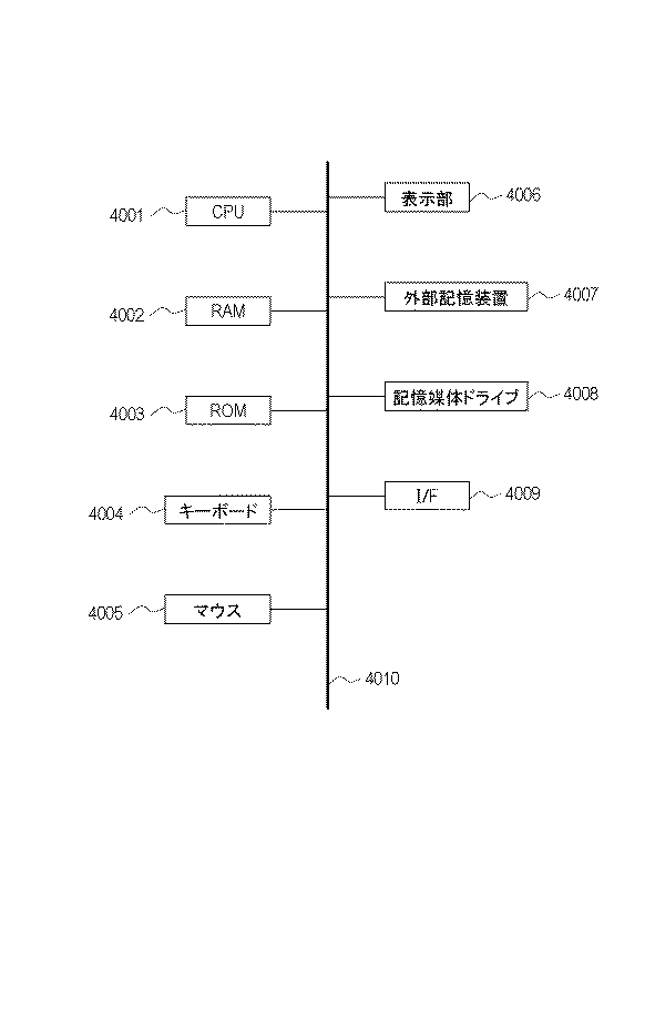
図5は、本実施形態における情報装置1000のハードウェア構成図である。同図において、CPU4001は、バス4010を介して接続する各デバイスを統括的に制御する。CPU4001は、読み出し専用メモリ(ROM)4003に記憶された処理ステップやプログラムを読み出して実行する。オペレーティングシステム(OS)をはじめ、本実施形態に係る各処理プログラム、デバイスドライバ等はROM4003に記憶されており、ランダムアクセスメモリ(RAM)4002に一時記憶され、CPU4001によって適宜実行される。また、入力I/Fとしてキーボード4004やマウス4005は、外部の装置(表示装置や操作装置など)から情報処理装置1000で処理可能な形式で入力信号として入力する。また、出力I/F4009は、外部の装置(表示装置)へ表示装置が処理可能な形式で出力信号として出力する。
FIG. 5 is a hardware configuration diagram of the
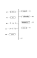
図1は、本実施形態に係る情報処理装置1000の構成図である。
FIG. 1 is a configuration diagram of an
情報処理装置1000は、画像取得部1010、特徴検出部1020、モード切り替え情報入力部1030、モード切り替え部1040、位置姿勢推定部1050、CGデータ描画部1060によって構成される。
The
情報処理装置1000は、撮像装置100とディスプレイ200に接続されている。本実施形態では撮像装置およびディスプレイ200に有線または無線で接続されている。
The
撮像装置100は、ユーザーの頭部に装着されるHMDに内蔵または外部に装着されている。例えば、動画をフレーム画像として連続的に撮影するビデオカメラやデジタルカメラが用いられる。
The
ディスプレイ200は、HMD(ヘッドマウントディスプレイ)であり、CGデータ描画部1060で描画されたCGデータを表示する。ディスプレイ200は、液晶ディスプレイであっても有機ELディスプレイであってもよく、CGと合成された画像を表示できるものであればどのような形態であってもかまわない。
The
画像取得部1010は、撮像装置100によって撮影された画像を連続的に取得する。画像取得部1010は、撮像装置の出力がUSBやIEEE1394などのデジタル出力であれば、例えば、USBインターフェースボードや、IEEE1394インターフェースボードによって実現される。撮像装置の出力がNTSCなどのアナログ出力であればアナログビデオキャプチャボードによって実現される。また、予め記憶装置に記憶してある静止画像や動画像のデジタルデータを読み出してもよい。取得された画像は、特徴検出部1020に入力される。
The
特徴検出部1020は、画像取得部1010が連続的に取得する画像それぞれから特徴を検出する。詳しい処理は後述するが、本実施形態では特徴として、輝度勾配を有する特徴点を検出する。ここで、特徴検出部1020は、所定の特徴数を上限として検出するか、または、所定の特徴数Lを上限として、利用する特徴を位置姿勢推定部1050に出力する。
The
モード切り替え情報入力部1030は、ジャイロ500の計測値である加速度または角速度をモード切り替え情報として入力され、モード切り替え情報をモード切り替え部1040へ出力する。
The mode switching
モード切り替え部1040は、モード切り替え情報入力部1030から入力されたモード切り替え情報に基づき、撮像部の位置姿勢を推定するモードとして、フレームレート優先モードか推定精度の優先モードかを切り替える。モード切り替え部1040は、切り替えたモードを位置推定部1050へ出力する。モードの切り替え方法の詳細は後述する。
The
位置姿勢推定部1050は、特徴検出部1020から入力された特徴とマップ400に基づいて撮像装置の位置姿勢を推定(位置姿勢導出)する。推定方法は後述する。推定した撮像装置の位置姿勢をCG描画部1060に出力する。また、生成したマップをマップ400に出力してマップを更新する。
The position and
CGデータ保持部300は、描画するCGデータを保持している。CGデータの形式はCG画像としてレンダリングできるものであれば何でもよく形式は問わない。
The CG
CGデータ描画部1060は、CGデータ保持部300から描画するべきCGデータを取得し、位置姿勢推定部1050によって出力された撮像装置の位置姿勢を仮想カメラの位置姿勢としてセットし、CGデータを描画する。撮像装置100で取得した画像の上にCGデータを合成して描画し合成画像をユーザーに提示することで、複合現実感(Mixed Reality)を実現することができる。また、CGデータのみを描画する場合には、仮想現実感(Virtual Reality)を実現することができる。
The CG
そして、合成画像をディスプレイ200に出力(表示制御)する。
Then, the composite image is output (display control) to the
これらの各機能部は、CPU4001が、ROM4003に格納されたプログラムをRAM4002に展開し、後述する各フローチャートに従った処理を実行することで実現されている。また例えば、CPU4001を用いたソフトウェア処理の代替としてハードウェアを構成する場合には、ここで説明する各機能部の処理に対応させた演算部や回路を構成すればよい。
Each of these functional units is realized by the
本実施形態では、撮像装置の位置姿勢を定義するための座標系(ここでは、環境中の一点を原点として定義し、互いに直交する3軸を夫々X軸、Y軸、Z軸として定義した座標系)を世界座標系と呼ぶ。位置が既知の環境中の複数の特徴を基準にして世界座標系を定義してもよい。または、撮像装置が最初に撮像した際の位置及び姿勢を基準として世界座標系を定義してもよいし、環境中に配置された夫々の指標を構成する各頂点の位置が既知であってもよい。位置が既知の特徴や指標に基づいてスケールを決定してもよい。または複数地点で撮像した際の既知の撮像位置に基づいて世界座標系のスケールを決定してもよい。 In the present embodiment, a coordinate system (here, one point in the environment is defined as an origin, and three axes orthogonal to each other are defined as an X axis, a Y axis, and a Z axis, respectively) for defining the position and orientation of the imaging apparatus. System) is called the world coordinate system. The world coordinate system may be defined based on a plurality of features in an environment whose position is known. Alternatively, the world coordinate system may be defined based on the position and orientation when the image capturing apparatus first captures an image, or the position of each vertex constituting each index placed in the environment may be known. Good. The scale may be determined based on features or indices whose positions are known. Alternatively, the scale of the world coordinate system may be determined based on a known imaging position when imaging is performed at a plurality of points.
また、本発明においては、撮像装置の歪み補正係数や焦点距離や主点位置などのカメラ内部パラメーターは、公知の手法により校正済みとする。 Further, in the present invention, the camera internal parameters such as the distortion correction coefficient, the focal length, and the principal point position of the imaging device are assumed to have been calibrated by a known method.
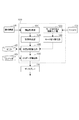
次に、第1の実施形態に係る情報処理装置1000の処理手順について説明する。図2は、第1の実施形態に係る情報処理装置1000の処理手順を示すフローチャートである。
Next, a processing procedure of the
ステップS2010において、画像取得部1010は、撮像装置100で撮影した画像を取得する。
In step S2010, the
ステップS2020において、モード切り替え情報入力部1030は、ジャイロ500の計測値である加速度Atまたは角速度ωtを取得する。
In step S2020, the mode switching
また、1フレーム前の画像を取得した時刻のフレーム番号をt−1とし、フレームtにおける速度をVtとすると、式(1)のようにあらわせる。 Further, the frame number of the time obtained one frame preceding image and t-1, if the speed in the frame t and V t, can be expressed as Equation (1).
モード切り替え情報入力部1030は、速度Vtまたは角速度ωtをモード切り替え情報として出力する。ステップS2030において、モード切り替え情報である速度Vtが閾値VThよりも大きいまたは角速度ωtがωThよりも大きい場合、ユーザーは速く動いているため、モードはフレームレート優先モードであると判定する。一方のその逆の場合には、ユーザーはゆっくり動いているため、推定精度の優先モードであると判定する。
Mode switching
ステップS2040において、ステップS2030で判定したモードに切り替え、判定したモードを位置姿勢推定部1050にセットする。
In step S2040, the mode is switched to the mode determined in step S2030, and the determined mode is set in position and
ステップS2050において、特徴検出部1020が、ステップS2010で取得された画像に対して特徴検出を行う。特徴検出とは、特徴点の画像内の画像座標を検出することをいう。ここで画像から特徴点を検出する処理について述べる。近傍の画素間で輝度勾配が閾値以上の点を特徴点とする。輝度勾配は、画像上で隣り合う画素の濃度の変化量であり、閾値以上に変化する点を特徴点とする。輝度勾配の検出は、例えばSobelオペレータ,Prewittオペレータなどの公知のエッジ検出オペレータにより行う。各画素について、エッジ検出オペレータを画像の水平方向、垂直方向について適用する。そして、その出力値をもとに、エッジ強度を算出する。エッジ検出オペレータの水平方向の出力値がfx、垂直方向の出力値がfyである場合、該画素におけるエッジ強度Iは式(2)のように算出される。
In step S2050, the
ステップS2060において、位置姿勢推定部1050が、特徴に対応するマップ400を取得する。本実施形態では、特徴に対応するマップ400は、複数の画像からそれぞれ検出された特徴点の奥行き値が、その画像を撮影した時の撮像装置の位置姿勢と対応づけられて保持される。特徴点の奥行き値は、例えば、画像上の座標の対応付けを行うことで推定することができる。例えば、KLTと呼ばれる特徴追跡手法によって時系列に位置を変えて撮影された画像から特徴点を追跡し、複数の画像間の特徴点の対応付けを行う。求められた複数の画像間における特徴点の対応からE行列(基礎行列)と呼ばれる変換行列を推定し、E行列から撮像装置の位置姿勢を求め、複数画像間の相対位置姿勢に基づいてステレオ法により特徴点の位置または奥行きの3次元情報を推定する。マップ400として推定される特徴点の奥行き値は、世界座標系における3次元的な位置であっても、各撮像装置で撮影した位置からの奥行値であっても良い。また、本願明細書において、マップを推定するために用いられた各画像をキーフレームと呼ぶ。
In step S2060, position and
また、それぞれが異なるテクスチャ特徴を有する特徴点(自然特徴点)を特徴としてもよい。この場合には、既知の情報として予め保持している各々の特徴のテンプレート画像によるテンプレートマッチングを画像上に施すことにより、画像から特徴を検出する。また、SIFT特徴のように識別子を有し、識別可能な特徴を用いてもよい。これに限らず、空間中に固定される特徴であってそれを撮影した画像から検出可能なものであればどのような特徴であってもかまわない。 Further, feature points (natural feature points) each having a different texture feature may be used as a feature. In this case, the feature is detected from the image by performing template matching using the template image of each feature previously stored as known information on the image. Further, a feature that has an identifier such as a SIFT feature and can be identified may be used. However, the present invention is not limited to this, and any feature may be used as long as it is a feature fixed in space and can be detected from an image obtained by capturing the feature.
ステップS2070において、位置姿勢推定部1050が、ステップS2050で検出された特徴点と、ステップS2060で取得されたマップと、ステップS2040で切り替えたモードに基づいて、撮像装置の位置姿勢を推定する。
In step S2070, the position and
フレームレート優先モードの場合、撮像のフレームレートに合致するようにEKF(拡張カルマンフィルター)などの予測を用いて撮像装置の位置姿勢を推定する。1フレーム前に処理した時刻のフレームt−1から現在の画像が取得された時刻のフレームtまでの差であるΔt、及びt−1におけるEKFの事後内部状態を用いて、EKFの時刻tにおける事前内部状態を求める。予測により撮像のフレームレートに合致するように撮像装置の位置姿勢を推定するのであれば何れの公知の方法であってもよい。 In the case of the frame rate priority mode, the position and orientation of the imaging device are estimated using prediction such as EKF (extended Kalman filter) so as to match the frame rate of imaging. Using Δt, which is the difference between the frame t-1 at the time processed one frame before and the frame t at the time when the current image was acquired, and the posterior internal state of the EKF at t-1, the time at the time t of the EKF is calculated. Find the internal state in advance. Any known method may be used as long as the position and orientation of the imaging device are estimated so as to match the frame rate of imaging by prediction.
推定精度の優先モードの場合、フレームレート優先モードよりも長い時間をかけて高精度に撮像装置の位置姿勢を推定する。フレームレート優先モードよりも長い時間をかけて高精度に撮像装置の位置姿勢を推定する手法であれば、何れの公知の手法であってもよい。マップに基づいて撮像装置位置姿勢を推定する手法は、検出した特徴から撮像装置位置姿勢を推定する手法であれば何れの公知の手法であってよい。 In the case of the estimation accuracy priority mode, the position and orientation of the imaging device are estimated with higher accuracy over a longer time than in the frame rate priority mode. Any known method may be used as long as the method estimates the position and orientation of the imaging device with high accuracy over a longer time than in the frame rate priority mode. The method of estimating the position and orientation of the imaging device based on the map may be any known method as long as the position and orientation of the imaging device are estimated from the detected features.
マップに基づいて撮像装置位置姿勢を推定する手法について説明する。ステップS2060で取得するマップに含まれる特徴点をステップS2010で入力された画像に投影する。投影される特徴点は、例えば、時系列的に直近の画像を撮像した時の撮像装置の位置姿勢に最も近い位置姿勢に対応づけられた特徴点を選択して投影すればよい。そして、投影された特徴点の画像内の位置の周囲の輝度値に基づいて、投影された特徴点の位置における輝度値が一致するように撮像装置の位置姿勢を推定する。 A method for estimating the position and orientation of the imaging device based on the map will be described. The feature points included in the map acquired in step S2060 are projected on the image input in step S2010. As the projected feature point, for example, a feature point associated with the position and orientation closest to the position and orientation of the imaging device at the time of capturing the most recent image in time series may be selected and projected. Then, based on the luminance values around the position of the projected feature point in the image, the position and orientation of the imaging device are estimated such that the luminance values at the position of the projected feature point match.
ここで、位置姿勢推定部1050が推定する撮像装置の位置姿勢は、複合現実感や仮想現実感における仮想カメラの視点としてCG描画に使われるため、ユーザーの動きに合わせてリアルタイム処理が求められる。そのため、初期のマップが生成された後、処理負荷の高いマップ生成と、比較的処理負荷の軽い撮像装置位置姿勢推定は、並列に処理される。位置姿勢推定部1050は、特徴とマップとに基づいて撮像装置位置姿勢を推定したら、撮像装置位置姿勢推定結果をCGデータ描画部1060に出力する。
Here, since the position and orientation of the imaging device estimated by the position and
ステップS2080では、CGデータ保持部300から描画するべきCGデータを取得し、位置姿勢推定部1050によって出力された撮像装置位置姿勢を仮想カメラの位置姿勢としてセットし、CGデータを描画する。撮像装置100で取得した画像の上にCGデータを合成して描画し合成画像をユーザーに提示することで、複合現実感(Mixed Reality)を実現することができる。また、CGデータのみを描画する場合には、仮想現実感(Virtual Reality)を実現することができる。
In step S2080, CG data to be drawn is acquired from the CG
ステップS2090で、処理を終了する場合には本フローを終了し、継続する場合には、ステップS2010に処理を戻す。 In step S2090, when the processing is to be ended, the present flow is ended, and when the processing is to be continued, the processing is returned to step S2010.
以上のように、ジャイロの計測値である加速度または角速度に応じて、撮像装置位置姿勢推定するモードをフレームレート優先モードと推定精度の優先モードを判定し、モードに応じた処理によって撮像装置の位置姿勢を推定する。これにより、ユーザーの速い動きの場合にはフレームレートを低下させずに位置姿勢を推定することでユーザーの動きに素早く追従し、じっくり観察するようなユーザーのゆっくりした動きの場合には、高精度な位置姿勢を出力することができる。すなわち、撮像装置の位置姿勢を推定する際に、ユーザーの動きに応じてフレームレートを優先するか高精度を優先するかを切り替えることで、快適な複合現実感を提供することができる。 As described above, the mode for estimating the position and orientation of the imaging device is determined as the frame rate priority mode or the estimation accuracy priority mode according to the acceleration or angular velocity that is the measurement value of the gyro, and the position of the imaging device is determined by processing according to the mode. Estimate the posture. This makes it possible to quickly follow the user's movement by estimating the position and orientation without reducing the frame rate in the case of fast movement of the user, and to achieve high accuracy in the case of slow movement of the user who observes slowly. It is possible to output a simple position and orientation. That is, when estimating the position and orientation of the imaging device, a comfortable mixed reality can be provided by switching between giving priority to the frame rate or giving high accuracy in accordance with the movement of the user.
(変形例)
第1の実施形態では、フレームレート優先モードの場合、撮像のフレームレートに合致するようにEKF(拡張カルマンフィルター)のような予測を用いて撮像装置の位置姿勢を推定した。ここで、モード切り替え部1040は、フレームレート優先モードの場合、所望のフレームレートをフレームレートの上限値として設定してもよい。本変形例では、撮像装置の更新レートに基づいて設定する。
(Modification)
In the first embodiment, in the frame rate priority mode, the position and orientation of the imaging apparatus are estimated using prediction such as an EKF (extended Kalman filter) so as to match the frame rate of imaging. Here, in the case of the frame rate priority mode,
位置姿勢推定部1050は、設定したフレームレートの上限値を超えないように処理できる場合には、扱う特徴点数を増加させることで情報量を向上させ、高精度化する。設定したフレームレートの上限値を実現しつつ、余った処理時間を高精度化処理に割り当てる。ここで、フレームレートの上限値は、撮像の更新レートに基づいて設定することに限るものではない。ユーザーがフレームレートの上限値を設定してもよいし、ディスプレイの更新レートをフレームレートの上限値として設定してもよい。
When the position and
以上のように、フレームレートの上限値を設定することで、必要以上のフレームレートで処理する必要がなくなり、設定したフレームレートに合致する中で最も時間をかけて精度よく撮像装置の位置または姿勢を推定することができる。すなわち、撮像装置の位置姿勢を推定する際に、フレームレートを優先しつつ、可能な範囲で高精度な処理を行うことで、快適な複合現実感を提供することができる。 As described above, by setting the upper limit value of the frame rate, it is not necessary to perform processing at an unnecessary frame rate, and the position or orientation of the imaging device takes the longest time and accuracy with the set frame rate. Can be estimated. That is, when estimating the position and orientation of the imaging apparatus, by performing processing with high accuracy within the possible range while giving priority to the frame rate, it is possible to provide a comfortable mixed reality.
(第2の実施形態)
第1の実施形態では、ジャイロの計測値である加速度または角速度に応じてフレームレート優先モードと推定精度の優先モードを判定し、モードに応じた処理によって撮像装置の位置姿勢を推定した。しかし、フレームレート優先モードと推定精度の優先モードを切り替えるモード切り替え情報は、ジャイロの計測値である加速度または角速度に基づくものに限らない。
(Second embodiment)
In the first embodiment, the frame rate priority mode and the estimation accuracy priority mode are determined according to the acceleration or angular velocity that is the measurement value of the gyro, and the position and orientation of the imaging device are estimated by the processing according to the mode. However, the mode switching information for switching between the frame rate priority mode and the estimation accuracy priority mode is not limited to information based on acceleration or angular velocity that is a gyro measurement value.
本実施形態では、過去フレームにおける位置または姿勢の変化量をモード切り替え情報として処理する。 In the present embodiment, the change amount of the position or the posture in the past frame is processed as the mode switching information.
モード切り替え情報入力部1030は、過去フレームにおける位置または姿勢の変化量をモード切り替え情報として、モード切り替え部1040に入力する。ここで、1フレーム前に処理した時刻のフレームt−1と、2フレーム前に処理した時刻のフレームt−2の間の位置の変化量Pdiffまたは姿勢の変化量Rdiffとする。PdiffがPThよりも大きい場合またはRdiffがRThよりも大きい場合、ユーザーは速く動いているためフレームレートを向上させることで快適な複合現実感体験を提供する。そのためモードはフレームレート優先モードであると判定する。一方、その逆の場合には、ユーザーはじっくり観察しているため、推定精度の優先モードであると判定する。
The mode switching
ここで、過去フレームにおける位置または姿勢の変化量であれば、フレームはt−1とt−2の間のみに固定されるものではないことはいうまでもない。また、変化量Pdiffまたは姿勢の変化量Rdiffと、フレーム間の時間に基づいて、速度Vまたは角速度ωを求めてもよい。速度Vまたは角速度ωを用いる場合、第1の実施形態と同様となる。 Here, it is needless to say that the frame is not fixed only between t-1 and t-2 as long as the change amount is the position or the posture in the past frame. Further, the velocity V or the angular velocity ω may be obtained based on the change amount P diff or the posture change amount R diff and the time between frames. When the velocity V or the angular velocity ω is used, it is the same as in the first embodiment.
以上のように、過去フレームにおけるカメラの位置または姿勢の変化量に応じて、フレームレート優先モードまたは推定精度の優先モードを判定し、モードに応じた処理によって撮像装置の位置姿勢を推定する。すなわち、撮像装置の位置姿勢を推定する際に、ユーザーの動きに応じてフレームレートを優先するか高精度を優先するかを切り替えることで、快適な複合現実感を提供することができる。 As described above, the frame rate priority mode or the priority mode of estimation accuracy is determined according to the amount of change in the position or orientation of the camera in the past frame, and the position and orientation of the imaging device are estimated by processing according to the mode. That is, when estimating the position and orientation of the imaging device, a comfortable mixed reality can be provided by switching between giving priority to the frame rate or giving high accuracy in accordance with the movement of the user.
(第3の実施形態)
第2の実施形態では、過去フレームにおけるカメラの位置または姿勢の変化量に応じて、フレームレート優先モードと推定精度の優先モードを判定し、モードに応じた処理によって撮像装置の位置姿勢を推定した。しかし、フレームレート優先モードと推定精度の優先モードを切り替えるモード切り替え情報は、これに限るものではない。
(Third embodiment)
In the second embodiment, the frame rate priority mode and the estimation accuracy priority mode are determined in accordance with the amount of change in the position or orientation of the camera in the past frame, and the position and orientation of the imaging device are estimated by processing according to the mode. . However, the mode switching information for switching between the frame rate priority mode and the estimation accuracy priority mode is not limited to this.
本実施形態では、ジェスチャーを認識することによってフレームレート優先モードと推定精度の優先モードを判定する。 In the present embodiment, the frame rate priority mode and the estimation accuracy priority mode are determined by recognizing a gesture.
モード切り替え情報入力部1030は、識別可能なジェスチャーの認識結果をモード切り替え部1040に入力する。
The mode switching
モード切り替え部1040は、HMDを被った人の手をHMDに搭載した撮像装置で撮影した画像から識別し、撮像装置が撮影する画像において、左から右へ手をスワイプさせる場合、フレームレート優先モードに切り替える。また、モード切り替え部1040は、撮像装置が撮影する画像において、右から左へ手をスワイプさせる場合、推定精度の優先モードに切り替える。ここで、2つのモードを切り替えるために識別可能なジェスチャーであれば、いずれのジェスチャーであってもよい。例えば、指を1本立てるジェスチャーや指を2本立てるジェスチャーによって切り替えてもよい。
The
以上のように、モード切り替え情報としてジェスチャーを利用し、ジェスチャーに応じて、フレームレート優先モードまたは推定精度の優先モードを判定し、モードに応じた処理によって撮像装置の位置姿勢を推定する。すなわち、撮像装置の位置姿勢を推定する際に、ユーザーの意図に応じてフレームレートを優先するか高精度を優先するかを切り替えることで、ユーザーの目的に合致した複合現実感を提供することができる。 As described above, the gesture is used as the mode switching information, the frame rate priority mode or the estimation accuracy priority mode is determined according to the gesture, and the position and orientation of the imaging device are estimated by the processing according to the mode. That is, when estimating the position and orientation of the imaging device, it is possible to provide mixed reality that matches the user's purpose by switching between giving priority to the frame rate and giving priority to high accuracy according to the user's intention. it can.
(第4の実施形態)
第3の実施形態では、モード切り替え情報としてジェスチャーを利用し、ジェスチャーに応じて、フレームレート優先モードと推定精度の優先モードを判定し、モードに応じた処理によって撮像装置の位置姿勢を推定した。しかし、フレームレート優先モードと推定精度の優先モードを切り替えるモード切り替え情報は、これに限るものではない。
(Fourth embodiment)
In the third embodiment, a gesture is used as mode switching information, a frame rate priority mode and a priority mode of estimation accuracy are determined according to the gesture, and the position and orientation of the imaging device are estimated by a process according to the mode. However, the mode switching information for switching between the frame rate priority mode and the estimation accuracy priority mode is not limited to this.
本実施形態では、音声を認識することによってフレームレート優先モードと推定精度の優先モードを判定する。 In the present embodiment, the frame rate priority mode and the estimation accuracy priority mode are determined by recognizing the voice.
モード切り替え情報入力部1030は、識別可能な音声認識情報をモード切り替え部1040に入力する。
The mode switching
モード切り替え部1040は、利用者が「フレームレート優先モード」と発声した場合、公知の音声認識技術により、フレームレート優先モードと判定する。また、モード切り替え部1040は、利用者が「推定精度の優先モード」と発声した場合、公知の音声認識技術により、推定精度の優先モードと判定する。2つのモードを切り替えるために識別可能な音声認識情報であれば、いずれの音声であってもよい。
When the user utters “frame rate priority mode”, the
以上のように、モード切り替え情報として音声認識情報を利用し、音声認識情報に応じて、フレームレート優先モードまたは推定精度の優先モードを判定する。判定したモードに応じた処理によって撮像装置の位置姿勢を推定することで、ユーザーの目的に合致した複合現実感を提供することができる。 As described above, the speech recognition information is used as the mode switching information, and the frame rate priority mode or the estimation accuracy priority mode is determined according to the speech recognition information. By estimating the position and orientation of the imaging device by processing according to the determined mode, mixed reality that meets the user's purpose can be provided.
(第5の実施形態)
第4の実施形態では、モード切り替え情報として音声認識情報を利用し、音声認識情報に応じて、フレームレート優先モードと推定精度の優先モードを判定し、モードに応じた処理によって撮像装置の位置姿勢を推定した。しかし、フレームレート優先モードと推定精度の優先モードを切り替えるモード切り替え情報は、これに限るものではない。
(Fifth embodiment)
In the fourth embodiment, the voice recognition information is used as the mode switching information, and the frame rate priority mode and the estimation accuracy priority mode are determined according to the voice recognition information. Was estimated. However, the mode switching information for switching between the frame rate priority mode and the estimation accuracy priority mode is not limited to this.
本実施形態では、CPUの負荷状況によってフレームレート優先モードと推定精度の優先モードを判定する。 In the present embodiment, the frame rate priority mode and the estimation accuracy priority mode are determined based on the CPU load status.
モード切り替え情報入力部1030は、CPUの負荷状況をモード切り替え部1040に入力する。
The mode switching
モード切り替え部1040は、Qtが閾値QThよりも大きい場合、フレームレート優先モードに切り替える。一方で、Qtが閾値QThよりも小さい場合、CPUに余裕があるため、処理に時間をかけ、高精度に撮像装置の位置姿勢を推定する推定精度の優先モードに切り替える。
ここで、現在の画像が取得された時刻のフレームtにおけるフレームCPUの負荷状況はCPU使用率Qtで表す。Qtが閾値QThよりも大きい場合、CPUの負荷率が高いため、処理に時間がかかり、撮像の更新間隔に1フレームあたりの処理時間が間に合わなくなる可能性が高くなる。 Here, the load condition of a frame CPU in the frame t at time that the current image was acquired indicates a CPU utilization Q t. If Q t is larger than the threshold Q Th, since the load rate of the CPU is high, the processing takes time, processing time per frame is likely to be too late to update interval of imaging.
以上のように、モード切り替え情報としてCPU負荷状況を利用し、CPU負荷状況に応じて、フレームレート優先モードまたは推定精度の優先モードを判定し、モードに応じた処理によって撮像装置の位置姿勢を推定する。こうすることで、快適な複合現実感を提供することができる。 As described above, the CPU load status is used as the mode switching information, the frame rate priority mode or the estimation accuracy priority mode is determined according to the CPU load status, and the position and orientation of the imaging device are estimated by the processing according to the mode. I do. By doing so, a comfortable mixed reality can be provided.
(第6の実施形態)
第1の実施形態では、フレームレート優先モードの場合、撮像のフレームレートに合致するようにEKF(拡張カルマンフィルター)のような予測を用いて撮像装置の位置姿勢を推定した。しかし、推定精度の優先モードよりもフレームレートを向上させるのであればこれに限らない。
(Sixth embodiment)
In the first embodiment, in the frame rate priority mode, the position and orientation of the imaging apparatus are estimated using prediction such as an EKF (extended Kalman filter) so as to match the frame rate of imaging. However, the present invention is not limited to this, as long as the frame rate is improved more than the priority mode of the estimation accuracy.
本実施形態では、推定精度の優先モードよりも処理する情報量を減らすことでフレームレートを向上させる。 In the present embodiment, the frame rate is improved by reducing the amount of information to be processed compared to the priority mode of the estimation accuracy.
以下で、情報量を減らす手法について説明する。 Hereinafter, a method for reducing the amount of information will be described.
画像取得部1010が画像を取得する際に、画像の解像度を低下させる。
When the
特徴検出部1020に入力される画像の解像度が、推定精度の優先モードよりも低いため、処理する情報量が減ることで高解像度よりも高速に処理することができる。
Since the resolution of the image input to the
ここで、推定精度の優先モードよりも処理する情報量を減らすのであれば解像度低下させる手法に限らない。例えば、特徴検出部1020が検出する特徴点数を減らしてもよいし、キーフレームを扱う公知の技術の場合、マップ400に保持されるキーフレームのうち処理するキーフレーム数を減らすことで情報量を削減してもよい。
Here, as long as the amount of information to be processed is reduced as compared with the priority mode of the estimation accuracy, the method is not limited to the method of reducing the resolution. For example, the number of feature points detected by the
また、特徴検出部1020が前処置として行う画像処理パラメーターを削減することで情報量を削減してもよい。エッジ強調の画像処理パラメーターであるフィルタサイズを小さくすることで情報量を削減する。エッジ強調のフィルタは、5×5や3x3のフィルタが一般的である。また、特徴検出部1020が前処置として行う画像処理におけるノイズリダクションの画像処理パラメーターであるフィルタサイズを小さくすることで情報量を削減してもよい。ノイズリダクションの処理としては平滑化フィルタやガウシアンフィルタが用いられることが一般的である。
Further, the information amount may be reduced by reducing image processing parameters performed by the
以上のように、フレームレート優先モードでは、撮像装置の位置または姿勢を推定するための情報量を推定精度の優先モードよりも削減することで、所望のフレームレートに近づけることができ、快適な複合現実感を提供することができる。 As described above, in the frame rate priority mode, the amount of information for estimating the position or orientation of the imaging device is reduced from that in the priority mode of estimation accuracy, so that the desired frame rate can be approached, and a comfortable composite Realism can be provided.
(第7の実施形態)
第1の実施形態では、ジャイロの計測値である加速度または角速度に応じてフレームレート優先モードと推定精度の優先モードを判定し、モードに応じた処理によって撮像装置の位置姿勢を推定した。しかし、フレームレート優先モードと推定精度の優先モードを切り替えるモード切り替え情報は、ジャイロの計測値である加速度または角速度に基づくものに限らない。
(Seventh embodiment)
In the first embodiment, the frame rate priority mode and the estimation accuracy priority mode are determined according to the acceleration or angular velocity that is the measurement value of the gyro, and the position and orientation of the imaging device are estimated by the processing according to the mode. However, the mode switching information for switching between the frame rate priority mode and the estimation accuracy priority mode is not limited to information based on acceleration or angular velocity that is a gyro measurement value.
本実施形態では、オプティカルフローをモード切り替え情報として処理する。 In the present embodiment, an optical flow is processed as mode switching information.
モード切り替え情報入力部1030は、過去フレームからの特徴の画像上の変化量であるオプティカルフローをモード切り替え情報として、モード切り替え部1040に入力する。ここで、1フレーム前に処理した時刻のフレームt−1と、2フレーム前に処理した時刻のフレームt−2の間の画像上での位置の変化量Xiとする。iはオプティカルフローを求める特徴の識別子である。所定の数以上の特徴においてXiがXThよりも大きい場合、ユーザーまたは撮影している物体は速く動いていると判定されるためフレームレートを向上させることで快適な複合現実感体験を提供する。そのためモードはフレームレート優先モードであると判定する。一方、その逆の場合には、ユーザーはじっくり観察しているため、推定精度の優先モードであると判定する。
The mode switching
ここで、画像上における特徴の位置の変化量であれば、フレームはt−1とt−2の間のみに固定されるものではないことはいうまでもない。 Here, it goes without saying that the frame is not fixed only between t-1 and t-2 as long as the change amount of the position of the feature on the image.
また、撮像装置が撮影した時刻におけるt内での画像上における特徴の位置の変化量として、モーションブラーをモード切り替え情報として扱ってもよい。モーションブラーは、撮像装置が露光している最中に動いた場合に発生する。モーションブラーを検知する手法は、いずれの公知の手法であってよい。所定の数以上の特徴において、モーションブラーの量MiがMThよりも大きい場合、ユーザーまたは撮影している物体は速く動いていると判定されるためフレームレートを向上させることで快適な複合現実感体験を提供する。そのためモードはフレームレート優先モードであると判定する。一方、その逆の場合には、ユーザーはじっくり観察しているため、推定精度の優先モードであると判定する。 Further, the motion blur may be treated as the mode switching information as the amount of change in the position of the feature on the image within t at the time when the image capturing apparatus shoots. Motion blur occurs when the imaging device moves during exposure. The method of detecting motion blur may be any known method. In a predetermined number or more features, when the amount of motion blur M i is larger than M Th, the user or taken by that object to improve the frame rate to be judged to be moving fast comfortable MR Provide a feeling experience. Therefore, the mode is determined to be the frame rate priority mode. On the other hand, in the opposite case, since the user is observing slowly, it is determined that the estimation accuracy is the priority mode.
以上のように、オプティカルフローに応じて、フレームレート優先モードまたは推定精度の優先モードを判定し、モードに応じた処理によって撮像装置の位置姿勢を推定する。すなわち、撮像装置の位置姿勢を推定する際に、ユーザーまたは物体の動きに応じてフレームレートを優先するか高精度を優先するかを切り替えることで、快適な複合現実感を提供することができる。 As described above, the frame rate priority mode or the estimation accuracy priority mode is determined according to the optical flow, and the position and orientation of the imaging device are estimated by the processing according to the mode. That is, when estimating the position and orientation of the imaging apparatus, by switching between giving priority to the frame rate and giving priority to high accuracy in accordance with the movement of the user or the object, a comfortable mixed reality can be provided.
(第8の実施形態)
第1の実施形態では、ジャイロの計測値である加速度または角速度に応じてフレームレート優先モードと推定精度の優先モードを判定し、モードに応じた処理によって撮像装置の位置姿勢を推定した。しかし、フレームレート優先モードと推定精度の優先モードを切り替えるモード切り替え情報は、ジャイロの計測値である加速度または角速度に基づくものに限らない。
(Eighth embodiment)
In the first embodiment, the frame rate priority mode and the estimation accuracy priority mode are determined according to the acceleration or angular velocity that is the measurement value of the gyro, and the position and orientation of the imaging device are estimated by the processing according to the mode. However, the mode switching information for switching between the frame rate priority mode and the estimation accuracy priority mode is not limited to information based on acceleration or angular velocity that is a gyro measurement value.
本実施形態では、ユーザーインターフェースでユーザーが入力した入力情報をモード切り替え情報として処理する。 In the present embodiment, input information input by the user on the user interface is processed as mode switching information.
モード切り替え情報入力部1030は、ユーザーインターフェースでユーザーが入力した入力情報をモード切り替え情報として、モード切り替え部1040に入力する。ここで、ユーザーインターフェースとしては、ボタンでもよいし、チェックボックスでもよいし、その他の公知のユーザーインターフェースであればいずれのユーザーインターフェースであってもよい。
The mode switching
モード切り替え部1040は、ユーザーインターフェースによりフレームレート優先モードが選択された場合、モードとしてフレームレート優先モードであると判定する。一方、ユーザーインターフェースで推定精度の優先モードが選択された場合には、推定精度の優先モードであると判定する。
When the frame rate priority mode is selected by the user interface, the
以上のように、ユーザーインターフェースでユーザーが選択した入力情報に応じて、フレームレート優先モードまたは推定精度の優先モードを判定し、モードに応じた処理によって撮像装置の位置姿勢を推定する。すなわち、撮像装置の位置姿勢を推定する際に、ユーザーの意図に応じてフレームレートを優先するか高精度を優先するかを切り替えることで、快適な複合現実感を提供することができる。 As described above, the frame rate priority mode or the estimation accuracy priority mode is determined according to the input information selected by the user on the user interface, and the position and orientation of the imaging device are estimated by the processing according to the mode. That is, when estimating the position and orientation of the imaging device, a comfortable mixed reality can be provided by switching between giving priority to the frame rate and giving high priority to the accuracy according to the intention of the user.
(第9の実施形態)
第1の実施形態では、ジャイロの計測値である加速度または角速度に応じてフレームレート優先モードと推定精度の優先モードを判定し、モードに応じた処理によって撮像装置の位置姿勢を推定した。ここで、ユーザーが動き出した際にフレームレートが低いとHMDを装着したユーザーの動きに映像が追い付いてこられずHMDを装着したまま動く際に転倒や衝突などの危険性が向上する。
(Ninth embodiment)
In the first embodiment, the frame rate priority mode and the estimation accuracy priority mode are determined according to the acceleration or angular velocity that is the measurement value of the gyro, and the position and orientation of the imaging device are estimated by the processing according to the mode. Here, if the frame rate is low when the user starts moving, the video cannot catch up with the movement of the user wearing the HMD, and the danger of falling or collision when moving with the HMD is improved.
そこで、本実施形態では、ユーザーの動き出し時にジャイロの計測値である加速度または角速度に応じてフレームレート優先モードとして判定し、急激にフレームレートを向上させるように処理する。 Thus, in the present embodiment, when the user starts moving, the mode is determined to be the frame rate priority mode according to the acceleration or angular velocity which is the measurement value of the gyro, and processing is performed so as to sharply improve the frame rate.
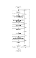
モード切り替え情報入力部1030は、撮像装置100が撮像した時刻のフレーム番号tと概略同時刻に取得したジャイロ500の計測値である加速度Atまたは角速度ωtを取得する。撮像装置100が露光する露光時間と画像を情報処理装置に転送する際にかかる転送時間を加えた時間におけるフレーム番号をtdelayとする。ジャイロ500は撮像装置の更新レートよりも速い更新レートで動作させ、tdelayにおけるジャイロ500の計測値である加速度Atdelayまたは角速度ωtdelayを取得する。
Mode switching
また、画像を取得した時刻のフレーム番号tdelayにおける速度をVtdelayとすると、式(3)のようにあらわせる。 Further, if the speed at the frame number t delay at the time when the image is acquired is V tdelay , it is expressed as in Expression (3).
モード切り替え情報入力部1030は、速度Vtdelayまたは角速度ωtdelayをモード切り替え情報として出力する。
The mode switching
ステップS2030において、モード切り替え情報である速度Vtdelayが閾値VTh’よりも大きいまたは角速度ωtdelayがωTh’よりも大きい場合、ユーザーは急激に動いているため、モードはフレームレート優先モードであると判定する。 In step S2030, when the mode switching information is a velocity V tdelay threshold V Th 'large or angular velocity omega than tdelay is omega Th' greater than, because the user is rapidly moving, mode is the frame rate priority mode Is determined.
ここで、ユーザーの動き出し時にジャイロの計測値である加速度または角速度に応じてフレームレート優先モードとして判定したが、ユーザーの動き出し時の加速または角速度が取得できるセンサーであればジャイロに限るものではない。センサーとして光学式のセンサーであってもよいし、磁気式のセンサーであってもよい。 Here, the frame rate priority mode is determined according to the acceleration or angular velocity that is the measurement value of the gyro when the user starts moving, but the sensor is not limited to the gyro as long as the sensor can acquire the acceleration or angular velocity when the user starts moving. The sensor may be an optical sensor or a magnetic sensor.
以上のように、撮像装置が撮像した同フレーム内でのユーザーの動きの変化量を、更新レートの速いジャイロを利用して取得し、これをモード切り替え情報とする。これによりユーザーが急激に動いた場合にも、次のフレームまで待たずにフレームレート優先モードに設定することができる。すなわち、撮像装置の位置姿勢を推定する際に、ユーザーの急激な動きに応じてフレームレートを優先するように切り替えることで、安全かつ快適な複合現実感を提供することができる。 As described above, the amount of change in the user's movement in the same frame captured by the imaging device is acquired using the gyro having a fast update rate, and this is used as mode switching information. Thus, even when the user moves suddenly, it is possible to set the frame rate priority mode without waiting for the next frame. In other words, when estimating the position and orientation of the imaging apparatus, a safe and comfortable mixed reality can be provided by switching so that the frame rate is prioritized in accordance with the rapid movement of the user.
(他の実施形態)
本発明は、上述の実施形態の1以上の機能を実現するプログラムを、ネットワーク又は記憶媒体を介してシステム又は装置に供給し、そのシステム又は装置のコンピュータにおける1つ以上のプロセッサーがプログラムを読出し実行する処理でも実現可能である。また、1以上の機能を実現する回路(例えば、ASIC)によっても実現可能である。
(Other embodiments)
The present invention supplies a program for realizing one or more functions of the above-described embodiments to a system or an apparatus via a network or a storage medium, and one or more processors in a computer of the system or the apparatus read and execute the program. This processing can be realized. Further, it can also be realized by a circuit (for example, an ASIC) that realizes one or more functions.
Claims (15)
フレームレートよりも前記撮像装置の位置または姿勢の少なくともいずれか一方の推定精度を優先する推定精度の優先モードと、前記推定精度よりもフレームレートを優先するフレームレート優先モードと、のいずれかを選択する選択手段と、
前記選択手段で選択されたモードに基づき、前記画像の特徴から前記撮像装置の位置または姿勢の少なくともいずれか一方を推定する推定手段と、
前記推定された前記撮像装置の位置または姿勢の少なくともいずれか一方に基づく画像を表示手段に表示させる制御手段と、を有することを特徴とする情報処理装置。 Acquisition means for acquiring an image from the imaging device;
Select one of a priority mode of the estimation accuracy that prioritizes the estimation accuracy of at least one of the position and the orientation of the imaging device over the frame rate, and a frame rate priority mode that prioritizes the frame rate over the estimation accuracy Means for selecting,
Estimating means for estimating at least one of the position or orientation of the imaging device from the characteristics of the image, based on the mode selected by the selecting means,
An information processing apparatus comprising: a control unit that causes a display unit to display an image based on at least one of the estimated position and orientation of the imaging device.
Priority Applications (2)
| Application Number | Priority Date | Filing Date | Title |
|---|---|---|---|
| JP2018184795A JP7406875B2 (en) | 2018-09-28 | 2018-09-28 | Information processing equipment and programs |
| US16/579,493 US10970807B2 (en) | 2018-09-28 | 2019-09-23 | Information processing apparatus and storage medium |
Applications Claiming Priority (1)
| Application Number | Priority Date | Filing Date | Title |
|---|---|---|---|
| JP2018184795A JP7406875B2 (en) | 2018-09-28 | 2018-09-28 | Information processing equipment and programs |
Publications (3)
| Publication Number | Publication Date |
|---|---|
| JP2020052979A true JP2020052979A (en) | 2020-04-02 |
| JP2020052979A5 JP2020052979A5 (en) | 2021-11-11 |
| JP7406875B2 JP7406875B2 (en) | 2023-12-28 |
Family
ID=69945128
Family Applications (1)
| Application Number | Title | Priority Date | Filing Date |
|---|---|---|---|
| JP2018184795A Active JP7406875B2 (en) | 2018-09-28 | 2018-09-28 | Information processing equipment and programs |
Country Status (2)
| Country | Link |
|---|---|
| US (1) | US10970807B2 (en) |
| JP (1) | JP7406875B2 (en) |
Cited By (1)
| Publication number | Priority date | Publication date | Assignee | Title |
|---|---|---|---|---|
| WO2025004917A1 (en) * | 2023-06-30 | 2025-01-02 | ソニーグループ株式会社 | Information processing device, information processing method, and information processing system |
Families Citing this family (7)
| Publication number | Priority date | Publication date | Assignee | Title |
|---|---|---|---|---|
| US10937191B2 (en) * | 2018-10-23 | 2021-03-02 | Dell Products, Lp | Predictive simultaneous localization and mapping system using prior user session positional information |
| US11227007B2 (en) * | 2019-07-23 | 2022-01-18 | Obayashi Corporation | System, method, and computer-readable medium for managing image |
| US11158087B2 (en) * | 2019-12-06 | 2021-10-26 | Intel Corporation | Adaptive virtual camera for indirect-sparse simultaneous localization and mapping systems |
| WO2022078266A1 (en) * | 2020-10-16 | 2022-04-21 | Zhejiang Dahua Technology Co., Ltd. | Systems and methods for data transmission |
| CN112102411B (en) * | 2020-11-02 | 2021-02-12 | 中国人民解放军国防科技大学 | Visual positioning method and device based on semantic error image |
| US20240221312A1 (en) * | 2021-04-30 | 2024-07-04 | Visionary Machines Pty Ltd | Systems and methods for generating and/or using 3-dimensional information with one or more cameras |
| US11812165B2 (en) * | 2021-06-16 | 2023-11-07 | Mediatek Inc. | Method and apparatus for dynamically changing frame rate of sensor output frames according to whether motion blur condition is met |
Citations (2)
| Publication number | Priority date | Publication date | Assignee | Title |
|---|---|---|---|---|
| JP2016122975A (en) * | 2014-12-25 | 2016-07-07 | セイコーエプソン株式会社 | Display device and control method of display device |
| JP2017207818A (en) * | 2016-05-16 | 2017-11-24 | キヤノン株式会社 | Image processing apparatus, image processing method and program |
Family Cites Families (4)
| Publication number | Priority date | Publication date | Assignee | Title |
|---|---|---|---|---|
| US6741790B1 (en) * | 1997-05-29 | 2004-05-25 | Red Hen Systems, Inc. | GPS video mapping system |
| JP4532982B2 (en) | 2004-05-14 | 2010-08-25 | キヤノン株式会社 | Arrangement information estimation method and information processing apparatus |
| US7456833B1 (en) * | 2005-06-15 | 2008-11-25 | Nvidia Corporation | Graphical representation of load balancing and overlap |
| US9978180B2 (en) * | 2016-01-25 | 2018-05-22 | Microsoft Technology Licensing, Llc | Frame projection for augmented reality environments |
-
2018
- 2018-09-28 JP JP2018184795A patent/JP7406875B2/en active Active
-
2019
- 2019-09-23 US US16/579,493 patent/US10970807B2/en active Active
Patent Citations (2)
| Publication number | Priority date | Publication date | Assignee | Title |
|---|---|---|---|---|
| JP2016122975A (en) * | 2014-12-25 | 2016-07-07 | セイコーエプソン株式会社 | Display device and control method of display device |
| JP2017207818A (en) * | 2016-05-16 | 2017-11-24 | キヤノン株式会社 | Image processing apparatus, image processing method and program |
Cited By (1)
| Publication number | Priority date | Publication date | Assignee | Title |
|---|---|---|---|---|
| WO2025004917A1 (en) * | 2023-06-30 | 2025-01-02 | ソニーグループ株式会社 | Information processing device, information processing method, and information processing system |
Also Published As
| Publication number | Publication date |
|---|---|
| JP7406875B2 (en) | 2023-12-28 |
| US10970807B2 (en) | 2021-04-06 |
| US20200104969A1 (en) | 2020-04-02 |
Similar Documents
| Publication | Publication Date | Title |
|---|---|---|
| JP2020052979A (en) | Information processing device and program | |
| EP3718048B1 (en) | Method of analyzing objects in images recorded by a camera of a head mounted device | |
| JP6789624B2 (en) | Information processing device, information processing method | |
| JP6723061B2 (en) | Information processing apparatus, information processing apparatus control method, and program | |
| TWI701941B (en) | Method, apparatus and electronic device for image processing and storage medium thereof | |
| JP2019522851A (en) | Posture estimation in 3D space | |
| KR20170031733A (en) | Technologies for adjusting a perspective of a captured image for display | |
| EP3644826A1 (en) | A wearable eye tracking system with slippage detection and correction | |
| WO2022174594A1 (en) | Multi-camera-based bare hand tracking and display method and system, and apparatus | |
| JP2017129567A (en) | Information processing apparatus, information processing method, and program | |
| JP6894707B2 (en) | Information processing device and its control method, program | |
| CN113228117B (en) | Creation device, creation method, and recording medium recording creation program | |
| KR101256046B1 (en) | Method and system for body tracking for spatial gesture recognition | |
| JP2012048463A (en) | Information processor and information processing method | |
| JP5518677B2 (en) | Virtual information giving apparatus and virtual information giving program | |
| JP2021009557A (en) | Information processing equipment, information processing methods, and programs | |
| JP2023054710A (en) | Information processing device and method, program | |
| JP6632298B2 (en) | Information processing apparatus, information processing method and program | |
| JP7710185B2 (en) | Photographing device, photographing operation support method, and photographing operation support program | |
| JP2022516466A (en) | Information processing equipment, information processing methods, and programs | |
| CN117612251A (en) | Human body posture recognition method and system | |
| JP6704712B2 (en) | Information processing apparatus, control method of information processing apparatus, and program | |
| JP2015201734A (en) | Image processing system, control method of the same, and program | |
| JP2023026244A (en) | Image generation apparatus, image generation method, and program | |
| JP2580516B2 (en) | Real-time three-dimensional motion measuring apparatus and method |
Legal Events
| Date | Code | Title | Description |
|---|---|---|---|
| A521 | Request for written amendment filed |
Free format text: JAPANESE INTERMEDIATE CODE: A523 Effective date: 20210928 |
|
| A621 | Written request for application examination |
Free format text: JAPANESE INTERMEDIATE CODE: A621 Effective date: 20210928 |
|
| A131 | Notification of reasons for refusal |
Free format text: JAPANESE INTERMEDIATE CODE: A131 Effective date: 20221206 |
|
| A521 | Request for written amendment filed |
Free format text: JAPANESE INTERMEDIATE CODE: A523 Effective date: 20230201 |
|
| A131 | Notification of reasons for refusal |
Free format text: JAPANESE INTERMEDIATE CODE: A131 Effective date: 20230606 |
|
| A521 | Request for written amendment filed |
Free format text: JAPANESE INTERMEDIATE CODE: A523 Effective date: 20230728 |
|
| TRDD | Decision of grant or rejection written | ||
| A01 | Written decision to grant a patent or to grant a registration (utility model) |
Free format text: JAPANESE INTERMEDIATE CODE: A01 Effective date: 20231114 |
|
| RD01 | Notification of change of attorney |
Free format text: JAPANESE INTERMEDIATE CODE: A7421 Effective date: 20231213 |
|
| A61 | First payment of annual fees (during grant procedure) |
Free format text: JAPANESE INTERMEDIATE CODE: A61 Effective date: 20231213 |
|
| R151 | Written notification of patent or utility model registration |
Ref document number: 7406875 Country of ref document: JP Free format text: JAPANESE INTERMEDIATE CODE: R151 |