JP6789624B2 - Information processing device, information processing method - Google Patents
Information processing device, information processing method Download PDFInfo
- Publication number
- JP6789624B2 JP6789624B2 JP2015228094A JP2015228094A JP6789624B2 JP 6789624 B2 JP6789624 B2 JP 6789624B2 JP 2015228094 A JP2015228094 A JP 2015228094A JP 2015228094 A JP2015228094 A JP 2015228094A JP 6789624 B2 JP6789624 B2 JP 6789624B2
- Authority
- JP
- Japan
- Prior art keywords
- information processing
- orientation
- generation
- information
- map generation
- Prior art date
- Legal status (The legal status is an assumption and is not a legal conclusion. Google has not performed a legal analysis and makes no representation as to the accuracy of the status listed.)
- Active
Links
Images


Classifications
-
- G—PHYSICS
- G06—COMPUTING; CALCULATING OR COUNTING
- G06T—IMAGE DATA PROCESSING OR GENERATION, IN GENERAL
- G06T7/00—Image analysis
- G06T7/60—Analysis of geometric attributes
-
- G—PHYSICS
- G06—COMPUTING; CALCULATING OR COUNTING
- G06T—IMAGE DATA PROCESSING OR GENERATION, IN GENERAL
- G06T7/00—Image analysis
- G06T7/70—Determining position or orientation of objects or cameras
- G06T7/73—Determining position or orientation of objects or cameras using feature-based methods
-
- G—PHYSICS
- G06—COMPUTING; CALCULATING OR COUNTING
- G06T—IMAGE DATA PROCESSING OR GENERATION, IN GENERAL
- G06T2207/00—Indexing scheme for image analysis or image enhancement
- G06T2207/10—Image acquisition modality
- G06T2207/10004—Still image; Photographic image
-
- G—PHYSICS
- G06—COMPUTING; CALCULATING OR COUNTING
- G06T—IMAGE DATA PROCESSING OR GENERATION, IN GENERAL
- G06T2207/00—Indexing scheme for image analysis or image enhancement
- G06T2207/10—Image acquisition modality
- G06T2207/10016—Video; Image sequence
-
- G—PHYSICS
- G06—COMPUTING; CALCULATING OR COUNTING
- G06T—IMAGE DATA PROCESSING OR GENERATION, IN GENERAL
- G06T2207/00—Indexing scheme for image analysis or image enhancement
- G06T2207/30—Subject of image; Context of image processing
- G06T2207/30244—Camera pose
Description
本発明は、撮像装置の位置姿勢の推定技術に関するものである。 The present invention relates to a technique for estimating the position and orientation of an imaging device.
現実世界と仮想世界とをリアルタイムに融合させる技術として、複合現実感(MR:Mixed Reality)技術や拡張現実感(AR:Augmented Reality)技術が知られている。これらの技術は、現実空間とコンピュータによって作られる仮想空間とを繋ぎ目なく融合する技術である。これらの技術は、組み立て作業時に作業手順や配線の様子を重畳表示する組み立て支援、患者の体表面に体内の様子を重畳表示する手術支援等、様々な分野への応用が期待される。 Mixed reality (MR: Mixed Reality) technology and augmented reality (AR: Augmented Reality) technology are known as technologies for fusing the real world and the virtual world in real time. These technologies are technologies that seamlessly fuse the real space and the virtual space created by a computer. These technologies are expected to be applied to various fields such as assembly support that superimposes the work procedure and wiring state during assembly work, and surgical support that superimposes the state of the body on the patient's body surface.
MR技術を実現する上で解決しなければならない大きな問題の一つとして、位置合わせの問題がある。仮想物体が現実空間に実在するように利用者が感じるためには、仮想物体と現実空間との間の幾何学的な整合性が取れている必要がある。即ち、仮想物体は現実空間中に存在するべき位置に存在しているように常に利用者から観察されなければならない。 One of the major problems that must be solved in order to realize MR technology is the problem of alignment. In order for the user to feel that the virtual object actually exists in the real space, it is necessary that the virtual object and the real space are geometrically consistent. That is, the virtual object must always be observed by the user as if it were in a position where it should exist in the real space.
また、観察者が、仮想物体を現実空間に実在するように感じるための装置の一つとして、ビデオシースルー型の情報処理装置がある。これは、ビデオカメラで現実世界を撮影し、その撮影画像に仮想物体を重畳した合成画像を、リアルタイムにディスプレイ等の表示部に表示させて観察者に提示する装置である。一般にこのような情報処理装置としては、背面にビデオカメラを有するタブレット端末と呼ばれる携帯型情報端末や、頭部搭載型のビデオシースルー型HMD(Head Mounted Display)などが用いられる。 Further, as one of the devices for the observer to feel that the virtual object actually exists in the real space, there is a video see-through type information processing device. This is a device that captures the real world with a video camera, displays a composite image in which a virtual object is superimposed on the captured image on a display unit such as a display in real time, and presents it to an observer. Generally, as such an information processing device, a portable information terminal called a tablet terminal having a video camera on the back, a head-mounted video see-through type HMD (Head Mounted Display), or the like is used.
ビデオシースルー型HMDを利用するMRでは、HMDに内蔵されているカメラから画像が入力される毎に、画像撮影時のカメラの現実空間における位置姿勢を計測する。そしてこのカメラの位置姿勢と、焦点距離などのカメラの固有パラメーターと、に基づいてCG(Computer Graphics)を描画し、該CGを現実空間の撮影画像上に重畳するという処理が一般的に行われる。そのため、ビデオシースルー型HMDを利用するMRの場合、位置合わせの問題は、HMDに内蔵したカメラの現実空間における位置姿勢を計測する問題となる。 In an MR that uses a video see-through HMD, each time an image is input from the camera built into the HMD, the position and orientation of the camera in the real space at the time of image shooting is measured. Then, a process of drawing CG (Computer Graphics) based on the position and orientation of the camera and the unique parameters of the camera such as the focal length and superimposing the CG on the captured image in the real space is generally performed. .. Therefore, in the case of an MR using a video see-through type HMD, the problem of alignment becomes a problem of measuring the position and orientation of the camera built in the HMD in the real space.
カメラの位置姿勢の計測は、例えば磁気センサや超音波センサ、光学式センサなど6自由度の物理センサによって計測することが可能である。一方で、ビデオシースルー型HMDを利用する場合には、ビデオシースルー型HMDに内蔵されているカメラからの画像情報を位置合わせのために利用することが可能である。画像情報を利用する位置合わせ方法は、物理センサを利用する方法に比べて手軽且つ低コストであるため、広く利用されている。画像情報を利用する位置合わせ手法では、現実空間中における3次元位置が既知の指標をカメラで撮影し、指標の撮影画像上での位置と3次元位置との対応を基にカメラの位置姿勢を推定することが行われている。既知の指標としては、現実空間中に人為的に配置した指標などがある。例としては、四角形マーカ、円形マーカ、点マーカなどが挙げられる。しかし、現実環境中に指標を多数配置することは人的・時間的に高コストになり、景観も損なわれるという問題がある。 The position and orientation of the camera can be measured by a physical sensor with 6 degrees of freedom, such as a magnetic sensor, an ultrasonic sensor, or an optical sensor. On the other hand, when the video see-through type HMD is used, the image information from the camera built in the video see-through type HMD can be used for the alignment. The alignment method using image information is widely used because it is easier and less costly than the method using a physical sensor. In the alignment method using image information, an index whose three-dimensional position is known in real space is photographed by a camera, and the position and orientation of the camera are determined based on the correspondence between the position on the captured image of the index and the three-dimensional position. Estimates are being made. Known indicators include indicators artificially placed in real space. Examples include quadrilateral markers, circular markers, point markers, and the like. However, arranging a large number of indicators in the real environment is costly in terms of human and time, and there is a problem that the landscape is also impaired.
そこで、既知の指標を用いずに撮影画像上で輝度勾配のあるエッジや角点など自然特徴を検出し、それらを基にカメラの位置姿勢を推定することが行われている。 Therefore, natural features such as edges and corner points with a brightness gradient are detected on the captured image without using a known index, and the position and orientation of the camera are estimated based on these natural features.
非特許文献1に記載の技術では、自然特徴として特徴点を画像から検出する。カメラを移動させ、初期画像で検出した特徴点から2次元的に特徴点を追跡し、初期画像と現画像の2つの画像間で特徴点周りの8×8の画素パッチを対応付ける。画像座標の対応点から、2つの画像を撮影したカメラの相対的な位置姿勢と対応付けた特徴点群の3次元情報である位置を推定する。ここで、非特許文献1では、特徴点群の3次元情報である位置と、その周辺の画像パッチを合わせてマップと呼んでいる。さらに、初めの2つの画像から算出されるマップを初期マップと呼ぶ。算出したマップ(ここでは3次元の位置情報を持つ特徴点群)を、現在のカメラの位置姿勢に基づいて画像面に投影し、検出した特徴点と、投影された特徴点と、の誤差を最小化するように、カメラの位置姿勢を更新する。カメラの位置姿勢が推定されており、特徴点を十分推定しているときに、キーフレームと呼ばれる画像を動画像から取得する。各キーフレームで検出された特徴点をエピポーラ線上を探索して対応付けを行う。各キーフレームのカメラ位置姿勢と、特徴点群の3次元位置を、各キーフレーム上での投影誤差が最小化されるようにバンドル調整を行い、非線形最適化計算によって、マップを高精度に算出する。また、非特許文献1では、マウスや画面のタッチ入力など、マニュアルで入力することで、マッピングを開始する。マッピングを開始した後は、カメラの位置姿勢を推定しながら並列処理でマップ生成の処理が継続される。 In the technique described in Non-Patent Document 1, feature points are detected from images as natural features. The camera is moved to trace the feature points two-dimensionally from the feature points detected in the initial image, and an 8 × 8 pixel patch around the feature points is associated between the two images of the initial image and the current image. From the corresponding points of the image coordinates, the position which is the three-dimensional information of the feature point cloud associated with the relative position and orientation of the cameras that captured the two images is estimated. Here, in Non-Patent Document 1, the position which is the three-dimensional information of the feature point group and the image patch around the position are collectively called a map. Further, the map calculated from the first two images is called an initial map. The calculated map (here, a group of feature points with three-dimensional position information) is projected onto the image plane based on the current position and orientation of the camera, and the error between the detected feature points and the projected feature points is calculated. Update the position and orientation of the camera to minimize it. When the position and orientation of the camera are estimated and the feature points are sufficiently estimated, an image called a key frame is acquired from the moving image. The feature points detected at each key frame are searched on the epipolar line and associated with each other. The camera position and orientation of each key frame and the three-dimensional position of the feature point cloud are bundle-adjusted so that the projection error on each key frame is minimized, and the map is calculated with high accuracy by nonlinear optimization calculation. To do. Further, in Non-Patent Document 1, mapping is started by manually inputting with a mouse or touch input on the screen. After starting the mapping, the map generation process is continued by parallel processing while estimating the position and orientation of the camera.
非特許文献2では、自然特徴として画像全体から輝度勾配のある点群を密に検出する。初期マップの生成は非特許文献1と同様の手法を利用している。初期マップの生成後、マップの点を現画像に投影した時、マップの点のキーフレーム上の輝度値と現フレーム上の輝度値とが一致するように位置姿勢を更新する。また、前キーフレームと位置が閾値以上離れた場合に次のキーフレームを追加する。近傍のキーフレームのマップの点を、追加したキーフレームでエピポーラ探索し、対応付けを行い、2つのキーフレーム間の相対位置姿勢と対応情報に基づいてマップの点の現キーフレームにおける奥行情報を推定する。非特許文献2では、キーフレームの画像情報とキーフレーム上で輝度勾配のある点の奥行情報とキーフレームの位置姿勢を合わせて、マップと呼んでいる。ここで、キーフレームを逐次追加していくと誤差が蓄積してくため、マップの最適化を行うことで、マップ全体の整合がとれるようにしている。 In Non-Patent Document 2, as a natural feature, a point cloud having a brightness gradient is densely detected from the entire image. The same method as in Non-Patent Document 1 is used to generate the initial map. After the initial map is generated, when the map points are projected onto the current image, the position and orientation are updated so that the brightness values of the map points on the key frame and the brightness values on the current frame match. In addition, the next key frame is added when the position is separated from the previous key frame by a threshold value or more. The map points of nearby keyframes are epipolarly searched with the added keyframes, associated with each other, and the depth information of the map points in the current keyframe is obtained based on the relative position / orientation between the two keyframes and the corresponding information. presume. In Non-Patent Document 2, the image information of the key frame, the depth information of the point having the brightness gradient on the key frame, and the position and orientation of the key frame are combined and called a map. Here, since errors accumulate as keyframes are added one after another, the map is optimized so that the entire map can be aligned.
非特許文献1や非特許文献2に記載の技術は、SLAM(Simultaneous Localization And Mapping)と呼ばれる技術である。カメラの自己位置姿勢を推定するLocalizationと、特徴点の位置を推定するMappingとを同時に行う手法である。 The technique described in Non-Patent Document 1 and Non-Patent Document 2 is a technique called SLAM (Simultaneus Localization And Mapping). This is a method of simultaneously performing localization for estimating the self-position and orientation of the camera and mapping for estimating the position of a feature point.
非特許文献1や非特文献2のように、カメラの位置姿勢の推定とマップの推定とを同時に行う手法において、マップ生成を継続し続けると、メモリの上限に達してオーバーフローになる危険性がある。また、情報量が増加することにより処理負荷が高くなるので、フレームレートが落ちるなどの問題が生じることがある。そこで、カメラ位置姿勢を推定しながら常に同時にマップを生成するのではなく、カメラ位置姿勢を推定しながらマップ生成を行い、ある時点でマップの生成を停止させ、それまでに生成したマップを使ってカメラ位置姿勢を推定する。このとき、カメラ位置姿勢の推定技術の専門家ではないユーザや事前知識を持たないユーザは、どの時点でマップ生成を開始または停止または再開すればよいのかが分からないという課題があった。 In the method of estimating the position and orientation of the camera and estimating the map at the same time as in Non-Patent Document 1 and Non-Special Document 2, if the map generation is continued, there is a risk that the upper limit of the memory will be reached and overflow will occur. .. In addition, since the processing load increases as the amount of information increases, problems such as a decrease in the frame rate may occur. Therefore, instead of always generating a map at the same time while estimating the camera position and orientation, map generation is performed while estimating the camera position and orientation, the map generation is stopped at a certain point, and the map generated so far is used. Estimate the camera position and orientation. At this time, there is a problem that a user who is not an expert in the camera position / orientation estimation technique or a user who does not have prior knowledge does not know at what point the map generation should be started, stopped, or restarted.
本発明はこのような問題に鑑みてなされたものであり、撮像装置の位置姿勢の推定において用いる特徴の3次元位置情報の生成を、該当分野の専門的な知識がないユーザであっても、より省メモリで実現させる技術を提供する。 The present invention has been made in view of such a problem, and even a user who does not have specialized knowledge in the relevant field can generate three-dimensional position information of features used in estimating the position and orientation of an imaging device. Provide technology that realizes more memory saving.
本発明の一様態は、登録済みの特徴の3次元位置情報と、撮像装置が撮像したフレーム画像における特徴と、に基づいて、前記撮像装置の位置姿勢を推定する推定手段と、
前記推定手段が推定した位置姿勢に基づいて、未登録の特徴の3次元位置情報を生成して登録する生成手段と
を備え、
前記生成手段は、未登録の特徴の3次元位置情報の生成及び登録を、前記推定手段が前記撮像装置の位置姿勢の推定処理を開始したタイミング、前記撮像装置が撮像したフレーム画像から特徴を検出したタイミング、特徴を連続して抽出したフレーム画像の数が閾値以上となったタイミング、のいずれかのタイミングで開始してから規定の時間が経過するまで実行し、該規定の時間が経過すると停止する
ことを特徴とする。
The uniform state of the present invention includes an estimation means for estimating the position and orientation of the image pickup device based on the three-dimensional position information of the registered feature and the feature in the frame image captured by the image pickup device.
It is provided with a generation means for generating and registering three-dimensional position information of unregistered features based on the position / orientation estimated by the estimation means.
The generation means detects the generation and registration of the three-dimensional position information of the unregistered feature from the frame image captured by the image pickup device at the timing when the estimation means starts the estimation process of the position and orientation of the image pickup device. It is executed until the specified time elapses from the start at any of the timings when the feature is set and the timing when the number of frame images in which the features are continuously extracted exceeds the threshold value, and stops when the specified time elapses. It is characterized by doing.
本発明の構成によれば、撮像装置の位置姿勢の推定において用いる特徴の3次元位置情報の生成を、該当分野の専門的な知識がないユーザであっても、より省メモリで実現させることができる。 According to the configuration of the present invention, it is possible to realize the generation of three-dimensional position information of the feature used in the estimation of the position and orientation of the image pickup apparatus with more memory saving even by a user who does not have specialized knowledge in the relevant field. it can.
以下、添付図面を参照し、本発明の好適な実施形態について説明する。なお、以下説明する実施形態は、本発明を具体的に実施した場合の一例を示すもので、特許請求の範囲に記載した構成の具体的な実施例の1つである。 Hereinafter, preferred embodiments of the present invention will be described with reference to the accompanying drawings. In addition, the embodiment described below shows an example when the present invention is concretely implemented, and is one of the specific examples of the configuration described in the claims.
[第1の実施形態]
本実施形態では、次のような構成を有する情報処理装置の一例について説明する。即ち、登録済みの特徴の3次元位置情報と、撮像装置が撮像したフレーム画像における特徴と、に基づいて、撮像装置の位置姿勢を推定し、該推定した位置姿勢に基づいて、未登録の特徴の3次元位置情報を生成して登録する。なお、未登録の特徴の3次元位置情報の生成及び登録を、該推定の実行に応じて制御する。
[First Embodiment]
In this embodiment, an example of an information processing apparatus having the following configuration will be described. That is, the position and orientation of the image pickup device are estimated based on the three-dimensional position information of the registered feature and the feature in the frame image captured by the image pickup device, and the unregistered feature is based on the estimated position and orientation. 3D position information is generated and registered. It should be noted that the generation and registration of the three-dimensional position information of the unregistered feature is controlled according to the execution of the estimation.
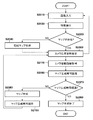
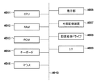
先ず、本実施形態に係る情報処理装置を含むシステムの構成例について、図1のブロック図を用いて説明する。図1に示す如く、本実施形態に係るシステムは、カメラ100、表示部200、情報処理装置1000、を有する。
First, a configuration example of a system including an information processing device according to the present embodiment will be described with reference to the block diagram of FIG. As shown in FIG. 1, the system according to the present embodiment includes a
先ず、カメラ100について説明する。カメラ100は、現実空間の動画像を撮像するステレオカメラであり、撮像した動画像を構成する各フレームの画像(フレーム画像)を順次、後段の情報処理装置1000に対して送出する。カメラ100は、HMDに搭載されるステレオカメラであっても良いし、スマートフォンやタブレット端末装置などの携帯型端末装置に搭載されるステレオカメラであっても良く、その実装形態は特定の実装形態に限るものではない。また、カメラ100は、以下の処理において位置姿勢を推定する対象となるものであり、その推定する位置姿勢は、世界座標系におけるものである。世界座標系とは、現実空間中の1点を原点とし、該原点で互いに直交する3軸をそれぞれ、X軸、Y軸、Z軸とする座標系である。なお、世界座標系の定義は、特定の定義に限るものではない。例えば、現実空間中における位置が既知の複数の特徴を基準にして世界座標系を定義してもよい。また、カメラ100が最初に撮像した際の位置及び姿勢を基準として世界座標系を定義してもよい。また、現実空間中に配置された夫々の指標を構成する各頂点の位置が既知であってもよい。位置が既知の特徴や指標に基づいてスケールを決定してもよい。または複数地点で撮像した際の既知の撮像位置に基づいて世界座標系のスケールを決定してもよい。また、カメラ100の位置姿勢の表現方法については特定の表現方法に限るものではない。なお、以下では、カメラ100の歪み補正係数や焦点距離や主点位置などのカメラ内部パラメータは、公知の手法により校正済みとする。
First, the
次に、表示部200について説明する。表示部200は、CRTや液晶画面などにより構成されており、情報処理装置1000から出力された画像や文字を表示する。なお、表示部200は、HMDに搭載されている表示画面であっても良いし、スマートフォンやタブレット端末装置などの携帯型端末装置に搭載される表示画面であっても良く、その実装形態は特定の実装形態に限るものではない。
Next, the
次に、情報処理装置1000について説明する。
Next, the
画像取得部1010は、カメラ100から順次送出されるフレーム画像を取得し、該取得したフレーム画像を後段の特徴抽出部1020に対して送出する。画像取得部1010は、カメラ100の出力がNTSCなどのアナログ出力であればアナログビデオキャプチャボードによって実現される。また、カメラ100の出力がIEEE1394などのデジタル出力であれば、例えばIEEE1394インタフェースボードによって実現される。なお、画像取得部1010によるフレーム画像の取得元はカメラ100に限るものではなく、例えば、予めカメラ100によって撮像され、ハードディスクなどの記憶装置に格納しておいたフレーム画像群を読み出すようにしても構わない。なお、本実施形態で取り扱うフレーム画像群は、動画像を構成する各フレームであっても良いし、連続的に撮像された静止画像群であっても良い。
The
特徴抽出部1020は、画像取得部1010から送出されたフレーム画像から特徴点を抽出する。特徴点とは、例えば、周囲と比べて輝度値が閾値以上異なる輝度値を有する画素領域であっても良いし、机の角や窓枠などの画像特徴(自然特徴)であっても良い。
The
位置姿勢推定部1030は、特徴点の3次元位置情報又はカメラ100から特徴点までの奥行き情報を含むマップと、特徴抽出部1020によって抽出された特徴点と、を用いて、カメラ100の位置姿勢を推定する。マップは、例えば、特徴点の3次元情報である位置又はカメラ100から特徴点までの奥行き情報、フレーム画像において各特徴点周辺の画像パッチ(画素集合で、例えば5画素×5画素のサイズの画素領域)、撮影時のカメラ100の位置姿勢、を含む。なお、上記のマップに相当する情報と、画像中の特徴点と、を用いてカメラ100の位置姿勢を推定する技術は周知の技術である。
The position /
設定部1040は、マップ生成部1050がマップを生成する期間の長さ、すなわちマップ生成時間を設定する。マップ生成時間は、予め設定された時間であっても良いし、ユーザが不図示の操作部を操作して適宜設定した時間であっても良い。
The
マップ生成部1050は、設定部1040が設定したマップ生成時間の期間に限って(初期マップは除く)マップを生成し、該生成したマップを記憶部1060に格納する。
The
提示部1070は、設定部1040が設定したマップ生成時間、該マップ生成時間において残りの時間、マップ生成を開始してからの現在の経過時間等を表す情報を表示部200に対して送出する。
The
次に、情報処理装置1000が行う処理について、同処理のフローチャートを示す図2を用いて説明する。
Next, the process performed by the
<ステップS2010>
画像取得部1010は、カメラ100から順次出力されたそれぞれのフレーム画像を後段の特徴抽出部1020に転送する。
<Step S2010>
The
<ステップS2020>
特徴抽出部1020は、画像取得部1010から受けた各フレーム画像から特徴点を抽出する。ここで、フレーム画像からの特徴点の抽出処理の一例について説明する。ここでは、フレーム画像において近傍の画素間で輝度勾配が閾値以上の点を特徴点とする。輝度勾配は、画像上で隣り合う画素の濃度が閾値以上に変化する点である。輝度勾配の検出は、例えばSobelオペレータ,Prewittオペレータなどの公知のエッジ検出オペレータにより行う。各画素について、エッジ検出オペレータを画像の水平方向、垂直方向について適用する。そして、その出力値をもとに、エッジ強度を算出する。エッジ検出オペレータの水平方向の出力値がfx、垂直方向の出力値がfyである場合、エッジ検出オペレータを適用する画素におけるエッジ強度Iは以下の式のように算出される。
<Step S2020>
The
I=√(fx2+fy2)
<ステップS2030>
位置姿勢推定部1030は、まだマップが生成されていないか否かを判断する。この判断の結果、まだマップが生成されていない場合には、最初のマップ、即ち初期マップを作成すべく、処理はステップS2040に進む。一方、既にマップは作成されている場合(少なくとも初期マップは作成されている場合)には、処理はステップS2050に進む。
I = √ (fx 2 + fy 2 )
<Step S2030>
The position /
<ステップS2040>
マップ生成部1050は、画像取得部1010が取得したフレーム画像からマップ(初期マップ)を生成する。例えば、初期マップは、複数画像から抽出した特徴点の画像上の座標の対応付けを行うことで推定することができる。例えば、KLTと呼ばれる特徴追跡手法によって時系列に位置を変えて撮影された画像から特徴を追跡し、複数の画像の特徴点の対応付けを行う。画像における特徴点の対応からE行列(基礎行列)と呼ばれる変換行列を推定し、E行列からカメラの位置姿勢を求め、複数画像間の相対位置姿勢に基づいてステレオ法により特徴点の位置または奥行きの3次元情報を推定する。マップは、特徴点群の3次元的な位置または各カメラで撮影した位置からの奥行情報と、その特徴点周辺の画像パッチと、各撮影位置におけるカメラの位置姿勢を保持する。なお、マップの生成方法やマップに含まれる情報の種類については、上記に限らない。また、本実施形態では、特徴点の3次元情報の推定に用いられたフレーム画像をキーフレームと呼ぶ。
<Step S2040>
The
<ステップS2050>
位置姿勢推定部1030は、ステップS2020において特徴抽出部1020がフレーム画像から抽出した特徴点と、記憶部1060に格納されているマップと、を用いて、カメラ100の位置姿勢を推定する。この推定では、マップが表す特徴点をフレーム画像上に投影し、該投影した特徴点と、該フレーム画像上で特徴抽出部1020が抽出した特徴点と、のずれを極小化するようにカメラ100の位置姿勢を繰り返し演算により求める。この技術は周知であるため、この技術に係るこれ以上の詳細な説明は省略する。
<Step S2050>
The position /
マップに基づいてカメラ位置姿勢を推定する手法は、非特許文献1や非特許文献2のように、抽出した特徴点からカメラ位置姿勢を推定する手法であれば何れの公知の手法であってもよい。 The method for estimating the camera position / orientation based on the map may be any known method as long as it is a method for estimating the camera position / orientation from the extracted feature points as in Non-Patent Document 1 and Non-Patent Document 2. Good.
ここで、ステップS2010〜S2050の処理は、上述の通り、カメラ100の位置姿勢を推定する処理であり、この推定された位置姿勢は、例えば、MRの場合、仮想空間の画像を生成する際に「仮想視点の位置姿勢」として用いられる。MRでは、仮想視点の位置姿勢に基づいて仮想空間の画像を生成し、該生成した仮想空間の画像と現実空間の画像とを合成してユーザに提示する。そのため、仮想視点は、ユーザの視点の動きにリアルタイムで追従する必要があり、この推定処理にはリアルタイム性が要求される。然るに、ステップS2010〜S2050の処理は、フレーム画像が入力されるたびに繰り返し行われる処理である。
Here, the process of steps S2010 to S2050 is a process of estimating the position and orientation of the
一方で、後述するステップS2060〜S2100の処理は、後述するようにキーフレームからマップを生成する処理である。最初のステップS2050の処理が行われた後、ステップS2060〜S2100の処理はステップS2010〜S2050の処理と並行して行われる。然るに、図2のフローチャートでは、ステップS2050の処理の後は、ステップS2010に戻ると共に、ステップS2060にも進む。 On the other hand, the process of steps S206 to S2100 described later is a process of generating a map from keyframes as described later. After the processing of the first step S2050 is performed, the processing of steps S206 to S2100 is performed in parallel with the processing of steps S2010 to S2050. However, in the flowchart of FIG. 2, after the processing of step S2050, the process returns to step S2010 and proceeds to step S2060.
<ステップS2060>
設定部1040は(カメラ100の位置姿勢の推定処理を開始したことをトリガにして)、マップ(初期マップを除く)の生成期間として予め設定されている時間をマップ生成時間として設定すると共に、計時を開始する。なお、計時開始以降は、本ステップではマップ生成時間の設定は行わない。
<Step S2060>
The setting unit 1040 (triggered by the start of the position / orientation estimation process of the camera 100) sets a preset time as the map generation period (excluding the initial map) as the map generation time, and clocks the map. To start. After the start of timekeeping, the map generation time is not set in this step.
<ステップS2070>
設定部1040は、ステップS2060で計時を開始してからマップ生成時間が経過したか否かを判断する。この判断の結果、計時を開始してからマップ生成時間が経過した場合には、処理はステップS2090に進み、計時を開始してからマップ生成時間が経過していない場合には、処理はステップS2080に進む。
<Step S2070>
The
<ステップS2080>
マップ生成部1050は、ステップS2050において推定されたカメラ100の位置姿勢と、前回のステップS2050において推定したカメラ100の位置姿勢と、の差分が閾値以上であるか否かを判断する。そして、位置成分の差分が閾値以上、及び/又は姿勢成分の差分が閾値以上であると判断した場合には、ステップS2010において画像取得部1010が取得したフレーム画像をキーフレームとして記憶部1060に登録する。そして、記憶部1060に規定枚数以上のキーフレームが登録されると、マップ生成部1050は、特徴点周辺の画素パッチをカメラ100の位置姿勢に基づいてエピポーラ探索し、複数キーフレーム間で特徴点のステレオマッチングを行う。そしてマップ生成部1050は、ステレオマッチング結果に基づいて特徴点の3次元位置または奥行き値を算出する。そしてマップ生成部1050は、算出された特徴点の3次元位置または奥行き値と、画素パッチと、カメラ位置姿勢をセットにして、マップとして記憶部1060に追加登録する。この新たに登録されたマップは、次フレーム以降でカメラ100の位置姿勢を推定する際に用いられる。
<Step S2080>
The
なお、ステップS2010において画像取得部1010が取得したフレーム画像がキーフレームであるか否かを判断するための方法は、上記の方法に限るものではなく、様々な方法が適用可能である。
The method for determining whether or not the frame image acquired by the
<ステップS2090>
設定部1040は、マップ生成部1050にマップ生成の停止を指示するので、マップ生成部1050はマップの生成処理を終了させる。これにより、カメラ100の位置姿勢の推定を開始してからマップ生成時間が経過する間だけ、マップ生成を行うことになる。マップの生成を終了した後は、図2のフローチャートは、ステップS2010〜S2050の処理を繰り返し行うことになり、ステップS2060〜S2100の処理は行われない。
<Step S2090>
Since the
<ステップS2100>
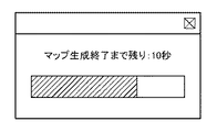
提示部1070は、マップの生成を開始してからの経過時間、マップ生成の残り時間等、現在のマップ生成の進捗状況を表す情報を表示部200に対して送出するので、表示部200には、このような進捗状況が表示される。例えば、図3に示す如く、マップ生成が終了するまでの残り時間(図3では残り時間は10秒)を、文字情報とプログレスバーとを併用して通知するためのウィンドウを表示部200に表示させる。また、現在のマップ生成の進捗状況を音声としてユーザに通知するようにしても構わない。このように、現在のマップ生成の進捗状況をユーザに通知するための方法には様々な方法が考えられ、如何なる方法を採用しても構わない。
<Step S2100>
Since the
このように、本実施形態では、カメラ100の位置姿勢の推定を開始したことに応じて規定の期間だけマップ生成を行い、マップ生成の終了後は、それまでに生成されたマップに基づいて、カメラ100の位置姿勢を推定する。このような構成により、マップを生成し続けることがなくなるため、メモリの上限に達してオーバーフローしてしまうことや、計算に使用される情報量が増えることによって処理負荷が高くなりフレームレートが落ちるということを避けることができる。
As described above, in the present embodiment, the map is generated for a predetermined period according to the start of the estimation of the position and orientation of the
また、どれくらいの間マップ生成を行うのか、いつマップ生成を終了させるのか、というようなカメラ位置姿勢推定技術の専門的な知識がなくても、自動的にマップ生成に要する時間を設定することができる。そのため、ユーザの負担を軽減し、簡便に複合現実感を体験できるようになる。 In addition, it is possible to automatically set the time required for map generation without having specialized knowledge of camera position / orientation estimation technology such as how long the map is generated and when the map generation is finished. it can. Therefore, the burden on the user can be reduced and the mixed reality can be easily experienced.
以下では、本実施形態の変形例について説明する。なお、本実施形態の変形例1−1及び変形例1−2では、第1の実施形態との差分について重点的に説明し、特に触れない限りは、第1の実施形態と同様であるものとする。 Hereinafter, a modified example of the present embodiment will be described. In the modified examples 1-1 and 1-2 of the present embodiment, the differences from the first embodiment will be mainly described, and unless otherwise specified, they are the same as those of the first embodiment. And.
<変形例1−1>
第1の実施形態では、計時開始からマップ生成時間が経過した場合にマップの生成を終了させていたが、マップの生成の終了条件はこれに限るものではない。本変形例では、計時を開始して以降、マップの生成及び追加登録がなされない連続時間Tを別途計時し、連続時間Tが閾値を超えた時点でマップの生成を終了させるようにしても構わない。
<Modification 1-1>
In the first embodiment, the map generation is terminated when the map generation time has elapsed from the start of the timekeeping, but the end condition of the map generation is not limited to this. In this modification, the continuous time T for which map generation and additional registration are not performed after the start of time counting may be separately timed, and the map generation may be terminated when the continuous time T exceeds the threshold value. Absent.
本変形例に係る情報処理装置の動作について、図4のフローチャートに従って説明する。図4のフローチャートにおいて、図2に示した処理ステップと同じ処理ステップには同じステップ番号を付しており、該処理ステップに係る説明は省略する。 The operation of the information processing apparatus according to this modification will be described with reference to the flowchart of FIG. In the flowchart of FIG. 4, the same processing step as the processing step shown in FIG. 2 is assigned the same step number, and the description relating to the processing step will be omitted.
<ステップS3010>
設定部1040は、マップの生成及び追加登録がなされない連続時間Tを計時する。
<Step S3010>
The
<ステップS3020>
設定部1040は、連続時間Tが閾値Tthを超えたか否かを判断する。閾値Tthは、例えば、60秒などに設定しておいてもよい。この判断の結果、連続時間Tが閾値Tthを超えた場合には、処理はステップS3030に進み、連続時間Tが閾値Tthを超えていない場合には、処理はステップS2050に進む。連続時間Tが閾値Tthを超える場合とは、例えば、次のキーフレームが登録されるまで時間がかかってしまったりして、マップの生成条件を満たさない場合である。
<Step S3020>
The
<ステップS3030>
設定部1040は、マップ生成時間を0に再設定する。その後、処理はステップS2050に戻るが、ステップS2060では何も処理は行わず、ステップS2070では、マップ生成時間=0であるため、処理はステップS2090に進み、マップの生成は終了する。
<Step S3030>
The
このように、本実施形態によれば、マップが十分に生成されて新たなマップが追加されなくなった場合などに、自動的にマップ生成を停止することができる。これにより、ユーザはいつマップ生成を停止すればよいのかを考慮する必要がなくなる。したがって、前提知識を持たないユーザであっても簡便に使用することができる。また、処理負荷の高いマップ生成を続ける必要がなくなるため、処理負荷を軽減することができる。 As described above, according to the present embodiment, the map generation can be automatically stopped when the map is sufficiently generated and a new map is not added. This eliminates the need for the user to consider when to stop map generation. Therefore, even a user who does not have the prerequisite knowledge can easily use it. Further, since it is not necessary to continue generating a map having a high processing load, the processing load can be reduced.
<変形例1−2>
変形例1−1では、新たなマップが追加されない連続時間Tを計時し、該連続時間Tが閾値Tthを超えた場合には、マップ生成時間を0に設定してマップ生成を停止していた。しかし、新たにマップが追加されるのは、ユーザが位置や姿勢を変えながら動いた場合である。そのため、ユーザが動かず止まっている場合には、十分な数のマップが生成されないままその生成が停止してしまう可能性がある。このように、ケースによっては、マップ生成を停止する必要がない場合がある。
<Modification 1-2>
In the modified example 1-1, the continuous time T in which a new map is not added is timed, and when the continuous time T exceeds the threshold value Tth, the map generation time is set to 0 and the map generation is stopped. .. However, a new map is added when the user moves while changing the position or posture. Therefore, if the user is stuck and stopped, there is a possibility that the generation will stop without generating a sufficient number of maps. Thus, in some cases, it may not be necessary to stop map generation.
そこで本変形例では、変形例1−1の構成において更に、ユーザが動かず止まっているかどうかを判定し、その判断結果をも参酌して、マップ生成を停止させるのか否かを決定する。本変形例に係る情報処理装置の動作について、図5のフローチャートに従って説明する。図5のフローチャートにおいて、図4に示した処理ステップと同じ処理ステップには同じステップ番号を付しており、該処理ステップに係る説明は省略する。 Therefore, in the present modification, in the configuration of the modification 1-1, it is further determined whether or not the user is stationary and stopped, and whether or not to stop the map generation is determined by taking the determination result into consideration. The operation of the information processing apparatus according to this modification will be described with reference to the flowchart of FIG. In the flowchart of FIG. 5, the same processing step as the processing step shown in FIG. 4 is assigned the same step number, and the description relating to the processing step will be omitted.
ステップS3020において、連続時間Tが閾値Tthを超えた場合には、処理はステップS3040に進み、連続時間Tが閾値Tthを超えていない場合には、処理はステップS2050に進む。 In step S3020, if the continuous time T exceeds the threshold value Tth, the process proceeds to step S3040, and if the continuous time T does not exceed the threshold value Tth, the process proceeds to step S2050.
<ステップS3040>
位置姿勢推定部1030は、前(過去)のフレームについて推定した位置(姿勢)と現フレームについて推定した位置(姿勢)との差分(絶対値)を求め、該差分の累積加算値を変化量Dとして求める。変化量Dは、位置成分のみについて求めても良いし、姿勢成分のみについて求めても良いし、両方の成分について求めても良い。
<Step S3040>
The position /
<ステップS3050>
位置姿勢推定部1030は、ステップS3040で求めた変化量Dが閾値Dthを超えているか否かを判断する。この判断の結果、変化量Dが閾値Dthを超えている場合には、処理はステップS3030に進み、変化量Dが閾値Dthを超えていない場合には、処理はステップS2050に戻る。
<Step S3050>
The position /
このような処理により、新たなマップが追加されなくなった場合であっても、カメラ100の位置姿勢の変化量が小さい場合には、ユーザが動いていないと判定することができ、自動的にマップ生成を停止することをしない。一方で、カメラ100の位置姿勢が所定の変化量よりも大きく動いているにも関わらず、新たにマップが追加されない場合には、マップ生成を停止することができる。
By such processing, even if a new map is not added, if the amount of change in the position and orientation of the
これにより、ユーザはいつマップ生成を停止すればよいのかを考慮する必要がなくなる。したがって、前提知識を持たないユーザであっても簡便に使用することができる。また、処理負荷の高いマップ生成を続ける必要がなくなるため、処理負荷を軽減することができる。 This eliminates the need for the user to consider when to stop map generation. Therefore, even a user who does not have the prerequisite knowledge can easily use it. Further, since it is not necessary to continue generating a map having a high processing load, the processing load can be reduced.
[第2の実施形態]
第1の実施形態では、カメラ位置姿勢推定とマップ生成とを並行して行う手法において、推定されたカメラ位置姿勢の入力を受けるとマップ生成時間を設定して計時を開始すると共にマップ生成を開始していた。そして、計時した時間がマップ生成時間を経過すると、マップ生成を終了した。しかしながら、マップ生成時間を設定する方法はこのような手法に限るものではない。例えば、複合現実感を体験する範囲が広い場合、生成すべきマップ数は多くなるため、複合現実感を体験する範囲が狭い場合に比べてより多いマップ生成時間が必要となる。このように、必要なマップ生成時間は、ケースに応じて異なるのが普通であるが、第1の実施形態のように、規定の1種類のマップ生成時間を設定してしまうと、ケースによっては十分なマップを生成することができず、マップが生成できない範囲ができてしまう。このように、複合現実感を体験する範囲に合わせてマップを生成することが望ましい。そこで、本実施形態では、カメラ位置姿勢推定とマップ生成とを並行して行う手法において、カメラの移動距離に基づいてマップ生成時間を設定する。以下では、第1の実施形態との差分について重点的に説明し、以下で特に触れない限りは、第1の実施形態と同様であるものとする。
[Second Embodiment]
In the first embodiment, in a method in which camera position / orientation estimation and map generation are performed in parallel, when the estimated camera position / orientation is input, the map generation time is set, timing is started, and map generation is started. Was. Then, when the timed time passed the map generation time, the map generation was completed. However, the method of setting the map generation time is not limited to such a method. For example, when the range of experiencing mixed reality is wide, the number of maps to be generated increases, so that more map generation time is required than when the range of experiencing mixed reality is narrow. As described above, the required map generation time is usually different depending on the case, but if one specified type of map generation time is set as in the first embodiment, it may be different depending on the case. It is not possible to generate a sufficient map, and there will be a range where the map cannot be generated. In this way, it is desirable to generate a map according to the range in which mixed reality is experienced. Therefore, in the present embodiment, the map generation time is set based on the moving distance of the camera in the method of performing the camera position / orientation estimation and the map generation in parallel. In the following, the differences from the first embodiment will be mainly described, and unless otherwise specified below, the same as the first embodiment.
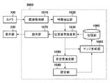
先ず、本実施形態に係る情報処理装置の構成例について、図6のブロック図を用いて説明する。図6において、図1に示した機能部と同じ機能部には同じ参照番号を付しており、該機能部に係る説明は省略する。情報処理装置2000は、情報処理装置1000の構成に分布取得部1080を加えたものである。
First, a configuration example of the information processing apparatus according to the present embodiment will be described with reference to the block diagram of FIG. In FIG. 6, the same functional unit as the functional unit shown in FIG. 1 is assigned the same reference number, and the description relating to the functional unit will be omitted. The
分布取得部1080は、カメラ100の現在位置(位置姿勢推定部1030が最近推定した位置)と、カメラ100の初期位置(予め測定若しくは取得されて記憶部1060に登録されている)と、の間の距離(移動距離)を求める。
The
設定部1040は、分布取得部1080が求めた移動距離に応じたマップ生成時間を設定する。
The
次に、情報処理装置2000の動作について、図7のフローチャートに従って説明する。なお、図7のフローチャートにおいて、図2に示した処理ステップと同じ処理ステップには同じステップ番号を付しており、該処理ステップに係る説明は省略する。
Next, the operation of the
<ステップS2110>
分布取得部1080は、位置姿勢推定部1030が最近推定した位置と、カメラ100の初期位置と、の間の距離(移動距離)を求める。なお、移動距離の求め方はこれに限るものではなく、例えば、GPS等を用いてカメラ100の初期位置からの移動経路を求めて、該移動経路の距離を移動距離として求めても良い。
<Step S2110>
The
ステップS2060では第1の実施形態と同様に、カメラ100の位置姿勢の推定処理を開始したことをトリガにしてマップ生成時間を設定するのであるが、初回は第1の実施形態と同様に、予め設定されている時間をマップ生成時間として設定する。そして2回目以降は、ステップS2110において求めた移動距離に応じたマップ生成時間を設定する。
In step S2060, as in the first embodiment, the map generation time is set by using the start of the estimation process of the position and orientation of the
例えば、閾値を3m、追加マップ生成時間を60秒とした場合、カメラ100の初期位置からの移動距離が3mを超えた時点で、現在設定されているマップ生成時間に60秒を加算して該マップ生成時間を更新する。そしてその後、カメラ100が移動した結果、カメラ100の初期位置からの移動距離が6mを超えた時点で、現在設定されているマップ生成時間に更に60秒を加算して該マップ生成時間を更新する。このようにして、初期位置から遠くなるほど、移動空間が大きいものと判断して、マップ生成時間をより大きくする。然るに、このような傾向でマップ生成時間を更新するのであれば、その更新方法やタイミングについてはこの例に限らない。
For example, when the threshold value is 3 m and the additional map generation time is 60 seconds, when the moving distance from the initial position of the
このような処理により、カメラ100の移動距離に応じて、すなわち、移動空間のサイズに応じてマップ生成時間を調整することができ、これにより、カメラの移動範囲に合わせてマップを生成することができる。
By such processing, the map generation time can be adjusted according to the moving distance of the
また、どれくらいの間マップ生成をおこなえばよいのか、またはいつマップ生成をやめればよいかをカメラ位置姿勢推定技術の専門的な知識がなくても、自動的にマップ生成に要する時間を設定することができる。そのため、ユーザの負担を軽減し、簡便に複合現実感を体験できるようになる。 In addition, it is necessary to automatically set the time required for map generation, even if you do not have specialized knowledge of camera position / orientation estimation technology, how long you should perform map generation or when you should stop map generation. Can be done. Therefore, the burden on the user can be reduced and the mixed reality can be easily experienced.
以下では、本実施形態の変形例について説明する。なお、本実施形態の変形例2−1及び変形例2−2では、第2の実施形態との差分について重点的に説明し、特に触れない限りは、第2の実施形態と同様であるものとする。 Hereinafter, a modified example of the present embodiment will be described. In the modified examples 2-1 and 2-2 of the present embodiment, the differences from the second embodiment will be mainly described, and unless otherwise specified, they are the same as those of the second embodiment. And.
<変形例2−1>
第2の実施形態では、カメラ100の移動距離が大きいほどマップ生成時間を延長していたが、マップ生成時間の延長方法はこれに限るものではない。本変形例では、記憶部1060に登録されているキーフレームの数に応じてマップ生成時間を延長する。
<Modification 2-1>
In the second embodiment, the map generation time is extended as the moving distance of the
本変形例に係る情報処理装置の動作について、図8のフローチャートに従って説明する。なお、図8のフローチャートにおいて、図7に示した処理ステップと同じ処理ステップには同じステップ番号を付しており、該処理ステップに係る説明は省略する。 The operation of the information processing apparatus according to this modification will be described with reference to the flowchart of FIG. In the flowchart of FIG. 8, the same processing step as the processing step shown in FIG. 7 is assigned the same step number, and the description of the processing step will be omitted.
<ステップS4010>
分布取得部1080は、記憶部1060に登録されているキーフレームの数Nをカウントする。
<Step S4010>
The
<ステップS4020>
分布取得部1080は、ステップS4010でカウントしたキーフレームの数Nが閾値Nth未満であるか否かを判断する。この判断の結果、キーフレームの数Nが閾値Nth未満である場合には、処理はステップS4030に進み、キーフレームの数Nが閾値Nth以上である場合には、処理はステップS2050に進む。
<Step S4020>
The
ここで、閾値Nthは、カメラ100の画角のオーバーラップが50%得られる場合の変化量に基づいて決定する。例えば、水平画角60度のカメラで水平360度をカバーする際には、12枚のキーフレームがあればよいため、閾値Nthを12とすることができる。しかし、閾値Nthの決定方法はこれに限るものはなく、実験によって十分な精度を得られるキーフレーム数から求めてもよいし、何れの公知の手法で求めてもよい。
Here, the threshold value Nth is determined based on the amount of change when the overlap of the angles of view of the
<ステップS4030>
設定部1040は、現在設定されているマップ生成時間を延長する。延長分はどのような値であっても良く、規定の値であっても良いし、キーフレームの数Nに応じた値であっても良い。
<Step S4030>
The
このような処理により、登録済みのキーフレームの数が少ないと判定される場合には、マップ生成時間を延長することで、マップ生成が不十分なために、カメラ位置姿勢の推定が正しく行えないということを避けることができる。 If it is determined that the number of registered keyframes is small by such processing, the camera position and orientation cannot be estimated correctly because the map generation is insufficient by extending the map generation time. You can avoid that.
<変形例2−2>
第2の実施形態では、カメラ100の移動距離を求め、該求めた移動距離に応じてマップ生成時間を調整していた。しかし、カメラ100の移動可能な範囲が予め分かっている場合には、ユーザが不図示の操作部を操作してその範囲を入力し、設定部1040は、入力された範囲に応じたマップ生成時間を設定するようにしても構わない。
<Modification 2-2>
In the second embodiment, the moving distance of the
例えば、ユーザが不図示の操作部を操作して、カメラ100の移動範囲として「3m×3mの床面」を入力した場合、設定部1040は、これに対応するマップ生成時間として60秒を設定する。また、ユーザが不図示の操作部を操作して、カメラ100の移動範囲として「6m×6mの床面」を入力した場合には、設定部1040は、これに対応するマップ生成時間として360秒を設定する。このような場合、記憶部1060には、各移動範囲に対応するマップ生成時間が予め登録されており、設定部1040は、ユーザが入力した移動範囲に応じたマップ生成時間を記憶部1060から取得することができる。なお、ユーザが入力した移動範囲に対応するマップ生成時間が登録されていない場合には、該移動範囲の近傍の登録済みの移動範囲に対応するマップ生成時間から補間により求めても良い。
For example, when the user operates an operation unit (not shown) and inputs "3 m × 3 m floor surface" as the movement range of the
[第3の実施形態]
特徴点の誤検出やマッチングの誤対応などにより、推定したカメラ位置姿勢の精度が低くなった場合、そのようなカメラ位置姿勢に基づくマップ生成を継続すると、結果として生成されるマップの精度が悪くなる。マップの精度が悪くなると、さらにカメラ位置姿勢の推定精度が悪くなってしまう。
[Third Embodiment]
If the accuracy of the estimated camera position / orientation becomes low due to erroneous detection of feature points or erroneous matching, if map generation based on such camera position / orientation is continued, the accuracy of the resulting map will be poor. Become. If the accuracy of the map deteriorates, the estimation accuracy of the camera position and orientation will further deteriorate.
そのため、本実施形態では、カメラ位置姿勢の安定性が低い場合には、マップ生成時間を一時的に0秒にすることでマップ生成を停止し、カメラ位置姿勢の安定性が高くなった場合に、所定のマップ生成時間を設定する。以下では、第1の実施形態との差分について重点的に説明し、以下で特に触れない限りは、第1の実施形態と同様であるものとする。 Therefore, in the present embodiment, when the stability of the camera position / orientation is low, the map generation is stopped by temporarily setting the map generation time to 0 seconds, and the stability of the camera position / orientation becomes high. , Set a predetermined map generation time. In the following, the differences from the first embodiment will be mainly described, and unless otherwise specified below, the same as the first embodiment.
本実施形態に係る情報処理装置の構成例について、図9のブロック図を用いて説明する。図9において、図1に示した機能部と同じ機能部には同じ参照番号を付しており、該機能部に係る説明は省略する。図9の情報処理装置3000は、情報処理装置1000に安定度推定部1090を加えたものである。
A configuration example of the information processing apparatus according to the present embodiment will be described with reference to the block diagram of FIG. In FIG. 9, the same functional unit as that shown in FIG. 1 is designated by the same reference number, and the description of the functional unit will be omitted. The
安定度推定部1090は、位置姿勢推定部1030が推定した位置姿勢の安定度を推定する。位置姿勢の安定度は、時系列に取得されるフレーム画像間でのカメラ100の位置及び/又は姿勢の変化量に基づいて推定する。変化量が閾値よりも大きい場合には、安定度を低く設定し、変化量が小さい場合には安定度を高く設定する。また、カメラ位置姿勢を推定する際の最適化計算において、誤差関数として再投影誤差を最小化する場合には、検出した特徴点の再投影誤差の分散であってもよい。また、特徴点周辺の輝度値を最小化する場合には、輝度値の分散であってもよい。また、カメラ位置姿勢の安定度は、公知の何れの手法によって求めてもよい。
The
次に、情報処理装置3000の動作について、図10のフローチャートに従って説明する。なお、図10のフローチャートにおいて、図2の処理ステップと同じ処理ステップには同じステップ番号を付しており、該処理ステップに係る説明は省略する。
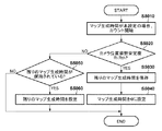
Next, the operation of the
<ステップS2120>
安定度推定部1090は、位置姿勢推定部1030が推定した位置姿勢の安定度を推定する。時系列で入力されるフレーム画像の撮像位置または撮像姿勢が、連続したフレーム画像間で所定の距離または姿勢変化量より大きい場合には、カメラ位置姿勢の推定に失敗している可能性があるため、安定度を低く設定する。
<Step S2120>
The
<ステップS2160>
設定部1040は、ステップS2120において推定した安定度に応じたマップ生成時間を設定する。ステップS2160の処理の詳細について、図11のフローチャートに従って説明する。
<Step S2160>
The
<ステップS5010>
設定部1040は(カメラ100の位置姿勢の推定処理を開始したことをトリガにして)、マップ(初期マップを除く)の生成期間として予め設定されている時間をマップ生成時間として設定すると共に、計時を開始する。なお、計時開始以降は、本ステップではマップ生成時間の設定は行わない。
<Step S5010>
The setting unit 1040 (triggered by the start of the position / orientation estimation process of the camera 100) sets a preset time as the map generation period (excluding the initial map) as the map generation time, and clocks the map. To start. After the start of timekeeping, the map generation time is not set in this step.
<ステップS5020>
設定部1040は、ステップS2120において推定した安定度Rが閾値Rth未満であるのか否かを判断する。この判断の結果、安定度Rが閾値Rth未満である場合には、処理はステップS5030に進み、安定度Rが閾値Rth以上である場合には、処理はステップS5050に進む。
<Step S5020>
The
<ステップS5030>
設定部1040は、マップ生成時間からステップS5010で計時を開始してからの経過時間を差し引いた残りの時間、すなわち、マップ生成のための残りの時間を求め、該求めた残りの時間を記憶部1060に格納する。
<Step S5030>
The
<ステップS5040>
設定部1040は、マップ生成時間を0に再設定する。その後、処理はステップS2070に進み。ステップS2070では、マップ生成時間=0であるため、処理はステップS2090に進み、マップの生成は終了する。
<Step S5040>
The
<ステップS5050>
設定部1040は、記憶部1060にステップS5030で格納した「残りの時間」が格納されているのか否かを判断する。この判断の結果、記憶部1060に「残りの時間」が格納されている場合には処理はステップS5060に進み、格納されていない場合には、処理はステップS2070に進む。
<Step S5050>
The
<ステップS5060>
設定部1040は、記憶部1060に格納されている「残りの時間」をマップ生成時間として設定する。
<Step S5060>
The
このような処理により、マップの精度が悪くなることを避け、カメラ位置姿勢の安定度が高いときのみマップ生成を行うことができるため、精度のよいマップ生成を行うことができる。 By such processing, it is possible to avoid deteriorating the accuracy of the map and to generate the map only when the stability of the camera position and orientation is high, so that it is possible to generate the map with high accuracy.
以下では、本実施形態の変形例について説明する。なお、本実施形態の変形例3−1及び変形例3−2では、第3の実施形態との差分について重点的に説明し、特に触れない限りは、第3の実施形態と同様であるものとする。 Hereinafter, a modified example of the present embodiment will be described. In the modified examples 3-1 and 3-2 of the present embodiment, the differences from the third embodiment will be mainly described, and unless otherwise specified, they are the same as those of the third embodiment. And.
<変形例3−1>
第3の実施形態では、カメラ100の位置姿勢の安定度に応じて、マップ生成の停止と再開を制御していたが、マップ生成の再開の制御方法はこれ以外の方法も考え得る。本変形例では、マップ生成時間が経過してマップ生成が終わった後、再度マップ生成を再開させる例について説明する。
<Modification 3-1>
In the third embodiment, the stop and restart of map generation are controlled according to the stability of the position and orientation of the
マップの特徴点を現在の撮影位置で撮影した画像に投影して、検出した特徴点と投影された特徴点との誤差を最小化するようにカメラ位置姿勢を推定する手法において、投影される特徴点が少ない場合に、マップ生成を再開してもよい。投影される特徴点が閾値より多いか否かを判断し、少ない場合にマップ生成時間に予め設定された時間を設定することで、マップ生成を再開してもよい。投影される特徴点が少ないということは、登録されている特徴点が少ないといえるため、追加で生成することが望ましい。 Projected features in a method that projects the feature points of a map onto an image taken at the current shooting position and estimates the camera position and orientation so as to minimize the error between the detected feature points and the projected feature points. Map generation may be resumed when there are few points. Map generation may be restarted by determining whether or not the projected feature points are more than the threshold value and setting a preset time for the map generation time when the number is less. Since it can be said that there are few registered feature points when the number of projected feature points is small, it is desirable to additionally generate them.
このような構成により、いったんマップ生成を終えたあとに、カメラ位置姿勢推定技術の専門的な知識がなくても、自動的にマップ生成を再開することができる。そのため、ユーザの負担を軽減し、簡便に複合現実感を体験できるようになる。 With such a configuration, once the map generation is completed, the map generation can be automatically restarted without any specialized knowledge of the camera position / orientation estimation technique. Therefore, the burden on the user can be reduced and the mixed reality can be easily experienced.
<変形例3−2>
変形例3−1では、カメラ位置姿勢の推定時に利用される特徴点の数に応じて、マップ生成を再開する方法について説明した。本変形例では、マップ生成を開始する方法について述べる。
<Modification example 3-2>
In the modified example 3-1 the method of restarting the map generation according to the number of feature points used when estimating the camera position and orientation has been described. In this modification, a method of starting map generation will be described.
既知の指標が検出されるとマップ生成を開始してもよい。さらに、既知の指標を連続検出するフレームの数が閾値以上となった場合に、マップ生成を開始してもよい。また、マップ生成をいったん終えたあとに、識別可能な指標でかつ予め登録しておいた指標を検出すると、マップ生成を再開してもよい。 Map generation may be initiated when known indicators are detected. Further, map generation may be started when the number of frames for continuously detecting a known index exceeds the threshold value. Further, once the map generation is completed, if an identifiable index and a pre-registered index are detected, the map generation may be restarted.
ここで指標について説明する。図12に示す如く、四角形形状の指標(以下、四角形指標と呼ぶ)は、内部に識別子を表すパターンを持ち、一意に同定可能であるとする。また、撮影画像に2値化処理を施した後にラベリング処理を行い、一定面積以上の領域の中から4つの直線によって形成されているものを候補領域として抽出する。さらに、候補領域の中に特定のパターンがあるか否かを判定することによって候補領域が指標領域であるかを判定し、内部のパターンを読み出すことによって指標の画像内の方向と識別子を取得することにより、取得された画像中から指標を検出する。 The index will be described here. As shown in FIG. 12, it is assumed that the quadrangular index (hereinafter referred to as a quadrilateral index) has a pattern representing an identifier inside and can be uniquely identified. Further, after the captured image is binarized, the labeling process is performed, and an area formed by four straight lines is extracted as a candidate area from the areas having a certain area or more. Further, it is determined whether the candidate area is an index area by determining whether or not there is a specific pattern in the candidate area, and the direction and identifier in the image of the index are acquired by reading the internal pattern. By doing so, the index is detected from the acquired image.
なお、指標は、四角形指標に限るものではなく、撮影画像上において検出可能であって、かついずれの指標であるのかを識別可能である指標であれば、何れの形態であってもよい。例えば、図13に示すように、それぞれが異なる色を有する円形状の指標のような点指標であってもよい。この場合には、画像上から各々の指標の色に対応する領域を検出し、その重心位置を指標の検出座標とする。また、それぞれが異なるテクスチャ特徴を有する特徴点(自然特徴点)を点指標としてもよい。この場合には、既知の情報として予め保持している各々の指標のテンプレート画像によるテンプレートマッチングを画像上に施すことにより、画像から指標を抽出する。これに限らず、空間中に固定される指標であって、それを撮影した画像から検出可能なものであればどのような指標であってもかまわない。 The index is not limited to the quadrilateral index, and may be in any form as long as it can be detected on the captured image and which index can be identified. For example, as shown in FIG. 13, it may be a point index such as a circular index in which each has a different color. In this case, the region corresponding to the color of each index is detected on the image, and the position of the center of gravity thereof is used as the detection coordinate of the index. Further, a feature point (natural feature point), each of which has a different texture feature, may be used as a point index. In this case, the index is extracted from the image by performing template matching on the image by the template image of each index held in advance as known information. Not limited to this, any index may be used as long as it is an index fixed in space and can be detected from the captured image.
以上のように、識別可能な指標を検出することで、マップ生成の開始を決定することができる。カメラ位置姿勢推定技術の専門的な知識がなくても、指標を検出するだけで自動的にマップ生成を開始または再開することができる。そのため、ユーザの負担を軽減し、簡便に複合現実感を体験できるようになる。 As described above, the start of map generation can be determined by detecting the identifiable index. Map generation can be automatically started or restarted simply by detecting an index without having specialized knowledge of camera position / orientation estimation technology. Therefore, the burden on the user can be reduced and the mixed reality can be easily experienced.
[第4の実施形態]
図1,6,9に示した各機能部はハードウェアで構成しても良いが、画像取得部1010及び記憶部1060をハードウェアで構成し、残りの機能部の1以上をソフトウェアで構成しても構わない。このような場合、画像取得部1010及び記憶部1060をハードウェアとして有し、該ソフトウェアを実行可能な処理部を有するコンピュータ装置は、情報処理装置1000,2000,3000に適用可能である。情報処理装置1000,2000,3000に適用可能なコンピュータ装置のハードウェア構成例について、図14のブロック図を用いて説明する。
[Fourth Embodiment]
Each of the functional units shown in FIGS. 1, 6 and 9 may be configured by hardware, but the
CPU4001は、RAM4002やROM4003に格納されているコンピュータプログラムやデータを用いて処理を実行する。これによりCPU4001は、コンピュータ装置全体の動作制御を行うと共に、情報処理装置1000,2000,3000が行うものとして上述した各処理を実行若しくは制御する。
The
RAM4002は、外部記憶装置4007や記憶媒体ドライブ4008からロードされたコンピュータプログラムやデータ、I/F(インターフェース)4009を介して外部から受信したデータ、を格納するためのエリアを有する。更に、RAM4002は、CPU4001が各種の処理を実行する際に用いるワークエリアを有する。このようにRAM4002は、各種のエリアを適宜提供することができる。なお、RAM4002は、上記の記憶部1060として使用可能である。
The
ROM4003には、コンピュータ装置の書き換え不要な設定データや、ブートプログラムなどが格納されている。
The
キーボード4004,マウス4005は、ユーザが操作することで各種の指示をCPU4001に対して入力するためのユーザインターフェースの一例である。表示部4006は、CRTや液晶画面などにより構成されており、CPU4001による処理結果を画像や文字などでもって表示することができる。なお、キーボード4004、マウス4005、表示部200の代わりにタッチパネル画面を設けても構わない。
The
外部記憶装置4007は、ハードディスクドライブ装置に代表される大容量情報記憶装置である。外部記憶装置4007には、OS(オペレーティングシステム)や、図1,6,9において画像取得部1010及び記憶部1060以外の各機能部の動作をCPU4001に実行させるためのコンピュータプログラムやデータが保存されている。このデータには、上記の閾値など、既知の情報として説明したものも含まれている。外部記憶装置4007に保存されているコンピュータプログラムやデータは、CPU4001による制御に従って適宜RAM4002にロードされ、CPU4001による処理対象となる。なお、外部記憶装置4007は、上記の記憶部1060として使用可能である。
The
記憶媒体ドライブ4008は、CD−ROMやDVD−ROM等の記憶媒体に対するコンピュータプログラムやデータの読み書きが可能な装置であり、読み出したコンピュータプログラムやデータは、RAM4002や外部記憶装置4007に対して出力される。なお、外部記憶装置4007に保存されているものとして説明したコンピュータプログラムやデータの一部若しくは全部をこの記憶媒体に記録しておいても良い。
The
I/F4009は、コンピュータ装置をネットワークや外部機器と接続するためのインターフェースとして機能するものであり、例えば、上記の画像取得部1010の機能も含む。図1,6,9の場合、I/F4009は、カメラ100を接続するためのアナログビデオポートあるいはIEEE1394等のデジタル入出力ポート、また、各種情報を表示部200に対して出力するためのDVIポートなどによって構成される。
The I /
CPU4001、RAM4002、ROM4003、キーボード4004、マウス4005、表示部4006、外部記憶装置4007、記憶媒体ドライブ4008、I/F4009は何れも、バス4010に接続されている。
The
なお、以上説明したそれぞれの実施形態や変形例は、その一部若しくは全部を適宜組み合わせて使用しても構わないし、選択的に使用するようにしても構わない。 It should be noted that each of the above-described embodiments and modifications may be used in combination in part or in whole as appropriate, or may be selectively used.
(その他の実施例)
本発明は、上述の実施形態の1以上の機能を実現するプログラムを、ネットワーク又は記憶媒体を介してシステム又は装置に供給し、そのシステム又は装置のコンピュータにおける1つ以上のプロセッサーがプログラムを読出し実行する処理でも実現可能である。また、1以上の機能を実現する回路(例えば、ASIC)によっても実現可能である。
(Other Examples)
The present invention supplies a program that realizes one or more functions of the above-described embodiment to a system or device via a network or storage medium, and one or more processors in the computer of the system or device reads and executes the program. It can also be realized by the processing to be performed. It can also be realized by a circuit (for example, ASIC) that realizes one or more functions.
1030:位置姿勢推定部 1040:設定部 1050:マップ生成部 1030: Position / orientation estimation unit 1040: Setting unit 1050: Map generation unit
Claims (12)
前記推定手段が推定した位置姿勢に基づいて、未登録の特徴の3次元位置情報を生成して登録する生成手段と
を備え、
前記生成手段は、未登録の特徴の3次元位置情報の生成及び登録を、前記推定手段が前記撮像装置の位置姿勢の推定処理を開始したタイミング、前記撮像装置が撮像したフレーム画像から特徴を検出したタイミング、特徴を連続して抽出したフレーム画像の数が閾値以上となったタイミング、のいずれかのタイミングで開始してから規定の時間が経過するまで実行し、該規定の時間が経過すると停止する
ことを特徴とする情報処理装置。 An estimation means for estimating the position and orientation of the imaging device based on the three-dimensional position information of the registered features and the features in the frame image captured by the imaging device.
It is provided with a generation means for generating and registering three-dimensional position information of unregistered features based on the position / orientation estimated by the estimation means.
The generation means detects the generation and registration of the three-dimensional position information of the unregistered feature from the frame image captured by the image pickup device at the timing when the estimation means starts the estimation process of the position and orientation of the image pickup device. It is executed until the specified time elapses from the start at any of the timings when the information is processed and the timing when the number of frame images in which the features are continuously extracted exceeds the threshold value, and stops when the specified time elapses. An information processing device characterized by
前記撮像装置の初期位置からの距離を取得する手段と、
前記距離に応じて前記規定の時間を更新する手段と
を備えることを特徴とする請求項1に記載の情報処理装置。 In addition
A means for acquiring the distance from the initial position of the image pickup apparatus and
The information processing apparatus according to claim 1, further comprising a means for updating the specified time according to the distance.
前記推定手段が推定した位置もしくは姿勢の変化が閾値以上となるフレーム画像の数に応じて前記規定の時間を更新する手段を備えることを特徴とする請求項1に記載の情報処理装置。 In addition
The information processing apparatus according to claim 1, further comprising means for updating the specified time according to the number of frame images in which the change in position or posture estimated by the estimation means is equal to or greater than a threshold value.
ユーザから前記撮像装置の移動範囲が入力されると、前記規定の時間として該移動範囲に対応する時間を設定する手段を備えることを特徴とする請求項1に記載の情報処理装置。 In addition
The information processing apparatus according to claim 1, further comprising means for setting a time corresponding to the moving range as the specified time when the moving range of the imaging device is input from the user.
前記推定手段が推定した位置及び/又は姿勢の変化量に応じて前記規定の時間を更新する手段を備えることを特徴とする請求項1に記載の情報処理装置。 In addition
The information processing apparatus according to claim 1, further comprising means for updating the specified time according to the amount of change in the position and / or posture estimated by the estimation means.
未登録の特徴の3次元位置情報の生成及び登録の進捗状況をユーザに通知する手段を備えることを特徴とする請求項1乃至9の何れか1項に記載の情報処理装置。 In addition
The information processing apparatus according to any one of claims 1 to 9 , further comprising means for notifying the user of the generation of three-dimensional position information of unregistered features and the progress of registration.
前記情報処理装置の推定手段が、登録済みの特徴の3次元位置情報と、撮像装置が撮像したフレーム画像における特徴と、に基づいて、前記撮像装置の位置姿勢を推定する推定工程と、
前記情報処理装置の生成手段が、前記推定工程で推定した位置姿勢に基づいて、未登録の特徴の3次元位置情報を生成して登録する生成工程と
を備え、
前記生成工程では、未登録の特徴の3次元位置情報の生成及び登録を、前記推定工程で前記撮像装置の位置姿勢の推定処理を開始したタイミング、前記撮像装置が撮像したフレーム画像から特徴を検出したタイミング、特徴を連続して抽出したフレーム画像の数が閾値以上となったタイミング、のいずれかのタイミングで開始してから規定の時間が経過するまで実行し、該規定の時間が経過すると停止する
ことを特徴とする情報処理方法。 It is an information processing method performed by an information processing device.
An estimation step in which the estimation means of the information processing device estimates the position and orientation of the image pickup device based on the three-dimensional position information of the registered features and the features in the frame image captured by the image pickup device.
The generation means of the information processing apparatus includes a generation step of generating and registering three-dimensional position information of unregistered features based on the position / orientation estimated in the estimation step.
In the generation step, the generation and registration of the three-dimensional position information of the unregistered feature is performed, and the feature is detected from the frame image captured by the image pickup device at the timing when the position and orientation estimation process of the image pickup device is started in the estimation step. It is executed until the specified time elapses from the start at any of the timings when the information is processed and the timing when the number of frame images in which the features are continuously extracted exceeds the threshold, and then stopped when the specified time elapses. An information processing method characterized by doing so.
Priority Applications (2)
| Application Number | Priority Date | Filing Date | Title |
|---|---|---|---|
| JP2015228094A JP6789624B2 (en) | 2015-11-20 | 2015-11-20 | Information processing device, information processing method |
| US15/354,002 US10839544B2 (en) | 2015-11-20 | 2016-11-17 | Information processing apparatus, information processing method, and non-transitory computer readable storage medium |
Applications Claiming Priority (1)
| Application Number | Priority Date | Filing Date | Title |
|---|---|---|---|
| JP2015228094A JP6789624B2 (en) | 2015-11-20 | 2015-11-20 | Information processing device, information processing method |
Publications (3)
| Publication Number | Publication Date |
|---|---|
| JP2017096725A JP2017096725A (en) | 2017-06-01 |
| JP2017096725A5 JP2017096725A5 (en) | 2019-01-10 |
| JP6789624B2 true JP6789624B2 (en) | 2020-11-25 |
Family
ID=58721793
Family Applications (1)
| Application Number | Title | Priority Date | Filing Date |
|---|---|---|---|
| JP2015228094A Active JP6789624B2 (en) | 2015-11-20 | 2015-11-20 | Information processing device, information processing method |
Country Status (2)
| Country | Link |
|---|---|
| US (1) | US10839544B2 (en) |
| JP (1) | JP6789624B2 (en) |
Families Citing this family (14)
| Publication number | Priority date | Publication date | Assignee | Title |
|---|---|---|---|---|
| JP6288060B2 (en) | 2015-12-10 | 2018-03-07 | カシオ計算機株式会社 | Autonomous mobile device, autonomous mobile method and program |
| JP6311695B2 (en) | 2015-12-16 | 2018-04-18 | カシオ計算機株式会社 | Autonomous mobile device, autonomous mobile method and program |
| JP6323439B2 (en) | 2015-12-17 | 2018-05-16 | カシオ計算機株式会社 | Autonomous mobile device, autonomous mobile method and program |
| JP6775969B2 (en) * | 2016-02-29 | 2020-10-28 | キヤノン株式会社 | Information processing equipment, information processing methods, and programs |
| JP6187623B1 (en) * | 2016-03-14 | 2017-08-30 | カシオ計算機株式会社 | Autonomous mobile device, autonomous mobile method and program |
| US10535160B2 (en) * | 2017-07-24 | 2020-01-14 | Visom Technology, Inc. | Markerless augmented reality (AR) system |
| US10282913B2 (en) | 2017-07-24 | 2019-05-07 | Visom Technology, Inc. | Markerless augmented reality (AR) system |
| US11003939B2 (en) * | 2018-07-06 | 2021-05-11 | Canon Kabushiki Kaisha | Information processing apparatus, information processing method, and storage medium |
| JP7227717B2 (en) * | 2018-08-31 | 2023-02-22 | キヤノン株式会社 | Information processing device, method, and program |
| WO2020045186A1 (en) * | 2018-08-31 | 2020-03-05 | キヤノン株式会社 | Information processing device, method, and program |
| JP7129283B2 (en) * | 2018-08-31 | 2022-09-01 | キヤノン株式会社 | Processing device, control method, and program |
| JP7360243B2 (en) | 2019-02-15 | 2023-10-12 | キヤノン株式会社 | Information processing device, information processing method, program |
| JP6959295B2 (en) * | 2019-04-22 | 2021-11-02 | 日鉄ソリューションズ株式会社 | Information processing system, information processing device, information processing method, program and storage medium |
| JP2023104609A (en) * | 2022-01-18 | 2023-07-28 | 株式会社ソニー・インタラクティブエンタテインメント | Information processing apparatus and information processing method |
Family Cites Families (12)
| Publication number | Priority date | Publication date | Assignee | Title |
|---|---|---|---|---|
| JP2003266345A (en) * | 2002-03-18 | 2003-09-24 | Sony Corp | Path planning device, path planning method, path planning program, and moving robot device |
| JP4533090B2 (en) * | 2004-05-14 | 2010-08-25 | キヤノン株式会社 | Index calibration apparatus and information processing method |
| US7613361B2 (en) * | 2004-05-14 | 2009-11-03 | Canon Kabushiki Kaisha | Information processing method and device |
| US8303505B2 (en) * | 2005-12-02 | 2012-11-06 | Abbott Cardiovascular Systems Inc. | Methods and apparatuses for image guided medical procedures |
| US20080256474A1 (en) * | 2007-04-16 | 2008-10-16 | Al Chakra | Interactive Progress Bar |
| JP5141507B2 (en) * | 2008-08-25 | 2013-02-13 | 村田機械株式会社 | Autonomous mobile device |
| US9003423B1 (en) * | 2011-07-29 | 2015-04-07 | Amazon Technologies, Inc. | Dynamic browser compatibility checker |
| US8913821B1 (en) * | 2011-09-26 | 2014-12-16 | Google Inc. | Preconditioner for solving linear equations for reconstructing three-dimensional structure of a scene |
| KR102077305B1 (en) * | 2013-05-09 | 2020-02-14 | 삼성전자 주식회사 | Method and apparatus for providing contents including augmented reality information |
| JP6368142B2 (en) | 2014-05-14 | 2018-08-01 | キヤノン株式会社 | Information processing apparatus and information processing method |
| US20170069138A1 (en) | 2015-09-09 | 2017-03-09 | Canon Kabushiki Kaisha | Information processing apparatus, method for controlling information processing apparatus, and storage medium |
| US9659371B2 (en) * | 2015-10-08 | 2017-05-23 | Christie Digital Systems Usa, Inc. | System and method for online projector-camera calibration from one or more images |
-
2015
- 2015-11-20 JP JP2015228094A patent/JP6789624B2/en active Active
-
2016
- 2016-11-17 US US15/354,002 patent/US10839544B2/en active Active
Also Published As
| Publication number | Publication date |
|---|---|
| US10839544B2 (en) | 2020-11-17 |
| US20170148167A1 (en) | 2017-05-25 |
| JP2017096725A (en) | 2017-06-01 |
Similar Documents
| Publication | Publication Date | Title |
|---|---|---|
| JP6789624B2 (en) | Information processing device, information processing method | |
| JP5388932B2 (en) | Information processing apparatus and control method thereof | |
| US9196093B2 (en) | Information presentation device, digital camera, head mount display, projector, information presentation method and non-transitory computer readable medium | |
| US9696543B2 (en) | Information processing apparatus and information processing method | |
| JP4136859B2 (en) | Position and orientation measurement method | |
| US10930008B2 (en) | Information processing apparatus, information processing method, and program for deriving a position orientation of an image pickup apparatus using features detected from an image | |
| TWI544447B (en) | System and method for augmented reality | |
| JP6338021B2 (en) | Image processing apparatus, image processing method, and image processing program | |
| JP2016167229A (en) | Coordinate transformation parameter determination device, coordinate transformation parameter determination method, and computer program for coordinate transformation parameter determination | |
| KR20170031733A (en) | Technologies for adjusting a perspective of a captured image for display | |
| JP7406875B2 (en) | Information processing equipment and programs | |
| WO2022174594A1 (en) | Multi-camera-based bare hand tracking and display method and system, and apparatus | |
| JP2017134771A (en) | Information processing device, information processing method, and program | |
| JP2018010599A (en) | Information processor, panoramic image display method, panoramic image display program | |
| CN110310325B (en) | Virtual measurement method, electronic device and computer readable storage medium | |
| JP2014026670A (en) | Information processing device, processing method therefor, and program | |
| US20200211275A1 (en) | Information processing device, information processing method, and recording medium | |
| JP7341736B2 (en) | Information processing device, information processing method and program | |
| JP2021009557A (en) | Information processing device, information processing method, and program | |
| JP5726024B2 (en) | Information processing method and apparatus | |
| JP4926598B2 (en) | Information processing method and information processing apparatus | |
| JP6109213B2 (en) | Information processing apparatus and method, program | |
| JP2020173629A (en) | Image processing system, virtual viewpoint video generation system, and control method and program of image processing system | |
| JP6576177B2 (en) | Information processing apparatus, information processing apparatus control method, and program | |
| JP6632298B2 (en) | Information processing apparatus, information processing method and program |
Legal Events
| Date | Code | Title | Description |
|---|---|---|---|
| A521 | Request for written amendment filed |
Free format text: JAPANESE INTERMEDIATE CODE: A523 Effective date: 20181116 |
|
| A621 | Written request for application examination |
Free format text: JAPANESE INTERMEDIATE CODE: A621 Effective date: 20181116 |
|
| A977 | Report on retrieval |
Free format text: JAPANESE INTERMEDIATE CODE: A971007 Effective date: 20190912 |
|
| A131 | Notification of reasons for refusal |
Free format text: JAPANESE INTERMEDIATE CODE: A131 Effective date: 20191025 |
|
| A521 | Request for written amendment filed |
Free format text: JAPANESE INTERMEDIATE CODE: A523 Effective date: 20191217 |
|
| A131 | Notification of reasons for refusal |
Free format text: JAPANESE INTERMEDIATE CODE: A131 Effective date: 20200403 |
|
| A521 | Request for written amendment filed |
Free format text: JAPANESE INTERMEDIATE CODE: A523 Effective date: 20200528 |
|
| TRDD | Decision of grant or rejection written | ||
| A01 | Written decision to grant a patent or to grant a registration (utility model) |
Free format text: JAPANESE INTERMEDIATE CODE: A01 Effective date: 20201005 |
|
| A61 | First payment of annual fees (during grant procedure) |
Free format text: JAPANESE INTERMEDIATE CODE: A61 Effective date: 20201104 |
|
| R151 | Written notification of patent or utility model registration |
Ref document number: 6789624 Country of ref document: JP Free format text: JAPANESE INTERMEDIATE CODE: R151 |