JP2020052901A - Moving object information detecting device, moving object information detecting method, and program - Google Patents
Moving object information detecting device, moving object information detecting method, and program Download PDFInfo
- Publication number
- JP2020052901A JP2020052901A JP2018183842A JP2018183842A JP2020052901A JP 2020052901 A JP2020052901 A JP 2020052901A JP 2018183842 A JP2018183842 A JP 2018183842A JP 2018183842 A JP2018183842 A JP 2018183842A JP 2020052901 A JP2020052901 A JP 2020052901A
- Authority
- JP
- Japan
- Prior art keywords
- object information
- vehicle
- unit
- information
- moving
- Prior art date
- Legal status (The legal status is an assumption and is not a legal conclusion. Google has not performed a legal analysis and makes no representation as to the accuracy of the status listed.)
- Granted
Links
Images


Landscapes
- Traffic Control Systems (AREA)
- Radar Systems Or Details Thereof (AREA)
Abstract
【課題】移動体情報検出装置において、進行方向に並走する移動体を個別に特定した後の各移動体の分離状態を保持することが可能な技術を提供する。【解決手段】車両情報検出装置10の制御部12は、第1判定部124が、個々に特定された二つのオブジェクト情報それぞれに対応する二つの範囲31A,31Bが一つに統合されたか否かを判定し、第1判定部124によって範囲31A,31Bが一つに統合されたと判定された場合に、第1判定部124による判定前の前記二つのオブジェクト情報が示す二つの車両30それぞれの走行方口D11及び前記幅方向D12の位置に基づいて、前記二つのオブジェクト情報の分離状態を維持するか否かを判定する。そして、分離状態を維持すると判定された場合に、車両特定部123が統合された範囲31Cを幅方向D12に二分割し、各範囲31C1,31C2それぞれについてオブジェクト情報を特定する処理を行う。【選択図】図7A moving body information detecting device capable of maintaining the separated state of each moving body after individually specifying the moving bodies running parallel to the direction of travel is provided. A control unit (12) of a vehicle information detection device (10) determines whether or not two ranges (31A, 31B) corresponding to two pieces of individually specified object information are integrated into one. is determined, and when the first determination unit 124 determines that the ranges 31A and 31B are integrated into one, the two vehicles 30 indicated by the two object information before determination by the first determination unit 124 run Based on the direction D11 and the position in the width direction D12, it is determined whether or not to maintain the separation state of the two pieces of object information. Then, when it is determined to maintain the separated state, the vehicle identification unit 123 divides the integrated range 31C into two in the width direction D12, and performs processing to identify object information for each of the ranges 31C1 and 31C2. [Selection drawing] Fig. 7
Description
本発明は、予め定められた検出対象エリアを同じ方向へ移動する複数の移動体の情報を検出する移動体情報検出装置、移動体情報検出方法、及びプログラムに関する。 The present invention relates to a moving object information detecting device, a moving object information detecting method, and a program for detecting information of a plurality of moving objects moving in a predetermined detection target area in the same direction.
従来、周波数が300MHz〜300GHz(波長:1mmから1000mm程度)のマイクロ波と称される電波(電磁波)を被測定物に向けて送信し、被測定物からの反射波を受信し、その反射波を解析することにより被測定物の物性値の情報を計測する技術が知られている。一般に、送信されたマイクロ波がターゲットに到達すると、ターゲットの材質や大きさ、表面形状に応じて散乱、屈折、減衰、遅延(移相)などの作用を受ける。このような作用を受けた反射波を受信し、その振幅や位相情報を送信波と比較することにより、被測定物の物性値情報として、被測定物の材質、形状、大きさ、距離、位置、及びこれらの時間的変化を非接触で計測することができる。 Conventionally, a radio wave (electromagnetic wave) called a microwave having a frequency of 300 MHz to 300 GHz (wavelength: about 1 mm to 1000 mm) is transmitted toward an object to be measured, a reflected wave from the object is received, and the reflected wave is received. There is known a technique of measuring information on physical property values of an object to be measured by analyzing data. In general, when a transmitted microwave reaches a target, the transmitted microwave receives an action such as scattering, refraction, attenuation, and delay (phase shift) according to the material, size, and surface shape of the target. By receiving the reflected wave subjected to such an action and comparing the amplitude and phase information with the transmitted wave, the material value, shape, size, distance, and position of the measured object are used as physical property value information of the measured object. , And their temporal changes can be measured in a non-contact manner.
このような計測技術を利用して、道路を走行する車両の位置や走行速度、長さ(走行方向の長さ)などの車両情報を検出する車両情報検出システムが知られている。前記車両情報検出システムの一例として、ドップラー方式の検出センサ(例えばドップラーレーダ)を用いて、道路を走行する車両の台数を計測する走行車両台数計測装置が公知である(特許文献1参照)。この種の車両情報検出システムでは、これまで、マイクロ波の周波数帯域のうち、所謂24GHz帯域(日本:24.05GHz〜24.25GHz、欧州:24.0GHz〜24.25GHz)の電波が用いられてきた。24GHz帯域の電波は、我が国の高度道路交通システム(ITS:Intelligent Transport Systems)において広く用いられており、また、欧米の各国でも広く採用されている。なお、我が国では、所謂76GHz帯域(76GHz〜77GHz)の電波を一般業務用として利用することが既に認められており、また、一般業務用に対して、所謂79GHz帯域(77GHz〜81GHz)の電波の利用も認められている。 A vehicle information detection system that detects vehicle information such as a position, a traveling speed, and a length (a length in a traveling direction) of a vehicle traveling on a road using such a measurement technique is known. As an example of the vehicle information detection system, a traveling vehicle number measurement device that measures the number of vehicles traveling on a road using a Doppler detection sensor (for example, a Doppler radar) is known (see Patent Document 1). In this type of vehicle information detection system, radio waves in a so-called 24 GHz band (Japan: 24.05 GHz to 24.25 GHz, Europe: 24.0 GHz to 24.25 GHz) have been used up to now. Was. Radio waves in the 24 GHz band are widely used in Intelligent Transport Systems (ITS) in Japan, and are also widely adopted in Europe and the United States. In Japan, the use of radio waves in the so-called 76 GHz band (76 GHz to 77 GHz) has already been approved for general business use, and the use of radio waves in the so-called 79 GHz band (77 GHz to 81 GHz) for general business use has already been approved. Use is also permitted.
昨今、高度道路交通システムにおいて、より高精度の車両情報検出処理が望まれている。しかしながら、従来の車両情報検出システムでは、道路の幅方向の距離分解能が低いため、複数車線を有する走行路において隣接して車両が並走する場合に、これら2つの車両を一つの車両と判定する誤検出が生じるおそれがある。具体的には、車両検出エリアに別々に進入した速度の異なる二つの車両が車両検出エリア内で横並びになると、進入直後に各車両が個別に特定されていたにもかかわらず、横並びになった場合に二つの車両が一つと判定されてしまい、その結果、車両検出エリアにおける車両台数を正確にカウントすることができなくなるという問題が生じうる。これに対して、高性能なICを用いたハード構成と、複雑な演算処理を行う特有のアルゴリズムとを適用することにより、走行路の幅方向の距離分解能を上げることができ、誤カウントを軽減することができるが、ハード構成のコスト負荷が増大するだけでなく、前記特有のアルゴリズムによる処理を行う演算部の処理負担も増大する。 In recent years, in the intelligent transportation system, more accurate vehicle information detection processing is desired. However, in the conventional vehicle information detection system, since the distance resolution in the width direction of the road is low, when vehicles are adjacent to each other on a traveling road having a plurality of lanes, these two vehicles are determined to be one vehicle. Erroneous detection may occur. Specifically, when two vehicles with different speeds that separately entered the vehicle detection area were side by side in the vehicle detection area, they were side by side even though each vehicle was individually specified immediately after the approach. In this case, two vehicles are determined to be one, and as a result, a problem may occur that the number of vehicles in the vehicle detection area cannot be accurately counted. On the other hand, by applying a hardware configuration using a high-performance IC and a specific algorithm for performing complicated arithmetic processing, it is possible to increase the distance resolution in the width direction of the traveling road and reduce erroneous counting. However, not only does the cost load of the hardware configuration increase, but also the processing load on the arithmetic unit that performs the processing by the specific algorithm increases.
本発明の目的は、進行方向に交差する幅方向における距離分解能が低い場合であっても、高性能なICを用いることなく、また、複雑な演算処理を行うことなく、進行方向に並走する移動体を個別に特定した後の各移動体の分離状態を保持することが可能な移動体情報検出装置、移動体情報検出方法、及びプログラムを提供することにある。 An object of the present invention is to perform parallel running in the traveling direction without using a high-performance IC and without performing complicated arithmetic processing, even when the distance resolution in the width direction crossing the traveling direction is low. It is an object of the present invention to provide a moving object information detecting device, a moving object information detecting method, and a program capable of holding a separated state of each moving object after individually specifying the moving objects.
本発明の一の局面に係る移動体情報検出装置は、予め定められた検出エリアを同じ方向へ移動する複数の移動体の情報を検出するものである。前記移動体情報検出装置は、移動体特定部と、第1判定部と、第2判定部と、を備える。前記移動体特定部は、前記移動体の進行方向の下流側から前記検出エリアに向けて周期的に送信された電波の反射波の分布を周期毎に解析して、分布密度が所定の閾値以上のグループを一つの移動体を示す移動体情報と特定する。前記第1判定部は、前記移動体特定部によって個々に特定された二つの移動体情報それぞれに対応する二つの前記グループが一つに統合されたか否かを判定する。前記第2判定部は、前記第1判定部によって前記二つのグループが一つに統合されたと判定された場合に、前記第1判定部による判定前の前記二つの移動体情報が示す二つの移動体それぞれの前記進行方向及び前記進行方向に交差する幅方向の位置に基づいて、前記二つの移動体情報の分離状態を維持するか否かを判定する。 A moving object information detection device according to one aspect of the present invention detects information on a plurality of moving objects that move in a same direction in a predetermined detection area. The mobile object information detection device includes a mobile object specifying unit, a first determination unit, and a second determination unit. The moving body identification unit analyzes the distribution of reflected waves of radio waves periodically transmitted from the downstream side in the traveling direction of the moving body toward the detection area, and the distribution density is equal to or higher than a predetermined threshold. Is specified as the mobile unit information indicating one mobile unit. The first determination unit determines whether the two groups corresponding to the two pieces of mobile information individually specified by the mobile body identification unit have been integrated into one. The second determination unit is configured to determine, when the first determination unit determines that the two groups have been integrated into one, two movements indicated by the two pieces of mobile object information before the determination by the first determination unit. It is determined whether or not to maintain the separated state of the two moving body information based on the position of the body in the traveling direction and the width direction crossing the traveling direction.
このように構成されているため、幅方向における距離分解能が低くても、検出エリアにおいて各移動体が個別に特定された場合は、その後に、一方の移動体が他方の移動体に追いついてこれらの移動体が一つとみなされる状況になったとしても、ひとたび個別に特定された各移動体の分離状態を保持することができる。その結果、実際に存在する二つの移動体の台数を正確にカウントすることができる。言い換えると、高性能なICが用いられず、また、複雑な演算処理を伴う高精度なアルゴリズムが用いられないことにより、幅方向における距離分解能が低い場合であっても、本発明によれば、検出エリアを走行する複数の移動体を正確にカウントすることができる。 With such a configuration, even if the distance resolution in the width direction is low, when each moving object is individually specified in the detection area, one moving object subsequently catches up with the other moving object and Even if a situation is assumed in which one mobile is regarded as one, the separated state of each mobile once specified individually can be maintained. As a result, it is possible to accurately count the number of actually existing two moving bodies. In other words, since a high-performance IC is not used and a high-precision algorithm involving complicated arithmetic processing is not used, even when the distance resolution in the width direction is low, according to the present invention, A plurality of moving objects traveling in the detection area can be accurately counted.
前記第2判定部は、前記第1判定部による判定前の前記二つの移動体情報それぞれが示す前記二つの移動体が前記幅方向に隣接しており、且つ、前記二つの移動体の前記進行方向の間隔が漸減している場合に、前記二つの移動体情報の分離状態を維持すると判定することが好ましい。 The second determination unit is configured such that the two mobile objects indicated by the two mobile object information before the determination by the first determination unit are adjacent to each other in the width direction, and the progress of the two mobile objects is performed. It is preferable to determine that the separated state of the two pieces of moving object information is maintained when the interval between the directions is gradually reduced.
これにより、第2判定部による判定処理、つまり、前記二つの移動体情報の分離状態を維持するとした判定処理の精度を向上させることができる。 Thereby, the accuracy of the determination process by the second determination unit, that is, the determination process of maintaining the separated state of the two pieces of moving object information can be improved.
前記移動体特定部は、前記第2判定部によって前記二つの移動体情報の分離状態を維持すると判定された場合に、前記分布を前記幅方向に二分して各分布それぞれに対応する前記移動体情報を特定する。 The moving body identification unit divides the distribution into two in the width direction when the second determining unit determines to maintain the separated state of the two moving body information, and the moving body corresponding to each distribution. Identify information.
これにより、前記二つの移動体情報の分離状態の維持を具体的に実現することができる。 Thereby, it is possible to specifically realize the maintenance of the separated state of the two pieces of moving object information.
本発明の移動体情報検出装置は、前記検出エリアにおける前記進行方向の下流側に定められた計数エリアにおける前記移動体情報の数を前記移動体の台数としてカウントする計数部を更に備える。 The moving object information detection device of the present invention further includes a counting unit that counts the number of the moving object information in the counting area defined on the downstream side in the traveling direction in the detection area as the number of the moving objects.
また、本発明の移動体情報検出装置は、前記移動体特定部によって特定された前記移動体情報に識別符号を設定する識別設定部を更に備える。この場合、前記計数部は、前記計数エリアにおける前記移動体情報の識別符号を検出し、前記識別符号の検出数を前記移動体の台数としてカウントする。これにより、前記移動体の台数をより正確にカウントすることができる。 Further, the moving object information detecting device of the present invention further includes an identification setting unit that sets an identification code to the moving object information specified by the moving object specifying unit. In this case, the counting unit detects an identification code of the moving object information in the counting area, and counts the number of detections of the identification code as the number of the moving objects. Thereby, the number of the moving bodies can be counted more accurately.
また、本発明の移動体情報検出装置は、前記移動体特定部によって特定された前記移動体情報を外部出力する出力部を更に備える。これにより、例えば、移動体の位置情報(オブジェクト情報)や速度情報、サイズ、台数などの前記移動体情報を外部出力することが可能となる。 Further, the moving body information detecting device of the present invention further includes an output unit that externally outputs the moving body information specified by the moving body specifying unit. This makes it possible to externally output the moving body information such as position information (object information), speed information, size, and number of moving bodies.
本発明の他の局面に移動体情報検出方法は、予め定められた検出エリアを同方向へ移動する複数の移動体の情報を検出する。前記移動体情報検出方法は、移動体特定ステップと、第1判定ステップと、第2判定ステップと、を含む。前記移動体特定方法は、前記移動体の進行方向の下流側から前記検出エリアに向けて周期的に送信された電波の反射波の分布を周期毎に解析して、分布密度が所定の閾値以上のグループを一つの移動体を示す移動体情報と特定する。前記第1判定ステップは、前記移動体特定部によって個々に特定された二つの移動体情報それぞれに対応する二つの前記グループが一つに統合されたか否かを判定する。前記第2判定ステップは、前記第1判定ステップによって前記二つのグループが一つに統合されたと判定された場合に、前記第1判定ステップによる判定前の前記二つの移動体情報が示す二つの移動体それぞれの前記進行方向及び前記進行方向に交差する幅方向の位置に基づいて、前記二つの移動体情報の分離状態を維持するか否かを判定する。 In another aspect of the present invention, a moving object information detecting method detects information of a plurality of moving objects moving in a same direction in a predetermined detection area. The moving object information detecting method includes a moving object specifying step, a first determining step, and a second determining step. The moving object identification method analyzes the distribution of reflected waves of radio waves periodically transmitted from the downstream side in the traveling direction of the moving object toward the detection area, and the distribution density is equal to or higher than a predetermined threshold. Is specified as the mobile unit information indicating one mobile unit. The first determination step determines whether or not the two groups corresponding to the two pieces of moving object information individually specified by the moving object specifying unit have been integrated into one. The second determination step includes, when the first determination step determines that the two groups have been integrated into one, the two movements indicated by the two pieces of moving object information before the determination by the first determination step. It is determined whether or not to maintain the separated state of the two moving body information based on the position of the body in the traveling direction and the width direction crossing the traveling direction.
本発明は、前記車両情報検出方法の各ステップをコンピュータに実行させるためのプログラム、又は、このようなプログラムを非一時的に記録したコンピュータ読み取り可能な記録媒体として捉えることもできる。 The present invention can also be regarded as a program for causing a computer to execute each step of the vehicle information detection method, or a computer-readable recording medium in which such a program is temporarily recorded.
本発明によれば、進行方向に交差する幅方向における距離分解能が低い電波を用いて移動体情報を検出する場合であっても、進行方向に並走する移動体を個別に特定した後の各移動体の分離状態を保持することが可能である。 According to the present invention, even when detecting mobile object information using a radio wave having a low distance resolution in the width direction intersecting with the traveling direction, even after individually identifying the mobile objects running in parallel in the traveling direction, It is possible to maintain the separated state of the moving object.
以下、適宜図面を参照して本発明の実施形態について説明する。なお、以下に説明される実施形態は本発明を具体化した一例にすぎず、本発明の技術的範囲を限定するものではない。 Hereinafter, embodiments of the present invention will be described with reference to the drawings as appropriate. It should be noted that the embodiments described below are merely examples embodying the present invention, and do not limit the technical scope of the present invention.
以下、図1乃至図7を参照して、本発明の実施形態に係る車両情報検出装置10(本発明の移動体情報検出装置の一例)について説明する。 Hereinafter, a vehicle information detecting device 10 (an example of a moving object information detecting device of the present invention) according to an embodiment of the present invention will be described with reference to FIGS.
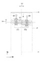
図1は、車両情報検出装置10が適用される自動車などの車両30(本発明の移動体の一例)の走行状態を説明するための模式図である。図2は、車両30が走行する道路40を示す平面図である。図3は、車両情報検出装置10及びレーダセンサ20の構成を示すブロック図である。
FIG. 1 is a schematic diagram for explaining a traveling state of a vehicle 30 (an example of a moving body of the present invention) such as an automobile to which the vehicle
図1に示すように、車両情報検出装置10は、道路40の路側エリアに設置された支柱25に取り付けられている。支柱25の頂部付近には、道路40上に予め定められた検出エリア45へ向けて車両情報検出用の電波信号SG1を照射するレーダセンサ20が取り付けられている。
As shown in FIG. 1, the vehicle
本実施形態では、車両情報検出装置10が適用される交通環境として、レーダセンサ20へ向けて車両30が同じ方向へ並んで走行することが出来る2つの車線40A,40Bを有する道路40を例示する。道路40上には、車両30を検出するための検出エリア45(図1の破線で囲まれたエリア)が定められている。検出エリア45は、レーダセンサ20よりも車両30の走行方向D11(本発明の進行方向の一例)の上流側に定められた計測開始位置P1から、計測開始位置P1とレーダセンサ20との間に定められた計測終了位置P2に至る領域である。車両情報検出装置10は、検出エリア45を走行方向D11へ走行する複数の車両30の車両情報(台数のカウント値、位置、速度、車両長さ等)を検出可能に構成されている。
In the present embodiment, as a traffic environment to which the vehicle
ここで、図2に示すように、検出エリア45において、計測開始位置P1から計測終了位置P2までの距離l1、つまり、検出エリア45において走行方向D10に沿った距離L1は、概ね150mである。また、平面視で、計測終了位置P2からレーダセンサ20までの距離L2は、概ね20mである。なお、車両情報検出装置10は、上述した交通環境に限られず、3車線以上の道路を複数の車両が並走する交通環境にも適用可能である。
Here, as shown in FIG. 2, in the
レーダセンサ20は、道路40の路面から所定高さに設置されている。レーダセンサ20は、車両情報検出装置10に無線又は有線によって電気的に接続されている。図3に示すように、レーダセンサ20は、アンテナ21と、アンテナ21に電波信号SG1を出力する送信回路22、アンテナ21からの信号を反射波信号SG2として入力する受信回路23、送信回路22及び受信回路23それぞれに24GHz帯域の正弦波信号を供給する発振回路24などを備える周知の構成を有する。受信回路23には、増幅回路(不図示)及びAD変換回路(不図示)が設けられており、受信した反射波信号SG2を増幅し、デジタル信号に変換してから、後述の制御部12に出力する。アンテナ21は、送受信切換回路(デュプレクサ回路)を備えることにより、送信用及び受信用を兼ねる。なお、レーダセンサ20としては、FMCW(Frequency Modulation Continuous Wave)型のレーダセンサや、ドップラー型のレーダセンサ、位相型のレーダセンサ等を適用可能である。
The
レーダセンサ20は、道路40上に定められた検出エリア45(図1参照)に向けて周期的に電波信号SG1を送信し、送信した電波信号SG1が車両30の表面や道路40の路面で反射してレーダセンサ20の前記アンテナに返ってきた反射波信号SG2を受信する。かかる送受信は所定の周期Tごとに行われる。つまり、レーダセンサ20は、前記周期Tごとに検出エリア45全域からの反射波信号SG2を受信して、反射波信号SG2をサンプリングする。サンプリングした反射波信号SG2は、受信回路23においてデジタル化された後に、車両情報検出装置10が備える後述の制御部12に出力される。ここで、前記周期Tは、例えば、周波数fを数Hz〜数十Hzとした場合に、1/f[s]である。つまり、電波信号SG1の走査は、1秒間に数回から数十回行われる。
The
レーダセンサ20が出射する電波信号SG1は、所謂準ミリ波(20GHz〜30GHzの電波)に属する電波であり、具体的には、我が国で法規されている占有周波数帯幅が200MHzの所謂24GHz帯域(24.05GHz〜24.25GHz)の電波である。また、電波信号SG1は、道路40の幅方向D12(つまり水平方向)の指向幅がΔθ1であり、垂直方向の角度幅が所定の角度θ2の指向特性を有するものである。本実施形態では、レーダセンサ20の高さ位置は、前記角度θ2の電波信号SG1が検出エリア45における走行方向D11の範囲を照射可能な位置に定められている。
The radio signal SG1 emitted by the
また、レーダセンサ20は、電波信号SG1を前記指向幅Δθ1ずつ幅方向D12へ走査することにより、前記周期T毎に検出エリア45の幅方向D12の全域を電波信号SG1で照射する。したがって、車両30が計測開始位置P1を超えて検出エリア45内に進入すると、車両30で反射してレーダセンサ20へ向けて返った反射波信号SG2がレーダセンサ20のアンテナ21によって受信される。ここで、幅方向D12の走査角θ1は、例えば、前記指向幅Δθ1の数倍に設定されている。なお、電波信号SG1は、一度の送信で道路40の路面に定められた検出エリア45の全体にわたって照射可能な指向特性を有していてもよい。この場合、レーダセンサ20は、電波信号SG1を幅方向D12へ走査する必要はない。
The
検出エリア45内には、通過する車両30の台数をカウントするための計数エリア46が定められている。この計数エリア46は、検出エリア45において走行方向D11の下流端部に定められている。後述するように、車両情報検出装置10は、車両30が計数エリア46を通過する際に、通過した車両30の台数をカウントする。
In the
図3に示すように、車両情報検出装置10は、制御部12と、記憶部13と、通信部14(本発明の出力部の一例)とを備えている。また、車両情報検出装置10には、上述したレーダセンサ20に加えて、ネットワークN1を通じて管理サーバ15と接続されている。
As shown in FIG. 3, the vehicle
通信部14は、通信インターフェースであり、車両情報検出装置10を有線又は無線でネットワークN1に接続し、ネットワークN1を介して管理サーバ15との間で所定の通信プロトコルに従ったデータ通信を実行する。通信部14は、車両情報検出装置10において後述の車両特定部123によって特定された車両30の位置情報(オブジェクト情報)や速度情報、車両サイズ、車両30のカウント情報などの車両情報をネットワークN1を介して管理サーバ15に出力する。
The communication unit 14 is a communication interface, connects the vehicle
管理サーバ15は、車両情報検出装置10から送られてきた車両30の車両情報を管理するサーバ装置である。本実施形態では、車両情報検出装置10は、管理サーバ15およびレーダセンサ20と通信可能に接続することによって、全体として車両情報検出システム100を構成する。管理サーバ15は、車両情報を表示するためのモニタなどの表示部を備えており、道路40における車両30の位置が視認できるように前記車両情報が前記表示部に表示される。なお、本実施形態では、車両情報検出装置10が管理サーバ15と通信可能に接続された構成について例示するが、車両情報検出装置10が管理サーバ15によって実現された構成であってもよい。
The
記憶部13は、HDD(Hard Disk Drive)又はSSD(Solid State Drive)などを含む不揮発性の記憶媒体である。記憶部13には、制御部12に各種処理を実行させるための制御プログラムや、車両情報検出装置10において実行される後述の車両情報検出処理に用いられる各閾値、レーダセンサ20から送られてきた反射波信号SG2の分布、車両情報検出装置10において特定された各種の車両情報などが記憶される。
The
制御部12は、CPU、ROM、及びRAMなどの制御機器を有する。前記ROMは、前記CPUに各種の処理を実行させるためのBIOS及びOSなどの制御プログラムが予め記憶された不揮発性の記憶媒体である。前記RAMは、各種の情報を記憶する揮発性又は不揮発性の記憶媒体であり、前記CPUが実行する各種の処理の一時記憶メモリ(作業領域)として使用される。制御部12は、前記ROM又は記憶部13に予め記憶された各種の制御プログラムを前記CPUで実行することにより車両情報検出装置10を制御する。前記制御プログラムを実行する前記CPU、或いは前記CPUを含む制御部12は、本発明のコンピュータの一例である。
The
図3に示すように、制御部12は、送信制御部121、物標計測部122、車両特定部123(本発明の移動体特定部の一例)、第1判定部124(本発明の第1判定部の一例)、第2判定部125(本発明の第2判定部の一例)、ID設定部126(本発明の識別設定部の一例)、追跡処理部127、車両計数部128(本発明の計数部の一例)などの各種の処理部を含む。制御部12は、前記CPUで前記制御プログラムに従って車両情報検出処理などの各種の処理を実行することによって前記各種の処理部として機能する。なお、制御部12に含まれる一部又は全部の処理部が電子回路で構成されていてもよい。また、前記制御プログラムは、複数のプロセッサーを前記各種の処理部として機能させるためのプログラムであってもよい。
As illustrated in FIG. 3, the
送信制御部121は、上述した周期Tごとに送信トリガを生成し、レーダセンサ20の送信回路22に出力する。送信回路22は、前記送信トリガを受けると、電波信号SG1をアンテナ21に送出して、アンテナ21から電波信号SG1を放射させるとともに、前記指向幅Δθ1(図1参照)ずつ幅方向D12へ電波信号SG1を走査する。
The
物標計測部122は、受信回路23から出力されたデジタル化後の複数の反射波信号SG2から所定レベル以上の反射波信号SG2を物標信号として抽出する。一般に、車両30で反射した反射波信号SG2と路面で反射した反射波信号SG2とを比較すると、車両30で反射した反射波信号SG2の強度の方が強い。したがって、前記所定レベルは、受け取った複数の反射波信号SG2(デジタル信号)から、車両30で反射した反射波信号SG2のみを区別可能な閾値に定められている。また、車両30で反射した反射波信号SG2は、車両30の表面の形状に応じて散乱、屈折、減衰、遅延(移相)などの作用を受ける。このため、電波信号SG1の1回の送信のたびに、複数の反射波信号SG2が受信回路23に受信され、その複数の反射波信号SG2から所定レベル以上の強度を有する複数の前記物標信号が抽出される。以下、このように抽出された複数の物標信号を物標信号SG2と称する。
The
また、物標計測部122は、電波信号SG1の送信時から反射波信号SG2を受信するまでの電波伝搬時間(遅れ時間)から換算して、電波信号SG1を反射させた車両30からレーダセンサ20までの距離を計測する。更に、物標計測部122は、計測した距離と、電波信号SG1の送信時の走査角と、所定の角度θ2(図1参照)などの情報から、検出エリア45における車両30の位置を計測する。車両30の位置は、図3に示すように幅方向D12をX軸とし、走行方向D11をY軸とした場合に、検出エリア45をXY平面としたXY座標として求められる。この座標情報は、前記周期Tが経過するたびに求められて、記憶部13に記憶される。なお、車両30までの距離や位置などの情報は、送信時の電波信号SG1と受信時の反射波信号SG2との周波数差を求め、この周波数差を分析することによって求めてもよい。
The
図4は、図2に示す位置で車両30(30A,30B)が走行している状態で、各車両30それぞれからの反射波信号SG2に基づく複数の物標信号SG2のXY平面における分布状態を示す図である。図2において、二つの車両30A,30Bは、走行方向D11に沿って距離DSだけ離間しているものとする。図4において、黒色のドット一つ一つが物標信号SG2を示し、そのドットの位置が各車両30の表面で反射したと推定できる反射位置を示す。図4に示すように、車両30の実際の位置(図2参照)に対応する範囲31A,31B(破線囲み部参照)における物標信号SG2の分布密度が高くなっている。一方、上述したように、反射波信号SG2は、車両30の表面の形状に応じて散乱、屈折、減衰、遅延(移相)などの作用を受ける。そのため、車両30の実際の位置に対応する範囲31Aよりも幅方向D12の外側へずれた位置にも、分布密度は低いが、物標信号SG2を示すドットが現れる。
FIG. 4 shows a distribution state of a plurality of target signals SG2 on the XY plane based on the reflected wave signals SG2 from the respective vehicles 30 in a state where the vehicles 30 (30A, 30B) are traveling at the position shown in FIG. FIG. In FIG. 2, it is assumed that the two vehicles 30A and 30B are separated by a distance DS along the traveling direction D11. In FIG. 4, each black dot indicates a target signal SG2, and the position of the dot indicates a reflection position at which it can be estimated that the dot has reflected on the surface of each vehicle 30. As shown in FIG. 4, the distribution density of the target signal SG2 in the
車両特定部123は、物標計測部122によって抽出された複数の物標信号SG2から一台の車両30を示すオブジェクト情報(本発明の移動体情報の一例)を特定する処理を行う。具体的には、図4に示す複数の反射波信号SG2の分布に基づいて、分布密度が所定の閾値TH(図6(A)参照)よりも大きい一つの塊(グループ)を1台の車両30を示すオブジェクト情報と特定するグループ処理を行う。ここで、図6(A)は、道路40の幅方向D12の物標信号SG2の分布状態の一例を示す図であり、図4の各範囲31A,31Bそれぞれの中心を通る幅方向D12の分布曲線W11,W12を示す。図6(A)に示すように、分布曲線W11において閾値TH以上の部分が範囲31Aに相当する部分である。また、分布曲線W12において閾値TH以上の部分が範囲31Bに相当する部分である。図4に示す例では、範囲31Aの部分の中心位置を示す位置情報が車両30Aを示すオブジェクト情報として特定される。また、範囲31Bの部分の中心位置を示す位置情報が車両30Bを示すオブジェクト情報として特定される。つまり、各オブジェクト情報は、検出エリア45における車両30の測定位置を示す位置情報であり、XY座標で表される。各オブジェクト情報は、前記周期Tが経過するたびに求められて、記憶部13に記憶される。
The
ID設定部126は、車両特定部123によって特定された前記オブジェクト情報に、当該オブジェクト情報を他のオブジェクト情報と識別するための識別ID(本発明の識別符号の一例)を付与する。例えば、ID設定部126は、任意にユニークな識別IDを発行し、前記オブジェクト情報に関連付けた状態で記憶部13に識別IDを記憶する。
The
追跡処理部127は、周期Tごとに特定された各オブジェクト情報(位置情報)を比較することにより、周期Tごとの前記オブジェクト情報が同じ車両30の測定位置を示すものであるかどうかを判定する。例えば、追跡処理部127は、電波信号SG1を送信する周期T、前記指向幅Δθ1、又は平均的な走行速度等を考慮して、各オブジェクト情報の位置間隔ΔDS、レーダセンサ20に対する角度方向の差分、走行速度の差分などが、同じ車両30と評価し得る所定範囲内であるか否かを判定し、前記所定範囲内である場合に、同じ車両30と判定する。なお、走行速度は、前々回及び前回の追跡処理によって同一と判定されたオブジェクト情報の位置に基づいて算出することができる。各オブジェクト情報が同じ車両30を示すものであると判定されると、後に特定されたオブジェクト情報に対して、既に付与された識別IDを引き継ぐ(付与する)処理を行う。かかる処理は、前記周期Tが経過するたびに行われて、記憶部13内のオブジェクト情報が更新される。
The
車両計数部128は、検出エリア45における走行方向D11の下流側に定められた計数エリア46を通過する際に、車両30の台数をカウントする。具体的には、車両特定部123によって特定されたオブジェクト情報が示す位置が、計数エリア46内である場合に、前記オブジェクト情報に関連付けられた識別IDを検出し、その検出回数を車両30の台数としてカウントする。このカウント値は、記憶部13に記憶されるとともに、管理サーバ15に出力される。
The
ところで、車両情報検出装置10で用いられる電波信号SG1は、所謂24GHz帯域である。24Ghz帯域の電波を利用する従来の車両情報検出装置では、道路40の幅方向D12の距離分解能が比較的低い。そのため、複数の車線40A,40Bを有する道路40において幅方向D12に隣接して車両30A,30Bが並走する場合に、これら2つの車両30A,30Bを一つの車両と判定する誤検出が生じるおそれがある。具体的には、検出エリア45に別々に進入した速度の異なる二つの車両30A,30Bが検出エリア45内で横並びになると、進入直後に各車両30A,30Bが個別に特定されていたにもかかわらず、横並びになった場合に二つの車両30A,30Bが一つの車両と判定されてしまい、例えば、検出エリア45を走行する車両30の台数を正確にカウントすることができなくなる。このような問題は、例えば、検出エリア45において同じ速度で車両30A,30Bが並走する場合に生じるとは限られない。例えば、一方の車両30Aがトレーラやバスなどの大型車であり、他方の車両30Bが小型車或いは普通車である場合に、車両30Bが車両30Aに追いついてから追い抜くまでの間も、二つの車両30A,30Bが一つの車両と判定されてしまい、上述の誤カウントが生じるおそれがある。
By the way, the radio signal SG1 used in the vehicle
例えば、図2に示す車両30(30A,30B)が走行方向D11へ移動して、所定時間後には図2の破線で示すように、二つの車両30A,30Bが検出エリア45内で横並びになると、図5に示すように、幅方向D12における車両30Aと車両30Bとの間の中間領域における物標信号SG2の分布密度が上がり、当該中間領域の分布密度が所定の閾値TH(図6(B)参照)を超える場合がある。この場合、車両30の実際の位置に対応する範囲のみならず、車両30Aと車両30Bとの間の中間領域を含む範囲31Cが所定の閾値THよりも大きい一つの塊(グループ)となり、前記グループ処理において、この範囲31Cが1台の車両30を示すオブジェクト情報と特定される。このような誤った特定が行われると、車両30の台数を正確にカウントすることができない。
For example, when the vehicle 30 (30A, 30B) shown in FIG. 2 moves in the traveling direction D11, and after a predetermined time, the two vehicles 30A, 30B lie side by side in the
これに対して、本実施形態の車両情報検出装置10は、走行方向D11に交差する幅方向D12における距離分解能が低い電波信号SG1を用いるにもかかわらず、走行方向D11に並走する車両30を個別に特定した後に両者が統合される場合でも、各車両30の分離状態を保持することができるように構成されている。
On the other hand, the vehicle
具体的には、制御部12に、上述の第1判定部124及び第2判定部125が含まれている。第1判定部124は、車両特定部123によって個々に特定された二つのオブジェクト情報を示す範囲31A,31Bが、その後の特定処理によって一つの範囲31Cに統合されたか否かを判定する。一旦、オブジェクト情報として範囲31A,31Bそれぞれの中心位置の位置情報が個別に特定された後に、図6(B)の分布曲線W13に示すように、幅方向D12にわたって所定の閾値THを超える範囲31Cの中心位置の位置情報がオブジェクト情報と特定された場合に、範囲31A,31Bが一つの範囲31Cに統合されたと判定される。
Specifically, the
なお、前記所定の閾値THの設定値を現在値よりも大きい数値にすることにより、範囲31Aと範囲31Bとの分離を維持することができる。しかしながら、上述したように、幅方向D12の距離分解能が低い本実施形態では、閾値THを大きくすると、オブジェクト情報が示す車両30の位置の検出精度が低下するため好ましくない。
The separation between the
第1判定部124によって、範囲31A,31Bが一つの範囲31Cに統合されたと判定されると、第2判定部125は、第1判定部124による判定前の二つのオブジェクト情報が示す検出エリア45内の位置、つまり、二つの車両30A,30Bそれぞれの位置に基づいて、前記二つのオブジェクト情報の分離状態を維持するか否かを判定する。かかる判定処理は、二つのオブジェクト情報の走行方向D11における位置、及び幅方向D12における位置に基づいて行われる。
When the
具体的には、第2判定部125は、第1判定部124による判定前の前記二つのオブジェクト情報それぞれが示す位置が幅方向D12に隣接しており、且つ、前記二つのオブジェクト情報の走行方向D11の間隔が漸減している場合は、前記二つのオブジェクト情報の分離状態を維持すると判定する。ここで、幅方向D12に隣接している状態には、各車線40A,40Bにおいて真横に各車両30が位置している状態だけでなく、幅方向D12から見て、各車線40A,40Bを走行する各車両30の一部が走行方向D11に重なっている状態も含む。この場合、検出エリア45内で、車両30Aに車両30Bが追いつき、もともと幅方向D12に分離していた範囲31Aと範囲31Bとが一つの範囲31Cに統合されることになる。
Specifically, the
前記第2判定部125によって前記二つのオブジェクト情報の分離状態を維持すると判定された場合は、車両特定部123は、一つに統合された範囲31Cを幅方向D12に二分割して、分割された各範囲31C1,31C2それぞれについてオブジェクト情報を特定する処理を行う。つまり、範囲31C1の中心位置を示す位置情報を一方のオブジェクト情報と特定し、範囲31C2の中心位置を示す位置情報を他方のオブジェクト情報と特定する。再び特定された二つのオブジェクト情報それぞれに対しては、ID設定部126によって、識別IDが付与される。
When the
[車両情報検出処理]
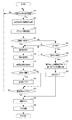
以下、図7のフローチャートを用いて、制御部12によって実行される車両情報検出処理の手順とともに、本発明の移動体情報検出方法の一例である車両情報検出方向について説明する。図7において、S11,S12,・・・は処理手順の番号(ステップ番号)を示す。
[Vehicle information detection processing]
Hereinafter, the procedure of the vehicle information detection process executed by the
〈ステップS11〜S13〉
図7に示すように、ステップS11では、制御部12は、電波信号SG1の1回の走査による反射波信号SG2を受信したかどうかを判定する。ここで、周期Tを経過するまでの間に反射波信号SG2を受信したと判定されると、次のステップS12において、制御部12の物標計測部122は、複数の反射波信号SG2から所定レベル以上の物標信号SG2を抽出する。その後、ステップS13において、制御部12の車両特定部123は、ステップS12で抽出された複数の物標信号SG2から一台の車両30を示すオブジェクト情報を特定する処理を行う。ここで、ステップS13は、本発明の移動体特定ステップの一例である。
<Steps S11 to S13>
As shown in FIG. 7, in step S11, the
〈ステップS14〜S15〉
次のステップS14では、制御部12は、検出エリア45の各車線40A,40Bそれぞれに車両30が存在しているか否かを判定する。かかる判定は、ステップS13で特定された前記オブジェクト情報が示す位置に基づいて行われる。
<Steps S14 to S15>
In the next step S14, the
〈ステップS15〜S17〉
ステップS14において、各車線40A,40Bそれぞれに車両30が存在していると判定されると、次のステップS15では、制御部12のID設定部126は、各車両30に対応するオブジェクト情報に対して識別IDを付与する。その後、前記オブジェクト情報が示す位置情報を車両30の測定位置と特定して、その測定位置を記憶部13に記憶する(S16)。また、制御部12は、各車両30の測定位置から車両間の距離DSを算出して、記憶部13に記憶する(S17)。
<Steps S15 to S17>
In step S14, when it is determined that the vehicle 30 exists in each of the
〈ステップS18〜S19〉
ステップS18では、制御部12は、距離DSが予め定められた閾値未満か否かを判定する。かかる判定は、次ぎにステップS13の処理が行われる場合に、個々に特定された二つのオブジェクト情報が一つに統合される可能性が高いか否かを判定するために行われる。例えば、距離DSが車両30の全長に相当する長さを前記閾値とすることができる。距離DSが前記全長以上の長さである場合は、上述した統合が生じ難い。したがって、ステップS18において、距離DSが前記閾値以上と判定された場合は、後述するステップS25の処理を実行する必要がない。この場合は、ステップS25の処理を行うためのトリガとしてのフラグ情報を各車両30に付与せずに、ステップS20に移行する。一方、距離DSが前記閾値未満の場合は、各車両30が幅方向D12に隣接していると評価でき、次に行われるステップS13の処理において、二つのオブジェクト情報が一つに統合されることになる。したがって、ステップS18において、距離DSが前記閾値未満と判定された場合は、制御部12は、ステップS25の処理を行うためのトリガとしてのフラグ情報を各車両30に対応するオブジェクト情報に付与し(S19)、その後にステップS20に移行する。
<Steps S18 to S19>
In step S18, the
〈ステップS20〜S22〉
ステップS20では、制御部12は、オブジェクト情報が示す位置に基づいて、車両30が計数エリア46内に存在しているか否かを判定する。車両30が計数エリア46内に存在している場合は、オブジェクト情報に関連付けられた識別IDを検出して、車両30の台数をカウントする(S21)。つまり、記憶部13における車両のカウント値を一つインクリメントする。その後、カウントされた車両30に対応するオブジェクト情報及びそれに付与していたフラグ情報を記憶部13から削除し、もう一方の車両30のオブジェクト情報に付与していたフラグ情報も削除する(S22)。一方、ステップS20において、車両30が計数エリア46内に存在していないと判定されると、ステップS11に戻り、ステップS11以降の処理が繰り返される。
<Steps S20 to S22>
In step S20,
〈ステップS23〉
ステップS14において、各車線40A,40Bに車両30が存在していない、つまり、いずれか一方の車線にだけ車両30が存在していると判定された場合、制御部12は、次のステップS23において、当該車両30に対応するオブジェクト情報にフラグ情報が付与されているか否かを判定する。かかる判定は、ステップS13において個々に特定された二つのオブジェクト情報が一つに統合されたか否かを判定するために行われる。ステップS23は、本発明の第1判定ステップの一例である。ここで、各車線40A,40Bそれぞれに車両30が存在している状態から、一方の車線だけに車両30が存在している状態に変化するケースとしては、以下の2通りが考えられる。一つは、車両30が計数エリア46を通過して検出エリア45から退出したケースである。もう一つは、各車両30が幅方向D12に隣接する位置で並走しているために、二つの車両30に対応する各オブジェクト情報の基準となる範囲31A,31Bが一つの範囲30Cに統合されて一つのオブジェクト情報と特定されたケースである。
<Step S23>
In step S14, when it is determined that the vehicle 30 does not exist in each of the
前者のケースでは、ステップS22においてフラグ情報が削除される。したがって、この場合は、ステップS23においてフラグ情報が付与されていないと判定され、ステップS15に進み、ステップS15以降の処理が行われる。なお、この場合は、各車線40A,40Bの一方にだけ車両30が存在している状況であるため、ステップS17の処理は行われずスキップされる。後者のケースでは、車両30に付されたフラグ情報は残っているため、この場合は、ステップS23においてフラグ情報が付与されていると判定されて、次のステップS24に進む。
In the former case, the flag information is deleted in step S22. Therefore, in this case, it is determined in step S23 that the flag information has not been added, and the process proceeds to step S15, where the processing after step S15 is performed. In this case, since the vehicle 30 exists only in one of the
〈ステップS24〜S26〉
ステップS24では、制御部12は、上述の統合前の二つの車両30の距離DSが漸減していたか否かを判定する。かかる判定は、統合前の二つのオブジェクト情報の分離状態を維持するか否かを判定するために行われる。ステップS24は、本発明の第2判定ステップの一例である。当該判定処理は、記憶部13に記憶された距離DSに関する履歴に基づいて行われる。
<Steps S24 to S26>
In step S24, the
ここで、統合前の二つの車両30の距離DSが徐々に減少していたことは、二つの車両30が相対的に近づいていることを意味し、その後に統合された可能性が高いと推定できる。したがって、ステップS24において、統合前の二つの車両30の距離DSが徐々に減少していたと判定された場合は、統合前の二つのオブジェクト情報の分離状態を維持する必要がある。このため、制御部12の車両特定部123は、一つに統合されたオブジェクト情報に対応する範囲31Cを幅方向D12に二分割して、分割された各範囲31C1,31C2それぞれについてオブジェクト情報を特定する処理を行う(S25)。その後、各オブジェクト情報に対して識別IDが付与される(S26)。その後の処理は、ステップS21に進む。一方、ステップS24において、統合前の二つの車両30の距離DSが漸減していないと判定された場合は、ステップS15に進み、ステップS15以降の処理が行われる。
Here, the gradual decrease in the distance DS between the two vehicles 30 before the integration means that the two vehicles 30 are relatively close to each other, and it is estimated that the possibility that the two vehicles 30 were integrated later is high. it can. Therefore, when it is determined in step S24 that the distance DS between the two vehicles 30 before the integration is gradually reduced, it is necessary to maintain the separated state of the two object information before the integration. Therefore, the
以上説明したように、本実施形態に係る車両情報検出装置10では、道路40の路面に定められた検出エリア45に向けて周期的に電波信号SG1が送信され、車両特定部123が、その反射波信号SG2の分布を周期毎に解析して、その分布密度が所定の閾値TH以上のグループを一つの車両30を示すオブジェクト情報と特定し、第1判定部124が、個々に特定された二つのオブジェクト情報それぞれに対応する二つの範囲31A,31Bが一つに統合されたか否かを判定し、第1判定部124によって範囲31A,31Bが一つに統合されたと判定された場合に、第1判定部124による判定前の前記二つのオブジェクト情報が示す二つの車両30それぞれの走行方向D11及び前記幅方向D12の位置に基づいて、第2判定部125が、前記二つのオブジェクト情報の分離状態を維持するか否かを判定する。そして、分離状態を維持すると判定された場合に、車両特定部123が、統合された範囲31Cを幅方向D12に二分割し、各範囲31C1,31C2それぞれについてオブジェクト情報を特定する処理を行う。
As described above, in the vehicle
このため、高性能なICを用いたハード構成や複雑な演算処理を行う特有のアルゴリズムなどが用いられていないために、幅方向D12における距離分解能が低い場合であっても、検出エリア45に実際に存在する二つの車両30の台数をカウントすることができる。つまり、各車線40A,40Bそれぞれの車両30が個別に特定された場合は、その後に各車両30が同じ速度で並走する状態になっても一つの車両と認識されず、各車両30の分離状態を保持することができる。これにより、正確に車両30の台数をカウントすることができる。また、一方の車両30Aがトレーラやバスなどの大型車であり、他方の車両30Bが小型車或いは普通車である場合に、各車両30がひとたび個別に特定されると、その後に、車両30Bが車両30Aに追いついてから追い抜くまでの間に各車両30が計数エリア46を通過しても、各車両30の分離状態が保持される。そのため、このような場合でも、正確に車両30の台数をカウントすることができる。
For this reason, even when the distance resolution in the width direction D12 is low, a hardware configuration using a high-performance IC or a specific algorithm for performing complicated arithmetic processing is not used. Can be counted. In other words, when the vehicles 30 in each of the
なお、上述の実施形態では、車両情報検出装置10の制御部12が物標計測部122および車両特定部123を具体的に実現する構成について例示したが、本発明はこの構成に限られない。例えば、レーダセンサ20の内部に演算処理部を設け、この演算処理部によって、物標計測部122および車両特定部123の各処理部が実現されてもよい。
In the above-described embodiment, the configuration in which the
10 :車両情報検出装置
12 :制御部
13 :記憶部
14 :通信部
15 :管理サーバ
20 :レーダセンサ
21 :アンテナ
22 :送信回路
23 :受信回路
24 :発振回路
25 :支柱
30 :車両
30A :車両
30B :車両
30C :範囲
31A :範囲
31B :範囲
31C :範囲
31C1 :範囲
31C2 :範囲
40 :道路
40A :車線
40B :車線
45 :検出エリア
46 :計数エリア
100 :車両情報検出システム
121 :送信制御部
122 :物標計測部
123 :車両特定部
124 :第1判定部
125 :第2判定部
126 :ID設定部
127 :追跡処理部
128 :車両計数部
10: Vehicle information detection device 12: Control unit 13: Storage unit 14: Communication unit 15: Management server 20: Radar sensor 21: Antenna 22: Transmission circuit 23: Receiving circuit 24: Oscillation circuit 25: Support 30: Vehicle 30A: Vehicle 30B: Vehicle 30C:
Claims (8)
前記移動体の進行方向の下流側から前記検出エリアに向けて周期的に送信された電波の反射波の分布を周期毎に解析して、分布密度が所定の閾値以上のグループを一つの移動体を示す移動体情報と特定する移動体特定部と、
前記移動体特定部によって個々に特定された二つの移動体情報それぞれに対応する二つの前記グループが一つに統合されたか否かを判定する第1判定部と、
前記第1判定部によって前記二つのグループが一つに統合されたと判定された場合に、前記第1判定部による判定前の前記二つの移動体情報が示す二つの移動体それぞれの前記進行方向及び前記進行方向に交差する幅方向の位置に基づいて、前記二つの移動体情報の分離状態を維持するか否かを判定する第2判定部と、を備える移動体情報検出装置。 A moving body information detection device that detects information of a plurality of moving bodies that move a predetermined detection area in the same direction,
Analyzing the distribution of reflected waves of radio waves periodically transmitted from the downstream side in the traveling direction of the moving body toward the detection area, and analyzing the distribution density of a group having a distribution density of not less than a predetermined threshold as one moving body A moving object specifying unit that specifies moving object information indicating
A first determination unit that determines whether the two groups corresponding to the two pieces of mobile information individually specified by the mobile body identification unit have been integrated into one,
When it is determined by the first determination unit that the two groups are integrated into one, the traveling direction of each of the two mobile objects indicated by the two mobile object information before the determination by the first determination unit and A moving body information detection device comprising: a second determination unit configured to determine whether to maintain the separated state of the two pieces of moving body information based on a position in a width direction crossing the traveling direction.
前記第1判定部による判定前の前記二つの移動体情報それぞれが示す前記二つの移動体が前記幅方向に隣接しており、且つ、前記二つの移動体の前記進行方向の間隔が漸減している場合に、前記二つの移動体情報の分離状態を維持すると判定する、請求項1に記載の移動体情報検出装置。 The second determination unit includes:
The two moving objects indicated by each of the two moving object information before the determination by the first determination unit are adjacent to each other in the width direction, and an interval between the two moving objects in the traveling direction gradually decreases. The mobile object information detection device according to claim 1, wherein when detecting, it is determined that the separated state of the two mobile object information is maintained.
前記第2判定部によって前記二つの移動体情報の分離状態を維持すると判定された場合に、前記分布を前記幅方向に二分して各分布それぞれに対応する前記移動体情報を特定する、請求項1又は2に記載の移動体情報検出装置。 The moving object identification unit,
When the second determination unit determines that the separated state of the two pieces of moving object information is to be maintained, the distribution is bisected in the width direction, and the moving object information corresponding to each distribution is specified. 3. The moving object information detection device according to 1 or 2.
前記計数部は、前記計数エリアにおける前記移動体情報の前記識別符号を検出し、前記識別符号の検出数を前記移動体の台数としてカウントする、請求項4に記載の移動体情報検出装置。 An identification setting unit that sets an identification code to the mobile object information specified by the mobile unit identification unit,
The moving object information detecting device according to claim 4, wherein the counting unit detects the identification code of the moving object information in the counting area, and counts the number of the detected identification codes as the number of the moving objects.
前記移動体の進行方向の下流側から前記検出エリアに向けて周期的に送信された電波の反射波の分布を周期毎に解析して、分布密度が所定の閾値以上のグループを一つの移動体を示す移動体情報と特定する移動体特定ステップと、
前記移動体特定ステップによって個々に特定された二つの移動体情報それぞれに対応する二つの前記グループが一つに統合されたか否かを判定する第1判定ステップと、
前記第1判定ステップによって前記二つのグループが一つに統合されたと判定された場合に、前記第1判定ステップによる判定前の前記二つの移動体情報が示す二つの移動体それぞれの前記進行方向及び前記進行方向に交差する幅方向の位置に基づいて、前記二つの移動体情報の分離状態を維持するか否かを判定する第2判定ステップと、を備える移動体情報検出方法。 A moving object information detection method for detecting information of a plurality of moving objects that move a predetermined detection area in the same direction,
Analyzing the distribution of reflected waves of radio waves periodically transmitted from the downstream side in the traveling direction of the moving body toward the detection area, and analyzing the distribution density of a group having a distribution density of not less than a predetermined threshold as one moving body A moving object specifying step for specifying moving object information indicating
A first determination step of determining whether the two groups corresponding to the two pieces of mobile information individually specified by the mobile body identification step have been integrated into one,
When it is determined that the two groups are integrated into one by the first determination step, the traveling directions of the two mobile bodies indicated by the two mobile body information before the determination by the first determination step and A second determining step of determining whether to maintain the separated state of the two pieces of moving object information based on a position in a width direction intersecting the traveling direction.
Priority Applications (1)
| Application Number | Priority Date | Filing Date | Title |
|---|---|---|---|
| JP2018183842A JP7139843B2 (en) | 2018-09-28 | 2018-09-28 | Mobile object information detection device, mobile object information detection method, and program |
Applications Claiming Priority (1)
| Application Number | Priority Date | Filing Date | Title |
|---|---|---|---|
| JP2018183842A JP7139843B2 (en) | 2018-09-28 | 2018-09-28 | Mobile object information detection device, mobile object information detection method, and program |
Publications (2)
| Publication Number | Publication Date |
|---|---|
| JP2020052901A true JP2020052901A (en) | 2020-04-02 |
| JP7139843B2 JP7139843B2 (en) | 2022-09-21 |
Family
ID=69997376
Family Applications (1)
| Application Number | Title | Priority Date | Filing Date |
|---|---|---|---|
| JP2018183842A Active JP7139843B2 (en) | 2018-09-28 | 2018-09-28 | Mobile object information detection device, mobile object information detection method, and program |
Country Status (1)
| Country | Link |
|---|---|
| JP (1) | JP7139843B2 (en) |
Cited By (1)
| Publication number | Priority date | Publication date | Assignee | Title |
|---|---|---|---|---|
| JP2021193492A (en) * | 2020-06-08 | 2021-12-23 | パナソニックIpマネジメント株式会社 | Information processing device and counting method |
Citations (4)
| Publication number | Priority date | Publication date | Assignee | Title |
|---|---|---|---|---|
| JP2001080437A (en) * | 1999-09-10 | 2001-03-27 | Denso Corp | Vehicular obstacle recognition device, car-to-car distance control device, car-to-car distance warning device and recording medium |
| JP2002122663A (en) * | 2000-10-12 | 2002-04-26 | Honda Motor Co Ltd | Object detection device for moving objects |
| JP2003288674A (en) * | 2002-03-28 | 2003-10-10 | Natl Inst For Land & Infrastructure Management Mlit | Method and apparatus for determining congestion in millimeter wave sensor |
| JP2015026127A (en) * | 2013-07-24 | 2015-02-05 | 富士通株式会社 | Vehicle flow measuring device, method and program |
-
2018
- 2018-09-28 JP JP2018183842A patent/JP7139843B2/en active Active
Patent Citations (4)
| Publication number | Priority date | Publication date | Assignee | Title |
|---|---|---|---|---|
| JP2001080437A (en) * | 1999-09-10 | 2001-03-27 | Denso Corp | Vehicular obstacle recognition device, car-to-car distance control device, car-to-car distance warning device and recording medium |
| JP2002122663A (en) * | 2000-10-12 | 2002-04-26 | Honda Motor Co Ltd | Object detection device for moving objects |
| JP2003288674A (en) * | 2002-03-28 | 2003-10-10 | Natl Inst For Land & Infrastructure Management Mlit | Method and apparatus for determining congestion in millimeter wave sensor |
| JP2015026127A (en) * | 2013-07-24 | 2015-02-05 | 富士通株式会社 | Vehicle flow measuring device, method and program |
Cited By (2)
| Publication number | Priority date | Publication date | Assignee | Title |
|---|---|---|---|---|
| JP2021193492A (en) * | 2020-06-08 | 2021-12-23 | パナソニックIpマネジメント株式会社 | Information processing device and counting method |
| JP7493154B2 (en) | 2020-06-08 | 2024-05-31 | パナソニックIpマネジメント株式会社 | Information processing device and counting method |
Also Published As
| Publication number | Publication date |
|---|---|
| JP7139843B2 (en) | 2022-09-21 |
Similar Documents
| Publication | Publication Date | Title |
|---|---|---|
| JP4593468B2 (en) | Radar equipment | |
| US9286796B2 (en) | Traffic flow measuring apparatus and method, and computer-readable storage medium for judging size of vehicle depending on number of times reflected wave from vehicle is detected within detection time | |
| KR102488038B1 (en) | Radar apparatus for vehicle and method for determining target of the same | |
| CN105093213B (en) | Radar system with improved multi-target discrimination | |
| KR102013224B1 (en) | Autonomous Emergencyy Braking System and Controlling Method Thereof | |
| JP6788388B2 (en) | Radar device and control method of radar device | |
| US20120313811A1 (en) | Obstacle detection apparatus | |
| JP2017003347A (en) | Object detection device and object detection method | |
| JP5122536B2 (en) | Radar equipment | |
| JP5206579B2 (en) | Object detection device | |
| US20130082868A1 (en) | Radar system and detection method | |
| CN106574969A (en) | Vehicle-mounted radar device, notification system, and traveling vehicle detection method of vehicle-mounted radar device | |
| JP2017166985A (en) | Rader system and target object detection method | |
| EP3876215B1 (en) | Sensing device, moving body system, and sensing method | |
| KR101609916B1 (en) | Radar apparatus and computer-readable storage medium having stored therein a program | |
| JP7139843B2 (en) | Mobile object information detection device, mobile object information detection method, and program | |
| KR102622937B1 (en) | Pedestrian Accident Prevention System and Method | |
| JP2014145731A (en) | Target detection apparatus and target detection method | |
| JP2017134012A (en) | Vehicle detection device, vehicle detection device control method and vehicle detection program | |
| JP7254243B2 (en) | Object detection system and object detection method | |
| JP2004295620A (en) | Vehicle collision possibility detection device | |
| JP2019027976A (en) | Radio wave sensor and estimation method | |
| JP2018112467A (en) | Radar device and target detection method | |
| JP2017156099A (en) | Radio wave sensor and detection program | |
| KR101534225B1 (en) | Radar apparatus |
Legal Events
| Date | Code | Title | Description |
|---|---|---|---|
| A621 | Written request for application examination |
Free format text: JAPANESE INTERMEDIATE CODE: A621 Effective date: 20210305 |
|
| A977 | Report on retrieval |
Free format text: JAPANESE INTERMEDIATE CODE: A971007 Effective date: 20220118 |
|
| A131 | Notification of reasons for refusal |
Free format text: JAPANESE INTERMEDIATE CODE: A131 Effective date: 20220125 |
|
| A521 | Request for written amendment filed |
Free format text: JAPANESE INTERMEDIATE CODE: A523 Effective date: 20220324 |
|
| TRDD | Decision of grant or rejection written | ||
| A01 | Written decision to grant a patent or to grant a registration (utility model) |
Free format text: JAPANESE INTERMEDIATE CODE: A01 Effective date: 20220809 |
|
| A61 | First payment of annual fees (during grant procedure) |
Free format text: JAPANESE INTERMEDIATE CODE: A61 Effective date: 20220822 |
|
| R150 | Certificate of patent or registration of utility model |
Ref document number: 7139843 Country of ref document: JP Free format text: JAPANESE INTERMEDIATE CODE: R150 |