JP2020040146A - Mobile robot - Google Patents
Mobile robot Download PDFInfo
- Publication number
- JP2020040146A JP2020040146A JP2018168032A JP2018168032A JP2020040146A JP 2020040146 A JP2020040146 A JP 2020040146A JP 2018168032 A JP2018168032 A JP 2018168032A JP 2018168032 A JP2018168032 A JP 2018168032A JP 2020040146 A JP2020040146 A JP 2020040146A
- Authority
- JP
- Japan
- Prior art keywords
- period
- vacuum pump
- signal output
- control
- mobile robot
- Prior art date
- Legal status (The legal status is an assumption and is not a legal conclusion. Google has not performed a legal analysis and makes no representation as to the accuracy of the status listed.)
- Granted
Links
Images


Classifications
-
- B—PERFORMING OPERATIONS; TRANSPORTING
- B25—HAND TOOLS; PORTABLE POWER-DRIVEN TOOLS; MANIPULATORS
- B25J—MANIPULATORS; CHAMBERS PROVIDED WITH MANIPULATION DEVICES
- B25J15/00—Gripping heads and other end effectors
- B25J15/06—Gripping heads and other end effectors with vacuum or magnetic holding means
-
- B—PERFORMING OPERATIONS; TRANSPORTING
- B25—HAND TOOLS; PORTABLE POWER-DRIVEN TOOLS; MANIPULATORS
- B25J—MANIPULATORS; CHAMBERS PROVIDED WITH MANIPULATION DEVICES
- B25J5/00—Manipulators mounted on wheels or on carriages
Abstract
Description
本発明は、移動ロボットに関する。 The present invention relates to a mobile robot.
ロボットアームにおいて対象物を把持する手法として、真空吸着が用いられている。真空吸着を実現するために、ロボットアームに真空ポンプが設けられ、真空ポンプの動作が制御されている。 Vacuum suction is used as a method for gripping an object in a robot arm. In order to realize vacuum suction, a vacuum pump is provided on the robot arm, and the operation of the vacuum pump is controlled.
特許文献1には、第1の真空排気手段が、ウェハが落下したり、ずれたりすることがなく、かつ、各チャック間のウェハの受け渡しを正確に行うことができる第1の真空吸着力を発生させるだけの真空排気能力を有し、第2の真空排気手段が、真空排気能力が前記第1の真空排気手段の真空排気能力より小さく、かつ、所定のチャック手段がマスク及びウェハ等を吸着保持するのに要する必要最小限の第2の真空吸着力を発生させるだけの真空排気能力を有する露光装置の保持システムが開示されている。 Patent Document 1 discloses that a first vacuum evacuation unit is provided with a first vacuum suction force capable of accurately transferring a wafer between chucks without dropping or shifting the wafer. The second vacuum pumping means has a vacuum pumping capacity smaller than that of the first vacuum pumping means, and a predetermined chuck means sucks a mask, a wafer and the like. There is disclosed a holding system of an exposure apparatus having a vacuum evacuation capacity sufficient to generate a minimum required second vacuum suction force required for holding.
特許文献2には、コネクタ部が、作業部が作業を行う際に、ステーションコネクタ部に接続され、ステーションコネクタ部から作業部に電力、信号、及び気体を供給して、作業部を作業可能な状態とし、作業部が作業を行わない際には、ステーションコネクタ部との接続が解除され、作業部への電力、信号、及び気体の供給を停止することで、作業部を作業停止した状態とする作業ロボットが開示されている。
In
ロボットアームを無人搬送車に載置した移動ロボットにおいて、動力源としてバッテリーが用いられることが多い。真空ポンプは消費電力が比較的大きいため、移動ロボットにおけるバッテリー消費量が大きくなり、1回の充電による移動ロボットの稼働可能時間の低下を招くという問題がある。そのため、移動中にバッテリー消費量を抑制可能な移動ロボットが求められている。 In a mobile robot having a robot arm mounted on an automatic guided vehicle, a battery is often used as a power source. Since the vacuum pump consumes relatively large power, the battery consumption of the mobile robot is large, and there is a problem that the operating time of the mobile robot is reduced by one charging. Therefore, there is a need for a mobile robot that can reduce battery consumption while moving.
しかしながら、特許文献1及び2には、移動中に移動ロボットのバッテリー消費量を抑制することは開示されていない。
However,
本発明は、このような実情を鑑みてなされたものであり、その目的は、移動中にバッテリー消費量を抑制可能な移動ロボットを提供することである。 The present invention has been made in view of such circumstances, and an object of the present invention is to provide a mobile robot capable of suppressing battery consumption while moving.
本発明は、上述した課題を解決するために、以下の構成を採用する。 The present invention employs the following configuration in order to solve the above-described problems.
すなわち、本開示に係る移動ロボットは、無人搬送車と、負圧により対象物を吸着することによって把持動作を行うロボットアームと、前記負圧を発生させる真空ポンプを制御する制御部であって、前記ロボットアームによって前記対象物の前記把持動作が行われている把持期間における前記真空ポンプの駆動量が、前記ロボットアームによって前記対象物の前記把持動作が行われていない状態で前記無人搬送車による移動が行われている移動期間における前記真空ポンプの駆動量よりも大きくなるように制御を行う制御部と、を備える。 That is, the mobile robot according to the present disclosure is an automatic guided vehicle, a robot arm that performs a gripping operation by sucking a target object by negative pressure, and a control unit that controls a vacuum pump that generates the negative pressure, The driving amount of the vacuum pump during the gripping period in which the gripping operation of the object is performed by the robot arm is performed by the automatic guided vehicle in a state where the gripping operation of the object is not performed by the robot arm. A control unit that controls the driving amount of the vacuum pump to be larger than a driving amount of the vacuum pump during a movement period in which the movement is performed.
上記構成によれば、把持期間における真空ポンプの駆動量が、移動期間における真空ポンプの駆動量よりも大きくなるように制御することで、対象物を好適に把持しつつ、移動期間における真空ポンプをアイドル状態にすることができる。このように、移動期間における真空ポンプをアイドル状態にすることで、移動ロボットの移動中に省エネを図ることができる。これにより、移動中にバッテリー消費量を抑制可能な移動ロボットを提供することができる。上述の駆動量は、真空ポンプを駆動させる量を指し、移動期間における真空ポンプの駆動量は、0であってもわずかに駆動していてもよい。 According to the above configuration, by controlling the driving amount of the vacuum pump during the holding period to be larger than the driving amount of the vacuum pump during the moving period, the vacuum pump during the moving period can be appropriately held while holding the target object. Can be idle. By setting the vacuum pump in the idle state during the movement period as described above, energy can be saved during movement of the mobile robot. This makes it possible to provide a mobile robot that can reduce battery consumption while moving. The above-mentioned drive amount indicates the amount by which the vacuum pump is driven, and the drive amount of the vacuum pump during the movement period may be 0 or slightly driven.
上記移動ロボットにおいて、前記制御部は、前記無人搬送車による移動が停止しており、前記ロボットアームによって前記対象物の前記把持動作が行われる直前の期間において、前記ロボットアームの位置を調整する位置調整期間をさらに設け、前記把持期間における前記真空ポンプの駆動量、前記位置調整期間における前記真空ポンプの駆動量、及び、前記移動期間における前記真空ポンプの駆動量が、この順で小さくなるように制御を行ってもよい。 In the mobile robot, the control unit may adjust the position of the robot arm during a period immediately before the movement by the automatic guided vehicle is stopped and the gripping operation of the object is performed by the robot arm. An adjustment period is further provided so that the drive amount of the vacuum pump during the gripping period, the drive amount of the vacuum pump during the position adjustment period, and the drive amount of the vacuum pump during the movement period are reduced in this order. Control may be performed.
上記構成によれば、位置調整期間において真空ポンプをある程度駆動しておくことによって、特に、初めて把持期間における真空ポンプの駆動量に移行させる際に、突入電流を抑制することができる。また、把持期間への遷移時に迅速に把持期間における真空ポンプの駆動量に移行させることができる。 According to the above configuration, by driving the vacuum pump to some extent during the position adjustment period, it is possible to suppress the inrush current, especially when the vacuum pump is driven for the first time during the gripping period. Further, at the time of transition to the holding period, it is possible to quickly shift to the driving amount of the vacuum pump in the holding period.
上記移動ロボットにおいて、前記制御部は、前記移動期間における移動距離の長さに応じて、前記真空ポンプの駆動量を変更するように制御を行ってもよい。 In the mobile robot, the control unit may perform control such that a drive amount of the vacuum pump is changed according to a length of a movement distance during the movement period.
上記構成によれば、例えば、対象物を把持するための一方の作業位置から他方の作業位置までの移動距離が長距離である場合には、制御部は、真空ポンプの駆動量を0に制御してもよい。また、一方の作業位置から他方の作業位置までの移動距離が中距離である場合には、制御部は、真空ポンプの駆動量を、真空ポンプが停止しない程度に小さく制御してもよい。これにより、消費電力を低減することができる。また、一方の作業位置から他方の作業位置までの移動距離が短距離である場合には、制御部は、真空ポンプの駆動量を、移動距離が短距離及び中距離である場合の真空ポンプの駆動量に比べて高く制御してもよい。これにより、把持期間への遷移時に迅速に把持期間における真空ポンプの駆動量に移行させることができる。 According to the above configuration, for example, when the moving distance from one working position to the other working position for gripping the object is a long distance, the control unit controls the driving amount of the vacuum pump to 0. May be. When the moving distance from one working position to the other working position is a medium distance, the control unit may control the driving amount of the vacuum pump to be small enough not to stop the vacuum pump. Thereby, power consumption can be reduced. Further, when the moving distance from one working position to the other working position is a short distance, the control unit controls the driving amount of the vacuum pump to the amount of the vacuum pump when the moving distance is the short distance and the medium distance. The control may be performed higher than the driving amount. Thereby, when shifting to the holding period, it is possible to promptly shift to the driving amount of the vacuum pump in the holding period.
上記移動ロボットにおいて、前記制御部は、アナログ信号を前記真空ポンプの制御信号として出力するアナログ信号出力部を備え、前記アナログ信号出力部は、前記期間の遷移時に所定の遷移期間を設けるとともに、該遷移期間において、前記アナログ信号を単調増加又は単調減少させる制御を行ってもよい。 In the mobile robot, the control unit includes an analog signal output unit that outputs an analog signal as a control signal of the vacuum pump, and the analog signal output unit provides a predetermined transition period when the period transitions, In the transition period, control for monotonically increasing or monotonically decreasing the analog signal may be performed.
上記構成によれば、真空ポンプの駆動量をスロープ状に変化させることができるため、突入電流を低減することができる。また、消費電力を低減し、制御を安定化することができる。上述の期間は、上述の把持期間、移動期間、及び位置調整期間の全てを含む。 According to the above configuration, since the driving amount of the vacuum pump can be changed in a slope shape, the rush current can be reduced. Further, power consumption can be reduced and control can be stabilized. The above-described period includes all of the above-described holding period, moving period, and position adjustment period.
上記移動ロボットにおいて、前記制御部から2値のデジタル信号を入力し、入力値に応じたアナログ信号を前記真空ポンプの制御信号として出力する切替回路をさらに備え、前記制御部は、前記切替回路に対して前記デジタル信号を出力するデジタル信号出力部を備え、前記デジタル信号出力部は、前記把持期間に第1の値のデジタル信号を出力し、前記移動期間に第2の値のデジタル信号を出力してもよい。 The mobile robot further includes a switching circuit that inputs a binary digital signal from the control unit and outputs an analog signal corresponding to the input value as a control signal of the vacuum pump. A digital signal output unit that outputs the digital signal, the digital signal output unit outputs a digital signal of a first value during the holding period, and outputs a digital signal of a second value during the movement period. May be.
上記構成によれば、制御部は、把持期間におけるピッキング用の移動ポンプの駆動量と、移動期間におけるアイドリング用の移動ポンプの駆動量との2通りの駆動量の制御であれば、デジタル信号を出力するデジタル信号出力部のみを備えていればよい。そのため、制御部は、アナログ信号を出力するアナログI/Oユニット等のアナログ信号出力部を備えている必要がない。また、切替回路は、2値のデジタル信号を入力し、入力値に応じたアナログ信号を出力する簡単な構成であるため、安価な回路によって実現できる。よって、全体としてコストの低減を図ることができる。 According to the above configuration, the control unit outputs a digital signal if the drive amount is controlled in two ways, that is, the drive amount of the picking moving pump during the gripping period and the drive amount of the idling moving pump during the moving period. It suffices if only the digital signal output unit for outputting is provided. Therefore, the control unit does not need to include an analog signal output unit such as an analog I / O unit that outputs an analog signal. Further, since the switching circuit has a simple configuration of inputting a binary digital signal and outputting an analog signal according to the input value, the switching circuit can be realized by an inexpensive circuit. Therefore, the cost can be reduced as a whole.
上記移動ロボットにおいて、前記制御部は、前記無人搬送車から受信する搬送状態信号に基づいて、前記期間を検知してもよい。 In the mobile robot, the control unit may detect the period based on a transfer state signal received from the automatic guided vehicle.
上記構成によれば、制御部は、無人搬送車から受信する搬送状態信号に基づいて、把持期間、移動期間、及び位置調整期間等の期間を検知することで、無人搬送車の搬送状態に応じて好適に各期間を設けることができる。これにより、各期間に応じた真空ポンプの駆動量をより好適に制御することができる。また、制御部は、無人搬送車の搬送状態と同期したタイミングで真空ポンプの駆動量を制御することができる。上述の搬送状態信号は、移動ロボットにおける無人搬送車の搬送状態を示す信号を指し、例えば、無人搬送車の搬送を制御する搬送制御信号及び無人搬送車の搬送状態に合わせたデジタル信号を含む。 According to the above configuration, the control unit detects a holding period, a movement period, and a position adjustment period and the like based on the transport state signal received from the automatic guided vehicle, and responds to the transport state of the automatic guided vehicle. Each period can be suitably provided. Thereby, the driving amount of the vacuum pump according to each period can be more appropriately controlled. Further, the control unit can control the driving amount of the vacuum pump at a timing synchronized with the transfer state of the automatic guided vehicle. The above-mentioned transfer state signal refers to a signal indicating the transfer state of the automatic guided vehicle in the mobile robot, and includes, for example, a transfer control signal for controlling the transfer of the automatic guided vehicle and a digital signal adapted to the transfer state of the automatic guided vehicle.
本発明によれば、移動中にバッテリー消費量を抑制可能な移動ロボットを提供することができる。 ADVANTAGE OF THE INVENTION According to this invention, the mobile robot which can suppress battery consumption during movement can be provided.
以下、本発明に係る実施の形態(以下、「本実施形態」とも表記する)を、図面に基づいて説明する。 Hereinafter, embodiments of the present invention (hereinafter, also referred to as “the present embodiment”) will be described with reference to the drawings.
§1 適用例
まず、図1を用いて、本発明が適用される場面の一例について説明する。
§1 Application Example First, an example of a scene to which the present invention is applied will be described with reference to FIG.
図1は、本実施形態に係る移動ロボット100の適用場面の一例を模式的に例示する。図1に示される通り、移動ロボット100は、搬送部1と、ロボットアーム2と、マニピュレータ制御部3と、を備えている。対象物は、ロボットアーム2に負圧により吸着されることで把持されるものであればよく、例えば、ワーク等が挙げられる。
搬送部1は、移動ロボット100を移動(搬送)させるものである。搬送部1は、無人搬送車11と、負圧を発生させる真空ポンプを制御する制御信号出力部12とを備えている。制御信号出力部12は、本発明の「制御部」の一例である。制御信号出力部12は、把持期間における真空ポンプの駆動量が、移動期間における真空ポンプの駆動量よりも大きくなるように制御を行う。把持期間は、ロボットアーム2によって対象物の把持動作が行われている期間を指す。移動期間は、ロボットアーム2によって対象物の把持動作が行われていない状態で搬送部1の無人搬送車11による移動が行われている期間を指す。
FIG. 1 schematically illustrates an example of an application scene of the
The transport unit 1 moves (transports) the
このように、移動期間における真空ポンプをアイドル状態にすることで、移動ロボット100の移動中に省エネを図ることができる。これにより、移動中に移動ロボット100のバッテリー消費量を抑制することができる。ここで、制御信号出力部12は、ON/OFFを切り替えることによって、真空ポンプの駆動量を制御してもよいし、真空ポンプの回転量を制御することで、真空ポンプの駆動量を制御してもよい。真空ポンプの回転量を制御することで、ON/OFFを切り替える場合に比べて、真空ポンプの駆動量の変化量を抑制することができるため、突入電流及び騒音を低減することができる。
By setting the vacuum pump in the idle state during the movement period, energy can be saved during the movement of the
ロボットアーム2は、負圧により対象物を吸着することによって把持動作を行うものである。ロボットアーム2は、吸着部22に対象物を吸着させることで、対象物の把持動作を行わせるマニピュレータ部21と、対象物を吸着する吸着部22とを備えている。吸着部22の一例として、吸盤を備える吸着パッド等が挙げられる。このようなマニピュレータ部21及び吸着部22を備えるロボットアーム2によれば、対象物を好適に吸着し、把持することができる。
The
マニピュレータ制御部3は、ロボットアーム2におけるマニピュレータ部21を制御する。これにより、これにより、ロボットアーム2が好適な位置に移動するように、マニピュレータ部21を駆動させることができる。
The
以上の通り、本実施形態に係る移動ロボット100によれば、対象物を好適に吸着しつつ、移動中に移動ロボット100のバッテリー消費量を抑制することができる。
As described above, according to the
§2 構成例
次に、図2を用いて、本実施形態に係る移動ロボット100のハードウェア構成の一例について説明する。
§2 Configuration Example Next, an example of a hardware configuration of the
図2は、本実施形態に係る移動ロボット100のハードウェア構成の一例を模式的に例示する。図2の例では、本実施形態に係る移動ロボット100は、搬送部1、ロボットアーム2、マニピュレータ制御部3、真空ポンプ4、及びバッテリー5を備えている。
FIG. 2 schematically illustrates an example of a hardware configuration of the
搬送部1は、無人搬送車11及び制御信号出力部12を備えている。
The transport unit 1 includes an automatic guided
図2の例では、無人搬送車11は、搬送制御部111を備えている。搬送制御部111は、無人搬送車11の搬送を制御することで、移動ロボット100の移動(搬送)を制御する。例えば、搬送制御部111は、ロボットアーム2によって対象物を把持することができる作業位置まで移動ロボット100を移動させる。また、搬送制御部111は、移動ロボット100が、既に作業位置に位置する場合は、移動ロボット100を移動させない。また、無人搬送車11は、無人搬送車11の搬送状態を示す信号である搬送状態信号を制御信号出力部12に送信する。
In the example of FIG. 2, the automatic guided
制御信号出力部12は、CPU(Central Processing Unit)、RAM(Random Access Memory)又はROM(Read Only Memory)等を含み、情報処理に応じて制御を行う。本実施形態では、制御信号出力部12は、PLC(Programmable Logic Controller)によって構成される。制御信号出力部12は、無人搬送車11における搬送制御部111から受信する搬送状態信号に基づいて、把持期間、移動期間、及び位置調整期間等の期間を検知してもよい。これにより、制御信号出力部12は、好適に各期間を設けることができる。その結果、各期間に応じた真空ポンプ4の駆動量をより好適に制御することができる。また、制御信号出力部12は、無人搬送車11の搬送状態と同期したタイミングで真空ポンプ4の駆動量を制御することができる。また、上述の搬送状態信号は、無人搬送車11の搬送を制御する搬送制御信号及び無人搬送車11の搬送状態に合わせたデジタル信号を含んでいてもよい。すなわち、制御信号出力部12は、搬送制御部111から受信した搬送制御信号に基づいて無人搬送車11の搬送状態を取得してもよいし、無人搬送車11の搬送状態に合わせたデジタル信号に基づいて無人搬送車11の搬送状態を取得してもよい。上述の位置調整期間については、後述の動作例にて詳細に説明する。
The control
また、制御信号出力部12は、アナログ信号を真空ポンプ4の制御信号として出力するアナログ信号出力部121を備えていてもよい。これによっても、上述したように真空ポンプ4の駆動量を制御することができる。アナログ信号出力部121については、後述の動作例にて詳細に説明する。また、制御信号出力部12は、マニピュレータ制御部3にマニピュレータ部21を制御するためのマニピュレータ制御信号を出力する。
Further, the control
マニピュレータ制御部3は、CPU(Central Processing Unit)、RAM(Random Access Memory)又はROM(Read Only Memory)等を含み、情報処理に応じて制御を行う。また、マニピュレータ制御部3は、制御信号出力部12から出力されたマニピュレータ制御信号に基づき、ロボットアーム2におけるマニピュレータ部21を制御する。マニピュレータ制御部3は、例えば、ロボットアーム2における吸着部22が対象物を吸着可能な作業位置に位置するように、マニピュレータ部21を駆動させる。また、マニピュレータ制御部3は、吸着部22が作業位置に位置した後、対象物に対する吸着部22の角度が所定の角度となるように、マニピュレータ部21を旋回させてもよい。これにより、吸着部22の位置をより好適な位置に微調整することができる。また、マニピュレータ制御部3は、吸着部22が対象物を吸着した後、例えば、ロボットアーム2における吸着部22が、マニピュレータ制御部3の上部に設置された所定の箱(不図示)の位置に位置するように、マニピュレータ部21を駆動させる。
The
真空ポンプ4は、駆動量に応じた負圧を発生させ、吸着部22に当該負圧を提供する。ここでは、移動ロボット100が真空ポンプ4を備えている例について説明しているが、本実施形態では、移動ロボット100は真空ポンプ4を備えておらず、移動ロボット100の外部に真空ポンプ4があってもよい。これによっても、制御信号出力部12が真空ポンプ4の駆動量を制御することによって、上述の例と同様の効果を奏することができる。
The vacuum pump 4 generates a negative pressure according to the driving amount, and provides the
ロボットアーム2は、マニピュレータ部21及び吸着部22を備えている。マニピュレータ部21は、マニピュレータ制御部3の制御に基づき、ロボットアーム2における吸着部22と共に駆動する。吸着部22は、マニピュレータ部21の駆動によって作業位置に位置した場合、真空ポンプ4の駆動量に応じた負圧により対象物を吸着することで、対象物の把持動作を行う。
The
バッテリー5は、移動ロボット100の各部、すなわち、搬送部1、ロボットアーム2、マニピュレータ制御部3、及び真空ポンプ4に電力を供給することで制御する。
The
なお、上述の例では、移動ロボット100はバッテリー5によって動作する構成となっているが、本実施形態ではこれに限定されない。本実施形態では、移動ロボット100は、移動ロボット100の外部から電源コードを介して電力が供給される構成となっていてもよい。
In the above example, the
§3 動作例
次に、図3を用いて、移動ロボット100の動作例を説明する。
Next, an operation example of the
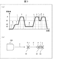
図3は、移動ロボット100の動作の一例を例示する。より具体的には、図3の(a)は、時間に対する移動ロボット100における真空ポンプ4の駆動量のグラフを例示している。また、図3の(b)は、移動ロボット100及び作業位置と、期間との関係を例示している。作業位置は、第1の作業位置X1、第2の作業位置X2及び第3の作業位置X3のことを指す。期間は、第1の移動期間a、位置調整期間b、第1の把持期間c、第2の移動期間d、第2の把持期間e、第3の移動期間f及び第3の把持期間gを指す。
FIG. 3 illustrates an example of the operation of the
以下で説明する動作手順は一例に過ぎず、各動作は可能な限り変更されてもよい。また、以下で説明する動作手順について、実施の形態に応じて、適宜、省略、置換、及び追加が可能である。 The operation procedure described below is merely an example, and each operation may be changed as much as possible. Further, the operation procedure described below can be appropriately omitted, replaced, or added according to the embodiment.
まず、移動ロボット100における制御信号出力部12は、無人搬送車11における搬送制御部111から搬送状態信号を受信する。制御信号出力部12は、当該搬送状態信号に基づき、第1の移動期間aを検知し、当該第1の移動期間aを設ける。無人搬送車11が第1の作業位置X1まで第1の移動期間aだけかけて移動ロボット100を移動させている間、制御信号出力部12は、真空ポンプ4の駆動量を0に制御する。
First, the control
次に、制御信号出力部12は、搬送制御部111から搬送状態信号を受信する。制御信号出力部12は、当該搬送状態信号に基づき、位置調整期間bを検知し、当該位置調整期間bを設ける。位置調整期間bは、無人搬送車11による移動が停止しており、ロボットアーム2によって対象物の把持動作が行われる直前の期間において、ロボットアーム2の位置を調整する期間を指す。ロボットアーム2の位置、すなわち、ロボットアーム2における吸着部22の位置は、マニピュレータ制御部3が、ロボットアーム2におけるマニピュレータ部21を制御することによって調整される。ロボットアーム2の位置が位置調整期間bだけかけて調整されている間、制御信号出力部12は、真空ポンプ4の駆動量を駆動量A2に制御する。
Next, the control
次に、制御信号出力部12は、搬送制御部111から搬送状態信号を受信する。制御信号出力部12は、当該搬送状態信号に基づき、第1の把持期間cを検知し、当該第1の把持期間cを設ける。第1の把持期間cは、第1の作業位置X1においてロボットアーム2によって対象物の把持動作が行われる期間を指す。第1の作業位置X1において移動ロボット100が停止した状態でロボットアーム2が第1の把持期間cだけかけて対象物を把持している間、制御信号出力部12は、真空ポンプ4の駆動量をピッキング(把持)用の駆動量Pに制御する。
Next, the control
次に、制御信号出力部12は、搬送制御部111から搬送状態信号を受信する。制御信号出力部12は、当該搬送状態信号に基づき、第2の移動期間dを検知し、当該第2の移動期間dを設ける。第2の移動期間dは、第1の作業位置X1から第2の作業位置X2に移動ロボット100が移動する期間を指す。第1の作業位置X1から第2の作業位置X2に第2の移動期間dだけかけて移動ロボット100が移動している間、制御信号出力部12は、真空ポンプ4の駆動量をアイドリング用の駆動量A3に制御する。
Next, the control
次に、制御信号出力部12は、搬送制御部111から搬送状態信号を受信する。制御信号出力部12は、当該搬送状態信号に基づき、第2の把持期間eを検知し、当該第2の把持期間eを設ける。第2の把持期間eは、第2の作業位置X2においてロボットアーム2によって対象物の把持動作が行われる期間を指す。第2の作業位置X2において移動ロボット100が停止した状態でロボットアーム2が第2の把持期間eだけかけて対象物を把持している間、制御信号出力部12は、真空ポンプ4の駆動量を駆動量Pに制御する。
Next, the control
次に、制御信号出力部12は、搬送制御部111から搬送状態信号を受信する。制御信号出力部12は、当該搬送状態信号に基づき、第3の移動期間fを検知し、当該第3の移動期間fを設ける。第3の移動期間fは、第2の作業位置X2から第3の作業位置X3に移動ロボット100が移動する期間を指す。第2の作業位置X2から第3の作業位置X3に第3の移動期間fだけかけて移動ロボット100が移動している間、制御信号出力部12は、真空ポンプ4の駆動量をアイドリング用の駆動量A1に制御する。
Next, the control
次に、制御信号出力部12は、搬送制御部111から搬送状態信号を受信する。制御信号出力部12は、当該搬送状態信号に基づき、第3の把持期間gを検知し、当該第3の把持期間gを設ける。第3の把持期間gは、第3の作業位置X3においてロボットアーム2によって対象物の把持動作が行われる期間を指す。第3の作業位置X3において移動ロボット100が停止した状態でロボットアーム2が第3の把持期間gだけかけて対象物を把持している間、制御信号出力部12は、真空ポンプ4の駆動量を駆動量Pに制御する。
Next, the control
図3の(a)の例では、制御信号出力部12は位置調整期間bを設け、把持期間(第1の把持期間c、第2の把持期間e及び第3の把持期間g)における真空ポンプ4の駆動量P、位置調整期間bにおける真空ポンプ4の駆動量A2、並びに、第1の移動期間a及び第2の移動期間dにおける真空ポンプ4の駆動量0及びA3が、この順に小さくなるように制御を行っている。
In the example of FIG. 3A, the control
このように、位置調整期間bにおいて真空ポンプ4をある程度駆動しておくことによって、特に、初めて把持期間(第1の把持期間c)における真空ポンプ4の駆動量Pに移行させる際に、突入電流を抑制することができる。また、把持期間(第1の把持期間c)への遷移時に迅速に把持期間(第1の把持期間c)における真空ポンプ4の駆動量Pに移行させることができる。 As described above, by driving the vacuum pump 4 to some extent in the position adjustment period b, especially when the vacuum pump 4 is shifted to the driving amount P of the vacuum pump 4 in the gripping period (first gripping period c) for the first time, the rush current is reduced. Can be suppressed. Further, at the time of transition to the gripping period (first gripping period c), it is possible to promptly shift to the driving amount P of the vacuum pump 4 in the gripping period (first gripping period c).
図3の(a)の例では、制御信号出力部12は、移動期間における移動距離の長さに応じて、真空ポンプ4の駆動量を変更するように制御を行っている。具体的には、制御信号出力部12は、第1の作業位置X1までの移動距離が長距離である第1の移動期間aにおいては、真空ポンプ4の駆動量を0に制御している。また、制御信号出力部12は、第1の作業位置X1から第2の作業位置X2までの移動距離が中距離である第2の移動期間dにおいては、真空ポンプ4の駆動量をA3に制御している。また、制御信号出力部12は、第2の作業位置から第3の作業位置X3までの移動距離が短距離である第3の移動期間fにおいては、真空ポンプ4の駆動量をA1に制御している。
In the example of FIG. 3A, the control
このように、一方の作業位置から他方の作業位置までの移動距離が長距離である場合には、制御信号出力部12は、真空ポンプ4の駆動量を0に制御し、中距離である場合には、真空ポンプ4の駆動量を、真空ポンプ4が停止しない程度に小さく制御している。これにより、消費電力を低減することができる。また、一方の作業位置から他方の作業位置までの移動距離が短距離である場合には、制御信号出力部12は、真空ポンプ4の駆動量を、移動距離が短距離及び中距離である場合の真空ポンプ4の駆動量0及びA3に比べて高いA1に制御している。これにより、把持期間(第3の把持期間g)への遷移時に迅速に当該把持期間における真空ポンプ4の駆動量に移行させることができる。
As described above, when the moving distance from one working position to the other working position is a long distance, the control
図3の(a)の例では、制御信号出力部12が、期間(第1の移動期間a、位置調整期間b、第1の把持期間c、第2の移動期間d、第2の把持期間e、第3の移動期間f及び第3の把持期間g)の遷移時に所定の遷移期間(第1の遷移期間h、第2の遷移期間i、第3の遷移期間j、第4の遷移期間k、第5の遷移期間l、及び第6の遷移期間m)を設けている。また、制御信号出力部12におけるアナログ信号出力部121が、当該遷移期間において、アナログ信号を単調増加又は単調減少させる制御を行っている。これにより、真空ポンプ4の駆動量をスロープ状に変化させることができるため、突入電流を低減することができる。また、消費電力を低減し、制御を安定化することができる。
In the example of FIG. 3A, the control
§4 変形例
以上、本発明の実施の形態を詳細に説明してきたが、上述の説明はあらゆる点において本発明の例示に過ぎない。本発明の範囲を逸脱することなく種々の改良及び変形を行うことができることは言うまでもない。例えば、以下のような変更が可能である。以下、変形例に係る移動ロボット1000について図4を参照して説明する。説明の便宜上、上述の実施形態と同様の部材に関しては同様の符号を用い、上述の実施形態と同様の点については、適宜説明を省略する。
§4 Modifications While the embodiments of the present invention have been described in detail, the above description is merely an example of the present invention in every respect. It goes without saying that various improvements and modifications can be made without departing from the scope of the invention. For example, the following changes are possible. Hereinafter, a
図4は、変形例に係る移動ロボットのハードウェア構成の一例を模式的に例示する。 FIG. 4 schematically illustrates an example of a hardware configuration of a mobile robot according to a modification.
図4の例では、移動ロボット1000は、搬送部1の代わりに切替回路6、搬送部10及びバッテリー55を備えている。この点以外は、移動ロボット1000は、移動ロボット100と同様の構成である。
In the example of FIG. 4, the
切替回路6は、搬送部10における制御信号出力部120から2値のデジタル信号を入力し、入力値に応じたアナログ信号を真空ポンプ4の制御信号として出力する。切替回路6には、例えば、SPEED信号切替回路が用いられる。
The
搬送部10は、制御信号出力部12の代わりに制御信号出力部120を備えている。この点以外は、搬送部10は、搬送部1と同様の構成である。
The
制御信号出力部120は、制御信号出力部12におけるアナログ信号出力部121の代わりに、切替回路6に対してデジタル信号を出力するデジタル信号出力部1201を備えている。デジタル信号出力部1201は、把持期間に第1の値のデジタル信号を出力し、移動期間に第2の値のデジタル信号を出力する。
The control
これにより、制御信号出力部120は、把持期間におけるピッキング用の真空ポンプ4の駆動量と、移動期間におけるアイドリング用の真空ポンプ4の駆動量との2通りの駆動量の制御であれば、デジタル信号を出力するデジタル信号出力部1201のみを備えていればよい。そのため、制御信号出力部120は、アナログ信号を出力するアナログI/Oユニット等のアナログ信号出力部121を備えている必要がない。また、切替回路6は、2値のデジタル信号を入力し、入力値に応じたアナログ信号を出力する簡単な構成であるため、安価な回路によって実現できる。よって、全体としてコストの低減を図ることができる。
Accordingly, the control
バッテリー55は、搬送部1の代わりに、切替回路6及び搬送部10に電力を供給する以外は、バッテリー5と同様に移動ロボット1000の各部を制御する。
The
§5 まとめ
本発明の態様1に係る移動ロボット100、1000は、無人搬送車11と、負圧により対象物を吸着することによって把持動作を行うロボットアーム2と、前記負圧を発生させる真空ポンプ4を制御する制御部(制御信号出力部12、120)であって、前記ロボットアーム2によって前記対象物の前記把持動作が行われている把持期間(第1の把持期間c、第2の把持期間e、第3の把持期間g)における前記真空ポンプ4の駆動量Pが、前記ロボットアーム2によって前記対象物の前記把持動作が行われていない状態で前記無人搬送車11による移動が行われている移動期間(第1の移動期間a、第2の移動期間d)における前記真空ポンプ4の駆動量A2、A3よりも大きくなるように制御を行う制御部(制御信号出力部12、120)と、を備える。
§5 Conclusion The
本発明の態様2に係る移動ロボット100、1000は、上記態様1において、前記制御部(制御信号出力部12、120)は、前記無人搬送車11による移動が停止しており、前記ロボットアーム2によって前記対象物の前記把持動作が行われる直前の期間において、前記ロボットアーム2の位置を調整する位置調整期間bをさらに設け、前記把持期間(第1の把持期間c、第2の把持期間e、第3の把持期間g)における前記真空ポンプ4の駆動量P、前記位置調整期間bにおける前記真空ポンプ4の駆動量A2、及び、前記移動期間(第1の移動期間a、第2の移動期間d)における前記真空ポンプ4の駆動量A2、A3が、この順で小さくなるように制御を行ってもよい。
In the
本発明の態様3に係る移動ロボット100、1000は、上記態様1又は2において、前記制御部(制御信号出力部12、120)は、前記移動期間(第1の移動期間a、第2の移動期間d、第3の移動期間f)における移動距離の長さに応じて、前記真空ポンプ4の駆動量を変更するように制御を行ってもよい。
In the
本発明の態様4に係る移動ロボット100は、上記態様1〜3のいずれかにおいて、前記制御部(制御信号出力部12)は、アナログ信号を前記真空ポンプ4の制御信号として出力するアナログ信号出力部121を備え、前記アナログ信号出力部121は、前記期間(第1の移動期間a、位置調整期間b、第1の把持期間c、第2の移動期間d、第2の把持期間e、第3の移動期間f、第3の把持期間g)の遷移時に所定の遷移期間(第1の遷移期間h、第2の遷移期間i、第3の遷移期間j、第4の遷移期間k、第5の遷移期間l)を設けるとともに、該遷移期間(第1の遷移期間h、第2の遷移期間i、第3の遷移期間j、第4の遷移期間k、第5の遷移期間l、及び第6の遷移期間m)において、前記アナログ信号を単調増加又は単調減少させる制御を行ってもよい。
In the
本発明の態様5に係る移動ロボット1000は、上記態様1〜3のいずれかにおいて、前記制御部(制御信号出力部120)から2値のデジタル信号を入力し、入力値に応じたアナログ信号を前記真空ポンプ4の制御信号として出力する切替回路6をさらに備え、前記制御部(制御信号出力部120)は、前記切替回路6に対して前記デジタル信号を出力するデジタル信号出力部1201を備え、前記デジタル信号出力部1201は、前記把持期間(第1の把持期間c、第2の把持期間e、第3の把持期間g)に第1の値のデジタル信号を出力し、前記移動期間(第1の移動期間a、第2の移動期間d)に第2の値のデジタル信号を出力してもよい。
The
本発明の態様6に係る移動ロボット100、1000は、上記態様1〜5のいずれかにおいて、前記制御部(制御信号出力部12、120)は、前記無人搬送車11から受信する搬送状態信号に基づいて、前記期間(第1の移動期間a、位置調整期間b、第1の把持期間c、第2の移動期間d、第2の把持期間e、第3の移動期間f、第3の把持期間g)を検知してもよい。
In the
1、10 搬送部
2 ロボットアーム
3 マニピュレータ制御部
4 真空ポンプ
5、55 バッテリー
6 切替回路
11 無人搬送車
12、120 制御信号出力部(制御部)
21 マニピュレータ部
22 吸着部
100、1000 移動ロボット
111 搬送制御部
121 アナログ信号出力部
1201 デジタル信号出力部
a 第1の移動期間(移動期間)
b 位置調整期間
c 第1の把持期間(把持期間)
d 第2の移動期間(移動期間)
e 第2の把持期間(把持期間)
f 第3の移動期間(移動期間)
g 第3の把持期間(把持期間)
h 第1の遷移期間(遷移期間)
i 第2の遷移期間(遷移期間)
j 第3の遷移期間(遷移期間)
k 第4の遷移期間(遷移期間)
l 第5の遷移期間(遷移期間)
m 第6の遷移期間(遷移期間)
X1 第1の作業位置
X2 第2の作業位置
X3 第3の作業位置
1, 10
b Position adjustment period c First grip period (grip period)
d Second moving period (moving period)
e Second gripping period (gripping period)
f Third moving period (moving period)
g Third gripping period (gripping period)
h First transition period (transition period)
i Second transition period (transition period)
j Third transition period (transition period)
k Fourth transition period (transition period)
l Fifth transition period (transition period)
m Sixth transition period (transition period)
X1 First work position X2 Second work position X3 Third work position
Claims (6)
負圧により対象物を吸着することによって把持動作を行うロボットアームと、
前記負圧を発生させる真空ポンプを制御する制御部であって、前記ロボットアームによって前記対象物の前記把持動作が行われている把持期間における前記真空ポンプの駆動量が、前記ロボットアームによって前記対象物の前記把持動作が行われていない状態で前記無人搬送車による移動が行われている移動期間における前記真空ポンプの駆動量よりも大きくなるように制御を行う制御部と、
を備える移動ロボット。 Automatic guided vehicles,
A robot arm that performs a gripping operation by attracting an object by negative pressure,
A control unit that controls a vacuum pump that generates the negative pressure, wherein a driving amount of the vacuum pump during a gripping period in which the gripping operation of the target is performed by the robot arm is performed by the robot arm. A control unit that performs control such that the driving amount of the vacuum pump is larger than a driving amount of the vacuum pump during a movement period in which the movement by the automatic guided vehicle is performed in a state where the gripping operation of the object is not performed,
Mobile robot equipped with.
前記無人搬送車による移動が停止しており、前記ロボットアームによって前記対象物の前記把持動作が行われる直前の期間において、前記ロボットアームの位置を調整する位置調整期間をさらに設け、
前記把持期間における前記真空ポンプの駆動量、前記位置調整期間における前記真空ポンプの駆動量、及び、前記移動期間における前記真空ポンプの駆動量が、この順で小さくなるように制御を行う請求項1に記載の移動ロボット。 The control unit includes:
The movement by the automatic guided vehicle is stopped, and in a period immediately before the gripping operation of the object is performed by the robot arm, a position adjustment period for adjusting the position of the robot arm is further provided,
The control is performed such that the drive amount of the vacuum pump during the gripping period, the drive amount of the vacuum pump during the position adjustment period, and the drive amount of the vacuum pump during the movement period are reduced in this order. The mobile robot according to 1.
前記移動期間における移動距離の長さに応じて、前記真空ポンプの駆動量を変更するように制御を行う請求項1又は2に記載の移動ロボット。 The control unit includes:
The mobile robot according to claim 1, wherein control is performed to change a driving amount of the vacuum pump according to a length of a moving distance in the moving period.
前記アナログ信号出力部は、前記期間の遷移時に所定の遷移期間を設けるとともに、該遷移期間において、前記アナログ信号を単調増加又は単調減少させる制御を行う請求項1〜3のいずれか1項に記載の移動ロボット。 The control unit includes an analog signal output unit that outputs an analog signal as a control signal of the vacuum pump,
4. The analog signal output unit according to claim 1, wherein a predetermined transition period is provided at a transition of the period, and control is performed to monotonically increase or decrease the analog signal during the transition period. 5. Mobile robot.
前記制御部は、前記切替回路に対して前記デジタル信号を出力するデジタル信号出力部を備え、
前記デジタル信号出力部は、前記把持期間に第1の値のデジタル信号を出力し、前記移動期間に第2の値のデジタル信号を出力する請求項1〜3のいずれか1項に記載の移動ロボット。 A switching circuit that inputs a binary digital signal from the control unit and outputs an analog signal corresponding to the input value as a control signal of the vacuum pump;
The control unit includes a digital signal output unit that outputs the digital signal to the switching circuit,
The movement according to any one of claims 1 to 3, wherein the digital signal output unit outputs a digital signal having a first value during the holding period, and outputs a digital signal having a second value during the movement period. robot.
Priority Applications (2)
| Application Number | Priority Date | Filing Date | Title |
|---|---|---|---|
| JP2018168032A JP6988747B2 (en) | 2018-09-07 | 2018-09-07 | Mobile robot |
| PCT/JP2019/034899 WO2020050345A1 (en) | 2018-09-07 | 2019-09-05 | Moving robot |
Applications Claiming Priority (1)
| Application Number | Priority Date | Filing Date | Title |
|---|---|---|---|
| JP2018168032A JP6988747B2 (en) | 2018-09-07 | 2018-09-07 | Mobile robot |
Publications (2)
| Publication Number | Publication Date |
|---|---|
| JP2020040146A true JP2020040146A (en) | 2020-03-19 |
| JP6988747B2 JP6988747B2 (en) | 2022-01-05 |
Family
ID=69721513
Family Applications (1)
| Application Number | Title | Priority Date | Filing Date |
|---|---|---|---|
| JP2018168032A Active JP6988747B2 (en) | 2018-09-07 | 2018-09-07 | Mobile robot |
Country Status (2)
| Country | Link |
|---|---|
| JP (1) | JP6988747B2 (en) |
| WO (1) | WO2020050345A1 (en) |
Citations (7)
| Publication number | Priority date | Publication date | Assignee | Title |
|---|---|---|---|---|
| JPH073987U (en) * | 1993-06-08 | 1995-01-20 | シチズン時計株式会社 | Traveling robot |
| JP2000110735A (en) * | 1998-10-01 | 2000-04-18 | Internatl Business Mach Corp <Ibm> | Pump protection system, pump protection method, and pump system |
| WO2007041003A2 (en) * | 2005-09-30 | 2007-04-12 | Photon Dynamics, Inc. | Vacuum gripping system for positioning large thin substrate on a support table |
| JP2009027976A (en) * | 2007-07-26 | 2009-02-12 | National Agriculture & Food Research Organization | Holding apparatus |
| JP2010075612A (en) * | 2008-09-29 | 2010-04-08 | Panasonic Corp | Vacuum cleaner |
| US20150032252A1 (en) * | 2013-07-25 | 2015-01-29 | IAM Robotics, LLC | System and method for piece-picking or put-away with a mobile manipulation robot |
| JP2016048474A (en) * | 2014-08-27 | 2016-04-07 | シャープ株式会社 | Autonomous mobile body and autonomous mobile body system |
-
2018
- 2018-09-07 JP JP2018168032A patent/JP6988747B2/en active Active
-
2019
- 2019-09-05 WO PCT/JP2019/034899 patent/WO2020050345A1/en active Application Filing
Patent Citations (7)
| Publication number | Priority date | Publication date | Assignee | Title |
|---|---|---|---|---|
| JPH073987U (en) * | 1993-06-08 | 1995-01-20 | シチズン時計株式会社 | Traveling robot |
| JP2000110735A (en) * | 1998-10-01 | 2000-04-18 | Internatl Business Mach Corp <Ibm> | Pump protection system, pump protection method, and pump system |
| WO2007041003A2 (en) * | 2005-09-30 | 2007-04-12 | Photon Dynamics, Inc. | Vacuum gripping system for positioning large thin substrate on a support table |
| JP2009027976A (en) * | 2007-07-26 | 2009-02-12 | National Agriculture & Food Research Organization | Holding apparatus |
| JP2010075612A (en) * | 2008-09-29 | 2010-04-08 | Panasonic Corp | Vacuum cleaner |
| US20150032252A1 (en) * | 2013-07-25 | 2015-01-29 | IAM Robotics, LLC | System and method for piece-picking or put-away with a mobile manipulation robot |
| JP2016048474A (en) * | 2014-08-27 | 2016-04-07 | シャープ株式会社 | Autonomous mobile body and autonomous mobile body system |
Also Published As
| Publication number | Publication date |
|---|---|
| JP6988747B2 (en) | 2022-01-05 |
| WO2020050345A1 (en) | 2020-03-12 |
Similar Documents
| Publication | Publication Date | Title |
|---|---|---|
| US9957116B2 (en) | Method for providing vacuum to a moving element | |
| WO2017104648A1 (en) | Substrate transfer robot and method for operating same | |
| KR102146143B1 (en) | Conveyance base and conveyance system | |
| KR101752507B1 (en) | Substrate transfer apparatus, substrate transfer method and storage medium | |
| JPH10118969A (en) | Conveying object adsorptive device | |
| JP5633555B2 (en) | Robot system | |
| WO2020050345A1 (en) | Moving robot | |
| JP5449856B2 (en) | Semiconductor wafer transfer method | |
| JP6326130B2 (en) | Substrate transfer device | |
| JP2004079569A (en) | Substrate transport apparatus and substrate transport method | |
| JP2005052919A (en) | Acceleration control method of work carrying device | |
| KR20140123207A (en) | Conveyor apparatus for rotating a meterial in material production equipment | |
| KR20210043785A (en) | Object transport apparatus and object transport method | |
| JP6204498B2 (en) | Electronic component mounting machine | |
| JP2008022044A (en) | Circuit component mounting system | |
| JP2002307361A (en) | Member carrier device and member positioning method | |
| JP2016203201A (en) | Automatic programming device, loader device, and plate-material conveyance method | |
| JP2006005136A (en) | Transporting apparatus | |
| JP2001219390A (en) | Carrying device | |
| CN111341709B (en) | Substrate transmission method, control module and substrate transmission system | |
| JP6667028B2 (en) | Transfer apparatus, control method thereof, and substrate processing system | |
| JP2007184657A (en) | Circuit component mounting system | |
| JP2019004259A (en) | Communication device and robot system | |
| JP2001127492A (en) | Variable speed system for printed board conveyor | |
| JP2006153483A (en) | Semiconductor manufacturing apparatus |
Legal Events
| Date | Code | Title | Description |
|---|---|---|---|
| A621 | Written request for application examination |
Free format text: JAPANESE INTERMEDIATE CODE: A621 Effective date: 20201215 |
|
| A131 | Notification of reasons for refusal |
Free format text: JAPANESE INTERMEDIATE CODE: A131 Effective date: 20210511 |
|
| A521 | Request for written amendment filed |
Free format text: JAPANESE INTERMEDIATE CODE: A523 Effective date: 20210604 |
|
| TRDD | Decision of grant or rejection written | ||
| A01 | Written decision to grant a patent or to grant a registration (utility model) |
Free format text: JAPANESE INTERMEDIATE CODE: A01 Effective date: 20211102 |
|
| A61 | First payment of annual fees (during grant procedure) |
Free format text: JAPANESE INTERMEDIATE CODE: A61 Effective date: 20211115 |
|
| R150 | Certificate of patent or registration of utility model |
Ref document number: 6988747 Country of ref document: JP Free format text: JAPANESE INTERMEDIATE CODE: R150 |