JP2020038031A - Ventilation hole terminal member and building - Google Patents

Ventilation hole terminal member and building Download PDF

Info

Publication number
JP2020038031A
JP2020038031A JP2018165092A JP2018165092A JP2020038031A JP 2020038031 A JP2020038031 A JP 2020038031A JP 2018165092 A JP2018165092 A JP 2018165092A JP 2018165092 A JP2018165092 A JP 2018165092A JP 2020038031 A JP2020038031 A JP 2020038031A
Authority
JP
Japan
Prior art keywords
plate
terminal member
elastic support
water drop
receiving plate
Prior art date
Legal status (The legal status is an assumption and is not a legal conclusion. Google has not performed a legal analysis and makes no representation as to the accuracy of the status listed.)
Granted
Application number
JP2018165092A
Other languages
Japanese (ja)
Other versions
JP7212479B2 (en
Inventor
憲太郎 野田
Kentaro Noda
憲太郎 野田
拓 黒木
Taku Kuroki
拓 黒木
大脇 雅直
Masanao Owaki
雅直 大脇
徳人 水野
Norihito Mizuno
徳人 水野
正輝 成▲瀬▼
Masaki Naruse
正輝 成▲瀬▼
田中 祐介
Yusuke Tanaka
祐介 田中
Current Assignee (The listed assignees may be inaccurate. Google has not performed a legal analysis and makes no representation or warranty as to the accuracy of the list.)
Kumagai Gumi Co Ltd
Mitsubishi Jisho Residence Co Ltd
Melco Airtec Corp
Original Assignee
Kumagai Gumi Co Ltd
Mitsubishi Jisho Residence Co Ltd
Melco Airtec Corp
Priority date (The priority date is an assumption and is not a legal conclusion. Google has not performed a legal analysis and makes no representation as to the accuracy of the date listed.)
Filing date
Publication date
Application filed by Kumagai Gumi Co Ltd, Mitsubishi Jisho Residence Co Ltd, Melco Airtec Corp filed Critical Kumagai Gumi Co Ltd
Priority to JP2018165092A priority Critical patent/JP7212479B2/en
Publication of JP2020038031A publication Critical patent/JP2020038031A/en
Application granted granted Critical
Publication of JP7212479B2 publication Critical patent/JP7212479B2/en
Active legal-status Critical Current
Anticipated expiration legal-status Critical

Links

Images

Abstract

To provide a ventilation hole terminal member, etc. that have improved an effect to reduce the sound of middle and high frequency bandwidths when waterdrops fall and collide.SOLUTION: A ventilation hole terminal member is attached to a ventilation hole formed in an outer wall of a building, and includes a hood part 3 protruding from an outer wall surface of the building to the outside of the building, and a waterdrop receiving plate 5 provided on a top plate 32 of the hood part 3 through an elastic support body 4. A primary natural frequency fof a vibration proofing body composed of the waterdrop receiving plate 5 and the elastic support body 4 is set to be a frequency of 16 Hz or higher and 125 Hz or lower in an octave band.SELECTED DRAWING: Figure 1

Description

本発明は、水滴落下衝突音の居室内への伝播を低減させることができる構造を備えた換気口端末部材等に関する。   The present invention relates to a ventilation port terminal member and the like provided with a structure capable of reducing propagation of a water drop impact sound into a living room.

集合住宅、ホテル、事務所ビル等の建物においては、換気設備の設置が義務付けられている。当該換気設備としては、居室に換気口が設置されて、居室の外壁にベントキャップ等と呼称される換気口端末部材が設置されることが多い。
当該換気口端末部材は、フード部が外壁面よりも外側に突出するように建物の上下階の外壁の換気孔にそれぞれ取付けられ、上下階の各換気口端末部材が、垂直線上に位置されることが多い。
当該建物においては、降雨等の後に、上階の換気口端末部材から水滴が落下して下階の換気口端末部材のフード部の天板の上に衝突した際に、水滴落下衝突音が生じ、当該水滴落下衝突音が固体伝播音として居室内に伝播する。
当該水滴落下衝突音の低下対策を施した換気口端末部材としては、例えば、フード部の天板の上に弾性支持体を介して水滴受板が設けられた構造のものが知られている(特許文献1参照)。
In buildings such as multi-family dwellings, hotels, office buildings, etc., installation of ventilation equipment is obligatory. As the ventilation equipment, a ventilation opening is often installed in a living room, and a ventilation opening terminal member called a vent cap or the like is often installed on an outer wall of the living room.
The ventilation port terminal members are respectively attached to the ventilation holes of the outer walls of the upper and lower floors of the building such that the hood portion protrudes outside the outer wall surface, and the respective ventilation port terminal members of the upper and lower floors are positioned on a vertical line. Often.
In the building, when water drops fall from the terminal member on the upper floor and collide with the top plate of the hood part of the terminal member on the lower floor after rainfall, a water drop falling sound is generated. Then, the water drop impact sound propagates into the living room as solid sound.
As a vent opening terminal member which has taken measures to reduce the water drop impact sound, for example, one having a structure in which a water drop receiving plate is provided on a top plate of a hood via an elastic support member is known ( Patent Document 1).

特許第5258712号公報Japanese Patent No. 5258712

しかしながら、特許文献1に開示された換気口端末部材では、弾性支持体が支持板と弾性部材とで構成される。当該弾性支持体の支持板は、板厚1mm前後であるため剛性が高く、弾性部材はゴムであるので、弾性支持体と水滴受板とで構成される防振体の一次固有振動数fが高くなり、上述した水滴落下衝突時における中高周波数帯域の音を低減させる効果が十分ではないという課題があった。
本願発明は、水滴落下衝突時における中高周波数帯域の音を低減させる効果を向上させた換気口端末部材等を提供するものである。
However, in the ventilation port terminal member disclosed in Patent Literature 1, the elastic support is configured by the support plate and the elastic member. Since the support plate of the elastic support has a plate thickness of about 1 mm, it has high rigidity, and the elastic member is rubber. Therefore, the primary natural frequency f 0 of the vibration isolator composed of the elastic support and the water drop receiving plate is provided. Therefore, there is a problem that the effect of reducing the sound in the middle and high frequency bands at the time of the above-mentioned water drop falling collision is not sufficient.
SUMMARY OF THE INVENTION The present invention provides a vent port terminal member and the like having an improved effect of reducing sound in a middle and high frequency band at the time of a water drop falling collision.

本発明に係る換気口端末部材は、建物の外壁に形成された換気孔に取付けられる換気口端末部材であって、建物の外壁面より建物の外側に突出するフード部と、フード部の天板の上に弾性支持体を介して設けられた水滴受板とを備え、水滴受板と弾性支持体とで構成される防振体の一次固有振動数fが、オクターブバンドの16Hz以上で125Hz以下の周波数となるように設定されたことを特徴とする。
また、弾性支持体が板ばねであることを特徴とする。請求項1に記載の換気口端末部材。
また、弾性支持体がコイルばねであることを特徴とする。
以上のように構成された換気口端末部材によれば、水滴落下衝突時における中高周波数帯域の音を低減させる効果が向上した換気口端末部材を得ることができる。
また、弾性支持体がゴムであることを特徴とする。
また、弾性支持体がばねとゴムとで構成されたことを特徴とする。
以上のように構成された換気口端末部材によれば、ゴムが有する減衰の効果によって、防振体の共振ポイントの増幅倍率を低下させる効果が付与されるので、共振ポイントの弊害を抑えて水滴落下衝突音の低減効果を向上した換気口端末部材を得ることができる。
また、水滴受板の板厚を0.5mm〜5mmとしたことによって、水滴受板と弾性支持体とで構成される防振体の一次固有振動数fが、オクターブバンドの16Hz以上で125Hz以下の周波数となるように設定されたことを特徴とするので、防振体を構造体として成立させることができて、かつ、水滴落下衝突時における中高周波数帯域の音を低減させることができる換気口端末部材を得ることができる。
また、本発明に係る建物は、上述したいずれかの換気口端末部材のフード部及び水滴受板が外壁面よりも外側に突出するように当該換気口端末部材が外壁に設けられた建物であって、建物の上下階の外壁に設けられた各換気口端末部材の各水滴受板が、垂直線上に位置されたので、上階の換気口端末部材から水滴が落下して下階の換気口端末部材の水滴受板に衝突した際に生じる水滴落下衝突音の低減効果に優れた建物を提供できる。
The ventilation port terminal member according to the present invention is a ventilation port terminal member attached to a ventilation hole formed on an outer wall of a building, a hood portion projecting outside the building from an outer wall surface of the building, and a top plate of the hood portion And a water drop receiving plate provided on an elastic support via an elastic support, and a primary natural frequency f 0 of the vibration isolator formed of the water drop receiving plate and the elastic support is 125 Hz in an octave band of 16 Hz or more. The frequency is set to be as follows.
Further, the elastic support is a leaf spring. A vent terminal member according to claim 1.
Further, the elastic support is a coil spring.
According to the ventilation port terminal member configured as described above, it is possible to obtain a ventilation port terminal member having an improved effect of reducing the sound in the middle and high frequency bands at the time of a water drop falling collision.
Further, the elastic support is made of rubber.
Further, the elastic support is constituted by a spring and rubber.
According to the ventilation port terminal member configured as described above, the effect of reducing the amplification factor of the resonance point of the vibration isolator is provided by the damping effect of the rubber, so that the adverse effect of the resonance point is suppressed and water droplets are suppressed. It is possible to obtain a ventilation port terminal member having an improved effect of reducing a falling collision sound.
Further, by setting the thickness of the water drop receiving plate to 0.5 mm to 5 mm, the primary natural frequency f 0 of the vibration isolator formed of the water drop receiving plate and the elastic support is 125 Hz at 16 Hz or more of the octave band. Since it is characterized by being set to have the following frequencies, the vibration isolator can be realized as a structure, and the sound in the middle and high frequency band at the time of a water drop falling collision can be reduced. A mouth end member can be obtained.
Further, the building according to the present invention is a building in which the ventilation port terminal member is provided on the outer wall such that the hood portion and the water drop receiving plate of any of the above-described ventilation port terminal members project outside the outer wall surface. Since the water drop receiving plate of each ventilation port terminal member provided on the outer wall of the upper and lower floors of the building is located on a vertical line, water drops fall from the upper floor ventilation port terminal member and the lower floor ventilation port It is possible to provide a building that is excellent in the effect of reducing the sound of a water drop falling when it collides with the water drop receiving plate of the terminal member.

換気口端末部材を前側から見た斜視図(実施形態1)。FIG. 3 is a perspective view of a vent opening terminal member viewed from the front side (first embodiment). 換気口端末部材を後側から見た斜視図(実施形態1)。The perspective view which looked at the ventilation-port terminal member from the back side (first embodiment). 換気口端末部材の正面図(実施形態1)。FIG. 3 is a front view of a vent terminal member (first embodiment). 換気口端末部材の背面図(実施形態1)。The rear view of a ventilation port terminal member (Embodiment 1). 建物の上下階の外壁に取付けられた上の換気口端末部材から下の換気口端末部材に水滴が落下する状態を示す図(実施形態1)。The figure which shows the state which a water drop falls from the upper ventilation port terminal member attached to the outer wall of the upper and lower floors of a building to the lower ventilation port terminal member (Embodiment 1). 弾性支持体の構造を示す断面図(実施形態1)。Sectional drawing which shows the structure of an elastic support (Embodiment 1). 弾性支持体の構造を示す断面図(実施形態2)。Sectional drawing which shows the structure of an elastic support (Embodiment 2). 弾性支持体の構造を示す断面図(実施形態3)。Sectional drawing which shows the structure of an elastic support (Embodiment 3). 弾性支持体の構造を示す断面図(実施形態4)。Sectional drawing which shows the structure of an elastic support (Embodiment 4). 弾性支持体の構造を示す断面図(実施形態5)。Sectional drawing which shows the structure of an elastic support (Embodiment 5). 弾性支持体の構造を示す断面図(実施形態6)。Sectional drawing which shows the structure of an elastic support (Embodiment 6). 弾性支持体の構造を示す断面図(実施形態7)。Sectional drawing which shows the structure of an elastic support (Embodiment 7). 弾性支持体の構造を示す断面図(実施形態8)。Sectional drawing which shows the structure of an elastic support (Embodiment 8). 弾性支持体の構造を示す断面図(実施形態9)。Sectional drawing which shows the structure of an elastic support (Embodiment 9). 各試験体での水滴落下衝突音のFFT解析結果を示す図。The figure which shows the FFT analysis result of the water drop falling collision sound in each test body. 各試験体での水滴落下衝突音の測定結果を示す図であり、(a)は数値表、(b)は比較グラフ。It is a figure which shows the measurement result of the water droplet falling collision sound in each test body, (a) is a numerical table, (b) is a comparison graph.

実施形態1
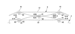
図1乃至図6に示すように、実施形態1に係る換気用端末部材1は、建物90の外壁91に建物90の内外に連通するように形成された換気孔92に挿入される筒部2と、建物90の外壁面93より外側に突出するフード部3と、フード部3の天板32の上に弾性支持体4を介して設けられた水滴受板5とを備え、水滴受板5と弾性支持体4とで構成される防振体の一次固有振動数fが、オクターブバンドの16Hz以上で125Hz以下の周波数となるように設定されている。
当該換気用端末部材1の筒部2、フード部3、水滴受板5は、例えば金属板により形成される。
Embodiment 1
As shown in FIGS. 1 to 6, the ventilation terminal member 1 according to the first embodiment includes a cylindrical portion 2 inserted into a ventilation hole 92 formed in an outer wall 91 of a building 90 so as to communicate with the inside and outside of the building 90. A hood portion 3 protruding outward from an outer wall surface 93 of the building 90; and a water droplet receiving plate 5 provided on a top plate 32 of the hood portion 3 with an elastic support 4 interposed therebetween. The primary natural frequency f 0 of the vibration isolator composed of the elastic support 4 and the elastic support 4 is set to be a frequency of 16 Hz or more and 125 Hz or less in the octave band.
The cylindrical part 2, the hood part 3, and the water drop receiving plate 5 of the terminal member for ventilation 1 are formed of, for example, a metal plate.

図1,図2に示すように、フード部3は、四角形状の前板31と、天板(上板)32と、左側板33と、右側板34と、後板35とを備えた直方体函状に形成されており、下部が開口された室外側通風孔36(図1参照)に形成されて、かつ、後板35を形成する四角形状の板の中央側が開口された室内側通風孔37に形成され、当該室内側通風孔37の孔縁側に筒部2の一端開口縁側が接続されている。即ち、筒部2が、フード部3の後板35に接続されて当該後板35の後方に延長するように設けられた構成となっている。筒部2は、例えば、円筒部に形成される。
即ち、フード部3は、換気口端末部材1が換気孔92に取付けられることによって、下部の室外側通風孔36、及び、室内側通風孔37を介して、建物90の内側から建物90の外側に、又は、建物90の外側から建物90の内側に空気が流通可能となる。
また、室外側通風孔36、及び、室内側通風孔37のうち、少なくとも、一方の通風孔はガラリ38(図1参照)に形成されている。
As shown in FIGS. 1 and 2, the hood portion 3 is a rectangular parallelepiped including a square front plate 31, a top plate (upper plate) 32, a left side plate 33, a right side plate 34, and a rear plate 35. An indoor ventilation hole that is formed in a box shape, is formed in an outdoor ventilation hole 36 (see FIG. 1) having an open lower portion, and has a square plate that forms the rear plate 35 and has a central opening. One end of the cylindrical portion 2 is connected to the edge of the indoor-side ventilation hole 37. That is, the configuration is such that the tubular portion 2 is connected to the rear plate 35 of the hood portion 3 and extends rearward of the rear plate 35. The cylindrical part 2 is formed in a cylindrical part, for example.
That is, the hood portion 3 is configured such that the ventilation port terminal member 1 is attached to the ventilation hole 92, so that the lower side outside ventilation hole 36 and the lower room outside ventilation hole 37 allow the hood portion 3 to extend from the inside of the building 90 to the outside of the building 90. Air can flow from the outside of the building 90 to the inside of the building 90.
Further, at least one of the outdoor-side ventilation holes 36 and the indoor-side ventilation holes 37 is formed in the gallery 38 (see FIG. 1).

換言すれば、フード部3は、四角形状の前板31と、前板31の板面と対向する板面を備えた後板35と、前板31の四角形の上辺と後板35の四角形の上辺とを繋ぐ天板32と、前板31の四角形の上辺の一端より下方に延長する四角形の左辺と後板35の四角形の上辺の一端より下方に延長する左辺とを繋ぐ左側板33と、前板31の四角形の上辺の他端より下方に延長する四角形の右辺と後板35の四角形の上辺の他端より下方に延長する右辺とを繋ぐ右側板34とで構成され、換気口端末部材1が換気孔92に取付けられた場合、これら前板31と天板32と左側板33と右側板34と後板35とで囲まれた空間が、下部の室外側通風孔36を介して室外と連通し、かつ、後板35の室内側通風孔37を介して室内と連通するように構成されている。   In other words, the hood portion 3 includes a square front plate 31, a rear plate 35 having a plate surface facing the plate surface of the front plate 31, and a rectangular upper side of the front plate 31 and a square of the rear plate 35. A top plate 32 connecting the upper side, a left side plate 33 connecting a left side of the square extending below one end of the upper side of the square of the front plate 31 and a left side extending below one end of the upper side of the square of the rear plate 35, A ventilation plate terminal member, comprising a right side plate connecting the right side of the square extending below the other end of the upper side of the square of the front plate 31 and the right side extending below the other end of the upper side of the square of the rear plate 35; 1 is attached to the ventilation hole 92, the space surrounded by the front plate 31, the top plate 32, the left side plate 33, the right side plate 34, and the rear plate 35 is connected to the outside through the lower outdoor ventilation hole 36. So that it communicates with the room through the room-side ventilation hole 37 of the rear plate 35. It has been made.

即ち、換気口端末部材1は、筒部2が筒部2の他端側から建物90の外壁91に形成された換気孔92に挿入されて、フード部3の後板35の後面35aが建物90の外壁面93に近接し、かつ、天板32が上方、左側板33が左側、右側板34が右側に位置された状態となるように設置される。
尚、筒部2の外周面には、例えば図外の板ばねが設けられており、当該筒部2が換気孔92内に押し込まれて当該板ばねが換気孔92の内面にばね弾性によって押し付けられることによって、換気口端末部材1が換気孔92に固定され、当該固定された状態で、フード部3の後板35の上縁、左縁、右縁と外壁面93との隙間にシーリング材等の隙間充填剤が充填されることにより、換気口端末部材1が換気孔92に取付けられる。
That is, in the ventilation port terminal member 1, the cylindrical portion 2 is inserted into the ventilation hole 92 formed in the outer wall 91 of the building 90 from the other end side of the cylindrical portion 2, and the rear surface 35 a of the rear plate 35 of the hood portion 3 is attached to the building. 90, the top plate 32 is located above, the left side plate 33 is located on the left side, and the right side plate 34 is located on the right side.
Note that, for example, a leaf spring (not shown) is provided on the outer peripheral surface of the tubular portion 2. The tubular portion 2 is pushed into the ventilation hole 92, and the leaf spring is pressed against the inner surface of the ventilation hole 92 by spring elasticity. As a result, the ventilation port terminal member 1 is fixed to the ventilation hole 92, and in the fixed state, a sealing material is provided in a gap between the upper edge, the left edge, the right edge, and the outer wall surface 93 of the rear plate 35 of the hood portion 3. And the like, the ventilation port terminal member 1 is attached to the ventilation hole 92.

また、フード部3の後板35の下端側には、フード部35の板面を伝って流れてくる水を受けて当該受けた水を外壁面93から離れた外壁面93の前側に流す水切部39を備える。
水切部39は、例えば、フード部3の後板35において室外側通風孔36よりも下方に突出した部分により形成された奥板39aと、奥板39aの下端側の左右の側縁より突出する突出片39b,39bと、奥板39aの下端及び左右の突出片39b,39bの下端より前方下方に傾斜して突出する傾斜片39cと、傾斜片39cの左右の側縁より上方に立ち上がるように設けられた左右の規制片39d,39dとを備えた構成である。
当該水切部39を備えたので、フード部3の板面を伝って流れてくる水滴が傾斜片39cを介して外壁面93の前側に流下して、下階の換気孔92に取付けられた換気口端末部材1の水滴受板5上に落下するので、水滴が外壁面93を伝って流れ落ちることを防止でき、外壁面93に水跡が付いてしまうことを防止できる。
Further, the lower end of the rear plate 35 of the hood 3 is a drainer that receives water flowing along the plate surface of the hood 35 and flows the received water to a front side of the outer wall 93 away from the outer wall 93. A part 39 is provided.
The draining portion 39 is, for example, a back plate 39a formed by a portion of the rear plate 35 of the hood portion 3 that protrudes below the outdoor ventilation hole 36, and protrudes from left and right side edges at the lower end side of the back plate 39a. The protruding pieces 39b, 39b, the inclined piece 39c that is inclined downward and forward from the lower end of the back plate 39a and the lower ends of the left and right protruding pieces 39b, 39b, and rises above the left and right side edges of the inclined piece 39c. The left and right regulating pieces 39d, 39d are provided.
Since the water draining section 39 is provided, water drops flowing along the plate surface of the hood section 3 flow down to the front side of the outer wall surface 93 via the inclined piece 39c, and the ventilation attached to the ventilation hole 92 on the lower floor. Since the water drops fall on the water drop receiving plate 5 of the mouth end member 1, water drops can be prevented from flowing down the outer wall surface 93 and water marks can be prevented from being formed on the outer wall surface 93.

フード部3の天板32の上に弾性支持体4を介して設けられた水滴受板5は、フード部3の天板32の上方を覆うように配置された屋根形状の板材により構成される。
図1に示すように、例えば、水滴受板5の上面は、寄棟の頂上部がフード部3の天板32の長方形よりも一回り小さい相似な長方形の平面状となった屋根形状に形成される。
換言すれば、水滴受板5は、例えば、フード部3の天板32の長方形よりも一回り小さい長方形状の板により形成されて板面がフード部3の天板32の板面と所定の間隔を隔てて平行に対向すように配置された中央板部51と、当該中央板部51を構成する長方形の各辺縁から対応するフード部3の天板32の長方形の各辺縁に近付くように傾斜する傾斜板により形成された周辺板部52,52…とを備えた構成である。
そして、水滴受板5は、中央板部51を構成する長方形の中心5Cが、フード部3の天板32の板面と直交して当該天板32の長方形の中心を通過する垂直線V上に位置されるように、弾性支持体4を介してフード部3の天板32の上に設けられる。
The water drop receiving plate 5 provided on the top plate 32 of the hood unit 3 via the elastic support 4 is configured by a roof-shaped plate material arranged so as to cover above the top plate 32 of the hood unit 3. .
As shown in FIG. 1, for example, the upper surface of the water drop receiving plate 5 is formed in a roof shape in which the top of the ridge has a similar rectangular flat surface slightly smaller than the rectangular shape of the top plate 32 of the hood 3. Is done.
In other words, the water drop receiving plate 5 is formed of, for example, a rectangular plate that is slightly smaller than the rectangular shape of the top plate 32 of the hood portion 3, and the plate surface is in a predetermined shape with the plate surface of the top plate 32 of the hood portion 3. A central plate portion 51 arranged so as to face in parallel at an interval, and each of the rectangular edges constituting the central plate portion 51 approach respective rectangular edges of the top plate 32 of the corresponding hood portion 3. , And peripheral plate portions 52, 52,... Formed by inclined plates that are inclined as described above.
The water drop receiving plate 5 has a rectangular center 5C constituting the central plate portion 51 on a vertical line V passing through the rectangular center of the top plate 32 orthogonally to the plate surface of the top plate 32 of the hood portion 3. Is provided on the top plate 32 of the hood portion 3 via the elastic support 4 so as to be positioned at

そして、図5に示すように、上下階の外壁91,91に、換気口端末部材1のフード部3及び水滴受板5が外壁面93より外側に突出するように各換気口端末部材1,1が設けられ、各換気口端末部材1,1の各水滴受板5,5の中心5C,5Cが、垂直線V上に位置された建物90が構成される。
当該建物90においては、上階に取付けられた換気口端末部材1のフード部3の板面を伝って水切部39に流れてくる水が水切部39の傾斜片39cの前端を介して下階に取付けられた換気口端末部材1の水滴受板5の上に落下する。
Then, as shown in FIG. 5, on the outer walls 91, 91 of the upper and lower floors, each of the ventilation port terminal members 1, 1 such that the hood portion 3 and the water drop receiving plate 5 of the ventilation port terminal member 1 protrude outside the outer wall surface 93. 1 is provided, and a center 90 of each water drop receiving plate 5, 5 of each ventilation port terminal member 1, 1 is located on the vertical line V to form a building 90.
In the building 90, water flowing to the draining portion 39 along the plate surface of the hood portion 3 of the ventilation port terminal member 1 attached to the upper floor is passed through the front end of the inclined piece 39c of the draining portion 39 to the lower floor. Falls on the water drop receiving plate 5 of the ventilation port terminal member 1 attached to the air outlet.

そこで、実施形態1の換気口端末部材1では、フード部3の天板32の上に弾性支持体4を介して水滴受板5を設けた構成とし、当該水滴受板5と弾性支持体4とで構成される防振体の一次固有振動数fを、オクターブバンドの16Hz以上で125Hz以下の周波数となるように設定することによって、当該換気口端末部材1の水滴受板5の上に水滴が落下した際の水滴落下衝突音における中高周波数帯域の音を低減させるようにした。 Therefore, in the ventilation port terminal member 1 of the first embodiment, the water drop receiving plate 5 is provided on the top plate 32 of the hood portion 3 via the elastic support 4, and the water drop receiving plate 5 and the elastic support 4 are provided. By setting the primary natural frequency f 0 of the vibration insulator to be a frequency of not less than 125 Hz and not less than 16 Hz in the octave band, The sound in the middle and high frequency band in the sound of a water drop falling when a water drop falls is reduced.

図6に示すように、実施形態1の換気口端末部材1は、弾性支持体4を、ばねとしての板ばね60により構成し、当該板ばね60と水滴受板5とで構成される防振体の一次固有振動数fを、オクターブバンドの16Hz以上で125Hz以下の周波数となるように、より好ましくは、オクターブバンドの16Hz以上で63Hz以下の周波数となるように設定した。 As shown in FIG. 6, in the ventilation port terminal member 1 of the first embodiment, the elastic support 4 is configured by a leaf spring 60 as a spring, and the vibration isolator is configured by the leaf spring 60 and the water drop receiving plate 5. The primary natural frequency f 0 of the body was set so as to be a frequency of 125 Hz or less in the octave band of 16 Hz or more, and more preferably to a frequency of 63 Hz or less in the octave band of 16 Hz or more.

板ばね60は、水滴受板5の中央板部51の下面と平行となる面を有して中央板部51に連結される中央板部62と、中央板部62の左右両方の端部からそれぞれ中央板部51の下面と直交して天板32に近づく方向に延長する左右の立ち下がり板部63,63と、左右の立ち下がり板部63,63の下端からそれぞれ互いに反対方向に下って延長する左右の傾斜板部64,64と、各傾斜板部64,64の下端からそれぞれ互いに反対方向に延長して天板32と平行となる面を有して天板32に連結される左右両方の端板部61,61とを備えた形状のものを用いた。   The leaf spring 60 has a surface parallel to the lower surface of the central plate portion 51 of the water droplet receiving plate 5 and is connected to the central plate portion 51, and from both left and right ends of the central plate portion 62 Each of the left and right falling plate portions 63, 63 extending in a direction approaching the top plate 32 at right angles to the lower surface of the central plate portion 51, and descending in opposite directions from the lower ends of the left and right falling plate portions 63, 63, respectively. The left and right inclined plate portions 64, 64 extending from the lower ends of the respective inclined plate portions 64, 64 and extending in opposite directions to be parallel to the top plate 32 and connected to the top plate 32. A shape having both end plate portions 61 and 61 was used.

実施形態1の換気口端末部材1は、例えば図6に示すように、板ばね60の左右両方の端板部61,61がフード部3の天板32にボルト41及びナット42により連結されるとともに、天板32に連結された板ばね60の左右両方の端板部61,61よりも上方に位置された板ばね60の中央板部62と水滴受板5の中央板部51とが1組以上のボルト41及びナット42により連結された構成とした。
尚、天板32の下面とナット42との間、中央板部62の下面とナット42との間には、例えば、平座金43及びばね座金44が設置される。
In the ventilation port terminal member 1 of the first embodiment, for example, as shown in FIG. 6, both left and right end plate portions 61, 61 of a leaf spring 60 are connected to a top plate 32 of the hood portion 3 by bolts 41 and nuts 42. At the same time, the central plate portion 62 of the plate spring 60 located above the left and right end plate portions 61, 61 of the plate spring 60 connected to the top plate 32 and the central plate portion 51 of the water droplet receiving plate 5 It was configured to be connected by more than one set of bolts 41 and nuts 42.
A flat washer 43 and a spring washer 44 are provided between the lower surface of the top plate 32 and the nut 42 and between the lower surface of the central plate portion 62 and the nut 42, for example.

実施形態2
図7に示すように、実施形態2の換気口端末部材1は、弾性支持体4を、ばねとしての複数の板ばね60A,60Bにより構成し、当該複数の板ばね60A,60Bと水滴受板5とで構成される防振体の一次固有振動数fを、オクターブバンドの16Hz以上で125Hz以下の周波数となるように、より好ましくは、オクターブバンドの16Hz以上で63Hz以下の周波数となるように設定した。
Embodiment 2
As shown in FIG. 7, in the ventilation port terminal member 1 according to the second embodiment, the elastic support 4 is constituted by a plurality of leaf springs 60A and 60B as springs, and the plurality of leaf springs 60A and 60B and the water drop receiving plate. 5 so that the primary natural frequency f 0 of the vibration isolator becomes a frequency of 125 Hz or less in the octave band of 16 Hz or more, and more preferably a frequency of 63 Hz or less in the octave band of 16 Hz or more. Set to.

板ばね60Aは、天板32の上面と平行となる面を有して天板32に連結される左右両方の端板部61A,61Aと、左右両方の端板部61A,61A間を繋ぐ湾曲板部62Aとを備えた形状のものを用いた。
また、板ばね60Bは、水滴受板5の中央板部51の下面と平行となる面を有して中央板部51に連結される左右両方の端板部61B,61Bと、左右両方の端板部61B,61B間を繋ぐ湾曲板部62Bとを備えた形状のものを用いた。
The leaf spring 60 </ b> A has a surface parallel to the upper surface of the top plate 32 and is connected to the top plate 32 so that both the left and right end plate portions 61 </ b> A, 61 </ b> A are connected to the left and right end plate portions 61 </ b> A, 61 </ b> A. A shape having a plate portion 62A was used.
Further, the leaf spring 60B has both left and right end plate portions 61B, 61B having a surface parallel to the lower surface of the central plate portion 51 of the water drop receiving plate 5 and connected to the central plate portion 51, and both left and right ends. The one having a shape provided with a curved plate portion 62B connecting the plate portions 61B, 61B was used.

実施形態2の換気口端末部材1は、例えば図7に示すように、一方の板ばね60Aの左右両方の端板部61A,61Aが天板32の左右側にボルト41及びナット42により連結されるとともに、他方の板ばね60Bの左右両方の端板部61B,61Bが水滴受板5の中央板部51の左右側にボルト41及びナット42により連結され、かつ、一方の板ばね60Aの左右両方の端板部61A,61Aよりも上方に位置された一方の板ばね60Aの湾曲板部62Aの中央部と他方の板ばね60Bの左右両方の端板部61B,61Bよりも下方に位置された他方の板ばね60Bの湾曲板部62Bの中央部とがボルト41及びナット42により連結された構成とした。
尚、天板32の下面とナット42との間、他方の板ばね60Bの端板部61Bの下面とナット42との間、一方の板ばね60Aの湾曲板部62Aの中央部の下面とナット42との間には、例えば、平座金43及びばね座金44が設置される。
7, the left and right end plate portions 61A, 61A of one leaf spring 60A are connected to the left and right sides of the top plate 32 by bolts 41 and nuts 42, for example, as shown in FIG. At the same time, the left and right end plate portions 61B, 61B of the other leaf spring 60B are connected to the left and right sides of the central plate portion 51 of the water drop receiving plate 5 by bolts 41 and nuts 42, and the left and right ends of the one leaf spring 60A. The central portion of the curved plate portion 62A of one leaf spring 60A positioned above both end plate portions 61A, 61A and the lower portion of both the left and right end plate portions 61B, 61B of the other leaf spring 60B. The other plate spring 60B is configured to be connected to the center of the curved plate portion 62B by the bolt 41 and the nut 42.
The lower surface of the top plate 32 and the nut 42, the lower surface of the end plate portion 61B of the other leaf spring 60B and the nut 42, and the lower surface of the central portion of the curved plate portion 62A of the one leaf spring 60A and the nut For example, a flat washer 43 and a spring washer 44 are provided between the flat washer 42 and the spring washer 42.

実施形態3
図8に示すように、実施形態3の換気口端末部材1は、弾性支持体4を、ばねとしてのコイルばね(圧縮コイルばね)60Cと支軸46とにより構成し、当該コイルばね60Cと支軸46と水滴受板5とで構成される防振体の一次固有振動数fを、オクターブバンドの16Hz以上で125Hz以下の周波数となるように、より好ましくは、オクターブバンドの16Hz以上で63Hz以下の周波数となるように設定した。
Embodiment 3
As shown in FIG. 8, in the ventilation port terminal member 1 of the third embodiment, the elastic support 4 includes a coil spring (compression coil spring) 60 </ b> C as a spring and a support shaft 46. The primary natural frequency f 0 of the vibration isolator constituted by the shaft 46 and the water drop receiving plate 5 is set to a frequency of 16 Hz or more in the octave band and 125 Hz or less, more preferably 63 Hz in the octave band of 16 Hz or more. The following frequencies were set.

コイルばね60Cは、水滴受板5の中央板部51の左端部側に配置された左のコイルばね60Cと、水滴受板5の中央板部51の右端部側に配置された右のコイルばね60Cとを用いた。   The coil spring 60C includes a left coil spring 60C disposed on the left end side of the central plate portion 51 of the water droplet receiving plate 5 and a right coil spring disposed on the right end portion of the central plate portion 51 of the water droplet receiving plate 5. 60C.

実施形態3の換気口端末部材1は、例えば図8に示すように、コイルばね60Cの一端61C側が、天板32の上面と接触するか、又は、天板32と連結されるとともに、コイルばね60Cの他端62C側が、水滴受板5の下面と接触するか、又は、水滴受板5と連結された構成とした。   As shown in FIG. 8, for example, as shown in FIG. 8, the one end 61 </ b> C side of the coil spring 60 </ b> C contacts the upper surface of the top plate 32 or is connected to the top plate 32. The other end 62 </ b> C side of the 60 </ b> C is in contact with the lower surface of the water droplet receiving plate 5 or is connected to the water droplet receiving plate 5.

具体的には、図8に示すように、水滴受板5の中央板部51の下面の左右側には、当該下面から突出するように支軸46,46が設けられている。即ち、当該支軸46の他端46aが溶接等の固定手段によって水滴受板5の中央板部51に下面に取付けられている。
また、フード部3の天板32において、コイルばね60Cの一端61Cが配置される位置には、それぞれ、支軸46を貫通させるための軸貫通孔47が形成されている。
Specifically, as shown in FIG. 8, support shafts 46 are provided on the left and right sides of the lower surface of the central plate portion 51 of the water droplet receiving plate 5 so as to protrude from the lower surface. That is, the other end 46a of the support shaft 46 is attached to the lower surface of the center plate portion 51 of the water droplet receiving plate 5 by fixing means such as welding.
Further, in the top plate 32 of the hood portion 3, a shaft through hole 47 for allowing the support shaft 46 to pass therethrough is formed at a position where the one end 61C of the coil spring 60C is disposed.

そして、実施形態3の換気口端末部材1は、水滴受板5の中央板部51の下面に固定されている支軸46を、コイルばね60Cの他端62C側からコイルばね60Cの中空部及び天板32の軸貫通孔47に通して、支軸46の一端46b側を天板32の下面より下方に突出させ、当該支軸46の一端46b側に軸止部材48を取付けることによって、コイルばね60Cの他端62Cが水滴受板5の中央板部51の下面に接触し、かつ、コイルばね60Cの一端61Cが天板32の上面に接触した状態が維持されるように構成される。   The ventilation port terminal member 1 according to the third embodiment is configured such that the support shaft 46 fixed to the lower surface of the center plate portion 51 of the water drop receiving plate 5 is moved from the other end 62C side of the coil spring 60C to the hollow portion of the coil spring 60C. One end 46b of the support shaft 46 is protruded downward from the lower surface of the top plate 32 through the shaft through hole 47 of the top plate 32, and the shaft stopper member 48 is attached to the one end 46b side of the support shaft 46. The other end 62 </ b> C of the spring 60 </ b> C is configured to contact the lower surface of the central plate portion 51 of the water drop receiving plate 5, and to maintain the state in which the one end 61 </ b> C of the coil spring 60 </ b> C contacts the upper surface of the top plate 32.

また、実施形態3では、弾性支持体4は、コイルばね60Cの他端62Cと水滴受板5の中央板部51の下面とを溶接、接着等の固定手段によって連結するとともに、コイルばね60Cの一端61Cと天板32の上面とを溶接、接着等の固定手段によって連結した構成としてもよい。   In the third embodiment, the elastic support 4 connects the other end 62C of the coil spring 60C and the lower surface of the central plate portion 51 of the water drop receiving plate 5 by fixing means such as welding or bonding. The one end 61C and the upper surface of the top plate 32 may be connected by a fixing means such as welding or bonding.

また、図示しないが、実施形態3では、弾性支持体4は、支軸46を備えずに、例えば、コイルばね60Cの他端62Cと水滴受板5の中央板部51の下面とが溶接、接着等の固定手段によって連結され、かつ、コイルばね60Cの一端61Cと天板32の上面とが溶接、接着等の固定手段によって連結された構成としてもよい。
即ち、実施形態3の換気口端末部材1は、弾性支持体4を、ばねとしてコイルばね(圧縮コイルばね)60Cにより構成し、当該コイルばね60Cと水滴受板5とで構成される防振体の一次固有振動数fを、オクターブバンドの16Hz以上で125Hz以下の周波数となるように、より好ましくは、オクターブバンドの16Hz以上で63Hz以下の周波数となるように設定した構成としてもよい。
Further, although not shown, in the third embodiment, the elastic support 4 does not include the support shaft 46, and for example, the other end 62C of the coil spring 60C and the lower surface of the central plate portion 51 of the water drop receiving plate 5 are welded. A configuration may be used in which the ends are connected by fixing means such as adhesion, and the one end 61C of the coil spring 60C and the upper surface of the top plate 32 are connected by fixing means such as welding or adhesion.
That is, in the ventilation port terminal member 1 of the third embodiment, the elastic support 4 is constituted by a coil spring (compression coil spring) 60C as a spring, and the vibration isolator is constituted by the coil spring 60C and the water drop receiving plate 5. The primary natural frequency f 0 may be set to be a frequency of 125 Hz or less in the octave band of 16 Hz or more, and more preferably to a frequency of 63 Hz or less in the octave band of 16 Hz or more.

実施形態4
図9に示すように、実施形態4の換気口端末部材1は、弾性支持体4を、実施形態1(図6参照)の板ばね60と同じものにより構成し、当該板ばね60と水滴受板5とで構成される防振体の一次固有振動数fを、オクターブバンドの16Hz以上で125Hz以下の周波数となるように、より好ましくは、オクターブバンドの16Hz以上で63Hz以下の周波数となるように設定した。
Embodiment 4
As shown in FIG. 9, in the ventilation port terminal member 1 of the fourth embodiment, the elastic support 4 is formed of the same leaf spring 60 of the first embodiment (see FIG. 6). the primary natural frequency f 0 of the isolator composed of a plate 5, so that the frequencies below 125Hz above 16Hz octave band, more preferably, less than or equal to the frequency 63Hz above 16Hz octave band Was set as follows.

即ち、図9に示すように、板ばねとして図6の板ばね60と同じものを使用して、当該板ばね60の左右両方の端板部61,61と水滴受板5の中央板部51の左右側とがボルト41及びナット42により連結されるとともに、中央板部51の左右側に連結された左右両方の端板部61,61よりも下方に位置された中央板部62と天板32の中央側とが1組以上のボルト41及びナット42により連結された構成とした。
尚、天板32の下面とナット42との間、端板部61の下面とナット42との間には、例えば、平座金43及びばね座金44が設置される。
That is, as shown in FIG. 9, the same leaf spring as that of FIG. 6 is used as the leaf spring, and both the left and right end plate portions 61, 61 of the leaf spring 60 and the central plate portion 51 of the water droplet receiving plate 5 are used. The left and right sides are connected by bolts 41 and nuts 42, and the top plate and a center plate portion 62 located below both left and right end plate portions 61, 61 connected to the left and right sides of the center plate portion 51. 32 is connected to the center side by one or more bolts 41 and nuts 42.
A flat washer 43 and a spring washer 44 are provided between the lower surface of the top plate 32 and the nut 42 and between the lower surface of the end plate portion 61 and the nut 42, for example.

実施形態5
図10に示すように、実施形態5の換気口端末部材1は、弾性支持体4を、ばねとしての板ばね60xとゴム70とにより構成し、当該板ばね60xとゴム70と水滴受板5とで構成される防振体の一次固有振動数fを、オクターブバンドの16Hz以上で125Hz以下の周波数となるように、より好ましくは、オクターブバンドの16Hz以上で63Hz以下の周波数となるように設定した。
Embodiment 5
As shown in FIG. 10, in the ventilation port terminal member 1 of the fifth embodiment, the elastic support 4 is constituted by a leaf spring 60x as a spring and a rubber 70, and the leaf spring 60x, the rubber 70 and the water drop receiving plate 5 So that the primary natural frequency f 0 of the vibration isolator is set to a frequency of 125 Hz or less in the octave band of 16 Hz or more, and more preferably a frequency of 63 Hz or less in the octave band of 16 Hz or more. Set.

板ばね60xは、水滴受板5の中央板部51の下面と平行となる面を有して中央板部51に連結される中央板部62xと、中央板部62xの左右の端部からそれぞれ中央板部51と直交して天板32に近づく方向に延長する左右の立ち下がり板部63x,63xと、左右の立ち下がり板部63x,63xの下端からそれぞれ互いに反対方向に延長して天板32の上面と平行となる面を有した左右両方の端板部61x,61xとを備えた形状のものを用いた。   The leaf spring 60x has a surface parallel to the lower surface of the central plate portion 51 of the water drop receiving plate 5 and is connected to the central plate portion 51 and the central plate portion 62x, and from the left and right ends of the central plate portion 62x, respectively. The left and right falling plate portions 63x, 63x extending in a direction orthogonal to the central plate portion 51 and approaching the top plate 32, and the top plate extending from the lower ends of the left and right falling plate portions 63x, 63x in directions opposite to each other. A shape provided with both left and right end plate portions 61x, 61x having a surface parallel to the upper surface of 32 was used.

実施形態5の換気口端末部材1は、例えば図10に示すように、板ばね60xの左右両方の端板部61x,61xの延長端部側が天板32にゴム70を介してボルト41及びナット42により連結されるとともに、天板32に連結された板ばね60xの左右両方の端部61x,61xよりも上方に位置された板ばね60の中央板部62xと水滴受板5の中央板部51とが1組以上のボルト41及びナット42により連結された構成とした。
尚、中央板部62xの下面とナット42との間には、例えば、平座金43及びばね座金44が設置される。
As shown in FIG. 10, for example, the extended end portions of the left and right end plate portions 61 x, 61 x of the leaf spring 60 x are attached to the top plate 32 with the bolt 41 and the nut via the rubber 70, as shown in FIG. The central plate portion 62x of the plate spring 60 and the central plate portion of the water droplet receiving plate 5 which are connected to the top plate 32 and are located above both left and right ends 61x, 61x of the plate spring 60x connected to the top plate 32. 51 are connected by one or more sets of bolts 41 and nuts 42.
Note that, for example, a flat washer 43 and a spring washer 44 are provided between the lower surface of the central plate portion 62x and the nut 42.

板ばね60xの左右の端板部61x,61xの延長端部側とフード部3の天板32とのゴム連結部7,7は、具体的には、次のように構成される。
板ばね60xの左右両方の端板部61x,61xの延長端部側には、それぞれ、ボルト41を貫通させるボルト貫通孔が形成されている。
また、ゴム70は、中心に、金属筒45を装着するための装着孔73が形成された円筒状でかつ外周面には外周面を一周するリング状の溝71が形成された円筒状のゴムである。
また、フード部3の天板32において、板ばね60xの左右両方の端板部61x,61xの延長端部側が連結される位置には、それぞれ、円筒状のゴム70が嵌め込まれる嵌合用貫通孔72が形成されている。
The rubber connecting portions 7, 7 between the extended end sides of the left and right end plate portions 61x, 61x of the leaf spring 60x and the top plate 32 of the hood portion 3 are specifically configured as follows.
Bolt through holes through which the bolts 41 pass are formed on the extended end sides of the left and right end plate portions 61x, 61x of the leaf spring 60x.
The rubber 70 has a cylindrical shape in which a mounting hole 73 for mounting the metal cylinder 45 is formed at the center, and a ring-shaped groove 71 is formed on the outer peripheral surface so as to go around the outer peripheral surface. It is.
Further, in the top plate 32 of the hood portion 3, fitting through holes into which the cylindrical rubber 70 is fitted are respectively provided at positions where the extended end portions of the left and right end plate portions 61x, 61x of the leaf spring 60x are connected. 72 are formed.

予めゴム70の装着孔73内に金属筒45を装着しておき、そして、フード部3の天板32に形成された嵌合用貫通孔72の孔縁が円筒状ゴム70のリング状の溝71に嵌まり込むように、ゴム70を嵌合用貫通孔72に取付ける。
その後、板ばね60xの端板部61xの延長端部側に形成されたボルト貫通孔とゴム70の内側に装着された金属筒45の筒孔とが一致するように、板ばね60xの端板部61xを天板32の上面より上方に突出するゴム70の一端面に設置し、ボルト41を板ばね60xの端板部61xのボルト貫通孔と金属筒45の筒孔とに通してボルト41の先端側を天板32の下面より下方に突出するゴム70の他端面より下方に突出させる。
そして、このゴム70の他端面より下方に突出させたボルト41の先端側に例えば平座金43及びばね座金44を介してナット42を締結することにより、板ばね60xの端板部61xの延長端部側と天板32とがゴム70を介してボルト41及びナット42により連結された構造のゴム連結部7が構成される。
The metal cylinder 45 is mounted in advance in the mounting hole 73 of the rubber 70, and the hole edge of the fitting through hole 72 formed in the top plate 32 of the hood portion 3 is formed by the ring-shaped groove 71 of the cylindrical rubber 70. The rubber 70 is attached to the fitting through hole 72 so as to fit into the fitting hole 72.
Thereafter, the end plate of the leaf spring 60x is adjusted so that the bolt through hole formed on the extension end side of the end plate portion 61x of the leaf spring 60x and the cylinder hole of the metal cylinder 45 mounted inside the rubber 70 match. The portion 61x is installed on one end surface of the rubber 70 projecting upward from the upper surface of the top plate 32, and the bolt 41 is passed through the bolt through hole of the end plate portion 61x of the leaf spring 60x and the cylinder hole of the metal cylinder 45. Of the rubber 70 projecting below the lower surface of the top plate 32 downward.
Then, the nut 42 is fastened to the tip end of the bolt 41 projecting downward from the other end surface of the rubber 70 via, for example, a flat washer 43 and a spring washer 44, thereby extending the end plate 61x of the leaf spring 60x. The rubber connecting portion 7 has a structure in which the portion side and the top plate 32 are connected by a bolt 41 and a nut 42 via a rubber 70.

尚、図示しないが、実施形態5においては、弾性支持体4は、板ばね60xの端板部61x側及び中央板部62xのうちの少なくとも一方が、ゴム連結部7によって連結された構成とすればよい。例えば、実施形態5の弾性支持体4は、板ばね60xの左右両方の端板部61x,61xがゴム連結部7を介して天板32に連結されるとともに、板ばね60xの中央板部62xがゴム連結部7を介して水滴受板5に連結された構成としてもよい。   Although not shown, in the fifth embodiment, the elastic support 4 has a configuration in which at least one of the end plate portion 61x side and the central plate portion 62x of the leaf spring 60x is connected by the rubber connection portion 7. I just need. For example, in the elastic support 4 of the fifth embodiment, the left and right end plate portions 61x, 61x of the leaf spring 60x are connected to the top plate 32 via the rubber connecting portion 7, and the central plate portion 62x of the leaf spring 60x. May be connected to the water drop receiving plate 5 via the rubber connecting portion 7.

実施形態6
図11に示すように、実施形態6の換気口端末部材1は、弾性支持体4を、実施形態2(図7参照)の複数の板ばね60A,60Bとゴム70,70とにより構成し、当該複数の板ばね60A,60Bとゴム70,70と水滴受板5とで構成される防振体の一次固有振動数fを、オクターブバンドの16Hz以上で125Hz以下の周波数となるように、より好ましくは、オクターブバンドの16Hz以上で63Hz以下の周波数となるように設定した。
Embodiment 6
As shown in FIG. 11, the ventilation port terminal member 1 of the sixth embodiment is configured such that the elastic support body 4 includes the plurality of leaf springs 60A and 60B and the rubbers 70 and 70 of the second embodiment (see FIG. 7). The primary natural frequency f 0 of the vibration isolator constituted by the plurality of leaf springs 60A, 60B, the rubbers 70, 70, and the water drop receiving plate 5 is set to a frequency of 16 Hz or more and 125 Hz or less in the octave band. More preferably, the frequency is set so that the frequency is 16 Hz or more and 63 Hz or less in the octave band.

即ち、図11に示すように、複数の板ばね60A,60Bとして実施形態2の複数の板ばね60A,60Bと同じものを使用して、一方の板ばね60Aの左右両方の端板部61A,61Aと天板32との連結部をゴム連結部7により構成した。
図11において特に説明しなかった部分の構成は、実施形態2(図7)の構成と同じである。
That is, as shown in FIG. 11, the same plurality of leaf springs 60A, 60B of the second embodiment are used as the plurality of leaf springs 60A, 60B, and both left and right end plate portions 61A, 61A, of one leaf spring 60A are used. The connecting portion between 61A and the top plate 32 was constituted by the rubber connecting portion 7.
The configuration of a portion not particularly described in FIG. 11 is the same as the configuration of the second embodiment (FIG. 7).

尚、図示しないが、実施形態6においては、弾性支持体4は、一方の板ばね60Aの左右両方の端板部61A,61Aと天板32との連結部、他方の板ばね60Bの左右両方の端板部61B,61Bと水滴受板5との連結部、一方の板ばね60Aの湾曲板部62Aの中央部と他方の板ばね60Bの湾曲板部62Bの中央部との連結部のうちの、1つ以上の連結部が、ゴム連結部7により構成されていればよい。   In addition, although not shown, in Embodiment 6, the elastic support 4 is a connecting portion between the left and right end plate portions 61A, 61A of one leaf spring 60A and the top plate 32, and a left and right portion of the other leaf spring 60B. Of the connecting portions between the end plate portions 61B, 61B and the water drop receiving plate 5, and the connecting portion between the central portion of the curved plate portion 62A of one leaf spring 60A and the central portion of the curved plate portion 62B of the other leaf spring 60B. It is sufficient that at least one of the connecting portions is constituted by the rubber connecting portion 7.

実施形態7
図12に示すように、実施形態7の換気口端末部材1は、弾性支持体4を、実施形態3(図8参照)の複数のコイルばね60C,60Cとゴム70,70とにより構成し、当該複数のコイルばね60C,60Cとゴム70,70と水滴受板5とで構成される防振体の一次固有振動数fを、オクターブバンドの16Hz以上で125Hz以下の周波数となるように、より好ましくは、オクターブバンドの16Hz以上で63Hz以下の周波数となるように設定した。
Embodiment 7
As shown in FIG. 12, the ventilation port terminal member 1 of the seventh embodiment includes the elastic support 4 configured by the plurality of coil springs 60 </ b> C, 60 </ b> C and the rubbers 70, 70 of the third embodiment (see FIG. 8). The primary natural frequency f 0 of the vibration isolator composed of the plurality of coil springs 60C, 60C, the rubbers 70, 70 and the water drop receiving plate 5 is set to a frequency of not less than 125 Hz and not less than 16 Hz in the octave band. More preferably, the frequency is set so that the frequency is 16 Hz or more and 63 Hz or less in the octave band.

即ち、実施形態7の換気口端末部材1は、図12に示すように、実施形態3と同じ複数のコイルばね60C,60Cを使用して、装着孔73内に金属筒45が装着されたゴム70を、コイルばね60Cの一端61Cと軸止部材48との間に設置して構成されたゴム連結部7Aを備えた構成とした。
図12において特に説明しなかった部分の構成は、実施形態3(図8)の構成と同じである。
尚、コイルばね60Cの一端61Cと水滴受板5とをゴム連結部7Aを用いて連結してもよい。
即ち、図示しないが、実施形態7においては、弾性支持体4は、コイルばね60Cの一端61Cと天板32との連結部、コイルばね60Cの一端61Cと水滴受板5との連結部のうちの、1つ以上の連結部が、ゴム連結部7Aにより構成されていればよい。
That is, as shown in FIG. 12, the ventilation port terminal member 1 of the seventh embodiment uses the same plurality of coil springs 60C, 60C as in the third embodiment, and the rubber member having the metal cylinder 45 mounted in the mounting hole 73. 70 is provided with a rubber connecting portion 7A provided between one end 61C of the coil spring 60C and the shaft stopper 48.
The configuration of the portion not particularly described in FIG. 12 is the same as the configuration of the third embodiment (FIG. 8).
Note that the one end 61C of the coil spring 60C and the water drop receiving plate 5 may be connected using the rubber connecting portion 7A.
That is, although not shown, in the seventh embodiment, the elastic support member 4 includes a connecting portion between the one end 61C of the coil spring 60C and the top plate 32 and a connecting portion between the one end 61C of the coil spring 60C and the water droplet receiving plate 5. It is sufficient that at least one of the connecting portions is constituted by the rubber connecting portion 7A.

実施形態8
図13に示すように、実施形態8の換気口端末部材1は、弾性支持体4を、実施形態4(図9参照)の板ばね60とゴム70,70とにより構成し、当該板ばね60とゴム70,70と水滴受板5とで構成される防振体の一次固有振動数fを、オクターブバンドの16Hz以上で125Hz以下の周波数となるように、より好ましくは、オクターブバンドの16Hz以上で63Hz以下の周波数となるように設定した。
Embodiment 8
As shown in FIG. 13, in the ventilation port terminal member 1 of the eighth embodiment, the elastic support 4 is configured by the leaf spring 60 and the rubbers 70 and 70 of the fourth embodiment (see FIG. 9). The primary natural frequency f 0 of the vibration isolator composed of the rubber 70, the rubber 70, and the water drop receiving plate 5 is set to a frequency of 16 Hz or more in the octave band and 125 Hz or less, more preferably 16 Hz in the octave band. The frequency was set so as to be 63 Hz or less.

即ち、実施形態8の換気口端末部材1は、図13に示すように、実施形態4の板ばね60と同じものを使用して、当該板ばね60の中央板部62と天板32の中央側との連結部を1組以上のゴム連結部7により構成した。
図13において特に説明しなかった部分の構成は、実施形態4(図9)の構成と同じである。
That is, as shown in FIG. 13, the ventilation port terminal member 1 of the eighth embodiment uses the same leaf spring 60 of the fourth embodiment, and the center plate portion 62 of the leaf spring 60 and the center of the top plate 32. The connection part with the side was constituted by one or more rubber connection parts 7.
The configuration of the portion not particularly described in FIG. 13 is the same as the configuration of the fourth embodiment (FIG. 9).

尚、実施形態8においては、弾性支持体4は、板ばね60Cの中央板部62と天板32との連結部、板ばね60Cの端板部61と水滴受板5との連結部のうちの、少なくとも一方の連結部が、ゴム連結部7により構成されていればよい。   In the eighth embodiment, the
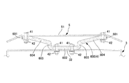
 elastic support 4 is formed of a connecting portion between the central plate portion 62 of the plate spring 60C and the top plate 32 and a connecting portion between the end plate portion 61 of the plate spring 60C and the water droplet receiving plate 5. It is sufficient that at least one of the connecting portions is constituted by the rubber connecting portion 7.

実施形態9
図14に示すように、実施形態9の換気口端末部材1は、弾性支持体4を、例えば実施形態4(図9参照)や実施形態8(図13参照)で示した板ばね60と同様な形状に形成されてばね機能を持つゴムとしてのゴム板600により構成し、当該ゴム板600と水滴受板5とで構成される防振体の一次固有振動数fを、オクターブバンドの16Hz以上で125Hz以下の周波数となるように、より好ましくは、オクターブバンドの16Hz以上で63Hz以下の周波数となるように設定した。
Embodiment 9
As shown in FIG. 14, the ventilation port terminal member 1 of the ninth embodiment has the elastic support 4 similar to the leaf spring 60 shown in the fourth embodiment (see FIG. 9) or the eighth embodiment (see FIG. 13). A primary natural frequency f 0 of a vibration isolator composed of the rubber plate 600 and the water drop receiving plate 5 is formed by a rubber plate 600 as a rubber having a spring function and having a octave band of 16 Hz. The frequency is set so as to be 125 Hz or less, and more preferably to be 63 Hz or less in the octave band of 16 Hz or more.

ゴム板600は、フード部3の天板32に連結される中央板部602と、中央板部602の左右の端部からそれぞれ天板32と直交して水滴受板5に近づく方向に延長する左右の立ち上がり板部603,603と、左右の立ち上がり板部603,603の上端からそれぞれ互いに反対方向に上がって延長する左右の傾斜板部604,604と、各傾斜板部604,604の上端からそれぞれ互いに反対方向に延長して水滴受板5に連結される左右両方の端板部601,601とを備えた形状のものを用いた。   The rubber plate 600 extends from the left and right end portions of the central plate portion 602 connected to the top plate 32 of the hood portion 3 to the direction approaching the water droplet receiving plate 5 at right angles to the top plate 32, respectively. Left and right rising plate portions 603, 603, left and right inclined plate portions 604, 604 extending upward from opposite ends of the left and right rising plate portions 603, 603, respectively, and extending from the upper ends of the respective inclined plate portions 604, 604. The one having the left and right end plate portions 601 and 601 which are respectively extended in opposite directions and connected to the water drop receiving plate 5 was used.

即ち、実施形態9の換気口端末部材1は、図14に示すように、ゴム板600の左右両方の端板部601,601が水滴受板5の中央板部51の左右側にボルト41及びナット42により連結されるとともに、中央板部51の左右側に連結された左右の端板部601,601よりも下方に位置された中央板部602が天板32の中央側にボルト41及びナット42により連結された構成とした。
尚、天板32の下面とナット42との間、端板部601の下面とナット42との間には、例えば、平座金43及びばね座金44が設置される。
That is, as shown in FIG. 14, the left and right end plate portions 601 and 601 of the rubber plate 600 are provided with the bolt 41 and the bolt 41 on the left and right sides of the central plate portion 51 of the water droplet receiving plate 5, as shown in FIG. A central plate portion 602, which is connected by the nut 42 and located below the left and right end plate portions 601 and 601 connected to the left and right sides of the central plate portion 51, has a bolt 41 and a nut on the center side of the top plate 32. 42.
A flat washer 43 and a spring washer 44 are provided between the lower surface of the top plate 32 and the nut 42 and between the lower surface of the end plate portion 601 and the nut 42, for example.

本発明の換気口端末部材1の水滴落下衝突音低減効果を確認するための実験を以下のように行った。   An experiment for confirming the effect of the ventilation port terminal member 1 of the present invention to reduce the impact of the water drop falling collision was performed as follows.

・実験方法
共同住宅の給気孔に取付けた換気口端末部材の各試験体に水滴が落下する状況を模擬した実験を簡易無響室内で行った。
実験設備は以下のとおりである。
足場の下部に内径900mm角の箱(内部をグラスウールで吸音処理した箱)を設置し、箱の正面中央の位置の外側に換気口端末部材の試験体を設置するとともに、内側にレジスター(内側換気口)を設置した。レジスターは樹脂製のプッシュタイプとし、実験時は「開」の状態とした。
共同住宅の一般的な階高を想定し,換気口端末部材の試験体天端に高さ3mの位置からスポイトを使って水滴を落下させた。
水滴落下衝突音の測定は、マイクロホンを箱内部の中心の位置に設置し、水滴落下衝突音のA特性音圧レベル、及び、1/3オクターブバンド音圧レベルの最大値を測定した。水滴の落下回数は,1試験体に対し50回とし,外部からの影響の小さい40回のデータの平均値を測定値とした。
・ Experimental method An experiment was performed in a simple anechoic chamber to simulate the situation where water droplets fell on each test piece of the terminal member of the ventilation port attached to the air supply hole of the apartment house.
The experimental equipment is as follows.
At the bottom of the scaffold, a box with an inner diameter of 900 mm (a box whose inside is sound-absorbed with glass wool) is installed, and a test piece of the terminal member of the vent is installed outside the center of the front of the box, and a register (inside ventilation) is installed inside. Mouth) was installed. The register was a push type made of resin, and was in an "open" state during the experiment.
Assuming a common floor height of the apartment house, water drops were dropped from a position 3 m in height to the top end of the test member of the ventilation port terminal member using a dropper.
For the measurement of the water drop impact sound, a microphone was installed at the center position inside the box, and the maximum value of the A-weighted sound pressure level and the 1/3 octave band sound pressure level of the water drop impact sound was measured. The number of drops of the water droplet was set to 50 times for one specimen, and the average value of the data of 40 times with little external influence was used as the measured value.

・換気口端末部材の試験体
実験に用いた換気口端末部材の試験体の設計値は、以下のとおりである。
(a)従来品=天板32の上に水滴受板5を備えない構成の換気口端末部材。
(b)先行技術文献品=特許文献1に開示された構成の換気口端末部材(防振体のばね定数k=248.8N/mm、防振体の一次固有振動数f=300Hz)。
(c)出願品=実施形態5(図10参照)の換気口端末部材1(板ばね60のばね定数k=11.0N/mm、防振体の一次固有振動数f=63Hz)。
尚、各換気口端末部材の試験体の材質、寸法等は、以下のとおりである。
筒部、フード部、水滴受板の材質=ステンレス鋼SUS304、筒部の径=97mm、水滴受板の短辺43mm、長辺150mm、水滴受板の板厚1mm、水滴受板の質量m=70g。
-Specimen of vent terminal member The design value of the specimen of vent member used in the experiment is as follows.
(A) Conventional product: a ventilation port terminal member having a configuration in which the water drop receiving plate 5 is not provided on the top plate 32.
(B) Prior art document = Ventilation port terminal member having the configuration disclosed in Patent Document 1 (spring constant k of the vibration isolator: 248.8 N / mm, primary natural frequency f 0 = 300 Hz of the vibration isolator).
(C) Application product = Ventilation port terminal member 1 of Embodiment 5 (see FIG. 10) (spring constant k of leaf spring 60 = 11.0 N / mm, primary natural frequency f 0 of the vibration isolator = 63 Hz).
In addition, the material, dimensions, etc. of the test body of each ventilation port terminal member are as follows.
Material of tube portion, hood portion, water drop receiving plate = stainless steel SUS304, diameter of tube portion = 97 mm, short side 43 mm, long side 150 mm of water drop receiving plate, plate thickness 1 mm of water drop receiving plate, mass m of water drop receiving plate = 70 g.

・実験結果
図15に、上述した換気口端末部材の各試験体の水滴落下衝突音のFFT解析結果を示し、図16に、各試験体の1/3オクターブバンド中心周波数−音圧レベルの測定結果を示す。
従来品と先行技術文献品とを比較すると、先行技術文献品では1000Hz近辺の音圧レベルが低下していることがわかる。
また、先行技術文献品と出願品とを比較すると、出願品では100Hz以上の音圧レベルが大幅に低下していることがわかる。このことは、本発明の換気口端末部材1では、防振体が有効に作用して、水滴受板5からフード部3への振動エネルギーの伝達率が低くなっていることを表している。
出願品の防振体の一次固有振動数はオクターブバンド63Hzに設定したものであり、この63Hzの√2倍である89Hz以上の領域が防振領域となったと考えられる。
また、先行技術文献品と出願品との100Hz以下の領域を比較すると、出願品の方が音圧レベルが高くなっており、一次固有振動数である63Hzの周辺は先行技術文献品に比べて振動が増幅されていることがわかる。
即ち、出願品では、防振体の一次固有振動数fを低い周波数帯に設定したことにより、高い周波数帯域の振動伝達量が小さくなったと考えられる。
このように、出願品によれば、水滴Wが水滴受板5に衝突した際に生じる水滴落下衝突音における中高周波数帯域の音を低減させる効果が向上することがわかった。
-Experimental results Fig. 15 shows the results of FFT analysis of the impact sound of water drops falling on the test specimens of the above-mentioned ventilation port terminal members, and Fig. 16 shows the measurement of 1/3 octave band center frequency-sound pressure level of each test specimen. The results are shown.
Comparing the conventional product and the prior art document product, it can be seen that the sound pressure level around 1000 Hz is reduced in the prior art document product.
Further, comparing the prior art document product and the application product, it can be seen that the sound pressure level of 100 Hz or more is significantly reduced in the application product. This indicates that, in the ventilation port terminal member 1 of the present invention, the vibration isolator works effectively and the transmission rate of vibration energy from the water droplet receiving plate 5 to the hood portion 3 is reduced.
The primary natural frequency of the vibration isolator of the application was set to an octave band of 63 Hz, and it is considered that a region of 89 Hz or more, which is √2 times this 63 Hz, became the vibration isolating region.
In addition, comparing the prior art document product and the application product in a region of 100 Hz or less, the application product has a higher sound pressure level, and the vicinity of 63 Hz which is the primary natural frequency is higher than that of the prior art document product. It can be seen that the vibration is amplified.
That is, in the application, it is considered that the vibration transmission amount in the high frequency band is reduced by setting the primary natural frequency f 0 of the vibration isolator to the low frequency band.
Thus, according to the application, it has been found that the effect of reducing the sound in the middle and high frequency band in the sound of the water drop falling collision generated when the water drop W collides with the water drop receiving plate 5 is improved.

また、出願品のA特性音圧レベルは、30dB以下であり、人が気になるレベルではないことがわかる。   Also, the A-weighted sound pressure level of the applied product is 30 dB or less, which indicates that the level is not a level that is anxious to humans.

尚、水滴受板5と弾性支持体4とで構成される防振体の一次固有振動数fは、式(1)で求めることができる。

Figure 2020038031
ここで、
:一次固有振動数(Hz)
m:水滴受板の質量(kg)
k:ばね定数(N/m) In addition, the primary natural frequency f 0 of the vibration isolator constituted by the water drop receiving plate 5 and the elastic support 4 can be obtained by Expression (1).
Figure 2020038031
here,
f 0 : primary natural frequency (Hz)
m: Mass of water drop receiving plate (kg)
k: spring constant (N / m)

一般に、上述した防振体の一次固有振動数fを低くするためには、弾性支持体4のばね定数を小さくすればよいが、弾性支持体4のばね定数を小さくしすぎると、弾性支持体4が柔らかくなりすぎて、防振体を構造体として成立させることが難しくなる。
そこで、このような場合は、水滴受板5の質量を大きくすることによって、防振体の一次固有振動数fを目標値(例えば、オクターブバンドの16Hz以上で63Hz以下)に設定すればよい。
Generally, in order to lower the primary natural frequency f 0 of the above-mentioned vibration isolator, the spring constant of the elastic support 4 may be reduced, but if the spring constant of the elastic support 4 is too small, the elastic support may be reduced. The body 4 becomes too soft, making it difficult to establish the vibration isolator as a structure.
Therefore, in such a case, the primary natural frequency f 0 of the vibration isolator may be set to a target value (for example, 16 Hz or more and 63 Hz or less in an octave band) by increasing the mass of the water droplet receiving plate 5. .

即ち、設計時において、防振体の一次固有振動数fの目標値を決め、防振体の一次固有振動数fが当該目標値となるように、上述した式(1)に基づいて、防振体を構成する、水滴受板5の質量m、及び、弾性支持体4のばね定数kを決める。 That is, at the design stage, determines the target value of the primary natural frequency f 0 of the isolator, as the primary natural frequency f 0 of the isolator is the target value, based on the above equation (1) The mass m of the water drop receiving plate 5 and the spring constant k of the elastic support 4 are determined.

以下に、換気口端末部材1の筒部2の径を変えた場合における、水滴受板5の質量mと弾性支持体4のばね定数kとの組み合わせを例示する。尚、ここでは、水滴受板5として、板厚1mm,2.5mmのステンレス鋼SUS303を使用した場合の設計例を示す。   Hereinafter, a combination of the mass m of the water droplet receiving plate 5 and the spring constant k of the elastic support member 4 when the diameter of the cylindrical portion 2 of the ventilation port terminal member 1 is changed will be exemplified. Here, a design example in which stainless steel SUS303 having a plate thickness of 1 mm and 2.5 mm is used as the water droplet receiving plate 5 is shown.

設計例1=筒部2の径が75mm、水滴受板5の短辺33mm、長辺125mmの場合。
[1]水滴受板5の板厚1mmの場合。
(a)防振体の一次固有振動数fの目標値=30Hz→水滴受板5の質量m=51g、弾性支持体4のばね定数k=1.8N/mm。
(b)防振体の一次固有振動数fの目標値=40Hz→水滴受板5の質量m=51g、弾性支持体4のばね定数k=3.2N/mm。
[2]水滴受板5の板厚2.5mmの場合。
(a)防振体の一次固有振動数fの目標値=30Hz→水滴受板5の質量m=100g、弾性支持体4のばね定数k=3.6N/mm。
(b)防振体の一次固有振動数fの目標値=40Hz→水滴受板5の質量m=100g、弾性支持体4のばね定数k=6.4N/mm。
Design Example 1 = A case where the diameter of the cylindrical portion 2 is 75 mm, the short side of the water droplet receiving plate 5 is 33 mm, and the long side is 125 mm.
[1] When the thickness of the water drop receiving plate 5 is 1 mm.
(A) The target value of the primary natural frequency f 0 of the vibration isolator = 30 Hz → the mass m of the water droplet receiving plate 5 = 51 g, and the spring constant k of the elastic support 4 = 1.8 N / mm.
(B) Target value of the primary natural frequency f 0 of the vibration isolator = 40 Hz → mass m of the water drop receiving plate 5 = 51 g, and spring constant k of the elastic support 4 = 3.2 N / mm.
[2] The case where the thickness of the water drop receiving plate 5 is 2.5 mm.
(A) Target value of primary natural frequency f 0 of vibration isolator = 30 Hz → mass m of water drop receiving plate 5 = 100 g, spring constant k of elastic support 4 = 3.6 N / mm.
(B) Target value of the primary natural frequency f 0 of the vibration isolator = 40 Hz → mass m of the water drop receiving plate 5 = 100 g, spring constant k of the elastic support 4 = 6.4 N / mm.

設計例2=筒部2の径が100mm、水滴受板5の短辺43mm、長辺150mm。
[1]水滴受板5の板厚1mmの場合。
(a)防振体の一次固有振動数fの目標値=30Hz→水滴受板5の質量m=70g、弾性支持体4のばね定数k=2.5N/mm。
(b)防振体の一次固有振動数fの目標値=40Hz→水滴受板5の質量m=70g、弾性支持体4のばね定数k=4.4N/mm。
[2]水滴受板5の板厚2.5mmの場合。
(a)防振体の一次固有振動数fの目標値=30Hz→水滴受板5の質量m=147g、弾性支持体4のばね定数k=5.2N/mm。
(b)防振体の一次固有振動数fの目標値=40Hz→水滴受板5の質量m=147g、弾性支持体4のばね定数k=9.3N/mm。
Design Example 2 = The diameter of the cylindrical portion 2 is 100 mm, the short side of the water droplet receiving plate 5 is 43 mm, and the long side is 150 mm.
[1] When the thickness of the water drop receiving plate 5 is 1 mm.
(A) Target value of the primary natural frequency f 0 of the vibration isolator = 30 Hz → mass m of the water drop receiving plate 5 = 70 g, and spring constant k of the elastic support 4 = 2.5 N / mm.
(B) Target value of the primary natural frequency f 0 of the vibration isolator = 40 Hz → mass m of the water drop receiving plate 5 = 70 g, spring constant k of the elastic support 4 = 4.4 N / mm.
[2] The case where the thickness of the water drop receiving plate 5 is 2.5 mm.
(A) The target value of the primary natural frequency f 0 of the vibration isolator = 30 Hz → the mass m of the water drop receiving plate 5 = 147 g, and the spring constant k of the elastic support 4 = 5.2 N / mm.
(B) Target value of the primary natural frequency f 0 of the vibration isolator = 40 Hz → mass m of the water drop receiving plate 5 = 147 g, spring constant k of the elastic support 4 = 9.3 N / mm.

各実施形態の換気口端末部材1では、落下する水滴の衝撃力に対して十分な剛性があり、加工が可能な板厚であることを考慮して、水滴受板5の板厚を0.5mm〜5mmとしたことによって、水滴受板5と弾性支持体4とで構成される防振体の一次固有振動数fを、オクターブバンドの16Hz以上で125Hz以下の周波数となるように、より好ましくは、オクターブバンドの16Hz以上で63Hz以下の周波数となるように設定した。
例えば、筒部2の径が75mmの場合において、水滴受板5の板厚を1mm、水滴受板5の質量を50gとすることで、防振体のばね定数を0.8にでき、防振体の一次固有振動数fをオクターブバンドの20Hzに設計できる。
また、筒部2の径が150mmの場合において、水滴受板5の板厚を3mm、水滴受板5の質量を300gとすることで、防振体のばね定数を4.7にでき、防振体の一次固有振動数fをオクターブバンドの20Hzに設計できる。
In the ventilation port terminal member 1 of each embodiment, the plate thickness of the water droplet receiving plate 5 is set to 0. By setting the width to 5 mm to 5 mm, the primary natural frequency f 0 of the vibration isolator constituted by the water drop receiving plate 5 and the elastic support 4 is set to a frequency of 16 Hz or more and 125 Hz or less in the octave band. Preferably, the frequency is set to be not less than 63 Hz and not less than 16 Hz in the octave band.
For example, when the diameter of the cylindrical portion 2 is 75 mm, by setting the thickness of the water drop receiving plate 5 to 1 mm and the mass of the water drop receiving plate 5 to 50 g, the spring constant of the vibration isolator can be set to 0.8, and The primary natural frequency f 0 of the vibration body can be designed to be 20 Hz in the octave band.
When the diameter of the cylindrical portion 2 is 150 mm, the spring constant of the vibration isolator can be set to 4.7 by setting the thickness of the water droplet receiving plate 5 to 3 mm and the mass of the water droplet receiving plate 5 to 300 g, thereby preventing the vibration. The primary natural frequency f 0 of the vibration body can be designed to be 20 Hz in the octave band.

尚、水滴受板5の質量mを調整する場合において、水滴受板5の質量mを大きくする場合は、例えば、水滴受板5のに所望の質量mのおもり等を付加すればよい。
この場合、おもり等は、弾性支持体4と水滴受板5とが連結されている位置の上方に位置する水滴受板5の上面に付加することが好ましい。
In addition, when adjusting the mass m of the water droplet receiving plate 5, when increasing the mass m of the water droplet receiving plate 5, for example, a weight having a desired mass m may be added to the water droplet receiving plate 5.
In this case, it is preferable that the weight or the like be added to the upper surface of the water drop receiving plate 5 located above the position where the elastic support 4 and the water drop receiving plate 5 are connected.

各実施形態1乃至実施形態9の換気口端末部材1によれば、弾性支持体4を、ばね(板ばね60、板ばね60Aと板ばね60Bの組み合わせ、コイルばね60C)、あるいは、ばねとゴム7、あるいは、ゴム板(ゴム)600により構成し、当該弾性支持体4と水滴受板5とで構成される防振体の一次固有振動数fを、オクターブバンドの16Hz以上で125Hz以下の周波数となるように、より好ましくは、オクターブバンドの16Hz以上で63Hz以下の周波数となるように設定したので、水滴Wが水滴受板5に衝突した際に生じる水滴落下衝突音における中高周波数帯域の音を低減させることができる。 According to the ventilation port terminal member 1 of each of the first to ninth embodiments, the elastic support 4 is made of a spring (leaf spring 60, a combination of the leaf spring 60A and the leaf spring 60B, a coil spring 60C), or a spring and rubber. 7 or a rubber plate (rubber) 600, and the primary natural frequency f 0 of the vibration isolator constituted by the elastic support 4 and the water drop receiving plate 5 is set to be not less than 16 Hz and not more than 125 Hz in the octave band. Since the frequency is more preferably set to a frequency of not less than 63 Hz and not less than 16 Hz of the octave band, the water drop W is generated when the water drop W collides with the water drop receiving plate 5. Sound can be reduced.

即ち、各実施形態1乃至実施形態9の換気口端末部材1によれば、一次固有振動数fの√2倍にあたる周波数より高い周波数帯において振動伝達率が1以下の防振域となるので、水滴受板5からフード部3への振動伝達が抑制されて、水滴の落下衝突で生成された振動エネルギーのフード部3への伝播を抑制することができる。 That is, according to the ventilation port terminal member 1 of each of the first to ninth embodiments, the vibration transmissibility is 1 or less in a frequency band higher than a frequency corresponding to √2 times the primary natural frequency f 0 . In addition, the transmission of vibration from the water droplet receiving plate 5 to the hood portion 3 is suppressed, and the propagation of the vibration energy generated by the falling collision of the water droplet to the hood portion 3 can be suppressed.

また、当該一次固有振動数fの周辺の周波数帯は振動増幅域であり、各実施形態1乃至実施形態9で示した防振体の構造を採用することにより、防振体の一次固有振動数fの共振ポイントの増幅倍率は大きくなるが、一次固有振動数fの近辺の周波数帯は周波数補正A特性での補正量が大きな領域であるため、人が感じる音圧レベルとしては低い値になる。 The frequency band around the primary natural frequency f 0 is a vibration amplification region, and by adopting the structure of the vibration isolator described in each of Embodiments 1 to 9, the primary natural vibration of the vibration isolator can be achieved. Although the amplification factor at the resonance point of the number f 0 becomes large, the frequency band near the primary natural frequency f 0 is a region where the correction amount of the frequency correction A characteristic is large, so that the sound pressure level felt by a person is low. Value.

また、実施形態5乃至実施形態8(図10〜図13参照)に示した換気口端末部材1のように、弾性支持体4がゴム連結部7やゴム連結部7Aを備えた構成の場合、ゴム連結部7,7Aのゴム70が有する減衰の効果によって、防振体の共振ポイントの増幅倍率を低下させる効果が付与されるので、共振ポイントの弊害を抑えて水滴落下衝突音の低減効果を向上した換気口端末部材1を得ることができる。   Further, in the case of a configuration in which the elastic support 4 is provided with the rubber connecting portion 7 or the rubber connecting portion 7A as in the ventilation port terminal member 1 shown in the fifth to eighth embodiments (see FIGS. 10 to 13), The damping effect of the rubber 70 of the rubber connecting portions 7 and 7A has an effect of reducing the amplification factor of the resonance point of the vibration isolator, so that the adverse effect of the resonance point is suppressed and the effect of reducing the water drop impact sound is reduced. An improved vent terminal member 1 can be obtained.

また、実施形態9(図14参照)に係る換気口端末部材1によれば、弾性支持体4を、ばね機能を持つように形成されたゴム板600で構成したため、ゴムが有する減衰の効果を持たせることができるので、防振体の共振ポイントの増幅倍率を低下させる効果が付与され、共振ポイントの弊害を抑えて水滴落下衝突音の低減効果を向上した換気口端末部材1を得ることができる。   Further, according to the ventilation port terminal member 1 according to the ninth embodiment (see FIG. 14), since the elastic support 4 is constituted by the rubber plate 600 formed so as to have a spring function, the damping effect of the rubber is reduced. As a result, the effect of lowering the amplification factor of the resonance point of the vibration isolator is provided, and the ventilation port terminal member 1 having an improved effect of reducing the impact sound of the water drop falling while suppressing the adverse effect of the resonance point can be obtained. it can.

また、本発明によれば、水滴受板5の板厚を0.5mm〜5mmとしたことによって、水滴受板5と弾性支持体4とで構成される防振体の一次固有振動数fを、オクターブバンドの16Hz以上で125Hz以下の周波数となるように設定したので、防振体を構造体として成立させることができて、かつ、水滴落下衝突時における中高周波数帯域の音を低減させることができる換気口端末部材1を得ることができる。 Further, according to the present invention, by setting the thickness of the water drop receiving plate 5 to 0.5 mm to 5 mm, the primary natural frequency f 0 of the vibration isolator constituted by the water drop receiving plate 5 and the elastic support 4 is provided. Is set to have a frequency of not less than 125 Hz and not less than 16 Hz in the octave band, so that the vibration isolator can be realized as a structure, and the sound in the mid-high frequency band at the time of a water drop falling collision can be reduced. Can be obtained.

また、本発明によれば、上述した換気口端末部材1のフード部3及び水滴受板5が外壁面93よりも外側に突出するように当該換気口端末部材1が外壁91に設けられ、上下階の外壁91に設けられた各換気口端末部材1,1…の各水滴受板5,5…が、垂直線V上に位置された建物90を構築することによって、上階の換気口端末部材1から水滴Wが落下して下階の換気口端末部材1の水滴受板5に衝突した際に生じる水滴落下衝突音の低減効果に優れた建物90を提供できる。   Further, according to the present invention, the ventilation port terminal member 1 is provided on the outer wall 91 so that the hood portion 3 and the water droplet receiving plate 5 of the above-described ventilation port terminal member 1 protrude outside the outer wall surface 93. Each of the water drop receiving plates 5, 5,... Provided on the outer wall 91 of the floor constitutes a building 90 located on the vertical line V, thereby forming a terminal on the upper floor. It is possible to provide the building 90 which is excellent in the effect of reducing the sound of the water droplet falling collision generated when the water droplet W falls from the member 1 and collides with the water droplet receiving plate 5 of the ventilation port terminal member 1 on the lower floor.

尚、板ばねの形状としては、例えば、Z型やコ字型に形成されたものでも良い。   The shape of the leaf spring may be, for example, a Z-shape or a U-shape.

また、板ばねやコイルばねやゴム板を複数個用いた構成であってもよい。
例えば、実施形態3や実施形態7においては、弾性支持体4は、1つ以上のコイルばね60Cにより構成されていればよい。
また、板ばね、コイルばね、ゴム板のうちの2つ以上を用いて弾性支持体4を構成してもよい。
Further, a configuration using a plurality of leaf springs, coil springs, and rubber plates may be used.
For example, in the third embodiment and the seventh embodiment, the elastic support 4 may be configured by one or more coil springs 60C.
Further, the elastic support 4 may be configured using two or more of a leaf spring, a coil spring, and a rubber plate.

換気用端末部材1の全体形状は丸形でもよい。
また、換気用端末部材1のフード部3の天板32や水滴受板5の形状は矩形でなくてもよい。
また、換気用端末部材1は、開口部が、フード部3の下部のみでなく、フード部3の側面、正面に設けられた構成であってもよい。また、開口部にネットが張られた構成のものであってもよい。
The overall shape of the ventilation terminal member 1 may be round.
Further, the shape of the top plate 32 and the water drop receiving plate 5 of the hood 3 of the ventilation terminal member 1 may not be rectangular.
Further, the ventilation terminal member 1 may have a configuration in which the opening is provided not only in the lower portion of the hood portion 3 but also in the side surface and the front surface of the hood portion 3. Further, a configuration in which a net is stretched in the opening may be used.

また、換気用端末部材1は、筒部2を備えずに、外壁に直接取り付けられる構成のものであってもよい。   Further, the terminal member for ventilation 1 may be configured to be directly attached to the outer wall without including the tubular portion 2.

また、水滴受板5と弾性支持体4との連結、弾性支持体4と天板32との連結は、ボルト及びナットによる連結でなくともよい。例えば、溶接や接着剤等によって連結された構成としてもよい。   Further, the connection between the water drop receiving plate 5 and the elastic support 4 and the connection between the elastic support 4 and the top plate 32 need not be connected by bolts and nuts. For example, it may be configured to be connected by welding, an adhesive, or the like.

1 換気口端末部材、3 フード部、4 弾性支持体、5 水滴受板、7 ゴム、
32 フード部の天板、60,60A,60B 板ばね、60C コイルばね、
90 建物、91 外壁、92 換気孔、93 外壁面、600 ゴム板。
1 Ventilation port terminal member, 3 hood part, 4 elastic support, 5 water drop receiving plate, 7 rubber,
32 Hood top plate, 60, 60A, 60B leaf spring, 60C coil spring,
90 building, 91 outer wall, 92 ventilation hole, 93 outer wall, 600 rubber plate.

Claims (7)

建物の外壁に形成された換気孔に取付けられる換気口端末部材であって、
建物の外壁面より建物の外側に突出するフード部と、フード部の天板の上に弾性支持体を介して設けられた水滴受板とを備え、
水滴受板と弾性支持体とで構成される防振体の一次固有振動数fが、オクターブバンドの16Hz以上で125Hz以下の周波数となるように設定されたことを特徴とする換気口端末部材。
A ventilation port terminal member attached to a ventilation hole formed on an outer wall of the building,
A hood portion protruding outside the building from the outer wall surface of the building, and a water drop receiving plate provided via an elastic support on a top plate of the hood portion,
A vent opening terminal member characterized in that the primary natural frequency f 0 of the vibration isolator constituted by the water drop receiving plate and the elastic support is set to a frequency of 16 Hz or more and 125 Hz or less in an octave band. .
弾性支持体が板ばねであることを特徴とする請求項1に記載の換気口端末部材。   The ventilation port terminal member according to claim 1, wherein the elastic support is a leaf spring. 弾性支持体がコイルばねであることを特徴とする請求項1に記載の換気口端末部材。   The ventilation port terminal member according to claim 1, wherein the elastic support is a coil spring. 弾性支持体がゴムであることを特徴とする請求項1に記載の換気口端末部材。   The ventilation port terminal member according to claim 1, wherein the elastic support is rubber. 弾性支持体がばねとゴムとで構成されたことを特徴とする請求項1に記載の換気口端末部材。   The ventilation port terminal member according to claim 1, wherein the elastic support member is constituted by a spring and rubber. 水滴受板の板厚を0.5mm〜5mmとしたことによって、水滴受板と弾性支持体とで構成される防振体の一次固有振動数fが、オクターブバンドの16Hz以上で125Hz以下の周波数となるように設定されたことを特徴とする請求項1乃至請求項5のいずれか一項に記載の換気口端末部材。 By setting the thickness of the water drop receiving plate to 0.5 mm to 5 mm, the primary natural frequency f 0 of the vibration isolator composed of the water drop receiving plate and the elastic support is set to be not less than 125 Hz and not less than 16 Hz in the octave band. The terminal member according to any one of claims 1 to 5, wherein the member is set to have a frequency. 請求項1乃至請求項6のいずれか一項に記載された換気口端末部材のフード部及び水滴受板が外壁面よりも外側に突出するように当該換気口端末部材が外壁に設けられた建物であって、
建物の上下階の外壁に設けられた各換気口端末部材の各水滴受板が、垂直線上に位置されたことを特徴とする建物。
A building having a ventilation port terminal member provided on an outer wall such that a hood portion and a water drop receiving plate of the ventilation port terminal member according to any one of claims 1 to 6 protrude outside the outer wall surface. And
A building, wherein each water drop receiving plate of each ventilation port terminal member provided on the outer wall of the upper and lower floors of the building is located on a vertical line.
JP2018165092A 2018-09-04 2018-09-04 Vent terminal member and building Active JP7212479B2 (en)

Priority Applications (1)

Application Number Priority Date Filing Date Title
JP2018165092A JP7212479B2 (en) 2018-09-04 2018-09-04 Vent terminal member and building

Applications Claiming Priority (1)

Application Number Priority Date Filing Date Title
JP2018165092A JP7212479B2 (en) 2018-09-04 2018-09-04 Vent terminal member and building

Publications (2)

Publication Number Publication Date
JP2020038031A true JP2020038031A (en) 2020-03-12
JP7212479B2 JP7212479B2 (en) 2023-01-25

Family

ID=69737720

Family Applications (1)

Application Number Title Priority Date Filing Date
JP2018165092A Active JP7212479B2 (en) 2018-09-04 2018-09-04 Vent terminal member and building

Country Status (1)

Country Link
JP (1) JP7212479B2 (en)

Cited By (2)

* Cited by examiner, † Cited by third party
Publication number Priority date Publication date Assignee Title
JP2020106251A (en) * 2018-12-28 2020-07-09 三菱地所レジデンス株式会社 Ventilation hole terminal member and building
JP2020143837A (en) * 2019-03-06 2020-09-10 株式会社熊谷組 Ventilation hole terminal member and building

Citations (9)

* Cited by examiner, † Cited by third party
Publication number Priority date Publication date Assignee Title
JPS5263401U (en) * 1975-11-04 1977-05-11
WO1989007225A1 (en) * 1988-02-03 1989-08-10 Turbima Oy Replacement air valve
JP2000220353A (en) * 1999-02-01 2000-08-08 Tostem Corp Bay window
JP2008051488A (en) * 2007-03-29 2008-03-06 Fujita Corp Sound-proof ventilation port
JP2011058735A (en) * 2009-09-10 2011-03-24 Mitsubishi Electric Corp Ventilation hood
JP2011190971A (en) * 2010-03-12 2011-09-29 Mitsubishi Electric Corp Ventilation hood
JP2011237078A (en) * 2010-05-07 2011-11-24 Kumagai Gumi Co Ltd Sound insulation vent cap
KR101414506B1 (en) * 2013-12-06 2014-07-07 주식회사 모니터리 Roof Monitor
JP2016095070A (en) * 2014-11-13 2016-05-26 東急建設株式会社 Sound deadening tubular body and sound deadening structure for natural ventilation opening

Patent Citations (9)

* Cited by examiner, † Cited by third party
Publication number Priority date Publication date Assignee Title
JPS5263401U (en) * 1975-11-04 1977-05-11
WO1989007225A1 (en) * 1988-02-03 1989-08-10 Turbima Oy Replacement air valve
JP2000220353A (en) * 1999-02-01 2000-08-08 Tostem Corp Bay window
JP2008051488A (en) * 2007-03-29 2008-03-06 Fujita Corp Sound-proof ventilation port
JP2011058735A (en) * 2009-09-10 2011-03-24 Mitsubishi Electric Corp Ventilation hood
JP2011190971A (en) * 2010-03-12 2011-09-29 Mitsubishi Electric Corp Ventilation hood
JP2011237078A (en) * 2010-05-07 2011-11-24 Kumagai Gumi Co Ltd Sound insulation vent cap
KR101414506B1 (en) * 2013-12-06 2014-07-07 주식회사 모니터리 Roof Monitor
JP2016095070A (en) * 2014-11-13 2016-05-26 東急建設株式会社 Sound deadening tubular body and sound deadening structure for natural ventilation opening

Cited By (4)

* Cited by examiner, † Cited by third party
Publication number Priority date Publication date Assignee Title
JP2020106251A (en) * 2018-12-28 2020-07-09 三菱地所レジデンス株式会社 Ventilation hole terminal member and building
JP7226998B2 (en) 2018-12-28 2023-02-21 三菱地所レジデンス株式会社 Vent terminal member and building
JP2020143837A (en) * 2019-03-06 2020-09-10 株式会社熊谷組 Ventilation hole terminal member and building
JP7208831B2 (en) 2019-03-06 2023-01-19 株式会社熊谷組 Vent terminal member and building

Also Published As

Publication number Publication date
JP7212479B2 (en) 2023-01-25

Similar Documents

Publication Publication Date Title
JP2020038031A (en) Ventilation hole terminal member and building
Ljunggren et al. Correlation between sound insulation and occupants’ perception–Proposal of alternative single number rating of impact sound
US7647744B2 (en) Acoustic isolator clip for isolating wallboard support channels from frame member
JP5258712B2 (en) Ventilation hood
US3110357A (en) Acoustic curb
JP7306824B2 (en) Vent terminal member and building
CN108981130A (en) A kind of design method of the denoising device of air-conditioning
US8069947B2 (en) Sound attenuation canopy
JP7226998B2 (en) Vent terminal member and building
Kornadt et al. Characterisation of structure-borne sound sources
JP6530830B1 (en) Sound reduction system
JP4231471B2 (en) Ceiling structure
JP2006070494A (en) Floor structure
JP7208831B2 (en) Vent terminal member and building
US20190194937A1 (en) Acoustic and insulation mounting
JP2007100449A (en) Dynamic damper for house
CN202248343U (en) Sound insulating and vibration reducing device
KR101562951B1 (en) A damping hanger for the ceiling structure and construction method for the celling structure using the same
JP2009084816A (en) Floor supporting leg
WO2020157486A1 (en) Sound attenuating clip
JP2009133071A (en) Floor structure of wooden house
JP7402038B2 (en) Ventilation port terminal member and building
JP2022092852A (en) Ventilation port terminal member and building
US10139126B2 (en) Airborne noise reduction system and method
Höller et al. Direct sound transmission loss of heavy gauge steel stud walls

Legal Events

Date Code Title Description
A621 Written request for application examination

Free format text: JAPANESE INTERMEDIATE CODE: A621

Effective date: 20210317

A977 Report on retrieval

Free format text: JAPANESE INTERMEDIATE CODE: A971007

Effective date: 20220125

A131 Notification of reasons for refusal

Free format text: JAPANESE INTERMEDIATE CODE: A131

Effective date: 20220208

A521 Request for written amendment filed

Free format text: JAPANESE INTERMEDIATE CODE: A523

Effective date: 20220411

A131 Notification of reasons for refusal

Free format text: JAPANESE INTERMEDIATE CODE: A131

Effective date: 20220830

A521 Request for written amendment filed

Free format text: JAPANESE INTERMEDIATE CODE: A523

Effective date: 20220930

TRDD Decision of grant or rejection written
A01 Written decision to grant a patent or to grant a registration (utility model)

Free format text: JAPANESE INTERMEDIATE CODE: A01

Effective date: 20230110

A61 First payment of annual fees (during grant procedure)

Free format text: JAPANESE INTERMEDIATE CODE: A61

Effective date: 20230113

R150 Certificate of patent or registration of utility model

Ref document number: 7212479

Country of ref document: JP

Free format text: JAPANESE INTERMEDIATE CODE: R150