JP2020106251A - Ventilation hole terminal member and building - Google Patents

Ventilation hole terminal member and building Download PDF

Info

Publication number
JP2020106251A
JP2020106251A JP2018247743A JP2018247743A JP2020106251A JP 2020106251 A JP2020106251 A JP 2020106251A JP 2018247743 A JP2018247743 A JP 2018247743A JP 2018247743 A JP2018247743 A JP 2018247743A JP 2020106251 A JP2020106251 A JP 2020106251A
Authority
JP
Japan
Prior art keywords
plate
terminal member
water drop
ventilation port
port terminal
Prior art date
Legal status (The legal status is an assumption and is not a legal conclusion. Google has not performed a legal analysis and makes no representation as to the accuracy of the status listed.)
Granted
Application number
JP2018247743A
Other languages
Japanese (ja)
Other versions
JP7226998B2 (en
Inventor
憲太郎 野田
Kentaro Noda
憲太郎 野田
拓 黒木
Taku Kuroki
拓 黒木
大脇 雅直
Masanao Owaki
雅直 大脇
徳人 水野
Norihito Mizuno
徳人 水野
正輝 成▲瀬▼
Masaki Naruse
正輝 成▲瀬▼
田中 祐介
Yusuke Tanaka
祐介 田中
Current Assignee (The listed assignees may be inaccurate. Google has not performed a legal analysis and makes no representation or warranty as to the accuracy of the list.)
Kumagai Gumi Co Ltd
Mitsubishi Jisho Residence Co Ltd
Melco Airtec Corp
Original Assignee
Kumagai Gumi Co Ltd
Mitsubishi Jisho Residence Co Ltd
Melco Airtec Corp
Priority date (The priority date is an assumption and is not a legal conclusion. Google has not performed a legal analysis and makes no representation as to the accuracy of the date listed.)
Filing date
Publication date
Application filed by Kumagai Gumi Co Ltd, Mitsubishi Jisho Residence Co Ltd, Melco Airtec Corp filed Critical Kumagai Gumi Co Ltd
Priority to JP2018247743A priority Critical patent/JP7226998B2/en
Publication of JP2020106251A publication Critical patent/JP2020106251A/en
Application granted granted Critical
Publication of JP7226998B2 publication Critical patent/JP7226998B2/en
Active legal-status Critical Current
Anticipated expiration legal-status Critical

Links

Images

Abstract

To provide a high-quality ventilation hole terminal member and the like that can reduce variation in sound pressure level when a water droplet drops and collides with a water droplet receiving plate.SOLUTION: A ventilation hole terminal member is fitted to a ventilation hole that is formed in an outside wall of a building. The ventilation hole terminal member includes: a hood part 3 protruding outside the building from an outside wall surface of the building; and a water droplet receiving plate 5 provided on a top plate 32 of the hood part 3 via a plate-like elastic support body 4 (leaf spring 60). A through-hole X is provided in a part of the elastic support body 4 which does not come into contact with the top plate 32 of the hood part 3 and the water droplet receiving plate 5.SELECTED DRAWING: Figure 7

Description

本発明は、フード部の天板の上に弾性支持体を介して水滴受板が設けられた構造を備えた換気口端末部材等に関する。 The present invention relates to a ventilation port terminal member and the like having a structure in which a water drop receiving plate is provided on a top plate of a hood section via an elastic support.

集合住宅、ホテル、事務所ビル等の建物においては、換気設備の設置が義務付けられている。当該換気設備としては、居室に換気口が設置されて、居室の外壁にベントキャップ等と呼称される換気口端末部材が設置されることが多い。
当該換気口端末部材は、フード部が外壁面よりも外側に突出するように建物の上下階の外壁の換気孔にそれぞれ取付けられ、上下階の各換気口端末部材が、垂直線上に位置されることが多い。
当該建物においては、降雨等の後に、上階の換気口端末部材から水滴が落下して下階の換気口端末部材のフード部の天板の上に衝突した際に、水滴落下衝突音が生じ、当該水滴落下衝突音が固体伝播音として居室内に伝播する。
当該水滴落下衝突音の低下対策を施した換気口端末部材としては、例えば、フード部の天板の上に弾性支持体を介して水滴受板が設けられた構造のものが知られている(特許文献1参照)。
Ventilation equipment is required to be installed in buildings such as multi-family housing, hotels, and office buildings. As the ventilation equipment, a ventilation port is often installed in a living room, and a ventilation port terminal member called a vent cap or the like is often installed on an outer wall of the living room.
The ventilation port terminal members are attached to the ventilation holes of the outer wall of the upper and lower floors of the building, respectively, so that the hood portion projects outward from the outer wall surface, and the ventilation port terminal members of the upper and lower floors are located on the vertical line. Often.
In the building, when a drop of water drops from the ventilation port end member on the upper floor and collides with the top plate of the hood part of the ventilation port end member on the lower floor after rain, etc. The sound of the water drop falling collision propagates into the living room as solid propagation sound.
As a ventilation port terminal member that is provided with a measure to reduce the water drop drop collision sound, for example, one having a structure in which a water drop receiving plate is provided on an upper plate of a hood portion via an elastic support is known ( See Patent Document 1).

特許第5258712号公報Japanese Patent No. 5258712

しかしながら、特許文献1に開示された換気口端末部材では、後述する実験結果から明らかなように、水滴受板への水滴落下衝突時の音圧レベルのばらつきが大きく、品質面での課題がある。
本願発明は、水滴受板への水滴落下衝突時の音圧レベルのばらつきを小さくできる高品質な換気口端末部材等を提供するものである。
However, in the ventilation port terminal member disclosed in Patent Document 1, as is clear from the experimental result described later, there is a large variation in the sound pressure level at the time of collision of a water drop falling on the water drop receiving plate, and there is a problem in terms of quality. ..
The present invention provides a high-quality ventilation port terminal member and the like that can reduce variations in sound pressure level at the time of collision of a water drop falling on a water drop receiving plate.

本発明に係る換気口端末部材は、建物の外壁に形成された換気孔に取付けられる換気口端末部材であって、建物の外壁面より建物の外側に突出するフード部と、フード部の天板の上に板状の弾性支持体を介して設けられた水滴受板とを備え、弾性支持体におけるフード部の天板及び水滴受板と接していない部分に貫通孔が設けられたことを特徴とするので、水滴受板への水滴落下衝突時の音圧レベルのばらつきを小さくできる高品質な換気口端末部材を提供できる。
また、水滴受板と弾性支持体とで構成される防振体の一次固有振動数fが、オクターブバンドの16Hz以上で125Hz以下の周波数となるように設定されたので、さらに、水滴落下衝突時における中高周波数帯域の音を低減させる効果が向上し、水滴落下衝突音の低減効果に優れた換気口端末部材を提供できる。
また、弾性支持体は、中央側がフード部の天板に取付けられて両方の端部側が水滴受板に取付けられた板材、又は、中央側が水滴受板に取付けられて両方の端部側がフード部の天板に取付けられた板材により構成され、貫通孔は、弾性支持体の中央側と端部側との間の部分において、板の延長方向に沿って延長する長孔により構成されたので、水滴落下衝突時の音圧レベルのばらつきをより抑制できるようになり、より高品質な換気口端末部材を提供できる。
また、本発明に係る建物は、上述したいずれかの換気口端末部材のフード部及び水滴受板が外壁面よりも外側に突出するように当該換気口端末部材が外壁に設けられた建物であって、建物の上下階の外壁に設けられた各換気口端末部材の各水滴受板が、垂直線上に位置されたので、上階の換気口端末部材から水滴が落下して下階の換気口端末部材の水滴受板に衝突した際に生じる水滴落下衝突音の音圧レベルのばらつきを小さくできる建物を提供できる。
A ventilation port terminal member according to the present invention is a ventilation port terminal member that is attached to a ventilation hole formed in an outer wall of a building, and includes a hood portion projecting to the outside of the building from an outer wall surface of the building, and a top plate of the hood portion. And a water drop receiving plate provided via a plate-like elastic support on the top, and a through hole is provided in a portion of the elastic support that is not in contact with the top plate and the water drop receiving plate. Therefore, it is possible to provide a high-quality ventilation port terminal member that can reduce variations in sound pressure level at the time of collision of water drops falling on the water drop receiving plate.
In addition, since the primary natural frequency f 0 of the vibration isolator constituted by the water drop receiving plate and the elastic support is set to be a frequency of 16 Hz or more in the octave band and 125 Hz or less, further water drop collision It is possible to provide a ventilation port terminal member that has an improved effect of reducing sound in the middle and high frequency bands during use, and that is excellent in the effect of reducing the sound of water droplet drop collision.
Further, the elastic support member is a plate member whose center side is attached to the top plate of the hood portion and both end portions thereof are attached to the water drop receiving plate, or the center side is attached to the water drop receiving plate and both end sides thereof are the hood portion. It is composed of a plate material attached to the top plate, and the through hole is composed of an elongated hole extending along the extension direction of the plate in the portion between the center side and the end side of the elastic support, It is possible to further suppress the variation in the sound pressure level at the time of a water drop collision, and it is possible to provide a higher quality ventilation port terminal member.
Further, the building according to the present invention is a building in which the ventilation port terminal member is provided on the outer wall so that the hood portion and the water drop receiving plate of any of the ventilation port terminal members described above project outward from the outer wall surface. As the water drop receiving plates of the ventilation port terminal members provided on the outer walls of the upper and lower floors of the building were located on the vertical line, water drops fell from the ventilation port terminal members of the upper floor and the ventilation port of the lower floor was opened. It is possible to provide a building in which variations in the sound pressure level of the water drop falling collision sound generated when the water drop collision plate of the terminal member collides can be reduced.

換気口端末部材を前側から見た斜視図(実施形態1)。The perspective view which looked at the ventilation port terminal member from the front side (Embodiment 1). 換気口端末部材を後側から見た斜視図(実施形態1)。The perspective view which looked at the ventilation port terminal member from the back side (Embodiment 1). 換気口端末部材の正面図(実施形態1)。The front view of the ventilation port terminal member (Embodiment 1). 換気口端末部材の背面図(実施形態1)。The rear view of a ventilation port terminal member (Embodiment 1). 建物の上下階の外壁に取付けられた上の換気口端末部材から下の換気口端末部材に水滴が落下する状態を示す図(実施形態1)。The figure which shows the state which water droplets drop from the upper ventilation port terminal member attached to the outer wall of the upper and lower floors of a building to the lower ventilation port terminal member (Embodiment 1). 換気口端末部材の防振体の構造を示す断面図(実施形態1)。Sectional drawing which shows the structure of the vibration isolator of a ventilation port terminal member (Embodiment 1). 弾性支持体と水滴受板とを離して示す斜視図(実施形態1)。The perspective view which shows an elastic support body and a water drop receiving plate apart (Embodiment 1). 弾性支持体を上から見た平面図(実施形態1)。The top view which looked at the elastic support body from the top (Embodiment 1). 実験結果を示す図。The figure which shows an experimental result. 実験結果を示す図。The figure which shows an experimental result. 換気口端末部材の防振体の構造を示す断面図(実施形態2)。Sectional drawing which shows the structure of the vibration isolator of a ventilation port terminal member (Embodiment 2). 換気口端末部材の防振体の構造を示す断面図(実施形態3)。Sectional drawing which shows the structure of the vibration isolator of a ventilation port terminal member (Embodiment 3). 換気口端末部材の防振体の構造を示す断面図(実施形態4)。Sectional drawing which shows the structure of the vibration isolator of a ventilation port terminal member (Embodiment 4). 換気口端末部材の防振体の構造を示す断面図(実施形態5)。Sectional drawing which shows the structure of the vibration isolator of a ventilation port terminal member (Embodiment 5).

実施形態1
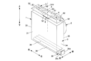
図1乃至図6に示すように、実施形態1に係る換気口端末部材1は、建物90の外壁91に建物90の内外に連通するように形成された換気孔92に挿入される筒部2と、建物90の外壁面93より外側に突出するフード部3と、フード部3の天板32の上に板状の弾性支持体4を介して設けられた水滴受板5とを備え、弾性支持体4におけるフード部3の天板32及び水滴受板5と接していない部分に貫通孔(スリット)Xが設けられており、かつ、水滴受板5と弾性支持体4とで構成される防振体の一次固有振動数fが、オクターブバンドの16Hz以上で125Hz以下の周波数となるように設定されている。
当該換気口端末部材1の筒部2、フード部3、水滴受板5は、例えば金属板により形成される。
尚、本明細書においては、換気口端末部材1の上、下、左、右、前、後は、図1,図2に示した方向と定義して説明する。
Embodiment 1
As shown in FIGS. 1 to 6, the ventilation port terminal member 1 according to the first embodiment has a cylindrical portion 2 inserted into a ventilation hole 92 formed in an outer wall 91 of a building 90 so as to communicate with the inside and outside of the building 90. And a hood portion 3 projecting outward from the outer wall surface 93 of the building 90, and a water drop receiving plate 5 provided on the top plate 32 of the hood portion 3 via a plate-shaped elastic support body 4, A through hole (slit) X is provided in a portion of the support 4 which is not in contact with the top plate 32 and the water drop receiving plate 5 of the hood portion 3, and is composed of the water drop receiving plate 5 and the elastic support 4. The primary natural frequency f 0 of the vibration isolator is set to be a frequency of 16 Hz or higher and 125 Hz or lower in the octave band.
The cylinder portion 2, the hood portion 3, and the water drop receiving plate 5 of the ventilation port terminal member 1 are formed of, for example, metal plates.
In this specification, the top, bottom, left, right, front, and rear of the ventilation port terminal member 1 are defined as the directions shown in FIGS.

図1,図2に示すように、フード部3は、四角形状の前板31と、天板(上板)32と、左側板33と、右側板34と、後板35とを備えた直方体函状に形成されており、下部が開口された室外側通風孔36(図1参照)に形成されて、かつ、後板35を形成する四角形状の板の中央側が開口された室内側通風孔37に形成され、当該室内側通風孔37の孔縁側に筒部2の一端開口縁側が接続されている。即ち、筒部2が、フード部3の後板35に接続されて当該後板35の後方に延長するように設けられた構成となっている。筒部2は、例えば、円筒部に形成される。
即ち、フード部3は、換気口端末部材1が換気孔92に取付けられることによって、下部の室外側通風孔36、及び、室内側通風孔37を介して、建物90の内側から建物90の外側に、又は、建物90の外側から建物90の内側に空気が流通可能となる。
また、室外側通風孔36、及び、室内側通風孔37のうち、少なくとも、一方の通風孔はガラリ38(図1参照)に形成されている。
As shown in FIGS. 1 and 2, the hood portion 3 is a rectangular parallelepiped including a square front plate 31, a top plate (upper plate) 32, a left side plate 33, a right side plate 34, and a rear plate 35. An indoor side ventilation hole which is formed in a box shape and is formed in the outdoor side ventilation hole 36 (see FIG. 1) whose lower part is opened, and which is formed by opening the central side of the rectangular plate forming the rear plate 35. 37, and one end opening edge side of the tubular portion 2 is connected to the hole edge side of the indoor side ventilation hole 37. That is, the tubular portion 2 is connected to the rear plate 35 of the hood portion 3 and is provided so as to extend behind the rear plate 35. The cylindrical portion 2 is formed, for example, in a cylindrical portion.
That is, in the hood part 3, the ventilation port terminal member 1 is attached to the ventilation hole 92, so that the inside of the building 90 is exposed to the outside of the building 90 via the lower outdoor ventilation hole 36 and the indoor ventilation hole 37. Alternatively, air can flow from the outside of the building 90 to the inside of the building 90.
Further, at least one of the outdoor side ventilation hole 36 and the indoor side ventilation hole 37 is formed in the gallery 38 (see FIG. 1).

換言すれば、フード部3は、四角形状の前板31と、前板31の板面と対向する板面を備えた後板35と、前板31の四角形の上辺と後板35の四角形の上辺とを繋ぐ天板32と、前板31の四角形の上辺の一端より下方に延長する四角形の左辺と後板35の四角形の上辺の一端より下方に延長する左辺とを繋ぐ左側板33と、前板31の四角形の上辺の他端より下方に延長する四角形の右辺と後板35の四角形の上辺の他端より下方に延長する右辺とを繋ぐ右側板34とで構成され、換気口端末部材1が換気孔92に取付けられた場合、これら前板31と天板32と左側板33と右側板34と後板35とで囲まれた空間が、下部の室外側通風孔36を介して室外と連通し、かつ、後板35の室内側通風孔37を介して室内と連通するように構成されている。 In other words, the hood portion 3 has a quadrangular front plate 31, a rear plate 35 having a plate surface facing the plate surface of the front plate 31, a quadrangular upper side of the front plate 31 and a quadrangular shape of the rear plate 35. A top plate 32 connecting the upper side, a left side plate 33 connecting the left side of the quadrangle extending downward from one end of the upper side of the quadrangle of the front plate 31 and the left side extending below one end of the upper side of the quadrangle of the rear plate 35, A right side plate 34 that connects a right side of a quadrangle extending downward from the other end of the quadrangle of the front plate 31 and a right side extending downward from the other end of the quadrangle of the quadrangle of the rear plate 35, and a ventilation port terminal member. When 1 is attached to the ventilation hole 92, the space surrounded by the front plate 31, the top plate 32, the left side plate 33, the right side plate 34, and the rear plate 35 is exposed to the outside through the lower outdoor side ventilation hole 36. It is configured to communicate with the inside of the room through the ventilation holes 37 on the inside of the rear plate 35.

即ち、換気口端末部材1は、筒部2が筒部2の他端側から建物90の外壁91に形成された換気孔92に挿入されて、フード部3の後板35の後面35aが建物90の外壁面93に近接し、かつ、天板32が上方、左側板33が左側、右側板34が右側に位置された状態となるように設置される。
尚、筒部2の外周面には、例えば図外の板ばねが設けられており、当該筒部2が換気孔92内に押し込まれて当該板ばねが換気孔92の内面にばね弾性によって押し付けられることによって、換気口端末部材1が換気孔92に固定され、当該固定された状態で、フード部3の後板35の上縁、左縁、右縁と外壁面93との隙間にシーリング材等の隙間充填剤が充填されることにより、換気口端末部材1が換気孔92に取付けられる。
That is, in the ventilation port terminal member 1, the tubular portion 2 is inserted from the other end side of the tubular portion 2 into the ventilation hole 92 formed in the outer wall 91 of the building 90, and the rear surface 35a of the rear plate 35 of the hood portion 3 is the building. The top plate 32 is installed close to the outer wall surface 93 of 90, the left plate 33 is located on the left side, and the right plate 34 is located on the right side.
A leaf spring (not shown), for example, is provided on the outer peripheral surface of the tubular portion 2. The tubular portion 2 is pushed into the ventilation hole 92 and the leaf spring is pressed against the inner surface of the ventilation hole 92 by spring elasticity. Accordingly, the ventilation port terminal member 1 is fixed to the ventilation hole 92, and in the fixed state, the sealing material is provided in the gap between the upper edge, the left edge, the right edge of the rear plate 35 of the hood portion 3 and the outer wall surface 93. The ventilation port terminal member 1 is attached to the ventilation hole 92 by being filled with a gap filling agent such as.

また、フード部3の後板35の下端側には、フード部3の板面を伝って流れてくる水を受けて当該受けた水を外壁面93から離れた外壁面93の前側に流す水切部39を備える。
水切部39は、例えば、フード部3の後板35において室外側通風孔36よりも下方に突出した部分により形成された奥板39aと、奥板39aの下端側の左右の側縁より突出する突出片39b,39bと、奥板39aの下端及び左右の突出片39b,39bの下端より前方下方に傾斜して突出する傾斜片39cと、傾斜片39cの左右の側縁より上方に立ち上がるように設けられた左右の規制片39d,39dとを備えた構成である。
当該水切部39を備えたので、フード部3の板面を伝って流れてくる水滴が傾斜片39cを介して外壁面93の前側に流下して、下階の換気孔92に取付けられた換気口端末部材1の水滴受板5上に落下するので、水滴が外壁面93を伝って流れ落ちることを防止でき、外壁面93に水跡が付いてしまうことを防止できる。
Further, on the lower end side of the rear plate 35 of the hood portion 3, a water drainer for receiving water flowing along the plate surface of the hood portion 3 and flowing the received water to the front side of the outer wall surface 93 separated from the outer wall surface 93. The unit 39 is provided.
The draining part 39 projects from, for example, an inner plate 39a formed by a portion of the rear plate 35 of the hood portion 3 that projects below the outdoor ventilation holes 36, and left and right side edges on the lower end side of the inner plate 39a. The protruding pieces 39b, 39b, the lower end of the inner plate 39a and the inclined pieces 39c inclined forward and downward from the lower ends of the left and right protruding pieces 39b, 39b, and rising up from the left and right side edges of the inclined piece 39c. This is a configuration including the left and right restricting pieces 39d and 39d provided.
Since the water drain portion 39 is provided, the water droplets flowing along the plate surface of the hood portion 3 flow down to the front side of the outer wall surface 93 via the inclined piece 39c, and are attached to the ventilation holes 92 on the lower floor. Since it drops onto the water droplet receiving plate 5 of the mouth end member 1, it is possible to prevent water droplets from flowing down along the outer wall surface 93 and to prevent water marks on the outer wall surface 93.

フード部3の天板32の上に弾性支持体4を介して設けられた水滴受板5は、フード部3の天板32の上方を覆うように配置された屋根形状の板材により構成される。
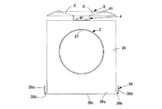
図1に示すように、例えば、水滴受板5の上面は、寄棟の頂上部がフード部3の天板32の長方形よりも一回り小さい相似な長方形の平面状となった屋根形状に形成される。
換言すれば、水滴受板5は、例えば、フード部3の天板32の長方形よりも一回り小さい長方形状の板により形成されて板面がフード部3の天板32の板面と所定の間隔を隔てて平行に対向すように配置された中央板部51と、当該中央板部51を構成する長方形の各辺縁から対応するフード部3の天板32の長方形の各辺縁に近付くように傾斜する傾斜板により形成された周辺板部52,52…とを備えた構成である。
そして、水滴受板5は、中央板部51を構成する長方形の中心5Cが、フード部3の天板32の板面と直交して当該天板32の長方形の中心を通過する垂直線V上に位置されるように、弾性支持体4を介してフード部3の天板32の上に設けられる。
The water drop receiving plate 5 provided on the top plate 32 of the hood part 3 via the elastic support body 4 is configured by a roof-shaped plate material arranged so as to cover the top plate 32 of the hood part 3. ..
As shown in FIG. 1, for example, the upper surface of the water drop receiving plate 5 is formed into a roof shape in which the top of the ridge is a similar rectangular flat surface that is slightly smaller than the rectangle of the top plate 32 of the hood 3. To be done.
In other words, the water drop receiving plate 5 is formed of, for example, a rectangular plate that is slightly smaller than the rectangular shape of the top plate 32 of the hood portion 3 and has a plate surface that is a predetermined plane with the plate surface of the top plate 32 of the hood portion 3. A central plate portion 51 arranged to face each other in parallel at a distance, and each rectangular side edge of the central plate portion 51 approaches each rectangular side edge of the top plate 32 of the corresponding hood portion 3. And the peripheral plate portions 52, 52 formed by the inclined plates.
The water drop receiving plate 5 has a rectangular center 5</b>C that constitutes the central plate portion 51 on a vertical line V that is orthogonal to the plate surface of the top plate 32 of the hood part 3 and passes through the center of the rectangle of the top plate 32. Is provided on the top plate 32 of the hood portion 3 via the elastic support body 4 so as to be located at.

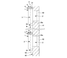
そして、図5に示すように、上下階の外壁91,91に、換気口端末部材1のフード部3及び水滴受板5が外壁面93より外側に突出するように各換気口端末部材1,1が設けられ、各換気口端末部材1,1の各水滴受板5,5の中心5C,5Cが、垂直線V上に位置された建物90が構成される。
当該建物90においては、上階に取付けられた換気口端末部材1のフード部3の板面を伝って水切部39に流れてくる水が水切部39の傾斜片39cの前端を介して下階に取付けられた換気口端末部材1の水滴受板5の上に落下する。
Then, as shown in FIG. 5, on the outer walls 91, 91 of the upper and lower floors, the hood portion 3 and the water drop receiving plate 5 of the ventilation port terminal member 1 are projected to the outside of the outer wall surface 93, respectively. 1 is provided, and the center 5C, 5C of each water drop receiving plate 5, 5 of each ventilation port terminal member 1, 1 is located on the vertical line V to form a building 90.
In the building 90, water flowing along the plate surface of the hood portion 3 of the ventilation port terminal member 1 attached to the upper floor to the water draining portion 39 passes through the front end of the inclined piece 39c of the water draining portion 39 to the lower floor. It falls on the water drop receiving plate 5 of the ventilation port terminal member 1 attached to the.

実施形態1では、水滴受板5への水滴落下衝突時の音圧レベルのばらつきを小さくして高品質な換気口端末部材1を提供するため、板状の弾性支持体4におけるフード部3の天板32及び水滴受板5と接していない部分に貫通孔Xを設けるとともに、当該水滴受板5と弾性支持体4とで構成される防振体の一次固有振動数fを、オクターブバンドの16Hz以上で125Hz以下の周波数となるように、より好ましくは、オクターブバンドの16Hz以上で63Hz以下の周波数となるように設定した。 In the first embodiment, in order to provide a high-quality ventilation port terminal member 1 by reducing the variation in the sound pressure level at the time of a water drop drop collision with the water drop receiving plate 5, the hood portion 3 of the plate-shaped elastic support 4 is provided. A through hole X is provided in a portion which is not in contact with the top plate 32 and the water drop receiving plate 5, and the primary natural frequency f 0 of the vibration isolator constituted by the water drop receiving plate 5 and the elastic support 4 is set to the octave band. Of 16 Hz or more and 125 Hz or less, and more preferably 16 Hz or more of the octave band and 63 Hz or less.

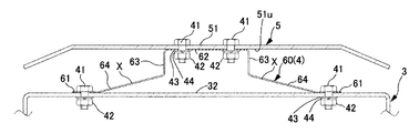
弾性支持体4は、板ばね60を使用した。当該板ばね60は、図6に示すように、天板32の上面の中央側に連結される中央板部62と、中央板部62の左右両方の端部からそれぞれ天板32の上面と直交して水滴受板5の中央板部51に近づく方向に延長する左右の立ち上がり板部63,63と、左右の立ち上がり板部63,63の上端からそれぞれ互いに反対方向に上がって傾斜するように延長する左右の傾斜板部64,64と、各傾斜板部64,64の上端からそれぞれ互いに反対方向に延長して水滴受板5の中央板部51の下面51uと接触して水滴受板5の中央板部51の左右両側に連結される左右両方の端板部61,61とを備えた形状のものを用いた。 As the elastic support body 4, a leaf spring 60 was used. As shown in FIG. 6, the leaf spring 60 includes a central plate portion 62 connected to the central side of the upper surface of the top plate 32, and right and left end portions of the central plate portion 62 that are orthogonal to the upper surface of the top plate 32, respectively. Then, the left and right rising plate parts 63, 63 extending in a direction approaching the central plate part 51 of the water drop receiving plate 5 and the upper ends of the left and right rising plate parts 63, 63 are respectively extended so as to rise in opposite directions and incline. The left and right inclined plate portions 64, 64 extending in opposite directions from the upper ends of the inclined plate portions 64, 64, respectively, and contacting the lower surface 51u of the central plate portion 51 of the water droplet receiving plate 5, A shape having both left and right end plate portions 61, 61 connected to both left and right sides of the central plate portion 51 was used.

即ち、実施形態1の換気口端末部材1は、図6に示すように、弾性支持体4を、貫通孔Xが形成された板ばね60により構成し、当該板ばね60の中央板部62の中心と天板32の上面の中心とを一致させた状態で当該中央板部62と天板32とが1組以上のボルト41及びナット42により連結されるとともに、天板32に連結された板ばね60の中央板部62よりも上方に位置された板ばね60の左右両方の端板部61,61と中央板部51の左右側とがボルト41及びナット42により連結された構成とした。
尚、天板32の下面とナット42との間、端板部61の下面とナット42との間には、例えば、平座金43及びばね座金44が設置される。
That is, in the ventilation port terminal member 1 of the first embodiment, as shown in FIG. 6, the elastic support body 4 is configured by the leaf spring 60 in which the through hole X is formed, and the central plate portion 62 of the leaf spring 60 is provided. The center plate portion 62 and the top plate 32 are connected by one or more sets of bolts 41 and nuts 42 in a state where the center and the center of the upper surface of the top plate 32 are aligned, and the plate connected to the top plate 32. The left and right end plate portions 61, 61 of the leaf spring 60, which are located above the central plate portion 62 of the spring 60, and the left and right sides of the central plate portion 51 are connected by bolts 41 and nuts 42.
In addition, for example, a flat washer 43 and a spring washer 44 are installed between the lower surface of the top plate 32 and the nut 42 and between the lower surface of the end plate portion 61 and the nut 42.

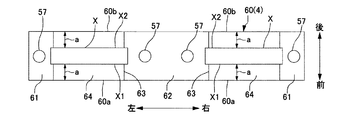
即ち、実施形態1に係る換気口端末部材1の弾性支持体4として板ばね60は、中央側の中央板部62がフード部3の天板32に取付けられて左右両方の端部側の端板部61,61が水滴受板5に取付けられた金属板等の板材により構成され、貫通孔Xは、例えば、板ばね60の中央板部62と端板部61との間の部分において、板ばね60の延長方向に沿って延長する一定幅の長孔(スリット)により構成されている。
具体的には、図7,図8に示すように、貫通孔Xは、板ばね60の延長方向に沿って左の立ち上がり板部63及び傾斜板部64の全域に亘って延長する左の貫通孔Xと、板ばね60の延長方向に沿って右の立ち上がり板部63及び傾斜板部64の全域に亘って延長する右の貫通孔Xとにより構成される。
また、左の貫通孔X及び右の貫通孔Xは、立ち上がり板部63及び傾斜板部64の前後幅方向の中央側に設けられる。換言すれば、左の貫通孔X及び右の貫通孔Xは、貫通孔Xの前側側縁X1と立ち上がり板部63及び傾斜板部64の前側縁60aとの間の板幅aと、貫通孔Xの後側側縁X2と立ち上がり板部63及び傾斜板部64の後側縁60bとの間の板幅aとが等しくなるように、立ち上がり板部63及び傾斜板部64の前後幅方向の中央側に形成されている。
尚、図7において、符号56は、水滴受板5の中央板部51の左右両側に形成されたボルト挿通孔、図7,図8において、符号57は、板ばね60の中央板部62及び端板部61,61に形成されたボルト挿通孔である。
That is, in the leaf spring 60 as the elastic support body 4 of the ventilation port terminal member 1 according to the first embodiment, the central plate portion 62 on the center side is attached to the top plate 32 of the hood portion 3 and the end portions on both left and right end portions are provided. The plate portions 61, 61 are made of a plate material such as a metal plate attached to the water drop receiving plate 5, and the through hole X has, for example, a portion between the central plate portion 62 and the end plate portion 61 of the leaf spring 60. The leaf spring 60 is formed of a long hole (slit) having a constant width extending along the extension direction of the leaf spring 60.
Specifically, as shown in FIGS. 7 and 8, the through hole X is a left through hole that extends along the extension direction of the leaf spring 60 over the entire area of the left rising plate portion 63 and the inclined plate portion 64. The hole X and the right through hole X extending along the extension direction of the leaf spring 60 over the entire area of the right rising plate portion 63 and the inclined plate portion 64 are formed.
The left through hole X and the right through hole X are provided on the center side of the rising plate portion 63 and the inclined plate portion 64 in the front-rear width direction. In other words, the left through-hole X and the right through-hole X have a plate width a between the front side edge X1 of the through hole X and the front side edge 60a of the rising plate portion 63 and the inclined plate portion 64, and the through hole. The rear side edge X2 of X and the rear side edge 60b of the rising plate portion 63 and the inclined plate portion 64 are arranged to be equal to each other in the front-rear width direction of the rising plate portion 63 and the inclined plate portion 64. It is formed on the center side.
In FIG. 7, reference numeral 56 is a bolt insertion hole formed on both right and left sides of the central plate portion 51 of the water drop receiving plate 5, and in FIGS. 7 and 8, reference numeral 57 is a central plate portion 62 of the leaf spring 60 and It is a bolt insertion hole formed in the end plate portions 61, 61.

実施形態1及び後述する各実施形態の換気口端末部材1において、水滴受板5と弾性支持体4とで構成される防振体の一次固有振動数fは、次式(1)で求めることができる。

Figure 2020106251
ここで、
:防振体の一次固有振動数(Hz)
m:水滴受板の質量(kg)
k:弾性支持体のばね定数(N/m) In the ventilation port terminal member 1 of the first embodiment and each of the embodiments described later, the primary natural frequency f 0 of the vibration isolator including the water drop receiving plate 5 and the elastic support body 4 is calculated by the following equation (1). be able to.
Figure 2020106251
here,
f 0 : Primary natural frequency (Hz) of the vibration isolator
m: Mass of water drop receiving plate (kg)
k: Spring constant of elastic support (N/m)

一般に、上述した防振体の一次固有振動数fを低くするためには、弾性支持体4のばね定数を小さくすればよいが、弾性支持体4のばね定数を小さくしすぎると、弾性支持体4が柔らかくなりすぎて、防振体を構造体として成立させることが難しくなる。
そこで、このような場合は、水滴受板5の質量を大きくすることによって、防振体の一次固有振動数fを目標値(例えば、オクターブバンドの16Hz以上で63Hz以下)に設定すればよい。
例えば、水滴受板5に、錘、補強板等の質量体を付加することにより、水滴受板5の質量を大きくして、防振体の一次固有振動数fを目標値(例えば、オクターブバンドの16Hz以上で63Hz以下)に設定すればよい。
Generally, in order to lower the primary natural frequency f 0 of the vibration isolator described above, the spring constant of the elastic support 4 may be reduced, but if the spring constant of the elastic support 4 is too low, the elastic support 4 is elastically supported. The body 4 becomes too soft, and it becomes difficult to establish the vibration isolator as a structure.
Therefore, in such a case, the primary natural frequency f 0 of the vibration isolator may be set to a target value (for example, 16 Hz or more in the octave band and 63 Hz or less) by increasing the mass of the water drop receiving plate 5. ..
For example, by adding a mass body such as a weight or a reinforcing plate to the water drop receiving plate 5, the mass of the water drop receiving plate 5 is increased to set the primary natural frequency f 0 of the vibration isolator to a target value (for example, octave). The band may be set to 16 Hz or more and 63 Hz or less).

本発明の換気口端末部材1の水滴落下衝突音低減効果を確認するための実験を以下のように行った。 An experiment for confirming the water drop falling collision noise reduction effect of the ventilation port terminal member 1 of the present invention was conducted as follows.

・実験方法
共同住宅の給気孔に取付けた換気口端末部材の各試験体に水滴が落下する状況を模擬した実験を簡易無響室内で行った。
実験設備は以下のとおりである。
足場の下部に内径900mm角の箱(内部をグラスウールで吸音処理した箱)を設置し、箱の正面中央の位置の外側に換気口端末部材の試験体を設置するとともに、内側にレジスター(内側換気口)を設置した。レジスターは樹脂製のプッシュタイプとし、実験時は「開」の状態とした。
共同住宅の一般的な階高を想定し,換気口端末部材の試験体天端に高さ3mの位置からスポイトを使って水滴を落下させた。
水滴落下衝突音の測定は、マイクロホンを箱内部の中心の位置に設置し、水滴落下衝突音の1/3オクターブバンド音圧レベルを測定した。試験体天端への水滴の落下回数は、1試験体に対し50回とした。
-Experimental method An experiment was conducted in a simple anechoic chamber to simulate the situation in which water drops fell on each test piece of the ventilation port end member attached to the air supply hole of the apartment house.
The experimental equipment is as follows.
A box with an inner diameter of 900 mm square (a box with sound absorption treated with glass wool inside) was installed at the bottom of the scaffold, and a test piece of ventilation port end member was installed outside the center of the front of the box, and a register (inside ventilation) Mouth) was installed. The register was a push type made of resin, and was in the "open" state during the experiment.
Assuming the general floor height of an apartment building, a dropper was used to drop a drop of water from the position at a height of 3 m at the top of the test body of the ventilation end member.
For the measurement of water drop impact sound, a microphone was installed in the center of the box and the sound pressure level of 1/3 octave band of the water impact sound was measured. The number of drops of water drops on the top of the test body was 50 times per one test body.

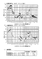
実験に用いた換気口端末部材の各試験体は、図9,図10に示すように、
・スリットあり=実施形態1の換気口端末部材1
・スリットなし=実施形態1の換気口端末部材1と比べた場合に貫通孔(スリット)Xを備えない弾性支持体を備えた換気口端末部材(特許文献1の換気口端末部材と同等の換気口端末部材)
である。
尚、スリットありの試験体の設計値は、水滴受板の質量=57g、弾性支持体のばね定数k=4.3N/mm、及び、水滴受板の質量=136g、弾性支持体のばね定数k=4.3N/mmとした。
また、スリットなしの試験体の設計値は、水滴受板の質量=57g、弾性支持体のばね定数k=4.9N/mm、及び、水滴受板の質量=136g、弾性支持体のばね定数k=4.9N/mmとした。
また、各換気口端末部材の試験体の材質、寸法等は、以下のとおりである。
共通部分=筒部、フード部、水滴受板の材質=ステンレス鋼SUS304、水滴受板5の短辺43mm、長辺150mm。
Each test piece of the ventilation port terminal member used in the experiment is, as shown in FIG. 9 and FIG.
-With slit = ventilation port terminal member 1 of the first embodiment
No slit=Ventilation port terminal member provided with an elastic support member having no through hole (slit) X when compared with the ventilation port terminal member 1 of Embodiment 1 (ventilation port terminal member of Patent Document 1 equivalent ventilation Mouth end member)
Is.
The design values of the test piece with the slits are as follows: mass of water drop receiving plate=57 g, spring constant k of elastic support k=4.3 N/mm, and mass of water drop receiving plate=136 g, spring constant of elastic support. k=4.3 N/mm.
The design values of the test body without slits are as follows: mass of water drop receiving plate = 57 g, spring constant k of elastic support k = 4.9 N/mm, and mass of water drop receiving plate = 136 g, spring constant of elastic support. k=4.9 N/mm.
The material, dimensions, etc. of the test piece of each ventilation port end member are as follows.
Common parts=cylindrical portion, hood, water drop receiving plate material=stainless steel SUS304, water drop receiving plate 5 has a short side of 43 mm and a long side of 150 mm.

・実験結果
図9(a)は、スリットありの試験体(水滴受板の質量=57g、弾性支持体のばね定数k=4.3N/mm)での、1/3オクターブバンド中心周波数−音圧レベルの測定結果を示す。
図9(b)は、スリットなしの試験体(水滴受板の質量=57g、弾性支持体のばね定数k=4.9N/mm)での、1/3オクターブバンド中心周波数−音圧レベルの測定結果を示す。
図9(c)は、50回の音圧レベル測定値の250Hz帯域での標準偏差、及び、50回の音圧レベル測定値の1.6kHz帯域での標準偏差を、スリットありの試験体とスリットなしの試験体とで比較した図表である。
また、図10(a)は、スリットありの試験体(水滴受板の質量=136g、弾性支持体のばね定数k=4.3N/mm)での、1/3オクターブバンド中心周波数−音圧レベルの測定結果を示す。
図10(b)は、スリットなしの試験体(水滴受板の質量=136g、弾性支持体のばね定数k=4.9N/mm)での、1/3オクターブバンド中心周波数−音圧レベルの測定結果を示す。
図10(c)は、50回の音圧レベル測定値の500Hz帯域での標準偏差、及び、50回の音圧レベル測定値の630Hz帯域での標準偏差を、スリットありの試験体とスリットなしの試験体とで比較した図表である。
-Experimental result Fig.9 (a) is a 1/3 octave band center frequency-sound in the test body with a slit (mass of water drop receiving plate = 57 g, spring constant k of an elastic support body = 4.3 N/mm). The measurement result of the pressure level is shown.
FIG. 9B shows the 1/3 octave band center frequency-sound pressure level in a test body without slits (mass of water drop receiving plate=57 g, spring constant k of elastic support k=4.9 N/mm). The measurement results are shown.
FIG. 9C shows the standard deviation of the sound pressure level measurement value of 50 times in the 250 Hz band and the standard deviation of the sound pressure level measurement value of 50 times in the 1.6 kHz band as the test body with the slit. It is a chart compared with the test body without slit.
In addition, FIG. 10A shows a 1/3 octave band center frequency-sound pressure in a test body with slits (mass of water drop receiving plate=136 g, spring constant k of elastic support body=4.3 N/mm). The level measurement results are shown.
FIG. 10B shows the 1/3 octave band center frequency-sound pressure level in a test body without a slit (mass of water drop receiving plate=136 g, spring constant k of elastic support k=4.9 N/mm). The measurement results are shown.
FIG. 10C shows the standard deviation of the sound pressure level measurement value of 50 times in the 500 Hz band, and the standard deviation of the sound pressure level measurement value of 50 times in the 630 Hz band, with a test piece with slit and without slit. It is a chart compared with the test body of.

図9(a),(b)、図10(a),(b)に示す実験結果から明らかなように、スリットありでは、スリットなしと比べて、ほぼすべての帯域で、50回の音圧レベル測定値のばらつき(標準偏差)が小さくなっていることがわかる。
例えば、図9からわかるように、音圧レベル測定値の250Hz帯域での標準偏差は、スリットありの場合、0.9であるのに対して、スリットなしの場合は、1.8である。
また、音圧レベル測定値の1.6kHz帯域での標準偏差は、スリットありの場合、2.1であるのに対して、スリットなしの場合は、2.8である。
また、図10からわかるように、音圧レベル測定値の500Hz帯域での標準偏差は、スリットありの場合、1.3であるのに対して、スリットなしの場合は、3.9である。
また、音圧レベル測定値の630Hz帯域での標準偏差は、スリットありの場合、1.4であるのに対して、スリットなしの場合は、4.0である。
As is clear from the experimental results shown in FIGS. 9(a), (b), and FIGS. 10(a), (b), with the slit, the sound pressure was 50 times in almost all bands compared with the case without the slit. It can be seen that the variation (standard deviation) of the level measurement values is small.
For example, as can be seen from FIG. 9, the standard deviation of the sound pressure level measurement value in the 250 Hz band is 0.9 when the slit is provided, while it is 1.8 when the slit is not provided.
Further, the standard deviation of the sound pressure level measurement value in the 1.6 kHz band is 2.1 with the slit, whereas it is 2.8 without the slit.
Further, as can be seen from FIG. 10, the standard deviation of the sound pressure level measured value in the 500 Hz band is 1.3 with the slits, whereas it is 3.9 without the slits.
Further, the standard deviation of the sound pressure level measurement value in the 630 Hz band is 1.4 when the slit is provided, whereas it is 4.0 when the slit is not provided.

実験結果から明らかなように、スリットありの試験体、即ち、実施形態1の換気口端末部材1は、スリットなしの試験体と比べて、音圧レベル測定値の標準偏差(ばらつき)が小さく高品質な換気口端末部材となることがわかった。 As is clear from the experimental results, the test piece with the slit, that is, the ventilation port terminal member 1 of the first embodiment has a small standard deviation (variation) of the sound pressure level measurement value and a high value as compared with the test piece without the slit. It was found to be a quality ventilation port end member.

即ち、実施形態1に係る換気口端末部材1によれば、弾性支持体4におけるフード部3の天板32及び水滴受板5と接していない部分に貫通孔(スリット)Xを備えた構成としたので、水滴受板5への水滴落下衝突時の音圧レベルのばらつきを小さくできる高品質な換気口端末部材となることがわかった。 That is, according to the ventilation port terminal member 1 of the first embodiment, a configuration in which the through hole (slit) X is provided in a portion of the elastic support 4 that is not in contact with the top plate 32 and the water drop receiving plate 5 of the hood portion 3, Therefore, it was found that a high-quality ventilation port terminal member capable of reducing the variation in the sound pressure level at the time of collision of a water drop falling on the water drop receiving plate 5 can be obtained.

また、実施形態1に係る換気口端末部材1によれば、水滴受板5と弾性支持体4とで構成される防振体の一次固有振動数fが、オクターブバンドの16Hz以上で125Hz以下の周波数となるように設定したので、水滴落下衝突時における中高周波数帯域の音を低減させる効果が向上し、水滴落下衝突時のA特性音圧レベルをより低減できて、水滴落下衝突音の低減効果に優れた換気口端末部材1を得ることができる。 Further, according to the ventilation port terminal member 1 according to the first embodiment, the primary natural frequency f 0 of the vibration isolator constituted by the water drop receiving plate 5 and the elastic support body 4 is 16 Hz or more in the octave band and 125 Hz or less. Since it is set to be the frequency of, the effect of reducing the sound in the middle and high frequency bands at the time of a water drop drop collision is improved, the A characteristic sound pressure level at the time of a water drop drop collision can be further reduced, and the water drop drop collision sound can be reduced. It is possible to obtain the ventilation port terminal member 1 having an excellent effect.

実施形態2
図11に示すように、実施形態2の換気口端末部材1は、弾性支持体4を、ばねとしての板ばね60により構成し、当該板ばね60は、水滴受板5の中央板部51の下面51uと接触して中央板部51の中央側に連結される中央板部62と、中央板部62の左右両方の端部からそれぞれ中央板部51の下面51uと直交して天板32に近づく方向に延長する左右の立ち下がり板部63,63と、左右の立ち下がり板部63,63の下端からそれぞれ互いに反対方向に下って傾斜して延長する左右の傾斜板部64,64と、各傾斜板部64,64の下端からそれぞれ互いに反対方向に延長して天板32の上面と接触して天板32に連結される左右両方の端板部61,61とを備えた形状のものを用いた。即ち、実施形態1の換気口端末部材1で説明した板ばね60を上下逆向きにして使用した。
Embodiment 2
As shown in FIG. 11, in the ventilation port terminal member 1 according to the second embodiment, the elastic support body 4 is configured by a leaf spring 60 as a spring, and the leaf spring 60 corresponds to the central plate portion 51 of the water drop receiving plate 5. The central plate portion 62 which is in contact with the lower surface 51u and is connected to the central side of the central plate portion 51, and the left and right ends of the central plate portion 62 are respectively orthogonal to the lower surface 51u of the central plate portion 51 to the top plate 32. Left and right falling plate portions 63, 63 extending in the approaching direction, and left and right inclined plate portions 64, 64 extending downwardly and inclining in opposite directions from the lower ends of the left and right falling plate portions 63, 63, respectively. A shape having both left and right end plate portions 61, 61 extending in opposite directions from the lower ends of the inclined plate portions 64, 64 and contacting the upper surface of the top plate 32 and connected to the top plate 32. Was used. That is, the leaf spring 60 described in the ventilation port terminal member 1 of the first embodiment is used upside down.

実施形態2の換気口端末部材1は、例えば図11に示すように、板ばね60の左右両方の端板部61,61がフード部3の天板32にボルト41及びナット42により連結されるとともに、天板32に連結された板ばね60の左右両方の端板部61,61よりも上方に位置された板ばね60の中央板部62と水滴受板5の中央板部51とが1組以上のボルト41及びナット42により連結された構成とした。
尚、天板32の下面とナット42との間、中央板部62の下面とナット42との間には、例えば、平座金43及びばね座金44が設置される。
In the ventilation port terminal member 1 of the second embodiment, for example, as shown in FIG. 11, both left and right end plate portions 61, 61 of the leaf spring 60 are connected to the top plate 32 of the hood portion 3 by bolts 41 and nuts 42. At the same time, the central plate portion 62 of the leaf spring 60 and the central plate portion 51 of the water drop receiving plate 5 located above the left and right end plate portions 61, 61 of the plate spring 60 connected to the top plate 32 are 1 The bolts 41 and the nuts 42 of a set or more are connected to each other.
In addition, for example, a flat washer 43 and a spring washer 44 are installed between the lower surface of the top plate 32 and the nut 42 and between the lower surface of the central plate portion 62 and the nut 42.

そして、実施形態2に係る換気口端末部材1では、貫通孔Xは、実施形態1と同様に、板ばね60の延長方向に沿って左の立ち下がり板部63及び傾斜板部64の全域に亘って延長する左の貫通孔Xと、板ばね60の延長方向に沿って右の立ち下がり板部63及び傾斜板部64の全域に亘って延長する右の貫通孔Xとにより構成され、板ばね60と水滴受板5とで構成される防振体の一次固有振動数fを、オクターブバンドの16Hz以上で125Hz以下の周波数となるように、より好ましくは、オクターブバンドの16Hz以上で63Hz以下の周波数となるように設定した。 Then, in the ventilation port terminal member 1 according to the second embodiment, the through hole X is formed in the entire area of the left falling plate portion 63 and the inclined plate portion 64 along the extension direction of the leaf spring 60, as in the first embodiment. A left through hole X extending over the entire length and a right through hole X extending over the entire area of the right falling plate portion 63 and the inclined plate portion 64 along the extension direction of the leaf spring 60. The primary natural frequency f 0 of the vibration isolator composed of the spring 60 and the water drop receiving plate 5 is set to a frequency of 16 Hz or more in the octave band and 125 Hz or less, and more preferably 63 Hz in the 16 Hz or more of the octave band. The frequency was set as follows.

実施形態3
図12に示すように、実施形態3の換気口端末部材1は、弾性支持体4を、ばねとしての複数の板ばね60A,60Bにより構成し、当該複数の板ばね60A,60Bと水滴受板5とで構成される防振体の一次固有振動数fを、オクターブバンドの16Hz以上で125Hz以下の周波数となるように、より好ましくは、オクターブバンドの16Hz以上で63Hz以下の周波数となるように設定した。
Embodiment 3
As shown in FIG. 12, in the ventilation port terminal member 1 of the third embodiment, the elastic support body 4 is configured by a plurality of leaf springs 60A and 60B as springs, and the plurality of leaf springs 60A and 60B and the water drop receiving plate. The primary natural frequency f 0 of the vibration isolator composed of 5 and 5 is set to a frequency of 16 Hz or higher in the octave band and 125 Hz or lower, and more preferably 16 Hz or higher in the octave band and 63 Hz or lower. Set to.

板ばね60Aは、天板32の上面と接触して天板32に連結される左右両方の端板部61A,61Aと、左右両方の端板部61A,61A間を繋ぐ湾曲板部62Aとを備えた形状のものを用いた。
また、板ばね60Bは、水滴受板5の中央板部51の下面51uと接触して中央板部51に連結される左右両方の端板部61B,61Bと、左右両方の端板部61B,61B間を繋ぐ湾曲板部62Bとを備えた形状のものを用いた。
The leaf spring 60A includes both left and right end plate portions 61A and 61A that are in contact with the upper surface of the top plate 32 and are connected to the top plate 32, and a curved plate portion 62A that connects the left and right end plate portions 61A and 61A. The shape provided was used.
Further, the leaf spring 60B is in contact with the lower surface 51u of the central plate portion 51 of the water drop receiving plate 5 and is connected to the central plate portion 51 on both left and right end plate portions 61B and 61B, and both left and right end plate portions 61B and 61B. A shape having a curved plate portion 62B connecting between 61B was used.

実施形態3の換気口端末部材1は、例えば図12に示すように、一方の板ばね60Aの左右両方の端板部61A,61Aが天板32の左右側にボルト41及びナット42により連結されるとともに、他方の板ばね60Bの左右両方の端板部61B,61Bが水滴受板5の中央板部51の左右側にボルト41及びナット42により連結され、かつ、一方の板ばね60Aの左右両方の端板部61A,61Aよりも上方に位置された一方の板ばね60Aの湾曲板部62Aの中央部と他方の板ばね60Bの左右両方の端板部61B,61Bよりも下方に位置された他方の板ばね60Bの湾曲板部62Bの中央部とがボルト41及びナット42により連結された構成とした。
そして、貫通孔Xは、例えば、一方の板ばね60Aの湾曲板部62Aの左右側と、他方の板ばね60Bの湾曲板部62Bの左右側とに、それぞれ設けるようにした。
尚、天板32の下面とナット42との間、他方の板ばね60Bの端板部61Bの下面とナット42との間、一方の板ばね60Aの湾曲板部62Aの中央部の下面とナット42との間には、例えば、平座金43及びばね座金44が設置される。
In the ventilation port terminal member 1 of the third embodiment, for example, as shown in FIG. 12, the left and right end plate portions 61A and 61A of one leaf spring 60A are connected to the left and right sides of the top plate 32 by bolts 41 and nuts 42. In addition, the left and right end plate portions 61B, 61B of the other leaf spring 60B are connected to the left and right sides of the central plate portion 51 of the water drop receiving plate 5 by bolts 41 and nuts 42, and the left and right sides of the one leaf spring 60A are connected. It is located below both end plate parts 61A and 61A, and is located below the center part of the curved plate part 62A of one plate spring 60A and the left and right end plate parts 61B and 61B of the other plate spring 60B. The center of the curved plate portion 62B of the other leaf spring 60B is connected by the bolt 41 and the nut 42.
The through holes X are provided, for example, on the left and right sides of the curved plate portion 62A of the one leaf spring 60A and on the left and right sides of the curved plate portion 62B of the other leaf spring 60B.
In addition, between the lower surface of the top plate 32 and the nut 42, between the lower surface of the end plate portion 61B of the other leaf spring 60B and the nut 42, and between the lower surface of the curved plate portion 62A of the one leaf spring 60A and the nut 42. For example, a plain washer 43 and a spring washer 44 are installed between the flat washer 42 and the spring 42.

実施形態4
図13に示すように、実施形態4の換気口端末部材1は、弾性支持体4を、ゴム70と実施形態1(図6参照)の板ばね60とにより構成し、当該板ばね60とゴム70と水滴受板5とで構成される防振体の一次固有振動数fを、オクターブバンドの16Hz以上で125Hz以下の周波数となるように、より好ましくは、オクターブバンドの16Hz以上で63Hz以下の周波数となるように設定した。
貫通孔Xは、実施形態1と同様に、例えば、板ばね60の延長方向に沿って左の立ち上がり板部63及び傾斜板部64の全域に亘って延長する左の貫通孔Xと、板ばね60の延長方向に沿って右の立ち上がり板部63及び傾斜板部64の全域に亘って延長する右の貫通孔Xとにより構成した。
Embodiment 4
As shown in FIG. 13, in the ventilation port terminal member 1 of the fourth embodiment, the elastic support body 4 is configured by the rubber 70 and the leaf spring 60 of the first embodiment (see FIG. 6). 70 and the water drop receiving plate 5 so that the primary natural frequency f 0 of the vibration proof body is 16 Hz or higher in the octave band and 125 Hz or lower, and more preferably 16 Hz or higher in the octave band and 63 Hz or lower. The frequency was set to.
Similar to the first embodiment, the through hole X includes, for example, a left through hole X extending along the extension direction of the leaf spring 60 over the entire area of the left rising plate portion 63 and the inclined plate portion 64, and a leaf spring. The right through-hole X is formed by extending the right rising plate portion 63 and the inclined plate portion 64 along the extension direction of 60.

実施形態4の換気口端末部材1は、例えば図13に示すように、板ばね60の中央板部62が天板32の中央部にゴム70を介してボルト41及びナット42により連結されるとともに、天板32に連結された板ばね60の中央板部62よりも上方に位置された板ばね60の左右両方の端板部61,61と水滴受板5の中央板部51の左右側とがボルト41及びナット42により連結された構成とした。
尚、端板部61の下面とナット42との間には、例えば、平座金43及びばね座金44が設置される。
In the ventilation port terminal member 1 of the fourth embodiment, as shown in FIG. 13, for example, the central plate portion 62 of the leaf spring 60 is connected to the central portion of the top plate 32 via the rubber 70 by the bolt 41 and the nut 42. , The left and right end plate portions 61, 61 of the leaf spring 60 positioned above the central plate portion 62 of the leaf spring 60 connected to the top plate 32, and the left and right sides of the central plate portion 51 of the water drop receiving plate 5. Is connected by a bolt 41 and a nut 42.
A flat washer 43 and a spring washer 44 are installed between the lower surface of the end plate portion 61 and the nut 42, for example.

板ばね60の中央板部62とフード部3の天板32とのゴム連結部7は、具体的には、次のように構成される。
板ばね60の中央板部62には、ボルト41を貫通させるボルト貫通孔が形成されている。
また、ゴム70は、中心に、金属筒45を装着するための装着孔73が形成された円筒状でかつ外周面には外周面を一周するリング状の溝71が形成された円筒状のゴムである。
また、フード部3の天板32において、板ばね60の中央板部62が連結される位置には、円筒状のゴム70が嵌め込まれる嵌合用貫通孔72が形成されている。
The rubber connecting portion 7 between the central plate portion 62 of the leaf spring 60 and the top plate 32 of the hood portion 3 is specifically configured as follows.
The central plate portion 62 of the leaf spring 60 has a bolt through hole through which the bolt 41 penetrates.
Further, the rubber 70 has a cylindrical shape in which a mounting hole 73 for mounting the metal cylinder 45 is formed in the center, and a ring-shaped groove 71 is formed on the outer peripheral surface to encircle the outer peripheral surface. Is.
Further, in the top plate 32 of the hood portion 3, a fitting through hole 72 into which the cylindrical rubber 70 is fitted is formed at a position where the central plate portion 62 of the leaf spring 60 is connected.

予めゴム70の装着孔73内に金属筒45を装着しておき、そして、フード部3の天板32に形成された嵌合用貫通孔72の孔縁が円筒状ゴム70のリング状の溝71に嵌まり込むように、ゴム70を嵌合用貫通孔72に取付ける。
その後、板ばね60の中央板部62に形成されたボルト貫通孔とゴム70の内側に装着された金属筒45の筒孔とが一致するように、板ばね60の中央板部62を天板32の上面より上方に突出するゴム70の一端面に設置し、ボルト41を板ばね60の中央板部62のボルト貫通孔と金属筒45の筒孔とに通してボルト41の先端側を天板32の下面より下方に突出するゴム70の他端面より下方に突出させる。
そして、このゴム70の他端面より下方に突出させたボルト41の先端側に例えば平座金43及びばね座金44を介してナット42を締結することにより、板ばね60の中央板部62と天板32とがゴム70を介してボルト41及びナット42により連結された構造のゴム連結部7が構成される。
尚、板ばね60の中央板部62と天板32と連結するゴム連結部7は、図13に示すように、1組以上設けられる。
The metal cylinder 45 is previously mounted in the mounting hole 73 of the rubber 70, and the hole edge of the fitting through hole 72 formed in the top plate 32 of the hood portion 3 has a ring-shaped groove 71 of the cylindrical rubber 70. The rubber 70 is attached to the fitting through hole 72 so that the rubber 70 is fitted into the fitting through hole 72.
Then, the central plate portion 62 of the leaf spring 60 is placed on the top plate so that the bolt through hole formed in the central plate portion 62 of the leaf spring 60 and the cylindrical hole of the metal cylinder 45 mounted inside the rubber 70 are aligned with each other. It is installed on one end surface of the rubber 70 projecting upward from the upper surface of 32, and the bolt 41 is passed through the bolt through hole of the central plate portion 62 of the plate spring 60 and the cylindrical hole of the metal cylinder 45 so that the tip side of the bolt 41 is raised. The rubber 70 protruding downward from the lower surface of the plate 32 is caused to protrude downward from the other end surface.
Then, the nut 42 is fastened to the tip end side of the bolt 41 protruding downward from the other end surface of the rubber 70, for example, via the flat washer 43 and the spring washer 44, so that the central plate portion 62 of the leaf spring 60 and the top plate. A rubber connecting portion 7 having a structure in which 32 and 32 are connected via a rubber 70 by a bolt 41 and a nut 42 is configured.
Note that, as shown in FIG. 13, one or more sets of rubber connecting portions 7 that connect the central plate portion 62 of the leaf spring 60 and the top plate 32 are provided.

また、図示しないが、実施形態4においては、弾性支持体4は、板ばね60の端板部61側及び中央板部62のうちの少なくとも一方が、ゴム連結部7によって連結された構成とすればよい。例えば、実施形態4の弾性支持体4は、板ばね60の左右両方の端板部61,61がゴム連結部7を介して水滴受板5に連結されるとともに、板ばね60の中央板部62がゴム連結部7を介して天板32に連結された構成としてもよい。 Further, although not shown, in the fourth embodiment, the elastic support body 4 is configured such that at least one of the end plate portion 61 side and the central plate portion 62 of the leaf spring 60 is connected by the rubber connecting portion 7. Good. For example, in the elastic support body 4 according to the fourth embodiment, the left and right end plate portions 61, 61 of the leaf spring 60 are connected to the water drop receiving plate 5 via the rubber connecting portion 7, and the central plate portion of the leaf spring 60 is connected. The configuration may be such that 62 is connected to the top plate 32 via the rubber connecting portion 7.

即ち、実施形態4の換気口端末部材1は、図13に示すように、実施形態1の板ばね60と同じものを使用して、当該板ばね60の中央板部62と天板32の中央側との連結部を1組以上のゴム連結部7により構成した。
尚、図13において特に説明しなかった部分の構成は、実施形態1(図6)の構成と同じである。
That is, as shown in FIG. 13, the ventilation port terminal member 1 of the fourth embodiment is the same as the leaf spring 60 of the first embodiment, and the center plate portion 62 of the leaf spring 60 and the center of the top plate 32 are used. The connecting portion with the side is constituted by one or more sets of rubber connecting portions 7.
Note that the configuration of the parts not particularly described in FIG. 13 is the same as that of the first embodiment (FIG. 6).

実施形態5
図14に示すように、実施形態5の換気口端末部材1は、弾性支持体4を、例えば実施形態1(図6参照)や実施形態4(図13参照)で示した板ばね60と同様な形状に形成されてばね機能を持つゴムとしてのゴム板600により構成し、当該ゴム板600と水滴受板5とで構成される防振体の一次固有振動数fを、オクターブバンドの16Hz以上で125Hz以下の周波数となるように、より好ましくは、オクターブバンドの16Hz以上で63Hz以下の周波数となるように設定した。
Embodiment 5
As shown in FIG. 14, the ventilation port terminal member 1 of the fifth embodiment has the same elastic support 4 as the leaf spring 60 shown in the first embodiment (see FIG. 6) or the fourth embodiment (see FIG. 13). Of the vibration isolator formed by the rubber plate 600 as a rubber having a spring function and having a spring shape, and the rubber plate 600 and the water drop receiving plate 5 have a primary natural frequency f 0 of 16 Hz of the octave band. The frequency is set to 125 Hz or less, and more preferably set to 16 Hz or more and 63 Hz or less in the octave band.

ゴム板600は、フード部3の天板32に連結される中央板部602と、中央板部602の左右の端部からそれぞれ天板32と直交して水滴受板5に近づく方向に延長する左右の立ち上がり板部603,603と、左右の立ち上がり板部603,603の上端からそれぞれ互いに反対方向に上がって延長する左右の傾斜板部604,604と、各傾斜板部604,604の上端からそれぞれ互いに反対方向に延長して水滴受板5に連結される左右両方の端板部601,601とを備えた形状のものを用いた。 The rubber plate 600 extends from the left and right ends of the center plate 602 connected to the top plate 32 of the hood part 3 in a direction orthogonal to the top plate 32 and close to the water drop receiving plate 5. From the upper ends of the left and right rising plate portions 603 and 603, the left and right rising plate portions 603 and 603, and the left and right inclined plate portions 604 and 604, which rise and extend in mutually opposite directions, respectively. A shape having a pair of left and right end plate portions 601 and 601 connected to the water drop receiving plate 5 respectively extending in opposite directions was used.

即ち、実施形態5の換気口端末部材1は、図14に示すように、ゴム板600の左右両方の端板部601,601が水滴受板5の中央板部51の左右側にボルト41及びナット42により連結されるとともに、中央板部51の左右側に連結された左右の端板部601,601よりも下方に位置された中央板部602が天板32の中央側にボルト41及びナット42により連結された構成とした。
尚、天板32の下面とナット42との間、端板部601の下面とナット42との間には、例えば、平座金43及びばね座金44が設置される。
貫通孔Xは、実施形態1と同様に、例えば、ゴム板600の延長方向に沿って左の立ち上がり板部603及び傾斜板部604の全域に亘って延長する左の貫通孔Xと、ゴム板600の延長方向に沿って右の立ち上がり板部603及び傾斜板部604の全域に亘って延長する右の貫通孔Xとにより構成した。
That is, in the ventilation port terminal member 1 of the fifth embodiment, as shown in FIG. 14, the left and right end plate portions 601 and 601 of the rubber plate 600 are attached to the left and right sides of the central plate portion 51 of the water drop receiving plate 5 by the bolts 41 and The central plate portion 602, which is connected to the central plate portion 51 and is located below the left and right end plate portions 601 and 601, which are connected to the right and left sides of the central plate portion 51, has a bolt 41 and a nut on the central side of the top plate 32. It is configured to be connected by 42.
In addition, for example, a flat washer 43 and a spring washer 44 are installed between the lower surface of the top plate 32 and the nut 42 and between the lower surface of the end plate portion 601 and the nut 42.
Similar to the first embodiment, the through hole X includes, for example, a left through hole X extending along the extension direction of the rubber plate 600 over the entire area of the left rising plate portion 603 and the inclined plate portion 604, and a rubber plate. The right through-hole X extends along the extension direction of 600 over the entire area of the right rising plate portion 603 and the inclined plate portion 604.

各実施形態2乃至実施形態5の換気口端末部材1によれば、弾性支持体4を、ばね(板ばね60、板ばね60Aと板ばね60Bの組み合わせ、コイルばね60C)、あるいは、ばねとゴム70、あるいは、ゴム板(ゴム)600により構成し、当該弾性支持体4と水滴受板5とで構成される防振体の一次固有振動数fを、オクターブバンドの16Hz以上で125Hz以下の周波数となるように、より好ましくは、オクターブバンドの16Hz以上で63Hz以下の周波数となるように設定したので、実施形態1の換気口端末部材1と同様に、水滴落下衝突時の音圧レベルの標準偏差(ばらつき)を小さくできる高品質な換気口端末部材となり、また、水滴落下衝突時のA特性音圧レベルを低減できて、水滴落下衝突音の低減効果に優れた換気用端末部材となる。 According to the ventilation port terminal member 1 of each of the second to fifth embodiments, the elastic support body 4 is formed of a spring (a leaf spring 60, a combination of the leaf springs 60A and 60B, a coil spring 60C), or a spring and a rubber. 70 or a rubber plate (rubber) 600, and the primary natural frequency f 0 of the vibration isolator composed of the elastic support 4 and the water drop receiving plate 5 is set to 16 Hz or more in the octave band and 125 Hz or less. Since the frequency is set so that the frequency is more preferably 16 Hz or more and 63 Hz or less in the octave band, the sound pressure level at the time of water drop collision is similar to that of the ventilation port terminal member 1 of the first embodiment. It becomes a high-quality ventilation end member that can reduce the standard deviation (variation), and can also reduce the A-weighted sound pressure level at the time of a water drop collision, making it a ventilation terminal member that has an excellent effect of reducing the water drop collision sound. ..

即ち、各実施形態1乃至実施形態5の換気口端末部材1によれば、一次固有振動数fの√2倍にあたる周波数より高い周波数帯において振動伝達率が1以下の防振域となるので、水滴受板5からフード部3への振動伝達が抑制されて、水滴の落下衝突で生成された振動エネルギーのフード部3への伝播を抑制することができる。 That is, according to the ventilation port end member 1 of each of the first to fifth embodiments, the vibration transmissibility is 1 or less in the vibration isolation region in the frequency band higher than the frequency corresponding to √2 times the primary natural frequency f 0 . The vibration transmission from the water drop receiving plate 5 to the hood part 3 is suppressed, and the propagation of the vibration energy generated by the drop collision of the water drops to the hood part 3 can be suppressed.

また、当該一次固有振動数fの周辺の周波数帯は振動増幅域であり、各実施形態1乃至実施形態5で示した防振体の構造を採用することにより、防振体の一次固有振動数fの共振ポイントの増幅倍率は大きくなるが、一次固有振動数fの近辺の周波数帯は周波数補正A特性での補正量が大きな領域であるため、人が感じる音圧レベルとしては低い値になる。 Further, the frequency band around the primary natural frequency f 0 is a vibration amplification region, and by adopting the structure of the vibration isolator shown in each of the first to fifth embodiments, the primary natural vibration of the vibration isolator is obtained. Although the amplification factor of the resonance point of the number f 0 is large, the frequency band in the vicinity of the primary natural frequency f 0 is a region in which the correction amount in the frequency correction A characteristic is large, and therefore the sound pressure level felt by a person is low. It becomes a value.

また、実施形態4(図13参照)に示した換気口端末部材1のように、弾性支持体4がゴム連結部7を備えた構成の場合、ゴム連結部7のゴム70が有する減衰の効果によって、防振体の共振ポイントの増幅倍率を低下させる効果が付与されるので、共振ポイントの弊害を抑えて水滴落下衝突音の低減効果を向上した換気口端末部材1を得ることができる。 Further, like the ventilation port terminal member 1 shown in the fourth embodiment (see FIG. 13), in the case where the elastic support body 4 is provided with the rubber connecting portion 7, the damping effect of the rubber 70 of the rubber connecting portion 7 is obtained. As a result, the effect of reducing the amplification factor of the resonance point of the vibration isolator is added, so that it is possible to obtain the ventilation port terminal member 1 in which the adverse effect of the resonance point is suppressed and the effect of reducing the sound of water droplet drop collision is improved.

また、実施形態5(図14参照)に係る換気口端末部材1によれば、弾性支持体4を、ばね機能を持つように形成されたゴム板600で構成したため、ゴムが有する減衰の効果を持たせることができるので、防振体の共振ポイントの増幅倍率を低下させる効果が付与され、共振ポイントの弊害を抑えて水滴落下衝突音の低減効果を向上した換気口端末部材1を得ることができる。 Further, according to the ventilation port terminal member 1 according to the fifth embodiment (see FIG. 14 ), since the elastic support body 4 is configured by the rubber plate 600 formed to have a spring function, the damping effect of rubber is obtained. Since it can be provided, the effect of lowering the amplification factor of the resonance point of the vibration isolator is given, and the ventilation port terminal member 1 can be obtained in which the adverse effect of the resonance point is suppressed and the effect of reducing the water drop collision sound is improved. it can.

また、本発明によれば、上述した換気口端末部材1のフード部3及び水滴受板5が外壁面93よりも外側に突出するように当該換気口端末部材1が外壁91に設けられ、上下階の外壁91に設けられた各換気口端末部材1,1…の各水滴受板5,5…が、垂直線V上に位置された建物90を構築することによって、上階の換気口端末部材1から水滴Wが落下して下階の換気口端末部材1の水滴受板5に衝突した際に生じる水滴落下衝突音の音圧レベルのばらつきを小さくできるとともに、水滴落下衝突音の低減効果に優れた建物90を提供できる。 Further, according to the present invention, the ventilation port terminal member 1 is provided on the outer wall 91 so that the hood portion 3 and the water drop receiving plate 5 of the ventilation port terminal member 1 described above project outward from the outer wall surface 93, and The water drop receiving plates 5, 5 of the ventilation port terminal members 1, 1 provided on the outer wall 91 of the floor construct the building 90 positioned on the vertical line V, thereby forming the ventilation port terminal of the upper floor. It is possible to reduce variations in the sound pressure level of the water drop collision sound that occurs when the water droplet W drops from the member 1 and collides with the water drop receiving plate 5 of the ventilation port terminal member 1 on the lower floor, and the effect of reducing the water drop collision sound is reduced. An excellent building 90 can be provided.

尚、換気口端末部材1の全体形状は丸形でもよい。
また、換気口端末部材1のフード部3の天板32や水滴受板5の形状は矩形でなくてもよい。
また、換気口端末部材1は、開口部が、フード部3の下部のみでなく、フード部3の側面、正面に設けられた構成であってもよい。また、開口部にネットが張られた構成のものであってもよい。
The overall shape of the ventilation port terminal member 1 may be round.
Further, the shapes of the top plate 32 and the water drop receiving plate 5 of the hood portion 3 of the ventilation port terminal member 1 do not have to be rectangular.
Further, the ventilation port terminal member 1 may have a configuration in which the opening is provided not only on the lower portion of the hood portion 3 but also on the side surface and the front surface of the hood portion 3. Further, the opening may be covered with a net.

また、換気口端末部材1は、筒部2を備えずに、外壁に直接取り付けられる構成のものであってもよい。 Further, the ventilation port terminal member 1 may be configured so as to be directly attached to the outer wall without including the tubular portion 2.

また、水滴受板5と弾性支持体4との連結、弾性支持体4と天板32との連結は、ボルト及びナットによる連結でなくともよい。例えば、溶接や接着剤等によって連結された構成としてもよい。 Further, the connection between the water drop receiving plate 5 and the elastic support 4 and the connection between the elastic support 4 and the top plate 32 do not have to be connection by bolts and nuts. For example, it may be configured to be connected by welding, an adhesive, or the like.

尚、貫通孔Xは、弾性支持体4におけるフード部3の天板32及び水滴受板5と接していない部分に、例えば、弾性支持体4の中心を基準として、前後左右に均等に設けられていればよく、個数、形状等は、特に限定されない。
例えば、貫通孔Xは、板状の弾性支持体4の延長方向に沿って延長する複数の長孔(スリット)が板状の弾性支持体4の板幅方向に沿って所定間隔を隔てて並ぶように形成された構成、あるいは、板状の弾性支持体4の板幅方向に沿って延長する複数の長孔(スリット)が板状の弾性支持体4の延長方向に沿って所定間隔を隔てて並ぶように形成された構成、あるいは、円孔や矩形孔等の複数の個別孔が板状の弾性支持体4の延長方向に沿って所定間隔を隔てて並ぶように形成された構成、円孔や矩形孔等の複数の個別孔が板状の弾性支持体4にパンチングメタルのようにランダムに形成された構成等であってもよい。
The through holes X are evenly provided in the front, rear, left and right of the elastic support 4 in a portion of the hood 3 that is not in contact with the top plate 32 and the water drop receiving plate 5, for example, with the center of the elastic support 4 as a reference. The number, shape, etc. are not particularly limited.
For example, in the through hole X, a plurality of long holes (slits) extending along the extension direction of the plate-shaped elastic support body 4 are arranged at predetermined intervals along the plate width direction of the plate-like elastic support body 4. Or a plurality of elongated holes (slits) extending along the plate width direction of the plate-like elastic support body 4 at predetermined intervals along the extension direction of the plate-like elastic support body 4. A structure in which the holes are arranged side by side, or a plurality of individual holes such as circular holes and rectangular holes are formed at predetermined intervals along the extension direction of the plate-shaped elastic support 4, A plurality of individual holes such as holes and rectangular holes may be randomly formed in the plate-shaped elastic support 4 like punching metal.

また、各実施形態では、水滴受板5と弾性支持体4とで構成される防振体の一次固有振動数fが、オクターブバンドの16Hz以上で125Hz以下の周波数となるように設定された例を示したが、水滴受板5と弾性支持体4とで構成される防振体の一次固有振動数fが、オクターブバンドの16Hz以上で125Hz以下の周波数となるように設定されていなくてもよい。例えば、当該防振体の一次固有振動数fが、オクターブバンドの16Hzよりも多少低い周波数となるように設定されたり、あるいは、当該防振体の一次固有振動数fが、オクターブバンドの125Hzよりも多少高い周波数となるように設定されていても構わない。 Further, in each of the embodiments, the primary natural frequency f 0 of the vibration isolator including the water drop receiving plate 5 and the elastic support 4 is set to be a frequency of 16 Hz or higher and 125 Hz or lower in the octave band. Although an example is shown, the primary natural frequency f 0 of the vibration isolator constituted by the water drop receiving plate 5 and the elastic support 4 is not set to be a frequency of 16 Hz or higher and 125 Hz or lower in the octave band. May be. For example, the primary natural frequency f 0 of the vibration isolator is set to be a frequency slightly lower than 16 Hz of the octave band, or the primary natural frequency f 0 of the vibration isolator is set to the octave band. The frequency may be set to be slightly higher than 125 Hz.

1 換気口端末部材、3 フード部、4 弾性支持体、5 水滴受板、
32 フード部の天板、90 建物、91 外壁、92 換気孔、93 外壁面、
X 貫通孔。
1 ventilation port terminal member, 3 hood part, 4 elastic support, 5 water drop receiving plate,
32 Hood top plate, 90 building, 91 outer wall, 92 ventilation hole, 93 outer wall surface,
X through hole.

Claims (4)

建物の外壁に形成された換気孔に取付けられる換気口端末部材であって、
建物の外壁面より建物の外側に突出するフード部と、フード部の天板の上に板状の弾性支持体を介して設けられた水滴受板とを備え、
弾性支持体におけるフード部の天板及び水滴受板と接していない部分に貫通孔が設けられたことを特徴とする換気口端末部材。
A ventilation port terminal member attached to a ventilation hole formed on an outer wall of a building,
A hood portion protruding from the outer wall surface of the building to the outside of the building, and a water drop receiving plate provided on the top plate of the hood portion via a plate-shaped elastic support,
A ventilation port terminal member, wherein a through hole is provided in a portion of the elastic support member that is not in contact with the top plate and the water drop receiving plate of the hood portion.
水滴受板と弾性支持体とで構成される防振体の一次固有振動数fが、オクターブバンドの16Hz以上で125Hz以下の周波数となるように設定されたことを特徴とする請求項1に記載の換気口端末部材。 The primary natural frequency f 0 of the vibration isolator constituted by the water drop receiving plate and the elastic support is set to be a frequency of 16 Hz or more and 125 Hz or less in the octave band. Ventilation port terminal member described. 弾性支持体は、中央側がフード部の天板に取付けられて両方の端部側が水滴受板に取付けられた板材、又は、中央側が水滴受板に取付けられて両方の端部側がフード部の天板に取付けられた板材により構成され、
貫通孔は、弾性支持体の中央側と端部側との間の部分において、板の延長方向に沿って延長する長孔により構成されたことを特徴とする請求項1又は請求項2に記載の換気口端末部材。
The elastic support is a plate material whose center side is attached to the top plate of the hood part and both end sides are attached to the water drop receiving plate, or the center side is attached to the water drop receiving plate and both ends are the top of the hood part. It is composed of plate material attached to the plate,
The through hole is formed by a long hole extending along the extension direction of the plate in a portion between the center side and the end side of the elastic support body. Ventilation port terminal member.
請求項1乃至請求項3のいずれか一項に記載された換気口端末部材のフード部及び水滴受板が外壁面よりも外側に突出するように当該換気口端末部材が外壁に設けられた建物であって、
建物の上下階の外壁に設けられた各換気口端末部材の各水滴受板が、垂直線上に位置されたことを特徴とする建物。
A building in which the ventilation port terminal member is provided on the outer wall so that the hood portion and the water drop receiving plate of the ventilation port terminal member according to any one of claims 1 to 3 project outward from the outer wall surface. And
A building characterized in that each water drop receiving plate of each ventilation port terminal member provided on the outer wall of the upper and lower floors of the building is positioned on a vertical line.
JP2018247743A 2018-12-28 2018-12-28 Vent terminal member and building Active JP7226998B2 (en)

Priority Applications (1)

Application Number Priority Date Filing Date Title
JP2018247743A JP7226998B2 (en) 2018-12-28 2018-12-28 Vent terminal member and building

Applications Claiming Priority (1)

Application Number Priority Date Filing Date Title
JP2018247743A JP7226998B2 (en) 2018-12-28 2018-12-28 Vent terminal member and building

Publications (2)

Publication Number Publication Date
JP2020106251A true JP2020106251A (en) 2020-07-09
JP7226998B2 JP7226998B2 (en) 2023-02-21

Family

ID=71448772

Family Applications (1)

Application Number Title Priority Date Filing Date
JP2018247743A Active JP7226998B2 (en) 2018-12-28 2018-12-28 Vent terminal member and building

Country Status (1)

Country Link
JP (1) JP7226998B2 (en)

Citations (9)

* Cited by examiner, † Cited by third party
Publication number Priority date Publication date Assignee Title
JPH0914711A (en) * 1995-06-23 1997-01-17 Unix:Kk Ventilation port cover
JP2000111111A (en) * 1998-10-05 2000-04-18 Mitsubishi Electric Corp Hood
CN2903775Y (en) * 2006-04-12 2007-05-23 罗皎政 Outdoor machine case of split air conditioner
JP2009139058A (en) * 2007-12-10 2009-06-25 Mitsubishi Electric Corp Outdoor terminal component
JP2011058735A (en) * 2009-09-10 2011-03-24 Mitsubishi Electric Corp Ventilation hood
JP2011190971A (en) * 2010-03-12 2011-09-29 Mitsubishi Electric Corp Ventilation hood
KR20120002581U (en) * 2010-10-06 2012-04-16 삼성중공업 주식회사 Fire wall damper assembly for preventing noise and ship including it
JP2020038031A (en) * 2018-09-04 2020-03-12 三菱地所レジデンス株式会社 Ventilation hole terminal member and building
JP2020106246A (en) * 2018-12-28 2020-07-09 三菱地所レジデンス株式会社 Ventilation hole terminal member and building

Patent Citations (9)

* Cited by examiner, † Cited by third party
Publication number Priority date Publication date Assignee Title
JPH0914711A (en) * 1995-06-23 1997-01-17 Unix:Kk Ventilation port cover
JP2000111111A (en) * 1998-10-05 2000-04-18 Mitsubishi Electric Corp Hood
CN2903775Y (en) * 2006-04-12 2007-05-23 罗皎政 Outdoor machine case of split air conditioner
JP2009139058A (en) * 2007-12-10 2009-06-25 Mitsubishi Electric Corp Outdoor terminal component
JP2011058735A (en) * 2009-09-10 2011-03-24 Mitsubishi Electric Corp Ventilation hood
JP2011190971A (en) * 2010-03-12 2011-09-29 Mitsubishi Electric Corp Ventilation hood
KR20120002581U (en) * 2010-10-06 2012-04-16 삼성중공업 주식회사 Fire wall damper assembly for preventing noise and ship including it
JP2020038031A (en) * 2018-09-04 2020-03-12 三菱地所レジデンス株式会社 Ventilation hole terminal member and building
JP2020106246A (en) * 2018-12-28 2020-07-09 三菱地所レジデンス株式会社 Ventilation hole terminal member and building

Also Published As

Publication number Publication date
JP7226998B2 (en) 2023-02-21

Similar Documents

Publication Publication Date Title
JP5258712B2 (en) Ventilation hood
JP7212479B2 (en) Vent terminal member and building
JP7306824B2 (en) Vent terminal member and building
JP2020106251A (en) Ventilation hole terminal member and building
JP2009097239A (en) Soundproof wall
JP7208831B2 (en) Vent terminal member and building
EP0165760B1 (en) Sound insulating device
Szłapa et al. A comparison of handgun shots, balloon bursts, and a compressor nozzle hiss as sound sources for reverberation time assessment
JP2021162201A (en) Ventilation hole terminal member, and, building
JP4231471B2 (en) Ceiling structure
JP2022092852A (en) Ventilation port terminal member and building
JP4964078B2 (en) Floor support legs
US10166936B2 (en) Damping material
JP7402038B2 (en) Ventilation port terminal member and building
JP2009243078A (en) Sound insulation door
JP4806253B2 (en) Floor structure
KR101061533B1 (en) Fixing apparatus of broadcasting sound equipment
KR101519002B1 (en) Wall panel base board of clean room
Hirakawa et al. Impact sound insulation: Transient power input from the rubber ball on locally reacting mass spring systems
JP4971759B2 (en) Mass damper and beam damping structure using it
JP2016180301A (en) Sound absorption body and sound absorbing structure
KR200285777Y1 (en) A ceiling vibroisolating device for decreasing a crashing sound of the floor
JP2018025083A (en) Dwelling damping material
JP2006125195A (en) Floor structure
JP4190485B2 (en) Liquid filled vibration isolator

Legal Events

Date Code Title Description
A621 Written request for application examination

Free format text: JAPANESE INTERMEDIATE CODE: A621

Effective date: 20211118

A977 Report on retrieval

Free format text: JAPANESE INTERMEDIATE CODE: A971007

Effective date: 20220713

A131 Notification of reasons for refusal

Free format text: JAPANESE INTERMEDIATE CODE: A131

Effective date: 20220802

A521 Request for written amendment filed

Free format text: JAPANESE INTERMEDIATE CODE: A523

Effective date: 20220930

TRDD Decision of grant or rejection written
A01 Written decision to grant a patent or to grant a registration (utility model)

Free format text: JAPANESE INTERMEDIATE CODE: A01

Effective date: 20230207

A61 First payment of annual fees (during grant procedure)

Free format text: JAPANESE INTERMEDIATE CODE: A61

Effective date: 20230209

R150 Certificate of patent or registration of utility model

Ref document number: 7226998

Country of ref document: JP

Free format text: JAPANESE INTERMEDIATE CODE: R150