JP2020036848A - Game machine - Google Patents
Game machine Download PDFInfo
- Publication number
- JP2020036848A JP2020036848A JP2018166608A JP2018166608A JP2020036848A JP 2020036848 A JP2020036848 A JP 2020036848A JP 2018166608 A JP2018166608 A JP 2018166608A JP 2018166608 A JP2018166608 A JP 2018166608A JP 2020036848 A JP2020036848 A JP 2020036848A
- Authority
- JP
- Japan
- Prior art keywords
- image
- effect
- display area
- state
- character
- Prior art date
- Legal status (The legal status is an assumption and is not a legal conclusion. Google has not performed a legal analysis and makes no representation as to the accuracy of the status listed.)
- Pending
Links
- 238000006073 displacement reaction Methods 0.000 claims abstract description 143
- 230000000694 effects Effects 0.000 claims description 363
- 230000002708 enhancing effect Effects 0.000 abstract 1
- 238000004519 manufacturing process Methods 0.000 description 31
- 230000008859 change Effects 0.000 description 16
- 230000007123 defense Effects 0.000 description 11
- 238000000034 method Methods 0.000 description 4
- 238000003860 storage Methods 0.000 description 4
- 239000000725 suspension Substances 0.000 description 4
- 238000010924 continuous production Methods 0.000 description 3
- 230000007704 transition Effects 0.000 description 3
- 230000008901 benefit Effects 0.000 description 2
- 238000010304 firing Methods 0.000 description 2
- 238000013459 approach Methods 0.000 description 1
- 238000007562 laser obscuration time method Methods 0.000 description 1
- 230000014759 maintenance of location Effects 0.000 description 1
- 238000012986 modification Methods 0.000 description 1
- 230000004048 modification Effects 0.000 description 1
- 239000011120 plywood Substances 0.000 description 1
- 230000001960 triggered effect Effects 0.000 description 1
Images


Abstract
Description
本発明は、遊技機に関する。 The present invention relates to a gaming machine.
表示領域に画像が表示された状態から、当該画像が表示領域に対してずれたかのような状態に変化させる演出(画像変位演出と称する)を実行することが可能な遊技機が公知である(例えば、下記特許文献1参照)。
A gaming machine capable of executing an effect of changing an image displayed in a display area to a state as if the image is displaced from the display area (referred to as an image displacement effect) is known (for example, a gaming machine). And
本発明が解決しようとする課題は、画像変位演出の趣向性を向上させることが可能な遊技機を提供することにある。 The problem to be solved by the present invention is to provide a gaming machine capable of improving the taste of an image displacement effect.
上記課題を解決するためになされた本発明にかかる遊技機は、表示領域を有する表示装置と、前記表示領域に所定の対象物を表した特定画像を含む所定の画像が表示された第一状態から、当該所定の画像が前記表示領域に対して三次元的に変位したかのように表示された状態であって前記第一状態における表示領域の外縁に相当する部分が枠画像として表示された第二状態に変化する画像変位演出を実行する演出実行手段と、を備え、前記画像変位演出は、前記第一状態における前記特定画像と前記表示領域の外縁の相対的な関係が、前記第二状態における前記特定画像と前記枠画像の相対的な関係と異なるものとなる演出であることを特徴とする。 A gaming machine according to the present invention made to solve the above problem has a display device having a display area, and a first state in which a predetermined image including a specific image representing a predetermined object is displayed in the display area. From this, in a state where the predetermined image is displayed as if three-dimensionally displaced with respect to the display area, a portion corresponding to an outer edge of the display area in the first state is displayed as a frame image. Effect performing means for executing an image displacement effect that changes to a second state, wherein the image displacement effect is such that the relative relationship between the specific image and the outer edge of the display area in the first state is the second position. The effect is different from the relative relationship between the specific image and the frame image in the state.
本発明にかかる遊技機によれば、画像変位演出の趣向性を向上させることが可能である。 According to the gaming machine of the present invention, it is possible to improve the taste of the image displacement effect.
1)遊技機の基本構成
以下、本発明にかかる遊技機1の一実施形態について図面を参照して詳細に説明する。まず、図1を参照して遊技機1の全体構成について簡単に説明する。
1) Basic Configuration of Gaming Machine Hereinafter, an embodiment of the
遊技機1は遊技盤90を備える。遊技盤90は、ほぼ正方形の合板により成形されており、発射装置908(発射ハンドル)の操作によって発射された遊技球を遊技領域902に案内する通路を構成するガイドレール903が略円弧形状となるように設けられている。
The
遊技領域902には、表示装置10、始動入賞口904、大入賞口906、アウト口などが設けられている。表示装置10の表示領域11は、遊技盤90に形成された開口を通じて視認される領域である。また、遊技領域902には、流下する遊技球が衝突することにより遊技球の流下態様に変化を与える障害物としての遊技釘が複数設けられている。遊技領域902を流下する遊技球は、遊技釘に衝突したときの条件に応じて様々な態様に変化する。
In the
このような遊技機1では、発射装置908を操作することにより遊技領域902に向けて遊技球を発射する。遊技領域902を流下する遊技球が、始動入賞口904や大入賞口906等の入賞口に入賞すると、所定の数の賞球が払出装置により払い出される。
In such a
なお、遊技機1の枠体、遊技球を貯留する下皿や上皿など、本発明に関係のない遊技機1の構成要素は説明を省略する。これらについては公知の遊技機と同様の構造のものが適用できる。
Components of the
大当たりの抽選は、図示されない制御基板に設けられた当否判定手段が始動入賞口904への遊技球の入賞を契機として実行する(このような始動入賞口は複数設けられていてもよい)。具体的には、始動入賞口904への遊技球の入賞を契機として乱数源から数値(当否判定情報)が取得され、当該数値が予め定められた大当たりの数値と同じである場合には大当たりとなり、異なる場合にははずれとなる。本実施形態では、当該数値が取得された順に当否判定結果の報知が開始される(いわゆる変動が開始される)こととなるが、未だ当否判定結果の報知が完了していない当否判定情報が存在する場合には、新たに取得された当否判定情報は保留情報として図示されない制御基板に設けられた記憶手段に記憶される。記憶手段に保留情報が記憶されていることは、保留画像(保留図柄)80として表示される(図2参照)。
The jackpot lottery is executed by a winning / failing determination means provided on a control board (not shown) triggered by a winning of a game ball to the starting winning port 904 (a plurality of such starting winning ports may be provided). Specifically, when a game ball is awarded to the
本実施形態では、保留画像80として、当否判定結果を報知する報知演出は開始されている(当否判定結果を示す識別図柄70(識別図柄群70g)の変動は開始されている)ものの、当否判定結果の報知は完了していない(当否判定結果を示す態様で識別図柄70(識別図柄群70g)の変動が停止していない)ものに対応する変動中保留画像81(いわゆる「当該変動保留」を示す画像)と、当否判定結果を報知する報知演出が開始されていない(当否判定結果を示す識別図柄70(識別図柄群70g)の変動が開始されていない)ものに対応する変動前保留画像82が表示される(図2参照)。変動前保留画像82に対応する保留情報の最大の記憶数は上限が決められている。本実施形態では、始動入賞口904(いわゆる「特図1」)に入賞することによって得られる保留情報(当否判定情報)の最大の記憶数は四つである。
In the present embodiment, as the
本実施形態では、公知の遊技機と同様に、表示装置10の表示領域11に表示される識別図柄70(図2参照)の組み合わせによって当否判定結果を遊技者に報知する。具体的には、複数種の識別図柄70を含む識別図柄群70g(左識別図柄群70gL、中識別図柄群70gC、右識別図柄群70gR)が変動を開始し、最終的に各識別図柄群70gから一の識別図柄70が選択されて停止する。大当たりに当選している場合には各識別図柄群70gから選択されて停止した識別図柄70の組み合わせは所定の組み合わせ(例えば、同じ識別図柄70の三つ揃い)となる。はずれである場合にはそれ以外(大当たりとなる組み合わせ以外)の組み合わせとなる。なお、各図においては、識別図柄70を構成する「数字(文字)」のみを図示するが、当該数字とキャラクタ等が組み合わされた図柄を識別図柄70として設定することができる。
In the present embodiment, similarly to the known gaming machines, the result of the determination as to whether or not the game is valid is notified to the player by a combination of the identification symbols 70 (see FIG. 2) displayed in the
2)第一画像変位演出
当否判定結果を報知する報知演出(識別図柄70の変動開始から当否判定結果を示す組み合わせで停止するまでの演出)として、種々の演出が実行される。本実施形態では、当該演出の一種として、第一画像変位演出(後述する第二画像変位演出、第三画像変位演出と区別するために形式的に「第一」を付す。画像変位演出は、一般的に「シェイク演出」等と称されるものでもある)を実行することが可能である。すなわち、第一画像変位演出は、対象の当否判定結果を報知する一連の演出の一部として発生しうるものである。以下、当該第一画像変位演出について詳細に説明する。なお、特に明示した場合を除き、以下の説明において「画像」(基準画像20等)というときは、静止画と動画の両方を含むものとする。
2) First Image Displacement Effect Various effects are executed as a notification effect for notifying the result of the determination of the appropriateness (the effect from the start of the change of the
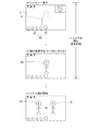
第一画像変位演出の基本的態様は、表示装置10の表示領域11に基準画像20が表示された第一状態(図3(a)に示す状態)から、表示領域11に対して当該基準画像20がずれたかのように表示された第二状態(図3(b)に示す状態)に変位するというものである。基準画像20は、第一状態にて表示領域11に表示される画像である。本実施形態では、第一状態にて表示領域11の全体に表示される画像が基準画像20として設定される。ただし、第一状態にて表示領域11に表示される画像の一部のみが基準画像20として変位する構成としてもよい。基準画像20は静止画および動画のいずれであってよいが、第一状態から第二状態にかけて基準画像20が表す画像の内容は遊技者から同一視できる態様に維持される(ただし、後述するように、識別図柄70を表す部分は除く)。
The basic mode of the first image displacement effect is that the
表示領域11に対する基準画像20全体の変位態様は種々考えられる。本実施形態では、基準画像20が平面方向(表示装置10の表示領域11に沿う方向をいう。以下同じ)に対してあたかも傾斜するように変位したかのような表示(三次元的に変位したかのような表示)がなされる。より具体的には、本実施形態では、基準画像20の左側縁が奥側に、基準画像20の右側縁が手前側に向かうように、基準画像20があたかも回動したかのような表示がなされる(図3(a)(b)参照)。ただし、かかる変位態様はあくまで一例である。基準画像20が平面方向に沿って(上下左右いずれかの方向に)変位したかのような表示(二次元的に変位したかのような表示)がなされるようにしてもよいし、基準画像20が奥(後)に変位したかのような表示がなされてもよい。また、時間経過とともに基準画像20の変位量が変化するかのような態様(例えば、基準画像20が揺れる態様)としてもよい。また、基準画像20の輪郭形状が変化する態様(例えば、基準画像20の輪郭が歪む態様)としてもよい。また、基準画像20の変位によりその一部が表示領域11外に位置したかのような態様(一部が見切れる態様)としてもよい。また、第一画像変位演出が終了したときに再び基準画像20が元に戻るような演出形態としてもよいし、基準画像20が元に戻らずに全く別の画像が表示された状態に移行しうるような演出形態としてもよい。
Various displacement modes of the
また、第一画像変位演出の第二状態においては、基準画像20の外縁に沿う枠画像30が表示される(図3(b)参照)。当該枠画像30は、第一状態における表示領域11の外縁に相当する部分であることを示すものである。本実施形態では、第一状態において枠画像30は表示されない。つまり、第一画像変位演出は、基準画像20が表示領域11に対してずれたかのように表示される演出であるから、当該ずれを表現するために、第二状態にて枠画像30を表示する。遊技者は、第一状態における表示領域11の外縁が、第二状態にて枠画像30として表示される箇所までずれてしまったかのような印象を受ける。表示領域11は、大まかにみて略方形状を呈するものであるから、本実施形態のように基準画像20が三次元的に変位する第一画像変位演出であれば、第二状態における枠画像30は三次元的な表現で方形状を呈するように見える態様(平面視で略平行四辺形状)とされる。本実施形態では、第一状態から第二状態にかけて、枠画像30は表示領域11の外縁から次第に離れていくように形状変化し、最終的に図示されるような態様に行き着く。なお、枠画像30が全く表示されない構成としてもよい。このような構成である場合における、表示領域11に対してずれたかのように表示される画像(本実施形態では後述する背景画像22)と、それ以外の部分の境界も「枠画像30」に含まれるものとする。
In the second state of the first image displacement effect, a
基準画像20には識別図柄70が含まれる。具体的には、基準画像20は、少なくとも識別図柄70およびその背景として表示される背景画像22を含む(図3(a)参照)。識別図柄70を表示する画像レイヤと背景画像22を表示する画像レイヤを別のレイヤとし、前者のレイヤが後者のレイヤよりも手前に設定された構成とすれば、識別図柄70の背景として背景画像22が表示された態様を構築することができる。以下、基準画像20における識別図柄70(三つの識別図柄70)を表した部分を特定画像21と称する。第一状態から第二状態に推移したとき、少なくとも背景画像22に相当する部分が表示領域11に対して三次元的に変位したかのような表示がなされるとともに、当該背景画像22の周囲に枠画像30が表示されることになる。このような変化が生じることで、遊技者は、第一状態にて表示されていた画像があたかも表示領域11に対してずれたかのような印象を受けることになる。
The
ここで、第二状態においては、特定画像21と枠画像30の相対的な関係が、第一状態における特定画像21と表示領域11の外縁との相対的な関係と異なるものとなる。つまり、第一状態において表示される特定画像21を含めた基準画像20全体をそのまま表示領域11に対して変位させたと仮定した場合における第二状態での表示態様(仮想表示態様)とは異なるように見える特定画像21と枠画像30の相対的な関係とされるということである。
Here, in the second state, the relative relationship between the
第一状態では、特定画像21は表示領域11内に収まった状態にある(図3(a)参照)。つまり、特定画像21の全体が、表示領域11の外縁よりも内側に位置した状態にある。一方、第一状態から第二状態に推移し、表示領域11内に第一状態における表示領域11の外縁に相当する部分である枠画像30が表示された状態においては、本実施形態では特定画像21の一部が枠画像30からはみ出るように表示される(図3(b)参照)。つまり、第一状態から第二状態に推移することで、背景画像22が表示領域11に対して三次元的に変位したかのような態様を示すために枠画像30が表示されるところ、当該枠画像30と特定画像21(識別図柄70)の相対的な位置関係を維持せず、特定画像21が枠画像30からはみ出た状態とされる。第二状態における枠画像30の外側の領域は、表示領域11に対して基準画像20が変位することによって生じた領域(以下、外側領域11sと称することもある)であるところ、当該外側領域11sに特定画像21の一部が表示されるような態様とされる。
In the first state, the
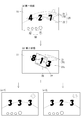
なお、本実施形態では、第一画像変位演出を通じて(第一状態から第二状態に変化しても)、識別図柄70が変動した状態が維持される。少なくとも第一画像変位演出が実行されるときにおける識別図柄70の変動態様は、各識別図柄群70gを構成する識別図柄70が所定位置で回転しつつ、一回転する度に識別図柄70の種類が変化するような態様とされる。このような識別図柄70が特定画像21として、第二状態においては枠画像30からはみ出た状態で変動する(回転する)ように表示されるものである(図3(b)参照)。本実施形態では、左の識別図柄70(左識別図柄群70gL)と右の識別図柄70(右の識別図柄群70gR)の一部が枠画像30からはみ出た状態となる。
In the present embodiment, the state in which the
本実施形態では、第一状態における表示領域11の外縁に対する相対的な特定画像21の大きさよりも、第二状態における枠画像30に対する相対的な特定画像21の大きさの方が大きくなるように設定されることで、前記第二状態において前記特定画像21の少なくとも一部が枠画像30からはみ出るように表示される。換言すれば、第一状態における表示領域11の外縁が第二状態における枠画像30として変化する量に比して、第一状態から第二状態にかけての特定画像21が変化する量は小さいがゆえに、第二状態にて特定画像21の一部が枠画像30からはみ出た状態となるといえる。
In the present embodiment, the size of the
その後(第二状態後)、枠画像30が次第に大きくなる(表示領域11の外縁に近づく)ような表示がなされ、最終的には枠画像30が表示されない状態となる。つまり、枠画像30が「表示領域11の外縁」に戻ったかのような表示がなされることで、表示領域11に対して画像がずれたかのように示される状態が終了することになる。これとともに、特定画像21(識別図柄70)の全体が表示領域11内に表示された状態に推移する。本実施形態では、このときに識別図柄70の変動が停止する。つまり、第一画像変位演出が終了し、枠画像30が表示されない状態となったことと略同時に、当否判定結果を示す識別図柄70の組み合わせが表示されるように制御される。すなわち、本実施形態における第一画像変位演出は当否判定結果を示す識別図柄70の組み合わせを示す直前に開始されるものであって、当該第一画像変位演出の終了と略同時に当該組み合わせ(大当たりまたははずれを示す組み合わせ)が示されることになる(図3(c−1)(c−2)参照)。
Thereafter (after the second state), display is performed such that the
なお、第一画像変位演出終了後に当否判定結果を示す識別図柄70の組み合わせが示されるのではなく、第一画像変位演出終了後にいわゆるチャンス目(遊技者に有利な事象が発生することや、有利な事象が発生する蓋然性が高まったことを示す組み合わせ)が示されるかどうかの演出態様としてもよい。また、画像変位演出終了後に示される各識別図柄70は、擬似停止(完全には停止していないが遊技者には停止しているように見える態様をいう。例えば各識別図柄70がわずかに揺れているような状態とされる)した状態にあるものとしてもよい。
It should be noted that the combination of the
このように、本実施形態における第一画像変位演出では、基準画像20が表示領域11に対して変位したかのような印象を遊技者に与えるため、第二状態にて「第一状態における表示領域11の外縁」に相当する部分である枠画像30が表示される。このような構成であることを前提とし、第一状態においては全体が表示領域11の外縁の内側に表示されていた特定画像21を、第二状態にてその一部がはみ出るように表示する。このようにすることで、表示領域11に対する「画像のずれ」が生じた結果、第一状態において表示されていた一部の画像(特定画像21)が、表示領域11(枠画像30)よりも大きくなったかのような印象を遊技者に与える面白みのある演出態様とすることができる。
As described above, in the first image displacement effect in the present embodiment, in order to give the player an impression as if the
以下、上記実施形態における第一画像変位演出を改良、具体化、変形等した具体例について説明する。なお、可能な限りにおいて、以下の具体例を用いて説明する技術を複数組み合わせて適用した構成としてもよい。 Hereinafter, specific examples in which the first image displacement effect in the above embodiment is improved, embodied, deformed, and the like will be described. As far as possible, a configuration in which a plurality of techniques described using the following specific examples are applied may be adopted.
○第一具体例
上記実施形態における第一画像変位演出では、特定画像21として当否判定結果を示す識別図柄70が設定されていることを説明したが、これ以外の画像を特定画像21として設定することも可能である。第一状態にて表示される基準画像20を構成する画像であれば、どのような画像を特定画像21として設定してもよい。
○ First Specific Example In the first image displacement effect in the above-described embodiment, it has been described that the
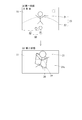
例えば、第一状態にて表示されるあるキャラクタが特定画像21として設定され、その背景として背景画像22が表示されているものとする(図4(a)参照)。第二状態に推移したときに、当該キャラクタの画像の一部が枠画像30(背景画像22の周囲の画像)からはみ出たかのような表示がなされるものとする(図4(b)参照)。このようにすれば、第一状態においては表示領域11よりも小さかったキャラクタ(表示領域11内に全体が表示されていた)が、第二状態に推移することで表示領域11(枠画像30)よりも大きくなったかのような印象を遊技者に与えることができる。
For example, it is assumed that a certain character displayed in the first state is set as the
○第二具体例
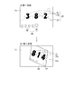
上記実施形態では、第二状態に移行したとき、特定画像21の一部が枠画像30の外側にはみ出たような表示がなされることを説明したが、特定画像21の全体が枠画像30の外側に表示されるような態様としてもよい。つまり、表示領域11に対して基準画像20が変位したかのような表示がなされることによって生じた外側領域11sに、特定画像21の全体が表示されるような態様とする(図5(b)参照)。
O Second specific example In the above-described embodiment, it has been described that when the second state is entered, a display in which a part of the
このようにすることで、特定画像21が表示領域11外に移動したかのような印象を遊技者に与えることが可能である。つまり、第二状態における枠画像30は、表示領域11の外縁を仮想的に表したものであるといえるから、その外側に特定画像21が表示されるようにすることで、第一状態においては表示領域11内に表示されていた特定画像21が、第二状態に推移することで表示領域11外まで移動したかのような印象を与えることが可能である。
By doing so, it is possible to give the player an impression as if the
○第三具体例
上記実施形態では、第二状態に移行したとき、特定画像21の一部が枠画像30の外側にはみ出たような表示がなされることを説明したが、特定画像21の全体が枠画像30の内側に表示されるような態様であってもよい。第一状態における特定画像21と表示領域11の外縁の相対的な関係と、第二状態における特定画像21の枠画像30の相対的な関係が、遊技者には異なるように見えるものであればよい。
Third Specific Example In the above-described embodiment, it has been described that when the second state is entered, a display in which a part of the
例えば、第一状態における特定画像21と表示領域11の外縁の近さ(距離感)(図6(a)参照)よりも、第二状態における特定画像21と枠画像30の近さ(距離感)(図6(b)参照)が小さくなるように見えるようにすることで、第一状態から第二状態に推移することで、特定画像21が大きくなったかのような印象を遊技者に与えることが可能である。
For example, the closeness (the sense of distance) between the
○第四具体例
特定画像21として識別図柄70が設定されている構成において、当該識別図柄70の組み合わせの態様を変化させる演出として第一画像変位演出が発生するものとする。例えば、第一状態にて、各識別図柄群70gの変動が擬似停止し、識別図柄70がある組み合わせ(事前組み合わせ)で示されたとする(図7(a)参照)。その後、第二状態に推移し、特定画像21である識別図柄70の一部が枠画像30からはみ出た状態とされるとともに、各識別図柄群70gが再び変動を開始する(図7(b)参照)。そして、枠画像30が次第に大きくなる(表示領域11の外縁に近づく)ような表示がなされ、最終的には枠画像30が表示されない状態となる。このときに表示される識別図柄70の組み合わせ(事後組み合わせ)が上記事前組み合わせから変化しうる(必ず変化するものとしてもよいし、変化する場合もあれば変化しない場合もあるものとしてもよい)設定とする(図7(c)参照)。
○ Fourth specific example In a configuration in which the
事前組み合わせから事後組み合わせへの変化は、遊技者にとって有利なものであることが好ましい。つまり、事後組み合わせは、遊技者にとって有利な事象が発生することや、有利な事象が発生する蓋然性が高まったことを示唆するものであるとよい。その例としては、当否判定結果がはずれを示す事前組み合わせから、大当たりを示す事後組み合わせに変化すること(図7(a)から図7(c)への変化)が挙げられる。図示しないが、別の例としては、ある大当たり(例えば、大当たり遊技終了後の遊技状態が、当否抽選に当選する確率が低い低確率遊技状態となる大当たり)に当選したことを示す組み合わせから、当該ある大当たりよりも遊技者が享受する利益が大きい別の大当たり(例えば、大当たり遊技終了後の遊技状態が、当否抽選に当選する確率が高い高確率遊技状態となる大当たり)に当選したことを示す組み合わせに変化することが挙げられる。さらに、図示しないが、別の例としては、事前組み合わせから公知の連続演出(擬似連続演出や先読み連続演出)の発生を示す事後組み合わせに変化することが挙げられる。 The change from the pre-combination to the post-combination is preferably advantageous for the player. In other words, the post-combination should preferably indicate that an advantageous event has occurred for the player, or that the probability that the advantageous event has occurred has increased. As an example, a change from a pre-combination indicating a loss to a post-combination indicating a jackpot (a change from FIG. 7A to FIG. 7C) may be given as an example. Although not shown, as another example, a combination indicating that a certain jackpot (eg, a gaming state after the end of the jackpot game becomes a low-probability gaming state in which the probability of winning the winning / non-selection lottery is low) is determined from the combination A combination that indicates that a player has won another jackpot (for example, a jackpot in which the gaming state after the jackpot game ends is a high-probability gaming state in which the probability of winning in the winning / non-winning lottery is high) in which the profit that the player enjoys is greater than a certain jackpot. To change. Further, although not shown, another example is a change from a pre-combination to a post-combination indicating the occurrence of a known continuous production (pseudo continuous production or look-ahead continuous production).
3)第二画像変位演出
以下、第二画像変位演出(上述した第一画像変位演出、後述する第三画像変位演出と区別するために形式的に「第二」を付す)について説明する。第二画像変位演出は、表示領域11に対して基準画像20が変位したかのように表示されるというものである点については、上記第一画像変位演出と同じである。第二画像変位演出は、基準画像20の変位を分かりやすくするために、可動ユニット40を利用した演出である。なお、上記第一画像変位演出にて、以下の第二画像変位演出にて説明するような事象が発生するようにしてもよい。
3) Second Image Displacement Effect Hereinafter, the second image displacement effect (formally given “second” to distinguish it from the first image displacement effect described above and the third image displacement effect described later) will be described. The second image displacement effect is the same as the first image displacement effect in that the second image displacement effect is displayed as if the
可動ユニット40(図8参照)は、複数の可動部41を有する。本実施形態における可動ユニット40は、計四つの可動部41を有する。表示領域11の上側および下側にそれぞれ二つずつの可動部41が配置されている。上側の左に設けられた可動部41を左上可動部411、上側の右に設けられた可動部41を右上可動部412、下側の左に設けられた可動部41を左下可動部413、下側の右に設けられた可動部41を右下可動部414と称する。これらの可動部41は、表示領域11の平面方向に沿って原位置(図8において点線で示す)と進出位置(図8において実線で示す)との間をスライド動作することが可能である。各可動部41を動作させるための構造はどのようなものであってもよいから説明を省略する。各可動部41を動作させるための構造が別に構成されていてもよい(ユニットが別であってもよい)。例えば、左上可動部411と右上可動部412およびそれを駆動させるための構造が一つのユニットであり、左下可動部413と右下可動部414およびそれを駆動させるための構造が一つのユニットである構成としてもよい(複数のユニットをまとめて可動ユニット40とする)。
The movable unit 40 (see FIG. 8) has a plurality of
各可動部41は、原位置に位置するときよりも、進出位置に位置するときの方が、遊技盤90に形成された開口901を通じて露出する領域が大きい。換言すれば、各可動部41は、原位置に位置するときよりも、進出位置に位置するときの方が、前後方向において表示領域11に重なる範囲が大きい。本実施形態では、原位置に位置する可動部41は遊技盤90に完全に覆われており、遊技盤90の裏側を覗きこむようにしなければ原位置に位置する可動部41を視認することができない。左上可動部411および右上可動部412は、原位置から下方に向かってスライドして進出位置に到達する。進出位置に位置する左上可動部411は表示領域11の左上の一部を覆う。進出位置に位置する右上可動部412は表示領域11の右上の一部を覆う。左下可動部413および右下可動部414は、原位置から上方に向かってスライドして進出位置に到達する。進出位置に位置する左下可動部413は表示領域11の左下の一部を覆う。進出位置に位置する右下可動部414は表示領域11の右下の一部を覆う。
Each
第二状態における基準画像20の態様(外縁の形状)が異なる複数種の演出形態が設定されているものとする。本実施形態では、第二状態における枠画像30の形状が異なる第一形態(図9(a)参照)と第二形態(図9(b)参照)が設定されている(いずれも基準画像20が表示領域11に対して三次元的に変位したかのように見える態様である)。第一形態の枠画像30は、上下の辺が左から右にかけて上方に向かうように傾斜する略平行四辺形状を呈する。第二形態の枠画像30は、上下の辺が左から右にかけて下方に向かうように傾斜する略平行四辺形状を呈する。なお、第二画像変位演出を説明する各図においては、枠画像30のみ図示し、枠画像30の内側の画像の態様を省略する。
It is assumed that a plurality of types of effect forms having different modes (outer edge shapes) of the
第二状態において第一形態の枠画像30が表示されるときには、左上可動部411および右下可動部414が進出位置に位置する。右上可動部412および左下可動部413は原位置に位置したままとされる。左上可動部411および右下可動部414は、基準画像20が表示領域11に対して変位したかのような表示がなされることによって生じる外側領域11sに重なる(図9(a)参照)。このようにすることで、基準画像20(枠画像30)は、左上可動部411および右下可動部414に押されることで変形したかのように見えることになる。
When the
一方、第二状態において第二形態の枠画像30が表示されるときには、右上可動部412および左下可動部413が進出位置に位置する。左上可動部411および右下可動部414は原位置に位置したままとされる。右上可動部412および左下可動部413は、基準画像20が表示領域11に対して変位したかのような表示がなされることによって生じる外側領域11sに重なる(図9(b)参照)。このようにすることで、基準画像20(枠画像30)は、右上可動部412および左下可動部413に押されることで変形したかのように見えることになる。
On the other hand, when the
このように、本実施形態では、枠画像30の外側領域11sに重なるように一部の可動部41が進出する(以下、第二状態において進出位置に位置する可動部41を対象可動部41Sと称することもある)。これにより、基準画像20(枠画像30)は、対象可動部41Sに押されることで変位(変形)したかのように見えることになる。つまり、対象可動部41Sにより、基準画像20(枠画像30)が表示領域11に対して変位したことが強調され、画像変位演出の発生が分かりやすいものとなる。
As described above, in the present embodiment, some of the
また、第二状態における枠画像30の形態に応じて対象可動部41Sを異ならせるとよい。本実施形態では、枠画像30が第一形態とされるときには左上可動部411右下可動部414が対象可動部41Sとされ、枠画像30が第二形態とされるときには右上可動部412と左下可動部413が対象可動部41Sとされている。このように、表示領域11に対する枠画像30の変位(変形)の態様に応じて進出位置に位置する可動部41を異ならせる(対象可動部41Sとされる一または複数の可動部41が、完全一致とならないようにする)ことで、枠画像30の変位(変形)の態様の違いが強調されることになる。
Further, the target
特に、本実施形態のように、枠画像30が略平行四辺形状とされるのであれば、対象可動部41Sの組み合わせを対角線上に位置する可動部41の組み合わせとする(「右上可動部412と左下可動部413」または「左上可動部411と右下可動部414」の組み合わせとする)ことで、枠画像30(表示領域11)が可動部41により略平行四辺形状に変形させられたかのような印象を受ける演出態様となる。
In particular, if the
以下、上記実施形態における第二画像変位演出を改良、具体化、変形等した具体例について説明する。なお、可能な限りにおいて、以下の具体例を用いて説明する技術を複数組み合わせて適用した構成としてもよい。 Hereinafter, specific examples in which the second image displacement effect in the above embodiment is improved, embodied, deformed, and the like will be described. As far as possible, a configuration in which a plurality of techniques described using the following specific examples are applied may be adopted.
○第一具体例
第二状態における枠画像30の形態と対象可動部41Sとされる可動部41の関係は、上記実施形態にて説明したもの以外にも種々考えられる。基本的には、枠画像30の形態(外側領域11sの形状)に応じ、対象可動部41Sとされる可動部41が設定されるものとする。大まかに左上、右上、左下、右下というように表示領域11を四分割で捉え、外側領域11sの大きさが大きくなる箇所に対応する可動部41を対象可動部41Sとして設定する。以下に考えられる態様を列挙する。
First Specific Example The relationship between the form of the
図10(a)に示すように、基準画像20が表示領域11に対して下方に変位したかのような演出態様である場合(第二状態にてあたかも表示領域11の上側縁が枠画像30として表示されたかのような演出態様である場合)には、左上可動部411および右上可動部412を対象可動部41Sとする。一方、図10(b)に示すように、基準画像20が表示領域11に対して上方に変位したかのような演出態様である場合(第二状態にてあたかも表示領域11の下側縁が枠画像30として表示されたかのような演出態様である場合)には、左下可動部413および右下可動部414を対象可動部41Sとする。このようにすることで、対象可動部41Sとして設定された可動部41により、基準画像20(枠画像30)が下方または上方に押されて変位したかのような印象を与えることが可能である。
As shown in FIG. 10A, in the case where the
図10(c)に示すように、基準画像20が後方(奥)に変位したかのような演出態様である場合には、全ての可動部41を対象可動部41Sとする。つまり、左上可動部411、右上可動部412、左下可動部413および右下可動部414を進出位置に位置させる。このようにすることで、全ての可動部41により基準画像20が奥に押し込まれて変位したかのような印象を与えることが可能である。
As shown in FIG. 10C, when the
図10(a)〜(c)に示した例のように、枠画像30の上側縁や下側縁が、表示領域11の上側縁や下側縁に対して略平行に表示されるような態様は、表示領域11の上側縁や下側縁に略直交する方向に基準画像20が変位するかのような態様であるから、上側の可動部41(左上可動部411、右上可動部412)の両方や、下側の可動部41(左下可動部413、右下可動部414)の両方をひとまとまりとして進出位置に位置させるとよい。
As in the example shown in FIGS. 10A to 10C, the upper edge and the lower edge of the
図11に示すように、基準画像20が表示領域11に対して斜めに傾くような演出態様である場合には、複数の可動部41のうちのいずれか一つのみを対象可動部41Sとする。このようにすることで、対象可動部41Sにより基準画像20が斜めに傾いたかのような印象を与えることが可能である。
As shown in FIG. 11, when the
上記実施形態(図9)や、図11に示した例のように、枠画像30の上側縁や下側縁が、表示領域11の上側縁や下側縁に対して傾いた状態で表示されるような態様である場合には、上側の可動部41(左上可動部411、右上可動部412)の一方、下側の可動部41(左下可動部413、右下可動部414)の一方を進出位置に位置させ、当該進出位置に位置した可動部41に押されて基準画像20が傾いてしまったかのような印象を与えるようにするとよい。
As in the above embodiment (FIG. 9) and the example shown in FIG. 11, the upper edge and the lower edge of the
○第二具体例
上記実施形態における可動ユニット40は、複数の可動部41を有するものであることを説明したが、一の可動部41のみを有する構成としてもよい。基準画像20の変位が発生するとき(第二状態時)に当該一の可動部41が進出位置に位置するようにして、当該基準画像20の変位が強調されるようにする。
Second Specific Example Although the
○第三具体例
上記実施形態における可動ユニット40は、表示領域11の上側に二つの可動部41、下側に二つの可動部41を有するものであることを説明したが、当該可動部41の配置の態様はあくまで一例である。表示領域11の上側および下側に一つずつの可動部41が設けられた構成としてもよいし、表示領域11の上側および下側に三つ以上の可動部41が設けられた構成としてもよい。また、表示領域11の左側および右側に一または複数の可動部41が設けられた構成としてもよい。第二状態時における枠画像30の形態(外側領域11sの形状)に合わせて一または複数の可動部41を配置すればよい。
Third Specific Example Although it has been described that the
○第四具体例
上記実施形態における可動部41は、原位置と進出位置との間を往復動作するものであることを説明したが、可動部41の進出位置として複数の位置が設定された構成としてもよい。例えば、上記実施形態にて説明したように可動ユニット40が左上可動部411、右上可動部412、左下可動部413、右下可動部414の四つを有するものである構成において、各可動部41は原位置から所定量表示領域11の中央側に変位した第一進出位置、および、当該第一進出位置からさらに表示領域11の中央側に変位した第二進出位置に位置することが可能であるとする。つまり、各可動部41は、表示領域11の中央側への突出量が異なる複数の進出位置に位置することが可能であるものとする。
Fourth Specific Example Although the
図12(a)に示すように、枠画像30が第一形態Aとされるときには、左上可動部411および右下可動部414を第一進出位置に位置させる。図12(b)に示すように、第一形態Aよりも枠画像30が大きく変位(変形)した第一形態B(第一形態Aよりも枠画像30の表示領域11の外縁からの変位量が大きくなった形態)とされるときには、左上可動部411および右下可動部414を第二進出位置に位置させる。つまり、表示領域11に対する枠画像30の変位(変形)量に合わせて、対象可動部41Sの進出位置を変化させる。対象可動部41Sの進出位置に合わせて、枠画像30の形態が異なる態様となるように制御されるものであるともいえる。
As shown in FIG. 12A, when the
このように、可動部41の進出位置として複数の位置を設定しておき、表示領域11に対する枠画像30の変位(変形)量に合わせて当該進出位置を制御することで、枠画像30が可動部41により変形させられたかのような印象を与える効果を向上させることが可能である。
As described above, a plurality of positions are set as the advance positions of the
4)バトル演出における画像変位演出の利用(第三画像変位演出)
以下、第三画像変位演出(上述した第一画像変位演出、第二画像変位演出と区別するために形式的に「第三」を付す)について説明する。第三画像変位演出は、表示領域11に対して基準画像20が変位したかのように表示されるというものである点については、上記第一画像変位演出、第二画像変位演出と同じである。第三画像演出は、いわゆる「バトル演出」中に発生するものである。
4) Use of image displacement effects in battle effects (third image displacement effects)
Hereinafter, the third image displacement effect (formally given “third” to distinguish it from the first image displacement effect and the second image displacement effect described above) will be described. The third image displacement effect is the same as the first image displacement effect and the second image displacement effect in that the third image displacement effect is displayed as if the
バトル演出(図13参照)は、味方側キャラクタ50と敵側キャラクタ51が戦い、味方側キャラクタ50が勝利する結末(以下、勝利結末と称することもある)となったときに、遊技者に有利な事象が発生するというものである。本実施形態では、勝利結末となったとき(図13(c−1)参照)には、対象の当否判定結果が大当たりであることが確定する(大当たりが報知される)。一方、味方側キャラクタ50が敗北する(敵側キャラクタ51が勝利する)結末(以下、敗北結末と称することもある)となったとき(図13(c−2)参照には、対象の当否判定結果がはずれであることが確定する。
The battle effect (see FIG. 13) is advantageous to the player when the
バトル演出においては、味方側キャラクタ50が敵側キャラクタ51に攻撃することを示す攻撃演出(特定演出)が実行される。当該攻撃演出として実行されうる候補として、複数種の攻撃演出が設定されている。本実施形態では、第一攻撃演出(第一特定演出)(図13(b−1)参照)および第二攻撃演出(第二特定演出)(図13(b−2)参照)の二種類が設定されている。第一攻撃演出と第二攻撃演出は、味方側キャラクタ50の「攻撃の強さ」が異なる。第一攻撃演出に比して、第二攻撃演出の方が、味方側キャラクタ50の攻撃が強いことを示すものである。第一攻撃演出はいわゆる「弱攻撃」を示すものであり、第二攻撃演出がいわゆる「強攻撃」を示すものである。バトル演出においては、所定の期間中に第一攻撃演出および第二攻撃演出の一方が発生する。味方側キャラクタ50の攻撃の強さが「第二攻撃演出>第一攻撃演出」であるのであるから、当該期間中に第二攻撃演出が発生した場合の方が、第一攻撃演出が発生した場合に比して、勝利結末に至る蓋然性が高くなるように(すなわち、当否判定結果が大当たりとなる蓋然性(大当たり信頼度)が高くなるように)設定されている。
In the battle effect, an attack effect (specific effect) indicating that the
第一攻撃演出時に表示される画像(以下、第一攻撃画像501と称することもある)の基本的態様と第二攻撃演出時に表示される画像(以下、第二攻撃画像502と称することもある)の基本的態様は異なる。つまり、味方側キャラクタ50の敵側キャラクタ51に対する攻撃が異なるものであること(一方が弱攻撃であり、他方が強攻撃であること)が分かるような表示がなされる。例えば、当該攻撃の内容を示すような文字が表示される(図13(b−1)(b−2)参照)。
The basic mode of an image displayed during the first attack effect (hereinafter, sometimes referred to as a first attack image 501) and the image displayed during the second attack effect (hereinafter, sometimes referred to as a second attack image 502) The basic aspects of ()) are different. In other words, a display is made such that it is possible to recognize that the
上記のように、第一攻撃画像501と第二攻撃画像502の基本的態様は異なるものの、このような画像の基本的態様の違いだけでは、現在発生している攻撃演出がいずれの演出であるのか(弱攻撃であるのか強攻撃であるのか)遊技者が分からない可能性がある。これを踏まえ、本実施形態では、第一攻撃演出時には画像変位演出を発生させず(図13(b−1)参照)、第二攻撃演出時には画像変位演出を発生させる(図13(b−2)参照)(当該第二攻撃演出時における画像変位演出が第三画像変位演出であるとする)。つまり、第一攻撃演出は、第一攻撃画像501を表示領域11に対して変位させない(「シェイク」しない)演出である一方、第二攻撃演出は、第二攻撃画像502を基準画像20として、当該第二攻撃画像502が表示領域11に対して変位したかのように表示される(「シェイク」する)演出である。
As described above, although the basic modes of the
画像変位演出は、表示領域11に表示されている画像が何らかの力が作用することで表示領域11に対してずれたかのように示されるものであるから、「強い攻撃」が発生することで画面が揺れたかのような印象を遊技者に与えることができる。したがって、第二攻撃演出がいわゆる「強攻撃」であることを分かりやすく示すことが可能である。
The image displacement effect is such that the image displayed in the
以下、上記実施形態における第三画像変位演出(バトル演出)を改良、具体化、変形等した具体例について説明する。なお、可能な限りにおいて、以下の具体例を用いて説明する技術を複数組み合わせて適用した構成としてもよい。 Hereinafter, specific examples in which the third image displacement effect (battle effect) in the above embodiment is improved, embodied, or modified will be described. As far as possible, a configuration in which a plurality of techniques described using the following specific examples are applied may be adopted.
○第一具体例
上記実施形態における第三画像変位演出は、バトル演出の一部として発生しうるものであることを説明したが、バトル演出以外にも利用することが可能である。つまり、ある所定の期間中に、表示領域11に第一画像521が表示される演出(第一特定演出)と、表示領域11に第一画像521とは異なる第二画像522が表示される演出であって第一特定演出が発生したときよりも大当たり信頼度が高いことを示唆する演出(第二特定演出)のうちのいずれかが実行されるものにおいて、第一特定演出の発生時には画像変位演出を発生させず、第二特定演出の発生時には画像変位演出を発生させる(第三画像変位演出を発生させる)ものとすればよい。
First Specific Example Although it has been described that the third image displacement effect in the above embodiment can occur as a part of the battle effect, the third image displacement effect can be used other than the battle effect. That is, during a certain period, an effect in which the
このような演出の一例としては、いわゆる「選択演出」を挙げることができる(図14参照)。第一画像521と第二画像522のいずれかが選択されて遊技者に示される演出において、第二画像522が選択されたことがいわゆるチャンスアップであることを示すために、第一画像521が選択されたときには画像変位演出が発生せず(図14(b−1)参照)、第二画像522が選択されたときには画像変位演出が発生する(図14(b−2)参照)ものとする。
An example of such an effect is a so-called “selection effect” (see FIG. 14). In the effect that one of the
○第二具体例
上記実施形態では、攻撃演出(特定演出)として第一攻撃演出(第一特定演出)と第二攻撃演出(第二特定演出)の二種類が設定されていることを説明したが、三種以上の攻撃演出(特定演出)が設定されていてもよい。
O Second specific example In the above embodiment, two types of attack effects (specific effects), a first attack effect (first specific effects) and a second attack effect (second specific effects), have been described. However, three or more types of attack effects (specific effects) may be set.
このような構成である場合、三種以上の攻撃演出のうち、発生したときの大当たり信頼度が最も高い攻撃演出が実行されるときに画像変位演出(第三画像変位演出)が発生するように設定されたものとすることが考えられる。このようにすれば、遊技者にとって最も喜ばしい攻撃演出とそれ以外の攻撃演出の差を分かりやすくすることができるという利点がある。これに対し、N種(N≧3)の攻撃演出のうち、大当たり信頼度が高い方から数えてM種(M<N)の攻撃演出のうちのいずれかが実行されるときに画像変位演出(第三画像変位演出)が発生するように設定されたものとすることが考えられる。このようにすることで、画像変位演出の発生は、あるレベル以上の大当たり信頼度を示唆するものであるということを分かりやすく示すことが可能である。 In the case of such a configuration, the image displacement effect (third image displacement effect) is set to occur when an attack effect having the highest jackpot reliability when it occurs is executed among three or more types of attack effects. It is conceivable that this was done. By doing so, there is an advantage that the difference between the attack presentation that is most pleasing to the player and the other attack presentation can be easily understood. On the other hand, among the N (N ≧ 3) attack productions, the image displacement production is performed when any of the M (M <N) attack productions is counted from the one with the highest jackpot reliability. (Third image displacement effect) may be set. By doing so, it is possible to clearly show that the occurrence of the image displacement effect indicates the jackpot reliability of a certain level or more.
○第三具体例
上記実施形態では、第一攻撃演出(第一特定演出)時に画像変位演出が発生せず、第二攻撃演出(第二特定演出)時に画像変位演出(第三画像変位演出)が発生するように設定されていることを説明したが、いずれの攻撃演出時にも画像変位演出が発生するものとし、各攻撃演出時における基準画像20(攻撃画像)の変位の態様が異なるものとする。
○ Third specific example In the above embodiment, no image displacement effect occurs during the first attack effect (first specific effect), and image displacement effect (third image displacement effect) during the second attack effect (second specific effect). Has been described so as to occur, but it is assumed that an image displacement effect is generated at any of the attack effects, and the displacement mode of the reference image 20 (attack image) at each of the attack effects is different. I do.
具体的には、第一攻撃演出時における表示領域11に対する第一攻撃画像501の変位(ずれ)の大きさ(図15(a)参照)よりも、第二攻撃演出時における表示領域11に対する第二攻撃画像502の変位(ずれ)の大きさ(図15(b)参照)が大きくなるように設定する。つまり、相対的に大当たり信頼度が高い攻撃演出時の方が、大当たり信頼度が低い攻撃演出時よりも、攻撃画像(基準画像20)の表示領域11に対する変位が大きくなる(大きく揺れる)ように設定し、大当たり信頼度に差があることを分かりやすくする。
Specifically, rather than the magnitude of the displacement (shift) of the
三種以上の攻撃演出(特定演出)が設定された構成(第二具体例)に対しても本例にて説明した事項を適用することが可能である。例えば、第一攻撃演出(大当たり信頼度が最も低い)、第二攻撃演出、第三攻撃演出(大当たり信頼度が最も低い)の三つが設定されている構成において、第一攻撃演出時には画像変位演出が発生せず(図16(a)参照)、第二攻撃演出時および第三攻撃演出時には画像変位演出が発生するようにする(図16(b)(c)参照)。そして、第二攻撃演出時における表示領域11に対する基準画像20(第二攻撃画像502)の変位(ずれ)の大きさ(図16(b)参照)よりも、第三攻撃演出時における表示領域11に対する基準画像20(第三攻撃画像503)の変位(ずれ)の大きさ(図16(c)参照)が大きくなるように設定する。
The matter described in this example can be applied to a configuration (second specific example) in which three or more types of attack effects (specific effects) are set. For example, in a configuration in which the first attack effect (lowest hit reliability), the second attack effect, and the third attack effect (lowest hit reliability) are set, an image displacement effect is produced during the first attack effect. Does not occur (see FIG. 16A), and an image displacement effect is generated at the time of the second attack effect and the third attack effect (see FIGS. 16B and 16C). Then, the magnitude of the displacement (shift) of the reference image 20 (the second attack image 502) with respect to the
○第四具体例
上記実施形態では、味方側キャラクタ50が攻撃していることを示す攻撃演出時に画像変位演出(第三画像変位演出)が発生しうるものであることを説明したが、敵側キャラクタ51が攻撃していることを示す演出(以下、守備演出と称することもある)時に画像変位演出が発生しうるようにしてもよい(図17参照)。なお、一のバトル演出において、上述した攻撃演出と守備演出の両方が発生するものとしてもよいし、一方のみが発生するものとしてもよい。
○ Fourth Specific Example In the above-described embodiment, the image displacement effect (third image displacement effect) can be generated at the time of an attack effect indicating that the
守備演出として、第一守備演出(第一特定演出)(図17(b−1)参照)と第二守備演出(第二特定演出)(図17(b−2)参照)の二種類が設定されているものとする。第一守備演出と第二守備演出は、敵側キャラクタ51の「攻撃の強さ」が異なる。第一守備演出に比して、第二守備演出の方が、敵側キャラクタ51の攻撃が強いことを示すものであるとする。バトル演出は味方側キャラクタ50が勝利することが成功結末として設定されているのであるから、第一守備演出が発生したときの大当たり信頼度の方が、第二守備演出が発生したときの大当たり信頼度よりも高いといえる。つまり、第一守備演出と第二守備演出の大当たり信頼度の高低の関係(図17(b−1)(b−2)参照)は、上記実施形態にて説明した第一攻撃演出と第二攻撃演出の大当たり信頼度の高低の関係(図13(b−1)(b−2)参照)と逆である。
Two types of defensive effects, a first defensive effect (first specific effect) (see FIG. 17 (b-1)) and a second defensive effect (second specific effect) (see FIG. 17 (b-2)) are set. It is assumed that The first defense effect and the second defense effect differ in the “strength of attack” of the
このような条件下において、第一守備演出が実行されるときには画像変位演出は発生しない(図17(b−1)参照)ものの、第二守備演出が実行されるときには画像変位演出が発生する(図17(b−2)参照)ようにする。このようにすることで、第二守備演出時における敵側キャラクタ51の攻撃が、いわゆる「強攻撃」であることを分かりやすく示すことが可能である。大当たり信頼度についていえば、攻撃演出に関しては画像変位演出が発生した方が大当たり信頼度は高く、守備演出に関しては画像変位演出が発生した方が大当たり信頼度は低いという演出態様となる。
Under such conditions, when the first defense effect is executed, the image displacement effect does not occur (see FIG. 17 (b-1)), but when the second defense effect is executed, the image displacement effect occurs ( FIG. 17B-2). By doing so, it is possible to clearly indicate that the attack of the
一のバトル演出において攻撃演出と守備演出の両方が発生する場合には、上記態様とは逆に、第二守備演出が実行されるときには画像変位演出は発生しないものの、第一守備演出が実行されるときには画像変位演出が発生するようにしてもよい。このようにすれば、攻撃演出と守備演出の両方において、画像変位演出が発生した場合の方が大当たり信頼度が高くなる(チャンスアップである)設定となるため、大当たり信頼度の高低を把握しやすいという利点がある。 When both an attack effect and a defensive effect occur in one battle effect, contrary to the above aspect, when the second defensive effect is performed, the image displacement effect does not occur, but the first defensive effect is executed. When the image is displayed, an image displacement effect may be generated. In this way, in both the attack effect and the defensive effect, the image hitting effect is set to have a higher jackpot reliability (increased chance) when the image displacement effect is generated. There is an advantage that it is easy.
5)バトル予告演出
味方側キャラクタ50と敵側キャラクタ51が戦うバトル演出が発生する前に、バトル予告演出が発生するものとする(図18参照)。バトル予告演出は、バトル演出にて戦うキャラクタの種類がどのようなものとなるかを事前に示唆する演出である。本実施形態におけるバトル予告演出では、バトル演出にて戦う敵側キャラクタ51の種類を予告する。バトル予告演出における予告の態様はどのようなものであってもよい。予告の態様が複数種設定されていてもよい。本実施形態では、敵側キャラクタ51のシルエットSが表示された(図18(a)参照)後、当該シルエットSが表すキャラクタが明らかになる(図18(b)参照)ことで、バトル演出にて戦う敵側キャラクタ51の種類が示されるというバトル予告演出が実行される。以下の説明においては、バトル予告演出にて予告されたキャラクタを「予告キャラクタ60」と称することもある。
5) Battle notice effect It is assumed that the battle notice effect occurs before the battle effect in which the
バトル演出にて登場する味方側キャラクタ50は、キャラクタAとされるものとする(図18(c)参照)。つまり、キャラクタAが、敵側キャラクタ51として登場するキャラクタと戦い、勝利した場合には、当否判定結果が大当たりであることが確定する。
The
バトル演出に登場することがある敵側キャラクタ51として、キャラクタX、キャラクタY、キャラクタZの三つが設定されているものとする。基本的には、当該三つのキャラクタのうちのいずれかがバトル演出にて登場することになる。したがって、バトル予告演出にて、当該三つのキャラクタのうちのいずれかが「予告キャラクタ60」として示されるのが通常(通常態様)である(図18(b)参照)。
It is assumed that three characters, character X, character Y, and character Z, are set as the
これに対し、バトル予告演出による特殊な予告態様(以下、特殊態様と称することもある)(図19参照)として、キャラクタAが「予告キャラクタ60」として示される態様が発生しうる。上記の通り、キャラクタAは、バトル演出にて味方側キャラクタ50として登場するキャラクタである。つまり、バトル予告演出により、味方側キャラクタ50と同種のキャラクタであるキャラクタAが、バトル演出に登場する敵側キャラクタ51として示唆される場合がある(図19(b)参照)。
On the other hand, as a special notice mode (hereinafter, also referred to as a special mode) based on the battle notice effect (see FIG. 19), a mode in which the character A is indicated as the “notify
「バトル演出」の性格上、戦う対象のキャラクタが同種のものとなることは通常ではない。そのため、このような通常ではないキャラクタがバトル予告演出にて予告キャラクタ60として示唆される特殊態様を発生させることで、遊技者に驚きを与えることが可能となる。なお、本実施形態では、バトル演出が開始されるよりも前に、味方側キャラクタ50がキャラクタAであることが示されている(例えば、バトル演出が発生するよりも前の状況にて、味方側キャラクタ50がキャラクタAであるかのように示す演出や画像(図18(a)、図19(a)の右上参照)が実行される)。したがって、バトル予告演出にてキャラクタAが予告キャラクタ60として示された場合、当該キャラクタAが味方側キャラクタ50と同種のキャラクタであると遊技者は容易に把握できる。
Due to the nature of "battle production", it is not normal that the characters to be fighted are of the same kind. For this reason, such an unusual character generates a special mode suggested as the
バトル予告演出が特殊態様となった場合、その後発生するバトル演出(図19(c)参照)が勝利結末となることが確定する。本実施形態では、バトル演出が勝利結末となることは、当否判定結果が大当たりとなることが確定するものであるため、バトル予告演出が特殊態様となることは、大当たりが確定する演出(いわゆるプレミア演出)であるといえる。 When the battle announcement effect is in a special mode, it is determined that the battle effect (see FIG. 19C) that occurs thereafter will be the victory ending. In the present embodiment, the fact that the battle effect is a victory ending determines that the result of the determination is a jackpot. Therefore, the fact that the battle announcement effect is a special mode is an effect in which the jackpot is determined (a so-called premium). Directing).
本実施形態では、バトル予告演出にて予告キャラクタ60がキャラクタAとなることが示された場合であっても、その後発生するバトル演出に登場する敵側キャラクタ51は通常のキャラクタ(本実施形態ではキャラクタX〜Zのいずれか)とされる(図19(c)参照)。キャラクタA(味方)とキャラクタA(敵)が戦う映像は違和感のあるものであるし、このような映像を敢えて用意しておくことはコストアップを招くことから、バトル演出自体は特殊な態様とする必要はないといえる。また、バトル予告演出にて予告キャラクタ60がキャラクタAとなることは、勘の良い遊技者であればプレミア演出であると気づく蓋然性が高いから、その後実行されるバトル演出にて敢えて特殊な映像を出力する必要はないといえる。ただし、キャラクタA(味方)とキャラクタA(敵)が戦うバトル演出が実行されるようにすることを否定するものではない。
In the present embodiment, even if the
以下、上記実施形態におけるバトル予告演出(バトル演出)を改良、具体化、変形等した具体例について説明する。なお、可能な限りにおいて、以下の具体例を用いて説明する技術を複数組み合わせて適用した構成としてもよい。 Hereinafter, specific examples in which the battle notice effect (battle effect) in the above embodiment is improved, embodied, or modified will be described. As far as possible, a configuration in which a plurality of techniques described using the following specific examples are applied may be adopted.
〇第一具体例
バトル予告演出が特殊態様となった場合には、バトル演出が実行されずに特別な演出が発生して大当たりであることが報知されるようにしてもよい。上記の通り、バトル予告演出が特殊態様となることは、大当たりが確定するものであるから、その後のバトル演出にて勝敗を示すことは不要であるとし、バトル演出が実行されないようにしてもよい。なお、このようなバトル演出が発生しないケースがある構成とする場合であっても、バトル予告演出は、バトル演出に登場するキャラクタ(敵側キャラクタ51)を示唆するものであるとする。
〇First Specific Example When the battle announcement effect is in a special mode, the battle effect may not be executed and a special effect may be generated to notify that a big hit has occurred. As described above, since the battle announcement effect is a special mode, the jackpot is determined. Therefore, it is unnecessary to indicate a win or loss in the subsequent battle effect, and the battle effect may not be executed. . Even in a case where there is a case where such a battle effect does not occur, it is assumed that the battle announcement effect indicates a character (enemy character 51) appearing in the battle effect.
〇第二具体例
バトル演出にて登場する味方側キャラクタ50を、複数種のキャラクタのうちから遊技者が選択することが可能なものとする。例えば、選択画面を表示し、キャラクタA1、キャラクタA2のうちから、遊技者が好みのキャラクタを味方側キャラクタ50として選択可能であるとする(図20(a)参照)。このような場合には、味方側キャラクタ50として選択されたキャラクタに応じ、バトル予告演出の特殊態様が異なるものとされる。すなわち、キャラクタA1が味方側キャラクタ50として選択された場合にはバトル予告演出にて予告キャラクタ60がキャラクタA1となることがバトル予告演出の特殊態様となる(図20(b)(c)参照)。図示しないが、キャラクタA2が味方側キャラクタ50として選択された場合にはバトル予告演出にて予告キャラクタ60がキャラクタA2となることが、バトル予告演出の特殊態様となる。つまり、味方側キャラクタ50として選択されうるキャラクタそれぞれについて、対応するバトル予告演出の特定態様を用意しておくとよい。
{Second Specific Example} It is assumed that a player can select the
これに対し、味方側キャラクタ50として一部のキャラクタが選択された場合には、バトル予告演出の特定態様が発生しないような設定としてもよい。上記の例に則していえば、キャラクタA1が味方側キャラクタ50として選択された場合にはキャラクタA1が予告キャラクタ60となるバトル予告演出が発生するものの、キャラクタA2が味方側キャラクタ50として選択された場合にはキャラクタA2が予告キャラクタ60となるようなバトル予告演出は発生しないものとする。このようにすれば、味方側キャラクタ50としていずれのキャラクタを選択するかによって、特殊態様のバトル予告演出が発生するかどうかが決まるという面白みのある遊技性を実現することが可能である。
On the other hand, when some characters are selected as the ally-
〇第三具体例
上記実施形態におけるバトル予告演出は、バトル演出に登場する敵側キャラクタ51を予告するものであることを説明したが、バトル予告演出により、バトル演出に登場する味方側キャラクタ50が予告されるものとしてもよい。
〇Third Specific Example Although it has been described that the battle announcement effect in the above embodiment is to notify the
味方側キャラクタ50として登場しうるキャラクタとして複数種のキャラクタが設定されているものとする。バトル予告演出では、当該複数種のキャラクタのうちのいずれかが予告キャラクタ60として示される。当該予告キャラクタ60の種類と、敵側キャラクタ51として設定されているキャラクタの種類が同種のキャラクタとなる特殊態様が発生するものとする。
It is assumed that a plurality of types of characters are set as characters that can appear as the
〇第四具体例
上記実施形態におけるバトル予告演出は、バトル演出の態様を予告するものであることを説明したが、バトル演出以外の演出について同様の技術思想を適用することも可能である。
具体 Fourth Specific Example Although it has been described that the battle announcement effect in the above-described embodiment is to announce the mode of the battle effect, the same technical idea can be applied to the effect other than the battle effect.
予告演出により、対象演出の態様が示唆されるものであるとする。対象演出は、少なくとも二つの演出要素が示されるものであるとする。当該演出要素は、演出の性格上、互いに異なるものとなるのが通常であるとする。このような条件下において、予告演出により、対象演出にて登場する演出要素が同じものとなるような示唆(特区種態様)がなされる場合があるものとする。つまり、遊技者には対象演出にて示される二つの演出要素が同じものとなることは考えられないような条件下において、予告演出にて二つの演出要素が同じものとなる示唆がなされるものとする。このようにすることで、予告演出の特殊態様により、遊技者に驚きを与えることが可能となる。 It is assumed that the notice effect indicates the mode of the target effect. It is assumed that the target effect is one in which at least two effect elements are indicated. It is assumed that the effect elements are usually different from each other due to the character of the effect. Under such conditions, it is assumed that a suggestion (special zone type mode) may be made by the notice effect so that the effect elements appearing in the target effect are the same. In other words, under the condition that the two production elements shown in the target production are not considered to be the same in the target production, it is suggested that the two production elements are the same in the preliminary production And By doing so, it is possible to surprise the player by the special mode of the notice effect.
以上、本発明の実施の形態について詳細に説明したが、本発明は上記実施の形態に何ら限定されるものではなく、本発明の要旨を逸脱しない範囲で種々の改変が可能である。 As described above, the embodiments of the present invention have been described in detail. However, the present invention is not limited to the above embodiments, and various modifications can be made without departing from the gist of the present invention.
上記実施形態にかかる遊技機1はいわゆるぱちんこ遊技機であるが、ぱちんこ遊技機特有の構成を利用した事項を除き、回胴式遊技機等他の遊技機に対しても同様の技術思想が適用可能である。
The
上記実施形態から得られる具体的手段(遊技機)を以下に列挙する。 Specific means (gaming machines) obtained from the above embodiment are listed below.
・手段1−1
表示領域を有する表示装置と、前記表示領域に所定の対象物を表した特定画像を含む所定の画像が表示された第一状態から、当該所定の画像が前記表示領域に対して変位したかのように表示された状態であって前記第一状態における表示領域の外縁に相当する部分が枠画像として表示された第二状態に変化する画像変位演出を実行する演出実行手段と、を備え、前記画像変位演出は、前記第一状態における前記特定画像と前記表示領域の外縁の相対的な関係が、前記第二状態における前記特定画像と前記枠画像の相対的な関係と異なるものとなる演出であることを特徴とする遊技機。
上記遊技機によれば、表示領域に対する「画像のずれ」が生じた結果、第一状態において表示されていた一部の画像(特定画像)と、表示領域(枠画像)の関係が変化したかのような印象を遊技者に与える面白みのある演出態様とすることができる。
-Means 1-1
A display device having a display area, and from a first state in which a predetermined image including a specific image representing a predetermined target object is displayed in the display area, whether the predetermined image is displaced with respect to the display area. Effect performing means for executing an image displacement effect that changes to a second state in which a portion corresponding to the outer edge of the display area in the first state is displayed as a frame image, The image displacement effect is an effect in which the relative relationship between the specific image and the outer edge of the display area in the first state is different from the relative relationship between the specific image and the frame image in the second state. A gaming machine characterized by the following.
According to the gaming machine, as a result of the “image shift” with respect to the display area, the relationship between a part of the image (specific image) displayed in the first state and the display area (frame image) has changed. It is possible to provide an interesting presentation mode that gives the player the impression as described above.
・手段1−2
前記第二状態において、前記特定画像の少なくとも一部が、前記枠画像からはみ出るように表示されることを特徴とする手段1−1に記載の遊技機。
このようにすることで、表示領域に対する「画像のずれ」が生じた結果、第一状態において表示されていた一部の画像(特定画像)と、表示領域(枠画像)の関係が変化したということを分かりやすく示すことが可能となる。
・ Means 1-2
The gaming machine according to claim 1-1, wherein in the second state, at least a part of the specific image is displayed so as to protrude from the frame image.
By doing so, as a result of “image shift” with respect to the display area, the relationship between a part of the image (specific image) displayed in the first state and the display area (frame image) has changed. This can be easily understood.
・手段1−3
前記第一状態における前記表示領域の外縁に対する相対的な前記特定画像の大きさよりも、前記第二状態における前記枠画像に対する相対的な前記特定画像の大きさの方が大きくなるように設定されることで、前記第二状態において前記特定画像の少なくとも一部が前記枠画像からはみ出るように表示されることを特徴とする手段1−2に記載の遊技機。
このようにすることで、表示領域に対する「画像のずれ」が生じた結果、第一状態において表示されていた一部の画像(特定画像)が、表示領域(枠画像)よりも大きくなったかのような印象を遊技者に与える面白みのある演出態様とすることができる。
・ Means 1-3
The size of the specific image relative to the frame image in the second state is set to be larger than the size of the specific image relative to the outer edge of the display area in the first state. The gaming machine according to claim 1-2, wherein in the second state, at least a part of the specific image is displayed so as to protrude from the frame image.
By doing so, as a result of “image shift” with respect to the display area, it is as if some of the images (specific images) displayed in the first state were larger than the display area (frame images). It is possible to provide an entertaining presentation mode that gives the player a natural impression.
・手段1−4
前記第二状態において、前記特定画像の全部が、前記枠画像の外側に表示されることを特徴とする手段1−1に記載の遊技機。
このように、表示領域に対する「画像のずれ」が生じた結果、第一状態において表示されていた一部の画像(特定画像)の全部が、表示領域(枠画像)外に飛び出したかのような印象を遊技者に与える面白みのある演出態様とすることができる。
・ Means 1-4
The gaming machine according to claim 1-1, wherein in the second state, the entirety of the specific image is displayed outside the frame image.
As described above, as a result of the “image shift” with respect to the display area, the impression that all of the partial image (specific image) displayed in the first state jumps out of the display area (frame image) is obtained. Is given to the player.
・手段1−5
前記所定の対象物は、当否判定結果を示す識別図柄であることを特徴とする手段1−21から手段1−4のいずれかに記載の遊技機。
このようにすることで、表示領域に対する「画像のずれ」が生じた結果、表示領域(枠画像)と識別図柄の位置関係が変化するという面白みのある演出態様とすることができる。
・ Means 1-5
The gaming machine according to any one of means 1-21 to 1-4, wherein the predetermined object is an identification symbol indicating a result of the determination as to whether the object is correct.
By doing so, as a result of the occurrence of “image shift” with respect to the display area, it is possible to provide an interesting presentation mode in which the positional relationship between the display area (frame image) and the identification symbol changes.
・手段2−1
複数種の演出形態に変化することが可能な可動ユニットと、表示領域を有する表示装置と、前記表示領域に所定の画像が表示された第一状態から、当該所定の画像が前記表示領域に対して変位したかのように表示された状態であって前記第一状態における表示領域の外縁に相当する部分が枠画像として表示された第二状態に変化する画像変位演出を実行する演出実行手段と、を備え、前記画像変位演出の前記第二状態にて表示される前記枠画像の態様に応じ、前記可動ユニットの演出形態が変化することを特徴とする遊技機。
上記遊技機によれば、可動ユニットの形態により、枠画像の態様が強調されることになるから、画像変位演出が分かりやすいものとなる。
-Means 2-1
A movable unit capable of changing to a plurality of effect forms, a display device having a display area, and a first state in which a predetermined image is displayed in the display area, the predetermined image is displayed on the display area. Effect performing means for performing an image displacement effect of changing to a second state where a portion corresponding to the outer edge of the display area in the first state is displayed as a frame image in a state where it is displayed as if displaced. Wherein the effect form of the movable unit changes according to the mode of the frame image displayed in the second state of the image displacement effect.
According to the above gaming machine, the form of the movable unit emphasizes the form of the frame image, so that the image displacement effect can be easily understood.
・手段2−2
前記可動ユニットは、一または複数の可動部を有し、当該可動部は、原位置に位置するときよりも前記表示領域に重なる範囲が大きい進出位置に位置することが可能であり、前記可動変位演出の前記第二状態において、前記一または複数の可動部のうちのいずれかが対象可動部として前記進出位置に位置し、当該対象可動部が前記表示領域における前記枠画像が表示された部分よりも外側の領域である外側領域に重なることを特徴とする手段2−1に記載の遊技機。
このようにすることで、対象可動部に押されて枠画像(表示領域)が変形したかのような印象を遊技者に与えることが可能となる。
・ Means 2-2
The movable unit has one or a plurality of movable parts, and the movable part can be located at an advanced position where a range overlapping with the display area is greater than when the movable part is located at an original position. In the second state of the effect, one of the one or a plurality of movable parts is located at the advance position as a target movable part, and the target movable part is located in a portion of the display area where the frame image is displayed. The gaming machine according to
By doing so, it is possible to give the player an impression as if the frame image (display area) was deformed by being pushed by the target movable portion.
・手段2−3
前記可動ユニットは、複数の可動部を有し、前記可動変位演出の前記第二状態において、前記枠画像が第一形態であるときに前記対象可動部とされる一または複数の可動部と、前記枠画像が前記第一形態であるときとは異なる第二形態であるときに前記対象可動部とされる一または複数の可動部は、少なくとも一部が異なるものであることを特徴とする手段2−2に記載の遊技機。
このように、複数の可動部を備える場合、枠画像の形態に応じて対象可動部とされる可動部が変化するようにすれば、枠画像の形態の違いが分かりやすくなる。
・ Means 2-3
The movable unit has a plurality of movable parts, in the second state of the movable displacement effect, when the frame image is the first form, one or more movable parts and the target movable part, When the frame image is in the second mode different from the first mode, at least a part of the one or more movable sections to be the target movable section is different. The gaming machine according to 2-2.
As described above, when a plurality of movable parts are provided, if the movable part that is the target movable part is changed according to the form of the frame image, the difference in the form of the frame image can be easily understood.
・手段2−4
前記可動部は、前記進出位置として、第一進出位置および当該第一進出位置とは異なる位置である第二進出位置に位置することが可能であり、前記可動変位演出の前記第二状態において、前記可動部が前記第一進出位置に位置するときと、前記第二進出位置に位置するときとでは、前記枠画像の形態が異なるように制御されることを特徴とする手段2−2に記載の遊技機。
このように、可動部の進出位置を複数設定し、枠画像の形態に応じて当該進出位置を変化させるようにすれば、枠画像の形態の違いが分かりやすくなる。
・ Means 2-4
The movable portion, as the advance position, it is possible to be located at a first advance position and a second advance position that is a position different from the first advance position, in the second state of the movable displacement effect, The means 2-2 wherein the form of the frame image is controlled to be different between when the movable portion is located at the first advance position and when it is located at the second advance position. Gaming machine.
In this way, if a plurality of advance positions of the movable part are set and the advance positions are changed according to the form of the frame image, the difference in the form of the frame image can be easily understood.
・手段3−1
表示領域を有する表示装置と、所定条件の成立を契機として当否判定を行う当否判定手段と、前記当否判定手段による当否判定結果が当たりとなる蓋然性である当たり信頼度を、予め定められた所定の期間中に実行される演出が、複数種の特定演出のうちのいずれであるかによって示唆する特定演出実行手段と、前記表示領域に表示される画像が、当該表示領域に対して変位したかのように表示される画像変位演出を実行する画像変位演出実行手段と、を備え、前記複数種の特定演出として、前記表示装置に第一画像が表示される第一特定演出と、前記表示装置に前記第一画像とは異なる第二画像が表示される演出であって前記第一特定演出が発生したときよりも前記当たり信頼度が高いことを示唆する第二特定演出が設定されており、前記第一特定演出の発生時には前記画像変位演出を発生させず、前記第二特定演出の発生時には前記画像変位演出を発生させることを特徴とする遊技機。
上記遊技機によれば、当たり信頼度が高い第二特定演出の発生時には画像変位演出が発生するため、第一特定演出に比して信頼度が高い演出であるということが分かりやすい。
・ Means 3-1
A display device having a display area, a pass / fail determination unit that performs a pass / fail determination when a predetermined condition is satisfied, and a hit reliability, which is a probability that the hit / fail determination result by the hit / fail determination unit is a hit, is a predetermined predetermined value. The effect performed during the period, the specific effect execution means suggesting which of the plurality of types of specific effects, and whether the image displayed in the display area is displaced with respect to the display area Image displacement effect execution means for executing an image displacement effect displayed as described above, and as the plurality of types of specific effects, a first specific effect in which a first image is displayed on the display device, and the display device A second specific effect that is an effect in which a second image different from the first image is displayed and indicates that the hit reliability is higher than when the first specific effect has occurred, and One specific effect at the time of occurrence of without causing the image displacement effect, the gaming machine wherein the second time specific effect occurring, characterized in that generating the image displacement effect.
According to the gaming machine, an image displacement effect occurs when the second specific effect with a high hit reliability occurs, and therefore, it is easy to understand that the effect has a higher reliability than the first specific effect.
・手段3−2
味方側キャラクタと敵側キャラクタが戦い、前記味方側キャラクタが勝利する結末となったときに、遊技者に有利な事象が発生するバトル演出が実行されるものであり、前記特定演出は、前記味方側キャラクタが前記敵側キャラクタに攻撃することを示すものであって、前記第二特定演出は、前記第一特定演出よりも、前記味方側キャラクタの攻撃が強いことを示すものであることを特徴とする手段3−1に記載の遊技機。
・手段3−3
味方側キャラクタと敵側キャラクタが戦い、前記敵側キャラクタが勝利する結末となることで、遊技者に有利な事象が発生しないことを示すバトル演出が実行されるものであり、前記特定演出は、前記敵側キャラクタが前記味方側キャラクタに攻撃することを示すものであって、前記第二特定演出は、前記第一特定演出よりも、前記敵側キャラクタの攻撃が強いことを示すものであることを特徴とする手段3−1に記載の遊技機。
このように、いわゆる強攻撃であることを示す場合に画像変位演出が発生するようにすることで、攻撃が強いということと、画像の変位(画像のゆれ)が発生することがリンクした分かりやすい演出とすることが可能である。
・ Means 3-2
When the ally character and the enemy character battle and the ally character ends, a battle effect in which an event advantageous to the player occurs is executed, and the specific effect is the ally character. A side character attacks the enemy side character, and the second specific effect indicates that the attack of the ally character is stronger than the first specific effect. The gaming machine according to means 3-1.
・ Means 3-3
A battle effect is shown in which the ally character and the enemy character fight and the enemy character wins, so that a battle effect indicating that an event advantageous to the player does not occur is performed. The second specific effect indicates that the enemy character attacks the ally character more strongly than the first specific effect. 3. The gaming machine according to item 3-1.
As described above, by displaying an image displacement effect when indicating a so-called strong attack, it is easy to understand that the attack is strong and the image displacement (image shake) occurs. It can be a production.
・手段4−1
一方側キャラクタと複数種の他方側キャラクタのうちのいずれかが戦い、その結末により、遊技者に有利な事象が発生するか否かを示すバトル演出と、前記バトル演出の前に発生する演出であって、当該バトル演出に登場する前記他方側キャラクタの種類を事前に示唆するバトル予告演出と、を実行する演出実行手段を備え、前記バトル予告演出の態様として、前記一方側キャラクタと同種のキャラクタが、前記バトル演出に登場する前記他方側キャラクタとして示唆される特殊態様が設定されていることを特徴とする遊技機。
上記遊技機によれば、バトル演出における味方側キャラクタと敵側キャラクタが同種のキャラクタとなる面白みのある予告が発生することによる遊技の趣向性向上が期待できる。
・ Means 4-1
One of the one-sided characters and one of the other types of the other-side characters fight, and a battle effect indicating whether or not an event advantageous to the player occurs due to the ending thereof, and an effect that occurs before the battle effect. A battle announcement effect that indicates in advance the type of the other-side character appearing in the battle effect; and a battle announcement effect for executing the battle announcement effect. As a mode of the battle announcement effect, a character of the same kind as the one-side character is provided. However, a special mode suggested as the other character appearing in the battle effect is set.
According to the gaming machine, it is expected that the interestingness of the game can be improved by generating an interesting notice that the ally character and the enemy character are the same kind of character in the battle effect.
・手段4−2
前記バトル予告演出が前記特殊態様となった場合、その後発生する前記バトル演出の結末は遊技者に有利な結末となることが確定することを特徴とする手段4−1に記載の遊技機。
味方側キャラクタと敵側キャラクタが同種のキャラクタとなる予告の発生は、バトル演出の結末が遊技者に有利な結末となることが確定するものとすればよい。
.Means 4-2
The gaming machine according to claim 4-1, wherein when the battle notice effect is in the special mode, it is determined that the end of the battle effect that occurs thereafter is an advantageous result for the player.
The occurrence of the notice that the ally character and the enemy character are the same kind of character may be determined so that it is determined that the ending of the battle effect is an ending that is advantageous to the player.
1 遊技機
10 表示装置
11 表示領域
11s 外側領域
20 基準画像
21 特定画像
22 背景画像
30 枠画像
40 可動ユニット
41 可動部
411 左上可動部
412 右上可動部
413 左下可動部
414 右下可動部
41S 対象可動部
50 味方側キャラクタ
51 敵側キャラクタ
501 第一攻撃画像
502 第二攻撃画像
60 予告キャラクタ
70 識別図柄
Claims (1)
前記表示領域に所定の対象物を表した特定画像を含む所定の画像が表示された第一状態から、当該所定の画像が前記表示領域に対して三次元的に変位したかのように表示された状態であって前記第一状態における表示領域の外縁に相当する部分が枠画像として表示された第二状態に変化する画像変位演出を実行する演出実行手段と、
を備え、
前記画像変位演出は、前記第一状態における前記特定画像と前記表示領域の外縁の相対的な関係が、前記第二状態における前記特定画像と前記枠画像の相対的な関係と異なるものとなる演出であることを特徴とする遊技機。 A display device having a display area;
From the first state in which the predetermined image including the specific image representing the predetermined object is displayed in the display area, the predetermined image is displayed as if it were three-dimensionally displaced with respect to the display area. Effect performing means for performing an image displacement effect that changes to the second state in which the portion corresponding to the outer edge of the display area in the first state is displayed as a frame image in the first state,
With
The image displacement effect is an effect in which the relative relationship between the specific image in the first state and the outer edge of the display area is different from the relative relationship between the specific image and the frame image in the second state. A gaming machine characterized by the following.
Priority Applications (1)
| Application Number | Priority Date | Filing Date | Title |
|---|---|---|---|
| JP2018166608A JP2020036848A (en) | 2018-09-06 | 2018-09-06 | Game machine |
Applications Claiming Priority (1)
| Application Number | Priority Date | Filing Date | Title |
|---|---|---|---|
| JP2018166608A JP2020036848A (en) | 2018-09-06 | 2018-09-06 | Game machine |
Publications (2)
| Publication Number | Publication Date |
|---|---|
| JP2020036848A true JP2020036848A (en) | 2020-03-12 |
| JP2020036848A5 JP2020036848A5 (en) | 2021-10-14 |
Family
ID=69737117
Family Applications (1)
| Application Number | Title | Priority Date | Filing Date |
|---|---|---|---|
| JP2018166608A Pending JP2020036848A (en) | 2018-09-06 | 2018-09-06 | Game machine |
Country Status (1)
| Country | Link |
|---|---|
| JP (1) | JP2020036848A (en) |
Citations (2)
| Publication number | Priority date | Publication date | Assignee | Title |
|---|---|---|---|---|
| JP2015213605A (en) * | 2014-05-09 | 2015-12-03 | 株式会社ニューギン | Game machine |
| JP2016150142A (en) * | 2015-02-18 | 2016-08-22 | 株式会社平和 | Game machine |
-
2018
- 2018-09-06 JP JP2018166608A patent/JP2020036848A/en active Pending
Patent Citations (2)
| Publication number | Priority date | Publication date | Assignee | Title |
|---|---|---|---|---|
| JP2015213605A (en) * | 2014-05-09 | 2015-12-03 | 株式会社ニューギン | Game machine |
| JP2016150142A (en) * | 2015-02-18 | 2016-08-22 | 株式会社平和 | Game machine |
Similar Documents
| Publication | Publication Date | Title |
|---|---|---|
| JP6618022B2 (en) | Game machine | |
| JP6782500B2 (en) | Game machine | |
| JP7229543B2 (en) | game machine | |
| JP6804098B2 (en) | Game machine | |
| JP2020036849A (en) | Game machine | |
| JP6628199B2 (en) | Gaming machine | |
| JP6733102B2 (en) | Amusement machine | |
| JP6593764B2 (en) | Game machine | |
| JP6618021B2 (en) | Game machine | |
| JP6913945B2 (en) | Pachinko machine | |
| JP2020036848A (en) | Game machine | |
| JP2020036850A (en) | Game machine | |
| JP2020036851A (en) | Game machine | |
| JP7131794B2 (en) | game machine | |
| JP6628198B2 (en) | Gaming machine | |
| JP7246675B2 (en) | game machine | |
| JP7118407B2 (en) | game machine | |
| JP6908928B2 (en) | Pachinko machine | |
| JP2021069516A (en) | Game machine | |
| JP7229532B2 (en) | game machine | |
| JP7187046B2 (en) | game machine | |
| JP2018187483A (en) | Game machine | |
| JP7454205B2 (en) | gaming machine | |
| JP6872230B2 (en) | Pachinko game machine | |
| JP6846586B2 (en) | Game machine |
Legal Events
| Date | Code | Title | Description |
|---|---|---|---|
| A621 | Written request for application examination |
Free format text: JAPANESE INTERMEDIATE CODE: A621 Effective date: 20210901 |
|
| A521 | Request for written amendment filed |
Free format text: JAPANESE INTERMEDIATE CODE: A523 Effective date: 20210903 |
|
| A977 | Report on retrieval |
Free format text: JAPANESE INTERMEDIATE CODE: A971007 Effective date: 20220608 |
|
| A131 | Notification of reasons for refusal |
Free format text: JAPANESE INTERMEDIATE CODE: A131 Effective date: 20220621 |
|
| A521 | Request for written amendment filed |
Free format text: JAPANESE INTERMEDIATE CODE: A523 Effective date: 20220802 |
|
| A131 | Notification of reasons for refusal |
Free format text: JAPANESE INTERMEDIATE CODE: A131 Effective date: 20221129 |
|
| A521 | Request for written amendment filed |
Free format text: JAPANESE INTERMEDIATE CODE: A523 Effective date: 20221228 |
|
| A02 | Decision of refusal |
Free format text: JAPANESE INTERMEDIATE CODE: A02 Effective date: 20230411 |
|
| A521 | Request for written amendment filed |
Free format text: JAPANESE INTERMEDIATE CODE: A523 Effective date: 20230502 |
|
| A911 | Transfer to examiner for re-examination before appeal (zenchi) |
Free format text: JAPANESE INTERMEDIATE CODE: A911 Effective date: 20230515 |
|
| A912 | Re-examination (zenchi) completed and case transferred to appeal board |
Free format text: JAPANESE INTERMEDIATE CODE: A912 Effective date: 20230728 |