JP2020032918A - Hybrid vehicle - Google Patents
Hybrid vehicle Download PDFInfo
- Publication number
- JP2020032918A JP2020032918A JP2018162376A JP2018162376A JP2020032918A JP 2020032918 A JP2020032918 A JP 2020032918A JP 2018162376 A JP2018162376 A JP 2018162376A JP 2018162376 A JP2018162376 A JP 2018162376A JP 2020032918 A JP2020032918 A JP 2020032918A
- Authority
- JP
- Japan
- Prior art keywords
- engine
- motor
- hybrid vehicle
- secondary battery
- power
- Prior art date
- Legal status (The legal status is an assumption and is not a legal conclusion. Google has not performed a legal analysis and makes no representation as to the accuracy of the status listed.)
- Withdrawn
Links
Images


Classifications
-
- B—PERFORMING OPERATIONS; TRANSPORTING
- B60—VEHICLES IN GENERAL
- B60W—CONJOINT CONTROL OF VEHICLE SUB-UNITS OF DIFFERENT TYPE OR DIFFERENT FUNCTION; CONTROL SYSTEMS SPECIALLY ADAPTED FOR HYBRID VEHICLES; ROAD VEHICLE DRIVE CONTROL SYSTEMS FOR PURPOSES NOT RELATED TO THE CONTROL OF A PARTICULAR SUB-UNIT
- B60W20/00—Control systems specially adapted for hybrid vehicles
- B60W20/40—Controlling the engagement or disengagement of prime movers, e.g. for transition between prime movers
-
- F—MECHANICAL ENGINEERING; LIGHTING; HEATING; WEAPONS; BLASTING
- F02—COMBUSTION ENGINES; HOT-GAS OR COMBUSTION-PRODUCT ENGINE PLANTS
- F02N—STARTING OF COMBUSTION ENGINES; STARTING AIDS FOR SUCH ENGINES, NOT OTHERWISE PROVIDED FOR
- F02N11/00—Starting of engines by means of electric motors
- F02N11/08—Circuits or control means specially adapted for starting of engines
- F02N11/0814—Circuits or control means specially adapted for starting of engines comprising means for controlling automatic idle-start-stop
- F02N11/0818—Conditions for starting or stopping the engine or for deactivating the idle-start-stop mode
- F02N11/0825—Conditions for starting or stopping the engine or for deactivating the idle-start-stop mode related to prevention of engine restart failure, e.g. disabling automatic stop at low battery state
-
- B—PERFORMING OPERATIONS; TRANSPORTING
- B60—VEHICLES IN GENERAL
- B60W—CONJOINT CONTROL OF VEHICLE SUB-UNITS OF DIFFERENT TYPE OR DIFFERENT FUNCTION; CONTROL SYSTEMS SPECIALLY ADAPTED FOR HYBRID VEHICLES; ROAD VEHICLE DRIVE CONTROL SYSTEMS FOR PURPOSES NOT RELATED TO THE CONTROL OF A PARTICULAR SUB-UNIT
- B60W20/00—Control systems specially adapted for hybrid vehicles
- B60W20/10—Controlling the power contribution of each of the prime movers to meet required power demand
- B60W20/13—Controlling the power contribution of each of the prime movers to meet required power demand in order to stay within battery power input or output limits; in order to prevent overcharging or battery depletion
-
- B—PERFORMING OPERATIONS; TRANSPORTING
- B60—VEHICLES IN GENERAL
- B60K—ARRANGEMENT OR MOUNTING OF PROPULSION UNITS OR OF TRANSMISSIONS IN VEHICLES; ARRANGEMENT OR MOUNTING OF PLURAL DIVERSE PRIME-MOVERS IN VEHICLES; AUXILIARY DRIVES FOR VEHICLES; INSTRUMENTATION OR DASHBOARDS FOR VEHICLES; ARRANGEMENTS IN CONNECTION WITH COOLING, AIR INTAKE, GAS EXHAUST OR FUEL SUPPLY OF PROPULSION UNITS IN VEHICLES
- B60K1/00—Arrangement or mounting of electrical propulsion units
- B60K1/04—Arrangement or mounting of electrical propulsion units of the electric storage means for propulsion
-
- B—PERFORMING OPERATIONS; TRANSPORTING
- B60—VEHICLES IN GENERAL
- B60K—ARRANGEMENT OR MOUNTING OF PROPULSION UNITS OR OF TRANSMISSIONS IN VEHICLES; ARRANGEMENT OR MOUNTING OF PLURAL DIVERSE PRIME-MOVERS IN VEHICLES; AUXILIARY DRIVES FOR VEHICLES; INSTRUMENTATION OR DASHBOARDS FOR VEHICLES; ARRANGEMENTS IN CONNECTION WITH COOLING, AIR INTAKE, GAS EXHAUST OR FUEL SUPPLY OF PROPULSION UNITS IN VEHICLES
- B60K6/00—Arrangement or mounting of plural diverse prime-movers for mutual or common propulsion, e.g. hybrid propulsion systems comprising electric motors and internal combustion engines ; Control systems therefor, i.e. systems controlling two or more prime movers, or controlling one of these prime movers and any of the transmission, drive or drive units Informative references: mechanical gearings with secondary electric drive F16H3/72; arrangements for handling mechanical energy structurally associated with the dynamo-electric machine H02K7/00; machines comprising structurally interrelated motor and generator parts H02K51/00; dynamo-electric machines not otherwise provided for in H02K see H02K99/00
- B60K6/20—Arrangement or mounting of plural diverse prime-movers for mutual or common propulsion, e.g. hybrid propulsion systems comprising electric motors and internal combustion engines ; Control systems therefor, i.e. systems controlling two or more prime movers, or controlling one of these prime movers and any of the transmission, drive or drive units Informative references: mechanical gearings with secondary electric drive F16H3/72; arrangements for handling mechanical energy structurally associated with the dynamo-electric machine H02K7/00; machines comprising structurally interrelated motor and generator parts H02K51/00; dynamo-electric machines not otherwise provided for in H02K see H02K99/00 the prime-movers consisting of electric motors and internal combustion engines, e.g. HEVs
- B60K6/22—Arrangement or mounting of plural diverse prime-movers for mutual or common propulsion, e.g. hybrid propulsion systems comprising electric motors and internal combustion engines ; Control systems therefor, i.e. systems controlling two or more prime movers, or controlling one of these prime movers and any of the transmission, drive or drive units Informative references: mechanical gearings with secondary electric drive F16H3/72; arrangements for handling mechanical energy structurally associated with the dynamo-electric machine H02K7/00; machines comprising structurally interrelated motor and generator parts H02K51/00; dynamo-electric machines not otherwise provided for in H02K see H02K99/00 the prime-movers consisting of electric motors and internal combustion engines, e.g. HEVs characterised by apparatus, components or means specially adapted for HEVs
- B60K6/26—Arrangement or mounting of plural diverse prime-movers for mutual or common propulsion, e.g. hybrid propulsion systems comprising electric motors and internal combustion engines ; Control systems therefor, i.e. systems controlling two or more prime movers, or controlling one of these prime movers and any of the transmission, drive or drive units Informative references: mechanical gearings with secondary electric drive F16H3/72; arrangements for handling mechanical energy structurally associated with the dynamo-electric machine H02K7/00; machines comprising structurally interrelated motor and generator parts H02K51/00; dynamo-electric machines not otherwise provided for in H02K see H02K99/00 the prime-movers consisting of electric motors and internal combustion engines, e.g. HEVs characterised by apparatus, components or means specially adapted for HEVs characterised by the motors or the generators
-
- B—PERFORMING OPERATIONS; TRANSPORTING
- B60—VEHICLES IN GENERAL
- B60K—ARRANGEMENT OR MOUNTING OF PROPULSION UNITS OR OF TRANSMISSIONS IN VEHICLES; ARRANGEMENT OR MOUNTING OF PLURAL DIVERSE PRIME-MOVERS IN VEHICLES; AUXILIARY DRIVES FOR VEHICLES; INSTRUMENTATION OR DASHBOARDS FOR VEHICLES; ARRANGEMENTS IN CONNECTION WITH COOLING, AIR INTAKE, GAS EXHAUST OR FUEL SUPPLY OF PROPULSION UNITS IN VEHICLES
- B60K6/00—Arrangement or mounting of plural diverse prime-movers for mutual or common propulsion, e.g. hybrid propulsion systems comprising electric motors and internal combustion engines ; Control systems therefor, i.e. systems controlling two or more prime movers, or controlling one of these prime movers and any of the transmission, drive or drive units Informative references: mechanical gearings with secondary electric drive F16H3/72; arrangements for handling mechanical energy structurally associated with the dynamo-electric machine H02K7/00; machines comprising structurally interrelated motor and generator parts H02K51/00; dynamo-electric machines not otherwise provided for in H02K see H02K99/00
- B60K6/20—Arrangement or mounting of plural diverse prime-movers for mutual or common propulsion, e.g. hybrid propulsion systems comprising electric motors and internal combustion engines ; Control systems therefor, i.e. systems controlling two or more prime movers, or controlling one of these prime movers and any of the transmission, drive or drive units Informative references: mechanical gearings with secondary electric drive F16H3/72; arrangements for handling mechanical energy structurally associated with the dynamo-electric machine H02K7/00; machines comprising structurally interrelated motor and generator parts H02K51/00; dynamo-electric machines not otherwise provided for in H02K see H02K99/00 the prime-movers consisting of electric motors and internal combustion engines, e.g. HEVs
- B60K6/22—Arrangement or mounting of plural diverse prime-movers for mutual or common propulsion, e.g. hybrid propulsion systems comprising electric motors and internal combustion engines ; Control systems therefor, i.e. systems controlling two or more prime movers, or controlling one of these prime movers and any of the transmission, drive or drive units Informative references: mechanical gearings with secondary electric drive F16H3/72; arrangements for handling mechanical energy structurally associated with the dynamo-electric machine H02K7/00; machines comprising structurally interrelated motor and generator parts H02K51/00; dynamo-electric machines not otherwise provided for in H02K see H02K99/00 the prime-movers consisting of electric motors and internal combustion engines, e.g. HEVs characterised by apparatus, components or means specially adapted for HEVs
- B60K6/28—Arrangement or mounting of plural diverse prime-movers for mutual or common propulsion, e.g. hybrid propulsion systems comprising electric motors and internal combustion engines ; Control systems therefor, i.e. systems controlling two or more prime movers, or controlling one of these prime movers and any of the transmission, drive or drive units Informative references: mechanical gearings with secondary electric drive F16H3/72; arrangements for handling mechanical energy structurally associated with the dynamo-electric machine H02K7/00; machines comprising structurally interrelated motor and generator parts H02K51/00; dynamo-electric machines not otherwise provided for in H02K see H02K99/00 the prime-movers consisting of electric motors and internal combustion engines, e.g. HEVs characterised by apparatus, components or means specially adapted for HEVs characterised by the electric energy storing means, e.g. batteries or capacitors
-
- B—PERFORMING OPERATIONS; TRANSPORTING
- B60—VEHICLES IN GENERAL
- B60K—ARRANGEMENT OR MOUNTING OF PROPULSION UNITS OR OF TRANSMISSIONS IN VEHICLES; ARRANGEMENT OR MOUNTING OF PLURAL DIVERSE PRIME-MOVERS IN VEHICLES; AUXILIARY DRIVES FOR VEHICLES; INSTRUMENTATION OR DASHBOARDS FOR VEHICLES; ARRANGEMENTS IN CONNECTION WITH COOLING, AIR INTAKE, GAS EXHAUST OR FUEL SUPPLY OF PROPULSION UNITS IN VEHICLES
- B60K6/00—Arrangement or mounting of plural diverse prime-movers for mutual or common propulsion, e.g. hybrid propulsion systems comprising electric motors and internal combustion engines ; Control systems therefor, i.e. systems controlling two or more prime movers, or controlling one of these prime movers and any of the transmission, drive or drive units Informative references: mechanical gearings with secondary electric drive F16H3/72; arrangements for handling mechanical energy structurally associated with the dynamo-electric machine H02K7/00; machines comprising structurally interrelated motor and generator parts H02K51/00; dynamo-electric machines not otherwise provided for in H02K see H02K99/00
- B60K6/20—Arrangement or mounting of plural diverse prime-movers for mutual or common propulsion, e.g. hybrid propulsion systems comprising electric motors and internal combustion engines ; Control systems therefor, i.e. systems controlling two or more prime movers, or controlling one of these prime movers and any of the transmission, drive or drive units Informative references: mechanical gearings with secondary electric drive F16H3/72; arrangements for handling mechanical energy structurally associated with the dynamo-electric machine H02K7/00; machines comprising structurally interrelated motor and generator parts H02K51/00; dynamo-electric machines not otherwise provided for in H02K see H02K99/00 the prime-movers consisting of electric motors and internal combustion engines, e.g. HEVs
- B60K6/22—Arrangement or mounting of plural diverse prime-movers for mutual or common propulsion, e.g. hybrid propulsion systems comprising electric motors and internal combustion engines ; Control systems therefor, i.e. systems controlling two or more prime movers, or controlling one of these prime movers and any of the transmission, drive or drive units Informative references: mechanical gearings with secondary electric drive F16H3/72; arrangements for handling mechanical energy structurally associated with the dynamo-electric machine H02K7/00; machines comprising structurally interrelated motor and generator parts H02K51/00; dynamo-electric machines not otherwise provided for in H02K see H02K99/00 the prime-movers consisting of electric motors and internal combustion engines, e.g. HEVs characterised by apparatus, components or means specially adapted for HEVs
- B60K6/36—Arrangement or mounting of plural diverse prime-movers for mutual or common propulsion, e.g. hybrid propulsion systems comprising electric motors and internal combustion engines ; Control systems therefor, i.e. systems controlling two or more prime movers, or controlling one of these prime movers and any of the transmission, drive or drive units Informative references: mechanical gearings with secondary electric drive F16H3/72; arrangements for handling mechanical energy structurally associated with the dynamo-electric machine H02K7/00; machines comprising structurally interrelated motor and generator parts H02K51/00; dynamo-electric machines not otherwise provided for in H02K see H02K99/00 the prime-movers consisting of electric motors and internal combustion engines, e.g. HEVs characterised by apparatus, components or means specially adapted for HEVs characterised by the transmission gearings
- B60K6/365—Arrangement or mounting of plural diverse prime-movers for mutual or common propulsion, e.g. hybrid propulsion systems comprising electric motors and internal combustion engines ; Control systems therefor, i.e. systems controlling two or more prime movers, or controlling one of these prime movers and any of the transmission, drive or drive units Informative references: mechanical gearings with secondary electric drive F16H3/72; arrangements for handling mechanical energy structurally associated with the dynamo-electric machine H02K7/00; machines comprising structurally interrelated motor and generator parts H02K51/00; dynamo-electric machines not otherwise provided for in H02K see H02K99/00 the prime-movers consisting of electric motors and internal combustion engines, e.g. HEVs characterised by apparatus, components or means specially adapted for HEVs characterised by the transmission gearings with the gears having orbital motion
-
- B—PERFORMING OPERATIONS; TRANSPORTING
- B60—VEHICLES IN GENERAL
- B60K—ARRANGEMENT OR MOUNTING OF PROPULSION UNITS OR OF TRANSMISSIONS IN VEHICLES; ARRANGEMENT OR MOUNTING OF PLURAL DIVERSE PRIME-MOVERS IN VEHICLES; AUXILIARY DRIVES FOR VEHICLES; INSTRUMENTATION OR DASHBOARDS FOR VEHICLES; ARRANGEMENTS IN CONNECTION WITH COOLING, AIR INTAKE, GAS EXHAUST OR FUEL SUPPLY OF PROPULSION UNITS IN VEHICLES
- B60K6/00—Arrangement or mounting of plural diverse prime-movers for mutual or common propulsion, e.g. hybrid propulsion systems comprising electric motors and internal combustion engines ; Control systems therefor, i.e. systems controlling two or more prime movers, or controlling one of these prime movers and any of the transmission, drive or drive units Informative references: mechanical gearings with secondary electric drive F16H3/72; arrangements for handling mechanical energy structurally associated with the dynamo-electric machine H02K7/00; machines comprising structurally interrelated motor and generator parts H02K51/00; dynamo-electric machines not otherwise provided for in H02K see H02K99/00
- B60K6/20—Arrangement or mounting of plural diverse prime-movers for mutual or common propulsion, e.g. hybrid propulsion systems comprising electric motors and internal combustion engines ; Control systems therefor, i.e. systems controlling two or more prime movers, or controlling one of these prime movers and any of the transmission, drive or drive units Informative references: mechanical gearings with secondary electric drive F16H3/72; arrangements for handling mechanical energy structurally associated with the dynamo-electric machine H02K7/00; machines comprising structurally interrelated motor and generator parts H02K51/00; dynamo-electric machines not otherwise provided for in H02K see H02K99/00 the prime-movers consisting of electric motors and internal combustion engines, e.g. HEVs
- B60K6/42—Arrangement or mounting of plural diverse prime-movers for mutual or common propulsion, e.g. hybrid propulsion systems comprising electric motors and internal combustion engines ; Control systems therefor, i.e. systems controlling two or more prime movers, or controlling one of these prime movers and any of the transmission, drive or drive units Informative references: mechanical gearings with secondary electric drive F16H3/72; arrangements for handling mechanical energy structurally associated with the dynamo-electric machine H02K7/00; machines comprising structurally interrelated motor and generator parts H02K51/00; dynamo-electric machines not otherwise provided for in H02K see H02K99/00 the prime-movers consisting of electric motors and internal combustion engines, e.g. HEVs characterised by the architecture of the hybrid electric vehicle
- B60K6/44—Series-parallel type
- B60K6/445—Differential gearing distribution type
-
- B—PERFORMING OPERATIONS; TRANSPORTING
- B60—VEHICLES IN GENERAL
- B60W—CONJOINT CONTROL OF VEHICLE SUB-UNITS OF DIFFERENT TYPE OR DIFFERENT FUNCTION; CONTROL SYSTEMS SPECIALLY ADAPTED FOR HYBRID VEHICLES; ROAD VEHICLE DRIVE CONTROL SYSTEMS FOR PURPOSES NOT RELATED TO THE CONTROL OF A PARTICULAR SUB-UNIT
- B60W10/00—Conjoint control of vehicle sub-units of different type or different function
- B60W10/04—Conjoint control of vehicle sub-units of different type or different function including control of propulsion units
- B60W10/06—Conjoint control of vehicle sub-units of different type or different function including control of propulsion units including control of combustion engines
-
- B—PERFORMING OPERATIONS; TRANSPORTING
- B60—VEHICLES IN GENERAL
- B60W—CONJOINT CONTROL OF VEHICLE SUB-UNITS OF DIFFERENT TYPE OR DIFFERENT FUNCTION; CONTROL SYSTEMS SPECIALLY ADAPTED FOR HYBRID VEHICLES; ROAD VEHICLE DRIVE CONTROL SYSTEMS FOR PURPOSES NOT RELATED TO THE CONTROL OF A PARTICULAR SUB-UNIT
- B60W10/00—Conjoint control of vehicle sub-units of different type or different function
- B60W10/04—Conjoint control of vehicle sub-units of different type or different function including control of propulsion units
- B60W10/08—Conjoint control of vehicle sub-units of different type or different function including control of propulsion units including control of electric propulsion units, e.g. motors or generators
-
- B—PERFORMING OPERATIONS; TRANSPORTING
- B60—VEHICLES IN GENERAL
- B60W—CONJOINT CONTROL OF VEHICLE SUB-UNITS OF DIFFERENT TYPE OR DIFFERENT FUNCTION; CONTROL SYSTEMS SPECIALLY ADAPTED FOR HYBRID VEHICLES; ROAD VEHICLE DRIVE CONTROL SYSTEMS FOR PURPOSES NOT RELATED TO THE CONTROL OF A PARTICULAR SUB-UNIT
- B60W10/00—Conjoint control of vehicle sub-units of different type or different function
- B60W10/24—Conjoint control of vehicle sub-units of different type or different function including control of energy storage means
- B60W10/26—Conjoint control of vehicle sub-units of different type or different function including control of energy storage means for electrical energy, e.g. batteries or capacitors
-
- B—PERFORMING OPERATIONS; TRANSPORTING
- B60—VEHICLES IN GENERAL
- B60W—CONJOINT CONTROL OF VEHICLE SUB-UNITS OF DIFFERENT TYPE OR DIFFERENT FUNCTION; CONTROL SYSTEMS SPECIALLY ADAPTED FOR HYBRID VEHICLES; ROAD VEHICLE DRIVE CONTROL SYSTEMS FOR PURPOSES NOT RELATED TO THE CONTROL OF A PARTICULAR SUB-UNIT
- B60W20/00—Control systems specially adapted for hybrid vehicles
- B60W20/20—Control strategies involving selection of hybrid configuration, e.g. selection between series or parallel configuration
-
- B—PERFORMING OPERATIONS; TRANSPORTING
- B60—VEHICLES IN GENERAL
- B60W—CONJOINT CONTROL OF VEHICLE SUB-UNITS OF DIFFERENT TYPE OR DIFFERENT FUNCTION; CONTROL SYSTEMS SPECIALLY ADAPTED FOR HYBRID VEHICLES; ROAD VEHICLE DRIVE CONTROL SYSTEMS FOR PURPOSES NOT RELATED TO THE CONTROL OF A PARTICULAR SUB-UNIT
- B60W30/00—Purposes of road vehicle drive control systems not related to the control of a particular sub-unit, e.g. of systems using conjoint control of vehicle sub-units, or advanced driver assistance systems for ensuring comfort, stability and safety or drive control systems for propelling or retarding the vehicle
- B60W30/18—Propelling the vehicle
- B60W30/18009—Propelling the vehicle related to particular drive situations
- B60W30/18109—Braking
- B60W30/18136—Engine braking
-
- F—MECHANICAL ENGINEERING; LIGHTING; HEATING; WEAPONS; BLASTING
- F02—COMBUSTION ENGINES; HOT-GAS OR COMBUSTION-PRODUCT ENGINE PLANTS
- F02D—CONTROLLING COMBUSTION ENGINES
- F02D29/00—Controlling engines, such controlling being peculiar to the devices driven thereby, the devices being other than parts or accessories essential to engine operation, e.g. controlling of engines by signals external thereto
- F02D29/02—Controlling engines, such controlling being peculiar to the devices driven thereby, the devices being other than parts or accessories essential to engine operation, e.g. controlling of engines by signals external thereto peculiar to engines driving vehicles; peculiar to engines driving variable pitch propellers
-
- F—MECHANICAL ENGINEERING; LIGHTING; HEATING; WEAPONS; BLASTING
- F02—COMBUSTION ENGINES; HOT-GAS OR COMBUSTION-PRODUCT ENGINE PLANTS
- F02D—CONTROLLING COMBUSTION ENGINES
- F02D41/00—Electrical control of supply of combustible mixture or its constituents
- F02D41/02—Circuit arrangements for generating control signals
- F02D41/021—Introducing corrections for particular conditions exterior to the engine
-
- F—MECHANICAL ENGINEERING; LIGHTING; HEATING; WEAPONS; BLASTING
- F02—COMBUSTION ENGINES; HOT-GAS OR COMBUSTION-PRODUCT ENGINE PLANTS
- F02D—CONTROLLING COMBUSTION ENGINES
- F02D41/00—Electrical control of supply of combustible mixture or its constituents
- F02D41/02—Circuit arrangements for generating control signals
- F02D41/14—Introducing closed-loop corrections
- F02D41/1401—Introducing closed-loop corrections characterised by the control or regulation method
-
- F—MECHANICAL ENGINEERING; LIGHTING; HEATING; WEAPONS; BLASTING
- F02—COMBUSTION ENGINES; HOT-GAS OR COMBUSTION-PRODUCT ENGINE PLANTS
- F02D—CONTROLLING COMBUSTION ENGINES
- F02D9/00—Controlling engines by throttling air or fuel-and-air induction conduits or exhaust conduits
- F02D9/02—Controlling engines by throttling air or fuel-and-air induction conduits or exhaust conduits concerning induction conduits
-
- F—MECHANICAL ENGINEERING; LIGHTING; HEATING; WEAPONS; BLASTING
- F02—COMBUSTION ENGINES; HOT-GAS OR COMBUSTION-PRODUCT ENGINE PLANTS
- F02N—STARTING OF COMBUSTION ENGINES; STARTING AIDS FOR SUCH ENGINES, NOT OTHERWISE PROVIDED FOR
- F02N11/00—Starting of engines by means of electric motors
- F02N11/04—Starting of engines by means of electric motors the motors being associated with current generators
-
- F—MECHANICAL ENGINEERING; LIGHTING; HEATING; WEAPONS; BLASTING
- F02—COMBUSTION ENGINES; HOT-GAS OR COMBUSTION-PRODUCT ENGINE PLANTS
- F02N—STARTING OF COMBUSTION ENGINES; STARTING AIDS FOR SUCH ENGINES, NOT OTHERWISE PROVIDED FOR
- F02N11/00—Starting of engines by means of electric motors
- F02N11/08—Circuits or control means specially adapted for starting of engines
- F02N11/0814—Circuits or control means specially adapted for starting of engines comprising means for controlling automatic idle-start-stop
- F02N11/0818—Conditions for starting or stopping the engine or for deactivating the idle-start-stop mode
- F02N11/0833—Vehicle conditions
-
- H—ELECTRICITY
- H01—ELECTRIC ELEMENTS
- H01M—PROCESSES OR MEANS, e.g. BATTERIES, FOR THE DIRECT CONVERSION OF CHEMICAL ENERGY INTO ELECTRICAL ENERGY
- H01M10/00—Secondary cells; Manufacture thereof
- H01M10/42—Methods or arrangements for servicing or maintenance of secondary cells or secondary half-cells
- H01M10/48—Accumulators combined with arrangements for measuring, testing or indicating the condition of cells, e.g. the level or density of the electrolyte
- H01M10/486—Accumulators combined with arrangements for measuring, testing or indicating the condition of cells, e.g. the level or density of the electrolyte for measuring temperature
-
- H—ELECTRICITY
- H01—ELECTRIC ELEMENTS
- H01M—PROCESSES OR MEANS, e.g. BATTERIES, FOR THE DIRECT CONVERSION OF CHEMICAL ENERGY INTO ELECTRICAL ENERGY
- H01M10/00—Secondary cells; Manufacture thereof
- H01M10/60—Heating or cooling; Temperature control
- H01M10/61—Types of temperature control
- H01M10/613—Cooling or keeping cold
-
- H—ELECTRICITY
- H01—ELECTRIC ELEMENTS
- H01M—PROCESSES OR MEANS, e.g. BATTERIES, FOR THE DIRECT CONVERSION OF CHEMICAL ENERGY INTO ELECTRICAL ENERGY
- H01M10/00—Secondary cells; Manufacture thereof
- H01M10/60—Heating or cooling; Temperature control
- H01M10/62—Heating or cooling; Temperature control specially adapted for specific applications
- H01M10/625—Vehicles
-
- H—ELECTRICITY
- H01—ELECTRIC ELEMENTS
- H01M—PROCESSES OR MEANS, e.g. BATTERIES, FOR THE DIRECT CONVERSION OF CHEMICAL ENERGY INTO ELECTRICAL ENERGY
- H01M10/00—Secondary cells; Manufacture thereof
- H01M10/60—Heating or cooling; Temperature control
- H01M10/65—Means for temperature control structurally associated with the cells
- H01M10/656—Means for temperature control structurally associated with the cells characterised by the type of heat-exchange fluid
- H01M10/6561—Gases
- H01M10/6562—Gases with free flow by convection only
-
- B—PERFORMING OPERATIONS; TRANSPORTING
- B60—VEHICLES IN GENERAL
- B60K—ARRANGEMENT OR MOUNTING OF PROPULSION UNITS OR OF TRANSMISSIONS IN VEHICLES; ARRANGEMENT OR MOUNTING OF PLURAL DIVERSE PRIME-MOVERS IN VEHICLES; AUXILIARY DRIVES FOR VEHICLES; INSTRUMENTATION OR DASHBOARDS FOR VEHICLES; ARRANGEMENTS IN CONNECTION WITH COOLING, AIR INTAKE, GAS EXHAUST OR FUEL SUPPLY OF PROPULSION UNITS IN VEHICLES
- B60K1/00—Arrangement or mounting of electrical propulsion units
- B60K2001/003—Arrangement or mounting of electrical propulsion units with means for cooling the electrical propulsion units
- B60K2001/005—Arrangement or mounting of electrical propulsion units with means for cooling the electrical propulsion units the electric storage means
-
- B—PERFORMING OPERATIONS; TRANSPORTING
- B60—VEHICLES IN GENERAL
- B60K—ARRANGEMENT OR MOUNTING OF PROPULSION UNITS OR OF TRANSMISSIONS IN VEHICLES; ARRANGEMENT OR MOUNTING OF PLURAL DIVERSE PRIME-MOVERS IN VEHICLES; AUXILIARY DRIVES FOR VEHICLES; INSTRUMENTATION OR DASHBOARDS FOR VEHICLES; ARRANGEMENTS IN CONNECTION WITH COOLING, AIR INTAKE, GAS EXHAUST OR FUEL SUPPLY OF PROPULSION UNITS IN VEHICLES
- B60K1/00—Arrangement or mounting of electrical propulsion units
- B60K1/04—Arrangement or mounting of electrical propulsion units of the electric storage means for propulsion
- B60K2001/0405—Arrangement or mounting of electrical propulsion units of the electric storage means for propulsion characterised by their position
-
- B—PERFORMING OPERATIONS; TRANSPORTING
- B60—VEHICLES IN GENERAL
- B60W—CONJOINT CONTROL OF VEHICLE SUB-UNITS OF DIFFERENT TYPE OR DIFFERENT FUNCTION; CONTROL SYSTEMS SPECIALLY ADAPTED FOR HYBRID VEHICLES; ROAD VEHICLE DRIVE CONTROL SYSTEMS FOR PURPOSES NOT RELATED TO THE CONTROL OF A PARTICULAR SUB-UNIT
- B60W2510/00—Input parameters relating to a particular sub-units
- B60W2510/24—Energy storage means
- B60W2510/242—Energy storage means for electrical energy
- B60W2510/244—Charge state
-
- B—PERFORMING OPERATIONS; TRANSPORTING
- B60—VEHICLES IN GENERAL
- B60W—CONJOINT CONTROL OF VEHICLE SUB-UNITS OF DIFFERENT TYPE OR DIFFERENT FUNCTION; CONTROL SYSTEMS SPECIALLY ADAPTED FOR HYBRID VEHICLES; ROAD VEHICLE DRIVE CONTROL SYSTEMS FOR PURPOSES NOT RELATED TO THE CONTROL OF A PARTICULAR SUB-UNIT
- B60W2510/00—Input parameters relating to a particular sub-units
- B60W2510/24—Energy storage means
- B60W2510/242—Energy storage means for electrical energy
- B60W2510/246—Temperature
-
- B—PERFORMING OPERATIONS; TRANSPORTING
- B60—VEHICLES IN GENERAL
- B60W—CONJOINT CONTROL OF VEHICLE SUB-UNITS OF DIFFERENT TYPE OR DIFFERENT FUNCTION; CONTROL SYSTEMS SPECIALLY ADAPTED FOR HYBRID VEHICLES; ROAD VEHICLE DRIVE CONTROL SYSTEMS FOR PURPOSES NOT RELATED TO THE CONTROL OF A PARTICULAR SUB-UNIT
- B60W2710/00—Output or target parameters relating to a particular sub-units
- B60W2710/06—Combustion engines, Gas turbines
- B60W2710/0605—Throttle position
-
- B—PERFORMING OPERATIONS; TRANSPORTING
- B60—VEHICLES IN GENERAL
- B60W—CONJOINT CONTROL OF VEHICLE SUB-UNITS OF DIFFERENT TYPE OR DIFFERENT FUNCTION; CONTROL SYSTEMS SPECIALLY ADAPTED FOR HYBRID VEHICLES; ROAD VEHICLE DRIVE CONTROL SYSTEMS FOR PURPOSES NOT RELATED TO THE CONTROL OF A PARTICULAR SUB-UNIT
- B60W2710/00—Output or target parameters relating to a particular sub-units
- B60W2710/06—Combustion engines, Gas turbines
- B60W2710/0616—Position of fuel or air injector
- B60W2710/0627—Fuel flow rate
-
- B—PERFORMING OPERATIONS; TRANSPORTING
- B60—VEHICLES IN GENERAL
- B60W—CONJOINT CONTROL OF VEHICLE SUB-UNITS OF DIFFERENT TYPE OR DIFFERENT FUNCTION; CONTROL SYSTEMS SPECIALLY ADAPTED FOR HYBRID VEHICLES; ROAD VEHICLE DRIVE CONTROL SYSTEMS FOR PURPOSES NOT RELATED TO THE CONTROL OF A PARTICULAR SUB-UNIT
- B60W2710/00—Output or target parameters relating to a particular sub-units
- B60W2710/06—Combustion engines, Gas turbines
- B60W2710/0677—Engine power
-
- B—PERFORMING OPERATIONS; TRANSPORTING
- B60—VEHICLES IN GENERAL
- B60W—CONJOINT CONTROL OF VEHICLE SUB-UNITS OF DIFFERENT TYPE OR DIFFERENT FUNCTION; CONTROL SYSTEMS SPECIALLY ADAPTED FOR HYBRID VEHICLES; ROAD VEHICLE DRIVE CONTROL SYSTEMS FOR PURPOSES NOT RELATED TO THE CONTROL OF A PARTICULAR SUB-UNIT
- B60W2710/00—Output or target parameters relating to a particular sub-units
- B60W2710/08—Electric propulsion units
-
- B—PERFORMING OPERATIONS; TRANSPORTING
- B60—VEHICLES IN GENERAL
- B60Y—INDEXING SCHEME RELATING TO ASPECTS CROSS-CUTTING VEHICLE TECHNOLOGY
- B60Y2200/00—Type of vehicle
- B60Y2200/90—Vehicles comprising electric prime movers
- B60Y2200/92—Hybrid vehicles
-
- B—PERFORMING OPERATIONS; TRANSPORTING
- B60—VEHICLES IN GENERAL
- B60Y—INDEXING SCHEME RELATING TO ASPECTS CROSS-CUTTING VEHICLE TECHNOLOGY
- B60Y2300/00—Purposes or special features of road vehicle drive control systems
- B60Y2300/18—Propelling the vehicle
- B60Y2300/192—Power-up or power-down of the driveline, e.g. start up of a cold engine
-
- B—PERFORMING OPERATIONS; TRANSPORTING
- B60—VEHICLES IN GENERAL
- B60Y—INDEXING SCHEME RELATING TO ASPECTS CROSS-CUTTING VEHICLE TECHNOLOGY
- B60Y2306/00—Other features of vehicle sub-units
- B60Y2306/05—Cooling
-
- F—MECHANICAL ENGINEERING; LIGHTING; HEATING; WEAPONS; BLASTING
- F02—COMBUSTION ENGINES; HOT-GAS OR COMBUSTION-PRODUCT ENGINE PLANTS
- F02D—CONTROLLING COMBUSTION ENGINES
- F02D2200/00—Input parameters for engine control
- F02D2200/50—Input parameters for engine control said parameters being related to the vehicle or its components
- F02D2200/503—Battery correction, i.e. corrections as a function of the state of the battery, its output or its type
-
- F—MECHANICAL ENGINEERING; LIGHTING; HEATING; WEAPONS; BLASTING
- F02—COMBUSTION ENGINES; HOT-GAS OR COMBUSTION-PRODUCT ENGINE PLANTS
- F02D—CONTROLLING COMBUSTION ENGINES
- F02D2250/00—Engine control related to specific problems or objectives
- F02D2250/18—Control of the engine output torque
-
- F—MECHANICAL ENGINEERING; LIGHTING; HEATING; WEAPONS; BLASTING
- F02—COMBUSTION ENGINES; HOT-GAS OR COMBUSTION-PRODUCT ENGINE PLANTS
- F02N—STARTING OF COMBUSTION ENGINES; STARTING AIDS FOR SUCH ENGINES, NOT OTHERWISE PROVIDED FOR
- F02N2200/00—Parameters used for control of starting apparatus
- F02N2200/06—Parameters used for control of starting apparatus said parameters being related to the power supply or driving circuits for the starter
- F02N2200/061—Battery state of charge [SOC]
-
- F—MECHANICAL ENGINEERING; LIGHTING; HEATING; WEAPONS; BLASTING
- F02—COMBUSTION ENGINES; HOT-GAS OR COMBUSTION-PRODUCT ENGINE PLANTS
- F02N—STARTING OF COMBUSTION ENGINES; STARTING AIDS FOR SUCH ENGINES, NOT OTHERWISE PROVIDED FOR
- F02N2200/00—Parameters used for control of starting apparatus
- F02N2200/06—Parameters used for control of starting apparatus said parameters being related to the power supply or driving circuits for the starter
- F02N2200/064—Battery temperature
-
- H—ELECTRICITY
- H01—ELECTRIC ELEMENTS
- H01M—PROCESSES OR MEANS, e.g. BATTERIES, FOR THE DIRECT CONVERSION OF CHEMICAL ENERGY INTO ELECTRICAL ENERGY
- H01M2220/00—Batteries for particular applications
- H01M2220/20—Batteries in motive systems, e.g. vehicle, ship, plane
-
- Y—GENERAL TAGGING OF NEW TECHNOLOGICAL DEVELOPMENTS; GENERAL TAGGING OF CROSS-SECTIONAL TECHNOLOGIES SPANNING OVER SEVERAL SECTIONS OF THE IPC; TECHNICAL SUBJECTS COVERED BY FORMER USPC CROSS-REFERENCE ART COLLECTIONS [XRACs] AND DIGESTS
- Y02—TECHNOLOGIES OR APPLICATIONS FOR MITIGATION OR ADAPTATION AGAINST CLIMATE CHANGE
- Y02E—REDUCTION OF GREENHOUSE GAS [GHG] EMISSIONS, RELATED TO ENERGY GENERATION, TRANSMISSION OR DISTRIBUTION
- Y02E60/00—Enabling technologies; Technologies with a potential or indirect contribution to GHG emissions mitigation
- Y02E60/10—Energy storage using batteries
-
- Y—GENERAL TAGGING OF NEW TECHNOLOGICAL DEVELOPMENTS; GENERAL TAGGING OF CROSS-SECTIONAL TECHNOLOGIES SPANNING OVER SEVERAL SECTIONS OF THE IPC; TECHNICAL SUBJECTS COVERED BY FORMER USPC CROSS-REFERENCE ART COLLECTIONS [XRACs] AND DIGESTS
- Y02—TECHNOLOGIES OR APPLICATIONS FOR MITIGATION OR ADAPTATION AGAINST CLIMATE CHANGE
- Y02T—CLIMATE CHANGE MITIGATION TECHNOLOGIES RELATED TO TRANSPORTATION
- Y02T10/00—Road transport of goods or passengers
- Y02T10/10—Internal combustion engine [ICE] based vehicles
- Y02T10/40—Engine management systems
-
- Y—GENERAL TAGGING OF NEW TECHNOLOGICAL DEVELOPMENTS; GENERAL TAGGING OF CROSS-SECTIONAL TECHNOLOGIES SPANNING OVER SEVERAL SECTIONS OF THE IPC; TECHNICAL SUBJECTS COVERED BY FORMER USPC CROSS-REFERENCE ART COLLECTIONS [XRACs] AND DIGESTS
- Y02—TECHNOLOGIES OR APPLICATIONS FOR MITIGATION OR ADAPTATION AGAINST CLIMATE CHANGE
- Y02T—CLIMATE CHANGE MITIGATION TECHNOLOGIES RELATED TO TRANSPORTATION
- Y02T10/00—Road transport of goods or passengers
- Y02T10/60—Other road transportation technologies with climate change mitigation effect
- Y02T10/62—Hybrid vehicles
-
- Y—GENERAL TAGGING OF NEW TECHNOLOGICAL DEVELOPMENTS; GENERAL TAGGING OF CROSS-SECTIONAL TECHNOLOGIES SPANNING OVER SEVERAL SECTIONS OF THE IPC; TECHNICAL SUBJECTS COVERED BY FORMER USPC CROSS-REFERENCE ART COLLECTIONS [XRACs] AND DIGESTS
- Y02—TECHNOLOGIES OR APPLICATIONS FOR MITIGATION OR ADAPTATION AGAINST CLIMATE CHANGE
- Y02T—CLIMATE CHANGE MITIGATION TECHNOLOGIES RELATED TO TRANSPORTATION
- Y02T10/00—Road transport of goods or passengers
- Y02T10/60—Other road transportation technologies with climate change mitigation effect
- Y02T10/70—Energy storage systems for electromobility, e.g. batteries
-
- Y—GENERAL TAGGING OF NEW TECHNOLOGICAL DEVELOPMENTS; GENERAL TAGGING OF CROSS-SECTIONAL TECHNOLOGIES SPANNING OVER SEVERAL SECTIONS OF THE IPC; TECHNICAL SUBJECTS COVERED BY FORMER USPC CROSS-REFERENCE ART COLLECTIONS [XRACs] AND DIGESTS
- Y02—TECHNOLOGIES OR APPLICATIONS FOR MITIGATION OR ADAPTATION AGAINST CLIMATE CHANGE
- Y02T—CLIMATE CHANGE MITIGATION TECHNOLOGIES RELATED TO TRANSPORTATION
- Y02T10/00—Road transport of goods or passengers
- Y02T10/60—Other road transportation technologies with climate change mitigation effect
- Y02T10/7072—Electromobility specific charging systems or methods for batteries, ultracapacitors, supercapacitors or double-layer capacitors
-
- Y—GENERAL TAGGING OF NEW TECHNOLOGICAL DEVELOPMENTS; GENERAL TAGGING OF CROSS-SECTIONAL TECHNOLOGIES SPANNING OVER SEVERAL SECTIONS OF THE IPC; TECHNICAL SUBJECTS COVERED BY FORMER USPC CROSS-REFERENCE ART COLLECTIONS [XRACs] AND DIGESTS
- Y02—TECHNOLOGIES OR APPLICATIONS FOR MITIGATION OR ADAPTATION AGAINST CLIMATE CHANGE
- Y02T—CLIMATE CHANGE MITIGATION TECHNOLOGIES RELATED TO TRANSPORTATION
- Y02T90/00—Enabling technologies or technologies with a potential or indirect contribution to GHG emissions mitigation
- Y02T90/10—Technologies relating to charging of electric vehicles
- Y02T90/14—Plug-in electric vehicles
Abstract
Description
この発明は、駆動用モータに給電する蓄電装置を、エンジンの吸気通路を流れる吸入空気により冷却する構成を有するハイブリッド車両に関するものである。 The present invention relates to a hybrid vehicle having a configuration in which a power storage device that supplies power to a drive motor is cooled by intake air flowing through an intake passage of an engine.
従来、エンジンが搭載された車両用のバッテリ冷却装置が記載されている(例えば特許文献1参照)。特許文献1に記載のバッテリは、車両に搭載された音響機器、空調機器、オルタネータおよびスターターモータ等の電子機器類に電力を供給するためのものである。近年、電子機器類は、高性能化に伴い消費電力が増加している。このため、バッテリ容量の増大化、端子電圧の高圧化およびセル数の削減化などが図られている。しかしながら、バッテリは、そのような高性能化またはコスト低減を施すことに伴って放電時および充電時に生じる発熱が増大する。バッテリには上限温度があり、この上限温度を越えて使用するとバッテリは性能劣化が生じることが知られている。そこで、車両に搭載されるバッテリには冷却装置が設けられている。特許文献1に記載の冷却装置は、エンジンの吸気通路にバッテリを配置して吸気通路を流れる吸入空気をバッテリに直接あててバッテリを冷却している。 BACKGROUND ART Conventionally, a battery cooling device for a vehicle on which an engine is mounted has been described (for example, see Patent Document 1). The battery described in Patent Literature 1 is for supplying electric power to electronic devices such as an audio device, an air conditioner, an alternator, and a starter motor mounted on a vehicle. 2. Description of the Related Art In recent years, power consumption of electronic devices has been increasing with higher performance. Therefore, an increase in battery capacity, an increase in terminal voltage, a reduction in the number of cells, and the like have been attempted. However, the battery generates more heat at the time of discharging and charging at the same time as the performance or cost is reduced. A battery has an upper limit temperature, and it is known that the performance of the battery is deteriorated when the battery is used beyond the upper limit temperature. Accordingly, a cooling device is provided for a battery mounted on a vehicle. In the cooling device described in Patent Literature 1, a battery is disposed in an intake passage of an engine, and intake air flowing through the intake passage is directly applied to the battery to cool the battery.
ところで、駆動力源としてエンジンおよびモータを備えたハイブリッド車両では、エンジンから出力される駆動力により走行するエンジン走行と、エンジンを停止してモータから出力する駆動力により走行する電動走行との少なくとも一方で走行することができる。このようなハイブリッド車両に前述したバッテリ冷却装置を搭載すると、エンジン走行時にはバッテリを冷却可能であるが、電動走行時にはエンジンが停止しているため、バッテリを冷却することができない可能性がある。 By the way, in a hybrid vehicle including an engine and a motor as a driving force source, at least one of an engine traveling in which the vehicle travels by the driving force output from the engine and an electric traveling in which the engine stops and travels by the driving force outputted from the motor. You can run with. When the above-described battery cooling device is mounted on such a hybrid vehicle, the battery can be cooled during engine running, but the battery may not be cooled because the engine is stopped during electric running.
本発明は上記の技術的課題に着目して成されたものであり、蓄電装置を電動走行時に冷却することができるハイブリッド車両を提供することを目的とするものである。 The present invention has been made in view of the above technical problem, and has as its object to provide a hybrid vehicle that can cool a power storage device during electric driving.
この発明では、上記の目的を達成するために、エンジンと、駆動用モータと、前記エンジンを回転させるクランキング手段と、前記エンジンを停止して前記駆動用モータから出力する駆動力により走行する電動走行時に前記駆動用モータに給電する蓄電装置とを備え、前記エンジンの吸気通路を流れる吸入空気を使用して前記蓄電装置を冷却する構成を有するハイブリッド車両において、前記蓄電装置の温度を検出する検出部と、前記エンジン、前記駆動用モータおよび前記クランキング手段を制御するコントローラとを備え、前記コントローラは、前記電動走行時に、前記蓄電装置の温度が予め決められた第1閾値を超えたと判断すると前記クランキング手段を駆動するように構成されていることを特徴とするものである。 According to the present invention, in order to achieve the above object, an engine, a driving motor, cranking means for rotating the engine, and an electric motor running with a driving force output from the driving motor after stopping the engine. A power storage device for supplying power to the drive motor during traveling, and detecting a temperature of the power storage device in a hybrid vehicle having a configuration for cooling the power storage device using intake air flowing through an intake passage of the engine. And a controller that controls the engine, the drive motor and the cranking means, and the controller determines that the temperature of the power storage device has exceeded a predetermined first threshold during the electric traveling. The cranking means is configured to be driven.
この発明では、前記蓄電装置の充電量の程度を検出する充電量検出部を備え、前記コントローラは、前記充電量が予め決めた第2閾値以下の場合に前記クランキング手段を駆動し、かつ燃料供給を行うエンジンファイアリング制御を実行し、また、前記充電量が前記第2閾値を超える場合には前記クランキング手段を駆動し、かつ前記燃料供給を停止するクランキング制御を実行するように構成されていてもよい。 According to the present invention, the power storage device further includes a charge amount detection unit that detects a degree of charge amount, the controller drives the cranking unit when the charge amount is equal to or less than a predetermined second threshold value, and Executing the engine firing control for supplying the fuel, and when the charge amount exceeds the second threshold, driving the cranking means and executing the cranking control for stopping the fuel supply. It may be.
この発明では、前記コントローラは、前記クランキング制御を実行するときに、前記吸気通路に設けられたスロットルバルブの開度をアイドリング運転時の開度よりも増大させるように制御してもよい。 According to the present invention, the controller may control the opening of the throttle valve provided in the intake passage to be larger than the opening during the idling operation when performing the cranking control.
この発明では、前記コントローラは、前記エンジンファイアリング制御を実行するときに、エンジン出力を前記蓄電装置の入力電力の制限値に基づいて変更するように制御してもよい。 In the present invention, the controller may perform control such that an engine output is changed based on a limit value of input power of the power storage device when performing the engine firing control.
この発明では、前記クランキング手段は、前記エンジンに連結された発電機能付きモータであってよい。この場合には、前記蓄電装置は、前記発電機能付きモータで発電した電力を充電可能であってよい。 In the present invention, the cranking means may be a motor with a power generation function connected to the engine. In this case, the power storage device may be capable of charging power generated by the motor with a power generation function.
この発明によれば、電動走行時に、蓄電装置の温度が予め決められた第1閾値を超えると、クランキング手段を駆動してエンジンを回転させる。これにより、電動走行時であっても蓄電装置を冷却することができる。 According to the present invention, when the temperature of the power storage device exceeds a predetermined first threshold value during electric running, the cranking means is driven to rotate the engine. Thus, the power storage device can be cooled even during electric traveling.
図1は、本発明の実施形態としてのハイブリッド車両1の一例を模式的に示す説明図である。図1に示す実施形態は、エンジン2を車体の前側に配置し、かつエンジン2や第2モータ5の動力を駆動輪3に伝達するハイブリッド車両1の一例である。ハイブリッド車両1は、エンジン2、第1モータ4、駆動用モータである第2モータ5、二次電池6、動力伝達装置7、変速機8、デファレンシャルギヤ9、検出部10および制御部11などを備えている。
FIG. 1 is an explanatory diagram schematically showing an example of a hybrid vehicle 1 as an embodiment of the present invention. The embodiment shown in FIG. 1 is an example of a hybrid vehicle 1 in which an
第1モータ4は、動力伝達装置7によりエンジン2に連結された発電機能付きのモータである。具体的には第1モータ4は、主としてエンジン2をモータリングするトルクを出力し、さらにはエンジン2により回転されて発電を行う。第1モータ4は、この発明の実施形態におけるクランキング手段の一例である。第2モータ5は、走行のための駆動力を出力し、また減速時にエネルギ回生を行うためのものであり、例えば永久磁石式の同期電動機のような発電機能を有するモータである。エンジン2は、ガソリンなどの燃料と空気との混合気を燃焼させて機械的な動力を発生する熱機関であって、複数の気筒を備えるとともに、各気筒に空気を導入する吸入通路と、各気筒から燃焼排ガスを排出するための排気管を備えている。
The
動力伝達装置7は、例えば遊星歯車機構を備えた動力分割機構であってもよい。具体的には、動力分割機構は、遊星歯車機構を構成する第1回転要素(キャリヤ)にエンジン2が連結されるとともに第2回転要素(サンギヤ)に第1モータ4が連結され、さらに第3回転要素(リングギヤ)が出力部材とされている。そして、その出力部材に第2モータ5が連結され、第1モータ4で発生させた電力を第2モータ5に供給するように構成されている。動力伝達装置7の出力部材は、変速機8の入力軸にトルクを伝達する。そのような動力分割機構は、エンジン2が出力した動力を第1モータ4と出力部材とに分割する。第1モータ4は、エンジン2によって回転させられることにより発電を行い、それに伴う反力を第2回転要素に加える。したがって、エンジン2の回転数が第1モータ4によって燃費効率の良い回転数に制御されるとともに、変速機8にはエンジン2の出力トルクと第1モータ4よる反力トルクとが合算されて入力される。なお、動力分割機構の遊星歯車機構としては、シングルピニオン式に限らず、ダブルピニオン式の遊星歯車機構を使用してもよい。
The power transmission device 7 may be, for example, a power split mechanism provided with a planetary gear mechanism. Specifically, in the power split mechanism, the
また、動力分割機構としては、さらにエンジン2の出力軸もしくはその出力軸に連結されている所定の回転部材の回転を止める係合機構を備えた機構であってもよい。係合機構は、エンジン2もしくはこれに連結される第1回転要素、またはエンジン2と第1回転要素とを繋ぐエンジン軸の逆回転(負回転)を阻止するように係合する、例えばワンウェイクラッチであってもよい。このワンウェイクラッチは、第1モータ4を負回転させることに伴う反力を受け持ってエンジン2、第1回転要素もしくはエンジン軸の回転を阻止し、その結果、第1モータ4の出力トルクを正回転方向のトルクとして第3回転要素に伝達するようになっている。すなわち、動力分割機構は、電動走行モード時に第1モータ4および第2モータ5を走行用モータとして機能させるいわゆる2モータ電動走行モードを実行可能に構成された機構であってもよい。
Further, the power split mechanism may be a mechanism further provided with an engagement mechanism for stopping rotation of the output shaft of the
なお、上述した動力伝達装置7を省略して、第1モータ4をエンジン2に直接連結し、かつ第1モータ4で発生した電力を第2モータ5に供給して、第2モータ5から出力される駆動力を出力部材に伝達する構成であってよい。この場合には、エンジン2を運転して走行する第1電動走行モードと、エンジン2を停止して走行する第2電動走行モードとを二次電池6の充電容量(SOC)などに基づいて適宜切り替えて走行するシリーズ式のハイブリッド車両となる。
The power transmission device 7 described above is omitted, the
変速機8は、動力伝達装置7から伝達されるトルクを適宜増減してデファレンシャルギヤ9に出力する機構であって、有段変速機や変速比を連続的に変化させることのできる無段変速機などによって構成することができる。変速機8は、より好ましくは、係合することによりトルクを伝達し、解放することによりトルク伝達を遮断してニュートラル状態を設定することのできるクラッチ機構を備えていてもよい。なお、変速機8を省略してもよい。デファレンシャルギヤ9に伝達されたトルクは、駆動輪3に伝達される。 The transmission 8 is a mechanism for appropriately increasing or decreasing the torque transmitted from the power transmission device 7 and outputting the torque to the differential gear 9, and is a stepped transmission or a continuously variable transmission capable of continuously changing the gear ratio. And the like. The transmission 8 may more preferably include a clutch mechanism capable of transmitting a torque by being engaged, and interrupting the transmission by releasing the clutch to set a neutral state. Note that the transmission 8 may be omitted. The torque transmitted to the differential gear 9 is transmitted to the drive wheels 3.
二次電池6は、電動走行時に第2モータ5に給電するとともに、第1モータ4で発電した電力を充電可能になっている。二次電池6は、外部電源から充電可能な電池であってもよい。なお、二次電池6は、キャパシタに代替してもよい。二次電池6は、この発明の実施形態における蓄電装置の一例である。検出部10は、二次電池6の温度、出力電圧および出力電流を検出し、検出した情報を制御部11に送る。制御部11は、これら情報に基づき二次電池6のSOCを推定する。検出部10および制御部11は、この発明の実施形態における充電量検出部の一例である。
The
ハイブリッド車両1は、エンジン走行モード、電動走行モード、およびシリーズ走行モードのいずれかに、車速、アクセル開度および二次電池6のSOCなどに基づいて適宜切り替えて走行することができる。エンジン走行モードは、エンジン2の駆動力のみで走行するモードである。シリーズ走行モードは、エンジン2を運転し、かつ第1モータ4で発電した電力で二次電池6を充電し、かつ二次電池6から第2モータ5に給電して第2モータ5の駆動力により走行するモードである。電動走行モードは、エンジン2を停止し、かつ二次電池6から第2モータ5に給電して第2モータ5の駆動力により走行するモードである。エンジン走行モードおよびシリーズ走行モードは、いずれもエンジン2を運転するモードであるため、電動走行モードからエンジン走行モードまたはシリーズ走行モードに切り替えるときには、エンジン2を始動するために第1モータ4が駆動される。
The hybrid vehicle 1 can travel by appropriately switching to any of the engine traveling mode, the electric traveling mode, and the series traveling mode based on the vehicle speed, the accelerator opening, the SOC of the
制御部11は、エンジン2、第1モータ4および第2モータ5を制御して、各走行モードの切り替えのための制御を行うコントローラの一例である。この制御部11は、マイクロコンピュータを主体にして構成され、図示しない各種のセンサから入力されるデータや予め記憶しているデータなどを使用して演算を行い、その演算の結果を制御指令信号として出力するように構成されている。入力されるデータの一例は、アクセル開度、エンジン回転数、車速、二次電池6のSOCなどであり、また予め記憶しているデータは、各走行モードをアクセル開度や車速によって定めたマップや、アクセル開度と要求駆動力との関係を定めたマップなどである。さらに、制御部から出力される制御指令信号は、エンジン2を始動するための点火信号や燃料噴射信号ならびにスターター用の駆動信号、第1モータ4および第2モータ5の起動や停止ならびに発電などの指令信号および出力の制御信号、エンジン2に付設されている電子スロットルバルブの開度信号などである。
The
図2は、エンジンの吸気通路の一例を模式的に示す説明図である。図2に示すようにエンジン2は、エアクリーナ13を介して取り入れた空気を吸気通路14、吸気コレクタ(サージタンク)15、吸気マニホールド16および吸気バルブ17を介して各気筒の燃焼室に吸入する。吸気通路14には、二次電池6が設置されている。二次電池6は、吸気通路14を流れる吸入空気により冷却される。具体的には、二次電池6が吸気通路14の内部に設けられており、吸気通路14は、吸入空気が二次電池6の周囲を通過するように設けられている。なお、この発明では、二次電池6をエアクリーナ13と吸気コレクタ15との間の吸気通路14に設置することに限らず、二次電池6の熱が吸気通路14を流れる空気と熱交換可能であれば何処に設置されていてもよい。また、例えば、吸気通路14を流れる空気流を動力源として駆動される冷却ファンにより二次電池6を冷却する構成であってもよい。つまり、ダクトあるいはファンにより吸入空気を二次電池6によび込み、二次電池6に直接その空気をあてて冷却すればよい。要は吸気通路14を流れる吸入空気を利用して二次電池6を冷却する構成であればよい。
FIG. 2 is an explanatory diagram schematically showing an example of the intake passage of the engine. As shown in FIG. 2, the
吸気コレクタ15の上流側の吸気通路14には、スロットルバルブ18が設けられている。スロットルバルブ18は、スロットルモータ19の駆動により開度が制御される。制御部11は、アクセルペダルの踏み込み量などに基づいてスロットルモータ19を駆動してスロットルバルブ18の開度を制御する。なお、制御部11は、アクセルペダルの操作とは独立にスロットルバルブ18の開度を制御することが可能になっている。吸気通路14には、スロットル開度センサ20が設けられている。スロットル開度センサ20は、スロットルバルブ18の開度を検出し、検出した開度に応じた信号を制御部11に出力する。
A
二次電池6は、密閉構造の電池パックになっている。密閉構造の電池パックは、密閉された筐体で複数のセルなどを収容している。その電池パックは、筺体によってセルおよび筐体内壁部を空気循環させる内部循環流によりセルの熱を筐体に移動させ、筐体温度を上げることで連通しない外部空気と温度差をつけることで熱交換して放熱する。
The
図3は、制御部が電動走行時に実行する二次電池の冷却動作の手順を示すフローチャートである。なお、図3には記載が無いが、まず、エンジン2が停止になっているか否かが判断される。この判断は、その時点の走行モードに基づいて行うことができ、あるいは点火信号や燃料噴射信号などが出力されていないことに基づいて行うことができる。
FIG. 3 is a flowchart illustrating a procedure of a cooling operation of the secondary battery performed by the control unit during electric traveling. Although not shown in FIG. 3, first, it is determined whether or not the
図3に示すようにステップS1では、二次電池6の温度Tbを予め決められた所定時間ごとに監視し、その温度Tbが第1閾値T1を超えたか否かを判断する。温度Tbが第1閾値T1を超えた場合にはステップS2に移行し、そうでない場合にはリターンされる。
As shown in FIG. 3, in step S1, the temperature Tb of the
ステップS2では、現時点での二次電池6のSOCが下限として定めた第2閾値SOC1を超えたか否かを判断する。SOCが第2閾値SOC1を超えた場合には、ステップS3に移行し、また、SOCが第2閾値SOC1以下の場合には、ステップS4に移行する。
In step S2, it is determined whether or not the current SOC of the
ステップS3では、エンジンモータリング制御を実行する。エンジンモータリング制御は、第1モータ4を駆動してエンジン2を回転させ、かつエンジン2への燃料供給を遮断する制御である。このとき、スロットルバルブ18の開度を十分に小さい開度、例えばエンジン2のアイドリング運転時の開度になるように制御してもよい。これによりエンジン2は、燃焼が行われずに回転される。エンジン2が回転されると各気筒に向けて吸気される吸入空気より二次電池6が冷却される。エンジンモータリング制御は、この発明の実施形態におけるクランキング制御の一例である。
In step S3, engine motoring control is executed. The engine motoring control is a control in which the
ステップS3は、SOCが十分に多いとき、つまり二次電池6を充電する必要がないときの手順である。よって、電動走行中にSOCが十分に多いときには、エンジン2に供給する燃料を使用することなく二次電池6を冷却することができる。また、エンジン2を運転したときに生じるトルクショックが現れないのでドライバに違和感を与えることを防止することができる。つまり、滑らかな走行を持続することできる。さらに、エンジン音が生じないので静粛性の高い走行を継続することができる。よって、SOCが十分に多いときには、二次電池6の冷却を実行しながら、トルク変動が少なく滑らかで静粛性の高い電動走行の航続距離を延ばすことが可能になる。
Step S3 is a procedure when the SOC is sufficiently large, that is, when there is no need to charge the
なお、ステップS2では、SOCが第2閾値SOC1を超えたか否かを条件としているが、代わりに、ハイブリッド車両1が下り坂を走行中か否かを条件としてもよい。この場合には、下り坂を走行中であると判断した場合にステップS3に移行する。下り坂を走行中であるとの判断は、電動走行時で、かつアクセルペダルを踏んでない状態にて、第2モータ5が発電し、発電した電力を二次電池6に充電する回生ブレーキ中であることを検出することで判断してよい。なお、ステップS2の条件の他の例としては、減速走行時で、かつ回生ブレーキ中であることを条件としてもよい。これによれば、回生ブレーキ中であるので、第2モータ5で発電した電力により二次電池6が充電される。よって、二次電池6のSOCの上昇が見込まれるためステップS3に移行してもよい。
Note that, in step S2, the condition is whether the SOC has exceeded the second threshold value SOC1, but instead, the condition may be that the hybrid vehicle 1 is traveling on a downhill. In this case, when it is determined that the vehicle is traveling on a downhill, the process proceeds to step S3. The determination that the vehicle is traveling on a downhill is made during regenerative braking in which the
ステップS4では、エンジンファイアリング制御を実行する。エンジンファイアリング制御は、第1モータ4を駆動してエンジン2を回転させ、かつエンジン2に燃料供給を行う制御である。燃料供給は、エンジンが燃焼運転可能な最小のトルクが発生する程度に、つまりアイドリング運転時と同じ程度に燃料供給量が調節される。これによりエンジン2の自立運転が開始される。エンジン2が運転されるとエンジン2に吸気される吸入空気より二次電池6が冷却される。ステップS4は、SOCが少ないときの手順であるため、エンジン2を運転して第1モータ4で発電させて発電した電力により二次電池6を充電ししながら、二次電池を冷却することができる。これにより、電動走行に早期に移行することができる。
In step S4, engine firing control is executed. The engine firing control is a control for driving the
また、電動走行時にエンジン2を運転する走行モードに移行すると、吸入空気により二次電池6が冷却されて、吸入空気と二次電池6との間での熱交換により吸入空気が高温になり、高温の吸入空気が各気筒に吸気される。このため、未燃燃料の排出を軽減することができる。つまり、燃焼後に気筒内に付着して残留した未燃燃料は、排気過程でピストンにより掻き上げられ、高温の吸入空気にさらされることより蒸発して高濃度の炭化水素(HC)として排出されると推定できる。よって、エンジン始動時に触媒温度が低くてもエンジン始動時のHCの排気量(エミッション量)の悪化を抑制することができる。
Further, when the vehicle shifts to the traveling mode in which the
なお、ステップS3にてエンジンモータリング制御を実施するときに、吸入空気量を増大して二次電池6の冷却効果を高めるために、スロットルバルブ18の開度を増大してもよい。このような実施形態を図4で説明する。
When performing the engine motoring control in step S3, the opening degree of the
図4は、エンジンモータリング制御を実施するときにスロットルバルブの開度を増大した別の実施形態を示すフローチャートである。図4に示すようにステップS5にて、制御部11は、エンジンモータリング制御を実施するときに、スロットルバルブ18の開度をアイドル運転時よりも大きくなるように増大させる。例えば、スロットルバルブ18を全開するように制御してもよい。スロットルバルブ18の開度を増大すると、エンジン2に取り込む吸入空気量が増大する。このため、二次電池6の冷却効率が向上する。また、吸入空気量が増大するとモ−タリングに必要な動力が低減される。つまり第1モータ4がエンジン2を回転させるための動力が低減される。このため、二次電池6から第1モータ4に給電する電力量を抑えることができる。
FIG. 4 is a flowchart illustrating another embodiment in which the opening degree of the throttle valve is increased when the engine motoring control is performed. As shown in FIG. 4, in step S5, when performing the engine motoring control, the
なお、図4では、図3で説明した手順と同じ手順に同符号を付与しており、同符号を付与した手順についてはここでの詳しい説明を省略する。また、ステップS4にてエンジンファイアリング制御を実施したときのエンジン出力を二次電池6の入力電力の制限値(充電電力上限値)に応じて変えてもよい。このような実施形態を図5で説明する。 In FIG. 4, the same steps as those described in FIG. 3 are given the same reference numerals, and detailed description of the steps given the same reference numerals will be omitted. Further, the engine output when the engine firing control is performed in step S4 may be changed according to the limit value of the input power of the secondary battery 6 (the upper limit of the charging power). Such an embodiment will be described with reference to FIG.
図5は、エンジンファイアリング制御を実施したときのエンジン出力を二次電池の入力電力の制限値に応じて変更する他の実施形態を示すフローチャートである。図5に示すようにステップS6にて、制御部11は、エンジンファイアリング制御を実施したときのエンジン出力を二次電池6の入力電力の制限値に応じて変更する。
FIG. 5 is a flowchart illustrating another embodiment in which the engine output when the engine firing control is performed is changed according to the limit value of the input power of the secondary battery. As shown in FIG. 5, in step S6, the
二次電池6の入力電力の制限値(以下、単に「制限値」と称す。)は、二次電池6に充電可能な電力の制限値であり、例えばSOCおよび二次電池6の温度などに基づいて設定される。つまり、制限値は、過充電により電池電圧が最高許容電圧(上限電圧)より高くなったり、SOCが制御上限値より高くなったりするのを防止するように設定される。制限値が大きい場合は、SOCが第2閾値SOC1未満の範囲におけるSOCが十分に大きい場合や二次電池6の温度が非常に高い場合などである。制限値が小さい場合は、前記範囲におけるSOCが十分に小さい場合などである。ここで制限値が大きいとは、二次電池6が充電を許容できる電力の大きさが小さいことをいう。制限値が小さいとは、二次電池6が充電を許容できる電力の大きさが大きいことをいう。
The limit value of the input power of the secondary battery 6 (hereinafter, simply referred to as “limit value”) is a limit value of power that can be charged to the
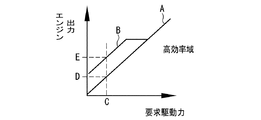
図6は、エンジン出力と要求駆動力と二次電池の入力電力の制限値との関係を示すグラフである。要求駆動力は、アクセル開度などの駆動要求量および車速により求められる。その要求駆動力は、予め用意したマップから求めることができる。ついで、その要求駆動力を達成するようにエンジン出力を制御することが行われている。 FIG. 6 is a graph showing the relationship between the engine output, the required driving force, and the limit value of the input power of the secondary battery. The required driving force is obtained from the required driving amount such as the accelerator opening and the vehicle speed. The required driving force can be obtained from a prepared map. Then, the engine output is controlled so as to achieve the required driving force.
制御部11は、例えばアクセル開度をパラメータとして車速と要求駆動力との予め記憶された駆動力マップを参照して実際のアクセル開度および車速に基づいて要求駆動力を算出する。そして、制御部11は、例えば駆動輪3のタイヤ有効半径、現在の変速機8のギヤ段におけるギヤ比およびデファレンシャルギヤ9の終減速比などに基づいて、その要求駆動力が得られる要求エンジントルクを演算する。エンジン出力は、要求エンジントルクとエンジン回転数との積で求まる。例えば図6に示した直線Aは、左端が要求駆動力がゼロを通りかつ右端を上に向けて傾斜した直線であり、要求駆動力に対して低燃費となるようにエンジン出力を求めるためのものである。そして、この実施形態では、制限値の大きさに基づいてエンジン出力を増大する分を直線Bで示している。
The
制限値が十分に大きい場合には、直線Aに基づいてエンジン出力を求める。また、制限値が十分に小さい場合には、直線Bに基づいてエンジン出力を求める。同図に示す直線Bは、SOCを第2閾値SOC1以上に回復させる分を考慮して要求駆動力に対して直線Aよりもエンジン出力が高くなるように設定されている。 When the limit value is sufficiently large, the engine output is obtained based on the straight line A. If the limit value is sufficiently small, the engine output is obtained based on the straight line B. The straight line B shown in the drawing is set so that the engine output becomes higher than the straight line A with respect to the required driving force in consideration of the recovery of the SOC to the second threshold value SOC1 or more.
つまり、要求駆動力Cのときに、かつ制限値が十分に小さい場合には、制限値が十分に大きい場合に設定される値Dよりも大きい値Eにエンジン出力が設定される。エンジン出力を増加した分に対応した吸入空気を取り込めるため、二次電池6の冷却効率が向上する。しかも、エンジン出力が増加することで第1モータ4による発電量が増加し、二次電池6に充電される電力が増加する。よって、十分な充電量に二次電池6を早期に回復させることができ、よって電動走行に早期に戻すことができる。
That is, at the required driving force C and when the limit value is sufficiently small, the engine output is set to a value E larger than the value D set when the limit value is sufficiently large. Since the intake air corresponding to the increase in the engine output can be taken in, the cooling efficiency of the
要求駆動力Cのときに、かつ制限値が十分に大きい場合には、制限値が十分に小さい場合に設定される値Eよりも小さい値Dにエンジン出力が設定される。このため、二次電池6のSOCを維持しながら二次電池6の冷却を行うことができる。また、制限値が十分に大きい場合には、要求駆動力が小さいときもエンジン2をできるだけ高効率の回転領域(高効率域)で運転させることができる。
At the required driving force C and when the limit value is sufficiently large, the engine output is set to a value D smaller than a value E set when the limit value is sufficiently small. Therefore, the
なお、図5で説明した実施形態は、図4で説明した実施形態に組み合わせることができる。また、図5では、図3で説明した手順と同じ手順に同符号を付与しており、同符号を付与した手順についてはここでの詳しい説明を省略する。 Note that the embodiment described in FIG. 5 can be combined with the embodiment described in FIG. In FIG. 5, the same steps as those described in FIG. 3 are denoted by the same reference numerals, and detailed description of the steps denoted by the same reference numerals will be omitted.
以上、本発明は、上述した実施形態で示した構成に限定されないのであって、特許を請求している範囲で適宜に変更して実施することができる。例えば上記各実施例では、クランキング手段を第1モータ4として説明しているが、第1モータ4の代わりにスターターモータであってもよい。また、上記各実施例で説明した制御部11は、エンジンモータリング制御を実行しているが、代わりにクランキング制御を実行してもよい。電動走行時に実施されるクランキング制御は、例えばアクセルペダルを踏んでいない減速走行時でかつ回生量が少ないと見込まれる場合などの特定条件のときに、エンジン2を走行慣性力で回転させる制御であってもよい。具体的には、ハイブリッド車両1は、エンジン2の駆動力を駆動輪3に伝達する係合状態とその伝達を遮断する解放状態とに切り替わるクラッチ機構を備えている。クラッチ機構は制御部11に制御される。制御部11は電動走行時にクラッチ機構を解放状態にする。また、制御部11は、電動走行時に蓄電装置の温度が予め決められた第1閾値を超えたと判断しかつ特定条件のときにクラッチ機構を係合状態にして走行慣性力でエンジン2を回転させる。この場合にはクラッチ機構がこの発明の実施形態におけるクランキング手段の一例である。クランキング手段の駆動はクラッチ機構を係合状態に切り替えることを含む。
As described above, the present invention is not limited to the configuration shown in the above-described embodiment, and can be appropriately modified and implemented within the scope of the claims. For example, in the above embodiments, the cranking means is described as the
1…ハイブリッド車両、 2…エンジン、 3…駆動輪、 4…第1モータ、 5…第2モータ、 6…二次電池、 7…動力伝達装置、 8…変速機、 9…デファレンシャルギヤ、 10…検出部、 11…制御部、 13…エアクリーナ、 14…吸気通路。 DESCRIPTION OF SYMBOLS 1 ... Hybrid vehicle, 2 ... Engine, 3 ... Drive wheel, 4 ... 1st motor, 5 ... 2nd motor, 6 ... Secondary battery, 7 ... Power transmission device, 8 ... Transmission, 9 ... Differential gear, 10 ... Detecting unit, 11: control unit, 13: air cleaner, 14: intake passage.
Claims (5)
前記蓄電装置の温度を検出する検出部と、
前記エンジン、前記駆動用モータおよび前記クランキング手段を制御するコントローラとを備え、
前記コントローラは、前記電動走行時に、前記蓄電装置の温度が予め決められた第1閾値を超えたと判断すると前記クランキング手段を駆動するように構成されている、
ことを特徴とするハイブリッド車両。 An engine, a driving motor, cranking means for rotating the engine, and a power storage device for supplying power to the driving motor during electric traveling in which the engine is stopped and the vehicle travels with a driving force output from the driving motor. A hybrid vehicle having a configuration for cooling the power storage device using intake air flowing through an intake passage of the engine,
A detection unit that detects a temperature of the power storage device;
A controller for controlling the engine, the driving motor and the cranking means,
The controller is configured to drive the cranking unit when determining that the temperature of the power storage device has exceeded a predetermined first threshold during the electric traveling,
A hybrid vehicle, characterized in that:
前記蓄電装置の充電量の程度を検出する充電量検出部を備え、
前記コントローラは、前記充電量が予め決められた第2閾値以下の場合に前記クランキング手段を駆動し、かつ燃料供給を行うエンジンファイアリング制御を実行し、また、前記充電量が前記第2閾値を超える場合には前記クランキング手段を駆動して、かつ前記燃料供給を停止するクランキング制御を実行するように構成されている、
ことを特徴とするハイブリッド車両。 The hybrid vehicle according to claim 1,
A charge amount detection unit that detects a degree of charge amount of the power storage device,
The controller drives the cranking means when the charge amount is equal to or less than a predetermined second threshold value, and executes engine firing control for supplying fuel, and the controller sets the charge amount to the second threshold value. When it exceeds, is configured to drive the cranking means, and to perform the cranking control to stop the fuel supply,
A hybrid vehicle, characterized in that:
前記コントローラは、前記クランキング制御を実行するときに、前記吸気通路に設けられたスロットルバルブの開度をアイドリング運転時の開度よりも増大させるように制御する、
ことを特徴とするハイブリッド車両。 The hybrid vehicle according to claim 2,
The controller, when performing the cranking control, controls the opening degree of the throttle valve provided in the intake passage to be larger than the opening degree during idling operation,
A hybrid vehicle, characterized in that:
前記コントローラは、前記エンジンファイアリング制御を実行するときに、エンジン出力を前記蓄電装置の入力電力の制限値に基づいて変更するように制御する、
ことを特徴とするハイブリッド車両。 The hybrid vehicle according to claim 2 or 3,
The controller, when executing the engine firing control, controls to change the engine output based on the limit value of the input power of the power storage device,
A hybrid vehicle, characterized in that:
前記クランキング手段は前記エンジンに連結された発電機能付きモータになっており、
前記蓄電装置は前記発電機能付きモータで発電した電力を充電可能になっている、
ことを特徴するハイブリッド車両。 The hybrid vehicle according to any one of claims 1 to 4,
The cranking means is a motor with a power generation function connected to the engine,
The power storage device is configured to be able to charge power generated by the motor with a power generation function,
A hybrid vehicle characterized by that:
Priority Applications (3)
| Application Number | Priority Date | Filing Date | Title |
|---|---|---|---|
| JP2018162376A JP2020032918A (en) | 2018-08-31 | 2018-08-31 | Hybrid vehicle |
| US16/451,712 US20200070808A1 (en) | 2018-08-31 | 2019-06-25 | Hybrid vehicle |
| CN201910729757.7A CN110871786A (en) | 2018-08-31 | 2019-08-08 | Hybrid vehicle |
Applications Claiming Priority (1)
| Application Number | Priority Date | Filing Date | Title |
|---|---|---|---|
| JP2018162376A JP2020032918A (en) | 2018-08-31 | 2018-08-31 | Hybrid vehicle |
Publications (1)
| Publication Number | Publication Date |
|---|---|
| JP2020032918A true JP2020032918A (en) | 2020-03-05 |
Family
ID=69641982
Family Applications (1)
| Application Number | Title | Priority Date | Filing Date |
|---|---|---|---|
| JP2018162376A Withdrawn JP2020032918A (en) | 2018-08-31 | 2018-08-31 | Hybrid vehicle |
Country Status (3)
| Country | Link |
|---|---|
| US (1) | US20200070808A1 (en) |
| JP (1) | JP2020032918A (en) |
| CN (1) | CN110871786A (en) |
Cited By (1)
| Publication number | Priority date | Publication date | Assignee | Title |
|---|---|---|---|---|
| CN113829963A (en) * | 2020-06-23 | 2021-12-24 | 北京新能源汽车股份有限公司 | Vehicle control method and device |
Families Citing this family (3)
| Publication number | Priority date | Publication date | Assignee | Title |
|---|---|---|---|---|
| JP7232092B2 (en) * | 2019-03-20 | 2023-03-02 | 株式会社Subaru | vehicle controller |
| JP7011677B2 (en) * | 2020-03-02 | 2022-01-26 | 本田技研工業株式会社 | Battery unit |
| US11605845B2 (en) * | 2021-01-07 | 2023-03-14 | Ford Global Technologies, Llc | Strategies for warming stationary vehicle traction battery |
-
2018
- 2018-08-31 JP JP2018162376A patent/JP2020032918A/en not_active Withdrawn
-
2019
- 2019-06-25 US US16/451,712 patent/US20200070808A1/en not_active Abandoned
- 2019-08-08 CN CN201910729757.7A patent/CN110871786A/en not_active Withdrawn
Cited By (2)
| Publication number | Priority date | Publication date | Assignee | Title |
|---|---|---|---|---|
| CN113829963A (en) * | 2020-06-23 | 2021-12-24 | 北京新能源汽车股份有限公司 | Vehicle control method and device |
| CN113829963B (en) * | 2020-06-23 | 2023-07-25 | 北京新能源汽车股份有限公司 | Control method and device for vehicle |
Also Published As
| Publication number | Publication date |
|---|---|
| CN110871786A (en) | 2020-03-10 |
| US20200070808A1 (en) | 2020-03-05 |
Similar Documents
| Publication | Publication Date | Title |
|---|---|---|
| US9669834B2 (en) | Regenerative control device for hybrid vehicle | |
| US9688265B2 (en) | Regenerative control device for hybrid vehicle | |
| JP4519085B2 (en) | Control device for internal combustion engine | |
| WO2012056870A1 (en) | Control device for hybrid vehicle | |
| US11142202B2 (en) | Control system for hybrid vehicle | |
| JP2020032918A (en) | Hybrid vehicle | |
| JP2012250676A (en) | Engine start control device of hybrid vehicle | |
| JP2011239605A (en) | Controller of vehicle | |
| US10639984B2 (en) | Control system for vehicle | |
| US20190283730A1 (en) | Control system for hybrid vehicle | |
| JP5459144B2 (en) | Hybrid car | |
| JP2018086941A (en) | Hybrid vehicle | |
| JP5716425B2 (en) | Hybrid car | |
| JP6492908B2 (en) | Control device for hybrid vehicle | |
| US9457796B2 (en) | Vehicle and control method for vehicle | |
| JP6091169B2 (en) | Vehicle control device | |
| JP2019025985A (en) | Hybrid vehicular engine start control apparatus and start control method | |
| JP7252996B2 (en) | vehicle controller | |
| JP6409735B2 (en) | Control device for hybrid vehicle | |
| JP2013043570A (en) | Control device of hybrid vehicle | |
| JP2020104660A (en) | Hybrid-vehicular drive force control apparatus | |
| JP6631375B2 (en) | Hybrid car | |
| JP2019026038A (en) | Hybrid vehicular engine start control apparatus and start control method | |
| JP2019025986A (en) | Hybrid vehicle | |
| JP2019043347A (en) | Hybrid vehicle |
Legal Events
| Date | Code | Title | Description |
|---|---|---|---|
| A621 | Written request for application examination |
Free format text: JAPANESE INTERMEDIATE CODE: A621 Effective date: 20210121 |
|
| A761 | Written withdrawal of application |
Free format text: JAPANESE INTERMEDIATE CODE: A761 Effective date: 20210709 |