JP2020016264A5 - - Google Patents
Download PDFInfo
- Publication number
- JP2020016264A5 JP2020016264A5 JP2018138128A JP2018138128A JP2020016264A5 JP 2020016264 A5 JP2020016264 A5 JP 2020016264A5 JP 2018138128 A JP2018138128 A JP 2018138128A JP 2018138128 A JP2018138128 A JP 2018138128A JP 2020016264 A5 JP2020016264 A5 JP 2020016264A5
- Authority
- JP
- Japan
- Prior art keywords
- spring
- outer peripheral
- flywheel
- rotating member
- hysteresis torque
- Prior art date
- Legal status (The legal status is an assumption and is not a legal conclusion. Google has not performed a legal analysis and makes no representation as to the accuracy of the status listed.)
- Granted
Links
- 230000002093 peripheral Effects 0.000 description 13
- 230000023298 conjugation with cellular fusion Effects 0.000 description 1
- 230000013011 mating Effects 0.000 description 1
- 238000005096 rolling process Methods 0.000 description 1
- 238000007789 sealing Methods 0.000 description 1
- 230000021037 unidirectional conjugation Effects 0.000 description 1
Images

Description
(7)好ましくは、ダンパ部は、弾性部材を保持するとともに第2回転部材に連結された保持プレートを有し、保持プレートは第1回転部材と軸方向に対向して配置されている。そして、第1ヒステリシストルク発生機構は、第1回転部材と保持プレートとの間に配置されている。 (7) Preferably, the damper portion has a holding plate that holds the elastic member and is connected to the second rotating member , and the holding plate is arranged so as to face the first rotating member in the axial direction. The first hysteresis torque generation mechanism is arranged between the first rotating member and the holding plate.
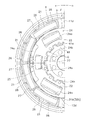
<外周側スプリング21及び内周側スプリング22>
図4に示すように、外周側スプリング21は円周方向に並べて配置されている。隣接する外周側スプリング21の間には中間スプリングシート27が配置されており、4つの外周側スプリング21は直列に作用する。4つの外周側スプリング21の円周方向の端部には、2つの端部スプリングシート28が配置されている。各スプリングシート27,28には、外周側スプリング21の端部が挿入される筒状部が形成されている。
<Outer
As shown in FIG. 4, the outer
図4に示されていない他の4つの外周側スプリング21についても同様である。すなわち、他の4つの外周側スプリング21は中間スプリングシート27を介して直列に作用する。また、他の4つの外周側スプリング21の円周方向の端部には端部スプリングシート28が配置されている。
The same applies to the other four outer
以上のように、連結部材65は、第2フライホイール52に固定され、外周側スプリング21及び内周側スプリング22の出力側の部材として機能する。すなわち、連結部材65は、第2フライホイール52とともに、第1フライホイール51に対して相対回転可能な第2回転部材の一例である。
As described above, the connecting member 65 is fixed to the second flywheel 52 and functions as a member on the output side of the outer
以上の構成により、第1ヒステリシストルク発生機構55は、第1フライホイール51と第2サイドプレート69(すなわち第2フライホイール52)との相対回転時に第1ヒステリシストルクを発生する。 With the above configuration, the first hysteresis torque generation mechanism 55 generates the first hysteresis torque when the first flywheel 51 and the second side plate 69 (that is, the second flywheel 52 ) rotate relative to each other.
(a)前記実施形態では、摩擦部材を環状の平板で形成したが、図13に示すように、摩擦部材90を屈曲した形状にしてもよい。この場合は、摩擦部材90が当接する相手側部材も同様の形状にする必要がある。 (A) In the above embodiment, the friction member is formed of an annular flat plate, but as shown in FIG. 13 , the friction member 90 may have a bent shape. In this case, the mating member with which the friction member 90 comes into contact needs to have the same shape.
1 フライホイール組立体
50 ダンパ装置
2,51 第1フライホイール(第1回転転部材)
3,52 第2フライホイール(第2回転部材)
11,58 フライホイール本体(第1プレート)
12,59 プレート(第2プレート)
14,53 軸受
4,54 ダンパ部
5,55,83 第1ヒステリシストルク発生機構
6,56 第2ヒステリシストルク発生機構
21 外周側スプリング(弾性部材)
22 内周側スプリング(弾性部材)
23 中間部材
65 連結部材
31,32,68,69 サイドプレート(保持プレート)
38,71,84 第1摩擦部材
90 摩擦部材
39,85 第1コーンスプリング
42 第2摩擦部材
43 第2コーンスプリング
45 第3ヒステリシストルク発生機構
75 通気路
76 一方向弁
87,92,94,96 シール用コーンスプリング
1 Flywheel assembly
50 Damper device 2,51 1st flywheel (1st rotary rolling member)
3,52 Second flywheel (second rotating member)
11,58 Flywheel body (1st plate)
12,59 plate (second plate)
14,53
22 Inner circumference spring (elastic member)
23 Intermediate member
65 Connecting members 31, 32, 68, 69 Side plates (holding plates)
38,71,84 1st friction member
90
Claims (1)
前記第1ヒステリシストルク発生機構は、前記第1回転部材と前記保持プレートとの間に配置されている、
請求項1から4のいずれかに記載のダンパ装置。 The damper portion has a holding plate that holds the elastic member and is connected to the second rotating member , and the holding plate is arranged so as to face the first rotating member in the axial direction.
The first hysteresis torque generating mechanism is arranged between the first rotating member and the holding plate.
The damper device according to any one of claims 1 to 4.
Priority Applications (1)
| Application Number | Priority Date | Filing Date | Title |
|---|---|---|---|
| JP2018138128A JP7170447B2 (en) | 2018-07-24 | 2018-07-24 | damper device |
Applications Claiming Priority (1)
| Application Number | Priority Date | Filing Date | Title |
|---|---|---|---|
| JP2018138128A JP7170447B2 (en) | 2018-07-24 | 2018-07-24 | damper device |
Publications (3)
| Publication Number | Publication Date |
|---|---|
| JP2020016264A JP2020016264A (en) | 2020-01-30 |
| JP2020016264A5 true JP2020016264A5 (en) | 2021-08-26 |
| JP7170447B2 JP7170447B2 (en) | 2022-11-14 |
Family
ID=69580181
Family Applications (1)
| Application Number | Title | Priority Date | Filing Date |
|---|---|---|---|
| JP2018138128A Active JP7170447B2 (en) | 2018-07-24 | 2018-07-24 | damper device |
Country Status (1)
| Country | Link |
|---|---|
| JP (1) | JP7170447B2 (en) |
Family Cites Families (3)
| Publication number | Priority date | Publication date | Assignee | Title |
|---|---|---|---|---|
| DE3519912A1 (en) * | 1985-06-04 | 1986-12-04 | Daimler-Benz Ag, 7000 Stuttgart | DEVICE FOR REDUCING VIBRATION OF A DRIVETRAIN EXCITING ON THE ENGINE SIDE |
| DE3609149A1 (en) * | 1986-03-19 | 1987-10-01 | Daimler Benz Ag | DEVICE FOR REDUCING VIBRATIONS OF A DRIVETRAIN EXCITING ON THE ENGINE SIDE, PARTICULARLY DIVIDED FLYWHEEL |
| JP4240147B2 (en) * | 1996-09-03 | 2009-03-18 | アイシン精機株式会社 | Power transmission mechanism |
-
2018
- 2018-07-24 JP JP2018138128A patent/JP7170447B2/en active Active
Similar Documents
| Publication | Publication Date | Title |
|---|---|---|
| JP6240149B2 (en) | Torque transmission device for automobile | |
| TWI235799B (en) | Crankshaft damper and method of assembly | |
| JP2014521006A (en) | Reciprocating compressor with leaf spring attached | |
| US8568243B2 (en) | Flywheel assembly | |
| US20150240909A1 (en) | Damper device | |
| CN104662325B (en) | Torsional vibration damper and the drag ring for torsional vibration damper | |
| JP2018132160A5 (en) | ||
| US20170051818A1 (en) | Device for the Transmission of a Torque with Torsional Vibration Damping | |
| JP2020037982A5 (en) | ||
| US20210025459A1 (en) | Torsional vibration, clutch disk and clutch | |
| JP2020016264A5 (en) | ||
| US20180051755A1 (en) | Integrated snap ring and return spring | |
| US3627298A (en) | Fluid springs | |
| JP2019533783A (en) | Automotive clutch assembly with shock absorber for smooth clutch engagement | |
| JP2021076226A5 (en) | ||
| US10352396B2 (en) | Damper device | |
| JP2019163853A5 (en) | ||
| CN206738489U (en) | Damper disc assembly | |
| TWI695941B (en) | Sliding-contact-type wave generator, strain wave gearing and wave generating method | |
| JP2022095172A5 (en) | ||
| JP2019011816A5 (en) | ||
| EP1176338A3 (en) | Torsional vibration damper | |
| US9599187B2 (en) | Damper device | |
| JP6955842B2 (en) | One-way clutch | |
| JP2020148332A5 (en) |