JP2020008547A - Magnetic detection module, detection device, case assembly, and manufacturing method of magnetic detection module - Google Patents
Magnetic detection module, detection device, case assembly, and manufacturing method of magnetic detection module Download PDFInfo
- Publication number
- JP2020008547A JP2020008547A JP2018195711A JP2018195711A JP2020008547A JP 2020008547 A JP2020008547 A JP 2020008547A JP 2018195711 A JP2018195711 A JP 2018195711A JP 2018195711 A JP2018195711 A JP 2018195711A JP 2020008547 A JP2020008547 A JP 2020008547A
- Authority
- JP
- Japan
- Prior art keywords
- housing
- magnetic
- case
- cap
- detection module
- Prior art date
- Legal status (The legal status is an assumption and is not a legal conclusion. Google has not performed a legal analysis and makes no representation as to the accuracy of the status listed.)
- Granted
Links
Images


Classifications
-
- G—PHYSICS
- G01—MEASURING; TESTING
- G01D—MEASURING NOT SPECIALLY ADAPTED FOR A SPECIFIC VARIABLE; ARRANGEMENTS FOR MEASURING TWO OR MORE VARIABLES NOT COVERED IN A SINGLE OTHER SUBCLASS; TARIFF METERING APPARATUS; MEASURING OR TESTING NOT OTHERWISE PROVIDED FOR
- G01D5/00—Mechanical means for transferring the output of a sensing member; Means for converting the output of a sensing member to another variable where the form or nature of the sensing member does not constrain the means for converting; Transducers not specially adapted for a specific variable
- G01D5/12—Mechanical means for transferring the output of a sensing member; Means for converting the output of a sensing member to another variable where the form or nature of the sensing member does not constrain the means for converting; Transducers not specially adapted for a specific variable using electric or magnetic means
- G01D5/244—Mechanical means for transferring the output of a sensing member; Means for converting the output of a sensing member to another variable where the form or nature of the sensing member does not constrain the means for converting; Transducers not specially adapted for a specific variable using electric or magnetic means influencing characteristics of pulses or pulse trains; generating pulses or pulse trains
- G01D5/24428—Error prevention
- G01D5/24433—Error prevention by mechanical means
- G01D5/24442—Error prevention by mechanical means by mounting means
-
- G—PHYSICS
- G01—MEASURING; TESTING
- G01D—MEASURING NOT SPECIALLY ADAPTED FOR A SPECIFIC VARIABLE; ARRANGEMENTS FOR MEASURING TWO OR MORE VARIABLES NOT COVERED IN A SINGLE OTHER SUBCLASS; TARIFF METERING APPARATUS; MEASURING OR TESTING NOT OTHERWISE PROVIDED FOR
- G01D5/00—Mechanical means for transferring the output of a sensing member; Means for converting the output of a sensing member to another variable where the form or nature of the sensing member does not constrain the means for converting; Transducers not specially adapted for a specific variable
- G01D5/12—Mechanical means for transferring the output of a sensing member; Means for converting the output of a sensing member to another variable where the form or nature of the sensing member does not constrain the means for converting; Transducers not specially adapted for a specific variable using electric or magnetic means
- G01D5/14—Mechanical means for transferring the output of a sensing member; Means for converting the output of a sensing member to another variable where the form or nature of the sensing member does not constrain the means for converting; Transducers not specially adapted for a specific variable using electric or magnetic means influencing the magnitude of a current or voltage
- G01D5/142—Mechanical means for transferring the output of a sensing member; Means for converting the output of a sensing member to another variable where the form or nature of the sensing member does not constrain the means for converting; Transducers not specially adapted for a specific variable using electric or magnetic means influencing the magnitude of a current or voltage using Hall-effect devices
-
- G—PHYSICS
- G01—MEASURING; TESTING
- G01D—MEASURING NOT SPECIALLY ADAPTED FOR A SPECIFIC VARIABLE; ARRANGEMENTS FOR MEASURING TWO OR MORE VARIABLES NOT COVERED IN A SINGLE OTHER SUBCLASS; TARIFF METERING APPARATUS; MEASURING OR TESTING NOT OTHERWISE PROVIDED FOR
- G01D5/00—Mechanical means for transferring the output of a sensing member; Means for converting the output of a sensing member to another variable where the form or nature of the sensing member does not constrain the means for converting; Transducers not specially adapted for a specific variable
- G01D5/12—Mechanical means for transferring the output of a sensing member; Means for converting the output of a sensing member to another variable where the form or nature of the sensing member does not constrain the means for converting; Transducers not specially adapted for a specific variable using electric or magnetic means
- G01D5/14—Mechanical means for transferring the output of a sensing member; Means for converting the output of a sensing member to another variable where the form or nature of the sensing member does not constrain the means for converting; Transducers not specially adapted for a specific variable using electric or magnetic means influencing the magnitude of a current or voltage
- G01D5/16—Mechanical means for transferring the output of a sensing member; Means for converting the output of a sensing member to another variable where the form or nature of the sensing member does not constrain the means for converting; Transducers not specially adapted for a specific variable using electric or magnetic means influencing the magnitude of a current or voltage by varying resistance
-
- G—PHYSICS
- G01—MEASURING; TESTING
- G01L—MEASURING FORCE, STRESS, TORQUE, WORK, MECHANICAL POWER, MECHANICAL EFFICIENCY, OR FLUID PRESSURE
- G01L3/00—Measuring torque, work, mechanical power, or mechanical efficiency, in general
- G01L3/02—Rotary-transmission dynamometers
- G01L3/04—Rotary-transmission dynamometers wherein the torque-transmitting element comprises a torsionally-flexible shaft
- G01L3/10—Rotary-transmission dynamometers wherein the torque-transmitting element comprises a torsionally-flexible shaft involving electric or magnetic means for indicating
- G01L3/101—Rotary-transmission dynamometers wherein the torque-transmitting element comprises a torsionally-flexible shaft involving electric or magnetic means for indicating involving magnetic or electromagnetic means
- G01L3/104—Rotary-transmission dynamometers wherein the torque-transmitting element comprises a torsionally-flexible shaft involving electric or magnetic means for indicating involving magnetic or electromagnetic means involving permanent magnets
-
- G—PHYSICS
- G01—MEASURING; TESTING
- G01L—MEASURING FORCE, STRESS, TORQUE, WORK, MECHANICAL POWER, MECHANICAL EFFICIENCY, OR FLUID PRESSURE
- G01L5/00—Apparatus for, or methods of, measuring force, work, mechanical power, or torque, specially adapted for specific purposes
- G01L5/22—Apparatus for, or methods of, measuring force, work, mechanical power, or torque, specially adapted for specific purposes for measuring the force applied to control members, e.g. control members of vehicles, triggers
- G01L5/221—Apparatus for, or methods of, measuring force, work, mechanical power, or torque, specially adapted for specific purposes for measuring the force applied to control members, e.g. control members of vehicles, triggers to steering wheels, e.g. for power assisted steering
-
- G—PHYSICS
- G01—MEASURING; TESTING
- G01R—MEASURING ELECTRIC VARIABLES; MEASURING MAGNETIC VARIABLES
- G01R33/00—Arrangements or instruments for measuring magnetic variables
- G01R33/0011—Arrangements or instruments for measuring magnetic variables comprising means, e.g. flux concentrators, flux guides, for guiding or concentrating the magnetic flux, e.g. to the magnetic sensor
-
- G—PHYSICS
- G01—MEASURING; TESTING
- G01R—MEASURING ELECTRIC VARIABLES; MEASURING MAGNETIC VARIABLES
- G01R33/00—Arrangements or instruments for measuring magnetic variables
- G01R33/0047—Housings or packaging of magnetic sensors ; Holders
-
- G—PHYSICS
- G01—MEASURING; TESTING
- G01R—MEASURING ELECTRIC VARIABLES; MEASURING MAGNETIC VARIABLES
- G01R33/00—Arrangements or instruments for measuring magnetic variables
- G01R33/007—Environmental aspects, e.g. temperature variations, radiation, stray fields
- G01R33/0076—Protection, e.g. with housings against stray fields
-
- G—PHYSICS
- G01—MEASURING; TESTING
- G01R—MEASURING ELECTRIC VARIABLES; MEASURING MAGNETIC VARIABLES
- G01R33/00—Arrangements or instruments for measuring magnetic variables
- G01R33/02—Measuring direction or magnitude of magnetic fields or magnetic flux
- G01R33/06—Measuring direction or magnitude of magnetic fields or magnetic flux using galvano-magnetic devices
- G01R33/07—Hall effect devices
- G01R33/072—Constructional adaptation of the sensor to specific applications
-
- G—PHYSICS
- G01—MEASURING; TESTING
- G01R—MEASURING ELECTRIC VARIABLES; MEASURING MAGNETIC VARIABLES
- G01R33/00—Arrangements or instruments for measuring magnetic variables
- G01R33/02—Measuring direction or magnitude of magnetic fields or magnetic flux
- G01R33/06—Measuring direction or magnitude of magnetic fields or magnetic flux using galvano-magnetic devices
- G01R33/09—Magnetoresistive devices
- G01R33/091—Constructional adaptation of the sensor to specific applications
Abstract
Description
本発明は、磁気検出モジュール、検出装置、ケースアセンブリ、及び、磁気検出モジュールの製造方法に関する。 The present invention relates to a magnetic detection module, a detection device, a case assembly, and a method for manufacturing a magnetic detection module.
従来、可動体の移動に応じて発生する磁束を検出する検出装置が知られている。例えば特許文献1に開示されたトルクセンサは、車両のパワーステアリング装置において、ハウジング内に収容されたトーションバーの捩れ変位により発生する磁束変化を磁気センサで検出することで、操舵トルクを検出する。
2. Description of the Related Art Conventionally, a detection device that detects a magnetic flux generated according to the movement of a movable body is known. For example, a torque sensor disclosed in
このトルクセンサは、センサホルダにハウジングの取付穴に接合するインロー筒部を形成し、ハウジングの取付穴とインロー筒部の外周面との間にシール部材を圧縮して介装して両者の間を密封する。そして、シール部材の弾性力がインロー筒部に対して外周面の半径方向に作用する構成としている。 In this torque sensor, a spigot cylinder portion is formed in a sensor holder to be joined to a mounting hole of a housing, and a seal member is interposed between the mounting hole of the housing and the outer peripheral surface of the spigot cylinder by being compressed and interposed therebetween. Seal. The elastic force of the seal member acts on the spigot cylinder in the radial direction of the outer peripheral surface.
また従来、磁気センサを含む磁気検出モジュールをハウジングの取付穴に挿入する構成の検出装置が知られている。例えば特許文献2に開示されたトルク検出装置は、検出部及び検出回路基板等を含むケース(すなわち磁気検出モジュール)が、ハウジングのラジアル方向から貫通孔(すなわち取付穴)に挿入される。ハウジングの貫通孔の外側端部、及びケースの外面は、検出部のハウジング内での位置を決める位置決め面を有する。 Conventionally, a detection device having a configuration in which a magnetic detection module including a magnetic sensor is inserted into a mounting hole of a housing is known. For example, in a torque detection device disclosed in Patent Document 2, a case (that is, a magnetic detection module) including a detection unit, a detection circuit board, and the like is inserted into a through hole (that is, a mounting hole) in a radial direction of a housing. The outer end of the through-hole of the housing and the outer surface of the case have a positioning surface that determines the position of the detection unit in the housing.
[第1の課題]
一般に可動体の移動に応じて発生する磁束を検出する検出装置の構造として、可動体や磁束発生部が収容されたハウジングに、磁気センサを有し検出信号を外部に出力する磁気検出モジュールが取り付けられる構造が採用される。磁気検出モジュールは、磁気センサがケースに収納されてなるケースアセンブリを含む。ケースアセンブリは、磁気センサの他、信号出力回路が搭載された基板や信号線が配線されるコネクタ等を有する。このようなモジュール構造とすることで、現実の製品では、他から部品として供給された磁気検出モジュールが組立工場でハウジングに取り付けられる。
[First issue]
Generally, a magnetic detection module that has a magnetic sensor and outputs a detection signal to the outside is attached to the housing that houses the movable body and the magnetic flux generation unit as a structure of the detection device that detects the magnetic flux generated according to the movement of the movable body. Is adopted. The magnetic detection module includes a case assembly in which a magnetic sensor is housed in a case. The case assembly includes, in addition to the magnetic sensor, a board on which a signal output circuit is mounted, a connector for wiring signal lines, and the like. With such a module structure, in a real product, a magnetic detection module supplied as a component from another is attached to a housing at an assembly factory.
ところで、特許文献1に開示されたトルクセンサはシール部材を備えるものであるが、現実にはトルクセンサが搭載される車両の部位により、ラック搭載タイプでは防水機能が要求され、コラム搭載タイプでは防水機能が要求されないという違いがある。そのため、防水仕様の検出装置に適用される場合は磁気検出モジュールとハウジングとの間にシール材を設ける必要があり、非防水仕様の検出装置に適用される場合は磁気検出モジュールとハウジングとの間のシール材は不要である。
Incidentally, the torque sensor disclosed in
仮に、防水仕様及び非防水仕様のハウジングに対しそれぞれ専用のケースを例えば樹脂成形により製造すると二種類の金型が必要となり、また二種類のケースの生産調整や在庫管理工数が発生する。さらに、例えば防水仕様の中でもシール材の形状やサイズの異なる複数の仕様が存在する場合、より他機種の生産切り替えが必要となり、金型コストや管理コストが増大する。 If a dedicated case is manufactured for each of a waterproof specification housing and a non-waterproof specification housing by, for example, resin molding, two types of molds are required, and production adjustment and inventory management man-hours for the two types of cases are required. Further, for example, in the case where there are a plurality of specifications having different shapes and sizes of sealing materials among the waterproof specifications, it is necessary to switch production of another model, and the die cost and management cost increase.
[第2の課題]
特許文献2の構成では、ハウジングの取付穴の内壁は長方形筒状である。一方、ハウジングの取付穴の内壁が円筒状である場合の位置決め構成に関して、特許文献2には具体的に明示されていない。
[Second task]
In the configuration of Patent Document 2, the inner wall of the mounting hole of the housing has a rectangular cylindrical shape. On the other hand, Patent Document 2 does not specifically disclose a positioning configuration when the inner wall of the mounting hole of the housing is cylindrical.
また、特許文献2の構成では、挿入部の外郭は磁性リングによって囲まれているため、磁気センサの収納部分が挿入作業時にハウジングに直接接触して破損するおそれはない。一方、磁気センサが収納されたセンサ部が磁気検出モジュールの先端面から突出する構成では、挿入時の位置ずれや傾きによりセンサ部がハウジング側の部材と干渉すると、磁気センサの破損や特性変化が生じるおそれがある。 Further, in the configuration of Patent Literature 2, since the outer periphery of the insertion portion is surrounded by the magnetic ring, there is no possibility that the storage portion of the magnetic sensor directly contacts the housing during the insertion operation and is damaged. On the other hand, in a configuration in which the sensor unit housing the magnetic sensor protrudes from the front end surface of the magnetic detection module, if the sensor unit interferes with a member on the housing side due to misalignment or inclination at the time of insertion, breakage or characteristic change of the magnetic sensor may occur. May occur.
[第1群の発明の目的]
第1群の発明は上記第1の課題に鑑みてなされたものであり、その目的は、共通の構成要素を用いた簡易な構成変更により、仕様が異なる複数のハウジングへ選択的に取付可能な磁気検出モジュール、それを構成するケースアセンブリ、及び、その製造方法を提供することにある。
[Object of the first group of the invention]
The first group of inventions has been made in view of the above first problem, and an object of the invention is to selectively attach to a plurality of housings having different specifications by a simple configuration change using a common component. An object of the present invention is to provide a magnetic detection module, a case assembly constituting the module, and a method of manufacturing the same.
[第2群の発明の目的]
第2群の発明は上記第2の課題に鑑みてなされたものであり、その目的は、内壁が円筒状の取付穴を有するハウジングに磁気検出モジュールが取り付けられる検出装置において、先端面から突出するセンサ部とハウジング側の部材との干渉を防止する検出装置、及び磁気検出モジュールを提供することにある。
[Object of the second group of the invention]
The second group of inventions has been made in view of the second problem, and an object thereof is to provide a detection device in which a magnetic detection module is mounted on a housing having an inner wall having a cylindrical mounting hole, and which protrudes from a distal end surface. An object of the present invention is to provide a detection device for preventing interference between a sensor unit and a member on a housing side, and a magnetic detection module.
[第1群の発明]
本発明の磁気検出モジュールは、取付部の形状又は大きさが異なる複数の仕様のハウジング(401、402)のいずれかに選択的に取付可能に設けられ、ハウジング内で発生した磁束を検出する。この磁気検出モジュールは、磁束を検出する一つ以上の磁気センサ(71、72)と、磁気センサが収納されるケース(501)と、ケースの端部に装着可能でありシール材(89)が設けられるキャップ(801、805)と、を備える。
[Invention of the first group]
The magnetic detection module of the present invention is provided so as to be selectively attachable to any one of a plurality of housings (401, 402) having different specifications or shapes of an attachment portion, and detects a magnetic flux generated in the housing. This magnetic detection module includes one or more magnetic sensors (71, 72) for detecting magnetic flux, a case (501) in which the magnetic sensors are housed, and a seal material (89) that can be attached to the end of the case. Provided (801, 805).
この磁気検出モジュールは、ケースにキャップが装着されない状態で、第1の仕様のハウジング(401)に取付可能であり、且つ、ケースにキャップが装着された状態で、第2の仕様のハウジング(402)にシール材を介して取付可能である。なお、シール材は、キャップがケースに装着される時点で設けられておらず、ハウジングに取り付ける前に設けられてもよい。 This magnetic detection module can be attached to the housing (401) of the first specification without the cap attached to the case, and the housing (402) of the second specification with the cap attached to the case. ) Can be attached via a sealing material. Note that the sealing material is not provided when the cap is mounted on the case, but may be provided before the cap is mounted on the housing.
例えばこの磁気検出モジュールは、検出される磁束を磁気センサに誘導する一つ以上の磁束誘導部材(601、602)をケース内にさらに備える。 For example, the magnetic detection module further includes one or more magnetic flux guide members (601, 602) for guiding a detected magnetic flux to the magnetic sensor in a case.
本発明では、キャップの有無によりハウジングへの取付仕様を変更可能である。具体的には、防水仕様のハウジングに対しては、シール材が設けられるキャップがケースに装着された磁気検出モジュールが供給される。また、非防水仕様のハウジングに対しては、キャップが装着されないケースアセンブリが単独で磁気検出モジュールとして供給される。よって、例えばケースを樹脂成形により製造する場合、ケースの金型は一種類でよく、在庫管理も簡易になる。 In the present invention, the specification of attachment to the housing can be changed depending on the presence or absence of the cap. Specifically, a magnetic detection module in which a cap provided with a sealing material is attached to a case is supplied to a waterproof housing. In addition, for a non-waterproof housing, a case assembly without a cap is supplied alone as a magnetic detection module. Therefore, for example, when the case is manufactured by resin molding, only one type of mold is required for the case, and inventory management is simplified.
また、上記の磁気検出モジュールを構成するケースアセンブリの発明が提供される。このケースアセンブリは、磁束を検出する一つ以上の磁気センサ(71、72)と、磁気センサが収納されるケース(501)と、を備える。このケースアセンブリは、単独で第1の仕様のハウジングに取付可能であり、且つ、シール材(89)が設けられるキャップ(801、805)がケースの端部に装着された状態で、第2の仕様のハウジングにシール材を介して取付可能である。 Further, the invention of a case assembly constituting the above-described magnetic detection module is provided. The case assembly includes one or more magnetic sensors (71, 72) for detecting magnetic flux, and a case (501) in which the magnetic sensors are housed. The case assembly can be attached to the housing of the first specification by itself, and the cap (801, 805) provided with the sealing material (89) is attached to the second end of the case with the cap (801, 805). It can be attached to the specified housing via a sealing material.
また、上記の磁気検出モジュールの製造方法の発明が提供される。この磁気検出モジュールの製造方法は、収納工程と、選択工程と、装着工程と、を含む。収納工程では、磁束を検出する一つ以上の磁気センサ(71、72)がケース(501)に収納されケースアセンブリが製造される。選択工程では、取付対象であるハウジングの仕様に応じて、ケースアセンブリを単独で用いるか、又は、ハウジングの仕様毎に設定されるキャップ(801、805)をケースの端部に装着して用いるかが選択される。装着工程では、選択工程においてキャップをケースに装着することが選択された場合、キャップがケースに装着され固定される。 Further, an invention of a method for manufacturing the above-described magnetic detection module is provided. The method for manufacturing the magnetic detection module includes a storing step, a selecting step, and a mounting step. In the housing step, one or more magnetic sensors (71, 72) for detecting magnetic flux are housed in the case (501) to manufacture a case assembly. In the selection process, depending on the specification of the housing to be mounted, the case assembly is used alone, or caps (801, 805) set for each housing specification are used by attaching to the end of the case. Is selected. In the attaching step, when the cap is selected to be attached to the case in the selecting step, the cap is attached to the case and fixed.
[第2群の発明]
本発明の検出装置は、ハウジング(402)と、磁気検出モジュール(903、904)と、を備える。ハウジングは、検出対象となる物理量の大きさに応じて発生する磁束を伝達する一組のヨーク(31、32)が内部に設けられた取付穴(42)を有する。磁気検出モジュールは、ハウジングの取付穴に取り付けられ、ケース(504)に収納された一つ以上の磁気センサ(71、72)によりヨークから伝達される磁束を検出する。一組のヨークは、互いに対向し磁気回路を形成するリング部(35、36)を有する。
[Invention of the second group]
The detection device of the present invention includes a housing (402) and a magnetic detection module (903, 904). The housing has a mounting hole (42) in which a set of yokes (31, 32) for transmitting magnetic flux generated according to the magnitude of the physical quantity to be detected is provided. The magnetic detection module is mounted in a mounting hole of the housing, and detects magnetic flux transmitted from the yoke by one or more magnetic sensors (71, 72) housed in the case (504). The set of yokes has ring portions (35, 36) facing each other to form a magnetic circuit.
ハウジングの取付穴は、開口側に形成される大穴(426)、及び、大穴の奥に形成される小穴(425)を有する。磁気検出モジュールは、筒部(813、814)、並びに、センサ部(840)を有する。筒部は、取付穴の内壁に対向し、大穴に挿入される大軸部(866)、及び、小穴に挿入される小軸部(865)を有する。なお、筒部(814)は、ケース(504)に一体に形成されてもよい。或いは、筒部は、ケースの端部に装着されたキャップ(803)の板状のキャップ本体(813)により構成されてもよい。センサ部は、磁気センサが収納され、筒部の先端面から突出して一組のヨークのリング部同士の間に挿入される。 The mounting hole of the housing has a large hole (426) formed on the opening side and a small hole (425) formed inside the large hole. The magnetic detection module has a cylinder (813, 814) and a sensor (840). The cylindrical portion has a large shaft portion (866) inserted into the large hole, facing the inner wall of the mounting hole, and a small shaft portion (865) inserted into the small hole. Note that the cylindrical portion (814) may be formed integrally with the case (504). Alternatively, the tubular portion may be constituted by a plate-like cap body (813) of the cap (803) attached to the end of the case. The sensor unit houses the magnetic sensor, protrudes from the distal end surface of the tubular unit, and is inserted between the ring units of a pair of yokes.
取付穴及び筒部の軸方向と直交する方向において、センサ部とリング部との最小間隔を「センサマージン(μ)」と定義する。大穴と大軸部との片側嵌合隙間(ε1)、又は、小穴と小軸部との片側嵌合隙間(ε2)のうち少なくとも一方は、センサマージンよりも小さく設定されている。 The minimum distance between the sensor portion and the ring portion in a direction orthogonal to the axial direction of the mounting hole and the cylindrical portion is defined as “sensor margin (μ)”. At least one of the one-side fitting gap (ε1) between the large hole and the large shaft portion or the one-side fitting gap (ε2) between the small hole and the small shaft portion is set smaller than the sensor margin.
例えば「筒部」は、円筒状の「円筒部」として形成される。この場合、「大穴」、「小穴」、「大軸部」及び「小軸部」は、それぞれ、「大径穴」、「小径穴」、「大径部」及び「小径部」と読み替えられる。また、「筒部の軸方向と直交する方向」は、「円筒部の径方向」と読み替えられる。 For example, the “cylindrical part” is formed as a cylindrical “cylindrical part”. In this case, "large hole", "small hole", "large shaft portion" and "small shaft portion" are read as "large diameter hole", "small diameter hole", "large diameter portion" and "small diameter portion", respectively. . Further, “the direction orthogonal to the axial direction of the cylindrical portion” is read as “radial direction of the cylindrical portion”.
これにより、本発明の検出装置は、磁気検出モジュールを取付穴へ挿入する時の位置ずれや傾きが抑制される。したがって、センサ部がハウジング側の部材であるヨークのリング部と干渉することが防止される。また、上記の検出装置においてハウジングに取り付けられる磁気検出モジュールの発明が提供される。 Thus, in the detection device of the present invention, the displacement and the inclination when the magnetic detection module is inserted into the mounting hole are suppressed. Therefore, the sensor section is prevented from interfering with the ring section of the yoke, which is a member on the housing side. Further, an invention of a magnetic detection module attached to a housing in the above detection device is provided.
以下、検出装置及び磁気検出モジュールの複数の実施形態を図面に基づいて説明する。複数の実施形態で実質的に同一の構成には同一の符号を付して説明を省略する。本実施形態の検出装置は、電動パワーステアリング装置において操舵トルクを検出するトルク検出装置として機能する。また、本実施形態の磁気検出モジュールは、このトルク検出装置に適用される。第1、第2実施形態は、[課題を解決するための手段]に記載した[第1群の発明]に対応する。第3、第4実施形態は、同じく[第2群の発明]に対応する。特に第3実施形態のうちシール材であるOリングが装着される形態は、[第1群の発明]にも対応する。 Hereinafter, a plurality of embodiments of a detection device and a magnetic detection module will be described with reference to the drawings. In a plurality of embodiments, substantially the same configuration is denoted by the same reference numeral, and description thereof is omitted. The detection device according to the present embodiment functions as a torque detection device that detects a steering torque in an electric power steering device. Further, the magnetic detection module of the present embodiment is applied to this torque detection device. The first and second embodiments correspond to [First Invention Group] described in [Means for Solving the Problems]. The third and fourth embodiments also correspond to the [second group of inventions]. In particular, the form in which the O-ring as the sealing material is mounted in the third embodiment also corresponds to [First Group of Invention].
最初に図1を参照し、「検出装置」としてのトルク検出装置10の基本構成について説明する。トルク検出装置10は、磁気検出モジュール90を含み、入力されたトルクに応じて発生する磁束に基づきトルクを検出する。
First, a basic configuration of a
トルク検出装置10は、車両に搭載されるハウジング40に収容される要素と、磁気検出モジュール90として構成されハウジング40に取り付けられる要素とからなる。ハウジング40に収容される要素には、トーションバー13、多極磁石14、一組のヨーク31、32等が含まれる。磁気検出モジュール90として構成される要素には、磁束誘導部材601、602及び磁気センサ71、72等が含まれる。
The
トーションバー13は、一端側が入力軸11に、他端側が出力軸12に、それぞれ固定ピン15で固定され、入力軸11と出力軸12とを中心軸Oの同軸上に連結する。トーションバー13は、棒状の弾性部材であり、ステアリングシャフト94に加わる操舵トルクを捩じれ変位に変換する。多極磁石14は、入力軸11に固定され、N極とS極とが周方向に交互に配置されている。
One end of the
一組のヨーク31、32は、軟磁性体で形成され、多極磁石14の径外側で出力軸12に固定される。各ヨーク31、32は、軸方向にギャップを介して互いに対向するリング部35、36、及び、各リング部35、36の内周縁から相手のリング部に向かって軸方向に延びる複数の爪33、34を有する。多極磁石14のN極及びS極と同数の爪33、34がリング部35、36の内周縁に沿って全周に等間隔に設けられる。一方のヨーク31の爪33と他方のヨーク32の爪34とは、周方向にずれて交互に配置される。こうして、一組のヨーク31、32は、多極磁石14が発生する磁界内に磁気回路を形成する。
The pair of
トーションバー13、多極磁石14、及び、一組のヨーク31、32は同軸に構成されるため、それらのいずれを基準として中心軸Oが定義されてもよい。本明細書では、磁束誘導部材601、602との対向関係が着目されるヨーク31、32を基準として、基本的に「ヨーク31、32の中心軸O」と記載する。また、実施形態の説明では、トーションバー13、多極磁石14、一組のヨーク31、32等の軸方向及び径方向を、単に「軸方向」及び「径方向」という。
Since the
磁気検出モジュール90の磁束誘導部材601、602は、軟磁性体で形成され、一組のヨーク31、32と本体600が軸方向に対向し、磁気回路の磁束を磁気センサ71、72に誘導する。本実施形態では、軸方向に互いに対向する一組の磁束誘導部材601、602が備えられる。
The magnetic
以下、説明の便宜上、図1において第1軸11側に配置されるヨーク31及び磁束誘導部材601を「上側のヨーク31」及び「上側の磁束誘導部材601」という。また、第2軸12側に配置されるヨーク32及び磁束誘導部材602を「下側のヨーク32」及び「下側の磁束誘導部材602」という。上側の磁束誘導部材601は上側のヨーク31に対向し、下側の磁束誘導部材602は下側のヨーク32に対向する。
Hereinafter, for convenience of explanation, the
本実施形態の一組の磁束誘導部材601、602は、本体600から分岐した二組の延接部61、62を有している。詳しくは、延接部61、62は、本体600からヨーク31、32の径方向外側に延びる。二つの磁気センサ71、72は、それぞれ延接部61、62の間に配置される。延接部61、62は、磁気センサ71、72が間に配置される部分においてギャップが最小となるように、軸方向に段差を有している。
The pair of magnetic
磁気センサ71、72は、一組のヨーク31、32のリング部35、36から磁束誘導部材601、602により誘導された磁束を検出して電圧信号に変換し、ハーネスを経由して外部の処理装置に出力する。例えば磁気センサ71、72は、ホール素子、磁気抵抗素子等が樹脂モールドされた略直方体のICパッケージで構成されている。なお、本実施形態の磁気検出モジュール90は、二つの磁気センサ71、72を備え、操舵トルクとして二つの値を冗長的に処理装置に出力する。このような冗長構成とすることで、仮に磁気センサや演算回路の故障により一方の情報が使用不能となっても、処理装置は制御を継続することができる。
The
ここで図27を参照し、トルク検出装置が適用される電動パワーステアリング装置の概略構成について説明する。なお、図27に示す電動パワーステアリング装置100はコラムアシスト式であるが、ラックアシスト式電動パワーステアリング装置にも同様に適用可能である。
Here, a schematic configuration of an electric power steering device to which the torque detection device is applied will be described with reference to FIG. Although the electric
ハンドル93に接続されたステアリングシャフト94には操舵トルクを検出するためのトルク検出装置10が設置されている。ステアリングシャフト94の先端にはピニオンギア96が設けられており、ピニオンギア96はラック軸97に噛み合っている。ラック軸97の両端には、タイロッド等を介して、一対の車輪98が回転可能に連結されている。ステアリングシャフト94の回転運動は、ピニオンギア96によってラック軸97の直線運動に変換され、一対の車輪98が操舵される。
A steering
トルク検出装置10は、ステアリングシャフト94を構成する入力軸11と出力軸12との間に設けられ、ステアリングシャフト94に加わる操舵トルクを検出してECU91に出力する。ECU91は、検出された操舵トルクに応じて、モータ92の出力を制御する。モータ92が発生した操舵アシストトルクは、減速ギア95を介して減速され、ステアリングシャフト94に伝達される。
The
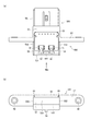
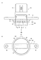
次に、ハウジング40に磁気検出モジュール90を取り付ける構造について説明する。本実施形態では、取付部の形状又は大きさが異なる二つの仕様のハウジング40を想定する。図2に示すハウジング401は、電動パワーステアリング装置のステアリングシャフトに設けられるコラム搭載タイプのハウジングである。図3に示すハウジング402は、ステアリングシャフト先端のピニオンギアと車輪とを連結するラック軸に設けられるラック搭載タイプのハウジングである。
Next, a structure for attaching the
ラック搭載タイプのハウジング402は、車両走行時等に路面から雨水等がかかる環境にあり、取付部の隙間からハウジング内部に水が浸入することを防止するため、取付部にシール材を設ける必要がある。一方、車室内に設けられるコラム搭載タイプのハウジング401では水が浸入するおそれがないため、取付部にシール材を設ける必要が無い。
The rack-mounted
つまり、車両におけるトルク検出装置10の搭載部位に応じて非防水仕様のハウジング401と防水仕様のハウジング402とが存在する。ハウジング401は「第1の仕様のハウジング」に相当し、ハウジング402は「第2の仕様のハウジング」に相当する。なお、本明細書において「防水」の「水」とは、純粋な水に限らず、ハウジングに浸入するおそれがある液体全般を意味するものとする。
That is, there are a
ハウジング401、402は、いずれも軸Oを中心軸とする略円筒状を呈し、外周の一部に平坦な取付板400が形成されている。ハウジング401、402の説明において、便宜上、図2(a)、図3(a)における上側を「上」、下側を「下」として記す。取付板400は、中心軸Oを含む平面に跨って取付穴41、42が形成されており、取付穴41、42の周方向両側にボルト等の固定用穴48が形成されている。二点鎖線は、図7、図8に示すフランジ57が当接する部分を示し、固定用穴48は、フランジ57の固定用穴58の位置に対応する。
Each of the
図2(a)、(b)に示すように、コラム搭載タイプのハウジング401では取付穴41は略長方形状に形成されている。取付穴41の中央下部には一つの回転規制溝44が形成されており、取付穴41の両サイド上部には二つの回転規制溝45が形成されている。中央下部の回転規制溝44は比較的浅く形成されており、両サイド上部の回転規制溝45は比較的深く形成されている。回転規制溝44、45の機能については図5(b)を参照して後述する。
As shown in FIGS. 2A and 2B, in the column-mounted
図3(a)、(b)に示すように、ラック搭載タイプのハウジング402では、取付穴42は、深さ方向の奥側にある略長方形のケース穴421、深さ方向の真ん中にある円形のシール穴422、端面側にある円形のインロー穴423から構成されている。また、インロー穴423の中央上部には、インロー穴423に連続して一つの回転規制溝471が形成されている。回転規制溝471の機能については図6(b)を参照して後述する。
As shown in FIGS. 3A and 3B, in the rack-mounted
このように取付部の形状や大きさが異なる二種類のハウジング401、402に対する磁気検出モジュール90の仕様として、それぞれ専用のケースを製造することもできる。しかし、その場合、二種類の樹脂成形金型が必要となったり、二種類のケースの生産調整や在庫管理工数が発生したりする。そこで第1、第2実施形態では、共通の構成要素を用いた簡易な構成変更により、仕様が異なる二種類のハウジング401、402へ選択的に取付可能な磁気検出モジュールを提供することを目的とする。
As described above, as the specifications of the
(第1実施形態)
続いて、第1実施形態の磁気検出モジュールの具体的構成について説明する。第1実施形態は、ケース共用化に関する基本的な技術的思想が反映されたものであり、第2実施形態は、第1実施形態に対し、外部からの磁気ノイズを遮断する磁気シールド部材をさらに備えるものである。以下、各実施形態の検出装置、及び磁気検出モジュールの符号について、「10」及び「90」に続く3桁目に実施形態の番号を付す。構成部材の符号については、その実施形態に特有の構成の場合、同様に3桁目に実施形態の番号を付し、前述の実施形態と実質的に同じ構成の場合、前述の実施形態の符号を援用する。
(1st Embodiment)
Subsequently, a specific configuration of the magnetic detection module of the first embodiment will be described. The first embodiment reflects the basic technical idea of sharing the case, and the second embodiment is different from the first embodiment in that a magnetic shield member that blocks external magnetic noise is further provided. It is provided. Hereinafter, the numbers of the embodiments are given to the third digits following “10” and “90” for the reference numerals of the detection device and the magnetic detection module of each embodiment. Regarding the reference numerals of the constituent members, in the case of the configuration specific to the embodiment, the number of the embodiment is similarly given to the third digit, and in the case of the configuration substantially the same as the above-described embodiment, the reference numeral of the above-described embodiment is used. Invite.
図4〜図8を参照し、第1実施形態のトルク検出装置101、及び磁気検出モジュール901の構成を説明する。磁気検出モジュール901は、ケースアセンブリ500と、キャップ801とを備える。ケースアセンブリ500は、ケース501、及び、ケース501の箱部51に収納された磁束誘導部材601、602、磁気センサ71、72、基板70等を備える。磁束誘導部材601、602、及び磁気センサ71、72については、図1を参照して上述した通りである。基板70は、磁気センサ71、72の他にセンサ信号の出力回路等が搭載される。
The configurations of the
ケース501は、樹脂で成形され、直方体状の箱部51、外部の処理装置に信号を伝送するハーネスが接続されるコネクタ部56、及び、ハウジング401、402への取付時の固定用穴58が形成されたフランジ部57等を有する。箱部51の底とコネクタ部56の底との間には、基板70に接続される端子73がインサート成形されている。磁気センサ71、72が搭載された略長方形の基板70は、箱部51の底に設置される。
The
以下、説明の便宜上、箱部51の開口端52側を上とし、箱部51の底側を下とする。また、箱部51の磁気センサ71、72が搭載される側を前方とし、コネクタ部56側を後方とする。箱部51のフランジ部57から前方に位置するケース501の端部は挿入部53をなしている。[図面の簡単な説明]の欄では、開口端52側から視た図を平面図と表し、挿入部53側から視た図を正面図と表す。以下の説明で、「平面視にて」は「開口端52側から視たとき」の意味で用いる。
Hereinafter, for convenience of description, the opening
図7等に示すように、挿入部53は、前壁531、側壁532、底壁533を含む直方体状である。両側の側壁532の開口端52側の縁には、上方に突出する「誤組み付け防止部」兼「回転規制部」としての突起部55が形成されている。また、箱部51の下面において、左右方向における中央部であって、前後方向におけるフランジ部57の近傍に、下方に突出する「誤組み付け防止部」兼「回転規制部」としての突起部54が形成されている。
As shown in FIG. 7 and the like, the
「誤組み付け防止部」は、ケース501又はキャップ801をハウジング40に組み付けるとき所定の相対角度に位置する姿勢のみで組み付け可能とし、所定の相対角度以外に位置する姿勢での誤組み付けを防止する。「回転規制部」は、ケース501又はキャップ801をハウジング40に組み付けた後のハウジング40に対する回転を規制する。
The “mis-assembly prevention section” enables the
一組の磁束誘導部材601、602は、それぞれ、平面視にて長方形帯状であり磁束を集める本体600と、本体600から直交方向に延びる二つの延設部61、62を有し、各延設部61、62が磁気センサ71、72を上下方向に挟むように設置される。言い換えれば磁気センサ71、72は、一組の磁束誘導部材601、602の間に配置される。磁束誘導部材601、602は、ハウジング40内に設けられる筒状のヨーク31、32のリング部35、36に本体600の少なくとも一部が対向し、ヨーク31、32に形成された磁気回路から磁束を誘導する。以下、磁束誘導部材601、602の長方形帯状の形状を簡単に「直線状」と表す。磁束誘導部材601、602の詳細な構成及び作用については後述する。
Each of the pair of magnetic
磁束誘導部材601、602、磁気センサ71、72、基板70が収納された後、ケース501の箱部51は、開口端52から溶融樹脂でポッティングされ、収納部品が固定される。また、図6(b)に破線で示すように、開口端52を塞ぐフタ59が別部品として用いられてもよい。その場合、上側の磁束誘導部材601は、フタ59と一体にインサート成形可能である。なお、他の実施形態では、フタ59を用いず溶融樹脂のポッティングのみ、或いは、ポッティングせずフタ59のみで開口端52を塞いでもよい。
After the magnetic
こうして、ケース501に磁束誘導部材601、602、磁気センサ71、72、基板70が収納されたケースアセンブリ500が構成される。ケースアセンブリ500は、単独で非防水仕様のハウジング401に取付可能である。また、挿入部53にキャップ801が装着された状態で、防水仕様のハウジング402に取付可能である。非防水仕様のハウジング401に取り付けられる場合、単独のケースアセンブリ500が「磁気検出モジュール」を構成する。なお、キャップ801が装着される相手は製造工程的にはケースアセンブリ500であるが、部品単位での観点から、「キャップ801はケース501に装着される」と表すこともできる。
Thus, the
キャップ801は、樹脂で成形され、円板状のキャップ本体811のケース501側の端面に、ケース501の挿入部53が挿入される受容穴83が形成されている。受容穴83は、ケース501の挿入部53の形状に対応した長方形状に開口しており、受容穴83の深さは、キャップ本体811の厚さよりも深い。受容穴83の両サイド上部には、突起部55が挿入される突起収容溝85が形成されている。これにより、挿入部53を受容穴83に挿入する際、180°反対向きに挿入することが防止される。
The
キャップ本体811のケース501とは反対側の端面には、端面に接続し、受容穴83の底部を覆って袋状とする封止部84が形成されている。封止部84は、キャップ本体811からケース501とは反対側に直方体状に突出し、外壁が受容穴83の底部の内壁に対し一回り大きく形成されている。要するに、封止部84の外壁と受容部83の内壁との間は、水が漏れないように連通が遮断されている。
On the end surface of the
キャップ本体811の外周には、受容穴83の開口面側の外鍔部863、及び、封止部84の突出側の内鍔部88が平行に設けられ、外鍔部863と内鍔部88との間に外周溝82が形成されている。外鍔部863の中央上部には径外方向に突出する「誤組み付け防止部」兼「回転規制部」としての突起部871が形成されている。
An
外周溝82には、「シール材」としてのOリング89が装着される。このとき、Oリング89の内周面は外周溝82の底壁に当接する。Oリング89は、キャップ801とケース501とを組み付ける前に外周溝82に装着されてもよく、キャップ801とケース501とを組み付けた後に外周溝82に設けられてもよい。
An O-
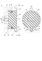
図5(b)に、ケースアセンブリ500が単独で非防水仕様のハウジング401の取付穴41に取り付けられたトルク検出装置101を示す。ケース501の挿入部53は略長方形の取付穴41に挿入される。このとき、下部の突起部54が回転規制溝44に挿入され、上部両サイドの突起部55が回転規制溝45に挿入される。したがって、ケースアセンブリ500がハウジング401に組み付けられるとき、取付穴41に180°反対向きに誤組み付けされることが防止される。また、組み付け後、ハウジング401に対するケースアセンブリ500の回転が規制される。
FIG. 5B shows the
図6(b)に、ケースアセンブリ500にキャップ801が装着された磁気検出モジュール901が防水仕様のハウジング402の取付穴42に取り付けられたトルク検出装置101を示す。キャップ801の封止部84は略長方形のケース穴421に挿入され、内鍔部88はシール穴422に挿入され、外鍔部863はインロー穴423に挿入される。このとき、突起部871が回転規制溝471に挿入されることで、磁気検出モジュール901がハウジング402に組み付けられるとき、取付穴42に180°反対向きに誤組み付けされることが防止される。また、組み付け後、ハウジング402に対する磁気検出モジュール901の回転が規制される。
FIG. 6B shows the
取付穴42に取り付けられた状態で、Oリング89の外周面はシール穴422の内壁に押し付けられる。したがって、両方向矢印Cpで示すように、Oリング89は、径方向に圧縮され、軸シールに用いられる。軸シールは面シールに比べ、シール関連部品の寸法ばらつきや組付時の傾きの影響を受けにくくシール機能に優れている。
The outer peripheral surface of the O-
次に図9〜図12を参照し、キャップ801とハウジング402との取付における「誤組み付け防止部」及び「回転規制部」の構成が異なる第1実施形態の変形例について説明する。図9(a)、図11(a)は、キャップ801をハウジング402に取り付けた状態を示す模式断面図である。模式断面図では、キャップ801とケース501とを融合した模式的な断面を示し、図6(b)のような内部構造の正確な図示を省略する。また、キャップ本体811の先端面から突出する袋部84に覆われた角柱状の部分を「センサ部840」と記す。センサ部840には磁気センサ71、72が収納される。ここで、「収納される」には、モールドされる構成が含まれる。
Next, with reference to FIGS. 9 to 12, a description will be given of a modification of the first embodiment in which the configurations of the “erroneous assembly preventing section” and the “rotation restricting section” in mounting the
図9(b)、図11(b)は、キャップ801の基端側において、キャップ801又はハウジング402に設けられた「誤組み付け防止部」及び「回転規制部」を示す径方向断面図である。図10、図12は、図3(b)に対応するハウジング402の取付穴42の斜視図である。
FIGS. 9B and 11B are radial cross-sectional views showing the “mis-assembly preventing section” and the “rotation restricting section” provided on the
図9、図10に示す第1変形例では、キャップ本体811の上部に図4等と同様の突起部871が形成されると共に、キャップ本体811の下部に、所定の間隔を隔てて径外方向に略平行に突出する一対の双突起部872が形成される。ハウジング402の端面には、双突起部872に挟まれる回転規制凸部472が形成されている。一方、ハウジング402の端面の突起部871に対応する部分は、凹凸の無い平坦な端面となっている。
In the first modified example shown in FIGS. 9 and 10, a
双突起部872が回転規制凸部472を挟む回転位置でキャップ801がハウジング402に組み付けられることで、双突起部872は「回転規制部」として機能する。また、キャップ801をハウジング402に組み付けるとき、回転方向の位置を180°誤った位置で組み付けようとすると、突起部871がハウジング402の回転規制凸部472に干渉するため、「誤組み付け防止部」として機能する。このように第1変形例では、キャップ本体811の突起部871及び双突起部872が、それぞれハウジング402の回転規制凸部472を利用して「誤組み付け防止部」及び「回転規制部」の機能を分担する。
When the
図11、図12に示す第2変形例では、キャップ本体811の下部に径外方向に突出する突起部874が形成される。キャップ本体811の上部は凹凸の無い単純な円筒面となっている。ハウジング402は、取付穴42の下方の台座部46に、突起部874の先端が係合する回転規制溝474が形成されている。また、回転規制溝474とは反対側の取付穴42の縁部に干渉凸部473が形成されている。
In the second modification shown in FIGS. 11 and 12, a
突起部874の先端が回転規制溝474に係合する回転位置でキャップ801がハウジング402に組み付けられることで、突起部874は「回転規制部」として機能する。また、キャップ801をハウジング402に組み付けるとき、回転方向の位置を180度誤った位置で組み付けようとすると、突起部874がハウジング402の干渉凸部473に干渉するため、「誤組み付け防止部」として機能する。このように第2変形例では、キャップ本体811の突起部874が、ハウジング402の干渉凸部473を利用して「誤組み付け防止部」として機能し、且つ、ハウジング402の回転規制溝474を利用して「回転規制部」として機能する。
The
次に図13、図14を参照し、本実施形態の磁束誘導部材601、602の構成について説明する。図13、図14には、ケースアセンブリ500をハウジングに取り付けた状態でのヨーク31、32と、磁束誘導部材601、602及び磁気センサ71、72との間の磁束伝達作用を平面図、側面図、軸方向断面図の三図によって示す。平面図は軸方向の第1軸11側から視た図を意味し、側面図は径方向から視た図を意味する。
Next, the configuration of the magnetic
「平面図」は、厳密には上側の磁束誘導部材601の上部で多極磁石14及びヨーク31、32の爪33、34を切断した径方向断面図であるが、磁束誘導部材601の視点から「平面図」と記す。また、径方向断面視にて実際に環が見えるのは下側のヨーク32のみであるが、説明の都合上、上側のヨーク31を含めて符号を「31、32」と付す。
The “plan view” is strictly a radial cross-sectional view in which the
図13(a)の平面図には、中心軸Oを通って左右方向に延びる「基準線X」が記載される。基準線Xは、二つの磁気センサ71、72の中間位置と中心軸Oとを結ぶ仮想直線と定義される。言い換えれば、二つの磁気センサ71、72は、基準線Xに対して対称に配置される。なお、磁気センサが一つの形態では、基準線Xは、磁気センサと中心軸Oとを結ぶ仮想直線と定義される。
In the plan view of FIG. 13A, a “reference line X” extending in the left-right direction through the central axis O is described. The reference line X is defined as an imaginary straight line connecting an intermediate position between the two
図13(b)の側面図は、基準線Xに沿って磁気センサ71、72を径方向外側から視た図である。二点鎖線は爪33、34の外形を示す。側面図では、トーションバー13、多極磁石14の図示を省略する。図14の軸方向断面図は、中心軸O及び基準線Xを含む平面での断面図である。軸方向断面図ではトーションバー13の図示を省略し、多極磁石14は外形線のみを示す。
The side view of FIG. 13B is a diagram in which the
本実施形態では、平面視にて、磁束誘導部材601、602の本体は、基準線Xに対して対称な長方形帯状、すなわち直線状に形成されている。磁束誘導部材601、602の長手方向の辺は、基準線Xに直交する直線である。
In the present embodiment, the main bodies of the magnetic
磁束誘導部材601、602は、本体600から径方向外側に延びる延設部61、62を有しており、「本体600における延接部61、62への分岐部位」をS部と記す。「延接部61、62への分岐部位」は、実質的に磁気センサ71、72の近傍を意味する。なお、「S部」は多極磁石14のS極と同じ記号であるが、それらの区別は自明であり、混同のおそれはない。また、基準線Xを挟み、磁束誘導部材601、602の本体600とヨーク31、32との対向範囲におけるヨーク31、32の周方向両端に対応する部位を「本体600の周端部63、64」と定義し、図中、破線ハッチングで示す。S部から中心軸Oまでの距離dsは、周端部63、64から中心軸Oまでの距離deよりも短い。
The magnetic
側面視及び軸方向断面視にて、磁束誘導部材601、602は、軸方向の内側において一定のギャップでヨーク31、32の環状面に対向し、その対向面積は、磁気センサ7172に近い中間部65で相対的に大きく、周端部63、64に向かうほど小さくなる。延設部61、62への分岐部位であるS部では、周端部63、64に比べ対向面積が大きいため、磁束誘導部材601、602とヨーク31、32との間の単位面積当たりの磁気パーミアンスが大きくなる。ここで、「単位面積当たり」の意味は、部位毎に磁気パーミアンスを比較する範囲の面積を同一とすることを明確に記すことにある。以下の説明では、都度の「単位面積当たり」の記載を省略し、「磁気パーミアンス」とは「単位面積当たりの磁気パーミアンス」を意味するものとして解釈する。
In a side view and an axial cross-sectional view, the magnetic
二つの磁気センサ71、72は、それぞれ延接部61、62の間に配置される。延接部61、62は、磁気センサ71、72が間に配置される部分においてギャップが最小となるように軸方向に折り曲げられ、段差を有している。
The two
次に図15を参照し、この構成により信号が大きくなる理由を説明する。図15に、磁束誘導部材601、602とヨーク31、32との間の磁気パーミアンスについて、基準線Xからの距離または回転角度と磁気パーミアンスとの相関図を示す。磁気パーミアンスPは、材の透磁率μ、対向面積A、ギャップ長Lを用いて、式(1)で表される。
P=μ(A/L) ・・・(1)
Next, with reference to FIG. 15, the reason why the signal is increased by this configuration will be described. FIG. 15 shows a correlation diagram between the distance or the rotation angle from the reference line X and the magnetic permeance between the magnetic
P = μ (A / L) (1)
ここで、磁束誘導部材601、602は単一の軟磁性材質で形成されることを前提とすると、磁束誘導部材601、602とヨーク31、32との対向面積Aが大きいほど、又は、ギャップ長Lが短いほど、磁気パーミアンスPは大きくなる。本実施形態では、磁束誘導部材601、602とヨーク31、32とのギャップは一定であるが、対向面積が中間部65から周端部63、64に向かうほど小さくなるため、中間部65の磁気パーミアンスが周端部63、64の磁気パーミアンスよりも大きくなる。その相関特性は、図15中、P1のような直線、P2のような変曲点の無い単純な曲線、P3のようなS字曲線或いはステップ状の折れ線等、どのような特性であってもよい。
Here, assuming that the magnetic
磁気センサ71、72は、中間部65の近くの本体600から分岐した延設部61、62に設置され、磁束誘導部材601、602の本体600における延接部61、62への分岐部位は、実質的に「磁気センサ71、72の近傍」を意味する。そして、磁束誘導部材601、602は、延接部61、62への分岐部位で、周端部63、64に比べ、「磁束誘導部材601、602とヨーク31、32との間の単位面積当たりの磁気パーミアンス」が大きくなるように構成されている。これにより、磁気センサ71、72の信号を大きくすることができる。
The
次に図16のフローチャートを参照し、磁気検出モジュールの製造方法について説明する。フローチャートの説明で記号Sは「ステップ」を表す。S10の収納工程では、磁束誘導部材601、602、磁気センサ71、72、基板70等がケース501の箱部51に収納される。そして、例えば箱部51の残りの空間に溶融樹脂がポッティングされ、磁気センサ71、72が固定される。また、箱部51にフタ58が被せられてもよい。こうして収納工程S10で、ケースアセンブリ500が製造される。
Next, a method for manufacturing the magnetic detection module will be described with reference to the flowchart in FIG. In the description of the flowchart, the symbol S represents “step”. In the storage step of S10, the magnetic
S20の選択工程では、取付対象であるハウジングの仕様に応じて、ケースアセンブリ500を単独で用いるか、又は、ハウジングの仕様毎に設定されるキャップ801をケース501の端部に装着して用いるかが選択される。第1実施形態では、シール材が不要な非防水仕様のハウジング401、又は、シール材を要する防水仕様のハウジング402のいずれに取り付けられるかが選択されるものとする。
In the selection step of S20, depending on the specification of the housing to be attached, whether the
S25では選択結果が判断される。防水仕様のハウジング402に取り付けられる場合、S25でYESと判定され、S30の装着工程に移行する。非防水仕様のハウジング401に取り付けられる場合、S25でNOと判定され、処理を終了する。この場合、ケースアセンブリ500は、キャップ801が装着されることなく単独で用いられる。
In S25, the selection result is determined. When it is mounted on the
S30の装着工程では、キャップ801がケース501に装着され固定される。第1実施形態の構成では、ケース501の端部に形成された挿入部53が、キャップ801に形成された受容穴83に挿入される。その後、ケース501の挿入部53とキャップ801の受容穴83との接合部がレーザ溶着等により溶着される。ここで、図4〜図8に示される受容穴83の底部を覆って袋状とする封止部84が設けられない構成においても、磁気センサ71、72を囲む接合部が一周溶着されることで、受容穴83の底部からの漏水を防止することができる。
In the mounting step of S30, the
装着工程においてキャップ801は接着剤で固定されてもよい。また、収納工程で溶融樹脂がポッティングされる場合、ポッティングの硬化と接着剤の硬化とは同時に行われることが好ましい。これにより、サイクルタイムを短縮することができる。
In the mounting process, the
以上のように第1実施形態の磁気検出モジュール901は、キャップ801の有無によりハウジング40への取付仕様を変更可能である。具体的には、防水仕様のハウジング402に対してはシール材89が設けられるキャップ801がケース501に装着された磁気検出モジュールが供給される。また、非防水仕様のハウジング401に対してはキャップ801が装着されないケースアセンブリ501が単独で磁気検出モジュールとして供給される。よって、例えばケース501を樹脂成形により製造する場合、ケース501の金型は一種類でよく、在庫管理も簡易になる。
As described above, the specification of the
(第2実施形態)
次に図17、図18を参照し、磁気シールド部材が設けられた第2実施形態の磁気検出モジュール902について説明する。磁気シールド部材は、鉄やパーマロイ等の軟磁性体で形成され、外部からの磁気ノイズを遮断する。
(2nd Embodiment)
Next, a
図17に示す形態は、非防水仕様のハウジング401に単独で取り付けられるケースアセンブリ500の挿入部53に長方形枠状の磁気シールド部材37が設けられている。詳しくは、ケース501に溶融樹脂がポッティングされた後、磁気センサ71、72を四方から囲むように磁気シールド部材37が被せられる。したがって、磁気センサ71、72に向かう磁気ノイズが効果的に遮断される。
In the embodiment shown in FIG. 17, a rectangular frame-shaped
図18に示す形態は、防水仕様のハウジング402に取り付けられる磁気検出モジュール902のキャップ801に、一対のアーチ状の磁気シールド部材38が設けられている。一対の磁気シールド部材38は、封止部84を上下方向から囲むように設けられる。図18(b)に示すように、磁気シールド部材38は、奥行き方向の中心線Dsが磁気センサ71、72に重なるように配置される。したがって、磁気センサ71、72に向かう磁気ノイズが効果的に遮断される。
In the embodiment shown in FIG. 18, a pair of arch-shaped
(第3実施形態)
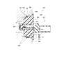
次に図19を参照し、第3実施形態について説明する。第3実施形態のトルク検出装置103は、内壁が円筒状の取付穴42を有するハウジング402と、取付穴42に取り付けられた磁気検出モジュール903と、を備える。図19には図示しないが、ハウジング402の内部には、トルクの大きさに応じて発生する磁束を伝達する一組のヨーク31、32が設けられている。磁気検出モジュール903は、一つ以上の磁気センサ71、72により、ヨーク31、32から伝達される磁束を検出する。
(Third embodiment)
Next, a third embodiment will be described with reference to FIG. The
第3実施形態の磁気検出モジュール903は、第1実施形態と同様に、ケース501の先端に円板状のキャップ803が装着されている。キャップ803におけるキャップ本体813の外周面は、取付穴42の内壁に対向する。ただし、第1実施形態のキャップ801では、外鍔部863と内鍔部88との間に外周溝82が形成されているのに対し、第3実施形態のキャップ803には内鍔部が設けられておらず、径方向の段差部823が外周に形成されている。図19の例では、段差部823に、軸シール用のシール材としてOリング89が装着されているが、他の実施例ではOリング89は無くてもよい。段差部823は、キャップ本体813の基端側の大径部866と、先端側の小径部865との段差により構成される。大径部866及び小径部865は、「大軸部」及び「小軸部」に相当する。
In the
取付穴42は、端面428側に対して奥から順に、ケース穴424、小径穴425、大径穴426、面取り部427を有する。大径穴426及び小径穴425は、「大穴」及び「小穴」に相当する。キャップ803の大径部866は大径穴426に挿入され、小径部865は小径穴425に挿入される。大径部866の基端側には、ハウジング402の端面428に当接する鍔部868が形成される。また、キャップ本体813の先端面からセンサ部840が突出している。センサ部840の先端は、一組のヨーク31、32のリング部35、36同士の間に挿入される。
The mounting
第3実施形態のトルク検出装置103では、大径部866と大径穴426、又は小径部865と小径穴425との嵌合隙間と、センサ部840とヨークのリング部との隙間との寸法関係が適切に調整される。その寸法関係に関する構成及び作用効果は、次の第4実施形態のトルク検出装置104による構成及び作用効果と同じであるため、第4実施形態において一緒に説明する。
In the
(第4実施形態)
次に図20を参照し、第4実施形態について説明する。第4実施形態のトルク検出装置104は、内壁が円筒状の取付穴42を有するハウジング402と、取付穴42に取り付けられた磁気検出モジュール904と、を備える。第3実施形態と同様に、ハウジング402の内部には、トルクの大きさに応じて発生する磁束を伝達する一組のヨーク31、32が設けられている。磁気検出モジュール904は、一つ以上の磁気センサ71、72により、ヨーク31、32から伝達される磁束を検出する。
(Fourth embodiment)
Next, a fourth embodiment will be described with reference to FIG. The
磁気検出モジュール904は、複数のハウジングへ選択的に取付可能とすることを目的としておらず、取付対象は、内壁が円筒状の取付穴42を有するハウジング402に限られる。第4実施形態では、ハウジング402への磁気検出モジュール904の挿入時に、センサ部840とハウジング402側の部材との干渉を防止することが目的とされる。そのため、第4実施形態の磁気検出モジュール904は、別部材のキャップがケースの端部に装着される構成ではなく、一体のケース504により構成されている。ケース504は、図19に示す第3実施形態においてケース501にキャップ803が装着された状態と同等の形状に、樹脂で一体に形成されている。つまり、ケース501とキャップ803とを融合したものが第4実施形態の一体のケース504である。
The
第3実施形態のキャップ803のキャップ本体813に相当する部分を、第4実施形態では「円筒部814」と呼ぶ。円筒部814は、「筒部」に相当し、取付穴42の内壁に対向する。また、円筒部814の先端面からセンサ部840が突出している。逆に言えば、第4実施形態のケース504の円筒部814が別部材のキャップ803のキャップ本体813により構成された形態が、第3実施形態に相当する。要するに、第3実施形態のうちOリング89が装着される形態は、「防水仕様及び非防水仕様の複数のハウジングへの選択的取付」及び「磁気センサとハウジング側部材との干渉防止」の二つの目的を両立するものと位置づけられる。
A portion corresponding to the
したがって、第4実施形態の円筒部814、及び、円筒部814が対向する取付穴42の構成は、第3実施形態のキャップ本体813、及び、キャップ本体813の外周面が対向する取付穴42の構成と実質的に同じである。取付穴42は、開口側に形成される大径穴426、及び、大径穴426の奥に形成される小径穴425を有する。
Therefore, the
円筒部814は、基端側から磁気センサ71、72が配置される先端側に向かって、ハウジングの端面428に当接する鍔部868、大径穴426に挿入される大径部866、及び、小径穴425に挿入される小径部865を有する。図20の例では、小径部865の外周にシール材としてOリング89が装着されているが、他の実施例ではOリング89は無くてもよい。Oリング89は、小径穴425の内壁との間で軸シールに用いられる。
The
次に図21、図22を参照し、第3実施形態のトルク検出装置103におけるキャップ本体813と取付穴42の内径との寸法関係、又は、第4実施形態のトルク検出装置104における円筒部814の外径と取付穴42の内径との寸法関係について説明する。この部分の説明では、代表として、第4実施形態の「円筒部814」等の用語を用いる。第3実施形態については、例えば「円筒部814」を「キャップ本体813」に読み替えればよい。
21 and 22, a dimensional relationship between the
図21、図22のトルク検出装置104の断面図示は、図9、図11と同様に模式的なものである。円筒部814の先端面から突出する角柱状の部分である「センサ部840」には、磁気センサ71、72が収納される。「収納される」には、モールドされる構成が含まれる。磁気検出モジュール904の取付穴42への挿入時に、位置ずれや傾きにより、センサ部840がハウジング402側の部材と干渉すると、磁気センサ71、72の破損や特性変化が生じるおそれがある。そこで第4実施形態では、センサ部840とハウジング402側の部材との干渉を防止する。
Cross-sectional views of the
具体的には、センサ部840は、一組のヨーク31、32の互いに対向するリング部35、36同士の間に挿入される。リング部35、36の間に生じる磁束がセンサ部840を通過することで、磁気センサ71、72が磁束を検出する。センサ部840とリング部35、36との最小間隔を「センサマージンμ」と定義する。図21、図22に示すように、リング部35、36の中心に対してセンサ部840の位置が偏っていない場合には、センサマージンμは、リング部35、36間の距離からセンサ部840の厚さを差し引いた長さの2分の1となる。
Specifically, the
図21及び図22は、径の寸法関係が異なる2パターンの実施例を示す。各部の寸法の記号を以下のように定義する。「片側嵌合隙間」は、穴の直径と軸の直径との嵌合隙間の2分の1に相当する。記号中の文字「h」はハウジング、「s」はセンサを表す。
φDh1:大径穴426の内径(=φds1+2×ε1)
φds1:大径部866の外径
ε1:大径穴426と大径部866との片側嵌合隙間
φDh2:小径穴425の内径(=φds2+2×ε2)
φds2:小径部865の外径
ε2:小径穴425と小径部865との片側嵌合隙間
FIG. 21 and FIG. 22 show an embodiment of two patterns having different dimensional relationships of diameters. The symbols for the dimensions of each part are defined as follows. The “one-sided fitting gap” corresponds to half the fitting gap between the diameter of the hole and the diameter of the shaft. The letter “h” in the symbol represents the housing, and “s” represents the sensor.
φDh1: inner diameter of large diameter hole 426 (= φds1 + 2 × ε1)
φds1: outer diameter of the large-
φds2: outer diameter of the
図21に示す実施例では、大径穴426と大径部866との片側嵌合隙間ε1が例えば0.1ミリ未満の微小隙間に設定される。つまり、大径穴426と大径部866との嵌合がインロー構造となっている。したがって、円筒部814が取付穴42に挿入されるときの同軸度、直角度等の精度が確保される。また、隙間ε1は、センサマージンμよりも小さく設定されている(ε1<μ)。好ましくは、隙間ε1は、センサマージンμよりも極めて小さく設定されている(ε1<<μ)。なお、小径穴425と小径部865との片側嵌合隙間ε2は、隙間ε1と同等以上であればよい。
In the embodiment shown in FIG. 21, the one-side fitting gap ε1 between the large-
この構成における円筒部814及び取付穴42の軸方向寸法について、大径穴426の挿入端(すなわち、面取り部427と大径穴426との境界)からヨーク31、32のリング部35、36の外縁までの距離を「ハウジング側距離Lh1」と定義する。また、大径部426と小径部425との境界からセンサ部840の先端までの距離を「センサ側距離Ls1」と定義する。ハウジング側距離Lh1は、センサ側距離Ls1より長く設定されている。
Regarding the axial dimensions of the
このような寸法設定により、円筒部814の軸が取付穴42の軸に対して最大に傾き、周方向の片側で大径部866の外壁が大径穴426の内壁に接触した場合でも、センサ部840の先端位置の変動はセンサマージンμよりも小さく抑えられる。したがって、磁気検出モジュールの挿入時に、センサ部840とハウジング側部材であるヨーク31、32との干渉を防止することができる。
With such a dimension setting, even when the axis of the
図22に示す実施例では、小径穴425と小径部865との片側嵌合隙間ε2が例えば0.1ミリ未満の微小隙間に設定される。つまり、小径穴425と小径部865との嵌合がインロー構造となっている。したがって、円筒部814が取付穴42に挿入されるときの同軸度、直角度等の精度が確保される。また、隙間ε2は、センサマージンμよりも小さく設定されている(ε2<μ)。好ましくは、隙間ε2は、センサマージンμよりも極めて小さく設定されている(ε2<<μ)。なお、大径穴426と大径部866との片側嵌合隙間ε1は、隙間ε2と同等以上であればよい。
In the embodiment shown in FIG. 22, the one-side fitting gap ε2 between the small-
この構成における円筒部814及び取付穴42の軸方向寸法について、小径穴425の挿入端(すなわち、大径穴426と小径穴425との境界)からヨーク31、32のリング部35、36の外縁までの距離を「ハウジング側距離Lh2」と定義する。また、円筒部814の先端面からセンサ部840の先端までの距離を「センサ側距離Ls2」と定義する。ハウジング側距離Lh2は、センサ側距離Ls2より長く設定されている。
Regarding the axial dimension of the
このような寸法設定により、円筒部814の軸が取付穴42の軸に対して最大に傾き、周方向の片側で小径部865の外壁が小径穴425の内壁に接触した場合でも、センサ部840の先端位置の変動はセンサマージンμよりも小さく抑えられる。したがって、磁気検出モジュールの挿入時に、センサ部840とハウジング側部材であるヨーク31、32との干渉を防止することができる。
With such a dimension setting, even when the axis of the
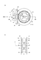
次に図23〜図25を参照し、取付穴42に対する円筒部814の回転規制及び誤組み付け防止の構成について説明する。例えば特許文献2(特許第4753545号公報)の従来技術では、磁性リングが磁気ヨークの径外方向に配置され、磁気ヨークと径方向に対向している。この構成では、位置決めにより、磁性リングと磁気ヨークとの同心度を確保することが有効であるが、回転方向の位置精度は性能に対してあまり影響しない。それに対し、一組のヨーク31、32のリング部35、36同士の間に磁気センサ71、72が配置される第4実施形態のトルク検出装置104では、取付穴42に対する円筒部814の回転方向の位置決めが重要となる。また、磁気検出モジュール904を例えば180°誤った方向に組付けられることを防止することが重要となる。
Next, with reference to FIGS. 23 to 25, a configuration for restricting the rotation of the
図23〜図25の各図(a)は、図21、図22のA−A線断面での円筒部814の断面を示す。各図(b)は、図21、図22のB方向矢視によるハウジングの取付穴の正面視を示す。なお、図23〜図25の各形状に応じた図21、図22の組付断面の変更箇所については、図示を省略する。また、例えば防水不要のコラム搭載タイプに用いられる場合、各図においてOリング89を無くしてもよい。
FIGS. 23A to 25A show cross sections of the
図23(a)、(b)に示す例では、大径部866の周方向の一箇所に径外方向に突出する突起部875が形成されている。また、取付穴42の対応する箇所に回転規制溝475が形成されている。この構成例は、図3(a)、(b)、図4等の突起部871及び回転規制部471の構成例と類似している。ただし、図4の例では、インロー穴423に挿入された外鍔部863の外周に突起部871が形成されているのに対し、図23(a)の例では、大径部866の外周に突起部875が形成されている点が異なる。このように、円筒部814の外周面のどの部分に突起部が形成されても本質的な違いは無い。
In the example shown in FIGS. 23A and 23B, a
この例では、突起部875が回転規制溝475に係合することにより、円筒部814の回転が規制される。また、円筒部814と取付穴42との相対角度が正規の角度に位置する姿勢のみで組み付け可能とし、所定の相対角度以外に位置する姿勢での誤組み付けを防止する。このように突起部875及び回転規制溝475は、「誤組み付け防止部」兼「回転規制部」として機能する。
In this example, the rotation of the
図24(a)、(b)に示す例では、大径部866の周方向の一方に平坦部876が形成されている。また、取付穴42の対応する箇所に回転規制凹部476が形成されている。平坦部876は、突起部875の幅を広げ、且つ、大径部866の外径に対する突出長を短く変形した形態に相当する。図24(a)の例では、大径部866の外径に対する平坦部876の突出長をほぼ0としている。また、大径部866の外径よりもマイナス側(すなわち中心側)に平坦部876を形成し、大径部866の外周形状について、周方向の一部を直線で結んだD字状としてもよい。この例では、平坦部876が回転規制凹部476に係合することにより、平坦部876及び回転規制凹部476は、「誤組み付け防止部」兼「回転規制部」として機能する。
In the example shown in FIGS. 24A and 24B, a
図25(a)、(b)に示す例では、円形の大径部866に対し径外方向に離れた位置に分離部877が形成されている。分離部877は、二点鎖線で示す連結部878を介して、鍔部868と連結されている。また、取付穴42の対応する箇所に回転規制穴477が形成されている。例えばハウジング402に後加工で回転規制穴477を形成するような場合、形状が単純であるため加工が容易である。この例では、分離部877が回転規制穴477に嵌合することにより、分離部877及び回転規制穴477は、「誤組み付け防止部」兼「回転規制部」として機能する。
In the example shown in FIGS. 25A and 25B, a
図23〜図25の各構成において、突起部875、平坦部876、分離部877の位置は図示位置に限らず、周方向のどの位置でもよい。また、これらが周方向に複数配置されてもよい。ただし、「誤組み付け防止部」として機能させる場合、回転対称となる複数の位置が存在しないように、回転非対称な位置に複数配置される必要がある。さらに、図9〜図12に示す第1実施形態の変形例のように、ハウジング402側に凸部が設けられてもよい。
23 to 25, the positions of the protruding
(その他の実施形態)
(a)図4〜図8に示す形態のキャップ801は、先端部に袋状の封止部84が形成されているのに対し、図26に示す磁気検出モジュール905のように、先端が袋状になっていないキャップ805を用いてもよい。先端に封止部84が形成される形態に比べ、この形態では、先端の樹脂厚み分だけ、ヨーク31、32と磁束誘導部材601、602との対向部の距離(ギャップ)が小さくなるため、感度を向上させることができる。この場合、キャップ805とケース501との界面からの浸水を防止するため、図26(b)の(*)部に示す接触部分がレーザ溶着や接着剤にて封止されていることが必要である。
(Other embodiments)
(A) The
(b)第1、第2実施形態では、シール材としてのOリング89がキャップ801の外周溝82に装着され、ハウジング402の取付穴42の内壁との間で軸シールに用いられる。その他のシール材として、面シールに用いられるOリングやパッキン又はガスケット等がキャップに設けられてもよい。またシール材は、防水用のものに限らず、オイルシール用や気体シール用のものであってもよい。また、キャップ本体811の外周においてOリング89が装着される部分の形状は、外周溝82に限らず、第3、第4実施形態と同様に径方向の段差部であってもよい。
(B) In the first and second embodiments, the O-
(c)第1、第2実施形態では、ケース501へのキャップ801の装着の有無により、防水仕様及び非防水仕様の二種類のハウジング401、402への取付が選択可能となる。その他、例えば防水仕様の中でも軸シールのOリング仕様と面シールのパッキン仕様とがある場合や、Oリングのサイズ違いの仕様がある場合等に、各仕様に応じたキャップを選択してケースに装着可能としてもよい。或いは、取付部の形状やサイズが異なる複数の非防水仕様のハウジングに対するアダプタとして、キャップがケースに装着されてもよい。
(C) In the first and second embodiments, the attachment to the two types of
(d)磁気検出モジュールが備える磁気センサの数は、上記実施形態で例示される二つに限らず、一つでもよく三つ以上でもよい。また、磁気検出モジュールは磁束誘導部材601、602を備えず、ハウジング40内で発生した磁束が一組のヨーク31、32から磁気センサ71、72に直接伝達されてもよい。磁束誘導部材601、602を備える構成では、磁束誘導部材の本体の形状は直線形状に限らず、ヨークに沿った円弧形状等であってもよく、延設部が設けられなくてもよい。また、磁束誘導部材は、一組のヨーク31、32と軸方向でなく径方向に対向してもよい。
(D) The number of magnetic sensors provided in the magnetic detection module is not limited to two as exemplified in the above embodiment, and may be one or three or more. Further, the magnetic detection module may not include the magnetic
(e)ケース501及びキャップ801は樹脂成形品に限らず、磁気検出に影響しない他の材料で製造されてもよい。また、ケース501へのキャップ801の装着方法は、ケース501の挿入部53をキャップ801の受容穴83に挿入し、接合部を溶着又は接着する方法に限らず、例えば圧入等によって装着してもよい。
(E) The
(f)ハウジング401、402への誤組み付け防止部及び回転規制部の形状は、上記実施形態に示す突起部、溝等に限らない。また、誤組み付け防止部及び回転規制部の位置や数は適宜設定してよい。さらに、両方の機能を兼ね備える形態に限らず、誤組み付け防止機能のみ、又は、回転規制機能のみを備えてもよい。例えば非対称形状により誤組み付け防止部が構成されてもよい。加えて、他の構成により誤組み付け防止や回転規制の目的が達成される場合等には、誤組み付け防止部や回転規制部が設けられなくてもよい。
(F) The shapes of the erroneous assembly preventing portions and the rotation restricting portions on the
(g)第4実施形態の円筒部814は、円筒状に限らず、楕円筒状、長円筒状、多角形筒状等を含めた「筒部」として形成されてもよい。第3実施形態のキャップ本体813についても同様である。楕円筒部や長円筒部等であれば、Oリングによるシール機能も確保される。また、楕円筒部であれば「径」を用いて表現可能であるが、非円筒状の筒部において「径」の概念が適用しにくい場合、大径部及び小径部を「大軸部」及び「小軸部」として一般化すればよい。また、これらが対向する取付穴の大径穴及び小径穴を「大穴」及び「小穴」として一般化すればよい。また、筒部の軸方向と直交し中心から周縁に向かう方向を擬似的な「径方向」として、インロー構造における径方向の片側での軸部と穴との隙間を「片側嵌合隙間」と解釈すればよい。
(G) The
(h)本発明の検出装置、又は本発明の磁気検出モジュールが適用される検出装置は、電動パワーステアリング装置のトルク検出装置に限らず、検出対象となる物理量の大きさに応じて発生する磁束を検出するものであればよい。発生した磁束は、ハウジング内部に設けられた一組のヨークにより伝達され、磁気検出モジュールの磁気センサによって検出される。例えば可動体の回転や直線移動に応じて発生する磁束を検出する回転検出装置、位置検出装置等として利用可能である。 (H) The detecting device to which the detecting device of the present invention or the magnetic detecting module of the present invention is applied is not limited to the torque detecting device of the electric power steering device, and the magnetic flux generated according to the magnitude of the physical quantity to be detected. May be used as long as it can detect. The generated magnetic flux is transmitted by a pair of yokes provided inside the housing and detected by a magnetic sensor of the magnetic detection module. For example, the present invention can be used as a rotation detecting device, a position detecting device, or the like that detects a magnetic flux generated in accordance with rotation or linear movement of a movable body.
以上、本発明はこのような実施形態に限定されるものではなく、その趣旨を逸脱しない範囲において、種々の形態で実施することができる。 As described above, the present invention is not limited to such an embodiment, and can be implemented in various forms without departing from the spirit thereof.
10(101−104)・・・トルク検出装置(検出装置)、
40(401、402)・・・ハウジング、
425・・・小径穴(小穴)、 426・・・大径穴(大穴)、
501、504・・・ケース、
500・・・ケースアセンブリ、
601、602・・・磁束誘導部材、
71、72・・・磁気センサ、
801、803、805・・・キャップ、
811、813・・・キャップ本体、 814・・・円筒部(筒部)、
865・・・小径部(小軸部)、 866・・・大径部(大軸部)、
89 ・・・Oリング(シール部材)、
90(901−905)・・・磁気検出モジュール。
10 (101-104): torque detection device (detection device)
40 (401, 402) ... housing,
425: small-diameter hole (small hole), 426: large-diameter hole (large hole),
501, 504 ... case,
500 ... case assembly,
601, 602... Magnetic flux guide members,
71, 72 ... magnetic sensor,
801, 803, 805 ... cap,
811, 813: cap body, 814: cylindrical part (cylindrical part),
865: small diameter portion (small shaft portion) 866: large diameter portion (large shaft portion)
89 ··· O-ring (seal member)
90 (901-905): Magnetic detection module.
Claims (32)
磁束を検出する一つ以上の磁気センサ(71、72)と、
前記磁気センサが収納されるケース(501)と、
前記ケースの端部に装着可能でありシール材(89)が設けられるキャップ(801、805)と、
を備え、
前記ケースに前記キャップが装着されない状態で、第1の仕様の前記ハウジング(401)に取付可能であり、且つ、前記ケースに前記キャップが装着された状態で、第2の仕様の前記ハウジング(402)に前記シール材を介して取付可能である磁気検出モジュール。 A magnetic detection module, which is provided so as to be selectively attachable to one of a plurality of housings (401, 402) having different shapes or sizes of attachment portions, and detects a magnetic flux generated in the housing,
One or more magnetic sensors (71, 72) for detecting magnetic flux;
A case (501) in which the magnetic sensor is housed,
Caps (801, 805) that can be attached to the end of the case and are provided with a sealing material (89);
With
The housing (402) of the second specification can be attached to the housing (401) of the first specification without the cap being mounted on the case, and the housing (402) of the second specification with the cap mounted on the case. A) a magnetic detection module that can be attached via the sealing material.
前記シール材は、前記外周溝に装着されるOリングである請求項1に記載の磁気検出モジュール。 The cap has a disk-shaped cap body (811) in which an outer circumferential groove (82) is formed,
The magnetic detection module according to claim 1, wherein the sealing material is an O-ring mounted on the outer peripheral groove.
前記キャップ本体の一方の端面に開口し、前記ケースの端部に形成された挿入部(53)が挿入され、前記一方の端面からの深さが前記キャップ本体の厚さよりも深い受容穴(83)、及び、前記キャップ本体の他方の端面に接続し、前記受容穴の底部を覆って袋状とする封止部(84)が形成されている請求項1〜3のいずれか一項に記載の磁気検出モジュール。 The cap is
A receiving hole (83), which is open at one end face of the cap body and into which an insertion portion (53) formed at the end of the case is inserted, and whose depth from the one end face is greater than the thickness of the cap body. 4. A sealing part (84) connected to the other end face of the cap body and covering the bottom of the receiving hole to form a bag. Magnetic detection module.
前記ヨークの軸方向の投影において、
前記磁気センサが一つの場合、前記磁気センサと前記ヨークの中心軸とを結び、前記磁気センサが複数の場合、複数の前記磁気センサの中間位置と前記ヨークの中心軸とを結ぶ仮想直線を基準線(X)とし、
前記基準線を挟み、前記磁束誘導部材の前記本体と前記ヨークとの対向範囲における前記ヨークの周方向両端に対応する部位を前記本体の周端部(63、64)と定義すると、
前記磁束誘導部材は、前記本体における前記周端部よりも前記基準線側の中間部(65)で、前記周端部に比べ、前記磁束誘導部材と前記ヨークとの間の単位面積当たりの磁気パーミアンスが大きくなるように構成されている請求項5または6に記載の磁気検出モジュール。 The magnetic flux guide member has at least a part of the main body opposed to a cylindrical yoke (31, 32) provided in the housing, and guides a magnetic flux from a magnetic circuit formed in the yoke.
In the axial projection of the yoke,
When the number of the magnetic sensors is one, the magnetic sensor is connected to the center axis of the yoke. When the number of the magnetic sensors is plural, a virtual straight line connecting an intermediate position of the plurality of magnetic sensors and the center axis of the yoke is used as a reference. Line (X),
When a portion corresponding to both circumferential ends of the yoke in a range where the magnetic flux guide member faces the main body and the yoke with the reference line interposed therebetween is defined as a peripheral end portion (63, 64) of the main body.
The magnetic flux guiding member is located at an intermediate portion (65) closer to the reference line than the peripheral end of the main body, and has a higher magnetic flux per unit area between the magnetic flux guiding member and the yoke than the peripheral end. The magnetic detection module according to claim 5, wherein the magnetic detection module is configured to increase permeance.
前記ハウジングの取付穴に取り付けられ、ケース(501)に収納された一つ以上の磁気センサ(71、72)により前記ヨークから伝達される磁束を検出する請求項1〜12のいずれか一項に記載の磁気検出モジュールと、
を備える検出装置。 A housing (401, 402) in which a set of yokes (31, 32) for transmitting magnetic flux generated according to the magnitude of a physical quantity to be detected is provided;
The magnetic sensor according to claim 1, wherein the magnetic flux transmitted from the yoke is detected by one or more magnetic sensors attached to the mounting hole of the housing and housed in the case. A magnetic detection module as described,
A detection device comprising:
前記トーションバーの一端側に固定された多極磁石(14)と、
を前記ハウジング内にさらに備え、
前記一組のヨークは、前記トーションバーの他端側に固定され、前記多極磁石の磁界内に磁気回路を形成し、
前記ヨークから伝達される磁束を前記磁気センサにより検出し、前記トーションバーに加わるトルクを検出するトルク検出装置として機能する請求項13または14に記載の検出装置。 A torsion bar (13) torsionally displaced according to the torque,
A multi-pole magnet (14) fixed to one end of the torsion bar;
Further provided in the housing,
The set of yokes is fixed to the other end of the torsion bar, and forms a magnetic circuit in the magnetic field of the multipole magnet;
15. The detecting device according to claim 13, wherein the magnetic sensor detects a magnetic flux transmitted from the yoke and functions as a torque detecting device that detects a torque applied to the torsion bar.
磁束を検出する一つ以上の磁気センサ(71、72)と、
前記磁気センサが収納されるケース(501)と、
を備え、
単独で第1の仕様の前記ハウジング(401)に取付可能であり、且つ、シール材(89)が設けられるキャップ(801、805)が前記ケースの端部に装着された状態で、第2の仕様の前記ハウジング(402)に前記シール材を介して取付可能であるケースアセンブリ。 A case assembly which is provided so as to be selectively attachable to any one of a plurality of housings (401, 402) having different shapes or sizes of attachment portions, and constitutes a magnetic detection module for detecting a magnetic flux generated in the housing. And
One or more magnetic sensors (71, 72) for detecting magnetic flux;
A case (501) in which the magnetic sensor is housed,
With
In a state where the caps (801, 805) which can be attached to the housing (401) of the first specification alone and are provided with the sealing material (89) are attached to the end of the case, the second A case assembly attachable to the housing (402) according to specifications via the sealant.
磁束を検出する一つ以上の磁気センサ(71、72)がケース(501)に収納されケースアセンブリが製造される収納工程と、
取付対象である前記ハウジングの仕様に応じて、前記ケースアセンブリを単独で用いるか、又は、前記ハウジングの仕様毎に設定されるキャップ(801、805)を前記ケースの端部に装着して用いるかが選択される選択工程と、
前記選択工程において前記キャップを前記ケースに装着することが選択された場合、前記キャップが前記ケースに装着され固定される装着工程と、
を含む磁気検出モジュールの製造方法。 A method for manufacturing a magnetic detection module, which is provided so as to be selectively attachable to one of a plurality of specifications of housings (401, 402) having different shapes or sizes of mounting portions, and detects a magnetic flux generated in the housing. hand,
A housing process in which one or more magnetic sensors (71, 72) for detecting magnetic flux are housed in the case (501) and a case assembly is manufactured;
Whether the case assembly is used alone or caps (801, 805) set for each specification of the housing are attached to the ends of the case according to the specifications of the housing to be attached. A selection step in which is selected,
When the cap is selected to be attached to the case in the selecting step, an attaching step in which the cap is attached and fixed to the case,
A method for manufacturing a magnetic detection module including:
前記選択工程において、
取付部にシール材が不要な前記ハウジングに対しては前記ケースアセンブリを単独で用いることが選択され、
取付部にシール材を要する前記ハウジングに対しては前記キャップを前記ケースに装着した状態で用いることが選択される請求項17に記載の磁気検出モジュールの製造方法。 The cap is provided with a seal member (89) for sealing between the cap and the housing when attached to the housing,
In the selecting step,
It is selected that the case assembly is used alone for the housing that does not require a sealing material in the mounting portion,
The method for manufacturing a magnetic detection module according to claim 17, wherein it is selected that the cap is mounted on the case with respect to the housing that requires a seal material in a mounting portion.
前記装着工程において、
前記ケースの端部に形成された挿入部(53)が前記キャップに形成された受容穴(83)に挿入された後、前記ケースの挿入部と前記キャップの前記受容穴との接合部が溶着される請求項17または18に記載の磁気検出モジュールの製造方法。 The case and the cap are formed of a resin material,
In the mounting step,
After the insertion portion (53) formed at the end of the case is inserted into the receiving hole (83) formed in the cap, the joint between the insertion portion of the case and the receiving hole of the cap is welded. The method for manufacturing a magnetic detection module according to claim 17, wherein
前記装着工程において前記キャップは接着剤で固定され、
前記ポッティングの硬化と前記接着剤の硬化とは同時に行われる請求項17〜19のいずれか一項に記載の磁気検出モジュールの製造方法。 In the storage step, the magnetic sensor is fixed by potting,
In the mounting step, the cap is fixed with an adhesive,
The method of manufacturing a magnetic detection module according to claim 17, wherein the curing of the potting and the curing of the adhesive are performed simultaneously.
前記ハウジングの取付穴に取り付けられ、ケース(501、504)に収納された一つ以上の磁気センサ(71、72)により前記ヨークから伝達される磁束を検出する磁気検出モジュール(903、904)と、
を備える検出装置であって、
前記一組のヨークは、互いに対向し磁気回路を形成するリング部(35、36)を有し、
前記ハウジングの前記取付穴は、開口側に形成される大穴(426)、及び、前記大穴の奥に形成される小穴(425)を有し、
前記磁気検出モジュールは、前記取付穴の内壁に対向し、前記大穴に挿入される大軸部(866)、及び、前記小穴に挿入される小軸部(865)を有する筒部(813、814)、並びに、前記磁気センサが収納され、前記筒部の先端面から突出して一組の前記ヨークの前記リング部同士の間に挿入されるセンサ部(840)を有し、
前記取付穴及び前記筒部の軸方向と直交する方向において、
前記センサ部と前記リング部との最小間隔をセンサマージン(μ)と定義すると、前記大穴と前記大軸部との片側嵌合隙間(ε1)、又は、前記小穴と前記小軸部との片側嵌合隙間(ε2)のうち少なくとも一方は、前記センサマージンよりも小さく設定されている検出装置。 A housing (402) having a mounting hole (42) provided therein with a pair of yokes (31, 32) for transmitting magnetic flux generated according to the magnitude of a physical quantity to be detected;
A magnetic detection module (903, 904) mounted in a mounting hole of the housing and detecting a magnetic flux transmitted from the yoke by one or more magnetic sensors (71, 72) housed in a case (501, 504); ,
A detection device comprising:
The pair of yokes have ring portions (35, 36) facing each other to form a magnetic circuit,
The mounting hole of the housing has a large hole (426) formed on the opening side and a small hole (425) formed inside the large hole,
The magnetic detection module has a cylindrical portion (813, 814) facing the inner wall of the mounting hole and having a large shaft portion (866) inserted into the large hole and a small shaft portion (865) inserted into the small hole. And a sensor unit (840) in which the magnetic sensor is housed and protrudes from the distal end surface of the cylindrical portion and is inserted between the ring portions of the pair of yokes,
In a direction orthogonal to the axial direction of the mounting hole and the cylindrical portion,
If the minimum distance between the sensor part and the ring part is defined as a sensor margin (μ), a one-side fitting gap (ε1) between the large hole and the large shaft part, or one side of the small hole and the small shaft part A detecting device in which at least one of the fitting gaps (ε2) is set smaller than the sensor margin.
前記取付穴及び前記筒部の軸方向において、前記大穴の挿入端から前記ヨークの前記リング部の外縁までの距離(Lh1)は、前記大軸部と前記小軸部との境界から前記センサ部の先端までの距離(Ls1)よりも長く設定されている請求項21に記載の検出装置。 A one-sided fitting gap (ε1) between the large hole and the large shaft portion is set smaller than the sensor margin;
The distance (Lh1) from the insertion end of the large hole to the outer edge of the ring portion of the yoke in the axial direction of the mounting hole and the cylindrical portion is determined by the distance between the boundary between the large shaft portion and the small shaft portion and the sensor portion. 22. The detection device according to claim 21, wherein the detection device is set to be longer than a distance (Ls1) to a tip of the detection device.
前記取付穴及び前記筒部の軸方向において、前記ハウジングの前記小穴の挿入端から前記ヨークの前記周縁部の外縁までの距離(Lh2)は、前記筒部の先端面から前記センサ部の先端までの距離(Ls2)よりも長く設定されている請求項21に記載の検出装置。 A one-side fitting gap (ε2) between the small hole and the small shaft portion is set smaller than the sensor margin;
The distance (Lh2) from the insertion end of the small hole of the housing to the outer edge of the peripheral portion of the yoke in the axial direction of the mounting hole and the cylindrical portion is from the distal end surface of the cylindrical portion to the distal end of the sensor portion. The detection device according to claim 21, wherein the detection device is set to be longer than the distance (Ls2).
前記トーションバーの一端側に固定された多極磁石(14)と、
を前記ハウジング内にさらに備え、
前記一組のヨークは、前記トーションバーの他端側に固定され、前記多極磁石の磁界内に磁気回路を形成し、前記多極磁石の径外側で前記リング部を有し、
前記ヨークから伝達される磁束を前記磁気センサにより検出し、前記トーションバーに加わるトルクを検出するトルク検出装置として機能する請求項21〜27のいずれか一項に記載の検出装置。 A torsion bar (13) torsionally displaced according to the torque,
A multi-pole magnet (14) fixed to one end of the torsion bar;
Further provided in the housing,
The set of yokes is fixed to the other end of the torsion bar, forms a magnetic circuit in the magnetic field of the multipole magnet, and has the ring portion outside the diameter of the multipole magnet,
The detection device according to any one of claims 21 to 27, wherein the magnetic sensor detects a magnetic flux transmitted from the yoke, and functions as a torque detection device that detects torque applied to the torsion bar.
前記検出装置を構成する前記ハウジングとは取付部の形状又は大きさが異なる仕様のハウジングを第1の仕様のハウジング(401)とし、前記検出装置を構成する前記ハウジングを第2の仕様のハウジング(402)とすると、
前記ケースに前記キャップが装着されない状態で、前記第1の仕様のハウジングに取付可能であり、且つ、前記ケースに前記キャップが装着された状態で、前記第2の仕様のハウジングに取付可能である磁気検出モジュール。 A magnetic detection module attached to the housing in the detection device according to claim 30,
A housing having a specification different in shape or size of a mounting portion from the housing constituting the detection device is a first specification housing (401), and the housing constituting the detection device is a second specification housing ( 402)
It is attachable to the housing of the first specification in a state where the cap is not attached to the case, and is attachable to the housing of the second specification in a state where the cap is attached to the case. Magnetic detection module.
Priority Applications (6)
| Application Number | Priority Date | Filing Date | Title |
|---|---|---|---|
| PCT/JP2019/024190 WO2020004161A1 (en) | 2018-06-28 | 2019-06-19 | Magnetic detection module, detection device, case assembly, and production method for magnetic detection module |
| EP19826069.7A EP3816599A4 (en) | 2018-06-28 | 2019-06-19 | Magnetic detection module, detection device, case assembly, and production method for magnetic detection module |
| EP22183102.7A EP4109064A1 (en) | 2018-06-28 | 2019-06-19 | Magnetic detection module, detection device, case assembly, and production method for magnetic detection module |
| JP2020019658A JP6947236B2 (en) | 2018-06-28 | 2020-02-07 | Detection device |
| US17/129,094 US11353521B2 (en) | 2018-06-28 | 2020-12-21 | Magnetic detection module, detection device, case assembly, and production method for magnetic detection module |
| US17/829,295 US11579211B2 (en) | 2018-06-28 | 2022-05-31 | Detection device |
Applications Claiming Priority (2)
| Application Number | Priority Date | Filing Date | Title |
|---|---|---|---|
| JP2018123160 | 2018-06-28 | ||
| JP2018123160 | 2018-06-28 |
Related Child Applications (1)
| Application Number | Title | Priority Date | Filing Date |
|---|---|---|---|
| JP2020019658A Division JP6947236B2 (en) | 2018-06-28 | 2020-02-07 | Detection device |
Publications (3)
| Publication Number | Publication Date |
|---|---|
| JP2020008547A true JP2020008547A (en) | 2020-01-16 |
| JP2020008547A5 JP2020008547A5 (en) | 2020-03-19 |
| JP6908014B2 JP6908014B2 (en) | 2021-07-21 |
Family
ID=69151582
Family Applications (3)
| Application Number | Title | Priority Date | Filing Date |
|---|---|---|---|
| JP2018195711A Active JP6908014B2 (en) | 2018-06-28 | 2018-10-17 | Manufacturing method of magnetic detector module, detector, case assembly, and magnetic detector module |
| JP2020019658A Active JP6947236B2 (en) | 2018-06-28 | 2020-02-07 | Detection device |
| JP2021150036A Active JP7103498B2 (en) | 2018-06-28 | 2021-09-15 | Detection device |
Family Applications After (2)
| Application Number | Title | Priority Date | Filing Date |
|---|---|---|---|
| JP2020019658A Active JP6947236B2 (en) | 2018-06-28 | 2020-02-07 | Detection device |
| JP2021150036A Active JP7103498B2 (en) | 2018-06-28 | 2021-09-15 | Detection device |
Country Status (3)
| Country | Link |
|---|---|
| US (1) | US11353521B2 (en) |
| EP (1) | EP3816599A4 (en) |
| JP (3) | JP6908014B2 (en) |
Cited By (1)
| Publication number | Priority date | Publication date | Assignee | Title |
|---|---|---|---|---|
| WO2023027038A1 (en) * | 2021-08-24 | 2023-03-02 | 株式会社デンソー | Torque detection device |
Families Citing this family (4)
| Publication number | Priority date | Publication date | Assignee | Title |
|---|---|---|---|---|
| WO2023025379A1 (en) * | 2021-08-25 | 2023-03-02 | Thyssenkrupp Presta Ag | Sensor device for a motor vehicle steering system, steering system for a motor vehicle, and method for producing a sensor device |
| EP4163597A1 (en) * | 2021-10-06 | 2023-04-12 | thyssenkrupp Presta Aktiengesellschaft | Steering system for a motor vehicle |
| CN114434137B (en) * | 2022-03-03 | 2023-05-23 | 苏州天准科技股份有限公司 | Assembling device for sealing ring in heat exchanger of motor vehicle |
| WO2024035032A1 (en) * | 2022-08-08 | 2024-02-15 | 엘지이노텍 주식회사 | Sensor device |
Citations (10)
| Publication number | Priority date | Publication date | Assignee | Title |
|---|---|---|---|---|
| WO1997004318A1 (en) * | 1995-07-21 | 1997-02-06 | Matsushita Electric Industrial Co., Ltd. | Magnetic rotational speed sensor |
| JPH09329463A (en) * | 1996-06-10 | 1997-12-22 | Mitsubishi Electric Corp | Detector |
| JP2004309448A (en) * | 2003-02-20 | 2004-11-04 | Nippon Seiki Co Ltd | Magnetic sensor |
| JP2006132978A (en) * | 2004-11-02 | 2006-05-25 | Denso Corp | Rotation detector |
| JP2007147461A (en) * | 2005-11-28 | 2007-06-14 | Denso Corp | Magnetic sensor |
| JP2008249598A (en) * | 2007-03-30 | 2008-10-16 | Jtekt Corp | Torque detection device |
| US20110167920A1 (en) * | 2008-07-14 | 2011-07-14 | Continental Teves Ag & Co. Ohg | Torque sensor arrangement with rotational angle index detection |
| JP2013032942A (en) * | 2011-08-01 | 2013-02-14 | Denso Corp | Manufacturing method of rotation detection device |
| JP2016011900A (en) * | 2014-06-30 | 2016-01-21 | ダイハツ工業株式会社 | Attachment device of torque sensor |
| JP2018072250A (en) * | 2016-11-01 | 2018-05-10 | 株式会社東海理化電機製作所 | Sensor device |
Family Cites Families (20)
| Publication number | Priority date | Publication date | Assignee | Title |
|---|---|---|---|---|
| US5121289A (en) * | 1990-01-31 | 1992-06-09 | Honeywell Inc. | Encapsulatable sensor assembly |
| US5414355A (en) * | 1994-03-03 | 1995-05-09 | Honeywell Inc. | Magnet carrier disposed within an outer housing |
| US5563510A (en) * | 1995-04-11 | 1996-10-08 | Component Sales & Consultants, Inc. | Variable reluctance sensor having hermetically sealed housing and damping element |
| US5631557A (en) * | 1996-02-16 | 1997-05-20 | Honeywell Inc. | Magnetic sensor with encapsulated magnetically sensitive component and magnet |
| US6504366B2 (en) * | 2001-03-29 | 2003-01-07 | Honeywell International Inc. | Magnetometer package |
| JP2005128870A (en) * | 2003-10-24 | 2005-05-19 | Jatco Ltd | Vehicle controller |
| EP1584908B1 (en) | 2004-04-08 | 2011-11-16 | Jtekt Corporation | Torque detecting apparatus and manufacturing method thereof |
| JP4085078B2 (en) * | 2004-07-20 | 2008-04-30 | 住電エレクトロニクス株式会社 | Rotation detection sensor |
| JP4645477B2 (en) * | 2006-02-27 | 2011-03-09 | 株式会社デンソー | Rotation detector |
| JP4997474B2 (en) * | 2007-03-29 | 2012-08-08 | 株式会社ジェイテクト | Torque detection device |
| WO2008120739A1 (en) | 2007-03-29 | 2008-10-09 | Jtekt Corporation | Torque detecting device |
| FR2929005B1 (en) * | 2008-03-18 | 2010-04-02 | Jtekt Europe Sas | TORQUE DETECTION DEVICE FOR POWER STEERING OF MOTOR VEHICLE |
| JP5153490B2 (en) | 2008-07-11 | 2013-02-27 | カヤバ工業株式会社 | Torque sensor |
| JP5843100B2 (en) * | 2011-11-08 | 2016-01-13 | 株式会社ジェイテクト | Torque detection device and electric power steering device |
| US8776619B2 (en) * | 2011-11-18 | 2014-07-15 | Bourns, Inc. | Small angle sensor for measuring steering shaft torque |
| JP5955611B2 (en) * | 2012-03-30 | 2016-07-20 | 株式会社ショーワ | Power steering apparatus and method for manufacturing power steering apparatus |
| US9244090B2 (en) * | 2012-12-18 | 2016-01-26 | Trail Tech, Inc. | Speed sensor assembly |
| FR3047560B1 (en) | 2016-02-10 | 2018-03-16 | Jtekt Europe | METHOD FOR MANUFACTURING A TORQUE SENSOR COMPRISING AN ENCAPSULATION STEP OF THE SENSOR ELECTRONIC CIRCUIT |
| JP6726593B2 (en) | 2016-10-05 | 2020-07-22 | Kyb株式会社 | Torque sensor |
| JP6791065B2 (en) | 2017-04-28 | 2020-11-25 | 株式会社Soken | Torque detector and sensor module |
-
2018
- 2018-10-17 JP JP2018195711A patent/JP6908014B2/en active Active
-
2019
- 2019-06-19 EP EP19826069.7A patent/EP3816599A4/en active Pending
-
2020
- 2020-02-07 JP JP2020019658A patent/JP6947236B2/en active Active
- 2020-12-21 US US17/129,094 patent/US11353521B2/en active Active
-
2021
- 2021-09-15 JP JP2021150036A patent/JP7103498B2/en active Active
Patent Citations (10)
| Publication number | Priority date | Publication date | Assignee | Title |
|---|---|---|---|---|
| WO1997004318A1 (en) * | 1995-07-21 | 1997-02-06 | Matsushita Electric Industrial Co., Ltd. | Magnetic rotational speed sensor |
| JPH09329463A (en) * | 1996-06-10 | 1997-12-22 | Mitsubishi Electric Corp | Detector |
| JP2004309448A (en) * | 2003-02-20 | 2004-11-04 | Nippon Seiki Co Ltd | Magnetic sensor |
| JP2006132978A (en) * | 2004-11-02 | 2006-05-25 | Denso Corp | Rotation detector |
| JP2007147461A (en) * | 2005-11-28 | 2007-06-14 | Denso Corp | Magnetic sensor |
| JP2008249598A (en) * | 2007-03-30 | 2008-10-16 | Jtekt Corp | Torque detection device |
| US20110167920A1 (en) * | 2008-07-14 | 2011-07-14 | Continental Teves Ag & Co. Ohg | Torque sensor arrangement with rotational angle index detection |
| JP2013032942A (en) * | 2011-08-01 | 2013-02-14 | Denso Corp | Manufacturing method of rotation detection device |
| JP2016011900A (en) * | 2014-06-30 | 2016-01-21 | ダイハツ工業株式会社 | Attachment device of torque sensor |
| JP2018072250A (en) * | 2016-11-01 | 2018-05-10 | 株式会社東海理化電機製作所 | Sensor device |
Cited By (1)
| Publication number | Priority date | Publication date | Assignee | Title |
|---|---|---|---|---|
| WO2023027038A1 (en) * | 2021-08-24 | 2023-03-02 | 株式会社デンソー | Torque detection device |
Also Published As
| Publication number | Publication date |
|---|---|
| JP2021185390A (en) | 2021-12-09 |
| US11353521B2 (en) | 2022-06-07 |
| JP2020073936A (en) | 2020-05-14 |
| EP3816599A4 (en) | 2021-12-29 |
| JP7103498B2 (en) | 2022-07-20 |
| EP3816599A1 (en) | 2021-05-05 |
| JP6908014B2 (en) | 2021-07-21 |
| JP6947236B2 (en) | 2021-10-13 |
| US20210109166A1 (en) | 2021-04-15 |
Similar Documents
| Publication | Publication Date | Title |
|---|---|---|
| JP7103498B2 (en) | Detection device | |
| US8887580B2 (en) | Torque detection device, method of manufacturing torque detection device, and electric power steering system including torque detection device | |
| US9255857B2 (en) | Torque detecting device and electric power steering system | |
| JP6791065B2 (en) | Torque detector and sensor module | |
| US20190226925A1 (en) | Torque sensor | |
| JP2017533407A (en) | Torque sensor device | |
| JP2020008547A5 (en) | ||
| US11579211B2 (en) | Detection device | |
| EP3736539A1 (en) | Sensing device | |
| WO2018198576A1 (en) | Torque detection device and sensor module | |
| US9945742B2 (en) | Torque sensor and electric power steering apparatus | |
| JP6617612B2 (en) | Torque angle detector | |
| JP2012194144A (en) | Torque sensor | |
| KR102105643B1 (en) | Torque sensor unit | |
| JP6704441B2 (en) | Rotation detector | |
| JP2018059741A (en) | Torque sensor manufacturing method | |
| JP3206066U (en) | Sensor built-in sealing device | |
| JP2019028030A (en) | Magnetic detector, torque sensor, and electrically-driven power steering device | |
| JP6431466B2 (en) | Rotation detector | |
| KR101585337B1 (en) | Torque sensor unit | |
| JP2018059740A (en) | Torque sensor | |
| KR20070121872A (en) | Motor of electric power steering | |
| JP2014224789A (en) | Sensor built-in sealing device |
Legal Events
| Date | Code | Title | Description |
|---|---|---|---|
| A521 | Request for written amendment filed |
Free format text: JAPANESE INTERMEDIATE CODE: A523 Effective date: 20200207 |
|
| A621 | Written request for application examination |
Free format text: JAPANESE INTERMEDIATE CODE: A621 Effective date: 20201109 |
|
| TRDD | Decision of grant or rejection written | ||
| A01 | Written decision to grant a patent or to grant a registration (utility model) |
Free format text: JAPANESE INTERMEDIATE CODE: A01 Effective date: 20210601 |
|
| A61 | First payment of annual fees (during grant procedure) |
Free format text: JAPANESE INTERMEDIATE CODE: A61 Effective date: 20210614 |
|
| R151 | Written notification of patent or utility model registration |
Ref document number: 6908014 Country of ref document: JP Free format text: JAPANESE INTERMEDIATE CODE: R151 |