JP2020008171A - Hydraulic system for working machine - Google Patents

Hydraulic system for working machine Download PDF

Info

Publication number
JP2020008171A
JP2020008171A JP2019104519A JP2019104519A JP2020008171A JP 2020008171 A JP2020008171 A JP 2020008171A JP 2019104519 A JP2019104519 A JP 2019104519A JP 2019104519 A JP2019104519 A JP 2019104519A JP 2020008171 A JP2020008171 A JP 2020008171A
Authority
JP
Japan
Prior art keywords
oil passage
valve
traveling
hydraulic
oil
Prior art date
Legal status (The legal status is an assumption and is not a legal conclusion. Google has not performed a legal analysis and makes no representation as to the accuracy of the status listed.)
Granted
Application number
JP2019104519A
Other languages
Japanese (ja)
Other versions
JP7179683B2 (en
Inventor
祐史 福田
Yuji Fukuda
祐史 福田
太樹 阿部
Taiki Abe
太樹 阿部
冨田 淳
Atsushi Tomita
淳 冨田
裕也 小西
Hironari Konishi
裕也 小西
史孝 藤澤
Fumitaka Fujisawa
史孝 藤澤
雄大 古賀
Takehiro Koga
雄大 古賀
Current Assignee (The listed assignees may be inaccurate. Google has not performed a legal analysis and makes no representation or warranty as to the accuracy of the list.)
Kubota Corp
Original Assignee
Kubota Corp
Priority date (The priority date is an assumption and is not a legal conclusion. Google has not performed a legal analysis and makes no representation as to the accuracy of the date listed.)
Filing date
Publication date
Application filed by Kubota Corp filed Critical Kubota Corp
Priority to US16/449,862 priority Critical patent/US10920881B2/en
Publication of JP2020008171A publication Critical patent/JP2020008171A/en
Application granted granted Critical
Publication of JP7179683B2 publication Critical patent/JP7179683B2/en
Active legal-status Critical Current
Anticipated expiration legal-status Critical

Links

Images

Landscapes

  • Fluid-Pressure Circuits (AREA)
  • Control Of Fluid Gearings (AREA)

Abstract

To provide a hydraulic system for a working machine that can warm up fluid tubes in a simple manner by means of a brake-operation valve and a traveling operation valve.SOLUTION: The hydraulic system for a working machine includes: a hydraulic pump to output operation fluid; a braking mechanism to brake a traveling device and release braking of the traveling device on the basis of pressure of operation fluid; a traveling pump to drive the traveling device on the basis of pressure of operation fluid; a brake-operation valve to control operation fluid supplying to the braking mechanism; a traveling operation valve to control operation fluid supplying to the traveling pump; a first fluid tube connecting the brake mechanism and the brake-operation valve; a second fluid tube connecting the traveling pump and the traveling operation valve; a third fluid tube connecting the first fluid tube and the second fluid tube; a first discharge fluid tube connected to the brake operation valve to discharge the operation fluid flowing through the brake-operation valve; and a second discharge fluid tube connected to the traveling operation valve to discharge the operation fluid flowing through the traveling operation valve. The traveling operation valve is set to be a pressure higher than a brake set pressure set by the brake operation valve.SELECTED DRAWING: Figure 1

Description

本発明は、例えば、スキッドステアローダ、コンパクトトラックローダ、バックホー等の作業機の油圧システムに関するものである。   The present invention relates to a hydraulic system for a working machine such as a skid steer loader, a compact truck loader, and a backhoe.

従来、作業機において暖機を行う技術として特許文献1に示されているものがある。
特許文献1の作業機は、ポンプから吐出されて供給対象に送られるパイロット油の圧力を制御するパイロット圧制御弁と、このパイロット圧制御弁が組み込まれた弁ボディとを備えている。特許文献1では、弁ボディに、ポンプから吐出されたパイロット油を流入させるヒートアップ油路を設け、ヒートアップ油路に流入させたパイロット油をリリーフ弁又は絞りを介して作動油タンクに流すことにより弁ボディをヒートアップしている。
2. Description of the Related Art Conventionally, there is a technique disclosed in Patent Document 1 as a technique for warming up a working machine.
The work machine disclosed in Patent Document 1 includes a pilot pressure control valve that controls the pressure of pilot oil discharged from a pump and sent to a supply target, and a valve body in which the pilot pressure control valve is incorporated. In Patent Literature 1, a heat-up oil passage that allows pilot oil discharged from a pump to flow into a valve body is provided, and the pilot oil that flows into the heat-up oil passage flows into a hydraulic oil tank via a relief valve or a throttle. This heats up the valve body.

特許第5809544号公報Japanese Patent No. 5809544

特許文献1の作業機では、暖機のために弁ボディを加工して、当該弁ボディ内に、リリーフ弁又は絞りを繋ぐ油圧油路を形成しなければならなかった。
本発明は、このような従来技術の問題点を解決すべくなされたものであって、ブレーキ作動弁及び走行作動弁によって油路の暖機を簡単に行うことができる作業機油圧システムの提供を目的とする。
In the working machine of Patent Literature 1, the valve body must be machined for warming up, and a hydraulic oil path connecting the relief valve or the throttle must be formed in the valve body.
The present invention has been made in order to solve such problems of the related art, and provides a working machine hydraulic system that can easily warm up an oil passage by a brake operating valve and a traveling operating valve. Aim.

技術的課題を解決するために本発明が講じた技術的手段は、以下の通りである。
作業機の油圧システムは、作動油を吐出する油圧ポンプと、作動油の圧力に基づいて走行装置の制動と当該制動の解除とを行うブレーキ機構と、作動油の圧力に基づいて前記走行装置を駆動させる走行ポンプと、前記ブレーキ機構に供給する作動油を制御するブレーキ作動弁と、前記走行ポンプに供給する作動油を制御する走行作動弁と、前記ブレーキ機構と前記ブレーキ作動弁とを接続する第1油路と、前記走行ポンプと前記走行作動弁とを接続する第2油路と、前記第1油路と前記第2油路とを接続する第3油路と、前記ブレーキ作動弁に連通し且つ前記ブレーキ作動弁を通過した作動油を排出する第1排出油路と、前記走行作動弁に連通し且つ前記走行作動弁を通過した作動油を排出する第2排出油路と、を備え、前記走行作動弁は、前記ブレーキ作動弁で設定されたブレーキ設定圧よりも高い圧力に設定する。
The technical measures taken by the present invention to solve the technical problem are as follows.
The hydraulic system of the working machine includes a hydraulic pump that discharges hydraulic oil, a brake mechanism that performs braking of the traveling device based on the pressure of the hydraulic oil, and releases the braking, and the traveling device that is based on the pressure of the hydraulic oil. A traveling pump to be driven, a brake actuation valve for controlling hydraulic oil supplied to the brake mechanism, a traveling actuation valve for controlling hydraulic oil supplied to the traveling pump, and the brake mechanism and the brake actuation valve are connected. A first oil passage, a second oil passage connecting the traveling pump and the traveling actuation valve, a third oil passage connecting the first oil passage and the second oil passage, and a brake actuation valve. A first discharge oil passage communicating with and discharging the hydraulic oil passing through the brake operation valve, and a second discharge oil passage communicating with the travel operation valve and discharging hydraulic oil passing through the travel operation valve. The travel operating valve, Serial set to a pressure higher than the brake set pressure set by the brake actuation valve.

前記ブレーキ作動弁は、前記ブレーキ機構が前記制動を行う制動圧に設定する第1位置と、前記解除圧に設定する第2位置とに切換可能なブレーキ切換弁である。
前記ブレーキ作動弁は、前記ブレーキ機構が前記制動を行う制動圧から前記解除圧に可変可能なブレーキ比例弁である。
前記第2油路には、操作に応じて前記走行ポンプに作動油を供給する圧力を変更可能な操作弁が設けられ、前記第3油路は、前記第2油路において前記走行作動弁と前記操作弁との区間に接続されている。
The brake actuating valve is a brake switching valve that can be switched between a first position where the brake mechanism sets the braking pressure at which the braking is performed and a second position where the brake mechanism sets the release pressure.
The brake actuating valve is a brake proportional valve that is variable from a braking pressure at which the brake mechanism performs the braking to the release pressure.
The second oil passage is provided with an operation valve capable of changing a pressure for supplying hydraulic oil to the traveling pump in accordance with an operation, and the third oil passage is connected to the traveling operation valve in the second oil passage. It is connected to the section with the operation valve.

前記第2油路には、操作に応じて前記走行ポンプに作動油を供給する圧力を変更可能な操作弁が設けられ、前記第3油路は、前記第2油路において前記操作弁と前記走行ポンプの区間に接続され、前記走行作動弁は、前記第2油路において前記操作弁よりも上流側に設けられている。
前記走行作動弁は、原動機の回転数に基づいて前記油圧ポンプへの作動油の圧力を変更するアンチストール比例弁、又は、前記操作弁への作動油の供給を停止可能な油圧ロック切換弁である。
The second oil passage is provided with an operation valve capable of changing a pressure for supplying hydraulic oil to the traveling pump in accordance with an operation, and the third oil passage is provided in the second oil passage with the operation valve. The traveling operation valve is connected to a section of the traveling pump, and is provided on the second oil passage at an upstream side of the operation valve.
The travel operating valve is an anti-stall proportional valve that changes the pressure of hydraulic oil to the hydraulic pump based on the rotation speed of a prime mover, or a hydraulic lock switching valve that can stop supply of hydraulic oil to the operating valve. is there.

前記第3油路に設けられ且つ、前記第2油路から前記第1油路への作動油を許容し、前記第1油路から前記第2油路への作動油を阻止する逆止弁を備えている。
作業機の油圧システムは、前記走行ポンプから吐出した作動油によって作動可能な走行モータと、前記走行モータと走行ポンプとを接続する変速用油路と、備え、前記走行ポンプは、前記走行ポンプの斜板を操作可能なレギュレータを含み、前記走行作動弁は、前記レギュレータによって前記斜板を操作することで前記走行ポンプを正転及び逆転のいずれかに切り換える。
A check valve that is provided in the third oil passage and that allows hydraulic oil from the second oil passage to the first oil passage and that blocks hydraulic oil from the first oil passage to the second oil passage; It has.
The hydraulic system of the work machine includes: a traveling motor operable by hydraulic oil discharged from the traveling pump; and a shift oil passage that connects the traveling motor and the traveling pump. The traveling operation valve includes a regulator that can operate the swash plate, and the traveling operation valve switches the traveling pump to one of forward rotation and reverse rotation by operating the swash plate with the regulator.

本発明によれば、ブレーキ作動弁及び走行作動弁によって油路の暖機を簡単に行うことができる。   According to the present invention, the oil passage can be easily warmed up by the brake operation valve and the traveling operation valve.

第1実施形態における作業機の油圧システム(油圧油路)を示す図である。It is a figure showing a hydraulic system (hydraulic oilway) of a work machine in a 1st embodiment. 作業機の走行系の油圧システムの部分拡大図である。It is the elements on larger scale of the hydraulic system of the traveling system of a working machine. 図2Aの第1変形例を示す図である。It is a figure which shows the 1st modification of FIG. 2A. 図2Bの第2変形例を示す図である。It is a figure which shows the 2nd modification of FIG. 2B. 第3油路の接続先を変更した第3変形例である。It is the 3rd modification which changed the connection destination of the 3rd oilway. エンジン回転数と走行一次圧の関係を示す図である。FIG. 3 is a diagram illustrating a relationship between an engine speed and a traveling primary pressure. 第2実施形態における作業機の油圧システム(油圧油路)を示す図である。It is a figure showing a hydraulic system (hydraulic oilway) of a work machine in a 2nd embodiment. 第3実施形態における作業機の油圧システム(油圧油路)を示す図である。It is a figure showing a hydraulic system (hydraulic oilway) of a work machine in a 3rd embodiment. 第4実施形態における作業機の油圧システム(油圧油路)を示す図である。It is a figure showing a hydraulic system (hydraulic oilway) of a work machine in a 4th embodiment. 第5実施形態における作業機の油圧システム(油圧油路)を示す図である。It is a figure showing a hydraulic system (hydraulic oilway) of a work machine in a 5th embodiment. 第5実施形態における作業機の油圧システムの変形例を示す図である。It is a figure which shows the modification of the hydraulic system of the working machine in 5th Embodiment. 作業機の一例であるトラックローダを示す側面図である。It is a side view which shows the track loader which is an example of a working machine.

以下、本発明に係る作業機1の油圧システムの実施形態について、適宜図面を参照しながら説明する。
[第1実施形態]
図10は、本発明に係る作業機1の側面図を示している。図10では、作業機1の一例として、コンパクトトラックローダを示している。但し、本発明に係る作業機1はコンパクトトラックローダに限定されず、例えば、スキッドステアローダ等の他の種類のローダ作業機であってもよい。また、ローダ作業機以外の作業機1であってもよい。
Hereinafter, an embodiment of a hydraulic system of the work machine 1 according to the present invention will be described with reference to the drawings as appropriate.
[First Embodiment]
FIG. 10 shows a side view of the working machine 1 according to the present invention. FIG. 10 shows a compact truck loader as an example of the work machine 1. However, the working machine 1 according to the present invention is not limited to a compact truck loader, and may be another type of loader working machine such as a skid steer loader. Further, the work machine 1 other than the loader work machine may be used.

作業機1は、図10に示すように、作業機1は、機体2と、キャビン3と、作業装置4と、走行装置5とを備えている。
本発明の実施形態において、作業機1の運転席8に着座した運転者の前側(図10の左側)を前方、運転者の後側(図10の右側)を後方、運転者の左側(図10の手前側)を左方、運転者の右側(図10の奥側)を右方として説明する。また、前後の方向に直交する方向である水平方向を機体幅方向として説明する。機体2の中央部から右部或いは左部へ向かう方向を機体外方として説明する。言い換えれば、機体外方とは、機体幅方向であって、機体2から離れる方向である。機体外方とは反対の方向を、機体内方として説明する。言い換えれば、機体内方とは、機体幅方向であって、機体2に近づく方向である。
As shown in FIG. 10, the working machine 1 includes a machine body 2, a cabin 3, a working device 4, and a traveling device 5.
In the embodiment of the present invention, the front side (left side in FIG. 10) of the driver sitting on the driver's seat 8 of the work machine 1 is forward, the rear side (right side in FIG. 10) is rearward, and the left side of the driver (FIG. 10 is described as a left side, and the right side of the driver (a back side in FIG. 10) is described as a right side. In addition, a horizontal direction that is a direction orthogonal to the front and rear directions will be described as a body width direction. The direction from the center of the body 2 to the right or left will be described as the outside of the body. In other words, the outside of the body is the direction of the body width and the direction away from the body 2. The direction opposite to the outside of the body will be described as the inside of the body. In other words, the inside of the airframe is the width direction of the airframe and the direction approaching the airframe 2.

キャビン3は、機体2に搭載されている。このキャビン3には運転席8が設けられている。作業装置4は機体2に装着されている。走行装置5は、機体2の外側に設けられている。機体内の後部には、原動機32が搭載されている。
作業装置4は、ブーム10と、作業具11と、リフトリンク12と、制御リンク13と、ブームシリンダ14と、バケットシリンダ15とを有している。
The cabin 3 is mounted on the body 2. The cabin 3 is provided with a driver's seat 8. The working device 4 is mounted on the machine body 2. The traveling device 5 is provided outside the body 2. A prime mover 32 is mounted at the rear of the body.
The working device 4 includes a boom 10, a work implement 11, a lift link 12, a control link 13, a boom cylinder 14, and a bucket cylinder 15.

ブーム10は、キャビン3の右側及び左側に上下揺動自在に設けられている。作業具11は、例えば、バケットであって、当該バケット11は、ブーム10の先端部(前端部)に上下揺動自在に設けられている。リフトリンク12及び制御リンク13は、ブーム10が上下揺動自在となるように、ブーム10の基部(後部)を支持している。ブームシリンダ14は、伸縮することによりブーム10を昇降させる。バケットシリンダ15は、伸縮することによりバケット11を揺動させる。   The boom 10 is provided on the right and left sides of the cabin 3 so as to be vertically swingable. The work implement 11 is, for example, a bucket, and the bucket 11 is provided at the front end (front end) of the boom 10 so as to be vertically swingable. The lift link 12 and the control link 13 support a base (rear part) of the boom 10 so that the boom 10 can swing up and down. The boom cylinder 14 moves the boom 10 up and down by expanding and contracting. The bucket cylinder 15 swings the bucket 11 by expanding and contracting.

リフトリンク12、制御リンク13及びブームシリンダ14は、左側と右側の各ブーム10に対応して機体2の左側と右側にそれぞれ設けられている。
リフトリンク12は、各ブーム10の基部の後部に、縦向きに設けられている。このリフトリンク12の上部(一端側)は、各ブーム10の基部の後部寄りに枢支軸16(第1枢支軸)を介して横軸回りに回転自在に枢支されている。また、リフトリンク12の下部(他端側)は、機体2の後部寄りに枢支軸17(第2枢支軸)を介して横軸回りに回転自在に枢支されている。第2枢支軸17は、第1枢支軸16の下方に設けられている。
The lift link 12, the control link 13, and the boom cylinder 14 are provided on the left and right sides of the body 2 corresponding to the left and right booms 10, respectively.
The lift link 12 is provided at the rear of the base of each boom 10 in a vertical direction. The upper part (one end side) of the lift link 12 is rotatably supported around a horizontal axis via a pivot 16 (first pivot) near a rear portion of the base of each boom 10. Further, a lower portion (the other end side) of the lift link 12 is rotatably supported around a horizontal axis via a pivot shaft 17 (second pivot shaft) near a rear portion of the body 2. The second pivot 17 is provided below the first pivot 16.

ブームシリンダ14の上部は、枢支軸18(第3枢支軸)を介して横軸回りに回転自在に枢支されている。第3枢支軸18は、各ブーム10の基部であって、当該基部の前部に設けられている。ブームシリンダ14の下部は、枢支軸19(第4枢支軸)を介して横軸回りに回転自在に枢支されている。第4枢支軸19は、機体2の後部の下部寄りであって第3枢支軸18の下方に設けられている。   The upper part of the boom cylinder 14 is rotatably supported about a horizontal axis via a pivot 18 (third pivot). The third pivot 18 is provided at the base of each boom 10 and at the front of the base. The lower part of the boom cylinder 14 is rotatably supported around a horizontal axis via a pivot 19 (a fourth pivot). The fourth pivot 19 is provided near the lower rear of the body 2 and below the third pivot 18.

制御リンク13は、リフトリンク12の前方に設けられている。この制御リンク13の一端は、枢支軸20(第5枢支軸)を介して横軸回りに回転自在に枢支されている。第5枢支軸20は、機体2であって、リフトリンク12の前方に対応する位置に設けられている。制御リンク13の他端は、枢支軸21(第6枢支軸)を介して横軸回りに回転自在に枢支されている。第6枢支軸21は、ブーム10であって、第2枢支軸17の前方で且つ第2枢支軸17の上方に設けられている。   The control link 13 is provided in front of the lift link 12. One end of the control link 13 is rotatably supported around a horizontal axis via a pivot 20 (fifth pivot). The fifth pivot 20 is the body 2 and is provided at a position corresponding to the front of the lift link 12. The other end of the control link 13 is rotatably supported around a horizontal axis via a pivot 21 (sixth pivot). The sixth pivot 21 is the boom 10 and is provided in front of the second pivot 17 and above the second pivot 17.

ブームシリンダ14を伸縮することにより、リフトリンク12及び制御リンク13によって各ブーム10の基部が支持されながら、各ブーム10が第1枢支軸16回りに上下揺動し、各ブーム10の先端部が昇降する。制御リンク13は、各ブーム10の上下揺動に伴って第5枢支軸20回りに上下揺動する。リフトリンク12は、制御リンク13の上下揺動に伴って第2枢支軸17回りに前後揺動する。   By expanding and contracting the boom cylinder 14, each boom 10 swings up and down around the first pivot shaft 16 while the base of each boom 10 is supported by the lift link 12 and the control link 13. Goes up and down. The control link 13 swings up and down around the fifth pivot 20 as each boom 10 swings up and down. The lift link 12 swings back and forth around the second pivot 17 with the vertical swing of the control link 13.

ブーム10の前部には、バケット11の代わりに別の作業具11が装着可能とされている。別の作業具11としては、例えば、油圧圧砕機、油圧ブレーカ、アングルブルーム、アースオーガ、パレットフォーク、スイーパー、モア、スノウブロア等のアタッチメント(予備アタッチメント)である。
左側のブーム10の前部には、接続部材50が設けられている。接続部材50は、予備アタッチメントに装備された油圧機器と、ブーム10に設けられたパイプ等の第1管材とを接続する装置である。具体的には、接続部材50の一端には、第1管材が接続可能で、他端には、予備アタッチメントの油圧機器に接続された第2管材が接続可能である。これにより、第1管材を流れる作動油は、第2管材を通過して油圧機器に供給される。
At the front of the boom 10, another work tool 11 can be mounted instead of the bucket 11. As another working tool 11, there is an attachment (preliminary attachment) such as a hydraulic crusher, a hydraulic breaker, an angle bloom, an earth auger, a pallet fork, a sweeper, a mower, a snow blower, and the like.
A connection member 50 is provided at a front portion of the left boom 10. The connection member 50 is a device that connects a hydraulic device mounted on the preliminary attachment and a first pipe material such as a pipe provided on the boom 10. Specifically, a first pipe member can be connected to one end of the connection member 50, and a second pipe member connected to a hydraulic device of the spare attachment can be connected to the other end. Thereby, the hydraulic oil flowing through the first pipe material is supplied to the hydraulic equipment through the second pipe material.

バケットシリンダ15は、各ブーム10の前部寄りにそれぞれ配置されている。バケットシリンダ15を伸縮することで、バケット11が揺動される。
左側及び右側の各走行装置5は、本実施形態ではクローラ型(セミクローラ型を含む)の走行装置5が採用されている。なお、前輪及び後輪を有する車輪型の走行装置5を採用してもよい。
The bucket cylinders 15 are respectively arranged near the front portions of the respective booms 10. The bucket 11 is swung by expanding and contracting the bucket cylinder 15.
In the present embodiment, the traveling devices 5 of the crawler type (including the semi-crawler type) are adopted as the traveling devices 5 on the left and right sides. Note that a wheel-type traveling device 5 having a front wheel and a rear wheel may be employed.

次に、本発明に係る作業機1の油圧システムについて説明する。作業機1の油圧システムは、走行系の油圧システムと、作業系の油圧システムを有している。
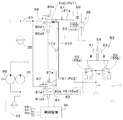
図1に示すように、走行系の油圧システムは、走行系の油圧システムは、走行装置5を駆動するシステムであって、原動機32と、第1油圧ポンプ(油圧ポンプ)P1と、第1走行モータ機構31Lと、第2走行モータ機構31Rと、走行駆動回路34とを備えている。
Next, a hydraulic system of the work machine 1 according to the present invention will be described. The hydraulic system of the working machine 1 has a traveling hydraulic system and a working hydraulic system.
As shown in FIG. 1, the traveling-system hydraulic system is a traveling-system hydraulic system that drives the traveling device 5, and includes a motor 32, a first hydraulic pump (hydraulic pump) P <b> 1, and a first traveling system. A motor mechanism 31L, a second traveling motor mechanism 31R, and a traveling drive circuit 34 are provided.

原動機32は、電気モータ、エンジン等から構成されている。この実施形態では、原動機32はエンジンである。第1油圧ポンプP1は、原動機32の動力によって駆動するポンプであって、定容量型のギヤポンプによって構成されている。第1油圧ポンプP1は、タンク(作動油タンク)22に貯留された作動油を吐出可能である。第1油圧ポンプP1の吐出側には、作動油を流す吐出油路40が設けられている。吐出油路40の中途部には、フィルタ35が設けられている。吐出油路40の作動油の吐出側は、複数に分岐している。当該吐出油路40の吐出側には、第1チャージ油路41が接続されている。第1チャージ油路41は、走行駆動機構34に至っている。第1油圧ポンプP1から吐出した作動油のうち、制御用として用いられる作動油のことをパイロット油、パイロット油の圧力のことをパイロット圧ということがある。   The prime mover 32 includes an electric motor, an engine, and the like. In this embodiment, the prime mover 32 is an engine. The first hydraulic pump P1 is a pump driven by the power of the prime mover 32, and is configured by a constant displacement gear pump. The first hydraulic pump P1 can discharge hydraulic oil stored in a tank (hydraulic oil tank) 22. On the discharge side of the first hydraulic pump P1, a discharge oil passage 40 through which hydraulic oil flows is provided. A filter 35 is provided in the middle of the discharge oil passage 40. The discharge side of the hydraulic oil in the discharge oil passage 40 is branched into a plurality. A first charge oil passage 41 is connected to the discharge side of the discharge oil passage 40. The first charge oil passage 41 reaches the traveling drive mechanism 34. Of the hydraulic oil discharged from the first hydraulic pump P1, hydraulic oil used for control may be referred to as pilot oil, and pressure of the pilot oil may be referred to as pilot pressure.

走行駆動機構34は、第1走行モータ機構31L及び第2走行モータ機構31Rを駆動する機構であって、第1走行モータ機構31Lの駆動用の駆動回路(左用駆動回路)34Lと、第2走行モータ機構31Rの駆動用の駆動回路(右用駆動回路)34Rとを有している。
駆動回路34L,34Rは、それぞれHSTポンプ(走行ポンプ)52L、52Rと、変速用油路57h,57iと、第2チャージ油路42とを有している。変速用油路57h,57iは、HSTポンプ52L,52RとHSTモータ36とを接続する油路である。第2チャージ油路42は、変速用油路57h,57iに接続され、第1油圧ポンプP1からの作動油を変速用油路57h,57iに補充する油路である。HSTポンプ52L,52Rは、原動機32の動力によって駆動される斜板形可変容量アキシャルポンプである。HSTポンプ52L,52Rは、パイロット圧が作用する前進用受圧部52aと後進用受圧部52bとを有し、受圧部52a,52bに作用するパイロット圧によって斜板の角度が変更される。斜版の角度を変更することによって、HSTポンプ52L,52Rの出力(作動油の吐出量)や作動油の吐出方向を変えることができる。言い換えれば、HSTポンプ52L,52Rは、斜板の角度を変更されることによって、走行装置5へ出力する駆動力を変更する。
The traveling drive mechanism 34 is a mechanism that drives the first traveling motor mechanism 31L and the second traveling motor mechanism 31R, and includes a driving circuit (left driving circuit) 34L for driving the first traveling motor mechanism 31L and a second traveling motor. And a drive circuit (right drive circuit) 34R for driving the motor mechanism 31R.
The drive circuits 34L and 34R have HST pumps (traveling pumps) 52L and 52R, shift oil passages 57h and 57i, and a second charge oil passage 42, respectively. The shift oil passages 57h and 57i are oil passages connecting the HST pumps 52L and 52R and the HST motor 36. The second charge oil passage 42 is connected to the shift oil passages 57h and 57i, and is an oil passage for replenishing the hydraulic oil from the first hydraulic pump P1 to the shift oil passages 57h and 57i. The HST pumps 52L and 52R are swash plate type variable displacement axial pumps driven by the power of the prime mover 32. Each of the HST pumps 52L and 52R has a forward pressure receiving portion 52a and a reverse pressure receiving portion 52b on which pilot pressure acts, and the angle of the swash plate is changed by the pilot pressure acting on the pressure receiving portions 52a and 52b. The output of the HST pumps 52L and 52R (discharge amount of hydraulic oil) and the discharge direction of hydraulic oil can be changed by changing the angle of the swash plate. In other words, the HST pumps 52L and 52R change the driving force output to the traveling device 5 by changing the angle of the swash plate.

第1走行モータ機構31Lは、機体2の左側に設けられた走行装置5の駆動軸に動力を伝達する機構である。第2走行モータ機構31Rは、機体2の右側に設けられた走行装置5の駆動軸に動力を伝達する機構である。第1走行モータ機構31Lは、HSTモータ(走行モータ)36と、変速機構を有している。
HSTモータ36は、斜板形可変容量アキシャルモータあって、車速(回転)を1速或いは2速に変更することができるモータである。言い換えれば、HSTモータ36は、作業機1の推進力を変更することができるモータである。
The first traveling motor mechanism 31L is a mechanism that transmits power to a drive shaft of the traveling device 5 provided on the left side of the body 2. The second traveling motor mechanism 31R is a mechanism that transmits power to a drive shaft of the traveling device 5 provided on the right side of the body 2. The first travel motor mechanism 31L has an HST motor (travel motor) 36 and a speed change mechanism.
The HST motor 36 is a swash plate type variable displacement axial motor that can change the vehicle speed (rotation) to first speed or second speed. In other words, the HST motor 36 is a motor that can change the propulsion force of the work implement 1.

変速機構は、斜板切換シリンダ38aと、切換弁38bとを含んでいる。斜板切換シリンダ38aは、伸縮によってHSTモータ36の斜板の角度を変更するシリンダである。切換弁38bは、斜板切換シリンダ38aを一方側或いは他方側に伸縮させる弁であって、第1位置39a及び第2位置39bに切り換わる二位置切換弁である。切換弁38bの切換は、変速切換弁33により行う。変速切換弁33は、吐出油路40に接続され且つ第1走行モータ機構31Lの切換弁38b及び第2走行モータ機構31Rの切換弁38bに接続されている。変速切換弁33は、第1位置33aと第2位置33bとに切り換え可能な二位置切換弁である。変速切換弁33を第1位置33aにすると、切換弁38bに作用させる作動油の圧力を所定の速度(例えば、1速)に対応する圧力(減速圧)に設定する。また、変速切換弁33を第2位置33bにすると、切換弁38bに作用させる作動油の圧力を所定の速度(1速)よりも早く速度(2速)に対応する圧力(増速圧)に設定する。したがって、変速切換弁33が第1位置33aの場合、切換弁38bは第1位置39aになり、これに伴って、斜板切換シリンダ38aは収縮し、HSTモータ36を1速にすることができる。また、変速切換弁33が第2位置33bの場合、切換弁38bは第2位置39bになり、これに伴って、斜板切換シリンダ38aは伸長し、HSTモータ36を2速にすることができる。なお、HSTモータ36を1速又は2速の変速は制御装置90の制御により行う。例えば、制御装置90には、スイッチ(変速スイッチ)等の操作部材58が設けられている。操作部材58を1速に切り換えると、制御装置90は、変速切換弁33のソレノイドを消磁する制御信号を出力して当該変速切換弁33を第1位置33aにする。また、操作部材58を2速に切り換えると、制御装置90は、変速切換弁33のソレノイドを励磁する制御信号を出力して当該変速切換弁33を第2位置33bにする。   The transmission mechanism includes a swash plate switching cylinder 38a and a switching valve 38b. The swash plate switching cylinder 38a is a cylinder that changes the angle of the swash plate of the HST motor 36 by expansion and contraction. The switching valve 38b is a valve that expands and contracts the swash plate switching cylinder 38a to one side or the other side, and is a two-position switching valve that switches between a first position 39a and a second position 39b. The switching of the switching valve 38 b is performed by the shift switching valve 33. The speed changeover switching valve 33 is connected to the discharge oil passage 40 and is connected to the switching valve 38b of the first traveling motor mechanism 31L and the switching valve 38b of the second traveling motor mechanism 31R. The shift switching valve 33 is a two-position switching valve that can switch between a first position 33a and a second position 33b. When the shift switching valve 33 is set to the first position 33a, the pressure of the operating oil acting on the switching valve 38b is set to a pressure (deceleration pressure) corresponding to a predetermined speed (for example, first speed). When the shift switching valve 33 is set to the second position 33b, the pressure of the hydraulic oil applied to the switching valve 38b is increased to a pressure (increased pressure) corresponding to the speed (second speed) faster than a predetermined speed (first speed). Set. Therefore, when the shift switching valve 33 is at the first position 33a, the switching valve 38b is at the first position 39a, and accordingly, the swash plate switching cylinder 38a is contracted, and the HST motor 36 can be set to the first speed. . When the shift switching valve 33 is at the second position 33b, the switching valve 38b is at the second position 39b. Accordingly, the swash plate switching cylinder 38a is extended, and the HST motor 36 can be set to the second speed. . The HST motor 36 shifts to the first speed or the second speed under the control of the control device 90. For example, the control device 90 is provided with an operation member 58 such as a switch (speed change switch). When the operating member 58 is switched to the first speed, the control device 90 outputs a control signal for demagnetizing the solenoid of the shift switching valve 33 to set the shift switching valve 33 to the first position 33a. When the operating member 58 is switched to the second speed, the control device 90 outputs a control signal for exciting the solenoid of the shift switching valve 33 to set the shift switching valve 33 to the second position 33b.

また、第1走行モータ機構31Lは、ブレーキ機構30を有している。ブレーキ機構30は、右側の走行装置5の制動、即ち、HSTモータ36の回転又はHSTモータ36の回転に伴って回転する出力軸の回転を停止可能である。ブレーキ機構30は、第1油圧ポンプP1から吐出されたパイロット油(作動油)によって、走行モータ機構31を制動する作動状態となったり、制動を解除する作動状態に変化する。例えば、ブレーキ機構30は、走行モータ機構31の出力軸に設けられた第1ディスクと、移動可能な第2ディスクと、第2ディスクが第1ディスクに接触する側へ付勢するバネとを備えている。また、ブレーキ機構30は、第1ディスク、第2ディスク及びバネを収容する収容部(収容ケース)59を備えている。この収容部59であって、第2ディスクが納められている部分と、ブレーキ切換弁80aとは、後述するように油路を介して接続されている。ブレーキ切換弁80aは、ブレーキ機構30における制動及び制動の解除(制動解除)を行う電磁弁であって、第1位置80a1と第2位置80a2とに切り換え可能な二位置切換弁である。ブレーキ切換弁80aは、第1位置80a1である場合、ブレーキ機構30に作用させる作動油の圧力(収容部59に作用する圧力)を当該ブレーキ機構30が制動する圧力(制動圧)に設定する。また、ブレーキ切換弁80aは、第2位置80a2である場合、作動油の圧力を制動解除する圧力(解除圧)以上に設定する。なお、ブレーキ切換弁80aの切換は、制御装置90の制御により行う。例えば、制御装置90には、ブレーキ切換弁80aのソレノイドを消磁する制御信号を出力して当該ブレーキ切換弁80aを第1位置80a1にする。また、制御装置90は、ブレーキ切換弁80aのソレノイドを励磁する制御信号を出力して当該ブレーキ切換弁80aを第2位置80a2にする。また、制御装置90からブレーキ切換弁80aへの制御信号の出力は、例えば、スイッチを設けておき、スイッチを手動で操作することにより行っても良いし、制御装置90が作業機の運転状況を判断して自動的に行ってもよい。   The first traveling motor mechanism 31L has a brake mechanism 30. The brake mechanism 30 can stop the braking of the traveling device 5 on the right side, that is, the rotation of the HST motor 36 or the rotation of the output shaft that rotates with the rotation of the HST motor 36. The brake mechanism 30 changes to an operation state of braking the traveling motor mechanism 31 or an operation state of releasing the braking by the pilot oil (hydraulic oil) discharged from the first hydraulic pump P1. For example, the brake mechanism 30 includes a first disk provided on an output shaft of the traveling motor mechanism 31, a movable second disk, and a spring for urging the second disk to contact the first disk. ing. Further, the brake mechanism 30 includes a housing portion (housing case) 59 for housing the first disk, the second disk, and the spring. The portion of the housing portion 59 in which the second disk is stored and the brake switching valve 80a are connected via an oil passage as described later. The brake switching valve 80a is an electromagnetic valve that performs braking and release of braking (braking release) in the brake mechanism 30, and is a two-position switching valve that can be switched between a first position 80a1 and a second position 80a2. When in the first position 80a1, the brake switching valve 80a sets the pressure of the hydraulic oil applied to the brake mechanism 30 (the pressure applied to the storage portion 59) to the pressure (braking pressure) at which the brake mechanism 30 performs braking. When the brake switching valve 80a is at the second position 80a2, the pressure of the hydraulic oil is set to be equal to or higher than the pressure at which the brake is released (release pressure). The switching of the brake switching valve 80a is performed under the control of the control device 90. For example, the control device 90 outputs a control signal for demagnetizing the solenoid of the brake switching valve 80a to set the brake switching valve 80a to the first position 80a1. Further, the control device 90 outputs a control signal for exciting the solenoid of the brake switching valve 80a to set the brake switching valve 80a to the second position 80a2. In addition, the output of the control signal from the control device 90 to the brake switching valve 80a may be performed, for example, by providing a switch and manually operating the switch. The judgment may be made automatically.

したがって、ブレーキ制切換弁80aが第1位置80a1である場合、収容部59の格納部のパイロット油が排出され、第2ディスクが制動の方向に動き、ブレーキ機構30における制動を行うことができる。また、ブレーキ制切換弁80aが第2位置80a2である場合、収容部59の格納部にパイロット油が供給され、第2ディスクが制動とは反対側(バネの付勢方向とは反対側)に動き、ブレーキ機構30における制動解除を行うことができる。なお、第2走行モータ機構31Rは、第1走行モータ機構31Lと同様の構成であって、第1走行モータ機構31Lで示した構成を第2走行モータ機構31Rに読み替えればよいため、構成の説明を省略する。   Therefore, when the brake control switching valve 80a is at the first position 80a1, the pilot oil in the storage section of the storage section 59 is discharged, the second disk moves in the direction of braking, and braking by the brake mechanism 30 can be performed. When the brake control switching valve 80a is at the second position 80a2, the pilot oil is supplied to the storage portion of the storage portion 59, and the second disk is turned on the opposite side to braking (opposite to the biasing direction of the spring). Movement and release of braking in the brake mechanism 30 can be performed. The second traveling motor mechanism 31R has the same configuration as the first traveling motor mechanism 31L, and the configuration shown by the first traveling motor mechanism 31L may be replaced with the second traveling motor mechanism 31R. Description is omitted.

図1に示すように、作業機1は、操作装置53を備えている。操作装置53は、走行装置5、即ち、第1走行モータ機構31L、第2走行モータ機構31R及び走行駆動機構34を操作する装置である。操作装置53は、第1操作部材54と、複数の操作弁55(55a、55b、55c、55d)とを有している。
第1操作部材54は、操作弁55に支持され、左右方向(機体幅方向)又は前後方向に揺動する操作部材である。また、複数の操作弁55は、共通、即ち、1本の第1操作部材54によって操作される。複数の操作弁55は、第1操作部材54の揺動に基づいて作動する。複数の操作弁55には、吐出油路40を介して、第1油圧ポンプP1からの作動油(パイロット油)が供給可能である。複数の操作弁55は、操作弁55a、操作弁55b、操作弁55c及び操作弁55dである。
As shown in FIG. 1, the work machine 1 includes an operation device 53. The operating device 53 is a device that operates the traveling device 5, that is, the first traveling motor mechanism 31L, the second traveling motor mechanism 31R, and the traveling driving mechanism 34. The operating device 53 has a first operating member 54 and a plurality of operating valves 55 (55a, 55b, 55c, 55d).
The first operating member 54 is an operating member that is supported by the operating valve 55 and swings in the left-right direction (machine body width direction) or the front-back direction. Further, the plurality of operation valves 55 are operated in common, that is, by one first operation member 54. The plurality of operation valves 55 operate based on the swing of the first operation member 54. Hydraulic oil (pilot oil) from the first hydraulic pump P1 can be supplied to the plurality of operation valves 55 via the discharge oil passage 40. The plurality of operation valves 55 are an operation valve 55a, an operation valve 55b, an operation valve 55c, and an operation valve 55d.

複数の操作弁55と、走行系の走行駆動機構34(走行ポンプ52L,52R)とは、走行油路45によって接続されている。走行油路45は、第1走行油路45a、第2走行油路45b、第3走行油路45c、第4走行油路45dと、第5走行油路45eとを有している。第1走行油路45aは、走行ポンプ52Lの前進用受圧部52aに接続された油路である。第2走行油路45bは、走行ポンプ52Lの後進用受圧部52bに接続された油路である。第3走行油路45cは、走行ポンプ52Rの前進用受圧部52aに接続された油路である。第4走行油路45dは、走行ポンプ52Rの後進用受圧部52bに接続された油路である。第5走行油路45eは、操作弁55、第1走行油路45a、第2走行油路45b、第3走行油路45c、第4走行油路45dを接続する油路である。第5走行油路45eは、複数のシャトル弁46と、複数の操作弁55(55a、55b、55c、55d)とを接続している。   The plurality of operation valves 55 and the travel drive mechanism 34 (travel pumps 52L and 52R) of the travel system are connected by a travel oil path 45. The traveling oil passage 45 has a first traveling oil passage 45a, a second traveling oil passage 45b, a third traveling oil passage 45c, a fourth traveling oil passage 45d, and a fifth traveling oil passage 45e. The first traveling oil passage 45a is an oil passage connected to the forward pressure receiving portion 52a of the traveling pump 52L. The second traveling oil passage 45b is an oil passage connected to the reverse pressure receiving portion 52b of the traveling pump 52L. The third traveling oil passage 45c is an oil passage connected to the forward pressure receiving portion 52a of the traveling pump 52R. The fourth traveling oil passage 45d is an oil passage connected to the reverse pressure receiving portion 52b of the traveling pump 52R. The fifth traveling oil passage 45e is an oil passage connecting the operation valve 55, the first traveling oil passage 45a, the second traveling oil passage 45b, the third traveling oil passage 45c, and the fourth traveling oil passage 45d. The fifth traveling oil passage 45e connects the plurality of shuttle valves 46 and the plurality of operation valves 55 (55a, 55b, 55c, 55d).

第1操作部材54を前方(図1では矢示A1方向)に揺動させると、操作弁55aが操作されて該操作弁55aからパイロット圧が出力され、走行モータ36の出力軸が第1操作部材54の揺動量に比例した速度で正転(前進回転)して作業機1が前方に直進する。また、第1操作部材54を後方(図1では矢示A2方向)に揺動させると、操作弁55bが操作されて該操作弁55bからパイロット圧が出力され、走行モータ36の出力軸が第1操作部材54の揺動量に比例した速度で逆転(後進回転)して作業機1が後方に直進する。   When the first operating member 54 is swung forward (in the direction indicated by the arrow A1 in FIG. 1), the operating valve 55a is operated, and the pilot pressure is output from the operating valve 55a. The work implement 1 rotates forward (rotation forward) at a speed proportional to the swing amount of the member 54, and the work machine 1 moves straight forward. When the first operating member 54 is swung rearward (in the direction indicated by the arrow A2 in FIG. 1), the operating valve 55b is operated and the pilot pressure is output from the operating valve 55b, and the output shaft of the traveling motor 36 is moved to the second position. The reverse rotation (reverse rotation) at a speed proportional to the swing amount of the one operation member 54 causes the work machine 1 to move straight back.

また、第1操作部材54を右方(図1では矢示A3方向)に揺動させると、操作弁55cが操作されて該操作弁55cからパイロット圧が出力され、左側の走行モータ36の出力軸が正転し且つ右側の走行モータ36の出力軸が逆転して作業機1が右側に旋回する。第1操作部材54を左方(図1では矢示A4方向)に揺動させると、操作弁55dが操作されて該操作弁55dからパイロット圧が出力され、左側の走行モータ36の出力軸が逆転し且つ右側の走行モータ36の出力軸が正転して作業機1が左側に旋回する。   When the first operation member 54 is swung to the right (in the direction indicated by the arrow A3 in FIG. 1), the operation valve 55c is operated, and the pilot pressure is output from the operation valve 55c. The shaft rotates forward and the output shaft of the traveling motor 36 on the right rotates reversely, and the work machine 1 turns to the right. When the first operating member 54 is swung to the left (in the direction indicated by the arrow A4 in FIG. 1), the operating valve 55d is operated, the pilot pressure is output from the operating valve 55d, and the output shaft of the left traveling motor 36 is driven. The work machine 1 rotates in the reverse direction and the output shaft of the traveling motor 36 on the right rotates forward, and the work machine 1 turns to the left.

また、第1操作部材54を斜め方向に揺動させると、受圧部52aと受圧部52bとに作用するパイロット圧の差圧によって、左方の走行モータ36及び右側の走行モータ36の出力軸の回転方向及び回転速度が決定され、作業機1が前進又は後進しながら右旋回又は左旋回する。
図1に示すように、吐出油路40には、操作装置53(操作弁55a、55b、55c、55d)に供給する作動油を停止可能な油圧ロック切換弁81aが接続されている。油圧ロック切換弁81aは、第1位置81a1と第2位置81a2とに切り換え可能な二位置切換弁である。油圧ロック切換弁81aを第1位置81a1にすると、第1油圧ポンプP1からのパイロット油は、操作弁55a、55b、55c、55dには供給されず、第1操作部材54を操作しても操作弁55a、55b、55c、55dによる作動油の圧力がHSTポンプ(走行ポンプ)52L、52Rに作用しないロック状態になる。油圧ロック切換弁81aを第2位置81a2にすると、第1油圧ポンプP1からのパイロット油は、操作弁55a、55b、55c、55dには供給され、第1操作部材54の操作に伴って、操作弁55a、55b、55c、55dによる作動油の圧力がHSTポンプ(走行ポンプ)52L、52Rに作用するロック解除状態になる。
When the first operation member 54 is swung in an oblique direction, the output pressure of the left traveling motor 36 and the output shaft of the right traveling motor 36 are increased by the differential pressure between the pilot pressure acting on the pressure receiving portion 52a and the pressure receiving portion 52b. The rotation direction and the rotation speed are determined, and the work machine 1 turns right or left while moving forward or backward.
As shown in FIG. 1, a hydraulic lock switching valve 81a capable of stopping hydraulic oil supplied to the operation device 53 (operation valves 55a, 55b, 55c, and 55d) is connected to the discharge oil passage 40. The hydraulic lock switching valve 81a is a two-position switching valve that can be switched between a first position 81a1 and a second position 81a2. When the hydraulic lock switching valve 81a is set to the first position 81a1, the pilot oil from the first hydraulic pump P1 is not supplied to the operation valves 55a, 55b, 55c, and 55d. The lock state is established in which the pressure of the hydraulic oil by the valves 55a, 55b, 55c, and 55d does not act on the HST pumps (traveling pumps) 52L and 52R. When the hydraulic lock switching valve 81a is set to the second position 81a2, the pilot oil from the first hydraulic pump P1 is supplied to the operation valves 55a, 55b, 55c, and 55d, and is operated in accordance with the operation of the first operation member 54. The pressure of the hydraulic oil by the valves 55a, 55b, 55c, and 55d is in an unlocked state in which the pressure acts on the HST pumps (traveling pumps) 52L and 52R.

さて、作業機1の油圧システムは、第1油圧機器に接続する第1油路と、第2油圧機器に接続する第2油路とを第3油路で接続し、第1油圧機器に供給する作動油を制御する第1作動弁に第1排出油路を接続し、且つ、第2油圧機器に供給する作動油を制御する第2作動弁に第2排出油路を接続することによって、暖機を行い易くしている。この実施形態では、第1油圧機器は、ブレーキ機構30、第2油圧機器は、走行駆動機構34である。また、第1作動弁は、ブレーキ機構30に供給する作動油を制御するブレーキ作動弁の1つであるブレーキ切換弁80a、第2作動弁は、走行駆動機構34に供給する作動油を制御する走行作動弁の1つである油圧ロック切換弁81aである。   Now, the hydraulic system of the work machine 1 connects the first hydraulic path connected to the first hydraulic apparatus and the second hydraulic path connected to the second hydraulic apparatus by the third hydraulic path, and supplies the first hydraulic apparatus to the first hydraulic apparatus. By connecting the first discharge oil passage to the first hydraulic valve that controls the hydraulic oil to be activated, and by connecting the second discharge oil passage to the second hydraulic valve that controls the hydraulic oil supplied to the second hydraulic device, It is easy to warm up. In this embodiment, the first hydraulic device is the brake mechanism 30, and the second hydraulic device is the traveling drive mechanism 34. Further, the first operating valve is one of the brake operating valves that controls the operating oil supplied to the brake mechanism 30, and the second operating valve controls the operating oil supplied to the traveling drive mechanism 34. This is a hydraulic lock switching valve 81a which is one of the traveling operation valves.

以下、第1油路、第2油路、第3油路について説明する。
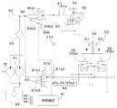
図1及び図2Aに示すように、第1油路61は、第1油圧機器(ブレーキ機構30)と、第1油圧機器(ブレーキ機構30)に供給する作動油を制御する第1作動弁(ブレーキ切換弁)80aとを接続する油路である。この実施形態では、第1油路61は、第1ブレーキ油路61aと、第2ブレーキ油路61bとを含んでいる。第1ブレーキ油路61aは、第1走行モータ機構31Lのブレーキ機構30と、ブレーキ切換弁(第1作動弁)80aとを接続する油路である。第2ブレーキ油路61bは、第2走行モータ機構31Rのブレーキ機構30と、ブレーキ切換弁(第1作動弁)80aとを接続する油路である。第1ブレーキ油路61aと第2ブレーキ油路61bとは途中で合流していて、合流後の油路(第1ブレーキ油路61aと第2ブレーキ油路61bとの兼用油路)61cがブレーキ切換弁80aに接続されている。兼用油路61cには、作動油の流量を低減する絞り部74が設けられている。言い換えれば、絞り部74は、第1油路61において、第3油路63が第1油路61に接続する接続部(後述する合流部64)とブレーキ切換弁80aに接続する接続部との区間に設けられている。
Hereinafter, the first oil passage, the second oil passage, and the third oil passage will be described.
As shown in FIGS. 1 and 2A, the first oil passage 61 is provided with a first hydraulic device (brake mechanism 30) and a first operating valve (hydraulic oil) that controls hydraulic oil supplied to the first hydraulic device (brake mechanism 30). Brake switching valve) 80a. In this embodiment, the first oil passage 61 includes a first brake oil passage 61a and a second brake oil passage 61b. The first brake oil passage 61a is an oil passage that connects the brake mechanism 30 of the first traveling motor mechanism 31L and the brake switching valve (first operating valve) 80a. The second brake oil passage 61b is an oil passage that connects the brake mechanism 30 of the second traveling motor mechanism 31R and the brake switching valve (first operating valve) 80a. The first brake oil passage 61a and the second brake oil passage 61b merge on the way, and the merged oil passage (combined oil passage for the first brake oil passage 61a and the second brake oil passage 61b) 61c is braked. It is connected to the switching valve 80a. A throttle portion 74 for reducing the flow rate of hydraulic oil is provided in the dual-purpose oil passage 61c. In other words, in the first oil passage 61, the constricted portion 74 is formed by a connection (a junction 64 described later) where the third oil passage 63 is connected to the first oil passage 61 and a connection that is connected to the brake switching valve 80 a. It is provided in the section.

ブレーキ切換弁80aの排出ポートには、第1排出油路66が接続されている。第1排出油路66は、ブレーキ切換弁80aを通過した作動油、即ち、第1油路61(第1ブレーキ油路61a、第2ブレーキ油路61b)の作動油を排出可能である。第1排出油路66は、油圧ポンプの吸込み部や作動油タンク22等に接続されている。
第2油路62は、第2油圧機器(走行駆動機構34の走行ポンプ52L、52R)と、第2油圧機器(走行駆動機構34の走行ポンプ52L、52R)に供給する作動油を制御する第2作動弁(油圧ロック切換弁)81aとを接続する油路である。この実施形態では、第2油路62は、吐出油路40において油圧ロック切換弁81aと操作弁55a、55b、55c、55dとを接続する区間(油路)40aと、操作弁55a、55b、55c、55dと走行ポンプ52L、52Rとを接続する走行油路45とを含んでいる。
A first discharge oil passage 66 is connected to a discharge port of the brake switching valve 80a. The first discharge oil passage 66 can discharge the hydraulic oil that has passed through the brake switching valve 80a, that is, the hydraulic oil of the first oil passage 61 (the first brake oil passage 61a and the second brake oil passage 61b). The first discharge oil passage 66 is connected to a suction portion of a hydraulic pump, the hydraulic oil tank 22, and the like.
The second oil passage 62 controls hydraulic oil supplied to the second hydraulic equipment (the travel pumps 52L and 52R of the travel drive mechanism 34) and the second hydraulic equipment (the travel pumps 52L and 52R of the travel drive mechanism 34). This is an oil passage connecting the two-operation valve (hydraulic lock switching valve) 81a. In this embodiment, the second oil passage 62 includes a section (oil passage) 40a connecting the hydraulic lock switching valve 81a and the operation valves 55a, 55b, 55c, 55d in the discharge oil passage 40, and the operation valves 55a, 55b, A traveling oil passage 45 connecting the traveling pumps 52L, 52R to the traveling pumps 52L, 52R is included.

油圧ロック切換弁81aの排出ポートには、第2排出油路67が接続されている。第2排出油路67は、油圧ロック切換弁81aを通過した作動油、即ち、第2油路62の作動油を排出可能である。第2排出油路67は、油圧ポンプの吸込み部や作動油タンク22等に接続されている。
第3油路63は、第1油路61と第2油路62とを接続する油路である。第3油路63は、第1ブレーキ油路61aと第2ブレーキ油路61bとが合流する合流部64と、油路40aが合流する合流部65とを接続している。第3油路63は、吐出油路40において、操作弁55a、55b、55c、55dの上流側に接続されている。即ち、第3油路63は、操作弁55a、55b、55c、55dの一次側に接続されている。また、第3油路63には、逆止弁173が接続されている。逆止弁173は、第2油路62から第1油路61への作動油を許容し、第1油路61から第2油路62への作動油を阻止する。
A second discharge oil passage 67 is connected to a discharge port of the hydraulic lock switching valve 81a. The second discharge oil passage 67 can discharge the hydraulic oil that has passed through the hydraulic lock switching valve 81a, that is, the hydraulic oil in the second oil passage 62. The second discharge oil passage 67 is connected to a suction portion of the hydraulic pump, the hydraulic oil tank 22, and the like.
The third oil passage 63 is an oil passage that connects the first oil passage 61 and the second oil passage 62. The third oil passage 63 connects a junction 64 where the first brake oil passage 61a and the second brake oil passage 61b join, and a junction 65 where the oil passage 40a joins. The third oil passage 63 is connected to the discharge oil passage 40 on the upstream side of the operation valves 55a, 55b, 55c, and 55d. That is, the third oil passage 63 is connected to the primary side of the operation valves 55a, 55b, 55c, and 55d. Further, a check valve 173 is connected to the third oil passage 63. The check valve 173 allows hydraulic oil from the second oil passage 62 to the first oil passage 61 and blocks hydraulic oil from the first oil passage 61 to the second oil passage 62.

図1及び図2Aに示すように、油路40aにおいて、合流部65と第2作動弁(油圧ロック切換弁)81aとの間には絞り部84が設けられている。絞り部84は、吐出油路40において、第2作動弁(油圧ロック切換弁)81aの上流側に設けてもよい。
制御装置90は、ブレーキ切換弁(第1作動弁)80aで設定されるブレーキ設定圧(第1設定圧)PV1と、第2作動弁(油圧ロック切換弁)81aで設定される設定圧(第2設定圧)PV2との差圧を設定する。ブレーキ設定圧PV1は、例えば、ブレーキ切換弁80aの出力ポート100の圧力である。言い換えれば、第1設定圧PV1は、第1油路61(第1ブレーキ油路61a、第2ブレーキ油路61b)に作用する圧力である。
As shown in FIGS. 1 and 2A, a throttle portion 84 is provided in the oil passage 40a between the junction 65 and the second operating valve (hydraulic lock switching valve) 81a. The throttle portion 84 may be provided in the discharge oil passage 40 on the upstream side of the second operating valve (hydraulic lock switching valve) 81a.
The control device 90 includes a brake set pressure (first set pressure) PV1 set by a brake switching valve (first operating valve) 80a and a set pressure (second set pressure) set by a second operating valve (hydraulic lock switching valve) 81a. 2 Set pressure) Set the pressure difference from PV2. The brake set pressure PV1 is, for example, the pressure at the output port 100 of the brake switching valve 80a. In other words, the first set pressure PV1 is a pressure acting on the first oil passage 61 (the first brake oil passage 61a and the second brake oil passage 61b).

第2設定圧(設定圧)PV2は、例えば、油圧ロック切換弁81aの出力ポート101の圧力である。言い換えれば、第2設定圧PV2は、第2油路62に作用する圧力である。
制御装置90は、第1設定圧PV1と第2設定圧PV2との差圧が発生するように、ブレーキ切換弁80a及び油圧ロック切換弁81aを制御する。制御装置90は、例えば、暖機を行う暖機モードである場合に、ブレーキ切換弁80aのブレーキ設定圧PV1を、油圧ロック切換弁81aの設定圧PV2よりも低くする。言い換えれば、制御装置90は、暖機モードである場合、油圧ロック切換弁81aの設定圧PV2を、ブレーキ切換弁80aのブレーキ設定圧PV1よりも高くする。
The second set pressure (set pressure) PV2 is, for example, the pressure at the output port 101 of the hydraulic lock switching valve 81a. In other words, the second set pressure PV2 is a pressure acting on the second oil passage 62.
The control device 90 controls the brake switching valve 80a and the hydraulic lock switching valve 81a such that a differential pressure between the first set pressure PV1 and the second set pressure PV2 is generated. The control device 90 sets the brake set pressure PV1 of the brake switching valve 80a lower than the set pressure PV2 of the hydraulic lock switching valve 81a, for example, in a warm-up mode for performing warm-up. In other words, when in the warm-up mode, the control device 90 sets the set pressure PV2 of the hydraulic lock switching valve 81a higher than the brake set pressure PV1 of the brake switching valve 80a.

詳しくは、制御装置90は、暖機モードである場合、ブレーキ切換弁80aを第1位置80a1にすることにより、ブレーキ設定圧PV1をブレーキ機構30が制動する制動圧に設定する。また、制御装置90は、暖機モードである場合、油圧ロック切換弁81aを第2位置81a2にすることにより、設定圧PV2をブレーキ設定圧PV1よりも高くする。即ち、ブレーキ切換弁80aが制動状態であり、油圧ロック切換弁81aがロック解除状態である場合には、ブレーキ設定圧PV1<設定圧PV2であり、油圧ロック切換弁81aで設定する設定圧PV2は、ブレーキ切換弁80aで設定する作動油のブレーキ設定圧PV1よりも高くなる。   Specifically, in the warm-up mode, the control device 90 sets the brake set pressure PV1 to the braking pressure at which the brake mechanism 30 brakes by setting the brake switching valve 80a to the first position 80a1. Further, in the warm-up mode, the control device 90 sets the hydraulic pressure lock switching valve 81a to the second position 81a2 so that the set pressure PV2 is higher than the brake set pressure PV1. That is, when the brake switching valve 80a is in the braking state and the hydraulic lock switching valve 81a is in the unlocked state, the brake set pressure PV1 <the set pressure PV2, and the set pressure PV2 set by the hydraulic lock switch valve 81a is Becomes higher than the brake set pressure PV1 of the hydraulic oil set by the brake switching valve 80a.

図2Aの矢印A10に示すように、ブレーキ設定圧PV1<設定圧PV2である場合、油圧ロック切換弁81aを通過した作動油は、第2油路62及び第3油路63を経て、第1油路61に流れ、ブレーキ切換弁80aの排出ポートから第1排出油路66に排出される。これにより、第1油路(ブレーキ油路)及び第2油路(走行油路)の暖機を行うことができる。なお、暖機モードは、例えば、制御装置90に、ON/OFFに切り換え可能なモードスイッチ95を接続し、モードスイッチ95がONである場合には、暖機モードになり、モードスイッチ95がOFFである場合には、暖機モードが解除される。   As shown by an arrow A10 in FIG. 2A, when the brake set pressure PV1 <the set pressure PV2, the hydraulic oil that has passed through the hydraulic lock switching valve 81a passes through the second oil passage 62 and the third oil passage 63, and then enters the first oil passage. The oil flows into the oil passage 61 and is discharged from the discharge port of the brake switching valve 80a to the first discharge oil passage 66. This makes it possible to warm up the first oil passage (brake oil passage) and the second oil passage (travel oil passage). In the warming-up mode, for example, a mode switch 95 that can be switched ON / OFF is connected to the control device 90. When the mode switch 95 is ON, the warming-up mode is set and the mode switch 95 is turned OFF. If, the warm-up mode is canceled.

図2Bは、図2Aの第1変形例を示す図である。なお、図2Bは、説明の便宜上、第1走行モータ機構31L側の油路を示しているが、第2走行モータ機構31R側の油路は省略しており、第2走行モータ機構31R側の油路に対しても適用可能である。
図2Bに示すように、第1変形例は、第2作動弁を、電磁比例弁で構成されたアンチストール比例弁81bに変更した例である。
FIG. 2B is a diagram showing a first modification of FIG. 2A. 2B shows the oil passage on the first traveling motor mechanism 31L side for convenience of explanation, but the oil passage on the second traveling motor mechanism 31R side is omitted, and the oil passage on the second traveling motor mechanism 31R side is omitted. It is also applicable to oil passages.
As shown in FIG. 2B, the first modified example is an example in which the second operating valve is changed to an anti-stall proportional valve 81b constituted by an electromagnetic proportional valve.

アンチストール比例弁81bは、エンジンストールを防止する制御(アンチストール制御)を行う。図4は、エンジン回転数と、走行一次圧と、制御線L1、L2の関係を示している。走行一次圧とは、吐出油路40において、アンチストール比例弁81bから操作弁55(操作弁55a、操作弁55b、操作弁55c、操作弁55d)に至る区間における作動油の圧力(パイロット圧)である。即ち、操作部材54に設けられた操作弁55に入る作動油の一次圧である。制御線L1は、ドロップ量が所定未満である場合のエンジン回転数と、走行一次圧との関係を示している。制御線L2は、ドロップ量が所定以上である場合のエンジン回転数と、走行一次圧との関係を示している。   The anti-stall proportional valve 81b performs control for preventing engine stall (anti-stall control). FIG. 4 shows the relationship between the engine speed, the traveling primary pressure, and the control lines L1 and L2. The traveling primary pressure is a pressure (pilot pressure) of hydraulic oil in a section from the anti-stall proportional valve 81b to the operation valve 55 (the operation valve 55a, the operation valve 55b, the operation valve 55c, and the operation valve 55d) in the discharge oil passage 40. It is. That is, it is the primary pressure of the hydraulic oil entering the operation valve 55 provided on the operation member 54. The control line L1 indicates the relationship between the engine speed and the traveling primary pressure when the drop amount is less than the predetermined value. The control line L2 indicates the relationship between the engine speed and the traveling primary pressure when the drop amount is equal to or more than a predetermined value.

制御装置90は、ドロップ量が所定未満である場合、エンジンの実回転数と走行一次圧との関係が、制御線L1に一致するように、アンチストール比例弁81bの開度を調整する。また、制御装置90は、ドロップ量が所定以上である場合、エンジンの実回転数と走行一次圧との関係が、制御線L2に一致するように、アンチストール比例弁81bの開度を調整する。制御線L2では、所定のエンジン回転数に対する走行一次圧が、制御線L1の走行一次圧よりも低い。即ち、同一のエンジン回転数に着目した場合、制御線L2の走行一次圧が、制御線L1の走行一次圧よりも低い。したがって、制御線L2に基づく制御によって、操作弁55に入る作動油の圧力(パイロット圧)が低く抑えられる。その結果、HSTポンプ(走行ポンプ)52の斜板角が調整され、エンジンに作用する負荷が減少し、エンジンのストールを防止することができる。なお、図4では、1本の制御線L2を示しているが、制御線L2は複数であってもよい。例えば、エンジン回転数毎に制御線L2が設定されていてもよい。また、制御線L1及び制御線L2を示すデータ、或いは、関数等の制御パラメータ等は、制御装置90が有していることが好ましい。   When the drop amount is less than the predetermined value, control device 90 adjusts the opening degree of anti-stall proportional valve 81b such that the relationship between the actual engine speed and the traveling primary pressure matches control line L1. Further, when the drop amount is equal to or greater than the predetermined value, control device 90 adjusts the opening of anti-stall proportional valve 81b such that the relationship between the actual engine speed and the traveling primary pressure matches control line L2. . In the control line L2, the traveling primary pressure for a predetermined engine speed is lower than the traveling primary pressure of the control line L1. That is, when focusing on the same engine speed, the traveling primary pressure of the control line L2 is lower than the traveling primary pressure of the control line L1. Therefore, by the control based on the control line L2, the pressure (pilot pressure) of the hydraulic oil entering the operation valve 55 is suppressed low. As a result, the swash plate angle of the HST pump (traveling pump) 52 is adjusted, the load acting on the engine is reduced, and engine stall can be prevented. Although FIG. 4 shows one control line L2, a plurality of control lines L2 may be provided. For example, the control line L2 may be set for each engine speed. The control device 90 preferably has data indicating the control lines L1 and L2, or control parameters such as functions.

アンチストール比例弁81bは、1次ポート(ポンプポート)81b1、2次ポート81b2を有している。アンチストール比例弁81bの1次ポート81b1は吐出油路40に接続されている。アンチストール比例弁81bの2次ポート81b2は、第2油路62(油路40a)に接続されている。アンチストール比例弁81bの排出ポート81b3は、第2排出油路67を介して作動油タンク22に接続されている。アンチストール比例弁81bにおいては、第2設定圧(設定圧)PV2は、2次ポート81b2の圧力である。   The anti-stall proportional valve 81b has a primary port (pump port) 81b1 and a secondary port 81b2. The primary port 81b1 of the anti-stall proportional valve 81b is connected to the discharge oil passage 40. The secondary port 81b2 of the anti-stall proportional valve 81b is connected to the second oil passage 62 (oil passage 40a). The discharge port 81b3 of the anti-stall proportional valve 81b is connected to the hydraulic oil tank 22 via the second discharge oil passage 67. In the anti-stall proportional valve 81b, the second set pressure (set pressure) PV2 is the pressure of the secondary port 81b2.

第1変形例において、制御装置90は、暖機モードである場合に、ブレーキ切換弁80aを第1位置80a1にする一方、アンチストール比例弁81bの開度を最大に設定する。即ち、制御装置90は、暖機モードである場合に、ブレーキ切換弁80aのブレーキ設定圧PV1を制動圧、アンチストール比例弁81bの設定圧PV2を制動圧以上にする。
したがって、油圧ロック切換弁81aをアンチストール比例弁81bに変更した場合であっても、アンチストール比例弁81bの開度を設定することにより、ブレーキ設定圧PV1<設定圧PV2に設定することができる。この場合も、アンチストール比例弁81bを通過した作動油は、第2油路62及び第3油路63を経て、第1油路61に流れ、ブレーキ切換弁80aの排出ポートから第1排出油路66に排出することができる。なお、制御装置90は、暖機モードでない場合、上述したように、エンジンの回転数に基づいてアンチストールの制御を行う。上述した実施形態では、アンチストール比例弁81bの開度は最大にしているが、第2設定圧(設定圧)PV2がブレーキ設定圧PV1よりも高くなるように開度を設定すればよい。
In the first modification, the control device 90 sets the opening of the anti-stall proportional valve 81b to the maximum while setting the brake switching valve 80a to the first position 80a1 in the warm-up mode. That is, in the warm-up mode, the controller 90 sets the brake set pressure PV1 of the brake switching valve 80a to the brake pressure and sets the anti-stall proportional valve 81b set pressure PV2 to the brake pressure or more.
Therefore, even when the hydraulic lock switching valve 81a is changed to the anti-stall proportional valve 81b, the brake set pressure PV1 <set pressure PV2 can be set by setting the opening degree of the anti-stall proportional valve 81b. . Also in this case, the hydraulic oil that has passed through the anti-stall proportional valve 81b flows through the second oil passage 62 and the third oil passage 63 to the first oil passage 61, and the first oil is discharged from the discharge port of the brake switching valve 80a. It can be discharged to road 66. When not in the warm-up mode, the control device 90 performs anti-stall control based on the engine speed as described above. In the above-described embodiment, the opening degree of the anti-stall proportional valve 81b is maximized, but the opening degree may be set so that the second set pressure (set pressure) PV2 is higher than the brake set pressure PV1.

図2Cは、図2Bの第2変形例を示している。この第2変形例では、図2Cに示すように、ブレーキ作動弁を電磁比例弁(ブレーキ比例弁)80bに変更した例である。ブレーキ比例弁80bは、1次ポート(ポンプポート)80b1、2次ポート80b2を有している。ブレーキ比例弁80bの1次ポート80b1は吐出油路40に接続されている。ブレーキ比例弁80bの2次ポート80b2は、第1油路61に接続されている。ブレーキ比例弁80bの排出ポート80b3は、第1排出油路66を介して作動油タンク22に接続されている。ブレーキ比例弁80bにおいては、第1設定圧PV1は、2次ポート80b2の圧力である。   FIG. 2C shows a second modification of FIG. 2B. In the second modification, as shown in FIG. 2C, the brake operation valve is changed to an electromagnetic proportional valve (brake proportional valve) 80b. The brake proportional valve 80b has a primary port (pump port) 80b1 and a secondary port 80b2. The primary port 80b1 of the brake proportional valve 80b is connected to the discharge oil passage 40. The secondary port 80b2 of the brake proportional valve 80b is connected to the first oil passage 61. The discharge port 80b3 of the brake proportional valve 80b is connected to the hydraulic oil tank 22 via the first discharge oil passage 66. In the brake proportional valve 80b, the first set pressure PV1 is the pressure of the secondary port 80b2.

第2変形例において、制御装置90は、暖機モードである場合に、ブレーキ機構30が制動する制動圧となるようにブレーキ比例弁80bの開度を最小に設定する一方、アンチストール比例弁81bの開度を最大に設定する。即ち、制御装置90は、暖機モードである場合に、ブレーキ比例弁80bのブレーキ設定圧PV1を制動圧、アンチストール比例弁81bの設定圧PV2を制動圧以上にする。   In the second modification, the control device 90 sets the opening degree of the brake proportional valve 80b to a minimum value so that the braking pressure of the brake mechanism 30 is reduced in the warm-up mode, while the anti-stall proportional valve 81b Set the opening of the maximum. That is, in the warm-up mode, the controller 90 sets the brake set pressure PV1 of the brake proportional valve 80b to the braking pressure and sets the set pressure PV2 of the anti-stall proportional valve 81b to the brake pressure or more.

したがって、ブレーキ切換弁80aをブレーキ比例弁80bに変更した場合であっても、ブレーキ比例弁80b及びアンチストール比例弁81bの開度を設定することにより、ブレーキ設定圧PV1<設定圧PV2に設定することができる。この場合も、アンチストール比例弁81bを通過した作動油は、第2油路62及び第3油路63を経て、第1油路61に流れ、ブレーキ比例弁80bの排出ポート80b3から第1排出油路68に排出することができる。   Therefore, even when the brake switching valve 80a is changed to the brake proportional valve 80b, the brake set pressure PV1 <set pressure PV2 is set by setting the opening degrees of the brake proportional valve 80b and the anti-stall proportional valve 81b. be able to. Also in this case, the hydraulic oil that has passed through the anti-stall proportional valve 81b flows through the second oil passage 62 and the third oil passage 63 to the first oil passage 61, and the first discharge oil is discharged from the discharge port 80b3 of the brake proportional valve 80b. It can be discharged to the oil passage 68.

図3は、第3油路63の第3変形例を示している。上述した実施形態では、第3油路63は、操作弁55a、55b、55c、55dの上流側(一次側)に接続されていたが、第3変形例では、操作弁55a、55b、55c、55dの下流側(二次側)に接続されている。なお、図3は、説明の便宜上、複数の操作弁55a、55b、55c、55dのうち、操作弁55a、55bを示しているが、他の操作弁55c、55d及び当該操作弁55c、55dに接続される走行油路45c、45dも適用可能である。   FIG. 3 shows a third modification of the third oil passage 63. In the above-described embodiment, the third oil passage 63 is connected to the upstream side (primary side) of the operation valves 55a, 55b, 55c, and 55d. However, in the third modification, the operation valves 55a, 55b, 55c, It is connected to the downstream side (secondary side) of 55d. Note that FIG. 3 shows the operation valves 55a and 55b among the plurality of operation valves 55a, 55b, 55c, and 55d for convenience of description, but the other operation valves 55c and 55d and the operation valves 55c and 55d The connected traveling oil passages 45c and 45d are also applicable.

第3油路63は、第1暖機油路63aと、第2暖機油路63bとを含んでいる。第1暖機油路63aは、第2油路62を構成する第1走行油路45aに接続されている。また、第2暖機油路63bは、第2油路62を構成する第2走行油路45bに接続されている。第1走行油路45a及び第2走行油路45bには、逆止弁173が接続されている。第3変形例においても、制御装置90は、暖機モードである場合に、油圧ロック切換弁81aをロック解除状態(ロック解除圧)に設定し、ブレーキ切換弁80aを制動状態(制動圧)に設定することで、ブレーキ設定圧PV1<設定圧PV2にする。そうすると、第2油路62である第1走行油路45a及び第2走行油路45bの作動油が、第1暖機油路63a及び第2暖機油路63bを通過して、ブレーキ切換弁80aの排出ポートから排出することができる。なお、図3では、ブレーキ切換弁80a及び油圧ロック切換弁81aを示しているが、上述したように、ブレーキ比例弁80b、アンチストール比例弁81bであってもよい。   The third oil passage 63 includes a first warm-up oil passage 63a and a second warm-up oil passage 63b. The first warm-up oil passage 63a is connected to the first traveling oil passage 45a that forms the second oil passage 62. The second warm-up oil passage 63b is connected to a second traveling oil passage 45b that forms the second oil passage 62. A check valve 173 is connected to the first traveling oil passage 45a and the second traveling oil passage 45b. Also in the third modification, when in the warm-up mode, the control device 90 sets the hydraulic lock switching valve 81a to the unlocked state (unlocking pressure) and sets the brake switching valve 80a to the braking state (braking pressure). By setting, the brake set pressure PV1 <set pressure PV2. Then, the hydraulic oil in the first traveling oil passage 45a and the second traveling oil passage 45b, which is the second oil passage 62, passes through the first warm-up oil passage 63a and the second warm-up oil passage 63b, and the brake switching valve 80a Can be discharged from the discharge port. Although FIG. 3 shows the brake switching valve 80a and the hydraulic lock switching valve 81a, the brake proportional valve 80b and the anti-stall proportional valve 81b may be used as described above.

上述した実施形態において、第1作動弁、即ち、ブレーキ作動弁(ブレーキ切換弁80a、ブレーキ比例弁80b)で設定される第1設定圧(ブレーキ設定圧)PV1を測定可能な第1測定装置と、第2作動弁、即ち、走行作動弁(油圧ロック切換弁81a、アンチストール比例弁81b)で設定される第2設定圧PV2を測定可能な第2測定装置とを接続し、暖機モードである場合に、制御装置90が、ブレーキ設定圧PV1<設定圧PV2になるように、第1作動弁及び第2作動弁を制御してもよい。第1設定圧(ブレーキ設定圧)PV1及び第2設定圧(設定圧)PV2を、制御装置90が第1油圧ポンプP1の駆動(吐出圧、回転数等)、原動機回転数等から推定して、第1作動弁及び第2作動弁を制御してもよい。   In the above-described embodiment, a first measuring device capable of measuring a first set pressure (brake set pressure) PV1 set by a first operating valve, that is, a brake operating valve (a brake switching valve 80a, a brake proportional valve 80b). , A second operating valve, that is, a second measuring device capable of measuring a second set pressure PV2 set by a traveling operating valve (hydraulic lock switching valve 81a, anti-stall proportional valve 81b), and in a warm-up mode. In some cases, the control device 90 may control the first operating valve and the second operating valve such that the brake set pressure PV1 <the set pressure PV2. The control device 90 estimates the first set pressure (brake set pressure) PV1 and the second set pressure (set pressure) PV2 from the drive (discharge pressure, rotation speed, etc.) of the first hydraulic pump P1, the rotation speed of the prime mover, and the like. , The first operating valve and the second operating valve may be controlled.

また、制御装置90に作動油の温度を検出する温度検出装置91に接続し、温度検出装置91で検出された温度である検出温度に応じて差圧(ブレーキ設定圧PV1と設定圧PV2との差圧)を設定してもよい。制御装置90は、温度検出装置91で検出した検出温度が予め定められた設定温度よりも低い場合に差圧を大きくする。具体的には、制御装置90は、検出温度が氷点下であって作動油の粘性が高い場合は、アンチストール比例弁81bの開度を大きくし、検出温度が氷点下でない場合は、アンチストール比例弁81bの開度を小さくする。   Further, the control device 90 is connected to a temperature detecting device 91 for detecting the temperature of the hydraulic oil, and a differential pressure (a difference between the brake set pressure PV1 and the set pressure PV2) is determined according to the detected temperature which is the temperature detected by the temperature detector 91. Differential pressure). Control device 90 increases the differential pressure when the temperature detected by temperature detecting device 91 is lower than a predetermined set temperature. Specifically, the control device 90 increases the opening degree of the anti-stall proportional valve 81b when the detected temperature is below the freezing point and the viscosity of the hydraulic oil is high. The opening of 81b is reduced.

[第2実施形態]
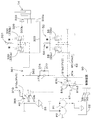
図5は、第2実施形態における作業機の油圧システムを示している。第2実施形態では、図5に示すように、第1油圧機器は、作業制御弁300、第1作動弁は、油圧ロック切換弁310、第2油圧機器は、走行駆動機構34(図示省略)、第2作動弁は、アンチストール比例弁81bである。
[Second embodiment]
FIG. 5 shows a hydraulic system of a working machine according to the second embodiment. In the second embodiment, as shown in FIG. 5, the first hydraulic device is a work control valve 300, the first operating valve is a hydraulic lock switching valve 310, and the second hydraulic device is a traveling drive mechanism 34 (not shown). The second operating valve is an anti-stall proportional valve 81b.

第1油路は、第1油圧機器(作業制御弁300)と、第1油圧機器(作業制御弁300)に供給する作動油を制御する第1作動弁(油圧ロック切換弁310)とを接続する油路361である。第2油路は、第2油圧機器(走行駆動機構34の走行ポンプ52L、52R)と、第2油圧機器(走行駆動機構34の走行ポンプ52L、52R)に供給する作動油を制御する第2作動弁(アンチストール比例弁81b)とを接続する油路62である。第2油路62は、第1実施形態と同様に、区間(油路)40a、走行油路45とを含んでいる。第3油路は、第1油路361と第2油路62とを接続する油路363である。   The first oil passage connects a first hydraulic device (work control valve 300) and a first hydraulic valve (hydraulic lock switching valve 310) that controls hydraulic oil supplied to the first hydraulic device (work control valve 300). The oil passage 361 is formed. The second oil passage controls a second hydraulic device (the traveling pumps 52L and 52R of the traveling drive mechanism 34) and a second hydraulic device that controls hydraulic oil supplied to the second hydraulic devices (the traveling pumps 52L and 52R of the traveling drive mechanism 34). This is an oil passage 62 for connecting to an operation valve (anti-stall proportional valve 81b). The second oil passage 62 includes a section (oil passage) 40a and a traveling oil passage 45, as in the first embodiment. The third oil passage is an oil passage 363 that connects the first oil passage 361 and the second oil passage 62.

作業制御弁300は、作業系の油圧シリンダ(作業油圧アクチュエータ)等に供給する作動油を制御する弁である。作業制御弁300は、例えば、ブームシリンダ14に供給する作動油を制御するブーム制御弁、バケットシリンダ15に供給する作動油を制御するバケット制御弁等である。この実施形態では、作業制御弁300は、ブーム制御弁であるとして説明を進めるが、バケット制御弁であってもよい。説明の便宜上、作業制御弁300を「ブーム制御弁300」として表記する。   The work control valve 300 is a valve that controls hydraulic oil supplied to a hydraulic cylinder (work hydraulic actuator) of a work system or the like. The work control valve 300 is, for example, a boom control valve that controls hydraulic oil supplied to the boom cylinder 14, a bucket control valve that controls hydraulic oil supplied to the bucket cylinder 15, and the like. In this embodiment, the operation control valve 300 will be described as a boom control valve, but may be a bucket control valve. For convenience of explanation, the work control valve 300 is described as “boom control valve 300”.

ブーム制御弁300は、例えば、3位置切換弁であって、中立位置から一方側に操作されると、ブーム制御弁300は、ブームシリンダ14のボトム側に作動油を供給する一方、ブームシリンダ14のロッド側から排出された作動油を作動油タンク等に排出することで、ブームシリンダ14を伸長させる。また、ブーム制御弁300は、中立位置から他方側に操作されると、ブームシリンダ14のロッド側に作動油を供給する一方、ブームシリンダ14のボトム側から排出された作動油を作動油タンク等に排出することで、ブームシリンダ14を収縮させる。なお、ブーム制御弁300は、当該ブーム制御弁300に設けられた受圧部300a、300bに付与されたパイロット油の圧力(パイロット圧)によって切り換えられる。   The boom control valve 300 is, for example, a three-position switching valve. When the boom control valve 300 is operated to one side from the neutral position, the boom control valve 300 supplies hydraulic oil to the bottom side of the boom cylinder 14 while the boom cylinder 14 The boom cylinder 14 is extended by discharging the hydraulic oil discharged from the rod side to a hydraulic oil tank or the like. When the boom control valve 300 is operated to the other side from the neutral position, the boom control valve 300 supplies hydraulic oil to the rod side of the boom cylinder 14 and supplies hydraulic oil discharged from the bottom side of the boom cylinder 14 to a hydraulic oil tank or the like. , The boom cylinder 14 is contracted. The boom control valve 300 is switched by the pressure of the pilot oil (pilot pressure) applied to the pressure receiving portions 300a and 300b provided in the boom control valve 300.

ブーム制御弁300の受圧部300a、300bには、それぞれ作業油路320が接続されている。作業油路320は、第1油路361の一部を構成する油路である。作業油路320には、複数の操作弁(作業操作弁)330(330a、330b)が接続されている。複数の操作弁330(330a、330b)は、複数の作業油路320に所定のパイロット圧を付与する弁であって、操作部材331の操作量に応じて、パイロット圧を変化させる。   A working oil passage 320 is connected to each of the pressure receiving portions 300a and 300b of the boom control valve 300. The working oil passage 320 is an oil passage that forms a part of the first oil passage 361. A plurality of operation valves (work operation valves) 330 (330a, 330b) are connected to the work oil passage 320. The plurality of operation valves 330 (330a, 330b) are valves that apply a predetermined pilot pressure to the plurality of working oil passages 320, and change the pilot pressure according to the operation amount of the operation member 331.

例えば、操作部材331を一方向に揺動されると、操作弁330aが操作されて、該操作弁330aからパイロット圧が出力され、当該パイロット圧がブーム制御弁300の受圧部300aに作用する。操作部材331を他方向に揺動されると、操作弁330bが操作されて、該操作弁330bからパイロット圧が出力され、当該パイロット圧がブーム制御弁300の受圧部300bに作用する。つまり、操作部材331を操作することによって、操作弁330から出力されるパイロット圧が変化して、ブーム制御弁300、即ち、ブームシリンダ14を操作することができる。   For example, when the operating member 331 is swung in one direction, the operating valve 330a is operated, a pilot pressure is output from the operating valve 330a, and the pilot pressure acts on the pressure receiving portion 300a of the boom control valve 300. When the operating member 331 is swung in the other direction, the operating valve 330b is operated, a pilot pressure is output from the operating valve 330b, and the pilot pressure acts on the pressure receiving portion 300b of the boom control valve 300. That is, by operating the operation member 331, the pilot pressure output from the operation valve 330 changes, and the boom control valve 300, that is, the boom cylinder 14 can be operated.

油圧ロック切換弁310は、操作弁330a、330bに供給する作動油を停止可能な弁である。油圧ロック切換弁310は、第1位置310aと第2位置310bとに切り換え可能な二位置切換弁である。油圧ロック切換弁310を第1位置310aにすると、第1油圧ポンプP1からのパイロット油は、第1油路361へ流れない一方で、第1油路361は第1排出油路366に接続される。即ち、油圧ロック切換弁310を第1位置310aにすると、第1油圧ポンプP1からのパイロット油は、操作弁330a、330bには供給されず、操作部材331を操作しても操作弁330a、330bによるパイロット圧がブーム制御弁300に作用しないロック状態になる。油圧ロック切換弁310を第2位置310bにすると、第1油圧ポンプP1からのパイロット油は、操作弁330a、330bに供給され、操作弁330a、330bの操作時にパイロット圧がブーム制御弁300に作用するロック解除状態になる。   The hydraulic lock switching valve 310 is a valve that can stop hydraulic oil supplied to the operation valves 330a and 330b. The hydraulic lock switching valve 310 is a two-position switching valve that can switch between a first position 310a and a second position 310b. When the hydraulic lock switching valve 310 is set to the first position 310a, the pilot oil from the first hydraulic pump P1 does not flow to the first oil passage 361, while the first oil passage 361 is connected to the first discharge oil passage 366. You. That is, when the hydraulic lock switching valve 310 is set to the first position 310a, the pilot oil from the first hydraulic pump P1 is not supplied to the operation valves 330a and 330b, and even if the operation member 331 is operated, the operation valves 330a and 330b Lock state in which the pilot pressure due to does not act on the boom control valve 300. When the hydraulic lock switching valve 310 is set to the second position 310b, the pilot oil from the first hydraulic pump P1 is supplied to the operation valves 330a and 330b, and the pilot pressure acts on the boom control valve 300 when the operation valves 330a and 330b are operated. Unlocked state.

第3油路363には、逆止弁373が接続されている。逆止弁373は、第2油路62から第1油路361への作動油を許容し、第1油路361から第2油路62への作動油を阻止する。また、逆止弁373の両側には、バイパス油路374が設けられている。バイパス油路374には、作動油の流量を低減させる絞り部377が設けられている。
第2実施形態において、制御装置90は、走行系の第1操作部材54の操作が行われていない場合(操作弁55a、55bが操作されていない場合)は、暖機モードに移行可能であって、アンチストール比例弁81bの開度を大きくすることで、アンチストール比例弁81bの設定圧PV2を、油圧ロック切換弁310の出力ポート310cの圧力(PV1)よりも大きくする。このように、制御装置90は、少なくとも走行駆動機構34が作動していない場合は、アンチストール比例弁81bの開度を大きくするため、第2油路62の作動油(パイロット油)が、第3油路363、バイパス油路374及び油圧ロック切換弁310を通過して、油圧ロック切換弁310の排出ポートから作動油タンク等に連通する第1排出油路366に排出することができる。即ち、第2実施形態では、作業機系の油圧ロック切換弁310と、アンチストール比例弁81bとを第3油路363によって連通可能にすることによって、暖機を行うことができる。
A check valve 373 is connected to the third oil passage 363. The check valve 373 allows the operating oil from the second oil passage 62 to the first oil passage 361 and blocks the operating oil from the first oil passage 361 to the second oil passage 62. In addition, bypass oil passages 374 are provided on both sides of the check valve 373. The bypass oil passage 374 is provided with a throttle 377 that reduces the flow rate of the working oil.
In the second embodiment, when the operation of the first operation member 54 of the traveling system is not performed (when the operation valves 55a and 55b are not operated), the control device 90 can shift to the warm-up mode. Thus, by increasing the opening of the anti-stall proportional valve 81b, the set pressure PV2 of the anti-stall proportional valve 81b is made larger than the pressure (PV1) of the output port 310c of the hydraulic lock switching valve 310. As described above, the control device 90 increases the opening degree of the anti-stall proportional valve 81b at least when the traveling drive mechanism 34 is not operating, so that the operating oil (pilot oil) of the second oil passage 62 After passing through the three oil passages 363, the bypass oil passage 374, and the hydraulic lock switching valve 310, the oil can be discharged from a discharge port of the hydraulic lock switching valve 310 to a first discharge oil passage 366 communicating with a hydraulic oil tank or the like. That is, in the second embodiment, the warm-up can be performed by enabling the hydraulic lock switching valve 310 of the working machine system and the anti-stall proportional valve 81b to communicate with each other through the third oil passage 363.

なお、作業機1の走行及び作業が禁止されている場合、即ち、油圧ロックモードである場合において、温度検出装置91によって検出されたパイロット油(作動油の温度)の温度が予め定められた温度以下になった場合に暖機モードにしてもよい。この場合、油圧ロック切換弁310は、第1位置310aに切り換わる一方、アンチストール比例弁81bは、予め定められた設定圧を大きくしている。暖機モードでない場合は、油圧ロック切換弁310は、第1位置310aに保持され、アンチストール比例弁81bは、停止状態(第2排出油路67と油路40aとを連通する)になる。   In addition, when traveling and work of the work implement 1 are prohibited, that is, in the case of the hydraulic lock mode, the temperature of the pilot oil (the temperature of the hydraulic oil) detected by the temperature detection device 91 is set to a predetermined temperature. The warm-up mode may be set in the following cases. In this case, the hydraulic lock switching valve 310 switches to the first position 310a, while the anti-stall proportional valve 81b increases the predetermined set pressure. When the engine is not in the warm-up mode, the hydraulic lock switching valve 310 is held at the first position 310a, and the anti-stall proportional valve 81b is stopped (communicating the second discharge oil passage 67 with the oil passage 40a).

また、設定圧PV2>設定圧PV1以外の状況、即ち、アンチストール比例弁81bの設定圧PV2が、油圧ロック切換弁310の出力ポート310cの圧力(PV1)よりも低くなった場合にも、2次側のパイロット油を、アンチストール比例弁81bを通じて第2排出油路67に排出してもよい。
具体的には、作業機1の走行及び作業のうち、走行のみが禁止されている場合、即ち、パーキングモードである場合では、油圧ロック切換弁310は、第2位置310bに保持され、アンチストール比例弁81bは、停止状態になる。これにより、第1油路361のパイロット油は、バイパス油路374及び油路40aを通過して第2排出油路67に流れる。
Also, in a situation other than the set pressure PV2> the set pressure PV1, that is, when the set pressure PV2 of the anti-stall proportional valve 81b becomes lower than the pressure (PV1) of the output port 310c of the hydraulic lock switching valve 310, 2 The pilot oil on the next side may be discharged to the second discharge oil passage 67 through the anti-stall proportional valve 81b.
Specifically, when only traveling of the traveling and work of the work implement 1 is prohibited, that is, in the parking mode, the hydraulic lock switching valve 310 is held at the second position 310b and the anti-stall The proportional valve 81b is stopped. Accordingly, the pilot oil in the first oil passage 361 flows through the bypass oil passage 374 and the oil passage 40a to the second discharge oil passage 67.

作業機1の走行及び作業が作動可能なモードである場合、即ち、運転モードである場合において、温度検出装置91によって検出されたパイロット油の温度が予め定められた温度以下になった場合に暖機モードになる。油圧ロック切換弁310は、第2位置310bに保持され、アンチストール比例弁81bの設定圧PV2は、油圧ロック切換弁310の出力ポート310cの圧力(PV1)よりも低く設定される。これにより、第1油路361のパイロット油は、バイパス油路374及び第2油路62を通過して、第2排出油路67に流れる。   In a mode in which traveling and operation of the work machine 1 are operable, that is, in the operation mode, when the temperature of the pilot oil detected by the temperature detection device 91 becomes equal to or lower than a predetermined temperature, the warm-up is performed. Mode. The hydraulic lock switching valve 310 is held at the second position 310b, and the set pressure PV2 of the anti-stall proportional valve 81b is set lower than the pressure (PV1) of the output port 310c of the hydraulic lock switching valve 310. Thereby, the pilot oil in the first oil passage 361 flows through the bypass oil passage 374 and the second oil passage 62 to the second discharge oil passage 67.

作業機の油圧システムは、作業油圧アクチュエータと、作業油圧アクチュエータに供給する作動油を制御する作業制御弁300と、作業制御弁300に供給する作動油の遮断が可能な油圧ロック切換弁310と、作動油の圧力に基づいて走行装置を駆動させる走行ポンプ52L、52Rと、走行ポンプ52L、52Rに供給する作動油を制御可能なアンチストール比例弁81bと、作業制御弁300と油圧ロック切換弁310とを接続する第1油路361と、走行ポンプ52L、52Rとアンチストール比例弁81bとを接続する第2油路62と、第1油路361と第2油路62とを接続する第3油路363と、を備え、アンチストール比例弁81bは、油圧ロック切換弁310で設定された圧力(設定圧PV1)よりも高い圧力に設定する。これによれば、アンチストール比例弁81bによって第2油路62の作動油が、第3油路363及び第1油路361を介して流すことができ、暖機を行うことができる。   The hydraulic system of the work machine includes a work hydraulic actuator, a work control valve 300 that controls hydraulic oil supplied to the work hydraulic actuator, a hydraulic lock switching valve 310 that can shut off hydraulic oil supplied to the work control valve 300, Traveling pumps 52L, 52R for driving the traveling device based on the pressure of the hydraulic oil, an anti-stall proportional valve 81b capable of controlling hydraulic oil supplied to the traveling pumps 52L, 52R, a work control valve 300, and a hydraulic lock switching valve 310 , A second oil passage 62 connecting the traveling pumps 52L, 52R and the anti-stall proportional valve 81b, and a third oil passage connecting the first oil passage 361 and the second oil passage 62. An oil passage 363, and the anti-stall proportional valve 81b is set to a pressure higher than the pressure set by the hydraulic lock switching valve 310 (set pressure PV1).According to this, the hydraulic oil in the second oil passage 62 can flow through the third oil passage 363 and the first oil passage 361 by the anti-stall proportional valve 81b, so that warm-up can be performed.

[第3実施形態]
図6は、第3実施形態における作業機の油圧システムを示している。第3実施形態では、図6に示すように、第1油圧機器は、作業制御弁300、第1作動弁は、油圧ロック切換弁310、第2油圧機器は、走行モータ(HSTモータ)36、第2作動弁は、変速切換弁33である。図6に示すように、例えば、変速切換弁33の上流側に絞り部467が設けられている。なお、絞り部467は、第3油路463と第2油路462とが接続する接続部と、変速切換弁33との間、又は、変速切換弁33を第2位置33bにした場合の内部油路に設けられていてもよい。
[Third embodiment]
FIG. 6 shows a hydraulic system of a working machine according to the third embodiment. In the third embodiment, as shown in FIG. 6, the first hydraulic device is a work control valve 300, the first operating valve is a hydraulic lock switching valve 310, the second hydraulic device is a travel motor (HST motor) 36, The second operating valve is a shift switching valve 33. As shown in FIG. 6, for example, a throttle portion 467 is provided on the upstream side of the shift switching valve 33. The throttle 467 is provided between the connection between the third oil passage 463 and the second oil passage 462 and the transmission switching valve 33, or when the transmission switching valve 33 is in the second position 33b. It may be provided in the oil passage.

第1油路は、第1油圧機器(作業制御弁300)と、第1油圧機器(作業制御弁300)に供給する作動油を制御する第1作動弁(油圧ロック切換弁310)とを接続する油路361である。第2油路は、第2油圧機器(走行モータ36)と、第2油圧機器(走行モータ36)に供給する作動油を制御する第2作動弁(変速切換弁33)とを接続する油路462である。第3油路は、第1油路361と第2油路462とを接続する油路463である。第3油路463には、逆止弁473が接続されている。逆止弁473は、第2油路462から第1油路361への作動油を許容し、第1油路361から第2油路62への作動油を阻止する。また、逆止弁473の両側には、バイパス油路474が設けられている。バイパス油路474には、作動油の流量を低減させる絞り部477が設けられている。   The first oil passage connects a first hydraulic device (work control valve 300) and a first hydraulic valve (hydraulic lock switching valve 310) that controls hydraulic oil supplied to the first hydraulic device (work control valve 300). The oil passage 361 is formed. The second oil passage connects the second hydraulic device (traveling motor 36) and a second operating valve (speed changeover switching valve 33) that controls hydraulic oil supplied to the second hydraulic device (traveling motor 36). 462. The third oil passage is an oil passage 463 connecting the first oil passage 361 and the second oil passage 462. A check valve 473 is connected to the third oil passage 463. The check valve 473 allows the operating oil from the second oil passage 462 to the first oil passage 361 and blocks the operating oil from the first oil passage 361 to the second oil passage 62. Further, on both sides of the check valve 473, bypass oil passages 474 are provided. The bypass oil passage 474 is provided with a throttle portion 477 for reducing the flow rate of the working oil.

したがって、制御装置90は、少なくとも走行駆動機構34が作動していない場合(第1操作部材54の操作が行われていない場合)に、変速切換弁33を第2位置33bにする。これにより、第2油路462の作動油(パイロット油)が、第3油路463及び油圧ロック切換弁310を通過して、油圧ロック切換弁310の排出ポートから第1排出油路366に排出することができる。即ち、第3実施形態では、作業機系の油圧ロック切換弁310と、変速切換弁33とを第3油路463によって連通可能にすることによって、暖機を行うことができる。   Therefore, the control device 90 sets the shift switching valve 33 to the second position 33b at least when the traveling drive mechanism 34 is not operating (when the first operation member 54 is not operated). As a result, the hydraulic oil (pilot oil) in the second oil passage 462 passes through the third oil passage 463 and the hydraulic lock switching valve 310, and is discharged from the discharge port of the hydraulic lock switching valve 310 to the first discharge oil passage 366. can do. That is, in the third embodiment, warm-up can be performed by enabling the hydraulic lock switching valve 310 of the working machine system and the transmission switching valve 33 to communicate with each other through the third oil passage 463.

なお、油圧ロックモードである場合において、温度検出装置91によって検出されたパイロット油の温度が予め定められた温度以下になった場合に暖機モードになる。この場合、油圧ロック切換弁310は、第1位置310aに切り換わる一方、変速切換弁33は第2位置33bに切り換わる。暖機モードでない場合は、油圧ロック切換弁310は、第1位置310aに保持され、変速切換弁33は第1位置33aになる。   In the case of the hydraulic lock mode, when the temperature of the pilot oil detected by the temperature detecting device 91 becomes equal to or lower than a predetermined temperature, the warm-up mode is set. In this case, the hydraulic lock switching valve 310 switches to the first position 310a, while the shift switching valve 33 switches to the second position 33b. When not in the warm-up mode, the hydraulic lock switching valve 310 is held at the first position 310a, and the shift switching valve 33 is at the first position 33a.

また、設定圧PV2>設定圧PV1以外の状況、変速切換弁33の設定圧PV2が、油圧ロック切換弁310の出力ポート310cの圧力(PV1)よりも低くなった場合も、2次側のパイロット油を、変速切換弁33を通じて第2排出油路67に排出することも可能である。
例えば、パーキングモードである場合では、油圧ロック切換弁310は、第2位置310bに保持され、変速切換弁33は第1位置33aになる。これにより、第1油路361のパイロット油は、バイパス油路474及び変速切換弁33を通過して排出される。
Also, in situations other than the setting pressure PV2> the setting pressure PV1, and when the setting pressure PV2 of the shift switching valve 33 becomes lower than the pressure (PV1) of the output port 310c of the hydraulic lock switching valve 310, the secondary pilot It is also possible to discharge the oil to the second discharge oil passage 67 through the shift switching valve 33.
For example, in the case of the parking mode, the hydraulic lock switching valve 310 is held at the second position 310b, and the shift switching valve 33 is at the first position 33a. As a result, the pilot oil in the first oil passage 361 is discharged through the bypass oil passage 474 and the transmission switching valve 33.

運転モードである場合において、温度検出装置91によって検出されたパイロット油の温度が予め定められた温度以下になった場合に暖機モードになる。暖機モードでは、運転者(オペレータ)が操作部材58を2速に切り換える操作をしても当該操作部材58による変速切換弁33の切換は行われず、変速切換弁33は第1位置33aに保持される。また、油圧ロック切換弁310は、第2位置310bに保持される。これにより、第1油路361のパイロット油は、バイパス油路474及び変速切換弁33を通過して排出される。   In the operation mode, when the temperature of the pilot oil detected by the temperature detection device 91 becomes equal to or lower than a predetermined temperature, the mode is set to the warm-up mode. In the warm-up mode, even when the driver (operator) performs an operation of switching the operation member 58 to the second speed, the shift member 33 is not switched by the operation member 58, and the shift valve 33 is held at the first position 33a. Is done. Further, the hydraulic lock switching valve 310 is held at the second position 310b. As a result, the pilot oil in the first oil passage 361 is discharged through the bypass oil passage 474 and the transmission switching valve 33.

作業機の油圧システムは、作業油圧アクチュエータと、作業油圧アクチュエータに供給する作動油を制御する作業制御弁300と、作業制御弁300に供給する作動油の遮断が可能な油圧ロック切換弁310と、作動油の圧力に基づいて走行装置の変速を可能な走行モータ36と、走行モータ36に供給する作動油を制御可能で且つ変速を行う変速切換弁33と、作業制御弁300と油圧ロック切換弁310とを接続する第1油路361と、走行モータ36と変速切換弁33とを接続する第2油路462と、第1油路361と第2油路462とを接続する第3油路463と、を備え、変速切換弁33は、油圧ロック切換弁310で設定された圧力(設定圧PV1)よりも高い圧力に設定する。これによれば、変速切換弁33によって第2油路462の作動油を、第3油路463及び第1油路361を介して流すことで、暖機を行うことができる。   The hydraulic system of the work machine includes a work hydraulic actuator, a work control valve 300 that controls hydraulic oil supplied to the work hydraulic actuator, a hydraulic lock switching valve 310 that can shut off hydraulic oil supplied to the work control valve 300, A traveling motor 36 capable of shifting the traveling device based on the pressure of the hydraulic oil, a shift switching valve 33 capable of controlling hydraulic oil supplied to the traveling motor 36 and performing a shift, a work control valve 300 and a hydraulic lock switching valve 310, a second oil passage 462 connecting the traveling motor 36 and the shift switching valve 33, and a third oil passage connecting the first oil passage 361 and the second oil passage 462. 463, and the shift switching valve 33 is set to a pressure higher than the pressure (set pressure PV1) set by the hydraulic lock switching valve 310. According to this, the warm-up can be performed by flowing the hydraulic oil in the second oil passage 462 through the third oil passage 463 and the first oil passage 361 by the shift switching valve 33.

[第4実施形態]
図7は、第4実施形態における作業機の油圧システムを示している。第4実施形態では、図7に示すように、第1油圧機器は、ブレーキ機構30、第1作動弁は、ブレーキ切換弁80a、第2油圧機器は、走行駆動機構34の走行ポンプ52L、52R、第2作動弁は、複数の操作弁55(55a、55b、55c、55d)である。第2作動弁である複数の操作弁55(55a、55b、55c、55d)は、走行ポンプ52L、52Rに供給する作動油を制御する走行作動弁である。
[Fourth embodiment]
FIG. 7 shows a hydraulic system of a working machine according to a fourth embodiment. In the fourth embodiment, as shown in FIG. 7, the first hydraulic device is the brake mechanism 30, the first operating valve is the brake switching valve 80a, and the second hydraulic device is the travel pumps 52L and 52R of the travel drive mechanism 34. The second operating valve is a plurality of operating valves 55 (55a, 55b, 55c, 55d). The plurality of operation valves 55 (55a, 55b, 55c, and 55d) serving as the second operation valves are traveling operation valves that control hydraulic oil supplied to the traveling pumps 52L and 52R.

第1油路は、第1油圧機器(ブレーキ機構30)と、第1油圧機器(ブレーキ機構30)に供給する作動油を制御する第1作動弁(ブレーキ切換弁)とを接続する油路61である。第2油路は、第2油圧機器(走行駆動機構34の走行ポンプ52L、52R)と、第2油圧機器(走行駆動機構34の走行ポンプ52L、52R)に供給する作動油を制御する第2作動弁(操作弁55a、55b、55c、55d)とを接続する走行油路45(第1走行油路45a、第2走行油路45b、第3走行油路45c、第4走行油路45d)である。第3油路は、第1油路61と第2油路45とを接続する油路563である。第3油路563には、逆止弁573が接続されている。逆止弁573は、第2油路45から第1油路61への作動油を許容し、第1油路61から第2油路45への作動油を阻止する。   The first oil passage is an oil passage 61 that connects the first hydraulic device (brake mechanism 30) and a first operating valve (brake switching valve) that controls hydraulic oil supplied to the first hydraulic device (brake mechanism 30). It is. The second oil passage controls a second hydraulic device (the traveling pumps 52L and 52R of the traveling drive mechanism 34) and a second hydraulic device that controls hydraulic oil supplied to the second hydraulic devices (the traveling pumps 52L and 52R of the traveling drive mechanism 34). Traveling oil passages 45 (first traveling oil passage 45a, second traveling oil passage 45b, third traveling oil passage 45c, and fourth traveling oil passage 45d) that connect to operation valves (operation valves 55a, 55b, 55c, and 55d). It is. The third oil passage is an oil passage 563 that connects the first oil passage 61 and the second oil passage 45. A check valve 573 is connected to the third oil passage 563. The check valve 573 allows the operating oil from the second oil passage 45 to the first oil passage 61 and blocks the operating oil from the first oil passage 61 to the second oil passage 45.

操作弁55a、55b、55c、55dは、比例電磁弁であって、制御装置90からの制御信号に応じて開度が変更可能である。制御装置90には、揺動自在な操作部材96が接続されている。操作部材96を前進に対応する方向に操作すると、操作弁55a、55cが操作部材96の操作量に応じて開き、走行ポンプ52L、52Rが正転する。操作部材96を後進に対応する方向に操作すると、操作弁55b、55dが操作部材96の操作量に応じて開き、走行ポンプ52L、52Rが逆転する。操作部材96を左旋回に対応する方向に操作すると、操作弁55b、55cが操作部材96の操作量に応じて開き、走行ポンプ52Lが逆転、走行ポンプ52Rが正転する。操作部材96を右旋回に対応する方向に操作すると、操作弁55a、55dが操作部材96の操作量に応じて開き、走行ポンプ52Lが正転、走行ポンプ52Rが逆転する。このように、操作部材96の操作によって、操作弁55a、55b、55c、55dを操作することができる。   The operation valves 55 a, 55 b, 55 c, and 55 d are proportional solenoid valves, and the degree of opening can be changed according to a control signal from the control device 90. A swingable operation member 96 is connected to the control device 90. When the operation member 96 is operated in a direction corresponding to the forward movement, the operation valves 55a and 55c open according to the operation amount of the operation member 96, and the traveling pumps 52L and 52R rotate forward. When the operation member 96 is operated in the direction corresponding to the reverse, the operation valves 55b and 55d are opened according to the operation amount of the operation member 96, and the traveling pumps 52L and 52R rotate in the reverse direction. When the operation member 96 is operated in the direction corresponding to the left turn, the operation valves 55b and 55c open according to the operation amount of the operation member 96, and the traveling pump 52L rotates in the reverse direction and the traveling pump 52R rotates in the forward direction. When the operation member 96 is operated in the direction corresponding to the right turn, the operation valves 55a and 55d are opened according to the operation amount of the operation member 96, and the traveling pump 52L rotates forward and the traveling pump 52R rotates reversely. As described above, the operation of the operation member 96 allows the operation valves 55a, 55b, 55c, and 55d to be operated.

制御装置90は、例えば、暖機モードである場合に、操作部材96の操作に関わらず、操作弁55a、55b、55c、55dの設定圧力(PV2)を、ブレーキ切換弁80aのブレーキ設定圧PV1よりも高くする。詳しくは、制御装置90は、暖機モードである場合、ブレーキ切換弁80aを第1位置80a1にする一方で、操作弁55a、55b、55c、55dの開度を大きくすることにより、操作弁55a、55b、55c、55dの設定圧力(PV2)を、ブレーキ設定圧PV1よりも大きくする。即ち、ブレーキ切換弁80aが制動状態である場合には、操作弁55a、55b、55c、55dを大きくすることにより、走行油路45の作動油(パイロット油)を、逆止弁573、第3油路563、第1油路61及びブレーキ切換弁80aを経て、第1排出油路66に流すことにより暖機することができる。   For example, in the warm-up mode, the control device 90 changes the set pressure (PV2) of the operation valves 55a, 55b, 55c, and 55d regardless of the operation of the operation member 96, and sets the brake set pressure PV1 of the brake switching valve 80a. Higher than More specifically, in the warm-up mode, the controller 90 sets the brake switching valve 80a to the first position 80a1 while increasing the opening degrees of the operation valves 55a, 55b, 55c, and 55d, thereby controlling the operation valve 55a. , 55b, 55c, and 55d are set to be larger than the brake set pressure PV1. That is, when the brake switching valve 80a is in the braking state, the operating oil (pilot oil) of the traveling oil passage 45 is increased by increasing the operation valves 55a, 55b, 55c, and 55d, so that the check valve 573 and the third valve 573 By flowing the oil to the first discharge oil passage 66 through the oil passage 563, the first oil passage 61, and the brake switching valve 80a, warm-up can be performed.

操作弁55a、55b、55c、55dの設定圧力(PV2)は、それぞれ同一の圧力であってもよいが、異なる圧力であってもよい。また、操作弁55a、55b、55c、55dの設定圧力(PV2)を順番にブレーキ設定圧PV1よりも大きくしてもよい。
作業機の油圧システムは、ブレーキ機構30と、ブレーキ作動弁80aと、走行ポンプ52L、52Rと、操作弁55a、55b、55c、55dと、ブレーキ機構30とブレーキ作動弁80aとを接続する第1油路61と、走行ポンプ52L、52Rと操作弁55a、55b、55c、55dとを接続する第2油路45と、第1油路61と第2油路45とを接続する第3油路563とを備えている。これによれば、操作弁55a、55b、55c、55dによって第2油路45の作動油を、第3油路563及び第1油路61を介して、ブレーキ作動弁80aに流すことができ、暖機を行うことができる。
The set pressures (PV2) of the operation valves 55a, 55b, 55c, and 55d may be the same pressure or different pressures. Further, the set pressure (PV2) of the operation valves 55a, 55b, 55c, and 55d may be sequentially set to be higher than the brake set pressure PV1.
The hydraulic system of the work machine includes a brake mechanism 30, a brake actuation valve 80a, traveling pumps 52L, 52R, operation valves 55a, 55b, 55c, 55d, and a first mechanism for connecting the brake mechanism 30 and the brake actuation valve 80a. An oil passage 61, a second oil passage 45 connecting the traveling pumps 52L, 52R and the operation valves 55a, 55b, 55c, 55d, and a third oil passage connecting the first oil passage 61 and the second oil passage 45. 563. According to this, the operating oil in the second oil passage 45 can flow to the brake operating valve 80a through the third oil passage 563 and the first oil passage 61 by the operation valves 55a, 55b, 55c, and 55d, Warm up can be performed.

[第5実施形態]
図8は、第5実施形態における作業機の油圧システムを示している。図8に示した油圧システムは、走行系の油圧システムであり、走行ポンプ52L、52Rと、操作弁155L、155Rとを備えている。
走行ポンプ52L、52Rのそれぞれは、レギュレータ156L、156Rを含んでいる。レギュレータ156L、156Rは、走行ポンプ52L、52Rの斜板の角度(斜板角度)を変更可能であって、作動油が供給可能な供給室157と、供給室157に設けられたピストンロッド158とを含んでいる。ピストンロッド158は、斜板に連結されていて、ピストンロッド158の作動によって斜板角度を変更することができる。
[Fifth Embodiment]
FIG. 8 shows a hydraulic system of a working machine according to a fifth embodiment. The hydraulic system shown in FIG. 8 is a traveling hydraulic system and includes traveling pumps 52L and 52R and operation valves 155L and 155R.
Each of the traveling pumps 52L, 52R includes a regulator 156L, 156R. The regulators 156L and 156R can change the angle of the swash plate (swash plate angle) of the traveling pumps 52L and 52R, supply a working oil to the supply chamber 157, and a piston rod 158 provided in the supply chamber 157. Contains. The piston rod 158 is connected to the swash plate, and the angle of the swash plate can be changed by the operation of the piston rod 158.

操作弁155Lは、レギュレータ156Lを操作する弁、即ち、走行ポンプ52Lに供給する作動油を制御する弁である。操作弁155Lは、電磁弁であって、制御装置90からソレノイド160Lに付与された制御信号に基づいてスプールが移動し且つ、スプールの移動による開度が変更する。また、操作弁155Lは、第1位置159aと第2位置159bと中立位置159cとに切り換え可能である。   The operation valve 155L is a valve that operates the regulator 156L, that is, a valve that controls hydraulic oil supplied to the traveling pump 52L. The operation valve 155L is an electromagnetic valve, and the spool moves based on a control signal given to the solenoid 160L from the control device 90, and the opening degree due to the movement of the spool changes. Further, the operation valve 155L can be switched between a first position 159a, a second position 159b, and a neutral position 159c.

操作弁155Lの第1ポートとレギュレータ156Lの供給室157とは、第1走行油路145aにより接続されている。操作弁155Lの第2ポートとレギュレータ156Lの供給室157とは、第2走行油路145bにより接続されている。
操作弁155Rは、レギュレータ156Rを操作する弁、即ち、走行ポンプ52Rに供給する作動油を制御する弁である。操作弁155Rは、電磁弁であって、制御装置90からソレノイド160Rに付与された制御信号に基づいてスプールが移動し且つ、スプールの移動による開度が変更する。また、操作弁155Rは、第1位置159aと第2位置159bと中立位置159cとに切り換え可能である。
The first port of the operation valve 155L and the supply chamber 157 of the regulator 156L are connected by a first traveling oil passage 145a. The second port of the operation valve 155L and the supply chamber 157 of the regulator 156L are connected by a second traveling oil passage 145b.
The operation valve 155R is a valve that operates the regulator 156R, that is, a valve that controls hydraulic oil supplied to the traveling pump 52R. The operation valve 155R is an electromagnetic valve, and the spool moves based on a control signal given from the control device 90 to the solenoid 160R, and the opening degree due to the movement of the spool changes. Further, the operation valve 155R can be switched between a first position 159a, a second position 159b, and a neutral position 159c.

操作弁155Rの第1ポートとレギュレータ156Lの供給室157とは、第3走行油路145cにより接続されている。操作弁155Lの第2ポートとレギュレータ156Lの供給室157とは、第4走行油路145dにより接続されている。
操作弁155L及び操作弁155Rを第1位置159aに切り換えれば、走行ポンプ52L、52Rは正転し、操作弁155L及び操作弁155Rを第2位置159bに切り換えれば、走行ポンプ52L、52Rは逆転する。操作弁155Lを第1位置159aに切り換え且つ操作弁155Rを第2位置159bに切り換えれば、走行ポンプ52Lは正転、走行ポンプ52Rは逆転する。操作弁155Lを第2位置159bに切り換え且つ操作弁155Rを第1位置159aに切り換えれば、走行ポンプ52Lは逆転、走行ポンプ52Rは正転する。したがって、操作弁155L及び操作弁155Rは、走行ポンプ52L、52Rを正転及び逆転のいずれかに切り換えることができ、走行作動弁の1つである。
The first port of the operation valve 155R and the supply chamber 157 of the regulator 156L are connected by a third traveling oil passage 145c. The second port of the operation valve 155L and the supply chamber 157 of the regulator 156L are connected by a fourth traveling oil passage 145d.
When the operation valves 155L and 155R are switched to the first position 159a, the traveling pumps 52L and 52R rotate forward, and when the operation valves 155L and 155R are switched to the second position 159b, the traveling pumps 52L and 52R become Reverse. When the operation valve 155L is switched to the first position 159a and the operation valve 155R is switched to the second position 159b, the traveling pump 52L rotates forward and the traveling pump 52R reverses. When the operation valve 155L is switched to the second position 159b and the operation valve 155R is switched to the first position 159a, the traveling pump 52L rotates in the reverse direction and the traveling pump 52R rotates in the forward direction. Therefore, the operation valve 155L and the operation valve 155R can switch the traveling pumps 52L and 52R between forward rotation and reverse rotation, and are one of traveling operation valves.

さて、第5実施形態における作業機の油圧システムにおいては、ブレーキ切換弁80aと、操作弁155L及び操作弁155Rとの切換によって暖機を行うことができる。
図8に示すように、第1油圧機器は、ブレーキ機構30、第1作動弁は、ブレーキ切換弁80a、第2油圧機器は、走行ポンプ52L、52R、第2作動弁は、操作弁155L及び操作弁155Rである。
Now, in the hydraulic system for a working machine according to the fifth embodiment, warm-up can be performed by switching between the brake switching valve 80a and the operation valves 155L and 155R.
As shown in FIG. 8, the first hydraulic device is the brake mechanism 30, the first operating valve is a brake switching valve 80a, the second hydraulic device is the traveling pumps 52L and 52R, the second operating valve is an operation valve 155L, This is the operation valve 155R.

第1油路は、第1油圧機器(ブレーキ機構30)と、第1油圧機器(ブレーキ機構30)に供給する作動油を制御する第1作動弁(ブレーキ切換弁)とを接続する油路61である。第2油路は、第2油圧機器(走行駆動機構34の走行ポンプ52L、52R)と、第2油圧機器(走行駆動機構34の走行ポンプ52L、52R)に供給する作動油を制御する第2作動弁(操作弁155L、155R)とを接続する走行油路(第1走行油路145a、第2走行油路145b、第3走行油路145c、第4走行油路145d)である。   The first oil passage is an oil passage 61 that connects the first hydraulic device (brake mechanism 30) and a first operating valve (brake switching valve) that controls hydraulic oil supplied to the first hydraulic device (brake mechanism 30). It is. The second oil passage controls a second hydraulic device (the traveling pumps 52L and 52R of the traveling drive mechanism 34) and a second hydraulic device that controls hydraulic oil supplied to the second hydraulic devices (the traveling pumps 52L and 52R of the traveling drive mechanism 34). These are traveling oil passages (first traveling oil passage 145a, second traveling oil passage 145b, third traveling oil passage 145c, and fourth traveling oil passage 145d) that connect to operation valves (operating valves 155L and 155R).

第3油路は、第1油路61と第2油路(第1走行油路145a、第2走行油路145b、第3走行油路145c、第4走行油路145d)とを接続する油路663である。第3油路663は、第1走行油路145aに接続された油路663a、第2走行油路145bに接続された油路663b、第3走行油路145cに接続された油路663c、第4走行油路145dに接続された油路663dを含んでいる。また、第3油路663は、油路663a、663b、663c、663dを合流する油路663eを含んでいる。   The third oil passage connects the first oil passage 61 and the second oil passage (first traveling oil passage 145a, second traveling oil passage 145b, third traveling oil passage 145c, and fourth traveling oil passage 145d). Road 663. The third oil passage 663 includes an oil passage 663a connected to the first travel oil passage 145a, an oil passage 663b connected to the second travel oil passage 145b, an oil passage 663c connected to the third travel oil passage 145c, It includes an oil passage 663d connected to the four traveling oil passage 145d. The third oil passage 663 includes an oil passage 663e that joins the oil passages 663a, 663b, 663c, and 663d.

油路663aと油路663bとが合流する合流部には、高圧選択弁610Lが接続され、油路663cと油路663dとが合流する合流部にも、高圧選択弁610Rが接続されている。油路663eの一端は、高圧選択弁610L、610Rに接続され、他端は、第1油路61に接続されている。油路663eにおいて、高圧選択弁610L、610Rよりも第1油路61側には、逆止弁611が接続されている。逆止弁611は、高圧選択弁610L、610Rから第1油路61への作動油を許容し、第1油路61から高圧選択弁610L、610Rへの作動油を阻止する。   A high-pressure selection valve 610L is connected to a junction where the oil passages 663a and 663b merge, and a high-pressure selection valve 610R is also connected to a junction where the oil passages 663c and 663d merge. One end of the oil passage 663e is connected to the high-pressure selection valves 610L and 610R, and the other end is connected to the first oil passage 61. In the oil passage 663e, a check valve 611 is connected to the first oil passage 61 closer to the first oil passage 61 than the high-pressure selection valves 610L and 610R. The check valve 611 allows hydraulic oil from the high-pressure selection valves 610L and 610R to the first oil passage 61 and blocks hydraulic oil from the first oil passage 61 to the high-pressure selection valves 610L and 610R.

制御装置90は、例えば、暖機モードである場合に、操作弁155L及び操作弁155Rの設定圧力(PV2)を、ブレーキ切換弁80aのブレーキ設定圧PV1よりも大きくする。詳しくは、制御装置90は、暖機モードである場合、ブレーキ切換弁80aを第1位置80a1にする一方で、操作弁155L及び操作弁155Rを第1位置159aに切り換えることにより、操作弁155L及び操作弁155Rの設定圧力(PV2)を、ブレーキ設定圧PV1よりも大きくする。即ち、ブレーキ切換弁80aが制動状態である場合には、操作弁155L及び操作弁155Rの開度を大きくすることにより、走行油路145の作動油(パイロット油)を、高圧選択弁610L、610R、第3油路663、第1油路61及びブレーキ切換弁80aを経て、第1排出油路66に流すことにより暖機することができる。なお、制御装置90は、暖機モードである場合において、操作弁155L及び操作弁155Rの切換は、上述した例に限定されず、操作弁155L及び操作弁155Rを第2位置159bに切り換えてもよいし、操作弁155L及び操作弁155Rのいずれか一方を第1位置159aに切り換え他方を第2位置159bに切り換えてもよい。   For example, in the warm-up mode, the control device 90 sets the set pressure (PV2) of the operation valve 155L and the operation valve 155R higher than the brake set pressure PV1 of the brake switching valve 80a. More specifically, in the warm-up mode, the control device 90 switches the operation valve 155L and the operation valve 155R to the first position 159a while setting the brake switching valve 80a to the first position 80a1 to thereby control the operation valves 155L and 155R. The set pressure (PV2) of the operation valve 155R is set higher than the brake set pressure PV1. That is, when the brake switching valve 80a is in the braking state, the operating oil (pilot oil) of the traveling oil passage 145 is increased by increasing the opening of the operating valve 155L and the operating valve 155R, and the high-pressure selection valves 610L and 610R. By flowing the fluid through the first oil passage 663, the third oil passage 663, the first oil passage 61, and the brake switching valve 80a, the warm-up can be performed. Note that, in the warm-up mode, the control device 90 does not limit the switching of the operation valves 155L and 155R to the above-described example, and may switch the operation valves 155L and 155R to the second position 159b. Alternatively, one of the operation valve 155L and the operation valve 155R may be switched to the first position 159a, and the other may be switched to the second position 159b.

図9は、第5実施形態における作業機の油圧システムの変形例を示している。図9において、第5実施形態と同様の構成は説明を省略する。
図9に示すように、第3油路663は、第1走行油路145aに接続された油路663a、第2走行油路145bに接続された油路663b、第3走行油路145cに接続された油路663c、第4走行油路145dに接続された油路663dを含んでいる。また、第3油路663は、油路663a、663b、663c、663dを合流する油路663eを含んでいる。油路663a、663b、663c、663dのそれぞれには、逆止弁612が接続されている。逆止弁612は、第2油路から第1油路61への作動油を許容し、第1油路61から第2油路への作動油を阻止する。図9の変形例においても制御装置90は、暖機モードである場合に、操作弁155L及び操作弁155Rを切り換えることによって、第2油路の作動油を第3油路663を経て、第1油路61に流すことにより暖機を行うことができる。
FIG. 9 shows a modification of the hydraulic system of the working machine according to the fifth embodiment. In FIG. 9, the description of the same configuration as that of the fifth embodiment is omitted.
As shown in FIG. 9, the third oil passage 663 is connected to an oil passage 663a connected to the first traveling oil passage 145a, an oil passage 663b connected to the second traveling oil passage 145b, and a third traveling oil passage 145c. Oil path 663c, and an oil path 663d connected to the fourth traveling oil path 145d. The third oil passage 663 includes an oil passage 663e that joins the oil passages 663a, 663b, 663c, and 663d. A check valve 612 is connected to each of the oil passages 663a, 663b, 663c, and 663d. The check valve 612 allows hydraulic oil from the second oil passage to the first oil passage 61 and blocks hydraulic oil from the first oil passage 61 to the second oil passage. Also in the modification example of FIG. 9, in the warm-up mode, the control device 90 switches the operation valve 155 </ b> L and the operation valve 155 </ b> R to transfer the hydraulic oil in the second oil passage through the third oil passage 663 to the first oil passage. By flowing the oil through the oil passage 61, warm-up can be performed.

第1走行油路145a、第2走行油路145b、第3走行油路145c及び第4走行油路145dには、作動油の流量を低減する絞り部166が設けられている。絞り部166により、供給室157へ供給/排出される流量が低減するため、急加速、急減速にならないように、走行性(操作性)を向上させることができる。
なお、暖機する場合においては、操作弁155L及び操作弁155Rにおける第1位置159aと第2位置159bとの切換を、それぞれ交互に行ってもよい。走行油路(第1走行油路145a、第2走行油路145b、第3走行油路145c、第4走行油路145d)に作用したパイロット油は、油路663eを介してブレーキ作動弁80aの第1排出油路66から排出されるため、HSTポンプ(走行ポンプ)52L、52Rの斜板は傾転せずに中立位置に保持される。
The first traveling oil passage 145a, the second traveling oil passage 145b, the third traveling oil passage 145c, and the fourth traveling oil passage 145d are provided with a throttle 166 for reducing the flow rate of the working oil. Since the flow rate supplied / discharged to the supply chamber 157 is reduced by the throttle 166, the traveling performance (operability) can be improved so as not to be suddenly accelerated or decelerated.
When warming up, switching between the first position 159a and the second position 159b of the operation valve 155L and the operation valve 155R may be performed alternately. The pilot oil acting on the traveling oil passages (the first traveling oil passage 145a, the second traveling oil passage 145b, the third traveling oil passage 145c, and the fourth traveling oil passage 145d) is supplied to the brake operating valve 80a via the oil passage 663e. Since the swash plates of the HST pumps (travel pumps) 52L and 52R are held at the neutral position without tilting because they are discharged from the first discharge oil passage 66.

以上、本発明について説明したが、今回開示された実施の形態はすべての点で例示であって制限的なものではないと考えられるべきである。本発明の範囲は上記した説明ではなくて特許請求の範囲によって示され、特許請求の範囲と均等の意味及び範囲内でのすべての変更が含まれることが意図される。   Although the present invention has been described above, it should be understood that the embodiments disclosed herein are illustrative in all aspects and not restrictive. The scope of the present invention is defined by the terms of the claims, rather than the description above, and is intended to include any modifications within the scope and meaning equivalent to the terms of the claims.

1 作業機
7 走行装置
30ブレーキ機構
61 第1油路
62 第2油路
63 第3油路
66 第1排出油路
67 第2排出油路
68 第1バイパス油路
71 第1逆止弁
80a ブレーキ作動弁
81a 変速作動弁
81b :アンチストール比例弁
300 :作業制御弁(ブーム制御弁)
300a :受圧部
300b :受圧部
310 :油圧ロック切換弁
310a :第1位置
310b :第2位置
310c :出力ポート
310d :排出ポート
320 :作業油路
330 :操作弁
330a :操作弁
330b :操作弁
331 :操作部材
361 :第1油路
363 :第3油路
373 :逆止弁
374 :バイパス油路
462 :第2油路
463 :第3油路
473 :逆止弁
474 :バイパス油路
563 :第3油路
573 :逆止弁
610L :高圧選択弁
610R :高圧選択弁
611 :逆止弁
612 :逆止弁
663 :第3油路
663a :油路
663b :油路
663c :油路
663d :油路
663e :油路
P1 :第1油圧ポンプ
PV2 :設定圧
P1 油圧ポンプ
REFERENCE SIGNS LIST 1 work machine 7 traveling device 30 brake mechanism 61 first oil passage 62 second oil passage 63 third oil passage 66 first discharge oil passage 67 second discharge oil passage 68 first bypass oil passage 71 first check valve 80a brake Operating valve 81a Transmission operating valve 81b: Anti-stall proportional valve 300: Work control valve (boom control valve)
300a: pressure receiving portion 300b: pressure receiving portion 310: hydraulic lock switching valve 310a: first position 310b: second position 310c: output port 310d: discharge port 320: working oil passage 330: operating valve 330a: operating valve 330b: operating valve 331 : Operation member 361: first oil passage 363: third oil passage 373: check valve 374: bypass oil passage 462: second oil passage 463: third oil passage 473: check valve 474: bypass oil passage 563: first 3 oil passage 573: check valve 610L: high pressure selection valve 610R: high pressure selection valve 611: check valve 612: check valve 663: third oil passage 663a: oil passage 663b: oil passage 663c: oil passage 663d: oil passage 663e: oil passage P1: first hydraulic pump PV2: set pressure P1 hydraulic pump

Claims (8)

作動油を吐出する油圧ポンプと、
作動油の圧力に基づいて走行装置の制動と当該制動の解除とを行うブレーキ機構と、
作動油の圧力に基づいて前記走行装置を駆動させる走行ポンプと、
前記ブレーキ機構に供給する作動油を制御するブレーキ作動弁と、
前記走行ポンプに供給する作動油を制御する走行作動弁と、
前記ブレーキ機構と前記ブレーキ作動弁とを接続する第1油路と、
前記走行ポンプと前記走行作動弁とを接続する第2油路と、
前記第1油路と前記第2油路とを接続する第3油路と、
前記ブレーキ作動弁に連通し且つ前記ブレーキ作動弁を通過した作動油を排出する第1排出油路と、
前記走行作動弁に連通し且つ前記走行作動弁を通過した作動油を排出する第2排出油路と、
を備え、
前記走行作動弁は、前記ブレーキ作動弁で設定されたブレーキ設定圧よりも高い圧力に設定する作業機の油圧システム。
A hydraulic pump that discharges hydraulic oil,
A brake mechanism that performs braking of the traveling device and release of the braking based on the pressure of the hydraulic oil,
A traveling pump that drives the traveling device based on the pressure of the hydraulic oil,
A brake actuation valve for controlling the hydraulic oil supplied to the brake mechanism;
A travel operating valve for controlling hydraulic oil supplied to the travel pump,
A first oil passage connecting the brake mechanism and the brake actuation valve;
A second oil passage connecting the traveling pump and the traveling operation valve;
A third oil passage connecting the first oil passage and the second oil passage,
A first discharge oil passage communicating with the brake operation valve and discharging hydraulic oil passing through the brake operation valve;
A second discharge oil passage communicating with the travel operation valve and discharging hydraulic oil that has passed through the travel operation valve;
With
The hydraulic system for a working machine, wherein the travel operating valve is set to a pressure higher than a brake set pressure set by the brake operating valve.
前記ブレーキ作動弁は、前記ブレーキ機構が前記制動を行う制動圧に設定する第1位置と、前記解除圧に設定する第2位置とに切換可能なブレーキ切換弁である請求項1に記載の作業機の油圧システム。   The work according to claim 1, wherein the brake actuating valve is a brake switching valve that can be switched between a first position where the brake mechanism sets a braking pressure at which the braking is performed and a second position where the brake mechanism sets the release pressure. Machine hydraulic system. 前記ブレーキ作動弁は、前記ブレーキ機構が前記制動を行う制動圧から前記解除圧に可変可能なブレーキ比例弁である請求項1に記載の作業機の油圧システム。   The hydraulic system for a working machine according to claim 1, wherein the brake actuating valve is a brake proportional valve that is variable from a braking pressure at which the brake mechanism performs the braking to the release pressure. 前記第2油路には、操作に応じて前記走行ポンプに作動油を供給する圧力を変更可能な操作弁が設けられ、
前記第3油路は、前記第2油路において前記走行作動弁と前記操作弁との区間に接続されている請求項1〜3のいずれかに記載の作業機の油圧システム。
The second oil passage is provided with an operation valve capable of changing a pressure for supplying hydraulic oil to the traveling pump in accordance with an operation,
The hydraulic system for a working machine according to claim 1, wherein the third oil passage is connected to a section between the traveling operation valve and the operation valve in the second oil passage.
前記第2油路には、操作に応じて前記走行ポンプに作動油を供給する圧力を変更可能な操作弁が設けられ、
前記第3油路は、前記第2油路において前記操作弁と前記走行ポンプの区間に接続され、
前記走行作動弁は、前記第2油路において前記操作弁よりも上流側に設けられている請求項1〜3のいずれかに記載の作業機の油圧システム。
The second oil passage is provided with an operation valve capable of changing a pressure for supplying hydraulic oil to the traveling pump in accordance with an operation,
The third oil passage is connected to the section between the operation valve and the traveling pump in the second oil passage,
The hydraulic system for a working machine according to any one of claims 1 to 3, wherein the traveling operation valve is provided on the second oil passage at an upstream side of the operation valve.
前記走行作動弁は、原動機の回転数に基づいて前記油圧ポンプへの作動油の圧力を変更するアンチストール比例弁、又は、前記操作弁への作動油の供給を停止可能な油圧ロック切換弁である請求項4又は5に記載の作業機の油圧システム。   The travel operating valve is an anti-stall proportional valve that changes the pressure of hydraulic oil to the hydraulic pump based on the rotation speed of a prime mover, or a hydraulic lock switching valve that can stop supply of hydraulic oil to the operating valve. The hydraulic system for a working machine according to claim 4 or 5. 前記第3油路に設けられ且つ、前記第2油路から前記第1油路への作動油を許容し、前記第1油路から前記第2油路への作動油を阻止する逆止弁を備えている請求項1〜6のいずれかに記載の作業機の油圧システム。   A check valve that is provided in the third oil passage and that allows hydraulic oil from the second oil passage to the first oil passage and that blocks hydraulic oil from the first oil passage to the second oil passage; The hydraulic system for a working machine according to any one of claims 1 to 6, further comprising: 前記走行ポンプから吐出した作動油によって作動可能な走行モータと、
前記走行モータと前記走行ポンプとを接続する変速用油路と、
を備え、
前記走行ポンプは、前記走行ポンプの斜板を操作可能なレギュレータを含み、
前記走行作動弁は、前記レギュレータによって前記斜板を操作することで前記走行ポンプを正転及び逆転のいずれかに切り換える請求項1〜7のいずれかに記載の作業機の油圧システム。
A traveling motor operable by hydraulic oil discharged from the traveling pump,
A shift oil passage connecting the traveling motor and the traveling pump;
With
The traveling pump includes a regulator that can operate a swash plate of the traveling pump,
The hydraulic system according to any one of claims 1 to 7, wherein the traveling operation valve switches the traveling pump to one of forward rotation and reverse rotation by operating the swash plate by the regulator.
JP2019104519A 2018-06-27 2019-06-04 Hydraulic system of work equipment Active JP7179683B2 (en)

Priority Applications (1)

Application Number Priority Date Filing Date Title
US16/449,862 US10920881B2 (en) 2018-06-27 2019-06-24 Hydraulic system for working machine

Applications Claiming Priority (2)

Application Number Priority Date Filing Date Title
JP2018122397 2018-06-27

Publications (2)

Publication Number Publication Date
JP2020008171A true JP2020008171A (en) 2020-01-16
JP7179683B2 JP7179683B2 (en) 2022-11-29

Family

ID=69151354

Family Applications (1)

Application Number Title Priority Date Filing Date
JP2019104519A Active JP7179683B2 (en) 2018-06-27 2019-06-04 Hydraulic system of work equipment

Country Status (1)

Country Link
JP (1) JP7179683B2 (en)

Cited By (1)

* Cited by examiner, † Cited by third party
Publication number Priority date Publication date Assignee Title
US11873894B2 (en) 2020-08-15 2024-01-16 Kubota Corporation Working machine

Citations (3)

* Cited by examiner, † Cited by third party
Publication number Priority date Publication date Assignee Title
JPS6122903U (en) * 1984-07-13 1986-02-10 株式会社神戸製鋼所 Hydraulic operating circuit
US4972762A (en) * 1989-03-06 1990-11-27 Kubik Philip A Warm-up circuit for hydraulic pilot control system
JP2018084334A (en) * 2017-12-25 2018-05-31 株式会社クボタ Hydraulic system of working machine

Patent Citations (4)

* Cited by examiner, † Cited by third party
Publication number Priority date Publication date Assignee Title
JPS6122903U (en) * 1984-07-13 1986-02-10 株式会社神戸製鋼所 Hydraulic operating circuit
US4972762A (en) * 1989-03-06 1990-11-27 Kubik Philip A Warm-up circuit for hydraulic pilot control system
JP2018084334A (en) * 2017-12-25 2018-05-31 株式会社クボタ Hydraulic system of working machine
JP6812338B2 (en) * 2017-12-25 2021-01-13 株式会社クボタ Work machine hydraulic system

Cited By (1)

* Cited by examiner, † Cited by third party
Publication number Priority date Publication date Assignee Title
US11873894B2 (en) 2020-08-15 2024-01-16 Kubota Corporation Working machine

Also Published As

Publication number Publication date
JP7179683B2 (en) 2022-11-29

Similar Documents

Publication Publication Date Title
JP6656989B2 (en) Working machine hydraulic system
JP6629121B2 (en) Working machine hydraulic system
JP7019556B2 (en) Working machine
JP6716413B2 (en) Hydraulic system of work machine and work machine
JP6812338B2 (en) Work machine hydraulic system
US10920881B2 (en) Hydraulic system for working machine
JP6866278B2 (en) Work machine hydraulic system
JP7005441B2 (en) Work machine hydraulic system
US11753798B2 (en) Hydraulic system for working machine
US10435867B2 (en) Hydraulic system for working machine
JP2016148446A (en) Hydraulic system of work machine, and work machine
JP6647969B2 (en) Working machine hydraulic system
JP6707515B2 (en) Hydraulic system of work equipment
JP7179683B2 (en) Hydraulic system of work equipment
JP6847821B2 (en) Work machine hydraulic system
JP2022033072A (en) Working machine
JP7005442B2 (en) Work machine hydraulic system
JP6682496B2 (en) Hydraulic system of work equipment
JP6766030B2 (en) Work machine hydraulic system
JP7009319B2 (en) Work machine hydraulic system
JP2021177100A (en) Hydraulic system of working machine
JP7478111B2 (en) Work Machine
JP6821552B2 (en) Work machine hydraulic system
JP6882153B2 (en) Work machine hydraulic system
JP7438914B2 (en) work equipment

Legal Events

Date Code Title Description
A621 Written request for application examination

Free format text: JAPANESE INTERMEDIATE CODE: A621

Effective date: 20210622

A977 Report on retrieval

Free format text: JAPANESE INTERMEDIATE CODE: A971007

Effective date: 20220530

A131 Notification of reasons for refusal

Free format text: JAPANESE INTERMEDIATE CODE: A131

Effective date: 20220614

A521 Request for written amendment filed

Free format text: JAPANESE INTERMEDIATE CODE: A523

Effective date: 20220803

TRDD Decision of grant or rejection written
A01 Written decision to grant a patent or to grant a registration (utility model)

Free format text: JAPANESE INTERMEDIATE CODE: A01

Effective date: 20221018

A61 First payment of annual fees (during grant procedure)

Free format text: JAPANESE INTERMEDIATE CODE: A61

Effective date: 20221116

R150 Certificate of patent or registration of utility model

Ref document number: 7179683

Country of ref document: JP

Free format text: JAPANESE INTERMEDIATE CODE: R150