JP2020007986A - Cryopump system - Google Patents

Cryopump system Download PDF

Info

Publication number
JP2020007986A
JP2020007986A JP2018130862A JP2018130862A JP2020007986A JP 2020007986 A JP2020007986 A JP 2020007986A JP 2018130862 A JP2018130862 A JP 2018130862A JP 2018130862 A JP2018130862 A JP 2018130862A JP 2020007986 A JP2020007986 A JP 2020007986A
Authority
JP
Japan
Prior art keywords
compressor
refrigerant gas
refrigerator
cryopump
pressure
Prior art date
Legal status (The legal status is an assumption and is not a legal conclusion. Google has not performed a legal analysis and makes no representation as to the accuracy of the status listed.)
Pending
Application number
JP2018130862A
Other languages
Japanese (ja)
Inventor
貴裕 谷津
Takahiro Yatsu
貴裕 谷津
Current Assignee (The listed assignees may be inaccurate. Google has not performed a legal analysis and makes no representation or warranty as to the accuracy of the list.)
Sumitomo Heavy Industries Ltd
Original Assignee
Sumitomo Heavy Industries Ltd
Priority date (The priority date is an assumption and is not a legal conclusion. Google has not performed a legal analysis and makes no representation as to the accuracy of the date listed.)
Filing date
Publication date
Application filed by Sumitomo Heavy Industries Ltd filed Critical Sumitomo Heavy Industries Ltd
Priority to JP2018130862A priority Critical patent/JP2020007986A/en
Priority to CN201980040153.XA priority patent/CN112334655A/en
Priority to PCT/JP2019/026296 priority patent/WO2020013031A1/en
Priority to TW108124067A priority patent/TWI727363B/en
Publication of JP2020007986A publication Critical patent/JP2020007986A/en
Pending legal-status Critical Current

Links

Images

Classifications

    • FMECHANICAL ENGINEERING; LIGHTING; HEATING; WEAPONS; BLASTING
    • F04POSITIVE - DISPLACEMENT MACHINES FOR LIQUIDS; PUMPS FOR LIQUIDS OR ELASTIC FLUIDS
    • F04BPOSITIVE-DISPLACEMENT MACHINES FOR LIQUIDS; PUMPS
    • F04B37/00Pumps having pertinent characteristics not provided for in, or of interest apart from, groups F04B25/00 - F04B35/00
    • F04B37/06Pumps having pertinent characteristics not provided for in, or of interest apart from, groups F04B25/00 - F04B35/00 for evacuating by thermal means
    • F04B37/08Pumps having pertinent characteristics not provided for in, or of interest apart from, groups F04B25/00 - F04B35/00 for evacuating by thermal means by condensing or freezing, e.g. cryogenic pumps
    • FMECHANICAL ENGINEERING; LIGHTING; HEATING; WEAPONS; BLASTING
    • F04POSITIVE - DISPLACEMENT MACHINES FOR LIQUIDS; PUMPS FOR LIQUIDS OR ELASTIC FLUIDS
    • F04BPOSITIVE-DISPLACEMENT MACHINES FOR LIQUIDS; PUMPS
    • F04B37/00Pumps having pertinent characteristics not provided for in, or of interest apart from, groups F04B25/00 - F04B35/00
    • F04B37/10Pumps having pertinent characteristics not provided for in, or of interest apart from, groups F04B25/00 - F04B35/00 for special use
    • F04B37/14Pumps having pertinent characteristics not provided for in, or of interest apart from, groups F04B25/00 - F04B35/00 for special use to obtain high vacuum
    • F04B37/16Means for nullifying unswept space
    • FMECHANICAL ENGINEERING; LIGHTING; HEATING; WEAPONS; BLASTING
    • F04POSITIVE - DISPLACEMENT MACHINES FOR LIQUIDS; PUMPS FOR LIQUIDS OR ELASTIC FLUIDS
    • F04BPOSITIVE-DISPLACEMENT MACHINES FOR LIQUIDS; PUMPS
    • F04B41/00Pumping installations or systems specially adapted for elastic fluids
    • F04B41/06Combinations of two or more pumps

Abstract

To provide the redundancy to a cryopump system.SOLUTION: A cryopump system 10 comprises: at least one cryopump 12, each cryopump 12 having a cryo-panel 16 and a refrigeration machine 18 for cooling the cryo-panel 16 using the adiabatic expansion of refrigerant gas; and N+1 compressors (N is a positive integer) 14 connected in parallel to supply refrigerant gas to each refrigeration machine 18 and operated simultaneously. Regarding any N compressors 14 among the N+1 compressors 14, the sum of the refrigerant gas supply capacities of the N compressors 14 is determined so as not to be less than the sum of the refrigerant gas flow rates required for cryo-panel cooling by the individual refrigerators 18 of at least one cryopump 12.SELECTED DRAWING: Figure 1

Description

本発明は、クライオポンプシステムに関する。   The present invention relates to a cryopump system.

クライオポンプは、極低温に冷却されたクライオパネルに気体分子を凝縮または吸着により捕捉して排気する真空ポンプである。クライオポンプは半導体回路製造プロセス等に要求される清浄な真空環境を実現するために一般に利用される。クライオポンプにはクライオパネルを冷却する極低温冷凍機が組み込まれている。冷凍機は圧縮機からの冷媒ガス供給によって動作する。   The cryopump is a vacuum pump that captures and exhausts gas molecules by condensing or adsorbing on a cryopanel cooled to an extremely low temperature. A cryopump is generally used to realize a clean vacuum environment required for a semiconductor circuit manufacturing process or the like. The cryopump incorporates a cryogenic refrigerator that cools the cryopanel. The refrigerator operates by supplying refrigerant gas from the compressor.

特開2012−67633号公報JP 2012-67633 A

半導体製造プロセスのための真空プロセス装置には多数のクライオポンプが設置されうる。多数のクライオポンプの同時運転など、比較的大流量で冷媒ガスを供給することが望まれる場合には、並列配置された複数台の圧縮機を有するクライオポンプシステムが使用されることがある。   Numerous cryopumps can be installed in a vacuum processing apparatus for a semiconductor manufacturing process. When it is desired to supply a refrigerant gas at a relatively large flow rate, such as simultaneous operation of a large number of cryopumps, a cryopump system having a plurality of compressors arranged in parallel may be used.

しかし、そうしたクライオポンプシステムの稼働中に何らかの理由によりいずれかの圧縮機が異常停止したとすると、クライオポンプへの冷媒ガスの供給能力が低下する。例えば、クライオポンプシステムが2台の圧縮機を有し、そのうち1台が停止したとすれば、冷媒ガスの供給能力はおよそ半分に低下しうる。不十分な冷媒ガスの供給は各クライオポンプの冷凍機の冷凍能力低下をもたらし、これはクライオパネルの温度上昇につながりうる。クライオパネル温度の顕著な上昇は、クライオポンプの機能を損なわせる。例えば、クライオパネル温度があるしきい値温度(例えば、約20K)を超えた場合、水素などの非凝縮性ガスの吸着が不能となる。   However, if any one of the compressors stops abnormally for some reason during the operation of the cryopump system, the supply capacity of the refrigerant gas to the cryopump decreases. For example, if the cryopump system has two compressors, one of which is stopped, the supply capacity of the refrigerant gas can be reduced by about half. Insufficient supply of the refrigerant gas causes a decrease in the refrigerating capacity of the refrigerator of each cryopump, which may lead to an increase in the temperature of the cryopanel. The remarkable increase in the temperature of the cryopanel impairs the function of the cryopump. For example, when the cryopanel temperature exceeds a certain threshold temperature (for example, about 20K), adsorption of a non-condensable gas such as hydrogen becomes impossible.

本発明のある態様の例示的な目的のひとつは、クライオポンプシステムに冗長性をもたせることにある。   One exemplary purpose of certain aspects of the present invention is to provide a cryopump system with redundancy.

本発明のある態様によると、クライオポンプシステムは、各クライオポンプが、クライオパネルと、冷媒ガスの断熱膨張を用いて前記クライオパネルを冷却する冷凍機と、を備える少なくとも一台のクライオポンプと、各冷凍機に冷媒ガスを供給するように並列接続され同時に運転されるN+1台の圧縮機(ただし、Nは正の整数)と、を備える。前記N+1台の圧縮機のうちどのN台の圧縮機についても、当該N台の圧縮機の冷媒ガス供給能力の合計が、前記少なくとも一台のクライオポンプの個々の冷凍機によるクライオパネル冷却に必要な冷媒ガス流量の合計を下回らないように定められている。   According to one embodiment of the present invention, the cryopump system includes at least one cryopump, wherein each cryopump includes a cryopanel and a refrigerator that cools the cryopanel using adiabatic expansion of refrigerant gas. N + 1 compressors (where N is a positive integer) that are connected in parallel so as to supply refrigerant gas to each refrigerator and are operated at the same time. Regarding any of the N + 1 compressors, the sum of the refrigerant gas supply capacities of the N compressors is necessary for cryopanel cooling by the individual refrigerators of the at least one cryopump. It is set so as not to be less than the total of the refrigerant gas flow rates.

なお、以上の構成要素の任意の組み合わせや本発明の構成要素や表現を、方法、装置、システムなどの間で相互に置換したものもまた、本発明の態様として有効である。   It is to be noted that any combination of the above-described components, and any replacement of the components and expressions of the present invention between methods, apparatuses, systems, and the like are also effective as embodiments of the present invention.

本発明によれば、クライオポンプシステムに冗長性をもたせることができる。   According to the present invention, the cryopump system can be provided with redundancy.

実施の形態に係るクライオポンプシステムを概略的に示す図である。It is a figure showing roughly the cryopump system concerning an embodiment. 実施の形態に係るクライオポンプシステムにおける冷媒ガスの流れを概略的に示す図である。It is a figure which shows roughly the flow of the refrigerant gas in the cryopump system which concerns on embodiment. 実施の形態に係るクライオポンプシステムに関する制御ブロック図である。It is a control block diagram regarding the cryopump system according to the embodiment.

以下、図面を参照しながら、本発明を実施するための形態について詳細に説明する。説明および図面において同一または同等の構成要素、部材、処理には同一の符号を付し、重複する説明は適宜省略する。図示される各部の縮尺や形状は、説明を容易にするために便宜的に設定されており、特に言及がない限り限定的に解釈されるものではない。実施の形態は例示であり、本発明の範囲を何ら限定するものではない。実施の形態に記述されるすべての特徴やその組み合わせは、必ずしも発明の本質的なものであるとは限らない。   Hereinafter, embodiments for implementing the present invention will be described in detail with reference to the drawings. In the description and drawings, the same or equivalent components, members, and processes are denoted by the same reference numerals, and redundant description will be omitted as appropriate. The scales and shapes of the illustrated parts are set for convenience in order to facilitate the description, and are not to be construed as limiting unless otherwise noted. The embodiments are exemplifications and do not limit the scope of the present invention in any way. All features and combinations described in the embodiments are not necessarily essential to the invention.

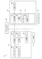
図1は、実施の形態に係るクライオポンプシステム10を概略的に示す図である。クライオポンプシステム10は、少なくとも1台のクライオポンプ12と、複数台の圧縮機14とを備える。ここでは、例示的な構成として、クライオポンプシステム10が2台のクライオポンプ12と2台の圧縮機14を有する場合を示す。   FIG. 1 is a diagram schematically illustrating a cryopump system 10 according to an embodiment. The cryopump system 10 includes at least one cryopump 12 and a plurality of compressors 14. Here, a case where the cryopump system 10 includes two cryopumps 12 and two compressors 14 is illustrated as an exemplary configuration.

クライオポンプ12は、例えばスパッタリング装置または蒸着装置の真空チャンバに取り付けられて、真空チャンバ内部の真空度を所望の真空プロセスに要求されるレベルまで高めるために使用される。   The cryopump 12 is attached to, for example, a vacuum chamber of a sputtering apparatus or a vapor deposition apparatus, and is used to increase the degree of vacuum inside the vacuum chamber to a level required for a desired vacuum process.

クライオポンプ12は、クライオパネル16と、冷媒ガスの断熱膨張を用いてクライオパネル16を冷却する冷凍機18と、を備える。クライオパネル16は、クライオポンプ12に収容されており、クライオポンプ12の動作中は冷凍機18によって極低温に冷却される。冷凍機18は、膨張機またはコールドヘッドとも称され、圧縮機14とともに極低温冷凍機を構成する。クライオポンプ12の吸気口から進入する気体は、極低温に冷却されたクライオパネル16の表面に凝縮され、またはクライオパネル16上に設けられた吸着材に吸着されて捕捉される。クライオパネル16の配置や形状などクライオポンプ12の構成は、種々の公知の構成を適宜採用することができるので、ここでは詳述しない。   The cryopump 12 includes a cryopanel 16 and a refrigerator 18 that cools the cryopanel 16 using adiabatic expansion of the refrigerant gas. The cryopanel 16 is housed in the cryopump 12, and is cooled to a very low temperature by the refrigerator 18 during operation of the cryopump 12. The refrigerator 18 is also called an expander or a cold head, and forms a cryogenic refrigerator together with the compressor 14. The gas entering from the suction port of the cryopump 12 is condensed on the surface of the cryopanel 16 cooled to an extremely low temperature, or is adsorbed and captured by an adsorbent provided on the cryopanel 16. The configuration of the cryopump 12, such as the arrangement and shape of the cryopanel 16, can employ various known configurations as appropriate, and will not be described in detail here.

圧縮機14は、冷凍機18に冷媒ガスを供給するように並列接続され同時に運転される。圧縮機14は、冷媒ガスを冷凍機18から回収し、回収した冷媒ガスを昇圧して、再び冷媒ガスを冷凍機18に供給するよう構成されている。   The compressors 14 are connected in parallel so as to supply refrigerant gas to the refrigerator 18 and are operated at the same time. The compressor 14 is configured to collect the refrigerant gas from the refrigerator 18, increase the pressure of the collected refrigerant gas, and supply the refrigerant gas to the refrigerator 18 again.

後述するように、クライオポンプシステム10の動作中、複数台の圧縮機14は常態として同時に運転される。いずれかの圧縮機14が何らかの要因により停止した場合、残りの圧縮機14は継続して運転される。   As described below, during the operation of the cryopump system 10, the plurality of compressors 14 are simultaneously operated in a normal state. If any one of the compressors 14 stops for some reason, the remaining compressors 14 are continuously operated.

圧縮機14と冷凍機18との間の冷媒ガスの循環が冷凍機18内での冷媒ガスの適切な圧力変動と容積変動の組み合わせをもって行われることにより、寒冷を発生する熱力学的サイクルが構成され、冷凍機18の冷却ステージが所望の極低温に冷却される。それにより、冷凍機18の冷却ステージに熱的に結合されたクライオパネル16を目標冷却温度に冷却することができる。冷媒ガスは、通例はヘリウムガスであるが、適切な他のガスが用いられてもよい。理解のために、冷媒ガスの流れる方向を図1に矢印で示す。   The circulation of the refrigerant gas between the compressor 14 and the refrigerator 18 is performed with an appropriate combination of pressure fluctuation and volume fluctuation of the refrigerant gas in the refrigerator 18, thereby forming a thermodynamic cycle for generating cold. Then, the cooling stage of the refrigerator 18 is cooled to a desired cryogenic temperature. Thereby, the cryopanel 16 thermally coupled to the cooling stage of the refrigerator 18 can be cooled to the target cooling temperature. The refrigerant gas is typically helium gas, but any other suitable gas may be used. For the sake of understanding, the direction in which the refrigerant gas flows is indicated by an arrow in FIG.

冷凍機18は、一例として、単段式または二段式のギフォード・マクマホン(Gifford-McMahon;GM)冷凍機であるが、パルス管冷凍機、スターリング冷凍機、またはそのほかのタイプの極低温冷凍機であってもよい。冷凍機18は、極低温冷凍機のタイプに応じて異なる構成を有する。圧縮機14は、極低温冷凍機のタイプによらず、同じ構成を用いることができる。   The refrigerator 18 is, for example, a single-stage or two-stage Gifford-McMahon (GM) refrigerator, but may be a pulse tube refrigerator, a Stirling refrigerator, or another type of cryogenic refrigerator. It may be. The refrigerator 18 has different configurations depending on the type of the cryogenic refrigerator. The same configuration can be used for the compressor 14 regardless of the type of the cryogenic refrigerator.

なお、一般に、圧縮機14から冷凍機18に供給される冷媒ガスの圧力と、冷凍機18から圧縮機14に回収される冷媒ガスの圧力は、ともに大気圧よりかなり高く、それぞれ第1高圧及び第2高圧と呼ぶことができる。説明の便宜上、第1高圧及び第2高圧はそれぞれ単に高圧及び低圧とも呼ばれる。典型的には、高圧は例えば約2〜3MPaの範囲にあり、低圧は例えば約0.5〜1.5MPaの範囲にある。   In general, the pressure of the refrigerant gas supplied from the compressor 14 to the refrigerator 18 and the pressure of the refrigerant gas recovered from the refrigerator 18 to the compressor 14 are both considerably higher than the atmospheric pressure, and the first high pressure and the first pressure, respectively. It can be referred to as a second high pressure. For convenience of explanation, the first high pressure and the second high pressure are also simply referred to as a high pressure and a low pressure, respectively. Typically, the high pressure is, for example, in the range of about 2-3 MPa and the low pressure is, for example, in the range of about 0.5-1.5 MPa.

圧縮機14は、吐出ポート20と吸入ポート21とを有する。吐出ポート20は、圧縮機14により高圧に昇圧された冷媒ガスを圧縮機14から送出するために圧縮機14に設けられた冷媒ガスの出口であり、吸入ポート21は、低圧の冷媒ガスを圧縮機14に受け入れるために圧縮機14に設けられた冷媒ガスの入口である。   The compressor 14 has a discharge port 20 and a suction port 21. The discharge port 20 is an outlet of the refrigerant gas provided in the compressor 14 for sending out the refrigerant gas pressurized to a high pressure by the compressor 14, and the suction port 21 compresses the low-pressure refrigerant gas. A refrigerant gas inlet provided in the compressor 14 for receipt by the compressor 14;

冷凍機18は、高圧ポート22と低圧ポート23とを有する。高圧ポート22は、冷凍機18の内部に高圧の作動ガスを受け入れるために冷凍機18に設けられた冷媒ガスの入口である。低圧ポート23は、冷凍機18の内部での冷媒ガスの膨張により減圧された低圧の冷媒ガスを冷凍機18から排出するために冷凍機18に設けられた冷媒ガスの出口である。   The refrigerator 18 has a high pressure port 22 and a low pressure port 23. The high-pressure port 22 is an inlet for a refrigerant gas provided in the refrigerator 18 for receiving a high-pressure working gas inside the refrigerator 18. The low-pressure port 23 is an outlet for the refrigerant gas provided in the refrigerator 18 for discharging the low-pressure refrigerant gas reduced in pressure by expansion of the refrigerant gas inside the refrigerator 18 from the refrigerator 18.

また、クライオポンプシステム10は、圧縮機14と冷凍機18との間で冷媒ガスを循環させるべくこれらを接続する配管システム24を備える。配管システム24は、高圧ライン26と低圧ライン28とを備える。高圧ライン26は、圧縮機14の吐出ポート20から高圧合流部25を経て冷凍機18の高圧ポート22へと冷媒ガスが流れることができるように構成されている。低圧ライン28は、冷凍機18の低圧ポート23から低圧合流部27を経て圧縮機14の吸入ポート21に冷媒ガスが流れることができるように構成されている。配管システム24は、圧縮機14ごとに吐出側逆止弁29と吸入側逆止弁30とを備える。   In addition, the cryopump system 10 includes a piping system 24 that connects refrigerant gas between the compressor 14 and the refrigerator 18 so as to circulate them. The piping system 24 includes a high pressure line 26 and a low pressure line 28. The high-pressure line 26 is configured such that refrigerant gas can flow from the discharge port 20 of the compressor 14 to the high-pressure port 22 of the refrigerator 18 via the high-pressure junction 25. The low-pressure line 28 is configured so that refrigerant gas can flow from the low-pressure port 23 of the refrigerator 18 to the suction port 21 of the compressor 14 via the low-pressure junction 27. The piping system 24 includes a discharge check valve 29 and a suction check valve 30 for each compressor 14.

高圧ライン26は、圧縮機高圧サブライン31と冷凍機高圧サブライン32とを有する。圧縮機高圧サブライン31は、圧縮機14の吐出ポート20を高圧合流部25に接続し、冷凍機高圧サブライン32は、冷凍機18の高圧ポート22を高圧合流部25に接続する。高圧ライン26は圧縮機14から冷凍機18への冷媒ガスの流路であるから、圧縮機14から冷凍機18に向かう流れ方向を高圧ライン26の順方向と呼び、その反対方向を高圧ライン26の逆方向と呼ぶことができる。順方向は、図示されている矢印の向きにあたる。吐出側逆止弁29は、順方向の冷媒ガス流れを許容し、逆方向の冷媒ガス流れを遮断するように、圧縮機高圧サブライン31に配置されている。   The high-pressure line 26 has a compressor high-pressure subline 31 and a refrigerator high-pressure subline 32. The compressor high pressure subline 31 connects the discharge port 20 of the compressor 14 to the high pressure junction 25, and the refrigerator high pressure subline 32 connects the high pressure port 22 of the refrigerator 18 to the high pressure junction 25. Since the high-pressure line 26 is a flow path of the refrigerant gas from the compressor 14 to the refrigerator 18, the flow direction from the compressor 14 to the refrigerator 18 is called a forward direction of the high-pressure line 26, and the opposite direction is the high-pressure line 26. Can be called the opposite direction. The forward direction corresponds to the direction of the illustrated arrow. The discharge-side check valve 29 is disposed in the compressor high-pressure sub-line 31 so as to allow the refrigerant gas flow in the forward direction and block the refrigerant gas flow in the reverse direction.

低圧ライン28は、圧縮機低圧サブライン33と冷凍機低圧サブライン34とを有する。圧縮機低圧サブライン33は、圧縮機14の吸入ポート21を低圧合流部27に接続し、冷凍機低圧サブライン34は、冷凍機18の低圧ポート23を低圧合流部27に接続する。低圧ライン28は、冷凍機18から圧縮機14への冷媒ガスの流路であるから、冷凍機18から圧縮機14に向かう流れ方向を低圧ライン28の順方向と呼び、その反対方向を低圧ライン28の逆方向と呼ぶことができる。吸入側逆止弁30は、順方向の冷媒ガス流れを許容し、逆方向の冷媒ガス流れを遮断するように、圧縮機低圧サブライン33に配置されている。   The low pressure line 28 has a compressor low pressure subline 33 and a refrigerator low pressure subline 34. The compressor low pressure subline 33 connects the suction port 21 of the compressor 14 to the low pressure junction 27, and the refrigerator low pressure subline 34 connects the low pressure port 23 of the refrigerator 18 to the low pressure junction 27. Since the low-pressure line 28 is a flow path of the refrigerant gas from the refrigerator 18 to the compressor 14, the flow direction from the refrigerator 18 to the compressor 14 is called a forward direction of the low-pressure line 28, and the opposite direction is the low-pressure line. 28 can be called the opposite direction. The suction-side check valve 30 is disposed in the compressor low-pressure sub-line 33 so as to allow the refrigerant gas flow in the forward direction and block the refrigerant gas flow in the reverse direction.

吐出側逆止弁29および吸入側逆止弁30はいずれも、順方向上流側(すなわち逆止弁への入口側)での冷媒ガス圧力が順方向下流側(すなわち逆止弁の出口側)での冷媒ガス圧力を超える場合に開き、逆に順方向上流側での冷媒ガス圧力が順方向下流側での冷媒ガス圧力を超えない場合に閉じるように構成されている。言い換えれば、各逆止弁(29,30)は、その逆止弁を流れる順方向の冷媒ガス流れがあるときには、逆止弁が順方向流れに生じさせる圧力損失によって自然に開く。一方、各逆止弁(29,30)は、その逆止弁の出入口間に冷媒ガスの逆流を生み出しうる圧力差(すなわち出口圧が入口圧より高い)が発生すると、閉じる。このように上流側と下流側との間の差圧の作用により開閉する逆止弁は一般に入手可能であり、各逆止弁(29,30)は、そうした汎用の逆止弁を適宜採用することができる。   In each of the discharge-side check valve 29 and the suction-side check valve 30, the refrigerant gas pressure on the upstream side in the forward direction (ie, the inlet side to the check valve) is the downstream side in the forward direction (ie, the outlet side of the check valve). It is configured to open when the refrigerant gas pressure exceeds the refrigerant gas pressure at the upstream in the forward direction and conversely when the refrigerant gas pressure at the upstream in the forward direction does not exceed the refrigerant gas pressure at the downstream in the forward direction. In other words, each check valve (29, 30) opens spontaneously due to the pressure loss caused by the check valve in the forward flow when there is a forward refrigerant gas flow through the check valve. On the other hand, each check valve (29, 30) closes when a pressure difference (that is, the outlet pressure is higher than the inlet pressure) is generated between the inlet and the outlet of the check valve, which can generate the backflow of the refrigerant gas. As described above, a check valve that opens and closes by the action of a differential pressure between the upstream side and the downstream side is generally available, and each check valve (29, 30) appropriately employs such a general-purpose check valve. be able to.

一例として、高圧ライン26および低圧ライン28は、フレキシブル管により構成されるが、リジッド管で構成されてもよい。また、高圧合流部25及び/または低圧合流部27は、単一部品(例えばマニホールド)として構成されてもよい。この単一部品に吐出側逆止弁29及び/または吸入側逆止弁30が組み込まれていてもよい。   As an example, the high-pressure line 26 and the low-pressure line 28 are configured by flexible pipes, but may be configured by rigid pipes. Further, the high-pressure junction 25 and / or the low-pressure junction 27 may be configured as a single component (for example, a manifold). The discharge side check valve 29 and / or the suction side check valve 30 may be incorporated in this single component.

配管システム24は、吐出側逆止弁29の両側に設けられた一組の脱着可能な継手35と、吸入側逆止弁30の両側に設けられたもう一組の脱着可能な継手35と、を備える。脱着可能な継手35は、例えば、セルフシーリング・カップリングである。   The piping system 24 includes a pair of detachable joints 35 provided on both sides of the discharge-side check valve 29, and another pair of detachable joints 35 provided on both sides of the suction-side check valve 30. Is provided. The detachable joint 35 is, for example, a self-sealing coupling.

なお、脱着可能な継手35は、吐出側逆止弁29の片側(すなわち、吐出側逆止弁29と吐出ポート20の間、または吐出側逆止弁29と高圧合流部25の間)にのみ設けられていてもよい。同様に、脱着可能な継手35は、吸入側逆止弁30の片側にのみ設けられていてもよい。吐出側逆止弁29は、吐出ポート20に一体的に組み込まれていてもよい。吸入側逆止弁30は、吸入ポート21に一体的に組み込まれていてもよい。   The detachable joint 35 is provided only on one side of the discharge-side check valve 29 (that is, between the discharge-side check valve 29 and the discharge port 20 or between the discharge-side check valve 29 and the high-pressure junction 25). It may be provided. Similarly, the detachable joint 35 may be provided only on one side of the suction-side check valve 30. The discharge side check valve 29 may be integrated with the discharge port 20. The suction side check valve 30 may be integrated with the suction port 21.

複数の圧縮機14は常態として、クライオポンプシステム10の動作中に同時に運転される。   The plurality of compressors 14 are normally operated simultaneously during the operation of the cryopump system 10.

図1に示されるように、各圧縮機14において圧縮された高圧の冷媒ガスは、圧縮機14の吐出ポート20から圧縮機高圧サブライン31に送出される。冷媒ガスは高圧ライン26の順方向に流れているから、吐出側逆止弁29を通じて流れることができる。複数の圧縮機14からの冷媒ガス流れは高圧合流部25で一度合流し、冷凍機高圧サブライン32へと再び分流される。冷媒ガスは冷凍機高圧サブライン32から冷凍機18の高圧ポート22を経て冷凍機18に供給される。こうして、クライオポンプシステム10は、複数の圧縮機14からクライオポンプ12へと高圧の冷媒ガスを供給することができる。   As shown in FIG. 1, the high-pressure refrigerant gas compressed in each compressor 14 is sent from a discharge port 20 of the compressor 14 to a compressor high-pressure sub-line 31. Since the refrigerant gas flows in the forward direction of the high pressure line 26, the refrigerant gas can flow through the discharge side check valve 29. The refrigerant gas flows from the plurality of compressors 14 are merged once in the high-pressure merging section 25 and are again divided into the high-pressure sub-line 32 of the refrigerator. The refrigerant gas is supplied to the refrigerator 18 from the refrigerator high-pressure subline 32 via the high-pressure port 22 of the refrigerator 18. Thus, the cryopump system 10 can supply high-pressure refrigerant gas from the plurality of compressors 14 to the cryopump 12.

各冷凍機18から排出される低圧の冷媒ガスは、冷凍機18の低圧ポート23から冷凍機低圧サブライン34を流れる。冷媒ガス流れは低圧合流部27で一度合流し、圧縮機低圧サブライン33へと再び分流される。冷媒ガスは低圧ライン28の順方向に流れているから、吸入側逆止弁30を通じて流れることができる。冷媒ガスは圧縮機低圧サブライン33から圧縮機14の吸入ポート21経て圧縮機14に回収される。こうして、クライオポンプシステム10は、クライオポンプ12から複数の圧縮機14へと低圧の冷媒ガスを回収することができる。   The low-pressure refrigerant gas discharged from each refrigerator 18 flows through the refrigerator low-pressure subline 34 from the low-pressure port 23 of the refrigerator 18. The refrigerant gas flows are merged once in the low-pressure merging section 27, and are diverted again to the compressor low-pressure subline 33. Since the refrigerant gas flows in the forward direction of the low-pressure line 28, it can flow through the suction-side check valve 30. Refrigerant gas is recovered by the compressor 14 from the compressor low-pressure subline 33 via the suction port 21 of the compressor 14. Thus, the cryopump system 10 can recover low-pressure refrigerant gas from the cryopump 12 to the plurality of compressors 14.

図2は、実施の形態に係るクライオポンプシステム10における冷媒ガスの流れを概略的に示す図である。図1に示されるクライオポンプシステム10の正常動作とは異なり、図2には、複数台の圧縮機14のうちある圧縮機14が何らかの要因により停止した異常時における冷媒ガスの流れを示す。圧縮機14は、停電、冷却設備の不具合、あるいは、気温や湿度、気圧など周囲環境の異常変動など、クライオポンプシステム10自体では制御不能または対処困難な種々の外部的要因により異常停止しうる。   FIG. 2 is a diagram schematically illustrating the flow of the refrigerant gas in the cryopump system 10 according to the embodiment. Unlike the normal operation of the cryopump system 10 shown in FIG. 1, FIG. 2 shows the flow of the refrigerant gas at the time of abnormality when one of the plurality of compressors 14 is stopped for some reason. The compressor 14 may abnormally stop due to various external factors that cannot be controlled or difficult to control by the cryopump system 10 itself, such as a power failure, a failure in a cooling facility, or an abnormal change in the surrounding environment such as temperature, humidity, and atmospheric pressure.

ある圧縮機14が異常停止した場合、残りの圧縮機14が継続して運転され、それによりクライオポンプシステム10の停止を回避することが可能となる。図2にはクライオポンプシステム10が2台の圧縮機14を有する例を示しているから、一方の圧縮機14が停止し、他方の圧縮機14は正常に運転を継続している。   When a certain compressor 14 abnormally stops, the remaining compressors 14 are continuously operated, so that the stop of the cryopump system 10 can be avoided. FIG. 2 shows an example in which the cryopump system 10 has two compressors 14, so one of the compressors 14 is stopped and the other compressor 14 continues to operate normally.

説明の便宜上、停止している圧縮機を第1圧縮機14aと称し、動作している圧縮機を第2圧縮機14bと称することとする。また、第1圧縮機14aに付随する吐出側逆止弁29および吸入側逆止弁30をそれぞれ、第1吐出側逆止弁29aおよび第1吸入側逆止弁30aと称する。同様に、第2圧縮機14bに付随する吐出側逆止弁29および吸入側逆止弁30をそれぞれ、第2吐出側逆止弁29bおよび第2吸入側逆止弁30bと称する。   For convenience of description, the stopped compressor is referred to as a first compressor 14a, and the operating compressor is referred to as a second compressor 14b. The discharge-side check valve 29 and the suction-side check valve 30 associated with the first compressor 14a are referred to as a first discharge-side check valve 29a and a first suction-side check valve 30a, respectively. Similarly, the discharge-side check valve 29 and the suction-side check valve 30 associated with the second compressor 14b are referred to as a second discharge-side check valve 29b and a second suction-side check valve 30b, respectively.

この場合、図2に示されるように、第1圧縮機14aにより圧縮された高圧の冷媒ガスは、第1圧縮機14aの吐出ポート20から高圧ライン26に送出される。冷媒ガスは、圧縮機高圧サブライン31から高圧合流部25を経て冷凍機高圧サブライン32に分岐し、各冷凍機18の高圧ポート22に流入する。冷媒ガスは高圧ライン26の順方向に流れているから、第1吐出側逆止弁29aを通じて流れることができる。   In this case, as shown in FIG. 2, the high-pressure refrigerant gas compressed by the first compressor 14a is sent from the discharge port 20 of the first compressor 14a to the high-pressure line 26. The refrigerant gas branches from the compressor high-pressure subline 31 through the high-pressure junction 25 to the refrigerator high-pressure subline 32, and flows into the high-pressure port 22 of each refrigerator 18. Since the refrigerant gas flows in the forward direction of the high pressure line 26, it can flow through the first discharge side check valve 29a.

一方、第2圧縮機14bは停止しているから、第2圧縮機14bの吐出ポート20から冷媒ガスは吐出されない。そのため、第2吐出側逆止弁29bについては、その順方向上流側での冷媒ガス圧力が順方向下流側での冷媒ガス圧力を下回り、第2吐出側逆止弁29bは閉鎖される。よって、第2吐出側逆止弁29bは、圧縮機高圧サブライン31を通じた第2圧縮機14bへの冷媒ガスの逆流を遮断する。   On the other hand, since the second compressor 14b is stopped, the refrigerant gas is not discharged from the discharge port 20 of the second compressor 14b. Therefore, as for the second discharge side check valve 29b, the refrigerant gas pressure on the upstream side in the forward direction falls below the refrigerant gas pressure on the downstream side in the forward direction, and the second discharge side check valve 29b is closed. Therefore, the second discharge-side check valve 29b blocks the backflow of the refrigerant gas to the second compressor 14b through the compressor high-pressure sub-line 31.

このようにして、高圧ライン26を通じて第1圧縮機14aから冷凍機18へと高圧の冷媒ガスを供給することができる。また、第1圧縮機14aから第2圧縮機14への高圧ライン26を通じた逆流が防止される。   Thus, high-pressure refrigerant gas can be supplied from the first compressor 14a to the refrigerator 18 through the high-pressure line 26. Further, backflow from the first compressor 14a to the second compressor 14 through the high-pressure line 26 is prevented.

冷凍機18から排出される低圧の冷媒ガスは、冷凍機18の低圧ポート23から低圧ライン28に送出される。冷媒ガスは、冷凍機低圧サブライン34から低圧合流部27および圧縮機低圧サブライン33を経て第1圧縮機14aの吸入ポート21に流入する。冷媒ガスは低圧ライン28の順方向に流れているから、第1吸入側逆止弁30aを通じて流れることができる。   The low-pressure refrigerant gas discharged from the refrigerator 18 is sent from the low-pressure port 23 of the refrigerator 18 to the low-pressure line 28. Refrigerant gas flows from the refrigerator low-pressure subline 34 to the suction port 21 of the first compressor 14a via the low-pressure junction 27 and the compressor low-pressure subline 33. Since the refrigerant gas flows in the forward direction of the low pressure line 28, it can flow through the first suction side check valve 30a.

一方、第2圧縮機14bは停止しているから、第2圧縮機14bの吸入ポート21から冷媒ガスは吸入されない。そのため、第2吸入側逆止弁30bについては、その順方向下流側で順方向上流側よりも圧力が高くなり、第2吸入側逆止弁30bは閉鎖される。よって、第2吸入側逆止弁30bは、圧縮機低圧サブライン33を通じた第2圧縮機14bへの冷媒ガスの逆流を遮断する。   On the other hand, since the second compressor 14b is stopped, the refrigerant gas is not sucked from the suction port 21 of the second compressor 14b. Therefore, the pressure of the second suction-side check valve 30b is higher on the downstream side in the forward direction than on the upstream side in the forward direction, and the second suction-side check valve 30b is closed. Therefore, the second suction-side check valve 30b blocks the backflow of the refrigerant gas to the second compressor 14b through the compressor low-pressure sub-line 33.

このようにして、低圧ライン28を通じて冷凍機18から第1圧縮機14aへと低圧の冷媒ガスを回収することができる。また、第2圧縮機14から第1圧縮機14aへの低圧ライン28を通じた逆流が防止される。   Thus, low-pressure refrigerant gas can be recovered from the refrigerator 18 to the first compressor 14a through the low-pressure line 28. Further, backflow from the second compressor 14 to the first compressor 14a through the low-pressure line 28 is prevented.

なお、圧縮機14においては通例、停止しているとき吐出ポート20と吸入ポート21は均圧化されている。すなわち、吐出ポート20と吸入ポート21はともに高圧と低圧の平均圧となっている(例えば高圧が2MPaで低圧が0.6MPaであれば平均圧は1.3MPaである)。よって、第2吐出側逆止弁29bと第2吸入側逆止弁30bはともに、出口圧が入口圧よりも顕著に高くなり、この圧力差によって確実に閉鎖される。   In the compressor 14, the discharge port 20 and the suction port 21 are normally equalized when the compressor is stopped. That is, both the discharge port 20 and the suction port 21 have high and low average pressures (for example, if the high pressure is 2 MPa and the low pressure is 0.6 MPa, the average pressure is 1.3 MPa). Therefore, the outlet pressure of both the second discharge-side check valve 29b and the second suction-side check valve 30b is significantly higher than the inlet pressure, and the pressure difference is surely closed.

図3は、実施の形態に係るクライオポンプシステム10に関する制御ブロック図である。図3は、クライオポンプシステム10の関連部分を示し、複数のクライオポンプ12のうち1つについて内部の詳細を示し、他のクライオポンプ12については同様であるので図示を省略する。同様に、複数の圧縮機14について詳細を示し、他の圧縮機14はそれと同様であるので内部の図示を省略する。   FIG. 3 is a control block diagram of the cryopump system 10 according to the embodiment. FIG. 3 shows a relevant portion of the cryopump system 10, showing internal details of one of the plurality of cryopumps 12, and illustration of other cryopumps 12 is omitted because it is the same. Similarly, the details of the plurality of compressors 14 are shown, and the other compressors 14 are the same as those, so that the internal illustration is omitted.

なお、こうしたクライオポンプシステム10の制御構成は、ハードウェア構成としてはコンピュータのCPUやメモリをはじめとする素子や回路で実現され、ソフトウェア構成としてはコンピュータプログラム等によって実現されるが、図3では適宜、それらの連携によって実現される機能ブロックとして描いている。これらの機能ブロックはハードウェア、ソフトウェアの組合せによっていろいろなかたちで実現できることは、当業者には理解されるところである。   Note that such a control configuration of the cryopump system 10 is realized as a hardware configuration by elements and circuits such as a CPU and a memory of a computer, and a software configuration is realized by a computer program and the like. , As functional blocks realized by their cooperation. It is understood by those skilled in the art that these functional blocks can be realized in various forms by a combination of hardware and software.

クライオポンプシステム10は、クライオポンプコントローラ(以下ではCPコントローラとも称する)100を備える。CPコントローラ100は、クライオポンプ12(即ち冷凍機18)および圧縮機14を制御する。CPコントローラ100は、各種演算処理を実行するCPU、各種制御プログラムを格納するROM、データ格納やプログラム実行のためのワークエリアとして利用されるRAM、入出力インターフェース、メモリ等を備える。また、CPコントローラ100は、クライオポンプ12が取り付けられる真空プロセス装置を制御するための上位のコントローラ(図示せず)とも通信可能に構成されている。   The cryopump system 10 includes a cryopump controller (hereinafter, also referred to as a CP controller) 100. The CP controller 100 controls the cryopump 12 (that is, the refrigerator 18) and the compressor 14. The CP controller 100 includes a CPU that executes various arithmetic processes, a ROM that stores various control programs, a RAM that is used as a work area for storing data and executing programs, an input / output interface, and a memory. Further, the CP controller 100 is configured to be able to communicate with a higher-level controller (not shown) for controlling a vacuum process device to which the cryopump 12 is attached.

CPコントローラ100は、クライオポンプ12及び圧縮機14とは別体として設置されている。CPコントローラ100は、クライオポンプ12及び圧縮機14と互いに通信可能に接続されている。クライオポンプ12はそれぞれ、CPコントローラ100と通信する入出力を処理するためのIOモジュール50を備える。なおCPコントローラ100は、いずれかのクライオポンプ12または圧縮機14と一体に搭載されていてもよい。   The CP controller 100 is installed separately from the cryopump 12 and the compressor 14. The CP controller 100 is communicably connected to the cryopump 12 and the compressor 14. Each of the cryopumps 12 includes an IO module 50 for processing input / output for communicating with the CP controller 100. Note that the CP controller 100 may be mounted integrally with any one of the cryopump 12 or the compressor 14.

CPコントローラ100は上述のように、各クライオポンプ12のIOモジュール50に通信可能に接続されている。IOモジュール50は、冷凍機インバータ52及び信号処理部54を含む。冷凍機18は、冷凍機18の熱力学的サイクルを駆動する駆動源としての冷凍機モータ56を備える。冷凍機インバータ52は外部電源例えば商用電源から供給される規定の電圧及び周波数の電力を調整し冷凍機モータ56に供給する。冷凍機モータ56に供給されるべき電圧及び周波数はCPコントローラ100により制御される。クライオポンプ12は、クライオパネル温度センサ58を備える。クライオパネル温度センサ58は、冷凍機18の冷却ステージ及び/またはクライオパネル16(図1参照)の温度を測定する。   As described above, the CP controller 100 is communicably connected to the IO module 50 of each cryopump 12. The IO module 50 includes a refrigerator inverter 52 and a signal processing unit 54. The refrigerator 18 includes a refrigerator motor 56 as a drive source for driving a thermodynamic cycle of the refrigerator 18. The refrigerator inverter 52 regulates power of a specified voltage and frequency supplied from an external power supply, for example, a commercial power supply, and supplies the regulated power to the refrigerator motor 56. The voltage and frequency to be supplied to the refrigerator motor 56 are controlled by the CP controller 100. The cryopump 12 includes a cryopanel temperature sensor 58. The cryopanel temperature sensor 58 measures the temperature of the cooling stage of the refrigerator 18 and / or the cryopanel 16 (see FIG. 1).

CPコントローラ100はセンサ出力信号に基づいて指令制御量を決定する。信号処理部54は、CPコントローラ100から送信された指令制御量を冷凍機インバータ52へと中継する。例えば、信号処理部54はCPコントローラ100からの指令信号を冷凍機インバータ52で処理可能な信号に変換して冷凍機インバータ52に送信する。指令信号は冷凍機18の運転周波数を表す信号を含む。また、信号処理部54は、クライオポンプ12の各種センサの出力をCPコントローラ100へと中継する。例えば、信号処理部54はセンサ出力信号をCPコントローラ100で処理可能な信号に変換してCPコントローラ100に送信する。   The CP controller 100 determines a command control amount based on the sensor output signal. The signal processing unit 54 relays the command control amount transmitted from the CP controller 100 to the refrigerator inverter 52. For example, the signal processing unit 54 converts a command signal from the CP controller 100 into a signal that can be processed by the refrigerator inverter 52 and transmits the signal to the refrigerator inverter 52. The command signal includes a signal indicating the operating frequency of the refrigerator 18. Further, the signal processing unit 54 relays outputs of various sensors of the cryopump 12 to the CP controller 100. For example, the signal processing unit 54 converts the sensor output signal into a signal that can be processed by the CP controller 100 and transmits the signal to the CP controller 100.

IOモジュール50の信号処理部54には、クライオパネル温度センサ58を含む各種センサが接続されている。クライオパネル温度センサ58は、クライオパネル16の温度を周期的に測定し、測定温度値を示す信号を出力する。クライオパネル温度センサ58の測定温度信号は、所定時間おきにCPコントローラ100へと入力され、温度測定値はCPコントローラ100の所定の記憶領域に格納保持される。   Various sensors including a cryopanel temperature sensor 58 are connected to the signal processing unit 54 of the IO module 50. The cryopanel temperature sensor 58 periodically measures the temperature of the cryopanel 16 and outputs a signal indicating the measured temperature value. The measured temperature signal of the cryopanel temperature sensor 58 is input to the CP controller 100 at predetermined time intervals, and the measured temperature value is stored and held in a predetermined storage area of the CP controller 100.

冷凍機18の運転周波数(運転速度ともいう)とは、冷凍機モータ56の運転周波数または回転数、冷凍機インバータ52の運転周波数、冷凍機18の熱力学的サイクル(例えばGMサイクルなどの冷凍サイクル)の周波数、または、これらのいずれかを表す。熱力学的サイクルの周波数とは、冷凍機18において行われる熱力学的サイクルの単位時間あたりの回数である。   The operating frequency (also referred to as operating speed) of the refrigerator 18 includes the operating frequency or rotation speed of the refrigerator motor 56, the operating frequency of the refrigerator inverter 52, and the thermodynamic cycle of the refrigerator 18 (for example, a refrigeration cycle such as a GM cycle). ) Or any of these. The frequency of the thermodynamic cycle is the number of thermodynamic cycles performed in the refrigerator 18 per unit time.

CPコントローラ100は、目標冷却温度とクライオパネルの測定温度との偏差の関数として(例えばPID制御により)冷凍機18の運転周波数を決定するよう構成されている。CPコントローラ100は、決定された運転周波数を冷凍機インバータ52に出力する。冷凍機インバータ52は、入力電力を、CPコントローラ100から入力された運転周波数を有するよう変換する。冷凍機インバータ52への入力電力は、冷凍機電源(図示せず)から供給される。冷凍機インバータ52は、変換された電力を冷凍機モータ56に出力する。こうして冷凍機モータ56は、CPコントローラ100によって決定され冷凍機インバータ52から出力された運転周波数で駆動される。   The CP controller 100 is configured to determine the operating frequency of the refrigerator 18 as a function of the deviation between the target cooling temperature and the measured temperature of the cryopanel (for example, by PID control). CP controller 100 outputs the determined operating frequency to refrigerator inverter 52. The refrigerator inverter 52 converts the input power to have the operating frequency input from the CP controller 100. Input power to the refrigerator inverter 52 is supplied from a refrigerator power supply (not shown). The refrigerator inverter 52 outputs the converted electric power to the refrigerator motor 56. Thus, the refrigerator motor 56 is driven at the operating frequency determined by the CP controller 100 and output from the refrigerator inverter 52.

クライオポンプ12への熱負荷が増加したときクライオパネル16の温度が高まりうる。クライオパネル温度センサ58の測定温度が目標温度よりも高温である場合には、CPコントローラ100は、冷凍機18の運転周波数を増加させる。その結果、冷凍機18における熱力学的サイクルの周波数も増加され(すなわち冷凍機18の冷凍能力は高まり)、クライオパネル16は目標温度に向けて冷却される。逆にクライオパネル温度センサ58の測定温度が目標温度よりも低温である場合には、冷凍機18の運転周波数は減少され冷凍能力は低下し、クライオパネル16は目標温度に向けて昇温される。こうして、クライオパネル16の温度を目標温度の近傍の温度範囲に留めることができる。熱負荷に応じて冷凍機18の運転周波数を適切に調整することができるので、こうした制御はクライオポンプ12の消費電力の低減に役立つ。   When the thermal load on the cryopump 12 increases, the temperature of the cryopanel 16 can increase. When the temperature measured by the cryopanel temperature sensor 58 is higher than the target temperature, the CP controller 100 increases the operating frequency of the refrigerator 18. As a result, the frequency of the thermodynamic cycle in the refrigerator 18 is also increased (that is, the refrigerating capacity of the refrigerator 18 is increased), and the cryopanel 16 is cooled toward the target temperature. Conversely, when the temperature measured by the cryopanel temperature sensor 58 is lower than the target temperature, the operating frequency of the refrigerator 18 is reduced, the refrigeration capacity is reduced, and the cryopanel 16 is heated toward the target temperature. . Thus, the temperature of the cryopanel 16 can be kept in a temperature range near the target temperature. Such control helps reduce the power consumption of the cryopump 12 because the operating frequency of the refrigerator 18 can be appropriately adjusted according to the heat load.

このように、冷凍機18でのクライオパネル冷却に使用される冷媒ガス流量は、クライオポンプ12への熱負荷に応じてクライオパネル16の温度を目標温度に維持するように変化する。仮に、圧縮機14から冷凍機18に供給される冷媒ガス流量が不足したとすると、冷凍機18の運転周波数が増加したとしても、冷凍機18の冷凍能力は十分に増加されない。そこで、実施の形態に係るクライオポンプシステム10は、圧縮機14からの冷媒ガス吐出流量を可変とするように構成されている。そうした圧縮機制御の一例を次に説明する。   As described above, the flow rate of the refrigerant gas used for cooling the cryopanel in the refrigerator 18 changes so as to maintain the temperature of the cryopanel 16 at the target temperature in accordance with the heat load on the cryopump 12. If the flow rate of the refrigerant gas supplied from the compressor 14 to the refrigerator 18 is insufficient, even if the operating frequency of the refrigerator 18 increases, the refrigerating capacity of the refrigerator 18 is not sufficiently increased. Therefore, the cryopump system 10 according to the embodiment is configured to make the refrigerant gas discharge flow rate from the compressor 14 variable. An example of such a compressor control will be described below.

また、圧縮機14は、圧縮機コントローラ60と、圧縮機インバータ62と、圧縮機モータ64と、第1圧力センサ66と、第2圧力センサ68とを備える。圧縮機14は、例えば、スクロール方式、ロータリ式、または冷媒ガスを昇圧するそのほかのポンプとして構成され、圧縮機モータ64はこれを駆動する駆動源として設けられている。   The compressor 14 includes a compressor controller 60, a compressor inverter 62, a compressor motor 64, a first pressure sensor 66, and a second pressure sensor 68. The compressor 14 is configured as, for example, a scroll type, a rotary type, or another pump for increasing the pressure of the refrigerant gas, and the compressor motor 64 is provided as a drive source for driving the compressor.

冷凍機18の場合と同様に、圧縮機コントローラ60は、圧縮機14の運転周波数を決定し、決定された運転周波数を圧縮機インバータ62に出力する。圧縮機インバータ62は、圧縮機コントローラ60から入力された運転周波数に従って入力電力を変換し、変換された電力を圧縮機モータ64に出力する。こうして圧縮機モータ64は、圧縮機コントローラ60によって決定され圧縮機インバータ62から出力された運転周波数で駆動される。ここで、圧縮機14の運転周波数とは例えば、圧縮機インバータ62の運転周波数、圧縮機モータ64の運転周波数または回転数を指す。   As in the case of the refrigerator 18, the compressor controller 60 determines the operating frequency of the compressor 14 and outputs the determined operating frequency to the compressor inverter 62. The compressor inverter 62 converts the input power according to the operating frequency input from the compressor controller 60 and outputs the converted power to the compressor motor 64. Thus, the compressor motor 64 is driven at the operating frequency determined by the compressor controller 60 and output from the compressor inverter 62. Here, the operating frequency of the compressor 14 indicates, for example, the operating frequency of the compressor inverter 62, the operating frequency or the rotation speed of the compressor motor 64.

第1圧力センサ66はクライオポンプシステム10の高圧(例えば高圧ライン26の圧力)を測定し、第2圧力センサ68はクライオポンプシステム10の低圧(例えば低圧ライン28の圧力)を測定するように圧縮機14の内部に設けられている。第1圧力センサ66および第2圧力センサ68はそれぞれ、冷媒ガスの圧力を周期的に測定し、測定圧力値を示す信号を圧縮機コントローラ60に出力する。圧縮機コントローラ60は、測定圧力信号及び/または圧縮機14の運転周波数をCPコントローラ100に送信してもよい。   The first pressure sensor 66 measures the high pressure of the cryopump system 10 (eg, the pressure in the high pressure line 26) and the second pressure sensor 68 compresses to measure the low pressure of the cryopump system 10 (eg, the pressure in the low pressure line 28). It is provided inside the machine 14. Each of the first pressure sensor 66 and the second pressure sensor 68 periodically measures the pressure of the refrigerant gas, and outputs a signal indicating the measured pressure value to the compressor controller 60. The compressor controller 60 may transmit the measured pressure signal and / or the operating frequency of the compressor 14 to the CP controller 100.

圧縮機コントローラ60は、第1圧力センサ66及び/または第2圧力センサ68の測定圧力に基づいて圧縮機14の運転周波数を制御するよう構成されている。例えば、圧縮機コントローラ60は、圧縮機14の吐出側と吸入側との差圧と目標差圧との偏差の関数として(例えばPID制御により)圧縮機14の運転周波数を決定するよう構成されている。このような圧縮機14の制御は、「差圧一定制御」と呼ばれることがある。なお必要に応じて、差圧の目標値は差圧一定制御の実行中に変更されてもよい。差圧一定制御において、圧縮機コントローラ60は、第1圧力センサ66の測定圧力と第2圧力センサ68の測定圧力との差圧を求める。圧縮機コントローラ60は、その測定差圧を差圧目標値に一致させるように圧縮機14の運転周波数を決定する。圧縮機コントローラ60は、測定差圧が差圧目標値より大きければ運転周波数を低下させ、測定差圧が差圧目標値より小さければ運転周波数を増加させる。   The compressor controller 60 is configured to control the operating frequency of the compressor 14 based on the measured pressure of the first pressure sensor 66 and / or the second pressure sensor 68. For example, the compressor controller 60 is configured to determine the operating frequency of the compressor 14 as a function of a deviation between a differential pressure between a discharge side and a suction side of the compressor 14 and a target differential pressure (for example, by PID control). I have. Such control of the compressor 14 may be referred to as “constant differential pressure control”. If necessary, the target value of the differential pressure may be changed during the execution of the constant differential pressure control. In the constant differential pressure control, the compressor controller 60 obtains a differential pressure between the measured pressure of the first pressure sensor 66 and the measured pressure of the second pressure sensor 68. The compressor controller 60 determines the operating frequency of the compressor 14 so that the measured differential pressure matches the differential pressure target value. The compressor controller 60 decreases the operating frequency if the measured differential pressure is larger than the target differential pressure value, and increases the operating frequency if the measured differential pressure is smaller than the differential pressure target value.

冷凍機18でのクライオパネル冷却に使用される冷媒ガス流量は、冷凍機18の運転周波数に比例し、例えば、冷凍機18の内部容積と冷凍機18の運転周波数との積から求まる。冷凍機18の運転周波数が増加するほど、圧縮機14から冷凍機18に供給すべき冷媒ガス流量は増える。このとき圧縮機14の運転周波数が低く、圧縮機14からの冷媒ガス供給が不十分だったとすると、圧縮機14の吐出側の圧力は低下する。冷凍機18の運転周波数が増加するとき冷凍機18から圧縮機14に回収すべき冷媒ガス流量も増える。このとき圧縮機14の運転周波数が低ければ、冷凍機18から排気される冷媒ガスを圧縮機14は十分に回収しないから、圧縮機14の吸入側の圧力は高まる。こうして、冷凍機18の運転周波数の増加は、圧縮機14の吐出側と吸入側との差圧を小さくする傾向をもたらす。逆に、冷凍機18の運転周波数の減少は、圧縮機14の吐出側と吸入側との差圧を大きくする傾向をもたらす。   The flow rate of the refrigerant gas used for cryopanel cooling in the refrigerator 18 is proportional to the operating frequency of the refrigerator 18 and is determined, for example, from the product of the internal volume of the refrigerator 18 and the operating frequency of the refrigerator 18. As the operating frequency of the refrigerator 18 increases, the flow rate of the refrigerant gas to be supplied from the compressor 14 to the refrigerator 18 increases. At this time, if the operating frequency of the compressor 14 is low and the supply of the refrigerant gas from the compressor 14 is insufficient, the pressure on the discharge side of the compressor 14 decreases. When the operating frequency of the refrigerator 18 increases, the flow rate of the refrigerant gas to be recovered from the refrigerator 18 to the compressor 14 also increases. At this time, if the operating frequency of the compressor 14 is low, the compressor 14 does not sufficiently collect the refrigerant gas exhausted from the refrigerator 18, so that the pressure on the suction side of the compressor 14 increases. Thus, an increase in the operating frequency of the refrigerator 18 tends to reduce the differential pressure between the discharge side and the suction side of the compressor 14. Conversely, a decrease in the operating frequency of the refrigerator 18 tends to increase the pressure difference between the discharge side and the suction side of the compressor 14.

圧縮機14の差圧一定制御によれば、クライオポンプ12への負荷が増し冷凍機18の運転周波数が増加するときには、圧縮機14の吐出側と吸入側との差圧低下を抑制するように圧縮機14の運転周波数が増加され、圧縮機14から冷凍機18への冷媒ガス供給も増加される。一方、クライオポンプ12への負荷が低下し冷凍機18の運転周波数が減少するときには、圧縮機14の運転周波数が減少されて圧縮機14から冷凍機18への冷媒ガス供給も抑制される。クライオポンプシステム10への負荷に応じて圧縮機14の運転周波数を適切に調整することができるので、差圧一定制御はクライオポンプシステム10の消費電力の低減に役立つ。   According to the differential pressure constant control of the compressor 14, when the load on the cryopump 12 increases and the operating frequency of the refrigerator 18 increases, the decrease in the differential pressure between the discharge side and the suction side of the compressor 14 is suppressed. The operating frequency of the compressor 14 is increased, and the supply of the refrigerant gas from the compressor 14 to the refrigerator 18 is also increased. On the other hand, when the load on the cryopump 12 decreases and the operating frequency of the refrigerator 18 decreases, the operating frequency of the compressor 14 decreases and the supply of the refrigerant gas from the compressor 14 to the refrigerator 18 is also suppressed. Since the operating frequency of the compressor 14 can be appropriately adjusted according to the load on the cryopump system 10, the constant differential pressure control helps to reduce the power consumption of the cryopump system 10.

ところで、典型的なクライオポンプシステムは、圧縮機を1台のみ有するように構成されることができる。これに対して、実施の形態に係るクライオポンプシステム10は、圧縮機14が1台のみではなく、もう1台の圧縮機14が追加されている。クライオポンプシステム10は、圧縮機14に関して冗長性を有する。これら2台の圧縮機14は、クライオポンプ12への冷媒ガス供給源としてクライオポンプシステム10の動作中に同時に運転される。   By the way, a typical cryopump system can be configured to have only one compressor. On the other hand, in the cryopump system 10 according to the embodiment, not only one compressor 14 but also another compressor 14 is added. The cryopump system 10 has redundancy with respect to the compressor 14. These two compressors 14 are simultaneously operated during operation of the cryopump system 10 as a supply source of the refrigerant gas to the cryopump 12.

2台の圧縮機14の冷媒ガス供給能力の合計が、クライオポンプ12の個々の冷凍機18によるクライオパネル冷却に必要な冷媒ガス流量の合計を下回らないように定められている。ここで、圧縮機14の冷媒ガス供給能力は、例えば、圧縮機14が最大の運転周波数で運転されるときに実現される圧縮機14の最大吐出流量を指す。冷凍機18に必要な冷媒ガス流量は、例えば、冷凍機18が最大の運転周波数で運転されるときに冷凍機18に使用される冷媒ガス流量を指す。よって、2台の圧縮機14の冷媒ガス供給能力をQc,Qcと表し、2台の冷凍機18の必要冷媒ガス流量をqr,qrと表すとき、次の関係が成り立つ。
Qc+Qc≧qr+qr
圧縮機14の冷媒ガス供給能力がこのように定められることにより、2台の圧縮機14の同時運転によって2台の冷凍機18に冷媒ガスを十分に供給することができる。冷凍機18における冷媒ガスの不足を回避することができるので、クライオパネル16を目標温度に維持し、クライオポンプシステム10の運転を継続することができる。
The sum of the refrigerant gas supply capacities of the two compressors 14 is set so as not to be less than the total of the refrigerant gas flow rates required for cryopanel cooling by the individual refrigerators 18 of the cryopump 12. Here, the refrigerant gas supply capacity of the compressor 14 indicates, for example, the maximum discharge flow rate of the compressor 14 that is realized when the compressor 14 is operated at the maximum operation frequency. The refrigerant gas flow rate required for the refrigerator 18 indicates, for example, a refrigerant gas flow rate used for the refrigerator 18 when the refrigerator 18 is operated at the maximum operating frequency. Therefore, when the refrigerant gas supply capacities of the two compressors 14 are represented by Qc 1 and Qc 2 and the required refrigerant gas flow rates of the two refrigerators 18 are represented by qr 1 and qr 2 , the following relationship is established.
Qc 1 + Qc 2 ≧ qr 1 + qr 2
With the refrigerant gas supply capacity of the compressor 14 determined in this way, the refrigerant gas can be sufficiently supplied to the two refrigerators 18 by the simultaneous operation of the two compressors 14. Since the shortage of the refrigerant gas in the refrigerator 18 can be avoided, the cryopanel 16 can be maintained at the target temperature, and the operation of the cryopump system 10 can be continued.

加えて、実施の形態に係るクライオポンプシステム10においては、2台の圧縮機14のうちどの圧縮機14についても、当該圧縮機14の冷媒ガス供給能力が、各クライオポンプ12の冷凍機18によるクライオパネル冷却に必要な冷媒ガス流量の合計を下回らないように定められている。すなわち、クライオポンプシステム10は、次の関係も満たす。
Qc≧qr+qr かつ Qc≧qr+qr
In addition, in the cryopump system 10 according to the embodiment, for any one of the two compressors 14, the refrigerant gas supply capacity of the compressor 14 depends on the refrigerator 18 of each cryopump 12. It is determined that the total flow rate of the refrigerant gas required for cooling the cryopanel does not fall below the total. That is, the cryopump system 10 also satisfies the following relationship.
Qc 1 ≧ qr 1 + qr 2 and Qc 2 ≧ qr 1 + qr 2

図2を参照して説明したように、何らかの原因により片方の圧縮機14が停止する状況が想定される。しかし、クライオポンプシステム10は、停止していない他方の圧縮機14によって2台の冷凍機18に冷媒ガスを十分に供給することができる。このようにして、たとえ1台の圧縮機14が運転しない状況にあっても、クライオポンプシステム10は、各クライオポンプ12のクライオパネル16を目標温度に維持し、クライオポンプシステム10の運転を継続することができる。   As described with reference to FIG. 2, it is assumed that one of the compressors 14 stops for some reason. However, the cryopump system 10 can sufficiently supply the two refrigerators 18 with the refrigerant gas by the other compressor 14 that is not stopped. In this way, even if one compressor 14 does not operate, the cryopump system 10 maintains the cryopanel 16 of each cryopump 12 at the target temperature and continues the operation of the cryopump system 10. can do.

実施の形態に係るクライオポンプシステム10の構成は、次のように一般化することができる。クライオポンプシステム10は、M台のクライオポンプ12と、各クライオポンプ12の冷凍機18に冷媒ガスを供給するように並列接続され同時に運転されるN+1台の圧縮機14と、を備える。ただし、M、Nはそれぞれ正の整数である。一例として、正の整数Mは、例えば、1またはそれより大きく、2またはそれより大きく、3またはそれより大きく、5またはそれより大きく、または、10またはそれより大きくてもよい。正の整数Mは、例えば、20またはそれより小さく、10またはそれより小さく、5またはそれより小さく、または、3またはそれより小さくてもよい。正の整数Nは、例えば、1またはそれより大きく、2またはそれより大きく、3またはそれより大きく、5またはそれより大きく、または、10またはそれより大きくてもよい。正の整数Nは、例えば、20またはそれより小さく、10またはそれより小さく、5またはそれより小さく、または、3またはそれより小さくてもよい。   The configuration of the cryopump system 10 according to the embodiment can be generalized as follows. The cryopump system 10 includes M cryopumps 12 and N + 1 compressors 14 connected in parallel so as to supply refrigerant gas to the refrigerators 18 of the cryopumps 12 and operated simultaneously. Here, M and N are each a positive integer. As an example, the positive integer M may be, for example, 1 or greater, 2 or greater, 3 or greater, 5 or greater, or 10 or greater. The positive integer M may be, for example, 20 or less, 10 or less, 5 or less, or 3 or less. The positive integer N may be, for example, 1 or more, 2 or more, 3 or more, 5 or more, or 10 or more. The positive integer N may be, for example, 20 or less, 10 or less, 5 or less, or 3 or less.

N+1台の圧縮機14のうちどのN台の圧縮機14についても、当該N台の圧縮機14の冷媒ガス供給能力の合計が、各クライオポンプ12の冷凍機18によるクライオパネル冷却に必要な冷媒ガス流量の合計を下回らないように定められている。よって、N+1台の圧縮機14の冷媒ガス供給能力をQc,Qc,・・・,Qc,QcN+1と表し、M台の冷凍機18の必要冷媒ガス流量をqr,qr,・・・,qrと表すとき、クライオポンプシステム10は、次の関係のすべてを満たす。
ΣQc−Qc≧Σqr
ΣQc−Qc≧Σqr
・・・・
ΣQc−Qc≧Σqr
ΣQc−QcN+1≧Σqr
ここで、ΣQc=Qc+Qc+・・・+Qc+QcN+1(すなわち、N+1台の圧縮機14の冷媒ガス供給能力の合計)、Σqr=qr+qr+・・・+qr(すなわち、M台の冷凍機18の必要冷媒ガス流量の合計)を表す。よって、上記の各式の左辺は、N+1台の圧縮機14のうち任意のN台の圧縮機14の冷媒ガス供給能力の合計を表す。
Regarding any one of the N + 1 compressors 14, the sum of the refrigerant gas supply capacities of the N compressors 14 is equal to the refrigerant required for cryopanel cooling by the refrigerator 18 of each cryopump 12. It is set so that it does not fall below the total gas flow rate. Therefore, the refrigerant gas supply capacity of the N + 1 compressors 14 is represented by Qc 1 , Qc 2 ,..., Qc N , Qc N + 1, and the required refrigerant gas flow rates of the M refrigerators 18 are qr 1 , qr 2 , .., Qr M , the cryopump system 10 satisfies all of the following relationships.
ΣQc-Qc 1 ≧ Σqr
ΣQc−Qc 2 ≧ Σqr
...
ΣQc−Qc N ≧ Σqr
ΣQc−Qc N + 1 ≧ Σqr
Here, ΔQc = Qc 1 + Qc 2 +... + Qc N + Qc N + 1 (that is, the sum of the refrigerant gas supply capacities of the N + 1 compressors 14), Δqr = qr 1 + qr 2 +... + Qr M (that is, (The sum of the required refrigerant gas flow rates of the M refrigerators 18). Therefore, the left side of each of the above equations represents the sum of the refrigerant gas supply capacities of any N compressors 14 among the N + 1 compressors 14.

このようにすれば、たとえ何らかの原因によりいずれかの圧縮機14が停止したとしても、クライオポンプシステム10は、停止していない残りの圧縮機14によってM台のクライオポンプ12の冷凍機18に冷媒ガスを十分に供給することができる。クライオポンプシステム10は、いずれかの圧縮機14が停止している間も、各クライオポンプ12のクライオパネル16を目標温度に維持し、クライオポンプシステム10の運転を継続することができる。   In this way, even if one of the compressors 14 stops for some reason, the cryopump system 10 sends the refrigerant to the refrigerators 18 of the M cryopumps 12 by the remaining compressors 14 that have not stopped. The gas can be supplied sufficiently. The cryopump system 10 can maintain the cryopanel 16 of each cryopump 12 at the target temperature and continue the operation of the cryopump system 10 while any of the compressors 14 is stopped.

また、N+1台の圧縮機14のすべてが運転している正常な状況では、クライオポンプシステム10が1台の余剰の圧縮機14を含むことになる。そのため、N+1台の圧縮機14の各々が供給すべき冷媒ガス流量は、クライオポンプシステム10がN台の圧縮機14のみを含む場合に比べて少なくてすむ。よって、実施の形態に係るクライオポンプシステム10によれば、各圧縮機14を比較的低い負荷(すなわち運転周波数)で運転することができ、これは圧縮機14の寿命を延ばすことに役立つ。   Also, in a normal situation where all of the N + 1 compressors 14 are operating, the cryopump system 10 will include one extra compressor 14. Therefore, the flow rate of the refrigerant gas to be supplied by each of the (N + 1) compressors 14 may be smaller than when the cryopump system 10 includes only the N compressors 14. Therefore, according to the cryopump system 10 according to the embodiment, each compressor 14 can be operated at a relatively low load (that is, operating frequency), which helps to extend the life of the compressor 14.

また、クライオポンプシステム10は、N+1台の圧縮機14を制御する制御部(例えば、圧縮機コントローラ60、またはCPコントローラ100)を備える。制御部は、同時に運転される圧縮機14の数がN+1台からN台に減少するとき、同時に運転されるN台の圧縮機14それぞれの冷媒ガス供給を増加するように各圧縮機14を制御するように構成されている。   In addition, the cryopump system 10 includes a control unit (for example, the compressor controller 60 or the CP controller 100) that controls the N + 1 compressors 14. When the number of compressors 14 operated simultaneously decreases from N + 1 to N, the control unit controls each compressor 14 so as to increase the supply of the refrigerant gas to each of the N compressors 14 operated at the same time. It is configured to

このような圧縮機制御に好適な一例は、上述の差圧一定制御である。複数台の圧縮機14のうちいずれかの圧縮機14が停止した状況を考えると、停止した一台の圧縮機14の分だけ合計の冷媒ガス供給流量が低下するから、高圧ライン26の圧力は低下し低圧ライン28の圧力は高まりうる。つまり、いずれかの圧縮機14が停止すると、残りの圧縮機14の各々の吐出側と吸入側との差圧が低下する傾向となる。差圧一定制御によれば、こうした差圧の低下が目標差圧へと回復するように各圧縮機14の運転周波数が増加される。このようにして、クライオポンプシステム10は、同時に運転される圧縮機14の数がN+1台からN台に減少するとき、同時に運転されるN台の圧縮機14それぞれの冷媒ガス供給を増加するように各圧縮機14を制御することができる。   One example suitable for such compressor control is the above-described constant differential pressure control. Considering a situation in which one of the plurality of compressors 14 is stopped, the total refrigerant gas supply flow rate is reduced by the amount of the stopped one compressor 14, so that the pressure of the high pressure line 26 becomes The pressure in the low pressure line 28 can decrease and increase. That is, when one of the compressors 14 stops, the differential pressure between the discharge side and the suction side of each of the remaining compressors 14 tends to decrease. According to the differential pressure constant control, the operating frequency of each compressor 14 is increased so that such a decrease in the differential pressure is restored to the target differential pressure. In this manner, the cryopump system 10 increases the refrigerant gas supply of each of the N simultaneously operated compressors 14 when the number of simultaneously operated compressors 14 decreases from N + 1 to N. Can control each compressor 14.

さらに、クライオポンプシステム10の配管システム24は、圧縮機14ごとに吐出側逆止弁29と吸入側逆止弁30とを備える。このようにすれば、複数台の圧縮機14のうちいずれかの圧縮機14が停止したとしても、運転している残りの圧縮機14から停止中の圧縮機14への冷媒ガスの逆流を防止することができる。吐出側逆止弁29と吸入側逆止弁30は差圧によって機械的に閉鎖されるので、電気的な制御を要することなくクライオポンプシステム10のから停止した圧縮機14を自然に切り離すことができる。   Further, the piping system 24 of the cryopump system 10 includes a discharge check valve 29 and a suction check valve 30 for each compressor 14. In this way, even if one of the plurality of compressors 14 stops, the backflow of the refrigerant gas from the remaining compressors 14 that are operating to the stopped compressors 14 is prevented. can do. Since the discharge side check valve 29 and the suction side check valve 30 are mechanically closed by the differential pressure, the stopped compressor 14 can be naturally separated from the cryopump system 10 without requiring electric control. it can.

とくに、吐出側逆止弁29と吸入側逆止弁30は出入口間の差圧で動作する汎用の逆止弁を採用でき、こうした逆止弁は比較的単純な構成を有し安価である。切り離しのための電気的な制御弁を配管システム24に設けるのに比べて、配管システム24を簡素に構成することができ、これはクライオポンプシステム10の製造コストの低減に役立ちうる。なお、必要に応じて、配管システム24は、吐出側逆止弁29及び/または吸入側逆止弁30に代えて、停止した圧縮機14への冷媒ガス逆流を遮断するように構成された制御弁を備えてもよい。   In particular, the discharge-side check valve 29 and the suction-side check valve 30 can be general-purpose check valves that operate with a differential pressure between the inlet and the outlet, and such check valves have a relatively simple configuration and are inexpensive. Compared to providing an electrical control valve for disconnection in the piping system 24, the piping system 24 can be configured simply, which can help reduce the manufacturing cost of the cryopump system 10. If necessary, the piping system 24 may be replaced with the discharge-side check valve 29 and / or the suction-side check valve 30 by a control configured to cut off the refrigerant gas backflow to the stopped compressor 14. A valve may be provided.

また、配管システム24は、吐出側逆止弁29の両側に設けられた一組の脱着可能な継手35を備える。配管システム24は、吸入側逆止弁30の両側に設けられたもう一組の脱着可能な継手35を備える。このようにすれば、作業者は、停止した圧縮機14をクライオポンプシステム10から取り外してメンテナンスを施すことができる。あるいは、作業者は、圧縮機14をクライオポンプシステム10から取り外して、新品のまたはメンテナンス済みの他の圧縮機と交換することができる。このようなメンテナンス作業をクライオポンプシステム10の運転を継続しながら行うことができるので、便利である。   The piping system 24 also includes a pair of detachable joints 35 provided on both sides of the discharge-side check valve 29. The piping system 24 includes another pair of detachable joints 35 provided on both sides of the suction-side check valve 30. In this way, the worker can remove the stopped compressor 14 from the cryopump system 10 and perform maintenance. Alternatively, the operator can remove the compressor 14 from the cryopump system 10 and replace it with another new or maintained compressor. This is convenient because such maintenance work can be performed while the operation of the cryopump system 10 is continued.

以上、本発明を実施例にもとづいて説明した。本発明は上記実施形態に限定されず、種々の設計変更が可能であり、様々な変形例が可能であること、またそうした変形例も本発明の範囲にあることは、当業者に理解されるところである。また、ある実施の形態に関連して説明した種々の特徴は、他の実施の形態にも適用可能である。組合せによって生じる新たな実施の形態は、組み合わされる実施の形態それぞれの効果をあわせもつ。   The present invention has been described based on the embodiments. It is understood by those skilled in the art that the present invention is not limited to the above-described embodiment, and that various design changes are possible, various modifications are possible, and such modifications are also within the scope of the present invention. By the way. In addition, various features described in relation to one embodiment can be applied to other embodiments. The new embodiment produced by the combination has the effects of the combined embodiments.

上述の実施の形態においては、冷凍機18に必要な冷媒ガス流量は、例えば、冷凍機18が最大の運転周波数で運転されるときに冷凍機18に使用される冷媒ガス流量を指すと説明している。現実には、冷凍機18の最大運転周波数が要求される場面は、クライオポンプシステム10の起動時(このとき冷凍機18は室温から極低温に高速に冷却することが望まれる)等など限定的であり、稀である。そのようにしてクライオポンプシステム10が起動されて安定的に稼動している状態では、冷凍機18に必要な冷媒ガス流量はそれほど多い必要はない。そこで、冷凍機18に必要な冷媒ガス流量は、冷凍機18がある運転周波数しきい値で運転されるときに冷凍機18に使用される冷媒ガス流量を指してもよい。この運転周波数しきい値は、最大の運転周波数より小さい。このようにすれば、圧縮機14の冷媒ガス供給能力をより低く設計することが可能となるので、個々の圧縮機14の小型化やクライオポンプシステム10の製造コストの低減につながりうる。   In the above-described embodiment, it is described that the refrigerant gas flow rate required for the refrigerator 18 indicates, for example, the refrigerant gas flow rate used for the refrigerator 18 when the refrigerator 18 is operated at the maximum operating frequency. ing. Actually, the scene where the maximum operating frequency of the refrigerator 18 is required is limited, such as when the cryopump system 10 is started (at this time, it is desired that the refrigerator 18 be rapidly cooled from room temperature to extremely low temperature). And rare. In such a state that the cryopump system 10 is activated and operates stably, the flow rate of the refrigerant gas required for the refrigerator 18 does not need to be so large. Therefore, the refrigerant gas flow rate required for the refrigerator 18 may refer to the refrigerant gas flow rate used for the refrigerator 18 when the refrigerator 18 is operated at a certain operation frequency threshold. This operating frequency threshold is lower than the maximum operating frequency. By doing so, it is possible to design the refrigerant gas supply capacity of the compressor 14 lower, which can lead to downsizing of the individual compressors 14 and reduction of the manufacturing cost of the cryopump system 10.

クライオポンプシステム10は、少なくとも一台のクライオポンプ12と、同時に運転されるN+1台より多くの圧縮機14(例えばN+2台またはN+3台の圧縮機14)を備えてもよい。N+1台より多くの圧縮機14のうちどのN台の圧縮機14についても、当該N台の圧縮機14の冷媒ガス供給能力の合計が、少なくとも一台のクライオポンプ12の個々の冷凍機18によるクライオパネル冷却に必要な冷媒ガス流量の合計を下回らないように定められていてもよい。このようにすれば、クライオポンプシステム10は、圧縮機14に関してさらに冗長化されており、例えば2台または3台の圧縮機14が停止したとしてもクライオポンプシステム10の運転を継続することができる。   The cryopump system 10 may include at least one cryopump 12 and more than N + 1 compressors 14 (e.g., N + 2 or N + 3 compressors) operating simultaneously. For any of the N compressors 14 out of the N + 1 compressors 14, the sum of the refrigerant gas supply capacities of the N compressors 14 depends on the individual refrigerators 18 of at least one cryopump 12. It may be set so as not to fall below the sum of the refrigerant gas flow rates required for cryopanel cooling. With this configuration, the cryopump system 10 is further made redundant with respect to the compressor 14, and the operation of the cryopump system 10 can be continued even if, for example, two or three compressors 14 are stopped. .

あるいは、N+1台を超える余剰の圧縮機14は、常態としては他の圧縮機14と同時に運転されない予備の圧縮機としてクライオポンプシステム10に設けられていてもよい。   Alternatively, the surplus compressors 14 exceeding N + 1 may be provided in the cryopump system 10 as spare compressors which are not normally operated simultaneously with the other compressors 14.

10 クライオポンプシステム、 12 クライオポンプ、 14 圧縮機、 16 クライオパネル、 18 冷凍機、 24 配管システム、 29 吐出側逆止弁、 30 吸入側逆止弁、 35 脱着可能な継手。   10 cryopump system, 12 cryopump, 14 compressor, 16 cryopanel, 18 refrigerator, 24 piping system, 29 discharge check valve, 30 suction check valve, 35 Detachable joint.

Claims (4)

各クライオポンプが、クライオパネルと、冷媒ガスの断熱膨張を用いて前記クライオパネルを冷却する冷凍機と、を備える少なくとも一台のクライオポンプと、
各冷凍機に冷媒ガスを供給するように並列接続され同時に運転されるN+1台の圧縮機(ただし、Nは正の整数)と、を備え、
前記N+1台の圧縮機のうちどのN台の圧縮機についても、当該N台の圧縮機の冷媒ガス供給能力の合計が、前記少なくとも一台のクライオポンプの個々の冷凍機によるクライオパネル冷却に必要な冷媒ガス流量の合計を下回らないように定められていることを特徴とするクライオポンプシステム。
Each cryopump, a cryopanel, and at least one cryopump comprising a refrigerator that cools the cryopanel using adiabatic expansion of refrigerant gas,
N + 1 compressors (where N is a positive integer) that are connected in parallel and operated at the same time to supply refrigerant gas to each refrigerator;
Regarding any of the N + 1 compressors, the sum of the refrigerant gas supply capacities of the N compressors is necessary for cryopanel cooling by the individual refrigerators of the at least one cryopump. A cryopump system characterized in that it is set so as not to be less than the total of the refrigerant gas flow rates.
前記N+1台の圧縮機を制御する制御部であって、同時に運転される圧縮機の数がN+1台からN台に減少するとき、同時に運転されるN台の圧縮機それぞれの冷媒ガス供給を増加するように各圧縮機を制御する制御部をさらに備えることを特徴とする請求項1に記載のクライオポンプシステム。   A control unit for controlling the N + 1 compressors, wherein when the number of compressors operated simultaneously decreases from N + 1 to N, the refrigerant gas supply of each of the N compressors operated simultaneously increases The cryopump system according to claim 1, further comprising a control unit that controls each of the compressors to perform the operation. 各クライオポンプの冷凍機と前記N+1台の圧縮機とを接続する配管システムであって、圧縮機ごとに吐出側逆止弁と吸入側逆止弁とを備える配管システムをさらに備えることを特徴とする請求項1または2に記載のクライオポンプシステム。   A piping system for connecting a refrigerator of each cryopump and the (N + 1) compressors, further comprising a piping system including a discharge check valve and a suction check valve for each compressor. The cryopump system according to claim 1, wherein: 前記配管システムは、前記吐出側逆止弁の両側に設けられた一組の脱着可能な継手と、前記吸入側逆止弁の両側に設けられたもう一組の脱着可能な継手と、を備えることを特徴とする請求項3に記載のクライオポンプシステム。   The piping system includes a pair of detachable joints provided on both sides of the discharge-side check valve, and another pair of detachable joints provided on both sides of the suction-side check valve. The cryopump system according to claim 3, wherein:
JP2018130862A 2018-07-10 2018-07-10 Cryopump system Pending JP2020007986A (en)

Priority Applications (4)

Application Number Priority Date Filing Date Title
JP2018130862A JP2020007986A (en) 2018-07-10 2018-07-10 Cryopump system
CN201980040153.XA CN112334655A (en) 2018-07-10 2019-07-02 Cryopump system and method for operating cryopump system
PCT/JP2019/026296 WO2020013031A1 (en) 2018-07-10 2019-07-02 Cryopump system and method for operating cryopump system
TW108124067A TWI727363B (en) 2018-07-10 2019-07-09 Cryogenic pump system

Applications Claiming Priority (1)

Application Number Priority Date Filing Date Title
JP2018130862A JP2020007986A (en) 2018-07-10 2018-07-10 Cryopump system

Publications (1)

Publication Number Publication Date
JP2020007986A true JP2020007986A (en) 2020-01-16

Family

ID=69142394

Family Applications (1)

Application Number Title Priority Date Filing Date
JP2018130862A Pending JP2020007986A (en) 2018-07-10 2018-07-10 Cryopump system

Country Status (4)

Country Link
JP (1) JP2020007986A (en)
CN (1) CN112334655A (en)
TW (1) TWI727363B (en)
WO (1) WO2020013031A1 (en)

Cited By (1)

* Cited by examiner, † Cited by third party
Publication number Priority date Publication date Assignee Title
KR102536332B1 (en) * 2022-09-23 2023-05-26 크라이오에이치앤아이(주) Cryogenic pump system

Families Citing this family (1)

* Cited by examiner, † Cited by third party
Publication number Priority date Publication date Assignee Title
JP2022092331A (en) * 2020-12-10 2022-06-22 アルバック・クライオ株式会社 Cryopump and heat insulation structure for cryopump

Citations (3)

* Cited by examiner, † Cited by third party
Publication number Priority date Publication date Assignee Title
JP2004136851A (en) * 2002-10-21 2004-05-13 Denso Corp Air conditioner for vehicle
JP2012067633A (en) * 2010-09-21 2012-04-05 Sumitomo Heavy Ind Ltd Cryopump system and control method thereof
JP2014219125A (en) * 2013-05-02 2014-11-20 株式会社前川製作所 Refrigeration system

Family Cites Families (7)

* Cited by examiner, † Cited by third party
Publication number Priority date Publication date Assignee Title
JP3538021B2 (en) * 1998-04-24 2004-06-14 株式会社東芝 Refrigerator cooling operation control device
JP2009121786A (en) * 2007-11-19 2009-06-04 Ihi Corp Cryogenic refrigerator and control method for it
TWI705187B (en) * 2011-03-04 2020-09-21 美商艾德華真空有限責任公司 A cryogenic refrigeration system and method for controlling supply of helium refrigerant
DE102011076858A1 (en) * 2011-06-01 2012-12-06 Siemens Aktiengesellschaft Device for cooling a superconducting machine and method for operating the device
JP6067423B2 (en) * 2013-03-04 2017-01-25 住友重機械工業株式会社 Cryogenic refrigerator, cryopump, nuclear magnetic resonance imaging apparatus, and control method for cryogenic refrigerator
CN206018879U (en) * 2016-08-26 2017-03-15 珠海格力电器股份有限公司 Heat pump and on-board air conditioner
CN108240722B (en) * 2018-03-21 2023-11-07 天津商业大学 Multi-circulation variable flow refrigerating system

Patent Citations (3)

* Cited by examiner, † Cited by third party
Publication number Priority date Publication date Assignee Title
JP2004136851A (en) * 2002-10-21 2004-05-13 Denso Corp Air conditioner for vehicle
JP2012067633A (en) * 2010-09-21 2012-04-05 Sumitomo Heavy Ind Ltd Cryopump system and control method thereof
JP2014219125A (en) * 2013-05-02 2014-11-20 株式会社前川製作所 Refrigeration system

Cited By (1)

* Cited by examiner, † Cited by third party
Publication number Priority date Publication date Assignee Title
KR102536332B1 (en) * 2022-09-23 2023-05-26 크라이오에이치앤아이(주) Cryogenic pump system

Also Published As

Publication number Publication date
TW202006251A (en) 2020-02-01
WO2020013031A1 (en) 2020-01-16
TWI727363B (en) 2021-05-11
CN112334655A (en) 2021-02-05

Similar Documents

Publication Publication Date Title
JP5738174B2 (en) Cryopump system, cryogenic system, control device for compressor unit, and control method therefor
JP5545858B2 (en) Cryopump system and control method thereof
JP4686572B2 (en) Cryopump, vacuum exhaust system, and diagnostic method thereof
US10054114B2 (en) Cryopump and method of monitoring cryopump
TWI705187B (en) A cryogenic refrigeration system and method for controlling supply of helium refrigerant
KR101652909B1 (en) Cryo pump system and operating method of cryo pump system
WO2020013031A1 (en) Cryopump system and method for operating cryopump system
WO2018147179A1 (en) Compressor unit for cryogenic refrigerator, and cryopump system
JP2020112315A (en) Method for starting cryogenic refrigerator, cryogenic refrigerator
US9068564B2 (en) Cryopump and method of monitoring cryopump
US11649998B2 (en) Cryocooler
KR20230071991A (en) Cryopump system and operating method of the same
CN113324342B (en) Compressor system and auxiliary cooling device for ultra-low temperature refrigerator
US11262105B2 (en) Cryocooler and cryocooler pipe system
JP2017214936A (en) Cryopump system, and operation method of cryopump system
WO2023218865A1 (en) Oil lubrication-type compressor for cryocooler
JP2019173756A (en) Cryopump system, operation method for cryopump system, refrigerator system, and operation method for refrigerator system
JP6556891B2 (en) Cooling device for liquefied gas and maintenance method thereof
JP2021063508A (en) Cryopump system, operation method for cryopump system, refrigerator system, and operation method for refrigerator system

Legal Events

Date Code Title Description
A621 Written request for application examination

Free format text: JAPANESE INTERMEDIATE CODE: A621

Effective date: 20210616

A131 Notification of reasons for refusal

Free format text: JAPANESE INTERMEDIATE CODE: A131

Effective date: 20220426

A521 Request for written amendment filed

Free format text: JAPANESE INTERMEDIATE CODE: A523

Effective date: 20220624

A131 Notification of reasons for refusal

Free format text: JAPANESE INTERMEDIATE CODE: A131

Effective date: 20220906

A521 Request for written amendment filed

Free format text: JAPANESE INTERMEDIATE CODE: A523

Effective date: 20221027

A02 Decision of refusal

Free format text: JAPANESE INTERMEDIATE CODE: A02

Effective date: 20221206