JP2020007967A - Internal combustion engine - Google Patents
Internal combustion engine Download PDFInfo
- Publication number
- JP2020007967A JP2020007967A JP2018129366A JP2018129366A JP2020007967A JP 2020007967 A JP2020007967 A JP 2020007967A JP 2018129366 A JP2018129366 A JP 2018129366A JP 2018129366 A JP2018129366 A JP 2018129366A JP 2020007967 A JP2020007967 A JP 2020007967A
- Authority
- JP
- Japan
- Prior art keywords
- gear
- internal combustion
- combustion engine
- starter motor
- crankcase
- Prior art date
- Legal status (The legal status is an assumption and is not a legal conclusion. Google has not performed a legal analysis and makes no representation as to the accuracy of the status listed.)
- Granted
Links
Images


Classifications
-
- F—MECHANICAL ENGINEERING; LIGHTING; HEATING; WEAPONS; BLASTING
- F02—COMBUSTION ENGINES; HOT-GAS OR COMBUSTION-PRODUCT ENGINE PLANTS
- F02B—INTERNAL-COMBUSTION PISTON ENGINES; COMBUSTION ENGINES IN GENERAL
- F02B61/00—Adaptations of engines for driving vehicles or for driving propellers; Combinations of engines with gearing
- F02B61/02—Adaptations of engines for driving vehicles or for driving propellers; Combinations of engines with gearing for driving cycles
-
- F—MECHANICAL ENGINEERING; LIGHTING; HEATING; WEAPONS; BLASTING
- F02—COMBUSTION ENGINES; HOT-GAS OR COMBUSTION-PRODUCT ENGINE PLANTS
- F02B—INTERNAL-COMBUSTION PISTON ENGINES; COMBUSTION ENGINES IN GENERAL
- F02B67/00—Engines characterised by the arrangement of auxiliary apparatus not being otherwise provided for, e.g. the apparatus having different functions; Driving auxiliary apparatus from engines, not otherwise provided for
- F02B67/04—Engines characterised by the arrangement of auxiliary apparatus not being otherwise provided for, e.g. the apparatus having different functions; Driving auxiliary apparatus from engines, not otherwise provided for of mechanically-driven auxiliary apparatus
-
- F—MECHANICAL ENGINEERING; LIGHTING; HEATING; WEAPONS; BLASTING
- F02—COMBUSTION ENGINES; HOT-GAS OR COMBUSTION-PRODUCT ENGINE PLANTS
- F02B—INTERNAL-COMBUSTION PISTON ENGINES; COMBUSTION ENGINES IN GENERAL
- F02B75/00—Other engines
- F02B75/16—Engines characterised by number of cylinders, e.g. single-cylinder engines
- F02B75/18—Multi-cylinder engines
- F02B75/20—Multi-cylinder engines with cylinders all in one line
-
- F—MECHANICAL ENGINEERING; LIGHTING; HEATING; WEAPONS; BLASTING
- F02—COMBUSTION ENGINES; HOT-GAS OR COMBUSTION-PRODUCT ENGINE PLANTS
- F02B—INTERNAL-COMBUSTION PISTON ENGINES; COMBUSTION ENGINES IN GENERAL
- F02B75/00—Other engines
- F02B75/02—Engines characterised by their cycles, e.g. six-stroke
- F02B2075/022—Engines characterised by their cycles, e.g. six-stroke having less than six strokes per cycle
- F02B2075/027—Engines characterised by their cycles, e.g. six-stroke having less than six strokes per cycle four
-
- F—MECHANICAL ENGINEERING; LIGHTING; HEATING; WEAPONS; BLASTING
- F02—COMBUSTION ENGINES; HOT-GAS OR COMBUSTION-PRODUCT ENGINE PLANTS
- F02B—INTERNAL-COMBUSTION PISTON ENGINES; COMBUSTION ENGINES IN GENERAL
- F02B75/00—Other engines
- F02B75/16—Engines characterised by number of cylinders, e.g. single-cylinder engines
- F02B75/18—Multi-cylinder engines
- F02B2075/1804—Number of cylinders
- F02B2075/1816—Number of cylinders four
-
- F—MECHANICAL ENGINEERING; LIGHTING; HEATING; WEAPONS; BLASTING
- F02—COMBUSTION ENGINES; HOT-GAS OR COMBUSTION-PRODUCT ENGINE PLANTS
- F02B—INTERNAL-COMBUSTION PISTON ENGINES; COMBUSTION ENGINES IN GENERAL
- F02B2275/00—Other engines, components or details, not provided for in other groups of this subclass
- F02B2275/18—DOHC [Double overhead camshaft]
-
- F—MECHANICAL ENGINEERING; LIGHTING; HEATING; WEAPONS; BLASTING
- F02—COMBUSTION ENGINES; HOT-GAS OR COMBUSTION-PRODUCT ENGINE PLANTS
- F02F—CYLINDERS, PISTONS OR CASINGS, FOR COMBUSTION ENGINES; ARRANGEMENTS OF SEALINGS IN COMBUSTION ENGINES
- F02F1/00—Cylinders; Cylinder heads
- F02F1/24—Cylinder heads
- F02F2001/244—Arrangement of valve stems in cylinder heads
- F02F2001/245—Arrangement of valve stems in cylinder heads the valve stems being orientated at an angle with the cylinder axis
Abstract
Description
本発明は、回転軸線回りで回転自在にクランク軸を支持し、多段変速機を収容するクランクケースと、クランクケースに結合されて、回転軸線に直交する鉛直面内に位置して水平面に対して起立するシリンダー軸線を有するシリンダーブロックと、多段変速機に組み込まれてクランクケースに回転自在に支持され、クランク軸のプライマリ駆動ギアに噛み合うプライマリ従動ギア、および、ワンウエイクラッチギアを同軸に支持するメイン軸と、ワンウエイクラッチギアに噛み合う小径ギアを一端に有し、スターターモーターの駆動ギアに噛み合う大径ギアを他端に有する減速ギアとを備える内燃機関に関する。 The present invention provides a crankcase that rotatably supports a crankshaft around a rotation axis and accommodates a multi-stage transmission, and is coupled to the crankcase and located in a vertical plane perpendicular to the rotation axis with respect to a horizontal plane. A cylinder block having an upstanding cylinder axis, a primary driven gear incorporated into a multi-stage transmission, rotatably supported by a crankcase, and meshing with a primary drive gear of the crankshaft, and a main shaft coaxially supporting a one-way clutch gear. And a reduction gear having, at one end, a small-diameter gear that meshes with the one-way clutch gear and a large-diameter gear at the other end that meshes with the drive gear of the starter motor.
特許文献1は、自動二輪車の車体フレームに搭載されるエンジンユニット(内燃機関)を開示する。エンジンユニットは、回転軸線回りで回転自在にクランク軸を支持し、変速装置(多段変速機)を収容するクランクケースを備える。クランクケースには、クランク軸の回転軸線に直交する鉛直面内に位置して水平面に対して起立するシリンダー軸線を有するシリンダーブロックが結合される。 Patent Literature 1 discloses an engine unit (internal combustion engine) mounted on a body frame of a motorcycle. The engine unit includes a crankcase that supports a crankshaft rotatably about a rotation axis and houses a transmission (multi-stage transmission). A cylinder block having a cylinder axis that stands in a vertical plane perpendicular to the rotation axis of the crankshaft and that stands up with respect to a horizontal plane is connected to the crankcase.
変速装置は、クランクケースに回転自在に支持され、クランク軸のプライマリ駆動ギアに噛み合うプライマリ従動ギア、および、ワンウエイクラッチギアを同軸に支持するメイン軸を有する。スターターモーターの減速ギアがメイン軸上のワンウエイクラッチに噛み合い、プライマリ従動ギアを介してクランク軸にスターターモーターの駆動力は伝達される。 The transmission has a primary driven gear rotatably supported by a crankcase and meshing with a primary drive gear of the crankshaft, and a main shaft coaxially supporting a one-way clutch gear. The reduction gear of the starter motor meshes with the one-way clutch on the main shaft, and the driving force of the starter motor is transmitted to the crankshaft via the primary driven gear.
特許文献1に記載のエンジンユニットではクランクケース上部とシリンダーブロック背面とで形成される谷部がデッドスペースとなっており、効率的に部品を配置することが望まれる。 In the engine unit described in Patent Literature 1, the valley formed by the upper part of the crankcase and the back of the cylinder block is a dead space, and it is desired to efficiently arrange components.
本発明は、上記実状に鑑みてなされたもので、クランクケースとシリンダーブロックとで形成される谷部に効率的に部品を配置することができる内燃機関を提供することを目的とする。 The present invention has been made in view of the above circumstances, and has as its object to provide an internal combustion engine that can efficiently arrange components in a valley formed by a crankcase and a cylinder block.
本発明の第1側面によれば、回転軸線回りで回転自在にクランク軸を支持し、多段変速機を収容するクランクケースと、前記クランクケースに結合されて、前記回転軸線に直交する鉛直面内に位置して水平面に対して起立するシリンダー軸線を有するシリンダーブロックと、前記多段変速機に組み込まれて前記クランクケースに回転自在に支持され、前記クランク軸のプライマリ駆動ギアに噛み合うプライマリ従動ギア、および、ワンウエイクラッチギアを同軸に支持するメイン軸と、前記ワンウエイクラッチギアに噛み合う小径ギアを一端に有し、スターターモーターの駆動ギアに噛み合う大径ギアを他端に有する減速ギアとを備える内燃機関において、前記スターターモーターの駆動軸は、減速ギアの回転軸線よりも下方で、軸方向視で前記大径ギアの幅内に配置される内燃機関が提供される。すなわち、スターターモーターは、減速ギアの回転軸線よりも下方で、クランク軸の回転軸線に平行であって大径ギアに一方から外接する第1鉛直面、および、第1鉛直面に平行であって大径ギアに他方から外接する第2鉛直面に挟まれる空間内に軸心を配置する駆動軸を有する。 According to the first aspect of the present invention, a crankcase that supports a crankshaft rotatably around a rotation axis and accommodates a multi-stage transmission, and a crankcase that is coupled to the crankcase and is perpendicular to the rotation axis A cylinder block having a cylinder axis that stands in a horizontal plane and is rotatably supported by the crankcase by being incorporated into the multi-stage transmission, and a primary driven gear that meshes with a primary drive gear of the crankshaft; and An internal combustion engine comprising: a main shaft coaxially supporting a one-way clutch gear; and a reduction gear having a small-diameter gear meshing with the one-way clutch gear at one end and a large-diameter gear meshing with a drive gear of a starter motor at the other end. The drive shaft of the starter motor is located below the rotation axis of the reduction gear, and is viewed in the axial direction. Internal combustion engine which is arranged within the width of Kidai径 gear is provided. That is, the starter motor is located below the rotation axis of the reduction gear, is parallel to the rotation axis of the crankshaft, and circumscribes the large-diameter gear from one side, and is parallel to the first vertical plane. It has a drive shaft whose axis is arranged in a space sandwiched by a second vertical surface circumscribing the large diameter gear from the other side.
第2側面によれば、第1側面の構成に加えて、前記駆動軸の軸心は軸方向視で前記小径ギアの幅内に配置される。すなわち、駆動軸は、クランク軸の回転軸線に平行であって小径ギアに一方から外接する第3鉛直面、および、第3鉛直面に平行であって小径ギアに他方から外接する第4鉛直面に挟まれる空間内に軸心を配置する。 According to the second aspect, in addition to the configuration of the first aspect, the axis of the drive shaft is disposed within the width of the small-diameter gear when viewed in the axial direction. That is, the drive shaft is parallel to the rotation axis of the crankshaft and circumscribes the small-diameter gear from one side, and the fourth vertical plane is parallel to the third plane and circumscribes the small-diameter gear from the other side. The axis is arranged in the space between the.
第3側面によれば、第1または第2側面の構成に加えて、前記メイン軸上で前記プライマリ従動ギアに連結されて、前記クランク軸の駆動力の伝達および切断を切り替えるクラッチを備え、前記駆動軸の軸心は、前記メイン軸に同軸で前記クラッチに外接する仮想円筒面の内側に配置される。 According to the third aspect, in addition to the configuration of the first or second aspect, the clutch further includes a clutch connected to the primary driven gear on the main shaft to switch transmission and disconnection of the driving force of the crankshaft, The axis of the drive shaft is arranged inside a virtual cylindrical surface that is coaxial with the main shaft and circumscribes the clutch.
第4側面によれば、第3側面の構成に加えて、前記減速ギアの回転軸線は前記仮想円筒面の外側に配置される。 According to the fourth aspect, in addition to the configuration of the third aspect, the rotation axis of the reduction gear is arranged outside the virtual cylindrical surface.
第5側面によれば、第1〜第4側面のいずれか1の構成に加えて、前記クランクケースは、前記メイン軸に同軸の仮想円筒面に沿って膨らみながら前記メイン軸を覆い、前記シリンダーブロックとの間に谷型空間を形成する上壁体を有し、前記スターターモーターは前記谷型空間内に配置される。 According to the fifth aspect, in addition to the configuration of any one of the first to fourth aspects, the crankcase covers the main shaft while expanding along a virtual cylindrical surface coaxial with the main shaft. There is an upper wall forming a valley-shaped space between the block and the block, and the starter motor is disposed in the valley-shaped space.
第6側面によれば、第5側面の構成に加えて、前記クランクケースは、ピストンを案内するシリンダーを囲んで前記スターターモーター側に膨出する肉厚部を有する。 According to the sixth aspect, in addition to the configuration of the fifth aspect, the crankcase has a thick portion that protrudes toward the starter motor around a cylinder that guides a piston.
第7側面によれば、第1〜第6側面のいずれか1の構成に加えて、前記メイン軸の軸方向に前記減速ギアからずれた位置で前記スターターモーターの上方にキャニスターが配置される。 According to the seventh aspect, in addition to the configuration of any one of the first to sixth aspects, a canister is arranged above the starter motor at a position shifted from the reduction gear in the axial direction of the main shaft.
第8側面によれば、第1〜第7側面のいずれか1の構成に加えて、前記スターターモーターは、円筒形状の外面から水平方向に外側に張り出して前記クランクケースに固定されるフランジを有する。 According to the eighth aspect, in addition to the configuration of any one of the first to seventh aspects, the starter motor has a flange that projects horizontally outward from a cylindrical outer surface and is fixed to the crankcase. .
第1側面によれば、スターターモーターと減速ギアとは縦方向に並べられるので、クランクケースとシリンダーブロックとで構成される谷部にスターターモーターは効率的に配置されることができる。 According to the first aspect, since the starter motor and the reduction gear are arranged in the vertical direction, the starter motor can be efficiently arranged in the valley formed by the crankcase and the cylinder block.
第2側面によれば、スターターモーターと減速ギアとは可及的に縦方向に並べられるので、クランクケースとシリンダーブロックとで構成される谷部にスターターモーターはさらに効率的に配置されることができる。 According to the second aspect, since the starter motor and the reduction gear are arranged in the vertical direction as much as possible, the starter motor can be more efficiently arranged in the valley formed by the crankcase and the cylinder block. it can.
第3側面によれば、メイン軸に同軸でクラッチに外接する仮想円筒面で囲まれる空間内にスターターモーターの駆動軸の軸心は位置するので、クランクケースとシリンダーブロックとで構成される谷部にスターターモーターはコンパクトに配置されることができる。 According to the third aspect, since the axis of the drive shaft of the starter motor is located in a space surrounded by a virtual cylindrical surface coaxial with the main shaft and circumscribing the clutch, the valley formed by the crankcase and the cylinder block The starter motor can be arranged compactly.
第4側面によれば、スターターモーターと減速ギアとは縦方向に並べられるので、クランクケースとシリンダーブロックとで構成される谷部にスターターモーターは効率的に配置されることができる。 According to the fourth aspect, since the starter motor and the reduction gear are arranged in the vertical direction, the starter motor can be efficiently arranged in a valley formed by the crankcase and the cylinder block.
第5側面によれば、スターターモーターは、クランクケースの上壁体とシリンダーブロックとの間に区画されるデッドスペースに効率的に配置されることができる。 According to the fifth aspect, the starter motor can be efficiently arranged in the dead space defined between the upper wall of the crankcase and the cylinder block.
第6側面によれば、スターターモーターと減速ギアとが縦方向に配置されることで、クランクケースとシリンダーブロックとで構成される谷部には十分に肉厚部を配置するスペースが確保されることができる。 According to the sixth aspect, by arranging the starter motor and the reduction gear in the vertical direction, a space for arranging a sufficiently thick portion is secured in the valley formed by the crankcase and the cylinder block. be able to.
第7側面によれば、スターターモーターと減速ギアとが縦方向に配置されることから、スターターモーターの上方で減速ギアの背後にスペースが生じ、この空間に十分な容積を有するキャニスターは効率的に配置されることができる。 According to the seventh aspect, since the starter motor and the reduction gear are arranged in the vertical direction, a space is created above the starter motor and behind the reduction gear, and a canister having a sufficient volume in this space can be efficiently provided. Can be arranged.
第8側面によれば、外面から垂直方向に上下にフランジが張り出す場合に比べて、スターターモーターは谷部の底に近く配置されることができ、内燃機関の中心に向かって重量物であるスターターモーターを近づけることで質量の集中に寄与することができる。 According to the eighth aspect, the starter motor can be disposed closer to the bottom of the valley and is heavy toward the center of the internal combustion engine, as compared with the case where the flange projects vertically upward and downward from the outer surface. Bringing the starter motor closer can contribute to the concentration of mass.
以下、添付図面を参照しつつ本発明の一実施形態を説明する。ここで、車体の上下前後左右は自動二輪車に乗車した乗員の目線に基づき規定されるものとする。 Hereinafter, an embodiment of the present invention will be described with reference to the accompanying drawings. Here, it is assumed that the up, down, front, rear, left and right of the vehicle body are defined based on the eyes of the occupant riding the motorcycle.
図1は本発明の一実施形態に係る鞍乗り型車両である自動二輪車の全体像を概略的に示す。自動二輪車11は、車体フレーム12と、車体フレーム12に装着された車体カバー13とを備える。車体カバー13は、前方から車体フレーム12を覆うフロントカウル14と、燃料タンク15の外面から前方に連続し、燃料タンク15の後方の乗員シート16に接続されるタンクカバー17とを有する。燃料タンク15に燃料は貯留される。自動二輪車11の運転にあたって乗員は乗員シート16を跨ぐ。
FIG. 1 schematically shows an overall image of a motorcycle which is a saddle-ride type vehicle according to an embodiment of the present invention. The
車体フレーム12は、ヘッドパイプ18と、ヘッドパイプ18から後ろ下がりに延びて、後下端にピボットフレーム19を有する左右1対のメインフレーム21と、メインフレーム21の下方の位置でヘッドパイプ18から下方に延び、メインフレーム21に一体化されるダウンフレーム22と、メインフレーム21の湾曲域21aから後上がりに延びトラス構造を構成する左右のシートフレーム23とを有する。シートフレーム23に乗員シート16は支持される。
The
ヘッドパイプ18には操向自在にフロントフォーク24が支持される。フロントフォーク24には車軸25回りで回転自在に前輪WFが支持される。フロントフォーク24の上端には操向ハンドル26が結合される。運転者は自動二輪車11の運転にあたって操向ハンドル26の左右端のグリップを握る。
A
車両の後方で車体フレーム12にはピボット27回りで上下に揺動自在にスイングアーム28が連結される。スイングアーム28の後端に車軸29回りで回転自在に後輪WRが支持される。前輪WFと後輪WRとの間で車体フレーム12には後輪WRに伝達される駆動力を生成する内燃機関31が搭載される。内燃機関31の動力は伝動装置を経て後輪WRに伝達される。
A
内燃機関31は、ダウンフレーム22およびメインフレーム21の間に配置されて、ダウンフレーム22およびメインフレーム21にそれぞれ連結されて支持され、回転軸線Rx回りで動力を出力するクランクケース32と、クランクケース32に結合されて、回転軸線Rxに直交する鉛直面内に位置して水平面に対して起立するシリンダー軸線Cを有するシリンダーブロック33と、シリンダーブロック33の上端に結合されて、動弁機構を支持するシリンダーヘッド34と、シリンダーヘッド34の上端に結合されて、シリンダーヘッド34上の動弁機構を覆うヘッドカバー35とを備える。
The
自動二輪車11は、燃料タンク15の下方であってクランクケース32の上方でシリンダーブロック33の背後に配置され、燃料タンク15に接続されて燃料タンク15から発生する燃料揮発ガスを蓄えるキャニスター36を備える。キャニスター36は、回転軸線Rxに平行に車幅方向に中心軸線Dxを有し、活性炭を収容する空間を区画する筒体を有する。したがって、キャニスター36の外形は円柱形状に形成される。
The
図2に示されるように、シリンダーブロック33にはシリンダー軸線Cに沿ってピストン37の線形往復運動を案内するシリンダー38が形成される。ここでは、シリンダーブロック33には回転軸線Rxに沿って4つのシリンダー38が並び、内燃機関31はいわゆる直列4気筒に構成される。ピストン37とシリンダーヘッド34との間に燃焼室39が区画される。カムシャフトの回転に応じて開閉する吸気弁41aおよび排気弁41bの働きで燃焼室39に混合気が導入され燃焼後の排ガスは燃焼室39から排気される。
As shown in FIG. 2, a
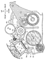
図3に示されるように、クランクケース32には回転軸線Rx回りで回転自在にクランク軸43が支持される。クランク軸43は、滑り軸受に連結されるジャーナル44と、隣接するジャーナル44の間に配置されて、回転軸線Rxに平行に延びクランクウエブを相互に結合するクランクピン45を有するクランク46とを備える。クランクピン45には、ピストン37から延びるコネクティングロッド47の大端部が回転自在に連結される。コネクティングロッド47はピストン37の線形往復運動をクランク軸43の回転運動に変換する。
As shown in FIG. 3, a
クランク軸43の一端はクランクケース32の左側面から外側に突出する。クランク軸43の一端にはACG(交流発電機)48が接続される。クランクケース32の左側面にはクランクケース32との間にACG48を収容するACGカバー49が結合される。ACG48は、ACGカバー49に固定されるステーター51と、クランクケース32から突き出るクランク軸43の一端に相対回転不能に結合されるローター52とを備える。ステーター51は、クランク軸43周りで周方向に配列されて、ステーターコアに巻き付けられる複数のコイル51aを有する。ローター52は、ステーター51を囲む環状の軌道に沿って周方向に配列される複数の磁石52aを有する。クランク軸43が回転すると、コイル51aに対して磁石52aが相対変位し、ACG48は発電する。
One end of the
クランク軸43の他端はクランクケース32の右側面から外側に突出する。クランク軸43の他端にはカムシャフトに動力を伝達するカム駆動機構53が連結される。カム駆動機構53は、クランク軸43に同軸に固定される駆動カムギア53aと、カムシャフトに固定される従動カムギア(図示されず)と、駆動カムギア53aから従動カムギアまで順番に噛み合って駆動カムギア53aから従動カムギアまで動力を伝達する複数のギアで構成されるカムギア列53bとを備える。クランクケース32の右側面にはクランクケース32との間に駆動カムギア53aを収容するカム駆動機構カバー54が結合される。ACGカバー49およびカム駆動機構カバー54はクランクケース32の外面に被さってクランク軸43を収容するクランク室55を区画する。カム駆動機構53は、駆動カムギア53a、従動カムギアおよびカムギア列53bに代えて、駆動スプロケット、従動スプロケットおよびカムチェーンを備えてもよい。
The other end of the
内燃機関31にはドグクラッチ式の多段変速機(以下「変速機」)56が組み込まれる。変速機56は、クランク室55から連続してクランクケース32に区画される変速機室57に収容される。変速機56はクランク軸43の軸心に平行な軸心を有するメイン軸58およびカウンター軸59を備える。メイン軸58およびカウンター軸59は転がり軸受61a、61b、62a、62bで回転自在にクランクケース32に支持される。
A dog clutch type multi-stage transmission (hereinafter, “transmission”) 56 is incorporated in the
メイン軸58およびカウンター軸59には複数の変速ギア63が支持される。変速ギア63は軸受61a、61b;62a、62b同士の間に配置されて変速機室57に収容される。変速ギア63は、メイン軸58またはカウンター軸59に同軸に相対回転自在に支持される回転ギア63aと、メイン軸58に相対回転不能に固定されて、対応する回転ギア63aに噛み合う固定ギア63bと、メイン軸58またはカウンター軸59に相対回転不能かつ軸方向変位自在に支持されて、対応する回転ギア63aに噛み合うシフトギア63cとを含む。回転ギア63aおよび固定ギア63bの軸方向変位は規制される。軸方向変位を通じてシフトギア63cが回転ギア63aに連結されると、回転ギア63aとメイン軸58またはカウンター軸59との相対回転は規制される。シフトギア63cが他軸の固定ギア63bに噛み合うと、メイン軸58およびカウンター軸59の間で回転動力は伝達される。他軸の固定ギア63bに噛み合う回転ギア63aにシフトギア63cが連結されると、メイン軸58およびカウンター軸59の間で回転動力は伝達される。こうしてメイン軸58とカウンター軸59との間で特定の変速ギア63が噛み合うことで規定の減速比でメイン軸58からカウンター軸59に回転動力は伝達される。
A plurality of transmission gears 63 are supported on the
メイン軸58の一端はクランクケース32の右側面から外側に突出する。メイン軸58の一端には、クランクケース32の外側で、クランク軸43のプライマリ駆動ギア64に噛み合うプライマリ従動ギア65と、プライマリ従動ギア65に連結されるワンウエイクラッチギア66とが相対回転自在に同軸に支持される。プライマリ駆動ギア64は例えばクランク軸43のクランク46に一体に形成される。ワンウエイクラッチギア66は、ギア歯から作用する外力に応じて一方向に回転する際にプライマリ従動ギア65に回転力を付加するとともに、クランク軸43からの駆動力に応じてプライマリ従動ギア65が回転する際にはプライマリ従動ギア65に対して相対回転しメイン軸58上で静止状態を維持する。
One end of the
メイン軸58上でプライマリ従動ギア65には摩擦クラッチ67が連結される。クランクケース32の右側面には、クランクケース32との間に摩擦クラッチ67を収容するクラッチカバー68が結合される。摩擦クラッチ67はクラッチアウター67aおよびクラッチハブ67bを備える。クラッチアウター67aにプライマリ従動ギア65は連結される。クラッチレバーの操作に応じて摩擦クラッチ67ではクラッチアウター67aおよびクラッチハブ67bの間で連結および切断が切り替えられる。
A
カウンター軸59には、クランクケース32の外側に配置される伝動装置69の駆動スプロケット69aが結合される。駆動スプロケット69aには駆動チェーン69bが巻き掛けられる。駆動チェーン69bは駆動スプロケット69aの回転動力を後輪WRに伝達する。
A
図2に示されるように、クランクケース32は、メイン軸58に同軸の仮想円筒面に沿って膨らみながらメイン軸58を覆い、シリンダーブロック33との間に谷型空間71を形成する上壁体72を有する。谷型空間71には、キャニスター36の下方でスターターモーター73が配置される。
As shown in FIG. 2, the
スターターモーター73は、回転軸線Rxに平行な中心軸を有する円筒形状の筐体73aを備える。筐体73a内に、中心軸上に軸心を有する駆動軸に結合されるローターと、ローターを囲むステーターとが収容される。筐体73aは、円筒形状の外面から水平方向に外側に張り出す前後1対のフランジ75を有する。フランジ75は、中心軸に平行な軸心を有するボルト部材でクランクケース32に固定される。
The
クランクケース32には、シリンダーブロック33との合わせ面76aを形成し、ピストン37の線形往復運動を案内するシリンダーライナーを受け入れる円筒空間を区画する台座76が形成される。台座76は、シリンダー38を囲んでスターターモーター73側に膨出する肉厚部76bを有する。肉厚部76bは、上壁体72から連続し、合わせ面76aに近づくにつれて上壁体72よりも厚みを増加させる。
A
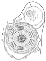
図4に示されるように、スターターモーター73の駆動軸77は減速ギア78を介してワンウエイクラッチギア66に接続される。減速ギア78は、回転軸線Gx回りで回転自在にクランクケース32に支持される軸体78aを備える。軸体78aの一端には、図5に示されるように、軸体78aに同軸に、クランクケース32の外側でワンウエイクラッチギア66に噛み合う小径ギア79が固定される。小径ギア79は、ワンウエイクラッチギア66の回転軸線を含む水平面Hrよりも上方で、ワンウエイクラッチギア66の回転軸線を含む垂直面PL1と、前方からワンウエイクラッチギア66に外接する垂直面PL2との間に収められる。
As shown in FIG. 4, the
軸体78aの他端には、図6に示されるように、軸体78aに同軸に、ギア室81内でスターターモーター73の駆動ギア82に噛み合う大径ギア83が形成される。駆動ギア82は例えばスターターモーター73の駆動軸77に刻まれる。駆動軸77の回転は減速ギア78で減速されてワンウエイクラッチギア66に伝達される。スターターモーター73は強制的にクランク軸43を回転駆動する駆動力を生成する。図4に示されるように、メイン軸58の軸方向にギア室81からずれた位置でスターターモーター73の上方にキャニスター36は配置される。
As shown in FIG. 6, a large-
ここでは、スターターモーター73の駆動軸77は、減速ギア78の回転軸線Gxよりも下方で、軸方向視で大径ギア83の幅内に配置される。言い換えると、スターターモーター73の駆動軸77は、減速ギア78の回転軸線Gxよりも下方で、クランク軸43の回転軸線Rxに平行であって大径ギア83に一方(前方)から外接する第1鉛直面VP1、および、第1鉛直面VP1に平行であって大径ギア83に他方(後方)から外接する第2鉛直面VP2に挟まれる空間内に軸心77aを配置する。しかも、駆動軸77の軸心77aは軸方向視で小径ギア79の幅内に配置される。言い換えると、駆動軸77の軸心77aは、クランク軸43の回転軸線Rxに平行であって小径ギア79に一方(前方)から外接する第3鉛直面VP3、および、第3鉛直面VP3に平行であって小径ギア79に他方(後方)から外接する第4鉛直面VP4に挟まれる空間内に位置する。
Here, the
図7に示されるように、プライマリ従動ギア65の外径は、外歯同士で小径ギア79に噛み合うワンウエイクラッチギア66の外径よりも大きく形成される。減速ギア78の回転軸線Gxは、メイン軸58に同軸で摩擦クラッチ67に外接する仮想円筒面Cvの外側に配置される。ここでは、減速ギア78の回転軸線Gxは、メイン軸58に同軸でプライマリ従動ギア65に外接する仮想円筒面Cqの外側に配置される。スターターモーター73の駆動軸77は仮想円筒面Cvの内側に軸心77aを配置する。
As shown in FIG. 7, the outer diameter of the primary driven
次に本実施形態の動作を説明する。内燃機関31の始動にあたってスターターモーター73に電力が供給されると、駆動軸77は軸心77a回りで規定の方向に回転する。駆動軸77の回転は減速ギア78の大径ギア83に伝達される。大径ギア83の歯数は駆動ギア82の歯数よりも著しく多いことから、駆動軸77に比べて減速ギア78の回転は減速される。減速ギア78の回転は小径ギア79からワンウエイクラッチギア66に伝達される。ワンウエイクラッチギア66の歯数は小径ギア79の歯数よりも著しく多いことから、減速ギア78に比べてワンウエイクラッチギア66の回転は減速される。
Next, the operation of the present embodiment will be described. When electric power is supplied to the
ワンウエイクラッチギア66はメイン軸58上でプライマリ従動ギア65とともに回転する。プライマリ従動ギア65の回転はプライマリ駆動ギア64からクランク軸43に伝達される。クランク軸43は指定された方向に強制的に回転する。燃焼室39で燃焼が開始され、シリンダー38内でピストン37の線形往復運動は開始される。スターターモーター73の動作は終了する。
The one-way
燃焼動作に応じてピストン37の線形往復運動が開始されると、プライマリ駆動ギア64からプライマリ従動ギア65を経てクラッチアウター67aに回転運動は伝達される。プライマリ従動ギア65の回転はワンウエイクラッチギア66には伝達されず、ワンウエイクラッチギア66はメイン軸58上で静止状態を維持する。内燃機関31の動作中にスターターモーター73への負荷は回避される。
When the linear reciprocating motion of the
本実施形態では、スターターモーター73の駆動軸77は、減速ギア78の回転軸線Gxよりも下方で、軸方向視で大径ギア83の幅内に配置される。すなわち、スターターモーター73の駆動軸77は、クランク軸43の回転軸線Rxに平行であって大径ギア83に一方(前方)から外接する第1鉛直面VP1、および、第1鉛直面VP1に平行であって大径ギア83に他方(後方)から外接する第2鉛直面VP2に挟まれる空間内に軸心77aを配置する。スターターモーター73と減速ギア78とは縦方向に並べられる。したがって、クランクケース32とシリンダーブロック33とで構成される谷型空間71にスターターモーター73は効率的に配置される。
In the present embodiment, the
特に、駆動軸77の軸心77aは軸方向視で小径ギア79の幅内に配置される。すなわち、駆動軸77の軸心77aは、クランク軸43の回転軸線Rxに平行であって小径ギア79に一方(前方)から外接する第3鉛直面VP3、および、第3鉛直面VP3に平行であって小径ギア79に他方(後方)から外接する第4鉛直面VP4に挟まれる空間内に位置することから、スターターモーター73と減速ギア78とは可及的に縦方向に並べられ、クランクケース32とシリンダーブロック33とで構成される谷型空間71にスターターモーター73はさらに効率的に配置される。
In particular, the
さらに、駆動軸77の軸心77aは、メイン軸58に同軸で摩擦クラッチ67に外接する仮想円筒面Cvの内側に配置される。こうして仮想円筒面Cvで囲まれる空間内に駆動軸77の軸心77aは位置するので、クランクケース32とシリンダーブロック33とで構成される谷型空間71にスターターモーター73はコンパクトに配置される。
Further, the
本実施形態では、減速ギア78の回転軸線Gxは、仮想円筒面Cvの外側に配置される。スターターモーター73と減速ギア78とは縦方向に並べられるので、クランクケース32とシリンダーブロック33とで構成される谷型空間71にスターターモーター73は効率的に配置される。
In the present embodiment, the rotation axis Gx of the
クランクケース32は、メイン軸58に同軸の仮想円筒面に沿って膨らみながらメイン軸58の変速ギア63を覆い、シリンダーブロック33との間に谷型空間71を形成する上壁体72を有する。このとき、スターターモーター73は谷型空間71内に配置される。スターターモーター73は、クランクケース32の上壁体72とシリンダーブロック33との間に区画されるデッドスペースに効率的に配置される。
The
クランクケース32は、ピストン37を案内するシリンダー38を囲んでスターターモーター73側に膨出する肉厚部76bを有する。スターターモーター73と減速ギア78とが縦方向に配置されることで、クランクケース32とシリンダーブロック33とで構成される谷部には十分に肉厚部76bを配置するスペースが確保される。
The
本実施形態に係る自動二輪車11では、メイン軸58の軸方向に減速ギア78のギア室81からずれた位置でスターターモーター73の上方にキャニスター36は配置される。スターターモーター73と減速ギア78とが縦方向に配置されることから、スターターモーター73の上方でギア室81の背後にスペースが生じ、このスペースに十分な容積を有するキャニスター36は効率的に配置される。
In the
スターターモーター73は、円筒形状の外面から水平方向に外側に張り出してクランクケース32に固定されるフランジ75を有する。外面から垂直方向に上下にフランジが張り出す場合に比べて、スターターモーター73は谷部の底に近く配置され、内燃機関31の中心に向かって重量物であるスターターモーター73を近づけることで質量の集中に寄与する。
The
31…内燃機関、32…クランクケース、33…シリンダーブロック、36…キャニスター、37…ピストン、38…シリンダー、43…クランク軸、56…多段変速機、58…メイン軸、64…プライマリ駆動ギア、65…プライマリ従動ギア、66…ワンウエイクラッチギア、67…クラッチ(摩擦クラッチ)、71…谷型空間、72…上壁体、73…スターターモーター、75…フランジ、76b…肉厚部、77…(スターターモーターの)駆動軸、77a…軸心、78…減速ギア、79…小径ギア、82…(スターターモーターの)駆動ギア、83…大径ギア、C…シリンダー軸線、Cv…(クラッチに外接する)仮想円筒面、Gx…(減速ギアの)回転軸線、Rx…(クランク軸の)回転軸線。
DESCRIPTION OF
Claims (8)
前記クランクケース(32)に結合されて、前記回転軸線(Rx)に直交する鉛直面内に位置して水平面に対して起立するシリンダー軸線(C)を有するシリンダーブロック(33)と、
前記多段変速機(56)に組み込まれて前記クランクケース(32)に回転自在に支持され、前記クランク軸(43)のプライマリ駆動ギア(64)に噛み合うプライマリ従動ギア(65)、および、ワンウエイクラッチギア(66)を同軸に支持するメイン軸(58)と、
前記ワンウエイクラッチギア(66)に噛み合う小径ギア(79)を一端に有し、スターターモーター(73)の駆動ギア(82)に噛み合う大径ギア(83)を他端に有する減速ギア(78)とを備える内燃機関(31)において、
前記スターターモーター(73)の駆動軸(77)は、減速ギア(78)の回転軸線(Gx)よりも下方で、軸方向視で前記大径ギア(83)の幅内に配置されることを特徴とする内燃機関。 A crankcase (32) rotatably supporting a crankshaft (43) around a rotation axis (Rx) and accommodating a multi-stage transmission (56);
A cylinder block (33) coupled to the crankcase (32) and having a cylinder axis (C) located in a vertical plane perpendicular to the rotation axis (Rx) and rising with respect to a horizontal plane;
A primary driven gear (65) rotatably supported by the crankcase (32) incorporated in the multi-stage transmission (56) and meshing with a primary drive gear (64) of the crankshaft (43); and a one-way clutch A main shaft (58) for coaxially supporting the gear (66);
A reduction gear (78) having a small-diameter gear (79) meshing with the one-way clutch gear (66) at one end, and a large-diameter gear (83) meshing with the drive gear (82) of the starter motor (73) at the other end; In an internal combustion engine (31) comprising:
The drive shaft (77) of the starter motor (73) is arranged below the rotation axis (Gx) of the reduction gear (78) and within the width of the large-diameter gear (83) when viewed in the axial direction. Features internal combustion engine.
Priority Applications (3)
| Application Number | Priority Date | Filing Date | Title |
|---|---|---|---|
| JP2018129366A JP6756782B2 (en) | 2018-07-06 | 2018-07-06 | Internal combustion engine |
| US16/502,145 US11035290B2 (en) | 2018-07-06 | 2019-07-03 | Internal combustion engine |
| DE102019118113.5A DE102019118113B4 (en) | 2018-07-06 | 2019-07-04 | Internal combustion engine with starter in a recessed space |
Applications Claiming Priority (1)
| Application Number | Priority Date | Filing Date | Title |
|---|---|---|---|
| JP2018129366A JP6756782B2 (en) | 2018-07-06 | 2018-07-06 | Internal combustion engine |
Publications (2)
| Publication Number | Publication Date |
|---|---|
| JP2020007967A true JP2020007967A (en) | 2020-01-16 |
| JP6756782B2 JP6756782B2 (en) | 2020-09-16 |
Family
ID=68943830
Family Applications (1)
| Application Number | Title | Priority Date | Filing Date |
|---|---|---|---|
| JP2018129366A Active JP6756782B2 (en) | 2018-07-06 | 2018-07-06 | Internal combustion engine |
Country Status (3)
| Country | Link |
|---|---|
| US (1) | US11035290B2 (en) |
| JP (1) | JP6756782B2 (en) |
| DE (1) | DE102019118113B4 (en) |
Cited By (1)
| Publication number | Priority date | Publication date | Assignee | Title |
|---|---|---|---|---|
| WO2021149708A1 (en) * | 2020-01-21 | 2021-07-29 | ヤマハ発動機株式会社 | Manual-transmission straddled vehicle |
Citations (9)
| Publication number | Priority date | Publication date | Assignee | Title |
|---|---|---|---|---|
| JPH1077936A (en) * | 1996-08-30 | 1998-03-24 | Yamaha Motor Co Ltd | Starter of vehicular engine unit |
| JP2005069145A (en) * | 2003-08-26 | 2005-03-17 | Honda Motor Co Ltd | Starter of engine for motorcycle |
| JP2009067336A (en) * | 2007-09-18 | 2009-04-02 | Yamaha Motor Co Ltd | Motorcycle |
| JP2012211553A (en) * | 2011-03-31 | 2012-11-01 | Honda Motor Co Ltd | Evaporation system of motorcycle |
| CN203189178U (en) * | 2013-04-20 | 2013-09-11 | 重庆润通动力有限公司 | Electric starting device of engine |
| JP2014015919A (en) * | 2012-07-11 | 2014-01-30 | Honda Motor Co Ltd | Engine starting device |
| JP2015074384A (en) * | 2013-10-10 | 2015-04-20 | ヤマハ発動機株式会社 | Saddle-riding type vehicle |
| US20170167550A1 (en) * | 2015-12-09 | 2017-06-15 | Honda Motor Co., Ltd. | Internal combustion engine |
| JP2017125432A (en) * | 2016-01-13 | 2017-07-20 | ヤマハ発動機株式会社 | Motorcycle |
Family Cites Families (10)
| Publication number | Priority date | Publication date | Assignee | Title |
|---|---|---|---|---|
| JP2566398B2 (en) | 1986-11-19 | 1996-12-25 | 本田技研工業株式会社 | Engine timing transmission |
| JPS6477936A (en) | 1987-09-18 | 1989-03-23 | Sanyo Electric Co | Reduction type x-ray lithographic device |
| US6202499B1 (en) * | 1999-10-27 | 2001-03-20 | Brinn, Inc. | Automotive transmission |
| BR0309013B1 (en) * | 2002-04-08 | 2012-04-17 | motor. | |
| JP2004092423A (en) | 2002-08-29 | 2004-03-25 | Yamaha Motor Co Ltd | Motorcycle engine |
| JP2008223880A (en) * | 2007-03-13 | 2008-09-25 | Yamaha Motor Co Ltd | Internal combustion engine and vehicle equipped with the same |
| JP4914776B2 (en) * | 2007-06-22 | 2012-04-11 | 本田技研工業株式会社 | Power unit for motorcycle |
| US8151772B2 (en) * | 2008-05-30 | 2012-04-10 | Brp-Powertrain Gmbh & Co. Kg | Supercharged engine |
| JP5290029B2 (en) * | 2009-03-31 | 2013-09-18 | 本田技研工業株式会社 | Internal combustion engine |
| JP6283641B2 (en) * | 2015-09-30 | 2018-02-21 | 本田技研工業株式会社 | Automatic clutch vehicle |
-
2018
- 2018-07-06 JP JP2018129366A patent/JP6756782B2/en active Active
-
2019
- 2019-07-03 US US16/502,145 patent/US11035290B2/en active Active
- 2019-07-04 DE DE102019118113.5A patent/DE102019118113B4/en active Active
Patent Citations (9)
| Publication number | Priority date | Publication date | Assignee | Title |
|---|---|---|---|---|
| JPH1077936A (en) * | 1996-08-30 | 1998-03-24 | Yamaha Motor Co Ltd | Starter of vehicular engine unit |
| JP2005069145A (en) * | 2003-08-26 | 2005-03-17 | Honda Motor Co Ltd | Starter of engine for motorcycle |
| JP2009067336A (en) * | 2007-09-18 | 2009-04-02 | Yamaha Motor Co Ltd | Motorcycle |
| JP2012211553A (en) * | 2011-03-31 | 2012-11-01 | Honda Motor Co Ltd | Evaporation system of motorcycle |
| JP2014015919A (en) * | 2012-07-11 | 2014-01-30 | Honda Motor Co Ltd | Engine starting device |
| CN203189178U (en) * | 2013-04-20 | 2013-09-11 | 重庆润通动力有限公司 | Electric starting device of engine |
| JP2015074384A (en) * | 2013-10-10 | 2015-04-20 | ヤマハ発動機株式会社 | Saddle-riding type vehicle |
| US20170167550A1 (en) * | 2015-12-09 | 2017-06-15 | Honda Motor Co., Ltd. | Internal combustion engine |
| JP2017125432A (en) * | 2016-01-13 | 2017-07-20 | ヤマハ発動機株式会社 | Motorcycle |
Cited By (1)
| Publication number | Priority date | Publication date | Assignee | Title |
|---|---|---|---|---|
| WO2021149708A1 (en) * | 2020-01-21 | 2021-07-29 | ヤマハ発動機株式会社 | Manual-transmission straddled vehicle |
Also Published As
| Publication number | Publication date |
|---|---|
| US11035290B2 (en) | 2021-06-15 |
| DE102019118113B4 (en) | 2023-12-07 |
| US20200011235A1 (en) | 2020-01-09 |
| JP6756782B2 (en) | 2020-09-16 |
| DE102019118113A1 (en) | 2020-01-09 |
Similar Documents
| Publication | Publication Date | Title |
|---|---|---|
| JP6695921B2 (en) | Saddle type vehicle | |
| JP4640830B2 (en) | Starter for internal combustion engine | |
| JP5314290B2 (en) | Vehicle power unit | |
| JP6813411B2 (en) | Internal combustion engine | |
| JP6756782B2 (en) | Internal combustion engine | |
| JP2000278926A (en) | Starter/generator for 4-cycle internal combustion engine | |
| US20050157966A1 (en) | Arrangement structure of bearings | |
| JP6986639B2 (en) | Power unit for saddle-riding vehicles | |
| JP5614265B2 (en) | Motorcycle clutch cable routing structure | |
| WO2019221225A1 (en) | Saddle type vehicle | |
| CN112739900B (en) | Power unit of saddle-type vehicle | |
| JP2020007966A (en) | Internal combustion engine | |
| JP6963116B2 (en) | Cover structure of power unit of saddle type vehicle | |
| JP4675408B2 (en) | Oil pump structure of internal combustion engine | |
| JP6900418B2 (en) | Internal combustion engine | |
| JP2009061994A (en) | Power unit | |
| JP6809106B2 (en) | Starter mechanism for saddle-mounted vehicles | |
| JP2020007965A (en) | Internal combustion engine | |
| JP2019065732A (en) | Internal combustion engine | |
| JP4287065B2 (en) | Motorcycle | |
| JP5687136B2 (en) | Power unit for small vehicles | |
| JP2023117997A (en) | Cooling structure for ac generator of internal combustion engine | |
| JP2020165519A (en) | Power unit | |
| JP2020012464A (en) | engine | |
| JP2006250094A (en) | Internal combustion engine |
Legal Events
| Date | Code | Title | Description |
|---|---|---|---|
| A621 | Written request for application examination |
Free format text: JAPANESE INTERMEDIATE CODE: A621 Effective date: 20190327 |
|
| A977 | Report on retrieval |
Free format text: JAPANESE INTERMEDIATE CODE: A971007 Effective date: 20200323 |
|
| A131 | Notification of reasons for refusal |
Free format text: JAPANESE INTERMEDIATE CODE: A131 Effective date: 20200325 |
|
| A521 | Request for written amendment filed |
Free format text: JAPANESE INTERMEDIATE CODE: A523 Effective date: 20200521 |
|
| TRDD | Decision of grant or rejection written | ||
| A01 | Written decision to grant a patent or to grant a registration (utility model) |
Free format text: JAPANESE INTERMEDIATE CODE: A01 Effective date: 20200805 |
|
| A61 | First payment of annual fees (during grant procedure) |
Free format text: JAPANESE INTERMEDIATE CODE: A61 Effective date: 20200827 |
|
| R150 | Certificate of patent or registration of utility model |
Ref document number: 6756782 Country of ref document: JP Free format text: JAPANESE INTERMEDIATE CODE: R150 |