JP2020006790A - Tire wheel assembly - Google Patents
Tire wheel assembly Download PDFInfo
- Publication number
- JP2020006790A JP2020006790A JP2018129229A JP2018129229A JP2020006790A JP 2020006790 A JP2020006790 A JP 2020006790A JP 2018129229 A JP2018129229 A JP 2018129229A JP 2018129229 A JP2018129229 A JP 2018129229A JP 2020006790 A JP2020006790 A JP 2020006790A
- Authority
- JP
- Japan
- Prior art keywords
- wheel
- tire
- air chamber
- lid
- wheel assembly
- Prior art date
- Legal status (The legal status is an assumption and is not a legal conclusion. Google has not performed a legal analysis and makes no representation as to the accuracy of the status listed.)
- Pending
Links
Images


Classifications
-
- B—PERFORMING OPERATIONS; TRANSPORTING
- B60—VEHICLES IN GENERAL
- B60C—VEHICLE TYRES; TYRE INFLATION; TYRE CHANGING; CONNECTING VALVES TO INFLATABLE ELASTIC BODIES IN GENERAL; DEVICES OR ARRANGEMENTS RELATED TO TYRES
- B60C19/00—Tyre parts or constructions not otherwise provided for
- B60C19/002—Noise damping elements provided in the tyre structure or attached thereto, e.g. in the tyre interior
-
- B—PERFORMING OPERATIONS; TRANSPORTING
- B60—VEHICLES IN GENERAL
- B60B—VEHICLE WHEELS; CASTORS; AXLES FOR WHEELS OR CASTORS; INCREASING WHEEL ADHESION
- B60B21/00—Rims
- B60B21/12—Appurtenances, e.g. lining bands
-
- B—PERFORMING OPERATIONS; TRANSPORTING
- B60—VEHICLES IN GENERAL
- B60B—VEHICLE WHEELS; CASTORS; AXLES FOR WHEELS OR CASTORS; INCREASING WHEEL ADHESION
- B60B27/00—Hubs
- B60B27/0047—Hubs characterised by functional integration of other elements
-
- B—PERFORMING OPERATIONS; TRANSPORTING
- B60—VEHICLES IN GENERAL
- B60B—VEHICLE WHEELS; CASTORS; AXLES FOR WHEELS OR CASTORS; INCREASING WHEEL ADHESION
- B60B2900/00—Purpose of invention
- B60B2900/10—Reduction of
- B60B2900/133—Noise
Abstract
Description
本発明は、タイヤホイール組立体に関する。 The present invention relates to a tire wheel assembly.
従来、リムのウェル部の外周面上にヘルムホルツレゾネータを有する車両用ホイールが知られている(例えば、特許文献1参照)。この特許文献1の車両用ホイールにおいては、ウェル部の外周面上でホイール周方向に延びるように縦壁が形成されており、ヘルムホルツレゾネータは、この縦壁に形成された溝部に係止される構成となっている。このような車両用ホイールによれば、リムに対するヘルムホルツレゾネータの取り付けを容易に行うことができる。 2. Description of the Related Art Conventionally, a vehicle wheel having a Helmholtz resonator on an outer peripheral surface of a well portion of a rim is known (for example, see Patent Document 1). In the vehicle wheel of Patent Document 1, a vertical wall is formed on the outer peripheral surface of the well portion so as to extend in the circumferential direction of the wheel, and the Helmholtz resonator is locked in a groove formed in the vertical wall. It has a configuration. According to such a vehicle wheel, the Helmholtz resonator can be easily attached to the rim.
ところが、従来の車両用ホイール(例えば、特許文献1参照)は、ホイールに前記の縦壁に溝部を要するため、ホイールの市販品をそのまま使用することができずにホイールの製造コストが増大する問題があった。したがって、市販品のホイールにヘルムホルツレゾネータを容易に取り付けることができるタイヤホイール組立体が望まれていた。 However, the conventional vehicle wheel (for example, see Patent Document 1) requires a groove in the vertical wall of the wheel, so that a commercially available wheel cannot be used as it is, and the manufacturing cost of the wheel increases. was there. Therefore, a tire-wheel assembly that can easily attach a Helmholtz resonator to a commercially available wheel has been desired.
本発明の課題は、市販品のホイールにヘルムホルツレゾネータを容易に取り付けることができるタイヤホイール組立体を提供することにある。 SUMMARY OF THE INVENTION An object of the present invention is to provide a tire-wheel assembly in which a Helmholtz resonator can be easily mounted on a commercially available wheel.
前記の課題を達成する本発明のタイヤホイール組立体は、ホイールの一対のビードシートと、前記ビードシートに配置されるタイヤビードとの間にホイール幅方向の両縁を挟持されてウェル部の上方に配置される蓋体と、前記蓋体に一体となって配置される副気室部材と、を備えることを特徴とする。
また、本発明のタイヤホイール組立体は、ホイールの一対のビードシートと、前記ビードシートに配置されるタイヤビードとの間にホイール幅方向の両縁を挟持されてウェル部の上方に配置される蓋体と、前記蓋体とホイールのウェル部の外周面との間に副気室を形成した副気室部材と、を備えることを特徴とする。
The tire-wheel assembly of the present invention that achieves the above object has a structure in which both edges in the wheel width direction are sandwiched between a pair of bead seats of a wheel and a tire bead disposed on the bead seat, and the upper portion of the well portion is provided. And a sub air chamber member integrally disposed with the lid.
Further, the tire-wheel assembly of the present invention is disposed above the well portion with both edges in the wheel width direction being sandwiched between a pair of bead seats of a wheel and a tire bead disposed on the bead seat. A lid, and a sub air chamber member having a sub air chamber formed between the lid and an outer peripheral surface of a well portion of the wheel.
本発明によれば、市販品のホイールにヘルムホルツレゾネータを容易に取り付けることができるタイヤホイール組立体を提供することができる。 ADVANTAGE OF THE INVENTION According to this invention, the tire wheel assembly which can attach a Helmholtz resonator easily to a commercially available wheel can be provided.
次に、本発明の実施形態に係るタイヤホイール組立体について、適宜図面を参照しなが
ら詳細に説明する。なお、参照する図において、「X」は、ホイール周方向、「Y」は、ホイール幅方向、「Z」は、ホイール径方向、をそれぞれ示している。また、ホイール幅方向Yにおいて、ホイールにおけるウェル部の外周面の中央側を「ホイール幅方向Yの内側」と称し、ホイールにおけるリムフランジ側を「ホイール幅方向Yの外側」と称することがある。
Next, a tire wheel assembly according to an embodiment of the present invention will be described in detail with reference to the drawings as appropriate. In the drawings to be referred to, “X” indicates the wheel circumferential direction, “Y” indicates the wheel width direction, and “Z” indicates the wheel radial direction. In the wheel width direction Y, the center side of the outer peripheral surface of the well portion of the wheel may be referred to as “inside in the wheel width direction Y”, and the rim flange side of the wheel may be referred to as “outside in the wheel width direction Y”.
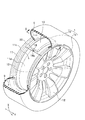
図1は、本発明の実施形態に係るタイヤホイール組立体1の斜視図である。図2は、図1のII−II断面図である。
図1に示すように、本実施形態に係るタイヤホイール組立体1は、ホイール1aとタイヤ1bとを主に備えて構成されている。
本実施形態でのホイール1aは、例えばアルミニウム合金、マグネシウム合金などの軽金属製のものを想定している。
ホイール1aは、タイヤ1bが組み付けられるリム11と、このリム11を図示しないハブに連結するためのディスク12と、を備えている。
FIG. 1 is a perspective view of a tire / wheel assembly 1 according to an embodiment of the present invention. FIG. 2 is a sectional view taken along line II-II of FIG.
As shown in FIG. 1, the tire-wheel assembly 1 according to the present embodiment mainly includes a wheel 1a and a
The wheel 1a in the present embodiment is assumed to be made of a light metal such as an aluminum alloy or a magnesium alloy.
The wheel 1a includes a
リム11は、ホイール幅方向Yの両端部にそれぞれ形成されるビードシート13同士の間で、ホイール径方向の内側(回転中心側)に向かって窪んだウェル部11cを有している。この窪みの底面で規定されるウェル部11cの外周面11dは、ホイール幅方向Yにわたってホイール軸を中心に略同径になっている。
The
図2に示すように、リム11は、ウェル部11cの外周面11dにおけるホイール幅方向Yの両端部のそれぞれからリムフランジ14側に向けて立ち上がる一対の縦壁15を備えている。また、リム11は、縦壁15のホイール幅方向Yの外側に、ハンプ16を介してビードシート13が形成されている。そして、ビードシート13のホイール幅方向Yの外側は、リムフランジ14へと立ち上っていく。
As shown in FIG. 2, the
図1に示すように、タイヤ1bは、リム11周りでトロイド状に延びることで、内側にタイヤ空気室9を形成している。
図2に示すように、タイヤ1bは、接地面を形成するトレッド21と、ショルダ22を介してタイヤ1bの側面を形成するサイドウォール23と、ビードシート13に配置されるタイヤビード24と、を備えている。
As shown in FIG. 1, the
As shown in FIG. 2, the
タイヤビード24の内側には、ビードワイヤ24aが配置されている。このビードワイヤ24aは、リム11の周方向に環状に延びている。そして、ビードワイヤ24aは、その緊縮力でタイヤビード24をビードシート13上に着座させている。
A
図1に示すように、本実施形態のタイヤホイール組立体1は、ウェル部11cの外周面11d上に配置された蓋体20と、この蓋体20に設けられた副気室部材10(ヘルムホルツレゾネータ)と、をさらに備えている。
As shown in FIG. 1, a tire wheel assembly 1 according to the present embodiment includes a
蓋体20は、ホイール周方向Xに沿うように湾曲している。
蓋体20としては、所定の剛性を有していれば特に制限はなく、例えば樹脂板、金属板などを想定している。
The
The
このような蓋体20は、図2に示すように、ホイール幅方向Yの両縁がビードシート13とタイヤビード24との間に挟持されている。
さらに具体的には、蓋体20のうち、ウェル部11c上に配置される部分は、ハンプ16の頂部よりも下方(ホイール径方向の内側)に配置されている。そして、本実施形態での蓋体20は、ホイール幅方向Yの中央部から外側に向かってホイール軸と並行して延びるとともに、ハンプ16からビードシート13に掛けては、これらハンプ16及びビード
シート13の周面形状に倣って延びている。
ちなみに、本実施形態での蓋体20は、ビードシート13との間、及び/又はタイヤビード24との間に、接着剤を介在させることもできる。
As shown in FIG. 2, both edges of the
More specifically, a portion of the
Incidentally, the
副気室部材10(ヘルムホルツレゾネータ)は、図1に示すように、蓋体20の上面(ホイール径方向の外側面)に配置されている。この副気室部材10は、中空部を有する箱体で構成されている。本実施形態での副気室部材10は、ポリプロピレン、ポリアミドなどの樹脂成形品を想定している。
The sub air chamber member 10 (Helmholtz resonator) is disposed on the upper surface (outer surface in the wheel radial direction) of the
副気室部材10は、図2に示すように、蓋体20側に配置される底板25bと、この底板25bと対向するように配置される上板25aと、これらの底板25bと上板25aとを接続する一対の側板25cと、を備えている。そして、これらの上板25a、底板25b及び側板25cで囲まれて形成される中空部は、副気室SCとして機能する。
As shown in FIG. 2, the auxiliary
副気室部材10は、図1に示すように、ホイール周方向Xに長く、蓋体20に沿うように湾曲するとともに、蓋体20と接続されている。副気室部材10と蓋体20との接続方法としては、例えば接着、溶着などが挙げられる。
As shown in FIG. 1, the sub
また、副気室部材10は、ホイール周方向Xの端部に管体18を有している。この管体18の内側には、連通孔18aが形成されている。この連通孔18aは、副気室SCとタイヤ空気室9とを連通させている。
The sub
本実施形態での副気室部材10は、図示しないが、ホイール周方向Xに4つ配置されるものを想定している。そして、各副気室SCに連通孔18aを形成する管体18のそれぞれは、ホイール回転軸周りに90度間隔に配置されている。ただし、副気室SCの数及び管体18の位置は、これに限定されるものではない。したがって、副気室SCの数が2つの場合には、それぞれの管体18同士は、ホイール回転軸周りに90度開く位置に配置することができる。また、副気室SCの数が3つ又は5つ以上の場合には、それぞれの管体18は、ホイール周方向Xに等間隔に配置することができる。
Although not shown, four auxiliary
このような副気室部材10のホイール1aに対する取付は、ホイール1aのビードシート13に、蓋体20の両端を介在させつつ、タイヤ1bのタイヤビード24をセットする通常のタイヤ組付方法により行うことができる。
The attachment of the auxiliary
<作用効果>
次に、本実施形態のタイヤホイール組立体1の奏する作用効果について説明する。
本実施形態のタイヤホイール組立体1においては、蓋体20の両端がタイヤビード24とビードシート13との間に挟持されることで、副気室部材10が蓋体20を介してタイヤホイール組立体1に支持される。
<Effects>
Next, the operation and effect of the tire and wheel assembly 1 of the present embodiment will be described.
In the tire and wheel assembly 1 of the present embodiment, the auxiliary
このタイヤホイール組立体1によれば、ホイール1aのビードシート13にタイヤビード24に配置することで副気室部材10を取り付けることができる。つまり、タイヤホイール組立体1は、従来のホイール(例えば、特許文献1参照)と異なって、副気室部材10を取り付けるための縦壁をホイール1aに形成する必要がない。したがって、このタイヤホイール組立体1によれば、市販品のホイール1aに副気室部材10を容易に取り付けることができる。
According to the tire-wheel assembly 1, the auxiliary
また、本実施形態のタイヤホイール組立体1においては、蓋体20のうち、ウェル部11cの上方に配置される部分は、ハンプ16の頂部よりも下方に配置されている。これによりタイヤホイール組立体1は、副気室部材10をタイヤ空気室9内で、よりホイール径
方向Zの内側に配置することができる。このようなタイヤホイール組立体1によれば、ビードシート13にタイヤビード24を組み付ける際に、タイヤビード24の副気室部材10に対する干渉が、より低減される。
In the tire / wheel assembly 1 of the present embodiment, the portion of the
以上、本発明の実施形態について説明したが、本発明は前記実施形態に限定されず、種々の形態で実施することができる。
前記実施形態では、副気室部材10を蓋体20の上面に取り付けたが、タイヤホイール組立体1は、副気室部材10を蓋体20の下面に取り付ける構成とすることもできる。
As described above, the embodiments of the present invention have been described. However, the present invention is not limited to the above embodiments, and can be implemented in various forms.
In the above embodiment, the sub
また、本発明は、蓋体20とウェル部11cの外周面11dとの間に副気室を形成することで、副気室部材10を省略することもできる。
図3は、他の実施形態(変形例)に係るタイヤホイール組立体101の斜視図である。図4は、図3のIV−IV断面図である。なお、図3及び図4中、前記実施形態と同様の構成要素については同じ符号を付してその詳細な説明を省略する。
In the present invention, the sub
FIG. 3 is a perspective view of a tire and
図3に示すように、変形例に係るタイヤホイール組立体101においては、蓋体120のホイール周方向Xの両端部のそれぞれに縦板25dを設けることで蓋体120とウェル部11cとの間を封止している。なお、図3中、縦板25dは、作図の便宜上、一方の縦板25dのみ記載し、他方の縦板25dの記載は省略している。
As shown in FIG. 3, in the tire /
また、蓋体120には、ホイール周方向X及びホイール幅方向Yの略中央に、連通孔118aが形成されている。
この蓋体120は、前記実施形態の蓋体20(図2参照)における副気室部材10(図2参照)を省略し、縦板25d及び連通孔118aを設けた以外は、蓋体20と同様に形成されている。
In the
The
図4に示すように、蓋体120は、ウェル部11cとの間に副気室SCを形成している。また、連通孔118aは、副気室SCとタイヤ空気室9とを連通させている。
なお、図4中、符号121は、連通孔118a周りに設けた円筒状のカラー部材であり、蓋体120の板厚にカラー部材121の高さを加えることで、設計上の連通孔118aの所定長さを確保している。
As shown in FIG. 4, the
In FIG. 4,
以上のような、タイヤホイール組立体101によれば、前記実施形態のタイヤホイール組立体1と同様の作用効果を奏するほか、副気室部材10を省略することができる。これによりタイヤホイール組立体101は、軽量化及び製造コストの削減を達成することができる。また、タイヤホイール組立体101によれば、ビードシート13にタイヤビード24を組み付ける際に、タイヤビード24の副気室部材10に対する干渉を、より確実に低減することができる。
According to the
1 タイヤホイール組立体
1a ホイール
1b タイヤ
9 タイヤ空気室
10 副気室部材
11 リム
11c ウェル部
11d 外周面
12 ディスク
13 ビードシート
14 リムフランジ
15 縦壁
16 ハンプ
18 管体
18a 連通孔
20 蓋体
21 トレッド
22 ショルダ
23 サイドウォール
24 タイヤビード
24a ビードワイヤ
25a 上板
25b 底板
25c 側板
25d 縦板
101 タイヤホイール組立体
118a 連通孔
SC 副気室
X ホイール周方向
Y ホイール幅方向
Z ホイール径方向
Reference Signs List 1 tire wheel
Claims (3)
前記蓋体に一体となって配置される副気室部材と、
を備えることを特徴とするタイヤホイール組立体。 A pair of bead seats of the wheel, and a lid disposed above the well portion with both edges in the wheel width direction sandwiched between tire beads arranged on the bead seat,
A sub air chamber member integrally disposed on the lid,
A tire-wheel assembly comprising:
前記蓋体とホイールのウェル部の外周面との間に副気室を形成した副気室部材と、
を備えることを特徴とするタイヤホイール組立体。 A pair of bead seats of the wheel, and a lid disposed above the well portion with both edges in the wheel width direction sandwiched between tire beads arranged on the bead seat,
A sub air chamber member that forms a sub air chamber between the lid and the outer peripheral surface of the well portion of the wheel,
A tire-wheel assembly comprising:
Priority Applications (3)
| Application Number | Priority Date | Filing Date | Title |
|---|---|---|---|
| JP2018129229A JP2020006790A (en) | 2018-07-06 | 2018-07-06 | Tire wheel assembly |
| US16/460,721 US20200009922A1 (en) | 2018-07-06 | 2019-07-02 | Tire-wheel assembly |
| CN201910593939.6A CN110682736A (en) | 2018-07-06 | 2019-07-03 | Tire hub assembly |
Applications Claiming Priority (1)
| Application Number | Priority Date | Filing Date | Title |
|---|---|---|---|
| JP2018129229A JP2020006790A (en) | 2018-07-06 | 2018-07-06 | Tire wheel assembly |
Publications (1)
| Publication Number | Publication Date |
|---|---|
| JP2020006790A true JP2020006790A (en) | 2020-01-16 |
Family
ID=69101828
Family Applications (1)
| Application Number | Title | Priority Date | Filing Date |
|---|---|---|---|
| JP2018129229A Pending JP2020006790A (en) | 2018-07-06 | 2018-07-06 | Tire wheel assembly |
Country Status (3)
| Country | Link |
|---|---|
| US (1) | US20200009922A1 (en) |
| JP (1) | JP2020006790A (en) |
| CN (1) | CN110682736A (en) |
Families Citing this family (2)
| Publication number | Priority date | Publication date | Assignee | Title |
|---|---|---|---|---|
| JP2019196045A (en) * | 2018-05-08 | 2019-11-14 | 本田技研工業株式会社 | Vehicle wheel |
| CN110808022A (en) * | 2019-11-08 | 2020-02-18 | 中信戴卡股份有限公司 | Sound absorption device and vehicle wheel with same |
Family Cites Families (3)
| Publication number | Priority date | Publication date | Assignee | Title |
|---|---|---|---|---|
| WO2003029028A1 (en) * | 2001-09-18 | 2003-04-10 | Bridgestone Corporation | Rim wheel, and tire-rim assembly |
| JP2004148978A (en) * | 2002-10-30 | 2004-05-27 | Bridgestone Corp | Support body, and pneumatic run-flat tire |
| JP6235933B2 (en) * | 2014-02-28 | 2017-11-22 | 本田技研工業株式会社 | Vehicle wheel |
-
2018
- 2018-07-06 JP JP2018129229A patent/JP2020006790A/en active Pending
-
2019
- 2019-07-02 US US16/460,721 patent/US20200009922A1/en not_active Abandoned
- 2019-07-03 CN CN201910593939.6A patent/CN110682736A/en active Pending
Also Published As
| Publication number | Publication date |
|---|---|
| US20200009922A1 (en) | 2020-01-09 |
| CN110682736A (en) | 2020-01-14 |
Similar Documents
| Publication | Publication Date | Title |
|---|---|---|
| JP4551422B2 (en) | Vehicle wheel | |
| JPWO2015137368A1 (en) | Vehicle wheel | |
| JP2009107357A (en) | Wheel for vehicle | |
| JP2020006789A (en) | Vehicular wheel | |
| JP2020006790A (en) | Tire wheel assembly | |
| JP2015174496A (en) | vehicle wheel | |
| WO2015137369A1 (en) | Vehicle wheel | |
| JP2010095147A (en) | Vehicle wheel | |
| WO2017159828A1 (en) | Vehicle wheel | |
| JP6964561B2 (en) | Vehicle wheels | |
| JP2019214278A (en) | Tire wheel assembly | |
| JP6908574B2 (en) | Vehicle wheels | |
| JP2020082812A (en) | Vehicle wheel | |
| JP2004291896A (en) | Wheel for vehicle | |
| JP2019196045A (en) | Vehicle wheel | |
| JP2015058853A (en) | Vehicle wheel | |
| JP2015174502A (en) | vehicle wheel | |
| JP2008143286A (en) | Wheel for vehicle and its manufacturing method | |
| JP2007137393A (en) | Vehicle wheel and its manufacturing method | |
| JP2015174495A (en) | vehicle wheel | |
| CN110466285B (en) | Vehicle tire hub assembly | |
| JP2003326907A (en) | Helmholtz resonant absorber structural member for rim wheel, rim wheel with helmholtz resonant absorber, tire/rim assembly with helmholtz resonant absorber, and manufacturing method of the same | |
| JP2020083022A (en) | Vehicular wheel | |
| JP2020104816A (en) | Vehicular wheel | |
| JP5091748B2 (en) | Vehicle wheel |
Legal Events
| Date | Code | Title | Description |
|---|---|---|---|
| A521 | Written amendment |
Free format text: JAPANESE INTERMEDIATE CODE: A523 Effective date: 20190212 |