JP2020003063A - Connection structure for synthetic resin tube - Google Patents
Connection structure for synthetic resin tube Download PDFInfo
- Publication number
- JP2020003063A JP2020003063A JP2019108391A JP2019108391A JP2020003063A JP 2020003063 A JP2020003063 A JP 2020003063A JP 2019108391 A JP2019108391 A JP 2019108391A JP 2019108391 A JP2019108391 A JP 2019108391A JP 2020003063 A JP2020003063 A JP 2020003063A
- Authority
- JP
- Japan
- Prior art keywords
- pull
- diameter
- synthetic resin
- ring
- out prevention
- Prior art date
- Legal status (The legal status is an assumption and is not a legal conclusion. Google has not performed a legal analysis and makes no representation as to the accuracy of the status listed.)
- Granted
Links
- 229920003002 synthetic resin Polymers 0.000 title claims abstract description 116
- 239000000057 synthetic resin Substances 0.000 title claims abstract description 116
- 230000002265 prevention Effects 0.000 claims abstract description 259
- 238000003780 insertion Methods 0.000 claims abstract description 71
- 230000037431 insertion Effects 0.000 claims abstract description 70
- 230000002093 peripheral effect Effects 0.000 claims abstract description 33
- 239000000463 material Substances 0.000 description 7
- 238000010276 construction Methods 0.000 description 6
- 229920005989 resin Polymers 0.000 description 6
- 239000011347 resin Substances 0.000 description 6
- 239000004033 plastic Substances 0.000 description 5
- 229920003023 plastic Polymers 0.000 description 5
- 238000007789 sealing Methods 0.000 description 5
- 239000000853 adhesive Substances 0.000 description 4
- 230000001070 adhesive effect Effects 0.000 description 4
- 230000008602 contraction Effects 0.000 description 4
- 230000009467 reduction Effects 0.000 description 4
- 238000000926 separation method Methods 0.000 description 3
- 229920002430 Fibre-reinforced plastic Polymers 0.000 description 2
- 230000007423 decrease Effects 0.000 description 2
- 230000005489 elastic deformation Effects 0.000 description 2
- 239000011151 fibre-reinforced plastic Substances 0.000 description 2
- 238000004519 manufacturing process Methods 0.000 description 2
- 230000000149 penetrating effect Effects 0.000 description 2
- 230000003449 preventive effect Effects 0.000 description 2
- 238000010008 shearing Methods 0.000 description 2
- XLYOFNOQVPJJNP-UHFFFAOYSA-N water Substances O XLYOFNOQVPJJNP-UHFFFAOYSA-N 0.000 description 2
- 229920001875 Ebonite Polymers 0.000 description 1
- JOYRKODLDBILNP-UHFFFAOYSA-N Ethyl urethane Chemical compound CCOC(N)=O JOYRKODLDBILNP-UHFFFAOYSA-N 0.000 description 1
- 229910000831 Steel Inorganic materials 0.000 description 1
- 230000009471 action Effects 0.000 description 1
- 230000008901 benefit Effects 0.000 description 1
- 239000002131 composite material Substances 0.000 description 1
- 229920006332 epoxy adhesive Polymers 0.000 description 1
- 238000007373 indentation Methods 0.000 description 1
- 230000013011 mating Effects 0.000 description 1
- 238000012986 modification Methods 0.000 description 1
- 230000004048 modification Effects 0.000 description 1
- 229920005672 polyolefin resin Polymers 0.000 description 1
- 239000004800 polyvinyl chloride Substances 0.000 description 1
- 229920000915 polyvinyl chloride Polymers 0.000 description 1
- 230000000717 retained effect Effects 0.000 description 1
- 230000007480 spreading Effects 0.000 description 1
- 239000010959 steel Substances 0.000 description 1
Images


Landscapes
- Joints With Sleeves (AREA)
- Joints Allowing Movement (AREA)
Abstract
Description
本発明は、合成樹脂管どうしの接続構造に関し、特に、繊維強化プラスチック管(FRP管)や繊維強化プラスチック複合管(FRPM管)等の硬質の合成樹脂管に適した接続構造に関する。 The present invention relates to a connection structure between synthetic resin tubes, and more particularly to a connection structure suitable for a hard synthetic resin tube such as a fiber reinforced plastic tube (FRP tube) or a fiber reinforced plastic composite tube (FRPM tube).
一般に、この種の合成樹脂管の一端部には受口が形成され、他端部には挿口が形成されている。受口の内周面には受側抜防部材が設けられ、挿口の外周面には挿側抜防部材が設けられている。
2つの合成樹脂管を接続する際は、一方の合成樹脂管の受口に他方の合成樹脂管の挿口を挿し込む。地震や管内圧の上昇等により合成樹脂管どうし間に抜け力が作用したときは、これら合成樹脂管の受側抜防部材及び挿側抜防部材どうしが突き当たることによって受口から挿口が外れるのが防止される。
Generally, a receiving port is formed at one end of this type of synthetic resin tube, and an insertion port is formed at the other end. A receiving-side pullout prevention member is provided on the inner peripheral surface of the receiving port, and an insertion-side pullout preventing member is provided on the outer peripheral surface of the insertion port.
When connecting two synthetic resin tubes, the insertion opening of the other synthetic resin tube is inserted into the socket of one synthetic resin tube. When a pull-out force acts between synthetic resin pipes due to an earthquake, an increase in pipe pressure, etc., the insertion stoppers come off from the receptacles because the receiving-side and anti-insertion members of these synthetic resin pipes abut each other. Is prevented.
特許文献1の合成樹脂管接続構造においては、受側抜防部材がC字状の抜防リングになっている。受口の内周面には、環状凹部が形成されている。該環状凹部に抜防リングの外周側部分が収容されている。抜防リングの内周側部分は環状凹部から内周側へ突出されている。受口に挿口を挿し込む際、挿側抜防部材が、抜防リングを拡径させながら抜防リングよりも受口の奥側へ押し込まれる。挿側抜防部材の通過後、抜防リングが縮径方向へ弾性復帰される。
In the synthetic resin pipe connection structure of
特許文献2の合成樹脂管接続構造においては、抜防リングの周方向の両端部間の切欠部に拡径ピースを嵌めることによって抜防リングを拡径できる。そのうえで、挿口を受口に挿し込む。このとき、挿側抜防部材は、抜防リングに当たることなく、抜防リングよりも受口の奥側へ移行できる。挿側抜防部材の通過後、拡径ピースを外す。これによって、抜防リングが縮径方向へ弾性復帰される。 In the synthetic resin pipe connection structure of Patent Literature 2, the diameter of the pull-out prevention ring can be increased by fitting a large-diameter piece into a cutout between both ends in the circumferential direction of the pull-out prevention ring. Then, insert the mouthpiece into the mouthpiece. At this time, the insertion-side withdrawal prevention member can move to the back side of the receiving port with respect to the withdrawal prevention ring without hitting the withdrawal prevention ring. After passing through the insertion prevention member, the enlarged diameter piece is removed. As a result, the pull-out prevention ring is elastically returned in the diameter reducing direction.
前掲特許文献1,2において、抜防リングを合成樹脂管に組み付けるには、抜防リングを縮径させた状態で受口の先端部から環状凹部までスライドさせる必要がある。しかし、抜防リングは、弾性によって拡径しようとするために、環状凹部に達するまでの受口の内周面に強く当たって引っ掛かりやすい。
In the above-mentioned
また、特許文献1においては、受口に挿口を挿し込む際、挿側抜防部材を押し込むことによって抜防リングを拡径させなければならず、過大な押し込み力を要する。抜防リングの弾性変形抵抗を小さくすれば拡径させ易くなるが、そうすると、前記挿し込み前の合成樹脂管を配管施工現場まで運搬する時や供用後の合成樹脂管どうし間に抜け力が作用した時、抜防リングが拡径変形されやすくなり、合成樹脂管どうしが外れてしまうおそれがある。
Further, in
特許文献2においては、抜防リングが材質によっては拡径ピースで拡径させたとき塑性変形してしまうことが起き得る。そうすると、挿口の挿し込み後に拡径ピースを外しても、抜防リングが縮径されず、抜け防止機能を果たせない。
本発明は、前記事情に鑑み、抜防リングの合成樹脂管への組み付け性、及び合成樹脂管どうしの接続施工性を高めることを第1目的とする。更に好ましくは抜け防止機能を確保することを第2目的とする。
In Patent Literature 2, depending on the material, when the diameter of the pull-out prevention ring is increased by an enlarged-diameter piece, plastic deformation may occur. Then, even if the enlarged piece is removed after the insertion of the insertion hole, the pull-out prevention ring is not reduced in diameter, and the function of preventing the removal is not fulfilled.
SUMMARY OF THE INVENTION In view of the circumstances described above, a first object of the present invention is to enhance the assemblability of a prevention ring to a synthetic resin pipe and the connection workability between synthetic resin pipes. More preferably, the second object is to secure the function of preventing the detachment.
前記課題を解決するため、本発明は、受口を有する受側合成樹脂管と、挿口を有する挿側合成樹脂管とを含み、前記受口に前記挿口が挿し入れられることによってこれら合成樹脂管どうしが接続される合成樹脂管接続構造であって、
前記挿口の外周面に設けられた挿側抜防部材と、
前記合成樹脂管どうしが接続されているときの接続径状態より大径又は拡開された拡径状態と前記接続径状態より小径又は収縮された縮径状態との間で拡縮可能かつ各状態に保持可能な抜防リングと、
を備え、前記受口における前記挿側抜防部材を囲むべき部分よりも管軸方向の先端側の内周面には、前記拡径状態及び接続径状態における抜防リングが収容される環状凹部が形成されており、
前記縮径状態においては、前記抜防リングの外径が前記受口における前記環状凹部より先端側の受口先端部の内径より小さく、
前記拡径状態においては、前記抜防リングの内径が前記挿側抜防部材の外径より大きく、
前記接続径状態においては、前記抜防リングの内径が前記挿側抜防部材の外径より小さいことを特徴とする。
In order to solve the above problems, the present invention includes a receiving synthetic resin pipe having a receiving port, and an inserting synthetic resin pipe having a receiving port. A synthetic resin pipe connection structure in which resin pipes are connected to each other,
An insertion-side pullout prevention member provided on the outer peripheral surface of the insertion opening,
When the synthetic resin pipes are connected to each other, they can be expanded and contracted between a larger or expanded diameter state than the connection diameter state and a reduced or contracted diameter state than the connection diameter state. A retaining ring that can be held,
An annular concave portion on the inner peripheral surface on the distal end side in the tube axis direction than a portion of the receiving port that should surround the insertion-side withdrawal prevention member, in which the withdrawal prevention ring in the enlarged diameter state and the connection diameter state is accommodated. Is formed,
In the reduced diameter state, the outer diameter of the pull-out prevention ring is smaller than the inner diameter of the distal end of the receiving port on the distal side of the annular concave portion in the receiving port,
In the expanded state, the inner diameter of the pull-out prevention ring is larger than the outer diameter of the insertion-side pull-out prevention member,
In the connection diameter state, the inner diameter of the pull-out prevention ring is smaller than the outer diameter of the insertion-side pull-out prevention member.
抜防リングを合成樹脂管の受口に組み付ける際は、抜防リングを縮径状態に保持する。そうすることで、抜防リングを受口の先端部から環状凹部まで容易にスライドさせることができる。その後、抜防リングを拡径させて環状凹部に収容する。更に抜防リングを拡径状態に保持する。そうすることで、例えば合成樹脂管を配管施工現場まで運搬する時などに抜防リングが合成樹脂管から外れるのを防止できる。
配管施工現場などで2つの合成樹脂管どうしを接続する際は、抜防リングを拡径状態に保持しておく。そうすることで、挿側抜防部材を抜防リングに当たることなく抜防リングよりも受口の奥側へ移行させることができ、挿口を受口に容易に挿し込むことができる。その後、抜防リングを縮径させて接続径状態に保持する。
施工後ひいては供用後の2つの合成樹脂管どうし間に抜け力が作用したときは、挿側抜防部材が抜防リングに突き当たって係止され、かつ抜防リングが環状凹部における受口先端部側の内壁に突き当たって係止される。この結果、挿口が受口から外れるのを阻止できる。
前記拡径状態、接続径状態、縮径状態のうち少なくとも拡径状態及び縮径状態における抜防リングは、必ずしも円形(真円又はほぼ真円)である必要はなく、概略雲形や渦巻き形などの変形円形状であってもよい。変形円形状の抜防リングの外径は、その抜防リングに対する最小包含円(最小外接円)の直径で規定される。同抜防リングの内径は、その抜防リングに対する最大内接円の直径で規定される。ここで、最小外接円は、抜防リングを包む円のうち最小のものを言い、最小包含円と同義である。最大内接円は、抜防リングの内部に収まる円のうち最大のものを言う。
When attaching the stopper ring to the socket of the synthetic resin tube, keep the stopper ring in a reduced diameter state. By doing so, the pull-out prevention ring can be easily slid from the distal end portion of the receptacle to the annular concave portion. Then, the diameter of the pull-out prevention ring is expanded and accommodated in the annular concave portion. Further, the pull-out prevention ring is held in the expanded state. By doing so, for example, when the synthetic resin pipe is conveyed to the piping construction site, the pull-out prevention ring can be prevented from coming off from the synthetic resin pipe.
When connecting two synthetic resin pipes at a piping construction site or the like, the pull-out prevention ring is kept in an expanded state. By doing so, it is possible to shift the insertion-side withdrawal prevention member to the back side of the receiving port from the withdrawal-preventing ring without hitting the withdrawal-preventing ring, and the insertion port can be easily inserted into the receiving port. Thereafter, the diameter of the pull-out prevention ring is reduced to maintain the connection diameter.
When a pull-out force acts between the two synthetic resin pipes after construction and thus after operation, the insertion-side pull-out prevention member abuts against the pull-out preventing ring and is locked, and the pull-out preventing ring is connected to the receiving end of the annular recess. It is locked by hitting the inner wall on the side. As a result, the insertion can be prevented from coming off the reception opening.
At least in the expanded state, the connected diameter state, and the reduced diameter state, the pull-out prevention ring in the expanded state and the reduced diameter state does not necessarily need to have a circular shape (a perfect circle or a substantially perfect circle), and may have a roughly cloud shape or a spiral shape. May be a deformed circular shape. The outer diameter of the deformed circular ring is defined by the diameter of the minimum enclosing circle (minimum circumscribed circle) for the ring. The inner diameter of the ring is defined by the diameter of the largest inscribed circle for the ring. Here, the minimum circumscribed circle refers to the smallest one of the circles surrounding the pull-out prevention ring, and has the same meaning as the minimum included circle. The maximum inscribed circle is the largest circle that fits inside the safety ring.
前記合成樹脂管接続構造が、前記抜防リングを前記3つの径状態のうち少なくとも拡径状態及び縮径状態に選択的に保持可能かつ保持解除可能な保持手段を更に備えていることが好ましい。この場合の抜防リングは、弾性的に拡縮されることが好ましい。
抜防リングを合成樹脂管の受口に組み付ける際は、保持手段(リング径保持手段)によって抜防リングを縮径状態に保持する。組み付け後、保持手段の保持を解除し、抜防リングを拡径させて環状凹部に収容する。更に好ましくは、保持手段によって抜防リングを前記縮径状態より大径の好ましくは前記拡径状態に保持する。挿口を受口に挿し込んだ後、保持手段の保持を解除することで抜防リングを縮径方向へ弾性復帰させる。これによって、抜防リングが自然状態ないしは前記接続径状態となる。
好ましくは、自然状態の抜防リングは、前記縮径状態より大径かつ前記拡径状態より小径であり、より好ましくは前記接続径状態とほぼ同径である。
前記接続状態において、前記保持手段が前記抜防リングを前記接続径状態に保持していることが好ましい。
これによって、合成樹脂管どうし間に抜け力が作用したとき、抜防リングが拡径変形されるのを阻止でき、抜け防止機能を確実に発揮することができる。
前記保持手段は、抜防リングの合成樹脂管への組み付け操作、挿口と受口との嵌め込み操作などの邪魔にならないように設置されていることが好ましい。
It is preferable that the synthetic resin pipe connection structure further includes a holding means capable of selectively holding and releasing the at least one of the three diameter states in the expanded state and the reduced state. In this case, the pull-out prevention ring is preferably elastically expanded and contracted.
When assembling the pull-out prevention ring to the opening of the synthetic resin pipe, the pull-out prevention ring is held in a reduced diameter state by a holding means (ring diameter holding means). After the assembling, the holding means is released, and the diameter of the pull-out prevention ring is increased to be accommodated in the annular recess. More preferably, the retaining ring holds the pull-out prevention ring in a larger diameter than the reduced diameter state, preferably in the expanded state. After the insertion opening is inserted into the receiving opening, the retaining ring is released from the retaining means so that the retaining ring is elastically returned in the diameter reducing direction. As a result, the pull-out prevention ring is in the natural state or the connection diameter state.
Preferably, the retaining ring in the natural state has a larger diameter than the reduced diameter state and a smaller diameter than the expanded diameter state, and more preferably has substantially the same diameter as the connection diameter state.
In the connection state, it is preferable that the holding unit holds the pull-out prevention ring in the connection diameter state.
Thus, when a pull-out force acts between the synthetic resin pipes, it is possible to prevent the pull-out prevention ring from being expanded and deformed, and the pull-out prevention function can be reliably exhibited.
It is preferable that the holding means is installed so as not to hinder the operation of assembling the pull-out prevention ring to the synthetic resin tube and the operation of fitting the insertion opening and the receiving opening.
前記抜防リングが、C字状のリング本体部と、前記リング本体部の周方向の両端部からそれぞれ前記周方向へ延び出て互いにラップされる一対の延出片部とを含み、
前記保持手段によって、前記一対の延出片部どうしのラップ量が複数の所定の大きさに選択的に保持されることが好ましい。
前記リング本体部の拡縮に伴って前記一対の延出片部どうしのラップ量が減増される。
好ましくは、前記保持手段によって保持可能な複数の所定ラップ量のうち最小のラップ量のとき、抜防リングが前記拡径状態となり、前記複数の所定ラップ量のうち最大のラップ量のとき、抜防リングが前記縮径状態となる。更に前記複数の所定ラップ量のうち中間のラップ量のとき、抜防リングが前記接続径状態となる。
The pull-out prevention ring includes a C-shaped ring main body, and a pair of extension pieces that extend in the circumferential direction from both circumferential ends of the ring main body and are wrapped with each other,
It is preferable that the wrap amount between the pair of extension pieces is selectively held at a plurality of predetermined sizes by the holding means.
As the ring body expands and contracts, the amount of wrap between the pair of extension pieces decreases.
Preferably, when the wrap amount is the minimum of the plurality of predetermined wrap amounts that can be held by the holding means, the pull-out prevention ring is in the expanded state. The diameter of the prevention ring is reduced. Further, when the wrap amount is an intermediate wrap amount among the plurality of predetermined wrap amounts, the pull-out prevention ring is in the connection diameter state.
前記リング本体部の周方向の各端部と各延出片部とによって、反対側の延出片部が嵌め入れられる相欠き部が画成されていることが好ましい。
これによって、一対の延出片部が、互いに相手側の相欠き部に嵌め入れられることでラップされる。
It is preferable that each end portion in the circumferential direction of the ring main body portion and each extension piece portion define a notch portion into which the extension piece on the opposite side is fitted.
As a result, the pair of extending pieces are wrapped by being fitted into the mating portions on the other side.
前記一対の延出片部どうしが、互いに前記管軸方向にずれて前記周方向にラップされていることが好ましい。
好ましくは、各延出片部の前記管軸方向に沿う幅は、前記リング本体部の前記管軸方向に沿う幅より小さい。
It is preferable that the pair of extending pieces are wrapped in the circumferential direction so as to be shifted from each other in the tube axis direction.
Preferably, the width of each extension piece along the tube axis direction is smaller than the width of the ring body along the tube axis direction.
前記保持手段が、前記一対の延出片部を跨ぐ長さの軸状部材を含み、
一方の延出片部には前記軸状部材を挿抜可能な穴部が形成され、
他方の延出片部には前記軸状部材と係合可能な係合部が前記周方向に離れて複数形成されていることが好ましい。
前記軸状部材を、一方の延出片部の穴部に挿通して他方の延出片部の何れか1の係合部に選択的に係合させる。これによって、一対の延出片部どうしのラップ量を所定に保持でき、抜防リングを所望の径に保持できる。前記係合部の配置によって、一対の延出片部どうしのラップ量が規定され、抜防リングの拡径状態における径や縮径状態における径が規定される。
好ましくは、前記軸状部材は、ボルトによって構成されている。
前記穴部は、雌ねじ付きのねじ穴であってもよく、雌ねじ無しのボルト挿通穴であってもよい。
前記係合部は、雌ねじ無しのボルト挿通穴であってもよく、雌ねじ付きのねじ穴であってもよい。
The holding means includes a shaft-like member having a length straddling the pair of extension pieces,
A hole is formed in one of the extension pieces so that the shaft-like member can be inserted and withdrawn,
It is preferable that a plurality of engaging portions that can be engaged with the shaft-shaped member are formed on the other extension piece so as to be separated from each other in the circumferential direction.
The shaft-like member is inserted into a hole of one of the extension pieces to selectively engage with any one of the engagement portions of the other extension piece. As a result, the wrap amount between the pair of extension pieces can be maintained at a predetermined value, and the pull-out prevention ring can be maintained at a desired diameter. The arrangement of the engagement portion defines the amount of wrap between the pair of extension pieces, and defines the diameter of the pull-out prevention ring in the expanded state and the reduced diameter.
Preferably, the shaft member is formed by a bolt.
The hole may be a screw hole with a female screw or a bolt insertion hole without a female screw.
The engagement portion may be a bolt insertion hole without a female screw or a screw hole with a female screw.
前記拡径状態においては、前記軸状部材が、一方の延出片部の前記穴部を貫通して他方の延出片部の延出端部に係止されることが好ましい。
これによって、前記延出端部が、前記拡径状態に対応する係合部を構成する。前記延出端部には、前記軸状部材の周側部が嵌る凹部が形成されていてもよい。
In the expanded state, it is preferable that the shaft-like member penetrates the hole of one extension piece and is locked to the extension end of the other extension piece.
Thereby, the extending end forms an engaging portion corresponding to the expanded state. The extended end may be formed with a concave portion into which the peripheral side of the shaft-like member is fitted.
前記一対の延出片部又は前記リング本体部の両端部には、前記抜防リングへの縮径力を付与可能な一対の引掛部が設けられていることが好ましい。
抜防リングが前記拡径状態において塑性変形を来したときは、前記引掛部を指や工具でつまんで抜防リングに縮径力を付与する。これによって、抜防リングを強制的に縮径させて接続状態における径状態にすることができる。
It is preferable that a pair of hooks that can apply a diameter reducing force to the pull-out prevention ring are provided at the pair of extending pieces or both ends of the ring main body.
When the stopper ring undergoes plastic deformation in the expanded state, the hooking portion is pinched with a finger or a tool to apply a contraction force to the stopper ring. As a result, it is possible to forcibly reduce the diameter of the pull-out prevention ring to a diameter state in the connected state.
前記引掛部が、前記抜防リングに対して着脱可能であってもよい。
前記引掛部がボルトによって構成されていてもよい。前記係合部の1つが、前記ボルトからなる引掛部を螺合可能な雌ねじ穴であってもよい。
The hook portion may be detachable from the pull-out prevention ring.
The hook portion may be constituted by a bolt. One of the engaging portions may be a female screw hole into which a hook portion made of the bolt can be screwed.
ここで、前記抜防リングが一体物で弾性変形によって拡縮される場合、拡縮用の拡径治具や縮径治具が必要となる。また、拡縮時に塑性変形を来たすおそれがある。さらに、抜防リングの拡径状態又は縮径状態を解除したとき、抜防リングが勢いよく弾性復帰することがあり得る。
このような課題を解決するために、前記抜防リングが周方向に複数に分割されていることが好ましい。詳しくは、前記抜防リングが、周方向に並べられて隣接するものどうしが回転可能に連結された複数の部分リングを含み、前記部分リングのうち隣接する2つの端部分リングどうしが、前記拡径状態及び縮径状態では離間又は分離され、前記接続径状態では連結されていることが好ましい。
これによって、拡縮用の拡径治具や縮径治具を用いなくても、抜防リングを簡単に拡縮させることができる。また、抜防リングが各状態において塑性変形を来たすおそれを回避できる。さらに、抜防リングが弾性的に拡縮変形されるのを防止でき、安全性を確保できる。
Here, in the case where the pull-out prevention ring is expanded and contracted by an elastic deformation as an integral body, a diameter-expanding jig for contracting and expanding is required. Moreover, there is a possibility that plastic deformation may occur during expansion and contraction. Furthermore, when the diameter expansion or contraction state of the pull-out prevention ring is released, the pull-out prevention ring may vigorously return elastically.
In order to solve such a problem, it is preferable that the pull-out prevention ring is divided into a plurality in the circumferential direction. Specifically, the pull-out prevention ring includes a plurality of partial rings which are arranged in a circumferential direction and adjacent ones of the partial rings are rotatably connected to each other. It is preferable that they are separated or separated in the diameter state and the diameter reduction state, and are connected in the connection diameter state.
This makes it possible to easily expand and contract the pull-out prevention ring without using a diameter expanding jig or a diameter reducing jig. In addition, it is possible to avoid the possibility that the pull-out prevention ring will undergo plastic deformation in each state. Furthermore, it is possible to prevent the pull-out prevention ring from being elastically expanded and contracted, thereby ensuring safety.
前記抜防リングが、前記部分リングを3つ以上含むことが好ましい。これによって、拡径状態における抜防リングの内径を挿側抜防部材の外径より確実に大きくでき、挿口を受口に挿し入れる際、抜防リングと挿側抜防部材とが干渉するのを確実に避けることができる。
部分リングの数は4つ程度がより好ましい。これによって、製造コストを抑えることができる。
It is preferable that the pull-out prevention ring includes three or more of the partial rings. Thereby, the inner diameter of the pull-out prevention ring in the expanded state can be surely larger than the outer diameter of the insertion side pull-out prevention member, and when inserting the insertion port into the receiving port, the prevention ring and the insertion-side prevention member interfere with each other. Can surely be avoided.
The number of partial rings is more preferably about four. As a result, manufacturing costs can be reduced.
前記合成樹脂管接続構造が、前記拡径状態における前記端部分リングの対向端部どうしを前記周方向に離間させて保持する拡開保持治具を備えていることが好ましい。これによって、挿口を受口に挿し入れる際に、抜防リングを拡径状態に確実に保持することができる。 It is preferable that the synthetic resin pipe connection structure includes an expansion holding jig for holding the opposite end portions of the end portion rings in the expanded state in a state of being separated from each other in the circumferential direction. Thus, when inserting the insertion opening into the receiving opening, the pull-out prevention ring can be reliably held in the expanded state.
前記合成樹脂管接続構造が、前記接続径状態における前記端部分リングの対向端部どうしを重ねて連結する連結部材を備えていることが好ましい。
これによって、合成樹脂管どうしを接続した状態において、抜防リングを接続径状態に確実に保持することができる。
It is preferable that the synthetic resin pipe connection structure includes a connecting member that overlaps and connects opposing ends of the end portion rings in the connection diameter state.
Thus, in a state where the synthetic resin tubes are connected to each other, the pull-out prevention ring can be reliably held in the connection diameter state.
前記抜防リングには管軸方向の挿側抜防部材側へ向かって拡径された受側テーパ面が形成され、前記挿側抜防部材には管軸方向の抜防リング側へ向かって縮径された挿側テーパ面が形成されていることが好ましい。
合成樹脂管どうしが接続された状態においては、前記受側テーパ面及び挿側テーパ面どうしが前記管軸方向に対峙される。合成樹脂管に抜き力が作用したときは、前記テーパ面どうしが突き当たることで、挿口が受口から抜け出るのが阻止されるとともに、挿側抜防部材の剪断破壊や剥離を確実に防止できる。
The pull-out prevention ring has a receiving tapered surface that is enlarged in diameter toward the insertion-side pull-out prevention member side in the tube axis direction. It is preferable that the insertion side tapered surface with a reduced diameter is formed.
In a state where the synthetic resin tubes are connected to each other, the receiving side tapered surface and the insertion side tapered surface face each other in the tube axis direction. When a pulling force is applied to the synthetic resin pipe, the tapered surfaces abut against each other to prevent the insertion opening from coming out of the receiving opening, and to reliably prevent shear breakage and peeling of the insertion-side pullout prevention member. .
前記受口の周方向の一箇所には、前記抜防リングが臨む窓部が形成されていることが好ましい。
前記窓部を通して、抜防リングの拡縮操作、延出片部のラップ量調節、保持手段による前記ラップ量固定操作、固定解除操作などを行うことができる。
前記窓部は、前記受口の先端面に達することで切り欠き状になっていてもよい。
It is preferable that a window portion facing the pull-out prevention ring is formed at one location in the circumferential direction of the receiving port.
Through the window portion, it is possible to perform an operation of expanding / contracting the pull-out prevention ring, adjusting a wrap amount of the extension piece portion, and performing an operation of fixing the wrap amount by a holding means, a release operation, and the like.
The window may be notched by reaching the tip end surface of the receptacle.
前記合成樹脂管は、FRPやFRPMなどの硬質合成樹脂製であることが好ましい。硬質樹脂とは、一般的なポリオレフィン系樹脂やポリ塩化ビニルより硬度が高い樹脂を言う。硬質樹脂の弾性係数は、好ましくは30000kgf/cm2(3000MPa)以上である。 The synthetic resin pipe is preferably made of a hard synthetic resin such as FRP or FRPM. The hard resin is a resin having higher hardness than general polyolefin resin or polyvinyl chloride. The elastic modulus of the hard resin is preferably at least 30,000 kgf / cm 2 (3000 MPa).
前記受口と前記挿口との間は環状のシール部材によってシールされる。前記シール部材は、受口における前記挿側抜防部材を囲むべき部分よりも環状凹部側とは反対側の内周面に設けられていることが好ましい。これによって、挿口を受口に挿し入れる際、挿側抜防部材がシール部材を乗り越える必要がなく、挿し入れ作業を一層容易化できる。かつ、前記乗り越えによるシール部材の損傷を防止できる。
前記シール部材は、受口先端部(受口における環状凹部より先端側)の内周面に設けられていてもよい。
前記シール部材は、挿口先端部(挿口における挿側抜防部材より抜防リング側とは反対側)の外周面に設けられていてもよい。この場合、挿側抜防部材とシール部材とが一体であってもよい。
The space between the receiving port and the insertion port is sealed by an annular sealing member. It is preferable that the seal member is provided on an inner peripheral surface on a side opposite to the annular concave side with respect to a portion of the receiving opening that should surround the insertion-side removal prevention member. Accordingly, when inserting the insertion port into the reception port, the insertion-side removal prevention member does not need to climb over the seal member, and the insertion operation can be further facilitated. In addition, it is possible to prevent the seal member from being damaged due to the crossing.
The seal member may be provided on an inner peripheral surface at a distal end portion of the receiving port (a distal end side of the annular concave portion in the receiving port).
The seal member may be provided on an outer peripheral surface of a tip end portion of the insertion opening (an opposite side of the insertion prevention member at the insertion opening to the side of the prevention ring). In this case, the insertion-side pullout prevention member and the seal member may be integrated.
本発明によれば、合成樹脂管接続構造における抜防リングの合成樹脂管への組み付け性、及び合成樹脂管どうしの接続施工性を高めることができる。更には抜け防止機能を確保できる。 ADVANTAGE OF THE INVENTION According to this invention, the attachment property of the prevention ring in a synthetic resin pipe connection structure to a synthetic resin pipe, and the connection workability of synthetic resin pipes can be improved. Further, the function of preventing the detachment can be secured.
以下、本発明の実施形態を図面にしたがって説明する。
<第1実施形態>
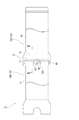
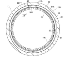
図1に示すように、本発明形態は、複数(図では2つ)の合成樹脂管10の接続構造1に係る。これら合成樹脂管10が一列に連ねられ、例えば下水管、農業用水管等として用いられる。各合成樹脂管10は、FRPやFRPM等の硬質樹脂にて構成されている。各合成樹脂管10は、円形断面の管本体部11と、受口12と、挿口13を有している。管本体部11の一端部(図1において左端部)に受口12が設けられ、他端部(図1において右端部)に挿口13が設けられている。受口12は、挿口13より大径である。
Hereinafter, embodiments of the present invention will be described with reference to the drawings.
<First embodiment>
As shown in FIG. 1, the embodiment of the present invention relates to a
図1及び図2に示すように、隣接する2つの合成樹脂管10のうち、一方(同図において右側)の合成樹脂管10の受口12に、他方の合成樹脂管10の挿口13が挿し込まれることで、これら合成樹脂管10,10どうしが接続状態となっている。
以下、特に断らない限り、2つの合成時樹脂10どうしは接続状態になっているものとする。また、前記2つの合成樹脂管10を互いに区別する際は、受口側の合成樹脂管10を「受側合成樹脂管10A」と称し、挿口側の合成樹脂管10を「挿側合成樹脂管10B」と称す。かつ特に断らない限り、受口12は、合成樹脂管10Aのものを指し、挿口13は、合成樹脂管10Bのものを指す。
As shown in FIGS. 1 and 2, one of the two adjacent synthetic resin pipes 10 (the right side in the figure) has a receiving
Hereinafter, unless otherwise specified, it is assumed that the two
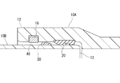
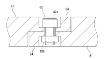
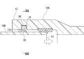
図2に示すように、受口12にシール部材20が設けられている。受口12の奥側(図2において右側)の内周面には、浅いシール用環状溝12dが形成されている。シール用環状溝12dにシール部材20が嵌め込まれている。シール部材20は、ゴム等にて構成され、環状になっている。シール部材20は、受口12の内側へ突出されている。図7に示すように、非弾性変形状態におけるシール部材20の突出端部の内径は、挿口13の外径よりも小さい。図2に示すように、合成樹脂管10どうしの接続状態においては、シール部材20が、挿口13の先端部分13eの外周面の全周に密着されることで、受口12と挿口13との間がシールされている。
As shown in FIG. 2, a
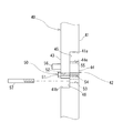
図2に示すように、合成樹脂管接続構造1には、合成樹脂管10どうしの離脱防止手段1cが設けられている。離脱防止手段1cは、挿側抜防部材30と、抜防リング40を含む。挿側抜防部材30の材質は、硬質ゴム、樹脂等である。挿側抜防部材30は、挿口13におけるシール部材20が密着する挿側先端部分13eよりも管本体部11側(図2において左側)の外周面に配置されている。挿側抜防部材30は、挿口13の周方向に沿う環状に形成されている。挿側抜防部材30の外径は、受口12の内径よりも僅かに小さい。挿側抜防部材30の外周面には、挿側先端部分13eへ向かって縮径するテーパ部31が形成されている。
As shown in FIG. 2, the synthetic resin
挿側抜防部材30は、接着剤やネジなどの固定手段(詳細図示省略)を介して挿口13に固定されている。接着剤としては、エポキシ系接着剤、ウレタン系接着剤等の種々の接着剤を適用できる。
挿側抜防部材30が、合成樹脂管10の外周面から突出された環状凸部によって構成され、合成樹脂管10と一体になっていてもよい。
The insertion-side
The insertion-side
図2に示すように、合成樹脂管10どうしの接続状態において、受口12が挿側抜防部材30を囲んでいる。受口12における挿側抜防囲繞部分12b(挿側抜防部材30を囲むべき部分)よりも先端側の内周面には、環状凹部16が形成されている。
As shown in FIG. 2, when the
図2に示すように、環状凹部16に抜防リング40が収容されている。抜防リング40は、挿側抜防部材30と管軸方向(図2において左右方向)に対峙されるようにして受口12に着脱・係止可能、かつ拡縮可能である。
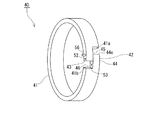
詳しくは、図3に示すように、抜防リング40は、リング本体部41と、拡縮可能部42を有している。
リング本体部41は、C字状になっている。リング本体部41の断面形状は、例えば長方形(四角形)になっている。
As shown in FIG. 2, a pull-
Specifically, as shown in FIG. 3, the pull-
The ring
図3に示すように、C字状のリング本体部41の周方向の両端部41a,41bどうし間に拡縮可能部42が設けられている。すなわち、抜防リング40の周方向の一箇所に拡縮可能部42が設けられている。図5(a)〜同図(d)に示すように、拡縮可能部42は、抜防リング40の周方向に伸縮可能である。拡縮可能部42の伸縮によって、抜防リング40が拡縮される。
As shown in FIG. 3, an expandable /
図4に示すように、拡縮可能部42は、一対の延出片部43,44を含む。リング本体部41の一端部41aから延出片部43が抜防リング40の周方向に沿って延び出ている。リング本体部41の周方向の他端部41bから延出片部44が前記周方向に沿って延び出ている。
各延出片部43,44の周方向の長さは、リング本体部41の周長に対して十分に短い。
各延出片部43,44の幅(管軸方向に沿う寸法)は、リング本体部41の幅(管軸方向に沿う寸法)より小さく、リング本体部41の幅の半分程度である。一対の延出片部43,44どうしの幅の合計が、リング本体部41の幅と実質的に等しい。
各延出片部43,44の厚さは、リング本体部41の厚さと同程度である。
As shown in FIG. 4, the expandable /
The circumferential length of each of the
The width (dimension along the tube axis direction) of each
The thickness of each
延出片部43,44どうしが、互いに管軸方向(図4において左右)にずれて、周方向(図4において上下)にラップされている。
リング本体部41における延出片部43より幅広の一端部41aと延出片部43とによって、相欠き部45が画成されている。相欠き部45に反対側の延出片部44が嵌め入れられている。
リング本体部41における延出片部44より幅広の他端部41bと延出片部44とによって、相欠き部46が画成されている。相欠き部46に延出片部43が嵌め入れられている。
The
One
A
図5(a)〜同図(d)に示すように、延出片部43,44どうしのラップ量に応じて、拡縮可能部42が伸縮され、ひいては抜防リング40が拡縮される。
ラップ量が減少すれば、拡縮可能部42が伸長され、抜防リング40が拡径される。
ラップ量が増大すれば、拡縮可能部42が収縮され、抜防リング40が縮径される。
As shown in FIGS. 5A to 5D, the expandable /
When the wrap amount is reduced, the expandable /
When the wrap amount increases, the expandable /
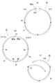
図4に示すように、抜防リング40には、保持手段50が設けられている。
保持手段50は、抜防リング40を縮径状態(図5(a))、接続径状態(図5(d))、拡径状態(図5(b))の3つ(複数)の径状態に選択的に保持可能かつ保持解除可能である。
すなわち、保持手段50は、拡縮可能部42を3つ(複数)の長さ状態に選択的に保持可能かつ保持解除可能である。要するに、一対の延出片部43,44どうしのラップ量を3つ(複数)の所定の大きさに選択的に保持可能かつ保持解除可能である。3つの所定ラップ量のうち最小のラップ量のとき、抜防リング40が拡径状態となり(図5(b))、中間のラップ量のとき、抜防リング40が接続径状態となり(図5(d))、最大のラップ量のとき、抜防リング40が縮径状態となる(図5(a))。
As shown in FIG. 4, the retaining
The holding means 50 changes the diameter of the pull-
That is, the holding
図5(c)に示すように、保持手段50による径状態保持を解除すると、抜防リング40は自然状態となり、一対の延出片部43,44どうしのラップ量が自然状態の長さになる。
As shown in FIG. 5C, when the holding of the diameter state by the holding means 50 is released, the pull-
縮径状態の抜防リング40は、自然状態の抜防リング40より小径の円形である。
さらに、図7に示すように、縮径状態における抜防リング40の外径は、受口12における環状凹部16より先端側の受口先端部12eの内径より小径である。
The pull-
Further, as shown in FIG. 7, the outer diameter of the pull-
拡径状態の抜防リング40は、自然状態の抜防リング40より大径の円形である。
さらに、図9に示すように、拡径状態における抜防リング40の外径は、環状凹部16に収容可能な大きさであり、かつ内径は挿側抜防部材30の外径より大径である。
The
Further, as shown in FIG. 9, the outer diameter of the pull-
図2に示すように、合成樹脂管10どうしの接続状態においては、抜防リング40が保持手段50によって接続径状態に保持されている。該接続径状態の抜防リング40が、環状凹部16内に配置されている。
接続径状態の抜防リング40は、縮径状態より大径かつ拡径状態より小径の円形であり、自然状態の抜防リング40と略同径か少し小径になっている。さらに接続径状態の抜防リング40は、外径が受口先端部12eの内径より大径であり、かつ内径が挿側抜防部材30の外径より小径になっている。したがって、抜防リング40の外周側部が環状凹部16内に収容され、かつ抜防リング40の内周側部は、環状凹部16から受口12の内部へ突出されている。更に好ましくは、抜防リング40の内周面が、挿口13の外周面の全周にほぼ当接又は近接されている。
As shown in FIG. 2, when the
The pull-
図4に示すように、保持手段50は、ボルト51(軸状部材)を含む。ボルト51の脚部は、一対の延出片部43,44をこれら延出片部43,44の幅方向(図4において左右方向)に跨ぐ長さを有している。
一方の延出片部43には、該延出片部43を幅方向に貫通する穴部52が形成されている。穴部52は、ボルト51をねじ込み可能(挿抜可能)な雌ネジ孔である。
As shown in FIG. 4, the holding means 50 includes a bolt 51 (shaft member). The leg of the
A
図4に示すように、他方の延出片部44には、ボルト51と係合可能な3つ(複数)の係合部53,54,55が形成されている。これら係合部53,54,55は、延出片部44の延出方向(図4において上下方向)に互いに離れている。
As shown in FIG. 4, three (plural)
図5(a)に示すように、リング本体部41の端部41bに一番近い係合部53は、縮径状態用である。該係合部53は、ボルト51よりも大径の雌ネジ孔によって構成されており、延出片部44を該延出片部44の幅方向に貫通している。
As shown in FIG. 5A, the
図5(d)に示すように、中間の係合部54は、接続径状態用である。該係合部54は、延出片部44を該延出片部44の幅方向に貫通するキリ穴によって構成されている。
As shown in FIG. 5D, the intermediate engaging
図5(b)に示すように、リング本体部41の端部41bから一番遠い係合部55は、拡径状態用である。該係合部55は、延出片部44の延出端部44eに形成された凹溝によって構成されており、延出端部44eから半円状に凹むとともに延出片部44の幅方向に延びている。
As shown in FIG. 5B, the
一方の延出片部43の穴部52に対して、他方の延出片部44の何れか1の係合部53,54,55が位置合わせされたうえで、ボルト51が、穴部52を通して前記何れか1の係合部53,54,55に係合される。これによって、一対の延出片部43,44どうしのラップ量が所定に保持され、抜防リング40が所定の径に保持される。
After one of the engaging
図4に示すように、合成樹脂管10どうしの接続状態ひいては抜防リング40の接続径状態においては、中間の係合部54が穴部52に位置合わせされている。そして、ボルト51が、穴部52にねじ込まれるとともに、貫通キリ穴からなる係合部54に挿通されて係合されている。
As shown in FIG. 4, in the connection state of the
図5(a)に示すように、縮径状態においては、係合部53が穴部52に位置合わせされ、ボルト51が、穴部52にねじ込まれるとともに係合部53に挿通される。なお、係合部53を構成する雌ねじ穴はボルト51より大径であるために、ボルト51と螺合されることはない。
ボルト51の脚部における係合部53,54に引っ掛かる先端側部分については、ネジ山の無い丸棒形状としてもよく、前記脚部における雌ネジ穴部52と対応する根元側部分だけにネジ山が切られていてもよい。そうすることで、前記先端側部分が雌ネジ穴部52内を通るときは捩じ込み作業を行う必要が無く、前記根元側部分が雌ネジ穴部52に達してから捩じ込み作業を行えばよく、捩じ込み作業の負担を軽減できる。
As shown in FIG. 5A, in the reduced diameter state, the engaging
The distal end portion of the leg portion of the
図5(b)に示すように、拡径状態においては、係合部55が穴部52に位置合わせされ、ボルト51が穴部52にねじ込まれるとともに、半円凹溝状の係合部55にボルト51の周側部が嵌って係止される。
As shown in FIG. 5B, in the diameter-expanded state, the engaging
図5(d)に示すように、更に抜防リング40には、縮径力付与用の一対の引掛部56,57が付属されている。引掛部56は一方の延出片部43に設けられ、引掛部57は他方の延出片部44に設けられている。これら引掛部56,57は、延出片部43,44の側端面から受口12の先端側(図5(d)において左側)へ向けて互いに平行に突出されている。
As shown in FIG. 5D, the pull-
引掛部56は、延出片部43に着脱不能に固定されたピンによって構成されている。なお、引掛部56が、ボルト等によって構成され、延出片部43に着脱可能であってもよい。
図4及び図5(d)に示すように、引掛部57は、ボルトによって構成されており、延出片部44の雌ネジ孔からなる係合部53にねじ込み可能ひいては着脱可能である。係合部53が、引掛部57の取り付け手段として兼用されている。引掛部57は、後述する縮径操作のときのみ抜防リング40に取り付けることにしてもよい。
The
As shown in FIG. 4 and FIG. 5D, the hooking
図1に示すように、受口12の周方向の一箇所には、窓部12hが形成されている。窓部12hは、受口12の先端面に達する切り欠き状になっている。窓部12hに一対の延出片部43,44が臨んでいる。
As shown in FIG. 1, a
合成樹脂管10どうしは、次のようにして接続される。
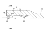
接続に先立ち、受側合成樹脂管10Aの受口12に抜防リング40を組み付けておく。図6に示すように、組み付けに際して、縮径冶具60を用意する。例えば、縮径冶具60は、伸縮シャフト61と、一対のホルダ62を含む。伸縮シャフト61は、ターンバックルなどで構成され、中央の胴部61cを回すことによって伸縮される。伸縮シャフト61の両端部にそれぞれホルダ62が設けられている。
The
Prior to connection, a pull-
縮径冶具60を抜防リング40の内側に配置して、伸縮シャフト61を抜防リング40の直径方向に向け、両端のホルダ62でリング本体部41の互いに180°離れて対向する部分を保持する。そして、胴部61cを収縮方向へ回すことによって、図6の白抜き矢印に示すように、伸縮シャフト61を収縮させる。これによって、リング本体部41ひいては抜防リング40が縮径される。
続いて、図5(a)に示すように、保持手段50によって抜防リング40を縮径状態に保持する。すなわち、穴部52と縮径状態用係合部53を位置合わせし、ボルト51を穴部52にねじ込むとともに係合部53に挿し入れて係合させる。また、縮径冶具60を抜防リング40から外して撤去する。
そして、図7に示すように、抜防リング40を受口先端部12eに差し入れる。抜防リング40は縮径状態に保持されているから、受口先端部12eに容易に差し入れることができ、更には環状凹部16まで容易にスライドさせることができる。
The reducing
Subsequently, as shown in FIG. 5A, the retaining
Then, as shown in FIG. 7, the pull-
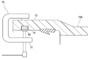
図7の二点鎖線にて示すように、抜防リング40を環状凹部16の内側に位置決めした後、ボルト51を係合部53から外すことによって、保持手段50による保持を解除する。
更に図8及び図9に示すように、拡径冶具70によって、抜防リング40を拡径させる。拡径冶具70は、例えば複数のシャコ万力71(C形クランプ)によって構成されている。これらシャコ万力71を受口12の周方向に間隔を置いて設け、各シャコ万力71によって受口12と抜防リング40とを挟み付ける。これによって、抜防リング40が拡径状態になり、抜防リング40のほぼ全体が環状凹部16内に入り込む。
続いて、保持手段50によって抜防リング40を拡径状態に保持する。すなわち、図5(b)に示すように、ボルト51を穴部52にねじ込むとともに延出端部44eの凹溝状の係合部55に引っ掛ける。また、拡径冶具70を受口12から外して撤去する。
抜防リング40を拡径状態に保持しておくことによって、例えば合成樹脂管10を配管施工現場まで運搬する時などに抜防リング40に振動が加わっても、抜防リング40が環状凹部16から外れるのを防止できる。ひいては、抜防リング40が合成樹脂管10から脱落するのを確実に防止できる。
As shown by the two-dot chain line in FIG. 7, after the pull-
Further, as shown in FIGS. 8 and 9, the diameter of the pull-
Subsequently, the retaining
By keeping the retaining
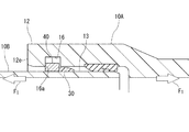
配管施工現場において、2つの合成樹脂管10A,10Bどうしを接続する際は、保持手段50によって抜防リング40を拡径状態に保持しておく(図5(b))。そのうえで、図10に示すように、挿側合成樹脂管10Bの挿口13を受側合成樹脂管10Aの受口12に挿し入れる。このとき、抜防リング40が拡径状態に保持されているために、挿側抜防部材30が抜防リング40に当たることはない。これによって、挿側抜防部材30を抜防リング40よりも受口12の奥側(図10において右側)へ容易に移行させることができる。ひいては、挿口13の挿し込み操作を容易に挿し込むことができる。
When connecting the two
その後、図5(c)に示すように、ボルト51を係合部55から外すことによって、保持手段50による抜防リング40の拡径状態への保持を解除する。これによって、抜防リング40が、縮径方向へ弾性復帰して、自然状態すなわち接続径状態に近い径状態となる。
なお、前記ボルト51を係合部55から外す操作は、受口12の窓部12h(図1)を通して行うことができる。
After that, as shown in FIG. 5C, the
The operation of removing the
一方、抜防リング40が前記拡径状態に保持されていた段階で塑性変形を来していたときは、図11に示すように、拡径状態の保持を解除しても、抜防リング40はあまり縮径されない。
この場合、図12に示すように、ボルトからなる引掛部57を雌ねじ孔からなる係合部53に取り付ける。そして、一対の引掛部56,57を指や工具でつまんで互いに接近方向に力F5を加える。これによって、抜防リング40に縮径力を付与でき、塑性変形した抜防リング40を強制的に接続径状態まで縮径させることができる。
図12の二点鎖線にて示すように、前記縮径力付与の操作は、受口12の窓部12hを通して行うことができる。
On the other hand, if the
In this case, as shown in FIG. 12, a
As shown by the two-dot chain line in FIG. 12, the operation of applying the diameter reducing force can be performed through the
さらに、保持手段50のボルト51を穴部52にねじ込むとともに接続径状態用係合部54に挿し入れて係合させる。当該ボルト51のねじ込み及び挿し入れ操作は、窓部12h(図12の二点鎖線)を通して行うことができる。
これによって、図5(d)に示すように、抜防リング40を接続径状態に保持することができる。引掛部57は、その後撤去してもよく(図4)、残置してもよい(図5(d))。
このようにして、合成樹管10A,10Bどうしが接続される(図1)。
Further, the
Thereby, as shown in FIG. 5D, the pull-
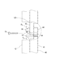
In this way, the
図13に示すように、配管施工後ひいては供用後の2つの合成樹脂管10どうし間に抜け力F1が作用したときは、挿側抜防部材30が抜防リング40に突き当たって係止され、かつ抜防リング40が環状凹部16における受口先端側の内壁16aに突き当たって係止される。この結果、挿口13が受口12から外れるのを阻止できる。
保持手段50によって抜防リング40が接続径状態に保持されているから、前記抜け力F1の作用時に抜防リング40が拡径変形されるのを阻止できる。したがって、抜け防止機能を確実に発揮することができ、合成樹管10A,10Bどうしの接続状態を確実に維持することができる。
As shown in FIG. 13, when the pull-out force F 1 acts between the two
Since the holding means 50抜防
次に、本発明の他の実施形態を説明する。以下の説明において、既述の形態と重複する構成に関しては図面に同一符号を付して説明を省略する。
<第2実施形態>
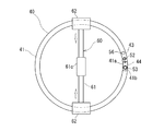
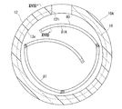
図14〜図25は、本発明の第2実施形態を示したものである。図14(a)〜同図(c)に示すように、第2実施形態においては、抜防リング80が周方向に複数に分割されている。分割式の抜防リング80は、4つ(複数)の部分リング81を含む。各部分リング81は、中心角90°程度の円弧状に形成されている。これら部分リング81が周方向に並べられている。
Next, another embodiment of the present invention will be described. In the following description, configurations that are the same as those in the above-described embodiment are given the same reference numerals in the drawings, and description thereof is omitted.
<Second embodiment>
14 to 25 show a second embodiment of the present invention. As shown in FIGS. 14A to 14C, in the second embodiment, the pull-
図15及び図16(a)に示すように、各部分リング81の両端部には連結凸片84が形成されている。隣接する部分リング81の対向する連結凸片84どうしが合成樹脂管10A,10B(図1及び図24参照)の管軸方向(図15において上下方向)にずれて周方向(図15において左右方向)に重ねられている。これら連結凸片84が、軸状の連結部材82,83を介して回転可能に連結されている。連結部材82,83の軸線は、管軸方向に沿っている。
As shown in FIG. 15 and FIG. 16A, connecting
図15に示すように、4つの連結部材82,83のうち、3つの連結部材82は、それぞれボルト82a及びナット82bによって構成されている。
図16に示すように、もう1つの連結部材83は、ボルトによって構成されている。該連結部材83は、部分リング81のうち隣接する2つの端部分リング81Aどうし間に配置されている。
As shown in FIG. 15, of the four connecting
As shown in FIG. 16, another connecting
図16(a)に示すように、合成樹脂管10A,10Bどうしが接続されているときは(図1及び図24参照)、これら2つの端部分リング81Aの連結凸片84A(延出片部)が互いに重ねられ、かつボルトからなる連結部材83(保持手段)が、一方の連結凸片84Aを貫通して、他方の連結凸片84Aにねじ込まれている。これによって、2つの端部分リング81Aが連結されている。ひいては、図14(b)に示すように、4つの部分リング81が環状に連なり、抜防リング80が円形の接続径状態に保持される。図23に示すように、該接続径状態における抜防リング80の外径は、受口先端部12eの内径より大きく、かつ抜防リング80の内径は挿側抜防部材30の外径より小さい。
As shown in FIG. 16A, when the
図16(a)に示すように、ボルトからなる連結部材83は、端部分リング81Aに対して着脱可能である。図16(b)に示すように、連結部材83を外すことによって、2つの端部分リング81Aどうしが分離され、接続径状態の保持が解除される。
図14(a)及び図14(c)に示すように、端部分リング81Aどうしの分離時における抜防リング80は、C字状又は開環状となる。かつ4つの部分リング81が任意に相対回転されることによって、接続径状態より大径又は拡開された拡径状態(拡開状態、図14(a))と、接続径状態より小径又は収縮された縮径状態(収縮状態、図14(c))との間で拡縮可能(展開収縮可能)である。
As shown in FIG. 16A, the connecting
As shown in FIGS. 14 (a) and 14 (c), when the end
図14(c)に示すように、縮径状態の抜防リング80は、たとえば概略渦巻き状に丸められている。図17に示すように、縮径状態においては、抜防リング80の外径(最小包含円の直径)が、受口先端部12eの内径より小さい。なお、縮径状態の抜防リング80は、接続径状態より小径又は収縮されていればよく、4つの部分リング81どうしの相対回転によって任意の形状を取り得る。
As shown in FIG. 14C, the pull-
図14(a)及び図21(a)に示すように、拡径状態においては、2つの端部分リング81Aが抜防リング80の周方向に離間され、抜防リング80が概略C字状になっている。図21(c)に示すように、2つの端部分リング81Aどうしの間には、拡開保持治具85(保持手段)が介在される。拡開保持治具85によって、端部分リング81Aどうしの間隔が保持される。
図21(b)に示すように、拡開保持治具85は、抜防リング80の周方向に沿って延びる板状に形成されている。図21(c)及び図22に示すように、該拡開保持治具85が、2つの端部分リング81Aの連結凸片84Aどうし間に架け渡されている。各連結凸片84Aと拡開保持治具85とは、連結ボルト87,88によって連結されている。拡開保持治具85の一端部には、一方の連結ボルト87を通す円形の挿通孔85aが形成されている。拡開保持治具85の他端部には、他方の連結ボルト88を通す長孔85bが形成されている。長孔85bの長径は拡開保持治具85の長手方向へ向けられている。長孔85bの長さ分だけ、端部分リング81Aの離間距離を微調整できる。
連結ボルト87,88を外せば、拡開保持治具85による拡径状態の保持が解除される。
As shown in FIGS. 14 (a) and 21 (a), in the expanded state, the two end
As shown in FIG. 21B, the
When the connecting
図19に示すように、拡径状態における抜防リング80の内径(最大内接円の直径)は、挿側抜防部材30の外径より大きく、好ましくは受口12の内径と略等しいかそれより大きい。拡径状態における抜防リング80の外径(最小包含円の直径)は、環状凹部16の内底面の内径と略等しいかそれより小さい。
As shown in FIG. 19, the inner diameter (the diameter of the maximum inscribed circle) of the pull-
図25(a)に示すように、各部分リング81ひいては抜防リング80には、受側テーパ面86が形成されている。受側テーパ面86は、抜防リング80の接続径状態において挿側抜防部材30と対向する側部に配置されている。詳しくは、受側テーパ面86は、抜防リング80の内周面から管軸方向の挿側抜防部材側(図25(a)において右側)へ向かって拡径され、抜防リング80の挿側抜防部材側の端面に達している。管軸に対する受側テーパ面86の角度θ86は、好ましくは5°≦θ86≦60°であり、より好ましくは、θ86=10°程度である。
As shown in FIG. 25A, a receiving side tapered
図25(a)に示すように、挿側抜防部材30には、挿側テーパ面36が形成されている。挿側テーパ面36は、挿側抜防部材30における接続径状態の抜防リング80と対向する側部に配置されている。詳しくは、挿側テーパ面36は、挿側抜防部材30の外周面から管軸方向の抜防リング側(図25(a)において左側)へ向かって縮径され、挿側抜防部材30の抜防リング側の端面又は底面(内周面)に達している。管軸に対する挿側テーパ面36の角度θ36は、好ましくは5°≦θ36≦60°であり、より好ましくは、θ36=45°程度である。
合成樹脂管10A,10Bどうしが接続された状態において、テーパ面86,36どうしが管軸方向(図25(a)において左右方向)に対峙されている。
As shown in FIG. 25A, the insertion-side
When the
第2実施形態においては、次のようにして、合成樹脂管10どうしが接続される。
図14(c)及び図16(b)に示すように、一対の端部分リング81Aどうしを分離し、抜防リング80を縮径状態とする。手作業で簡単に収縮(縮径)させることができ、収縮用の治具は不要である。
そして、図17及び図18に示すように、抜防リング80を受口先端部12eに差し入れる。縮径状態の抜防リング80は、外径(最小包含円の直径)が受口先端部12eの内径より小さいから、受口先端部12eに容易に差し入れることができる。
In the second embodiment, the
As shown in FIGS. 14C and 16B, the pair of end
Then, as shown in FIG. 17 and FIG. 18, the pull-
図18において二点鎖線にて示すように、抜防リング80を環状凹部16の径方向内側に位置させた後、該抜防リング80を環状凹部16の内部に挿し入れながら拡径状態にする。拡開用の治具を使わなくても手作業で簡単に拡開(拡径)できる。図19に示すように、拡開によって、抜防リング80のほぼ全体が環状凹部16の内部に収容される。離間させた一対の端部分リング81Aどうしの間には拡開保持治具85を装着する。前記拡開及び装着作業は、窓部12hを通して行うことができる。
拡径状態での各部分リング81には応力が殆ど作用していない。したがって、拡径状態を長時間維持したとしても、部分リング81が塑性変形を来たすことは殆どない。
As shown by the two-dot chain line in FIG. 18, after the pull-
Little stress acts on each of the
次に、図20に示すように、挿側合成樹脂管10Bの挿口13を受側合成樹脂管10Aの受口12に挿し入れる。抜防リング80が拡径状態に保持されているために、抜防リング80と挿側抜防部材30とが干渉し合うことがなく、挿側抜防部材30を抜防リング80よりも受口12の奥側(図20において右側)へ容易に移行させることができる。
Next, as shown in FIG. 20, the
次に、拡開保持治具85を抜防リング80から外して撤去する(図21)。そして、抜防リング80を収縮(縮径)させる。部分リング81は殆ど塑性変形していないから、簡単かつ確実に収縮させることができる。拡開保持治具85の撤去時に抜防リング80が勢いよく自然状態に弾性復帰することもなく、安全に作業できる。
図23に示すように、一対の端部分リング81Aの連結凸片84Aどうしを重ねて連結部材83によって連結する。これによって、抜防リング80が接続径状態に保持される。
前記拡開保持治具85の撤去、抜防リング80の縮径、連結部材83の装着作業などは、窓部12hを通して行うことができる。
図24に示すように、このようにして、合成樹管10A,10Bどうしが接続される。図25(a)に示すように、抜防リング80は、環状凹部16に収容されて、挿側抜防部材30と管軸方向に対峙されている。
Next, the
As shown in FIG. 23, the connecting
Removal of the
As shown in FIG. 24, the
図25(b)に示すように、接続後の2つの合成樹脂管10どうし間に抜け力F1が作用したときは、抜防リング80の受側テーパ面86と挿側抜防部材30の挿側テーパ面36とが突き当たる。これによって、挿側抜防部材30に作用する剪断力及び剥離力が低減される。したがって、挿側抜防部材30が剪断破壊されたり挿口13の外周面から剥離されたりするのを抑制できる。この結果、離脱防止性能が高まり、挿口13が受口12から外れるのを確実に阻止できる。
図示は省略するが、合成樹脂管の管路が曲がっていても剪断力を確実に低減でき、離脱防止性能を確保できる。
As shown in FIG. 25 (b), when the exit force F 1 between and if two
Although not shown, the shearing force can be reliably reduced even if the conduit of the synthetic resin pipe is bent, and the detachment prevention performance can be secured.
第2実施形態の合成樹脂管接続構造1によれば、部分リングの数(抜防リング80の分割数)を4つとすることによって、コストの上昇を抑えることができる。かつ挿口13の挿入時に挿側抜防部材30との干渉を確実に避けることができる。
ちなみに、抜防リング80の分割数が多いと、挿口13の挿入時における挿側抜防部材30との干渉を確実に回避できるが、構造が複雑化して製造コストが上昇する。抜防リング80の分割数が少ないと、拡径状態における抜防リング80の部分リング81どうしの連結部分が環状凹部16から径方向の内側へ突出されやすくなり、挿口13の挿入時に挿側抜防部材30と干渉しやすくなる。環状凹部16を深くすれば、抜防リング80の分割数が少なくても拡径状態における抜防リング80の全体を環状凹部16内に収容可能であるが、受口12の厚みを大きくする必要があり、材料コストが高くなってしまう。
According to the synthetic resin
Incidentally, if the number of divisions of the pull-
本発明は、前記実施形態に限定されるものではなく、その趣旨を逸脱しない範囲において種々の改変をなすことができる。
例えば、第1実施形態の抜防リング40が、第2実施形態と同様の受側テーパ面86を有していてもよく、かつ第1実施形態の挿側抜防部材30が、第2実施形態と同様の挿側テーパ面36を有していてもよい。
一対の延出片部43,44どうしが、厚さ方向(径方向)に重ね合わされるようになっていてもよい。
第1実施形態の保持手段50は、抜防リング40を少なくとも縮径状態と拡径状態の2つの径状態に選択的に保持可能かつ保持解除可能であればよく、接続径状態に保持する機能を省いてもよい。
第1実施形態の自然状態における抜防リング40が接続径状態より小径であってもよい。接続径状態の抜防リング40が挿口13の外周面に弾性的に圧接されていてもよい。
引掛部56,57は、リング本体部41における延出片部43の近傍部に設けられていてもよい。
挿側抜防部材30は、必ずしも環状である必要はなく、挿口13の周方向に間隔を置いて配置された複数の突起によって構成されていてもよい。
第2実施形態の部分リング81の数は、4つに限らず、2つまたは3つでもよく、5つ以上でもよい。
The present invention is not limited to the above embodiment, and various modifications can be made without departing from the gist of the present invention.
For example, the pull-
The pair of
The holding means 50 of the first embodiment only needs to be able to selectively hold the
The retaining
The
The insertion-side
The number of the
実施例を説明する。本発明が以下の実施例に限定されるものではない。
抜防リングの受側テーパ面及び挿側抜防部材の挿側テーパ面の有無及び角度と離脱防止性能との関係を調べた。
テストサンプルとして、抜防リングを模した一対の平鋼からなる平行板と、挿口を模したFRP製板材を用意した。
平行板どうしの間の隙間は、25mmであった。平行板を鉛直に立てて配置した。各平行板の鉛直な対向面と水平な上面との角部には受側テーパ面を模した受側斜面を形成した。鉛直方向(管軸方向に相当)に対する受側斜面の角度は、10°、30°、45°、90°(斜面無し)の4通りとした。
FRP製板材の厚さは20mmであった。
FRP製板材の両面には挿側抜防部材を模したゴム板を接着した。ゴム板の幅は50mmであった。ゴム板の厚さは8mmであった。
ゴム板の外側面(FRP製板材側とは反対側の面)と下端面との角部には、挿側テーパ面を模した挿側斜面を形成した。鉛直方向(管軸方向に相当)に対する挿側斜面の角度は、45°と90°(斜面無し)の2通りとした。
前記ゴム板付きのFRP製板材を鉛直にして平行板の上方から平行板どうしの間に押し込み、ゴム板が剥離又は剪断破壊されたときの押し込み荷重(最大荷重)を測定した。
An embodiment will be described. The present invention is not limited to the following examples.
The relationship between the presence / absence and angle of the receiving taper surface of the pull-out prevention ring and the insertion-side taper surface of the insertion-side pull-out prevention member and the separation prevention performance was examined.
As a test sample, a pair of flat plates made of a pair of flat steel simulating a pull-out prevention ring and a FRP plate material simulating an insertion opening were prepared.
The gap between the parallel plates was 25 mm. The parallel plate was placed upright. A receiving-side slope simulating a receiving-side tapered surface was formed at the corner between the vertical opposing surface and the horizontal upper surface of each parallel plate. The angles of the receiving-side slopes with respect to the vertical direction (corresponding to the tube axis direction) were four types: 10 °, 30 °, 45 °, and 90 ° (no slope).
The thickness of the FRP plate was 20 mm.
A rubber plate simulating an insertion-side pullout prevention member was bonded to both surfaces of the FRP plate material. The width of the rubber plate was 50 mm. The thickness of the rubber plate was 8 mm.
At the corner between the outer surface of the rubber plate (the surface opposite to the FRP plate material side) and the lower end surface, an insertion-side slope simulating an insertion-side tapered surface was formed. The angle of the insertion side slope with respect to the vertical direction (corresponding to the pipe axis direction) was set to 45 ° and 90 ° (no slope).
The FRP plate material with the rubber plate was vertically pushed between the parallel plates from above the parallel plates, and the indentation load (maximum load) when the rubber plate was peeled or sheared was measured.
結果は、表1の通りであった。

本発明は、例えば下水道管や農業用水管の継手構造に適用できる。 INDUSTRIAL APPLICATION This invention is applicable to the joint structure of a sewer pipe or an agricultural water pipe, for example.
1 合成樹脂管接続構造
10A 受側合成樹脂管
10B 挿側合成樹脂管
12 受口
12b 挿側抜防囲繞部分(挿側抜防部材を囲むべき部分)
12e 受口先端部
12h 窓部
13 挿口
16 環状凹部
20 シール部材
30 挿側抜防部材
36 挿側テーパ面
40 抜防リング
41 リング本体部
41a 一端部
41b 他端部
42 拡縮可能部
43 一方の延出片部
44 他方の延出片部
44e 延出端部
45,46 相欠き部
50 保持手段
51 ボルト(軸状部材)
52 穴部
53 縮径用係合部
54 接続径用係合部
55 拡径用係合部
56,57 引掛部
80 分割式抜防リング
81 部分リング
81A 端部分リング
83 連結部材
84A 連結凸片(対向端部)
85 拡開保持治具
86 受側テーパ面
1 Synthetic Resin
41a One
52
80 split
85
Claims (15)
前記挿口の外周面に設けられた挿側抜防部材と、
前記合成樹脂管どうしが接続されているときの接続径状態より大径又は拡開された拡径状態と前記接続径状態より小径又は収縮された縮径状態との間で拡縮可能かつ各状態に保持可能な抜防リングと、
を備え、前記受口における前記挿側抜防部材を囲むべき部分よりも管軸方向の先端側の内周面には、前記拡径状態及び接続径状態における抜防リングが収容される環状凹部が形成されており、
前記縮径状態においては、前記抜防リングの外径が前記受口における前記環状凹部より先端側の受口先端部の内径より小さく、
前記拡径状態においては、前記抜防リングの内径が前記挿側抜防部材の外径より大きく、
前記接続径状態においては、前記抜防リングの内径が前記挿側抜防部材の外径より小さいことを特徴とする合成樹脂管接続構造。 A synthetic resin pipe connection including a receiving synthetic resin pipe having a receiving port, and an inserting synthetic resin pipe having an inserting port, wherein the synthetic resin pipes are connected to each other by inserting the inserting port into the receiving port; Structure,
An insertion-side pullout prevention member provided on the outer peripheral surface of the insertion opening,
When the synthetic resin pipes are connected to each other, they can be expanded and contracted between a larger or expanded diameter state than the connection diameter state and a reduced or contracted diameter state than the connection diameter state. A retaining ring that can be held,
An annular concave portion on the inner peripheral surface on the distal end side in the tube axis direction than a portion of the receiving port that should surround the insertion-side withdrawal prevention member, in which the withdrawal prevention ring in the enlarged diameter state and the connection diameter state is accommodated. Is formed,
In the reduced diameter state, the outer diameter of the pull-out prevention ring is smaller than the inner diameter of the distal end of the receiving port on the distal side of the annular concave portion in the receiving port,
In the expanded state, the inner diameter of the pull-out prevention ring is larger than the outer diameter of the insertion-side pull-out prevention member,
In the connection diameter state, an inner diameter of the pull-out prevention ring is smaller than an outer diameter of the insertion-side pull-out prevention member, wherein the connection structure is a synthetic resin pipe.
前記保持手段によって、前記一対の延出片部どうしのラップ量が複数の所定の大きさに選択的に保持されることを特徴とする請求項1又は2に記載の合成樹脂管接続構造。 The pull-out prevention ring includes a C-shaped ring main body, and a pair of extension pieces that extend in the circumferential direction from both circumferential ends of the ring main body and are wrapped with each other,
3. The synthetic resin pipe connection structure according to claim 1, wherein a wrap amount between the pair of extension pieces is selectively held at a plurality of predetermined sizes by the holding unit. 4.
一方の延出片部には前記軸状部材を挿抜可能な穴部が形成され、
他方の延出片部には前記軸状部材と係合可能な係合部が前記周方向に複数形成されていることを特徴とする請求項3〜5の何れか1項に記載の合成樹脂管接続構造。 The holding means includes a shaft-like member having a length straddling the pair of extension pieces,
A hole is formed in one of the extension pieces so that the shaft-like member can be inserted and withdrawn,
The synthetic resin according to any one of claims 3 to 5, wherein a plurality of engaging portions capable of engaging with the shaft-shaped member are formed in the other extension piece portion in the circumferential direction. Pipe connection structure.
Applications Claiming Priority (2)
| Application Number | Priority Date | Filing Date | Title |
|---|---|---|---|
| JP2018117238 | 2018-06-20 | ||
| JP2018117238 | 2018-06-20 |
Publications (2)
| Publication Number | Publication Date |
|---|---|
| JP2020003063A true JP2020003063A (en) | 2020-01-09 |
| JP7269105B2 JP7269105B2 (en) | 2023-05-08 |
Family
ID=69099544
Family Applications (1)
| Application Number | Title | Priority Date | Filing Date |
|---|---|---|---|
| JP2019108391A Active JP7269105B2 (en) | 2018-06-20 | 2019-06-11 | Connection structure of synthetic resin pipes |
Country Status (1)
| Country | Link |
|---|---|
| JP (1) | JP7269105B2 (en) |
Citations (4)
| Publication number | Priority date | Publication date | Assignee | Title |
|---|---|---|---|---|
| JPS5241919A (en) * | 1975-09-30 | 1977-03-31 | Kubota Ltd | Lock-ring for fixing a pipe joint firmly |
| JPS54106917A (en) * | 1978-02-09 | 1979-08-22 | Kubota Ltd | Separation prevented pipe fitting |
| JPS5896181U (en) * | 1981-12-23 | 1983-06-30 | 株式会社栗本鉄工所 | Locking ring in pipe fittings |
| JP2017214976A (en) * | 2016-05-31 | 2017-12-07 | 積水化学工業株式会社 | Connection structure and connection method of hard resin tube |
-
2019
- 2019-06-11 JP JP2019108391A patent/JP7269105B2/en active Active
Patent Citations (4)
| Publication number | Priority date | Publication date | Assignee | Title |
|---|---|---|---|---|
| JPS5241919A (en) * | 1975-09-30 | 1977-03-31 | Kubota Ltd | Lock-ring for fixing a pipe joint firmly |
| JPS54106917A (en) * | 1978-02-09 | 1979-08-22 | Kubota Ltd | Separation prevented pipe fitting |
| JPS5896181U (en) * | 1981-12-23 | 1983-06-30 | 株式会社栗本鉄工所 | Locking ring in pipe fittings |
| JP2017214976A (en) * | 2016-05-31 | 2017-12-07 | 積水化学工業株式会社 | Connection structure and connection method of hard resin tube |
Also Published As
| Publication number | Publication date |
|---|---|
| JP7269105B2 (en) | 2023-05-08 |
Similar Documents
| Publication | Publication Date | Title |
|---|---|---|
| US7469936B2 (en) | Pipe coupling | |
| CA3113781C (en) | Fitting device, arrangement and method | |
| JP2016524100A (en) | Connector with arcuate rigid brazing material | |
| US9822912B2 (en) | Push-to-connect fitting device, arrangement and method | |
| MXPA04009299A (en) | A collet for pipe coupling. | |
| JP2006118704A (en) | Insertion type joint | |
| WO2013056273A2 (en) | Push-fit fitting with grip nut for pipes | |
| US20080203723A1 (en) | Detachable pipe joint and joining method | |
| JP4791946B2 (en) | Pipe joint made of synthetic resin | |
| KR102015114B1 (en) | The water pipe connection device with excellent workability and vibration proof | |
| JP2020003063A (en) | Connection structure for synthetic resin tube | |
| JP5137195B2 (en) | Pipe fitting | |
| KR20180030958A (en) | Pipe coupler | |
| JP2010180693A (en) | Pile joint structure | |
| JP2015094462A (en) | Pipe joint | |
| US20060163872A1 (en) | Pipe coupling | |
| CN111868431A (en) | Pipe joint, press ring for pipe joint, and pipe joining method | |
| KR101296670B1 (en) | One touch fitting for pipe connection | |
| US20050253386A1 (en) | Coupling of tubular members | |
| JP3959666B2 (en) | Sleeve type fitting | |
| JP2006070994A (en) | Slip-off prevented pipe joint | |
| JP5466999B2 (en) | Pipe fitting | |
| JP2002228064A (en) | Push ring for pipe joint, and pipe joint | |
| JP5218924B2 (en) | Plug-in fitting | |
| KR100543019B1 (en) | Device for coupling plastic pipes |
Legal Events
| Date | Code | Title | Description |
|---|---|---|---|
| A621 | Written request for application examination |
Free format text: JAPANESE INTERMEDIATE CODE: A621 Effective date: 20220322 |
|
| A131 | Notification of reasons for refusal |
Free format text: JAPANESE INTERMEDIATE CODE: A131 Effective date: 20230117 |
|
| A977 | Report on retrieval |
Free format text: JAPANESE INTERMEDIATE CODE: A971007 Effective date: 20230118 |
|
| A521 | Request for written amendment filed |
Free format text: JAPANESE INTERMEDIATE CODE: A523 Effective date: 20230302 |
|
| TRDD | Decision of grant or rejection written | ||
| A01 | Written decision to grant a patent or to grant a registration (utility model) |
Free format text: JAPANESE INTERMEDIATE CODE: A01 Effective date: 20230328 |
|
| A61 | First payment of annual fees (during grant procedure) |
Free format text: JAPANESE INTERMEDIATE CODE: A61 Effective date: 20230421 |
|
| R151 | Written notification of patent or utility model registration |
Ref document number: 7269105 Country of ref document: JP Free format text: JAPANESE INTERMEDIATE CODE: R151 |