JP2020003025A - Front fork - Google Patents
Front fork Download PDFInfo
- Publication number
- JP2020003025A JP2020003025A JP2018123916A JP2018123916A JP2020003025A JP 2020003025 A JP2020003025 A JP 2020003025A JP 2018123916 A JP2018123916 A JP 2018123916A JP 2018123916 A JP2018123916 A JP 2018123916A JP 2020003025 A JP2020003025 A JP 2020003025A
- Authority
- JP
- Japan
- Prior art keywords
- chamber
- front fork
- choke
- pressure
- orifice
- Prior art date
- Legal status (The legal status is an assumption and is not a legal conclusion. Google has not performed a legal analysis and makes no representation as to the accuracy of the status listed.)
- Pending
Links
Images


Abstract
Description
本発明は、フロントフォークの改良に関する。 The present invention relates to an improvement of a front fork.
従来、鞍乗型車両の前輪を懸架するフロントフォークは、アウターチューブと、このアウターチューブ内に摺動自在に挿入されるインナーチューブとを有して構成されるテレスコピック型のチューブ部材を備えている。さらに、フロントフォークの中には、アウターチューブを車輪側に、インナーチューブを車体側に設けた、いわゆる正立型のフロントフォークがある(例えば、特許文献1)。 2. Description of the Related Art Conventionally, a front fork for suspending a front wheel of a saddle-ride type vehicle includes a telescopic tube member including an outer tube and an inner tube slidably inserted into the outer tube. . Further, among the front forks, there is a so-called upright type front fork in which an outer tube is provided on a wheel side and an inner tube is provided on a vehicle body side (for example, Patent Document 1).
そして、そのような正立型のフロントフォークでは、アウターチューブの内側にシリンダを設けてこれらの間に形成される液室と、シリンダの内側からその上側にかけて形成されるリザーバ室とを仕切るとともに、インナーチューブの下端に設けたピストン部で液室を伸側室と圧側室とに区画している。また、シリンダには、伸側室とリザーバ室とを連通する伸側オリフィスと、圧側室とリザーバ室とを連通する圧側オリフィスが形成されている。 In such an upright front fork, a cylinder is provided inside the outer tube to partition a liquid chamber formed between the cylinder and a reservoir chamber formed from the inside of the cylinder to the upper side thereof, The liquid chamber is partitioned into a growth side chamber and a pressure side chamber by a piston provided at the lower end of the inner tube. Further, the cylinder is formed with an expansion-side orifice that connects the expansion-side chamber and the reservoir chamber, and a compression-side orifice that connects the compression-side chamber and the reservoir chamber.
上記構成によれば、フロントフォークの伸長時には、伸側室の液体が伸側オリフィスを通ってリザーバ室へ移動して、その液体の流れに付与される抵抗に起因する伸側の減衰力が発生する。反対に、フロントフォークの収縮時には、圧側室の液体が圧側オリフィスを通ってリザーバ室へ移動して、その液体の流れに付与される抵抗に起因する圧側の減衰力が発生する。 According to the above configuration, when the front fork is extended, the liquid in the extension side chamber moves to the reservoir chamber through the extension side orifice, and the extension side damping force is generated due to the resistance applied to the flow of the liquid. . Conversely, when the front fork contracts, the liquid in the pressure side chamber moves to the reservoir chamber through the pressure side orifice, and a pressure side damping force is generated due to the resistance applied to the flow of the liquid.
従来のフロントフォークでは、圧側の減衰力は、シリンダに形成された圧側オリフィスの大きさの変更により調節される。しかしながら、収縮時におけるピストン部の速度(ピストン速度)に対する減衰力の特性(減衰力特性)は、図7に示すように、オリフィス特有の二乗特性となる。このため、たとえ圧側オリフィスを小さくしたとしても、ピストン速度が低速域にある場合の減衰力を大きくするのが難しく、低速域での圧側の減衰力が不足することがある。 In a conventional front fork, the compression side damping force is adjusted by changing the size of the compression side orifice formed in the cylinder. However, the characteristic (damping force characteristic) of the damping force with respect to the speed of the piston portion (piston speed) at the time of contraction is a square characteristic peculiar to the orifice as shown in FIG. For this reason, even if the compression-side orifice is reduced, it is difficult to increase the damping force when the piston speed is in a low-speed range, and the compression-side damping force in a low-speed range may be insufficient.
そこで、本発明は、このような問題を解決するために創案されたものであり、ピストン速度が低速域にある場合であっても、圧側の減衰力が不足するのを防止できるフロントフォークの提供を目的とする。 Therefore, the present invention has been made in order to solve such a problem, and provides a front fork that can prevent insufficient pressure-side damping force even when the piston speed is in a low speed range. With the goal.
上記課題を解決するフロントフォークは、筒状であって車輪側のアウターチューブ内に設けられ、上端が車体側のインナーチューブ内に移動可能に挿入されるとともに、外周側の液室と、内側から上側にかけて形成されるリザーバ室とを仕切るシリンダと、インナーチューブに設けられて液室を伸側室と圧側室とに区画するピストン部と、圧側室とリザーバ室とを連通するオリフィスと、圧側室内又はリザーバ室内にチョーク通路を形成するチョーク部材とを備えている。 The front fork for solving the above-mentioned problem is cylindrical and provided in an outer tube on the wheel side, the upper end is movably inserted into an inner tube on the vehicle body side, and a liquid chamber on the outer peripheral side, from the inside, A cylinder partitioning a reservoir chamber formed over the upper side, a piston portion provided in the inner tube to divide the liquid chamber into a growth side chamber and a pressure side chamber, an orifice communicating the pressure side chamber and the reservoir chamber, and a pressure side chamber or A choke member for forming a choke passage in the reservoir chamber.
上記構成によれば、フロントフォークの収縮時に液体がオリフィスとチョーク通路を通過して、これらの抵抗によって圧力損失が生じ、圧側の減衰力が発生する。そして、フロントフォークの収縮時においてピストン速度が低速域にある場合には、チョーク通路による圧力損失が支配的となり、圧側の減衰力が比例特性となる。このため、低速域での圧側の減衰力を大きくできるので、低速域において圧側の減衰力が不足するのを防止できる。 According to the above configuration, when the front fork contracts, the liquid passes through the orifice and the choke passage, and a pressure loss occurs due to these resistances, and a pressure-side damping force is generated. When the piston speed is in the low speed range when the front fork is contracted, the pressure loss due to the choke passage becomes dominant, and the pressure-side damping force has a proportional characteristic. For this reason, the compression-side damping force in the low-speed range can be increased, so that the compression-side damping force in the low-speed range can be prevented from becoming insufficient.
また、上記フロントフォークでは、チョーク通路がシリンダとチョーク部材との間にできる隙間、又はチョーク部材に形成された孔により形成されているとよい。これらの構成によれば、チョーク通路を容易に形成できる。 In the front fork, the choke passage may be formed by a gap formed between the cylinder and the choke member, or a hole formed in the choke member. According to these configurations, the choke passage can be easily formed.
また、上記フロントフォークでは、チョーク部材がシリンダ内に配置されているとよい。当該構成によれば、フロントフォークの収縮時にはチョーク通路がオリフィスの下流に配置されるので、液体がこれらを滞りなく通過しやすくなる。さらには、チョーク部材がフロントフォークのストロークの妨げにならないので、チョーク部材を設けたことでフロントフォークのストローク長を確保できなくなったり、フロントフォークが軸方向に嵩張ったりするのを防止できる。 In the front fork, the choke member may be arranged in the cylinder. According to this configuration, when the front fork is contracted, the choke passage is disposed downstream of the orifice, so that the liquid can easily pass through the orifice without interruption. Furthermore, since the choke member does not hinder the stroke of the front fork, the provision of the choke member can prevent the stroke length of the front fork from being secured or prevent the front fork from becoming bulky in the axial direction.
また、上記フロントフォークでは、チョーク通路の圧側室側の開口がオリフィスのリザーバ室側の開口と対向しない位置であって、そのオリフィスの開口よりも上側に配置されているとよい。当該構成によれば、液体がオリフィスとチョーク通路との間を滞りなく行き来しやすくなる。 Further, in the front fork, the opening of the choke passage on the pressure side chamber side may not be opposed to the opening of the orifice on the reservoir chamber side, and may be disposed above the opening of the orifice. According to this configuration, the liquid can easily flow back and forth between the orifice and the choke passage.
また、上記フロントフォークでは、チョーク部材がアウターチューブとシリンダとを連結するボルトに取り付けられているとよい。当該構成によれば、チョーク通路をリザーバ内の所定の位置に容易に形成できる。さらには、チョーク部材の着脱が容易であるので、チョーク部材の交換による減衰力のチューニングを容易にできる。 In the front fork, the choke member may be attached to a bolt connecting the outer tube and the cylinder. According to this configuration, the choke passage can be easily formed at a predetermined position in the reservoir. Further, since the choke member can be easily attached and detached, tuning of the damping force by replacing the choke member can be facilitated.
本発明のフロントフォークによれば、ピストン速度が低速域にある場合であっても、圧側の減衰力が不足するのを防止できる。 ADVANTAGE OF THE INVENTION According to the front fork of this invention, even when the piston speed is in a low speed area | region, it can prevent that the damping force of a compression side runs short.
以下に本発明の実施の形態のフロントフォークについて、図面を参照しながら説明する。いくつかの図面を通して付された同じ符号は、同じ部品か対応する部品を示す。また、フロントフォークが車両に取り付けられた状態での上下を、特別な説明がない限り、単に「上」「下」という。 Hereinafter, a front fork according to an embodiment of the present invention will be described with reference to the drawings. Like reference numerals throughout the several figures indicate the same or corresponding parts. The upper and lower sides of the vehicle with the front fork attached to the vehicle are simply referred to as “up” and “down” unless otherwise specified.
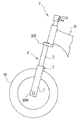
図1に示すように、本発明の一実施の形態に係るフロントフォークFは、鞍乗型車両Vにおいて前輪Wを懸架する懸架装置である。鞍乗型車両とは、鞍に跨るような姿勢で乗車するタイプの車両全般のことであり、オートバイ、スクータ、自転車等が含まれる。本発明に係るフロントフォークは、如何なる鞍乗型車両に搭載されていてもよい。 As shown in FIG. 1, a front fork F according to an embodiment of the present invention is a suspension device for suspending a front wheel W in a straddle-type vehicle V. The straddle-type vehicle is a general type of vehicle that rides in a posture that straddles a saddle, and includes motorcycles, scooters, bicycles, and the like. The front fork according to the present invention may be mounted on any saddle type vehicle.
つづいて、本発明の一実施の形態に係るフロントフォークFの具体的な構造について説明する。フロントフォークFは、アウターチューブ1とインナーチューブ2とを有して構成されるテレスコピック型のチューブ部材Tを備えている。さらに、フロントフォークFは正立型であり、アウターチューブ1の上側開口からインナーチューブ2が摺動自在に挿入されている。
Subsequently, a specific structure of the front fork F according to one embodiment of the present invention will be described. The front fork F includes a telescopic tube member T configured to include the
そして、アウターチューブ1には、車輪側ブラケットBWが一体に設けられており、アウターチューブ1は、その車輪側ブラケットBWを介して前輪Wの車軸に連結される。その一方、インナーチューブ2は、その上端部に連結される車体側ブラケットBBを介して車体Bに連結される。
The
このように、フロントフォークFは、アウターチューブ1を前輪(車輪)W側へ、インナーチューブ2を車体B側へ向けて配置され、車体Bと前輪Wの車軸との間に介装されている。そして、鞍乗型車両Vが凹凸のある路面を走行する等して前輪Wが上下に振動すると、インナーチューブ2がアウターチューブ1に出入りしてフロントフォークFが伸縮する。
As described above, the front fork F is arranged with the
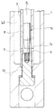
つづいて、インナーチューブ2の上端開口は、キャップ(図示せず)で塞がれている。その一方、アウターチューブ1は、図2に示すように有底筒状であり、アウターチューブ1の下側開口はその底部1aで塞がれている。さらに、アウターチューブ1とインナーチューブ2の重複部の間は、オイルシール10とダストシール11により塞がれている。このようにしてチューブ部材T内は密閉空間とされており、そのチューブ部材T内に液体と気体が封入されている。
Subsequently, the upper end opening of the inner tube 2 is closed with a cap (not shown). On the other hand, the
また、アウターチューブ1の底部1aには、シリンダ3がボルト30で連結されている。このシリンダ3は、筒状部3aと、この筒状部3aの先端から径方向外側へ張り出す環状のバルブケース部3bとを含む。そして、筒状部3aがアウターチューブ1の中心部に軸方向に沿うように起立して、そのバルブケース部3bがインナーチューブ2の内側に軸方向へ移動自在に挿入されている。
The
このシリンダ3により、チューブ部材T内は、バルブケース部3bの下側であって筒状部3aの外周側に形成される筒状の液室Lと、筒状部3aの内側から筒状部3a及びバルブケース部3bの上側にかけて形成されるリザーバ室Rとに仕切られている。さらに、シリンダ3の外周側の液室Lは、インナーチューブ2の下端部に設けられるピストン部20によって上側の伸側室L1と下側の圧側室L2とに区画されている。
Due to the
また、ピストン部20の上側には、伸切ばね21が積層されている。そして、この伸切ばね21は、フロントフォークFの最伸長時にピストン部20とバルブケース部3bとの間で圧縮されて、最伸長時の衝撃を緩和する。なお、図2に示す伸切ばね21は、コイルばねであるが、コイルばね以外のばねでもよい。また、伸切ばね21に替えて、クッションラバー等を設け、このクッションラバーでフロントフォークFの最伸長時の衝撃を緩和してもよい。
An
また、バルブケース部3bの上側には、懸架ばねSが積層されている。この懸架ばねSの上端は、インナーチューブ2の上端を塞ぐキャップ(図示せず)で支えられている。このため、本実施の形態の懸架ばねSは、シリンダ3とインナーチューブ2との間に介装されているといえる。
Further, a suspension spring S is laminated on the upper side of the
そして、インナーチューブ2がアウターチューブ1内へ侵入してフロントフォークFが収縮すると、懸架ばねSの圧縮量が大きくなり、当該圧縮に抗する懸架ばねSの弾性力が大きくなる。このように、懸架ばねSは、その圧縮量に見合った弾性力を発揮するようになっており、フロントフォークFを伸長方向へ附勢して車体Bを弾性支持するようになっている。
When the inner tube 2 enters the
なお、懸架ばねSの配置は、図示する限りではなく、適宜変更できる。例えば、懸架ばねSは、インナーチューブ2の下端とアウターチューブ1の底部1aとの間に介装されていてもよい。さらに、本実施の形態の懸架ばねSは、コイルばねであるが、エアばね等のコイルばね以外のばねでもよい。
Note that the arrangement of the suspension spring S is not limited to that shown in the figure, and can be changed as appropriate. For example, the suspension spring S may be interposed between the lower end of the inner tube 2 and the bottom 1a of the
つづいて、伸側室L1と圧側室L2には、それぞれ作動油等の液体が充填されている。その一方、リザーバ室Rには、上記液体と同じ液体が貯留されるとともに、その液面上方にエア等の気体が封入されている。その液面は、シリンダ3のバルブケース部3bよりも高い位置にある。
Subsequently, the expansion-side chamber L1 and the compression-side chamber L2 are each filled with a liquid such as hydraulic oil. On the other hand, the same liquid as the above liquid is stored in the reservoir chamber R, and a gas such as air is sealed above the liquid surface. The liquid level is higher than the
そして、そのバルブケース部3bの外周には、環状のバルブ収容溝3cが形成されており、このバルブ収容溝3cの内側にインナーチューブ2の内周に摺接する環状のチェックバルブ4が軸方向へ移動可能に挿入されている。また、バルブ収容溝3cの壁面のうちチェックバルブ4の上端に対向する部分がシート面3dとなっており、このシート面3dにチェックバルブ4が離着座する。
An annular
そして、フロントフォークFの収縮時には、チェックバルブ4がシート面3dから離れ、そのチェックバルブ4の内周側を通ってリザーバ室Rから伸側室L1へ向かう液体の流れが許容される。反対に、フロントフォークFの伸長時には、チェックバルブ4がシート面3dに着座して、リザーバ室Rと伸側室L1との連通を遮断した状態に維持される。
When the front fork F is contracted, the check valve 4 is separated from the
また、シリンダ3における筒状部3aの上部には、伸側室L1とシリンダ3の内側とを連通する伸側オリフィス5が形成されるとともに、筒状部3aの下部には、圧側室L2とシリンダ3の内側とを連通する圧側オリフィス6が形成されている。シリンダ3の内側は、リザーバ室Rの一部であるので、伸側オリフィス5及び圧側オリフィス6は、ともに伸側室L1又は圧側室L2とリザーバ室Rとを連通しているといえる。
An
そして、フロントフォークFの伸長時には、液体が伸側オリフィス5を通って伸側室L1からリザーバ室Rへと流れ、その流れに対して抵抗が付与される。反対に、フロントフォークFの収縮時には、液体が圧側オリフィス6を通って圧側室L2からリザーバ室Rへと流れ、その流れに対して抵抗が付与される。
Then, when the front fork F extends, the liquid flows from the extension side chamber L1 to the reservoir chamber R through the
つづいて、シリンダ3内には、圧側オリフィス6のリザーバ室R側開口と対向する位置であって、伸側オリフィス5のリザーバ室R側開口よりも下側にチョーク部材7が設けられている。
Subsequently, a
図3に示すように、そのチョーク部材7は、ニードル状の弁体部7aと、この弁体部7aの末端に連なる螺子部7bとを含む。そして、チョーク部材7は、その螺子部7bがボルト30の先端に螺合され、弁体部7aの尖端が上側を向くようにしてシリンダ3内に配置されている。弁体部7aの外径は、シリンダ3における筒状部3aの内径よりも若干小さく、弁体部7aとシリンダ3との間にできる筒状の隙間によってチョーク通路8が形成される。
As shown in FIG. 3, the
このように、本実施の形態では、リザーバ室Rにおけるシリンダ3内の下側部分にチョーク通路8が形成されている。そして、フロントフォークFの収縮時に液体が圧側オリフィス6を通って圧側室L2からリザーバ室Rへ流入すると、リザーバ室Rの液体がチョーク通路8を通過してチョーク部材7の上方へと向かい、その流れに対して抵抗が付与される。
As described above, in the present embodiment, the
また、本実施の形態では、シリンダ3において圧側オリフィス6が形成される部分は、その直上部よりも内径が拡径された拡径部3eとされており、この拡径部3eとチョーク部材7との間が絞りとならない設定となっている。換言すると、本実施の形態では、チョーク通路8の下端に位置する圧側室L2側の開口が圧側オリフィス6のリザーバ室R側の開口よりも上側にあり、チョーク通路8と圧側オリフィス6が直接連通しない構造となっている。
Further, in the present embodiment, the portion of the
そして、シリンダ3の拡径部3eとチョーク部材7との間に形成されて、チョーク通路8と圧側オリフィス6とを接続する部分を接続部9とすると、本実施の形態では、この接続部9とチョーク通路8がリザーバ室R内に形成されている。このようなリザーバ室Rにおいて、実質的にリザーバ室として機能する部分は、チョーク部材7よりも上側の接続部9及びチョーク通路8を除いた部分である。
If a portion formed between the
つまり、実質的にリザーバ室として機能する部分をリザーバ室部rとすると、本実施の形態では圧側室L2とそのリザーバ室部rとが圧側オリフィス6、接続部9、及びチョーク通路8を介して連通されるようになっている。その一方、伸側室L1は、伸側オリフィス5を介してリザーバ室部rと連通されている。
That is, assuming that the portion which substantially functions as the reservoir chamber is the reservoir chamber portion r, in the present embodiment, the pressure side chamber L2 and the reservoir chamber portion r are connected via the
次に、本発明の一実施の形態に係るフロントフォークFの作動について説明する。 Next, the operation of the front fork F according to one embodiment of the present invention will be described.
インナーチューブ2がアウターチューブ1から退出するフロントフォークFの伸長時には、インナーチューブ2がアウターチューブ1とシリンダ3との間に形成される筒状の液室Lから退出し、ピストン部20がその液室L内を上方へ移動して伸側室L1を縮小するとともに圧側室L2を拡大する。
When the front fork F in which the inner tube 2 retreats from the
そして、このフロントフォークFの伸長時には、縮小される伸側室L1の液体が伸側オリフィス5を通ってリザーバ室部r(リザーバ室R)へと移動する。その一方、拡大する圧側室L2には、リザーバ室部rの液体がチョーク通路8、接続部9、及び圧側オリフィス6を介して供給される。
When the front fork F is extended, the liquid in the extension side chamber L1 to be reduced moves to the reservoir chamber r (reservoir R) through the
このようなフロントフォークFの伸長時には、伸側室L1からリザーバ室Rへと向かう液体の流れに対し、伸側オリフィス5により抵抗が付与される。このため、フロントフォークFの伸長時には伸側室L1の圧力が上昇し、フロントフォークFの伸長作動を妨げる伸側の減衰力が発生する。
When the front fork F is extended, resistance to the flow of the liquid from the extension side chamber L1 to the reservoir chamber R is given by the
反対に、インナーチューブ2がアウターチューブ1内へ侵入するフロントフォークFの収縮時には、インナーチューブ2がアウターチューブ1とシリンダ3との間に形成される筒状の液室L内へ侵入し、ピストン部20がその液室L内を下方へ移動して圧側室L2を縮小するとともに伸側室L1を拡大する。
Conversely, when the front fork F in which the inner tube 2 enters the
そして、このフロントフォークFの収縮時には、縮小される圧側室L2の液体が圧側オリフィス6を通ってリザーバ室Rへ移動するとともに、このリザーバ室R内を接続部9、チョーク通路8の順に通ってリザーバ室部rへと移動する。また、フロントフォークFの収縮時にはチェックバルブ4が開き、リザーバ室部rの液体が拡大する伸側室L1へと供給される。
When the front fork F is contracted, the liquid in the pressure side chamber L2 to be reduced moves to the reservoir chamber R through the
このようなフロントフォークFの収縮時には、圧側室L2からリザーバ室Rへと向かう液体の流れに対し、圧側オリフィス6により抵抗が付与されるとともに、リザーバ室R内を接続部9からリザーバ室部rへと向かう液体の流れに対し、チョーク通路8により抵抗が付与される。このため、フロントフォークFの収縮時には圧側室L2の圧力が上昇し、フロントフォークFの収縮作動を妨げる圧側の減衰力が発生する。
When the front fork F contracts, a resistance is given to the flow of the liquid from the pressure side chamber L2 toward the reservoir chamber R by the
より詳しくは、圧側オリフィス6及びチョーク通路8は、通過する液体に抵抗を与えて圧力損失をもたらす。また、オリフィスである圧側オリフィス6による圧力損失は、流量の二乗に比例して大きくなる二乗特性をもつ。その一方、チョーク通路8による圧力損失は、流量に比例して大きくなる比例特性をもつ。
More specifically, the pressure-
そして、通過する液体の流量が少ないときには、圧側オリフィス6による圧力損失がチョーク通路8による圧力損失よりも小さいが、流量の増加に伴い圧側オリフィス6による圧力損失がチョーク通路8による圧力損失を追い抜いて大きくなるように設定されている。
When the flow rate of the passing liquid is small, the pressure loss caused by the pressure-
また、流量はピストン部20の速度(ピストン速度)に比例するので、フロントフォークFの収縮時においてピストン速度が低速域にある場合には、チョーク通路8による圧力損失が支配的となる。このため、低速域での圧側の減衰力は、図4中実線aに示すように、ピストン速度の増加に伴い比例的に増加する比例特性となり、図4中破線cで示す従来のフロントフォークの低速域での圧側の減衰力と比べて大きくなる。
Further, since the flow rate is proportional to the speed of the piston portion 20 (piston speed), when the piston speed is in a low speed range when the front fork F is contracted, the pressure loss due to the
その一方、フロントフォークFの収縮時におけるピストン速度が低速域を超えて中高速域にある場合には、圧側オリフィス6による圧力損失が支配的となる。このため、中高速域での圧側の減衰力は、図4中実線bに示すように、ピストン速度の増加に伴いその速度の二乗に比例して増加する二乗特性となり、従来のフロントフォークの中高速域での圧側の減衰力と同等になる。
On the other hand, when the piston speed at the time of contraction of the front fork F is in the middle to high speed range beyond the low speed range, the pressure loss due to the
次に、本発明の一実施の形態に係るフロントフォークFの作用効果について説明する。 Next, the operation and effect of the front fork F according to one embodiment of the present invention will be described.
本実施の形態のフロントフォークFは、前輪(車輪)W側のアウターチューブ1と、このアウターチューブ1内に摺動自在に挿入される車体B側のインナーチューブ2と、筒状であってアウターチューブ1内に設けられ、上端がインナーチューブ2内に移動可能に挿入されるシリンダ3とを備えている。そして、このシリンダ3により、シリンダ3の外周側の液室Lと、シリンダ3の内側から上側にかけて形成されるリザーバ室Rとが仕切られている。
The front fork F of the present embodiment has an
さらに、本実施の形態のフロントフォークFは、インナーチューブ2に設けられて、液室Lを伸側室L1と圧側室L2とに区画するピストン部20と、圧側室L2とリザーバ室Rとを連通する圧側オリフィス(オリフィス)6と、リザーバ室R内にチョーク通路8を形成するチョーク部材7とを備えている。
Further, the front fork F of the present embodiment is provided in the inner tube 2 and communicates the
上記構成によれば、フロントフォークFの収縮時に液体が圧側オリフィス(オリフィス)6とチョーク通路8を通過して、これらの抵抗によって圧力損失が生じ、圧側の減衰力が発生する。そして、フロントフォークFの収縮時においてピストン速度が低速域にある場合には、チョーク通路8による圧力損失が支配的となり、圧側の減衰力が比例特性となる(図4中実線a)。
According to the above configuration, when the front fork F is contracted, the liquid passes through the pressure-side orifice (orifice) 6 and the
このため、本実施の形態のフロントフォークFでは、従来のフロントフォークのように、圧側オリフィスのみで圧側の減衰力を発生する場合(図4中破線c、図7)と比較して、低速域の圧側減衰力を大きくできる。よって、本実施の形態のフロントフォークFによれば、ピストン速度が低速域にある場合であっても、圧側の減衰力が不足するのを防止できる。 For this reason, in the front fork F of the present embodiment, as compared with a case where a compression-side orifice generates a compression-side damping force only by a compression-side orifice (broken line c in FIG. 4, FIG. 7), as in a conventional front fork, Pressure side damping force can be increased. Therefore, according to the front fork F of the present embodiment, even when the piston speed is in the low speed range, it is possible to prevent the pressure-side damping force from becoming insufficient.
さらには、このような効果を奏するのに必要な従来のフロントフォークからの主な変更は、チョーク部材7の追加のみである。このため、上記構成によれば、ピストン速度が低速域にある場合に圧側の減衰力が不足するのを防止するための構造を非常に安価に実現できる。
Further, the main change from the conventional front fork required to exhibit such an effect is only the addition of the
なお、本実施の形態では、ピストン速度の領域を低速域と、中高速域とに区画しているが、各領域の閾値はそれぞれ任意に設定できる。 In the present embodiment, the region of the piston speed is divided into a low speed region and a medium / high speed region, but the threshold of each region can be set arbitrarily.
また、本実施の形態のフロントフォークFでは、チョーク通路8がシリンダ3とチョーク部材7との間にできる隙間により形成されている。このため、チョーク通路8を容易に形成できる。なお、チョーク通路8の形成方法は、適宜変更できる。例えば、チョーク部材7に形成された孔によりチョーク通路が形成されていてもよく、この場合にもチョーク通路を容易に形成できる。
In the front fork F of the present embodiment, the
また、本実施の形態では、チョーク通路8の下端(圧側室L2側の開口)が圧側オリフィス(オリフィス)6のリザーバ室R側の開口と対向しない位置であって、その開口よりも上側に配置されている。このように、本実施の形態では、圧側オリフィス(オリフィス)6とチョーク通路8が直接連通されない構造となっている。このため、液体が圧側オリフィス(オリフィス)6とチョーク通路8との間を滞りなく行き来しやすい。
Further, in the present embodiment, the lower end (opening on the pressure side chamber L2 side) of the
さらに、本実施の形態では、シリンダ3において圧側オリフィス6が形成される部分の内径が拡径されて拡径部3eとなっている。当該構成によれば、その拡径部3eとチョーク部材7との間に絞りとして機能しない接続部9を形成し、この接続部9を介して圧側オリフィス(オリフィス)6とチョーク通路8とを連通できる。つまり、上記構成によれば、圧側オリフィス(オリフィス)6とチョーク通路8が直接連通されない構造を容易に実現できる。
Further, in the present embodiment, the inner diameter of the portion of the
なお、圧側オリフィス(オリフィス)6とチョーク通路8との間に接続部9を介在させて、液体の流れを良くするための構成は、上記の限りではなく、適宜変更できる。例えば、図5に示す第一の変形例に係るチョーク部材7Aように、圧側オリフィス(オリフィス)6と対向する部分に他の部分よりも外径が小さい縮径部7cを形成し、その縮径部7cとシリンダ3との間に接続部9を形成してもよい。
The configuration for improving the flow of the liquid by interposing the connecting
さらには、接続部9を廃し、圧側オリフィス(オリフィス)6とチョーク通路8とを直接連通させるようにしてもよい。
Further, the connecting
また、第一の変形例を含む本実施の形態のチョーク部材7,7Aは、アウターチューブ1とシリンダ3とを連結するボルト30に取り付けられている。このため、チョーク通路8をリザーバ室R内の所定の位置に容易に形成できる。
Further, the
さらに、上記構成によれば、チョーク部材7,7Aの着脱を容易にできるので、チョーク部材7,7Aの交換により減衰力のチューニングを容易にできる。具体的には、例えば、一実施の形態に係るチョーク部材7を利用する場合、外径又は軸方向長さの異なる弁体部7aを有する複数種類のチョーク部材7を予め用意しておき、減衰力のチューニングの際には異なる種類のチョーク部材7に交換すればよい。
Further, according to the above configuration, since the
さらに、第一の変形例を含む本実施の形態では、チョーク部材7,7Aとボルト30が別体形成されていて、これらが螺合により連結されている。このため、減衰力のチューニングの際には、チョーク部材7,7A部分のみを交換すればよく、交換部品のコストを低減できる。
Further, in the present embodiment including the first modified example, the
とはいえ、チョーク部材7,7Aとボルト30を一つの部品として一体成形してもよい。さらには、チョーク部材7,7Aは、必ずしもボルト30に取り付けられていなくてもよい。例えば、図6に示す第二の変形例に係るチョーク部材7Bのように、シリンダ3の内周に嵌合されていてもよい。
However, the
なお、図6に示すチョーク部材7Bには、軸方向に貫通する孔が形成されており、当該孔によりチョーク通路8が形成されている。しかし、本例のようにチョーク部材7Bをシリンダ3に嵌合する場合であっても、例えば、チョーク部材7Bの外周に軸方向に沿って切欠きを形成し、この切欠きによってチョーク部材7Bとシリンダ3との間にできる隙間によりチョーク通路8を形成してもよい。
In addition, a hole penetrating in the axial direction is formed in the
また、図6に示すチョーク部材7Bのように、チョーク部材7Bをシリンダ3の内周に嵌合して固定した場合、そのチョーク部材7Bを圧側オリフィス6より上側に嵌合すれば、シリンダ3に拡径部3e(図3)を形成したり、チョーク部材7Aに縮径部7c(図5)を形成したりせず、圧側オリフィス6とチョーク通路8との間に接続部9を形成できる。このため、接続部9を形成するのが容易である。
When the
また、各変形例を含む本実施の形態のチョーク部材7,7A,7Bは、シリンダ3内に配置されており、チョーク通路8がリザーバ室R内に形成されている。このため、フロントフォークFの収縮時にはチョーク通路8が圧側オリフィス6の下流に配置されるので、液体がこれらを滞りなく通過しやすい。
Further, the
さらに、上記構成によれば、チョーク部材7,7A,7BがフロントフォークFのストロークの妨げにならない。このため、チョーク部材7,7A,7Bを設けたことで、フロントフォークFのストローク長を確保できなくなったり、フロントフォークFが軸方向に嵩張ったりするのを防止できる。
Further, according to the above configuration, the
しかし、チョーク通路8を圧側室L2内に形成してもよい。この場合、例えば、シリンダ3の外周であって圧側オリフィス6と対向する位置に筒状のチョーク部材を設け、このチョーク部材とシリンダ3との間にできる隙間によりチョーク通路を形成してもよい。また、シリンダ3の外周及びアウターチューブ1の内周に嵌合する環状のチョーク部材を圧側オリフィス6よりも上側に設け、このチョーク部材を貫通する孔によりチョーク通路を形成してもよい。
However, the
以上、本発明の好ましい実施の形態を詳細に説明したが、特許請求の範囲から逸脱しない限り、改造、変形、及び変更が可能である。 As described above, the preferred embodiments of the present invention have been described in detail, but modifications, variations, and changes can be made without departing from the scope of the claims.
B・・・車体、F・・・フロントフォーク、L・・・液室、L1・・・伸側室、L2・・・圧側室、R・・・リザーバ室、W・・・前輪(車輪)、1・・・アウターチューブ、2・・・インナーチューブ、3・・・シリンダ、6・・・圧側オリフィス(オリフィス)、7・・・チョーク部材、8・・・チョーク通路、20・・・ピストン部、30・・・ボルト
B: body, F: front fork, L: liquid chamber, L1: extension side chamber, L2: compression side chamber, R: reservoir chamber, W: front wheel (wheel), DESCRIPTION OF
Claims (6)
前記アウターチューブ内に摺動自在に挿入される車体側のインナーチューブと、
筒状であって前記アウターチューブ内に設けられ、上端が前記インナーチューブ内に移動可能に挿入されるとともに、外周側の液室と、内側から上側にかけて形成されるリザーバ室とを仕切るシリンダと、
前記インナーチューブに設けられて、前記液室を伸側室と圧側室とに区画するピストン部と、
前記圧側室と前記リザーバ室とを連通するオリフィスと、
前記圧側室内又は前記リザーバ室内にチョーク通路を形成するチョーク部材とを備えている
ことを特徴とするフロントフォーク。 An outer tube on the wheel side,
An inner tube on the vehicle body side slidably inserted into the outer tube,
A cylinder that is cylindrical and provided in the outer tube, the upper end is movably inserted into the inner tube, and a liquid chamber on the outer peripheral side, and a cylinder that partitions a reservoir chamber formed from the inside to the upper side,
A piston portion provided on the inner tube, for partitioning the liquid chamber into a stretching side chamber and a pressure side chamber,
An orifice communicating the pressure side chamber and the reservoir chamber,
A choke member that forms a choke passage in the compression-side chamber or the reservoir chamber.
ことを特徴とする請求項1に記載のフロントフォーク。 The front fork according to claim 1, wherein the choke passage is formed by a gap formed between the cylinder and the choke member.
ことを特徴とする請求項1に記載のフロントフォーク。 The front fork according to claim 1, wherein the choke passage is formed by a hole formed in the choke member.
ことを特徴とする請求項1から3の何れか一項に記載のフロントフォーク。 The front fork according to any one of claims 1 to 3, wherein the choke member is arranged in the cylinder.
ことを特徴とする請求項4に記載のフロントフォーク。 The opening of the choke passage on the pressure side chamber side is a position not opposed to the opening of the orifice on the reservoir chamber side, and is disposed above the opening of the orifice. Front fork.
ことを特徴とする請求項4又は5に記載のフロントフォーク。
The front fork according to claim 4 or 5, wherein the choke member is attached to a bolt that connects the outer tube and the cylinder.
Priority Applications (1)
| Application Number | Priority Date | Filing Date | Title |
|---|---|---|---|
| JP2018123916A JP2020003025A (en) | 2018-06-29 | 2018-06-29 | Front fork |
Applications Claiming Priority (1)
| Application Number | Priority Date | Filing Date | Title |
|---|---|---|---|
| JP2018123916A JP2020003025A (en) | 2018-06-29 | 2018-06-29 | Front fork |
Publications (1)
| Publication Number | Publication Date |
|---|---|
| JP2020003025A true JP2020003025A (en) | 2020-01-09 |
Family
ID=69099285
Family Applications (1)
| Application Number | Title | Priority Date | Filing Date |
|---|---|---|---|
| JP2018123916A Pending JP2020003025A (en) | 2018-06-29 | 2018-06-29 | Front fork |
Country Status (1)
| Country | Link |
|---|---|
| JP (1) | JP2020003025A (en) |
-
2018
- 2018-06-29 JP JP2018123916A patent/JP2020003025A/en active Pending
Similar Documents
| Publication | Publication Date | Title |
|---|---|---|
| US7513490B2 (en) | Shock absorber assembly | |
| JP5456618B2 (en) | Hydraulic shock absorber | |
| US10145438B2 (en) | Shock absorber | |
| US10060497B2 (en) | Shock absorber | |
| JP6212340B2 (en) | Shock absorber and suspension system | |
| JP5415992B2 (en) | Hydraulic shock absorber | |
| CN105452708A (en) | Shock absorber with frequency dependent passive valve | |
| US9855811B2 (en) | Vehicle suspension system | |
| JP2004092911A (en) | Shock absorber for two-wheeler | |
| US20170284495A1 (en) | Shock absorber | |
| JP2010084831A (en) | Damper | |
| WO2013021798A1 (en) | Damper with vehicle height adjusting function | |
| JP5383451B2 (en) | Hydraulic shock absorber | |
| JP4902497B2 (en) | Hydraulic shock absorber | |
| JP6219582B2 (en) | Suspension device | |
| WO2016024538A1 (en) | Front fork | |
| JP5008634B2 (en) | Front fork | |
| JP2020026831A (en) | Front fork | |
| WO2018220202A1 (en) | Pressurized telescopic front fork leg, front fork and vehicle | |
| JP2020003025A (en) | Front fork | |
| CN112292543B (en) | Front fork | |
| JP6438339B2 (en) | Hydraulic shock absorber | |
| JP2005147210A (en) | Vehicular hydraulic buffer | |
| JP5969943B2 (en) | Magnetorheological fluid shock absorber and front fork | |
| JP6916757B2 (en) | Front fork |