JP2020002930A - Control device of engine - Google Patents
Control device of engine Download PDFInfo
- Publication number
- JP2020002930A JP2020002930A JP2018125867A JP2018125867A JP2020002930A JP 2020002930 A JP2020002930 A JP 2020002930A JP 2018125867 A JP2018125867 A JP 2018125867A JP 2018125867 A JP2018125867 A JP 2018125867A JP 2020002930 A JP2020002930 A JP 2020002930A
- Authority
- JP
- Japan
- Prior art keywords
- combustion
- knock
- strong knock
- engine
- region
- Prior art date
- Legal status (The legal status is an assumption and is not a legal conclusion. Google has not performed a legal analysis and makes no representation as to the accuracy of the status listed.)
- Granted
Links
- 238000002485 combustion reaction Methods 0.000 claims abstract description 344
- 239000000446 fuel Substances 0.000 claims abstract description 151
- 230000001629 suppression Effects 0.000 claims abstract description 59
- 238000000034 method Methods 0.000 claims abstract description 37
- 230000008569 process Effects 0.000 claims abstract description 26
- 238000012545 processing Methods 0.000 claims abstract description 16
- 238000002347 injection Methods 0.000 claims description 45
- 239000007924 injection Substances 0.000 claims description 45
- 239000000203 mixture Substances 0.000 claims description 33
- 238000001514 detection method Methods 0.000 claims description 6
- 230000006835 compression Effects 0.000 description 43
- 238000007906 compression Methods 0.000 description 43
- 230000020169 heat generation Effects 0.000 description 12
- 238000005516 engineering process Methods 0.000 description 11
- 238000010586 diagram Methods 0.000 description 8
- 238000009826 distribution Methods 0.000 description 8
- 239000004071 soot Substances 0.000 description 8
- 230000008859 change Effects 0.000 description 5
- 230000003197 catalytic effect Effects 0.000 description 4
- 239000003502 gasoline Substances 0.000 description 4
- 238000004364 calculation method Methods 0.000 description 3
- 230000007423 decrease Effects 0.000 description 3
- 238000002474 experimental method Methods 0.000 description 3
- TVMXDCGIABBOFY-UHFFFAOYSA-N octane Chemical compound CCCCCCCC TVMXDCGIABBOFY-UHFFFAOYSA-N 0.000 description 3
- 230000008901 benefit Effects 0.000 description 2
- 239000003054 catalyst Substances 0.000 description 2
- 238000001816 cooling Methods 0.000 description 2
- 239000000498 cooling water Substances 0.000 description 2
- 230000006866 deterioration Effects 0.000 description 2
- 239000002828 fuel tank Substances 0.000 description 2
- 230000007246 mechanism Effects 0.000 description 2
- 230000009467 reduction Effects 0.000 description 2
- 230000000979 retarding effect Effects 0.000 description 2
- 238000013517 stratification Methods 0.000 description 2
- 239000004215 Carbon black (E152) Substances 0.000 description 1
- 230000002159 abnormal effect Effects 0.000 description 1
- 230000009471 action Effects 0.000 description 1
- 230000002411 adverse Effects 0.000 description 1
- 238000011161 development Methods 0.000 description 1
- 230000000694 effects Effects 0.000 description 1
- 239000000284 extract Substances 0.000 description 1
- 229930195733 hydrocarbon Natural products 0.000 description 1
- 150000002430 hydrocarbons Chemical class 0.000 description 1
- 239000013067 intermediate product Substances 0.000 description 1
- 239000007788 liquid Substances 0.000 description 1
- 238000004519 manufacturing process Methods 0.000 description 1
- 238000005192 partition Methods 0.000 description 1
- 230000002250 progressing effect Effects 0.000 description 1
- 230000004044 response Effects 0.000 description 1
- 238000012360 testing method Methods 0.000 description 1
- 238000009827 uniform distribution Methods 0.000 description 1
- 238000011144 upstream manufacturing Methods 0.000 description 1
- 238000009834 vaporization Methods 0.000 description 1
- 230000008016 vaporization Effects 0.000 description 1
- 239000002699 waste material Substances 0.000 description 1
- XLYOFNOQVPJJNP-UHFFFAOYSA-N water Substances O XLYOFNOQVPJJNP-UHFFFAOYSA-N 0.000 description 1
Images


Classifications
-
- F—MECHANICAL ENGINEERING; LIGHTING; HEATING; WEAPONS; BLASTING
- F02—COMBUSTION ENGINES; HOT-GAS OR COMBUSTION-PRODUCT ENGINE PLANTS
- F02D—CONTROLLING COMBUSTION ENGINES
- F02D41/00—Electrical control of supply of combustible mixture or its constituents
- F02D41/30—Controlling fuel injection
- F02D41/3011—Controlling fuel injection according to or using specific or several modes of combustion
- F02D41/3017—Controlling fuel injection according to or using specific or several modes of combustion characterised by the mode(s) being used
- F02D41/3035—Controlling fuel injection according to or using specific or several modes of combustion characterised by the mode(s) being used a mode being the premixed charge compression-ignition mode
- F02D41/3041—Controlling fuel injection according to or using specific or several modes of combustion characterised by the mode(s) being used a mode being the premixed charge compression-ignition mode with means for triggering compression ignition, e.g. spark plug
-
- F—MECHANICAL ENGINEERING; LIGHTING; HEATING; WEAPONS; BLASTING
- F02—COMBUSTION ENGINES; HOT-GAS OR COMBUSTION-PRODUCT ENGINE PLANTS
- F02D—CONTROLLING COMBUSTION ENGINES
- F02D35/00—Controlling engines, dependent on conditions exterior or interior to engines, not otherwise provided for
- F02D35/02—Controlling engines, dependent on conditions exterior or interior to engines, not otherwise provided for on interior conditions
- F02D35/023—Controlling engines, dependent on conditions exterior or interior to engines, not otherwise provided for on interior conditions by determining the cylinder pressure
-
- F—MECHANICAL ENGINEERING; LIGHTING; HEATING; WEAPONS; BLASTING
- F02—COMBUSTION ENGINES; HOT-GAS OR COMBUSTION-PRODUCT ENGINE PLANTS
- F02D—CONTROLLING COMBUSTION ENGINES
- F02D41/00—Electrical control of supply of combustible mixture or its constituents
- F02D41/02—Circuit arrangements for generating control signals
- F02D41/14—Introducing closed-loop corrections
- F02D41/1401—Introducing closed-loop corrections characterised by the control or regulation method
- F02D2041/1412—Introducing closed-loop corrections characterised by the control or regulation method using a predictive controller
-
- F—MECHANICAL ENGINEERING; LIGHTING; HEATING; WEAPONS; BLASTING
- F02—COMBUSTION ENGINES; HOT-GAS OR COMBUSTION-PRODUCT ENGINE PLANTS
- F02D—CONTROLLING COMBUSTION ENGINES
- F02D35/00—Controlling engines, dependent on conditions exterior or interior to engines, not otherwise provided for
- F02D35/02—Controlling engines, dependent on conditions exterior or interior to engines, not otherwise provided for on interior conditions
- F02D35/027—Controlling engines, dependent on conditions exterior or interior to engines, not otherwise provided for on interior conditions using knock sensors
-
- F—MECHANICAL ENGINEERING; LIGHTING; HEATING; WEAPONS; BLASTING
- F02—COMBUSTION ENGINES; HOT-GAS OR COMBUSTION-PRODUCT ENGINE PLANTS
- F02P—IGNITION, OTHER THAN COMPRESSION IGNITION, FOR INTERNAL-COMBUSTION ENGINES; TESTING OF IGNITION TIMING IN COMPRESSION-IGNITION ENGINES
- F02P15/00—Electric spark ignition having characteristics not provided for in, or of interest apart from, groups F02P1/00 - F02P13/00 and combined with layout of ignition circuits
- F02P15/08—Electric spark ignition having characteristics not provided for in, or of interest apart from, groups F02P1/00 - F02P13/00 and combined with layout of ignition circuits having multiple-spark ignition, i.e. ignition occurring simultaneously at different places in one engine cylinder or in two or more separate engine cylinders
Abstract
Description
開示する技術は、エンジンの制御装置に関し、所定の強さ以上のノック(ノッキングともいう)を抑制する技術に関する。 The disclosed technology relates to a control device for an engine, and relates to a technology for suppressing knock (knocking) having a predetermined strength or more.
ノックは、エンジンの運転時に異音や振動を発する現象であり、特に火花点火式のエンジンにおいて問題視されている。ノックの発生は、利用者の快適性やエンジンの信頼性に悪影響を与える。そのため、ノックの抑制は、この種の技術分野において重要な課題となっており、これまでも様々な対策が提案されている。 Knock is a phenomenon that generates abnormal noise and vibration during operation of the engine, and is particularly regarded as a problem in a spark ignition type engine. Knocking adversely affects user comfort and engine reliability. Therefore, suppression of knock has become an important issue in this type of technical field, and various measures have been proposed so far.
例えば、特許文献1には、ノックを検出するノックセンサを備えたエンジンが開示されている。このエンジンのECUは、ノックセンサで検出される信号に基づいてノックの有無を判定する。ノックが有ると判定された場合、ECUは、点火時期を遅角させ、エンジンの負荷に応じて、遅角量と共に燃料の減少量を制御する。それにより、ノックが発生した時に、排気ガスの温度上昇を抑制しながらノックを抑制している。
For example,
特許文献2には、第1及び第2の直噴型の燃料噴射弁、並びに、これら燃料噴射弁の各々に対応した第1及び第2の点火プラグを備えたエンジンが開示されている。このエンジンでは、運転状態に応じた量の燃料が、圧縮上死点の前と後に分けて噴射される。そうすることで、熱効率を向上しながらノックの発生を抑制し、エンジンの高圧縮比が実現できるようにしている。 Patent Literature 2 discloses an engine including first and second direct injection type fuel injection valves and first and second spark plugs corresponding to each of the fuel injection valves. In this engine, an amount of fuel corresponding to the operation state is injected separately before and after the compression top dead center. By doing so, the generation of knock is suppressed while improving the thermal efficiency, and a high compression ratio of the engine can be realized.
エンジンの運転中、不快な騒音や振動として問題視されている通常のノックとは明らかに強度が異なる、強いノック(強ノックともいう)が、突発的に発生する場合がある。このような強ノックは、通常のノックとは異なり、エンジンにダメージを与える可能性が高い。そのため、強ノックは、エンジンの信頼性を低下させる原因となる。強ノックはまた、高い圧縮比で発生し易いことから、高圧縮エンジンの開発の妨げにもなっている。 During the operation of the engine, a strong knock (also referred to as a strong knock) having a clearly different strength from a normal knock which is regarded as a problem as unpleasant noise or vibration may occur suddenly. Such a strong knock, unlike a normal knock, is likely to damage the engine. Therefore, a strong knock causes a reduction in engine reliability. Strong knock also tends to occur at high compression ratios, which has hindered the development of high compression engines.
特許文献1のように、点火時期を遅角(リタード)させることはノックの抑制には有効である。しかし、実質的な圧縮比が低下するため、燃費が悪化するし、出力の低下を招く。また、燃焼条件が制約されるため、実施できる運転領域が限られる。そのため、特許文献1のエンジンは、強ノックが抑制できない場合もあり得る。
As in
特許文献2のエンジンは、1回の燃焼サイクルの過程で燃焼を2度行うため、構造が複雑になる。特許文献2のエンジンもまた、燃焼条件が制約されるため、特許文献1のエンジンと同様に、強ノックが抑制できない場合もあり得る。
The structure of the engine of Patent Document 2 is complicated because combustion is performed twice in the course of one combustion cycle. Since the combustion conditions of the engine of Patent Literature 2 are also restricted, strong knocking may not be suppressed in the same manner as the engine of
特に、特許文献1や2の方法では、強ノックだけでなく、通常のノックも含めたノック全般を抑制するため、無駄が多い。従って、強ノックを抑制する観点からは、効率性に欠け、燃費の悪化を招く。
In particular, in the methods of
そこで、本発明者らは、強ノックの選択的な抑制が可能になる方法として、燃焼初期のタイミングで強ノックの発生を予測し、その燃焼の初期以降のタイミングで強ノックを抑制することを考えた。 Therefore, the inventors of the present invention have proposed a method of selectively suppressing strong knock, in which the occurrence of strong knock is predicted at an early stage of combustion, and the strong knock is suppressed at a later timing of the combustion. Thought.
しかし、燃焼はバラつくため、その影響を受け易いという問題がある。すなわち、異なる燃焼条件であれば燃焼の状態は異なるし、燃焼条件が同じであっても、燃焼の状態は常に同じであるとは限らない。更に、時間の経過によって燃焼の状態が変化する場合もあり得る。また、実機を量産する観点からは、加工のバラツキ等により、各エンジン間や各気筒間で燃焼の状態に差が生じる場合も考慮する必要がある。 However, since the combustion varies, there is a problem that the combustion is easily affected. That is, the combustion state is different under different combustion conditions, and even if the combustion conditions are the same, the combustion state is not always the same. Furthermore, the state of combustion may change over time. Also, from the viewpoint of mass production of the actual machine, it is necessary to consider a case where a difference occurs in the combustion state between each engine or each cylinder due to a variation in processing or the like.
それに対し、先の方法では、僅かな燃焼期間内で、強ノックの予測と抑制とが行われるので、時間的余裕はほとんど無い。そのため、予測の判断基準を厳しくすると、強ノックの発生を見逃す可能性が高くなる。それにより、予測の判断基準は緩めざるを得ないが、そうすると、強ノックの誤った予測が増加し、不必要な強ノック抑制処理が多発するという問題がある。 On the other hand, in the above method, the prediction and suppression of the strong knock are performed within a short combustion period, so that there is little time margin. Therefore, if the criterion for prediction is strict, the possibility of overlooking the occurrence of strong knock increases. As a result, the criterion for prediction must be relaxed, but this causes a problem that false prediction of strong knock increases and unnecessary strong knock suppression processing frequently occurs.
そこで開示する技術の目的は、効率的かつ高精度な予測に基づいて、強いノックを選択的に抑制でき、エンジンの信頼性を向上させることができる制御装置を提供することにある。 An object of the technology disclosed herein is to provide a control device capable of selectively suppressing strong knock based on efficient and highly accurate prediction and improving engine reliability.
開示する技術は、燃焼室の内部に燃料を噴射して形成される混合気に点火することによって燃焼を行うエンジンの制御装置に関する。 The disclosed technology relates to a control device for an engine that performs combustion by igniting a mixture formed by injecting fuel into a combustion chamber.
前記エンジンは、往復するピストンによって容積が変化するように筒内に区画された燃焼室と、前記燃焼室に臨むように配置された点火プラグと、前記燃焼室の内部に燃料を噴射する燃料噴射弁と、を備えている。 The engine includes a combustion chamber partitioned in a cylinder such that the volume changes by a reciprocating piston, a spark plug arranged to face the combustion chamber, and fuel injection for injecting fuel into the combustion chamber. And a valve.
前記制御装置は、前記点火プラグ及び前記燃料噴射弁の各々と電気的に接続されていて、前記点火プラグ及び前記燃料噴射弁に制御信号を出力する。更に、前記制御装置は、前記エンジンの運転状態に基づいて、その燃焼の行われる運転領域が、所定の強さ以上のノックが発生する強ノック発生領域であるか否かを判定する強ノック領域判定部と、その燃焼の初期のタイミングで、筒内圧を所定の閾値と比較することにより、前記ノックの発生を予測する強ノック予測部と、前記強ノック予測部の予測に基づいて、その燃焼と同一の燃焼サイクル内で前記ノックの発生を抑制する強ノック抑制処理が実行可能な強ノック抑制部と、を有している。そして、前記強ノック領域判定部で前記強ノック発生領域であると判定され、かつ、前記強ノック予測部で前記ノックの発生が予測された場合に、前記強ノック抑制部が前記強ノック抑制処理を実行する。 The control device is electrically connected to each of the ignition plug and the fuel injection valve, and outputs a control signal to the ignition plug and the fuel injection valve. Further, the control device is configured to determine, based on an operation state of the engine, whether an operation region in which the combustion is performed is a strong knock occurrence region in which knock of a predetermined strength or more occurs. A determination unit, a strong knock prediction unit that predicts the occurrence of the knock by comparing the in-cylinder pressure with a predetermined threshold value at the initial timing of the combustion, and a combustion process based on the prediction of the strong knock prediction unit. And a strong knock suppression unit capable of executing a strong knock suppression process for suppressing the occurrence of the knock in the same combustion cycle. When the strong knock region is determined to be the strong knock occurrence region by the strong knock region determination unit, and the occurrence of the knock is predicted by the strong knock prediction unit, the strong knock suppression unit performs the strong knock suppression process. Execute
また、開示する技術は、エンジンの制御装置であって、前記エンジンは、往復するピストンによって容積が変化するように筒内に区画された燃焼室と、前記燃焼室に臨むように配置された点火プラグと、前記燃焼室の内部に燃料を噴射する燃料噴射弁と、を備え、
前記制御装置は、前記燃焼室の筒内圧を検出する筒内圧センサを含み、前記エンジンの運転状態を検出する複数のセンサと、前記点火プラグ、前記燃料噴射弁、及び前記センサの各々と電気的に接続されていて、前記センサの各々から出力される入力信号に基づいて、前記点火プラグ及び前記燃料噴射弁に制御信号を出力するコントローラと、を備え、
前記コントローラは、前記燃料噴射弁を作動させて、前記燃焼室の内部に混合気を形成する燃料噴射制御部と、前記点火プラグを作動させて、前記燃焼室の内部の混合気に点火する点火制御部と、前記エンジンの運転状態に基づいて、その燃焼の行われる運転領域が、所定の強さ以上のノックが発生する強ノック発生領域であるか否かを判定する強ノック領域判定部と、その燃焼の初期のタイミングで、前記筒内圧センサの検出値を所定の閾値と比較することにより、所定の強さ以上のノックの発生を予測する強ノック予測部と、前記強ノック予測部の予測に基づいて、その燃焼と同一の燃焼サイクル内で前記ノックの発生を抑制する強ノック抑制処理が実行可能な強ノック抑制部と、を有し、
前記強ノック領域判定部で前記強ノック発生領域であると判定され、かつ、前記強ノック予測部で前記ノックの発生が予測された場合に、前記強ノック抑制部が前記強ノック抑制処理を実行する、とすることができる。
Also, the disclosed technology is a control device for an engine, wherein the engine has a combustion chamber partitioned in a cylinder such that the volume changes with a reciprocating piston, and an ignition disposed to face the combustion chamber. A plug and a fuel injection valve for injecting fuel into the combustion chamber,
The control device includes an in-cylinder pressure sensor for detecting an in-cylinder pressure of the combustion chamber, and a plurality of sensors for detecting an operating state of the engine, and electrically connected to each of the spark plug, the fuel injection valve, and the sensor. A controller that outputs a control signal to the ignition plug and the fuel injection valve based on an input signal output from each of the sensors,
A controller configured to operate the fuel injection valve to form an air-fuel mixture inside the combustion chamber; and to operate the spark plug to ignite the air-fuel mixture inside the combustion chamber. A control unit, based on the operating state of the engine, a strong knock region determining unit that determines whether an operation region in which the combustion is performed is a strong knock occurrence region in which knock of a predetermined strength or more occurs. At the initial timing of the combustion, a strong knock prediction unit for predicting the occurrence of knock of a predetermined strength or more by comparing the detection value of the in-cylinder pressure sensor with a predetermined threshold, and a strong knock prediction unit Based on the prediction, having a strong knock suppression unit capable of executing a strong knock suppression process that suppresses the occurrence of the knock in the same combustion cycle as the combustion,
When the strong knock region is determined to be the strong knock occurrence region by the strong knock region determination unit, and when the occurrence of the knock is predicted by the strong knock prediction unit, the strong knock suppression unit executes the strong knock suppression process. You can.
すなわち、このエンジンの制御装置によれば、強ノックの予測と抑制とが、同一の燃焼サイクルにおいて行われる。従って、ノック全般を大まかに抑制するのではなく、強ノックだけを選択的に抑制できるので、効率的であり、燃費の低下を招くことなく、エンジンの信頼性を向上させることができる。 That is, according to the engine control device, the prediction and the suppression of the strong knock are performed in the same combustion cycle. Therefore, not only the overall knock is roughly suppressed, but only the strong knock can be selectively suppressed, so that the efficiency is improved and the reliability of the engine can be improved without lowering the fuel consumption.
そして、強ノックの発生を予測する際には、燃焼初期の筒内圧が所定の閾値と比較されるが、上述したように、燃焼バラツキに起因した強ノックの見逃しを回避するためには、閾値は、余裕のある安全な値に設定せざるを得ない。そうすると、強ノックの誤った予測が増加し、不必要な強ノック抑制処理が多発することになるが、本発明者らは、強ノックが発生する領域は、エンジンの運転領域のうち、所定の領域に限定しても、実用的には問題ないことを見出した。 When predicting the occurrence of strong knock, the in-cylinder pressure at the beginning of combustion is compared with a predetermined threshold value. As described above, in order to avoid overlooking strong knock due to combustion variation, a threshold value is set. Must be set to a safe value that can afford. Then, erroneous prediction of strong knock increases, and unnecessary strong knock suppression processing frequently occurs.However, the present inventors have found that the region where strong knock occurs is a predetermined region of the engine operating region. It has been found that there is no practical problem even if it is limited to the region.
そこで、この制御装置では、エンジンの運転領域が、そのような強ノックが発生する強ノック発生領域であるか否かを判別し、そして、エンジンの運転領域が強ノック発生領域であると判定され、かつ、強ノックの発生が予測された場合に、強ノックの抑制処理を実行するようにしている。そうすることで、強ノックの見逃しを防止しながら、不必要な強ノックの抑制処理の増加を抑制することが可能になる。従って、効率的かつ高精度な予測に基づいて、強いノックを選択的に抑制できるので、エンジンの信頼性を向上させることができる。 Therefore, in this control device, it is determined whether or not the engine operation area is a strong knock occurrence area where such a strong knock occurs, and it is determined that the engine operation area is a strong knock occurrence area. In addition, when occurrence of strong knock is predicted, strong knock suppression processing is executed. By doing so, it is possible to suppress an increase in unnecessary strong knock suppression processing while preventing a strong knock from being overlooked. Therefore, strong knock can be selectively suppressed based on efficient and highly accurate prediction, so that the reliability of the engine can be improved.
前記エンジンの制御装置ではまた、前記強ノック抑制部は、前記強ノック抑制処理として、前記燃焼室の内部に燃料を追加噴射する、としてもよい。 In the engine control device, the strong knock suppression unit may perform additional injection of fuel into the combustion chamber as the strong knock suppression processing.
強ノックの発生が予測されたのと同一の燃焼サイクルで、強ノックを抑制する処理を行うには、時間的余裕はほとんどない。それに対し、このエンジンでは、燃焼室の内部に直接燃料を噴射するので、強ノックが発生する前に燃料を燃焼室の内部に噴射することができる。燃料が噴射されると、燃焼が進行している混合気が撹拌されて、未燃混合気の局所的な温度の上昇が抑制される。その結果、強ノックを抑制できる。燃料を追加噴射するだけなので、既存の装置が利用でき、構造の複雑化を回避できる点でも有利である。 In the same combustion cycle in which the occurrence of the strong knock is predicted, there is almost no time margin to perform the process of suppressing the strong knock. On the other hand, in this engine, the fuel is directly injected into the combustion chamber, so that the fuel can be injected into the combustion chamber before a strong knock occurs. When fuel is injected, the air-fuel mixture that is undergoing combustion is agitated, and a local increase in the temperature of the unburned air-fuel mixture is suppressed. As a result, strong knock can be suppressed. Since only additional fuel is injected, the existing device can be used and the structure can be advantageously prevented from being complicated.
前記エンジンの制御装置ではまた、追加噴射される燃料の量は、前記筒内圧の値に基づいて設定される、としてもよい。 In the engine control device, the amount of fuel to be additionally injected may be set based on the value of the in-cylinder pressure.
強ノックを安定して抑制する観点からは、追加噴射する燃料の量は多い方が有効である。しかし、燃料の追加噴射量が多くなれば、その分だけ煤も増加する。それに対し、追加噴射する燃料の量を、筒内圧の値に基づいて大小に設定すれば、強ノックの安定した抑制と、煤の抑制とをバランスよく実現できる。 From the viewpoint of stably suppressing strong knock, it is more effective to increase the amount of fuel to be additionally injected. However, as the additional fuel injection amount increases, soot increases accordingly. On the other hand, if the amount of fuel to be additionally injected is set to be large or small based on the value of the in-cylinder pressure, stable suppression of strong knock and suppression of soot can be realized in a well-balanced manner.
前記エンジンの制御装置ではまた、前記エンジンは、少なくとも一部の運転領域で、点火による燃焼が開始した後に、混合気の残部が自己着火により燃焼する所定形態の燃焼を行うように構成され、前記ノックの発生の予測及び抑制の各処理が、前記運転領域で実行される、としてもよい。 In the control device for the engine, the engine is configured to perform a predetermined form of combustion in which the remainder of the air-fuel mixture burns by self-ignition after combustion by ignition is started in at least a part of the operating range, Each process of predicting and suppressing knocking may be executed in the operating region.
すなわち、エンジンで、後述するSPCCI燃焼が行われ、強ノックの発生の予測及び抑制の各処理が、そのSPCCI燃焼が行われる領域でも実行される。SPCCI燃焼では、高度に制御された状態で、点火によるSI燃焼が行われるので、同一燃焼サイクルでの強ノックの発生予測及び抑制との相性がよく、強ノックを高精度かつ安定して抑制できる。 That is, the engine performs SPCCI combustion, which will be described later, and the processing of predicting and suppressing the occurrence of strong knock is also performed in an area where the SPCCI combustion is performed. In SPCCI combustion, since SI combustion is performed by ignition in a highly controlled state, it is compatible with the prediction and suppression of strong knock in the same combustion cycle, and strong knock can be suppressed with high accuracy and stability. .
前記エンジンの制御装置ではまた、前記強ノック発生領域は、前記エンジンの運転領域のうち、少なくとも最高回転が存在する高回転側の運転領域を含む、としてもよい。 In the engine control device, the strong knock occurrence region may include at least a high-rotation side operation region where the maximum rotation exists, of the operation region of the engine.
強ノックは、特に、高回転側の運転領域で発生しやすいので、強ノック発生領域が高回転側の運転領域を含むことで、強ノックを効率的かつ安定して抑制できる。 Since the strong knock is likely to occur particularly in the high-rotation-side operation region, the strong knock can be efficiently and stably suppressed by including the high-rotation-side operation region in the strong-knock occurrence region.
前記強ノック発生領域は、更に、前記高回転側の運転領域のうち、最低負荷から最高負荷までの全負荷の領域を含む、としてもよい。 The strong knock occurrence region may further include a region of a full load from a minimum load to a maximum load in the high rotation side operation region.
強ノックは、高回転側であれば、負荷が小さくても発生する可能性があることが確認されたことから、強ノック発生領域が高回転側の全負荷の領域を含むことで、強ノックをより確実に抑制することが可能になる。 It was confirmed that the strong knock could occur even at a low load on the high rotation side, so that the strong knock generation area includes the full load area on the high rotation side, Can be suppressed more reliably.
前記強ノック発生領域は、更に、前記エンジンの運転領域のうち、最低回転が存在する低回転側の運転領域を含まない中回転の運転領域であって、最高負荷が存在する高負荷側の運転領域を含む、としてもよい。 The strong knock occurrence region is a medium rotation operation region that does not include the low rotation side operation region where the lowest rotation exists among the operation regions of the engine, and is a high load side operation region where the highest load exists. It may include an area.
強ノックは、このような運転領域でも発生する可能性があるため、強ノック発生領域がその運転領域を含むことで、強ノックをよりいっそう確実に抑制することが可能になる。 Since the strong knock may occur in such an operation region, the strong knock can be suppressed more reliably by including the operation region in the strong knock generation region.
前記エンジンの制御装置ではまた、前記強ノック領域判定部で前記強ノック発生領域でないと判定された場合、前記強ノック抑制部は、前記強ノック抑制処理を実行しない、としてもよい。 In the engine control device, when the strong knock region determination unit determines that the region is not the strong knock occurrence region, the strong knock suppression unit may not perform the strong knock suppression process.
そうすれば、ノック抑制処理の実行回数を削減できるので、制御装置の処理負担を軽減でき、効率的な制御が行える。 Then, the number of executions of the knock suppression process can be reduced, so that the processing load on the control device can be reduced and efficient control can be performed.
開示する技術によれば、効率的かつ高精度な予測に基づいて、強いノックを選択的に抑制できるので、エンジンの信頼性を向上させることができる。 According to the disclosed technology, strong knock can be selectively suppressed based on efficient and high-precision prediction, so that the reliability of the engine can be improved.
以下、開示する技術の実施形態を図面に基づいて詳細に説明する。ただし、以下の説明は、本質的に例示に過ぎず、本発明、その適用物あるいはその用途を制限するものではない。 Hereinafter, embodiments of the disclosed technology will be described in detail with reference to the drawings. However, the following description is merely an example in nature, and does not limit the present invention, its application, or its use.
<エンジンの構成>
図1に、本実施形態で開示するエンジン1を示す。このエンジン1は、燃焼サイクルとして、吸気行程、圧縮行程、膨張行程、及び排気行程の4つの行程を繰り返す4ストロークエンジンである。エンジン1は、動力源として自動車に搭載されており、自動車は、エンジン1が運転することによって走行する。
<Engine configuration>
FIG. 1 shows an
エンジン1は、ガソリンを含有する燃料で運転する。エンジン1の燃料は、純正のガソリンでも、バイオエタノール等を含むガソリンでもよい。すなわち、このエンジン1の燃料は、少なくともガソリンを含む液体燃料であれば、どのような燃料であってもよい。
The
このエンジン1は、一部の運転領域において、所定形態の燃焼、すなわちSI(Spark Ignition)燃焼とCI(Compression Ignition)燃焼とを組み合わせた形態の燃焼(Spark Controlled Compression Ignition、SPCCI燃焼ともいう)を行うように構成されている。
The
SI燃焼は、混合気を強制的に点火することで開始する燃焼である。CI燃焼は、圧縮によって高温高圧になった混合気が自着火することで開始する燃焼である。SPCCI燃焼では、点火によって燃焼が開始される。その後、点火された混合気が火炎伝播によって燃焼し、その燃焼の発熱と圧力上昇とにより、燃焼の過程で混合気の残部(未燃混合気)が自着火によって燃焼する。 SI combustion is combustion started by forcibly igniting an air-fuel mixture. CI combustion is combustion started by the self-ignition of the air-fuel mixture which has become high temperature and high pressure by compression. In SPCCI combustion, combustion is started by ignition. Thereafter, the ignited air-fuel mixture is burned by flame propagation, and the remaining heat of the air-fuel mixture (unburned air-fuel mixture) is combusted by self-ignition in the course of combustion due to the heat generation and pressure increase of the combustion.
SI燃焼の発熱量を調整することで、圧縮開始前の温度のバラツキが吸収できる。従って、圧縮開始前の温度に応じてSI燃焼の開始タイミングを制御すれば、CI燃焼を制御できる。SPCCI燃焼は、燃焼条件の制御により、CI燃焼にSI燃焼が有機的に組み合わされた燃焼形態である。 By adjusting the calorific value of the SI combustion, the temperature variation before the start of compression can be absorbed. Therefore, if the start timing of SI combustion is controlled according to the temperature before the start of compression, CI combustion can be controlled. SPCCI combustion is a combustion mode in which SI combustion is organically combined with CI combustion by controlling combustion conditions.
エンジン1は、シリンダブロック12と、その上に載置されるシリンダヘッド13とで構成されたエンジン本体10を備える。シリンダブロック12の内部には、複数のシリンダ11(気筒)が形成されている(図1では、1つのシリンダ11のみを示す)。エンジン本体10は、更に、ピストン3、インジェクタ(燃料噴射弁)6、点火プラグ25、吸気弁21、排気弁22なども備える。
The
各シリンダ11内には、ピストン3が一定の範囲(下死点と上死点の間)を往復するように、摺動可能な状態で嵌入されている。ピストン3は、コネクティングロッド14を介してクランクシャフト15に連結されている。ピストン3は、シリンダブロック12及びシリンダヘッド13と共に、容積が変化する燃焼室17をシリンダ11の内部に区画している。なお、「燃焼室17」は、ピストン3の位置に関わらず、エンジン本体10の内部に形成される燃焼空間を意味する。
The
図2に示すように、燃焼室17の天井面は、2つの傾斜面、傾斜面を有するいわゆるペントルーフ形状である。燃焼室17の床面、つまりピストン3の上面にはキャビティ31(凹部)が形成されている。キャビティ31は、ピストン3が圧縮上死点付近に位置するときに、インジェクタ6に向かい合う。燃焼室17の形状は、エンジン1の仕様に応じて変更できる。例えばキャビティ31の形状、ピストン3の上面の形状、及び、燃焼室17の天井面の形状等は、適宜変更することが可能である。
As shown in FIG. 2, the ceiling surface of the
エンジン1の幾何学的圧縮比(ピストン3が下死点にあるときの燃焼室17の容積に対するピストン3が上死点にあるときの燃焼室17の容積の比率)は、10以上30以下、好ましくは14以上18以下に設定されている。SPCCI燃焼は、SI燃焼による発熱と圧力上昇とを利用して、CI燃焼を制御する。従って、このエンジン1では、混合気を自着火させるために、ピストン3が圧縮上死点に至った時の燃焼室17の温度(圧縮端温度)を高くする必要はない。
The geometric compression ratio of the engine 1 (the ratio of the volume of the
つまり、このエンジン1の幾何学的圧縮比は、SI燃焼のみを行う通常の火花点火式エンジンより高く、CI燃焼のみを行う場合よりも低くなっている。幾何学的圧縮比が高いことは、熱効率の増加に有利であり、幾何学的圧縮比が低いことは、冷却損失及び機械損失の低減に有利である。エンジン1の幾何学的圧縮比は、燃料の仕様に応じて設定してもよい。例えば、レギュラー仕様(燃料のオクタン価が91程度)の場合、14以上17以下としてもよく、ハイオク仕様(燃料のオクタン価が96程度)の場合、15以上18以下としてもよい。
That is, the geometric compression ratio of the
シリンダヘッド13には、シリンダ11毎に、燃焼室17に連通する2つの吸気ポート18が形成されている。吸気弁21は、各吸気ポート18に設置されていて、燃焼室17と吸気ポート18との間を開閉する。吸気弁21は可変動弁機構(例えば、吸気電動S−VT23、図3参照)によって開閉され、その開閉時期及び/又は開閉量は変更可能となっている。
The
シリンダヘッド13にはまた、シリンダ11毎に、燃焼室17に連通する2つの排気ポート19が形成されている。排気弁22は、各排気ポート19に設置されていて、燃焼室17と排気ポート19との間を開閉する。排気弁22は可変動弁機構(例えば、排気電動S−VT24、図3参照)によって開閉され、その開閉時期及び/又は開閉量は変更可能となっている。
The
インジェクタ6は、シリンダ11毎に、シリンダヘッド13に設置されている。インジェクタ6は、燃焼室17の天井面の略中央部から燃焼室17の中に燃料を直接噴射するよう構成されている。インジェクタ6の噴射中心X2は、シリンダ11の中心X1からずれた位置で、キャビティ31と対向している。インジェクタ6は、周方向に等間隔で配置された複数の噴孔を有しており、これら噴孔から噴射される燃料の噴霧は、図2に二点鎖線で示すように、燃焼室17の上部から斜め下方に向かって放射状に拡散する。インジェクタ6は、ソレノイドやピエゾ素子の駆動によって開閉するノズルを有している。それにより、ノズルの開閉は制御信号に高速で応答し、例えば1ms以下の高速噴射が可能に構成されている。
The
インジェクタ6は、燃料供給装置61に接続されている。燃料供給装置61は、インジェクタ6を含めて、燃料タンク63、燃料供給路62、燃料ポンプ65、コモンレール64などで構成されている。燃料ポンプ65により、燃料タンク63に収容されている燃料が、燃料供給路62を通じてコモンレール64に圧送される。燃料は、30MPa以上の高圧でコモンレール64に蓄えられる。コモンレール64は燃料供給路62を通じてインジェクタ6と接続されており、インジェクタ6が開弁することで、30MPa以上の高圧、例えば50MPa以上70MPa以下で燃料が燃焼室17の中に噴射される。このエンジン1では、60MPaに燃料の噴射圧を設定してもよい。
The
点火プラグ25は、シリンダ11毎に、シリンダヘッド13に設置されている。点火プラグ25は、燃焼室17に形成される混合気を強制的に点火する。点火プラグ25は、その先端に電極を有し、その電極が2つの吸気ポート18,18の間から燃焼室17の上部に臨むように配置されている。
The
エンジン本体10の一側面には、各シリンダ11の吸気ポート18に連通する吸気通路40が接続されている。吸気通路40には、エアクリーナー41、サージタンク42、スロットル弁43、過給機44、電磁クラッチ45、インタークーラー46などが設置されている。吸気通路40を通じて燃焼室17にガス(新気及び/又はEGRガス)が導入される。
An
スロットル弁43は、燃焼室17の中へ導入する新気の量を変更する。過給機44は、エンジン1によって駆動され、燃焼室17に導入するガスを過給する。過給機44は、電磁クラッチ45の連結と遮断とにより、ガスを過給する状態(オン)と、ガスを過給しない状態(オフ)とに切り替え制御される。インタークーラー46は、過給機44で圧縮されたガスを冷却する。
The
吸気通路40には、過給機44及びインタークーラー46をバイパスするバイパス通路47が接続されている。バイパス通路47には、ガスの流量を変更するエアバイパス弁48が配設されている。電磁クラッチ45を遮断することによって過給機44をオフにし、エアバイパス弁48を全開にすることで、ガスは、バイパス通路47を通じて燃焼室17に導入される。その場合、エンジン1は非過給(自然吸気)の状態で運転する。エンジン1を過給状態で運転する場合は、電磁クラッチ45を連結することによって過給機44をオンにして、エアバイパス弁48の開度を変更する。そうすることで、過給圧を変更しながら燃焼室17に過給したガスを導入することができる。
A
吸気ポート18の一方には、燃焼室17の中にスワール流(図2の白抜き矢印参照)を形成し、その強さを変更するスワール弁56が設置されている。その開度が小さいとスワール流が強くなり、その開度が大きいとスワール流が弱くなる。このエンジン1では、特に、安定したSPCCI燃焼を実現するために、スワール比は1.5〜3(スワール弁56の開度であれば、25%〜40%)となる範囲で調整される。
A
エンジン本体10の他側面には、各シリンダ11の排気ポート19に連通する排気通路50が接続されている。排気通路50には、2つの触媒コンバーター57,58が設置されている。上流の触媒コンバーター57は、エンジンルーム内に配置され、三元触媒とGPFとを有している。下流の触媒コンバーター58は、エンジンルーム外に配置され、三元触媒を有している。なお、触媒コンバーター57,58の構成は、エンジン1の仕様に応じて適宜変更できる。
An
吸気通路40と排気通路50との間には、既燃ガスの一部を吸気通路40に還流させるEGR通路52が接続されている。EGR通路52には、EGRクーラー53及びEGR弁54が設置されている。EGR弁54は、EGR通路52を流れる既燃ガスの流量を変更し、EGRクーラー53は、EGR通路52を流れる既燃ガスを冷却する(外部EGRシステム)。外部EGRシステムにより、冷却された既燃ガス(外部EGRガス)が燃焼室17に供給される。
An
このエンジン1の制御装置は、複数のセンサSW1〜SW17を備えている。これらセンサSW1〜SW17は、エンジン1に設置されている。具体的には、エアフローセンサSW1、第1吸気温度センサSW2、圧力センサSW3、第2吸気温度センサSW4、圧力センサSW5、筒内圧センサSW6、排気温度センサSW7、リニアO2センサSW8、ラムダO2センサSW9、水温センサSW10、クランク角センサSW11、アクセル開度センサSW12、吸気カム角センサSW13、排気カム角センサSW14、EGR差圧センサSW15、燃圧センサSW16、第3吸気温度センサSW17などが、エンジン1の各所に設置されている。
The control device of the
例えば、クランク角センサSW11は、エンジン本体10に取り付けられていて、クランクシャフト15の回転角を検知する。筒内圧センサSW6は、シリンダ11毎にシリンダヘッド13に取り付けられていて、各燃焼室17の中の圧力(筒内圧ともいう)を検知する。筒内圧センサSW6の場合、その検出信号は、例えば、エンジン1の最高回転数でクランクシャフト15が1度回転する時間と同等かそれ以下の間隔で出力可能である。
For example, the crank angle sensor SW11 is attached to the
このエンジン1の制御装置はまた、ECU8(コントローラの一例)を備えている。図1に示すように、ECU8は、プロセッサ8a、メモリ8b、インターフェース8c等を含むハードウエアと、後述する運転領域マップ70などの各種データや制御プログラム等を含むソフトウエアなどで構成されている。ECU8は、例えば、32又は64ビットの、動作周波数が100MHz以上の高性能なプロセッサ8aを有しており、高速かつ高度な演算処理が可能である。
The control device of the
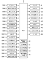
図3に示すように、ECU8には、インジェクタ6を作動させて、燃焼室17の内部に混合気を形成する燃料噴射制御部80、点火プラグ25を作動させて、燃焼室17の内部の混合気に点火する点火制御部81などが実装されている。詳細は後述するが、ECU8にはまた、強ノック予測部82、強ノック抑制部83、及び強ノック領域判定部84が実装されており、所定の強さ以上のノック(強ノック)の発生を予測し、その予測に基づいてその強ノックを抑制する制御も行う。
As shown in FIG. 3, the
センサSW1〜SW17は、ECU8と電気的に接続されていて、エンジン1の運転中は、常時、検知した信号をECU8に出力する。ECU8は、各センサSW1〜SW17から入力される出力信号と、運転領域マップ70等のデータとに基づいて、エンジン1を適正に運転するために、エンジン1を構成している各装置を制御する。
The sensors SW <b> 1 to SW <b> 17 are electrically connected to the
具体的には、図3に示すように、ECU8は、また、インジェクタ6、点火プラグ25、吸気電動S−VT23、排気電動S−VT24、燃料供給システム61、スロットル弁43、EGR弁54、電磁クラッチ45、エアバイパス弁48、スワール弁56などの各装置と電気的に接続されていて、これら装置に制御信号を出力し、これら装置を制御する。
Specifically, as shown in FIG. 3, the
<運転領域マップ>
図4に、エンジン1の運転制御に用いられる運転領域マップ70の一例を示す。この運転領域マップ70は、温間時の運転に用いられるものであり、互いに区画された次の3つの領域を含む。
<Operation area map>
FIG. 4 shows an example of an
A1:アイドル運転を含みかつ、低回転及び中回転の低負荷の領域に広がる「低負荷領域」
A2:全開負荷を含みかつ、低負荷領域A1よりも負荷が高い、低回転及び中回転の領域に広がる「高負荷領域」
A3:低負荷領域A1及び高負荷領域A2よりも回転数が高く、かつ、低負荷から高負荷まで負荷領域の全域にわたる「高回転領域」
A1: "Low-load area" including idle operation and extending to low- and medium-speed low-load areas
A2: “High load area” that includes a fully open load and has a higher load than the low load area A1, and spreads over low and medium rotation areas.
A3: The “high rotation region” in which the rotation speed is higher than the low load region A1 and the high load region A2, and covers the entire load region from low load to high load.
ここでいう「低回転」、「中回転」、及び、「高回転」の各領域は、例えば、エンジン1の全運転領域を回転方向に略三等分にした場合の、低回転側から順に並ぶ各分割領域である。1200rpm程度未満の回転数N1を「低回転」、4000rpm程度以上の回転数N2を「高回転」、回転数N1以上N2未満を「中回転」としてもよい。
The regions of “low rotation”, “medium rotation”, and “high rotation” referred to here are, for example, sequentially from the low rotation side when the entire operation region of the
「低負荷」及び「高負荷」は、低負荷側から高負荷側まで負荷領域の全域を略2等分した場合の低負荷側の分割領域及び高負荷側の分割領域としてもよい。 The “low load” and the “high load” may be a low load side divided region and a high load side divided region when the entire load region from the low load side to the high load side is approximately equally divided into two.
また、以降の説明で用いる、燃焼サイクルでの行程における「前期」、「中期」、及び「後期」は、各行程を3等分した場合での前からの各分割期間を意味する。また同様に、「前半」及び「後半」は、各行程を2等分した場合での前からの各分割期間を意味する。 Further, “first half”, “middle half”, and “late half” in the strokes in the combustion cycle used in the following description mean the respective divided periods from before when each stroke is divided into three equal parts. Similarly, “first half” and “second half” mean each divided period from before when each process is divided into two equal parts.
エンジン1は、運転領域マップ70の全域でSPCCI燃焼を行ってもよいが、本実施形態では、低負荷領域A1、及び高負荷領域A2において、SPCCI燃焼を行う。高回転領域A3において、エンジン1は、火花点火によるSI燃焼を行う。なお、冷間時や始動時など、エンジン1が十分に暖まっていない時には、全領域においてSI燃焼を行ってもよい。
The
過給機44は、低負荷領域A1及び高負荷領域A2における、低負荷かつ低回転の領域(図4に符号Tで示す原点側の領域:非過給領域)でオフされる。エンジン1は、この領域では、自然吸気の状態で運転する。過給機44は、非過給領域以外の領域(過給領域)においてオンされる。エンジン1は、過給領域では、過給機44の下流側が、大気圧より動的に高圧になる状態で運転する。
The
(低負荷領域A1)
エンジン1は、燃費の向上及び排出ガス性能の向上を主目的として、低負荷領域A1において、SPCCI燃焼を行う。
(Low load area A1)
The
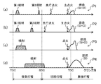
具体的には、エンジン1が低負荷領域A1で運転している時、点火プラグ25は、先行点火と主点火とからなる複数の点火を実行する。先行点火は、圧縮行程の前期または中期のいずれかに実行される。主点火は、圧縮行程の後期から膨張行程の初期までの期間に実行される。
Specifically, when the
例えば、図4に示す運転ポイントP1では、図5の(a)に示すように、点火プラグ25は、圧縮行程の前期に先行点火を実行し、圧縮行程の後期に主点火を実行する。運転ポイントP1よりも高負荷の運転ポイントP2では、点火プラグ25は、図5の(b)に示すように、運転ポイントP1より早期に先行点火を実行し、圧縮行程の後期に主点火を実行する。
For example, at an operation point P1 shown in FIG. 4, as shown in FIG. 5A, the
先行点火では、混合気は燃焼しない。先行点火は、火花(アーク)の周囲の混合気を850K以上1140K未満という狙いの温度にまで上昇させることにより、燃料成分(炭化水素)を開裂させてOHラジカルを含む中間生成物を生成することを目的として行われる。また、燃焼を防止するため、先行点火のエネルギーは、主点火のエネルギーよりも小さくされる。それにより、先行点火が行われても燃焼は開始しない。 In the pre-ignition, the air-fuel mixture does not burn. The pre-ignition is to raise an air-fuel mixture around a spark (arc) to a target temperature of 850 K or more and less than 1140 K, thereby cleaving a fuel component (hydrocarbon) to produce an intermediate product containing OH radicals. It is performed for the purpose. Further, in order to prevent combustion, the energy of the pre-ignition is made smaller than the energy of the main ignition. Thus, combustion does not start even if the pre-ignition is performed.
主点火により、混合気が燃焼する。すなわち、主点火により、火炎伝播が生じ、SI燃焼が開始する。SI燃焼が開始されると、それに引き続いてCI燃焼が開始する。すなわち、主点火により、圧縮上死点の直前でSPCCI燃焼が開始し、膨張行程の初期にSPCCI燃焼が終了する。 The mixture is burned by the main ignition. That is, flame propagation occurs due to main ignition, and SI combustion starts. When SI combustion starts, CI combustion starts subsequently. That is, due to the main ignition, SPCCI combustion starts immediately before the compression top dead center, and SPCCI combustion ends at the beginning of the expansion stroke.
(SPCCI燃焼)
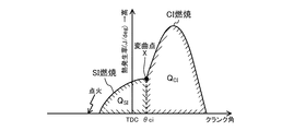
図6に、SPCCI燃焼による燃焼波形(熱発生率の波形)を示す。SPCCI燃焼の熱発生率は、通常、SI燃焼時よりもCI燃焼時の方が急峻になる。容積が最小になる上死点の近傍でSI燃焼が生じると、燃焼室の温度および圧力が急激に上昇する。それにより、未燃混合気が自着火し、CI燃焼が開始される。CI燃焼は、SI燃焼よりも急峻なので、燃焼波形の傾きが急増する。すなわち、SPCCI燃焼の燃焼波形は、CI燃焼が開始するタイミングで変曲点Xを有している。
(SPCCI combustion)
FIG. 6 shows a combustion waveform (waveform of heat generation rate) by SPCCI combustion. The heat generation rate of SPCCI combustion is generally steeper during CI combustion than during SI combustion. When SI combustion occurs near the top dead center where the volume is minimized, the temperature and pressure of the combustion chamber rapidly increase. Thereby, the unburned air-fuel mixture self-ignites, and CI combustion is started. Since the CI combustion is steeper than the SI combustion, the slope of the combustion waveform sharply increases. That is, the combustion waveform of the SPCCI combustion has the inflection point X at the timing when the CI combustion starts.
CI燃焼の開始後は、SI燃焼とCI燃焼とが並行して行われる。従って、CI燃焼での熱発生率は相対的に大きくなる。ただし、SPCCI燃焼では、CI燃焼は、ピストンが下降する圧縮上死点の後に行われるように制御されるため、CI燃焼時のdp/dθ(燃焼騒音の指標)は抑制される。 After the start of CI combustion, SI combustion and CI combustion are performed in parallel. Therefore, the heat generation rate in CI combustion becomes relatively large. However, in the SPCCI combustion, the CI combustion is controlled to be performed after the compression top dead center at which the piston descends, so that dp / dθ (combustion noise index) during the CI combustion is suppressed.
CI燃焼はSI燃焼に比べて燃焼速度が速いので、相対的に燃焼期間を短縮できる。すなわち、SPCCI燃焼では、燃焼期間を圧縮上死点の近傍に集約できるので、燃費が向上する。従って、SPCCI燃焼では、適切なタイミングで最適な燃焼波形が得られるように、SI燃焼とCI燃焼との比率を、エンジン1の運転条件に応じて制御することが重要である。
Since the combustion speed of CI combustion is higher than that of SI combustion, the combustion period can be relatively shortened. That is, in the SPCCI combustion, the combustion period can be concentrated near the compression top dead center, so that the fuel efficiency is improved. Therefore, in SPCCI combustion, it is important to control the ratio between SI combustion and CI combustion in accordance with the operating conditions of the
そのため、SPCCI燃焼では、SI燃焼とCI燃焼とが適切な組み合わせ状態で発生するよう、SPCCI燃焼におけるSI燃焼の割合(SI率、熱量比率)が、制御に用いられている。SI率は、例えば、SPCCI燃焼の全熱量(QSI+QCI)に対するSI燃焼での熱量(QSI)の割合としてもよい。また、圧縮上死点前の適切なタイミングでSI燃焼が開始するよう、SPCCI燃焼では、SI燃焼からCI燃焼に切り替わるときの変曲点Xのクランク角(θci)も、制御に用いられている。 For this reason, in SPCCI combustion, the ratio of SI combustion (SI ratio, calorific value ratio) in SPCCI combustion is used for control so that SI combustion and CI combustion occur in an appropriate combination. The SI rate may be, for example, a ratio of the calorific value (Q SI ) in the SI combustion to the total caloric value (Q SI + Q CI ) in the SPCCI combustion. In SPCCI combustion, the crank angle (θci) at the inflection point X when switching from SI combustion to CI combustion is also used for control so that SI combustion starts at an appropriate timing before the compression top dead center. .
SPCCI燃焼では、これらSI率及びθciが、エンジン1の運転状態に応じて、適切な値となるように、点火時期、燃料の噴射時期、燃料の噴射量、空気量、EGRガス量、スワール弁56の開度等が制御される。
In the SPCCI combustion, the ignition timing, the fuel injection timing, the fuel injection amount, the air amount, the EGR gas amount, and the swirl valve are set so that the SI ratio and θci become appropriate values according to the operating state of the
例えば、エンジン1が低負荷領域A1で運転している時、インジェクタ6は、先行点火よりも早いタイミングで、エンジン1の負荷に応じた燃料を複数回に分けて噴射する。例えば、運転ポイントP1及び運転ポイントP2では、吸気行程の期間で2回の噴射が行われ、インジェクタ6は、吸気行程の前半に第1噴射を行い、吸気行程の後半に第2噴射を行う。第1噴射と第2噴射の各噴射量は、高負荷側ほど第1噴射の噴射量が少なくなるように設定される。
For example, when the
エンジン1が低負荷領域A1で運転している時、燃焼室17に導入される空気(新気)と、燃焼室17に噴射される燃料との重量比である空燃比(A/F)は、理論空燃比(14.7)よりも大きく設定される。具体的には、A/Fは、20以上35以下の範囲に設定される。
When the
エンジン1が低負荷領域A1で運転している時、安定したSPCCI燃焼を実現するために、必要に応じて、排気上死点を挟んで吸気弁21及び排気弁22の双方が開かれるように制御される。いわゆるオーバーラップ期間の設定により、燃焼室17に高温の既燃ガス(内部EGRガス)が導入される。また、必要に応じて、EGR弁54が開くように制御され、燃焼室17に、いったん外部に排出されて冷却される排気ガス(外部EGRガス)が導入される。
When the
エンジン1が低負荷領域A1で運転している時、燃焼開始時点での混合気の成層化を促進するため、燃焼室17に強いスワール流が形成される。すなわち、スワール弁56は、50%よりも低い低開度に設定されるように制御される。
When the
(高負荷領域A2)
エンジン1は、燃費の向上及び排出ガス性能の向上を主目的として、高負荷領域A2において、SPCCI燃焼を行う。
(High load area A2)
The
具体的には、エンジン1が高負荷領域A2で運転している時、点火プラグ25は、1回の点火、すなわち、主点火のみを行う。
Specifically, when the
例えば、図4に示す運転ポイントP3では、図5の(c)に示すように、圧縮行程の後期に1回の点火を実行する。この点火により、圧縮上死点の直前にSPCCI燃焼が開始し、膨張行程の初期にSPCCI燃焼が終了する。 For example, at an operation point P3 shown in FIG. 4, as shown in FIG. 5C, one ignition is performed in the latter half of the compression stroke. Due to this ignition, SPCCI combustion starts immediately before the compression top dead center, and SPCCI combustion ends at the beginning of the expansion stroke.
エンジン1が高負荷領域A2で運転している時、インジェクタ6は、エンジン1の負荷に応じた燃料を、吸気行程の期間中に1回で噴射する。必要に応じて、複数回に分けて噴射してもよい。
When the
エンジン1が高負荷領域A2で運転している時、A/Fは、理論空燃比に略一致するように設定される。高負荷側では、必要に応じてA/Fを理論空燃よりもリッチ、つまり空気過剰率を1以下(λ≦1)に設定してもよい。また、エンジン1が高負荷領域A2で運転している時、必要に応じて外部EGRガスが燃焼室17に導入される。対して、内部EGRガスの燃焼室17への導入は実質的に停止される。
When the
エンジン1が高負荷領域A2で運転している時、燃焼開始時点での混合気の成層化を促進するため、燃焼室17に強いスワール流が形成される。すなわち、スワール弁56は、低負荷領域A1と同等かそれ以下の開度に設定されるように制御される。
When the
(高回転領域A3)
エンジン1は、安定した運転を実現するため、高回転領域A3において、SI燃焼を行う。
(High rotation area A3)
The
すなわち、エンジン1が高回転領域A3で運転している時、インジェクタ6は、吸気行程を含む所定の期間で燃料を噴射する。例えば、運転ポイントP4では、図5の(d)に示すように、インジェクタ6は、吸気行程から圧縮行程にわたる期間にわたって燃料を噴射する。
That is, when the
そして、点火プラグ25は、圧縮行程の後期から膨張行程の初期までの期間(運転ポイントP4では、圧縮行程の後期)に1回の点火を行う。この点火によってSI燃焼が圧縮上死点の直前に開始し、混合気の全てが火炎伝播により燃焼して、膨張行程の初期にSI燃焼が終了する。
Then, the
エンジン1が高回転領域A3で運転している時、A/Fは、略理論空燃比か、それよりもリッチ(λ≦1)となるように設定される。また、エンジン1の充填効率を高めるため、スワール弁56は全開とされる。
When the
<強ノックの予測及び抑制>
ノックは、一般に、SI燃焼が行われる火花点火式エンジンにおいて問題視されている現象である。詳しくは、点火プラグによる着火で混合気の燃焼が開始すると、火炎伝播によって燃焼が拡大していく。その間、未燃混合気(エンドガス)の温度及び圧力が局所的に高まって、自着火による燃焼が発生する場合がある。自着火による燃焼は火炎伝播による燃焼よりも急峻なため、その圧力振動が騒音や衝撃を形成し、ノックを発生させる。
<Prediction and control of strong knock>
Knock is a phenomenon generally regarded as a problem in a spark ignition engine in which SI combustion is performed. Specifically, when the combustion of the air-fuel mixture is started by the ignition of the ignition plug, the combustion is expanded by the flame propagation. During that time, the temperature and pressure of the unburned air-fuel mixture (end gas) locally increase, and combustion due to self-ignition may occur. Since the combustion due to self-ignition is steeper than the combustion due to flame propagation, the pressure vibration forms noise or impact and generates knock.
通常のノックは、エンジンが高負荷の運転領域において低回転で運転しているときに発生し、回転数が高まって火炎伝播速度が早まることで解消されていく。しかし、ノックは、エンジンが高回転で運転しているときにも発生する。高回転で運転しているときに発生するノックは、低回転で運転しているときに発生するノックよりも強い傾向がある。そして、突発的に、通常のノックとは明らかに強度が異なる、強いノック(強ノック)が発生する場合がある。 Normal knock occurs when the engine is operating at a low rotation speed in a high-load operation range, and is eliminated by increasing the rotation speed and increasing the flame propagation speed. However, knock also occurs when the engine is running at high speed. Knock generated when operating at high speed tends to be stronger than knock generated when operating at low speed. Then, suddenly, a strong knock (strong knock) having a clearly different strength from the normal knock may occur.
SPCCI燃焼が行われるこのエンジン1では、燃焼時における燃焼室17の中の圧力は、一般的な火花点火式エンジンよりも高くなる。そのため、このエンジン1は、一般的な火花点火式エンジンと比べると、強ノックが発生し易い傾向がある。
In the
強ノックは、頻度は少なくても、エンジン1にダメージを与える可能性が高い。そのため、強ノックは、エンジン1の信頼性を低下させる原因となる。一般的なノック抑制方法として、点火時期のリタード制御、すなわち膨張行程の初期に点火時期を遅角させることが行われている。この方法によっても強ノックを抑制することはできるが、燃焼効率が低下するし、出力の減少によって必要なトルクが得られないおそれもある。
The strong knock is likely to cause damage to the
それに対し、本発明者らは、燃焼状態から強ノックの発生が予測可能であることを見出した。その知見に基づき、このエンジン1の制御装置には、強ノックの発生が精度高く予測でき、その予測に基づいて、強ノックの選択的な抑制を可能にする技術が組み込まれている。
In contrast, the present inventors have found that the occurrence of strong knock can be predicted from the combustion state. Based on the knowledge, the control device of the
具体的には、図3に示すように、ECU8に、強ノック予測部82及び強ノック抑制部83が実装されている。強ノック予測部82は、燃焼初期の所定のタイミングで、強ノックの発生を予測する処理を実行する。強ノック抑制部83は、その予測に基づいて、そのタイミング以降の燃焼過程で、強ノックの発生を抑制する処理を実行する。次に、これら処理について、詳しく説明する。
Specifically, as shown in FIG. 3, a strong
(強ノックの予測)
本発明者らは、様々な実験を行った結果、燃焼初期の燃焼状態に基づいて、ノック強度が精度高く検知できることを見出した。具体的には、燃焼初期に相当する、50%よりも小さい所定の質量燃焼割合となる時期、好ましくは、質量燃焼割合が10%となる時期(mfb10%時期)により、ノック強度が精度高く検知できることを見出した。
(Strong knock prediction)
The present inventors have conducted various experiments and found that knock intensity can be detected with high accuracy based on the combustion state at the beginning of combustion. Specifically, the knock intensity is detected with high accuracy at a time when the predetermined mass combustion ratio smaller than 50%, which corresponds to the initial stage of combustion, and preferably at a time when the mass combustion ratio becomes 10% (mfb 10% time). I found what I can do.
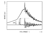
ここでいうノック強度は、ノックの強さを表す指標であり、ノックに起因する筒内圧パルスの振幅値である。ノック強度は、筒内圧を演算処理することによって取得される。 Here, the knock intensity is an index indicating the knock intensity, and is the amplitude value of the in-cylinder pressure pulse caused by the knock. Knock strength is obtained by calculating the in-cylinder pressure.
ノック強度を、図7を参照して具体的に説明する。図7の上側に示す波形は、ある燃焼サイクルにおける筒内圧変化を示している。燃焼後期に見られるパルス状の波形は、ノックを示している。このような筒内圧の圧力波形を、ハイパスフィルター(HPF)などで処理することで、圧力波形から圧縮圧などのエンジン固有の圧力変動成分が除去される。それにより、図7の下側に示すように、ノックに起因する圧力パルスのみからなる圧力波形が抽出される。一般的には、その圧力波形の圧力パルスのうち、最大となる振幅値が、その燃焼サイクルにおけるノック強度とされる(単位:bar)。 The knock strength will be specifically described with reference to FIG. The waveform shown on the upper side of FIG. 7 shows a change in the in-cylinder pressure in a certain combustion cycle. The pulse-like waveform seen in the later stage of combustion indicates knock. By processing such a pressure waveform of the in-cylinder pressure with a high-pass filter (HPF) or the like, an engine-specific pressure fluctuation component such as a compression pressure is removed from the pressure waveform. Thereby, as shown in the lower part of FIG. 7, a pressure waveform consisting of only the pressure pulse caused by the knock is extracted. In general, among the pressure pulses of the pressure waveform, the maximum amplitude value is defined as the knock intensity in the combustion cycle (unit: bar).
質量燃焼割合(MFB又はMBFともいう)は、この技術分野で一般に用いられている、燃焼状態を示す指標である。質量燃焼割合は、概略、全燃料質量に対する燃焼した燃料質量の割合(%)に相当する。質量燃焼割合はまた、燃焼室17に供給された1つの燃焼サイクルあたりの燃料の質量Aのうち、燃焼した燃料の質量Bの比(B/A、単位%)としてもよい。質量燃焼割合はまた、燃焼室17に供給された燃料の全てが燃焼したときに発生する総発熱量Cに対する、対象とする時点までに発生した発熱量Dの割合(D/C、単位%)としてもよい。
The mass combustion ratio (also referred to as MFB or MBF) is an index generally used in this technical field, which indicates a combustion state. The mass combustion ratio roughly corresponds to the ratio (%) of the burned fuel mass to the total fuel mass. The mass combustion ratio may be a ratio (B / A, unit%) of the mass B of the burned fuel to the mass A of the fuel per combustion cycle supplied to the
従って、mfb10%時期は、例えば、全燃料質量に対して燃焼した燃料質量の割合が10%となる時期(単位:deg、「°」)とすることができる。mfb10%時期は、燃焼状態に関連した燃焼状態指標値に相当するものであり、燃焼が10%進んだ時のクランク角度ともいえる。 Therefore, the mfb 10% period can be, for example, a period (unit: deg, “°”) at which the ratio of the burned fuel mass to the total fuel mass becomes 10%. The mfb 10% period corresponds to a combustion state index value related to the combustion state, and can be said to be a crank angle when combustion advances by 10%.
(mfb10%時期の算出)
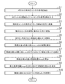
mfb10%時期は、筒内圧に基づき、ECU8によって算出される。そのmfb10%時期の算出手順を、図8のフローチャートを用いて説明する。
(Calculation of mfb 10% timing)
The mfb 10% timing is calculated by the
ECU8は、メモリ8bに記憶されている筒内圧センサSW6の信号(圧縮行程の後半から吸気行程の前半の信号)を抽出する(ステップS1)。その後、ECU8は、抽出した筒内圧センサSW6の信号を、ノックの周波数帯の信号が除去可能なIIRフィルタ(不図示)に通す。それにより、筒内圧センサSW6の信号からノックの信号が除去される(ステップS2)。
The
そして、ECU8は、IIRフィルタから出力された筒内圧センサSW6の信号であって50kHzでサンプリングされた信号を、メモリ8bに記憶されているクランク角センサSW11の信号を用いて、所定のクランク角度毎の信号に変換する(ステップS3)。そうして、ECU8は、筒内圧センサSW6の信号を筒内圧(絶対圧)に変換する(ステップS4)。
Then, the
続いて、ECU8は、各クランク角度θにおける熱発生率△Q(θ)を、得られた筒内圧を用いて算出する。そして、ECU8は、クランク角度毎に熱発生率△Q(θ)を積算することにより、各クランク角度θにおける熱発生量Q(θ)を算出する(ステップS5)。
Subsequently, the
次に、ECU8は、熱発生量Q(θ)の最小値(最小熱発生値Qmin)、及び、最小熱発生値Qminとなるときのクランク角度(mfb0%時期)を算出する(ステップS6)。そして、ECU8は、最小熱発生値Qminが、0(ゼロ)となるように、熱発生量Q(θ)を補正する(ステップS7)。
Next, the
その後、ECU8は、熱発生量Q(θ)の最大値(最大熱発生値Qmax)を算出する(ステップS8)。ECU8は、その最大熱発生値Qmaxの10%に相当する熱発生値Q10を算出する(ステップS9)。そうして、ECU8は、熱発生値Q10となるときのクランク角度を算出し、このクランク角度を、mfb10%時期として決定する(ステップS10)。
Thereafter, the
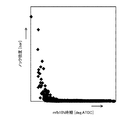
(mfb10%時期とノック強度との関係)
mfb10%時期は、点火時期が略同一であっても、燃焼条件が異なれば、進角したり遅角したりする。燃焼条件が同じでも、燃焼の開始タイミング等のバラツキにより、進角したり遅角したりする。すなわち、点火時期が略同一でも、mfb10%時期のデータは、バラツキを持った一定の分布を形成する。
(Relationship between mfb 10% timing and knock intensity)
The mfb 10% timing is advanced or retarded under different combustion conditions even if the ignition timing is substantially the same. Even if the combustion conditions are the same, the angle may be advanced or retarded due to variations in the combustion start timing or the like. That is, even when the ignition timings are substantially the same, the data at the mfb 10% timing forms a uniform distribution with variations.
図9に、mfb10%時期とノック強度との関係を表したグラフの一例を示す。このグラフは、強ノックが発生し易い所定の条件下で燃焼試験を行い、各燃焼データから得られたmfb10%時期とノック強度との関係をプロットしたものである。点火時期は、略同一(圧縮上死点の直前)である。このグラフに認められるように、mfb10%時期が進角するとノック強度が増加してノックが発生する。 FIG. 9 shows an example of a graph representing the relationship between the mfb 10% timing and the knock intensity. This graph plots the relationship between the mfb 10% timing and the knock intensity obtained from each combustion data by performing a combustion test under predetermined conditions in which strong knock is likely to occur. The ignition timings are substantially the same (just before the compression top dead center). As can be seen from this graph, when the mfb 10% timing is advanced, the knock intensity increases and knock occurs.
そして、これらノックの中には、通常のノックとは明らかに異なる強ノック(例えば、ノック強度が40barを超え、更には100barを超えるようなノック)が含まれている。強ノックは、ピストン3等、燃焼室17を構成している構造に物理的な障害を与えるおそれがあるノックであり、例えば、ノック強度が40bar以上のノックと定義できる。また、強ノックはノック強度が45bar以上のノックと定義してもよい。
These knocks include strong knocks that are clearly different from normal knocks (for example, knocks whose knock strength exceeds 40 bar and further exceeds 100 bar). The strong knock is a knock that may cause a physical obstacle to a structure constituting the
これら強ノックは、mfb10%時期が所定値以上に進角することで発生する(逆に所定角度未満では発生しない)傾向が認められる。すなわち、SI燃焼が開始した後、SI燃焼が早く進むほど、ノック強度は高くなる。そして、強ノックは、SI燃焼が著しく早く進み、mfb10%時期が所定値以上に進角した時に発生する。
It is recognized that these strong knocks tend to occur when the mfb 10% timing advances beyond a predetermined value (conversely, they do not occur when the angle is less than the predetermined angle). That is, after the SI combustion starts, the quicker the SI combustion, the higher the knock strength. The strong knock occurs when SI combustion proceeds extremely quickly and the
このような条件下で得られるmfb10%時期は、確率分布(正規分布)に従って分布する。図10の(a)に、そのようなmfb10%時期の分布情報を例示する。 The mfb 10% timing obtained under such conditions is distributed according to a probability distribution (normal distribution). FIG. 10A illustrates such distribution information at the mfb 10% timing.
上述したように、強ノックは、mfb10%時期が所定角度以上に進角した時に発生する。従って、mfb10%時期の分布情報から、所望する強ノックの発生確率に応じた所定のmfb10%時期(それより進角すると強ノックが所定の確率で発生する可能性があると判定できる値、強ノック判定角度θs)を設定することができる。
As described above, the strong knock occurs when the mfb 10% timing is advanced beyond a predetermined angle. Therefore, based on the distribution information of the mfb 10% timing, a
更に、本発明者らは、mfb10%時期と、燃焼初期の筒内圧との間には、一次的な相関関係があることも見出した。図10の(b)に、その一例を示す。図10の(b)の縦軸に示す燃焼初期の筒内圧(燃焼初期筒内圧Pi)は、燃焼初期のタイミングに相当する、圧縮上死点(0°CA)から圧縮上死点後9°CAまでのタイミングにおいて、筒内圧センサSW6で検出される筒内圧の平均値を示している。 Furthermore, the present inventors have also found that there is a primary correlation between the mfb 10% timing and the in-cylinder pressure at the beginning of combustion. FIG. 10B shows an example thereof. The in-cylinder pressure at the early stage of combustion (initial in-cylinder pressure Pi at the beginning of combustion) shown on the vertical axis of FIG. 10B corresponds to the timing of the initial stage of combustion, and is 9 ° after the compression top dead center (0 ° CA). In the timing up to CA, the average value of the in-cylinder pressure detected by the in-cylinder pressure sensor SW6 is shown.
後述するように、このエンジン1の制御装置では、この燃焼初期筒内圧Piに基づいて強ノックの発生が予測される。なお、この燃焼初期筒内圧Piは一例であり、燃焼初期の所定のタイミングで得られる筒内圧センサSW6の検出値であれば、1つの検出値であってもよいし、不連続なクランク角度での2つ以上の検出値の平均値であってもよい。
As will be described later, in the control device of the
この相関関係により、クランク角度に対して相対的な値である、mfb10%時期から、クランク角度に対して絶対的な値である、燃焼初期筒内圧Piへの変換が可能になる。従って、図10の(b)に示すように、mfb10%時期と燃焼初期筒内圧Piとの相関関係から、強ノック判定角度θsに対応した燃焼初期筒内圧Piの値(強ノック判定閾値Ps、閾値に相当)が設定できる。 This correlation makes it possible to convert from the mfb 10% timing, which is a value relative to the crank angle, to the initial combustion pressure Pi, which is an absolute value for the crank angle. Therefore, as shown in FIG. 10B, from the correlation between the mfb 10% timing and the combustion initial cylinder pressure Pi, the value of the combustion initial cylinder pressure Pi corresponding to the strong knock determination angle θs (the strong knock determination threshold Ps, (Corresponding to a threshold).
このエンジン1の制御装置では、予め実験等によって得られた強ノック判定閾値Psが、強ノック予測部82に設定されている。
In the control device of the
それにより、燃焼初期筒内圧Piが強ノック判定閾値Ps以下であれば、強ノック発生の可能性は無いと、高精度で判定でき、燃焼初期筒内圧Piが強ノック判定閾値Ps超であれば、強ノック発生の可能性が有ると、高精度で判定できる。 Accordingly, if the initial combustion cylinder pressure Pi is equal to or less than the strong knock determination threshold Ps, it is possible to determine with high accuracy that there is no possibility of occurrence of strong knock, and if the combustion initial cylinder pressure Pi exceeds the strong knock determination threshold Ps. If there is a possibility of occurrence of strong knock, it can be determined with high accuracy.
この予測方法によれば、燃焼初期筒内圧Piに基づいて強ノックの発生を予測するので、燃焼後期はCI燃焼が行われるSPCCI燃焼でも、燃焼初期には、点火によるSI燃焼が行われるので、SPCCI燃焼にも適用可能である。すなわち、運転領域に、SI燃焼が行われる領域と、SPCCI燃焼が行われる領域とが混在している場合であっても、この予測方法であれば、制約を受けることなく適用できる。 According to this prediction method, the occurrence of strong knock is predicted based on the initial combustion in-cylinder pressure Pi. Therefore, even in SPCCI combustion in which CI combustion is performed in the latter period of combustion, SI combustion by ignition is performed in the early stage of combustion. It is also applicable to SPCCI combustion. That is, even when the operating region includes a region in which SI combustion is performed and a region in which SPCCI combustion is performed, this prediction method can be applied without restriction.
従って、このエンジン1では、SI燃焼が行われる高回転領域A3だけでなく、SPCCI燃焼が行われる高負荷領域A2においても、強ノックの発生の予測及び抑制の各処理が行われる。各領域の間で、処理に差異を設ける必要もない。必要があれば、これら処理を低負荷領域A1で行うことも可能である。
Therefore, in the
このような強ノックの発生を予測する処理は、ECU8によって実行される。すなわち、強ノック予測部82が、燃焼初期筒内圧Piを強ノック判定閾値Psと比較する。そうすることにより、強ノックが発生する可能性の有無を判定する。強ノック予測部82には、予め、強ノック判定閾値Psが設定されており、燃焼初期に筒内圧センサSW6で検知される燃焼初期筒内圧Piと、その強ノック判定閾値Psとを比較することにより、強ノック予測部82が、強ノックが発生する可能性の有無を判定する。
The process of predicting the occurrence of such a strong knock is executed by the
(強ノックの抑制)
強ノックは、頻度が低いうえに突発的に発生する。更に、強ノックは、単発でもエンジン1の信頼性に与える影響は大きい。従って、予測が行われた燃焼サイクル以降の燃焼サイクルにおいて、ノックを抑制する処理を行っても、予測した強ノックは抑制できないし、強ノックが続いて発生するとは限らないので、適切でない。
(Control of strong knock)
Strong knock occurs infrequently and suddenly. Further, a strong knock has a large effect on the reliability of the
従って、強ノックの発生が予測されたのと同一の燃焼サイクルで、強ノックを抑制する処理を行う必要がある。具体的には、同じ燃焼サイクルでの燃焼過程において、強ノックが予測された後、かつ、強ノックが発生する前まで期間に、強ノックを抑制する処理を行う必要がある。 Therefore, it is necessary to perform a process for suppressing the strong knock in the same combustion cycle in which the occurrence of the strong knock is predicted. Specifically, in the combustion process in the same combustion cycle, it is necessary to perform a process for suppressing strong knock after a strong knock is predicted and before a strong knock occurs.
しかし、そのような期間は僅かしかない。特に、エンジン1の回転数が高い領域では、燃焼期間が短くなるので、条件は更に厳しくなる。そこで、このエンジン1の制御装置では、そのような制約された条件の下でも強ノックの抑制が可能になるように、燃焼室17の内部に燃料を追加噴射する。
However, there are only a few such periods. Particularly, in a region where the number of revolutions of the
具体的には、強ノック予測部82で強ノックが発生すると予測された場合、つまり燃焼初期筒内圧Piが強ノック判定閾値Psを超えていた場合、ECU8(強ノック抑制部83)は、燃焼室17の内部に、本来的な要求量以上の燃料を追加して噴射する。
Specifically, when the strong
このエンジン1には、燃焼室17の内部に燃料を噴射するインジェクタ6が設置されている。インジェクタ6は、高圧で瞬時に燃料を噴射することができる。従って、このエンジン1では、強ノックが発生すると予測されると、強ノック抑制部83は、インジェクタ6が燃料を追加噴射するように制御する。
The
燃焼室17の内部に、高圧で燃料が噴射されると、燃焼が進行している混合気が撹拌される。前述したように、ノックは、未燃混合気の温度及び圧力が局所的に高まることによって発生する。そのため、燃焼の過程で混合気が撹拌されると、混合気全体の温度が均質化されるので、未燃混合気の局所的な温度の上昇が抑制される。その結果、強ノックが抑制される。燃料であれば、既設のインジェクタ6を利用して噴射できる。燃料の気化による冷却作用が得られる利点もある。
When fuel is injected into the
(燃焼バラツキへの対応)
上述したように、燃焼状態に関連したmfb10%時期の分布情報を用いることで、所望する強ノックの発生確率に基づいた強ノック判定閾値Psを取得することができる。この強ノック判定閾値Psが、強ノック予測部82に設定され、強ノック予測部82が強ノック判定閾値Psに基づいて強ノックの発生を予測することで、強ノックの発生の有無が精度高く行える。
(Response to combustion variations)
As described above, by using the distribution information of the mfb 10% timing related to the combustion state, it is possible to acquire the strong knock determination threshold value Ps based on the desired probability of occurrence of strong knock. This strong knock determination threshold Ps is set in the strong
しかし、燃焼条件によって燃焼状態は変化するし、同じ燃焼条件であっても、時間の経過によって燃焼状態が変化する可能性もある。また、エンジン1では、複数の気筒で燃焼が行われるが、これら各気筒での燃焼状態は、程度差はあるものの、それぞれ異なっているのが普通である。また更に、実機を量産する観点からは、加工のバラツキ等により、各エンジン1間や各気筒間において、燃焼状態に差が生じるため、これらを考慮する必要もある。燃焼状態が変化すれば、それに伴ってmfb10%時期の分布情報も変化する。
However, the combustion state changes depending on the combustion conditions, and even under the same combustion conditions, the combustion state may change over time. Further, in the
このような燃焼状態の差異(燃焼バラツキ)は、強ノック判定閾値Psの設定精度に大きく影響する。本来、強ノックを予測してから強ノックを抑制するまでに、時間的余裕があれば、この程度の差異は問題にはならない。しかし、このエンジン1の制御装置では、同じ燃焼サイクルにおいて、強ノックの予測と抑制とを行うため、このような差異を無視できるほどの時間的余裕は無い。
Such a difference in combustion state (combustion variation) greatly affects the setting accuracy of the strong knock determination threshold value Ps. Originally, if there is enough time between the prediction of a strong knock and the suppression of a strong knock, such a difference does not matter. However, since the control device of the
そのため、強ノック判定閾値Psは、燃焼バラツキを考慮すると、余裕のある安全な値に設定せざるを得ない。そうした場合、強ノックの予測精度が低下するため、不必要な燃料の追加噴射が増加し、煤の増加や燃費の悪化などの不具合を招く。 For this reason, the strong knock determination threshold value Ps must be set to a safe value with a margin in consideration of the combustion variation. In such a case, the prediction accuracy of the strong knock is reduced, so that unnecessary additional fuel injection is increased, which causes problems such as an increase in soot and deterioration in fuel efficiency.
それに対し、本発明者らは、このような比較的高圧縮な条件下で行われる燃焼について、様々な実験を行った結果、強ノックが発生するのは、所定の運転領域にほぼ限定されるとみなしても、実用的には問題ないことを見出した。 On the other hand, the present inventors have conducted various experiments on combustion performed under such relatively high compression conditions, and as a result, occurrence of strong knock is substantially limited to a predetermined operation region. It was found that there was no problem in practice.
特に、このエンジン1は、SPCCI燃焼を行うため、燃焼時の筒内圧は、SI燃焼のみを行うエンジンよりも高くなるように幾何学的圧縮比が設計されている。SPCCI燃焼では、上述したように、燃焼形態と燃焼タイミングとが、精度高く制御される利点がある。そこで、このエンジン1の制御装置には、かかる知見に基づき、燃焼バラツキの影響を最小限に抑制できるように工夫されている。
In particular, since the
具体的には、図3に示したように、ECU8に、強ノック領域判定部84が実装されている。強ノック領域判定部84は、エンジン1の運転状態に基づいて、対象とする燃焼が行われる運転領域が、強ノックが発生する領域(強ノック発生領域)であるか否かを判定する。そして、強ノック領域判定部84で強ノック発生領域であると判定され、かつ、強ノック予測部で強ノックの発生が予測された場合に限って、強ノック抑制部が強ノック抑制処理を実行するように構成されている。
Specifically, as shown in FIG. 3, the strong knock
(強ノック発生領域)
強ノック発生領域は、エンジン1の全運転領域のうち、強ノックが発生する確率の高い領域である(強ノック高発生領域ともいえる)。強ノック発生領域以外の領域は、強ノックが発生する確率は低く、実用的な観点からは、強ノックが発生しない領域とみなすことができる。その強ノック発生領域を、図4に、符号Rkで示す(周囲がハッチングされた領域)。
(High knock generation area)
The strong knock occurrence region is a region where the probability of occurrence of strong knock is high in the entire operation region of the engine 1 (also referred to as a strong knock occurrence region). The region other than the strong knock occurrence region has a low probability of occurrence of strong knock, and can be regarded as a region where strong knock does not occur from a practical viewpoint. The region where the strong knock occurs is indicated by a symbol Rk in FIG. 4 (a region whose periphery is hatched).
本発明者らは、強ノックの発生は、冷却水や吸気の温度など、外部環境の温度変化に対しては、ほとんど影響を受けないことを見出した。そのため、強ノック判定領域Rkは、冷却水や吸気の温度など、外部環境の温度が高低に変化しても、変化することなく一定に設定されている。従って、エンジン1の運転領域マップ70が、冷間時や温間時など、温度の変化に応じて変更されても、強ノック判定領域Rkは、一定に維持される。
The present inventors have found that the occurrence of strong knocking is hardly affected by changes in the temperature of the external environment such as the temperature of cooling water and intake air. For this reason, the strong knock determination region Rk is set to be constant without changing even when the temperature of the external environment such as the temperature of the cooling water or the intake air changes. Therefore, even if the
強ノック発生領域Rkは、エンジン1の全運転領域のうち、高回転側の運転領域のうち、アイドル運転を含む最低負荷から、全開負荷を含む最高負荷までの全負荷の領域(高回転全負荷領域)を含む。本実施形態の高回転全負荷領域は、高回転領域A3とほぼ重複している。 The strong knock occurrence region Rk is a region of a full load from a minimum load including an idling operation to a maximum load including a fully open load in a high rotation side operation region of the entire operation region of the engine 1 (high rotation full load). Region). The high rotation full load region of the present embodiment substantially overlaps with the high rotation region A3.
更に強ノック発生領域Rkは、エンジン1の運転領域のうち、低回転側の運転領域を含まない中回転の運転領域であって高負荷側の運転領域(中回転高負荷領域)を含む。本実施形態の中回転高負荷領域は、高負荷領域A2の高回転側の一部領域と重複している。
Further, the strong knock generation region Rk is a medium rotation operation region that does not include the low rotation side operation region and includes a high load side operation region (middle rotation high load region) in the operation region of the
従って、強ノック発生領域Rkには、SI燃焼が行われる領域とSPCCI燃焼が行われる領域の双方が含まれるが、上述したように、開示する強ノックの予測方法によれば、制約を受けることなく行える。従って、強ノックの予測及び抑制の各制御が共用できるので、制御の複雑化を回避できる。 Therefore, the strong knock occurrence region Rk includes both the region in which SI combustion is performed and the region in which SPCCI combustion is performed. However, as described above, according to the disclosed method of predicting strong knock, there are some restrictions. It can be done without. Therefore, the control for predicting and suppressing the strong knock can be shared, so that the control can be prevented from becoming complicated.
(強ノックの予測制御及び抑制制御)
図11、図12に、このエンジン1で行われる強ノックの予測制御及び抑制制御の一例を示す。図11は、強ノックの、領域判定制御、予測制御、及び抑制制御に関するフローチャートであり、図12は、これら制御に関連する主な状態量の変化を、クランク角度に沿って例示した状態図である。
(Strong knock prediction control and suppression control)
FIGS. 11 and 12 show examples of the strong knock prediction control and the suppression control performed by the
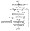
図11に示すように、ECU8は、エンジン1の運転が開始されると、各センサSW1〜SW17から出力される信号を読み込む(ステップS11)。それにより、ECU8は、これら入力値と、メモリ8bに記憶されている、運転領域マップ70等の制御データとに基づいて、エンジン1の運転状態を判断する。
As shown in FIG. 11, when the operation of the
例えば、ECU8は、アクセル開度センサSW12の出力信号に基づいて、出力が要求されるトルクを算出する。また、ECU8は、クランク角センサSW11の出力信号からエンジン1の回転数を算出する。そして、ECU8(強ノック領域判定部84)は、算出されたトルク及び回転数から、運転領域マップ70における現時点の存在位置を特定し、エンジン1が強ノック発生領域Rkで運転しているか否かを判定する(ステップS12)。
For example, the
その結果、強ノック領域判定部84が、エンジン1が強ノック発生領域Rkで運転していないと判定した場合、ECU8は、その時の燃焼では、強ノックの予測制御及び抑制制御は実行しない。すなわち、その運転領域での燃焼では、強ノックが発生する確率は極めて低いので、燃料を追加噴射しない。それにより、燃費の悪化や煤の増加を抑制できる。
As a result, when the strong knock
一方、強ノック領域判定部84が、エンジン1が強ノック発生領域Rkで運転していると判定した場合、ECU8は、筒内圧センサSW6から入力される検出信号に基づいて、各燃焼サイクルでの燃焼初期筒内圧Piを取得する(ステップS13)。具体的には、図12に示すように、強ノック予測部82が、圧縮上死点(0°CA)から圧縮上死点後9°CAまでの期間に検出される筒内圧の検出値からその平均値を算出し、これを燃焼初期筒内圧Piとする。
On the other hand, when the strong knock
その燃焼サイクルにおいて、更にクランク角度が数度進む間に、強ノック予測部82は、取得した燃焼初期筒内圧Piと強ノック判定閾値Psとを比較する(ステップS14)。強ノック判定閾値Psは、燃焼バラツキを考慮して、余裕のある安全な値に設定されている。従って、強ノックの発生を高確率で予測できる。そして、強ノック判定閾値Psは、強ノック予測部82に予め設定されているので、瞬時に比較できる。
In the combustion cycle, while the crank angle further advances by several degrees, the strong
その結果、燃焼初期筒内圧Piが強ノック判定閾値Psを超えた場合には、強ノック予測部82は、強ノックが発生すると予測し、燃料を追加噴射するようにインジェクタ6に制御信号を出力する(ステップS15,S16)。
As a result, when the initial combustion in-cylinder pressure Pi exceeds the strong knock determination threshold value Ps, the strong
図12に示すように、インジェクタ6への制御信号が出力された後、実際に燃料が噴射されるまでにはタイムラグ(この例では10°CA程度)が発生する。強ノック予測部82は、このタイムラグを考慮して制御信号を出力する。それにより、ノックが発生する直前に燃料が追加噴射される。
As shown in FIG. 12, a time lag (about 10 ° CA in this example) occurs after the control signal is output to the
強ノックが発生する直前に燃料が噴射されることで、本来であれば、図12において仮想線で示すようなノック強度の大きなノックが発生するところが、実線で示すような、ノック強度の小さいノックが発生する。すなわち、強ノックの発生が抑制される。 When the fuel is injected immediately before the strong knock occurs, a knock having a large knock strength as indicated by the imaginary line in FIG. 12 would normally occur, whereas a knock having a small knock strength as indicated by the solid line in FIG. Occurs. That is, occurrence of strong knock is suppressed.
一方、強ノック予測部82が、燃焼初期筒内圧Piと強ノック判定閾値Psとを比較した結果、燃焼初期筒内圧Piが強ノック判定閾値Ps以下であった場合には、強ノック予測部82は、強ノックは発生しないと予測し、燃料の追加噴射を指示することなく、処理を終了する(ステップS17)。
On the other hand, when the strong
ECU8は、このような一連の処理を、燃焼サイクルごとに実行する。
The
なお、ノック抑制の観点からすれば、強ノックの発生が予測される特定の燃焼サイクルだけでなく、強ノックの発生がある程度推測される不特定多数の燃焼サイクルで燃料を追加噴射して強ノックを抑制することも可能である。しかし、追加噴射に用いられる燃料は、エンジン1の運転に必要な燃料とは別であることから、多数の燃焼サイクルで燃料を追加噴射すると、燃費が悪化する。また、このような燃料の追加噴射は、煤の増加を招く。
In addition, from the viewpoint of knock suppression, not only the specific combustion cycle in which the occurrence of strong knock is predicted but also the unspecified number of combustion cycles in which the occurrence of strong knock is estimated to some extent Can also be suppressed. However, the fuel used for the additional injection is different from the fuel required for the operation of the
それに対し、このエンジン1の制御装置では、強ノックが予測された特定の燃焼サイクルだけが選択されて燃料が追加噴射されるので、燃料を追加噴射する頻度を最小限に抑制でき、強ノックを効率的かつ効果的に抑制できる。
On the other hand, in the control device of the
また、強ノックを安定して抑制する観点からは、追加噴射する燃料の量は多い方が有効である。しかし、燃料の追加噴射量が多くなれば、その分だけ煤も増加する。同じ燃焼サイクルで予測から追加噴射まで行うため、燃料が噴射できる時間が短いという制約もある。従って、これらの点を考慮すると、追加噴射する燃料の量(質量)は、燃料が追加噴射される燃焼サイクルにおいて噴射される燃料の全量(噴射燃料総質量)の5%以上10%以下に設定するのが好ましい。 Further, from the viewpoint of stably suppressing strong knock, it is more effective to increase the amount of fuel to be additionally injected. However, as the additional fuel injection amount increases, soot increases accordingly. Since the same combustion cycle is performed from prediction to additional injection, there is also a restriction that the time during which fuel can be injected is short. Therefore, in consideration of these points, the amount (mass) of the fuel to be additionally injected is set to be 5% or more and 10% or less of the total amount (total injected fuel) of the fuel to be injected in the combustion cycle in which the fuel is additionally injected. Is preferred.
追加噴射する燃料の量は、筒内圧の値に基づいて設定してもよい。例えば、追加噴射する燃料の量が、燃焼初期筒内圧Piと強ノック判定閾値Psとの差が大きくなるほど、多くなるように設定することが考えられる。そうすれば、強ノックの安定した抑制と、煤の抑制とを効率よく実現できる。 The amount of fuel to be additionally injected may be set based on the value of the in-cylinder pressure. For example, it is conceivable to set the amount of fuel to be additionally injected to increase as the difference between the initial combustion in-cylinder pressure Pi and the strong knock determination threshold value Ps increases. Then, stable suppression of strong knock and suppression of soot can be efficiently realized.
このように、開示する技術にかかるエンジンの制御装置によれば、強ノックの予測と抑制とが、同一の燃焼サイクルにおいて行われる。従って、ノック全般を大まかに抑制するのではなく、強ノックを選択的に抑制できるので、効率的であり、燃費の低下を招くことなく、エンジンの信頼性を向上させることができる。 As described above, according to the engine control device according to the disclosed technology, prediction and suppression of strong knock are performed in the same combustion cycle. Therefore, strong knock can be selectively suppressed instead of roughly suppressing overall knock, so that it is efficient, and the reliability of the engine can be improved without lowering fuel consumption.
また、このエンジンの制御装置によれば、統計的な分布情報から得られる強ノックの発生確率に基づいて、強ノックの発生予測の基準となる閾値が取得される。従って、頻度が少ないうえに突発的に発生する強ノックであっても、高精度な予測が行える。 Further, according to the engine control device, a threshold value serving as a reference for predicting occurrence of strong knock is obtained based on the probability of occurrence of strong knock obtained from statistical distribution information. Therefore, highly accurate prediction can be performed even for a strong knock that occurs infrequently and suddenly.
更に、その閾値の信頼性は、燃焼バラツキによって低下するおそれがあるが、このエンジンの制御装置では、燃焼バラツキを考慮して、閾値が余裕のある安全な値に設定されている。従って、燃焼バラツキの影響を低減でき、高精度な予測が安定して行える。 Further, the reliability of the threshold value may decrease due to combustion variations. However, in this engine control device, the threshold value is set to a safe value with a margin in consideration of the combustion variations. Therefore, the influence of combustion variation can be reduced, and highly accurate prediction can be stably performed.
しかし、閾値を余裕のある安全な値に設定すると、不必要な燃料の追加噴射が増加し、それに伴って煤も増加する。それに対し、このエンジンの制御装置では、予め強ノックの予測及び抑制の各制御を行う領域が、強ノックが発生する特定の領域に限定されているので、そのような不具合を抑制できる。 However, if the threshold is set to a safe value with a margin, unnecessary additional fuel injection increases, and soot increases accordingly. On the other hand, in the engine control device, the region in which the control of the prediction and the suppression of the strong knock is previously performed is limited to a specific region in which the strong knock occurs. Therefore, such a problem can be suppressed.
強ノックを高精度かつ効果的に抑制できるので、このエンジンの制御装置は、特に高圧縮比のエンジンに有効である。 Since the strong knock can be suppressed with high accuracy and effectively, the control device for this engine is particularly effective for an engine having a high compression ratio.
開示する技術にかかるエンジンの制御装置は、上述した実施形態に限定されず、それ以外の種々の構成をも包含する。例えば、実施形態では、SPCCI燃焼を行うエンジン1を例示したが、開示する技術にかかるエンジンの制御装置は、通常の火花点火式エンジンにも適用できる。また、エンジン1の具体的構造や具体的制御は、一例であり、仕様に応じて適宜変更可能である。
The engine control device according to the disclosed technology is not limited to the above-described embodiment, and includes various other configurations. For example, in the embodiment, the
1 エンジン
6 インジェクタ(燃料噴射弁)
10 エンジン本体
11 シリンダ(気筒)
17 燃焼室
25 点火プラグ
70 運転領域マップ
82 強ノック予測部
83 強ノック抑制部
84 強ノック領域判定部
1
10
17
Claims (9)
前記エンジンは、
往復するピストンによって容積が変化するように筒内に区画された燃焼室と、
前記燃焼室に臨むように配置された点火プラグと、
前記燃焼室の内部に燃料を噴射する燃料噴射弁と、
を備え、
前記制御装置は、
前記点火プラグ及び前記燃料噴射弁の各々と電気的に接続されていて、前記点火プラグ及び前記燃料噴射弁に制御信号を出力するとともに、
前記エンジンの運転状態に基づいて、その燃焼の行われる運転領域が、所定の強さ以上のノックが発生する強ノック発生領域であるか否かを判定する強ノック領域判定部と、
その燃焼の初期のタイミングで、筒内圧を所定の閾値と比較することにより、前記ノックの発生を予測する強ノック予測部と、
前記強ノック予測部の予測に基づいて、その燃焼と同一の燃焼サイクル内で前記ノックの発生を抑制する強ノック抑制処理が実行可能な強ノック抑制部と、
を有し、
前記強ノック領域判定部で前記強ノック発生領域であると判定され、かつ、前記強ノック予測部で前記ノックの発生が予測された場合に、前記強ノック抑制部が前記強ノック抑制処理を実行するエンジンの制御装置。 A control device for an engine that performs combustion by igniting a mixture formed by injecting fuel into a combustion chamber,
The engine is
A combustion chamber partitioned in a cylinder such that the volume changes with a reciprocating piston,
A spark plug arranged to face the combustion chamber,
A fuel injection valve for injecting fuel into the interior of the combustion chamber,
With
The control device includes:
While being electrically connected to each of the ignition plug and the fuel injection valve, and outputting a control signal to the ignition plug and the fuel injection valve,
A strong knock region determination unit that determines whether or not an operation region in which combustion is performed is a strong knock occurrence region in which knock of a predetermined strength or more occurs based on the operating state of the engine.
At the initial timing of the combustion, by comparing the in-cylinder pressure with a predetermined threshold, a strong knock prediction unit that predicts the occurrence of the knock,
Based on the prediction of the strong knock prediction unit, a strong knock suppression unit capable of executing a strong knock suppression process that suppresses the occurrence of the knock in the same combustion cycle as the combustion,
Has,
When the strong knock region is determined to be the strong knock occurrence region by the strong knock region determination unit, and when the occurrence of the knock is predicted by the strong knock prediction unit, the strong knock suppression unit executes the strong knock suppression process. Engine control device.
前記強ノック抑制部は、前記強ノック抑制処理として、前記燃焼室の内部に燃料を追加噴射するエンジンの制御装置。 The engine control device according to claim 1,
The control apparatus for an engine, wherein the strong knock suppression unit performs additional injection of fuel into the combustion chamber as the strong knock suppression processing.
追加噴射される燃料の量は、前記筒内圧の値に基づいて設定されるエンジンの制御装置。 The engine control device according to claim 2,
An engine control device in which the amount of fuel to be additionally injected is set based on the value of the in-cylinder pressure.
前記エンジンは、少なくとも一部の運転領域で、点火による燃焼が開始した後に、混合気の残部が自己着火により燃焼する所定形態の燃焼を行うように構成され、
前記ノックの発生の予測及び抑制の各処理が、前記運転領域で実行されるエンジンの制御装置。 The engine control device according to any one of claims 1 to 3,
The engine is configured to perform, in at least a part of the operating region, a predetermined form of combustion in which the remainder of the air-fuel mixture is combusted by self-ignition after combustion by ignition is started,
An engine control device in which each process of predicting and suppressing occurrence of knock is executed in the operating region.
前記強ノック発生領域は、前記エンジンの運転領域のうち、少なくとも最高回転が存在する高回転側の運転領域を含むエンジンの制御装置。 The control device for an engine according to any one of claims 1 to 4,
The engine control device according to claim 1, wherein the strong knock occurrence region includes an operation region on a high rotation side where at least a maximum rotation exists, of the operation region of the engine.
前記強ノック発生領域は、更に、前記高回転側の運転領域のうち、最低負荷から最高負荷までの全負荷の領域を含むエンジンの制御装置。 The engine control device according to claim 5,
The engine control device, wherein the strong knock occurrence region further includes a full load region from a minimum load to a maximum load in the high rotation side operation region.
前記強ノック発生領域は、更に、前記エンジンの運転領域のうち、最低回転が存在する低回転側の運転領域を含まない中回転の運転領域であって、最高負荷が存在する高負荷側の運転領域を含むエンジンの制御装置。 The engine control device according to claim 6,
The strong knock occurrence region is a medium rotation operation region that does not include the low rotation side operation region where the lowest rotation exists among the operation regions of the engine, and is a high load side operation region where the highest load exists. Engine control device including the area.
前記強ノック領域判定部で前記強ノック発生領域でないと判定された場合、前記強ノック抑制部は、前記強ノック抑制処理を実行しないエンジンの制御装置。 An engine control device according to any one of claims 1 to 7,
If the strong knock region determination unit determines that the region is not the strong knock occurrence region, the strong knock suppression unit does not execute the strong knock suppression process.
前記エンジンは、
往復するピストンによって容積が変化するように筒内に区画された燃焼室と、
前記燃焼室に臨むように配置された点火プラグと、
前記燃焼室の内部に燃料を噴射する燃料噴射弁と、
を備え、
前記制御装置は、
前記燃焼室の筒内圧を検出する筒内圧センサを含み、前記エンジンの運転状態を検出する複数のセンサと、
前記点火プラグ、前記燃料噴射弁、及び前記センサの各々と電気的に接続されていて、前記センサの各々から出力される入力信号に基づいて、前記点火プラグ及び前記燃料噴射弁に制御信号を出力するコントローラと、
を備え、
前記コントローラは、
前記燃料噴射弁を作動させて、前記燃焼室の内部に混合気を形成する燃料噴射制御部と、
前記点火プラグを作動させて、前記燃焼室の内部の混合気に点火する点火制御部と、
前記エンジンの運転状態に基づいて、その燃焼の行われる運転領域が、所定の強さ以上のノックが発生する強ノック発生領域であるか否かを判定する強ノック領域判定部と、
その燃焼の初期のタイミングで、前記筒内圧センサの検出値を所定の閾値と比較することにより、所定の強さ以上のノックの発生を予測する強ノック予測部と、
前記強ノック予測部の予測に基づいて、その燃焼と同一の燃焼サイクル内で前記ノックの発生を抑制する強ノック抑制処理が実行可能な強ノック抑制部と、
を有し、
前記強ノック領域判定部で前記強ノック発生領域であると判定され、かつ、前記強ノック予測部で前記ノックの発生が予測された場合に、前記強ノック抑制部が前記強ノック抑制処理を実行するエンジンの制御装置。 An engine control device,
The engine is
A combustion chamber partitioned in a cylinder such that the volume changes by a reciprocating piston,
A spark plug arranged to face the combustion chamber,
A fuel injection valve for injecting fuel into the interior of the combustion chamber,
With
The control device includes:
A plurality of sensors including an in-cylinder pressure sensor for detecting an in-cylinder pressure of the combustion chamber, and detecting an operating state of the engine,
The ignition plug, the fuel injector, and the sensor are electrically connected to each other, and output a control signal to the ignition plug and the fuel injector based on an input signal output from each of the sensors. Controller and
With
The controller is
A fuel injection control unit that operates the fuel injection valve to form an air-fuel mixture inside the combustion chamber;
An ignition control unit that operates the ignition plug to ignite an air-fuel mixture inside the combustion chamber;
A strong knock region determination unit that determines whether or not the operation region in which the combustion is performed is a strong knock occurrence region in which knock of a predetermined strength or more occurs based on the operating state of the engine.
At the initial timing of the combustion, a strong knock prediction unit that predicts the occurrence of knock of a predetermined strength or more by comparing the detection value of the in-cylinder pressure sensor with a predetermined threshold,
Based on the prediction of the strong knock prediction unit, a strong knock suppression unit capable of executing a strong knock suppression process that suppresses the occurrence of the knock in the same combustion cycle as the combustion,
Has,
When the strong knock region is determined to be the strong knock occurrence region by the strong knock region determination unit, and the occurrence of the knock is predicted by the strong knock prediction unit, the strong knock suppression unit executes the strong knock suppression process. Engine control device.
Priority Applications (1)
| Application Number | Priority Date | Filing Date | Title |
|---|---|---|---|
| JP2018125867A JP6777120B2 (en) | 2018-07-02 | 2018-07-02 | Engine control |
Applications Claiming Priority (1)
| Application Number | Priority Date | Filing Date | Title |
|---|---|---|---|
| JP2018125867A JP6777120B2 (en) | 2018-07-02 | 2018-07-02 | Engine control |
Publications (2)
| Publication Number | Publication Date |
|---|---|
| JP2020002930A true JP2020002930A (en) | 2020-01-09 |
| JP6777120B2 JP6777120B2 (en) | 2020-10-28 |
Family
ID=69099427
Family Applications (1)
| Application Number | Title | Priority Date | Filing Date |
|---|---|---|---|
| JP2018125867A Active JP6777120B2 (en) | 2018-07-02 | 2018-07-02 | Engine control |
Country Status (1)
| Country | Link |
|---|---|
| JP (1) | JP6777120B2 (en) |
Citations (3)
| Publication number | Priority date | Publication date | Assignee | Title |
|---|---|---|---|---|
| JPH01301946A (en) * | 1988-05-31 | 1989-12-06 | Toyota Central Res & Dev Lab Inc | Combustion prediction/discrimination device for internal combustion engine |
| JP2009030545A (en) * | 2007-07-27 | 2009-02-12 | Mazda Motor Corp | Control device of engine for vehicle |
| JP2010071284A (en) * | 2008-09-18 | 2010-04-02 | Ifp | Method for detecting abnormal combustion in internal combustion engine |
-
2018
- 2018-07-02 JP JP2018125867A patent/JP6777120B2/en active Active
Patent Citations (3)
| Publication number | Priority date | Publication date | Assignee | Title |
|---|---|---|---|---|
| JPH01301946A (en) * | 1988-05-31 | 1989-12-06 | Toyota Central Res & Dev Lab Inc | Combustion prediction/discrimination device for internal combustion engine |
| JP2009030545A (en) * | 2007-07-27 | 2009-02-12 | Mazda Motor Corp | Control device of engine for vehicle |
| JP2010071284A (en) * | 2008-09-18 | 2010-04-02 | Ifp | Method for detecting abnormal combustion in internal combustion engine |
Also Published As
| Publication number | Publication date |
|---|---|
| JP6777120B2 (en) | 2020-10-28 |
Similar Documents
| Publication | Publication Date | Title |
|---|---|---|
| EP3514359B1 (en) | Method to be performed by a control device for an engine, and engine | |
| JP6558408B2 (en) | Control device for compression self-ignition engine | |
| JP6638828B2 (en) | Engine control device | |
| US7412967B2 (en) | Engine controller | |
| EP3514360B1 (en) | Engine | |
| JP2018084175A (en) | Control device for compression self-ignition type engine | |
| JP2023020229A (en) | engine system | |
| EP3670879A1 (en) | Combustion control system for engine | |
| JP6493504B2 (en) | Control device for compression ignition engine | |
| JP6558404B2 (en) | Control device for compression ignition engine | |
| JP6601481B2 (en) | Control device for compression ignition engine | |
| JP6777120B2 (en) | Engine control | |
| JP6777119B2 (en) | Engine control | |
| JP7225594B2 (en) | Control device for compression ignition engine and method for determining temperature in cylinder | |
| JP5925099B2 (en) | Control device for internal combustion engine | |
| JP2010138720A (en) | Ignition control device for engine | |
| JP6555308B2 (en) | Control device for compression ignition engine | |
| JP2019039391A (en) | Compression self-ignition engine with supercharger | |
| JP7135835B2 (en) | Engine combustion control device | |
| JP2019039390A (en) | Compression self-ignition type engine | |
| JP2020183729A (en) | Control device for engine | |
| JP2019039389A (en) | Compression self-ignition engine with supercharger | |
| JP2005226492A (en) | Internal combustion engine equipped with turbocharger | |
| JP2007132209A (en) | Control device for compression ignition internal combustion engine |
Legal Events
| Date | Code | Title | Description |
|---|---|---|---|
| A621 | Written request for application examination |
Free format text: JAPANESE INTERMEDIATE CODE: A621 Effective date: 20200715 |
|
| A871 | Explanation of circumstances concerning accelerated examination |
Free format text: JAPANESE INTERMEDIATE CODE: A871 Effective date: 20200722 |
|
| A975 | Report on accelerated examination |
Free format text: JAPANESE INTERMEDIATE CODE: A971005 Effective date: 20200806 |
|
| TRDD | Decision of grant or rejection written | ||
| A01 | Written decision to grant a patent or to grant a registration (utility model) |
Free format text: JAPANESE INTERMEDIATE CODE: A01 Effective date: 20200908 |
|
| A61 | First payment of annual fees (during grant procedure) |
Free format text: JAPANESE INTERMEDIATE CODE: A61 Effective date: 20200921 |
|
| R150 | Certificate of patent or registration of utility model |
Ref document number: 6777120 Country of ref document: JP Free format text: JAPANESE INTERMEDIATE CODE: R150 |