EP3514359B1 - Method to be performed by a control device for an engine, and engine - Google Patents
Method to be performed by a control device for an engine, and engine Download PDFInfo
- Publication number
- EP3514359B1 EP3514359B1 EP19152313.3A EP19152313A EP3514359B1 EP 3514359 B1 EP3514359 B1 EP 3514359B1 EP 19152313 A EP19152313 A EP 19152313A EP 3514359 B1 EP3514359 B1 EP 3514359B1
- Authority
- EP
- European Patent Office
- Prior art keywords
- combustion
- knock
- fuel
- engine
- pressure
- Prior art date
- Legal status (The legal status is an assumption and is not a legal conclusion. Google has not performed a legal analysis and makes no representation as to the accuracy of the status listed.)
- Active
Links
Images


Classifications
-
- F—MECHANICAL ENGINEERING; LIGHTING; HEATING; WEAPONS; BLASTING
- F02—COMBUSTION ENGINES; HOT-GAS OR COMBUSTION-PRODUCT ENGINE PLANTS
- F02D—CONTROLLING COMBUSTION ENGINES
- F02D35/00—Controlling engines, dependent on conditions exterior or interior to engines, not otherwise provided for
- F02D35/02—Controlling engines, dependent on conditions exterior or interior to engines, not otherwise provided for on interior conditions
- F02D35/027—Controlling engines, dependent on conditions exterior or interior to engines, not otherwise provided for on interior conditions using knock sensors
-
- F—MECHANICAL ENGINEERING; LIGHTING; HEATING; WEAPONS; BLASTING
- F02—COMBUSTION ENGINES; HOT-GAS OR COMBUSTION-PRODUCT ENGINE PLANTS
- F02D—CONTROLLING COMBUSTION ENGINES
- F02D33/00—Controlling delivery of fuel or combustion-air, not otherwise provided for
- F02D33/003—Controlling the feeding of liquid fuel from storage containers to carburettors or fuel-injection apparatus ; Failure or leakage prevention; Diagnosis or detection of failure; Arrangement of sensors in the fuel system; Electric wiring; Electrostatic discharge
- F02D33/006—Controlling the feeding of liquid fuel from storage containers to carburettors or fuel-injection apparatus ; Failure or leakage prevention; Diagnosis or detection of failure; Arrangement of sensors in the fuel system; Electric wiring; Electrostatic discharge depending on engine operating conditions, e.g. start, stop or ambient conditions
-
- F—MECHANICAL ENGINEERING; LIGHTING; HEATING; WEAPONS; BLASTING
- F02—COMBUSTION ENGINES; HOT-GAS OR COMBUSTION-PRODUCT ENGINE PLANTS
- F02D—CONTROLLING COMBUSTION ENGINES
- F02D35/00—Controlling engines, dependent on conditions exterior or interior to engines, not otherwise provided for
- F02D35/02—Controlling engines, dependent on conditions exterior or interior to engines, not otherwise provided for on interior conditions
- F02D35/023—Controlling engines, dependent on conditions exterior or interior to engines, not otherwise provided for on interior conditions by determining the cylinder pressure
-
- F—MECHANICAL ENGINEERING; LIGHTING; HEATING; WEAPONS; BLASTING
- F02—COMBUSTION ENGINES; HOT-GAS OR COMBUSTION-PRODUCT ENGINE PLANTS
- F02D—CONTROLLING COMBUSTION ENGINES
- F02D37/00—Non-electrical conjoint control of two or more functions of engines, not otherwise provided for
- F02D37/02—Non-electrical conjoint control of two or more functions of engines, not otherwise provided for one of the functions being ignition
-
- F—MECHANICAL ENGINEERING; LIGHTING; HEATING; WEAPONS; BLASTING
- F02—COMBUSTION ENGINES; HOT-GAS OR COMBUSTION-PRODUCT ENGINE PLANTS
- F02D—CONTROLLING COMBUSTION ENGINES
- F02D41/00—Electrical control of supply of combustible mixture or its constituents
- F02D41/02—Circuit arrangements for generating control signals
- F02D41/14—Introducing closed-loop corrections
- F02D41/1438—Introducing closed-loop corrections using means for determining characteristics of the combustion gases; Sensors therefor
- F02D41/1493—Details
- F02D41/1495—Detection of abnormalities in the air/fuel ratio feedback system
-
- F—MECHANICAL ENGINEERING; LIGHTING; HEATING; WEAPONS; BLASTING
- F02—COMBUSTION ENGINES; HOT-GAS OR COMBUSTION-PRODUCT ENGINE PLANTS
- F02D—CONTROLLING COMBUSTION ENGINES
- F02D41/00—Electrical control of supply of combustible mixture or its constituents
- F02D41/22—Safety or indicating devices for abnormal conditions
-
- F—MECHANICAL ENGINEERING; LIGHTING; HEATING; WEAPONS; BLASTING
- F02—COMBUSTION ENGINES; HOT-GAS OR COMBUSTION-PRODUCT ENGINE PLANTS
- F02D—CONTROLLING COMBUSTION ENGINES
- F02D41/00—Electrical control of supply of combustible mixture or its constituents
- F02D41/30—Controlling fuel injection
- F02D41/38—Controlling fuel injection of the high pressure type
- F02D41/40—Controlling fuel injection of the high pressure type with means for controlling injection timing or duration
- F02D41/402—Multiple injections
- F02D41/405—Multiple injections with post injections
-
- F—MECHANICAL ENGINEERING; LIGHTING; HEATING; WEAPONS; BLASTING
- F02—COMBUSTION ENGINES; HOT-GAS OR COMBUSTION-PRODUCT ENGINE PLANTS
- F02P—IGNITION, OTHER THAN COMPRESSION IGNITION, FOR INTERNAL-COMBUSTION ENGINES; TESTING OF IGNITION TIMING IN COMPRESSION-IGNITION ENGINES
- F02P5/00—Advancing or retarding ignition; Control therefor
- F02P5/04—Advancing or retarding ignition; Control therefor automatically, as a function of the working conditions of the engine or vehicle or of the atmospheric conditions
- F02P5/145—Advancing or retarding ignition; Control therefor automatically, as a function of the working conditions of the engine or vehicle or of the atmospheric conditions using electrical means
- F02P5/15—Digital data processing
- F02P5/152—Digital data processing dependent on pinking
-
- G—PHYSICS
- G01—MEASURING; TESTING
- G01L—MEASURING FORCE, STRESS, TORQUE, WORK, MECHANICAL POWER, MECHANICAL EFFICIENCY, OR FLUID PRESSURE
- G01L23/00—Devices or apparatus for measuring or indicating or recording rapid changes, such as oscillations, in the pressure of steam, gas, or liquid; Indicators for determining work or energy of steam, internal-combustion, or other fluid-pressure engines from the condition of the working fluid
- G01L23/22—Devices or apparatus for measuring or indicating or recording rapid changes, such as oscillations, in the pressure of steam, gas, or liquid; Indicators for determining work or energy of steam, internal-combustion, or other fluid-pressure engines from the condition of the working fluid for detecting or indicating knocks in internal-combustion engines; Units comprising pressure-sensitive members combined with ignitors for firing internal-combustion engines
- G01L23/221—Devices or apparatus for measuring or indicating or recording rapid changes, such as oscillations, in the pressure of steam, gas, or liquid; Indicators for determining work or energy of steam, internal-combustion, or other fluid-pressure engines from the condition of the working fluid for detecting or indicating knocks in internal-combustion engines; Units comprising pressure-sensitive members combined with ignitors for firing internal-combustion engines for detecting or indicating knocks in internal combustion engines
- G01L23/225—Devices or apparatus for measuring or indicating or recording rapid changes, such as oscillations, in the pressure of steam, gas, or liquid; Indicators for determining work or energy of steam, internal-combustion, or other fluid-pressure engines from the condition of the working fluid for detecting or indicating knocks in internal-combustion engines; Units comprising pressure-sensitive members combined with ignitors for firing internal-combustion engines for detecting or indicating knocks in internal combustion engines circuit arrangements therefor
- G01L23/227—Devices or apparatus for measuring or indicating or recording rapid changes, such as oscillations, in the pressure of steam, gas, or liquid; Indicators for determining work or energy of steam, internal-combustion, or other fluid-pressure engines from the condition of the working fluid for detecting or indicating knocks in internal-combustion engines; Units comprising pressure-sensitive members combined with ignitors for firing internal-combustion engines for detecting or indicating knocks in internal combustion engines circuit arrangements therefor using numerical analyses
-
- F—MECHANICAL ENGINEERING; LIGHTING; HEATING; WEAPONS; BLASTING
- F02—COMBUSTION ENGINES; HOT-GAS OR COMBUSTION-PRODUCT ENGINE PLANTS
- F02D—CONTROLLING COMBUSTION ENGINES
- F02D41/00—Electrical control of supply of combustible mixture or its constituents
- F02D41/02—Circuit arrangements for generating control signals
- F02D41/14—Introducing closed-loop corrections
- F02D41/1401—Introducing closed-loop corrections characterised by the control or regulation method
- F02D2041/1412—Introducing closed-loop corrections characterised by the control or regulation method using a predictive controller
-
- F—MECHANICAL ENGINEERING; LIGHTING; HEATING; WEAPONS; BLASTING
- F02—COMBUSTION ENGINES; HOT-GAS OR COMBUSTION-PRODUCT ENGINE PLANTS
- F02D—CONTROLLING COMBUSTION ENGINES
- F02D2200/00—Input parameters for engine control
- F02D2200/02—Input parameters for engine control the parameters being related to the engine
- F02D2200/06—Fuel or fuel supply system parameters
- F02D2200/0602—Fuel pressure
-
- F—MECHANICAL ENGINEERING; LIGHTING; HEATING; WEAPONS; BLASTING
- F02—COMBUSTION ENGINES; HOT-GAS OR COMBUSTION-PRODUCT ENGINE PLANTS
- F02D—CONTROLLING COMBUSTION ENGINES
- F02D2250/00—Engine control related to specific problems or objectives
- F02D2250/14—Timing of measurement, e.g. synchronisation of measurements to the engine cycle
-
- F—MECHANICAL ENGINEERING; LIGHTING; HEATING; WEAPONS; BLASTING
- F02—COMBUSTION ENGINES; HOT-GAS OR COMBUSTION-PRODUCT ENGINE PLANTS
- F02D—CONTROLLING COMBUSTION ENGINES
- F02D41/00—Electrical control of supply of combustible mixture or its constituents
- F02D41/30—Controlling fuel injection
- F02D41/3011—Controlling fuel injection according to or using specific or several modes of combustion
- F02D41/3017—Controlling fuel injection according to or using specific or several modes of combustion characterised by the mode(s) being used
- F02D41/3035—Controlling fuel injection according to or using specific or several modes of combustion characterised by the mode(s) being used a mode being the premixed charge compression-ignition mode
- F02D41/3041—Controlling fuel injection according to or using specific or several modes of combustion characterised by the mode(s) being used a mode being the premixed charge compression-ignition mode with means for triggering compression ignition, e.g. spark plug
Definitions
- the disclosed technique relates to a technique for predicting occurrence of an intense knock (also referred to as knocking) having a predetermined intensity or higher in an engine, and suppressing the intense knock based on the prediction.
- an intense knock also referred to as knocking
- a knock is an abnormal noise generated during an operation of an engine, and is particularly seen as a problem in a spark-ignition engine. Occurrence of the knock affects user's comfort or reliability of the engine. Thus, suppression of the knock is an important issue in this technical field, and various measures have been proposed so far.
- Japanese Patent Laid-Open No. 2008-291758 discloses an engine including a knock sensor that detects a knock.
- An ECU of this engine determines whether or not a knock is occurring based on a signal detected by the knock sensor.
- the ECU retards an ignition timing and controls a retarded amount and a fuel reduction amount based on an engine load.
- the knock is suppressed while a temperature increase of an exhaust gas is suppressed.
- Japanese Patent Laid-Open No. 2012-41846 discloses an engine including first and second direct-injection type fuel injectors, and first and second ignition plugs corresponding to the fuel injectors, respectively.
- fuel of an amount corresponding to an operating state is injected before and after compression top dead center.
- an air-fuel ratio is set to be lean, and the fuel is injected from the first fuel injector and burned by ignition by the first ignition plug.
- the air-fuel ratio is set to be rich, and the fuel is injected from the second fuel injector and burned by ignition by the second ignition plug.
- an intense knock with an amplitude of a pressure change of higher than 100 bars occurs, although not frequently (for example, about 0.1%).
- Such an intense knock is likely to damage the engine, reducing in reliability of the engine.
- the intense knock tends to occur in an engine with a high compression ratio, preventing improvement of fuel efficiency.
- the engine in Japanese Patent Laid-Open No. 2012-41846 needs to perform two combustions during one combustion cycle, increasing the number of members and making a structure complex. A combustion condition is also restricted. It is difficult to stably perform the two combustions by ignition at high rotation of the engine with a short combustion time. Thus, the engine in Japanese Patent Laid-Open No. 2012-41846 is unsuitable for suppressing an intense knock.
- US 2012/029789 A1 discloses a method of preventing a pre-ignition event within a cylinder of a spark ignition engine.
- JP 2002 174135 A discloses a compression self-ignition type internal combustion engine aiming to avoid the occurrence of knocking by suppressing abrupt combustion and enlarge an ignition timing allowable range during compression self-ignition combustion operation.
- JP 2008 014275 A discloses a control device for an internal combustion engine aiming to improve a combustion condition in a middle of combustion when an in-cylinder combustion condition is excessively quick combustion.
- US 2008/035129 A1 discloses a method of controlling the combustion of an internal-combustion engine, in particular a direct-injection supercharged engine, notably of gasoline type.
- An object of the disclosed technique is to effectively suppress an intense knock and improve reliability of an engine.
- One disclosed technique relates to a method as defined in claim 1.
- One disclosed technique relates to an engine as defined in claim 7.
- One disclosed technique relates to a method for predicting occurrence of a knock with a predetermined intensity or higher in an engine that burns an air-fuel mixture formed in a combustion chamber by supplying fuel containing gasoline into the combustion chamber.
- the method includes: a knock information obtaining step of detecting or estimating pressure in the combustion chamber in an initial stage of combustion after a start of the combustion; and a knock intensity determination step of comparing the pressure with a preset reference value and determining whether or not the pressure exceeds the reference value during the course of the combustion, wherein when the pressure exceeds the reference value, it is predicted that the knock occurs before an end of the combustion.
- this method is obtained by the present inventors having found that occurrence of a knock with a predetermined intensity or higher can be predicted from cylinder inner pressure in an initial stage of combustion.
- a series of processing steps for predicting occurrence of an intense knock is performed during one combustion period in the same combustion cycle.
- a sudden intense knock that does not frequently occur can be stably and efficiently predicted.
- the knock intensity determination step may be performed within a period in which a crank angle is between 15° before top dead center and 25° after the top dead center.
- the intense knock tends to occur when the engine is operated in a high load and high rotation operating range. Under a combustion condition in such an operating range, an initial stage of combustion suitable for determining an intense knock is often within a period in which a crank angle is between 15° before the top dead center and 25° after the top dead center. Thus, performing the knock intensity determination step during this period allows efficient and stable prediction of an intense knock.
- the knock intensity determination step may be performed within a period in which a burned mass fraction (BMF) is between 5% and 20% during the combustion.
- the burned mass fraction is an index representing a progress of combustion, and approximately corresponds to a fraction (%) of burned fuel mass to total fuel mass.
- a combustion period changes depending on the combustion condition at that time such as an ignition timing, and an optimum determination timing changes accordingly.
- the determination timing when the determination timing is set based on the crank angle, the determination timing may be shifted from the optimum timing.
- the determination timing is set based on the burned mass fraction, the optimum timing can be maintained even if the combustion condition changes.
- the knock intensity determination step is performed within the period in which the burned mass fraction is between 5% and 20%, a period for suppressing an intense knock can be ensured before a timing of occurrence of the intense knock. This can suppress the intense knock and improve reliability of the engine.
- Another disclosed technique relates to a method for suppressing a knock with a predetermined intensity or higher in an engine that burns an air-fuel mixture formed in a combustion chamber by supplying fuel containing gasoline into the combustion chamber.
- the method includes, in addition to the knock information obtaining step and the knock intensity determination step described above, a knock suppression step of injecting a fluid into the combustion chamber before an end of the combustion when the pressure exceeds the reference value.
- the fluid when occurrence of an intense knock is predicted, the fluid is injected into the combustion chamber before an end of the combustion.
- an air-fuel mixture under combustion is agitated.
- a temperature of the entire air-fuel mixture is equalized. This can suppress a local temperature increase of an unburned air-fuel mixture, and thus suppress an intense knock.
- the engine includes an injector that injects the fuel into the combustion chamber, and uses the fuel additionally injected from the injector as the fluid in the knock suppression step.
- the air-fuel mixture is agitated using an existing injector and fuel. This eliminates the need for complex improvement or addition of a device, and easily suppress an intense knock. Cooling action due to vaporization of the fuel is also advantageously obtained.
- the injection of the fluid in the knock suppression step may be performed within a period before the burned mass fraction reaches 50% during the combustion.
- the engine includes: a combustion chamber defined in a cylinder so as to have a volume varied by a piston moving up and down; a fuel supply device that supplies fuel containing gasoline into the combustion chamber; and a control device having knock occurrence prediction means for predicting occurrence of a knock.
- the knock occurrence prediction means includes a knock information obtaining unit that detects or estimates pressure in the combustion chamber, and a knock intensity determination unit in which a reference value as a reference for determining an intense knock with a predetermined intensity or higher is set.
- the knock information obtaining unit detects or estimates the pressure in an initial stage of combustion after a start of the combustion.
- the knock intensity determination unit compares the pressure with the reference value and determines whether or not the pressure exceeds the reference value during the course of the combustion. When the pressure exceeds the reference value, the control device predicts that the intense knock occurs before an end of the combustion.
- a sudden intense knock that does not frequently occur can be stably and efficiently predicted.
- the determination by the knock intensity determination unit may be performed within a period in which a crank angle is between 15° before top dead center and 25° after the top dead center, or within a period in which the burned mass fraction is between 5% and 20% during the combustion.
- the fuel supply device includes an injector that injects the fuel into the combustion chamber, which when the pressure exceeds the reference value, additionally injects the fuel before an end of combustion.
- the additional fuel injection by the injector may be performed within a period before the burned mass fraction reaches 50% during the combustion.
- a geometric compression ratio of the engine may be 14 or more. Since an intense knock tends to occur at a high compression ratio, applying this technique to the engine having a geometric compression ratio of 14 or more is more effective.
- the disclosed techniques can effectively suppress an intense knock and improve reliability of an engine.
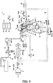
- FIG. 1 shows an engine 1 to which the disclosed technique is applied.
- This engine 1 is mounted particularly in an automobile.
- the automobile travels by the engine 1 being operated.
- the engine 1 is operated using fuel containing gasoline.
- the fuel for the engine 1 may be substantially pure gasoline or gasoline containing bioethanol or the like.
- the fuel for the engine 1 may be any fuel as long as it is liquid fuel containing at least gasoline.
- the engine 1 performs combustion (also referred to as Spark Controlled Compression Ignition (SPCCI) combustion) that is a combination of spark ignition (SI) combustion and compression ignition (CI) combustion.
- SI combustion is started by forcedly igniting an air-fuel mixture.
- CI combustion is started by self-ignition of an air-fuel mixture.
- SPCCI combustion an ignited air-fuel mixture is burned by flame propagation, and heat generation and a pressure increase due to the combustion cause an unburned air-fuel mixture to be burned by self-ignition.
- Adjusting an amount of heat generation by the SI combustion can absorb variations in temperature before a start of compression.
- controlling a start timing of the SI combustion according to the temperature before the start of the compression can control the CI combustion.
- the SPCCI combustion is a combustion mode in which the SI combustion and the CI combustion are organically controlled.
- the engine 1 includes an engine body 10 including a cylinder block 12 and a cylinder head 13 placed thereon. A plurality of cylinders 11 are formed in the cylinder block 12 (only one cylinder 11 is shown in FIG. 1 ).
- the engine body 10 further includes a piston 3, an injector 6, an ignition plug 25, an intake valve 21, an exhaust valve 22, or the like.
- a piston 3 is fitted in each cylinder 11 so as to move up and down.
- the piston 3 is coupled to a crank shaft 15 via a connecting rod 14.
- the piston 3 together with the cylinder block 12 and the cylinder head 13 defines a combustion chamber 17 having a varying volume.
- the "combustion chamber 17" refers to a combustion space formed in the engine body 10 irrespective of a position of the piston 3.
- a top surface of the combustion chamber 17 has a so-called pentroof shape.
- a bottom surface of the combustion chamber 17, that is, an upper surface of the piston 3 has a cavity (recess). The cavity faces the injector 6 when the piston 3 is located near compression top dead center.
- the shape of the combustion chamber 17 may be changed according to specifications of the engine 1. For example, shapes of the cavity, the upper surface of the piston 3, and the top surface of the combustion chamber 17 may be changed as appropriate.
- a geometric compression ratio of the engine 1 is set to 14 to 30 (both inclusive), particularly about 14 to about 30, preferably 14 to 18 (both inclusive), particularly about 14 to about 18.
- the CI combustion is controlled using heat generation and a pressure increase caused by the SI combustion.
- a temperature (compression end temperature) of the combustion chamber 17 when the piston 3 reaches the compression top dead center to cause self-ignition of the air-fuel mixture.
- the geometric compression ratio of the engine 1 is higher than that of a general spark ignition engine that performs only the SI combustion, and lower than that when only the CI combustion is performed.
- the high geometric compression ratio is advantageous for increasing thermal efficiency
- the low geometric compression ratio is advantageous for reducing cooling loss and mechanical loss.
- the geometric compression ratio of the engine 1 may be set according to fuel specifications. For example, for regular specifications (fuel octane number of about 91), the geometric compression ratio may be 14 to 17 (both inclusive), particularly about 14 to about 17, and for high-octane specifications (fuel octane number of about 96), the geometric compression ratio may be 15 to 18, particularly about 15 to about 18.
- the cylinder head 13 has particularly two intake ports 18 communicating with the combustion chamber 17 for each cylinder 11.
- the intake valve 21 is provided in each intake port 18 to open/close between the combustion chamber 17 and the intake port 18.
- the intake valve 21 is opened/closed particularly by a variable valve mechanism, and an opening/closing timing and/or an opening/closing amount thereof are changeable.
- the cylinder head 13 also has particularly two exhaust ports 19 communicating with the combustion chamber 17 for each cylinder 11.
- the exhaust valve 22 is provided in each exhaust port 19 to open/close between the combustion chamber 17 and the exhaust port 19.
- the exhaust valve 22 is opened/closed by a variable valve mechanism, and an opening/closing timing and/or an opening/closing amount thereof are changeable.
- the injector 6 is provided on the cylinder head 13 for each cylinder 11.
- the injector 6 is configured to directly inject fuel into the combustion chamber 17 from a substantial center of the top surface of the combustion chamber 17.
- An injection center of the injector 6 faces the cavity.
- the injector 6 has a plurality of injection holes arranged at circumferentially regular intervals, and spray of the fuel injected from the injection holes radially spreads obliquely downward from an upper part of the combustion chamber 17.
- the injector 6 has a nozzle opened/closed by driving a solenoid or a piezoelectric element. Thus, opening/closing of the nozzle can respond to a control signal at high speed, and high-speed injection, for example, at about 1 ms or less can be performed.
- the injector 6 is connected to a fuel supply device 61.
- the fuel supply device 61 is constituted by the injector 6, a fuel tank 63, a fuel supply passage 62, a fuel pump 65, a common rail 64, or the like.
- the fuel pump 65 feeds fuel accommodated in the fuel tank 63 through the fuel supply passage 62 to the common rail 64.
- the fuel is stored in the common rail 64 at high pressure of 30 MPa or more.
- the common rail 64 is connected through the fuel supply passage 62 to the injector 6, and the injector 6 is opened to inject the fuel into the combustion chamber 17 at high pressure of 30 MPa or more. In the engine 1, fuel injection pressure is set to 60 MPa.
- the ignition plug 25 is provided on the cylinder head 13 for each cylinder 11.
- the ignition plug 25 forcedly ignites an air-fuel mixture formed in the combustion chamber 17.
- the ignition plug 25 has an electrode at its front end, and is placed so that the electrode faces the upper part of the combustion chamber 17 between the two intake ports 18, 18.
- An intake passage 40 communicating with the intake port 18 in each cylinder 11 is connected to one side surface of the engine body 10.
- an air cleaner 41, a surge tank 42, a throttle valve 43, a supercharger 44, an intercooler 46, or the like are provided in the intake passage 40.
- a gas is introduced through the intake passage 40 into the combustion chamber 17.
- the throttle valve 43 changes an amount of fresh air to be introduced into the combustion chamber 17.
- the supercharger 44 is driven by the engine 1, and boosts a gas to be introduced into the combustion chamber 17.
- the supercharger 44 is controlled to switch between a state (ON) where the gas is boosted and a state (OFF) where the gas is not boosted.
- the intercooler 46 cools the gas compressed by the supercharger 44.
- a bypass passage 47 that bypasses the supercharger 44 and the intercooler 46 is connected to the intake passage 40.
- an air bypass valve 48 that changes a gas flow rate is provided. Turning off the supercharger 44 to fully open the air bypass valve 48 causes the gas to be introduced through the bypass passage 47 into the combustion chamber 17. In that case, the engine 1 is operated in an unboosted (naturally aspirated) state. When the engine 1 is operated in a boosted state, the supercharger 44 is turned on to change the opening of the air bypass valve 48. Then, the boosted gas can be introduced into the combustion chamber 17 while boost pressure is being changed.
- a swirl control valve 56 is provided that forms a swirl flow in the combustion chamber 17 and changes an intensity of the swirl flow.
- a swirl ratio is adjusted within a range of 1.5 to 3, particularly about 1.5 to about 3, (25% to 40%, particularly about 25% to about 40%, for the opening of the swirl control valve 56).
- An exhaust passage 50 communicating with the exhaust port 19 in each cylinder 11 is connected to the other side surface of the engine body 10.
- the upstream catalyst converter 57 is placed in an engine room, and has a three-way catalyst and a gasoline particulate filter (GPF).
- the downstream catalyst converter 58 is placed outside the engine room and has a three-way catalyst. Configurations of the catalyst converters 57, 58 can be changed according to specifications of the engine 1 as appropriate.
- An EGR passage 52 that returns part of burned gas to the intake passage 40 is connected between the intake passage 40 and the exhaust passage 50.
- an EGR cooler 53 and an EGR valve 54 are provided in the EGR passage 52.
- the EGR valve 54 changes a flow rate of the burned gas flowing through the EGR passage 52, and the EGR cooler 53 cools the burned gas flowing through the EGR passage 52 (external EGR system).
- the external EGR system supplies the burned gas at low temperature into the combustion chamber 17.
- a plurality of sensors SW1 to SW16 are provided.
- an air flow sensor SW1, an intake temperature sensor SW2, a pressure sensor SW3, an intake temperature sensor SW4, a pressure sensor SW5, a pressure sensor SW6, an exhaust temperature sensor SW7, a linear oxygen sensor SW8, a lambda oxygen sensor SW9, a water temperature sensor SW10, a crank angle sensor SW11, an accelerator opening sensor SW12, an intake cam angle sensor SW13, an exhaust cam angle sensor SW14, an EGR differential pressure sensor SW15, a fuel pressure sensor SW16, or the like are provided in various parts in the engine 1.
- the sensors SW1 to SW16 are connected to an ECU 8 (an example of a control device), and constantly output detected signals to the ECU 8 during the operation of the engine 1.
- crank angle sensor SW11 is mounted to the engine 1 and detects a rotation angle of the crank shaft 15.
- the pressure sensor SW6 is mounted to the cylinder head 13 for each cylinder 11, detects pressure in each combustion chamber 17 (also referred to as cylinder inner pressure), and outputs a detected signal to the ECU 8.
- the pressure sensor SW6 can output the detected signal, for example, at an interval equal to or shorter than a time for one revolution of the crank shaft 15 at maximum rotational speed of the engine 1.
- the ECU 8 is constituted by hardware including a processor 8a, a memory 8b, an interface 8c, or the like, and software including various data such as an operating range map 70 and control programs, or the like.
- the ECU 8 includes a high-performance processor 8a, for example, of 32 or 64 bits with an operating frequency of 100 MHz, particularly about 100 MHz, or more, and can perform a high-speed advanced arithmetic processing.
- the ECU 8 controls the devices that constitute the engine 1 (only the injector 6 and the ignition plug 25 are shown as examples in FIG. 2 ) to properly operate the engine 1 based on the signals output from the sensors SW1 to SW16 and the data such as the operating range map 70 described below.
- the ECU 8 also performs control to predict occurrence of a knock with a predetermined intensity or higher and suppress the knock based on the prediction as described later in detail.
- FIG. 3 shows an example of the operating range map 70 used for controlling the operation of the engine 1.
- the operating range map 70 is used for an operation during warming, and particularly includes the following five divided ranges.
- the low rotation, medium rotation, and high rotation ranges herein refer to ranges arranged in order from a low rotation side when an entire operating range of the engine 1 is substantially divided into three in a rotational direction.
- the low rotation refers to less than a rotational speed N1 (for example, about 1200 rpm)
- the high rotation refers to a rotational speed N2 (for example, about 4000 rpm) or more
- the medium rotation refers to the rotational speed N1 or more and less than N2.
- the engine 1 may perform the SPCCI combustion in the entire range in the operating range map 70, but in this configuration, the engine 1 performs the SPCCI combustion in the low load range (1), the medium load range (2), and the high load medium rotation range (3). In the other ranges, specifically, the high load low rotation range (4) and the high rotation range (5), the engine 1 performs the SI combustion by spark ignition. When the engine 1 is not sufficiently warmed as in cooling or at the start, the SI combustion may be performed in part or all of the low load range (1), the medium load range (2), and the high load medium rotation range (3).
- the supercharger 44 is turned off in the low load and low rotation range in the low load range (1) and the medium load range (2). In these ranges, the engine 1 is operated in an unboosted state, that is, a naturally aspirated state.
- the supercharger 44 is turned on in the other ranges, for example, the high load medium rotation range (3), the high load low rotation range (4), and the high rotation range (5). In these ranges, the engine 1 is operated in a boosted state, that is, a state in which a downstream side of the supercharger 44 is dynamically subjected to higher pressure than atmospheric pressure.
- the engine 1 performs the SPCCI combustion in the low load range (1) or the like mainly for improving fuel consumption and exhaust gas performance.
- the swirl control valve 56 is controlled by a predetermined opening on a closing side, and a diagonal swirl flow having a predetermined intensity is formed in the combustion chamber 17 (for example, a swirl ratio of about 1.5 to about 3).
- An excess air ratio ⁇ of the air-fuel mixture formed in the combustion chamber 17 is controlled to be more than one in the low load range (1) (an A/F is about 30 or more), substantially one (about 1.0 to about 1.2) in the medium load range (2), and one or less in the high load range.
- An EGR gas is introduced into the combustion chamber 17 as required.
- an internal EGR gas is introduced by setting of a positive or negative overlap period.
- an external EGR gas cooled as required is introduced.
- An amount of the EGR gas is controlled to decrease with increasing load.
- the upper part in FIG. 4 shows an example of the mode of the SPCCI combustion (combustion in the high load medium rotation range (3)).
- the fuel is injected at a predetermined timing within a period from an intake stroke to a compression stroke, and as shown, injected in a divided manner (denoted by reference numerals Inl, In2) as required.
- the air-fuel mixture in combination with the swirl flow may be stratified (for example, an A/F of the air-fuel mixture in a center is about 20 to about 30 and an A/F of the air-fuel mixture in an outer peripheral portion is about 35 or more).
- a G/F in the entire combustion chamber 17 when the SPCCI combustion is performed is generally controlled to about 18 to about 50 (both inclusive).
- the ignition plug 25 performs forced ignition at a predetermined timing around the compression top dead center (denoted by reference numeral S1).
- the air-fuel mixture formed in the combustion chamber 17 is subjected to the SPCCI combustion.
- a combustion waveform of the CI combustion following the SI combustion (a waveform representing a change in heat generation rate; denoted by reference numeral W1) is formed.
- the engine 1 of this configuration performs the SI combustion when stable SPCCI combustion is difficult such as in the high rotation range (5).
- the swirl control valve 56 is controlled on an opening side (normally, substantially fully open).
- the external EGR gas cooled as required is introduced, and an excess air ratio ⁇ of the air-fuel mixture is controlled to substantially one (about 1.0 to about 1.2).
- retard injection is performed. Specifically, within a period from a latter stage of the compression stroke to an initial stage of the expansion stroke (retard period), the injector 6 injects fuel at high pressure (for example, about 30 MPa or more).
- the fuel is injected during the intake stroke (denoted by reference numeral In3).
- the ignition plug 25 performs forced ignition (denoted by reference numeral S2) at a predetermined timing around the compression top dead center.
- S2 forced ignition
- W2 a combustion waveform of the SI combustion
- a knock is particularly seen as a problem in a spark-ignition engine that performs SI combustion. Specifically, when combustion of an air-fuel mixture is started by ignition by an ignition plug, the combustion spreads by flame propagation. Meanwhile, an unburned air-fuel mixture (end gas) may be locally increased in temperature and pressure to cause combustion by self-ignition. Since the combustion by self-ignition is more sudden than the combustion by flame propagation, pressure vibration thereof generates a noise or an impact to cause a knock.
- the knock occurs when the engine is operated at low rotation in a high load operating range, and is eliminated by a rotational speed increasing to increase a flame propagation speed.
- the knock also occurs when the engine is operated at high rotation.
- the knock that occurs when the engine is operated at high rotation tends to be more intense than the knock that occurs when the engine is operated at low rotation.
- An intense knock with a predetermined intensity or higher may occur although not frequently (for example, about 0.1%) .
- the geometric compression ratio is about 14 or more, and pressure in the combustion chamber 17 during combustion is set to be higher than that in a typical spark ignition engine.
- a knock is more likely to occur than in the typical spark ignition engine.
- an intense knock may occur in this engine 1.
- the intense knock is highly likely to damage the engine even if not frequently.
- the intense knock reduces reliability of the engine.
- the present inventors have found that occurrence of the intense knock can be predicted from cylinder inner pressure in an initial stage of combustion. Based on the findings, the engine 1 includes a technique that allows prediction of occurrence of an intense knock with high precision and suppression of the intense knock based on the prediction.
- the engine 1 first performs a knock information obtaining processing 100 (knock information obtaining step) of detecting or estimating cylinder inner pressure in an initial stage of combustion after a start of the combustion, from a latter stage of the compression stroke to an initial stage of the expansion stroke; and a knock intensity determination processing 101 (knock intensity determination step) of comparing the cylinder inner pressure with a preset reference value SV and determining whether or not the cylinder inner pressure exceeds the reference value SV during the course of the combustion.
- a knock information obtaining processing 100 knock information obtaining step
- a knock intensity determination processing 101 knock intensity determination step
- a knock occurrence prediction program 80 (knock occurrence prediction means) for predicting occurrence of the intense knock is installed in the ECU 8.
- the knock occurrence prediction program 80 includes a knock information obtaining unit 81 and a knock intensity determination unit 82.
- the knock information obtaining processing 100 is performed by the knock information obtaining unit 81, and the knock intensity determination processing 101 is performed by the knock intensity determination unit 82.
- the ECU 8 detects the cylinder inner pressure based on the detected signal constantly input from the pressure sensor SW6 during the operation of the engine 1.
- the knock information obtaining unit 81 obtains the cylinder inner pressure in the initial stage of combustion after the start of the combustion, from the latter stage of the compression stroke to the initial stage of the expansion stroke.
- the knock intensity determination unit 82 cooperates with the knock information obtaining unit 81 to predict occurrence of the intense knock.
- a reference value SV as a reference for determining the intense knock is set.
- the reference value SV is a value of cylinder inner pressure at a predetermined determination timing corresponding to a predetermined knock intensity (Kp) (for example, 100 bars or the like).
- Kp knock intensity
- the reference value SV is stored in the memory 8b in the ECU 8.
- the reference value SV is changeable and set correspondingly to specifications of the engine 1.
- the knock intensity is an index representing the intensity of a knock, and an amplitude value of a cylinder inner pressure pulse due to the knock.
- the knock intensity is obtained by an arithmetic processing of cylinder inner pressure data.
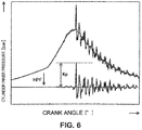
- a waveform shown on the upper side in FIG. 6 represents a cylinder inner pressure change in a certain combustion cycle.
- a pulse-like waveform in a latter stage of combustion represents a knock.
- Such a pressure waveform of the cylinder inner pressure is processed using a high-pass filter (HPF) or the like to remove, from the pressure waveform, a pressure changing component inherent in the engine such as compression pressure.
- HPF high-pass filter
- a pressure waveform only including a pressure pulse due to the knock is extracted.
- a maximum amplitude value is regarded as a knock intensity (Kp) (in bars) in the combustion cycle.
- the reference value SV is a value of cylinder inner pressure at a predetermined timing in the initial stage of combustion before the intense knock occurs (specifically, during the process of the combustion from immediately after the start of the combustion of the air-fuel mixture to subsequent occurrence of the knock), and previously obtained by an experiment or the like.
- One or more reference values SV may be set.
- the reference value SV may be set according to a determination condition. With reference to FIG. 7 , an example thereof will be described.
- the graph in FIG. 7 shows cylinder inner pressure changes during combustion under a predetermined condition.
- the combustion condition corresponds to a case where the engine 1 is operated at a rotational speed of 4000 rpm, particularly about 4000 rpm, in the high rotation range (5) (this will be described below as the combustion in the engine 1).
- FIG. 7 shows cylinder inner pressure changes in many combustion cycles performed under the same combustion condition such as the same fuel injection amount or injection timing or the same ignition timing in a superimposed manner.
- the injection of fuel is collectively performed at a predetermined timing in the intake stroke, and the ignition by the ignition plug 25 is performed at a timing of a crank angle (CA) of around 7° before the compression top dead center (also referred to as -7° CA).
- CA crank angle
- the cylinder inner pressure gradually increases toward the compression top dead center, and the combustion by the ignition is started near the compression top dead center (0° CA).
- the expansion stroke is entered after the compression top dead center, the combustion by flame propagation progresses with decreasing cylinder inner pressure caused by the piston 3 moving down.
- the combustion heat and combustion pressure cause self-ignition in part of the combustion cycles, and many pressure pulses representing a knock occur at and after 20° CA, particularly about 20°.
- slight pulses have abnormally high peaks.
- a knock representing a pressure pulse higher than the reference line L in FIG. 7 is an intense knock with a predetermined knock intensity or higher
- the frequency of occurrence of the intense knock is a few times per 1000 combustion cycles.
- the cylinder inner pressure in the initial stage of the combustion tends to be relatively higher than in the combustion without occurrence of the intense knock.
- the present inventors have focused on this fact, and found that by comparing the cylinder inner pressure with the predetermined reference value SV at a proper timing in the initial stage of the combustion, whether or not the intense knock subsequently occurs can be determined.
- the cylinder inner pressure is relatively high in an initial stage of combustion from immediately after the start of the combustion of the air-fuel mixture (in this example, a timing of a crank angle of a few degrees after the compression top dead center) to subsequent occurrence of the knock, and a pressure difference from the combustion without occurrence of the intense knock is found.
- setting a reference value SV that allows determination of the pressure difference, and comparing the cylinder inner pressure with the reference value SV in the initial stage of the combustion allows determination whether or not the intense knock subsequently occurs.
- the pressure sensor SW6 detects the cylinder inner pressure at an interval of 1° CA, particularly about 1° CA, and output to the ECU 8.
- the ECU 8 includes the processor 8a that can perform a high-speed advanced arithmetic processing.
- the cylinder inner pressure detected by the pressure sensor SW6 can be compared with the reference value SV to predict the intense knock that occurs during the course of the combustion. For example, even when the engine 1 is operated at high rotation higher than 5000 rpm, the intense knock can be predicted.
- the timing suitable for determining whether or not the cylinder inner pressure exceeds the reference value SV (determination timing) varies according to the combustion condition.
- the determination timing is preferably set within a period corresponding to the combustion condition under which the intense knock tends to occur.
- the determination timing is preferably set within a period in which a crank angle is between 15°, particularly about 15°, before the top dead center (-15° CA) and 25°, particularly about 25°, after the top dead center (25° CA).
- the intense knock tends to occur when the engine is operated in a high load and high rotation operating range.
- the initial stage of combustion is often within a period from -15° CA to 25° CA, particularly about -15° CA to about 25° CA,.
- setting the determination timing within this period allows efficient and stable prediction of an intense knock.
- a knock suppression processing needs to be performed during the process of combustion before subsequent occurrence of a knock.
- the determination timing needs to be set to an early timing when occurrence of an intense knock can be determined in the initial stage of the combustion.
- the determination timing is preferably set within a period from 5° CA to 13° CA, particularly from about 5° CA to about 13° CA (rl in FIG. 7 ).
- 9° CA particularly about 9° CA, is set as the determination timing under the illustrated combustion condition.
- the cylinder inner pressure used for comparison with the reference value SV may be a detected value of cylinder inner pressure obtained from the detected signal from the pressure sensor SW6, or a value obtained by calculating a plurality of detected values of cylinder inner pressure.
- One or more determination timings may be set. For a plurality of determination timings, a reference value SV may be set for each determination timing, the reference values SV may be compared with corresponding values of the cylinder inner pressure, and comprehensive determination may be made. Information on such cylinder inner pressure is obtained by the knock information obtaining unit 81.
- the determination timing is preferably set based on the burned mass fraction (BMF), and is preferably set within a period in which the burned mass fraction is between 5% and 20%, particularly between about 5% and about 20%, in terms of knock suppression.
- the combustion period is advanced or retarded depending on the combustion condition. Accordingly, an optimum determination timing also changes.
- the determination timing when the determination timing is set based on the crank angle, the determination timing may be shifted from the optimum timing as the combustion condition changes.
- the determination timing when the determination timing is set based on the burned mass fraction, the determination timing changes with changing combustion condition, and thus the optimum timing can be maintained.
- the "burned mass fraction" herein is an index representing a progress of combustion used in this technical field.
- the burned mass fraction approximately corresponds to a fraction (%) of burned fuel mass to total fuel mass.
- the burned mass fraction may be a fraction of burned fuel mass B to mass A of fuel supplied into the combustion chamber 17 per one combustion cycle (B/A; in %).
- the burned mass fraction may be a fraction of an amount of heat generation D that has occurred before a target point to a total amount of heat generation C that occurs when all the fuel supplied into the combustion chamber 17 is burned (D/C; in %).
- the burned mass fraction can be calculated from history of the cylinder inner pressure after the start of combustion.
- the knock intensity determination unit 82 calculates the burned mass fraction based on the history of the cylinder inner pressure immediately after the start of the combustion, and performs a determination timing judgement processing (determination timing judgement step) for judging the determination timing based on the burned mass fraction.
- FIG. 8 shows a graph of the burned mass fraction corresponding to FIG. 7 .
- the burned mass fraction before near 0° CA at which the combustion starts is 0%. Then, the combustion progresses to increase the burned mass fraction, the combustion ends after around 20° CA, and the burned mass fraction reaches 100%.
- the period r1 at 5° CA to 13° CA described above corresponds to the period in which the burned mass fraction is between 5% and 20%.
- 9° CA corresponds to the timing at the burned mass fraction of 10%.
- the determination timing is set within the period in which the burned mass fraction is between about 5% and about 20%. Specifically, at the timing at the burned mass fraction of about 10%, whether or not the intense knock occurs is determined.
- the knock suppression processing 102 (knock suppression step) for suppressing the intense knock is performed. Specifically, before the end of the combustion, a fluid (additional fuel in this engine 1) is injected into the combustion chamber 17.
- a series of processing steps for suppressing the intense knock following the processing for predicting of the intense knock described above is performed during one combustion period in the same combustion cycle.
- the combustion starts at the timing around the compression top dead center, and ends during the expansion stroke.
- occurrence of the intense knock is predicted, and the fuel is additionally injected based on the prediction.
- the engine 1 includes the injector 6 for injecting the fuel into the combustion chamber 17.
- the injector 6 can instantly inject the fuel at high pressure.
- the ECU 8 performs control so that the injector 6 additionally injects the fuel.
- the knock suppression processing 102 is performed by the ECU 8.
- the air-fuel mixture under combustion is agitated.
- the knock is caused by an unburned air-fuel mixture being locally increased in temperature and pressure.
- the temperature of the entire air-fuel mixture is equalized to suppress the local temperature increase of the unburned air-fuel mixture, thereby suppressing the intense knock.
- the fuel can be injected using an existing injector 6. Cooling action due to vaporization of the fuel is also advantageously obtained.
- the intense knock occurs after the compression top dead center during the combustion period.
- the fuel is additionally injected after the compression top dead center (0° CA).
- the earliest intense knock occurs at the timing of 20° CA, particularly about 20° CA,.
- the fuel needs to be additionally injected at least before 20° CA.
- the fuel is preferably additionally injected at least before about 18° CA (see arrow Y1 in FIG. 7 ) to suppress the intense knock.
- 18° CA in the intense knock combustion corresponds to the burned mass fraction of about 50%.
- the fuel is preferably additionally injected within a period after the start of the combustion and before the burned mass fraction reaches 50% (see arrow Y2 in FIG. 8 ).
- agitation is preferably performed immediately before occurrence of the knock. Even if the agitation is performed in a state where the temperature of the unburned air-fuel mixture is not locally sufficiently increased, a high temperature suppression effect cannot be obtained. A temperature suppression effect by the agitation is higher in a state where the temperature of the unburned air-fuel mixture is locally sufficiently increased because of a larger temperature difference of the air-fuel mixture. Thus, injecting the fuel immediately before occurrence of the knock allows more efficient suppression of the knock.
- the fuel is preferably additionally injected within a period in which the burned mass fraction is between about 20% and about 50%, and more preferably, within a period in which the burned mass fraction is between about 30% and about 50%.
- the fuel may be additionally injected in all the combustion cycles to suppress the intense knock.
- the fuel used for additional injection is different from the fuel required for operating the engine 1, and additional fuel injection in all the combustion cycle reduces fuel consumption. Also, such additional fuel injection increases soot. Thus, in view of improvement in fuel consumption and exhaust performance, additional fuel injection in all the combustion cycle is unpreferable.
- the fuel is additionally injected only when the intense knock is predicted. This can minimize the frequency of the additional fuel injection, and effectively suppress the intense knock.
- mass of the fuel additionally injected is set to about 10% or less of total mass of the fuel injected in the combustion cycle in which the fuel is additionally injected (total mass of injected fuel).
- the injector 6 can achieve a required agitating effect of the air-fuel mixture even with such an injection amount.
- the mass of the fuel additionally injected is set to about 5% of the total mass of injected fuel.
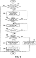
- FIGS. 9 and 10 show an example of prediction control and suppression control of an intense knock performed in this engine 1.
- the intense knock tends to occur when the engine is operated at high rotational speed in the high load range.
- the engine 1 is configured so that the prediction control and suppression control of the intense knock are performed in a predetermined range (target range) from the high load medium rotation range (3) for the SPCCI combustion to the high load range in the high rotation range (5) for the SI combustion.
- the prediction control and suppression control of the intense knock may be performed in the entire operating range, performing the prediction control and suppression control only in the partial target range in which the intense knock may occur can efficiently suppress the intense knock and reduce a processing load on the ECU 8.
- the ECU 8 determines whether or not the engine 1 is operated in the target range based on the detected signals input from the crank angle sensor SW11, the accelerator opening sensor SW12, or the like during the operation of the engine 1 (step S1).
- the ECU 8 continuously receives the detected signal from the pressure sensor SW6 to predict and suppress the intense knock (step S2).
- the description is made on the assumption that the engine 1 is operated in the high load range in the high rotation range (5) in FIG. 3 as the target range.
- the knock information obtaining unit 81 obtains cylinder inner pressure from the detected signal as required.
- the cylinder inner pressure may be a value directly obtained from the input detected signal (so-called actual measurement) or an indirect value obtained by an arithmetical processing of the input detected signal.
- the ECU 8 determines whether or not ignition by the ignition plug 25 is performed (step S3). In the target range, the combustion is started by ignition by the ignition plug 25, and thus the ECU 8 detects an ignition timing for each combustion cycle. Then, when the ignition by the ignition plug 25 is performed, the knock intensity determination unit 82 calculates the burned mass fraction of the combustion started by the ignition based on the history of the pressure sensor SW6 (step S4).
- the knock intensity determination unit 82 continuously calculates the burned mass fraction using the detected signal input from the crank angle sensor SW11 and the detected signal subsequently input from the pressure sensor SW6.
- the knock intensity determination unit 82 compares the cylinder inner pressure obtained by the knock information obtaining unit 81 with the reference value SV (step S6).
- the knock intensity determination unit 82 predicts that the intense knock occurs (step S7).
- the knock intensity determination unit 82 predicts that the intense knock does not occur (step S8).
- the ECU 8 finishes the intense knock prediction control and suppression control in that combustion cycle, and moves to intense knock prediction control and suppression control in the next combustion cycle.
- the ECU 8 instructs the injector 6 to additionally inject fuel (step S9).
- a control signal to open the nozzle for a time corresponding to an amount of fuel additionally injected is output to the injector 6.
- the additional fuel injection suppresses the intense knock, and thus the knock is eliminated, or a knock with a low knock intensity occurs.
- an engine similar to the engine 1 described above (having a geometric compression ratio of 17 or more) was used. Fuel was collectively injected in an intake stroke so that an operating state is the same as in a high load range, and the engine was operated at a rotational speed of 4000 rpm. During the operation of the engine, two combustion cycles were extracted in which an intense knock of the same level is predicted to occur, and in the combustion cycles, cylinder inner pressure changes in combustions with and without additional fuel injection were compared.
- FIG. 11 shows the results.
- the graph shown by the thin line represents the cylinder inner pressure change in the combustion without additional fuel injection (comparative example).
- the graph shown by the thick line represents the cylinder inner pressure change in the combustion with additional fuel injection (example).
- the fuel was additionally injected immediately before the knock occurs as shown in the upper part in FIG. 11 .
- the intense knock occurred, and when the fuel was additionally injected, the knock intensity was low, and it was found that the intense knock was suppressed.
- a type of an engine to which the disclosed technique can be applied is not limited to that of the engine 1 of the embodiment.
- the disclosed technique can be applied to any engines in which a knock occurs.
- the disclosed technique can be applied to a typical spark ignition engine or a compression self-ignition engine without spark ignition.
- the cylinder inner pressure used for determining the intense knock is not necessarily obtained by detection using the pressure sensor SW6.
- the cylinder inner pressure may be indirectly estimated from data such as a combustion condition, and the estimated value may be used for determining the intense knock. Prediction and suppression of the intense knock may be performed in the entire operating range of the engine, not limited to a particular operating range.
Description
- The disclosed technique relates to a technique for predicting occurrence of an intense knock (also referred to as knocking) having a predetermined intensity or higher in an engine, and suppressing the intense knock based on the prediction.
- A knock is an abnormal noise generated during an operation of an engine, and is particularly seen as a problem in a spark-ignition engine. Occurrence of the knock affects user's comfort or reliability of the engine. Thus, suppression of the knock is an important issue in this technical field, and various measures have been proposed so far.
- For example,
Japanese Patent Laid-Open No. 2008-291758 -
Japanese Patent Laid-Open No. 2012-41846 - Specifically, before the compression top dead center, an air-fuel ratio is set to be lean, and the fuel is injected from the first fuel injector and burned by ignition by the first ignition plug. After the compression top dead center, the air-fuel ratio is set to be rich, and the fuel is injected from the second fuel injector and burned by ignition by the second ignition plug. Thus, occurrence of a knock is suppressed while thermal efficiency is improved to achieve a high compression ratio of the engine.
- Particularly in the case where an engine is operated at high rotation, an intense knock with an amplitude of a pressure change of higher than 100 bars occurs, although not frequently (for example, about 0.1%). Such an intense knock is likely to damage the engine, reducing in reliability of the engine. Also, the intense knock tends to occur in an engine with a high compression ratio, preventing improvement of fuel efficiency.
- As in
Japanese Patent Laid-Open No. 2008-291758 - The engine in
Japanese Patent Laid-Open No. 2012-41846 Japanese Patent Laid-Open No. 2012-41846 -
US 2012/029789 A1 discloses a method of preventing a pre-ignition event within a cylinder of a spark ignition engine. -
JP 2002 174135 A -
JP 2008 014275 A -
US 2008/035129 A1 discloses a method of controlling the combustion of an internal-combustion engine, in particular a direct-injection supercharged engine, notably of gasoline type. - An object of the disclosed technique is to effectively suppress an intense knock and improve reliability of an engine.
- One disclosed technique relates to a method as defined in
claim 1. - One disclosed technique relates to an engine as defined in claim 7.
- One disclosed technique relates to a method for predicting occurrence of a knock with a predetermined intensity or higher in an engine that burns an air-fuel mixture formed in a combustion chamber by supplying fuel containing gasoline into the combustion chamber.
- The method includes: a knock information obtaining step of detecting or estimating pressure in the combustion chamber in an initial stage of combustion after a start of the combustion; and a knock intensity determination step of comparing the pressure with a preset reference value and determining whether or not the pressure exceeds the reference value during the course of the combustion, wherein when the pressure exceeds the reference value, it is predicted that the knock occurs before an end of the combustion.
- Specifically, this method is obtained by the present inventors having found that occurrence of a knock with a predetermined intensity or higher can be predicted from cylinder inner pressure in an initial stage of combustion. In this method, a series of processing steps for predicting occurrence of an intense knock is performed during one combustion period in the same combustion cycle. Thus, even a sudden intense knock that does not frequently occur can be stably and efficiently predicted.
- The knock intensity determination step may be performed within a period in which a crank angle is between 15° before top dead center and 25° after the top dead center.
- The intense knock tends to occur when the engine is operated in a high load and high rotation operating range. Under a combustion condition in such an operating range, an initial stage of combustion suitable for determining an intense knock is often within a period in which a crank angle is between 15° before the top dead center and 25° after the top dead center. Thus, performing the knock intensity determination step during this period allows efficient and stable prediction of an intense knock.
- The knock intensity determination step may be performed within a period in which a burned mass fraction (BMF) is between 5% and 20% during the combustion. The burned mass fraction is an index representing a progress of combustion, and approximately corresponds to a fraction (%) of burned fuel mass to total fuel mass.
- A combustion period changes depending on the combustion condition at that time such as an ignition timing, and an optimum determination timing changes accordingly. Thus, when the determination timing is set based on the crank angle, the determination timing may be shifted from the optimum timing. On the other hand, when the determination timing is set based on the burned mass fraction, the optimum timing can be maintained even if the combustion condition changes.
- Further, when the knock intensity determination step is performed within the period in which the burned mass fraction is between 5% and 20%, a period for suppressing an intense knock can be ensured before a timing of occurrence of the intense knock. This can suppress the intense knock and improve reliability of the engine.
- Another disclosed technique relates to a method for suppressing a knock with a predetermined intensity or higher in an engine that burns an air-fuel mixture formed in a combustion chamber by supplying fuel containing gasoline into the combustion chamber.
- The method includes, in addition to the knock information obtaining step and the knock intensity determination step described above, a knock suppression step of injecting a fluid into the combustion chamber before an end of the combustion when the pressure exceeds the reference value.
- Specifically, in this method, when occurrence of an intense knock is predicted, the fluid is injected into the combustion chamber before an end of the combustion. When the fluid is injected into the combustion chamber, an air-fuel mixture under combustion is agitated. When the air-fuel mixture is agitated during the combustion, a temperature of the entire air-fuel mixture is equalized. This can suppress a local temperature increase of an unburned air-fuel mixture, and thus suppress an intense knock.
- The engine includes an injector that injects the fuel into the combustion chamber, and uses the fuel additionally injected from the injector as the fluid in the knock suppression step.
- Then, the air-fuel mixture is agitated using an existing injector and fuel. This eliminates the need for complex improvement or addition of a device, and easily suppress an intense knock. Cooling action due to vaporization of the fuel is also advantageously obtained.
- The injection of the fluid in the knock suppression step may be performed within a period before the burned mass fraction reaches 50% during the combustion.
- In experiments conducted so far, the earliest occurrence of an intense knock was found at a timing of the burned mass fraction of 50%. Thus, injecting the fluid before that timing can suppress most of intense knocks.
- The engine includes: a combustion chamber defined in a cylinder so as to have a volume varied by a piston moving up and down; a fuel supply device that supplies fuel containing gasoline into the combustion chamber; and a control device having knock occurrence prediction means for predicting occurrence of a knock. The knock occurrence prediction means includes a knock information obtaining unit that detects or estimates pressure in the combustion chamber, and a knock intensity determination unit in which a reference value as a reference for determining an intense knock with a predetermined intensity or higher is set. The knock information obtaining unit detects or estimates the pressure in an initial stage of combustion after a start of the combustion. The knock intensity determination unit compares the pressure with the reference value and determines whether or not the pressure exceeds the reference value during the course of the combustion. When the pressure exceeds the reference value, the control device predicts that the intense knock occurs before an end of the combustion.
- According to this engine, a sudden intense knock that does not frequently occur can be stably and efficiently predicted.
- Similarly to the method described above, the determination by the knock intensity determination unit may be performed within a period in which a crank angle is between 15° before top dead center and 25° after the top dead center, or within a period in which the burned mass fraction is between 5% and 20% during the combustion.
- According to the invention, the fuel supply device includes an injector that injects the fuel into the combustion chamber, which when the pressure exceeds the reference value, additionally injects the fuel before an end of combustion.
- This eliminates the need for complex improvement or addition of a device, and effectively suppresses an intense knock to improve reliability of the engine.
- Similarly to the method described above, the additional fuel injection by the injector may be performed within a period before the burned mass fraction reaches 50% during the combustion.
- A geometric compression ratio of the engine may be 14 or more. Since an intense knock tends to occur at a high compression ratio, applying this technique to the engine having a geometric compression ratio of 14 or more is more effective.
- The disclosed techniques can effectively suppress an intense knock and improve reliability of an engine.
-
-
FIG. 1 is a schematic view of a configuration of an engine according to an embodiment; -
FIG. 2 is a block diagram of a configuration of a control device; -
FIG. 3 shows an example of an operating range map used for controlling the engine; -
FIG. 4 illustrates a combustion state in a main operating range; -
FIG. 5 is a main flowchart of intense knock prediction and suppression processing steps; -
FIG. 6 illustrates a knock intensity; -
FIG. 7 is a graph showing a relationship between a cylinder inner pressure change and a crank angle during combustion in a plurality of combustion cycles; -
FIG. 8 is a graph showing a relationship between a burned mass fraction and a crank angle during each combustion inFIG. 7 ; -
FIG. 9 is an exemplary flowchart of control of intense knock prediction and suppression; -
FIG. 10 illustrates a combustion state when the intense knock prediction and suppression are controlled; and -
FIG. 11 is a graph showing a result of a verification test of the control of the intense knock prediction and suppression. - Now, an embodiment of the present invention will be described in detail with reference to the drawings. However, the descriptions mentioned below are merely essentially illustrative, and do not limit the present invention, application or use thereof.
-
FIG. 1 shows anengine 1 to which the disclosed technique is applied. Thisengine 1 is mounted particularly in an automobile. The automobile travels by theengine 1 being operated. Theengine 1 is operated using fuel containing gasoline. The fuel for theengine 1 may be substantially pure gasoline or gasoline containing bioethanol or the like. Specifically, the fuel for theengine 1 may be any fuel as long as it is liquid fuel containing at least gasoline. - The
engine 1 performs combustion (also referred to as Spark Controlled Compression Ignition (SPCCI) combustion) that is a combination of spark ignition (SI) combustion and compression ignition (CI) combustion. Specifically, the SI combustion is started by forcedly igniting an air-fuel mixture. The CI combustion is started by self-ignition of an air-fuel mixture. In the SPCCI combustion, an ignited air-fuel mixture is burned by flame propagation, and heat generation and a pressure increase due to the combustion cause an unburned air-fuel mixture to be burned by self-ignition. - Adjusting an amount of heat generation by the SI combustion can absorb variations in temperature before a start of compression. Thus, controlling a start timing of the SI combustion according to the temperature before the start of the compression can control the CI combustion. The SPCCI combustion is a combustion mode in which the SI combustion and the CI combustion are organically controlled.
- The
engine 1 includes anengine body 10 including acylinder block 12 and acylinder head 13 placed thereon. A plurality ofcylinders 11 are formed in the cylinder block 12 (only onecylinder 11 is shown inFIG. 1 ). Theengine body 10 further includes apiston 3, aninjector 6, anignition plug 25, anintake valve 21, anexhaust valve 22, or the like. - A
piston 3 is fitted in eachcylinder 11 so as to move up and down. Thepiston 3 is coupled to a crankshaft 15 via a connectingrod 14. Thepiston 3 together with thecylinder block 12 and thecylinder head 13 defines acombustion chamber 17 having a varying volume. The "combustion chamber 17" refers to a combustion space formed in theengine body 10 irrespective of a position of thepiston 3. - A top surface of the
combustion chamber 17 has a so-called pentroof shape. A bottom surface of thecombustion chamber 17, that is, an upper surface of thepiston 3 has a cavity (recess). The cavity faces theinjector 6 when thepiston 3 is located near compression top dead center. The shape of thecombustion chamber 17 may be changed according to specifications of theengine 1. For example, shapes of the cavity, the upper surface of thepiston 3, and the top surface of thecombustion chamber 17 may be changed as appropriate. - A geometric compression ratio of the
engine 1 is set to 14 to 30 (both inclusive), particularly about 14 to about 30, preferably 14 to 18 (both inclusive), particularly about 14 to about 18. In the SPCCI combustion, the CI combustion is controlled using heat generation and a pressure increase caused by the SI combustion. Thus, in theengine 1, there is no need to increase a temperature (compression end temperature) of thecombustion chamber 17 when thepiston 3 reaches the compression top dead center to cause self-ignition of the air-fuel mixture. - Specifically, the geometric compression ratio of the
engine 1 is higher than that of a general spark ignition engine that performs only the SI combustion, and lower than that when only the CI combustion is performed. The high geometric compression ratio is advantageous for increasing thermal efficiency, and the low geometric compression ratio is advantageous for reducing cooling loss and mechanical loss. The geometric compression ratio of theengine 1 may be set according to fuel specifications. For example, for regular specifications (fuel octane number of about 91), the geometric compression ratio may be 14 to 17 (both inclusive), particularly about 14 to about 17, and for high-octane specifications (fuel octane number of about 96), the geometric compression ratio may be 15 to 18, particularly about 15 to about 18. - The
cylinder head 13 has particularly twointake ports 18 communicating with thecombustion chamber 17 for eachcylinder 11. Theintake valve 21 is provided in eachintake port 18 to open/close between thecombustion chamber 17 and theintake port 18. Theintake valve 21 is opened/closed particularly by a variable valve mechanism, and an opening/closing timing and/or an opening/closing amount thereof are changeable. - The
cylinder head 13 also has particularly twoexhaust ports 19 communicating with thecombustion chamber 17 for eachcylinder 11. Theexhaust valve 22 is provided in eachexhaust port 19 to open/close between thecombustion chamber 17 and theexhaust port 19. Theexhaust valve 22 is opened/closed by a variable valve mechanism, and an opening/closing timing and/or an opening/closing amount thereof are changeable. - The
injector 6 is provided on thecylinder head 13 for eachcylinder 11. Theinjector 6 is configured to directly inject fuel into thecombustion chamber 17 from a substantial center of the top surface of thecombustion chamber 17. An injection center of theinjector 6 faces the cavity. Theinjector 6 has a plurality of injection holes arranged at circumferentially regular intervals, and spray of the fuel injected from the injection holes radially spreads obliquely downward from an upper part of thecombustion chamber 17. Theinjector 6 has a nozzle opened/closed by driving a solenoid or a piezoelectric element. Thus, opening/closing of the nozzle can respond to a control signal at high speed, and high-speed injection, for example, at about 1 ms or less can be performed. - The
injector 6 is connected to afuel supply device 61. Thefuel supply device 61 is constituted by theinjector 6, afuel tank 63, afuel supply passage 62, afuel pump 65, acommon rail 64, or the like. Thefuel pump 65 feeds fuel accommodated in thefuel tank 63 through thefuel supply passage 62 to thecommon rail 64. The fuel is stored in thecommon rail 64 at high pressure of 30 MPa or more. Thecommon rail 64 is connected through thefuel supply passage 62 to theinjector 6, and theinjector 6 is opened to inject the fuel into thecombustion chamber 17 at high pressure of 30 MPa or more. In theengine 1, fuel injection pressure is set to 60 MPa. - The ignition plug 25 is provided on the
cylinder head 13 for eachcylinder 11. The ignition plug 25 forcedly ignites an air-fuel mixture formed in thecombustion chamber 17. The ignition plug 25 has an electrode at its front end, and is placed so that the electrode faces the upper part of thecombustion chamber 17 between the twointake ports - An
intake passage 40 communicating with theintake port 18 in eachcylinder 11 is connected to one side surface of theengine body 10. In theintake passage 40, anair cleaner 41, asurge tank 42, athrottle valve 43, asupercharger 44, anintercooler 46, or the like are provided. A gas is introduced through theintake passage 40 into thecombustion chamber 17. - The
throttle valve 43 changes an amount of fresh air to be introduced into thecombustion chamber 17. Thesupercharger 44 is driven by theengine 1, and boosts a gas to be introduced into thecombustion chamber 17. Thesupercharger 44 is controlled to switch between a state (ON) where the gas is boosted and a state (OFF) where the gas is not boosted. Theintercooler 46 cools the gas compressed by thesupercharger 44. - A
bypass passage 47 that bypasses thesupercharger 44 and theintercooler 46 is connected to theintake passage 40. In thebypass passage 47, anair bypass valve 48 that changes a gas flow rate is provided. Turning off thesupercharger 44 to fully open theair bypass valve 48 causes the gas to be introduced through thebypass passage 47 into thecombustion chamber 17. In that case, theengine 1 is operated in an unboosted (naturally aspirated) state. When theengine 1 is operated in a boosted state, thesupercharger 44 is turned on to change the opening of theair bypass valve 48. Then, the boosted gas can be introduced into thecombustion chamber 17 while boost pressure is being changed. - In one of the
intake ports 18, aswirl control valve 56 is provided that forms a swirl flow in thecombustion chamber 17 and changes an intensity of the swirl flow. When an opening of theswirl control valve 56 is small, the intensity of the swirl flow is high, and when the opening of theswirl control valve 56 is large, the intensity of the swirl flow is low. In thisengine 1, to achieve particularly stable SPCCI combustion, a swirl ratio is adjusted within a range of 1.5 to 3, particularly about 1.5 to about 3, (25% to 40%, particularly about 25% to about 40%, for the opening of the swirl control valve 56). - An
exhaust passage 50 communicating with theexhaust port 19 in eachcylinder 11 is connected to the other side surface of theengine body 10. In theexhaust passage 50, particularly twocatalyst converters upstream catalyst converter 57 is placed in an engine room, and has a three-way catalyst and a gasoline particulate filter (GPF). Thedownstream catalyst converter 58 is placed outside the engine room and has a three-way catalyst. Configurations of thecatalyst converters engine 1 as appropriate. - An
EGR passage 52 that returns part of burned gas to theintake passage 40 is connected between theintake passage 40 and theexhaust passage 50. In theEGR passage 52, anEGR cooler 53 and anEGR valve 54 are provided. TheEGR valve 54 changes a flow rate of the burned gas flowing through theEGR passage 52, and theEGR cooler 53 cools the burned gas flowing through the EGR passage 52 (external EGR system). The external EGR system supplies the burned gas at low temperature into thecombustion chamber 17. - In the
engine 1, a plurality of sensors SW1 to SW16 are provided. For example, an air flow sensor SW1, an intake temperature sensor SW2, a pressure sensor SW3, an intake temperature sensor SW4, a pressure sensor SW5, a pressure sensor SW6, an exhaust temperature sensor SW7, a linear oxygen sensor SW8, a lambda oxygen sensor SW9, a water temperature sensor SW10, a crank angle sensor SW11, an accelerator opening sensor SW12, an intake cam angle sensor SW13, an exhaust cam angle sensor SW14, an EGR differential pressure sensor SW15, a fuel pressure sensor SW16, or the like are provided in various parts in theengine 1. As shown inFIG. 2 , the sensors SW1 to SW16 are connected to an ECU 8 (an example of a control device), and constantly output detected signals to theECU 8 during the operation of theengine 1. - For example, the crank angle sensor SW11 is mounted to the
engine 1 and detects a rotation angle of thecrank shaft 15. The pressure sensor SW6 is mounted to thecylinder head 13 for eachcylinder 11, detects pressure in each combustion chamber 17 (also referred to as cylinder inner pressure), and outputs a detected signal to theECU 8. The pressure sensor SW6 can output the detected signal, for example, at an interval equal to or shorter than a time for one revolution of thecrank shaft 15 at maximum rotational speed of theengine 1. - As shown in
FIGS. 1 and2 , theECU 8 is constituted by hardware including aprocessor 8a, amemory 8b, aninterface 8c, or the like, and software including various data such as anoperating range map 70 and control programs, or the like. TheECU 8 includes a high-performance processor 8a, for example, of 32 or 64 bits with an operating frequency of 100 MHz, particularly about 100 MHz, or more, and can perform a high-speed advanced arithmetic processing. - The
ECU 8 controls the devices that constitute the engine 1 (only theinjector 6 and theignition plug 25 are shown as examples inFIG. 2 ) to properly operate theengine 1 based on the signals output from the sensors SW1 to SW16 and the data such as theoperating range map 70 described below. TheECU 8 also performs control to predict occurrence of a knock with a predetermined intensity or higher and suppress the knock based on the prediction as described later in detail. -
FIG. 3 shows an example of theoperating range map 70 used for controlling the operation of theengine 1. Theoperating range map 70 is used for an operation during warming, and particularly includes the following five divided ranges. - (1) "Low load range" with idling and expanding over low rotation and medium rotation ranges.
- (2) "Medium load range" with a higher load than the low load range and expanding over the low rotation and medium rotation ranges.
- (3) "High load medium rotation range" with a higher load than the medium load range and being a medium rotation range in a high load range with a full load.
- (4) "High load low rotation range" being a low rotation range with a lower rotational speed than the medium rotation range in the high load range.
- (5) "High rotation range" with a higher rotational speed than the low load range, medium load range, high load medium rotation range, and high load low rotation range.
- The low rotation, medium rotation, and high rotation ranges herein refer to ranges arranged in order from a low rotation side when an entire operating range of the
engine 1 is substantially divided into three in a rotational direction. The low rotation refers to less than a rotational speed N1 (for example, about 1200 rpm), the high rotation refers to a rotational speed N2 (for example, about 4000 rpm) or more, and the medium rotation refers to the rotational speed N1 or more and less than N2. - The
engine 1 may perform the SPCCI combustion in the entire range in theoperating range map 70, but in this configuration, theengine 1 performs the SPCCI combustion in the low load range (1), the medium load range (2), and the high load medium rotation range (3). In the other ranges, specifically, the high load low rotation range (4) and the high rotation range (5), theengine 1 performs the SI combustion by spark ignition. When theengine 1 is not sufficiently warmed as in cooling or at the start, the SI combustion may be performed in part or all of the low load range (1), the medium load range (2), and the high load medium rotation range (3). - The
supercharger 44 is turned off in the low load and low rotation range in the low load range (1) and the medium load range (2). In these ranges, theengine 1 is operated in an unboosted state, that is, a naturally aspirated state. Thesupercharger 44 is turned on in the other ranges, for example, the high load medium rotation range (3), the high load low rotation range (4), and the high rotation range (5). In these ranges, theengine 1 is operated in a boosted state, that is, a state in which a downstream side of thesupercharger 44 is dynamically subjected to higher pressure than atmospheric pressure. - The
engine 1 performs the SPCCI combustion in the low load range (1) or the like mainly for improving fuel consumption and exhaust gas performance. When the SPCCI combustion is performed, theswirl control valve 56 is controlled by a predetermined opening on a closing side, and a diagonal swirl flow having a predetermined intensity is formed in the combustion chamber 17 (for example, a swirl ratio of about 1.5 to about 3). - An excess air ratio λ of the air-fuel mixture formed in the
combustion chamber 17 is controlled to be more than one in the low load range (1) (an A/F is about 30 or more), substantially one (about 1.0 to about 1.2) in the medium load range (2), and one or less in the high load range. An EGR gas is introduced into thecombustion chamber 17 as required. For example, in the low load range (1), an internal EGR gas is introduced by setting of a positive or negative overlap period. In the medium load range (2) and the high load medium rotation range (3), an external EGR gas cooled as required is introduced. An amount of the EGR gas is controlled to decrease with increasing load. - The upper part in
FIG. 4 shows an example of the mode of the SPCCI combustion (combustion in the high load medium rotation range (3)). The fuel is injected at a predetermined timing within a period from an intake stroke to a compression stroke, and as shown, injected in a divided manner (denoted by reference numerals Inl, In2) as required. The air-fuel mixture in combination with the swirl flow may be stratified (for example, an A/F of the air-fuel mixture in a center is about 20 to about 30 and an A/F of the air-fuel mixture in an outer peripheral portion is about 35 or more). A G/F in theentire combustion chamber 17 when the SPCCI combustion is performed is generally controlled to about 18 to about 50 (both inclusive). - The ignition plug 25 performs forced ignition at a predetermined timing around the compression top dead center (denoted by reference numeral S1). Thus, the air-fuel mixture formed in the
combustion chamber 17 is subjected to the SPCCI combustion. Thus, a combustion waveform of the CI combustion following the SI combustion (a waveform representing a change in heat generation rate; denoted by reference numeral W1) is formed. - The
engine 1 of this configuration performs the SI combustion when stable SPCCI combustion is difficult such as in the high rotation range (5). When the SI combustion is performed, theswirl control valve 56 is controlled on an opening side (normally, substantially fully open). Also, when the SI combustion is performed, the external EGR gas cooled as required is introduced, and an excess air ratio λ of the air-fuel mixture is controlled to substantially one (about 1.0 to about 1.2). - In the high load low rotation range (4), retard injection is performed. Specifically, within a period from a latter stage of the compression stroke to an initial stage of the expansion stroke (retard period), the
injector 6 injects fuel at high pressure (for example, about 30 MPa or more). - As shown in the lower part in
FIG. 4 , in the high rotation range (5), the fuel is injected during the intake stroke (denoted by reference numeral In3). The ignition plug 25 performs forced ignition (denoted by reference numeral S2) at a predetermined timing around the compression top dead center. Thus, the air-fuel mixture formed in thecombustion chamber 17 is burned without self-ignition, and a combustion waveform of the SI combustion is formed (denoted by reference numeral W2) . - A knock is particularly seen as a problem in a spark-ignition engine that performs SI combustion. Specifically, when combustion of an air-fuel mixture is started by ignition by an ignition plug, the combustion spreads by flame propagation. Meanwhile, an unburned air-fuel mixture (end gas) may be locally increased in temperature and pressure to cause combustion by self-ignition. Since the combustion by self-ignition is more sudden than the combustion by flame propagation, pressure vibration thereof generates a noise or an impact to cause a knock.
- Generally, the knock occurs when the engine is operated at low rotation in a high load operating range, and is eliminated by a rotational speed increasing to increase a flame propagation speed. However, the knock also occurs when the engine is operated at high rotation. The knock that occurs when the engine is operated at high rotation tends to be more intense than the knock that occurs when the engine is operated at low rotation. An intense knock with a predetermined intensity or higher may occur although not frequently (for example, about 0.1%) .
- In the
engine 1 that performs the SPCCI combustion, the geometric compression ratio is about 14 or more, and pressure in thecombustion chamber 17 during combustion is set to be higher than that in a typical spark ignition engine. Thus, in theengine 1, a knock is more likely to occur than in the typical spark ignition engine. As in the typical spark ignition engine, an intense knock may occur in thisengine 1. - The intense knock is highly likely to damage the engine even if not frequently. Thus, the intense knock reduces reliability of the engine. In this respect, the present inventors have found that occurrence of the intense knock can be predicted from cylinder inner pressure in an initial stage of combustion. Based on the findings, the
engine 1 includes a technique that allows prediction of occurrence of an intense knock with high precision and suppression of the intense knock based on the prediction. - Specifically, as shown in
FIG. 5 , theengine 1 first performs a knock information obtaining processing 100 (knock information obtaining step) of detecting or estimating cylinder inner pressure in an initial stage of combustion after a start of the combustion, from a latter stage of the compression stroke to an initial stage of the expansion stroke; and a knock intensity determination processing 101 (knock intensity determination step) of comparing the cylinder inner pressure with a preset reference value SV and determining whether or not the cylinder inner pressure exceeds the reference value SV during the course of the combustion. When the cylinder inner pressure exceeds the reference value SV, it is predicted that the intense knock occurs before an end of the combustion. - Specifically, as shown in
FIG. 2 , a knock occurrence prediction program 80 (knock occurrence prediction means) for predicting occurrence of the intense knock is installed in theECU 8. The knockoccurrence prediction program 80 includes a knockinformation obtaining unit 81 and a knockintensity determination unit 82. The knockinformation obtaining processing 100 is performed by the knockinformation obtaining unit 81, and the knockintensity determination processing 101 is performed by the knockintensity determination unit 82. - Specifically, the
ECU 8 detects the cylinder inner pressure based on the detected signal constantly input from the pressure sensor SW6 during the operation of theengine 1. The knockinformation obtaining unit 81 obtains the cylinder inner pressure in the initial stage of combustion after the start of the combustion, from the latter stage of the compression stroke to the initial stage of the expansion stroke. The knockintensity determination unit 82 cooperates with the knockinformation obtaining unit 81 to predict occurrence of the intense knock. In the knockintensity determination unit 82, a reference value SV as a reference for determining the intense knock is set. - The reference value SV is a value of cylinder inner pressure at a predetermined determination timing corresponding to a predetermined knock intensity (Kp) (for example, 100 bars or the like). The reference value SV is stored in the
memory 8b in theECU 8. The reference value SV is changeable and set correspondingly to specifications of theengine 1. - The knock intensity is an index representing the intensity of a knock, and an amplitude value of a cylinder inner pressure pulse due to the knock. The knock intensity is obtained by an arithmetic processing of cylinder inner pressure data.
- With reference to
FIG. 6 , the knock intensity will be specifically described. A waveform shown on the upper side inFIG. 6 represents a cylinder inner pressure change in a certain combustion cycle. A pulse-like waveform in a latter stage of combustion represents a knock. Such a pressure waveform of the cylinder inner pressure is processed using a high-pass filter (HPF) or the like to remove, from the pressure waveform, a pressure changing component inherent in the engine such as compression pressure. Thus, as shown on the lower side inFIG. 6 , a pressure waveform only including a pressure pulse due to the knock is extracted. Typically, in the pressure pulse of the pressure waveform, a maximum amplitude value is regarded as a knock intensity (Kp) (in bars) in the combustion cycle. - The reference value SV is a value of cylinder inner pressure at a predetermined timing in the initial stage of combustion before the intense knock occurs (specifically, during the process of the combustion from immediately after the start of the combustion of the air-fuel mixture to subsequent occurrence of the knock), and previously obtained by an experiment or the like. One or more reference values SV may be set. The reference value SV may be set according to a determination condition. With reference to
FIG. 7 , an example thereof will be described. - The graph in
FIG. 7 shows cylinder inner pressure changes during combustion under a predetermined condition. The combustion condition corresponds to a case where theengine 1 is operated at a rotational speed of 4000 rpm, particularly about 4000 rpm, in the high rotation range (5) (this will be described below as the combustion in the engine 1).FIG. 7 shows cylinder inner pressure changes in many combustion cycles performed under the same combustion condition such as the same fuel injection amount or injection timing or the same ignition timing in a superimposed manner. - Under the illustrated combustion condition, the injection of fuel is collectively performed at a predetermined timing in the intake stroke, and the ignition by the
ignition plug 25 is performed at a timing of a crank angle (CA) of around 7° before the compression top dead center (also referred to as -7° CA). Thus, the cylinder inner pressure gradually increases toward the compression top dead center, and the combustion by the ignition is started near the compression top dead center (0° CA). When the expansion stroke is entered after the compression top dead center, the combustion by flame propagation progresses with decreasing cylinder inner pressure caused by thepiston 3 moving down. The combustion heat and combustion pressure cause self-ignition in part of the combustion cycles, and many pressure pulses representing a knock occur at and after 20° CA, particularly about 20°. - Among the pressure pulses, slight pulses have abnormally high peaks. For example, when a knock representing a pressure pulse higher than the reference line L in
FIG. 7 is an intense knock with a predetermined knock intensity or higher, the frequency of occurrence of the intense knock is a few times per 1000 combustion cycles. - In the combustion with occurrence of the intense knock, the cylinder inner pressure in the initial stage of the combustion tends to be relatively higher than in the combustion without occurrence of the intense knock. The present inventors have focused on this fact, and found that by comparing the cylinder inner pressure with the predetermined reference value SV at a proper timing in the initial stage of the combustion, whether or not the intense knock subsequently occurs can be determined.
- For example, for the cylinder inner pressure change in the combustion with occurrence of the intense knock at the earliest timing (also referred to as intense knock combustion) as shown by arrow A in
FIG. 7 , the cylinder inner pressure is relatively high in an initial stage of combustion from immediately after the start of the combustion of the air-fuel mixture (in this example, a timing of a crank angle of a few degrees after the compression top dead center) to subsequent occurrence of the knock, and a pressure difference from the combustion without occurrence of the intense knock is found. Thus, setting a reference value SV that allows determination of the pressure difference, and comparing the cylinder inner pressure with the reference value SV in the initial stage of the combustion allows determination whether or not the intense knock subsequently occurs. - As described above, in this
engine 1, the pressure sensor SW6 detects the cylinder inner pressure at an interval of 1° CA, particularly about 1° CA, and output to theECU 8. TheECU 8 includes theprocessor 8a that can perform a high-speed advanced arithmetic processing. Thus, at a predetermined timing in the initial stage of the combustion, the cylinder inner pressure detected by the pressure sensor SW6 can be compared with the reference value SV to predict the intense knock that occurs during the course of the combustion. For example, even when theengine 1 is operated at high rotation higher than 5000 rpm, the intense knock can be predicted. - The timing suitable for determining whether or not the cylinder inner pressure exceeds the reference value SV (determination timing) varies according to the combustion condition. Thus, the determination timing is preferably set within a period corresponding to the combustion condition under which the intense knock tends to occur. Specifically, the determination timing is preferably set within a period in which a crank angle is between 15°, particularly about 15°, before the top dead center (-15° CA) and 25°, particularly about 25°, after the top dead center (25° CA).
- As described above, the intense knock tends to occur when the engine is operated in a high load and high rotation operating range. Under the combustion condition in such an operating range, the initial stage of combustion is often within a period from -15° CA to 25° CA, particularly about -15° CA to about 25° CA,. Thus, setting the determination timing within this period allows efficient and stable prediction of an intense knock.
- In terms of knock suppression, a knock suppression processing needs to be performed during the process of combustion before subsequent occurrence of a knock. Thus, the determination timing needs to be set to an early timing when occurrence of an intense knock can be determined in the initial stage of the combustion.
- For example, under the combustion condition in
FIG. 7 , the determination timing is preferably set within a period from 5° CA to 13° CA, particularly from about 5° CA to about 13° CA (rl inFIG. 7 ). In thisengine - The cylinder inner pressure used for comparison with the reference value SV may be a detected value of cylinder inner pressure obtained from the detected signal from the pressure sensor SW6, or a value obtained by calculating a plurality of detected values of cylinder inner pressure. One or more determination timings may be set. For a plurality of determination timings, a reference value SV may be set for each determination timing, the reference values SV may be compared with corresponding values of the cylinder inner pressure, and comprehensive determination may be made. Information on such cylinder inner pressure is obtained by the knock
information obtaining unit 81. - Further, the determination timing is preferably set based on the burned mass fraction (BMF), and is preferably set within a period in which the burned mass fraction is between 5% and 20%, particularly between about 5% and about 20%, in terms of knock suppression.
- The combustion period is advanced or retarded depending on the combustion condition. Accordingly, an optimum determination timing also changes. Thus, when the determination timing is set based on the crank angle, the determination timing may be shifted from the optimum timing as the combustion condition changes. On the other hand, when the determination timing is set based on the burned mass fraction, the determination timing changes with changing combustion condition, and thus the optimum timing can be maintained.
- The "burned mass fraction" herein is an index representing a progress of combustion used in this technical field. The burned mass fraction approximately corresponds to a fraction (%) of burned fuel mass to total fuel mass. The burned mass fraction may be a fraction of burned fuel mass B to mass A of fuel supplied into the
combustion chamber 17 per one combustion cycle (B/A; in %). The burned mass fraction may be a fraction of an amount of heat generation D that has occurred before a target point to a total amount of heat generation C that occurs when all the fuel supplied into thecombustion chamber 17 is burned (D/C; in %). - The burned mass fraction can be calculated from history of the cylinder inner pressure after the start of combustion. In this
engine 1, the knockintensity determination unit 82 calculates the burned mass fraction based on the history of the cylinder inner pressure immediately after the start of the combustion, and performs a determination timing judgement processing (determination timing judgement step) for judging the determination timing based on the burned mass fraction. -
FIG. 8 shows a graph of the burned mass fraction corresponding toFIG. 7 . In the illustrated combustion condition, the burned mass fraction before near 0° CA at which the combustion starts is 0%. Then, the combustion progresses to increase the burned mass fraction, the combustion ends after around 20° CA, and the burned mass fraction reaches 100%. - In the intense knock combustion, the period r1 at 5° CA to 13° CA described above corresponds to the period in which the burned mass fraction is between 5% and 20%. In the intense knock combustion, 9° CA corresponds to the timing at the burned mass fraction of 10%.
- Thus, in this
engine 1, to predict and suppress the intense knock, the determination timing is set within the period in which the burned mass fraction is between about 5% and about 20%. Specifically, at the timing at the burned mass fraction of about 10%, whether or not the intense knock occurs is determined. - As shown in
FIG. 5 , in thisengine 1, when occurrence of the intense knock is predicted in the knockintensity determination processing 101, that is, when the cylinder inner pressure exceeds the reference value SV at the determination timing, the knock suppression processing 102 (knock suppression step) for suppressing the intense knock is performed. Specifically, before the end of the combustion, a fluid (additional fuel in this engine 1) is injected into thecombustion chamber 17. - A series of processing steps for suppressing the intense knock following the processing for predicting of the intense knock described above is performed during one combustion period in the same combustion cycle. In this
engine 1, the combustion starts at the timing around the compression top dead center, and ends during the expansion stroke. During the period from the start to end of the combustion, occurrence of the intense knock is predicted, and the fuel is additionally injected based on the prediction. - The
engine 1 includes theinjector 6 for injecting the fuel into thecombustion chamber 17. Theinjector 6 can instantly inject the fuel at high pressure. Thus, in thisengine 1, when occurrence of the intense knock is predicted, theECU 8 performs control so that theinjector 6 additionally injects the fuel. Specifically, theknock suppression processing 102 is performed by theECU 8. - When the fuel is injected into the
combustion chamber 17 at high pressure, the air-fuel mixture under combustion is agitated. As described above, the knock is caused by an unburned air-fuel mixture being locally increased in temperature and pressure. Thus, when the air-fuel mixture is agitated during the combustion, the temperature of the entire air-fuel mixture is equalized to suppress the local temperature increase of the unburned air-fuel mixture, thereby suppressing the intense knock. The fuel can be injected using an existinginjector 6. Cooling action due to vaporization of the fuel is also advantageously obtained. - The intense knock occurs after the compression top dead center during the combustion period. Thus, the fuel is additionally injected after the compression top dead center (0° CA).
- Also, as shown in
FIG. 7 , the earliest intense knock occurs at the timing of 20° CA, particularly about 20° CA,. Thus, to suppress the intense knock, the fuel needs to be additionally injected at least before 20° CA. Considering a time for an agitating effect to be given to the air-fuel mixture after the injection, the fuel is preferably additionally injected at least before about 18° CA (see arrow Y1 inFIG. 7 ) to suppress the intense knock. - Referring to
FIG. 8 , 18° CA, particularly about 18° CA, in the intense knock combustion corresponds to the burned mass fraction of about 50%. Thus, the fuel is preferably additionally injected within a period after the start of the combustion and before the burned mass fraction reaches 50% (see arrow Y2 inFIG. 8 ). - On the other hand, to efficiently suppress the knock, agitation is preferably performed immediately before occurrence of the knock. Even if the agitation is performed in a state where the temperature of the unburned air-fuel mixture is not locally sufficiently increased, a high temperature suppression effect cannot be obtained. A temperature suppression effect by the agitation is higher in a state where the temperature of the unburned air-fuel mixture is locally sufficiently increased because of a larger temperature difference of the air-fuel mixture. Thus, injecting the fuel immediately before occurrence of the knock allows more efficient suppression of the knock.
- Even if a control signal to additionally inject the fuel is output to the
injector 6, it takes a certain time before theinjector 6 actually injects the fuel (seeFIG. 10 ). Thus, a certain time needs to be ensured between the determination timing and the additional fuel injection. - Thus, the fuel is preferably additionally injected within a period in which the burned mass fraction is between about 20% and about 50%, and more preferably, within a period in which the burned mass fraction is between about 30% and about 50%.
- In terms of knock suppression, the fuel may be additionally injected in all the combustion cycles to suppress the intense knock. However, the fuel used for additional injection is different from the fuel required for operating the
engine 1, and additional fuel injection in all the combustion cycle reduces fuel consumption. Also, such additional fuel injection increases soot. Thus, in view of improvement in fuel consumption and exhaust performance, additional fuel injection in all the combustion cycle is unpreferable. - In this
engine 1, the fuel is additionally injected only when the intense knock is predicted. This can minimize the frequency of the additional fuel injection, and effectively suppress the intense knock. - To suppress the knock, it is effective to additionally inject a larger amount of fuel. However, additionally injecting a larger amount of fuel increases soot accordingly. Also, since the processing steps from the prediction to the additional injection are performed in the same combustion cycle, the time for the fuel injection is short. Thus, in view of these points, mass of the fuel additionally injected is set to about 10% or less of total mass of the fuel injected in the combustion cycle in which the fuel is additionally injected (total mass of injected fuel). The
injector 6 can achieve a required agitating effect of the air-fuel mixture even with such an injection amount. In thisengine 1, the mass of the fuel additionally injected is set to about 5% of the total mass of injected fuel. -
FIGS. 9 and10 show an example of prediction control and suppression control of an intense knock performed in thisengine 1. - As described above, the intense knock tends to occur when the engine is operated at high rotational speed in the high load range. Thus, as shown by chain line E in
FIG. 3 , theengine 1 is configured so that the prediction control and suppression control of the intense knock are performed in a predetermined range (target range) from the high load medium rotation range (3) for the SPCCI combustion to the high load range in the high rotation range (5) for the SI combustion. - Although the prediction control and suppression control of the intense knock may be performed in the entire operating range, performing the prediction control and suppression control only in the partial target range in which the intense knock may occur can efficiently suppress the intense knock and reduce a processing load on the
ECU 8. - Thus, the ECU 8 (specifically, the knock occurrence prediction program 80) determines whether or not the
engine 1 is operated in the target range based on the detected signals input from the crank angle sensor SW11, the accelerator opening sensor SW12, or the like during the operation of the engine 1 (step S1). When theengine 1 is operated in the target range, theECU 8 continuously receives the detected signal from the pressure sensor SW6 to predict and suppress the intense knock (step S2). Here, the description is made on the assumption that theengine 1 is operated in the high load range in the high rotation range (5) inFIG. 3 as the target range. - The knock
information obtaining unit 81 obtains cylinder inner pressure from the detected signal as required. The cylinder inner pressure may be a value directly obtained from the input detected signal (so-called actual measurement) or an indirect value obtained by an arithmetical processing of the input detected signal. - Then, the
ECU 8 determines whether or not ignition by theignition plug 25 is performed (step S3). In the target range, the combustion is started by ignition by theignition plug 25, and thus theECU 8 detects an ignition timing for each combustion cycle. Then, when the ignition by theignition plug 25 is performed, the knockintensity determination unit 82 calculates the burned mass fraction of the combustion started by the ignition based on the history of the pressure sensor SW6 (step S4). - As shown in
FIG. 10 , when the ignition is performed at the timing of -7° CA, particularly about -7° CA, the knockintensity determination unit 82 continuously calculates the burned mass fraction using the detected signal input from the crank angle sensor SW11 and the detected signal subsequently input from the pressure sensor SW6. When the burned mass fraction reaches about 10% (Yes in step S5), the knockintensity determination unit 82 compares the cylinder inner pressure obtained by the knockinformation obtaining unit 81 with the reference value SV (step S6). - As a result, when the cylinder inner pressure is the reference value SV or higher, the knock
intensity determination unit 82 predicts that the intense knock occurs (step S7). When the cylinder inner pressure is lower than the reference value SV, the knockintensity determination unit 82 predicts that the intense knock does not occur (step S8). When it is predicted that the intense knock does not occur, theECU 8 finishes the intense knock prediction control and suppression control in that combustion cycle, and moves to intense knock prediction control and suppression control in the next combustion cycle. - On the other hand, when it is predicted that the intense knock occurs, the
ECU 8 instructs theinjector 6 to additionally inject fuel (step S9). Thus, a control signal to open the nozzle for a time corresponding to an amount of fuel additionally injected is output to theinjector 6. - As shown in
FIG. 10 , there is a time lag (about 10° CA in this example) after the control signal is output and before the fuel is actually injected. TheECU 8 outputs the control signal in view of the time lag. Thus, the fuel is additionally injected immediately before the knock occurs. - The additional fuel injection suppresses the intense knock, and thus the knock is eliminated, or a knock with a low knock intensity occurs.
- A test was conducted to verify an intense knock suppression effect by additional fuel injection. In the verification test, an engine similar to the
engine 1 described above (having a geometric compression ratio of 17 or more) was used. Fuel was collectively injected in an intake stroke so that an operating state is the same as in a high load range, and the engine was operated at a rotational speed of 4000 rpm. During the operation of the engine, two combustion cycles were extracted in which an intense knock of the same level is predicted to occur, and in the combustion cycles, cylinder inner pressure changes in combustions with and without additional fuel injection were compared. -
FIG. 11 shows the results. The graph shown by the thin line represents the cylinder inner pressure change in the combustion without additional fuel injection (comparative example). The graph shown by the thick line represents the cylinder inner pressure change in the combustion with additional fuel injection (example). The fuel was additionally injected immediately before the knock occurs as shown in the upper part inFIG. 11 . As is apparent from the graphs, when the fuel was not additionally injected, the intense knock occurred, and when the fuel was additionally injected, the knock intensity was low, and it was found that the intense knock was suppressed. - Thus, with the
engine 1 to which the disclosed technique is applied, occurrence of an intense knock that does not occur frequently can be predicted with high precision, and the intense knock can be effectively suppressed, thereby improving reliability. - The disclosed technique is not limited to the embodiment described above, but encompasses various other configurations. The scope of the invention is defined by the claims.
- For example, a type of an engine to which the disclosed technique can be applied is not limited to that of the
engine 1 of the embodiment. The disclosed technique can be applied to any engines in which a knock occurs. For example, the disclosed technique can be applied to a typical spark ignition engine or a compression self-ignition engine without spark ignition. - The cylinder inner pressure used for determining the intense knock is not necessarily obtained by detection using the pressure sensor SW6. For example, the cylinder inner pressure may be indirectly estimated from data such as a combustion condition, and the estimated value may be used for determining the intense knock. Prediction and suppression of the intense knock may be performed in the entire operating range of the engine, not limited to a particular operating range.
-
- 1 engine
- 3 piston
- 6 injector
- 8 ECU
- 17 combustion chamber
- 25 ignition plug
- 80 knock occurrence prediction program (knock occurrence prediction means)
- 81 knock information obtaining unit
- 82 knock intensity determination unit
- SV reference value
Claims (12)
- A method to be performed by a control device (8) for an engine (1) configured to burn an air-fuel mixture formed in a combustion chamber (17) by supplying fuel containing gasoline into the combustion chamber (17), the method comprising:a knock information obtaining step of detecting or estimating pressure in the combustion chamber (17) after a start of the combustion;a knock intensity determination step of comparing the pressure with a preset reference value and determining whether or not the pressure exceeds the reference value during a course of the combustion;a step of predicting that a knock with a predetermined intensity or higher occurs before an end of the combustion, when the pressure exceeds the reference value; anda knock suppression step of injecting a fluid into the combustion chamber (17) before the end of the combustion, when the pressure exceeds the reference value,wherein the engine (1) includes an injector (6) configured to inject the fuel into the combustion chamber (17), and the fluid in the knock suppression step is the fuel additionally injected from the injector (6) after a compression top dead center and before 20° CA, andmass of the fuel additionally injected is set to about 10% or less of total mass of the fuel injected in a combustion cycle in which the fuel is additionally injected,characterized in thatthe fuel is injected into the combustion chamber (17) at a pressure of 30 MPa or more.
- The method according to claim 1, wherein the knock information obtaining step includes detecting or estimating pressure in the combustion chamber (17) in an initial stage of combustion after the start of the combustion.
- The method according to claim 1 or 2, wherein when the pressure exceeds the reference value, it is predicted that the knock occurs before the end of the combustion.
- The method according to any one of the preceding claims, wherein the knock intensity determination step is performed within a period in which a crank angle is between about 15° before top dead center and about 25° after the top dead center.
- The method according to any one of the preceding claims, wherein the knock intensity determination step is performed within a period in which a burned mass fraction is between about 5% and about 20% during the combustion.
- The method according to any one of the preceding claims, wherein the injection of the fluid in the knock suppression step is performed within a period before a burned mass fraction reaches about 50% during the combustion.
- An engine (1) comprising:a combustion chamber (17) in a cylinder;a fuel supply device (6) configured to supply fuel containing gasoline into the combustion chamber (17); anda control device (8) having knock occurrence prediction means (80) for predicting occurrence of a knock,wherein the knock occurrence prediction means (80) includes:a knock information obtaining unit (81) configured to detect or estimate pressure in the combustion chamber (17); anda knock intensity determination unit (82) in which a reference value as a reference for determining a knock with a predetermined intensity or higher is set,the knock information obtaining unit (81) is configured to detect or estimate the pressure after a start of the combustion, andthe knock intensity determination unit (82) is configured to compare the pressure with the reference value and determine whether or not the pressure exceeds the reference value during a course of the combustion,whereinthe control device (8) is configured to predict that the knock occurs before an end of the combustion, when the pressure exceeds the reference value, andthe fuel supply device (6) is configured to inject the fuel into the combustion chamber (17) before the end of the combustion, when the pressure exceeds the reference value,wherein the fuel supply device (6) includes an injector configured to inject the fuel into the combustion chamber (17),the injector is configured to additionally inject the fuel after a compression top dead center and before 20° CA, when the pressure exceeds the reference value, andmass of the fuel additionally injected is set to about 10% or less of total mass of the fuel injected in a combustion cycle in which the fuel is additionally injected,characterized in thatthe injector is configured to inject the fuel into the combustion chamber (17) at a pressure of 30 MPa or more.
- The engine (1) according to claim 7, wherein the knock information obtaining unit (81) is configured to detect or estimate the pressure in an initial stage of combustion after the start of the combustion.
- The engine (1) according to claim 7 or 8, wherein the determination by the knock intensity determination unit (82) is performed within a period in which a crank angle is between about 15° before top dead center and about 25° after the top dead center.
- The engine (1) according to any one of claims 7 to 9, wherein the determination by the knock intensity determination unit (82) is performed within a period in which a burned mass fraction is between about 5% and about 20% during the combustion.
- The engine (1) according to any one of claims 7 to 10, wherein the additional fuel injection by the injector is performed within a period before a burned mass fraction reaches about 50% during the combustion.
- The engine (1) according to any one of claims 7 to 11, wherein a geometric compression ratio is about 14 or more.
Applications Claiming Priority (1)
| Application Number | Priority Date | Filing Date | Title |
|---|---|---|---|
| JP2018007852A JP6848888B2 (en) | 2018-01-22 | 2018-01-22 | Engine capable of suppressing strong knock |
Publications (2)
| Publication Number | Publication Date |
|---|---|
| EP3514359A1 EP3514359A1 (en) | 2019-07-24 |
| EP3514359B1 true EP3514359B1 (en) | 2021-08-18 |
Family
ID=65036682
Family Applications (1)
| Application Number | Title | Priority Date | Filing Date |
|---|---|---|---|
| EP19152313.3A Active EP3514359B1 (en) | 2018-01-22 | 2019-01-17 | Method to be performed by a control device for an engine, and engine |
Country Status (4)
| Country | Link |
|---|---|
| US (1) | US10871112B2 (en) |
| EP (1) | EP3514359B1 (en) |
| JP (1) | JP6848888B2 (en) |
| CN (1) | CN110067665B (en) |
Families Citing this family (11)
| Publication number | Priority date | Publication date | Assignee | Title |
|---|---|---|---|---|
| WO2018096586A1 (en) * | 2016-11-22 | 2018-05-31 | マツダ株式会社 | Control device of compression autoignition engine |
| WO2019039554A1 (en) * | 2017-08-25 | 2019-02-28 | マツダ株式会社 | Premixed compression ignition type engine with supercharging system |
| JP6848889B2 (en) * | 2018-01-22 | 2021-03-24 | マツダ株式会社 | engine |
| JP2021021339A (en) * | 2019-07-24 | 2021-02-18 | マツダ株式会社 | Fuel injection control device for engine |
| JP2021021337A (en) * | 2019-07-24 | 2021-02-18 | マツダ株式会社 | Fuel injection control device for engine |
| JP2021021340A (en) * | 2019-07-24 | 2021-02-18 | マツダ株式会社 | Fuel injection control device for engine |
| JP2021021338A (en) * | 2019-07-24 | 2021-02-18 | マツダ株式会社 | Fuel injection control device for engine |
| CN113250837B (en) * | 2020-02-12 | 2023-08-08 | 联合汽车电子有限公司 | Super knock monitoring system and method, pre-control system and method |
| CN111396210B (en) * | 2020-03-31 | 2022-08-23 | 潍柴动力股份有限公司 | Control method and device of natural gas engine, storage medium and processor |
| KR102246466B1 (en) * | 2020-04-16 | 2021-04-30 | 서울대학교산학협력단 | Method for predicting knocking occurrence of engine |
| CN111980821A (en) * | 2020-08-20 | 2020-11-24 | 联合汽车电子有限公司 | Super knock control system and method |
Family Cites Families (31)
| Publication number | Priority date | Publication date | Assignee | Title |
|---|---|---|---|---|
| JP2717665B2 (en) * | 1988-05-31 | 1998-02-18 | 株式会社豊田中央研究所 | Combustion prediction determination device for internal combustion engine |
| JP3965905B2 (en) * | 2000-12-05 | 2007-08-29 | 日産自動車株式会社 | Compression self-ignition internal combustion engine |
| JP4126971B2 (en) * | 2002-06-27 | 2008-07-30 | トヨタ自動車株式会社 | INTERNAL COMBUSTION ENGINE OPERATED BY COMPRESSED SELF-IGNITION OF MIXED AIR AND CONTROL METHOD FOR INTERNAL COMBUSTION ENGINE |
| JP4036138B2 (en) * | 2003-05-02 | 2008-01-23 | 日産自動車株式会社 | Combustion control device for spark ignition internal combustion engine |
| JP4119796B2 (en) * | 2003-06-20 | 2008-07-16 | 三菱重工業株式会社 | Combustion diagnosis, combustion control method and apparatus for internal combustion engine |
| JP2006291758A (en) | 2005-04-07 | 2006-10-26 | Toyota Motor Corp | Lubricating device and engine |
| JP4507975B2 (en) * | 2005-05-09 | 2010-07-21 | トヨタ自動車株式会社 | Engine control device |
| FR2897900B1 (en) * | 2006-02-28 | 2008-06-06 | Inst Francais Du Petrole | METHOD FOR CONTROLLING THE COMBUSTION PHASE OF AN INTERNAL COMBUSTION ENGINE, ESPECIALLY DIRECT INJECTION ENGINE OF PETROL TYPE |
| JP2008014275A (en) * | 2006-07-07 | 2008-01-24 | Toyota Motor Corp | Control device for internal combustion engine |
| JP4882787B2 (en) * | 2007-02-19 | 2012-02-22 | トヨタ自動車株式会社 | Control device for internal combustion engine |
| JP4775320B2 (en) | 2007-05-25 | 2011-09-21 | トヨタ自動車株式会社 | Control device for internal combustion engine |
| US20120029789A1 (en) * | 2010-04-30 | 2012-02-02 | Southwest Research Institute | Methods of detecting pre-ignition and preventing it from causing knock in direct injection spark ignition engines |
| JP2012041846A (en) | 2010-08-18 | 2012-03-01 | Daihatsu Motor Co Ltd | Method for controlling fuel injection and ignition timing of internal combustion engine |
| DE102010043920B4 (en) * | 2010-11-15 | 2014-09-11 | Ford Global Technologies, Llc | Method for avoiding turbocharger damage |
| JP5500102B2 (en) * | 2011-02-24 | 2014-05-21 | マツダ株式会社 | Control device for spark ignition gasoline engine |
| JP6054862B2 (en) * | 2011-02-25 | 2016-12-27 | 本田技研工業株式会社 | In-cylinder pressure detection device for a direct fuel injection internal combustion engine |
| JP5447423B2 (en) * | 2011-03-31 | 2014-03-19 | マツダ株式会社 | gasoline engine |
| CN103134637A (en) * | 2011-11-25 | 2013-06-05 | 上海汽车集团股份有限公司 | Method and device for judging engine knock |
| DE102012203487B4 (en) * | 2012-03-06 | 2014-07-10 | Robert Bosch Gmbh | Method and device for detecting pre-ignition in a gasoline engine |
| JP5925099B2 (en) * | 2012-10-02 | 2016-05-25 | 本田技研工業株式会社 | Control device for internal combustion engine |
| JP5881627B2 (en) * | 2013-01-28 | 2016-03-09 | 三菱重工業株式会社 | Abnormal combustion detection system for internal combustion engine |
| US11078860B2 (en) * | 2013-03-11 | 2021-08-03 | Wayne State University | Predictive correction in internal combustion engines |
| JP6288699B2 (en) * | 2014-01-10 | 2018-03-07 | 三菱重工業株式会社 | Internal combustion engine knock determination device and knock control device |
| JP6260795B2 (en) * | 2015-03-27 | 2018-01-17 | マツダ株式会社 | Engine fuel control device |
| WO2017116490A1 (en) * | 2015-12-30 | 2017-07-06 | Cummins Inc. | Control strategies for lean burn spark ignition engines |
| JP2017141693A (en) * | 2016-02-08 | 2017-08-17 | トヨタ自動車株式会社 | Control device of internal combustion engine |
| KR101807042B1 (en) * | 2016-05-24 | 2018-01-10 | 현대자동차 주식회사 | Apparatus of controlling of gasolin-diesel complex combustion engine and method thereof |
| KR101826562B1 (en) * | 2016-11-02 | 2018-02-07 | 현대자동차 주식회사 | Apparatus for controlling gasolin-diesel complex combustion engine and method using the same |
| US10465632B2 (en) * | 2017-10-24 | 2019-11-05 | Robert Bosch Gmbh | Method and device for operating a combustion engine |
| US10816438B2 (en) * | 2017-11-14 | 2020-10-27 | Tula Technology, Inc. | Machine learning for misfire detection in a dynamic firing level modulation controlled engine of a vehicle |
| JP6848889B2 (en) * | 2018-01-22 | 2021-03-24 | マツダ株式会社 | engine |
-
2018
- 2018-01-22 JP JP2018007852A patent/JP6848888B2/en active Active
-
2019
- 2019-01-17 EP EP19152313.3A patent/EP3514359B1/en active Active
- 2019-01-21 CN CN201910052285.6A patent/CN110067665B/en active Active
- 2019-01-22 US US16/253,795 patent/US10871112B2/en active Active
Non-Patent Citations (1)
| Title |
|---|
| None * |
Also Published As
| Publication number | Publication date |
|---|---|
| JP2019127829A (en) | 2019-08-01 |
| EP3514359A1 (en) | 2019-07-24 |
| CN110067665A (en) | 2019-07-30 |
| US20190226411A1 (en) | 2019-07-25 |
| CN110067665B (en) | 2022-07-22 |
| US10871112B2 (en) | 2020-12-22 |
| JP6848888B2 (en) | 2021-03-24 |
Similar Documents
| Publication | Publication Date | Title |
|---|---|---|
| EP3514359B1 (en) | Method to be performed by a control device for an engine, and engine | |
| EP3514360B1 (en) | Engine | |
| US9897034B2 (en) | Control device of an engine | |
| EP1835155B1 (en) | Engine controller | |
| JP2001355484A (en) | Compressed self-ignition type internal combustion engine | |
| JP3799898B2 (en) | In-cylinder injection engine control device | |
| EP2829723A1 (en) | Control device of internal combustion engine with supercharger | |
| EP3670879A1 (en) | Combustion control system for engine | |
| JP6181012B2 (en) | In-cylinder fuel injection internal combustion engine control device | |
| JP4529835B2 (en) | Control device for internal combustion engine | |
| JP3775942B2 (en) | Fuel injection control device for internal combustion engine | |
| WO2021079665A1 (en) | Internal combustion engine control device | |
| US11293395B2 (en) | Control device for engine | |
| JP6011461B2 (en) | Combustion state diagnostic device | |
| JP2006132399A (en) | Control device and control method for an engine with supercharger | |
| JP6777120B2 (en) | Engine control | |
| JP6777119B2 (en) | Engine control | |
| JP6323687B2 (en) | Engine control device | |
| JP2985725B2 (en) | Air-fuel ratio control device for internal combustion engine | |
| JP2010138720A (en) | Ignition control device for engine | |
| JP2019105201A (en) | Control device of engine | |
| JPS60125752A (en) | Fuel injection apparatus of engine |
Legal Events
| Date | Code | Title | Description |
|---|---|---|---|
| PUAI | Public reference made under article 153(3) epc to a published international application that has entered the european phase |
Free format text: ORIGINAL CODE: 0009012 |
|
| STAA | Information on the status of an ep patent application or granted ep patent |
Free format text: STATUS: THE APPLICATION HAS BEEN PUBLISHED |
|
| AK | Designated contracting states |
Kind code of ref document: A1 Designated state(s): AL AT BE BG CH CY CZ DE DK EE ES FI FR GB GR HR HU IE IS IT LI LT LU LV MC MK MT NL NO PL PT RO RS SE SI SK SM TR |
|
| AX | Request for extension of the european patent |
Extension state: BA ME |
|
| STAA | Information on the status of an ep patent application or granted ep patent |
Free format text: STATUS: REQUEST FOR EXAMINATION WAS MADE |
|
| 17P | Request for examination filed |
Effective date: 20200123 |
|
| RBV | Designated contracting states (corrected) |
Designated state(s): AL AT BE BG CH CY CZ DE DK EE ES FI FR GB GR HR HU IE IS IT LI LT LU LV MC MK MT NL NO PL PT RO RS SE SI SK SM TR |
|
| STAA | Information on the status of an ep patent application or granted ep patent |
Free format text: STATUS: EXAMINATION IS IN PROGRESS |
|
| 17Q | First examination report despatched |
Effective date: 20200529 |
|
| STAA | Information on the status of an ep patent application or granted ep patent |
Free format text: STATUS: EXAMINATION IS IN PROGRESS |
|
| GRAP | Despatch of communication of intention to grant a patent |
Free format text: ORIGINAL CODE: EPIDOSNIGR1 |
|
| STAA | Information on the status of an ep patent application or granted ep patent |
Free format text: STATUS: GRANT OF PATENT IS INTENDED |
|
| INTG | Intention to grant announced |
Effective date: 20210406 |
|
| GRAS | Grant fee paid |
Free format text: ORIGINAL CODE: EPIDOSNIGR3 |
|
| GRAA | (expected) grant |
Free format text: ORIGINAL CODE: 0009210 |
|
| STAA | Information on the status of an ep patent application or granted ep patent |
Free format text: STATUS: THE PATENT HAS BEEN GRANTED |
|
| AK | Designated contracting states |
Kind code of ref document: B1 Designated state(s): AL AT BE BG CH CY CZ DE DK EE ES FI FR GB GR HR HU IE IS IT LI LT LU LV MC MK MT NL NO PL PT RO RS SE SI SK SM TR |
|
| REG | Reference to a national code |
Ref country code: GB Ref legal event code: FG4D |
|
| REG | Reference to a national code |
Ref country code: CH Ref legal event code: EP |
|
| REG | Reference to a national code |
Ref country code: DE Ref legal event code: R096 Ref document number: 602019006860 Country of ref document: DE |
|
| REG | Reference to a national code |
Ref country code: IE Ref legal event code: FG4D Ref country code: AT Ref legal event code: REF Ref document number: 1421854 Country of ref document: AT Kind code of ref document: T Effective date: 20210915 |
|
| REG | Reference to a national code |
Ref country code: LT Ref legal event code: MG9D |
|
| REG | Reference to a national code |
Ref country code: NL Ref legal event code: MP Effective date: 20210818 |
|
| REG | Reference to a national code |
Ref country code: AT Ref legal event code: MK05 Ref document number: 1421854 Country of ref document: AT Kind code of ref document: T Effective date: 20210818 |
|
| PG25 | Lapsed in a contracting state [announced via postgrant information from national office to epo] |
Ref country code: LT Free format text: LAPSE BECAUSE OF FAILURE TO SUBMIT A TRANSLATION OF THE DESCRIPTION OR TO PAY THE FEE WITHIN THE PRESCRIBED TIME-LIMIT Effective date: 20210818 Ref country code: BG Free format text: LAPSE BECAUSE OF FAILURE TO SUBMIT A TRANSLATION OF THE DESCRIPTION OR TO PAY THE FEE WITHIN THE PRESCRIBED TIME-LIMIT Effective date: 20211118 Ref country code: AT Free format text: LAPSE BECAUSE OF FAILURE TO SUBMIT A TRANSLATION OF THE DESCRIPTION OR TO PAY THE FEE WITHIN THE PRESCRIBED TIME-LIMIT Effective date: 20210818 Ref country code: HR Free format text: LAPSE BECAUSE OF FAILURE TO SUBMIT A TRANSLATION OF THE DESCRIPTION OR TO PAY THE FEE WITHIN THE PRESCRIBED TIME-LIMIT Effective date: 20210818 Ref country code: NO Free format text: LAPSE BECAUSE OF FAILURE TO SUBMIT A TRANSLATION OF THE DESCRIPTION OR TO PAY THE FEE WITHIN THE PRESCRIBED TIME-LIMIT Effective date: 20211118 Ref country code: PT Free format text: LAPSE BECAUSE OF FAILURE TO SUBMIT A TRANSLATION OF THE DESCRIPTION OR TO PAY THE FEE WITHIN THE PRESCRIBED TIME-LIMIT Effective date: 20211220 Ref country code: ES Free format text: LAPSE BECAUSE OF FAILURE TO SUBMIT A TRANSLATION OF THE DESCRIPTION OR TO PAY THE FEE WITHIN THE PRESCRIBED TIME-LIMIT Effective date: 20210818 Ref country code: FI Free format text: LAPSE BECAUSE OF FAILURE TO SUBMIT A TRANSLATION OF THE DESCRIPTION OR TO PAY THE FEE WITHIN THE PRESCRIBED TIME-LIMIT Effective date: 20210818 Ref country code: SE Free format text: LAPSE BECAUSE OF FAILURE TO SUBMIT A TRANSLATION OF THE DESCRIPTION OR TO PAY THE FEE WITHIN THE PRESCRIBED TIME-LIMIT Effective date: 20210818 Ref country code: RS Free format text: LAPSE BECAUSE OF FAILURE TO SUBMIT A TRANSLATION OF THE DESCRIPTION OR TO PAY THE FEE WITHIN THE PRESCRIBED TIME-LIMIT Effective date: 20210818 |
|
| PG25 | Lapsed in a contracting state [announced via postgrant information from national office to epo] |
Ref country code: PL Free format text: LAPSE BECAUSE OF FAILURE TO SUBMIT A TRANSLATION OF THE DESCRIPTION OR TO PAY THE FEE WITHIN THE PRESCRIBED TIME-LIMIT Effective date: 20210818 Ref country code: LV Free format text: LAPSE BECAUSE OF FAILURE TO SUBMIT A TRANSLATION OF THE DESCRIPTION OR TO PAY THE FEE WITHIN THE PRESCRIBED TIME-LIMIT Effective date: 20210818 Ref country code: GR Free format text: LAPSE BECAUSE OF FAILURE TO SUBMIT A TRANSLATION OF THE DESCRIPTION OR TO PAY THE FEE WITHIN THE PRESCRIBED TIME-LIMIT Effective date: 20211119 |
|
| PG25 | Lapsed in a contracting state [announced via postgrant information from national office to epo] |
Ref country code: NL Free format text: LAPSE BECAUSE OF FAILURE TO SUBMIT A TRANSLATION OF THE DESCRIPTION OR TO PAY THE FEE WITHIN THE PRESCRIBED TIME-LIMIT Effective date: 20210818 |
|
| PG25 | Lapsed in a contracting state [announced via postgrant information from national office to epo] |
Ref country code: DK Free format text: LAPSE BECAUSE OF FAILURE TO SUBMIT A TRANSLATION OF THE DESCRIPTION OR TO PAY THE FEE WITHIN THE PRESCRIBED TIME-LIMIT Effective date: 20210818 |
|
| REG | Reference to a national code |
Ref country code: DE Ref legal event code: R097 Ref document number: 602019006860 Country of ref document: DE |
|
| PG25 | Lapsed in a contracting state [announced via postgrant information from national office to epo] |
Ref country code: SM Free format text: LAPSE BECAUSE OF FAILURE TO SUBMIT A TRANSLATION OF THE DESCRIPTION OR TO PAY THE FEE WITHIN THE PRESCRIBED TIME-LIMIT Effective date: 20210818 Ref country code: SK Free format text: LAPSE BECAUSE OF FAILURE TO SUBMIT A TRANSLATION OF THE DESCRIPTION OR TO PAY THE FEE WITHIN THE PRESCRIBED TIME-LIMIT Effective date: 20210818 Ref country code: RO Free format text: LAPSE BECAUSE OF FAILURE TO SUBMIT A TRANSLATION OF THE DESCRIPTION OR TO PAY THE FEE WITHIN THE PRESCRIBED TIME-LIMIT Effective date: 20210818 Ref country code: EE Free format text: LAPSE BECAUSE OF FAILURE TO SUBMIT A TRANSLATION OF THE DESCRIPTION OR TO PAY THE FEE WITHIN THE PRESCRIBED TIME-LIMIT Effective date: 20210818 Ref country code: CZ Free format text: LAPSE BECAUSE OF FAILURE TO SUBMIT A TRANSLATION OF THE DESCRIPTION OR TO PAY THE FEE WITHIN THE PRESCRIBED TIME-LIMIT Effective date: 20210818 Ref country code: AL Free format text: LAPSE BECAUSE OF FAILURE TO SUBMIT A TRANSLATION OF THE DESCRIPTION OR TO PAY THE FEE WITHIN THE PRESCRIBED TIME-LIMIT Effective date: 20210818 |
|
| PLBE | No opposition filed within time limit |
Free format text: ORIGINAL CODE: 0009261 |
|
| STAA | Information on the status of an ep patent application or granted ep patent |
Free format text: STATUS: NO OPPOSITION FILED WITHIN TIME LIMIT |
|
| 26N | No opposition filed |
Effective date: 20220519 |
|
| PG25 | Lapsed in a contracting state [announced via postgrant information from national office to epo] |
Ref country code: IT Free format text: LAPSE BECAUSE OF FAILURE TO SUBMIT A TRANSLATION OF THE DESCRIPTION OR TO PAY THE FEE WITHIN THE PRESCRIBED TIME-LIMIT Effective date: 20210818 |
|
| PG25 | Lapsed in a contracting state [announced via postgrant information from national office to epo] |
Ref country code: SI Free format text: LAPSE BECAUSE OF FAILURE TO SUBMIT A TRANSLATION OF THE DESCRIPTION OR TO PAY THE FEE WITHIN THE PRESCRIBED TIME-LIMIT Effective date: 20210818 Ref country code: MC Free format text: LAPSE BECAUSE OF FAILURE TO SUBMIT A TRANSLATION OF THE DESCRIPTION OR TO PAY THE FEE WITHIN THE PRESCRIBED TIME-LIMIT Effective date: 20210818 |
|
| REG | Reference to a national code |
Ref country code: CH Ref legal event code: PL |
|
| REG | Reference to a national code |
Ref country code: BE Ref legal event code: MM Effective date: 20220131 |
|
| PG25 | Lapsed in a contracting state [announced via postgrant information from national office to epo] |
Ref country code: LU Free format text: LAPSE BECAUSE OF NON-PAYMENT OF DUE FEES Effective date: 20220117 |
|
| PG25 | Lapsed in a contracting state [announced via postgrant information from national office to epo] |
Ref country code: FR Free format text: LAPSE BECAUSE OF NON-PAYMENT OF DUE FEES Effective date: 20220131 Ref country code: BE Free format text: LAPSE BECAUSE OF NON-PAYMENT OF DUE FEES Effective date: 20220131 |
|
| PG25 | Lapsed in a contracting state [announced via postgrant information from national office to epo] |
Ref country code: LI Free format text: LAPSE BECAUSE OF NON-PAYMENT OF DUE FEES Effective date: 20220131 Ref country code: CH Free format text: LAPSE BECAUSE OF NON-PAYMENT OF DUE FEES Effective date: 20220131 |
|
| PG25 | Lapsed in a contracting state [announced via postgrant information from national office to epo] |
Ref country code: IE Free format text: LAPSE BECAUSE OF NON-PAYMENT OF DUE FEES Effective date: 20220117 |
|
| PGFP | Annual fee paid to national office [announced via postgrant information from national office to epo] |
Ref country code: DE Payment date: 20221130 Year of fee payment: 5 |
|
| GBPC | Gb: european patent ceased through non-payment of renewal fee |
Effective date: 20230117 |
|
| PG25 | Lapsed in a contracting state [announced via postgrant information from national office to epo] |
Ref country code: GB Free format text: LAPSE BECAUSE OF NON-PAYMENT OF DUE FEES Effective date: 20230117 |