JP2019520249A - Device for operating a hydraulic carrier rod of a rotary printing press - Google Patents
Device for operating a hydraulic carrier rod of a rotary printing press Download PDFInfo
- Publication number
- JP2019520249A JP2019520249A JP2019513108A JP2019513108A JP2019520249A JP 2019520249 A JP2019520249 A JP 2019520249A JP 2019513108 A JP2019513108 A JP 2019513108A JP 2019513108 A JP2019513108 A JP 2019513108A JP 2019520249 A JP2019520249 A JP 2019520249A
- Authority
- JP
- Japan
- Prior art keywords
- carrier rod
- tool
- hydraulic
- clamping system
- control device
- Prior art date
- Legal status (The legal status is an assumption and is not a legal conclusion. Google has not performed a legal analysis and makes no representation as to the accuracy of the status listed.)
- Granted
Links
Images
Classifications
-
- B—PERFORMING OPERATIONS; TRANSPORTING
- B41—PRINTING; LINING MACHINES; TYPEWRITERS; STAMPS
- B41F—PRINTING MACHINES OR PRESSES
- B41F27/00—Devices for attaching printing elements or formes to supports
- B41F27/10—Devices for attaching printing elements or formes to supports for attaching non-deformable curved printing formes to forme cylinders
- B41F27/105—Devices for attaching printing elements or formes to supports for attaching non-deformable curved printing formes to forme cylinders for attaching cylindrical printing formes
-
- B—PERFORMING OPERATIONS; TRANSPORTING
- B41—PRINTING; LINING MACHINES; TYPEWRITERS; STAMPS
- B41F—PRINTING MACHINES OR PRESSES
- B41F30/00—Devices for attaching coverings or make-ready devices; Guiding devices for coverings
- B41F30/04—Devices for attaching coverings or make-ready devices; Guiding devices for coverings attaching to transfer cylinders
-
- B—PERFORMING OPERATIONS; TRANSPORTING
- B41—PRINTING; LINING MACHINES; TYPEWRITERS; STAMPS
- B41P—INDEXING SCHEME RELATING TO PRINTING, LINING MACHINES, TYPEWRITERS, AND TO STAMPS
- B41P2227/00—Mounting or handling printing plates; Forming printing surfaces in situ
- B41P2227/20—Means enabling or facilitating exchange of tubular printing or impression members, e.g. printing sleeves, blankets
- B41P2227/21—Means facilitating exchange of sleeves mounted on cylinders without removing the cylinder from the press
Landscapes
- Rotary Presses (AREA)
- Supply, Installation And Extraction Of Printed Sheets Or Plates (AREA)
Abstract
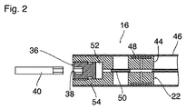
本発明はプレスにおけるマンドレルをスリーブに固定する便利な方法に関する。スリーブ(20)は、それ自身及びグリップを変形させるマンドレル(16)へ空気圧力を加えることによりスリーブに取り付けられている。圧力は、マンドレルの内側のねじに設けられたピストン(36)により加えられ、ピストンは締められた場合に、圧力が増加し、スリーブを把持する。【選択図】図2The present invention relates to a convenient method of securing a mandrel in a press to a sleeve. The sleeve (20) is attached to the sleeve by applying air pressure to the mandrel (16) which deforms itself and the grip. Pressure is applied by a piston (36) provided on the screw inside the mandrel, and when the piston is tightened, the pressure increases and grips the sleeve. [Selection] Figure 2
Description
本発明は、回転式印刷機の油圧キャリアロッドを作動させるためのデバイスに関し、このデバイスは、キャリアロッドの回転駆動部と、回転駆動部用の電子制御デバイスと、キャリアロッドの一端を支持するための移動可能なベアリング機構とを有し、キャリアロッドは、キャリアロッド上でシリンダースリーブをクランプするための油圧クランプシステムを有し、クランプシステムは、移動可能なベアリング機構に支持されるキャリアロッドの一端においてツール用のカップリングを備えた回転作動部材を有する。 The invention relates to a device for operating a hydraulic carrier rod of a rotary printing press, which device supports a rotary drive of a carrier rod, an electronic control device for the rotary drive and one end of the carrier rod. The carrier rod having a hydraulic clamping system for clamping the cylinder sleeve on the carrier rod, the clamping system comprising an end of the carrier rod supported by the movable bearing mechanism , The rotary operating member provided with the coupling for the tool.
回転式印刷機は、例えば欧州特許第1 362 697号から公知であり、印刷シリンダースリーブなどの交換可能な円筒形スリーブが、印刷機のフレームに回転駆動様式で恒久的に支持されるキャリアロッドに押し込まれる。シリンダースリーブを固定するために、キャリアロッドは、油圧クランプシステムを有し、これを用いて、シリンダースリーブがキャリアロッド上でクランプした状態となるようにキャリアロッドの円周方向壁の各部分を油圧で膨張させることができる。油圧が解放されてキャリアロッドの端部においてベアリング機構が取り除かれると、次に、円筒形スリーブは、キャリアロッドから軸方向に引き抜くことができる。
A rotary printing machine is known, for example, from
油圧クランプシステムを作動及び不作動にするために、キャリアロッドの端部に回転作動部材が設けられる。この作動部材を一方向に回転させることで油圧流体が加圧され、反対方向に回転させることで油圧が解放される。作動部材は、ツール用のカップリングを有する。このカップリングは、六角レンチを挿入することができる、例えば内面六角形状を有する。 A rotary actuation member is provided at the end of the carrier rod to activate and deactivate the hydraulic clamping system. The hydraulic fluid is pressurized by rotating the actuating member in one direction, and the hydraulic pressure is released by rotating the actuating member in the opposite direction. The actuating member has a coupling for the tool. This coupling has an inner hexagonal shape, for example, into which a hex wrench can be inserted.
従来の印刷機において、クランプシステムは、ツールの助けを借りて作動部材を手動で回転させることで作動する。 In conventional printing presses, the clamping system operates by manually rotating the actuating member with the aid of a tool.
本発明の目的は、クランプシステムの作動を単純かつ大部分を自動化することができるデバイスを提供することである。 The object of the present invention is to provide a device which allows the operation of the clamping system to be simple and largely automated.
本発明によれば、この目的は、装置が、ツールを軸方向に移動可能で回転固定的にとベアリング機構上に保持するツールホルダーを備え、制御デバイスが、ツールホルダーの軸方向伸長移動を制御し、これによってツールとカップリングを係合させ、回転駆動部を作動させ、結果的にツールに対して相対的にキャリアロッドを回転させるように構成される点で達成できる。 According to the invention, this object is provided that the device comprises a tool holder which holds the tool axially displaceably and rotationally fixedly on the bearing mechanism, the control device controlling the axial extension movement of the tool holder Thus, this can be achieved in that the tool and the coupling are engaged, the rotary drive is actuated and consequently the carrier rod is rotated relative to the tool.
本発明の装置の場合、ツールがベアリング機構上で回転固定的に保持されるので、このツールは、どんな時も近くにある。ツールを作動部材に結合するために、ツールは、カップリングに係合するように作動部材の方向に軸方向に移動する。本発明によれば、キャリアロッドは、ツールを回転させるのではなく、固定されたツールに関して回転する。そのために、既存の回転駆動部を利用する。ツールホルダーの伸長移動及びキャリアロッドの回転は、電子制御デバイスによって制御され、作業シーケンスは大部分が自動化される。 In the case of the device according to the invention, the tool is at all times close because the tool is held rotationally fixed on the bearing mechanism. To couple the tool to the actuating member, the tool is moved axially in the direction of the actuating member to engage the coupling. According to the invention, the carrier rod rotates with respect to the fixed tool rather than rotating the tool. To do this, the existing rotary drive is used. The extension movement of the tool holder and the rotation of the carrier rod are controlled by the electronic control device and the working sequence is largely automated.
好都合な実施形態及びさらなる発展は下位の請求項に記載される。 Advantageous embodiments and further developments are described in the subclaims.
好都合な実施形態において、本質的に公知の制御デバイスは、キャリアロッド上の回転駆動部によって付与されたトルクを測定できるようにもデザインされる。クランプシステムが作動すると、この機能は、ツールで保持された作動部材がキャリアロッド上に付与する逆トルクを測定することもできる。これにより、作動部材上に付与される作動力、従って油圧系の圧力を正確に投入する(dose)ことができる。 In an advantageous embodiment, the essentially known control device is also designed to be able to measure the torque applied by the rotary drive on the carrier rod. When the clamping system is activated, this function can also measure the counter torque that the actuating member held by the tool exerts on the carrier rod. This allows the operating force applied on the operating member, and hence the pressure of the hydraulic system, to be accurately dosed.
代替的に又は追加的に、キャリアロッドが回転駆動部によって回転する回転角は、測定することもできる。これにより、例えば、クランプシステムが解除された場合に、作動部材を正確に規定された開始位置に戻すことが可能になる。
以下において、例示的な実施形態は、図面を参照して詳細に説明されている。
Alternatively or additionally, the rotation angle at which the carrier rod is rotated by the rotation drive can also be measured. This makes it possible, for example, to return the actuating member to the exactly defined starting position when the clamping system is released.
In the following, exemplary embodiments are described in detail with reference to the drawings.
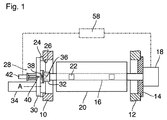
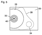
図1において、回転式印刷機のフレームの2つの側面部10、12が部分断面図で示されている。図1において、右側の側面部12は、キャリアロッド16を反対側の側面部10に向かって片持ち梁のように突出する方式で支持するベアリングブロック14を保持する。回転駆動部18は、ベアリングブロック14の外側に配置されており、これによってキャリアロッド16は回転できる。キャリアロッド16は、シリンダースリーブ20を保持し、これは油圧クランプシステム22によってキャリアロッド上に固定され、キャリアロッド16は、さらに回転駆動部18によって回転させることができる。図1の左側の側面部10上には、シリンダースリーブ20の通過を可能にするような大きさの取り出し開口部26を有するベアリングブロック24が配置されている。移動可能なベアリング機構28は、ベアリングブロック24上に保持される。このベアリング機構28はベースプレート30を有し、ベースプレート30は、図1に示す状態では、取り出し開口部26を閉じ、内部においてキャリアロッド16の個別の端部用のベアリング32を保持する。駆動ユニット34により、ベアリング機構28は、ベアリングブロック24から軸方向に引き抜くこと、及び油圧クランプシステム22が不作動となった後でシリンダースリーブ20をキャリアロッド16から引き抜くことができるように、取り出し開口部26を開放する位置に旋回軸Aの周りで旋回することができる。
In FIG. 1, the two
油圧クランプシステムを作動及び不作動とするために、作動部材36が、ベアリング32内に収容されたキャリアロッド16の端部に配置され、これは、油圧クランプシステム22内の油圧流体を加圧するためにキャリアロッド16に対して回転することができる。ベアリング機構28のベースプレート30に向く外面側上で、作動部材36は、ツール40用の例えば内面六角の形態のカップリング38を有する。カップリング38に対して相補的な外面六角部を有するツール40は、ツールホルダー42を用いて、軸方向に移動可能かつ、ベースプレート30上に回転固定的に保持される。
In order to activate and deactivate the hydraulic clamping system, an actuating
図1において、ツールホルダー42は、ツール40をカップリング38から遠く離れた位置で保持する位置で示されている。この状態では、キャリアロッド16及びシリンダースリーブ20で形成されたユニットは、結果的に回転駆動部18による回転状態に設定できる。
In FIG. 1,
図2において、作動部材が配置されるキャリアロッド16の端部が拡大軸方向断面で示されている。油圧クランプシステム22は、キャリアロッドの円周方向壁46を内部から支持する複数の油圧ブッシュ44で形成される。各油圧ブッシュは、その外周壁の内部に環状室48を有し、環状室は油圧ライン50によって油圧流体で満たされた圧力室52に接続する。圧力室52は、キャリアロッド16の端部の中に挿入されたプラグ54内に形成され、これはさらに作動部材36を収容する。作動部材36は、プラグ54の中にねじ込まれるねじ形状を有し、同時に圧力室52を定めるピストンを形成する。作動部材36がツール40によってプラグ54の中により深くねじ込まれると、結果的に圧力室52、油圧ライン50、及び環状室48の中の油圧流体が加圧される。その結果、油圧ブッシュ及びこれによって支持されるキャリアロッド16の円周方向壁46の区域が弾性的に膨張する。これによって、キャリアロッドの円周方向壁46が、シリンダースリーブ20の内周面に対してしっかりとクランプされる。作動部材36が反時計方向に回転すると、油圧流体が解放されるので、シリンダースリーブ20は解除されてキャリアロッド16から引き抜くことができる。
In FIG. 2 the end of the
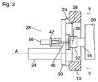
図3には、ベアリング機構28が拡大されて示されている。ツールホルダー42は、空気圧シリンダー56を有し、空気圧シリンダーは、図1及び3に示す状態でキャリアロッド16の軸上に中心を置き、ツール40によって軸方向に延びることができ、図3に示すようにツールの外周六角部は、作動部材36のカップリングと係合する。
The
シリンダースリーブ20をキャリアロッド16から解除する場合、最初に油圧クランプシステム22を解放する必要がある。そのために、キャリアロッド16及びシリンダースリーブ20は、回転駆動部18の助けを借りて回転し、ツール40によって回転固定的に保持される作動部材36は、プラグ54からねじ出されるので圧力室52の容積が増大し、これに対応して油圧が低下する。その後、ツール40は、空気圧シリンダー56によって非係合位置に引き戻される。
When releasing the
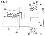
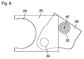
その後、駆動ユニット34によって、ベアリング機構28全体がベアリングブロック24から離れて軸方向に移動する。ベアリング32は、キャリアロッド16の端部から引き出される。その後、ベアリング機構28は、駆動ユニット34によって旋回軸Aの周りを旋回して図4及び6に示す位置になり、シリンダースリーブ20を取り外すことができるように取り出し開口部26を解放する。
Thereafter, the
前述の動作シーケンスを反対にすることで、新規のシリンダースリーブをキャリアロッド16上に取り付けることができる。ベアリング機構28が、図3及び5に示す位置に戻ると、ベアリング32及びツール40は、再度キャリアロッドの軸上に、従って作動要素36のカップリング38上に中心を置くことになる。
A new cylinder sleeve can be mounted on the
ツールが空気圧シリンダー56によって作動部材36の方向に延びると、ツールの外面六角部とカップリング38の内面六角部が相対的に回転する場合があり、ツールは、即座に係合できない。しかしながら、その後、キャリアロッド、従って作動部材36が回転駆動部18の助けを借りて回転する場合、空気圧シリンダーによって弾性的な付勢状態に維持されるので、ツール40は、正しい角度位置に達するとすぐに自動的にロックする。キャリアロッドのさらなる回転中に、作動部材36は次により深くねじ込まれ、油圧系が再度加圧される。
When the tool is extended by the
図1には、印刷機の電子制御デバイス58が概略的に示されている。制御デバイスは、特に回転駆動部18の機能、並びにツールホルダーの空気圧シリンダー56の機能も制御し、前述の動作シーケンスは、制御デバイス58によって調整及び制御することができる。
The
通常、回転駆動部18は、統合された角度インクリメンタルエンコーダを含むことができ、これによってキャリアロッドの角度位置を測定することができる。角度位置は制御デバイス58にフィードバックされる。このようにして、作動部材36が常に同じ角度で回転することを保証でき、クランプシステム22の油圧は、高い精度で所定値に維持することができる。
Typically, the
好都合な実施形態において、制御デバイス58は、回転駆動部18の例えば電流使用量による公知の方法でもって回転駆動部が実際に付与するトルクを測定することもできる。この場合、制御デバイスは、クランプシステムの張力状態で、トルクが所定の閾値に達するとすぐに回転運動が終了するように作動することもできる。
In an advantageous embodiment, the
作動部材36のねじ抜き動作が停止部(図示せず)で規制される限り、ねじ抜き動作は、クランプシステムが解放されていたとしても、トルクが所定の閾値に達するとすぐに終了することができる。さもなければ、角度インクリメンタルエンコーダからのデータに基づいて、クランプシステムが解放されると、作動部材36が規定の中立位置の状態にされることが保証される。
As long as the unscrewing movement of the actuating
16 キャリアロッド
22 クランプシステム
36 作動部材
38 カップリング
40 ツール
44 油圧ブッシュ
46 円周方向壁
48 環状室
50 油圧ライン
52 圧力室
54 プラグ
Claims (4)
キャリアロッド用の回転駆動部(18)と、
回転駆動部用の電子制御デバイス(58)と、
前記キャリアロッド(16)の一端を支持するための移動可能なベアリング機構(28)と、
を備え、前記キャリアロッド(16)は、前記キャリアロッド上に押し込まれたシリンダースリーブ(20)をクランプするための油圧クランプシステム(22)を有し、前記クランプシステムは、前記移動可能なベアリング機構(28)に取り付けられた、前記キャリアロッドの一端に回転作動部材を有し、前記回転作動部材(36)は、ツール(40)のためのカップリング(38)を備えており、
前記装置は、前記ツール(40)を軸方向に移動可能で回転固定的に前記ベアリング機構(28)上に保持するツールホルダー(42)を備え、
前記制御デバイス(58)は、前記ツールホルダー(42)の軸方向伸長移動を制御し、これによって前記ツール(40)と前記カップリング(38)を係合させ、前記回転駆動部(18)を作動させ、結果的に前記ツール(40)に対して相対的に前記キャリアロッド(16)を回転させるように設定されることを特徴とする、装置。 Apparatus for operating a hydraulic carrier rod (16) of a rotary printing press, comprising:
A rotary drive (18) for the carrier rod,
An electronic control device (58) for the rotary drive;
A movable bearing mechanism (28) for supporting one end of the carrier rod (16);
The carrier rod (16) comprises a hydraulic clamping system (22) for clamping the cylinder sleeve (20) pushed onto the carrier rod, the clamping system comprising the movable bearing mechanism (28) mounted on one end of the carrier rod, the rotary operating member (36) comprising a coupling (38) for a tool (40);
The apparatus comprises a tool holder (42) for axially moving the tool (40) and holding it rotationally fixed on the bearing mechanism (28).
The control device (58) controls the axial extension movement of the tool holder (42), thereby engaging the tool (40) and the coupling (38), and the rotational drive (18) Device, characterized in that it is set to operate and consequently to rotate the carrier rod (16) relative to the tool (40).
Applications Claiming Priority (3)
| Application Number | Priority Date | Filing Date | Title |
|---|---|---|---|
| DE202016102779.9U DE202016102779U1 (en) | 2016-05-25 | 2016-05-25 | Device for actuating a hydraulic carrier bar of a rotary printing machine |
| DE202016102779.9 | 2016-05-25 | ||
| PCT/EP2017/025146 WO2017202506A1 (en) | 2016-05-25 | 2017-05-24 | Apparatus for actuating a hydraulic carrier rod of a rotary printing machine |
Publications (2)
| Publication Number | Publication Date |
|---|---|
| JP2019520249A true JP2019520249A (en) | 2019-07-18 |
| JP6690058B2 JP6690058B2 (en) | 2020-04-28 |
Family
ID=58994882
Family Applications (1)
| Application Number | Title | Priority Date | Filing Date |
|---|---|---|---|
| JP2019513108A Active JP6690058B2 (en) | 2016-05-25 | 2017-05-24 | Device for actuating a hydraulic carrier rod of a rotary printing press |
Country Status (7)
| Country | Link |
|---|---|
| US (1) | US11001052B2 (en) |
| EP (1) | EP3463889B1 (en) |
| JP (1) | JP6690058B2 (en) |
| CA (1) | CA3024377C (en) |
| DE (1) | DE202016102779U1 (en) |
| ES (1) | ES2828311T3 (en) |
| WO (1) | WO2017202506A1 (en) |
Citations (6)
| Publication number | Priority date | Publication date | Assignee | Title |
|---|---|---|---|---|
| EP0736382A1 (en) * | 1995-03-20 | 1996-10-09 | Erminio Rossini S.P.A. | Mandrel assembly for a removable printing cylinder |
| US5610491A (en) * | 1993-07-08 | 1997-03-11 | Baumuller Nurnberg Gmbh | Electrical drive system for the positioning of rotating equipment |
| JP2004001515A (en) * | 2002-05-18 | 2004-01-08 | Fischer & Krecke Gmbh & Co | Apparatus for handling sleeve of cylinder for printing |
| EP1745929A1 (en) * | 2005-07-21 | 2007-01-24 | Fischer & Krecke GmbH & Co. KG | Printing machine |
| JP2007099436A (en) * | 2005-10-04 | 2007-04-19 | Canon Inc | Recording device |
| JP2014091301A (en) * | 2012-11-06 | 2014-05-19 | Miyakoshi Printing Machinery Co Ltd | Printing cylinder of printer |
Family Cites Families (12)
| Publication number | Priority date | Publication date | Assignee | Title |
|---|---|---|---|---|
| US4386566A (en) * | 1980-10-06 | 1983-06-07 | Mosstype Corporation | Mandrel assembly for demountable printing cylinder |
| DE59504993D1 (en) * | 1995-10-18 | 1999-03-11 | Fischer & Krecke Gmbh & Co | Device for changing printing cylinder sleeves in printing machines |
| US6161478A (en) * | 1999-11-02 | 2000-12-19 | The Holdrite Co., Inc. | Printing cylinder assembly |
| DE19961868A1 (en) * | 1999-12-22 | 2001-06-28 | Roland Man Druckmasch | Cylinder for printing forme making device, has blocking device which blocks screw body when screw movement is produced by driven cylinder |
| DE20012929U1 (en) * | 2000-07-25 | 2000-11-23 | Polywest Kunststofftechnik Saueressig & Partner GmbH & Co. KG, 48683 Ahaus | Adapter sleeve, especially for printing machines |
| US6553908B1 (en) * | 2000-09-29 | 2003-04-29 | Heidelberger Druckmaschinen Ag | Web fanout control system |
| DE202004011420U1 (en) * | 2004-07-21 | 2004-09-30 | Comexi S.A. | Automatic handling system for print rollers in printing press has a transfer mounting on support rails and with a grip for fitting and removing print rollers |
| DE102004037253B4 (en) * | 2004-07-31 | 2013-09-05 | Windmöller & Hölscher Kg | Sleevewechselsystem |
| EP1880961A4 (en) * | 2005-05-13 | 2010-09-01 | Gunze Kk | Sheet material stacking method and sheet material stacking device |
| DE102007017097B4 (en) * | 2006-09-15 | 2011-06-01 | Sdf Schnitt-Druck-Falz Spezialmaschinen Gmbh | Printing cylinder changing device for printing length variable printing units in a full rotation printing press |
| DE202007014676U1 (en) * | 2007-10-19 | 2009-02-26 | Liebherr-Machines Bulle S.A. | Hydraulic drive system |
| US9579876B1 (en) * | 2016-02-03 | 2017-02-28 | Siko Co., Ltd. | Printing mechanism |
-
2016
- 2016-05-25 DE DE202016102779.9U patent/DE202016102779U1/en active Active
-
2017
- 2017-05-24 CA CA3024377A patent/CA3024377C/en active Active
- 2017-05-24 US US16/302,919 patent/US11001052B2/en active Active
- 2017-05-24 EP EP17727490.9A patent/EP3463889B1/en active Active
- 2017-05-24 ES ES17727490T patent/ES2828311T3/en active Active
- 2017-05-24 JP JP2019513108A patent/JP6690058B2/en active Active
- 2017-05-24 WO PCT/EP2017/025146 patent/WO2017202506A1/en not_active Ceased
Patent Citations (6)
| Publication number | Priority date | Publication date | Assignee | Title |
|---|---|---|---|---|
| US5610491A (en) * | 1993-07-08 | 1997-03-11 | Baumuller Nurnberg Gmbh | Electrical drive system for the positioning of rotating equipment |
| EP0736382A1 (en) * | 1995-03-20 | 1996-10-09 | Erminio Rossini S.P.A. | Mandrel assembly for a removable printing cylinder |
| JP2004001515A (en) * | 2002-05-18 | 2004-01-08 | Fischer & Krecke Gmbh & Co | Apparatus for handling sleeve of cylinder for printing |
| EP1745929A1 (en) * | 2005-07-21 | 2007-01-24 | Fischer & Krecke GmbH & Co. KG | Printing machine |
| JP2007099436A (en) * | 2005-10-04 | 2007-04-19 | Canon Inc | Recording device |
| JP2014091301A (en) * | 2012-11-06 | 2014-05-19 | Miyakoshi Printing Machinery Co Ltd | Printing cylinder of printer |
Also Published As
| Publication number | Publication date |
|---|---|
| EP3463889A1 (en) | 2019-04-10 |
| DE202016102779U1 (en) | 2017-08-28 |
| CA3024377A1 (en) | 2017-11-30 |
| ES2828311T3 (en) | 2021-05-26 |
| JP6690058B2 (en) | 2020-04-28 |
| US11001052B2 (en) | 2021-05-11 |
| EP3463889B1 (en) | 2020-09-23 |
| WO2017202506A1 (en) | 2017-11-30 |
| CA3024377C (en) | 2020-12-15 |
| US20190152217A1 (en) | 2019-05-23 |
Similar Documents
| Publication | Publication Date | Title |
|---|---|---|
| RU2663668C2 (en) | Portable device, portable expanding device and method for operating portable device | |
| CA2892530C (en) | Apparatus for the assembly and disassembly of hydraulic cylinders | |
| US6195863B1 (en) | Disc brake piston installation tool | |
| ITRE20090009A1 (en) | '' DEVICE FOR LOCKING A RIM '' | |
| US8307874B1 (en) | Tire changing method and machine with angularly positionable drive axis | |
| JP2020121402A (en) | Methods for recorded tightening or re-tightening of screw connections | |
| JP2018001402A (en) | Fastening unit | |
| JP6509567B2 (en) | Calibrator with multiple plate cylinders | |
| GB2092924A (en) | Method and apparatus for controlling the clamping of workpieces to machine tools | |
| CN102744313B (en) | Automatic continuous rotating punching machine | |
| US20040088844A1 (en) | Extractor, in particular for extracting center pins | |
| WO2024216684A1 (en) | Auxiliary positioning apparatus for engineering drill, and engineering drill | |
| US20100284754A1 (en) | Fitting removal apparatus and method of using same | |
| JP2019520249A (en) | Device for operating a hydraulic carrier rod of a rotary printing press | |
| CN202655438U (en) | Automatic continuous rotary drilling machine | |
| US3927872A (en) | Vise including fluid pressure clamping means | |
| US8863387B2 (en) | System for plugging heat exchanging tubes | |
| US2670644A (en) | Attachment for power-driven rotary tools | |
| EP3003614B1 (en) | Collet assembly including a locking mechanism | |
| US20060266105A1 (en) | Wheel balancer system with automatic wheel clamping and wheel centering | |
| JP2004223640A (en) | Attaching and detaching device for the clamp arm of the revolving clamp | |
| EP0027663B1 (en) | A multi-purpose tool with a two-directional motor | |
| EP1600292A3 (en) | Device for attaching a tool sleeve to a tool cylinder of a rotary die stamping press or of a rotary printing press | |
| US5657540A (en) | Method of and tool for dismounting and mounting of roller ring | |
| JP3659510B2 (en) | Marking device for hydraulic torque wrench |
Legal Events
| Date | Code | Title | Description |
|---|---|---|---|
| A621 | Written request for application examination |
Free format text: JAPANESE INTERMEDIATE CODE: A621 Effective date: 20181120 |
|
| A131 | Notification of reasons for refusal |
Free format text: JAPANESE INTERMEDIATE CODE: A131 Effective date: 20190917 |
|
| A521 | Request for written amendment filed |
Free format text: JAPANESE INTERMEDIATE CODE: A523 Effective date: 20191031 |
|
| TRDD | Decision of grant or rejection written | ||
| A01 | Written decision to grant a patent or to grant a registration (utility model) |
Free format text: JAPANESE INTERMEDIATE CODE: A01 Effective date: 20200309 |
|
| A61 | First payment of annual fees (during grant procedure) |
Free format text: JAPANESE INTERMEDIATE CODE: A61 Effective date: 20200408 |
|
| R150 | Certificate of patent or registration of utility model |
Ref document number: 6690058 Country of ref document: JP Free format text: JAPANESE INTERMEDIATE CODE: R150 |
|
| R250 | Receipt of annual fees |
Free format text: JAPANESE INTERMEDIATE CODE: R250 |
|
| R250 | Receipt of annual fees |
Free format text: JAPANESE INTERMEDIATE CODE: R250 |
|
| R250 | Receipt of annual fees |
Free format text: JAPANESE INTERMEDIATE CODE: R250 |
|
| R250 | Receipt of annual fees |
Free format text: JAPANESE INTERMEDIATE CODE: R250 |