JP2019513507A - Spiral head, grinding component and food processor - Google Patents
Spiral head, grinding component and food processor Download PDFInfo
- Publication number
- JP2019513507A JP2019513507A JP2019502128A JP2019502128A JP2019513507A JP 2019513507 A JP2019513507 A JP 2019513507A JP 2019502128 A JP2019502128 A JP 2019502128A JP 2019502128 A JP2019502128 A JP 2019502128A JP 2019513507 A JP2019513507 A JP 2019513507A
- Authority
- JP
- Japan
- Prior art keywords
- barrel
- spiral head
- area
- food
- spiral
- Prior art date
- Legal status (The legal status is an assumption and is not a legal conclusion. Google has not performed a legal analysis and makes no representation as to the accuracy of the status listed.)
- Pending
Links
- 238000004140 cleaning Methods 0.000 claims abstract description 40
- 239000002994 raw material Substances 0.000 claims abstract description 22
- 230000005540 biological transmission Effects 0.000 claims description 64
- 239000002699 waste material Substances 0.000 claims description 41
- 235000011389 fruit/vegetable juice Nutrition 0.000 claims description 29
- 238000004891 communication Methods 0.000 claims description 10
- 238000007790 scraping Methods 0.000 abstract 1
- 239000000243 solution Substances 0.000 description 100
- 239000000463 material Substances 0.000 description 17
- 238000007599 discharging Methods 0.000 description 16
- 239000002245 particle Substances 0.000 description 14
- 239000010794 food waste Substances 0.000 description 12
- 238000000034 method Methods 0.000 description 12
- 229910001220 stainless steel Inorganic materials 0.000 description 8
- 239000010935 stainless steel Substances 0.000 description 8
- 230000008569 process Effects 0.000 description 7
- 238000003825 pressing Methods 0.000 description 6
- 230000009471 action Effects 0.000 description 5
- 238000001914 filtration Methods 0.000 description 5
- 230000009467 reduction Effects 0.000 description 5
- RYGMFSIKBFXOCR-UHFFFAOYSA-N Copper Chemical compound [Cu] RYGMFSIKBFXOCR-UHFFFAOYSA-N 0.000 description 4
- 238000005299 abrasion Methods 0.000 description 4
- 238000005056 compaction Methods 0.000 description 4
- 229910052802 copper Inorganic materials 0.000 description 4
- 239000010949 copper Substances 0.000 description 4
- 239000002184 metal Substances 0.000 description 4
- 229910052751 metal Inorganic materials 0.000 description 4
- 238000000926 separation method Methods 0.000 description 4
- 238000003860 storage Methods 0.000 description 4
- 239000012780 transparent material Substances 0.000 description 4
- 238000009434 installation Methods 0.000 description 3
- 238000012546 transfer Methods 0.000 description 3
- 230000009286 beneficial effect Effects 0.000 description 2
- 239000000919 ceramic Substances 0.000 description 2
- 238000000151 deposition Methods 0.000 description 2
- 230000000694 effects Effects 0.000 description 2
- 238000005516 engineering process Methods 0.000 description 2
- -1 etc. Substances 0.000 description 2
- 230000009246 food effect Effects 0.000 description 2
- 230000009916 joint effect Effects 0.000 description 2
- 239000007769 metal material Substances 0.000 description 2
- 230000008859 change Effects 0.000 description 1
- 238000002347 injection Methods 0.000 description 1
- 239000007924 injection Substances 0.000 description 1
- JEIPFZHSYJVQDO-UHFFFAOYSA-N iron(III) oxide Inorganic materials O=[Fe]O[Fe]=O JEIPFZHSYJVQDO-UHFFFAOYSA-N 0.000 description 1
- 238000012986 modification Methods 0.000 description 1
- 230000004048 modification Effects 0.000 description 1
- 238000012545 processing Methods 0.000 description 1
- 238000007789 sealing Methods 0.000 description 1
- 238000006467 substitution reaction Methods 0.000 description 1
Images


Classifications
-
- A—HUMAN NECESSITIES
- A47—FURNITURE; DOMESTIC ARTICLES OR APPLIANCES; COFFEE MILLS; SPICE MILLS; SUCTION CLEANERS IN GENERAL
- A47J—KITCHEN EQUIPMENT; COFFEE MILLS; SPICE MILLS; APPARATUS FOR MAKING BEVERAGES
- A47J19/00—Household machines for straining foodstuffs; Household implements for mashing or straining foodstuffs
- A47J19/02—Citrus fruit squeezers; Other fruit juice extracting devices
- A47J19/023—Citrus fruit squeezers; Other fruit juice extracting devices including a pressing cone or reamer
-
- A—HUMAN NECESSITIES
- A47—FURNITURE; DOMESTIC ARTICLES OR APPLIANCES; COFFEE MILLS; SPICE MILLS; SUCTION CLEANERS IN GENERAL
- A47J—KITCHEN EQUIPMENT; COFFEE MILLS; SPICE MILLS; APPARATUS FOR MAKING BEVERAGES
- A47J19/00—Household machines for straining foodstuffs; Household implements for mashing or straining foodstuffs
- A47J19/06—Juice presses for vegetables
-
- A—HUMAN NECESSITIES
- A47—FURNITURE; DOMESTIC ARTICLES OR APPLIANCES; COFFEE MILLS; SPICE MILLS; SUCTION CLEANERS IN GENERAL
- A47J—KITCHEN EQUIPMENT; COFFEE MILLS; SPICE MILLS; APPARATUS FOR MAKING BEVERAGES
- A47J19/00—Household machines for straining foodstuffs; Household implements for mashing or straining foodstuffs
- A47J19/02—Citrus fruit squeezers; Other fruit juice extracting devices
- A47J19/025—Citrus fruit squeezers; Other fruit juice extracting devices including a pressing screw
-
- A—HUMAN NECESSITIES
- A47—FURNITURE; DOMESTIC ARTICLES OR APPLIANCES; COFFEE MILLS; SPICE MILLS; SUCTION CLEANERS IN GENERAL
- A47J—KITCHEN EQUIPMENT; COFFEE MILLS; SPICE MILLS; APPARATUS FOR MAKING BEVERAGES
- A47J19/00—Household machines for straining foodstuffs; Household implements for mashing or straining foodstuffs
- A47J19/02—Citrus fruit squeezers; Other fruit juice extracting devices
Abstract
【課題】スパイラルヘッドを提供する。【解決手段】本発明はスパイラルヘッド(13)、粉砕コンポーネント及びフードプロセッサーを提供し、スパイラルヘッド(13)は、原料を供給するための供給領域(1311)、供給領域(1311)に接続された粉砕領域(1312)及び粉砕領域(1312)に接続された排出領域(1313)を含むスパイラルヘッド本体(131)を含み、粉砕領域(1312)に複数のスパイラルリブ(132)が設置され、排出領域(1313)にクリーニング構造(133)が設置される。スパイラルヘッド(13)は、フードプロセッサーに用いられ、且つ搾汁やくず排出に用いられず、食物の粉砕のみに用いられているため、その構造が比較的簡単であって、同時に、排出領域(1313)にクリーニング構造(133)を設置する。【選択図】図1To provide a spiral head. The invention provides a spiral head (13), a grinding component and a food processor, wherein the spiral head (13) is connected to a supply area (1311) for supplying raw material, a supply area (1311). A plurality of spiral ribs (132) are provided in the grinding area (1312), including a spiral head body (131) including a grinding area (1312) and a discharge area (1313) connected to the grinding area (1312); A cleaning structure (133) is installed at (1313). The spiral head (13) is used in a food processor and is not used for squeezing or scraping, but only for crushing food, so its structure is relatively simple and, at the same time, the drainage area ( 1313) install the cleaning structure (133). [Selected figure] Figure 1
Description
本発明は、キッチン用品分野に関し、特に、スパイラルヘッド、粉砕コンポーネント及びフードプロセッサーに関する。 The present invention relates to the field of kitchenware, and in particular to a spiral head, a grinding component and a food processor.
市販されている既存のジューサーは縦式と横式との2種類に分けられ、縦式ジューサーは、搾汁時にスパイラルヘッドとフィルターが押し付け、回転ブラシがフィルターのアウターリングを拭き取るので、コンポーネントが多く、装着が複雑であって、またフィルター孔が小さいので洗浄が面倒であるので、消費者の体験が悪く、横式ジューサーは、充分に搾汁できないので、搾汁率が比較的低い。
従って、搾汁率が高いとともにコンポーネントが少なく、構造が簡単であるジューサー及び該ジューサーに用いられるスパイラルヘッドの提示が緊急に解決しなければならない問題になった。
The existing juicers on the market can be divided into two types, vertical and horizontal, and the vertical juicer has many components, as the spiral head and the filter press when squeezing and the rotating brush wipes the outer ring of the filter However, since the installation is complicated and the cleaning is difficult because the filter holes are small, the consumer experience is poor, and the horizontal juicer can not squeeze sufficiently, so the squeeze rate is relatively low.
Therefore, the presentation of a juicer having a high squeezing rate, a small number of components and a simple structure, and a spiral head used for the juicer has become an urgent problem to be solved.
本発明は、少なくとも既存技術又は関連技術に存在する技術課題における一つを解決することをその目的とする。
よって、本発明は、スパイラルヘッドを提供することをその目的とする。
本発明は、粉砕コンポーネントを提供することを他の目的とする。
本発明は、フードプロセッサーを提供することを他の目的とする。
The present invention aims to solve at least one of the technical problems existing in the existing technology or the related technology.
Therefore, the present invention aims to provide a spiral head.
Another object of the invention is to provide a grinding component.
Another object of the present invention is to provide a food processor.
これに鑑み、本発明の第1の態様の実施例によると、原料を供給するための供給領域、前記供給領域に接続された粉砕領域及び前記粉砕領域に接続された排出領域を含むスパイラルヘッド本体を含み、前記粉砕領域に複数のスパイラルリブが設置され、前記排出領域にクリーニング構造が設置されるスパイラルヘッドを提供する。 In view of this, according to an embodiment of the first aspect of the present invention, a spiral head body including a supply area for supplying a raw material, a grinding area connected to the supply area, and a discharge area connected to the grinding area The spiral head is provided with a plurality of spiral ribs in the crushing area, and a cleaning structure is provided in the discharge area.
本発明の第1態様の実施例で提供するスパイラルヘッドによると、スパイラルヘッドがフードプロセッサーの供給口と協同する供給領域を含み、即ち、転圧しようとする食物を供給口から優先的にスパイラルヘッドの供給領域に達するようにし、その後、スパイラルの粉砕領域で転圧されて、最後に粉砕後の食物が排出領域から排出され、同時に、該スパイラルヘッドがフードプロセッサーに用いられ、且つ搾汁やくず排出に用いられず、食物の粉砕のみに用いられているので、その構造が比較的簡単であって、同時に、排出領域にクリーニング構造を設置することで、該クリーニング構造によって粉砕後の食物を所定の領域まで押し付けて、粉砕後の食物を簡単に該所定の領域から押し出すことができ、スパイラルヘッドの材料排出効率を向上させる。 According to the spiral head provided in the embodiment of the first aspect of the present invention, the spiral head includes a feeding area cooperating with the feeding port of the food processor, that is, the spiral head preferentially receives food to be compressed from the feeding port. To reach the feed area, and then compressed in the grinding area of the spiral, and finally the food after grinding is discharged from the discharge area, and at the same time, the spiral head is used in the food processor and juice and waste The structure is relatively simple because it is not used for discharging food but only for crushing food, and at the same time, by installing a cleaning structure in the discharging area, the food after crushing is specified by the cleaning structure. The food after grinding can be easily pushed out of the predetermined area, and the material discharge efficiency of the spiral head can be reduced. To above.
そして、本発明で提供する上記実施例におけるスパイラルヘッドはさらに以下の付加的技術的特徴を有する。 And the spiral head in the above-mentioned embodiment provided by the present invention has the following additional technical features.
上記技術案において、前記スパイラルヘッド本体の横断面の面積が、前記供給領域から前記粉砕領域へ徐々に増加することが好ましい。 In the above technical solution, it is preferable that the area of the cross section of the spiral head main body gradually increases from the supply area to the grinding area.
該技術案において、スパイラルヘッド本体の横断面の面積が供給領域から粉砕領域へ徐々に増加する、つまり、スパイラルヘッド本体がほぼ円錐状をなし、ここで該円錐状のテーパ角度は3°〜15°の範囲内であることが好ましく、5°であることがさらに好ましく、このように設置すると、スパイラルヘッドをフードプロセッサーに用いて食物を粉砕する際に食物をますます粉砕して、フードプロセッサーによる食物の粉砕効果を向上させ、搾汁率を向上させることができる。 In the technical solution, the area of the cross section of the spiral head body gradually increases from the supply area to the grinding area, that is, the spiral head body has a substantially conical shape, wherein the conical taper angle is 3 ° to 15 Preferably within the range of 5 °, more preferably 5 °, and when installed in this manner, the spiral head is used as a food processor to further crush the food when the food is crushed, the food processor It is possible to improve the crushing effect of food and to improve the juicing rate.
上記技術案において、前記クリーニング構造の数量が複数であることが好ましく、このように設置すると、複数のクリーニング構造を用いてスパイラルヘッドによって粉砕した後の食物を所定の領域へ押し付けて、粉砕後の食物を該所定の領域から排出することができる。 In the above technical solution, it is preferable that the number of the cleaning structures is plural, and when installed in this manner, the food after being crushed by the spiral head using the plurality of cleaning structures is pressed against a predetermined area and crushed. Food can be drained from the predetermined area.
上記技術案において、複数の前記クリーニング構造が前記排出領域で対称に設置されることが好ましく、複数のクリーニング構造が対称に設置されることで、スパイラルヘッド周囲の粉砕後の食物を全部所定の領域に押し付けて、材料排出の盲点の出現を防止する。 In the above technical solution, a plurality of the cleaning structures are preferably disposed symmetrically in the discharge area, and the plurality of the cleaning structures are disposed symmetrically so that the crushed food around the spiral head is entirely in a predetermined area. To prevent the emergence of blind spots in the material discharge.
上記技術案において、前記クリーニング構造がクリーニングリブであるか、及び/又は前記クリーニング構造が前記スパイラルヘッド本体から突出した斜面構造であることが好ましい。 In the above technical solution, preferably, the cleaning structure is a cleaning rib and / or the cleaning structure is a sloped structure protruding from the spiral head body.
該技術案において、クリーニング構造がクリーニングリブであってもよく、スパイラルヘッド本体から突出した斜面構造であることもでき、排出領域の食物を所定の領域内へ押し付けることのできる他の構造であることもできる。 In the technical solution, the cleaning structure may be a cleaning rib, may be a slope structure projecting from the spiral head body, or another structure capable of pressing food in the discharge area into a predetermined area. You can also.
上記技術案において、前記スパイラルリブが、前記粉砕領域と前記排出領域の接続箇所から前記粉砕領域へ延長し、前記スパイラルリブの前記排出領域から離れた一端が先鋭な形状に形成されることが好ましい。 In the above technical solution, it is preferable that the spiral rib extends from a connection point between the crushing area and the discharge area to the crushing area, and one end of the spiral rib remote from the discharge area is formed into a sharp shape .
該技術案において、スパイラルリブを排出領域の一端から離れる先鋭な形状に形成することで、食物をさらに粉砕して、搾汁率を向上させることができる。 In this technical solution, the food can be further crushed to improve the squeeze rate by forming the spiral rib in a sharp shape away from one end of the discharge area.
上記技術案において、スパイラルヘッドの素材が食品レベル、耐摩耗性プラスチックであることが好ましく、例えばステンレス鋼、銅等の金属材料であることができ、セラミックス、Cセグメントはめステンレス鋼、銅等であることもでき、ここで、スパイラルヘッドが一体に射出成形されることが好ましい。 In the above technical solution, the material of the spiral head is preferably food grade, abrasion resistant plastic, for example, can be metal material such as stainless steel, copper, etc., ceramic, C segment stainless steel, copper etc. It is preferable that the spiral head be integrally injection-molded.
上記技術案において、前記供給領域と前記粉砕領域との高さ比例がAで、前記高さ比例Aの値が0.5≦A≦0.75で、前記粉砕領域と前記排出領域との高さ比例がBで、前記高さ比例Bの値が1/3≦B≦1/15であることが好ましい。 In the above technical solution, the height proportion between the supply area and the crushing area is A, and the value of the height proportion A is 0.5 ≦ A ≦ 0.75, and the height between the crushing area and the discharge area is high. Preferably, the magnitude proportion is B and the value of the height proportion B is 1/3 ≦ B ≦ 1/15.
該技術案において、供給領域と粉砕領域及び排出領域との高さ比例を合理的に設定することで、スパイラルヘッドの原料供給、粉砕、材料排出の三つの工程が合理的に協同し、食物がスパイラルヘッドの三つの領域に合理的に分布されて、食物が供給領域に堆積することを防止し、食物くずが排出領域を塞ぐことを防止し、原料供給、転圧、材料排出の三つの工程がスムーズに行われて、スパイラルヘッドが食物を転圧する際に食物が詰まる等の故障を防止し、ユーザの体験を向上させることができる。 In this technical proposal, by setting the height proportion of feed area to grinding area and discharge area rationally, three steps of raw material supply, grinding and material discharge of spiral head cooperate rationally, and food It is rationally distributed in the three areas of the spiral head to prevent food from depositing in the supply area and prevent food waste from clogging the discharge area, and it has three steps of raw material supply, compaction, and material discharge. Can be smoothly performed to prevent a failure such as food clogging when the spiral head compacts the food, and can improve the user's experience.
上記技術案において、前記スパイラルリブが、前記スパイラルヘッド本体の径方向における投影高さはhで、前記投影高さhの値が0.5mm≦h≦29.99mmであることが好ましい。 In the above technical solution, preferably, the projected height of the spiral rib in the radial direction of the spiral head main body is h, and the value of the projected height h is 0.5 mm ≦ h ≦ 29.99 mm.
該技術案において、スパイラルリブのスパイラルヘッド本体の径方向における投影高さを0.5mm以上29.99mm以下の範囲内に設定することで、スパイラルリブが一定の高さを有してスパイラルヘッド本体と一定の容積を有する通路を形成して、粉砕後の食物が供給領域から該通路内に入って、通路に沿って徐々に排出領域へ移動して、粉砕材料の排出を完成するとともに、スパイラルリブのスパイラルヘッド本体の径方向における投影高さを0.5mm以上29.99mm以下の範囲内に設定することで、スパイラルリブが高過ぎることがなく、スパイラルリブ全体の強度を確保し、スパイラルヘッドによる食物の転圧程度を適切に高めて、食物の粉砕効果を向上させることができ、同時に、スパイラルリブの強度が向上された後、スパイラルヘッド全体の強度を向上させることができ、スパイラルヘッドの使用寿命を延長する。 In the technical solution, by setting the projected height of the spiral rib in the radial direction of the spiral head main body within a range of 0.5 mm or more and 29.99 mm or less, the spiral rib has a certain height and the spiral head main body Forming a passage having a constant volume, and crushed food enters the passage from the supply area and gradually moves along the passage to the discharge area to complete the discharge of the crushed material and By setting the projected height of the rib in the radial direction of the spiral head main body within the range of 0.5 mm or more and 29.99 mm or less, the strength of the entire spiral rib is ensured without the spiral rib being too high, and the spiral head It is possible to appropriately increase the degree of food compaction by the food to improve the crushing effect of the food, and at the same time, after the strength of the spiral rib is improved, the spa The overall strength of the irral head can be improved, and the service life of the spiral head can be extended.
上記技術案において、前記スパイラルリブの前記スパイラルヘッド本体に接続される一端の幅はt1で、前記幅t1の値が5mm≦t1≦21.99mmであることが好ましい。 In the above technical solution, preferably, a width of one end of the spiral rib connected to the spiral head main body is t1, and a value of the width t1 is 5 mm ≦ t1 ≦ 21.99 mm.
該技術案において、スパイラルリブのスパイラルヘッド本体に接続される一端(即ち、スパイラルリブの基部)の幅を5mm以上21.99mm以下の範囲内に設定することで、スパイラルリブとスパイラルヘッド本体とが一定の接続幅を有し、スパイラルリブとスパイラルヘッド本体との間の接続強度を向上させ、スパイラルヘッドのスパイラルリブが搾汁やくず排出中に破断される状況の発生を防止し、スパイラルヘッド全体の強度を向上させることができ、スパイラルヘッドの使用寿命を延長する。 In the technical solution, by setting the width of one end (that is, the base of the spiral rib) connected to the spiral head body of the spiral rib within the range of 5 mm or more and 21.99 mm or less, the spiral rib and the spiral head body are Has a certain connection width, improves the connection strength between the spiral rib and the spiral head body, prevents the occurrence of a situation where the spiral rib of the spiral head is broken during squeezing and waste discharge, the entire spiral head The strength of the spiral head can be improved and the service life of the spiral head can be extended.
上記技術案において、前記スパイラルリブの前記スパイラルヘッド本体から離れた一端の幅はt2で、前記幅t2の値が1mm≦t2≦4.99mmであることが好ましい。 In the above technical solution, it is preferable that a width of one end of the spiral rib apart from the spiral head main body be t2, and a value of the width t2 be 1 mm ≦ t2 ≦ 4.99 mm.
該技術案において、スパイラルリブのスパイラルヘッド本体から離れた一端(即ち、スパイラルリブの端部)の幅を1mm以上4.99mm以下の範囲内に設定することで、スパイラルリブの端部の幅が小さく、粉砕後の食物をスパイラルヘッドに沿って原料供給区間から順に圧搾区間及びくず排出領域間に移動するように案内し、スパイラルヘッドの搾汁やくず排出効率を向上させることができる。 In the technical solution, the width of the end of the spiral rib is set by setting the width of one end (that is, the end of the spiral rib) apart from the spiral head main body of the spiral rib within the range of 1 mm to 4.99 mm. A small, crushed food can be guided to move along the spiral head sequentially from the raw material supply section to the squeezing section and the waste discharge area, and the squeeze and waste discharge efficiency of the spiral head can be improved.
上記技術案において、スパイラルヘッドが、前記スパイラルヘッド本体が装着される装着軸をさらに含むことが好ましい。 In the above technical solution, preferably, the spiral head further includes a mounting shaft on which the spiral head body is mounted.
該技術案において、スパイラルヘッドを装着する際、装着軸を介してモーター等の駆動装置に駆動接続されて、スパイラルヘッドの駆動装着を実現する。 In the technical solution, when the spiral head is mounted, the drive is connected to a driving device such as a motor via a mounting shaft to realize driving mounting of the spiral head.
本発明の第2態様の実施例によると、フードプロセッサーに用いられる粉砕コンポーネントであって、第1バレルと、前記第1バレル内に回転可能に装着された第1の態様のいずれかの実施例で提供するスパイラルヘッドと、を含み、前記スパイラルヘッドが前記第1バレルと協同して食物を粉砕する粉砕コンポーネントを提供する。 According to an embodiment of the second aspect of the present invention, a grinding component for use in a food processor, comprising: a first barrel; and any of the first aspect rotatably mounted in said first barrel. Providing a grinding component, wherein the spiral head cooperates with the first barrel to grind food.
本発明の実施例の粉砕コンポーネントによると、圧搾コンポーネントを含むフードプロセッサーに適用でき、粉砕コンポーネントで食物を粉砕することができ、粉砕後の食物は圧搾コンポーネント内に入って、圧搾コンポーネントによって搾汁やくず排出工程を完成し、即ち、食物の粉砕と搾汁やくず排出工程を別々に行って、粉砕コンポーネントとして主に上記第1の態様のいずれかの実施例で提供するスパイラルヘッドを用いて食物を粉砕することで、本発明の第2態様の実施例で提供する粉砕コンポーネントによると、上記いずれかの実施例で提供するスパイラルヘッドによる有益な効果をすべて有する。 According to the crushing component of the embodiment of the present invention, it can be applied to a food processor including a squeezing component, and the food can be smashed with the smashing component, and the crushed food enters the squeezing component and squeezes the juice by the squeezing component The waste discharging step is completed, ie, the food crushing and the squeezing and waste discharging steps are performed separately, and the food using the spiral head mainly provided in any of the embodiments of the first aspect as a grinding component The grinding component provided in the embodiment of the second aspect of the present invention has all the beneficial effects of the spiral head provided in any of the above embodiments.
上記技術案において、前記スパイラルヘッドと前記第1バレルの内壁との間に第1の隙間を設置することが好ましく、ここで、前記第1の隙間は前記供給領域から前記排出領域へ徐々に縮小される。 In the above technical solution, it is preferable to place a first gap between the spiral head and the inner wall of the first barrel, wherein the first gap gradually reduces from the supply area to the discharge area. Be done.
該技術案において、スパイラルヘッドが第1バレルの内壁と協同して食物を粉砕する際、スパイラルヘッドと第1バレルの内壁とによって粉砕通路を形成し、第1の隙間は供給領域から排出領域へ徐々に縮小され、つまり、スパイラルヘッドと第1バレルの内壁とによって形成する粉砕通路がますます狭くなるので、該粉砕通路によって食物を粉砕する際、食物をますます粉砕することができ、具体的に、食物が第1バレルに入った直後は、食物の粒子が大きく、第1バレルの内壁と粉砕装置との間の距離が食物の粒子に適応するが、粉砕装置と第1バレルの作用で、食物が徐々に小さい粒子に粉砕されて第1バレルの底部へ移動するので、第1バレルの底部の第1の隙間を小さく設定することで、ここでの食物の粒子サイズに適応させる一方、ここでの食物が粉砕装置と第1バレルとの共同作用で、さらに小さい粒子に粉砕されて、食物を順に充分に粉砕して、食物の搾汁率を向上させることができる。 In the technical solution, when the spiral head cooperates with the inner wall of the first barrel to crush the food, a crushing passage is formed by the spiral head and the inner wall of the first barrel, and the first gap is from the supply area to the discharge area. The food material can be crushed more and more when the food is crushed by the grinding passage, since it is gradually shrunk, that is, the grinding passage formed by the spiral head and the inner wall of the first barrel becomes narrower. However, immediately after the food enters the first barrel, the particles of food are large and the distance between the inner wall of the first barrel and the crusher adapts to the particles of food, but with the action of the crusher and the first barrel Since the food is gradually broken into small particles and moved to the bottom of the first barrel, by setting the first gap at the bottom of the first barrel small, one adapts to the particle size of the food here , In synergy with the food grinder and a first barrel here, it is crushed into smaller particles, and in order thoroughly pulverized food, it is possible to improve the juice rate of food.
上記技術案において、前記第1の隙間が0.3mm〜18.99mmの範囲内であって、供給領域と第1バレルの内壁との間の隙間が3mm〜18.99mmで、くず排出領域と第1バレルの内壁との間の隙間が0.3〜2.99mmであることが好ましい。 In the above technical solution, the first gap is in the range of 0.3 mm to 18.99 mm, and the gap between the supply region and the inner wall of the first barrel is 3 mm to 18.99 mm, and It is preferable that a gap between the first barrel and the inner wall is 0.3 to 2.99 mm.
上記技術案において、前記第1バレルの入口が前記供給領域に近い一端から前記排出領域に近い一端へ徐々に縮小されることが好ましい。 In the above technical solution, it is preferable that the inlet of the first barrel be gradually reduced from one end close to the supply area to one end close to the discharge area.
該技術案において、第1バレルの入口が供給領域に近い一端から前記排出領域の一端へ徐々に縮小され、即ち、第1バレルの内部空洞が上方が大きく下方が小さい逆円錐状であるので、スパイラルヘッドとの間の第1の隙間が上方から下方に徐々に縮小されて、食物をますます粉砕して、食物の搾汁率を向上させることができる。 In the technical solution, the inlet of the first barrel is gradually reduced from one end close to the supply area to one end of the discharge area, that is, the internal cavity of the first barrel is in the form of a large inverted cone with a small upper part and The first gap between the spiral head and the spiral head is gradually reduced from the upper side to the lower side, and the food can be further crushed to improve the juicing rate of the food.
本発明の第3態様の実施例によると、供給口と、第1バレルが前記供給口に連通する第2態様のいずれかの実施例に記載の粉砕コンポーネントと、前記第1バレルと連通口を介して連通される第2バレルと前記第2バレル内に回転可能に装着されて前記第2バレルの内壁と協同して搾汁やくず排出を行う圧搾装置とを含む圧搾コンポーネントと、前記粉砕コンポーネントと前記圧搾コンポーネントが装着され、前記粉砕コンポーネントのスパイラルヘッドを駆動して食物を粉砕し及び前記圧搾装置を駆動して搾汁やくず排出を行う駆動コンポーネントを含むホストコンポーネントと、を含むフードプロセッサーを提供する。 According to an embodiment of the third aspect of the invention, there is provided a comminution component according to any of the embodiments of the second aspect, wherein the supply port and the first barrel communicate with the supply port, the first barrel and the communication port A squeezing component comprising: a second barrel communicated via the squeezing device, and a squeezing device rotatably mounted in the second barrel and cooperating with the inner wall of the second barrel for squeezing and discharging waste; And a host component including a driving component mounted on the squeezing component and driving a spiral head of the crushing component to smash food and driving the squeezing device to squeeze and discharge waste. provide.
本発明の実施例のフードプロセッサーによると、食物が供給口から第1バレル内に入ってからスパイラルヘッドと第1バレルの側壁と協同して食物を粉砕し、粉砕後の食物はスパイラルヘッドの作用で連通口から第2バレル内に入ってから、圧搾装置によって圧搾して、食物のジュースとくずとが分離される。該技術案によると、食物の粉砕工程と搾汁やくず排出工程を分離して、粉砕工程において、搾汁やくず排出の必要がないので、第1バレル内にフィルター及び回転ブラシ等の部品を設置する必要がなく、第1バレル内の食物が第1バレルとスパイラルヘッドの共同作用で粉砕され、同時に、搾汁やくず排出中に圧搾装置を略水平に設置でき、即ち、搾汁やくず排出システムを横式に設置することができ、食物のジュースとくずとの分離に有利であって、このように設置すると、フードプロセッサーの搾汁率を確保する一方、フィルター、回転ブラシ等の部品の使用を回避して、フードプロセッサーの構造が簡単で装着の便宜を図ることができ、同時にフィルターを除去したので、ユーザのクリーニング難易度を低減し、ユーザの体験を向上させることができる。 According to the food processor of the embodiment of the present invention, the food enters the first barrel from the supply port and then cooperates with the spiral head and the side wall of the first barrel to crush the food, and the crushed food acts as the spiral head After entering the second barrel through the communication port, it is squeezed by the squeezer to separate the juice and the waste of the food. According to the technical solution, the food crushing process and the squeezing and waste discharging process are separated, and there is no need for squeezing and waste discharging in the crushing process, parts such as a filter and a rotating brush are contained in the first barrel. The food in the first barrel does not need to be installed, and the food in the first barrel is crushed by the joint action of the first barrel and the spiral head, and at the same time, the squeezing device can be installed approximately horizontally during squeezing and crumb discharging, ie The drainage system can be installed horizontally, which is advantageous for the separation of food juice and waste, and when installed in this way, it ensures the juicing rate of the food processor while parts such as filters, rotating brushes etc. The food processor's structure is simple and easy to install by avoiding the use of the filter, and at the same time the filter is removed, reducing the user's cleaning difficulty and improving the user's experience. Rukoto can.
上記技術案において、前記第2バレルにジュース排出口とくず排出口が設置され、前記ジュース排出口に濾過シートが設置されることが好ましい。 In the above technical solution, it is preferable that a juice outlet and a debris outlet are installed in the second barrel, and a filter sheet is installed in the juice outlet.
該技術案において、粉砕後の食物が第2バレルに入った後に圧搾装置の圧搾作用でジュースとくずとに分離され、分離後の食物ジュースは第2バレル上のジュース排出口から排出され、分離後の食物くずは第2バレル上のくず排出口から排出される。そして、濾過シートを設置することで、食物くずがジュース排出口から排出されることを防止し、同時に、食物くずの粒子サイズに応じて濾過シートと圧搾装置との間の距離を合理的に設置することで、圧搾装置と濾過シートとの間の摩擦によって濾過シートの自動クリーニングを実現することができ、ここで、具体的に、圧搾装置が前記濾過シートに接触するか、又は圧搾装置と前記濾過シートとの間の隙間が食物くずの粒子サイズより小さい。 In the technical solution, after the crushed food enters the second barrel, it is separated into juice and waste by the squeezing action of the press, and the separated food juice is discharged from the juice outlet on the second barrel and separated The latter food waste is discharged from the waste outlet on the second barrel. And, by installing the filter sheet, food waste is prevented from being discharged from the juice outlet, and at the same time, the distance between the filter sheet and the pressing device is rationally installed according to the particle size of the food waste. In this way, the friction between the squeezing device and the filter sheet can realize the automatic cleaning of the filter sheet, in which, specifically, the squeezing device contacts the filter sheet or the squeezing device and the squeezing device The gap between the filter sheet and the food waste particle size is smaller.
ここで、前記濾過シートが金属濾過シートであることが好ましく、金属濾過シートの硬度及び耐摩耗性が優れているので、圧搾装置で濾過シートのクリーニングを行う時、フィルターが強度不足で破壊されることを防止することができる。 Here, the filter sheet is preferably a metal filter sheet, and the hardness and the abrasion resistance of the metal filter sheet are excellent. Therefore, when the filter sheet is cleaned by a squeezing device, the filter is broken due to insufficient strength. Can be prevented.
上記技術案において、前記くず排出口に圧搾シートが設置されることが好ましい。 In the above technical solution, it is preferable that a squeeze sheet be installed at the waste discharge port.
該技術案において、くず排出口に圧搾シートを設置することで、食物をさらに圧搾して、食物のジュースとくずとの分離が一層徹底的であって、さらに多い食物ジュースを圧搾することができ、フードプロセッサーの搾汁率を向上させることができる。ここで、圧搾シートが圧搾フィルムであることが好ましく、圧搾フィルムが一定の弾性を具備するので、食物くずをさらに圧搾することができる。 In the technical solution, by placing a squeeze sheet at the waste outlet, the food can be further squeezed so that the separation of food juice and waste is more thorough, and more food juice can be squeezed. Can improve the juicing rate of the food processor. Here, the squeeze sheet is preferably a squeeze film, and since the squeeze film has a certain elasticity, food waste can be further squeezed.
上記技術案において、前記圧搾装置が圧搾スクリューであることが好ましい。 In the above technical solution, the squeezing device is preferably a squeezing screw.
上記技術案において、前記第2バレルが、一端が開口され、他端が前記連通口を介して前記第1バレルに連通される中空のバレルベースと、前記バレルベースの開口端を覆い、前記くず排出口が設置されるバレル蓋と、を含むことが好ましい。 In the above technical solution, the second barrel covers the hollow barrel base having one end opened and the other end communicated with the first barrel through the communication port, and the open end of the barrel base, the scrap It is preferable to include the barrel lid in which the discharge port is installed.
該技術案において、まずバレルベースを第1バレル上に装着してから、圧搾装置を駆動コンポーネント上に駆動装着し、その後、バレル蓋でバレルベース上を覆うことで第2バレルの装着を完成する。 In the technical solution, first, the barrel base is mounted on the first barrel, and then the squeezing device is drive mounted on the drive component, and then the barrel lid is covered with the barrel lid to complete the mounting of the second barrel. .
ここで、前記バレルベースと前記第1バレルとを一体構造に形成することが好ましく、このように設置すると、第1バレルとバレルベースとの間の接続強度を強化する一方、第1バレルとバレルベースとの間のシール性を保証し、ジュース漏れを防止できる。 Here, it is preferable to form the barrel base and the first barrel into an integral structure, and when installed in this way, the connection strength between the first barrel and the barrel base is enhanced, while the first barrel and the barrel are formed. Sealing property with the base can be guaranteed, and juice leakage can be prevented.
上記技術案において、前記第1バレル及び/又は前記第2バレルが、透明材料又はステンレス鋼材料で形成されることが好ましい。 In the above technical solution, it is preferable that the first barrel and / or the second barrel be formed of a transparent material or a stainless steel material.
該技術案において、第1バレルと第2バレルを透明材料で形成することで、ユーザが第1バレルと第2バレル内の食物を観察でき、ユーザが第1バレルと第2バレル内の食物の状況を把握でき、ユーザの体験を向上させることができる。そして、第1バレルと第2バレルをステンレス鋼で形成すると、第1バレルと第2バレルの強度を確保できる一方、第1バレルと第2バレルがさびる等の状況を防止して、第1バレルと第2バレルの耐久性を向上させることができる。 In the technical solution, the user can observe the food in the first barrel and the second barrel by forming the first barrel and the second barrel with a transparent material, and the user can check the food in the first barrel and the second barrel. The situation can be grasped and the user's experience can be improved. Then, if the first and second barrels are formed of stainless steel, the strength of the first and second barrels can be secured, while preventing the first and second barrels from rusting, etc. And the durability of the second barrel can be improved.
上記技術案において、前記駆動コンポーネントが、モーター軸が設置されるモーターと、少なくとも、前記モーター軸に駆動接続され、前記スパイラルヘッドに接続されて前記スパイラルヘッドを駆動して食物を粉砕する第1駆動軸が設置される第1伝達体、前記モーター軸に駆動接続され、前記圧搾装置に接続されて前記圧搾装置を駆動して搾汁やくず排出を行う第2駆動軸が設置される第2伝達体を含む、伝達コンポーネントと、を含み、前記第1駆動軸が鉛直に設置され、前記第1駆動軸と前記第2駆動軸とが所定の角度βをなし、前記所定の角度βの値が60°≦β≦135°であることが好ましい。 In the above technical solution, the drive component is at least a motor on which a motor shaft is installed, and at least a drive that is connected to the motor shaft and connected to the spiral head to drive the spiral head to crush food. A first transmission body on which a shaft is installed, and a second transmission on which a second drive shaft which is drivingly connected to the motor shaft and connected to the squeezing device to drive the squeezing device to discharge squeezed or scraps A transmission component including a body, wherein the first drive shaft is vertically installed, the first drive shaft and the second drive shaft form a predetermined angle β, and the value of the predetermined angle β is It is preferable that 60 ° ≦ β ≦ 135 °.
該技術案において、同一のモーターと伝達コンポーネントによる伝達を利用して、二つ又は複数の駆動軸にスパイラルヘッドと圧搾装置の駆動を同時に実現させて、即ち、駆動コンポーネントが同一のモーターによって実現した複数軸駆動で、二つの軸又は二つ以上の軸を含み、各駆動軸を同一の減速機又は異なる減速機によって実現することができ、具体的に、異なるギヤ伝達又は他の伝達方式、例えばはすばかさ歯車、タービンワーム、ねじ歯車等による伝達によって方向を変更して複数の駆動軸間の所定の角度の出力を実現することができる。そして、第1駆動軸と第2駆動軸は同方向に回転することができ、例えばいずれも時計回りに回転するか又はいずれも反時計回りに回転することもでき、そして、第1駆動軸と第2駆動軸が相反する方向に回転することもでき、具体的に、例えば一つが時計回りに回転し他の一つが反時計回りに回転することができる。ここで、前記所定の角度βが60°以上135°以下であることが好ましく、前記所定の角度βが70°以上120°以下であることがさらに好ましく、具体的に、例えば前記所定の角度βは90°である。 In this technical solution, the drive of the spiral head and the squeezing device is simultaneously realized on two or more drive shafts using transmission by the same motor and transmission component, that is, the drive components are realized by the same motor. With multi-axis drive, including two axes or two or more axes, each drive axis can be realized by the same reduction gear or different reduction gears, specifically different gear transmission or other transmission schemes, eg The direction can be changed by transmission by a bevel gear, a turbine worm, a screw gear or the like to realize an output of a predetermined angle between a plurality of drive shafts. And, the first drive shaft and the second drive shaft can rotate in the same direction, for example, both can rotate clockwise or can both rotate counterclockwise, and the first drive shaft The second drive shaft can also rotate in opposite directions, specifically, for example, one can rotate clockwise and the other can rotate counterclockwise. Here, the predetermined angle β is preferably 60 ° or more and 135 ° or less, more preferably 70 ° or more and 120 ° or less, and specifically, for example, the predetermined angle β Is 90 °.
上記技術案において、前記第1駆動軸と前記第2駆動軸との間の回転比がCで、前記回転比Cの値が0.8≦C≦1.5であることが好ましい。 In the above technical solution, it is preferable that a rotation ratio between the first drive shaft and the second drive shaft be C, and a value of the rotation ratio C be 0.8 ≦ C ≦ 1.5.
該技術案において、第1伝達体と第2伝達体とのパラメータを合理的に選択することで、第1駆動軸と第2駆動軸の回転比Cを合理的に制御して、第1駆動軸と前記第2駆動軸との間の回転速度が具体的な応用状況に適合される。ここで、具体的に、例えば圧搾装置が圧搾スクリューである場合、前記第1駆動軸と前記第2駆動軸の回転比は0.8〜1.5の範囲内であって、具体的に、例えばスパイラルヘッドの回転速度が60RPMであると、圧搾スクリューの回転速度を48RPM〜90RPMに設定し、ここでRPMは回転速度の単位である回転/分である。 In the technical solution, by rationally selecting the parameters of the first transmission body and the second transmission body, the rotation ratio C of the first drive shaft and the second drive shaft can be rationally controlled to obtain the first drive. The rotational speed between the shaft and the second drive shaft is adapted to the specific application. Here, specifically, for example, when the squeezing device is a squeezing screw, the rotation ratio of the first drive shaft and the second drive shaft is in the range of 0.8 to 1.5, and specifically, For example, if the rotational speed of the spiral head is 60 RPM, then the rotational speed of the squeeze screw is set at 48 to 90 RPM, where RPM is the unit of rotation, which is the unit of rotational speed.
上記技術案において、前記第1伝達体と前記第2伝達体が互いに噛み合うかさ歯車であって、又は前記第1伝達体がタービンで、前記第2伝達体がワームであって、又は前記第1伝達体と前記第2伝達体が軸が互いに交互に設置された二つのはすば歯車であることが好ましい。 In the above technical solution, the first transmission body and the second transmission body mesh with each other, or the first transmission body is a turbine, and the second transmission body is a worm, or the first transmission body is a worm. Preferably, the transfer body and the second transfer body are two helical gears, the shafts of which are alternately arranged.
該技術案において、伝達コンポーネントによってモーターの出力方向を複数軸、複数角度の出力に変更させた場合、第1伝達体と第2伝達体として様々な伝達方式を利用することができ、具体的に、例えばかさ歯車とかさ歯車による伝達方式を利用することができ、タービン、ワームの伝達方式を利用することもでき、ねじ歯車等の伝達方式を利用することもできる。 In the technical solution, when the output direction of the motor is changed to the output of plural axes and plural angles by the transmission component, various transmission methods can be used as the first transmission body and the second transmission body, and specifically For example, a transmission system using a bevel gear and a bevel gear may be used, a transmission system using a turbine or a worm may be used, and a transmission system using a screw gear may be used.
上記技術案において、前記伝達コンポーネントが、互いに組み立てられる上ケースと下ケースを含むケースをさらに含み、前記上ケースと前記下ケースによって装着室を形成し、前記第1伝達体と前記第2伝達体が前記装着室内に位置し、前記第1駆動軸と前記第2駆動軸が前記ケース外部まで延出することが好ましい。 In the above technical solution, the transmission component may further include a case including an upper case and a lower case assembled to each other, wherein the upper case and the lower case form a mounting chamber, and the first and second transmission bodies. Preferably, the first drive shaft and the second drive shaft extend outside the case.
該技術案において、第1伝達体と第2伝達体及び第1駆動軸と第2駆動軸を前記ケース内に装着することで、具体的に使用する際、伝達コンポーネントを一つの全体として移動及び交換することができる。 In the technical solution, the first transmission body and the second transmission body and the first drive shaft and the second drive shaft are mounted in the case to move the transmission components as one whole when specifically used. It can be exchanged.
上記技術案において、伝達コンポーネントが、前記第1伝達体と前記モーター軸との間に設置されて、モーター軸の回転速度を第1駆動軸と第2駆動軸に必要な回転速度に低減するための減速コンポーネントをさらに含むことが好ましい。 In the above technical solution, a transmission component is disposed between the first transmission body and the motor shaft to reduce the rotation speed of the motor shaft to the rotation speed required for the first drive shaft and the second drive shaft. It is preferable to further include a deceleration component of
上記技術案において、前記フードプロセッサーが、前記第1バレル上に設置され、前記供給口が設置される原料供給筒をさらに含むことが好ましい。 In the above technical solution, it is preferable that the food processor further includes a raw material supply cylinder installed on the first barrel and installed with the supply port.
該技術案において、原料供給筒をもっぱら設置して食物の原料供給を制御し、この時、供給口は原料供給筒に設置される。 In the technical solution, the raw material supply cylinder is installed exclusively to control the raw material supply of food, and at this time, the supply port is installed in the raw material supply cylinder.
他の技術案において、原料供給筒をもっぱら設置せず、食物を直接第1バレル内に一回で投入することもでき、この時、第1バレル上に開閉可能なバレル蓋が設置され、供給口が第1バレルの開口である。 According to another technical solution, the food can be directly put into the first barrel at one time without exclusively installing the raw material supply cylinder, and at this time, the openable barrel lid is installed on the first barrel and the supply is performed. The mouth is the opening of the first barrel.
上記技術案において、前記ホストコンポーネントが、ベースとハウジングとをさらに含み、前記ハウジングと前記ベースによって収容室を形成し、前記駆動コンポーネントが前記ベース上に設置されて前記収容室内に位置することが好ましい。 In the above technical solution, preferably, the host component further includes a base and a housing, and the housing and the base form a storage chamber, and the drive component is installed on the base and located in the storage chamber. .
上記技術案において、前記ホストコンポーネントが、フードプロセッサーの動作パラメータを制御するための制御モジュールをさらに含むことが好ましく、具体的に、例えばスパイラルヘッドと圧搾装置の回転速度等を制御し、プログラムモジュールを設置してフードプロセッサーのスマート化プログラム制御を実現することもでき、具体的に、例えばクリーニングプログラムモジュール、複数の搾汁プログラムモジュール等を設置して、フードプロセッサーのスマート化搾汁とスマート化クリーニングを実現することができる。 In the above technical solution, preferably, the host component further includes a control module for controlling an operating parameter of the food processor, specifically, for example, controlling a rotational speed of a spiral head and a squeezing device, and a program module Smart processor control of food processor can be realized by installing it. Specifically, for example, cleaning program module, multiple juicing program modules etc. are installed to make food processor smart juicing and smart cleaning It can be realized.
上記技術案において、前記ホストコンポーネントが、例えば駆動コンポーネント等のフードプロセッサーの部品に電力を供給するための電源モジュールをさらに含むことが好ましく、少なくとも幹線給電に挿入される電源プラグを含み、これにより、具体的に使用する際に直接電源プラグによって幹線給電に接続して、該フードプロセッサーに電力を供給する。 In the above technical solution, the host component preferably further includes a power supply module for supplying power to parts of the food processor such as, for example, a drive component, and at least includes a power plug inserted into the mains power supply. When specifically used, it is connected to the mains by direct power plug to supply power to the food processor.
上記技術案において、前記フードプロセッサーが、ジューサーと搾汁機を含むことが好ましい。 In the above technical solution, the food processor preferably includes a juicer and a squeezer.
本発明の他の態様とメリットは以下の説明によって明確になり、又は本発明を実施することで理解できる。 Other aspects and advantages of the present invention will become apparent as the description proceeds and may be understood by practice of the invention.
本発明の上記及び/又は他の態様とメリットは以下の図面を結合した実施例の説明からさらに明確になり、容易に理解できる。
本願は、2016年7月6日に中国特許庁に出願された、出願番号が2016105337468、発明の名称が「スパイラルヘッド、粉砕コンポーネント及びフードプロセッサー」である中国特許出願と、2016年7月6日に中国特許庁に出願された、出願番号が2016207143053、発明の名称が「スパイラルヘッド、粉砕コンポーネント及びフードプロセッサー」である中国実用新案出願に基づき優先権を主張し、その開示のすべてをここに取り入れる。 The present application is a Chinese patent application filed with the Chinese Patent Office on July 6, 2016, with the application number 2016105337468 and the title of the invention being "Spiral Head, Grinding Component and Food Processor", July 6, 2016 Claim priority based on a China utility model application, filed with the China Patent Office, with application number 2016207143053, and the title of the invention is "Spiral head, grinding component and food processor", the entire disclosure of which is incorporated herein .
本発明の上記目的、特徴とメリットをさらに明確に理解するように、以下、図面と具体的な実施形態を結合して本発明をさらに詳しく説明する。尚、矛盾しない限り、本願の実施例及び実施例における特徴を互いに組み合せることができる。 The present invention will be described in more detail by combining the drawings and specific embodiments so that the above objects, features and advantages of the present invention will be more clearly understood. The features of the embodiments of the present application can be combined with each other as long as no contradiction arises.
本発明を充分に理解するように、以下の説明で多くの具体的な細部を説明するが、本発明をここで説明するものと異なる他の方式で実施することもできるので、本発明の保護範囲は以下で開示する具体的な実施例に限定されない。 Although a number of specific details are set forth in the following description in order to provide a thorough understanding of the present invention, the present invention may be practiced in other ways than those described herein, so that protection of the present invention The scope is not limited to the specific embodiments disclosed below.
以下、図1〜図9を参照して、本発明の一部の実施例で提供するスパイラルヘッド、粉砕コンポーネント及びフードプロセッサーを説明する。 The spiral head, grinding component and food processor provided in some embodiments of the present invention will now be described with reference to FIGS. 1-9.
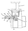
図1〜図3に示すように、本発明の第1の態様の実施例において、スパイラルヘッド本体131を含むスパイラルヘッド13を提供し、スパイラルヘッド本体131は、原料を供給するための供給領域1311と、供給領域1311に接続される粉砕領域1312と、粉砕領域1312に接続される排出領域1313とを、含む。ここで、粉砕領域1312に複数のスパイラルリブ132が設置され、排出領域1313にクリーニング構造133が設置される。
As shown in FIGS. 1 to 3, in the embodiment of the first aspect of the present invention, a
本発明の第1の態様の実施例で提供するスパイラルヘッド13によると、スパイラルヘッド13がフードプロセッサーの供給口と協同する供給領域1311を含み、即ち、転圧しようとする食物が供給口から優先的にスパイラルヘッドの供給領域1311に達するようにし、その後、スパイラルの粉砕領域1312で転圧されて、最後に粉砕後の食物が排出領域1313から排出され、同時に、該スパイラルヘッド13がフードプロセッサーに用いられ、且つ搾汁やくず排出に用いられず、食物の粉砕のみに用いられているので、その構造が比較的簡単であって、同時に、排出領域1313にクリーニング構造133を設置することで、該クリーニング構造133によって粉砕後の食物を所定の領域まで押し付けて、粉砕後の食物を簡単に該所定の領域から押し出すことができ、スパイラルヘッド13の材料排出効率を向上させる。
According to the
ここで、図1における点線はスパイラルヘッド13の供給領域1311と粉砕領域1312又は粉砕領域1312と排出領域1313との間の境界線である。
Here, the dotted line in FIG. 1 is a boundary between the
上記技術案において、図1〜図3に示すように、スパイラルヘッド本体131の横断面の面積が、供給領域1311から粉砕領域1312へ徐々に増加することが好ましい。
In the above technical solution, as shown in FIG. 1 to FIG. 3, it is preferable that the area of the cross section of the spiral head
該技術案において、スパイラルヘッド本体131の横断面の面積が供給領域1311から粉砕領域1312へ徐々に増加し、つまり、スパイラルヘッド本体131がほぼ円錐状をなし、ここで該円錐状のテーパ角度は3°〜15°の範囲内であることが好ましく、5°であることがさらに好ましく、このように設置すると、スパイラルヘッド13をフードプロセッサーに用いて食物を粉砕する際に食物をますます粉砕して、フードプロセッサーによる食物の粉砕効果を向上させ、搾汁率を向上させることができる。
In the technical solution, the area of the cross section of the
上記技術案において、図1〜図3に示すように、クリーニング構造133の数量が複数であることが好ましく、このように設置すると、複数のクリーニング構造133を用いてスパイラルヘッド13によって粉砕した後の食物を所定の領域へ押し付けて、粉砕後の食物を該所定の領域から排出することができる。
In the above technical solution, as shown in FIGS. 1 to 3, it is preferable that the number of cleaning
上記技術案において、複数のクリーニング構造133が排出領域1313で対称に設置されることが好ましく、複数のクリーニング構造133が対称に設置されることで、スパイラルヘッド13周囲の粉砕後の食物を全部所定の領域に押し付けて、材料排出の盲点の出現を防止する。
In the above technical solution, it is preferable that the plurality of cleaning
上記技術案において、クリーニング構造133がクリーニングリブであるか、及び/又はクリーニング構造133がスパイラルヘッド本体から突出した斜面構造であることが好ましい。
In the above technical solution, preferably, the cleaning
該技術案において、クリーニング構造がクリーニングリブであってもよく、スパイラルヘッド本体から突出した斜面構造であることもでき、排出領域の食物を所定の領域内へ押し付けることのできる他の構造であることもできる。 In the technical solution, the cleaning structure may be a cleaning rib, may be a slope structure projecting from the spiral head body, or another structure capable of pressing food in the discharge area into a predetermined area. You can also.
上記技術案において、図1と図2に示すように、スパイラルリブ132が、粉砕領域1312と排出領域1313の接続箇所から粉砕領域1312へ延長し、スパイラルリブ132の排出領域1313から離れた一端が先鋭な形状に形成されることが好ましい。
In the above technical solution, as shown in FIGS. 1 and 2, the
該技術案において、図1と図2に示すように、スパイラルリブ132を排出領域1313の一端から離れる先鋭な形状に形成することで、食物をさらに粉砕して、搾汁率を向上させることができる。
In the technical solution, as shown in FIG. 1 and FIG. 2, by forming the
上記技術案において、スパイラルヘッド13の素材が食品レベル、耐摩耗性プラスチックであることが好ましく、例えばステンレス鋼、銅等の金属材料であることができ、セラミックス、Cセグメントはめステンレス鋼、銅等であることもでき、ここで、スパイラルヘッド13が一体に射出成形されることが好ましい。
In the above technical solution, it is preferable that the material of the
上記技術案において、供給領域1311と粉砕領域1312との高さ比例がAで、高さ比例Aの値が0.5≦A≦0.75で、粉砕領域1312と排出領域1313との高さ比例がBで、高さ比例Bの値が1/30≦B≦1/15であることが好ましい。
In the above technical solution, the height proportion between the
該技術案において、供給領域1311と粉砕領域1312及び排出領域1313との高さ比例を合理的に設定することで、スパイラルヘッドの原料供給、粉砕、材料排出の三つの工程が合理的に協同し、食物がスパイラルヘッドの三つの領域に合理的に分布されて、食物が供給領域1311に堆積することを防止し、食物くずが排出領域1313を塞ぐことを防止し、原料供給、転圧、材料排出の三つの工程がスムーズに行われて、スパイラルヘッドが食物を転圧する際に食物が詰まる等の故障を防止し、ユーザの体験を向上させることができる。
By setting the height proportions of the
上記技術案において、図4に示すように、スパイラルリブ132が、スパイラルヘッド本体131の径方向における投影高さはhで、投影高さhの値が0.5mm≦h≦29.99mmであることが好ましい。
In the above technical solution, as shown in FIG. 4, the
該技術案において、スパイラルリブ132のスパイラルヘッド本体131の径方向における投影高さを0.5mm以上29.99mm以下の範囲内に設定することで、スパイラルリブ132が一定の高さを有してスパイラルヘッド本体131と一定の容積を有する通路を形成して、粉砕後の食物が供給領域1311から該通路内に入って、通路に沿って徐々に排出領域1313へ移動して、粉砕材料の排出を完成するとともに、スパイラルリブ132のスパイラルヘッド本体131の径方向における投影高さを0.5mm以上29.99mm以下の範囲内に設定することで、スパイラルリブ132が高過ぎることがなく、スパイラルリブ132全体の強度を確保し、スパイラルヘッドによる食物の転圧程度を適切に高めて、食物の粉砕効果を向上させることができ、同時に、スパイラルリブ132の強度が向上された後、スパイラルヘッド全体の強度を向上させることができ、スパイラルヘッドの使用寿命を延長する。
In the technical solution, by setting the projected height of the
上記技術案において、図4に示すように、前記スパイラルリブ132のスパイラルヘッド本体131に接続される一端の幅はt1で、前記幅t1の値が5mm≦t1≦21.99mmであることが好ましい。
In the above technical solution, as shown in FIG. 4, the width of one end of the
該技術案において、スパイラルリブ132のスパイラルヘッド本体131に接続される一端(即ち、スパイラルリブ132の基部)の幅を5mm以上21.99mm以下の範囲内に設定することで、スパイラルリブ132とスパイラルヘッド本体131とが一定の接続幅を有し、スパイラルリブ132とスパイラルヘッド本体131との間の接続強度を向上させ、スパイラルヘッド13のスパイラルリブ132が搾汁やくず排出中に破断される状況の発生を防止し、スパイラルヘッド13全体の強度を向上させることができ、スパイラルヘッド13の使用寿命を延長する。
In the technical solution, the
上記技術案において、図4に示すように、スパイラルリブ132のスパイラルヘッド本体131から離れた一端の幅はt2で、前記幅t2の値が1mm≦t2≦4.99mmであることが好ましい。
In the above technical solution, as shown in FIG. 4, the width of one end of the
該技術案において、スパイラルリブ132のスパイラルヘッド本体131から離れた一端(即ち、スパイラルリブ132の端部)の幅を1mm以上4.99mm以下の範囲内に設定することで、スパイラルリブ132の端部の幅が小さく、粉砕後の食物をスパイラルヘッド13に沿って原料供給区間から順に圧搾区間及びくず排出領域間に移動するように案内し、スパイラルヘッド13の搾汁やくず排出効率を向上させることができる。
In this technical solution, the end of the
上記技術案において、図6〜図8に示すように、スパイラルヘッド13が、スパイラルヘッド本体131が装着される装着軸をさらに含むことが好ましい。
In the above technical solution, as shown in FIGS. 6 to 8, it is preferable that the
該技術案において、スパイラルヘッド13を装着する際、装着軸を介してモーター等の駆動装置に駆動接続されて、スパイラルヘッドの駆動装着を実現する。
In this technical solution, when the
図5に示すように、本発明の第2態様の実施例によると、フードプロセッサーに用いられる粉砕コンポーネントであって、第1バレル11と、第1バレル11内に回転可能に装着された第1の態様のいずれかの実施例で提供するスパイラルヘッド13と、を含み、スパイラルヘッド13が第1バレル11と協同して食物を粉砕する粉砕コンポーネントを提供する。
As shown in FIG. 5, according to an embodiment of the second aspect of the present invention, there is provided a grinding component for use in a food processor, the
本発明の実施例の粉砕コンポーネントによると、圧搾コンポーネントを含むフードプロセッサーに適用でき、粉砕コンポーネントで食物を粉砕することができ、粉砕後の食物は圧搾コンポーネント内に入って、圧搾コンポーネントによって搾汁やくず排出工程を完成し、即ち、食物の粉砕と搾汁やくず排出工程を別々に行って、粉砕コンポーネントとして主に上記第1の態様のいずれかの実施例で提供するスパイラルヘッド13を用いて食物を粉砕することで、本発明の第2態様の実施例で提供する粉砕コンポーネントによると、上記いずれかの実施例で提供するスパイラルヘッド13による有益な効果をすべて有する。
According to the crushing component of the embodiment of the present invention, it can be applied to a food processor including a squeezing component, and the food can be smashed with the smashing component, and the crushed food enters the squeezing component and squeezes the juice by the squeezing component The waste discharging step is completed, ie, the food crushing and squeezing and waste discharging steps are performed separately, using the
上記技術案において、図5に示すように、スパイラルヘッド13と第1バレル11の内壁との間に第1の隙間を設置することが好ましく、ここで、第1の隙間は供給領域1311から排出領域1313へ徐々に縮小される。
In the above technical solution, as shown in FIG. 5, it is preferable to place a first gap between the
該技術案において、スパイラルヘッド13が第1バレル11の内壁と協同して食物を粉砕する際、スパイラルヘッド13と第1バレル11の内壁とによって粉砕通路を形成し、第1の隙間は供給領域1311から排出領域1313へ徐々に縮小され、つまり、スパイラルヘッド13と第1バレル11の内壁とによって形成する粉砕通路がますます狭くなるので、該粉砕通路によって食物を粉砕する際、食物をますます粉砕することができ、具体的に、食物が第1バレル11に入った直後は、食物の粒子が大きく、第1バレル11の内壁と粉砕装置との間の距離が食物の粒子に適応するが、粉砕装置と第1バレル11の作用で、食物が徐々に小さい粒子に粉砕されて第1バレル11の底部へ移動するので、第1バレル11の底部の第1の隙間を小さく設定することで、ここでの食物の粒子サイズに適応させる一方、ここでの食物が粉砕装置と第1バレル11との共同作用で、さらに小さい粒子に粉砕されて、食物を順に充分に粉砕して、食物の搾汁率を向上させることができる。
In the technical solution, when the
上記技術案において、第1の隙間が0.3mm〜18.99mmの範囲内であって、さらに、図5に示すように、供給領域1311と第1バレル11の内壁との間の隙間L1が3mm〜18.99mmで、くず排出領域と第1バレル11の内壁との間の隙間L2が0.3mm〜2.99mmであることが好ましい。
In the above technical solution, the first gap is in the range of 0.3 mm to 18.99 mm, and further, as shown in FIG. 5, the gap L1 between the
上記技術案において、図5に示すように、第1バレル11の入口が供給領域1311に近い一端から排出領域1313に近い一端へ徐々に縮小されることが好ましい。
該技術案において、第1バレル11の入口が供給領域1311に近い一端から排出領域1313の一端へ徐々に縮小され、即ち、第1バレル11の内部空洞が上方が大きく下方が小さい逆円錐状であるので、スパイラルヘッド13との間の第1の隙間が上方から下方に徐々に縮小されて、食物をますます粉砕して、食物の搾汁率を向上させることができる。
In the above technical solution, as shown in FIG. 5, it is preferable that the inlet of the
In the technical solution, the inlet of the
本発明の第3態様の実施例によると、図6〜図9に示すように、供給口と、第1バレル11が供給口に連通する第2態様のいずれかの実施例に記載の粉砕コンポーネントと、第1バレル11と連通口18を介して連通される第2バレル12と第2バレル12内に回転可能に装着されて第2バレル12の内壁と協同して搾汁やくず排出を行う圧搾装置14とを含む圧搾コンポーネントと、粉砕コンポーネントと前記圧搾コンポーネントが装着され、粉砕コンポーネントのスパイラルヘッド13を駆動して食物を粉砕し及び圧搾装置14を駆動して搾汁やくず排出を行う駆動コンポーネント21を含むホストコンポーネント2と、を含むフードプロセッサーを提供する。
According to an embodiment of the third aspect of the present invention, as shown in FIGS. 6-9, the grinding component according to any of the embodiments of the second aspect, wherein the supply port and the
本発明の実施例のフードプロセッサーによると、食物が供給口から第1バレル11内に入ってからスパイラルヘッド13と第1バレル11の側壁と協同して食物を粉砕し、粉砕後の食物はスパイラルヘッド13の作用で連通口から第2バレル12内に入ってから、圧搾装置14によって圧搾して、食物のジュースとくずとが分離される。該技術案によると、食物の粉砕工程と搾汁やくず排出工程を分離して、粉砕工程において、搾汁やくず排出の必要がないので、第1バレル11内にフィルター及び回転ブラシ等の部品を設置する必要がなく、第1バレル11内の食物が第1バレル11とスパイラルヘッド13の共同作用で粉砕され、同時に、搾汁やくず排出中に圧搾装置14を略水平に設置でき、即ち、搾汁やくず排出システムを横式に設置することができ、食物のジュースとくずとの分離に有利であって、このように設置すると、フードプロセッサーの搾汁率を確保する一方、フィルター、回転ブラシ等の部品の使用を回避して、フードプロセッサーの構造が簡単で装着の便宜を図ることができ、同時にフィルターを除去したので、ユーザのクリーニング難易度を低減し、ユーザの体験を向上させることができる。
According to the food processor of the embodiment of the present invention, after the food enters the
ここで、図6〜図8に示すように、粉砕コンポーネントと圧搾コンポーネントによって、ホストコンポーネント2上に装着されるバレルコンポーネントを構成する。
Here, as shown in FIGS. 6-8, the crushing component and the squeezing component constitute a barrel component mounted on the
上記技術案において、連通口の圧搾装置の軸方向における投影幅L3が2mm〜19mmの範囲内であることが好ましい。 In the said technical solution, it is preferable that the projection width L3 in the axial direction of the expression apparatus of a communicating port exists in the range of 2 mm-19 mm.
上記技術案において、図6〜図8に示すように、第2バレル12にジュース排出口121とくず排出口122が設置され、ジュース排出口121に濾過シート15が設置されることが好ましい。
In the above technical solution, as shown in FIG. 6 to FIG. 8, it is preferable that the
該技術案において、粉砕後の食物が第2バレル12に入った後に圧搾装置14の圧搾作用でジュースとくずとに分離され、分離後の食物ジュースは第2バレル12上のジュース排出口121から排出され、分離後の食物くずは第2バレル12上のくず排出口122から排出される。そして、濾過シート15を設置することで、食物くずがジュース排出口121から排出されることを防止し、同時に、食物くずの粒子サイズに応じて濾過シート15と圧搾装置14との間の距離を合理的に設置することで、圧搾装置14と濾過シート15との間の摩擦によって濾過シート15の自動クリーニングを実現することができ、ここで、具体的に、圧搾装置14が濾過シート15に接触するか、又は圧搾装置14と濾過シート15との間の隙間が食物くずの粒子サイズより小さい。
In the technical solution, after the crushed food enters the
ここで、濾過シート15が金属濾過シートであることが好ましく、金属濾過シートの硬度及び耐摩耗性が優れているので、圧搾装置14で濾過シート15のクリーニングを行う時、フィルターが強度不足で破壊されることを防止することができる。
Here, the
上記技術案において、くず排出口122に圧搾シート16が設置されることが好ましい。
In the above technical solution, it is preferable that the
該技術案において、くず排出口122に圧搾シート16を設置することで、食物をさらに圧搾して、食物のジュースとくずとの分離が一層徹底的であって、さらに多い食物ジュースを圧搾することができ、フードプロセッサーの搾汁率を向上させることができる。ここで、圧搾シート16が圧搾フィルムであることが好ましく、圧搾フィルムが一定の弾性を具備するので、食物くずをさらに圧搾することができる。
In the technical solution, by squeezing the food further by installing the
上記技術案において、図6〜図9に示すように、圧搾装置14が圧搾スクリューであることが好ましい。
In the above technical solution, as shown in FIGS. 6 to 9, the squeezing
上記技術案において、第2バレル12が、一端が開口され、他端が連通口を介して第1バレル11に連通される中空のバレルベース123と、バレルベース123の開口端を覆い、くず排出口が設置されるバレル蓋124と、を含むことが好ましい。
In the above technical solution, the
該技術案において、まずバレルベース123を第1バレル11上に装着してから、圧搾装置を駆動コンポーネント上に駆動装着し、その後、バレル蓋124でバレルベース123上を覆うことで第2バレル12の装着を完成する。
In the technical solution, first, the
ここで、バレルベース123と第1バレル11とを一体構造に形成することが好ましく、このように設置すると、第1バレル11とバレルベース123との間の接続強度を強化する一方、第1バレル11とバレルベース123との間のシール性を保証し、ジュース漏れを防止できる。
Here, it is preferable to form the
上記技術案において、第1バレル11及び/又は第2バレル12が、透明材料又はステンレス鋼材料で形成されることが好ましい。
In the above technical solution, it is preferable that the
該技術案において、第1バレル11と第2バレル12を透明材料で形成することで、ユーザが第1バレル11と第2バレル12内の食物を観察でき、ユーザが第1バレル11と第2バレル12内の食物の状況を把握でき、ユーザの体験を向上させることができる。そして、第1バレル11と第2バレル12をステンレス鋼で形成すると、第1バレル11と第2バレル12の強度を確保できる一方、第1バレル11と第2バレル12がさびる等の状況を防止して、第1バレル11と第2バレル12の耐久性を向上させることができる。
In the technical solution, the user can observe the food in the
上記技術案において、図9に示すように、駆動コンポーネント21が、モーター軸が設置されるモーター211と、少なくとも、モーター軸に駆動接続され、スパイラルヘッド13に接続されてスパイラルヘッド13を駆動して食物を粉砕する第1駆動軸213が設置される第1伝達体212、モーター軸に駆動接続され、圧搾装置14に接続されて圧搾装置14を駆動して搾汁やくず排出を行う第2駆動軸215が設置される第2伝達体214を含む、伝達コンポーネントと、を含み、第1駆動軸が鉛直に設置され、第1駆動軸と第2駆動軸215とが所定の角度βをなし、前記所定の角度βの値が60°≦β≦135°であることが好ましい。
In the above technical solution, as shown in FIG. 9, the driving
該技術案において、同一のモーター211と伝達コンポーネントによる伝達を利用して、二つ又は複数の駆動軸にスパイラルヘッド13と圧搾装置14の駆動を同時に実現させて、即ち、駆動コンポーネント21が同一のモーター211によって実現した複数軸駆動で、二つの軸又は二つ以上の軸を含み、各駆動軸を同一の減速機又は異なる減速機によって実現することができ、具体的に、異なるギヤ伝達又は他の伝達方式、例えばはすばかさ歯車、タービンワーム、ねじ歯車等による伝達によって方向を変更して複数の駆動軸間の所定の角度の出力を実現することができる。そして、第1駆動軸と第2駆動軸215は同方向に回転することができ、例えばいずれも時計回りに回転するか又はいずれも反時計回りに回転することもでき、そして、第1駆動軸と第2駆動軸215が相反する方向に回転することもでき、具体的に、例えば一つが時計回りに回転し他の一つが反時計回りに回転することができる。ここで、所定の角度βが60°以上135°以下であることが好ましく、所定の角度βが70°以上120°以下であることがさらに好ましく、具体的に、例えば所定の角度βは90°である。
In this technical solution, the drive of the
上記技術案において、第1駆動軸と第2駆動軸215との間の回転比がCで、前記回転比Cの値が0.8≦C≦1.5であることが好ましい。
In the above technical solution, it is preferable that the rotation ratio between the first drive shaft and the
該技術案において、第1伝達体212と第2伝達体214とのパラメータを合理的に選択することで、第1駆動軸と第2駆動軸215の回転比Cを合理的に制御して、第1駆動軸と第2駆動軸215との間の回転速度が具体的な応用状況に適合される。ここで、具体的に、例えば圧搾装置14が圧搾スクリューである場合、第1駆動軸と第2駆動軸215の回転比は0.8〜1.5の範囲内であって、具体的に、例えばスパイラルヘッド13の回転速度が60RPMであると、圧搾スクリューの回転速度を48RPM〜90RPMに設定し、ここでRPMは回転速度の単位である回転/分である。
In the technical solution, the rotational ratio C of the first drive shaft and the
上記技術案において、第1伝達体212と第2伝達体214が互いに噛み合うかさ歯車であって、又は第1伝達体212がタービンで、第2伝達体214がワームであって、又は第1伝達体212と第2伝達体214が軸が互いに交互に設置された二つのはすば歯車であることが好ましい。
In the above technical solution, the
該技術案において、伝達コンポーネントによってモーター211の出力方向を複数軸、複数角度の出力に変更させた場合、第1伝達体212と第2伝達体214として様々な伝達方式を利用することができ、具体的に、例えばかさ歯車とかさ歯車による伝達方式を利用することができ、タービン、ワームの伝達方式を利用することもでき、ねじ歯車等の伝達方式を利用することもできる。
In the technical solution, when the output direction of the
上記技術案において、図9に示すように、伝達コンポーネントが、互いに組み立てられる上ケース217と下ケース216を含むケースをさらに含み、上ケース217と下ケース216によって装着室を形成し、第1伝達体212と第2伝達体214が装着室内に位置し、第1駆動軸と第2駆動軸215が前記ケース外部まで延出することが好ましい。
In the above technical solution, as shown in FIG. 9, the transmission component further includes a case including an
該技術案において、第1伝達体212と第2伝達体214及び第1駆動軸と第2駆動軸215をケース内に装着することで、具体的に使用する際、伝達コンポーネントを一つの全体として移動及び交換することができる。
In the technical solution, the
上記技術案において、図9に示すように、伝達コンポーネントが、第1伝達体212とモーター軸との間に設置されて、モーター軸の回転速度を第1駆動軸と第2駆動軸215に必要な回転速度に低減するための減速コンポーネント218をさらに含むことが好ましい。
In the above technical solution, as shown in FIG. 9, the transmission component is disposed between the
上記技術案において、図6と図7に示すように、フードプロセッサーが、第1バレル11上に設置され、供給口が設置される原料供給筒17をさらに含むことが好ましい。
In the above technical solution, as shown in FIGS. 6 and 7, it is preferable that the food processor further includes a raw
該技術案において、原料供給筒17をもっぱら設置して食物の原料供給を制御し、この時、供給口は原料供給筒17に設置される。
In the technical solution, the raw
他の技術案において、図8に示すように、原料供給筒17をもっぱら設置せず、食物を直接第1バレル11内に一回で投入することもでき、この時、第1バレル11上に開閉可能なバレル蓋が設置され、供給口が第1バレル11の開口である。
In another technical solution, as shown in FIG. 8, the food can be introduced directly into the
上記技術案において、図6〜図8に示すように、ホストコンポーネント2が、ベース22とハウジング23とをさらに含み、ハウジング23とベース22によって収容室を形成し、駆動コンポーネント21がベース22上に設置されて収容室内に位置することが好ましい。
In the above technical solution, as shown in FIGS. 6 to 8, the
上記技術案において、ホストコンポーネント2が、フードプロセッサーの動作パラメータを制御するための制御モジュールをさらに含むことが好ましく、具体的に、例えばスパイラルヘッド13と圧搾装置14の回転速度等を制御し、プログラムモジュールを設置してフードプロセッサーのスマート化プログラム制御を実現することもでき、具体的に、例えばクリーニングプログラムモジュール、複数の搾汁プログラムモジュール等を設置して、フードプロセッサーのスマート化搾汁とスマート化クリーニングを実現することができる。
In the above technical solution, the
上記技術案において、ホストコンポーネント2が、例えば駆動コンポーネント21等のフードプロセッサーの部品に電力を供給するための電源モジュールをさらに含むことが好ましく、少なくとも幹線給電に挿入される電源プラグを含み、これにより、具体的に使用する際に直接電源プラグによって幹線給電に接続して、該フードプロセッサーに電力を供給する。
In the above technical solution, the
上記技術案において、前記フードプロセッサーが、ジューサーと搾汁機を含むことが好ましい。 In the above technical solution, the food processor preferably includes a juicer and a squeezer.
明細書の記載において、明確に規定されていない限り、「第1」、「第2」等の用語は説明の目的に使用されるものであって、相対的な重要性を示す又は示唆するものではない。「接続」、「装着」、「固定」等の用語は広義的に理解するべきであって、例えば「接続」は固定して接続されるものであってもよく、着脱可能な接続であることもでき、又は一体に接続されることであることもできる。そして、直接接続されるものであってもよく、中間媒体を介して接続されるものであることもできる。当業者にとって、具体的な状況に応じて上記用語の本発明における具体的な意味を理解するべきである。 In the description of the specification, unless specifically stated otherwise, the terms "first", "second" and the like are used for descriptive purposes and indicate or suggest relative importance. is not. The terms "connection", "attachment", "fixing" and the like should be understood in a broad sense, for example, "connection" may be fixed and connected, and is a detachable connection. It can also be or be connected together. And, it may be directly connected or may be connected via an intermediate medium. Those skilled in the art should understand the specific meanings of the above terms in the present invention depending on the specific situation.
明細書の記載において、「一実施例」、「一部の実施例」、「具体的な実施例」等の説明は、当該実施例又は例示的に説明した具体的な特徴、構造、材料又は特性が本発明の少なくとも一実施例又は実例に含まれることを意味する。本明細書において、上記用語の説明は同一の実施例又は実例を意味するものではない。そして、説明した具体的な特徴、構造、材料又は特性はいずれか一つ又は複数の実施例又は実例で適切な方式で結合することができる。
以上は、本発明の好適な実施例に過ぎず、本発明を限定するものではない。当業者であれば本発明に様々な修正や変形が可能である。本発明の精神や原則内での全ての変更、置換、改良などは本発明の保護範囲内に含まれる。
In the description of the specification, the descriptions of “one embodiment”, “some embodiments”, “specific embodiments” and the like are specific features, structures, materials or the characteristics described in the embodiments or exemplarily described. It is meant that the features are included in at least one embodiment or example of the invention. In the present specification, the explanations of the above terms do not mean the same embodiment or example. And, the particular features, structures, materials or characteristics described may be combined in any suitable manner in any one or more embodiments or illustrations.
The above are merely preferred embodiments of the present invention, and do not limit the present invention. Those skilled in the art can make various modifications and variations to the present invention. All changes, substitutions, improvements and the like within the spirit and principle of the present invention are included in the protection scope of the present invention.
ここで、図1〜図9における符号と部品名称との対応関係は以下のとおりである。
11:第1バレル、12:第2バレル、121:ジュース排出口、122:くず排出口、123:バレルベース、124:バレル蓋、13:スパイラルヘッド、131:スパイラルヘッド本体、1311:供給領域、1312:粉砕領域、1313:排出領域、132:スパイラルリブ、133:クリーニング構造、14:圧搾装置、15:濾過シート、16:圧搾シート、17:原料供給筒、18:連通口、2:ホストコンポーネント、21:駆動コンポーネント、211:モーター、212:第1伝達体、213:第1駆動軸、214:第2伝達体、215:第2駆動軸、216:下ケース、217:上ケース、218:減速コンポーネント、22:ベース、23:ハウジング。
Here, the correspondence between the reference numerals in FIGS. 1 to 9 and the part names is as follows.
11: first barrel, 12: second barrel, 121: juice outlet, 122: waste outlet, 123: barrel base, 124: barrel lid, 13: spiral head, 131: spiral head body, 1311: supply area, 1312: crushing area, 1313: discharge area, 132: spiral rib, 133: cleaning structure, 14: squeezing device, 15: filtration sheet, 16: squeezing sheet, 17: raw material supply cylinder, 18: communication port, 2: host component , 21: drive component, 211: motor, 212: first transmission body, 213: first drive shaft, 214: second transmission body, 215: second drive shaft, 216: lower case, 217: upper case, 218: Deceleration component, 22: base, 23: housing.
Claims (19)
前記粉砕領域に複数のスパイラルリブが設置され、前記排出領域にクリーニング構造が設置されることを特徴とするスパイラルヘッド。 A spiral head body including a supply area for supplying a raw material, a grinding area connected to the supply area, and a discharge area connected to the grinding area;
A spiral head having a plurality of spiral ribs installed in the crushing area and a cleaning structure installed in the discharge area.
第1バレルと、
前記第1バレル内に回転可能に装着された、請求項1乃至9のいずれか1項に記載のスパイラルヘッドと、を含み、前記スパイラルヘッドが前記第1バレルと協同して食物を粉砕することを特徴とする粉砕コンポーネント。 Grinding components used in food processors,
With the first barrel,
10. A spiral head according to any of the preceding claims, mounted rotatably in the first barrel, wherein the spiral head cooperates with the first barrel to crush food. Grinding component characterized by
前記第1の隙間は前記供給領域から前記排出領域へ徐々に縮小されることを特徴とする請求項10に記載の粉砕コンポーネント。 A first gap is provided between the spiral head and the inner wall of the first barrel,
Grinding component according to claim 10, wherein the first gap is gradually reduced from the supply area to the discharge area.
第1バレルが前記供給口に連通する請求項10乃至12のいずれか1項に記載の粉砕コンポーネントと、
前記第1バレルと連通口を介して連通される第2バレルと前記第2バレル内に回転可能に装着されて前記第2バレルの内壁と協同して搾汁やくず排出を行う圧搾装置とを含む圧搾コンポーネントと、
前記粉砕コンポーネントと前記圧搾コンポーネントとが装着され、前記粉砕コンポーネントのスパイラルヘッドを駆動して食物を粉砕し及び前記圧搾装置を駆動して搾汁やくず排出を行う駆動コンポーネントを含むホストコンポーネントと、を含むことを特徴するフードプロセッサー。 Supply port,
Grinding component according to any of the claims 10 to 12, wherein a first barrel is in communication with the supply port;
A second barrel communicated with the first barrel via a communication port, and a squeezing device rotatably mounted in the second barrel and performing squeezing and waste discharge in cooperation with the inner wall of the second barrel; Containing squeeze components,
A host component including a driving component mounted on the crushing component and the squeezing component, driving a spiral head of the crushing component to smash food and driving the squeezing device to squeeze and discharge waste Food processor characterized by including.
前記ジュース排出口に濾過シートが設置されることを特徴とする請求項13に記載のフードプロセッサー。 A juice outlet and a debris outlet are installed in the second barrel,
The food processor according to claim 13, wherein a filter sheet is installed at the juice outlet.
一端が開口され、他端が前記連通口を介して前記第1バレルに連通される中空のバレルベースと、
前記バレルベースの開口端を覆い、前記くず排出口が設置されるバレル蓋と、を含むことを特徴とする請求項14に記載のフードプロセッサー。 The second barrel is
A hollow barrel base having one end open and the other end communicating with the first barrel via the communication port;
The food processor according to claim 14, further comprising: a barrel lid that covers the open end of the barrel base and is provided with the waste discharge port.
モーター軸が設置されるモーターと、
少なくとも、前記モーター軸に駆動接続され、前記スパイラルヘッドに接続されて前記スパイラルヘッドを駆動して食物を粉砕する第1駆動軸が設置される第1伝達体、及び前記モーター軸に駆動接続され、前記圧搾装置に接続されて前記圧搾装置を駆動して搾汁やくず排出を行う第2駆動軸が設置される第2伝達体を含む、伝達コンポーネントと、を含み、
前記第1駆動軸が鉛直に設置され、前記第1駆動軸と前記第2駆動軸とが所定の角度βをなし、前記所定の角度βの値が60°≦β≦135°であることを特徴とする請求項13乃至17のいずれか1項に記載のフードプロセッサー。 The driving component is
A motor on which a motor shaft is installed,
At least a first transmission body provided with a first drive shaft that is drivingly connected to the motor shaft and connected to the spiral head to drive the spiral head to crush food, and the motor shaft is drivingly connected. A transmission component including a second transmission body connected to the squeezing device to drive a second squeezing device to drive the squeezing device to squeeze and discharge wastes;
The first drive shaft is vertically installed, the first drive shaft and the second drive shaft form a predetermined angle β, and the value of the predetermined angle β is 60 ° ≦ β ≦ 135 ° 18. Food processor according to any of the claims 13 to 17, characterized in that.
Applications Claiming Priority (5)
| Application Number | Priority Date | Filing Date | Title |
|---|---|---|---|
| CN201610533746.8A CN107581879A (en) | 2016-07-06 | 2016-07-06 | Spiral head, pulverize component and food cooking machine |
| CN201620714305.3U CN205994231U (en) | 2016-07-06 | 2016-07-06 | Spiral head, pulverize assembly and food cooking machine |
| CN201620714305.3 | 2016-07-06 | ||
| CN201610533746.8 | 2016-07-06 | ||
| PCT/CN2017/074752 WO2018006608A1 (en) | 2016-07-06 | 2017-02-24 | Spiral blade, grinding component, and food processor |
Publications (1)
| Publication Number | Publication Date |
|---|---|
| JP2019513507A true JP2019513507A (en) | 2019-05-30 |
Family
ID=60901764
Family Applications (1)
| Application Number | Title | Priority Date | Filing Date |
|---|---|---|---|
| JP2019502128A Pending JP2019513507A (en) | 2016-07-06 | 2017-02-24 | Spiral head, grinding component and food processor |
Country Status (5)
| Country | Link |
|---|---|
| US (1) | US11717104B2 (en) |
| EP (1) | EP3443876B1 (en) |
| JP (1) | JP2019513507A (en) |
| KR (1) | KR102125788B1 (en) |
| WO (1) | WO2018006608A1 (en) |
Families Citing this family (2)
| Publication number | Priority date | Publication date | Assignee | Title |
|---|---|---|---|---|
| DE102018212162B4 (en) * | 2018-07-20 | 2020-06-04 | BSH Hausgeräte GmbH | Feeder for a juicer, food processor and juicer with a feeder |
| KR20200002766U (en) * | 2019-06-13 | 2020-12-23 | 주식회사 휴롬 | Screw for juicing and juicer using the same |
Family Cites Families (53)
| Publication number | Priority date | Publication date | Assignee | Title |
|---|---|---|---|---|
| JPS5716504Y2 (en) * | 1979-04-12 | 1982-04-06 | ||
| US4429626A (en) * | 1981-04-30 | 1984-02-07 | Tokyo Electric Co., Ltd. | Juice extractor device |
| US4440074A (en) * | 1982-01-25 | 1984-04-03 | Tokyo Denki Kabushiki Kaisha | Juice extractor |
| JPH06169740A (en) * | 1991-02-13 | 1994-06-21 | Moon H Lee | Juicer |
| US5396836A (en) * | 1993-08-06 | 1995-03-14 | Kim; Jong Gill | Detachable connecting apparatus of squeezing roller housing for juice extractor |
| KR960003079Y1 (en) * | 1993-12-24 | 1996-04-16 | 이몽용 | Machine for extracting juices |
| US5592873A (en) * | 1995-12-01 | 1997-01-14 | Angel Life Co., Ltd. | Juice extractor |
| US5906154A (en) * | 1997-11-25 | 1999-05-25 | Dong-A Engineering Co., Ltd. | Juice extractor |
| JP2000166779A (en) * | 1998-12-10 | 2000-06-20 | Sanyo Electric Co Ltd | Electric-driven cooking machine |
| FR2839255B1 (en) * | 2002-05-02 | 2006-02-10 | Georges Gallo | ELECTROMECHANICAL TABLE PRESSOR FOR GRAPE |
| KR100755440B1 (en) | 2006-06-21 | 2007-09-05 | 김영기 | Juice squeezing extractor |
| US7958820B2 (en) * | 2006-08-02 | 2011-06-14 | Duperon Innovation, Inc. | Compactor construction |
| US8474374B2 (en) * | 2007-09-06 | 2013-07-02 | Russell T. Trovinger | Juicer with alternate cutters |
| CN101697857B (en) * | 2009-10-29 | 2012-09-05 | 九阳股份有限公司 | Easy cleaning extrusion type juicer |
| KR20120012039A (en) | 2010-07-30 | 2012-02-09 | 웅진코웨이주식회사 | Eccentric type juice extracting screw and juicer comprising the same |
| KR101710539B1 (en) * | 2011-03-31 | 2017-02-27 | 코웨이 주식회사 | An extracting juice screw assembly for preventing from flowing backward |
| KR101282315B1 (en) | 2011-06-14 | 2013-07-04 | 김영기 | Juicer for green vegetable juice |
| WO2013069828A1 (en) * | 2011-11-09 | 2013-05-16 | Lee Ji Hye | Juicer with simple assembly and disassembly of housing |
| CN202665186U (en) | 2012-05-16 | 2013-01-16 | 九阳股份有限公司 | Easily cutting juicer |
| CN202760965U (en) * | 2012-07-09 | 2013-03-06 | 九阳股份有限公司 | Fast juice discharging juicer |
| CN102764060B (en) * | 2012-07-09 | 2014-10-22 | 九阳股份有限公司 | Juice extractor with high juice obtaining speed |
| CN203122036U (en) | 2013-01-09 | 2013-08-14 | 广东德豪润达电气股份有限公司 | Juicer |
| RU2656845C2 (en) * | 2013-04-23 | 2018-06-06 | Бревилл Пти Лимитед | Juice extractor with double drive |
| KR101440235B1 (en) * | 2013-06-12 | 2014-09-12 | 서상운 | Agricultural products extracting apparatus |
| US10271673B2 (en) | 2013-09-05 | 2019-04-30 | Coway Co., Ltd. | Detachable juice extracting screw assembly and juicer comprising same |
| WO2015150233A1 (en) * | 2014-03-31 | 2015-10-08 | Koninklijke Philips N.V. | Juice extractor |
| CN203873619U (en) | 2014-06-06 | 2014-10-15 | 何汝生 | Large-caliber feeding system with automatic slicing function |
| CN203873525U (en) * | 2014-06-06 | 2014-10-15 | 何汝生 | Spiral knife with automatic slicing, juicing and residue removing functions |
| CN203892468U (en) | 2014-06-09 | 2014-10-22 | 淄博昊纳机械有限公司 | Vertical dual-output speed reducer |
| KR101611553B1 (en) * | 2014-06-13 | 2016-04-12 | 김재원 | Juice squeezing module for juicer |
| CN104083066B (en) | 2014-07-08 | 2016-08-31 | 广东美的生活电器制造有限公司 | Screw extrusion type juicer |
| KR101485401B1 (en) | 2014-07-25 | 2015-01-26 | 주식회사 경은 | Juice machine |
| CN104305851A (en) | 2014-09-12 | 2015-01-28 | 佛山市顺德区客浦电器有限公司 | Household juicer screw and manufacturing method thereof |
| CN105589473A (en) | 2014-11-09 | 2016-05-18 | 西安银河网电智能电气有限公司 | Solar street lamp single-shaft tracking transmission structure |
| WO2016074394A1 (en) * | 2014-11-13 | 2016-05-19 | 东莞市福是多电器有限公司 | Double-layer screen grinding mechanism and double-layer screen grinding juicer |
| KR101548910B1 (en) * | 2014-11-25 | 2015-09-02 | 최길윤 | Juicer |
| CN104433759B (en) * | 2014-12-17 | 2018-02-16 | 刘雄 | A kind of juice extractor |
| US10238137B2 (en) * | 2014-12-30 | 2019-03-26 | Koninklijke Philips N.V. | Juice extractor |
| CN204520244U (en) | 2015-03-26 | 2015-08-05 | 上海国生实业有限公司 | A kind of spiral propeller for Normal juice machine |
| CN204617858U (en) | 2015-04-29 | 2015-09-09 | 强明 | A kind of Normal juice machine spiral top |
| CN204797529U (en) | 2015-06-14 | 2015-11-25 | 广东新宝电器股份有限公司 | Grinding head of successive layer cutting |
| CN204889739U (en) | 2015-06-16 | 2015-12-23 | 林存蔚 | Food processor |
| CN204764939U (en) * | 2015-07-15 | 2015-11-18 | 浙江绍兴苏泊尔生活电器有限公司 | Stock machine screw rod device and have its stock machine |
| CN204985548U (en) | 2015-07-30 | 2016-01-20 | 南宁东祥科技有限公司 | Pivot planet branch transmission case |
| US9731467B2 (en) * | 2015-09-17 | 2017-08-15 | Tsun-Wei LIN | Food processor |
| CN205107255U (en) * | 2015-11-09 | 2016-03-30 | 蓝玉 | Fruit processing equipment of squeezing juice |
| CN105361624A (en) | 2015-11-26 | 2016-03-02 | 江门市贝尔斯顿电器有限公司 | Juicer screw structure with material scrapers |
| JP6765456B2 (en) * | 2016-07-06 | 2020-10-07 | 広東美的生活電器制造有限公司Guangdong Midea Consumer Electrics Manufacturing Co., Ltd. | Food cooker |
| CN206729714U (en) * | 2017-01-05 | 2017-12-12 | 刘建军 | Sap extraction module for juice extractor |
| WO2019062330A1 (en) * | 2017-09-28 | 2019-04-04 | 广东美的生活电器制造有限公司 | Screw, food processing cup assembly and food processor |
| KR200488915Y1 (en) * | 2018-02-07 | 2019-08-13 | 주식회사 휴롬 | Juice squeezing drum and juicer |
| TWM574887U (en) * | 2018-11-13 | 2019-03-01 | 連錦瑞 | Multifunctional juice strainer structure of juice extracting device |
| JP7414963B2 (en) * | 2019-08-15 | 2024-01-16 | グリーンフィールド ワールド トレード インコーポレイテッド | Masticating juicer with improved adjustable cap |
-
2017
- 2017-02-24 KR KR1020187026806A patent/KR102125788B1/en active IP Right Grant
- 2017-02-24 EP EP17823421.7A patent/EP3443876B1/en active Active
- 2017-02-24 WO PCT/CN2017/074752 patent/WO2018006608A1/en active Application Filing
- 2017-02-24 JP JP2019502128A patent/JP2019513507A/en active Pending
-
2018
- 2018-12-25 US US16/231,972 patent/US11717104B2/en active Active
Also Published As
| Publication number | Publication date |
|---|---|
| WO2018006608A1 (en) | 2018-01-11 |
| KR102125788B1 (en) | 2020-06-23 |
| US11717104B2 (en) | 2023-08-08 |
| KR20180110142A (en) | 2018-10-08 |
| EP3443876A4 (en) | 2019-04-24 |
| US20190125117A1 (en) | 2019-05-02 |
| EP3443876A1 (en) | 2019-02-20 |
| EP3443876B1 (en) | 2021-05-12 |
Similar Documents
| Publication | Publication Date | Title |
|---|---|---|
| RU2399361C1 (en) | Juicer | |
| CN107296474A (en) | Food processor | |
| KR200454079Y1 (en) | Auxiliary container for compaction of vertical juicer | |
| CN104305849B (en) | A kind of easy cleaning extrusion type juicer | |
| CN205994232U (en) | Food cooking machine | |
| JP6765456B2 (en) | Food cooker | |
| CN205994228U (en) | Food cooking machine | |
| KR102232499B1 (en) | Crimping screw, crimp module and food processor | |
| JP2019513507A (en) | Spiral head, grinding component and food processor | |
| KR102222240B1 (en) | Drive module and food cooking equipment | |
| CN204105680U (en) | Juice extractor | |
| CN206062849U (en) | Food cooking machine | |
| CN107581932B (en) | Food processor | |
| CN107581931B (en) | Extrusion screw, extrusion subassembly and food processor | |
| CN210433297U (en) | Manual type household juicer | |
| CN107581880B (en) | Food processor | |
| CN105249797A (en) | Using method of juicer | |
| CN204133100U (en) | Normal juice machine | |
| CN206979303U (en) | food processor | |
| CN107569082B (en) | Vertical screw juicer with good filtering effect | |
| CN109567625B (en) | Food processor | |
| CN107581879A (en) | Spiral head, pulverize component and food cooking machine | |
| CN108113441B (en) | Barrel assembly and food processor | |
| CN208852965U (en) | A kind of kitchen grinder that rubbish from cooking can be handled | |
| CN205994233U (en) | Drive component and food cooking machine |
Legal Events
| Date | Code | Title | Description |
|---|---|---|---|
| A621 | Written request for application examination |
Free format text: JAPANESE INTERMEDIATE CODE: A621 Effective date: 20181003 |
|
| A977 | Report on retrieval |
Free format text: JAPANESE INTERMEDIATE CODE: A971007 Effective date: 20191018 |
|
| A131 | Notification of reasons for refusal |
Free format text: JAPANESE INTERMEDIATE CODE: A131 Effective date: 20191119 |
|
| A521 | Request for written amendment filed |
Free format text: JAPANESE INTERMEDIATE CODE: A523 Effective date: 20200206 |
|
| A02 | Decision of refusal |
Free format text: JAPANESE INTERMEDIATE CODE: A02 Effective date: 20200714 |