JP2019512397A - Image plane placement in laser processing systems - Google Patents
Image plane placement in laser processing systems Download PDFInfo
- Publication number
- JP2019512397A JP2019512397A JP2018548223A JP2018548223A JP2019512397A JP 2019512397 A JP2019512397 A JP 2019512397A JP 2018548223 A JP2018548223 A JP 2018548223A JP 2018548223 A JP2018548223 A JP 2018548223A JP 2019512397 A JP2019512397 A JP 2019512397A
- Authority
- JP
- Japan
- Prior art keywords
- workpiece
- intensity distribution
- shape
- spatial intensity
- laser
- Prior art date
- Legal status (The legal status is an assumption and is not a legal conclusion. Google has not performed a legal analysis and makes no representation as to the accuracy of the status listed.)
- Pending
Links
Images
Classifications
-
- B—PERFORMING OPERATIONS; TRANSPORTING
- B23—MACHINE TOOLS; METAL-WORKING NOT OTHERWISE PROVIDED FOR
- B23K—SOLDERING OR UNSOLDERING; WELDING; CLADDING OR PLATING BY SOLDERING OR WELDING; CUTTING BY APPLYING HEAT LOCALLY, e.g. FLAME CUTTING; WORKING BY LASER BEAM
- B23K26/00—Working by laser beam, e.g. welding, cutting or boring
- B23K26/08—Devices involving relative movement between laser beam and workpiece
- B23K26/082—Scanning systems, i.e. devices involving movement of the laser beam relative to the laser head
-
- B—PERFORMING OPERATIONS; TRANSPORTING
- B23—MACHINE TOOLS; METAL-WORKING NOT OTHERWISE PROVIDED FOR
- B23K—SOLDERING OR UNSOLDERING; WELDING; CLADDING OR PLATING BY SOLDERING OR WELDING; CUTTING BY APPLYING HEAT LOCALLY, e.g. FLAME CUTTING; WORKING BY LASER BEAM
- B23K26/00—Working by laser beam, e.g. welding, cutting or boring
- B23K26/02—Positioning or observing the workpiece, e.g. with respect to the point of impact; Aligning, aiming or focusing the laser beam
- B23K26/03—Observing, e.g. monitoring, the workpiece
- B23K26/032—Observing, e.g. monitoring, the workpiece using optical means
-
- B—PERFORMING OPERATIONS; TRANSPORTING
- B23—MACHINE TOOLS; METAL-WORKING NOT OTHERWISE PROVIDED FOR
- B23K—SOLDERING OR UNSOLDERING; WELDING; CLADDING OR PLATING BY SOLDERING OR WELDING; CUTTING BY APPLYING HEAT LOCALLY, e.g. FLAME CUTTING; WORKING BY LASER BEAM
- B23K26/00—Working by laser beam, e.g. welding, cutting or boring
- B23K26/02—Positioning or observing the workpiece, e.g. with respect to the point of impact; Aligning, aiming or focusing the laser beam
- B23K26/06—Shaping the laser beam, e.g. by masks or multi-focusing
- B23K26/062—Shaping the laser beam, e.g. by masks or multi-focusing by direct control of the laser beam
- B23K26/0626—Energy control of the laser beam
-
- B—PERFORMING OPERATIONS; TRANSPORTING
- B23—MACHINE TOOLS; METAL-WORKING NOT OTHERWISE PROVIDED FOR
- B23K—SOLDERING OR UNSOLDERING; WELDING; CLADDING OR PLATING BY SOLDERING OR WELDING; CUTTING BY APPLYING HEAT LOCALLY, e.g. FLAME CUTTING; WORKING BY LASER BEAM
- B23K26/00—Working by laser beam, e.g. welding, cutting or boring
- B23K26/02—Positioning or observing the workpiece, e.g. with respect to the point of impact; Aligning, aiming or focusing the laser beam
- B23K26/06—Shaping the laser beam, e.g. by masks or multi-focusing
- B23K26/073—Shaping the laser spot
-
- B—PERFORMING OPERATIONS; TRANSPORTING
- B23—MACHINE TOOLS; METAL-WORKING NOT OTHERWISE PROVIDED FOR
- B23K—SOLDERING OR UNSOLDERING; WELDING; CLADDING OR PLATING BY SOLDERING OR WELDING; CUTTING BY APPLYING HEAT LOCALLY, e.g. FLAME CUTTING; WORKING BY LASER BEAM
- B23K26/00—Working by laser beam, e.g. welding, cutting or boring
- B23K26/36—Removing material
- B23K26/38—Removing material by boring or cutting
- B23K26/382—Removing material by boring or cutting by boring
- B23K26/384—Removing material by boring or cutting by boring of specially shaped holes
Abstract
第1の空間強度分布により特徴付けられる第1のレーザエネルギービームを生成することを含む、ワークピースを加工する方法及び装置が開示される。第1のワークピースは、第1のレーザエネルギービームを用いて加工され、スキャンレンズと第1のワークピースとの間の第1の距離で複数のフィーチャを形成し、第2の距離で第2のフィーチャを形成する。上記方法では、複数のフィーチャのうち第1の空間強度分布の形状に最も似た形状を有するフィーチャを決定し、プロセス距離をそのフィーチャを生成した距離として設定する。このプロセス距離を用いて、第2の空間強度分布を有する第2のレーザエネルギービームを用いて第2のワークピースの表面を加工する。A method and apparatus for processing a workpiece is disclosed that includes generating a first laser energy beam characterized by a first spatial intensity distribution. The first workpiece is processed using a first laser energy beam to form a plurality of features at a first distance between the scan lens and the first workpiece and at a second distance Form the feature of In the above method, a feature having a shape most similar to the shape of the first spatial intensity distribution is determined among the plurality of features, and the process distance is set as the distance that generated the feature. Using this process distance, the surface of the second workpiece is machined using a second laser energy beam having a second spatial intensity distribution.
Description
I.技術分野
本明細書において述べられる実施形態は、概して、像平面の配置に関し、特にレーザ加工システムにおいて像平面を配置するための方法及び装置に関するものである。
I. TECHNICAL FIELD The embodiments described herein relate generally to the arrangement of image planes, and more particularly, to methods and apparatus for arranging image planes in a laser processing system.
II.技術的背景
公知の「パーカッション」ドリリング手法を用いてワークピース(例えばプリント配線板)内にビアを形成するようなレーザ加工システムにおいては、レーザビームが、典型的には、円形の開口を用いて空間的にクリップされ、整形され、あるいは像形成され、その後、スキャンレンズにより焦点が合わされ、ワークピースの表面に照射される。典型的には、像形成レーザビーム(imaged laser beam)の空間強度特性は、開口と関連付けられた像平面でのレーザアブレーションに対して最適なものにされる。このため、ワークピース表面が、像平面と所定の空間的関係を有している場合(例えば、ワークピース表面と像平面とが同一平面上にあるか、スキャンレンズとワークピースとが互いに位置決めされる精度及び正確性を考えれば、少なくとも実質的に同一平面上にある場合)には、開口は、ワークピース表面に「像形成」されると考えられ、ワークピースに形成されるフィーチャは、所望の幾何学的特性(例えばサイズ、形状、深さなど)を有する。
II. Technical Background In laser processing systems where vias are formed in a workpiece (e.g. a printed wiring board) using known "percussion" drilling techniques, the laser beam typically uses a circular opening. Spatially clipped, shaped or imaged, and then focused by the scan lens to illuminate the surface of the workpiece. Typically, the spatial intensity profile of the imaged laser beam is optimized for laser ablation at the image plane associated with the aperture. Thus, if the workpiece surface has a predetermined spatial relationship with the image plane (eg, the workpiece surface and the image plane are coplanar or the scan lens and workpiece are positioned relative to one another) Opening is considered to be “imaged” on the workpiece surface, and the features to be formed on the workpiece are Geometric properties (eg, size, shape, depth, etc.) of
像平面を見つける1つの方法では、ユーザは、レーザビーム(すなわち円形の開口を用いてクリップされたレーザビーム)を用いてワークピースにテストパターンをアブレートすることによりレーザシステムを用いて実験を行った後に、テストパターンのある幾何学的特性(例えばサイズ、形状、深さなど)が許容可能なものであるか否かを外観上判断する必要がある。多くの場合、この実験は複数回行われ、ユーザは、それぞれの実験に対してワークピース表面とスキャンレンズとの間の距離を変化させる。様々な距離で行われる実験から得られるテストパターンの外観を比較し、そのテストパターンの幾何学的特性が最も良いかを決定する。最も良い幾何学的特性を有すると判断されたテストパターンを生み出した実験中にワークピース表面が存在した平面が像平面であるとみなされる。 In one method of finding the image plane, the user has experimented with the laser system by ablating the test pattern on the workpiece with a laser beam (ie a laser beam clipped with a circular aperture) Later on, it may be necessary to determine in appearance whether certain geometrical properties (e.g. size, shape, depth etc) of the test pattern are acceptable. Often this experiment is performed multiple times and the user changes the distance between the workpiece surface and the scan lens for each experiment. The appearances of the test patterns obtained from experiments conducted at various distances are compared to determine if the geometrical properties of the test pattern are the best. The plane in which the workpiece surface was present during the experiment that produced the test pattern determined to have the best geometric properties is considered to be the image plane.
行われる可能性のある実験の回数を少なくするために、レーザビームの光学特性、レーザシステムの開口及びスキャンレンズを最初にシミュレートし、像平面と、像形成レーザビームが最小スポットサイズ(すなわち最大中央輝度)を有する(ビームが伝搬する軸に直交する)平面との間の距離(本明細書においては「Δz」とも記載する)を概算することができる。Δzが概算されると、システムのユーザは、(例えば、スキャンレンズ又はワークピースを支持するステージを作動することにより)スキャンレンズとワークピース表面との間の距離を調整して最小スポットサイズの平面にワークピース表面を配置した後、ワークピース表面を(公称)像平面に移動するためにΔzに等しいオフセットを加える。また、スキャンレンズに対してワークピース表面が変化した位置を補償するためにレーザビームパワーも調整することができる。その後、ワークピース表面が公称像平面に位置決めされる実験中、及びワークピース表面の最適な配置を確認するためにワークピース表面が公称像平面のわずかに上方さらに/あるいはわずかに下方に位置決めされるいくつかの実験中にテストパターンをアブレートすることができる。 In order to reduce the number of experiments that can be performed, the optical properties of the laser beam, the aperture of the laser system and the scan lens are first simulated, and the image plane and the imaging laser beam have the smallest spot size (ie maximum The distance (also referred to herein as “Δz”) between a plane having a central brightness) (orthogonal to the axis through which the beam propagates) can be approximated. Once Δz is estimated, the user of the system adjusts the distance between the scan lens and the workpiece surface (eg, by actuating the scan lens or the stage supporting the workpiece) to flatten the minimum spot size. After placing the workpiece surface in, add an offset equal to Δz to move the workpiece surface to the (nominal) image plane. The laser beam power can also be adjusted to compensate for the changed position of the workpiece surface relative to the scan lens. The workpiece surface is then positioned slightly above and / or slightly below the nominal image plane during experiments in which the workpiece surface is positioned at the nominal image plane, and to ensure optimal placement of the workpiece surface. Test patterns can be ablated during some experiments.
上記で述べたシミュレーション手法は有用なものであるが、欠点がないわけではない。例えば、レーザシステムをシミュレートしてΔzを概算するために必要なソフトウェアは高価な場合があり、典型的なレーザ加工システムに簡単に組み込むことができない場合がある。また、シミュレーションを行うためには、光学に関する深い知識が必要であり、システムのユーザはそのような知識を持っていないことがある。加えて、ワークピースにアブレートされるテストパターンは、スキャンレンズとワークピース表面との間の距離が変化した場合であっても、一般的に丸い形状であり、レーザビームのパワーを調整することにより、アブレートされるテストパターンにおけるフィーチャのサイズ及び深さが変化し得る。したがって、ワークピース表面が像平面にあったときに形成されたテストパターンを正確に特定することは難しくて時間のかかるプロセスとなり得る。 Although the simulation approach described above is useful, it is not without its disadvantages. For example, the software required to simulate a laser system to approximate Δz may be expensive and may not be easily incorporated into a typical laser processing system. Also, in order to perform the simulation, a deep knowledge of optics is required, and the user of the system may not have such knowledge. In addition, the test pattern ablated on the workpiece is generally round in shape, even if the distance between the scan lens and the workpiece surface changes, by adjusting the power of the laser beam The size and depth of features in the test pattern being ablated may vary. Thus, accurately identifying a test pattern formed when the workpiece surface is at the image plane can be a difficult and time consuming process.
本明細書においては、スキャンレンズを有するレーザ加工システムを用いてワークピースを加工する方法が開示される。この方法は、レーザエネルギービームが伝搬する経路に直交する平面で見た場合にビームの焦点で非円形外縁形状を有する第1の空間強度分布によって特徴付けられる第1のレーザエネルギービームを生成することを含んでいる。 Disclosed herein is a method of processing a workpiece using a laser processing system having a scan lens. The method generates a first laser energy beam characterized by a first spatial intensity distribution having a non-circular perimeter shape at a focal point of the beam when viewed in a plane orthogonal to a path along which the laser energy beam propagates. Contains.
前記第1のレーザエネルギービームを用いて第1のワークピースが加工される。この加工では、前記第1のワークピースに複数のフィーチャを形成し、前記複数のフィーチャのうちの1つを形成している間の前記スキャンレンズと前記第1のワークピースとの間の第1の距離は、前記複数のフィーチャのうちの他の少なくとも1つを形成している間の前記スキャンレンズと前記第1のワークピースとの間の第2の距離とは異なる。 A first workpiece is machined using the first laser energy beam. In this processing, a plurality of features are formed on the first workpiece, and a first between the scan lens and the first workpiece is formed while forming one of the plurality of features. Is different from a second distance between the scan lens and the first workpiece while forming at least one other of the plurality of features.
この方法は、前記複数のフィーチャのうち、前記第1の空間強度分布の形状に最も似た形状を有するフィーチャを決定し、プロセス距離を、前記第1の空間強度分布の形状に最も似た形状を有する前記フィーチャを形成している間の前記スキャンレンズと前記第1のワークピースとの間の距離として設定することをさらに含んでいる。前記スキャンレンズから前記レーザエネルギービームが伝搬する前記経路に直交する平面に向かう前記プロセス距離にある平面として像平面が決定される。 The method determines a feature having a shape most similar to the shape of the first spatial intensity distribution among the plurality of features, and a shape having a process distance most similar to the shape of the first spatial intensity distribution The method further includes setting as a distance between the scan lens and the first workpiece while forming the feature having a. The image plane is determined as a plane at the process distance from the scan lens to a plane orthogonal to the path along which the laser energy beam propagates.
第2のワークピースの面が実質的に前記像平面に配置される。前記第1の空間強度分布とは異なる第2の空間強度分布により特徴付けられる変調レーザエネルギービームを形成するために第2のレーザエネルギービームが生成される。前記第2の空間強度分布により特徴付けられる前記変調レーザエネルギービームを用いて、前記像平面に配置された第2のワークピースの前記面が加工される。 The face of the second workpiece is arranged substantially in the image plane. A second laser energy beam is generated to form a modulated laser energy beam characterized by a second spatial intensity distribution different from the first spatial intensity distribution. With the modulated laser energy beam characterized by the second spatial intensity distribution, the surface of the second workpiece located at the image plane is machined.
I.序論
本明細書においては、実施形態の例が添付図面を参照して述べられる。明確にそうでないことが記載されていない限り、図面においては、構成要素、フィーチャ、要素などのサイズや位置など、またそれらの相対的な距離は、必ずしも縮尺通りではなく、明確にするために誇張されている場合がある。
I. INTRODUCTION In the present specification, examples of embodiments are described with reference to the accompanying drawings. In the drawings, the size and location of components, features, elements, etc., and their relative distances are not necessarily to scale unless explicitly stated otherwise, and are exaggerated for clarity It may have been.
明細書において使用される用語は、特定の例示的な実施形態を説明するためだけのものであり、限定を意図しているものではない。本明細書で使用される場合には、内容が明確にそうではないことを示している場合を除き、単数形は複数形を含むことを意図している。さらに、「備える」及び/又は「備えている」という用語は、本明細書で使用されている場合には、述べられた特徴、整数、ステップ、動作、要素、及び/又は構成要素の存在を特定するものであるが、1つ以上の他の特徴、整数、ステップ、動作、要素、構成要素、及び/又はそのグループの存在又は追加を排除するものではないことを理解すべきである。特に示している場合を除き、値の範囲が記載されているときは、その範囲は、その範囲の上限と下限の間にあるサブレンジだけではなく、その上限及び下限を含むものである。特に示している場合を除き、「第1」や「第2」などの用語は、要素を互いに区別するために使用されているだけである。例えば、あるノードを「第1のノード」と呼ぶことができ、同様に別のノードを「第2のノード」と呼ぶことができ、あるいはこれと逆にすることもできる。本明細書において使用されるセクション見出しは、整理のためだけのものであり、述べられた主題を限定するものと解釈すべきではない。 The terminology used herein is for the purpose of describing particular exemplary embodiments only and is not intended to be limiting. As used herein, the singular forms are intended to include the plural, unless the context clearly indicates otherwise. Further, the terms "comprising" and / or "including", as used herein, mean the presence of the recited feature, integer, step, action, element, and / or component. It is to be understood that the identification does not exclude the presence or addition of one or more other features, integers, steps, operations, elements, components, and / or groups thereof. Unless otherwise indicated, when ranges of values are recited, the ranges include the upper and lower limits as well as the subranges between the upper and lower limits of the range. Unless otherwise indicated, terms such as "first" and "second" are only used to distinguish elements from one another. For example, one node may be referred to as the "first node", and another node may similarly be referred to as the "second node", or vice versa. The section headings used herein are for organizational purposes only and should not be construed as limiting the stated subject matter.
特に示されている場合を除き、「約」や「その前後」などの用語は、量、サイズ、配合、パラメータ、及び他の数量及び特性が、正確ではなく、また正確である必要がなく、必要に応じて、あるいは許容誤差、換算係数、端数計算、測定誤差など、及び当業者に知られている他のファクタを反映して、概数であってもよく、さらに/あるいは大きくても小さくてもよいことを意味している。 Unless specifically indicated, terms such as "about" and "before and after" do not have to be accurate or accurate in quantity, size, formulation, parameters, and other quantities and characteristics, It may be an approximate number, and / or larger or smaller, as necessary, or reflecting other factors known to those skilled in the art, such as tolerances, conversion factors, rounding, measurement errors, etc. It also means good things.
本明細書において、「下方」、「下」、「下側」、「上方」、及び「上側」などの空間的に相対的な用語は、図に示されるような、ある要素又は特徴の他の要素又は特徴に対する関係を述べる際に説明を容易にするために使用され得るものである。空間的に相対的な用語は、図において示されている方位に加えて異なる方位を含むことを意図するものであることは理解すべきである。例えば、他の要素又は特徴の「下方」又は「下」にあるとして説明される要素は、図中の対象物が反転した場合には、他の要素又は特徴の「上方」を向くことになる。このように、「下方」という例示的な用語は、上方及び下方の方位の双方を含み得るものである。対象物が他の方位を向く場合(例えば90度回転される場合や他の方位にある場合)には、本明細書において使用される空間的に相対的な記述子はこれに応じて解釈され得る。 As used herein, spatially relative terms such as “lower”, “lower”, “lower”, “upper”, and “upper” refer to certain other elements or features as shown in the figures. Can be used to facilitate the description in describing the relationship to the elements or features of the It should be understood that the spatially relative terms are intended to include different orientations in addition to the orientation shown in the figures. For example, an element described as being "below" or "below" another element or feature will point "above" another element or feature if the object in the figure is inverted. . Thus, the exemplary term "lower" may include both upper and lower orientations. Where the object points in another orientation (eg, rotated 90 degrees or in another orientation), the spatially relative descriptors used herein are interpreted accordingly. obtain.
図面を通して同様の数字は同様の要素を意味している。このため、同一又は類似の数字は、対応する図面で言及又は説明されていない場合であっても、他の図面を参照して述べられることがある。また、参照番号の付されていない要素であっても、他の図面を参照して述べられることがある。 Like numbers refer to like elements throughout the drawings. Thus, the same or similar numbers may be stated with reference to other figures, even if they are not mentioned or described in the corresponding figures. Also, even elements that are not labeled may be described with reference to other figures.
本開示の精神及び教示を逸脱することなく、多くの異なる形態、実施形態及び組み合わせが考えられ、本開示を本明細書で述べた実施形態の例に限定して解釈すべきではないことは理解できよう。むしろ、これらの例及び実施形態は、本開示が完全かつすべてを含むものであって、本開示の範囲を当業者に十分に伝えるように提供されるものである。 It is understood that many different forms, embodiments and combinations are conceivable without departing from the spirit and teachings of the present disclosure and that the present disclosure should not be interpreted as being limited to the examples of embodiments described herein. I can do it. Rather, these examples and embodiments are intended to be complete and complete, including the present disclosure, and are provided to fully convey the scope of the present disclosure to those skilled in the art.
II.システム概観
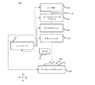
図1は、本発明の一実施形態によるレーザ加工システムを模式的に示すものであり、このレーザ加工システムは、レーザエネルギー像形成ビームを用いてワークピースを加工するように構成されている。以下でより詳細に述べるように、レーザエネルギー像形成ビームは、レーザエネルギービームで開口やマスクなどを照射することにより形成され、加工するワークピース上に開口やマスクなどの像を投影する。
II. System Overview FIG. 1 schematically illustrates a laser processing system according to an embodiment of the present invention, which is configured to process a workpiece using a laser energy imaging beam . As described in more detail below, a laser energy imaging beam is formed by illuminating an aperture, mask or the like with a laser energy beam to project an image of the aperture, mask or the like onto a workpiece to be processed.
一般的に、レーザ放射でワークピースを照射して、ワークピースを形成する1以上の材料の1以上の特質又は特性(例えば、化学的組成、結晶構造、電子構造、マイクロ構造、ナノ構造、濃度、粘度、屈折率、透磁率、比誘電率など)を加熱したり、溶融したり、蒸発させたり、アブレートしたり、クラックしたり、脱色したり、研磨したり、粗くしたり、炭化したり、発泡させたり、あるいは改質したりすることにより加工の全体又は一部が行われる。そのような材料は、加工前又は加工中にワークピースの外表面に存在していてもよいし、あるいは、加工の前又は加工中にワークピース内に位置していても(すなわちワークピースの外表面に存在していなくても)よい。図示された装置により行われるプロセスの具体的な例としては、ビアドリリング、穿孔、溶接、スクライビング、エングレービング、マーキング(例えば表面マーキング、準表面マーキングなど)、カッティング、レーザ誘起フォワード転送、洗浄、漂白、高輝度ピクセル修復(例えば、カラーフィルタ暗化、OLED材料の改質など)、膜除去、表面テクスチャリングなどが挙げられる。このように、処理の結果として、ワークピース上に、あるいはワークピース内に形成され得るフィーチャは、開口、スロット、ビア(例えば、非貫通ビア、貫通ビア、スロットビア)、溝、トレンチ、スクライブライン、切溝、凹部、導電トレース、オーム接触、抵抗パターン、印(例えば、テクスチュア、又はテクスチュラルなどにおいて外観上区別できる1以上の特性を有するワークピース内又はそのようなワークピース上の1以上の領域を備える)、又はこれに類似するもの、あるいはこれらを任意に組み合わせたものを含み得る。フィーチャが開口、ビアなどとして形成される場合には、そのようなフィーチャは、任意の好適な形状又は所望の形状(例えば、円形、楕円形、正方形、矩形、三角形、環状など、あるいはこれらを任意に組み合わせたもの)を有することができる。 Generally, one or more characteristics or properties of one or more materials that irradiate the workpiece with laser radiation to form the workpiece (eg, chemical composition, crystal structure, electronic structure, microstructure, nanostructure, concentration) Viscosity, refractive index, permeability, relative permittivity, etc.), heating, melting, evaporating, ablating, cracking, decoloring, polishing, roughening, carbonizing, etc. The whole or part of the processing is performed by foaming or reforming. Such material may be present on the outer surface of the workpiece before or during processing, or may be located within the workpiece before or during processing (i.e. outside the workpiece). Even if it does not exist on the surface). Specific examples of processes performed by the illustrated apparatus include via drilling, drilling, welding, scribing, engraving, marking (eg surface marking, quasi surface marking etc), cutting, laser induced forward transfer, cleaning, Bleaching, high intensity pixel restoration (eg, color filter darkening, modification of OLED materials, etc.), film removal, surface texturing and the like. Thus, the features that may be formed on or in the workpiece as a result of processing are openings, slots, vias (eg non-penetrating vias, through vias, slot vias), trenches, trenches, scribe lines , Kerfs, recesses, conductive traces, ohmic contacts, resistive patterns, markings (eg textures, or textures, etc.) within or on a workpiece having one or more properties that are distinguishable in appearance A region may be included, or the like, or any combination thereof. Where the features are formed as openings, vias, etc., such features may have any suitable or desired shape (eg, circular, elliptical, square, rectangular, triangular, annular, etc., or any of these) Can be combined).
本装置により加工可能なワークピースは、金属、高分子、セラミック、又は複合材料として包括的に特徴付けることができる。加工可能なワークピースの具体例としては、プリント回路基板(PCB)のパネル(本明細書においては「PCBパネル」ともいう)、PCB、フレキシブルプリント配線板(FPC)、集積回路(IC)、ICパッケージ(ICP)、発光ダイオード(LED)、LEDパッケージ、半導体ウェハ、電子又は光学デバイス基板(例えば、Al2O3、AlN、BeO、Cu、GaAS、GaN、Ge、InP、Si、SiO2、SiC、Si1-xGex(0.0001<x<0.9999)など、あるいはこれらを任意に組み合わせたもの又はその合金から形成される基板)、微小流体デバイス用のプラスチック、ガラス(例えば、非強化ガラス又は熱強化ガラス又は化学強化ガラス)、石英、サファイヤ、プラスチック、シリコンなどから形成される物、タッチセンサ、電子ディプレイの構成要素(例えば、表面にTFT、カラーフィルタ、有機LED(OLED)アレイ、量子ドットLEDアレイなど、あるいはこれらを任意に組み合わせたものが形成された基板)、カバーガラス、レンズ、ミラー、スクリーンプロテクタなど、タービンブレード、粉末、膜、箔、板、型、布地(織物、フェルトなど)、外科用器具、医療用インプラント、パッケージされた電化製品、靴、自転車、自動車、自動車部品又は航空部品(例えば、フレーム、ボディパネルなど)、器具(例えば、電子レンジ、オーブン、冷蔵庫など)、(例えば、腕時計、コンピュータ、スマートフォン、タブレットコンピュータ、ウェアラブル電子デバイスなど、あるいはこれらを任意に組み合わせたもののための)デバイスのハウジングが挙げられる。スマートフォンは、一般的に、(APPLE社やSAMSUNG社などにより製造される)IPHONEやGALAXYなどの携帯電子デバイスを含むものと理解されている。タブレットコンピュータは、一般的に、(APPLE社、SAMSUNG社、GOOGLE社、SONY社などにより製造される)IPAD、GALAXY NOTE、NEXUS、XPERIAなどの携帯電子デバイスを含むものと理解されている。ウェアラブル電子デバイスは、一般的に、(PEBBLE社、APPLE社、MOTOROLA社、SONY社などにより製造される)PEBBLE、APPLE WATCH、MOTO 360、SMARTWATCH、GEARなどの典型的にはユーザの手首に装着される電子デバイスを含むものであるが、典型的にはユーザの足、脚、胴、腕、指、頭、耳などに装着される電子デバイスをも含み得ると理解されている。 The workpieces that can be processed by the present apparatus can be comprehensively characterized as metals, polymers, ceramics, or composites. Specific examples of processable workpieces include printed circuit board (PCB) panels (also referred to herein as "PCB panels"), PCBs, flexible printed wiring boards (FPCs), integrated circuits (ICs), ICs Package (ICP), light emitting diode (LED), LED package, semiconductor wafer, electronic or optical device substrate (eg, Al 2 O 3 , AlN, BeO, Cu, GaAS, GaN, Ge, InP, Si, SiO 2 , SiC , Si 1 -x Ge x (substrates formed from such as 0.0001 <x <0.9999, or any combination thereof or alloys thereof), plastics for microfluidic devices, glasses (eg non-tempered glass or thermal) Tempered glass or chemically tempered glass), quartz, sapphire, plastic, silicon etc., touch sensor, component of electronic display (eg, TFT on surface, color filter, organic LED) OLED) array, quantum dot LED array, etc., or a substrate on which any combination thereof is formed, cover glass, lens, mirror, screen protector etc., turbine blade, powder, film, foil, plate, mold, fabric (Textile, felt, etc.), surgical instruments, medical implants, packaged appliances, shoes, bicycles, automobiles, automobile parts or aviation parts (eg, frames, body panels, etc.), instruments (eg, microwave oven, oven) , A refrigerator, etc.), a housing of the device (eg, for a watch, a computer, a smartphone, a tablet computer, a wearable electronic device, etc., or any combination thereof). Smartphones are generally understood to include portable electronic devices such as IPHONE and GALAXY (manufactured by APPLE, SAMSUNG, etc.). Tablet computers are generally understood to include portable electronic devices such as IPAD (manufactured by APPLE, SAMSUNG, GOOGLE, SONY, etc.), GALAXY NOTE, NEXUS, XPERIA etc. Wearable electronic devices are typically worn on the user's wrist, typically PEBBLE, APPLE WATCH, MOTO 360, SMARTWATCH, GEAR, etc. (manufactured by PEBBLE, APPLE, MOTOROLA, SONY etc.) It is understood that it may also include electronic devices that are typically worn on the user's feet, legs, torso, arms, fingers, head, ears, etc.
したがって、加工できる材料は、1以上の金属(例えば、Al、Ag、Au、Cu、Fe、In、Mg、Pt、Sn、Tiなど、あるいはこれらを任意に組み合わせたもの)、導電性金属酸化物(例えばITOなど)、透明な導電性ポリマー、セラミック、ワックス、樹脂、(例えば、酸化ケイ素、窒化ケイ素、酸窒化ケイ素など、あるいはこれらを任意に組み合わせたもののように層間誘電体構造として用いられる)無機誘電材料、low-k誘電体材料(例えば、メチルシルセスキオキサン(MSQ)、水素シルセスキオキサン(HSQ)、フッ化オルトケイ酸テトラエチル(FTEOS)など、あるいはこれらを任意に組み合わせたもの)、有機誘電体材料(例えば、SILK、ベンゾシクロブテン、Nautilus(いずれもDow社により製造される)、ポリフルオロテトラエチレン(DuPont社により製造される)、FLARE(Allied Chemical社により製造される)など、あるいはこれらを任意に組み合わせたもの)、ファイバガラス、高分子材料(ポリアミド、ポリイミド、ポリエステル、ポリアセタール、ポリカーボネート、改質ポリフェニレンエーテル、ポリブチレンテレフタレート、ポリフェニレンサルファイド、ポリエーテルスルホン、ポリエーテルイミド、ポリエーテルエーテルケトン、液晶ポリマー、アクリロニトリルブタジエンスチレン、及びこれらの任意の化合物、複合物、又は混ぜ物)、革、紙、組立材(例えば、「ABF」としても知られる、味の素ビルドアップフィルムなど)、ガラス繊維強化エポキシ積層体(例えばFR4)、プリプレグなど、あるいはこれらの任意の複合物、積層体、又は他の組み合わせを含んでいる。 Therefore, materials that can be processed include one or more metals (eg, Al, Ag, Au, Cu, Fe, In, Mg, Pt, Sn, Ti, etc., or any combination thereof), conductive metal oxides (For example, ITO etc.), transparent conductive polymer, ceramic, wax, resin, (for example, silicon oxide, silicon nitride, silicon oxynitride etc., or any combination thereof, etc. used as an interlayer dielectric structure) Inorganic dielectric materials, low-k dielectric materials (eg, methyl silsesquioxane (MSQ), hydrogen silsesquioxane (HSQ), tetraethyl fluorosilicate orthosilicate (FTEOS), etc., or any combination thereof) Organic dielectric materials (eg SILK, benzocyclobutene, Nautilus (all manufactured by Dow), polyfluorotetraethylene (manufactured by DuPont) ), FLARE (manufactured by Allied Chemical), etc., or any combination thereof, fiber glass, polymer material (polyamide, polyimide, polyester, polyacetal, polycarbonate, modified polyphenylene ether, polybutylene terephthalate, etc.) Polyphenylene sulfide, polyether sulfone, polyether imide, polyether ether ketone, liquid crystal polymer, acrylonitrile butadiene styrene, and any compound, composite or mixture thereof, leather, paper, assembly material (for example, "ABF") Also known as Ajinomoto Build-Up Film, etc.), glass fiber reinforced epoxy laminates (eg FR4), prepregs etc. or any composites, laminates or other combinations thereof.
図1を参照すると、レーザ加工システム100は、レーザパルスを生成するためのレーザ源102と、ビームイメージングシステム104と、ビームポジショナ106と、ワークピースポジショナ108と、スキャンレンズ110と、コントローラ112と、必要に応じてカメラ114とを含んでいる。図示はされていないが、レーザ加工システム100は、レーザ源102により生成されたレーザパルスをレーザ源102とスキャンレンズ110との間に延びる1以上のビーム経路(例えば、ビーム経路116)に沿って集束し、拡大し、コリメートし、成形し、偏光し、フィルタし、分割し、結合し、あるいは改質し、調整し、方向付けるための1以上の光学要素(例えば、ビームエキスパンダ、ビーム整形器、アパーチャ、高調波発生結晶、フィルタ、コリメータ、レンズ、ミラー、偏光器、波長板、回折光学素子など、あるいはこれらを任意に組み合わせたもの)も含んでいる。スキャンレンズ110を通過したレーザパルスは、ワークピース101に照射されるようにビーム軸に沿って伝搬する。レーザパルスは、典型的には、加工されるワークピース表面101aの領域に入射するように照射される。伝搬されるレーザパルスにより照射される領域は、本明細書では、「プロセススポット」、「スポット位置」、あるいは単に「スポット」と呼ばれ、ビーム軸がワークピース101を横切る領域を包含する。
Referring to FIG. 1, a
A.レーザ源
一実施形態においては、レーザ源102は、レーザパルスを生成することができる。このため、レーザ源102は、パルスレーザ源、QCWレーザ源、CWレーザ源を含み得る。レーザ源102がQCWレーザ源又はCWレーザ源を含む場合、レーザ源102は、QCWレーザ源又はCWレーザ源から出力されるレーザ放射のビームを時間的に変調するパルスゲーティングユニット(例えば、音響光学(AO)変調器(AOM)、ビームチョッパなど)をさらに含み得る。他の実施形態においては、レーザ源102により生成されるレーザパルスは、紫外光(UV)、可視光(例えば緑色)、又は赤外光(IR)、近赤外光(NIR)、短波長赤外光(SWIR)、中波長赤外光(MWIR)、又は長波長赤外光(LWIR)の範囲の電磁スペクトル、あるいはこれらを任意に組み合わせたもののうち1つ以上において1以上の波長を有するものとして特徴付けることができる。
A. Laser Source In one embodiment, the
レーザ源102により出力されたレーザパルスは、30fsから900msの範囲にあるパルス幅又はパルス持続時間(すなわち、時間に対する光パワーの半値全幅(FWHM)に基づく)を有することができる。しかしながら、パルス持続時間を30fsよりも短くしてもよく、あるいは900msよりも長くしてもよいことは理解できよう。このように、レーザ源102により出力される少なくとも1つのレーザパルスは、10fs、15fs、30fs、50fs、100fs、150fs、200fs、300fs、500fs、700fs、750fs、850fs、900fs、1ps、2ps、3ps、4ps、5ps、7ps、10ps、15ps、25ps、500ps、1ns、1.5ns、2ns、5ns、10ns、20ns、50ns、100ns、200ns、400ns、800ns、1000ns、2μs、5μs、10μs、50μs、100μs、300μs、500μs、900μs、1ms、2ms、5ms、10ms、20ms、50ms、100ms、300ms、500ms、900ms、1sなどよりも長いか等しいパルス持続時間を有することができる。同様に、レーザ源102により出力される少なくとも1つのレーザパルスは、1s、900ms、500ms、300ms、100ms、50ms、20ms、10ms、5ms、2ms、1ms、300ms、900μs、500μs、300μs、100μs、50μs、10μs、5μs、1000ns、800ns、400ns、200ns、100ns、50ns、20ns、10ns、5ns、2ns、1.5ns、1ns、500ps、25ps、15ps、10ps、7ps、5ps、4ps、3ps、2ps、1ps、900fs、850fs、750fs、700fs、500fs、300fs、200fs、150fs、100fs、50fs、30fs、15fs、10fsなどよりも短いパルス持続時間を有することができる。一実施形態においては、レーザ源102により出力されるレーザパルスは、3psから15psの範囲にあるパルス持続時間を有している。他の実施形態においては、レーザ源102により出力されるレーザパルスは、5psから7psの範囲にあるパルス持続時間を有している。
The laser pulse output by the
レーザ源102により出力されるレーザパルスは、100mWから50kWの範囲にある平均パワーを有することができる。しかしながら、平均パワーを100mWよりも小さくしてもよく、あるいは50kWよりも大きくしてもよいことは理解できよう。このように、レーザ源102により出力されるレーザパルスは、100mW、300mW、500mW、800mW、1W、2W、3W、4W、5W、6W、7W、500W、2kW、3kW、20kW、50kWなどよりも大きいか等しい平均パワーを有することができる。同様に、レーザ源102により出力されるレーザパルスは、50kW、20kW、3kW、2kW、500W、7W、6W、5W、4W、3W、2W、1W、800mW、500mW、300mW、100mWなどよりも小さい平均パワーを有することができる。
The laser pulses output by the
レーザ源102によりレーザパルスを5kHzから1GHzの範囲にあるパルス繰り返し率で出力することができる。しかしながら、パルス繰り返し率は、5kHzより低くてもよく、あるいは1GHzよりも高くてもよいことは理解できよう。このように、レーザ源102によりレーザパルスを、5kHz、50kHz、100kHz、250kHz、500kHz、800kHz、900kHz、1MHz、2MHz、10MHz、20MHz、50MHz、70MHz、100MHz、150MHz、200MHz、250MHz、300MHz、350MHz、500MHz、550MHz、700MHz、900MHz、2GHz、10GHzなどよりも高いか等しいパルス繰り返し率で出力することができる。同様に、レーザ源102によりレーザパルスを、10GHz、2GHz、1GHz、900MHz、700MHz、550MHz、500MHz、350MHz、300MHz、250MHz、200MHz、150MHz、100MHz、90MHz、70MHz、50MHz、20MHz、10MHz、2MHz、1MHz、900kHz、800kHz、500kHz、250kHz、100kHz、50kHz、5kHzなどよりも低いパルス繰り返し率で出力することができる。他の実施形態においては、レーザ源102を任意の特定のパルス繰り返し率で動作させるのではなく、需要に応じて1以上のレーザパルスを生成するように動作させることができる。
The
波長、パルス持続時間、平均パワー及びパルス繰り返し率に加えて、ワークピース101に照射されるレーザパルスは、パルスエネルギー、ピークパワーなどのような1以上の他の特性により特徴付けることができる。これらの1以上の他の特性は、ワークピース101又はその構成要素を加工するのに十分な光強度(W/cm2で測定される)、フルエンス(J/cm2で測定される)などでプロセススポットにおいてワークピース101を照射するために(例えば、必要に応じて波長、パルス持続時間、平均パワー及びパルス繰り返し率などの1以上の他の特性に基づいて)選択することができる。
In addition to wavelength, pulse duration, average power and pulse repetition rate, the laser pulse that is applied to the
他の実施形態においては、レーザ源102は、QCWレーザ源又はCWレーザ源として提供されてもよく、パルスゲーティングユニットを含んでいなくてもよい。そのような実施形態においては、レーザ源102は、ビーム経路116に沿って続いて伝搬するための連続レーザビームを生成し得る。このように、レーザ源102は、レーザエネルギーのビームを生成可能なものとして広く特徴付けることができる。レーザエネルギーは、その後、ビーム経路116に沿って伝搬可能な、一連のレーザパルスとして、あるいは連続レーザビームとして表すことができる。本明細書で述べられる多くの実施形態はレーザパルスに言及しているが、これに代えて、連続ビームを用いることができることを理解すべきである。
In other embodiments, the
レーザ源102が提供され得るレーザの種類の例としては、ガスレーザ(例えば、二酸化炭素レーザ、一酸化炭素レーザ、エキシマレーザなど)、固体レーザ(例えば、Nd:YAGレーザ)、ロッドレーザ、ファイバレーザ、フォトニック結晶ロッド/ファイバレーザ、パッシブモードロック固体バルク又はファイバレーザ、色素レーザ、モードロックダイオードレーザなど、あるいはこれらを任意に組み合わせたものが挙げられる。レーザ源102として提供され得るレーザ源の例としては、EOLITE社により製造されるBOREAS、HEGOA、SIROCCO又はCHINOOKシリーズのレーザ、PYROPHOTONICS社により製造されるPYROFLEXシリーズのレーザ、COHERENT社により製造されるPALADIN Advanced 355又はDIAMONDシリーズのレーザ、IPG PHOTONICS社により製造されるGLPN-500-Rレーザなどのレーザ源が挙げられる。
Examples of types of lasers that the
B.ビームイメージングシステム
ビームイメージングシステム104に入力されるレーザエネルギーのビームの空間強度分布(本明細書においては「入力空間強度分布」とも呼ばれる)は、ガウス形プロファイル、sech2プロファイル、ローレンツ形プロファイルなどとして特徴付けることができ、ビームイメージングシステム104は、レーザエネルギーの入力ビームの空間強度プロファイルを空間的にクリップ、クロップ、トランケート、あるいは変調するように構成されている。このように、ビームイメージングシステム104により出力されるレーザエネルギーのビームは、入力空間強度分布とは異なる変調空間強度プロファイルを有するものとして特徴付けることができる。
B. Beam Imaging System The spatial intensity distribution (also referred to herein as “input spatial intensity distribution”) of the beam of laser energy input to the beam imaging system 104 is characterized as a Gaussian profile, sech 2 profile, Lorentz profile, etc. The beam imaging system 104 may be configured to spatially clip, crop, truncate, or modulate the spatial intensity profile of the input beam of laser energy. Thus, the beam of laser energy output by beam imaging system 104 can be characterized as having a modulated spatial intensity profile that differs from the input spatial intensity distribution.
ある実施形態においては、ビームイメージングシステム104は、アパーチャホイール、アイリス絞り、光学スリット、空間光変調器、マスクなど、あるいはこれらを任意に組み合わせたもののような1以上のイメージング要素を備えていてもよい。ビームイメージングシステム104は、必要に応じて、回折光学要素(DOE)を含んでいてもよい。しかしながら、一実施形態においては、レーザ加工システム100はDOEを含んでいない。一般的に、アパーチャホイールは、不透明な円板にその円板の中心から半径方向に等距離の位置に複数のアパーチャが形成されたものとして提供され得る。しかしながら、アパーチャホイールが他の好適な方法により構成されていてもよいことは理解できよう。ビームイメージングシステム104内で使用され得るアイリス絞りは、円形(又は少なくとも略円形)のアパーチャ、正方形又は矩形のアパーチャ、三角形のアパーチャなど、あるいはこれらを任意に組み合わせたものを規定するように構成されるアイリス絞りを含んでいる。
In one embodiment, the beam imaging system 104 may include one or more imaging elements, such as an aperture wheel, iris diaphragm, optical slit, spatial light modulator, mask, etc., or any combination thereof. . Beam imaging system 104 may optionally include diffractive optical elements (DOEs). However, in one embodiment,
ビームイメージングシステムのイメージング要素は、入射するレーザエネルギービームの空間強度プロファイルを変調するように(例えば、アパーチャホイール、アイリス絞り又は他のマスクの場合にモータにより)機械的に又は(例えば、空間光変調器の場合に)電子的に駆動され得る。これにより空間的に変調されたレーザエネルギービームが出力される。例えば、アパーチャホイールをスピンドル上に(例えばその中心に)搭載し、ビーム経路116を選択的にアパーチャ内に入れる(あるいはアパーチャから出す)ように回転させてもよい。ビーム経路116上の中央に置かれたアイリスにアイリス絞りを搭載し、アイリスにより規定される開口のサイズを開閉又は調整するようにアイリス絞りを駆動してもよい。ビームイメージングシステム104は、必要に応じて、入射レーザエネルギービームの空間強度プロファイルが変調されないように(又は少なくとも実質的に変調されないように)入射レーザエネルギービームを通過させるように構成されていてもよい。
The imaging element of the beam imaging system is mechanically (eg, by spatial light modulation) (eg, by a motor in the case of an aperture wheel, iris diaphragm or other mask) to modulate the spatial intensity profile of the incident laser energy beam Can be driven electronically). This produces a spatially modulated laser energy beam. For example, the aperture wheel may be mounted on (e.g., at the center of) the spindle and the
一般的に、ビームイメージングシステム104は、(ビーム経路116に直交する平面において評価した場合)円形又は非円形(例えば、楕円形、正方形、矩形、三角形、星形、複数の部分的な円又は楔形のような破断円又は不連続円、あるいは任意の形状)又はこれらを任意に組み合わせた形状の空間強度プロファイルを有するレーザエネルギービームを出力するように構成されている。例えば、ビームイメージングシステム104は、少なくとも1つの円形アパーチャと少なくとも1つの非円形アパーチャとを有するアパーチャホイールを含み得る。 In general, beam imaging system 104 may be circular or non-circular (e.g., elliptical, square, rectangular, triangular, star-shaped, multiple partial circles or wedges (as assessed in the plane orthogonal to beam path 116)) It is configured to output a laser energy beam having a space intensity profile having a shape such as a broken circle or a discontinuous circle, or any shape) or any combination thereof. For example, beam imaging system 104 may include an aperture wheel having at least one circular aperture and at least one non-circular aperture.
他の例においては、ビームイメージングシステム104は、ビーム経路116に沿って直列に配置された2つのイメージング要素を含んでいる。この例においては、イメージング要素の一方は、円形アパーチャを含んでいてもよく(あるいは円形アパーチャを規定するように構成されていてもよく)、イメージング要素の他方は、非円形アパーチャを含んでいてもよい(あるいは非円形アパーチャを規定するように構成されていてもよい)。あるいは、両方のイメージング要素が、円形のアパーチャを含んでいてもよいが、較正コマンド(下記参照)に応答して作動した際に、イメージング要素により規定される円形アパーチャの中心が同軸とならないように構成されていてもよい。この状態においては、円形のアパーチャが、入射レーザエネルギービームの空間強度分布プロファイルを変調して非円形で両凸状の空間強度分布プロファイルを有するレーザエネルギービームを出力する。
In another example, beam imaging system 104 includes two imaging elements arranged in series along
他の例では、ビームイメージングシステム104は、ビーム経路116に沿って直列に配置された2つのイメージング要素を含んでいる。この例においては、イメージング要素の一方は、円形アパーチャを含んでいてもよく(あるいは円形アパーチャを規定するように構成されていてもよく)、イメージング要素の他方は、非円形アパーチャを含んでいてもよい(あるいは非円形アパーチャを規定するように構成されていてもよい)。
In another example, beam imaging system 104 includes two imaging elements arranged in series along
C.ビームポジショナ
ビームポジショナ106は、スキャンレンズ110に対してビーム経路116を移動させるように、ビームイメージングシステム104の出力からビーム経路116に沿って伝搬するレーザエネルギービームを回折し、反射し、屈折し、あるいはこれに類することをし、あるいはこれらを組み合わせることが可能である。一般的に、ビームポジショナ106は、(例えばスキャンレンズ110から)ワークピース101上に投影されたスキャン領域内でプロセススポットをスキャン、移動、あるいは位置決めできるように、X軸及びY軸(又はX方向及びY方向)に沿ってワークピース101に対してビーム軸を移動させるように構成される。図示はされていないが、X軸(又はX方向)は、図示されたY軸及びZ軸(Y方向及びZ方向)に直交する軸(又は方向)を意味するものと理解されよう。
C. Beam
ビームポジショナ106は、AO偏向器(AOD)システム、電気光学偏向器(EOD)システム、ファーストステアリングミラー(FSM)要素(例えば圧電アクチュエータ、電歪アクチュエータ、ボイスコイルアクチュエータなどを組み込んだもの)、ガルバノメータミラーシステム(例えば、2つのガルバノメータミラー要素を含み、1つのガルバノメータミラー要素は、ワークピース101に対してX方向に沿ってビーム軸を移動させるように配置され、他方のガルバノメータミラー要素は、ワークピース101に対してY方向に沿ってビーム軸を移動させるように配置されたもの)など、あるいはこれらを任意に組み合わせたものとして提供され得る。
The
D.ワークピースポジショナ
ワークピースポジショナ108は、スキャンレンズ110に対してX方向、Y方向、及び/又はZ方向にワークピース101を移動させることができる。このため、ワークピースポジショナ108が、ワークピース101をX方向及び/又はY方向に移動させる点において、ワークピースポジショナ108は、スキャンレンズ110により投影されるスキャン領域にワークピース101の異なる領域を入れたり、スキャン領域から出したりするように構成される。一実施形態においては、ワークピースポジショナ108は、(例えば、それぞれX方向、Y方向及び/又はZ方向に沿ってワークピース101を並進移動可能な)1以上の直動ステージ、(例えば、それぞれX方向、Y方向及び/又はZ方向に平行な軸を中心とした回転移動をワークピース101に与えることが可能な)1以上の回転ステージなど、あるいはこれらを任意に組み合わせたものとして提供される。一実施形態においては、ワークピースポジショナ108は、ワークピース101をX方向に沿って移動するためのX軸ステージと、X軸ステージにより支持され(これによりX軸ステージによりX方向に沿って移動可能であり)、ワークピース101をY方向に沿って移動するためのY軸ステージとを含んでいる。レーザ加工システム100は、必要に応じて、ワークピースポジショナ108に連結されたチャック(図示せず)を含んでいてもよい。ワークピース101は、このチャックにクランプ、固定、保持、取付、又は支持され得る。図示はされていないが、レーザ加工システム100は、ワークピースポジショナ108を支持するオプションのベースを含んでいてもよい。
D. Workpiece Positioner Workpiece positioner 108 can move
これまで述べたように、レーザ加工システム100は、ビームポジショナ106、スキャンレンズ110などの構成要素の位置が、ワークピースポジショナ108を介して移動されるワークピース101に対して(例えば、周知なように1以上の支持部、フレームなどを介して)レーザ加工システム100内で静止している、いわゆる「スタック型」位置決めシステムを利用している。図示はされていないが、他の実施形態においては、ビームポジショナ106、スキャンレンズ110などの1以上の構成要素を移動させるために1以上の補助ポジショナ(例えば、1以上の直動ステージ、回転ステージなど、あるいはこれらを任意に組み合わせたもの)を設けてもよく、ワークピース101が静止していてもよい(この場合には、ワークピースポジショナ108を省略してもよい)。
As discussed above, the
さらに他の実施形態においては、レーザ加工システム100は、ビームポジショナ106、スキャンレンズ110などの1以上の構成要素が1以上の補助ポジショナ(図示せず)により位置決めされる分割軸位置決めシステムを用いることができる。そのような実施形態においては、ビームポジショナ106、第2のポジショナ108、スキャンレンズ110などの1以上の構成要素を移動させるように1以上の直動ステージ又は回転ステージが配置及び構成され、ワークピースポジショナ108は、ワークピース101を移動するように配置及び構成される。レーザ加工システム100において有益に又は有利に用いることが可能な分割軸位置決めシステムの例としては、米国特許第5,751,585号、第5,798,927号、第5,847,960号、第6,706,999号、第7,605,343号、第8,680,430号、第8,847,113号、又は米国特許出願公開第2014/0083983号に開示されたもののいずれか、あるいはこれらを任意に組み合わせたものが挙げられる。これらの公報のそれぞれは、参照によりその全体が本明細書に組み込まれる。
In yet another embodiment,
他の実施形態においては、ビームポジショナ106、スキャンレンズ110などの1以上の構成要素は、多軸関節ロボットアーム(例えば、2軸、3軸、4軸、5軸、又は6軸アーム)により搬送され得る。そのような実施形態においては、ビームポジショナ106及び/又はスキャンレンズ110は、必要に応じて、ロボットアームのエンドエフェクタとして搬送され得る。さらに他の実施形態においては、ワークピース101は、多軸関節ロボットアームのエンドエフェクタ上で直接(すなわちワークピースポジショナ108なしで)搬送され得る。さらに他の実施形態においては、ワークピースポジショナ108は、多軸関節ロボットアームのエンドエフェクタ上で搬送され得る。
In other embodiments, one or more components such as the
D.スキャンレンズ
(例えば、単純なレンズ又は複合レンズのいずれかとして提供される)スキャンレンズ110は、一般的には、ビームウェストを生成するようにビーム経路116に沿って方向付けられたレーザエネルギーの焦点を合わせるように構成されている。スキャンレンズ110は、fシータレンズ、テレセントリックレンズ、アキシコンレンズなど、あるいはこれらを任意に組み合わせたものとして提供され得る。一実施形態においては、スキャンレンズ110は、固定焦点距離レンズとして提供され、(例えば、ビーム軸に沿ってビームウェストの位置を変化させるように)スキャンレンズ110を移動するように構成されるレンズアクチュエータ(図示せず)に連結される。例えば、レンズアクチュエータは、Z方向に沿ってスキャンレンズ110を直線的に並進させるように構成されるボイスコイルとして提供されてもよい。他の実施形態においては、スキャンレンズ110は、ビーム軸に沿ってビームウェストの位置を変化させるために(例えばレンズアクチュエータを介して)作動され得る可変焦点距離レンズ(例えば、ズームレンズ、又はCOGNEX社、VARIOPTIC社などにより現在提供されている技術を組み込んだ、いわゆる「液体レンズ」など)として提供される。
D. The scan lens 110 (eg, provided as either a simple lens or a compound lens) generally receives a focus of laser energy directed along
E.コントローラ
一般的に、コントローラ112は、レーザ源102、ビームポジショナ106、ワークピースポジショナ108、レンズアクチュエータなどのレーザ加工システム100の1以上の構成要素と(例えば、USB、Ethernet、Firewire、Wi-Fi、RFID、NFC、Bluetooth、Li-Fiなど、あるいはこれらを任意に組み合わせたもののような1以上の有線又は無線通信リンクを介して)通信可能に連結されている。これらの構成要素は、コントローラ112により出力される1以上の制御信号に応じて動作可能となっている。
E. Controller In general, the
一般的に、コントローラ112は、命令を実行する際に制御信号を生成するように構成される1以上のプロセッサを含んでいる。プロセッサは、命令を実行するように構成されるプログラマブルプロセッサ(例えば、1以上の汎用コンピュータプロセッサ、マイクロプロセッサ、デジタル信号プロセッサなど、あるいはこれらを任意に組み合わせたものを含む)として提供され得る。プロセッサにより実行可能な命令は、ソフトウェア、ファームウェアなど、あるいは、プログラマブルロジックデバイス(PLD)、フィールドプログラマブルゲートアレイ(FPGA)、フィールドプログラマブルオブジェクトアレイ(FPOA)、特定用途向け集積回路(ASIC)を含む(デジタル回路、アナログ回路、アナログ/デジタル混合回路を含む)好適な形態の回路など、あるいはこれらを任意に組み合わせて実現され得る。命令の実行は、1つのプロセッサ上で行ってもよく、複数のプロセッサに分散させてもよく、1つのデバイス内又はデバイスのネットワークにわたる複数のプロセッサにわたって並行に行っても、あるいはこれに類する方法でも、あるいはこれらを任意に組み合わせて行ってもよい。
Generally,
一実施形態においては、コントローラ112は、(例えば、1以上の有線又は無線通信リンクを介して)プロセッサによりアクセス可能なコンピュータメモリのような有形媒体を含んでいる。本明細書で使用される場合には、「コンピュータメモリ」は、磁気媒体(例えば、磁気テープ、ハードディスクドライブなど)、光学ディスク、揮発性又は不揮発性半導体メモリ(例えば、RAM、ROM、NAND型フラッシュメモリ、NOR型フラッシュメモリ、SONOSメモリなど)などを含んでおり、ローカルアクセス可能なもの、又は(例えばネットワークを通じて)遠隔アクセス可能なもの、又はこれらを組み合わせたものであってもよい。一般的に、命令は、コンピュータソフトウェア(例えば、実行コード、ファイル、命令など、ライブラリファイルなど)として格納され得る。そのようなコンピュータソフトウェアは、例えば、C、C++、Visual Basic、Java、Python、Tel、Perl、Scheme、Rubyなどによって書かれ、当業者によって本明細書で述べられた説明から簡単に作成することができる。コンピュータソフトウェアは、通常、コンピュータメモリにより伝達される1以上のデータ構造に格納される。
In one embodiment,
図示はされていないが、1以上のドライバ(例えば、RFドライバ、サーボドライバ、ラインドライバ、電源など)が、レーザ源102、ビームポジショナ106、第2のポジショナ108、ワークピースポジショナ108、レーザアクチュエータなどのような1以上の構成要素の入力と通信可能に連結され得る。一実施形態においては、それぞれのドライバは、典型的には、コントローラ112が通信可能に連結される入力を含んでおり、これにより、コントローラ112は1以上の制御信号(例えばトリガ信号など)を生成可能となっている。この制御信号は、レーザ加工システム100の1以上の構成要素に関連付けられた1以上のドライバの入力に伝達され得る。このように、レーザ源102、ビームポジショナ106、第2のポジショナ108、第3のポジショナ、レンズアクチュエータなどの構成要素は、コントローラ112により生成された制御信号に応答するようになっている。
Although not shown, one or more drivers (e.g., RF driver, servo driver, line driver, power supply, etc.) include the
他の実施形態においては、図示はされていないが、1以上の付加的なコントローラ(例えば、構成要素固有のコントローラ)が、必要に応じて、レーザ源102、ビームポジショナ106、ワークピースポジショナ108、レンズアクチュエータなどの構成要素と通信可能に連結された(そして当該構成要素に関連付けられた)ドライバの入力と通信可能に連結され得る。この実施形態において、それぞれの構成要素固有のコントローラは、コントローラ112と通信可能に連結され、コントローラ112から受信した1以上の制御信号に応答して1以上の制御信号(例えばトリガ信号など)を生成可能であってもよい。この1以上の制御信号は、その後、これと通信可能に連結されたドライバの入力に伝達され得る。この実施形態において、構成要素固有のコントローラは、コントローラ112に関して述べたのと同様に構成され得る。
In other embodiments, although not shown, one or more additional controllers (e.g., component specific controllers) may optionally include the
1以上の構成要素固有のコントローラが設けられる他の実施形態においては、ある構成要素(例えばレーザ源102)に関連付けられた構成要素固有のコントローラは、ある構成要素(例えばビームポジショナ106など)に関連付けられた構成要素固有のコントローラと通信可能に連結され得る。この実施形態においては、構成要素固有のコントローラのうち1つ以上が、1以上の他の構成要素固有のコントローラから受信した1以上の制御信号に応答して、1以上の制御信号(例えばトリガ信号など)を生成可能である。 In other embodiments in which one or more component-specific controllers are provided, the component-specific controller associated with a component (e.g., laser source 102) is associated with a component (e.g., beam positioner 106) And may be communicatively coupled to the component-specific controller. In this embodiment, one or more of the component specific controllers are responsive to one or more control signals received from one or more other component specific controllers, such as one or more control signals (eg, trigger signals). Etc) can be generated.
E.カメラ
カメラ114がレーザ加工システム100に含まれている場合、カメラ114は、概して、ワークピース101の画像を取り込み、取り込まれた画像を表す画像データをコントローラ112に送信するように構成されている。カメラ114は、デジタルカメラ(例えば、CCDカメラ、CMOSカメラなど、あるいはこれらを任意に組み合わせたもの)であることがあり、カメラ114の視野が完全にスキャン領域の外側にあるように構成及び配置され得る。他の実施形態においては、カメラ114は、カメラ114の視野が完全にスキャン領域の内部にあるように構成及び配置される。さらに他の実施形態においては、カメラ114は、カメラ114の視野が部分的にのみスキャン領域の内部にあるように構成及び配置される。カメラ114の視野が完全にスキャン領域の外側にある(あるいは部分的にのみスキャン領域の内部にある)場合には、ワークピースポジショナ108は、スキャン領域内で位置決め可能なワークピース101の任意の領域をカメラ114の視野内で位置決めするように構成され得る。
E. When the
III.像平面配置に関する実施形態
ワークピース表面101aがビームイメージングシステム104の1以上のイメージング要素(例えば、1以上のアパーチャ、マスクなど)に関連付けられた像平面に配置される場合、ワークピース表面101aに照射されるプロセススポットの形状は、ビームイメージングシステム104により出力されるレーザエネルギービームの形状と同一である(又は少なくとも類似する)。一般的に、前処理又は較正ステップ中に像平面が配置される。像平面が配置された後、レーザ加工システム100は、ワークピース表面101aを像平面に固定するように調整され、望んでいる形でワークピース101が加工される。
III. Embodiment Relating to Image Plane Placement When the
像平面を配置するために、ユーザは、(例えば、ワークピース101上の1以上のプロセススポットにレーザエネルギー像形成ビームを照射することにより)ワークピース101を加工してワークピース101に複数のテストパターンを形成することにより実験を行う。一般的に、照射されるレーザエネルギービームの特性は、ワークピース101(又はその構成要素)をプロセススポットあるいはその周辺でアブレート、溶融、脱色などするように選択又は設定される。像平面配置プロセス中には、(例えば、ビーム経路116に直交する平面で見た場合に)非円形の変調空間強度プロファイル(本明細書においては「テスト空間強度プロファイル」とも呼ばれる)を有するレーザエネルギービームを通過させるようにビームイメージングシステム104の動作が(例えば、手動で、あるいはコントローラ112を介して)制御される。テスト空間強度プロファイルは、任意の好適な非円形(例えば、楕円形、正方形、矩形、三角形、三日月形、半円形、アルベロス形状、星形など、あるいは任意の形状)の形状を有し得る。その後、ワークピース101にテストパターンを形成するように、レーザ源102と、ビームポジショナ106及びワークピースポジショナ108のうち1つ以上の動作が(例えば、コントローラ112により)制御される。
To place the image plane, a user processes the workpiece 101 (eg, by irradiating a laser energy imaging beam to one or more process spots on the workpiece 101) to perform multiple tests on the
像平面配置プロセス中には、ワークピース表面101aとスキャンレンズ110との間の距離(本明細書においては「プロセス距離」とも呼ばれる)が異なる複数のテストパターンが形成される。それぞれのテストパターンが形成される前にワークピース101、スキャンレンズ110、又はこれらの組み合わせをZ軸に沿って再度位置決めするようにワークピースポジショナ108、補助ポジショナ、あるいはこれらを任意に組み合わせたものの動作を(例えば、手動で、あるいはコントローラ112を介して)作動又は制御することにより、プロセス距離が(漸次的又はそれ以外の方法で)調整されてもよい。一実施形態においては、プロセス距離は、2mmの距離にわたって、1.5mmの距離にわたって、1.2mmの距離にわたって、1mmの距離にわたって、0.5mmの距離にわたって、これに類する距離にわたって調整され得る。このように、テストパターンは、基準距離を含む、あるいは基準距離からオフセットされた1組のプロセス距離にわたってワークピース101に形成されるものとして特徴付けることができる。本明細書において使用される場合には、「基準距離」は、スキャンレンズ110の作動距離(すなわち、ワークピース表面101aがスキャンレンズ110の焦点面にあるときのスキャンレンズ110の前縁とワークピース表面101aとの間の距離)、カメラ114の焦点距離、(例えば、距離センサ、タッチダウンセンサなどにより記録される)スキャンレンズ110とワークピース表面101aとの間の距離などを意味することがあり、あるいはこれらから得られるものであり得る。
During the image plane placement process, a plurality of test patterns are formed that differ in the distance between the
一般的に、それぞれのテストパターンは、その後に行われる視覚分析及びその比較を容易にするためにワークピース101の異なる領域に形成される。一実施形態においては、それぞれのテストパターンが形成される領域は、像平面配置プロセス中にテストパターンが形成される順序に対応している。例えば、像平面配置プロセス中に形成されるテストパターンは、m×nの配列のワークピース領域に配置されてもよく(m及びnは整数であり、m≧1、n>1。個々の領域は順序対(m,n)により特定される)、第1のテストパターンは、配列の領域(1,1)に形成され、第2のテストパターンは、配列の(1,2)に形成されるなどしてもよい。このように、配列内における特定のテストパターンの位置は、特定のプロセス距離を示している。
In general, each test pattern is formed on different areas of
一実施形態においては、ユーザは、(例えば、コントローラ112と通信可能に連結されたユーザ入力デバイス(図示せず)を介してそのようにする命令を入力することにより)像平面配置プロセスを実行してもよい。ユーザ入力デバイスは、キーボード、コンピュータマウス、タッチスクリーンなどであり得る。ユーザからの命令を受信すると、コントローラ112は、レーザ源102、ビームイメージングシステム104、ビーム位置決めシステム106、ワークピース位置決めシステム108、1以上の補助ポジショナなど、あるいはこれらを任意に組み合わせたもののうち1つ以上の動作を制御して、ワークピース101に複数のテストパターンを形成してもよい。多くの場合、これらの基準距離は、像平面から(多くても)数ミリメートル離れている。
In one embodiment, the user performs an image plane placement process (eg, by inputting instructions to do so via a user input device (not shown) communicatively coupled to the controller 112). May be The user input device may be a keyboard, computer mouse, touch screen, etc. Upon receiving an instruction from the user, the
複数のテストパターンを形成した後、ユーザは、(例えば外観上)テストパターンを検査し、ビームイメージングシステム104において選択されたアパーチャの非円形形状に最も似た形状を有するフィーチャを含むテストパターンがどれかを決定してもよい。一般的に、ワークピース表面101aがアパーチャの像平面に含まれているときにフィーチャが形成されると、ワークピース表面101aに照射されるプロセススポットの形状(ひいては、ワークピース101に形成されたフィーチャの形状)は、テスト空間強度プロファイルの形状によく似る。ワークピース表面101aが像平面から離れた位置にある場合には、プロセススポットの形状(ひいては、ワークピース101に形成されたフィーチャの形状)は、テスト空間強度プロファイルの形状にあまり似ない。場合によっては、像平面から十分遠くに離れた位置にあるワークピース表面101aに照射されるプロセススポットの形状(ひいては、ワークピース101に形成されるフィーチャの形状)は、テスト空間強度プロファイルの形状にかかわらず、円形である。プロセススポットの形状又はプロセススポットに形成されるフィーチャの形状を評価することによって、ビームプロファイルをシミュレーションしたり、上述したΔzを概算したりする必要なく、アパーチャの像平面を簡単かつ高速に配置することができる。
After forming the plurality of test patterns, the user inspects the test pattern (eg, in appearance) and which test pattern includes features having a shape most similar to the non-circular shape of the selected aperture in beam imaging system 104 You may decide Generally, when a feature is formed when the
選択されたアパーチャの非円形形状に最もよく似た形状を有するフィーチャを含むテストパターンが特定されると、ユーザは、(例えば、手動で、あるいはコントローラ112を介して)ワークピースポジショナ108、補助ポジショナ、あるいはそれらを任意に組み合わせたものを作動し、あるいはその動作を制御して、ワークピース101、スキャンレンズ110、又はそれらを任意に組み合わせたものをZ軸に沿って再度位置決めしてワークピース表面101aをビームイメージングシステム104の像平面内に配置することにより、プロセス距離を設定することができる。その後、ビームイメージングシステム104の動作を(例えばコントローラ112を介して)制御して、テスト変調空間強度プロファイルとは異なる非変調空間強度プロファイル又は変調空間強度プロファイル(本明細書においては「プロセス空間強度プロファイル」とも呼ばれる)を有するレーザエネルギービームを通過させることができる。一般的に、プロセス空間強度プロファイルは円形であるが、プロセス空間強度プロファイルがテスト空間強度プロファイルとは異なっていれば、非円形(例えば、楕円形、正方形、矩形、三角形、三日月形、半円形、アルベロス形状、星形など、あるいは任意の形状)であってもよい。しかしながら、他の実施形態においては、プロセス空間強度プロファイルが、テスト空間強度プロファイルと同一であってもよい。その後、レーザ源102と、ビームポジショナ106及びワークピースポジショナ108のうち1つ以上の動作を(例えばコントローラ112により)制御して、ワークピース表面101aが像平面に置かれたワークピース101を加工する。行うことができる例示的なプロセスとしては、パーカッションドリリング手法(例えば、単一のレーザパルス又は複数のレーザパルスを用いてPCBのようなワークピースにビアを形成する)が挙げられる。
Once a test pattern is identified that includes features having a shape that most closely resembles the non-circular shape of the selected aperture, the user (e.g., manually or via the controller 112) may position the workpiece positioner 108, the auxiliary positioner. Or a combination of any of the above is activated, or the operation thereof is controlled to reposition the
上述したように、ユーザは、像平面配置プロセス中に形成されたテストパターンの外観を検査する責任を負っている。他の実施形態においては、外観検査をアルゴリズムに則して行ってもよい。例えば、カメラ114によりテストパターンの画像を取り込んで、取り込まれた画像を表す画像データを生成してもよい。画像データをコントローラ112に送信して、像平面配置プロセス中にビームイメージングシステム104で設定されたアパーチャの形状に最も似た形状を有するフィーチャを含むテストパターンがどれかを決定するためにそこで処理してもよい。そのために画像データを任意の好適な方法により処理することができる。利用可能な例示的な処理手法としては、スケール不変特徴変換(SIFT)、高速ロバストフィーチャ(SURF)、勾配位置・方向ヒストグラム(GLOH)、方向付けられた勾配のヒストグラム(HOG)など、あるいはこれらを任意に組み合わせたものが挙げられる。ビームイメージングシステム104で設定されたアパーチャに最も似た形状のフィーチャを有するテストパターンの位置(例えば、上述したm×n配列のような配列)が特定され、特定された位置に関連付けられたプロセス距離が(例えばコントローラ112により)像平面が配置されるスキャンレンズ110からの距離として設定される。その後、コントローラ112は、ワークピースポジショナ108、補助ポジショナ、又はこれらを任意に組み合わせたものの動作を制御して、ビームイメージングシステム104の像平面内にワークピース表面101aが位置するようにワークピース101、スキャンレンズ110、又はこれらを任意に組み合わせたものを再び位置決めすることができる。
As mentioned above, the user is responsible for inspecting the appearance of the test pattern formed during the image plane placement process. In another embodiment, visual inspection may be performed according to an algorithm. For example, an image of a test pattern may be captured by the
上記実施形態においては、較正ステップ中に最初に処理されるワークピース101は、較正ステップ後に(例えば、内部にビアを形成するように)処理されるワークピース101と同一である。しかしながら、他の実施形態においては、較正ステップ中に最初に処理されたワークピース101(本明細書においては「較正ワークピース」とも呼ばれる)をワークピースポジショナ108から取り除き、新しいワークピース101(本明細書においては「プロセスワークピース」とも呼ばれる)を(例えば、内部にビアを形成する)処理のためにワークピースポジショナ108上に搭載することができる。この実施形態においては、較正ワークピースは、プロセスワークピースと同一(又は少なくとも実質的に同一)の厚さを有するか、あるいは較正ワークピースとプロセスワークピースの厚さが異なっている。プロセスワークピースの厚さが較正ワークピースの厚さと異なる場合には、ワークピースポジショナ108、補助ポジショナ、又はこれらを任意に組み合わせたものを(例えば手動で、あるいはコントローラ112を介して)作動させるか制御して、厚さの違いを補償し、プロセスワークピースのワークピース表面101aがビームイメージングシステム104の像平面内に位置するようにプロセスワークピース101、スキャンレンズ110、又はその組み合わせをZ軸に沿って再び位置決めすることができる。
In the above embodiment, the
上記を考慮すると、上述したレーザ加工システムと像平面配置プロセスには数多くの利点があることを理解すべきである。例えば、像平面配置プロセスは、最小スポットサイズの平面を見つけ出す必要がなく、像平面を直接求めるものである。円形スポットのための最小スポットサイズを見つけ出すことは、中間的なステップに過ぎず、アブレーションクレータに形成されるフィーチャの形状がそれほど変化しないことに加え、フィーチャの幾何学的特性(例えば、サイズ、深さなど)もレーザエネルギーに依存しているので、そのような最小スポットサイズを見つけ出すプロセスはある程度主観的なものとなる。単に像平面を直接求めることにより時間が節約され、誤差を低減することができる。像平面が直接配置されるので、複雑で時間のかかるΔzを概算するためのビームプロファイルのシミュレーションを行う必要がない。 In view of the above, it should be understood that the laser processing system and image plane placement process described above have many advantages. For example, the image plane placement process does not have to find the plane of the smallest spot size, but directly determines the image plane. Finding the smallest spot size for a circular spot is only an intermediate step and in addition to not significantly changing the shape of the features formed in the ablation crater, the geometrical characteristics of the features (eg size, depth, etc.) ) Also depends on the laser energy, so the process of finding such a minimum spot size is to some extent subjective. By simply determining the image plane directly, time is saved and errors can be reduced. Because the image plane is located directly, there is no need to simulate beam profiles to estimate complex and time-consuming Δz.
IV.結論
上記は、本発明の実施形態及び例を説明したものであって、これに限定するものとして解釈されるものではない。いくつかの特定の実施形態及び例が図面を参照して述べられたが、当業者は、本発明の新規な教示や利点から大きく逸脱することなく、開示された実施形態及び例と他の実施形態に対して多くの改良が可能であることを容易に認識するであろう。したがって、そのような改良はすべて、特許請求の範囲において規定される本発明の範囲に含まれることを意図している。例えば、当業者は、そのような組み合わせが互いに排他的になる場合を除いて、いずれかの文や段落、例又は実施形態の主題を他の文や段落、例又は実施形態の一部又は全部の主題と組み合わせることができることを理解するであろう。したがって、本発明の範囲は、以下の特許請求の範囲とこれに含まれるべき請求項の均等物とによって決定されるべきである。
IV. Conclusion The above describes the embodiments and examples of the present invention and is not to be construed as limiting. Although several specific embodiments and examples have been described with reference to the drawings, those skilled in the art will appreciate that the disclosed embodiments and examples and other implementations do not depart significantly from the novel teachings and advantages of the present invention. It will be readily appreciated that many modifications to the form are possible. Accordingly, all such modifications are intended to be included within the scope of the present invention as defined in the claims. For example, one of ordinary skill in the art would understand that the subject matter of any sentence or paragraph, example or embodiment may be part or all of another sentence or paragraph, example or embodiment, unless such combination would be mutually exclusive. It will be understood that it can be combined with the subject of Accordingly, the scope of the present invention should be determined by the following claims and the equivalents of the claims to be included therein.
Claims (7)
レーザエネルギービームが伝搬する経路に直交する平面で見た場合にビームの焦点で非円形外縁形状を有する第1の空間強度分布によって特徴付けられる第1のレーザエネルギービームを生成し、
前記第1のレーザエネルギービームを用いて第1のワークピースを加工し、
前記加工では、前記第1のワークピースに複数のフィーチャを形成し、前記複数のフィーチャのうちの1つを形成している間の前記スキャンレンズと前記第1のワークピースとの間の第1の距離は、前記複数のフィーチャのうちの他の少なくとも1つを形成している間の前記スキャンレンズと前記第1のワークピースとの間の第2の距離とは異なり、
前記複数のフィーチャのうち、前記第1の空間強度分布の形状に最も似た形状を有するフィーチャを決定し、
プロセス距離を、前記第1の空間強度分布の形状に最も似た形状を有する前記フィーチャを形成している間の前記スキャンレンズと前記第1のワークピースとの間の距離として設定し、
像平面を前記スキャンレンズから前記レーザエネルギービームが伝搬する前記経路に直交する平面に向かう前記プロセス距離にある平面として決定し、
第2のワークピースの面を実質的に前記像平面に配置し、
前記第1の空間強度分布とは異なる第2の空間強度分布により特徴付けられる変調レーザエネルギービームを形成するために第2のレーザエネルギービームを生成し、
前記第2の空間強度分布により特徴付けられる前記変調レーザエネルギービームを用いて、前記像平面に配置された第2のワークピースの前記面を加工する、
方法。 A method of processing a workpiece using a laser processing system having a scan lens, the method comprising:
Generating a first laser energy beam characterized by a first spatial intensity distribution having a non-circular perimeter shape at the focal point of the beam when viewed in a plane orthogonal to the path along which the laser energy beam propagates;
Processing a first workpiece using the first laser energy beam;
In the processing, a plurality of features are formed on the first work piece, and a first between the scan lens and the first work piece is formed while forming one of the plurality of features. Is different from a second distance between the scan lens and the first workpiece while forming at least one other of the plurality of features,
Among the plurality of features, determining a feature having a shape most similar to the shape of the first spatial intensity distribution,
A process distance is set as the distance between the scan lens and the first workpiece while forming the features having a shape most similar to the shape of the first spatial intensity distribution,
Determining an image plane as a plane at the process distance from the scan lens to a plane orthogonal to the path along which the laser energy beam propagates;
Placing the face of the second workpiece substantially in said image plane,
Generating a second laser energy beam to form a modulated laser energy beam characterized by a second spatial intensity distribution different from the first spatial intensity distribution;
Machining the surface of a second workpiece disposed at the image plane using the modulated laser energy beam characterized by the second spatial intensity distribution;
Method.
前記複数のフィーチャの画像を取り込み、前記取り込まれた画像を表す画像データを生成し、
前記画像データをコントローラに送信し、
前記コントローラにより前記画像データを処理する、
請求項1の方法。 In determining a feature having a shape most similar to the shape of the first spatial intensity distribution among the plurality of features, further,
Capturing an image of the plurality of features and generating image data representing the captured image;
Sending the image data to the controller,
Processing the image data by the controller;
The method of claim 1.
レーザ源と、
レーザエネルギービームが伝搬する経路に直交する平面で見た場合にビームの焦点で非円形外縁形状を有する第1の空間強度分布により特徴付けられる第1のレーザエネルギービームを生成するように適合され、前記第1の空間強度分布とは異なる第2の空間強度分布により特徴付けられる変調レーザエネルギービームを形成するために、第2のレーザエネルギービームを生成するように適合されたビームイメージングシステムと、
ビームポジショナと、
スキャンレンズと、
ワークピースポジショナとを備え、
前記ワークピースポジショナから前記スキャンレンズに向かって直交する距離は可変であり、
前記第1の空間強度分布とは異なり、前記複数のフィーチャのそれぞれを形成する間の前記ワークピースから前記スキャンレンズに向かって直交する距離の関数として互いに異なる形状を有する複数のフィーチャを有するワークピースを備える、
装置。 An apparatus for laser processing a substrate,
A laser source,
Adapted to generate a first laser energy beam characterized by a first spatial intensity distribution having a non-circular outer edge shape at the focal point of the beam when viewed in a plane orthogonal to the path along which the laser energy beam propagates; A beam imaging system adapted to generate a second laser energy beam to form a modulated laser energy beam characterized by a second spatial intensity distribution different from the first spatial intensity distribution;
Beam positioner,
With scan lens,
With a workpiece positioner,
The orthogonal distance from the workpiece positioner towards the scanning lens is variable,
A workpiece having a plurality of features that differ from each other as a function of the distance from the workpiece towards the scan lens while forming each of the plurality of features, unlike the first spatial intensity distribution. Equipped with
apparatus.
Applications Claiming Priority (3)
| Application Number | Priority Date | Filing Date | Title |
|---|---|---|---|
| US201662309759P | 2016-03-17 | 2016-03-17 | |
| US62/309,759 | 2016-03-17 | ||
| PCT/US2017/022987 WO2017161284A1 (en) | 2016-03-17 | 2017-03-17 | Location of image plane in a laser processing system |
Publications (2)
| Publication Number | Publication Date |
|---|---|
| JP2019512397A true JP2019512397A (en) | 2019-05-16 |
| JP2019512397A5 JP2019512397A5 (en) | 2020-04-23 |
Family
ID=59851425
Family Applications (1)
| Application Number | Title | Priority Date | Filing Date |
|---|---|---|---|
| JP2018548223A Pending JP2019512397A (en) | 2016-03-17 | 2017-03-17 | Image plane placement in laser processing systems |
Country Status (6)
| Country | Link |
|---|---|
| US (1) | US10864599B2 (en) |
| JP (1) | JP2019512397A (en) |
| KR (1) | KR20180118143A (en) |
| CN (1) | CN108700661A (en) |
| TW (1) | TW201733728A (en) |
| WO (1) | WO2017161284A1 (en) |
Cited By (3)
| Publication number | Priority date | Publication date | Assignee | Title |
|---|---|---|---|---|
| JP2021098223A (en) * | 2019-12-24 | 2021-07-01 | ビアメカニクス株式会社 | Laser processing device and laser processing method |
| JP2021533564A (en) * | 2018-08-08 | 2021-12-02 | ロジャーズ ジャーマニー ゲーエムベーハーRogers Germany GmbH | A method for processing a metal-ceramic substrate, a system for performing the method, and a metal-ceramic substrate produced by the method. |
| WO2023228548A1 (en) * | 2022-05-24 | 2023-11-30 | ソニーグループ株式会社 | Beam shaping device and processing device |
Families Citing this family (3)
| Publication number | Priority date | Publication date | Assignee | Title |
|---|---|---|---|---|
| CN108025396B (en) * | 2015-09-09 | 2020-09-11 | 伊雷克托科学工业股份有限公司 | Laser processing apparatus, method of laser processing a workpiece and related arrangements |
| JP7066368B2 (en) * | 2017-10-24 | 2022-05-13 | 住友重機械工業株式会社 | Laser machining machine control device, laser machining method, and laser machining machine |
| CN113751880A (en) * | 2020-06-05 | 2021-12-07 | Nps株式会社 | Etching apparatus |
Citations (4)
| Publication number | Priority date | Publication date | Assignee | Title |
|---|---|---|---|---|
| JPH0847790A (en) * | 1994-06-02 | 1996-02-20 | Mitsubishi Electric Corp | Method and device for optical processing |
| JP2002517315A (en) * | 1998-05-29 | 2002-06-18 | エクシテック リミテッド | Apparatus and method for drilling micro via holes in electrical circuit wiring package |
| JP2007229786A (en) * | 2006-03-02 | 2007-09-13 | Sumitomo Heavy Ind Ltd | Laser machining system and focussing control method |
| US20090002687A1 (en) * | 2007-06-29 | 2009-01-01 | Thomas Wenzel | Focus determination for laser-mask imaging systems |
Family Cites Families (16)
| Publication number | Priority date | Publication date | Assignee | Title |
|---|---|---|---|---|
| AU4660293A (en) | 1992-12-23 | 1994-07-19 | Bausch & Lomb Incorporated | Method of shaping laser beam |
| US5751585A (en) | 1995-03-20 | 1998-05-12 | Electro Scientific Industries, Inc. | High speed, high accuracy multi-stage tool positioning system |
| US5847960A (en) | 1995-03-20 | 1998-12-08 | Electro Scientific Industries, Inc. | Multi-tool positioning system |
| US6720519B2 (en) * | 2001-11-30 | 2004-04-13 | Matsushita Electric Industrial Co., Ltd. | System and method of laser drilling |
| US6815638B2 (en) * | 2002-07-25 | 2004-11-09 | Matsushita Electric Industrial Co., Ltd. | Method of determining a minimum pulse width for a short pulse laser system |
| AU2003267781A1 (en) | 2002-09-13 | 2004-04-30 | Tamicare Ltd. | Laser modification of complex objects |
| US6706999B1 (en) | 2003-02-24 | 2004-03-16 | Electro Scientific Industries, Inc. | Laser beam tertiary positioner apparatus and method |
| US7605343B2 (en) | 2006-05-24 | 2009-10-20 | Electro Scientific Industries, Inc. | Micromachining with short-pulsed, solid-state UV laser |
| US20090242526A1 (en) | 2008-03-26 | 2009-10-01 | Electro Scientific Industries, Inc. | Laser micromachining through a protective member |
| US8198564B2 (en) | 2008-09-09 | 2012-06-12 | Electro Scientific Industries, Inc. | Adaptive optic beamshaping in laser processing systems |
| US8680430B2 (en) | 2008-12-08 | 2014-03-25 | Electro Scientific Industries, Inc. | Controlling dynamic and thermal loads on laser beam positioning system to achieve high-throughput laser processing of workpiece features |
| CN110039173B (en) | 2010-10-22 | 2021-03-23 | 伊雷克托科学工业股份有限公司 | Laser machining system and method for beam dithering and skiving |
| US9610653B2 (en) | 2012-09-21 | 2017-04-04 | Electro Scientific Industries, Inc. | Method and apparatus for separation of workpieces and articles produced thereby |
| CN115351414A (en) * | 2014-11-14 | 2022-11-18 | 株式会社尼康 | Shaping device |
| US10357848B2 (en) * | 2015-01-19 | 2019-07-23 | General Electric Company | Laser machining systems and methods |
| US20160370614A1 (en) * | 2015-06-16 | 2016-12-22 | Electro Scientific Industries, Inc. | Laser processing apparatus, methods of laser-processing workpieces and related arrangements |
-
2017
- 2017-03-17 CN CN201780009710.2A patent/CN108700661A/en not_active Withdrawn
- 2017-03-17 TW TW106108939A patent/TW201733728A/en unknown
- 2017-03-17 JP JP2018548223A patent/JP2019512397A/en active Pending
- 2017-03-17 WO PCT/US2017/022987 patent/WO2017161284A1/en active Application Filing
- 2017-03-17 US US16/067,711 patent/US10864599B2/en active Active
- 2017-03-17 KR KR1020187025789A patent/KR20180118143A/en not_active Application Discontinuation
Patent Citations (4)
| Publication number | Priority date | Publication date | Assignee | Title |
|---|---|---|---|---|
| JPH0847790A (en) * | 1994-06-02 | 1996-02-20 | Mitsubishi Electric Corp | Method and device for optical processing |
| JP2002517315A (en) * | 1998-05-29 | 2002-06-18 | エクシテック リミテッド | Apparatus and method for drilling micro via holes in electrical circuit wiring package |
| JP2007229786A (en) * | 2006-03-02 | 2007-09-13 | Sumitomo Heavy Ind Ltd | Laser machining system and focussing control method |
| US20090002687A1 (en) * | 2007-06-29 | 2009-01-01 | Thomas Wenzel | Focus determination for laser-mask imaging systems |
Cited By (5)
| Publication number | Priority date | Publication date | Assignee | Title |
|---|---|---|---|---|
| JP2021533564A (en) * | 2018-08-08 | 2021-12-02 | ロジャーズ ジャーマニー ゲーエムベーハーRogers Germany GmbH | A method for processing a metal-ceramic substrate, a system for performing the method, and a metal-ceramic substrate produced by the method. |
| JP7073578B2 (en) | 2018-08-08 | 2022-05-23 | ロジャーズ ジャーマニー ゲーエムベーハー | A method for processing a metal-ceramic substrate, a system for performing the method, and a metal-ceramic substrate produced by the method. |
| JP2021098223A (en) * | 2019-12-24 | 2021-07-01 | ビアメカニクス株式会社 | Laser processing device and laser processing method |
| JP7386073B2 (en) | 2019-12-24 | 2023-11-24 | ビアメカニクス株式会社 | Laser processing equipment and laser processing method |
| WO2023228548A1 (en) * | 2022-05-24 | 2023-11-30 | ソニーグループ株式会社 | Beam shaping device and processing device |
Also Published As
| Publication number | Publication date |
|---|---|
| US10864599B2 (en) | 2020-12-15 |
| KR20180118143A (en) | 2018-10-30 |
| WO2017161284A1 (en) | 2017-09-21 |
| TW201733728A (en) | 2017-10-01 |
| CN108700661A (en) | 2018-10-23 |
| US20190001434A1 (en) | 2019-01-03 |
Similar Documents
| Publication | Publication Date | Title |
|---|---|---|
| JP7404316B2 (en) | Laser processing apparatus, method for laser processing a workpiece, and related configurations | |
| JP2019512397A (en) | Image plane placement in laser processing systems | |
| TWI829703B (en) | Laser-processing apparatus, methods of operating the same, and methods of processing workpieces using the same | |
| TWI774721B (en) | Method and system for extending optics lifetime in laser processing apparatus | |
| TW201803674A (en) | Laser processing apparatus and methods of laser-processing workpieces | |
| TW202105863A (en) | Laser processing apparatus, methods of operating the same, and methods of processing workpieces using the same | |
| US20230061635A1 (en) | Laser processing apparatus facilitating directed inspection of laser-processed workpieces and methods of operating the same | |
| TW201904700A (en) | Laser processing apparatus, methods of use and related arrangements | |
| KR20240050452A (en) | Laser-processing apparatus, methods of operating the same, and methods of processing workpieces using the same |
Legal Events
| Date | Code | Title | Description |
|---|---|---|---|
| A521 | Request for written amendment filed |
Free format text: JAPANESE INTERMEDIATE CODE: A523 Effective date: 20200310 |
|
| A621 | Written request for application examination |
Free format text: JAPANESE INTERMEDIATE CODE: A621 Effective date: 20200310 |
|
| A977 | Report on retrieval |
Free format text: JAPANESE INTERMEDIATE CODE: A971007 Effective date: 20210303 |
|
| A131 | Notification of reasons for refusal |
Free format text: JAPANESE INTERMEDIATE CODE: A131 Effective date: 20210309 |
|
| A02 | Decision of refusal |
Free format text: JAPANESE INTERMEDIATE CODE: A02 Effective date: 20211012 |