JP2019511368A - Vacuum-type welding holder and method of using the same - Google Patents
Vacuum-type welding holder and method of using the same Download PDFInfo
- Publication number
- JP2019511368A JP2019511368A JP2018552176A JP2018552176A JP2019511368A JP 2019511368 A JP2019511368 A JP 2019511368A JP 2018552176 A JP2018552176 A JP 2018552176A JP 2018552176 A JP2018552176 A JP 2018552176A JP 2019511368 A JP2019511368 A JP 2019511368A
- Authority
- JP
- Japan
- Prior art keywords
- workpiece
- vacuum
- workpiece support
- workpieces
- holder
- Prior art date
- Legal status (The legal status is an assumption and is not a legal conclusion. Google has not performed a legal analysis and makes no representation as to the accuracy of the status listed.)
- Pending
Links
Images
Classifications
-
- B—PERFORMING OPERATIONS; TRANSPORTING
- B23—MACHINE TOOLS; METAL-WORKING NOT OTHERWISE PROVIDED FOR
- B23K—SOLDERING OR UNSOLDERING; WELDING; CLADDING OR PLATING BY SOLDERING OR WELDING; CUTTING BY APPLYING HEAT LOCALLY, e.g. FLAME CUTTING; WORKING BY LASER BEAM
- B23K37/00—Auxiliary devices or processes, not specially adapted for a procedure covered by only one of the other main groups of this subclass
- B23K37/04—Auxiliary devices or processes, not specially adapted for a procedure covered by only one of the other main groups of this subclass for holding or positioning work
- B23K37/0408—Auxiliary devices or processes, not specially adapted for a procedure covered by only one of the other main groups of this subclass for holding or positioning work for planar work
-
- B—PERFORMING OPERATIONS; TRANSPORTING
- B23—MACHINE TOOLS; METAL-WORKING NOT OTHERWISE PROVIDED FOR
- B23K—SOLDERING OR UNSOLDERING; WELDING; CLADDING OR PLATING BY SOLDERING OR WELDING; CUTTING BY APPLYING HEAT LOCALLY, e.g. FLAME CUTTING; WORKING BY LASER BEAM
- B23K37/00—Auxiliary devices or processes, not specially adapted for a procedure covered by only one of the other main groups of this subclass
- B23K37/04—Auxiliary devices or processes, not specially adapted for a procedure covered by only one of the other main groups of this subclass for holding or positioning work
-
- B—PERFORMING OPERATIONS; TRANSPORTING
- B23—MACHINE TOOLS; METAL-WORKING NOT OTHERWISE PROVIDED FOR
- B23K—SOLDERING OR UNSOLDERING; WELDING; CLADDING OR PLATING BY SOLDERING OR WELDING; CUTTING BY APPLYING HEAT LOCALLY, e.g. FLAME CUTTING; WORKING BY LASER BEAM
- B23K26/00—Working by laser beam, e.g. welding, cutting or boring
- B23K26/08—Devices involving relative movement between laser beam and workpiece
- B23K26/0869—Devices involving movement of the laser head in at least one axial direction
- B23K26/0876—Devices involving movement of the laser head in at least one axial direction in at least two axial directions
-
- B—PERFORMING OPERATIONS; TRANSPORTING
- B23—MACHINE TOOLS; METAL-WORKING NOT OTHERWISE PROVIDED FOR
- B23K—SOLDERING OR UNSOLDERING; WELDING; CLADDING OR PLATING BY SOLDERING OR WELDING; CUTTING BY APPLYING HEAT LOCALLY, e.g. FLAME CUTTING; WORKING BY LASER BEAM
- B23K31/00—Processes relevant to this subclass, specially adapted for particular articles or purposes, but not covered by any single one of main groups B23K1/00 - B23K28/00
- B23K31/02—Processes relevant to this subclass, specially adapted for particular articles or purposes, but not covered by any single one of main groups B23K1/00 - B23K28/00 relating to soldering or welding
-
- B—PERFORMING OPERATIONS; TRANSPORTING
- B23—MACHINE TOOLS; METAL-WORKING NOT OTHERWISE PROVIDED FOR
- B23Q—DETAILS, COMPONENTS, OR ACCESSORIES FOR MACHINE TOOLS, e.g. ARRANGEMENTS FOR COPYING OR CONTROLLING; MACHINE TOOLS IN GENERAL CHARACTERISED BY THE CONSTRUCTION OF PARTICULAR DETAILS OR COMPONENTS; COMBINATIONS OR ASSOCIATIONS OF METAL-WORKING MACHINES, NOT DIRECTED TO A PARTICULAR RESULT
- B23Q3/00—Devices holding, supporting, or positioning work or tools, of a kind normally removable from the machine
- B23Q3/02—Devices holding, supporting, or positioning work or tools, of a kind normally removable from the machine for mounting on a work-table, tool-slide, or analogous part
- B23Q3/06—Work-clamping means
- B23Q3/061—Work-clamping means adapted for holding a plurality of workpieces
-
- B—PERFORMING OPERATIONS; TRANSPORTING
- B23—MACHINE TOOLS; METAL-WORKING NOT OTHERWISE PROVIDED FOR
- B23Q—DETAILS, COMPONENTS, OR ACCESSORIES FOR MACHINE TOOLS, e.g. ARRANGEMENTS FOR COPYING OR CONTROLLING; MACHINE TOOLS IN GENERAL CHARACTERISED BY THE CONSTRUCTION OF PARTICULAR DETAILS OR COMPONENTS; COMBINATIONS OR ASSOCIATIONS OF METAL-WORKING MACHINES, NOT DIRECTED TO A PARTICULAR RESULT
- B23Q3/00—Devices holding, supporting, or positioning work or tools, of a kind normally removable from the machine
- B23Q3/02—Devices holding, supporting, or positioning work or tools, of a kind normally removable from the machine for mounting on a work-table, tool-slide, or analogous part
- B23Q3/06—Work-clamping means
- B23Q3/08—Work-clamping means other than mechanically-actuated
- B23Q3/088—Work-clamping means other than mechanically-actuated using vacuum means
-
- B—PERFORMING OPERATIONS; TRANSPORTING
- B23—MACHINE TOOLS; METAL-WORKING NOT OTHERWISE PROVIDED FOR
- B23Q—DETAILS, COMPONENTS, OR ACCESSORIES FOR MACHINE TOOLS, e.g. ARRANGEMENTS FOR COPYING OR CONTROLLING; MACHINE TOOLS IN GENERAL CHARACTERISED BY THE CONSTRUCTION OF PARTICULAR DETAILS OR COMPONENTS; COMBINATIONS OR ASSOCIATIONS OF METAL-WORKING MACHINES, NOT DIRECTED TO A PARTICULAR RESULT
- B23Q3/00—Devices holding, supporting, or positioning work or tools, of a kind normally removable from the machine
- B23Q3/18—Devices holding, supporting, or positioning work or tools, of a kind normally removable from the machine for positioning only
- B23Q3/186—Aligning devices
-
- B—PERFORMING OPERATIONS; TRANSPORTING
- B23—MACHINE TOOLS; METAL-WORKING NOT OTHERWISE PROVIDED FOR
- B23K—SOLDERING OR UNSOLDERING; WELDING; CLADDING OR PLATING BY SOLDERING OR WELDING; CUTTING BY APPLYING HEAT LOCALLY, e.g. FLAME CUTTING; WORKING BY LASER BEAM
- B23K2101/00—Articles made by soldering, welding or cutting
- B23K2101/006—Vehicles
Landscapes
- Engineering & Computer Science (AREA)
- Mechanical Engineering (AREA)
- Physics & Mathematics (AREA)
- Optics & Photonics (AREA)
- Plasma & Fusion (AREA)
- Laser Beam Processing (AREA)
- Jigs For Machine Tools (AREA)
- Butt Welding And Welding Of Specific Article (AREA)
Abstract
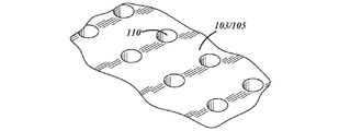
真空式溶接保持具(100)は、第1のワークピース(202)を支持するための第1のワークピース支持体(102)および第2のワークピース(204)を支持すためのる第2のワークピース支持体(104)を備える。前記第1のワークピースの支持体は、前記第2のワークピース支持体に対して摺動可能とすることができ、ワークピース支持面(103)に形成された少なくとも1つの開口部(110)を介して、前記第1のワークピースに真空を供給するよう構成することができる。前記溶接保持具は、前記第1および第2のワークピースを位置調整するゲージバー(114)を備える。真空源(300)によって生成された減圧は、前記ワークピース支持面の前記開口部に伝達され、前記第1のワークピースを、溶接前に、前記ゲージバーに接触させて位置調整しつつ適所に保持することができる。
【選択図】図1A vacuum weld holder (100) is provided for supporting a first workpiece support (102) for supporting a first workpiece (202) and a second for supporting a second workpiece (204). Workpiece support (104). The support of the first workpiece may be slidable relative to the second workpiece support and at least one opening (110) formed in the workpiece support surface (103) Through the first and second workpieces to provide a vacuum to the first workpiece. The weld holder includes a gauge bar (114) that aligns the first and second workpieces. The reduced pressure generated by the vacuum source (300) is transmitted to the opening in the workpiece support surface to hold the first workpiece in position while aligning and contacting the gauge bar prior to welding. can do.
[Selected figure] Figure 1
Description
本願は、2016年4月4日に出願された米国仮特許出願第62/318,075号に基づく優先権を主張し、この相互参照により、当該出願に記載された記載内容を全て援用する。 This application claims priority to US Provisional Patent Application No. 62 / 318,075, filed April 4, 2016, which is incorporated by reference in its entirety.
本開示は、溶接保持具、特に、レーザ溶接作業に用いられる保持具に関する。 The present disclosure relates to weld holders, and more particularly to holders used in laser welding operations.
自動車、すなわち、車両用途で用いられるような、テーラード・ブランクは、レーザ溶接等の溶接技術を用いて接合される。通常、溶接中や接合中のワークピースは溶接保持具で拘束しなければならない。レーザ溶接のように精密な接合方法では、接合加工中、ワークピース同士を終始変わらない位置で保持するため、通常、比較的しっかりした保持具を必要とする。ワークピースを適切に拘束することにより、ワークピースを接合することができ、通常は恒久的に1つのピースとして固定することができる。ワークピース間に品質の高い溶接接合部を形成するには、ワークピース同士の位置調整も重要である。 Tailored blanks, as used in automotive or vehicle applications, are joined using welding techniques such as laser welding. Generally, workpieces during welding and joining must be restrained by a welding holder. Precision bonding methods, such as laser welding, usually require a relatively rigid holding tool to hold the workpieces together in a consistent position during bonding. By appropriately constraining the workpieces, the workpieces can be joined and usually fixed permanently as one piece. In order to form a high quality weld joint between workpieces, alignment of the workpieces with one another is also important.
公知の取り組みとして、鋼のワークピースを磁性保持具を用いて拘束することがある。磁性保持具は、一般に、印加磁力によりワークピースを保持するものである。こうした方法は、アルミニウムのような非磁性材料には機能しない。 A known approach is to restrain steel workpieces with magnetic holders. Magnetic holders generally hold a workpiece by means of an applied magnetic force. Such methods do not work for nonmagnetic materials such as aluminum.
このため、代替可能なワークピース材により広く適用でき、かつレーザ溶接に適した配置形態でワークピースを保持できる、既存の方法に代わるワークピース保持方法への取り組みが必要とされている。 Therefore, there is a need for an alternative to the existing method of holding a workpiece that can be applied more widely to replaceable workpiece materials and hold the workpiece in a configuration suitable for laser welding.
例えば、レーザ溶接作業に用いる溶接保持具を例示する説明をここに記載する。1以上のワークピース支持体を設けて、ワークピースのハンドリングや、他のワークピースに対する位置決めを行うことができる。例示としてのワークピース支持体は、低圧力源あるいは真空からの減圧を、ワークピースと流体連通するよう選択的に配置し、保持具がワークピースを選択的に把持できるようにすることができる。ワークピースを選択的に把持するために減圧を利用することは、アルミニウムやアルミニウム合金製の材料を含む、溶接容易な実質上いかなる材料の溶接においても、この保持具を用いることを可能とする点で有利である。実施例のワークピース支持体は、ワークピースの支持面における開口部を介して、ワークピースに真空や減圧を選択的に印加することができる。開口部は、ワークピース支持体の1以上の真空パッドに設けてよい。 For example, a description is provided herein that illustrates a weld holder for use in a laser welding operation. One or more workpiece supports may be provided to handle workpieces and position them relative to other workpieces. An exemplary workpiece support may be selectively arranged to place a low pressure source or a reduced pressure from a vacuum in fluid communication with the workpiece to allow the holder to selectively grip the workpiece. The use of reduced pressure to selectively grip the workpiece allows this holder to be used in the welding of virtually any material that is easy to weld, including aluminum and aluminum alloy materials. Is advantageous. The example workpiece support can selectively apply vacuum or vacuum to the workpiece through an opening in the workpiece's support surface. The openings may be provided in one or more vacuum pads of the workpiece support.
さらに後述のように、例示としての溶接保持具は、第1のワークピースを支持するための第1のワークピース支持体および第2のワークピースを支持するための第2のワークピース支持体を備えてよい。第1のワークピース支持体は、第2のワークピース支持体に対してスライド可能とすることができ、また、真空源あるいは減圧源からの減圧を、ワークピース支持面における開口部を介して、第1のワークピースの下面に供給するよう構成することができる。溶接保持具はまた、第1および第2のワークピースの位置調整をするためのゲージバーを備えていてよい。ゲージバーが第1および第2のワークピース間から移動する間、真空源によって生成された減圧が、第1のワークピース支持体がワークピースを定位置に保持すためにワークピース支持面における開口部に伝達される。 As further described below, the exemplary weld holder comprises a first workpiece support for supporting a first workpiece and a second workpiece support for supporting a second workpiece. May be equipped. The first workpiece support may be slidable relative to the second workpiece support, and a reduced pressure from a vacuum or vacuum source may be provided through an opening in the workpiece support surface. It can be configured to supply the lower surface of the first workpiece. The weld holder may also include a gauge bar for aligning the first and second workpieces. While the gauge bar is moved between the first and second workpieces, the reduced pressure generated by the vacuum source causes an opening in the workpiece support surface for the first workpiece support to hold the workpiece in place. Transmitted to
実施例によっては、ワークピース支持面に保持されこれに接触したワークピースに、ワークピース支持面に設けられた1つ以上の開口部を介して真空を印加することができる。ワークピース支持面は、保持具および/又はワークピース支持体と比較して相対的に小さく、ワークピースと接触するよう構成された、複数の真空「パッド」を備えていてもよい。あるいは、減圧あるいは真空をワークピースに伝えるよう構成された開口部が形成されており、相対的に大きく、全体が連続しているワークピース支持面によって、ワークピースを支持してもよい。実施例によっては、例えば、比較的弾性のある材料を介してシール面をなし、ワークピース支持面に形成された開口部を全体的に取り囲む、ガスケットを設けて、ワークピース支持体によってワークピースに印加される有効吸引力を増加させることができる。他の実施例として、例えば、ガスケットなしで十分に、真空がワークピースに伝えられるような場合、ガスケットは不要であったり、望ましくないこともある。 In some embodiments, a vacuum may be applied to the workpiece held on and in contact with the workpiece support surface through one or more openings provided in the workpiece support surface. The workpiece support surface may comprise a plurality of vacuum "pads" which are relatively small compared to the holder and / or workpiece support and configured to contact the workpiece. Alternatively, the workpiece may be supported by a relatively large, generally continuous workpiece support surface that is formed with an opening configured to deliver reduced pressure or vacuum to the workpiece. In some embodiments, a workpiece support may be provided with a gasket, for example, with a gasket that provides a sealing surface through a relatively elastic material and generally surrounds an opening formed in the workpiece support surface. The effective suction applied can be increased. As another example, the gasket may be unnecessary or undesirable if, for example, the vacuum is transferred to the workpiece sufficiently without the gasket.
真空式溶接保持具の例示としての使用方法も開示する。一実例として、その方法は、真空源を用いて第1のワークピースを第1のワークピース支持体に固定すること、および第2のワークピースを第2のワークピース支持体に固定することを含む。この方法はさらに、第1および第2のワークピースを、第1および第2のワークピースの間に配置したゲージバーの方に接触が生じるまで押すこと、およびゲージバーの位置が第1および第2のワークピースの間から外れるようゲージバーを下降させることを含んでよい。この方法はまた、吸引固定された第1のワークピースを備えた第1のワークピース支持体を、固定された第2のワークピースを備えた第2のワークピース支持体の方に、接触が生じるまでスライドさせ、第1および第2のワークピースをそれぞれの端部で位置調整することも含む。 Also disclosed is an exemplary method of using a vacuum weld holder. As an illustration, the method comprises securing a first workpiece to a first workpiece support using a vacuum source and securing a second workpiece to a second workpiece support. Including. The method further includes pushing the first and second workpieces until contact occurs with the gauge bar disposed between the first and second workpieces, and the positions of the gauge bars are first and second. Lowering the gauge bar out of the way between the workpieces may be included. The method also includes contacting a first workpiece support with a suction-fixed first workpiece to a second workpiece support with a fixed second workpiece. Sliding to occur, including aligning the first and second workpieces at their respective ends.
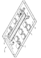
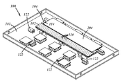
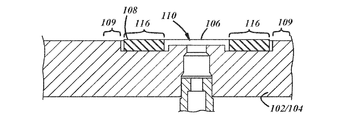
ここで、図1から図8を参照して、例示としての溶接保持具100を図解し、さらに詳細に説明する。溶接保持具100は、第1および第2のワークピース支持体102、104を備え、各ワークピース支持体は、保持具100の基部101に支持されている。第1および第2のワークピース支持体102、104は、例えば、図4に示されるように、対応する第1および第2のワークピース202、204を支持する。例えば、支持体102、104は、第1および第2のワークピース202、204同士をその端部に沿って容易に溶接できるように、第1および第2のワークピース202、204を互いに接触するよう位置決めする。例示としての取り組みにおいては、第1および第2のワークピース202、204を、その対向端部に沿って当接させることにより、ワークピース202、204間の突合せ接合部の形成を容易にすることができる。こうして、溶接材、例えば、テーラード溶接ブランクを、第1および第2のワークピース202、204の接合により形成することができる。また、ラップジョイント、突合せとラップの組み合わせ接合、類似あるいは異なる寸法の材料同士の接合、類似のあるいは異種の金属同士の接合等、他のタイプの溶接接合部も形成することができる。
An
後述の実施例において2つのワークピース202、204が示されているが、これらは単なる例示であって、2つを超えるワークピースが様々な配置で接合できることは理解できる。単なる一例として、2つ以上のワークピースを第3のワークピースの一端部に沿って接合することができる。また、ワークピース202、204は、その接合端部がおおむね同じ長さを有するものとして図示されているが、接合されるワークピースは長さが違ってもよい。
Although two
ワークピース202、204は、便宜にかなう任意の材料で形成してよい。また、さらに後述するように、例示としての保持具100は、鉄系材料、ひいてはいかなる特定の材種に限定されるものではない。
The
ワークピース202、204はまた、便宜にかなう任意のサイズおよび/又は厚さとすることができる。以下に説明する実施例では、ワークピース202、204はシート形状を有するものとして示されている。他の形態、例えば、非平坦、非平面のワークピースも対象としてよい。一例として、ワークピースは、約0.5ミリメートルから2.5ミリメートルの厚みの鋼板であってよい。別の例として、ワークピースは、約1.0ミリメートルから2.0ミリメートルの厚みのアルミニウムシートであってよい。
The
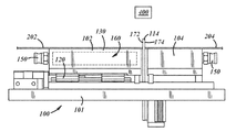
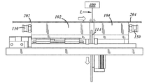
第1および第2のワークピース支持体102、104は、互いに移動可能であってもよい。より具体的には、図2にもっともよく示されているように、第1のワークピース支持体102は第2のワークピース支持体104に対しスライド可能としてよい。さらに後述するように、第1および第2のワークピース支持体102、104間の相対移動を、ワークピース202、204を移動して、接触させ、両者の溶接を容易にすることに利用できる。ここで例示する説明は、第1のワークピース支持体102が、保持具100の基部101に沿ってスライド可能であり、第2のワークピース支持体104が基部101に全体的に固定されている構成を対象としているが、第1および第2のワークピース202、204間で相対移動させる他の方法を用いてよい。単なる例として、第2のワークピース支持体104が、基部101に沿って移動可能であってよく、もしくは第1および第2のワークピース支持体102、104の両者が基部101に沿って移動可能であってよい。ワークピース支持体102、104は、単なる例として、鋼、アルミニウム、または合成材料といった、便宜にかなう任意の材料で形成してよい。
The first and second workpiece supports 102, 104 may be movable relative to one another. More specifically, as best seen in FIG. 2, the
図2にもっともよく示されているように、第1のワークピース支持体102は、レール120に沿って基部101に対し平行移動することができる。レール120は、第1のワークピース支持体102が、概ね、第1および第2のワークピース202、204の対向端部に垂直かほぼ垂直な方向においてレール120に沿ってスライドするように配置してよい。さらに、レール120は、第1のワークピース支持体102の動作を、基部101に対し平行かほぼ平行である並進運動に概ね制限することができる。さらに後述のように、レール120は、第1および第2のワークピース202、204間で位置調整が行われた後、第1のワークピース202が第2のワークピース204の方へ向かう比較的距離の短い横移動を容易にし、ワークピース202、204の対向端部を当接させることができる。第2のワークピース支持体104が基部101に対し移動可能である実施例においては、基部101に対する第2のワークピース支持体の移動すなわちスライドを容易にするために、レール120などの種々の相対移動機構を設けることができる。
As best seen in FIG. 2, the
第1のワークピース支持体102及び第2のワークピース支持体104は、それぞれ真空源や減圧源を利用し、関連するワークピースを選択的に把持することができる。上記のように、真空源を利用することにより、ワークピース支持体102および/又は104は、アルミニウムのような非鉄金属を含む実質的にあらゆるタイプの材料でできたワークピースを把持することができる。このように、保持具100は、溶接可能な任意の材料で形成されたワークピース同士の溶接に使用することができる。真空を利用する方法の別の利点は、サイクルタイムの低減であり、これは、真空や減圧が生成される際の相対速度に起因しうるものであり、次々にワークピース支持体102および/又は104がワークピースを把持することを促進させる。さらに、ワークピースの解放は、ワークピースに印加された圧力を逆転することで促進され、形成されたワークピースにダメージを与えず、迅速に解放できる程度にワークピースを「吹き出す」ことができる。
The
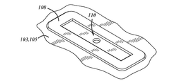
図1にもっともよく示されているように、第1および第2のワークピース支持体102、104は各々、それぞれのワークピース支持面103、105に複数の開口部110を備えてよい。例えば、図1に示されるように、第1のワークピース支持体102および/又は第2のワークピース支持体104上で比較的多数の開口部110を使用することで、比較的大きい把持力がワークピースの広い表面積全域、全長に渡って加えられることになり、そのワークピースを対応するワークピース支持面103、105に引きつけることができる。こうして、前記開口部110は、ワークピースの比較的安定しかつ確実な位置決めをもたらすことができる。
As best seen in FIG. 1, the first and second workpiece supports 102, 104 may each be provided with a plurality of
やり方によっては、開口部110を比較的小さくかつ多数とし、ワークピース202/204への減圧の印加を比較的広範囲に拡げることができる。単なる例として、開口部は比較的小径、例えば、10ミリメートル以下としてよい。別の例として、比較的多数の開口部、例えば、ワークピース支持面103/105の1平方フィートあたり少なくとも20個の開口部を設けてよい。
In some implementations, the
ここで、図5A、5B及び5Cを参照するが、やり方によっては、複数の真空パッド106をワークピース支持体102、104のワークピース支持面103、105上に設けてよい。実施例の真空パッド106は、ワークピース支持体102、104における開口部110の周囲にシール面を延在させていてよい。シール面は、通常、ワークピース202及び/又は204の下面と接触するよう構成され、開口部110の周囲に、ワークピース202及び/又は204への吸引力の印加を促進するシールを形成できる。
Referring now to FIGS. 5A, 5B and 5C, in some manners, a plurality of
実施例によっては、シール面は、ガスケットにより設けることもできる。例えば、図5A、5Bおよび5Cにもっともよく示されるように、各真空パッド106は、ワークピース支持体102、104における開口部110の周囲にガスケット108を備えることができる。開口部110は、真空源あるいは低圧源300と流体連通させることができる。他の実施例として、真空或いは低圧を、再生ポンプにより提供してもよい。ガスケット108は、ワークピース支持面103/105における凹溝部に配置することができる。例えば、ガスケット108は、ワークピース支持面103/105に形成された外周凹部116に配置してよい。ガスケット108および/又は外周凹部116は各々、開口部110を囲むことによって対応するワークピースの下面に対するガスケットのシール度を増大させるように、開口部110の周囲を概ね取り囲めばよい。これによって、吸引力や真空が開口部110と流体連通して配置され、ガスケット108がワークピース(図示なし)の表面に接触して配置されていれば、ワークピースは、通常、真空によりガスケットに接触して保持されることになる。ガスケット108は、ワークピース202、204の表面をシールし易い、比較的軟質であるか、可撓性のある材料で形成してよい。単なる例として、ゴム、ブチル、またはプラスチック材料を使用することができる。
In some embodiments, the sealing surface may be provided by a gasket. For example, as best seen in FIGS. 5A, 5B and 5C, each
例えば、図5A/5B/5Cには、単一の開口部110が示されているが、別の実施例として、単一のガスケット108あるいはシール面109が、同様のあるいは異なる寸法の複数の開口部110を取り囲んでよいことも理解すべきである。このように、単一の真空パッド106が、関連する複数の開口部110を備えてもよい。
For example, although a
他の例では、図5A/5B/5Cに示されたものとは対照的に、シール面を得るためにガスケットは使用しない。ガスケットのない実施例は、例えば、実質上前述したような開口部110を設けるが、開口部110を取り囲むガスケット108及び/又は外周凹部116はなしに行うことができる。ワークピース支持体102/104で一つ以上の真空パッド106が使用される実施例では、開口部110を取り囲む、ワーク面103/105の一部分109(図5A参照)が、ワークピース202/204(図5Aに図示なし)の下面と接触することにより、シール面の役目をすることができる。
In another example, in contrast to that shown in FIGS. 5A / 5B / 5C, no gasket is used to obtain the sealing surface. The non-gasket embodiment may, for example, provide the
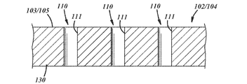
ここで、図6Aおよび6Cを参照し、ガスケットを使用しない別の実施例を示す。ワークピース支持体102/104は、ワークピース支持面103/105を設けた上部保持支持体130を備える。複数の開口部110は、ワークピース支持面103/105に画定される。図6A/6Bに示されるように、複数の通路111が上部保持支持体内に延在し、ワークピース支持面103/105に開口部110を画定する。上部保持支持体130は、部分的に、前記ワークピース支持体102/104の真空キャビティを画定することができる(図1参照)。これにより、通路111は、減圧或いは真空を開口部110に伝え、ワークピース(図6A/6Bに図示なし)をワークピース支持面103/105上に引きつけることができる。
Referring now to FIGS. 6A and 6C, another embodiment is shown that does not use a gasket. The
上記のように、開口部110を比較的小さくかつ多数とし、ワークピース202/204への減圧の印加を比較的広範囲に拡げることができる。開口部は、例えば、比較的小径、例えば、10ミリメートル以下とできる。さらに、比較的多数の開口部、例えば、ワークピース支持面103/105の1平方フィートあたり少なくとも20個の開口部を設けてよい。このようにして、ワークピース支持体102/103は、それぞれワークピース202/204を比較的大部分に渡って把持することができる。単なる一例として、ワークピース支持体102/103は、それぞれワークピース202/204を端部長さの50%を超えて把持し、これにより、ワークピース支持体102/104が、レーザ溶接等による接合のためのワークピース202/204の位置調整を維持する度合いが高まる。
As noted above, the
減圧或いは真空は、便宜にかなう方法で、例示としてのワークピース支持体102/104の開口部110に供給してよい。単なる例として、図1にもっともよく示されるように、ワークピース支持体102は、コネクタ150と流体連通する内部キャビティ160を画定してよい。コネクタ150は、再生ポンプ、真空源、減圧等からの連結部、例えば、着脱可能な連結部を受け入れることができる。キャビティに印加された減圧や真空は、開口部110の内部に、そして通路111を経てキャビティ160に空気を引き込むことができる(図6Aにもっともよく示される)。これにより、ワークピース支持面103/105に配置されたワークピースは、ワークピース支持体102/104に引きつけられ、ワークピース支持体102/104に固定することができる。
The reduced pressure or vacuum may be supplied to the
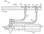
図5Cに示される別のやり方では、真空源300は、例えば、可撓性チューブ304を経て、真空パッド106の開口部110と連通した、マニホールドあるいはベンチュリトンネル302を備えていてよい。チューブ304の両端は、管継手、例えば図7に示される分岐した管状継手を介して、真空パッド106およびベンチュリトンネル302に接続できる。流体あるいはガス供給源、例えば、エアコンプレッサは、流体が供給端部からベンチュリトンネル302を通り、排出端部308を通って循環するよう、ベンチュリトンネル302の供給端部306に接続してよい。チューブ304は、供給端部および排出端部306、308間にあるベンチュリトンネル302に接続され、真空流は開口部110からチューブ304を通って生成される。2つの真空パッド106を真空源300に接続しているチューブ304が図示されているが、さらにチューブを付加することにより、さらに多数の真空パッド106を真空源に接続することができる。これにより、マニホールドは、任意の数の真空パッド106、およびその開口部110を便宜にかなった真空源に接続することができる。
Alternatively, as shown in FIG. 5C, the
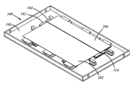
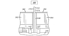
ここで、図1−4、7A及び7Bを参照するが、溶接保持具100は、第1および第2ワークピース202、204を位置調整するためのゲージバー114を備えてよい。ゲージバー114は、第1および第2ワークピース202、204の間に配置されて、両者間に隙間を画定し、第1および第2ワークピース202、204同士の位置調整を容易にする。図2および図7Aにもっともよく示されるように、ゲージバー114は、第1の位置調整面172および第2の位置調整面174を備えていてよい。位置調整面172、174は、概ね平面であって、ワークピース202、204の端部がゲージバー114に押し付けられる際の各端部の位置調整を容易にする。ゲージバー114は、ワークピース202、204に対して平行移動、もしくは垂直方向上下に移動し、後述するように、ワークピース202、204同士をその対向端部に沿って当接させる。一実施例では、ゲージバー114は、ワークピース202、204の間に位置し、両ワークピースの端部の位置調整ができる位置である伸長アライメント位置から、ワークピースの下方に位置する退避溶接位置まで退避する。ゲージバー114は溶接中のワークピース同士の境界面の下方に位置する排気室140まで退避することができる。
Referring now to FIGS. 1-4, 7A and 7B, the
ゲージバー114は、第1および第2ワークピース202、204の対向端部を位置調整するよう構成してよい。一実施例として、ワークピース支持面103/105は、開口部110を介して供給された真空/減圧により、第1および第2ワークピース202、204に全体的に把持力を及ぼし、ゲージバー114が第1および第2ワークピース202、204の間から移動した後においても、第1および第2ワークピース202、204を溶接のための位置調整をされたままとできる。あるいは、ゲージバー114と接触させたままでのワークピース202、204の連続的な位置調整を容易にするために、ゲージバー114によってワークピース202、204それぞれに付与される剪断力が、ワークピース202、204に働く真空力をわずかに超えていることが望ましい。このように、ゲージバー114と接触していることで、ワークピース202、204を十分に把持することが可能となり、ワークピース間にずれを生じさせるような大きな動きを阻止できる一方、ワークピース202、204を、ワークピース支持体102/104に対してわずかに移動させて、少々のずれを修正することができる。
The
溶接保持具100は、さらに、1つ以上の補助プッシャーを備えてよく、ゲージバー114が下降した後に第1および第2ワークピース202、204を移動して接触させるために用いる。例えば、補助プッシャー122はそれぞれ、第1のワークピース102および第1のワークピース支持体102がともに、ワークピース支持体102を支持するレール120が許容するとおりにゲージバー114に向かってスライドするよう、第1のワークピース102およびワークピース支持体102を押すことができる。補助プッシャー122は、こうして、位置調整された第1のワークピース202を押し、第2のワークピース204と当接させることができる。補助プッシャー122が第1のワークピース202を第2のワークピース204の方に移動させる間、第1のワークピース支持体102は吸引力/真空を維持して、第1のワークピース202が第1のワークピース支持体102に固定された状態を保つことができる。しかるべく、第1のワークピース202の移動は概ね、第1のワークピース支持体102がレール120に沿って移動する間、スライドする第1のワークピース支持体102により可能である。補助プッシャー122は、溶接前のワークピース202、204の位置決めのみならず、溶接中のワークピースに対して、溶接接合部の形成を促す力(比較的小さく、例えば、25−30psi、あるいは10ポンドより小さい力)を働かせることもできる。
The
ここで、図7Aおよび7Bを参照して、第1および第2ワークピース202、204を接合するのに用いられる、例示としての溶接工程をさらに詳説する。図7Aにおいて、ゲージバー114は、第1および第2ワークピース202、204間に介在した状態にあり、第1および第2ワークピース202、204の隣接する端部は、互いに位置調整されているが、接触はしていない。さらに具体的には、ワークピース202、204の端部は、ゲージバー114におけるそれぞれの位置調整面172、174に当接している。ゲージバー114は、初期においては第1および第2ワークピース202、204の位置調整された隣接端部間に隙間を残しつつ、降下させてよい。図7Bに示されるように、補助プッシャー122は、その後、ワークピース202、204が引っ込んだゲージバー114の上方で接触するよう促すことができる。より具体的には、補助プッシャー122は、第1のワークピース支持体102および第1のワークピース202を横方向にスライドさせて、第1および第2ワークピース202、204の隣接端部を合わせ、突合せ接合を形成することができる。レーザヘッド400は、第1および第2ワークピース202、204の近傍、例えば、第1および第2ワークピース202、204の上方に配置してよい。レーザヘッド400は、その後、ワークピース202、204の端部に沿うか、あるいは近接してレーザL(図7B参照)の照準を合わせ、両者を溶接し単一部品とすることができる。熟練した職人であれば十分理解できるように、レーザヘッドの特定の形式や数は、ワークピース202、204に対する方向あるいは距離と同様に、多数の要因によって決定することができ、かつ、ここに記載された溶接保持具は、特定のレーザヘッドの態様に限定されない。
Referring now to Figures 7A and 7B, an exemplary welding process used to join the first and
ビームダンプともいう排気室140を、第1および第2ワークピース202、204の下方であって、ワークピース202、204の上方に位置するレーザヘッド400の反対側に設けてよい。溶接工程において、第1および第2ワークピース202、204の近接端部に沿ってシールドガスを供給することが、便宜にかなっていることがある。単なる一実施例として、排気室140には、アルゴンのような不活性ガスを供給し、アルミニウムを溶接する際に生じる空孔を減少させることができる。不活性ガスは、溶接工程における第1および第2のワークピース202、204の不本意な反応を概ね最小限に抑えることができる。図7Aおよび7Bの実施例によれば、排気室140は一対の垂直支柱142、水平支柱すなわちプラットフォーム144および2つのワークピース202、204の下面により画定される。排気室が他の構成をとり得ることは明らかである。
An
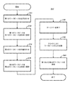
ここで、図8を参照すると、例えば溶接するために、第1および第2のワークピースを位置決めおよび/又は接合するプロセス800が示されている。プロセス800は、ブロック805で開始され、ここで、第1のワークピースは、第1のワークピース支持体上で位置決めされるか位置調整される。厚みの異なるワークピースでなるテーラード・ブランクにおいては、厚みの大きいピースを最初に位置決めし、固定することが望ましい。上述のように、第1のワークピース202は、第1のワークピース支持体102上にセットしてよい。第1のワークピース202は、第1のワークピース支持体102上で位置決めし、便宜にかなう方法で、第2のワークピース204に接合、例えば溶接するための位置調整をしてよい。一例では、第1のワークピース202の端部、例えば、第2のワークピース204に溶接されない側端部の一方を拘束する1つ以上のゲージピンを、第1のワークピース支持体102に設け、第1のワークピース202の側端部をゲージピンで位置調整する。ゲージピンは、このようにしてワークピース202をx方向、すなわち溶接端部に平行な方向で位置調整できる。
Referring now to FIG. 8, a
第1のワークピース202の位置調整および/又は位置決めの一部として、第1のワークピース202を、配置されたゲージバーの方に、接触が生じるまで押すことにより、第1のワークピースは、y方向、すなわち溶接端部に垂直な方向において位置調整することもできる。例えば、第1のワークピース202を第1のワークピース支持体102上に装着する際に、第1のワークピース202をゲージバー114に押し付け、第1のワークピース202の端部を概ね位置調整することができる。ワークピース202は、このようにして、ゲージバー114によって第一の次元での位置調整ができ、ゲージピンによって第二の次元での位置調整ができる。
By pressing the
ブロック810に進み、ワークピース202は、例えば、真空源或いは減圧を利用して、第1のワークピース支持体に固定される。前述のように、第1のワークピース支持体102は、ワークピース202を把持することができる。例えば、真空源300あるいは再生ポンプにより生成された減圧は、第1のワークピース202がワークピース支持面103に引きつけられて、所定の位置に保持できるよう、ワークピース支持面103の開口部110に伝えられる。第1のワークピース202はゲージバー114によりこうして位置調整され、第1のワークピース支持体102に固定される。次いで、プロセス800はブロック820に進むことができる。
Continuing to block 810, the
ブロック820では、第2のワークピースを、第2のワークピース支持体上に位置決めするか、あるいは位置調整することができる。例えば、前述したように、第2のワークピース204は、第2のワークピース支持体104上にセットすることができる。第2のワークピース204は、第1のワークピース202の位置調整について前述したのと同様のやり方で、第2のワークピース支持体104上で位置決めし、2つの次元で位置調整することができる。より具体的には、第2のワークピース204を溶接端部に沿ってゲージバー114に押接する一方で、第一の方向で第2のワークピース204の非溶接端部を位置調整するために、一つ以上のゲージピンを設けることができる。ゲージバー114は、一定あるいは実質的に一定の厚さを規定してよく、第1および第2ワークピース202、204の溶接端部は、例えば溶接作業による接合のための平行あるいは平行でない位置調整がなされる。次いで、プロセス800は、ブロック830に進む。
At
ブロック830では、第2のワークピースを、第2のワークピース支持体に固定することができる。例えば、前述したように、第2のワークピース204は、一つ以上の開口部110を介して印加される真空源、あるいは減圧によって、第2のワークピース支持体104に固定することができる。また、例えば、磁気装置やクランプを使用する、標準的な非真空法を利用し、第2のワークピース204を固定してもよい。こうして、第1および第2ワークピース202、204の両者は互いに平行に位置調整され、それぞれ、第1および第2ワークピース支持体102、104に固定される。次いで、プロセス800はブロック840に進む。
At
ブロック840では、ゲージバーの位置が第1および第2のワークピース間から外れるよう、ゲージバーを下降させることができる。例えば、第1および第2ワークピース202、204は、平行であって互いに位置調整されることが望ましいが、その両者の隣接端部間に隙間が画定されるよう、ゲージバー114を下降させることができる。次いで、プロセス800は、ブロック850に進むことができる。
At
ブロック850では、第1のワークピース支持体は、真空固定された第1のワークピースとともに、固定された第2のワークピースと一体の第2のワークピース支持体の方に、両者が接触するまでスライドさせることができる。例えば、補助プッシャー122は、第1のワークピース102および/又は第1のワークピース支持体202をそれぞれ、第2のワークピース104および/又は第2のワークピース支持体204の方への移動を促すことができる。第1および第2ワークピース202、204間の接触により、第1および第2のワークピース202、204は各端部に沿って位置調整され、例えば溶接による接合を行うための位置決めがなされるよう、隣接して配置される。
At
ブロック860に進んで、第1および第2ワークピースを溶接することができる。例えば、前述したように、レーザヘッド400を用いて、第1および第2ワークピース202、204をレーザ溶接することができる。溶接工程においては、溶接位置に近接した排気室、例えば、チャンバ140内で、排気を循環させることができる。排気室140では、真空源300によって生成された減圧を利用すれば、排気の除去を促進できる。
Advancing to block 860, the first and second workpieces can be welded. For example, as discussed above, the
前述の記載は、本発明を定義づけではなく、本発明の1以上の実例の記載であると理解されるべきである。本発明は、ここに開示した特定の実施例に限定されるものではなく、後述の請求項によってのみ範囲決定されるものである。さらに、前述の記載に含まれる記述は、特定の実例に関するものであり、字句が明確に定義されている場合を除いて、本発明の権利範囲あるいは請求項で用いた表現の定義を限定するものと解釈されるべきでない。様々な他の実施例や、開示されている実施例の様々な変更や変形は、当業者にとって明らかなものとなろう。こうした他の実施例、変更及び変形全ては、添付された請求項の範囲内に属すよう意図される。 It is to be understood that the above description is not to define the invention, but to be a description of one or more examples of the invention. The present invention is not limited to the specific embodiments disclosed herein, but is only limited by the following claims. Furthermore, the description contained in the foregoing description relates to specific examples, and restricts the definition of the expression used in the scope of claims of the present invention or claims except when the word is clearly defined. It should not be interpreted as Various other embodiments and various modifications and variations of the disclosed embodiments will be apparent to those skilled in the art. All such other embodiments, modifications and variations are intended to fall within the scope of the appended claims.
本明細書および請求項で使用されているように、「例えば」、「例えば」、「例えば」、「のように」、「のような」という表現、および「含む」、「有する」、「含む」という動詞やこれらの他の動詞形態は、一つ以上の構成要素や他のアイテムを列挙して使用される場合、常に非限定的に解釈すべきであり、これは、列挙したことを他の追加構成要素やアイテムを排除するものとして判断すべきでないことを意味する。他の表現は、異なる解釈を必要とする文脈で使用されない限り、最も広い合理的な意味で解釈されるべきである。 As used herein and in the claims, the expressions "for example", "for example", "for example", "like", "like", and "including", "having", " The verb "comprise" and these other verb forms should always be interpreted in a non-limiting manner, when used in a list of one or more components or other items, which means that It means that it should not be judged as excluding other additional components or items. Other expressions should be interpreted in the broadest reasonable sense unless they are used in a context that requires a different interpretation.
Claims (22)
第2のワークピース(204)を支持するための第2のワークピース支持体(104)を備え、該第2のワークピース支持体に対して、前記第1のワークピース支持体は摺動可能であり、
前記第1および第2のワークピースを位置調整するためのゲージバー(114)を備え、該第1のワークピースの端部を位置調整するための第1の位置調整面(172)と前記第2のワークピースの端部を位置調整するための第2の位置調整面(174)を有し、該ゲージバーは、伸長アライメント位置と退避溶接位置の間で移動可能であり、
前記ゲージバーが前記伸張アライメント位置から前記退避溶接位置に移動する間、前記第1のワークピースが前記減圧により、前記ワークピース支持面に保持されるよう構成された、真空式溶接保持具(100)。 A workpiece support surface comprising a first workpiece support (102) for supporting a first workpiece (202), the first workpiece support having at least one opening (110) (103), configured to provide reduced pressure from the vacuum source (300) to the lower surface of the first workpiece through the opening in the workpiece support surface;
A second workpiece support (104) for supporting a second workpiece (204), said first workpiece support being slidable relative to the second workpiece support And
A first alignment surface (172) for aligning the ends of the first workpiece and the second alignment bar with a gauge bar (114) for aligning the first and second workpieces; A second alignment surface (174) for aligning the end of the workpiece, the gauge bar being movable between an extended alignment position and a retracted welding position;
A vacuum weld holder (100) configured to hold the first workpiece on the workpiece support surface by the vacuum while moving the gauge bar from the stretch alignment position to the retraction weld position. .
第2のワークピース(204)を支持するための第2のワークピース支持体(104)を備え、該第2のワークピース支持体に対して、前記第1のワークピース支持体はスライド可能であり、
前記第1および第2のワークピースを位置調整するための、伸長アライメント位置と退避溶接位置との間で移動可能なゲージバー(114)を備え、
前記第1および第2のワークピース支持体の間に配置されている排気室(140)を備え、該排気室(140)は、前記第1および第2のワークピースの前記端部に沿って不活性ガスを供給するよう構成されており、
前記ゲージバー(114)が前記伸張アライメント位置から前記退避溶接位置に移動する間、前記第1のワークピースが、前記減圧により前記ワークピース支持面に保持されるよう構成された、真空式溶接保持具(100)。 A workpiece support surface comprising a first workpiece support (102) for supporting a first workpiece (202), the first workpiece support having at least one opening (110) (103), configured to supply a reduced pressure from a vacuum source (300) to the lower surface of the first workpiece through the opening in the workpiece support surface,
A second workpiece support (104) for supporting a second workpiece (204), relative to the second workpiece support, said first workpiece support being slidable Yes,
A gauge bar (114) movable between an extended alignment position and a retracted welding position for aligning the first and second workpieces;
An exhaust chamber (140) disposed between the first and second workpiece supports, the exhaust chamber (140) being along the ends of the first and second workpieces. Configured to supply an inert gas,
A vacuum weld holder configured to hold the first workpiece on the workpiece support surface by the reduced pressure while the gauge bar (114) is moved from the stretch alignment position to the retraction weld position. (100).
真空源(300)から第1のワークピース支持体(102)のワークピース支持面(103)にある開口部(110)を介して前記第1のワークピースの下面に供給される減圧を利用して、前記第1のワークピースを前記第1のワークピース支持体に固定する工程と、
前記第2のワークピースを第2のワークピース支持体(104)に固定する工程と、
前記第1のワークピースを前記減圧により前記ワークピース支持面に接触させて保持しながら、前記ゲージバーを伸長アライメント位置から退避溶接位置に移動させ、前記ゲージバーを前記第1および第2のワークピースの間から外れさせる工程と、
真空固定された第1のワークピースと一体の前記第1のワークピース支持体を、固定された第2のワークピースと一体の前記第2のワークピース支持体の方に、接触が生じるまでスライドさせ、前記第1および第2のワークピースをそれぞれの端部で位置調整する工程からなる、真空式溶接保持具(100)の使用方法。 A first workpiece (202) and a second workpiece (204) are positioned between the first and second workpieces (202, 204) and an end of the first workpiece is Toward the gauge bar (114) comprising a first alignment surface (172) for alignment and a second alignment surface (174) for aligning the end of the second workpiece Pushing until it contacts the gauge bar,
Using the reduced pressure supplied from the vacuum source (300) to the underside of said first workpiece via the opening (110) in the workpiece support surface (103) of the first workpiece support (102) Securing the first workpiece to the first workpiece support;
Securing the second workpiece to a second workpiece support (104);
The gauge bar is moved from the extended alignment position to the retraction welding position while holding the first work piece in contact with the work piece support surface by the depressurization, and the gauge bar is made of the first and second work pieces. A process of moving away from each other;
Slide the first workpiece support integral with the vacuum-fixed first workpiece until contact is made towards the second workpiece support integral with the fixed second workpiece And adjusting the first and second workpieces at their respective ends.
Applications Claiming Priority (3)
| Application Number | Priority Date | Filing Date | Title |
|---|---|---|---|
| US201662318075P | 2016-04-04 | 2016-04-04 | |
| US62/318,075 | 2016-04-04 | ||
| PCT/US2017/025917 WO2017176734A1 (en) | 2016-04-04 | 2017-04-04 | Vacuum-based weld fixture and method of using the same |
Publications (1)
| Publication Number | Publication Date |
|---|---|
| JP2019511368A true JP2019511368A (en) | 2019-04-25 |
Family
ID=59958751
Family Applications (1)
| Application Number | Title | Priority Date | Filing Date |
|---|---|---|---|
| JP2018552176A Pending JP2019511368A (en) | 2016-04-04 | 2017-04-04 | Vacuum-type welding holder and method of using the same |
Country Status (7)
| Country | Link |
|---|---|
| US (1) | US20170282308A1 (en) |
| EP (1) | EP3439824A4 (en) |
| JP (1) | JP2019511368A (en) |
| KR (1) | KR20180122744A (en) |
| CN (1) | CN109070286A (en) |
| MX (1) | MX2018011746A (en) |
| WO (1) | WO2017176734A1 (en) |
Families Citing this family (8)
| Publication number | Priority date | Publication date | Assignee | Title |
|---|---|---|---|---|
| US11260679B2 (en) * | 2018-12-21 | 2022-03-01 | Kateeva, Inc. | Gripping for print substrates |
| WO2022187398A1 (en) * | 2021-03-02 | 2022-09-09 | Extol Inc. | Laser part retention system and method |
| JP7541121B2 (en) * | 2022-01-14 | 2024-08-27 | 日銘電脳配件(上海)有限公司 | Welding jig and clamping method |
| CN115106819A (en) * | 2022-08-30 | 2022-09-27 | 启东先和丝杠制造有限公司 | Steel plate cutting and positioning device for slider for lead screw production |
| CN115575512B (en) * | 2022-10-09 | 2025-07-25 | 上海宝钢阿赛洛激光拼焊有限公司 | Welding line detection device for splice welding plate and detection flow system |
| CN115846873B (en) * | 2023-02-24 | 2023-05-23 | 西安藤飞属信息科技有限公司 | Welding tool for industrial robot manufacturing |
| CN119319331B (en) * | 2024-12-17 | 2025-05-27 | 湖州德尔福汽车部件有限公司 | A fully automatic laser welding tool with exhaust gas treatment |
| CN120962197A (en) * | 2025-10-10 | 2025-11-18 | 常州韫昊科技有限公司 | Board welding equipment capable of recycling welding slag and welding process |
Citations (4)
| Publication number | Priority date | Publication date | Assignee | Title |
|---|---|---|---|---|
| JPS5859740A (en) * | 1981-09-21 | 1983-04-08 | ガ−バ−・サイエンテイフイツク・プロダクツ・インコ−ポレ−テツド | Vacuum workpiece holder |
| JPS61185590U (en) * | 1985-05-09 | 1986-11-19 | ||
| JP2002336964A (en) * | 2001-05-16 | 2002-11-26 | Akihisa Murata | Butt joining machine for strip metal sheets |
| JP2009233831A (en) * | 2008-03-28 | 2009-10-15 | Fuji Heavy Ind Ltd | Vacuum chuck |
Family Cites Families (14)
| Publication number | Priority date | Publication date | Assignee | Title |
|---|---|---|---|---|
| SE501343C2 (en) * | 1993-06-11 | 1995-01-23 | Volvo Ab | Device for position fixing of plates during welding |
| FI98439C (en) * | 1993-06-17 | 1997-06-25 | Kvaerner Masa Yards Oy | Welding Procedure |
| JP2795339B2 (en) * | 1994-07-18 | 1998-09-10 | 川崎重工業株式会社 | Welding method of laminated structure |
| CA2167111A1 (en) * | 1996-01-12 | 1997-07-13 | Bob Bishop | Method and apparatus for butt welding together sheet blanks |
| US6302315B1 (en) * | 2000-05-01 | 2001-10-16 | General Tool Company | Friction stir welding machine and method |
| US6803538B2 (en) * | 2001-08-31 | 2004-10-12 | Honda Canada Inc. | Laser welding system |
| US8240539B2 (en) * | 2004-05-28 | 2012-08-14 | Panasonic Corporation | Joining apparatus with UV cleaning |
| CN101208175B (en) * | 2005-06-06 | 2010-05-12 | 株式会社Ihi | Method and device for positioning butt-jointed and welded plates |
| JP4636261B2 (en) * | 2005-10-14 | 2011-02-23 | トヨタ自動車株式会社 | Butt welding system for steel plate and butt welding method for steel plate |
| JP5077576B2 (en) * | 2008-11-20 | 2012-11-21 | 株式会社Ihi | Processing equipment |
| EP2594355B1 (en) | 2011-11-17 | 2016-06-08 | Nexans | Cross cutting and seam welding machine and process with a device for positioning two opposing ends of materials one against the other |
| CN104259725B (en) | 2014-10-28 | 2016-05-04 | 无锡汉神电气有限公司 | Flat-plate direct seam welding vacuum chuck device |
| CN204639431U (en) * | 2015-02-26 | 2015-09-16 | 昆山宝锦激光拼焊有限公司 | A kind of laser assembly solder machine positioning device |
| CN204818434U (en) * | 2015-06-25 | 2015-12-02 | 象山普精金属制品厂 | Thickness that varies steel sheet laser welding device |
-
2017
- 2017-04-04 US US15/478,760 patent/US20170282308A1/en not_active Abandoned
- 2017-04-04 EP EP17779648.9A patent/EP3439824A4/en not_active Withdrawn
- 2017-04-04 CN CN201780020555.4A patent/CN109070286A/en active Pending
- 2017-04-04 MX MX2018011746A patent/MX2018011746A/en unknown
- 2017-04-04 KR KR1020187031805A patent/KR20180122744A/en not_active Ceased
- 2017-04-04 WO PCT/US2017/025917 patent/WO2017176734A1/en not_active Ceased
- 2017-04-04 JP JP2018552176A patent/JP2019511368A/en active Pending
Patent Citations (4)
| Publication number | Priority date | Publication date | Assignee | Title |
|---|---|---|---|---|
| JPS5859740A (en) * | 1981-09-21 | 1983-04-08 | ガ−バ−・サイエンテイフイツク・プロダクツ・インコ−ポレ−テツド | Vacuum workpiece holder |
| JPS61185590U (en) * | 1985-05-09 | 1986-11-19 | ||
| JP2002336964A (en) * | 2001-05-16 | 2002-11-26 | Akihisa Murata | Butt joining machine for strip metal sheets |
| JP2009233831A (en) * | 2008-03-28 | 2009-10-15 | Fuji Heavy Ind Ltd | Vacuum chuck |
Also Published As
| Publication number | Publication date |
|---|---|
| WO2017176734A1 (en) | 2017-10-12 |
| US20170282308A1 (en) | 2017-10-05 |
| CN109070286A (en) | 2018-12-21 |
| MX2018011746A (en) | 2018-12-19 |
| EP3439824A1 (en) | 2019-02-13 |
| KR20180122744A (en) | 2018-11-13 |
| EP3439824A4 (en) | 2019-05-01 |
Similar Documents
| Publication | Publication Date | Title |
|---|---|---|
| JP2019511368A (en) | Vacuum-type welding holder and method of using the same | |
| US7556187B2 (en) | Method of manufacturing cylindrical body, friction stir welding method, and friction stir welding device | |
| CN205200916U (en) | Friction stir welding meets frock clamp | |
| JP2009142840A (en) | Pipe welding method, and horizontal automatic welding apparatus of pipe | |
| CN101472703A (en) | Method of and device for butt welding without weld filler materials thin metal sheets using clamping pressing devices, at least one pressing element being suitable for applying two or more distinct pr | |
| US6184493B1 (en) | Vertical diffusion bonding apparatus | |
| CN115243809A (en) | bending machine | |
| WO2013191099A1 (en) | Fixed jig | |
| US7815094B2 (en) | Method of manufacturing cylindrical body, and friction stir welding method | |
| JP2007022310A (en) | Roof glass transfer jig | |
| JP3272197B2 (en) | Lap welding jig | |
| JP2002137091A (en) | Steel plate butt welding method and apparatus | |
| JP3885053B2 (en) | Friction stir welding equipment | |
| JP2004001081A (en) | Method and apparatus for butt welding metal plate | |
| JP3618686B2 (en) | Butt joining device for strip metal sheet | |
| CN113770527A (en) | Steel pipe end plate welding machine | |
| KR102038402B1 (en) | Pipe bending device | |
| EP1714744A2 (en) | Inflatable clamping systems and methods | |
| JP2003275883A (en) | Butt joining method | |
| US20060027541A1 (en) | Programmable non-contact fusion welding apparatus and method | |
| CN107138856B (en) | Vehicle front venting plate jaw type brakes wheel disc welding and palletizing apparatus | |
| US2909951A (en) | Method and apparatus for uniting tubular members | |
| JP5032913B2 (en) | Rim welding line equipment | |
| CN106077958A (en) | A kind of laser stamp of symmetrical picture and text | |
| JP3820400B2 (en) | Friction stir welding jig |
Legal Events
| Date | Code | Title | Description |
|---|---|---|---|
| A621 | Written request for application examination |
Free format text: JAPANESE INTERMEDIATE CODE: A621 Effective date: 20181129 |
|
| A977 | Report on retrieval |
Free format text: JAPANESE INTERMEDIATE CODE: A971007 Effective date: 20191220 |
|
| A131 | Notification of reasons for refusal |
Free format text: JAPANESE INTERMEDIATE CODE: A131 Effective date: 20200107 |
|
| A02 | Decision of refusal |
Free format text: JAPANESE INTERMEDIATE CODE: A02 Effective date: 20200728 |