JP2019511301A - Ventilator with improved synchrony in transition from exhalation to inspiratory movement - Google Patents
Ventilator with improved synchrony in transition from exhalation to inspiratory movement Download PDFInfo
- Publication number
- JP2019511301A JP2019511301A JP2018550597A JP2018550597A JP2019511301A JP 2019511301 A JP2019511301 A JP 2019511301A JP 2018550597 A JP2018550597 A JP 2018550597A JP 2018550597 A JP2018550597 A JP 2018550597A JP 2019511301 A JP2019511301 A JP 2019511301A
- Authority
- JP
- Japan
- Prior art keywords
- ventilator
- exhalation
- time constant
- flow signal
- transition
- Prior art date
- Legal status (The legal status is an assumption and is not a legal conclusion. Google has not performed a legal analysis and makes no representation as to the accuracy of the status listed.)
- Ceased
Links
Images

Classifications
-
- A—HUMAN NECESSITIES
- A61—MEDICAL OR VETERINARY SCIENCE; HYGIENE
- A61M—DEVICES FOR INTRODUCING MEDIA INTO, OR ONTO, THE BODY; DEVICES FOR TRANSDUCING BODY MEDIA OR FOR TAKING MEDIA FROM THE BODY; DEVICES FOR PRODUCING OR ENDING SLEEP OR STUPOR
- A61M16/00—Devices for influencing the respiratory system of patients by gas treatment, e.g. mouth-to-mouth respiration; Tracheal tubes
- A61M16/021—Devices for influencing the respiratory system of patients by gas treatment, e.g. mouth-to-mouth respiration; Tracheal tubes operated by electrical means
- A61M16/022—Control means therefor
- A61M16/024—Control means therefor including calculation means, e.g. using a processor
- A61M16/026—Control means therefor including calculation means, e.g. using a processor specially adapted for predicting, e.g. for determining an information representative of a flow limitation during a ventilation cycle by using a root square technique or a regression analysis
-
- A—HUMAN NECESSITIES
- A61—MEDICAL OR VETERINARY SCIENCE; HYGIENE
- A61M—DEVICES FOR INTRODUCING MEDIA INTO, OR ONTO, THE BODY; DEVICES FOR TRANSDUCING BODY MEDIA OR FOR TAKING MEDIA FROM THE BODY; DEVICES FOR PRODUCING OR ENDING SLEEP OR STUPOR
- A61M16/00—Devices for influencing the respiratory system of patients by gas treatment, e.g. mouth-to-mouth respiration; Tracheal tubes
- A61M16/0003—Accessories therefor, e.g. sensors, vibrators, negative pressure
-
- A—HUMAN NECESSITIES
- A61—MEDICAL OR VETERINARY SCIENCE; HYGIENE
- A61M—DEVICES FOR INTRODUCING MEDIA INTO, OR ONTO, THE BODY; DEVICES FOR TRANSDUCING BODY MEDIA OR FOR TAKING MEDIA FROM THE BODY; DEVICES FOR PRODUCING OR ENDING SLEEP OR STUPOR
- A61M16/00—Devices for influencing the respiratory system of patients by gas treatment, e.g. mouth-to-mouth respiration; Tracheal tubes
- A61M16/10—Preparation of respiratory gases or vapours
- A61M16/104—Preparation of respiratory gases or vapours specially adapted for anaesthetics
-
- A—HUMAN NECESSITIES
- A61—MEDICAL OR VETERINARY SCIENCE; HYGIENE
- A61M—DEVICES FOR INTRODUCING MEDIA INTO, OR ONTO, THE BODY; DEVICES FOR TRANSDUCING BODY MEDIA OR FOR TAKING MEDIA FROM THE BODY; DEVICES FOR PRODUCING OR ENDING SLEEP OR STUPOR
- A61M16/00—Devices for influencing the respiratory system of patients by gas treatment, e.g. mouth-to-mouth respiration; Tracheal tubes
- A61M16/20—Valves specially adapted to medical respiratory devices
- A61M16/208—Non-controlled one-way valves, e.g. exhalation, check, pop-off non-rebreathing valves
-
- A—HUMAN NECESSITIES
- A61—MEDICAL OR VETERINARY SCIENCE; HYGIENE
- A61B—DIAGNOSIS; SURGERY; IDENTIFICATION
- A61B5/00—Measuring for diagnostic purposes; Identification of persons
- A61B5/08—Detecting, measuring or recording devices for evaluating the respiratory organs
- A61B5/087—Measuring breath flow
-
- A—HUMAN NECESSITIES
- A61—MEDICAL OR VETERINARY SCIENCE; HYGIENE
- A61M—DEVICES FOR INTRODUCING MEDIA INTO, OR ONTO, THE BODY; DEVICES FOR TRANSDUCING BODY MEDIA OR FOR TAKING MEDIA FROM THE BODY; DEVICES FOR PRODUCING OR ENDING SLEEP OR STUPOR
- A61M16/00—Devices for influencing the respiratory system of patients by gas treatment, e.g. mouth-to-mouth respiration; Tracheal tubes
- A61M16/01—Devices for influencing the respiratory system of patients by gas treatment, e.g. mouth-to-mouth respiration; Tracheal tubes specially adapted for anaesthetising
-
- A—HUMAN NECESSITIES
- A61—MEDICAL OR VETERINARY SCIENCE; HYGIENE
- A61M—DEVICES FOR INTRODUCING MEDIA INTO, OR ONTO, THE BODY; DEVICES FOR TRANSDUCING BODY MEDIA OR FOR TAKING MEDIA FROM THE BODY; DEVICES FOR PRODUCING OR ENDING SLEEP OR STUPOR
- A61M16/00—Devices for influencing the respiratory system of patients by gas treatment, e.g. mouth-to-mouth respiration; Tracheal tubes
- A61M16/10—Preparation of respiratory gases or vapours
- A61M16/14—Preparation of respiratory gases or vapours by mixing different fluids, one of them being in a liquid phase
- A61M16/16—Devices to humidify the respiration air
-
- A—HUMAN NECESSITIES
- A61—MEDICAL OR VETERINARY SCIENCE; HYGIENE
- A61M—DEVICES FOR INTRODUCING MEDIA INTO, OR ONTO, THE BODY; DEVICES FOR TRANSDUCING BODY MEDIA OR FOR TAKING MEDIA FROM THE BODY; DEVICES FOR PRODUCING OR ENDING SLEEP OR STUPOR
- A61M16/00—Devices for influencing the respiratory system of patients by gas treatment, e.g. mouth-to-mouth respiration; Tracheal tubes
- A61M16/20—Valves specially adapted to medical respiratory devices
- A61M16/201—Controlled valves
- A61M16/202—Controlled valves electrically actuated
- A61M16/203—Proportional
- A61M16/204—Proportional used for inhalation control
-
- A—HUMAN NECESSITIES
- A61—MEDICAL OR VETERINARY SCIENCE; HYGIENE
- A61M—DEVICES FOR INTRODUCING MEDIA INTO, OR ONTO, THE BODY; DEVICES FOR TRANSDUCING BODY MEDIA OR FOR TAKING MEDIA FROM THE BODY; DEVICES FOR PRODUCING OR ENDING SLEEP OR STUPOR
- A61M16/00—Devices for influencing the respiratory system of patients by gas treatment, e.g. mouth-to-mouth respiration; Tracheal tubes
- A61M16/20—Valves specially adapted to medical respiratory devices
- A61M16/201—Controlled valves
- A61M16/202—Controlled valves electrically actuated
- A61M16/203—Proportional
- A61M16/205—Proportional used for exhalation control
-
- A—HUMAN NECESSITIES
- A61—MEDICAL OR VETERINARY SCIENCE; HYGIENE
- A61M—DEVICES FOR INTRODUCING MEDIA INTO, OR ONTO, THE BODY; DEVICES FOR TRANSDUCING BODY MEDIA OR FOR TAKING MEDIA FROM THE BODY; DEVICES FOR PRODUCING OR ENDING SLEEP OR STUPOR
- A61M16/00—Devices for influencing the respiratory system of patients by gas treatment, e.g. mouth-to-mouth respiration; Tracheal tubes
- A61M16/0003—Accessories therefor, e.g. sensors, vibrators, negative pressure
- A61M2016/0015—Accessories therefor, e.g. sensors, vibrators, negative pressure inhalation detectors
- A61M2016/0018—Accessories therefor, e.g. sensors, vibrators, negative pressure inhalation detectors electrical
-
- A—HUMAN NECESSITIES
- A61—MEDICAL OR VETERINARY SCIENCE; HYGIENE
- A61M—DEVICES FOR INTRODUCING MEDIA INTO, OR ONTO, THE BODY; DEVICES FOR TRANSDUCING BODY MEDIA OR FOR TAKING MEDIA FROM THE BODY; DEVICES FOR PRODUCING OR ENDING SLEEP OR STUPOR
- A61M16/00—Devices for influencing the respiratory system of patients by gas treatment, e.g. mouth-to-mouth respiration; Tracheal tubes
- A61M16/0003—Accessories therefor, e.g. sensors, vibrators, negative pressure
- A61M2016/0027—Accessories therefor, e.g. sensors, vibrators, negative pressure pressure meter
-
- A—HUMAN NECESSITIES
- A61—MEDICAL OR VETERINARY SCIENCE; HYGIENE
- A61M—DEVICES FOR INTRODUCING MEDIA INTO, OR ONTO, THE BODY; DEVICES FOR TRANSDUCING BODY MEDIA OR FOR TAKING MEDIA FROM THE BODY; DEVICES FOR PRODUCING OR ENDING SLEEP OR STUPOR
- A61M16/00—Devices for influencing the respiratory system of patients by gas treatment, e.g. mouth-to-mouth respiration; Tracheal tubes
- A61M16/0003—Accessories therefor, e.g. sensors, vibrators, negative pressure
- A61M2016/003—Accessories therefor, e.g. sensors, vibrators, negative pressure with a flowmeter
- A61M2016/0033—Accessories therefor, e.g. sensors, vibrators, negative pressure with a flowmeter electrical
- A61M2016/0036—Accessories therefor, e.g. sensors, vibrators, negative pressure with a flowmeter electrical in the breathing tube and used in both inspiratory and expiratory phase
-
- A—HUMAN NECESSITIES
- A61—MEDICAL OR VETERINARY SCIENCE; HYGIENE
- A61M—DEVICES FOR INTRODUCING MEDIA INTO, OR ONTO, THE BODY; DEVICES FOR TRANSDUCING BODY MEDIA OR FOR TAKING MEDIA FROM THE BODY; DEVICES FOR PRODUCING OR ENDING SLEEP OR STUPOR
- A61M16/00—Devices for influencing the respiratory system of patients by gas treatment, e.g. mouth-to-mouth respiration; Tracheal tubes
- A61M16/0003—Accessories therefor, e.g. sensors, vibrators, negative pressure
- A61M2016/003—Accessories therefor, e.g. sensors, vibrators, negative pressure with a flowmeter
- A61M2016/0033—Accessories therefor, e.g. sensors, vibrators, negative pressure with a flowmeter electrical
- A61M2016/0042—Accessories therefor, e.g. sensors, vibrators, negative pressure with a flowmeter electrical in the expiratory circuit
-
- A—HUMAN NECESSITIES
- A61—MEDICAL OR VETERINARY SCIENCE; HYGIENE
- A61M—DEVICES FOR INTRODUCING MEDIA INTO, OR ONTO, THE BODY; DEVICES FOR TRANSDUCING BODY MEDIA OR FOR TAKING MEDIA FROM THE BODY; DEVICES FOR PRODUCING OR ENDING SLEEP OR STUPOR
- A61M2205/00—General characteristics of the apparatus
- A61M2205/50—General characteristics of the apparatus with microprocessors or computers
- A61M2205/502—User interfaces, e.g. screens or keyboards
- A61M2205/505—Touch-screens; Virtual keyboard or keypads; Virtual buttons; Soft keys; Mouse touches
-
- A—HUMAN NECESSITIES
- A61—MEDICAL OR VETERINARY SCIENCE; HYGIENE
- A61M—DEVICES FOR INTRODUCING MEDIA INTO, OR ONTO, THE BODY; DEVICES FOR TRANSDUCING BODY MEDIA OR FOR TAKING MEDIA FROM THE BODY; DEVICES FOR PRODUCING OR ENDING SLEEP OR STUPOR
- A61M2205/00—General characteristics of the apparatus
- A61M2205/50—General characteristics of the apparatus with microprocessors or computers
- A61M2205/52—General characteristics of the apparatus with microprocessors or computers with memories providing a history of measured variating parameters of apparatus or patient
-
- A—HUMAN NECESSITIES
- A61—MEDICAL OR VETERINARY SCIENCE; HYGIENE
- A61M—DEVICES FOR INTRODUCING MEDIA INTO, OR ONTO, THE BODY; DEVICES FOR TRANSDUCING BODY MEDIA OR FOR TAKING MEDIA FROM THE BODY; DEVICES FOR PRODUCING OR ENDING SLEEP OR STUPOR
- A61M2230/00—Measuring parameters of the user
- A61M2230/40—Respiratory characteristics
- A61M2230/42—Rate
-
- A—HUMAN NECESSITIES
- A61—MEDICAL OR VETERINARY SCIENCE; HYGIENE
- A61M—DEVICES FOR INTRODUCING MEDIA INTO, OR ONTO, THE BODY; DEVICES FOR TRANSDUCING BODY MEDIA OR FOR TAKING MEDIA FROM THE BODY; DEVICES FOR PRODUCING OR ENDING SLEEP OR STUPOR
- A61M2230/00—Measuring parameters of the user
- A61M2230/40—Respiratory characteristics
- A61M2230/46—Resistance or compliance of the lungs
Landscapes
- Health & Medical Sciences (AREA)
- Pulmonology (AREA)
- Heart & Thoracic Surgery (AREA)
- Engineering & Computer Science (AREA)
- Anesthesiology (AREA)
- Biomedical Technology (AREA)
- Emergency Medicine (AREA)
- Hematology (AREA)
- Life Sciences & Earth Sciences (AREA)
- Animal Behavior & Ethology (AREA)
- General Health & Medical Sciences (AREA)
- Public Health (AREA)
- Veterinary Medicine (AREA)
- Measurement Of The Respiration, Hearing Ability, Form, And Blood Characteristics Of Living Organisms (AREA)
Abstract
本発明は、生物(12)に、少なくとも補助的に人工呼吸を行うための人工呼吸器(10)に関するものであり、人工呼吸器(10)は、呼吸ガス容器に接続するための接続構造、呼吸ガス誘導アセンブリ(30)、呼吸ガス誘導アセンブリ(30)内で圧力を変更するための圧力変更アセンブリ(16)、呼吸ガス誘導アセンブリ(30)内の呼吸ガス体積フローを示すフロー信号(50)を供給するフローセンサ(44)、及び、人工呼吸器(10)の動作を制御する制御装置(18)であって、フロー信号推移(50)の勾配の増大が、勾配変化閾値(58)を超える場合に、人工呼吸器(10)の呼気動作から吸気動作への移行をトリガーするように構成された制御装置(18)、を含んでいる。本発明によると、制御装置(18)は、勾配変化閾値(58)を、人工呼吸されるべき患者(12)それぞれの呼気時定数に応じて算出し、フロー信号推移(50)の勾配の増大が、呼気時定数に基づいて算出された勾配変化閾値(58)を超える場合に、人工呼吸器(10)の呼気動作から吸気動作への移行をトリガーするように構成されている。 The present invention relates to a ventilator (10) for at least auxiliary ventilation to a living being (12), the ventilator (10) being a connection structure for connecting to a breathing gas container, Respiratory gas induction assembly (30), pressure change assembly (16) for changing pressure in respiratory gas induction assembly (30), flow signal (50) indicative of respiratory gas volume flow in respiratory gas induction assembly (30) And a controller (18) for controlling the operation of the ventilator (10), wherein the increase of the gradient of the flow signal transition (50) causes the gradient change threshold (58) to And a controller (18) configured to trigger a transition from the exhalation operation to the inspiratory operation of the ventilator (10) if exceeded. According to the invention, the controller (18) calculates a gradient change threshold (58) according to the respective expiratory time constant of the patient (12) to be ventilated and the gradient of the flow signal transition (50) is increased. Is configured to trigger a transition from the expiratory operation of the ventilator (10) to the inspiratory operation if the gradient change threshold (58) calculated based on the expiratory time constant is exceeded.
Description
本発明は、正常な状態において呼吸している生物に、少なくとも補助的に人工呼吸を行うための人工呼吸器に関するものであり、当該人工呼吸器は、
−呼吸ガス容器に接続するための接続構造、
−人工呼吸器の吸気動作の際には、新鮮な吸気呼吸ガスを、接続構造から患者インターフェースに向かって誘導し、呼気動作の際には、代謝された呼気呼吸ガスを、患者インターフェースから離れるように誘導する呼吸ガス誘導アセンブリ、
−呼吸ガス誘導アセンブリ内で呼吸ガスの圧力を変更するための圧力変更アセンブリ、
−呼吸ガス誘導アセンブリ内の、少なくとも呼気呼吸ガスの呼吸ガスフローを示すフロー信号を供給するように構成され、配置されたフローセンサ、及び、
−人工呼吸器の動作を制御する制御装置であって、時間的に連続して供給されたフロー信号を表しているフロー信号推移の勾配の増大が、勾配変化閾値を超える場合に、人工呼吸器の呼気動作から吸気動作への移行をトリガーするように構成された制御装置、
を含んでいる。
The present invention relates to an artificial respirator for at least supplementary ventilation to an organism breathing in a normal state, said artificial respirator comprising
Connection structure for connection to the breathing gas container,
-During the inspiratory operation of the ventilator, a fresh inspiratory respiratory gas is induced from the connection structure towards the patient interface and in the case of the expiratory operation the metabolized expiratory respiratory gas is released from the patient interface Breathing gas guiding assembly to guide to
A pressure change assembly for changing the pressure of the breathing gas in the breathing gas induction assembly,
-A flow sensor configured and arranged to supply a flow signal indicative of at least the breathing gas flow of exhaled breathing gas within the breathing gas directing assembly;
A control device for controlling the operation of the ventilator, wherein the increase in the gradient of the flow signal transition representing the flow signal supplied continuously in time exceeds the gradient change threshold; Controller configured to trigger a transition from the exhalation operation to the inspiratory operation of
Contains.
このような同属の人工呼吸器は、特許文献1から知られている。特許文献1は、人工呼吸段階の間に検出された呼吸フロー曲線の勾配が著しく増大した場合に、人工呼吸器を呼気段階と吸気段階との間で切り替えることを教示している。このような著しい増大が存在するか否かは、生じている勾配の増大と、所定の勾配変化閾値との比較を用いて決定される。この教示は、別の、同様に先行技術から知られた、人工呼吸器の呼気動作から吸気動作への移行に関するトリガー基準の改善を描写している。 Such a cognate ventilator is known from Patent Document 1. U.S. Pat. No. 5,959,095 teaches switching the ventilator between the exhalation phase and the inspiratory phase if the slope of the respiratory flow curve detected during the artificial respiration phase increases significantly. The presence or absence of such a significant increase is determined using a comparison of the resulting increase in slope with a predetermined slope change threshold. This teaching describes another, as is also known from the prior art, improvement of the triggering criteria for the transition from the expiratory movement to the inspiratory movement of a ventilator.
非常に単純なトリガー基準は、呼吸フロー曲線、すなわち経時的なフロー信号推移の、基準水準の通過、例えばゼロの通過、又は、ゼロとは異なる基準水準の通過である。当該トリガー基準は、例えば特許文献2から知られている。この基準の欠点は、実質的に、正常な呼吸器系を有する患者においてのみ、十分に機能するという点にあり、それに対して、慢性閉塞症の患者(COPD患者)の人工呼吸の間には、患者が人工呼吸の間に自発呼吸を示す場合、患者にとって不快な非同調が生じ得る。 A very simple trigger criterion is the passage of a reference level, for example the passage of a zero level or the passage of a reference level different from zero, of the respiratory flow curve, ie the flow signal transition over time. The trigger standard is known, for example, from Patent Document 2. The disadvantage of this criterion is that it works substantially only in patients with a normal respiratory system, whereas, during artificial ventilation of patients with chronic obstruction (COPD patients) If the patient exhibits spontaneous breathing during mechanical ventilation, unpleasant desynchrony for the patient can occur.
さらに、フロー信号の基準水準の通過のトリガー基準は、人工呼吸の際に生じ得るリークによる作用に対して敏感である。なぜなら、例えば、呼吸マスクは、可能な患者インターフェースとして、人工呼吸が施されるべき患者の鼻及び口の周りの顔の部分を完全には閉じないからである。別の原因も、人工呼吸の間のリークフロー及びリークによる作用を生じさせる可能性がある。 Furthermore, the triggering criteria for the passage of the reference level of the flow signal are sensitive to the effects of leaks that can occur during artificial respiration. For example, respiratory masks do not completely close the face area around the patient's nose and mouth to be ventilated, as a possible patient interface. Other causes may also cause leak flow and effects due to leaks during mechanical ventilation.
ETSに基づくトリガーの際の、リークによるエラーを回避するために、特許文献3は、呼気動作から吸気動作への移行に関する呼吸ガスフロー−トリガー閾値を、追加の値の分だけ上昇させることを教示しており、この追加の値は、吸気の間の平均化した呼吸圧力と、吸気及び呼気の間の平均化された呼吸圧力の合計との比から、吸気の間及び呼気の間における呼吸フローの平均値の差分を乗じて形成されている。 In order to avoid errors due to leaks during triggering based on ETS, US Pat. No. 6,087,015 teaches raising the breathing gas flow-triggering threshold for the transition from exhalation operation to inspiratory operation by an additional value. This additional value is the ratio of the averaged respiration pressure during inspiration to the sum of the averaged respiration pressure during inspiration and expiration, and the respiration flow during inspiration and during expiration. It is formed by multiplying the difference of the average value of.
しかしながら、特許文献3から知られた、ETSに基づく技術的教示も、COPD患者等の、病的な呼吸器を有する患者にとっては、人工呼吸の間の望ましくない非同調につながり得る。 However, technical teachings based on ETS, known from US Pat. No. 5,677, 544, can also lead to undesired desynchronization during artificial respiration for patients with morbid respiratory organs, such as COPD patients.
加えて、特許文献4からは、いわゆる「サイクリング」、すなわち人工呼吸器の吸気動作から呼気動作への移行に関して、ETSに基づく決定閾値を、人工呼吸を施される患者それぞれの呼気時定数に応じて変更することが知られている。 In addition, from the patent document 4, the decision threshold based on ETS is referred to according to the exhalation time constant of each patient who receives artificial respiration for so-called "cycling", that is, the transition from inspiratory operation to expiratory operation of the ventilator. It is known to change.
ETSは、いわゆる「呼気トリガー感度」を表している。その際、吸気プロセスの間に生じる最大呼吸ガスフローの百分率が重要であり、当該百分率は、サイクリング閾値として用いられる。吸気段階の間の呼吸ガスフローが、所定のサイクリング閾値まで低下する場合、人工呼吸器は、吸気動作から呼気動作に切り替えられる。正常な患者に関しては、ETSに基づいたサイクリング閾値はしばしば、吸気段階の間に生じる最大呼吸ガスフローの約25%である。 ETS represents so-called "breath trigger sensitivity". The percentage of maximal respiratory gas flow that occurs during the inspiratory process is then important, which is used as the cycling threshold. If the respiratory gas flow during the inspiratory phase drops to a predetermined cycling threshold, the ventilator is switched from inspiratory operation to expiratory operation. For normal patients, the ETS-based cycling threshold is often about 25% of the maximal respiratory gas flow that occurs during the inspiratory phase.
特許文献4は、人工呼吸を施される患者それぞれの、算出された呼気時定数に応じて、可能なサイクリング閾値の範囲を予め選択すること、及び、予め選択されたパーセント範囲内での圧力に支援された吸気段階の終末における呼吸ガス圧力推移における「超プラトー圧(supraplateau−pressure)」と表記される圧力のオーバーシュート(Druckueberschwinger)の値に応じて、生じている最大吸気呼吸ガスフローの具体的なパーセント値を、サイクリング閾値として選択することを教示している。 U.S. Pat. No. 5,952,099 preselects a range of possible cycling thresholds depending on the calculated exhalation time constant of each patient to be ventilated, and a pressure within a preselected percentage range. Depending on the value of the pressure overshoot (Druckueberschwinger) denoted as "superplateau-pressure" in the respiratory gas pressure transition at the end of the assisted inspiratory phase, the embodiment of the maximum inspiratory respiratory gas flow occurring Teach you to select a percentage value as the cycling threshold.
特許文献4から知られた技術的教示を用いて、確かに、人工呼吸器による人工呼吸と自発呼吸を行う患者との同調性は改善し得るものの、従来の人工呼吸器のETSに基づく制御挙動ゆえに、当該人工呼吸器は、しばしば生じるリークフローに対して抵抗力を有さず、それによって、呼気時定数及び記載された圧力挙動を用いて調整されたサイクリング閾値を通じた同調性の利点は、再び消失し得る。 Although using the technical teaching known from Patent Document 4 can indeed improve the synchronization between the ventilator and the patient who performs spontaneous respiration, the control behavior based on the ETS of the conventional ventilator can be improved. Hence, the ventilator is not resistant to the leak flow that often occurs, whereby the advantage of synchrony through the cycling threshold adjusted with the expiratory time constant and the described pressure behavior is It can disappear again.
同属の特許文献1から知られた技術的教示を用いて、ETSに基づくトリガー閾値及びサイクリング閾値に比べて、リークフローに対する感受性を減少させることができる。なぜなら、呼気動作から吸気動作への移行のトリガーに関しては、もはや呼吸ガスフローの具体的な値又は具体的な割合の値が重要なのではなく、経時的な呼吸ガス−フロー信号推移の形状が重要だからである。当該形状は、リークが生じた場合でも、ある程度までは維持される。特許文献1の教示に従って機能する人工呼吸器は、慢性閉塞症の患者に、別の、例えばETSに基づいて機能する人工呼吸器に比べて、改善した同調性を伴って人工呼吸を施すことも可能である。もっとも、COPDは、呼吸器系に生じ得る病変の1つに過ぎない。正常な呼吸挙動から逸脱する呼吸挙動につながる、別の、同様に生じる呼吸器系の変化を有する患者には、特許文献1から知られた技術的教示を用いては、ETSに基づいて機能する人工呼吸器に比べて同調性が低下した状態で、人工呼吸が行われ得る。 The technical teaching known from co-pending US patent application Ser. No. 10 / 118,099 can be used to reduce the sensitivity to leak flow as compared to ETS-based trigger and cycling thresholds. Because, with regard to triggering the transition from exhalation to inspiratory movement, the specific value or the specific value of the respiratory gas flow is no longer important, but the shape of the respiratory gas-flow signal transition over time is important That's why. The shape is maintained to some extent even if a leak occurs. A ventilator that functions in accordance with the teachings of US Pat. No. 6,097,015 also provides a patient with chronic occlusion with ventilatory with improved synchrony compared to another ventilator that functions based on, for example, ETS. It is possible. However, COPD is only one of the lesions that can occur in the respiratory system. Patients with other, similarly occurring changes in the respiratory system that lead to respiratory behavior that deviates from normal respiratory behavior work based on ETS, using the technical teaching known from US Pat. Artificial respiration may be performed with reduced entrainment compared to a ventilator.
加えて、呼吸器系が損なわれていない患者と同様にCOPD患者にも、特許文献1に従って機能する同一の人工呼吸器で人工呼吸を施すべきである場合には、その際に用いられる所定の勾配変化閾値は、つねに妥協であり、この妥協は、全ての患者に適用可能であり、従って、個々の場合に、人工呼吸における非同調性につながり得る。なぜなら、人工呼吸が行われるべき患者それぞれは、所定の勾配変化閾値の根拠になる事例に、限られた範囲でのみ当てはまるからである。 In addition, COPD patients as well as patients whose respiratory system has not been compromised should be ventilated with the same ventilator working in accordance with US Pat. The gradient change threshold is always a compromise, which is applicable to all patients, and thus can lead to non-synchronization in artificial respiration in individual cases. The reason is that each patient on which artificial respiration is to be performed applies only to a limited extent to the case on which a predetermined gradient change threshold is based.
従って、本発明の課題は、患者に、その呼吸器系の病的状態にかかわらず、同調性を改善させて人工呼吸を行うことができるまで、冒頭に挙げた人工呼吸器を改善することにある。 Therefore, the object of the present invention is to improve the ventilator mentioned at the beginning until the patient is able to improve the synchrony and to perform artificial respiration regardless of the pathological condition of the respiratory system. is there.
本課題は、同属の人工呼吸器によって解決され、当該人工呼吸器では、制御装置がさらに、勾配変化閾値を、人工呼吸されるべき患者それぞれの呼気時定数に応じて算出し、フロー信号推移の勾配の増大が、呼気時定数に基づいて算出された勾配変化閾値を超える場合に、人工呼吸器の呼気動作から吸気動作への移行をトリガーするように構成されている。 This problem is solved by a ventilator of the same genus, in which the control device further calculates a gradient change threshold according to the exhalation time constant of each patient to be ventilated, and the flow signal transition is It is configured to trigger the transition from the exhalation operation to the inspiratory operation of the ventilator if the increase in the gradient exceeds a gradient change threshold calculated based on the expiratory time constant.
人工呼吸が施されるべき患者それぞれの呼気時定数に応じた、勾配変化閾値の算出、必要に応じて変更、及び、それに伴う調整によって、人工呼吸器の呼気動作から吸気動作への移行は、患者それぞれの呼吸器系の病的状態に、略最適に適合することが可能である。なぜなら、人間の呼気時定数は、患者の人工呼吸に関して極めて重要なパラメータであるからである。 The transition from the ventilator's expiratory movement to the inspiratory movement is calculated by calculating the slope change threshold, modifying it as necessary, and adjusting accordingly, depending on the exhalation time constant of each patient to be ventilated. It is possible to adapt to the patient's respiratory condition in a nearly optimal manner. The reason is that human's exhalation time constant is a very important parameter for patient's artificial respiration.
人工呼吸が施されるべき患者それぞれの呼気時定数に応じた勾配変化閾値の変更によって、少なくとも呼気動作から吸気動作に移行する際に、人工呼吸器の動作の、患者の呼吸器系の任意の病的状態への適合が行われ得る。 By changing the gradient change threshold according to the exhalation time constant of each patient to be ventilated, at least at the time of transition from expiratory operation to inspiratory operation, any of the patient's respiratory system of ventilator operation Adaptation to pathological conditions may be performed.
本出願では、「トリガー」という概念によって、単に人工呼吸器の呼気動作から吸気動作への移行の開始が表されているに過ぎないことを明確にしておく。それに対して、吸気動作から呼気動作への、逆方向における移行の開始には、「サイクリング」という概念が用いられる。 In the present application, it is clarified that the concept of "trigger" merely represents the start of the transition from the exhalation operation to the inspiratory operation of the ventilator. On the other hand, the concept of "cycling" is used to initiate the transition in the reverse direction from inspiratory to expiratory motion.
本発明に基づいて構成された制御装置を用いて、正常な呼吸器系を有する患者に比べて、平均以上の高い呼気時定数を有するCOPD患者だけではなく、その呼気時定数が正常な呼吸器系を有する患者に比べて、平均以上に短いARDS患者にも、優れた同調性を伴って人工呼吸を施すことができる。 With a controller configured according to the present invention, a respiratory system whose expiratory time constant is normal, as well as COPD patients having an average high expiratory time constant as compared to a patient having a normal respiratory system Compared to patients with the system, ARDS patients who are shorter than average can also be ventilated with excellent synchrony.
ここで議論されている呼気動作から吸気動作への移行の際にしばしば生じる非同調性は、いわゆる「オートトリガー」であり、オートトリガーでは、人工呼吸器が、対応して予め設定された決定基準に基づいて、患者が実際に息を吸い込んでいない、又は、吸気努力を行っていない状態で、吸気プロセスを開始する。すると、人工呼吸器が、実際にはまだ息を吐出そうと望んでいる、又は、少なくともちょうど息を吐出そうとしているところである患者に、その呼吸努力に反して、呼吸ガスを導入するという状況が生じる。これは、患者において、鎮静状態にも関わらず、激しい反応を引き起こし得るものであり、激しい反応はまた、さらなる人工呼吸にとっても不利なものである。 The non-synchronism that often occurs at the transition from expiratory to inspiratory movement discussed here is the so-called "auto-trigger", in which the ventilator has a corresponding preset decision criterion Initiate the inspiratory process with the patient not actually inhaling or undertaking an inspiratory effort. Then, the situation where the respirator, in fact, wants to exhale, or at least just introduce the breathing gas to the patient who is about to exhale, contrary to the breathing effort. It occurs. This can cause a vigorous response in the patient despite sedation, which is also disadvantageous for further mechanical ventilation.
慣用的に「ぜんそく」又は「たばこ病」とも称されるCOPDは、閉塞性の呼吸挙動ゆえに、比較的不変の呼吸ガスフロー信号推移につながるものであり、このようなフロー信号推移では、その勾配の値の変化は比較的容易かつ確実に認識できるので、既知の同属の人工呼吸器も、COPD患者に関して、比較的良好な結果を供給している。 COPD, also routinely referred to as "asthma" or "tobacco disease", leads to relatively invariant respiratory gas flow signal transitions due to the obstructive breathing behavior, and in such flow signal transitions, its gradient Since changes in the value of can be relatively easily and reliably recognized, the known congenital ventilators also provide relatively good results for COPD patients.
ARDS患者は、慣用的に「硬い」肺とも称される、拘束性の呼吸器系を有している。この場合、呼吸は衝動的に行われることが多く、その結果、呼気段階の間に、呼吸ガスフロー信号推移の1つ又は複数の、折れ曲がりの形を有する不安定性が生じ得る。これらの折れ曲がった箇所は、フロー信号の勾配の値の変化を表しており、当該変化は、不利に選択された勾配変化閾値において、オートトリガーを引き起こし得る。 ARDS patients have a restrictive respiratory system, also conventionally referred to as "stiff" lungs. In this case, the breathing is often performed in an impulse manner, which can result in instability during the exhalation phase, which has one or more bending shapes of the respiratory gas flow signal profile. These bends represent changes in the value of the gradient of the flow signal, which can cause an auto-trigger at a disadvantageously selected gradient change threshold.
本発明は、本発明に係る改善された人工呼吸器を用いて、ARDS患者にも、同時性を改善して人工呼吸を施すことができるように助けるものである。 The present invention helps to improve the synchrony and provide artificial respiration to ARDS patients using the improved ventilator according to the present invention.
描写された関連ゆえに、その呼気時定数が、正常な呼吸器系を有する患者の呼気時定数よりも小さいARDS患者に、より高い値の勾配変化閾値でもって人工呼吸を施すことが有利であり、それによって、呼気段階の間の、フロー信号推移におけるARDSに典型的な不安定性が、勾配変化閾値を通じては検出されず、実際に、患者の挙動と一致して、呼気動作から吸気動作への移行が行われるべき場合に、呼気段階の終末におけるフロー信号推移の勾配変化のより大きい値が、まず、正しく、トリガー信号として用いられる。 Because of the delineation, it is advantageous to give artificial respiration with a higher value of the gradient change threshold to ARDS patients whose exhalation time constant is smaller than the exhalation time constant of patients with normal respiratory system, Thereby, during the exhalation phase, the instability typical of ARDS in the flow signal transition is not detected through the gradient change threshold, indeed it is in line with the patient's behavior, the transition from expiratory to inspiratory movement If is to be performed, the larger value of the gradient change of the flow signal transition at the end of the expiratory phase is firstly used as the trigger signal.
同様に、その呼気時定数が、正常な呼吸器系を有する患者の呼気時定数よりも大きいCOPD患者に、ARDS患者のそれよりも、及び、正常な呼吸器系を有する患者のそれよりも小さい値である勾配変化閾値でもって、人工呼吸を施すことが可能である。 Similarly, in COPD patients whose exhalation time constants are greater than those of patients with normal respiratory system, those of ARDS patients are smaller than those of patients with normal respiratory system It is possible to give artificial respiration with the gradient change threshold which is a value.
それゆえ、制御装置は、好ましくは、勾配変化閾値の値を、呼気時定数が増大するにつれて減少させるように、及び、その逆を行うように構成されている。 Therefore, the controller is preferably configured to decrease the value of the slope change threshold as the exhalation time constant increases, and vice versa.
好ましくは、制御装置は、望ましくないエラートリガーを回避するために、このようなフロー信号推移の勾配の変化について、勾配変化閾値の超過が存在するかどうかを調査するように構成されており、当該変化を通じて、フロー信号推移の勾配が増大、すなわちフロー信号推移が漸進的に上昇する。勾配変化閾値は、好ましくはフロー信号推移が上昇する区間において用いられるべき勾配増大閾値であり、それに対して、下降する区間では用いられない。 Preferably, the controller is configured to investigate whether there is a gradient change threshold violation for such a change in gradient of the flow signal transition to avoid unwanted error triggers. Through the change, the slope of the flow signal transition increases, ie the flow signal transition gradually rises. The gradient change threshold is preferably the gradient increase threshold to be used in the interval where the flow signal transition rises, whereas it is not used in the descending interval.
さらに、ここで、本出願において議論されているトリガー基準は、それに基づいて、制御装置が人工呼吸器の動作を呼気から吸気に変化させる、又は、変化させることが可能である唯一のトリガー基準ではないことを明確にしておく。制御装置は、好ましくは複数の、例えば25よりも多いトリガー基準を有しており、その内のいずれのトリガー基準も、それが存在している場合に、制御装置に、人工呼吸器の動作を呼気から吸気に切り替えさせる。 Furthermore, here, the trigger criteria discussed in the present application are based on that the only trigger criteria that the controller is capable of changing or changing the ventilator's operation from exhalation to inspiration. Make it clear. The controller preferably has a plurality of trigger criteria, for example more than 25, of which any trigger criteria, when present, causes the controller to operate the ventilator. Switch from exhalation to inhalation.
基本的に、本発明の単純な実施例では、制御装置がキーボード等の入力装置と協働することが規定されていて良く、キーボードを通じて、人工呼吸が施されるべき患者それぞれに当てはまる呼気時定数の入力が可能である。 Basically, in a simple embodiment of the present invention, it may be defined that the control device cooperates with an input device such as a keyboard, through which the exhalation time constant applies to each patient to be ventilated. Input is possible.
言及されたフローセンサを用いてすでに、基本的に、人工呼吸が施されるべき患者の呼気時定数を算出することが可能であり、そのために、制御装置は、好ましくはそれぞれの人工呼吸の適用において、呼気時定数を算出するように構成されている。フローセンサは、呼吸ガスフローを、好ましくは体積流量として検出する。質量流量としての、付加的又は代替的な検出も同様に可能である。 With the flow sensor mentioned, it is already basically possible to calculate the exhalation time constant of the patient to be ventilated, for which purpose the controller preferably applies the respective ventilating breath. , Is configured to calculate the exhalation time constant. The flow sensor detects respiratory gas flow, preferably as volumetric flow. Additional or alternative detection as mass flow is likewise possible.
その際、時定数を、人工呼吸の適用の開始時に一度、人工呼吸の適用の残りの時間全体に関して算出し、算出された値で、人工呼吸の適用を実施することが考えられる。 At that time, it is conceivable to calculate the time constant once at the start of the application of artificial respiration, for the entire remaining time of the application of artificial respiration, and to carry out the application of artificial respiration with the calculated value.
代替的に、呼気時定数を、人工呼吸の適用の間、所定の時間間隔において繰り返し算出し、人工呼吸の適用を、それぞれ最後に算出された時定数の値で継続することも考えられる。患者の特に正確で、従って有利に特に同調した人工呼吸は、制御装置が呼気時定数を呼吸ごとに算出するように構成されていることによって行われ得る。 Alternatively, it is also conceivable to calculate the exhalation time constant repeatedly during the application of the artificial respiration at predetermined time intervals and to continue the application of the artificial respiration with the value of the last calculated time constant. A patient's particularly accurate, and thus preferably particularly synchronized, artificial respiration can be performed by the control device being configured to calculate the exhalation time constant on a breath-by-breath basis.
基本的に、患者の呼気時定数を自動的に算出するための数多くの可能性が知られている。特に有利な手法は、非特許文献1に記載されており、その内容はここで参照される。 In principle, numerous possibilities are known for automatically calculating the exhalation time constant of a patient. A particularly advantageous approach is described in non-patent document 1, the content of which is referred to here.
例えば、制御装置は、呼気時定数を、呼気プロセスの間に吐出される体積と、その際生じる最大の呼気体積流量との間の比に基づいて、好ましくは反復数詞的に、及び/又は、呼吸の際に生じるレジスタンスとコンプライアンスとに基づいて算出するように構成され得る。レジスタンスとコンプライアンスとを別に算出すること、及び、そこから乗法によって、呼気時定数を算出することは可能であるが、時定数を吐出された体積とその際生じる最大の呼気体積流量との比から算出することよりも好ましくはない。ここでは、反復数値算出法が存在しており、反復数値算出法は、わずかな反復ステップの後で既に、各人工呼吸事例に関する実際の時定数とは無視できる程度に異なる、適切な値に収束する。 For example, the control unit preferably controls the exhalation time constant based on the ratio between the volume exhaled during the exhalation process and the maximum expiratory volume flow produced thereby, preferably in a few words and / or It can be configured to calculate based on resistance and compliance that occur during breathing. It is possible to calculate the exhalation time constant separately by calculating resistance and compliance separately, and from there, it is possible to calculate the time constant from the ratio between the exhaled volume and the maximum expiratory volume flow rate generated at that time. It is not preferable to calculating. Here, there is an iterative numerical calculation method, which converges to an appropriate value, which is already negligible after the few iterative steps, to a negligible difference from the actual time constant for each ventilatory case Do.
「フロー信号推移」という概念は、フローセンサによって供給されるフロー信号の経時的推移が完全に記録され、供給されなければならないという趣旨で理解されるべきではない。本発明の利点を得るためには、フロー信号推移が、そこからフロー信号推移の勾配の変化が算出可能である程度の時間的間隔に亘って存在すれば十分である。「フロー信号推移」という概念はまた、その勾配の変化を算出するために、連続的な推移が強制的に必要であるという趣旨で誤解されるべきではない。時間的に連続する、一連の離散したフロー信号値も、本出願の意味でのフロー信号推移を表している。その際、この短いフロー信号推移の勾配の変化を算出し、評価するためには、例えば3つの時間的に相前後して検出されたフロー信号値で十分である。つまり、第1のフロー信号値と第2のフロー信号値との間で、差分商を用いて、これら両方の基点の間のフロー信号推移の勾配が算出され、同様に、第2のフロー信号値と第3のフロー信号値との間でも、やはり差分商を通じて算出される。まず第1のフロー信号値と第2のフロー信号値との間、及び、さらに第2のフロー信号値と第3のフロー信号値との間で、このように算出された勾配は、例えば減法によって互いに比較することが可能であり、フロー信号推移の勾配の変化の程度を表す差分値を、フロー信号推移の勾配変化閾値と比較することができる。このような勾配変化閾値との比較の結果に応じて、トリガーするか、又は、トリガーしないことが可能である。 The concept of "flow signal transition" should not be understood in the sense that the temporal progression of the flow signal supplied by the flow sensor is completely recorded and must be supplied. In order to obtain the advantages of the present invention, it is sufficient for the flow signal transition to be present for a time interval from which a change in the slope of the flow signal transition can be calculated. The concept of "flow signal transition" should also not be misunderstood in the sense that a continuous transition is obligatory to calculate the change in the gradient. A series of discrete flow signal values that are temporally continuous also represent flow signal transitions in the sense of the present application. At this time, for example, three temporally consecutive detected flow signal values are sufficient to calculate and evaluate the change of the gradient of this short flow signal transition. That is, using the difference quotient between the first flow signal value and the second flow signal value, the gradient of the flow signal transition between these two base points is calculated, and similarly, the second flow signal Also between the value and the third flow signal value is also calculated through the difference quotient. The gradient thus calculated, for example, between the first flow signal value and the second flow signal value and also between the second flow signal value and the third flow signal value Can be compared with each other, and a difference value representing the degree of change of the slope of the flow signal transition can be compared to the slope change threshold of the flow signal transition. Depending on the result of the comparison with such a slope change threshold, it is possible to trigger or not to trigger.
本出願において、時間的に相前後して検出又は供給されたフロー信号値が問題となる場合、これは好ましくは、直接相前後して検出又は供給されたことを意味しているが、それは必要不可欠ではない。 In the present application, if flow signal values detected or supplied one after another in time become problematic, this preferably means that they were detected or supplied one after another directly, but that is necessary It is not essential.
自明のことながら、フロー信号推移の勾配の変化を算出するためのさらなる可能性が知られている。例えば、フロー信号推移は、少なくとも部分的に、関数によって近似可能であり、当該近似関数は、時間に応じて、2回導出され得る。関数の2回目の導出は、知られているように、関数又は値の推移の勾配の変化に関する基準である。 It is self-evident that further possibilities are known for calculating the change in slope of the flow signal progression. For example, the flow signal transition may be at least partially approximated by a function, which may be derived twice depending on the time. The second derivation of the function is, as is known, a criterion for the change of the slope of the function or value progression.
人工呼吸を施されるべき患者の呼気時定数に基づいて、勾配変化閾値を効果的に変更するために、本発明の有利なさらなる発展形態では、人工呼吸器が、制御装置によって少なくとも読むことができるデータ記憶装置を有しており、当該データ記憶装置には、勾配変化閾値の値と呼気時定数との間の関係、又は、勾配変化閾値の値の変化値と呼気時定数との間の関係が保存されていることが規定され得る。この関係は、勾配変化閾値の値だけではなく、その符号にも該当し得る。 In an advantageous further development of the invention, in order to effectively change the gradient change threshold based on the exhalation time constant of the patient to be ventilated, the ventilator at least reads by the control device Data storage device, wherein the relationship between the value of the gradient change threshold and the exhalation time constant or the variation between the value of the gradient change threshold and the exhalation time constant It can be defined that relationships are preserved. This relationship may apply not only to the value of the gradient change threshold but also to its sign.
この関係は、図表又はグラフを使用した特性要因図の形で保存され得る。好ましくは、データ記憶装置には、勾配変化閾値の値と呼気時定数との間の関数関係、又は、勾配変化閾値の値の変化値と呼気時定数との間の関数関係が保存されており、それは、勾配変化閾値が絶対的に算出されるべきなのか、又は、以前に用いられた勾配変化閾値に適用されるべき変化の値のみが算出されるべきなのか次第、すなわち勾配変化閾値の変化が絶対的に生じるべきなのか、又は、漸進的に生じるべきなのか次第である。基本的に、両方が可能である。制御装置は、好ましくは、適用が行われるべき勾配変化閾値を、呼気時定数から出発して、関数関係を用いて算出するように構成されている。従って、勾配変化閾値の内挿又は外挿を算出する必要はなく、必要に応じて、変化増分の検出という中間ステップを用いて、及び、変化増分を最後に有効であった勾配変化閾値に適用して、それぞれ時定数値に当てはまる勾配変化閾値を直接算出することができる。 This relationship may be stored in the form of a characterization chart using a chart or graph. Preferably, the data storage device stores a functional relationship between the gradient change threshold value and the expiratory time constant or a functional relationship between the gradient change threshold value change value and the expiratory time constant. It depends on whether the gradient change threshold should be calculated absolutely or only the value of the change to be applied to the gradient change threshold used previously, ie gradient change threshold It depends on whether the change should occur absolutely or progressively. Basically, both are possible. The controller is preferably configured to calculate the gradient change threshold at which the application is to be performed, starting from the expiratory time constant, using a functional relationship. Therefore, it is not necessary to calculate the interpolation or extrapolation of the gradient change threshold, but if necessary, apply the change increment to the gradient change threshold last effective, using an intermediate step of detecting the change increment Then, it is possible to directly calculate the gradient change threshold that applies to each time constant value.
好ましくは、人工呼吸器は、制御装置によって書き込み可能なデータ記憶装置を有しており、データ記憶装置には、フローセンサによって供給されたフロー信号値が記憶可能であり、これらの値から、経時的なフロー信号推移が算出される。これは、上述したデータ記憶装置であり得る。 Preferably, the ventilator comprises a data storage writable by the controller, in which the flow signal values supplied by the flow sensor can be stored, from which values over time Flow signal transition is calculated. This may be the data storage device described above.
しばしば、フローセンサによって得られたフロー信号は、ノイズを有しており、それゆえ、直接の評価には準最適に適している。従って、制御装置が、フローセンサによって供給されたフロー信号を、例えば低域フィルタリング又は移動平均の形成によって平滑化するように構成されていると、さらに規定することができる。その際、移動平均の形成は、最後の5から6のフロー信号値を、必要に応じて加重して、考慮し得る。経時的なフロー信号推移の平滑化は、特に、フロー信号推移の勾配の変化が、フロー信号推移に少なくとも部分的に近づいている近似関数の微分によって生じるべきである場合に有利である。なぜなら、平滑化された信号推移に関する近似関数は、少ないエラーで算出可能だからである。好ましくは、呼気時定数の算出は、平滑化されたフロー信号推移に基づいて行われる。 Often, the flow signal obtained by the flow sensor is noisy and therefore suitable suboptimally for direct evaluation. Thus, it can further be provided that the controller is configured to smooth the flow signal provided by the flow sensor, for example by low pass filtering or forming a moving average. The formation of a moving average can then be taken into account, weighting the last 5 to 6 flow signal values as required. Smoothing of the flow signal transition over time is advantageous, in particular, if the change in slope of the flow signal transition is to be caused by the derivative of an approximation function that is at least partially approaching the flow signal transition. This is because the approximation function for the smoothed signal transition can be calculated with a small number of errors. Preferably, the calculation of the exhalation time constant is performed based on the smoothed flow signal transition.
呼気動作の初期段階におけるフロー信号推移の勾配変化に基づく、望ましくないトリガーを回避するために、本発明の有利なさらなる発展形態によると、制御装置は、人工呼吸器の呼気動作から吸気動作への移行を、例えば呼気動作の開始又はフロー信号の基準水準の通過等の、所定の特徴的な事象の後で、所定の時間的間隔が経過する前にはトリガーしないように構成されている。フロー信号の基準水準の通過は、ゼロ水準、又は、ゼロとは異なる基準水準の通過であり得る。 According to an advantageous further development of the invention, in order to avoid undesired triggering based on gradient changes of the flow signal transition in the early phase of the exhalation movement, the control device switches from the exhalation movement of the ventilator to the inhalation movement. The transition is configured not to be triggered after a predetermined characteristic event, for example after the start of an exhalation operation or the passage of a reference level of the flow signal, before a predetermined time interval has elapsed. The passage of the reference level of the flow signal may be a zero level or a passage of a reference level different from zero.
呼気動作の開始時には、一般的に、人工呼吸器の吸気弁が閉じられ、呼気弁が開かれ、それによって、患者において、呼吸ガスフローの方向の反転が生じる。その際、フロー信号は、符号を変化させる。つまり、フロー信号はまず、値を著しく低下させ、その後、符号を反転させて、値を著しく増大させる。その後生じる最大の呼吸ガスフローから出発して、フロー信号の値は、呼気の進行に伴って再び低下する。それゆえ、通常、呼気段階の開始時には、フロー信号推移の勾配の変化が生じるが、この変化は、呼気動作から吸気動作への移行をトリガーすべきではない。これは、上述した手段によって防止される。 At the beginning of the exhalation operation, the ventilator's intake valve is generally closed and the exhalation valve is opened, thereby causing a reversal of the direction of respiratory gas flow in the patient. At that time, the flow signal changes the code. That is, the flow signal first reduces the value significantly and then reverses the sign to increase the value significantly. Starting from the maximum respiratory gas flow that occurs thereafter, the value of the flow signal decreases again with the progress of exhalation. Therefore, usually at the beginning of the exhalation phase, a change in the slope of the flow signal transition occurs, but this change should not trigger the transition from the exhalation operation to the inspiratory operation. This is prevented by the means described above.
その際、特徴的事象の発生の後、移行をトリガーすべきではない所定の時間的間隔を、呼気時定数に基づいて算出することも考えられる。なぜなら、COPD患者の場合、呼気段階は、正常な呼吸器系を有する患者よりも長く続き、ARDS患者の場合、呼気段階は、正常な呼吸器系を有する患者よりも短いからである。 At that time, it is also conceivable to calculate a predetermined time interval which should not trigger transition after occurrence of the characteristic event based on the expiratory time constant. Because in COPD patients, the expiratory phase lasts longer than in patients with normal respiratory system, and in ARDS patients the expiratory phase is shorter than in patients with normal respiratory system.
従って、この所定の時間的間隔は、ARDSの患者において、正常な呼吸器系を有する患者よりも短く選択され、正常な呼吸器系を有する患者の所定の時間的間隔は、COPD患者の場合よりも短く選択され得る。それゆえ、この所定の時間的間隔は、例えば呼気時定数に対して比例するように選択されていて良い。 Thus, this predetermined time interval is selected to be shorter in ARDS patients than in patients with normal respiratory system, and the predetermined time interval of patients with normal respiratory system is greater than in COPD patients. May also be selected short. Thus, this predetermined time interval may, for example, be selected to be proportional to the expiratory time constant.
本発明に係る人工呼吸器は、好ましくは、PSV(圧支持換気法)モードにおいて人工呼吸を行うように構成されている。 The ventilator according to the invention is preferably configured to perform artificial respiration in PSV (pressure-supported ventilation) mode.
以下に、添付の図面を用いて、本発明を詳細に説明する。示されているのは以下の図である: The invention will be described in detail below with the aid of the attached drawings. Shown are the following figures:
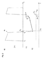
図1には、本発明に係る人工呼吸器の実施形態を、参照符号10で全体的に表している。人工呼吸器10は、図示された例では、ヒト患者12のPSVモードでの人工呼吸に用いられる。 In FIG. 1, an embodiment of a ventilator according to the invention is indicated generally by the reference numeral 10. The ventilator 10 is used for artificial respiration in the PSV mode of the human patient 12 in the illustrated example.
人工呼吸器10は、ハウジング14を有しており、当該ハウジング内には、ハウジング材料が不透明なので外からは認識できないが、圧力変更アセンブリ16と制御装置18とが受容され得る。
The ventilator 10 has a
圧力変更アセンブリ16は、これまで知られているように構成されており、ポンプ、圧縮機、送風機、蓄圧器、減圧弁等を有し得る。さらに、人工呼吸器10は、これまで知られているように、吸気弁20と呼気弁22とを有している。
The
制御装置18は、一般的には、コンピュータ又はマイクロプロセッサとして構成されている。当該制御装置は、図1には示されていない記憶装置を含んでおり、それによって、人工呼吸器10の動作に必要なデータを保存し、必要な場合には呼び出すことができる。記憶装置は、ネットワーク構築の際に、ハウジング14の外側に配置され、データ伝送コネクションを通じて制御装置18に接続されていても良い。当該データ伝送コネクションは、ケーブル又は無線リンクによって形成され得る。しかしながら、データ伝送コネクションの障害が、人工呼吸器10の動作に影響を与える可能性を回避するために、記憶装置は、好ましくは制御装置18に組み込まれているか、又は、少なくとも制御装置18と同じハウジング14に受容されている。
The
人工呼吸器10に、又は、より正確には制御装置18にデータを入力するために、人工呼吸器10は、データ入力部24を有しており、当該データ入力部は、図1に示された例では、キーボードによって表されている。以下にさらに詳細に記載するように、キーボードは、制御装置18の唯一のデータ入力部ではない。実際には、制御装置18は、例えばネットワーク回線、無線リンク、又は、センサ接続部26等の、様々なデータ入力部を通じてデータを獲得することができる。これらについては、以下で、詳細に検討する。
In order to input data into the ventilator 10 or more precisely into the
治療している医師にデータを出力するために、人工呼吸器10は、出力装置28を有していて良く、図示された例ではスクリーンを有している。
In order to output data to the treating physician, the ventilator 10 may have an
人工呼吸のために、患者12は、人工呼吸器10と、より正確にはハウジング14内の圧力変更アセンブリ16と、呼吸ガス誘導アセンブリ30を通じて接続されている。患者12は、このために挿管されている。チューブ31は、人工呼吸器10の患者インターフェースを形成している。代替的に、患者インターフェースは、鼻及び口を覆うマスクを含み得る。
For mechanical ventilation, the patient 12 is connected through a respiratory
これに加えて、人工呼吸器10は、呼吸ガス容器に接続するための、図1には示されていない接続構造を有している。当該接続構造は、単純な場合では、吸気管であって良く、当該吸気管を通じて、周囲空気が、望ましくはフィルタを介在させて、人工呼吸器10のすぐ周囲から、呼吸ガス誘導アセンブリ30内へ吸い込まれ得る。当該接続構造は、フロー導管連結部であっても良く、当該フロー導管連結部を用いて人工呼吸器が、空気であれ、酸素であれ、ガス容器に接続可能である。当該ガス容器は、例えば病院に設備の一部として設置されているような、ガスタンク又は集合容器であり得る。
In addition to this, the ventilator 10 has a connection structure not shown in FIG. 1 for connecting to the breathing gas container. The connection structure may, in a simple case, be an inspiratory tube, through which ambient air, preferably with a filter interposed, immediately around the ventilator 10 into the respiratory
呼吸ガス誘導アセンブリ30は、吸気ホース32を有しており、吸気ホース32を通じて、新鮮な呼吸ガスが、圧力変更アセンブリ16から患者12の肺へ誘導され得る。吸気ホース32は、中断可能であり、第1の吸気ホース34と第2の吸気ホース36とを有し、これらの間には、効果的に湿気を与え、必要な場合には、患者12に供給される新鮮な呼吸ガスの温度調整も行うために、調整装置38を設けることができる。調整装置38は、外部の液体容器40と接続可能であり、液体容器40によって、湿気を与えるための水、又は、例えば炎症の抑制又は気道の拡張ための薬剤も、調整装置38に供給可能である。本発明に係る人工呼吸器10を麻酔人工呼吸器として用いる場合、揮発性の麻酔薬が、管理下で、人工呼吸器10によって、患者12に投与され得る。調整装置38は、新鮮な呼吸ガスが、患者12に、所定の水分含量で、必要に応じて薬剤のエアロゾルを添加し、所定の温度で供給されるように手配する。
The breathing
呼吸ガス誘導アセンブリ30は、すでに言及した吸気弁20及び呼気弁22の他に、さらに呼気ホース42を有しており、呼気ホース42を通じて、代謝された呼吸ガスが、患者12の肺から大気に放出される。
In addition to the
吸気ホース32は、吸気弁20に連結されており、呼気ホース42は、呼気弁22に連結されている。これら2つの弁の内、ガスフローの通過のために、同時にはそれぞれ1つのみが開かれる。弁20及び22の作動制御は、同様に制御装置18によって行われる。
The
人工呼吸サイクルの間、まず吸気段階が続く間は、呼気弁22は閉じられており、吸気弁20は開かれているので、新鮮な呼吸ガスがハウジング14から患者12に誘導され得る。新鮮な呼吸ガスのフローは、圧力変更アセンブリ16による呼吸ガスの効率的な圧力上昇を通じてもたらされる。圧力の上昇に基づいて、新鮮な呼吸ガスは、患者12の肺に流入し、肺に近い身体部分、すなわち特に胸郭を、肺に近い身体部分の個々の弾性に反して膨張させる。それによって、患者12の肺の内部におけるガス圧も上昇する。
During the artificial respiration cycle, the
吸気段階の終わりに、吸気弁20は閉じられ、呼気弁22が開かれる。呼気段階が開始する。吸気段階の最後までに上昇した、患者12の肺内の呼吸ガスのガス圧ゆえに、当該呼吸ガスは、呼気弁22が開かれた後、大気中に流れ、流れ続けると、患者12の肺内のガス圧は低下する。肺12内のガス圧が、例えば人工呼吸器10において設定された呼気終末陽圧、すなわち大気圧よりもわずかに高い圧力に達すると、呼気弁22が閉じられて呼気段階は終了し、さらなる人工呼吸サイクルが引き続き行われる。これは、複数のトリガー基準の内の1つであり、その存在によって、制御装置は、人工呼吸器の呼気動作から吸気動作への切り替えをトリガーし得る。
At the end of the inspiratory phase, the
吸気段階の間、患者12には、いわゆる人工呼吸の一回換気量、すなわち1呼吸当たりの呼吸ガス体積が供給される。人工呼吸の一回換気量を、1分当たりの人工呼吸サイクル数と、すなわち人工呼吸頻度と乗じると、ここで行われる人工呼吸の分時換気量になる。 During the inspiratory phase, the patient 12 is supplied with a so-called artificial ventilation tidal volume, ie a respiratory gas volume per breath. The ventilation tidal volume of artificial respiration is multiplied by the number of artificial respiration cycles per minute, that is, the artificial respiration frequency to obtain the minute ventilation of the artificial respiration performed here.
好ましくは、人工呼吸器10、特に制御装置18は、人工呼吸器10の人工呼吸動作を特徴付ける人工呼吸動作パラメータを、人工呼吸動作の間、繰り返しアップデートする、又は、検出するように構成されており、それによって、人工呼吸動作が、いずれの時点においても可能な限り最適に、人工呼吸が施されるべき患者12それぞれに合わせられていることが保証される。特に有利には、1つ又は複数の人工呼吸動作パラメータの決定は、人工呼吸頻度を用いて行われるので、各人工呼吸サイクルに関して、最新の、従って患者12に最適に合わせられた人工呼吸動作パラメータが供給され得る。
Preferably, the ventilator 10, and in particular the
人工呼吸器10は、少なくともフローセンサ44と、好ましくは、例えば呼吸ガス誘導アセンブリ30内の呼吸ガス圧力を測定するための圧力センサ等のさらなるセンサと、データを伝送できるように接続されている。フローセンサ44は、呼吸ガス誘導アセンブリ30内で支配的な呼吸ガスフローを検出し、呼吸ガスフローを表す信号を出力する。フローセンサ44は、好ましくはセンサ誘導アセンブリ46を用いて、制御装置18のデータ入力部26と連結されている。センサ誘導アセンブリ46は、電気的信号伝送回線を含み得るが、必ずしも必要ではない。センサ誘導アセンブリ46は、同様にホース管を有することが可能であり、当該ホース管は、フロー方向においてフローセンサ44の両側で支配的なガス圧力を、データ入力部26に伝送し、データ入力部26では、当該ガス圧力は、図1に示されていない圧力センサによって定量化される。
The ventilator 10 is connected so as to be able to transmit data at least to the flow sensor 44 and preferably to further sensors, for example pressure sensors for measuring the breathing gas pressure in the breathing
単に、完全性のために、本発明に係る人工呼吸器10が、ポータブルの人工呼吸器10として、転がすことのできる台48の上に受容され得ることを指摘しておく。
It is merely pointed out that the ventilator 10 according to the invention can be received as a portable ventilator 10 on a
フローセンサ44は、好ましくは呼吸ガス誘導アセンブリ30の一部の内に配置されており、そこではフローセンサ44は、吸気フローだけではなく、呼気フローも検出可能である。代替的に、又は、過剰という理由から付加的にも、吸気ホース32及び/又は呼気ホース42及び/又はハウジング14に、少なくとも1つのさらなるフローセンサを設けても良い。
The flow sensor 44 is preferably located within a portion of the respiratory
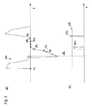
図2aには、経時的なフロー信号推移50が例示的かつ極めて概略的に示されており、明らかであるように、これは、図1の患者12がCOPD患者である場合である。吸気プロセスは、時点t0において開始する。当該時点において、制御装置18は、上述の吸気プロセスを導入し、吸気導管32内の圧力を、予め設定された吸気圧力まで上昇させる。
In FIG. 2a, the
吸気ホース32内の圧力上昇によって、例えば時間単位当たりの体積における体積流量として記録される呼吸ガスフローが急速に増大し、その後、肺に新鮮な呼吸ガスが満たされていくにつれて、値が低下していく。患者12の方へ、又は、患者12の中へ向かう呼吸ガスフローは、取り決めに従って、プラスの符号が付されている。
The pressure rise in the
患者12の肺が充填されると、患者の肺、肺を取り囲む呼吸筋、及び、胸郭は拡張する。時点t1では、サイクリング、すなわち人工呼吸器10の吸気動作から呼気動作への切り替えが行われる。吸気弁20は閉じられ、呼気弁22は開かれる。それによって、患者に向かう呼吸ガスフローは急激に低下し、そのフロー方向が逆転し、患者12の呼吸器系の領域における、肺への新鮮な呼吸ガスの導入によって前もって上昇した身体の緊張によって動かされる。患者12の息の吐出しは受動的に行われ、新鮮な呼吸ガスが送り込まれることによって拡張した身体部分が緩められる。
When the patient's 12 lungs are filled, the patient's lungs, the respiratory muscles surrounding the lungs, and the thorax expand. At time t 1, cycling, that is, switching to exhalation from the intake operation of the ventilator 10 are carried out. The
方向の反転によって、呼吸ガスフローはマイナスになり、弁、すなわち吸気弁20と呼気弁22とが切り替えられた後の時点t2でようやく、実際の呼気プロセスが生じ、呼気プロセスでは、代謝した呼吸ガスが患者12の肺から排出される。これは、COPD患者の場合、その閉塞した呼吸器系ゆえに、徐々にしか行われないので、フロー信号推移50は、比較的小さい、さしあたり一定の勾配で増大する。呼吸ガスフローは、値としては低下するが、フローの符号を考慮すると、増大している。なぜなら、呼吸ガスフローは、値としては、より低いマイナスの値に変化するからである。これは、時間単位当たりに、COPD患者によって呼吸された、代謝された呼吸ガスが、略一定の体積流量の差分値の分だけ減少したことを意味している。
The reversal of direction, the breathing gas flow becomes negative, the valve, i.e. finally at time t 2 after the
COPD患者12の肺が空になっていくのにつれて初めて、フロー信号勾配50における変化、特に増大が生じる。これに関しては、フロー信号推移の3つの最後の基点、すなわち基点52、54及び56が参照される。
Only as the lungs of COPD patient 12 empties will a change, especially an increase in
図2aにおいて認識可能であるように、フロー信号推移50の勾配の値は、基点52と基点54との間において、基点52において先行する基点に比べて変化している。勾配は増加している。
As can be appreciated in FIG. 2a, the value of the slope of the
フロー信号推移50の勾配は、再び、基点54と基点56との間で変化する。勾配は再び増加する。
The slope of the
図2bには、時間軸tにわたって、図2aの時間軸tに関連付けて、勾配の増加が示されている。その際、図2aの基点52から基点56の領域におけるフロー信号推移の描写に対応して、曲線の先行する推移と比較した、基点52から基点54へのフロー信号推移50の勾配の変化は、基点54と基点56との間における推移50の勾配の変化よりも低くなっている。勾配の変化は、勾配の算出に用いられる基点の対の、それぞれ時間的に遅い基点に、すなわち基点54及び基点56に割り当てられている。従って、先行する区間の推移と比較した、基点52及び基点54の領域におけるフロー信号推移50の勾配の変化値、特に増加値は、54sで示されており、基点50と基点52との間の区間に対する、基点54及び基点56の領域におけるフロー信号推移の変化値、特に増加値は、56sで示されている。
In FIG. 2b, the increase of the slope is shown over the time axis t in relation to the time axis t of FIG. In that case, the change in slope of the
図2bには、さらに、勾配変化閾値58が示されており、勾配変化閾値58は、人工呼吸器10の呼気動作から吸気動作への移行を引き起こすためのトリガー基準として用いられる。 Also shown in FIG. 2b is a gradient change threshold 58, which is used as a trigger criterion to trigger a transition from the exhalation operation to the inspiratory operation of the ventilator 10.
勾配変化閾値58は、図2bの例において、COPD患者に関して適切に、患者がまだ呼気段階にあり、吸気努力をしていない変化値54sが、勾配変化閾値58よりも下側に位置するように選択されている。 The gradient change threshold 58 is appropriate for the COPD patient in the example of FIG. 2b so that the patient is still in the expiratory phase and the change value 54s without inspiratory effort is below the gradient change threshold 58. It is selected.
とはいえ、変化値56sは、自身で吸気努力を行う際に、COPD患者に典型的な値に戻るので、この値は、勾配変化閾値58を超過し、従って、制御装置18に、人工呼吸器10を呼気動作から吸気動作に切り替えさせる。
Nevertheless, since the change value 56s returns to a value typical for COPD patients when doing inspiratory effort on its own, this value exceeds the gradient change threshold 58, and thus the
図2bにおいて認識できるように、呼気フローの値が初めて著しく増大した後で、患者から出てくる呼吸ガスフローの値が、徐々に再び低下する場合、呼気の最初の段階で、つまりt2の時点で、フロー信号推移50の勾配に著しい増加が生じている。
As can be appreciated in FIG. 2b, if the value of the respiratory gas flow emerging from the patient gradually decreases again after the value of the expiratory flow has increased significantly for the first time, then in the first phase of the exhalation, ie t 2 At the point in time there is a significant increase in the slope of the
このフロー信号推移50の勾配の変化が、呼気動作の開始時にすでに、吸気動作への移行を引き起こすことを防止するために、制御装置18には、時間の閾値60が保存されており、当該閾値から、トリガー信号を供給するための、経時的フロー信号推移50の勾配の変化がようやく観察される。時間の閾値60は、例えば吸気弁20を閉じてから、又は、呼気弁22を開いてからの所定の期間であり得る。
In order to prevent the change of the gradient of the
図3a及び図3bには、ARDS患者に関する、図2a及び図2bにそれぞれ対応するフロー信号推移150の描写が示されている。ARDS患者は、いわゆる拘束性の呼吸器系を有しており、そのコンプライアンスは非常に低い。当該呼吸器系は、呼吸器が正常な患者よりも弾性が少ない。それに対して、COPD患者の場合、呼吸器系のレジスタンスは、呼吸器が正常な患者よりも大きい。
Figures 3a and 3b show a depiction of the
ARDS患者の呼吸器系のコンプライアンスが減少するので、患者の肺への新鮮な呼吸ガスの導入は、比較的弾性に乏しい肺と、同様に弾性に乏しい気道とに対して、増大した仕事を必要とする。従って、フロー信号推移150は、基本的に、呼吸器が正常な患者の場合よりも勾配が急であり、特にCOPD患者よりも勾配が急である。得られたフローの最大値も、より大きい。
Because respiratory compliance in ARDS patients is reduced, the introduction of fresh respiratory gas into the patient's lungs requires increased work on the less elastic lungs and also the less elastic airways. I assume. Thus, the
図2a及び図2bと同じ、及び、機能が同じ詳細部分には、図3a及び図3bにおいて同じ参照符号が用いられるが、符号の数には100が加えられている。 The same reference numerals are used in FIGS. 3a and 3b for the same detail parts as in FIGS. 2a and 2b and for the same functions, but with 100 added to the number of symbols.
図3aにおいて認識されるように、呼気段階の開始時には、呼気呼吸ガスフローは、COPD患者の場合よりも高い値に達しており、これは、ARDS患者のコンプライアンスが低いのと同様に、COPD患者の呼吸が閉塞性であることによる。概ね同じ理由から、図3aに係るARDS患者の場合は、COPD患者の場合よりも、呼気呼吸ガスフローが速く低下する。 As recognized in FIG. 3a, at the beginning of the exhalation phase, the exhaled breath gas flow has reached a higher value than for COPD patients, which is similar to the low compliance of ARDS patients. Due to the fact that their breathing is obstructive. For roughly the same reason, in the case of ARDS patients according to FIG. 3a, the exhaled breath gas flow drops faster than in the case of COPD patients.
これは、ARDS患者の呼気時定数が、COPD患者の呼気時定数よりも著しく低い値を有することによっても明らかになる。 This is also manifested by the fact that the exhalation time constant of ARDS patients has a value significantly lower than that of COPD patients.
COPD患者の場合、呼気段階の間のフロー信号推移は、長い期間にわたって一定の勾配で延在するが、ARDS患者の場合、フロー信号推移の勾配は、一般的には、呼気段階の間に複数回変化する。 For COPD patients, the flow signal transition during the expiratory phase extends with a constant slope over a long period of time, while for ARDS patients, the slope of the flow signal transition is generally more than one during the expiratory phase. Change times.
フロー信号推移の勾配の変化を考慮するトリガー基準の存在に関する呼気フロー信号推移の評価のために、ここで議論されるトリガー基準に関しては、好ましくはフロー信号150の勾配の変化であって、フロー信号推移150の勾配が増大する、すなわちフロー信号推移150の湾曲がY座標のプラスの無限から見た場合に凹型の形状を有している変化のみが考慮され、他方、フロー信号推移150がより平坦になる勾配の凸状の変化は、最初は全く考慮されない。
For the evaluation of the exhalation flow signal transition with respect to the presence of a trigger criterion that takes into account the change in the gradient of the flow signal transition, with regard to the trigger criterion discussed here, preferably the change in the gradient of the
それに対応して、図3bでは、フロー信号曲線150の勾配の、プラスである変化のみが示されている。
Correspondingly, only positive changes of the slope of the
呼気プロセスの間の、基点162における比較的明らかな勾配の増加は、COPD患者に関しては、図2bに示された勾配変化閾値58をはるかに超えた、従って呼気動作から吸気動作への移行を引き起こし得る値に達していることが認識される。 The relatively apparent increase in slope at the origin point 162 during the exhalation process far exceeded the slope change threshold 58 shown in FIG. 2b for COPD patients, thus causing a transition from expiratory to inspiratory movement It is recognized that the obtained value has been reached.
ARDS患者にとっては、呼気段階のこの期間における人工呼吸器10の切り替えは、非常に不快であろう。なぜなら、患者は、呼気プロセスの最中に、患者に向かって流れてくる吸気フローの負荷を受けている可能性があるからである。 For ARDS patients, switching ventilators 10 during this period of the exhalation phase would be very uncomfortable. This is because the patient may be under load from the inspiratory flow flowing towards the patient during the exhalation process.
従って、ARDS患者に関する勾配変化閾値158は、有利には、COPD患者に関する勾配変化閾値よりも大きくなるように選択されている。呼吸器が正常な患者に関する、対応する勾配変化閾値は、閾値58と閾値158との間に位置し得る。
Thus, the
呼気プロセスの終了時、基点154から、PSVモードにおいて補助的に人工呼吸を施されたARDS患者は、呼吸ガスの吸入を開始し、それによって、フロー信号推移150の勾配の著しい増大が生じる。基点154と基点156との間における推移は、直接先行する基点152と基点154との間の推移よりも著しく急であるか、又は、著しく大きい勾配を有している。人工呼吸の間に、少なくとも時折自発的に呼吸をしているARDS患者の、自身の吸気努力に基づいて、このフロー信号推移の上昇は、プラスのフロー信号に至るまで行われる。付属する変化値156sは、図3bに示されている。当該変化値156sは、ARDS患者に関して決定された勾配変化閾値158を超過し、従って、人工呼吸器10の呼気動作から吸気動作への移行を引き起こす。
At the end of the exhalation process, from the origin point 154, an ARDS patient who has been assisted artificially in PSV mode begins to inhale breathing gas, which results in a significant increase in the slope of the
人工呼吸器10のデータ記憶装置は、特性要因図、図表、保存された関数又は近似関数等の形で、人工呼吸の場合に用いられるべき勾配変化閾値と、患者12の呼吸器系の状態を特徴付ける呼気時定数との間の関係を含み得る。 The data storage device of the ventilator 10, in the form of a factorial diagram, a chart, a stored function or an approximation function, etc., the gradient change threshold to be used in the case of artificial respiration and the condition of the respiratory system of the patient 12 It may include the relationship between the exhalation time constants to characterize.
制御装置18は、現在人工呼吸を行うべき患者12の呼気時定数から出発して、保存された関係を用いて、現在人工呼吸を行うべき患者12に関して適用されるべき勾配変化閾値のデータが存在するかを確認する、又は、演算オペレーションによって算出することができる。
Starting from the expiratory time constant of the patient 12 who is currently to be ventilated, the
現在人工呼吸を行うべき患者12の呼気時定数は、例えば勾配変化閾値に関する少なくとも1つの初期値を有するために呼気時定数が知られている場合、医療従事者によって手動で人工呼吸器10に入力することができる。 The expiratory time constant of the patient 12 who is currently to be ventilated is manually entered into the ventilator 10 by the healthcare worker if the expiratory time constant is known, for example to have at least one initial value for the slope change threshold. can do.
有利には、制御装置18は、制御装置18が利用できるセンサ情報に基づいて、人工呼吸を施されるべき患者12それぞれの呼気時定数を算出するように構成されている。このために、先行技術では、複数の手段が知られている。呼気時定数を算出するための可能な方法は、ただフローセンサ44によって得られる情報に基づいて実施され得る。例えば、呼気時定数は、呼気段階の間に吐出された呼吸ガス体積と、その際、同じ呼気段階の間に生じる最大の呼吸ガスフローとを用いて算出され得る。呼気時定数を算出するための、さらなる可能な算出方法については、すでに説明の冒頭部分で指摘されている。
Advantageously, the
従って、本発明に係る人工呼吸器10を用いて、正反対の病的な呼吸器系を有する患者にさえも、高い同調性を伴って、穏やかかつ確実に人工呼吸を行うことができる。なぜなら、人工呼吸器10は、患者12の呼吸器系の状態を検出し、検出された呼吸器系の状態から出発して、人工呼吸器10の呼気動作から吸気動作への切り替えに関する、勾配に依存するトリガー基準を、人工呼吸を施されるべき患者それぞれに適応させることができるからである。 Thus, with the ventilator 10 according to the present invention, even patients with opposite pathological respiratory systems can be ventilated gently and reliably, with high synchrony. Because the ventilator 10 detects the state of the respiratory system of the patient 12 and starts from the detected state of the respiratory system on the gradient for switching from the expiratory operation to the inspiratory operation of the ventilator 10 This is because the dependent trigger criteria can be adapted to each patient to be ventilated.
10 人工呼吸器
12 患者
14 ハウジング
16 圧力変更アセンブリ
18 制御装置
20 吸気弁
22 呼気弁
24 データ入力部
26 センサ接続部
28 出力装置
30 呼吸ガス誘導アセンブリ
31 チューブ、患者インターフェース
32 吸気ホース
34 第1の吸気ホース
36 第2の吸気ホース
38 調整装置
40 液体容器
42 呼気ホース
44 フローセンサ
46 センサ誘導アセンブリ
48 台
50、150 フロー信号推移
52、54、56、152、154、156 基点
54s 変化値
56s、156s 変化値
58、158 勾配変化閾値
60、160 時間の閾値
162 基点
DESCRIPTION OF SYMBOLS 10 Ventilator 12
Claims (10)
−呼吸ガス容器に接続するための接続構造、
−前記人工呼吸器(10)の吸気動作の際には、新鮮な吸気呼吸ガスを、前記接続構造から患者インターフェース(31)に向かって誘導し、呼気動作の際には、代謝された呼気呼吸ガスを、前記患者インターフェース(31)から離れるように誘導する呼吸ガス誘導アセンブリ(30)、
−前記呼吸ガス誘導アセンブリ(30)内で呼吸ガスの圧力を変更するための圧力変更アセンブリ(16)、
−前記呼吸ガス誘導アセンブリ(30)内の、少なくとも呼気呼吸ガスの呼吸ガス体積フローを示すフロー信号(50;150)を供給するように構成され、配置されたフローセンサ(44)、及び、
−前記人工呼吸器(10)の動作を制御する制御装置(18)であって、時間的に連続して供給されたフロー信号を表しているフロー信号推移(50;150)の勾配の増大が、勾配変化閾値(58;158)を超える場合に、前記人工呼吸器(10)の呼気動作から吸気動作への移行をトリガーするように構成された制御装置(18)、
を含んでいる人工呼吸器において、
前記制御装置(18)がさらに、前記勾配変化閾値(58;158)を、人工呼吸されるべき患者(12)それぞれの呼気時定数に応じて算出し、前記フロー信号推移(50;150)の勾配の増大が、前記呼気時定数に基づいて算出された勾配変化閾値(58;158)を超える場合に、前記人工呼吸器(10)の呼気動作から吸気動作への移行をトリガーするように構成されていることを特徴とする人工呼吸器(10)。 A respirator (10) for at least supplemental ventilation of a living being (12) breathing in a normal condition,
Connection structure for connection to the breathing gas container,
-During the inspiratory operation of the ventilator (10), a fresh inspiratory respiratory gas is derived from the connection structure towards the patient interface (31), and in the case of the expiratory operation the metabolized exhalation breath A breathing gas directing assembly (30) for directing gas away from the patient interface (31);
A pressure change assembly (16) for changing the pressure of the breathing gas in said breathing gas guiding assembly (30);
-A flow sensor (44) configured and arranged to supply a flow signal (50; 150) indicative of at least the breathing gas volume flow of exhaled breathing gas within said breathing gas guiding assembly (30), and
A control device (18) for controlling the operation of the ventilator (10), wherein an increase in the slope of the flow signal transition (50; 150) representing the flow signal supplied continuously in time A controller (18) configured to trigger a transition from an exhalation operation to an inspiratory operation of the ventilator (10) if a gradient change threshold (58; 158) is exceeded.
In a ventilator that contains
The controller (18) further calculates the gradient change threshold (58; 158) according to the expiratory time constant of the patient (12) to be artificially ventilated, and the flow signal transition (50; 150). It is configured to trigger the transition from the exhalation operation to the inspiratory operation of the ventilator (10) when the increase in gradient exceeds the gradient change threshold (58; 158) calculated based on the expiratory time constant. Ventilator (10) characterized by being.
Applications Claiming Priority (3)
| Application Number | Priority Date | Filing Date | Title |
|---|---|---|---|
| DE102016206442.8 | 2016-04-15 | ||
| DE102016206442.8A DE102016206442A1 (en) | 2016-04-15 | 2016-04-15 | Ventilator with improved synchrony in the transition from expiratory to inspiratory operation |
| PCT/EP2017/058577 WO2017178440A1 (en) | 2016-04-15 | 2017-04-10 | Respirator having improved synchronicity during the transition from expiratory to inspiratory operation |
Publications (2)
| Publication Number | Publication Date |
|---|---|
| JP2019511301A true JP2019511301A (en) | 2019-04-25 |
| JP2019511301A5 JP2019511301A5 (en) | 2020-05-21 |
Family
ID=58503650
Family Applications (1)
| Application Number | Title | Priority Date | Filing Date |
|---|---|---|---|
| JP2018550597A Ceased JP2019511301A (en) | 2016-04-15 | 2017-04-10 | Ventilator with improved synchrony in transition from exhalation to inspiratory movement |
Country Status (7)
| Country | Link |
|---|---|
| US (1) | US20200215283A9 (en) |
| EP (1) | EP3247437B1 (en) |
| JP (1) | JP2019511301A (en) |
| CN (1) | CN109069780A (en) |
| AU (1) | AU2017251164A1 (en) |
| DE (1) | DE102016206442A1 (en) |
| WO (1) | WO2017178440A1 (en) |
Families Citing this family (11)
| Publication number | Priority date | Publication date | Assignee | Title |
|---|---|---|---|---|
| DE102017006655A1 (en) * | 2017-07-13 | 2019-01-17 | GRÜNDLER GmbH | Respiratory support system and patient set for this |
| DE102017008791A1 (en) * | 2017-09-20 | 2019-03-21 | Drägerwerk AG & Co. KGaA | Method of operating a ventilator and ventilator operating on the procedure |
| WO2020049411A1 (en) * | 2018-09-04 | 2020-03-12 | Fisher & Paykel Healthcare Limited | Support for a breathing assistance apparatus and/or accessories |
| JP7290406B2 (en) * | 2018-10-03 | 2023-06-13 | 帝人ファーマ株式会社 | Breathing gas supply device and its control method |
| CN110947062A (en) * | 2019-03-31 | 2020-04-03 | 湖南明康中锦医疗科技发展有限公司 | Respiration withdrawal judgment method of respiration support equipment |
| DE102020002278A1 (en) * | 2019-04-24 | 2020-10-29 | Löwenstein Medical Technology S.A. | Breathing gas supply system and procedure |
| WO2021068160A1 (en) * | 2019-10-10 | 2021-04-15 | 深圳迈瑞生物医疗电子股份有限公司 | Ventilation mode switch control method and device, medical ventilation apparatus, and storage medium |
| WO2021109003A1 (en) * | 2019-12-03 | 2021-06-10 | 深圳迈瑞生物医疗电子股份有限公司 | Pressure generation device identification method and system, ventilation support apparatus, and storage medium |
| CN111298255B (en) * | 2020-02-22 | 2023-07-18 | 湖南城市学院 | Breathing machine based on ventilation capacity automatic triggering switching output respiratory air pressure |
| CN111632241B (en) * | 2020-06-08 | 2021-05-11 | 山东科技大学 | Control system of humidification therapeutic instrument |
| CN114681739B (en) * | 2020-12-30 | 2024-07-30 | 深圳迈瑞生物医疗电子股份有限公司 | Anesthesia breathing equipment and breathing circuit compliance detection method |
Citations (4)
| Publication number | Priority date | Publication date | Assignee | Title |
|---|---|---|---|---|
| JPH05184676A (en) * | 1991-07-04 | 1993-07-27 | Draegerwerk Ag | Artificial respirator for discriminating respiratory phase |
| JPH09313608A (en) * | 1996-06-03 | 1997-12-09 | Respironics Inc | Detection method for gas flow |
| US6439229B1 (en) * | 2000-08-08 | 2002-08-27 | Newport Medical Instruments, Inc. | Pressure support ventilation control system and method |
| US20140053840A1 (en) * | 2011-12-30 | 2014-02-27 | Beijing Aeonmed Co., Ltd. | Human-Machine Synchronization Method And Device Of Invasive Ventilator Operating In Noninvasive Ventilation Mode |
Family Cites Families (12)
| Publication number | Priority date | Publication date | Assignee | Title |
|---|---|---|---|---|
| US3834382A (en) | 1972-09-05 | 1974-09-10 | Johnson Service Co | Fluidic respirator control system with patient triggering response means |
| US5632269A (en) * | 1989-09-22 | 1997-05-27 | Respironics Inc. | Breathing gas delivery method and apparatus |
| DE4432219C1 (en) | 1994-09-10 | 1996-04-11 | Draegerwerk Ag | Automatic breathing system for patients |
| US5551419A (en) * | 1994-12-15 | 1996-09-03 | Devilbiss Health Care, Inc. | Control for CPAP apparatus |
| DE19528113C2 (en) * | 1995-08-01 | 2002-09-12 | Univ Ludwigs Albert | ventilator |
| DE10031079A1 (en) * | 2000-06-30 | 2002-02-07 | Map Gmbh | Measuring patient breathing and state, correlates present respiration signals with prior reference measurements, to adjust CPAP therapy pressure accordingly |
| DE102004014538A1 (en) * | 2004-03-23 | 2005-10-13 | Seleon Gmbh | Method for controlling a BiLevel device and BiLevel device |
| WO2007059263A2 (en) * | 2005-11-16 | 2007-05-24 | Cardiopulmonary Technologies, Inc, | Side-stream respiratory gas monitoring system and method |
| DE102007052897B4 (en) * | 2007-11-07 | 2013-02-21 | Dräger Medical GmbH | Method for automatically controlling a ventilation system and associated ventilation system |
| US9636474B2 (en) * | 2010-08-27 | 2017-05-02 | Resmed Limited | Adaptive cycling for respiratory treatment apparatus |
| US9592356B2 (en) * | 2010-09-10 | 2017-03-14 | Koninklijke Philips N.V. | System and method for identifying breathing transitions |
| CN103608062B (en) * | 2011-03-18 | 2016-04-13 | 马奎特紧急护理公司 | Support breathing apparatus and the method for ventilation |
-
2016
- 2016-04-15 DE DE102016206442.8A patent/DE102016206442A1/en not_active Withdrawn
-
2017
- 2017-04-10 WO PCT/EP2017/058577 patent/WO2017178440A1/en active Application Filing
- 2017-04-10 AU AU2017251164A patent/AU2017251164A1/en not_active Abandoned
- 2017-04-10 JP JP2018550597A patent/JP2019511301A/en not_active Ceased
- 2017-04-10 EP EP17716248.4A patent/EP3247437B1/en active Active
- 2017-04-10 CN CN201780023459.5A patent/CN109069780A/en active Pending
- 2017-04-10 US US16/093,818 patent/US20200215283A9/en not_active Abandoned
Patent Citations (4)
| Publication number | Priority date | Publication date | Assignee | Title |
|---|---|---|---|---|
| JPH05184676A (en) * | 1991-07-04 | 1993-07-27 | Draegerwerk Ag | Artificial respirator for discriminating respiratory phase |
| JPH09313608A (en) * | 1996-06-03 | 1997-12-09 | Respironics Inc | Detection method for gas flow |
| US6439229B1 (en) * | 2000-08-08 | 2002-08-27 | Newport Medical Instruments, Inc. | Pressure support ventilation control system and method |
| US20140053840A1 (en) * | 2011-12-30 | 2014-02-27 | Beijing Aeonmed Co., Ltd. | Human-Machine Synchronization Method And Device Of Invasive Ventilator Operating In Noninvasive Ventilation Mode |
Also Published As
| Publication number | Publication date |
|---|---|
| CN109069780A (en) | 2018-12-21 |
| AU2017251164A1 (en) | 2018-09-13 |
| WO2017178440A1 (en) | 2017-10-19 |
| EP3247437A1 (en) | 2017-11-29 |
| US20190134331A1 (en) | 2019-05-09 |
| EP3247437B1 (en) | 2018-10-31 |
| DE102016206442A1 (en) | 2017-10-19 |
| US20200215283A9 (en) | 2020-07-09 |
Similar Documents
| Publication | Publication Date | Title |
|---|---|---|
| JP2019511301A (en) | Ventilator with improved synchrony in transition from exhalation to inspiratory movement | |
| US9968751B2 (en) | Method and apparatus for resolving upper airway obstruction, resistance or instability | |
| JP5775882B2 (en) | Ventilation system controlled automatically | |
| US11931509B2 (en) | Systems and methods for drive pressure spontaneous ventilation | |
| EP2401015B1 (en) | Pressure support system with machine delivered breaths | |
| US20070272241A1 (en) | System and Method for Scheduling Pause Maneuvers Used for Estimating Elastance and/or Resistance During Breathing | |
| US20080142011A1 (en) | System and method of a positive airway pressure device gathering data as to apnea type | |
| JP2020508194A (en) | Automatic PEEP selection for mechanical ventilation | |
| JP2000000307A (en) | Method for detecting at least one parameter and respirator | |
| JPH08257016A (en) | Detecting method for gas stream | |
| US9272111B2 (en) | Leak estimation using function estimation | |
| CN103619392A (en) | Method and apparatus for assisting airway clearance | |
| JP2020535909A (en) | Ventilator with automatic detection of flow sensor error for spontaneous respiration | |
| CN109152899A (en) | Method and apparatus for giving patient ventilating | |
| EP3902587A1 (en) | Pressure support system and method of providing pressure support therapy to a patient | |
| JP6522771B2 (en) | Ventilator | |
| CN110237375B (en) | Breathing machine and negative pressure sputum excretion machine | |
| CN110892486B (en) | Ventilator gas delivery inhalation via virtual pressure trigger mechanism | |
| CN210933251U (en) | Pressure control device, anesthesia machine and breathing machine | |
| WO2015138924A1 (en) | Device for the emulation of a cough in ventilated patients | |
| JP7528205B2 (en) | Method for performing a P/V procedure that automatically avoids lung hyperinflation and a ventilator configured to perform said method | |
| CN117642200A (en) | Ventilation equipment and pressure rise time adjusting method | |
| JPWO2021083981A5 (en) |
Legal Events
| Date | Code | Title | Description |
|---|---|---|---|
| A521 | Request for written amendment filed |
Free format text: JAPANESE INTERMEDIATE CODE: A523 Effective date: 20200406 |
|
| A621 | Written request for application examination |
Free format text: JAPANESE INTERMEDIATE CODE: A621 Effective date: 20200406 |
|
| A977 | Report on retrieval |
Free format text: JAPANESE INTERMEDIATE CODE: A971007 Effective date: 20210317 |
|
| A01 | Written decision to grant a patent or to grant a registration (utility model) |
Free format text: JAPANESE INTERMEDIATE CODE: A01 Effective date: 20210510 |
|
| A045 | Written measure of dismissal of application [lapsed due to lack of payment] |
Free format text: JAPANESE INTERMEDIATE CODE: A045 Effective date: 20210927 |