EP3247437B1 - Respirator having improved synchronicity during the transition from expiratory to inspiratory operation - Google Patents
Respirator having improved synchronicity during the transition from expiratory to inspiratory operation Download PDFInfo
- Publication number
- EP3247437B1 EP3247437B1 EP17716248.4A EP17716248A EP3247437B1 EP 3247437 B1 EP3247437 B1 EP 3247437B1 EP 17716248 A EP17716248 A EP 17716248A EP 3247437 B1 EP3247437 B1 EP 3247437B1
- Authority
- EP
- European Patent Office
- Prior art keywords
- expiratory
- ventilator
- time constant
- flow
- control device
- Prior art date
- Legal status (The legal status is an assumption and is not a legal conclusion. Google has not performed a legal analysis and makes no representation as to the accuracy of the status listed.)
- Active
Links
Images

Classifications
-
- A—HUMAN NECESSITIES
- A61—MEDICAL OR VETERINARY SCIENCE; HYGIENE
- A61M—DEVICES FOR INTRODUCING MEDIA INTO, OR ONTO, THE BODY; DEVICES FOR TRANSDUCING BODY MEDIA OR FOR TAKING MEDIA FROM THE BODY; DEVICES FOR PRODUCING OR ENDING SLEEP OR STUPOR
- A61M16/00—Devices for influencing the respiratory system of patients by gas treatment, e.g. mouth-to-mouth respiration; Tracheal tubes
- A61M16/021—Devices for influencing the respiratory system of patients by gas treatment, e.g. mouth-to-mouth respiration; Tracheal tubes operated by electrical means
- A61M16/022—Control means therefor
- A61M16/024—Control means therefor including calculation means, e.g. using a processor
- A61M16/026—Control means therefor including calculation means, e.g. using a processor specially adapted for predicting, e.g. for determining an information representative of a flow limitation during a ventilation cycle by using a root square technique or a regression analysis
-
- A—HUMAN NECESSITIES
- A61—MEDICAL OR VETERINARY SCIENCE; HYGIENE
- A61M—DEVICES FOR INTRODUCING MEDIA INTO, OR ONTO, THE BODY; DEVICES FOR TRANSDUCING BODY MEDIA OR FOR TAKING MEDIA FROM THE BODY; DEVICES FOR PRODUCING OR ENDING SLEEP OR STUPOR
- A61M16/00—Devices for influencing the respiratory system of patients by gas treatment, e.g. mouth-to-mouth respiration; Tracheal tubes
- A61M16/0003—Accessories therefor, e.g. sensors, vibrators, negative pressure
-
- A—HUMAN NECESSITIES
- A61—MEDICAL OR VETERINARY SCIENCE; HYGIENE
- A61M—DEVICES FOR INTRODUCING MEDIA INTO, OR ONTO, THE BODY; DEVICES FOR TRANSDUCING BODY MEDIA OR FOR TAKING MEDIA FROM THE BODY; DEVICES FOR PRODUCING OR ENDING SLEEP OR STUPOR
- A61M16/00—Devices for influencing the respiratory system of patients by gas treatment, e.g. mouth-to-mouth respiration; Tracheal tubes
- A61M16/10—Preparation of respiratory gases or vapours
- A61M16/104—Preparation of respiratory gases or vapours specially adapted for anaesthetics
-
- A—HUMAN NECESSITIES
- A61—MEDICAL OR VETERINARY SCIENCE; HYGIENE
- A61M—DEVICES FOR INTRODUCING MEDIA INTO, OR ONTO, THE BODY; DEVICES FOR TRANSDUCING BODY MEDIA OR FOR TAKING MEDIA FROM THE BODY; DEVICES FOR PRODUCING OR ENDING SLEEP OR STUPOR
- A61M16/00—Devices for influencing the respiratory system of patients by gas treatment, e.g. mouth-to-mouth respiration; Tracheal tubes
- A61M16/20—Valves specially adapted to medical respiratory devices
- A61M16/208—Non-controlled one-way valves, e.g. exhalation, check, pop-off non-rebreathing valves
-
- A—HUMAN NECESSITIES
- A61—MEDICAL OR VETERINARY SCIENCE; HYGIENE
- A61B—DIAGNOSIS; SURGERY; IDENTIFICATION
- A61B5/00—Measuring for diagnostic purposes; Identification of persons
- A61B5/08—Detecting, measuring or recording devices for evaluating the respiratory organs
- A61B5/087—Measuring breath flow
-
- A—HUMAN NECESSITIES
- A61—MEDICAL OR VETERINARY SCIENCE; HYGIENE
- A61M—DEVICES FOR INTRODUCING MEDIA INTO, OR ONTO, THE BODY; DEVICES FOR TRANSDUCING BODY MEDIA OR FOR TAKING MEDIA FROM THE BODY; DEVICES FOR PRODUCING OR ENDING SLEEP OR STUPOR
- A61M16/00—Devices for influencing the respiratory system of patients by gas treatment, e.g. mouth-to-mouth respiration; Tracheal tubes
- A61M16/01—Devices for influencing the respiratory system of patients by gas treatment, e.g. mouth-to-mouth respiration; Tracheal tubes specially adapted for anaesthetising
-
- A—HUMAN NECESSITIES
- A61—MEDICAL OR VETERINARY SCIENCE; HYGIENE
- A61M—DEVICES FOR INTRODUCING MEDIA INTO, OR ONTO, THE BODY; DEVICES FOR TRANSDUCING BODY MEDIA OR FOR TAKING MEDIA FROM THE BODY; DEVICES FOR PRODUCING OR ENDING SLEEP OR STUPOR
- A61M16/00—Devices for influencing the respiratory system of patients by gas treatment, e.g. mouth-to-mouth respiration; Tracheal tubes
- A61M16/10—Preparation of respiratory gases or vapours
- A61M16/14—Preparation of respiratory gases or vapours by mixing different fluids, one of them being in a liquid phase
- A61M16/16—Devices to humidify the respiration air
-
- A—HUMAN NECESSITIES
- A61—MEDICAL OR VETERINARY SCIENCE; HYGIENE
- A61M—DEVICES FOR INTRODUCING MEDIA INTO, OR ONTO, THE BODY; DEVICES FOR TRANSDUCING BODY MEDIA OR FOR TAKING MEDIA FROM THE BODY; DEVICES FOR PRODUCING OR ENDING SLEEP OR STUPOR
- A61M16/00—Devices for influencing the respiratory system of patients by gas treatment, e.g. mouth-to-mouth respiration; Tracheal tubes
- A61M16/20—Valves specially adapted to medical respiratory devices
- A61M16/201—Controlled valves
- A61M16/202—Controlled valves electrically actuated
- A61M16/203—Proportional
- A61M16/204—Proportional used for inhalation control
-
- A—HUMAN NECESSITIES
- A61—MEDICAL OR VETERINARY SCIENCE; HYGIENE
- A61M—DEVICES FOR INTRODUCING MEDIA INTO, OR ONTO, THE BODY; DEVICES FOR TRANSDUCING BODY MEDIA OR FOR TAKING MEDIA FROM THE BODY; DEVICES FOR PRODUCING OR ENDING SLEEP OR STUPOR
- A61M16/00—Devices for influencing the respiratory system of patients by gas treatment, e.g. mouth-to-mouth respiration; Tracheal tubes
- A61M16/20—Valves specially adapted to medical respiratory devices
- A61M16/201—Controlled valves
- A61M16/202—Controlled valves electrically actuated
- A61M16/203—Proportional
- A61M16/205—Proportional used for exhalation control
-
- A—HUMAN NECESSITIES
- A61—MEDICAL OR VETERINARY SCIENCE; HYGIENE
- A61M—DEVICES FOR INTRODUCING MEDIA INTO, OR ONTO, THE BODY; DEVICES FOR TRANSDUCING BODY MEDIA OR FOR TAKING MEDIA FROM THE BODY; DEVICES FOR PRODUCING OR ENDING SLEEP OR STUPOR
- A61M16/00—Devices for influencing the respiratory system of patients by gas treatment, e.g. mouth-to-mouth respiration; Tracheal tubes
- A61M16/0003—Accessories therefor, e.g. sensors, vibrators, negative pressure
- A61M2016/0015—Accessories therefor, e.g. sensors, vibrators, negative pressure inhalation detectors
- A61M2016/0018—Accessories therefor, e.g. sensors, vibrators, negative pressure inhalation detectors electrical
-
- A—HUMAN NECESSITIES
- A61—MEDICAL OR VETERINARY SCIENCE; HYGIENE
- A61M—DEVICES FOR INTRODUCING MEDIA INTO, OR ONTO, THE BODY; DEVICES FOR TRANSDUCING BODY MEDIA OR FOR TAKING MEDIA FROM THE BODY; DEVICES FOR PRODUCING OR ENDING SLEEP OR STUPOR
- A61M16/00—Devices for influencing the respiratory system of patients by gas treatment, e.g. mouth-to-mouth respiration; Tracheal tubes
- A61M16/0003—Accessories therefor, e.g. sensors, vibrators, negative pressure
- A61M2016/0027—Accessories therefor, e.g. sensors, vibrators, negative pressure pressure meter
-
- A—HUMAN NECESSITIES
- A61—MEDICAL OR VETERINARY SCIENCE; HYGIENE
- A61M—DEVICES FOR INTRODUCING MEDIA INTO, OR ONTO, THE BODY; DEVICES FOR TRANSDUCING BODY MEDIA OR FOR TAKING MEDIA FROM THE BODY; DEVICES FOR PRODUCING OR ENDING SLEEP OR STUPOR
- A61M16/00—Devices for influencing the respiratory system of patients by gas treatment, e.g. mouth-to-mouth respiration; Tracheal tubes
- A61M16/0003—Accessories therefor, e.g. sensors, vibrators, negative pressure
- A61M2016/003—Accessories therefor, e.g. sensors, vibrators, negative pressure with a flowmeter
- A61M2016/0033—Accessories therefor, e.g. sensors, vibrators, negative pressure with a flowmeter electrical
- A61M2016/0036—Accessories therefor, e.g. sensors, vibrators, negative pressure with a flowmeter electrical in the breathing tube and used in both inspiratory and expiratory phase
-
- A—HUMAN NECESSITIES
- A61—MEDICAL OR VETERINARY SCIENCE; HYGIENE
- A61M—DEVICES FOR INTRODUCING MEDIA INTO, OR ONTO, THE BODY; DEVICES FOR TRANSDUCING BODY MEDIA OR FOR TAKING MEDIA FROM THE BODY; DEVICES FOR PRODUCING OR ENDING SLEEP OR STUPOR
- A61M16/00—Devices for influencing the respiratory system of patients by gas treatment, e.g. mouth-to-mouth respiration; Tracheal tubes
- A61M16/0003—Accessories therefor, e.g. sensors, vibrators, negative pressure
- A61M2016/003—Accessories therefor, e.g. sensors, vibrators, negative pressure with a flowmeter
- A61M2016/0033—Accessories therefor, e.g. sensors, vibrators, negative pressure with a flowmeter electrical
- A61M2016/0042—Accessories therefor, e.g. sensors, vibrators, negative pressure with a flowmeter electrical in the expiratory circuit
-
- A—HUMAN NECESSITIES
- A61—MEDICAL OR VETERINARY SCIENCE; HYGIENE
- A61M—DEVICES FOR INTRODUCING MEDIA INTO, OR ONTO, THE BODY; DEVICES FOR TRANSDUCING BODY MEDIA OR FOR TAKING MEDIA FROM THE BODY; DEVICES FOR PRODUCING OR ENDING SLEEP OR STUPOR
- A61M2205/00—General characteristics of the apparatus
- A61M2205/50—General characteristics of the apparatus with microprocessors or computers
- A61M2205/502—User interfaces, e.g. screens or keyboards
- A61M2205/505—Touch-screens; Virtual keyboard or keypads; Virtual buttons; Soft keys; Mouse touches
-
- A—HUMAN NECESSITIES
- A61—MEDICAL OR VETERINARY SCIENCE; HYGIENE
- A61M—DEVICES FOR INTRODUCING MEDIA INTO, OR ONTO, THE BODY; DEVICES FOR TRANSDUCING BODY MEDIA OR FOR TAKING MEDIA FROM THE BODY; DEVICES FOR PRODUCING OR ENDING SLEEP OR STUPOR
- A61M2205/00—General characteristics of the apparatus
- A61M2205/50—General characteristics of the apparatus with microprocessors or computers
- A61M2205/52—General characteristics of the apparatus with microprocessors or computers with memories providing a history of measured variating parameters of apparatus or patient
-
- A—HUMAN NECESSITIES
- A61—MEDICAL OR VETERINARY SCIENCE; HYGIENE
- A61M—DEVICES FOR INTRODUCING MEDIA INTO, OR ONTO, THE BODY; DEVICES FOR TRANSDUCING BODY MEDIA OR FOR TAKING MEDIA FROM THE BODY; DEVICES FOR PRODUCING OR ENDING SLEEP OR STUPOR
- A61M2230/00—Measuring parameters of the user
- A61M2230/40—Respiratory characteristics
- A61M2230/42—Rate
-
- A—HUMAN NECESSITIES
- A61—MEDICAL OR VETERINARY SCIENCE; HYGIENE
- A61M—DEVICES FOR INTRODUCING MEDIA INTO, OR ONTO, THE BODY; DEVICES FOR TRANSDUCING BODY MEDIA OR FOR TAKING MEDIA FROM THE BODY; DEVICES FOR PRODUCING OR ENDING SLEEP OR STUPOR
- A61M2230/00—Measuring parameters of the user
- A61M2230/40—Respiratory characteristics
- A61M2230/46—Resistance or compliance of the lungs
Definitions
- Such a generic ventilator is from the EP 0 521 314 A1 known.
- This document teaches switching a respirator between an expiratory phase and an inspiratory phase when the respiratory flow curve determined during the ventilation phase shows a significant increase in its steepness. Whether or not there is such a significant increase is determined based on a comparison of an increase in steepness with a predetermined slope change threshold.
- This lesson represents an improvement another, also known from the prior art trigger criteria for a transition from expiratory to inspiratory operation of the ventilator.
- a very simple trigger criterion is the base level crossing, such as a zero crossing or a passage through a non-zero base level, the Atemströmungskurve, ie the temporal flow waveform, this trigger criterion is for example from US 3,834,382 known.
- the disadvantage of this criterion is that it essentially works satisfactorily only in patients with a healthy respiratory system, whereas unpleasant asynchronisms may occur to the patient during the artificial respiration of chronic obstructive patients (COPD patients) when the patient shows spontaneous respiration during the artificial respiration ,
- COPD patients chronic obstructive patients
- the trigger criterion of a base level crossing of the flow signal is sensitive to leakage-related effects that may occur in artificial respiration, for example because a respiratory mask, as a potential patient interface, does not completely terminate with the nose and mouth of the patient being ventilated. Other causes can cause leakage currents and thus leakage-induced effects during artificial respiration.
- a breathgas flow trigger threshold for a transition from expiratory to inspiratory operation to increase an additional amount formed by the ratio between the averaged breath pressure during inspiration and the sum of the averaged breath pressures during inspiration and expiration multiplied by the difference of averaged values of respiratory flows during inspiration and during expiration.
- ETS Expiratory Trigger Sensitivity
- This is a percentage of the maximum respiratory gas flow occurring during an inspiratory process, which serves as the cycling threshold. Then, when the flow of breathing gas has dropped to the predetermined cycling threshold during the inspiratory phase, the ventilator is switched from the inspiratory mode to the expiratory mode.
- the ETS-based cycling threshold is often about 25% of the maximum respiratory gas flow occurring during the inspiratory phase.
- the US Pat. No. 6,439,229 B1 now teaches to preselect a range of possible cycling thresholds depending on the determined expiratory time constant of the respective ventilated patient, and a concrete percentage of, within the preselected percentage range, at the end of the pressure-assisted inspiratory phase within the preselected percentage range, depending on the amount of a pressure overshoot referred to as supraplateau-pressure to select the maximum inspiratory breathing gas flow as the cycling threshold.
- the predetermined slope-change threshold used in this case always a compromise that should be applicable to all patients and therefore in individual cases can lead to asynchronies in ventilation, because the patient to be respirated based on the predetermined slope change threshold case only partially applies.
- control device is further configured to determine the slope change threshold depending on an expiratory time constant of each patient to be respirated and then triggers the transition from expiratory to inspiratory operation of the ventilator . if the increase in the slope of the flow waveform exceeds the slope change threshold determined according to the expiratory time constant.
- the transition from expiratory operation to inspiratory operation of the ventilator to the pathological state of the respiratory system of the respective patient can be adjusted almost optimally, as the expiratory time constant of a person represents a highly relevant for the artificial respiration of a patient parameters.
- triggers in the present application is merely intended to trigger a transition from expiratory to inspiratory operation of the ventilator.
- cycling is used to trigger a transition in the opposite direction from inspiratory to expiratory operation.
- control device designed according to the invention not only COPD patients, which have an above-average expiratory time constant compared to patients with healthy respiratory systems, can be ventilated with excellent synchrony, but also ARDS patients whose expiratory time constant is above average short compared to patients with healthy respiratory systems ,
- COPD which is also commonly referred to as “asthma” or “smoker's lung”
- asthma or “smoker's lung”
- due to the obstructive breathing behavior leads to relatively steady breathing gas flow waveforms at which an absolute change in their steepness is relatively easy and safe to determine, so that the already known generic respirator for COPD patients provides relatively good results.
- ARDS patients have a restorative respiratory system, commonly referred to as a "hard" lung. Respiration is often impulsive, which can lead to one or more discontinuities of the breathing gas flow waveform in the form of kinks during an expiratory phase. These kinks represent changes in magnitude of the slope of the flux signal, which may trigger car triggers if the slope change threshold is not favorably selected.
- the present invention also helps to ventilate ARDS patients with the inventively improved ventilator with improved synchrony.
- COPD patients whose expiratory time constant is greater than those of healthy respiratory patients may be ventilated at a slope change threshold that is lower in magnitude than that of ARDS patients and lower than that of patients with a healthy respiratory system.
- the controller is preferably configured to reduce the magnitude of the slope change threshold as the expiratory time constant increases, and vice versa.
- control device is preferably designed to check only those changes in the steepness of the flux waveform to the presence of the exceeding of the slope change threshold value by which the slope of the flux waveform increases, ie, the flux waveform progressively increases.
- the slope change threshold is then preferably a slope increase threshold to apply in rising flux waveform sections, but not in descending ones.
- the trigger criterion discussed in the present application is not the only trigger criterion according to which the control device can change or change the operation of the ventilation device from expiratory to inspiratory.
- the control device preferably has a plurality, for example more than 25, trigger criteria, each of which, in the event of its presence, causes the control device to switch the operation of the ventilation device from expiratory to inspiratory.
- control device interacts with an input device, such as a keyboard and the like, by which the input of an expiratory time constant applicable to the respective patient to be ventilated is possible.
- the flow sensor preferably detects the respiratory gas flow as a volumetric flow. An additional or alternative detection as a mass flow is also possible.
- the control device being designed to detect the expiratory time constant in a spectacular manner.
- control device may be designed to determine the expiratory time constant in accordance with the ratio between the volume exhaled during an exhalation process and the maximum expiratory volumetric flow occurring, preferably iteratively numerically, and / or in accordance with the resistance and compliance occurring during a breath. Determining the resistance and the compliance separately and calculating the expiratory time constant from multiplication is possible, but less preferred than the time constant from the ratio of exhaled volume and thereby calculated maximum expiratory flow rate.
- iterative numerical calculation methods exist, which converge to a true value after just a few iteration steps, which differs only negligibly from the actual time constant for the respective ventilation case.
- flow waveform should not be understood to record and provide the full time course of the flux signal provided by the flow sensor. It is sufficient to achieve the advantages of the present invention, when the flow waveform is present over such a long period of time that it can be determined from the change in a slope of the flow waveform. Also, the term “flow waveform” should not be misunderstood to the effect that a continuous course is required to determine a change in its steepness.
- a sequence of discrete flow signal values which are consecutive in time also represents a flow signal course in the sense of the present application. For example, three flow signal values ascertained chronologically one after the other suffice to determine and evaluate a change in the steepness of this short flow signal course.
- a slope of the flow signal course between these two interpolation points can be determined and also between the second and third flow signal value, again by a difference quotient.
- the slopes thus determined, once between the first and second flow signal values and once again between the second and third flow signal values, can be compared with one another, for example by subtraction, the difference value, which represents a measure of the change in the slope or steepness of the flow signal course, with the slope.
- Change threshold of the flow waveform can be compared. Depending on the outcome of such a comparison with the slope change threshold, then triggering may or may not be initiated.
- the flow signal waveform can be approximated at least in sections by a function, which approximation function can be derived twice over time.
- the second derivative of a function is known to be a measure of the change in the slope of a function or a value curve.
- the ventilator has a data memory which is at least readable by the control device and in which a relationship exists between the magnitude of the slope change threshold value and the expiratory time constant or a relationship between a change value of the magnitude of the slope change threshold and the expiratory time constant.
- the relationship may also affect its sign beyond the magnitude of the slope change threshold.
- the relationship can be stored in the form of a tabular or graphical map.
- a functional relationship between the magnitude of the slope change threshold and the expiratory time constant or a functional relationship between a change value of the slope change threshold and the expiratory time constant is stored in the data memory - depending on whether the slope change threshold is absolute or just on
- the change amount to be applied to the previously used steepness change threshold is to be determined, that is, whether the change in the slope change threshold value should be absolute or incremental. Both are possible in principle.
- the control device is then preferably designed to determine an applicable slope change threshold based on the expiratory time constant based on the functional relationship.
- the ventilator preferably has a data memory which can be written by the control device and in which flow signal values provided by the flow sensor can be stored in order to determine from the values a temporal flow signal course. This may be the above-mentioned data store.
- the control device is designed to smooth the flow signal provided by the flow sensor, for example by low-pass filtering or by sliding averaging.
- the moving averaging can take into account the last five to six flow signal values, optionally weighted.
- a smoothing of the temporal flux waveform is particularly advantageous if the change in the slope of the flow waveform should be made by differentiating an approximated approximately to the flow waveform approximated proximity function, since an approximation function for a smooth waveform with low error can be determined.
- the determination of the expiratory time constant preferably takes place on the basis of the smoothed flow signal course.
- the control device is adapted to the transition from expiratory operation to inspiratory operation of the ventilator not before a predetermined period of time predetermined characteristic event, such as a start of the expiratory operation or a base level crossing of the flow signal to trigger.
- the base level crossing of the flow signal may be a pass through a zero level or a non-zero base level.
- an inspiratory valve of the ventilator is usually closed and an expiratory valve is opened, causing the patient to reverse the direction of the respiratory gas flow.
- the flux signal thereby changes the sign, that is, initially falls sharply in magnitude, and then rises sharply in magnitude with the opposite sign. Starting from the maximum respiratory gas flow then occurring, the flow signal drops again in magnitude as the expiration progresses. It is therefore usually at the beginning of an expiratory phase to a change in the steepness of the flow waveform, which should trigger but no transition from expiratory to inspiratory operation. This is prevented with the previously described measure.
- the predetermined period of time may be shorter in ARDS patients than in patients with a healthy respiratory system and in turn shorter than that of COPD patients.
- the predetermined period of time can therefore be selected, for example, proportionally to the expiratory time constant.
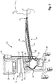
- FIG. 1 an embodiment of a ventilation device according to the invention is generally designated 10.
- the respiratory device 10 is used in the illustrated example for the artificial respiration of a human patient 12 in PSV mode.
- the respiratory device 10 has a housing 14, in which - a pressure change arrangement 16 and a control device 18 can be accommodated, which is not visible from outside because of the opaque housing material.
- the pressure variation assembly 16 is constructed in a manner known per se and may include a pump, a compressor, a blower, a pressure vessel, a reducing valve, and the like.
- the respiratory device 10 in a conventional manner an inspiratory valve 20 and an expiratory valve 22.
- the control device 18 is usually realized as a computer or microprocessor. It includes an in FIG. 1 Not shown storage device to save necessary for the operation of the ventilation device 10 necessary data and if necessary to call.
- the storage device may be in network operation Also located outside of the housing 14 and be connected by a data transmission connection to the controller 18.
- the data transmission connection may be formed by a cable or a radio link.
- the memory device is preferably integrated in the control device 18 or at least accommodated in the same housing 14 as the latter.
- the respiration device 10 can have a data input 24, which can be found in the in FIG. 1 represented example is represented by a keyboard.
- a data input 24 can be found in the in FIG. 1 represented example is represented by a keyboard.
- the keyboard is not the only data input of the controller 18.
- the controller 18 may receive data via various data inputs, such as a network line, radio link, or via sensor ports 26, discussed in detail below ,
- the respiratory device 10 may include an output device 28, in the example shown a screen.
- the patient 12 is connected to the respirator 10, more specifically to the pressure modifier assembly 16 in the housing 14, via a breathing gas conduit assembly 30.
- the patient 12 is intubated for this purpose.
- the tube 31 forms a patient interface of the ventilator 10.
- the patient interface may include a mask covering the nose and mouth.
- the respirator 10 also has an in FIG. 1 not shown connection formation for connection to a breathing gas supply.
- this connection formation can be an intake pipe, through which ambient air - if desired with the interposition of a filter - can be sucked into the breathing gas line arrangement 30 from the immediate surroundings of the ventilator 10.
- the connection formation may also be a flow line coupling be, by means of which the ventilator with a gas supply - be it air or oxygen - connectable.
- the gas supply can be, for example, a gas container or a collective supply, as it is installed in clinics as part of the building services.
- the breathing gas line arrangement 30 has an inspiratory tube 32, via which fresh breathing gas can be conducted from the pressure change arrangement 16 into the lungs of the patient 12.
- the inspiration tube 32 may be interrupted and have a first inspiratory tube 34 and a second inspiratory tube 36, between which a conditioning device 38 for targeted moistening and possibly also temperature control of the patient 12 supplied fresh breathing gas can be provided.
- the conditioning device 38 may be connected to an external fluid reservoir 40, via which water for humidification or else a medicament, for example for inhibiting inflammation or for expanding the respiratory tract, can be supplied to the conditioning device 38.
- volatile anesthetics can be delivered in a controlled manner to the patient 12 via the ventilation device 10.
- the conditioning device 38 ensures that the fresh breathing gas is supplied to the patient 12 with a predetermined moisture content, optionally with the addition of a drug aerosol and at a predetermined temperature.
- the breathing gas line arrangement 30 also has an expiratory tube 42, via which metabolized respiratory gas is blown out of the lungs of the patient 12 into the atmosphere.
- the inspiratory tube 32 is coupled to the inspiration valve 20, the expiratory tube 42 to the expiratory valve 22. Only one of the two valves is opened at the same time for the passage of a gas flow.
- the actuation control of the valves 20 and 22 is likewise effected by the control device 18.
- the exhalation valve 22 is initially closed for the duration of the inspiration phase, and the inspiration valve 20 is opened, so that fresh breathing gas can be conducted from the housing 14 to the patient 12.
- a flow of the fresh respiratory gas is effected by targeted pressure increase of the respiratory gas by the pressure change arrangement 16. Due to the increase in pressure, the fresh respiratory gas flows into the lungs of the patient 12 and expands there the body area near the lungs, ie in particular the thorax, against the individual elasticity of the body parts close to the lungs. As a result, the gas pressure inside the lung of the patient 12 also increases.
- the inspiration valve 20 is closed and the expiratory valve 22 is opened. It begins the expiratory phase. Due to the increased gas pressure of the respiratory gas located in the lungs of the patient 12 until the end of the inspiration phase, this gas flows into the atmosphere after the expiratory valve 22 has been opened, the gas pressure in the lungs of the patient 12 decreasing as the flow duration progresses. For example, when the gas pressure in the lungs 12 reaches a positive end-expiratory pressure set at the respirator 10, ie a slightly higher pressure than the atmospheric pressure, the expiratory phase is terminated with the closing of the expiratory valve 22 and another ventilation cycle follows. This can be one of several trigger criteria, by the presence of which the control device can trigger a reversal of the ventilator from expiratory to inspiratory operation.
- the patient 12 is supplied with the so-called respiratory tidal volume, ie the respiratory gas volume per breath.
- the respiratory device 10, in particular the control device 18, is designed to repeat respiratory operating parameters that characterize the ventilation mode of the respiratory device 10 during the ventilator operation to update or to determine to ensure that the ventilator is tuned as optimally as possible to each patient to be respirated 12 at any time.
- the determination of one or more ventilation operating parameters with the ventilation frequency, so that for each ventilation cycle current and thus optimally adapted to the patient 12 ventilation operating parameters can be provided.
- the respirator 10 is communicatively coupled to at least one of a flow sensor 44, preferably further sensors, such as a pressure sensor for measuring respiratory gas pressure in the breathing gas conduit assembly 30.
- the flow sensor 44 detects the respiratory gas flow prevailing in the breathing gas line arrangement 30 and outputs a signal representing the respiratory gas flow or the respiratory gas flow.
- the flow sensor 44 is preferably coupled to the data inputs 26 of the control device 18 by means of a sensor line arrangement 46.
- the sensor lead 46 may or may not include electrical signal transmission lines. It can also have hose lines which transmit the prevailing in the flow direction on both sides of the flow sensor 44 gas pressure to the data inputs 26, where these of in FIG. 1 not shown pressure sensors are quantified.
- respiration device 10 can be accommodated as a mobile respiration device 10 on a rollable frame 48.
- the flow sensor 44 is preferably located in a portion of the breathing gas conduit assembly 30 in which it can sense both the inspiratory flow and the expiratory flow. Alternatively or for redundancy reasons, in addition, at least one further flow sensor may be provided in the inspiration hose 32 and / or in the expiration hose 42 and / or in the housing 14.
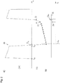
- FIG. 2a is exemplary and roughly schematically illustrated a temporal flow waveform 50, as it turns out, when the patient 12 of FIG. 1 is a COPD patient.
- the inspiratory process begins at time to, at which the controller 18 initiates the inspiratory process described above and increases the pressure in the inspiratory line 32 to a preset inspiratory pressure.
- the respiratory gas flow increases rapidly, for example as a volumetric flow in volume per unit of time, and then gradually decreases in magnitude as the lung is filled with fresh respiratory gas.
- the respiratory gas flow toward the patient 12 or into the patient 12 is, as agreed, subject to a positive sign.
- the amount of the slope or the slope of the flow waveform 50 between the support points 52 and 54 changes in comparison to the previous in the support point 52 bases.
- the slope is increasing.
- the slope of the flux waveform 50 again changes between the bases 54 and 56. The slope increases again.
- FIG. 2b is about the time axis t, correlated with the time axis t of FIG. 2a , plotted the increase in steepness. It is, as it is the representation of the flow waveform in FIG. 2a in the area of the interpolation points 52 to 56, the change in the steepness of the flux waveform 50 from the interpolation point 52 to the interpolation point 54 is plotted lower than the change in the steepness of the course 50 between the interpolation points 54 and 56 compared to the previous curve.
- the changes in the slope are respectively assigned to the temporally later interpolation points of a pair of interpolation points used for calculating the steepness, ie the interpolation points 54 and 56.
- a slope change threshold 58 is entered, which is used as a trigger criterion for triggering a transition from the expiratory operation to the inspiratory operation of the ventilation device 10.
- the slope change threshold 58 is the example in FIG. 2b for COPD patients, so that the 54s change value, at which the patient is still in the expiratory phase and has not made his own effort for inspiration, is below the slope change threshold 58.
- the modifier 56s returns to a typical COPD patient value when exercising its own inspiratory effort, such that this value exceeds the transconductance threshold 58, thus causing the controller 18 to switch the ventilator 10 from an expiratory mode to an inspiratory mode.
- a temporal threshold 60 is stored in the control device 18, from which only a change in the slope of the temporal flow signal curve 50 to provide a Trigger signal is observed.
- the temporal threshold 60 may be, for example, a predetermined period of time from the closing of the inspiratory valve 20 or from the opening of the expiratory valve 22.
- FIGS. 3a and 3b are den FIGS. 2a and 2b respectively corresponding representation of a flow waveform 150 for an ARDS patient shown.
- ARDS patients have a so-called restruc- tive respiratory system whose compliance is very low. The respiratory system is less elastic than in respiratory healthy patients. In COPD patients, on the other hand, the resistance of the respiratory system to respiratory healthy patients is increased.
- the flow waveform 150 is therefore generally steeper than in respiratory healthy patients and especially steeper than COPD patients. The maximum amounts of the river reached are also larger.
- FIGS. 3a and 3b Same and functionally identical details as in the FIGS. 2a and 2b are in the FIGS. 3a and 3b denoted by the same reference numerals but increased by the number 100.
- the expiratory flow of gas at the beginning of the expiratory phase reaches a value higher than in the case of a COPD patient, which is due to the obstructive breathing of the COPD patient as well as the low compliance of the ARDS patient.
- the expiratory flow of respiratory gas falls in the ARDS patient FIG. 3a faster than the COPD patient.
- the slope of the flow waveform in the ARDS patient usually changes several times during the expiratory phase.
- trigger criterion for the presently discussed trigger criteria preferably only those changes in the slope of the flow waveform 150 are considered, in which the slope of the flow waveform 150 increases, in which therefore the Curvature of the flux waveform 150 as viewed from the positive infinity the ordinate has a concave shape, while convex changes in steepness, at which the flux waveform 150 becomes flatter, are not considered at all.
- the slope change threshold 158 for ARDS patients is therefore advantageously chosen larger than that for COPD patients.
- a corresponding slope change threshold for respiratory healthy patients could be between thresholds 58 and 158.
- the assisted ventilated ARDS patient in the PSV mode begins to aspirate breathing gas, which leads to a considerable increase in the steepness of the flow waveform 150.
- the course section between the support points 154 and 156 is significantly steeper or has a significantly greater slope than the immediately preceding course section between the support points 152 and 154. Due to the own inspiratory effort of at least occasionally spontaneously respiring during respiration ARDS patient finds this increase in the flow waveform right down to a positive flow signal.
- the associated change value 156s is in FIG. 3b shown. It exceeds that for ARDS patients defined slope change threshold 158 and thus triggers a changeover from expiratory to inspiratory operation of the ventilator 10 from.
- a data memory of the ventilator 10 may include, in the form of a map, a table, a stored function or approximation function, and the like, a relationship between the slope change threshold to be applied in a ventilator case and an expiratory time constant characterizing the condition of the patient 12's respiratory system.
- control device 18 can then use the stored relationship to query the steepness change threshold to be used for the patient 12 currently to be ventilated or to determine it by arithmetic operations.
- the expiratory time constant of the patient 12 currently being ventilated may be manually entered into the ventilator 10 by medical personnel, if known, such as to have at least an initial value for the slope change threshold.
- the control device 18 is designed to determine the expiratory time constant of the respective patient 12 to be ventilated on the basis of the sensor information that is accessible to it.
- the expiratory time constant may be carried out solely on the basis of the information received from the flow sensor 44.
- the expiratory time constant can be determined on the basis of the respiratory gas volume exhaled during an expiratory phase and the maximum respiratory gas flow which has occurred during the same expiratory phase. Further possible investigation methods for determining the expiratory time constant have already been mentioned above in the introduction to the description.
- the ventilator 10 is able to determine the condition of the respiratory system of the patient 12 and based on the determined state of the respiratory system adapt the slope-dependent trigger criterion for a changeover of the ventilator 10 from expiratory to inspiratory operation to the respective patient to be ventilated.
Description
Die vorliegende Erfindung betrifft ein Beatmungsgerät zur wenigstens unterstützenden Beatmung von im gesunden Zustand atmenden Lebewesen, wobei das Beatmungsgerät umfasst:
- eine Anschlussformation zur Verbindung mit einem Atemgasvorrat,
- eine bei inspiratorischem Betrieb des Beatmungsgeräts frisches inspiratorisches Atemgas von der Anschlussformation zu einer Patientenschnittstelle hin führende und bei exspiratorischem Betrieb verstoffwechseltes exspiratorisches Atemgas von der Patientenschnittstelle weg führende Atemgas-Leitungsanordnung,
- eine Druckveränderungsanordnung zur Veränderung des Drucks von Atemgas in der Atemgas-Leitungsanordnung,
- einen Flusssensor, welcher dazu ausgebildet und angeordnet ist, ein einen Atemgasstrom wenigstens von exspiratorischem Atemgas in der Atemgas-Leitungsanordnung repräsentierendes Flusssignal bereitzustellen,
- eine den Betrieb des Beatmungsgeräts steuernde Steuereinrichtung, welche dazu ausgebildet ist, einen Übergang von exspiratorischem Betrieb zu inspiratorischem Betrieb des Beatmungsgeräts dann zu triggern, wenn eine Zunahme der Steilheit eines Flusssignalverlaufs, welcher zeitlich nacheinander bereitgestellte Flusssignale wiedergibt, einen Steilheit-Änderungsschwellenwert übersteigt.
- a connection formation for connection to a breathing gas supply,
- inspiratory respiratory breathable inspiratory breathing gas exhaling inspiratory breathing gas from the junction formation to a patient interface and metabolized during expiratory operation away from the patient interface leading breathing gas line assembly;
- a pressure variation arrangement for varying the pressure of breathing gas in the breathing gas conduit,
- a flow sensor configured and arranged to provide a flow signal representative of a flow of breathing gas at least from expiratory breathing gas in the breathing gas conduit assembly;
- a controller controlling the operation of the ventilator configured to trigger a transition from expiratory to inspiratory operation of the ventilator when an increase in the slope of a flow waveform representing successive flow signals exceeds a slope change threshold.
Ein derartiges gattungsgemäßes Beatmungsgerät ist aus der
Ein sehr einfaches Triggerkriterium stellt der Basisniveaudurchgang, etwa ein Nulldurchgang oder ein Durchgang durch ein von Null verschiedenes Basisniveau, der Atemströmungskurve, also des zeitlichen Flusssignalverlaufs, dar. Dieses Triggerkriterium ist beispielsweise aus der
Darüber hinaus ist das Triggerkriterium eines Basisniveaudurchgangs des Flusssignals empfindlich gegen leckagebedingte Effekte, die bei künstlicher Beatmung auftreten können, beispielsweise weil eine Beatmungsmaske als eine mögliche Patientenschnittstelle nicht vollständig mit der Gesichtspartie um Nase und Mund des zu beatmenden Patienten abschließt. Auch andere Ursachen können Leckage-Ströme und somit leckagebedingte Effekte während der künstlichen Beatmung bewirken.In addition, the trigger criterion of a base level crossing of the flow signal is sensitive to leakage-related effects that may occur in artificial respiration, for example because a respiratory mask, as a potential patient interface, does not completely terminate with the nose and mouth of the patient being ventilated. Other causes can cause leakage currents and thus leakage-induced effects during artificial respiration.
Zur Vermeidung von leckagebedingten Fehlern bei einer ETS-basierten Triggerung lehrt die
Auch die aus der
Aus der
Mit ETS ist die sogenannte "Expiratory Trigger Sensitivity" bezeichnet. Dabei handelt es sich um einen Prozentsatz des während eines Inspirationsvorgangs auftretenden maximalen Atemgasflusses, welcher als Cycling-Schwellenwert dient. Dann, wenn der Atemgasfluss während der Inspirationsphase auf den vorbestimmten Cycling-Schwellenwert abgefallen ist, wird das Beatmungsgerät vom inspiratorischen Betrieb auf den exspiratorischen Betrieb umgesteuert. Für gesunde Patienten liegt der ETS-basierte Cycling-Schwellenwert häufig bei etwa 25 % des während der Inspirationsphase auftretenden maximalen Atemgasflusses.With ETS the so-called "Expiratory Trigger Sensitivity" is designated. This is a percentage of the maximum respiratory gas flow occurring during an inspiratory process, which serves as the cycling threshold. Then, when the flow of breathing gas has dropped to the predetermined cycling threshold during the inspiratory phase, the ventilator is switched from the inspiratory mode to the expiratory mode. For healthy patients, the ETS-based cycling threshold is often about 25% of the maximum respiratory gas flow occurring during the inspiratory phase.
Die
Mit der aus der
Mit der aus der gattungsgemäßen
Darüber hinaus ist dann, wenn sowohl Patienten mit unbeeinträchtigtem Atemsystem als auch COPD-Patienten durch ein und dasselbe gemäß der
Es ist daher Aufgabe der vorliegenden Erfindung, das eingangs genannte Beatmungsgerät dahingehend zu verbessern, dass mit ihm Patienten ungeachtet des pathologischen Zustands ihres Atemsystems mit verbesserter Synchronität beatmet werden können.It is therefore an object of the present invention to improve the above-mentioned ventilator to the effect that patients with it regardless of the pathological condition of their respiratory system with improved synchrony can be ventilated.
Diese Aufgabe löst die vorliegende Erfindung durch ein gattungsgemäßes Beatmungsgerät, bei welchem die Steuereinrichtung weiter dazu ausgebildet ist, den Steilheit-Änderungsschwellenwert abhängig von einer exspiratorischen Zeitkonstante des jeweils zu beatmenden Patienten zu ermitteln und den Übergang von exspiratorischem Betrieb zu inspiratorischem Betrieb des Beatmungsgeräts dann zu triggern, wenn die Zunahme der Steilheit des Flusssignalverlaufs den nach Maßgabe der exspiratorischen Zeitkonstante ermittelten Steilheit-Änderungsschwellenwert übersteigt.This object is achieved by the present invention by a generic ventilator in which the control device is further configured to determine the slope change threshold depending on an expiratory time constant of each patient to be respirated and then triggers the transition from expiratory to inspiratory operation of the ventilator . if the increase in the slope of the flow waveform exceeds the slope change threshold determined according to the expiratory time constant.
Durch die Ermittlung, gegebenenfalls Änderung und damit Anpassung des Steilheit-Änderungsschwellenwertes abhängig von der exspiratorischen Zeitkonstante des jeweils zu beatmenden Patienten kann der Übergang von exspiratorischem Betrieb zu inspiratorischem Betrieb des Beatmungsgerätes an den pathologischen Zustand des Atemsystems des jeweiligen Patienten nahezu optimal angepasst werden, da die exspiratorische Zeitkonstante einer Person einen für die künstliche Beatmung eines Patienten hochrelevanten Parameter darstellt.By determining, possibly changing and thus adapting the slope change threshold value depending on the expiratory time constant of each patient to be ventilated, the transition from expiratory operation to inspiratory operation of the ventilator to the pathological state of the respiratory system of the respective patient can be adjusted almost optimally, as the expiratory time constant of a person represents a highly relevant for the artificial respiration of a patient parameters.
Durch die Veränderung des Steilheit-Änderungsschwellenwertes abhängig von der exspiratorischen Zeitkonstante des jeweils zu beatmenden Patienten kann so eine Anpassung des Betriebs des Beatmungsgerätes zumindest beim Übergang von exspiratorischem zu inspiratorischem Betrieb an beliebige pathologische Zustände der Atemsysteme von Patienten erfolgen.By changing the slope change threshold value depending on the expiratory time constant of the respective patient to be ventilated, an adaptation of the operation of the ventilator at least during the transition from expiratory to inspiratory operation to any pathological conditions of the respiratory systems of patients.
Es sei klargestellt, dass mit dem Begriff "Triggern" in der vorliegenden Anmeldung lediglich das Auslösen eines Überganges von exspiratorischem Betrieb zu inspiratorischem Betrieb des Beatmungsgeräts bezeichnet ist. Für das Auslösen eines Übergangs in entgegengesetzter Richtung von inspiratorischem zu exspiratorischem Betrieb wird dagegen der Begriff "Cycling" verwendet.It should be understood that the term "triggers" in the present application is merely intended to trigger a transition from expiratory to inspiratory operation of the ventilator. In contrast, the term "cycling" is used to trigger a transition in the opposite direction from inspiratory to expiratory operation.
Mit der erfindungsgemäß ausgebildeten Steuereinrichtung können nicht nur COPD-Patienten, welche verglichen mit Patienten mit gesunden Atemsystemen eine überdurchschnittlich hohe exspiratorische Zeitkonstante aufweisen, mit hervorragender Synchronität beatmet werden, sondern auch ARDS-Patienten, deren exspiratorische Zeitkonstante verglichen mit Patienten mit gesunden Atemsystemen überdurchschnittlich kurz ist.With the control device designed according to the invention not only COPD patients, which have an above-average expiratory time constant compared to patients with healthy respiratory systems, can be ventilated with excellent synchrony, but also ARDS patients whose expiratory time constant is above average short compared to patients with healthy respiratory systems ,
Eine bei dem vorliegend diskutierten Übergang von exspiratorischem zu inspiratorischem Betrieb häufig auftretende Asynchronität ist das sogenannte "Autotriggern", bei welchem das Beatmungsgerät aufgrund entsprechend voreingetellter Entscheidungskriterien einen Inspirationsvorgang auslöst, ohne dass der Patient tatsächlich einatmet oder Anstrengungen für einen Inspiration unternimmt. Es entsteht dann die Situation, dass das Beatmungsgerät dem Patienten, der eigentlich noch ausatmen möchte oder wenigstens im Begriff ist, auszuatmen, gegen dessen Atemanstrengung Atemgas einführt. Dies kann bei Patienten trotz Sedierung heftige Reaktionen auslösen, die auch für die weitere künstliche Beatmung unvorteilhaft sind.One of the frequently occurring asynchronisms in the presently discussed transition from expiratory to inspiratory operation is the so-called "auto-triggering", where the ventilator triggers an inspiratory process based on pre-established decision criteria without the patient actually inhaling or making any effort to inspire. It then arises the situation that the respirator, the patient who wants to actually exhale or at least is about to exhale, introduces against the breath of breathing. This can trigger severe reactions in patients despite sedation, which are also unfavorable for further artificial respiration.
COPD, was landläufig auch als "Asthma" oder "Raucherlunge" bezeichnet wird, führt aufgrund des obstruktiven Atemverhaltens zu verhältnismäßig stetigen Atemgas-Flusssignalverläufen, an denen eine betragsmäßige Änderung ihrer Steilheit relativ einfach und sicher feststellbar ist, sodass auch das bereits bekannte gattungsgemäße Beatmungsgerät für COPD-Patienten verhältnismäßig gute Ergebnisse liefert.COPD, which is also commonly referred to as "asthma" or "smoker's lung", due to the obstructive breathing behavior leads to relatively steady breathing gas flow waveforms at which an absolute change in their steepness is relatively easy and safe to determine, so that the already known generic respirator for COPD patients provides relatively good results.
ARDS-Patienten weisen ein restruktives Atemsystem auf, was landläufig als "harte" Lunge bezeichnet wird. Die Atmung erfolgt hier häufig stoßartig, was während einer Exspirationsphase zu einer oder mehreren Unstetigkeiten des Atemgas-Flusssignalverlaufs in Form von Knicken führen kann. Diese Knickstellen stellen betragsmäßige Änderungen der Steilheit des Flusssignals dar, welche bei unvorteilhaft gewähltem Steilheit-Änderungsschwellenwert ein Autotriggern auslösen können.ARDS patients have a restorative respiratory system, commonly referred to as a "hard" lung. Respiration is often impulsive, which can lead to one or more discontinuities of the breathing gas flow waveform in the form of kinks during an expiratory phase. These kinks represent changes in magnitude of the slope of the flux signal, which may trigger car triggers if the slope change threshold is not favorably selected.
Die vorliegende Erfindung hilft, auch ARDS-Patienten mit dem erfindungsgemäß verbesserten Beatmungsgerät mit verbesserter Synchronität beatmen zu können.The present invention also helps to ventilate ARDS patients with the inventively improved ventilator with improved synchrony.
Wegen des geschilderten Zusammenhangs ist es vorteilhaft, ARDS-Patienten, deren exspiratorische Zeitkonstante kleiner als jene von Patienten mit gesundem Atemsystem ist, mit einem betragsmäßig höheren Steilheit-Änderungsschwellenwert zu beatmen, um ARDS-typische Unstetigkeiten im Flusssignalverlauf während einer Exspirationsphase durch den Steilheit-Änderungsschwellenwert nicht zu erfassen und korrekterweise erst eine betragsmäßig größere Änderung der Steilheit des Flusssignalverlaufs am Ende der Exspirationsphase als Triggersignal heranzuziehen, wenn tatsächlich auch in Übereinstimmung mit dem Patientenverhalten ein Übergang von exspiratorischem zu inspiratorischem Betrieb stattfinden soll.Because of the relationship described, it is advantageous to ventilate ARDS patients whose expiratory time constant is less than those of healthy respiratory patients with a magnitude higher steepness change threshold to ARDS typical discontinuities in the flow waveform during an expiratory phase through the slope change threshold can not be detected and correct to use only a magnitude larger change in the slope of the flow waveform at the end of the expiratory phase as a trigger signal when a transition from expiratory to inspiratory operation should actually take place in accordance with the patient behavior.
Ebenso können COPD-Patienten, deren exspiratorische Zeitkonstante größer als jene von Patienten mit gesundem Atemsystem ist, mit einem Steilheit-Änderungsschwellenwert beatmet werden, der betragsmäßig geringer ist als der von ARDS-Patienten und geringer ist als der von Patienten mit gesundem Atemsystem.Similarly, COPD patients whose expiratory time constant is greater than those of healthy respiratory patients may be ventilated at a slope change threshold that is lower in magnitude than that of ARDS patients and lower than that of patients with a healthy respiratory system.
Daher ist die Steuereinrichtung vorzugsweise dazu ausgebildet, den Betrag des Steilheit-Änderungsschwellenwerts mit zunehmender exspiratorischer Zeitkonstante zu verringern und umgekehrt.Therefore, the controller is preferably configured to reduce the magnitude of the slope change threshold as the expiratory time constant increases, and vice versa.
Bevorzugt ist die Steuereinrichtung zur Vermeidung von unerwünschten Fehltriggerungen dazu ausgebildet, nur solche Änderungen der Steilheit des Flusssignalverlaufs auf das Vorliegen des Überschreiten des Steilheit-Änderungsschwellenwerts zu überprüfen, durch welche die Steigung des Flusssignalverlaufs zunimmt, also der Flusssignalverlauf progressiv ansteigt. Der Steilheit-Änderungsschwellenwert ist dann bevorzugt ein Steilheit-Zunahmeschwellenwert, anzuwenden in ansteigenden Flussignalverlaufsabschnitten, nicht dagegen in abfallenden.In order to avoid undesired false triggerings, the control device is preferably designed to check only those changes in the steepness of the flux waveform to the presence of the exceeding of the slope change threshold value by which the slope of the flux waveform increases, ie, the flux waveform progressively increases. The slope change threshold is then preferably a slope increase threshold to apply in rising flux waveform sections, but not in descending ones.
Weiterhin sei an dieser Stelle klargestellt, dass das in der vorliegenden Anmeldung diskutierte Triggerkriterium nicht das einzige Triggerkriterium ist, gemäß welchem die Steuereinrichtung den Betrieb der Beatmungsvorrichtung von exspiratorisch auf inspiratorisch ändert oder ändern kann. Die Steuereinrichtung weist bevorzugt eine Mehrzahl, etwa mehr als 25, Triggerkriterien auf, von welchen jedes im Falle seines Vorliegens die Steuereinrichtung veranlasst, den Betrieb der Beatmungsvorrichtung von exspiratorisch auf inspiratorisch umzusteuern.Furthermore, it should be made clear at this point that the trigger criterion discussed in the present application is not the only trigger criterion according to which the control device can change or change the operation of the ventilation device from expiratory to inspiratory. The control device preferably has a plurality, for example more than 25, trigger criteria, each of which, in the event of its presence, causes the control device to switch the operation of the ventilation device from expiratory to inspiratory.
Grundsätzlich kann gemäß einem einfachen Ausführungsbeispiel der vorliegenden Erfindung vorgesehen sein, dass die Steuereinrichtung mit einer Eingabevorrichtung, etwa einer Tastatur und dergleichen, zusammenwirkt, durch die die Eingabe einer für den jeweils zu beatmenden Patienten zutreffenden exspiratorischen Zeitkonstante möglich ist.In principle, it can be provided according to a simple embodiment of the present invention that the control device interacts with an input device, such as a keyboard and the like, by which the input of an expiratory time constant applicable to the respective patient to be ventilated is possible.
Bereits mit dem erwähnten Flusssensor ist es grundsätzlich möglich, die exspiratorische Zeitkonstante eines zu beatmenden Patienten zu ermitteln, weshalb die Steuereinrichtung bevorzugt dazu ausgebildet ist, die exspiratorische Zeitkonstante in einer jeweiligen Beatmungsanwendung zu ermitteln. Der Flusssensor erfasst den Atemgasstrom bevorzugt als Volumenstrom. Eine zusätzliche oder alternative Erfassung als Massenstrom ist ebenfalls möglich.Already with the mentioned flow sensor, it is basically possible to determine the expiratory time constant of a patient to be ventilated, which is why the control device is preferably designed to determine the expiratory time constant in a respective ventilation application. The flow sensor preferably detects the respiratory gas flow as a volumetric flow. An additional or alternative detection as a mass flow is also possible.
Dabei kann daran gedacht sein, die Zeitkonstante einmal zu Beginn der Beatmungsanwendung für die gesamte restliche Dauer der Beatmungsanwendung zu ermitteln und mit dem ermittelten Wert die Beatmungsanwendung durchzuführen.It may be thought to determine the time constant once at the beginning of the respiratory application for the entire remaining duration of the respiratory application and to perform the ventilation application with the determined value.
Alternativ kann daran gedacht sein, die exspiratorische Zeitkonstante in vorbestimmten Zeitabständen während einer Beatmungsanwendung immer wieder zu ermitteln und die Beatmungsanwendung mit dem jeweils zuletzt ermittelten Zeitkonstantenwert fortzusetzen. Eine besonders genaue und damit vorteilhaft besonders synchrone Beatmung eines Patienten kann dadurch erfolgen, dass die Steuereinrichtung dazu ausgebildet ist, die exspiratorische Zeitkonstante atemzugsweise zu ermitteln.Alternatively, it may be considered to repeatedly determine the expiratory time constant at predetermined time intervals during a respiratory application and to continue the respiratory application with the respectively last-determined time constant value. A particularly accurate and thus advantageously particularly synchronous ventilation of a patient can be achieved by the control device being designed to detect the expiratory time constant in a breathtaking manner.
Grundsätzlich sind zahlreiche Möglichkeiten bekannt, eine exspiratorische Zeitkonstante eines Patienten automatisiert zu ermitteln. Besonders vorteilhafte Methoden hierzu sind offenbart in
Beispielsweise kann die Steuereinrichtung dazu ausgebildet sein, die exspiratorische Zeitkonstante nach Maßgabe des Verhältnisses zwischen dem während eines Exspirationsvorgangs ausgeatmeten Volumen und dem dabei aufgetretenen maximalen exspiratorischen Volumenstrom, bevorzugt iterativ numerisch, oder/und nach Maßgabe der bei einem Atemhub auftretenden Resistance und Compliance zu ermitteln. Die Resistance und die Compliance getrennt zu ermitteln und daraus aus Multiplikation die exspiratorische Zeitkonstante zu errechnen, ist möglich, aber weniger bevorzugt als die Zeitkonstante aus dem Verhältnis von ausgeatmetem Volumen und dabei aufgetretenem maximalen exspiratorischen Volumenstrom zu berechnen. Hier existieren iterative nummerische Berechnungsmethoden, welche bereits nach wenigen Iterationsschritten zu einem zutreffenden Wert konvergieren, der sich von der tatsächlichen Zeitkonstante für den jeweiligen Beatmungsfall nur in vernachlässigbarem Umfang unterscheidet.For example, the control device may be designed to determine the expiratory time constant in accordance with the ratio between the volume exhaled during an exhalation process and the maximum expiratory volumetric flow occurring, preferably iteratively numerically, and / or in accordance with the resistance and compliance occurring during a breath. Determining the resistance and the compliance separately and calculating the expiratory time constant from multiplication is possible, but less preferred than the time constant from the ratio of exhaled volume and thereby calculated maximum expiratory flow rate. Here, iterative numerical calculation methods exist, which converge to a true value after just a few iteration steps, which differs only negligibly from the actual time constant for the respective ventilation case.
Der Begriff "Flusssignalverlauf" soll nicht dahingehend verstanden werden, dass der vollständige zeitliche Verlauf des vom Flusssensor bereitgestellten Flusssignals aufgezeichnet und bereitgestellt werden muss. Es reicht zur Erzielung der Vorteile der vorliegenden Erfindung aus, wenn der Flusssignalverlauf über eine so lange Zeitspanne vorliegt, dass daraus die Änderung einer Steilheit des Flusssignalverlaufs ermittelt werden kann. Auch soll der Begriff "Flusssignalverlauf" nicht dahingehend missverstanden werden, dass zwingend ein kontinuierlicher Verlauf zur Ermittlung einer Änderung von dessen Steilheit benötigt wird. Auch eine Folge von zeitlich aufeinanderfolgenden diskreten Flusssignalwerten stellt einen Flusssignalverlauf im Sinne der vorliegenden Anmeldung dar. Dabei reichen beispielsweise drei zeitlich nacheinander ermittelte Flusssignalwerte aus, um eine Änderung der Steilheit dieses kurzen Flusssignalverlaufs zu ermitteln und auszuwerten. So kann zwischen erstem und zweitem Flusssignalwert mittels eines Differenzenquotienten eine Steigung des Flusssignalverlaufs zwischen diesen beiden Stützpunkten ermittelt werden und ebenso zwischen zweitem und drittem Flusssignalwert, wiederum durch einen Differenzenquotienten. Die so ermittelten Steigungen einmal zwischen erstem und zweitem Flusssignalwert und ein weiteres Mal zwischen zweitem und drittem Flusssignalwert können miteinander verglichen werden, beispielsweise durch Subtraktion, wobei der Unterschiedswert, der ein Maß für die Änderung der Steigung beziehungsweise Steilheit des Flusssignalverlaufs darstellt, mit dem Steilheit-Änderungsschwellenwert des Flusssignalverlaufs verglichen werden kann. Abhängig vom Ausgang eines solchen Vergleichs mit dem Steilheit-Änderungsschwellenwert kann dann das Triggern veranlasst werden oder nicht.The term "flow waveform" should not be understood to record and provide the full time course of the flux signal provided by the flow sensor. It is sufficient to achieve the advantages of the present invention, when the flow waveform is present over such a long period of time that it can be determined from the change in a slope of the flow waveform. Also, the term "flow waveform" should not be misunderstood to the effect that a continuous course is required to determine a change in its steepness. A sequence of discrete flow signal values which are consecutive in time also represents a flow signal course in the sense of the present application. For example, three flow signal values ascertained chronologically one after the other suffice to determine and evaluate a change in the steepness of this short flow signal course. Thus, between the first and second flow signal value by means of a difference quotient, a slope of the flow signal course between these two interpolation points can be determined and also between the second and third flow signal value, again by a difference quotient. The slopes thus determined, once between the first and second flow signal values and once again between the second and third flow signal values, can be compared with one another, for example by subtraction, the difference value, which represents a measure of the change in the slope or steepness of the flow signal course, with the slope. Change threshold of the flow waveform can be compared. Depending on the outcome of such a comparison with the slope change threshold, then triggering may or may not be initiated.
Wenn in der vorliegenden Anmeldung von zeitlich nacheinander ermittelten oder bereitgestellten Flusssignalwerten die Rede ist, so bedeutet dies bevorzugt, aber nicht notwendigerweise, unmittelbar nacheinander ermittelt oder bereitgestellt.If in the present application of successively determined or provided flow signal values is mentioned, this means preferably, but not necessarily, determined or provided directly one after the other.
Selbstverständlich sind weitere Möglichkeiten zur Ermittlung der Änderung der Steilheit eines Flusssignalverlaufs bekannt. Beispielsweise kann der Flusssignalverlauf wenigstens abschnittsweise durch eine Funktion angenähert werden, welche Näherungsfunktion nach der Zeit zweimal abgeleitet werden kann. Die zweite Ableitung einer Funktion ist bekanntermaßen ein Maß für die Änderung der Steilheit einer Funktion oder eines Werteverlaufs.Of course, further possibilities for determining the change in the steepness of a flow signal course are known. For example, the flow signal waveform can be approximated at least in sections by a function, which approximation function can be derived twice over time. The second derivative of a function is known to be a measure of the change in the slope of a function or a value curve.
Zur zielführenden Veränderung des Steilheit-Änderungsschwellenwertes auf Grundlage der exspiratorischen Zeitkonstante des zu beatmenden Patienten kann gemäß einer vorteilhaften Weiterbildung der vorliegenden Erfindung vorgesehen sein, dass das Beatmungsgerät einen von der Steuereinrichtung wenigstens lesbaren Datenspeicher aufweist, in welchem ein Zusammenhang zwischen dem Betrag des Steilheit-Änderungsschwellenwerts und der exspiratorischen Zeitkonstante oder ein Zusammenhang zwischen einem Änderungswert des Betrags des Steilheit-Änderungsschwellenwerts und der exspiratorischen Zeitkonstante hinterlegt ist. Der Zusammenhang kann über den Betrag des Steilheit-Änderungsschwellenwerts hinaus auch dessen Vorzeichen betreffen.According to an advantageous development of the present invention, it can be provided for purposefully changing the slope change threshold value on the basis of the expiratory time constant of the patient to be ventilated that the ventilator has a data memory which is at least readable by the control device and in which a relationship exists between the magnitude of the slope change threshold value and the expiratory time constant or a relationship between a change value of the magnitude of the slope change threshold and the expiratory time constant. The relationship may also affect its sign beyond the magnitude of the slope change threshold.
Der Zusammenhang kann in Form eines tabellarischen oder graphischen Kennfelds hinterlegt sein. Bevorzugt ist im Datenspeicher ein funktioneller Zusammenhang zwischen dem Betrag des Steilheit-Änderungsschwellenwertes und der exspiratorischen Zeitkonstante oder ein funktioneller Zusammenhang zwischen einem Änderungswert des Betrages des Steilheit-Änderungsschwellenwertes und der exspiratorischen Zeitkonstante hinterlegt - je nachdem ob der Steilheit-Änderungsschwellenwert absolut ermittelt oder lediglich ein auf den zuvor verwendeten Steilheit-Änderungsschwellenwert anzuwendender Änderungsbetrag ermittelt werden soll, ob also die Änderung des Steilheit-Änderungsschwellenwertes absolut oder inkrementell erfolgen soll. Beides ist grundsätzlich möglich. Die Steuereinrichtung ist dann bevorzugt dazu ausgebildet, einen anzuwendenden Steilheit-Änderungsschwellenwert ausgehend von der exspiratorischen Zeitkonstante anhand des funktionellen Zusammenhangs zu ermitteln. Somit braucht keine Interpolation oder Extrapolation von Steilheit-Änderungsschwellenwerten berechnet werden, sondern es kann unmittelbar der jeweils für einen Zeitkonstantenwert zutreffende Steilheit-Änderungsschwellenwert ermittelt werden, gegebenenfalls unter Anwendung des Zwischenschrittes der Ermittlung eines Änderungsinkrements und Anwendung des Änderungsinkrements auf den zuletzt gültigen Steilheit-Änderungsschwellenwert.The relationship can be stored in the form of a tabular or graphical map. Preferably, a functional relationship between the magnitude of the slope change threshold and the expiratory time constant or a functional relationship between a change value of the slope change threshold and the expiratory time constant is stored in the data memory - depending on whether the slope change threshold is absolute or just on The change amount to be applied to the previously used steepness change threshold is to be determined, that is, whether the change in the slope change threshold value should be absolute or incremental. Both are possible in principle. The control device is then preferably designed to determine an applicable slope change threshold based on the expiratory time constant based on the functional relationship. Thus, no interpolation or extrapolation of steepness change thresholds need be calculated, but it may be immediate determining the slope change threshold applicable to a time constant value, optionally using the intermediate step of determining a change increment and applying the change increment to the most recent slope change threshold.
Vorzugsweise weist das Beatmungsgerät einen von der Steuereinrichtung beschreibbaren Datenspeicher auf, in welchem vom Flusssensor bereitgestellte Flusssignalwerte gespeichert werden können, um aus den Werten einen zeitlichen Flusssignalverlauf zu ermitteln. Dies kann der oben bezeichnete Datenspeicher sein.The ventilator preferably has a data memory which can be written by the control device and in which flow signal values provided by the flow sensor can be stored in order to determine from the values a temporal flow signal course. This may be the above-mentioned data store.
Häufig ist das vom Flusssensor erhaltene Flusssignal rauschbehaftet und zu einer unmittelbaren Auswertung daher suboptimal geeignet. Daher kann weiter vorgesehen sein, dass die Steuereinrichtung dazu ausgebildet ist, das vom Flusssensor bereitgestellte Flusssignal zu glätten, etwa durch Tiefpassfilterung oder durch gleitende Mittelwertbildung. Die gleitende Mittelwertbildung kann dabei die letzten fünf bis sechs Flusssignalwerte berücksichtigen, gegebenenfalls gewichtet. Eine Glättung des zeitlichen Flusssignalverlaufs ist vor allem dann vorteilhaft, wenn die Änderung der Steilheit des Flusssignalverlaufs durch Differenzieren einer an den Flusssignalverlauf wenigstens abschnittsweise angenäherten Näherungsfunktion erfolgen soll, da eine Näherungsfunktion für einen geglätteten Signalverlauf mit geringem Fehler ermittelbar ist. Bevorzugt erfolgt die Ermittlung der exspiratorischen Zeitkonstante auf Grundlage des geglätteten Flusssignalverlaufs.Frequently, the flow signal obtained from the flow sensor is noisy and therefore suboptimal suitable for immediate evaluation. Therefore, it can further be provided that the control device is designed to smooth the flow signal provided by the flow sensor, for example by low-pass filtering or by sliding averaging. The moving averaging can take into account the last five to six flow signal values, optionally weighted. A smoothing of the temporal flux waveform is particularly advantageous if the change in the slope of the flow waveform should be made by differentiating an approximated approximately to the flow waveform approximated proximity function, since an approximation function for a smooth waveform with low error can be determined. The determination of the expiratory time constant preferably takes place on the basis of the smoothed flow signal course.
Um ein unerwünschtes Triggern aufgrund von Steilheits-Änderungen des Flusssignalverlaufs in der Anfangsphase des Exspirationsbetriebs zu vermeiden, ist die Steuereinrichtung gemäß einer vorteilhaften Weiterbildung der vorliegenden Erfindung dazu ausgebildet, den Übergang von exspiratorischem Betrieb zu inspiratorischem Betrieb des Beatmungsgeräts nicht vor Ablauf einer vorbestimmten Zeitspanne nach einem vorgegebenen charakteristischen Ereignis, wie etwa ein Beginn des exspiratorischen Betriebs oder ein Basisniveaudurchgang des Flusssignals, zu triggern. Der Basisniveaudurchgang des Flusssignals kann ein Durchgang durch ein Nullniveau oder durch ein von Null verschiedenes Basisniveau sein.In order to avoid unwanted triggering due to steepness changes of the flow waveform in the initial phase of the expiratory operation, the control device according to an advantageous embodiment of the present invention is adapted to the transition from expiratory operation to inspiratory operation of the ventilator not before a predetermined period of time predetermined characteristic event, such as a start of the expiratory operation or a base level crossing of the flow signal to trigger. The base level crossing of the flow signal may be a pass through a zero level or a non-zero base level.
Zu Beginn des Exspirationsbetriebs wird üblicherweise ein Inspirationsventil des Beatmungsgeräts geschlossen und ein Exspirationsventil geöffnet, wodurch es am Patienten zu einer Richtungsumkehrung des Atemgasstroms kommt. Das Flusssignal ändert dabei das Vorzeichen, fällt also zunächst betragsmäßig stark ab und steigt dann mit umgekehrten Vorzeichen betragsmäßig stark an. Ausgehend von dem dann auftretenden maximalen Atemgasfluss fällt das Flusssignal betragsmäßig mit fortschreitender Exspiration wieder ab. Es kommt daher in der Regel zu Beginn einer Exspirationsphase zu einer Änderung der Steilheit des Flusssignalverlaufs, die jedoch gerade keinen Übergang von exspiratorischem zu inspiratorischem Betrieb triggern soll. Dies wird mit der zuvor geschilderten Maßnahme verhindert.At the beginning of the expiratory operation, an inspiratory valve of the ventilator is usually closed and an expiratory valve is opened, causing the patient to reverse the direction of the respiratory gas flow. The flux signal thereby changes the sign, that is, initially falls sharply in magnitude, and then rises sharply in magnitude with the opposite sign. Starting from the maximum respiratory gas flow then occurring, the flow signal drops again in magnitude as the expiration progresses. It is therefore usually at the beginning of an expiratory phase to a change in the steepness of the flow waveform, which should trigger but no transition from expiratory to inspiratory operation. This is prevented with the previously described measure.
Auch dabei kann daran gedacht sein, die vorbestimmte Zeitspanne, innerhalb der ab Eintritt des charakteristischen Ereignisses kein Übergang getriggert werden soll, nach Maßgabe der exspiratorischen Zeitkonstante zu ermitteln, da bei COPD-Patienten die Exspirationsphase länger dauert als bei Patienten mit gesundem Atemsystem und bei ARDS-Patienten die Exspirationsphase kürzer ist als bei Patienten mit gesundem Atemsystem.Again, it may be thought to determine the predetermined period of time within which no transition is to be triggered from the onset of the characteristic event, according to the expiratory time constant, since in COPD patients the expiratory phase lasts longer than in patients with a healthy respiratory system and in ARDS Patients the expiratory phase is shorter than in patients with a healthy respiratory system.
Daher kann die vorbestimmte Zeitspanne bei ARDS-Patienten kürzer gewählt sein als bei Patienten mit gesundem Atemsystem und deren Zeitspanne wiederum kürzer als jene von COPD-Patienten. Die vorbestimmte Zeitspanne kann daher beispielsweise proportional zur exspiratorischen Zeitkonstante gewählt sein.Therefore, the predetermined period of time may be shorter in ARDS patients than in patients with a healthy respiratory system and in turn shorter than that of COPD patients. The predetermined period of time can therefore be selected, for example, proportionally to the expiratory time constant.
Das erfindungsgemäße Beatmungsgerät ist bevorzugt zur künstlichen Beatmung im PSV-Modus (PSV = "Pressure Support Ventilation") ausgebildet.The ventilator according to the invention is preferably designed for artificial respiration in PSV mode (PSV = "Pressure Support Ventilation").
Die vorliegende Erfindung wird nachfolgend anhand der beiliegenden Zeichnungen näher erläutert. Es stellt dar:
Figur 1- eine schematische Darstellung einer erfindungsgemäßen, zur künstlichen Beatmung eines Patienten hergerichteten Beatmungsvorrichtung,
- Figur 2a
- einen beispielhaften zeitlichen Verlauf eines Flusssignals eines COPD-Patienten,
- Figur 2b
- eine beispielhafte graphische Darstellung von im zeitlichen Flusssignalverlauf von
Fig. 2a auftretenden Zunahmen der Steilheit des Flusssignalverlaufs mit anwendbarem Steilheit-Änderungsschwellenwert zur Triggerung eines Inspirationsvorgangs, - Figur 3a
- einen beispielhaften zeitlichen Verlauf eines Flusssignals eines ARDS-Patienten und
- Figur 3b
- eine beispielhafte graphische Darstellung von im zeitlichen Flusssignalverlauf von
Fig. 3a auftretenden Zunahmen der Steilheit des Flusssignalverlaufs mit anwendbarem Steilheit-Änderungsschwellenwert zur Triggerung eines Inspirationsvorgangs.
- FIG. 1
- 1 is a schematic representation of a ventilation device according to the invention, designed for the artificial respiration of a patient,
- FIG. 2a
- an exemplary time course of a flow signal of a COPD patient,
- FIG. 2b
- an exemplary graphical representation of the temporal flow waveform of
Fig. 2a occurring increases in the slope of the flux waveform with applicable slope change threshold for triggering an inspiratory process; - FIG. 3a
- an exemplary time course of a flow signal of an ARDS patient and
- FIG. 3b
- an exemplary graphical representation of the temporal flow waveform of
Fig. 3a occurring increases in the slope of the flux waveform with applicable slope change threshold for triggering an inspiratory process.
In
Die Beatmungsvorrichtung 10 weist ein Gehäuse 14 auf, in dem - von außen wegen des blickdichten Gehäusematerials nicht erkennbar - eine Druckveränderungsanordnung 16 und eine Steuereinrichtung 18 aufgenommen sein können.The respiratory device 10 has a
Die Druckveränderungsanordnung 16 ist in an sich bekannter Weise aufgebaut und kann eine Pumpe, einen Verdichter, ein Gebläse, einen Druckbehälter, ein Reduzierventil und dergleichen aufweisen. Weiter weist die Beatmungsvorrichtung 10 in an sich bekannter Weise ein Inspirationsventil 20 und ein Exspirationsventil 22 auf.The
Die Steuereinrichtung 18 ist üblicherweise als Computer oder Mikroprozessor realisiert. Sie umfasst eine in
Zur Eingabe von Daten in die Beatmungsvorrichtung 10 bzw. genauer in die Steuereinrichtung 18 kann die Beatmungsvorrichtung 10 einen Dateneingang 24 aufweisen, welcher in dem in
Zur Ausgabe von Daten an den behandelnden Therapeuten kann die Beatmungsvorrichtung 10 ein Ausgabegerät 28 aufweisen, im dargestellten Beispiel einen Bildschirm.To output data to the treating therapist, the respiratory device 10 may include an
Zur künstlichen Beatmung ist der Patient 12 mit der Beatmungsvorrichtung 10, genauer mit der Druckveränderungsanordnung 16 im Gehäuse 14, über eine Atemgas-Leitungsanordnung 30 verbunden. Der Patient 12 ist hierfür intubiert. Der Tubus 31 bildet eine Patientenschnittstelle des Beatmungsgeräts 10. Alternativ kann die Patientenschnittstelle eine Nase und Mund überdeckende Maske umfassen.For artificial respiration, the
Das Beatmungsgerät 10 weist überdies eine in
Die Atemgas-Leitungsanordnung 30 weist einen Inspirationsschlauch 32 auf, über welchen frisches Atemgas von der Druckveränderungsanordnung 16 in die Lunge des Patienten 12 geleitet werden kann. Der Inspirationsschlauch 32 kann unterbrochen sein und einen ersten Inspirationsschlauch 34 und einen zweiten Inspirationsschlauch 36 aufweisen, zwischen welchen eine Konditionierungseinrichtung 38 zur gezielten Befeuchtung und gegebenenfalls auch Temperierung des dem Patienten 12 zugeführten frischen Atemgases vorgesehen sein kann. Die Konditionierungseinrichtung 38 kann mit einem externen Flüssigkeitsvorrat 40 verbunden sein, über den Wasser zur Befeuchtung oder auch ein Medikament, etwa zur Entzündungshemmung oder zur Erweiterung der Atemwege, der Konditionierungseinrichtung 38 zugeführt werden kann. Bei einem Einsatz der vorliegenden Beatmungsvorrichtung 10 als Anästhesie-Beatmungsvorrichtung können so volatile Anästhetika kontrolliert über die Beatmungsvorrichtung 10 an den Patienten 12 abgegeben werden. Die Konditionierungseinrichtung 38 sorgt dafür, dass das frische Atemgas dem Patienten 12 mit einem vorbestimmten Feuchtegehalt, gegebenenfalls unter Zugabe eines Medikamenten-Aerosols und mit einer vorbestimmten Temperatur zugeleitet wird.The breathing
Die Atemgas-Leitungsanordnung 30 weist neben dem bereits erwähnten Inspirationsventil 20 und Exspirationsventil 22 weiter einen Exspirationsschlauch 42 auf, über welchen verstoffwechseltes Atemgas aus der Lunge des Patienten 12 in die Atmosphäre abgeblasen wird.In addition to the already mentioned
Der Inspirationsschlauch 32 ist mit dem Inspirationsventil 20 gekoppelt, der Exspirationsschlauch 42 mit dem Exspirationsventil 22. Von den beiden Ventilen ist jeweils nur eines gleichzeitig zum Durchlass einer Gasströmung geöffnet. Die Betätigungssteuerung der Ventile 20 und 22 erfolgt ebenfalls durch die Steuereinrichtung 18.The
Während eines Beatmungszyklus ist zunächst für die Dauer der Inspirationsphase das Exspirationsventil 22 geschlossen und das Inspirationsventil 20 geöffnet, sodass frisches Atemgas vom Gehäuse 14 zum Patienten 12 geleitet werden kann. Eine Strömung des frischen Atemgases wird durch gezielte Druckerhöhung des Atemgases durch die Druckveränderungsanordnung 16 bewirkt. Aufgrund der Druckerhöhung strömt das frische Atemgas in die Lunge des Patienten 12 und expandiert dort den lungennahen Körperbereich, also insbesondere den Brustkorb, gegen die individuelle Elastizität der lungennahen Körperteile. Hierdurch steigt auch der Gasdruck im Inneren der Lunge des Patienten 12 an.During a ventilation cycle, the
Am Ende der Inspirationsphase wird das Inspirationsventil 20 geschlossen und das Exspirationsventil 22 geöffnet. Es beginnt die Exspirationsphase. Aufgrund des bis zum Ende der Inspirationsphase erhöhten Gasdrucks des in der Lunge des Patienten 12 befindlichen Atemgases strömt dieses nach dem Öffnen des Exspirationsventils 22 in die Atmosphäre, wobei sich mit fortschreitender Strömungsdauer der Gasdruck in der Lunge des Patienten 12 verringert. Erreicht der Gasdruck in der Lunge 12 beispielsweise einen an der Beatmungsvorrichtung 10 eingestellten positiven endexspiratorischen Druck, also einen geringfügig höheren Druck als den Atmosphärendruck, wird die Exspirationsphase mit dem Schließen des Exspirationsventils 22 beendet und es schließt sich ein weiterer Beatmungszyklus an. Dies kann eines von mehreren Triggerkriterien sein, durch deren Vorliegen die Steuereinrichtung eine Umsteuerung des Beatmungsgeräts von exspiratorischem zu inspiratorischem Betrieb triggern kann.At the end of the inspiration phase, the
Während der Inspirationsphase wird dem Patienten 12 das sogenannte Beatmungs-Tidalvolumen zugeführt, also das Atemgas-Volumen pro Atemhub. Das Beatmungs-Tidalvolumen multipliziert mit der Anzahl an Beatmungszyklen pro Minute, also multipliziert mit der Beatmungsfrequenz, ergibt das Minutenvolumen der vorliegend durchgeführten künstlichen Beatmung.During the inspiration phase, the
Bevorzugt ist die Beatmungsvorrichtung 10, insbesondere die Steuereinrichtung 18, dazu ausgebildet, Beatmungs-Betriebsparameter, die den Beatmungsbetrieb der Beatmungsvorrichtung 10 kennzeichnen, während des Beatmungsbetriebs wiederholt zu aktualisieren bzw. zu ermitteln, um sicherzustellen, dass der Beatmungsbetrieb zu jedem Zeitpunkt möglichst optimal auf den jeweils zu beatmenden Patienten 12 abgestimmt ist. Besonders vorteilhaft erfolgt die Bestimmung eines oder mehrerer Beatmungs-Betriebsparameter mit der Beatmungsfrequenz, sodass für jeden Beatmungszyklus aktuelle und damit optimal an den Patienten 12 angepasste Beatmungs-Betriebsparameter bereitgestellt werden können.Preferably, the respiratory device 10, in particular the
Die Beatmungsvorrichtung 10 ist wenigstens mit einem Flusssensor 44, vorzugsweise mit noch weiteren Sensoren, wie etwa einem Drucksensor zur Messung des Atemgasdrucks in der Atemgas-Leitungsanordnung 30, datenübertragungsmäßig verbunden. Der Flusssensor 44 erfasst die in der Atemgas-Leitungsanordnung 30 herrschende Atemgas-Strömung und gibt ein die die Atemgas-Strömung bzw. den Atemgas-Fluss repräsentierendes Signal aus. Der Flusssensor 44 ist bevorzugt mittels einer Sensor-Leitungsanordnung 46 mit den Dateneingängen 26 der Steuereinrichtung 18 gekoppelt. Die Sensor-Leitungsanordnung 46 kann, muss jedoch nicht, elektrische Signalübertragungsleitungen umfassen. Sie kann ebenso Schlauchleitungen aufweisen, die den in Strömungsrichtung beiderseits des Flusssensors 44 herrschenden Gasdruck an die Dateneingänge 26 übertragen, wo diese von in
Lediglich der Vollständigkeit halber sei darauf hingewiesen, dass die erfindungsgemäße Beatmungsvorrichtung 10 als mobile Beatmungsvorrichtung 10 auf einem rollbaren Gestell 48 aufgenommen sein kann.For the sake of completeness, it should be pointed out that the respiration device 10 according to the invention can be accommodated as a mobile respiration device 10 on a
Der Flusssensor 44 ist bevorzugt in einem Abschnitt der Atemgas-Leitungsanordnung 30 angeordnet, in welchem er sowohl den inspiratorischen Fluss wie auch den exspiratorischen Fluss erfassen kann. Alternativ oder aus Redundanzgründen auch zusätzlich können im Inspirationsschlauch 32 oder/und im Exspirationsschlauch 42 oder/und im Gehäuse 14 je wenigstens ein weiterer Flusssensor vorgesehen sein.The
In
Der Inspirationsvorgang beginnt zum Zeitpunkt to, bei welchem die Steuereinrichtung 18 den oben beschriebenen Inspirationsvorgang einleitet und den Druck in der Inspirationsleitung 32 auf einen voreingestellten Inspirationsdruck erhöht.The inspiratory process begins at time to, at which the
Durch die Druckerhöhung im Inspirationsschlauch 32 steigt der Atemgasfluss, notiert beispielsweise als Volumenstrom in Volumen pro Zeiteinheit, rasch an und nimmt dann mit zunehmender Füllung der Lunge mit frischem Atemgas betragsmäßig allmählich ab. Der Atemgasfluss zum Patienten 12 hin beziehungsweise in den Patienten 12 hinein sei vereinbarungsgemäß mit positivem Vorzeichen behaftet.As a result of the increase in pressure in the
Mit der Füllung der Lunge des Patienten 12 wird dessen Lunge und mit dieser die ihn umgebende Atemmuskulatur und der Brustkorb des Patienten gedehnt. Zu einem Zeitpunkt t1 findet ein Cycling statt, also ein Umsteuern des Beatmungsgeräts 10 vom inspiratorischen Betrieb in den exspiratorischen Betrieb. Das Inspirationsventil 20 wird geschlossen und das Exspirationsventil 22 wird geöffnet. Hierdurch fällt der Atemgasstrom zum Patienten hin schlagartig ab und kehrt sich in seiner Strömungsrichtung um, getrieben durch die zuvor durch das Einleiten von frischem Atemgas in die Lunge erhöhte Körperspannung im Bereich der Atmungsorgane des Patienten 12. Die Ausatmung des Patienten 12 erfolgt passiv, in dem man die durch das Einblasen von frischem Atemgas gedehnten Körperpartien entspannen lässt.With the filling of the lungs of the patient 12 whose lungs and with this the surrounding respiratory muscles and the ribcage of the patient is stretched. At a time t 1 , cycling takes place, that is, a changeover of the ventilator 10 from the inspiratory mode to the expiratory mode. The
Durch die Richtungsumkehr wird der Atemgasfluss negativ, wobei erst zum Zeitpunkt t2 nach dem Umschalten der Ventile: Inspirationsventil 20 und Exspirationsventil 22, sich der eigentliche Exspirationsvorgang einstellt, bei dem das verstoffwechselte Atemgas aus der Lunge des Patienten 12 entweicht. Dies geschieht bei COPD-Patienten aufgrund ihres obstruktiven Atemsystems nur allmählich, sodass der Flusssignalverlauf 50 mit verhältnismäßig geringer und zunächst konstanter Steigung zunimmt. Betragsmäßig nimmt der Atemgasfluss ab, unter Berücksichtigung des Vorzeichens des Flusses nimmt dieser jedoch zu, da er sich hin zu betragsmäßig niedrigeren negativen Werten verändert. Dies bedeutet, dass pro Zeiteinheit das vom COPD-Patienten exspirierte verstoffwechselte Atemgas um einen in etwa konstanten Volumenstrom-Differenzbetrag abnimmt.By reversing the direction of the breathing gas flow is negative, only at time t 2 after switching the valves:
Erst mit fortgeschrittener Entleerung der Lunge des COPD-Patienten 12 treten Änderungen, insbesondere Zunahmen, in der Steilheit des Flusssignalverlaufs 50 auf. Hierzu sei auf die drei letzten Stützpunkte des Flusssignalverlaufs, das sind die Stützpunkte 52, 54 und 56 verwiesen.Only with advanced emptying of the lungs of the
Wie in
Die Steigung beziehungsweise Steilheit des Flusssignalverlaufs 50 ändert sich erneut zwischen den Stützpunkten 54 und 56. Die Steigung nimmt erneut zu.The slope of the
In
In
Der Steilheit-Änderungsschwellenwert 58 ist in Beispiel der
Der Änderungswert 56s geht allerdings auf einen für COPD-Patienten typischen Wert bei Ausübung einer eigenen Inspirationsanstrengung zurück, sodass dieser Wert den Steilheit-Änderungsschwellenwert 58 überschreitet und somit die Steuereinrichtung 18 veranlasst, das Beatmungsgerät 10 von einem exspiratorischen Betrieb in einen inspiratorischen Betrieb umzuschalten.However, the modifier 56s returns to a typical COPD patient value when exercising its own inspiratory effort, such that this value exceeds the transconductance threshold 58, thus causing the
Wie in
Um zu verhindern, dass diese Änderung der Steilheit des Flusssignalverlaufs 50 bereits zu Beginn des exspiratorischen Betriebs einen Übergang zum inspiratorischen Betrieb auslöst, ist in der Steuereinrichtung 18 eine zeitliche Schwelle 60 hinterlegt, ab welcher erst eine Änderung der Steilheit des zeitlichen Flusssignalverlaufs 50 zur Bereitstellung eines Triggersignals beobachtet wird. Die zeitliche Schwelle 60 kann beispielsweise eine vorbestimmte Zeitspanne ab dem Schließen des Inspirationsventils 20 oder ab dem Öffnen des Exspirationsventils 22 sein.In order to prevent this change in the steepness of the
In den
Aufgrund der verringerten Compliance des Atemsystems von ARDS-Patienten erfordert das Einleiten von frischem Atemgas in die Lunge des Patienten eine erhöhte Arbeit gegen die verhältnismäßig unelastische Lunge und die ebenso unelastischen Atemwege. Der Flusssignalverlauf 150 ist daher grundsätzlich steiler als bei respiratorisch gesunden Patienten und vor allem steiler als COPD-Patienten. Die erreichten Maximalbeträge des Flusses sind auch größer.Due to the decreased compliance of the respiratory system of ARDS patients, the introduction of fresh respiratory gas into the lungs of the patient requires increased work against the relatively inelastic lung and also inelastic respiratory tract. The
Gleiche und funktionsgleiche Details wie in den
Wie in
Dies wird auch dadurch deutlich, dass die exspiratorische Zeitkonstante eines ARDS-Patienten einen erheblich niedrigeren Wert aufweist als jene des COPD-Patienten.This is also evident from the fact that the expiratory time constant of an ARDS patient has a considerably lower value than that of the COPD patient.
Während beim COPD-Patienten der Flusssignalverlauf während der Exspirationsphase über einen langen Zeitraum mit konstanter Steigung verläuft, ändert sich die Steigung des Flusssignalverlaufs beim ARDS-Patienten üblicherweise während der Exspirationsphase mehrmals.While in the COPD patient, the flow waveform during the expiratory phase over a long period of constant slope, the slope of the flow waveform in the ARDS patient usually changes several times during the expiratory phase.
Für die Auswertung des exspiratorischen Flusssignalverlaufs hinsichtlich des Vorliegens des die Änderung der Steilheit des Flusssignalverlaufs berücksichtigenden Triggerkriteriums werden für das vorliegend diskutierte Triggerkriterium bevorzugt nur jene Änderungen der Steilheit des Flusssignalverlaufs 150 in Betracht gezogen, bei welchen die Steigung des Flusssignalverlaufs 150 zunimmt, bei welchem also die Krümmung des Flusssignalverlaufs 150 bei Betrachtung aus dem positiv Unendlichen der Ordinate eine konkave Gestalt aufweist, während konvexe Änderungen der Steilheit, bei welchen der Flusssignalverlauf 150 flacher wird, gar nicht erst in Betracht gezogen werden.For the evaluation of the expiratory flow waveform with regard to the presence of the change criterion of the slope of the flow waveform accounted for trigger criterion for the presently discussed trigger criteria preferably only those changes in the slope of the
Dementsprechend sind in
Zu erkennen ist, dass eine verhältnismäßig deutliche Zunahme der Steigung während des Exspirationsvorgangs bei Stützpunkt 162 einen Wert erreicht, welcher für COPD-Patienten weit jenseits des in
Für ARDS-Patienten wäre eine Umsteuerung des Beatmungsgeräts 10 in diesem Abschnitt der Exspirationsphase sehr unangenehm, da der Patient mitten in einem Exspirationsvorgang mit einer ihm entgegenströmenden Inspirationsströmung belastet würde.For ARDS patients, reversing the ventilator 10 in this portion of the expiratory phase would be very uncomfortable because the patient would be burdened with inspiratory flow in the middle of an expiratory procedure.
Der Steilheit-Änderungsschwellenwert 158 für ARDS-Patienten ist daher vorteilhafterweise größer gewählt als jener für COPD-Patienten. Ein entsprechender Steilheit-Änderungsschwellenwert für respiratorisch gesunde Patienten könnte zwischen den Schwellenwerten 58 und 158 liegen.The
Am Ende des Exspirationsvorgangs, ab dem Stützpunkt 154 beginnt der im PSV-Modus unterstützend beatmete ARDS-Patient mit dem Ansaugen von Atemgas, wodurch es zu einer erheblichen Zunahme der Steilheit des Flusssignalverlaufs 150 kommt. Der Verlaufsabschnitt zwischen den Stützpunkten 154 und 156 ist erheblich steiler beziehungsweise weist eine erheblich größere Steigung auf als der unmittelbar vorhergehende Verlaufsabschnitt zwischen den Stützpunkten 152 und 154. Aufgrund der eigenen Inspirationsanstrengung des während der Beatmung wenigstens gelegentlich spontan atmenden ARDS-Patienten findet dieser Anstieg im Flusssignalverlauf bis hinein zu einem positiven Flusssignal statt. Der zugehörige Änderungswert 156s ist in
Ein Datenspeicher des Beatmungsgeräts 10 kann in Form eines Kennfelds, einer Tabelle, einer hinterlegten Funktion oder Näherungsfunktion und dergleichen einen Zusammenhang zwischen dem in einem Beatmungsfall anzuwendenden Steilheit-Änderungsschwellenwert und einer den Zustand des Atemsystems des Patienten 12 charakterisierenden exspiratorischen Zeitkonstante enthalten.A data memory of the ventilator 10 may include, in the form of a map, a table, a stored function or approximation function, and the like, a relationship between the slope change threshold to be applied in a ventilator case and an expiratory time constant characterizing the condition of the patient 12's respiratory system.
Die Steuereinrichtung 18 kann dann ausgehend von der exspiratorischen Zeitkonstante des aktuell zu beatmenden Patienten 12 anhand des hinterlegten Zusammenhangs den für den aktuell zu beatmenden Patienten 12 anzuwendenden Steilheit-Änderungsschwellenwert abfragen oder durch Rechenoperationen ermitteln.Based on the expiratory time constant of the patient 12 currently to be ventilated, the
Die exspiratorische Zeitkonstante des aktuell zu beatmenden Patienten 12 kann von ärztlichem Personal in das Beatmungsgerät 10 manuell eingegeben werden, wenn diese bekannt ist, etwa um wenigstens einen Anfangswert für den Steilheit-Änderungsschwellenwert zu haben.The expiratory time constant of the patient 12 currently being ventilated may be manually entered into the ventilator 10 by medical personnel, if known, such as to have at least an initial value for the slope change threshold.
In vorteilhafter Weise ist die Steuereinrichtung 18 dazu ausgebildet, anhand der ihr zugänglichen Sensorinformation die exspiratorische Zeitkonstante des jeweils zu beatmenden Patienten 12 zu ermitteln. Hierfür sind im Stand der Technik mehrere Maßnahmen bekannt. Eine mögliche Art und Weise zur Ermittlung der exspiratorischen Zeitkonstante kann allein aufgrund der vom Flusssensor 44 erhaltenen Information ausgeführt werden. Beispielsweise kann die exspiratorische Zeitkonstante anhand des während einer Exspirationsphase ausgeatmeten Atemgasvolumens und dem dabei während derselben Exspirationsphase aufgetretenen maximalen Atemgasfluss ermittelt werden. Auf weitere mögliche Ermittlungsverfahren zur Ermittlung der exspiratorischen Zeitkonstante wurde oben in der Beschreibungseinleitung bereits hingewiesen.In an advantageous manner, the
Mit dem vorliegenden erfindungsgemäßen Beatmungsgerät 10 können somit selbst Patienten mit diametral unterschiedlichen pathologischen Atemsystemen mit hoher Synchronität schonend und zuverlässig beatmet werden, da das Beatmungsgerät 10 in der Lage ist, den Zustand des Atemsystems des Patienten 12 zu ermitteln und ausgehend von dem ermittelten Zustand des Atemsystems das steilheitsabhängige Triggerkriterium für eine Umsteuerung des Beatmungsgeräts 10 von exspiratorischem zu inspiratorischem Betrieb an den jeweils zu beatmenden Patienten anzupassen. With the present ventilator 10 according to the invention, even patients with diametrically different pathological breathing systems with high synchronicity can thus be gently and reliably ventilated, since the ventilator 10 is able to determine the condition of the respiratory system of the
Claims (10)
- A ventilator (10) for at least supportive ventilation of living beings (12) breathing in a healthy state, the ventilator encompassing:- a connector configuration for connection to a respiratory gas reservoir;- a respiratory gas conduit arrangement (30) conveying fresh inspiratory respiratory gas from the connector configuration to a patient interface (31) upon inspiratory operation of the ventilator (10), and conveying metabolized expiratory respiratory gas away from the patient interface (31) upon expiratory operation;- a pressure modifying arrangement (16) for modifying the pressure of respiratory gas in the respiratory gas conduit arrangement (30);- a flow sensor (44) that is embodied and arranged to furnish a flow signal (50; 150) representing a respiratory gas volumetric flow at least of expiratory respiratory gas in the respiratory gas conduit arrangement (30);- a control device (18) that controls the operation of the ventilator (10) and is embodied to trigger a transition from expiratory operation to inspiratory operation of the ventilator (10) when an increase in the slope of a flow signal profile (50; 150), which reproduces flow signals furnished successively in time, exceeds a slope change threshold value (58; 158),wherein the control device (18) is further embodied to ascertain the slope change threshold value (58; 158) as a function of an expiratory time constant of the respective patient (12) to be ventilated, and to trigger the transition from expiratory operation to inspiratory operation of the ventilator (10) when the increase in the slope of the flow signal profile (50; 150) exceeds the slope change threshold value (58; 158) ascertained in accordance with the expiratory time constant.
- The ventilator (10) according to Claim 1, wherein the control device (18) is embodied to decrease the magnitude of the slope change threshold value (58; 158) with an increasing expiratory time constant, and vice versa.
- The ventilator (10) according to Claim 1 or 2, wherein the control device (18) is embodied to ascertain the expiratory time constant in one respective ventilation use instance.
- The ventilator (10) according to Claim 3, wherein the control device (18) is embodied to ascertain the expiratory time constant breath by breath.
- The ventilator (10) according to Claim 3 or 4, wherein the control device (18) is embodied to ascertain the expiratory time constant, preferably iteratively numerically, in accordance with the ratio between exhaled volume and the maximum expiratory volumetric flow that occurred in the context of that expiration event, and/or in accordance with the resistance and compliance that occur in the context of one breath.
- The ventilator (10) according to one of the preceding claims, wherein it comprises a data memory, at least readable by the control device (18), in which a correlation between the magnitude of the slope change threshold value (58; 158) and the expiratory time constant, or a correlation between a change value of the magnitude of the slope change threshold value (58; 158) and the expiratory time constant, is stored.
- The ventilator (10) according to Claim 6, wherein a functional correlation between the magnitude of the slope change threshold value (58; 158) and the expiratory time constant, or a functional correlation between a change value of the magnitude of the slope change threshold value (58; 158) and the expiratory time constant, is stored in the data memory; and the control device (18) is embodied to ascertain, proceeding from the expiratory time constant based on the functional correlation, a slope change threshold value (58; 158) that is to be used.
- The ventilator (10) according to one of the preceding claims, wherein the control device (18) is embodied to smooth the flow signal (50; 150) furnished by the flow sensor (44), for example by low-pass filtering or by calculation of a moving average.
- The ventilator (10) according to one of the preceding claims, wherein the control device (18) is embodied not to trigger the transition from expiratory operation to inspiratory operation of the ventilator (10) until a predetermined time span (60; 160) has elapsed after a predefined characteristic event, for example a beginning of expiratory operation or a baseline-level crossing of the flow signal (50; 150).
- The ventilator (10) according to Claim 9, wherein the control device is embodied to ascertain the predetermined time span (60; 160) in accordance with the expiratory time constant.
Applications Claiming Priority (2)
| Application Number | Priority Date | Filing Date | Title |
|---|---|---|---|
| DE102016206442.8A DE102016206442A1 (en) | 2016-04-15 | 2016-04-15 | Ventilator with improved synchrony in the transition from expiratory to inspiratory operation |
| PCT/EP2017/058577 WO2017178440A1 (en) | 2016-04-15 | 2017-04-10 | Respirator having improved synchronicity during the transition from expiratory to inspiratory operation |
Publications (2)
| Publication Number | Publication Date |
|---|---|
| EP3247437A1 EP3247437A1 (en) | 2017-11-29 |
| EP3247437B1 true EP3247437B1 (en) | 2018-10-31 |
Family
ID=58503650
Family Applications (1)
| Application Number | Title | Priority Date | Filing Date |
|---|---|---|---|
| EP17716248.4A Active EP3247437B1 (en) | 2016-04-15 | 2017-04-10 | Respirator having improved synchronicity during the transition from expiratory to inspiratory operation |
Country Status (7)
| Country | Link |
|---|---|
| US (1) | US20200215283A9 (en) |
| EP (1) | EP3247437B1 (en) |
| JP (1) | JP2019511301A (en) |
| CN (1) | CN109069780A (en) |
| AU (1) | AU2017251164A1 (en) |
| DE (1) | DE102016206442A1 (en) |
| WO (1) | WO2017178440A1 (en) |
Families Citing this family (10)
| Publication number | Priority date | Publication date | Assignee | Title |
|---|---|---|---|---|
| DE102017006655A1 (en) * | 2017-07-13 | 2019-01-17 | GRÜNDLER GmbH | Respiratory support system and patient set for this |
| DE102017008791A1 (en) * | 2017-09-20 | 2019-03-21 | Drägerwerk AG & Co. KGaA | Method of operating a ventilator and ventilator operating on the procedure |
| CN113271999A (en) * | 2018-09-04 | 2021-08-17 | 费雪派克医疗保健有限公司 | Support for breathing assistance apparatus and/or accessories |
| JP7290406B2 (en) * | 2018-10-03 | 2023-06-13 | 帝人ファーマ株式会社 | Breathing gas supply device and its control method |
| CN110947062A (en) * | 2019-03-31 | 2020-04-03 | 湖南明康中锦医疗科技发展有限公司 | Respiration withdrawal judgment method of respiration support equipment |
| DE102020002278A1 (en) * | 2019-04-24 | 2020-10-29 | Löwenstein Medical Technology S.A. | Breathing gas supply system and procedure |
| WO2021068160A1 (en) * | 2019-10-10 | 2021-04-15 | 深圳迈瑞生物医疗电子股份有限公司 | Ventilation mode switch control method and device, medical ventilation apparatus, and storage medium |
| CN114126691A (en) * | 2019-12-03 | 2022-03-01 | 深圳迈瑞生物医疗电子股份有限公司 | Pressure generating device identification method and system, ventilation support device, and storage medium |
| CN111298255B (en) * | 2020-02-22 | 2023-07-18 | 湖南城市学院 | Breathing machine based on ventilation capacity automatic triggering switching output respiratory air pressure |
| CN111632241B (en) * | 2020-06-08 | 2021-05-11 | 山东科技大学 | Control system of humidification therapeutic instrument |
Family Cites Families (16)
| Publication number | Priority date | Publication date | Assignee | Title |
|---|---|---|---|---|
| US3834382A (en) | 1972-09-05 | 1974-09-10 | Johnson Service Co | Fluidic respirator control system with patient triggering response means |
| US5632269A (en) * | 1989-09-22 | 1997-05-27 | Respironics Inc. | Breathing gas delivery method and apparatus |
| DE4122069A1 (en) * | 1991-07-04 | 1993-01-07 | Draegerwerk Ag | METHOD FOR DETECTING A PATIENT'S BREATHING PHASES IN ASSISTANT VENTILATION METHODS |
| DE4432219C1 (en) | 1994-09-10 | 1996-04-11 | Draegerwerk Ag | Automatic breathing system for patients |
| US5551419A (en) * | 1994-12-15 | 1996-09-03 | Devilbiss Health Care, Inc. | Control for CPAP apparatus |
| DE19528113C2 (en) * | 1995-08-01 | 2002-09-12 | Univ Ludwigs Albert | ventilator |
| JP2926392B2 (en) * | 1996-06-03 | 1999-07-28 | レスピロニクス,インコーポレイテッド | Detector |
| DE10031079A1 (en) * | 2000-06-30 | 2002-02-07 | Map Gmbh | Measuring patient breathing and state, correlates present respiration signals with prior reference measurements, to adjust CPAP therapy pressure accordingly |
| US6439229B1 (en) | 2000-08-08 | 2002-08-27 | Newport Medical Instruments, Inc. | Pressure support ventilation control system and method |
| DE102004014538A1 (en) * | 2004-03-23 | 2005-10-13 | Seleon Gmbh | Method for controlling a BiLevel device and BiLevel device |
| WO2007059263A2 (en) * | 2005-11-16 | 2007-05-24 | Cardiopulmonary Technologies, Inc, | Side-stream respiratory gas monitoring system and method |
| DE102007052897B4 (en) * | 2007-11-07 | 2013-02-21 | Dräger Medical GmbH | Method for automatically controlling a ventilation system and associated ventilation system |
| EP2608832B1 (en) * | 2010-08-27 | 2022-09-28 | ResMed Pty Ltd | Adaptive cycling for respiratory treatment apparatus |
| CN103124574B (en) * | 2010-09-10 | 2016-06-08 | 皇家飞利浦电子股份有限公司 | System and method for identification of breathing conversion |
| EP2686050B1 (en) * | 2011-03-18 | 2018-04-25 | Maquet Critical Care AB | Breathing apparatus and method for support ventilation |
| CN103182120B (en) * | 2011-12-30 | 2016-06-15 | 北京谊安医疗系统股份有限公司 | Invasive respirator is the device of man-machine synchronization under noninvasive ventilation mode |
-
2016
- 2016-04-15 DE DE102016206442.8A patent/DE102016206442A1/en not_active Withdrawn
-
2017
- 2017-04-10 AU AU2017251164A patent/AU2017251164A1/en not_active Abandoned
- 2017-04-10 WO PCT/EP2017/058577 patent/WO2017178440A1/en active Application Filing
- 2017-04-10 CN CN201780023459.5A patent/CN109069780A/en active Pending
- 2017-04-10 US US16/093,818 patent/US20200215283A9/en not_active Abandoned
- 2017-04-10 JP JP2018550597A patent/JP2019511301A/en not_active Ceased
- 2017-04-10 EP EP17716248.4A patent/EP3247437B1/en active Active
Also Published As
| Publication number | Publication date |
|---|---|
| JP2019511301A (en) | 2019-04-25 |
| EP3247437A1 (en) | 2017-11-29 |
| AU2017251164A1 (en) | 2018-09-13 |
| CN109069780A (en) | 2018-12-21 |
| WO2017178440A1 (en) | 2017-10-19 |
| US20190134331A1 (en) | 2019-05-09 |
| US20200215283A9 (en) | 2020-07-09 |
| DE102016206442A1 (en) | 2017-10-19 |
Similar Documents
| Publication | Publication Date | Title |
|---|---|---|
| EP3247437B1 (en) | Respirator having improved synchronicity during the transition from expiratory to inspiratory operation | |
| DE102006030520B3 (en) | Respiratory gas supplying device for patient, has control device that is provided for controlling inspiration pressure based on pulmonary inner pressure and pulmonary target pressure | |
| EP1960025B1 (en) | Flexible conduit system for respiratory devices | |
| DE10217762C1 (en) | Respiration gas supply control method for artificial respirator compares actual respiration path pressure with intial respiration path pressure for regulation of respiration gas supply parameter | |
| EP3691723B1 (en) | Ventilator with automatic detection of a fault in a flow sensor, taking into account spontaneous breathing | |
| CH701124B1 (en) | Respirator and adjustment method for this. | |
| WO2017037152A1 (en) | Ventilator with error detection for flow sensors | |
| EP3270993B1 (en) | Respirators | |
| DE102017217859A1 (en) | Ventilation device with flow and pressure signal based detection of errors of a flow sensor of the device | |
| WO2005099799A1 (en) | Respiratory device and method for ventilating a patient | |
| EP3261698B1 (en) | Respiratory device | |
| DE102018003026A1 (en) | Ventilation device with a safety valve | |
| DE102017008791A1 (en) | Method of operating a ventilator and ventilator operating on the procedure | |
| EP1586343B1 (en) | Breathing device and method of controlling a breathing device | |
| EP4141846A1 (en) | System for simulating the breathing of a living being | |
| DE102007054390A1 (en) | Rebreathing gas portion determining method for use in respiration gas supply system, involves determining expiration and leakage volumes, and determining difference between expiration and leakage volumes as rebreathing portion | |
| DE102020123138B3 (en) | Method and device for the automatic determination of the setpoint frequency of a ventilator | |
| EP3957347A1 (en) | Ventilator for high-flow oxygen therapy | |
| WO2021083981A1 (en) | Method for carrying out a p/v maneuver which automatically prevents an over-dilation of the lungs, and ventilation device designed to carry out the method | |
| EP4251246A1 (en) | Detection of asynchrony during respiratory treatment | |
| DE102006018042A1 (en) | Respirator controlling method for use by e.g. ill patient, involves carrying out measurements and data storages by controlling respirator in functional condition, where respirator automatically selects conditions due to measurements | |
| DE102014119374B4 (en) | ventilation system | |
| DE102022108124A1 (en) | Ventilation device and method with spontaneous breathing phases | |
| DE102022112209A1 (en) | Ventilator, valve device and method for operating a ventilator | |
| WO2022167638A1 (en) | Method and ventilation apparatus for determining a respiratory-gas content in a respiratory tract during artificial ventilation |
Legal Events
| Date | Code | Title | Description |
|---|---|---|---|
| STAA | Information on the status of an ep patent application or granted ep patent |
Free format text: STATUS: UNKNOWN |
|
| STAA | Information on the status of an ep patent application or granted ep patent |
Free format text: STATUS: THE INTERNATIONAL PUBLICATION HAS BEEN MADE |
|
| PUAI | Public reference made under article 153(3) epc to a published international application that has entered the european phase |
Free format text: ORIGINAL CODE: 0009012 |
|
| STAA | Information on the status of an ep patent application or granted ep patent |
Free format text: STATUS: REQUEST FOR EXAMINATION WAS MADE |
|
| 17P | Request for examination filed |
Effective date: 20170720 |
|
| AK | Designated contracting states |
Kind code of ref document: A1 Designated state(s): AL AT BE BG CH CY CZ DE DK EE ES FI FR GB GR HR HU IE IS IT LI LT LU LV MC MK MT NL NO PL PT RO RS SE SI SK SM TR |
|
| AX | Request for extension of the european patent |
Extension state: BA ME |
|
| GRAP | Despatch of communication of intention to grant a patent |
Free format text: ORIGINAL CODE: EPIDOSNIGR1 |
|
| STAA | Information on the status of an ep patent application or granted ep patent |
Free format text: STATUS: GRANT OF PATENT IS INTENDED |
|
| INTG | Intention to grant announced |
Effective date: 20180601 |
|
| GRAS | Grant fee paid |
Free format text: ORIGINAL CODE: EPIDOSNIGR3 |
|
| GRAA | (expected) grant |
Free format text: ORIGINAL CODE: 0009210 |
|
| STAA | Information on the status of an ep patent application or granted ep patent |
Free format text: STATUS: THE PATENT HAS BEEN GRANTED |
|
| RIN1 | Information on inventor provided before grant (corrected) |
Inventor name: NOVOTNI, DOMINIK Inventor name: MEYER, JOHANNES BJOERN THOMAS |
|
| DAV | Request for validation of the european patent (deleted) | ||
| DAX | Request for extension of the european patent (deleted) | ||
| AK | Designated contracting states |
Kind code of ref document: B1 Designated state(s): AL AT BE BG CH CY CZ DE DK EE ES FI FR GB GR HR HU IE IS IT LI LT LU LV MC MK MT NL NO PL PT RO RS SE SI SK SM TR |
|
| REG | Reference to a national code |
Ref country code: CH Ref legal event code: EP Ref country code: GB Ref legal event code: FG4D Free format text: NOT ENGLISH |
|
| REG | Reference to a national code |
Ref country code: AT Ref legal event code: REF Ref document number: 1058647 Country of ref document: AT Kind code of ref document: T Effective date: 20181115 |
|
| REG | Reference to a national code |
Ref country code: DE Ref legal event code: R096 Ref document number: 502017000308 Country of ref document: DE |
|
| REG | Reference to a national code |
Ref country code: IE Ref legal event code: FG4D Free format text: LANGUAGE OF EP DOCUMENT: GERMAN |
|
| REG | Reference to a national code |
Ref country code: CH Ref legal event code: NV Representative=s name: E. BLUM AND CO. AG PATENT- UND MARKENANWAELTE , CH |
|
| REG | Reference to a national code |
Ref country code: SE Ref legal event code: TRGR |
|
| REG | Reference to a national code |
Ref country code: NL Ref legal event code: FP |
|
| REG | Reference to a national code |
Ref country code: NO Ref legal event code: T2 Effective date: 20181031 |
|
| REG | Reference to a national code |
Ref country code: LT Ref legal event code: MG4D |
|
| PG25 | Lapsed in a contracting state [announced via postgrant information from national office to epo] |
Ref country code: ES Free format text: LAPSE BECAUSE OF FAILURE TO SUBMIT A TRANSLATION OF THE DESCRIPTION OR TO PAY THE FEE WITHIN THE PRESCRIBED TIME-LIMIT Effective date: 20181031 Ref country code: IS Free format text: LAPSE BECAUSE OF FAILURE TO SUBMIT A TRANSLATION OF THE DESCRIPTION OR TO PAY THE FEE WITHIN THE PRESCRIBED TIME-LIMIT Effective date: 20190228 Ref country code: HR Free format text: LAPSE BECAUSE OF FAILURE TO SUBMIT A TRANSLATION OF THE DESCRIPTION OR TO PAY THE FEE WITHIN THE PRESCRIBED TIME-LIMIT Effective date: 20181031 Ref country code: LV Free format text: LAPSE BECAUSE OF FAILURE TO SUBMIT A TRANSLATION OF THE DESCRIPTION OR TO PAY THE FEE WITHIN THE PRESCRIBED TIME-LIMIT Effective date: 20181031 Ref country code: FI Free format text: LAPSE BECAUSE OF FAILURE TO SUBMIT A TRANSLATION OF THE DESCRIPTION OR TO PAY THE FEE WITHIN THE PRESCRIBED TIME-LIMIT Effective date: 20181031 Ref country code: PL Free format text: LAPSE BECAUSE OF FAILURE TO SUBMIT A TRANSLATION OF THE DESCRIPTION OR TO PAY THE FEE WITHIN THE PRESCRIBED TIME-LIMIT Effective date: 20181031 Ref country code: BG Free format text: LAPSE BECAUSE OF FAILURE TO SUBMIT A TRANSLATION OF THE DESCRIPTION OR TO PAY THE FEE WITHIN THE PRESCRIBED TIME-LIMIT Effective date: 20190131 Ref country code: LT Free format text: LAPSE BECAUSE OF FAILURE TO SUBMIT A TRANSLATION OF THE DESCRIPTION OR TO PAY THE FEE WITHIN THE PRESCRIBED TIME-LIMIT Effective date: 20181031 |
|
| PG25 | Lapsed in a contracting state [announced via postgrant information from national office to epo] |
Ref country code: GR Free format text: LAPSE BECAUSE OF FAILURE TO SUBMIT A TRANSLATION OF THE DESCRIPTION OR TO PAY THE FEE WITHIN THE PRESCRIBED TIME-LIMIT Effective date: 20190201 Ref country code: RS Free format text: LAPSE BECAUSE OF FAILURE TO SUBMIT A TRANSLATION OF THE DESCRIPTION OR TO PAY THE FEE WITHIN THE PRESCRIBED TIME-LIMIT Effective date: 20181031 Ref country code: PT Free format text: LAPSE BECAUSE OF FAILURE TO SUBMIT A TRANSLATION OF THE DESCRIPTION OR TO PAY THE FEE WITHIN THE PRESCRIBED TIME-LIMIT Effective date: 20190301 Ref country code: AL Free format text: LAPSE BECAUSE OF FAILURE TO SUBMIT A TRANSLATION OF THE DESCRIPTION OR TO PAY THE FEE WITHIN THE PRESCRIBED TIME-LIMIT Effective date: 20181031 |
|
| PG25 | Lapsed in a contracting state [announced via postgrant information from national office to epo] |
Ref country code: IT Free format text: LAPSE BECAUSE OF FAILURE TO SUBMIT A TRANSLATION OF THE DESCRIPTION OR TO PAY THE FEE WITHIN THE PRESCRIBED TIME-LIMIT Effective date: 20181031 Ref country code: DK Free format text: LAPSE BECAUSE OF FAILURE TO SUBMIT A TRANSLATION OF THE DESCRIPTION OR TO PAY THE FEE WITHIN THE PRESCRIBED TIME-LIMIT Effective date: 20181031 Ref country code: CZ Free format text: LAPSE BECAUSE OF FAILURE TO SUBMIT A TRANSLATION OF THE DESCRIPTION OR TO PAY THE FEE WITHIN THE PRESCRIBED TIME-LIMIT Effective date: 20181031 |
|
| REG | Reference to a national code |
Ref country code: DE Ref legal event code: R097 Ref document number: 502017000308 Country of ref document: DE |
|
| PG25 | Lapsed in a contracting state [announced via postgrant information from national office to epo] |
Ref country code: SK Free format text: LAPSE BECAUSE OF FAILURE TO SUBMIT A TRANSLATION OF THE DESCRIPTION OR TO PAY THE FEE WITHIN THE PRESCRIBED TIME-LIMIT Effective date: 20181031 Ref country code: EE Free format text: LAPSE BECAUSE OF FAILURE TO SUBMIT A TRANSLATION OF THE DESCRIPTION OR TO PAY THE FEE WITHIN THE PRESCRIBED TIME-LIMIT Effective date: 20181031 Ref country code: RO Free format text: LAPSE BECAUSE OF FAILURE TO SUBMIT A TRANSLATION OF THE DESCRIPTION OR TO PAY THE FEE WITHIN THE PRESCRIBED TIME-LIMIT Effective date: 20181031 Ref country code: SM Free format text: LAPSE BECAUSE OF FAILURE TO SUBMIT A TRANSLATION OF THE DESCRIPTION OR TO PAY THE FEE WITHIN THE PRESCRIBED TIME-LIMIT Effective date: 20181031 |
|
| PLBE | No opposition filed within time limit |
Free format text: ORIGINAL CODE: 0009261 |
|
| STAA | Information on the status of an ep patent application or granted ep patent |
Free format text: STATUS: NO OPPOSITION FILED WITHIN TIME LIMIT |
|
| 26N | No opposition filed |
Effective date: 20190801 |
|
| PG25 | Lapsed in a contracting state [announced via postgrant information from national office to epo] |
Ref country code: SI Free format text: LAPSE BECAUSE OF FAILURE TO SUBMIT A TRANSLATION OF THE DESCRIPTION OR TO PAY THE FEE WITHIN THE PRESCRIBED TIME-LIMIT Effective date: 20181031 |
|
| REG | Reference to a national code |
Ref country code: BE Ref legal event code: MM Effective date: 20190430 |
|
| PG25 | Lapsed in a contracting state [announced via postgrant information from national office to epo] |
Ref country code: MC Free format text: LAPSE BECAUSE OF FAILURE TO SUBMIT A TRANSLATION OF THE DESCRIPTION OR TO PAY THE FEE WITHIN THE PRESCRIBED TIME-LIMIT Effective date: 20181031 Ref country code: LU Free format text: LAPSE BECAUSE OF NON-PAYMENT OF DUE FEES Effective date: 20190410 |
|
| PG25 | Lapsed in a contracting state [announced via postgrant information from national office to epo] |
Ref country code: BE Free format text: LAPSE BECAUSE OF NON-PAYMENT OF DUE FEES Effective date: 20190430 |
|
| PG25 | Lapsed in a contracting state [announced via postgrant information from national office to epo] |
Ref country code: TR Free format text: LAPSE BECAUSE OF FAILURE TO SUBMIT A TRANSLATION OF THE DESCRIPTION OR TO PAY THE FEE WITHIN THE PRESCRIBED TIME-LIMIT Effective date: 20181031 |
|
| PG25 | Lapsed in a contracting state [announced via postgrant information from national office to epo] |
Ref country code: CY Free format text: LAPSE BECAUSE OF FAILURE TO SUBMIT A TRANSLATION OF THE DESCRIPTION OR TO PAY THE FEE WITHIN THE PRESCRIBED TIME-LIMIT Effective date: 20181031 |
|
| PG25 | Lapsed in a contracting state [announced via postgrant information from national office to epo] |
Ref country code: MT Free format text: LAPSE BECAUSE OF FAILURE TO SUBMIT A TRANSLATION OF THE DESCRIPTION OR TO PAY THE FEE WITHIN THE PRESCRIBED TIME-LIMIT Effective date: 20181031 Ref country code: HU Free format text: LAPSE BECAUSE OF FAILURE TO SUBMIT A TRANSLATION OF THE DESCRIPTION OR TO PAY THE FEE WITHIN THE PRESCRIBED TIME-LIMIT; INVALID AB INITIO Effective date: 20170410 |
|
| PG25 | Lapsed in a contracting state [announced via postgrant information from national office to epo] |
Ref country code: MK Free format text: LAPSE BECAUSE OF FAILURE TO SUBMIT A TRANSLATION OF THE DESCRIPTION OR TO PAY THE FEE WITHIN THE PRESCRIBED TIME-LIMIT Effective date: 20181031 |
|
| PGFP | Annual fee paid to national office [announced via postgrant information from national office to epo] |
Ref country code: NO Payment date: 20230322 Year of fee payment: 7 Ref country code: IE Payment date: 20230322 Year of fee payment: 7 Ref country code: FR Payment date: 20230321 Year of fee payment: 7 |
|
| PGFP | Annual fee paid to national office [announced via postgrant information from national office to epo] |
Ref country code: SE Payment date: 20230327 Year of fee payment: 7 Ref country code: GB Payment date: 20230321 Year of fee payment: 7 |
|
| P01 | Opt-out of the competence of the unified patent court (upc) registered |
Effective date: 20230521 |
|
| PGFP | Annual fee paid to national office [announced via postgrant information from national office to epo] |
Ref country code: NL Payment date: 20230321 Year of fee payment: 7 |
|
| PGFP | Annual fee paid to national office [announced via postgrant information from national office to epo] |
Ref country code: DE Payment date: 20230321 Year of fee payment: 7 Ref country code: CH Payment date: 20230502 Year of fee payment: 7 |
|
| PGFP | Annual fee paid to national office [announced via postgrant information from national office to epo] |
Ref country code: AT Payment date: 20230322 Year of fee payment: 7 |