JP2019505754A - Processing equipment and method for processing a workpiece - Google Patents
Processing equipment and method for processing a workpiece Download PDFInfo
- Publication number
- JP2019505754A JP2019505754A JP2018529125A JP2018529125A JP2019505754A JP 2019505754 A JP2019505754 A JP 2019505754A JP 2018529125 A JP2018529125 A JP 2018529125A JP 2018529125 A JP2018529125 A JP 2018529125A JP 2019505754 A JP2019505754 A JP 2019505754A
- Authority
- JP
- Japan
- Prior art keywords
- heat transfer
- gas
- heated gas
- circulating air
- heated
- Prior art date
- Legal status (The legal status is an assumption and is not a legal conclusion. Google has not performed a legal analysis and makes no representation as to the accuracy of the status listed.)
- Granted
Links
- 238000000034 method Methods 0.000 title claims description 76
- 238000010438 heat treatment Methods 0.000 claims abstract description 124
- 239000007789 gas Substances 0.000 claims description 666
- 230000008569 process Effects 0.000 claims description 61
- 238000011282 treatment Methods 0.000 claims description 37
- 230000004087 circulation Effects 0.000 claims description 16
- 238000000926 separation method Methods 0.000 claims description 13
- 238000002485 combustion reaction Methods 0.000 claims description 12
- 238000009833 condensation Methods 0.000 claims description 10
- 230000005494 condensation Effects 0.000 claims description 10
- 238000011144 upstream manufacturing Methods 0.000 description 21
- 238000010992 reflux Methods 0.000 description 11
- 238000007781 pre-processing Methods 0.000 description 6
- 238000009795 derivation Methods 0.000 description 5
- 230000001143 conditioned effect Effects 0.000 description 4
- 238000002156 mixing Methods 0.000 description 4
- 238000000746 purification Methods 0.000 description 4
- 230000000903 blocking effect Effects 0.000 description 3
- 238000004140 cleaning Methods 0.000 description 3
- 238000001035 drying Methods 0.000 description 3
- 239000002904 solvent Substances 0.000 description 3
- 239000000126 substance Substances 0.000 description 3
- 238000001816 cooling Methods 0.000 description 2
- 238000003618 dip coating Methods 0.000 description 2
- 230000009969 flowable effect Effects 0.000 description 2
- 239000012535 impurity Substances 0.000 description 2
- 238000009413 insulation Methods 0.000 description 2
- 239000000463 material Substances 0.000 description 2
- 238000013021 overheating Methods 0.000 description 2
- 238000005192 partition Methods 0.000 description 2
- 239000011435 rock Substances 0.000 description 2
- 230000007704 transition Effects 0.000 description 2
- 238000005054 agglomeration Methods 0.000 description 1
- 230000002776 aggregation Effects 0.000 description 1
- 230000001174 ascending effect Effects 0.000 description 1
- 230000015572 biosynthetic process Effects 0.000 description 1
- 230000000295 complement effect Effects 0.000 description 1
- 238000004132 cross linking Methods 0.000 description 1
- 230000007423 decrease Effects 0.000 description 1
- 230000001419 dependent effect Effects 0.000 description 1
- 230000008021 deposition Effects 0.000 description 1
- 238000009826 distribution Methods 0.000 description 1
- 239000013056 hazardous product Substances 0.000 description 1
- 230000036541 health Effects 0.000 description 1
- 239000003973 paint Substances 0.000 description 1
- 238000003672 processing method Methods 0.000 description 1
- 230000005855 radiation Effects 0.000 description 1
Images


Classifications
-
- B—PERFORMING OPERATIONS; TRANSPORTING
- B05—SPRAYING OR ATOMISING IN GENERAL; APPLYING FLUENT MATERIALS TO SURFACES, IN GENERAL
- B05D—PROCESSES FOR APPLYING FLUENT MATERIALS TO SURFACES, IN GENERAL
- B05D3/00—Pretreatment of surfaces to which liquids or other fluent materials are to be applied; After-treatment of applied coatings, e.g. intermediate treating of an applied coating preparatory to subsequent applications of liquids or other fluent materials
- B05D3/04—Pretreatment of surfaces to which liquids or other fluent materials are to be applied; After-treatment of applied coatings, e.g. intermediate treating of an applied coating preparatory to subsequent applications of liquids or other fluent materials by exposure to gases
- B05D3/0406—Pretreatment of surfaces to which liquids or other fluent materials are to be applied; After-treatment of applied coatings, e.g. intermediate treating of an applied coating preparatory to subsequent applications of liquids or other fluent materials by exposure to gases the gas being air
- B05D3/0413—Heating with air
-
- F—MECHANICAL ENGINEERING; LIGHTING; HEATING; WEAPONS; BLASTING
- F24—HEATING; RANGES; VENTILATING
- F24H—FLUID HEATERS, e.g. WATER OR AIR HEATERS, HAVING HEAT-GENERATING MEANS, e.g. HEAT PUMPS, IN GENERAL
- F24H3/00—Air heaters
- F24H3/02—Air heaters with forced circulation
- F24H3/06—Air heaters with forced circulation the air being kept separate from the heating medium, e.g. using forced circulation of air over radiators
- F24H3/08—Air heaters with forced circulation the air being kept separate from the heating medium, e.g. using forced circulation of air over radiators by tubes
- F24H3/087—Air heaters with forced circulation the air being kept separate from the heating medium, e.g. using forced circulation of air over radiators by tubes using fluid fuel
-
- F—MECHANICAL ENGINEERING; LIGHTING; HEATING; WEAPONS; BLASTING
- F26—DRYING
- F26B—DRYING SOLID MATERIALS OR OBJECTS BY REMOVING LIQUID THEREFROM
- F26B15/00—Machines or apparatus for drying objects with progressive movement; Machines or apparatus with progressive movement for drying batches of material in compact form
- F26B15/10—Machines or apparatus for drying objects with progressive movement; Machines or apparatus with progressive movement for drying batches of material in compact form with movement in a path composed of one or more straight lines, e.g. compound, the movement being in alternate horizontal and vertical directions
- F26B15/12—Machines or apparatus for drying objects with progressive movement; Machines or apparatus with progressive movement for drying batches of material in compact form with movement in a path composed of one or more straight lines, e.g. compound, the movement being in alternate horizontal and vertical directions the lines being all horizontal or slightly inclined
- F26B15/14—Machines or apparatus for drying objects with progressive movement; Machines or apparatus with progressive movement for drying batches of material in compact form with movement in a path composed of one or more straight lines, e.g. compound, the movement being in alternate horizontal and vertical directions the lines being all horizontal or slightly inclined the objects or batches of materials being carried by trays or racks or receptacles, which may be connected to endless chains or belts
-
- F—MECHANICAL ENGINEERING; LIGHTING; HEATING; WEAPONS; BLASTING
- F26—DRYING
- F26B—DRYING SOLID MATERIALS OR OBJECTS BY REMOVING LIQUID THEREFROM
- F26B21/00—Arrangements or duct systems, e.g. in combination with pallet boxes, for supplying and controlling air or gases for drying solid materials or objects
- F26B21/02—Circulating air or gases in closed cycles, e.g. wholly within the drying enclosure
- F26B21/04—Circulating air or gases in closed cycles, e.g. wholly within the drying enclosure partly outside the drying enclosure
-
- F—MECHANICAL ENGINEERING; LIGHTING; HEATING; WEAPONS; BLASTING
- F26—DRYING
- F26B—DRYING SOLID MATERIALS OR OBJECTS BY REMOVING LIQUID THEREFROM
- F26B23/00—Heating arrangements
- F26B23/02—Heating arrangements using combustion heating
-
- F—MECHANICAL ENGINEERING; LIGHTING; HEATING; WEAPONS; BLASTING
- F26—DRYING
- F26B—DRYING SOLID MATERIALS OR OBJECTS BY REMOVING LIQUID THEREFROM
- F26B23/00—Heating arrangements
- F26B23/10—Heating arrangements using tubes or passages containing heated fluids, e.g. acting as radiative elements; Closed-loop systems
-
- F—MECHANICAL ENGINEERING; LIGHTING; HEATING; WEAPONS; BLASTING
- F28—HEAT EXCHANGE IN GENERAL
- F28D—HEAT-EXCHANGE APPARATUS, NOT PROVIDED FOR IN ANOTHER SUBCLASS, IN WHICH THE HEAT-EXCHANGE MEDIA DO NOT COME INTO DIRECT CONTACT
- F28D7/00—Heat-exchange apparatus having stationary tubular conduit assemblies for both heat-exchange media, the media being in contact with different sides of a conduit wall
- F28D7/0066—Multi-circuit heat-exchangers, e.g. integrating different heat exchange sections in the same unit or heat-exchangers for more than two fluids
-
- F—MECHANICAL ENGINEERING; LIGHTING; HEATING; WEAPONS; BLASTING
- F26—DRYING
- F26B—DRYING SOLID MATERIALS OR OBJECTS BY REMOVING LIQUID THEREFROM
- F26B2210/00—Drying processes and machines for solid objects characterised by the specific requirements of the drying good
- F26B2210/12—Vehicle bodies, e.g. after being painted
Abstract
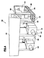
構造が簡単であって、エネルギ効率のよい加工対象物処理を可能にする処理設備を提供するために、処理設備が、複数の処理室区画を備えた処理室を有し、処理室区画がそれぞれ処理設備の複数の別々の循環空気モジュールの1つに関連づけられており、加熱ガスガイドを備えた加熱設備を有し、その場合に複数の循環空気モジュールが、特に処理室区画を通して案内されるガスを加熱するために、加熱ガスガイドと連結されていることが、提案される。【選択図】図1In order to provide a processing facility that is simple in structure and enables energy-efficient processing of an object to be processed, the processing facility includes a processing chamber having a plurality of processing chamber sections, each of which has a processing chamber section. Gas associated with one of a plurality of separate circulating air modules of the processing facility and having a heating facility with a heated gas guide, in which case the plurality of circulating air modules are guided in particular through the processing chamber compartment It is proposed that it is connected to a heated gas guide for heating. [Selection] Figure 1
Description
本発明は、加工対象物を処理する処理設備及び方法に関する。特に処理設備は、コーティングされた車両本体を乾燥させるために用いられる。したがって加工対象物を処理する方法は、コーティングされた車両本体を乾燥させる方法である。 The present invention relates to a processing facility and method for processing a workpiece. In particular, the processing equipment is used to dry the coated vehicle body. Therefore, the method of processing the workpiece is a method of drying the coated vehicle body.
処理設備と処理方法は、特に特許文献1、特許文献2、特許文献3及び特許文献4から知られている。
Processing equipment and processing methods are known, in particular from patent document 1,
本発明の課題は、構造が簡単であって、エネルギ効率のよい加工対象物の処理を可能にする処理設備を提供することである。 An object of the present invention is to provide a processing facility that has a simple structure and enables processing of an energy efficient workpiece.
この課題は、本発明によれば、加工対象物を処理する処理設備が次のものを有することによって解決される:
複数の処理室区画を備えた処理室を有し、処理室区画がそれぞれ処理設備の複数の別々の循環空気モジュールの1つに関連づけられている;
加熱ガスガイド(導管)を備えた加熱設備を有し、その場合に複数の循環空気モジュールが、特に処理室区画を通して案内されるガスを加熱するために、加熱ガスガイドと連結されている。
This problem is solved according to the invention by the processing equipment for processing the workpiece having:
Having a process chamber with a plurality of process chamber compartments, each of which is associated with one of a plurality of separate circulating air modules of the treatment facility;
A heating facility with a heated gas guide (conduit) is provided, in which case a plurality of circulating air modules are connected with the heated gas guide, in particular for heating the gas guided through the processing chamber compartment.
本発明に係る処理設備が、加熱ガスガイドを備えた加熱設備を有し、その加熱ガスガイドが循環空気モジュールと連結されていることによって、処理室区画へ供給すべきガスが簡単且つ効率的に加熱可能である。それによって処理設備は、好ましくは特にエネルギ効率よく駆動することができる。 The processing facility according to the present invention has a heating facility provided with a heated gas guide, and the heated gas guide is connected to the circulating air module, so that the gas to be supplied to the processing chamber section can be easily and efficiently supplied. It can be heated. Thereby, the processing equipment can preferably be driven particularly efficiently.
加熱ガスガイドは、好ましくはそれ自体閉成されて、例えばリング形状に閉成されて、形成されているので、加熱ガスガイド内で案内される加熱ガス流の少なくとも部分ガス流は、何回も加熱ガスガイドを貫流する。 The heated gas guide is preferably closed by itself, for example in the form of a ring, so that at least a partial gas flow of the heated gas flow guided in the heated gas guide can be many times. Flow through the heated gas guide.
加熱ガスは、好ましくは生ガス及び/又は純ガスであって、それは、処理室内で使用するのに、すなわち処理室を貫流するのに、適しており、及び/又はそのために設けられている。 The heated gas is preferably a raw gas and / or a pure gas, which is suitable for and / or provided for use in the processing chamber, i.e. to flow through the processing chamber.
加熱ガスは、好ましくは処理室区画の少なくともすぐ上流において、循環空気モジュール及び/又は処理室区画内のガス流に比較して高められた温度を有している。 The heated gas preferably has an elevated temperature, at least immediately upstream of the processing chamber compartment, compared to the circulating air module and / or the gas flow in the processing chamber compartment.
好ましくは、加熱ガスは、加熱設備の加熱装置の排ガスではなく、特に燃焼排ガスではない。 Preferably, the heated gas is not an exhaust gas of a heating device of a heating facility, and in particular is not a combustion exhaust gas.
「それ自体閉成された加熱ガスガイド」というのは、特に、その中で加熱ガス流の少なくとも一部が循環して案内される、加熱ガスガイドである。それとは関係なく、好ましくは、それ自体閉成された加熱ガスガイドにおいて、加熱ガス流へ新鮮ガスを連続的又は段階的に供給すること、及び/又は加熱ガス流から加熱ガスを導出することも、行うことができる。 A “heated gas guide closed in itself” is in particular a heated gas guide in which at least part of the heated gas flow is circulated and guided. Regardless, it is also preferable to supply fresh gas continuously or stepwise into the heated gas stream and / or to derive the heated gas from the heated gas stream in a heated gas guide which is itself closed. ,It can be carried out.
新鮮ガスの供給と加熱ガスの導出、すなわち加熱ガスの交換が、好ましくは加熱ガス流が加熱ガスガイドを1回通過する場合に、加熱ガスガイドの所定の箇所を通過して流れる加熱ガス流の少なくとも40%、好ましくは少なくとも約50%、特に少なくとも約80%、例えば少なくとも約90%が、完全な通過後にこの箇所へ新たに達するように、寸法設計されていると、好ましい場合がある。 The supply of the fresh gas and the derivation of the heating gas, i.e. the exchange of the heating gas, preferably when the heating gas flow passes through the heating gas guide once, the heating gas flow flowing through a predetermined location of the heating gas guide. It may be preferred if at least 40%, preferably at least about 50%, in particular at least about 80%, for example at least about 90%, are dimensioned to reach this point again after complete passage.
新鮮ガス流の供給及び/又は加熱ガス流からの加熱ガスの導出は、好ましくは、処理設備の処理室区画及び/又は循環空気モジュール内でのみ行われる。 The supply of the fresh gas stream and / or the derivation of the heated gas from the heated gas stream is preferably performed only in the processing chamber compartment and / or the circulating air module of the processing facility.
しかしまた、加熱設備に新鮮ガス供給及び/又は排ガス搬出を関連づけることもでき、それを用いて処理室区画の外部及び/又は循環空気モジュールの外部において新鮮ガスを供給し、もしくは加熱ガス流から加熱ガスを導出することができる。 However, it is also possible to associate a fresh gas supply and / or exhaust gas discharge with the heating facility, which is used to supply fresh gas outside the processing chamber compartment and / or outside the circulating air module or to heat from the heated gas stream. Gas can be derived.
循環空気モジュール及び/又は処理室区画は、好ましくは加熱ガスガイドの構成要素である。 The circulating air module and / or the processing chamber compartment is preferably a component of the heated gas guide.
特に加熱ガスは、好ましくは少なくとも部分的に何回か処理室区画を通して案内することができ、その後に(新たに)加熱ガスガイドの、循環空気モジュールの外部及び/又は処理室区画の外部に位置する部分を貫流する。 In particular, the heated gas can preferably be guided at least partly several times through the process chamber compartment, after which it is (newly) located outside the circulating air module and / or outside the process chamber compartment. It flows through the part to be.
本発明の形態において、加熱ガスガイドが循環空気ガイド(導管)を有することができ、その循環空気ガイドが部分的に、複数の並列に配置された循環空気モジュール及び/又は処理室区画によって形成される。 In a form of the invention, the heated gas guide can have a circulating air guide (conduit), which is partly formed by a plurality of parallel circulating air modules and / or process chamber compartments. The
循環空気モジュール及び/又は処理室区画内で、好ましくはガス流が循環空気回路内で案内可能であって、その循環空気回路へ加熱ガスガイドから加熱ガスが供給可能である。好ましくは、各循環空気モジュール及び/又は処理室区画の、循環して案内されるガス流の部分ガス流が、循環空気モジュール及び/又は処理室区画から導出可能であって、加熱ガスガイドによって閉成された循環内で案内可能であり、最終的に加熱ガス流の一部として新たに1つ又は複数の循環空気モジュール及び/又は処理室区画へ供給可能である。 Within the circulating air module and / or processing chamber compartment, preferably a gas flow can be guided in the circulating air circuit, and heated gas can be supplied to the circulating air circuit from the heated gas guide. Preferably, a partial gas flow of each circulating air module and / or process chamber compartment that is circulated and guided can be derived from the circulation air module and / or process chamber compartment and is closed by a heated gas guide. It can be guided in the created circulation and can finally be supplied to one or more circulating air modules and / or process chamber compartments as part of the heated gas stream.
好ましくは処理設備が移送装置を有しており、その移送装置によって加工対象物が処理室へ供給可能であり、処理室から導出可能であり、及び/又は移送装置の移送方向に処理室を通して移送可能である。 Preferably, the processing facility has a transfer device by which the workpiece can be supplied to the processing chamber, can be withdrawn from the processing chamber and / or transferred through the processing chamber in the transfer direction of the transfer device. Is possible.
処理室区画及び/又は循環空気モジュールは、好ましくは移送方向に互いに連続して配置されている。 The processing chamber compartment and / or the circulating air module are preferably arranged continuously in the transfer direction.
循環空気モジュールが、互いに独立した循環空気モジュールであると、効果的であり得る。 It may be advantageous if the circulating air modules are circulating air modules that are independent of each other.
循環空気モジュール、特に各循環空気モジュールが、好ましくは以下のものを有している:
ガスを処理室区画へ供給するためのガス供給;及び/又は
処理室区画からガスを導出するためのガス導出;及び/又は
(循環空気)ガス流を駆動するための送風機装置;及び/又は
(循環空気)ガス流から不純物を分離するための分離装置;及び/又は
処理室区画へ供給すべき(循環空気)ガス流をガス供給の複数の入口開口部へ分配するための分配装置;及び/又は
収集装置、この収集装置によってガス導出の複数の出口開口部(還流開口部)を通して処理室から導出された(循環空気)ガス流をまとめて案内することができる。
The circulating air module, in particular each circulating air module, preferably has the following:
A gas supply for supplying gas to the processing chamber compartment; and / or a gas outlet for extracting gas from the processing chamber compartment; and / or a blower device for driving the (circulating air) gas flow; and / or ( A separation device for separating impurities from the (circulating air) gas stream; and / or a distribution device for distributing the (circulating air) gas stream to be supplied to the processing chamber compartment to a plurality of inlet openings of the gas supply; and / or Alternatively, the collecting device and the collecting device can collectively guide the (circulated air) gas flow led out from the processing chamber through a plurality of outlet openings (reflux openings) for gas discharge.
各循環空気モジュールは、好ましくは、付属の処理室と共に処理設備の1つの、特に完全な、区画を形成する。 Each circulating air module preferably forms one, in particular a complete, compartment of the processing facility together with an associated processing chamber.
この明細書及び請求項において、「循環空気」という概念は、必ずしもガスとしての「空気」に限定されない。むしろ「循環空気」という概念は、好ましくは循環(循環空気回路)内で案内されるガスを表し、それが特に何回か処理され、及び/又は再利用される。 In this specification and claims, the concept of “circulating air” is not necessarily limited to “air” as a gas. Rather, the concept of “circulating air” preferably represents a gas that is guided in the circulation (circulation air circuit), which is treated and / or reused in particular several times.
同様に、「供給空気」、「供給空気流」「導出空気」及び「導出空気流」は、必ずしもガスとしての「空気」に限定されず、むしろまったく一般的に、循環空気回路内で案内されるガス(供給空気、供給空気流)もしくは循環空気回路から導出されるガス(排出空気、排出空気流)を表す。 Similarly, “supply air”, “supply air flow”, “derived air” and “derived air flow” are not necessarily limited to “air” as a gas, but rather are generally guided in a circulating air circuit. Gas (supply air, supply air flow) or gas derived from the circulating air circuit (exhaust air, exhaust air flow).
本発明の形態において、加熱設備は加熱装置と熱伝達器(熱交換器)とを有することができ、その熱伝達器によって、加熱装置内で発生された熱を加熱ガスガイド内で案内される加熱ガスへ伝達することができる。 In the embodiment of the present invention, the heating equipment can have a heating device and a heat transfer device (heat exchanger), and the heat generated by the heat transfer device is guided in the heating gas guide by the heat transfer device. Can be transmitted to heated gas.
熱伝達器は、特に、加熱装置の排ガス内に含まれる熱を加熱ガスの加熱に利用することができるようにするために、加熱装置の排ガスレーン内に配置されている。 In particular, the heat transfer device is arranged in the exhaust gas lane of the heating device so that the heat contained in the exhaust gas of the heating device can be used for heating the heating gas.
処理設備が、加熱設備とは異なる、及び/又は独立した新鮮ガス供給を有しており、それを用いて新鮮ガスが処理室へ供給可能であると、効果的であり得る。 It may be advantageous if the treatment facility has a fresh gas supply that is different from and / or independent of the heating facility and can be used to supply fresh gas to the treatment chamber.
新鮮ガスは、好ましくは加熱ガス流とは関係なく、循環空気モジュール及び/又は処理室区画内で案内されるガス流へ、そしてそれに伴って処理室へ、供給可能である。 The fresh gas is preferably supplied independently of the heated gas stream, to the gas stream guided in the circulating air module and / or the process chamber compartment, and accordingly to the process chamber.
さらに、新鮮空気流を少なくとも部分的にロックガス流として利用することができ、そのようにして処理室へ供給することができる。 Furthermore, the fresh air stream can be used at least in part as a rock gas stream and can thus be supplied to the processing chamber.
処理設備が新鮮ガス供給を有し、それを用いて新鮮ガスが、加熱ガスガイド内で案内される加熱ガス流へ供給可能であると、効果的であり得る。 It may be advantageous if the treatment facility has a fresh gas supply, which can be used to supply fresh gas to the heated gas stream guided in the heated gas guide.
新鮮ガス供給は、好ましくは、特に処理室内の実際の熱需要に従って、制御装置によって開ループ制御可能及び/又は閉ループ制御可能である。 The fresh gas supply is preferably open-loop controllable and / or closed-loop controllable by the control device, in particular according to the actual heat demand in the processing chamber.
新鮮ガス流が少なくとも近似的に一定の体積流及び/又は質量流をもって、1つ又は複数のロックへ、特に入口ロック及び/又は出口ロックへ供給可能であると、好ましい場合がある。 It may be preferred if the fresh gas stream can be supplied to one or more locks, in particular to the inlet lock and / or the outlet lock, at least with a substantially constant volume flow and / or mass flow.
その代わりに、あるいはそれに加えて、新鮮ガス流は可変の体積流及び/又は質量流をもって1つ又は複数のロックへ、特に入口ロック及び/又は出口ロックへ供給可能とすることができる。 Alternatively or additionally, the fresh gas flow can be supplied to the one or more locks, in particular to the inlet lock and / or the outlet lock, with a variable volume flow and / or mass flow.
少なくとも近似的に一定の体積流及び/又は質量流は、特に時間的に処理室内の実際の熱需要に依存しない。 The at least approximately constant volume and / or mass flow does not depend on the actual heat demand in the process chamber, in particular in time.
可変の体積流及び/又は質量流は、好ましくは、処理室内の実際の熱需要に従って適合され、及び/又は、開ループ制御及び/又は閉ループ制御される。 The variable volume flow and / or mass flow is preferably adapted according to the actual heat demand in the process chamber and / or is open-loop controlled and / or closed-loop controlled.
さらに、少なくとも近似的に一定の体積流及び/又は質量流を有する新鮮ガス流を加熱ガス流へ供給可能とすることができる。 Furthermore, a fresh gas stream having at least an approximately constant volumetric flow and / or mass flow can be supplied to the heated gas stream.
その代わりに、あるいはそれに加えて、可変の体積流及び/又は質量流を有する新鮮ガス流を加熱ガス流へ供給可能とすることができる。 Alternatively, or in addition, a fresh gas stream having a variable volume flow and / or mass flow can be provided to the heated gas stream.
特に少なくとも近似的に一定の体積流及び/又は質量流を有する、新鮮ガス流は、好ましくは、この新鮮ガス流によって処理設備の平均的な新鮮空気需要の少なくとも約30%、特に少なくとも約40%、例えば約50%がカバーされるように、選択されている。この新鮮ガス流は、特に1つ又は複数のロックへ供給される新鮮ガス流である。 A fresh gas stream, in particular having at least an approximately constant volumetric flow and / or mass flow, is preferably at least about 30%, in particular at least about 40%, of the average fresh air demand of the processing equipment by this fresh gas stream. For example, about 50% is selected. This fresh gas stream is in particular a fresh gas stream supplied to one or more locks.
特に可変の体積流及び/又は質量流を有する、他の新鮮ガス流は、これによって処理設備の平均的な新鮮空気需要の少なくとも約30%、特に少なくとも約40%、例えば約50%がカバーされるように、選択されている。この新鮮ガス流は、特に中央で加熱ガス流へ供給される新鮮ガス流である。 Other fresh gas streams, particularly with variable volumetric and / or mass flows, thereby cover at least about 30%, in particular at least about 40%, for example about 50%, of the average fresh air demand of the processing equipment. So that it is selected. This fresh gas stream is a fresh gas stream that is supplied to the heated gas stream, particularly in the middle.
新鮮ガス供給は、特に加熱装置の排ガスから熱を、新鮮ガス供給によって供給すべき新鮮ガスへ伝達するために、加熱装置の排ガスレーンへの熱伝達器と連結されている。 The fresh gas supply is connected to a heat transfer to the exhaust gas lane of the heating device, in particular for transferring heat from the exhaust gas of the heating device to the fresh gas to be supplied by the fresh gas supply.
新鮮ガスを加熱するための熱伝達器は、好ましくは、加熱ガスを加熱するための熱伝達器とは異なる熱伝達器である。 The heat transfer device for heating the fresh gas is preferably a heat transfer device different from the heat transfer device for heating the heating gas.
それとは異なり、共通の熱伝達器の互いに異なる区画を、一方で新鮮ガスを加熱するため、そして他方では加熱ガスを加熱するために用いることができる。その場合に新鮮ガス供給と加熱ガスガイドは、特に共通の熱伝達器を有する。その場合に特に、好ましくは、熱伝達器の冷側が複数のセグメントに分割されている。特に複数の互いに独立して貫流可能且つ流体的に有効に互いに分離されたセグメントを設けることができる。 In contrast, different sections of a common heat transfer can be used on the one hand for heating fresh gas and on the other hand for heating heated gas. In that case the fresh gas supply and the heated gas guide have in particular a common heat transfer. In particular, the cold side of the heat transfer device is preferably divided into a plurality of segments. In particular, it is possible to provide a plurality of segments which can flow independently of each other and which are fluidly effectively separated from one another.
処理設備は、好ましくは1つ又は複数のロックを有しており、そのロックは特に新鮮ガスロックとして形成され、且つ新鮮ガスによって貫流され、あるいは貫流可能である。 The treatment facility preferably has one or more locks, which locks are formed in particular as fresh gas locks and are flowed through or can flow through with fresh gas.
その代わりに、あるいはそれに加えて、処理設備が1つ又は複数の循環空気ロックを有することができ、その循環空気ロックは循環空気によって、すなわち循環内で案内されるガス流によった貫流され、あるいは貫流可能である。そのために特に、各循環空気ロックを循環空気モジュールに関連づけることができる。 Alternatively or in addition, the treatment facility can have one or more circulating air locks, which are circulated by the circulating air, i.e. by the gas flow guided in the circulation, Or it can flow through. For this purpose, in particular, each circulating air lock can be associated with a circulating air module.
特に、処理設備が循環空気ロックを有する場合に、新鮮ガス流が直接加熱ガス流に混合され、あるいは混合可能とすることができる。それによって新鮮ガスを処理室へ供給するための別体の新鮮ガス導管を省くことができる。 In particular, if the treatment facility has a circulating air lock, the fresh gas stream can be mixed directly into the heated gas stream or can be mixed. Thereby, a separate fresh gas conduit for supplying fresh gas to the processing chamber can be dispensed with.
加熱ガスガイドが中央の加熱ガス導管を有し、その中で加熱ガスが案内され、あるいは案内可能であり、且つその加熱ガス導管によって複数の循環空気モジュール及び/又は処理室区画へ加熱ガイドから加熱ガスが供給可能であると、効果的であることができ、その場合に加熱ガスは直接あるいは循環空気モジュールを介して間接的にそれぞれの処理室区画内へ導入可能である。 The heated gas guide has a central heated gas conduit in which the heated gas is guided or can be guided and heated by the heated gas conduit to a plurality of circulating air modules and / or process chamber compartments. If gas can be supplied, it can be effective, in which case the heated gas can be introduced directly or indirectly into the respective processing chamber compartments via a circulating air module.
したがって加熱ガスガイドは、好ましくは、供給空気を処理室区画内の循環空気回路へ供給するための供給空気ガイドを形成する。 Thus, the heated gas guide preferably forms a supply air guide for supplying supply air to a circulating air circuit in the process chamber compartment.
さらに、加熱ガスガイドが中央の加熱ガス導管を有することができ、その中で加熱ガスが案内され、あるいは案内可能であって、且つその加熱ガス導管を用いてガスが循環空気モジュールから、及び/又は処理室区画から導出可能である。 In addition, the heated gas guide can have a central heated gas conduit in which the heated gas is guided or can be guided, and with which the heated gas conduit is used to pass gas from the circulating air module and / or Alternatively, it can be derived from the processing chamber compartment.
したがって加熱ガスガイドは、好ましくは、循環空気モジュール内で循環して案内されるガス流から排出空気を導出するための排出空気ガイドを形成している。 The heated gas guide thus preferably forms an exhaust air guide for deriving the exhaust air from a gas stream which is circulated and guided in the circulating air module.
加熱ガスガイドが中央の加熱ガス導管を有し、それを用いて加熱ガスがリング状に加熱ガスを加熱するための熱伝達器から複数の循環空気モジュール及び/又は処理室区画へ、そして新たに熱伝達器へ戻るように案内可能であると、好ましい場合がある。 The heated gas guide has a central heated gas conduit with which the heated gas is used to heat the heated gas in the form of a ring to a plurality of circulating air modules and / or process chamber compartments and newly It may be preferable to be able to guide back to the heat transfer.
その代わりに、あるいはそれに加えて、加熱ガスガイドが中央の加熱ガス導管を有しており、それを用いて、特に加熱ガスとして用いられるガスが、1つ又は複数の循環空気モジュール及び/又は処理室区画から導出可能であり、且つそれを加熱するために熱伝達器へ供給可能であり、そして次に1つ又は複数の循環空気モジュール及び/又は処理室区画へ案内可能であるように、することができる。 Alternatively or additionally, the heated gas guide has a central heated gas conduit, with which the gas used in particular as the heated gas can be used as one or more circulating air modules and / or treatments. In such a way that it can be derived from the chamber compartment and can be supplied to a heat transfer device to heat it and then be guided to one or more circulating air modules and / or processing chamber compartments. be able to.
加熱ガスガイド内で案内される加熱ガスは、好ましくは1つの送風機により、あるいは複数の送風機によって駆動可能である。 The heated gas guided in the heated gas guide can preferably be driven by one blower or by a plurality of blowers.
加熱ガスガイドが、加熱ガスガイド内で案内される加熱ガス流を循環空気モジュール及び/又は処理室区画へ分配するために複数の分枝又は分岐を有することができる。 The heated gas guide may have a plurality of branches or branches to distribute the heated gas flow guided in the heated gas guide to the circulating air module and / or the process chamber compartment.
特に、加熱ガスガイドが、循環空気モジュール及び/又は処理室区画に沿って延びるメイン供給導管を有することができ、そのメイン供給導管から加熱ガス流の一部が分岐可能であり、且つそれぞれの循環空気モジュール及び/又は処理室区画へ供給可能である。 In particular, the heated gas guide can have a main supply conduit extending along the circulating air module and / or the process chamber compartment, from which a part of the heated gas stream can be branched and the respective circulation It can be supplied to the air module and / or the processing chamber compartment.
メイン供給導管は、例えば処理室の外部において、特に処理室区画全体の外部において、及び/又は移動方向に対して平行に延びることができる。 The main supply conduit can for example extend outside the processing chamber, in particular outside the entire processing chamber section and / or parallel to the direction of movement.
好ましくは、メイン供給導管は、特にすべての循環空気ガイドに加熱ガスを供給することができるようにするために、少なくとも近似的に処理室の長さ全体にわたって延びている。 Preferably, the main supply conduit extends at least approximately the entire length of the processing chamber, in particular to be able to supply heated gas to all circulating air guides.
さらに、メイン供給導管は、処理室の内部及び/又は移送方向に対して平行に延びることができる。例えば、メイン供給導管は、移送装置の互いに対して平行且つ移送方向に対して平行に延びる2つの移送ユニットの間の中間領域内に配置することができる。 Furthermore, the main supply conduit can extend parallel to the interior of the processing chamber and / or to the transfer direction. For example, the main supply conduit can be arranged in an intermediate region between two transfer units extending parallel to each other and parallel to the transfer direction of the transfer device.
メイン供給導管は、好ましくは処理室の床内に統合され、あるいは処理室の床上に直接配置されている。 The main supply conduit is preferably integrated into the processing chamber floor or placed directly on the processing chamber floor.
メイン供給導管が、処理すべき加工対象物の下方を通って延び、及び/又は処理すべき加工対象物の完全に下方で、特に処理すべき加工対象物のすぐ下方に配置されていると、好ましい場合がある。それによってメイン供給導管は、特に熱放射により、及び/又は対流によって、処理室を通して案内されるガス流の加熱に、及び/又は処理すべき加工対象物の加熱に、寄与することができる。 The main supply conduit extends below the work piece to be treated and / or is located completely below the work piece to be treated, in particular directly below the work piece to be treated; It may be preferable. Thereby, the main supply conduit can contribute to the heating of the gas stream guided through the processing chamber and / or the heating of the workpiece to be processed, in particular by heat radiation and / or by convection.
メイン供給導管は、特に処理室区画全体を通って、及び/又は処理室区画全体内へ、延びている。 The main supply conduit extends in particular through the entire processing chamber section and / or into the entire processing chamber section.
メイン供給導管が矩形通路として形成されており、その矩形通路が移送方向に対して垂直に見て、移送方向に対して垂直に見た、メイン供給導管の高さの少なくとも3倍、特に少なくとも5倍、例えば少なくとも10倍となる幅を有していると、好ましい場合がある。 The main supply conduit is formed as a rectangular passage, which is at least three times the height of the main supply conduit, in particular at least 5 when viewed perpendicular to the transfer direction. It may be preferable to have a width that is double, for example, at least 10 times.
メイン供給通路が、流入弁を介して直接、循環空気モジュール及び/又は循環空気ガイドの還流導管内へ連通していると、好ましい場合がある。 It may be preferred if the main supply passage communicates directly into the circulating air module and / or the circulating conduit of the circulating air guide via the inlet valve.
最終的に循環空気モジュール及び/又は処理室区画へ加熱ガスを供給するための複数の供給空気流を得るために、分枝又は分岐を用いて、加熱ガス流が効果的に分配可能である。 The heated gas stream can be effectively distributed using branches or branches to ultimately obtain a plurality of supply air streams for supplying heated gas to the circulating air module and / or process chamber compartment.
加熱ガスガイドがメイン分岐部を有しており、それを用いて加熱ガス流全体が第1の加熱ガス部分流と第2の加熱ガス部分流へ分配可能であって、その場合に第1の加熱ガス部分流が、処理設備の移送装置の移送方向に関して第1の循環空気モジュールへ、あるいは最初のn番目までの循環空気モジュールへ、及び/又は第1の処理室区画へ、あるいは最初のn番目までの処理室区画へ供給可能であり、且つその場合に第2の加熱ガス部分流が好ましくは他のすべての循環空気モジュール及び/又は処理室区画へ分配可能であると、効果的であり得る。 The heated gas guide has a main branch, which can be used to distribute the entire heated gas flow into the first heated gas partial flow and the second heated gas partial flow, in which case the first The heated gas partial stream is directed to the first circulating air module, or to the first nth circulating air module, and / or to the first processing chamber compartment, or to the first n with respect to the transfer direction of the transfer device of the processing equipment. It is possible to supply up to the first processing chamber compartment and in that case the second heated gas partial stream is preferably distributable to all other circulating air modules and / or processing chamber compartments. obtain.
第1の循環空気モジュールは、好ましくは処理室区画に関連づけられた循環空気モジュールである。しかしまた、この第1の循環空気モジュールが、循環空気ロックに関連づけられた循環空気モジュールであってもよい。 The first circulating air module is preferably a circulating air module associated with the process chamber compartment. However, the first circulating air module may also be a circulating air module associated with the circulating air lock.
加熱ガスガイドが、循環空気モジュール及び/又は処理室区画から導出された複数のガス流をまとめて案内するための複数の合流部を有していると、好ましい場合がある。 It may be preferred if the heated gas guide has a plurality of merging sections for guiding a plurality of gas flows derived from the circulating air module and / or the processing chamber compartment together.
特に、それによって好ましくは、循環空気モジュール及び/又は処理室区画からの排出空気流をまとめて案内することができ、且つ加熱ガス全体流として新たに加熱可能であって、且つ最終的に新たに循環空気モジュール及び/又は処理室区画へ供給可能である。 In particular, thereby preferably the exhaust air flow from the circulation air module and / or the processing chamber compartment can be guided together and can be reheated as a whole heated gas flow and finally renewed It can be supplied to the circulating air module and / or the processing chamber compartment.
加熱ガスガイドがメイン合流部を有することができ、それを用いて、処理設備の移送装置の移送方向に関して第1の循環空気モジュール又は最初のn番目までの循環空気モジュール及び/又は第1の処理室区画又は最初のn番目までの処理室区画の排ガス流が、すでにまとめて案内されている、他のすべての循環空気モジュール及び/又は処理室区画の排ガス流と共に、一緒に案内可能である。 The heated gas guide may have a main junction, using which the first circulating air module or the first nth circulating air module and / or the first processing with respect to the transfer direction of the transfer device of the processing equipment The exhaust gas flow of the chamber compartment or the first nth processing chamber compartment can be guided together with all other circulating air modules and / or exhaust gas flow of the processing chamber compartment already guided together.
メイン分岐部及び/又はメイン合流部の使用は、特に、加熱ガス流全体を唯一の流れ方向においてメイン供給導管及び/又はメイン導出導管を通して案内する必要がないようにするために、加熱ガス導管のメイン供給導管及び/又はメイン導出導管の通路横断面を減少させるために、用いることができる。 The use of the main branch and / or the main junction is particularly suitable for the heating gas conduit so that the entire heating gas flow does not have to be guided through the main supply conduit and / or main outlet conduit in the only flow direction. It can be used to reduce the passage cross section of the main supply conduit and / or the main outlet conduit.
各循環空気モジュール及び/又は各処理室区画は、流入弁及び/又は排出弁を有することができ、それを用いて循環空気モジュール及び/又は処理室区画へ供給すべき加熱ガス流の体積流及び/又は循環空気モジュール及び/又は処理室区画から導出されるガス流の体積流を開ループ制御及び/又は閉ループ制御することができる。 Each circulating air module and / or each processing chamber compartment may have an inflow valve and / or an exhaust valve, which is used to volume the heated gas stream to be supplied to the circulating air module and / or the processing chamber section and The volume flow of the gas flow derived from the circulating air module and / or the processing chamber compartment can be open-loop controlled and / or closed-loop controlled.
好ましくはそれによって、それぞれの循環空気モジュール及び/又は処理室区画内で案内される循環空気流の供給空気流及び/又は排出空気流が開ループ制御可能及び/又は閉ループ制御可能である。 Preferably, thereby, the supply air flow and / or the exhaust air flow of the circulating air flow guided in the respective circulating air module and / or processing chamber compartment is open-loop controllable and / or closed-loop controllable.
処理設備は、好ましくは制御装置を有しており、それを用いて循環空気モジュール及び/又は処理室区画へ供給すべき加熱ガス流の体積流及び/又は循環空気モジュールから、及び/又は処理室区画から導出されるガス流の体積流が開ループ制御可能及び/又は閉ループ制御である。 The treatment facility preferably has a control device, which is used to supply a volumetric flow of heated gas flow to be supplied to the circulation air module and / or the treatment chamber compartment and / or from the circulation air module and / or the treatment chamber. The volume flow of the gas flow derived from the compartment is open loop controllable and / or closed loop control.
好ましくは制御装置を用いて体積流を制御することにより、常に、それぞれの循環空気モジュール及び/又は処理室区画内で案内される循環空気流の所望の温度が実質的に一定であるような量の加熱ガスが、それぞれの循環空気モジュール及び/又は処理室区画へ供給可能である。 An amount such that the desired temperature of the circulating air flow guided in the respective circulating air module and / or process chamber compartment is always substantially constant, preferably by controlling the volume flow using a control device. Of heated gas can be supplied to the respective circulating air module and / or processing chamber compartment.
制御装置は、好ましくは、上述した機能が実施可能であり、及び/又は上述したパラメータが維持され、特に少なくとも近似的に一定に維持されるように、形成され、且つ整えられている。 The control device is preferably configured and arranged such that the functions described above can be performed and / or the parameters described above are maintained, in particular at least approximately constant.
処理設備が制御装置を有し、その制御装置を用いて、加熱ガスガイド内で案内される加熱ガス流の少なくとも近似的に一定の体積流が維持可能であると、好ましい場合がある。その場合に特に、加熱ガス流を駆動する加熱ガスガイドの送風機を、例えば駆動出力の変化によって、開ループ制御及び/又は閉ループ制御することができる。 It may be preferred if the treatment facility has a control device and can use the control device to maintain at least an approximately constant volume flow of the heated gas flow guided in the heated gas guide. In particular, the blower of the heated gas guide that drives the heated gas flow can be subjected to open loop control and / or closed loop control, for example, by changing the drive output.
加熱ガス流を駆動するための送風機(又はベンチレータとも称される)は、好ましくは周波数コンバータを有しており、それを介して開ループ制御及び/又は閉ループ制御を行うことができる。 The blower (or also referred to as a ventilator) for driving the heated gas flow preferably has a frequency converter through which open loop control and / or closed loop control can be performed.
好ましくは、加熱ガスガイドの送風機の開ループ制御及び/又は閉ループ制御によって、処理設備の全エネルギ需要における変動、特に加熱需要における変動を補償することができる。 Preferably, fluctuations in the total energy demand of the processing equipment, in particular fluctuations in the heating demand, can be compensated by open-loop control and / or closed-loop control of the blower of the heated gas guide.
その代わりに、あるいはそれに加えて、特に、加熱需要が少ない場合にすでに加熱ガス流の小さい体積流が調節されており、特に体積流が最小値に減少されている場合に、加熱ガス流の温度のための目標値及び/又は実際値を適合させることができる。 Instead, or in addition, the temperature of the heated gas stream is adjusted, especially when the heating gas flow is already small and the volume flow of the heated gas stream is adjusted to a minimum value. The target value and / or the actual value for can be adapted.
さらに、加熱需要が減少されている場合に、まず加熱ガス流の温度を低下させることができる。加熱ガス流の温度があらかじめ定められた下限値に達した場合に、さらに、送風機の適切な開ループ制御及び/又は閉ループ制御によって体積流を減少させることができる。 Furthermore, when the heating demand is reduced, the temperature of the heated gas stream can first be reduced. When the temperature of the heated gas stream reaches a predetermined lower limit, the volume flow can be further reduced by appropriate open loop control and / or closed loop control of the blower.
処理設備が制御装置を有することができ、それを用いて加熱ガスガイド内で案内される加熱ガス流の少なくとも近似的に一定の温度を維持することができる。その場合に特に、加熱ガス流を加熱するための熱伝達器を迂回して案内されるバイパス体積流を調節し、特に所望に変化させることができる。例えば、加熱ガスガイド内で案内される加熱ガス流の所望の温度を得るために、加熱ガス流を加熱するための熱伝達器を通って案内される体積流の、バイパス体積流に対する比率を変化させることができる。 The processing facility can have a controller, which can be used to maintain at least an approximately constant temperature of the heated gas flow guided in the heated gas guide. In that case, in particular, the bypass volume flow guided around the heat exchanger for heating the heated gas stream can be adjusted and varied as desired. For example, to obtain the desired temperature of the heated gas flow guided in the heated gas guide, the ratio of the volume flow guided through the heat transfer device for heating the heated gas flow to the bypass volume flow is changed. Can be made.
本発明の形態において、加熱ガスガイドがすべての循環空気モジュール及び/又は処理室区画を迂回するための1つ又は複数のバイパス導管を有することができる。このようにして、特に個々の循環空気モジュール及び/又は処理室区画の望ましくない供給不足を回避するために、加熱ガス流のリザーブを準備することができる。バイパス導管を用いて、特に加熱ガスガイドのメイン供給導管内の加熱ガスの過剰提供を維持することができる。 In a form of the invention, the heated gas guide may have one or more bypass conduits for bypassing all circulating air modules and / or process chamber compartments. In this way, a reserve of the heated gas stream can be prepared, in particular to avoid undesired supply shortages of the individual circulating air modules and / or process chamber compartments. Bypass conduits can be used to maintain an oversupply of heated gas, particularly in the main supply conduit of the heated gas guide.
好ましくはメイン供給導管がその下流側の端部において、及び/又は移送方向に関してその後方の端部において、バイパス導管内へ連通している。 Preferably, the main supply conduit communicates into the bypass conduit at its downstream end and / or at its rear end with respect to the transfer direction.
バイパス導管は、好ましくはメイン導出導管の上流側の端部において、及び/又は移送方向に関してその後方の端部において、メイン導出導管内へ連通している。 The bypass conduit communicates into the main outlet conduit, preferably at the upstream end of the main outlet conduit and / or at its rear end with respect to the transfer direction.
バイパス導管は、例えば、加熱ガスを循環空気モジュールへ供給するための加熱ガス導管の複数の、特にすべての分岐及び/又は分枝の上流に配置されている。その代わりに、あるいはそれに加えて、バイパス導管は、循環空気モジュールからのガス流をまとめて案内するための加熱ガスガイドの複数の、特にすべての合流部の下流に、配置することができる。 The bypass conduit is, for example, arranged upstream of a plurality, in particular all branches and / or branches of the heated gas conduit for supplying heated gas to the circulating air module. Alternatively or additionally, the bypass conduit can be arranged downstream of a plurality, in particular all the confluences, of the heated gas guide for collectively guiding the gas flow from the circulating air module.
さらに、バイパス導管が、加熱ガスを循環空気モジュールへ供給するための加熱ガスガイドの複数の、特にすべての分岐及び/又は分枝の下流に配置されていると、好ましい場合がある。その代わりに、あるいはそれに加えて、バイパス導管は、循環空気モジュールからのガス流をまとめて案内するための加熱ガスガイドの複数の、特にすべての合流部の上流に配置することができる。 Furthermore, it may be preferred if the bypass conduit is arranged downstream of a plurality, in particular all branches and / or branches of the heated gas guide for supplying heated gas to the circulating air module. Alternatively or additionally, the bypass conduit can be arranged upstream of a plurality, in particular all the junctions of the heated gas guide for guiding the gas flow from the circulating air module together.
バイパス導管を用いて、好ましくは、特に導出部分内で案内されるガス流の温度を常に凝縮温度の上に維持するために、熱いガスを加熱ガス導管の導出部分内へ直接導入することができる。 With a bypass conduit, hot gas can preferably be introduced directly into the outlet part of the heated gas conduit, in particular in order to keep the temperature of the gas stream guided in the outlet part always above the condensation temperature. .
好ましくは、バイパス導管は、加熱ガス導管の供給区画の、移送方向に関して前方の端部において、加熱ガス導管の供給区画から分岐している。 Preferably, the bypass conduit branches off from the heated gas conduit supply section at the forward end of the heated gas conduit supply section with respect to the transport direction.
バイパス導管は、好ましくは、メイン導出導管の下流側の端部において、及び/又は移送方向に関してその前方の端部において、加熱ガス導管の導出区画内へ連通している。 The bypass conduit preferably communicates into the outlet section of the heated gas conduit at the downstream end of the main outlet conduit and / or at its forward end with respect to the transfer direction.
バイパス導管を介して循環空気ガイドを迂回して案内される加熱ガス流の体積流は、好ましくはバイパス弁によって開ループ制御可能及び/又は閉ループ制御である。 The volume flow of the heated gas flow guided around the circulating air guide via the bypass conduit is preferably open-loop controllable and / or closed-loop control by a bypass valve.
本発明の他の形態において、圧力センサを用いて加熱ガスガイドのメイン供給導管内の圧力を求めることができる。特にそれから加熱ガス需要を定めることができる。 In another form of the invention, a pressure sensor can be used to determine the pressure in the main supply conduit of the heated gas guide. In particular, the heating gas demand can then be determined.
求められたメイン供給導管内の圧力に従って、好ましくは、制御装置を用いて、加熱ガス流を駆動するための送風機の移送出力、特にベンチレータ回転数が、特にメイン供給導管内の圧力が常にあらかじめ定められた圧力領域内にあるように、開ループ制御可能及び/又は閉ループ制御可能である。それによって好ましくは、循環空気ガイドへの確実な熱供給を保証することができ、過剰供給を準備する必要がなく、且つバイパス導管を介して循環空気ガイドを迂回する必要がない。 According to the determined pressure in the main supply conduit, preferably the control device is used to always predetermine the transfer output of the blower for driving the heated gas flow, in particular the speed of the ventilator, in particular the pressure in the main supply conduit. Open-loop controllable and / or closed-loop controllable so as to be within the specified pressure region. Thereby, preferably a reliable heat supply to the circulating air guide can be ensured, there is no need to prepare for excess supply and there is no need to bypass the circulating air guide via a bypass conduit.
その代わりに、あるいはそれに加えて、センサ装置を用いて、及び/又は適切なフィードバックによって、流入弁及び/又は排出弁のそれぞれの位置を求めることができ、且つ加熱ガス流を駆動するための送風機の移送出力、特にベンチレータ回転数を開ループ制御及び/又は閉ループ制御する場合に、考慮することができる。 Alternatively or additionally, a blower for driving the heated gas flow, the position of each of the inlet and / or outlet valves can be determined using a sensor device and / or by suitable feedback Can be taken into account in the case of open-loop control and / or closed-loop control of the output power of the ventilator, in particular the speed of the ventilator.
さらに、その代わりに、あるいはそれに加えて、センサ装置を用いて、特に流入弁のすぐ下流の、循環空気ガイド内、流入弁内あるいは流入弁における、及び/又は排出弁内あるいは排出弁における、ガス流のそれぞれの温度を求めることができ、且つ加熱ガス流を駆動するための送風機の移送出力、特にベンチレータ回転数を開ループ制御及び/又は閉ループ制御する際に考慮することができる。 Furthermore, alternatively or in addition, a sensor device is used, in particular directly downstream of the inflow valve, in the circulating air guide, in the inflow valve or in the inflow valve and / or in the exhaust valve or in the exhaust valve. The temperature of each of the streams can be determined and can be taken into account when performing open loop control and / or closed loop control of the blower transfer output for driving the heated gas stream, in particular the ventilator speed.
加熱ガス流を駆動するための送風機の移送出力、特にベンチレータ回転数、を開ループ制御及び/又は閉ループ制御することによって、好ましくは、処理設備の特に効率的及び/又はエネルギを節約する駆動が可能である。さらに、好ましくは、バイパス導管なしでも、循環空気ガイドへの加熱ガスの供給過剰又は供給不足を回避することができる。 A particularly efficient and / or energy-saving drive of the processing equipment is possible, preferably by open-loop control and / or closed-loop control of the transfer output of the blower for driving the heated gas flow, in particular the ventilator speed. It is. Furthermore, it is possible to avoid oversupply or undersupply of the heated gas to the circulating air guide, preferably without a bypass conduit.
本発明は、さらに、加工対象物を処理する方法に関する。 The invention further relates to a method for processing a workpiece.
これに関して本発明の課題は、加工対象物を簡単且つエネルギ効率よく処理することができる方法を提供することである。 In this regard, the object of the present invention is to provide a method that allows simple and energy efficient processing of workpieces.
この課題は、本発明によれば、以下のことを有する方法によって解決される:
別々の循環内で案内される複数のガス流によって、処理設備の処理室の複数の処理室区画を貫流する;
処理設備の加熱設備の加熱ガスガイド内で案内される加熱ガス流を用いてガス流を加熱する。
This problem is solved according to the invention by a method comprising:
Flow through the process chamber compartments of the process chamber of the processing facility by a plurality of gas streams guided in separate circulations;
The gas stream is heated using a heated gas stream guided in a heated gas guide of a heating facility of the processing facility.
本発明に係る方法は、好ましくは、処理設備に関連して説明した特徴及び/又は利点の1つ又は複数を有している。 The method according to the invention preferably has one or more of the features and / or advantages described in connection with the processing equipment.
さらに、処理設備は、好ましくは、方法に関連して説明した個々のあるいは複数の特徴及び/又は利点を有している。 Further, the processing equipment preferably has the individual or features and / or advantages described in connection with the method.
本発明に係る方法において、好ましくは、別々の循環内で案内される複数のガス流を加熱するために、これらの各ガス流の部分流をそれぞれのガス流から導出して、加熱ガス流の部分流に代えることができる。 In the method according to the invention, preferably a partial stream of each of these gas streams is derived from the respective gas stream in order to heat a plurality of gas streams guided in separate circulations. It can be replaced with a partial flow.
この明細書及び付属の請求項において、「弁」というのは、特に、導管内の通過量を調節するための各種の閉鎖部材又は開放部材である。特に弁は、フラップとすることができる。 In this specification and the appended claims, a “valve” is, in particular, various closing or opening members for adjusting the amount of passage through the conduit. In particular, the valve can be a flap.
循環空気モジュールが、それぞれ循環空気ガイドを有し、あるいはそれを形成すると、好ましい場合がある。しかしまた、循環空気モジュールが、循環空気ガイドの単なる一部であり、すなわち循環空気ガイド内で案内されガス流を駆動するために用いられる部分であってもよい。その場合に他の部分が、特に付属の処理室区画である。 It may be preferred if the circulating air modules each have or form a circulating air guide. However, the circulating air module may also be just a part of the circulating air guide, i.e. the part guided in the circulating air guide and used to drive the gas flow. In that case, the other part is in particular the attached processing chamber compartment.
好ましくは、各循環空気モジュールは、少なくとも1つの送風機と、送風機のすぐ上流に配置された吸い込み室とを有している。 Preferably, each circulating air module has at least one blower and a suction chamber located immediately upstream of the blower.
吸い込み室内へ、好ましくは供給通路が連通し、その供給通路を介して加熱ガス供給の加熱ガス導管、特にメイン供給導管からの加熱ガスが、循環空気モジュールへ供給可能である。このようにして循環空気モジュールの少なくとも1つの送風機を用いて加熱ガスを、好ましくは加熱ガス導管から吸い出すことができる。 A supply passage communicates with the suction chamber, preferably through which a heated gas conduit for supplying heated gas, in particular a heated gas from the main supply conduit, can be supplied to the circulating air module. In this way, the heated gas can be drawn off preferably from the heated gas conduit using at least one blower of the circulating air module.
加熱ガスを循環空気モジュールへ分配するためのメイン供給導管は、好ましくは処理設備の移送装置の移送方向に対して平行及び/又は処理室の少なくとも近似的に全長にわたって延びている。 The main supply conduit for distributing the heated gas to the circulating air module preferably extends parallel to the transfer direction of the transfer device of the processing equipment and / or at least approximately the entire length of the processing chamber.
メイン供給導管は、好ましくはハウジングの外部に配置されており、そのハウジング内部空間が処理室を形成する。 The main supply conduit is preferably arranged outside the housing, and the interior space of the housing forms a processing chamber.
さらに、加熱設備がメイン導出導管を有することができ、そのメイン導出導管は処理設備の移送装置の移送方向に対して平行及び/又は処理室の少なくとも近似的に全長にわたって延びている。 In addition, the heating facility can have a main outlet conduit that extends parallel to the transfer direction of the transfer device of the processing facility and / or extends at least approximately the entire length of the processing chamber.
メイン導出導管は、好ましくは、循環空気モジュール及び/又は処理室区画から導出されたガス流を導出するために用いられる。 The main outlet conduit is preferably used to derive a gas flow derived from the circulating air module and / or the processing chamber compartment.
メイン導出導管は、好ましくは、処理室を包囲するハウジングの内部に、特にハウジングの内部空間の一部を分割又は分離することによって、配置されている。 The main outlet conduit is preferably arranged inside the housing surrounding the processing chamber, in particular by dividing or separating a part of the interior space of the housing.
好ましくは、各循環空気モジュール又は各処理室区画の少なくとも1つの排出弁が、循環空気モジュール及び/又は処理室区画内で案内されるガス流からガス流を導出するために、仕切り壁内に配置されており、その仕切り壁がハウジングの内部空間を処理室とメイン導出導管に分割する。 Preferably, at least one discharge valve of each circulating air module or each processing chamber compartment is arranged in the partition wall for deriving a gas flow from the gas flow guided in the circulating air module and / or processing chamber compartment The partition wall divides the interior space of the housing into a processing chamber and a main outlet conduit.
好ましくは、処理設備の形態において、加工対象物、特に車両本体の横移送が設けられている。その場合に車両本体の車両長手軸は、水平且つ移送装置の移送方向に対して垂直に方向付けされている。 Preferably, in the form of the processing equipment, a lateral transfer of the object to be processed, particularly the vehicle body, is provided. In that case, the longitudinal axis of the vehicle body is oriented horizontally and perpendicular to the transfer direction of the transfer device.
処理室区画を通して案内されるガス流のメイン流れ方向が少なくとも近似的に、移送される車両本体の車両長手軸に対して平行であると、好ましい場合がある。特に、メイン流れ方向は車両長手軸に対して実質的に平行に、車両本体の回りを前から後ろへ向かってガス流が貫流するように、方向付けすることができる。しかしまた、メイン流れ方向を、車両本体の回りをガス流が後方から前方へ向かって流れるように、方向付けすることもできる。 It may be preferred if the main flow direction of the gas flow guided through the processing chamber compartment is at least approximately parallel to the vehicle longitudinal axis of the vehicle body to be transferred. In particular, the main flow direction can be oriented so that the gas flow flows through the vehicle body from the front to the rear substantially parallel to the longitudinal axis of the vehicle. However, it is also possible to direct the main flow direction so that the gas flow flows around the vehicle body from the rear to the front.
さらに、処理設備において、長手移送を設けることもでき、それにおいて車両長手軸は移送装置の移送方向に対して平行に方向付けされている。 Furthermore, a longitudinal transfer can be provided in the processing facility, in which the longitudinal axis of the vehicle is oriented parallel to the transfer direction of the transfer device.
処理設備がメイン処理設備と前処理設備とを有していると、好ましい場合がある。 It may be preferable if the processing facility has a main processing facility and a pretreatment facility.
好ましくは、メイン処理設備と前処理設備は、それぞれ別の加熱ガスガイドを有している。 Preferably, the main processing facility and the pretreatment facility each have a separate heated gas guide.
好ましくは、メイン処理設備も前処理設備も有する処理設備は、2つの互いに独立した、それ自体閉成された加熱ガスガイドを有しており、それらは特に共通の加熱装置と熱的に連結されている。 Preferably, the processing facility, which has both a main processing facility and a pretreatment facility, has two mutually independent heated gas guides, which are in particular thermally connected to a common heating device. ing.
メイン処理設備は、メイン処理設備を加熱装置の排ガス導出導管と熱的に連結するための熱伝達器を有している。 The main processing facility has a heat transfer device for thermally connecting the main processing facility to the exhaust gas outlet conduit of the heating device.
さらに、好ましくは、前処理設備は、前処理設備を加熱装置の排ガス排出導管と熱的に連結するための熱伝達器を有している。 Further, preferably, the pretreatment facility has a heat transfer device for thermally connecting the pretreatment facility with the exhaust gas discharge conduit of the heating device.
メイン処理設備の処理室へ、及び/又は前処理設備の処理室へ新鮮ガスを供給するための新鮮ガス供給が熱伝達器を有し、それを用いて新鮮ガス供給が加熱装置の排ガス排出導管と熱的に連結されていると、好ましい場合がある。 The fresh gas supply for supplying fresh gas to the processing chamber of the main processing facility and / or to the processing chamber of the pretreatment facility has a heat transfer device, with which the fresh gas supply is used as an exhaust gas discharge conduit of the heating device In some cases, it is preferable to be thermally connected to each other.
1つ又は複数の熱伝達器は、好ましくは排ガス排出導管に接して、あるいはその中に配置されている。 The one or more heat exchangers are preferably arranged in contact with or in the exhaust gas discharge conduit.
新鮮ガス供給の熱伝達器は、好ましくは排ガス排出導管内の排ガスの流れ方向に関して、メイン処理設備の熱伝達器の下流又は上流に、及び/又は前処理設備の熱伝達器の上流又は下流に配置されている。 The fresh gas supply heat exchanger is preferably downstream or upstream of the main treatment facility heat transfer and / or upstream or downstream of the pretreatment facility heat transfer, preferably with respect to the flow direction of the exhaust gas in the exhaust gas discharge conduit. Has been placed.
好ましくは、メイン処理設備の熱伝達器は、排ガス排出導管内の排ガスの流れ方向に関して、前処理設備の熱伝達体の上流又は下流に配置されている。 Preferably, the heat transfer device of the main processing facility is arranged upstream or downstream of the heat transfer body of the pretreatment facility with respect to the flow direction of the exhaust gas in the exhaust gas discharge conduit.
好ましい実施形態において、熱伝達器は加熱装置の排ガス排出導管と次のように、すなわち加熱装置から導出された排ガスがまず、メイン処理設備の熱伝達体へ、次に前処理設備の熱伝達体へ、そしてそれに続いて新鮮ガス供給の熱伝達器へ供給され、あるいは供給可能であるように、連結されている。 In a preferred embodiment, the heat transfer device is connected to the exhaust gas exhaust conduit of the heating device as follows: the exhaust gas derived from the heating device is first to the heat transfer body of the main processing facility and then to the heat transfer body of the pretreatment facility. And subsequently connected to a fresh gas supply heat exchanger or connected so that it can be supplied.
前処理設備からの排ガスとメイン処理設備からの排ガスは、好ましくは一緒に案内可能であり、且つ共通の排ガス流として加熱装置へ供給可能である。 The exhaust gas from the pretreatment facility and the exhaust gas from the main treatment facility can preferably be guided together and can be supplied to the heating device as a common exhaust gas stream.
本発明の形態において、加熱装置の熱伝達器は多段で形成することができる。特に熱伝達器へ供給すべき媒体は、好ましくは次々と複数の熱伝達段へ供給可能である。 In the embodiment of the present invention, the heat transfer device of the heating device can be formed in multiple stages. In particular, the medium to be supplied to the heat transfer device can preferably be supplied to a plurality of heat transfer stages one after another.
熱伝達段は、好ましくは、熱伝達器へ供給すべき媒体が熱伝達段を次々と貫流するように配置され、及び/又はそのように流体的に有効に互いに接続されている。 The heat transfer stages are preferably arranged such that the medium to be supplied to the heat transfer flows one after the other through the heat transfer stages and / or are so fluidly connected to one another.
熱伝達器の複数の熱伝達段は、好ましくは、熱伝達器へ供給すべき1つ又は複数の媒体の流れ方向に関して、及び/又は空間的に、互いに連続するように、特に1列に連続するように、配置されている。 The heat transfer stages of the heat transfer are preferably continuous, in particular in a row, so as to be continuous with one another with respect to the flow direction of the medium or media to be supplied to the heat transfer and / or spatially. To be arranged.
熱伝達器の複数の熱伝達段は、1方向に空間的に互いに連続して配置することができ、且つ、媒体、特に第1の媒体によってこの方向に次々と貫流可能である。 The plurality of heat transfer stages of the heat transfer device can be arranged spatially consecutively in one direction and can flow one after the other in this direction by a medium, in particular the first medium.
さらに、熱伝達段は、好ましくは次のように、すなわち熱伝達器へ供給すべき第2の媒体が熱伝達段を、第1の媒体の貫流順序及び/又は第1の媒体の貫流順序とは逆の貫流順序とは異なる貫流順序において貫流するように、流体的に有効に互いに接続されている。 In addition, the heat transfer stage is preferably as follows: the second medium to be supplied to the heat transfer is the heat transfer stage, the first medium flow sequence and / or the first medium flow sequence. Are fluidly and effectively connected to each other so as to flow in a flow sequence different from the reverse flow sequence.
複数の熱伝達器が一緒になって熱伝達装置を形成すると、好ましい場合がある。その場合に熱伝達器は、特に空間的に互いに分離された、及び/又は空間的に互いに隣接する、熱伝達装置の熱伝達区画である。 It may be preferred if a plurality of heat transferers together form a heat transfer device. In this case, the heat transfer device is a heat transfer section of the heat transfer device, in particular spatially separated from one another and / or spatially adjacent to one another.
各熱伝達器及び/又は各熱伝達区画は、好ましくはそれぞれ複数の熱伝達段を有している。 Each heat transfer and / or each heat transfer section preferably has a plurality of heat transfer stages.
熱伝達区画、特にすべての熱伝達区画のすべての熱伝達段は、好ましくは空間的に一列で互いに連続して配置されており、及び/又は媒体によって直列に次々と貫流可能である。 The heat transfer sections, in particular all the heat transfer stages of all the heat transfer sections, are preferably arranged one after the other in a spatial sequence and / or can flow through one after another in series by the medium.
特に、すべての熱伝達区画の熱伝達段は、熱源を形成する加熱ガスによって次々と貫流可能とすることができる。加熱ガスは、特に加熱装置の、特に熱的な排ガス浄化装置の、及び/又は1つ又は複数のガスタービン装置の、排ガスである。 In particular, the heat transfer stages of all heat transfer sections can be made to flow one after another by means of the heated gas forming the heat source. The heated gas is in particular the exhaust gas of a heating device, in particular of a thermal exhaust gas purification device and / or of one or more gas turbine devices.
好ましくは、ヒートシンクを形成する複数の媒体、特に冷ガスが設けられており、その冷ガスは加熱ガスからの熱伝達によって加熱される。 Preferably, a plurality of media forming the heat sink, in particular cold gas, is provided, which is heated by heat transfer from the heated gas.
各熱伝達器に、及び/又は熱伝達区画に、それぞれ加熱すべき冷ガスが関連づけられていると、効果的であり得る。各冷ガスは、好ましくはそれぞれ別体の熱伝達器及び/又は熱伝達区画のみによって、加熱可能である。 It may be advantageous if a cold gas to be heated is associated with each heat transfer and / or heat transfer section. Each cold gas is preferably heatable only by a separate heat transfer and / or heat transfer section.
冷ガスは、例えば加熱ガス、特に生ガス、循環空気などとすることができる。 The cold gas can be, for example, a heated gas, particularly raw gas, circulating air, and the like.
さらに、冷ガスは、特に他の冷ガス、新鮮空気などとすることができる。 Furthermore, the cold gas can be in particular other cold gas, fresh air or the like.
本発明の形態において、熱伝達器及び/又は熱伝達区画は、一方で加熱ガスにより、他方では冷ガス、例えば新鮮空気によって、次のように、すなわち加熱ガスと冷ガスが熱伝達区画を、特に複数の熱伝達段の貫流順序に関して、向流で貫流するように、貫流可能とすることができる。 In the form of the present invention, the heat transfer and / or heat transfer section is on the one hand with a heated gas, on the other hand with a cold gas, for example fresh air, as follows: the heated gas and the cold gas pass through the heat transfer section, In particular, with respect to the flow order of the plurality of heat transfer stages, it is possible to allow flow through so as to flow in countercurrent.
その代わりに、あるいはそれに加えて、熱伝達器及び/又は熱伝達区画が一方で加熱ガスにより、他方では冷ガスによって次のように、すなわち冷ガスがそれぞれ先行する熱伝達段に関して交互に1つ又は複数のより熱い熱伝達段を貫流し、且つ1つ又は複数のより冷たい熱伝達段を貫流するように、貫流可能とすることができる。その場合により熱い熱伝達段とより冷たい熱伝達段は、加熱ガスの流れルートに沿った熱伝達段の異なる位置によって生じる。 Instead, or in addition, the heat transfer and / or heat transfer section is on the one hand with heated gas and on the other hand with cold gas as follows: Or it can be flowable through a plurality of hotter heat transfer stages and through one or more cooler heat transfer stages. The hotter heat transfer stage and the cooler heat transfer stage are then caused by different positions of the heat transfer stage along the heated gas flow route.
熱伝達器及び/又は熱伝達装置は、好ましくは1つ又は複数のパイプ束熱伝達器、特にコンビネーションパイプ束熱伝達器を有し、あるいはそれから形成されている。 The heat transfer device and / or heat transfer device preferably has or is formed of one or more pipe bundle heat transfer devices, in particular combination pipe bundle heat transfer devices.
熱伝達器及び/又は熱伝達装置は、好ましくは、加熱ガスを案内するために、複数の互いに対して並列に延びる中空円筒状のパイプを有している。特に、加熱ガスから冷ガスへ熱を伝達するために、パイプの回りを冷ガスが流れることができる。 The heat transfer device and / or heat transfer device preferably comprises a plurality of hollow cylindrical pipes extending parallel to one another for guiding the heated gas. In particular, the cold gas can flow around the pipe to transfer heat from the heated gas to the cold gas.
中空円筒状のパイプを包囲する空間が、複数の分離部材によって複数の互いに分離された熱伝達領域に分割されていると、好ましい場合がある。それによって、特に異なる初期温度(それぞれの熱伝達領域内の加熱ガス及び/又はパイプの温度)を有する熱伝達を可能にするために、冷ガスは、パイプの長手方向の延びに沿った様々な位置において所望にパイプと接触することができる。それによって好ましくは、最終的に冷ガス内の望ましくないプロセス、特にクラックプロセス又はその他の化学的及び/又は熱的にもたらされる遷移を回避するために、冷ガスの過熱を回避することができる。 It may be preferable if the space surrounding the hollow cylindrical pipe is divided into a plurality of mutually separated heat transfer regions by a plurality of separating members. Thereby, in order to allow heat transfer, in particular with different initial temperatures (heating gas and / or pipe temperature in the respective heat transfer zone), the cold gas can vary in various ways along the longitudinal extension of the pipe. The pipe can be contacted as desired in position. Thereby, preferably overheating of the cold gas can be avoided in order to avoid undesired processes in the cold gas, in particular crack processes or other chemically and / or thermally induced transitions.
分離部材は、特に分離プレートであって、その分離プレートは中空円筒状のパイプを挿通させ、及び/又は収容するための開口部を有している。開口部は、好ましくは中空円筒状のパイプに対して相補的に、特に分離プレートができる限り正確な嵌め合いで中空円筒状のパイプ上へ挿し嵌めることができるように、形成されている。 The separating member is in particular a separating plate, which has an opening through which a hollow cylindrical pipe is inserted and / or received. The opening is preferably complementary to the hollow cylindrical pipe, in particular so that the separation plate can be inserted and fitted onto the hollow cylindrical pipe with an exact fit.
熱伝達領域は、熱伝達段を定め、及び/又は特に熱伝達段である。 The heat transfer area defines a heat transfer stage and / or is in particular a heat transfer stage.
好ましくは、パイプ束熱伝達器の中空円筒状のパイプは、互いに異なる冷ガスのための複数の、特にすべての熱伝達区画にわたって延びている。 Preferably, the hollow cylindrical pipe of the pipe bundle heat exchanger extends over a plurality, in particular all heat transfer sections, for different cold gases.
パイプ束熱伝達器の中空円筒状のパイプが、複数の、特にすべての熱伝達区画の複数の、特にすべての熱伝達段にわたって延びていると、好ましい場合がある。 It may be preferred if the hollow cylindrical pipe of the pipe bundle heat exchanger extends across a plurality, in particular all heat transfer stages, of all heat transfer sections.
例えば、加熱ガスは、完全につながったパイプのみを用いてすべての熱伝達区画のすべての熱伝達段を通って案内可能とすることができる。 For example, the heated gas can be guided through all heat transfer stages of all heat transfer sections using only fully connected pipes.
熱伝達領域は、好ましくは、冷ガスが複数の熱伝達領域を通して次々と案内可能であるように、特に接続ガスガイドを用いて流体的に有効に互いに接続されている。 The heat transfer areas are preferably fluidly connected to one another, in particular using connecting gas guides, so that the cold gas can be guided one after the other through the plurality of heat transfer areas.
分離部材は、好ましくはパイプの長手延び方向に沿った個々の熱伝達領域の間でガスの溢流を阻止し、あるいは最小限に抑える。 Separation members preferably prevent or minimize gas overflow between individual heat transfer regions along the length of the pipe.
例えばベンチレータ及び/又は送風機を開ループ制御及び/又は閉ループ制御するための適切な制御装置を使用しながら、圧力開ループ制御及び/又は圧力閉ループ制御を用いて、隣接する熱伝達領域の間に圧力勾配が発生可能であり、及び/又は維持可能であると、好ましい場合がある。 Pressure between adjacent heat transfer regions using pressure open loop control and / or pressure closed loop control, for example using a suitable controller for open loop control and / or closed loop control of the ventilator and / or blower It may be preferred if a gradient can be generated and / or maintained.
隣接する熱伝達領域の間の圧力勾配は、好ましくは次のように、すなわち熱伝達領域からより少ない凝縮リスクを有する、より冷たい冷ガスが分離部材を通して、より高い凝縮リスクを有する比較的熱い冷ガスが内部に配置されている、隣接する熱伝達領域へ流れるように、発生可能及び/又は維持可能である。その場合に冷ガスは、特に互いに異なる冷ガスである。 The pressure gradient between adjacent heat transfer zones is preferably as follows: a cooler cold gas having a lower condensation risk from the heat transfer zone, and a relatively hot It can be generated and / or maintained such that the gas flows to an adjacent heat transfer region disposed therein. In this case, the cold gas is particularly different from each other.
より少ない凝集リスクを有する冷ガスは、特に新鮮空気及び/又は前乾燥機からの空気である。 Cold gases with a lower agglomeration risk are in particular fresh air and / or air from the pre-dryer.
より高い凝縮リスクを有する冷ガスは、特にメイン乾燥機からの空気である。 A cold gas with a higher condensation risk is in particular the air from the main dryer.
「凝縮リスク」という概念は、この明細書及び添付の請求項において、それぞれ実際に存在する温度から冷却した場合に部分的に凝縮する、ガスの傾向である。 The concept of “condensation risk” is, in this specification and the appended claims, the tendency of a gas to condense partially when cooled from the temperatures that actually exist.
特に凝縮リスクは、冷ガスが隣接する熱伝達領域からのガスと接触し、及び/又は混合された場合に、冷ガスからのガス状の溶剤が凝縮する危険である。 In particular, the condensation risk is the danger that the gaseous solvent from the cold gas will condense when the cold gas comes into contact with and / or mixed with the gas from the adjacent heat transfer area.
本発明の形態において、2つの熱伝達領域を2つの分離部材によって互いに分離することができ、その場合に2つの分離部材の間に間隙領域が形成され、その間隙領域へ遮断空気、特に新鮮空気が供給可能である。それによって特に、2つの熱伝達領域の間のガスの混合及び/又は溢流を阻止し、及び/又は最小限に抑えることができる。 In the form of the present invention, the two heat transfer regions can be separated from each other by two separation members, in which case a gap region is formed between the two separation members, and the cut-off air, particularly fresh air, is formed in the gap region. Can be supplied. Thereby, in particular, gas mixing and / or overflow between the two heat transfer zones can be prevented and / or minimized.
1つ又は複数の熱伝達器を用いてガスを加熱する代わりに、あるいはそれに加えて、直接的な加熱を設けることができる。 Instead of or in addition to heating the gas using one or more heat transfer devices, direct heating can be provided.
その場合に例えば、ガスバーナー及び/又はガスタービン、特にマイクロガスタービンによって、熱い排ガスを発生させることができ、それが加熱ガス流として、あるいは加熱ガス流の構成要素として、加熱ガスガイドへ供給される。その場合にそれに加えて、特に、例えば有害物質投入(特にNOxとCO)あるいはその他の、最初に発生された排ガスの成分の処理室への望ましくない供給を最小限に抑えるために、処理室の上流に排ガス浄化を設けることができる。 In that case, hot exhaust gas can be generated, for example, by a gas burner and / or a gas turbine, in particular a micro gas turbine, which is supplied to the heated gas guide as a heated gas stream or as a component of the heated gas stream. The In addition, in that case, in particular, in order to minimize the unwanted supply of components of the first generated exhaust gas to the treatment chamber, for example hazardous material inputs (especially NOx and CO) or otherwise. An exhaust gas purification can be provided upstream.
1つ又は複数の循環空気モジュール及び/又は循環空気ガイドのために直接的な加熱が設けられていると、好ましい場合がある。特にこれは、例えばカソード浸漬塗装設備に接続される、前乾燥機のために、好ましい場合がある。それによって、場合によっては、最適化された塗料架橋化を得ることができる。 It may be preferred if direct heating is provided for one or more circulating air modules and / or circulating air guides. In particular this may be preferred, for example, for a pre-dryer connected to a cathode dip coating facility. Thereby, in some cases, optimized paint cross-linking can be obtained.
この種の直接的な加熱のために、例えばマイクロガスタービンからの排ガスを使用することができる。 For this type of direct heating, for example, exhaust gas from a micro gas turbine can be used.
加熱ガス流に以下のガス流が供給され、あるいは加熱ガス流が以下のガス流によって形成されると、好ましい場合がある:
a)燃焼装置、例えば1つ又は複数のマイクロガスタービンあるいはガスバーナーの排ガス、それによって特に基礎負荷がカバーされる;
b)補助バーナー、特に調整する、及び/又は調整可能な送風機バーナー、例えばいわゆるLowNOxバーナーの排ガス、それによって負荷交代及び/又は負荷ピークが補償される;
c)洗浄ガス、特に洗浄空気、これは、特に安全と冷却の理由から燃焼装置の、特に1つ又は複数のマイクロガスタービンのハウジングを通して案内される。
この洗浄ガスは、特に約40℃と約80℃の間の温度を有している。
It may be preferred if the following gas stream is supplied to the heated gas stream or if the heated gas stream is formed by the following gas stream:
a) Combustion devices, such as the exhaust gas of one or more micro gas turbines or gas burners, thereby covering especially the basic load;
b) Auxiliary burners, in particular exhaust gases of adjustable and / or adjustable blower burners, for example so-called LowNOx burners, thereby compensating for load shifts and / or load peaks;
c) The cleaning gas, in particular the cleaning air, is guided through the housing of the combustion device, in particular one or more micro gas turbines, especially for safety and cooling reasons.
This cleaning gas has in particular a temperature between about 40 ° C. and about 80 ° C.
この種の加熱ガス流は、特に前乾燥機を加熱するために利用することができる。 This type of heated gas stream can be used in particular to heat the pre-dryer.
その代わりに、あるいはそれに加えて、1つ又は複数の循環空気モジュール及び/又は循環空気ガイドのために、間接的な加熱を設けることができる。特にこれは、例えばカソード浸漬塗装設備に接続されるメイン乾燥機のために効果的であり得る。 Alternatively or additionally, indirect heating can be provided for one or more circulating air modules and / or circulating air guides. In particular, this can be effective, for example, for a main dryer connected to a cathode dip coating facility.
この種の間接的な加熱のために、例えば熱伝達器を使用することができる。 For this type of indirect heating, for example, a heat transfer can be used.
本発明の形態において、加熱ガスガイドが排出空気送風機を有することができ、それは、特に、循環空気モジュール及び/又は循環空気ガイド内で必要とされなかった、及び/又はそれを迂回して案内された、過剰な加熱ガスを処理設備の周囲へ、特に外気へ、放出する。 In a form of the invention, the heated gas guide can have an exhaust air blower, which is not required in and / or is bypassed in particular in the circulating air module and / or circulating air guide. In addition, excess heated gas is released around the processing equipment, especially into the outside air.
さらに、排出空気送風機は、好ましくは前乾燥機からの所望の排出空気体積流及び/又は排出空気質量流を保証することができ、それによって直接加熱する際に供給される加熱ガス流の体積流と、導出される排出空気の体積流及び/又は質量流が釣り合う。そのために、例えば2つ又はそれより多い体積流ゾンデ、特に規格体積流ゾンデを使用することができ、その場合に体積流ゾンデは、全体として供給される加熱ガス流の体積流及び/又は質量流を検出し、及び/又はその場合に体積流ゾンデは、過剰な加熱ガス流の体積流及び/又は質量流と、処理室から導出された排出空気の体積流及び/又は質量流の合計を検出し、及び/又は求める。排出空気送風機は、好ましくは、供給された体積流及び/又は質量流が、導出された体積流及び/又は質量流に相当するように、閉ループ制御される。 Furthermore, the exhaust air blower can preferably ensure the desired exhaust air volume flow and / or exhaust air mass flow from the pre-dryer, whereby the volume flow of the heated gas stream supplied when heating directly. And the volume flow and / or mass flow of the exhaust air that is derived is balanced. To that end, for example, two or more volume flow sondes, in particular standard volume flow sondes, can be used, in which case the volume flow sonde is a volume flow and / or mass flow of the heated gas flow supplied as a whole. And / or volume flow sonde in this case detects the sum of the volume flow and / or mass flow of the excess heated gas flow and the volume flow and / or mass flow of the exhaust air derived from the process chamber And / or seek. The exhaust air blower is preferably closed-loop controlled so that the supplied volumetric flow and / or mass flow corresponds to the derived volumetric flow and / or mass flow.
本発明の形態において、それぞれの循環空気モジュール及び/又はそれぞれの循環空気ガイドの送風機の代わりに、あるいはそれに加えて、インジェクタ装置を設けることができる。 In the form of the invention, an injector device can be provided instead of or in addition to the respective circulating air module and / or the respective circulating air guide blower.
1つ又は複数の循環空気モジュール及び/又は1つ又は複数の循環空気ガイドが、それぞれ1つ又は複数のインジェクタ装置を有していると、好ましい場合がある。 It may be preferred if the one or more circulating air modules and / or one or more circulating air guides each have one or more injector devices.
インジェクタ装置は、好ましくはインジェクタノズルを有しており、それを用いてガス流が処理室内へ導入可能である。その場合にインジェクタノズルは、特にインジェクタ原理に従って処理室へのガス流の供給を可能にする。 The injector device preferably has an injector nozzle, which can be used to introduce a gas flow into the process chamber. The injector nozzle then makes it possible to supply a gas flow to the process chamber, in particular according to the injector principle.
ガス流は、好ましくは空気、特に過熱された空気である。例えばガス流は、加熱ガス流である。 The gas stream is preferably air, in particular superheated air. For example, the gas flow is a heated gas flow.
好ましくは、ガス流は、インジェクタノズルを用いて少なくとも約10m/s、好ましくは少なくとも約15m/s、例えば約20m/sの流れ速度で処理室内へ導入可能である。 Preferably, the gas stream can be introduced into the processing chamber using an injector nozzle at a flow velocity of at least about 10 m / s, preferably at least about 15 m / s, for example about 20 m / s.
好ましくは、ガス流は、インジェクタノズルを用いて、最大で約40m/s、好ましくは最大で約30m/s、例えば約25m/sの流れ速度で処理室内へ導入可能である。 Preferably, the gas stream can be introduced into the processing chamber using an injector nozzle at a flow velocity of up to about 40 m / s, preferably up to about 30 m / s, for example about 25 m / s.
さらに、ガス流は、インジェクタノズルを用いて、最大で約200mm、好ましくは最大で約150mm、例えば約100mmのビーム直径で処理室内へ導入可能である。 In addition, the gas stream can be introduced into the processing chamber using an injector nozzle with a beam diameter of up to about 200 mm, preferably up to about 150 mm, for example about 100 mm.
さらに、ガス流は、インジェクタノズルを用いて、少なくとも約10mm、好ましくは少なくとも約50mm、例えば約80mmのビーム直径で処理室内へ導入可能である。 Furthermore, the gas stream can be introduced into the processing chamber using an injector nozzle with a beam diameter of at least about 10 mm, preferably at least about 50 mm, for example about 80 mm.
好ましくは、ガス流は、インジェクタノズルを用いて、少なくとも約150℃、好ましくは少なくとも約200℃、例えば少なくとも約250℃の温度で処理室内へ導入可能である。 Preferably, the gas stream can be introduced into the processing chamber using an injector nozzle at a temperature of at least about 150 ° C, preferably at least about 200 ° C, such as at least about 250 ° C.
さらに、好ましくは、ガス流は、インジェクタノズルを用いて、最大で約500℃、好ましくは最大で約450℃、例えば最大で約400℃の温度で処理室内へ導入可能である。 Further, preferably, the gas stream can be introduced into the processing chamber using an injector nozzle at a temperature of up to about 500 ° C., preferably up to about 450 ° C., for example up to about 400 ° C.
インジェクタノズルを用いて処理室へ供給されるガス流は、特に加工対象物へ、及び/又は処理すべき加工対象物の内部空間へ向けられ、あるいは向けることができる。 The gas stream supplied to the processing chamber using the injector nozzle can be directed or directed specifically to the workpiece and / or to the interior space of the workpiece to be processed.
本発明の他の好ましい特徴及び利点が、実施例についての以下の説明及び図面表示に対象である。 Other preferred features and advantages of the present invention are directed to the following description of embodiments and drawing representations.
同一又は機能的に等価の部材には、全図において同一の参照符号が設けられている。 The same or functionally equivalent members are provided with the same reference numerals in all drawings.
図1に図式的に示す、全体を符号100で示す処理設備の第1の実施形態は、加工対象物102を処理するために用いられる。
A first embodiment of a processing facility, shown schematically in FIG. 1 and indicated generally by 100, is used for processing a
処理設備100は、例えば、加工対象物102を乾燥させるための乾燥設備104である。
The
加工対象物102は、例えば車両本体106である。
The
処理設備100は、好ましくは、前もって塗装された、あるいは他のように処理された車両本体106を乾燥させるために用いられる。
The
加工対象物102は、処理設備100の移送装置108によって処理設備100の処理室112を通して移送方向110に移送可能である。
The
処理室112は、複数の、例えば少なくとも4つの、特に少なくとも6つの、好ましくは正確に7つの処理室区画114を有し、あるいはこれらの処理室区画114によって形成されている。
The
各処理室区画114には、好ましくは別々の循環空気モジュール116が関連づけられている。
Each
各循環空気モジュール116によって、好ましくはガス流が循環内で、特に循環空気ガイド118内で、案内可能であり、且つそれぞれの処理室区画114を通して案内可能である。好ましくはそれぞれ循環空気モジュール116とそれぞれ処理室区画114が、循環空気ガイド118を形成する。
Each circulating
好ましくは、各循環空気モジュール116は、循環内で案内されるガス流を駆動するための、1つ又は複数の送風機120を有している。
Preferably, each circulating
各循環空気モジュール116及び/又は各処理室区画114は、さらに好ましくは、流入弁122と排出弁124とを有している。
Each circulating
流入弁122によって、好ましくは、供給空気流として用いられるガス流が、循環空気ガイド118内で案内されるガス流へ供給可能である。
The
排出弁124によって、好ましくは、循環空気ガイド118内で案内される空気流の一部を排出することができる。
A
したがって流入弁122と排出弁124によって、循環空気ガイド118内で案内されるガス流の交換を実施することができる。循環空気ガイド118内で案内されるガス流のこの交換は、特に循環ガイド118内で案内されるガス流の所定のパラメータを開ループ制御及び/又は閉ループ制御するために用いられる。好ましくは特に、それによって循環空気ガイド118内で案内されるガス流の温度を開ループ制御及び/又は閉ループ制御することができる。
Accordingly, the gas flow guided in the circulating
特に、循環空気ガイド118内で案内されるガス流は、加熱ガスの供給によって加熱可能とすることができる。その場合にこの熱投入は、さらに、処理すべき加工対象物102を加熱し、特に車両本体106として形成された加工対象物102を乾燥させるために、用いられる。
In particular, the gas flow guided in the circulating
各循環空気ガイド118へ供給すべきガスは、好ましくは加熱ガスであり、その加熱ガスは、処理設備100の加熱設備126によって準備することができる。
The gas to be supplied to each circulating
加熱設備126は、好ましくは加熱装置128を有しており、その加熱装置は、例えば熱的な排ガス浄化装置130として形成されている。
The
加熱装置128によって、好ましくは熱い排ガスを発生させることができ、その排ガスは排ガス排出導管132を介して加熱装置128から導出することができる。
The
好ましくは、加熱装置126は、さらに、少なくとも1つの熱伝達器134を有し、その熱伝達器は、他の媒体の加熱に排ガスの熱を利用するために、排ガス排出導管132と熱的に連結されている。
Preferably, the
この他の媒体は、例えば加熱ガスであって、その加熱ガスは閉成された加熱ガスガイド136内で案内されており、あるいは案内可能である。
The other medium is, for example, a heated gas, and the heated gas is guided or can be guided in the closed
加熱ガスガイド136は、特に循環空気ガイドであって、その循環空気ガイド内で、その中で案内される加熱ガスの少なくとも大部分が循環して案内され、あるいは案内可能である。
The
加熱ガスガイド136は、好ましくは加熱ガス導管18と、加熱ガス導管138内で案内される加熱ガスを駆動するための1つ又は複数の送風機120とを有している。
The
加熱設備126の熱伝達器134によって好ましくは加熱装置128の排ガス排出導管132が加熱ガス導管138と熱的に連結されている。
The exhaust
加熱ガス導管138は、好ましくは供給区画140を有しており、その供給区画が熱伝達器134を循環空気モジュール116と、及び/又は処理室区画114と接続する。
The
加熱ガス導管138の供給区画140を介して、特に加熱された加熱ガスが循環空気ガイド118へ、そしてそれに伴って処理室区画114へ供給可能である。
Through the
加熱ガス導管138は、さらに、導出区画142を有しており、それを介して、循環空気ガイド118から導出されたガスが導出可能であり、且つそれを新たに加熱するために熱伝達体134へ供給可能である。
The
加熱ガス導管138の供給区画140は、好ましくは、加熱ガス流全体を個々の循環空気モジュール116へ、及び/又は処理室区画114へ分配するために、複数の分岐144又は分枝146を有している。
The
導出区画142は、好ましくは、循環空気ガイド118から導出された個々の(部分)ガス流をまとめて案内して、共通のガス流として新たに熱伝達器134へ供給することができるようにするために、複数の共通ガイド148を有している。
The lead-out
加熱ガスガイド136は、好ましくはさらに、バイパス導管150を有しており、それを用いて、加熱ガス導管138の供給区画140を介して循環空気ガイド118へ供給される加熱ガス流全体の部分ガス流を、循環空気モジュール116全体及び/又は処理室区画114を迂回して案内可能であり、且つ導出部分142へ直接供給可能である。
The
この種のバイパス導管150を使用することによって、好ましくは、加熱ガス需要が変動する場合でも、循環空気ガイド118内で常に充分な量の加熱ガスを自由に使用するために、循環空気ガイド118の前で加熱ガスの過剰供給を準備することができる。
By using this type of
バイパス導管150を介して循環空気ガイド118を迂回して案内される加熱ガス流の体積流は、好ましくはバイパス弁152によって開ループ制御可能及び/又は閉ループ制御可能である。
The volume flow of the heated gas flow guided around the circulating
加熱ガスガイド136は、好ましくは、送風機120及び/又は流入弁122及び/又は排出弁124及び/又はバイパス導管150のバイパス弁152を開ループ制御及び/又は閉ループ制御するために1つ又は複数の制御装置154を有している。
The
したがって1つ又は複数の制御装置154を用いて、特に加熱ガス流を循環空気ガイド118へ分配することを開ループ制御及び/又は閉ループ制御することができる。
Accordingly, one or
さらに、1つ又は複数の制御装置154を用いて、加熱ガス流の全体積流及び/又は温度が開ループ制御可能及び/又は閉ループ制御可能である。
In addition, the overall volume and / or temperature of the heated gas flow can be open-loop controlled and / or closed-loop controlled using one or
加熱ガスガイド136は、さらに、熱伝達体134の領域内にバイパス導管150を有している。バイパス導管150により、且つこのバイパス導管150に関連づけられたバイパス弁152によって、好ましくは加熱ガス流全体のどの部分体積流を、それを加熱するために熱伝達体134を通して案内するか、あるいはそれを迂回させるか、を開ループ制御可能及び/又は閉ループ制御可能である。それによって特に、熱伝達体134とバイパス導管150の下流及び/又は循環空気ガイド118の上流で加熱ガス流の一定の温度を開ループ制御及び/又は閉ループ制御することができる。
The
処理設備100の形態において、加熱ガス導管138、特に加熱ガス導管138の供給区画140は、メイン供給導管156を有することができる。
In the form of the
このメイン供給導管156は、好ましくは処理室112の外部において移送方向110に対して平行に延びている。好ましくは、循環空気ガイド118全体に加熱ガスを供給することができるようにするために、メイン供給導管156は少なくとも近似的に処理室112の長さ全体にわたって延びている。
This
加熱ガス導管138、特に加熱ガス導管138の導出区画142は、好ましくはメイン導出導管158を有している。
The
メイン導出導管158は、好ましくは処理室112の外部に配置されており、あるいはその中に統合されている。
The
特に、メイン導出導管158は、移送方向110に対して平行に、及び/又は少なくとも近似的に、処理室112の全長にわたって延びることができる。それによって好ましくは、循環空気ガイド118から導出される(部分)ガス流全体を導出することができる。
In particular, the
循環空気ガイド118全体を迂回するためのバイパス導管150は、好ましくは、メイン供給導管156及び/又はメイン導出導管158の、移送装置108の移送方向110に関して後方の端部に配置されている。
A
処理設備100は、さらに、新鮮ガスを処理室112へ供給するための新鮮ガス供給160を有している。
The
新鮮ガス供給160は、好ましくは、新鮮ガス導管162と、新鮮ガス導管162内で新鮮ガス流を駆動するための送風機120とを有している。
The
さらに、新鮮ガス供給160は、好ましくは熱伝達体134を有しており、それを用いて新鮮ガス導管162と加熱装置128の排ガス排出導管132が熱的に互いに連結されている。それによって特に、新鮮ガス供給160を介して供給される新鮮ガスが、処理室112へ供給される前に加熱可能である。
In addition, the
新鮮ガス導管162は、好ましく、加工対象物102が処理室112内へ導入される入口区画164の領域内で、及び/又は加工対象物102が処理室112から導出される出口区画166の領域内で、処理室112内へ連通している。
The
その場合に特に、入口区画164の領域内に入口ロック168が、及び/又は出口区画166の領域内で出口ロック170が設けられている。さらに、1つ又は複数の中間ロックを設けることができる。
In particular, an
新鮮ガスガイド160を介して供給される新鮮ガスは、特にロックガスとして用いられ、そのロックガスによって、循環空気ガイド118内で案内されるガスが入口区画164及び/又は出口区画166を通って外側へ向かって、処理設備100の周囲へ放出されることを、回避することができる。
The fresh gas supplied via the
新鮮ガス流の体積流は、好ましくは入口区画164及び/又は出口区画166から始まって、移送方向110に沿って、あるいはそれとは逆に、したがって循環空気ガイド118内で案内されるガス流に対して横方向に流れる横流が生じるように、選択されている。このことが特に、処理室112内で案内されるガス流に不純物及び/又はその他の物質、例えば溶剤蒸気などが付着することが、処理室112の中心へ向かって増大することを、もたらす。
The volume flow of the fresh gas flow preferably starts with the
したがって処理設備100の排ガス導出172の上流側の端部は、移送方向110に関して好ましくは実質的に中央において、処理室110に配置されている。
Therefore, the upstream end of the
排ガス導出172を介して、特に処理室112からの排ガス流が導出可能であり、且つ好ましくは直接加熱装置128へ供給可能である。
Via the
特に、処理室112から導出された排ガスが溶剤を含んでいる場合に、加熱装置128によって、排ガス内に含まれる、及び/又は燃焼の際に遊離するエネルギを利用しながら浄化を行うことができる。
In particular, when the exhaust gas derived from the
上述した処理設備100は、以下のように機能する:
The
加工対象物102を加熱及び/又は乾燥するために、加工対象物は移送装置108によって入口ロック168を通して処理室112内へ移送される。処理室112内で加工対象物102は、次々と処理室区画114を通過する。
In order to heat and / or dry the
個々の、複数の、あるいはすべての処理室区画114は、循環して案内されるガス流によって貫流され、そのガス流が、加工対象物102の温度に対して上昇した温度を有しているので、加工対象物102はガス流が回りを流れ、及び/又は流れつくことによって加熱され、あるいはあらかじめ定められた温度を維持する。
Individual, plurality or all of the process chamber compartments 114 are flowed by a circulatingly guided gas flow, which has a temperature that is elevated relative to the temperature of the
その場合にまず比較的冷たい加工対象物102が、特に移送方向110に関して最初の処理室区画114内で最大の熱エネルギを吸収するので、この第1の処理室区画114の循環空気モジュール116及び/又は循環空気ガイド118は、最大の加熱出力をもたらさなければならない。それに続く処理室区画114は、好ましくは連続的により低い加熱出力をもたらす。
In that case, the relatively
それぞれの加熱出力は、加熱設備126からの加熱ガスがそれぞれの循環空気モジュール116及び/又はそれぞれの処理室区画114へ供給されることによって、もたらされる。
Each heating output is provided by heating gas from the
この加熱ガスは、最終的に循環空気ガイド118内で案内される全ガス流とそれに伴って加工対象物102も加熱するために、高められた温度を有している。
This heated gas has an elevated temperature in order to finally heat the entire gas flow guided in the circulating
加熱ガスは、熱伝達体134によって加熱装置128の熱い排ガスを使用しながら加熱されることによって、準備される。
The heated gas is prepared by being heated by the
その場合に例えば、加熱ガスは少なくとも約200℃の、好ましくは少なくとも約250℃の、例えば約270℃の温度に加熱することができる。 In that case, for example, the heated gas can be heated to a temperature of at least about 200 ° C, preferably at least about 250 ° C, such as about 270 ° C.
各循環空気ガイド118へ供給される加熱ガス体積流をバランスさせるために、好ましくは、循環空気ガイド118内で案内されるガス流のしかるべき部分体積流が循環空気ガイド118から導出される。
In order to balance the heated gas volume flow supplied to each circulating
循環空気ガイド118全体から導出されたこれらのガス流は、まとめられて新たな加熱へ、そしてそれに伴って加熱された加熱ガスを準備するために、熱伝達体134へ供給される。
These gas streams derived from the entire circulating
特に、加工対象物102がそれを乾燥させる場合に健康上重要な物質を放出する場合には、そのあまりにも高い濃縮と周囲への望ましくない放出は回避されなければならない。そのために処理室112に、新鮮ガス供給160を介して新鮮ガスが供給されて、その新鮮ガスは、健康上重要な物質を含んだガスと共に排ガス導出172を介して導出される。
In particular, if the
導出された排ガスは、その後、加熱装置128内で、特にその中に含まれる物質を燃焼させることによって、浄化される。
The derived exhaust gas is then purified in the
加熱装置128からの排ガスは、その後、排ガス排出導管132を介して導出される。この排ガス内に含まれる熱は、新鮮ガス供給160を介して供給される新鮮ガス及び/又は加熱ガスガイド136内で案内される加熱ガスを加熱するために、利用される。
The exhaust gas from the
図2に示す処理設備100の第2の実施形態は、図1に示す第1の実施形態から、実質的に、加熱ガス導管138がメイン分岐部180及び/又はメイン合流部182を有していることによって、区別される。
The second embodiment of the
メイン分岐部180は、好ましくは、加熱された加熱ガス全流を、メイン供給導管156へ供給する際にすでに、一方で、移送方向110に関して最初の循環空気ガイド118へ、そして他方では残りすべての循環空気ガイド118へ分配するために、用いられる。それによって特にメイン供給導管156の流れ横断面を最小限に抑えることができる。というのは、加熱ガス流全体を循環空気ガイド118全体のために、例えば移送方向110に沿ってメイン供給導管156を通して案内する必要がないからである。むしろ、移送方向110に関して最初の、他の循環空気ガイド118に比較して最大の加熱出力をもたらさなければならない、循環空気ガイド118のために加熱ガス部分体積流を分岐して、移送方向110とは逆にこの循環空気ガイド118へ供給することができる。
The
メイン合流部182は、好ましくは、移送方向110に関して最初の循環空気ガイド118から導出された部分ガス流を、他のすべての循環空気ガイド118から導入された部分ガス流と共にまとめて案内するために用いられる。それによって好ましくは、メイン導出導管158の導管横断面を最小限に抑えることができる。
The
そのほかにおいては、図2に示す処理設備100の第2の実施形態は、構造と機能に関して図1に示す第1の実施形態と一致するので、その限りにおいて上述した説明が参照される。
Otherwise, the second embodiment of the
図3に示す処理設備100の第3の実施形態は、図2に示す第2の実施形態から、新鮮ガス供給160が直接加熱ガスガイド136内へ連通することによって、実質的に区別される。
The third embodiment of the
したがって処理室122へ供給すべき新鮮ガスは、図3に示す処理設備100の第3の実施形態においては、加熱ガス導管138、特に加熱ガス導管138の供給区画140を介して循環空気ガイド118とそれに伴ってそれぞれの処理室区画114へ供給可能である。
Accordingly, the fresh gas to be supplied to the
その場合に入口ロック168と出口ロック170は、好ましくは、循環空気によって貫流可能である。そのために、好ましくは別々の循環空気モジュール116あるいはそれぞれ隣接する処理室区画114の循環空気モジュール116が入口ロック168に、もしくは出口ロック170に関連づけられている。
In that case, the
そのほかにおいて、図3に示す実施形態は構造と機能に関して、図2に示す実施形態と一致するので、その限りにおいて上述した説明が参照される。 Otherwise, the embodiment shown in FIG. 3 corresponds to the embodiment shown in FIG. 2 in terms of structure and function, so that reference is made to the above description to that extent.
上述したすべての実施形態において、さらに、入口区画164内及び/又は出口区画166内で付加的な、特に調整され、あるいは調整されない新鮮空気又はその他の新鮮ガスを供給することができ、それによって好ましくは、処理室112からのガスの望ましくない流出が回避される。
In all the embodiments described above, additional, particularly conditioned or not conditioned fresh air or other fresh gas can be provided in the
その代わりに、あるいはそれに加えて、調整された、あるいは調整されない新鮮空気又はその他の新鮮ガスを、特に加熱ガス流を加熱するための熱伝達体134のすぐ上流で、及び/又は加熱ガスガイド136内の加熱ガス流を駆動するための送風機120のすぐ上流で、加熱ガス流へ供給することができる。それによって好ましくは、別の新鮮ガス供給160を最小限まで削減し、あるいは完全に回避することができる。特に好ましくは、新鮮空気又はその他の新鮮ガスを入口区画164及び/又は出口区画166へ供給するための別の通路、導管及び/又は絶縁を省くことができる。
Alternatively or in addition, conditioned or non-conditioned fresh air or other fresh gas, particularly immediately upstream of the
図4から10に示す、循環空気ガイド118の実施形態は、図1、2、3又は11に示す処理設備100の循環空気ガイド118の例である。
The embodiment of the circulating
その場合に循環空気ガイド118の循環空気モジュール116は、循環空気ガイド118の処理室区画114に関連づけられているので、この処理室区画114は、循環空気回路内で案内されるガス流によって貫流可能である。
In this case, the circulating
特に図4、6及び8から10から読み取ることができるように、循環空気モジュール116に、及び/又は循環空気モジュール116及び/又は処理室区画114によって形成される循環空気ガイド118に、加熱ガスを供給することができるようにするために、循環空気モジュール116は処理設備100のメイン供給導管156に連結されている。
As can be read in particular from FIGS. 4, 6 and 8 to 10, heated gas is supplied to the circulating
循環空気モジュール116は、循環空気ガイド118内でガス流を駆動するための1つ又は複数の送風機120を有している。
The circulating
循環空気ガイド118は、好ましくは1つ又は複数の送風機120、圧力チャンバ190、処理室区画114、還流導管192及び/又は吸い込み室194を有している。
The circulating
圧力チャンバ190は、特に1つ又は複数の送風機120のすぐ上流に配置されており、好ましくは、処理室区画114へ供給すべきガス流を均一化し、且つガス流を処理室区画114へ供給するための複数の供給開口部196へガス流を分配するために用いられる。
The
供給開口部196を介して処理室区画114へ導入されたガス流は、好ましくは部分的に、1つ又は複数の還流開口部198を介して処理室区画114から導出可能であり、還流導管192を介して吸い込み室194へ供給可能である。
The gas stream introduced into the
供給開口部196を介して処理室区画114へ供給されたガス流の他の部分は、好ましくは導出開口部200を介して循環空気ガイド118から、そして処理室区画114から導出可能であり、且つメイン導出導管158へ供給可能である。
Other portions of the gas flow supplied to the
供給開口部196、還流開口部198及び/又は導出開口部200は、好ましくは、処理室チャンバ114を通して案内されるガス流の少なくとも大部分が加工対象物102の一方の側へ供給され、あるいは供給可能であって、加工対象物102のこの側とは逆の側において導出可能又は導出されるように、配置されている。それによって好ましくは、処理室区画114の最適化された貫流と加工対象物102の最適化された加熱が得られる。
The
特に図5から読み取れるように、好ましくは処理室区画114の側壁内に配置されている供給開口部196に加えて、他の供給開口部196を設けることができ、それらは処理室チャンバ114を下方へ向かって仕切る床202内に配置されている。加工対象物102は、これらの付加的な供給開口部196によって、好ましくは下方からの流れを受けることができる。特に図4、7及び8から読み取れるように、床202内に配置された供給開口部196へのガス流の供給は、圧力チャンバ190から床202の下方又は床202内に延びる1つ又は複数の床通路204を介して行われる。
As can be seen in particular in FIG. 5, in addition to the
ガス流を付加的な供給開口部196へ供給するために、例えば2つのこの種の床通路204が設けられている。
For example, two
これら2つの床通路204は、好ましくは還流導管192の両側に配置されている(特に図7を参照)。
These two
吸い込み室194は、好ましくは1つ又は複数の送風機120のすぐ上流に配置されているので、吸い込み室194内にあるガスは1つ又は複数の送風機120を介して吸い込むことができる。
The
還流導管192は、吸い込み室194内へ連通している。さらに、吸い込み室194は、還流導管192の下流側に配置された端部によって形成することができる。
The
吸い込み室194を介して、好ましくは、メイン供給導管156から加熱ガスが循環空気ガイド118内へ供給される。
Heated gas is preferably supplied from the
そのために供給通路206が設けられており、その供給通路がメイン供給導管156を吸込室194と流体的に有効に接続する。
For this purpose, a
供給通路206内に、あるいはその一方又は両方の端部に、好ましくは弁が、特に流入弁122が配置されている(図4から図10には示されていない)。この弁によって、好ましくは、循環空気ガイド118へ供給される加熱ガスの(体積流の)量が開ループ制御可能及び/又は閉ループ制御可能である。
A valve, in particular an
供給通路206が好ましくは吸い込み室194内へ連通することによって、1つ又は複数の送風機120を用いて簡単且つエネルギ効率よくメイン供給導管156からの加熱ガスを、循環空気ガイド118内で案内されるガス流に混合することができる。次に1つ又は複数の送風機120と圧力チャンバを貫流することによって、さらに、好ましくは、供給される加熱ガスと循環空気ガイド118内で案内される残りのガス流の均一な混合が保証されている。
The
したがって処理室区画114へ供給されるガス流は、好ましくは、加熱ガスとの混合にもかかわらず、好ましくは一定の温度を有する均質なガス流である。
Thus, the gas stream supplied to the
処理設備100及び/又は循環空気ガイド118の(図示されない)他の実施形態において、さらに、メイン供給導管156からの加熱ガスは、最終的に付加的な供給開口部196によって、処理室区画114及び/又は加工対象物102の個々の領域を残りの領域よりも強く加熱するために、直接床通路204内へ供給することができる。
In other embodiments (not shown) of the
特に図5から読み取れるように、メイン導出導管158は、好ましくは、処理室区画114を包囲するハウジング208内に統合されている。
As can be read in particular from FIG. 5, the
ハウジング208は、例えば実質的に直方体形状に形成されている。メイン導出導管158は、例えばハウジング208の直方体形状の内部空間の一部を分離することによって、形成されている。その場合に特に、ハウジング208の内部空間の上方の角部領域を、メイン導出導管158を形成するために処理室区画114から区切ることができる。
The
それに対してメイン供給導管156は、好ましくはハウジング208の外部に配置されている。しかし、メイン供給導管156も同様に、ハウジング208の内部空間の領域を区切ることによって形成することができる。上述した循環空気モジュール116及びそれによって実現される循環空気ガイド118は、好ましくは以下のように機能する:
In contrast, the
送風機120によって、ガス流が駆動されて、まず圧力チャンバ190へ供給される。
The gas flow is driven by the
場合によっては弁を有することができる、供給開口部196を介して、ガス流が処理室区画114内へ導入される。
A gas stream is introduced into the
この処理室区画114内に、好ましくは少なくとも1つの加工対象物102が配置されており、その加工対象物はガス流がその回りを流れることによってガス流から熱を吸収し、それによって加熱される。特にそれによって加工対象物102が乾燥される。
Within this
1つ又は複数の還流開口部198と還流導管192を介して、処理室区画114を通って案内されるガスが導出されて、吸込室194へ供給される。この吸込室194からその中にあるガスが最終的に新たに、1つ又は複数の送風機120を介して吸い込まれるので、処理室チャンバ114を通して案内されるガスのための循環が形成されている。
The gas guided through the
処理設備100の駆動において、循環して案内されるガスは、特に加工対象物102への熱伝達に基づいて、冷却される。
In driving the
したがって連続的又は規則的に熱が供給されなければならない。 Therefore, heat must be supplied continuously or regularly.
これは、循環空気ガイド118内で案内されるガスに比較して加熱された、加熱設備126からの加熱ガスの供給によって行われる。
This is done by supplying heated gas from a
この加熱ガスは、メイン供給導管156を介して準備されて、必要に応じて供給通路206を介して分岐されて、吸い込み室194へ供給される。特に加熱ガスは、供給通路206を吸い込み室194へ接続することにより、1つ又は複数の送風機120を用いて必要に応じてメイン供給導管156から吸引される。
This heated gas is prepared via the
好ましくは同時に、特に弁、例えば1つ又は複数の排出弁124によって形成される導出開口部200を介して、循環空気ガイド118内で案内されるガス流の一部が循環空気ガイド118から導出される。それによって特に、循環空気ガイド118内で案内されるガス流の全体積流は、加熱ガスの供給にもかかわらず、一定に維持することができる。
Preferably, at the same time, a part of the gas flow guided in the circulating
導出されたガスは、メイン導出導管158を介して導出される。
The derived gas is derived via the
好ましくは、例えば図1から3又は11に示す、処理設備100は、図4から10に示す循環空気モジュール116及び/又は処理室区画114の複数を有している。循環空気モジュール116及び/又は処理室区画114は、好ましくは移送方向110に対して垂直に、それぞれの循環空気ガイド118内で案内されるガス流によって貫流可能である。2つまたはそれより多い循環空気モジュール116及び/又は循環空気ガイド118の間の横の流れは、好ましくは最少である。
Preferably, the
好ましくは、移送方向110に対して平行の成分を有する横流れは、処理室112から供給される新鮮ガスのみに基づいて、及び/又は処理室112からの排ガスの導出のみに基づいて(特に図1と2を参照)生じる。
Preferably, the transverse flow having a component parallel to the
上述した処理設備100及び/又は循環空気モジュール116及び/又は循環空気ガイド118及び/又は処理室区画114の実施形態は、特に加工対象物102、特に車両本体106が移送方向110に対して横方向に、特に垂直に、処理室112を通して移送される、いわゆる横走行方法において、使用するのに適している。その場合に特に、車両長手軸は水平且つ移送方向110に対して実質的に垂直に方向付けされている。
The embodiments of the
しかし、説明した実施形態は、車両長手方向が移送方向110に対して平行に方向付けされている、加工対象物102のいわゆる長手移送においても、使用することができる。
However, the described embodiment can also be used in so-called longitudinal transfer of the
図11に示す処理設備100の第4の実施形態は、図1に示す第1の実施形態から、実質的に、処理設備100がメイン処理設備220と前処理設備222とを有していることによって、区別される。
In the fourth embodiment of the
メイン処理設備220は、例えばメイン乾燥機224である。前処理設備222は、例えば前乾燥機である。
The
好ましくは、メイン処理設備220は、図1に関して説明した、処理設備100の第1の実施形態と実質的に同一に形成されている。
Preferably, the
したがって前処理設備222は、説明した実施形態のいずれかに基づく、特に第1の実施形態に基づく、処理設備100のための選択的な付加部分である。
Accordingly, the
前処理設備222は、好ましくは同様に、説明した実施形態のいずれかに基づく、特に第1の実施形態に基づく、処理設備100である。
The
前処理設備222が、メイン処理設備220よりも小さく寸法設計されていると、好ましい場合がある。例えば、前処理設備222は、メイン処理設備220よりも小さい処理室112及び/又は好ましくは少ない処理室区画114を有することができる。
It may be preferred if the
例えば、前処理設備222は、3つか4つの処理室区画114のみを有することができる。
For example, the
前処理設備222は、好ましくは、メイン処理設備220の加熱ガスガイド136とは異なる、及び/又は独立した加熱ガスガイド136を有している。
The
好ましくは前処理設備222の循環空気モジュール116及び/又は処理室区画114へ、メイン処理設備220の加熱ガスガイド136とは関係なく、加熱ガスが供給可能である。
Preferably, the heated gas can be supplied to the circulating
前処理設備222の加熱ガスガイド136は、好ましくは別体の熱伝達器134によって加熱装置128の排ガス排出導管132と熱的に連結されている。
The
前処理設備222を加熱装置128の排ガス排出導管132と熱的に連結するための熱伝達器134は、排ガス排出導管132内の加熱装置128の排ガスの流れ方向に関して、メイン処理設備220を加熱装置128の排ガス排出導管132と熱的に連結するための熱伝達器134の上流又は下流に配置することができる。好ましくは前処理設備222の熱伝達器134は、メイン処理設備220の熱伝達器134の下流に配置されている。
The
新鮮ガス供給160を加熱装置128の排ガス排出導管132と連結するための熱伝達器134は、好ましくは、メイン処理設備220の熱伝達器134の下流及び/又は前処理設備222の熱伝達器134の下流に配置されている。それによって大体においては低い新鮮ガス温度(新鮮空気温度)に基づいて、加熱装置128の排ガス内に存在する熱の利用を最適化することができる。
The
好ましくは処理設備100全体が、専用の加熱装置128を有しており、その加熱装置によって熱を、メイン処理設備220の加熱ガスガイド136のためにも、前処理設備222の加熱ガスガイド136のためにも、準備することができる。
Preferably, the
処理設備100は、新鮮ガスをメイン処理設備220の処理室12へも、前処理設備222の処理室112へも供給するための共通の新鮮ガス供給160を有することができる。
The
しかしその代わりに、処理設備100が2つの新鮮ガス供給160を有することもでき、その場合に一方の新鮮ガス供給160がメイン処理設備220に関連づけられ、そして他の新鮮ガス供給160が前処理設備222に関連づけられている(図には示されていない)。
Alternatively, however, the
前処理設備222からの排ガスは、好ましくは前処理設備222の排ガス導出172によってメイン処理設備220の排ガス導出172へ供給可能である。
The exhaust gas from the
したがって前処理設備222からの排ガスは、好ましくはメイン処理設備220からの排ガスと一緒に、共通の加熱装置128へ供給可能である。
Accordingly, the exhaust gas from the
処理すべき加工対象物102は、好ましくは移送装置108、特に唯一の移送装置108によって、まず前処理設備222の処理室112を通り、次にメイン処理設備220の処理室112を通って移送可能である。
The
図11において、前処理設備222とメイン処理設備220は、互いに離隔して示されている。これは、好ましくは機能方法を説明するためだけに用いられる。しかしまた、前処理設備222とメイン処理設備220を互いに直接連続するように配置することもできる。例えば、中間ロックとして形成されたロックが、そうでない場合には直接互いに隣接する処理室112を流れ技術的に互いに分離することができる。その場合にこの中間ロックは、同時に、前処理設備222の出口ロック170とメイン処理設備220の入口ロック168を形成する。
In FIG. 11, the
メイン処理設備220に加えて前処理設備222が設けられており、且つ別体の加熱ガスガイド136を有していることによって、特に処理すべき加工対象物102の蒸発が激しい場合、あるいは処理室区画114を通して案内されるガス流の汚れが激しい場合に、全体として処理設備100に属する処理室112の簡単且つ効率的な分割を実現することができる。
The
そのほかにおいて、処理設備100、特にメイン処理設備220も前処理設備222も、それぞれそれ自体、構造と機能に関して図1に示す第1の実施形態と一致するので、その限りにおいてその上述した説明が参照される。
In addition, the
図12に示す処理設備100の第5の実施形態は、図1に示す第1の実施形態から、実質的に、加熱ガスガイド136が付加的なバイパス導管150を有しており、それを用いて、加熱ガス導管138の供給区画140を介して循環空気ガイド118へ供給すべき加熱ガス流全体の部分ガス流が、すべての循環空気モジュール116及び/又は処理室区画114を迂回可能であり、直接導出区画142へ供給可能であることによって、区別される。
The fifth embodiment of the
付加的なバイパス導管150は、特にメイン供給導管156の上流、特に全分岐144及び/又は分枝146の上流で、加熱ガス導管138の供給区画140から分岐している。
The
付加的なバイパス導管150は、メイン供給導管156及び/又はメイン導出導管158の、好ましくは移送装置108の移送方向110に関して前方の端部に、すなわち好ましくは処理設備100の入口区画164の領域内に、配置されている。
The
バイパス導管150を介して循環空気ガイド118を迂回して案内される加熱ガス流の体積流は、好ましくはバイパス弁152によって開ループ制御可能及び/又は閉ループ制御可能である。
The volume flow of the heated gas flow guided around the circulating
好ましくは、付加的なバイパス導管150は、特にメイン導出導管158の下流で、例えば合流部148全体の下流で、導出区画142内へ連通する。
Preferably, the
この種の付加的なバイパス導管150を使用することによって、好ましくは、供給区画140からの部分ガス流は、メイン供給導管156とメイン導出導管158を迂回しながら循環空気モジュール116及び/又は循環空気ガイド118を迂回して案内することができる。それによって、導出部分142を用いて全体として導出すべきガス流を加熱するために、比較的熱いガスを直接導出部分142内へ導入することができる。
By using this type of
その場合にガス流は、特に、望ましくない凝縮物形成を阻止する温度に加熱される。 In that case, the gas stream is heated, in particular, to a temperature that prevents unwanted condensate formation.
制御装置154によって、バイパス導管150のバイパス弁152とそれに伴って導出区画142への熱いガスの供給は、好ましくは、導出区画142内で案内されるガス流の実際の温度が常に凝縮温度を上回るように、制御される。特に、あらかじめ定められた最小の温度目標値に基づく閉ループ制御が設けられている。
By means of the
そのほかにおいて、図12に示す処理設備100の第5の実施形態は、構造と機能に関して図1に示す第1の実施形態と一致するので、その限りにおいてその上述した説明が参照される。
Otherwise, the fifth embodiment of the
図13に示す処理設備100の第6の実施形態は、図2に示す第2の実施形態から、実質的に、図12に示す第5の実施形態と同様に付加的なバイパス導管150が設けられていることによって、区別される。
The sixth embodiment of the
したがって処理設備100の第6の実施形態は、基礎的な構造と基礎的な機能に関して図2に示す第2の実施形態と一致するので、その限りにおいてその上述した説明が参照される。付加的なバイパス導管150に関しては、処理設備100の第6の実施形態は、図12に示す第5の実施形態と一致するので、その限りにおいてその上述した説明が参照される。
Accordingly, the sixth embodiment of the
他の(図示されない)実施形態において、必要な場合には、1つ又は複数のバイパス導管150を補い、あるいは省くことができる。例えば、図3に示す処理設備100の実施形態も、必要な場合には、図12に示す第5の実施形態の付加的なバイパス導管150を有することができる。
In other (not shown) embodiments, one or
図14に示す処理設備100の第7の実施形態は、図13に示す第6の実施形態から、実質的に、新鮮ガス導管162が分枝146を有しており、その分枝によって選択的に新鮮ガスの異なる体積流及び/又は質量流がロックガスとして、あるいはまたは加熱ガス流に加えて供給される新鮮ガスとして、供給可能であることにより、区別される。
The seventh embodiment of the
その場合に新鮮ガス導管162は、一方で入口ロック168と出口ロック170内へ、他方では加熱ガスガイド136内へ、例えば加熱ガスガイド136の導出区画142内へ、連通している。
The
この種の新鮮ガス供給160によって、一定の新鮮ガス流をロックガスとして使用することができ、それによって処理室112へ供給することができる。特に処理室112内で変化するパラメータに依存する、供給される新鮮ガスの可変の割合が、好ましくは加熱ガスガイド136内の加熱ガス流へ供給される。その場合に特に、新鮮ガスと混合された加熱ガス流を処理室112へ供給する前に調整することができるようにするために、送風機120及び/又は加熱ガスガイド136の熱伝達体134の上流に供給が設けられている。
This type of
そのほかにおいて、図14に示す処理設備100の第7の実施形態は、構造と機能に関して図13に示す第6の実施形態と一致するので、その限りにおいてその上述した説明が参照される。
Otherwise, the seventh embodiment of the
図15に示す処理設備100の第8の実施形態は、特に図4から10に示す実施形態から、実質的に、加熱ガスガイド136のメイン供給導管156が処理室112の内部に延びていることによって、区別される。
The eighth embodiment of the
その場合にメイン供給導管156は、特に、処理すべき加工対象物102の下方に延びている。
In this case, the
メイン供給導管156は、特に、例えばフラットな、矩形通路として形成されており、処理室112の床202上に固定されている。
The
この種の形態は、特に、メイン供給導管156の熱絶縁を省くことを可能にする。
This type of configuration in particular makes it possible to dispense with thermal insulation of the
好ましくは、簡単な混合フラップが、各循環空気モジュール116のメイン供給導管156と還流導管192との間に流入弁122として設けられている。その場合には、別体の供給通路206は同様に省くことができる。
A simple mixing flap is preferably provided as an
特にメイン供給導管156は、移送装置108の2つの移送技術レーンの間に配置されている。
In particular, the
メイン供給導管156は、例えば、処理室112の内部で加工対象物102を加熱するための放射部材として用いることができる。
The
メイン供給導管156内で案内される加熱ガスの流れ方向は、好ましくは、移送装置108の移送方向110に相当する。
The flow direction of the heated gas guided in the
そのほかにおいて、図15に示す処理設備100の実施形態は、構造と機能に関して、図4から10に実施形態と一致するので、その限りにおいてその上述した説明が参照される。
Otherwise, the embodiment of the
図16から図21には、熱伝達装置300の種々の実施形態が示されており、それらは上述した熱伝達器134の1つ又は複数を形成し、及び/又はそれに代わることができる。
16-21 illustrate various embodiments of a
特に、上述した熱伝達器134の複数を一緒に、後述する熱伝達装置300によって形成することができる。
In particular, a plurality of the
図16に示す熱伝達装置300の第1の実施形態は、複数の熱伝達段302を有しており、順次それらを通して加熱すべき冷ガスを案内することができる。
The first embodiment of the
熱を放出する加熱ガスも、熱伝達段302を次々と貫流する。
The heated gas that releases heat also flows through the
その場合に加熱ガスは、例えば多数の中空円筒状のパイプ304を貫流し、それらは例えば4つの熱伝達段302を通して線形に延びている。
The heated gas then flows through a number of hollow
その場合に熱伝達段302は、例えば第1の熱伝達段302a、第2の熱伝達段302b、第3の熱伝達段302c及び第4の熱伝達段302dである。
In that case, the
中空円筒状のパイプ304を包囲する空間306が、冷ガスによって貫流される。
A
中空円筒状のパイプ304を包囲する空間306は、複数の分離部材308によって分割されており、それによって互いに分離された熱伝達段302が生じる。
A
分離部材308は、特に、中空円筒状のパイプ304の長手方向に対して実質的に垂直に延びている。
In particular, the separating
したがって熱伝達段302は、特に、熱を放出する加熱ガスと熱を吸収する冷ガスとによってクロスフローで貫流される。
Accordingly, the
熱伝達段302は、例えば、特に中空円筒状のパイプ304に沿った分離部材308の位置に従って、異なる寸法を有することができる。
The
例えば、狭い第1の熱伝達段302aを設けることができ、それに3つのより大きい、あるいはより幅広の熱伝達段302b、302c、302dが連続している。
For example, a narrow first
熱伝達段302、特に熱伝達段の、中空円筒状のパイプ304を包囲し、且つ分離部材308によって互いに分離されている空間306は、ガスガイド310によって、例えば冷ガスがあらかじめ定められた順序において熱伝達段302を次々と貫流することができるように、流体的に有効に互いに接続されている。
The
図16に示す熱伝達装置300の第1の実施形態において、冷ガスはまず、第1の熱伝達段302aを貫流し、次に第4の熱伝達段302d、その後第3の熱伝達段302c、そして最後に第2の熱伝達段302bを次々と通って案内される。
In the first embodiment of the
加熱ガスは熱伝達段302を昇順で貫流するので、熱伝達段302内の温度は、第1の熱伝達段302aから第4の熱伝達段302dへ向かって低下する。したがって冷ガスは、まず最も熱い熱伝達段302を貫流し、次に残りの熱伝達段302を上昇する温度水準をもって次々と貫流する。
Since the heated gas flows through the
熱伝達装置300を適切に設計することによって、特に、暖めるべき冷ガスの望ましくない過熱を回避することができる。それによって特に、冷ガスの個々の成分の物質的遷移のリスクを減少させ、あるいは完全に回避することができる。
By appropriately designing the
図17に示す熱伝達装置300の第2の実施形態は、図16に示す第1の実施形態から、実質的に、熱伝達装置300が2つの別々の熱伝達区画312を有していることによって、区別される。
The second embodiment of the
その場合に各熱伝達区画312に、加熱すべき異なる冷ガスが関連づけられている。
Each
その場合に加熱ガスの流れ方向に関して上流側に、例えば加熱ガスを加熱するための熱伝達区画312が設けられている。その下流には、例えば新鮮ガス流を加熱するための熱伝達区画312が設けられている。
In that case, for example, a
これらの熱伝達区画312は、それ自体、それぞれ3つの熱伝達段302に分割されている。
These
その場合に加熱ガス流を加熱するための熱伝達区画312は、例えば、第1の熱伝達段302a、その後第3の熱伝達段302cそして最後に第2の熱伝達段302bが次々と貫流されるように、加熱ガスによって貫流される。
In that case, the
それに対して新鮮ガスを加熱するための熱伝達区画312の熱伝達段302は、加熱ガスと冷ガスによって同じ順序で貫流され、すなわち第1の熱伝達段302a、その後第2の熱伝達段302bそして最後に第3の熱伝達段302cが次々と貫流される。
In contrast, the
したがって図17に示す熱伝達装置300の第2の実施形態は、特にコンビ熱伝達体であって、それを用いて2つの異なる冷ガスが唯一の加熱ガスを使用しながら加熱可能である。
Therefore, the second embodiment of the
図17からさらに読み取れるように、熱伝達装置300は1つ又は複数のバイパス導管150を有することができ、それを用いて加熱ガスが、1つ又は複数の熱伝達段302を迂回して案内可能である。さらにその代わりに、あるいはそれに加えて、1つ又は複数のバイパス導管150を用いて複数の冷ガス流を付属の1つ又は複数の熱伝達段302を迂回して案内可能とすることができる。
As can be further read from FIG. 17, the
それぞれのバイパス体積流を制御するために、特にバイパス弁152を設けることができる。
In particular, a
そのほかにおいて、図17に示す熱伝達装置300の第2の実施形態は、構造と機能に関して、図16に示す第1の実施形態と一致するので、その限りにおいてその上述した説明が参照される。
Otherwise, the second embodiment of the
図18に示す熱伝達装置300の第3の実施形態は、図17に示す第2の実施形態から、実質的に、冷ガス、特に新鮮ガス流、を加熱するために2つの熱伝達区画312が設けられていることによって区別され、その場合にこれら2つの熱伝達区画312の間に、他の冷ガス、特に加熱ガス流、を加熱するための熱伝達区画312が設けられている。
The third embodiment of the
したがって他の熱伝達区画312の両側に配置されている、2つの熱伝達区画312が一緒になって、冷ガス、特に新鮮ガス流、を加熱するための熱伝達段302を形成する。
Thus, two
その場合に第1の熱伝達段302aは、例えば加熱ガス流に関して、加熱ガス流を加熱するための熱伝達区画312全体の上流に配置されており、新鮮ガス流を加熱するための他の熱伝達段302b、302cは、加熱ガス流を加熱するための熱伝達区画312の下流に配置されている。
In that case, the first
特に図18に示す形態によって、加熱ガス流をまず新鮮ガス流によって冷却してから、それが加熱ガス流を加熱するために利用されることによって、加熱ガス流の過熱を減少させることができる。 In particular, according to the configuration shown in FIG. 18, the heated gas stream can be reduced by first cooling it with a fresh gas stream and then using it to heat the heated gas stream.
そのほかにおいて、図18に示す熱伝達装置300の第3の実施形態は、構造と機能に関して、図17に示す第2の実施形態と一致するので、その限りにおいてその上述した説明が参照される。
Otherwise, the third embodiment of the
図19に示す熱伝達装置300の第4の実施形態は、図17に示す第2の実施形態から、実質的に、3つの異なる冷ガスのために3つの熱伝達区画312が設けられていることによって、区別される。
The fourth embodiment of the
好ましくは、各熱伝達区画312は、2つの熱伝達段302を有している。
Preferably, each
加熱ガスの流れ方向に関して、好ましくは、メイン乾燥機用の加熱ガス流を加熱するための熱伝達区画312、前乾燥機のための加熱ガス流を加熱するための熱伝達区画312そして新鮮ガス流を加熱するための熱伝達区画312が次々と互いに連続して配置されている。
Regarding the flow direction of the heated gas, preferably a
熱伝達装置300全体の内部の、特に中空円筒状のパイプ304を包囲する空間306全体の内部の、圧力勾配は、好ましくは、場合によって生じる、分離部材308を通って1つの熱伝達段302から隣接する熱伝達段へ流れる漏れ流が、望ましくない凝縮をもたらすことがないように、選択されている。
The pressure gradient within the entire
例えば、中央の熱伝達区画312内の圧力は、隣接する熱伝達段312内におけるよりも高く選択することができるので、中央の熱伝達区画312内で案内される冷ガス、特に前乾燥機のための加熱ガス流は、漏れが生じた場合に隣接する熱交換区画312内へ達し、その逆はない。特にそれによって、好ましくは、高い凝縮リスクを有する熱いガスが、熱伝達装置300のより冷たい領域(熱伝達段302)内へ達することを、回避することができる。
For example, the pressure in the central
そのほかにおいて、図19に示す熱伝達装置300の第4の実施形態は、構造と機能に関して図17に示す第2の実施形態と一致するので、その限りにおいてその上述した説明が参照される。
In other respects, the fourth embodiment of the
図20に示す熱伝達装置300の第5の実施形態は、図19に示す第4の実施形態から、実質的に、2つの隣接する熱伝達区画312の間に2つの分離部材308が配置されていることによって、区別される。
The fifth embodiment of the
その場合に2つの分離部材308の間の間隙領域314は、例えば遮断ガス、例えば遮断空気、特に新鮮ガスによってすすぐことができる。それによって、隣接する熱伝達区画312の間の望ましくないガス交換を回避することができる。
In that case, the
そのほかにおいて、図20に示す熱伝達装置300の第5の実施形態は、構造と機能に関して、図19に示す第4の実施形態と一致するので、その限りにおいてその上述した説明が参照される。
In other respects, the fifth embodiment of the
図21には、熱伝達装置300の図式的な斜視図が示されている。
FIG. 21 shows a schematic perspective view of the
この表示は、単なる例として、中空円筒状のパイプ304と分離部材308を有している。
This display has, as an example only, a hollow
その場合に分離部材308には、通路316及び/又は中空円筒状のパイプ304のための収容部318が設けられている。特に分離部材308は、中空円筒状のパイプ304の束の上へ滑らせて取り付けることができる。
In that case, the separating
分離部材308は、特にプレート形状又は平坦に形成されている。
In particular, the separating
図21に示す熱伝達装置300の実施形態は、特にパイプ束熱伝達器320であって、上述した熱伝達器134及び/又は熱伝達装置300のすべてのために使用することができる。
The embodiment of the
Claims (19)
−複数の処理室区画を有する処理室であって、前記複数の処理室区画がそれぞれ当該処理設備(100)の複数の別々の循環空気モジュール(116)の1つに関連づけられている処理室と、
−加熱ガスガイド(136)を有する加熱設備(126)と、を具備し、
複数の循環空気モジュール(116)が、特に前記処理室区画(114)を通して案内される前記ガスを加熱するために、前記加熱ガスガイド(136)と連結されている処理設備。 A processing facility (100) for processing a workpiece,
A processing chamber having a plurality of processing chamber compartments, each of the plurality of processing chamber compartments being associated with one of a plurality of separate circulating air modules (116) of the processing equipment (100); ,
A heating facility (126) having a heated gas guide (136);
A processing facility in which a plurality of circulating air modules (116) are connected with the heated gas guide (136), in particular for heating the gas guided through the processing chamber compartment (114).
冷ガスが、1つ又は複数の循環空気ガイド(118)及び/又は循環空気モジュール(116)の循環空気であり、及び/又は、
冷ガスが新鮮ガス、特に新鮮空気であることを特徴とする請求項6に記載の処理設備(100)。 Cold gas is the heated gas and / or
The cold gas is the circulating air of the one or more circulating air guides (118) and / or the circulating air module (116), and / or
7. Treatment facility (100) according to claim 6, characterized in that the cold gas is fresh gas, in particular fresh air.
−別々の循環内で案内される複数のガス流が、処理設備(100)の処理室(112)の複数の処理室区画(114)を貫流することと、
−前記処理設備(100)の加熱設備(126)の加熱ガスガイド(136)内で案内される加熱ガス流によってガス流を加熱すること、を有する、方法。 A method for processing a workpiece (102) comprising:
-A plurality of gas streams guided in separate circulations flow through a plurality of process chamber compartments (114) of a process chamber (112) of a processing facility (100);
Heating the gas stream with a heated gas stream guided in a heated gas guide (136) of a heating facility (126) of the processing facility (100).
Applications Claiming Priority (5)
| Application Number | Priority Date | Filing Date | Title |
|---|---|---|---|
| DE102015224916.6 | 2015-12-10 | ||
| DE102015224916.6A DE102015224916A1 (en) | 2015-12-10 | 2015-12-10 | Treatment plant and method for treating workpieces |
| PCT/EP2016/075206 WO2017097483A1 (en) | 2015-12-10 | 2016-10-20 | Treatment installation and method for treating workpieces |
| EPPCT/EP2016/075206 | 2016-10-20 | ||
| PCT/EP2016/080699 WO2017098056A1 (en) | 2015-12-10 | 2016-12-12 | Treatment plant and method for treating workpieces |
Publications (2)
| Publication Number | Publication Date |
|---|---|
| JP2019505754A true JP2019505754A (en) | 2019-02-28 |
| JP6959233B2 JP6959233B2 (en) | 2021-11-02 |
Family
ID=57184450
Family Applications (1)
| Application Number | Title | Priority Date | Filing Date |
|---|---|---|---|
| JP2018529125A Active JP6959233B2 (en) | 2015-12-10 | 2016-12-12 | Processing equipment and methods for processing objects to be processed |
Country Status (12)
| Country | Link |
|---|---|
| US (1) | US20180356154A1 (en) |
| EP (7) | EP3730886B1 (en) |
| JP (1) | JP6959233B2 (en) |
| KR (1) | KR20180091880A (en) |
| CN (6) | CN116809351A (en) |
| DE (1) | DE102015224916A1 (en) |
| ES (3) | ES2966617T3 (en) |
| FI (3) | FI3730886T3 (en) |
| HU (3) | HUE064175T2 (en) |
| PL (3) | PL3730885T3 (en) |
| PT (4) | PT3730884T (en) |
| WO (2) | WO2017097483A1 (en) |
Families Citing this family (12)
| Publication number | Priority date | Publication date | Assignee | Title |
|---|---|---|---|---|
| DE102015214711A1 (en) | 2015-07-31 | 2017-02-02 | Dürr Systems Ag | Treatment plant and method for treating workpieces |
| DE102015214706A1 (en) | 2015-07-31 | 2017-02-02 | Dürr Systems Ag | Treatment plant and method for treating workpieces |
| DE102016125060B4 (en) * | 2016-12-21 | 2023-02-16 | Eisenmann Gmbh | Device for tempering objects |
| DE102018113685A1 (en) * | 2018-06-08 | 2018-08-23 | Eisenmann Se | Plant for drying vehicle bodies |
| JP6796874B2 (en) * | 2018-12-11 | 2020-12-09 | 株式会社桂精機製作所 | Drying device |
| DE102020213945A1 (en) * | 2020-11-05 | 2022-05-05 | Volkswagen Aktiengesellschaft | Apparatus and method for drying a workpiece with cascading heat input |
| CN114076513A (en) * | 2021-11-26 | 2022-02-22 | 南京佩尔哲汽车内饰系统有限公司 | Double-side heating device based on automobile composite interior panel material |
| CN115111899A (en) * | 2021-12-01 | 2022-09-27 | 安徽唯甜生物科技开发有限公司 | Rotation sweetleaf chrysanthemum blade stoving case |
| DE102022106284A1 (en) * | 2022-03-17 | 2023-09-21 | Dürr Systems Ag | Treatment system and method for treating workpieces |
| DE102022113071A1 (en) * | 2022-05-24 | 2023-11-30 | Dürr Systems Ag | Recirculation system, treatment system and method for operating a recirculation system |
| DE102022113079A1 (en) | 2022-05-24 | 2023-11-30 | Dürr Systems Ag | Conversion kit for a treatment system and method for converting a treatment system |
| DE102022113076A1 (en) | 2022-05-24 | 2023-11-30 | Dürr Systems Ag | Treatment system for treating workpieces and a method for treating workpieces |
Family Cites Families (39)
| Publication number | Priority date | Publication date | Assignee | Title |
|---|---|---|---|---|
| US2970811A (en) * | 1958-01-06 | 1961-02-07 | Combustion Eng | Self protecting air heater |
| US4140467A (en) * | 1975-06-09 | 1979-02-20 | Kenneth Ellison | Convection oven and method of drying solvents |
| US4132007A (en) * | 1977-08-17 | 1979-01-02 | Voorheis James T | Single burner heater and incinerator |
| DE3222700C1 (en) * | 1982-06-16 | 1983-11-17 | Otmar Dipl.-Ing. 8000 München Schäfer | Plant with a dryer for organic substances |
| JPS6150671A (en) * | 1984-08-20 | 1986-03-12 | Mazda Motor Corp | Drying oven for painting |
| FR2644879B1 (en) * | 1989-03-24 | 1991-06-14 | Knipiler Gaston | HIGH TEMPERATURE THREE-STAGE AIR HEATER |
| DE9109134U1 (en) * | 1991-07-24 | 1991-10-02 | Herrmann, Johannes, 8490 Cham, De | |
| NL9101408A (en) * | 1991-08-20 | 1993-03-16 | Stork Contiweb | BURNER UNIT. |
| DE4326877C1 (en) * | 1993-08-11 | 1994-10-13 | Babcock Bsh Ag | Method of drying plates, and drier |
| US5456023A (en) * | 1994-06-28 | 1995-10-10 | Ransburg Corporation | Advance cure paint spray booth |
| US5477846A (en) * | 1994-08-17 | 1995-12-26 | Cameron; Gordon M. | Furnace-heat exchanger preheating system |
| JP3251157B2 (en) * | 1995-10-03 | 2002-01-28 | 株式会社大氣社 | Paint drying oven |
| DE19644717A1 (en) * | 1996-10-28 | 1998-04-30 | Schlierbach Gmbh | Process for drying thin layers and device for carrying out the process |
| EP0849001A1 (en) * | 1996-12-20 | 1998-06-24 | Robert sen. Wälti | Spray booth and air circulation system for a workspace |
| GB9702473D0 (en) * | 1997-02-07 | 1997-03-26 | Junair Spraybooths Ltd | Spraybooth |
| US5868565A (en) * | 1997-06-17 | 1999-02-09 | Nowack; William C. | Method of heat treating articles and oven therefor |
| DE19735322A1 (en) * | 1997-08-14 | 1999-02-18 | Bayerische Motoren Werke Ag | Air dryer with post-combustion plant and clean gas pipe |
| US6062850A (en) * | 1997-11-21 | 2000-05-16 | Honda Giken Kogyo Kabushiki Kaisha | Paint curing oven |
| CZ299333B6 (en) * | 1998-05-07 | 2008-06-25 | Megtec Systems, Inc. | Web dryer with fully integrated regenerative heat source and drying process of a running web of material |
| DE19941184A1 (en) * | 1999-08-30 | 2001-03-01 | Flaekt Ab | Paint dryer and paint dryer system |
| DE20104204U1 (en) | 2001-03-12 | 2001-07-19 | Duerr Systems Gmbh | Hot air dryer for a coating system |
| DE10125771C1 (en) * | 2001-05-26 | 2002-11-21 | Eisenmann Kg Maschbau | Drying plant, for drying automobile body after paint spraying, has drying tunnel incorporating air jets in its sidewalls for distribution of circulated hot air |
| DE10151645A1 (en) | 2001-10-12 | 2003-06-18 | Duerr Systems Gmbh | Hot air dryer for a coating system |
| WO2006041451A1 (en) | 2004-09-29 | 2006-04-20 | Durr Industries, Inc. | Production paint shop design |
| JP4964556B2 (en) * | 2006-10-12 | 2012-07-04 | トリニティ工業株式会社 | Painting equipment |
| DE102007024745A1 (en) | 2007-05-26 | 2008-11-27 | Bayerische Motoren Werke Aktiengesellschaft | Device for drying objects, in particular painted vehicle bodies |
| DE102008012792B4 (en) * | 2008-03-05 | 2013-01-03 | Eisenmann Ag | Dryer for paint shop |
| DE102009021004A1 (en) * | 2009-04-24 | 2010-10-28 | Dürr Systems GmbH | Drying and / or curing plant |
| DE102010001234A1 (en) * | 2010-01-26 | 2011-07-28 | Dürr Systems GmbH, 74321 | Plant for drying car bodies with gas turbine |
| DE102011076469A1 (en) * | 2011-01-26 | 2012-07-26 | Dürr Systems GmbH | Surface treatment device e.g. lacquering device, for e.g. painting surface of car body, has thermal power engine mechanically coupled with function unit, so that energy is mechanically transferred by thermal power engine to function unit |
| DE202011104983U1 (en) * | 2011-08-25 | 2012-11-26 | Crone Wärmetechnik GmbH | Drying system for paint drying |
| DE102011119436B4 (en) * | 2011-11-25 | 2020-08-06 | Eisenmann Se | Device for tempering objects |
| DE102012007769A1 (en) * | 2012-04-20 | 2013-10-24 | Eisenmann Ag | Plant for treating objects |
| DE102012207312A1 (en) * | 2012-05-02 | 2013-11-07 | Dürr Systems GmbH | Process chamber with device for injecting gaseous fluid |
| DE102013203089A1 (en) * | 2013-02-25 | 2014-08-28 | Dürr Systems GmbH | Combustion plant, workpiece treatment plant and method for operating an incinerator |
| DE102013004131B4 (en) * | 2013-03-09 | 2022-07-28 | Volkswagen Aktiengesellschaft | Device for treating a coating of a vehicle body |
| DE102013004136A1 (en) * | 2013-03-09 | 2014-09-11 | Volkswagen Aktiengesellschaft | Device for drying a workpiece and method for operating such a device |
| CN103822510B (en) * | 2014-03-07 | 2016-04-13 | 中石化上海工程有限公司 | Muitishell tubular heat exchanger |
| ES2618455T3 (en) * | 2014-03-28 | 2017-06-21 | Sabine Schindler | Additional burner |
-
2015
- 2015-12-10 DE DE102015224916.6A patent/DE102015224916A1/en active Pending
-
2016
- 2016-10-20 ES ES20179795T patent/ES2966617T3/en active Active
- 2016-10-20 PT PT201797917T patent/PT3730884T/en unknown
- 2016-10-20 CN CN202310629363.0A patent/CN116809351A/en active Pending
- 2016-10-20 CN CN201680071890.2A patent/CN108369066A/en active Pending
- 2016-10-20 WO PCT/EP2016/075206 patent/WO2017097483A1/en unknown
- 2016-10-20 EP EP20179796.6A patent/EP3730886B1/en active Active
- 2016-10-20 PL PL20179795.8T patent/PL3730885T3/en unknown
- 2016-10-20 FI FIEP20179796.6T patent/FI3730886T3/en active
- 2016-10-20 PT PT167848910T patent/PT3387354T/en unknown
- 2016-10-20 EP EP16784891.0A patent/EP3387354B1/en active Active
- 2016-10-20 PL PL20179791.7T patent/PL3730884T3/en unknown
- 2016-10-20 PL PL16784891T patent/PL3387354T3/en unknown
- 2016-10-20 EP EP20179791.7A patent/EP3730884B1/en active Active
- 2016-10-20 PT PT201797966T patent/PT3730886T/en unknown
- 2016-10-20 EP EP20179795.8A patent/EP3730885B1/en active Active
- 2016-10-20 HU HUE20179791A patent/HUE064175T2/en unknown
- 2016-10-20 EP EP23212266.3A patent/EP4306889A3/en active Pending
- 2016-10-20 HU HUE20179795A patent/HUE064310T2/en unknown
- 2016-10-20 ES ES16784891T patent/ES2884305T3/en active Active
- 2016-10-20 PT PT201797958T patent/PT3730885T/en unknown
- 2016-10-20 ES ES20179791T patent/ES2965861T3/en active Active
- 2016-10-20 HU HUE16784891A patent/HUE055544T2/en unknown
- 2016-10-20 FI FIEP20179795.8T patent/FI3730885T3/en active
- 2016-10-20 FI FIEP20179791.7T patent/FI3730884T3/en active
- 2016-12-12 JP JP2018529125A patent/JP6959233B2/en active Active
- 2016-12-12 CN CN202311669862.9A patent/CN117804186A/en active Pending
- 2016-12-12 EP EP16819831.5A patent/EP3387355B1/en active Active
- 2016-12-12 KR KR1020187019262A patent/KR20180091880A/en unknown
- 2016-12-12 CN CN201680071840.4A patent/CN108369065A/en active Pending
- 2016-12-12 US US16/060,821 patent/US20180356154A1/en active Pending
- 2016-12-12 CN CN202311670257.3A patent/CN117824325A/en active Pending
- 2016-12-12 WO PCT/EP2016/080699 patent/WO2017098056A1/en active Application Filing
- 2016-12-12 CN CN202311673463.XA patent/CN117804187A/en active Pending
- 2016-12-12 EP EP20182366.3A patent/EP3745066A3/en active Pending
Also Published As
Similar Documents
| Publication | Publication Date | Title |
|---|---|---|
| JP2019505754A (en) | Processing equipment and method for processing a workpiece | |
| CN104056765B (en) | Device and method for running this device for drying workpiece | |
| CN102906522B (en) | For the device of dry goods | |
| BR112017019335B1 (en) | Treatment plant and process for treating workpieces | |
| CN104285101B (en) | Heat accumulation type off-gas purifier | |
| CN103547874B (en) | dryer | |
| JP2003113473A5 (en) | ||
| DK158322B (en) | METHOD OF OPERATING A BIVAL POWERABLE ABSORPTION HEAT PUMP AND BIVAL PATTERN HEAT PUMP FOR EXERCISING THE PROCEDURE | |
| RU2009123437A (en) | AIR CONDITIONING UNIT FOR AIR SUPPLY AIR FLOW OF THE DRYING CABIN OF A PAIRING UNIT AND METHOD FOR AIR CONDITIONING THE AIR SUPPLY FLOW | |
| JP4916349B2 (en) | Precision air temperature control device | |
| KR101700436B1 (en) | Heat exchange apparatus of circulating fluidized bed boiler | |
| US20050000113A1 (en) | Textile machine with recirculating air heating effected by gas-heated head exchangers | |
| JP5839192B2 (en) | Superheated steam heat treatment equipment | |
| TWI263013B (en) | Continuous-flow steam generator and its operation method | |
| CA2699825A1 (en) | Method and device for recovering heat | |
| KR101715488B1 (en) | A fluidized bed heat exchanger for condensing heat recovery from multi-type heat sources | |
| US20220341665A1 (en) | Separating device, treatment system, method for separating two spatial regions, and method for treating workpieces | |
| JP2010048440A (en) | Exhaust heat recovery system and method for batch kiln | |
| MX2014015603A (en) | Heating furnace. | |
| US20170234169A1 (en) | Supercritical CO2 Generation System Applying Plural Heat Sources | |
| TWI625213B (en) | Tools for moulding an article and method of manufacturing an article | |
| CN114930103A (en) | Temperature control device | |
| CN113253775A (en) | Temperature control device | |
| CN220195445U (en) | Processing apparatus for processing a workpiece | |
| CN117980659A (en) | Process air device for heating process air |
Legal Events
| Date | Code | Title | Description |
|---|---|---|---|
| A621 | Written request for application examination |
Free format text: JAPANESE INTERMEDIATE CODE: A621 Effective date: 20191206 |
|
| A977 | Report on retrieval |
Free format text: JAPANESE INTERMEDIATE CODE: A971007 Effective date: 20201016 |
|
| A131 | Notification of reasons for refusal |
Free format text: JAPANESE INTERMEDIATE CODE: A131 Effective date: 20201020 |
|
| A521 | Request for written amendment filed |
Free format text: JAPANESE INTERMEDIATE CODE: A523 Effective date: 20210120 |
|
| A131 | Notification of reasons for refusal |
Free format text: JAPANESE INTERMEDIATE CODE: A131 Effective date: 20210323 |
|
| TRDD | Decision of grant or rejection written | ||
| A01 | Written decision to grant a patent or to grant a registration (utility model) |
Free format text: JAPANESE INTERMEDIATE CODE: A01 Effective date: 20210907 |
|
| A61 | First payment of annual fees (during grant procedure) |
Free format text: JAPANESE INTERMEDIATE CODE: A61 Effective date: 20211007 |
|
| R150 | Certificate of patent or registration of utility model |
Ref document number: 6959233 Country of ref document: JP Free format text: JAPANESE INTERMEDIATE CODE: R150 |