JP2019505352A - Endoscopic instrument, sensor film, and method - Google Patents
Endoscopic instrument, sensor film, and method Download PDFInfo
- Publication number
- JP2019505352A JP2019505352A JP2018558454A JP2018558454A JP2019505352A JP 2019505352 A JP2019505352 A JP 2019505352A JP 2018558454 A JP2018558454 A JP 2018558454A JP 2018558454 A JP2018558454 A JP 2018558454A JP 2019505352 A JP2019505352 A JP 2019505352A
- Authority
- JP
- Japan
- Prior art keywords
- conductive layer
- endoscopic instrument
- sensing element
- substrate core
- sensor
- Prior art date
- Legal status (The legal status is an assumption and is not a legal conclusion. Google has not performed a legal analysis and makes no representation as to the accuracy of the status listed.)
- Pending
Links
- 238000000034 method Methods 0.000 title claims description 40
- 239000000758 substrate Substances 0.000 claims abstract description 96
- 229910000679 solder Inorganic materials 0.000 claims abstract description 49
- 239000012636 effector Substances 0.000 claims abstract description 32
- 230000007246 mechanism Effects 0.000 claims abstract description 19
- 229910052751 metal Inorganic materials 0.000 claims description 27
- 239000002184 metal Substances 0.000 claims description 27
- 230000005294 ferromagnetic effect Effects 0.000 claims description 25
- 239000000853 adhesive Substances 0.000 claims description 19
- 230000001070 adhesive effect Effects 0.000 claims description 19
- 238000004891 communication Methods 0.000 claims description 14
- 238000001356 surgical procedure Methods 0.000 claims description 14
- 238000002567 electromyography Methods 0.000 claims description 11
- 239000000463 material Substances 0.000 claims description 11
- 229920001343 polytetrafluoroethylene Polymers 0.000 claims description 9
- 239000004810 polytetrafluoroethylene Substances 0.000 claims description 9
- 239000004812 Fluorinated ethylene propylene Substances 0.000 claims description 8
- 230000003287 optical effect Effects 0.000 claims description 8
- 229920009441 perflouroethylene propylene Polymers 0.000 claims description 8
- 230000000007 visual effect Effects 0.000 claims description 8
- 238000001566 impedance spectroscopy Methods 0.000 claims description 7
- 230000017531 blood circulation Effects 0.000 claims description 5
- 230000008859 change Effects 0.000 claims description 5
- -1 polytetrafluoroethylene Polymers 0.000 claims description 5
- 238000009429 electrical wiring Methods 0.000 claims description 4
- HQQADJVZYDDRJT-UHFFFAOYSA-N ethene;prop-1-ene Chemical group C=C.CC=C HQQADJVZYDDRJT-UHFFFAOYSA-N 0.000 claims description 4
- 230000005291 magnetic effect Effects 0.000 claims description 4
- 229920000642 polymer Polymers 0.000 claims description 4
- 229920002635 polyurethane Polymers 0.000 claims description 4
- 239000004814 polyurethane Substances 0.000 claims description 4
- 238000003466 welding Methods 0.000 claims description 4
- RYGMFSIKBFXOCR-UHFFFAOYSA-N Copper Chemical compound [Cu] RYGMFSIKBFXOCR-UHFFFAOYSA-N 0.000 claims description 3
- 230000005540 biological transmission Effects 0.000 claims description 3
- 229910052802 copper Inorganic materials 0.000 claims description 3
- 239000010949 copper Substances 0.000 claims description 3
- PCHJSUWPFVWCPO-UHFFFAOYSA-N gold Chemical compound [Au] PCHJSUWPFVWCPO-UHFFFAOYSA-N 0.000 claims description 3
- 229910052737 gold Inorganic materials 0.000 claims description 3
- 239000010931 gold Substances 0.000 claims description 3
- 230000008569 process Effects 0.000 claims description 3
- 238000012545 processing Methods 0.000 claims description 3
- BQCADISMDOOEFD-UHFFFAOYSA-N Silver Chemical compound [Ag] BQCADISMDOOEFD-UHFFFAOYSA-N 0.000 claims description 2
- 238000012508 change request Methods 0.000 claims description 2
- 238000002844 melting Methods 0.000 claims description 2
- 230000008018 melting Effects 0.000 claims description 2
- 239000013307 optical fiber Substances 0.000 claims description 2
- 229910052709 silver Inorganic materials 0.000 claims description 2
- 239000004332 silver Substances 0.000 claims description 2
- 239000002904 solvent Substances 0.000 claims description 2
- 210000004556 brain Anatomy 0.000 claims 3
- 239000010408 film Substances 0.000 description 25
- 210000001519 tissue Anatomy 0.000 description 10
- 239000004642 Polyimide Substances 0.000 description 8
- 230000006835 compression Effects 0.000 description 8
- 238000007906 compression Methods 0.000 description 8
- 229920001721 polyimide Polymers 0.000 description 8
- 230000008878 coupling Effects 0.000 description 7
- 238000010168 coupling process Methods 0.000 description 7
- 238000005859 coupling reaction Methods 0.000 description 7
- 238000013459 approach Methods 0.000 description 6
- 239000004020 conductor Substances 0.000 description 6
- 239000012811 non-conductive material Substances 0.000 description 6
- 238000005452 bending Methods 0.000 description 5
- 238000002674 endoscopic surgery Methods 0.000 description 4
- 230000001939 inductive effect Effects 0.000 description 4
- 229910052744 lithium Inorganic materials 0.000 description 4
- 239000004593 Epoxy Substances 0.000 description 3
- WHXSMMKQMYFTQS-UHFFFAOYSA-N Lithium Chemical compound [Li] WHXSMMKQMYFTQS-UHFFFAOYSA-N 0.000 description 3
- 230000008901 benefit Effects 0.000 description 3
- 230000000694 effects Effects 0.000 description 3
- 230000006870 function Effects 0.000 description 3
- 230000001954 sterilising effect Effects 0.000 description 3
- 238000004659 sterilization and disinfection Methods 0.000 description 3
- 230000000638 stimulation Effects 0.000 description 3
- IJGRMHOSHXDMSA-UHFFFAOYSA-N Atomic nitrogen Chemical compound N#N IJGRMHOSHXDMSA-UHFFFAOYSA-N 0.000 description 2
- 208000027418 Wounds and injury Diseases 0.000 description 2
- 239000011248 coating agent Substances 0.000 description 2
- 238000000576 coating method Methods 0.000 description 2
- 238000004146 energy storage Methods 0.000 description 2
- 239000007789 gas Substances 0.000 description 2
- 238000003384 imaging method Methods 0.000 description 2
- 238000004519 manufacturing process Methods 0.000 description 2
- NDVLTYZPCACLMA-UHFFFAOYSA-N silver oxide Chemical compound [O-2].[Ag+].[Ag+] NDVLTYZPCACLMA-UHFFFAOYSA-N 0.000 description 2
- 229910001220 stainless steel Inorganic materials 0.000 description 2
- 239000010935 stainless steel Substances 0.000 description 2
- 229920001651 Cyanoacrylate Polymers 0.000 description 1
- 208000034693 Laceration Diseases 0.000 description 1
- MWCLLHOVUTZFKS-UHFFFAOYSA-N Methyl cyanoacrylate Chemical compound COC(=O)C(=C)C#N MWCLLHOVUTZFKS-UHFFFAOYSA-N 0.000 description 1
- 206010052428 Wound Diseases 0.000 description 1
- HCHKCACWOHOZIP-UHFFFAOYSA-N Zinc Chemical compound [Zn] HCHKCACWOHOZIP-UHFFFAOYSA-N 0.000 description 1
- 238000002679 ablation Methods 0.000 description 1
- NIXOWILDQLNWCW-UHFFFAOYSA-N acrylic acid group Chemical group C(C=C)(=O)O NIXOWILDQLNWCW-UHFFFAOYSA-N 0.000 description 1
- 239000003570 air Substances 0.000 description 1
- 229910052782 aluminium Inorganic materials 0.000 description 1
- XAGFODPZIPBFFR-UHFFFAOYSA-N aluminium Chemical compound [Al] XAGFODPZIPBFFR-UHFFFAOYSA-N 0.000 description 1
- 238000004458 analytical method Methods 0.000 description 1
- 238000003491 array Methods 0.000 description 1
- QVGXLLKOCUKJST-UHFFFAOYSA-N atomic oxygen Chemical compound [O] QVGXLLKOCUKJST-UHFFFAOYSA-N 0.000 description 1
- 238000001574 biopsy Methods 0.000 description 1
- 239000008280 blood Substances 0.000 description 1
- 210000004369 blood Anatomy 0.000 description 1
- 230000036772 blood pressure Effects 0.000 description 1
- 229910052799 carbon Inorganic materials 0.000 description 1
- 230000000747 cardiac effect Effects 0.000 description 1
- 239000000470 constituent Substances 0.000 description 1
- 238000002788 crimping Methods 0.000 description 1
- 230000006866 deterioration Effects 0.000 description 1
- 238000010586 diagram Methods 0.000 description 1
- 238000002565 electrocardiography Methods 0.000 description 1
- 230000002708 enhancing effect Effects 0.000 description 1
- 125000003700 epoxy group Chemical group 0.000 description 1
- 239000003302 ferromagnetic material Substances 0.000 description 1
- 238000001914 filtration Methods 0.000 description 1
- 230000035876 healing Effects 0.000 description 1
- 238000005286 illumination Methods 0.000 description 1
- 230000006698 induction Effects 0.000 description 1
- 230000002452 interceptive effect Effects 0.000 description 1
- 150000002500 ions Chemical class 0.000 description 1
- 238000005461 lubrication Methods 0.000 description 1
- 238000012423 maintenance Methods 0.000 description 1
- 229910000734 martensite Inorganic materials 0.000 description 1
- 238000001465 metallisation Methods 0.000 description 1
- 238000002324 minimally invasive surgery Methods 0.000 description 1
- 230000004048 modification Effects 0.000 description 1
- 238000012986 modification Methods 0.000 description 1
- 210000003205 muscle Anatomy 0.000 description 1
- 229910052757 nitrogen Inorganic materials 0.000 description 1
- 239000001301 oxygen Substances 0.000 description 1
- 229910052760 oxygen Inorganic materials 0.000 description 1
- 238000006213 oxygenation reaction Methods 0.000 description 1
- 238000007747 plating Methods 0.000 description 1
- 229920000647 polyepoxide Polymers 0.000 description 1
- 238000004382 potting Methods 0.000 description 1
- 230000005855 radiation Effects 0.000 description 1
- 229910001923 silver oxide Inorganic materials 0.000 description 1
- 239000010409 thin film Substances 0.000 description 1
- 230000035899 viability Effects 0.000 description 1
- 239000011701 zinc Substances 0.000 description 1
- 229910052725 zinc Inorganic materials 0.000 description 1
Images


Classifications
-
- A—HUMAN NECESSITIES
- A61—MEDICAL OR VETERINARY SCIENCE; HYGIENE
- A61B—DIAGNOSIS; SURGERY; IDENTIFICATION
- A61B17/00—Surgical instruments, devices or methods, e.g. tourniquets
- A61B17/28—Surgical forceps
- A61B17/29—Forceps for use in minimally invasive surgery
-
- A—HUMAN NECESSITIES
- A61—MEDICAL OR VETERINARY SCIENCE; HYGIENE
- A61B—DIAGNOSIS; SURGERY; IDENTIFICATION
- A61B17/00—Surgical instruments, devices or methods, e.g. tourniquets
- A61B17/34—Trocars; Puncturing needles
- A61B17/3494—Trocars; Puncturing needles with safety means for protection against accidental cutting or pricking, e.g. limiting insertion depth, pressure sensors
-
- A—HUMAN NECESSITIES
- A61—MEDICAL OR VETERINARY SCIENCE; HYGIENE
- A61B—DIAGNOSIS; SURGERY; IDENTIFICATION
- A61B5/00—Measuring for diagnostic purposes; Identification of persons
- A61B5/06—Devices, other than using radiation, for detecting or locating foreign bodies ; determining position of probes within or on the body of the patient
- A61B5/065—Determining position of the probe employing exclusively positioning means located on or in the probe, e.g. using position sensors arranged on the probe
- A61B5/067—Determining position of the probe employing exclusively positioning means located on or in the probe, e.g. using position sensors arranged on the probe using accelerometers or gyroscopes
-
- A—HUMAN NECESSITIES
- A61—MEDICAL OR VETERINARY SCIENCE; HYGIENE
- A61B—DIAGNOSIS; SURGERY; IDENTIFICATION
- A61B5/00—Measuring for diagnostic purposes; Identification of persons
- A61B5/68—Arrangements of detecting, measuring or recording means, e.g. sensors, in relation to patient
- A61B5/6846—Arrangements of detecting, measuring or recording means, e.g. sensors, in relation to patient specially adapted to be brought in contact with an internal body part, i.e. invasive
- A61B5/6847—Arrangements of detecting, measuring or recording means, e.g. sensors, in relation to patient specially adapted to be brought in contact with an internal body part, i.e. invasive mounted on an invasive device
-
- A—HUMAN NECESSITIES
- A61—MEDICAL OR VETERINARY SCIENCE; HYGIENE
- A61B—DIAGNOSIS; SURGERY; IDENTIFICATION
- A61B90/00—Instruments, implements or accessories specially adapted for surgery or diagnosis and not covered by any of the groups A61B1/00 - A61B50/00, e.g. for luxation treatment or for protecting wound edges
- A61B90/06—Measuring instruments not otherwise provided for
-
- A—HUMAN NECESSITIES
- A61—MEDICAL OR VETERINARY SCIENCE; HYGIENE
- A61B—DIAGNOSIS; SURGERY; IDENTIFICATION
- A61B90/00—Instruments, implements or accessories specially adapted for surgery or diagnosis and not covered by any of the groups A61B1/00 - A61B50/00, e.g. for luxation treatment or for protecting wound edges
- A61B90/36—Image-producing devices or illumination devices not otherwise provided for
- A61B90/361—Image-producing devices, e.g. surgical cameras
-
- A—HUMAN NECESSITIES
- A61—MEDICAL OR VETERINARY SCIENCE; HYGIENE
- A61B—DIAGNOSIS; SURGERY; IDENTIFICATION
- A61B17/00—Surgical instruments, devices or methods, e.g. tourniquets
- A61B2017/00017—Electrical control of surgical instruments
- A61B2017/00022—Sensing or detecting at the treatment site
- A61B2017/00026—Conductivity or impedance, e.g. of tissue
-
- A—HUMAN NECESSITIES
- A61—MEDICAL OR VETERINARY SCIENCE; HYGIENE
- A61B—DIAGNOSIS; SURGERY; IDENTIFICATION
- A61B17/00—Surgical instruments, devices or methods, e.g. tourniquets
- A61B2017/00017—Electrical control of surgical instruments
- A61B2017/00022—Sensing or detecting at the treatment site
- A61B2017/00039—Electric or electromagnetic phenomena other than conductivity, e.g. capacity, inductivity, Hall effect
- A61B2017/00044—Sensing electrocardiography, i.e. ECG
-
- A—HUMAN NECESSITIES
- A61—MEDICAL OR VETERINARY SCIENCE; HYGIENE
- A61B—DIAGNOSIS; SURGERY; IDENTIFICATION
- A61B17/00—Surgical instruments, devices or methods, e.g. tourniquets
- A61B2017/00017—Electrical control of surgical instruments
- A61B2017/00022—Sensing or detecting at the treatment site
- A61B2017/00057—Light
-
- A—HUMAN NECESSITIES
- A61—MEDICAL OR VETERINARY SCIENCE; HYGIENE
- A61B—DIAGNOSIS; SURGERY; IDENTIFICATION
- A61B17/00—Surgical instruments, devices or methods, e.g. tourniquets
- A61B2017/00017—Electrical control of surgical instruments
- A61B2017/00022—Sensing or detecting at the treatment site
- A61B2017/00084—Temperature
-
- A—HUMAN NECESSITIES
- A61—MEDICAL OR VETERINARY SCIENCE; HYGIENE
- A61B—DIAGNOSIS; SURGERY; IDENTIFICATION
- A61B17/00—Surgical instruments, devices or methods, e.g. tourniquets
- A61B2017/00017—Electrical control of surgical instruments
- A61B2017/00022—Sensing or detecting at the treatment site
- A61B2017/00106—Sensing or detecting at the treatment site ultrasonic
- A61B2017/0011—Sensing or detecting at the treatment site ultrasonic piezoelectric
-
- A—HUMAN NECESSITIES
- A61—MEDICAL OR VETERINARY SCIENCE; HYGIENE
- A61B—DIAGNOSIS; SURGERY; IDENTIFICATION
- A61B17/00—Surgical instruments, devices or methods, e.g. tourniquets
- A61B2017/00017—Electrical control of surgical instruments
- A61B2017/00115—Electrical control of surgical instruments with audible or visual output
-
- A—HUMAN NECESSITIES
- A61—MEDICAL OR VETERINARY SCIENCE; HYGIENE
- A61B—DIAGNOSIS; SURGERY; IDENTIFICATION
- A61B17/00—Surgical instruments, devices or methods, e.g. tourniquets
- A61B2017/00017—Electrical control of surgical instruments
- A61B2017/00221—Electrical control of surgical instruments with wireless transmission of data, e.g. by infrared radiation or radiowaves
-
- A—HUMAN NECESSITIES
- A61—MEDICAL OR VETERINARY SCIENCE; HYGIENE
- A61B—DIAGNOSIS; SURGERY; IDENTIFICATION
- A61B17/00—Surgical instruments, devices or methods, e.g. tourniquets
- A61B2017/00681—Aspects not otherwise provided for
- A61B2017/00734—Aspects not otherwise provided for battery operated
-
- A—HUMAN NECESSITIES
- A61—MEDICAL OR VETERINARY SCIENCE; HYGIENE
- A61B—DIAGNOSIS; SURGERY; IDENTIFICATION
- A61B17/00—Surgical instruments, devices or methods, e.g. tourniquets
- A61B17/28—Surgical forceps
- A61B17/2812—Surgical forceps with a single pivotal connection
- A61B17/282—Jaws
- A61B2017/2825—Inserts of different material in jaws
-
- A—HUMAN NECESSITIES
- A61—MEDICAL OR VETERINARY SCIENCE; HYGIENE
- A61B—DIAGNOSIS; SURGERY; IDENTIFICATION
- A61B17/00—Surgical instruments, devices or methods, e.g. tourniquets
- A61B17/28—Surgical forceps
- A61B17/29—Forceps for use in minimally invasive surgery
- A61B2017/2901—Details of shaft
- A61B2017/2902—Details of shaft characterized by features of the actuating rod
-
- A—HUMAN NECESSITIES
- A61—MEDICAL OR VETERINARY SCIENCE; HYGIENE
- A61B—DIAGNOSIS; SURGERY; IDENTIFICATION
- A61B17/00—Surgical instruments, devices or methods, e.g. tourniquets
- A61B17/28—Surgical forceps
- A61B17/29—Forceps for use in minimally invasive surgery
- A61B2017/2901—Details of shaft
- A61B2017/2905—Details of shaft flexible
-
- A—HUMAN NECESSITIES
- A61—MEDICAL OR VETERINARY SCIENCE; HYGIENE
- A61B—DIAGNOSIS; SURGERY; IDENTIFICATION
- A61B17/00—Surgical instruments, devices or methods, e.g. tourniquets
- A61B17/28—Surgical forceps
- A61B17/29—Forceps for use in minimally invasive surgery
- A61B2017/2901—Details of shaft
- A61B2017/2908—Multiple segments connected by articulations
-
- A—HUMAN NECESSITIES
- A61—MEDICAL OR VETERINARY SCIENCE; HYGIENE
- A61B—DIAGNOSIS; SURGERY; IDENTIFICATION
- A61B17/00—Surgical instruments, devices or methods, e.g. tourniquets
- A61B17/28—Surgical forceps
- A61B17/29—Forceps for use in minimally invasive surgery
- A61B2017/2926—Details of heads or jaws
- A61B2017/2932—Transmission of forces to jaw members
-
- A—HUMAN NECESSITIES
- A61—MEDICAL OR VETERINARY SCIENCE; HYGIENE
- A61B—DIAGNOSIS; SURGERY; IDENTIFICATION
- A61B90/00—Instruments, implements or accessories specially adapted for surgery or diagnosis and not covered by any of the groups A61B1/00 - A61B50/00, e.g. for luxation treatment or for protecting wound edges
- A61B90/06—Measuring instruments not otherwise provided for
- A61B2090/064—Measuring instruments not otherwise provided for for measuring force, pressure or mechanical tension
- A61B2090/065—Measuring instruments not otherwise provided for for measuring force, pressure or mechanical tension for measuring contact or contact pressure
-
- A—HUMAN NECESSITIES
- A61—MEDICAL OR VETERINARY SCIENCE; HYGIENE
- A61B—DIAGNOSIS; SURGERY; IDENTIFICATION
- A61B2562/00—Details of sensors; Constructional details of sensor housings or probes; Accessories for sensors
- A61B2562/02—Details of sensors specially adapted for in-vivo measurements
- A61B2562/0219—Inertial sensors, e.g. accelerometers, gyroscopes, tilt switches
-
- A—HUMAN NECESSITIES
- A61—MEDICAL OR VETERINARY SCIENCE; HYGIENE
- A61B—DIAGNOSIS; SURGERY; IDENTIFICATION
- A61B2562/00—Details of sensors; Constructional details of sensor housings or probes; Accessories for sensors
- A61B2562/02—Details of sensors specially adapted for in-vivo measurements
- A61B2562/0223—Magnetic field sensors
-
- A—HUMAN NECESSITIES
- A61—MEDICAL OR VETERINARY SCIENCE; HYGIENE
- A61B—DIAGNOSIS; SURGERY; IDENTIFICATION
- A61B2562/00—Details of sensors; Constructional details of sensor housings or probes; Accessories for sensors
- A61B2562/02—Details of sensors specially adapted for in-vivo measurements
- A61B2562/0261—Strain gauges
-
- A—HUMAN NECESSITIES
- A61—MEDICAL OR VETERINARY SCIENCE; HYGIENE
- A61B—DIAGNOSIS; SURGERY; IDENTIFICATION
- A61B2562/00—Details of sensors; Constructional details of sensor housings or probes; Accessories for sensors
- A61B2562/16—Details of sensor housings or probes; Details of structural supports for sensors
- A61B2562/164—Details of sensor housings or probes; Details of structural supports for sensors the sensor is mounted in or on a conformable substrate or carrier
-
- A—HUMAN NECESSITIES
- A61—MEDICAL OR VETERINARY SCIENCE; HYGIENE
- A61B—DIAGNOSIS; SURGERY; IDENTIFICATION
- A61B2562/00—Details of sensors; Constructional details of sensor housings or probes; Accessories for sensors
- A61B2562/18—Shielding or protection of sensors from environmental influences, e.g. protection from mechanical damage
- A61B2562/182—Electrical shielding, e.g. using a Faraday cage
-
- A—HUMAN NECESSITIES
- A61—MEDICAL OR VETERINARY SCIENCE; HYGIENE
- A61B—DIAGNOSIS; SURGERY; IDENTIFICATION
- A61B2562/00—Details of sensors; Constructional details of sensor housings or probes; Accessories for sensors
- A61B2562/18—Shielding or protection of sensors from environmental influences, e.g. protection from mechanical damage
- A61B2562/187—Strain relief means
-
- A—HUMAN NECESSITIES
- A61—MEDICAL OR VETERINARY SCIENCE; HYGIENE
- A61B—DIAGNOSIS; SURGERY; IDENTIFICATION
- A61B2562/00—Details of sensors; Constructional details of sensor housings or probes; Accessories for sensors
- A61B2562/22—Arrangements of medical sensors with cables or leads; Connectors or couplings specifically adapted for medical sensors
- A61B2562/225—Connectors or couplings
- A61B2562/227—Sensors with electrical connectors
Landscapes
- Health & Medical Sciences (AREA)
- Life Sciences & Earth Sciences (AREA)
- Surgery (AREA)
- Engineering & Computer Science (AREA)
- Animal Behavior & Ethology (AREA)
- Veterinary Medicine (AREA)
- Biomedical Technology (AREA)
- Heart & Thoracic Surgery (AREA)
- Medical Informatics (AREA)
- Molecular Biology (AREA)
- Public Health (AREA)
- General Health & Medical Sciences (AREA)
- Pathology (AREA)
- Nuclear Medicine, Radiotherapy & Molecular Imaging (AREA)
- Physics & Mathematics (AREA)
- Biophysics (AREA)
- Ophthalmology & Optometry (AREA)
- Human Computer Interaction (AREA)
- Oral & Maxillofacial Surgery (AREA)
- Endoscopes (AREA)
- Surgical Instruments (AREA)
- Instruments For Viewing The Inside Of Hollow Bodies (AREA)
Abstract
トロカールと共に使用するための内視鏡器具が提供され、前記内視鏡器具は、近位端および遠位端を有する細長いシャフト本体と、前記近位端においてアクチュエータ機構を操作することによって動作可能な前記遠位端におけるエンドエフェクタアセンブリと、第1の表面および第2の表面を有する基板コアと、前記第1の表面上の少なくとも1つのセンシング素子と、前記少なくとも1つのセンシング素子からのセンシングされた信号を受信するための電子機器モジュールと、前記第1の表面上に存在する第1の導電層と、前記第2の表面上に存在する第2の導電層とを備え、前記少なくとも1つのセンシング素子は、前記遠位端に隣接して配置されており、前記電子機器モジュールは、前記近位端に隣接して配置されており、前記第1の導電層は、その上にコーティングされた第1のソルダーマスクを有し、前記第2の導電層は、その上にコーティングされた第2のソルダーマスクを有し、前記少なくとも1つのセンシング素子に結合された前記第2の導電層は、前記少なくとも1つのセンシング素子からの前記センシングされた信号を前記電子機器モジュールに中継し、かつ前記第1の導電層は接地されている。 An endoscopic instrument for use with a trocar is provided, the endoscopic instrument being operable by manipulating an elongated shaft body having a proximal end and a distal end and an actuator mechanism at the proximal end. An end effector assembly at the distal end, a substrate core having a first surface and a second surface, at least one sensing element on the first surface, and sensed from the at least one sensing element An electronic device module for receiving a signal; a first conductive layer present on the first surface; and a second conductive layer present on the second surface, the at least one sensing An element is disposed adjacent to the distal end, and the electronics module is disposed adjacent to the proximal end; The electrical layer has a first solder mask coated thereon, and the second conductive layer has a second solder mask coated thereon and is coupled to the at least one sensing element. The second conductive layer relays the sensed signal from the at least one sensing element to the electronic device module, and the first conductive layer is grounded.
Description
発明の分野
本発明は、内視鏡手術に関し、より詳細には、1つ以上のセンサに関連する内視鏡器具に関する。
The present invention relates to endoscopic surgery and, more particularly, to an endoscopic instrument associated with one or more sensors.
伝統的な開腹手術には、外科医を手術部位の組織と直接接触させる手術ツールおよび技法が使用される。したがって、外科医は、手術ツールの助けを借りて手術する際に、しばしば繊細な組織に加えられる力の量を判断することができる。一般的に、組織に過剰な力を加えると、打ち傷、裂け傷またはさらに悪化した傷などの損傷を招くことがある。伝統的な開腹手術では、外科医はツールに及ぼす力を幾分制御するが、この種類の手術は、内部手術部位に到達するのに大量の切開を必要とする。手術部位に届くのに必要な切開量を大幅に減らすために、伝統的な手術は内視鏡手術に取って代わられている。 Traditional open surgery uses surgical tools and techniques that allow the surgeon to be in direct contact with the tissue at the surgical site. Thus, a surgeon can often determine the amount of force applied to a delicate tissue when operating with the aid of a surgical tool. In general, applying excessive force to tissue can result in damage such as a wound, laceration or even worse wound. In traditional open surgery, the surgeon has some control over the force on the tool, but this type of surgery requires a large incision to reach the internal surgical site. Traditional surgery has been replaced by endoscopic surgery to significantly reduce the amount of incision required to reach the surgical site.
内視鏡手術は、細長いツールを身体の小さな切開部に挿入する手術方法である。これらの内視鏡ツールまたは器具は、近位ハンドルと、該ハンドルから延びる細長い部材と、遠位エンドエフェクタとからなる。エンドエフェクタは、把持鉗子、スネア、剪刀、針またはリトラクタであってもよいが、これらに限定されない。内視鏡器具は、内視鏡器具用の導管を備えるトロカールを介して体内に挿入される。トロカールは、鋭利で取り外し可能な遠位先端と、医療用中空チューブと、近位バルブとからなる。一般的に、トロカールは、鋭利で取り外し可能な先端に適合するように寸法決めされた小さな切開部を通して体内に挿入され、先端が手術部位に到達するまで体内に進められる。トロカールは、トロカールと内視鏡器具との相互運用性のために標準サイズで製造されている。トロカールは、チャネルを体内に形成し、周囲の組織をツール摩擦による損傷から保護することに加えて、窒素、酸素または空気などのガスを空洞に注入して空洞を拡張し、内視鏡器具用のより大きな作業領域を形成するポートとしても機能することができる。内視鏡器具とトロカールとの間の隙間は、ガスが逃げないように最小化される。 Endoscopic surgery is a surgical method in which an elongated tool is inserted into a small incision in the body. These endoscopic tools or instruments comprise a proximal handle, an elongated member extending from the handle, and a distal end effector. The end effector may be, but is not limited to, a grasping forceps, a snare, a scissors, a needle or a retractor. The endoscopic instrument is inserted into the body via a trocar comprising a conduit for the endoscopic instrument. The trocar consists of a sharp, removable distal tip, a medical hollow tube, and a proximal valve. Generally, the trocar is inserted into the body through a small incision sized to fit a sharp and removable tip and advanced into the body until the tip reaches the surgical site. Trocars are manufactured in standard sizes for interoperability between trocars and endoscopic instruments. In addition to forming channels in the body and protecting the surrounding tissue from damage due to tool friction, trocars expand the cavity by injecting a gas such as nitrogen, oxygen or air into the cavity for endoscopic instruments. It can also function as a port that forms a larger working area. The gap between the endoscopic instrument and the trocar is minimized so that no gas escapes.
内視鏡手術は、内部手術部位に到達するのに必要な切開量を大幅に減らすが、外科医が対処しなければならない多くの問題も引き起こす。トロカールは、内視鏡器具がトロカールの内外に並進させられる際に内視鏡器具のメカニカルアドバンテージを変化させる支点効果を生む。器具は、その長さのためにメカニカルアドバンテージが相当高かったり相当低かったりすることが多い。最後に、トロカールは、医療用チューブに垂直な潤滑および負荷によって変化する摩擦を生む。これらの機能的構造はすべて、外科医が組織に加える力の量を正確に判断することをより困難にする。大部分の組織が比較的繊細であることを考慮に入れると、過度の力を加えた場合、組織を打ち砕いたり、引き裂いたり、死滅させたりすることで、外科的合併症、芳しくない手術結果および/または患者の不快感につながる可能性がある。さらに、縫合結び目の結紮において、結び目をきつく結紮しすぎると組織が死んでしまう原因になり得ることから、正確に力を加えることが必要とされるが、緩く結紮しすぎると漏出または治癒不良につながる可能性がある。 Endoscopic surgery significantly reduces the amount of incision required to reach the internal surgical site, but also creates many problems that the surgeon must deal with. Trocars produce a fulcrum effect that changes the mechanical advantage of the endoscopic instrument as it is translated into and out of the trocar. Instruments are often quite high or low in mechanical advantage due to their length. Finally, trocars produce friction that varies with lubrication and load perpendicular to the medical tube. All of these functional structures make it more difficult for the surgeon to accurately determine the amount of force applied to the tissue. Taking into account that most tissues are relatively delicate, if excessive force is applied, the tissue can be crushed, torn, or killed, resulting in surgical complications, poor surgical results and And / or patient discomfort. Furthermore, in the ligation of suture knots, if the knot is too tight, it can cause the tissue to die, so it is necessary to apply force accurately, but if it is loosely ligated, leakage or poor healing will occur. There is a possibility of connection.
内視鏡器具を使用する際に組織に加えられる力を測定する試みにおいては、様々な手法が提案されている。例えば、1つの手法では、遠位センサが、器具のシャフトに機械加工されている溝に挿入されたワイヤを使用して器具の外部に結合される。しかしながら、この方法では、センサを収容し、かつ器具のシャフトに溝を形成するように器具を変更する必要がある。 Various approaches have been proposed in attempts to measure the force applied to tissue when using an endoscopic instrument. For example, in one approach, a distal sensor is coupled to the exterior of the instrument using a wire inserted into a groove machined into the instrument shaft. However, this method requires that the instrument be modified to accommodate the sensor and form a groove in the instrument shaft.
さらに別の手法では、センサおよびワイヤが埋め込まれたシースが器具を覆って配置される。しかしながら、これらのシースは、既存の内視鏡器具とその意図された大きさのトロカールとの間に適合するには厚みがありすぎるため、次の大きいサイズのトロカールを使用しなければならないか、または増加した嵩を収容するようにトロカールまたは器具を再設計しなければならない。さらに、シースは滅菌されなければならない余分なアイテムであり、また、シースは器具のシャフトと完全には接触していないので、センサ読み取り値が記録されない可能性があり、したがって、センサ読み取り値が失われる期間がいくらか出てくる可能性がある。センサ読み取り値におけるこのムラは、この手法の信頼性および適性を損ねる。 In yet another approach, a sheath embedded with sensors and wires is placed over the instrument. However, these sheaths are too thick to fit between an existing endoscopic instrument and its intended size trocar, so must the next larger size trocar be used? Or the trocar or instrument must be redesigned to accommodate the increased bulk. In addition, the sheath is an extra item that must be sterilized, and because the sheath is not in full contact with the instrument shaft, sensor readings may not be recorded, and therefore sensor readings are lost. There is a possibility that some period will appear. This variation in sensor readings detracts from the reliability and suitability of this approach.
さらに別の手法では、遠位センサは、器具の内部のワイヤと結合される。しかしながら、この手法では、センサを製造中に器具に組み込む必要があるか、または器具が分解されるように設計する必要がある。 In yet another approach, the distal sensor is coupled with a wire inside the instrument. However, this approach requires that the sensor be incorporated into the instrument during manufacture or that the instrument be designed to be disassembled.
本発明の目的は、上述の欠点の少なくとも1つを軽減または回避することである。 The object of the present invention is to alleviate or avoid at least one of the above-mentioned drawbacks.
発明の概要
その1つの態様では、トロカールと共に使用するための内視鏡器具が提供され、前記内視鏡器具は、
近位端および遠位端を有する細長いシャフト本体と、
前記近位端においてアクチュエータ機構を操作することによって動作可能な前記遠位端におけるエンドエフェクタアセンブリと、
第1の表面および第2の表面を有する基板コアと、
前記細長いシャフト本体上の少なくとも1つのセンシング素子と、
前記少なくとも1つのセンシング素子からのセンシングされた信号を受信するための電子機器モジュールと、
前記第1の表面上に存在する第1の導電層と、
前記第2の表面上に存在する第2の導電層と
を備え、
前記基板は、前記細長いシャフト本体にコンフォーマルに取り付けられており、
前記少なくとも1つのセンシング素子は、前記遠位端に隣接して配置されており、
前記電子機器モジュールは、前記近位端に隣接して配置されており、
前記第1の導電層は、その上にコーティングされた第1のソルダーマスクを有し、
前記第2の導電層は、その上にコーティングされた第2のソルダーマスクを有し、前記少なくとも1つのセンシング素子に結合された前記第2の導電層は、前記少なくとも1つのセンシング素子からの前記センシングされた信号を前記電子機器モジュールに中継し、かつ前記第1の導電層は接地されている。
SUMMARY OF THE INVENTION In one aspect thereof, an endoscopic instrument for use with a trocar is provided, the endoscopic instrument comprising:
An elongate shaft body having a proximal end and a distal end;
An end effector assembly at the distal end operable by manipulating an actuator mechanism at the proximal end;
A substrate core having a first surface and a second surface;
At least one sensing element on the elongated shaft body;
An electronic device module for receiving a sensed signal from the at least one sensing element;
A first conductive layer present on the first surface;
A second conductive layer present on the second surface;
The substrate is conformally attached to the elongated shaft body;
The at least one sensing element is disposed adjacent to the distal end;
The electronics module is disposed adjacent to the proximal end;
The first conductive layer has a first solder mask coated thereon;
The second conductive layer has a second solder mask coated thereon, and the second conductive layer coupled to the at least one sensing element includes the second conductive layer from the at least one sensing element. The sensed signal is relayed to the electronic device module, and the first conductive layer is grounded.
その別の態様では、トロカールと共に使用するための内視鏡器具が提供され、前記内視鏡器具は、
近位端および遠位端を有する細長いシャフト本体と、
前記近位端においてアクチュエータ機構を操作することによって動作可能な前記遠位端におけるエンドエフェクタアセンブリと、
第1の表面および第2の表面を有する基板コアと、
前記細長いシャフト本体上の少なくとも1つのセンシング素子と、
前記少なくとも1つのセンシング素子からのセンシングされた信号を受信するための電子機器モジュールと、
前記第1の表面上に存在する第1の導電層と、
前記第2の表面上に存在する第2の導電層と
を備え、
前記基板コアは、前記細長いシャフト本体にコンフォーマルに取り付けられており、
前記少なくとも1つのセンシング素子は、前記遠位端に隣接して配置されており、
前記電子機器モジュールは、前記近位端に隣接して配置されており、
前記第1の導電層は、その上に低摩擦の非導電層を有し、
前記第2の導電層は、その上にコーティングされたソルダーマスクを有し、前記少なくとも1つのセンシング素子に結合された前記第2の導電層は、前記少なくとも1つのセンシング素子からの前記センシングされた信号を前記電子機器モジュールに中継し、前記第1の導電層は接地されており、
前記低摩擦の非導電層は、前記基板コア、第2の導電層およびソルダーマスクの縁部を取り囲むように接着剤を介して第1の導電層に接着されている。
In another aspect thereof, an endoscopic instrument for use with a trocar is provided, the endoscopic instrument comprising:
An elongate shaft body having a proximal end and a distal end;
An end effector assembly at the distal end operable by manipulating an actuator mechanism at the proximal end;
A substrate core having a first surface and a second surface;
At least one sensing element on the elongated shaft body;
An electronic device module for receiving a sensed signal from the at least one sensing element;
A first conductive layer present on the first surface;
A second conductive layer present on the second surface;
The substrate core is conformally attached to the elongated shaft body;
The at least one sensing element is disposed adjacent to the distal end;
The electronics module is disposed adjacent to the proximal end;
The first conductive layer has a low friction non-conductive layer thereon;
The second conductive layer has a solder mask coated thereon, and the second conductive layer coupled to the at least one sensing element is the sensed from the at least one sensing element. Relay the signal to the electronic module, the first conductive layer is grounded;
The low-friction non-conductive layer is bonded to the first conductive layer via an adhesive so as to surround edges of the substrate core, the second conductive layer, and the solder mask.
その別の態様では、トロカールと共に使用するための内視鏡器具が提供され、前記内視鏡器具は、
近位端および遠位端を有する細長いシャフト本体と、
前記近位端においてアクチュエータ機構を操作することによって動作可能な前記遠位端におけるエンドエフェクタアセンブリと、
前記細長いシャフト本体上の少なくとも1つのセンシング素子と、
前記少なくとも1つのセンシング素子からのセンシングされた信号を受信するための電子機器モジュールと、
上部基板コアと、
下部基板コアと、
前記上部基板コアと前記下部基板コアとの間の中間導電層と、
前記上部基板コア上に存在する第1の導電層と、
前記第1の導電層の下に存在し、その上にコーティングされた第2のソルダーマスクを有する第2の導電層と
を備え、
前記少なくとも1つのセンシング素子は、前記遠位端に隣接して配置されており、
前記電子機器モジュールは、前記近位端に隣接して配置されており、
前記上部基板コアおよび前記下部基板コアは、前記細長いシャフト本体にコンフォーマルに取り付けられており、
前記第1の導電層は、その上にコーティングされた第1のソルダーマスクを有し、
前記中間導電層は前記センシングされた信号を中継し、かつ前記第1の導電層および前記第2の導電層は接地されている。
In another aspect thereof, an endoscopic instrument for use with a trocar is provided, the endoscopic instrument comprising:
An elongate shaft body having a proximal end and a distal end;
An end effector assembly at the distal end operable by manipulating an actuator mechanism at the proximal end;
At least one sensing element on the elongated shaft body;
An electronic device module for receiving a sensed signal from the at least one sensing element;
An upper substrate core;
A lower substrate core,
An intermediate conductive layer between the upper substrate core and the lower substrate core;
A first conductive layer present on the upper substrate core;
A second conductive layer present under the first conductive layer and having a second solder mask coated thereon;
The at least one sensing element is disposed adjacent to the distal end;
The electronics module is disposed adjacent to the proximal end;
The upper substrate core and the lower substrate core are conformally attached to the elongated shaft body;
The first conductive layer has a first solder mask coated thereon;
The intermediate conductive layer relays the sensed signal, and the first conductive layer and the second conductive layer are grounded.
その別の態様では、トロカールと共に使用するための内視鏡器具が提供され、前記内視鏡器具は、
近位端および遠位端を有する細長いシャフト本体と、
前記近位端においてアクチュエータ機構を操作することによって動作可能な前記遠位端におけるエンドエフェクタアセンブリと、
第1の表面および第2の表面を有する基板コアと、
前記細長いシャフト本体上の少なくとも1つのセンシング素子と、
前記少なくとも1つのセンシング素子からのセンシングされた信号を受信するための電子機器モジュールと、
前記第1の表面上に存在する接地された強磁性金属のシートであって、前記接地された強磁性金属のシートと、
前記第2の表面上に存在する導電層と
を備え、
前記基板は、前記細長いシャフト本体にコンフォーマルに取り付けられており、
前記少なくとも1つのセンシング素子は、前記遠位端に隣接して配置されており、
前記電子機器モジュールは、前記近位端に隣接して配置されており、
前記第2の導電層は、その上にコーティングされたソルダーマスクを有し、かつ前記第2の導電層は、前記少なくとも1つのセンシング素子からの前記センシングされた信号を前記電子機器モジュールに中継するために前記少なくとも1つのセンシング素子に結合されている。
In another aspect thereof, an endoscopic instrument for use with a trocar is provided, the endoscopic instrument comprising:
An elongate shaft body having a proximal end and a distal end;
An end effector assembly at the distal end operable by manipulating an actuator mechanism at the proximal end;
A substrate core having a first surface and a second surface;
At least one sensing element on the elongated shaft body;
An electronic device module for receiving a sensed signal from the at least one sensing element;
A grounded ferromagnetic metal sheet present on the first surface, the grounded ferromagnetic metal sheet; and
A conductive layer present on the second surface;
The substrate is conformally attached to the elongated shaft body;
The at least one sensing element is disposed adjacent to the distal end;
The electronics module is disposed adjacent to the proximal end;
The second conductive layer has a solder mask coated thereon, and the second conductive layer relays the sensed signal from the at least one sensing element to the electronic device module. For this purpose, the at least one sensing element is coupled.
その別の態様では、トロカールと共に使用するための内視鏡器具が提供され、前記内視鏡器具は、
近位端および遠位端を有する細長いシャフト本体と、
前記近位端においてアクチュエータ機構を操作することによって動作可能な前記遠位端におけるエンドエフェクタアセンブリと、
前記細長いシャフト本体上の少なくとも1つのセンシング素子と、
前記少なくとも1つのセンシング素子からのセンシングされた信号を受信するための電子機器モジュールと、
上部基板コアと、
下部基板コアと、
前記上部基板コアと前記下部基板コアとの間の中間導電層と、
低摩擦の非導電層を有し、前記上部基板コア上に存在する接地された第1の導電層としての強磁性金属のシートと、
前記第1の導電層の下に存在し、その上にコーティングされた第2のソルダーマスクを有する第2の導電層と、を備え、
前記少なくとも1つのセンシング素子は、前記遠位端に隣接して配置されており、
前記電子機器モジュールは、前記近位端に隣接して配置されており、
前記上部基板コアおよび前記下部基板コアは、前記細長いシャフト本体にコンフォーマルに取り付けられており、
前記低摩擦の非導電層は、接着剤を介して前記上部基板コア、下部基板コア、中間導電層、第2の導電層および第2のソルダーマスクの縁部を取り囲んで、前記接地された強磁性金属のシートに接着されており、
前記中間導電層は、前記センシングされた信号を中継し、かつ前記接地された強磁性金属のシートおよび第2の導電層は接地されている。
In another aspect thereof, an endoscopic instrument for use with a trocar is provided, the endoscopic instrument comprising:
An elongate shaft body having a proximal end and a distal end;
An end effector assembly at the distal end operable by manipulating an actuator mechanism at the proximal end;
At least one sensing element on the elongated shaft body;
An electronic device module for receiving a sensed signal from the at least one sensing element;
An upper substrate core;
A lower substrate core,
An intermediate conductive layer between the upper substrate core and the lower substrate core;
A sheet of ferromagnetic metal as a grounded first conductive layer having a low friction non-conductive layer and present on the upper substrate core;
A second conductive layer present under the first conductive layer and having a second solder mask coated thereon,
The at least one sensing element is disposed adjacent to the distal end;
The electronics module is disposed adjacent to the proximal end;
The upper substrate core and the lower substrate core are conformally attached to the elongated shaft body;
The low friction non-conductive layer surrounds the edge of the upper substrate core, the lower substrate core, the intermediate conductive layer, the second conductive layer, and the second solder mask through an adhesive, Adhered to a sheet of magnetic metal,
The intermediate conductive layer relays the sensed signal, and the grounded ferromagnetic metal sheet and the second conductive layer are grounded.
その別の態様では、外科的処置中に内視鏡器具のエンドエフェクタに関連する少なくとも1つの特性をセンシングする方法であって、前記内視鏡器具はトロカールを介して使用され、前記内視鏡器具は、近位端および遠位端を有する細長いシャフト本体と、前記近位端においてアクチュエータ機構を操作することによって動作可能な前記遠位端におけるエンドエフェクタアセンブリとを備え、前記方法は、
前記細長いシャフト本体上にコンフォーマルにセンサフィルムを固定するステップを含み、前記センサフィルムは、
第1の表面および第2の表面を有する基板コアと、
前記遠位端に隣接して配置された少なくとも1つのセンシング素子と、
前記第1の表面上に存在する第1の導電層と、
前記第2の表面上に存在する第2の導電層と
を含み、
前記基板コアは、前記細長いシャフト本体にコンフォーマルに取り付けられており、
前記第1の導電層は、その上にコーティングされた第1のソルダーマスクを有し、前記第1の導電層は接地されており、
前記第2の導電層は、その上にコーティングされた第2のソルダーマスクを有し、前記少なくとも1つのセンシング素子に結合されており、
前記方法は、更に、
前記少なくとも1つのセンシング素子に少なくとも1つの特性を測定させ、センシングされた信号を出力させ、前記センシングされた信号を前記第2の導電層を介して電子機器モジュールに伝達させるステップと、
前記電子機器モジュールにおいて、前記センシングされた信号を受信し、前記センシングされた信号を処理して前記特性を測定するステップと
を含む。
In another aspect thereof, a method of sensing at least one characteristic associated with an end effector of an endoscopic instrument during a surgical procedure, wherein the endoscopic instrument is used via a trocar, The instrument comprises an elongate shaft body having a proximal end and a distal end, and an end effector assembly at the distal end operable by manipulating an actuator mechanism at the proximal end, the method comprising:
Fixing the sensor film conformally on the elongated shaft body, the sensor film comprising:
A substrate core having a first surface and a second surface;
At least one sensing element disposed adjacent to the distal end;
A first conductive layer present on the first surface;
A second conductive layer present on the second surface;
The substrate core is conformally attached to the elongated shaft body;
The first conductive layer has a first solder mask coated thereon, and the first conductive layer is grounded;
The second conductive layer has a second solder mask coated thereon and is coupled to the at least one sensing element;
The method further comprises:
Causing the at least one sensing element to measure at least one characteristic, outputting a sensed signal, and transmitting the sensed signal to the electronic device module through the second conductive layer;
Receiving the sensed signal in the electronic device module and processing the sensed signal to measure the characteristic.
その別の態様では、
第1の表面および第2の表面を有する基板コアと、
少なくとも1つの特性をセンシングするための少なくとも1つのセンシング素子と、
前記第1の表面上に存在する第1の導電層と、
前記第2の表面上に存在する第2の導電層と
を含むセンサフィルムが提供され、
前記第1の導電層は、その上にコーティングされた第1のソルダーマスクを有し、かつ前記第1の導電層は接地されており、
前記第2の導電層は、その上にコーティングされた第2のソルダーマスクを有し、かつ少なくとも1つのセンシング素子に結合されている。
In another aspect thereof,
A substrate core having a first surface and a second surface;
At least one sensing element for sensing at least one characteristic;
A first conductive layer present on the first surface;
A sensor film comprising a second conductive layer present on the second surface;
The first conductive layer has a first solder mask coated thereon, and the first conductive layer is grounded;
The second conductive layer has a second solder mask coated thereon and is coupled to at least one sensing element.
好適には、本発明は、センシング能力または機能性を手術器具に付け加えるために、内視鏡器具などの標準的な手術器具に容易に関連付けることができるセンサフィルムを提供する。センサフィルムは、薄いコンフォーマルな基板を備え、これにより、既存の内視鏡器具は、変更なしで器具の遠位先端のセンサと通信することができる。センサフィルムは、センサフィルムを備える器具を、器具向けの既存のトロカールと共に使用することができるように寸法決めされ、製造中にセンサおよびワイヤを器具に組み込む必要がなく、またはツールが分解され得る必要もない。 Preferably, the present invention provides a sensor film that can be easily associated with a standard surgical instrument such as an endoscopic instrument to add sensing capability or functionality to the surgical instrument. The sensor film comprises a thin conformal substrate so that existing endoscopic instruments can communicate with the sensor at the distal tip of the instrument without modification. The sensor film is dimensioned so that the instrument with the sensor film can be used with existing trocars for the instrument and the sensor and wires need not be incorporated into the instrument during manufacture or the tool can be disassembled Nor.
センサフィルムによって検出された信号は、処理および解釈され、リアルタイムのフィードバック、および所定の閾値に基づく警告を提供するために外科医に中継される。より具体的には、標準的な手術器具にセンサフィルムが後付けされ、それによって、特殊な手術用センシング器具に関連する取得コストおよび維持コストが抑えられる。加えて、センサフィルムは交換可能であることから、複数のセンサを任意の特定の器具に関連付けることができ、任意の器具に対する用途が追加で広げられる。したがって、万が一センサフィルムまたはセンサが故障した場合には、従来技術の特殊な手術用センシング器具のいくつかに共通しているような器具全体の交換は必要ではなく、センサフィルムのみの交換が必要となる。 The signal detected by the sensor film is processed and interpreted and relayed to the surgeon to provide real-time feedback and alerts based on predetermined thresholds. More specifically, standard surgical instruments are retrofitted with a sensor film, thereby reducing acquisition and maintenance costs associated with specialized surgical sensing instruments. In addition, since the sensor film is replaceable, multiple sensors can be associated with any particular instrument, further expanding the application for any instrument. Therefore, in the unlikely event of a sensor film or sensor failure, it is not necessary to replace the entire instrument as is common to some of the special surgical sensing instruments of the prior art, and only the sensor film needs to be replaced. Become.
本発明のいくつかの例示的な実施形態を、添付の図面を参照して、単なる例として以下に説明する。 Several exemplary embodiments of the present invention will now be described, by way of example only, with reference to the accompanying drawings.
例示的な実施形態の詳細な説明
本明細書における本発明の例示的な実施形態の詳細な説明は、添付のブロック図および概略図を参照し、これらは説明のための例示的な実施形態を示す。これらの例示的な実施形態は、当業者が本発明を実施できるように十分詳細に記載されているが、本発明の精神および範囲から逸脱することなく他の実施形態を実現することもでき、論理的および機械的変更を行うこともできることを理解されたい。したがって、本明細書における詳細な説明の提示は、説明のみを目的とするものであって、限定するものではない。例えば、方法またはプロセスの記載のいずれかにおいて挙げられるステップは、任意の順序で実行することもでき、提示される順序に限定されない。
DETAILED DESCRIPTION OF EXEMPLARY EMBODIMENTS The detailed description of exemplary embodiments of the invention herein refers to the accompanying block diagrams and schematics, which illustrate exemplary embodiments for illustration. Show. These exemplary embodiments are described in sufficient detail to enable those skilled in the art to practice the invention, but other embodiments may be implemented without departing from the spirit and scope of the invention, It should be understood that logical and mechanical changes can also be made. Accordingly, the presentation of detailed descriptions herein is for illustrative purposes only and is not intended to be limiting. For example, the steps recited in any of the method or process descriptions can be performed in any order and are not limited to the order presented.
さらに、本明細書に示され記載された特定の実施形態は、本発明およびその最良の形態を説明するものであって、本発明の範囲を決して限定するためのものではないことを理解されたい。本明細書に含まれる様々な図に示される接続線は、様々な要素間の例示的な機能的関連および/または物理的結合を表すためのものである。実際のシステムでは、多くの代替的または追加的な機能的関連または物理的接続が存在し得ることに留意されたい。 Furthermore, it is to be understood that the specific embodiments shown and described herein are illustrative of the invention and its best mode and are not intended to limit the scope of the invention in any way. . The connecting lines shown in the various figures contained herein are intended to represent exemplary functional relationships and / or physical couplings between the various elements. Note that in an actual system, there may be many alternative or additional functional associations or physical connections.
図1は、例示的なセンサフィルム12を備える、低侵襲手術において使用するための例示的な手術器具10、例えば内視鏡器具を示す。図示されているように、手術器具10は、近位端16および遠位端18を有する細長いシャフト本体14と、近位端16においてアクチュエータ機構22を操作することによって動作可能な遠位端18におけるエンドエフェクタアセンブリ20とを備える。したがって、アクチュエータ機構22とエンドエフェクタアセンブリ20とは、細長いシャフト本体14内のプッシュロッドまたはワイヤ(図示せず)を介して相互接続される。センサフィルム12は、1つ以上のセンシング素子24を有する基板23を備え、該センシング素子24は、そこから延びる通信媒体26(処理のためにセンシングされた信号を近位端16における電子機器モジュール28に中継するための媒体)に結合されている。一般的に、センサフィルム12は、センシング素子24がエンドエフェクタ20を有する遠位端18に隣接して配置されるように、細長いシャフト本体14の上に配置され、取り付け手段によってそこに固定される。基板23は比較的薄く、内視鏡器具10がトロカールの内外に並進する際にトロカールに引っかからないように、突出部またはフラップなしで細長いシャフト本体14上に積層される。さらに、基板23およびセンシング素子18は、内視鏡器具10とトロカールとの間に嵌合するように寸法決めされる。通信媒体26には、電気配線、光ファイバ、またはそれらの任意の組合せが含まれ得るが、これらに限定されない。1つの例示的な実施形態では、金、銀または銅の電気配線を有するポリイミドの1つ以上の層が、薄いコンフォーマルな基板23として、またはその一部として使用される。電子機器モジュール28は、センサ信号を解釈するためのアナログフロントエンドを少なくとも備える。さらに、電子機器モジュール28は、有線および/または無線通信インターフェース、電源、電源回路、バッテリ、バッテリ充電回路、センサ、論理回路、マイクロプロセッサ、またはそれらの任意の組合せを含み得るが、これらに限定されない。追加のセンサには、加速度計、ジャイロスコープ、容量式タッチ、温度、圧力、湿度、無線アンテナ、磁気センサ、チルトセンサ、またはそれらの任意の組合せが含まれ得るが、これらに限定されない。
FIG. 1 shows an exemplary
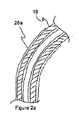
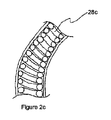
図2に示されるように、薄い基板23はまた、可撓性または半可撓性の内視鏡器具20に適合するように可撓性または半可撓性であってもよい。可撓性または半可撓性の器具の場合、薄い基板23は、好ましくは、内視鏡器具10の細長いシャフト本体14の材料の弾性限界または有効弾性限界を超える材料28aから構成される。有効弾性限界が使用されるのは、細長いシャフト本体14の幾何学的形状またはアセンブリが、図2bおよび図2cにそれぞれに示されるように、限定するものではないがヒンジ28b、バネ28c、およびスパイラルカットチューブ(図示せず)などのその構成材料の弾性限界を超えることを可能にする場合である。基板23はまた、図2dおよび図2eにそれぞれ示されるように、限定するものではないが基板23における折り目28dまたは切れ目28eなどの幾何学的形状の変更によって内視鏡器具に適合するように、その有効弾性限界を増加させることもできる。
As shown in FIG. 2, the
別の例示的な実施形態では、図3a〜図3cに示されるように、基板31には、外来ノイズ信号に対する内蔵式シールドが含まれる。好ましくは、シールドは、センサフィルム12に対する放射、容量性、誘導性、磁気または導電性の干渉の影響を最小限に抑えることができる基板材料または積層体を含む。シールドは、唯一のノイズフィルタとして機能することができるか、またはセンシング素子24に関連する回路、および通信媒体26、またはアナログもしくはデジタルフィルタリングを含むセンシング素子24のシールドに加えて実施することができる。
In another exemplary embodiment, as shown in FIGS. 3a-3c, the
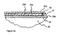
1つの例示的な実施形態では、図3aに示されるように、内視鏡器具10の細長いシャフト本体29は、導電性材料を担持する対向表面およびその上にコーティングされたソルダーマスクを有する長手方向の基板コア31を備える。マスクされた導電性材料を有する基板コア31は、細長いシャフト本体29上に配置され、接着剤30によってその上に固定される。より詳細には、基板コア31、例えばポリイミド、または任意の類似材料が、上部導電層32aと下部導電層32bとの間に挟まれる。上部導電層32aは接地シールドとして作用し、一方で、下部導電層32bはセンシング素子24からのセンサ信号を電子機器モジュール28に中継する。上部導電層32aはソルダーマスク33aで絶縁され、一方で、下部導電層32bはソルダーマスク33bで絶縁される。好ましくは、ソルダーマスク33aおよびソルダーマスク33bは医療グレードである。この構成では、内視鏡器具10の細長い金属シャフト本体29が追加のシールドとして機能する。さらに、限定するものではないがエッジメタライゼーションまたは導電性コーティングなどのエッジステッチング35または類似の技術を使用して、シールドされた接地用導体を上部導電層32aから、センシングされた信号を伝える下部導電層32bの縁部の周りに延在させることができ、これによりシールド保護が強化される。このシールドは、回路を直接伝導ノイズおよび高周波ノイズから保護し、容量結合もいくらか保護する。また、内視鏡器具10の細長いシャフト本体29が、限定するものではないがマルテンサイト系またはフェライト系等級のステンレス鋼などの強磁性材料で構成されている場合、誘導ノイズからの保護が向上される。
In one exemplary embodiment, as shown in FIG. 3a, the
別の例示的な実施形態では、図3bに示されるように、ソルダーマスク33aの上側が、ポリマー、フッ素化エチレンプロピレン(FEP)、ポリウレタン、ポリテトラフルオロエチレン(PTFE)または類似の材料などの低摩擦の非導電性材料で置き換えられる。低摩擦の非導電性材料は、内視鏡器具10に対する他の層31、32b、33bの側の周りに、接着剤30を介して上部導電層32aに層として接着される。低摩擦の非導電性材料36は、内視鏡器具10がトロカール内を移動する際に内視鏡器具10の滑動抵抗を低減する。加えて、低摩擦の非導電性材料36は、内視鏡器具10の耐摩耗性を改善し、伝導ノイズに対するより高い抵抗を生み、絶縁耐力を改善する。
In another exemplary embodiment, as shown in FIG. 3b, the upper side of the
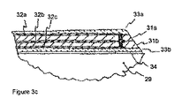
別の例示的な実施形態では、図3cに示されるように、ポリイミド31aおよび31bの2つの層ならびに導電性材料の3つの層32a、32bおよび32cが含まれる。センサ信号を伝達する上部導電層32bは、ポリイミド層31aと31bとの間に挟まれ、一方で、導電性材料32a、32cの外側層は両方とも容量結合を低減する接地シールドである。別の例示的な実施形態では、図3cに示される先の実施形態から図3dを見ると、ポリイミド31は、図3cの上部導電層32aの代わりに、一方の側では導電層32を、他方の側では接地された強磁性金属37のシートを備える。強磁性金属37は誘導ノイズ保護を低減し、強磁性金属37には、限定するものではないがフェライト系等級のステンレス鋼が含まれ得る。内視鏡器具10の細長いシャフト本体29の金属も強磁性である場合か、または別のシートが導電性材料の信号層32の下に置かれる場合、回路は誘導ノイズから実質的に保護される。
In another exemplary embodiment, as shown in FIG. 3c, two layers of polyimide 31a and 31b and three layers of
さらに別の例示的な実施形態では、図3b、3cおよび3dの先の例示的な実施形態における特徴を組み合わせて、個々の利点を集約することができる。図3eに示される例のように、PTFEなどの低摩擦の非導電性材料の外層36を、両面ポリイミド28(上部導電層32bがセンサ信号を中継し、下部導電層32cが接地シールドである)の上の強磁性シート37の上に配置することができる。内視鏡器具シャフト14が強磁性である場合、これは、耐摩耗性および滑動抵抗を改善すると同時に、導電性、容量性、誘導性および高周波ノイズに対する実質的な保護を提供する。
In yet another exemplary embodiment, the features in the previous exemplary embodiments of FIGS. 3b, 3c, and 3d can be combined to aggregate individual advantages. As in the example shown in FIG. 3e, the outer layer 36 of a low friction non-conductive material such as PTFE is coated with double-sided polyimide 28 (the upper
図4に示されるように、センサフィルム12は、内視鏡器具10の細長いシャフト本体42に固定された1つ以上のセンシング素子24を有する基板40を備える。一般的に、センサフィルム12は、センシング素子24が所望の特性を測定するように、細長いシャフト本体42の上に配置され、取り付け手段によってそこに固定される。1つの例示的な実施形態では、1つ以上のセンシング素子24は電気ベースであり、1つ以上のセンシング素子24には、限定するものではないが溶接、導電性エポキシ、導電性接着剤、バネ接点、クリンピング、機械的インターロック、ブラシ、低温はんだ、またはそれらの任意の組合せによって作り出される電気的結合44が含まれる。機能的接触に加えて、センシング素子24は、機械的結合手段46を介して機械的にも結合されて、センシング素子24の機能的接触およびまたはその組立てにおける補助が保護され得る。
As shown in FIG. 4, the
1つの例では、センシング素子24は、力を測定するために金属または圧電ひずみゲージである。したがって、ひずみゲージ24は、それらが取り付けられている手術器具10が張力または圧縮を受けたときに抵抗の変化に基づいて電圧信号を出力するように構成される。1つ以上のひずみゲージ24は、内視鏡器具10の構造シャフト42に機械的に結合される。ひずみゲージ24の結合は、好ましくは、できるだけ薄い接着剤48を用いて、ひずみゲージ24の材料とシャフト本体42の材料との間の硬度で達成される。接着剤48は、シアノアクリレート、エポキシまたはアクリルであってもよいが、これらに限定されない。さらに、1つ以上のひずみゲージ24は、限定するものではないが超音波溶接、溶剤溶接、溶融、またはそれらの何らかの組合せを使用して、接着剤の有無にかかわらず、構造シャフト本体42に溶接することもできる。また、ひずみゲージ24は、各ゲージに2つ以上のひずみゲージパターンを備えることもできる。例えば、1つの例示的な実施形態では、第2のひずみゲージパターンは、熱補償を提供するために、第1のひずみゲージパターンに対して垂直に配置される。
In one example, sensing
図5a〜図5eは、内視鏡器具10が、細長いシャフト50および/またはエンドエフェクタ52上に1つ以上のセンシング素子54を備える異なる遠位センサの種類および構成を示す。センシング素子54には、限定するものではないがひずみゲージ、高周波アンテナ、加速度計、ジャイロスコープ、磁力計、圧電センサ、超音波センサ、容量センサ、ブラッグ回折格子、温度計、光センサ、または任意のアレイ、より大きなシステムの一部、ハイブリッドの一部、それらの適用の一部もしくはそれらの組合せの一部であって、限定するものではないがガルバニ式センシング、インピーダンス分光法、イメージセンシング、光電容積脈波(PPG)、血流、脈波電波時間(PTT)、心弾動図(BCG)、筋電図検査(EMG)、心電図検査(ECGまたはEKG)、脳波検査(EEG)が含まれる。
FIGS. 5 a-5 e show different distal sensor types and configurations in which the
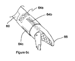
別の例示的な実施形態では、図6a〜6cに示されるように、1つ以上のひずみゲージ62が複数の構成に配置される。例えば、図6aでは、ひずみゲージ62a、62bおよび62cは、器具10のシャフト60に平行に、かつシャフト60の反対側に配置される。この構成は、屈曲および伸長/圧縮の一方向の区別を可能にし、これにより、生検ツールおよび脳神経外科ツール(ただしこれらに限定されない)などの純粋な伸長/圧縮における動作を目的とするリトラクタおよび内視鏡器具(ただしこれらに限定されない)などの単一の屈曲方向における動作を目的とする内視鏡器具10にとって有用となる。
In another exemplary embodiment, as shown in FIGS. 6a-6c, one or more strain gauges 62 are arranged in a plurality of configurations. For example, in FIG. 6 a, strain gauges 62 a, 62 b and 62 c are disposed parallel to the
別の例示的な実施形態では、図6bに示されるように、2つのひずみゲージ63a、63bが器具10のシャフト60に平行に配置され、互いに等間隔で配置される。ひずみゲージ63a、63bの等しい間隔が好ましく、他の構成も動作可能であるが、2つの曲げモーメントならびに圧縮および/または伸長の全体的な最適分解能を提供するものではない。この構成は、曲げ方向および伸長/圧縮の両方の区別を可能にし、これにより、把持鉗子および持針器(ただしこれらに限定されない)などの手術器具10において有用となる。別の例示的な実施形態では、図6cに示されるように、内視鏡器具シャフト60に対しておおよそ45度で位置調整されたパターンを有するひずみゲージ64aが、圧縮および伸長を含む曲げモーメントを決定するのを助ける追加のひずみゲージパターン64b、64cを備える内視鏡器具シャフト60のトルクを決定するために使用される。
In another exemplary embodiment, as shown in FIG. 6b, two
組織との直接の接触が必要とされる状況では、1つ以上のセンシング素子62a、62b、62c、63a、63b、64a、64b、および64cは、エンドエフェクタ66と並んで、貫通して、もしくは一体化されて配置されていてもよいし、または薄い基板23の外側に配置されていてもよいが、これらに限定されず、この場合、内視鏡器具10は、1つ以上のセンシング素子62a、62b、62c、63a、63b、64a、64bおよび64cを収容するように変更されていても変更されていなくてもよい。
In situations where direct contact with tissue is required, one or
別の例示的な実施形態では、電極は、内視鏡器具シャフト60上に配置され、エンドエフェクタ66内に組み込まれるか、またはその両方である。これらの電極は、インピーダンス分光法、EMG、ECG、EEG、電気刺激、またはそれらの任意の組合せに使用することができるが、これらに限定されない。1つの用途では、インピーダンス分光法、EMGおよび電気刺激の2つ以上の組合せを使用して、筋肉の生存度を評価および監視することができる。
In another exemplary embodiment, the electrodes are disposed on the
図7に示されるように、遠位先端72に配置されたセンシング素子70に加えて、1つ以上のセンシング素子74を、限定するものではないがシフトロッドまたはケーブルなどのエンドエフェクタ76を制御する機構の任意の部分に配置することもできる。好ましくは、センシング素子74は、内視鏡器具10上の位置に配置され、この場合、内視鏡器具10の変更は必要とされない。
As shown in FIG. 7, in addition to the sensing element 70 disposed at the
1つの例示的な実施形態では、内視鏡器具10の遠位セクションの1つ以上のひずみゲージは、位置情報および力情報の両方を与えるために、加速度計、ジャイロスコープ、チルトセンサ、または任意の組合せによって補われる。エネルギー貯蔵装置が使用される別の例示的な実施形態では、小型かつ高エネルギー密度で製造可能な任意のエネルギー貯蔵装置を使用することができ、このエネルギー貯蔵装置には、酸化銀、リチウム、アルミニウムイオン、亜鉛、薄膜、スーパーキャパシタ、またはそれらの任意の組合せが含まれるが、これらに限定されない。
In one exemplary embodiment, one or more strain gauges in the distal section of the
別の例示的な実施形態では、電子機器モジュールにおける1つ以上の温度センサを使用して、感度の高いアナログ部品に対する熱影響が補償される。別の例示的な実施形態では、電子機器は、オートクレービングの典型的な温度である121℃を超えるように定格された電気的部品、例えば自動車用定格部品およびフッ化黒鉛リチウム電池(lithium poly-carbon monofluoride batteries)(ただしこれらに限定されない)を選択し、メッキ、コーティング、ポッティング、密閉ケース内封入、またはそれらの任意の組合せ(ただしこれらに限定されない)による直接暴露から部品を保護することによって、オートクレービングとして知られている蒸気滅菌に耐えることができるように選択することができる。オートクレービングとして知られている蒸気滅菌が使用される前述の実施形態の代わりとして、電池および/または電子機器は取り外し可能にすることができ、そのためオートクレービングに耐えるように取り外し可能な部品を選択する必要がない。 In another exemplary embodiment, one or more temperature sensors in the electronics module are used to compensate for thermal effects on sensitive analog components. In another exemplary embodiment, the electronic device is an electrical component rated to exceed a typical autoclaving temperature of 121 ° C., such as an automotive rated component and a lithium polylithium battery (lithium polylithium battery). -carbon monofluoride batteries) (but not limited to) by protecting the parts from direct exposure by plating, coating, potting, enclosing in a sealed case, or any combination thereof (but not limited to) It can be chosen to withstand steam sterilization, known as autoclaving. As an alternative to the previous embodiment where steam sterilization known as autoclaving is used, batteries and / or electronics can be made removable, so that removable parts can be used to withstand autoclaving. There is no need to choose.
1つの例示的な実施形態では、センサ読み取り値が、視覚、触覚または聴覚フィードバックを提供するために外科医に中継される。フィードバックが視覚的である場合、情報の表示は、情報を内視鏡モニタに重ね合わせること、情報を表示するための別個のデバイスを持たせること、または既存のデバイス、例えば携帯電話、タブレット、ラップトップ、コンピュータまたはディスプレイモニタ(ただしこれらに限定されない)に情報を表示するためのソフトウェアアプリケーションを持たせることによって行うことができるが、これらに限定されない。 In one exemplary embodiment, sensor readings are relayed to the surgeon to provide visual, tactile or auditory feedback. If the feedback is visual, the display of information can be superimposed on the endoscope monitor, have a separate device for displaying the information, or existing devices such as mobile phones, tablets, laptops This can be done by having a software application for displaying information on, but not limited to, a top, computer or display monitor.
図8aは、身体81の外科手術中に、外科医80または他の医療専門家などのユーザ80にフィードバックを提供する外科的フィードバックシステムを示す。内視鏡器具86にコンフォーマルに接着されたセンサフィルム84に関連するセンサ82からの読み取り値は、電気的、赤外線、光学的または無線接続の少なくとも1つを介して電子機器モジュール88に中継される。1つの例示的な実施形態では、電子機器モジュール88は、無線通信を使用し、手術中にユーザ80の動きを制限する物理的接続または視線問題がないように、バッテリなどの電源によって電力が供給される。
FIG. 8 a shows a surgical feedback system that provides feedback to a
電子機器モジュール88は、センサ読み取り値を測定し、データをフィードバックデバイス90に送信し、そこでユーザ80はフィードバックを受信し、それに応じて内視鏡器具86の動作を変更することができる。1つの例示的な実施形態では、電子機器モジュール88は、スマートフォン、タブレット、またはラップトップを含むがこれらに限定されないモバイルデバイスなどのフィードバックデバイス90に、無線伝送を介してフィードバックデータを通信する。モバイルデバイス90への無線通信は、医療従事者がフィードバックシステムを迅速にセットアップすることを可能にし、後で学習および分析のために収集データを保持することを可能にする。あるいは電子機器モジュール88は、有線接続または無線接続を介して表示モニタ92にフィードバックデータを通信する。
The
別の例示的な実施形態では、図8bに示されるように、内視鏡ビデオ撮像装置94は、外科手術に関する画像を取り込み、電子機器モジュール88は、無線伝送を介してセンシングされたデータをビデオオーバーレイユニット96に通信することから、センサ情報は、リアルタイムでモニタ92に表示するために、内視鏡ビデオユニット98からのビデオ画像の上に重ね合わされる。これにより、経験豊富な外科医80は、内視鏡ビデオユニット98からのビデオ画像を見ることになるモニタ92を通して、内視鏡器具86上の1つ以上のセンサ82からの視覚フィードバックを受信することができる。
In another exemplary embodiment, as shown in FIG. 8b, endoscopic
別の例示的な実施形態では、センサ付き器具は、他のセンサ付き器具またはセンサと共に動作することができるが、必須ではない。センサ付き器具またはセンサは、異なるセンサ、センサ配列、センサの数、またはそれらの組合せを有していても有していなくてもよい。これらのセンサ付き器具および/またはセンサは協調しても協調しなくてもよい。協調には、センサデータの共有、時間の同期、イベントの同期、デバイス動作の変更の要求、データの要求、センサ読み取り値の要求、またはそれらの任意の組合せが含まれるが、これらに限定されない。これらのセンサ付きデバイスまたはセンサは、任意の手法または構成でネットワーク接続させることができる。ネットワーク接続には、装置間の協調が最小限に抑えられるように互いに干渉しないように器具動作をプランニングすること、センサ付き器具またはセンサ間の協調、中央ハブとの協調、またはそれらの任意の組合せが含まれ得るが、これらに限定されない。したがって、2つの内視鏡的持針器が、器具の先端でひずみゲージと通信しているセンサフィルムと共に使用される。この構成は、縫合結紮において経験される力の大きさの完全な評価を可能にする。これらの内視鏡的持針器は、縫合結紮の相対運動を追加的に捕捉するために、それらの電子機器モジュールにおいて加速度計および/またはジャイロスコープを有していてもよく、その必要がある。 In another exemplary embodiment, the sensored instrument can operate with other sensored instruments or sensors, but is not required. A sensored instrument or sensor may or may not have different sensors, sensor arrays, number of sensors, or combinations thereof. These sensored instruments and / or sensors may or may not cooperate. Coordination includes, but is not limited to, sensor data sharing, time synchronization, event synchronization, device operation change request, data request, sensor reading request, or any combination thereof. These sensored devices or sensors can be networked in any manner or configuration. For network connections, plan appliance operations so that they do not interfere with each other so that coordination between devices is minimized, coordination between instruments with sensors or sensors, coordination with a central hub, or any combination thereof Can be included, but is not limited to these. Thus, two endoscopic needle holders are used with a sensor film that is in communication with a strain gauge at the tip of the instrument. This configuration allows a complete assessment of the magnitude of the force experienced in suture ligation. These endoscopic needle holders may and need to have accelerometers and / or gyroscopes in their electronics module to additionally capture the relative movement of the suture ligature .
別の例示的な実施形態では、センサフィルムを備える1つの内視鏡器具が、器具の先端の光学システムと通信し、例えば、限定するものではないがPPGおよび内視鏡が使用される。内視鏡およびセンサ付き器具は、内視鏡の光を瞬間的にスイッチオフにすることによって協調し、そうして光学システムが暗闇の中で読み取りを実行できるようになる。この瞬間的な内視鏡のスイッチオフは、人間の目には気付かないほど迅速に行うことができ、これは、内視鏡観察のために暗闇および照明において同時連続的な読み取りを効果的に提供するために一貫して行うことができる。 In another exemplary embodiment, one endoscopic instrument comprising a sensor film communicates with the optical system at the instrument tip, such as, but not limited to, PPG and endoscope. The endoscope and sensored instrument cooperate by momentarily switching off the light of the endoscope, thus allowing the optical system to perform a reading in the dark. This momentary endoscope switch-off can be done so quickly that it is not noticeable by the human eye, which effectively provides simultaneous readings in the dark and illumination for endoscopic observation. Can be done consistently to provide.
別の例示的な実施形態では、センサフィルムを備える内視鏡器具は、電気ベースのセンサおよび限定するものではないが電気メス、高周波アブレーションまたは電気刺激などの電気または高周波エネルギーを利用する別の内視鏡器具と通信し、これらは、電気または高周波エネルギーツールが動作している間、電気センサが読み取られず、かつ/または電子機器モジュールが接続されないように協調される。この協調は、正確なセンサ読み取り値を保証し、電子機器モジュールを損傷から保護するのに役立つ。 In another exemplary embodiment, an endoscopic instrument comprising a sensor film is an electrical based sensor and another internal that utilizes electrical or high frequency energy such as, but not limited to, an electric scalpel, high frequency ablation or electrical stimulation. Communicating with the endoscopic instrument, these are coordinated so that the electrical sensor is not read and / or the electronics module is not connected while the electrical or radio frequency energy tool is operating. This coordination helps to ensure accurate sensor readings and protect the electronics module from damage.
別の例示的な実施形態では、PPGまたはBCGがセンサとして使用され、エンドエフェクタと一体化される。最も重要なのは、これにより、外科医は、他の測定規準に加えて、手術中の局所血液酸素化を評価することができる。このシステムは、別のPPG、BCGもしくはECGを備え付けた内視鏡器具または外部PPG、BCG、ECG、またはPTTの一部として使用される他の心臓モニタと組み合わせることで手術中および/またはリアルタイムで血圧を評価することができるが、その必要もない。 In another exemplary embodiment, PPG or BCG is used as a sensor and integrated with the end effector. Most importantly, this allows the surgeon to assess local blood oxygenation during surgery in addition to other metrics. This system can be combined with other PPG, BCG, ECG, or other cardiac monitors used as part of an external PPG, BCG, ECG, or PTT in surgery and / or in real time Blood pressure can be assessed, but it is not necessary.
別の例示的な実施形態では、最大4つのひずみゲージが、2つの曲げモーメント、トルク、および圧縮または伸長からなる器具の先端によって経験されるすべての力およびトルクを捕捉できるように、異なる点および方向で内視鏡器具の遠位セクションに配置される。内視鏡器具への機械的結合はエポキシによって達成される。これらのひずみゲージは、金メッキされた銅の電気配線を有するポリイミド基板に導電性接着剤によって取り付けられる。薄い基板は、最終的に、アナログフロントエンド、温度センサ、ブルートゥーストランシーバおよびバッテリを備える電子機器モジュールに取り付けられる。これにより、外科医は、処置を妨げるワイヤなしで、内視鏡器具の先端で経験される力のすべてを見て、その動きを一致させて記録することができる。温度センサからの読み取り値は、アナログフロントエンドからの読み取り値を温度補償して精度を向上させるために使用される。この例示的な実施形態は、元の内視鏡器具の変更を行わず、手術中に完全に無線である。 In another exemplary embodiment, different points and so that up to four strain gauges can capture all the forces and torques experienced by the tip of the instrument consisting of two bending moments, torque, and compression or extension. In the direction of the distal section of the endoscopic instrument. Mechanical coupling to the endoscopic instrument is achieved by epoxy. These strain gauges are attached by conductive adhesive to a polyimide substrate having gold-plated copper electrical wiring. The thin substrate is finally attached to an electronics module comprising an analog front end, a temperature sensor, a Bluetooth transceiver and a battery. This allows the surgeon to see all of the forces experienced at the tip of the endoscopic instrument and record their movements in a coordinated manner without wires interfering with the procedure. The reading from the temperature sensor is used to temperature compensate the reading from the analog front end to improve accuracy. This exemplary embodiment does not change the original endoscopic instrument and is completely wireless during surgery.
器具がオートクレービングとして知られている蒸気滅菌を受ける別の例示的な実施形態では、電池はフッ化黒鉛リチウム電池であり、部品はすべて121℃よりも高く定格され、電子機器モジュールは密封ケースであり、電子機器部品は、コンフォーマルにコーティング、金メッキおよび/または封止される。これにより、デバイスを分解せずに器具を滅菌することができ、湿気に起因するアナログフロントエンドの誤差および劣化を防ぎつつ、校正およびバッテリ交換が容易な電子機器にアクセスすることができる。 In another exemplary embodiment where the instrument undergoes steam sterilization known as autoclaving, the battery is a lithium fluorinated graphite battery, all parts are rated above 121 ° C., and the electronics module is in a sealed case. And the electronic component is conformally coated, gold plated and / or sealed. As a result, the instrument can be sterilized without disassembling the device, and an electronic device that can be easily calibrated and replaced can be accessed while preventing an error and deterioration of the analog front end due to moisture.
1つ以上の機械的作動ロッドまたはケーブルを必要とするエンドエフェクタを内視鏡器具が有する別の例示的な実施形態では、追加のひずみゲージをプルロッドまたはケーブルの露出した近位の部分に配置することができる。1つ以上の追加のひずみゲージを使用して、作動力を捕捉するとともに、プルロッドまたはケーブル力を外力によって生じる圧縮/伸長から区別することができる。 In another exemplary embodiment where the endoscopic instrument has an end effector that requires one or more mechanical actuation rods or cables, an additional strain gauge is placed on the exposed proximal portion of the pull rod or cable. be able to. One or more additional strain gauges can be used to capture the actuation force and to distinguish pull rod or cable forces from compression / extension caused by external forces.
これらの例示的な実施形態は、当業者が本発明を実施できるように十分に詳細に記載されているが、本発明の精神および範囲から逸脱することなく他の実施形態を実現することもでき、論理的および機械的変更を行うこともできることを理解されたい。上記の詳細な説明は、例示のみを目的とするものであって、限定するものではなく、本発明の範囲は、上記の説明と、添付の特許請求の範囲に関して定義される。 While these exemplary embodiments have been described in sufficient detail to enable those skilled in the art to practice the invention, other embodiments may be implemented without departing from the spirit and scope of the invention. It should be understood that logical and mechanical changes can also be made. The foregoing detailed description is intended for purposes of illustration only and is not intended to be limiting. The scope of the present invention is defined with respect to the above description and the appended claims.
10 手術器具
12 センサフィルム
14 細長いシャフト本体
16 近位端
18 遠位端
20 エンドエフェクタアセンブリ
22 アクチュエータ機構
23 基板
24 センシング素子
26 通信媒体
28 電子機器モジュール
28a 細長いシャフト本体の材料の弾性限界または有効弾性限界を超える材料
28b ヒンジ
28c バネ
28d 折り目
28e 切れ目
29 細長いシャフト本体
31 基板(基板コア)
31a,31b ポリイミド層
32a 上部導電層
32b 下部導電層
32c 下部導電層
33a ソルダーマスク
33b ソルダーマスク
35 エッジステッチング
36 非導電性材料
37 強磁性金属
40 基板
42 細長いシャフト本体
44 電気的結合
46 機械的結合手段
48 接着剤
50 細長いシャフト
52 エンドエフェクタ
54 センシング素子
60 シャフト
62a,b,c ひずみゲージ
63a,b ひずみゲージ
64a ひずみゲージ
64b,c ひずみゲージパターン
66 エンドエフェクタ
70 センシング素子
72 遠位先端
74 センシング素子
76 エンドエフェクタ
80 外科医(ユーザ)
81 身体
82 センサ
84 センサフィルム
86 内視鏡器具
88 電子機器モジュール
90 フィードバックデバイス
92 表示モニタ
94 内視鏡ビデオ撮像装置
98 内視鏡ビデオユニット
DESCRIPTION OF
31a,
DESCRIPTION OF
Claims (85)
近位端および遠位端を有する細長いシャフト本体と、
前記近位端においてアクチュエータ機構を操作することによって動作可能な前記遠位端におけるエンドエフェクタアセンブリと、
第1の表面および第2の表面を有する基板コアと、
前記細長いシャフト本体上の少なくとも1つのセンシング素子と、
前記少なくとも1つのセンシング素子からのセンシングされた信号を受信するための電子機器モジュールと、
前記第1の表面上に存在する第1の導電層と、
前記第2の表面上に存在する第2の導電層と
を備え、
前記基板は、前記細長いシャフト本体にコンフォーマルに取り付けられており、
前記少なくとも1つのセンシング素子は、前記遠位端に隣接して配置されており、
前記電子機器モジュールは、前記近位端に隣接して配置されており、
前記第1の導電層は、その上にコーティングされた第1のソルダーマスクを有し、
前記第2の導電層は、その上にコーティングされた第2のソルダーマスクを有し、前記少なくとも1つのセンシング素子に結合された前記第2の導電層は、前記少なくとも1つのセンシング素子からの前記センシングされた信号を前記電子機器モジュールに中継し、かつ前記第1の導電層は接地されている、内視鏡器具。 An endoscopic instrument for use with a trocar, the endoscopic instrument comprising:
An elongate shaft body having a proximal end and a distal end;
An end effector assembly at the distal end operable by manipulating an actuator mechanism at the proximal end;
A substrate core having a first surface and a second surface;
At least one sensing element on the elongated shaft body;
An electronic device module for receiving a sensed signal from the at least one sensing element;
A first conductive layer present on the first surface;
A second conductive layer present on the second surface;
The substrate is conformally attached to the elongated shaft body;
The at least one sensing element is disposed adjacent to the distal end;
The electronics module is disposed adjacent to the proximal end;
The first conductive layer has a first solder mask coated thereon;
The second conductive layer has a second solder mask coated thereon, and the second conductive layer coupled to the at least one sensing element includes the second conductive layer from the at least one sensing element. An endoscopic instrument that relays a sensed signal to the electronic device module, and the first conductive layer is grounded.
前記第1のソルダーマスクが低摩擦の非導電層で置き換えられており、前記低摩擦の非導電層が、接着剤を介して前記基板コア、中間導電層、第2の導電層および第2のソルダーマスクの縁部を取り囲んで、接地された強磁性金属のシートに接着されており、
前記中間導電層が前記センサ信号を中継し、かつ前記第2の導電層が接地シールドである、請求項4記載の内視鏡器具。 The substrate core comprises a grounded sheet of ferromagnetic metal instead of the first conductive layer;
The first solder mask is replaced with a low friction non-conductive layer, and the low friction non-conductive layer is bonded to the substrate core, the intermediate conductive layer, the second conductive layer, and the second through an adhesive. Surrounding the edge of the solder mask and bonded to a grounded sheet of ferromagnetic metal,
The endoscopic instrument according to claim 4, wherein the intermediate conductive layer relays the sensor signal and the second conductive layer is a ground shield.
近位端および遠位端を有する細長いシャフト本体と、
前記近位端においてアクチュエータ機構を操作することによって動作可能な前記遠位端におけるエンドエフェクタアセンブリと、
第1の表面および第2の表面を有する基板コアと、
前記細長いシャフト本体上の少なくとも1つのセンシング素子と、
前記少なくとも1つのセンシング素子からのセンシングされた信号を受信するための電子機器モジュールと、
前記第1の表面上に存在する第1の導電層と、
前記第2の表面上に存在する第2の導電層と
を備え、
前記基板コアは、前記細長いシャフト本体にコンフォーマルに取り付けられており、
前記少なくとも1つのセンシング素子は、前記遠位端に隣接して配置されており、
前記電子機器モジュールは、前記近位端に隣接して配置されており、
前記第1の導電層は、その上に低摩擦の非導電層を有し、
前記第2の導電層は、その上にコーティングされたソルダーマスクを有し、前記少なくとも1つのセンシング素子に結合された前記第2の導電層は、前記少なくとも1つのセンシング素子からの前記センシングされた信号を前記電子機器モジュールに中継し、かつ前記第1の導電層は接地されており、
前記低摩擦の非導電層は、前記基板コア、第2の導電層およびソルダーマスクの縁部を取り囲むように接着剤を介して第1の導電層に接着されている、内視鏡器具。 An endoscopic instrument for use with a trocar, the endoscopic instrument comprising:
An elongate shaft body having a proximal end and a distal end;
An end effector assembly at the distal end operable by manipulating an actuator mechanism at the proximal end;
A substrate core having a first surface and a second surface;
At least one sensing element on the elongated shaft body;
An electronic device module for receiving a sensed signal from the at least one sensing element;
A first conductive layer present on the first surface;
A second conductive layer present on the second surface;
The substrate core is conformally attached to the elongated shaft body;
The at least one sensing element is disposed adjacent to the distal end;
The electronics module is disposed adjacent to the proximal end;
The first conductive layer has a low friction non-conductive layer thereon;
The second conductive layer has a solder mask coated thereon, and the second conductive layer coupled to the at least one sensing element is the sensed from the at least one sensing element. Relay the signal to the electronic device module, and the first conductive layer is grounded;
The endoscopic instrument, wherein the low-friction non-conductive layer is bonded to the first conductive layer via an adhesive so as to surround edges of the substrate core, the second conductive layer, and the solder mask.
近位端および遠位端を有する細長いシャフト本体と、
前記近位端においてアクチュエータ機構を操作することによって動作可能な前記遠位端におけるエンドエフェクタアセンブリと、
前記細長いシャフト本体上の少なくとも1つのセンシング素子と、
前記少なくとも1つのセンシング素子からのセンシングされた信号を受信するための電子機器モジュールと、
上部基板コアと、
下部基板コアと、
前記上部基板コアと前記下部基板コアとの間の中間導電層と、
前記上部基板コア上に存在する第1の導電層と、
前記第2の導電層の下に存在し、その上にコーティングされた第2のソルダーマスクを有する第2の導電層と
を備え、
前記少なくとも1つのセンシング素子は、前記遠位端に隣接して配置されており、
前記電子機器モジュールは、前記近位端に隣接して配置されており、
前記上部基板コアおよび前記下部基板コアは、前記細長いシャフト本体にコンフォーマルに取り付けられており、
前記第1の導電層は、その上にコーティングされた第1のソルダーマスクを有し、
前記中間導電層は前記センシングされた信号を中継し、かつ前記第1の導電層および第2の導電層は接地されている、内視鏡器具。 An endoscopic instrument for use with a trocar, the endoscopic instrument comprising:
An elongate shaft body having a proximal end and a distal end;
An end effector assembly at the distal end operable by manipulating an actuator mechanism at the proximal end;
At least one sensing element on the elongated shaft body;
An electronic device module for receiving a sensed signal from the at least one sensing element;
An upper substrate core;
A lower substrate core,
An intermediate conductive layer between the upper substrate core and the lower substrate core;
A first conductive layer present on the upper substrate core;
A second conductive layer present under the second conductive layer and having a second solder mask coated thereon,
The at least one sensing element is disposed adjacent to the distal end;
The electronics module is disposed adjacent to the proximal end;
The upper substrate core and the lower substrate core are conformally attached to the elongated shaft body;
The first conductive layer has a first solder mask coated thereon;
The endoscopic instrument, wherein the intermediate conductive layer relays the sensed signal, and the first conductive layer and the second conductive layer are grounded.
近位端および遠位端を有する細長いシャフト本体と、
前記近位端においてアクチュエータ機構を操作することによって動作可能な前記遠位端におけるエンドエフェクタアセンブリと、
第1の表面および第2の表面を有する基板コアと、
前記細長いシャフト本体上の少なくとも1つのセンシング素子と、
前記少なくとも1つのセンシング素子からのセンシングされた信号を受信するための電子機器モジュールと、
前記第1の表面上に存在する接地された強磁性金属のシートであって、前記接地された強磁性金属のシートと、
前記第2の表面上に存在する導電層と
を備え、
前記基板コアは、前記細長いシャフト本体にコンフォーマルに取り付けられており、
前記少なくとも1つのセンシング素子は、前記遠位端に隣接して配置されており、
前記電子機器モジュールは、前記近位端に隣接して配置されており、
前記第2の導電層は、その上にコーティングされたソルダーマスクを有し、かつ前記第2の導電層は、前記少なくとも1つのセンシング素子からの前記センシングされた信号を前記電子機器モジュールに中継するために前記少なくとも1つのセンシング素子に結合されている、内視鏡器具。 An endoscopic instrument for use with a trocar, the endoscopic instrument comprising:
An elongate shaft body having a proximal end and a distal end;
An end effector assembly at the distal end operable by manipulating an actuator mechanism at the proximal end;
A substrate core having a first surface and a second surface;
At least one sensing element on the elongated shaft body;
An electronic device module for receiving a sensed signal from the at least one sensing element;
A grounded ferromagnetic metal sheet present on the first surface, the grounded ferromagnetic metal sheet; and
A conductive layer present on the second surface;
The substrate core is conformally attached to the elongated shaft body;
The at least one sensing element is disposed adjacent to the distal end;
The electronics module is disposed adjacent to the proximal end;
The second conductive layer has a solder mask coated thereon, and the second conductive layer relays the sensed signal from the at least one sensing element to the electronic device module. An endoscopic instrument coupled to the at least one sensing element for the purpose.
近位端および遠位端を有する細長いシャフト本体と、
前記近位端においてアクチュエータ機構を操作することによって動作可能な前記遠位端におけるエンドエフェクタアセンブリと、
前記細長いシャフト本体上の少なくとも1つのセンシング素子と、
前記少なくとも1つのセンシング素子からのセンシングされた信号を受信するための電子機器モジュールと、
上部基板コアと、
下部基板コアと、
前記上部基板コアと前記下部基板コアとの間の中間導電層と、
前記上部基板コア上に存在する接地された強磁性金属のシートと、
前記第2の導電層の下に存在し、その上にコーティングされた第2のソルダーマスクを有する第2の導電層と
を備え、
前記少なくとも1つのセンシング素子は、前記遠位端に隣接して配置されており、
前記電子機器モジュールは、前記近位端に隣接して配置されており、
前記上部基板コアおよび前記下部基板コアは、前記細長いシャフト本体にコンフォーマルに取り付けられており、
前記接地された強磁性金属のシートの第1の導電層は、低摩擦の非導電層を有し、
前記低摩擦の非導電層は、接着剤を介して前記上部基板コア、下部基板コア、中間導電層、第2の導電層および第2のソルダーマスクの縁部を取り囲んで、前記接地された強磁性金属のシートに接着されており、
前記中間導電層は前記センシングされた信号を中継し、かつ前記接地された強磁性金属のシートおよび第2の導電層は接地されている、内視鏡器具。 An endoscopic instrument for use with a trocar, the endoscopic instrument comprising:
An elongate shaft body having a proximal end and a distal end;
An end effector assembly at the distal end operable by manipulating an actuator mechanism at the proximal end;
At least one sensing element on the elongated shaft body;
An electronic device module for receiving a sensed signal from the at least one sensing element;
An upper substrate core;
A lower substrate core,
An intermediate conductive layer between the upper substrate core and the lower substrate core;
A grounded sheet of ferromagnetic metal present on the upper substrate core;
A second conductive layer present under the second conductive layer and having a second solder mask coated thereon,
The at least one sensing element is disposed adjacent to the distal end;
The electronics module is disposed adjacent to the proximal end;
The upper substrate core and the lower substrate core are conformally attached to the elongated shaft body;
The first conductive layer of the grounded sheet of ferromagnetic metal has a low friction non-conductive layer;
The low friction non-conductive layer surrounds the edge of the upper substrate core, the lower substrate core, the intermediate conductive layer, the second conductive layer, and the second solder mask through an adhesive, Adhered to a sheet of magnetic metal,
An endoscopic instrument, wherein the intermediate conductive layer relays the sensed signal, and the grounded ferromagnetic metal sheet and the second conductive layer are grounded.
前記細長いシャフト本体上にコンフォーマルにセンサフィルムを固定するステップを含み、前記センサフィルムは、
第1の表面および第2の表面を有する基板コアと、
前記遠位端に隣接して配置された少なくとも1つのセンシング素子と、
前記第1の表面上に存在する第1の導電層と、
前記第2の表面上に存在する第2の導電層と
を含み、
前記第1の導電層は、その上にコーティングされた第1のソルダーマスクを有し、前記第1の導電層は接地されており、
前記第2の導電層は、その上にコーティングされた第2のソルダーマスクを有し、
前記方法は、更に、
前記少なくとも1つのセンシング素子に結合されている前記ステップと、
前記少なくとも1つのセンシング素子に少なくとも1つの特性を測定させ、センシングされた信号を出力させ、前記センシングされた信号を前記第2の導電層を介して電子機器モジュールに伝達させるステップと、
前記電子機器モジュールにおいて、前記センシングされた信号を受信し、前記センシングされた信号を処理して前記特性を測定するステップと
を含む、方法。 A method for sensing at least one characteristic associated with an end effector of an endoscopic instrument during a surgical procedure, the endoscopic instrument being used via a trocar, wherein the endoscopic instrument is a proximal end An elongated shaft body having a distal end and an end effector assembly at the distal end operable by manipulating an actuator mechanism at the proximal end, the method comprising:
Fixing the sensor film conformally on the elongated shaft body, the sensor film comprising:
A substrate core having a first surface and a second surface;
At least one sensing element disposed adjacent to the distal end;
A first conductive layer present on the first surface;
A second conductive layer present on the second surface;
The first conductive layer has a first solder mask coated thereon, and the first conductive layer is grounded;
The second conductive layer has a second solder mask coated thereon;
The method further comprises:
The step coupled to the at least one sensing element;
Causing the at least one sensing element to measure at least one characteristic, outputting a sensed signal, and transmitting the sensed signal to the electronic device module through the second conductive layer;
Receiving at the electronic device module the sensed signal and processing the sensed signal to measure the characteristic.
前記第1のソルダーマスクが低摩擦の非導電層で置き換えられており、前記低摩擦の非導電層が、接着剤を介して前記基板コア、中間導電層、第2の導電層および第2のソルダーマスクの縁部を取り囲んで、接地された強磁性金属のシートに接着されており、
前記中間導電層が前記センシングされた信号を中継し、かつ前記第2の導電層が接地シールドである、請求項50記載の方法。 The substrate core comprises a grounded sheet of ferromagnetic metal instead of the first conductive layer;
The first solder mask is replaced with a low friction non-conductive layer, and the low friction non-conductive layer is bonded to the substrate core, the intermediate conductive layer, the second conductive layer, and the second through an adhesive. Surrounding the edge of the solder mask and bonded to a grounded sheet of ferromagnetic metal,
51. The method of claim 50, wherein the intermediate conductive layer relays the sensed signal and the second conductive layer is a ground shield.
少なくとも1つの特性をセンシングするための少なくとも1つのセンシング素子と、
前記第1の表面上に存在する第1の導電層と、
前記第2の表面上に存在する第2の導電層と
を含むセンサフィルムであって、
前記第1の導電層は、その上にコーティングされた第1のソルダーマスクを有し、かつ前記第1の導電層は接地されており、
前記第2の導電層は、その上にコーティングされた第2のソルダーマスクを有し、かつ少なくとも1つのセンシング素子に結合されている、センサフィルム。 A substrate core having a first surface and a second surface;
At least one sensing element for sensing at least one characteristic;
A first conductive layer present on the first surface;
A sensor film comprising a second conductive layer present on the second surface,
The first conductive layer has a first solder mask coated thereon, and the first conductive layer is grounded;
The second conductive layer has a second solder mask coated thereon and is coupled to at least one sensing element.
前記第1のソルダーマスクが低摩擦の非導電層で置き換えられており、前記低摩擦の非導電層が、接着剤を介して前記基板コア、中間導電層、第2の導電層および第2のソルダーマスクの縁部を取り囲んで、接地された強磁性金属のシートに接着されており、
前記中間導電層が前記センシングされた信号を中継し、かつ前記第2の導電層が接地シールドである、請求項73記載のセンサフィルム。 The substrate core comprises a grounded sheet of ferromagnetic metal instead of the first conductive layer;
The first solder mask is replaced with a low friction non-conductive layer, and the low friction non-conductive layer is bonded to the substrate core, the intermediate conductive layer, the second conductive layer, and the second through an adhesive. Surrounding the edge of the solder mask and bonded to a grounded sheet of ferromagnetic metal,
74. The sensor film of claim 73, wherein the intermediate conductive layer relays the sensed signal and the second conductive layer is a ground shield.
Priority Applications (1)
| Application Number | Priority Date | Filing Date | Title |
|---|---|---|---|
| JP2022063559A JP7332743B2 (en) | 2016-01-29 | 2022-04-06 | Sensor film for endoscope instruments |
Applications Claiming Priority (3)
| Application Number | Priority Date | Filing Date | Title |
|---|---|---|---|
| US201662289120P | 2016-01-29 | 2016-01-29 | |
| US62/289,120 | 2016-01-29 | ||
| PCT/CA2017/050103 WO2017127944A1 (en) | 2016-01-29 | 2017-01-27 | Sensor film for endoscopic instruments |
Related Child Applications (1)
| Application Number | Title | Priority Date | Filing Date |
|---|---|---|---|
| JP2022063559A Division JP7332743B2 (en) | 2016-01-29 | 2022-04-06 | Sensor film for endoscope instruments |
Publications (2)
| Publication Number | Publication Date |
|---|---|
| JP2019505352A true JP2019505352A (en) | 2019-02-28 |
| JP2019505352A5 JP2019505352A5 (en) | 2021-02-18 |
Family
ID=59396863
Family Applications (2)
| Application Number | Title | Priority Date | Filing Date |
|---|---|---|---|
| JP2018558454A Pending JP2019505352A (en) | 2016-01-29 | 2017-01-27 | Endoscopic instrument, sensor film, and method |
| JP2022063559A Active JP7332743B2 (en) | 2016-01-29 | 2022-04-06 | Sensor film for endoscope instruments |
Family Applications After (1)
| Application Number | Title | Priority Date | Filing Date |
|---|---|---|---|
| JP2022063559A Active JP7332743B2 (en) | 2016-01-29 | 2022-04-06 | Sensor film for endoscope instruments |
Country Status (8)
| Country | Link |
|---|---|
| US (3) | US11617594B2 (en) |
| EP (2) | EP3407814B1 (en) |
| JP (2) | JP2019505352A (en) |
| KR (1) | KR102392681B1 (en) |
| CN (1) | CN108697450A (en) |
| AU (1) | AU2017210779A1 (en) |
| CA (1) | CA3011760C (en) |
| WO (1) | WO2017127944A1 (en) |
Families Citing this family (5)
| Publication number | Priority date | Publication date | Assignee | Title |
|---|---|---|---|---|
| KR102392681B1 (en) | 2016-01-29 | 2022-04-29 | 포센 인코포레이티드 | Sensor film for endoscopic instruments |
| US10595951B2 (en) | 2016-08-15 | 2020-03-24 | Covidien Lp | Force sensor for surgical devices |
| TWI676464B (en) * | 2017-12-15 | 2019-11-11 | 劉佳星 | Capacitive accelerometer device and sensing method thereof |
| CN110308514B (en) * | 2019-07-26 | 2021-01-26 | 南京邮电大学 | Micro-driver based on optical waveguide structure |
| CN115944397B (en) * | 2023-03-10 | 2023-06-06 | 北京云力境安科技有限公司 | Endoscope adapter |
Citations (9)
| Publication number | Priority date | Publication date | Assignee | Title |
|---|---|---|---|---|
| JP2003234550A (en) * | 2002-02-08 | 2003-08-22 | Mitsumi Electric Co Ltd | Flexible printed circuit |
| JP2009524056A (en) * | 2006-01-19 | 2009-06-25 | スリーエム イノベイティブ プロパティズ カンパニー | Capacitive sensor and method of manufacturing the same |
| JP2009141105A (en) * | 2007-12-06 | 2009-06-25 | Nikon Corp | Flexible circuit and electronic equipment |
| US20100016855A1 (en) * | 2008-07-15 | 2010-01-21 | Immersion Corporation | Modular Tool With Signal Feedback |
| JP2014086591A (en) * | 2012-10-24 | 2014-05-12 | Namics Corp | Coverlay film, flexible printed wiring board using the same, and manufacturing method thereof |
| JP2014160838A (en) * | 2014-04-03 | 2014-09-04 | Fujikura Ltd | Printed-wiring board |
| WO2015119890A1 (en) * | 2014-02-04 | 2015-08-13 | Boston Scientific Scimed, Inc. | Alternative placement of thermal sensors on bipolar electrode |
| WO2015155630A1 (en) * | 2014-04-11 | 2015-10-15 | Koninklijke Philips N.V. | Needle with thin film piezoelectric sensors |
| JP2015198960A (en) * | 2009-02-26 | 2015-11-12 | アボット ダイアベティス ケア インコーポレイテッドAbbott Diabetes Care Inc. | Improved analyte sensors and methods of making and using the same |
Family Cites Families (17)
| Publication number | Priority date | Publication date | Assignee | Title |
|---|---|---|---|---|
| US5902248A (en) * | 1996-11-06 | 1999-05-11 | Millar Instruments, Inc. | Reduced size catheter tip measurement device |
| US9113880B2 (en) * | 2007-10-05 | 2015-08-25 | Covidien Lp | Internal backbone structural chassis for a surgical device |
| TWI277381B (en) * | 2005-04-12 | 2007-03-21 | Au Optronics Corp | Double-sided flexible printed circuit board |
| CA2561034C (en) * | 2005-09-30 | 2014-12-09 | Sherwood Services Ag | Flexible endoscopic catheter with an end effector for coagulating and transfecting tissue |
| US20070078484A1 (en) * | 2005-10-03 | 2007-04-05 | Joseph Talarico | Gentle touch surgical instrument and method of using same |
| JP5152993B2 (en) | 2005-12-30 | 2013-02-27 | インテュイティブ サージカル インコーポレイテッド | Modular force sensor |
| US7930065B2 (en) * | 2005-12-30 | 2011-04-19 | Intuitive Surgical Operations, Inc. | Robotic surgery system including position sensors using fiber bragg gratings |
| US20080147125A1 (en) * | 2006-12-12 | 2008-06-19 | Dennis Colleran | Active Settling Plate and Method of Use |
| US20110046637A1 (en) * | 2008-01-14 | 2011-02-24 | The University Of Western Ontario | Sensorized medical instrument |
| EP2340428A1 (en) * | 2008-04-18 | 2011-07-06 | Socovar Societe En Commandite | System for sensing and displaying softness and force |
| US9364203B2 (en) * | 2010-08-18 | 2016-06-14 | Deutsches Zentrum für Luft- und Raumfahrt e.V. | Minimally invasive instrument |
| EP2645298A1 (en) * | 2012-03-30 | 2013-10-02 | austriamicrosystems AG | Portable object and information transmission system |
| WO2015020952A1 (en) * | 2013-08-04 | 2015-02-12 | President And Fellows Of Harvard College | Pop-up laminate structures with integrated electronics |
| TWI667865B (en) * | 2014-05-07 | 2019-08-01 | 易鼎股份有限公司 | Flexible circuit board line lap structure |
| CN204721710U (en) * | 2015-05-07 | 2015-10-21 | 深圳市星之光实业发展有限公司 | A kind of multi-layer flexible circuit board |
| KR102392681B1 (en) | 2016-01-29 | 2022-04-29 | 포센 인코포레이티드 | Sensor film for endoscopic instruments |
| US10795509B2 (en) * | 2016-03-24 | 2020-10-06 | Synaptics Incorporated | Force sensing within display stack |
-
2017
- 2017-01-27 KR KR1020187024498A patent/KR102392681B1/en active IP Right Grant
- 2017-01-27 AU AU2017210779A patent/AU2017210779A1/en not_active Abandoned
- 2017-01-27 CN CN201780011691.7A patent/CN108697450A/en active Pending
- 2017-01-27 WO PCT/CA2017/050103 patent/WO2017127944A1/en active Application Filing
- 2017-01-27 EP EP17743539.3A patent/EP3407814B1/en active Active
- 2017-01-27 JP JP2018558454A patent/JP2019505352A/en active Pending
- 2017-01-27 CA CA3011760A patent/CA3011760C/en active Active
- 2017-01-27 US US16/072,834 patent/US11617594B2/en active Active
- 2017-01-27 EP EP23211101.3A patent/EP4299021A3/en active Pending
-
2020
- 2020-12-29 US US17/137,196 patent/US11786264B2/en active Active
- 2020-12-29 US US17/137,213 patent/US12102346B2/en active Active
-
2022
- 2022-04-06 JP JP2022063559A patent/JP7332743B2/en active Active
Patent Citations (13)
| Publication number | Priority date | Publication date | Assignee | Title |
|---|---|---|---|---|
| JP2003234550A (en) * | 2002-02-08 | 2003-08-22 | Mitsumi Electric Co Ltd | Flexible printed circuit |
| JP2009524056A (en) * | 2006-01-19 | 2009-06-25 | スリーエム イノベイティブ プロパティズ カンパニー | Capacitive sensor and method of manufacturing the same |
| JP2009141105A (en) * | 2007-12-06 | 2009-06-25 | Nikon Corp | Flexible circuit and electronic equipment |
| US20100016855A1 (en) * | 2008-07-15 | 2010-01-21 | Immersion Corporation | Modular Tool With Signal Feedback |
| JP2011528261A (en) * | 2008-07-15 | 2011-11-17 | イマージョン コーポレーション | Modular instrument with signal feedback |
| JP2015198960A (en) * | 2009-02-26 | 2015-11-12 | アボット ダイアベティス ケア インコーポレイテッドAbbott Diabetes Care Inc. | Improved analyte sensors and methods of making and using the same |
| JP2014086591A (en) * | 2012-10-24 | 2014-05-12 | Namics Corp | Coverlay film, flexible printed wiring board using the same, and manufacturing method thereof |
| WO2015119890A1 (en) * | 2014-02-04 | 2015-08-13 | Boston Scientific Scimed, Inc. | Alternative placement of thermal sensors on bipolar electrode |
| JP2017506096A (en) * | 2014-02-04 | 2017-03-02 | ボストン サイエンティフィック サイムド,インコーポレイテッドBoston Scientific Scimed,Inc. | Alternative placement of temperature sensors on bipolar electrodes |
| JP2014160838A (en) * | 2014-04-03 | 2014-09-04 | Fujikura Ltd | Printed-wiring board |
| WO2015155630A1 (en) * | 2014-04-11 | 2015-10-15 | Koninklijke Philips N.V. | Needle with thin film piezoelectric sensors |
| CN106163432A (en) * | 2014-04-11 | 2016-11-23 | 皇家飞利浦有限公司 | There is the pin of film piezo-electric sensor |
| JP2017512586A (en) * | 2014-04-11 | 2017-05-25 | コーニンクレッカ フィリップス エヌ ヴェKoninklijke Philips N.V. | Needle with thin film piezoelectric sensor |
Also Published As
| Publication number | Publication date |
|---|---|
| CA3011760A1 (en) | 2017-08-03 |
| US20210113230A1 (en) | 2021-04-22 |
| US12102346B2 (en) | 2024-10-01 |
| EP4299021A2 (en) | 2024-01-03 |
| EP4299021A3 (en) | 2024-06-05 |
| CN108697450A (en) | 2018-10-23 |
| US11786264B2 (en) | 2023-10-17 |
| EP3407814A4 (en) | 2019-12-04 |
| US20210113229A1 (en) | 2021-04-22 |
| EP3407814A1 (en) | 2018-12-05 |
| KR20180108717A (en) | 2018-10-04 |
| JP2022095823A (en) | 2022-06-28 |
| CA3011760C (en) | 2020-12-15 |
| AU2017210779A1 (en) | 2018-08-02 |
| US20190059921A1 (en) | 2019-02-28 |
| KR102392681B1 (en) | 2022-04-29 |
| JP7332743B2 (en) | 2023-08-23 |
| US11617594B2 (en) | 2023-04-04 |
| EP3407814B1 (en) | 2023-11-22 |
| WO2017127944A1 (en) | 2017-08-03 |
Similar Documents
| Publication | Publication Date | Title |
|---|---|---|
| JP7332743B2 (en) | Sensor film for endoscope instruments | |
| US20220369472A1 (en) | Catheter and method for catheter assembly | |
| US7751872B2 (en) | Portable electrocardiogram | |
| JP2022095823A5 (en) | ||
| US11583193B2 (en) | Wireless intraluminal device and system | |
| US20200375568A1 (en) | Auxiliary electrocardiogram (ecg) assemblies and clinical data acquisition systems including auxiliary ecg assemblies | |
| EP3727140A1 (en) | A compact system used to determine tissue or artifact characteristics | |
| JP2019505352A5 (en) | Medical devices, sensor films, and methods | |
| JP2018198981A (en) | Dongle with shape memory | |
| JP2020534073A (en) | Cables and related continuity monitoring systems and methods | |
| JP7451524B2 (en) | Ablation catheter with laminated circuit assembly | |
| US20220079466A1 (en) | A sensor | |
| AU2021269062B2 (en) | Transcutaneous sound sensor | |
| JPH08131447A (en) | Intra-celom diagnostic treatment device | |
| CA2702242C (en) | Portable electrocardiogram |
Legal Events
| Date | Code | Title | Description |
|---|---|---|---|
| A521 | Request for written amendment filed |
Free format text: JAPANESE INTERMEDIATE CODE: A523 Effective date: 20180928 |
|
| A621 | Written request for application examination |
Free format text: JAPANESE INTERMEDIATE CODE: A621 Effective date: 20200121 |
|
| A521 | Request for written amendment filed |
Free format text: JAPANESE INTERMEDIATE CODE: A523 Effective date: 20210108 |
|
| A871 | Explanation of circumstances concerning accelerated examination |
Free format text: JAPANESE INTERMEDIATE CODE: A871 Effective date: 20210108 |
|
| A977 | Report on retrieval |
Free format text: JAPANESE INTERMEDIATE CODE: A971007 Effective date: 20210113 |
|
| A975 | Report on accelerated examination |
Free format text: JAPANESE INTERMEDIATE CODE: A971005 Effective date: 20210114 |
|
| A131 | Notification of reasons for refusal |
Free format text: JAPANESE INTERMEDIATE CODE: A131 Effective date: 20210208 |
|
| A601 | Written request for extension of time |
Free format text: JAPANESE INTERMEDIATE CODE: A601 Effective date: 20210510 |
|
| A521 | Request for written amendment filed |
Free format text: JAPANESE INTERMEDIATE CODE: A523 Effective date: 20210705 |
|
| A131 | Notification of reasons for refusal |
Free format text: JAPANESE INTERMEDIATE CODE: A131 Effective date: 20210816 |
|
| A521 | Request for written amendment filed |
Free format text: JAPANESE INTERMEDIATE CODE: A523 Effective date: 20211111 |
|
| A02 | Decision of refusal |
Free format text: JAPANESE INTERMEDIATE CODE: A02 Effective date: 20211206 |