JP2019221063A - Power supply device for vehicle - Google Patents
Power supply device for vehicle Download PDFInfo
- Publication number
- JP2019221063A JP2019221063A JP2018116642A JP2018116642A JP2019221063A JP 2019221063 A JP2019221063 A JP 2019221063A JP 2018116642 A JP2018116642 A JP 2018116642A JP 2018116642 A JP2018116642 A JP 2018116642A JP 2019221063 A JP2019221063 A JP 2019221063A
- Authority
- JP
- Japan
- Prior art keywords
- battery
- voltage
- state
- control unit
- conversion unit
- Prior art date
- Legal status (The legal status is an assumption and is not a legal conclusion. Google has not performed a legal analysis and makes no representation as to the accuracy of the status listed.)
- Ceased
Links
Images


Classifications
-
- B—PERFORMING OPERATIONS; TRANSPORTING
- B60—VEHICLES IN GENERAL
- B60L—PROPULSION OF ELECTRICALLY-PROPELLED VEHICLES; SUPPLYING ELECTRIC POWER FOR AUXILIARY EQUIPMENT OF ELECTRICALLY-PROPELLED VEHICLES; ELECTRODYNAMIC BRAKE SYSTEMS FOR VEHICLES IN GENERAL; MAGNETIC SUSPENSION OR LEVITATION FOR VEHICLES; MONITORING OPERATING VARIABLES OF ELECTRICALLY-PROPELLED VEHICLES; ELECTRIC SAFETY DEVICES FOR ELECTRICALLY-PROPELLED VEHICLES
- B60L58/00—Methods or circuit arrangements for monitoring or controlling batteries or fuel cells, specially adapted for electric vehicles
- B60L58/10—Methods or circuit arrangements for monitoring or controlling batteries or fuel cells, specially adapted for electric vehicles for monitoring or controlling batteries
- B60L58/18—Methods or circuit arrangements for monitoring or controlling batteries or fuel cells, specially adapted for electric vehicles for monitoring or controlling batteries of two or more battery modules
- B60L58/20—Methods or circuit arrangements for monitoring or controlling batteries or fuel cells, specially adapted for electric vehicles for monitoring or controlling batteries of two or more battery modules having different nominal voltages
-
- B—PERFORMING OPERATIONS; TRANSPORTING
- B60—VEHICLES IN GENERAL
- B60L—PROPULSION OF ELECTRICALLY-PROPELLED VEHICLES; SUPPLYING ELECTRIC POWER FOR AUXILIARY EQUIPMENT OF ELECTRICALLY-PROPELLED VEHICLES; ELECTRODYNAMIC BRAKE SYSTEMS FOR VEHICLES IN GENERAL; MAGNETIC SUSPENSION OR LEVITATION FOR VEHICLES; MONITORING OPERATING VARIABLES OF ELECTRICALLY-PROPELLED VEHICLES; ELECTRIC SAFETY DEVICES FOR ELECTRICALLY-PROPELLED VEHICLES
- B60L58/00—Methods or circuit arrangements for monitoring or controlling batteries or fuel cells, specially adapted for electric vehicles
- B60L58/10—Methods or circuit arrangements for monitoring or controlling batteries or fuel cells, specially adapted for electric vehicles for monitoring or controlling batteries
- B60L58/18—Methods or circuit arrangements for monitoring or controlling batteries or fuel cells, specially adapted for electric vehicles for monitoring or controlling batteries of two or more battery modules
-
- B—PERFORMING OPERATIONS; TRANSPORTING
- B60—VEHICLES IN GENERAL
- B60L—PROPULSION OF ELECTRICALLY-PROPELLED VEHICLES; SUPPLYING ELECTRIC POWER FOR AUXILIARY EQUIPMENT OF ELECTRICALLY-PROPELLED VEHICLES; ELECTRODYNAMIC BRAKE SYSTEMS FOR VEHICLES IN GENERAL; MAGNETIC SUSPENSION OR LEVITATION FOR VEHICLES; MONITORING OPERATING VARIABLES OF ELECTRICALLY-PROPELLED VEHICLES; ELECTRIC SAFETY DEVICES FOR ELECTRICALLY-PROPELLED VEHICLES
- B60L3/00—Electric devices on electrically-propelled vehicles for safety purposes; Monitoring operating variables, e.g. speed, deceleration or energy consumption
- B60L3/0023—Detecting, eliminating, remedying or compensating for drive train abnormalities, e.g. failures within the drive train
- B60L3/0046—Detecting, eliminating, remedying or compensating for drive train abnormalities, e.g. failures within the drive train relating to electric energy storage systems, e.g. batteries or capacitors
-
- B—PERFORMING OPERATIONS; TRANSPORTING
- B60—VEHICLES IN GENERAL
- B60L—PROPULSION OF ELECTRICALLY-PROPELLED VEHICLES; SUPPLYING ELECTRIC POWER FOR AUXILIARY EQUIPMENT OF ELECTRICALLY-PROPELLED VEHICLES; ELECTRODYNAMIC BRAKE SYSTEMS FOR VEHICLES IN GENERAL; MAGNETIC SUSPENSION OR LEVITATION FOR VEHICLES; MONITORING OPERATING VARIABLES OF ELECTRICALLY-PROPELLED VEHICLES; ELECTRIC SAFETY DEVICES FOR ELECTRICALLY-PROPELLED VEHICLES
- B60L50/00—Electric propulsion with power supplied within the vehicle
- B60L50/50—Electric propulsion with power supplied within the vehicle using propulsion power supplied by batteries or fuel cells
-
- B—PERFORMING OPERATIONS; TRANSPORTING
- B60—VEHICLES IN GENERAL
- B60L—PROPULSION OF ELECTRICALLY-PROPELLED VEHICLES; SUPPLYING ELECTRIC POWER FOR AUXILIARY EQUIPMENT OF ELECTRICALLY-PROPELLED VEHICLES; ELECTRODYNAMIC BRAKE SYSTEMS FOR VEHICLES IN GENERAL; MAGNETIC SUSPENSION OR LEVITATION FOR VEHICLES; MONITORING OPERATING VARIABLES OF ELECTRICALLY-PROPELLED VEHICLES; ELECTRIC SAFETY DEVICES FOR ELECTRICALLY-PROPELLED VEHICLES
- B60L53/00—Methods of charging batteries, specially adapted for electric vehicles; Charging stations or on-board charging equipment therefor; Exchange of energy storage elements in electric vehicles
- B60L53/20—Methods of charging batteries, specially adapted for electric vehicles; Charging stations or on-board charging equipment therefor; Exchange of energy storage elements in electric vehicles characterised by converters located in the vehicle
-
- B—PERFORMING OPERATIONS; TRANSPORTING
- B60—VEHICLES IN GENERAL
- B60L—PROPULSION OF ELECTRICALLY-PROPELLED VEHICLES; SUPPLYING ELECTRIC POWER FOR AUXILIARY EQUIPMENT OF ELECTRICALLY-PROPELLED VEHICLES; ELECTRODYNAMIC BRAKE SYSTEMS FOR VEHICLES IN GENERAL; MAGNETIC SUSPENSION OR LEVITATION FOR VEHICLES; MONITORING OPERATING VARIABLES OF ELECTRICALLY-PROPELLED VEHICLES; ELECTRIC SAFETY DEVICES FOR ELECTRICALLY-PROPELLED VEHICLES
- B60L58/00—Methods or circuit arrangements for monitoring or controlling batteries or fuel cells, specially adapted for electric vehicles
- B60L58/10—Methods or circuit arrangements for monitoring or controlling batteries or fuel cells, specially adapted for electric vehicles for monitoring or controlling batteries
- B60L58/12—Methods or circuit arrangements for monitoring or controlling batteries or fuel cells, specially adapted for electric vehicles for monitoring or controlling batteries responding to state of charge [SoC]
-
- B—PERFORMING OPERATIONS; TRANSPORTING
- B60—VEHICLES IN GENERAL
- B60R—VEHICLES, VEHICLE FITTINGS, OR VEHICLE PARTS, NOT OTHERWISE PROVIDED FOR
- B60R16/00—Electric or fluid circuits specially adapted for vehicles and not otherwise provided for; Arrangement of elements of electric or fluid circuits specially adapted for vehicles and not otherwise provided for
- B60R16/02—Electric or fluid circuits specially adapted for vehicles and not otherwise provided for; Arrangement of elements of electric or fluid circuits specially adapted for vehicles and not otherwise provided for electric constitutive elements
- B60R16/03—Electric or fluid circuits specially adapted for vehicles and not otherwise provided for; Arrangement of elements of electric or fluid circuits specially adapted for vehicles and not otherwise provided for electric constitutive elements for supply of electrical power to vehicle subsystems or for
-
- H—ELECTRICITY
- H02—GENERATION; CONVERSION OR DISTRIBUTION OF ELECTRIC POWER
- H02J—CIRCUIT ARRANGEMENTS OR SYSTEMS FOR SUPPLYING OR DISTRIBUTING ELECTRIC POWER; SYSTEMS FOR STORING ELECTRIC ENERGY
- H02J7/00—Circuit arrangements for charging or depolarising batteries or for supplying loads from batteries
-
- B—PERFORMING OPERATIONS; TRANSPORTING
- B60—VEHICLES IN GENERAL
- B60L—PROPULSION OF ELECTRICALLY-PROPELLED VEHICLES; SUPPLYING ELECTRIC POWER FOR AUXILIARY EQUIPMENT OF ELECTRICALLY-PROPELLED VEHICLES; ELECTRODYNAMIC BRAKE SYSTEMS FOR VEHICLES IN GENERAL; MAGNETIC SUSPENSION OR LEVITATION FOR VEHICLES; MONITORING OPERATING VARIABLES OF ELECTRICALLY-PROPELLED VEHICLES; ELECTRIC SAFETY DEVICES FOR ELECTRICALLY-PROPELLED VEHICLES
- B60L2210/00—Converter types
- B60L2210/10—DC to DC converters
-
- B—PERFORMING OPERATIONS; TRANSPORTING
- B60—VEHICLES IN GENERAL
- B60L—PROPULSION OF ELECTRICALLY-PROPELLED VEHICLES; SUPPLYING ELECTRIC POWER FOR AUXILIARY EQUIPMENT OF ELECTRICALLY-PROPELLED VEHICLES; ELECTRODYNAMIC BRAKE SYSTEMS FOR VEHICLES IN GENERAL; MAGNETIC SUSPENSION OR LEVITATION FOR VEHICLES; MONITORING OPERATING VARIABLES OF ELECTRICALLY-PROPELLED VEHICLES; ELECTRIC SAFETY DEVICES FOR ELECTRICALLY-PROPELLED VEHICLES
- B60L2240/00—Control parameters of input or output; Target parameters
- B60L2240/40—Drive Train control parameters
- B60L2240/52—Drive Train control parameters related to converters
- B60L2240/529—Current
-
- Y—GENERAL TAGGING OF NEW TECHNOLOGICAL DEVELOPMENTS; GENERAL TAGGING OF CROSS-SECTIONAL TECHNOLOGIES SPANNING OVER SEVERAL SECTIONS OF THE IPC; TECHNICAL SUBJECTS COVERED BY FORMER USPC CROSS-REFERENCE ART COLLECTIONS [XRACs] AND DIGESTS
- Y02—TECHNOLOGIES OR APPLICATIONS FOR MITIGATION OR ADAPTATION AGAINST CLIMATE CHANGE
- Y02T—CLIMATE CHANGE MITIGATION TECHNOLOGIES RELATED TO TRANSPORTATION
- Y02T10/00—Road transport of goods or passengers
- Y02T10/60—Other road transportation technologies with climate change mitigation effect
- Y02T10/70—Energy storage systems for electromobility, e.g. batteries
-
- Y—GENERAL TAGGING OF NEW TECHNOLOGICAL DEVELOPMENTS; GENERAL TAGGING OF CROSS-SECTIONAL TECHNOLOGIES SPANNING OVER SEVERAL SECTIONS OF THE IPC; TECHNICAL SUBJECTS COVERED BY FORMER USPC CROSS-REFERENCE ART COLLECTIONS [XRACs] AND DIGESTS
- Y02—TECHNOLOGIES OR APPLICATIONS FOR MITIGATION OR ADAPTATION AGAINST CLIMATE CHANGE
- Y02T—CLIMATE CHANGE MITIGATION TECHNOLOGIES RELATED TO TRANSPORTATION
- Y02T10/00—Road transport of goods or passengers
- Y02T10/60—Other road transportation technologies with climate change mitigation effect
- Y02T10/7072—Electromobility specific charging systems or methods for batteries, ultracapacitors, supercapacitors or double-layer capacitors
-
- Y—GENERAL TAGGING OF NEW TECHNOLOGICAL DEVELOPMENTS; GENERAL TAGGING OF CROSS-SECTIONAL TECHNOLOGIES SPANNING OVER SEVERAL SECTIONS OF THE IPC; TECHNICAL SUBJECTS COVERED BY FORMER USPC CROSS-REFERENCE ART COLLECTIONS [XRACs] AND DIGESTS
- Y02—TECHNOLOGIES OR APPLICATIONS FOR MITIGATION OR ADAPTATION AGAINST CLIMATE CHANGE
- Y02T—CLIMATE CHANGE MITIGATION TECHNOLOGIES RELATED TO TRANSPORTATION
- Y02T10/00—Road transport of goods or passengers
- Y02T10/60—Other road transportation technologies with climate change mitigation effect
- Y02T10/72—Electric energy management in electromobility
-
- Y—GENERAL TAGGING OF NEW TECHNOLOGICAL DEVELOPMENTS; GENERAL TAGGING OF CROSS-SECTIONAL TECHNOLOGIES SPANNING OVER SEVERAL SECTIONS OF THE IPC; TECHNICAL SUBJECTS COVERED BY FORMER USPC CROSS-REFERENCE ART COLLECTIONS [XRACs] AND DIGESTS
- Y02—TECHNOLOGIES OR APPLICATIONS FOR MITIGATION OR ADAPTATION AGAINST CLIMATE CHANGE
- Y02T—CLIMATE CHANGE MITIGATION TECHNOLOGIES RELATED TO TRANSPORTATION
- Y02T10/00—Road transport of goods or passengers
- Y02T10/80—Technologies aiming to reduce greenhouse gasses emissions common to all road transportation technologies
- Y02T10/92—Energy efficient charging or discharging systems for batteries, ultracapacitors, supercapacitors or double-layer capacitors specially adapted for vehicles
-
- Y—GENERAL TAGGING OF NEW TECHNOLOGICAL DEVELOPMENTS; GENERAL TAGGING OF CROSS-SECTIONAL TECHNOLOGIES SPANNING OVER SEVERAL SECTIONS OF THE IPC; TECHNICAL SUBJECTS COVERED BY FORMER USPC CROSS-REFERENCE ART COLLECTIONS [XRACs] AND DIGESTS
- Y02—TECHNOLOGIES OR APPLICATIONS FOR MITIGATION OR ADAPTATION AGAINST CLIMATE CHANGE
- Y02T—CLIMATE CHANGE MITIGATION TECHNOLOGIES RELATED TO TRANSPORTATION
- Y02T90/00—Enabling technologies or technologies with a potential or indirect contribution to GHG emissions mitigation
- Y02T90/10—Technologies relating to charging of electric vehicles
- Y02T90/14—Plug-in electric vehicles
Abstract
Description
本発明は、車両用電源装置に関するものである。 The present invention relates to a power supply device for a vehicle.
特許文献1には、EV、HEV、PEV等の、所謂xEVの電源システムにおいて、車両の低温始動性を向上させ、低電圧電源の容量の拡大を目的として、高圧バッテリ、低電圧である14V系バッテリに加えて、低電圧より大きい中電圧である42V系バッテリを備える電源システムが開示されている。
この電源システムは42V系バッテリ、及び14V系バッテリが個別のDCDCコンバータを介して高圧バッテリと電力のやり取りを行うことができる。
Patent Literature 1 discloses a so-called xEV power supply system such as an EV, a HEV, a PEV, etc., in order to improve the low-temperature startability of a vehicle and expand the capacity of a low-voltage power supply. A power supply system including a battery and a medium-voltage 42V battery having a medium voltage higher than a low voltage is disclosed.
In this power supply system, a 42V system battery and a 14V system battery can exchange power with a high voltage battery via a separate DCDC converter.
この電源システムは42V系バッテリ、及び14V系バッテリがそれぞれ個別のDCDCコンバータを介して高圧バッテリと電力のやり取りを行うため、各DCDCコンバータは絶縁型である必要がある。この場合、各DCDCコンバータにはトランスが搭載されることになる。これにより、この電源システムは2つのトランスが用いられることによってシステムのサイズが大きくなるおそれがある。 In this power supply system, since the 42V-system battery and the 14V-system battery exchange power with the high-voltage battery via the respective DCDC converters, each DCDC converter needs to be insulated. In this case, a transformer is mounted on each DCDC converter. This may increase the size of the power supply system due to the use of two transformers.
本発明は上述した課題の少なくとも一つを解決するためになされたものであり、高圧用の第1バッテリを備えた車両用電源システムにおいて、第1バッテリよりも出力電圧の低い第2バッテリ及び第2バッテリよりも出力電圧が低い第3バッテリを良好に充電し得る構成を、より小型且つ簡易に実現することを目的とするものである。 SUMMARY An advantage of some aspects of the invention is to provide a vehicle power supply system including a high-voltage first battery and a second battery having a lower output voltage than the first battery. It is an object of the present invention to realize a configuration capable of satisfactorily charging a third battery having an output voltage lower than that of the second battery, in a smaller size and easier.
本発明の一つである車両用電源装置は、
高圧用の第1バッテリと、
前記第1バッテリの充放電経路となる第1導電路と、
前記第1バッテリの出力電圧よりも低い電圧を出力する第2バッテリと、
前記第2バッテリの充放電経路となる第2導電路と、
前記第2バッテリの出力電圧よりも低い電圧を出力する第3バッテリと、
前記第3バッテリの充放電経路となる第3導電路と、
を備えた車両用電源システムに用いられる車両用電源装置であって、
絶縁型のDCDCコンバータとして構成され、前記第1導電路に印加された電圧を降圧して前記第2導電路に出力電圧を印加する第1降圧動作を行う第1電圧変換部と、
非絶縁型のDCDCコンバータとして構成され、前記第2導電路に印加された電圧を降圧して前記第3導電路に出力電圧を印加する第2降圧動作を行う第2電圧変換部と、
を備える。
A power supply device for a vehicle, which is one of the present invention,
A first battery for high voltage;
A first conductive path serving as a charge / discharge path for the first battery;
A second battery that outputs a voltage lower than the output voltage of the first battery;
A second conductive path serving as a charge / discharge path for the second battery;
A third battery that outputs a voltage lower than the output voltage of the second battery;
A third conductive path serving as a charge / discharge path for the third battery;
A vehicle power supply device used in a vehicle power supply system comprising:
A first voltage conversion unit configured as an isolated DCDC converter and performing a first step-down operation of stepping down a voltage applied to the first conductive path and applying an output voltage to the second conductive path;
A second voltage converter configured as a non-insulated DCDC converter and performing a second step-down operation of stepping down a voltage applied to the second conductive path and applying an output voltage to the third conductive path;
Is provided.
上記車両用電源装置は、高圧用負荷への電力供給経路(第1導電路)に印加される高電圧を2つの絶縁型DCDCコンバータによってそれぞれ降圧して第2バッテリ及び第3バッテリを充電するのではなく、第1導電路の高電圧を絶縁型のDCDCコンバータ(第1電圧変換部)によって降圧して第2導電路に中電圧を印加し、第2導電路を介して第2バッテリを充電する構成を採用した上で、この第2導電路の中電圧を非絶縁型のDCDCコンバータ(第2電圧変換部)によって降圧して第3バッテリを充電する構成となっている。
このように、高電圧を出力する第1バッテリの電力に基づいて第2バッテリ及び第3バッテリを充電するにあたり、一方の電圧変換部(第2電圧変換部)を非絶縁型のDCDCコンバータとして構成可能であるため、2つの絶縁型のDCDCコンバータによって直接的に第2バッテリ及び第3バッテリを充電する構成と比較して、小型化及び軽量化を図りやすくなる。また、第2電圧変換部は、第2導電路に印加される中電圧を入力電圧とする形で第3導電路の低電圧を生成する構成であるため、入力電圧が抑えられ、非絶縁型のDCDCコンバータとしても問題が生じにくい。
The vehicle power supply device charges the second battery and the third battery by respectively reducing the high voltage applied to the power supply path (first conductive path) to the high-voltage load by the two insulated DCDC converters. Instead, the high voltage of the first conductive path is stepped down by an insulation type DCDC converter (first voltage converter) to apply an intermediate voltage to the second conductive path, and charge the second battery via the second conductive path. Then, the third battery is charged by lowering the intermediate voltage of the second conductive path by a non-insulated DCDC converter (second voltage converter).
As described above, in charging the second battery and the third battery based on the power of the first battery that outputs a high voltage, one of the voltage converters (the second voltage converter) is configured as a non-insulated DCDC converter. Since it is possible, it is easier to reduce the size and weight as compared with a configuration in which the second battery and the third battery are directly charged by two insulated DCDC converters. Further, since the second voltage conversion unit is configured to generate the low voltage of the third conductive path by using the medium voltage applied to the second conductive path as the input voltage, the input voltage is suppressed, and the non-insulated type is used. The problem is unlikely to occur even with the DCDC converter of the above.
ゆえに、高圧用の第1バッテリを備えた車両用電源システムにおいて、第2バッテリ(第1バッテリよりも出力電圧の低いバッテリ)及び第3バッテリ(第2バッテリよりも出力電圧が低いバッテリ)を良好に充電し得る構成を、より小型且つ簡易に実現し得る。 Therefore, in the vehicle power supply system including the first battery for high voltage, the second battery (battery having a lower output voltage than the first battery) and the third battery (battery having a lower output voltage than the second battery) are good. The structure which can be charged can be realized more compactly and easily.
ここで、本発明の望ましい一例を示す。ただし、本発明は以下の例に限定されない。 Here, a desirable example of the present invention will be described. However, the present invention is not limited to the following example.
本発明の車両用電源装置は、第1電圧変換部の動作を制御する第1制御部と、第2電圧変換部の動作を制御する第2制御部とを備え、第1制御部は、第2バッテリの充電状態が所定の低下状態であるときに、第1電圧変換部から第2導電路に出力される電流の値を予め定められた第1電圧変換部の目標電流値よりも大きくするように第1電圧変換部の降圧動作を制御し、第2制御部は、第2バッテリの充電状態が所定の低下状態であるときに、第2電圧変換部から第3導電路に出力される電流の値を予め定められた第2電圧変換部の目標電流値よりも小さくするように第2電圧変換部の降圧動作を制御する構成であってもよい。 A power supply device for a vehicle according to the present invention includes a first control unit that controls an operation of a first voltage conversion unit, and a second control unit that controls an operation of a second voltage conversion unit. (2) When the state of charge of the battery is in a predetermined reduced state, the value of the current output from the first voltage converter to the second conductive path is made larger than a predetermined target current value of the first voltage converter. Controls the step-down operation of the first voltage converter, and outputs the second control unit to the third conductive path when the state of charge of the second battery is in a predetermined reduced state. The configuration may be such that the step-down operation of the second voltage converter is controlled so that the current value is smaller than a predetermined target current value of the second voltage converter.
第1電圧変換部の第1降圧動作によって第2バッテリを充電し、第2電圧変換部の第2降圧動作によって第3バッテリを充電する構成のものでは、第1電圧変換部の降圧動作によって電流を供給しても第2電圧変換部の降圧動作がなされていると第2バッテリの充電速度は低下せざるを得ない。この問題は、第2バッテリの充電状態が所定の低下状態となっているときに顕著となり、第2電圧変換部の降圧動作がなされていると第2バッテリの低下状態は解消されにくい。しかし、上記構成のように、第2バッテリの充電状態が所定の低下状態であるときに、第1電圧変換部から第2導電路に出力される電流を大きくし、第2電圧変換部から第3導電路に出力される電流を小さくすれば、第3導電路への出力を維持しつつ第2バッテリの充電を優先することができ、より早期に第2バッテリの低下状態を解消しやすい。 In a configuration in which the second battery is charged by the first step-down operation of the first voltage converter and the third battery is charged by the second step-down operation of the second voltage converter, the current is reduced by the step-down operation of the first voltage converter. Is supplied, if the step-down operation of the second voltage converter is performed, the charging speed of the second battery must be reduced. This problem is remarkable when the state of charge of the second battery is in a predetermined low state, and the low state of the second battery is difficult to be eliminated when the step-down operation of the second voltage converter is performed. However, as in the above configuration, when the state of charge of the second battery is in the predetermined lowered state, the current output from the first voltage converter to the second conductive path is increased, and If the current output to the third conductive path is reduced, it is possible to give priority to charging the second battery while maintaining the output to the third conductive path, and it is easier to eliminate the low state of the second battery earlier.
本発明の車両用電源装置は、第1電圧変換部の動作を制御する第1制御部と、第2電圧変換部の動作を制御する第2制御部とを備え、第1制御部は、第3バッテリの充電状態が所定の第2低下状態であるときに、第1電圧変換部から第2導電路に出力される電流の値を予め定められた第1電圧変換部の目標電流値よりも大きくするように第1電圧変換部の降圧動作を制御し、第2制御部は、第3バッテリの充電状態が所定の第2低下状態であるときに、第2電圧変換部から第3導電路に出力される電流の値を予め定められた第2電圧変換部の目標電流値よりも大きくするように第2電圧変換部の降圧動作を制御する構成であってもよい。 A power supply device for a vehicle according to the present invention includes a first control unit that controls an operation of a first voltage conversion unit, and a second control unit that controls an operation of a second voltage conversion unit. (3) When the state of charge of the battery is the second predetermined state, the value of the current output from the first voltage converter to the second conductive path is set to be smaller than a predetermined target current value of the first voltage converter. The step-down operation of the first voltage converter is controlled so as to increase the voltage, and the second controller is configured to switch the third voltage from the second voltage converter to the third conductive path when the state of charge of the third battery is a predetermined second lowering state. The step-down operation of the second voltage converter may be controlled so that the value of the current output to the second voltage converter is larger than a predetermined target current value of the second voltage converter.
第1電圧変換部の第1降圧動作によって第2バッテリを充電し、第2電圧変換部の第2降圧動作によって第3バッテリを充電する構成のものでは、第3バッテリの充電状態が低下した場合、第2電圧変換部からの充電電流を大きくすることで第3バッテリの充電状態の低下を早期に解消しやすくなるが、このようにすると、第2バッテリの放電が促進されすぎたり、第2バッテリの充電速度が低下したりする虞がある。しかし、上記構成のように、第3バッテリの充電状態が所定の第2低下状態であるときに、第1電圧変換部から充電電流を大きくし、第2電圧変換部からの充電電流も大きくすれば、第3バッテリの充電を促進して第2低下状態をより早期に解消することができるとともに、このような充電促進に起因して第2バッテリ側の放電が進行しすぎたり、充電速度が低下しすぎたりすることを抑制することができる。 In the configuration in which the second battery is charged by the first step-down operation of the first voltage converter and the third battery is charged by the second step-down operation of the second voltage converter, the state of charge of the third battery is reduced. By increasing the charging current from the second voltage converter, it is easy to eliminate the decrease in the state of charge of the third battery at an early stage. However, in this case, the discharging of the second battery is promoted too much, There is a possibility that the charging speed of the battery is reduced. However, as in the above configuration, when the state of charge of the third battery is the second predetermined state of decrease, the charge current from the first voltage converter is increased, and the charge current from the second voltage converter is also increased. In this case, the charging of the third battery can be promoted to eliminate the second reduced state earlier, and the discharge of the second battery can be excessively advanced or the charging speed can be reduced due to the promotion of the charging. It is possible to prevent the temperature from being too low.
本発明の車両用電源装置は、第1電圧変換部の動作を制御する第1制御部と、第2電圧変換部の動作を制御する第2制御部とを備え、第1制御部は、第1バッテリの充電状態が所定の異常状態であるときに、第1電圧変換部の動作を停止し、第2制御部は、少なくとも第1電圧変換部の動作が停止している場合において第2バッテリの充電状態が所定の正常状態でない場合に、第2電圧変換部に、第3導電路に印加された電圧を昇圧して第2導電路に出力電圧を印加する昇圧動作を行わせる構成であってもよい。 A power supply device for a vehicle according to the present invention includes a first control unit that controls an operation of a first voltage conversion unit, and a second control unit that controls an operation of a second voltage conversion unit. When the state of charge of one battery is in a predetermined abnormal state, the operation of the first voltage converter is stopped, and the second controller is configured to stop the operation of the second battery at least when the operation of the first voltage converter is stopped When the state of charge is not a predetermined normal state, the second voltage converter performs a boosting operation of boosting the voltage applied to the third conductive path and applying an output voltage to the second conductive path. You may.
第1電圧変換部の第1降圧動作によって第2バッテリを充電し、第2電圧変換部の第2降圧動作によって第3バッテリを充電する構成のものでは、第1バッテリの充電状態が異常状態であるときには第1電圧変換部の動作を停止することが望ましい。しかし、このように第1電圧変換部の動作を停止してしまうと、第2バッテリの充電状態が低下して正常状態から外れたとしても第2バッテリを充電できないという問題がある。そこで、上記構成では、第1電圧変換部の動作が停止している場合において第2バッテリの充電状態が所定の正常状態でない場合に、第2電圧変換部に昇圧動作を行わせるようにしている。このようにすれば、上記事態が生じたとしても第3バッテリの電力を利用して第2バッテリの充電不足を早期に解消することができる。 In a configuration in which the second battery is charged by the first step-down operation of the first voltage converter and the third battery is charged by the second step-down operation of the second voltage converter, the state of charge of the first battery is abnormal. In some cases, it is desirable to stop the operation of the first voltage converter. However, when the operation of the first voltage conversion unit is stopped in this way, there is a problem that the second battery cannot be charged even if the state of charge of the second battery is lowered and deviates from a normal state. Therefore, in the above configuration, when the operation of the first voltage converter is stopped and the state of charge of the second battery is not the predetermined normal state, the second voltage converter is caused to perform the boosting operation. . With this configuration, even if the above situation occurs, the shortage of charge of the second battery can be eliminated at an early stage by using the power of the third battery.
本発明の車両用電源装置は、第1電圧変換部の動作を制御する第1制御部と、
第2電圧変換部の動作を制御する第2制御部とを備え、第1制御部は、第1バッテリの充電状態が所定の異常状態であるときに、第1電圧変換部の動作を停止し、第2制御部は、少なくとも第1電圧変換部の動作が停止している場合において第2バッテリの充電状態が所定の正常状態である場合、第3バッテリの充電状態が所定の低レベル状態であれば、第2電圧変換部から出力される電流の値を予め定められた第2電圧変換部の目標電流値よりも大きくするように第2電圧変換部の降圧動作を制御する構成であってもよい。
The power supply device for a vehicle according to the present invention includes a first control unit that controls an operation of the first voltage conversion unit;
A second control unit that controls the operation of the second voltage conversion unit, wherein the first control unit stops the operation of the first voltage conversion unit when the state of charge of the first battery is in a predetermined abnormal state. The second control unit is configured to determine whether the state of charge of the third battery is a predetermined low level state when the state of charge of the second battery is a predetermined normal state at least when the operation of the first voltage conversion unit is stopped. If so, the step-down operation of the second voltage converter is controlled so that the value of the current output from the second voltage converter becomes larger than a predetermined target current value of the second voltage converter. Is also good.
第1電圧変換部の第1降圧動作によって第2バッテリを充電し、第2電圧変換部の第2降圧動作によって第3バッテリを充電する構成のものでは、第1バッテリの充電状態が異常状態であるときには第1電圧変換部の動作を停止することが望ましい。しかし、このような場合でも、第3バッテリの充電状態が低下したときには第2電圧変換部からの充電電流を大きくして第3バッテリの充電を促進することが望ましいが、第2バッテリが正常状態でないときにこのような動作を行ってしまうと、第2バッテリが放電されすぎてしまう虞がある。しかし、上記構成のように、第1電圧変換部の動作が停止している場合において第3バッテリの充電状態が所定の低レベル状態である場合、第2バッテリの充電状態が所定の正常状態であることを条件として第2電圧変換部の出力電流を大きくすれば、第1電圧変換部の動作停止時に第3バッテリの充電を促進することに起因して第2バッテリの充電状態が悪化しすぎてしまうような事態を回避することができる。 In a configuration in which the second battery is charged by the first step-down operation of the first voltage converter and the third battery is charged by the second step-down operation of the second voltage converter, the state of charge of the first battery is abnormal. In some cases, it is desirable to stop the operation of the first voltage converter. However, even in such a case, when the state of charge of the third battery is reduced, it is desirable to increase the charge current from the second voltage converter to promote the charge of the third battery. If such an operation is performed when it is not, the second battery may be excessively discharged. However, as in the above configuration, when the operation of the first voltage converter is stopped and the state of charge of the third battery is a predetermined low level state, the state of charge of the second battery is a predetermined normal state. If the output current of the second voltage converter is increased on the condition that there is a certain condition, the state of charge of the second battery is excessively deteriorated due to promotion of charging of the third battery when the operation of the first voltage converter is stopped. Can be avoided.
本発明の車両用電源装置は、第1電圧変換部の動作を制御する第1制御部と、
第2電圧変換部の動作を制御する第2制御部と、第1電圧変換部の異常を検出する異常検出部とを備え、第2制御部は、異常検出部によって第1電圧変換部の異常が検出された場合において第2バッテリの充電状態が所定の正常状態でない場合に、第2電圧変換部に、第3導電路に印加された電圧を昇圧して第2導電路に出力電圧を印加する昇圧動作を行わせる構成であってもよい。
The power supply device for a vehicle according to the present invention includes a first control unit that controls an operation of the first voltage conversion unit;
A second control unit that controls an operation of the second voltage conversion unit; and an abnormality detection unit that detects an abnormality of the first voltage conversion unit. The second control unit uses the abnormality detection unit to detect an abnormality of the first voltage conversion unit. When the state of charge is detected and the state of charge of the second battery is not the predetermined normal state, the voltage applied to the third conductive path is boosted by the second voltage converter and the output voltage is applied to the second conductive path. It may be configured to perform a step-up operation.
第1電圧変換部の第1降圧動作によって第2バッテリを充電し、第2電圧変換部の第2降圧動作によって第3バッテリを充電する構成のものでは、第1電圧変換部が異常である場合、第2バッテリの充電状態が低下して正常状態から外れても第1電圧変換部によって充電電流を正常に供給できないため第2バッテリを迅速に正常状態に戻せない虞がある。そこで、上記構成では、第1電圧変換部の異常が検出された場合において第2バッテリの充電状態が所定の正常状態でない場合に、第2電圧変換部に昇圧動作を行わせるようにしている。このようにすれば、上記事態が生じたとしても第3バッテリの電力を利用して第2バッテリの充電不足を早期に解消することができる。 In a configuration in which the second battery is charged by the first step-down operation of the first voltage converter and the third battery is charged by the second step-down operation of the second voltage converter, the first voltage converter is abnormal. In addition, even if the state of charge of the second battery is reduced and deviates from the normal state, the charging current cannot be normally supplied by the first voltage converter, so that the second battery may not be returned to the normal state quickly. Therefore, in the above configuration, the second voltage converter is caused to perform the boosting operation when the state of charge of the second battery is not the predetermined normal state when the abnormality of the first voltage converter is detected. With this configuration, even if the above situation occurs, the shortage of charge of the second battery can be eliminated at an early stage by using the power of the third battery.
本発明の車両用電源装置は、第1電圧変換部の動作を制御する第1制御部と、第2電圧変換部の動作を制御する第2制御部と、第1電圧変換部の異常を検出する異常検出部とを備え、第2制御部は、異常検出部によって第1電圧変換部の異常が検出された場合において第2バッテリの充電状態が所定の正常状態である場合、第3バッテリの充電状態が所定の低レベル状態であれば、第2電圧変換部から出力される電流の値を予め定められた第2電圧変換部の目標電流値よりも大きくするように第2電圧変換部の降圧動作を制御する構成であってもよい。 A power supply device for a vehicle according to the present invention includes a first control unit that controls an operation of a first voltage conversion unit, a second control unit that controls an operation of a second voltage conversion unit, and detects an abnormality of the first voltage conversion unit. An abnormality detection unit that performs the operation of the third battery when the state of charge of the second battery is a predetermined normal state when the abnormality of the first voltage conversion unit is detected by the abnormality detection unit. If the state of charge is a predetermined low level state, the value of the current output from the second voltage converter is set to be larger than a predetermined target current value of the second voltage converter. A configuration for controlling the step-down operation may be employed.
第1電圧変換部の第1降圧動作によって第2バッテリを充電し、第2電圧変換部の第2降圧動作によって第3バッテリを充電する構成のものでは、第1電圧変換部が異常である場合、第1電圧変換部による充電動作は期待できなくなる。しかし、このような場合でも、第3バッテリの充電状態が低下したときには第2電圧変換部からの充電電流を大きくして第3バッテリの充電を促進することが望ましいが、第2バッテリが正常状態でないときにこのような動作を行ってしまうと、第2バッテリへの電流供給が十分に行えない状況下で第2バッテリが放電されすぎてしまう虞がある。しかし、上記構成のように、第1電圧変換部の異常が検出された場合において第3バッテリの充電状態が所定の低レベル状態である場合、第2バッテリの充電状態が所定の正常状態であることを条件として第2電圧変換部の出力電流を大きくすれば、第1電圧変換部の異常時に第3バッテリの充電を促進することに起因して第2バッテリの充電状態が悪化しすぎてしまうような事態を回避することができる。 In a configuration in which the second battery is charged by the first step-down operation of the first voltage converter and the third battery is charged by the second step-down operation of the second voltage converter, the first voltage converter is abnormal. In addition, the charging operation by the first voltage converter cannot be expected. However, even in such a case, when the state of charge of the third battery is reduced, it is desirable to increase the charge current from the second voltage converter to promote the charge of the third battery. If such an operation is performed when it is not, the second battery may be discharged excessively in a situation where the current cannot be sufficiently supplied to the second battery. However, as in the above configuration, when the abnormality of the first voltage converter is detected and the state of charge of the third battery is a predetermined low level state, the state of charge of the second battery is a predetermined normal state. If the output current of the second voltage converter is increased under the condition, the charge state of the second battery is excessively deteriorated due to promoting the charging of the third battery when the first voltage converter is abnormal. Such a situation can be avoided.
<実施例1>
以下、本発明を具体化した実施例1について説明する。
図1で示す車両Caは、第1バッテリ10から電力供給を受ける走行用モータによって車輪を回転させる動力が発生する車両であり、電気自動車、ハイブリッド自動車、プラグインハイブリッド自動車などの所謂xEV車両となっている。車両用電源システム100は、車両Caに搭載される電源システムであり、高圧用の第1バッテリ10と、第1バッテリ10の充放電経路となる第1導電路17と、第1バッテリ10の出力電圧よりも低い電圧を出力する第2バッテリ11と、第2バッテリ11の充放電経路となる第2導電路18と、第2バッテリ11の出力電圧よりも低い電圧を出力する第3バッテリ12と、第3バッテリ12の充放電経路となる第3導電路19と、車両用電源装置1(以下、電源装置1ともいう)とを備える。
<Example 1>
Hereinafter, a first embodiment of the present invention will be described.
The vehicle Ca shown in FIG. 1 is a vehicle in which power for rotating wheels is generated by a traveling motor that receives power supply from the
図1のように、電源装置1は、高圧系の第1導電路17、中圧系の第2導電路18、及び低圧系の第3導電路19の三系統に電力を供給し得る構成とされている。
As shown in FIG. 1, the power supply device 1 can supply power to three systems of a first
電源装置1は、第1導電路17に第1バッテリ10の出力電圧(例えば200V程度)が印加され、第2導電路18に第2バッテリ11の出力電圧(例えば48V程度)が印加され、第3導電路19に第3バッテリ12の出力電圧(例えば12V程度)が印加される構成とされ、第1導電路17、第2導電路18、及び第3導電路19に接続された電気的負荷に電力を供給し得る。第2バッテリ11の満充電時の出力電圧は第1バッテリ10の満充電時の出力電圧よりも低い。また、第3バッテリ12の満充電時の出力電圧は第2バッテリ11の満充電時の出力電圧よりも低い。なお、第1バッテリ10の出力電圧は、第1バッテリ10の高電位側端子とグラウンドとの電位差を意味し、第2バッテリ11の出力電圧は、第2バッテリ11の高電位側端子とグラウンドとの電位差を意味し、第3バッテリ12の出力電圧は、第3バッテリ12の高電位側端子とグラウンドとの電位差を意味する。
In the power supply device 1, the output voltage (for example, about 200 V) of the
第1導電路17は、第1バッテリ10の高電位側端子が電気的に接続されている。第1バッテリ10は、高圧用の負荷(図1の例ではモータ30など)に電力を供給し得るバッテリである。第1バッテリ10は、例えば、リチウムイオン電池又はニッケル水素電池等の単電池を複数直列に組み合わせて構成される組電池であり、およそ200Vの電圧を出力することができる。第1バッテリ10の電圧は200Vに限らず、300V程度であってもよい。また、第1バッテリ10の低電位側端子には、低電位側導電路20が電気的に接続されている。低電位側導電路20は、例えばグラウンド部として機能し、所定のグラウンド電位(例えば0V)に保たれる導電路である。
The first
第1導電路17には電気的負荷としてPCU(パワーコントロールユニット)32が接続されている。PCU32にはモータ30が電気的に接続され、モータ30にはエンジン31が接続されている。PCU32は、直流電力と所定の制御がなされた交流駆動信号との間の変換を行うインバータ回路を含む回路ユニットであり、モータ30に交流電力を供給することができる。また、モータ30はエンジン31を始動させるための始動源として用いられる。
A PCU (power control unit) 32 is connected to the first
第1バッテリ10とPCU32との間の第1導電路17、及び低電位側導電路20にはSMR(システムメインリレー)33が接続されている。SMR33は、第1リレー33A、第2リレー33B、及び第3リレー33Cを有している。第1リレー33A、第2リレー33B、及び第3リレー33Cはリレースイッチである。第1リレー33Aは第1導電路17に設けられ、第2リレー33Bは低電位側導電路20に設けられている。第3リレー33Cは抵抗が直列に接続されており、第1リレー33Aと並列に第1導電路17に電気的に接続されている。第1リレー33A、第2リレー33B、及び第3リレー33Cは、所定の制御装置の制御によってオンオフが切り替えられる。
An SMR (system main relay) 33 is connected to the first
また、SMR33とPCU32との間の第1導電路17、及び低電位側導電路20には第1電圧変換部13が接続されている。第1電圧変換部13は、トランスを有し、降圧が可能な公知の絶縁型降圧DCDCコンバータである。第1電圧変換部13には第2導電路18が電気的に接続されている。第1電圧変換部13は、第1導電路17を入力側導電路とし、第2導電路18を出力側導電路とし、第1導電路17に印加された入力電圧を降圧して第2導電路18に出力電圧を印加するように降圧動作を行い得る。これにより、第1電圧変換部13は後述する第2バッテリ11を第1バッテリ10からの電力に基づいて充電しつつ、後述する第1負荷34に電力を供給することができる。なお、第1電圧変換部13の出力電圧は、第2バッテリ11の満充電時の充電電圧(例えば48V)と同程度又はこれよりも少し高い電圧である。本構成では、第1電圧変換部13によって行われる降圧動作(第1導電路17に印加された電圧を降圧して第2導電路18に所定の出力電圧を印加する動作)が第1降圧動作の一例に相当する。
The
第2導電路18には、第2バッテリ11、電気的負荷である第1負荷34、及び第2電圧変換部14が電気的に接続されている。
The
第2バッテリ11は、例えば、第1バッテリ10と同種の単電池を用い、直列に組み合わせる個数が異なるもので構成することができ、およそ48Vの電圧を出力することができる。また、第2バッテリ11は第1バッテリ10と別体の構成となっている。第2バッテリ11は高電位側端子が第2導電路18に接続されており、低電位側端子がグラウンド電位(0V)に保たれている。
The
第1負荷34は、第2導電路18を介して供給される電力によって動作する。第1負荷34は、比較的大電力を必要とする機器及びxEV車両の進化に伴って新しく追加される補機及び電子機器等であり、例えば、電動パワーステアリングのモータや、エアコンのコンプレッサ等である。
The
第2電圧変換部14はトランスを有しておらず、降圧及び昇圧の双方を実行することができる公知の非絶縁型の双方向DCDCコンバータであり、例えば同期整流方式のDCDCコンバータであってもよく、ダイオード整流方式のDCDCコンバータであってもよい。第2電圧変換部14の一方側には第2導電路18が電気的に接続され、他方側には第3導電路19が電気的に接続されている。第2電圧変換部14は、第2導電路18に印加された電圧を降圧して第3導電路19に出力電圧を印加する降圧動作を行い得る。なお、第2電圧変換部14がこのように行う降圧動作(第2導電路18に印加された電圧を降圧して第3導電路19に出力電圧を印加する降圧動作)が第2降圧動作の一例に相当する。第2降圧動作のときに第2電圧変換部14第3導電路19に印加する出力電圧は、例えば満充電時の第3バッテリ12の充電電圧と同程度又はこれよりも少し高い電圧である。更に、第2電圧変換部14は、第3導電路19に印加された電圧を昇圧して第2導電路18に出力電圧を印加する昇圧動作も行い得る。昇圧動作のときに第2電圧変換部14が第2導電路18に印加する出力電圧は、例えば満充電時の第1バッテリ10の充電電圧と同程度又はこれよりも少し高い電圧である。このように構成されるため、第2電圧変換部14が第2降圧動作を行うときには、後述する第3バッテリ12を第2バッテリ11からの電力に基づいて充電しつつ、後述する第2負荷35にも電力を供給することができる。また、第2電圧変換部14が昇圧動作を行うときには、第2バッテリ11を第3バッテリ12からの電力に基づいて充電しつつ、第1負荷34にも電力を供給することができる。
The second voltage converter 14 has no transformer and is a known non-isolated bidirectional DCDC converter that can perform both step-down and step-up. For example, even if it is a synchronous rectification type DCDC converter, Alternatively, a DC-DC converter of a diode rectification system may be used. A second
第3導電路19には、第3バッテリ12、及び電気的負荷である第2負荷35が電気的に接続されている。
The
第3バッテリ12は、例えば、従来から車載用蓄電池として用いられる公知の鉛蓄電池を用いることができ、およそ12Vの電圧を出力することができる。第3バッテリ12は高電位側の端子が第3導電路19に接続されており、低電位側の端子がグラウンド電位(0V)に保たれている。
As the
第2負荷35は、第3導電路19を介して供給される電力によって動作する。第2負荷35は、例えば、ワイパーに用いられるモータ等の補機及び各種電子機器等の低圧用の負荷である。
The
また、電源装置1は、第1制御部15、第2制御部16、及びBMU(バッテリマネジメントユニット)36を備えている。なお、第1制御部15と第2制御部16は共通の制御装置によって兼用されてもよく、別々の制御装置によって実現されてもよいが、以下では、別々の制御装置によって実現される場合を代表例として説明する。
Further, the power supply device 1 includes a
第1制御部15は、例えば、マイクロコンピュータとして構成されており、CPU、ROM、RAM、不揮発性メモリ等を具備している。第1制御部15は、第2バッテリ11や第3バッテリ12の充電状態(以下、SOC(State of Charge)ともいう)に基づいて第1電圧変換部13に与えるPWM信号D1のデューティを演算するとともに、演算で得られた所定の値のデューティに設定されたPWM信号D1を第1電圧変換部13に出力し、第1電圧変換部13の動作を制御し得る構成となっている。また、第1制御部15は、第2バッテリ11が接続された第2導電路18の電圧の値V2や電流の値A2等を取得し得る構成となっており、これら取得した値に基づいて第2バッテリ11のSOCを得ることによって第2バッテリ11のSOCを監視する。第1制御部15が第2バッテリ11のSOCを検出する方法は、公知の様々な方法を採用し得る。
The
第2制御部16は、例えば、マイクロコンピュータとして構成されており、CPU、ROM、RAM、不揮発性メモリ等を具備している。第2制御部16は、第3バッテリ12や第2バッテリ11のSOCに基づいて第2電圧変換部14に与えるPWM信号D2のデューティを演算するとともに、演算で得られた所定の値のデューティに設定されたPWM信号D2を第2電圧変換部14に出力し、第2電圧変換部14の動作を制御し得る構成となっている。また、第2制御部16は、第3バッテリ12が接続された第3導電路19の電圧の値V3や電流の値A3等を取得し得る構成となっており、これら取得した値に基づいて第3バッテリ12のSOCを得ることによって第3バッテリ12のSOCを監視し得る。第2制御部16が第3バッテリ12のSOCを検出する方法は、公知の様々な方法を採用し得る。
The
BMU36は、第1バッテリ10の各単電池の電圧の値V1や電流の値A1等を取得し得る構成となっており、これら取得した値に基づいて第1バッテリ10のSOCを検出する。BMU36が第1バッテリ10のSOCを検出する方法は、公知の様々な方法を採用し得る。
The
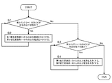
次に、第1制御部15及び第2制御部16によって実行される制御について、図2等を参照しつつ説明する。第1制御部15及び第2制御部16の動作開始条件は、例えばイグニッション信号のオフからオンへの切り替わり等であり、これ以外の動作開始条件であってもよい。
Next, control executed by the
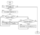
図2の制御は、図3及び図4の制御が実行されないときに繰り返される制御である。図2の制御では、第1制御部15及び第2制御部16の少なくともいずれかが、第2バッテリ11のSOCが所定の低下状態であるか判定する(S1)。ここで第2バッテリ11のSOCが所定の低下状態であるとは、第2導電路18の電圧の値V2や電流の値A2等に基づいて得られた現在の第2バッテリ11のSOCが、第2バッテリ11が満充電された状態に対して所定の割合より低い状態であることを意味する。具体的には、第1制御部15によって監視される第2バッテリ11のSOCが所定の第2SOC閾値以下である場合を「第2バッテリ11の充電状態が所定の低下状態である場合」の一例とし、ステップS1では、第2バッテリ11のSOCが第2SOC閾値以下である場合にステップS2の処理を行い、第2バッテリ11のSOCが第2SOC閾値を超える場合にステップS3の処理を行う。
The control in FIG. 2 is a control that is repeated when the control in FIGS. 3 and 4 is not performed. In the control of FIG. 2, at least one of the
第1制御部15及び第2制御部16は、ステップS1において第2バッテリ11のSOCが第2SOC閾値以下であると判定した場合、ステップS2において第1電圧変換部13からの出力電流を大きくし、第2電圧変換部14からの出力電流を小さくするように制御を行う。なお、本構成では、予め第1電圧変換部13の目標電流値(第1目標電流値It1)が定められており、第2バッテリ11を充電する際に第1電圧変換部13に対して通常の降圧動作を行わせる場合(ステップS2、S4以外のとき)には、第1電圧変換部13からの出力電流が第1目標電流値It1となるように第1制御部15が第1電圧変換部13の降圧動作(第1降圧動作)を制御する。また、予め第2電圧変換部14の目標電流値(第2目標電流値It2)が定められており、第3バッテリ12を充電する際に第2電圧変換部14に対して通常の降圧動作を行わせる場合(ステップS2、S4以外のとき)には、第2電圧変換部14からの出力電流が第2目標電流値It2となるように第2制御部16が第2電圧変換部14の降圧動作(第2降圧動作)を制御する。一方、ステップS1において第2バッテリ11のSOCが第2SOC閾値以下であると判定した場合(第2バッテリ11の充電状態が所定の低下状態であるとき)には、第1制御部15は、第1電圧変換部13から第2導電路18に出力される電流の値を予め定められた第1電圧変換部13の目標電流値(第1目標電流値It1)よりも大きくするように第1電圧変換部13の降圧動作を制御し、第2制御部16は、第2電圧変換部14から第3導電路19に出力される電流の値を予め定められた第2電圧変換部14の目標電流値(第2目標電流値It2)よりも小さくするように第2電圧変換部14の降圧動作を制御する。
When the
第1制御部15及び第2制御部16は、ステップS1において第2バッテリ11のSOCが第2SOC閾値以下でないと判定した場合、ステップS2において第3バッテリ12のSOCが所定の低下状態であるか判定する(S3)。ここで、第3バッテリ12のSOCが所定の低下状態であるとは、第3導電路19の電圧の値V3や電流の値A3等に基づいて得られた現在の第3バッテリ12のSOCが、第3バッテリ12が満充電された状態に対して所定の割合より低い状態であることを意味する。具体的には、第2制御部16によって監視される第3バッテリ12のSOCが所定の第3SOC閾値以下である場合を「第3バッテリ12の充電状態が所定の第2低下状態である場合」の一例とし、ステップS3では、第3バッテリ12のSOCが第3SOC閾値以下である場合にステップS4の処理を行い、第3バッテリ12のSOCが第3SOC閾値を超える場合に図2の処理を終了する。
If the
第1制御部15及び第2制御部16は、ステップS3において第3バッテリ12のSOCが第3SOC閾値以下であると判定した場合、ステップS4において第1電圧変換部13からの出力電流を大きくし、第2電圧変換部14からの出力電流を大きくするように制御を行う。具体的には、第1制御部15は、第1電圧変換部13から第2導電路18に出力される電流の値を予め定められた第1電圧変換部13の目標電流値(第1目標電流値It1)よりも大きくするように第1電圧変換部13の降圧動作を制御し、第2制御部16は、第2電圧変換部14から第3導電路19に出力される電流の値を予め定められた第2電圧変換部14の目標電流値(第2目標電流値It2)よりも大きくするように第2電圧変換部14の降圧動作を制御する。
If the
第1制御部15及び第2制御部16は、ステップS3において第3バッテリ12のSOCが第3SOC閾値以下でないと判定した場合、図2の制御を終了し、第1制御部15及び第2制御部16は通常動作にもどる。そして、第1制御部15及び第2制御部16が通常動作を行っている状態で図2の制御を再び行う。通常動作では、第1制御部15は、第1電圧変換部13から第2導電路18に出力される電流の値を第1目標電流値It1とするように第1電圧変換部13の降圧動作を制御し、第2制御部16は、第2電圧変換部14から第3導電路19に出力される電流の値を第2目標電流値It2とするように第2電圧変換部14の降圧動作を制御する。なお、第1制御部15及び第2制御部16は、第2バッテリ11の充電電圧が第1閾値を超え、第3バッテリの充電電圧が第2閾値を超えた場合に第1電圧変換部13及び第2電圧変換部14の動作を停止させるようにしてもよい。
When the
次に、図3の制御を説明する。図3の制御は、図2の制御が繰り替えられているときに所定条件が成立した場合に開始される制御である。所定条件は、「第1バッテリ10又は第1電圧変換部13のいずれかが異常状態である」という条件である。図2の制御が繰り返されているときに所定条件が成立した場合、第1制御部15及び第2制御部16は、第1バッテリ10が異常状態であるか否かを判定する。本構成では、BMU36は、取得した第1バッテリ10の各単電池の電圧の値V1や電流の値A1に基づいて公知の方法で第1バッテリ10のSOCを検出する。そして、BMU36は、第1バッテリ10のSOCが第1SOC閾値以下であると判定した場合、異常状態通知信号R1を第1制御部15に出力するようになっている。第1制御部15は、ステップS11において異常状態通知信号R1が入力されたか否かを判定し、異常状態通知信号R1が入力された場合(第1バッテリ10の充電状態が所定の異常状態(SOCが第1SOC閾値以下の状態)となった場合)、ステップS12において第1電圧変換部13の動作を停止する。
Next, the control of FIG. 3 will be described. The control in FIG. 3 is a control that is started when a predetermined condition is satisfied while the control in FIG. 2 is repeated. The predetermined condition is a condition that “either the
第1制御部15及び第2制御部16は、ステップS12の後、ステップS13において第2バッテリ11のSOCが第2SOC閾値以下であるか否かを判定し、ステップS13において第2バッテリ11のSOCが第2SOC閾値以下であると判定した場合(第2バッテリ11の充電状態が所定の正常状態でない場合)、ステップS14に進み、第2電圧変換部14に昇圧動作を行わせる。例えば、ステップS13、S14が繰り返される間に第1制御部15から第2制御部16に昇圧動作指示信号L3が出力され、第2制御部16は、この昇圧動作指示信号L3に応じて第2電圧変換部14に昇圧動作を行わせる。
After step S12, the
第1制御部15及び第2制御部16は、ステップS13において第2バッテリ11のSOCが第2SOC閾値以下でないと判定した場合(第2バッテリ11の充電状態が所定の正常状態である場合)ステップS15において第3バッテリ12のSOCが第3SOC閾値以下であるか否か判定する(S15)。第1制御部15及び第2制御部16は、ステップS15において第3バッテリ12のSOCが第3SOC閾値以下であると判定した場合(第3バッテリ12の充電状態が所定の低レベル状態である場合)、ステップS16において第2電圧変換部14から出力される電流の値を予め定められた第2電圧変換部14の目標電流値(第2目標電流値It2)よりも大きくするように第2電圧変換部14の降圧動作を制御する。この制御は、第3バッテリ12のSOCが第3SOC閾値を超えるまで繰り返される。第1制御部15及び第2制御部16は、ステップS15において第3バッテリ12のSOCが第3SOC閾値以下でないと判定した場合、図3の制御を終了する。なお、ステップS11において、第1バッテリ10のSOCが第1SOC閾値以下でないと判定した場合にも図3の制御を終了する。
When the
次に、図4の制御を説明する。図4の制御は、例えば図3の制御の後に開始される制御である。第1制御部15(又は第2制御部16)は、ステップS21において、第1電圧変換部13が異常状態であるか否かを判定する。ステップS21での異常状態の判定方法は様々であり、例えば、第1電圧変換部13の出力電圧が所定電圧範囲外である場合を異常状態と判定してもよく、第1電圧変換部13からの出力電流が所定電流範囲外である場合を異常状態と判定してもよい。この構成では、例えば、第1制御部15が異常検出部の一例に相当する。
Next, the control of FIG. 4 will be described. The control in FIG. 4 is, for example, control started after the control in FIG. In step S21, the first control unit 15 (or the second control unit 16) determines whether the first
第1制御部15及び第2制御部16は、ステップS21において第1電圧変換部13が異常状態であると判定した場合、ステップS22において第2バッテリ11のSOCが第2SOC閾値以下であるか否かを判定し、ステップS22において第2バッテリ11のSOCが第2SOC閾値以下であると判定した場合(第2バッテリ11の充電状態が所定の正常状態でない場合)、ステップS23に進み、第2電圧変換部14に昇圧動作を行わせる。例えば、ステップS22、S23が繰り返される間に第1制御部15から第2制御部16に昇圧動作指示信号L3が出力され、第2制御部16は、この昇圧動作指示信号L3に応じて第2電圧変換部14に昇圧動作を行わせる。
When the
第1制御部15及び第2制御部16は、ステップS22において第2バッテリ11のSOCが第2SOC閾値以下でないと判定した場合(第2バッテリ11の充電状態が所定の正常状態である場合)ステップS24において第3バッテリ12のSOCが第3SOC閾値以下であるか否か判定する。第1制御部15及び第2制御部16は、ステップS24において第3バッテリ12のSOCが第3SOC閾値以下であると判定した場合(第3バッテリ12の充電状態が所定の低レベル状態である場合)、ステップS25において第2電圧変換部14から出力される電流の値を予め定められた第2電圧変換部14の目標電流値(第2目標電流値It2)よりも大きくするように第2電圧変換部14の降圧動作を制御する。この制御は、第3バッテリ12のSOCが第3SOC閾値を超えるまで繰り返される。第1制御部15及び第2制御部16は、ステップS24において第3バッテリ12のSOCが第3SOC閾値以下でないと判定した場合、図4の制御を終了する。なお、ステップS21において、第1電圧変換部13が異常状態でないと判定した場合にも図4の制御を終了する。
When the
次に、本構成の効果を例示する。
上述した車両用電源装置1は、高圧用負荷への電力供給経路(第1導電路17)に印加される高電圧を2つの絶縁型DCDCコンバータによってそれぞれ降圧して第2バッテリ11及び第3バッテリ12を充電するのではなく、第1導電路17の高電圧を絶縁型のDCDCコンバータ(第1電圧変換部13)によって降圧して第2導電路18に中電圧を印加し、第2導電路18を介して第2バッテリ11を充電する構成を採用した上で、この第2導電路18の中電圧を非絶縁型のDCDCコンバータ(第2電圧変換部14)によって降圧して第3バッテリを充電する構成となっている。このように、高電圧を出力する第1バッテリ10の電力に基づいて第2バッテリ11及び第3バッテリ12を充電するにあたり、一方の電圧変換部(第2電圧変換部14)を非絶縁型のDCDCコンバータとして構成可能であるため、2つの絶縁型のDCDCコンバータによって直接的に第2バッテリ11及び第3バッテリ12を充電する構成と比較して、小型化及び軽量化を図りやすくなる。また、第2電圧変換部14は、第2導電路18に印加される中電圧を入力電圧とする形で第3導電路19の低電圧を生成する構成であるため、入力電圧が抑えられ、非絶縁型のDCDCコンバータとしても問題が生じにくい。
Next, effects of the present configuration will be exemplified.
The above-described vehicular power supply device 1 reduces the high voltage applied to the power supply path (first conductive path 17) to the high-voltage load by the two insulated DCDC converters to reduce the high voltage applied to the
ゆえに、高圧用の第1バッテリ10を備えた車両用電源システム100において、第2バッテリ11(第1バッテリ10よりも出力電圧の低いバッテリ)及び第3バッテリ12(第2バッテリ11よりも出力電圧が低いバッテリ)を良好に充電し得る構成を、より小型且つ簡易に実現し得る。
Therefore, in the vehicle
また、本構成の車両用電源装置1は、第2電圧変換部14が第1導電路17に接続されていない。このため、第2電圧変換部14、第3バッテリ12、第2負荷35などをメンテナンスするときに、第1導電路17の高電圧の影響を受けにくい形でメンテナンスすることができ、メンテナンス作業を行いやすい。
Further, in the vehicle power supply device 1 of this configuration, the second voltage converter 14 is not connected to the first
また、本構成の車両用電源装置1は、第1電圧変換部13の動作を制御する第1制御部15と、第2電圧変換部14の動作を制御する第2制御部16とを備え、第1制御部15は、第2バッテリ11の充電状態が所定の低下状態であるときに、第1電圧変換部13から出力される電流の値を予め定められた第1電圧変換部13の目標電流値よりも大きくするように第1電圧変換部13の降圧動作を制御し、第2制御部16は、第2バッテリ11の充電状態が所定の低下状態であるときに、第2電圧変換部14から出力される電流の値を予め定められた第2電圧変換部14の目標電流値よりも小さくするように第2電圧変換部14の降圧動作を制御するように動作する。
In addition, the vehicle power supply device 1 of the present configuration includes a
第1電圧変換部13の第1降圧動作によって第2バッテリ11を充電し、第2電圧変換部14の第2降圧動作によって第3バッテリ12を充電する構成のものでは、第1電圧変換部13の降圧動作によって電流を供給しても第2電圧変換部14の降圧動作がなされていると第2バッテリ11の充電速度は低下せざるを得ない。この問題は、第2バッテリ11の充電状態が所定の低下状態となっているときに顕著となり、第2電圧変換部14の降圧動作がなされていると第2バッテリ11の低下状態は解消されにくい。しかし、上記構成のように、第2バッテリ11の充電状態が所定の低下状態であるときに、第1電圧変換部13から第2導電路18に出力される電流を大きくし、第2電圧変換部14から第3導電路19に出力される電流を小さくすれば、第3導電路19への出力を維持しつつ第2バッテリ11の充電を優先することができ、より早期に第2バッテリ11の低下状態を解消しやすい。
In a configuration in which the
また、第1制御部15は、第3バッテリ12の充電状態が所定の第2低下状態であるときに、第1電圧変換部13から出力される電流の値を予め定められた第1電圧変換部13の目標電流値よりも大きくするように第1電圧変換部13の降圧動作を制御し、第2制御部16は、第3バッテリ12の充電状態が所定の第2低下状態であるときに、第2電圧変換部14から出力される電流の値を予め定められた第2電圧変換部14の目標電流値よりも大きくするように第2電圧変換部14の降圧動作を制御するように動作する。
Further, when the state of charge of the
第1電圧変換部13の第1降圧動作によって第2バッテリ11を充電し、第2電圧変換部14の第2降圧動作によって第3バッテリ12を充電する構成のものでは、第3バッテリ12の充電状態が低下した場合、第2電圧変換部14からの充電電流を大きくすることで第3バッテリ12の充電状態の低下を早期に解消しやすくなるが、このようにすると、第2バッテリ11の放電が促進されすぎたり、第2バッテリ11の充電速度が低下したりする虞がある。しかし、上記構成のように、第3バッテリ12の充電状態が所定の第2低下状態であるときに、第1電圧変換部13から充電電流を大きくし、第2電圧変換部14からの充電電流も大きくすれば、第3バッテリ12の充電を促進して第2低下状態をより早期に解消することができるとともに、このような充電促進に起因して第2バッテリ11側の放電が進行しすぎたり、充電速度が低下しすぎたりすることを抑制することができる。
In the configuration in which the
また、第1制御部15は、第1バッテリ10の充電状態が所定の異常状態であるときに、第1電圧変換部13の動作を停止し、第2制御部16は、少なくとも第1電圧変換部13の動作が停止している場合において第2バッテリ11の充電状態が所定の正常状態でない場合には第2電圧変換部14に、第3導電路19に印加された電圧を昇圧して第2導電路18に出力電圧を印加する昇圧動作を行わせるように動作する。
The
第1電圧変換部13の第1降圧動作によって第2バッテリ11を充電し、第2電圧変換部14の第2降圧動作によって第3バッテリ12を充電する構成のものでは、第1バッテリ10の充電状態が異常状態であるときには第1電圧変換部13の動作を停止することが望ましい。しかし、このように第1電圧変換部13の動作を停止してしまうと、第2バッテリ11の充電状態が低下して正常状態から外れたとしても第2バッテリ11を充電できないという問題がある。そこで、上記構成では、第1電圧変換部13の動作が停止している場合において第2バッテリ11の充電状態が所定の正常状態でない場合に、第2電圧変換部14に昇圧動作を行わせるようにしている。このようにすれば、上記事態が生じたとしても第3バッテリ12の電力を利用して第2バッテリ11の充電不足を早期に解消することができる。
In a configuration in which the
また、第1制御部15は、第1バッテリ10の充電状態が所定の異常状態であるときに、第1電圧変換部13の動作を停止し、第2制御部16は、少なくとも第1電圧変換部13の動作が停止している場合において第2バッテリ11の充電状態が所定の正常状態である場合、第3バッテリ12の充電状態が所定の低レベル状態であれば、第2電圧変換部14から出力される電流の値を予め定められた第2電圧変換部14の目標電流値よりも大きくするように第2電圧変換部14の降圧動作を制御するように動作する。
The
第1電圧変換部13の第1降圧動作によって第2バッテリ11を充電し、第2電圧変換部14の第2降圧動作によって第3バッテリ12を充電する構成のものでは、第1バッテリ10の充電状態が異常状態であるときには第1電圧変換部13の動作を停止することが望ましい。しかし、このような場合でも、第3バッテリ12の充電状態が低下したときには第2電圧変換部14からの充電電流を大きくして第3バッテリ12の充電を促進することが望ましいが、第2バッテリ11が正常状態でないときにこのような動作を行ってしまうと、第2バッテリ11が放電されすぎてしまう虞がある。しかし、上記構成のように、第1電圧変換部13の動作が停止している場合において第3バッテリ12の充電状態が所定の低レベル状態である場合、第2バッテリ11の充電状態が所定の正常状態であることを条件として第2電圧変換部14の出力電流を大きくすれば、第1電圧変換部13の動作停止時に第3バッテリ12の充電を促進することに起因して第2バッテリ11の充電状態が悪化しすぎてしまうような事態を回避することができる。
In a configuration in which the
また、第2制御部16は、異常検出部40によって第1電圧変換部13の異常が検出された場合において第2バッテリ11の充電状態が所定の正常状態でない場合には第2電圧変換部14に、第3導電路19に印加された電圧を昇圧して第2導電路18に出力電圧を印加する昇圧動作を行わせるように動作する。
In addition, when the abnormality of the
第1電圧変換部13の第1降圧動作によって第2バッテリ11を充電し、第2電圧変換部14の第2降圧動作によって第3バッテリ12を充電する構成のものでは、第1電圧変換部13が異常である場合、第2バッテリ11の充電状態が低下して正常状態から外れても第1電圧変換部13によって充電電流を正常に供給できないため第2バッテリ11を迅速に正常状態に戻せない虞がある。そこで、上記構成では、第1電圧変換部13の異常が検出された場合において第2バッテリ11の充電状態が所定の正常状態でない場合に、第2電圧変換部14に昇圧動作を行わせるようにしている。このようにすれば、上記事態が生じたとしても第3バッテリ12の電力を利用して第2バッテリ11の充電不足を早期に解消することができる。
In a configuration in which the
また、本構成の車両用電源装置1は、第1電圧変換部13の動作を制御する第1制御部15と、第2電圧変換部14の動作を制御する第2制御部16と、第1電圧変換部13の異常を検出する異常検出部40とを備え、第2制御部16は、異常検出部40によって第1電圧変換部13の異常が検出された場合において第2バッテリ11の充電状態が所定の正常状態である場合、第3バッテリ12の充電状態が所定の低レベル状態であれば、第2電圧変換部14から出力される電流の値を予め定められた第2電圧変換部14の目標電流値よりも大きくするように第2電圧変換部14の降圧動作を制御する構成である。
Further, the vehicle power supply device 1 of the present configuration includes a
第1電圧変換部13の第1降圧動作によって第2バッテリ11を充電し、第2電圧変換部14の第2降圧動作によって第3バッテリ12を充電する構成のものでは、第1電圧変換部13が異常である場合、第1電圧変換部13による充電動作は期待できなくなる。しかし、このような場合でも、第3バッテリ12の充電状態が低下したときには第2電圧変換部14からの充電電流を大きくして第3バッテリ12の充電を促進することが望ましいが、第2バッテリ11が正常状態でないときにこのような動作を行ってしまうと、第2バッテリ11への電流供給が十分に行えない状況下で第2バッテリ11が放電されすぎてしまう虞がある。しかし、上記構成のように、第1電圧変換部13の異常が検出された場合において第3バッテリ12の充電状態が所定の低レベル状態である場合、第2バッテリ11の充電状態が所定の正常状態であることを条件として第2電圧変換部14の出力電流を大きくすれば、第1電圧変換部13の異常時に第3バッテリ12の充電を促進することに起因して第2バッテリ11の充電状態が悪化しすぎてしまうような事態を回避することができる。
In a configuration in which the
<他の実施例>
本発明は上記記述及び図面によって説明した実施例に限定されるものではなく、例えば次のような実施例も本発明の技術的範囲に含まれる。
<Other embodiments>
The present invention is not limited to the embodiments described with reference to the above description and the drawings. For example, the following embodiments are also included in the technical scope of the present invention.
実施例1では、車両用電源システム100が3つのバッテリ(第1バッテリ、第2バッテリ、及び第3バッテリ)を備えているが、出力電圧が異なる別のバッテリをさらに備えてもよい。この場合、この電圧が異なる別のバッテリは、さらに別の電圧変換部を介して第2バッテリに接続される構成が望ましい。
In the first embodiment, the vehicle
実施例1では、第1制御部、及び第2制御部の動作開始条件をイグニッション信号のオフからオンへの切り替わりであることを例示したが、例えば、ハイブリッド車両や電気自動車などにおいて、車両始動用の電源投入されていない状態から電源投入されている状態への切り替わり等であってもよい。 In the first embodiment, the operation start conditions of the first control unit and the second control unit are described as switching of the ignition signal from off to on. May be switched from a state where the power is not turned on to a state where the power is turned on.
実施例1では、第1制御部、及び第2制御部をそれぞれ個別の情報処理装置(個別のマイクロコンピュータ等)として構成されていることを例示したが、これらが共通の情報処理装置(共通のマイクロコンピュータ等)によって構成されていてもよい。 In the first embodiment, the first control unit and the second control unit are illustrated as being configured as individual information processing devices (individual microcomputers or the like). (A microcomputer or the like).
実施例1では、第1バッテリと第2バッテリとを別体としているが、単電池を直列に複数組み合わせて248Vのバッテリを構成し、このバッテリに中間タップを設け、200Vの第1バッテリと48Vの第2バッテリとを一体化した構成とすることもできる。また、実施例1では、第1バッテリと第2バッテリとに同じ単電池が用いられているが、200Vの第1バッテリを構成する単電池と異なる種類の電池として48Vの第2バッテリを構成してもよい。 In the first embodiment, the first battery and the second battery are separated from each other. However, a plurality of cells are combined in series to form a 248V battery, an intermediate tap is provided in the battery, and the 200V first battery and the 48V And the second battery may be integrated. In the first embodiment, the same single battery is used for the first battery and the second battery. However, a 48V second battery is configured as a battery of a different type from the single battery configuring the 200V first battery. You may.
いずれの例でも、第2バッテリの充電状態が所定の低下状態とは、第2バッテリの出力電圧が閾値電圧以下の状態であってもよい。また、第3バッテリの充電状態が所定の第2低下状態とは、第3バッテリの出力電圧が閾値電圧以下の状態であってもよい。また、第1バッテリの充電状態が所定の異常状態とは、第3バッテリの出力電圧が閾値電圧以下の状態であってもよい。或いは、第2バッテリの充電状態が所定の正常状態でない場合とは、第2バッテリの出力電圧が閾値電圧以下の場合であってもよい。また、第3バッテリの充電状態が所定の低レベル状態とは、第3バッテリの充電電圧が閾値電圧以下の状態であってもよい。 In any of the examples, the state of charge of the second battery being a predetermined low state may be a state in which the output voltage of the second battery is equal to or lower than the threshold voltage. In addition, the state of charge of the third battery being the predetermined second lowered state may be a state in which the output voltage of the third battery is equal to or lower than the threshold voltage. In addition, the state of charge of the first battery being a predetermined abnormal state may be a state in which the output voltage of the third battery is equal to or lower than the threshold voltage. Alternatively, the case where the state of charge of the second battery is not the predetermined normal state may be the case where the output voltage of the second battery is equal to or lower than the threshold voltage. Further, the state of charge of the third battery being a predetermined low level state may be a state in which the charge voltage of the third battery is equal to or lower than the threshold voltage.
1…車載用電源装置
10…第1バッテリ
11…第2バッテリ
12…第3バッテリ
13…第1電圧変換部
14…第2電圧変換部
15…第1制御部(異常検出部)
16…第2制御部
17…第1導電路
18…第2導電路
19…第3導電路
100…車両用電源システム
DESCRIPTION OF SYMBOLS 1 ... In-vehicle
Claims (7)
前記第1バッテリの充放電経路となる第1導電路と、
前記第1バッテリの出力電圧よりも低い電圧を出力する第2バッテリと、
前記第2バッテリの充放電経路となる第2導電路と、
前記第2バッテリの出力電圧よりも低い電圧を出力する第3バッテリと、
前記第3バッテリの充放電経路となる第3導電路と、
を備えた車両用電源システムに用いられる車両用電源装置であって、
絶縁型のDCDCコンバータとして構成され、前記第1導電路に印加された電圧を降圧して前記第2導電路に出力電圧を印加する第1降圧動作を行う第1電圧変換部と、
非絶縁型のDCDCコンバータとして構成され、前記第2導電路に印加された電圧を降圧して前記第3導電路に出力電圧を印加する第2降圧動作を行う第2電圧変換部と、
を備える車両用電源装置。 A first battery for high voltage;
A first conductive path serving as a charge / discharge path for the first battery;
A second battery that outputs a voltage lower than the output voltage of the first battery;
A second conductive path serving as a charge / discharge path for the second battery;
A third battery that outputs a voltage lower than the output voltage of the second battery;
A third conductive path serving as a charge / discharge path for the third battery;
A vehicle power supply device used in a vehicle power supply system comprising:
A first voltage conversion unit configured as an isolated DCDC converter and performing a first step-down operation of stepping down a voltage applied to the first conductive path and applying an output voltage to the second conductive path;
A second voltage converter configured as a non-insulated DCDC converter and performing a second step-down operation of stepping down a voltage applied to the second conductive path and applying an output voltage to the third conductive path;
A vehicle power supply device comprising:
前記第2電圧変換部の動作を制御する第2制御部と、
を備え、
前記第1制御部は、前記第2バッテリの充電状態が所定の低下状態であるときに、前記第1電圧変換部から前記第2導電路に出力される電流の値を予め定められた前記第1電圧変換部の目標電流値よりも大きくするように前記第1電圧変換部の降圧動作を制御し、
前記第2制御部は、前記第2バッテリの充電状態が前記所定の低下状態であるときに、前記第2電圧変換部から前記第3導電路に出力される電流の値を予め定められた前記第2電圧変換部の目標電流値よりも小さくするように前記第2電圧変換部の降圧動作を制御する請求項1に記載の車両用電源装置。 A first control unit that controls an operation of the first voltage conversion unit;
A second control unit that controls the operation of the second voltage conversion unit;
With
The first control unit is configured to set a value of a current output from the first voltage conversion unit to the second conductive path to a predetermined value when the state of charge of the second battery is a predetermined low state. Controlling the step-down operation of the first voltage converter so as to be larger than the target current value of the one voltage converter;
The second control unit is configured to set a value of a current output from the second voltage conversion unit to the third conductive path in advance when the state of charge of the second battery is the predetermined state of decrease. The vehicle power supply device according to claim 1, wherein the step-down operation of the second voltage converter is controlled so as to be smaller than a target current value of the second voltage converter.
前記第2電圧変換部の動作を制御する第2制御部と、
を備え、
前記第1制御部は、前記第3バッテリの充電状態が所定の第2低下状態であるときに、前記第1電圧変換部から前記第2導電路に出力される電流の値を予め定められた前記第1電圧変換部の目標電流値よりも大きくするように前記第1電圧変換部の降圧動作を制御し、
前記第2制御部は、前記第3バッテリの充電状態が前記所定の第2低下状態であるときに、前記第2電圧変換部から前記第3導電路に出力される電流の値を予め定められた前記第2電圧変換部の目標電流値よりも大きくするように前記第2電圧変換部の降圧動作を制御する請求項1又は請求項2に記載の車両用電源装置。 A first control unit that controls an operation of the first voltage conversion unit;
A second control unit that controls the operation of the second voltage conversion unit;
With
The first control unit sets a value of a current output from the first voltage conversion unit to the second conductive path in advance when the state of charge of the third battery is a predetermined second low state. Controlling a step-down operation of the first voltage converter so as to be larger than a target current value of the first voltage converter;
The second control unit is configured to preset a value of a current output from the second voltage conversion unit to the third conductive path when the state of charge of the third battery is the predetermined second low state. The power supply device for a vehicle according to claim 1, wherein the step-down operation of the second voltage converter is controlled so as to be larger than a target current value of the second voltage converter.
前記第2電圧変換部の動作を制御する第2制御部と、
を備え、
前記第1制御部は、前記第1バッテリの充電状態が所定の異常状態であるときに、前記第1電圧変換部の動作を停止し、
前記第2制御部は、少なくとも前記第1電圧変換部の動作が停止している場合において前記第2バッテリの充電状態が所定の正常状態でない場合に、前記第2電圧変換部に、前記第3導電路に印加された電圧を昇圧して前記第2導電路に出力電圧を印加する昇圧動作を行わせる請求項1から請求項3に記載の車両用電源装置。 A first control unit that controls an operation of the first voltage conversion unit;
A second control unit that controls the operation of the second voltage conversion unit;
With
The first control unit, when the state of charge of the first battery is a predetermined abnormal state, stops the operation of the first voltage conversion unit,
The second control unit, when at least the operation of the first voltage conversion unit is stopped and the state of charge of the second battery is not a predetermined normal state, causes the second voltage conversion unit to perform the third The power supply device for a vehicle according to claim 1, wherein a voltage applied to the conductive path is boosted to perform a boosting operation of applying an output voltage to the second conductive path.
前記第2電圧変換部の動作を制御する第2制御部と、
を備え、
前記第1制御部は、前記第1バッテリの充電状態が所定の異常状態であるときに、前記第1電圧変換部の動作を停止し、
前記第2制御部は、少なくとも前記第1電圧変換部の動作が停止している場合において前記第2バッテリの充電状態が所定の正常状態である場合、前記第3バッテリの充電状態が所定の低レベル状態であれば、前記第2電圧変換部から出力される電流の値を予め定められた前記第2電圧変換部の目標電流値よりも大きくするように前記第2電圧変換部の降圧動作を制御する請求項1から請求項4に記載の車両用電源装置。 A first control unit that controls an operation of the first voltage conversion unit;
A second control unit that controls the operation of the second voltage conversion unit;
With
The first control unit, when the state of charge of the first battery is a predetermined abnormal state, stops the operation of the first voltage conversion unit,
The second control unit is configured to change the state of charge of the third battery to a predetermined low level when the state of charge of the second battery is a predetermined normal state at least when the operation of the first voltage conversion unit is stopped. In the case of the level state, the step-down operation of the second voltage converter is performed so that the value of the current output from the second voltage converter is larger than a predetermined target current value of the second voltage converter. The power supply device for a vehicle according to claim 1, wherein the power supply device is controlled.
前記第2電圧変換部の動作を制御する第2制御部と、
前記第1電圧変換部の異常を検出する異常検出部と、
を備え、
前記第2制御部は、前記異常検出部によって前記第1電圧変換部の異常が検出された場合において前記第2バッテリの充電状態が所定の正常状態でない場合に、前記第2電圧変換部に、前記第3導電路に印加された電圧を昇圧して前記第2導電路に出力電圧を印加する昇圧動作を行わせる請求項1から請求項5に記載の車両用電源装置。 A first control unit that controls an operation of the first voltage conversion unit;
A second control unit that controls the operation of the second voltage conversion unit;
An abnormality detection unit that detects abnormality of the first voltage conversion unit;
With
The second control unit, when the abnormality detection unit detects an abnormality in the first voltage conversion unit, when the state of charge of the second battery is not a predetermined normal state, the second voltage conversion unit, The power supply device for a vehicle according to any one of claims 1 to 5, wherein a boosting operation of boosting a voltage applied to the third conductive path and applying an output voltage to the second conductive path is performed.
前記第2電圧変換部の動作を制御する第2制御部と、
前記第1電圧変換部の異常を検出する異常検出部と、
を備え、
前記第2制御部は、前記異常検出部によって前記第1電圧変換部の異常が検出された場合において前記第2バッテリの充電状態が所定の正常状態である場合、前記第3バッテリの充電状態が所定の低レベル状態であれば、前記第2電圧変換部から出力される電流の値を予め定められた前記第2電圧変換部の目標電流値よりも大きくするように前記第2電圧変換部の降圧動作を制御する請求項1から請求項6に記載の車両用電源装置。 A first control unit that controls an operation of the first voltage conversion unit;
A second control unit that controls the operation of the second voltage conversion unit;
An abnormality detection unit that detects abnormality of the first voltage conversion unit;
With
The second control unit, when the abnormality detection unit detects an abnormality in the first voltage conversion unit, when the state of charge of the second battery is a predetermined normal state, the state of charge of the third battery is If the predetermined low level state, the value of the current output from the second voltage converter is set to be larger than a predetermined target current value of the second voltage converter. The power supply device for a vehicle according to claim 1, which controls a step-down operation.
Priority Applications (4)
| Application Number | Priority Date | Filing Date | Title |
|---|---|---|---|
| JP2018116642A JP2019221063A (en) | 2018-06-20 | 2018-06-20 | Power supply device for vehicle |
| CN201980036983.5A CN112236917A (en) | 2018-06-20 | 2019-06-03 | Power supply device for vehicle |
| PCT/JP2019/021898 WO2019244606A1 (en) | 2018-06-20 | 2019-06-03 | Vehicle power supply device |
| US17/252,777 US20210261018A1 (en) | 2018-06-20 | 2019-06-03 | Vehicle power supply device |
Applications Claiming Priority (1)
| Application Number | Priority Date | Filing Date | Title |
|---|---|---|---|
| JP2018116642A JP2019221063A (en) | 2018-06-20 | 2018-06-20 | Power supply device for vehicle |
Publications (2)
| Publication Number | Publication Date |
|---|---|
| JP2019221063A true JP2019221063A (en) | 2019-12-26 |
| JP2019221063A5 JP2019221063A5 (en) | 2021-01-21 |
Family
ID=68982683
Family Applications (1)
| Application Number | Title | Priority Date | Filing Date |
|---|---|---|---|
| JP2018116642A Ceased JP2019221063A (en) | 2018-06-20 | 2018-06-20 | Power supply device for vehicle |
Country Status (4)
| Country | Link |
|---|---|
| US (1) | US20210261018A1 (en) |
| JP (1) | JP2019221063A (en) |
| CN (1) | CN112236917A (en) |
| WO (1) | WO2019244606A1 (en) |
Cited By (2)
| Publication number | Priority date | Publication date | Assignee | Title |
|---|---|---|---|---|
| JP2021142810A (en) * | 2020-03-11 | 2021-09-24 | 本田技研工業株式会社 | Power supply device for vehicle |
| JP2021142824A (en) * | 2020-03-11 | 2021-09-24 | 本田技研工業株式会社 | Power supply device for vehicle |
Families Citing this family (2)
| Publication number | Priority date | Publication date | Assignee | Title |
|---|---|---|---|---|
| JP7295912B2 (en) | 2021-08-27 | 2023-06-21 | 本田技研工業株式会社 | vehicle |
| JP7295915B2 (en) * | 2021-09-22 | 2023-06-21 | 本田技研工業株式会社 | vehicle power system |
Citations (2)
| Publication number | Priority date | Publication date | Assignee | Title |
|---|---|---|---|---|
| JP2011030363A (en) * | 2009-07-24 | 2011-02-10 | Toyota Industries Corp | Vehicle power supply unit |
| JP2017081348A (en) * | 2015-10-27 | 2017-05-18 | 株式会社デンソー | Power supply control device |
Family Cites Families (1)
| Publication number | Priority date | Publication date | Assignee | Title |
|---|---|---|---|---|
| JP2012115031A (en) * | 2010-11-24 | 2012-06-14 | Toyota Motor Corp | Vehicle power supply system |
-
2018
- 2018-06-20 JP JP2018116642A patent/JP2019221063A/en not_active Ceased
-
2019
- 2019-06-03 US US17/252,777 patent/US20210261018A1/en not_active Abandoned
- 2019-06-03 WO PCT/JP2019/021898 patent/WO2019244606A1/en active Application Filing
- 2019-06-03 CN CN201980036983.5A patent/CN112236917A/en active Pending
Patent Citations (2)
| Publication number | Priority date | Publication date | Assignee | Title |
|---|---|---|---|---|
| JP2011030363A (en) * | 2009-07-24 | 2011-02-10 | Toyota Industries Corp | Vehicle power supply unit |
| JP2017081348A (en) * | 2015-10-27 | 2017-05-18 | 株式会社デンソー | Power supply control device |
Cited By (4)
| Publication number | Priority date | Publication date | Assignee | Title |
|---|---|---|---|---|
| JP2021142810A (en) * | 2020-03-11 | 2021-09-24 | 本田技研工業株式会社 | Power supply device for vehicle |
| JP2021142824A (en) * | 2020-03-11 | 2021-09-24 | 本田技研工業株式会社 | Power supply device for vehicle |
| JP7010989B2 (en) | 2020-03-11 | 2022-01-26 | 本田技研工業株式会社 | Vehicle power supply |
| JP7010988B2 (en) | 2020-03-11 | 2022-01-26 | 本田技研工業株式会社 | Vehicle power supply |
Also Published As
| Publication number | Publication date |
|---|---|
| CN112236917A (en) | 2021-01-15 |
| US20210261018A1 (en) | 2021-08-26 |
| WO2019244606A1 (en) | 2019-12-26 |
Similar Documents
| Publication | Publication Date | Title |
|---|---|---|
| US11208006B2 (en) | Electric power supply system | |
| WO2019244606A1 (en) | Vehicle power supply device | |
| JP5577775B2 (en) | Electric vehicle power supply | |
| JP5605320B2 (en) | Vehicle power supply | |
| US8884461B2 (en) | Battery system for vehicle and control method thereof | |
| CN110546852A (en) | Power supply device, power storage system, and charging method | |
| US8760111B2 (en) | Secondary battery output power controller | |
| CN113711457A (en) | Conversion device, conversion system, switching device, vehicle including these devices, and control method | |
| JP5796457B2 (en) | Battery system and battery system control method | |
| JP7290965B2 (en) | Electric vehicle power supply system | |
| JP5835136B2 (en) | In-vehicle charging controller | |
| JP2012034488A (en) | Charger | |
| US20120139522A1 (en) | Converter controller | |
| JP7178892B2 (en) | vehicle battery charging controller | |
| JP2013176251A (en) | Power supply device | |
| US9252608B2 (en) | Electrical storage system, and control method for electrical storage system | |
| JP2014150593A (en) | Power supply system for vehicle | |
| JP2017030408A (en) | Vehicular power supply system | |
| JP5822779B2 (en) | Power storage system and charge / discharge control method thereof | |
| JP2019134636A (en) | Charging system and charging method | |
| JP2018182799A (en) | Vehicular power supply device | |
| JP2014054119A (en) | On-vehicle power control unit | |
| JP2015061504A (en) | Power storage system | |
| CN219339219U (en) | Charging and discharging system and vehicle | |
| US11964620B2 (en) | Vehicular power supply device |
Legal Events
| Date | Code | Title | Description |
|---|---|---|---|
| A621 | Written request for application examination |
Free format text: JAPANESE INTERMEDIATE CODE: A621 Effective date: 20200930 |
|
| A521 | Request for written amendment filed |
Free format text: JAPANESE INTERMEDIATE CODE: A523 Effective date: 20201202 |
|
| A131 | Notification of reasons for refusal |
Free format text: JAPANESE INTERMEDIATE CODE: A131 Effective date: 20211118 |
|
| A521 | Request for written amendment filed |
Free format text: JAPANESE INTERMEDIATE CODE: A523 Effective date: 20211220 |
|
| A01 | Written decision to grant a patent or to grant a registration (utility model) |
Free format text: JAPANESE INTERMEDIATE CODE: A01 Effective date: 20220510 |
|
| A045 | Written measure of dismissal of application [lapsed due to lack of payment] |
Free format text: JAPANESE INTERMEDIATE CODE: A045 Effective date: 20220922 |