JP2019203396A - Purge control valve - Google Patents

Purge control valve Download PDF

Info

Publication number
JP2019203396A
JP2019203396A JP2018097176A JP2018097176A JP2019203396A JP 2019203396 A JP2019203396 A JP 2019203396A JP 2018097176 A JP2018097176 A JP 2018097176A JP 2018097176 A JP2018097176 A JP 2018097176A JP 2019203396 A JP2019203396 A JP 2019203396A
Authority
JP
Japan
Prior art keywords
passage
control valve
purge control
side annular
outflow
Prior art date
Legal status (The legal status is an assumption and is not a legal conclusion. Google has not performed a legal analysis and makes no representation as to the accuracy of the status listed.)
Pending
Application number
JP2018097176A
Other languages
Japanese (ja)
Inventor
佐藤 昌宏
Masahiro Sato
昌宏 佐藤
Current Assignee (The listed assignees may be inaccurate. Google has not performed a legal analysis and makes no representation or warranty as to the accuracy of the list.)
Hamanakodenso Co Ltd
Original Assignee
Hamanakodenso Co Ltd
Priority date (The priority date is an assumption and is not a legal conclusion. Google has not performed a legal analysis and makes no representation as to the accuracy of the date listed.)
Filing date
Publication date
Application filed by Hamanakodenso Co Ltd filed Critical Hamanakodenso Co Ltd
Priority to JP2018097176A priority Critical patent/JP2019203396A/en
Publication of JP2019203396A publication Critical patent/JP2019203396A/en
Pending legal-status Critical Current

Links

Images

Landscapes

  • Supplying Secondary Fuel Or The Like To Fuel, Air Or Fuel-Air Mixtures (AREA)

Abstract

To provide a purge control valve which enables reduction of assembly work hours of a filter member.SOLUTION: A purge control valve 4 is a control valve installed at an evaporative fuel passage in which an evaporative fuel desorbed from a canister circulates toward an engine. The purge control valve 4 includes: a body housing 40 having a housing internal passage 401a in which the evaporative fuel circulates therein and incorporating an electromagnetic coil part 42 for driving a valve body 43; and an outflow member 6 connected to the body housing 40. In the outflow member 6, a cylindrical part 62 having a valve seat 63, an outflow tubular part 60 formed with an outflow passage 60a through which the evaporative fuel flowing out from the housing internal passage 401a circulates, and a filter part 7 which allows passage of the evaporative fuel and prevents passage of foreign objects are integrally molded.SELECTED DRAWING: Figure 4

Description

この明細書における開示は、エンジンに向けて蒸発燃料が流通する蒸発燃料通路に設けられたパージ制御弁に関する。   The disclosure in this specification relates to a purge control valve provided in an evaporated fuel passage through which evaporated fuel flows toward an engine.

特許文献1には、燃料タンク内で発生する蒸発燃料をエンジンの吸気側にパージする蒸発燃料パージ装置が記載されている。この蒸発燃料パージ装置は、本体部の内部に設けられた燃料流路に設けられて、蒸発燃料中の塵や埃等の異物を補足するフィルタ部材を備えている。   Patent Document 1 describes an evaporated fuel purge device that purges evaporated fuel generated in a fuel tank to the intake side of an engine. This evaporative fuel purge device is provided with a filter member that is provided in a fuel flow path provided inside the main body and supplements foreign matter such as dust and dirt in the evaporative fuel.

特開2014−111915号公報JP 2014-111915 A

特許文献1のフィルタ部材は、フィルタ部材に設けられたリング部の一端が隔壁に形成された環状溝部に嵌めこまれ、フィルタ部の他端側の先端部が燃料流出パイプが形成された部品に当接することによって本体部内に固定されている。蒸発燃料パージ装置にフィルタ部材を組みつけるためには、リング部の先端を隔壁の環状溝部に嵌めこみ、燃料流出パイプが形成された部品と隔壁とでフィルタ部材を挟み込む作業を正確に行う必要がある。   In the filter member of Patent Document 1, one end of a ring portion provided in the filter member is fitted into an annular groove formed in a partition wall, and the tip portion on the other end side of the filter portion is a component in which a fuel outflow pipe is formed. It is fixed in the main body by abutting. In order to assemble the filter member into the evaporated fuel purge device, it is necessary to fit the tip of the ring portion into the annular groove of the partition wall and accurately perform the work of sandwiching the filter member between the part where the fuel outflow pipe is formed and the partition wall. is there.

この明細書における開示の目的は、フィルタ部材の組立て工数を低減できるパージ制御弁を提供することである。   An object of the disclosure in this specification is to provide a purge control valve capable of reducing the number of assembling steps of a filter member.

この明細書に開示された複数の態様は、それぞれの目的を達成するために、互いに異なる技術的手段を採用する。また、特許請求の範囲およびこの項に記載した括弧内の符号は、一つの態様として後述する実施形態に記載の具体的手段との対応関係を示す一例であって、技術的範囲を限定するものではない。   A plurality of aspects disclosed in this specification adopt different technical means to achieve each purpose. Further, the reference numerals in parentheses described in the claims and in this section are examples showing the correspondence with specific means described in the embodiments described later as one aspect, and limit the technical scope. is not.

開示されたパージ制御弁の一つは、キャニスタ(16)から脱離された蒸発燃料がエンジン(22)に向けて流通する蒸発燃料通路に設置されるパージ制御弁(4)であって、キャニスタ側から流入した蒸発燃料が流通するハウジング内通路(401a)を内部に有し、ハウジング内通路を開閉する弁体(43)を駆動する電磁コイル部(42)を内蔵する本体ハウジング(40)と、本体ハウジングに連結されている流出用部材(6)とを備え、流出用部材には、弁体が着座する弁座(63)を有する筒状部(62)と、ハウジング内通路から流出した蒸発燃料が流通する流出通路(60a)が形成された流出部(60)と、蒸発燃料の通過を許容し異物の通過を阻止するフィルタ部(7)とが一体成形されている。   One of the disclosed purge control valves is a purge control valve (4) installed in an evaporated fuel passage through which evaporated fuel desorbed from the canister (16) flows toward the engine (22). A body housing (40) having an internal housing passage (401a) through which evaporated fuel flowing in from the side flows, and a built-in electromagnetic coil portion (42) for driving a valve body (43) for opening and closing the internal housing passage; And an outflow member (6) connected to the main body housing. The outflow member flows out of the tubular portion (62) having the valve seat (63) on which the valve body is seated and the passage in the housing. An outflow portion (60) in which an outflow passage (60a) through which the evaporated fuel flows is formed and a filter portion (7) that allows passage of the evaporated fuel and prevents passage of foreign matters are integrally formed.

このパージ制御弁によれば、少なくとも、蒸発燃料の流出通路と弁座を有する筒状部とフィルタ部とが一体成形された流出用部材を備え、この流出用部材と電磁コイル部を内蔵する本体ハウジングとが連結される構成を有する。この構成により、流出用部材を本体ハウジングに結合することによって、フィルタ部を備えるパージ制御弁を製造できる。以上より、フィルタ部材の組み付け工数を低減できるパージ制御弁を提供できる。   According to this purge control valve, at least a main body including an outflow member in which an evaporative fuel outflow passage, a cylindrical portion having a valve seat, and a filter portion are integrally formed, and the outflow member and the electromagnetic coil portion are built in. It has the structure connected with a housing. With this configuration, the purge control valve including the filter portion can be manufactured by coupling the outflow member to the main body housing. As described above, it is possible to provide a purge control valve that can reduce the number of assembling steps of the filter member.

第1実施形態のパージ制御弁を搭載可能な蒸発燃料処理システムを示した概要図である。It is the schematic which showed the evaporated fuel processing system which can mount the purge control valve of 1st Embodiment. 第1実施形態のパージ制御弁を示した正面図である。It is the front view which showed the purge control valve of 1st Embodiment. 第1実施形態のパージ制御弁を示した下面図である。It is the bottom view which showed the purge control valve of 1st Embodiment. 図3におけるIV−IV切断面を示した断面図である。It is sectional drawing which showed the IV-IV cut surface in FIG. 図4における丸内を拡大した部分拡大図である。It is the elements on larger scale which expanded the circle in FIG. フィルタユニットを示した斜視図である。It is the perspective view which showed the filter unit.

(第1実施形態)
第1実施形態について、図1〜図6を参照しながら説明する。図1に示す蒸発燃料処理システムは、キャニスタ16に吸着した燃料中のHCガス等をエンジン22の吸気通路に供給するものであり、燃料タンク14からの蒸発燃料が大気に放出されることを防止するシステムでもある。この蒸発燃料処理システムは、蒸発燃料通路における所定の位置に、吸気通路に供給される蒸発燃料の流量を調整可能なパージ制御弁4を備えている。パージ制御弁4は、電磁コイル部42を内蔵する本体ハウジング40と、本体ハウジング40と結合する流入用部材5と、本体ハウジング40と結合する流出用部材6とを備えている。本体ハウジング40、流入用部材5、流出用部材6のそれぞれは、樹脂材料により形成されている。
(First embodiment)
A first embodiment will be described with reference to FIGS. The evaporative fuel processing system shown in FIG. 1 supplies HC gas or the like in the fuel adsorbed by the canister 16 to the intake passage of the engine 22 and prevents the evaporative fuel from the fuel tank 14 from being released into the atmosphere. It is also a system to do. This evaporative fuel processing system includes a purge control valve 4 that can adjust the flow rate of the evaporative fuel supplied to the intake passage at a predetermined position in the evaporative fuel passage. The purge control valve 4 includes a main body housing 40 containing the electromagnetic coil portion 42, an inflow member 5 coupled to the main body housing 40, and an outflow member 6 coupled to the main body housing 40. Each of the main body housing 40, the inflow member 5, and the outflow member 6 is formed of a resin material.

エンジン22の吸気系1に導入された蒸発燃料は、インジェクタ等からエンジン22に供給される燃焼用燃料と混合されてエンジン22のシリンダ内で燃焼される。エンジン22の吸気系1は、エンジン22の吸気マニホールド20にスロットルバルブ21を介して吸気管10の一端側が接続され、さらに吸気管10の途中にフィルタ23が設けられて構成されている。蒸発燃料パージ系2は、燃料タンク14、キャニスタ16が、配管15、配管17、配管19、配管18を介して吸気マニホールド20に接続されて形成されている。   The evaporated fuel introduced into the intake system 1 of the engine 22 is mixed with combustion fuel supplied to the engine 22 from an injector or the like and burned in a cylinder of the engine 22. The intake system 1 of the engine 22 is configured such that one end side of the intake pipe 10 is connected to an intake manifold 20 of the engine 22 via a throttle valve 21, and a filter 23 is provided in the middle of the intake pipe 10. The evaporative fuel purge system 2 is formed by connecting a fuel tank 14 and a canister 16 to an intake manifold 20 via a pipe 15, a pipe 17, a pipe 19 and a pipe 18.

フィルタ23は、吸気管10の最上流部に設けられ、吸気中の塵や埃等を捕捉する。スロットルバルブ21は、アクセルペダルと連動して吸気マニホールド20の入口部における開度を調節して、吸気マニホールド20内に流入される吸気量を調節する吸気量調節弁である。吸気は、フィルタ23、スロットルバルブ21を順に通過して吸気マニホールド20内に流入し、インジェクタ等から噴射される燃焼用燃料と所定の空燃比となるように混合されてシリンダ内で燃焼される。   The filter 23 is provided at the most upstream part of the intake pipe 10 and captures dust, dust, and the like in the intake air. The throttle valve 21 is an intake air amount adjustment valve that adjusts the amount of intake air flowing into the intake manifold 20 by adjusting the opening at the inlet of the intake manifold 20 in conjunction with the accelerator pedal. The intake air sequentially passes through the filter 23 and the throttle valve 21, flows into the intake manifold 20, is mixed with combustion fuel injected from an injector or the like so as to have a predetermined air-fuel ratio, and is combusted in the cylinder.

燃料タンク14は、ガソリン等の燃料を貯留する容器である。燃料タンク14は、配管15によってキャニスタ16の流入部16aに接続されている。キャニスタ16は、内部に活性炭等の吸着材が封入された容器であり、燃料タンク14内で発生する蒸発燃料を、配管15を介して流入部16aから取り入れ、吸着材に一時的に吸着する。キャニスタ16には、外部の新鮮な空気を吸入するための吸入部16bが設けられている。キャニスタ16が吸入部16bを備えることにより、キャニスタ16内には大気圧が作用する。キャニスタ16は、吸入された新鮮な空気によって吸着材に吸着した蒸発燃料を容易に離脱することができる。   The fuel tank 14 is a container for storing fuel such as gasoline. The fuel tank 14 is connected to the inflow portion 16 a of the canister 16 by a pipe 15. The canister 16 is a container in which an adsorbent such as activated carbon is enclosed. The canister 16 takes in evaporated fuel generated in the fuel tank 14 from the inflow portion 16a via the pipe 15 and temporarily adsorbs the adsorbent on the adsorbent. The canister 16 is provided with a suction portion 16b for sucking fresh fresh air. By providing the canister 16 with the suction portion 16 b, atmospheric pressure acts in the canister 16. The canister 16 can easily remove the evaporated fuel adsorbed on the adsorbent by the freshly sucked air.

吸入部16bには、例えばバルブモジュールが一体に設けられている。バルブモジュールは、外部の新鮮な空気を吸入するための吸入部を開閉するキャニスタクローズバルブと、大気に対してガスを放出したり大気を吸入したりすることが可能な内部ポンプと、を内蔵している。キャニスタ16がキャニスタクローズバルブを備えることによれば、キャニスタ16内に大気圧を作用させることができる。キャニスタ16は、吸入された新鮮な空気によって吸着材に吸着した蒸発燃料を容易に脱離可能、すなわちパージすることができる。   For example, a valve module is integrally provided in the suction portion 16b. The valve module has a built-in canister close valve that opens and closes a suction section for sucking in fresh fresh air, and an internal pump that can discharge gas to the atmosphere and suck air. ing. When the canister 16 includes the canister close valve, atmospheric pressure can be applied to the canister 16. The canister 16 can easily desorb, that is, purge, the evaporated fuel adsorbed on the adsorbent by the freshly sucked air.

キャニスタ16には、吸着材から離脱された蒸発燃料が流出される流出部16cが設けられている。流出部16cには配管17の一端側が接続されている。配管17の他端側は、パージ制御弁4の流入部に接続されている。ここで、配管17内の通路は、パージ制御弁4に対して燃料が流入する燃料流入通路とも称する。パージ制御弁4と逆止弁装置3は、配管19によって接続されることにより連通する。逆止弁装置3の流出側は、配管18の一端側に接続されている。ここで、配管18内の通路は、パージ制御弁4から流出した燃料が通る燃料流出通路とも称する。配管18の他端側は吸気マニホールド20の流入部に接続されている。   The canister 16 is provided with an outflow portion 16c through which the evaporated fuel separated from the adsorbent flows out. One end side of the pipe 17 is connected to the outflow portion 16c. The other end side of the pipe 17 is connected to the inflow portion of the purge control valve 4. Here, the passage in the pipe 17 is also referred to as a fuel inflow passage through which fuel flows into the purge control valve 4. The purge control valve 4 and the check valve device 3 communicate with each other by being connected by a pipe 19. The outflow side of the check valve device 3 is connected to one end side of the pipe 18. Here, the passage in the pipe 18 is also referred to as a fuel outflow passage through which the fuel flowing out from the purge control valve 4 passes. The other end side of the pipe 18 is connected to the inflow portion of the intake manifold 20.

パージ制御弁4は、蒸発燃料通路を開閉する開閉手段であり、キャニスタ16から流出する蒸発燃料をエンジン22へ供給することを許可および阻止できる。パージ制御弁4は、図4に示すように、弁体43と、コイル部420、スプリング424等を含む電磁コイル部42とを備えている。パージ制御弁4は、コイル部420に通電されたときに発生する電磁力とスプリング424の付勢力とのバランスに応じて弁体43を駆動することによって、ハウジング内通路401aを開閉する。   The purge control valve 4 is an opening / closing means for opening and closing the evaporated fuel passage, and can permit and block the supply of the evaporated fuel flowing out from the canister 16 to the engine 22. As shown in FIG. 4, the purge control valve 4 includes a valve body 43 and an electromagnetic coil part 42 including a coil part 420, a spring 424, and the like. The purge control valve 4 opens and closes the in-housing passage 401a by driving the valve body 43 in accordance with the balance between the electromagnetic force generated when the coil portion 420 is energized and the biasing force of the spring 424.

パージ制御弁4は、ハウジング内通路401aを形成する本体ハウジング40を備える。ハウジング内通路401aは、本体ハウジング40内のチャンバ室400aや本体内部絞り通路402aよりも下流に設けられた通路である。パージ制御弁4は、通常は蒸発燃料通路をなすハウジング内通路401aを閉じた状態を維持しコイル部420に通電が行われると、電磁力がスプリング424の弾性力に打ち勝って、弁体43が弁座63から離間してハウジング内通路401aを開いた状態にする。制御装置は、通電のオン時間とオフ時間とによって形成される1周期の時間に対するオン時間の比率、すなわちデューティ比を制御してコイル部420に通電を行う。パージ制御弁4は、デューティコントロールバルブともいう。この通電制御により、ハウジング内通路401aを流通する蒸発燃料の流量は調節される。   The purge control valve 4 includes a main body housing 40 that forms a housing inner passage 401a. The in-housing passage 401a is a passage provided downstream of the chamber chamber 400a in the main body housing 40 and the main body inner throttle passage 402a. In the purge control valve 4, when the coil portion 420 is energized while the housing passage 401 a that normally forms an evaporative fuel passage is closed and the coil portion 420 is energized, the electromagnetic force overcomes the elastic force of the spring 424. The in-housing passage 401a is opened away from the valve seat 63. The control device energizes the coil unit 420 by controlling the ratio of the on time to the time of one cycle formed by the energization on time and the off time, that is, the duty ratio. The purge control valve 4 is also called a duty control valve. By this energization control, the flow rate of the evaporated fuel flowing through the in-housing passage 401a is adjusted.

逆止弁装置3は、キャニスタ16から吸気管10に至る蒸発燃料通路であって、パージ制御弁4と吸気マニホールド20との間に設置された逆流防止用の弁である。逆止弁装置3は、蒸発燃料通路において、燃料流入通路(配管19内の通路)から燃料流出通路(配管18内の通路)への蒸発燃料の本来の流通を許容し、燃料流出通路から燃料流入通路への蒸発燃料の逆流を阻止する。逆止弁装置3は、蒸発燃料の本来の流通に伴って流路を開き、蒸発燃料の逆流に伴って流路を閉じるように動作する弁体を備える。   The check valve device 3 is an evaporative fuel passage extending from the canister 16 to the intake pipe 10 and is a valve for preventing a reverse flow installed between the purge control valve 4 and the intake manifold 20. The check valve device 3 allows the original flow of the evaporated fuel from the fuel inflow passage (passage in the pipe 19) to the fuel outflow passage (passage in the pipe 18) in the evaporative fuel passage. Prevents the backflow of evaporated fuel to the inflow passage. The check valve device 3 includes a valve body that operates to open the flow path with the original flow of the evaporated fuel and close the flow path with the reverse flow of the evaporated fuel.

車両の走行時に、制御装置によってパージ制御弁4が開弁状態になると、ピストンの吸入作用によって発生する吸気マニホールド20内の負圧とキャニスタ16にかかる大気圧との差が生じる。この圧力差によって、キャニスタ16内に吸着された蒸気燃料は、燃料流入通路、パージ制御弁4、逆止弁装置3、燃料流出通路を流れ、吸気マニホールド20内に吸引される。   When the purge control valve 4 is opened by the control device while the vehicle is running, a difference between the negative pressure in the intake manifold 20 generated by the intake action of the piston and the atmospheric pressure applied to the canister 16 occurs. Due to this pressure difference, the vapor fuel adsorbed in the canister 16 flows through the fuel inflow passage, the purge control valve 4, the check valve device 3, and the fuel outflow passage, and is sucked into the intake manifold 20.

吸気マニホールド20内に吸引された蒸発燃料は、インジェクタ等からエンジン22に供給される本来の燃焼用燃料と混合されて、エンジン22のシリンダ内で燃焼される。また、エンジン22のシリンダ内においては、燃焼用燃料と吸気との混合割合である空燃比が予め定めた所定の空燃比となるように制御される。制御装置は、パージ制御弁4の開弁時間と閉弁時間をデューティ制御することで、蒸発燃料をパージしても、所定の空燃比が維持されるように蒸発燃料のパージ量を調節する。   The evaporated fuel sucked into the intake manifold 20 is mixed with the original combustion fuel supplied from the injector or the like to the engine 22 and burned in the cylinder of the engine 22. Further, in the cylinder of the engine 22, the air-fuel ratio, which is the mixing ratio of the combustion fuel and the intake air, is controlled so as to become a predetermined air-fuel ratio. The control device performs duty control on the opening time and the closing time of the purge control valve 4 to adjust the purge amount of the evaporated fuel so that the predetermined air-fuel ratio is maintained even if the evaporated fuel is purged.

図2〜図4に示すように、パージ制御弁4は、流入用部材5と、流出用部材6と、流入用部材5と流出用部材6とが連結されている本体ハウジング40とを備えている。流入用部材5は、配管17と本体ハウジング40とを連通させる部材である。流出用部材6は本体ハウジング40と配管19とを連通させる部材である。   As shown in FIGS. 2 to 4, the purge control valve 4 includes an inflow member 5, an outflow member 6, and a main body housing 40 to which the inflow member 5 and the outflow member 6 are connected. Yes. The inflow member 5 is a member that allows the pipe 17 and the main body housing 40 to communicate with each other. The outflow member 6 is a member that allows the main body housing 40 and the pipe 19 to communicate with each other.

流入用部材5は、キャニスタ16側からの蒸発燃料が流入する流入管状部50と、溶着または接着によって本体ハウジング40に固定されるフランジ部51とを備えている。流入管状部50は、内部に流入通路50aを有する流入部である。流入管状部50は、蒸発燃料処理システムにおいて蒸発燃料通路を形成する配管17に接続されており、配管17を介してキャニスタ16に連通している。   The inflow member 5 includes an inflow tubular portion 50 into which evaporated fuel from the canister 16 side flows, and a flange portion 51 fixed to the main body housing 40 by welding or adhesion. The inflow tubular portion 50 is an inflow portion having an inflow passage 50a inside. The inflow tubular portion 50 is connected to a pipe 17 that forms an evaporative fuel passage in the evaporative fuel processing system, and communicates with the canister 16 via the pipe 17.

フランジ部51は、上流端に位置する環状壁部に流入管状部50が一体に設けられ、下流端に位置する開口部の外周縁に放射状に突出する部分である。フランジ部51は、本体ハウジング40のフランジ部400bに接合される部分である。フランジ部51は、フランジ部400bに重ね合わされた状態で一体に接合されている。   The flange portion 51 is a portion in which the inflow tubular portion 50 is integrally provided on the annular wall portion located at the upstream end, and projects radially from the outer peripheral edge of the opening located at the downstream end. The flange portion 51 is a portion joined to the flange portion 400 b of the main body housing 40. The flange portion 51 is integrally joined in a state of being overlapped with the flange portion 400b.

本体ハウジング40は、一方端側に底部を有し、一方端側とは反対側である他方端側に下流側開口部を有し、さらに底部に対して側方であって下流側開口部に対して交差する方向に開口する上流側開口部を有する。本体ハウジング40は、ハウジング内通路401aを開閉するための弁体43と、弁体43を駆動するための電磁コイル部42とを収容している。電磁コイル部42は、本体ハウジング40における底部に一体に設置されている。   The main body housing 40 has a bottom portion on one end side, a downstream opening portion on the other end side opposite to the one end side, and a side opening with respect to the bottom portion at the downstream opening portion. It has an upstream opening that opens in a direction that intersects it. The main body housing 40 accommodates a valve body 43 for opening and closing the in-housing passage 401a and an electromagnetic coil portion 42 for driving the valve body 43. The electromagnetic coil portion 42 is integrally installed on the bottom portion of the main body housing 40.

下流側開口部、上流側開口部は円形状である。下流側開口部の全周には、径外方向に放射状に突出するフランジ部401bが設けられている。上流側開口部の全周には、径外方向に放射状に突出するフランジ部400bが設けられている。フランジ部400bは、流入用部材5のフランジ部51に接合される部分である。   The downstream opening and the upstream opening are circular. A flange portion 401b that protrudes radially outward is provided on the entire circumference of the downstream opening. A flange portion 400b that protrudes radially outward is provided on the entire circumference of the upstream opening. The flange portion 400 b is a portion joined to the flange portion 51 of the inflow member 5.

本体ハウジング40は、チャンバ室形成部400と、チャンバ室形成部400に対して交差する方向に延びる形状であって流出用部材6に連結されている流出側筒状部401と、を有している。チャンバ室形成部400と流出側筒状部401とは、互いに直交する方向に、延びる通路および開口する開口部を形成している。チャンバ室形成部400は、上流端に位置する開口部の外周縁に放射状に突出するフランジ部400bが形成され、開口部よりも下流にチャンバ室400aを形成する筒状部である。   The main body housing 40 includes a chamber chamber forming portion 400 and an outflow side tubular portion 401 that extends in a direction intersecting the chamber chamber forming portion 400 and is connected to the outflow member 6. Yes. The chamber chamber forming portion 400 and the outflow side tubular portion 401 form an extending passage and an opening that opens in a direction orthogonal to each other. The chamber chamber forming portion 400 is a cylindrical portion in which a flange portion 400b that protrudes radially is formed on the outer peripheral edge of the opening located at the upstream end, and the chamber chamber 400a is formed downstream of the opening.

チャンバ室400aは、上流端においてチャンバ室400aよりも通路横断面積が小さい流入通路50aに連通し、下流端においてチャンバ室400aよりも通路横断面積が小さい本体内部絞り通路402aに連通している。流入通路50aの通路横断面積は、流入通路50aの中心軸に対して直交する平面によって流入通路50aを切断した場合の断面積である。チャンバ室400aの通路横断面積は、チャンバ室400aが形成する通路の中心軸に対して直交する平面によってチャンバ室400aを切断した場合の断面積である。本体内部絞り通路402aの通路横断面積は、本体内部絞り通路402aの中心軸に対して直交する平面によって本体内部絞り通路402aを切断した場合の断面積である。したがって、蒸発燃料通路は、流入通路50aからチャンバ室400aに進んだところで通路横断面積が急激に増加するようになっている。チャンバ室400aは、パージ制御弁4において発生する脈動の低減効果を奏するチャンバ容積を提供している。   The chamber chamber 400a communicates with an inflow passage 50a having a smaller passage cross-sectional area than the chamber chamber 400a at the upstream end, and communicates with a main body internal throttle passage 402a having a smaller passage cross-sectional area than the chamber chamber 400a at the downstream end. The passage cross-sectional area of the inflow passage 50a is a cross-sectional area when the inflow passage 50a is cut by a plane orthogonal to the central axis of the inflow passage 50a. The passage cross-sectional area of the chamber chamber 400a is a cross-sectional area when the chamber chamber 400a is cut by a plane orthogonal to the central axis of the passage formed by the chamber chamber 400a. The passage cross-sectional area of the main body inner throttle passage 402a is a cross-sectional area when the main body inner throttle passage 402a is cut by a plane orthogonal to the central axis of the main body inner throttle passage 402a. Therefore, in the fuel vapor passage, the passage cross-sectional area increases abruptly when it advances from the inflow passage 50a to the chamber chamber 400a. The chamber chamber 400 a provides a chamber volume that has an effect of reducing pulsation generated in the purge control valve 4.

流出側筒状部401は、下流端に位置する開口部の外周縁に放射状に突出するフランジ部401bが形成され、開口部よりも上流に柱状空間を形成する筒状部である。フランジ部401bは、流出用部材6のフランジ部61に接合される部分である。本体ハウジング40は、チャンバ室形成部400と流出側筒状部401とがつながっている連絡壁部402を備えている。連絡壁部402は、本体ハウジング40において、交差するチャンバ室形成部400と流出側筒状部401とを連結する壁部である。本体ハウジング40は、連絡壁部402と電磁コイル部42との間に形成されている本体内部絞り通路402aを内部に有している。したがって、流入通路50aと本体内部絞り通路402aは、チャンバ室400aに対して上流側および下流側において通路横断面積を小さくしている通路である。   The outflow side tubular portion 401 is a tubular portion in which a flange portion 401b that protrudes radially is formed on the outer peripheral edge of the opening located at the downstream end, and a columnar space is formed upstream of the opening. The flange portion 401 b is a portion joined to the flange portion 61 of the outflow member 6. The main body housing 40 includes a communication wall portion 402 in which the chamber chamber forming portion 400 and the outflow side tubular portion 401 are connected. The connecting wall portion 402 is a wall portion that connects the intersecting chamber chamber forming portion 400 and the outflow side tubular portion 401 in the main body housing 40. The main body housing 40 has a main body internal throttle passage 402 a formed between the communication wall portion 402 and the electromagnetic coil portion 42. Therefore, the inflow passage 50a and the main body internal throttle passage 402a are passages having a small passage cross-sectional area on the upstream side and the downstream side with respect to the chamber chamber 400a.

パージ制御弁4は、弁体43、可動コア422、電磁コイル部42等を備えて構成される。電磁コイル部42は、コイル部420、ボビン421等を含み、樹脂材料により形成された被覆部404によって覆われている。被覆部404は、本体ハウジング40と一体に形成されている。換言すれば、電磁コイル部42は、被覆部404によって樹脂モールドされているともいえる。   The purge control valve 4 includes a valve body 43, a movable core 422, an electromagnetic coil unit 42, and the like. The electromagnetic coil part 42 includes a coil part 420, a bobbin 421, and the like, and is covered with a covering part 404 formed of a resin material. The covering portion 404 is formed integrally with the main body housing 40. In other words, it can be said that the electromagnetic coil portion 42 is resin-molded by the covering portion 404.

パージ制御弁4は、例えば、本体ハウジング40に埋め込まれたナットに螺合するボルトによって車両側の部材に固定されている。可動コア422は磁気を通す材質、例えば磁性材料で構成されている。筒状体である可動コア422は、開口端から内挿された状態のシャフト部材425およびスプリング424を取り囲んでいる。弁体43は、ゴム等の弾性変形可能な材質で形成されている。弁体43は、基部と弁部とで可動コア422の頭部を両側から挟むようにして可動コア422に装着されて可動コア422と一体になっている。   The purge control valve 4 is fixed to a member on the vehicle side by, for example, a bolt that is screwed into a nut embedded in the main body housing 40. The movable core 422 is made of a magnetic material, such as a magnetic material. The movable core 422 that is a cylindrical body surrounds the shaft member 425 and the spring 424 that are inserted from the open end. The valve body 43 is made of an elastically deformable material such as rubber. The valve body 43 is attached to the movable core 422 so as to be integrated with the movable core 422 so that the base portion and the valve portion sandwich the head of the movable core 422 from both sides.

固定コア423は、電磁力によってスプリング424の付勢力に抗して軸方向に移動する可動コア422を摺動可能に支持する。スプリング424は、固定コア423に固定されているシャフト部材425に軸方向の一端部が接触し可動コア422の頭部に軸方向の他端部が接触した状態で可動コア422の筒状部の内側に設けられている。したがって、スプリング424は、可動コア422を弁座63側へ移動させようとする付勢力を提供している。固定コア423は、シャフト部材425を固定するとともに、外嵌めされるボビン421に組み付けられている。固定コア423、シャフト部材425、可動コア422、弁体43は、軸心が同軸をなすように設置されている。シャフト部材425は、例えばポリブチレンテレフタラート、ガラス繊維を含有して強化されたポリブチレンテレフタラートによって形成されている。固定コア423、可動コア422は磁気を通す材質で構成されている。固定コア423は、例えば冷間圧造用炭素鋼線によって形成されている。可動コア422は、鋼板にフッ素系樹脂を被覆した金属構成部と、低温領域でもゴム弾性を維持できる低温フッ素ゴムによるゴム構成部と、を含んでいる。   The fixed core 423 slidably supports the movable core 422 that moves in the axial direction against the urging force of the spring 424 by electromagnetic force. The spring 424 has a cylindrical portion of the movable core 422 in a state where one end in the axial direction is in contact with the shaft member 425 fixed to the fixed core 423 and the other end in the axial direction is in contact with the head of the movable core 422. It is provided inside. Therefore, the spring 424 provides an urging force for moving the movable core 422 to the valve seat 63 side. The fixed core 423 fixes the shaft member 425 and is assembled to a bobbin 421 to be externally fitted. The fixed core 423, the shaft member 425, the movable core 422, and the valve body 43 are installed such that the axes are coaxial. The shaft member 425 is made of, for example, polybutylene terephthalate reinforced with polybutylene terephthalate or glass fiber. The fixed core 423 and the movable core 422 are made of a material that allows magnetism to pass through. The fixed core 423 is made of, for example, a cold forging carbon steel wire. The movable core 422 includes a metal component in which a steel plate is coated with a fluorine resin, and a rubber component made of low-temperature fluororubber that can maintain rubber elasticity even in a low-temperature region.

図2〜図4に示すように、本体ハウジング40は、電磁コイル部42が設置されている一方端側の底部において外方に延びるコネクタ403を備えている。コネクタ403は、コイル部420に通電するためのターミナル403aを内蔵する。コネクタ403は、本体ハウジング40の内部から底部を貫通して外部に突出するターミナル403aを支持する樹脂成形部である。ターミナル403aはコイル部420と電気的に接続されている通電用端子である。コネクタ403には、電源部や電流制御装置からの電力を供給するための電源側コネクタが接続される。コネクタ403と電源側コネクタとが接続されてターミナル403aが電流制御装置等に電気的に接続されると、パージ制御弁4はコイル部420に通電する電流を制御できる。   As shown in FIGS. 2 to 4, the main body housing 40 includes a connector 403 that extends outward at the bottom on one end side where the electromagnetic coil portion 42 is installed. The connector 403 includes a terminal 403 a for energizing the coil unit 420. The connector 403 is a resin molding part that supports a terminal 403 a that penetrates the bottom from the inside of the main body housing 40 and protrudes to the outside. The terminal 403 a is an energization terminal that is electrically connected to the coil unit 420. The connector 403 is connected to a power supply side connector for supplying power from the power supply unit and the current control device. When the connector 403 and the power supply side connector are connected and the terminal 403a is electrically connected to a current control device or the like, the purge control valve 4 can control the current supplied to the coil section 420.

流出用部材6は、溶着または接着によって本体ハウジング40に固定されるフランジ部61と、フランジ部61に対して直交するよう方向にフランジ部61から突出する流出管状部60とを備えている。流出管状部60は、内部に流出通路60aを有する流出部である。流出管状部60は、ハウジング内通路401aから流出した蒸発燃料が流通する流出通路60aを形成している。流出管状部60は、蒸発燃料処理システムにおいて蒸発燃料通路を形成する配管19に接続されて、配管19を介して逆止弁装置3に連通している。   The outflow member 6 includes a flange portion 61 that is fixed to the main body housing 40 by welding or adhesion, and an outflow tubular portion 60 that protrudes from the flange portion 61 in a direction orthogonal to the flange portion 61. The outflow tubular portion 60 is an outflow portion having an outflow passage 60a therein. The outflow tubular portion 60 forms an outflow passage 60a through which the evaporated fuel flowing out from the in-housing passage 401a flows. The outflow tubular portion 60 is connected to a pipe 19 that forms an evaporated fuel passage in the evaporated fuel processing system, and communicates with the check valve device 3 through the pipe 19.

流出用部材6は、フランジ部61において流出管状部60とは反対側に突出する筒状部62を備えている。筒状部62は、先端側に、弁体43が接触する弁座63を有している。筒状部62は、フランジ部401bの開口部を通じて本体ハウジング40の内側に突出する形状であり、弁体43が開弁状態であるときにハウジング内通路401aから流出した蒸発燃料が流通する内部通路62aを内部に有する。   The outflow member 6 includes a cylindrical portion 62 that protrudes to the opposite side of the outflow tubular portion 60 in the flange portion 61. The cylindrical part 62 has a valve seat 63 with which the valve element 43 contacts on the tip side. The cylindrical portion 62 has a shape that protrudes to the inside of the main body housing 40 through the opening of the flange portion 401b, and an internal passage through which evaporated fuel flowing out from the in-housing passage 401a flows when the valve body 43 is in the valve open state. 62a inside.

フランジ部61は、筒状部62と流出管状部60とがつながっている連結部分の全周において径外方向に放射状に突出する部分である。フランジ部61は、本体ハウジング40のフランジ部401bに接合される部分である。フランジ部61は、フランジ部401bに重ね合わされた状態で一体に接合されている。   The flange portion 61 is a portion that protrudes radially outward in the radial direction on the entire circumference of the connecting portion where the tubular portion 62 and the outflow tubular portion 60 are connected. The flange portion 61 is a portion joined to the flange portion 401 b of the main body housing 40. The flange portion 61 is integrally joined in a state where the flange portion 61 is overlapped with the flange portion 401b.

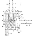
図4、図6に示すように、流出用部材6は、筒状部62と、流出通路60aが形成された流出管状部60と、蒸発燃料の通過を許容し異物の通過を阻止するフィルタ部7とを備えている。筒状部62と流出管状部60とフィルタ部7とは、流出用部材6において一体成形されている。この明細書において述べる一体成形とは、二次接着や機械的接合を用いないで部材の接合と同時に製品を一体に成形することである。フィルタ部7は、二次接着や機械的接合を用いないでフランジ部61との接合と同時に流出用部材6に一体に成形されている。   As shown in FIGS. 4 and 6, the outflow member 6 includes a tubular portion 62, an outflow tubular portion 60 in which an outflow passage 60 a is formed, and a filter portion that allows passage of evaporated fuel and prevents passage of foreign matter. 7. The tubular portion 62, the outflow tubular portion 60, and the filter portion 7 are integrally formed in the outflow member 6. The integral molding described in this specification means that a product is integrally molded simultaneously with the joining of members without using secondary bonding or mechanical joining. The filter portion 7 is formed integrally with the outflow member 6 at the same time as the joining with the flange portion 61 without using secondary bonding or mechanical joining.

フィルタ部7は、フランジ部61に一体成形されて筒状部62を取り囲むように形成された枠体と、枠体に一体成形されているメッシュ部73とを備えている。メッシュ部73は、蒸発燃料の通過を許容し、燃料中の異物の通過を阻止する部分である。メッシュ部73は、例えばナイロン樹脂によって形成することができる。フィルタ部7において、枠体とメッシュ部73とは、同一の材料によって一体成形してもよいし、異なる材料によって一体成形してもよい。枠体は、先端側環状部70と、先端側環状部70に対向するように設けられた基部側環状部71と、複数の連絡部72とが一体に成形された円筒状をなすかご形である。   The filter portion 7 includes a frame body that is integrally formed with the flange portion 61 so as to surround the cylindrical portion 62, and a mesh portion 73 that is integrally formed with the frame body. The mesh part 73 is a part that allows passage of evaporated fuel and prevents passage of foreign matter in the fuel. The mesh portion 73 can be formed of, for example, nylon resin. In the filter part 7, the frame and the mesh part 73 may be integrally formed of the same material or may be integrally formed of different materials. The frame body is a squirrel-cage cage formed by integrally forming a distal end side annular portion 70, a base side annular portion 71 provided so as to face the distal end side annular portion 70, and a plurality of connecting portions 72. It is.

先端側環状部70は、筒状部62の先端側に位置する弁座63を取り囲むようにフランジ部61に対して離間した位置に設けられている。基部側環状部71は、フランジ部61に一体に成形されている。複数の連絡部72は、周方向に間隔をあけて並んでいる。各連絡部72は、フィルタ部7の軸方向に離間している先端側環状部70と基部側環状部71とを橋渡しするように、先端側環状部70および基部側環状部71に一体成形されている。連絡部72は、先端側環状部70と基部側環状部71の間において延びる棒状の部分である。メッシュ部73は、基部側環状部71と先端側環状部70の間を埋めるように先端側環状部70および基部側環状部71に一体成形されている。メッシュ部73は、さらに周方向に隣り合う連絡部72と連絡部72の間を埋めるように、周方向に並ぶ両方の連絡部72に一体成形されている。   The distal end side annular portion 70 is provided at a position spaced from the flange portion 61 so as to surround the valve seat 63 located on the distal end side of the cylindrical portion 62. The base side annular portion 71 is formed integrally with the flange portion 61. The some connection part 72 is located in a line with the space | interval in the circumferential direction. Each connecting portion 72 is integrally formed with the tip-side annular portion 70 and the base-side annular portion 71 so as to bridge the tip-side annular portion 70 and the base-side annular portion 71 that are spaced apart in the axial direction of the filter portion 7. ing. The connecting portion 72 is a rod-like portion extending between the distal end side annular portion 70 and the base side annular portion 71. The mesh portion 73 is integrally formed with the distal end side annular portion 70 and the proximal side annular portion 71 so as to fill a space between the proximal side annular portion 71 and the distal end side annular portion 70. The mesh portion 73 is integrally formed with both the connecting portions 72 arranged in the circumferential direction so as to fill between the connecting portions 72 adjacent to each other in the circumferential direction.

図4、図5に示すように、流出用部材6が本体ハウジング40に連結された状態において、先端側環状部70における先端部70aは本体ハウジング40の底部側に設置された電磁コイル部42を覆う被覆部404に接触している。先端部70aは、先端側環状部70において、全周に設けられている構成でもよいし、周方向の所定範囲に部分的に設けられている構成でもよい。先端部70aは、先端側環状部70の外周縁部において軸方向に突出している。先端部70aは、先端側環状部70の外周縁部において、全周に設けられている構成でもよいし、周方向の所定範囲に部分的に設けられている構成でもよい。   As shown in FIGS. 4 and 5, in the state where the outflow member 6 is connected to the main body housing 40, the front end portion 70 a of the front end side annular portion 70 has the electromagnetic coil portion 42 installed on the bottom side of the main body housing 40. It is in contact with the covering portion 404 to be covered. The distal end portion 70a may be configured to be provided on the entire circumference of the distal end side annular portion 70 or may be configured to be partially provided in a predetermined range in the circumferential direction. The distal end portion 70 a protrudes in the axial direction at the outer peripheral edge portion of the distal end side annular portion 70. The distal end portion 70a may be provided on the entire circumference of the outer peripheral edge portion of the distal end side annular portion 70 or may be provided partially in a predetermined range in the circumferential direction.

被覆部404は、絶縁性を有する材料で形成されており、電磁コイル部42に対して蒸発燃料を遮断している。被覆部404には、弁体43と同軸状に溝部404aが設けられている。溝部404aは、先端側環状部70の先端部70aが嵌合可能な位置および形状となるように設けられている。   The covering portion 404 is made of an insulating material, and blocks the evaporated fuel from the electromagnetic coil portion 42. The cover 404 is provided with a groove 404 a coaxial with the valve body 43. The groove 404a is provided so as to have a position and a shape in which the distal end portion 70a of the distal end side annular portion 70 can be fitted.

被覆部404は、先端側環状部70の先端部70aよりも硬度が小さい材料で形成されていることが好ましい。これによれば、被覆部404と先端部70aとが接触したときに、被覆部404の方がより大きく変形しやすくなる。また、先端側環状部70の先端部70aは、被覆部404よりも硬度が小さい材料で形成されていることが好ましい。これによれば、被覆部404と先端部70aとが接触したときに、先端部70aの方がより大きく変形しやすくなる。先端部70aや被覆部404の硬度は、例えばビッカーズ硬さ試験方法を示したJIS Z 2244にしたがって測定することができる。   The covering portion 404 is preferably formed of a material having a lower hardness than the distal end portion 70 a of the distal end side annular portion 70. According to this, when the coating | coated part 404 and the front-end | tip part 70a contact, the direction of the coating | coated part 404 becomes easier to deform | transform larger. Moreover, it is preferable that the front-end | tip part 70a of the front end side cyclic | annular part 70 is formed with the material whose hardness is smaller than the coating | coated part 404. FIG. According to this, when the coating | coated part 404 and the front-end | tip part 70a contact, the direction of the front-end | tip part 70a becomes easier to deform | transform larger. The hardness of the tip portion 70a and the covering portion 404 can be measured, for example, according to JIS Z 2244 showing the Vickers hardness test method.

連絡部72は、筒状部62から離間するほど、換言すれば径外方向に向かうほど先細りする横断面を有している。この形状によれば、一体成形時に連絡部72から、メッシュ部73や先端側環状部70や基部側環状部71へ樹脂材料が流れやすいため、フィルタ部7の寸法品質、形状品質の向上に寄与する。   The connecting portion 72 has a cross section that tapers away from the cylindrical portion 62, in other words, as it goes in the radially outward direction. According to this shape, since the resin material easily flows from the connecting portion 72 to the mesh portion 73, the distal end side annular portion 70, and the base side annular portion 71 during integral molding, it contributes to improving the dimensional quality and shape quality of the filter portion 7. To do.

次に、第1実施形態のパージ制御弁4がもたらす作用効果について説明する。パージ制御弁4は、キャニスタ16から脱離された蒸発燃料がエンジン22に向けて流通する蒸発燃料通路に設置される制御弁である。パージ制御弁4は、キャニスタ16側から流入した蒸発燃料が流通するハウジング内通路401aを内部に有し、ハウジング内通路401aを開閉する弁体43を駆動する電磁コイル部42を内蔵する本体ハウジング40を備える。さらにパージ制御弁4は、本体ハウジング40に連結されている流出用部材6を備える。流出用部材6には、弁体43が着座する弁座63を有する筒状部62と、ハウジング内通路401aから流出した蒸発燃料が流通する流出通路60aが形成された流出部と、蒸発燃料の通過を許容し異物の通過を阻止するフィルタ部7とが一体成形されている。   Next, the effect which the purge control valve 4 of 1st Embodiment brings is demonstrated. The purge control valve 4 is a control valve installed in the evaporated fuel passage through which the evaporated fuel desorbed from the canister 16 flows toward the engine 22. The purge control valve 4 has an in-housing passage 401a through which evaporated fuel flowing from the canister 16 side flows, and a main body housing 40 having a built-in electromagnetic coil portion 42 that drives a valve body 43 that opens and closes the in-housing passage 401a. Is provided. Further, the purge control valve 4 includes an outflow member 6 connected to the main body housing 40. The outflow member 6 includes a cylindrical portion 62 having a valve seat 63 on which the valve body 43 is seated, an outflow portion in which an outflow passage 60a through which the evaporated fuel flowing out from the in-housing passage 401a circulates, A filter portion 7 that allows passage and prevents passage of foreign matters is integrally formed.

このパージ制御弁4によれば、少なくとも、流出通路60aと弁座63を有する筒状部62とフィルタ部7とが一体成形された流出用部材6を備え、流出用部材6と電磁コイル部42を内蔵する本体ハウジング40とが連結される構成を有する。この構成を有する流出用部材6を本体ハウジング40に結合することによって、フィルタ部7を備えるパージ制御弁4を製造できる。以上によれば、フィルタの組み付け工数が抑えられるパージ制御弁4を提供できる。   The purge control valve 4 includes the outflow member 6 in which at least the tubular portion 62 having the outflow passage 60a and the valve seat 63 and the filter portion 7 are integrally formed. The outflow member 6 and the electromagnetic coil portion 42 are provided. And a main body housing 40 having a built-in structure. The purge control valve 4 including the filter unit 7 can be manufactured by coupling the outflow member 6 having this configuration to the main body housing 40. Based on the above, it is possible to provide the purge control valve 4 in which the number of steps for assembling the filter can be suppressed.

このパージ制御弁4によれば、フィルタ部7は軸方向の片側部のみを本体ハウジング40に対して固定する構成であるので、フィルタ部7が固定される相手側部品とフィルタ部7とに関わる寸法精度を軸方向の両端部において要求する必要がない。したがって、前述の従来技術に対して製造コストを抑えることができ、生産性が高いパージ制御弁4を提供できる。また、流出部、弁座63およびフィルタ部7を一体成形した単一の部品である構成によれば、フィルタ部品と流出用部材とのそれぞれを部品として管理する必要がないため、部品管理工数を抑制可能なパージ制御弁4を提供できる。   According to the purge control valve 4, the filter unit 7 is configured to fix only one side portion in the axial direction to the main body housing 40, so that the filter unit 7 is related to the counterpart part to which the filter unit 7 is fixed and the filter unit 7. There is no need to require dimensional accuracy at both axial ends. Therefore, the manufacturing cost can be reduced as compared with the above-described conventional technology, and the purge control valve 4 with high productivity can be provided. Moreover, according to the structure which is the single component which integrally formed the outflow part, the valve seat 63, and the filter part 7, since it is not necessary to manage each of the filter part and the outflow member as a part, the part management man-hour is reduced. A purge control valve 4 that can be suppressed can be provided.

フィルタ部7は、流出用部材6において本体ハウジング40に結合されているフランジ部61に一体成形されて筒状部62を取り囲むように形成された枠体と、枠体に一体成形されているメッシュ部73とを備えている。この構成によれば、筒状部62を取り囲むようにメッシュ部73を有したフィルタ部7を流出用部材6に一体成形することができる。この構成を有する流出用部材6を本体ハウジング40に結合することによって、開弁状態において周囲から弁座63の内側に流入する蒸発燃料がメッシュ部73を通過するパージ制御弁4を製造できる。   The filter portion 7 is formed integrally with a flange portion 61 coupled to the main body housing 40 in the outflow member 6 so as to surround the cylindrical portion 62, and a mesh integrally formed with the frame body. Part 73. According to this configuration, the filter portion 7 having the mesh portion 73 so as to surround the cylindrical portion 62 can be integrally formed with the outflow member 6. By coupling the outflow member 6 having this configuration to the main body housing 40, the purge control valve 4 in which the evaporated fuel flowing from the surroundings into the valve seat 63 in the open state passes through the mesh portion 73 can be manufactured.

枠体は、筒状部62の先端側に位置する弁座63を取り囲むようにフランジ部61に対して離間して設けられた先端側環状部70を有する。先端側環状部70の先端部70aは、絶縁性を有して蒸発燃料を遮断するように電磁コイル部42を覆う被覆部404に接触している。この構成によれば、流出用部材6を本体ハウジング40に結合することによって、先端側環状部70の先端部70aが被覆部404に接触するので、本体ハウジング40に対してフィルタ部7を位置決めできフィルタ部7を安定した状態で設置できる。   The frame body has a tip-side annular portion 70 that is provided apart from the flange portion 61 so as to surround the valve seat 63 positioned on the tip side of the cylindrical portion 62. The distal end portion 70a of the distal end side annular portion 70 is in contact with a covering portion 404 that covers the electromagnetic coil portion 42 so as to have an insulating property and block evaporated fuel. According to this configuration, by connecting the outflow member 6 to the main body housing 40, the distal end portion 70 a of the distal end side annular portion 70 comes into contact with the covering portion 404, so that the filter portion 7 can be positioned with respect to the main body housing 40. The filter unit 7 can be installed in a stable state.

被覆部404には、弁体43と同軸状に溝部404aが設けられている。先端側環状部70の先端部70aは溝部404aに嵌合している。この構成によれば、流出用部材6を本体ハウジング40に結合することによって、先端側環状部70の先端部70aが溝部404aに嵌合するので、本体ハウジング40に対してフィルタ部7を位置決めできフィルタ部7を安定した状態で設置できる。さらにこの構成によれば、弁体43に対する弁座63の調心を図る機能を有するパージ制御弁4を提供できる。   The cover 404 is provided with a groove 404 a coaxial with the valve body 43. The distal end portion 70a of the distal end side annular portion 70 is fitted in the groove portion 404a. According to this configuration, by connecting the outflow member 6 to the main body housing 40, the front end portion 70 a of the front end side annular portion 70 is fitted into the groove portion 404 a, so that the filter portion 7 can be positioned with respect to the main body housing 40. The filter unit 7 can be installed in a stable state. Furthermore, according to this configuration, the purge control valve 4 having a function of aligning the valve seat 63 with respect to the valve body 43 can be provided.

被覆部404は、先端側環状部70の先端部70aよりも硬度が小さい材料で形成されている。この構成によれば、先端部70aが被覆部404の表面や溝部404aに食い込むように接地するので、先端側環状部70と被覆部404との密着性能を高めたパージ制御弁4を提供できる。   The covering portion 404 is formed of a material having a lower hardness than the distal end portion 70 a of the distal end side annular portion 70. According to this configuration, since the tip portion 70a is grounded so as to bite into the surface of the covering portion 404 and the groove portion 404a, the purge control valve 4 with improved adhesion performance between the tip-side annular portion 70 and the covering portion 404 can be provided.

先端側環状部70の先端部70aは、被覆部404よりも硬度が小さい材料で形成されている。この構成によれば、先端部70aが被覆部404の表面や溝部404aに対して押しつぶされるように変形して接地するので、先端側環状部70と被覆部404との密着性能を高めたパージ制御弁4を提供できる。   The distal end portion 70 a of the distal end side annular portion 70 is formed of a material having a hardness lower than that of the covering portion 404. According to this configuration, the distal end portion 70a is deformed so as to be crushed against the surface of the covering portion 404 and the groove portion 404a and is grounded, so that the purge control that improves the close contact performance between the distal end side annular portion 70 and the covering portion 404. A valve 4 can be provided.

枠体は、先端側環状部70と、フランジ部61に一体に成形された基部側環状部71と、周方向に間隔をあけて並び先端側環状部70と基部側環状部71とを橋渡しするように一体成形されている複数の連絡部72とを有する。メッシュ部73は、基部側環状部71と先端側環状部70の間において、周方向に隣り合う連絡部72と連絡部72の間を埋めるように、連絡部72、先端側環状部70および基部側環状部71に一体成形されている。   The frame body bridges the distal end side annular portion 70 and the base side annular portion 71 with a distal end side annular portion 70, a base portion side annular portion 71 integrally formed with the flange portion 61, and a circumferential interval. And a plurality of connecting portions 72 integrally formed. The mesh portion 73 is connected between the base portion side annular portion 71 and the tip end side annular portion 70 so as to fill a space between the contact portion 72 and the contact portion 72 adjacent in the circumferential direction. The side annular portion 71 is integrally formed.

この構成によれば、フィルタ部7は先端側環状部70と基部側環状部71の間に複数の連絡部72とメッシュ部73とが一体成形されている。このため、フィルタ部7に対して軸方向に圧縮力がかかった場合にフィルタ部7を先端側環状部70と基部側環状部71の間で変形させることができる。したがって、製造時にフィルタ部7に対して軸方向に圧縮力がかかった場合でも、先端側環状部70を被覆部404との接触状態を確保しつつ流出用部材6を本体ハウジング40に適正に連結可能なパージ制御弁4を提供できる。   According to this configuration, in the filter unit 7, the plurality of connecting portions 72 and the mesh portion 73 are integrally formed between the distal end side annular portion 70 and the base portion side annular portion 71. For this reason, when a compressive force is applied to the filter portion 7 in the axial direction, the filter portion 7 can be deformed between the distal end side annular portion 70 and the base side annular portion 71. Therefore, even when a compressive force is applied to the filter portion 7 in the axial direction at the time of manufacture, the outflow member 6 is properly connected to the main body housing 40 while ensuring the contact state between the distal end side annular portion 70 and the covering portion 404. A possible purge control valve 4 can be provided.

(他の実施形態)
この明細書の開示は、例示された実施形態に制限されない。開示は、例示された実施形態と、それらに基づく当業者による変形態様を包含する。例えば、開示は、実施形態において示された部品、要素の組み合わせに限定されず、種々変形して実施することが可能である。開示は、多様な組み合わせによって実施可能である。開示は、実施形態に追加可能な追加的な部分をもつことができる。開示は、実施形態の部品、要素が省略されたものを包含する。開示は、一つの実施形態と他の実施形態との間における部品、要素の置き換え、または組み合わせを包含する。開示される技術的範囲は、実施形態の記載に限定されない。開示される技術的範囲は、特許請求の範囲の記載によって示され、さらに特許請求の範囲の記載と均等の意味および範囲内での全ての変更を含むものと解されるべきである。
(Other embodiments)
The disclosure of this specification is not limited to the illustrated embodiments. The disclosure encompasses the illustrated embodiments and variations by those skilled in the art based thereon. For example, the disclosure is not limited to the combination of components and elements shown in the embodiments, and various modifications can be made. The disclosure can be implemented in various combinations. The disclosure may have additional parts that can be added to the embodiments. The disclosure includes those in which the components and elements of the embodiment are omitted. The disclosure encompasses parts, element replacements, or combinations between one embodiment and another. The technical scope disclosed is not limited to the description of the embodiments. The technical scope disclosed is indicated by the description of the claims, and should be understood to include all modifications within the meaning and scope equivalent to the description of the claims.

明細書に開示の目的を達成可能なパージ制御弁は、前述の実施形態において開示した蒸発燃料処理システムに限定して適用される流量調整装置ではない。このパージ制御弁は、例えば、パージ制御弁を通過した蒸発燃料を過給機よりも上流の通路に導入することができ、過給時パージを行えるシステムに適用することもできる。   The purge control valve that can achieve the object disclosed in the specification is not a flow rate adjusting device that is applied only to the evaporated fuel processing system disclosed in the above-described embodiment. For example, the purge control valve can be applied to a system in which the evaporated fuel that has passed through the purge control valve can be introduced into a passage upstream of the supercharger, and purge at the time of supercharging can be performed.

明細書に開示の目的を達成可能なパージ制御弁は、別部品である本体ハウジング40と流入用部材5とが一体に結合された構成の装置だけでなく、本体ハウジング40と流入用部材5とが一つの部品によって構成されている装置も含むものである。   The purge control valve that can achieve the object disclosed in the specification is not only a device in which the main body housing 40 and the inflow member 5 which are separate parts are integrally coupled, but also the main body housing 40 and the inflow member 5. Includes a device composed of a single component.

明細書に開示の目的を達成可能なパージ制御弁は、前述の実施形態において示した構成を有する流出用部材6に限定されるものではない。例えば、流出用部材6は、流入管状部50を備える構成であってもよい。   The purge control valve that can achieve the object disclosed in the specification is not limited to the outflow member 6 having the configuration shown in the above-described embodiment. For example, the outflow member 6 may be configured to include the inflow tubular portion 50.

4…パージ制御弁、 6…流出用部材、7…フィルタ部、 16…キャニスタ
22…エンジン、 40…本体ハウジング、 42…電磁コイル部
43…弁体、 60…流出管状部(流出部)、 60a…流出通路、 61…フランジ部
62…筒状部、 63…弁座、 70…先端側環状部(枠体)、 70a…先端部
71…基部側環状部(枠体)、 72…連絡部(枠体)、 73…メッシュ部
401a…ハウジング内通路、 404…被覆部、 404a…溝部
DESCRIPTION OF SYMBOLS 4 ... Purge control valve, 6 ... Outflow member, 7 ... Filter part, 16 ... Canister 22 ... Engine, 40 ... Main body housing, 42 ... Electromagnetic coil part 43 ... Valve body, 60 ... Outflow tubular part (outflow part), 60a ... Outflow passageway 61 ... Flange part 62 ... Cylindrical part 63 ... Valve seat 70 ... Tip side annular part (frame body), 70a ... Tip part 71 ... Base side annular part (frame body), 72 ... Connecting part ( Frame body), 73 ... mesh part 401a ... passage in housing, 404 ... covering part, 404a ... groove part

Claims (7)

キャニスタ(16)から脱離された蒸発燃料がエンジン(22)に向けて流通する蒸発燃料通路に設置されるパージ制御弁(4)であって、
前記キャニスタ側から流入した蒸発燃料が流通するハウジング内通路(401a)を内部に有し、前記ハウジング内通路を開閉する弁体(43)を駆動する電磁コイル部(42)を内蔵する本体ハウジング(40)と、
前記本体ハウジングに連結されている流出用部材(6)と、
を備え、
前記流出用部材には、前記弁体が着座する弁座(63)を有する筒状部(62)と、前記ハウジング内通路から流出した蒸発燃料が流通する流出通路(60a)が形成された流出部(60)と、蒸発燃料の通過を許容し異物の通過を阻止するフィルタ部(7)とが一体成形されているパージ制御弁。
A purge control valve (4) installed in an evaporated fuel passage through which evaporated fuel desorbed from the canister (16) flows toward the engine (22);
A main body housing (inside housing housing passage (401a) through which evaporated fuel flowing in from the canister side circulates and incorporating an electromagnetic coil portion (42) for driving a valve body (43) that opens and closes the inside housing passage ( 40)
An outflow member (6) connected to the body housing;
With
The outflow member is formed with a tubular portion (62) having a valve seat (63) on which the valve body is seated, and an outflow passage (60a) through which evaporated fuel flowing out from the passage in the housing flows. A purge control valve in which a part (60) and a filter part (7) which allows passage of evaporated fuel and prevents passage of foreign substances are integrally formed.
前記フィルタ部は、前記流出用部材において前記本体ハウジングに結合されているフランジ部(61)に一体成形されて前記筒状部を取り囲むように形成された枠体(70,71,72)と、前記枠体に一体成形されているメッシュ部(73)とを備えている請求項1に記載のパージ制御弁。   The filter portion is formed integrally with a flange portion (61) coupled to the main body housing in the outflow member, and is formed so as to surround the cylindrical portion (70, 71, 72), The purge control valve according to claim 1, further comprising a mesh portion (73) integrally formed with the frame body. 前記枠体は、前記筒状部の先端側に位置する前記弁座を取り囲むように前記フランジ部に対して離間して設けられた先端側環状部(70)を有し、
前記先端側環状部における先端部(70a)は、絶縁性を有して蒸発燃料を遮断するように前記電磁コイル部を覆う被覆部(404)に接触している請求項2に記載のパージ制御弁。
The frame body has a distal end side annular portion (70) provided so as to be separated from the flange portion so as to surround the valve seat located on the distal end side of the cylindrical portion,
The purge control according to claim 2, wherein the tip end portion (70a) of the tip end side annular portion is in contact with a covering portion (404) that covers the electromagnetic coil portion so as to have an insulating property and block evaporated fuel. valve.
前記被覆部には、前記弁体と同軸状に溝部(404a)が設けられており、前記先端側環状部の前記先端部は前記溝部に嵌合している請求項3に記載のパージ制御弁。   The purge control valve according to claim 3, wherein the covering portion is provided with a groove portion (404a) coaxially with the valve body, and the tip portion of the tip-side annular portion is fitted in the groove portion. . 前記被覆部は、前記先端側環状部の前記先端部よりも硬度が小さい材料で形成されている請求項3または請求項4に記載のパージ制御弁。   The purge control valve according to claim 3 or 4, wherein the covering portion is formed of a material having a hardness smaller than that of the tip portion of the tip side annular portion. 前記先端側環状部の前記先端部は、前記被覆部よりも硬度が小さい材料で形成されている請求項3または請求項4に記載のパージ制御弁。   The purge control valve according to claim 3 or 4, wherein the tip portion of the tip-side annular portion is formed of a material having a hardness lower than that of the covering portion. 前記枠体は、前記フランジ部に一体に成形された基部側環状部(71)と、周方向に間隔をあけて並び前記先端側環状部と前記基部側環状部とを橋渡しするように一体成形されている複数の連絡部(72)とを有し、
前記メッシュ部は、前記基部側環状部と前記先端側環状部の間において、周方向に隣り合う前記連絡部と前記連絡部の間を埋めるように、前記連絡部、前記先端側環状部および前記基部側環状部に一体成形されている請求項3から請求項6のいずれか一項に記載のパージ制御弁。
The frame body is integrally formed so as to bridge the base-side annular portion (71) integrally formed with the flange portion, and the distal-end-side annular portion and the base-side annular portion arranged at intervals in the circumferential direction. A plurality of communication parts (72) that are connected,
The mesh portion is arranged between the base portion side annular portion and the tip end side annular portion so as to fill a space between the connecting portion and the connecting portion adjacent in the circumferential direction. The purge control valve according to any one of claims 3 to 6, wherein the purge control valve is integrally formed with the base-side annular portion.
JP2018097176A 2018-05-21 2018-05-21 Purge control valve Pending JP2019203396A (en)

Priority Applications (1)

Application Number Priority Date Filing Date Title
JP2018097176A JP2019203396A (en) 2018-05-21 2018-05-21 Purge control valve

Applications Claiming Priority (1)

Application Number Priority Date Filing Date Title
JP2018097176A JP2019203396A (en) 2018-05-21 2018-05-21 Purge control valve

Publications (1)

Publication Number Publication Date
JP2019203396A true JP2019203396A (en) 2019-11-28

Family

ID=68726425

Family Applications (1)

Application Number Title Priority Date Filing Date
JP2018097176A Pending JP2019203396A (en) 2018-05-21 2018-05-21 Purge control valve

Country Status (1)

Country Link
JP (1) JP2019203396A (en)

Cited By (1)

* Cited by examiner, † Cited by third party
Publication number Priority date Publication date Assignee Title
JP2021169790A (en) * 2020-04-15 2021-10-28 浜名湖電装株式会社 Purge valve

Citations (6)

* Cited by examiner, † Cited by third party
Publication number Priority date Publication date Assignee Title
JPS5025125U (en) * 1973-06-29 1975-03-22
JP2002013659A (en) * 2000-06-29 2002-01-18 Denso Corp Solenoid valve
JP2006305519A (en) * 2005-05-02 2006-11-09 Denso Corp Filter apparatus
JP2011226513A (en) * 2010-04-16 2011-11-10 Mitsubishi Electric Corp Solenoid valve device
JP2013221537A (en) * 2012-04-13 2013-10-28 Denso Corp Fluid control valve device
JP2014111915A (en) * 2012-12-05 2014-06-19 Hamanako Denso Co Ltd Evaporation fuel purge device

Patent Citations (6)

* Cited by examiner, † Cited by third party
Publication number Priority date Publication date Assignee Title
JPS5025125U (en) * 1973-06-29 1975-03-22
JP2002013659A (en) * 2000-06-29 2002-01-18 Denso Corp Solenoid valve
JP2006305519A (en) * 2005-05-02 2006-11-09 Denso Corp Filter apparatus
JP2011226513A (en) * 2010-04-16 2011-11-10 Mitsubishi Electric Corp Solenoid valve device
JP2013221537A (en) * 2012-04-13 2013-10-28 Denso Corp Fluid control valve device
JP2014111915A (en) * 2012-12-05 2014-06-19 Hamanako Denso Co Ltd Evaporation fuel purge device

Cited By (2)

* Cited by examiner, † Cited by third party
Publication number Priority date Publication date Assignee Title
JP2021169790A (en) * 2020-04-15 2021-10-28 浜名湖電装株式会社 Purge valve
JP7368733B2 (en) 2020-04-15 2023-10-25 浜名湖電装株式会社 Manufacturing method of purge valve

Similar Documents

Publication Publication Date Title
US7591281B2 (en) Electromagnetic valve
JP5585569B2 (en) solenoid valve
US5967124A (en) Vapor leak detection system having a shared electromagnet coil for operating both pump and vent valve
JP6028771B2 (en) Two-stage switching valve
US10544757B2 (en) Check valve device and vapor fuel supply system
JP6028764B2 (en) solenoid valve
JP2006226457A (en) Solenoid valve
JP2001295720A (en) Solenoid valve and fuel supply device using it
US5974861A (en) Vapor leak detection module having a shared electromagnet coil for operating both pump and vent valve
JP2019203396A (en) Purge control valve
JP6225480B2 (en) Evaporative fuel purge device
JPH10266923A (en) Solenoid valve
JP7192728B2 (en) Purge control valve device
KR20190073936A (en) Purge control solenoid valve
US11415094B2 (en) Fuel pressure regulator
JP7006553B2 (en) Purge control valve
JP2019190397A (en) Purge control valve
US11060485B2 (en) Control valve assembly
US11028790B2 (en) Purge control valve device
JP7205431B2 (en) Flow regulator
JP7192727B2 (en) Purge control valve device
JP4114301B2 (en) Solenoid valve and fuel supply device using the same
JP7151523B2 (en) control valve assembly
CN112539291A (en) Purge control valve apparatus
JP6662270B2 (en) solenoid valve

Legal Events

Date Code Title Description
A621 Written request for application examination

Free format text: JAPANESE INTERMEDIATE CODE: A621

Effective date: 20201026

A131 Notification of reasons for refusal

Free format text: JAPANESE INTERMEDIATE CODE: A131

Effective date: 20210824

A02 Decision of refusal

Free format text: JAPANESE INTERMEDIATE CODE: A02

Effective date: 20220301