JP2019200986A - Cell and cell system - Google Patents
Cell and cell system Download PDFInfo
- Publication number
- JP2019200986A JP2019200986A JP2019061986A JP2019061986A JP2019200986A JP 2019200986 A JP2019200986 A JP 2019200986A JP 2019061986 A JP2019061986 A JP 2019061986A JP 2019061986 A JP2019061986 A JP 2019061986A JP 2019200986 A JP2019200986 A JP 2019200986A
- Authority
- JP
- Japan
- Prior art keywords
- terminal
- charge
- discharge
- monitor
- monitor terminal
- Prior art date
- Legal status (The legal status is an assumption and is not a legal conclusion. Google has not performed a legal analysis and makes no representation as to the accuracy of the status listed.)
- Granted
Links
- 238000007599 discharging Methods 0.000 claims description 20
- 230000008602 contraction Effects 0.000 claims description 4
- 238000010248 power generation Methods 0.000 description 52
- 238000001514 detection method Methods 0.000 description 14
- 229910052751 metal Inorganic materials 0.000 description 7
- 239000002184 metal Substances 0.000 description 7
- 238000012544 monitoring process Methods 0.000 description 6
- 239000011255 nonaqueous electrolyte Substances 0.000 description 5
- HBBGRARXTFLTSG-UHFFFAOYSA-N Lithium ion Chemical compound [Li+] HBBGRARXTFLTSG-UHFFFAOYSA-N 0.000 description 4
- 229910001416 lithium ion Inorganic materials 0.000 description 4
- 239000004020 conductor Substances 0.000 description 3
- 239000000470 constituent Substances 0.000 description 3
- 238000010586 diagram Methods 0.000 description 3
- WABPQHHGFIMREM-UHFFFAOYSA-N lead(0) Chemical compound [Pb] WABPQHHGFIMREM-UHFFFAOYSA-N 0.000 description 3
- 238000000034 method Methods 0.000 description 3
- 238000009434 installation Methods 0.000 description 2
- 239000000463 material Substances 0.000 description 2
- 239000007769 metal material Substances 0.000 description 2
- 230000004048 modification Effects 0.000 description 2
- 238000012986 modification Methods 0.000 description 2
- 239000011347 resin Substances 0.000 description 2
- 229920005989 resin Polymers 0.000 description 2
- 239000007787 solid Substances 0.000 description 2
- RYGMFSIKBFXOCR-UHFFFAOYSA-N Copper Chemical compound [Cu] RYGMFSIKBFXOCR-UHFFFAOYSA-N 0.000 description 1
- WHXSMMKQMYFTQS-UHFFFAOYSA-N Lithium Chemical compound [Li] WHXSMMKQMYFTQS-UHFFFAOYSA-N 0.000 description 1
- 239000011149 active material Substances 0.000 description 1
- 229910052782 aluminium Inorganic materials 0.000 description 1
- XAGFODPZIPBFFR-UHFFFAOYSA-N aluminium Chemical compound [Al] XAGFODPZIPBFFR-UHFFFAOYSA-N 0.000 description 1
- 238000005219 brazing Methods 0.000 description 1
- 229910052802 copper Inorganic materials 0.000 description 1
- 239000010949 copper Substances 0.000 description 1
- 230000003247 decreasing effect Effects 0.000 description 1
- 238000005516 engineering process Methods 0.000 description 1
- 239000000284 extract Substances 0.000 description 1
- 238000009413 insulation Methods 0.000 description 1
- 238000005304 joining Methods 0.000 description 1
- 238000010030 laminating Methods 0.000 description 1
- 229910052744 lithium Inorganic materials 0.000 description 1
- 239000007773 negative electrode material Substances 0.000 description 1
- 239000007774 positive electrode material Substances 0.000 description 1
- 238000003825 pressing Methods 0.000 description 1
- 239000007784 solid electrolyte Substances 0.000 description 1
- 238000003466 welding Methods 0.000 description 1
Images


Classifications
-
- H—ELECTRICITY
- H01—ELECTRIC ELEMENTS
- H01M—PROCESSES OR MEANS, e.g. BATTERIES, FOR THE DIRECT CONVERSION OF CHEMICAL ENERGY INTO ELECTRICAL ENERGY
- H01M10/00—Secondary cells; Manufacture thereof
- H01M10/05—Accumulators with non-aqueous electrolyte
- H01M10/058—Construction or manufacture
-
- H—ELECTRICITY
- H01—ELECTRIC ELEMENTS
- H01M—PROCESSES OR MEANS, e.g. BATTERIES, FOR THE DIRECT CONVERSION OF CHEMICAL ENERGY INTO ELECTRICAL ENERGY
- H01M10/00—Secondary cells; Manufacture thereof
- H01M10/05—Accumulators with non-aqueous electrolyte
- H01M10/052—Li-accumulators
- H01M10/0525—Rocking-chair batteries, i.e. batteries with lithium insertion or intercalation in both electrodes; Lithium-ion batteries
-
- H—ELECTRICITY
- H01—ELECTRIC ELEMENTS
- H01M—PROCESSES OR MEANS, e.g. BATTERIES, FOR THE DIRECT CONVERSION OF CHEMICAL ENERGY INTO ELECTRICAL ENERGY
- H01M10/00—Secondary cells; Manufacture thereof
- H01M10/42—Methods or arrangements for servicing or maintenance of secondary cells or secondary half-cells
- H01M10/48—Accumulators combined with arrangements for measuring, testing or indicating the condition of cells, e.g. the level or density of the electrolyte
- H01M10/482—Accumulators combined with arrangements for measuring, testing or indicating the condition of cells, e.g. the level or density of the electrolyte for several batteries or cells simultaneously or sequentially
-
- H—ELECTRICITY
- H01—ELECTRIC ELEMENTS
- H01M—PROCESSES OR MEANS, e.g. BATTERIES, FOR THE DIRECT CONVERSION OF CHEMICAL ENERGY INTO ELECTRICAL ENERGY
- H01M50/00—Constructional details or processes of manufacture of the non-active parts of electrochemical cells other than fuel cells, e.g. hybrid cells
- H01M50/50—Current conducting connections for cells or batteries
- H01M50/543—Terminals
- H01M50/547—Terminals characterised by the disposition of the terminals on the cells
- H01M50/55—Terminals characterised by the disposition of the terminals on the cells on the same side of the cell
-
- H—ELECTRICITY
- H01—ELECTRIC ELEMENTS
- H01M—PROCESSES OR MEANS, e.g. BATTERIES, FOR THE DIRECT CONVERSION OF CHEMICAL ENERGY INTO ELECTRICAL ENERGY
- H01M50/00—Constructional details or processes of manufacture of the non-active parts of electrochemical cells other than fuel cells, e.g. hybrid cells
- H01M50/20—Mountings; Secondary casings or frames; Racks, modules or packs; Suspension devices; Shock absorbers; Transport or carrying devices; Holders
- H01M50/204—Racks, modules or packs for multiple batteries or multiple cells
- H01M50/207—Racks, modules or packs for multiple batteries or multiple cells characterised by their shape
- H01M50/209—Racks, modules or packs for multiple batteries or multiple cells characterised by their shape adapted for prismatic or rectangular cells
-
- H—ELECTRICITY
- H01—ELECTRIC ELEMENTS
- H01M—PROCESSES OR MEANS, e.g. BATTERIES, FOR THE DIRECT CONVERSION OF CHEMICAL ENERGY INTO ELECTRICAL ENERGY
- H01M50/00—Constructional details or processes of manufacture of the non-active parts of electrochemical cells other than fuel cells, e.g. hybrid cells
- H01M50/50—Current conducting connections for cells or batteries
- H01M50/543—Terminals
- H01M50/552—Terminals characterised by their shape
- H01M50/553—Terminals adapted for prismatic, pouch or rectangular cells
-
- Y—GENERAL TAGGING OF NEW TECHNOLOGICAL DEVELOPMENTS; GENERAL TAGGING OF CROSS-SECTIONAL TECHNOLOGIES SPANNING OVER SEVERAL SECTIONS OF THE IPC; TECHNICAL SUBJECTS COVERED BY FORMER USPC CROSS-REFERENCE ART COLLECTIONS [XRACs] AND DIGESTS
- Y02—TECHNOLOGIES OR APPLICATIONS FOR MITIGATION OR ADAPTATION AGAINST CLIMATE CHANGE
- Y02E—REDUCTION OF GREENHOUSE GAS [GHG] EMISSIONS, RELATED TO ENERGY GENERATION, TRANSMISSION OR DISTRIBUTION
- Y02E60/00—Enabling technologies; Technologies with a potential or indirect contribution to GHG emissions mitigation
- Y02E60/10—Energy storage using batteries
Abstract
Description
本開示は、電池および電池システムに関する。 The present disclosure relates to batteries and battery systems.
電池として、リチウムイオン二次電池等の非水電解質二次電池が知られている。非水電解質二次電池は、集電体上に活物質層が配置された2つの電極を、セパレータを介して積層することで構成された発電要素を含んでいる。 As the battery, a non-aqueous electrolyte secondary battery such as a lithium ion secondary battery is known. The nonaqueous electrolyte secondary battery includes a power generation element configured by laminating two electrodes, each having an active material layer disposed on a current collector, with a separator interposed therebetween.
リチウムイオン二次電池等の非水電解質二次電池は、二次電池の中でも高エネルギー密度で、かつ、高電圧での動作が可能という特徴を有している。そのため、リチウムイオン二次電池等の非水電解質二次電池は、小型軽量化を図りやすい二次電池として携帯電話等の情報機器に使用されており、近年、ハイブリッド自動車用、電気自動車用、または定置用等の、大型の動力用途としての需要も高まっている。 Nonaqueous electrolyte secondary batteries such as lithium ion secondary batteries are characterized by being capable of operating at a high energy density and high voltage among secondary batteries. Therefore, non-aqueous electrolyte secondary batteries such as lithium ion secondary batteries are used in information devices such as mobile phones as secondary batteries that are easy to reduce in size and weight, and in recent years, for hybrid vehicles, electric vehicles, or There is also an increasing demand for large power applications such as stationary applications.
これら大型の動力用途などでは一つの筐体の中に複数の発電要素が収納されていることが多い。また、複数の発電要素で構成される電池システムでは、長寿命、高安全性を確保するために、一つ一つの発電要素の電圧、温度または内圧等を監視し、制御することがなされている。 In such large power applications, a plurality of power generation elements are often housed in a single casing. Further, in a battery system composed of a plurality of power generation elements, in order to ensure a long life and high safety, the voltage, temperature, internal pressure, etc. of each power generation element are monitored and controlled. .
従来、筐体に収納された発電要素の電圧等を監視することができる電池として、発電要素を充放電させるための充放電端子と、発電要素の電圧、温度または内圧等を監視するためのモニター端子とを有する電池が知られている。 Conventionally, as a battery that can monitor the voltage and the like of a power generation element housed in a casing, a charge and discharge terminal for charging and discharging the power generation element, and a monitor for monitoring the voltage, temperature, internal pressure, etc. Batteries having terminals are known.
例えば、特許文献1に開示されたバイポーラ二次電池では、バイポーラ電極と固体電解質とを交互に積層して発電要素を形成している。発電要素の積層方向の両端に位置するバイポーラ電極には発電要素を充放電させるための正極タブおよび負極タブを接続し、発電要素の積層方向の両端以外のバイポーラ電極には発電要素の電圧を検知するための電圧検知用タブを接続している。電圧検知用タブを正極タブおよび負極タブとは異なる方向から引き出して、正極タブ、負極タブおよび電圧検知用タブを外部端子に固定して取り付けている。
For example, in the bipolar secondary battery disclosed in
また、特開2008−146943号公報に開示された組電池では、複数の薄型電池を薄型電池の厚み方向に積層し、積層方向に相隣接する電極タブ同士を接続して、複数の薄型電池を電気的に直列および/または並列に接続している。積層方向に重なり合って相隣接する複数の電極タブの少なくとも1つの電極タブに、電圧検出用コネクタを差し込んで嵌合するための凸状または凹状の嵌合部を成形している。 In the assembled battery disclosed in Japanese Patent Application Laid-Open No. 2008-146943, a plurality of thin batteries are stacked in the thickness direction of the thin batteries, and electrode tabs adjacent to each other in the stacking direction are connected to each other. Electrically connected in series and / or in parallel. A convex or concave fitting portion for inserting and fitting a voltage detection connector is formed on at least one electrode tab of a plurality of electrode tabs that are adjacent to each other in the stacking direction.
しかしながら、従来の電池では、充放電端子とモニター端子とが短絡するリスクがある。 However, in the conventional battery, there is a risk that the charge / discharge terminal and the monitor terminal are short-circuited.
本開示は、充放電端子とモニター端子とが短絡するリスクを低減できる電池および電池システムを提供することを目的とする。 An object of this indication is to provide the battery and battery system which can reduce the risk that a charging / discharging terminal and a monitor terminal short-circuit.
本開示の一態様に係る電池は、少なくとも1つの単電池と、前記少なくとも1つの単電池を収納する筐体と、前記少なくとも1つの単電池と電気的に接続された少なくとも1つの第1充放電端子と、前記少なくとも1つの単電池と電気的に接続された少なくとも1つの第1モニター端子と、を備える。前記少なくとも1つの第1充放電端子は、前記筐体の表面から部分的に突出する凸形状を有し、前記少なくとも1つの第1モニター端子は、前記筐体の前記表面から部分的に窪む凹形状を有する。 A battery according to an aspect of the present disclosure includes at least one unit cell, a housing that houses the at least one unit cell, and at least one first charge / discharge electrically connected to the at least one unit cell. A terminal and at least one first monitor terminal electrically connected to the at least one unit cell. The at least one first charge / discharge terminal has a convex shape partially protruding from the surface of the casing, and the at least one first monitor terminal is partially recessed from the surface of the casing. It has a concave shape.
また、本開示の一態様に係る電池システムは、上記の電池、前記第1充放電端子と電気的に接続される第2充放電端子、及び前記第1モニター端子と電気的に接続される第2モニター端子、を備える。前記第1充放電端子と前記第2充放電端子とが接続される形態である第1接続形態は、前記第1モニター端子と前記第2モニター端子とが接続される形態である第2接続形態と異なる。 In addition, a battery system according to an aspect of the present disclosure includes the battery, a second charge / discharge terminal electrically connected to the first charge / discharge terminal, and a first electrically connected to the first monitor terminal. 2 monitor terminals. The first connection form in which the first charge / discharge terminal and the second charge / discharge terminal are connected is the second connection form in which the first monitor terminal and the second monitor terminal are connected. And different.
本開示によれば、充放電端子とモニター端子とが短絡するリスクを低減でき、多くの端子を簡便に設けることができる。 According to the present disclosure, the risk of a short circuit between the charge / discharge terminal and the monitor terminal can be reduced, and many terminals can be easily provided.
(本開示の一態様を得るに至った経緯)
本開示の実施の形態の説明に先立ち、本開示の一態様を得るに至った経緯について説明する。
(Background to obtaining one embodiment of the present disclosure)
Prior to the description of the embodiments of the present disclosure, the background of obtaining one aspect of the present disclosure will be described.
特許文献1に開示されたバイポーラ二次電池では、充放電端子となる正極タブおよび負極タブと、モニター端子となる電圧検知用タブとが露出しているために、正極タブおよび負極タブと電圧検知用タブとが短絡するおそれがある。さらに、特許文献1に開示されたバイポーラ二次電池では、正極タブおよび負極タブと電圧検知用タブとがバイポーラ二次電池の異なる側面から取り出されているために、バイポーラ二次電池を機器に搭載する際に設置効率が悪くなる。しかも、特許文献1に開示されたバイポーラ二次電池は、セル間電圧をモニターするものであって、発電要素を収納する筐体である電池容器には何ら工夫がなされていない。
In the bipolar secondary battery disclosed in
また、特許文献2に開示された組電池では、充放電端子となる一対の電極タブと、複数の薄型電池の個別の電圧をモニターするためのモニター端子となる電圧検出用端子部とが近接して設けられているので、特許文献1に開示されたバイポーラ二次電池と比べて機器搭載時の設置効率は悪くならない。しかしながら、特許文献2に開示された組電池は、電圧検出用端子部が電池の集電体を利用して形成されているため、強度上の課題がある。このため、電圧検出用端子部に電圧検出コネクタを差し込む時に電圧検出用端子部が変形し、一対の電極タブと電圧検出用端子部とが短絡するおそれがある。
Moreover, in the assembled battery disclosed in
本発明者は、発電要素を収納する筐体を工夫することによって、充放電端子とモニター端子とが短絡するリスクを低減でき、多くの端子を簡便に設けることができる電池等を実現できることを見出した。特に、本発明者は、充放電端子およびモニター端子を筐体の同一の面に形成した場合であっても、充放電端子とモニター端子とが短絡するリスクを低減できる電池を実現できることを見出した。 The present inventor has found that by devising a housing for housing the power generation element, the risk of short-circuiting between the charge / discharge terminal and the monitor terminal can be reduced, and a battery or the like in which many terminals can be easily provided can be realized. It was. In particular, the inventor has found that even when the charge / discharge terminal and the monitor terminal are formed on the same surface of the housing, a battery capable of reducing the risk of short-circuiting between the charge / discharge terminal and the monitor terminal can be realized. .
本開示は、以下の項目を含む。 The present disclosure includes the following items.
[項目1]
本開示の項目1に係る電池は、少なくとも1つの単電池と、前記少なくとも1つの単電池を収納する筐体と、前記少なくとも1つの単電池と電気的に接続された少なくとも1つの第1充放電端子と、前記少なくとも1つの単電池と電気的に接続された少なくとも1つの第1モニター端子と、を備える。前記少なくとも1つの第1充放電端子は、前記筐体の表面から部分的に突出する凸形状を有し、前記少なくとも1つの第1モニター端子は、前記筐体の前記表面から部分的に窪む凹形状を有する。
[Item 1]
The battery according to
[項目2]
本開示の項目1に記載の電池において、前記少なくとも1つの第1充放電端子と前記少なくとも1つの第1モニター端子とは、前記筐体の同一の面に設けられていてもよい。
[Item 2]
In the battery according to
[項目3]
本開示の項目2に記載の電池において、前記少なくとも1つの第1充放電端子は、2つの第1充放電端子を備え、前記少なくとも1つの第1モニター端子は、複数の第1モニター端子を備え、前記複数の第1モニター端子は、前記2つの第1充放電端子の間に一列に並んでいてもよい。
[Item 3]
In the battery according to
[項目4]
本開示の項目4に係る電池システムは、本開示の項目1から3のいずれかに記載の電池、前記第1充放電端子と電気的に接続される第2充放電端子、及び前記第1モニター端子と電気的に接続される第2モニター端子、を備える。前記第1充放電端子と前記第2充放電端子とが接続される形態である第1接続形態は、前記第1モニター端子と前記第2モニター端子とが接続される形態である第2接続形態と異なる。
[Item 4]
A battery system according to
[項目5]
本開示の項目4に記載の電池システムにおいて、前記第1接続形態における、前記第1充放電端子と前記第2充放電端子との接触面積は、前記第2接続形態における、前記第1モニター端子と前記第2モニター端子との接触面積よりも、大きくてもよい。
[Item 5]
In the battery system according to
[項目6]
本開示の項目5に記載の電池システムにおいて、前記第2充放電端子は、凹形状を有し、前記第1接続形態において、前記第1充放電端子の前記凸形状と前記第2充放電端子の前記凹形状とが嵌め合わされ、かつ前記第1充放電端子の前記凸形状の端部が前記第2充放電端子の一部に接触してもよい。
[Item 6]
In the battery system according to Item 5 of the present disclosure, the second charge / discharge terminal has a concave shape, and in the first connection form, the convex shape of the first charge / discharge terminal and the second charge / discharge terminal. And the convex end of the first charge / discharge terminal may be in contact with a part of the second charge / discharge terminal.
[項目7]
本開示の項目4から6のいずれかに記載の電池システムは、前記第2充放電端子と前記第2モニター端子とを保持する保持体をさらに備え、前記第2充放電端子は、前記保持体の表面から部分的に窪む凹形状を有し、前記第2モニター端子は、前記保持体の前記表面から部分的に突出する凸形状を有していてもよい。
[Item 7]
The battery system according to any one of
[項目8]
本開示の項目7に記載の電池システムにおいて、前記保持体は、前記保持体内に配置されたスプリングを含み、前記第2モニター端子は、前記スプリングの伸縮により動くことが可能に構成されていてもよい。
[Item 8]
In the battery system according to item 7 of the present disclosure, the holding body may include a spring disposed in the holding body, and the second monitor terminal may be configured to be movable by expansion and contraction of the spring. Good.
以下、本開示の実施の形態について、図面を参照しながら説明する。以下に説明する実施の形態は、いずれも本開示の一具体例を示すものである。したがって、以下の実施の形態で示される形状、材料、構成要素、構成要素の配置位置および接続形態等は、一例であって本開示を限定する主旨ではない。よって、以下の実施の形態における構成要素のうち、本開示の最上位概念を示す独立請求項に記載されていない構成要素については、任意の構成要素として説明される。 Hereinafter, embodiments of the present disclosure will be described with reference to the drawings. Each of the embodiments described below shows a specific example of the present disclosure. Accordingly, the shapes, materials, components, arrangement positions, connection forms, and the like shown in the following embodiments are merely examples, and are not intended to limit the present disclosure. Therefore, among the constituent elements in the following embodiments, constituent elements that are not described in the independent claims indicating the highest concept of the present disclosure are described as arbitrary constituent elements.
なお、各図は、模式図であり、必ずしも厳密に図示されたものではない。また、各図において、実質的に同一の構成に対しては同一の符号を付しており、重複する説明は省略または簡略化する。 Each figure is a schematic diagram and is not necessarily illustrated strictly. Moreover, in each figure, the same code | symbol is attached | subjected to the substantially same structure, The overlapping description is abbreviate | omitted or simplified.
(実施の形態1)
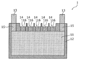
まず、実施の形態1に係る電池1について、図1、図2Aおよび図2Bを用いて説明する。図1は、実施の形態に係る電池1の外観の一例を示す斜視図である。図2Aは、同電池1の上面図であり、図2Bは、図2AのIIB−IIB線における同電池1の断面図である。
(Embodiment 1)
First,
図1、図2Aおよび図2Bに示すように、本実施の形態における電池1は、発電要素11と、発電要素11を収納する筐体12と、発電要素11と電気的に接続された第1充放電端子13と、発電要素11と電気的に接続された第1モニター端子14とを備える。発電要素11は、少なくとも1つの単電池の一例である。
As shown in FIG. 1, FIG. 2A, and FIG. 2B, the
発電要素11は、例えば、正極活物質層が正極集電体に配置された正極と、負極活物質層が負極集電体に配置された負極と、正極と負極との間に介在するセパレータとを含む。発電要素11は、別途外装体に収納されていてもよい。
The
発電要素11は、1つの単電池であってもよいし、複数の単電池が組み合わされた組電池であってもよい。単電池としては、一次電池および二次電池のいずれであってもよい。二次電池である単電池は、例えば、全固体リチウム二次電池等の全固体電池であってもよいし、リチウムイオン二次電池等の非水電解質二次電池であってもよい。
The
また、発電要素11が組電池である場合、複数の単電池のそれぞれが並列または直列に接続されることで組電池が構成されていてもよい。このとき、組電池の電極と第1充放電端子13とが電気的に接続されていてもよいし、組電池の電極と第1モニター端子14とが電気的に接続されていてもよい。また、本実施の形態のように、第1モニター端子14が複数設けられている場合には、複数の単電池の電極のそれぞれと複数の第1モニター端子14のそれぞれとが1対1で接続されていてもよい。
When the
筐体12は、発電要素11を収納する容器である。筐体12は、所定の形状を有するリジッドな容器である。本実施の形態において、筐体12の外形は、略直方体である。筐体12は、樹脂製および金属製のいずれであってもよい。なお、発電要素11が複数配置されている場合、筐体12は、複数の発電要素11を収納する。
The
第1充放電端子13は、発電要素11を充電するため、または/及び発電要素11を放電させるため端子である。つまり、第1充放電端子13は、発電要素11に電力を印加したり発電要素11から電力を取り出したりするための構造体である。
The first charge /
第1充放電端子13は、発電要素11に直接接続されていてもよいが、本実施の形態のように、例えばリード線15を介して発電要素11と接続されていてもよい。第1充放電端子13と発電要素11とが電気的に接続されることで、第1充放電端子13を通じて発電要素11に電力を印加したり発電要素11から電力を取り出したりすることができる。
Although the 1st charging / discharging
第1充放電端子13は、筐体12の表面の一部から突出する凸形状を有する。具体的には、第1充放電端子13は、棒状であって、金属等の導電性材料からなるオス端子である。一例として、第1充放電端子13の形状は、円柱状であるが、凸形状であれば、特に限定されるものではない。本実施の形態において、第1充放電端子13は、一対設けられている。つまり、2つの第1充放電端子13が筐体12に設けられている。
The first charge /
一方、第1モニター端子14は、発電要素11の状態を検知するための端子である。第1モニター端子14は、例えば、発電要素11の動作様態等をモニタリングするための構造体である。より具体的には、第1モニター端子14は、発電要素11内に収納された素電池の電圧、温度、もしくは圧力、または素電池内に存在するガス等を検知して、モニター信号として取り出す。なお、第1モニター端子14によってモニターするものは、これらに限るものではなく、発電要素11に関してセンシング可能なものであればよい。
On the other hand, the
第1モニター端子14は、発電要素11に直接接続されていてもよいが、本実施の形態のように、例えばリード線16を介して発電要素11と接続されていてもよい。第1モニター端子14と発電要素11とが電気的に接続されることで、第1モニター端子14を通じて発電要素11の動作様態等をモニタリングすることができる。例えば、第1モニター端子14が発電要素11の電圧をモニタリングする電圧検出用端子である場合、第1モニター端子14を通じて発電要素11の電圧がモニター信号として検出される。
The
第1モニター端子14は、筐体12の表面の一部が窪んだ凹形状を有する。具体的には、第1モニター端子14は、筐体12の一部に形成された凹部からなるメス端子である。一例として、第1モニター端子14の形状は、角孔形状であるが、凹形状であれば、特に限定されるものではない。なお、第1モニター端子14は、筐体12に形成された凹部とともに、この凹部の底部に設けられた金属等の導電性材料からなる導電部材を有していてもよい。
The
また、本実施の形態において、電池1は複数の第1モニター端子14を含む。具体的には、5つの第1モニター端子14が筐体12に設けられている。この場合、複数の第1モニター端子14は、上記のように複数の単電池と1対1で接続されていてもよいが、複数の第1モニター端子14の各々が、1つの発電要素11における電圧、温度および圧力等の各々をモニタリングするものであってもよい。
In the present embodiment,
第1充放電端子13と第1モニター端子14とは、筐体12の同一の面に設けられている。本実施の形態において、第1充放電端子13と第1モニター端子14とは、筐体12の上面に設けられている。また、5つの第1モニター端子14は、一対の第1充放電端子13の間に一列に並んで設けられている。なお、本実施の形態において、第1充放電端子13と第1モニター端子14とは一列に並べて設けられているが、これに限るものではなく、複数列に並べて設けられていてもよい。
The first charge /
以上、本実施の形態に係る電池1によれば、第1充放電端子13が筐体12の表面の一部から突出する凸形状を有し、第1モニター端子14が筐体12の表面の一部が窪んだ凹形状を有する。
As described above, according to the
この構成により、第1充放電端子13と第1モニター端子14との絶縁距離を稼ぐことができるので、第1充放電端子13と第1モニター端子14とが短絡するリスクを低減することができる。
With this configuration, since the insulation distance between the first charge /
より具体的に説明すると、仮に第1充放電端子13と第1モニター端子14とがいずれも凸形状を有する場合、第1充放電端子13および第1モニター端子14のそれぞれにケーブル等を接続する際に第1充放電端子13と第1モニター端子14とが短絡するリスクが高まる。一方、仮に第1充放電端子13と第1モニター端子14とがいずれも凹形状を有する場合、電流を流すために特に大きな形状を要する第1充放電端子13が発電要素11内に入り込む構造となり、体積エネルギー密度が低下する。これに対して、本実施の形態に係る電池1のように、第1充放電端子13を凸形状とし、第1モニター端子14を凹形状にすることで、電池1の体積エネルギー密度を低下させることなく、第1充放電端子13と第1モニター端子14とが短絡するリスクを低減できる。なお、第1モニター端子14には電流を流さないので第1モニター端子14の形状を大きくする必要がないため、第1モニター端子14の形状を凹形状にしても体積エネルギー密度が大きく下がることはない。
More specifically, if both the first charge /
また、第1充放電端子13と第1モニター端子14とが短絡するリスクが低減することで、本実施の形態のように、複数の第1充放電端子13と複数の第1モニター端子14とを筐体12の同一の面に設けることが可能となる。つまり、複数の第1充放電端子13と複数の第1モニター端子14とからなる端子群を筐体12の同一の面に設けた場合であっても端子群が短絡するリスクが低減されている。このように、複数の第1充放電端子13と複数の第1モニター端子14とからなる端子群を同一の面に設けることで、端子群を簡便に筐体12に設けることができる。
Moreover, since the risk that the first charge /
具体的には、本実施の形態における電池1では、端子群として、一対の第1充放電端子13と、一対の第1充放電端子13の間に一列に並んで設けられた複数の第2モニター端子24とが筐体12に設けられている。
Specifically, in the
これにより、一対の第1充放電端子13同士が短絡することを低減できるとともに、第1充放電端子13および第1モニター端子14のそれぞれにケーブル等の外部接続部材を容易に接続することができる。
Thereby, while being able to reduce a short circuit between a pair of 1st charge /
しかも、第1充放電端子13の形状と第1モニター端子14の形状が異なっているので、第1充放電端子13と第1モニター端子14とを容易に区別することができる。これにより、第1充放電端子13および第1モニター端子14の各々にケーブル等の外部接続部材を接続する際に誤接続することを抑制することもできる。
Moreover, since the shape of the first charge /
(実施の形態2)
次に、実施の形態2に係る電池システム100について、図3および図4を用いて説明する。図3は、実施の形態に係る電池システム100の外観の一例を示す図であり、外部接続部材2と電池1とが接続する前の状態を示している。図4は、電池システム100における外部接続部材2と電池1との接続状態の一例を示す図である。
(Embodiment 2)
Next,
図3および図4に示すように、本実施の形態における電池システム100は、上述の実施の形態1における電池1と、電池1と接続される外部接続部材2と、を備える。
As shown in FIGS. 3 and 4,
外部接続部材2は、電池1に装着されることで電池1に接続される。外部接続部材2は、電池1と機械的および電気的に接続される。外部接続部材2は、例えば、接続プラグであってもよいし、接続蓋であってもよい。
The
外部接続部材2は、保持体22と、第1充放電端子13と接続される第2充放電端子23と、第1モニター端子14と接続される第2モニター端子24と、を有する。第2充放電端子23と第2モニター端子24とは、保持体22に保持されている。保持体22は、例えば絶縁樹脂材料によって構成される。保持体22は、金属材料によって構成されていてもよい。保持体22を金属材料によって構成する場合は、第2充放電端子23と第2モニター端子とを絶縁する構成を設ければよい。
The
第2充放電端子23は、第1充放電端子13と機械的および電気的に接続される端子である。第2充放電端子23は、保持体22の一部を窪ませた凹形状を有し、第1充放電端子13と嵌合することで第1充放電端子13と機械的に接続される。具体的には、第2充放電端子23は、保持体22の一部に形成された凹部からなるメス端子である。第2充放電端子23の形状は、一例として円柱孔形状であるが、第1充放電端子13を収納できる形状であれば、第2充放電端子23の形状は、特に限定されるものではない。
The second charge /
また、第2充放電端子23は、第1充放電端子13と電気的に接続されるため、第1充放電端子13に嵌合される第2充放電端子23は、第1充放電端子13との接触面積を大きくするために、第2充放電端子23を構成する凹部の内壁全面に金属膜23aが形成されていてもよい。金属膜23aは、例えば、銅又はアルミニウム等によって構成される。
Further, since the second charge /
第2充放電端子23は、第1充放電端子13と同じ数だけ設けられている。具体的には、2つの第2充放電端子23が保持体22に設けられている。
The same number of second charge /
一方、第2モニター端子24は、第1モニター端子14と機械的および電気的に接続される端子である。第2モニター端子24は、保持体22の一部から突出する凸形状を有する。具体的には、第2モニター端子24は、棒状であって、金属等導電性材料からなるオス端子である。一例として、第2モニター端子24の形状は、円柱状又は角柱状であるが、凸形状であれば、特に限定されるものではない。第2モニター端子24は、先端部が第1モニター端子14に接触することで、第1モニター端子14と電気的に接続される。
On the other hand, the
本実施の形態において、保持体22内にはスプリング25が配置されている。第2モニター端子24は、保持体22内に配置されたスプリング25の伸縮によって動くことができるに構成されている。具体的には、保持体22には、複数の第2モニター端子24の各々の後端部に空間部が形成されており、スプリング25はその空間部に配置されている。スプリング25は、例えば弾性変形するコイルスプリングであり、押圧の有無によって伸び縮みする。スプリング25が伸び縮みすることによって第2モニター端子24がその長手方向に沿って移動し、第2モニター端子24の保持体22からの突出量が変化する。
In the present embodiment, a
なお、第2モニター端子24は、第1モニター端子14と同じ数だけ設けられている。具体的には、5つの第2モニター端子24が保持体22に設けられている。
Note that the same number of
第2充放電端子23と第2モニター端子24とは、保持体22の同一の面に設けられている。本実施の形態において、第2充放電端子23と第2モニター端子24とは、電池1の筐体12の上面と対向する保持体22の面(つまり下面)に設けられている。また、第2充放電端子23および第2モニター端子24の配置は、第1充放電端子13および第1モニター端子14の配置と同じである。つまり、一対の第2充放電端子23の間に、5つの第2モニター端子24が一列に並んでいる。
The second charge /
第2充放電端子23は、保持体22から引き出された第2充放電ケーブル26と電気的に接続され、第2モニター端子24は、保持体22から引き出された第2モニターケーブル27と電気的に接続される。具体的には、第2充放電端子23は、保持体22内の第2充放電接続部28で第2充放電ケーブル26と接合され、第2モニター端子24は、保持体22内の第2モニター接続部29で第2モニターケーブル27と接合される。これらの接合の方法としては、カシメ、ねじ止め、溶接、ロウ付け等の公知の方法を用いることができる。
The second charge /
このように構成される外部接続部材2は、図4に示すようにして電池1と接続される。具体的には、電池1の第1充放電端子13の端部と外部接続部材2の第2充放電端子23の一部とが接続され、電池1の第1モニター端子14の一部と外部接続部材2の第2モニター端子24の端部とが接続される。
The
これにより、電池1の発電要素11に対して外部接続部材2を通じて充放電を行ったりモニターしたりすることができる。具体的には、外部接続部材2の第2充放電端子23と電池1の第1充放電端子13とを通じて、発電要素11に電力を印加したり発電要素11から電力を取り出したりすることができる。また、外部接続部材2の第2モニター端子24と電池1の第1モニター端子14とを通じて、発電要素11の電圧、温度、もしくは圧力、または発電要素11に存在するガス等を検知することができる。
Thereby, charging / discharging with respect to the electric
この場合、本実施の形態では、第1充放電端子13が凸形状、第1モニター端子14が凹形状、第2充放電端子23が凹形状、第2モニター端子24が凸形状を有するので、第1充放電端子13と第2充放電端子23との接続形態である第1接続形態と、第1モニター端子14と第2モニター端子24との接続形態である第2接続形態とは、互いに異なっている。
In this case, in the present embodiment, the first charge /
この構成により、電池1の体積エネルギー密度を低下させずに、かつ、充放電端子である第1充放電端子13及び第2充放電端子23と、モニター端子である第1モニター端子14及び第2モニター端子24とが短絡するリスクを低減しながら、電池1と外部接続部材2との接続が可能な電池システム100を実現できる。
With this configuration, the first energy charging / discharging
また、第1接続形態における第1充放電端子13と第2充放電端子23との接触面積である第1接触面積は、第2接続形態における第1モニター端子14と第2モニター端子24との接触面積である第2接触面積よりも大きくてもよい。
Moreover, the 1st contact area which is a contact area of the 1st charging / discharging
この構成により、充放電端子である第1充放電端子13及び第2充放電端子23と、モニター端子である第1モニター端子14及び第2モニター端子24との接触抵抗を低減しながら、より小型の電池システム100を実現できる。
With this configuration, the contact resistance between the first charge /
また、第1接続形態は、第1充放電端子13と第2充放電端子23とが嵌め合わされる形態であり、かつ、第1充放電端子13の端部が第2充放電端子23の一部に接触する形態であってもよい。
The first connection form is a form in which the first charge /
この構成により、第1充放電端子13と第2充放電端子23との接触抵抗を低減しながら、より小型の電池システム100を実現できる。
With this configuration, a
また、本実施の形態において、第2充放電端子23と第2モニター端子24とは、保持体22に保持されている。
In the present embodiment, the second charge /
この構成により、第2充放電端子23および第2モニター端子24を保持体22中に埋設して一体化できるので、第2充放電端子23および第2モニター端子24のそれぞれを第1充放電端子13および第1モニター端子14に接続する際に、これらの端子が短絡することを抑制できるとともに、これらの端子を接続する工程の簡略化を図ることができる。
With this configuration, since the second charge /
また、本実施の形態において、第2充放電端子23は、保持体22の一部を窪ませた凹形状を有し、第2モニター端子24は、保持体22から突出する凸形状を有する。
Further, in the present embodiment, the second charge /
この構成により、充放電端子である第1充放電端子13及び第2充放電端子23と、モニター端子である第1モニター端子14及び第2モニター端子24とが短絡するリスクをより低減できる。
With this configuration, it is possible to further reduce the risk of a short circuit between the first charge /
また、本実施の形態において、第2モニター端子24は、保持体22内に配置されたスプリング25の伸縮により動くことが可能に構成されている。
Further, in the present embodiment, the
この構成により、スプリング25によって第2モニター端子24を第1モニター端子14に押し付けることができるので、第1モニター端子14と第2モニター端子24との接触抵抗を低減することができる。すなわち、第1モニター端子14はモニター信号を取り出すためのものであるので大きな端子である必要がなく小さくすることができるものの、第1モニター端子14を小さくすると、第1モニター端子14と第2モニター端子24との接触面積が小さくなる。この場合、第1モニター端子14と第2モニター端子24とが十分に接触していない状態になると、接触抵抗が非常に大きくなってしまうおそれがある。そこで、第2モニター端子24をスプリング25によって第1モニター端子14に押し付ける構造にすることで、第1モニター端子14と第2モニター端子24とが十分に接触せずに第1モニター端子14と第2モニター端子24との接触抵抗が大きくなってしまうことを抑制できる。この結果、小さい第1モニター端子14を採用することができるので、複数の第1モニター端子14を筐体12に容易に設けることができる。
With this configuration, since the
(変形例)
以上、本開示に係る電池および電池システムについて、実施の形態1、2に基づいて説明したが、本開示は、上記の実施の形態1、2に限定されるものではない。
(Modification)
Although the battery and the battery system according to the present disclosure have been described based on the first and second embodiments, the present disclosure is not limited to the first and second embodiments.
例えば、上記の各実施の形態に対して当業者が思いつく各種変形を施して得られる形態、又は、本開示の趣旨を逸脱しない範囲で上記の各実施の形態における構成要素および機能を任意に組み合わせることで実現される形態も本開示に含まれる。 For example, a form obtained by making various modifications conceivable by those skilled in the art to the above-described embodiments, or arbitrarily combining the components and functions in the above-described embodiments without departing from the gist of the present disclosure A form realized by this is also included in the present disclosure.
本開示の技術は、充放電端子およびモニター端子を備える電池、並びにこの電池を備える電池システム等に利用することができる。 The technology of the present disclosure can be used for a battery including a charge / discharge terminal and a monitor terminal, a battery system including the battery, and the like.
1 電池
2 外部接続部材
11 発電要素
12 筐体
13 第1充放電端子
14 第1モニター端子
15、16 リード線
22 保持体
23 第2充放電端子
23a 金属膜
24 第2モニター端子
25 スプリング
26 第2充放電ケーブル
27 第2モニターケーブル
28 第2充放電接続部
29 第2モニター接続部
100 電池システム
DESCRIPTION OF
Claims (8)
前記少なくとも1つの単電池を収納する筐体と、
前記少なくとも1つの単電池と電気的に接続された少なくとも1つの第1充放電端子と、
前記少なくとも1つの単電池と電気的に接続された少なくとも1つの第1モニター端子と、
を備え、
前記少なくとも1つの第1充放電端子は、前記筐体の表面から部分的に突出する凸形状を有し、
前記少なくとも1つの第1モニター端子は、前記筐体の前記表面から部分的に窪む凹形状を有する、
電池。 At least one unit cell;
A housing for housing the at least one unit cell;
At least one first charge / discharge terminal electrically connected to the at least one unit cell;
At least one first monitor terminal electrically connected to the at least one unit cell;
With
The at least one first charge / discharge terminal has a convex shape partially protruding from the surface of the housing,
The at least one first monitor terminal has a concave shape partially recessed from the surface of the housing.
battery.
請求項1に記載の電池。 The at least one first charge / discharge terminal and the at least one first monitor terminal are provided on the same surface of the casing.
The battery according to claim 1.
前記少なくとも1つの第1モニター端子は、複数の第1モニター端子を備え、
前記複数の第1モニター端子は、前記2つの第1充放電端子の間に一列に並んでいる、
請求項2に記載の電池。 The at least one first charging / discharging terminal includes two first charging / discharging terminals,
The at least one first monitor terminal includes a plurality of first monitor terminals;
The plurality of first monitor terminals are arranged in a line between the two first charge / discharge terminals,
The battery according to claim 2.
前記少なくとも1つの単電池を収納する筐体と、
前記少なくとも1つの単電池と電気的に接続された少なくとも1つの第1充放電端子と、
前記少なくとも1つの単電池と電気的に接続された少なくとも1つの第1モニター端子と、
を含み、
前記少なくとも1つの第1充放電端子は、前記筐体の表面から部分的に突出する凸形状を有し、
前記少なくとも1つの第1モニター端子は、前記筐体の前記表面から部分的に窪む凹形状を有する、
電池、
前記第1充放電端子と電気的に接続される第2充放電端子、及び
前記第1モニター端子と電気的に接続される第2モニター端子、
を備え、
前記第1充放電端子と前記第2充放電端子とが接続される形態である第1接続形態は、前記第1モニター端子と前記第2モニター端子とが接続される形態である第2接続形態と異なる、
電池システム。 At least one unit cell;
A housing for housing the at least one unit cell;
At least one first charge / discharge terminal electrically connected to the at least one unit cell;
At least one first monitor terminal electrically connected to the at least one unit cell;
Including
The at least one first charge / discharge terminal has a convex shape partially protruding from the surface of the housing,
The at least one first monitor terminal has a concave shape partially recessed from the surface of the housing.
battery,
A second charge / discharge terminal electrically connected to the first charge / discharge terminal; and a second monitor terminal electrically connected to the first monitor terminal;
With
The first connection form in which the first charge / discharge terminal and the second charge / discharge terminal are connected is the second connection form in which the first monitor terminal and the second monitor terminal are connected. Different from the
Battery system.
請求項4に記載の電池システム。 The contact area between the first charge / discharge terminal and the second charge / discharge terminal in the first connection form is larger than the contact area between the first monitor terminal and the second monitor terminal in the second connection form. ,large,
The battery system according to claim 4.
前記第1接続形態において、
前記第1充放電端子の前記凸形状と前記第2充放電端子の前記凹形状とが嵌め合わされ、かつ
前記第1充放電端子の前記凸形状の端部が前記第2充放電端子の一部に接触する、
請求項5に記載の電池システム。 The second charge / discharge terminal has a concave shape,
In the first connection mode,
The convex shape of the first charge / discharge terminal and the concave shape of the second charge / discharge terminal are fitted together, and the convex end portion of the first charge / discharge terminal is a part of the second charge / discharge terminal. In contact with the
The battery system according to claim 5.
前記第2充放電端子は、前記保持体の表面から部分的に窪む凹形状を有し、
前記第2モニター端子は、前記保持体の前記表面から部分的に突出する凸形状を有する、
請求項4から6のいずれか1項に記載の電池システム。 A holding body that holds the second charge / discharge terminal and the second monitor terminal;
The second charge / discharge terminal has a concave shape partially recessed from the surface of the holding body,
The second monitor terminal has a convex shape partially protruding from the surface of the holding body.
The battery system according to any one of claims 4 to 6.
前記第2モニター端子は、前記スプリングの伸縮により動くことが可能に構成されている、
請求項7に記載の電池システム。 The holding body includes a spring disposed in the holding body,
The second monitor terminal is configured to be movable by expansion and contraction of the spring.
The battery system according to claim 7.
Applications Claiming Priority (2)
| Application Number | Priority Date | Filing Date | Title |
|---|---|---|---|
| JP2018090598 | 2018-05-09 | ||
| JP2018090598 | 2018-05-09 |
Publications (2)
| Publication Number | Publication Date |
|---|---|
| JP2019200986A true JP2019200986A (en) | 2019-11-21 |
| JP7291889B2 JP7291889B2 (en) | 2023-06-16 |
Family
ID=68464252
Family Applications (1)
| Application Number | Title | Priority Date | Filing Date |
|---|---|---|---|
| JP2019061986A Active JP7291889B2 (en) | 2018-05-09 | 2019-03-27 | Batteries and battery systems |
Country Status (3)
| Country | Link |
|---|---|
| US (1) | US11398664B2 (en) |
| JP (1) | JP7291889B2 (en) |
| CN (1) | CN110474012B (en) |
Families Citing this family (1)
| Publication number | Priority date | Publication date | Assignee | Title |
|---|---|---|---|---|
| JP2022057666A (en) * | 2020-09-30 | 2022-04-11 | トヨタ自動車株式会社 | battery |
Citations (4)
| Publication number | Priority date | Publication date | Assignee | Title |
|---|---|---|---|---|
| WO2008016152A1 (en) * | 2006-08-04 | 2008-02-07 | Gs Yuasa Corporation | Lead acid battery |
| JP2008146943A (en) * | 2006-12-07 | 2008-06-26 | Nissan Motor Co Ltd | Battery pack and its manufacturing method |
| JP2016018634A (en) * | 2014-07-07 | 2016-02-01 | 株式会社東芝 | Battery module |
| JP2016115642A (en) * | 2014-12-18 | 2016-06-23 | 株式会社オートネットワーク技術研究所 | Battery wiring module |
Family Cites Families (16)
| Publication number | Priority date | Publication date | Assignee | Title |
|---|---|---|---|---|
| JP2002358998A (en) * | 2001-06-01 | 2002-12-13 | Yuasa Corp | Closed lead acid storage battery |
| JP4111043B2 (en) | 2003-04-18 | 2008-07-02 | 日産自動車株式会社 | Bipolar secondary battery |
| FR2937184A1 (en) * | 2008-10-15 | 2010-04-16 | Peugeot Citroen Automobiles Sa | Enclosure for covering upper surface of electric battery in electric vehicle, has common protection casing for onboard electric and/or electronic devices, and quick attachment units provided in recesses in lower part of enclosure |
| JP5481881B2 (en) | 2009-03-04 | 2014-04-23 | 日産自動車株式会社 | Battery module |
| JP2011010446A (en) | 2009-06-25 | 2011-01-13 | Shindengen Electric Mfg Co Ltd | Charge monitoring apparatus, charge monitoring system, and charging module |
| KR101152635B1 (en) * | 2010-04-08 | 2012-06-04 | 주식회사 엘지화학 | Voltage Sensing Assembly for Battery Module and Battery Module Employed with the Same |
| KR20130019697A (en) * | 2011-08-17 | 2013-02-27 | 삼성에스디아이 주식회사 | Battery pack and battery module comprising the same |
| JP5751676B2 (en) * | 2012-02-17 | 2015-07-22 | 株式会社オートネットワーク技術研究所 | Battery wiring module |
| JP2014022236A (en) * | 2012-07-19 | 2014-02-03 | Sanyo Electric Co Ltd | Battery system |
| JP6064505B2 (en) * | 2012-10-10 | 2017-01-25 | 株式会社オートネットワーク技術研究所 | Power storage module |
| CN104737325B (en) * | 2012-10-19 | 2017-09-26 | 住友重机械工业株式会社 | Power storage module and Work machine |
| JP6075150B2 (en) | 2013-03-27 | 2017-02-08 | 株式会社オートネットワーク技術研究所 | Wiring module |
| US9823310B2 (en) * | 2014-07-25 | 2017-11-21 | Duracell U.S. Operations, Inc. | Battery state of charge indicator with an indicator circuit |
| CN204793092U (en) * | 2015-07-02 | 2015-11-18 | 汕头市毅和电源科技有限公司 | A lead -acid battery |
| DE112016003986T5 (en) * | 2015-09-01 | 2018-05-30 | Kabushiki Kaisha Toyota Jidoshokki | ELECTRICITY STORAGE DEVICE |
| JP6613773B2 (en) * | 2015-09-30 | 2019-12-04 | 株式会社Gsユアサ | Power storage device |
-
2019
- 2019-03-27 JP JP2019061986A patent/JP7291889B2/en active Active
- 2019-04-02 US US16/372,513 patent/US11398664B2/en active Active
- 2019-04-23 CN CN201910326865.XA patent/CN110474012B/en active Active
Patent Citations (4)
| Publication number | Priority date | Publication date | Assignee | Title |
|---|---|---|---|---|
| WO2008016152A1 (en) * | 2006-08-04 | 2008-02-07 | Gs Yuasa Corporation | Lead acid battery |
| JP2008146943A (en) * | 2006-12-07 | 2008-06-26 | Nissan Motor Co Ltd | Battery pack and its manufacturing method |
| JP2016018634A (en) * | 2014-07-07 | 2016-02-01 | 株式会社東芝 | Battery module |
| JP2016115642A (en) * | 2014-12-18 | 2016-06-23 | 株式会社オートネットワーク技術研究所 | Battery wiring module |
Also Published As
| Publication number | Publication date |
|---|---|
| CN110474012B (en) | 2023-04-07 |
| CN110474012A (en) | 2019-11-19 |
| JP7291889B2 (en) | 2023-06-16 |
| US20190348662A1 (en) | 2019-11-14 |
| US11398664B2 (en) | 2022-07-26 |
Similar Documents
| Publication | Publication Date | Title |
|---|---|---|
| JP5061698B2 (en) | Power storage device | |
| JP7162706B2 (en) | Storage element | |
| KR101565115B1 (en) | Battery Pack and method for manufacturing the same | |
| JP2019075308A (en) | Power storage element and power storage module | |
| JP6194572B2 (en) | Storage element and power supply module | |
| KR100786875B1 (en) | Battery module | |
| JP2012043771A (en) | Rechargeable battery and battery module | |
| CN107275524B (en) | Battery cell | |
| KR20150035205A (en) | Secondary battery | |
| CN111937186A (en) | Battery module | |
| US20130189553A1 (en) | Cell housing for electrochemical cells for assembly of an electrochemical energy storage | |
| KR20130053026A (en) | Rechargeable battery | |
| KR20140124247A (en) | Rechargeable battery | |
| US8658307B2 (en) | Rechargeable battery | |
| KR20200024249A (en) | Battery cell | |
| JP2015082386A (en) | Storage battery | |
| KR20160129571A (en) | Electrode assembly and secondary battery comprising the same | |
| KR20120094994A (en) | Secondary battery | |
| CN108023034B (en) | Battery cell and method for producing a battery cell | |
| KR101121205B1 (en) | Secondary battery | |
| JP7291889B2 (en) | Batteries and battery systems | |
| KR102374743B1 (en) | Pouch type secondary battery | |
| US8993139B2 (en) | Sealed secondary battery | |
| US8492014B2 (en) | Secondary battery | |
| CN110291658B (en) | Battery unit and battery module |
Legal Events
| Date | Code | Title | Description |
|---|---|---|---|
| A621 | Written request for application examination |
Free format text: JAPANESE INTERMEDIATE CODE: A621 Effective date: 20220208 |
|
| A977 | Report on retrieval |
Free format text: JAPANESE INTERMEDIATE CODE: A971007 Effective date: 20221227 |
|
| A131 | Notification of reasons for refusal |
Free format text: JAPANESE INTERMEDIATE CODE: A131 Effective date: 20230110 |
|
| A521 | Request for written amendment filed |
Free format text: JAPANESE INTERMEDIATE CODE: A523 Effective date: 20230227 |
|
| TRDD | Decision of grant or rejection written | ||
| A01 | Written decision to grant a patent or to grant a registration (utility model) |
Free format text: JAPANESE INTERMEDIATE CODE: A01 Effective date: 20230509 |
|
| A61 | First payment of annual fees (during grant procedure) |
Free format text: JAPANESE INTERMEDIATE CODE: A61 Effective date: 20230524 |
|
| R151 | Written notification of patent or utility model registration |
Ref document number: 7291889 Country of ref document: JP Free format text: JAPANESE INTERMEDIATE CODE: R151 |