JP2016115642A - Battery wiring module - Google Patents
Battery wiring module Download PDFInfo
- Publication number
- JP2016115642A JP2016115642A JP2014255947A JP2014255947A JP2016115642A JP 2016115642 A JP2016115642 A JP 2016115642A JP 2014255947 A JP2014255947 A JP 2014255947A JP 2014255947 A JP2014255947 A JP 2014255947A JP 2016115642 A JP2016115642 A JP 2016115642A
- Authority
- JP
- Japan
- Prior art keywords
- connector
- detection
- battery
- detection connector
- resin protector
- Prior art date
- Legal status (The legal status is an assumption and is not a legal conclusion. Google has not performed a legal analysis and makes no representation as to the accuracy of the status listed.)
- Granted
Links
- 238000001514 detection method Methods 0.000 claims abstract description 133
- 230000001012 protector Effects 0.000 claims abstract description 56
- 229920005989 resin Polymers 0.000 claims abstract description 56
- 239000011347 resin Substances 0.000 claims abstract description 56
- 230000013011 mating Effects 0.000 claims description 19
- 238000003780 insertion Methods 0.000 claims description 10
- 230000037431 insertion Effects 0.000 claims description 10
- 238000009434 installation Methods 0.000 abstract 3
- 238000005516 engineering process Methods 0.000 description 4
- 230000004308 accommodation Effects 0.000 description 3
- 238000000034 method Methods 0.000 description 2
- 238000000465 moulding Methods 0.000 description 2
- 230000002093 peripheral effect Effects 0.000 description 2
- 229920003002 synthetic resin Polymers 0.000 description 2
- 239000000057 synthetic resin Substances 0.000 description 2
- 230000000694 effects Effects 0.000 description 1
- 239000002184 metal Substances 0.000 description 1
- 230000002265 prevention Effects 0.000 description 1
- 230000000717 retained effect Effects 0.000 description 1
Images


Classifications
-
- H—ELECTRICITY
- H01—ELECTRIC ELEMENTS
- H01M—PROCESSES OR MEANS, e.g. BATTERIES, FOR THE DIRECT CONVERSION OF CHEMICAL ENERGY INTO ELECTRICAL ENERGY
- H01M50/00—Constructional details or processes of manufacture of the non-active parts of electrochemical cells other than fuel cells, e.g. hybrid cells
- H01M50/50—Current conducting connections for cells or batteries
-
- H—ELECTRICITY
- H01—ELECTRIC ELEMENTS
- H01M—PROCESSES OR MEANS, e.g. BATTERIES, FOR THE DIRECT CONVERSION OF CHEMICAL ENERGY INTO ELECTRICAL ENERGY
- H01M50/00—Constructional details or processes of manufacture of the non-active parts of electrochemical cells other than fuel cells, e.g. hybrid cells
- H01M50/20—Mountings; Secondary casings or frames; Racks, modules or packs; Suspension devices; Shock absorbers; Transport or carrying devices; Holders
- H01M50/204—Racks, modules or packs for multiple batteries or multiple cells
- H01M50/207—Racks, modules or packs for multiple batteries or multiple cells characterised by their shape
- H01M50/209—Racks, modules or packs for multiple batteries or multiple cells characterised by their shape adapted for prismatic or rectangular cells
-
- H—ELECTRICITY
- H01—ELECTRIC ELEMENTS
- H01M—PROCESSES OR MEANS, e.g. BATTERIES, FOR THE DIRECT CONVERSION OF CHEMICAL ENERGY INTO ELECTRICAL ENERGY
- H01M50/00—Constructional details or processes of manufacture of the non-active parts of electrochemical cells other than fuel cells, e.g. hybrid cells
- H01M50/50—Current conducting connections for cells or batteries
- H01M50/569—Constructional details of current conducting connections for detecting conditions inside cells or batteries, e.g. details of voltage sensing terminals
-
- Y—GENERAL TAGGING OF NEW TECHNOLOGICAL DEVELOPMENTS; GENERAL TAGGING OF CROSS-SECTIONAL TECHNOLOGIES SPANNING OVER SEVERAL SECTIONS OF THE IPC; TECHNICAL SUBJECTS COVERED BY FORMER USPC CROSS-REFERENCE ART COLLECTIONS [XRACs] AND DIGESTS
- Y02—TECHNOLOGIES OR APPLICATIONS FOR MITIGATION OR ADAPTATION AGAINST CLIMATE CHANGE
- Y02E—REDUCTION OF GREENHOUSE GAS [GHG] EMISSIONS, RELATED TO ENERGY GENERATION, TRANSMISSION OR DISTRIBUTION
- Y02E60/00—Enabling technologies; Technologies with a potential or indirect contribution to GHG emissions mitigation
- Y02E60/10—Energy storage using batteries
Landscapes
- Chemical & Material Sciences (AREA)
- Chemical Kinetics & Catalysis (AREA)
- Electrochemistry (AREA)
- General Chemical & Material Sciences (AREA)
- Connection Of Batteries Or Terminals (AREA)
- Battery Mounting, Suspending (AREA)
Abstract
Description
本明細書によって開示される技術は、電池配線モジュールに関する。 The technique disclosed by this specification is related with a battery wiring module.
電気自動車やハイブリッド車に搭載される電池モジュールは、複数の単電池をバスバーを介して直列接続して構成されるが、それに加え、各単電池の状態(電圧や温度等)を検知する手段を備えている。
従来、例えば単電池の電圧を検知する手段として、特開2014−22175号公報(下記特許文献1)に記載のものが提案されている。このものは、電圧検知線の端末に接続された電圧検知端子を収容した検知コネクタを、各単電池に設けられた電池側コネクタに嵌合する、いわゆるコネクタ方式である。
Battery modules mounted on electric vehicles and hybrid vehicles are configured by connecting a plurality of single cells in series via a bus bar. In addition, means for detecting the state (voltage, temperature, etc.) of each single cell is provided. I have.
Conventionally, as a means for detecting the voltage of a single cell, for example, a device described in Japanese Patent Laid-Open No. 2014-22175 (Patent Document 1 below) has been proposed. This is a so-called connector system in which a detection connector containing a voltage detection terminal connected to a terminal of a voltage detection line is fitted to a battery side connector provided in each unit cell.
より具体的には、電池配線モジュールとして、単電池群の上面に位置決めされて装着される樹脂プロテクタが備えられ、この樹脂プロテクタには、バスバーが定位置に保持される一方、単電池の電池側コネクタと対向する位置ごとに、検知コネクタが挿入されるコネクタ装着部が形成され、同コネクタ装着部の後部側に検知コネクタが予め挿入された構造である。そして、樹脂プロテクタが単電池群の上面に位置決めされて装着されたのち、バスバーにより隣り合う単電池の電極同士が接続され、続いて検知コネクタをコネクタ装着部内で前進させて相手の電池側コネクタと嵌合接続するようになっている。 More specifically, the battery wiring module includes a resin protector that is positioned and mounted on the upper surface of the unit cell group. The resin protector includes a bus bar that is held at a fixed position, and a battery side of the unit cell. A connector mounting portion into which the detection connector is inserted is formed at each position facing the connector, and the detection connector is inserted in advance on the rear side of the connector mounting portion. Then, after the resin protector is positioned and mounted on the upper surface of the unit cell group, the electrodes of the adjacent unit cells are connected by the bus bar, and then the detection connector is advanced in the connector mounting portion to connect the other battery side connector. It is designed to be fitted and connected.
上記先行技術のものでは、検知コネクタをコネクタ装着部の後部側に保持するに当たり、後方への抜け止めは図られているものの、前方への移動については然したる規制手段が設けられておらず、そのため検知コネクタをコネクタ装着部に初めに挿入する際に、必要以上に前進した位置まで押し込むおそれがある。そうすると、樹脂プロテクタが単電池群の上面で位置決めされる前に、検知コネクタが電池側コネクタ等に当たり、樹脂プロテクタが傾く等に起因して改めて位置決めする作業が面倒となったり、検知コネクタがコネクタ装着部内で傾いてコネクタ同士の嵌合がスムーズにできなかったりして、組み付け作業に手間取るおそれがあり、さらなる改善が希求されていた。
本明細書によって開示される技術は上記のような事情に基づいて完成されたものであって、その目的は、電池配線モジュールの組み付け作業性を向上させるところにある。
In the above prior art, in order to hold the detection connector on the rear side of the connector mounting portion, although the rearward prevention is intended, there is no appropriate restriction means for the forward movement. Therefore, when the detection connector is first inserted into the connector mounting portion, the detection connector may be pushed to a position advanced more than necessary. Then, before the resin protector is positioned on the upper surface of the unit cell group, the detection connector hits the battery side connector, etc., and the work of positioning again due to the resin protector tilting etc. is troublesome, or the detection connector is attached to the connector. There has been a need for further improvement because there is a risk that it will be difficult to smoothly fit the connectors by tilting in the part, and it may take time for assembly work.
The technology disclosed in this specification has been completed based on the above-described circumstances, and an object thereof is to improve the assembly workability of the battery wiring module.
本明細書によって開示される技術は、正極及び負極の電極端子を有する単電池を複数個並べてなる単電池群に装着される電池配線モジュールであって、隣り合う互いに逆極性の前記電極端子同士を接続するための接続部材が保持され、前記単電池群の上面に位置決めされて装着される樹脂プロテクタと、前記各単電池の状態を検知するための検知端子が収容され、前記単電池の上面に突設された電池側コネクタと嵌合可能な検知コネクタと、前記樹脂プロテクタの前記電池側コネクタと対向した位置において前記検知コネクタが挿入可能に設けられたコネクタ装着部と、が備えられ、前記樹脂プロテクタが前記単電池群の上面に装着された状態において、前記接続部材により隣り合う互いに逆極性の前記電極端子同士が接続されるとともに、前記検知コネクタを前記コネクタ装着部内で前進させることにより相手の前記電池側コネクタと嵌合接続するようにしたものにおいて、前記コネクタ装着部と前記検知コネクタとの間には、前記検知コネクタを、前記樹脂プロテクタが位置決めされる前には前記電池側コネクタとは干渉しない位置に弾性的に仮保持する仮保持機構部が設けられている構成である。 The technology disclosed in this specification is a battery wiring module mounted on a unit cell group in which a plurality of unit cells having positive and negative electrode terminals are arranged, and the adjacent electrode terminals having opposite polarities are connected to each other. A connecting member for connecting is held, a resin protector that is positioned and mounted on the upper surface of the unit cell group, and a detection terminal for detecting the state of each unit cell are housed on the upper surface of the unit cell. A detection connector that can be fitted to the protruding battery side connector; and a connector mounting portion that is provided so that the detection connector can be inserted at a position facing the battery side connector of the resin protector. In a state where the protector is mounted on the upper surface of the unit cell group, the electrode members adjacent to each other having opposite polarities are connected by the connection member, In the one where the detection connector is moved forward in the connector mounting portion to be fitted and connected to the battery side connector of the other party, the detection connector is inserted between the connector mounting portion and the detection connector. Before the resin protector is positioned, a temporary holding mechanism portion is provided that elastically temporarily holds it at a position where it does not interfere with the battery side connector.
上記構成では、樹脂プロテクタを単電池群の上面に装着するに当たり、位置決めされる前には、コネクタ装着部に仮保持された検知コネクタが相手の電池側コネクタ等と干渉することが回避される。その結果、樹脂プロテクタの装着作業やコネクタ同士の嵌合作業が迅速に行え、ひいては電池配線モジュールの組み付けを能率良く行うことができる。 In the above configuration, when the resin protector is mounted on the upper surface of the unit cell group, it is avoided that the detection connector temporarily held by the connector mounting portion interferes with the mating battery side connector or the like before positioning. As a result, the mounting operation of the resin protector and the fitting operation between the connectors can be performed quickly, and as a result, the battery wiring module can be assembled efficiently.
また、以下のような構成としてもよい。
前記コネクタ装着部の対向した二内面には、先端に頭部を有する一対の弾性挟持片が互いに接離する方向の弾性変位可能に設けられるとともに、前記検知コネクタの対応した外面が下部側が引っ込んだ段差状に形成されて、同段差面により前記弾性挟持片の前記頭部に当接する係止面が形成され、かつ、前記係止面と前記頭部の被当接面との少なくともいずれか一方が順テーパ面をなしてセミロック構造とされており、前記検知コネクタにおける両側の前記係止面が、前記弾性挟持片の前記頭部における前記被当接面に当接して挿入が停止されたところが仮保持位置となっている。
The following configuration may also be used.
Two opposing inner surfaces of the connector mounting portion are provided so that a pair of elastic clamping pieces having a head at the tip can be elastically displaced in a direction in which they come into contact with each other, and the corresponding outer surface of the detection connector is retracted on the lower side. A locking surface that is formed in a step shape and that abuts against the head portion of the elastic clamping piece is formed by the step surface, and at least one of the locking surface and a contacted surface of the head portion Is formed as a semi-lock structure with a forward tapered surface, and the engagement surfaces on both sides of the detection connector are in contact with the contacted surface of the head of the elastic clamping piece, and the insertion is stopped. Temporary holding position.
上記構成では、検知コネクタが仮保持位置まで挿入されて停止されると、同仮保持位置において検知コネクタは一対の弾性挟持片で弾性的に挟持されることにより仮保持される。停止部分の構造はセミロック構造であるから、所定以上の力を検知コネクタに加えることにより検知コネクタを改めて押し込むことができる。 In the above configuration, when the detection connector is inserted and stopped to the temporary holding position, the detection connector is temporarily held by the elastic holding pieces at the temporary holding position. Since the structure of the stop portion is a semi-lock structure, the detection connector can be pushed in again by applying a predetermined force or more to the detection connector.
前記仮保持位置に仮保持された前記検知コネクタは、前記樹脂プロテクタが前記単電池群の上面に正規に装着された場合に、相手の前記電池側コネクタの直上に位置する設定となっている。
上記構成では、検知コネクタを仮保持位置から押し込んで相手の電池側コネクタに嵌合する動作を、よりスムーズに行うことができる。
The detection connector temporarily held in the temporary holding position is set to be positioned immediately above the mating battery-side connector when the resin protector is properly mounted on the upper surface of the unit cell group.
In the above configuration, the operation of pushing the detection connector from the temporary holding position and fitting the detection connector to the mating battery side connector can be performed more smoothly.
前記コネクタ装着部内には、前記検知コネクタが前記仮保持位置に挿入された際に同検知コネクタに設けられた被係止部に弾性的に係止して抜け止めする弾性抜止部が設けられており、かつ、前記弾性抜止部と前記被係止部との間にはクリアランスが設けられている。 In the connector mounting portion, there is provided an elastic retaining portion that is elastically locked to a latched portion provided in the detection connector to prevent the detection connector from coming off when the detection connector is inserted into the temporary holding position. And a clearance is provided between the elastic retaining portion and the locked portion.
成形上や組み付け誤差等により、仮係止位置にある検知コネクタが下方に向けて必要以上に進出した形態を採り、樹脂プロテクタが装着された際に、検知コネクタが相手の電池側コネクタに当接する場合があり得る。その際、仮に検知コネクタが弾性抜止片により後退不能に係止されていると、上記の樹脂プロテクタが装着された際には、検知コネクタと相手の電池側コネクタ同士が強く衝突するおそれがある。
それに対して本構成では、仮保持位置にある検知コネクタの被係止部と弾性抜止片との間に、クリアランスすなわち遊びが設けられた構造となっているから、検知コネクタが必要以上に進出した形態において樹脂プロテクタが装着されることにより、検知コネクタが相手の電池側コネクタに当接したとしても、遊びがあることで検知コネクタが後方に逃げ、コネクタ同士が強く衝突することが回避される。
Due to molding and assembly errors, the detection connector at the temporary locking position has advanced more than necessary downward, and when the resin protector is installed, the detection connector contacts the mating battery connector. There may be cases. At this time, if the detection connector is locked so as not to be retractable by the elastic retaining piece, the detection connector and the mating battery-side connector may collide strongly when the resin protector is attached.
On the other hand, in this structure, since the clearance, that is, the play is provided between the locked portion of the detection connector in the temporary holding position and the elastic retaining piece, the detection connector has advanced more than necessary. By mounting the resin protector in the form, even if the detection connector comes into contact with the other battery-side connector, the detection connector escapes backward due to play and it is avoided that the connectors collide strongly.
本明細書によって開示される技術によれば、電池配線モジュールの組み付け作業性を向上させることができる。 According to the technology disclosed in this specification, the workability of assembling the battery wiring module can be improved.
<実施形態>
実施形態を図1ないし図8に基づいて説明する。本実施形態に係る電池モジュールMは、電気自動車、ハイブリッド車等の車両(図示せず)に搭載されて、同車両を駆動するための電源として使用される。
電池モジュールMは、図1に示すように、複数の単電池11を並べてなる単電池群10を有し、図2に示すように、単電池群10の上面中央部に電池配線モジュール20が装着された構造である。
<Embodiment>
An embodiment will be described with reference to FIGS. The battery module M according to the present embodiment is mounted on a vehicle (not shown) such as an electric vehicle or a hybrid vehicle, and is used as a power source for driving the vehicle.
As shown in FIG. 1, the battery module M has a
単電池11は、詳しくは図示しないが、4個の薄いラミネート型電池を直列接続して合成樹脂製のパック11A内に収容したものであって、全体として扁平な直方体形状に形成されている。単電池11の上面の中央部には、正負一対の電極端子12が一定間隔を開けて突出形成されている。電極端子12は、図1及び図3に示すように、短寸の四角柱形に形成され、上面中心には、平面視正方形の端子台13が突出形成されている。端子台13には、後記するバスバー21を固定するためのボルト孔14が切られている。
Although not shown in detail, the
単電池11は、正極と負極の電極端子12が交互に前後逆に配された姿勢で、図1に示すように左右方向に重ねて並べられることにより、単電池群10が形成されている。言い換えると、当該単電池群10では、左右に隣り合う電極端子12同士において極性が互いに逆となっている。
As shown in FIG. 1, the
単電池11の上面における両電極端子12の間には、電池側コネクタ15が形成されている。この電池側コネクタ15は雄側コネクタであって、図3に示すように、上面開口の角筒状をなす雄ハウジング16を有している。同雄ハウジング16はパック11Aと一体的に形成され、奥面からは、4本の雄端子17が左右方向(図3における紙面の表裏方向)に並んで突設されている。各雄端子17は、単電池11を構成する4個のラミネート型電池から個別に導出されて配されている。
A battery-
次に、電池配線モジュール20について説明する。電池配線モジュール20は、図2に示すように、上記した単電池群10の上面に位置決めして装着される樹脂プロテクタ40を有する。樹脂プロテクタ40には、隣り合う単電池11の正負の電極端子12同士を接続する複数のバスバー21と、各単電池11に設けられた電池側コネクタ15と個別に嵌合される複数の検知コネクタ30が装着されるようになっている。
Next, the
バスバー21は、導電性に優れた金属板をプレス加工して形成され、図2に示すように、全体として横長の略長方形状をなしている。バスバー21の両端部には、電極端子12の端子台13に切られたボルト孔14に螺合されるボルト23の挿通孔22が開口されている。
The
検知コネクタ30は雌側コネクタであって、図2ないし図4に示すように、上記した単電池11に設けられた電池側コネクタ15の雄ハウジング16と嵌合される合成樹脂製の雌ハウジング31を有している。雌ハウジング31は略直方体状に形成されており、内部には4個のキャビティ32が左右方向に並んで形成されている。各キャビティ32内には、電圧検知線25の端末に圧着された雌端子27(電圧検知端子)が上方から挿入され、樹脂ランス33に係止されることで抜け止めされて収容されるようになっている。検知コネクタ30の後面(上面)から引き出された電圧検知線25は4本が一纏めにされる(電圧検知ハーネス25H)。
The
後記するように、検知コネクタ30が相手の電池側コネクタ15に嵌合され、正規量嵌合されると、図8に示すように、検知コネクタ30の雌ハウジング31における一側面に設けられたロック片35が、電池側コネクタ15の雄ハウジング16に設けられたロック突部18に嵌って係止することで、両コネクタ15,30が正規の嵌合状態にロックされるようになっている。両コネクタ15,30が正規に嵌合されると、図7に示すように、対応する4本ずつの雄端子17と雌端子27とが正規に接続される。
As will be described later, when the
樹脂プロテクタ40は、複数のユニットを連結して形成されており、図2に示すように、単電池11の並び方向(同図の左右方向)に細長い形状に形成されている(単電池群10の全長に匹敵する長さを有する)。
樹脂プロテクタ40の長さ方向に沿った両側縁部には、上記したバスバー21を保持する複数ずつのバスバー保持部42が、半ピッチずれた千鳥状に配されて列設されている。
The
A plurality of bus
バスバー保持部42は、図2及び図3に示すように、バスバー21が略緊密に嵌合可能な上面開口の箱形に形成されており、底面42Aの長さ方向の両端部には方形の窓孔43が開口されている。窓孔43は、電極端子12の端子台13よりも一回り大きく形成されている。バスバー21は、底面42Aで受けられることによりバスバー保持部42内に保持され、挿通孔22が形成された両端部が窓孔43を通して下面に露出されている。バスバー保持部42の内面には、バスバー21が上方に抜けるのを阻止する複数の抜け止め部44が形成されている。
As shown in FIGS. 2 and 3, the bus
バスバー保持部42の外底面の両端部には、図3に示すように、電極端子12が緊密に嵌合する下面開口の略角筒形をなす位置決め筒部46が形成されている。位置決め筒部46は、窓孔43と同心に形成され、同位置決め筒部46の下端内周縁には、テーパ状の誘い込み面47が形成されている。
At both ends of the outer bottom surface of the bus
前後両側縁において一列に並んだバスバー保持部42の中間位置には、詳しくは後記する複数のコネクタ装着部60が一列に並んで設けられているとともに、コネクタ装着部60の列と、両バスバー保持部42の列の間には、それぞれ電線収容溝50が形成されている。
電線収容溝50は、コネクタ装着部60に装着された検知コネクタ30から引き出された電圧検知線25をまとめて収容することに機能するものであって、当該樹脂プロテクタ40の全長に亘る連続した溝状に形成されている。図3に示すように、電線収容溝50の上端は、バスバー保持部42の上端よりも所定寸法上方に位置しており、外底面は、位置決め筒部46の下端と面一の位置にある。電線収容溝50の上面開口には、電圧検知線25のはみ出しを規制する複数の押さえ片51が、ヒンジを介して開閉可能に設けられている。押さえ片51は、図2に示すように、隣り合うバスバー保持部42の間の位置ごとに配されている。
A plurality of
The electric
コネクタ装着部60について説明する。コネクタ装着部60は、検知コネクタ30が上方から真直に挿入可能な概ね角筒状に形成されており、各単電池11に設けられた電池側コネクタ15の直上に対応する位置ごとに、複数個が一列に並んで形成されている。コネクタ装着部60の上下両面は、電線収容溝50の上下両面と面一に位置している。
The
樹脂プロテクタ40を単電池群10の上面に装着するに当たっては、下面に形成された各位置決め筒部46に対応する電極端子12を嵌合しつつ押し込まれ、電極端子12の端子台13が窓孔43を通してバスバー21に当たったところで押し込みが停止される。そのとき、図5に示すように、電池側コネクタ15の上端部が、コネクタ装着部60の下端部内に所定寸法進入する。
係る状態においてコネクタ装着部60に挿入された検知コネクタ30が下方に押し込まれることにより、相手の電池側コネクタ15と嵌合されるようになっている。
When the
In this state, when the
さて、本実施形態では、樹脂プロテクタ40を単電池群10の上面に位置決めして装着する際の便宜のために、また、相手の電池側コネクタ15との嵌合動作をスムーズに行うことを意図して、検知コネクタ30をコネクタ装着部60の所定位置に仮保持する機構が構成されており、以下それについて説明する。
Now, in the present embodiment, for the convenience of positioning and mounting the
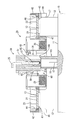
検知コネクタ30を構成する雌ハウジング31の外形形状は、図4に示すように、下端側が縮径された段差状に形成されており、同段差面が係止面37とされている。ただし係止面37は順テーパ面となっている。
一方、コネクタ装着部60における左右の内壁の下部位置には、一対の弾性挟持片62が互いに対向した形態で立ち上がり形成されている。弾性挟持片62は、雌ハウジング31の係止面37に当接する頭部63を上端に有し、頭部63が接離する方向に弾性撓み可能となっている。弾性挟持片62の頭部63の被当接面63Aは、順テーパ面とされている。
なお、係止面37と被当接面63Aとは順テーパ面同士が当接して係止されているのであるから、いわゆるセミロック構造となっている。
As shown in FIG. 4, the outer shape of the
On the other hand, a pair of
The locking
検知コネクタ30が対応するコネクタ装着部60に上方から挿入されると、雌ハウジング31の下部の縮径部36Bが、一対の弾性挟持片62を弾性的に拡げつつその間に進入し、係止面37が両弾性挟持片62の頭部63に当たったところで挿入が一旦停止され、両弾性挟持片62の復元力により両頭部63の間で縮径部36Bの上端が弾性的に挟持されることで、検知コネクタ30が停止位置で仮保持される。
When the
この停止位置が検知コネクタ30の仮保持位置であって、この仮保持位置では、図5に参照して示すように、検知コネクタ30の雌ハウジング31の下面31A(嵌合端面)が、樹脂プロテクタ40が単電池群10の上面に装着されて電池側コネクタ15がコネクタ装着部60の下部に進入した場合の、電池側コネクタ15における雄ハウジング16の上面16A(嵌合端面)の直上に位置する設定となっている。
This stop position is the temporary holding position of the
また、検知コネクタ30が上記の仮保持位置に仮保持された状態では、雌ハウジング31の下面31Aが、コネクタ装着部60の下面60Aよりも上方に所定寸法後退しており、従って樹脂プロテクタ40を単電池群10の上面に装着するに際して、位置決め筒部46を電極端子12に嵌めて位置決めする場合に、雌ハウジング31が電池側コネクタ15に当たることが回避されるようになっている。
Further, in a state where the
上記のように仮保持された検知コネクタ30を抜け止めする機構が備えられている。図3に示すように、検知コネクタ30の雌ハウジング31における前後の側面の下端寄りの位置には、一対の係止突部38が形成されている。各係止突部38は、前後の各側面において対角をなす位置に設けられており、その上面が水平な係止面39Aであり、下面角部にテーパ状のガイド面39Bが形成されている。
A mechanism for preventing the
一方、コネクタ装着部60における前後の内壁の上端位置には、上記した各係止突部38に係止して抜け止めする一対の弾性抜止片65が設けられている。弾性抜止片65は、短寸で下向きに形成され、下端部が接離する方向に弾性変位可能となっている。弾性抜止片65の下端面が水平な係止面66であり、係止突部38と対向する内面が、下端に向けて次第に内方に張り出したテーパ状のガイド面67となっている。
On the other hand, a pair of
検知コネクタ30が対応するコネクタ装着部60に上方から挿入されると、雌ハウジング31の前後の面に突設された係止突部38が、ガイド面67に摺接しつつ一対の弾性抜止片65を弾性的に拡げつつ押し込まれ、仮保持位置まで押し込まれる間に、係止突部38が弾性抜止片65を通過することにより、両弾性抜止片65が元姿勢に復動し、係止面66が、係止突部38の上方に係止可能に突き出される。
When the
ここで、上記した両弾性抜止片65が元姿勢に復動するのは、検知コネクタ30が仮保持位置に達する少し手前のタイミングであり、したがって検知コネクタ30が仮保持位置に仮保持されたときには、図3に示すように、係止突部38の係止面39Aと、弾性抜止片65の係止面66との間に、所定のクリアランスcが確保されるようになっている。同クリアランスcは、検知コネクタ30が仮保持位置から上方に移動することを許容する、「遊び」として機能するようになっている。
Here, it is the timing just before the
続いて、電池モジュールMの組み立て手順の一例を説明する。
まず、図1に示すように、図示10個の単電池11が、正極と負極の電極端子12が交互に前後逆に配された姿勢において左右方向に重ねて並べられることにより単電池群10が形成され、ケース等の所定の収容部材に入れられて保持される。
Then, an example of the assembly procedure of the battery module M is demonstrated.
First, as shown in FIG. 1, 10
一方、電池配線モジュール20側では、樹脂プロテクタ40に対して、複数枚のバスバー21と、電圧検知ハーネス25Hの端末に設けられた複数個の検知コネクタ30が予め装着される。
バスバー21は、図3に示すように、バスバー保持部42内の底面42Aに押し込まれ、抜け止め部44で抜け止めされつつ固定的に保持される。バスバー21における挿通孔22が形成された端部が、窓孔43を通して下面に露出される。
On the other hand, on the
As shown in FIG. 3, the
電圧検知ハーネス25Hの端末に設けられた各検知コネクタ30は、対応するコネクタ装着部60に仮保持される。検知コネクタ30は、所定の姿勢を取ってコネクタ装着部60に上方から挿入される。
検知コネクタ30が挿入されると、雌ハウジング31の下端の縮径部36Bが一対の弾性挟持片62を弾性的に拡げつつその間に押し込まれ、それとともに雌ハウジング31の前後の面の係止突部38が、一対の弾性抜止片65を弾性的に拡げつつ押し込まれる。
Each
When the
検知コネクタ30の挿入が進んで、図4に示すように、雌ハウジング31の左右の係止面37が各弾性挟持片62の頭部63に当たったところで挿入が一旦停止され、そのとき弾性復元力により両弾性挟持片62の頭部63の間で縮径部36Bの上端が弾性的に挟持されることにより、検知コネクタ30が仮保持位置で仮保持される。この仮保持位置では、雌ハウジング31の下面31A(嵌合面)が、コネクタ装着部60の下面開口から上方に所定寸法後退して退避した状態にある。
この間に、前後の係止突部38が弾性抜止片65を通過することにより、両弾性抜止片65が元姿勢に復動し、係止突部38の上方における所定のクリアランスcを開けた位置において抜け止め可能に突き出される。
As the insertion of the
During this time, when the front and
検知コネクタ30の上面から引き出された電圧検知ハーネス25Hは、図2に示すように、前後の電線収容溝50に交互に収容され、各電線収容溝50の一端(例えば右端)に向けて流されて同右端から導出される。電線収容溝50の上面開口には、押さえ片51が閉じられて被着される。
As shown in FIG. 2, the
以上のように、電池配線モジュール20では、樹脂プロテクタ40のバスバー保持部42にバスバー21が固定的に保持される一方、コネクタ装着部60に検知コネクタ30が仮保持位置に仮保持され、併せて電線収容溝50に電圧検知線25が収容された形態で準備される。
As described above, in the
上記のように準備された電池配線モジュール20の樹脂プロテクタ40が、図3の矢線に示すように、単電池群10の上面に装着される。詳細には、樹脂プロテクタ40の下面に形成された各位置決め筒部46の下端内周縁の誘い込み面47に、対応する電極端子12の上端が嵌合されることで芯出しされつつ、樹脂プロテクタ40が位置決めされ、しかるのち電極端子12が位置決め筒部46内を緊密に摺動することで案内されて、樹脂プロテクタ40が水平姿勢を維持したままで押し込まれる。
ここで、検知コネクタ30が仮保持位置に仮保持されている場合には、雌ハウジング31の下面31Aがコネクタ装着部60内に所定量後退しており、位置決め筒部46と電極端子12とが嵌合し初めて位置決めされる際には、相手の電池側コネクタ15と干渉することが回避されるから、迅速に位置決めを行うことが可能となる。
The
Here, when the
電池配線モジュール20(樹脂プロテクタ40)の押し込みが進み、図5に示すように、電極端子12の端子台13が、バスバー保持部42の底面42Aの窓孔43を通してバスバー21に当たったところで押し込みが停止され、これにより樹脂プロテクタ40が正規装着された状態となる。このとき、バスバー21の端部に設けられた挿通孔22が、電極端子12の端子台13に切られたボルト孔14と整合する(図2参照)。
また、図5に示すように、電池側コネクタ15の雄ハウジング16の上端がコネクタ装着部60の下端部内に所定寸法進入し、コネクタ装着部60に仮保持された検知コネクタ30における雌ハウジング31の下面31Aは、雄ハウジング16の上面16Aの直上に位置する。
As the battery wiring module 20 (resin protector 40) is pushed in, the
Further, as shown in FIG. 5, the upper end of the
樹脂プロテクタ40が単電池群10の上面において正規位置に装着されたら、まずバスバー21が電極端子12に対して固定される。それには、バスバー保持部42内においてバスバー21の挿通孔22にボルト23を通し、同ボルト23を端子台13のボルト孔14に螺合して締め付けて固定することにより、隣り合う互いに逆極性の電極端子12同士がバスバー21により電気的に接続される。すべてのバスバー21が固定されたら、全10個の単電池11が直列接続された単電池群10が構成される。
When the
続いて、各コネクタ装着部60に仮保持された検知コネクタ30が押し込まれて、相手の電池側コネクタ15と嵌合される。
仮保持位置において、雌ハウジング31の係止面37が、弾性挟持片62の頭部63の被当接面63Aに当たって押し込みが停止された部分では、順テーパ面同士が当接することでセミロック構造となっているから、検知コネクタ30を所定以上の力で押し込むと、一対の弾性挟持片62が開きつつ頭部63が係止面37を越え、両弾性挟持片62が雌ハウジング31における上部側の拡径部36Aを挟んで摺接しつつ、検知コネクタ30が相手の電池側コネクタ15に嵌合される。特に、仮保持位置に仮保持された検知コネクタ30は、押し込み前において相手の電池側コネクタ15の直上に位置しているから、嵌合動作が正確にかつスムーズに行われる。
正規量嵌合されたところで、図8に示すように、ロック片35がロック突部18に嵌って係止することにより、両コネクタ15,30が正規の嵌合状態にロックされる。それに伴い、対応する4本ずつの雄端子17と雌端子27とが正規に接続される。
Subsequently, the
In the temporary holding position, in the portion where the locking
When the proper amount is fitted, as shown in FIG. 8, the
以上により、図2に示すように電池モジュールMの組み立てが完了する。このように組み立てられた電池モジュールMでは、図示10個の単電池11がバスバー21を介して直列接続され、また、コネクタ方式により各単電池11に電圧検知線25が接続されて引き出された形態を採る。
Thus, the assembly of the battery module M is completed as shown in FIG. In the battery module M assembled in this way, the 10
なお、樹脂プロテクタ40のコネクタ装着部60に対して、検知コネクタ30を予め仮保持位置に仮保持する場合に、検知コネクタ30を勢い良く押し込む等により、図4に示された仮保持位置を越えた位置まで押し込む可能性がある。このときは、両弾性挟持片62が雌ハウジング31の上側の拡径部36Aの外面を弾性的に挟んでいるだけであるから、そのまま検知コネクタ30を引きまたは押し戻すことができる。仮保持位置まで戻されると、弾性挟持片62の頭部63が係止面37の下側に落ち込み、そのときのフィーリング等で検知コネクタ30が仮保持位置まで戻されたことが確認できる。
When the
また上記したように、検知コネクタ30の仮保持位置を、樹脂プロテクタ40が単電池群10の上面に装着された場合に、検知コネクタ30が相手の電池側コネクタ15の直上に来るように設定することで、引き続く両コネクタ15,30の嵌合動作の便宜を図っているとともに、搬送時等に検知コネクタ30がコネクタ装着部60から抜け出ないように、コネクタ装着部60内に、検知コネクタ30の係止突部38に弾性的に係止して抜け止めする弾性挟持片62を備えている。
Further, as described above, the temporary holding position of the
ここで、部材や部位の寸法誤差や組み付け誤差等により、仮保持位置にある検知コネクタ30が下方(相手の電池側コネクタ15側)に向けて必要以上に進出した形態にあり、樹脂プロテクタ40が装着された際において、検知コネクタ30が相手の電池側コネクタ15に当接する場合があり得る。その際、仮に検知コネクタ30が弾性抜止片65により後退不能に係止されていると、上記した樹脂プロテクタ40が装着された際には、検知コネクタ30と相手の電池側コネクタ15とが強く当たり合い、損傷するおそれがある。
Here, due to dimensional errors or assembly errors of members or parts, the
それに対して、本実施形態では、仮保持位置に仮保持された検知コネクタ30の係止突部38の係止面39Aと、弾性抜止片65の係止面66との間に、所定のクリアランスcが確保され、すなわち「遊び」が設けられた構造となっている。したがって、仮係止位置にある検知コネクタ30が下方に向けて必要以上に進出していて、樹脂プロテクタ40が装着された際に、検知コネクタ30が相手の電池側コネクタ15に当接したとしても、「遊び」があることで検知コネクタ30が上方に逃げ、強く当たり合うことが回避される。
On the other hand, in the present embodiment, a predetermined clearance is provided between the locking
本実施形態の電池配線モジュール20によれば、以下のような効果を得ることができる。
検知コネクタ30をコネクタ装着部60に挿入して仮保持する場合に、同検知コネクタ30を仮保持する位置が、樹脂プロテクタ40が単電池群10の上面に装着されるに当たって位置決めされるタイミングでは、検知コネクタ30が相手の電池側コネクタ15とは干渉しない位置に設定されている。したがって、樹脂プロテクタ40を装着するに際して位置決めされる前には、仮保持された検知コネクタ30が相手の電池側コネクタ15等と干渉することが回避される。そのため、樹脂プロテクタ40の装着作業やコネクタ15,30同士の嵌合作業が迅速に行え、すなわち電池配線モジュール20の組み付けを能率良く行うことができる。
According to the
When the
仮保持位置に仮保持された検知コネクタ30は、樹脂プロテクタ40が単電池群10の上面に正規に装着された場合には、相手の電池側コネクタ15の直上に位置する設定としたから、検知コネクタ30を仮保持位置から押し込んで相手の電池側コネクタ15に嵌合する動作が、よりスムーズに行われる。
The
コネクタ装着部60内には、仮保持位置にある検知コネクタ30の係止突部38に弾性的に係止して抜け止めする弾性抜止片65が備えられ、搬送時等にコネクタ装着部60から抜け出ないようにしているが、特に、仮保持位置にある検知コネクタ30の係止突部38の係止面39Aと弾性抜止片65の係止面66との間には、クリアランスcすなわち遊びが設けられている。
そのため、成形上や組み付け誤差等により、検知コネクタ30が下方に必要以上に進出した形態を採り、樹脂プロテクタ40が装着された際に、検知コネクタ30が相手の電池側コネクタ15に当接する場合があったとしても、上記の遊びが設けられていることで検知コネクタ30が後方(上方)に逃げ、コネクタ15,30同士が強く衝突することが回避され、ひいてはコネクタ15,30が損傷する等を未然に防止できる。
In the
Therefore, there is a case where the
<他の実施形態>
本明細書によって開示される技術は上記記述及び図面によって説明した実施形態に限定されるものではなく、次のようなものも技術的範囲に含まれる。
(1)上記実施形態では、仮保持機構部を構成する弾性挟持片が上向きに形成された場合を例示したが、下向きに形成されていてもよい。
(2)仮保持機構部としては、上記実施形態とは逆に、検知コネクタ側に弾性挟持片を、コネクタ装着部の内面に係止面を設けるようにしてもよい。
(3)上記実施形態では、樹脂プロテクタが単電池群の上面に装着された場合に、電池側コネクタがコネクタ装着部の下部内に所定寸法進入する設定となっているが、進入量は適宜に設定でき、また、進入することなくコネクタ装着部の下方に控えている構造であってもよい。
<Other embodiments>
The technology disclosed in this specification is not limited to the embodiments described with reference to the above description and drawings, and the following is also included in the technical scope.
(1) In the above embodiment, the case where the elastic clamping piece constituting the temporary holding mechanism portion is formed upward is illustrated, but it may be formed downward.
(2) As a temporary holding mechanism part, contrary to the said embodiment, you may make it provide an elastic clamping piece in the detection connector side, and a locking surface in the inner surface of a connector mounting part.
(3) In the above embodiment, when the resin protector is mounted on the upper surface of the unit cell group, the battery side connector is set to enter a predetermined dimension into the lower part of the connector mounting portion. The structure which can be set and is kept below the connector mounting part without entering may be sufficient.
(4)上記実施形態では、樹脂プロテクタの位置決めを、同樹脂プロテクタの下面に設けた位置決め筒部と電極端子の嵌合により行う場合を例示したが、樹脂プロテクタと下面の単電池群の上面との間で嵌合して位置決めできる限り、他の構造であってもよい。
(5)上記実施形態では、単電池の状態を検知する検知端子として電圧検知端子を例示したが、温度を検知する端子等の他の検知端子であってもよい。
(6)なお、隣り合う互いに逆極性の電極端子同士を接続するための接続部材には、バスバーに限らず、編組線や被覆電線を用いてもよい。
(4) In the above embodiment, the case where the resin protector is positioned by fitting the positioning cylindrical portion provided on the lower surface of the resin protector with the electrode terminal is exemplified. Other structures may be used as long as they can be fitted and positioned.
(5) In the said embodiment, although the voltage detection terminal was illustrated as a detection terminal which detects the state of a cell, other detection terminals, such as a terminal which detects temperature, may be sufficient.
(6) The connecting member for connecting adjacent electrode terminals having opposite polarities is not limited to a bus bar, and a braided wire or a covered electric wire may be used.
M…電池モジュール
10…単電池群
11…単電池
12…電極端子
15…電池側コネクタ
20…電池配線モジュール
21…バスバー(接続部材)
25…電圧検知線
27…雌端子(電圧検知端子)
30…検知コネクタ
31…雌ハウジング
37…係止面(仮保持機構部)
38…係止突部(被係止部)
40…樹脂プロテクタ
46…位置決め筒部
60…コネクタ装着部
62…弾性挟持片(仮保持機構部)
63…頭部
63A…被当接面
65…弾性抜止片
c…クリアランス
M ...
25 ...
30 ...
38 ... Locking protrusion (locked part)
DESCRIPTION OF
63 ...
Claims (4)
隣り合う互いに逆極性の前記電極端子同士を接続するための接続部材が保持され、前記単電池群の上面に位置決めされて装着される樹脂プロテクタと、
前記各単電池の状態を検知するための検知端子が収容され、前記単電池の上面に突設された電池側コネクタと嵌合可能な検知コネクタと、
前記樹脂プロテクタの前記電池側コネクタと対向した位置において前記検知コネクタが挿入可能に設けられたコネクタ装着部と、が備えられ、
前記樹脂プロテクタが前記単電池群の上面に装着された状態において、前記接続部材により隣り合う互いに逆極性の前記電極端子同士が接続されるとともに、前記検知コネクタを前記コネクタ装着部内で前進させることにより相手の前記電池側コネクタと嵌合接続するようにしたものにおいて、
前記コネクタ装着部と前記検知コネクタとの間には、前記検知コネクタを、前記樹脂プロテクタが位置決めされる前には前記電池側コネクタとは干渉しない位置に弾性的に仮保持する仮保持機構部が設けられている電池配線モジュール。 A battery wiring module attached to a unit cell group in which a plurality of unit cells having positive and negative electrode terminals are arranged,
A connecting member for connecting adjacent electrode terminals having opposite polarities to each other is held, and a resin protector that is positioned and mounted on the upper surface of the unit cell group,
A detection terminal for detecting the state of each unit cell is housed, and a detection connector that can be fitted to a battery-side connector protruding from the upper surface of the unit cell,
A connector mounting portion provided so that the detection connector can be inserted at a position facing the battery side connector of the resin protector, and
In a state where the resin protector is mounted on the upper surface of the unit cell group, the electrode members adjacent to each other with opposite polarities are connected to each other by the connecting member, and the detection connector is advanced in the connector mounting portion. In what is fitted and connected to the battery side connector of the other party,
Between the connector mounting portion and the detection connector, there is a temporary holding mechanism portion that elastically temporarily holds the detection connector at a position where it does not interfere with the battery side connector before the resin protector is positioned. Battery wiring module provided.
前記検知コネクタの対応した外面が下部側が引っ込んだ段差状に形成されて、同段差面により前記弾性挟持片の前記頭部に当接する係止面が形成され、
かつ、前記係止面と前記頭部の被当接面との少なくともいずれか一方が順テーパ面をなしてセミロック構造とされており、
前記検知コネクタにおける両側の前記係止面が、前記弾性挟持片の前記頭部における前記被当接面に当接して挿入が停止されたところが仮保持位置となっている請求項1に記載の電池配線モジュール。 A pair of elastic clamping pieces having a head at the tip are provided on two opposing inner surfaces of the connector mounting portion so as to be elastically displaceable in a direction in which they come into contact with and away from each other
The corresponding outer surface of the detection connector is formed in a stepped shape with the lower side retracted, and a locking surface that contacts the head of the elastic clamping piece is formed by the stepped surface,
And at least any one of the locking surface and the contacted surface of the head is a semi-lock structure with a forward tapered surface,
2. The battery according to claim 1, wherein a position where the engaging surfaces on both sides of the detection connector are in contact with the contacted surface of the head of the elastic clamping piece and insertion is stopped is a temporary holding position. 3. Wiring module.
Priority Applications (3)
| Application Number | Priority Date | Filing Date | Title |
|---|---|---|---|
| JP2014255947A JP6217984B2 (en) | 2014-12-18 | 2014-12-18 | Battery wiring module |
| CN201580066588.3A CN107004820B (en) | 2014-12-18 | 2015-12-01 | Battery Wiring module |
| PCT/JP2015/083711 WO2016098575A1 (en) | 2014-12-18 | 2015-12-01 | Battery wiring module |
Applications Claiming Priority (1)
| Application Number | Priority Date | Filing Date | Title |
|---|---|---|---|
| JP2014255947A JP6217984B2 (en) | 2014-12-18 | 2014-12-18 | Battery wiring module |
Publications (2)
| Publication Number | Publication Date |
|---|---|
| JP2016115642A true JP2016115642A (en) | 2016-06-23 |
| JP6217984B2 JP6217984B2 (en) | 2017-10-25 |
Family
ID=56126472
Family Applications (1)
| Application Number | Title | Priority Date | Filing Date |
|---|---|---|---|
| JP2014255947A Expired - Fee Related JP6217984B2 (en) | 2014-12-18 | 2014-12-18 | Battery wiring module |
Country Status (3)
| Country | Link |
|---|---|
| JP (1) | JP6217984B2 (en) |
| CN (1) | CN107004820B (en) |
| WO (1) | WO2016098575A1 (en) |
Cited By (3)
| Publication number | Priority date | Publication date | Assignee | Title |
|---|---|---|---|---|
| CN109964340A (en) * | 2016-11-22 | 2019-07-02 | 株式会社自动网络技术研究所 | Interconnection module |
| JP2019200986A (en) * | 2018-05-09 | 2019-11-21 | パナソニックIpマネジメント株式会社 | Cell and cell system |
| CN112585810A (en) * | 2018-08-29 | 2021-03-30 | 住友电装株式会社 | Battery wiring module |
Families Citing this family (3)
| Publication number | Priority date | Publication date | Assignee | Title |
|---|---|---|---|---|
| JP7120233B2 (en) * | 2017-06-16 | 2022-08-17 | 株式会社Gsユアサ | power storage device |
| JP6299917B1 (en) * | 2017-08-09 | 2018-03-28 | 株式会社オートネットワーク技術研究所 | Connection module |
| JP6465196B1 (en) * | 2017-12-11 | 2019-02-06 | 株式会社オートネットワーク技術研究所 | Storage module and connection module |
Citations (6)
| Publication number | Priority date | Publication date | Assignee | Title |
|---|---|---|---|---|
| JPH09102372A (en) * | 1995-10-06 | 1997-04-15 | Fujitsu Takamisawa Component Kk | Right angle type connector |
| JP2002208454A (en) * | 2001-01-04 | 2002-07-26 | Sumitomo Wiring Syst Ltd | Connector |
| JP2011258413A (en) * | 2010-06-09 | 2011-12-22 | Auto Network Gijutsu Kenkyusho:Kk | Battery connection assembly |
| JP2013080693A (en) * | 2011-09-20 | 2013-05-02 | Auto Network Gijutsu Kenkyusho:Kk | Wiring module for battery |
| JP2014149982A (en) * | 2013-02-01 | 2014-08-21 | Auto Network Gijutsu Kenkyusho:Kk | Wiring module |
| JP2014149984A (en) * | 2013-02-01 | 2014-08-21 | Auto Network Gijutsu Kenkyusho:Kk | Wiring module |
Family Cites Families (2)
| Publication number | Priority date | Publication date | Assignee | Title |
|---|---|---|---|---|
| JP5668555B2 (en) * | 2011-03-18 | 2015-02-12 | 株式会社オートネットワーク技術研究所 | Battery module |
| JP5772525B2 (en) * | 2011-11-11 | 2015-09-02 | 株式会社オートネットワーク技術研究所 | Battery wiring module |
-
2014
- 2014-12-18 JP JP2014255947A patent/JP6217984B2/en not_active Expired - Fee Related
-
2015
- 2015-12-01 WO PCT/JP2015/083711 patent/WO2016098575A1/en active Application Filing
- 2015-12-01 CN CN201580066588.3A patent/CN107004820B/en active Active
Patent Citations (6)
| Publication number | Priority date | Publication date | Assignee | Title |
|---|---|---|---|---|
| JPH09102372A (en) * | 1995-10-06 | 1997-04-15 | Fujitsu Takamisawa Component Kk | Right angle type connector |
| JP2002208454A (en) * | 2001-01-04 | 2002-07-26 | Sumitomo Wiring Syst Ltd | Connector |
| JP2011258413A (en) * | 2010-06-09 | 2011-12-22 | Auto Network Gijutsu Kenkyusho:Kk | Battery connection assembly |
| JP2013080693A (en) * | 2011-09-20 | 2013-05-02 | Auto Network Gijutsu Kenkyusho:Kk | Wiring module for battery |
| JP2014149982A (en) * | 2013-02-01 | 2014-08-21 | Auto Network Gijutsu Kenkyusho:Kk | Wiring module |
| JP2014149984A (en) * | 2013-02-01 | 2014-08-21 | Auto Network Gijutsu Kenkyusho:Kk | Wiring module |
Cited By (5)
| Publication number | Priority date | Publication date | Assignee | Title |
|---|---|---|---|---|
| CN109964340A (en) * | 2016-11-22 | 2019-07-02 | 株式会社自动网络技术研究所 | Interconnection module |
| CN109964340B (en) * | 2016-11-22 | 2021-12-03 | 株式会社自动网络技术研究所 | Wiring module |
| JP2019200986A (en) * | 2018-05-09 | 2019-11-21 | パナソニックIpマネジメント株式会社 | Cell and cell system |
| JP7291889B2 (en) | 2018-05-09 | 2023-06-16 | パナソニックIpマネジメント株式会社 | Batteries and battery systems |
| CN112585810A (en) * | 2018-08-29 | 2021-03-30 | 住友电装株式会社 | Battery wiring module |
Also Published As
| Publication number | Publication date |
|---|---|
| CN107004820B (en) | 2019-08-30 |
| CN107004820A (en) | 2017-08-01 |
| JP6217984B2 (en) | 2017-10-25 |
| WO2016098575A1 (en) | 2016-06-23 |
Similar Documents
| Publication | Publication Date | Title |
|---|---|---|
| JP6217984B2 (en) | Battery wiring module | |
| US10854860B2 (en) | Inter-battery connection device and inter-battery connection device assembly | |
| US10333236B2 (en) | Battery wiring module | |
| EP2624376B1 (en) | Cell voltage detecting connector | |
| US9397327B2 (en) | Battery connecting assembly | |
| US8657621B2 (en) | Connector apparatus | |
| JP2013093237A (en) | Wiring module for battery | |
| CN106953039B (en) | Battery module and battery pack | |
| US9413095B2 (en) | Connector | |
| JP5582204B2 (en) | Wiring module | |
| JP2011018579A (en) | Connector | |
| CN109155378B (en) | Connection structure of power storage module and control device | |
| JP6465196B1 (en) | Storage module and connection module | |
| US8021199B2 (en) | Electrical connector having large locking force | |
| JP5970343B2 (en) | Electrical connector | |
| JP5974918B2 (en) | Wiring module | |
| CN217306798U (en) | Electrical connector | |
| JP2019096548A (en) | Electrical connector and locking method of connection terminal in electrical connector | |
| JP2012186063A (en) | Battery connection assembly | |
| JP6156156B2 (en) | Wiring module | |
| WO2020246428A1 (en) | Electrical connector and method for locking connection terminal in said electrical connector | |
| US20220360011A1 (en) | Connector | |
| CN113168970B (en) | Connection module | |
| JP5835149B2 (en) | connector | |
| JP3275281B2 (en) | Joint connector |
Legal Events
| Date | Code | Title | Description |
|---|---|---|---|
| A621 | Written request for application examination |
Free format text: JAPANESE INTERMEDIATE CODE: A621 Effective date: 20161125 |
|
| TRDD | Decision of grant or rejection written | ||
| A01 | Written decision to grant a patent or to grant a registration (utility model) |
Free format text: JAPANESE INTERMEDIATE CODE: A01 Effective date: 20170831 |
|
| A61 | First payment of annual fees (during grant procedure) |
Free format text: JAPANESE INTERMEDIATE CODE: A61 Effective date: 20170913 |
|
| R150 | Certificate of patent or registration of utility model |
Ref document number: 6217984 Country of ref document: JP Free format text: JAPANESE INTERMEDIATE CODE: R150 |
|
| LAPS | Cancellation because of no payment of annual fees |