JP2019200868A - Nonaqueous secondary battery - Google Patents
Nonaqueous secondary battery Download PDFInfo
- Publication number
- JP2019200868A JP2019200868A JP2018093401A JP2018093401A JP2019200868A JP 2019200868 A JP2019200868 A JP 2019200868A JP 2018093401 A JP2018093401 A JP 2018093401A JP 2018093401 A JP2018093401 A JP 2018093401A JP 2019200868 A JP2019200868 A JP 2019200868A
- Authority
- JP
- Japan
- Prior art keywords
- mass
- active material
- secondary battery
- positive electrode
- insulating layer
- Prior art date
- Legal status (The legal status is an assumption and is not a legal conclusion. Google has not performed a legal analysis and makes no representation as to the accuracy of the status listed.)
- Granted
Links
Classifications
-
- Y—GENERAL TAGGING OF NEW TECHNOLOGICAL DEVELOPMENTS; GENERAL TAGGING OF CROSS-SECTIONAL TECHNOLOGIES SPANNING OVER SEVERAL SECTIONS OF THE IPC; TECHNICAL SUBJECTS COVERED BY FORMER USPC CROSS-REFERENCE ART COLLECTIONS [XRACs] AND DIGESTS
- Y02—TECHNOLOGIES OR APPLICATIONS FOR MITIGATION OR ADAPTATION AGAINST CLIMATE CHANGE
- Y02P—CLIMATE CHANGE MITIGATION TECHNOLOGIES IN THE PRODUCTION OR PROCESSING OF GOODS
- Y02P70/00—Climate change mitigation technologies in the production process for final industrial or consumer products
- Y02P70/50—Manufacturing or production processes characterised by the final manufactured product
Abstract
Description
本発明は、無機絶縁体を主体とする多孔性の絶縁層をセパレータとして備えた非水二次電池に関するものである。 The present invention relates to a non-aqueous secondary battery provided with a porous insulating layer mainly composed of an inorganic insulator as a separator.
近年、携帯電話、ノート型パーソナルコンピュータ等のポータブル電子機器の発達や、電気自動車の実用化等に伴い、小型・軽量で且つ高容量・高エネルギー密度の非水二次電池が必要とされるようになってきている。 In recent years, along with the development of portable electronic devices such as mobile phones and notebook personal computers, and the practical application of electric vehicles, non-aqueous secondary batteries with small size, light weight, high capacity and high energy density are required. It is becoming.
現在、この要求に応え得る非水二次電池として、例えばリチウムイオン電池が知られており、正極活物質にコバルト酸リチウム(LixCoO2)、ニッケル酸リチウム(LixNiO2)、ニッケル−コバルト−マンガン酸リチウム(LixNiy1Coy2Mny3O2:0.9<x<1.1、0<y1,y2,y3<1、y1+y2+y3=1で表されるNCM材料)等のリチウム含有複合酸化物あるいはこれらの複合体や混合物を用い、負極活物質に黒鉛等を用いて電池が構成されている。そして、非水二次電池の適用機器の更なる発達に伴って、非水二次電池の更なる高容量化・高エネルギー密度化が求められている。 Currently, lithium ion batteries, for example, are known as non-aqueous secondary batteries that can meet this requirement, and the positive electrode active materials include lithium cobaltate (Li x CoO 2 ), lithium nickelate (Li x NiO 2 ), nickel- cobalt - lithium manganate (Li x Ni y1 Co y2 Mn y3 O 2: 0.9 <x <1.1,0 <y1, y2, y3 <1, y1 + y2 + y3 = NCM material represented by 1) lithium such as A battery is constituted by using the composite oxide or a composite or a mixture thereof and using graphite or the like as the negative electrode active material. And with the further development of the application equipment of a non-aqueous secondary battery, further higher capacity and higher energy density of the non-aqueous secondary battery are required.
非水二次電池の高容量化及び高エネルギー密度化を図る手法の一つとして、正極活物質を高電圧で充電して用いることが挙げられる。またNCM材料のNi比率を高くして容量を増加させる方法も検討されている。一方、容量や電圧が上がるにつれて電池の安全性は低下する傾向にある。 One technique for increasing the capacity and energy density of a non-aqueous secondary battery is to charge and use a positive electrode active material at a high voltage. A method of increasing the capacity by increasing the Ni ratio of the NCM material has also been studied. On the other hand, the safety of the battery tends to decrease as the capacity and voltage increase.
従来、安全性を改善する方法としては、電解液添加剤や正極材料への添加元素、表面被覆、セパレータへの絶縁材料コートなどが検討されてきた。特に樹脂製セパレータへの絶縁材料被覆は、電池が短絡しにくくかつ短絡が生じた際の短絡部位の拡大を抑制する効果があり、最近需要が拡大している。例えば、特許文献1では、耐熱材料を含有するセパレータを用いたリチウムイオン電池において、電解液量を、正極、負極およびセパレータにおける空隙の合計体積の0.9倍以上1.6倍以下とすることにより、充放電を繰り返した際の容量減少を抑制し、サイクル特性に優れる電池を提供することが提案されている。 Conventionally, as a method for improving safety, an additive for electrolytic solution, an additive element for a positive electrode material, a surface coating, an insulating material coating for a separator, and the like have been studied. In particular, the insulating material coating on the resin separator has an effect of suppressing the expansion of the short-circuited part when the battery is difficult to be short-circuited and a short-circuit occurs, and the demand has recently increased. For example, in Patent Document 1, in a lithium ion battery using a separator containing a heat-resistant material, the amount of electrolytic solution is 0.9 to 1.6 times the total volume of voids in the positive electrode, the negative electrode, and the separator. Thus, it has been proposed to provide a battery having excellent cycle characteristics by suppressing a decrease in capacity when charging and discharging are repeated.
ところで、本発明者らの検討では、NCM材料のNi比率を増加させるなどにより高エネルギー密度化された電池を用いる場合、セパレータ絶縁層の厚みが薄くなるとその効果が生じ難くなり、樹脂層の溶融の際に絶縁層の効果が発現しなくなる傾向であることがわかった。従って、より高温でも安全性に寄与できる絶縁層を形成する必要がある。 By the way, in the study by the present inventors, when using a battery having a high energy density by increasing the Ni ratio of the NCM material or the like, the effect becomes difficult to occur when the separator insulating layer is thinned, and the resin layer is melted. In this case, it was found that the effect of the insulating layer tended not to appear. Therefore, it is necessary to form an insulating layer that can contribute to safety even at higher temperatures.
一方、固体電解質を用いた電池も安全性が高いと考えられている。固体電解質自体も耐熱性に優れた材料であり、前記の絶縁層と同等以上の効果を発現できると期待されている。しかし、電池の作動に難があり、活物質と固体電解質の界面形成が課題になっている。そのため、特許文献2〜4などにおいて、電解液を界面に介在させることで、良好な界面を形成し、絶縁層の効果を発揮しつつ、作動特性を改善することも提案されており、特許文献2では、固体電解質層を、層状の緻密部と電解液を保持する多孔質部とからなる構造とすることにより、充放電時のデンドライトによる短絡を防止できることも記載されている。 On the other hand, a battery using a solid electrolyte is also considered to be highly safe. The solid electrolyte itself is also a material excellent in heat resistance, and is expected to exhibit an effect equivalent to or higher than that of the insulating layer. However, the operation of the battery is difficult, and the formation of the interface between the active material and the solid electrolyte is a problem. Therefore, in Patent Documents 2 to 4 and the like, it has also been proposed to improve the operating characteristics while forming an excellent interface and exhibiting the effect of the insulating layer by interposing an electrolytic solution at the interface. 2 describes that the solid electrolyte layer has a structure composed of a layered dense portion and a porous portion for holding an electrolytic solution, thereby preventing a short circuit due to dendrite during charging and discharging.
しかし、本発明者の検討によれば、無機絶縁体を主体とする多孔性の絶縁層をセパレータとする非水二次電池では、重量エネルギー密度を高めたり、安全性を高めるために電解液量を制限しようとすると、充電時にリチウムのデンドライトが形成されやすくなり、却って安全性が損なわれやすくなることが明らかとなった。 However, according to the study of the present inventor, in a non-aqueous secondary battery using a porous insulating layer mainly composed of an inorganic insulator as a separator, the amount of electrolyte is increased in order to increase the weight energy density or increase the safety. It was clarified that lithium dendrite tends to be formed during charging, and the safety tends to be impaired.
本発明は上記問題を解決しようとするものであり、重量エネルギー密度が高く、かつ充放電特性に優れると共に、充電時にリチウムデンドライトが形成されにくく安全性の高い非水二次電池を提供するものである。 The present invention is intended to solve the above problems, and provides a non-aqueous secondary battery that has high weight energy density, excellent charge / discharge characteristics, and is highly resistant to lithium dendrite formation during charging. is there.
本発明の非水二次電池は、電池容器内に、電極体と非水電解液を有し、前記電極体は、正極活物質層を有する正極と、負極活物質層を有する負極と、前記正極および前記負極の間に介在させてなる多孔性の絶縁層とを有し、前記絶縁層は、無機絶縁体を80質量%以上の割合で含有し、かつ空孔率が50%以下であり、前記電池容器内の前記非水電解液の質量が、前記電極体の正極活物質層、負極活物質層および絶縁層の質量の合計と、前記非水電解液の質量との総和に対し、2%以上60%以下であることを特徴とする。 The non-aqueous secondary battery of the present invention has an electrode body and a non-aqueous electrolyte in a battery container, and the electrode body includes a positive electrode having a positive electrode active material layer, a negative electrode having a negative electrode active material layer, A porous insulating layer interposed between the positive electrode and the negative electrode, the insulating layer containing an inorganic insulator in a proportion of 80% by mass or more, and a porosity of 50% or less The mass of the non-aqueous electrolyte in the battery container is the sum of the mass of the positive electrode active material layer, the negative electrode active material layer and the insulating layer of the electrode body, and the total mass of the non-aqueous electrolyte solution. It is characterized by being 2% or more and 60% or less.
また、本発明の非水二次電池の別の実施形態は、電池容器内に、直列に導電接続された複数の電極体と非水電解液を有し、前記電極体は、正極活物質層を有する正極と、負極活物質層を有する負極と、前記正極および前記負極の間に介在させてなる多孔性の絶縁層とを有し、前記絶縁層は、無機絶縁体を80質量%以上の割合で含有し、かつ空孔率が50%以下であり、前記電池容器内の前記非水電解液の質量が、それぞれの電極体の正極活物質層、負極活物質層および絶縁層の質量の合計と、前記非水電解液の質量との総和に対し、2%以上60%以下であることを特徴とする。 Another embodiment of the non-aqueous secondary battery of the present invention has a plurality of electrode bodies electrically connected in series and a non-aqueous electrolyte in a battery container, the electrode body comprising a positive electrode active material layer A negative electrode having a negative electrode active material layer, and a porous insulating layer interposed between the positive electrode and the negative electrode, wherein the insulating layer comprises 80% by mass or more of an inorganic insulator. And the mass of the non-aqueous electrolyte in the battery container is the mass of the positive electrode active material layer, the negative electrode active material layer, and the insulating layer of each electrode body. It is 2% or more and 60% or less with respect to the sum total of the total and the mass of the non-aqueous electrolyte.
本発明によれば、重量エネルギー密度が高く、かつ充放電特性に優れると共に、充電時にリチウムデンドライトが形成されにくく安全性の高い非水二次電池を提供することができる。 According to the present invention, it is possible to provide a non-aqueous secondary battery that has a high weight energy density and excellent charge / discharge characteristics, and that is difficult to form lithium dendrite during charging and has high safety.
本発明の非水二次電池では、耐熱性を向上させるために、正極活物質層を有する正極と、負極活物質層を有する負極との間に、無機絶縁体を80質量%以上の割合で含有する多孔性の絶縁層を介在させている。 In the nonaqueous secondary battery of the present invention, in order to improve heat resistance, an inorganic insulator is added at a ratio of 80% by mass or more between a positive electrode having a positive electrode active material layer and a negative electrode having a negative electrode active material layer. A porous insulating layer is contained.
前記絶縁層は、従来の樹脂製の多孔質フィルムに代わり、あるいは樹脂製の多孔質フィルムと共にセパレータとして機能するものであり、独立膜であってもよく、また、正極活物質層、負極活物質層および樹脂製の多孔質フィルムのいずれかの表面、あるいは全ての表面に塗布などにより形成するのであってもよい。 The insulating layer functions as a separator in place of a conventional resin porous film or together with a resin porous film, and may be an independent film. Also, a positive electrode active material layer, a negative electrode active material It may be formed by coating or the like on any or all surfaces of the layer and the resin porous film.
なお、電池の重量エネルギー密度を高めるためには、活物質に高容量のものを用いる以外に、非水電解液のように活物質以外の成分の割合を減らすことが考えられるが、本発明者の検討によれば、前記多孔性の絶縁層をセパレータとする場合、電解液量が少なくなるほど充電時にリチウムデンドライトが形成されやすくなり、短絡しやすくなることがわかった。 In order to increase the weight energy density of the battery, it is conceivable to reduce the proportion of components other than the active material, such as a non-aqueous electrolyte, in addition to using a high-capacity active material. According to the above studies, it was found that when the porous insulating layer is used as a separator, as the amount of the electrolyte decreases, lithium dendrites are more easily formed during charging and short-circuiting is more likely.
具体的には、電池容器内の非水電解液の質量が、正極活物質層、負極活物質層および絶縁層の質量の合計と、前記非水電解液の質量との総和に対し60%以下となった場合に、リチウムデンドライト形成による短絡を生じやすくなることが判明した。 Specifically, the mass of the non-aqueous electrolyte in the battery container is 60% or less with respect to the total of the mass of the positive electrode active material layer, the negative electrode active material layer, and the insulating layer and the mass of the non-aqueous electrolyte. In this case, it has been found that short-circuiting due to lithium dendrite formation is likely to occur.
これに対し、前記絶縁層の空孔率を50%以下とした場合には、リチウムデンドライトの形成が抑制され、安全性を高めることが可能となる。絶縁層の空孔率は、45%以下が好ましく、40%以下がより好ましい。一方、絶縁層の空孔率が低くなりすぎると、イオン伝導性が低下して内部抵抗が高くなり、充放電特性が低下しやすくなるため、良好な充放電特性を得るためには、絶縁層の空孔率は、5%以上とすることが好ましく、20%以上とすることがより好ましい。 On the other hand, when the porosity of the insulating layer is 50% or less, formation of lithium dendrite is suppressed, and safety can be improved. The porosity of the insulating layer is preferably 45% or less, and more preferably 40% or less. On the other hand, if the porosity of the insulating layer is too low, the ionic conductivity is lowered, the internal resistance is increased, and the charge / discharge characteristics are liable to be lowered. The porosity is preferably 5% or more, and more preferably 20% or more.
非水電解液の含有量については、重量エネルギー密度を高める観点からは、少ないほど好ましく、電池容器内の非水電解液の質量は、正極活物質層、負極活物質層および絶縁層の質量の合計と、前記非水電解液の質量との総和に対し、50%以下であることが好ましく、45%以下であることがより好ましく、40%以下であることが最も好ましい。一方、非水電解液の含有量が少なくなりすぎると、イオン伝導性が低下して内部抵抗が高くなり、充放電特性が低下しやすくなるため、非水電解液の質量は、正極活物質層、負極活物質層および絶縁層の質量の合計と、前記非水電解液の質量との総和に対し、10%以上であることが好ましく、25%以上であることがより好ましく、33%以上であることが最も好ましい。 The content of the non-aqueous electrolyte is preferably as small as possible from the viewpoint of increasing the weight energy density, and the mass of the non-aqueous electrolyte in the battery container is the mass of the positive electrode active material layer, the negative electrode active material layer, and the insulating layer. It is preferably 50% or less, more preferably 45% or less, and most preferably 40% or less with respect to the sum of the total and the mass of the non-aqueous electrolyte. On the other hand, if the content of the non-aqueous electrolyte is too low, the ionic conductivity is lowered, the internal resistance is increased, and the charge / discharge characteristics are easily lowered. The total mass of the negative electrode active material layer and the insulating layer and the total mass of the non-aqueous electrolyte is preferably 10% or more, more preferably 25% or more, and 33% or more. Most preferably it is.
絶縁層を形成する無機絶縁体は、絶縁性の酸化物、窒化物、難溶性のイオン結晶、共有結合性結晶、粘土、天然あるいは人工鉱物などを用いることができ、Al2O3(アルミナ)、SiO2(シリカ)、TiO2、BaTiO3、ZrO2、窒化アルミニウム、窒化ケイ素、フッ化カルシウム、フッ化バリウム、硫酸バリウム、シリコン、ダイヤモンド、タルク、モンモリロナイト、ベーマイト、ゼオライト、アパタイト、カオリン、ムライト、スピネル、オリビン、セリサイト、ベントナイトなどが例示される。これらの中でも、アルミナ、シリカおよびベーマイトよりなる群から選択される少なくとも1種が好ましく用いられる。 As the inorganic insulator forming the insulating layer, insulating oxides, nitrides, sparingly soluble ionic crystals, covalent bonding crystals, clay, natural or artificial minerals, and the like can be used. Al 2 O 3 (alumina) , SiO 2 (silica), TiO 2 , BaTiO 3 , ZrO 2 , aluminum nitride, silicon nitride, calcium fluoride, barium fluoride, barium sulfate, silicon, diamond, talc, montmorillonite, boehmite, zeolite, apatite, kaolin, mullite , Spinel, olivine, sericite, bentonite and the like. Among these, at least one selected from the group consisting of alumina, silica and boehmite is preferably used.
また、無機絶縁体は、固体電解質であってもよく、例えば、酸化物系の固体電解質や硫化物系の固体電解質を用いることができる。 The inorganic insulator may be a solid electrolyte. For example, an oxide-based solid electrolyte or a sulfide-based solid electrolyte can be used.
酸化物系固体電解質としては、例えばガーネット型構造を有する固体電解質を挙げることができ、LiaLabZrcMAdOe(ここで、MAは、Sc、Ti、V、Y、Nb、Hf、Ta、Al、Si、GaおよびGeからなる群より選ばれる少なくとも一種の元素であり、5≦a≦8、2≦b≦4、0<c≦2、0≦d<1、11<e<13である。)などの化合物が具体的に例示される。 Examples of the oxide-based solid electrolyte include a solid electrolyte having a garnet structure, and Li a La b Zr c MA d O e (where MA is Sc, Ti, V, Y, Nb, Hf , Ta, Al, Si, Ga and Ge, at least one element selected from the group consisting of 5 ≦ a ≦ 8, 2 ≦ b ≦ 4, 0 <c ≦ 2, 0 ≦ d <1, 11 <e <13.) And the like are specifically exemplified.
硫化物系固体電解質としては、Liと、MB(ここで、MBは、P、Si、Ge、AlおよびBからなる群より選ばれる少なくとも一種の元素である)と、Sを含有する化合物を挙げることができ、Li2S−P2S5系の材料、Li2S−SiS2系の材料、Li2S−GeS2系の材料、Li2S−Al2S3系の材料、Li2S−SiS2−Li3PO4系の材料、Li2S−P2S5−GeS2系の材料、Li2S−Li2O−P2S5−SiS2系の材料、Li2S−GeS2−P2S5−SiS2系の材料、Li2S−SnS2−P2S5−SiS2系の材料などが具体的に例示される。 Examples of the sulfide-based solid electrolyte include a compound containing Li, MB (where MB is at least one element selected from the group consisting of P, Si, Ge, Al, and B), and S. Li 2 S—P 2 S 5 based material, Li 2 S—SiS 2 based material, Li 2 S—GeS 2 based material, Li 2 S—Al 2 S 3 based material, Li 2 S-SiS 2 -Li 3 PO 4 based material, Li 2 S-P 2 S 5 -GeS 2 based materials, Li 2 S-Li 2 O -P 2 S 5 -SiS 2 based materials, Li 2 S -GeS 2 -P 2 S 5 -SiS 2 based materials, such as Li 2 S-SnS 2 -P 2 S 5 -SiS 2 based materials are specifically exemplified.
硫化物系固体電解質は、前記のイオン伝導体のほかに、LiX(Xはハロゲン元素)を含有することが好ましく、化学安定性を高めるために、前記のイオン伝導体は、オルト組成のアニオン構造(PS43−構造、SiS44−構造、GeS44−構造、AlS33−構造、BS33−構造)をアニオンの主成分として有することが好ましい。オルト組成のアニオン構造の割合は、固体電解質中で50mol%以上であることが好ましく、70mol%以上であることがより好ましく、90mol%以上であることが特に好ましい。 The sulfide-based solid electrolyte preferably contains LiX (X is a halogen element) in addition to the ionic conductor. In order to improve chemical stability, the ionic conductor has an anion structure having an ortho composition. It is preferable to have (PS43-structure, SiS44-structure, GeS44-structure, AlS33-structure, BS33-structure) as a main component of the anion. The ratio of the anion structure of the ortho composition is preferably 50 mol% or more in the solid electrolyte, more preferably 70 mol% or more, and particularly preferably 90 mol% or more.
LiXとしては、LiClおよびLiFが好ましく、特に、イオン伝導体の構造中にLiClが取り込まれた状態で存在することが好ましい。言い換えると、硫化物系固体電解質は、単純な混合物ではなく、物理的に分離不可能な状態でハロゲン化リチウムを含有することが好ましい。 As LiX, LiCl and LiF are preferable, and it is particularly preferable that LiCl is present in a state in which LiCl is incorporated into the structure of the ion conductor. In other words, the sulfide-based solid electrolyte is preferably not a simple mixture but contains lithium halide in a physically inseparable state.
なお、硫化物系固体電解質は、結晶性材料であってもよく、非晶質材料であってもよい。また、ガラスであってもよく、結晶化ガラス(ガラスセラミックス)であってもよい。25℃における硫化物系固体電解質のLiイオ ン伝導度は、1×10⁻⁴S/cm以上であることが好ましく、1×10−3S/cm以上であることがより好ましい。 The sulfide-based solid electrolyte may be a crystalline material or an amorphous material. Further, it may be glass or crystallized glass (glass ceramics). The Li ion conductivity of the sulfide-based solid electrolyte at 25 ° C. is preferably 1 × 10 −4 S / cm or more, and more preferably 1 × 10 −3 S / cm or more.
無機絶縁体は、これらを1種単独で用いてもよく、2種以上を併用してもよい。 These inorganic insulators may be used alone or in combination of two or more.
無機絶縁体の形状は、シート状物であってもよく、また、粒子状物であってもよい。粒子状物(無機粒子)の場合、絶縁層の形成に用いる粒子の平均粒子径は、リチウムデンドライトの形成による短絡を防ぐため、2μm以下とすることが望ましく、1.5μm以下とすることがより望ましく、1μm以下とすることが最も望ましい。一方、平均粒子径が小さくなりすぎると、かさ高くなり、絶縁層の強度の低下や均質性の低下などを生じやすくなるため、平均粒子径は、0.01μm以上であることが好ましく、0.1μm以上であることがより好ましく、0.2μm以上であることが最も好ましい。 The shape of the inorganic insulator may be a sheet or a particulate. In the case of particulate matter (inorganic particles), the average particle size of the particles used for forming the insulating layer is preferably 2 μm or less and more preferably 1.5 μm or less in order to prevent short circuit due to the formation of lithium dendrite. Desirably, the thickness is most desirably 1 μm or less. On the other hand, if the average particle size is too small, the average particle size is preferably 0.01 μm or more because the bulkiness is increased, and the strength of the insulating layer and the homogeneity are easily decreased. It is more preferably 1 μm or more, and most preferably 0.2 μm or more.
また、絶縁層をより緻密なものとするためには、異なる粒度の無機粒子を組み合わせて用いることが好ましい。これにより、絶縁層の強度向上が期待できる。例えば、2種の粒度の無機粒子を組み合わせて用いる場合、粒度が大きい方の粒子の平均粒子径をDL、粒度が小さい方の粒子の平均粒子径をDSとすると、DL/DSが1.2以上であることが好ましく、1.5以上であることがより好ましく、2以上であることが最も好ましく、一方、5以下であることが好ましく、3以下であることがより好ましい。 In order to make the insulating layer denser, it is preferable to use a combination of inorganic particles having different particle sizes. Thereby, the strength improvement of an insulating layer can be expected. For example, when two types of inorganic particles are used in combination, DL / DS is 1.2 when the average particle size of the larger particle is DL and the average particle size of the smaller particle is DS. Preferably, it is 1.5 or more, more preferably 2 or more, most preferably 5 or less, and more preferably 3 or less.
なお、平均粒子径は、例えば、レーザー散乱粒度分布計(例えば、HORIBA社製「LA−920」)を用い、無機粒子を溶解したり、無機粒子が膨潤したりしない媒体に、無機粒子を分散させて測定した数平均粒子径として規定することができる。 The average particle size is determined by, for example, using a laser scattering particle size distribution meter (for example, “LA-920” manufactured by HORIBA) to disperse the inorganic particles in a medium in which the inorganic particles are not dissolved or the inorganic particles do not swell. And can be defined as the number average particle diameter measured.
前記多孔性の絶縁層は、前記無機粒子を含む絶縁層形成用スラリーを塗布し、乾燥することにより形成することができる。また、前記無機粒子同士を焼結させるなどにより一体化させて無機絶縁体のシート状物とすることもできる。
絶縁層形成用スラリーには増粘剤を使用してもよい。増粘剤を使用することにより、絶縁層形成用スラリーの粘度を好適な範囲に調整し、無機粒子の分散を均一化し、優れた分散状態を安定して維持できるようになる。
The porous insulating layer can be formed by applying a slurry for forming an insulating layer containing the inorganic particles and drying the slurry. Alternatively, the inorganic particles can be integrated by sintering or the like to form an inorganic insulator sheet.
A thickener may be used in the insulating layer forming slurry. By using a thickener, the viscosity of the insulating layer forming slurry is adjusted to a suitable range, the dispersion of the inorganic particles is made uniform, and an excellent dispersion state can be stably maintained.
増粘剤としては、絶縁層形成用スラリー中において、無機粒子を凝集させるなどの副作用がなく、スラリーを必要な粘度に調整できるものであればよいが、少量の添加で高い増粘作用を有するものが好ましい。また、増粘剤は、スラリーに使用する分散媒に対して良好に溶解または分散し得るものであることが好ましい。増粘剤の未溶解分や凝集物がスラリー中に多数存在すると、無機粒子の分散が不均一になり、スラリーを基材などに塗布し、乾燥することにより形成される絶縁層において、無機粒子の分布が不均一となる。そのため、絶縁層の耐熱性が低下し、ひいては、非水二次電池の信頼性や耐熱性を低下させるおそれを生じる。 Any thickening agent may be used as long as it has no side effects such as agglomeration of inorganic particles in the slurry for forming the insulating layer and the slurry can be adjusted to the required viscosity, but has a high thickening effect with a small amount of addition. Those are preferred. Moreover, it is preferable that a thickener can melt | dissolve or disperse | distribute favorably with respect to the dispersion medium used for a slurry. If there are many undissolved parts or aggregates of the thickener in the slurry, the dispersion of the inorganic particles becomes uneven, and the inorganic particles are formed in the insulating layer formed by applying the slurry to a substrate and drying. Distribution is non-uniform. Therefore, the heat resistance of the insulating layer is lowered, and as a result, the reliability and heat resistance of the nonaqueous secondary battery may be lowered.
増粘剤の具体例としては、ポリエチレングリコール、ポリアクリル酸、ポリビニルアルコール、ビニルメチルエーテル−無水マレイン酸共重合体などの合成高分子;カルボキシメチルセルロース、ヒドロキシエチルセルロース、ヒドロキシプロピルセルロースなどのセルロース誘導体;キサンタンガム、ウェランガム、ジェランガム、グアーガム、カラギーナンなどの天然多糖類などが挙げられる。これらは1種単独で用いてもよく、2種以上を併用してもよい。 Specific examples of thickeners include synthetic polymers such as polyethylene glycol, polyacrylic acid, polyvinyl alcohol, vinyl methyl ether-maleic anhydride copolymer; cellulose derivatives such as carboxymethyl cellulose, hydroxyethyl cellulose, hydroxypropyl cellulose; xanthan gum Natural polysaccharides such as welan gum, gellan gum, guar gum and carrageenan. These may be used alone or in combination of two or more.
絶縁層形成用スラリーにおける増粘剤の含有量は、スラリー中の固形分(分散媒を除く構成成分。以下、同じ。)の全体積中、10体積%以下であることが好ましく、5体積%以下であることがより好ましく、1体積%以下であることが更に好ましい。また、絶縁層形成用スラリーにおける増粘剤の含有量は、スラリー中の固形分の全体積中、0.1体積%以上であることが好ましい。 The content of the thickener in the insulating layer forming slurry is preferably 10% by volume or less, and preferably 5% by volume, based on the total volume of solids in the slurry (components excluding the dispersion medium; the same shall apply hereinafter). More preferably, it is more preferably 1% by volume or less. Moreover, it is preferable that content of the thickener in the slurry for insulating layer formation is 0.1 volume% or more in the total volume of the solid content in a slurry.
また、絶縁層形成用スラリーには、分散剤を使用することが好ましい。分散剤の使用によって、例えば、分散剤が無機粒子の表面に付着することで、絶縁層形成用スラリー中での無機粒子の分散性がより向上し、これら無機粒子同士の凝集を防止することができ、無機粒子の良好な分散状態をより安定して維持することができるようになる。 Moreover, it is preferable to use a dispersing agent for the insulating layer forming slurry. By using the dispersant, for example, the dispersant adheres to the surface of the inorganic particles, so that the dispersibility of the inorganic particles in the insulating layer forming slurry is further improved, and aggregation of these inorganic particles can be prevented. And a good dispersion state of the inorganic particles can be maintained more stably.
前記分散剤の具体例としては、アニオン系、カチオン系、ノニオン系の各種界面活性剤;ポリカルボン酸、ポリアクリル酸、ポリメタクリル酸、アミノ酸(アスパラギン酸など)、ポリカルボン酸塩、ポリアクリル酸塩、ポリメタクリル酸塩などの高分子系分散剤;などを用いることができる。分散剤には、上記例示のものを1種単独で用いてもよく、2種以上を併用してもよい。 Specific examples of the dispersant include various anionic, cationic, and nonionic surfactants; polycarboxylic acid, polyacrylic acid, polymethacrylic acid, amino acids (such as aspartic acid), polycarboxylic acid salts, and polyacrylic acid. Polymeric dispersants such as salts and polymethacrylates can be used. As the dispersant, those exemplified above may be used alone or in combination of two or more.
これらの分散剤の中でも、微粒子を分散させる作用が強いことから、イオン解離性の酸基(カルボキシル基、スルホン酸基、アミノ酸基、マレイン酸基など)またはイオン解離性の酸塩基(カルボン酸塩基、スルホン酸塩基、マレイン酸塩基など)を複数含有するものが好ましく、アスパラギン酸、ポリカルボン酸塩、ポリアクリル酸塩、ポリメタクリル酸塩がより好ましい。また、前記の高分子系分散剤が塩の場合(酸塩基を有する場合)、アンモニウム塩であることが好ましい。 Among these dispersants, since the action of dispersing fine particles is strong, ion dissociable acid groups (carboxyl group, sulfonic acid group, amino acid group, maleic acid group, etc.) or ion dissociable acid bases (carboxylate bases) , Sulfonate groups, maleate groups, and the like), and aspartic acid, polycarboxylates, polyacrylates, and polymethacrylates are more preferable. When the polymer dispersant is a salt (having an acid base), an ammonium salt is preferable.
絶縁層形成用スラリーにおける分散剤の含有量は、絶縁性微粒子100質量部に対して、0.1量部以上であることが好ましく、0.3質量部以上であることがより好ましい。ただし、分散剤の量を多くしすぎると、絶縁層における他の成分の比率が低下して、それらによる効果が小さくなる虞がある。よって、絶縁層形成用スラリーにおける分散剤の含有量は、絶縁性微粒子100質量部に対して、5質量部以下であることが好ましく、1質量部以下であることがより好ましい。 The content of the dispersant in the insulating layer forming slurry is preferably 0.1 parts by mass or more, and more preferably 0.3 parts by mass or more with respect to 100 parts by mass of the insulating fine particles. However, if the amount of the dispersing agent is excessively increased, the ratio of other components in the insulating layer is lowered, and there is a possibility that the effect due to them is reduced. Therefore, the content of the dispersant in the insulating layer forming slurry is preferably 5 parts by mass or less and more preferably 1 part by mass or less with respect to 100 parts by mass of the insulating fine particles.
絶縁層形成用スラリーには、形成される絶縁層において、無機粒子同士や、無機粒子と後述するその他の成分とを接着したり、絶縁層と基材とを接着したりする目的で、バインダを含有させることができる。バインダの種類は、非水二次電池内部で電気化学的に安定であり、非水二次電池の電解液に対して安定であるものであれば、特に制限はない。また、前記の増粘剤のうち、バインダとしての機能も有するものについては、増粘剤とバインダとを兼用させることもできる。 In the insulating layer forming slurry, in the formed insulating layer, a binder is added for the purpose of adhering inorganic particles to each other, inorganic particles and other components described later, or adhering the insulating layer and the substrate. It can be included. The type of the binder is not particularly limited as long as it is electrochemically stable inside the non-aqueous secondary battery and stable with respect to the electrolyte of the non-aqueous secondary battery. Moreover, about the thing which also has a function as a binder among the said thickeners, a thickener and a binder can also be combined.
バインダの具体例としては、例えば、エチレン−酢酸ビニル共重合体(EVA、酢酸ビニル由来の構造単位が20〜35モル%のもの);エチレン−エチルアクリレート共重合体、エチレン−エチルメタクリレート共重合体などの(メタ)アクリル酸共重合体;フッ素系ゴム;スチレン−ブタジエンゴム(SBR);ポリビニルアルコール(PVA);ポリビニルブチラール(PVB);ポリビニルピロリドン(PVP);ポリN−ビニルアセトアミド;架橋アクリル樹脂;ポリウレタン;エポキシ樹脂;などが用いられる。これらのバインダは、1種単独で使用してもよく、2種以上を併用してもよい。 Specific examples of the binder include, for example, an ethylene-vinyl acetate copolymer (EVA, having a structural unit derived from vinyl acetate of 20 to 35 mol%); an ethylene-ethyl acrylate copolymer, an ethylene-ethyl methacrylate copolymer. (Meth) acrylic acid copolymer such as: fluorinated rubber; styrene-butadiene rubber (SBR); polyvinyl alcohol (PVA); polyvinyl butyral (PVB); polyvinyl pyrrolidone (PVP); poly N-vinylacetamide; Polyurethane, epoxy resin, etc. are used. These binders may be used individually by 1 type, and may use 2 or more types together.
これらの中でも、自己架橋性を有する(メタ)アクリル酸共重合体がより好ましく、自己架橋性を有し、かつガラス転移温度(Tg)が−20℃以下の(メタ)アクリル酸共重合体が更に好ましい。 Among these, a (meth) acrylic acid copolymer having self-crosslinking property is more preferable, and a (meth) acrylic acid copolymer having self-crosslinking property and having a glass transition temperature (Tg) of −20 ° C. or less. Further preferred.
絶縁層形成用スラリーの分散媒としては、水を主成分とするものや有機溶媒(トルエンなどの芳香族炭化水素;テトラヒドロフランなどのフラン類;メチルエチルケトン、メチルイソブチルケトンなどのケトン類;など)が挙げられるが、水を主成分とするものが好ましい。 Examples of the dispersion medium for the insulating layer forming slurry include water-based components and organic solvents (aromatic hydrocarbons such as toluene; furans such as tetrahydrofuran; ketones such as methyl ethyl ketone and methyl isobutyl ketone; etc.). However, those containing water as the main component are preferred.
前記多孔性の絶縁層は、正極活物質層を有する正極と、負極活物質層を有する負極との間に介在させることにより、正極、絶縁層および負極の積層体からなる電極体が形成される。正極活物質層および負極活物質層は、それぞれ、正極活物質および負極活物質と、バインダや導電助剤などから構成され、例えば、金属箔などの集電体上に形成することができる。 The porous insulating layer is interposed between a positive electrode having a positive electrode active material layer and a negative electrode having a negative electrode active material layer, thereby forming an electrode body composed of a laminate of the positive electrode, the insulating layer, and the negative electrode. . The positive electrode active material layer and the negative electrode active material layer are each composed of a positive electrode active material and a negative electrode active material, a binder, a conductive auxiliary agent, and the like, and can be formed on a current collector such as a metal foil, for example.
正極活物質としては、例えば、LiCoO2などのリチウムコバルト酸化物;LiMnO2、Li2MnO3などのリチウムマンガン酸化物;LiNiO2などのリチウムニッケル酸化物;LiMn2O4、Li4/3Ti5/3O4などのスピネル構造のリチウム含有複合酸化物;LiFePO4などのオリビン構造のリチウム含有複合酸化物;前記の酸化物を基本組成とし各種元素で置換した酸化物;などが挙げられ、これらのうちの1種のみを用いてもよく、2種以上を併用してもよい。 Examples of the positive electrode active material include lithium cobalt oxides such as LiCoO 2 ; lithium manganese oxides such as LiMnO 2 and Li 2 MnO 3 ; lithium nickel oxides such as LiNiO 2 ; LiMn 2 O 4 and Li 4/3 Ti 5/3 O 4 and other spinel-structured lithium-containing composite oxides; LiFePO 4 and other olivine-structured lithium-containing composite oxides; oxides obtained by substituting the above-mentioned oxides with various elements; Only one of these may be used, or two or more may be used in combination.
正極活物質層に係る導電助剤には、例えば、天然黒鉛(鱗片状黒鉛など)、人造黒鉛などのグラファイト類;アセチレンブラック、ケッチェンブラック、チャンネルブラック、ファーネスブラック、ランプブラック、サーマルブラックなどのカ−ボンブラック類;炭素繊維;などの炭素材料を用いることが好ましく、また、金属繊維などの導電性繊維類;フッ化カーボン;アルミニウムなどの金属粉末類;酸化亜鉛;チタン酸カリウムなどの導電性ウィスカー類;酸化チタンなどの導電性金属酸化物;ポリフェニレン誘導体などの有機導電性材料;などを用いることもできる。 Examples of the conductive auxiliary agent related to the positive electrode active material layer include graphites such as natural graphite (eg, scaly graphite) and artificial graphite; acetylene black, ketjen black, channel black, furnace black, lamp black, thermal black, and the like. It is preferable to use carbon materials such as carbon blacks; carbon fibers; and conductive fibers such as metal fibers; carbon fluorides; metal powders such as aluminum; zinc oxide; Conductive whiskers; conductive metal oxides such as titanium oxide; organic conductive materials such as polyphenylene derivatives; and the like can also be used.
正極活物質層に係るバインダとしては、例えば、ポリフッ化ビニリデン(PVDF)、ポリテトラフルオロエチレン(PTFE)、スチレンブタジエンゴム(SBR)、カルボキシメチルセルロース(CMC)、ポリビニルピロリドン(PVP)などが挙げられる。 Examples of the binder relating to the positive electrode active material layer include polyvinylidene fluoride (PVDF), polytetrafluoroethylene (PTFE), styrene butadiene rubber (SBR), carboxymethyl cellulose (CMC), and polyvinylpyrrolidone (PVP).
正極集電体には、アルミニウム製の箔、パンチングメタル、網、エキスパンドメタルなどを用い得るが、通常、アルミニウム箔が用いられる。正極集電体の厚みは、10〜30μmであることが好ましい。 As the positive electrode current collector, an aluminum foil, a punching metal, a net, an expanded metal, or the like can be used, but an aluminum foil is usually used. The thickness of the positive electrode current collector is preferably 10 to 30 μm.
また、負極活物質としては、リチウムイオンをドープ・脱ドープできるものであればよく、例えば、黒鉛、熱分解炭素類、コークス類、ガラス状炭素、有機高分子化合物の焼成体、メソカーボンマイクロビーズ、炭素繊維、活性炭などの炭素質材料が挙げられる。また、リチウムまたはリチウム含有化合物なども負極活物質として使用することができる。前記のリチウム含有化合物としては、例えば、錫酸化物、ケイ素酸化物、ニッケル−ケイ素系合金、マグネシウム−ケイ素系合金、タングステン酸化物、リチウム鉄複合酸化物などの他、リチウム−アルミニウム、リチウム−鉛、リチウム−インジウム、リチウム−ガリウム、リチウム−インジウム−ガリウム、などのリチウム合金が挙げられる。これら例示の負極活物質の中には、製造時にはリチウムを含んでいないものもあるが、充電時にはリチウムを含んだ状態になる。 The negative electrode active material may be any material that can be doped / undoped with lithium ions. For example, graphite, pyrolytic carbons, cokes, glassy carbon, a fired body of an organic polymer compound, mesocarbon microbeads Carbonaceous materials such as carbon fiber and activated carbon. Moreover, lithium or a lithium-containing compound can also be used as the negative electrode active material. Examples of the lithium-containing compound include tin oxide, silicon oxide, nickel-silicon alloy, magnesium-silicon alloy, tungsten oxide, lithium iron composite oxide, lithium-aluminum, and lithium-lead. , Lithium-indium, lithium-gallium, lithium-indium-gallium, and other lithium alloys. Some of these exemplary negative electrode active materials do not contain lithium at the time of manufacture, but are in a state containing lithium at the time of charging.
負極活物質層に係るバインダには、正極活物質層に係るバインダとして先に例示した各種のバインダと同じものを使用することができる。また、導電助剤についても同様である。 As the binder related to the negative electrode active material layer, the same binder as the various binders exemplified above as the binder related to the positive electrode active material layer can be used. The same applies to the conductive assistant.
正極および負極は、例えば、活物質およびバインダ、更には必要に応じて導電助剤などを、NMPや水などの溶剤に分散あるいは溶解させてペースト状やスラリー状の組成物とし、これを集電体の片面または両面に塗布し、乾燥した後に、必要に応じてプレス処理を施す工程を経て製造することができる。 The positive electrode and the negative electrode are, for example, an active material and a binder, and further, if necessary, a conductive additive or the like dispersed or dissolved in a solvent such as NMP or water to obtain a paste-like or slurry-like composition. After applying to one side or both sides of the body and drying, it can be produced through a step of pressing as required.
正極活物質層および負極活物質層の空隙率は、電解液を含浸させやすくして充放電特性を向上させるために、22%以上とすることが望ましく、25%以上とすることがより望ましく、28%以上とすることが最も望ましい。一方、活物質層上に絶縁層を形成する場合には、絶縁層形成用スラリーが活物質層内部に浸入するのを防ぐために、活物質層の空隙率は、35%以下とすることが望ましく、32%以下とすることがより望ましく、29%以下とすることが最も望ましい。 The porosity of the positive electrode active material layer and the negative electrode active material layer is preferably 22% or more, and more preferably 25% or more in order to facilitate impregnation with the electrolyte and improve charge / discharge characteristics. Most preferably, it is 28% or more. On the other hand, when an insulating layer is formed on the active material layer, the porosity of the active material layer is desirably 35% or less in order to prevent the slurry for forming the insulating layer from entering the active material layer. 32% or less is more desirable, and 29% or less is most desirable.
正極活物質層および負極活物質層の空隙率の調整は、例えば、プレス処理の条件を変えることにより行うことができる。正極活物質層または負極活物質層の表面に絶縁層を形成する場合には、プレス処理後の活物質層上に絶縁層形成用スラリーを塗布して形成することにより、充放電特性への影響が少なく、また、より薄くかつ強固な絶縁層を形成できるため好ましい。 Adjustment of the porosity of a positive electrode active material layer and a negative electrode active material layer can be performed by changing the conditions of a press process, for example. In the case where an insulating layer is formed on the surface of the positive electrode active material layer or the negative electrode active material layer, the insulating layer forming slurry is applied on the active material layer after the press treatment, thereby affecting the charge / discharge characteristics. Is preferable, and a thinner and stronger insulating layer can be formed.
本発明の非水二次電池は、電池容器内に、前記電極体と非水電解液を収容することにより作製される。 The non-aqueous secondary battery of the present invention is produced by housing the electrode body and the non-aqueous electrolyte in a battery container.
前記非水電解液は、有機溶媒に無機リチウム塩や有機リチウム塩等の電解質塩を溶解して構成される。 The non-aqueous electrolyte is configured by dissolving an electrolyte salt such as an inorganic lithium salt or an organic lithium salt in an organic solvent.
前記有機溶媒としては、例えば、難燃性溶媒である1,1,2,2−テトラフルオロエチル2,2,3,3−テトラフルオロプロピルエーテル(HCF2CF2−O−CH2CF2CF2H:フッ素化率67%)などのフッ素化エーテル、リン酸トリメチルなどの燐酸エステルが好ましく用いられる。より具体的には、フッ素化エーテル[Rf2−OR4(但し、Rf2はフッ素を含有するアルキル基であり、R4はフッ素を含有してもよい有機基である。]、リン酸エステル[リン酸トリメチル(TMP)、リン酸トリス(トリフルオロエチル)(TFEP):(CF3CH2O)3P=O、リン酸トリフェニル(TPP):(C6H5O)3P=O、エチルジエチルホスホノアセテート(EDPA):(C2H5O)2(P=O)−CH2(C=O)OC2H5]や、前記各化合物の誘導体などを使用することが好ましい。 Examples of the organic solvent include 1,1,2,2-tetrafluoroethyl 2,2,3,3-tetrafluoropropyl ether (HCF 2 CF 2 —O—CH 2 CF 2 CF) which is a flame retardant solvent. Fluorinated ethers such as 2 H: fluorination rate 67%) and phosphate esters such as trimethyl phosphate are preferably used. More specifically, fluorinated ether [Rf 2 —OR 4 (where Rf 2 is an alkyl group containing fluorine, and R 4 is an organic group which may contain fluorine], phosphate ester [Trimethyl phosphate (TMP), Tris (trifluoroethyl) phosphate (TFEP): (CF 3 CH 2 O) 3 P═O, Triphenyl phosphate (TPP): (C 6 H 5 O) 3 P = O, ethyl diethylphosphonoacetate (EDPA) :( C 2 H 5 O) 2 (P = O) -CH 2 (C = O) OC 2 H 5] or, the use of such derivatives of the respective compounds preferable.
また、ジメチルカーボネート(DMC)、ジエチルカーボネート(DEC)、メチルエチルカーボネート(MEC)、ジプロピルカーボネート(DPC)、1,2−ジメトキシエタン、テトラヒドロフラン、2−メチルテトラヒドロフラン、1,3−ジオキソラン、蟻酸メチル、酢酸メチル、プロピオン酸プロピル、ジニトリル(セバコニトリルなど)やこれらの誘導体を用いることもできる。 Also, dimethyl carbonate (DMC), diethyl carbonate (DEC), methyl ethyl carbonate (MEC), dipropyl carbonate (DPC), 1,2-dimethoxyethane, tetrahydrofuran, 2-methyltetrahydrofuran, 1,3-dioxolane, methyl formate , Methyl acetate, propyl propionate, dinitrile (such as sebaconitrile) and derivatives thereof can also be used.
引火点が100℃以上であるエチレンカーボネート(EC)、プロピレンカーボネート(PC)、ブチレンカーボネート(BC)、ビニレンカーボネート(VC)、γ−ブチロラクトンなどを用いることもできる。 Ethylene carbonate (EC), propylene carbonate (PC), butylene carbonate (BC), vinylene carbonate (VC), γ-butyrolactone having a flash point of 100 ° C. or higher can also be used.
そのほか、1,3−プロパンサルトン、ジメチルスルフォキシド、ホルムアミド、ジメチルホルムアミド、アセトニトリル、ニトロメタン、スルホラン、3−メチル−2−オキサゾリジノン、プロピレンカーボネート誘導体などの非プロトン性有機溶媒を用いることもできる。 In addition, aprotic organic solvents such as 1,3-propane sultone, dimethyl sulfoxide, formamide, dimethylformamide, acetonitrile, nitromethane, sulfolane, 3-methyl-2-oxazolidinone, and propylene carbonate derivatives can also be used.
前述した溶媒を、1種単独で用いてもよいし、2種以上を併用してもよく、難燃性であるフッ素化エーテル、リン酸トリメチルなどの燐酸エステルや環状エステルを用いるのが望ましい。特にフッ素化エーテルを用いるのが望ましい。フッ素化エーテルとしては、フッ素化率50%以上の溶媒を用いると難燃性が高まるのでさらに望ましい。一方で、電解液へのリチウム塩の溶解性の観点からフッ素化率90%未満が望ましく、80%未満がより望ましい。フッ素化エーテルを用いる場合には、鎖状のエステルを共に用いることが望ましい。具体的には、ジメチルカーボネート(DMC)、ジエチルカーボネート(DEC)、メチルエチルカーボネート(MEC)、ジプロピルカーボネート(DPC)、プロピオン酸プロピル、プロピオン酸エチル、セバコニトリル、ピメロニトリル、グルタロニトリルが例示される。 The above-described solvents may be used alone or in combination of two or more, and it is desirable to use a flame retardant fluorinated ether, a phosphate ester such as trimethyl phosphate, or a cyclic ester. In particular, it is desirable to use a fluorinated ether. As the fluorinated ether, it is more desirable to use a solvent having a fluorination rate of 50% or more because flame retardancy is enhanced. On the other hand, from the viewpoint of the solubility of the lithium salt in the electrolytic solution, the fluorination rate is preferably less than 90%, and more preferably less than 80%. When using a fluorinated ether, it is desirable to use a chain ester together. Specific examples include dimethyl carbonate (DMC), diethyl carbonate (DEC), methyl ethyl carbonate (MEC), dipropyl carbonate (DPC), propyl propionate, ethyl propionate, sebacononitrile, pimelonitrile, and glutaronitrile. .
フッ素化エーテルと上記の鎖状エステルの組み合わせがより望ましい。全溶媒に占めるフッ素化エーテルの割合は、副反応を減らすために、質量比で30%以上が望ましく、50%以上がより望ましく、60%以上が最も望ましい。一方、充放電特性を低下させないためには、90%以下であることが望ましい。 A combination of a fluorinated ether and the above chain ester is more desirable. In order to reduce side reactions, the ratio of the fluorinated ether in the total solvent is preferably 30% or more, more preferably 50% or more, and most preferably 60% or more in terms of mass ratio. On the other hand, 90% or less is desirable in order not to deteriorate the charge / discharge characteristics.
上記無機リチウム塩としては、LiClO4、LiBF4、LiPF6、LiCF3SO3、LiCF3CO2、LiAsF6、LiSbF6、LiB10Cl10、低級脂肪族カルボン酸Li、LiAlCl4、LiCl、LiBr、LiI、クロロボランLi、四フェニルホウ酸Li等が挙げられ、これらを1種単独で用いてもよいし、2種以上を併用してもよい。 Examples of the inorganic lithium salt, LiClO 4, LiBF 4, LiPF 6, LiCF 3 SO 3, LiCF 3 CO 2, LiAsF 6, LiSbF 6, LiB 10 Cl 10, lower aliphatic carboxylic acids Li, LiAlCl 4, LiCl, LiBr , LiI, chloroborane Li, lithium tetraphenylborate and the like, and these may be used alone or in combination of two or more.
上記有機リチウム塩としては、LiCF3SO3、LiCF3CO2、Li2C2F4(SO3)2、LiN(CF3SO2)2、LiC(CF3SO2)3、LiCn1F2n1+1SO3(2≦n1≦7)、LiN(Rf1OSO2)2[但し、Rf1はフルオロアルキル基である。]、LiN(FSO2)2等が挙げられ、これらを1種単独で用いてもよいし、2種以上を併用してもよい。 Examples of the organic lithium salt include LiCF 3 SO 3 , LiCF 3 CO 2 , Li 2 C 2 F 4 (SO 3 ) 2 , LiN (CF 3 SO 2 ) 2 , LiC (CF 3 SO 2 ) 3 , LiC n1 F 2n1 + 1 SO 3 (2 ≦ n1 ≦ 7), LiN (Rf 1 OSO 2 ) 2 [wherein Rf 1 is a fluoroalkyl group. ], It includes LiN (FSO 2) 2 and the like, may be used those either alone, or in combination of two or more.
これらのリチウム塩の中では、特にLiN(FSO2)2を用いることが望ましい。難燃性溶媒との組み合わせにおいて溶解度が高く、電池特性をより改善できるからである。 Among these lithium salts, it is particularly desirable to use LiN (FSO 2 ) 2 . This is because the solubility in the combination with the flame retardant solvent is high, and the battery characteristics can be further improved.
上記電解質塩の濃度は、非水電解液中、例えば、0.2〜3.0mol/dm3であることが好ましく、0.5〜1.5mol/dm3であることがより好ましく、0.9〜1.3mol/dm3であることが更に好ましい。 The concentration of the electrolyte salt in the nonaqueous electrolyte solution, for example, is preferably 0.2~3.0mol / dm 3, more preferably from 0.5~1.5mol / dm 3, 0. More preferably, it is 9-1.3 mol / dm 3 .
また、上記非水電解液には、充放電サイクル特性の改善、高温貯蔵特性や過充電防止等の安全性を向上させる目的で、次に示す添加剤を適宜含有させることができる。添加剤としては、例えば、無水酸、スルホン酸エステル、ジニトリル、1,3−プロパンサルトン、ジフェニルジスルフィド、シクロヘキシルベンゼン、ビニレンカーボネート(VC)、ビフェニル、フルオロベンゼン、t−ブチルベンゼン、環状フッ素化カーボネート[トリフロオロプロピレンカーボネート(TFPC)、フルオロエチレンカーボネート(FEC)等]、又は、鎖状フッ素化カーボネート[トリフルオロジメチルカーボネート(TFDMC)、トリフルオロジエチルカーボネート(TFDEC)、トリフルオロエチルメチルカーボネート(TFEMC)等]、が挙げられる。 In addition, the non-aqueous electrolyte may appropriately contain the following additives for the purpose of improving charge / discharge cycle characteristics, high-temperature storage characteristics, and safety such as overcharge prevention. Examples of the additive include anhydride, sulfonate ester, dinitrile, 1,3-propane sultone, diphenyl disulfide, cyclohexylbenzene, vinylene carbonate (VC), biphenyl, fluorobenzene, t-butylbenzene, and cyclic fluorinated carbonate. [Trifluoropropylene carbonate (TFPC), fluoroethylene carbonate (FEC), etc.] or chain fluorinated carbonate [trifluorodimethyl carbonate (TFDMC), trifluorodiethyl carbonate (TFDEC), trifluoroethyl methyl carbonate (TFEMC) ) Etc.].
高電圧下での充放電サイクル特性の向上に効果が高い添加剤は、分子内にニトリル基を2つ以上有する化合物である。上記分子内にニトリル基を2つ以上有する化合物としては、例えば、スクシノニトリル、グルタロニトリル、アジポニトリル、1,5−ジシアノペンタン、1,6−ジシアノヘキサン、1,7−ジシアノヘプタン、1,8−ジシアノオクタン、1,9−ジシアノノナン、1,10−ジシアノデカン、1,12−ジシアノドデカン、テトラメチルスクシノニトリル、2−メチルグルタロニトリル、4−ジシアノペンタン、2,6−ジシアノヘプタン、2,7−ジシアノオクタン、2,8−ジシアノノナン、1,6−ジシアノデカン、1,2−ジシアノベンゼン等のジニトリル等が挙げられる。また、これらのジニトリル等は、その一部がフッ素化されていてもよい。 Additives that are highly effective in improving charge / discharge cycle characteristics under high voltage are compounds having two or more nitrile groups in the molecule. Examples of the compound having two or more nitrile groups in the molecule include succinonitrile, glutaronitrile, adiponitrile, 1,5-dicyanopentane, 1,6-dicyanohexane, 1,7-dicyanoheptane, 1, 8-dicyanooctane, 1,9-dicyanononane, 1,10-dicyanodecane, 1,12-dicyanododecane, tetramethylsuccinonitrile, 2-methylglutaronitrile, 4-dicyanopentane, 2,6-dicyanoheptane, Examples include dinitriles such as 2,7-dicyanooctane, 2,8-dicyanononane, 1,6-dicyanodecane and 1,2-dicyanobenzene. Some of these dinitriles may be fluorinated.
上記非水電解液における上記分子内にニトリル基を2つ以上有する化合物の濃度は、0.1質量%以上が望ましく、2質量%以上がより望ましく、10質量%以上が最も望ましく、また、50質量%以下が望ましく、30質量%以下がより望ましく、20質量%以下が最も望ましい。 The concentration of the compound having two or more nitrile groups in the molecule in the non-aqueous electrolyte is preferably 0.1% by mass or more, more preferably 2% by mass or more, and most preferably 10% by mass or more. % By mass or less is desirable, 30% by mass or less is more desirable, and 20% by mass or less is most desirable.
充電時の電池の温度は、特に限定されるものではないが、室温より高温で作動させることが望ましい、25℃以上が望ましく、30℃以上がより望ましく、45℃以上が最も望ましい。これは、高温になるほど、電解液量が少なくなっても短絡しにくくなり、さらに電解液のイオン伝導度が上昇して電池の充放電特性が向上するからである。ただし、電解液の蒸発を防ぐために、充電時の電池の温度は、200℃以下とすることが望ましく、170℃以下がより望ましく、150℃以下が最も望ましい。 The temperature of the battery during charging is not particularly limited, but it is desirable to operate at a temperature higher than room temperature, preferably 25 ° C. or higher, more preferably 30 ° C. or higher, and most preferably 45 ° C. or higher. This is because the higher the temperature is, the more difficult the short circuit occurs even when the amount of the electrolytic solution is reduced, and the ionic conductivity of the electrolytic solution is further increased to improve the charge / discharge characteristics of the battery. However, in order to prevent the electrolyte from evaporating, the temperature of the battery during charging is desirably 200 ° C. or less, more desirably 170 ° C. or less, and most desirably 150 ° C. or less.
電池の充電電圧は、4.2V以上であることが望ましく、4.35V以上がより望ましい。充電電圧が高くなると、充電深度が浅い状態でもリチウムデンドライトの形成による電池の短絡が生じやすくなるが、電解液の溶媒として、フッ素化エーテルと鎖状エステルとの混合溶媒を用いることにより、4.45V以上のより高い充電電圧においても、リチウムデンドライト形成による短絡を防ぐことが可能となる。 The charging voltage of the battery is preferably 4.2 V or higher, and more preferably 4.35 V or higher. When the charging voltage is increased, short-circuiting of the battery due to the formation of lithium dendrite is likely to occur even when the charging depth is shallow, but by using a mixed solvent of a fluorinated ether and a chain ester as a solvent for the electrolyte solution, 4. Even at a higher charging voltage of 45 V or higher, it is possible to prevent a short circuit due to the formation of lithium dendrite.
本発明では、前記電極体を単独で用いて電池を構成する以外に、複数の前記電極体を直列に導電接続して電池容器内に収容し、電圧をn倍化した電池を構成することも可能である。すなわち、電池容器内に、直列に導電接続された複数の電極体と非水電解液を有する非水二次電池において、電池容器内の非水電解液の質量の合計が、それぞれの電極体の正極活物質層、負極活物質層および絶縁層の質量の合計に対し、2%以上60%以下となるよう調整することにより、前記電極体を単独で用いた電池と同様に、重量エネルギー密度が高く、かつ充放電特性に優れると共に、充電時にリチウムデンドライトが形成されにくく安全性の高い非水二次電池であって、直列に接続された電極体の数に応じて作動電圧が高められた非水二次電池を構成することも可能である。 In the present invention, besides using the electrode body alone to constitute a battery, a plurality of the electrode bodies are conductively connected in series and accommodated in a battery container to constitute a battery having a voltage multiplied by n. Is possible. That is, in a nonaqueous secondary battery having a plurality of electrode bodies electrically connected in series and a nonaqueous electrolyte solution in a battery container, the total mass of the nonaqueous electrolyte solution in the battery container is By adjusting the total mass of the positive electrode active material layer, the negative electrode active material layer, and the insulating layer to be 2% or more and 60% or less, the weight energy density is similar to that of the battery using the electrode body alone. It is a non-aqueous secondary battery that is high and has excellent charge / discharge characteristics, and is difficult to form lithium dendrites during charging, and has high safety, and the operating voltage is increased according to the number of electrode bodies connected in series. It is also possible to constitute a water secondary battery.
本発明の非水二次電池の形態としては、スチール缶やアルミニウム缶などを電池容器(外装体)として使用した筒形(角筒形や円筒形など)やコイン形などが挙げられる。また、金属を蒸着したラミネートフィルムを電池容器としたソフトパッケージ電池とすることもできる。 Examples of the form of the non-aqueous secondary battery of the present invention include a tubular shape (such as a rectangular tube shape or a cylindrical shape) using a steel can or an aluminum can as a battery container (exterior body), a coin shape, or the like. Moreover, it can also be set as the soft package battery which used the laminated film which vapor-deposited the metal as a battery container.
なお、角筒形やコイン形などの形状を有する電池、あるいはラミネートフィルムを電池容器とした扁平形状の電池の場合には、電池の充放電特性を高めるために、電池を厚み方向に加圧した状態で充放電を行ってもよい。電池容器に加える圧力は、0.001kgf/cm2以上が望ましく、0.01kgf/cm2以上がより望ましい。一方、圧力が高すぎると特性が低下しやすくなるので、電池容器に加える圧力は、10000kgf/cm2以下が望ましい。 In addition, in the case of a battery having a shape such as a rectangular tube shape or a coin shape, or a flat battery having a laminate film as a battery container, the battery was pressurized in the thickness direction in order to enhance the charge / discharge characteristics of the battery. You may charge / discharge in a state. Pressure applied to the battery container, 0.001kgf / cm 2 or more is desirable, 0.01 kgf / cm 2 or more is more preferable. On the other hand, if the pressure is too high, the characteristics are liable to deteriorate, so the pressure applied to the battery container is preferably 10,000 kgf / cm 2 or less.
以下、実施例に基づいて本発明を詳細に述べる。ただし、下記実施例は、本発明を制限するものではない。 Hereinafter, the present invention will be described in detail based on examples. However, the following examples do not limit the present invention.
実施例1
〔正極の作製〕
先ず、正極活物質であるLiNi0.5Co0.2Mn0.3O2(以下“NCM523”):100質量部と、導電助剤であるアセチレンブラック:3.2質量部と、バインダであるPVDF:3.2質量部(NMP溶液として固形分量を供給)とを、溶媒であるNMPに均一になるように混合してペースト状の正極合剤組成物を調製した。次に、得られた組成物を、厚みが20μmのアルミニウム箔からなる集電体の片面に、塗布量が組成物の固形分量として19.5mg/cm2となるように塗布して乾燥させた後、プレス処理を行って、全厚が60μmになるように正極活物質層の厚みを調整し、タブ溶接部を残して長さ30mm、幅30mmになるように切断して正極を作製した。更に、この正極のタブ溶接部の活物質を取り除き、そのタブ溶接部にタブを溶接してリード部を形成した。
Example 1
[Production of positive electrode]
First, LiNi 0.5 Co 0.2 Mn 0.3 O 2 (hereinafter referred to as “NCM523”) as a positive electrode active material: 100 parts by mass, acetylene black as a conductive auxiliary agent: 3.2 parts by mass, and a binder A certain PVDF: 3.2 parts by mass (supplying a solid content as an NMP solution) was mixed with NMP as a solvent uniformly to prepare a paste-like positive electrode mixture composition. Next, the obtained composition was applied to one side of a current collector made of an aluminum foil having a thickness of 20 μm so that the coating amount was 19.5 mg / cm 2 as the solid content of the composition and dried. Thereafter, a press treatment was performed to adjust the thickness of the positive electrode active material layer so that the total thickness was 60 μm, and the positive electrode was manufactured by cutting to a length of 30 mm and a width of 30 mm leaving a tab weld. Further, the active material in the tab welded portion of the positive electrode was removed, and a tab was welded to the tab welded portion to form a lead portion.
〔絶縁層形成用スラリーの作製〕
イオン交換水:154mlとアスパラギン酸:10gを 加え攪拌した後。平均粒子径:0.5μmのアルミナ(Al2O3):385gを加え、さらに10時間攪拌して分散液を作製した。これを冷却しながらビーズミル処理して微粉砕スラリーを作製した。目開き5μmのメッシュを用いて、スラリー中の粗大粒子を取り除いた後、イオン交換水を加え、水:48質量%、アスパラギン酸:1質量%、アルミナ:51質量%を含む分散液を作製した。前記スラリー:100重量部にエチレン・酢酸ビニル共重合エマルジョンを3質量部加え、6時間攪拌して絶縁層形成用スラリーを得た。
[Preparation of insulating layer forming slurry]
After adding ion-exchanged water: 154 ml and aspartic acid: 10 g and stirring. Alumina (Al 2 O 3 ): 385 g having an average particle size of 0.5 μm was added, and further stirred for 10 hours to prepare a dispersion. While this was cooled, a bead mill treatment was performed to prepare a finely pulverized slurry. After removing coarse particles in the slurry using a mesh having an opening of 5 μm, ion exchange water was added to prepare a dispersion containing water: 48% by mass, aspartic acid: 1% by mass, and alumina: 51% by mass. . 3 parts by mass of ethylene / vinyl acetate copolymer emulsion was added to 100 parts by weight of the slurry and stirred for 6 hours to obtain an insulating layer forming slurry.
〔正極への絶縁層の形成〕
プレス処理された正極の活物質層上に、前記絶縁層形成用スラリーを塗布し120℃で10分間乾燥させた。乾燥後の塗膜をロールプレスすることにより、正極活物質層上に、アルミナの含有割合:98質量%、厚み:10μmで、空孔率:45%の絶縁層を形成した。
[Formation of insulating layer on positive electrode]
The insulating layer forming slurry was applied on the positive electrode active material layer subjected to the press treatment and dried at 120 ° C. for 10 minutes. By roll-pressing the dried coating film, an insulating layer having an alumina content of 98% by mass, a thickness of 10 μm, and a porosity of 45% was formed on the positive electrode active material layer.
〔負極の作製〕
負極活物質である黒鉛100質量部と、導電助剤であるVGCF(気相法炭素繊維):2重量部、バインダであるCMC:1質量部(1質量%の水溶液として固形分量を供給)とSBR:1質量部とを、溶媒であるイオン交換水に混合して、ペースト状の負極合剤組成物を調製した。次に、得られた組成物を、厚み16.5μmの銅箔の片面に、塗布量が組成物の固形分量として11.4mg/cm2となるように塗布して乾燥させた後、プレス処理を行って、全厚が88μmになるように負極活物質層の厚みを調整し、タブ溶接部を残して長さ32mm、幅32mmになるように切断して負極を作製した。更に、この負極のタブ溶接部にタブを溶接してリード部を形成した。
(Production of negative electrode)
100 parts by mass of graphite as a negative electrode active material, VGCF (vapor phase grown carbon fiber) as a conductive auxiliary agent: 2 parts by weight, CMC as a binder: 1 part by mass (a solid content is supplied as a 1% by mass aqueous solution) SBR: 1 part by mass was mixed with ion-exchanged water as a solvent to prepare a paste-like negative electrode mixture composition. Next, the obtained composition was applied to one side of a copper foil having a thickness of 16.5 μm so that the amount applied was 11.4 mg / cm 2 as the solid content of the composition, and then dried, followed by press treatment. The thickness of the negative electrode active material layer was adjusted so that the total thickness would be 88 μm, and the negative electrode was fabricated by cutting to a length of 32 mm and a width of 32 mm leaving the tab weld. Further, a tab was welded to the tab weld portion of the negative electrode to form a lead portion.
〔非水電解液の調製〕
メチルエチルカーボネート(MEC)と1,1,2,2−テトラフルオロエチル2,2,3,3−テトラフルオロプロピルエーテル(HFE)との質量比1:3の混合溶媒100gに、0.1molのLiN(FSO2)2を溶解して非水電解液を調製した。
(Preparation of non-aqueous electrolyte)
To 100 g of a mixed solvent having a mass ratio of 1: 3 of methyl ethyl carbonate (MEC) and 1,1,2,2-tetrafluoroethyl 2,2,3,3-tetrafluoropropyl ether (HFE), 0.1 mol of LiN (FSO 2 ) 2 was dissolved to prepare a non-aqueous electrolyte.
〔電池の組み立て〕
上記正極と上記負極とを、絶縁層を間に介在させて重ね、正極/絶縁層/負極の3層構成の電極体を作製した。得られた電極体をアルミニウムラミネートフィルムからなる外装体内に収納し、上記非水電解液を正極の絶縁層上に0.1ml注入し、減圧することにより電解液を含侵させた後、常圧で封止を行って非水二次電池を作製した。この電池における非水電解液の質量は、正極活物質層、負極活物質層および絶縁層の質量の合計と、非水電解液の質量との総和に対し34%であった。
[Assembling the battery]
The positive electrode and the negative electrode were overlapped with an insulating layer interposed therebetween to produce an electrode body having a three-layer structure of positive electrode / insulating layer / negative electrode. The obtained electrode body is housed in an outer package made of an aluminum laminate film, 0.1 ml of the nonaqueous electrolyte solution is injected onto the positive electrode insulating layer, and the electrolyte solution is impregnated by reducing the pressure, and then the atmospheric pressure is increased. Sealing was performed to prepare a non-aqueous secondary battery. The mass of the non-aqueous electrolyte in this battery was 34% with respect to the total of the mass of the positive electrode active material layer, the negative electrode active material layer and the insulating layer and the mass of the non-aqueous electrolyte.
作成した電池の側面に、3.5cm角のシリコンゴムを介してガラス板を配置し、150gの加重をかけ加圧しながら、25℃の温度環境下で、2.5mA(1/10C相当のレート)の定電流で4.2Vまで充電し、さらに4.2Vの定電圧で充電を行う定電流−定電圧充電と、2.5mAの定電流で3Vまで放電させる定電流放電を行い、そのときの放電容量を測定して充放電特性を評価した。なお、前記充放電において、外装体の側面に印加した圧力は0.015kgf/cm2であった。 A glass plate is placed on the side of the produced battery via a 3.5 cm square silicon rubber, and the pressure is applied under a load of 150 g and a pressure of 2.5 mA (a rate equivalent to 1/10 C) at a temperature of 25 ° C. ) To a constant current of 4.2), then a constant current-constant voltage charge to charge at a constant voltage of 4.2V, and a constant current discharge to discharge to 3V at a constant current of 2.5 mA. The discharge capacity was measured to evaluate the charge / discharge characteristics. In addition, in the said charging / discharging, the pressure applied to the side surface of an exterior body was 0.015 kgf / cm < 2 >.
実施例2
電池の充放電を45℃の温度環境下で実施した以外は、実施例1と同様にして充放電特性の評価を行った。
Example 2
The charge / discharge characteristics were evaluated in the same manner as in Example 1 except that the battery was charged / discharged in a temperature environment of 45 ° C.
実施例3
外装体の側面に印加する圧力を0.006kgf/cm2とした以外は、実施例1と同様にして充放電特性の評価を行った。
Example 3
The charge / discharge characteristics were evaluated in the same manner as in Example 1 except that the pressure applied to the side surface of the exterior body was 0.006 kgf / cm 2 .
実施例4
正極活物質層上に形成する絶縁層の厚みを20μmとし、空孔率を49%とした以外は、実施例1と同様にして非水二次電池を作製し、実施例1と同様にして充放電特性の評価を行った。この電池の正極活物質層、負極活物質層および絶縁層の質量の合計と、非水電解液の質量との総和に対する非水電解液の質量の割合は、30%であった。
Example 4
A non-aqueous secondary battery was produced in the same manner as in Example 1 except that the thickness of the insulating layer formed on the positive electrode active material layer was 20 μm and the porosity was 49%. The charge / discharge characteristics were evaluated. The ratio of the mass of the non-aqueous electrolyte to the total of the mass of the positive electrode active material layer, the negative electrode active material layer, and the insulating layer of this battery and the mass of the non-aqueous electrolyte was 30%.
実施例5
非水電解液の液量を0.08mlとした以外は、実施例1と同様にして非水二次電池を作製し、実施例2と同様にして充放電特性の評価を行った。この電池における、正極活物質層、負極活物質層および絶縁層の質量の合計と、非水電解液の質量との総和に対する非水電解液の質量の割合は、30%であった。
Example 5
A nonaqueous secondary battery was produced in the same manner as in Example 1 except that the amount of the nonaqueous electrolyte was changed to 0.08 ml, and the charge / discharge characteristics were evaluated in the same manner as in Example 2. In this battery, the ratio of the mass of the non-aqueous electrolyte to the total of the mass of the positive electrode active material layer, the negative electrode active material layer, and the insulating layer and the mass of the non-aqueous electrolyte was 30%.
実施例6
正極/絶縁層/負極の3層構成の電極体を2組作製し、一方の電極体の負極と他方の電極体の正極とを重ね合わせ、正極1/絶縁層1/負極1/正極2/絶縁層2/負極2の積層順となるよう2組の電極体を直列に導電接続し、正極1と負極2にそれぞれタブを溶接してリード部を形成することにより、2組の電極体の積層体を作製した。
Example 6
Two sets of electrode bodies having a three-layer structure of positive electrode / insulating layer / negative electrode are prepared, the negative electrode of one electrode body and the positive electrode of the other electrode body are overlapped, and positive electrode 1 / insulating layer 1 / negative electrode 1 / positive electrode 2 / Two sets of electrode bodies are conductively connected in series so that the order of lamination of insulating layer 2 / negative electrode 2 is established, and lead portions are formed by welding tabs to positive electrode 1 and negative electrode 2, respectively. A laminate was produced.
前記2組の電極体の積層体をアルミニウムラミネートフィルムからなる外装体内に収納し、それぞれの電極体の絶縁層と対向電極の間に、非水電解液を0.1mlずつ注入した以外は、実施例1と同様にして非水二次電池を作製した。この電池における、それぞれの電極体の正極活物質層、負極活物質層および絶縁層の質量の合計と、前記非水電解液の質量との総和に対する非水電解液の質量の割合は、34%であった。 Implementation was performed except that the laminate of the two sets of electrode bodies was housed in an exterior body made of an aluminum laminate film, and 0.1 ml of nonaqueous electrolyte was injected between the insulating layer and the counter electrode of each electrode body. A non-aqueous secondary battery was produced in the same manner as in Example 1. In this battery, the ratio of the mass of the non-aqueous electrolyte to the total of the mass of the positive electrode active material layer, the negative electrode active material layer, and the insulating layer of each electrode body and the mass of the non-aqueous electrolyte is 34%. Met.
作製した非水二次電池に対し、2.5mAの定電流で8.4Vまで充電し、さらに8.4Vの定電圧で充電を行う定電流−定電圧充電と、2.5mAの定電流で6Vまで放電させる定電流放電を行い、そのときの放電容量を測定して充放電特性を評価した。なお、前記充放電において、外装体の側面に印加した圧力は0.015kgf/cm2であった。 The produced non-aqueous secondary battery is charged to 8.4 V at a constant current of 2.5 mA and further charged at a constant voltage of 8.4 V, and at a constant current of 2.5 mA. A constant current discharge was performed to 6V, and the discharge capacity at that time was measured to evaluate the charge / discharge characteristics. In addition, in the said charging / discharging, the pressure applied to the side surface of an exterior body was 0.015 kgf / cm < 2 >.
比較例1
平均粒子径が0.5μmのアルミナを用いることにより、正極活物質層上に厚み:12.5μmで、空孔率:55%の絶縁層を形成した以外は、実施例1と同様にして非水二次電池を作製し、実施例1と同様にして充放電特性の評価を行った。この電池における、正極活物質層、負極活物質層および絶縁層の質量の合計と、非水電解液の質量との総和に対する非水電解液の質量の割合は、34%であった。
Comparative Example 1
By using alumina having an average particle diameter of 0.5 μm, a non-conductive layer having a thickness of 12.5 μm and a porosity of 55% was formed on the positive electrode active material layer in the same manner as in Example 1. A water secondary battery was produced, and charge / discharge characteristics were evaluated in the same manner as in Example 1. In this battery, the ratio of the mass of the non-aqueous electrolyte to the total of the mass of the positive electrode active material layer, the negative electrode active material layer, and the insulating layer and the mass of the non-aqueous electrolyte was 34%.
比較例2
非水電解液の液量を0.5mlとした以外は、実施例1と同様にして非水二次電池を作製し、実施例1と同様にして充放電特性の評価を行った。この電池における、正極活物質層、負極活物質層および絶縁層の質量の合計と、非水電解液の質量との総和に対する非水電解液の質量の割合は、73%であった。
Comparative Example 2
A non-aqueous secondary battery was produced in the same manner as in Example 1 except that the amount of the non-aqueous electrolyte was changed to 0.5 ml, and the charge / discharge characteristics were evaluated in the same manner as in Example 1. In this battery, the ratio of the mass of the non-aqueous electrolyte to the total of the mass of the positive electrode active material layer, the negative electrode active material layer, and the insulating layer and the mass of the non-aqueous electrolyte was 73%.
比較例3
非水電解液の液量を0.002mlとした以外は、実施例1と同様にして非水二次電池を作製し、実施例1と同様にして充放電特性の評価を行った。この電池における、正極活物質層、負極活物質層および絶縁層の質量の合計と、非水電解液の質量との総和に対する非水電解液の質量の割合は、1%であった。
Comparative Example 3
A non-aqueous secondary battery was produced in the same manner as in Example 1 except that the amount of the non-aqueous electrolyte was 0.002 ml, and the charge / discharge characteristics were evaluated in the same manner as in Example 1. In this battery, the ratio of the mass of the non-aqueous electrolyte to the total of the mass of the positive electrode active material layer, the negative electrode active material layer, and the insulating layer and the mass of the non-aqueous electrolyte was 1%.
比較例4
非水電解液の調製に、エチレンカーボネート(EC)とメチルエチルカーボネート(MEC)との質量比1:3の混合溶媒を用いた以外は、比較例2と同様にして非水二次電池を作製し、実施例1と同様にして充放電特性の評価を行った。
Comparative Example 4
A nonaqueous secondary battery was produced in the same manner as in Comparative Example 2 except that a mixed solvent having a mass ratio of ethylene carbonate (EC) and methyl ethyl carbonate (MEC) of 1: 3 was used for the preparation of the nonaqueous electrolyte. In the same manner as in Example 1, the charge / discharge characteristics were evaluated.
参考例1
外装体の側面を加圧せずに充放電を行った以外は、比較例1と同様にして充放電特性の評価を行った。
Reference example 1
The charge / discharge characteristics were evaluated in the same manner as in Comparative Example 1 except that charge / discharge was performed without applying pressure to the side surface of the outer package.
それぞれの電池の構成を表1に、充放電特性の評価結果を表2に示す。なお、各電池の重量エネルギー密度は、外装体内に収容した電極体の正極合剤層および絶縁層と、負極合剤層のうち前記正極合剤層と対向する部分の質量の合計と、非水電解液の質量との総和、および、測定された電池の放電容量を基に、各電池の個々の電極体の作動電圧(平均放電電圧)を3.7Vとして計算により求めた値である。 Table 1 shows the configuration of each battery, and Table 2 shows the evaluation results of the charge / discharge characteristics. The weight energy density of each battery is the sum of the masses of the positive electrode mixture layer and insulating layer of the electrode body accommodated in the outer package, the portion of the negative electrode mixture layer facing the positive electrode mixture layer, and non-aqueous Based on the total of the electrolyte solution mass and the measured discharge capacity of the battery, this is a value obtained by calculation assuming that the operating voltage (average discharge voltage) of each electrode body of each battery is 3.7V.
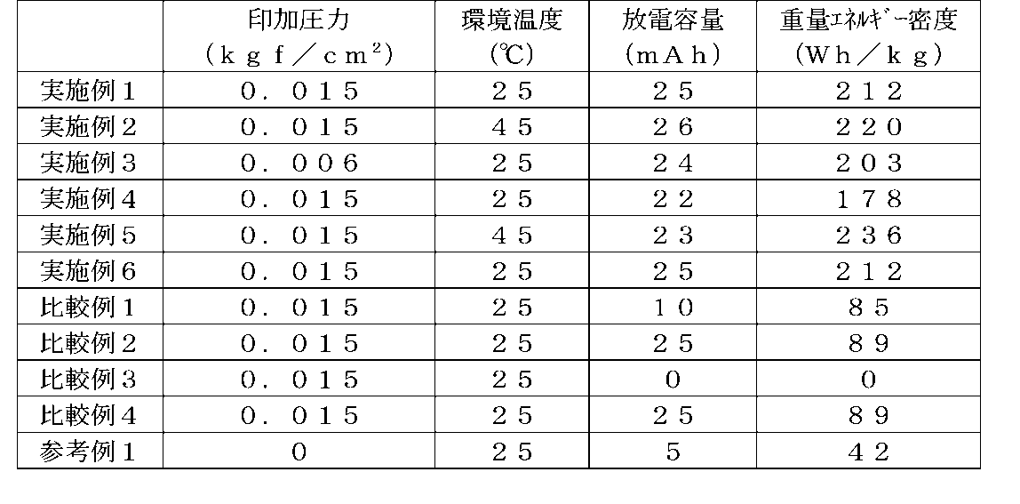
無機絶縁体を80質量%以上の割合で含有し、かつ空孔率が50%以下である絶縁層をセパレータとし、電池容器内の非水電解液の質量の割合を、正極活物質層、負極活物質層および絶縁層の質量の合計と、非水電解液の質量との総和に対し、2%以上60%以下の範囲とした本発明の非水二次電池では、重量エネルギー密度が高く、かつ充放電特性に優れると共に、充電時のリチウムデンドライトの形成が抑制され、安全性の高い電池とすることができた。 An insulating layer containing an inorganic insulator in a proportion of 80% by mass or more and having a porosity of 50% or less is used as a separator, and the proportion of the mass of the non-aqueous electrolyte in the battery container is defined as a positive electrode active material layer, a negative electrode In the non-aqueous secondary battery of the present invention in which the total mass of the active material layer and the insulating layer and the total mass of the non-aqueous electrolyte solution are in the range of 2% to 60%, the weight energy density is high, And while being excellent in charging / discharging characteristic, formation of lithium dendrite at the time of charge was suppressed, and it was able to be set as a highly safe battery.
一方、絶縁層の空孔率が50%より大きい比較例1の電池では、充電時のリチウムデンドライトの形成による短絡のため、放電容量が低くなっていた。また、非水電解液の量が多すぎる比較例2の電池では、充電時のリチウムデンドライトの形成による短絡がなく、実施例1と同じ放電容量が得られたが、電解液の重量が大きいため、電池の重量エネルギー密度が低くなり、逆に非水電解液の量が少なすぎる比較例3の電池では、イオン伝導性が低下して内部抵抗が高くなり、放電できなくなった。 On the other hand, in the battery of Comparative Example 1 in which the porosity of the insulating layer was greater than 50%, the discharge capacity was low due to a short circuit due to the formation of lithium dendrite during charging. Further, in the battery of Comparative Example 2 in which the amount of the non-aqueous electrolyte solution is too large, there was no short circuit due to the formation of lithium dendrite during charging, and the same discharge capacity as in Example 1 was obtained, but the weight of the electrolyte solution was large. In contrast, the battery of Comparative Example 3 in which the weight energy density of the battery was low and the amount of the non-aqueous electrolyte solution was too small, the ionic conductivity was lowered, the internal resistance was increased, and discharge was impossible.
また、難燃性溶媒であるフッ素化エーテルを全溶媒中に質量比で30%以上含有し、かつ鎖状エステル(MEC)との混合溶媒により非水電解液を構成した比較例2の電池は、汎用の環状カーボネートと鎖状カーボネートとの混合溶媒により非水電解液を構成した比較例4の電池と同等の放電容量が得られ、難燃性溶媒を含有する前記の電解液構成とすることにより、充放電特性を低下させずに電解液の難燃化が可能となることがわかる。 In addition, the battery of Comparative Example 2 that contains 30% or more of the fluorinated ether, which is a flame-retardant solvent, in a mass ratio in the total solvent, and constituted a non-aqueous electrolyte with a mixed solvent with a chain ester (MEC) is A discharge capacity equivalent to that of the battery of Comparative Example 4 in which a non-aqueous electrolyte is configured with a mixed solvent of general-purpose cyclic carbonate and chain carbonate is obtained, and the above-described electrolyte configuration containing a flame retardant solvent is used. Thus, it is understood that the electrolyte solution can be made flame retardant without deteriorating the charge / discharge characteristics.
さらに、外装体の側面を加圧せずに充放電を行った参考例1の電池よりも、外装体の側面に一定の圧力を印加した実施例1〜6の電池の方が放電容量が大幅に増加しており、本発明の非水二次電池では、充放電時に外装体の側面を加圧することが望ましいことがわかる。 Furthermore, the batteries of Examples 1 to 6 in which a certain pressure was applied to the side surface of the outer package had a larger discharge capacity than the battery of Reference Example 1 in which charging and discharging were performed without pressurizing the side surface of the outer package. It can be seen that, in the non-aqueous secondary battery of the present invention, it is desirable to pressurize the side surface of the outer package during charging and discharging.
また、実施例6の電池の評価結果より明らかなように、本発明の非水二次電池では、電解液量を少なくしていることから、電池容器の内部で複数の電極体を直列に導電接続しても、内部短絡を生じることなく充放電を行うことができる。 Further, as is clear from the evaluation results of the battery of Example 6, in the non-aqueous secondary battery of the present invention, since the amount of the electrolyte solution is reduced, a plurality of electrode bodies are electrically connected in series inside the battery container. Even if connected, charging and discharging can be performed without causing an internal short circuit.
Claims (10)
前記電極体は、正極活物質層を有する正極と、負極活物質層を有する負極と、前記正極および前記負極の間に介在させてなる多孔性の絶縁層とを有し、
前記絶縁層は、無機絶縁体を80質量%以上の割合で含有し、かつ空孔率が50%以下であり、
前記電池容器内の前記非水電解液の質量が、前記電極体の正極活物質層、負極活物質層および絶縁層の質量の合計と、前記非水電解液の質量との総和に対し、2%以上60%以下であることを特徴とする非水二次電池。 A non-aqueous secondary battery having an electrode body and a non-aqueous electrolyte in a battery container,
The electrode body has a positive electrode having a positive electrode active material layer, a negative electrode having a negative electrode active material layer, and a porous insulating layer interposed between the positive electrode and the negative electrode,
The insulating layer contains an inorganic insulator in a proportion of 80% by mass or more and has a porosity of 50% or less,
The mass of the non-aqueous electrolyte in the battery container is 2 with respect to the sum of the mass of the positive electrode active material layer, the negative electrode active material layer and the insulating layer of the electrode body and the mass of the non-aqueous electrolyte. % Non-aqueous secondary battery characterized by being not less than 60% and not more than 60%.
前記電極体は、正極活物質層を有する正極と、負極活物質層を有する負極と、前記正極および前記負極の間に介在させてなる多孔性の絶縁層とを有し、
前記絶縁層は、無機絶縁体を80質量%以上の割合で含有し、かつ空孔率が50%以下であり、
前記電池容器内の前記非水電解液の質量が、それぞれの電極体の正極活物質層、負極活物質層および絶縁層の質量の合計と、前記非水電解液の質量との総和に対し、2%以上60%以下であることを特徴とする非水二次電池。 A non-aqueous secondary battery having a plurality of electrode bodies electrically connected in series and a non-aqueous electrolyte in a battery container,
The electrode body has a positive electrode having a positive electrode active material layer, a negative electrode having a negative electrode active material layer, and a porous insulating layer interposed between the positive electrode and the negative electrode,
The insulating layer contains an inorganic insulator in a proportion of 80% by mass or more and has a porosity of 50% or less,
The mass of the non-aqueous electrolyte in the battery container is the sum of the mass of the positive electrode active material layer, the negative electrode active material layer and the insulating layer of each electrode body, and the total mass of the non-aqueous electrolyte solution. A nonaqueous secondary battery characterized by being 2% or more and 60% or less.
Priority Applications (1)
| Application Number | Priority Date | Filing Date | Title |
|---|---|---|---|
| JP2018093401A JP7083696B2 (en) | 2018-05-15 | 2018-05-15 | Non-water secondary battery |
Applications Claiming Priority (1)
| Application Number | Priority Date | Filing Date | Title |
|---|---|---|---|
| JP2018093401A JP7083696B2 (en) | 2018-05-15 | 2018-05-15 | Non-water secondary battery |
Publications (2)
| Publication Number | Publication Date |
|---|---|
| JP2019200868A true JP2019200868A (en) | 2019-11-21 |
| JP7083696B2 JP7083696B2 (en) | 2022-06-13 |
Family
ID=68612205
Family Applications (1)
| Application Number | Title | Priority Date | Filing Date |
|---|---|---|---|
| JP2018093401A Active JP7083696B2 (en) | 2018-05-15 | 2018-05-15 | Non-water secondary battery |
Country Status (1)
| Country | Link |
|---|---|
| JP (1) | JP7083696B2 (en) |
Cited By (3)
| Publication number | Priority date | Publication date | Assignee | Title |
|---|---|---|---|---|
| CN113013482A (en) * | 2021-02-22 | 2021-06-22 | 江西省允福亨新能源有限责任公司 | Solid electrolyte and preparation method of all-solid-state lithium ion battery |
| WO2021131889A1 (en) * | 2019-12-23 | 2021-07-01 | 株式会社Gsユアサ | Non-aqueous electrolyte power storage element and method for manufacturing same |
| WO2022030109A1 (en) * | 2020-08-03 | 2022-02-10 | パナソニックIpマネジメント株式会社 | Lithium ion secondary battery |
Citations (7)
| Publication number | Priority date | Publication date | Assignee | Title |
|---|---|---|---|---|
| JP2001283903A (en) * | 2000-03-29 | 2001-10-12 | Japan Storage Battery Co Ltd | Nonaqueous electrolyte secondary battery |
| JP2006310010A (en) * | 2005-04-27 | 2006-11-09 | Matsushita Electric Ind Co Ltd | Lithium ion secondary battery |
| JP2009199793A (en) * | 2008-02-20 | 2009-09-03 | Hitachi Maxell Ltd | Lithium secondary battery |
| JP2009272153A (en) * | 2008-05-08 | 2009-11-19 | Hitachi Maxell Ltd | Lithium secondary battery |
| WO2011162169A1 (en) * | 2010-06-25 | 2011-12-29 | Necエナジーデバイス株式会社 | Lithium ion secondary battery |
| WO2015076099A1 (en) * | 2013-11-25 | 2015-05-28 | 日産自動車株式会社 | Method for producing negative electrode for nonaqueous electrolyte secondary batteries |
| JP2016001567A (en) * | 2014-06-12 | 2016-01-07 | 日本電気株式会社 | Electrolyte and secondary battery using the same |
-
2018
- 2018-05-15 JP JP2018093401A patent/JP7083696B2/en active Active
Patent Citations (7)
| Publication number | Priority date | Publication date | Assignee | Title |
|---|---|---|---|---|
| JP2001283903A (en) * | 2000-03-29 | 2001-10-12 | Japan Storage Battery Co Ltd | Nonaqueous electrolyte secondary battery |
| JP2006310010A (en) * | 2005-04-27 | 2006-11-09 | Matsushita Electric Ind Co Ltd | Lithium ion secondary battery |
| JP2009199793A (en) * | 2008-02-20 | 2009-09-03 | Hitachi Maxell Ltd | Lithium secondary battery |
| JP2009272153A (en) * | 2008-05-08 | 2009-11-19 | Hitachi Maxell Ltd | Lithium secondary battery |
| WO2011162169A1 (en) * | 2010-06-25 | 2011-12-29 | Necエナジーデバイス株式会社 | Lithium ion secondary battery |
| WO2015076099A1 (en) * | 2013-11-25 | 2015-05-28 | 日産自動車株式会社 | Method for producing negative electrode for nonaqueous electrolyte secondary batteries |
| JP2016001567A (en) * | 2014-06-12 | 2016-01-07 | 日本電気株式会社 | Electrolyte and secondary battery using the same |
Cited By (3)
| Publication number | Priority date | Publication date | Assignee | Title |
|---|---|---|---|---|
| WO2021131889A1 (en) * | 2019-12-23 | 2021-07-01 | 株式会社Gsユアサ | Non-aqueous electrolyte power storage element and method for manufacturing same |
| WO2022030109A1 (en) * | 2020-08-03 | 2022-02-10 | パナソニックIpマネジメント株式会社 | Lithium ion secondary battery |
| CN113013482A (en) * | 2021-02-22 | 2021-06-22 | 江西省允福亨新能源有限责任公司 | Solid electrolyte and preparation method of all-solid-state lithium ion battery |
Also Published As
| Publication number | Publication date |
|---|---|
| JP7083696B2 (en) | 2022-06-13 |
Similar Documents
| Publication | Publication Date | Title |
|---|---|---|
| US11876223B2 (en) | Negative electrode for lithium metal battery and lithium metal battery comprising same | |
| JP5101692B2 (en) | Anode material with excellent conductivity and high-power secondary battery using the same | |
| EP3696894A1 (en) | Cathode material for lithium secondary battery, and cathode and lithium secondary battery which comprise same | |
| CN102522539B (en) | Cathode active material and lithium secondary battery containing the same | |
| KR20170047660A (en) | Composite anode active material, anode including the material, and lithium secondary battery including the anode | |
| WO2011052533A1 (en) | Lithium secondary battery | |
| JP2010015968A (en) | Lithium secondary battery | |
| KR102557725B1 (en) | Composite anode active material, anode including the material, and lithium secondary battery including the anode | |
| KR101789408B1 (en) | Lithium ion secondary battery | |
| CN112599850A (en) | Solid electrolyte composite layer and lithium ion battery | |
| JP2006222073A (en) | Nonaqueous secondary battery and method of manufacturing its anode | |
| KR20170127314A (en) | Lithium metal battery | |
| JP6477691B2 (en) | Secondary battery electrode binder composition, secondary battery electrode slurry composition, secondary battery electrode, and secondary battery | |
| JP2009026514A (en) | Nonaqueous electrolyte secondary battery | |
| KR102227810B1 (en) | Negative electrode slurry for lithium secondary battery, and preparing method thereof | |
| JP7083696B2 (en) | Non-water secondary battery | |
| JP3579280B2 (en) | Negative electrode for non-aqueous electrolyte secondary battery and non-aqueous electrolyte secondary battery provided with this negative electrode | |
| JP2011192561A (en) | Manufacturing method for nonaqueous electrolyte secondary battery | |
| KR101116551B1 (en) | Negative electrode for lithium secondary battery and lithium secondary battery comprising same | |
| KR102494419B1 (en) | Nonaqueous electrolyte additive for lithium secondary battery, nonaqueous electrolyte for lithium secondary battery comprising the same, and lithium secondary battery | |
| JP2015037068A (en) | Positive electrode for lithium ion battery, and lithium ion secondary battery | |
| JP7301449B2 (en) | Non-aqueous electrolyte for lithium secondary battery and lithium secondary battery containing the same | |
| JP2009187819A (en) | Method for manufacturing paste for lithium-ion secondary battery | |
| KR100696795B1 (en) | Negative active material composition for rechargeable lithium ion battery and rechargeable lithium ion battery comprising same | |
| EP3121883B1 (en) | Electrode for non-aqueous electrolyte secondary battery |
Legal Events
| Date | Code | Title | Description |
|---|---|---|---|
| A621 | Written request for application examination |
Free format text: JAPANESE INTERMEDIATE CODE: A621 Effective date: 20210225 |
|
| A977 | Report on retrieval |
Free format text: JAPANESE INTERMEDIATE CODE: A971007 Effective date: 20211207 |
|
| A131 | Notification of reasons for refusal |
Free format text: JAPANESE INTERMEDIATE CODE: A131 Effective date: 20220125 |
|
| A521 | Request for written amendment filed |
Free format text: JAPANESE INTERMEDIATE CODE: A523 Effective date: 20220322 |
|
| TRDD | Decision of grant or rejection written | ||
| A01 | Written decision to grant a patent or to grant a registration (utility model) |
Free format text: JAPANESE INTERMEDIATE CODE: A01 Effective date: 20220524 |
|
| A61 | First payment of annual fees (during grant procedure) |
Free format text: JAPANESE INTERMEDIATE CODE: A61 Effective date: 20220601 |
|
| R150 | Certificate of patent or registration of utility model |
Ref document number: 7083696 Country of ref document: JP Free format text: JAPANESE INTERMEDIATE CODE: R150 |