JP2019200375A - Image forming apparatus - Google Patents
Image forming apparatus Download PDFInfo
- Publication number
- JP2019200375A JP2019200375A JP2018096070A JP2018096070A JP2019200375A JP 2019200375 A JP2019200375 A JP 2019200375A JP 2018096070 A JP2018096070 A JP 2018096070A JP 2018096070 A JP2018096070 A JP 2018096070A JP 2019200375 A JP2019200375 A JP 2019200375A
- Authority
- JP
- Japan
- Prior art keywords
- condition
- state
- photoconductor
- type
- forming apparatus
- Prior art date
- Legal status (The legal status is an assumption and is not a legal conclusion. Google has not performed a legal analysis and makes no representation as to the accuracy of the status listed.)
- Granted
Links
- 230000015572 biosynthetic process Effects 0.000 claims abstract description 45
- 238000001514 detection method Methods 0.000 claims abstract description 29
- 238000002360 preparation method Methods 0.000 claims abstract description 18
- 230000007704 transition Effects 0.000 claims abstract description 16
- 238000012546 transfer Methods 0.000 claims description 137
- 238000000926 separation method Methods 0.000 claims description 32
- 108091008695 photoreceptors Proteins 0.000 claims description 29
- 230000000630 rising effect Effects 0.000 claims description 24
- 230000007246 mechanism Effects 0.000 claims description 12
- 238000004140 cleaning Methods 0.000 claims description 6
- 230000007613 environmental effect Effects 0.000 claims description 4
- 239000000463 material Substances 0.000 abstract description 7
- 238000000034 method Methods 0.000 description 83
- 230000008569 process Effects 0.000 description 77
- 239000000123 paper Substances 0.000 description 57
- 238000003384 imaging method Methods 0.000 description 14
- 238000012790 confirmation Methods 0.000 description 13
- 238000012545 processing Methods 0.000 description 10
- 230000002093 peripheral effect Effects 0.000 description 9
- 230000000052 comparative effect Effects 0.000 description 8
- 230000006870 function Effects 0.000 description 7
- 230000008859 change Effects 0.000 description 6
- 230000003111 delayed effect Effects 0.000 description 4
- 238000011161 development Methods 0.000 description 4
- 230000003287 optical effect Effects 0.000 description 4
- 239000011111 cardboard Substances 0.000 description 3
- 238000003466 welding Methods 0.000 description 3
- 238000010586 diagram Methods 0.000 description 2
- 238000010438 heat treatment Methods 0.000 description 2
- 230000004044 response Effects 0.000 description 2
- 230000007723 transport mechanism Effects 0.000 description 2
- 238000011144 upstream manufacturing Methods 0.000 description 2
- 239000003086 colorant Substances 0.000 description 1
- 238000004040 coloring Methods 0.000 description 1
- 238000004891 communication Methods 0.000 description 1
- 230000006866 deterioration Effects 0.000 description 1
- 239000006185 dispersion Substances 0.000 description 1
- 239000011521 glass Substances 0.000 description 1
- 238000004519 manufacturing process Methods 0.000 description 1
- 238000006386 neutralization reaction Methods 0.000 description 1
- 238000003825 pressing Methods 0.000 description 1
- 230000009467 reduction Effects 0.000 description 1
- 238000004904 shortening Methods 0.000 description 1
- 238000010792 warming Methods 0.000 description 1
Images

Classifications
-
- G—PHYSICS
- G03—PHOTOGRAPHY; CINEMATOGRAPHY; ANALOGOUS TECHNIQUES USING WAVES OTHER THAN OPTICAL WAVES; ELECTROGRAPHY; HOLOGRAPHY
- G03G—ELECTROGRAPHY; ELECTROPHOTOGRAPHY; MAGNETOGRAPHY
- G03G15/00—Apparatus for electrographic processes using a charge pattern
- G03G15/14—Apparatus for electrographic processes using a charge pattern for transferring a pattern to a second base
- G03G15/16—Apparatus for electrographic processes using a charge pattern for transferring a pattern to a second base of a toner pattern, e.g. a powder pattern, e.g. magnetic transfer
- G03G15/1605—Apparatus for electrographic processes using a charge pattern for transferring a pattern to a second base of a toner pattern, e.g. a powder pattern, e.g. magnetic transfer using at least one intermediate support
- G03G15/1615—Apparatus for electrographic processes using a charge pattern for transferring a pattern to a second base of a toner pattern, e.g. a powder pattern, e.g. magnetic transfer using at least one intermediate support relating to the driving mechanism for the intermediate support, e.g. gears, couplings, belt tensioning
-
- G—PHYSICS
- G03—PHOTOGRAPHY; CINEMATOGRAPHY; ANALOGOUS TECHNIQUES USING WAVES OTHER THAN OPTICAL WAVES; ELECTROGRAPHY; HOLOGRAPHY
- G03G—ELECTROGRAPHY; ELECTROPHOTOGRAPHY; MAGNETOGRAPHY
- G03G15/00—Apparatus for electrographic processes using a charge pattern
- G03G15/01—Apparatus for electrographic processes using a charge pattern for producing multicoloured copies
- G03G15/0142—Structure of complete machines
- G03G15/0178—Structure of complete machines using more than one reusable electrographic recording member, e.g. one for every monocolour image
- G03G15/0189—Structure of complete machines using more than one reusable electrographic recording member, e.g. one for every monocolour image primary transfer to an intermediate transfer belt
-
- G—PHYSICS
- G03—PHOTOGRAPHY; CINEMATOGRAPHY; ANALOGOUS TECHNIQUES USING WAVES OTHER THAN OPTICAL WAVES; ELECTROGRAPHY; HOLOGRAPHY
- G03G—ELECTROGRAPHY; ELECTROPHOTOGRAPHY; MAGNETOGRAPHY
- G03G15/00—Apparatus for electrographic processes using a charge pattern
- G03G15/50—Machine control of apparatus for electrographic processes using a charge pattern, e.g. regulating differents parts of the machine, multimode copiers, microprocessor control
- G03G15/5008—Driving control for rotary photosensitive medium, e.g. speed control, stop position control
-
- G—PHYSICS
- G03—PHOTOGRAPHY; CINEMATOGRAPHY; ANALOGOUS TECHNIQUES USING WAVES OTHER THAN OPTICAL WAVES; ELECTROGRAPHY; HOLOGRAPHY
- G03G—ELECTROGRAPHY; ELECTROPHOTOGRAPHY; MAGNETOGRAPHY
- G03G15/00—Apparatus for electrographic processes using a charge pattern
- G03G15/50—Machine control of apparatus for electrographic processes using a charge pattern, e.g. regulating differents parts of the machine, multimode copiers, microprocessor control
- G03G15/5029—Machine control of apparatus for electrographic processes using a charge pattern, e.g. regulating differents parts of the machine, multimode copiers, microprocessor control by measuring the copy material characteristics, e.g. weight, thickness
-
- G—PHYSICS
- G03—PHOTOGRAPHY; CINEMATOGRAPHY; ANALOGOUS TECHNIQUES USING WAVES OTHER THAN OPTICAL WAVES; ELECTROGRAPHY; HOLOGRAPHY
- G03G—ELECTROGRAPHY; ELECTROPHOTOGRAPHY; MAGNETOGRAPHY
- G03G2215/00—Apparatus for electrophotographic processes
- G03G2215/00362—Apparatus for electrophotographic processes relating to the copy medium handling
- G03G2215/00535—Stable handling of copy medium
- G03G2215/00717—Detection of physical properties
- G03G2215/00751—Detection of physical properties of sheet type, e.g. OHP
-
- G—PHYSICS
- G03—PHOTOGRAPHY; CINEMATOGRAPHY; ANALOGOUS TECHNIQUES USING WAVES OTHER THAN OPTICAL WAVES; ELECTROGRAPHY; HOLOGRAPHY
- G03G—ELECTROGRAPHY; ELECTROPHOTOGRAPHY; MAGNETOGRAPHY
- G03G2215/00—Apparatus for electrophotographic processes
- G03G2215/01—Apparatus for electrophotographic processes for producing multicoloured copies
- G03G2215/0103—Plural electrographic recording members
- G03G2215/0119—Linear arrangement adjacent plural transfer points
- G03G2215/0122—Linear arrangement adjacent plural transfer points primary transfer to an intermediate transfer belt
- G03G2215/0125—Linear arrangement adjacent plural transfer points primary transfer to an intermediate transfer belt the linear arrangement being horizontal or slanted
Landscapes
- Physics & Mathematics (AREA)
- General Physics & Mathematics (AREA)
- Engineering & Computer Science (AREA)
- Microelectronics & Electronic Packaging (AREA)
- Control Or Security For Electrophotography (AREA)
- Electrostatic Charge, Transfer And Separation In Electrography (AREA)
- Color Electrophotography (AREA)
Abstract
Description
本発明は、画像形成装置に関する。 The present invention relates to an image forming apparatus.
プリンタ、複写機、複合機などの画像形成装置は、画像の記録媒体として用いる複数枚のシートがセットされるシート台(トレイまたはカセットなど)を有しており、シート台から装置内の印刷位置へシートを搬送して印刷を行う。 Image forming apparatuses such as printers, copiers, and multifunction machines have a sheet table (such as a tray or cassette) on which a plurality of sheets used as image recording media are set, and the printing position within the apparatus from the sheet table. The sheet is conveyed to the printer and printed.
この種の画像形成装置の機能として、シートの種類に応じて動作の条件を適切な画像が得られるように設定する機能が知られている。例えば、電子写真式の画像形成装置において、シートを坪量によって分類することとし、坪量に応じて、搬送速度(プロセス速度)、現像バイアス、転写バイアス、および定着温度などを設定することが行われている。この設定により、ジャム、現像不良、転写不良、および定着不良などを防止することができる。 As a function of this type of image forming apparatus, a function of setting an operation condition so as to obtain an appropriate image according to the type of sheet is known. For example, in an electrophotographic image forming apparatus, a sheet is classified by basis weight, and a conveyance speed (process speed), a developing bias, a transfer bias, a fixing temperature, and the like are set according to the basis weight. It has been broken. This setting can prevent jamming, development failure, transfer failure, and fixing failure.
画像形成装置がシートの種類を取得する方法として、ユーザがシートの種類を幾つかの選択肢(普通紙、厚紙1、厚紙2など)から選択して指定する方法がある。画像形成装置は、ユーザの指定した種類に応じて動作の条件を設定する。
As a method for the image forming apparatus to acquire the sheet type, there is a method in which the user selects and specifies the sheet type from several options (plain paper,
しかし、近年、画像形成装置において使用可能なシートの種類が多様化していることから、ユーザがシートの種類を正しく指定するのが困難になっている。このため、画像形成装置が所定のセンサの出力に基づいて自動的にシートの種類を検知する方法が注目されている。 However, in recent years, since the types of sheets that can be used in the image forming apparatus are diversified, it is difficult for the user to correctly specify the type of sheet. For this reason, a method in which the image forming apparatus automatically detects the sheet type based on the output of a predetermined sensor has attracted attention.
シートの種類を検知するためのいわゆるメディアセンサをシートの搬送経路に配置する構成が知られている。この構成によると、シートがシート台において重なっている状態では検出しにくい透光性または厚さなどの物理量を検出して種類を判別することができる。また、複数のシート台を有する装置において、シートを取り出すシート台がいずれであっても1つのメディアセンサによりそのシートの種類を検知することができる。 There is known a configuration in which a so-called media sensor for detecting the type of a sheet is arranged in a sheet conveyance path. According to this configuration, it is possible to determine the type by detecting a physical quantity such as translucency or thickness that is difficult to detect when the sheets are overlapped on the sheet table. Further, in an apparatus having a plurality of sheet tables, the type of the sheet can be detected by one media sensor regardless of the sheet table from which the sheets are taken out.
メディアセンサをシートの搬送経路に配置した場合には、印刷ジョブの実行に際して、FPOT(First Print Output Time )を短くするために、センサ位置へのシートの搬送と並行して画像形成の準備(立上げ)が行われる。電子写真式の画像形成装置における画像形成の準備には、感光体を回転させてかつ帯電させるなどの処理が含まれる。 When the media sensor is arranged in the sheet conveyance path, preparation for image formation (stand-up) is performed in parallel with the conveyance of the sheet to the sensor position in order to shorten the FPOT (First Print Output Time) when executing the print job. Is raised). Preparation for image formation in an electrophotographic image forming apparatus includes processing such as rotating and charging a photoreceptor.
この画像形成の準備では、シートについて想定される複数の種類の1つに対応する動作条件が仮の条件とされ、仮の条件で画像を形成するものとして感光体の回転速度および帯電バイアスなどが設定される。そして、検知したシートの種類が仮の条件に対応する種類と異なる場合には、仮の条件から検知した種類に対応する確定条件に切り替え、確定条件での画像形成が可能になった後に、画像形成が開始される。 In this preparation for image formation, an operating condition corresponding to one of a plurality of types assumed for the sheet is set as a temporary condition, and the rotational speed and charging bias of the photosensitive member are used to form an image under the temporary condition. Is set. If the detected sheet type is different from the type corresponding to the tentative condition, the image is switched from the tentative condition to the finalized condition corresponding to the detected type, and image formation under the finalized condition becomes possible. Formation begins.
画像形成の準備を開始した後に動作条件を切り替える場合における画像形成の開始の遅れを低減するための先行技術として、特許文献1に記載の技術がある。特許文献1には、感光体ドラムの駆動源と中間転写ベルトの駆動源とが異なる画像形成装置において、感光体ドラムと中間転写ベルトとのニップ部にトナーを介在させた状態で感光体ドラムおよび中間転写ベルトの周速度を変更することが開示されている。
As a prior art for reducing the delay in the start of image formation when the operating conditions are switched after preparation for image formation is started, there is a technique described in
上に述べた特許文献1の技術によると、仮の条件から確定条件への切替えに際して感光体ドラムと中間転写ベルトとの間で駆動源が異なることに起因して周速度にずれが生じたとしても、感光体ドラムおよび中間転写ベルトの摩耗がトナーの介在により低減される。
According to the technique of
しかし、少なくとも動作条件の切替えの直前から切替え後に感光体ドラムおよび中間転写ベルトの回転が安定してこれらの周速度が等しくなるまでの間にわたって、現像器をオンにして色材であるトナーを感光体に付着し続ける必要がある。このため、色材が無駄に消費されてしまうという問題があった。 However, at least until the rotation of the photosensitive drum and the intermediate transfer belt is stabilized and the peripheral speeds are equalized immediately before switching the operating conditions, the developing unit is turned on to expose the toner as the color material. It needs to remain attached to the body. For this reason, there has been a problem that the color material is wasted.
本発明は、このような問題に鑑みてなされたもので、無駄に色材を消費することなく、立上げを開始した後に動作条件を切り替える場合における画像形成の開始の遅れを低減することを目的とする。 SUMMARY OF THE INVENTION The present invention has been made in view of such a problem, and an object of the present invention is to reduce a delay in the start of image formation when operating conditions are switched after start-up without wastefully consuming color materials. And
本発明の実施形態に係る画像形成装置は、シート状の媒体の種類に応じて設定される動作条件で前記媒体に画像を形成する画像形成装置であって、前記媒体の搬送経路に設けられたセンサの出力に基づいて前記媒体の種類が複数の想定された種類のいずれであるかを検知する検知部と、前記媒体の種類が検知される以前に、前記複数の想定された種類のうちの1つに対応する動作条件である仮の条件による画像形成の準備が部分的に完了した準立上り状態まで移行し、前記媒体の種類が検知された後に、検知された種類に対応する動作条件である確定条件による画像形成の準備が完了した立上り状態に移行するよう制御する立上げ制御部と、を有する。 An image forming apparatus according to an embodiment of the present invention is an image forming apparatus that forms an image on the medium under operating conditions set according to the type of sheet-like medium, and is provided in a conveyance path of the medium A detection unit that detects which of the plurality of assumed types of the medium is based on an output of the sensor; and before the type of the medium is detected, of the plurality of assumed types After the transition to a quasi-rise state in which the preparation of image formation based on a temporary condition that is an operating condition corresponding to one is partially completed and the type of the medium is detected, the operating condition corresponding to the detected type is And a start-up control unit that controls to shift to a start-up state in which preparation for image formation under certain fixed conditions is completed.
本発明によると、無駄に色材を消費することなく、立上げを開始した後に動作条件を切り替える場合における画像形成の開始の遅れを低減することができる。 According to the present invention, it is possible to reduce a delay in the start of image formation when switching operation conditions after starting up without wastefully consuming color materials.
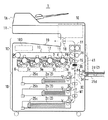
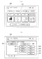
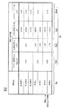
図1には本発明の一実施形態に係る画像形成装置1の構成の概要が、図2にはシート2の種類の検知に関わる操作画面600,650の例が、図3には動作条件テーブルD10の例が、それぞれ示されている。
FIG. 1 shows an outline of the configuration of an
図1において、画像形成装置1は、コピー機、プリンタ、ファクシミリ機、イメージリーダなどの機能を集約したMFP(Multi-functional Peripheral :多機能機または複合機)である。
In FIG. 1, an
画像形成装置1は、自動原稿送り装置(ADF:Auto Document Feeder)1A、フラットベッド型のスキャナ1B、電子写真方式のカラープリンタ1C、シートキャビネット1D、および操作パネル1Eなどを備える。
The
シートキャビネット1Dは、給紙トレイ25a,25b,25cを備える三段構成の引出し型である。画像形成装置1の右側面部には、手指しトレイ25dが設けられている。操作パネル1Eは、ユーザによる操作のための画面を表示するタッチパネルディスプレイを有し、入力操作に応じた信号を出力する。この信号に応じて、制御回路100により、画像形成装置1の動作が制御される。
The sheet cabinet 1D is a three-stage drawer type including
自動原稿送り装置1Aは、原稿トレイにセットされた原稿(シート)をスキャナ1Bの読取り位置へ搬送する。スキャナ1Bは、自動原稿送り装置1Aから搬送されてきたシート状の原稿またはプラテンガラスの上にセットされた各種の原稿から画像を読み取って画像データを生成する。
The
カラープリンタ1Cは、コピー、ネットワークプリンティング(PCプリント)、ファクシミリ受信、およびボックスプリントなどの印刷ジョブにおいて、シート(記録用の媒体)2の片面または両面にカラーまたはモノクロの画像を形成する。カラープリンタ1Cは、電子写真方式のタンデム型のプリンタエンジン10を備えており、プリンタエンジン10は、4個のイメージングユニット3y,3m,3c,3k、プリントヘッド6、および中間転写ベルト12を有する。
The color printer 1C forms a color or monochrome image on one side or both sides of a sheet (recording medium) 2 in print jobs such as copying, network printing (PC printing), facsimile reception, and box printing. The
イメージングユニット3y〜3kは、それぞれ筒状の感光体(PC: Photoconductor)4、帯電器5、現像器7、イレーサ8、およびクリーナ9などを有している。イレーサ8は、光照射により感光体4を除電する。クリーナ9は、例えばブレードを当接させて残トナーなどの付着物を感光体4から除去する。イメージングユニット3y〜3kの基本的な構成は同様である。
Each of the
プリントヘッド6は、イメージングユニット3y〜3kのそれぞれに対してパターン露光を行うためのレーザビームを射出する。プリントヘッド6において、感光体4の回転軸方向にレーザビームを偏向する主走査が行われる。この主走査と並行して、感光体4を定速回転させる副走査が行われる。
The print head 6 emits a laser beam for performing pattern exposure on each of the
中間転写ベルト12は、トナー像の一次転写における被転写体であり、一対のローラ間に巻回されて回転する。中間転写ベルト12の内側には、イメージングユニット3y,3m,3c,3kごとに一次転写ローラ11が配置されている。
The
カラー印刷モードにおいて、イメージングユニット3y〜3kは、Y(イエロー)、M(マゼンタ)、C(シアン)、およびK(ブラック)の4色のトナー像を並行して形成する。4色のトナー像は、回転中の中間転写ベルト12に順次に一次転写される。最初にYのトナー像が転写され、それに重なるようMのトナー像、Cのトナー像、およびKのトナー像が順次に転写される。
In the color printing mode, the
一次転写されたトナー像は、二次転写ローラ16と対向する印刷位置P6において、給紙トレイ25a〜25cのいずれかまたは手指しトレイ25dから取り出されてタイミングローラ15を経て搬送されてきたシート2に二次転写される。すなわち、例えば二次転写ローラ16に印加される転写電圧により静電吸引されて中間転写ベルト12からシート2に移る。二次転写の後、シート2は、定着器17の内部を通過し、排出ローラ18により排紙トレイ19へ送り出される。定着器17を通過するとき、加熱および加圧によってトナー像がシート2に定着する。
The primarily transferred toner image is taken out of one of the
モノクロ印刷モードにおいては、4個のイメージングユニット3y〜3kのうち、印刷位置(二次転写位置)P6に最も近いイメージングユニット3kによりトナー像が形成される。つまり、モノクロ印刷色は、K(ブラック)である。他のイメージングユニット3y〜3cではトナー像は形成されない。カラー印刷モードと同様に、一次転写、二次転写、および定着が行われてシート2にモノクロ画像が形成される。
In the monochrome printing mode, a toner image is formed by the imaging unit 3k closest to the printing position (secondary transfer position) P6 among the four
上段の給紙トレイ25a、中段の給紙トレイ25b、および下段の給紙トレイ25cの基本的な構成は同一であり、それぞれに多数枚のシート2(2a,2b,2c)をセットすることができる。セットするとは、給紙トレイに重ねて置いておくことを意味する。
The basic configuration of the
手指しトレイ25dにも多数枚のシート2dを重ねてセットすることができる。シート2dは、給紙トレイ25a〜25cに収まらない長尺シートでもよい。
A large number of
なお、以下において、給紙トレイ25a〜25cおよび手指しトレイ25dを区別せずに「トレイ25」と記すことがある。
In the following, the
画像形成装置1の内部においてシート2が通る搬送経路30は、4つのトレイ25に1つずつ対応する給紙路31,32,33,34、および共通路35を含んでいる。給紙路31〜34は、それぞれに対応するトレイ25から取り出されたシート2のみが通る経路である。これに対して、共通路35は、セットされたトレイ25が異なるシート2a,2b,2c,2dのいずれもが通る経路、すなわち4つのトレイ25に共通の経路である。本実施形態では、手差しトレイ25dが上段の給紙トレイ25aよりも上側に配置されているので、給紙路34の終端となる合流点P4から排出ローラ18までの経路が共通路35となっている。
The
画像形成装置1は、シート2の種類を検知するためのメディアセンサ(シート属性センサ)41を備えており、メディアセンサ41の出力に基づいて検知した種類に応じて印刷の動作条件を適切な画像が得られるように設定する。
The
メディアセンサ41は、共通路35のうちの印刷位置P6に対する上流側の位置、詳しくはタイミングローラ15と合流点P4との間に配置されている。
The
共通路35に配置することにより、トレイ25の個数にかかわらず、単一のメディアセンサ41によりシート2a,2b,2c,2dの種類を検知することができ、センサの個数の削減による小型化およびコスト低減を図ることができる。
By arranging in the
加えて、タイミングローラ15の上流側に配置することにより、種類を検知した後に印刷動作の条件を切り替える場合などにおいて、必要に応じてシート2を印刷位置P6の手前で待機させて切替えの時間を確保することができる。
In addition, by disposing the
メディアセンサ41は、種類の判別に用いる情報をシート2から取得する。例えば、メディアセンサ41は、光センサであり、タイミングローラ15に向かって移動中のシート2に検出光を照射し、シート2を透過した検出光の受光量をシート2の坪量を特定する情報として取得する。そして、受光量を示す検出信号を制御回路100に送る。
The
画像形成装置1は、入力された印刷ジョブの実行を開始する際に、ジョブによる指定に応じていずれかのトレイ25を選択する。例えば、ジョブにより指定されている出力画像サイズに対応するシート2がセットされているトレイ25を選択する。または、ジョブによりトレイ25が指定されている場合は、指定されているトレイ25を選択する。
When the
そして、選択したトレイ25について以前に検知されたシート2の種類を記憶している場合は、記憶している種類に応じた動作条件を設定し、選択したトレイ25からシート2を取り出し、設定した動作条件で印刷を行う。この場合は、メディアセンサ41の出力に基づく種類の検知を行わない。
If the previously detected type of the
他方、選択したトレイ25についてシート2の種類を記憶していない場合は、選択したトレイ25からシート2を取り出してタイミングローラ15まで搬送し、その間にメディアセンサ41の出力に基づいてシート2の種類を検知する。そして、検知した種類に応じた動作条件を設定して印刷を行う。なお、連続印刷ジョブにおいては、1枚目のシート2について種類の検知を行い、2枚目以降のシート2については種類の検知を行わない。
On the other hand, if the type of the
画像形成装置1においては、このようにシート2の種類を自動的に検知して印刷の動作条件を設定する「自動モード」と、ユーザが手動入力した種類に応じて動作条件を設定する「手動モード」とが設けられている。ユーザは、次の操作を行うことにより種類を指定することができる。
In the
ユーザによる操作を待つ状態において、操作パネル1Eには図2(A)に示す初期画面600が表示される。ユーザは、初期画面600の用紙ボタン612をタッチし、それにより表示される図示しないトレイ指定画面において、所望のトレイ25を指定する。ユーザがトレイ25を指定すると、図2(B)に示す種類指定画面650が表示される。
In a state of waiting for an operation by the user, an
種類指定画面650には、自動モード選択ボタン661、手動モード選択ボタン662、および種類選択ボタン671〜677が配置されている。種類選択ボタン671〜677は、坪量により分類された普通紙1、普通紙2、普通紙3、厚紙1、厚紙2、厚紙3、および厚紙4の7個の種類に対応する。
On the
ユーザは、種類を指定したい場合には、手動モード選択ボタン662をタッチして手動モードを指定し、続いて種類選択ボタン671〜677のいずれかをタッチして種類を指定する。手動モードが設定された状態でモード選択ボタン661をタッチすると、自動モードに切り替わる。このような種類の手動入力は、手指しトレイ25dを含む4個のトレイ25のそれぞれについて個別に行うことができる。
When the user wants to specify the type, he / she touches the manual
画像形成装置1は、ジョブの実行に際して選択したトレイ25に対して手動モードが設定されている場合は、種類の検知を行わない。この場合の動作条件は、ユーザにより指定された種類に対応する動作条件とされる。
The
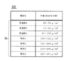
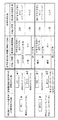
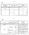
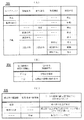
動作条件は、図3の動作条件テーブルD10に示される複数の動作条件値Dc(Dc1〜Dc4)の組合せである。図3の例では、7個の種類Dkのそれぞれに、動作条件値Dcとして、プロセス速度(画像形成速度)Vs、定着温度(定着設定温度)Ts、二次転写出力V16、およびカブリマージンVmが対応づけられている。 The operating condition is a combination of a plurality of operating condition values Dc (Dc1 to Dc4) shown in the operating condition table D10 of FIG. In the example of FIG. 3, for each of the seven types Dk, the process speed (image forming speed) Vs, the fixing temperature (fixing set temperature) Ts, the secondary transfer output V16, and the fog margin Vm are set as the operation condition value Dc. It is associated.
プロセス速度Vsは、二次転写および定着におけるシート2の搬送速度、感光体4の周速度、および中間転写ベルト12の移動速度などを規定する条件である。図3の例において、普通紙1〜3のプロセス速度Vsは、最も速い290mm/sとされ、厚紙1〜2のプロセス速度Vsは、次に速い210mm/sとされ、厚紙3〜4のプロセス速度Vsは、最も遅い105mm/sとされている。
The process speed Vs is a condition that defines the conveying speed of the
定着温度Tsは、定着器17における定着ヒータ217による加熱温度であり、二次転写出力V16は、二次転写ローラ16をバイアスする高圧電源回路の出力電圧である。
The fixing temperature Ts is a heating temperature by the fixing
カブリマージンVmは、下地部にトナーが付着するカブリを防ぐための条件であり、感光体4の帯電電位と現像DC出力との差である。現像DC出力を固定とする場合には、カブリマージンVmは、帯電電位を規定する条件である。カブリマージンVmは、帯電電位を実質的に決定する高圧電源回路の出力電圧(帯電DC出力)の制御により調整される。
The fog margin Vm is a condition for preventing the toner from adhering to the base portion, and is a difference between the charged potential of the
シート2の種類Dkの検知を行う場合においては、メディアセンサ41が配置されたセンサ位置へのシート2の搬送と並行して画像形成の準備、すなわち電子写真プロセスの立上げを行う。
In the case of detecting the type Dk of the
この立上げでは、想定されている複数の種類Dkの1つに対応する動作条件を「仮の条件」とし、仮の条件で画像を形成するものとして感光体4の回転速度および帯電電位などを制御する。
In this start-up, the operating condition corresponding to one of a plurality of types Dk assumed is a “temporary condition”, and the rotational speed and the charging potential of the
本実施形態においては、この仮の条件は可変とされており、予め定められている「初期設定条件」が仮の条件とされたり、初期設定条件を含むすべての動作条件の中から後に述べる設定テーブルを参照して選択される「任意設定条件」が仮の条件とされたりする。 In this embodiment, this temporary condition is variable, and a predetermined “initial setting condition” is set as a temporary condition, or a setting described later from all operating conditions including the initial setting condition. An “arbitrary setting condition” selected with reference to the table may be a temporary condition.
なお、以下において、初期設定条件に対応する種類を「初期設定種類」と記し、任意設定条件に対応する種類を「任意設定種類」と記し、初期設定種類と任意設定種類とを総称して「仮の種類」と記すことがある。 In the following, the type corresponding to the initial setting condition is referred to as “initial setting type”, the type corresponding to the arbitrary setting condition is referred to as “optional setting type”, and the initial setting type and the arbitrary setting type are collectively referred to as “ Sometimes referred to as “provisional type”.
仮の条件での立上げを開始した後に種類Dkが検知され、それによって画像形成に適合する動作条件が確定する。検知した種類Dkである確定種類Dkdが仮の種類Dkpと同一である場合、すなわち確定種類Dkdに対応する「確定条件」と仮の条件とが一致した場合は、仮の条件での立上げを続行する。そして、仮の条件(この場合は確定条件でもある)での画像形成が可能になった後に、画像形成( 潜像形成) を開始する。 The type Dk is detected after the start-up under the provisional conditions is started, thereby determining the operation conditions suitable for image formation. When the determined type Dkd, which is the detected type Dk, is the same as the temporary type Dkp, that is, when the “determined condition” corresponding to the determined type Dkd matches the temporary condition, the startup under the temporary condition is performed. continue. Then, image formation (latent image formation) is started after image formation under the provisional conditions (in this case, also the definite conditions) becomes possible.
これに対して、検知した種類Dk(確定種類Dkd)が仮の種類Dkpと異なる場合には、仮の条件から確定条件に切り替え、確定条件での画像形成が可能になった後に、画像形成を開始する。 On the other hand, when the detected type Dk (determined type Dkd) is different from the tentative type Dkp, the tentative condition is switched to the determined condition, and after the image formation under the determined condition becomes possible, the image formation is performed. Start.
図3の動作条件テーブルD10における7個の種類Dkのうち、例えば厚紙3がデフォルトの仮の種類Dkp、すなわち初期設定種類として定められている。この厚紙3は、対応するプロセス速度Vsが最も遅い種類群のうちの1つである。つまり、初期設定条件は、プロセス速度Vsが最も遅い動作条件とされている。
Among the seven types Dk in the operation condition table D10 of FIG. 3, for example, the
種類Dkを検知する場合にプロセス速度Vsを遅くすることにより、メディアセンサ41の検出可能範囲をシート2が通過する時間が長くなるので、制御周期で行う検出の回数が多くなり、検出の精度が高くなる。また、搬送経路30の構造または搬送用ローラの経時劣化などの上から遅く搬送するのが好ましいシート2を速く搬送したときに起こりやすいジャムを起こりにくくすることができる。
By reducing the process speed Vs when detecting the type Dk, the time for the
ただし、搬送性能が高くジャムのおそれが小さい場合などでは、プロセス速度Vsが最も遅い種類以外を初期設定種類に定めてもよい。 However, when the conveyance performance is high and the possibility of jamming is small, a type other than the slowest process speed Vs may be set as the initial set type.
また、例えばユーザが日常的に使用するシート2の種類Dkがほぼ決まっている場合などでは、その種類Dkを仮の種類Dkpに定めてもよい。その場合は、例えばユーザによる指定に従って、または過去の使用実績に基づいてユーザが最もよく使用するシート2の種類Dkを仮の種類Dkpに定めることができる。
Further, for example, when the type Dk of the
さて、画像形成装置1には、仮の種類Dkpと確定種類Dkdとが異なる場合において、種類Dkを検知してから画像形成を開始するまでの所要時間が従来よりも短くなるよう、画像形成に関わる要部の構成に応じた立上げを実現する機能が設けられている。
Now, when the provisional type Dkp and the determined type Dkd are different, the
以下、この機能を中心に画像形成装置1の構成および動作を説明する。
Hereinafter, the configuration and operation of the
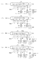
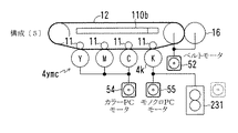
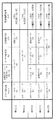
図4および図5には画像形成に関わる要部における駆動手段の構成の例が、それぞれ示されている。また、図6には要部の駆動源と駆動対象との組合せの例が表形式で示されている。 FIG. 4 and FIG. 5 show examples of the configuration of the driving means in the main part related to image formation. FIG. 6 shows an example of a combination of a driving source and a driving target of a main part in a table format.
画像形成装置1においては、図4、図5、および図6に示す5つの構成〔1〕〜〔5〕が択一的に採用される。
In the
構成〔1〕〜〔5〕のいずれにおいても、イメージングユニット3y,3m,3cの感光体4は、共通の駆動源により回転駆動される。以下、これらの3個の感光体4を総称して「カラー感光体4ymc」または「感光体4ymc」と記す。
In any of the configurations [1] to [5], the
また、構成〔1〕〜〔5〕のいずれにおいても、イメージングユニット3kの感光体4は、カラー感光体4ymcの駆動源とは異なる駆動源により回転駆動される。以下、イメージングユニット3kの感光体4を「モノクロ感光体4k」または「感光体4k」と記す。
In any of the configurations [1] to [5], the
構成〔1〕〜〔5〕のそれぞれの詳細は次の通りである。 Details of the configurations [1] to [5] are as follows.
構成〔1〕においては、図4(A)のように、モノクロ感光体4k、中間転写ベルト12、および二次転写ローラ16がメインモータ51により駆動される。カラー感光体4ymcは、カラーPCモータ54により駆動される。給紙搬送部231は、給紙モータ53により駆動される。この給紙搬送部231は、シート2を搬送する機構のうち、トレイ25からタイミングローラ15への搬送を受け持つ部分、つまり種類の検知に関わる部分である。
In the configuration [1], as shown in FIG. 4A, the monochrome
構成〔1〕においては、カラー感光体4ymcに対応する3個の一次転写ローラ11を一括に移動させることによりカラー感光体4ymcと中間転写ベルト12とを圧接させたり離間させたりする圧接離間機構110aが設けられる。
In the configuration [1], the three
モノクロ感光体4kに対応する一次転写ローラ11は、モノクロ感光体4kと中間転写ベルト12とが常に圧接するよう固定配置される。これにより構造を簡単化して製造コストを低減することができる。ただし、モノクロ感光体4kと中間転写ベルト12との圧接/離間を可能にする機構を設けてもよい。
The
構成〔1〕における感光体4ymc,4kと中間転写ベルト12との圧接/離間の状態は、感光体4kのみが圧接する「K圧接」とすべての感光体4ymc,4kが圧接する「全圧接」の2通りである。図4(A)ではK圧接の状態が描かれている。
In the configuration [1], the pressure contact / separation state between the photoconductors 4ymc and 4k and the
図4(B)に示す構成〔2〕は、上に述べた構成〔1〕の一部を変更したものである。その変更点は、給紙駆動部231の駆動源を給紙モータ53に代えてメインモータ51としたことである。図4(B)では、全圧接の状態が描かれている。
The configuration [2] shown in FIG. 4B is obtained by changing a part of the configuration [1] described above. The change is that the drive source of the paper
図4(C)に示す構成〔3〕においては、モノクロ感光体4kは、単独の駆動源であるモノクロPCモータ55により駆動され、カラー感光体4ymcは、カラーPCモータ54により駆動される。中間転写ベルト12および二次転写ローラ16は、ベルトモータ52により駆動され、給紙搬送部231は、給紙モータ53により駆動される。
In the configuration [3] shown in FIG. 4C, the monochrome
構成〔3〕においては、カラー感光体4ymcと中間転写ベルト12とを圧接させたり離間させたりするとともに、カラー感光体4ymcとは独立にモノクロ感光体4kと中間転写ベルト12とを圧接させたり離間させたりする圧接離間機構110bが設けられる。
In the configuration [3], the color photoreceptor 4ymc and the
構成〔3〕における感光体4ymc,4kと中間転写ベルト12との圧接/離間の状態は、すべての感光体4ymc,4kが離間する「全離間」、「K圧接」、および「全圧接」の3通りである。図4(C)では全離間の状態が描かれている。
In the configuration [3], the pressure contact / separation state between the photoconductors 4ymc, 4k and the
図4(D)に示す構成〔4〕は、構成〔3〕の一部を変更したものである。その変更点は、中間転写ベルト12および二次転写ローラ16の駆動源をベルトモータ52に代えて給紙モータ53としたことである。図4(D)では、K圧接の状態が描かれている。
The configuration [4] illustrated in FIG. 4D is obtained by changing a part of the configuration [3]. The change is that the drive source of the
図5に示す構成〔5〕は、構成〔3〕の一部を変更したものである。その変更点は、給紙搬送部231の駆動源を給紙モータ53に代えてモノクロPCモータ55としたことである。図5では、全圧接の状態が描かれている。
The configuration [5] shown in FIG. 5 is obtained by changing a part of the configuration [3]. The change is that the driving source of the paper feeding / conveying
なお、構成〔2〕および〔5〕のように感光体4kと給紙搬送部231とを共通の駆動源により駆動する場合は、駆動源と給紙搬送部231との間にクラッチを介在させるなどして感光体4kの回転開始から遅れたタイミングで給紙を開始することができる。
When the
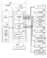
図7には制御回路100の構成が、図8にはシート判別テーブルD20の例が、それぞれ示されている。
FIG. 7 shows the configuration of the
制御回路100は、画像形成装置1の全体の制御を受け持つメイン制御部110、主としてプリンタエンジン10の制御を受け持つエンジン制御部120、および各種の制御データを記憶する不揮発性メモリ130などを備える。
The
メイン制御部110は、操作パネル1Eを用いた操作または外部のホスト装置との通信により印刷ジョブが入力されると、印刷に使用するトレイ25を選択する。
When a print job is input by an operation using the
選択したトレイ25について種類Dkが記憶されている場合は、その記憶されている種類Dkをエンジン制御部120に通知するとともに、印刷ジョブに応じた所定の制御を行うよう指令する。
When the type Dk is stored for the selected tray 25, the stored type Dk is notified to the
他方、選択したトレイ25について種類Dkが記憶されていない場合は、種類Dkの検知を行って印刷ジョブを実行するようエンジン制御部120に指令する。
On the other hand, if the type Dk is not stored for the selected tray 25, the
エンジン制御部120は、制御プログラムを実行するCPU(Central Processing Unit) 121およびその周辺デバイス(ROM、RAMなど)を備えている。そして、エンジン制御部120は、種類検知部125、立上げ制御部126、および画像形成制御部127などの機能を有している。これらの機能は、制御回路100のハードウェア構成により、および制御プログラムがCPUによって実行されることにより実現される。
The
種類検知部125は、メディアセンサ41から出力される検出信号S41に基づいて、トレイ25から取り出されてセンサ位置に搬送されたシート2の種類Dkを検知する。詳しくは、メイン制御部110から検知指令を受けると、所定の適切なタイミングで検出信号S41を取り込み、図8に示すように検出信号S41の値(図では坪量に換算した値)と種類Dkとを対応づけるシート判別テーブルD20から検出信号S41の値に対応する種類Dkを検知結果として取得する。すなわちシート2の種類Dkがシート判別テーブルD20に示される複数の種類Dkのいずれであるかを検知する。そして、このようにして検知した種類Dkを確定種類Dkdとして立上げ制御部126に通知する。
The
立上げ制御部126は、プリンタエンジン10をカラー印刷モードまたはモノクロ印刷モードの画像形成が可能な立上り状態に移行させる立上げ制御を担う。立上り状態は、プリントヘッド6による印字データに基づくパターン露光(潜像形成)を開始してもよい状態である。立上げ制御を開始するときの状態である非立上り状態として、例えば定着器17はウォームアップを終えているが感光体4は帯電されていない状態がある。
The start-up
立上げ制御部126の制御対象は、感光体駆動部204、高圧電源回路250、イレーサ部250、ベルト駆動部212、圧接離間機構110、定着ヒータ217、および搬送機構230などである。
Control targets of the start-up
感光体駆動部204は、感光体4k,4ymcを駆動するモータを有する。高圧電源回路250は、イメージングユニット3y〜3kにおける帯電・現像・一次転写のための電圧、および二次転写ローラ16による二次転写のための電圧を出力する。
The
イレーサ駆動部212は、イメージングユニット3y〜3kにおけるイレーサ8の光源を発光させるための給電回路である。
The
ベルト駆動部208は、中間転写ベルト12を駆動するモータを有する。圧接離間機構110は、上に述べた圧接離間機構110aまたは圧接離間機構110bである。定着ヒータ217は、定着器17の熱源である。
The
搬送機構230は、トレイ25から排紙トレイ19までのシート2の搬送に関わる駆動源、およびクラッチなどを有しており、給紙駆動部231を含む。
The
これらの制御対象のうち、感光体駆動部204、ベルト駆動部212、圧接離間機構110、および搬送機構230のそれぞれの構成は、上に述べた構成〔1〕〜〔5〕のいずれを採用するかによって変わる。例えば、構成〔1〕または〔2〕を採用する場合は、感光体駆動部204がベルト駆動部212を含むことになり、構成〔4〕を採用する場合は、給紙搬送部231がベルト駆動部212を兼ねることになる。
Among these control targets, each of the configurations of the photosensitive
立上げ制御部126は、立上り状態への移行が完了したことを画像形成制御部127に通知する。この通知を受けると、画像形成制御部127は、立上げ制御部126に代わって制御対象を制御するとともに、プリントヘッド6に印字データを転送してパターン露光( 印字)を行わせる。つまり、印刷ジョブにより指定された枚数の印刷を行うようプリンタエンジン10を制御する。
The
ところで、立上げ制御部126は、シート2の種類Dkを検知する場合において、検知を終えるまでは立上り状態とはしない立上げ制御である「改良立上げ制御」を、必要に応じて行う。改良立上げ制御を行う必要があるか否かは、構成〔1〕〜〔5〕のいずれであるかによって決まる。
By the way, when detecting the type Dk of the
改良立上げ制御は、詳しくは、種類Dkが検知される以前に、仮の条件による画像形成の準備が部分的に完了した「準立上り状態」まで移行させ、種類Dkが検知された後に、確定条件による画像形成の準備が完了した立上り状態に移行させる制御である。 Specifically, the improved start-up control is shifted to the “quasi-rise state” in which the preparation for image formation under the provisional conditions is partially completed before the type Dk is detected, and is confirmed after the type Dk is detected. This is control for shifting to a rising state where preparation for image formation according to conditions is completed.
さらに詳しくは、改良立上げ制御には、準立上り状態が互いに異なる第1の態様と第2の態様とがある。 More specifically, the improved start-up control includes a first mode and a second mode in which the quasi-rise state is different from each other.
第1の態様における準立上り状態は、「中間転写ベルト12と駆動源が異なる感光体4は中間転写ベルト12から離間しており、かつ給紙搬送部231と駆動源が異なる感光体4は停止している状態」である。
The quasi-rising state in the first aspect is that “the
第2の態様における準立上り状態は、「中間転写ベルト12と駆動源が異なる感光体4は中間転写ベルト12から離間しており、かつ給紙搬送部231と駆動源が異なる感光体4が任意設定速度で回転している状態」である。任意設定速度とは、上に述べた任意設定条件に対応する速度である。
The quasi-rising state in the second mode is that “the
次に、4個の感光体4(4k,4ymc)を使用するカラー印刷を行うものとして改良立上げ制御の例を説明する。 Next, an example of improved start-up control will be described assuming that color printing using four photoconductors 4 (4k, 4ymc) is performed.
図9には改良立上げ制御の第1例が、図10には改良立上げ制御の第2例が、それぞれ示されている。 FIG. 9 shows a first example of improved start-up control, and FIG. 10 shows a second example of improved start-up control.
〔改良立上げ制御の第1例〕
図9の第1例は、第1の態様の準立上り状態とする制御を含むものである。詳しくは次の通りである。
[First example of improved start-up control]
The first example of FIG. 9 includes the control for setting the quasi-rising state in the first mode. Details are as follows.
カラー感光体4ymcおよびモノクロ感光体4kのそれぞれの駆動源が、中間転写ベルト12の駆動源と同じ(共通)か否か、および給紙搬送部231の駆動源と同じか否かによって、制御の内容が変わる。
Depending on whether the drive sources of the color photoconductor 4ymc and the
図6も参照して、中間転写ベルト12と駆動源が同じという関係αには、構成〔1〕〜〔2〕のモノクロ感光体4kが当てはまる。
With reference to FIG. 6 as well, the
関係αでありかつ給紙搬送部231と駆動源が同じという関係α1には、構成〔2〕のモノクロ感光体4kが当てはまる。
The
また、関係αでありかつ給紙搬送部231と駆動源が異なるという関係α2には、構成〔1〕のモノクロ感光体4kが当てはまる。
In addition, the relationship [alpha] 2 and the relationship [alpha] 2 in which the driving source is different from the paper feeding / conveying
中間転写ベルト12と駆動源が異なるという関係βには、構成〔3〕〜〔5〕のモノクロ感光体4k、および構成〔1〕〜〔5〕のカラー感光体4ymcが当てはまる。
A
関係βでありかつ給紙搬送部231と駆動源が同じという関係β1には、構成〔5〕のモノクロ感光体4kが当てはまる。
The
また、関係βでありかつ給紙搬送部231と駆動源が異なるという関係β2には、構成〔3〕〜〔4〕のモノクロ感光体4k、および構成〔1〕〜〔5〕のカラー感光体4ymcが当てはまる。
In addition, the relationship β2, which is the relationship β and the driving source is different from that of the paper feeding / conveying
〔関係αである場合:関係α1または関係α2である場合〕
関係αである場合は、感光体4と中間転写ベルト12との間でプロセス速度Vsの切替えにより周速度がずれるおそれはほとんどない。したがって、この場合は、種類Dkが検知される以前に感光体4と中間転写ベルト12とを圧接させる。
[When relationship α: relationship α1 or relationship α2]
In the case of the relationship α, there is almost no possibility that the peripheral speed is shifted between the
〔関係α1である場合〕
関係α1である場合は、シート2をセンサ位置まで搬送するために給紙搬送部231を駆動するので、種類Dkを検知して動作条件が確定する以前(「条件確定以前」)の段階で感光体4を回転させる必要がある。条件確定以前における感光体4の回転速度は、仮の条件の速度であり、例えば初期設定条件の速度(最低速)である。
[When relationship α1]
In the case of the relation α1, since the sheet feeding / conveying
動作条件が確定した以後(「条件確定以後」)において、確定条件での立上り状態に移行させる処理としては、仮の条件から確定条件に動作条件を切替える条件切替え処理、または、いったん非立上げ状態に戻す立下げを行ってから確定条件で立ち上げる再立上げ処理を行う。 After the operating conditions are confirmed ("After confirming the conditions"), the process of shifting to the rising state with the confirmed conditions includes the condition switching process for switching the operating conditions from the temporary condition to the confirmed condition, or the non-startup state once. After performing the shutdown to return to, perform the restarting process to start up with a definite condition.
条件切替え処理においては、確定条件に応じて、複数の動作条件値Dc1〜Dc4のうちの少なくとも1つが変更される。感光体4の回転速度が変わる場合もあるし、変わらない場合もある。例えば仮の条件が初期設定条件であり確定条件が普通紙1に対応する動作条件である場合は(図3参照)、プロセス速度Vsを変更するので、感光体4の回転速度は変わる。確定条件が厚紙4に対応する動作条件である場合は、プロセス速度Vsを変更しないので、感光体4の回転速度は変わらない。
In the condition switching process, at least one of the plurality of operation condition values Dc1 to Dc4 is changed according to the final condition. The rotation speed of the
再立上げ処理は、条件切替え処理では帯電の切替わりの応答遅れに起因してカブリが起こるおそれがある場合に、条件切替え処理に代えて行われる。例えば、仮の条件と確定条件との間でカブリマージンVmの差がしきい値以上である場合に再立上げ処理を行う。 The re-start-up process is performed instead of the condition switching process when there is a possibility that fogging may occur due to a response delay in switching the charge in the condition switching process. For example, the re-start-up process is performed when the difference in fog margin Vm is greater than or equal to the threshold value between the temporary condition and the final condition.
条件切替え処理を行う場合も再立上げ処理を行う場合も、条件確定以後において、条件確定以前に圧接させた感光体4と中間転写ベルト12とを離間させることなく圧接したままに保つ。
Whether the condition switching process or the re-start-up process is performed, the
〔関係α2である場合〕
関係α2である場合は、感光体4の駆動源が給紙搬送部231の駆動源と独立しているので、シート2をセンサ位置まで搬送する際に感光体4を回転させる必要はない。したがって、条件確定以前において感光体4を回転させずに停止させておく。必然的に帯電を行わない。しかし、少なくとも定着器17を仮の条件の定着温度Tsに昇温させる制御を行うので、まるっきり立上げ制御を行わないわけではない。したがって、関係α2である場合の条件確定以前における電子写真プロセスの状態は、上に述べた通り、非立上り状態でもなく仮の条件の立上り状態でもない準立上り状態となる。
[When relationship α2]
In the case of the relationship α2, since the driving source of the
条件確定以後においては、実質的に非立上り状態である感光体4と他の制御対象とを確定条件での立上り状態に移行させる立上げ処理を行う。
After the condition is determined, a start-up process is performed to shift the
〔関係βである場合:関係β1または関係β2である場合〕
関係βである場合は、感光体4と中間転写ベルト12との間でプロセス速度Vsの切替えに際して周速度がずれるおそれがある。したがって、この場合は、条件確定以前は感光体4と中間転写ベルト12とを離間させておく。
[When relationship β: relationship β1 or relationship β2]
When the relationship β is satisfied, there is a possibility that the peripheral speed may be shifted when the process speed Vs is switched between the
これにより、周速度がずれたとしても、感光体4と中間転写ベルト12とが擦れ合わないので、これらの摩耗を防ぐことができる。加えて、仮に圧接させた場合には以後のプロセス速度Vsの切替えに先立っていったん離間させてから改めて圧接する必要があるが、条件確定以前に離間させておくことにより条件確定以後の離間を行う必要がなくなり、その分だけ画像形成の開始が早くなる。
As a result, even if the peripheral speed is deviated, the
〔関係β1である場合〕
関係β1である場合は、関係α1である場合と同様に、条件確定以前の段階で感光体4を回転させる。その回転速度は、仮の条件の速度であり、例えば初期設定条件の速度である。そして、仮の条件での帯電を行う。
[When relationship is β1]
In the case of the relation β1, as in the case of the relation α1, the
しかし、関係α1である場合とは違って、感光体4と中間転写ベルト12とを離間させておくので、仮の条件での立上り状態にはならない。つまり、条件確定以前において、電子写真プロセスは準立上り状態となる。
However, unlike the case of the relation α1, the
条件確定以後の制御は、関係α1である場合と同様である。すなわち、感光体4と中間転写ベルト12とを圧接したままとし、条件切替え処理または再立上げ処理を行う。
The control after the condition is determined is the same as in the case of the relation α1. That is, the
〔関係β2である場合〕
関係β2である場合は、関係α2である場合と同様に、条件確定以前において感光体4を回転させずに停止させておく。感光体4の帯電を行わないが、少なくとも定着器17を仮の条件の定着温度Tsに昇温させる制御を行うので、条件確定以前における電子写真プロセスの最終の状態は準立上り状態である。
[When relation is β2]
In the case of the relation β2, as in the case of the relation α2, the
条件確定以後においては、感光体4と中間転写ベルト12とを圧接させるとともに、関係α2である場合と同様に、感光体4と他の制御対象とを確定条件での立上り状態に移行させる立上げ処理を行う。
After the condition is established, the
〔改良立上げ制御の第2例〕
図10の第2例は、第2の態様の準立上り状態とする制御を含むものである。詳しくは次の通りである。
[Second example of improved start-up control]
The second example of FIG. 10 includes the control for setting the quasi-rising state of the second mode. Details are as follows.
第1例と同様に、関係α、α1、α2、β、β1、β2のいずれであるかによって制御の内容が変わる。 Similar to the first example, the contents of control vary depending on which of the relationships α, α1, α2, β, β1, and β2.
〔関係α1である場合〕
関係α1である場合は、第1例と同様の制御を行う。すなわち、条件確定以前において、感光体4と中間転写ベルト12とを圧接し、感光体4を例えば初期設定条件の速度で回転させる。そして、条件確定以後において、条件切替え処理または再立上げ処理を行う。
[When relationship α1]
In the case of the relationship α1, the same control as in the first example is performed. That is, before the condition is determined, the
〔関係α2である場合〕
関係α2である場合は、条件確定以前において、感光体4と中間転写ベルト12とを圧接し、感光体4を任意設定条件の速度で回転させる。感光体4に対する任意設定条件での帯電も行う。つまり、条件確定以前に電子写真プロセスを仮の条件での立上り状態に移行させておく。
[When relationship α2]
When the relationship α2 is satisfied, the
これにより、確定条件が仮の条件と一致した場合に、図9の第1例とは違って、感光体4を停止状態から立上げ状態に移行させる必要がないので、第1例と比べて画像形成の開始が早くなる。
Thus, unlike the first example of FIG. 9, when the final condition matches the provisional condition, it is not necessary to shift the
しかし、改良立上げ制御は、確定条件が仮の条件と一致しない場合を想定したものであるので、図10では、確定条件が仮の条件と一致しない場合の制御内容が示されている。 However, since the improved start-up control assumes that the final condition does not match the temporary condition, FIG. 10 shows the control content when the final condition does not match the temporary condition.
すなわち、条件確定以後においては、関係α1である場合と同様に、条件切替え処理または再立上げ処理を行う。 That is, after the condition is established, the condition switching process or the restart process is performed as in the case of the relation α1.
〔関係β1である場合〕
関係β1である場合は、第1例と同様の制御を行う。すなわち、条件確定以前において、感光体4と中間転写ベルト12とを離間させておくとともに、感光体4を例えば初期設定条件の速度で回転させる。離間させておくので、条件確定以前における電子写真プロセスの状態は準立上り状態である。そして、条件確定以後において、感光体4と中間転写ベルト12とを圧接するとともに、条件切替え処理または再立上げ処理を行う。
[When relationship is β1]
When the relationship is β1, the same control as in the first example is performed. That is, before the condition is determined, the
〔関係β2である場合〕
関係β2である場合は、条件確定以前において、感光体4と中間転写ベルト12とを離間させておくとともに、感光体4を任意設定条件の速度で回転させる。この場合も、条件確定以前における電子写真プロセスの状態は準立上り状態である。そして、条件確定以後において、感光体4と中間転写ベルト12とを圧接するとともに、条件切替え処理または再立上げ処理を行う。
[When relation is β2]
In the case of the relation β2, the
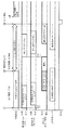
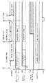
次に、仮の種類Dkpと確定種類Dkdとが一致しない場合における立上げ制御のタイミングの複数の例を挙げる。いずれの例においても、仮の種類Dkpは、初期設定種類(厚紙3)であり、確定種類Dkdは、普通紙(1、2、または3)である。つまり、最低の速度でシート2を搬送して種類Dkを検知し、その後に最高の速度に切り替える状況が想定されている。
Next, a plurality of examples of start-up control timings when the provisional type Dkp and the determined type Dkd do not match will be described. In any example, the provisional type Dkp is an initial setting type (thick paper 3), and the fixed type Dkd is plain paper (1, 2, or 3). That is, it is assumed that the
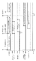
図11には立上げ制御のタイミングの第1例が示されている。図12には立上げ制御のタイミングの第2例が、図13には図12の第2例に対する比較例が、図14には立上げ制御のタイミングの第3例が、図15には図14の第3例に対する比較例が、それぞれ示されている。 FIG. 11 shows a first example of start-up control timing. 12 shows a second example of start-up control timing, FIG. 13 shows a comparative example to the second example of FIG. 12, FIG. 14 shows a third example of the start-up control timing, and FIG. Comparative examples for 14 third examples are shown respectively.
図11の第1例は、図9における関係β2である場合に対応する。 The first example of FIG. 11 corresponds to the case of the relation β2 in FIG.
立上げ制御を開始するタイミングt1において、初期設定速度の給紙が開始され、タイミングt2において、種類Dkの検知が完了する。 At timing t1 at which start-up control is started, paper feeding at an initial set speed is started, and detection of the type Dk is completed at timing t2.
タイミングt1からタイミングt2までの条件確定以前の期間において、感光体4と中間転写ベルト12との圧接/離間の状態は、離間に保たれる。また、カラー感光体4ymcおよびモノクロ感光体4kは、共に停止状態に保たれる。
In the period before the condition is determined from the timing t1 to the timing t2, the pressure contact / separation state between the
タイミングt2において、カラー感光体4ymcの立上げを開始する。そして、所定の時間Tdだけ遅れらせてモノクロ感光体4kの立上げを開始する。時間Tdの遅れを設けることにより、高圧電源回路250およびモータの電源の負荷を分散させる。
At timing t2, start-up of the color photoconductor 4ymc is started. Then, start-up of the monochrome
モノクロ感光体4kの立上げを開始した後に、二次転写ローラ16のクリーニング(例えば除電)を開始し、さらにその後に圧接/離間の状態を離間から圧接に切り替える。
After the start-up of the monochrome
確定条件の立上り状態へ移行が完了する頃に画像要求信号TODがオンとなる。画像要求信号TODは、例えば画像形成制御部127によりタイミングt2から所定の時間が経過したときに発せられる。画像要求信号TODがオンになったタイミングt3において、プリントヘッド6による印字(パターン露光による潜像形成)を開始する。
The image request signal TOD is turned on when the transition to the rising state of the definite condition is completed. The image request signal TOD is generated, for example, when a predetermined time has elapsed from the timing t2 by the image
一次転写されたトナー像が印刷位置P6に到着するときにシート2の画像形成領域も到着するよう見計らったタイミングt4において、タイミングローラ15から印刷位置P6への1枚目のシート2の搬送を開始する。搬送速度は、確定条件の速度である。
At the timing t4 when it is estimated that the image forming area of the
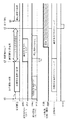
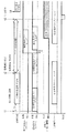
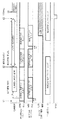
図12の第2例は、図9における関係βである場合、すなわち関係β1に当てはまるモノクロ感光体4kと関係β2に当てはまるカラー感光体4ymcとを有する場合に対応する。
The second example of FIG. 12 corresponds to the case of the relation β in FIG. 9, that is, the case of having the
タイミングt1において、モノクロ感光体4kの初期設定条件の立上げを開始する。カラー感光体4ymcは、停止させておく。
At timing t1, start-up of initial setting conditions for the monochrome
モノクロ感光体4kと給紙搬送部231とを共通のモノクロPCモータ55により駆動することから、タイミングt1からモータの回転が安定するのに要する時間Twの経過を待って、シート2の給紙を開始する。
Since the monochrome
タイミングt2において、カラー感光体4ymcの立上げを開始し、それから時間Tdだけ遅らせてモノクロ感光体4kの速度の切替えを開始する。また、二次転写ローラ16の動作条件を切り替える。そして、適時に圧接/離間の状態を離間から圧接に切り替える。
At the timing t2, the start-up of the color photoconductor 4ymc is started, and then the switching of the speed of the
その後、タイミングt3において、印字を開始し、タイミングt4において、印刷位置P6へのシート2の搬送を開始する。
Thereafter, printing is started at timing t3, and conveyance of the
図13の比較例においては、タイミングt1からタイミングt2までの条件確定以前の期間に、カラー感光体4ymcおよびモノクロ感光体4kを立ち上げるとともに、圧接/離間の状態を圧接にする。つまり、電子写真プロセスを初期設定条件の立上り状態まで移行させてしまう。
In the comparative example of FIG. 13, the color photoconductor 4ymc and the
このため、条件確定以後において、感光体4ymc,4kの動作条件を確定条件に切り替えるのに先立って、中間転写ベルト12と擦れ合うのを防ぐために、圧接/離間の状態をいったん離間に切り替える必要がある。したがって、少なくともこの離間への切替えに要する時間だけ印字の開始が遅れる。
For this reason, after the conditions are determined, the pressure contact / separation state needs to be once switched to separation in order to prevent rubbing against the
図12の第2例によると、条件確定以前において離間に保っておくので、確定条件への切替えに先立って離間に切り替える必要がない。したがって、タイミングt2において確定条件への切替えを開始することができ、印字開始を早めてFPOTを比較例よりも短くすることができる。しかも、感光体4および中間転写ベルト12の摩耗を抑えるためにこれらの間にトナーを介在させる先行技術を用いる必要がなく、トナーの無駄な消費を低減することができる。
According to the second example of FIG. 12, since the distance is maintained before the condition is determined, it is not necessary to switch to the distance before switching to the determined condition. Therefore, switching to the definite condition can be started at timing t2, and FPOT can be made shorter than that of the comparative example by accelerating the start of printing. Moreover, it is not necessary to use a prior art in which toner is interposed between the
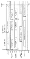
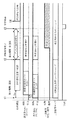
図14の第3例は、図9における関係α1に当てはまるモノクロ感光体4kと関係β2に当てはまるカラー感光体4ymcとを有する場合に対応する。
The third example of FIG. 14 corresponds to the case where the
タイミングt1において、モノクロ感光体4kの初期設定条件の立上げを開始する。カラー感光体4ymcは、停止させておく。また、少なくともカラー感光体4ymcについては、圧接/離間の状態を離間に保つ。
At timing t1, start-up of initial setting conditions for the monochrome
タイミングt2において、モノクロ感光体4kをいったん立ち下げる。モノクロ感光体4kの回転が止まると、モノクロ感光体4kよりも先にカラー感光体4ymcの確定条件での立上げを開始し、時間Tdだけ遅らせてモノクロ感光体4kの確定条件での立上げを開始する。カラー感光体4ymcの立上げを先に行うのは、一次転写の順序が上位のものから早く立上げを完了させるのが、印字の開始を早める上で有利であるからである。
At timing t2, the monochrome
図15の比較例においては、図13の比較例と同様に、条件確定以前の期間に、カラー感光体4ymcおよびモノクロ感光体4kを立ち上げるとともに、圧接/離間の状態を圧接にして電子写真プロセスを初期設定条件の立上り状態まで移行させてしまう。
In the comparative example of FIG. 15, as in the comparative example of FIG. 13, the
このため、条件確定以後において、感光体4ymc,4kの動作条件を確定条件に切り替えるのに先立って、圧接/離間の状態をいったん離間に切り替えることから、離間への切替えに要する時間だけ印字の開始が遅れる。 For this reason, after the condition is determined, the pressure contact / separation state is once switched to separation before the operation conditions of the photoconductors 4ymc and 4k are switched to the confirmation condition, so that printing is started for the time required for switching to separation. Is delayed.
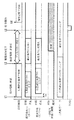
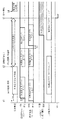
図16には立上げ制御のタイミングの第4例が、図17には同じく第5例が、図18には同じく第6例が、図19には同じく第7例が、図20には同じく第8例が、図21には同じく第9例が、それぞれ示されている。 FIG. 16 shows the fourth example of the start-up control timing, FIG. 17 shows the fifth example, FIG. 18 shows the sixth example, FIG. 19 shows the seventh example, and FIG. The eighth example is shown in FIG. 21 and the ninth example is also shown.
図16の第4例および図17の第5例は、図10における関係α2に当てはまるモノクロ感光体4kと関係β2に当てはまるカラー感光体4ymcとを有する場合に対応する。
The fourth example of FIG. 16 and the fifth example of FIG. 17 correspond to the case of having the
第4例および第5例のいずれも、条件確定以前において、圧接/離間の状態を離間に保ち、カラー感光体4ymcおよびモノクロ感光体4kを任意設定条件の立上り状態に移行させる。
In both the fourth example and the fifth example, the pressure contact / separation state is kept separated before the condition is determined, and the color photoreceptor 4ymc and the
そして、条件確定以後において、第4例では任意設定条件から確定条件に切り替える条件切替え処理を行い、第5例では非立上げ状態に戻して確定条件で立ち上げる再立上げ処理を行う。 Then, after the condition is confirmed, in the fourth example, a condition switching process for switching from the arbitrarily set condition to the confirmed condition is performed, and in the fifth example, a restart process for returning to the non-startup state and starting up with the confirmed condition is performed.
図18の第6例および図19の第7例は、図10における関係β1に当てはまるモノクロ感光体4kと関係β2に当てはまるカラー感光体4ymcとを有する場合に対応する。
The sixth example in FIG. 18 and the seventh example in FIG. 19 correspond to the case of having the
第6例および第7例のいずれも、条件確定以前において、圧接/離間の状態を離間に保ち、カラー感光体4ymcを任意設定条件の立上り状態に移行させるとともに、モノクロ感光体4kを初期設定条件の立上り状態に移行させる。その際に、カラー感光体4ymcの立上げをモノクロ感光体4kの立上げよりも先に開始する。
In both the sixth example and the seventh example, the pressure contact / separation state is kept separated before the condition is determined, the color photoconductor 4ymc is shifted to the rising state of the arbitrary setting condition, and the
そして、条件確定以後において、第6例では条件切替え処理を行い、第7例では再立上げ処理を行う。 Then, after the condition is determined, the condition switching process is performed in the sixth example, and the restarting process is performed in the seventh example.
図20の第8例および図21の第9例も、図10における関係α2に当てはまるモノクロ感光体4kと関係β2に当てはまるカラー感光体4ymcとを有する場合に対応する。
The eighth example of FIG. 20 and the ninth example of FIG. 21 also correspond to the case where the
第8例および第9例のいずれも、条件確定以前において、圧接/離間の状態を離間に保ち、カラー感光体4ymcを任意設定条件の立上り状態に移行させるとともに、モノクロ感光体4kを初期設定条件の立上り状態に移行させる。その際に、モノクロ感光体4kの立上げをカラー感光体4ymcの立上げよりも先に開始する。
In both the eighth example and the ninth example, the pressure contact / separation state is kept separated before the condition is determined, the color photoconductor 4ymc is shifted to the rising state of the arbitrary setting condition, and the
そして、条件確定以後において、第8例では条件切替え処理を行い、第9例では再立上げ処理を行う。 Then, after the condition is determined, the condition switching process is performed in the eighth example, and the restarting process is performed in the ninth example.
一般に、中間転写ベルト12を有した画像形成装置において電子写真プロセスを立ち上げる場合は、感光体4の立上げ時に付着したカブリトナーが一次転写位置を通過した後でなければ中間転写ベルト12の圧接を行えない。それは、カブリトナーによるシート2の裏面の汚れを防止する必要があるからである。低価格機では、構成〔1〕および〔2〕のようにモノクロ感光体4kは常時圧接となるので、カラートナーが一次転写位置を通過し終えるタイミングが中間転写ベルト12の圧接開始タイミングとなり、総プロセス立上げ時間(実質のFPOT)の律則となる。
In general, when an electrophotographic process is started up in an image forming apparatus having the
そこで、カラー印刷時はカラー感光体4ymcを先に立ち上げ、モータのピーク電流分散時間(Td)が経過した後にモノクロ感光体4kを立ち上げることでカラーカブリトナーが一次転写位置を通過し終えるタイミングを早めてFPOTを短縮している。
Therefore, at the time of color printing, the color photoconductor 4ymc is started up first, and the
しかし、シート2の種類Dkの検知を行うときは、種類Dkの確定を優先させるために、搬送に関わる駆動源を最初に駆動する。種類Dkの確定を早めることにより、FPOTを短縮することができる。つまり、給紙搬送部231とモノクロ感光体4kとで駆動源が共通である場合は、モノクロ感光体4kを先に立ち上げる。
However, when the type Dk of the
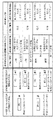
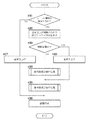
図22には画像形成装置1における立上げ制御の処理の流れが、図23には条件確定以前の処理の流れが、図24には条件確定以後の処理の流れが、それぞれ示されている。また、図25、図26、図27、および図28にはそれぞれ立上げ制御に関わる設定テーブルD31〜D36の例が示されている。
FIG. 22 shows the flow of start-up control processing in the
画像形成装置1は、印刷ジョブに際して図22に示す一連の処理を実行する。その過程において、印刷に使用する1つまたは複数の感光体4について、中間転写ベルト12および給紙搬送部231のそれぞれとの駆動源の関係に応じて立上げ制御の内容を決定する。
The
図22において、まず、シート2の種類Dkを検知するか否かを判断する(#301)。選択したトレイ25に対して有効な情報として種類Dkが記憶されている場合は、検知しないと判断し、種類Dkが記憶されていない場合は検知すると判断する。
In FIG. 22, first, it is determined whether or not the type Dk of the
検知しないと判断した場合は(#301でNO) 、非立上り状態から準立上り状態を意図的に経由させることなく直接に確定条件の立上り状態に移行させる通常立上げを行い(#307)、立上り状態になると直ちに印字(画像形成)を開始する(#306)。このときの確定条件は、記憶されている種類Dkに対応する動作条件である。 If it is determined not to be detected (NO in # 301), a normal startup is performed to shift directly from the non-rising state to the rising state of the deterministic condition without intentionally passing the quasi-rising state (# 307). Immediately after entering the state, printing (image formation) is started (# 306). The final condition at this time is an operation condition corresponding to the stored type Dk.
種類Dkを検知すると判断した場合は(#301でYES) 、図25(A)に示す設定テーブルD31を参照して通常立上げをするか否かを判断する(#302、#303)。 When it is determined that the type Dk is detected (YES in # 301), it is determined whether or not normal startup is performed with reference to the setting table D31 shown in FIG. 25A (# 302 and # 303).
設定テーブルD31は、使用頻度の高い種類Dkが判定されている場合には、その種類Dkに対応する動作条件を確定条件とみなして通常立上げを行い、それによってFPOTを短縮するために設けられている。設定テーブルD31は、種類Dkごとの使用回数を示すデータ量がしきい値未満であって判定の信頼性が不十分である場合は通常立上げを行わないことを示す。信頼性が十分でありかつ高頻度の種類Dkが有る場合に通常立上げを行うことを示す。 When the frequently used type Dk is determined, the setting table D31 is normally set up so that the operation condition corresponding to the type Dk is regarded as a definite condition, thereby shortening the FPOT. ing. The setting table D31 indicates that normal startup is not performed when the data amount indicating the number of times of use for each type Dk is less than the threshold value and the determination reliability is insufficient. It is shown that normal startup is performed when the reliability is sufficient and there is a high-frequency type Dk.
通常立上げをすると判断した場合は(#303でYES) 、通常立上げを行い(#308)、通常立上げを行った後に条件確定以後の処理(#305)へ進む。つまり、立上げ制御部126は、複数の想定された種類Dkのうちの使用頻度の高い種類Dkに対応した動作条件を仮の条件とする場合には、シート2の種類Dkが検知される以前に、仮の条件による画像形成の準備が完了した状態まで移行するよう制御する。これにより、仮の条件が検知した種類Dkに対応する真の確定条件と一致する場合に、動作条件を切り替えることなく直ちに印字を開始することができる。すなわち、種類Dkを検知しない場合と同様のFOPTを実現することができる。
If it is determined that the normal startup is to be performed (YES in # 303), the normal startup is performed (# 308), and after the normal startup, the process proceeds to the processing after the condition is determined (# 305). In other words, when the operation condition corresponding to the frequently used type Dk among the plurality of assumed types Dk is set as a provisional condition, the start-up
通常立上げをしないと判断した場合は(#303でNO) 、条件確定以前の処理(#304)と条件確定以後の処理(#305)とを順に実行した後、画像を形成する(#306)。 If it is determined not to start up normally (NO in # 303), the process before the condition confirmation (# 304) and the process after the condition confirmation (# 305) are executed in order, and then an image is formed (# 306). ).
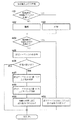
図23に示す条件確定以前の処理においては、まず、注目する感光体4の駆動源が中間転写ベルト12の駆動源と共通であるか否かをチェックする(#401)。
In the process before the condition confirmation shown in FIG. 23, first, it is checked whether or not the driving source of the
中間転写ベルト12との間で駆動源が共通ではない場合は(#401でNO) 、当該感光体4を中間転写ベルト12から離間させる(#402)。中間転写ベルト12と駆動源が共通である場合は(#401でYES) 、当該感光体4に中間転写ベルト12を圧接させる(#403)。
If the drive source is not common with the intermediate transfer belt 12 (NO in # 401), the
次に、注目する感光体4の駆動源が給紙搬送部231の駆動源と共通であるか否かをチェックする(#404)。
Next, it is checked whether or not the driving source of the
給紙搬送部231との間で駆動源が共通である場合は(#404でYES) 、当該感光体4を図25(B)に示す設定テーブルD32により設定されている仮の条件で立ち上げる(#410)。
If the drive source is shared with the paper feeding / conveying unit 231 (YES in # 404), the
設定テーブルD32は、ユーザが使用する可能性の高いシート2に動作条件を合わせつつも、ジャムのリスクを低減するよう例えば厚紙については普通紙よりも遅い搬送速度とすることを定めている。
The setting table D32 stipulates that the conveyance speed is slower than that of plain paper, for example, for thick paper so as to reduce the risk of jam while adjusting the operating conditions to the
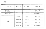
給紙搬送部231との間で駆動源が共通ではない場合は(#404でNO) 、図26(A)に示す設定テーブルD33を参照して感光体4に対する条件確定以前の状態の設定が停止であるか駆動であるかを確認する(#405、#406)。
If the drive source is not common with the paper feeding / conveying unit 231 (NO in # 404), the setting of the state before the condition determination for the
設定テーブルD33は、ユーザが停止または駆動を指定している場合は、指定の通りの処理を判断結果として定めている。また、ユーザが自動を指定した場合は、温度および湿度などの環境条件、感光体4の寿命の末期かそれ以外かという耐久条件、および種類Dkの使用頻度に応じて、停止と駆動とのいずれかを判断結果として定めている。例えば、使用頻度に規則性がない場合は、仮の条件と確定条件とが一致しない確率が大きいと考えられることから、無駄な走行を抑えるために判断結果は停止とされている。
In the setting table D33, when the user designates stop or drive, the designated process is determined as the determination result. If the user designates automatic, either stop or drive depending on the environmental conditions such as temperature and humidity, the endurance condition of the end of the life of the
条件確定以前の状態として停止が設定されている場合は、直ちに図22のフローに戻る。 If the stop is set as the state before the condition is determined, the process immediately returns to the flow of FIG.
他方、条件確定以前の状態として駆動が設定されている場合は、続いて、図26(B)および(C)に示す設定テーブルD34,D35を参照して、立上げ条件および立上げタイミングを判断する(#407、#408)。そして、判断した結果に従って仮の条件での立上げを行う(#409)。 On the other hand, when the driving is set as the state before the condition is determined, the startup conditions and the startup timing are determined with reference to the setting tables D34 and D35 shown in FIGS. 26B and 26C. (# 407, # 408). Then, startup is performed under temporary conditions according to the determined result (# 409).
設定テーブルD34は、種類Dkの使用頻度の判定の信頼性に応じて仮の条件を決めるために設けられており、種類Dkごとの使用回数を示すデータ量が設定量以上(十分)にある場合に高頻度の種類に対応する動作条件を仮の条件とすることを示す。データ量が不十分である場合は、初期設定条件を仮の条件とすることを示す。 The setting table D34 is provided to determine a provisional condition according to the reliability of the determination of the usage frequency of the type Dk, and the data amount indicating the number of times of use for each type Dk is greater than or equal to the set amount (sufficient). Fig. 5 shows that the operating condition corresponding to the high frequency type is set as a temporary condition. If the amount of data is insufficient, the initial setting condition is assumed to be a temporary condition.
設定テーブルD35は、種類Dkの検知の完了と実質的に同時に完了するように行う処理を定めている。例えば、感光体4がそれ以外を駆動しない単独の駆動源により駆動される場合は、その感光体4の立上げの完了タイミングと種類Dkの検知の完了タイミングと合わせることを示す。また、感光体4と転写機構とで駆動源が共通である場合は、感光体4の立上げの所要時間と転写クリーニングの所要時間との長い方の完了タイミングを種類Dkの検知の完了タイミングと合わせることを示す。設定テーブルD34の内容に従ってタイミングを制御することにより、感光体4および中間転写ベルト12の走行時間を最短にすることができる。
The setting table D35 defines processing to be performed substantially simultaneously with completion of detection of the type Dk. For example, when the
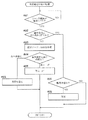
図24に示す条件確定以後の処理においては、シート2の種類Dkが検知されて動作条件が確定するのを待つ(#501)。動作条件が確定すると(#501でYES) 、確定条件が仮の条件と同じであるか否かを判断する(#502)。
In the processing after the condition confirmation shown in FIG. 24, the process waits until the type Dk of the
確定条件が仮の条件と同じである場合は(#502でYES) 、感光体4と中間転写ベルト12とが離間しているときは(#506でYES) 、これらを圧接した後に(#507)、図22のフローに戻る。離間していないときは、直ちに図22のフローに戻る。
If the confirmation condition is the same as the provisional condition (YES in # 502), if the
確定条件が仮の条件と同じではない場合は(#502でNO) 、図27に示す設定テーブルD36を参照して条件確定以後の処理の設定が条件切替え処理であるか再立上げ処理であるかを確認する(#503、#504)。そして、設定テーブルD36が示す設定に従って、条件切替え処理(#506)または再立上げ処理(#505)を行う。 If the confirmation condition is not the same as the provisional condition (NO in # 502), the setting of the process after the condition confirmation is a condition switching process or a restart process with reference to the setting table D36 shown in FIG. (# 503, # 504). Then, the condition switching process (# 506) or the restart process (# 505) is performed according to the setting indicated by the setting table D36.
設定テーブルD36は、ユーザが条件切替え処理または再立上げ処理を指定している場合は、指定の通りの処理を行うことを定めている。また、ユーザが自動を指定した場合は、温度および湿度などの環境条件、および感光体4の寿命の末期かそれ以外かという耐久条件に応じて、条件切替え処理と再立上げ処理とのいずれを行うかを定めている。
The setting table D36 defines that when the user designates the condition switching process or the restarting process, the designated process is performed. When the user designates automatic, either the condition switching process or the restarting process is performed according to environmental conditions such as temperature and humidity, and endurance conditions such as the end of the life of the
以上の実施形態によると、感光体4と中間転写ベルト12との速度のずれに因る摩耗を防ぐ緩衝材として色材であるトナーを無駄に消費することなく、電子写真プロセスの立上げを開始した後に動作条件を切り替える場合における印字開始の遅れを低減することができる。すなわち、種類Dkを検知する場合における印刷物が出力されるのをユーザが待つ時間を短くすることができる。
According to the above embodiment, the start-up of the electrophotographic process is started without wastefully consuming the toner, which is a coloring material, as a cushioning material that prevents wear due to the speed difference between the
条件確定以前の準立上げ状態を感光体4が停止した状態とすることにより感光体4およびその駆動源の寿命が延びる。それによりCPP(Cost Per Page) が低減される。
The life of the
条件確定以前の段階では立上り状態とはせずに準立上げ状態にとどめる改良立上げ制御は、カラー印刷モードに限らず、単一の感光体4kを値用するモノクロ印刷モードにおいても実施することができる。
The improved start-up control that remains in the semi-start-up state instead of the start-up state before the condition is determined is not limited to the color print mode, but also in the monochrome print mode that uses the value of the
動作条件の項目は、プロセス速度Vs、定着温度Ts、二次転写出力V16、およびカブリマージンVmに限らない。帯電出力、現像出力、イレーサ光量、一次転写出力、露光光量などのうちの1つまたは複数を加えてもよい。必ずしも項目の個数は複数である必要はない。 The operation condition items are not limited to the process speed Vs, the fixing temperature Ts, the secondary transfer output V16, and the fog margin Vm. One or more of charging output, development output, eraser light quantity, primary transfer output, exposure light quantity, etc. may be added. The number of items is not necessarily plural.
上に述べた実施形態において、準立上り状態への移行に二次転写ローラ16の立ち上げを含める場合には、非立上げ状態から立上り状態に移行する際に当該二次転写ローラ16のクリーニングを省略することができる。また、準立上り状態への移行に際して二次転写ローラ16を回転させる場合に、当該二次転写ローラ16のクリーニングを省略することができる。
In the embodiment described above, when the transition of the
また、メディアセンサ41は上記では光センサとして説明したが、それ以外のセンサでもよい。例えば、超音波センサ、紙厚センサ、カメラ、静電容量センサ等の紙の特性が検出できるセンサであればよい。また、メディアセンサ41は、1 個のセンサに限定されず、複数のセンサ(例えば、光センサと超音波センサ)からなる構成でもよい。このように複数のセンサを使うことで、光センサでは検知が難しい用紙に対しても超音波センサで検知することによってより多くの紙種を高精度に検知することができる。
The
その他、画像形成装置1の全体または各部の構成、動作および処理の内容、順序、またはタイミング、想定される複数の種類Dkの分類方法、個数、動作条件値Dcの具体値などは、本発明の趣旨に沿って適宜変更することができる。
In addition, the configuration of the whole or each part of the
1 画像形成装置
2 シート(媒体)
4 感光体
4ymc カラー感光体(第1の感光体)
4k モノクロ感光体(第2の感光体)
12 中間転写ベルト(被転写体)
16 二次転写ローラ(転写部材)
30 搬送経路
41 メディアセンサ(センサ)
51 メインモータ(共通駆動源、第2の駆動源)
52 ベルトモータ(第2の駆動源)
53 給紙モータ(第2の駆動源、媒体を搬送するため駆動源、第3の駆動源)
54 カラーPCモータ(第1の駆動源)
55 モノクロPCモータ(第1の駆動源)
110,110a,110b 圧接離間機構
125 種類検知部(検知部)
126 立上げ制御部
Dk 種類
t2 タイミング
1
4 photoconductor 4ymc color photoconductor (first photoconductor)
4k monochrome photoreceptor (second photoreceptor)
12 Intermediate transfer belt (transfer object)
16 Secondary transfer roller (transfer member)
30
51 Main motor (common drive source, second drive source)
52 Belt motor (second drive source)
53 Paper feed motor (second drive source, drive source for transporting the medium, third drive source)
54 Color PC motor (first drive source)
55 Monochrome PC motor (first drive source)
110, 110a, 110b 125 pressure detection / separation mechanism types detection unit (detection unit)
126 Start-up controller Dk Type t2 Timing
Claims (18)
前記媒体の搬送経路に設けられたセンサの出力に基づいて前記媒体の種類が複数の想定された種類のいずれであるかを検知する検知部と、
前記媒体の種類が検知される以前に、前記複数の想定された種類のうちの1つに対応する動作条件である仮の条件による画像形成の準備が部分的に完了した準立上り状態まで移行し、前記媒体の種類が検知された後に、検知された種類に対応する動作条件である確定条件による画像形成の準備が完了した立上り状態に移行するよう制御する立上げ制御部と、を有する、
ことを特徴とする画像形成装置。 An image forming apparatus that forms an image on the medium under operating conditions set according to the type of sheet-like medium,
A detection unit that detects which of the plurality of types of the medium is based on an output of a sensor provided in the conveyance path of the medium;
Before the type of the medium is detected, a transition is made to a quasi-rising state in which preparation for image formation based on a temporary condition that is an operation condition corresponding to one of the plurality of assumed types is partially completed. A start-up control unit that controls to shift to a start-up state in which preparation for image formation according to a determination condition that is an operation condition corresponding to the detected type is completed after the type of the medium is detected;
An image forming apparatus.
前記感光体を回転駆動する第1の駆動源と、
前記感光体から前記トナー像が転写される被転写体と、
前記被転写体を回転駆動する第2の駆動源と、
前記感光体と前記被転写体とを圧接させたり離間させたりする圧接離間機構と、を有しており、
前記準立上り状態は、前記感光体と前記被転写体とが離間している状態であり、
前記立上り状態は、前記感光体と前記被転写体とが圧接している状態である、
請求項1記載の画像形成装置。 A photoreceptor for forming a toner image corresponding to the image;
A first drive source for rotationally driving the photoreceptor;
A transfer object onto which the toner image is transferred from the photoreceptor;
A second drive source for rotationally driving the transfer object;
A pressure contact / separation mechanism that presses or separates the photoconductor and the transfer target, and
The quasi-rising state is a state where the photoconductor and the transfer target are separated from each other,
The rising state is a state where the photoconductor and the transfer target are in pressure contact with each other,
The image forming apparatus according to claim 1.
前記準立上り状態は、前記感光体と前記被転写体とが離間しかつ前記感光体が停止した状態である、
請求項2記載の画像形成装置。 The drive source for conveying the medium is different from the first drive source,
The quasi-rising state is a state in which the photoconductor and the transfer target are separated from each other and the photoconductor is stopped.
The image forming apparatus according to claim 2.
前記準立上り状態は、前記感光体と前記被転写体とが離間しかつ前記感光体が前記複数の動作条件のいずれかに対応する速度で回転する状態である、
請求項2記載の画像形成装置。 The drive source for conveying the medium is different from the first drive source,
The quasi-rising state is a state in which the photoconductor and the transfer target are separated from each other and the photoconductor rotates at a speed corresponding to any of the plurality of operation conditions.
The image forming apparatus according to claim 2.
請求項4記載の画像形成装置。 The rotational speed of the photoconductor in the quasi-rising state is a speed of an operating condition corresponding to a type whose usage frequency is higher than a threshold value among the plurality of assumed types.
The image forming apparatus according to claim 4.
請求項5記載の画像形成装置。 The start-up control unit sets the rotation speed as a speed of an initial setting condition when the use frequency is undetermined.
The image forming apparatus according to claim 5.
請求項3ないし6のいずれかに記載の画像形成装置 The start-up control unit starts preparation for image formation under the provisional condition so that the transition to the quasi-rise state is completed at the timing when the type of the medium is detected;
The image forming apparatus according to claim 3.
前記立上げ制御部は、前記媒体の種類が検知される以前において、前記媒体の搬送と並行して前記準立上り状態に移行するよう制御する、
請求項2記載の画像形成装置。 The first drive source doubles as a drive source for transporting the medium,
The start-up control unit controls to shift to the quasi-rise state in parallel with the conveyance of the medium before the type of the medium is detected.
The image forming apparatus according to claim 2.
前記媒体の種類が検知される以前において、
前記感光体と前記被転写体とを離間させておきかつ前記感光体を停止させておく制御、および前記感光体と前記被転写体とを離間させておきかつ前記感光体を回転させておく制御のいずれかを、ユーザによる指定、環境条件、および耐久条件のうちの1つまたは複数の組合せに応じて選択して行う、
請求項2記載の画像形成装置。 The start-up control unit
Before the media type is detected,
Control for keeping the photosensitive member and the transfer member separated and stopping the photosensitive member, and control for keeping the photosensitive member and the transfer member separated and rotating the photosensitive member Is selected according to one or more combinations of user designation, environmental conditions, and durability conditions,
The image forming apparatus according to claim 2.
請求項2ないし9のいずれかに記載の画像形成装置。 The start-up control unit switches the operation condition from the temporary condition to the final condition while rotating the photosensitive member when the final condition is different from the temporary condition.
The image forming apparatus according to claim 2.
請求項2ないし9のいずれかに記載の画像形成装置。 The start-up control unit performs a start-up control for returning the photoconductor to a non-start-up state immediately before starting preparation for image formation under the temporary condition when the final condition is different from the temporary condition. Performing control to shift from the non-start-up state to the start-up state,
The image forming apparatus according to claim 2.
前記確定条件が前記仮の条件と異なる場合において、
前記感光体を回転させながら前記動作条件を前記仮の条件から前記確定条件へ切り替える制御、および前記感光体を前記仮の条件による画像形成の準備を開始する直前の非立上げ状態に戻すための立下げ制御を行い、当該非立上げ状態から前記立上り状態に移行させる制御のいずれかを、ユーザによる指定、環境条件、および耐久条件のうちの1つまたは複数の組合せに応じて選択して行う、
請求項2ないし9のいずれかに記載の画像形成装置。 The start-up control unit
When the final condition is different from the temporary condition,
Control for switching the operating condition from the tentative condition to the final condition while rotating the photosensitive member, and returning the photosensitive member to a non-start-up state immediately before starting preparation for image formation under the temporary condition. One of the control to perform the fall control and shift from the non-rise state to the rise state is selected according to one or a combination of the designation by the user, the environmental condition, and the durability condition. ,
The image forming apparatus according to claim 2.
前記準立上り状態への移行に前記転写部材の立ち上げを含める場合に、前記非立上げ状態から前記立上り状態に移行する際に当該転写部材のクリーニングを省略する、
請求項11または12記載の画像形成装置。 A transfer member for transferring the toner image from the transfer target to the medium;
If the transition to the quasi-rise state includes the rise of the transfer member, cleaning of the transfer member is omitted when shifting from the non-rise state to the rise state,
The image forming apparatus according to claim 11 or 12.
前記準立上り状態への移行に際して前記転写部材を回転させる場合に、当該転写部材のクリーニングを省略する、
請求項2ないし13のいずれかに記載の画像形成装置。 A transfer member for transferring the toner image from the transfer target to the medium;
When the transfer member is rotated during the transition to the quasi-rise state, cleaning of the transfer member is omitted.
The image forming apparatus according to claim 2.
前記感光体から前記トナー像が転写される被転写体と、
前記感光体および前記被転写体の両方を回転駆動する共通駆動源と、
前記媒体を搬送するための駆動源と、を有しており、
前記準立上り状態は、前記感光体と前記被転写体とが圧接しかつ前記感光体および前記被転写体が共に停止している状態であり、
前記立上り状態は、前記感光体と前記被転写体とが圧接しかつ前記感光体および前記被転写体が共に回転している状態である、
請求項1記載の画像形成装置。 A photoreceptor for forming a toner image corresponding to the image;
A transfer object onto which the toner image is transferred from the photoreceptor;
A common drive source for rotationally driving both the photoconductor and the transfer object;
A drive source for transporting the medium,
The quasi-rising state is a state in which the photoconductor and the transfer target are in pressure contact and the photoconductor and the transfer target are both stopped.
The rising state is a state where the photoconductor and the transfer target body are in pressure contact with each other and the photoconductor and the transfer target body are rotating together.
The image forming apparatus according to claim 1.
前記画像に対応した第2のトナー像を形成するための第2の感光体と、
前記第1の感光体から前記第1のトナー像が転写されかつ前記第2の感光体から前記第2のトナー像が転写される被転写体と、
前記第1の感光体を回転駆動する第1の駆動源と、
前記第2の感光体および前記被転写体の両方を回転駆動する第2の駆動源と、
前記媒体を搬送するための第3の駆動源と、
前記感光体と前記被転写体とを圧接させたり離間させたりする圧接離間機構と、を有しており、
前記準立上り状態は、前記第1の感光体と前記被転写体とが離間しているとともに、前記第2の感光体と前記被転写体とが圧接しかつ前記第2の感光体および前記被転写体が共に停止している状態であり、
前記立上り状態は、前記第2の感光体と前記被転写体とが圧接しかつ前記第2の感光体および前記被転写体が共に回転している状態である、
請求項1記載の画像形成装置。 A first photoreceptor for forming a first toner image corresponding to the image;
A second photoreceptor for forming a second toner image corresponding to the image;
A transfer object onto which the first toner image is transferred from the first photoconductor and the second toner image is transferred from the second photoconductor;
A first drive source for rotationally driving the first photosensitive member;
A second drive source that rotationally drives both the second photoconductor and the transfer target;
A third drive source for transporting the medium;
A pressure contact / separation mechanism that presses or separates the photoconductor and the transfer target, and
In the quasi-rising state, the first photoconductor and the transfer target are separated from each other, the second photoconductor and the transfer target are in pressure contact, and the second photoconductor and the transfer target are in contact. The transfer body is in a stopped state,
The rising state is a state in which the second photoconductor and the transfer target are in pressure contact with each other and the second photoconductor and the transfer target are rotating together.
The image forming apparatus according to claim 1.
請求項1ないし16のいずれかに記載の画像形成装置 The provisional condition is determined according to one or a combination of a designation by a user, a use frequency of the type, and a conveyance performance.
The image forming apparatus according to claim 1.
請求項1記載の画像形成装置。 In the case where the operation condition corresponding to the frequently used type among the plurality of assumed types is set as the provisional condition, the start-up control unit, before the type of the medium is detected, Control to transition to a state where preparation for image formation under temporary conditions is completed,
The image forming apparatus according to claim 1.
Priority Applications (3)
| Application Number | Priority Date | Filing Date | Title |
|---|---|---|---|
| JP2018096070A JP7081297B2 (en) | 2018-05-18 | 2018-05-18 | Image forming device, state control method, and computer program |
| US16/408,810 US10725411B2 (en) | 2018-05-18 | 2019-05-10 | Image forming apparatus that forms an image on a sheet medium under an operation condition set in accordance with a type of the medium |
| CN201910393386.XA CN110501885B (en) | 2018-05-18 | 2019-05-13 | Image forming apparatus with a toner supply device |
Applications Claiming Priority (1)
| Application Number | Priority Date | Filing Date | Title |
|---|---|---|---|
| JP2018096070A JP7081297B2 (en) | 2018-05-18 | 2018-05-18 | Image forming device, state control method, and computer program |
Publications (2)
| Publication Number | Publication Date |
|---|---|
| JP2019200375A true JP2019200375A (en) | 2019-11-21 |
| JP7081297B2 JP7081297B2 (en) | 2022-06-07 |
Family
ID=68533655
Family Applications (1)
| Application Number | Title | Priority Date | Filing Date |
|---|---|---|---|
| JP2018096070A Active JP7081297B2 (en) | 2018-05-18 | 2018-05-18 | Image forming device, state control method, and computer program |
Country Status (3)
| Country | Link |
|---|---|
| US (1) | US10725411B2 (en) |
| JP (1) | JP7081297B2 (en) |
| CN (1) | CN110501885B (en) |
Citations (5)
| Publication number | Priority date | Publication date | Assignee | Title |
|---|---|---|---|---|
| JPH1184908A (en) * | 1997-09-12 | 1999-03-30 | Canon Inc | Image forming device |
| JP2004078128A (en) * | 2002-08-22 | 2004-03-11 | Fuji Xerox Co Ltd | Image forming device |
| JP2015014695A (en) * | 2013-07-05 | 2015-01-22 | キヤノン株式会社 | Image forming apparatus |
| JP2017102340A (en) * | 2015-12-03 | 2017-06-08 | キヤノン株式会社 | Image forming apparatus |
| JP2017223903A (en) * | 2016-06-17 | 2017-12-21 | キヤノン株式会社 | Image forming apparatus |
Family Cites Families (3)
| Publication number | Priority date | Publication date | Assignee | Title |
|---|---|---|---|---|
| JP4170803B2 (en) * | 2003-03-14 | 2008-10-22 | 株式会社リコー | Image forming apparatus |
| US7551306B2 (en) * | 2005-07-29 | 2009-06-23 | Canon Kabushiki Kaisha | Image forming apparatus and method for controlling the image forming apparatus |
| JP5864919B2 (en) | 2011-07-07 | 2016-02-17 | キヤノン株式会社 | Image forming apparatus |
-
2018
- 2018-05-18 JP JP2018096070A patent/JP7081297B2/en active Active
-
2019
- 2019-05-10 US US16/408,810 patent/US10725411B2/en active Active
- 2019-05-13 CN CN201910393386.XA patent/CN110501885B/en active Active
Patent Citations (5)
| Publication number | Priority date | Publication date | Assignee | Title |
|---|---|---|---|---|
| JPH1184908A (en) * | 1997-09-12 | 1999-03-30 | Canon Inc | Image forming device |
| JP2004078128A (en) * | 2002-08-22 | 2004-03-11 | Fuji Xerox Co Ltd | Image forming device |
| JP2015014695A (en) * | 2013-07-05 | 2015-01-22 | キヤノン株式会社 | Image forming apparatus |
| JP2017102340A (en) * | 2015-12-03 | 2017-06-08 | キヤノン株式会社 | Image forming apparatus |
| JP2017223903A (en) * | 2016-06-17 | 2017-12-21 | キヤノン株式会社 | Image forming apparatus |
Also Published As
| Publication number | Publication date |
|---|---|
| US20190354050A1 (en) | 2019-11-21 |
| US10725411B2 (en) | 2020-07-28 |
| CN110501885A (en) | 2019-11-26 |
| CN110501885B (en) | 2022-02-22 |
| JP7081297B2 (en) | 2022-06-07 |
Similar Documents
| Publication | Publication Date | Title |
|---|---|---|
| JP5983686B2 (en) | Paper conveying apparatus and image forming apparatus | |
| US8781345B2 (en) | Image forming apparatus and method of forming image | |
| US10558155B1 (en) | Image forming apparatus | |
| JP2020008621A (en) | Image forming apparatus | |
| JP2017138406A (en) | Image forming apparatus and temperature control method | |
| US9467586B2 (en) | Image forming apparatus | |
| JP5446441B2 (en) | Image forming apparatus | |
| JP2018106112A (en) | Image forming apparatus and image forming method | |
| EP2775353B1 (en) | Electrophotographic image forming apparatus | |
| US20080193157A1 (en) | Media Determination | |
| JP2012103580A (en) | Image forming apparatus | |
| JP2010211062A (en) | Image forming apparatus | |
| JP7081297B2 (en) | Image forming device, state control method, and computer program | |
| US11899999B2 (en) | Image forming apparatus, information processing terminal, method, and program | |
| JP2004226492A (en) | Image forming apparatus and copying apparatus | |
| JP5402453B2 (en) | Image forming apparatus and control method thereof | |
| JP2010256477A (en) | Color image forming apparatus | |
| JP5477086B2 (en) | Image forming apparatus | |
| US12007715B1 (en) | Image forming apparatus | |
| JP2006142713A (en) | Image forming apparatus, replenishment sheet display method thereof, and program for causing computer to execute the method | |
| US20240422275A1 (en) | Image forming apparatus and method for controlling optional paper feeder in image forming apparatus | |
| JP2013130772A (en) | Image forming apparatus | |
| JP2005164922A (en) | Image forming apparatus | |
| JP2025052740A (en) | Image formation device, method for controlling image formation device, and program | |
| JP6344341B2 (en) | Image forming apparatus, image forming system, and heating amount control method |
Legal Events
| Date | Code | Title | Description |
|---|---|---|---|
| A621 | Written request for application examination |
Free format text: JAPANESE INTERMEDIATE CODE: A621 Effective date: 20210416 |
|
| A977 | Report on retrieval |
Free format text: JAPANESE INTERMEDIATE CODE: A971007 Effective date: 20220214 |
|
| A131 | Notification of reasons for refusal |
Free format text: JAPANESE INTERMEDIATE CODE: A131 Effective date: 20220222 |
|
| A521 | Request for written amendment filed |
Free format text: JAPANESE INTERMEDIATE CODE: A523 Effective date: 20220406 |
|
| A521 | Request for written amendment filed |
Free format text: JAPANESE INTERMEDIATE CODE: A523 Effective date: 20220408 |
|
| TRDD | Decision of grant or rejection written | ||
| A01 | Written decision to grant a patent or to grant a registration (utility model) |
Free format text: JAPANESE INTERMEDIATE CODE: A01 Effective date: 20220426 |
|
| A61 | First payment of annual fees (during grant procedure) |
Free format text: JAPANESE INTERMEDIATE CODE: A61 Effective date: 20220509 |
|
| R150 | Certificate of patent or registration of utility model |
Ref document number: 7081297 Country of ref document: JP Free format text: JAPANESE INTERMEDIATE CODE: R150 |