JP2019197319A - Information processing device, information processing method and information processing program - Google Patents
Information processing device, information processing method and information processing program Download PDFInfo
- Publication number
- JP2019197319A JP2019197319A JP2018090015A JP2018090015A JP2019197319A JP 2019197319 A JP2019197319 A JP 2019197319A JP 2018090015 A JP2018090015 A JP 2018090015A JP 2018090015 A JP2018090015 A JP 2018090015A JP 2019197319 A JP2019197319 A JP 2019197319A
- Authority
- JP
- Japan
- Prior art keywords
- link
- flow
- value
- performance information
- information
- Prior art date
- Legal status (The legal status is an assumption and is not a legal conclusion. Google has not performed a legal analysis and makes no representation as to the accuracy of the status listed.)
- Granted
Links
Images


Classifications
-
- G—PHYSICS
- G06—COMPUTING OR CALCULATING; COUNTING
- G06F—ELECTRIC DIGITAL DATA PROCESSING
- G06F9/00—Arrangements for program control, e.g. control units
- G06F9/06—Arrangements for program control, e.g. control units using stored programs, i.e. using an internal store of processing equipment to receive or retain programs
- G06F9/46—Multiprogramming arrangements
- G06F9/50—Allocation of resources, e.g. of the central processing unit [CPU]
- G06F9/5005—Allocation of resources, e.g. of the central processing unit [CPU] to service a request
- G06F9/5027—Allocation of resources, e.g. of the central processing unit [CPU] to service a request the resource being a machine, e.g. CPUs, Servers, Terminals
- G06F9/5044—Allocation of resources, e.g. of the central processing unit [CPU] to service a request the resource being a machine, e.g. CPUs, Servers, Terminals considering hardware capabilities
-
- G—PHYSICS
- G06—COMPUTING OR CALCULATING; COUNTING
- G06F—ELECTRIC DIGITAL DATA PROCESSING
- G06F13/00—Interconnection of, or transfer of information or other signals between, memories, input/output devices or central processing units
- G06F13/10—Program control for peripheral devices
- G06F13/12—Program control for peripheral devices using hardware independent of the central processor, e.g. channel or peripheral processor
-
- G—PHYSICS
- G06—COMPUTING OR CALCULATING; COUNTING
- G06F—ELECTRIC DIGITAL DATA PROCESSING
- G06F11/00—Error detection; Error correction; Monitoring
- G06F11/30—Monitoring
- G06F11/3003—Monitoring arrangements specially adapted to the computing system or computing system component being monitored
- G06F11/3031—Monitoring arrangements specially adapted to the computing system or computing system component being monitored where the computing system component is a motherboard or an expansion card
-
- G—PHYSICS
- G06—COMPUTING OR CALCULATING; COUNTING
- G06F—ELECTRIC DIGITAL DATA PROCESSING
- G06F11/00—Error detection; Error correction; Monitoring
- G06F11/30—Monitoring
- G06F11/3003—Monitoring arrangements specially adapted to the computing system or computing system component being monitored
- G06F11/3041—Monitoring arrangements specially adapted to the computing system or computing system component being monitored where the computing system component is an input/output interface
-
- G—PHYSICS
- G06—COMPUTING OR CALCULATING; COUNTING
- G06F—ELECTRIC DIGITAL DATA PROCESSING
- G06F11/00—Error detection; Error correction; Monitoring
- G06F11/30—Monitoring
- G06F11/34—Recording or statistical evaluation of computer activity, e.g. of down time, of input/output operation ; Recording or statistical evaluation of user activity, e.g. usability assessment
- G06F11/3409—Recording or statistical evaluation of computer activity, e.g. of down time, of input/output operation ; Recording or statistical evaluation of user activity, e.g. usability assessment for performance assessment
- G06F11/3419—Recording or statistical evaluation of computer activity, e.g. of down time, of input/output operation ; Recording or statistical evaluation of user activity, e.g. usability assessment for performance assessment by assessing time
- G06F11/3423—Recording or statistical evaluation of computer activity, e.g. of down time, of input/output operation ; Recording or statistical evaluation of user activity, e.g. usability assessment for performance assessment by assessing time where the assessed time is active or idle time
-
- G—PHYSICS
- G06—COMPUTING OR CALCULATING; COUNTING
- G06F—ELECTRIC DIGITAL DATA PROCESSING
- G06F9/00—Arrangements for program control, e.g. control units
- G06F9/06—Arrangements for program control, e.g. control units using stored programs, i.e. using an internal store of processing equipment to receive or retain programs
- G06F9/46—Multiprogramming arrangements
- G06F9/50—Allocation of resources, e.g. of the central processing unit [CPU]
- G06F9/5005—Allocation of resources, e.g. of the central processing unit [CPU] to service a request
- G06F9/5011—Allocation of resources, e.g. of the central processing unit [CPU] to service a request the resources being hardware resources other than CPUs, Servers and Terminals
-
- G—PHYSICS
- G06—COMPUTING OR CALCULATING; COUNTING
- G06F—ELECTRIC DIGITAL DATA PROCESSING
- G06F2209/00—Indexing scheme relating to G06F9/00
- G06F2209/50—Indexing scheme relating to G06F9/50
- G06F2209/501—Performance criteria
-
- G—PHYSICS
- G06—COMPUTING OR CALCULATING; COUNTING
- G06F—ELECTRIC DIGITAL DATA PROCESSING
- G06F2209/00—Indexing scheme relating to G06F9/00
- G06F2209/50—Indexing scheme relating to G06F9/50
- G06F2209/509—Offload
Landscapes
- Engineering & Computer Science (AREA)
- Theoretical Computer Science (AREA)
- Physics & Mathematics (AREA)
- General Engineering & Computer Science (AREA)
- General Physics & Mathematics (AREA)
- Software Systems (AREA)
- Quality & Reliability (AREA)
- Computing Systems (AREA)
- Computer Hardware Design (AREA)
- Mathematical Physics (AREA)
- Debugging And Monitoring (AREA)
- Data Exchanges In Wide-Area Networks (AREA)
Abstract
【課題】システム全体の性能を最大化するようにフローを振り分けることができる情報処理装置、情報処理方法および情報処理プログラムを提供する。【解決手段】情報処理装置は、複数のリンクを経由してCPUと接続されるオフロード回路を備える。情報処理装置のオフロード回路は、論理回路と、収集部と、選択部とを備える。論理回路は、アプリケーションの処理を演算する。収集部は、アプリケーションの処理に対応するフローごとのリンクの性能情報を示す値と、リンクごとの使用可能な性能情報の最大値とを収集する。選択部は、フローごとのリンクの性能情報を示す値に基づいて、要する性能情報を満たしていないフローを判定する。また、選択部は、リンクごとの使用可能な性能情報の最大値と、リンクごとの現在使用されている性能情報の値とに基づいて、フローの振り分け先のリンクを選択して振り分ける。【選択図】図4An information processing apparatus, an information processing method, and an information processing program capable of distributing flows so as to maximize the performance of the entire system are provided. An information processing apparatus includes an offload circuit connected to a CPU via a plurality of links. The offload circuit of the information processing device includes a logic circuit, a collection unit, and a selection unit. The logic circuit calculates an application process. The collection unit collects a value indicating link performance information for each flow corresponding to the processing of the application, and a maximum value of usable performance information for each link. The selection unit determines a flow that does not satisfy required performance information based on a value indicating performance information of a link for each flow. In addition, the selection unit selects and distributes a flow distribution destination link based on the maximum value of available performance information for each link and the value of currently used performance information for each link. [Selection diagram] FIG.
Description
本発明は、情報処理装置、情報処理方法および情報処理プログラムに関する。 The present invention relates to an information processing apparatus, an information processing method, and an information processing program.
近年、CPU(Central Processing Unit)で動作するアプリケーションを、高速化のためにFPGA(Field Programmable Gate Array)等のハードウェアにオフロードして動作させることが提案されている。オフロードしたアプリケーションの一部は、ユーザロジック(オフロード回路)と呼ばれ、1つのFPGAに複数のユーザロジックを搭載する場合がある。複数のユーザロジックは、それぞれCPUで動作するアプリケーションに応じて、任意の組み合わせで動作することが想定されている。CPUとFPGAとの間は、例えば、PCI Express(以下、PCIeともいう。)等のI/Oバス経由での接続と、OpenCAPI(Open Coherent Accelerator Processor Interface)等のメモリコヒーレントバス経由での接続とがある。 In recent years, it has been proposed to operate an application running on a CPU (Central Processing Unit) by offloading it to hardware such as an FPGA (Field Programmable Gate Array) for speeding up. A part of the offloaded application is called user logic (offload circuit), and a plurality of user logics may be mounted on one FPGA. The plurality of user logics are assumed to operate in any combination depending on the application operating on the CPU. Between the CPU and the FPGA, for example, connection via an I / O bus such as PCI Express (hereinafter also referred to as PCIe), and connection via a memory coherent bus such as OpenCAPI (Open Coherent Accelerator Processor Interface) There is.
I/Oバス経由の接続は、アクセス遅延が大きく、CPUでキャッシュできないが、帯域は中から広帯域であり、FPGA側からのDMA(Direct Memory Access)転送に向く。一方、メモリコヒーレントバス経由の接続は、アクセス遅延が小さく、CPUでキャッシュできるが、帯域は小から中帯域であり、FPGA側からのメモリアクセスが可能である。CPUとFPGAとの間の接続(リンク)は、I/Oバス経由の接続と、メモリコヒーレントバス経由の接続との両方が用意される場合がある。この場合、ユーザロジックは、どのリンクを使用するかを事前に固定的に選択する。 The connection via the I / O bus has a large access delay and cannot be cached by the CPU, but the bandwidth is medium to wide, and is suitable for DMA (Direct Memory Access) transfer from the FPGA side. On the other hand, the connection via the memory coherent bus has a small access delay and can be cached by the CPU, but the bandwidth is small to medium, and memory access from the FPGA side is possible. As a connection (link) between the CPU and the FPGA, both a connection via an I / O bus and a connection via a memory coherent bus may be prepared. In this case, the user logic fixedly selects which link is used in advance.
しかしながら、ユーザロジックは、他のユーザロジックがどのリンクを使用するのかが運用時まで判らない。このため、例えば、ユーザロジック、コマンド種別およびアドレス範囲の組み合わせを表すフローを単位として各リンクに振り分ける場合、フローが要求する帯域に対してリンクの帯域が不足する等により、アプリケーションの性能要求を満たさない場合がある。 However, the user logic does not know which link is used by other user logic until operation. For this reason, for example, when a flow representing a combination of user logic, command type, and address range is allocated to each link, the performance requirement of the application is satisfied due to insufficient bandwidth of the link relative to the bandwidth required by the flow. There may not be.
一つの側面では、システム全体の性能を最大化するようにフローを振り分けることができる情報処理装置、情報処理方法および情報処理プログラムを提供することにある。 In one aspect, an object is to provide an information processing apparatus, an information processing method, and an information processing program capable of distributing a flow so as to maximize the performance of the entire system.
一つの態様では、情報処理装置は、複数のリンクを経由してCPUと接続されるオフロード回路を備える。情報処理装置のオフロード回路は、論理回路と、収集部と、選択部とを備える。論理回路は、アプリケーションの処理を演算する。収集部は、前記アプリケーションの処理に対応するフローごとの前記リンクの性能情報を示す値と、前記リンクごとの使用可能な性能情報の最大値とを収集する。選択部は、前記フローごとの前記リンクの性能情報を示す値に基づいて、要する性能情報を満たしていないフローを判定する。また、選択部は、前記リンクごとの使用可能な性能情報の最大値と、前記リンクごとの現在使用されている性能情報の値とに基づいて、前記フローの振り分け先のリンクを選択して振り分ける。 In one aspect, the information processing apparatus includes an offload circuit connected to the CPU via a plurality of links. The offload circuit of the information processing apparatus includes a logic circuit, a collection unit, and a selection unit. The logic circuit performs processing of the application. The collection unit collects a value indicating the performance information of the link for each flow corresponding to the processing of the application and a maximum value of usable performance information for each link. The selection unit determines a flow that does not satisfy the required performance information based on a value indicating the performance information of the link for each flow. Further, the selection unit selects and distributes the flow distribution destination link based on the maximum value of the usable performance information for each link and the value of the performance information currently used for each link. .
システム全体の性能を最大化するようにフローを振り分けることができる。 Flows can be distributed to maximize overall system performance.
以下、図面に基づいて、本願の開示する情報処理装置、情報処理方法および情報処理プログラムの実施例を詳細に説明する。なお、本実施例により、開示技術が限定されるものではない。また、以下の実施例は、矛盾しない範囲で適宜組みあわせてもよい。 Hereinafter, embodiments of an information processing apparatus, an information processing method, and an information processing program disclosed in the present application will be described in detail based on the drawings. The disclosed technology is not limited by the present embodiment. Further, the following embodiments may be appropriately combined within a consistent range.
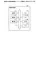
まず、図1を用いてリンクの帯域が不足する場合について説明する。図1は、複数のリンクでCPUとFPGAを接続する場合の一例を示す図である。図1の例では、CPU10にはメモリ11が接続され、CPU10とFPGA12との間のリンクとして、PCIe経由の接続と、OpenCAPI経由の接続との両方が用意される。ユーザロジックUL201〜UL203は、Mux/Demux13を介して、PCIeおよびOpenCAPIと接続される。
First, the case where the link bandwidth is insufficient will be described with reference to FIG. FIG. 1 is a diagram illustrating an example in which a CPU and FPGA are connected by a plurality of links. In the example of FIG. 1, a
ここで、PCIeは、Gen4 x16lane x2slotであり、帯域が51.2GB/s、アクセス遅延が1μs〜であるとする。また、OpenCAPIは、帯域が25.6GB/s、アクセス遅延が100ns〜であるとする。ユーザロジックの要求性能は、ユーザロジックUL201は、必要帯域10GB/s、許容アクセス遅延200nsである。ユーザロジックUL202は、必要帯域40GB/s、許容アクセス遅延2μsである。ユーザロジックUL203は、必要帯域20GB/s、許容アクセス遅延1μsである。 Here, it is assumed that PCIe is Gen4 × 16 lane × 2 slot, the bandwidth is 51.2 GB / s, and the access delay is 1 μs. Further, it is assumed that the OpenCAPI has a bandwidth of 25.6 GB / s and an access delay of 100 ns. The required performance of the user logic is that the user logic UL201 has a required bandwidth of 10 GB / s and an allowable access delay of 200 ns. The user logic UL 202 has a required bandwidth of 40 GB / s and an allowable access delay of 2 μs. The user logic UL 203 has a required bandwidth of 20 GB / s and an allowable access delay of 1 μs.
ユーザロジックUL201〜UL203は、事前にどのリンクを使用するかは固定選択であるとし、運用時まで他のユーザロジックがどれだけリンクを使用するか不明であるとする。この場合、図1の例では、ユーザロジックUL201は、OpenCAPIに割り振り、ユーザロジックUL202は、PCIeに割り振る。ところが、ユーザロジックUL203は、OpenCAPIとPCIeとのうち、どちらに割り振っても、必要帯域がリンクの帯域を上回ることになる。つまり、図1は、フローが要求する帯域に対してリンクの帯域が不足し、アプリケーションの性能要求を満たさない場合の例である。これに対し、動的にユーザロジックUL203の通信を2つの性質の異なるリンクに割り振ることができれば、システム全体としての性能を向上させることができる。 The user logics UL201 to UL203 assume that which link is used in advance is a fixed selection, and it is unknown how much other user logic uses the link until operation. In this case, in the example of FIG. 1, the user logic UL201 is allocated to OpenCAPI, and the user logic UL202 is allocated to PCIe. However, the required bandwidth exceeds the link bandwidth regardless of which of OpenCAPI and PCIe is allocated to the user logic UL203. That is, FIG. 1 is an example in the case where the link bandwidth is insufficient with respect to the bandwidth required by the flow and the application performance requirement is not satisfied. On the other hand, if communication of the user logic UL 203 can be dynamically allocated to two links having different properties, the performance of the entire system can be improved.
図2は、実施例の情報処理装置のハードウェア構成の一例を示すブロック図である。図2に示すように、情報処理装置100は、通信部110と、表示部111と、操作部112と、HDD(Hard Disk Drive)113と、メモリ120と、CPU130と、FPGA140とを有する。なお、通信部110、表示部111、操作部112、HDD113、CPU130およびFPGA140は、バス114を介して相互に接続される。また、CPU130は、メモリ120およびFPGA140と接続される。なお、情報処理装置100は、図2に示す機能部以外にも既知のコンピュータが有する各種の機能部、例えば各種の入力デバイスや音声出力デバイス等の機能部を有することとしてもかまわない。
FIG. 2 is a block diagram illustrating an example of a hardware configuration of the information processing apparatus according to the embodiment. As illustrated in FIG. 2, the information processing apparatus 100 includes a communication unit 110, a
通信部110は、例えば、NIC(Network Interface Card)等によって実現される。通信部110は、図示しないネットワークを介して他の情報処理装置と有線または無線で接続され、他の情報処理装置との間で情報の通信を司る通信インタフェースである。 The communication unit 110 is realized by, for example, a NIC (Network Interface Card). The communication unit 110 is a communication interface that is connected to another information processing apparatus via a network (not shown) in a wired or wireless manner and manages information communication with the other information processing apparatus.
表示部111は、各種情報を表示するための表示デバイスである。表示部111は、例えば、表示デバイスとして液晶ディスプレイ等によって実現される。表示部111は、CPU130から図示しない表示制御部を介して入力された表示画面等の各種画面を表示する。
The
操作部112は、情報処理装置100のユーザから各種操作を受け付ける入力デバイスである。操作部112は、例えば、入力デバイスとして、キーボードやマウス等によって実現される。操作部112は、ユーザによって入力された操作を操作情報としてCPU130に出力する。なお、操作部112は、入力デバイスとして、タッチパネル等によって実現されるようにしてもよく、表示部111の表示デバイスと、操作部112の入力デバイスとは、一体化されるようにしてもよい。
The operation unit 112 is an input device that receives various operations from the user of the information processing apparatus 100. The operation unit 112 is realized by, for example, a keyboard or a mouse as an input device. The operation unit 112 outputs an operation input by the user to the
HDD113は、補助記憶装置であり、CPU130で動作するOS(Operating System)や各種データを記憶する。なお、HDD113は、ハードディスクドライブの他にもフラッシュメモリ等の半導体メモリ素子を用いたSSD(Solid State Drive)や光ディスク等の記憶装置によって実現されてもよい。
The HDD 113 is an auxiliary storage device, and stores an OS (Operating System) operating on the
メモリ120は、主記憶装置であり、例えば、各種のSDRAM(Synchronous Dynamic Random Access Memory)等のようなRAM(Random Access Memory)等の半導体メモリ素子等の記憶装置によって実現される。メモリ120は、CPU130での処理に用いる情報を記憶する。なお、メモリ120は、バス114に接続してもよいし、FPGA140と直接接続してもよい。
The memory 120 is a main storage device and is realized by a storage device such as a semiconductor memory element such as a random access memory (RAM) such as various SDRAMs (Synchronous Dynamic Random Access Memory). The memory 120 stores information used for processing by the
CPU130は、HDD113等の記憶部に記憶されているプログラムに従って、メモリ120等のRAMを作業領域として各種処理を実行する。すなわち、CPU130は、OSやVM(Virtual Machine)によって制御され、各種処理を実行する。
The
FPGA140は、CPU130で動作するアプリケーションをオフロードするユーザロジックを動作させる。FPGA140は、CPU130とバス114(例えば、PCIe。)経由、および、メモリコヒーレントバス(例えば、OpenCAPI。)経由で接続される。すなわち、FPGA140は、複数のリンクを経由してCPU130と接続されるオフロード回路を構成する。なお、複数のリンクは、異なる種類のバスでなく、同じ種類のバスであってもよい。
The
図3は、実施例の情報処理装置の機能構成の一例を示すブロック図である。図3に示すように、情報処理装置100では、CPU130でOS/VM131が動作し、さらに、OS/VM131上でアプリケーションA1〜Amが動作している。また、FPGA140は、制御回路141と複数のユーザロジックUL1〜ULmとを有する。制御回路141は、リンクL1〜LnでCPU130と接続される。リンクL1〜Lnは、バス114およびメモリコヒーレントバスに対応する。ユーザロジックUL1〜ULmは、アプリケーションA1〜Amと対応付けられており、対応するアプリケーションA1〜Amとの間で、制御回路141およびリンクL1〜Lnを介して通信を行う。つまり、ユーザロジックUL1〜ULmは、アプリケーションA1〜Amの処理を演算する論理回路である。また、アプリケーションA1〜Am、および、ユーザロジックUL1〜ULmは、使用するリンクL1〜Lnのいずれかを用いて、それぞれ性能情報を制御回路141に出力する。なお、性能情報は、例えば、性能要件を満たす場合を「1」とし、性能要件を満たさない場合を「0」とする。
FIG. 3 is a block diagram illustrating an example of a functional configuration of the information processing apparatus according to the embodiment. As illustrated in FIG. 3, in the information processing apparatus 100, an OS /
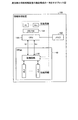
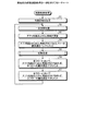
図4は、制御回路の機能構成の一例を示すブロック図である。図4に示すように、制御回路141は、インタフェースIF1〜IFnと、Mux/demux142と、Mux/demux143と、モニタ144と、セレクタ147とを有する。また、モニタ144は、フローテーブル145と、リンクテーブル146とを有する。
FIG. 4 is a block diagram illustrating an example of a functional configuration of the control circuit. As illustrated in FIG. 4, the
インタフェースIF1〜IFnは、リンクL1〜Lnに対応するインタフェースである。インタフェースIF1〜IFnは、リンクごとの使用帯域を表すデータであるPerf_per_link(1)〜(n)を、それぞれモニタ144に出力する。また、インタフェースIF1〜IFnは、フローを識別するフローID(Identifier)をMux/demux142に出力する。なお、フローは、ユーザロジックUL1〜ULm、コマンド種別(Read/Write)およびアドレス範囲の組み合わせに基づくデータの流れを表し、フローIDを用いて各フローを識別する。
The interfaces IF1 to IFn are interfaces corresponding to the links L1 to Ln. The interfaces IF1 to IFn output Perf_per_link (1) to (n), which are data representing the bandwidth used for each link, to the monitor 144, respectively. The interfaces IF1 to IFn output a flow ID (Identifier) for identifying the flow to the Mux /
Mux/demux142は、マルチプレクサおよびデマルチプレクサである。Mux/demux142は、インタフェースIF1〜IFn側から入力されるフローを多重化し、Mux/demux143に出力する。また、Mux/demux142は、Mux/demux143から入力される多重化されたフローを複数のフローに戻し、対応するインタフェースIF1〜IFnに出力する。Mux/demux142は、インタフェースIF1〜IFn側、および、Mux/demux143側から入力された各フローのフローIDをセレクタ147に出力する。Mux/demux142には、セレクタ147からフローIDに応じたリンク情報が入力される。Mux/demux142は、リンク情報に応じたインタフェースIF1〜IFnに、対応するフローを出力するようにフローの経路を切り替える。
Mux /
Mux/demux143は、マルチプレクサおよびデマルチプレクサである。Mux/demux143は、ユーザロジックUL1〜ULm側から入力されるパケットからフローを抽出して多重化し、Mux/demux142に出力する。また、Mux/demux143は、Mux/demux142から入力される多重化されたフローを複数のフローに戻し、対応するユーザロジックUL1〜ULmに出力する。Mux/demux143は、各フローに対応するフローIDをMux/demux142に出力する。また、Mux/demux143は、抽出したフローに関するフロー情報と、フローごとの使用帯域とを含むデータであるPerf_per_flow(1...m)をモニタ144に出力する。
Mux / demux 143 is a multiplexer and a demultiplexer. The Mux / demux 143 extracts and multiplexes the flows from the packets input from the user logic UL1 to ULm sides, and outputs them to the Mux /
モニタ144は、リンクL1〜Lnの使用帯域と、各フローの使用帯域と、性能情報とを収集し、フローテーブル145に記憶する。ここで、図5および図6を用いて、フローテーブル145およびリンクテーブル146について説明する。 The monitor 144 collects the used bandwidth of the links L <b> 1 to Ln, the used bandwidth of each flow, and the performance information and stores them in the flow table 145. Here, the flow table 145 and the link table 146 will be described with reference to FIGS. 5 and 6.
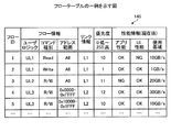
フローテーブル145は、フローごとにリンク情報(経路情報)、優先度、性能情報等を対応付けて記憶する。図5は、フローテーブルの一例を示す図である。図5に示すように、フローテーブル145は、「フローID」、「フロー情報」、「リンク情報」、「優先度」、「性能情報(現在値)」といった項目を有する。また、「フロー情報」は、「ユーザロジック」、「コマンド種別」、「アドレス範囲」といった項目を有する。また、「性能情報(現在値)」は、「アプリ性能」、「UL性能」、「使用帯域」といった項目を有する。 The flow table 145 stores link information (path information), priority, performance information, and the like in association with each flow. FIG. 5 is a diagram illustrating an example of a flow table. As illustrated in FIG. 5, the flow table 145 includes items such as “flow ID”, “flow information”, “link information”, “priority”, and “performance information (current value)”. The “flow information” includes items such as “user logic”, “command type”, and “address range”. The “performance information (current value)” includes items such as “application performance”, “UL performance”, and “bandwidth used”.
「フローID」は、フローを識別する識別子である。「ユーザロジック」は、当該フローに対応するユーザロジックを識別する識別子である。「コマンド種別」は、Read/Writeの別を示す情報である。「コマンド種別」は、Read/Writeのどちらも対象である場合はR/Wとする。「アドレス範囲」は、当該フローに対応するアドレス範囲を示す情報である。「リンク情報」は、当該フローが現在割り振られているリンクを示す情報である。 “Flow ID” is an identifier for identifying a flow. “User logic” is an identifier for identifying the user logic corresponding to the flow. The “command type” is information indicating whether Read / Write is performed. The “command type” is R / W when both Read / Write are targets. “Address range” is information indicating an address range corresponding to the flow. “Link information” is information indicating a link to which the flow is currently allocated.
「優先度」は、各フローの振り分けの優先度を示し、例えば、「0〜255」の256段階で表すことができる。この場合、数値が大きいほど優先度が高いとしている。「アプリ性能」は、アプリケーションA1〜Amから収集した性能情報である。「アプリ性能」は、OKであれば性能要件を満たし、NGであれば性能要件を満たさないことを示す。ここで、「アプリ性能」が性能要件を満たすとは、例えば、アプリケーションからユーザロジックに対してリクエストを送信してレスポンスが返ってくるまでの応答時間やスループット等が条件を満たす場合である。 “Priority” indicates the priority of distribution of each flow, and can be expressed, for example, in 256 levels from “0 to 255”. In this case, the higher the numerical value, the higher the priority. “App performance” is performance information collected from the applications A1 to Am. “App performance” indicates that the performance requirement is satisfied if OK, and the performance requirement is not satisfied if NG. Here, “application performance” satisfies the performance requirement is, for example, a case where a response time, a throughput, or the like until a response is returned from the application to the user logic is satisfied.
「UL性能」は、ユーザロジックUL1〜ULmから収集した性能情報である。「UL性能」は、OKであれば性能要件を満たし、NGであれば性能要件を満たさないことを示す。ここで、「UL性能」が性能要件を満たすとは、例えば、ユーザロジックからアプリケーションにレスポンスを送信してACKが返ってくるまでの応答時間や、アプリケーションからの単位時間あたりのリクエスト回数等が条件を満たす場合である。 “UL performance” is performance information collected from the user logics UL1 to ULm. “UL performance” indicates that the performance requirement is satisfied if OK, and the performance requirement is not satisfied if NG. Here, “UL performance” satisfies the performance requirements, for example, depending on the response time from the user logic sending the response to the application and returning the ACK, the number of requests from the application per unit time, etc. This is the case.
「アプリ性能」および「UL性能」では、OKは、モニタ144が収集した性能情報「1」に対応し、NGは、モニタ144が収集した性能情報「0」に対応する。性能情報は、例えば、モニタ144内に、アプリケーションA1〜Am、および、ユーザロジックUL1〜ULmに対応するレジスタを設け、それぞれがレジスタに「0」または「1」を書き込み、モニタ144が定期的にレジスタを参照することで収集できる。「使用帯域」は、当該フローが使用しているリンクL1〜Lnの帯域を示す情報である。 In “application performance” and “UL performance”, OK corresponds to performance information “1” collected by the monitor 144, and NG corresponds to performance information “0” collected by the monitor 144. For the performance information, for example, registers corresponding to the applications A1 to Am and the user logics UL1 to ULm are provided in the monitor 144, each of which writes “0” or “1” in the register, and the monitor 144 periodically It can be collected by referring to the register. “Used bandwidth” is information indicating the bandwidth of the links L1 to Ln used by the flow.
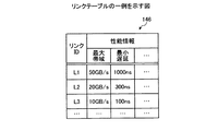
リンクテーブル146は、リンクL1〜Lnの性能情報を記憶する。図6は、リンクテーブルの一例を示す図である。図6に示すように、リンクテーブル146は、「リンクID」、「性能情報」といった項目を有する。また、「性能情報」は、「最大帯域」、「最小遅延」といった項目を有する。 The link table 146 stores performance information of the links L1 to Ln. FIG. 6 is a diagram illustrating an example of a link table. As shown in FIG. 6, the link table 146 has items such as “link ID” and “performance information”. The “performance information” has items such as “maximum bandwidth” and “minimum delay”.
「リンクID」は、リンクL1〜Lnを識別する識別子である。「最大帯域」は、当該リンクが収容可能な最大の帯域を示す情報である。「最小遅延」は、当該リンクにおける最小の遅延時間を示す情報である。 The “link ID” is an identifier for identifying the links L1 to Ln. “Maximum bandwidth” is information indicating the maximum bandwidth that the link can accommodate. “Minimum delay” is information indicating the minimum delay time in the link.
図4の説明に戻って、モニタ144は、使用帯域や性能情報の収集とともに、各フローの優先度を制御する。モニタ144は、電源が投入されると、初期状態を設定する。モニタ144は、初期状態として、フローテーブル145の優先度欄を全て「1」に設定する。モニタ144は、アプリケーションA1〜Am、および、ユーザロジックUL1〜ULmの動作が開始されると、フローテーブル145のフロー情報、リンク情報および性能情報を更新する。なお、フローIDは、例えば、アプリケーションの起動時に設定されたフローIDをアプリケーションから取得する。また、フローIDは、例えば、アプリケーションの終了時にアプリケーションからの指示により削除される。 Returning to the description of FIG. 4, the monitor 144 controls the priority of each flow along with the collection of used bandwidth and performance information. The monitor 144 sets an initial state when the power is turned on. The monitor 144 sets all priority fields of the flow table 145 to “1” as an initial state. When the operations of the applications A1 to Am and the user logics UL1 to ULm are started, the monitor 144 updates the flow information, link information, and performance information of the flow table 145. As the flow ID, for example, the flow ID set when the application is activated is acquired from the application. The flow ID is deleted by an instruction from the application when the application is terminated, for example.
つまり、モニタ144は、Mux/demux143から入力されるフロー情報に基づいて、フローテーブル145のフロー情報を更新する。モニタ144は、リンクテーブル146を参照し、インタフェースIF1〜IFnから入力されるリンクごとの使用帯域に基づいて、使用可能な帯域が多いリンクから順にフローを割り振って、フローテーブル145のリンク情報を更新する。モニタ144は、Mux/demux143から入力されるフローごとの使用帯域に基づいて、フローテーブル145のフローごとの使用帯域を更新する。モニタ144は、アプリケーションA1〜Am、および、ユーザロジックUL1〜ULmに対応するレジスタを参照し、フローテーブル145のアプリ性能およびUL性能を更新する。 That is, the monitor 144 updates the flow information in the flow table 145 based on the flow information input from the Mux / demux 143. The monitor 144 refers to the link table 146, allocates flows in order from the link with the largest available bandwidth, and updates the link information in the flow table 145 based on the bandwidth used for each link input from the interfaces IF1 to IFn. To do. The monitor 144 updates the used bandwidth for each flow in the flow table 145 based on the used bandwidth for each flow input from the Mux / demux 143. The monitor 144 refers to the registers corresponding to the applications A1 to Am and the user logics UL1 to ULm, and updates the application performance and UL performance of the flow table 145.
モニタ144は、フローテーブル145のアプリ性能およびUL性能がNGであるフローがある場合、当該フローの優先度をインクリメントする。次に、モニタ144は、セレクタ147に対して、切替処理の実行を指示する。 When there is a flow whose application performance and UL performance of the flow table 145 are NG, the monitor 144 increments the priority of the flow. Next, the monitor 144 instructs the selector 147 to execute the switching process.
モニタ144は、切替処理の終了後、フローテーブル145を参照し、全フローにおいて、アプリ性能またはUL性能がNGであれば、全フローの優先度をデクリメントする。また、モニタ144は、フローテーブル145を参照し、全フローにおいて、アプリ性能およびUL性能がOKであれば、全フローの優先度をデクリメントし、一定時間の待機後、再びアプリ性能およびUL性能を更新して優先度の制御を繰り返す。 The monitor 144 refers to the flow table 145 after the end of the switching process, and decrements the priority of all flows if the application performance or UL performance is NG in all flows. Also, the monitor 144 refers to the flow table 145, and if the application performance and UL performance are OK in all flows, the priority of all flows is decremented, and after waiting for a certain period of time, the application performance and UL performance are again reduced. Update and repeat priority control.
言い換えると、モニタ144は、アプリケーションの処理に対応するフローごとのリンクの性能情報を示す値と、リンクごとの使用可能な性能情報の最大値とを収集する収集部の一例である。また、モニタ144は、アプリケーションの処理に対応するフローごとのリンクの使用帯域を示す値と、リンクごとの使用可能な帯域の最大値とを収集する。また、モニタ144は、アプリケーションの処理、または、論理回路の性能が性能要件を満たしていない場合、対応するフローの優先度を上げる。また、モニタ144は、所定時間ごとに、リンクの使用帯域を示す値と、リンクごとの使用可能な帯域の最大値とを収集する。 In other words, the monitor 144 is an example of a collection unit that collects a value indicating the performance information of the link for each flow corresponding to the processing of the application and the maximum value of the usable performance information for each link. In addition, the monitor 144 collects a value indicating the used bandwidth of the link for each flow corresponding to the processing of the application and the maximum usable bandwidth for each link. Further, the monitor 144 increases the priority of the corresponding flow when the processing of the application or the performance of the logic circuit does not satisfy the performance requirement. In addition, the monitor 144 collects a value indicating the used bandwidth of the link and a maximum value of the usable bandwidth for each link at every predetermined time.
セレクタ147は、Mux/demux142からフローIDが入力されると、フローテーブル145を参照し、入力されたフローIDに対応するリンク情報をMux/demux142に出力する。すなわち、セレクタ147は、フローテーブル145を参照し、リンクL1〜Lnを流れるパケットを、適切なユーザロジックUL1〜ULmに接続する。
When the flow ID is input from the Mux /
また、セレクタ147は、モニタ144から切替処理の実行を指示されると、フローとリンクとの対応を切り替える切替処理を実行する。セレクタ147は、フローテーブル145を参照し、未判定のフローがあるか否かを判定する。セレクタ147は、未判定のフローがないと判定した場合には、切替処理を終了する。 Further, when the selector 147 is instructed to execute the switching process from the monitor 144, the selector 147 executes the switching process for switching the correspondence between the flow and the link. The selector 147 refers to the flow table 145 and determines whether there is an undetermined flow. When the selector 147 determines that there is no undetermined flow, the selector 147 ends the switching process.
セレクタ147は、未判定のフローがあると判定した場合には、未判定のフローのうち、優先度が最も高いフローを対象フローとして選択する。セレクタ147は、選択した対象フローについて、アプリ性能およびUL性能がOKであるか否かを判定する。セレクタ147は、アプリ性能およびUL性能がOKであると判定した場合には、次のフローの判定に進む。 When the selector 147 determines that there is an undetermined flow, the selector 147 selects a flow having the highest priority among the undetermined flows as a target flow. The selector 147 determines whether or not the application performance and the UL performance are OK for the selected target flow. If the selector 147 determines that the application performance and the UL performance are OK, the selector 147 proceeds to determination of the next flow.
セレクタ147は、アプリ性能およびUL性能がOKでないと判定した場合には、フローテーブル145およびリンクテーブル146を参照し、最も使用可能な帯域が大きいリンクを選択する。セレクタ147は、選択したリンクが対象フローのリンクと同じであるか否かを判定する。セレクタ147は、選択したリンクが対象フローのリンクと同じであると判定した場合には、次のフローの判定に進む。 When the selector 147 determines that the application performance and the UL performance are not OK, the selector 147 refers to the flow table 145 and the link table 146 and selects a link having the largest usable bandwidth. The selector 147 determines whether or not the selected link is the same as the link of the target flow. When the selector 147 determines that the selected link is the same as the link of the target flow, the selector 147 proceeds to determination of the next flow.
セレクタ147は、選択したリンクが対象フローのリンクと同じでないと判定した場合には、対象フローに選択したリンクを設定する。セレクタ147は、選択したリンクの使用帯域が最大帯域に収まるか否かを判定する。セレクタ147は、選択したリンクの使用帯域が最大帯域に収まると判定した場合には、切替処理を終了する。 When the selector 147 determines that the selected link is not the same as the link of the target flow, the selector 147 sets the selected link to the target flow. The selector 147 determines whether or not the used bandwidth of the selected link falls within the maximum bandwidth. If the selector 147 determines that the used bandwidth of the selected link falls within the maximum bandwidth, the selector 147 ends the switching process.
セレクタ147は、選択したリンクの使用帯域が最大帯域に収まらないと判定した場合には、フローテーブル145を参照し、選択したリンクを使用する最も優先度が低いフローを選択する。セレクタ147は、選択した最も優先度が低いフローのリンクに、対象フローの元のリンクを設定し、切替処理を終了する。すなわち、セレクタ147は、対象フローの元のリンクと、最も優先度が低いフローのリンクとを入れ替える。 When the selector 147 determines that the used bandwidth of the selected link does not fall within the maximum bandwidth, the selector 147 refers to the flow table 145 and selects the flow with the lowest priority using the selected link. The selector 147 sets the original link of the target flow to the selected link of the flow with the lowest priority, and ends the switching process. That is, the selector 147 replaces the original link of the target flow with the link of the flow with the lowest priority.
言い換えると、セレクタ147は、フローごとのリンクの性能情報を示す値に基づいて、要する性能情報を満たしていないフローを判定する。セレクタ147は、リンクごとの使用可能な性能情報の最大値と、リンクごとの現在使用されている性能情報の値とに基づいて、フローの振り分け先のリンクを選択して振り分ける。つまり、セレクタ147は、選択部の一例である。すなわち、セレクタ147は、フローごとのリンクの使用帯域を示す値に基づいて、要する帯域を満たしていないフローを判定する。セレクタ147は、リンクごとの使用可能な帯域の最大値と、リンクごとの現在使用されている帯域の値とに基づいて、フローの振り分け先のリンクを選択して振り分ける。 In other words, the selector 147 determines a flow that does not satisfy the required performance information based on a value indicating the link performance information for each flow. The selector 147 selects and distributes the flow distribution destination link based on the maximum value of the usable performance information for each link and the value of the performance information currently used for each link. That is, the selector 147 is an example of a selection unit. That is, the selector 147 determines a flow that does not satisfy the required bandwidth based on a value indicating the bandwidth used for the link for each flow. The selector 147 selects and distributes a flow distribution destination link based on the maximum usable bandwidth value for each link and the currently used bandwidth value for each link.
また、セレクタ147は、リンクごとの使用可能な帯域の最大値と、リンクごとの現在使用されている帯域の値とに基づいて、フローの振り分け先のリンクを選択する。セレクタ147は、選択した振り分け先のリンクに該フローを振り分けると、振り分け先のリンクの使用可能な帯域の最大値を超える場合、振り分け先のリンクを使用する最も優先度が低いフローを、振り分け元のリンクに振り分ける。また、セレクタ147は、所定時間ごとに、要する帯域を満たしていないフローを判定する。 Further, the selector 147 selects a flow distribution destination link based on the maximum usable bandwidth value for each link and the currently used bandwidth value for each link. When the selector 147 distributes the flow to the selected distribution destination link, and exceeds the maximum available bandwidth of the distribution destination link, the selector 147 selects the flow with the lowest priority using the distribution destination link. Sort to the link. In addition, the selector 147 determines a flow that does not satisfy the required bandwidth every predetermined time.
次に、実施例の情報処理装置100の動作について説明する。図7は、実施例の経路制御処理の一例を示すフローチャートである。 Next, the operation of the information processing apparatus 100 according to the embodiment will be described. FIG. 7 is a flowchart illustrating an example of the route control process according to the embodiment.
制御回路141のモニタ144は、電源が投入されると、初期状態を設定する(ステップS1)。モニタ144は、アプリケーションA1〜Am、および、ユーザロジックUL1〜ULmの動作が開始されると、フローテーブル145のフロー情報、リンク情報および性能情報を更新する。モニタ144は、動作開始後、一定時間待機する(ステップS2)。
The monitor 144 of the
その後、モニタ144は、アプリケーションA1〜Am、および、ユーザロジックUL1〜ULmに対応するレジスタを参照し、フローテーブル145のアプリ性能およびUL性能を更新する(ステップS3)。 Thereafter, the monitor 144 refers to the registers corresponding to the applications A1 to Am and the user logics UL1 to ULm, and updates the application performance and the UL performance of the flow table 145 (step S3).
モニタ144は、フローテーブル145のアプリ性能およびUL性能がNGであるフローの優先度をインクリメントする(ステップS4)。次に、モニタ144は、セレクタ147に対して、切替処理の実行を指示する(ステップS5)。 The monitor 144 increments the priority of the flow whose application performance and UL performance are NG in the flow table 145 (step S4). Next, the monitor 144 instructs the selector 147 to execute the switching process (step S5).
ここで、図8を用いて切替処理について説明する。図8は、実施例の切替処理の一例を示すフローチャートである。 Here, the switching process will be described with reference to FIG. FIG. 8 is a flowchart illustrating an example of the switching process according to the embodiment.
セレクタ147は、モニタ144から切替処理の実行を指示されると、フローとリンクとの対応を切り替える切替処理を実行する。セレクタ147は、フローテーブル145を参照し、未判定のフローがあるか否かを判定する(ステップS51)。セレクタ147は、未判定のフローがないと判定した場合には(ステップS51:否定)、切替処理を終了し、経路制御処理に戻る。 When the selector 147 is instructed to execute the switching process from the monitor 144, the selector 147 executes the switching process for switching the correspondence between the flow and the link. The selector 147 refers to the flow table 145 and determines whether there is an undetermined flow (step S51). When the selector 147 determines that there is no undetermined flow (No at Step S51), the selector 147 ends the switching process and returns to the path control process.
セレクタ147は、未判定のフローがあると判定した場合には(ステップS51:肯定)、未判定のフローのうち、優先度が最も高いフローを対象フローとして選択する(ステップS52)。セレクタ147は、選択した対象フローについて、アプリ性能およびUL性能がOKであるか否かを判定する(ステップS53)。セレクタ147は、アプリ性能およびUL性能がOKであると判定した場合には(ステップS53:肯定)、次のフローの判定を行うため、ステップS51に戻る。 When the selector 147 determines that there is an undetermined flow (step S51: affirmative), the selector 147 selects a flow having the highest priority among the undetermined flows (step S52). The selector 147 determines whether or not the application performance and the UL performance are OK for the selected target flow (step S53). If the selector 147 determines that the application performance and the UL performance are OK (step S53: Yes), the selector 147 returns to step S51 to determine the next flow.
セレクタ147は、アプリ性能およびUL性能がOKでないと判定した場合には(ステップS53:否定)、フローテーブル145およびリンクテーブル146を参照し、最も使用可能な帯域が大きいリンクを選択する(ステップS54)。セレクタ147は、選択したリンクが対象フローのリンクと同じであるか否かを判定する(ステップS55)。セレクタ147は、選択したリンクが対象フローのリンクと同じであると判定した場合には(ステップS55:肯定)、次のフローの判定を行うため、ステップS51に戻る。 When the selector 147 determines that the application performance and the UL performance are not OK (No at Step S53), the selector 147 refers to the flow table 145 and the link table 146, and selects the link with the largest available bandwidth (Step S54). ). The selector 147 determines whether or not the selected link is the same as the link of the target flow (step S55). If the selector 147 determines that the selected link is the same as the link of the target flow (step S55: Yes), the selector 147 returns to step S51 to determine the next flow.
セレクタ147は、選択したリンクが対象フローのリンクと同じでないと判定した場合には(ステップS55:否定)、対象フローに選択したリンクを設定する(ステップS56)。セレクタ147は、選択したリンクの使用帯域が最大帯域に収まるか否かを判定する(ステップS57)。セレクタ147は、選択したリンクの使用帯域が最大帯域に収まると判定した場合には(ステップS57:肯定)、切替処理を終了し、経路制御処理に戻る。 When the selector 147 determines that the selected link is not the same as the link of the target flow (No at Step S55), the selector 147 sets the selected link to the target flow (Step S56). The selector 147 determines whether or not the used bandwidth of the selected link falls within the maximum bandwidth (step S57). When the selector 147 determines that the used bandwidth of the selected link falls within the maximum bandwidth (step S57: Yes), the selector 147 ends the switching process and returns to the path control process.
セレクタ147は、選択したリンクの使用帯域が最大帯域に収まらないと判定した場合には(ステップS57:否定)、フローテーブル145を参照し、選択したリンクを使用する最も優先度が低いフローを選択する(ステップS58)。セレクタ147は、選択した最も優先度が低いフローのリンクに、対象フローの元のリンクを設定し(ステップS59)、切替処理を終了して経路制御処理に戻る。これにより、セレクタ147は、優先度の高いフローからリンクに振り分けることができる。 If the selector 147 determines that the used bandwidth of the selected link does not fall within the maximum bandwidth (No at step S57), the selector 147 refers to the flow table 145 and selects the flow with the lowest priority using the selected link. (Step S58). The selector 147 sets the original link of the target flow to the link of the selected flow with the lowest priority (step S59), ends the switching process, and returns to the path control process. As a result, the selector 147 can distribute the flow from a flow with high priority to the link.
図7の説明に戻って、モニタ144は、切替処理の終了後、フローテーブル145を参照し、全フローにおいて、アプリ性能またはUL性能がNGであれば、全フローの優先度をデクリメントする(ステップS6)。モニタ144は、フローテーブル145を参照し、全フローにおいて、アプリ性能およびUL性能がOKであれば、全フローの優先度をデクリメントし(ステップS7)、ステップS2に戻る。これにより、制御回路141は、システム全体の性能を最大化するようにフローを振り分けることができる。また、制御回路141は、ユーザロジックに依存することなく、システム全体の性能を最大化する通信パターンを自動的に決定できる。また、制御回路141は、ユーザロジックのFPGA接続方式に依存する部分を削減することができる。すなわち、情報処理装置100では、他のシステムへのユーザロジックの移植が容易となる。また、情報処理装置100では、インタフェース設計を共通化できるので、開発工数を削減できる。
Returning to the description of FIG. 7, the monitor 144 refers to the flow table 145 after the end of the switching process, and decrements the priority of all the flows if the application performance or the UL performance is NG in all the flows (step) S6). The monitor 144 refers to the flow table 145, and if the application performance and the UL performance are OK in all the flows, the priority of all the flows is decremented (step S7), and the process returns to step S2. Thereby, the
なお、上記実施例では、リンクの性能情報として使用帯域を用いたが、これに限定されない。例えば、リンクの性能情報としてレイテンシを用いてもよい。この場合、制御回路141は、Mux/demux142にレイテンシチェッカを接続し、定期的に計測用パケットを各リンクに送信して取得したレイテンシ情報に基づいて、各フローを各リンクに振り分ける。すなわち、モニタ144は、アプリケーションの処理に対応するフローごとのリンクのレイテンシを示す値と、リンクごとのレイテンシの最大値とを収集する。セレクタ147は、フローごとのリンクのレイテンシを示す値に基づいて、要するレイテンシを満たしていないフローを判定する。セレクタ147は、リンクごとのレイテンシの最大値と、リンクごとの現在のレイテンシの値とに基づいて、フローの振り分け先のリンクを選択して振り分ける。
In the above embodiment, the use band is used as the link performance information, but the present invention is not limited to this. For example, latency may be used as link performance information. In this case, the
このように、情報処理装置100は、複数のリンクを経由してCPUと接続されるオフロード回路を備える。オフロード回路は、FPGA140として、制御回路141と、ユーザロジックである論理回路とを備える。論理回路は、アプリケーションの処理を演算する。制御回路141は、アプリケーションの処理に対応するフローごとのリンクの性能情報を示す値と、リンクごとの使用可能な性能情報の最大値とを収集する。また、制御回路141は、フローごとのリンクの性能情報を示す値に基づいて、要する性能情報を満たしていないフローを判定する。また、制御回路141は、リンクごとの使用可能な性能情報の最大値と、リンクごとの現在使用されている性能情報の値とに基づいて、フローの振り分け先のリンクを選択して振り分ける。その結果、制御回路141は、システム全体の性能を最大化するようにフローを振り分けることができる。
As described above, the information processing apparatus 100 includes an offload circuit connected to the CPU via a plurality of links. The offload circuit includes, as the
また、制御回路141は、アプリケーションの処理に対応するフローごとのリンクの使用帯域を示す値と、リンクごとの使用可能な帯域の最大値とを収集する。また、制御回路141は、フローごとのリンクの使用帯域を示す値に基づいて、要する帯域を満たしていないフローを判定する。また、制御回路141は、リンクごとの使用可能な帯域の最大値と、リンクごとの現在使用されている帯域の値とに基づいて、フローの振り分け先のリンクを選択して振り分ける。その結果、制御回路141は、リンクの使用帯域に基づいてシステム全体の性能を最大化するようにフローを振り分けることができる。
In addition, the
また、制御回路141は、アプリケーションの処理、または、論理回路の性能が性能要件を満たしていない場合、対応するフローの優先度を上げる。その結果、制御回路141は、優先度に応じてフローを振り分けることができる。
The
また、制御回路141は、リンクごとの使用可能な帯域の最大値と、リンクごとの現在使用されている帯域の値とに基づいて、フローの振り分け先のリンクを選択する。制御回路141は、選択した振り分け先のリンクに該フローを振り分けると、振り分け先のリンクの使用可能な帯域の最大値を超える場合、振り分け先のリンクを使用する最も優先度が低いフローを、振り分け元のリンクに振り分ける。その結果、制御回路141は、優先度の高いフローと優先度の低いフローとが使用するリンクを入れ替えることができる。
Further, the
また、制御回路141は、所定時間ごとに、リンクの使用帯域を示す値と、リンクごとの使用可能な帯域の最大値とを収集する。また、制御回路141は、所定時間ごとに、要する帯域を満たしていないフローを判定する。その結果、制御回路141は、動的にフローを振り分けることができる。
In addition, the
また、制御回路141は、アプリケーションの処理に対応するフローごとのリンクのレイテンシを示す値と、リンクごとのレイテンシの最大値とを収集する。また、制御回路141は、フローごとのリンクのレイテンシを示す値に基づいて、要するレイテンシを満たしていないフローを判定する。制御回路141は、リンクごとのレイテンシの最大値と、リンクごとの現在のレイテンシの値とに基づいて、フローの振り分け先のリンクを選択して振り分ける。その結果、制御回路141は、リンクのレイテンシに基づいてシステム全体の性能を最大化するようにフローを振り分けることができる。
Further, the
また、図示した各部の各構成要素は、必ずしも物理的に図示の如く構成されていることを要しない。すなわち、各部の分散・統合の具体的形態は図示のものに限られず、その全部または一部を、各種の負荷や使用状況等に応じて、任意の単位で機能的または物理的に分散・統合して構成することができる。例えば、Mux/demux142とMux/demux143とを統合してクロスバースイッチとしてもよい。また、図示した各処理は、上記の順番に限定されるものでなく、処理内容を矛盾させない範囲において、同時に実施してもよく、順序を入れ替えて実施してもよい。
In addition, each component of each part illustrated does not necessarily need to be physically configured as illustrated. In other words, the specific form of distribution / integration of each unit is not limited to that shown in the figure, and all or a part thereof may be functionally or physically distributed / integrated in arbitrary units according to various loads or usage conditions. Can be configured. For example, Mux /
さらに、制御回路141で行われる各種処理機能は、CPU(またはMPU、MCU(Micro Controller Unit)等のマイクロ・コンピュータ)上で、その全部または任意の一部を実行するようにしてもよい。また、各種処理機能は、CPU(またはMPU、MCU等のマイクロ・コンピュータ)で解析実行されるプログラム上、またはワイヤードロジックによるハードウェア上で、その全部または任意の一部を実行するようにしてもよいことは言うまでもない。
Furthermore, various processing functions performed by the
なお、上記実施例で説明した制御回路141は、プログラムを読み込んで実行することで、図4、図7、図8等で説明した処理と同様の機能を実行することができる。例えば、制御回路141は、モニタ144、セレクタ147と同様の処理を実行するプロセスを実行することで、上記実施例と同様の処理を実行することができる。
Note that the
これらのプログラムは、インターネットなどのネットワークを介して配布することができる。また、これらのプログラムは、ハードディスク、フレキシブルディスク(FD)、CD−ROM、MO、DVDなどのコンピュータで読み取り可能な記録媒体に記録され、コンピュータによって記録媒体から読み出されることによって実行することができる。 These programs can be distributed via a network such as the Internet. These programs are recorded on a computer-readable recording medium such as a hard disk, a flexible disk (FD), a CD-ROM, an MO, and a DVD, and can be executed by being read from the recording medium by the computer.
100 情報処理装置
110 通信部
111 表示部
112 操作部
113 HDD
114 バス
120 メモリ
130 CPU
131 OS/VM
140 FPGA
141 制御回路
142,143 Mux/demux
144 モニタ
145 フローテーブル
146 リンクテーブル
147 セレクタ
A1〜Am アプリケーション
IF1〜IFn インタフェース
L1〜Ln リンク
UL1〜ULm ユーザロジック
DESCRIPTION OF SYMBOLS 100 Information processing apparatus 110
114 bus 120
131 OS / VM
140 FPGA
141 Control circuit 142,143 Mux / demux
Claims (8)
アプリケーションの処理を演算する論理回路と、
前記アプリケーションの処理に対応するフローごとの前記リンクの性能情報を示す値と、前記リンクごとの使用可能な性能情報の最大値とを収集する収集部と、
前記フローごとの前記リンクの性能情報を示す値に基づいて、要する性能情報を満たしていないフローを判定し、前記リンクごとの使用可能な性能情報の最大値と、前記リンクごとの現在使用されている性能情報の値とに基づいて、前記フローの振り分け先のリンクを選択して振り分ける選択部と、
を備えることを特徴とする情報処理装置。 In an offload circuit connected to the CPU via a plurality of links,
A logic circuit for calculating application processing;
A collection unit that collects a value indicating performance information of the link for each flow corresponding to the processing of the application, and a maximum value of usable performance information for each link;
Based on the value indicating the performance information of the link for each flow, the flow that does not satisfy the required performance information is determined, and the maximum value of the usable performance information for each link and the current value for each link are used. A selection unit that selects and distributes the link to which the flow is distributed based on the value of the performance information that is present,
An information processing apparatus comprising:
前記選択部は、前記フローごとの前記リンクの使用帯域を示す値に基づいて、要する帯域を満たしていないフローを判定し、前記リンクごとの使用可能な帯域の最大値と、前記リンクごとの現在使用されている帯域の値とに基づいて、前記フローの振り分け先のリンクを選択して振り分ける、
ことを特徴とする請求項1に記載の情報処理装置。 The collection unit collects a value indicating a bandwidth used for the link for each flow corresponding to the processing of the application, and a maximum value of a usable bandwidth for each link,
The selection unit determines a flow that does not satisfy a required bandwidth based on a value indicating a used bandwidth of the link for each flow, and determines a maximum usable bandwidth for each link and a current value for each link. Based on the bandwidth value being used, select and distribute the link to which the flow is distributed,
The information processing apparatus according to claim 1.
ことを特徴とする請求項2に記載の情報処理装置。 The collection unit increases the priority of the corresponding flow when the processing of the application or the performance of the logic circuit does not satisfy performance requirements.
The information processing apparatus according to claim 2.
ことを特徴とする請求項2または3に記載の情報処理装置。 The selection unit selects a link to which the flow is distributed based on a maximum value of a usable bandwidth for each link and a currently used bandwidth value for each link, and selects the selected distribution When the flow is distributed to the destination link, if the maximum available bandwidth of the distribution destination link is exceeded, the flow with the lowest priority using the distribution destination link is distributed to the distribution source link.
The information processing apparatus according to claim 2, wherein the information processing apparatus is an information processing apparatus.
前記選択部は、前記所定時間ごとに、前記要する帯域を満たしていないフローを判定する、
ことを特徴とする請求項2〜4のいずれか1つに記載の情報処理装置。 The collection unit collects a value indicating a used bandwidth of the link and a maximum value of a usable bandwidth for each link at predetermined time intervals,
The selection unit determines a flow that does not satisfy the required bandwidth every predetermined time.
The information processing apparatus according to claim 1, wherein the information processing apparatus is an information processing apparatus.
前記選択部は、前記フローごとの前記リンクのレイテンシを示す値に基づいて、要するレイテンシを満たしていないフローを判定し、前記リンクごとのレイテンシの最大値と、前記リンクごとの現在のレイテンシの値とに基づいて、前記フローの振り分け先のリンクを選択して振り分ける、
ことを特徴とする請求項1に記載の情報処理装置。 The collection unit collects a value indicating the latency of the link for each flow corresponding to the processing of the application, and a maximum value of the latency for each link,
The selection unit determines a flow that does not satisfy the required latency based on a value indicating the latency of the link for each flow, and determines a maximum latency value for each link and a current latency value for each link. Based on the above, select and distribute the link to which the flow is distributed,
The information processing apparatus according to claim 1.
前記アプリケーションの処理に対応するフローごとの前記リンクの性能情報を示す値と、前記リンクごとの使用可能な性能情報の最大値とを収集し、
前記フローごとの前記リンクの性能情報を示す値に基づいて、要する性能情報を満たしていないフローを判定し、前記リンクごとの使用可能な性能情報の最大値と、前記リンクごとの現在使用されている性能情報の値とに基づいて、前記フローの振り分け先のリンクを選択して振り分ける、
ことを特徴とする情報処理方法。 In an offload circuit that is connected to a CPU via a plurality of links and includes a logic circuit that calculates application processing,
Collecting a value indicating the performance information of the link for each flow corresponding to the processing of the application and the maximum value of the usable performance information for each link,
Based on the value indicating the performance information of the link for each flow, the flow that does not satisfy the required performance information is determined, and the maximum value of the usable performance information for each link and the current value for each link are used. Based on the value of the performance information being selected, the distribution destination link of the flow is selected and distributed,
An information processing method characterized by the above.
前記アプリケーションの処理に対応するフローごとの前記リンクの性能情報を示す値と、前記リンクごとの使用可能な性能情報の最大値とを収集し、
前記フローごとの前記リンクの性能情報を示す値に基づいて、要する性能情報を満たしていないフローを判定し、前記リンクごとの使用可能な性能情報の最大値と、前記リンクごとの現在使用されている性能情報の値とに基づいて、前記フローの振り分け先のリンクを選択して振り分ける、
処理をコンピュータに実行させることを特徴とする情報処理プログラム。 In an offload circuit that is connected to a CPU via a plurality of links and includes a logic circuit that calculates application processing,
Collecting a value indicating the performance information of the link for each flow corresponding to the processing of the application and the maximum value of the usable performance information for each link,
Based on the value indicating the performance information of the link for each flow, the flow that does not satisfy the required performance information is determined, and the maximum value of the usable performance information for each link and the current value for each link are used. Based on the value of the performance information being selected, the distribution destination link of the flow is selected and distributed,
An information processing program for causing a computer to execute processing.
Priority Applications (2)
| Application Number | Priority Date | Filing Date | Title |
|---|---|---|---|
| JP2018090015A JP7087649B2 (en) | 2018-05-08 | 2018-05-08 | Information processing equipment, information processing methods and information processing programs |
| US16/366,528 US10810047B2 (en) | 2018-05-08 | 2019-03-27 | Information processing device, information processing method, and computer-readable recording medium storing program |
Applications Claiming Priority (1)
| Application Number | Priority Date | Filing Date | Title |
|---|---|---|---|
| JP2018090015A JP7087649B2 (en) | 2018-05-08 | 2018-05-08 | Information processing equipment, information processing methods and information processing programs |
Publications (2)
| Publication Number | Publication Date |
|---|---|
| JP2019197319A true JP2019197319A (en) | 2019-11-14 |
| JP7087649B2 JP7087649B2 (en) | 2022-06-21 |
Family
ID=68464683
Family Applications (1)
| Application Number | Title | Priority Date | Filing Date |
|---|---|---|---|
| JP2018090015A Active JP7087649B2 (en) | 2018-05-08 | 2018-05-08 | Information processing equipment, information processing methods and information processing programs |
Country Status (2)
| Country | Link |
|---|---|
| US (1) | US10810047B2 (en) |
| JP (1) | JP7087649B2 (en) |
Families Citing this family (4)
| Publication number | Priority date | Publication date | Assignee | Title |
|---|---|---|---|---|
| US11182221B1 (en) | 2020-12-18 | 2021-11-23 | SambaNova Systems, Inc. | Inter-node buffer-based streaming for reconfigurable processor-as-a-service (RPaaS) |
| US11200096B1 (en) * | 2021-03-26 | 2021-12-14 | SambaNova Systems, Inc. | Resource allocation for reconfigurable processors |
| JP2023007160A (en) * | 2021-07-01 | 2023-01-18 | 富士通株式会社 | Information processing unit, control method, and control program |
| CN114860431B (en) * | 2022-04-22 | 2025-11-25 | 浪潮商用机器有限公司 | A memory access method, apparatus, device, and medium |
Citations (2)
| Publication number | Priority date | Publication date | Assignee | Title |
|---|---|---|---|---|
| JP2006331207A (en) * | 2005-05-27 | 2006-12-07 | Sony Computer Entertainment Inc | Information processing method, information processing apparatus, and server |
| JP2010171562A (en) * | 2009-01-21 | 2010-08-05 | Fujitsu Ltd | Communication apparatus and communication control method |
Family Cites Families (7)
| Publication number | Priority date | Publication date | Assignee | Title |
|---|---|---|---|---|
| US20030135609A1 (en) * | 2002-01-16 | 2003-07-17 | Sun Microsystems, Inc. | Method, system, and program for determining a modification of a system resource configuration |
| US7415595B2 (en) | 2005-05-24 | 2008-08-19 | Coresonic Ab | Data processing without processor core intervention by chain of accelerators selectively coupled by programmable interconnect network and to memory |
| US7940661B2 (en) * | 2007-06-01 | 2011-05-10 | Cisco Technology, Inc. | Dynamic link aggregation |
| TWI408557B (en) * | 2010-03-18 | 2013-09-11 | Faraday Tech Corp | High speed input/output system and power-saved control method thereof |
| US8929220B2 (en) * | 2012-08-24 | 2015-01-06 | Advanced Micro Devices, Inc. | Processing system using virtual network interface controller addressing as flow control metadata |
| JP5660149B2 (en) | 2013-03-04 | 2015-01-28 | 日本電気株式会社 | Information processing apparatus, job scheduling method, and job scheduling program |
| US10050884B1 (en) * | 2017-03-21 | 2018-08-14 | Citrix Systems, Inc. | Method to remap high priority connection with large congestion window to high latency link to achieve better performance |
-
2018
- 2018-05-08 JP JP2018090015A patent/JP7087649B2/en active Active
-
2019
- 2019-03-27 US US16/366,528 patent/US10810047B2/en not_active Expired - Fee Related
Patent Citations (2)
| Publication number | Priority date | Publication date | Assignee | Title |
|---|---|---|---|---|
| JP2006331207A (en) * | 2005-05-27 | 2006-12-07 | Sony Computer Entertainment Inc | Information processing method, information processing apparatus, and server |
| JP2010171562A (en) * | 2009-01-21 | 2010-08-05 | Fujitsu Ltd | Communication apparatus and communication control method |
Also Published As
| Publication number | Publication date |
|---|---|
| JP7087649B2 (en) | 2022-06-21 |
| US20190347136A1 (en) | 2019-11-14 |
| US10810047B2 (en) | 2020-10-20 |
Similar Documents
| Publication | Publication Date | Title |
|---|---|---|
| JP6961686B2 (en) | GPU remote communication using trigger operation | |
| JP5871233B2 (en) | Computer and bandwidth control method | |
| JP5088366B2 (en) | Virtual computer control program, virtual computer control system, and virtual computer migration method | |
| JP7087649B2 (en) | Information processing equipment, information processing methods and information processing programs | |
| JP6231679B2 (en) | Resource management for peripheral component interconnect express domain | |
| JP6022650B2 (en) | Technology for routing service chain flow packets between virtual machines | |
| US8972611B2 (en) | Multi-server consolidated input/output (IO) device | |
| US20170075838A1 (en) | Quality of service in interconnects with multi-stage arbitration | |
| CN109218355A (en) | Load equalizing engine, client, distributed computing system and load-balancing method | |
| JP2016119064A (en) | End-to-end datacenter performance control | |
| EP3224728B1 (en) | Providing shared cache memory allocation control in shared cache memory systems | |
| US10614542B2 (en) | High granularity level GPU resource allocation method and system | |
| US20180077649A1 (en) | Communications fabric with split paths for control and data packets | |
| EP2625619B1 (en) | Arbitrating stream transactions based on information related to the stream transaction(s) | |
| JP2011503731A (en) | Changing system routing information in link-based systems | |
| JP2014186411A (en) | Management device, information processing system, information processing method and program | |
| JP5331549B2 (en) | Distributed processing system and distributed processing method | |
| CN120492166A (en) | Channel bandwidth switching method, hard disk backboard, computer equipment and storage medium | |
| JP6427083B2 (en) | Resource allocation management device and service chaining system | |
| TWI650979B (en) | Load balance adjustment system and method thereof | |
| US12056072B1 (en) | Low latency memory notification | |
| WO2024072935A1 (en) | Connection modification based on traffic pattern | |
| JP2007179200A (en) | Computer system and storage virtualization apparatus | |
| US10467156B1 (en) | System and method of improving efficiency in parallel data processing of a RAID array | |
| US8346988B2 (en) | Techniques for dynamically sharing a fabric to facilitate off-chip communication for multiple on-chip units |
Legal Events
| Date | Code | Title | Description |
|---|---|---|---|
| A621 | Written request for application examination |
Free format text: JAPANESE INTERMEDIATE CODE: A621 Effective date: 20210210 |
|
| A977 | Report on retrieval |
Free format text: JAPANESE INTERMEDIATE CODE: A971007 Effective date: 20211228 |
|
| A131 | Notification of reasons for refusal |
Free format text: JAPANESE INTERMEDIATE CODE: A131 Effective date: 20220104 |
|
| A521 | Request for written amendment filed |
Free format text: JAPANESE INTERMEDIATE CODE: A523 Effective date: 20220228 |
|
| TRDD | Decision of grant or rejection written | ||
| A01 | Written decision to grant a patent or to grant a registration (utility model) |
Free format text: JAPANESE INTERMEDIATE CODE: A01 Effective date: 20220510 |
|
| A61 | First payment of annual fees (during grant procedure) |
Free format text: JAPANESE INTERMEDIATE CODE: A61 Effective date: 20220523 |
|
| R150 | Certificate of patent or registration of utility model |
Ref document number: 7087649 Country of ref document: JP Free format text: JAPANESE INTERMEDIATE CODE: R150 |