JP6961686B2 - GPU remote communication using trigger operation - Google Patents
GPU remote communication using trigger operation Download PDFInfo
- Publication number
- JP6961686B2 JP6961686B2 JP2019517022A JP2019517022A JP6961686B2 JP 6961686 B2 JP6961686 B2 JP 6961686B2 JP 2019517022 A JP2019517022 A JP 2019517022A JP 2019517022 A JP2019517022 A JP 2019517022A JP 6961686 B2 JP6961686 B2 JP 6961686B2
- Authority
- JP
- Japan
- Prior art keywords
- remote communication
- network remote
- generated network
- communication command
- gpu
- Prior art date
- Legal status (The legal status is an assumption and is not a legal conclusion. Google has not performed a legal analysis and makes no representation as to the accuracy of the status listed.)
- Active
Links
Images


Classifications
-
- G—PHYSICS
- G06—COMPUTING; CALCULATING OR COUNTING
- G06F—ELECTRIC DIGITAL DATA PROCESSING
- G06F15/00—Digital computers in general; Data processing equipment in general
- G06F15/16—Combinations of two or more digital computers each having at least an arithmetic unit, a program unit and a register, e.g. for a simultaneous processing of several programs
- G06F15/163—Interprocessor communication
- G06F15/173—Interprocessor communication using an interconnection network, e.g. matrix, shuffle, pyramid, star, snowflake
- G06F15/17306—Intercommunication techniques
- G06F15/17331—Distributed shared memory [DSM], e.g. remote direct memory access [RDMA]
-
- G—PHYSICS
- G06—COMPUTING; CALCULATING OR COUNTING
- G06F—ELECTRIC DIGITAL DATA PROCESSING
- G06F13/00—Interconnection of, or transfer of information or other signals between, memories, input/output devices or central processing units
- G06F13/38—Information transfer, e.g. on bus
-
- H—ELECTRICITY
- H04—ELECTRIC COMMUNICATION TECHNIQUE
- H04L—TRANSMISSION OF DIGITAL INFORMATION, e.g. TELEGRAPHIC COMMUNICATION
- H04L49/00—Packet switching elements
- H04L49/90—Buffering arrangements
- H04L49/9063—Intermediate storage in different physical parts of a node or terminal
-
- G—PHYSICS
- G06—COMPUTING; CALCULATING OR COUNTING
- G06F—ELECTRIC DIGITAL DATA PROCESSING
- G06F13/00—Interconnection of, or transfer of information or other signals between, memories, input/output devices or central processing units
- G06F13/38—Information transfer, e.g. on bus
- G06F13/382—Information transfer, e.g. on bus using universal interface adapter
-
- G—PHYSICS
- G06—COMPUTING; CALCULATING OR COUNTING
- G06T—IMAGE DATA PROCESSING OR GENERATION, IN GENERAL
- G06T1/00—General purpose image data processing
- G06T1/20—Processor architectures; Processor configuration, e.g. pipelining
-
- H—ELECTRICITY
- H04—ELECTRIC COMMUNICATION TECHNIQUE
- H04L—TRANSMISSION OF DIGITAL INFORMATION, e.g. TELEGRAPHIC COMMUNICATION
- H04L47/00—Traffic control in data switching networks
- H04L47/50—Queue scheduling
Description
(関連出願の相互参照)
本願は、2016年10月18日に出願された米国特許出願第15/297,079号の利益を主張し、この内容は、本明細書に十分に記載されているかのように、言及したことによって本明細書に組み込まれる。
(Cross-reference of related applications)
The present application claims the benefit of U.S. Patent Application No. 15 / 297,079 filed on October 18, 2016, which is referred to as if fully described herein. Incorporated herein by.
(政府の権利)
本発明は、アメリカ合衆国エネルギー省により授与された、ローレンス・バークレー国立研究所とのデザインフォワード2システム統合プロジェクト(Design Forward 2 System Integration Project)(主契約番号DE−AC02−05CH11231、外注番号7216338)に基づく政府支援を受けてなされたものである。政府は、本発明に関して一定の権利を有する。
(Government rights)
The present invention is based on the Design Forward 2 System Integration Project (main contract number DE-AC02-05CH11231, subcontract number 7216338) with the Lawrence Berkeley National Laboratory, which was awarded by the United States Department of Energy. It was done with government support. The government has certain rights with respect to the present invention.
ダイレクトメモリアクセス(DMA)は、中央処理装置(CPU)によって実行される個々の読み出し/書き込み動作を伴うことなく、特定の周辺ハードウェアがコンピュータシステムのメインメモリに直接アクセスすることができる技術である。このような周辺ハードウェアは、グラフィックスプロセッサ(GPU)、ネットワークインタフェースコントローラ(NIC)又は他の種類の入出力(I/O)デバイス等の他のデバイスを含むことができる。 Direct memory access (DMA) is a technique that allows specific peripheral hardware to directly access the main memory of a computer system without the need for individual read / write operations performed by a central processing unit (CPU). Such peripheral hardware can include other devices such as graphics processors (GPUs), network interface controllers (NICs) or other types of input / output (I / O) devices.
リモートダイレクトメモリアクセス(RDMA)は、1つのコンピュータ又は処理デバイスが、何れのコンピュータのCPU又はオペレーティングシステムも関与することなく、ネットワークを介して別のコンピュータ又は処理デバイスのメインメモリにアクセスすることができる技術である。DMA及びRDMAの両者は、メインメモリとハードウェアサブシステムとの間、又は、2つのコンピュータシステムのメインメモリの間のデータ転送中に、CPUが他の機能を実行するのを可能にするという利点を有することができる。また、DMA及びRDMAの両者は、CPUからのより多くの介入を必要とする技術よりもデータ転送速度を増加させるという利点を有することができ、バッファリングを減少又は排除することができる。 Remote Direct Memory Access (RDMA) allows one computer or processing device to access the main memory of another computer or processing device over a network without the involvement of the CPU or operating system of any computer. It's a technology. Both DMA and RDMA have the advantage of allowing the CPU to perform other functions during data transfer between main memory and hardware subsystems, or between the main memory of two computer systems. Can have. Also, both DMA and RDMA can have the advantage of increasing data transfer rates over techniques that require more intervention from the CPU, and can reduce or eliminate buffering.
GPUは、通常、ネットワークデバイスを制御することができない。分散したGPU間での通信には、CPUベースの通信ライブラリ又はCPU上で実行される他のソフトウェアが必要となる場合がある。GPUを用いて読み出し及び書き込み要求パケットやput及びgetコマンド等の通信ネットワークコマンドを構築すると、この動作が本質的にシリアルであり、GPU全体で効果的に並列化できないことから、パフォーマンスが低下する。 GPUs usually have no control over network devices. Communication between distributed GPUs may require a CPU-based communication library or other software running on the CPU. When a communication network command such as a read / write request packet or a put and get command is constructed by using the GPU, the performance is deteriorated because this operation is essentially serial and cannot be effectively parallelized in the entire GPU.
添付の図面と共に例として与えられる以下の説明から、より詳細な理解が得られるであろう。 A more detailed understanding may be obtained from the following description given as an example with the accompanying drawings.
マルチノードGPUクラスタは、接続されている各コンピュータに1つ以上のGPUが含まれるコンピュータクラスタである。GPUクラスタの様々な動作は、クラスタの異なるノード内のGPUが使用するために、クラスタ内の1つのGPUの出力のRDMA通信を必要とする場合がある。GPUは、現在、CPU上で実行されているクリティカルパスソフトウェアの支援がなければRDMA通信を供給することができず、通信ネットワークコマンドを効率的に生成することができない。その結果、GPU間のRDMAは、通常、非効率的であり、通信を開始するためにCPUを必要とする。RDMAの1つの潜在的な利点は、他のタスクのためにCPUを解放することであることから、これは望ましくない場合がある。 A multi-node GPU cluster is a computer cluster in which each connected computer contains one or more GPUs. Various operations of a GPU cluster may require RDMA communication of the output of one GPU in the cluster for use by GPUs in different nodes of the cluster. The GPU cannot supply RDMA communication without the support of the critical path software currently running on the CPU, and cannot efficiently generate communication network commands. As a result, RDMA between GPUs is usually inefficient and requires a CPU to initiate communication. This may not be desirable as one potential advantage of RDMA is freeing the CPU for other tasks.
したがって、CPUを使用して通信コマンドパケットのキューを事前に生成することによってこれらの欠点に対処する、2つのGPU間のRDMAの方法を本明細書で説明する。その後、GPUがリモートGPUと通信するためのデータを有する場合、GPUは、事前に生成されたコマンドによってバッファ内の位置が示される、システムメモリ又はローカルGPUメモリの一部等の送信バッファにデータを記憶することができる。次に、GPUは、データがバッファ内で準備できていることをインタフェースデバイスに知らせることができ、事前に生成されたコマンドの実行をトリガして、データを送信する。このようにして、GPUは、通信コマンドを生成する必要がなく、CPUは、通信動作のクリティカルパス中にコマンドを生成する必要がない。 Therefore, a method of RDMA between two GPUs that addresses these drawbacks by pre-queuing communication command packets using a CPU will be described herein. Then, if the GPU has data to communicate with the remote GPU, the GPU puts the data into a transmit buffer, such as system memory or part of the local GPU memory, whose position in the buffer is indicated by a pre-generated command. Can be remembered. The GPU can then notify the interface device that the data is ready in the buffer, triggering the execution of a pre-generated command to send the data. In this way, the GPU does not need to generate a communication command, and the CPU does not need to generate a command during the critical path of the communication operation.
いくつかの実施形態は、データを送信する方法を提供する。インタフェースデバイスは、事前に生成されたネットワークコマンドを中央処理装置(CPU)から受信することができる。インタフェースデバイスは、データがメモリ内で準備できていることを示す信号をグラフィックス処理装置(GPU)から受信することができる。インタフェースデバイスは、信号に基づいて、事前に生成されたネットワークコマンドを実行し、ネットワークを介してデータをターゲットデバイスに送信することができる。 Some embodiments provide a method of transmitting data. The interface device can receive pre-generated network commands from the central processing unit (CPU). The interface device can receive a signal from the graphics processing unit (GPU) indicating that the data is ready in memory. The interface device can execute pre-generated network commands based on the signal and send data over the network to the target device.
いくつかの実施形態では、事前に生成されたネットワークコマンドは、putコマンドを含む。信号は、カウンタ変数の値の変化を示すことができる。事前に生成されたネットワークコマンドは、メモリ内のアドレスへのポインタを含むことができる。事前に生成されたネットワークコマンドは、ターゲットデバイスを示す情報を含むことができる。事前に生成されたネットワークコマンドは、リモートput動作を開始するのに必要な信号数を示す閾値を含むことができる。情報は、メタデータを含むことができる。インタフェースデバイスは、ネットワークインタフェースコントローラ(NIC)を含むことができる。 In some embodiments, the pre-generated network command includes a put command. The signal can indicate a change in the value of the counter variable. Pre-generated network commands can include pointers to in-memory addresses. Pre-generated network commands can include information indicating the target device. The pre-generated network command can include a threshold indicating the number of signals required to initiate a remote put operation. The information can include metadata. The interface device can include a network interface controller (NIC).
いくつかの実施形態は、データを送信するデバイスを提供する。デバイスは、事前に生成されたネットワークコマンドを中央処理装置から受信するように構成された受信機回路を含むことができる。受信機回路は、データがメモリ内で準備できていることを示す信号をグラフィックス処理装置から受信するように構成されてもよい。デバイスは、信号に基づいて、事前に生成されたネットワークコマンドを実行するように構成されたプロセッサ回路を含むことができる。デバイスは、事前に生成されたネットワークコマンドに基づいて、ネットワークを介してデータをターゲットデバイスに送信するように構成された送信機回路を含むことができる。 Some embodiments provide a device for transmitting data. The device can include a receiver circuit configured to receive pre-generated network commands from a central processing unit. The receiver circuit may be configured to receive a signal from the graphics processor indicating that the data is ready in memory. The device can include a processor circuit configured to execute pre-generated network commands based on the signal. The device can include a transmitter circuit configured to send data over the network to the target device based on pre-generated network commands.
いくつかの実施形態では、事前に生成されたネットワークコマンドは、putコマンドを含む。信号は、カウンタ変数の値の変化を示すことができる。事前に生成されたネットワークコマンドは、メモリ内のアドレスへのポインタを含むことができる。事前に生成されたネットワークコマンドは、ターゲットデバイスを示す情報を含むことができる。情報は、メタデータを含むことができる。インタフェースデバイスは、ネットワークインタフェースコントローラ(NIC)を含むことができる。 In some embodiments, the pre-generated network command includes a put command. The signal can indicate a change in the value of the counter variable. Pre-generated network commands can include pointers to in-memory addresses. Pre-generated network commands can include information indicating the target device. The information can include metadata. The interface device can include a network interface controller (NIC).
いくつかの実施形態は、データを送信するシステムを提供する。システムは、1つ以上の中央処理装置(CPU)と、1つ以上のグラフィックス処理装置(GPU)と、を含むことができる。CPUは、複数の事前に生成されたネットワークコマンドを生成するように構成された処理回路と、事前に生成されたネットワークコマンドをインタフェースデバイスに送信するように構成された送信機回路と、を含むことができる。GPUは、ネットワークを介してターゲットデバイスに送信するためのデータを生成するように構成された処理回路と、データをバッファに記憶するように構成された記憶回路と、データがバッファに記憶されたことをインタフェースデバイスに知らせるように構成された送信機回路と、を含むことができ、これにより、インタフェースデバイスは、複数の事前に生成されたネットワークコマンドのうち1つのネットワークコマンドを実行する。 Some embodiments provide a system for transmitting data. The system can include one or more central processing units (CPUs) and one or more graphics processing units (GPUs). The CPU includes a processing circuit configured to generate a plurality of pre-generated network commands and a transmitter circuit configured to transmit the pre-generated network commands to the interface device. Can be done. The GPU has a processing circuit configured to generate data for transmission to the target device over the network, a storage circuit configured to store the data in a buffer, and the data stored in the buffer. Can include a transmitter circuit configured to inform the interface device, whereby the interface device executes one of a plurality of pre-generated network commands.
いくつかの実施形態では、CPU及びGPUは、単一のダイ上に配置されている。CPU及びGPUは、同じパッケージ内に配置することができる。インタフェースデバイスは、ネットワークインタフェースコントローラ(NIC)を含むことができる。 In some embodiments, the CPU and GPU are located on a single die. The CPU and GPU can be placed in the same package. The interface device can include a network interface controller (NIC).
図1は、1つ以上の開示された実施形態を実施可能な例示的なデバイス100のブロック図である。デバイス100は、例えば、コンピュータ、ゲームデバイス、ハンドヘルドデバイス、セットトップボックス、テレビ、携帯電話又はタブレットコンピュータを含む。デバイス100は、プロセッサ102と、メモリ104と、ストレージ106と、1つ以上の入力デバイス108と、1つ以上の出力デバイス110と、を含む。また、デバイス100は、入力ドライバ112及び出力ドライバ114をオプションで含むことができる。デバイス100は、図1に示されていない追加のコンポーネントを含んでもよいことを理解されたい。
FIG. 1 is a block diagram of an
プロセッサ102は、中央処理装置(CPU)、グラフィックス処理装置(GPU)、同じダイ上に配置されたCPU及びGPU、又は、1つ以上のプロセッサを含むことができ、各プロセッサコアはCPU又はGPUとすることができる。メモリ104は、プロセッサ102と同じダイ上に配置されてもよいし、プロセッサ102とは別に配置されてもよい。メモリ104は、例えば、ランダムアクセスメモリ(RAM)、ダイナミックRAM若しくはキャッシュ等の揮発性又は不揮発性メモリを含むことができる。
The
ストレージ106は、例えば、ハードディスクドライブ、ソリッドステートドライブ、光ディスク若しくはフラッシュドライブ等の固定又は取り外し可能なストレージデバイスを含むことができる。入力デバイス108は、キーボード、キーパッド、タッチスクリーン、タッチパッド、検出器、マイクロフォン、加速度計、ジャイロスコープ、バイオメトリックスキャナ又はネットワーク接続(例えば、無線IEEE802信号を送信及び/若しくは受信するための無線ローカルエリアネットワークカード)を含むことができる。出力デバイス110は、ディスプレイ、スピーカ、プリンタ、触覚フィードバック装置、1つ以上のライト、アンテナ又はネットワーク接続(例えば、無線IEEE802信号を送信及び/若しくは受信するための無線ローカルエリアネットワークカード)を含むことができる。
The
入力ドライバ112は、プロセッサ102及び入力デバイス108と通信し、プロセッサ102が入力デバイス108から入力を受信することを可能にする。出力ドライバ114は、プロセッサ102及び出力デバイス110と通信し、プロセッサ102が出力デバイス110に出力を送信することを可能にする。入力ドライバ112及び出力ドライバ114は、オプションのコンポーネントであり、デバイス100は、入力ドライバ112及び出力ドライバ114が存在しない場合であっても同様に動作することに留意されたい。
The
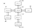
図2は、GPUリモート通信の態様を示す例示的なトポロジ200を示すシステム図である。トポロジ200は、CPU210と、GPU220と、システムメモリ230と、NIC240と、ローカル相互接続250と、コンピュータ通信ネットワーク260と、を含む。
FIG. 2 is a system diagram showing an
CPU210は、任意の適切な汎用処理装置又はプロセッサコアを含む。GPU220は、任意の適切なグラフィックス処理装置又はグラフィックスプロセッサコアを含む。CPU210及びGPU220は、別々のダイ又はパッケージ上に配置することができ、又は、アクセラレーテッド処理ユニット(APU)内等の同じダイ上のコアとすることができる。CPU210及びGPU220は、例えば、プロセッサ102(図1に関連して示され説明されている)として単一のダイ上に実装することができる。
The
システムメモリ230は、ランダムアクセスメモリ(RAM)等の任意の適切な非一時的なコンピュータ可読メモリを含む。システムメモリ230は、例えば、メモリ104(図1に関連して示され説明されている)として実装することができる。システムメモリ230は、ローカル相互接続250を介してCPU210及びCPU220と通信する。ローカル相互接続250は、PCIe(Peripheral Component Interconnect Express)バス等のように、コンピュータ内の周辺デバイスを相互接続するための任意の適切なバス又は他の媒体を含むことができる。
ネットワーク260は、RDMAを使用して、InfiniBandネットワーク及び/又はインターネット若しくはその任意の部分等のように、リモートシステムと通信するための任意の適切なコンピュータ通信ネットワークを含む。この例では、RDMAターゲットは、別のGPUを含むシステム内のメモリとすることができる。また、RDMAターゲットは、GPU220からの出力データの任意の使用者とすることができる。
NIC240は、ローカル相互接続250に接続されており、ローカル相互接続250を介して、CPU210、GPU220及びシステムメモリ230のためにネットワーク260との通信を提供する。例示的なトポロジ200は、これらの通信にNICを利用する。ネットワーク260への通信は、他の適切なI/Oデバイスによっても提供することができる。NIC240は、デバイスメモリ245を含む。
The
CPU210は、1つ以上のリモートputコマンド215を生成し、これらを、ローカル相互接続250を介してNIC240のデバイスメモリ245に記憶する。この例では、リモートputコマンド215は、NIC240のデバイスメモリ245に記憶されている。また、リモートputコマンドは、システムメモリ230等の任意の適切なメモリに記憶することもできる。この例及び本明細書の他の例では、リモートputコマンドが使用されている。一括動作(collective operations)、リモートgetコマンド、及び、送受信の双方のペアを含むがこれらに限定されない、トリガされたセマンティクスをサポートする他のネットワークメッセージ又は通信動作も使用することができる。リモートputコマンド215は、RDMAターゲット宛先、及び、送信用データに関する情報を含む。例えば、リモートputコマンド215’は、データがNICによってターゲットに適切に送信されるようにRDMAターゲット宛先を指定するメタデータ216’を含む。また、メタデータ216’は、(本明細書でさらに説明するように)putコマンド215’のトリガ条件に関するカウンタ値又は他の情報を含むことができ、他の情報を含むこともできる。リモートputコマンド215’は、システムメモリ230内の送信バッファ235内のアドレス又はアドレス範囲を指すバッファポインタ217’も含む。
The
また、各リモートputコマンド215は、トリガに関連付けられており、これにより、NIC240は、コマンドをいつ実行するかを決定することができる。この例では、リモートputコマンド215’は、カウンタ値218’に関連付けられている。リモートputコマンド215’’は、バッファポインタ217’’及びメタデータ216’’と同様に、異なるカウンタ値218’’と関連付けることができる。この例では、カウンタ値がトリガとして使用されている。トリガは、デバイスメモリ245又はシステムメモリ230内のフラグ又は他のレジスタをGPUが設定する等のように、任意の適切な所定のイベントであってもよく、これは、所望の実装に応じて、キュー内の所望の保留中のputコマンド又は次の保留中のputコマンドに対応する。
Also, each
いくつかの実装では、CPU210は、ターゲットを示すメタデータ、ソースを示すポインタ、メッセージを送信する前に待機するトリガの数を示す閾値、及び/又は、ネットワークメッセージをリモートターゲットに送信するのに必要な他のプロトコル固有情報を含むことができるリモートputコマンド215を事前に生成する。このコマンドパケットは、コマンドインタフェースを介してNICに通信することができ、内部NICメモリ又はグローバルシステムメモリに記憶することができる。NICは、カウンタを、ローカルメモリのプール又はグローバルシステムメモリから各メッセージに割り当てて、GPUから受信したトリガの数を追跡することができる。
In some implementations, the
GPU220は、その動作中にカーネルを実行し、ネットワーク260を介してリモートGPUに転送するためのデータを生成することができる。このようなデータが利用可能になると、GPU220は、当該データをシステムメモリ230の送信バッファ235に書き込む。この例では、送信バッファは、システムメモリに実装されている。送信バッファは、GPU220のローカルメモリ等の任意の適切なメモリに実装することができ、これは、特定の実施形態でのかかるメモリの利用可能性に依存する場合がある。
The
送信バッファ235内のデータがNIC240に見えるようになった後、GPU220は、1つの保留中のputコマンド215を実行するための信号をNIC240に送る。GPUは、適切なメモリフェンスを使用して、全ての変更データが送信バッファにフラッシュされ、NICから見えるようにすることができる。この例では、GPU220は、putコマンド215’’に関連するカウンタ値218’’をデクリメントするための信号をNIC240に送る動作を実行する。動作は、グローバルアトミックメモリ更新、メモリマップドレジスタ書き込み、又は、他の適切なトリガメカニズムとすることができる。カウンタ変数は、デバイスメモリ245又は他の適切な位置に記憶することができる。例えば、デクリメント後のカウンタ218’’の現在の値が、保留中のリモートputコマンド215’’のメタデータ216’’に含まれる閾値と一致する場合、NIC240は、リモートputコマンド215’’を実行し、バッファポインタ217’’によって示された送信バッファ235内の位置に存在するデータを、ネットワーク260を介して、メタデータ216’’によって示されたRDMAターゲットに送信する。
After the data in the transmit
NICをトリガするGPUの1つの可能な実装形態は、以下の表1の疑似コードによって示される。

表1の擬似コードは、グローバルアトミックを使用して、GPUによってNICのためのput動作をアクティブにする。この例では、NICがメモリアドレスをポーリングする必要がなく、メモリ値が変化したときに通知を受信することができる場合、NICは、mwaitのようなセマンティクスを使用して、カウンタを効率的に待機することができる。これは、NICキャッシュとGPUキャッシュとの間のキャッシュラインの制御の不要な転送を回避するという利点を有することができる。この例では、統一されたHSAのようなアドレス空間を想定している。 The pseudo code in Table 1 uses the global atomic to activate the put operation for the NIC by the GPU. In this example, if the NIC does not need to poll the memory address and can receive notifications when the memory value changes, the NIC uses semantics such as mwait to efficiently wait for the counter. can do. This can have the advantage of avoiding unnecessary transfers of cache line control between the NIC cache and the GPU cache. This example assumes a unified HSA-like address space.
NICをトリガするGPUの別の可能な実施形態は、以下の表2の疑似コードによって示される。
表2の疑似コードは、ローカルLDS同期とグローバルフラグとを用いた2段階の通知を使用する。このアプローチは、グローバルシグナルへの書き込みによって単一のワークアイテムにメッセージをトリガさせる前に、ローカルカウンタを使用してワークグループ内で同期する。このアプローチは、制御分岐の影響を受ける可能性がある。また、このアプローチは、単純なメモリマップドドアベルレジスタとして実装することができるフラグを使用して、NICの設計を簡素化する。 The pseudo-code in Table 2 uses two-step notification with local LDS synchronization and global flags. This approach uses local counters to synchronize within a workgroup before triggering a message on a single work item by writing to a global signal. This approach can be affected by control branching. This approach also simplifies the design of NICs with flags that can be implemented as simple memory-mapped doorbell registers.
図3は、GPUリモート通信の態様を示す例示的な方法300を示すフローチャートであり、例えば、例示的なトポロジ200及び/又は例示的なデバイス100を使用することができる。
FIG. 3 is a flowchart showing an exemplary method 300 showing aspects of GPU remote communication, for example, an
ステップ310では、コンピュータシステムのCPU(CPU210等)は、例えばリモートputコマンド等(リモートputコマンド215等)の1つ以上の通信コマンドを生成し、これらのコマンドを、NIC(例えば、NIC240等)又は他のインタフェースデバイス上のキューに記憶する。各通信コマンドは、送信バッファへのポインタを含む。この例では、送信バッファは、コンピュータシステムのシステムメモリ(システムメモリ230等)の一部である。送信バッファは、他の実施形態では、GPUローカルメモリ又は別のメモリの一部とすることもできる。
In step 310, the CPU of the computer system (
ステップ320では、コンピュータシステムのGPU(GPU220等)は、別のコンピュータシステムのGPUと通信するためのデータを生成する。例えば、GPUは、リモートGPUが使用するデータを生成するカーネルを実行することができる。ステップ330では、GPUは、生成されたデータを送信バッファに記憶する。ステップ340では、GPUは、送信バッファ内でデータが準備できていることをNICに知らせる。この例では、GPUは、NICのデバイスメモリ又はシステムメモリ等のメモリに記憶されているカウンタ変数をデクリメントすることによって、データを送信する準備ができていることを知らせる。他の実施形態では、GPUは、NICのデバイスメモリ又はメインシステムメモリ内のレジスタの値を設定すること等によって、他の任意の適切な方法で送信バッファ内でデータが準備できていることをNIC又は他のインタフェースデバイスに知らせることができる。 In step 320, the GPU of a computer system (such as GPU 220) generates data for communicating with a GPU of another computer system. For example, the GPU can run a kernel that produces the data used by the remote GPU. In step 330, the GPU stores the generated data in the transmit buffer. In step 340, the GPU informs the NIC that the data is ready in the transmit buffer. In this example, the GPU signals that it is ready to transmit data by decrementing counter variables stored in memory such as NIC device memory or system memory. In another embodiment, the GPU will indicate that the data is ready in the transmit buffer by any other suitable method, such as by setting the value of a register in the device memory or main system memory of the NIC. Alternatively, it can notify other interface devices.
ステップ350では、インタフェースデバイスは、GPUからの信号に基づいて、1つの通信コマンドを実行する。例えば、信号が、事前に生成されたputコマンドに関連するデクリメントされたカウンタ変数である場合、インタフェースデバイスは、カウンタ変数を、通信コマンドに含まれる閾値と比較することができる。カウンタ変数が複数のコマンドのうち1つのコマンドに記憶された閾値の値と一致する場合、NICは、当該コマンドを実行する。通信コマンドを実行することによって、NICは、送信バッファ内のデータ(例えば、通信コマンド内のポインタによって示された位置に存在する)を、コンピュータ通信ネットワークを介して、通信コマンド内で指定されたターゲット(例えば、リモートGPUのメモリ)に送信することができる。 In step 350, the interface device executes one communication command based on the signal from the GPU. For example, if the signal is a decremented counter variable associated with a pre-generated put command, the interface device can compare the counter variable to the threshold value contained in the communication command. If the counter variable matches the threshold value stored in one of the commands, the NIC executes the command. By executing the communication command, the NIC sends the data in the transmit buffer (eg, located at the position indicated by the pointer in the communication command) to the target specified in the communication command via the computer communication network. It can be transmitted to (for example, the memory of the remote GPU).
ステップ310では、ステップ320〜350が順次示されていることに留意されたい。また、CPUによる通信コマンドの生成は、他のステップの前及び他のステップとは無関係に、任意の適切なタイミングで生じる場合がある。これには、RDMA動作のクリティカルパスからCPUを削除するという利点がある。 Note that in step 310, steps 320-350 are shown in sequence. Further, the generation of the communication command by the CPU may occur at an arbitrary appropriate timing before the other step and regardless of the other step. This has the advantage of removing the CPU from the critical path of RDMA operation.
図4は、GPUリモート通信の態様を示す例示的な方法400を示すフローチャートであり、例えば、例示的なトポロジ200及び/又は例示的なデバイス100のGPUを使用することができる。
FIG. 4 is a flowchart showing an
ステップ410では、GPU(GPU220等)は、カーネルを実行し、コンピュータ通信ネットワークを介してリモートメモリ位置に送信するためのデータを生成する。リモートメモリ位置は、リモートGPUのデバイスメモリ、リモートGPUにアクセス可能なリモートデバイスのシステムメモリ、又は、任意の適切なRDMAターゲットであってもよい。
In
データが利用可能であるという条件420(例えば、GPUがカーネル又は特定のワークグループの実行を完了し、リモートメモリに送信するためのデータを生成した)では、ステップ430において、GPUは、データを送信バッファに書き込む。この例では、送信バッファは、システムメモリに実装されている。送信バッファは、GPUのデバイスメモリ等の任意の適切なメモリにも実装することができる。ステップ440では、GPUは、本明細書に記載されたもの等の任意の適切なシグナリング技術を使用して、コンピュータ通信ネットワークを介して送信バッファ内のデータをリモートGPU又は他のターゲットに送信するように、インタフェースデバイスをトリガする。例えば、GPUは、カウンタ変数をデクリメントして、デクリメントされたカウンタ変数と一致した関連する閾値を有する、事前に記憶されたリモートputコマンドを実行するように、インタフェースデバイスに信号を送ってもよい。
Under
図5は、GPUリモート通信の態様を示す例示的な方法500を示すフローチャートであり、例えば、例示的なトポロジ200及び/又は例示的なデバイス100のNICを使用することができる。
FIG. 5 is a flow chart showing an
NICが事前に生成されたリモートputコマンドをCPUから受信したという条件510では、ステップ520において、NICは、リモートputコマンドをデバイスメモリに記憶する。そうでない場合又はリモートputコマンドを記憶した後、NICは、データ準備完了信号(データが準備できていることを示す信号)をGPUから受信したかどうかを判別する。例えば、NICは、システムメモリ内のカウンタ変数の値(GPUがデクリメントすることができる)を1つ以上のリモートputコマンドの閾値と比較してもよいし、GPUによって設定可能なフラグ又はドアベルバッファの値をテストしてもよい。GPUから準備完了信号を受信したという条件530では、対応する事前に記憶されたputコマンドがローカルデバイスメモリに記憶されていると仮定すると、NICは、事前に記憶されたリモートputコマンドを実行して、リモートputコマンドのポインタによって示されたアドレスに存在する送信バッファに記憶されたデータを、コンピュータ通信ネットワークを介して、GPUメモリ、システムメモリ又は他の適切なRDMAターゲット等のリモートシステムのメモリに送信する。次に、NICは、GPUからの新たな準備完了信号又はCPUからの事前に生成された通信コマンドの監視を再開することができる。
Under the
図5に示すように、ステップ510及び520は、必ずしもステップ530,540と順次実行されるわけではない。例えば、ステップ520で通信コマンドを記憶した後、NICは、ステップ510で事前に生成された追加のputコマンドを受信することなく、ステップ530でGPUからの準備完了信号を無期限に監視することができる。したがって、CPUによる通信コマンドの生成は、他のステップの前及び他のステップとは無関係に、任意の適切なタイミングで生じる場合がある。これには、RDMA動作のクリティカルパスからCPUを削除するという利点がある。
As shown in FIG. 5,
図6は、GPUリモート通信の態様を示す例示的な方法600を示すフローチャートであり、例えば、例示的なトポロジ200及び/又は例示的なデバイス100のCPUを使用することができる。
FIG. 6 is a flowchart showing an
ステップ610では、GPUの出力に対する将来の通信パターンが決定又は予測される。ステップ620では、CPUは、通信パターンに基づいて、1つ以上の通信コマンドを生成する。通信コマンドは、例えばリモートputコマンドとすることができ、GPUからのデータを記憶する送信バッファへのポインタ、データの宛先を示す情報、及び、場合によってはカウンタ値又は他のトリガ情報を含むことができる。ステップ630では、CPUは、通信コマンドを、NICのデバイスメモリ又は他の適切なメモリに記憶するために、NIC又は他の適切なインタフェースデバイスに送信する。
In
本明細書における開示に基づいて多くの変形が可能であることを理解されたい。上記では、特徴及び要素が特定の組み合わせで説明されているが、各特徴又は要素は、他の特徴及び要素無しに単独で使用されてもよいし、他の特徴及び要素を伴って又は伴わずに様々な組み合わせで使用されてもよい。 It should be understood that many modifications are possible based on the disclosures herein. Although features and elements are described above in specific combinations, each feature or element may be used alone without other features and elements, with or without other features and elements. May be used in various combinations.
提供された方法は、汎用コンピュータ、プロセッサ又はプロセッサコアで実施されてもよい。適切なプロセッサには、例として、汎用プロセッサ、専用プロセッサ、従来のプロセッサ、デジタル信号プロセッサ(DSP)、複数のマイクロプロセッサ、DSPコアに関連する1つ以上のマイクロプロセッサ、コントローラ、マイクロコントローラ、特定用途向け集積回路(ASIC)、フィールドプログラマブルゲートアレイ(FPGA)回路、他のタイプの集積回路(IC)、及び/又は、ステートマシンが含まれる。このようなプロセッサは、処理されたハードウェア記述言語(HDL)命令(このような命令は、コンピュータ可読媒体に記憶することが可能である)の結果及びネットリストを含む他の中間データを用いて製造プロセスを構成することによって製造され得る。このようなプロセスの結果は、実施形態の形態を実施するプロセッサを製造するために半導体製造プロセスにおいて使用されるマスクワークであってもよい。 The provided method may be performed on a general purpose computer, processor or processor core. Suitable processors include, for example, general purpose processors, dedicated processors, conventional processors, digital signal processors (DSPs), multiple microprocessors, one or more microprocessors associated with DSP cores, controllers, microprocessors, specific applications. Included are integrated circuits (ASICs) for applications, field programmable gate array (FPGA) circuits, other types of integrated circuits (ICs), and / or state machines. Such processors use the results of processed hardware description language (HDL) instructions (such instructions can be stored on computer-readable media) and other intermediate data, including netlists. It can be manufactured by configuring the manufacturing process. The result of such a process may be mask work used in a semiconductor manufacturing process to manufacture a processor that implements an embodiment.
本明細書で提供された方法又はフローチャートは、汎用コンピュータ又はプロセッサによる実行のために非一時的なコンピュータ可読記憶媒体に組み込まれたコンピュータプログラム、ソフトウェア又はファームウェアで実施されてもよい。非一時的なコンピュータ可読記憶媒体の例には、例えば読み出し専用メモリ(ROM)、ランダムアクセスメモリ(RAM)、レジスタ、キャッシュメモリ、半導体メモリデバイス、内蔵ハードディスク、リムーバブルディスク等の磁気媒体、光磁気記憶媒体、例えばCD−ROMディスク及びデジタル多用途ディスク(DVD)等の光学媒体が含まれる。 The methods or flowcharts provided herein may be implemented in computer programs, software or firmware embedded in a non-temporary computer-readable storage medium for execution by a general purpose computer or processor. Examples of non-temporary computer-readable storage media include, for example, read-only memory (ROM), random access memory (RAM), registers, cache memory, semiconductor memory devices, internal hard disks, magnetic media such as removable disks, and optical magnetic storage. Mediums include optical media such as CD-ROM discs and digital versatile discs (DVDs).
Claims (20)
インタフェースデバイスによって、事前に生成されたネットワークリモート通信コマンドを中央処理装置から受信することであって、前記事前に生成されたネットワークリモート通信コマンドは、保留中のputコマンドによって指定されたメッセージを送信する前に待機するトリガの数を示す閾値を含む、ことと、
前記インタフェースデバイスによって、データがメモリ内で準備できていることを示す信号をグラフィックス処理装置から受信することであって、前記信号はトリガを含む、ことと、
前記グラフィックス処理装置から前記トリガを受信した後に、前記インタフェースデバイスが受信したトリガの数が、前記事前に生成されたネットワークリモート通信コマンドに含まれる前記閾値と一致することを判別することと、
前記判別したことに応じて、前記インタフェースデバイスによって、前記信号に基づいて、前記事前に生成されたネットワークリモート通信コマンドを実行し、ネットワークを介して前記データをターゲットデバイスに送信することと、を含む、
方法。 It ’s a way to send data,
The interface device receives a pre-generated network remote communication command from the central processing unit, and the pre-generated network remote communication command sends the message specified by the pending put command. Includes a threshold that indicates the number of triggers to wait before
The interface device receives a signal from the graphics processing device indicating that the data is ready in memory, and the signal includes a trigger.
Determining that, after receiving the trigger from the graphics processing device, the number of triggers received by the interface device matches the threshold included in the pre-generated network remote communication command.
In response to the determination, the interface device executes the pre-generated network remote communication command based on the signal and transmits the data to the target device via the network. include,
Method.
請求項1の方法。 The pre-generated network remote communication command includes a put command.
The method of claim 1.
請求項1の方法。 The signal is a signal for changing the value of the counter variable.
The method of claim 1.
請求項1の方法。 The pre-generated network remote communication command includes a threshold of a counter variable.
The method of claim 1.
請求項1の方法。 The pre-generated network remote communication command includes a pointer to the address in memory.
The method of claim 1.
請求項1の方法。 The pre-generated network remote communication command contains information indicating the target device.
The method of claim 1.
請求項6の方法。 The information includes metadata,
The method of claim 6.
請求項1の方法。 The interface device comprises a network interface controller (NIC).
The method of claim 1.
事前に生成されたネットワークリモート通信コマンドを中央処理装置から受信するように構成された受信機回路であって、前記事前に生成されたネットワークリモート通信コマンドは、保留中のputコマンドによって指定されたメッセージを送信する前に待機するトリガの数を示す閾値を含み、前記受信機回路は、データがメモリ内で準備できていることを示す信号であってトリガを含む信号をグラフィックス処理装置から受信するように構成されている、受信機回路と、
前記受信機回路が前記グラフィックス処理装置から前記トリガを受信した後に、前記受信機回路が受信したトリガの数が、前記事前に生成されたネットワークリモート通信コマンドに含まれる前記閾値と一致することを判別し、判別したことに応じて、前記信号に基づいて、前記事前に生成されたネットワークリモート通信コマンドを実行するように構成されたプロセッサ回路と、
前記事前に生成されたネットワークリモート通信コマンドに基づいて、ネットワークを介して前記データをターゲットデバイスに送信するように構成された送信機回路と、を備える、
デバイス。 A device that sends data
A receiver circuit configured to receive a pre-generated network remote communication command from a central processing unit, the pre-generated network remote communication command being specified by a pending put command. The receiver circuit receives a signal from the graphics processor that includes a threshold indicating the number of triggers to wait before sending a message, indicating that the data is ready in memory, including the triggers. The receiver circuit, which is configured to
After the receiver circuit receives the trigger from the graphics processor, the number of triggers received by the receiver circuit matches the threshold value included in the pre-generated network remote communication command. And, in response to the determination, a processor circuit configured to execute the pre-generated network remote communication command based on the signal.
It comprises a transmitter circuit configured to transmit the data to a target device over the network based on the pre-generated network remote communication command.
device.
請求項9のデバイス。 The pre-generated network remote communication command includes a put command.
The device of claim 9.
請求項9のデバイス。 The signal is a signal for changing the value of the counter variable.
The device of claim 9.
請求項9のデバイス。 The pre-generated network remote communication command includes a threshold of a counter variable.
The device of claim 9.
請求項9のデバイス。 The pre-generated network remote communication command includes a pointer to the address in memory.
The device of claim 9.
請求項9のデバイス。 The pre-generated network remote communication command contains information indicating the target device.
The device of claim 9.
請求項14のデバイス。 The information includes metadata,
The device of claim 14.
請求項9のデバイス。 The device comprises a network interface controller (NIC).
The device of claim 9.
中央処理装置(CPU)と、
グラフィックス処理装置(GPU)と、を備え、
前記CPUは、複数の事前生成ネットワークリモート通信コマンドを生成するように構成された処理回路と、前記事前生成ネットワークリモート通信コマンドをインタフェースデバイスに送信するように構成された送信機回路であって、前記事前生成ネットワークリモート通信コマンドは、保留中のputコマンドによって指定されたメッセージを送信する前に待機するトリガの数を示す閾値を含む、送信機回路と、を備え、
前記GPUは、ネットワークを介してターゲットデバイスに送信するためのデータを生成するように構成された処理回路と、前記データをバッファに記憶するように構成された記憶回路と、前記インタフェースデバイスが、前記複数の事前生成ネットワークリモート通信コマンドのうち1つの事前生成ネットワークリモート通信コマンドを実行するように、前記データが前記バッファに記憶されたことを前記インタフェースデバイスに知らせるように構成された送信機回路と、を備える、
システム。 A system that sends data
Central processing unit (CPU) and
Equipped with a graphics processing unit (GPU)
The CPU is a processing circuit configured to generate a plurality of pre-generated network remote communication commands and a transmitter circuit configured to transmit the pre-generated network remote communication commands to an interface device. The pregenerated network remote communication command comprises a transmitter circuit, which includes a threshold indicating the number of triggers to wait before sending the message specified by the pending put command.
The GPU includes a processing circuit configured to generate data to be transmitted to a target device via a network, a storage circuit configured to store the data in a buffer, and the interface device. to perform one of the pre-generated network remote communication commands among the plurality of pre-generated network remote communication command, a transmitter circuit for the data is configured to be stored in the buffer to inform the interface device, With,
system.
請求項17のシステム。 The CPU and the GPU are located on a single die.
The system of claim 17.
請求項17のシステム。 The CPU and the GPU are arranged in the same package.
The system of claim 17.
請求項17のシステム。 The interface device comprises a network interface controller (NIC).
The system of claim 17.
Applications Claiming Priority (3)
| Application Number | Priority Date | Filing Date | Title |
|---|---|---|---|
| US15/297,079 US10936533B2 (en) | 2016-10-18 | 2016-10-18 | GPU remote communication with triggered operations |
| US15/297,079 | 2016-10-18 | ||
| PCT/US2017/052250 WO2018075182A1 (en) | 2016-10-18 | 2017-09-19 | Gpu remote communication with triggered operations |
Publications (3)
| Publication Number | Publication Date |
|---|---|
| JP2019532427A JP2019532427A (en) | 2019-11-07 |
| JP2019532427A5 JP2019532427A5 (en) | 2020-11-12 |
| JP6961686B2 true JP6961686B2 (en) | 2021-11-05 |
Family
ID=61904564
Family Applications (1)
| Application Number | Title | Priority Date | Filing Date |
|---|---|---|---|
| JP2019517022A Active JP6961686B2 (en) | 2016-10-18 | 2017-09-19 | GPU remote communication using trigger operation |
Country Status (6)
| Country | Link |
|---|---|
| US (1) | US10936533B2 (en) |
| EP (1) | EP3529706B1 (en) |
| JP (1) | JP6961686B2 (en) |
| KR (1) | KR102245247B1 (en) |
| CN (1) | CN109690512B (en) |
| WO (1) | WO2018075182A1 (en) |
Families Citing this family (14)
| Publication number | Priority date | Publication date | Assignee | Title |
|---|---|---|---|---|
| US10534606B2 (en) | 2011-12-08 | 2020-01-14 | Oracle International Corporation | Run-length encoding decompression |
| US11113054B2 (en) | 2013-09-10 | 2021-09-07 | Oracle International Corporation | Efficient hardware instructions for single instruction multiple data processors: fast fixed-length value compression |
| US10599488B2 (en) | 2016-06-29 | 2020-03-24 | Oracle International Corporation | Multi-purpose events for notification and sequence control in multi-core processor systems |
| US10380058B2 (en) | 2016-09-06 | 2019-08-13 | Oracle International Corporation | Processor core to coprocessor interface with FIFO semantics |
| US10783102B2 (en) | 2016-10-11 | 2020-09-22 | Oracle International Corporation | Dynamically configurable high performance database-aware hash engine |
| US10459859B2 (en) | 2016-11-28 | 2019-10-29 | Oracle International Corporation | Multicast copy ring for database direct memory access filtering engine |
| US10725947B2 (en) | 2016-11-29 | 2020-07-28 | Oracle International Corporation | Bit vector gather row count calculation and handling in direct memory access engine |
| US20190044809A1 (en) * | 2017-08-30 | 2019-02-07 | Intel Corporation | Technologies for managing a flexible host interface of a network interface controller |
| US11429413B2 (en) * | 2018-03-30 | 2022-08-30 | Intel Corporation | Method and apparatus to manage counter sets in a network interface controller |
| US10740163B2 (en) * | 2018-06-28 | 2020-08-11 | Advanced Micro Devices, Inc. | Network packet templating for GPU-initiated communication |
| US10795840B2 (en) | 2018-11-12 | 2020-10-06 | At&T Intellectual Property I, L.P. | Persistent kernel for graphics processing unit direct memory access network packet processing |
| EP3942398A4 (en) * | 2019-05-23 | 2023-04-05 | Hewlett Packard Enterprise Development LP | System and method for facilitating data request management in a network interface controller (nic) |
| US11182221B1 (en) * | 2020-12-18 | 2021-11-23 | SambaNova Systems, Inc. | Inter-node buffer-based streaming for reconfigurable processor-as-a-service (RPaaS) |
| US11960813B2 (en) | 2021-08-02 | 2024-04-16 | Advanced Micro Devices, Inc. | Automatic redistribution layer via generation |
Family Cites Families (27)
| Publication number | Priority date | Publication date | Assignee | Title |
|---|---|---|---|---|
| US5278956A (en) | 1990-01-22 | 1994-01-11 | Vlsi Technology, Inc. | Variable sized FIFO memory and programmable trigger level therefor for use in a UART or the like |
| US8766993B1 (en) | 2005-04-06 | 2014-07-01 | Teradici Corporation | Methods and apparatus for enabling multiple remote displays |
| JP4439491B2 (en) | 2006-05-24 | 2010-03-24 | 株式会社ソニー・コンピュータエンタテインメント | Multi-graphics processor system, graphics processor and data transfer method |
| US8269782B2 (en) | 2006-11-10 | 2012-09-18 | Sony Computer Entertainment Inc. | Graphics processing apparatus |
| US8131814B1 (en) | 2008-07-11 | 2012-03-06 | Hewlett-Packard Development Company, L.P. | Dynamic pinning remote direct memory access |
| US20100013839A1 (en) * | 2008-07-21 | 2010-01-21 | Rawson Andrew R | Integrated GPU, NIC and Compression Hardware for Hosted Graphics |
| CN101539902B (en) * | 2009-05-05 | 2012-03-28 | 中国科学院计算技术研究所 | DMA device for nodes in multi-computer system and communication method |
| US20100325372A1 (en) * | 2009-06-17 | 2010-12-23 | Housty Oswin E | Parallel training of dynamic random access memory channel controllers |
| US9645866B2 (en) | 2010-09-20 | 2017-05-09 | Qualcomm Incorporated | Inter-processor communication techniques in a multiple-processor computing platform |
| US8902228B2 (en) * | 2011-09-19 | 2014-12-02 | Qualcomm Incorporated | Optimizing resolve performance with tiling graphics architectures |
| US9830288B2 (en) | 2011-12-19 | 2017-11-28 | Nvidia Corporation | System and method for transmitting graphics rendered on a primary computer to a secondary computer |
| CN104025065B (en) * | 2011-12-21 | 2018-04-06 | 英特尔公司 | The apparatus and method for the producer consumer instruction discovered for memory hierarchy |
| US9171348B2 (en) * | 2012-01-23 | 2015-10-27 | Google Inc. | Rendering content on computing systems |
| ITRM20120094A1 (en) * | 2012-03-14 | 2013-09-14 | Istituto Naz Di Fisica Nuclea Re | NETWORK INTERFACE CARD FOR PARALLEL CALCULATION NETWORK KNOT ON GPU, AND RELATIVE INTERNODAL COMMUNICATION METHOD |
| US9602437B1 (en) * | 2012-10-03 | 2017-03-21 | Tracey M. Bernath | System and method for accelerating network applications using an enhanced network interface and massively parallel distributed processing |
| US9582402B2 (en) | 2013-05-01 | 2017-02-28 | Advanced Micro Devices, Inc. | Remote task queuing by networked computing devices |
| US10134102B2 (en) * | 2013-06-10 | 2018-11-20 | Sony Interactive Entertainment Inc. | Graphics processing hardware for using compute shaders as front end for vertex shaders |
| US10062137B2 (en) * | 2014-02-27 | 2018-08-28 | Hewlett Packard Enterprise Development Lp | Communication between integrated graphics processing units |
| US10218645B2 (en) * | 2014-04-08 | 2019-02-26 | Mellanox Technologies, Ltd. | Low-latency processing in a network node |
| US10331595B2 (en) * | 2014-10-23 | 2019-06-25 | Mellanox Technologies, Ltd. | Collaborative hardware interaction by multiple entities using a shared queue |
| US9582463B2 (en) | 2014-12-09 | 2017-02-28 | Intel Corporation | Heterogeneous input/output (I/O) using remote direct memory access (RDMA) and active message |
| US9779466B2 (en) * | 2015-05-07 | 2017-10-03 | Microsoft Technology Licensing, Llc | GPU operation |
| US10248610B2 (en) * | 2015-06-23 | 2019-04-02 | Mellanox Technologies, Ltd. | Enforcing transaction order in peer-to-peer interactions |
| US10445850B2 (en) * | 2015-08-26 | 2019-10-15 | Intel Corporation | Technologies for offloading network packet processing to a GPU |
| US10210593B2 (en) * | 2016-01-28 | 2019-02-19 | Qualcomm Incorporated | Adaptive context switching |
| US10331590B2 (en) * | 2016-06-30 | 2019-06-25 | Intel Corporation | Graphics processing unit (GPU) as a programmable packet transfer mechanism |
| US10410313B2 (en) * | 2016-08-05 | 2019-09-10 | Qualcomm Incorporated | Dynamic foveation adjustment |
-
2016
- 2016-10-18 US US15/297,079 patent/US10936533B2/en active Active
-
2017
- 2017-09-19 KR KR1020197007796A patent/KR102245247B1/en active IP Right Grant
- 2017-09-19 WO PCT/US2017/052250 patent/WO2018075182A1/en unknown
- 2017-09-19 CN CN201780056487.7A patent/CN109690512B/en active Active
- 2017-09-19 EP EP17862965.5A patent/EP3529706B1/en active Active
- 2017-09-19 JP JP2019517022A patent/JP6961686B2/en active Active
Also Published As
| Publication number | Publication date |
|---|---|
| EP3529706B1 (en) | 2023-03-22 |
| JP2019532427A (en) | 2019-11-07 |
| EP3529706A1 (en) | 2019-08-28 |
| WO2018075182A1 (en) | 2018-04-26 |
| US10936533B2 (en) | 2021-03-02 |
| KR102245247B1 (en) | 2021-04-27 |
| US20180107627A1 (en) | 2018-04-19 |
| CN109690512A (en) | 2019-04-26 |
| EP3529706A4 (en) | 2020-03-25 |
| KR20190058483A (en) | 2019-05-29 |
| CN109690512B (en) | 2023-07-18 |
Similar Documents
| Publication | Publication Date | Title |
|---|---|---|
| JP6961686B2 (en) | GPU remote communication using trigger operation | |
| TWI447650B (en) | Interrupt distribution scheme | |
| US11290392B2 (en) | Technologies for pooling accelerator over fabric | |
| CN107077441B (en) | Method and apparatus for providing heterogeneous I/O using RDMA and proactive messages | |
| US9244881B2 (en) | Facilitating, at least in part, by circuitry, accessing of at least one controller command interface | |
| JP6303242B2 (en) | Apparatus and method for RDMA with commit ACK | |
| KR102086019B1 (en) | System and method for providing low latency to applications using heterogeneous processors | |
| US9881680B2 (en) | Multi-host power controller (MHPC) of a flash-memory-based storage device | |
| US20140330978A1 (en) | Accelerating USB Redirection over a Network | |
| CN115168256A (en) | Interrupt control method, interrupt controller, electronic device, medium, and chip | |
| KR20190098146A (en) | Method and apparatus for accessing non-volatile memory as byte addressable memory | |
| JP2021530022A (en) | Network packet temprating for GPU-driven communication | |
| US10505704B1 (en) | Data uploading to asynchronous circuitry using circular buffer control | |
| US10802828B1 (en) | Instruction memory | |
| US9311225B2 (en) | DMA channels | |
| US10713188B2 (en) | Inter-process signaling system and method | |
| US10951537B1 (en) | Adjustable receive queue for processing packets in a network device | |
| JP2018536945A (en) | Method and apparatus for time-based scheduling of tasks | |
| US10613890B2 (en) | Efficient I/O request handling | |
| JP2004348233A (en) | File sharing system, server, and program | |
| CN116501456A (en) | Systems, methods, and apparatus for queue management using a coherence interface |
Legal Events
| Date | Code | Title | Description |
|---|---|---|---|
| A521 | Request for written amendment filed |
Free format text: JAPANESE INTERMEDIATE CODE: A523 Effective date: 20200923 |
|
| A621 | Written request for application examination |
Free format text: JAPANESE INTERMEDIATE CODE: A621 Effective date: 20200923 |
|
| A871 | Explanation of circumstances concerning accelerated examination |
Free format text: JAPANESE INTERMEDIATE CODE: A871 Effective date: 20200923 |
|
| A975 | Report on accelerated examination |
Free format text: JAPANESE INTERMEDIATE CODE: A971005 Effective date: 20200930 |
|
| A131 | Notification of reasons for refusal |
Free format text: JAPANESE INTERMEDIATE CODE: A131 Effective date: 20201222 |
|
| A601 | Written request for extension of time |
Free format text: JAPANESE INTERMEDIATE CODE: A601 Effective date: 20210322 |
|
| A521 | Request for written amendment filed |
Free format text: JAPANESE INTERMEDIATE CODE: A523 Effective date: 20210521 |
|
| A131 | Notification of reasons for refusal |
Free format text: JAPANESE INTERMEDIATE CODE: A131 Effective date: 20210817 |
|
| A521 | Request for written amendment filed |
Free format text: JAPANESE INTERMEDIATE CODE: A523 Effective date: 20210827 |
|
| TRDD | Decision of grant or rejection written | ||
| A01 | Written decision to grant a patent or to grant a registration (utility model) |
Free format text: JAPANESE INTERMEDIATE CODE: A01 Effective date: 20210914 |
|
| A61 | First payment of annual fees (during grant procedure) |
Free format text: JAPANESE INTERMEDIATE CODE: A61 Effective date: 20211013 |
|
| R150 | Certificate of patent or registration of utility model |
Ref document number: 6961686 Country of ref document: JP Free format text: JAPANESE INTERMEDIATE CODE: R150 |