JP2019191902A - Flame detection device - Google Patents
Flame detection device Download PDFInfo
- Publication number
- JP2019191902A JP2019191902A JP2018083523A JP2018083523A JP2019191902A JP 2019191902 A JP2019191902 A JP 2019191902A JP 2018083523 A JP2018083523 A JP 2018083523A JP 2018083523 A JP2018083523 A JP 2018083523A JP 2019191902 A JP2019191902 A JP 2019191902A
- Authority
- JP
- Japan
- Prior art keywords
- flame
- test
- flame detection
- light
- test light
- Prior art date
- Legal status (The legal status is an assumption and is not a legal conclusion. Google has not performed a legal analysis and makes no representation as to the accuracy of the status listed.)
- Granted
Links
Images


Abstract
Description
本発明は、有炎燃焼時のCO2共鳴により発生する赤外線放射を検出して、炎の有無を判定する炎検出装置に関する。 The present invention relates to a flame detection device that detects infrared radiation generated by CO 2 resonance during flammable combustion to determine the presence or absence of a flame.
従来、有炎燃焼により発生する赤外線エネルギーを検出して、炎の有無を検出する炎検出装置にあっては、有炎燃焼時に発生するCO2の共鳴放射波長帯域における赤外線強度を検出して、炎の有無を検出する炎検出装置や炎検出方法がよく知られている。 Conventionally, in a flame detection device that detects infrared energy generated by flammable combustion and detects the presence or absence of flame, the infrared intensity in the resonance emission wavelength band of CO 2 generated during flammable combustion is detected, Flame detection devices and flame detection methods for detecting the presence or absence of a flame are well known.
ここで、従来技術における2波長式の炎検出装置について、簡単に説明する。図15は、燃焼炎と、その他の代表的な放射体の赤外波長域における赤外線スペクトルを示す概念図であり、横軸は赤外線の波長、縦軸は赤外線の相対強度を示す。 Here, the conventional two-wavelength flame detection apparatus will be briefly described. FIG. 15 is a conceptual diagram showing an infrared spectrum in the infrared wavelength region of a combustion flame and other typical radiators, where the horizontal axis indicates the wavelength of infrared rays and the vertical axis indicates the relative intensity of infrared rays.
図15に示すように、燃焼炎のスペクトル特性100においては、5μm付近の波長帯域にCO2の共鳴放射に伴う赤外線相対強度のピークがあり、また、このピーク波長の近傍に存在する特徴的な波長としては、例えば、長波長側の5.0μm付近に、赤外線相対強度が低い波長帯域が存在する。以下では、特に断らない限り、CO2共鳴放射帯とは、4.5μm帯を指すものとする。
As shown in FIG. 15, in the
2波長式の炎検出装置にあっては例えば、4.5μm付近の波長帯域と、5.0μm付近の波長帯域における各々の赤外線エネルギーを狭帯域の光学波長バンドパスフィルタにより選択透過させて、各々について検出センサにより該赤外線エネルギーを検出し、これを光電変換したうえで増幅等所定の処理を施して、エネルギー量に対応する電気信号(以下、「受光信号」という)とし、上記各々の波長帯域の受光信号レベルの相対比をとり、所定の閾値と比較することにより炎の有無を判定する。 In a two-wavelength flame detection device, for example, each infrared energy in a wavelength band near 4.5 μm and a wavelength band near 5.0 μm is selectively transmitted by a narrow band optical wavelength bandpass filter, The infrared energy is detected by a detection sensor, subjected to photoelectric conversion, and subjected to predetermined processing such as amplification to obtain an electrical signal corresponding to the amount of energy (hereinafter referred to as “light reception signal”), and each wavelength band The presence / absence of a flame is determined by taking the relative ratio of the received light signal level and comparing it with a predetermined threshold.
これにより、炎以外の赤外線放射体、例えば、スペクトル特性102に示す太陽光等の高温放射体や、スペクトル特性104に示す比較的低温の放射体、またスペクトル特性106に示す人体などの低温放射体等と炎との識別が可能となる。
Thereby, an infrared radiator other than a flame, for example, a high-temperature radiator such as sunlight shown in the
また、炎検出装置は透光性窓を介して有炎燃焼により発生する赤外線エネルギーを検出して、炎の有無を監視しており、炎の監視機能を維持するために、透光性窓の汚れを監視するための自己試験として、汚れ試験を行っている。 In addition, the flame detection device detects infrared energy generated by flammable combustion through a translucent window and monitors the presence or absence of a flame, and in order to maintain the flame monitoring function, As a self-test for monitoring dirt, a dirt test is conducted.
汚れ試験は、火災受信盤から定期的に送信される試験信号を受信した場合に、炎検知器の外側に設けられた試験光源から炎模擬光となる試験光を透光性窓に入射し、検出部で受光して、このときの受光信号を汚れていない初期状態と比較演算して減光率を求め、減光率が所定の汚れ閾値を超えた場合に汚れ警報信号を火災受信盤に送信して汚れ警報を出力させている。 In the dirt test, when a test signal periodically transmitted from the fire receiving panel is received, test light that becomes flame simulated light is incident on the translucent window from a test light source provided outside the flame detector, The detection unit receives the light and compares the received light signal with the unclean initial state to determine the light attenuation rate.If the light attenuation rate exceeds the specified contamination threshold, a contamination alarm signal is sent to the fire reception panel. Sending and outputting a dirt alarm.
図16は従来の炎検出装置の外観を示した説明図であり、図16(A)は斜め上側から見降ろした図であり、図16(B)は斜め下側から見上げた図である。 FIG. 16 is an explanatory view showing the appearance of a conventional flame detection device, FIG. 16 (A) is a view looking down from an oblique upper side, and FIG. 16 (B) is a view looking up from an oblique lower side.
図16に示すように、炎検出装置120は、ケース本体122の前面に設けられたカバーをセンサ収納部とし、このセンサ収納部124に左右一対の透光性窓126が設けられ、透光性窓126内の各々に対し、有炎燃焼により発生する赤外線エネルギーを受光する検出部が配置されている。また、透光性窓126の近傍となる上側に凸部128を張出し形成し、凸部128の下側の透光性窓126内の検出センサを見通せる位置に、試験光源を収納した試験光源部を備え、ここに透光性の試験窓130が設けられている。このような試験光源部を左右に対応して個別に設けている。
As shown in FIG. 16, the
火災受信盤から試験信号を受信して透光性窓126の汚れ試験を行う場合には、一方の試験窓130の試験光源を所定時間、例えば2秒間、所定周波数で駆動して試験光を試験窓130から対応する側の透光性窓126に照射し、検出部で受光し、この受光レベルを汚れのない初期状態の受光レベルと比較して減光率を求めて汚れ度合を判断し、続いて、他方の試験窓130の試験光源を同じく2秒間、所定周波数で駆動して試験光を試験窓130から対応する側の透光性窓126に照射し、検出部で受光し、この受光レベルを汚れのない初期状態の受光レベルと比較して減光率を求めて汚れ度合を判断している。
When the test signal is received from the fire receiving board and the stain test of the
しかしながら、このような従来の汚れ試験による試験光源の駆動は、2組の試験光源を順番に駆動しているため、炎検出装置の汚れ試験に要する時間が長くなる。炎検出装置は、火災受信盤からの試験信号により複数の炎検出装置の汚れ試験を順番に行うことから、多数の炎検出装置の汚れ試験を完了するまでの合計時間が長くなり、汚れ試験を行っている間、火災受信盤は通常の火災監視制御に加えて汚れ監視制御を行うことで制御負担が増加しており、万一、火災が発生した場合の処理性能に悪影響を及ぼす可能性がある。 However, the driving of the test light source by such a conventional stain test drives the two sets of test light sources in order, so that the time required for the stain test of the flame detection device becomes long. Since the flame detector performs the stain test of a plurality of flame detectors in order according to the test signal from the fire receiving board, the total time until the stain test of a large number of flame detectors is completed becomes longer, and the stain test is performed. During the operation, the fire reception board increases the control burden by performing the dirt monitoring control in addition to the normal fire monitoring control, which may adversely affect the processing performance in the event of a fire. is there.
本発明は、透光性窓の汚れ試験を行う試験光源の駆動を工夫することにより試験時間を短縮可能とする炎検出装置を提供することを目的とする。 It is an object of the present invention to provide a flame detection apparatus that can shorten the test time by devising the driving of a test light source that performs a stain test on a translucent window.
(炎検出装置)
本発明は、燃焼炎から放射される放射線エネルギーを、透光性窓を介して検出センサにより観測して燃焼炎の有無を判断し検出する2組の炎検出部が設けられた炎検出装置であって、
筐体前面に配置された透光性窓の間に設けられた中央凸部と、
中央凸部の両側に配置された試験窓から透光性窓を介して検出センサの各々に試験光を照射する一対の試験光源と、
一対の試験光源の一方を発光している間に他方の発光を停止するように交互にパルス駆動する試験制御部と、
が設けられたことを特徴とする。
(Flame detection device)
The present invention is a flame detection apparatus provided with two sets of flame detectors for observing the radiation energy radiated from a combustion flame with a detection sensor through a translucent window and determining the presence or absence of the combustion flame. There,
A central projection provided between the translucent windows disposed on the front surface of the housing;
A pair of test light sources that irradiate each of the detection sensors from the test windows disposed on both sides of the central convex portion through the translucent window;
A test control unit that alternately pulses to stop the light emission of one of the pair of test light sources while stopping the light emission of the other;
Is provided.
(共用の試験光源による試験)
また、本発明は、燃焼炎から放射される放射線エネルギーを、透光性窓を介して検出センサにより観測して燃焼炎の有無を判断し検出する2組の炎検出部が設けられた炎検出装置であって、
筐体前面に配置された透光性窓の間に設けられた中央凸部と、
前記中央凸部の両側に配置された試験窓から透光性窓を介して前記受光素子の各々に試験光を照射する1つの試験光源と、
が設けられ、
1つの試験光源からの試験光を、2組の検出部の検出センサの各々で同期間について検出し、検出した試験光量に基づいて自己診断を行うことを特徴とする。
(Test using a common test light source)
In addition, the present invention provides a flame detection system provided with two sets of flame detectors that detect and detect the presence or absence of a combustion flame by observing the radiation energy emitted from the combustion flame with a detection sensor through a translucent window. A device,
A central projection provided between the translucent windows disposed on the front surface of the housing;
One test light source for irradiating each of the light receiving elements from a test window disposed on both sides of the central convex portion through a light-transmitting window;
Is provided,
The test light from one test light source is detected for the same period by each of the detection sensors of the two sets of detection units, and self-diagnosis is performed based on the detected test light quantity.
(基本的な効果)
本発明は、燃焼炎から放射される放射線エネルギーを、透光性窓を介して検出センサにより観測して燃焼炎の有無を判断し検出する2組の炎検出ユニットが設けられた炎検出装置であって、筐体前面に配置された透光性窓の間に設けられた中央凸部と、中央凸部の両側に配置された試験窓から透光性窓を介して検出センサの各々に試験光を照射する一対の試験光源と、一対の試験光源の一方を発光している間に他方の発光を停止するように交互にパルス駆動する試験制御部とが設けられたため、前述した検知エリアの制約が低減し、中央凸部に対する試験光源と試験窓の配置構造を簡単にすることができる。
(Basic effect)
The present invention is a flame detection apparatus provided with two sets of flame detection units for observing the radiation energy radiated from a combustion flame with a detection sensor through a translucent window and determining the presence or absence of the combustion flame. A test is performed on each of the detection sensors from the central convex portion provided between the translucent windows arranged on the front surface of the housing and the test windows arranged on both sides of the central convex portion through the translucent windows. Since a pair of test light sources for irradiating light and a test control unit that alternately pulse-drives so as to stop the other light emission while emitting one of the pair of test light sources, The restriction is reduced, and the arrangement structure of the test light source and the test window with respect to the central convex portion can be simplified.
また、2組の試験光源を、一方を発光しているときに他方の発光を停止するように交互にパルス駆動することで、単一の試験光源をパルス駆動した場合と同等となる従来の約半分の駆動時間に低減することができ、火災受信盤からの指示で多数の炎検出装置の汚れ試験を順次行って終了するまでの合計試験時間を大幅に短縮し、火災受信盤に汚れ試験の制御負担が掛かる時間を必要最小限に短縮可能とする。 In addition, by alternately pulsing two sets of test light sources so as to stop the emission of the other light when one of the light sources emits light, it is equivalent to the conventional case where a single test light source is pulse-driven. The drive time can be reduced to half, and the total test time until the completion of the soil test of a large number of flame detectors in accordance with the instructions from the fire receiver is significantly shortened. Time required for control can be reduced to the minimum necessary.
(共用の試験光源による試験の効果)
本発明は、燃焼炎から放射される放射線エネルギーを、透光性窓を介して検出センサにより観測して燃焼炎の有無を判断し検出する2組の炎検出部が設けられた炎検出装置であって、筐体前面に配置された透光性窓の間に設けられた中央凸部と、
前記中央凸部の両側に配置された試験窓から透光性窓を介して前記受光素子の各々に試験光を照射する1つの試験光源とが設けられ、1つの試験光源からの試験光を、2組の検出部の検出センサの各々で同期間について検出し、検出した試験光量に基づいて自己診断を行うようにした。これにより2組の検出部で試験光源を共用することから、試験光源を駆動すると、2組の検出部で同時期に試験光量を検出する。したがって、複数の試験光源を順次又は交互に駆動して試験する必要がなく、試験期間を短縮できる。また、試験光源を駆動するための消費電流を低減することができる。
(Effects of testing with a common test light source)
The present invention is a flame detection apparatus provided with two sets of flame detectors for observing the radiation energy radiated from a combustion flame with a detection sensor through a translucent window and determining the presence or absence of the combustion flame. A central projection provided between the translucent windows disposed on the front surface of the housing;
One test light source that irradiates each of the light receiving elements with a test light from a test window disposed on both sides of the central convex portion through a translucent window is provided, and the test light from one test light source, Each of the detection sensors of the two sets of detection units detects the synchronization period, and performs self-diagnosis based on the detected test light quantity. As a result, the test light source is shared by the two sets of detection units. Therefore, when the test light source is driven, the test light amount is detected at the same time by the two sets of detection units. Accordingly, it is not necessary to test by sequentially or alternately driving a plurality of test light sources, and the test period can be shortened. In addition, current consumption for driving the test light source can be reduced.
[炎検出装置]
(装置概要)
図1は炎検出装置に組み込まれる炎検出ユニットの実施形態を示したブロック図であり、2波長式の炎検出装置を例にとっている。本実施形態の炎検出装置は、監視領域の炎の有無を検出する火災検出装置であるものとする。
[Flame detection device]
(Device overview)
FIG. 1 is a block diagram showing an embodiment of a flame detection unit incorporated in a flame detection apparatus, taking a two-wavelength flame detection apparatus as an example. It is assumed that the flame detection device of the present embodiment is a fire detection device that detects the presence or absence of a flame in the monitoring area.
図1に示すように、本実施形態の炎検出装置10の検出部は、炎検出部11−1と、同じ構成の別の炎検出部11−2(図示省略)の2組が組み込まれている。
As shown in FIG. 1, the detection unit of the
炎検出部11−1は、炎検出ユニット12a,12b、非炎検出ユニット12c、MPU(マイクロプロセッサユニット)15に設けられた判断部36と試験制御部38で構成される。
The flame detection unit 11-1 includes a
炎検出ユニット12a,12bは、監視エリアに存在する燃焼炎から放射される赤外線エネルギーを観測するものであり、燃焼炎からCO2共鳴に伴って放射される4.5μmを中心とする所定の波長帯域の赤外線を受光して光電変換し、炎受光信号E1,E2を出力する。
The
炎検出ユニット12a,12bには、サファイアガラス等を用いた赤外線の透光性窓18、炎検出センサ16a,16b、前置フィルタ24a,24b、プリアンプ26a,26b、メインアンプ28a,28bが設けられ、メインアンプ28a,28bから出力された炎受光信号E1,E2は終段アンプ30a,30bで更に増幅されて炎受光信号E1’,E2’となり、MPU15のA/D変換ポート35a,35bでデジタル受光信号に変換して取り込まれる。
The
また、炎検出ユニット12a,12bからの炎受光信号E1,E2は加算アンプ32で加算されて炎受光信号E3としてMPU15に出力され、MPU15のA/D変換ポート35cでデジタル受光信号に変換して取り込まれる。
Further, the flame light reception signals E1 and E2 from the
以下では、A/D変換前後で同じ記号を使用して説明する。後述する受光信号E4’についても同様である。 Hereinafter, the same symbols are used before and after A / D conversion. The same applies to a light receiving signal E4 'described later.
非炎検出ユニット12cは、監視エリアに存在する燃焼炎以外の発熱体等から放射される赤外線エネルギーを観測するものであり、概ね5.0μm〜7.0μmの波長帯域の赤外線エネルギーを受光して電気信号に変換した非炎受光信号E4を出力する。
The
非炎検出ユニット12cには、炎検出ユニット12a,12bと共用する赤外線の透光性窓18−1、非炎検出センサ16c、前置フィルタ24c、プリアンプ26c、メインアンプ28cが設けられ、メインアンプ28cから出力された炎受光信号E4は終段アンプ30cで更に増幅されて炎受光信号E4‘となり、MPU15のA/D変換ポート35dでデジタル受光信号に変換して取り込まれる。
The
判断部36は、炎受光信号E1、E2を加算した受光信号E3の信号レベル、例えば受光信号E3の所定期間の積分値ΣE3が所定閾値以上又は所定閾値を上回った場合に、炎受光信号E3と非炎受光信号E4’の、同じ期間の積分値の比ΣE3/Σ4’を算出し、これが別の閾値以上又はそれを超えた場合に炎有りと判断する。 When the signal level of the light reception signal E3 obtained by adding the flame light reception signals E1 and E2, for example, the integral value ΣE3 of the light reception signal E3 for a predetermined period exceeds or exceeds a predetermined threshold, A ratio ΣE3 / Σ4 ′ of integral values of the non-flame light reception signal E4 ′ in the same period is calculated, and when this exceeds or exceeds another threshold value, it is determined that there is a flame.
(汚れ試験の概要)
炎検出部11−1の透光性窓18−1に対しては試験光源として機能する試験光源60−1が設けられる。試験光源60−1は後の説明で明らかにする炎検出装置10の筐体(ケース本体)50の前面の中央凸部54に配置され、自己試験の一項目である汚れ試験の際、試験光源60−1の駆動による炎模擬光となる試験光を透光性の試験窓56−1から出力し、この試験光を透光性窓18−1内に配置された炎検出センサ16a,16b及び非炎検出センサ16cに受光させる。
(Outline of dirt test)
A test light source 60-1 that functions as a test light source is provided for the translucent window 18-1 of the flame detector 11-1. The test light source 60-1 is disposed on the central
中央凸部54には別の炎検出部11−2の透光性窓18−2の汚れ試験に用いる試験光源60−2と試験窓56−2も同様に配置されている。
Similarly, a test light source 60-2 and a test window 56-2 used for a stain test of the translucent window 18-2 of another flame detection unit 11-2 are arranged in the central
試験光源60−1,60−2には例えばクリプトンランプが使用される。また、試験光源60−1には試験光を試験窓56−1側、すなわち各検出センサに向けて反射する反射板として機能する反射フード74−1が設けられる。一方で、反射フード74−1は試験光源60−1の試験光を試験窓56−1からのみ出力させ、試験窓56−2側には透過しないようになっている。また、試験光源60−2にも同様に反射フード74−2が設けられ、試験光を試験窓56−2からのみ出力させる。 For example, krypton lamps are used as the test light sources 60-1 and 60-2. The test light source 60-1 is provided with a reflective hood 74-1 that functions as a reflector that reflects the test light toward the test window 56-1, that is, toward each detection sensor. On the other hand, the reflective hood 74-1 outputs test light from the test light source 60-1 only from the test window 56-1, and does not transmit it to the test window 56-2 side. Similarly, the test light source 60-2 is also provided with a reflective hood 74-2, and the test light is output only from the test window 56-2.
図1の例では、反射フード74−1と74−2は一体で、遮光性を有する板状部材の両面に反射コーティングを施している。 In the example of FIG. 1, the reflective hoods 74-1 and 74-2 are integrated, and a reflective coating is applied to both surfaces of a light-blocking plate-like member.
透光性窓18−1の汚れ試験は、炎検出ユニット12a,12bからの受光信号E1,E2を加算した炎受光信号E3に基づいて行われる。MPU15に設けられた試験制御部38は、図示しない火災受信盤から定期的に送信された試験信号を受信すると、試験光源60−1,60−2を順次駆動して試験光を出力させ、このとき加算器32から出力される炎受光信号E3を読み込んで初期状態(汚れのない状態)との比較演算により減光率を算出し、算出した減光率が所定の閾値以上又は所定の閾値を超えた場合に汚れ警報信号を火災受信盤に送信して汚れ警報を出力させ、管理者に炎検出装置10の清掃計画等の策定を促す。
The stain test of the translucent window 18-1 is performed based on the flame light reception signal E3 obtained by adding the light reception signals E1 and E2 from the
(装置外観とセンサユニット)
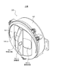
図2は炎検出装置の外観を示した説明図、図3は図2の炎検出装置を正面から示した説明図、図4は図2の炎検出装置を下側から見て中央凸部の試験光源及び試験窓と透光性窓内側の炎検出部を一部断面で示した説明図である。
(Appearance and sensor unit)
2 is an explanatory view showing the appearance of the flame detection device, FIG. 3 is an explanatory view showing the flame detection device of FIG. 2 from the front, and FIG. 4 is a view of the central convex portion when the flame detection device of FIG. It is explanatory drawing which showed the test light source, the test window, and the flame detection part inside a translucent window in a partial cross section.
図2乃至図4に示すように、炎検出装置10は、筐体50の前面に配置された前面カバーのセンサ収納部52に、図1の炎検出部11−1を含む2組の炎検出ユニットに対応して、赤外線の透光性窓18−1,18−2が設けられる。
As shown in FIGS. 2 to 4, the
なお、以下の説明で透光性窓18−1,18−2を区別する必要がない場合は、透光性窓18ということがある。同様に、試験窓56−1,56−2についても試験窓56ということがある。 In addition, in the following description, when it is not necessary to distinguish the translucent windows 18-1 and 18-2, they may be referred to as translucent windows 18. Similarly, the test windows 56-1 and 56-2 may be referred to as test windows 56.
透光性窓18−1,18−2内の各々には、図1に示した炎検出部11−1、及び他の炎検出部11−2における炎検出ユニット12a,12bの炎検出センサ16a,16b及び非炎検出ユニット12cの非炎検出センサ16cが配置されている。
In each of the translucent windows 18-1 and 18-2, the
また、センサ収納部52に設けられた透光性窓18−1,18−2の間には、中央凸部54が張出し形成される。中央凸部54には試験光源60−1,60−2が内蔵され、左右の側壁には試験窓56−1,56−2が配置される。
Further, a central
試験光源60−1は試験光を試験窓56−1から透光性窓18−1に向けて出力する。また、試験光源60−2は試験光を試験窓56−2から透光性窓18−2に向けて出力する。 The test light source 60-1 outputs test light from the test window 56-1 toward the translucent window 18-1. The test light source 60-2 outputs test light from the test window 56-2 toward the translucent window 18-2.
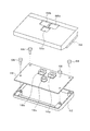
図2及び図3に示した一対の透光性窓18の内部には図5に示すようにセンサユニットが組み込まれている。センサユニットはユニット本体62とユニットカバー64で構成され、内部に回路基板48をビス68により固定して収納している。
As shown in FIG. 5, a sensor unit is incorporated in the pair of translucent windows 18 shown in FIGS. The sensor unit is composed of a unit
回路基板48には炎検出センサ16a,16bが隣接配置されている。ユニットカバー56の、炎検出センサ16a,16bに対向する位置には受光開口66a,66bが形成され、監視エリア側から透光性窓18を通った光を炎検出センサ16a,16bで受光できるようにしている。
また、回路基板48には非炎検出センサ16cが配置され、ユニットカバー64の、非炎検出センサ16cに対向する位置には受光開口66cが形成され、監視エリア側から透光性窓18を通った光を非炎検出センサ16cで受光できるようにしている。
In addition, a
(炎検出ユニット12a,12bの構成)
図1に示した炎検出ユニット12a,12bにおいて、炎検出センサ16a,16bは燃焼炎からCO2共鳴に伴って放射される、概ね4.5μmを中心波長とする赤外線波長帯域を有する赤外線エネルギーを電気信号に変換して受光信号として出力し、前置フィルタ24a,24bは炎検出センサ16a,16bから出力される受光信号から、炎の揺らぎ周波数に対応した所定の周波数帯域の信号成分のみを選択通過させ、プリアンプ26a,26bは前置フィルタ24a,24bを通過した信号成分を初段増幅し、メインアンプ28a,28bでさらに増幅して炎受光信号E1,E2を出力する。そして、終段アンプ30a,30bはこれを炎判断処理に適した信号レベルに増幅して炎受光信号E1’,E2’を出力する。
(Configuration of the
In the
ここで、炎検出センサ16a,16bは、光学波長フィルタ20a,20b、及び受光素子部22a,22bを備えている。
Here, the
炎検出ユニット12a,12bから終段アンプ30a,30bを介して出力された炎受光信号E1’,E2’は、MPU15に設けたA/D変換ポート35a,35bによりデジタル受光信号E1’,E2’に変換して読み込まれる。
The flame light reception signals E1 ′ and E2 ′ output from the
また、炎検出ユニット12a,12bから出力された炎受光信号E1及びE2は加算アンプ32で加算され、加算アンプ32からの炎受光信号E3はMPU15に設けたA/D変換ポート35cによりデジタル受光信号E3に変換して読み込まれ、判断部36で炎受光信号E3に基づく炎の有無の判断が実行される。以下、各構成について具体的に説明する。
The flame light reception signals E1 and E2 output from the
なお、本実施形態においては受光信号E1’,E2’を炎の有無判断に使用していないが、これを適宜使用して判断するようにしても良い。 In the present embodiment, the received light signals E1 'and E2' are not used to determine the presence or absence of flames, but may be determined using them as appropriate.
(炎検出センサ16a,16b)
図6は炎検出センサの概略構成を示した説明図、図7は図6の炎検出センサの等価回路を示した回路図である。
(
6 is an explanatory diagram showing a schematic configuration of the flame detection sensor, and FIG. 7 is a circuit diagram showing an equivalent circuit of the flame detection sensor of FIG.
図6に示すように、炎検出センサ16aは、基板40の表面に支持配置された焦電体45を備え、これに受光電極25を設け、基板40の裏面側に配置されたFET27、高抵抗(図示省略)を備えてなる受光素子部22aと、基板40を基部38上に支持しつつ基部38を貫通して設けられた端子42と、受光素子部22aの前方(図示上方)に光学波長フィルタ20aを備えたカバー部材44とからなるパッケージ構成を有している。
As shown in FIG. 6, the
また、受光素子部22aの等価回路は、図7に示すように、FET27のゲートから例えば焦電体45と高抵抗29の並列回路を介してゲート端子Gに接続し、またFET27のドレインとソースをそれぞれドレイン端子Dとソース端子Sに接続している。
Further, as shown in FIG. 7, an equivalent circuit of the light receiving
ここで、光学波長フィルタ20aは、4.5μmを中心とする所定の波長帯域を選択透過させるもので、例えば、シリコン、サファイア等の基板上に、公知の方法でそれぞれ形成することができる。また、炎検出ユニット12bの炎検出センサ16bも、炎検出センサ16aと同じ構造となる。
Here, the
更に、非炎検出ユニット12cの非炎検出センサ16cも、炎検出センサ16aと同じ構造となるが、光学波長フィルタ22cとして、概ね5.0μmを超える所定の波長帯域の赤外線を良好に透過するカットオンフィルタ(ロングパスフィルタ)を使用した点で相違する。
Further, the
(透光性窓18) 透光性窓18−1は、図2及び図3に示したように、炎検出センサ16a,16b及び非炎検出センサ16cが収納された図6のセンサユニットの監視エリア側に相当する上面側であって、炎検出センサ16a,16b及び非炎検出センサ16cの前面側に設けた、センサ収納部52の所定の開口部に配置され、上述のように、例えば、サファイアガラス等の赤外線透光性の部材により形成している。
(Translucent Window 18) As shown in FIGS. 2 and 3, the translucent window 18-1 is monitored by the sensor unit of FIG. 6 in which the
このため炎検出センサ16a,16b及び非炎検出センサ16cは、受光限界視野が透光性窓18−1の縁辺部で規制されることにより、所定の拡がり角度を有する視野範囲の検知エリアが設定される。
For this reason, the
ここで、透光性窓18−1を構成するサファイアガラスは、概ね7.0μm付近以下の波長帯域の赤外線を良好に透過するショートウェーブパス特性、換言すれば、概ね7.0μm付近より長波長の赤外線を遮断するロングウェーブカット特性を有するフィルタ部材として機能する。また、本実施形態にあっては、透光性窓18−1は、炎検出センサ16a,16b及び非炎検出センサ16cで共用する。
Here, the sapphire glass constituting the translucent window 18-1 has a short wave path characteristic that transmits infrared rays in a wavelength band of approximately 7.0 μm or less in a favorable manner, in other words, a longer wavelength than approximately 7.0 μm. It functions as a filter member having a long wave cut characteristic that blocks infrared rays. Moreover, in this embodiment, the translucent window 18-1 is shared by the
(前置フィルタ24a,24b,24c)
図1の炎検出ユニット12a,12bの前置フィルタ24a,24bは、周波数選択部として機能し、炎検出センサ16a,16bの受光素子部22a,22bから出力される受光信号から、炎判断処理に用いられる特定の周波数帯域の信号成分のみを通過させる例えばアクティブフィルタであり、後段のプリアンプ26a,26bに特定の周波数帯域の信号成分からなる受光信号を出力する。
(Pre-filters 24a, 24b, 24c)
The pre-filters 24a and 24b of the
同様に、前置フィルタ24cは、非炎検出センサ16cの受光部22cから出力された受光信号から、炎判断処理に用いられる特定の周波数帯域の信号成分のみを通過させる例えばアクティブフィルタであり、後段のプリアンプ26cに特定の周波数帯域の信号成分からなる受光信号を出力する。
Similarly, the pre-filter 24c is, for example, an active filter that passes only a signal component in a specific frequency band used for flame determination processing from the light reception signal output from the
このような周波数選択フィルタは、前置フィルタとしてだけでなくプリアンプから終段アンプまで適宜に配置され、周波数選択(抽出)しつつ信号増幅されるようになっている。 Such a frequency selection filter is appropriately arranged not only as a pre-filter but also from a preamplifier to a final stage amplifier, so that a signal is amplified while selecting (extracting) the frequency.
(プリアンプ26a,26b,26cとメインアンプ28a,28b,28c)
プリアンプ26a,26bは、前置フィルタ24a,24bを介して入力される受光信号を所定の増幅率で初段増幅し、メインアンプ28a,28bは、プリアンプ26a,26bからの各受光信号を増幅し、炎受光信号E1,E2として出力する。
(
The
終段アンプ30a,30bは、受光信号E1,E2を最終的に炎判断処理に適した信号レベルに調整増幅し、E1',E2'としてMPU15のA/D変換ポート35a,35bへ出力する。
The
同様に、プリアンプ26cは、前置フィルタ24cを介して出力される受光信号を所定の増幅率で初段増幅し、メインアンプ28c、終段アンプ30cは、プリアンプ26cからの受光信号を、後述する炎判断処理に適した信号レベルに増幅し、炎受光信号E4、炎受光信号E4’として出力する。
Similarly, the
(A/D変換ポート35a,35b,35c)
A/D変換ポート35a、35b,35cはMPU15の入力ポートとして設けたA/D変換器であり、炎受光信号E1’,E2'及び加算した炎受光信号E3を判断部15のデジタル処理に適したデジタル信号に変換して読み込む。
(A /
The A /
(非炎検出ユニット12c)
非炎検出ユニット12cは、炎検出センサ16a,16bとは異なる所定の波長帯域の赤外線エネルギーを電気信号に変換して出力する非炎検出センサ16cを備える。即ち、炎検出ユニット12a,12bは、燃焼炎からCO2共鳴により放射される、概ね4.5μmを中心波長とする波長帯の赤外線エネルギーを電気信号に変換した炎受光信号E1,E2を出力するのに対し、非炎検出ユニット12cは、概ね5.0μm〜7.0μmの波長帯域の赤外線エネルギーを電気信号に変換した非炎受光信号E4を出力する。
(
The
また、非炎検出ユニット12cは、非炎検出センサ16cに続いて、非炎検出センサ16cから出力される受光信号から、所定の周波数帯域の信号成分のみを通過させる前置フィルタ24cと、前置フィルタ24cを通過した信号成分を初段増幅するプリアンプ26cと、プリアンプ26cからの出力を増幅するメインアンプ28cとで構成される。
Further, the
非炎検出ユニット12cのメインアンプ28cから出力された非炎受光信号E4は、終段アンプ30cによりさらに調整増幅されて非炎受光信号E4’となり、MPU15のA/D変換ポート35dによりデジタル受光信号E4’に変換して読み込まれ、判断部36で炎の判断処理に用いられる。
The non-flame light reception signal E4 output from the
(非炎検出センサ16cの構成)
非炎検出センサ16cは、概ね5.0μmを超える所定の波長帯域の赤外線を良好に透過するカットオンフィルタで構成されるロングパスフィルタである光学波長フィルタ20cと、光学波長フィルタ20cを透過した光を受光して電気信号に変換して出力する図7と同様の等価回路でなる受光素子部22cを備え、図6に示したと同様な構造により、パッケージ化された構成とする。
(Configuration of
The
(非炎検出センサ16cの波長透過特性)
図8は、図1の実施形態に適用される光学波長フィルタ及び透光性窓の各波長における透過率を示した特性図である。
(Wavelength transmission characteristics of
FIG. 8 is a characteristic diagram showing the transmittance at each wavelength of the optical wavelength filter and the translucent window applied to the embodiment of FIG.
図8に示すように、図1の透光性窓18−1であるサファイアガラスにより、概ね7.0μm付近以下の赤外線が良好に透過するショートウェーブパス特性(又は、ロングウェーブカット特性)を有する透過率特性90が得られる。 As shown in FIG. 8, the sapphire glass that is the translucent window 18-1 in FIG. 1 has a short wave path characteristic (or long wave cut characteristic) that allows infrared rays of approximately 7.0 μm or less to be transmitted satisfactorily. A transmittance characteristic 90 is obtained.
また、光学波長フィルタ20a,20bを構成する、概ね4.5μm付近を中心波長とするバンドパスフィルタにより、当該中心波長近傍の波長帯域の赤外線エネルギーを選択透過する透過率特性92が得られる。これらの組合せにより、概ね4.5μm付近を中心波長とする合成透過特性94をもつバンドパスフィルタが構成される。
Further, a transmission characteristic 92 that selectively transmits infrared energy in a wavelength band in the vicinity of the center wavelength is obtained by a bandpass filter having an
一方、光学波長フィルタ20cを構成するロングパスフィルタにより、概ね5.0μm付近を超える所定の波長帯域の赤外線を選択透過するカットオンフィルタ特性を有する透過率特性96が得られる。これとサファイアガラスの透過特性90との組合せにより、概ね5.0μm〜7.0μmの波長帯域の赤外線を選択透過する合成特性98をもつ広帯域バンドパスフィルタが構成される。
On the other hand, the long-pass filter that constitutes the
(判断部36)
図9は燃焼炎から放射される赤外線を観測した場合に図1の炎検出部から出力される炎受光信号を示した信号波形図であり、図9(A)はA/D変換ポート35aからの、受光信号E1'の信号波形を示し、図9(B)はA/D変換ポート35bからの、受光信号E2'の信号波形を示す。
(Judgment part 36)
FIG. 9 is a signal waveform diagram showing a flame light reception signal output from the flame detection unit of FIG. 1 when the infrared ray radiated from the combustion flame is observed. FIG. 9 (A) is a diagram from the A /
図9(A)と(B)は、同じ構成の炎検出ユニット12a,12b経由で同時に得られたもので、相似性を有する。また、終段アンプ30aと30bの増幅率が同じであれば、ほぼ同じ波形となる。炎受光信号E3は、図9(A)と図9(B)を、加算アンプ32の増幅率を加味して合成した波形となる。
FIGS. 9A and 9B are obtained simultaneously through the
なお、本実施形態にあっては、A/D変換は64Hzで受光信号をサンプリングして行うものとし、すなわち各信号につき1秒間に64点のデジタルデータが得られるものとする。 In the present embodiment, the A / D conversion is performed by sampling the received light signal at 64 Hz, that is, 64 points of digital data are obtained per second for each signal.
判断部36は、図9に示す炎受光信号について、T=2秒(128データ)単位で基準電位からの差分の絶対値の和となる炎積分値ΣE3を求め、炎積分値ΣE3が所定の閾値以上又はこれを上回った場合に、次に説明する相対比判断へ進む。
The
判断部36は、炎積分値ΣE3が所定の閾値以上又はこれを上回った場合、この時と同じ2秒間について、炎積分値ΣE3を求めたと同様にして非炎積分値ΣE4’を求める。
When the flame integral value ΣE3 is equal to or more than a predetermined threshold value or exceeds the predetermined threshold value, the
次いで、判断部36は、炎積分値ΣE3と、非炎積分値ΣE4‘との相対比(ΣE3/ΣE4’)を算出し、相対比(ΣE3/ΣE4’)が、予め設定された閾値を超えた場合は、炎と判定して炎有り判断の第1要素を充足したとする。
Next, the
また、判断部36は炎受光信号E3について、ΣE3の算出に使用したのと同じ2秒間分(128データ)を高速フーリエ変換して結果を分析し、たとえば8Hz以下の周波数帯域に主成分がある場合に炎有り判断の第2要素を充足したとし、第1要素と第2要素の両方を充足した場合に、炎有りと判断する。
Further, the
図10は、燃焼炎から放射される赤外線を観測した場合に図1の炎検出部から得られる炎受光信号E3の周波数分布を示した説明図である。判断部36は、前述のとおり炎受光信号E3のT=2秒間(128データ)分を高速フーリエ変換して、例えば図10に示す周波数分布を得る。
FIG. 10 is an explanatory diagram showing the frequency distribution of the flame light reception signal E3 obtained from the flame detection unit of FIG. 1 when the infrared rays emitted from the combustion flame are observed. As described above, the
図10に示すように、燃焼炎から放射される赤外線を周波数軸で観測すると、概ね8Hzよりも低周波側FLに高い強度を示す周波数分布が得られることから、受光信号E3の周波数の主要な成分が8Hzまでの周波数帯域FLに存在することがわかる。一方、8Hzを超え、16Hzまでの高周波側の周波数帯域FHでは比較的強度の低い分布を示す。このような分布特性は、炎を観測した場合の信号の特徴である。 As shown in FIG. 10, when the infrared ray radiated from the combustion flame is observed on the frequency axis, a frequency distribution showing a higher intensity on the low frequency side FL than about 8 Hz is obtained, so that the main frequency of the light reception signal E3 is obtained. It can be seen that the component exists in the frequency band FL up to 8 Hz. On the other hand, in the frequency band FH on the high frequency side exceeding 8 Hz and up to 16 Hz, a relatively low intensity distribution is shown. Such a distribution characteristic is a characteristic of a signal when a flame is observed.
このため、炎受光信号E3の周波数分布に基づく炎判断は、例えば8Hzまでの範囲となる低周波側の相対強度積分値■FLおよび8Hzを超え16Hzまでの範囲と
なる高周波側の相対強度積分値ΣFHを求め、両積分値の比ΣFL/ΣFHが、予め設定された閾値以下の場合には、炎に相当する受光出力が検出されなかったものと判断し、炎有り判断の第2要素を充足しなかったとする。一方、ΣFL/ΣFHが閾値を超えた場合には、炎有り判断の第2要素を充足したとする。判断部36は、上記各判断をT=2秒ごとに繰り返す。
For this reason, the flame judgment based on the frequency distribution of the flame light reception signal E3 is, for example, the relative intensity integral value on the low frequency side in the range up to 8 Hz ■ FL and the relative intensity integral value on the high frequency side in the range exceeding 8 Hz to 16 Hz ΣFH is obtained, and if the ratio ΣFL / ΣFH of both integral values is equal to or less than a preset threshold value, it is determined that the received light output corresponding to the flame has not been detected, and the second element for determining the presence of flame is satisfied. Suppose you didn't. On the other hand, when ΣFL / ΣFH exceeds the threshold value, it is assumed that the second element for determining the presence of flame is satisfied. The
(試験制御部38)
図11は試験光源をパルス駆動する駆動信号を示したタイムチャートであり、図11(A)は試験光源60−1の駆動信号E11を示し、図11(B)は試験光源60−2の駆動信号E12を示す。
(Test control unit 38)
FIG. 11 is a time chart showing a drive signal for driving the test light source in pulses, FIG. 11A shows a drive signal E11 for the test light source 60-1, and FIG. 11B shows driving of the test light source 60-2. Signal E12 is shown.
試験制御部38は、火災受信盤が定期的に送信する試験信号を受信すると、図11に示す駆動信号E11,E12を試験光源60−1,60−2に出力して発光駆動し、透光性窓18−1,18−2に試験光を出力して汚れ試験を行う。
When the
試験制御部38は、駆動信号E1,E2を期間T1、例えばT1=2秒に亘り出力し、駆動信号E1,E2の周期はT2であり、更に駆動信号E1,E2は(T2/2)の位相ずれをもっている。
The
これにより駆動信号E11がHレベルとなって試験光源60−1を発光しているとき駆動信号E12がLレベルとなって試験光源60−2を消灯しており、また、駆動信号E11がLレベルとなって試験光源60−1を消灯しているとき駆動信号E12がHレベルとなって試験光源60−2を点灯しており、試験窓60−1,60−2からは交互に試験光が透光性窓18−1,18−2に向けて出力される。 As a result, when the drive signal E11 is H level and the test light source 60-1 is emitting light, the drive signal E12 is L level and the test light source 60-2 is turned off, and the drive signal E11 is L level. When the test light source 60-1 is turned off, the drive signal E12 becomes H level and the test light source 60-2 is turned on, and the test light is alternately transmitted from the test windows 60-1 and 60-2. It outputs toward the translucent windows 18-1 and 18-2.
このため試験制御部38による透光性窓18−1,18−2の両方の汚れ試験のための試験時間は、駆動期間T1に位相ずれ(T2/2)を加えたT1+(T2/2)時間となる。
For this reason, the test time for the stain test of both the translucent windows 18-1 and 18-2 by the
これに対し図16の従来例では、2組の透光性窓の試験を順番に行うことから、例えば、図11(A)の駆動をおこなって透光性窓18−1の汚れを試験した後に、続いて図11(B)の駆動をおこなって透光性窓18−2の汚れを試験することになり、1台の炎検出装置10について全体の試験時間は例えばT=4秒となるが、本実施形態にあっては、従来の略半分の2秒強の時間で済む。このため多数の炎検出装置10の汚れ試験を火災受信盤からの試験信号の送信で順番に行う場合、火災受信盤に汚れ試験による制御負荷が加わる時間を従来に比べて半減程度に短縮することができ、火災受信盤に制御負担が加わる時間を可能な限り短縮して本来の火災監視機能を維持することを可能とする。
On the other hand, in the conventional example of FIG. 16, since two sets of translucent windows are tested in order, for example, the drive of FIG. Subsequently, the drive of FIG. 11B is performed to test the contamination of the translucent window 18-2, and the entire test time for one
(汚れ試験制御)
図1のMPU15に設けられた試験制御部38は、火災受信盤10から試験信号を受信した場合に動作し、試験光源60−1,60−2を、図11に示した駆動信号により発光駆動し、透光性窓18−1,18−2を介して炎受光部11−1,11−2に試験光を照射して汚れ試験を行う。
(Stain test control)
The
例えば透光性窓18−1の汚れ試験を例にとると、試験制御部38は試験光源60−1を図11の駆動信号E11で発光駆動することにより、火災炎に相当する炎模擬光を試験窓56−1を通して出力させ、透光性窓18−1を介して炎検出センサ16a,16bに入射させる。試験光源60−1からの炎模擬光は、炎検出センサ16a,16bで受光する4.5μmを含み、且つ、炎に固有な2〜8Hzのゆらぎ周波数をもつ光としている。
For example, taking the stain test of the translucent window 18-1 as an example, the
透光性窓18−1は工場出荷時に汚れはなく、その際に汚れ試験で得られた炎受光信号E3の受光レベルがそれぞれ基準受光レベルとしてMPU15のメモリに記憶されており、減光率の演算に利用される。
The translucent window 18-1 is not contaminated at the time of shipment from the factory, and the light reception level of the flame light reception signal E3 obtained in the contamination test at that time is stored in the memory of the
すなわち、試験時の炎受光信号E3と基準受光レベルから減光率を求める。つまり、出荷時の減光率は0となっている。設置環境で運用期間が経過していくと、透光性窓18−1に汚れが付着し、減光率は徐々に増加していく。 That is, the light attenuation rate is obtained from the flame light reception signal E3 and the reference light reception level during the test. That is, the dimming rate at the time of shipment is zero. As the operation period elapses in the installation environment, dirt is attached to the translucent window 18-1, and the light attenuation rate gradually increases.
なお、減光率はこのように炎受光信号E3について求めても良いし、炎受光信号E1’,E2’、非炎受光信号E4’の何れかひとつ又は複数、又は全てについて求め、個別の減光率に基づいて以下に説明する補正を行っても良い。また、例えば各減光率の代表値や平均値を求めて汚れ警報や汚れ予告警報を行うようにしても良い。 The light attenuation rate may be obtained for the flame light reception signal E3 in this way, or may be obtained for any one, a plurality, or all of the flame light reception signals E1 ′, E2 ′ and the non-flame light reception signal E4 ′. The correction described below may be performed based on the light rate. Further, for example, a stain alarm or a stain warning alarm may be performed by obtaining a representative value or an average value of each dimming rate.
試験制御部38は、汚れ試験により減光率を求めると共に、(1−減光率)の逆数となる補正値を求めてメモリに記憶させ、その後の運用状態で検出される炎受光信号E3及び非炎受光信号E4’の受光レベル(受光値)を補正値で除算して汚れ補正を行い、判断部36は汚れ補正された炎受光信号E3及び非炎受光信号E4’の受光値により火災を判断する。
The
また、試験制御部38は、汚れ補正が不可能となる限界に対応した減光率となる閾値、例えば閾値0.5が予め設定されており、汚れ試験で求められた減光率が閾値以上又は閾値を上回った場合に透光性窓18−1の汚れ補正が不可能(例えば補正をしても所定の監視エリア全体を監視できない状態)となる汚れ異常と判断し、火災受信盤に汚れ警報信号を送信して汚れ警報を出力させる制御を行う。
In addition, the
また、試験制御部38は、閾値より小さい所定の予告閾値、例えば予告閾値0.4を予め設定し、汚れ試験で求められた減光率が予告閾値以上又は予告閾値を上回った場合に汚れ警報が近いと判断し、火災受信盤に汚れ予告警報信号を送信し、汚れ予告警報を出力させる制御を行うようにしても良い。
In addition, the
なお、本実施形態の汚れ試験は、透光性窓18の汚れと試験窓56の汚れをあわせて検出することになる。基準受光レベルを取得する場合には、透光性窓18だけでなく試験窓56も汚れていない状態でおこなう。 In the stain test of this embodiment, the stain on the translucent window 18 and the stain on the test window 56 are detected together. When the reference light reception level is acquired, not only the translucent window 18 but also the test window 56 is not dirty.
[試験光源を共用した炎検出装置の実施形態]
図12は試験光源を共用した炎検出装置の実施形態を正面から示した説明図、図13は図12の炎検出装置を下側から見て中央凸部に配置された試験光源及び試験窓と透光性窓の内側に配置された炎検出部を一部断面で示した説明図、図14は図12の試験光源をパルス駆動する駆動信号を示したタイムチャートである。
[Embodiment of flame detection apparatus sharing test light source]
FIG. 12 is an explanatory view showing an embodiment of a flame detection apparatus sharing a test light source from the front, and FIG. 13 is a view of a test light source and a test window arranged on a central convex portion when the flame detection apparatus of FIG. FIG. 14 is a time chart showing a drive signal for driving the test light source of FIG. 12 in a pulsed manner. FIG. 14 is an explanatory diagram showing a partial cross section of the flame detector disposed inside the translucent window.
図12及び図13に示すように、本実施形態の炎検出装置10にあっては、筐体前面となるセンサ収納部52の中央凸部54の両側に配置された試験窓56−1,56−2の内側に1つの試験光源60が配置されており、試験光源60からの試験光を、その両側に位置する透光性窓18−1,18−2を介して炎検出センサ16a,16b及び非炎検出センサ16cの各々に試験光を照射するようにしたことを特徴とする。それ以外の構成は、図1乃至図3の実施形態と同じになる。
As shown in FIG.12 and FIG.13, in the
このように透光性窓18−1,18−2に対し試験光源60を共用して1つにすることで、図2及び図3の炎検出装置で透光性窓18−1,18−2のそれぞれに対応して試験光源60−1,60−2を設けて汚れ試験を行う場合に比べ、試験光源60が収納される中央凸部54を小型化することができ、中央凸部54の構造に規制にされることによる検知エリアの制約(縮小)をより一層緩和することができる。
Thus, by sharing the
図14は図12の試験光源をパルス駆動する駆動信号を示したタイムチャートである。本実施形態の場合、試験制御部38は、火災受信盤が定期的に送信する試験信号を受信すると、図14に示す駆動信号E11(図11(A)の駆動信号に相当)を試験光源60に出力して発光駆動し、両側に位置する試験窓56−1,56−2を介して透光性窓18−1,18−2に試験光を出力して汚れ試験を行う。
FIG. 14 is a time chart showing drive signals for driving the test light source of FIG. 12 in pulses. In the case of the present embodiment, when the
このため駆動信号E11により試験光源60を駆動するだけで、透光性窓18−1,18−2の汚れ試験が同時にでき、透光性窓18−1,18−2のそれぞれに対応して別々に試験光源60−1,60−2を設けた場合のように図11(B)の駆動信号による駆動を行う必要がなく、したがって、試験時間を短縮できると共に、試験光源60の駆動に係る消費電流を低減することができる。
Therefore, only by driving the
[本発明の変形例]
(受光信号の平均)
上記の実施形態は、炎検出ユニット12a,12bからの炎受光信号E1,E2を加算器32で加算した炎受光信号E3を用いて判断部36により炎の有無の判断を行っているが、これに限定されず、例えば、炎検出ユニット12a,12bからの炎受光信号E1,E2の平均を求め、平均受光信号を取り込んで判断部36により炎の有無の判断を行うようにしても良い。
[Modification of the present invention]
(Average of received light signal)
In the above embodiment, the
(2波長方式)
また、上記の実施形態は、2波長方式の炎検出装置として、燃焼炎のCO2の共鳴放射帯である4.5μm付近の波長帯域と、5.0μm付近の波長帯域における各々の赤外線を観測して炎を判定しているが、4.5μm付近の波長帯域と、2.3μm付近の波長帯域における各々の赤外線を観測して炎を判定するようにしても良い。
(Two wavelength method)
In the above-described embodiment, as a two-wavelength flame detection device, each infrared ray in the wavelength band near 4.5 μm and the wavelength band near 5.0 μm, which is the CO 2 resonance radiation band of the combustion flame, is observed. However, the flame may be determined by observing each infrared ray in the wavelength band near 4.5 μm and in the wavelength band near 2.3 μm.
(3波長方式)
また、燃焼炎のCO2の共鳴放射帯である4.5μm帯の短波長側の、例えば、2.3μm付近の波長帯域における赤外線エネルギーを、5.0μm付近の波長帯域における赤外線を検出する2波長式と同様の手法で検出し、これらの3波長帯域における受光信号の相対比が炎からの放射の特徴に従うことを炎有りの判断要素とする3波長式の炎検出装置としても良い。
(3-wavelength method)
Further, for example, infrared energy in the wavelength band near 2.3 μm is detected on the short wavelength side of the 4.5 μm band, which is the resonance emission band of CO 2 of the combustion flame, and infrared radiation in the wavelength band near 5.0 μm is detected 2 A three-wavelength flame detection device may be used which detects by the same method as that of the wavelength method and uses the relative ratio of the received light signals in these three wavelength bands according to the characteristics of radiation from the flame as a determination factor for the presence of flame.
もちろん、他の波長帯を使用した1波長式、2波長式、3波長式、又は他の方式の炎検出装置としても良い。 Of course, it may be a one-wavelength type, two-wavelength type, three-wavelength type, or other type of flame detection device using other wavelength bands.
また、赤外線以外の放射線エネルギーを観測する炎検出装置に適用しても良い。 Moreover, you may apply to the flame detection apparatus which observes radiation energy other than infrared rays.
(感度試験)
また上記の実施形態の試験制御部38は、汚れ試験のほか、炎検出センサ16a,16bの感度試験を行うようにしても良い。試験制御部38の感度試験は、火災受信盤から定期的に送信される試験信号を受信した場合に、試験光を炎検出センサ16a,16bに入射して、この時の受光レベルに基づいて受光感度を検出し、受光感度が所定の閾値感度に低下するまでは、検出感度の逆数となる補正値で受光値を補正し、検出感度が所定の感度閾値に低下して補正が不可能となった場合には、炎検出センサ16a,16bの故障信号を防災受信盤に送信してセンサ故障警報を出力させる制御を行う。この感度試験は、非炎検出センサ16cについても同様に行う。
(Sensitivity test)
Further, the
(その他)
また、本発明は、その目的と利点を損なうことのない適宜の変形を含み、更に、上記の実施形態に示した数値による限定は受けない。
(Other)
Further, the present invention includes appropriate modifications that do not impair the object and advantages thereof, and is not limited by the numerical values shown in the above embodiments.
10:炎検出装置
11−1:炎検出部
12a,12b:炎検出ユニット
12c:非炎検出ユニット
15:MPU
16a,16b:炎検出センサ
16c:非炎検出センサ
18−1,18−2:透光性窓
20a,20b,20c:光学波長フィルタ
22a,22b:炎検出素子部
22c:非炎検出素子部
24a,24b,24c:前置フィルタ
25:受光電極
26a,26b,26c:プリアンプ
27:FET
28a,28b,28c:メインアンプ
30a,30b,30c:終段アンプ
32:加算アンプ
35a,35b,35c,35d:A/D変換ポート
36:判断部
38:試験制御部
45:焦電体
50:筐体
52:センサ収納部
54:中央凸部
56−1,56−2:試験窓
60,60−1,60−2:試験光源
74−1,74−2:反射フード
10: Flame detector 11-1:
16a, 16b:
28a, 28b, 28c:
Claims (2)
筐体前面に配置された前記透光性窓の間に、上下方向に配置された中央凸部と、
前記中央凸部の両側に配置された試験窓から前記透光性窓を介して前記検出センサの各々に試験光を照射する一対の試験光源と、
前記一対の試験光源の一方を発光している間に他方の発光を停止するように交互にパルス駆動する試験制御部と、
が設けられたことを特徴とする炎検出装置。
A flame detection apparatus provided with two sets of flame detectors for observing radiation energy radiated from a combustion flame with a detection sensor through a translucent window and determining the presence or absence of the combustion flame,
Between the translucent windows disposed on the front surface of the housing, a central convex portion disposed in the vertical direction,
A pair of test light sources that irradiate each of the detection sensors from the test windows disposed on both sides of the central convex portion through the translucent window;
A test control unit that alternately pulse-drives the other light emission while stopping one of the pair of test light sources;
A flame detection device characterized by that.
筐体前面に配置された前記透光性窓の間に設けられた中央凸部と、
前記中央凸部の両側に配置された試験窓から前記透光性窓を介して前記受光素子の各々に試験光を照射する1つの試験光源と、
が設けられ、
前記1つの試験光源からの試験光を、前記2組の検出部の検出センサの各々で同期間について検出し、検出した試験光量に基づいて自己診断をおこなうことを特徴とする炎検出装置。
A flame detection device provided with two sets of flame detectors for observing radiation energy emitted from a combustion flame with a detection sensor through a translucent window to determine the presence or absence of the combustion flame,
A central convex portion provided between the translucent windows disposed on the front surface of the housing;
One test light source that irradiates each of the light receiving elements with test light from the test windows disposed on both sides of the central convex portion through the translucent window;
Is provided,
A flame detection apparatus, wherein the test light from the one test light source is detected for the same period by each of the detection sensors of the two sets of detection units, and self-diagnosis is performed based on the detected test light quantity.
Priority Applications (1)
| Application Number | Priority Date | Filing Date | Title |
|---|---|---|---|
| JP2018083523A JP7016765B2 (en) | 2018-04-25 | 2018-04-25 | Flame detector |
Applications Claiming Priority (1)
| Application Number | Priority Date | Filing Date | Title |
|---|---|---|---|
| JP2018083523A JP7016765B2 (en) | 2018-04-25 | 2018-04-25 | Flame detector |
Publications (2)
| Publication Number | Publication Date |
|---|---|
| JP2019191902A true JP2019191902A (en) | 2019-10-31 |
| JP7016765B2 JP7016765B2 (en) | 2022-02-07 |
Family
ID=68390453
Family Applications (1)
| Application Number | Title | Priority Date | Filing Date |
|---|---|---|---|
| JP2018083523A Active JP7016765B2 (en) | 2018-04-25 | 2018-04-25 | Flame detector |
Country Status (1)
| Country | Link |
|---|---|
| JP (1) | JP7016765B2 (en) |
Citations (4)
| Publication number | Priority date | Publication date | Assignee | Title |
|---|---|---|---|---|
| JP2001076265A (en) * | 1999-09-01 | 2001-03-23 | Hochiki Corp | Fire detector |
| JP2002048638A (en) * | 2000-07-31 | 2002-02-15 | Hochiki Corp | Fire detector |
| JP2011187005A (en) * | 2010-03-11 | 2011-09-22 | Nohmi Bosai Ltd | Fire detector |
| JP2017162110A (en) * | 2016-03-08 | 2017-09-14 | 深田工業株式会社 | Flame detector |
-
2018
- 2018-04-25 JP JP2018083523A patent/JP7016765B2/en active Active
Patent Citations (4)
| Publication number | Priority date | Publication date | Assignee | Title |
|---|---|---|---|---|
| JP2001076265A (en) * | 1999-09-01 | 2001-03-23 | Hochiki Corp | Fire detector |
| JP2002048638A (en) * | 2000-07-31 | 2002-02-15 | Hochiki Corp | Fire detector |
| JP2011187005A (en) * | 2010-03-11 | 2011-09-22 | Nohmi Bosai Ltd | Fire detector |
| JP2017162110A (en) * | 2016-03-08 | 2017-09-14 | 深田工業株式会社 | Flame detector |
Also Published As
| Publication number | Publication date |
|---|---|
| JP7016765B2 (en) | 2022-02-07 |
Similar Documents
| Publication | Publication Date | Title |
|---|---|---|
| KR101692452B1 (en) | Optical detection of particle characteristics | |
| JP5109079B2 (en) | Flame detector | |
| AU2006251047B9 (en) | A flame detector and a method | |
| KR20110059608A (en) | Arrangement adapted for spectral analysis of small concentrations of gas | |
| JP7322205B2 (en) | Flame detector | |
| JP2019191902A (en) | Flame detection device | |
| JP7011969B2 (en) | Flame detector | |
| JP6430795B2 (en) | Flame detection device | |
| JP7429497B2 (en) | flame detection device | |
| JP7032982B2 (en) | Flame detector | |
| JP6526971B2 (en) | Flame detector | |
| JP2000187786A (en) | Fire detector and soil compensation method for fire detector | |
| JP7057228B2 (en) | Flame detector | |
| JP2002042263A (en) | Fire detector | |
| JP2014066600A (en) | Smog transmittance measurement apparatus | |
| JP3980816B2 (en) | Fire detector | |
| JP6748696B2 (en) | Flame detector | |
| JP7277643B2 (en) | flame detector | |
| JP7061517B2 (en) | Flame detector | |
| JP7400034B2 (en) | flame detection device | |
| JP7114306B2 (en) | Flame detector | |
| JP6894551B2 (en) | Flame detector | |
| JP7170791B2 (en) | flame detector | |
| JP7184269B2 (en) | Flame detector | |
| JP2004334715A (en) | Fire detector and method for measuring pollution rate of its test window |
Legal Events
| Date | Code | Title | Description |
|---|---|---|---|
| A621 | Written request for application examination |
Free format text: JAPANESE INTERMEDIATE CODE: A621 Effective date: 20210217 |
|
| A977 | Report on retrieval |
Free format text: JAPANESE INTERMEDIATE CODE: A971007 Effective date: 20211115 |
|
| A131 | Notification of reasons for refusal |
Free format text: JAPANESE INTERMEDIATE CODE: A131 Effective date: 20211117 |
|
| A521 | Request for written amendment filed |
Free format text: JAPANESE INTERMEDIATE CODE: A523 Effective date: 20211214 |
|
| TRDD | Decision of grant or rejection written | ||
| A01 | Written decision to grant a patent or to grant a registration (utility model) |
Free format text: JAPANESE INTERMEDIATE CODE: A01 Effective date: 20220105 |
|
| A61 | First payment of annual fees (during grant procedure) |
Free format text: JAPANESE INTERMEDIATE CODE: A61 Effective date: 20220126 |