JP2019178643A - Saddle-riding type vehicle - Google Patents
Saddle-riding type vehicle Download PDFInfo
- Publication number
- JP2019178643A JP2019178643A JP2018068094A JP2018068094A JP2019178643A JP 2019178643 A JP2019178643 A JP 2019178643A JP 2018068094 A JP2018068094 A JP 2018068094A JP 2018068094 A JP2018068094 A JP 2018068094A JP 2019178643 A JP2019178643 A JP 2019178643A
- Authority
- JP
- Japan
- Prior art keywords
- vehicle body
- air introduction
- outside air
- saddle
- body cover
- Prior art date
- Legal status (The legal status is an assumption and is not a legal conclusion. Google has not performed a legal analysis and makes no representation as to the accuracy of the status listed.)
- Pending
Links
- 239000002828 fuel tank Substances 0.000 claims abstract description 36
- 238000002485 combustion reaction Methods 0.000 claims abstract description 27
- 239000000446 fuel Substances 0.000 claims description 16
- 238000010926 purge Methods 0.000 claims description 10
- 238000001179 sorption measurement Methods 0.000 claims 1
- 238000007599 discharging Methods 0.000 description 4
- 239000000725 suspension Substances 0.000 description 4
- 239000000945 filler Substances 0.000 description 3
- 238000007789 sealing Methods 0.000 description 3
- 239000000428 dust Substances 0.000 description 2
- 229920001971 elastomer Polymers 0.000 description 2
- 230000002093 peripheral effect Effects 0.000 description 2
- 230000001012 protector Effects 0.000 description 2
- 239000005060 rubber Substances 0.000 description 2
- 125000002066 L-histidyl group Chemical group [H]N1C([H])=NC(C([H])([H])[C@](C(=O)[*])([H])N([H])[H])=C1[H] 0.000 description 1
- 210000000078 claw Anatomy 0.000 description 1
- 230000008020 evaporation Effects 0.000 description 1
- 238000001704 evaporation Methods 0.000 description 1
- 239000002184 metal Substances 0.000 description 1
- 229920006395 saturated elastomer Polymers 0.000 description 1
- 229920003002 synthetic resin Polymers 0.000 description 1
- 239000000057 synthetic resin Substances 0.000 description 1
- 238000011144 upstream manufacturing Methods 0.000 description 1
- 238000003466 welding Methods 0.000 description 1
Images


Classifications
-
- B—PERFORMING OPERATIONS; TRANSPORTING
- B60—VEHICLES IN GENERAL
- B60K—ARRANGEMENT OR MOUNTING OF PROPULSION UNITS OR OF TRANSMISSIONS IN VEHICLES; ARRANGEMENT OR MOUNTING OF PLURAL DIVERSE PRIME-MOVERS IN VEHICLES; AUXILIARY DRIVES FOR VEHICLES; INSTRUMENTATION OR DASHBOARDS FOR VEHICLES; ARRANGEMENTS IN CONNECTION WITH COOLING, AIR INTAKE, GAS EXHAUST OR FUEL SUPPLY OF PROPULSION UNITS IN VEHICLES
- B60K15/00—Arrangement in connection with fuel supply of combustion engines or other fuel consuming energy converters, e.g. fuel cells; Mounting or construction of fuel tanks
- B60K15/03—Fuel tanks
- B60K15/035—Fuel tanks characterised by venting means
-
- B—PERFORMING OPERATIONS; TRANSPORTING
- B62—LAND VEHICLES FOR TRAVELLING OTHERWISE THAN ON RAILS
- B62J—CYCLE SADDLES OR SEATS; AUXILIARY DEVICES OR ACCESSORIES SPECIALLY ADAPTED TO CYCLES AND NOT OTHERWISE PROVIDED FOR, e.g. ARTICLE CARRIERS OR CYCLE PROTECTORS
- B62J35/00—Fuel tanks specially adapted for motorcycles or engine-assisted cycles; Arrangements thereof
-
- B—PERFORMING OPERATIONS; TRANSPORTING
- B60—VEHICLES IN GENERAL
- B60K—ARRANGEMENT OR MOUNTING OF PROPULSION UNITS OR OF TRANSMISSIONS IN VEHICLES; ARRANGEMENT OR MOUNTING OF PLURAL DIVERSE PRIME-MOVERS IN VEHICLES; AUXILIARY DRIVES FOR VEHICLES; INSTRUMENTATION OR DASHBOARDS FOR VEHICLES; ARRANGEMENTS IN CONNECTION WITH COOLING, AIR INTAKE, GAS EXHAUST OR FUEL SUPPLY OF PROPULSION UNITS IN VEHICLES
- B60K15/00—Arrangement in connection with fuel supply of combustion engines or other fuel consuming energy converters, e.g. fuel cells; Mounting or construction of fuel tanks
- B60K15/03—Fuel tanks
- B60K15/063—Arrangement of tanks
- B60K15/067—Mounting of tanks
- B60K15/07—Mounting of tanks of gas tanks
-
- B—PERFORMING OPERATIONS; TRANSPORTING
- B60—VEHICLES IN GENERAL
- B60K—ARRANGEMENT OR MOUNTING OF PROPULSION UNITS OR OF TRANSMISSIONS IN VEHICLES; ARRANGEMENT OR MOUNTING OF PLURAL DIVERSE PRIME-MOVERS IN VEHICLES; AUXILIARY DRIVES FOR VEHICLES; INSTRUMENTATION OR DASHBOARDS FOR VEHICLES; ARRANGEMENTS IN CONNECTION WITH COOLING, AIR INTAKE, GAS EXHAUST OR FUEL SUPPLY OF PROPULSION UNITS IN VEHICLES
- B60K15/00—Arrangement in connection with fuel supply of combustion engines or other fuel consuming energy converters, e.g. fuel cells; Mounting or construction of fuel tanks
- B60K15/03—Fuel tanks
- B60K15/073—Tank construction specially adapted to the vehicle
-
- B—PERFORMING OPERATIONS; TRANSPORTING
- B62—LAND VEHICLES FOR TRAVELLING OTHERWISE THAN ON RAILS
- B62J—CYCLE SADDLES OR SEATS; AUXILIARY DEVICES OR ACCESSORIES SPECIALLY ADAPTED TO CYCLES AND NOT OTHERWISE PROVIDED FOR, e.g. ARTICLE CARRIERS OR CYCLE PROTECTORS
- B62J37/00—Arrangements of fuel supply lines, taps, or the like, on motor cycles or engine-assisted cycles
-
- B—PERFORMING OPERATIONS; TRANSPORTING
- B60—VEHICLES IN GENERAL
- B60K—ARRANGEMENT OR MOUNTING OF PROPULSION UNITS OR OF TRANSMISSIONS IN VEHICLES; ARRANGEMENT OR MOUNTING OF PLURAL DIVERSE PRIME-MOVERS IN VEHICLES; AUXILIARY DRIVES FOR VEHICLES; INSTRUMENTATION OR DASHBOARDS FOR VEHICLES; ARRANGEMENTS IN CONNECTION WITH COOLING, AIR INTAKE, GAS EXHAUST OR FUEL SUPPLY OF PROPULSION UNITS IN VEHICLES
- B60K15/00—Arrangement in connection with fuel supply of combustion engines or other fuel consuming energy converters, e.g. fuel cells; Mounting or construction of fuel tanks
- B60K15/03—Fuel tanks
- B60K2015/03328—Arrangements or special measures related to fuel tanks or fuel handling
- B60K2015/03473—Arrangements or special measures related to fuel tanks or fuel handling for draining or emptying a fuel tank
-
- B—PERFORMING OPERATIONS; TRANSPORTING
- B60—VEHICLES IN GENERAL
- B60K—ARRANGEMENT OR MOUNTING OF PROPULSION UNITS OR OF TRANSMISSIONS IN VEHICLES; ARRANGEMENT OR MOUNTING OF PLURAL DIVERSE PRIME-MOVERS IN VEHICLES; AUXILIARY DRIVES FOR VEHICLES; INSTRUMENTATION OR DASHBOARDS FOR VEHICLES; ARRANGEMENTS IN CONNECTION WITH COOLING, AIR INTAKE, GAS EXHAUST OR FUEL SUPPLY OF PROPULSION UNITS IN VEHICLES
- B60K15/00—Arrangement in connection with fuel supply of combustion engines or other fuel consuming energy converters, e.g. fuel cells; Mounting or construction of fuel tanks
- B60K15/03—Fuel tanks
- B60K15/063—Arrangement of tanks
- B60K2015/0636—Arrangement of tanks the fuel tank being part of the chassis or frame
-
- B—PERFORMING OPERATIONS; TRANSPORTING
- B60—VEHICLES IN GENERAL
- B60Y—INDEXING SCHEME RELATING TO ASPECTS CROSS-CUTTING VEHICLE TECHNOLOGY
- B60Y2200/00—Type of vehicle
- B60Y2200/10—Road Vehicles
- B60Y2200/12—Motorcycles, Trikes; Quads; Scooters
- B60Y2200/124—Buggies, Quads
Abstract
Description
本発明は、操向ハンドルを操向可能に支持するヘッドパイプを前端部に備える車体フレームと、この車体フレームの下部に支持される内燃機関と、前記車体フレームの上部に支持される燃料タンクと、外気を導入するための外気導入パイプを有するとともに前記燃料タンクで発生する蒸発燃料の吸着ならびに前記内燃機関の吸気系への蒸発燃料のパージを可能としたキャニスタと、前記車体フレーム、前記内燃機関および前記燃料タンクを覆う車体カバーとを備える鞍乗り型車両に関する。 The present invention relates to a vehicle body frame having a head pipe that supports a steering handle so as to be steerable at a front end, an internal combustion engine supported on a lower portion of the vehicle body frame, and a fuel tank supported on an upper portion of the vehicle body frame. A canister having an outside air introduction pipe for introducing outside air and capable of adsorbing the evaporated fuel generated in the fuel tank and purging the evaporated fuel to the intake system of the internal combustion engine, the vehicle body frame, and the internal combustion engine And a saddle-ride type vehicle including a vehicle body cover that covers the fuel tank.
燃料タンクで発生する蒸発燃料を吸着するキャニスタの外気導入パイプに連なる外気導入配管が車体フレームの一部を構成するパイプ状のフレーム部材に接続され、前記フレーム部材の内部が外気導入経路の一部を構成するようにしたものが、特許文献1で知られている。 The outside air introduction pipe connected to the outside air introduction pipe of the canister that adsorbs the evaporated fuel generated in the fuel tank is connected to a pipe-like frame member constituting a part of the vehicle body frame, and the inside of the frame member is a part of the outside air introduction path. Japanese Patent Application Laid-Open No. H10-228688 is known.
ところで、キャニスタの飽和状態では当該キャニスタの外気導入パイプから蒸気が出ることがあり、この外気導入パイプからの蒸気の発生時には速やかにその蒸気を車体外に排出することが望ましく、車体外に蒸気を効率よく排出し得る位置に外気導入パイプに連なる外気導入管の端部を配置したい。 By the way, when the canister is in a saturated state, steam may come out from the outside air introduction pipe of the canister, and when steam is generated from the outside air introduction pipe, it is desirable to quickly discharge the steam to the outside of the vehicle body. I would like to place the end of the outside air introduction pipe connected to the outside air introduction pipe at a position where it can be efficiently discharged.
本発明は、かかる事情に鑑みてなされたものであり、キャニスタの外気導入パイプから出た蒸気を車体外に効率よく排出し得るようにした鞍乗り型車両を提供することを目的とする。 The present invention has been made in view of such circumstances, and an object of the present invention is to provide a saddle-ride type vehicle that can efficiently discharge the steam emitted from the outside air introduction pipe of the canister to the outside of the vehicle body.
上記目的を達成するために、本発明は、操向ハンドルを操向可能に支持するヘッドパイプを前端部に備える車体フレームと、この車体フレームの下部に支持される内燃機関と、前記車体フレームの上部に支持される燃料タンクと、外気を導入するための外気導入パイプを有するとともに前記燃料タンクで発生する蒸発燃料の吸着ならびに前記内燃機関の吸気系への蒸発燃料のパージを可能としたキャニスタと、前記車体フレーム、前記内燃機関および前記燃料タンクを覆う車体カバーとを備える鞍乗り型車両において、前記キャニスタの前記外気導入パイプに一端部が連なって前記車体カバー内を延びる外気導入管路の他端側開口部が、前記車体カバーに設けられる透孔を貫通して車体カバーの外部に開口されることを第1の特徴とする。 In order to achieve the above object, the present invention provides a vehicle body frame provided with a head pipe for steering the steering handle at the front end, an internal combustion engine supported at a lower portion of the vehicle body frame, and the vehicle body frame. A fuel tank supported on the upper part, and a canister having an outside air introduction pipe for introducing outside air and capable of adsorbing the evaporated fuel generated in the fuel tank and purging the evaporated fuel to the intake system of the internal combustion engine; And a vehicle body cover that covers the vehicle body frame, the internal combustion engine, and the fuel tank, in addition to an outside air introduction conduit that extends in the body cover with one end connected to the outside air introduction pipe of the canister. The first feature is that the end opening is opened to the outside of the vehicle body cover through a through hole provided in the vehicle body cover.
また本発明は、第1の特徴の構成に加えて、前記外気導入管路の前記他端側開口部が、前記燃料タンクよりも上方に配置されることを第2の特徴とする。 In addition to the configuration of the first feature, the second feature of the present invention is that the opening on the other end side of the outside air introduction conduit is disposed above the fuel tank.
本発明は、第1または第2の特徴の構成に加えて、前記外気導入管路の前記他端側開口部を覆う目隠し部材が、前記車体カバーの外面との間に、外部に通じる少なくとも1つの排出通路を形成して前記車体カバーに取り付けられることを第3の特徴とする。 In the present invention, in addition to the configuration of the first or second feature, at least one of a blindfold member that covers the opening on the other end side of the outside air introduction conduit communicates with the outside of the vehicle body cover. A third feature is that two discharge passages are formed and attached to the vehicle body cover.
本発明は、第3の特徴の構成に加えて、前記目隠し部材が、前記外気導入管路の前記他端側開口部を覆う目隠し部材主部と、前記車体カバーの外面との間に前記排出通路を形成するようにして前記目隠し部材主部から側方に張り出す庇部とを一体に有することを第4の特徴とする。 According to the present invention, in addition to the configuration of the third feature, the blindfold member is disposed between the blindfold member main portion covering the other end side opening of the outside air introduction conduit and the outer surface of the vehicle body cover. According to a fourth aspect of the present invention, a flange is formed integrally with the blindfold member main portion so as to form a passage.
本発明は、第4の特徴の構成に加えて、前記車体カバーの一部を構成して車輪を覆うフェンダーのうち前記庇部の下方に配置される壁部が、前記排出通路の下方に配置される頂部と、その頂部から前下がりに傾斜する前傾斜部と、前記頂部から後下がりに傾斜する後傾斜部とから成るように形成されることを第5の特徴とする。 In the present invention, in addition to the configuration of the fourth feature, a wall portion disposed below the flange portion of the fender that forms part of the vehicle body cover and covers the wheel is disposed below the discharge passage. According to a fifth aspect of the present invention, it is formed of a top portion that is formed, a front inclined portion that is inclined forward and downward from the top portion, and a rear inclined portion that is inclined downward and rearward from the top portion.
本発明は、第3〜第5の特徴の構成のいずれかに加えて、前記目隠し部材の内面に、前記外気導入管路の前記他端側開口部から流入する蒸気をガイドする複数のリブが突設され、それらのリブの少なくとも1つのリブが、前記排出通路側に向けての前記蒸気の流れ方向に対向するように形成されることを第6の特徴とする。 In the present invention, in addition to any of the configurations of the third to fifth features, a plurality of ribs for guiding the steam flowing from the other-end-side opening of the outside air introduction conduit are provided on the inner surface of the blindfold member. A sixth feature is that the projection is provided and at least one of the ribs is formed so as to oppose the flow direction of the steam toward the discharge passage side.
本発明は、第6の特徴の構成に加えて、前記少なくとも1つのリブが、前記目隠し部材主部から前記庇部まで延びて前記目隠し部材の内面に突設されることを第7の特徴とする。 The seventh feature of the present invention is that, in addition to the structure of the sixth feature, the at least one rib extends from the main part of the blindfold member to the flange portion and protrudes from the inner surface of the blindfold member. To do.
さらに本発明は、第3〜第5の特徴の構成のいずれかに加えて、前記目隠し部材のうち少なくとも前記庇部の内面に、少なくとも1つのリブが突設されることを第8の特徴とする。 Furthermore, in addition to any of the configurations of the third to fifth features, the present invention is characterized in that at least one rib protrudes from at least the inner surface of the flange portion of the blindfold member. To do.
本発明の第1の特徴の構成によれば、外気導入管路が車体カバーに設けられる透孔を貫通して車体カバーの外部に開口されるので、車体カバーの外から新鮮な外気を取り入れ易いだけでなく、キャニスタから蒸気が出たときもその蒸気を車体カバー内でなく外部に効果的に排出することができる。 According to the configuration of the first feature of the present invention, since the outside air introduction pipe passes through the through hole provided in the vehicle body cover and is opened to the outside of the vehicle body cover, it is easy to take in fresh outside air from the outside of the vehicle body cover. In addition, when steam is emitted from the canister, the steam can be effectively discharged outside the body cover.
また本発明の第2の特徴によれば、外気導入管路が燃料タンクよりも上方で開口するので、車両走行時にまき上げられる埃などの影響を受け難くして外気を取り入れ易く、しかも外気導入管路の管長が比較的長くなるようにして蒸気を外気導入管路内に留めておく容量を外気導入管路に持たせることができる。 According to the second feature of the present invention, since the outside air introduction pipe opens above the fuel tank, it is difficult to be influenced by dust and the like that is raised when the vehicle travels, and it is easy to take in outside air. It is possible to give the outside air introduction pipe a capacity for keeping the steam in the outside air introduction pipe so that the pipe length of the pipe is relatively long.
本発明の第3の特徴によれば、外気導入管路の開口部が目隠し部材で覆われることで外観性を高めることが可能であり、しかも車体カバーの外面および目隠し部材間に、外部に通じる少なくとも1つの排出通路が形成されるので、蒸気を外部に排出する機能も維持することができる。 According to the third feature of the present invention, it is possible to enhance the appearance by covering the opening of the outside air introduction pipe line with the blindfold member, and it leads to the outside between the outer surface of the vehicle body cover and the blindfold member. Since at least one discharge passage is formed, the function of discharging steam to the outside can also be maintained.
本発明の第4の特徴によれば、目隠し部材が、外気導入管路の開口部を覆う目隠し部材主部と、その目隠し部材主部から側方に張り出す庇部とを一体に有し、庇部および前記車体カバーの外面間に排出通路が形成されるので、排出通路が外部から見え難くして外観性を高めた上で排出通路の流通面積を広く設定することができる。 According to the fourth feature of the present invention, the blindfold member integrally has a blindfold member main portion that covers the opening of the outside air introduction conduit, and a flange portion that projects laterally from the blindfold member main portion, Since the discharge passage is formed between the collar portion and the outer surface of the vehicle body cover, it is difficult to see the discharge passage from the outside and the appearance is improved, and the distribution area of the discharge passage can be set wide.
本発明の第5の特徴によれば、車輪を覆うフェンダーのうち庇部の下方に配置される壁部が、排出通路の下方に配置される頂部と、その頂部から前下がりに傾斜する前傾斜部と、前記頂部から後下がりに傾斜する後傾斜部から成るので、排出通路から排出される蒸気が、1箇所に集中することなく、溝内を前後に分かれて円滑に流れることになる。 According to the fifth feature of the present invention, the wall portion disposed below the flange portion of the fender that covers the wheel has a top portion disposed below the discharge passage, and a front slope inclined from the top portion to the front downward direction. And the rear inclined portion that inclines downward from the top portion, the steam discharged from the discharge passage flows smoothly and separately in the groove without being concentrated in one place.
本発明の第6の特徴によれば、目隠し部材の内面に外気導入管路から流入する蒸気をガイドするようにして複数のリブが突設され、少なくとも1つのリブが、蒸気の流れ方向に対向して形成されるので、目隠し部材および車体カバー間で蒸気が流れる際に蒸気の分散を図り、排出通路からの集中した蒸気の排出を回避することができる。 According to the sixth aspect of the present invention, a plurality of ribs project from the inner surface of the blindfold member so as to guide the steam flowing from the outside air introduction conduit, and at least one rib faces the steam flow direction. Therefore, when the steam flows between the blindfold member and the vehicle body cover, the steam is dispersed, and the concentrated steam discharge from the discharge passage can be avoided.
本発明の第7の特徴によれば、少なくとも1つのリブが、目隠し部材主部から庇部まで延びるように形成されるので、目隠し部材に突設されるリブの個数が増大しないようにしつつ、庇部を補強するとともに排出通路からの蒸気の排出方向に指向性を持たせることができる。 According to the seventh feature of the present invention, at least one rib is formed so as to extend from the main part of the blindfold member to the collar portion, so that the number of ribs protruding from the blindfold member does not increase, It is possible to reinforce the collar portion and to have directivity in the direction of discharging steam from the discharge passage.
さらに本発明の第8の特徴によれば、少なくとも庇部の内面にリブが突設されるので、庇部を補強するとともに排出通路からの蒸気の排出方向に指向性を持たせることができる。 Further, according to the eighth feature of the present invention, since the rib protrudes at least on the inner surface of the flange portion, the flange portion can be reinforced and directivity can be given to the direction of discharging steam from the discharge passage.
本発明の実施の形態について添付の図1〜図8を参照しながら説明する。なお以下の説明において上下、前後および左右は不整地走行車両に乗車した乗員から見た方向を言うものとする。 Embodiments of the present invention will be described with reference to the accompanying FIGS. In the following description, the top, bottom, front and back, and left and right refer to the directions viewed from the occupant riding the rough terrain vehicle.
先ず図1において、この鞍乗り型車両は不整地走行車両であり、その車体フレームFは、複数の金属製パイプを含む複数のフレーム部材が溶接、結合されて成り、内燃機関Eと、この内燃機関Eに供給される燃料を貯留して前記内燃機関Eの上方に配置される燃料タンク11とが前記車体フレームFに搭載される。
First, in FIG. 1, the saddle-ride type vehicle is a rough terrain vehicle, and its body frame F is formed by welding and joining a plurality of frame members including a plurality of metal pipes, and an internal combustion engine E and the internal combustion engine. A
図2を併せて参照して、前記車体フレームFの前部には、左右一対の前輪WFが独立懸架式のフロントサスペンション(図示せず)を介して懸架され、前記車体フレームFの後部には、左右一対の後輪WRが独立懸架式のリヤサスペンション(図示せず)を介して懸架されている。 Referring also to FIG. 2, a pair of left and right front wheels WF is suspended at the front portion of the body frame F via an independent suspension type front suspension (not shown). The left and right rear wheels WR are suspended via an independent suspension type rear suspension (not shown).
前記車体フレームFがその前端部に揺するヘッドパイプ14には、後上がりに傾斜したステアリングシャフト12が回転自在に支持されており、このステアリングシャフト12の上端部には、左右の前輪WFを操向操作するためのバー状の操向ハンドル13が取り付けられる。
A
前記内燃機関Eは、前記ステアリングシャフト12および前記操向ハンドル13の後方に配置されるようにして前記車体フレームFの下部に搭載されており、この内燃機関Eの上方に配置される前記燃料タンク11が前記車体フレームFの上部に支持される。また前記内燃機関Eの上方で前記燃料タンク11の後方に配置される乗員用シート15が前記車体フレームFに支持される。
The internal combustion engine E is mounted below the vehicle body frame F so as to be disposed behind the
前記内燃機関Eは、左右一対の前記前輪WFおよび左右一対の前記後輪WRを駆動する動力を発揮するものであり、左右一対の前記前輪WFを駆動する前部ドライブシャフト16が前記内燃機関Eから前方に延出され、左右一対の前記後輪WRを駆動する後部ドライブシャフト17が前記内燃機関Eから前方に延出される。
The internal combustion engine E exhibits power for driving the pair of left and right front wheels WF and the pair of left and right rear wheels WR, and a
前記車体フレームF、前記燃料タンク11、内燃機関E、前記前輪WFおよび前記後輪WRは車体カバー18で覆われる。この車体カバー18は、前記燃料タンク11を上方から覆うタンクカバー19と、そのタンクカバー19の左右両側に連なって前記内燃機関Eを側方から覆う位置に配置される左右一対のサイドカバー20と、左右一対の前輪WFをそれぞれ覆う位置に配置される左右一対のフロントフェンダー21と、左右一対の前記フロントフェンダー21間を結ぶ位置に配置されるフロントカバー22と、前記乗員用シート15に座った乗員が足を載せるようにして前記サイドカバー20の下端部および前記フロントフェンダー21の後端下部に連設される左右一対のステップ23と、前記サイドカバー20の後端部および前記ステップ23の後端部に連なって左右一対の後輪WRをそれぞれ覆う位置に配置される左右一対のリヤフェンダー24とを備える。
The vehicle body frame F, the
左右の前記フロントフェンダー21の前部および前記フロントカバー22の上方にはフロントキャリア25が配置されており、そのフロントキャリア25は、前記フロントフェンダー21および前記フロントカバー22を前方から覆って前記車体フレームFの前端部に取り付けられるフロントプロテクタ26に連設される。
A
前記燃料タンク11は、前記車体フレームFの前部の一部を構成する左右一対のフレーム部材27で支持されるものであり、このフレーム部材27は、後下がりに傾斜した前部傾斜部27aと、その前部傾斜部27aよりも急角度で当該前部傾斜部27aの後端に一体に連なる後部傾斜部27bとを有しており、左右一対の前記フレーム部材27の前記前部傾斜部27a上に前記燃料タンク11が支持される。
The
図3〜図5を併せて参照して、前記燃料タンク11は、左右一対の前記フレーム部材27のうち車幅方向右側の前記フレーム部材27の前記前部傾斜部27a上から右側方に張り出すように膨出した膨出部11aを車両前後方向の前部右側に一体に有しており、当該燃料タンク11の車幅方向中心から右側の前部に偏倚した位置に配置される給油口28が前記膨出部11aの上面に設けられ、この給油口28は、着脱可能な給油キャップ29で閉じられる。しかも前記タンクカバー19には、前記給油口28および前記給油キャップ29を外部に臨ませる円形の透孔30が形成される。
3 to 5, the
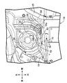
図2および図3に注目して、前記燃料タンク11で発生する蒸発燃料はキャニスタ31で吸着されるものであり、このキャニスタ31は、前記燃料タンク11における前記膨出部11aの下方に配置されるようにして、右側の前記フレーム部材27の前記前部傾斜部27aにステー32を介して支持される。
2 and 3, the evaporated fuel generated in the
前記ステー32は、車両前後方向に延びるステー主部32aと、そのステー主部32aの前後方向中間部から上方に延びる前部支持腕部32bと、前記ステー主部32aの後部から後上がりに傾斜しつつ上方に延びる後部支持腕部32cを一体に有するように形成される。
The
前記前部支持腕部32bの上部には係止孔33が形成されており、右側の前記フレーム部材27の前記前部傾斜部27aに固設される係合爪34が前記係止孔33に係合される。また前記後部支持腕部32cの上端部は、右側の前記フレーム部材27の前記前部傾斜部27aに固設される支持突部35にボルト36で締結される。
A locking
前記キャニスタ31は、当該キャニスタ31の長手方向を車両前後方向に沿わせた姿勢で前記ステー32に支持されるものであり、前記ステー32における前記ステー主部32aの下部には、車両前後方向に間隔をあけて配置される一対の略L字状のフック37a,37aを上部に有する取り付け板37が固着される。一方、前記キャニスタ31には、当該キャニスタ31を囲繞する一対のリング状のラバー38が取り付けられており、それらのラバー38に一体に突設された突部38aに形成されるスリット39に前記フック37aが差し込まれることで、前記キャニスタ31が前記ステー32に支持される。
The
ところで前記内燃機関Eの排気系41の下流端部を構成する排気マフラー42は、前記乗員用シート15よりも下方で左右一対の後輪WR間に配置されており、この排気マフラー42がその後端部に有する排気出口43の下端43aよりも下方に前記キャニスタ31が配置される。すなわち前記乗員用シート15における座部15aの最下部を通る第1の水平面HP1よりも下方に前記排気出口43の下端43aが配置されており、前記排気出口43の下端43aを通る第2の水平面HP2よりも下方に前記キャニスタ31が配置される。
Incidentally, the
前記キャニスタ31がその長手方向両端に有する端壁31a,31bのうち車両前後方向後方に臨む端壁31aには、チャージ用パイプ44およびパージ用パイプ45が突設される。前記チャージ用パイプ44に一端部が連なるチャージ用ホース46は、前記燃料タンク11および前記タンクカバー19間を前記燃料タンク11の中央部まで延出される。また前記燃料タンク11の上面中央部には、前記燃料タンク11内に配設される燃料ポンプ(図示せず)を支持する円形の支持板48が取り付けられており、前記燃料タンク11内の蒸発燃料を導くようにして前記支持板48に設けられて上方に突出する蒸発燃料用接続管49に前記チャージ用ホース46の他端部が接続される。
A
また前記パージ用パイプ45に一端部が連なるパージ用ホース47は、前記車体カバー18内で前記内燃機関E側に延出され、当該パージ用ホース47の他端部は、前記内燃機関Eの吸気系50(図1および図2参照)に接続される。
A
前記キャニスタ31がその長手方向両端に有する端壁31a,31bのうち車両前後方向前方に臨む端壁31bの下部にはドレインパイプ51が突設され、前記吸気系50への前記パージ用ホース47による蒸発燃料のパージ時にキャニスタ31内が負圧となってパージ抵抗が増大するのを防止する外気導入パイプ52が、前記ドレインパイプ51よりも上方に配置されるようにして前記端壁31bに突設される。
A
前記ドレインパイプ51には、密閉キャップ53が着脱可能に取り付けられる。また前記外気導入パイプ52に一端部が連なる外気導入管路である外気導入ホース54は、その他端側開口端部54aが前記燃料タンク11の上部に設けられる給油口28の周囲に配置されるようにして前記燃料タンク11における前記膨出部11aの上面まで延出されており、前記膨出部11aの上面に固着されるホルダ55で前記外気導入ホース54の上流側端部が保持されることにより、前記他端側開口端部54aは、前記給油口28の周囲かつ前記燃料タンク11の前記膨出部11aよりも上方に配置されることになる。
A sealing
図6を併せて参照して、前記タンクカバー19には、前記給油キャップ29を囲む隆起壁部19aが上方に隆起するようにして一体に設けられており、この隆起壁部19aは、車両前後方向前方に向かうにつれて高くなるように形成され、当該隆起壁19aの最前端の上端最高位部19aaは、給油キャップ29よりも上方位置にある。すなわち前記上端上端最高位部19aaを通る第3の水平面HP3よりも下方に前記給油キャップ29の上端が配置される。
Referring also to FIG. 6, the
前記隆起壁部19aには、その隆起壁部19aのうち車幅方向右側すなわち右側のフロントフェンダー21側の一部を切欠くようにして上方に開放する凹部57が形成される。しかも前記凹部57の前端壁57aには円形の透孔58が設けられており、前記外気導入ホース54の他端部は、前記他端側開口部54aをタンクカバー19の外方すなわち車体カバー18の外方に開口するようにして前記透孔58を貫通する。
The raised
図7および図8を併せて参照して、前記車体カバー18における前記タンクカバー19の前記隆起壁部19aには、前記外気導入ホース54の前記他端側開口部54aを覆う目隠し部材59が、前記凹部57を閉じるようにして取り付けられ、この目隠し部材59と前記隆起壁部19aの外面との間には、前記他端側開口部54aに通じる通路60と、その通路60に通じるとともに外部に通じる排出通路61とが形成される。
Referring to FIGS. 7 and 8 together, the raised
前記目隠し部材59は、前記外気導入ホース54の前記他端側開口部54aを覆うとともに前記凹部57の側面との間に前記通路60を形成する目隠し部材主部62と、前記凹部57の底壁57bとの間に前記排出通路61を形成するようにして前記目隠し部材主部62から右側の前記フロントフェンダー21側の側方に張り出す庇部63とを一体に有するようにして合成樹脂により形成される。
The
前記目隠し部材主部62は、前記隆起壁部19aの内周面に接続される第1側壁部62aと、前記隆起壁部19aの外周面に接続される第2側壁部62bと、前記凹部57の前記底壁57bに対向するようにして前記第1側壁部62aおよび前記第2側壁部62b間を結ぶ天井壁部62cとを一体に有するように形成され、前記庇部63は、前記第2側壁部62bの車両前後方向中間部から側方に張り出すように形成される。
The blindfold member
前記目隠し部材主部62における前記天井壁部62cの内面の車両前後方向に間隔をあけた2箇所には、前記凹部57の前記底壁57bに当接する取り付けボス64が一体に突設されており、前記底壁57bに下方から挿通されるねじ部材65を前記取り付けボス64に螺合して締め付けることにより、前記目隠し部材主部62すなわち目隠し部材59が前記タンクカバー19の前記隆起壁部19aに取り付けられる。
Mounting
前記目隠し部材59のうち少なくとも前記庇部63の内面には、少なくとも1つのリブ、この実施の形態では、車両前後方向に沿う前方側の第1のリブ66と、第1のリブ66よりも後方に配置される第2のリブ67とが突設される。
At least one rib on the inner surface of at least the
ところで前記目隠し部材59の内面には、前記第1のリブ66および前記第2のリブ67を含む複数たとえば4つのリブ66,67,68,69が前記外気導入ホース54の前記他端側開口部54aから前記通路60に流入する蒸気をガイドするようにして突設される。
By the way, a plurality of, for example, four
すなわち一対の前記取り付けボス64のうち車両前後方向前方側の取り付けボス64と、前記第1のリブ66との間には第3のリブ68が配置されており、この第3のリブ68は、前記目隠し部材主部62のうち前記庇部63が設けられる第2の側壁部62bとは反対側の側壁部である第1の側壁部62aに連なって第2の側壁部62b側に延びるようにして前記目隠し部材主部62の天井壁部62cに一体に突設される。また第2のリブ67よりも車両前後方向後方には第4のリブ69が配置されており、この第4のリブ69は、一対の前記取り付けボス64のうち車両前後方向後方側の取り付けボス64から第2の側壁部62b側に向けて延びるようにして、前記目隠し部材主部62の天井壁部62cに一体に突設される。
That is, a
また第1〜第4のリブ66〜69のうち少なくとも1つのリブ、この実施の形態では第1および第2のリブ66,67は、前記通路60内を前記排出通路61側に向けて流れる蒸気の流れ方向に対向するように形成され、第1のリブ68は通路60内を前記排出通路61側に向けて流れる蒸気の流れ方向に沿うように配置され、第4のリブ69は第1および第2のリブ66,67と平行に配置される。このような前記通路60内での第1〜第4リブ66〜69の配置によって、前記通路60はラビリンス通路となり、蒸気が前記通路60内をジグザグに流れ方向を変えるようにして流れることになる。
In addition, at least one of the first to
しかも第1〜第4のリブ66〜の69のうち前記通路60内を前記排出通路61側に向けて流れる蒸気の流れ方向に対向するように配置される少なくとも1つのリブすなわち第1のリブ66および第2のリブ67は、前記目隠し部材主部62から前記庇部63まで延びて前記目隠し部材59の内面に突設される。
In addition, among the first to
ところで右側の前記フロントフェンダー21は、そのフロントフェンダー21の一部を構成して前記庇部63の下方に配置される壁部70aを有している。この実施の形態では、図6および図7で明示するように、前記庇部63に対応する部分で車両前後方向に延びて上方に開放する溝70が右側の前記フロントフェンダー21に設けられており、前記壁部70aは前記溝70の底壁部である。しかも前記壁部70aは、前記排出通路61の下方すなわち前記庇部63のの下方に配置される頂部70aaと、その頂部70aaから前下がりに傾斜する前傾斜部70abと、前記頂部70aaから後下がりに傾斜する後傾斜部70acとから成るように形成される。
By the way, the right
次にこの実施の形態の作用について説明すると、内燃機関Eの排気系41の下流端部を構成する排気マフラー42が、乗員用シート15よりも下方に配置され、前記キャニスタ31が、前記排気マフラー42の排気出口43の下端43aよりも下方に配置され、そのキャニスタ31の下部に設けられるドレインパイプ51に密閉キャップ53が着脱可能に取り付けられるので、キャニスタ31が比較的低い位置に配置されるのにもかかわらず、キャニスタ31のドレインパイプ51に密閉キャップ53が取り付けられる簡単な構造で、キャニスタ31内への雨水の浸入を防止することができる。
Next, the operation of this embodiment will be described. An
また前記キャニスタ31の外気導入パイプ52に一端部が連なって前記車体カバー18内を延びる外気導入ホース54の他端側開口部54aが、前記車体カバー18におけるタンクカバー19に設けられる透孔58を貫通して車体カバー18の外部に開口されるので、車体カバー18の外から新鮮な外気を取り入れ易いだけでなく、キャニスタ31から蒸気が出たときもその蒸気を車体カバー18内でなく外部に効果的に排出することができる。
Also, the other end side opening 54a of the outside
また前記外気導入ホース54の前記他端側開口部54aが、前記燃料タンク11における膨出部11aよりも上方に配置されるので、車両走行時にまき上げられる埃などの影響を受け難くして外気を取り入れ易く、しかも外気導入ホース54の管長が比較的長くなるようにして蒸気を外気導入ホース54内に留めておく容量を外気導入ホース54に持たせることができる。
In addition, since the
また前記外気導入ホース54の前記他端側開口部54aを覆う目隠し部材59が、前記車体カバー18の外面との間に、外部に通じる少なくとも1つの排出通路61を形成して前記車体カバー18の前記タンクカバー19に取り付けられるので、外気導入ホース54の開口部が目隠し部材59で覆われることで外観性を高めることが可能であり、蒸気を外部に排出する機能も維持することができる。
A
また前記目隠し部材59が、前記外気導入ホース54の前記他端側開口部54aを覆う目隠し部材主部62と、前記車体カバー18のタンクカバー19の外面との間に前記排出通路61を形成するようにして前記目隠し部材主部62から側方に張り出す庇部63とを一体に有するので、排出通路61が外部から見え難くして外観性を高めた上で排出通路61の流通面積を広く設定することができる。
The
また前記車体カバー18の一部を構成して前輪WFを覆う右側のフロントフェンダー21のうち前記庇部63の下方に配置される壁部70aが、前記排出通路61の下方に配置される頂部70aaと、その頂部70aaから前下がりに傾斜する前傾斜部70abと、前記頂部70aaから後下がりに傾斜する後傾斜部70acとから成るように形成されるので、排出通路61から排出される蒸気が、1箇所に集中することなく、溝70内を前後に分かれて円滑に流れることになる。
In addition, a
また前記目隠し部材59の内面に、前記外気導入ホース54の前記他端側開口部54aから流入する蒸気をガイドする複数たとえば第1〜第4のリブ66,67,68,69が突設され、それらのリブ66〜69の少なくとも1つのリブ、この実施の形態では第1および第2のリブ66,67が、前記排出通路61側に向けての前記蒸気の流れ方向に対向するように形成されるので、目隠し部材59および車体カバー18間で蒸気が流れる際に蒸気の分散を図り、排出通路61からの集中した蒸気の排出を回避することができる。
Further, a plurality of, for example, first to
しかも第1および第2のリブ66,67が、前記目隠し部材主部62から前記庇部63まで延びて前記目隠し部材59の内面に突設されるので、目隠し部材59に突設されるリブ66〜69の個数が増大しないようにしつつ、庇部63を補強するとともに排出通路61からの蒸気の排出方向に指向性を持たせることができる。
Moreover, since the first and
以上、本発明の実施の形態について説明したが、本発明は上記実施の形態に限定されるものではなく、特許請求の範囲に記載された本発明を逸脱することなく種々の設計変更を行うことが可能である。 Although the embodiments of the present invention have been described above, the present invention is not limited to the above-described embodiments, and various design changes can be made without departing from the present invention described in the claims. Is possible.
11・・・燃料タンク
13・・・操向ハンドル
14・・・ヘッドパイプ
18・・・車体カバー
21・・・フロントフェンダー
31・・・キャニスタ
50・・・吸気系
52・・・外気導入パイプ
54・・・外気導入管路である外気導入ホース
54a・・・他端側開口部
58・・・透孔
59・・・目隠し部材
61・・・排出通路
62・・・目隠し部材主部
63・・・庇部
66,67,68,69・・・リブ
70a・・・壁部
70aa・・・頂部
70ab・・・前傾斜部
70ac・・・後傾斜部
E・・・内燃機関
F・・・車体フレーム
WF・・・前輪
DESCRIPTION OF
Claims (8)
Priority Applications (4)
| Application Number | Priority Date | Filing Date | Title |
|---|---|---|---|
| JP2018068094A JP2019178643A (en) | 2018-03-30 | 2018-03-30 | Saddle-riding type vehicle |
| US16/292,837 US11718171B2 (en) | 2018-03-30 | 2019-03-05 | Saddled vehicle |
| EP19164818.7A EP3546330A1 (en) | 2018-03-30 | 2019-03-25 | System to recover vaporized fuel from the tank of a saddled vehicle |
| BR102019005914A BR102019005914A2 (en) | 2018-03-30 | 2019-03-26 | vehicle to ride |
Applications Claiming Priority (1)
| Application Number | Priority Date | Filing Date | Title |
|---|---|---|---|
| JP2018068094A JP2019178643A (en) | 2018-03-30 | 2018-03-30 | Saddle-riding type vehicle |
Publications (1)
| Publication Number | Publication Date |
|---|---|
| JP2019178643A true JP2019178643A (en) | 2019-10-17 |
Family
ID=65911049
Family Applications (1)
| Application Number | Title | Priority Date | Filing Date |
|---|---|---|---|
| JP2018068094A Pending JP2019178643A (en) | 2018-03-30 | 2018-03-30 | Saddle-riding type vehicle |
Country Status (4)
| Country | Link |
|---|---|
| US (1) | US11718171B2 (en) |
| EP (1) | EP3546330A1 (en) |
| JP (1) | JP2019178643A (en) |
| BR (1) | BR102019005914A2 (en) |
Families Citing this family (2)
| Publication number | Priority date | Publication date | Assignee | Title |
|---|---|---|---|---|
| JP2019177768A (en) * | 2018-03-30 | 2019-10-17 | 本田技研工業株式会社 | Saddle-riding type vehicle |
| US11660955B2 (en) * | 2019-03-18 | 2023-05-30 | Kubota Corporation | Fuel tank of work vehicle and work vehicle |
Citations (7)
| Publication number | Priority date | Publication date | Assignee | Title |
|---|---|---|---|---|
| JPS6036566U (en) * | 1983-08-19 | 1985-03-13 | スズキ株式会社 | Motorcycle canister purge device |
| JP2005247151A (en) * | 2004-03-04 | 2005-09-15 | Toyota Motor Corp | Service hole cover structure for fuel tank access |
| JP2010229960A (en) * | 2009-03-30 | 2010-10-14 | Honda Motor Co Ltd | Atmosphere-opening structure for canister of vehicle |
| JP2011074801A (en) * | 2009-09-30 | 2011-04-14 | Honda Motor Co Ltd | Arrangement structure for evaporated fuel treatment device of saddle-type vehicle |
| JP2011214503A (en) * | 2010-03-31 | 2011-10-27 | Honda Motor Co Ltd | Vehicle |
| JP2012007537A (en) * | 2010-06-24 | 2012-01-12 | Suzuki Motor Corp | Canister arrangement structure of motorcycle |
| JP2015174600A (en) * | 2014-03-17 | 2015-10-05 | 本田技研工業株式会社 | Canister arrangement structure of saddle riding type vehicle |
Family Cites Families (17)
| Publication number | Priority date | Publication date | Assignee | Title |
|---|---|---|---|---|
| JPS5531463A (en) | 1978-08-29 | 1980-03-05 | Kuraray Co Ltd | Treatment method and apparatus for excess anesthetic gas |
| US5060620A (en) * | 1988-09-21 | 1991-10-29 | Ford Motor Company | Motor vehicle fuel vapor emission control assembly |
| JP2000168377A (en) * | 1998-12-09 | 2000-06-20 | Suzuki Motor Corp | Canister mounting structure for vehicle |
| JP4542516B2 (en) * | 2006-03-02 | 2010-09-15 | 本田技研工業株式会社 | Canister drainpipe |
| JP5150415B2 (en) * | 2008-08-29 | 2013-02-20 | 本田技研工業株式会社 | Motorcycle canister arrangement structure |
| JP4890532B2 (en) * | 2008-12-26 | 2012-03-07 | 本田技研工業株式会社 | Saddle riding vehicle |
| JP2010203313A (en) * | 2009-03-03 | 2010-09-16 | Honda Motor Co Ltd | Evaporated fuel control device for irregular ground traveling vehicle |
| JP5312140B2 (en) * | 2009-03-27 | 2013-10-09 | 本田技研工業株式会社 | Canister layout structure for saddle-ride type vehicles |
| JP5280273B2 (en) * | 2009-03-30 | 2013-09-04 | 本田技研工業株式会社 | Canister layout for saddle-ride type vehicles |
| JP5634290B2 (en) * | 2011-02-09 | 2014-12-03 | 本田技研工業株式会社 | Saddle riding |
| JP5719739B2 (en) * | 2011-09-27 | 2015-05-20 | 本田技研工業株式会社 | Motorcycle with evaporative fuel treatment device |
| JP6220210B2 (en) | 2013-10-01 | 2017-10-25 | 川崎重工業株式会社 | Motorcycle |
| JP2016008014A (en) | 2014-06-26 | 2016-01-18 | スズキ株式会社 | Fuel evaporation gas recovery apparatus of motor cycle |
| US9809110B2 (en) * | 2014-12-30 | 2017-11-07 | Yamaha Hatsudoki Kabushiki Kaisha | Saddle-riding type vehicle |
| JP6145486B2 (en) | 2015-09-29 | 2017-06-14 | 本田技研工業株式会社 | Saddle riding |
| JP6925801B2 (en) * | 2016-12-27 | 2021-08-25 | 本田技研工業株式会社 | Canister layout structure for saddle-riding vehicles |
| JP2019039311A (en) * | 2017-08-22 | 2019-03-14 | ヤマハ発動機株式会社 | vehicle |
-
2018
- 2018-03-30 JP JP2018068094A patent/JP2019178643A/en active Pending
-
2019
- 2019-03-05 US US16/292,837 patent/US11718171B2/en active Active
- 2019-03-25 EP EP19164818.7A patent/EP3546330A1/en not_active Withdrawn
- 2019-03-26 BR BR102019005914A patent/BR102019005914A2/en not_active IP Right Cessation
Patent Citations (7)
| Publication number | Priority date | Publication date | Assignee | Title |
|---|---|---|---|---|
| JPS6036566U (en) * | 1983-08-19 | 1985-03-13 | スズキ株式会社 | Motorcycle canister purge device |
| JP2005247151A (en) * | 2004-03-04 | 2005-09-15 | Toyota Motor Corp | Service hole cover structure for fuel tank access |
| JP2010229960A (en) * | 2009-03-30 | 2010-10-14 | Honda Motor Co Ltd | Atmosphere-opening structure for canister of vehicle |
| JP2011074801A (en) * | 2009-09-30 | 2011-04-14 | Honda Motor Co Ltd | Arrangement structure for evaporated fuel treatment device of saddle-type vehicle |
| JP2011214503A (en) * | 2010-03-31 | 2011-10-27 | Honda Motor Co Ltd | Vehicle |
| JP2012007537A (en) * | 2010-06-24 | 2012-01-12 | Suzuki Motor Corp | Canister arrangement structure of motorcycle |
| JP2015174600A (en) * | 2014-03-17 | 2015-10-05 | 本田技研工業株式会社 | Canister arrangement structure of saddle riding type vehicle |
Also Published As
| Publication number | Publication date |
|---|---|
| US20190299773A1 (en) | 2019-10-03 |
| US11718171B2 (en) | 2023-08-08 |
| EP3546330A1 (en) | 2019-10-02 |
| BR102019005914A2 (en) | 2020-04-28 |
Similar Documents
| Publication | Publication Date | Title |
|---|---|---|
| JP3165481U (en) | Saddle riding vehicle | |
| US8752661B2 (en) | Saddle seat type vehicle | |
| JP5775560B2 (en) | Saddle riding | |
| US9394860B2 (en) | Motorcycle | |
| US7469671B2 (en) | Air-intake duct and motorcycle comprising the same | |
| US10227957B2 (en) | Air cleaner structure in saddle-ride type vehicle | |
| JPWO2016170689A1 (en) | Cowling structure for saddle-ride type vehicles | |
| JP2018052413A (en) | Air guide structure of saddle-riding type vehicle | |
| JP2019178643A (en) | Saddle-riding type vehicle | |
| JP5420490B2 (en) | Flexible member wiring structure for vehicle | |
| JP6878368B2 (en) | Fuel supply structure for saddle-mounted vehicles | |
| JP2017178101A (en) | Saddle-riding type vehicle | |
| JP6629656B2 (en) | Saddle-type vehicle | |
| JP6776305B2 (en) | Evaporative fuel control device for saddle-mounted vehicles | |
| WO2021172422A1 (en) | Saddle-type vehicle | |
| JP2019177768A (en) | Saddle-riding type vehicle | |
| JP5778947B2 (en) | Exhaust gas purification device for saddle-ride type vehicles | |
| JP6876660B2 (en) | Saddle-type vehicle | |
| JP2021066386A (en) | vehicle | |
| JP2021066294A (en) | Saddle-riding type vehicle | |
| WO2017018292A1 (en) | Saddled vehicle | |
| JP2011043165A (en) | Air intake duct and motorcycle | |
| US11952068B2 (en) | Intake system | |
| JP2022175489A (en) | Saddle riding vehicle | |
| JP2022077585A (en) | Straddle-type vehicle |
Legal Events
| Date | Code | Title | Description |
|---|---|---|---|
| A621 | Written request for application examination |
Free format text: JAPANESE INTERMEDIATE CODE: A621 Effective date: 20181126 |
|
| A977 | Report on retrieval |
Free format text: JAPANESE INTERMEDIATE CODE: A971007 Effective date: 20190808 |
|
| A131 | Notification of reasons for refusal |
Free format text: JAPANESE INTERMEDIATE CODE: A131 Effective date: 20190828 |
|
| A02 | Decision of refusal |
Free format text: JAPANESE INTERMEDIATE CODE: A02 Effective date: 20200304 |