JP2019173801A - Structure of mounting gasket to block, and block - Google Patents
Structure of mounting gasket to block, and block Download PDFInfo
- Publication number
- JP2019173801A JP2019173801A JP2018060253A JP2018060253A JP2019173801A JP 2019173801 A JP2019173801 A JP 2019173801A JP 2018060253 A JP2018060253 A JP 2018060253A JP 2018060253 A JP2018060253 A JP 2018060253A JP 2019173801 A JP2019173801 A JP 2019173801A
- Authority
- JP
- Japan
- Prior art keywords
- wall portion
- block
- cylindrical
- gasket
- cylindrical wall
- Prior art date
- Legal status (The legal status is an assumption and is not a legal conclusion. Google has not performed a legal analysis and makes no representation as to the accuracy of the status listed.)
- Granted
Links
Images


Landscapes
- Gasket Seals (AREA)
Abstract
Description
本発明は、ブロックへのガスケットの装着構造およびブロックに関する。 The present invention relates to a structure for mounting a gasket to a block and the block.
従来、例えば特許文献1に記載のように、ガスケットを樹脂製流路ブロックに装着する構造が知られている。この構造においては、前記樹脂製流路ブロックにおけるポートの開口部周囲に形成された凸部を、前記ガスケットの凹部に嵌入するようになっている。
2. Description of the Related Art Conventionally, a structure in which a gasket is attached to a resin flow channel block as described in
従来のような装着構造に関して、樹脂製流路ブロックは、一般的に、金型を用いた樹脂成形によって製造されることから樹脂成形時に樹脂材料の収縮(いわゆるヒケ)が発生する可能性がある。仮に樹脂材料の収縮が生じると、前記樹脂製流路ブロックと、前記ガスケットとが、円滑でかつシール性良好に嵌め合わされず凹凸形状に仕上がらないことがあった。 Regarding the conventional mounting structure, since the resin flow path block is generally manufactured by resin molding using a mold, there is a possibility that the resin material shrinks (so-called sink) during resin molding. . If contraction of the resin material occurs, the resin flow path block and the gasket may not be smoothly and satisfactorily fitted with each other and may not be finished in an uneven shape.
このような場合でも、前記ガスケットを前記樹脂製流路ブロックに圧入することにより、前記樹脂製流路ブロックと他の部材(特許文献1の場合、バルブボディ)とを接続することはできる。
Even in such a case, the resin channel block and another member (in the case of
しかしながら、前記ガスケットと前記樹脂製流路ブロックとが十分に馴染まない状態で接続された場合には、両者の圧接領域に密着性が劣る個所が生じ、これにより良好なシール性能を得ることができないという懸念があった。 However, when the gasket and the resin flow path block are connected in a state where they are not sufficiently familiar with each other, there is a place where the adhesiveness is inferior in the pressure contact area between them, and it is not possible to obtain good sealing performance. There was a concern.
本発明は、このような問題に鑑みてなされたものであり、樹脂製ブロックに収縮(ヒケ)が発生するのを抑制して、シール性能の向上(良好化)を図ることを目的とする。 The present invention has been made in view of such a problem, and an object of the present invention is to suppress the occurrence of shrinkage (sink) in a resin block and improve (improve) the sealing performance.
本発明の第1の発明は、
流体流路を有する樹脂製のブロックと、前記流体流路の開口部を囲むガスケットとを備え、前記ガスケットが前記ブロックに圧入状態で装着されるブロックへのガスケットの装着構造であって、
前記ブロックは、
前記流体流路の開口部の径方向外側に設けられた筒状壁部と、
前記筒状壁部の径方向外側に隣接して設けられた溝部と、
前記筒状壁部の径方向内側に前記ガスケットの軸方向一側部を圧入する圧入部とを有するものである。
The first invention of the present invention is:
A resin block having a fluid flow path, and a gasket surrounding the opening of the fluid flow path, wherein the gasket is attached to the block in a press-fit state in the block;
The block is
A cylindrical wall provided outside in the radial direction of the opening of the fluid flow path;
A groove provided adjacent to the radially outer side of the cylindrical wall,
And a press-fitting portion that press-fits one axial side portion of the gasket on the radially inner side of the cylindrical wall portion.
この構成によれば、前記圧入部に前記ガスケットの軸方向一側部を圧入して、前記ブロックに前記ガスケットを装着することができる。しかも、前記ブロック、特に前記筒状壁部の周辺を金型を用いた樹脂成形によって製造するとき、前記筒状壁部の径方向内側の前記圧入部および径方向外側の前記溝部の各々に金型を設置して、前記筒状壁部を形成する樹脂材料の冷却速度の向上を図ることができる。したがって、このような製造時に前記筒状壁部を形成する樹脂材料の収縮(いわゆるヒケ)の発生を抑制することができる。結果、前記ブロックの筒状壁部の径方向内側に前記ガスケットの軸方向一側部を圧入したときに、前記ブロックと前記ガスケットとの圧接状態を良好なものにして、シール性能の向上(良好化)を図ることができる。 According to this configuration, the gasket can be attached to the block by press-fitting one side in the axial direction of the gasket into the press-fitting portion. In addition, when the periphery of the block, particularly the cylindrical wall portion, is manufactured by resin molding using a mold, a metal is formed in each of the press-fit portion on the radially inner side of the cylindrical wall portion and the groove portion on the radially outer side. By installing a mold, it is possible to improve the cooling rate of the resin material forming the cylindrical wall portion. Accordingly, it is possible to suppress the occurrence of shrinkage (so-called sink) of the resin material forming the cylindrical wall portion during such manufacture. As a result, when one axial part of the gasket is press-fitted into the radially inner side of the cylindrical wall part of the block, the pressure contact state between the block and the gasket is improved, and the sealing performance is improved (good ).
前記第1の発明の別の態様によれば、
前記筒状壁部は、当該筒状壁部の径方向に弾性変形可能に構成される。
According to another aspect of the first invention,
The said cylindrical wall part is comprised so that elastic deformation can be carried out to the radial direction of the said cylindrical wall part.
この構成によれば、前記ガスケットの軸方向一側部を前記圧入部に圧入するとき、前記ガスケットの軸方向一側部により前記筒状壁部を径方向に弾性変形させることが可能となる。そのため、前記ガスケットの軸方向一側部に対する、前記ブロックの筒状壁部の追従性を高めることができる。したがって、前記ガスケットの軸方向一側部の圧入後には、前記ガスケットの軸方向一側部と前記ブロックの筒状壁部とを略周方向全域において略均一の力で圧接させることが可能となる。よって、前記ブロックに前記ガスケットを装着したときにシール性能を発揮させつつ、そのシール性能を向上させることができる。 According to this configuration, when the one axial side portion of the gasket is press-fitted into the press-fit portion, the cylindrical wall portion can be elastically deformed in the radial direction by the one axial side portion of the gasket. Therefore, the followability of the cylindrical wall portion of the block with respect to the one axial side portion of the gasket can be enhanced. Accordingly, after press-fitting one side of the gasket in the axial direction, the one side of the gasket in the axial direction and the cylindrical wall of the block can be press-contacted with a substantially uniform force in the entire circumferential direction. . Therefore, the sealing performance can be improved while exhibiting the sealing performance when the gasket is attached to the block.
前記第1の発明の別の態様によれば、
前記筒状壁部は、円筒状に形成され、
前記溝部は、前記筒状壁部に沿う円環状に形成される。
According to another aspect of the first invention,
The cylindrical wall portion is formed in a cylindrical shape,
The groove is formed in an annular shape along the cylindrical wall.
この構成によれば、前記ブロックを製造するときに、円環状の筒状壁部を形成する金型が、前記筒状壁部の径方向内側および径方向外側に位置するので、当該金型による前記筒状壁部を形成する樹脂材料の冷却速度を効果的に向上させることができる。 According to this configuration, when the block is manufactured, the mold that forms the annular cylindrical wall portion is located on the radially inner side and the radially outer side of the cylindrical wall portion. The cooling rate of the resin material which forms the said cylindrical wall part can be improved effectively.
前記第1の発明の更なる態様によれば、
前記筒状壁部は、前記溝部と隣接する第1壁部と、前記筒状壁部の径方向外側に設けられた前記ブロックの外部空間と隣接する第2壁部とを前記筒状壁部の周方向に有し、
前記第1壁部の内側端と外側端との最短距離が、2.5mm〜5mmの範囲内にあるとともに、
前記筒状壁部の軸方向一方から見て、前記筒状壁部の軸心と、前記第1壁部の外側端とを最短距離で結ぶ第1直線と、前記筒状壁部の軸心と、前記第1壁部と前記第2壁部との境界に臨み、かつ、前記第1直線に係る前記第1壁部の外側端側に設けられ前記溝部の端部とを最短距離で結ぶ第2直線とがなす角度を角度Θとした場合に、前記第1壁部の内側端と、前記第1壁部の外側端のうち、前記筒状壁部の軸心を通りかつ前記第1直線に対し角度Θ/2をなす第3直線上に配置された外側端との最短距離が2.5mm〜12.5mmの範囲内にある。
According to a further aspect of the first invention,
The cylindrical wall portion includes a first wall portion adjacent to the groove portion, and a second wall portion adjacent to an external space of the block provided on a radially outer side of the cylindrical wall portion. In the circumferential direction of
The shortest distance between the inner end and the outer end of the first wall portion is in the range of 2.5 mm to 5 mm, and
A first straight line connecting the axial center of the cylindrical wall portion and the outer end of the first wall portion with the shortest distance when viewed from one axial direction of the cylindrical wall portion, and the axial center of the cylindrical wall portion And the end of the groove portion that is provided on the outer end side of the first wall portion that faces the boundary between the first wall portion and the second wall portion and that is associated with the first straight line at the shortest distance. When the angle formed by the second straight line is an angle Θ, the first wall portion passes between the inner end of the first wall portion and the outer end of the first wall portion through the axial center of the cylindrical wall portion and the first wall portion. The shortest distance from the outer end disposed on the third straight line that forms an angle Θ / 2 with respect to the straight line is in the range of 2.5 mm to 12.5 mm.
前記第1の発明のまた別の態様によれば、
前記筒状壁部は、前記溝部と隣接する第1壁部と、前記筒状壁部の径方向外側に設けられた前記ブロックの外部空間と隣接する第2壁部とを前記筒状壁部の周方向に有し、
前記第1壁部の内側端と外側端との最短距離が、2.5mm〜5mmの範囲内にあるとともに、
前記第2壁部の内側端と外側端との最短距離が、1.25mm〜12.5mmの範囲内にある。
According to still another aspect of the first invention,
The cylindrical wall portion includes a first wall portion adjacent to the groove portion, and a second wall portion adjacent to an external space of the block provided on a radially outer side of the cylindrical wall portion. In the circumferential direction of
The shortest distance between the inner end and the outer end of the first wall portion is in the range of 2.5 mm to 5 mm, and
The shortest distance between the inner end and the outer end of the second wall portion is in the range of 1.25 mm to 12.5 mm.
本発明の第2の発明は、
樹脂製のブロックであって、
流体流路の開口部の径方向外側に設けられた筒状壁部と、
前記筒状壁部の径方向内側に、前記流体流路の開口部を囲むシール部材の軸方向一側部が圧入される圧入部と、
前記筒状壁部の径方向外側に隣接する溝部と、
を有するものである。
The second invention of the present invention is:
A resin block,
A cylindrical wall provided on the radially outer side of the opening of the fluid flow path;
A press-fit portion into which one side in the axial direction of the seal member surrounding the opening of the fluid flow path is press-fitted on the radially inner side of the cylindrical wall portion;
A groove adjacent to the radially outer side of the cylindrical wall,
It is what has.
前記第2の発明の別の態様によれば、
前記筒状壁部は、円筒状に形成され、
前記溝部は、前記筒状壁部の形状に沿う円弧を含む形状に形成される。
According to another aspect of the second invention,
The cylindrical wall portion is formed in a cylindrical shape,
The groove is formed in a shape including an arc that follows the shape of the cylindrical wall.
本発明によれば、樹脂製ブロックに収縮(ヒケ)が発生するのを抑制してシール性能の向上(良好化)を図ることができる。 According to the present invention, it is possible to improve (improve) the sealing performance by suppressing the occurrence of shrinkage (sink) in the resin block.
本発明に係るブロックへのガスケットの装着構造およびブロックは、例えば、半導体分野、液晶・有機EL分野、医療・医薬分野、または、自動車関連分野においてブロックとガスケットとの装着のために使用され得る。 The gasket mounting structure and the block according to the present invention can be used for mounting the block and the gasket in the semiconductor field, the liquid crystal / organic EL field, the medical / pharmaceutical field, or the automotive field, for example.
なお、本発明に係るブロックへのガスケットの装着構造およびブロックは、上述の分野以外の分野においても用途等に応じて適宜使用可能である。 Note that the gasket mounting structure and the block according to the present invention can be appropriately used in fields other than the above-described fields depending on the application.
まず、本発明の第1実施形態を、図面を参照しつつ説明する。 First, a first embodiment of the present invention will be described with reference to the drawings.
図1は、前記第1実施形態を示す断面図である。図2は、図1の一部拡大図である。 FIG. 1 is a cross-sectional view showing the first embodiment. FIG. 2 is a partially enlarged view of FIG.
図1、図2に示すように、前記ブロックへのガスケットの装着構造は、樹脂製のブロック1と筒状のガスケット3とを備えている。そして、ガスケット3は、ブロック1のガスケット装着部5に圧入状態で装着される。
As shown in FIG. 1 and FIG. 2, the gasket mounting structure to the block includes a
ガスケット3は、ガスケット装着部5に装着された状態において、第1流体流路11の開口部13を囲み、当該第1流体流路11の開口部13の周囲を圧接しつつ嵌合される。
In a state where the
ブロック1は、ガスケット3によりブロック1に隣り合う別のブロック7と接合される。ガスケット3は、別のブロック7にも装着されて、ブロック1と別のブロック7との間に介在した状態でブロック1・7同士をつなぎ合わせる。
The
なお、本実施形態では、本発明に係るブロック1・7へのガスケット3の装着構造を採用している。
In this embodiment, the structure for attaching the
また、本実施形態において、ブロック1は、金型を用いた樹脂成形によって製造される樹脂製ブロックである。そして、別のブロック7も、金型を用いた樹脂成形によって製造される樹脂製ブロックである。
In the present embodiment, the
また、本発明におけるブロックは、例えば、レギュレータ、圧力計、バルブ、流量計、樹脂チューブ等のガスケットが装着される部分を備えるものを指すが、上記に限定するものではない。 Moreover, although the block in this invention points out what has a part with which gaskets, such as a regulator, a pressure gauge, a valve | bulb, a flow meter, a resin tube, are mounted | worn, for example, it is not limited to the above.
詳しくは、ガスケット3は、第1流体流路11と開口部13を介して接続される第2流体流路15を有している。ここで、ガスケット3は、軸方向において対称となる形状に形成されている。
Specifically, the
ガスケット3は、円筒状に形成されている。ガスケット3は、軸方向一方にある軸方向一側部17と、軸方向他方にある軸方向他側部19と、軸方向一側部17と軸方向他側部19との間にある軸方向中途部21とを有している。
The
ガスケット3の軸方向一側部17は、筒状のシール突部23と、筒状の傾斜突起25とを有している。ガスケット3のシール突部23は、第1流体流路11や開口部13と略同軸上にあり、傾斜突起25の径方向外側に位置している。
One
シール突部23は、径方向に略一定の厚さを有する円筒状に形成されている。シール突部23は、ガスケット3の軸方向中途部21からガスケット3の軸方向一方(下方)へ突出している。
The
シール突部23の外周部は、ガスケット3の軸方向一側部17の外周部をなす。そしてこのシール突部23の外周部に、外周側接触面27が設けられている。また、シール突部23の内周部に、内周側接触面29が設けられている。
The outer peripheral portion of the
傾斜突起25は、径方向に所定の厚さを有する円筒状に形成されている。傾斜突起25は、ガスケット3の軸方向中途部21からシール突部23と同一方向(ガスケット3の軸方向一方)へ突出している。
The
傾斜突起25は、シール突部23に対して、ガスケット3の径方向内方に所定間隔を隔てて配置されている。傾斜突起25は、ガスケット3の軸方向中途部21からの突出長がシール突部23の突出長よりも小さく設定されている。
The
傾斜突起25は、その外径がガスケット3の軸方向中途部21から軸方向一方へ向かって漸次縮小するように形成されている。こうして、傾斜突起25の外周部に、軸方向中途部21から軸方向一側部7側に向かうにつれて内周側へ傾斜する外周側接触面31が設けられている。
The
また、本実施形態に係るガスケット3は、熱可塑性の樹脂であるフッ素樹脂(例えば、パーフルオロアルコキシアルカン(PFA)、ポリテトラフルオロエチレン(PTFE))等から構成される。なお、ガスケット3は、使用分野や用途等に応じて、例えばポリプロピレン(PP)、高密度ポリエチレン(HDPE)、低密度ポリエチレン(LDPE)、または、ポリオキシメチレン(POM)、ゴム(エラストマー)等から構成してもよく、材料をフッ素樹脂に限定するものではない。
Further, the
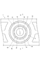
図3は、ブロック1のガスケット装着部5の周辺を軸方向一方から見た図である。図4は、図3のI−I矢視断面図である。図5は、図4の一部拡大図である。
FIG. 3 is a view of the periphery of the
図3、図4、図5に示すように、第1流体流路11の開口部13は、ブロック1の外部に露出する。第1流体流路11は、ガスケット3に形成された第2流体流路15と接続される。
As shown in FIGS. 3, 4, and 5, the
第1流体流路11は、ブロック1の本体部(図示せず)内に設けられている。また、第1流体流路11は、その一端部がガスケット装着部5の軸方向一方の端部(上端部)に至るように、ガスケット装着部5内にも設けられている。
The first
第1流体流路11は、ガスケット装着部5の軸方向(図1で示す上下方向)に延在している。第1流体流路11の一端部に形成された開口部13は、ガスケット装着部5の軸方向一方の端部(上端部)に位置している。
The
また、ブロック1は、200MPa〜3200MPaの弾性率を有する樹脂材料から構成されている。前記樹脂材料の弾性率は、JIS K 7161またはASTM D638に記載の方法にて測定された値である。
The
また、ブロック1は、300MPa〜2600MPaの弾性率を有する樹脂材料から構成されていることが好ましく、310MPa〜600MPaの弾性率を有する樹脂材料から構成されていることがより好ましい。
The
なお、ブロック1は、例えば、PFA、PTFEを含む熱可塑性の樹脂であるフッ素樹脂から構成され得る。また、ブロック1は、使用分野(用途)によっては、PP、HDPE、LDPE、または、POM樹脂等の樹脂材料から構成され得る。
In addition, the
図6は、ブロック1のガスケット装着部5とガスケット3の軸方向一側部17との関係を示す断面図である。
FIG. 6 is a cross-sectional view showing the relationship between the
図6にも示すように、ブロック1は、筒状壁部としての筒状外壁部37と、第1の溝部40と、圧入部としての第2の溝部70とを有している。
As shown in FIG. 6, the
より詳しくは、筒状外壁部37は、第1流体流路11の開口部13の径方向外側である開口部13の周囲に設けられている。本実施形態において、筒状外壁部37は、円筒状に形成されている。
More specifically, the cylindrical
第1の溝部40は、筒状外壁部37の径方向外側に隣接した状態で設けられている。本実施形態において、第1の溝部40は、筒状外壁部37の軸心42周りに同心状に配置されている。
The
筒状外壁部37は、その軸方向一方(上方)に開口するように、ガスケット装着部5に設けられている。筒状外壁部37の径方向内側に、シール突部23を受け入れることができる第2の溝部70が設けられている。
The cylindrical
筒状外壁部37は、ガスケット装着部5の基部44から上方に向かって突出している。そして、筒状外壁部37の突出端面(上端面)46が、第2の溝部70の周囲に配置されている。この突出端面46は平坦状に形成されている。
The cylindrical
筒状外壁部37は、径方向に略一定の厚さを有する円筒状に形成されている。本実施形態において、筒状外壁部37は、シール突部23の外径と略同一の内径を有している。
The cylindrical
筒状外壁部37は、その径方向に弾性変形可能に構成されている。筒状外壁部37は、その内側に圧入されるシール突部23(ガスケット3の軸方向一側部17)により弾性変形させられ得る。
The cylindrical
筒状外壁部37は、その内側にシール突部23が圧入された場合、このシール突部23の形状に応じて当該筒状外壁部37の周方向一部がその他の周方向一部と異なる方向へ独立して移動するように径方向に弾性変形し得る。
When the
たとえば、シール突部23の形状が断面真円筒形状であるのに対し、筒状外壁部37の形状が断面真円筒形状に形成されていない場合には、筒状外壁部37がシール突部23の形状にあわせて前記圧接部分の形状を変えるために弾性変形し得る。具体的には、筒状外壁部37の周方向一部が径方向外側に弾性変形しかつその他の周方向一部が径方向内側に弾性変形し得る。
For example, when the shape of the
図5に示すように筒状外壁部37は、第1厚さT1を有している。筒状外壁部37の第1厚さT1は、筒状外壁部37の径方向長さであって、より詳細にはこの筒状外壁部37を周方向の任意の個所で切断したときの径方向における長さを指す。
As shown in FIG. 5, the cylindrical
筒状外壁部37の第1厚さT1は、1.24mm〜14.6mmの範囲内の値に設定されている。なお、第1厚さT1は、周方向および軸方向のいずれにおいても略一定に設定されている。
The first thickness T1 of the cylindrical
また、筒状外壁部37は、所定の軸方向長さL1さを有している。筒状外壁部37の軸方向長さL1とは、基準面50からの軸方向への突出長である。
Further, the cylindrical
この基準面50は、筒状外壁部37の軸方向と直交する面である。基準面50は、ガスケット装着部5の基部44と筒状外壁部37との境界に存在する。
The
筒状外壁部37の軸方向長さL1は、1.8mm〜12.4mmの範囲内の値に設定されている。ここで、図4に示す筒状外壁部37の内径48は、5mm〜60mmの範囲内の値に設定されている。
The axial length L1 of the cylindrical
第1の溝部40は、筒状外壁部37の径方向外側であって、筒状外壁部37とブロック1の外側部分52との間に設けられている。
The
第1の溝部40は、有底状の溝であり、ブロック1の端面(上端面)でガスケット装着部5の軸方向一方(上方)に開口している。第1の溝部40は、筒状外壁部37の径方向における筒状外壁部37の外周を画定している。
The
第1の溝部40は、筒状外壁部37の形状に沿う円弧を含む形状に形成されている。第1の溝部40は、筒状外壁部37に沿ってその周方向に延びている。本実施形態において、第1の溝部40は、筒状外壁部37に沿う円環状に形成されている。
The
第1の溝部40は、筒状外壁部37の突出端面46側に開口部56を備え、基部44側に底部58を備えている。そして、第1の溝部40は、筒状外壁部37の全周にわたって当該筒状外壁部37と隣り合う。
The
図5に示すように、第1の溝部40は、所定の軸方向深さD1を有している。第1の溝部40の軸方向深さD1は、開口部56の開口端から底部58の底端までの最短距離を指す。
As shown in FIG. 5, the
本実施形態において、第1の溝部40の軸方向深さD1は、筒状外壁部37の軸方向長さL1と略同じに設定されている。
In the present embodiment, the axial depth D1 of the
ここで、第1の溝部40は、開口部56の開口端が筒状外壁部37の突出端面46と同一平面上に位置し、底部58の底端が基準面50と同一平面上に位置するように形成されている。
Here, in the
図5に示すように、第1の溝部40は、第1溝幅W1を有している。第1溝幅W1は、第1の溝部40の深さ方向の略全域にわたって略一定に設定されている。
As shown in FIG. 5, the
また、本実施形態において、ガスケット装着部5は、筒状内壁部39を更に有している。筒状内壁部39は、第1流体流路11の開口部13の径方向外側(開口部13の周囲)に設けられている。
In the present embodiment, the
筒状内壁部39は、筒状外壁部37に対して第1の溝部40と反対側の筒状外壁部37の径方向内側に設けられている。
The cylindrical
筒状内壁部39は、その軸方向の一部がシール突部23と傾斜突起25とにより形成される断面視台形状の空間内に受け入れられる。
The cylindrical
筒状内壁部39は、ガスケット装着部5の基部44から上方に向かって突出している。そして、筒状内壁部39の突出端面(上端面)61が、第1流体流路11の開口部13の周囲に配置されている。この突出端面61は平坦状に形成されている。
The cylindrical
筒状内壁部39は、径方向に所定の厚さを有する円筒状に形成されている。本実施形態において、筒状内壁部39は、シール突部23の内径よりも大きい外径と、傾斜突起25の内径に対して略同一の内径とを有している。
The cylindrical
筒状内壁部39は、筒状外壁部37に対して、ガスケット装着部5の径方向内側に所定間隔を隔てて配置されている。筒状内壁部39は、径方向で見たときに、筒状外壁部37に囲まれた状態で、この筒状外壁部37と略同軸上に配置されている。
The cylindrical
筒状内壁部39には、傾斜状の内周側接触面63が設けられている。内周側接触面63は、筒状内壁部39の突出端部61(上端部)側に位置し、突出端部61の途中から軸方向一方(上方)へ向かって漸次拡大するように形成されている。
The cylindrical
筒状内壁部39の内周側接触面63は、傾斜突起25の外周側接触面31と対向する。内周側接触面63は、外周側接触面31に圧接することができるように、外周側接触面31の傾斜度合いに応じた傾斜度合いを有している。
The inner peripheral
具体的には、第1流体流路11の軸心(筒状内壁部39の軸心)に対する内周側接触面63の傾斜角度と第2流体流路15の軸心(傾斜突起25の軸心)に対する外周側接触面31の傾斜角度との関係が、互いに異なるものとされている。
Specifically, the inclination angle of the inner
本実施形態においては、内周側接触面63の傾斜角度が、外周側接触面31の傾斜角度よりも大きく設定されている。なお、内周側接触面63の傾斜角度と外周側接触面31の傾斜角度とは、互いの傾斜角度が略同じとなるように設定してもよい。
In the present embodiment, the inclination angle of the inner peripheral
そして、筒状外壁部37の径方向内側に、シール突部23(ガスケット3の軸方向一側部17)が圧入される前記圧入部が設けられている。本実施形態において、この圧入部は、筒状外壁部37と筒状内壁部39との間に形成される前述の第2の溝部70からなる。
The press-fitting portion into which the seal projection 23 (one
第2の溝部70は、筒状外壁部37の径方向内側に、第1流体流路11の開口部13を囲むガスケット3(シール部材の一例)の軸方向一側部17が圧入され得るように構成されている。
In the
第2の溝部70は、ガスケット装着部5における有底状の溝であり、筒状外壁部37および筒状内壁部39の各々の軸方向一方(上方)に向かって開口している。
The
第2の溝部70は、筒状外壁部37の径方向における筒状外壁部37の内周を画定している。第2の溝部70は、筒状内壁部39の径方向における筒状内壁部39の外周を画定している。
The
第2の溝部70は、筒状内壁部39の突出端部側(突出端面61の外径側)に開口部73を備え、筒状内壁部39の突出基端部側(基部44側)に底部75を備えている。そして、第2の溝部70に、開口部73を通じてシール突部23が圧入される。
The
ここで、第2の溝部70は、筒状外壁部37および筒状内壁部39に沿う円環状であって、第1の溝部40と同心状に形成されている。図5、図6に示すように、第2の溝部70は、筒状外壁部37と筒状内壁部39との間において、径方向に略一定の第2溝幅W2を有している。
Here, the
第2の溝部70の開口部73は、筒状内壁部39の軸方向一方側に位置する突出端面61側ほど第2溝幅W2が大きく設定されている。これは、筒状内壁部39の外周部が突出端面61付近で傾斜状に形成されることにより実現されている。
The
図6に示すように、第2の溝部70の第2溝幅W2は、シール突部23の厚さ(径方向長さ)T2よりも小さく設定されている。この第2溝幅W2は、第2の溝部70にシール突部23を圧入することができるように適宜設定され得る。
As shown in FIG. 6, the second groove width W <b> 2 of the
第2の溝部70の第2溝幅W2は、筒状外壁部37および筒状内壁部39の各々の軸方向の略全域にわたって略一定に設定されている。ここで、第2の溝部70の第2溝幅W2とは、第2の溝部70の周方向一部における径方向長さを指す。
The second groove width W2 of the
また、シール突部23の厚さT2は、シール突部23の軸方向の略全域にわたって略一定に設定されている。ここで、シール突部23の厚さT2とは、このシール突部23の周方向一部における径方向長さを指す。
In addition, the thickness T2 of the
以上の構成により、ガスケット3の軸方向一側部17(シール突部23)をブロック1側の筒状外壁部37の径方向内側に、すなわちブロック1における筒状外壁部37と筒状内壁部39との間に形成される第2の溝部70に圧入することによって、ガスケット3をブロック1に装着することが可能となる。
With the above configuration, the one axial side portion 17 (seal protrusion 23) of the
そして、ガスケット3装着時には、ガスケット3側のシール突部23の外周側接触面27をブロック1側の筒状外壁部37の内周側接触面81に圧接することが可能となるとともに、シール突部23の内周側接触面29をブロック1側の筒状内壁部39の外周側接触面83に圧接することが可能となる。また、ブロック1と別のブロック7との接合により、ガスケット3側の傾斜突起25の外周側接触面31を筒状内壁部39の内周側接触面63に圧接することも可能となる。
When the
したがって、ブロック1にガスケット3を装着することにより、シール突部23と筒状外壁部37および筒状内壁部39の各々との間にシール力が径方向に作用し、シール突部23と筒状外壁部37および筒状内壁部39との間をシールすることができる。また、傾斜突起25と筒状内壁部39との間にシール力が軸方向に作用し、傾斜突起25と筒状内壁部39との間をシールすることもできる。
Therefore, by attaching the
また、樹脂成形によりブロック1を製造する場合、筒状外壁部37の径方向内側および径方向外側には、第2の溝部70および第1の溝部40を形成する金型が位置することとなる。これにより、成形後の冷却過程において、樹脂材料よりも金型の方が素早く冷却されることから、当該金型の間に挟まれた筒状外壁部37を形成する樹脂材料を他の部分よりも素早く冷却することができ、筒状外壁部37の樹脂を固定することが可能となる。よって、ブロック1の製造時に、筒状外壁部37を形成する樹脂材料の収縮(いわゆるヒケ)の発生を抑制することができる。その結果、第2の溝部70にガスケット3側のシール突部23を圧入したとき、両者の圧接状態を良好なものにして、シール性能の向上(良好化)を図ることができる。
Moreover, when manufacturing the
また、本実施形態においては、筒状外壁部37が、当該筒状外壁部37の径方向に弾性変形可能に構成されているので、筒状外壁部37にシール突部23を圧入することにより筒状外壁部37を径方向に弾性変形させることが可能となる。筒状外壁部37の弾性変形は、第1の溝部40と第2の溝部70とにより許容されるため、シール突部23に対する筒状外壁部37の追従性を高めることができる。したがって、第2の溝部70にシール突部23を圧入した場合、シール突部23と筒状外壁部37とが略周方向全域において略均一の力で圧接する。よって、シール突部23と筒状外壁部37との間のシール性能を安定させることができる。
In the present embodiment, the cylindrical
また、第1の溝部40が、筒状外壁部37に沿う円環状に形成されているので、筒状外壁部37の全周にわたって金型が設置されることになり、筒状外壁部37を形成する樹脂材料の冷却速度をより効果的に向上させることができる。
In addition, since the
次に、本発明の第2実施形態を、図面を参照しつつ説明する。 Next, a second embodiment of the present invention will be described with reference to the drawings.
本実施形態は、樹脂製のブロックにおける筒状壁部(筒状外壁部)と第1の溝部とが第1実施形態と相違する。 This embodiment is different from the first embodiment in the cylindrical wall portion (cylindrical outer wall portion) and the first groove portion in the resin block.
図7は、本実施形態においてブロック101のガスケット装着部103の周辺を軸方向一方から見た図である。図8は、図7の一部拡大図である。
FIG. 7 is a view of the periphery of the
なお、本実施形態に関して、第1実施形態と実質的に同一の構成には同一符号を付してその詳しい説明を省略する。 In addition, regarding this embodiment, the same code | symbol is attached | subjected to the structure substantially the same as 1st Embodiment, and the detailed description is abbreviate | omitted.
図7、図8に示すように、ブロック101は、筒状壁部と、第2の溝部(圧入部)70よりも外周側に位置する第1の溝部105A・105Bを有している。本実施形態において、ブロック101は、前記筒状壁部として、ガスケット装着部103に設けられた筒状外壁部111・112を備えている。
As shown in FIGS. 7 and 8, the
筒状外壁部111・112は、その軸方向が上下方向であって、第1流体流路11と同軸上に配置されている。筒状外壁部111・112の上端面は、平坦状に形成されている。
The cylindrical
筒状外壁部111・112は、第1外壁部111A・111Bと第2外壁部112A・112Bとを有している。筒状外壁部111・112は、第1実施形態における筒状外壁部37の円環状とは異なる形状である。
The cylindrical
詳しくは、筒状外壁部111は、その径方向外側に設けられた第1の溝部105A・105Bと隣接している。本実施形態において、筒状外壁部111は、2つの第1外壁部111A・111Bを有している。
Specifically, the cylindrical
各第1外壁部111A・111Bの内周面は、それぞれ、筒状外壁部111・112を軸方向一方(上方)から見て、第1流体流路11の開口部13に沿う円弧形状を呈するように形成されている。
The inner peripheral surfaces of the first
筒状外壁部112の径方向外側は、ブロック101の外部空間117である。本実施形態において、筒状外壁部112は、2つの第2外壁部112A・112Bを有している。
A radially outer side of the cylindrical
筒状外壁部111・112は、第1外壁部111A・111Bと第2外壁部112A・112Bとが第1流体流路11の開口部13を囲むように交互に設けられている。
The cylindrical
各第2外壁部112A・112Bの内周部は、それぞれ、筒状外壁部111・112を軸方向一方(上方)から見て、第1流体流路11の開口部13に沿う円弧形状を呈する内面と、平面形状を呈する外面とを有している。
The inner peripheral portions of the second
第2外壁部112Aの外面は、外部空間117に臨むブロック101の外面121Aに含まれている
The outer surface of the second
また、第2外壁部112Bの外面は、外部空間117に臨むブロック101の外面121Bに含まれている
The outer surface of the second
第1の溝部105A・105Bは、第1実施形態における第1の溝部40のような円環状と異なる形状に形成されている。
詳しくは、第1の溝部105A・105Bは、その径方向内側に設けられた第1外壁部111A・111Bと隣接している。
Specifically, the
第1の溝部105Aは、軸方向一方(上方)から見て、第1外壁部111Aの径方向外側を形成する円弧形状の弧状部分123Aを有している。弧状部分123Aは、第1の溝部105Aと第1外壁部111Aとを画定している。
105 A of 1st groove parts have the arc-shaped arc-shaped
第1の溝部105Bは、軸方向一方(上方)から見て、第1外壁部111Bの外周側を形成する円弧形状の弧状部分123Bを有している。弧状部分123Bは、第1の溝部105Bと第1外壁部111Bとを画定している。
The
これらの弧状部分123A・123Bは、筒状外壁部111・112の軸心119周りに同心状に配置されている。すなわち、第1の溝部105A・105Bは、筒状外壁部111・112の軸心119周りに同心状に配置されている。
These arc-shaped
図8に示すように、第1外壁部111A・111Bは、第3厚さT3を有している。この第3厚さT3は、筒状外壁部111の周方向(円弧形状を呈するように延びる方向)一部における径方向長さであって、弧状部分123A・123Bに対応する第2の溝部70の内周側接触面81および筒状外壁部111の縁部と、弧状部分123A・123Bとの径方向長さを指す。
As shown in FIG. 8, the first
筒状外壁部111の第3厚さT3は、筒状外壁部111の内側端と外側端との最短距離である。第3厚さT3は、2.5mm〜5.0mmの範囲内の値に設定されている。第3厚さT3は、筒状外壁部111の周方向略全域にわたっている。
The third thickness T3 of the cylindrical
第2外壁部112A・112Bは、第4厚さT4を有している。この第4厚さT4は、筒状外壁部112の周方向(内面が円弧形状を呈するように延びる方向)一部における径方向長さの最小値であって、外面121A、121Bに対応する第2の溝部70の内周側接触面81および筒状外壁部112の縁部と、外面121A、121Bとの径方向長さの最小値である。
The second
換言すれば、筒状外壁部112の第4厚さT4は、筒状外壁部112の内側端と外側端との最短距離である。第4厚さT4は、1.25mm〜12.5mmの範囲内の値に設定されている。第4厚さT4は、2つの第2外壁部112A・112Bが、略同じに構成されている。
In other words, the fourth thickness T4 of the cylindrical
また、第2外壁部112A・112Bは、第4厚さT4と同じ大きさ以上の第5厚さT5を有している。この第5厚さT5は、筒状外壁部112の周方向一部における径方向長さの最小値以上となる値である。
The second
第5厚さT5は、筒状外壁部111・112を軸方向一方(上方)から見て、第1仮想線131と第2仮想線132とのなす角度を角度Θとした場合に、筒状外壁部111・112の軸心119を通りかつ第1仮想線131に対する角度がΘ/2となる第3仮想線133上に位置する筒状外壁部112の外側端と内側端との最短距離である。第5厚さT5は、2.5mm〜12.5mmの範囲内の値に設定されている。
The fifth thickness T5 is cylindrical when the angle formed between the first
ここで、第1仮想線131は、筒状外壁部111・112の軸心119と筒状外壁部112の外側端141とを最短距離で結ぶ直線である。なお、本実施形態に係る外側端141は、外面121A・121B上に位置し、第1仮想線131と外面121A・121Bとが交わる点である。また、第2仮想線132は、筒状外壁部111・112の軸心119と第1の溝部105Aの外側端145側にある端部(図8でいえば第1の溝部105Aの弧状部分123Aの周方向端部145)とを最短距離で結ぶ直線である。
Here, the first
このような構成により、第1実施形態と同様に、ブロック101を金型を用いて樹脂成形により製造する場合、筒状外壁部111・112を形成する樹脂材料の収縮(いわゆるヒケ)の発生を抑制することができる。
With this configuration, as in the first embodiment, when the
すなわち、ブロック101の製造時において、第1の溝部105A・105B、ブロック101の外部空間117、および第2の溝部70を形成する部分にそれぞれ金型が設置されるので、筒状外壁部111・112を形成する樹脂材料の冷却速度の向上を図ることができる。
That is, at the time of manufacturing the
上述の教示を考慮すれば、本発明が多くの変更形態および変形形態をとり得ることは明らかである。したがって、本発明が、添付の特許請求の範囲内において、本明細書に記載された以外の方法で実施され得ることを理解されたい。 Obviously, many modifications and variations of the present invention are possible in light of the above teachings. It is therefore to be understood that within the scope of the appended claims, the invention may be practiced otherwise than as described herein.
1 ブロック
3 ガスケット
11 第1流体流路
13 開口部
23 シール突部
37 筒状外壁部(筒状壁部)
40 第1の溝部(溝部)
42 筒状外壁部の軸心(筒状壁部の軸心)
70 第2の溝部(圧入部)
101 ブロック
105A・105B 第1の溝部(溝部)
111・112 筒状外壁部(筒状壁部)
119 筒状外壁部の軸心(筒状壁部の軸心)
DESCRIPTION OF
40 First groove (groove)
42 Axis of cylindrical outer wall (axial center of cylindrical wall)
70 Second groove (press-fit part)
101
111/112 Tubular outer wall (tubular wall)
119 Axis of cylindrical outer wall (axial center of cylindrical wall)
Claims (7)
前記ブロックは、
前記流体流路の開口部の径方向外側に設けられた筒状壁部と、
前記筒状壁部の径方向外側に隣接して設けられた溝部と、
前記筒状壁部の径方向内側に前記ガスケットの軸方向一側部を圧入する圧入部とを有する、ブロックへのガスケットの装着構造。 A resin block having a fluid flow path, and a gasket surrounding the opening of the fluid flow path, wherein the gasket is attached to the block in a press-fit state in the block;
The block is
A cylindrical wall provided outside in the radial direction of the opening of the fluid flow path;
A groove provided adjacent to the radially outer side of the cylindrical wall,
A structure for mounting a gasket on a block, having a press-fitting portion for press-fitting one axial side portion of the gasket on the radially inner side of the cylindrical wall portion.
前記溝部は、前記筒状壁部に沿う円環状に形成される、請求項1または請求項2に記載のブロックへのガスケットの装着構造。 The cylindrical wall portion is formed in a cylindrical shape,
The structure for mounting a gasket on a block according to claim 1 or 2, wherein the groove is formed in an annular shape along the cylindrical wall.
前記第1壁部の内側端と外側端との最短距離が、2.5mm〜5mmの範囲内にあるとともに、
前記筒状壁部の軸方向一方から見て、前記筒状壁部の軸心と、前記第1壁部の外側端とを最短距離で結ぶ第1直線と、前記筒状壁部の軸心と、前記第1壁部と前記第2壁部との境界に臨み、かつ、前記第1直線に係る前記第1壁部の外側端側に設けられ前記溝部の端部とを最短距離で結ぶ第2直線とがなす角度を角度Θとした場合に、前記第1壁部の内側端と、前記第1壁部の外側端のうち、前記筒状壁部の軸心を通りかつ前記第1直線に対し角度Θ/2をなす第3直線上に配置された外側端との最短距離が2.5mm〜12.5mmの範囲内にある、請求項1または請求項2に記載のブロックへのガスケットの装着構造。 The cylindrical wall portion includes a first wall portion adjacent to the groove portion, and a second wall portion adjacent to an external space of the block provided on a radially outer side of the cylindrical wall portion. In the circumferential direction of
The shortest distance between the inner end and the outer end of the first wall portion is in the range of 2.5 mm to 5 mm, and
A first straight line connecting the axial center of the cylindrical wall portion and the outer end of the first wall portion with the shortest distance when viewed from one axial direction of the cylindrical wall portion, and the axial center of the cylindrical wall portion And the end of the groove portion that is provided on the outer end side of the first wall portion that faces the boundary between the first wall portion and the second wall portion and that is associated with the first straight line at the shortest distance. When the angle formed by the second straight line is an angle Θ, the first wall portion passes between the inner end of the first wall portion and the outer end of the first wall portion through the axial center of the cylindrical wall portion and the first end. 3. The block according to claim 1, wherein a shortest distance from an outer end disposed on a third straight line that forms an angle Θ / 2 with respect to the straight line is in a range of 2.5 mm to 12.5 mm. Gasket mounting structure.
前記第1壁部の内側端と外側端との最短距離が、2.5mm〜5mmの範囲内にあるとともに、
前記第2壁部の内側端と外側端との最短距離が、1.25mm〜12.5mmの範囲内にある、請求項1または請求項2に記載のブロックへのガスケットの装着構造。 The cylindrical wall portion includes a first wall portion adjacent to the groove portion, and a second wall portion adjacent to an external space of the block provided on a radially outer side of the cylindrical wall portion. In the circumferential direction of
The shortest distance between the inner end and the outer end of the first wall portion is in the range of 2.5 mm to 5 mm, and
The structure for mounting a gasket on a block according to claim 1 or 2, wherein a shortest distance between an inner end and an outer end of the second wall portion is in a range of 1.25 mm to 12.5 mm.
流体流路の開口部の径方向外側に設けられた筒状壁部と、
前記筒状壁部の径方向内側に、前記流体流路の開口部を囲むシール部材の軸方向一側部が圧入される圧入部と、
前記筒状壁部の径方向外側に隣接する溝部と、
を有するブロック。 A resin block,
A cylindrical wall provided on the radially outer side of the opening of the fluid flow path;
A press-fit portion into which one side in the axial direction of the seal member surrounding the opening of the fluid flow path is press-fitted on the radially inner side of the cylindrical wall portion;
A groove adjacent to the radially outer side of the cylindrical wall,
Block with.
前記溝部は、前記筒状壁部の形状に沿う円弧を含む形状に形成される、請求項6に記載のブロック。 The cylindrical wall portion is formed in a cylindrical shape,
The said groove part is a block of Claim 6 formed in the shape containing the circular arc which follows the shape of the said cylindrical wall part.
Priority Applications (1)
| Application Number | Priority Date | Filing Date | Title |
|---|---|---|---|
| JP2018060253A JP6883001B2 (en) | 2018-03-27 | 2018-03-27 | Gasket mounting structure on the block and the block |
Applications Claiming Priority (1)
| Application Number | Priority Date | Filing Date | Title |
|---|---|---|---|
| JP2018060253A JP6883001B2 (en) | 2018-03-27 | 2018-03-27 | Gasket mounting structure on the block and the block |
Publications (2)
| Publication Number | Publication Date |
|---|---|
| JP2019173801A true JP2019173801A (en) | 2019-10-10 |
| JP6883001B2 JP6883001B2 (en) | 2021-06-02 |
Family
ID=68170059
Family Applications (1)
| Application Number | Title | Priority Date | Filing Date |
|---|---|---|---|
| JP2018060253A Active JP6883001B2 (en) | 2018-03-27 | 2018-03-27 | Gasket mounting structure on the block and the block |
Country Status (1)
| Country | Link |
|---|---|
| JP (1) | JP6883001B2 (en) |
Citations (3)
| Publication number | Priority date | Publication date | Assignee | Title |
|---|---|---|---|---|
| JP2005140230A (en) * | 2003-11-06 | 2005-06-02 | Ckd Corp | Connection part sealing structure for fluid apparatus |
| JP2007147009A (en) * | 2005-11-29 | 2007-06-14 | Nippon Pillar Packing Co Ltd | Fluid gasket |
| JP2008240916A (en) * | 2007-03-27 | 2008-10-09 | Ckd Corp | Sealing structure of connecting parts |
-
2018
- 2018-03-27 JP JP2018060253A patent/JP6883001B2/en active Active
Patent Citations (3)
| Publication number | Priority date | Publication date | Assignee | Title |
|---|---|---|---|---|
| JP2005140230A (en) * | 2003-11-06 | 2005-06-02 | Ckd Corp | Connection part sealing structure for fluid apparatus |
| JP2007147009A (en) * | 2005-11-29 | 2007-06-14 | Nippon Pillar Packing Co Ltd | Fluid gasket |
| JP2008240916A (en) * | 2007-03-27 | 2008-10-09 | Ckd Corp | Sealing structure of connecting parts |
Also Published As
| Publication number | Publication date |
|---|---|
| JP6883001B2 (en) | 2021-06-02 |
Similar Documents
| Publication | Publication Date | Title |
|---|---|---|
| JP6905948B2 (en) | Gasket mounting structure on the block and gasket | |
| WO2019163690A1 (en) | Structure for mounting gasket to block | |
| KR102647284B1 (en) | Gasket mounting structure | |
| US6565096B2 (en) | Lip type seal | |
| JP2016148413A (en) | Resin-made pipe joint structure | |
| JP2019210984A (en) | Gasket mounting structure and gasket | |
| JP2019210986A (en) | Gasket mounting structure and gasket | |
| JP2019173801A (en) | Structure of mounting gasket to block, and block | |
| JP6949756B2 (en) | Gasket mounting structure on the block | |
| WO2018083955A1 (en) | Seal structure and manufacturing method thereof | |
| JP6944893B2 (en) | Gasket mounting structure on the block | |
| JP2019143784A (en) | Attachment structure of gasket to block | |
| JP2007139179A (en) | Piston seal | |
| WO2021070482A1 (en) | Sealing device | |
| JP7265861B2 (en) | pipe joint | |
| JP2017219169A (en) | Mounting structure of sealing device | |
| JP2013072472A (en) | Sealing device | |
| JP2020041547A (en) | Seal ring | |
| JP2017082877A (en) | Seal ring | |
| JP2018105466A (en) | Pipe joint and pipeline connection structure | |
| JP2018146092A (en) | Fluid damper device, equipment with damper and manufacturing method of fluid damper device | |
| JP2017122474A (en) | Sealing structure | |
| JP2015163810A (en) | Cylinder device and seal member |
Legal Events
| Date | Code | Title | Description |
|---|---|---|---|
| A621 | Written request for application examination |
Free format text: JAPANESE INTERMEDIATE CODE: A621 Effective date: 20200909 |
|
| A871 | Explanation of circumstances concerning accelerated examination |
Free format text: JAPANESE INTERMEDIATE CODE: A871 Effective date: 20200909 |
|
| A975 | Report on accelerated examination |
Free format text: JAPANESE INTERMEDIATE CODE: A971005 Effective date: 20201117 |
|
| A131 | Notification of reasons for refusal |
Free format text: JAPANESE INTERMEDIATE CODE: A131 Effective date: 20201124 |
|
| A521 | Request for written amendment filed |
Free format text: JAPANESE INTERMEDIATE CODE: A523 Effective date: 20210115 |
|
| A131 | Notification of reasons for refusal |
Free format text: JAPANESE INTERMEDIATE CODE: A131 Effective date: 20210310 |
|
| A521 | Request for written amendment filed |
Free format text: JAPANESE INTERMEDIATE CODE: A523 Effective date: 20210420 |
|
| TRDD | Decision of grant or rejection written | ||
| A01 | Written decision to grant a patent or to grant a registration (utility model) |
Free format text: JAPANESE INTERMEDIATE CODE: A01 Effective date: 20210506 |
|
| A61 | First payment of annual fees (during grant procedure) |
Free format text: JAPANESE INTERMEDIATE CODE: A61 Effective date: 20210507 |
|
| R150 | Certificate of patent or registration of utility model |
Ref document number: 6883001 Country of ref document: JP Free format text: JAPANESE INTERMEDIATE CODE: R150 |