JP2019170096A - Electric automobile - Google Patents
Electric automobile Download PDFInfo
- Publication number
- JP2019170096A JP2019170096A JP2018056892A JP2018056892A JP2019170096A JP 2019170096 A JP2019170096 A JP 2019170096A JP 2018056892 A JP2018056892 A JP 2018056892A JP 2018056892 A JP2018056892 A JP 2018056892A JP 2019170096 A JP2019170096 A JP 2019170096A
- Authority
- JP
- Japan
- Prior art keywords
- battery
- sub
- main battery
- state
- converter
- Prior art date
- Legal status (The legal status is an assumption and is not a legal conclusion. Google has not performed a legal analysis and makes no representation as to the accuracy of the status listed.)
- Pending
Links
Images


Classifications
-
- B—PERFORMING OPERATIONS; TRANSPORTING
- B60—VEHICLES IN GENERAL
- B60L—PROPULSION OF ELECTRICALLY-PROPELLED VEHICLES; SUPPLYING ELECTRIC POWER FOR AUXILIARY EQUIPMENT OF ELECTRICALLY-PROPELLED VEHICLES; ELECTRODYNAMIC BRAKE SYSTEMS FOR VEHICLES IN GENERAL; MAGNETIC SUSPENSION OR LEVITATION FOR VEHICLES; MONITORING OPERATING VARIABLES OF ELECTRICALLY-PROPELLED VEHICLES; ELECTRIC SAFETY DEVICES FOR ELECTRICALLY-PROPELLED VEHICLES
- B60L8/00—Electric propulsion with power supply from forces of nature, e.g. sun or wind
- B60L8/003—Converting light into electric energy, e.g. by using photo-voltaic systems
-
- H—ELECTRICITY
- H02—GENERATION; CONVERSION OR DISTRIBUTION OF ELECTRIC POWER
- H02J—CIRCUIT ARRANGEMENTS OR SYSTEMS FOR SUPPLYING OR DISTRIBUTING ELECTRIC POWER; SYSTEMS FOR STORING ELECTRIC ENERGY
- H02J7/00—Circuit arrangements for charging or depolarising batteries or for supplying loads from batteries
- H02J7/34—Parallel operation in networks using both storage and other dc sources, e.g. providing buffering
- H02J7/35—Parallel operation in networks using both storage and other dc sources, e.g. providing buffering with light sensitive cells
-
- Y—GENERAL TAGGING OF NEW TECHNOLOGICAL DEVELOPMENTS; GENERAL TAGGING OF CROSS-SECTIONAL TECHNOLOGIES SPANNING OVER SEVERAL SECTIONS OF THE IPC; TECHNICAL SUBJECTS COVERED BY FORMER USPC CROSS-REFERENCE ART COLLECTIONS [XRACs] AND DIGESTS
- Y02—TECHNOLOGIES OR APPLICATIONS FOR MITIGATION OR ADAPTATION AGAINST CLIMATE CHANGE
- Y02T—CLIMATE CHANGE MITIGATION TECHNOLOGIES RELATED TO TRANSPORTATION
- Y02T10/00—Road transport of goods or passengers
- Y02T10/60—Other road transportation technologies with climate change mitigation effect
- Y02T10/70—Energy storage systems for electromobility, e.g. batteries
-
- Y—GENERAL TAGGING OF NEW TECHNOLOGICAL DEVELOPMENTS; GENERAL TAGGING OF CROSS-SECTIONAL TECHNOLOGIES SPANNING OVER SEVERAL SECTIONS OF THE IPC; TECHNICAL SUBJECTS COVERED BY FORMER USPC CROSS-REFERENCE ART COLLECTIONS [XRACs] AND DIGESTS
- Y02—TECHNOLOGIES OR APPLICATIONS FOR MITIGATION OR ADAPTATION AGAINST CLIMATE CHANGE
- Y02T—CLIMATE CHANGE MITIGATION TECHNOLOGIES RELATED TO TRANSPORTATION
- Y02T10/00—Road transport of goods or passengers
- Y02T10/60—Other road transportation technologies with climate change mitigation effect
- Y02T10/7072—Electromobility specific charging systems or methods for batteries, ultracapacitors, supercapacitors or double-layer capacitors
-
- Y—GENERAL TAGGING OF NEW TECHNOLOGICAL DEVELOPMENTS; GENERAL TAGGING OF CROSS-SECTIONAL TECHNOLOGIES SPANNING OVER SEVERAL SECTIONS OF THE IPC; TECHNICAL SUBJECTS COVERED BY FORMER USPC CROSS-REFERENCE ART COLLECTIONS [XRACs] AND DIGESTS
- Y02—TECHNOLOGIES OR APPLICATIONS FOR MITIGATION OR ADAPTATION AGAINST CLIMATE CHANGE
- Y02T—CLIMATE CHANGE MITIGATION TECHNOLOGIES RELATED TO TRANSPORTATION
- Y02T10/00—Road transport of goods or passengers
- Y02T10/60—Other road transportation technologies with climate change mitigation effect
- Y02T10/72—Electric energy management in electromobility
-
- Y—GENERAL TAGGING OF NEW TECHNOLOGICAL DEVELOPMENTS; GENERAL TAGGING OF CROSS-SECTIONAL TECHNOLOGIES SPANNING OVER SEVERAL SECTIONS OF THE IPC; TECHNICAL SUBJECTS COVERED BY FORMER USPC CROSS-REFERENCE ART COLLECTIONS [XRACs] AND DIGESTS
- Y02—TECHNOLOGIES OR APPLICATIONS FOR MITIGATION OR ADAPTATION AGAINST CLIMATE CHANGE
- Y02T—CLIMATE CHANGE MITIGATION TECHNOLOGIES RELATED TO TRANSPORTATION
- Y02T10/00—Road transport of goods or passengers
- Y02T10/80—Technologies aiming to reduce greenhouse gasses emissions common to all road transportation technologies
- Y02T10/92—Energy efficient charging or discharging systems for batteries, ultracapacitors, supercapacitors or double-layer capacitors specially adapted for vehicles
-
- Y—GENERAL TAGGING OF NEW TECHNOLOGICAL DEVELOPMENTS; GENERAL TAGGING OF CROSS-SECTIONAL TECHNOLOGIES SPANNING OVER SEVERAL SECTIONS OF THE IPC; TECHNICAL SUBJECTS COVERED BY FORMER USPC CROSS-REFERENCE ART COLLECTIONS [XRACs] AND DIGESTS
- Y02—TECHNOLOGIES OR APPLICATIONS FOR MITIGATION OR ADAPTATION AGAINST CLIMATE CHANGE
- Y02T—CLIMATE CHANGE MITIGATION TECHNOLOGIES RELATED TO TRANSPORTATION
- Y02T90/00—Enabling technologies or technologies with a potential or indirect contribution to GHG emissions mitigation
- Y02T90/10—Technologies relating to charging of electric vehicles
- Y02T90/14—Plug-in electric vehicles
Abstract
Description
本発明は、太陽電池と複数のバッテリとを備えた電気自動車に関する。 The present invention relates to an electric vehicle including a solar cell and a plurality of batteries.
太陽電池と、電圧が200−400Vの高電圧バッテリと、電圧が12Vである低電圧バッテリと、太陽電池で発電された電力を各バッテリに適した電圧に変換して各バッテリに供給するDC/DCコンバータを備えた電気自動車が公知である(例えば、特許文献1)。 A solar cell, a high-voltage battery having a voltage of 200-400 V, a low-voltage battery having a voltage of 12 V, and a DC / DC that converts the electric power generated by the solar cell into a voltage suitable for each battery and supplies the voltage to each battery An electric vehicle including a DC converter is known (for example, Patent Document 1).
DC/DCコンバータは出力電圧及び出力電流に応じて効率が変化するため、1つのコンバータで異なる出力電圧を出力する場合、効率が低下するという問題がある。その結果、太陽電池からの電力による各バッテリの充電効率が低下する。一方、高電圧バッテリの公称電圧に適したDC/DCコンバータと、低電圧バッテリの公称電圧に適したDC/DCコンバータとを設けた場合、回路が複雑になると共に大型化し、またコストが増大するという問題がある。 Since the efficiency of the DC / DC converter changes according to the output voltage and the output current, there is a problem that the efficiency is lowered when different output voltages are output by one converter. As a result, the charging efficiency of each battery by the power from the solar battery is reduced. On the other hand, when a DC / DC converter suitable for the nominal voltage of a high-voltage battery and a DC / DC converter suitable for the nominal voltage of a low-voltage battery are provided, the circuit becomes complicated, the size increases, and the cost increases. There is a problem.
本発明は、以上の背景を鑑み、電気自動車において、コンバータの数を増やすことなく、太陽電池からの電力によるバッテリの充電効率を向上させることを課題とする。 In view of the above background, an object of the present invention is to improve the charging efficiency of a battery using electric power from a solar cell without increasing the number of converters in an electric vehicle.
上記課題を解決するために本発明のある態様は、メインバッテリ(3)と、前記メインバッテリと等しい公称電圧を有する少なくとも1つのサブバッテリ(4)と、太陽電池(6)と、前記太陽電池で発電された電力を昇圧して前記メインバッテリ及び前記サブバッテリに供給する共通の昇圧DC/DCコンバータ(8)とを有することを特徴とする電気自動車を提供する。 In order to solve the above problems, an aspect of the present invention includes a main battery (3), at least one sub-battery (4) having a nominal voltage equal to the main battery, a solar cell (6), and the solar cell. There is provided an electric vehicle comprising a common step-up DC / DC converter (8) for boosting the electric power generated in step (b) and supplying the boosted power to the main battery and the sub-battery.
この態様によれば、単一の昇圧DC/DCコンバータによって、太陽電池で発電された電力をメインバッテリ及びサブバッテリの充電に適した電圧に効率良く昇圧することができる。これにより、メインバッテリ及びサブバッテリの充電効率が向上する。 According to this aspect, the single boost DC / DC converter can efficiently boost the power generated by the solar battery to a voltage suitable for charging the main battery and the sub battery. Thereby, the charging efficiency of the main battery and the sub battery is improved.
上記の態様において、前記メインバッテリがインバータ(13)を介してモータジェネレータ(2)に接続され、前記サブバッテリが前記メインバッテリに接続され、前記モータジェネレータの力行及び回生時に、前記サブバッテリと前記メインバッテリとが切断されるとよい。 In the above aspect, the main battery is connected to the motor generator (2) via the inverter (13), the sub battery is connected to the main battery, and when the motor generator is in power running and regeneration, the sub battery and the The main battery may be disconnected.
この態様によれば、モータジェネレータの力行時にはメインバッテリからモータジェネレータに電力を供給し、モータジェネレータの回生時にはモータジェネレータからメインバッテリに電力が供給される。サブバッテリにはモータジェネレータの回生電力が供給されないため、サブバッテリの電圧及び電流の監視を簡素化することができ、コストを低減することができる。 According to this aspect, power is supplied from the main battery to the motor generator during power running of the motor generator, and power is supplied from the motor generator to the main battery during regeneration of the motor generator. Since the regenerative power of the motor generator is not supplied to the sub battery, monitoring of the voltage and current of the sub battery can be simplified, and the cost can be reduced.
上記の態様において、前記昇圧DC/DCコンバータの出力端を前記メインバッテリ又は前記サブバッテリの1つに接続した状態と、いずれにも接続しない状態とで切り替える第1切替スイッチ(9)と、車両の状態に応じて前記第1切替スイッチを切り替える制御装置(16)とを有するとよい。 In the above aspect, the first changeover switch (9) for switching between a state in which the output terminal of the step-up DC / DC converter is connected to one of the main battery or the sub battery and a state in which neither is connected to the main battery or the sub battery, It is good to have a control device (16) which changes the 1st changeover switch according to the state.
この態様によれば、第1切替スイッチによって太陽電池で発電された電力をいずれのバッテリに供給するか選択することができる。 According to this aspect, it is possible to select to which battery the electric power generated by the solar cell by the first changeover switch is supplied.
上記の態様において、前記制御装置は、前記車両が駐車状態であり、かつ前記メインバッテリの充電指標値が所定の判定値以下のときに、前記第1切替スイッチを前記昇圧DC/DCコンバータの出力端と前記メインバッテリとが接続した状態に制御するとよい。ここで、充電指標値は、バッテリのSOC(States Of Charge)や電圧等のSOCに相関するパラメータである。 In the above aspect, the control device causes the first changeover switch to output the boost DC / DC converter when the vehicle is in a parked state and a charge index value of the main battery is equal to or less than a predetermined determination value. Control may be made so that the end and the main battery are connected. Here, the charging index value is a parameter correlated with SOC such as battery SOC (States Of Charge) or voltage.
この態様によれば、モータジェネレータが停止した状態、すなわちモータジェネレータとメインバッテリとの間で電力の授受がない状態において、太陽電池からの電力によってメインバッテリを充電することができる。 According to this aspect, the main battery can be charged with the electric power from the solar cell in a state where the motor generator is stopped, that is, in a state where no electric power is transferred between the motor generator and the main battery.
上記の態様において、前記制御装置は、前記車両が走行状態であり、かつ前記サブバッテリの内で最も低い充電指標値が所定の判定値以下のときに、前記第1切替スイッチを前記昇圧DC/DCコンバータの出力端と充電指標値が最も低い前記サブバッテリとが接続した状態に制御するとよい。 In the above aspect, the control device sets the first changeover switch to the step-up DC / DC when the vehicle is in a running state and the lowest charge index value of the sub-batteries is equal to or less than a predetermined determination value. Control may be performed so that the output terminal of the DC converter is connected to the sub battery having the lowest charge index value.
この態様によれば、モータジェネレータが駆動した状態、すなわちモータジェネレータとメインバッテリとの間で電力の授受がある状態では、太陽電池からの電力によってサブバッテリを充電することができる。 According to this aspect, in a state where the motor generator is driven, that is, in a state where electric power is transferred between the motor generator and the main battery, the sub-battery can be charged with electric power from the solar cell.
上記の態様において、前記メインバッテリと前記サブバッテリの1つとが接続した状態と、前記メインバッテリと前記サブバッテリの全てとが切断した状態とで切り替える第2切替スイッチを有し、前記制御装置は、前記車両が停車状態であり、かつ前記メインバッテリの充電指標値が所定の判定値以下のときに、前記第2切替スイッチを前記メインバッテリが前記サブバッテリの1つに接続した状態に制御するとよい。 In the above aspect, the control device includes a second changeover switch that switches between a state where the main battery and one of the sub batteries are connected and a state where all of the main battery and the sub battery are disconnected. When the vehicle is stopped and the charge index value of the main battery is equal to or less than a predetermined determination value, the second changeover switch is controlled so that the main battery is connected to one of the sub-batteries. Good.
この態様によれば、モータジェネレータが停止した状態、すなわちモータジェネレータとメインバッテリとの間で電力の授受がない状態で、サブバッテリからの電力によってメインバッテリを充電することができる。 According to this aspect, the main battery can be charged with the electric power from the sub-battery in a state where the motor generator is stopped, that is, in a state where no electric power is transferred between the motor generator and the main battery.
上記の態様において、前記制御装置は、前記車両が停車状態であり、前記サブバッテリの内で最も低い充電指標値が所定の判定値以下のときに、前記第1切替スイッチを前記昇圧DC/DCコンバータの出力端と充電指標値が最も低い前記サブバッテリとが接続した状態に制御するとよい。 In the above aspect, the control device sets the first changeover switch to the boost DC / DC when the vehicle is in a stopped state and the lowest charge index value of the sub-batteries is equal to or lower than a predetermined determination value. Control may be performed so that the output terminal of the converter and the sub-battery with the lowest charging index value are connected.
この態様によれば、太陽電池からの電力によってサブバッテリを充電することができる。太陽電池から充電指標値が最小のサブバッテリへの電力供給は、充電指標値が最大のサブバッテリからメインバッテリへの電力供給と同時に行うことができる。 According to this aspect, the sub-battery can be charged with the electric power from the solar cell. The power supply from the solar battery to the sub battery with the smallest charge index value can be performed simultaneously with the power supply from the sub battery with the largest charge index value to the main battery.
上記の態様において、前記昇圧DC/DCコンバータは単方向非絶縁コンバータであるとよい。 In the above aspect, the step-up DC / DC converter may be a unidirectional non-insulated converter.
この態様によれば、昇圧DC/DCコンバータを簡素化及び小型化することができ、コストを低減することができる。 According to this aspect, the step-up DC / DC converter can be simplified and downsized, and the cost can be reduced.
上記の態様において、前記メインバッテリは、車体に固定された車載バッテリであり、前記サブバッテリは、前記車体に着脱可能に設けられた可搬バッテリであるとよい。 In the above aspect, the main battery may be an in-vehicle battery fixed to a vehicle body, and the sub battery may be a portable battery that is detachably attached to the vehicle body.
この態様によれば、サブバッテリを車両から取り外して他の用途に使用することができる。 According to this aspect, the sub battery can be removed from the vehicle and used for other purposes.
上記の態様において、前記メインバッテリ及び前記サブバッテリの公称電圧が48Vであるとよい。 In the above aspect, the nominal voltage of the main battery and the sub battery may be 48V.
この態様によれば、公称電圧を12Vにした場合に比べて出力を高くできると共に、使用する電流を下げることができるため、効率を向上させることができる。 According to this aspect, the output can be increased as compared with the case where the nominal voltage is set to 12 V, and the current to be used can be reduced, so that the efficiency can be improved.
以上の構成によれば、電気自動車において、コンバータの数を増やすことなく、太陽電池からの電力によるバッテリの充電効率を向上させることができる。 According to the above configuration, in the electric vehicle, the charging efficiency of the battery by the electric power from the solar cell can be improved without increasing the number of converters.
以下、本発明に係る電気自動車の実施形態について説明する。 Hereinafter, an embodiment of an electric vehicle according to the present invention will be described.
図1に示すように、電気自動車1は、走行用のモータジェネレータ2と、モータジェネレータ2に電力を供給するためのメインバッテリ3と、メインバッテリ3に電力を供給する少なくとも1つのサブバッテリ4を有する。メインバッテリ3は車体に固定された、充電可能な車載バッテリである。サブバッテリ4は、車体に対して着脱可能に設けられた、充電可能な可搬バッテリである。サブバッテリ4の数は任意であり、本実施形態では2つである。
As shown in FIG. 1, an
メインバッテリ3とサブバッテリ4のそれぞれとは、互いに等しい公称電圧(定格出力)を有する。ここで、公称電圧(定格出力)とは電池を通常使用した場合に、両端子間で得られる電圧の目安となる値である。各電池の公称電圧が互いに等しいとは、各電池の公称電圧の差が公称電圧に対して3%以内であることをいう。メインバッテリ3及びサブバッテリ4の公称電圧は、例えば48Vである。メインバッテリ3及びサブバッテリ4は、例えばリチウムイオン二次電池のようにSOCと電圧が比例するバッテリである。メインバッテリ3及びサブバッテリ4は、例えば3.0V〜4.0Vの電圧範囲を持つセルが12セル直列に接続されることによって、公称電圧48Vとなっている。電気自動車1は、メインバッテリ3及びサブバッテリ4と商用電源とを接続する充電回路(不図示)を有してもよい。
Each of the
電気自動車1は、メインバッテリ3及びサブバッテリ4に電力を供給する太陽電池6を有する。太陽電池6は、ソーラーパネルであり、例えば車体のルーフの上面に設けられている。太陽電池6は、MPPT回路7、昇圧DC/DCコンバータ8、及び第1切替スイッチ9を介してメインバッテリ3及び各サブバッテリ4に接続されている。
The
MPPT回路7は、スイッチングレギュレータ(DC/DCコンバータ)と、太陽電池6の出力電圧を検出する電圧センサと、太陽電池6の出力電流を検出する電流センサと、スイッチングレギュレータを制御する制御装置とを含む。制御装置16は、MPPT(Maximum Power Point Tracking:最大電力点追従)制御に基づいて、太陽電池6の出力が最大となるように、DC/DCコンバータを制御する。MPPT制御は、公知の山登り法に基づくとよい。
The
昇圧DC/DCコンバータ8は、MPPT回路7を介して太陽電池6から供給される電力を昇圧してメインバッテリ3及び前記サブバッテリ4に供給する。昇圧DC/DCコンバータ8は、単方向非絶縁コンバータであることが好ましい。本実施形態では、昇圧DC/DCコンバータ8は、スイッチング素子、チョークコイル、キャパシタを有する、単方向非絶縁のスイッチングレギュレータである。昇圧DC/DCコンバータ8は、入力端においてMPPTに接続され、出力端において第1切替スイッチ9に接続されている。昇圧DC/DCコンバータ8は、更に出力電圧を検出する電圧センサと、スイッチング素子を制御する制御装置とを有する。制御装置は、昇圧DC/DCコンバータ8の出力電圧と予め設定された目標電圧とに基づいてフィードバック制御を行い、出力電圧を目標電圧に維持する。目標電圧は、メインバッテリ3及びサブバッテリ4の公称電圧よりも高い所定の値に設定されていることが好ましい。昇圧DC/DCコンバータ8は、MPPT回路7から出力された電力をメインバッテリ3及び各サブバッテリ4に適した電圧に変換する共通(単一)の昇圧DC/DCコンバータである。
The step-up DC /
第1切替スイッチ9は、昇圧DC/DCコンバータ8の出力端をメインバッテリ3又はサブバッテリ4の1つに接続した状態と、いずれにも接続しない状態とで切り替える。本実施形態では、第1切替スイッチ9は、昇圧DC/DCコンバータ8の出力端をメインバッテリ3に接続した状態、サブバッテリ4の一つに接続した状態、サブバッテリ4の他の1つに接続した状態、いずれにも接続しない切断状態の4つの状態を選択することができる。
The
サブバッテリ4は、第2切替スイッチ11を介してメインバッテリ3に接続されている。第2切替スイッチ11は、メインバッテリ3をサブバッテリ4の1つに接続した状態と、メインバッテリ3をいずれのサブバッテリ4にも接続しない状態とで切り替える。本実施形態では、第2切替スイッチ11は、メインバッテリ3をサブバッテリ4の1つに接続した状態、サブバッテリ4を他の1つに接続した状態、いずれにも接続しない切断状態の3つの状態を選択することができる。
The sub battery 4 is connected to the
また、モータジェネレータ2は、インバータ13及び降圧DC/DCコンバータ14を介して補機バッテリ15に接続され、メインバッテリ3は降圧DC/DCコンバータ14を介して補機バッテリ15に接続されている。補機バッテリ15は、補機に電力を供給するためのバッテリであり、公称電圧は例えば12Vである。
第1切替スイッチ9及び第2切替スイッチ11は、電気信号によって駆動制御されるリレーであり、制御装置16によって制御される。制御装置16は、マイクロコンピュータやROM、RAM、周辺回路、入出力インタフェース、ドライバ等から構成された電子制御装置(ECU)である。制御装置16には、車両のイグニッションスイッチ17、シフト位置を検出するシフト位置センサ18、車速を検出する車速センサ19、メインバッテリ3を流れる電流値を検出する第1電流センサ21、各サブバッテリ4を流れる電流を検出する第2電流センサ22からの信号が入力される。
The
制御装置16は、メインバッテリ3及びサブバッテリ4の充電指標値を算出する。充電指標値は、バッテリのSOCや電圧等のSOCに相関するパラメータであってよい。本実施形態では、充電指標値としてSOCを使用する。制御装置16は、メインバッテリ3を流れる電流値を積算することによってメインバッテリ3のSOCを算出し、各サブバッテリ4を流れる電流値をそれぞれ積算することによって各サブバッテリのSOCを算出する。SOC(充電状態値)は、バッテリの満充電容量に対する充電容量の割合(充電状態)を示す値であり、0−100%の値である。なお、他の実施形態では、制御装置16は他の公知の手法に基づいて各バッテリの3、4のSOCを取得してもよい。
The
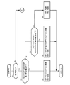
制御装置16は、図2及び図3に示す制御フローを所定の間隔で繰り返し実行し、各センサからの信号に基づいて取得される車両の状態に応じて第1切替スイッチ9及び第2切替スイッチ11を制御する。最初に、制御装置16は、各センサからの信号に基づいて車両が駐車状態であるか否かを判定する(S1)。本実施形態では、制御装置16は、シフト位置センサ18からの信号に基づいて、シフト位置が駐車位置(パーキング:P)であるときに車両が駐車状態であると判定し、シフト位置が他の位置にあるときに車両が駐車状態ではないと判定する。ここでの駐車状態は、イグニッションスイッチ17がオフの状態も含む。
The
他の実施形態では、制御装置16は、イグニッションスイッチ17からの信号に基づいて、イグニッションがオフであるときに車両が駐車状態であると判定してもよい。また、他の実施形態では、制御装置16は、車速センサ19からの信号に基づいて、車速が0を継続した期間が所定の判定値以上になったときに車両が駐車状態であると判定してもよい。
In another embodiment, the
ステップS1での判定結果がYesのとき、制御装置16は、メインバッテリ3のSOCが所定の第1判定値以下であるかを判定する(S2)。第1判定値はメインバッテリ3のSOCの適正範囲の上限値に対応した値に設定されている。ステップS2の判定結果がYesのとき、制御装置16は第1切替スイッチ9を、昇圧DC/DCコンバータ8とメインバッテリ3とを接続する状態に制御し、第2切替スイッチ11を切断状態に制御する(S3)。ステップS3を実行することによって、太陽電池6で発電された電力は、メインバッテリ3に供給され、メインバッテリ3が充電される。制御装置16は、ステップS3の処理を実行した後にリターンに進み、制御フローを繰り返す。
When the determination result in step S1 is Yes, the
ステップS2の判定結果がNoのとき、制御装置16は、複数のサブバッテリ4の内で最小のSOCが所定の第2判定値以下であるかを判定する(S4)。第2判定値はサブバッテリ4のSOCの適正範囲の上限値に対応した値に設定されている。複数のサブバッテリ4の内で最小のSOCが第2判定値以下のとき(S4の判定結果がYes)、制御装置16は、第1切替スイッチ9を、昇圧DC/DCコンバータ8とSOCが最小のサブバッテリ4とを接続する状態に制御し、第2切替スイッチ11を切断状態に制御する(S5)。ステップS5を実行することによって、太陽電池6で発電された電力はサブバッテリ4の内でSOCが最小のサブバッテリ4に供給され、SOCが最小のサブバッテリ4が充電される。制御装置16は、ステップS5の処理を実行した後にリターンに進み、制御フローを繰り返す。
When the determination result of step S2 is No, the
ステップS4の判定結果がNoのとき、制御装置16は、第1切替スイッチ9を切断状態に制御し、第2切替スイッチ11を切断状態に制御する(S6)。ステップS6の処理を実行することによって、メインバッテリ3及びサブバッテリ4のいずれも充電されない。制御装置16は、ステップS6の処理を実行した後にリターンに進み、制御フローを繰り返す。
When the determination result of step S4 is No, the
ステップS1での判定結果がNoのとき(駐車状態ではない)、制御装置16は、各センサからの信号に基づいて車両が停車状態であるか否かを判定する(S7)。本実施形態では、制御装置16は、シフト位置センサ18からの信号と車速センサ19からの信号に基づいて、シフト位置が前進又は後進位置であり、かつ車速が0であるときに車両が停車状態であると判定し、他の場合に車両が停車状態ではないと判定する。停車状態は、駐車状態と区別して認識される状態であり、アクセルペダルの踏み込みによって即時に発進できる状態をいう。シフト位置の前進位置は、例えばドライブ(D)、1速、2速を含み、後進位置はリバース(R)を含む。駐車状態及び停車状態のいずれでもない状態を、車両の走行状態とする。車両は、走行状態にあるとき、前進方向又は後進方向に0より大きい車速を有する。
When the determination result in step S1 is No (not in a parking state), the
他の実施形態では、制御装置16は、イグニッションスイッチ17からの信号及び車速センサ19からの信号に基づいて、イグニッションがオンであり、かつ車速が0のときに車両が停車状態であると判定してもよい。また、制御装置16は、イグニッションがオン、シフト位置が前進位置又は後進位置、車速が0の全ての条件が成立するときに車両が停車状態であると判定し、他の場合に車両が停車状態ではないと判定してもよい。
In another embodiment, the
ステップS7での判定結果がYesのとき、制御装置16は、メインバッテリ3のSOCが第1判定値以下であるかを判定する(S8)。ステップS8の判定結果がYesのとき、制御装置16は、複数のサブバッテリ4の内で最大のSOCが所定の第3判定値以上であるかを判定する(S9)。第3判定値はサブバッテリ4のSOCの適正範囲の下限値に対応した値に設定されている。
When the determination result in step S7 is Yes, the
ステップS9の判定結果がYesのとき、制御装置16は、複数のサブバッテリ4の内で最小のSOCが第2判定値以下であるかを判定する(S10)。ステップS10の判定結果がYesのとき、制御装置16は、第1切替スイッチ9を、昇圧DC/DCコンバータ8と複数のサブバッテリ4の内でSOCが最小のサブバッテリ4とを接続する状態に制御し、第2切替スイッチ11を複数のサブバッテリ4の内でSOCが最大のサブバッテリ4とメインバッテリ3とを接続した状態に制御する(S11)。ステップS11の処理を実行することによって、複数のサブバッテリ4の内でSOCが最大のサブバッテリ4からメインバッテリ3に電力が供給され、メインバッテリ3が充電されると同時に、太陽電池6から複数のサブバッテリ4の内でSOCが最小のサブバッテリ4に電力が供給され、SOCが最小のサブバッテリ4が充電される。
When the determination result of step S9 is Yes, the
ステップS10の判定結果がNoのとき、制御装置16は、第1切替スイッチ9を切断状態に制御し、第2切替スイッチ11を複数のサブバッテリ4の内でSOCが最大のサブバッテリ4とメインバッテリ3とを接続した状態に制御する(S12)。ステップS12の処理を実行することによって、複数のサブバッテリ4の内でSOCが最大のサブバッテリ4からメインバッテリ3に電力が供給され、メインバッテリ3が充電される。制御装置16は、ステップS11、S12の処理を実行した後にリターンに進み、制御フローを繰り返す。
When the determination result in step S10 is No, the
ステップS7での判定結果がNoであるとき、又はステップS8での判定結果がNoであるとき、制御装置16は、複数のサブバッテリ4の内で最小のSOCが第2判定値以下であるかを判定する(S13)。
When the determination result in step S7 is No, or when the determination result in step S8 is No, the
ステップS13での判定結果がYesのとき、又はステップS9の判定結果がNoのとき、制御装置16は、第1切替スイッチ9を、昇圧DC/DCコンバータ8とSOCが最小のサブバッテリ4とを接続する状態に制御し、第2切替スイッチ11を切断状態に制御する(S14)。ステップS14を実行することによって、太陽電池6からサブバッテリ4の内でSOCが最小のサブバッテリ4に電力が供給され、SOCが最小のサブバッテリ4が充電される。
When the determination result in step S13 is Yes, or when the determination result in step S9 is No, the
ステップS13の判定結果がNoのとき、制御装置16は、第1切替スイッチ9を切断状態に制御し、第2切替スイッチ11を切断状態に制御する(S15)。ステップS6の処理を実行することによって、メインバッテリ3及びサブバッテリ4のいずれも充電されない。制御装置16は、ステップS14、S15の処理を実行した後にリターンに進み、制御フローを繰り返す。
When the determination result of step S13 is No, the
以上の制御フローによれば、メインバッテリ3は、車両の駐車状態において太陽電池6から電力の供給を受けることができ、車両の停車時においてサブバッテリ4の1つから電力の供給を受けることができる。車両の駐車状態及び停車時は、メインバッテリ3とモータジェネレータ2との間で電力の授受がないため、メインバッテリ3の充電制御が容易になる。
According to the control flow described above, the
サブバッテリ4はモータジェネレータ2に接続されていないため、モータジェネレータ2の駆動状態、すなわち車両の走行状態においても充電が可能である。そのため、車両が走行状態にあるときには太陽電池6からサブバッテリ4に電力を供給し、駐車状態にあるときには太陽電池6からメインバッテリ3に電力を供給することによって、メインバッテリ3及びサブバッテリ4を効率良く充電することができる。
Since the sub-battery 4 is not connected to the
本実施形態に係る電気自動車1は、メインバッテリ3及び各サブバッテリ4の公称電圧が互いに等しいため、単一の昇圧DC/DCコンバータ8によって太陽電池6で発電された電力をメインバッテリ3及びサブバッテリ4の充電に適した電圧に昇圧することができる。昇圧DC/DCコンバータ8は、メインバッテリ3及びサブバッテリ4の公称電圧に適した構成を採用することができるため、変換効率を向上させることができる。その結果、メインバッテリ3及びサブバッテリ4の充電効率が向上させることができる。
In the
昇圧DC/DCコンバータ8に単方向非絶縁コンバータを適用することによって、装置を簡素化及び小型化することができ、またコストを低減することができる。
By applying a unidirectional non-insulating converter to the step-up DC /
サブバッテリ4は、車両から取り外して使用することができるため、野外用電源や非常用電源として使用することができる。また、屋外に電気自動車1の充電設備がない場合にもサブバッテリ4を車両から取り外し、室内に持ち込んで充電することができる。
Since the sub-battery 4 can be used by being removed from the vehicle, it can be used as an outdoor power source or an emergency power source. Further, even when there is no charging facility for the
以上で具体的実施形態の説明を終えるが、本発明は上記実施形態に限定されることなく幅広く変形実施することができる。例えば、電気自動車1は、モータジェネレータ2に加えて、駆動原としての内燃機関を有していてもよい。
Although the description of the specific embodiment is finished as described above, the present invention is not limited to the above embodiment and can be widely modified. For example, the
1 :電気自動車
2 :モータジェネレータ
3 :メインバッテリ
4 :サブバッテリ
6 :太陽電池
7 :MPPT回路
8 :昇圧DC/DCコンバータ
9 :第1切替スイッチ
11 :第2切替スイッチ
16 :制御装置
17 :イグニッションスイッチ
18 :シフト位置センサ
19 :車速センサ
21 :第1電流センサ
22 :第2電流センサ
DESCRIPTION OF SYMBOLS 1: Electric vehicle 2: Motor generator 3: Main battery 4: Sub battery 6: Solar cell 7: MPPT circuit 8: Boost DC / DC converter 9: 1st changeover switch 11: 2nd changeover switch 16: Controller 17: Ignition Switch 18: Shift position sensor 19: Vehicle speed sensor 21: First current sensor 22: Second current sensor
Claims (10)
前記メインバッテリと等しい公称電圧を有する少なくとも1つのサブバッテリと、
太陽電池と、
前記太陽電池で発電された電力を昇圧して前記メインバッテリ及び前記サブバッテリに供給する共通の昇圧DC/DCコンバータとを有することを特徴とする電気自動車。 A main battery,
At least one sub-battery having a nominal voltage equal to the main battery;
Solar cells,
An electric vehicle comprising: a common step-up DC / DC converter that boosts power generated by the solar cell and supplies the boosted power to the main battery and the sub-battery.
前記サブバッテリが前記メインバッテリに接続され、
前記モータジェネレータの力行及び回生時に、前記サブバッテリと前記メインバッテリとが切断されることを特徴とする請求項1に記載の電気自動車。 The main battery is connected to a motor generator via an inverter;
The sub-battery is connected to the main battery;
The electric vehicle according to claim 1, wherein the sub-battery and the main battery are disconnected during power running and regeneration of the motor generator.
車両の状態に応じて前記第1切替スイッチを切り替える制御装置とを有することを特徴とする請求項1又は請求項2に記載の電気自動車。 A first changeover switch for switching between a state in which the output terminal of the step-up DC / DC converter is connected to one of the main battery or the sub-battery and a state in which neither is connected to the main battery or the sub-battery;
The electric vehicle according to claim 1, further comprising a control device that switches the first changeover switch according to a state of the vehicle.
前記制御装置は、前記車両が停車状態であり、かつ前記メインバッテリの充電指標値が所定の判定値以下のときに、前記第2切替スイッチを前記メインバッテリが前記サブバッテリの1つに接続した状態に制御することを特徴とする請求項3〜請求項5のいずれか1つの項に記載の電気自動車。 A second changeover switch that switches between a state in which the main battery and one of the sub batteries are connected and a state in which the main battery and all of the sub batteries are disconnected;
The control device connects the second changeover switch to one of the sub-batteries when the vehicle is stopped and the charge index value of the main battery is equal to or less than a predetermined determination value. It controls to a state, The electric vehicle as described in any one of Claims 3-5 characterized by the above-mentioned.
前記制御装置は、前記車両が停車状態であり、前記サブバッテリの内で最も低い充電指標値が所定の判定値以下のときに、前記第1切替スイッチを前記昇圧DC/DCコンバータの出力端と充電指標値が最も低い前記サブバッテリとが接続した状態に制御することを特徴とする請求項6に記載の電気自動車。 A plurality of the sub-batteries are provided,
The control device sets the first changeover switch to the output terminal of the step-up DC / DC converter when the vehicle is stopped and the lowest charging index value of the sub-batteries is equal to or less than a predetermined determination value. The electric vehicle according to claim 6, wherein the electric vehicle is controlled to be connected to the sub battery having the lowest charging index value.
前記サブバッテリは、前記車体に着脱可能に設けられた可搬バッテリであることを特徴とする請求項1〜請求項8のいずれか1つの項に記載の電気自動車。 The main battery is an in-vehicle battery fixed to a vehicle body,
The electric vehicle according to any one of claims 1 to 8, wherein the sub-battery is a portable battery that is detachably attached to the vehicle body.
Priority Applications (2)
| Application Number | Priority Date | Filing Date | Title |
|---|---|---|---|
| JP2018056892A JP2019170096A (en) | 2018-03-23 | 2018-03-23 | Electric automobile |
| CN201910206471.0A CN110293849A (en) | 2018-03-23 | 2019-03-19 | Electric car |
Applications Claiming Priority (1)
| Application Number | Priority Date | Filing Date | Title |
|---|---|---|---|
| JP2018056892A JP2019170096A (en) | 2018-03-23 | 2018-03-23 | Electric automobile |
Publications (1)
| Publication Number | Publication Date |
|---|---|
| JP2019170096A true JP2019170096A (en) | 2019-10-03 |
Family
ID=68026404
Family Applications (1)
| Application Number | Title | Priority Date | Filing Date |
|---|---|---|---|
| JP2018056892A Pending JP2019170096A (en) | 2018-03-23 | 2018-03-23 | Electric automobile |
Country Status (2)
| Country | Link |
|---|---|
| JP (1) | JP2019170096A (en) |
| CN (1) | CN110293849A (en) |
Cited By (1)
| Publication number | Priority date | Publication date | Assignee | Title |
|---|---|---|---|---|
| CN114274900A (en) * | 2021-11-30 | 2022-04-05 | 合众新能源汽车有限公司 | Dual-power redundancy backup architecture and control method |
Families Citing this family (2)
| Publication number | Priority date | Publication date | Assignee | Title |
|---|---|---|---|---|
| KR20210059092A (en) * | 2019-11-14 | 2021-05-25 | 현대자동차주식회사 | Power supplier, Vehicle having the power supplier and method for controlling the vehicle |
| WO2022017210A1 (en) * | 2020-07-19 | 2022-01-27 | 林浩生 | Electric vehicle charging system capable of generating power by solar energy |
Family Cites Families (5)
| Publication number | Priority date | Publication date | Assignee | Title |
|---|---|---|---|---|
| WO2010131352A1 (en) * | 2009-05-14 | 2010-11-18 | トヨタ自動車株式会社 | Electric car and method for controlling the same |
| US8736101B2 (en) * | 2010-02-09 | 2014-05-27 | Toyota Jidosha Kabushiki Kaisha | Power source system for electric powered vehicle and control method thereof |
| JP5520629B2 (en) * | 2010-02-12 | 2014-06-11 | 富士重工業株式会社 | Vehicle power supply |
| JP2016067131A (en) * | 2014-09-25 | 2016-04-28 | 本田技研工業株式会社 | Charger system |
| JP6586290B2 (en) * | 2015-04-23 | 2019-10-02 | 本田技研工業株式会社 | Power storage control device, transport equipment, and power storage control method |
-
2018
- 2018-03-23 JP JP2018056892A patent/JP2019170096A/en active Pending
-
2019
- 2019-03-19 CN CN201910206471.0A patent/CN110293849A/en active Pending
Cited By (1)
| Publication number | Priority date | Publication date | Assignee | Title |
|---|---|---|---|---|
| CN114274900A (en) * | 2021-11-30 | 2022-04-05 | 合众新能源汽车有限公司 | Dual-power redundancy backup architecture and control method |
Also Published As
| Publication number | Publication date |
|---|---|
| CN110293849A (en) | 2019-10-01 |
Similar Documents
| Publication | Publication Date | Title |
|---|---|---|
| US8222866B2 (en) | Electrically-powered vehicle | |
| JP5267740B1 (en) | Vehicle power system | |
| CN101484332B (en) | Power controller of vehicle | |
| JP6621264B2 (en) | Control method for fuel cell system and fuel cell vehicle | |
| JP5382238B2 (en) | Hybrid vehicle and control method thereof | |
| JP5317806B2 (en) | Power system | |
| KR101592742B1 (en) | Charging control method for eco-friendly vehicle | |
| JP6866825B2 (en) | Vehicle power supply system | |
| JP4807590B2 (en) | Control device for hybrid vehicle | |
| CN101746247A (en) | Auxiliary drive apparatus and method of manufacturing same | |
| CN105103404A (en) | Control device, power supply control device, charge control method, charge control device, and power supply device for vehicle | |
| JP2014131404A (en) | Vehicle charger | |
| JP2019170096A (en) | Electric automobile | |
| CN113572212A (en) | Charging system and charging method using motor driving system | |
| WO2019244606A1 (en) | Vehicle power supply device | |
| JP2016181943A (en) | Power supply system | |
| CN101663804B (en) | Electrical apparatus and method of controlling the same | |
| JP5609226B2 (en) | Power supply | |
| JP2012050281A (en) | Battery charging system of electric vehicle | |
| CN109747437B (en) | Power supply system for vehicle | |
| KR102336964B1 (en) | Battery for hybrid vehicle and control method thereof | |
| JP4556989B2 (en) | Fuel cell power supply | |
| JP2019134636A (en) | Charging system and charging method | |
| KR102286833B1 (en) | PHEV charging system and its control method | |
| KR20190118085A (en) | Power converting system for vehicle |