JP2019155689A - Joined component and method for producing the same - Google Patents
Joined component and method for producing the same Download PDFInfo
- Publication number
- JP2019155689A JP2019155689A JP2018044139A JP2018044139A JP2019155689A JP 2019155689 A JP2019155689 A JP 2019155689A JP 2018044139 A JP2018044139 A JP 2018044139A JP 2018044139 A JP2018044139 A JP 2018044139A JP 2019155689 A JP2019155689 A JP 2019155689A
- Authority
- JP
- Japan
- Prior art keywords
- joining
- adhesive
- resin
- joined
- joint
- Prior art date
- Legal status (The legal status is an assumption and is not a legal conclusion. Google has not performed a legal analysis and makes no representation as to the accuracy of the status listed.)
- Granted
Links
- 238000004519 manufacturing process Methods 0.000 title claims description 24
- 229920005989 resin Polymers 0.000 claims abstract description 131
- 239000011347 resin Substances 0.000 claims abstract description 131
- 238000005304 joining Methods 0.000 claims abstract description 96
- 230000003014 reinforcing effect Effects 0.000 claims abstract description 75
- 239000000853 adhesive Substances 0.000 claims abstract description 67
- 230000001070 adhesive effect Effects 0.000 claims abstract description 65
- 230000009477 glass transition Effects 0.000 claims abstract description 29
- 239000004823 Reactive adhesive Substances 0.000 claims description 37
- 229920002430 Fibre-reinforced plastic Polymers 0.000 claims description 9
- 239000011151 fibre-reinforced plastic Substances 0.000 claims description 9
- 238000005452 bending Methods 0.000 abstract description 28
- 230000006866 deterioration Effects 0.000 abstract description 11
- 238000006757 chemical reactions by type Methods 0.000 abstract 1
- 239000000463 material Substances 0.000 description 70
- 238000000034 method Methods 0.000 description 50
- 238000001723 curing Methods 0.000 description 44
- 239000002985 plastic film Substances 0.000 description 43
- 229920006255 plastic film Polymers 0.000 description 43
- 239000010408 film Substances 0.000 description 34
- FGBJXOREULPLGL-UHFFFAOYSA-N ethyl cyanoacrylate Chemical compound CCOC(=O)C(=C)C#N FGBJXOREULPLGL-UHFFFAOYSA-N 0.000 description 17
- 239000004830 Super Glue Substances 0.000 description 16
- 230000002787 reinforcement Effects 0.000 description 16
- 238000012360 testing method Methods 0.000 description 13
- NIXOWILDQLNWCW-UHFFFAOYSA-N Acrylic acid Chemical compound OC(=O)C=C NIXOWILDQLNWCW-UHFFFAOYSA-N 0.000 description 9
- 229920000122 acrylonitrile butadiene styrene Polymers 0.000 description 9
- 229920006332 epoxy adhesive Polymers 0.000 description 9
- 229920005992 thermoplastic resin Polymers 0.000 description 9
- XECAHXYUAAWDEL-UHFFFAOYSA-N acrylonitrile butadiene styrene Chemical compound C=CC=C.C=CC#N.C=CC1=CC=CC=C1 XECAHXYUAAWDEL-UHFFFAOYSA-N 0.000 description 8
- 239000004676 acrylonitrile butadiene styrene Substances 0.000 description 8
- 239000000835 fiber Substances 0.000 description 8
- 238000013001 point bending Methods 0.000 description 8
- 239000000843 powder Substances 0.000 description 8
- 230000007246 mechanism Effects 0.000 description 7
- 238000005245 sintering Methods 0.000 description 6
- 238000000151 deposition Methods 0.000 description 5
- 238000013461 design Methods 0.000 description 5
- 238000010586 diagram Methods 0.000 description 5
- 238000001125 extrusion Methods 0.000 description 5
- 238000010438 heat treatment Methods 0.000 description 5
- 229920001187 thermosetting polymer Polymers 0.000 description 5
- 239000004697 Polyetherimide Substances 0.000 description 4
- 238000003475 lamination Methods 0.000 description 4
- 229920001601 polyetherimide Polymers 0.000 description 4
- 229920001651 Cyanoacrylate Polymers 0.000 description 3
- 239000004593 Epoxy Substances 0.000 description 3
- MWCLLHOVUTZFKS-UHFFFAOYSA-N Methyl cyanoacrylate Chemical compound COC(=O)C(=C)C#N MWCLLHOVUTZFKS-UHFFFAOYSA-N 0.000 description 3
- 238000011156 evaluation Methods 0.000 description 3
- 229920000747 poly(lactic acid) Polymers 0.000 description 3
- -1 polybutylene terephthalate Polymers 0.000 description 3
- 239000004626 polylactic acid Substances 0.000 description 3
- 230000002040 relaxant effect Effects 0.000 description 3
- 238000007493 shaping process Methods 0.000 description 3
- 239000007787 solid Substances 0.000 description 3
- 239000010409 thin film Substances 0.000 description 3
- NIXOWILDQLNWCW-UHFFFAOYSA-M Acrylate Chemical compound [O-]C(=O)C=C NIXOWILDQLNWCW-UHFFFAOYSA-M 0.000 description 2
- 239000004677 Nylon Substances 0.000 description 2
- 229920000299 Nylon 12 Polymers 0.000 description 2
- 239000004743 Polypropylene Substances 0.000 description 2
- 239000000654 additive Substances 0.000 description 2
- 230000000996 additive effect Effects 0.000 description 2
- 239000003795 chemical substances by application Substances 0.000 description 2
- 230000001771 impaired effect Effects 0.000 description 2
- 239000002184 metal Substances 0.000 description 2
- 238000000465 moulding Methods 0.000 description 2
- 229920001778 nylon Polymers 0.000 description 2
- 239000004417 polycarbonate Substances 0.000 description 2
- 229920000515 polycarbonate Polymers 0.000 description 2
- 229920001155 polypropylene Polymers 0.000 description 2
- IJGRMHOSHXDMSA-UHFFFAOYSA-N Atomic nitrogen Chemical compound N#N IJGRMHOSHXDMSA-UHFFFAOYSA-N 0.000 description 1
- JOYRKODLDBILNP-UHFFFAOYSA-N Ethyl urethane Chemical compound CCOC(N)=O JOYRKODLDBILNP-UHFFFAOYSA-N 0.000 description 1
- JHWNWJKBPDFINM-UHFFFAOYSA-N Laurolactam Chemical compound O=C1CCCCCCCCCCCN1 JHWNWJKBPDFINM-UHFFFAOYSA-N 0.000 description 1
- 229920000571 Nylon 11 Polymers 0.000 description 1
- 229920002292 Nylon 6 Polymers 0.000 description 1
- 238000003848 UV Light-Curing Methods 0.000 description 1
- 238000004026 adhesive bonding Methods 0.000 description 1
- 230000008901 benefit Effects 0.000 description 1
- 230000002542 deteriorative effect Effects 0.000 description 1
- 229910001873 dinitrogen Inorganic materials 0.000 description 1
- 230000000694 effects Effects 0.000 description 1
- 230000002708 enhancing effect Effects 0.000 description 1
- 230000001678 irradiating effect Effects 0.000 description 1
- 238000005259 measurement Methods 0.000 description 1
- 230000008018 melting Effects 0.000 description 1
- 238000002844 melting Methods 0.000 description 1
- 239000007769 metal material Substances 0.000 description 1
- 229920003023 plastic Polymers 0.000 description 1
- 239000004033 plastic Substances 0.000 description 1
- 229920001707 polybutylene terephthalate Polymers 0.000 description 1
- 239000012254 powdered material Substances 0.000 description 1
- 238000012545 processing Methods 0.000 description 1
- 230000002250 progressing effect Effects 0.000 description 1
- 238000003892 spreading Methods 0.000 description 1
- 230000007480 spreading Effects 0.000 description 1
- 239000000126 substance Substances 0.000 description 1
- 230000003746 surface roughness Effects 0.000 description 1
- 238000010998 test method Methods 0.000 description 1
- 229920001169 thermoplastic Polymers 0.000 description 1
- 239000004416 thermosoftening plastic Substances 0.000 description 1
Images


Abstract
Description
本発明は、接合部品及びその製造方法に関するものである。 The present invention relates to a joined component and a method for manufacturing the same.
従来、複数の樹脂板が接合されて形成される板状の接合部品が知られている。 Conventionally, a plate-like joining component formed by joining a plurality of resin plates is known.
特許文献1には、平板状の二つの樹脂板をその端面にて突合せ、その接合部材の突合せ部(接合部)を被覆するように当て板(補強部材)を接着剤で接着して設けた構造物(接合部品)が開示されている。この構造物(接合部品)では、上記接合部材の突合せ部(接合部)の端面間に12mm以上500mm以下の間隙を設けている。この間隙を設けることにより、構造物の突合せ部(接合部)を補強する当て板(補強部材)への応力集中を緩和し、突合せ部(接合部)の強度を改善できるとされている。 In Patent Document 1, two flat resin plates are butted at their end faces, and a backing plate (reinforcing member) is provided with an adhesive so as to cover the butting portion (joining portion) of the joining member. A structure (joint part) is disclosed. In this structure (joint part), a gap of 12 mm or more and 500 mm or less is provided between the end surfaces of the butted portion (joint part) of the joining member. By providing this gap, it is said that the stress concentration on the contact plate (reinforcing member) that reinforces the butting part (joining part) of the structure can be alleviated and the strength of the butting part (joining part) can be improved.
しかしながら、特許文献1の構造物(接合部品)では、上記端面間に設けた間隙により、構造物(接合部品)が突合せ部(接合部)で折れ曲がりやすくなり、構造物(接合部品)の曲げ強度を確保できなくなるおそれがある。この構造物(接合部品)の曲げ強度を確保するために当て板(補強部材)を厚くすると、当て板の端縁での段差が大きくなって構造物(接合部品)の外観性が劣化してしまう、という課題がある。 However, in the structure (joint part) of Patent Document 1, the structure (joint part) is easily bent at the abutting part (joint part) due to the gap provided between the end faces, and the bending strength of the structure (joint part) is increased. May not be secured. If the base plate (reinforcing member) is thickened to ensure the bending strength of the structure (joint part), the step at the edge of the base plate becomes large and the appearance of the structure (joint part) deteriorates. There is a problem of end.
上述した課題を解決するために、本発明は、複数の樹脂板が接合されて形成された板状の接合部品であって、前記複数の樹脂板の互いに隣り合う端面は接着剤で互いに接合され、前記複数の樹脂板の端面が互いに接合された接合部は、前記樹脂板のおもて面側及び裏面側の少なくとも一方側から前記接合部を覆うようにシート形状又は薄板形状の補強部材で補強されていることを特徴とするものである。 In order to solve the above-described problems, the present invention provides a plate-like joining component formed by joining a plurality of resin plates, and the adjacent end surfaces of the plurality of resin plates are joined to each other with an adhesive. The joint portion where the end surfaces of the plurality of resin plates are joined to each other is a sheet-shaped or thin plate-shaped reinforcing member that covers the joint portion from at least one of the front surface side and the back surface side of the resin plate. It is characterized by being reinforced.
本発明によれば、接合部材の接合部を補強する補強部材への応力集中を抑制するとともに、接合部品の曲げ強度を確保しつつ接合部材の外観性の劣化を防止することができる。 ADVANTAGE OF THE INVENTION According to this invention, while suppressing the stress concentration to the reinforcement member which reinforces the junction part of a joining member, deterioration of the external appearance of a joining member can be prevented, ensuring the bending strength of joining components.
以下、図面を参照して本発明の実施形態について説明する。なお、以下の実施形態では、接合対象の樹脂板の数が2つの場合について説明するが、接合対象の樹脂板の数は3以上であってもよい。 Hereinafter, embodiments of the present invention will be described with reference to the drawings. In addition, although the following embodiment demonstrates the case where the number of the resin plates of joining object is two, the number of the resin plates of joining object may be three or more.
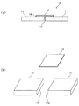
図1(a)は、本実施形態に係る接合部品10の一例を示す側面図である。また、図1(b)は、接合部品10の接着剤で接合する前の2つの樹脂板11及びプラスチックフィルム12の分解斜視図である。図1において、接合部品10は、2つの樹脂板11の端面11aを接着剤で互いに接合(接着)し、その接合部のおもて面側を覆うようにシート形状の補強部材としてのプラスチックフィルム12を接着剤で貼り付けた構成となっている。以下、図1に示す接合部品の構造を、「突き当て補強構造」ともいう。
Fig.1 (a) is a side view which shows an example of the joining
図1に示す接合部品10は、例えば、次のような製造方法で製造することができる。
接合部品10の製造方法の一例において、まず、2つの樹脂板11の端面11aの少なくとも一方の複数箇所に速硬化型接着剤を点状に塗布し、その速硬化型接着剤が硬化する前に速やかに2つの樹脂板11の端面11aを互いに突き当てる。これにより、2つの樹脂板11が速硬化型接着剤により仮固定される。
The joining
In an example of the manufacturing method of the joining
次に、仮固定された2つの樹脂板11の接合部の隙間に反応型接着剤13を流し込むとともに、その仮固定された2つの樹脂板11の接合部のおもて面側を覆うようにプラスチックフィルム12を反応型接着剤14で貼り付ける。その後、所定の硬化時間が経過して反応型接着剤13が硬化すると、2つの樹脂板11の接合部が本接着される。また、所定の硬化時間が経過して反応型接着剤14が硬化すると、プラスチックフィルム12が接合部を覆うように2つの樹脂板11に接着する。これにより、接合部の接合強度を増加させるとともに、接合部への応力集中を緩和させて曲げ強度を増加させる。
Next, the
なお、プラスチックフィルム12は、接合部のおもて面側に限らず、裏面側に貼り付けてもよく、両面側に貼り付けてもよい。プラスチックフィルム12は薄いので、貼り付けたときの段差を低く抑えることができ、接合部品10の外観を損なうことがなく外観性の劣化を防止できる。
In addition, the
また、上記接合部品10の製造方法では、2つの樹脂板11の端面11aを仮固定した後に反応型接着剤13で本接着しているが、仮固定せずに2つの樹脂板11の端面11aを反応型接着剤13で接着してもよい。
Moreover, in the manufacturing method of the said joining
上記2つの樹脂板11は、3次元造形工法によって造形された熱可塑性樹脂板であってもよい。
The two
昨今の日本のものづくり現場では、市場の個々のニーズに合わせるため、多品種小ロットの高付加価値製品へのシフトがますます加速している。そのような中、ものづくりの各工程において、3次元造形工法が活躍する領域がますます拡がってきていることから、製造業での3次元造形装置の活用が急速にすすみ、ものづくりを支える重要な役割を担っている。 In recent Japanese manufacturing sites, the shift to high-value-added products of various types and small lots is accelerating more and more in order to meet the individual needs of the market. Under such circumstances, the area in which 3D modeling methods are actively used in each manufacturing process is expanding, and the use of 3D modeling equipment in the manufacturing industry is rapidly progressing, and an important role that supports manufacturing. Is responsible.
3次元造形工法とは、3次元CADの設計データをもとにして、スライスされた2次元の層を1枚ずつ積み重ねていくことによって立体モデルを製作する造形工法である。3次元造形工法としては、熱で溶かした樹脂を積み重ねる材料押出堆積法(FDM方式)や、粉末状の素材にレーザーを照射して焼結させる粉末焼結積層法(SLS/SLM方式)などがある。 The three-dimensional modeling method is a modeling method for manufacturing a three-dimensional model by stacking sliced two-dimensional layers one by one based on design data of three-dimensional CAD. Three-dimensional modeling methods include a material extrusion deposition method (FDM method) in which resins melted by heat are stacked, and a powder sintering lamination method (SLS / SLM method) in which a powdered material is irradiated with a laser to be sintered. is there.
3次元造形工法では、3次元造形物の大型化が期待されているが、造形物の寸法は造形装置の仕様により制限されてしまう。3次元造形工法で大型の造形物を作製するためには、分割して造形した部品パーツを接着剤で接合する方法がある。しかし、部品パーツの端面同士を突き合せて接合した場合、板厚によっては接着面積が小さいことや、造形時に発生した造形物の歪みにより接合部に十分な接着強度が得られない場合がある。 In the three-dimensional modeling method, an increase in size of the three-dimensional model is expected, but the dimension of the model is limited by the specifications of the modeling apparatus. In order to produce a large shaped article by the three-dimensional modeling method, there is a method of joining component parts that are divided and shaped with an adhesive. However, when the end surfaces of the component parts are butted together and bonded, depending on the plate thickness, the bonding area may be small, or sufficient bonding strength may not be obtained at the bonded portion due to distortion of the molded object generated during modeling.
本実施形態の接合部品10は、その接合部にプラスチックフィルム12を貼り付けて補強するので、十分な接着強度が得られる。
Since the joining
3次元造形工法としては、上述した材料押出堆積法(FDM方式)や粉末焼結積層法(SLS/SLM方式)に限らず、熱可塑性樹脂を用いて溶解することにより造形する方法や、粉末状の素材を焼結させて造形する方法などであれば、何れの方法であってもよい。この3次元造形工法については後述する。熱可塑性樹脂の種類は問わないが、ナイロン6(登録商標)、ナイロン11(登録商標)、ナイロン12(登録商標)、ポリブチレンテレフタレート、ポリプロピレン、ポリカーボネート、ポリエーテルイミド、ABS樹脂、PLA樹脂(ポリ乳酸)等が一般的に用いられる。 The three-dimensional modeling method is not limited to the above-described material extrusion deposition method (FDM method) and powder sintering lamination method (SLS / SLM method), but also a method of modeling by melting using a thermoplastic resin, Any method may be used as long as it is a method of sintering and shaping the material. This three-dimensional modeling method will be described later. The type of thermoplastic resin is not limited, but nylon 6 (registered trademark), nylon 11 (registered trademark), nylon 12 (registered trademark), polybutylene terephthalate, polypropylene, polycarbonate, polyether imide, ABS resin, PLA resin (poly Lactic acid) is generally used.
樹脂板11の厚さの限界と精度については、3次元造形工法により異なるが、反りのない平坦な造形を得るためには、厚さが0.8[mm]以上が好ましい。さらに好ましくは厚さが2[mm]以上である。
Although the thickness limit and accuracy of the
プラスチックフィルム12は、その種類を問わないが、貼り付けたときに外観性を損なわないように、薄膜で高強度な材料が好ましい。
The type of the
速硬化型接着剤は、2つの樹脂板11の端面11aを互いに突き当てて仮固定させるため、塗布しやすく、空気中の水分で反応し、室温で速硬化(仮硬化)可能な接着剤である。例えば、速硬化型接着剤として、シアノアクリレート系接着剤などの主成分がエチルα−シアノアクリレートの接着剤を用いることができる。この速硬化型接着剤の硬化後の厚さは、0.01[mm]以上0.5[mm]以下が好ましい。
The fast-curing adhesive is an adhesive that is easy to apply, reacts with moisture in the air, and can be quickly cured (temporarily cured) at room temperature because the
反応型接着剤13,14は、2つの樹脂板11の端面11aを速硬化型接着剤で仮固定した後、2つの樹脂板11の接合部の隙間とおもて面のプラスチックフィルム12が貼り付けられる領域に塗布され、接合部及びプラスチックフィルム12を本接着する。この反応型接着剤13,14の硬化後の厚さは、0.01[mm]以上0.5[mm]以下が好ましい。
The
ここで、本発明者らが鋭意検討した結果、反応型接着剤13,14は硬化後のガラス転移温度が高いほど接合部品10の大きな曲げ強度を得ることができ、特に、硬化後のガラス転移温度が90[℃]以上の反応型接着剤がより効果的であることがわかった。
Here, as a result of intensive studies by the present inventors, the
硬化後のガラス転移温度が90[℃]以上の反応型接着剤13,14としては、例えば、熱硬化エポキシ、紫外線硬化エポキシ、可視光硬化エポキシ、紫外線硬化アクリレート、熱硬化アクリレート、シアノアクリレート、熱硬化ウレタン系から選択される。一方、90[℃]未満のガラス転移温度を有する接着剤では、接合部品に曲げ応力を加えたときに、接合部、特に断面部分に応力が集中するため、接合部が容易に剥離してしまう。
Examples of the
図2は、図1の構成の接合部品10について3点曲げ試験を行って得られた最大応力と、接着に用いた反応型接着剤14の硬化後のガラス転移温度との関係を示すグラフである。図2の試験では、2つの樹脂板11の接合部を仮固定する速硬化型接着剤として、シアノアクリレート系接着剤を使用した。また、2つの樹脂板11の接合部を本接着する反応型接着剤13及びその接合部のおもて面側を覆うようにプラスチックフィルム12を貼り付けて接着するための反応型接着剤14として、硬化後のガラス転移温度が互いに異なる7種類の接着剤を使用して試験を行った。なお、3点曲げ試験の試験方法については後述する。
FIG. 2 is a graph showing the relationship between the maximum stress obtained by performing a three-point bending test on the bonded
図2のグラフから、プラスチックフィルム12の接着に用いた反応型接着剤の硬化後のガラス転移温度が上昇するとともに、3点曲げ試験の最大応力(最大曲げ応力)も上昇することがわかる。特に、ガラス転移温度が90[℃]以上の反応型接着剤を使用した場合、いずれの場合も最大応力が40MPaを達成している。
From the graph of FIG. 2, it can be seen that the glass transition temperature after curing of the reactive adhesive used for bonding the
上記補強部材としてのプラスチックフィルム12は、繊維強化プラスチックフィルムであってもよい。本発明者らは、補強部材として、薄いフィルム材料を中心に各種の補強部材について検討した。薄いフィルム材料であれば、2つの樹脂板11の接合部を覆うように貼り付けたときに、フィルム材料を貼り付けた部分と貼り付けていない部分とで厚みの差がほとんど無く、設計上の制約が少ないとともに、外観性を損なわない。そして、本発明者らが鋭意検討した結果、補強部材として、繊維が配合された繊維強化プラスチックフィルムを貼り付けたときに、高い曲げ強度が得られることがわかった。
The
特に、繊維の長手方向が一方向に配向した繊維強化プラスチックフィルムを、接合部の幅方向と直交方向に設置して接着することにより、薄膜でも大きな曲げ強度が得られる。この場合、補強部材としての繊維強化プラスチックフィルムの厚さは、0.01[mm]〜0.1[mm]程度で充分な強度が得られる。すなわち、この厚さの繊維強化プラスチックフィルムであれば、成形母材である樹脂板11と同程度の曲げ強度、もしくは、それ以上の曲げ強度が得られる。
In particular, by installing and bonding a fiber reinforced plastic film in which the longitudinal direction of the fibers is oriented in one direction in a direction orthogonal to the width direction of the joint portion, a large bending strength can be obtained even in a thin film. In this case, the fiber reinforced plastic film as the reinforcing member has a thickness of about 0.01 [mm] to 0.1 [mm], and sufficient strength can be obtained. That is, if it is a fiber reinforced plastic film of this thickness, a bending strength comparable to or higher than that of the
繊維強化プラスチックフィルムは、2つの樹脂板11の接合部を覆うようにおもて面側又は裏面側のいずれか片面側に貼り付ければ強度的には十分である。しかし、繊維強化プラスチックフィルムを両面側に貼り付ければ、対称構造となり、歪みが少なくなり、高信頼性が要求される用途では好適である。
The fiber-reinforced plastic film is sufficient in terms of strength if it is applied to either the front side or the back side so as to cover the joint between the two
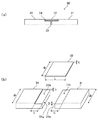
図3(a)は、本実施形態に係る他の接合部品20の一例を示す側面図である。また、図3(b)は、接合部品20の接着剤で接合する前の2つの樹脂板21とプラスチックフィルム22との分解斜視図である。図3において、接合部品20は、2つの樹脂板21の端面21aがそれぞれ互いに嵌め合う段差形状を有している。そして、2つの樹脂板21の端面21aを突き当てた嵌め合い補強構造の接合部のおもて面側を覆うようにプラスチックフィルム22を貼り付けた構成となっている。以下、図3に示す接合部品の構造を、「嵌め合い補強構造」ともいう。
Fig.3 (a) is a side view which shows an example of the other joining
図3に示す接合部品20は、例えば、次のような製造方法で製造することができる。
接合部品20の製造方法の一例において、まず、2つの樹脂板21の端面21aの少なくとも一方の複数箇所に速硬化型接着剤を点状に塗布し、その速硬化型接着剤が硬化する前に速やかに2つの樹脂板21の端面21aを互いに突き当てて嵌め合わせる。これにより、2つの樹脂板21が速硬化型接着剤により仮固定される。
3 can be manufactured by the following manufacturing method, for example.
In an example of the manufacturing method of the joining
次に、仮固定された2つの樹脂板21の嵌め合わされた接合部の隙間に反応型接着剤13を流し込むとともに、その仮固定された2つの樹脂板21の嵌め合わされた接合部のおもて面側を覆うようにプラスチックフィルム22を反応型接着剤24で貼り付ける。その後、所定の硬化時間が経過して反応型接着剤23が硬化すると2つの樹脂板21の嵌め合わされた接合部が本接着される。また、所定の硬化時間が経過して反応型接着剤24が硬化するとプラスチックフィルム22が、互いに嵌め合わされた接合部を覆うように2つの樹脂板21に接着する。これにより、接合部の接合強度を増加させるとともに、接合部への応力集中を緩和させて曲げ強度を増加させる。
Next, the
なお、上記接合部品20の製造方法では、2つの樹脂板21の端面21aを仮固定した後に反応型接着剤23で本接着しているが、仮固定せずに2つの樹脂板21の端面21aを反応型接着剤23で接着してもよい。
In the manufacturing method of the joining
図3に示す接合部品20では、2つの樹脂板21の端面21aがそれぞれ互いに嵌め合う段差形状であるため、互いに接着される端面21aの接着面積を広くとることができ、接着強度を向上させることができる。この結果、接合部品20の接合部では更に大きな曲げ強度を得ることができる。
In the joining
樹脂板の接着強度は接合部の接着面積に依存するため、接着面積が広いほど高い接着強度が得られる。高い接着強度を得るためには、樹脂板の端面の接着面積(平坦部面積)を多くとることが有効であるが、設計上接着面積を広くとれない場合がある。このような場合であっても、図3に示す構造であれば接着面積を広くとることができ、高い接着強度を得ることができる。例えば、図1に示す構造で樹脂板11の板厚が薄くて端面11aの接着面積が狭く接着強度が弱い場合、図3に示すように樹脂板21の端面21aを段差形状とすることで接着面積を広くして接着強度を向上させることができる。
Since the adhesive strength of the resin plate depends on the adhesive area of the joint, the higher the adhesive area, the higher the adhesive strength. In order to obtain high bonding strength, it is effective to increase the bonding area (flat part area) of the end face of the resin plate, but there are cases where the bonding area cannot be widened by design. Even in such a case, if the structure shown in FIG. 3 is used, the bonding area can be widened and high bonding strength can be obtained. For example, in the structure shown in FIG. 1, when the thickness of the
図4(a)は、本実施形態に係る更に他の接合部品30の一例を示す側面図である。また、図4(b)は、接合部品30の接着剤で接合する前の2つの樹脂板31とプラスチックフィルム32との分解斜視図である。図4において、接合部品30は、2つの樹脂板31の端面に段差部31bが形成されており、2つの樹脂板31の端面31aを突き当てた接合部の段差部31bを覆うようにプラスチックフィルム32を埋め込んだ埋め込み構造となっている。
FIG. 4A is a side view showing an example of still another joining
図4(b)において、プラスチックフィルム32は厚みt、長さL、幅Wの形状を有している。また、2つの樹脂板31の端面にはそれぞれ、深さD、奥行き長さS、幅Wの段差部31bが形成される。例えば、段差部31bの深さD=プラスチックフィルム32の厚みt、段差部31bの奥行き長さS=(プラスチックフィルム32の長さL)×0.98/2、段差部31bの幅W=プラスチックフィルム32の幅Wの関係を有していてもよい。これにより、2つの樹脂板31を突き当てた接合部でプラスチックフィルム32が段差部31bに埋め込まれ、隙間や段差が生じることなく優れた外観性を得ることができる。
In FIG. 4B, the
以下、図4に示す接合部品の構造を、「補強部材埋め込み構造」ともいう。この補強部材埋め込み構造では、補強部材としてのプラスチックフィルム32は段差部31bに埋め込まれて接合部の表面と面一になるので、補強部材は薄板形状であってもよい。
Hereinafter, the structure of the joining component shown in FIG. 4 is also referred to as “reinforcing member embedded structure”. In this reinforcing member embedding structure, the
図4に示す接合部品30は、例えば、次のような製造方法で製造することができる。
接合部品10の製造方法の一例において、まず、2つの樹脂板31の端面31aの少なくとも一方の複数箇所に速硬化型接着剤を点状に塗布し、その速硬化型接着剤が硬化する前に速やかに2つの樹脂板31の端面31aを互いに突き当てる。これにより、2つの樹脂板31が速硬化型接着剤により仮固定される。
The joining
In an example of the manufacturing method of the joining
次に、仮固定された2つの樹脂板31の接合部の隙間に反応型接着剤33を流し込むとともに、その仮固定された2つの樹脂板31の接合部の段差部31bのおもて面側を覆うようにプラスチックフィルム32を埋め込んで反応型接着剤34で貼り付ける。その後、所定の硬化時間が経過して反応型接着剤33が硬化すると、2つの樹脂板31の接合部が本接着される。また、所定の硬化時間が経過して反応型接着剤34が硬化すると、プラスチックフィルム32が接合部の段差部31bを覆うように2つの樹脂板31に接着する。これにより、接合部の接合強度を増加させるとともに、接合部への応力集中を緩和させて曲げ強度を増加させる。
Next, the
なお、上記接合部品30の製造方法では、2つの樹脂板31の端面31a及び段差部31bを仮固定した後に反応型接着剤33で本接着しているが、仮固定せずに2つの樹脂板31の端面31a及び段差部31bを反応型接着剤33で接着してもよい。
In addition, in the manufacturing method of the said joining
図4に示す接合部品30では、2つの樹脂板21の段差部31bにプラスチックフィルム32が埋め込まれて貼り付けられるため、プラスチックフィルム32の段差が生じない。これにより、より優れた外観を得ることができる。また、プラスチックフィルム32の段差による設計上の制限を緩和することができる。さらに、接合部品30の接合部ではより大きな曲げ強度を得ることができる。
In the joining
樹脂板の接合では、補強部材が大きいほど樹脂板との接着面積が広がるため、高い接着強度が得られる。このように、高い接着強度を得るためには、補強部材を大きくすることが有効であるが、接続部で樹脂板の表面に補強部材による段差が広く生じしまうため、設計上の制約を受ける場合がある。 In the bonding of the resin plates, the larger the reinforcing member, the larger the bonding area with the resin plate, so that a high bonding strength can be obtained. Thus, in order to obtain high adhesive strength, it is effective to enlarge the reinforcing member. However, a step due to the reinforcing member is widely generated on the surface of the resin plate at the connection portion, and thus there are design restrictions. There is.
図4に示す構造では、プラスチックフィルム32が樹脂板31の段差部31bに埋め込まれ、樹脂板31の表面にプラスチックフィルム32の段差が生じないので、大きなプラスチックフィルム32を用いることができる。特に、プラスチックフィルム32の長さLを長くすることができる。
In the structure shown in FIG. 4, the
以下、本実施形態に係る接合部品の実施例について説明する。ただし、本発明は、これらの実施例に限定されるものではない。 Hereinafter, examples of the joining component according to the present embodiment will be described. However, the present invention is not limited to these examples.
まず、各実施例で用いる熱可塑性樹脂板を3次元造形により造形するための3次元造形装置について説明する。3次元造形装置は、薄い層を積み上げる積層方式を基本としながら、その造形方式には数種類の方式があり、方式ごとに使える材料や造形物の特性は異なる。例えば、熱で溶かした樹脂を積み重ねる材料押出堆積法(FEM方式)は、ABSやPLA、ポリカーボネートなどの造形が可能であり、高い耐久性や耐熱性を得やすいので、試作品や治具、簡易型の造形などに適している。また、粉末状の素材にレーザーを照射して焼結させる粉末焼結積層造形法(SLS/SLM方式)は、ナイロン(登録商標)やポリプロピレンなどの樹脂だけでなく金属の造形も可能であり、最終製品や鋳型の製造にも用いられている。最近では、造形方法やマテリアルの多様化により用途に広がりを見せている。 First, a three-dimensional modeling apparatus for modeling a thermoplastic resin plate used in each example by three-dimensional modeling will be described. While the three-dimensional modeling apparatus is based on a lamination method in which thin layers are stacked, there are several types of modeling methods, and the characteristics of materials and modeling objects that can be used differ depending on the method. For example, the material extrusion deposition method (FEM method) that stacks the resin melted by heat is capable of forming ABS, PLA, polycarbonate, etc., and it is easy to obtain high durability and heat resistance. Suitable for mold shaping. In addition, the powder sintering additive manufacturing method (SLS / SLM method) in which a powdery material is irradiated with a laser to sinter can be used not only for resins such as nylon (registered trademark) and polypropylene, but also for metal modeling. It is also used in the manufacture of final products and molds. Recently, it has been expanded to various uses due to diversification of modeling methods and materials.
本実施例では、材料押出堆積法(FDM方式)の3次元造形装置と、粉末焼結積層造形法(SLS方式)の3次元造形装置を用いたので、これらの3次元造形装置について説明する。 In this embodiment, since a material extrusion deposition method (FDM method) three-dimensional modeling apparatus and a powder sintering additive manufacturing method (SLS method) three-dimensional modeling apparatus are used, these three-dimensional modeling apparatuses will be described.
[FDM方式の3次元造形装置]
図5は、FDM方式の3次元造形装置1の概略構成を示すブロック図である。また、図6は、FDM方式の3次元造形装置1の詳細を模式的に示す説明図である。
[FDM 3D modeling equipment]
FIG. 5 is a block diagram illustrating a schematic configuration of the FDM type three-dimensional modeling apparatus 1. FIG. 6 is an explanatory view schematically showing details of the FDM type three-dimensional modeling apparatus 1.
[全体説明]
FDM方式の3次元造形装置1は、主に、材料供給部100、3次元造形部200、駆動部300、制御部400から構成される。3次元造形装置1においては、制御部400の制御の下、駆動部300により各部を駆動し、材料供給部100から供給される材料を用いて3次元造形部200で3次元造形物を造形する。
[Overall description]
The FDM type three-dimensional modeling apparatus 1 mainly includes a
[材料供給部]
材料供給部100は、少なくとも、材料排出部材としての造形ヘッド110と、造形ヘッド110に造形材料であるフィラメントを供給するフィラメント供給部120とを備えている。フィラメントは、細長いワイヤー形状の固体であり、巻き回された状態で3次元造形装置1にセットされており、フィラメント供給部120により造形ヘッド110上のノズル111へ供給される。フィラメント供給部120により供給されたフィラメントは、造形ヘッド110で加熱溶融され、固体状態のフィラメントが後方より挿入されることにより溶融状態のフィラメントがノズル111から押し出される。
[Material supply section]
The
なお、造形ヘッド110上のノズル111から押し出される材料には、3次元造形物を構成する造形材料ではなく、3次元造形物を構成しないサポート材も含まれる。このサポート材は、通常、3次元造形物を構成する造形材料(フィラメント)とは異なる材料で形成され、最終的にはフィラメントで形成された3次元造形物から除去される。このサポート材も、造形ヘッド110で加熱溶融され、固体状態のサポート材のフィラメントが後方より挿入されることにより溶融状態のサポート材がノズル111から押し出される。
The material pushed out from the nozzle 111 on the
[3次元造形部]
3次元造形部200は、少なくとも、載置部210、チャンバー220、加熱部230から構成される。3次元造形部200におけるチャンバー220の内部は、3次元造形物を造形するための処理空間となっている。材料供給部100における造形ヘッド110から押し出される溶融状態のフィラメントは、加熱部230によって加熱されたチャンバー220の内部で、載置部210のステージ上に供給され、層状に順次積層される。
[3D modeling department]
The three-
[駆動部]
駆動部300は、少なくとも、X軸駆動機構310、Y軸駆動機構320、Z軸駆動機構330から構成される。駆動部300は、これらの駆動機構310,320,330により、材料供給部100の造形ヘッド110と、3次元造形部200における載置部210のステージとを相対的に移動させる。これにより、材料供給部100の造形ヘッド110から押し出されるフィラメントをステージ上の目標位置へ供給する。
[Drive part]
The
[SLS方式の3次元造形装置]
図7は、SLS方式の3次元造形装置5の概略構成を示すブロック図である。また、図8は、SLS方式の3次元造形装置5の詳細を模式的に示す説明図である。
[SLS 3D modeling equipment]
FIG. 7 is a block diagram showing a schematic configuration of the SLS type three-
[全体説明]
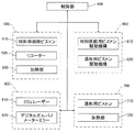
SLS方式の3次元造形装置5は、主に、材料供給部500、レーザー照射部600、3次元造形部700、駆動部800、制御部900から構成される。3次元造形装置5においては、制御部900の制御の下、レーザー照射部600でレーザーを照射しながら、駆動部800により各ピストン等を駆動し、材料供給部500から供給される材料を用いて3次元造形部700で3次元造形物を造形する。
[Overall description]
The SLS type three-
[材料供給部]
材料供給部500は、少なくとも、材料供給用ピストン510と、粉末の材料を3次元造形部700へ均一に敷き詰めるためのリコーター520と、材料を加熱する加熱部530とを備えている。材料供給用ピストン510を上昇させて3次元造形部700に材料を供給しつつ、リコーター520を作動させて、材料を3次元造形部700へ均一に敷き詰める。材料としては、例えば、ナイロン(登録商標)の粉末などの樹脂材料や金属の粉末などの金属材料を用いることができる。なお、樹脂材料の場合、FDM方式とは異なりサポート材が不要である。
[Material supply section]
The
[レーザー照射部]
レーザー照射部600は、少なくとも、CO2レーザー610と、デジタルガルバノメーターミラー620とを備えている。CO2レーザー610から発せられたCO2レーザー光を、デジタルガルバノメーターミラー620で走査して、3次元造形部700の材料に照射する。
[Laser irradiation part]
The
[3次元造形部]
3次元造形部700は、少なくとも、造形用ピストン710と、加熱部720とを備えている。3次元造形部700の材料は、レーザー照射部600から照射されるCO2レーザー光により造形され、造形用ピストン710が下降することにより、層状に順次積層される。
[3D modeling department]
The three-
なお、上記材料供給部500、デジタルガルバノメーターミラー620及び3次元造形部700は、窒素ガス雰囲気のチャンバー内に配設されている。
The
[駆動部]
駆動部800は、少なくとも、材料供給用ピストン駆動機構810と、造形用ピストン駆動機構820とを備えている。駆動部800は、これらの駆動機構810,820により、材料供給部500の材料供給用ピストン510と、3次元造形部700の造形用ピストン710とを移動させる。3次元造形部700で層状に順次積層されて3次元造形物が造形される動作に応じて造形用ピストン710が下降し、材料供給用ピストン510が上昇して必要な量の材料を3次元造形部700に供給する。
[Drive part]
The
次に、各実施例で用いた接合形状及び接合方法について詳細に説明する。
[実施例で用いた接合形状]
樹脂板は、同形状、同寸法の2つの熱可塑性造形物を接着接合した際に長さが80[mm]となるように設定し、幅は10[mm]、厚みは4[mm]とした。各構造の詳細な寸法は以下の通りである。
Next, the joining shape and joining method used in each example will be described in detail.
[Joint shape used in Examples]
The resin plate is set to have a length of 80 [mm] when two thermoplastic shaped articles having the same shape and the same dimensions are bonded and bonded, the width is 10 [mm], and the thickness is 4 [mm]. did. The detailed dimensions of each structure are as follows.
図1で示す突き当て補強構造の接合部品10では、熱可塑性樹脂の樹脂板の寸法は長さ40[mm]、幅10[mm]、厚み4[mm]とした。また、シート形状の補強部材の寸法は長さ20[mm]、幅10[mm]、厚み50[μm]とした。
In the joining
図3で示す嵌め合い補強構造の接合部品20では、熱可塑性樹脂の樹脂板の寸法は、長さ50[mm]、幅10[mm]、厚み4[mm]とし、段差部分は長さ20[mm]、厚み2[mm]とした。また、シート形状の補強部材の寸法は長さ20[mm]、幅10[mm]、厚み50[μm]とした。 3, the dimensions of the thermoplastic resin plate are 50 [mm], 10 [mm] wide and 4 [mm] thick, and the stepped portion has a length of 20 [mm]. [Mm] and thickness 2 [mm]. The dimensions of the sheet-shaped reinforcing member were 20 [mm] in length, 10 [mm] in width, and 50 [μm] in thickness.
図4で示す補強部材埋め込み構造の接合部品30では、熱可塑性樹脂の樹脂板の寸法は長さ40[mm]、幅10[mm]、厚み4[mm]とし、段差部分は長さ10[mm]、深さ1[mm]とした。また、シート形状の補強部材の寸法は長さ19.6[mm]、幅10[mm]、厚み1[mm]とした。
In the joining
[接合方法]
図1、3、4で示す補強構造の接合方法について説明する。
表1は、下記の各実施例で得られた、接着接合された3次元造形物の構成と、これらについての3点曲げ試験及び外観の評価結果とを示す。
[Joint method]
A method for joining the reinforcing structures shown in FIGS.
Table 1 shows the configuration of the three-dimensional structure that is adhesively bonded, obtained in each of the following examples, and the three-point bending test and the evaluation results of the appearance of these.

まず、表1に示した3次元造形工法により、熱可塑性樹脂の樹脂板を得た。次に、2つの同形状の熱可塑性樹脂の樹脂板の接合面に速硬化型接着剤としてシアノアクリレート系接着剤を塗布し、図1、図3及び図4に示した構造となるよう突き当て仮固定した。次に、仮固定した接合面の隙間に硬化後のガラス転移温度が90[℃]以上である反応型接着剤を流し込み本接着した。次に、シート形状の補強部材を接合部を覆うように片面または両面に本接着用接着剤で固定した。 First, a thermoplastic resin plate was obtained by the three-dimensional modeling method shown in Table 1. Next, a cyanoacrylate-based adhesive is applied as a fast-curing adhesive to the joint surfaces of two identically-shaped thermoplastic resin plates, and abutted to have the structure shown in FIGS. Temporarily fixed. Next, a reactive adhesive having a glass transition temperature after curing of 90 [° C.] or higher was poured into the gap between the temporarily fixed joint surfaces to perform main bonding. Next, the sheet-shaped reinforcing member was fixed with a main-bonding adhesive on one or both sides so as to cover the joint.
〔実施例1〕
ABS(Acrylonitrile Butadiene Styrene)材料を、FDM法(Stratasys社製、Fortus 900mc)を用いて、図1に示した突き当て補強構造用の3次元造形部品を得た。突き当て部の端面はシアノアクリレート系接着剤(東亞合成社製、アロン403TN)で仮固定した。接合部の片側面にはシート形状の補強部材としてFRPフィルム(倉敷紡績社製、クラパワーシート、厚み0.07[mm])を繊維の配向方向を接合部幅方向と直交になるように設置した。FRPフィルムの固定には仮固定と同様にシアノアクリレート系接着剤(東亞合成社製、アロン403TN、ガラス転移温度140[℃])を使用し、本実施例1の3次元造形接合部品を作製した。
[Example 1]
A three-dimensional shaped part for an abutting reinforcement structure shown in FIG. 1 was obtained by using an ABS (Acrylonitrile Butadiene Styrene) material using an FDM method (Stratasys, Fortus 900mc). The end face of the butting portion was temporarily fixed with a cyanoacrylate adhesive (Aron 403TN, manufactured by Toagosei Co., Ltd.). On one side of the joint, an FRP film (manufactured by Kurashiki Spinning Co., Ltd., Kura Power Sheet, thickness 0.07 [mm]) is installed as a sheet-shaped reinforcing member so that the fiber orientation direction is perpendicular to the joint width direction. did. For fixing the FRP film, a cyanoacrylate adhesive (manufactured by Toagosei Co., Ltd., Aron 403TN, glass transition temperature 140 [° C.]) was used in the same manner as temporary fixing, and the three-dimensional shaped joined part of Example 1 was produced. .
〔実施例2〕
PA12(Polyamide12)材料を、SLS法(RICOH社製、AM S5500P)を用いて、図1に示した突き当て補強構造用の3次元造形部品を得た。突き当て部の端面はシアノアクリレート系接着剤(スリーボンド社製、1783)で仮固定した。接合部の片側面にはシート形状の補強部材としてFRPフィルム(倉敷紡績社製、クラパワーシート、厚み0.07[mm])を繊維の配向方向を接合部幅方向と直交になるように設置した。突き当て部端面の本接着及びFRPフィルムの固定には熱硬化エポキシ接着剤(スリーボンド製、2204、ガラス転移温度109[℃])を使用し、本実施例2の3次元造形接合部品を作製した。
[Example 2]
A PA12 (Polyamide 12) material was obtained by using the SLS method (manufactured by RICOH, AM S5500P) to obtain a three-dimensional shaped part for abutting reinforcement structure shown in FIG. The end face of the abutting part was temporarily fixed with a cyanoacrylate adhesive (manufactured by Three Bond Co., 1783). On one side of the joint, an FRP film (manufactured by Kurashiki Spinning Co., Ltd., Kura Power Sheet, thickness 0.07 [mm]) is installed as a sheet-shaped reinforcing member so that the fiber orientation direction is perpendicular to the joint width direction. did. A thermosetting epoxy adhesive (manufactured by ThreeBond, 2204, glass transition temperature 109 [° C.]) was used for the main bonding of the end face of the abutting portion and the fixing of the FRP film, and the three-dimensional shaped joining component of Example 2 was produced. .
〔実施例3〕
PEI(Poly Ether Imide)材料を、FDM法(Stratasys社製、Fortus 900mc)を用いて、図3に示した嵌め合い補強構造用の3次元造形部品を得た。突き当て部の端面はシアノアクリレート系接着剤(東亞合成社製、アロン403TN)で仮固定した。接合部の片側面にはシート形状の補強部材としてLCPフィルム(千代田インテグレ社製、ぺリキュールLCP、厚み0.025[mm])を樹脂の配向方向を接合部幅方向と直交になるように設置した。突き当て部端面の本接着及びLCPフィルムの固定にはUV硬化エポキシ接着剤(スリーボンド社製、2082E、ガラス転移温度93[℃])を使用し、本実施例3の3次元造形接合部品を作製した。
Example 3
Using a PDM (Poly Ether Imide) material, FDM method (manufactured by Stratasys, Fortus 900mc), a three-dimensional shaped part for a fitting reinforcement structure shown in FIG. 3 was obtained. The end face of the butting portion was temporarily fixed with a cyanoacrylate adhesive (Aron 403TN, manufactured by Toagosei Co., Ltd.). LCP film (Pericule LCP, manufactured by Chiyoda Integre Co., Ltd., thickness 0.025 [mm]) as a sheet-shaped reinforcing member is installed on one side of the joint so that the resin orientation direction is perpendicular to the joint width direction. did. A UV-curing epoxy adhesive (manufactured by ThreeBond, 2082E, glass transition temperature 93 [° C.]) is used for the main bonding of the end face of the abutting portion and the fixing of the LCP film, and the three-dimensional shaped joining component of Example 3 is produced. did.
〔実施例4〕
PEI材料を、FDM法(Stratasys社製、Fortus 900mc)を用いて、図3に示した嵌め合い補強構造用の3次元造形部品を得た。突き当て部の端面はシアノアクリレート系接着剤(東亞合成社製、アロン403TN)で仮固定した。接合部の片側面にはシート形状の補強部材としてFRPフィルム(倉敷紡績社製、クラパワーシート、厚み0.07[mm])を繊維の配向方向を接合部幅方向と直交になるように設置した。突き当て部端面の本接着及びFRPフィルムの固定には熱硬化エポキシ接着剤(スリーボンド社製、2204、ガラス転移温度109[℃])を使用し、本実施例4の3次元造形接合部品を作製した。
Example 4
The PEI material was obtained by using the FDM method (manufactured by Stratasys, Fortus 900mc) to obtain a three-dimensional shaped part for a fitting reinforcement structure shown in FIG. The end face of the butting portion was temporarily fixed with a cyanoacrylate adhesive (Aron 403TN, manufactured by Toagosei Co., Ltd.). On one side of the joint, an FRP film (manufactured by Kurashiki Spinning Co., Ltd., Kura Power Sheet, thickness 0.07 [mm]) is installed as a sheet-shaped reinforcing member so that the fiber orientation direction is perpendicular to the joint width direction. did. A thermosetting epoxy adhesive (manufactured by ThreeBond Co., Ltd., 2204, glass transition temperature 109 [° C.]) is used for the final adhesion of the abutting portion end face and the fixing of the FRP film, and the three-dimensional shaped joining component of Example 4 is produced. did.
〔実施例5〕
ABS材料を、FDM法(Stratasys社製、Fortus 900mc)を用いて、図4に示した補強部材埋め込み構造用の3次元造形部品を得た。突き当て部の端面はシアノアクリレート系接着剤(スリーボンド社製、1783)で仮固定した。接合段差部にはシート形状の補強部材としてUV硬化FRPフィルム(サンコーテクノ社製、eシートクイック、厚み1[mm])を埋め込んだ。突き当て部端面の本接着及びUV硬化FRPフィルムの固定にはUV硬化エポキシ接着剤(スリーボンド社製、2082E、ガラス転移温度93[℃])を使用し、本実施例5の3次元造形接合部品を作製した。
Example 5
The ABS material was obtained by using the FDM method (Stratasys, Fortus 900mc) to obtain a three-dimensional shaped part for the reinforcing member embedded structure shown in FIG. The end face of the abutting part was temporarily fixed with a cyanoacrylate adhesive (manufactured by Three Bond Co., 1783). A UV-cured FRP film (manufactured by Sanko Techno Co., Ltd., e-sheet quick, thickness 1 [mm]) was embedded as a sheet-shaped reinforcing member in the joint step portion. A three-dimensional shaped joining component of Example 5 was used for the main bonding of the end face of the abutting portion and the fixing of the UV curable FRP film using a UV curable epoxy adhesive (manufactured by ThreeBond, 2082E, glass transition temperature 93 [° C.]). Was made.
〔実施例6〕
PA12材料を、SLS法(RICOH社製、AM S5500P)を用いて、図4に示した補強部材埋め込み構造用の3次元造形部品を得た。突き当て部の端面はシアノアクリレート系接着剤(東亞合成社製、アロン403TN)で仮固定した。接合段差部には被着体(3次元造形部品)と同様に造形したシート形状の補強部材としてPA12シートを埋め込んだ。突き当て部端面の本接着及びPA12シートの固定にはUV硬化エポキシ接着剤(協立化学産業社製、XS−EHL105、ガラス転移温度160[℃])を使用し、本実施例6の3次元造形接合部品を作製した。
Example 6
The PA12 material was obtained by using the SLS method (manufactured by RICOH, AM S5500P) to obtain a three-dimensional shaped part for the reinforcing member embedded structure shown in FIG. The end face of the butting portion was temporarily fixed with a cyanoacrylate adhesive (Aron 403TN, manufactured by Toagosei Co., Ltd.). A PA12 sheet was embedded as a sheet-shaped reinforcing member shaped in the same manner as the adherend (three-dimensional shaped part) in the joining step portion. A UV curable epoxy adhesive (manufactured by Kyoritsu Chemical Industry Co., Ltd., XS-EHL105, glass transition temperature 160 [° C.]) was used for the main adhesion of the end face of the abutting portion and the fixing of the PA12 sheet. A shaped joint part was produced.
〔実施例7〕
ABS(Acrylonitrile Butadiene Styrene)材料を、FDM法(Stratasys社製、Fortus 900mc)を用いて、図1に示した突き当て補強構造用の3次元造形部品を得た。突き当て部の仮固定は行わず、接合部の片側面にはシート形状の補強部材としてFRPフィルム(倉敷紡績社製、クラパワーシート、厚み0.07[mm])を繊維の配向方向を接合部幅方向と直交になるように設置した。FRPフィルムの固定にはシアノアクリレート系接着剤(東亞合成社製、アロン403TN、ガラス転移温度140[℃])を使用し、本実施例7の3次元造形接合部品を作製した。
Example 7
A three-dimensional shaped part for an abutting reinforcement structure shown in FIG. 1 was obtained by using an ABS (Acrylonitrile Butadiene Styrene) material using an FDM method (Stratasys, Fortus 900mc). The abutting part is not temporarily fixed, and an FRP film (Kurakibo Co., Ltd., Kura Power Sheet, thickness 0.07 [mm]) is joined as a sheet-shaped reinforcing member on one side of the joining part in the fiber orientation direction. It was installed so as to be orthogonal to the width direction. For fixing the FRP film, a cyanoacrylate-based adhesive (manufactured by Toagosei Co., Ltd., Aron 403TN, glass transition temperature 140 [° C.]) was used, and a three-dimensional shaped joined part of Example 7 was produced.
〔実施例8〕
ABS材料を、FDM法(Stratasys社製、Fortus 900mc)を用いて、図1に示した突き当て補強構造用の3次元造形部品を得た。突き当て部の端面はシアノアクリレート系接着剤(東亞合成社製、アロン403TN)で仮固定した。接合部の片側面にはシート形状の補強部材としてFRPフィルム(倉敷紡績社製、クラパワーシート、厚み0.07[mm])を繊維の配向方向を接合部幅方向と直交になるように設置した。突き当て部端面の本接着及びFRPフィルムの固定にはシアノアクリレート系接着剤(東亞合成社製、802、ガラス転移温度80[℃])を使用し、本実施例8の3次元造形接合部品を作製した。
Example 8
The ABS material was obtained by using the FDM method (Stratasys, Fortus 900mc) to obtain a three-dimensional shaped part for the butted reinforcement structure shown in FIG. The end face of the butting portion was temporarily fixed with a cyanoacrylate adhesive (Aron 403TN, manufactured by Toagosei Co., Ltd.). On one side of the joint, an FRP film (manufactured by Kurashiki Spinning Co., Ltd., Kura Power Sheet, thickness 0.07 [mm]) is installed as a sheet-shaped reinforcing member so that the fiber orientation direction is perpendicular to the joint width direction. did. A cyanoacrylate adhesive (802, manufactured by Toagosei Co., Ltd., glass transition temperature 80 [° C.]) is used for the main bonding of the end face of the abutting portion and the fixing of the FRP film. Produced.
〔実施例9〕
ABS材料を、FDM法(Stratasys社製、Fortus 900mc)を用いて、図1に示した突き当て補強構造用の3次元造形部品を得た。突き当て部の端面はシアノアクリレート系接着剤(スリーボンド社製、1783)で仮固定した。接合部の片側面にはシート形状の補強部材としてLCPフィルム(千代田インテグレ社製、ぺリキュールLCP、厚み0.025[mm])を樹脂の配向方向を接合部幅方向と直交になるように設置した。突き当て部端面の本接着及びLCPフィルムの固定には2液速硬化エポキシ接着剤(スリーボンド社製、2086M、ガラス転移温度45[℃])を使用し、本実施例9の3次元造形接合部品を作製した。
Example 9
The ABS material was obtained by using the FDM method (Stratasys, Fortus 900mc) to obtain a three-dimensional shaped part for the butted reinforcement structure shown in FIG. The end face of the abutting part was temporarily fixed with a cyanoacrylate adhesive (manufactured by Three Bond Co., 1783). LCP film (Pericule LCP, manufactured by Chiyoda Integre Co., Ltd., thickness 0.025 [mm]) as a sheet-shaped reinforcing member is installed on one side of the joint so that the resin orientation direction is perpendicular to the joint width direction. did. A two-component fast curing epoxy adhesive (manufactured by ThreeBond Co., Ltd., 2086M, glass transition temperature 45 [° C.]) is used for the main adhesion of the abutting portion end face and the fixing of the LCP film. Was made.
〔実施例10〕
PA12材料を、SLS法(RICOH社製、AM S5500P)を用いて、図3に示した嵌め合い補強構造用の3次元造形部品を得た。突き当て部の端面はシアノアクリレート系接着剤(東亞合成製、アロン403TN)で仮固定した。接合部の片側面にはシート形状の補強部材としてFRPフィルム(倉敷紡績社製、クラパワーシート、厚み0.07[mm])を繊維の配向方向を接合部幅方向と直交になるように設置した。突き当て部端面の本接着及びFRPフィルムの固定には可視光硬化エポキシ接着剤(オーテックス社製、EXTG−2010−A、ガラス転移温度85[℃])を使用し、本実施例10の3次元造形接合部品を作製した。
Example 10
The PA12 material was obtained by using the SLS method (manufactured by RICOH, AM S5500P) to obtain a three-dimensional shaped part for the fitting reinforcement structure shown in FIG. The end face of the butting portion was temporarily fixed with a cyanoacrylate adhesive (Aron 403TN, manufactured by Toagosei Co., Ltd.). On one side of the joint, an FRP film (manufactured by Kurashiki Spinning Co., Ltd., Kura Power Sheet, thickness 0.07 [mm]) is installed as a sheet-shaped reinforcing member so that the fiber orientation direction is perpendicular to the joint width direction. did. Visible light curing epoxy adhesive (manufactured by Autex, EXTG-2010-A, glass transition temperature 85 [° C.]) was used for main adhesion of the abutting portion end face and fixing of the FRP film. A dimensionally shaped bonded part was produced.
〔実施例11〕
PEI材料を、FDM法(Stratasys社製、Fortus 900mc)を用いて、図4に示した補強部材埋め込み構造用の3次元造形部品を得た。突き当て部の端面はシアノアクリレート系接着剤(スリーボンド社製、1783)で仮固定した。接合段差部にはシート形状の補強部材としてUV硬化FRPフィルム(サンコーテクノ社製、eシートクイック、厚み1[mm])を埋め込んだ。突き当て部端面の本接着及びUV硬化FRPフィルムの固定には熱硬化エポキシ接着剤(スリーボンド社製、2087、ガラス転移温度72[℃])を使用し、本実施例11の3次元造形接合部品を作製した。
Example 11
A three-dimensional shaped part for a reinforcing member embedded structure shown in FIG. 4 was obtained by using an FDM method (Stratasys, Fortus 900mc) for the PEI material. The end face of the abutting part was temporarily fixed with a cyanoacrylate adhesive (manufactured by Three Bond Co., 1783). A UV-cured FRP film (manufactured by Sanko Techno Co., Ltd., e-sheet quick, thickness 1 [mm]) was embedded as a sheet-shaped reinforcing member in the joint step portion. A thermosetting epoxy adhesive (manufactured by ThreeBond Co., Ltd., 2087, glass transition temperature 72 [° C.]) is used for the main bonding of the end face of the abutting portion and the fixing of the UV curable FRP film. Was made.
〔実施例12〕
PA12材料を、SLS法(RICOH社製、AM S5500P)を用いて、図4に示した補強部材埋め込み構造用の3次元造形部品を得た。突き当て部の端面はシアノアクリレート系接着剤(東亞合成社製、アロン403TN)で仮固定した。接合段差部には被着体(3次元造形部品)と同様に造形したシート形状の補強部材としてPA12シートを埋め込んだ。突き当て部端面の本接着及びPA12シートの固定には2液速硬化エポキシ接着剤(スリーボンド社製、2086M、ガラス転移温度45[℃])を使用し、本実施例12の3次元造形接合部品を作製した。
Example 12
The PA12 material was obtained by using the SLS method (manufactured by RICOH, AM S5500P) to obtain a three-dimensional shaped part for the reinforcing member embedded structure shown in FIG. The end face of the butting portion was temporarily fixed with a cyanoacrylate adhesive (Aron 403TN, manufactured by Toagosei Co., Ltd.). A PA12 sheet was embedded as a sheet-shaped reinforcing member shaped in the same manner as the adherend (three-dimensional shaped part) in the joining step portion. A two-component fast curing epoxy adhesive (manufactured by ThreeBond Co., Ltd., 2086M, glass transition temperature 45 [° C.]) is used for the main adhesion of the butting portion end face and the PA12 sheet. Was made.
上記各実施例で得られた接着接合された3次元造形物について、下記の各特性について評価を行った。 Each of the following characteristics was evaluated for the adhesively bonded three-dimensional structure obtained in each of the above examples.
[3点曲げ試験]
3点曲げ試験には万能試験機(島津製作所社製、AG−X)を用いた。接着接合された3次元造形物を支持する支点間距離は64[mm]とし、試験速度は10[mm/min]とした。圧子の半径は5[mm]を使用した。プラスチックフィルムの補強部材(補強シート)を片面のみに張り付けた場合は、補強シート面を下向きにセットし、上方向から中央部を圧子で押し込んだ。試験では、たわみ−荷重曲線が得られ、最大荷重より最大応力を求めた。この判定方法は、接着接合した3次元造形部品において、3点曲げ試験の最大応力が40[MPa]以上であるものを「○」とし、それ以外を「×」とした。
[3-point bending test]
A universal testing machine (manufactured by Shimadzu Corporation, AG-X) was used for the three-point bending test. The distance between supporting points for supporting the three-dimensional structure bonded and bonded was 64 [mm], and the test speed was 10 [mm / min]. The radius of the indenter was 5 [mm]. When a plastic film reinforcing member (reinforcing sheet) was attached to only one surface, the reinforcing sheet surface was set downward and the center portion was pushed in from above with an indenter. In the test, a deflection-load curve was obtained, and the maximum stress was determined from the maximum load. In this determination method, in the three-dimensional shaped part bonded and bonded, the three-point bending test having a maximum stress of 40 [MPa] or more was evaluated as “◯”, and the others were determined as “X”.
[表面性評価]
表面性としての外観性の測定には表面粗さ測定機(ACCRETEC社製、1400D)を用いた。突き当て接合部やシート形状の補強部材(補強シート、補強フィルム)により生じた段差部分に架かるように針を走査させ、段差の高さを測定した。この判定方法は、接着接合した3次元造形部品において、接合部の段差が0.5[mm]以下であるものを「○」とし、それ以外を「×」とした。
[Surface property evaluation]
A surface roughness measuring machine (manufactured by ACCRETEC, 1400D) was used for measurement of appearance as surface properties. The height of the step was measured by scanning the needle so as to hang over the step formed by the butted joint and the sheet-shaped reinforcing member (reinforcing sheet, reinforcing film). In this determination method, in a three-dimensional shaped part bonded and bonded, a case where the level difference of the bonded portion is 0.5 [mm] or less is set as “◯”, and the others are set as “X”.
[作業性評価]
作業性として、2つの樹脂板を付き合わせて補強部材を接着剤で貼り付けて補強する際の作業性のよいものを「○」とし、それ以外を「×」とした。
[Workability evaluation]
In terms of workability, “○” indicates that the two resin plates are attached to each other, and the reinforcing member is attached with an adhesive to reinforce, and “x” indicates the others.
表1に示すように、曲げ応力については、実施例1〜7の接着接合した3次元造形部品は最大曲げ応力が40[MPa]以上の判定基準を満たすが、実施例8〜12の接着接合した3次元造形部品は満たしていない。また、外観については、実施例1〜12の接着接合した3次元造形部品は、接合部の段差が0.5[mm]以下の判定基準を満たしている。また、作業性については、実施例1〜6、8〜12の3次元造形部品は判定基準を満たしているが、実施例7の仮固定しない3次元造形部品は判定基準を満たしていない。 As shown in Table 1, regarding the bending stress, the adhesively bonded three-dimensional shaped parts of Examples 1 to 7 satisfy the criterion of maximum bending stress of 40 [MPa] or more, but the adhesive bonding of Examples 8 to 12 The three-dimensional shaped part that was made is not satisfied. Moreover, about the external appearance, the level | step difference of the junction part has satisfy | filled the criteria with which the level | step difference of a junction part is 0.5 [mm] or less in the three-dimensional shaping | molding components adhesive-bonded of Examples 1-12. Moreover, about workability | operativity, although the three-dimensional modeling parts of Examples 1-6 and 8-12 satisfy | fill the criterion, the three-dimensional modeling part of Example 7 which is not temporarily fixed does not satisfy the criterion.
以上に説明したものは一例であり、次の態様毎に特有の効果を奏する。
(態様A)
複数の樹脂板11、21、31などの樹脂板が接合されて形成された板状の接合部品10、20、30であって、複数の樹脂板の互いに隣り合う端面11a、21a、31aは接着剤で互いに接合され、複数の樹脂板の端面が互いに接合された接合部は、樹脂板のおもて面側及び裏面側の少なくとも一方側から接合部を覆うようにプラスチックフィルム12、22、32などのシート形状又は薄板形状の補強部材で補強されている。
これによれば、上記実施形態について説明したように、複数の樹脂板の互いに隣り合う端面を接着剤で接合するとともに、その接合部を補強部材で補強することにより、樹脂板の端面間が接着剤で接合されずに端面間に間隙(空隙)がある場合に比して、接合部品が曲げられるときの接合部への応力集中が発生しにくくなり、高い曲げ強度を確保することができる。
更に、接合部における接着剤の部分とその周囲の樹脂板との間の弾性特性の差が小さくなり、樹脂板の端面間が接着剤で接合されずに端面間に間隙(空隙)がある場合に比して、接合部品が曲げられるときに接合部品の全体がより均一に曲がるようになり、接合部での折れ曲がりが発生しにくくなるので、接合部を補強する補強部材への応力集中を抑制することができる。
しかも、上記接合部を補強する補強部材はシート形状又は薄板形状の薄い補強部材であるため、補強部材の縁端部での段差を低く抑えることができるので、補強部材を貼り付けることによる接合部の外観性の劣化を防止できる。
以上のように、接合部品の接合部を補強する補強部材への応力集中を抑制するとともに、接合部品の高い曲げ強度を確保しつつ、接合部材の外観性の劣化を防止することができる。
(態様B)
上記態様Aにおいて、樹脂板の端面の接合に用いた接着剤は、硬化後のガラス転移温度が90[℃]以上の反応型接着剤14、24、34である。
これによれば、上記実施形態の実施例1〜7について説明したように、上記所定の硬化後のガラス転移温度を有する接着剤で樹脂板の端面を接合することにより、最大曲げ応力が40[MPa]以上の高い曲げ強度を確保することができる。また、上記所定の硬化後のガラス転移温度を有する接着剤で補強部材を貼り付けることにより、接合部での折れ曲がりが更に発生しにくくなる。
(態様C)
上記態様A又は態様Bにおいて、樹脂板の接合部は、反応型接着剤13、23、33などの接着剤による接合の前にシアノアクリレート系接着剤などの速硬化型接着剤で仮固定されている。
これによれば、上記実施形態の実施例1〜6、8〜12について説明したように、補強部材を貼り付ける接着時の作業性の向上が図れる。
(態様D)
上記態様A乃至態様Cのいずれかにおいて、補強部材はプラスチックフィルム12、22、32などの樹脂フィルムである。
これによれば、上記実施形態の実施例1〜12について説明したように、接合部の段差を更に抑えることができるので、外観性の劣化をより確実に防止することができる。また、接合部の段差を抑えられるので、設計上の自由度を向上させることができる。
(態様E)
上記態様Cにおいて、樹脂フィルムは繊維強化プラスチックフィルムである。
これによれば、上記実施形態の実施例1、2、4、5、7、8、10、11について説明したように、接合部を補強する機能を高めつつ補強部材を更に薄くすることができるため、高い曲げ強度を確保しつつ、外観性の劣化をより確実に防止できる。
(態様F)
上記態様A乃至Eのいずれかにおいて、樹脂板の互いに接合される端面に、互いに嵌め合い可能な複数の端面21aからなる嵌合部が形成されている。
これによれば、上記実施形態の実施例3、4、10について説明したように、接合部における接合面積が大きくなり、より高い曲げ強度が得られる。また、接合部に段差が発生しにくくなるので、外観性の劣化をより確実に防止できる。
(態様G)
上記態様A乃至Fのいずれかにおいて、樹脂板の互いに接合される接合部側の端部に、補強部材をはめ込み可能な複数の端面31aからなる段差部が形成されている。
これによれば、上記実施形態の実施例5、6、11、12について説明したように、樹脂板の互いに接合される接合部側の端部に形成された段差部に補強部材がはめ込まれることにより、接合部に段差が発生しにくくなるので、外観性の劣化をより確実に防止できる。
(態様H)
複数の樹脂板11、21、31などの樹脂板が接合されて形成される板状の接合部品10、20、30の製造方法であって、複数の樹脂板の互いに隣り合う端面を接着剤で接合するステップと、複数の樹脂板の接合部に、樹脂板のおもて面側及び裏面側の少なくとも一方側から接合部を覆うようにシート形状又は薄板形状のプラスチックフィルム12、22、32などの補強部材で補強するステップと、を含む。
これによれば、上記実施形態の実施例1〜12について説明したように、接合部品の接合部を補強する補強部材への応力集中を抑制するとともに、接合部品の高い曲げ強度を確保しつつ、接合部材の外観性の劣化を防止することができる。
(態様I)
上記態様Hにおいて、樹脂板の接合に用いる接着剤は、硬化後のガラス転移温度が90[℃]以上の反応型接着剤14、24、34である。
これによれば、上記実施形態の実施例1〜7について説明したように、接合部品が曲げられるときの接合部への応力集中が更に発生しにくくなるとともに、接合部での折れ曲がりが更に発生しにくくなる。
(態様J)
上記態様H又は態様Iにおいて、樹脂板の接合部を、接着剤による接合の前に速硬化型接着剤で仮固定するステップ、樹脂板の互いに接合される端面に、互いに嵌合可能な複数の端面21aからなる嵌合部を形成するステップ、及び、樹脂板の互いに接合される接合部側の端部に、補強部材をはめ込み可能な複数の端面31aからなる段差部を形成するステップの少なくとも一つのステップを更に含む。
これによれば、上記実施形態の実施例1〜6、8〜12について説明したように、樹脂板の接合部を接合前に速硬化型接着剤で仮固定することにより、補強部材を貼り付ける接着時の作業性の向上が図れる。また、上記実施形態の実施例3、4、10について説明したように、樹脂板の互いに接合される端面に嵌合部を形成することにより、接合部における接合面積が大きくなり、より高い曲げ強度が得られる。また、接合部に段差が発生しにくくなるので、外観性の劣化をより確実に防止できる。また、上記実施形態の実施例5、6、11、12について説明したように、樹脂板の互いに接合される接合部側の端部に形成された段差部に補強部材がはめ込まれることにより、接合部に段差が発生しにくくなるので、外観性の劣化をより確実に防止できる。
What was demonstrated above is an example, and there exists an effect peculiar for every following aspect.
(Aspect A)
Plate-like joined
According to this, as described in the above embodiment, the adjacent end surfaces of the plurality of resin plates are bonded with the adhesive, and the bonded portions are reinforced with the reinforcing member, whereby the end surfaces of the resin plates are bonded to each other. Compared to the case where there is a gap (gap) between the end faces without being joined with the agent, stress concentration at the joint when the joined part is bent is less likely to occur, and high bending strength can be ensured.
Furthermore, the difference in elastic properties between the adhesive portion and the surrounding resin plate at the joint is reduced, and the gap between the end surfaces of the resin plates is not bonded by the adhesive and there is a gap (gap) between the end surfaces. Compared to the above, when the joined part is bent, the whole joined part bends more uniformly, and bending at the joined part is less likely to occur. Therefore, stress concentration on the reinforcing member that reinforces the joined part is suppressed. can do.
Moreover, since the reinforcing member that reinforces the joining portion is a thin reinforcing member having a sheet shape or a thin plate shape, the step at the edge of the reinforcing member can be kept low, so the joining portion by attaching the reinforcing member It is possible to prevent deterioration of the appearance.
As described above, it is possible to prevent the deterioration of the appearance of the joining member while suppressing the stress concentration on the reinforcing member that reinforces the joining part of the joining component and securing the high bending strength of the joining component.
(Aspect B)
In the above aspect A, the adhesive used for joining the end faces of the resin plate is the
According to this, as described in Examples 1 to 7 of the above-described embodiment, the maximum bending stress is 40 [by joining the end faces of the resin plate with the adhesive having the predetermined glass transition temperature after curing. MPa] or higher bending strength can be ensured. Further, by sticking the reinforcing member with an adhesive having a glass transition temperature after the above-mentioned predetermined curing, bending at the joint portion is less likely to occur.
(Aspect C)
In the above aspect A or aspect B, the joint portion of the resin plate is temporarily fixed with a fast-curing adhesive such as a cyanoacrylate adhesive before joining with an adhesive such as the
According to this, as explained in Examples 1 to 6 and 8 to 12 of the above embodiment, it is possible to improve workability at the time of bonding for attaching the reinforcing member.
(Aspect D)
In any one of the above aspects A to C, the reinforcing member is a resin film such as a
According to this, as described in Examples 1 to 12 of the above-described embodiment, the level difference of the joint portion can be further suppressed, so that deterioration in appearance can be more reliably prevented. Moreover, since the level | step difference of a junction part can be suppressed, the freedom degree in design can be improved.
(Aspect E)
In the above aspect C, the resin film is a fiber-reinforced plastic film.
According to this, as described in Examples 1, 2, 4, 5, 7, 8, 10, and 11 of the above embodiment, the reinforcing member can be made thinner while enhancing the function of reinforcing the joint. For this reason, it is possible to more reliably prevent deterioration in appearance while ensuring high bending strength.
(Aspect F)
In any one of the above aspects A to E, a fitting portion including a plurality of end faces 21a that can be fitted to each other is formed on end faces of the resin plates that are joined to each other.
According to this, as described in Examples 3, 4, and 10 of the above-described embodiment, the joint area at the joint is increased, and higher bending strength is obtained. Moreover, since it becomes difficult to produce a level | step difference in a junction part, deterioration of an external appearance property can be prevented more reliably.
(Aspect G)
In any one of the above-described aspects A to F, a step portion including a plurality of
According to this, as described in Examples 5, 6, 11, and 12 of the above embodiment, the reinforcing member is fitted into the step portion formed at the end portion of the resin plate on the joint portion side to be joined to each other. As a result, it is difficult for a step to occur at the joint, and thus deterioration of the appearance can be more reliably prevented.
(Aspect H)
A method for manufacturing plate-like joining
According to this, as described in Examples 1 to 12 of the above embodiment, while suppressing the stress concentration on the reinforcing member that reinforces the joint portion of the joined part, while ensuring high bending strength of the joined part, Deterioration of the appearance of the joining member can be prevented.
(Aspect I)
In the above aspect H, the adhesive used for joining the resin plates is the
According to this, as described in Examples 1 to 7 of the above embodiment, the stress concentration at the joint portion when the joint component is bent is further less likely to occur, and the bending at the joint portion is further generated. It becomes difficult.
(Aspect J)
In the above aspect H or aspect I, the step of temporarily fixing the bonding portion of the resin plate with a fast-curing adhesive before bonding with the adhesive, and a plurality of pieces that can be fitted to each other on the end surfaces to be bonded to each other of the resin plate At least one of a step of forming a fitting portion made of the
According to this, as described in Examples 1 to 6 and 8 to 12 of the above embodiment, the reinforcing member is affixed by temporarily fixing the joining portion of the resin plate with the fast-curing adhesive before joining. Workability at the time of bonding can be improved. In addition, as described in Examples 3, 4, and 10 of the above-described embodiment, by forming the fitting portion on the end surfaces of the resin plates that are joined to each other, the joint area at the joint is increased, and higher bending strength is achieved. Is obtained. Moreover, since it becomes difficult to produce a level | step difference in a junction part, deterioration of an external appearance property can be prevented more reliably. In addition, as described in Examples 5, 6, 11, and 12 of the above-described embodiment, the reinforcing members are fitted into the step portions formed at the end portions of the resin plates that are joined to each other. Since it becomes difficult for a level difference to occur in the portion, it is possible to more reliably prevent deterioration in appearance.
1 材料押出堆積法(FDM方式)の3次元造形装置
5 粉末焼結積層法(SLS方式)の3次元造形装置
10、20、30 接合部品
11、21、31 樹脂板
11a 端面
21a 嵌合部(端面)
31a 端面
31b 段差部
12、22、32 プラスチックフィルム
13、23、33 反応型接着剤(又は、反応型接着剤及び速硬化型接着剤)
14、24、34 反応型接着剤
DESCRIPTION OF SYMBOLS 1 Three-dimensional modeling apparatus of material extrusion deposition method (FDM system) 5 Three-dimensional modeling apparatus of powder sintering lamination method (SLS system) 10, 20, 30 Joining
14, 24, 34 Reactive adhesive
Claims (10)
前記複数の樹脂板の互いに隣り合う端面は接着剤で互いに接合され、
前記複数の樹脂板の端面が互いに接合された接合部は、前記樹脂板のおもて面側及び裏面側の少なくとも一方側から前記接合部を覆うようにシート形状又は薄板形状の補強部材で補強されていることを特徴とする接合部品。 A plate-like joining component formed by joining a plurality of resin plates,
Adjacent end faces of the plurality of resin plates are bonded together with an adhesive,
The joint portion where the end faces of the plurality of resin plates are joined to each other is reinforced with a sheet-like or thin plate-like reinforcing member so as to cover the joint portion from at least one of the front side and the back side of the resin plate. Joined parts characterized by being made.
前記樹脂板の端面の接合に用いた接着剤は、硬化後のガラス転移温度が90[℃]以上の反応型接着剤であることを特徴とする接合部品。 The joined component of claim 1,
The adhesive used for joining the end faces of the resin plate is a reactive adhesive having a glass transition temperature after curing of 90 [° C.] or higher.
前記樹脂板の接合部は、前記接着剤による接合の前に速硬化型接着剤で仮固定されていることを特徴とする接合部品。 The joined component according to claim 1 or 2,
The joining part of the said resin board is temporarily fixed with the quick-curing-type adhesive agent before joining by the said adhesive agent.
前記補強部材は樹脂フィルムであることを特徴とする接合部品。 In the joining component according to any one of claims 1 to 3,
The joining component, wherein the reinforcing member is a resin film.
前記樹脂フィルムは繊維強化プラスチックフィルムであることを特徴とする接合部品。 The joined component of claim 4,
The joining part, wherein the resin film is a fiber reinforced plastic film.
前記樹脂板の互いに接合される端面に、互いに嵌め合い可能な嵌合部が形成されていることを特徴とする接合部品。 In the joining component in any one of Claims 1 thru | or 5,
A joining part characterized in that fitting portions that can be fitted to each other are formed on end surfaces of the resin plates that are joined to each other.
前記樹脂板の互いに接合される接合部側の端部に、前記補強部材をはめ込み可能な段差部が形成されていることを特徴とする接合部品。 In the joining component in any one of Claims 1 thru | or 6,
A joined part in which a stepped part capable of fitting the reinforcing member is formed at an end of the resin plate on the side of the joined part to be joined.
前記複数の樹脂板の互いに隣り合う端面を接着剤で接合するステップと、
前記複数の樹脂板の端面が互いに接合された接合部に、前記樹脂板のおもて面側及び裏面側の少なくとも一方側から前記接合部を覆うようにシート形状又は薄板形状の補強部材で補強するステップと、を含むことを特徴とする接合部品の製造方法。 A method of manufacturing a plate-like joint component formed by joining a plurality of resin plates,
Joining adjacent end faces of the plurality of resin plates with an adhesive;
Reinforced with a sheet-shaped or thin plate-shaped reinforcing member so as to cover the joint from at least one of the front side and the back side of the resin plate at the joint where the end surfaces of the plurality of resin plates are joined to each other And a step of manufacturing the joined part.
前記樹脂板の接合に用いる接着剤は、硬化後のガラス転移温度が90[℃]以上の反応型接着剤であることを特徴とする接合部品の製造方法。 In the manufacturing method of the joining components of Claim 8,
The adhesive used for joining the resin plates is a reactive adhesive having a glass transition temperature after curing of 90 [° C.] or higher.
前記樹脂板の接合部を、前記接着剤による接合の前に速硬化型接着剤で仮固定するステップ、前記樹脂板の互いに接合される端面に、互いに嵌合可能な嵌合部を形成するステップ、及び、前記樹脂板の互いに接合される接合部側の端部に、前記補強部材をはめ込み可能な段差部を形成するステップの少なくとも一つのステップを更に含むことを特徴とする接合部品の製造方法。 In the manufacturing method of the joining components of Claim 8 or 9,
Temporarily fixing the joint portion of the resin plate with a fast-curing adhesive before joining with the adhesive, and forming fitting portions that can be fitted to each other on end surfaces of the resin plate that are joined to each other And at least one step of forming a stepped portion into which the reinforcing member can be fitted at an end of the resin plate on the side of the joint portion to be joined to each other. .
Priority Applications (1)
| Application Number | Priority Date | Filing Date | Title |
|---|---|---|---|
| JP2018044139A JP7022384B2 (en) | 2018-03-12 | 2018-03-12 | Joined parts and their manufacturing methods |
Applications Claiming Priority (1)
| Application Number | Priority Date | Filing Date | Title |
|---|---|---|---|
| JP2018044139A JP7022384B2 (en) | 2018-03-12 | 2018-03-12 | Joined parts and their manufacturing methods |
Publications (2)
| Publication Number | Publication Date |
|---|---|
| JP2019155689A true JP2019155689A (en) | 2019-09-19 |
| JP7022384B2 JP7022384B2 (en) | 2022-02-18 |
Family
ID=67994512
Family Applications (1)
| Application Number | Title | Priority Date | Filing Date |
|---|---|---|---|
| JP2018044139A Active JP7022384B2 (en) | 2018-03-12 | 2018-03-12 | Joined parts and their manufacturing methods |
Country Status (1)
| Country | Link |
|---|---|
| JP (1) | JP7022384B2 (en) |
Citations (5)
| Publication number | Priority date | Publication date | Assignee | Title |
|---|---|---|---|---|
| JPS62287699A (en) * | 1986-06-06 | 1987-12-14 | 工業技術院長 | Method of electromagnetic shielding joint of conductive material |
| JPH01244833A (en) * | 1987-10-30 | 1989-09-29 | Hiraoka & Co Ltd | Jointed sheet for decorative illumination and method for joining |
| JPH0246364B2 (en) * | 1980-10-28 | 1990-10-15 | Meinan Machinery Works | SEITANBANNOSETSUGOHOHO |
| JP2006163377A (en) * | 2004-11-11 | 2006-06-22 | Nitto Denko Corp | Combination optical film, laminated combination optical film and image display device |
| JP2016172437A (en) * | 2015-03-04 | 2016-09-29 | ザ・ボーイング・カンパニーThe Boeing Company | Co-hardening process for joining composite material structure |
-
2018
- 2018-03-12 JP JP2018044139A patent/JP7022384B2/en active Active
Patent Citations (5)
| Publication number | Priority date | Publication date | Assignee | Title |
|---|---|---|---|---|
| JPH0246364B2 (en) * | 1980-10-28 | 1990-10-15 | Meinan Machinery Works | SEITANBANNOSETSUGOHOHO |
| JPS62287699A (en) * | 1986-06-06 | 1987-12-14 | 工業技術院長 | Method of electromagnetic shielding joint of conductive material |
| JPH01244833A (en) * | 1987-10-30 | 1989-09-29 | Hiraoka & Co Ltd | Jointed sheet for decorative illumination and method for joining |
| JP2006163377A (en) * | 2004-11-11 | 2006-06-22 | Nitto Denko Corp | Combination optical film, laminated combination optical film and image display device |
| JP2016172437A (en) * | 2015-03-04 | 2016-09-29 | ザ・ボーイング・カンパニーThe Boeing Company | Co-hardening process for joining composite material structure |
Also Published As
| Publication number | Publication date |
|---|---|
| JP7022384B2 (en) | 2022-02-18 |
Similar Documents
| Publication | Publication Date | Title |
|---|---|---|
| JP4838354B2 (en) | Method for constructing a three-dimensional object including metal parts | |
| JP6341156B2 (en) | Resin bonded body, resin bonded body manufacturing method, and vehicle structure | |
| EP3184295B1 (en) | Junction structure and method for manufacturing junction structure | |
| EP2199064A1 (en) | Composite shaped article and process for manufacturing the same | |
| JP6239272B2 (en) | Method and apparatus for molding fiber reinforced plastic member | |
| JP5263622B2 (en) | Joining structure and joining method of fiber reinforced plastic | |
| US10105898B2 (en) | Resin joined body, manufacturing method of resin joined body, and vehicle structure | |
| EP2564079B1 (en) | Improved fixating component for a fixture | |
| JP6932926B2 (en) | Housing | |
| US20230234343A1 (en) | Carbon fiber reinforced plastic structure and processing apparatus | |
| JP2019151030A (en) | Manufacturing method of metal-fiber reinforced resin composite molded body | |
| JP2019155689A (en) | Joined component and method for producing the same | |
| US11358345B2 (en) | Internal tooling for composite parts | |
| JP6302606B1 (en) | Manufacturing method of joined body | |
| US20200009766A1 (en) | Method for molding composite materials | |
| KR102299731B1 (en) | Welding method for steel sheet and carbon fiber reinforced plastics sheet | |
| JP2014213539A (en) | Method and apparatus for joining fiber-reinforced resin laminate, and fiber-reinforced resin material | |
| JP2017206015A (en) | Method for producing composite molding | |
| JP2013052527A (en) | Resin member and composite member as well as method for manufacturing composite member | |
| KR20190072222A (en) | Joining method of composite material panel, and the joining structure | |
| JP6379323B1 (en) | Bonding method of resin molded products | |
| JP2018027677A (en) | Method for joining dissimilar material | |
| JP2024006409A (en) | Metal-resin composite, and method and device for manufacturing the same | |
| EP2781345A1 (en) | Method and system for producing composite structures | |
| JP2015024553A (en) | Method for producing fiber-reinforced resin composite material |
Legal Events
| Date | Code | Title | Description |
|---|---|---|---|
| A621 | Written request for application examination |
Free format text: JAPANESE INTERMEDIATE CODE: A621 Effective date: 20210118 |
|
| A131 | Notification of reasons for refusal |
Free format text: JAPANESE INTERMEDIATE CODE: A131 Effective date: 20211029 |
|
| A521 | Request for written amendment filed |
Free format text: JAPANESE INTERMEDIATE CODE: A523 Effective date: 20211221 |
|
| TRDD | Decision of grant or rejection written | ||
| A01 | Written decision to grant a patent or to grant a registration (utility model) |
Free format text: JAPANESE INTERMEDIATE CODE: A01 Effective date: 20220107 |
|
| A61 | First payment of annual fees (during grant procedure) |
Free format text: JAPANESE INTERMEDIATE CODE: A61 Effective date: 20220120 |
|
| R151 | Written notification of patent or utility model registration |
Ref document number: 7022384 Country of ref document: JP Free format text: JAPANESE INTERMEDIATE CODE: R151 |