JP2019152249A - Dog clutch - Google Patents
Dog clutch Download PDFInfo
- Publication number
- JP2019152249A JP2019152249A JP2018036622A JP2018036622A JP2019152249A JP 2019152249 A JP2019152249 A JP 2019152249A JP 2018036622 A JP2018036622 A JP 2018036622A JP 2018036622 A JP2018036622 A JP 2018036622A JP 2019152249 A JP2019152249 A JP 2019152249A
- Authority
- JP
- Japan
- Prior art keywords
- dog
- transmission body
- engagement
- low
- transmission
- Prior art date
- Legal status (The legal status is an assumption and is not a legal conclusion. Google has not performed a legal analysis and makes no representation as to the accuracy of the status listed.)
- Pending
Links
Images


Classifications
-
- F—MECHANICAL ENGINEERING; LIGHTING; HEATING; WEAPONS; BLASTING
- F16—ENGINEERING ELEMENTS AND UNITS; GENERAL MEASURES FOR PRODUCING AND MAINTAINING EFFECTIVE FUNCTIONING OF MACHINES OR INSTALLATIONS; THERMAL INSULATION IN GENERAL
- F16D—COUPLINGS FOR TRANSMITTING ROTATION; CLUTCHES; BRAKES
- F16D11/00—Clutches in which the members have interengaging parts
- F16D11/08—Clutches in which the members have interengaging parts actuated by moving a non-rotating part axially
- F16D11/10—Clutches in which the members have interengaging parts actuated by moving a non-rotating part axially with clutching members movable only axially
-
- F—MECHANICAL ENGINEERING; LIGHTING; HEATING; WEAPONS; BLASTING
- F16—ENGINEERING ELEMENTS AND UNITS; GENERAL MEASURES FOR PRODUCING AND MAINTAINING EFFECTIVE FUNCTIONING OF MACHINES OR INSTALLATIONS; THERMAL INSULATION IN GENERAL
- F16D—COUPLINGS FOR TRANSMITTING ROTATION; CLUTCHES; BRAKES
- F16D11/00—Clutches in which the members have interengaging parts
- F16D11/14—Clutches in which the members have interengaging parts with clutching members movable only axially
Abstract
Description
本発明は、回転軸と、回転軸に対し相対回転可能に配置される伝動体との間の伝動経路の接続・遮断を切換えるためのドグクラッチに関する。 The present invention relates to a dog clutch for switching connection / disconnection of a transmission path between a rotation shaft and a transmission body arranged to be rotatable relative to the rotation shaft.
上記ドグクラッチにおいて、回転軸に軸方向摺動可能且つ相対回転不能に支持される中継部材と、その中継部材の軸方向一方側の側面に対向するよう配置され回転軸に対し相対回転可能な伝動体と、伝動体側に突き出すようにして中継部材に突設される係合ドグと、この係合ドグに係脱し得るように伝動体に周方向に間隔をおいて設けられる複数の係合凹部とを備え、係合ドグ及び係合凹部相互の噛合・離脱により回転軸と伝動体間を接続・遮断可能としたものは、例えば下記特許文献1に開示されるように既に知られている。
In the above dog clutch, a relay member that is supported by the rotary shaft so as to be slidable in the axial direction and not relatively rotatable, and a transmission body that is disposed so as to face the side surface of one side of the relay member in the axial direction and is rotatable relative to the rotary shaft And an engagement dog projecting from the relay member so as to project toward the transmission body, and a plurality of engagement recesses provided in the transmission body at intervals in the circumferential direction so that the engagement dog can be engaged with and disengaged from the engagement dog. An arrangement that can be connected and disconnected between the rotating shaft and the transmission body by engaging and disengaging the engagement dog and the engagement recess is already known as disclosed in, for example,
上記のようなドグクラッチにおいては、例えば係合凹部の周方向開口幅を広くすれば、係合ドグ及び係合凹部相互が噛み合い易くなって、その噛み合い効率が高まる利点があるが、その反面、噛合部のガタが大きくなり、加減速時やトルク変動時に動力が実際に伝わるまでの時間が長くなってドライブフィーリングを低下させる等の不都合がある。 In the dog clutch as described above, for example, if the opening width in the circumferential direction of the engagement recess is increased, the engagement dog and the engagement recess can be easily engaged with each other, and there is an advantage that the engagement efficiency is increased. There is an inconvenience that the backlash of the part becomes large, the time until the power is actually transmitted at the time of acceleration / deceleration or torque fluctuation becomes long and the drive feeling is lowered.
そこで特許文献1のドグクラッチでは、係合ドグ46a及び係合凹部43fが噛合する際の衝撃を緩和するために、伝動体(歯車43)に相対回動可能に支持され且つばね(49)付勢された衝撃吸収プレート48の当接片48aを、係合凹部43fに臨ませるように配置している。そして、係合ドグ46aが係合凹部43fに噛合するより前に係合ドグ46aを当接片48aに係合(即ちばね力を作用)させることで、噛合時の衝撃を吸収、低減できるようにしているが、係合凹部内に張り出す当接片のために係合凹部の実質的な開口幅が狭くなってしまい、上記した噛み合い効率を低下させてしまうという不都合がある。
Therefore, in the dog clutch of
このように従来の衝撃吸収構造では、噛み合い効率を高める課題の解決と、噛合ガタを小さくする課題の解決とを両立させることが困難であった。 As described above, in the conventional shock absorbing structure, it is difficult to achieve both the solution of the problem of increasing the meshing efficiency and the solution of the problem of reducing the meshing backlash.
本発明は、上記に鑑み提案されたものであり、ドグ噛合時の衝撃吸収効果を高めながら噛み合い効率を高め、しかも噛合後のガタを小さくすることができるドグクラッチを提供することを目的としている。 The present invention has been proposed in view of the above, and an object of the present invention is to provide a dog clutch capable of increasing the meshing efficiency while increasing the impact absorbing effect at the time of dog meshing and reducing the backlash after meshing.
上記目的を達成するために、本発明は、回転軸に軸方向移動可能且つ相対回転不能に支持される中継部材と、前記中継部材の軸方向一方側の側面に対向するよう配置され前記回転軸に対し相対回転可能な第1伝動体と、前記中継部材の前記側面に対向するよう配置され前記第1伝動体に対し相対回転可能な第2伝動体と、前記中継部材に突設される少なくとも1つの係合ドグと、前記係合ドグに係脱し得るように前記第1伝動体に周方向に間隔をおいて突設される複数の低ドグと、前記係合ドグに係脱し得るように前記第2伝動体に周方向に間隔をおいて突設されると共に、周方向で隣り合う前記低ドグの相互間に配置されて該低ドグよりも前記中継部材側に突き出す複数の高ドグと、前記高ドグ及び前記低ドグが前記係合ドグに対し非係合の状態で、前記隣り合う低ドグ間の所定位置に前記高ドグを保持し得る弾性部材とを備え、前記第1伝動体と前記回転軸との相対回転状態で前記中継部材を前記第1,第2伝動体に接近させる過程において、前記係合ドグに対し前記低ドグよりも先に係合する前記高ドグが、前記隣り合う低ドグのうちの一方の低ドグに対し前記弾性部材に抗して係合したときに、その他方の低ドグと前記高ドグとの間に、前記係合ドグが突入可能な周方向間隙が形成されることを第1の特徴とする。 In order to achieve the above object, the present invention provides a relay member that is axially movable and relatively non-rotatable on a rotary shaft, and is disposed so as to face a side surface on one axial side of the relay member. A first transmission body that can rotate relative to the relay member, a second transmission body that is disposed to face the side surface of the relay member and that can rotate relative to the first transmission body, and at least that protrudes from the relay member One engagement dog, a plurality of low dogs projecting from the first transmission body at intervals in the circumferential direction so as to be able to engage and disengage with the engagement dog, and so as to be able to engage and disengage with the engagement dog A plurality of high dogs projecting from the second transmission body at intervals in the circumferential direction and disposed between the low dogs adjacent in the circumferential direction and projecting toward the relay member side from the low dogs; The high dog and the low dog are not engaged with the engaging dog. And an elastic member capable of holding the high dog at a predetermined position between the adjacent low dogs, and the relay member is connected to the first and first rotating members in a relative rotation state between the first transmission body and the rotary shaft. 2 In the process of approaching the transmission body, the high dog engaged with the engagement dog before the low dog resists the elastic member with respect to one of the adjacent low dogs. The first feature is that a circumferential clearance is formed between the other low dog and the high dog when the engagement dog can be inserted.
また本発明は、第1の特徴に加えて、前記高ドグ及び前記低ドグが前記係合ドグに対し非係合の状態で、前記弾性部材が、前記隣り合う低ドグ間の所定の中間位置に前記高ドグを保持することを第2の特徴とする。 In addition to the first feature, the present invention provides a predetermined intermediate position between the adjacent low dogs when the high dog and the low dog are disengaged from the engagement dog. The second feature is that the high dog is held at the second position.
また本発明は、第1又は第2の特徴に加えて、前記弾性部材が、前記第1伝動体の、前記中継部材とは反対側に配置されていて、両端が前記第1,第2伝動体にそれぞれ係止されることを第3の特徴とする。 According to the present invention, in addition to the first or second feature, the elastic member is arranged on the opposite side of the first transmission body from the relay member, and both ends thereof are the first and second transmissions. The third feature is that each body is locked.
また本発明は、第1〜第3の何れかの特徴に加えて、前記第2伝動体が、前記第1伝動体に軸方向相対移動を制限された状態で支持され、前記第1,第2伝動体間に前記弾性部材が介装されることを第4の特徴とする。 According to the present invention, in addition to any one of the first to third features, the second transmission body is supported by the first transmission body in a state in which axial relative movement is restricted, A fourth feature is that the elastic member is interposed between the two transmission bodies.
また本発明は、第4の特徴に加えて、前記第1伝動体は、前記低ドグを有する第1伝動体本体と、前記第1伝動体本体に連設されて前記中継部材とは反対側に延びる取付ボス部とを有しており、前記取付ボス部には、前記第2伝動体が回転自在に嵌合されると共に出力部材又は入力部材が相対回転不能に嵌合され、更に前記取付ボス部には、前記第2伝動体及び前記出力部材又は入力部材を前記第1伝動体本体との間に挟む抜け止め手段が設けられることを第5の特徴とする。 According to the present invention, in addition to the fourth feature, the first transmission body includes a first transmission body having the low dog, and is connected to the first transmission body and is opposite to the relay member. A mounting boss extending to the mounting boss, the second transmission body being rotatably fitted to the mounting boss, and an output member or an input member being fitted so as not to be relatively rotatable. A fifth feature is that the boss portion is provided with a retaining means for sandwiching the second transmission body and the output member or the input member between the first transmission body and the first transmission body.
尚、本発明及び本明細書において、「軸方向」とは、回転軸の軸線に沿う方向をいい、また「周方向」とは、回転軸の軸線を中心とした円周方向をいう。 In the present invention and this specification, the “axial direction” refers to the direction along the axis of the rotating shaft, and the “circumferential direction” refers to the circumferential direction around the axis of the rotating shaft.
第1の特徴によれば、第1伝動体と回転軸との相対回転状態で、ドグクラッチを遮断状態から接続状態に切替えるべく中継部材を第1,第2伝動体に接近させると、係合ドグが低ドグよりも先に高ドグに係合する。この係合に伴い、高ドグが弾性部材の弾性抵抗を受けつつ、隣り合う低ドグのうちの一方の低ドグに係合すると、その他方の低ドグと高ドグとの間に、係合ドグが突入可能な周方向間隙が形成されるので、この間隙に係合ドグが突入、係合する。 According to the first feature, when the relay member is moved closer to the first and second transmission bodies in order to switch the dog clutch from the disconnected state to the connected state in the relative rotation state of the first transmission body and the rotary shaft, Engages the high dog before the low dog. With this engagement, when the high dog receives the elastic resistance of the elastic member and engages one of the adjacent low dogs, the engagement dog is interposed between the other low dog and the high dog. Since a circumferential gap is formed, the engagement dog enters and engages with this gap.
かくして、係合ドグが最初に高ドグに係合する際には、周方向で隣り合う高ドグ相互間の幅広の間隙が係合ドグに対する実質的な係合凹部となって、係合ドグと高ドグとの噛み合いを容易にするため、例えば高ドグ及び低ドグを合せた周方向幅を有するドグと、係合ドグとを噛み合わせる場合と比べて、噛み合い効率を効果的に高めることができる。また係合ドグが高ドグに最初に係合する際の衝撃を弾性部材の弾性変形により効果的に吸収、緩和することができる。更に高ドグが、隣り合う低ドグのうちの一方の低ドグに係合するのに応じて、その他方の低ドグと高ドグとの間に形成される周方向幅広の間隙に係合ドグが突入、係合するため、係合ドグが高ドグに単独で噛合する場合よりも、低ドグの幅分だけ係合ドグと高ドグとの噛合部のガタを低減することができ、適正な噛合状態が得られる。以上の結果、ドグ噛合時の衝撃の吸収、緩和を図りながら、噛み合い効率の向上と噛合部のガタ低減といった相反する課題を何れも達成可能な極めて高性能のドグクラッチが得られる。 Thus, when the engagement dog first engages the high dog, the wide gap between the high dogs adjacent in the circumferential direction becomes a substantial engagement recess for the engagement dog, In order to facilitate the meshing with the high dog, for example, the meshing efficiency can be effectively increased as compared with the case where the dog having a circumferential width including the high dog and the low dog is meshed with the engagement dog. . Further, it is possible to effectively absorb and mitigate the impact when the engaging dog first engages with the high dog by the elastic deformation of the elastic member. Further, as the high dog engages with one of the adjacent low dogs, the engagement dog is inserted into the circumferentially wide gap formed between the other low dog and the high dog. Since the engagement dog is engaged and engaged, the backlash of the engagement portion between the engagement dog and the high dog can be reduced by the width of the low dog, compared to the case where the engagement dog meshes with the high dog alone. A state is obtained. As a result, it is possible to obtain a very high performance dog clutch capable of achieving both of the conflicting problems of improving the meshing efficiency and reducing the looseness of the meshing part while absorbing and mitigating the impact during the dog meshing.
また第2の特徴によれば、高ドグ及び低ドグが係合ドグに対し非係合の状態で、弾性部材が、周方向で隣り合う低ドグ間の所定の中間位置に高ドグを保持するので、回転軸及び第1伝動体相互の相対回転の向きが一方向・他方向の何れの場合でも、ドグ噛合時の衝撃を有効に吸収、緩和することができる。 According to the second feature, the high dog and the low dog are disengaged from the engagement dog, and the elastic member holds the high dog at a predetermined intermediate position between adjacent low dogs in the circumferential direction. Therefore, even when the direction of relative rotation between the rotating shaft and the first transmission body is in one direction or the other direction, the impact at the time of dog engagement can be effectively absorbed and reduced.
また第3の特徴によれば、弾性部材が、第1伝動体の、中継部材とは反対側に配置されていて、両端が第1,第2伝動体にそれぞれ係止されるので、中継部材や高ドグ及び低ドグの形状に制約を加えることなく弾性部材を高い自由度を以て配置し且つ第1,第2伝動体に係止させることが可能となる。 According to the third feature, the elastic member is disposed on the opposite side of the first transmission body from the relay member, and both ends are respectively locked to the first and second transmission bodies. In addition, the elastic member can be arranged with a high degree of freedom and can be locked to the first and second transmission members without restricting the shapes of the high dog and the low dog.
また第4の特徴によれば、第2伝動体が、第1伝動体に軸方向相対移動を制限された状態で支持され、第1,第2伝動体間に弾性部材が介装されるので、第1,第2伝動体及び弾性部材を少なくとも含む小組立ユニットを構成でき、これにより、取り扱いが簡便となり、また回転軸への組付作業性も良好となる。 According to the fourth feature, the second transmission body is supported by the first transmission body in a state where axial relative movement is restricted, and an elastic member is interposed between the first and second transmission bodies. The small assembly unit including at least the first and second transmission members and the elastic member can be configured, whereby the handling becomes simple and the assembling workability to the rotating shaft is also improved.
また第5の特徴によれば、第1伝動体の取付ボス部に、第2伝動体が回転自在に嵌合されると共に出力部材(又は入力部材)が相対回転不能に嵌合され、更に第2伝動体及び出力部材(又は入力部材)を第1伝動体本体との間に挟む抜け止め手段が設けられるので、第1,第2伝動体及び弾性部材のみならず出力部材(又は入力部材)をも含む小組立ユニットを構成でき、回転軸への組付作業性が更に良好である。その上、第2伝動体及び出力部材(又は入力部材)の、取付ボス部からの各抜け止めのために、共通の抜け止め手段を利用できるから、それだけ構造簡素化が図られる。 According to the fifth feature, the second transmission body is rotatably fitted to the mounting boss portion of the first transmission body, and the output member (or input member) is fitted so as not to be relatively rotatable. 2 Since there is provided a retaining means for sandwiching the transmission body and the output member (or input member) between the first transmission body and the output member (or input member) as well as the first and second transmission bodies and the elastic member. A small assembly unit that also includes can be configured, and the assembly workability to the rotating shaft is further improved. In addition, since the common retaining means can be used to prevent the second transmission body and the output member (or input member) from coming off from the mounting boss portion, the structure can be simplified accordingly.
本発明の実施形態を添付図面に基づいて以下に説明する。 Embodiments of the present invention will be described below with reference to the accompanying drawings.
図1において、車両、例えば自動車における動力源E(例えば車載のエンジン)と負荷W(例えば車輪)との間の動力伝達経路には、本発明のドグクラッチDを動力断接手段の1つとして含む伝動装置(例えば常時噛み合い式変速装置)が配設される。 In FIG. 1, a dog clutch D of the present invention is included as one of the power connection / disconnection means in a power transmission path between a power source E (for example, an in-vehicle engine) and a load W (for example, a wheel) in a vehicle, for example, an automobile. A transmission device (for example, a constantly meshing transmission) is provided.
次にそのドグクラッチDの具体例を、図2〜図5も併せて参照して説明する。 Next, a specific example of the dog clutch D will be described with reference to FIGS.
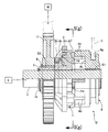
ドグクラッチDは、回転軸3と、その回転軸3の外周面に軸方向移動可能且つ相対回転不能に嵌合、支持(実施形態ではスプライン嵌合S1)される中継部材4と、中継部材4の軸方向一方側(図1で左側)の側面4sに対向するよう配置されると共に回転軸3の外周面に相対回転自在に嵌合、支持される第1伝動体1と、中継部材4の上記側面4sに対向するよう配置されると共に第1伝動体1に対し相対回転可能な第2伝動体2と、第1,第2伝動体1,2間に介装される弾性部材としての捩じりばね6とを備える。
The dog clutch D includes a
本実施形態において、回転軸3は、不図示の連動機構を介して動力源Eに接続される。また第1伝動体1は、これと一体的に回転する出力歯車7、及び不図示の連動機構を介して負荷Wに接続される。出力歯車7は、出力部材の一例である。
In the present embodiment, the rotating
中継部材4の前記側面4sには、第1,第2伝動体1,2側に突き出す複数の係合ドグ4dが周方向等間隔おきに突設される。また、それらの係合ドグ4dの背面側で中継部材4の外周面には、環状の係合溝4gが凹設される。その係合溝4gには、中継部材4を軸方向に駆動(即ち第1,第2伝動体1,2に対し進退操作)するための操作部材5(例えばシフトフォーク)が係合する。
On the
第1伝動体1は、回転軸3が中心部を回転自在に貫通する円盤状の第1伝動体本体1mと、その第1伝動体本体1mに連設されて中継部材4とは反対側に延びる取付ボス部1bとを一体に有しており、取付ボス部1bの内周面も回転軸3に回転自在に嵌合している。第1伝動体本体1mの外周部には、係合ドグ4dに対して係脱可能な径方向外向きの複数(本実施形態では係合ドグ4dと同数)の低ドグ1dが、周方向等間隔おきに突設されている。
The
取付ボス部1bの外周面は、先端側の小径部1b1と、その小径部1b1に第1段差部1bs1を介して連なる中径部1b2と、その中径部1b2に第2段差部1bs2を介して連なる大径部1b3とを有する段付き円筒面に形成されている。そして、小径部1b1に出力歯車7の内周部が相対回転不能に嵌合(実施形態ではスプライン嵌合S2)され、また中径部1b2に第2伝動体2の内周部が回転自在に嵌合される。
The outer peripheral surface of the mounting
また取付ボス部1bの特に小径部1b1の先部には、第2伝動体2及び出力歯車7を第1伝動体本体1mとの間に挟む止め輪8(例えばサークリップ)が設けられる。止め輪8は、抜け止め手段の一例であり、これに代えて、例えば取付ボス部1b(特に小径部1b1)の先部に螺合されるナットや、同先部に係止される割りピン等を使用してもよく、或いはまた、同先部をカシメ加工したカシメ部を抜け止め手段としてもよい。
Further, a retaining ring 8 (for example, a circlip) is provided at the front end of the small-diameter portion 1b1 of the mounting
回転軸3の外周には、取付ボス部1bの先端に係合して第1伝動体1の軸方向移動を規制する規制手段(例えばサークリップ等の止め輪9)が係止される。
A restricting means (for example, a retaining
また、第2伝動体2は、リング状の第2伝動体本体2mと、第2伝動体本体2mに対し軸方向(特に中継部材4とは反対側)にオフセット配置され且つ第2伝動体本体2mよりも小径のリング状の小径基部2bと、それら第2伝動体本体2m及び小径基部2b間を一体に接続すべく周方向等間隔おきに配置される複数の連結腕部2cとを備える。各連結腕部2cの外面は小径基部2bから第2伝動体本体2mに向かって径方向外方側に傾斜した斜面に形成される。
Further, the
そして、小径基部2bの内周面が、第1伝動体1の取付ボス部1bの中径部1b2に回転自在に嵌合、支持される。
And the inner peripheral surface of the small
また第2伝動体本体2mの、中継部材4との対向側面には、係合ドグ4dに対して係脱し得るように中継部材4側に張出す複数(本実施形態では係合ドグ4dと同数)の高ドグ2dが、周方向等間隔おきに突設される。その各々の高ドグ2dは、周方向で隣り合う低ドグ1d,1dの相互間に配置されており、且つ軸方向で低ドグ1dよりも中継部材4側に突き出している。
In addition, a plurality of the
捩じりばね6は、高ドグ2d及び低ドグ1dが係合ドグ4dに対し非係合の状態(例えば図5に示すようなドグクラッチDの遮断状態)で、隣り合う低ドグ1d,1d間の所定位置(本実施形態では低ドグ1d間の中間位置、即ち略真ん中)に高ドグ2dを自己の弾性で保持する機能を果たすものであって、本実施形態では捩じりコイルばねより構成される。そして、この捩じりばね6は、第1伝動体本体1mの、中継部材4とは反対側の側面1msに隣接配置されると共に、両端末61,62が第1,第2伝動体1,2相互の対向側面にそれぞれ係止される。
The
即ち、本実施形態の捩じりばね6は、そのコイル状のばね本体部6mが取付ボス部1bの大径部1b3に遊隙を存して嵌装され、このばね本体部6mの一端側の第1端末部61が、第1伝動体本体1mの前記側面1msに凹設した第1係止孔h1に係止される。またばね本体部6mの他端側の第2端末部62が、第2伝動体2(特に小径基部2b)の、第1伝動体本体1mの側面1msと対向する側面2bsに凹設した第2係止孔h2に係止される。
That is, the
上記したように第1伝動体1の取付ボス部1bの中径部1b2及び小径部1b1には、第2伝動体2の小径基部2b及び出力歯車7内周部がそれぞれ嵌合され、更にその小径基部2b及び出力歯車7を第1伝動体本体1mとの間に挟む止め輪8が、小径部1b1の先部に装着される。そのため、第2伝動体2は、出力歯車7と共に、第1伝動体1の取付ボス部1bに軸方向相対移動を制限された状態で支持される。
As described above, the small-
次に前記実施形態の作用を主として図5〜図8を参照して説明する。 Next, the operation of the above embodiment will be described mainly with reference to FIGS.
ドグクラッチDの組立に際しては、先ず、第1伝動体1の取付ボス1b(大径部1b3)に捩じりばね6のばね本体部6mを緩く嵌合させ且つそのばね6の第1端末部61を第1伝動体本体1mの係止孔h1に係止させることで、捩じりばね6を第1伝動体1に仮止めする。
When assembling the dog clutch D, first, the
次いで、第1伝動体1の取付ボス1b(中径部1b2)に第2伝動体2の小径基部2bを嵌合させ、それと共に捩じりばね6の第2端末部62を小径基部2bの係止孔h2に係止させることで、第2伝動体2及び捩じりばね6を第1伝動体1に仮止めする。
Next, the small
しかる後に取付ボス1b(小径部1b1)に出力歯車7をスプライン嵌合S2させ、次いで止め輪8を小径部1b1に係止させることで、止め輪8と第1伝動体本体1mとの間に、出力歯車7、第2伝動体2及び捩じりばね6を挟み込んで1個のサブアッセンブリを小組みする。
Thereafter, the
しかる後に、そのサブアッセンブリを回転軸3の一方(図1で左方)から嵌合させ、その嵌合状態を、回転軸3外周に係止させたサークリップ等の止め輪9で保持する。また回転軸3の他方(図1で右方)からは、中継部材4をスプライン嵌合S1させ、その中継部材4外周の係合溝4gに操作部材5を係合させて、この操作部材5で中継部材4を第1,第2伝動体1,2に対し随時に進退操作できるようにする。かくして、ドグクラッチDの組立てが終了する。なお、組立の手順は上記に限定されるものでは無い。
Thereafter, the sub-assembly is fitted from one of the rotating shafts 3 (left side in FIG. 1), and the fitting state is held by a retaining
このようにして組立てられ且つ所定の動力伝達経路に組み込まれたドグクラッチDが遮断状態(図5参照)にあり、しかも第1伝動体1と回転軸3とが相対回転中(例えば、回転軸3が第1伝動体1よりも高速で第1伝動体1と同方向に回転中、或いは第1伝動体1が停止し回転軸3だけが回転中)に、ドグクラッチDを接続状態に切替えるべく中継部材4を第1,第2伝動体1,2に対し接近操作する過程を想定する。
The dog clutch D assembled in this way and incorporated in a predetermined power transmission path is in the disconnected state (see FIG. 5), and the
この操作過程では、先ず、図6に示すように、低ドグ1dよりも突出高さの高い高ドグ2dが、低ドグ1dより先に係合ドグ4dに回転方向で係合する。尚、その係合に至るまでの間、係合ドグ4dと低ドグ1dとは回転方向に相対摺動可能である。
In this operation process, first, as shown in FIG. 6, the
上記係合により高ドグ2dは、これよりも高速回転する係合ドグ4dに追従、同期しようとして、捩じりばね6を弾性変形させながら高ドグ2d両側の2個の低ドグ1dに対し周方向に相対変位し、遂には、図7に示すように一方の(即ち回転軸3の回転方向前側の)低ドグ1dと係合するに至る。このとき、その他方の(即ち上記回転方向後側の)低ドグ1dと高ドグ2dとの間には、周方向に比較的広い(即ちドグクラッチDの遮断時における高ドグ2dと低ドグ1d間の間隙10よりも十分に広い(本実施形態では略2倍程度の幅広の)間隙20が形成される。
Due to the above engagement, the
そして、この間隙20は、係合ドグ4dの周方向幅と略同じか多少広めに設定されている。従って、図8に示すように、係合ドグ4dが間隙20にスムーズに突入、係合して、中継部材4と第1伝動体1との間が相対回転不能に連結される。即ち、ドグクラッチDが接続状態に切替わる。
The
このようにドグクラッチDを接続状態に切替えるために、回転軸3と第1伝動体1との相対回転中に中継部材4を第1,第2伝動体1,2に接近させると、係合ドグ4dが低ドグ1dよりも先に高ドグ2dに係合し(図6参照)、この係合に伴い、高ドグ2dが捩じりばね6の弾性抵抗を受けつつ、隣り合う低ドグ1d,1dのうちの一方の低ドグ1dに係合するに至る(図7参照)。このとき、その他方の低ドグ1dと高ドグ2dとの間には周方向に幅広の間隙20が形成されており、その間隙20に係合ドグ4dがスムーズに突入、係合する(図8参照)。
In order to switch the dog clutch D to the connected state in this way, when the relay member 4 is brought close to the first and
かくして、上記したドグクラッチDの遮断状態から接続状態への切替過程(即ち図5〜図8)において、係合ドグ4dが最初に高ドグ2dに係合する際には、周方向で隣り合う高ドグ2d,2d相互間の幅広の間隙が、係合ドグ4dに対する実質的な係合凹部となって、係合ドグ4dと高ドグ2dとの噛み合いを容易にするため、例えば、高ドグ2d及び低ドグ1dを合せた周方向幅を有するドグと、係合ドグ4dとを噛み合わせる場合と比べて、噛み合い効率を効果的に高めることができる。しかも、係合ドグ4dが高ドグ2dに最初に係合する際の衝撃は、捩じりばね6の弾性変形により効果的に吸収、緩和可能である。
Thus, in the switching process from the disconnected state to the connected state of the dog clutch D (that is, FIGS. 5 to 8), when the engaging
その上、高ドグ2dが、隣り合う低ドグ1d,1dのうちの一方の低ドグ1dに係合するのに応じて、その他方の低ドグ1dと高ドグ2dとの間に形成される周方向の幅広間隙20に係合ドグ4dが突入、係合するため、係合ドグ4dが高ドグ2dに単独で噛合する場合よりも、低ドグ1dの幅分だけ係合ドグ4dと高ドグ2dとの噛合部のガタを低減可能となり、これにより、適正な噛合状態が得られる。
In addition, as the
このようにドグクラッチDは、ドグ噛合時の衝撃の吸収、緩和を図りながら、噛み合い効率の向上と噛合部のガタ低減といった相反する課題を何れも達成可能とした、極めて高性能なドグクラッチである。 As described above, the dog clutch D is an extremely high-performance dog clutch that can achieve both conflicting problems such as improvement of meshing efficiency and reduction of backlash of the meshing part while absorbing and mitigating impact during dog meshing.
またこのドグクラッチDにおいては、高ドグ2d及び低ドグ1dが係合ドグ4dに対し非係合の状態(即ちクラッチ遮断状態)で、捩じりばね6が、周方向で隣り合う低ドグ1d,1d相互間の所定の中間位置(即ち略真ん中)に高ドグ2dを保持するよう設定される。これにより、回転軸3及び第1伝動体1相互の相対回転の回転方向が正,逆転何れの方向の場合でも、ドグ噛合時の衝撃を有効に吸収、緩和することができる。
In this dog clutch D, the
また捩じりばね6は、第1伝動体本体1mの、中継部材4とは反対側の側面1sに隣接配置されていて、両端末部61,62が第1,第2伝動体1,2にそれぞれ係止される設置態様である。これにより、中継部材4や高ドグ2d及び低ドグ1dの形状に制約を加えることなく、捩じりばね6を高い自由度を以て配置可能とし且つ第1,第2伝動体1,2に各々係止可能となる。
The
またドグクラッチDの組立完成状態において、第2伝動体2は、第1伝動体1に軸方向で所定の制限された摺動範囲内を摺動可能として支持され、第1,第2伝動体1,2間に捩じりばね6が介装される。これにより、第1,第2伝動体1,2及び捩じりばね6を含む小組立ユニットを構成できるため、その取り扱いが簡便であり、また回転軸3への組付作業性も良好である。
In the assembled state of the dog clutch D, the
また特に本実施形態では、第1伝動体1の取付ボス部1bに、第2伝動体2が回転自在に嵌合されると共に出力歯車7が相対回転不能に嵌合(スプライン嵌合S2)され、更に第2伝動体2及び出力歯車7を第1伝動体本体1mとの間に挟む止め輪8が設けられている。これにより、第1,第2伝動体1,2及び捩じりばね6のみならず出力歯車7をも含めた小組立ユニット、即ちサブアッセンブリを構成でき、それら構成部品1,2,6,7を一纏めに回転軸3へ組付け可能となることから、組付作業性が更に良好である。しかも第2伝動体2及び出力歯車7の、取付ボス部1bからの各抜け止めのために、共通の抜け止め手段すなわち止め輪8を利用できるから、それだけ構造簡素化が図られる。
Further, particularly in the present embodiment, the
以上、本発明の実施形態について説明したが、本発明は、実施形態に限定されるものではなく、その要旨を逸脱しない範囲で種々の設計変更が可能である。 As mentioned above, although embodiment of this invention was described, this invention is not limited to embodiment, A various design change is possible in the range which does not deviate from the summary.
例えば、前記実施形態では、回転軸3を入力側、即ち動力源E(例えばエンジン等)に連なる側とし、また第1伝動体1を出力側、即ち負荷W(例えば車輪等)に連なる側としたものを例示したが、本発明のドグクラッチは、第1伝動体1を入力側とし、また回転軸3を出力側として動力伝達経路に配置してもよい。その場合、第1伝動体1の取付ボス部1bには、前記実施形態の出力歯車7(出力部材)に代えて、負荷Wに連動する入力歯車(入力部材)が相対回転不能に嵌合、固定される。
For example, in the embodiment, the
また、前記実施形態の捩じりばね6は、高ドグ2d及び低ドグ1dが係合ドグ4dに対し非係合の状態で、隣り合う低ドグ1d,1d間の中間位置(即ち略真ん中)に高ドグ2dを保持するものを示したが、捩じりばね6の弾発力で高ドグ2dを、隣り合う低ドグ1d,1dのうちの一方の低ドグ1dに当接する位置、又は真ん中より一方の低ドグ1dに偏らせた位置に保持させるようにしてもよい。
In addition, the
また前記実施形態では、ドグクラッチDを自動車の変速装置に適用したものを示したが、本発明のドグクラッチの適用対象は、実施形態に限定されない。即ち、本発明のドグクラッチは、種々の伝動機械装置に適用可能であり、その用途は車両用や変速装置用に限定されない。 Moreover, although the thing which applied the dog clutch D to the transmission of a motor vehicle was shown in the said embodiment, the application object of the dog clutch of this invention is not limited to embodiment. That is, the dog clutch of the present invention can be applied to various transmission mechanical devices, and the use thereof is not limited to vehicles and transmissions.
D・・・・・ドグクラッチ
1・・・・・第1伝動体
1b・・・・取付ボス部
1d・・・・低ドグ
1m・・・・第1伝動体本体
2・・・・・第2伝動体
2d・・・・高ドグ
3・・・・・回転軸
4・・・・・中継部材
4d・・・・係合ドグ
4s・・・・側面
6・・・・・捩じりばね(弾性部材)
61,62・・第1,第2端末部(両端)
7・・・・・出力歯車(出力部材)
8・・・・・止め輪(抜け止め手段)
20・・・・間隙
D ...
61, 62 .. First and second terminal parts (both ends)
7. Output gear (output member)
8 ... Retaining ring (prevention means)
20 ... Gap
Claims (5)
前記中継部材(4)の軸方向一方側の側面(4s)に対向するよう配置され前記回転軸(3)に対し相対回転可能な第1伝動体(1)と、
前記中継部材(4)の前記側面(4s)に対向するよう配置され前記第1伝動体(1)に対し相対回転可能な第2伝動体(2)と、
前記中継部材(4)に突設される少なくとも1つの係合ドグ(4d)と、
前記係合ドグ(4d)に係脱し得るように前記第1伝動体(1)に周方向に間隔をおいて突設される複数の低ドグ(1d)と、
前記係合ドグ(4d)に係脱し得るように前記第2伝動体(2)に周方向に間隔をおいて突設されると共に、周方向で隣り合う前記低ドグ(1d,1d)の相互間に配置されて該低ドグ(1d)よりも前記中継部材(4)側に突き出す複数の高ドグ(2d)と、
前記高ドグ(2d)及び前記低ドグ(1d)が前記係合ドグ(4d)に対し非係合の状態で、前記隣り合う低ドグ(1d,1d)間の所定位置に前記高ドグ(2d)を保持し得る弾性部材(6)とを備え、
前記第1伝動体(1)と前記回転軸(3)との相対回転状態で前記中継部材(4)を前記第1,第2伝動体(1,2)に接近させる過程において、前記係合ドグ(4d)に対し前記低ドグ(1d)よりも先に係合する前記高ドグ(2d)が、前記隣り合う低ドグ(1d,1d)のうちの一方の低ドグ(1d)に対し前記弾性部材(6)に抗して係合したときに、その他方の低ドグ(1d)と前記高ドグ(2d)との間に、前記係合ドグ(4d)が突入可能な周方向間隙(20)が形成されることを特徴とするドグクラッチ。 A relay member (4) supported on the rotary shaft (3) so as to be axially movable and relatively non-rotatable;
A first transmission body (1) disposed so as to face a side surface (4s) on one axial side of the relay member (4) and rotatable relative to the rotation shaft (3);
A second transmission body (2) arranged to face the side surface (4s) of the relay member (4) and rotatable relative to the first transmission body (1);
At least one engagement dog (4d) protruding from the relay member (4);
A plurality of low dogs (1d) projecting from the first transmission body (1) at intervals in the circumferential direction so as to be engaged with and disengaged from the engagement dog (4d);
The low transmission gears (1d, 1d) adjacent to each other in the circumferential direction are provided on the second transmission body (2) so as to be engaged with and disengaged from the engagement dog (4d). A plurality of high dogs (2d) disposed between the low dogs (1d) and projecting toward the relay member (4),
When the high dog (2d) and the low dog (1d) are not engaged with the engaging dog (4d), the high dog (2d) is positioned at a predetermined position between the adjacent low dogs (1d, 1d). And an elastic member (6) capable of holding
In the process of bringing the relay member (4) closer to the first and second transmission bodies (1, 2) in a state of relative rotation between the first transmission body (1) and the rotary shaft (3), the engagement The high dog (2d) that is engaged with the dog (4d) before the low dog (1d) is in contact with one of the adjacent low dogs (1d, 1d) with respect to the low dog (1d). When engaged against the elastic member (6), a circumferential gap (in which the engagement dog (4d) can enter between the other low dog (1d) and the high dog (2d) ( 20) is formed.
前記第1,第2伝動体(1,2)間に前記弾性部材(6)が介装されることを特徴とする、請求項1〜3の何れか1項に記載のドグクラッチ。 The second transmission body (2) is supported in a state where axial relative movement is restricted by the first transmission body (1),
The dog clutch according to any one of claims 1 to 3, wherein the elastic member (6) is interposed between the first and second transmission bodies (1, 2).
前記取付ボス部(1b)には、前記第2伝動体(2)が回転自在に嵌合されると共に出力部材(7)又は入力部材が相対回転不能に嵌合され、
更に前記取付ボス部(1b)には、前記第2伝動体(2)及び前記出力部材(7)又は入力部材を前記第1伝動体本体(1m)との間に挟む抜け止め手段(8)が設けられることを特徴とする、請求項4に記載のドグクラッチ。 The first transmission body (1) includes a first transmission body (1m) having the low dog (1s) and the relay member (4) connected to the first transmission body (1m). A mounting boss (1b) extending to the opposite side,
The mounting boss (1b) is fitted with the second transmission body (2) so as to be rotatable, and the output member (7) or the input member is fitted so as not to be relatively rotatable.
Further, the mounting boss (1b) has a retaining means (8) for sandwiching the second transmission body (2) and the output member (7) or the input member with the first transmission body (1m). The dog clutch according to claim 4, wherein the dog clutch is provided.
Priority Applications (2)
| Application Number | Priority Date | Filing Date | Title |
|---|---|---|---|
| JP2018036622A JP2019152249A (en) | 2018-03-01 | 2018-03-01 | Dog clutch |
| PCT/JP2019/007468 WO2019167999A1 (en) | 2018-03-01 | 2019-02-27 | Dog clutch |
Applications Claiming Priority (1)
| Application Number | Priority Date | Filing Date | Title |
|---|---|---|---|
| JP2018036622A JP2019152249A (en) | 2018-03-01 | 2018-03-01 | Dog clutch |
Publications (2)
| Publication Number | Publication Date |
|---|---|
| JP2019152249A true JP2019152249A (en) | 2019-09-12 |
| JP2019152249A5 JP2019152249A5 (en) | 2020-07-27 |
Family
ID=67806262
Family Applications (1)
| Application Number | Title | Priority Date | Filing Date |
|---|---|---|---|
| JP2018036622A Pending JP2019152249A (en) | 2018-03-01 | 2018-03-01 | Dog clutch |
Country Status (2)
| Country | Link |
|---|---|
| JP (1) | JP2019152249A (en) |
| WO (1) | WO2019167999A1 (en) |
Citations (3)
| Publication number | Priority date | Publication date | Assignee | Title |
|---|---|---|---|---|
| JP2014152879A (en) * | 2013-02-12 | 2014-08-25 | Fuji Heavy Ind Ltd | Power transmission |
| JP2015105697A (en) * | 2013-11-29 | 2015-06-08 | 武蔵精密工業株式会社 | Dog clutch |
| US20150300417A1 (en) * | 2012-10-31 | 2015-10-22 | Daimler Ag | Form-Fitting Switching Unit for a Motor Vehicle Drive Train |
-
2018
- 2018-03-01 JP JP2018036622A patent/JP2019152249A/en active Pending
-
2019
- 2019-02-27 WO PCT/JP2019/007468 patent/WO2019167999A1/en active Application Filing
Patent Citations (3)
| Publication number | Priority date | Publication date | Assignee | Title |
|---|---|---|---|---|
| US20150300417A1 (en) * | 2012-10-31 | 2015-10-22 | Daimler Ag | Form-Fitting Switching Unit for a Motor Vehicle Drive Train |
| JP2014152879A (en) * | 2013-02-12 | 2014-08-25 | Fuji Heavy Ind Ltd | Power transmission |
| JP2015105697A (en) * | 2013-11-29 | 2015-06-08 | 武蔵精密工業株式会社 | Dog clutch |
Also Published As
| Publication number | Publication date |
|---|---|
| WO2019167999A1 (en) | 2019-09-06 |
Similar Documents
| Publication | Publication Date | Title |
|---|---|---|
| US6378677B1 (en) | Power transmission device having electromagnetic clutch | |
| KR101945432B1 (en) | Support structure of the rotating shaft of the vehicle | |
| CN108350952B (en) | Quick disconnect device of power transmission system | |
| US9156351B2 (en) | Power transfer device with low effort mode shift system | |
| CN109642654B (en) | Differential for motor vehicle | |
| JP2005083474A (en) | Electric linear actuator | |
| JP6648173B2 (en) | Vehicle drive system | |
| JP6277895B2 (en) | Torque transmission member and coupling portion between drive shaft and driven shaft | |
| JP2007040424A (en) | Electric linear actuator | |
| WO2019167999A1 (en) | Dog clutch | |
| US10988022B2 (en) | Electro-mechanical on demand (EMOD) transfer case—dual drive gear and shift fork consolidation | |
| JP3226587U (en) | Bistable latch mechanism and drive system high speed disconnect device made using the same | |
| JP2020190280A (en) | Power transmission path changeover device and two-stage transmission | |
| US9689471B2 (en) | Automatic transmission | |
| JP2016088406A (en) | Differential limiting device of four-wheel drive vehicle | |
| JP6696295B2 (en) | Power transmission device | |
| JPH0464747A (en) | Differential limiting device | |
| US11796043B1 (en) | Differential device | |
| JP7476873B2 (en) | Power transmission | |
| JP4145817B2 (en) | Differential unit with differential limiting mechanism | |
| CN110962590A (en) | Electric drive axle and vehicle | |
| JP5871522B2 (en) | Four-wheel drive vehicle transfer | |
| JP5915375B2 (en) | Torque transmission joint and electric power steering device | |
| EP3851705A1 (en) | Vehicular differential assembly | |
| JP4582055B2 (en) | Starter |
Legal Events
| Date | Code | Title | Description |
|---|---|---|---|
| A521 | Request for written amendment filed |
Free format text: JAPANESE INTERMEDIATE CODE: A523 Effective date: 20200508 |
|
| A621 | Written request for application examination |
Free format text: JAPANESE INTERMEDIATE CODE: A621 Effective date: 20200508 |
|
| A131 | Notification of reasons for refusal |
Free format text: JAPANESE INTERMEDIATE CODE: A131 Effective date: 20210303 |
|
| A02 | Decision of refusal |
Free format text: JAPANESE INTERMEDIATE CODE: A02 Effective date: 20211006 |