JP2019148105A - Gap obturator used in micropile construction method and micropile construction method using the same - Google Patents
Gap obturator used in micropile construction method and micropile construction method using the same Download PDFInfo
- Publication number
- JP2019148105A JP2019148105A JP2018033126A JP2018033126A JP2019148105A JP 2019148105 A JP2019148105 A JP 2019148105A JP 2018033126 A JP2018033126 A JP 2018033126A JP 2018033126 A JP2018033126 A JP 2018033126A JP 2019148105 A JP2019148105 A JP 2019148105A
- Authority
- JP
- Japan
- Prior art keywords
- casing
- bag body
- gap
- closing member
- micropile
- Prior art date
- Legal status (The legal status is an assumption and is not a legal conclusion. Google has not performed a legal analysis and makes no representation as to the accuracy of the status listed.)
- Granted
Links
- 238000010276 construction Methods 0.000 title claims abstract description 20
- 239000000463 material Substances 0.000 claims abstract description 74
- 239000011440 grout Substances 0.000 claims abstract description 57
- 230000002093 peripheral effect Effects 0.000 claims abstract description 55
- 238000000034 method Methods 0.000 claims abstract description 22
- 239000000945 filler Substances 0.000 claims abstract description 21
- 238000005553 drilling Methods 0.000 claims description 24
- 238000013459 approach Methods 0.000 claims description 3
- 238000000605 extraction Methods 0.000 claims description 3
- 239000004927 clay Substances 0.000 abstract description 6
- 239000002689 soil Substances 0.000 abstract description 3
- 238000002347 injection Methods 0.000 abstract description 2
- 239000007924 injection Substances 0.000 abstract description 2
- 239000000243 solution Substances 0.000 abstract 1
- XLYOFNOQVPJJNP-UHFFFAOYSA-N water Substances O XLYOFNOQVPJJNP-UHFFFAOYSA-N 0.000 description 8
- 239000011435 rock Substances 0.000 description 5
- 229910000831 Steel Inorganic materials 0.000 description 4
- 239000010959 steel Substances 0.000 description 4
- 239000004568 cement Substances 0.000 description 2
- 238000005304 joining Methods 0.000 description 2
- 239000008267 milk Substances 0.000 description 2
- 210000004080 milk Anatomy 0.000 description 2
- 235000013336 milk Nutrition 0.000 description 2
- 239000004570 mortar (masonry) Substances 0.000 description 2
- 230000002787 reinforcement Effects 0.000 description 2
- 230000003014 reinforcing effect Effects 0.000 description 2
- 239000012779 reinforcing material Substances 0.000 description 2
- 238000003466 welding Methods 0.000 description 2
- 238000005520 cutting process Methods 0.000 description 1
- 239000004744 fabric Substances 0.000 description 1
- 238000005429 filling process Methods 0.000 description 1
- 230000006641 stabilisation Effects 0.000 description 1
- 238000011105 stabilization Methods 0.000 description 1
Images


Classifications
-
- Y—GENERAL TAGGING OF NEW TECHNOLOGICAL DEVELOPMENTS; GENERAL TAGGING OF CROSS-SECTIONAL TECHNOLOGIES SPANNING OVER SEVERAL SECTIONS OF THE IPC; TECHNICAL SUBJECTS COVERED BY FORMER USPC CROSS-REFERENCE ART COLLECTIONS [XRACs] AND DIGESTS
- Y02—TECHNOLOGIES OR APPLICATIONS FOR MITIGATION OR ADAPTATION AGAINST CLIMATE CHANGE
- Y02E—REDUCTION OF GREENHOUSE GAS [GHG] EMISSIONS, RELATED TO ENERGY GENERATION, TRANSMISSION OR DISTRIBUTION
- Y02E10/00—Energy generation through renewable energy sources
- Y02E10/20—Hydro energy
Abstract
Description
本発明は、マイクロパイル工法で用いる隙間閉塞具およびその隙間閉塞具を用いたマイクロパイル工法に関する。 The present invention relates to a gap obturator used in a micropile construction method and a micropile construction method using the gap obturator.
マイクロパイル工法は、直径300mm以下の小径の場所打ち杭の総称であり、コンパクトな施工設備で備足りること、狭い空間で施工できること、既設構造物の機能を停止することなく施工できることなどの理由から、既設構造物の耐震補強や地盤補強、斜面の安定化などをはじめとする様々な用途に用いられている。
マイクロパイル工法では、まず、先端外周部が外側削孔用カッターとされた1番目のケーシングセグメントの内部に、先端に削孔ドリルが取着された1番目のロッドを挿通させ、それら1番目のケーシングセグメントとロッドとを回転させつつ、また、水を注入しつつ削孔していく工程が行なわれる。
The micropile construction method is a generic name for small-sized cast-in-place piles with a diameter of 300 mm or less, for reasons such as being sufficient with compact construction equipment, being able to be constructed in a narrow space, and being able to be constructed without stopping the functions of existing structures It is used for various purposes including seismic reinforcement of existing structures, ground reinforcement, and stabilization of slopes.
In the micropile method, first, the first rod having a drilling drill attached to the tip is inserted into the first casing segment whose outer periphery is the outer drilling cutter. A step of drilling while rotating the casing segment and the rod and injecting water is performed.
そして、所定の深さ毎に、ケーシングセグメントの端部に次のケーシングセグメントを継手部材を介して着脱可能に連結して継ぎ足すと共に、ロッドの端部に次のロッドを着脱可能に連結して継ぎ足し、ケーシングセグメントとロッドとを回転させ、また、水を注入しつつ削孔していく工程が行なわれる。
なお、外側削孔用カッターの外径は継手部材の外径を考慮し、ケーシングセグメントの外径よりも大きく、削孔後、削孔壁面とケーシングセグメントの外周面との間には環状隙間が形成される。
複数のケーシングセグメントが連結されることでケーシングが構成され、削孔された孔が軟弱層を通過し荷重支持層の所定の深さに到達したならば、ロッドと共に削孔ドリルをケーシングの内部から引き抜く工程が行なわれる。
そして、必要に応じて鉄筋などの補強材をケーシングの内部にケーシングの全長にわたって配設する。
Then, at each predetermined depth, the next casing segment is detachably connected to the end of the casing segment via a joint member and added, and the next rod is detachably connected to the end of the rod. The process of adding holes, rotating the casing segment and the rod, and drilling while injecting water is performed.
The outer diameter of the outer drilling cutter is larger than the outer diameter of the casing segment in consideration of the outer diameter of the joint member. After drilling, there is an annular gap between the drilling wall surface and the outer peripheral surface of the casing segment. It is formed.
When a plurality of casing segments are connected to form a casing, and the drilled hole passes through the soft layer and reaches a predetermined depth of the load support layer, the drill with the rod is removed from the inside of the casing. A drawing process is performed.
Then, if necessary, a reinforcing material such as a reinforcing bar is disposed inside the casing over the entire length of the casing.
次に、グラウトホースを用いてケーシングの内部にグラウト材を充填する。
グラウト材として、セメントミルク、モルタル材、小径の骨材を混入したコンクリート材が使用可能である。
次に、ケーシングの内部にグラウト材を加圧注入しつつ、ケーシングを引き抜く工程、すなわち、ケーシングセグメントの引き抜き工程が行なわれる。
グラウト材の加圧は、グラウト材が、削孔された孔の壁面に密着し、グラウト材と地盤との間の接合状態が強固となるような圧力で行なわれることが望ましい。
上方に位置する複数本のケーシングセグメントが継手部材と共に取り外され、最下位に位置する一番目のケーシングセグメントの下端が、荷重支持層の最上部に近づいたところで、ケーシングの引き抜きは終了する。
Next, the grout material is filled into the casing using a grout hose.
As the grout material, cement milk, mortar material, or a concrete material mixed with a small diameter aggregate can be used.
Next, a step of pulling out the casing while pressure-injecting the grout material into the casing, that is, a step of pulling out the casing segment is performed.
It is desirable that the grouting material be pressed under such a pressure that the grouting material is in close contact with the wall surface of the drilled hole and the bonding state between the grouting material and the ground becomes strong.
When the plurality of upper casing segments are removed together with the joint member and the lower end of the first casing segment located at the lowest position approaches the uppermost portion of the load support layer, the drawing of the casing is completed.
次に、ケーシングを、グラウト材が加圧充填されたグラウト材の中に所定量押し戻しグラウト材を加圧注入する工程が行なわれ、ケーシングで囲繞された部分と、ケーシングで囲繞されていない部分との間に、中間的な構造を有する部分を作り出す。
そして、グラウト材が硬化されることで、荷重支持層にグラウト材による地盤接合部が形成された杭体が得られる。
次に、ケーシングの上端部に鋼製の支圧板が溶接により接合され、杭体の杭頭部を構造物に連結するための連結構造が形成される。
Next, the step of pushing back the grout material by a predetermined amount into the grout material pressure-filled with the grout material is performed, and the part surrounded by the casing and the part not surrounded by the casing are In between, create a part with an intermediate structure.
And the pile body by which the ground junction part by the grout material was formed in the load support layer is obtained by hardening a grout material.
Next, a steel bearing plate is joined to the upper end of the casing by welding to form a connection structure for connecting the pile head of the pile body to the structure.
ところで地盤が軟弱地盤である場合、1番目のケーシングセグメントの先端外周部の外側削孔用カッターと、削孔ドリルとにより掘削された孔は、削孔時にその孔の壁面が崩れ、削孔された孔の内周面とケーシングの外周面との間の環状隙間は閉塞されるため、最終の工程においてケーシングの内部のグラウト材に圧力をかけることができる。 By the way, when the ground is soft ground, the hole drilled by the outer drilling cutter on the outer periphery of the tip of the first casing segment and the drilling drill is broken and the wall surface of the hole collapses during drilling. Since the annular gap between the inner peripheral surface of the hole and the outer peripheral surface of the casing is closed, pressure can be applied to the grout material inside the casing in the final step.
しかしながら、削孔すべき箇所が粘性土系の地盤や岩盤である場合、削孔された孔の内周面は崩れることが少なく、削孔後、削孔された孔の内周面とケーシングセグメントの外周面との間には環状隙間が常時確保されている状態となっている。
そのため、最終の工程において、グラウト材に圧力をかけることができず、ケーシング下端の周囲を含んだケーシングの直下に、グラウト材と地盤とが強固に接合した接合部を作ることができない。
このような事態を解消するため、従来では、1回グラウト材を注入し、そのグラウト材の硬化が始まりかけたところで、再度、グラウト材を注入しグラウト材に圧力を掛けるようにしており、作業時間を短縮できず、マイクロパイル工法を効率良く行なえない不具合があった。
このような事態を解消するため、高い粘性のグラウト材を使用することも考えられるが、この場合には、従来のポンプを使用できなくなり、大型のポンプを導入しなければならないなどコストが上昇する不具合が生じる。
However, when the location to be drilled is clayey ground or rock, the inner peripheral surface of the drilled hole is less likely to collapse, and after drilling, the inner peripheral surface of the drilled hole and the casing segment An annular gap is always ensured between the outer peripheral surface of each other.
Therefore, in the final process, pressure cannot be applied to the grout material, and a joint portion in which the grout material and the ground are firmly joined cannot be formed immediately below the casing including the periphery of the lower end of the casing.
In order to eliminate such a situation, conventionally, the grout material is injected once, and when the hardening of the grout material is about to start, the grout material is injected again and pressure is applied to the grout material. There was a problem that the time could not be shortened and the micropile method could not be performed efficiently.
In order to eliminate such a situation, it is conceivable to use a highly viscous grout material. In this case, however, the conventional pump cannot be used, and a large pump must be introduced, which increases costs. Trouble occurs.
本発明は前記事情に鑑み案出されたものであって、本発明の目的は、削孔すべき箇所が粘性土系の地盤や岩盤である場合、簡単な構造により削孔された孔の内周面とケーシングの外周面との間の環状隙間を確実に閉塞でき、マイクロパイル工法の最終の工程において、グラウト材の加圧注入を効率良く行なえるマイクロパイル工法で用いる隙間閉塞具及びその隙間閉塞具を用いたマイクロパイル工法を提供することにある。 The present invention has been devised in view of the above circumstances, and an object of the present invention is to provide a simple structure for a hole to be drilled when the portion to be drilled is a clay soil or rock. Gap obturator used in the micropile method that can reliably close the annular gap between the peripheral surface and the outer peripheral surface of the casing, and can efficiently pressurize the grout material in the final step of the micropile method, and the gap The object is to provide a micropile construction method using an obturator.
前記目的を達成するため、請求項1記載の発明は、ケーシングの回転により削孔された孔の内周面と前記ケーシングの外周面との間の環状隙間を閉塞するマイクロパイル工法で用いる隙間閉塞具であって、前記削孔された孔の延在方向と直交する平面で切断した断面形状が前記ケーシングの断面形状よりも大きくかつ前記削孔された孔の断面形状よりも小さい輪郭の縮小状態から、前記ケーシングの外周面の全周および前記削孔された孔の内周面の全周に密着する拡張状態へ可変な隙間閉塞部材と、前記隙間閉塞部材を前記縮小状態から前記拡張状態にする拡張手段とを備えることを特徴とする。
請求項2記載の発明は、前記隙間閉塞部材は、折り畳み可能な材料で形成され前記ケーシングが挿通される環状で袋状に形成された袋体で構成され、前記拡張手段は、前記袋体の内部に供給されることで前記袋体を拡張させる充填材と、前記充填材を前記袋体に供給する管体とを含んで構成されていることを特徴とする。
請求項3記載の発明は、前記袋体は、前記拡張状態で前記ケーシングの長手方向に沿った細長形状を呈し、その外周部にその長手方向に間隔をおいて大径部と小径部とが交互に並べられていることを特徴とする。
請求項4記載の発明は、ケーシングセグメントを継ぎ足しつつ軟弱層を通過し荷重支持層の所定の深さに削孔する削孔工程と、前記ケーシングセグメントが継ぎ足されて構成されたケーシングの内部にグラウト材を充填する充填工程と、前記ケーシングの下端が荷重支持層の最上部に近づいたところまで前記ケーシングを引き抜く引き抜き工程と、前記ケーシングを所定量押し戻す押し戻し工程とを有し、前記ケーシングの直下の荷重支持層の箇所においてグラウト材と荷重支持層とが強固に接合された接合部を形成するマイクロパイル工法において、削孔された孔の延在方向と直交する平面で切断した断面形状が前記ケーシングの断面形状よりも大きくかつ前記削孔された孔の断面形状よりも小さい輪郭の縮小状態から、前記ケーシングの外周面の全周および前記削孔された孔の内周面の全周に密着する拡張状態へ可変な隙間閉塞部材と、前記隙間閉塞部材を前記縮小状態から前記拡張状態にする拡張手段とを備えた隙間閉塞具を設け、前記引き抜き工程により地表に位置した前記ケーシングの箇所に、前記隙間閉塞部材を取り付けて前記隙間閉塞部材を前記縮小状態とし、前記押し戻し工程で前記隙間閉塞部材を前記削孔された孔内に位置させた後、前記拡張手段により前記隙間閉塞部材を拡張状態とし、前記削孔された孔の内周面と前記ケーシングの外周面との間の環状隙間を閉塞し、前記ケーシングセグメントの内部に前記グラウト材を加圧注入することを特徴とする。
請求項5記載の発明は、前記隙間閉塞部材は、折り畳み可能な材料で形成され前記ケーシングが挿通される環状で袋状に形成された袋体で構成され、前記引き抜き工程により地表に位置した前記ケーシングの箇所に、前記袋体を取り付けて前記袋体を前記縮小状態にした際に、前記袋体の前記縮小状態から前記拡張状態への変化を許容する部材を前記縮小状態の前記袋体上に巻回し、前記ケーシング上において前記袋体の前記縮小状態を維持するようにしたことを特徴とする。
請求項6記載の発明は、前記拡張手段は、前記袋体の内部に供給されることで前記袋体を拡張させる充填材と、前記充填材を前記袋体に供給する管体とを含んで構成され、前記充填材は、前記充填工程において前記ケーシングの内部に充填される前記グラウト材と同一のグラウト材であることを特徴とする。
In order to achieve the object, the invention according to
The invention according to claim 2 is characterized in that the gap closing member is formed of a foldable material and is formed into an annular bag shape through which the casing is inserted, and the expansion means is formed of the bag body. It is comprised including the filler which expands the said bag body by being supplied inside, and the pipe body which supplies the said filler to the said bag body.
According to a third aspect of the present invention, the bag body has an elongated shape along the longitudinal direction of the casing in the expanded state, and a large-diameter portion and a small-diameter portion are spaced apart in the longitudinal direction on the outer peripheral portion. It is characterized by being arranged alternately.
According to a fourth aspect of the present invention, there is provided a drilling step of passing through the soft layer and drilling to a predetermined depth of the load supporting layer while adding the casing segment, and a grout inside the casing formed by adding the casing segment. A filling step of filling the material, a drawing step of pulling out the casing until the lower end of the casing approaches the uppermost portion of the load supporting layer, and a pushing back step of pushing back the casing by a predetermined amount. In the micropile method for forming a joint in which the grout material and the load support layer are firmly joined at the position of the load support layer, the cross-sectional shape cut by a plane perpendicular to the extending direction of the drilled hole is the casing. From the reduced state of the contour that is larger than the cross-sectional shape and smaller than the cross-sectional shape of the drilled hole, A gap closing member that is variable to an expanded state that is in close contact with the entire circumference of the peripheral surface and the entire inner peripheral surface of the drilled hole, and an expansion means that changes the gap closing member from the reduced state to the expanded state. The gap closing member is provided, and the gap closing member is attached to the position of the casing located on the ground surface by the pulling process to bring the gap closing member into the reduced state, and the gap closing member is removed in the pushing back process. After being positioned in the hole, the gap closing member is in an expanded state by the expansion means, and the annular gap between the inner peripheral surface of the drilled hole and the outer peripheral surface of the casing is closed, The grout material is pressurized and injected into the casing segment.
According to a fifth aspect of the present invention, the gap closing member is made of a foldable material and is formed of a bag body formed in an annular bag shape through which the casing is inserted, and is located on the ground surface by the pulling process. A member that allows the bag body to change from the contracted state to the expanded state when the bag body is attached to the casing and the bag body is in the contracted state on the bag body in the contracted state. And the reduced state of the bag body is maintained on the casing.
According to a sixth aspect of the present invention, the expansion means includes a filler that expands the bag body by being supplied into the bag body, and a pipe body that supplies the filler to the bag body. It is comprised, The said filler is the same grout material as the said grout material with which the inside of the said casing is filled in the said filling process, It is characterized by the above-mentioned.
請求項1記載の発明によれば、削孔すべき箇所が粘性土系の地盤や岩盤である場合、マイクロパイル工法の最終の工程において、グラウト材に所望の圧力を掛けることができ、グラウト材による強固な地盤接合部を有する杭体を確実に得ることが可能となる。
請求項2記載の発明によれば、隙間閉塞具を簡易な構成の袋体と管体とで構成すると、安価に簡単に製作でき、また、ケーシングへの装着も簡単に短時間で行なえ、マイクロパイル工法の作業効率を高める上で有利となる。
請求項3記載の発明によれば、削孔された孔の内周面とケーシングセグメントの外周面との間の環状隙間を確実に閉塞する上で有利となる。
請求項4記載の発明によれば、削孔すべき箇所が粘性土系の地盤や岩盤である場合、マイクロパイル工法の最終の工程において、グラウト材に所望の圧力を掛けることができ、グラウト材による強固な地盤接合部を有する杭体を確実に得ることが可能となる。
請求項5記載の発明によれば、隙間閉塞部材を削孔された孔の内部に確実に配置する上で有利となる。
請求項6記載の発明によれば、ケーシングの内部に注入するグラウト材や、このグラウト材を注入するポンプなどをそのまま使用でき、袋体の拡張状態を安価に短時間で形成することが可能となる
According to the first aspect of the present invention, when the portion to be drilled is a clay-based ground or rock, a desired pressure can be applied to the grout material in the final step of the micropile construction method. It is possible to reliably obtain a pile body having a strong ground joint part.
According to the second aspect of the present invention, when the gap closing device is composed of a bag body and a tube body having a simple structure, it can be easily manufactured at low cost, and can be easily mounted in the casing in a short time. This is advantageous in increasing the work efficiency of the pile method.
According to the third aspect of the invention, it is advantageous for reliably closing the annular gap between the inner peripheral surface of the drilled hole and the outer peripheral surface of the casing segment.
According to the invention described in claim 4, when the portion to be drilled is a clay-based ground or rock, a desired pressure can be applied to the grout material in the final step of the micropile construction method. It is possible to reliably obtain a pile body having a strong ground joint part.
According to the invention described in claim 5, it is advantageous to reliably arrange the gap closing member inside the drilled hole.
According to the invention described in claim 6, the grout material injected into the casing, the pump for injecting the grout material, etc. can be used as they are, and the expanded state of the bag can be formed at a low cost in a short time. Become
以下に添付図面を参照して、本発明にかかるマイクロパイル工法で用いる隙間閉塞具の実施の形態について説明する。
図4(F)に示すように、ケーシングCは複数のケーシングセグメント12が継手14により連結されることで構成され、ケーシングCに本発明の隙間閉塞具20が用いられる。
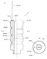
図1(A)、(B)に示すように、隙間閉塞具20は、隙間閉塞部材22と拡張手段24とを含んで構成されている。
Hereinafter, an embodiment of a gap obturator used in a micropile construction method according to the present invention will be described with reference to the accompanying drawings.
As shown in FIG. 4F, the casing C is configured by connecting a plurality of
As shown in FIGS. 1A and 1B, the
隙間閉塞部材22は、本実施の形態では、折り畳み可能な材料で袋状に形成された袋体26で構成され、図1では拡張状態となった袋体26を示している。
折り畳み可能な材料として、袋体26の内部に充填される充填材の漏れを阻止するに足る材料であればよく、従来公知の様々な材料が使用可能であるが、本実施の形態では、布を用いている。
袋体26はケーシングCの周囲を囲む環状を呈し、その中心に中心孔2602を備えている。
本実施の形態では、袋体26は、中心孔2602の周囲に位置する内周部2604と、内周部2604の外側に位置する外周部2606とを備えている。
また、袋体26の外周部2606には、袋体26が拡張した状態で、中心孔2602の軸方向に間隔をおいて複数の大径部2606Aと小径部2606Bとが交互に設けられている。
このように構成することで、図3に示すように、袋体26が拡張した状態で、ケーシングCにより削孔された孔16の内周面に効果的に密着し、粘性土系の地盤である場合には、削孔された孔16の内周面に外周部2606が食い込み、削孔された孔16の内周面とケーシングCの外周面との間の環状隙間Sをより確実に閉塞できるように図られている。
In this embodiment, the
Any foldable material may be used as long as it is sufficient to prevent leakage of the filling material filled in the
The
In the present embodiment, the
A plurality of large-
By configuring in this way, as shown in FIG. 3, the
袋体26は、図2で示すように、削孔された孔16の延在方向と直交する平面で切断した断面形状が前記ケーシングCの外周面に折り畳まれ削孔された孔16の断面形状よりも小さい輪郭の縮小状態と、図3で示すように、ケーシングCの外周面の全周に密着すると共に削孔された孔16の内周面の全周に密着する拡張状態とになるように形成されている。
したがって、袋体26は縮小状態で、削孔された孔16の延在方向と直交する平面で切断した断面形状がケーシングCの断面形状よりも大きくかつ削孔された孔16の断面形状よりも小さい輪郭となる。
As shown in FIG. 2, the
Therefore, the
図1(A)に示すように、拡張手段24は、袋体26の内部に供給されることで袋体26を拡張させる充填材と、充填材を袋体26に供給する管体28とを含んで構成されている。
充填材としては水、空気など袋体26を縮小状態から拡張状態にするものであればよい。本実施の形態では、充填材として後述する荷重支持層に削孔された孔16およびケーシングCの内部に充填するグラウト材Gを用いている。
管体28は袋体26の上端を貫通し、管体28の下端開口は袋体26の内部に位置している。
管体28が袋体26の上端を貫通する箇所は、袋体26に対して充填材が漏れないように管体28と袋体26とがシール部材2802を介して連結されており、また、ケーシングCの下方への移動に伴って管体28と袋体26とが一体に移動するように連結されている。
As shown in FIG. 1A, the expansion means 24 includes a filler that expands the
As the filler, any material such as water or air may be used as long as the
The
In the place where the
次に、図4を参照して隙間閉塞具20を用いたマイクロパイル工法について説明する。
図4(A)に示すように、マイクロパイル工法を施工するにあたり、先端外周部が外側削孔用カッター1202とされた1番目の細長い中空円筒形の鋼製のケーシングセグメント12の内部に、先端に削孔ドリル1802が取着された1番目のロッド18を挿通させ、それらケーシングセグメント12とロッド18とを回転させつつ、また、水を注入しつつ外側削孔用カッター1202と削孔ドリル1802とで軟弱層30に孔16を削孔していく工程が行なわれる。
なお、本実施の形態では、軟弱層30は粘性土系であり、削孔した場合、削孔された孔16の内周面は崩れず、孔16の輪郭が保持される。
Next, a micropile construction method using the
As shown in FIG. 4 (A), when the micropile method is applied, the distal end outer peripheral portion is formed in the first elongated hollow cylindrical
In the present embodiment, the
図4(B)、(C)に示すように、孔16が所定の深さとなる毎に、ケーシングセグメント12の端部に次の細長い中空円筒形の鋼製のケーシングセグメント12を継手14を介して着脱可能に連結して継ぎ足すと共に、ロッド18の端部に次のロッド18を着脱可能に連結して継ぎ足し、ケーシングセグメント12とロッド18とを回転させ、また、水を注入しつつ外側削孔用カッター1202と削孔ドリル1802とで孔16を削孔していく工程が行なわれる。
As shown in FIGS. 4B and 4C, every time the
複数のケーシングセグメント12が連結されることでケーシングCが構成される。
図4(C)に示すように、削孔された孔16が軟弱層30を通過し荷重支持層32の所定の深さに到達したならば、ロッド18と共に削孔ドリル1802をケーシングCの内部から引き抜く工程が行なわれる。
次に、必要に応じて、鉄筋などの補強材をケーシングCの内部にケーシングCの全長にわたって配設する。
Casing C is constituted by connecting a plurality of
As shown in FIG. 4C, when the drilled
Next, a reinforcing material such as a reinforcing bar is disposed inside the casing C over the entire length of the casing C as necessary.
次に、図4(D)に示すように、不図示のグラウトホースを用いてケーシングCの内部にグラウト材Gを充填する。
グラウト材Gとして、セメントミルク、モルタル材、小径の骨材を混入したコンクリート材が使用可能である。
次に、図4(E)に示すように、ケーシングCの内部にグラウト材Gを注入しつつ、ケーシングセグメント12を引き抜く工程、すなわち、ケーシングCの引き抜き工程が行なわれる。
Next, as shown in FIG. 4D, the grout material G is filled into the casing C using a grout hose (not shown).
As the grout material G, cement milk, mortar material, or a concrete material mixed with a small diameter aggregate can be used.
Next, as shown in FIG. 4E, a step of pulling out the
ケーシングCの引き抜きは、上下に隣り合うケーシングセグメント12のうち、下方に位置するケーシングセグメント12の上端が地盤上の近傍に位置したところで、下方のケーシングセグメント12を回転不能に把持し、上方のケーシングセグメント12を回転操作し、下方のケーシングセグメント12に対して上方のケーシングセグメント12を継手14と共に取り外すことで行なう。
上方に位置する複数本のケーシングセグメント12が継手14と共に取り外され、図4(E)に示すように、最下位に位置する一番目のケーシングセグメント12の下端が、荷重支持層32の最上部に近づいたところで、ケーシングCの引き抜きは終了する。
The casing C is pulled out by holding the
The plurality of
ここで図2、図4(F)に示すように、地盤上に位置するケーシングセグメント12の箇所に隙間閉塞具20の袋体26を取り付ける。
すなわち、環状の袋体26の中心孔1602にケーシングセグメント12を挿通し、管体28が上方に突出するように袋体26の下端を、締結具34によりケーシングCの外周面に締結する。締結具34としてはベルトなどの従来公知の様々な部材が使用可能である。
Here, as shown in FIG. 2 and FIG. 4 (F), the
That is, the
そして、図2に示すように、袋体26を縮小状態とし、袋体26の縮小状態から拡張状態への変化を許容する部材36を、縮小状態の袋体26上に巻回し、袋体26の縮小状態を維持した状態でケーシングCに装着する。
これにより、ケーシングCの下方への移動の際に、削孔された孔16の内周面と接触しても袋体26の縮小状態が維持され、袋体26の削孔された孔16内での移動が円滑になされるように図られる。
袋体26の縮小状態から拡張状態への変化を許容する部材36は、例えば、破断可能な紙製、あるいは、伸縮可能なゴム製などの紐状の部材や、あるいは、縮小状態の袋体26を覆う袋状の部材など、従来公知の様々な材料や形態のものが使用可能である。
なお、隙間閉塞具20は、削孔時に予めケーシングセグメント12に取着しておいてもよいが、本実施の形態のように、ケーシングCを引き抜いた際に取り付ける方が、袋体26の縮小状態を維持する上で有利となる。
Then, as shown in FIG. 2, the
Thus, when the casing C moves downward, the contracted state of the
The
Note that the
次に、図4(G)に示すように、隙間閉塞具20が取り付けられたケーシングCを、すでに注入されているグラウト材Gの中に所定量押し戻す工程が行なわれる。
ケーシングCが所定量押し戻されたならば、袋体26は、地盤表面の下方の削孔された孔16の内部に位置している。
Next, as shown in FIG. 4G, a step of pushing back the casing C, to which the
If the casing C is pushed back by a predetermined amount, the
次に、図3、図4(H)に示すように、管体28から充填材としてグラウト材Gを袋体26の内部に供給し、袋体26を縮小状態から拡張状態にし、袋体26の内周部2604をケーシングCの外周面の全周に密着させると共に、袋体26の外周部2606を削孔された孔16の内周面の全周に密着させる。
本実施の形態では、軟弱層30は粘性土系であるため、袋体26の拡張状態で、図3に示すように、袋体26の外周部2606は削孔された孔16の内周面に喰いこみ、軟弱層30、荷重支持層32に形成された環状隙間Sは完全に閉塞され、確実に大気と遮断される。
Next, as shown in FIG. 3 and FIG. 4 (H), the grout material G is supplied from the
In the present embodiment, since the
次に、ケーシングC内にグラウト材Gを加圧注入し、ケーシングCで囲繞された部分と、ケーシングCで囲繞されていない部分との間に、中間的な構造を有する部分を作り出す。
ケーシングC内へのグラウト材Gの加圧注入は、グラウト材Gが、削孔された孔16の壁面に密着し、グラウト材Gと地盤との間の接合状態が強固となるような圧力で行なわれることが望ましい。
本実施の形態では、拡張状態の袋体26により、軟弱層30、荷重支持層32に形成された環状隙間Sは完全に確実に大気と遮断されるので、所望の圧力でグラウト材Gに圧力を掛けることができ、グラウト材Gと地盤との接合状態を設計通りの強固なものにすることができる。
そして、図4(I)に示すように、グラウト材Gが硬化されることで、グラウト材Gによる地盤接合部38を有する杭体40が得られる。
次に、ケーシングCの上端部に鋼製の支圧板42が溶接により接合され、杭体40の杭頭部を構造物に連結するための連結構造が形成される。
Next, the grout material G is pressurized and injected into the casing C to create a portion having an intermediate structure between the portion surrounded by the casing C and the portion not surrounded by the casing C.
The pressure injection of the grout material G into the casing C is performed at such a pressure that the grout material G is brought into close contact with the wall surface of the drilled
In the present embodiment, the annular bag S formed in the
And as shown in FIG.4 (I), the
Next, a
したがって、本実施の形態によれば、削孔すべき箇所が粘性土系の地盤や岩盤である場合、削孔された孔16の内周面は崩れることが少なく、削孔後、削孔された孔16の内周面とケーシングセグメント12の外周面との間には環状隙間Sが常時確保されるものの、マイクロパイル工法の最終の工程において、グラウト材Gに所望の圧力を掛けることができ、グラウト材Gによる強固な地盤接合部38を有する杭体40を確実に得ることが可能となる。
しかも隙間閉塞部材22は、簡易な構成の袋体26と管体28とで構成されているので、安価に簡単に製作でき、また、ケーシングCへの装着も簡単に短時間で行なえ、マイクロパイル工法の作業効率を高める上で極めて有利となる。
Therefore, according to the present embodiment, when the portion to be drilled is a clay-based ground or rock, the inner peripheral surface of the drilled
Moreover, since the
また、袋体26を縮小状態から拡張状態にする充填材としてグラウト材Gを用いたので、ケーシングCの内部に注入するグラウト材Gや、このグラウト材Gを注入するポンプなどの既設の設備をそのまま使用でき、充填材として水や空気を用いる場合に較べて袋体26の拡張状態を安価に短時間で形成することが可能となる。
また、グラウト材Gが充填され拡張状態となった袋体26および管体28は埋め殺しとされ、充填材として水や空気を用いる場合に較べて杭体40の横抵抗を確保する上で有利となる。
In addition, since the grout material G is used as a filler for changing the
Moreover, the
なお、本実施の形態では、袋体26を布で構成した場合について説明したが、袋体26は、弾性を有するゴム材料で形成し、水や空気或いはグラウト材Gが充填されていない状態でその弾性によりしぼんでケーシングCの周囲で縮小状態となり、充填材が供給されることで膨張して拡張状態となるようにしてもよい。
また、本実施の形態では、袋体26を締結具34によりケーシングCに取り付けた場合について説明したが、縮小状態の袋体26を形成しておき、管体28により袋体26を、削孔された孔16内につり下げ、所定の箇所で袋体26を拡張状態にするようにしてもよい。
また、隙間閉塞部材22を配置する箇所は、最終工程でグラウト材Gに圧力を掛けることができればよく、したがって、地盤接合部38の上方箇所で地表面と地盤接合部38との間の箇所であればよく、実施例の箇所に限定されない。
また、本実施の形態では、隙間閉塞部材22を袋体26で構成した場合について説明したが、隙間閉塞具20は環状隙間Sを閉塞できる構造のものであればよく、例えば、隙間閉塞部材22として複数の羽からなり環状隙間Sの開閉を可能とした環状のシャッターを用い、拡張手段24としてシャッターを開閉させるアクチュエータを用いるなど、隙間閉塞具20として従来公知の様々な機械的構造のものも採用可能である。
In the present embodiment, the case where the
In the present embodiment, the case where the
Further, the location where the
Further, in the present embodiment, the case where the
12 ケーシングセグメント
14 継手
20 隙間閉塞具
22 隙間閉塞部材
24 拡張手段
26 袋体
2602 中心孔
2604 内周部
2606 外周部
2606A 大径部
2606B 小径部
28 管体
30 軟弱層
32 荷重支持層
34 締結具
38 地盤接合部
40 杭体
C ケーシング
G グラウト材
S 環状隙間
12
Claims (6)
前記削孔された孔の延在方向と直交する平面で切断した断面形状が前記ケーシングの断面形状よりも大きくかつ前記削孔された孔の断面形状よりも小さい輪郭の縮小状態から、前記ケーシングの外周面の全周および前記削孔された孔の内周面の全周に密着する拡張状態へ可変な隙間閉塞部材と、
前記隙間閉塞部材を前記縮小状態から前記拡張状態にする拡張手段と、
を備えることを特徴とするマイクロパイル工法で用いる隙間閉塞具。 A gap closing tool used in a micropile method for closing an annular gap S between an inner peripheral surface of a hole drilled by rotation of a casing and an outer peripheral surface of the casing,
From the reduced state of the contour, the cross-sectional shape cut by a plane orthogonal to the extending direction of the drilled hole is larger than the cross-sectional shape of the casing and smaller than the cross-sectional shape of the drilled hole, A gap closing member variable to an expanded state in close contact with the entire circumference of the outer peripheral surface and the inner peripheral surface of the drilled hole;
Expansion means for changing the gap closing member from the reduced state to the expanded state;
A gap obturator used in a micropile construction method characterized by comprising:
前記拡張手段は、前記袋体の内部に供給されることで前記袋体を拡張させる充填材と、前記充填材を前記袋体に供給する管体とを含んで構成されている、
ことを特徴とする請求項1記載のマイクロパイル工法で用いる隙間閉塞具。 The gap closing member is formed of a foldable material, and is configured by a bag body formed in an annular bag shape through which the casing is inserted,
The expansion means includes a filler that expands the bag body by being supplied into the bag body, and a tube body that supplies the filler to the bag body.
The gap obturator used in the micropile method according to claim 1.
ことを特徴とする請求項2記載のマイクロパイル工法で用いる隙間閉塞具。 The bag body has an elongated shape along the longitudinal direction of the casing in the expanded state, and a large-diameter portion and a small-diameter portion are alternately arranged on the outer peripheral portion at intervals in the longitudinal direction.
The gap obturator used in the micropile method according to claim 2.
削孔された孔の延在方向と直交する平面で切断した断面形状が前記ケーシングの断面形状よりも大きくかつ前記削孔された孔の断面形状よりも小さい輪郭の縮小状態から、前記ケーシングの外周面の全周および前記削孔された孔の内周面の全周に密着する拡張状態へ可変な隙間閉塞部材と、前記隙間閉塞部材を前記縮小状態から前記拡張状態にする拡張手段とを備えた隙間閉塞具を設け、
前記引き抜き工程により地表に位置した前記ケーシングの箇所に、前記隙間閉塞部材を取り付けて前記隙間閉塞部材を前記縮小状態とし、
前記押し戻し工程で前記隙間閉塞部材を前記削孔された孔内に位置させた後、前記拡張手段により前記隙間閉塞部材を拡張状態とし、前記削孔された孔の内周面と前記ケーシングの外周面との間の環状隙間Sを閉塞し、
前記ケーシングセグメントの内部に前記グラウト材を加圧注入する、
ことを特徴とするマイクロパイル工法。 A drilling step of drilling to a predetermined depth of the load support layer while passing through the soft layer while adding the casing segment, and a filling step of filling a grout material inside the casing formed by adding the casing segment; A pulling step of pulling out the casing until the lower end of the casing approaches the uppermost part of the load supporting layer; and a pushing back step of pushing back the casing by a predetermined amount, and a grout material at a position of the load supporting layer immediately below the casing. In the micropile method of forming a joint where the load support layer and the load support layer are firmly joined,
The outer circumference of the casing is reduced from a reduced state of a contour in which a cross-sectional shape cut along a plane orthogonal to the extending direction of the drilled hole is larger than the cross-sectional shape of the casing and smaller than the cross-sectional shape of the drilled hole. A gap closing member that can be changed to an expanded state that is in close contact with the entire circumference of the surface and the inner circumferential surface of the drilled hole, and an expansion unit that changes the gap closing member from the reduced state to the expanded state. Provided a gap closure device,
At the location of the casing located on the ground surface by the extraction step, the gap closing member is attached and the gap closing member is in the reduced state,
After the gap closing member is positioned in the drilled hole in the push-back step, the gap closing member is expanded by the expanding means, and the inner peripheral surface of the drilled hole and the outer periphery of the casing Closing the annular gap S between the surfaces,
Pressure-injecting the grout material into the casing segment;
A micropile construction method characterized by this.
前記引き抜き工程により地表に位置した前記ケーシングの箇所に、前記袋体を取り付けて前記袋体を前記縮小状態にした際に、
前記袋体の前記縮小状態から前記拡張状態への変化を許容する部材を前記縮小状態の前記袋体上に巻回し、前記ケーシング上において前記袋体の前記縮小状態を維持するようにした、
ことを特徴とする請求項4記載のマイクロパイル工法。 The gap closing member is formed of a foldable material, and is configured by a bag body formed in an annular bag shape through which the casing is inserted,
When the bag body is attached to the location of the casing located on the ground surface by the extraction step and the bag body is in the reduced state,
A member that allows the bag body to change from the reduced state to the expanded state is wound on the bag body in the reduced state, and the reduced state of the bag body is maintained on the casing.
The micropile construction method according to claim 4.
前記充填材は、前記充填工程において前記ケーシングの内部に充填される前記グラウト材と同一のグラウト材である、
ことを特徴とする請求項5記載のマイクロパイル工法。 The expansion means includes a filler that expands the bag body by being supplied into the bag body, and a tube body that supplies the filler to the bag body.
The filler is the same grout material as the grout material filled in the casing in the filling step.
The micropile construction method according to claim 5, wherein:
Priority Applications (2)
| Application Number | Priority Date | Filing Date | Title |
|---|---|---|---|
| JP2018033126A JP7081940B2 (en) | 2018-02-27 | 2018-02-27 | Micro pile method using a gap blocker |
| JP2022000463A JP7216230B2 (en) | 2018-02-27 | 2022-01-05 | Gap blocker used in the micropile construction method |
Applications Claiming Priority (1)
| Application Number | Priority Date | Filing Date | Title |
|---|---|---|---|
| JP2018033126A JP7081940B2 (en) | 2018-02-27 | 2018-02-27 | Micro pile method using a gap blocker |
Related Child Applications (1)
| Application Number | Title | Priority Date | Filing Date |
|---|---|---|---|
| JP2022000463A Division JP7216230B2 (en) | 2018-02-27 | 2022-01-05 | Gap blocker used in the micropile construction method |
Publications (2)
| Publication Number | Publication Date |
|---|---|
| JP2019148105A true JP2019148105A (en) | 2019-09-05 |
| JP7081940B2 JP7081940B2 (en) | 2022-06-07 |
Family
ID=67850299
Family Applications (1)
| Application Number | Title | Priority Date | Filing Date |
|---|---|---|---|
| JP2018033126A Active JP7081940B2 (en) | 2018-02-27 | 2018-02-27 | Micro pile method using a gap blocker |
Country Status (1)
| Country | Link |
|---|---|
| JP (1) | JP7081940B2 (en) |
Cited By (2)
| Publication number | Priority date | Publication date | Assignee | Title |
|---|---|---|---|---|
| CN112176806A (en) * | 2020-10-16 | 2021-01-05 | 于胜泉 | Stable road soft foundation treatment method and matched soft foundation treatment construction system |
| JP7393756B1 (en) | 2023-07-21 | 2023-12-07 | 弘和産業株式会社 | packer for casing |
Citations (3)
| Publication number | Priority date | Publication date | Assignee | Title |
|---|---|---|---|---|
| JPS51364B1 (en) * | 1969-10-17 | 1976-01-07 | ||
| JP4010383B2 (en) * | 1997-03-14 | 2007-11-21 | ドナルド ビー マーフィー コントラクターズ インコーポレーテッド | Pile method |
| JP2008303710A (en) * | 2008-08-22 | 2008-12-18 | Ashimori Ind Co Ltd | Method of driving pile directly below structure and bag-equipped pile |
-
2018
- 2018-02-27 JP JP2018033126A patent/JP7081940B2/en active Active
Patent Citations (3)
| Publication number | Priority date | Publication date | Assignee | Title |
|---|---|---|---|---|
| JPS51364B1 (en) * | 1969-10-17 | 1976-01-07 | ||
| JP4010383B2 (en) * | 1997-03-14 | 2007-11-21 | ドナルド ビー マーフィー コントラクターズ インコーポレーテッド | Pile method |
| JP2008303710A (en) * | 2008-08-22 | 2008-12-18 | Ashimori Ind Co Ltd | Method of driving pile directly below structure and bag-equipped pile |
Cited By (3)
| Publication number | Priority date | Publication date | Assignee | Title |
|---|---|---|---|---|
| CN112176806A (en) * | 2020-10-16 | 2021-01-05 | 于胜泉 | Stable road soft foundation treatment method and matched soft foundation treatment construction system |
| CN112176806B (en) * | 2020-10-16 | 2021-10-29 | 于胜泉 | Stable road soft foundation treatment method and matched soft foundation treatment construction system |
| JP7393756B1 (en) | 2023-07-21 | 2023-12-07 | 弘和産業株式会社 | packer for casing |
Also Published As
| Publication number | Publication date |
|---|---|
| JP7081940B2 (en) | 2022-06-07 |
Similar Documents
| Publication | Publication Date | Title |
|---|---|---|
| KR101027963B1 (en) | Construction method for concreting enlarged drill hole for piles and tention members | |
| JP2016089404A (en) | Grout method for cast-in-place concrete pile | |
| KR100870988B1 (en) | A boring machine and method for reinforcing earth using thereof | |
| JP7081940B2 (en) | Micro pile method using a gap blocker | |
| KR101276572B1 (en) | Pressurizing grouting type soil nailing and method for reinforcing slope using thereof | |
| JP5289639B1 (en) | Chemical injection method and chemical injection structure in the ground during chemical injection | |
| KR101859259B1 (en) | Apparatus to upgrade friction capacity of imbeded hollow type pile and construction method using thereby | |
| JP6474994B2 (en) | Shear reinforcement method for concrete structures | |
| JP5198992B2 (en) | Ground injection device and ground improvement method using the same | |
| KR20140089680A (en) | Piles for self-enlargement and construction method thereof | |
| KR100616359B1 (en) | Support-pipe using method of soil nailing | |
| JP7216230B2 (en) | Gap blocker used in the micropile construction method | |
| JP7032242B2 (en) | Inserting member for filling grout material used in micropile method and micropile method | |
| KR20120002276A (en) | Retaining structure and the construction method and expansion digging unit for it and anchor devices | |
| JP4341029B2 (en) | Pile foundation method | |
| KR101756933B1 (en) | The pile foundation construction method that can build bulb of various type | |
| JP2004076568A (en) | Bag body for civil engineering, method for laying bag body for civil engineering and its structure | |
| JP2006193966A (en) | Construction method and joint structure for joint part of impervious material enabling check of cut-off property | |
| JP3967106B2 (en) | Seismic retrofitting method for existing pipe manhole connection by non-cutting | |
| JP2023147566A (en) | Soil improvement body and construction method thereof | |
| JP2006063526A (en) | Expansive foot protection method using friction pile | |
| KR102037275B1 (en) | Partially expanding apparatus for underground pipe and composite cast in place pile method using the same | |
| KR20090114626A (en) | Drill machine for underground hole | |
| JP4330929B2 (en) | Water stop device and water stop method | |
| JP3320669B2 (en) | Non-cutting restoration method of service pipe at renewal of underground sewer |
Legal Events
| Date | Code | Title | Description |
|---|---|---|---|
| A621 | Written request for application examination |
Free format text: JAPANESE INTERMEDIATE CODE: A621 Effective date: 20210128 |
|
| A977 | Report on retrieval |
Free format text: JAPANESE INTERMEDIATE CODE: A971007 Effective date: 20211117 |
|
| A131 | Notification of reasons for refusal |
Free format text: JAPANESE INTERMEDIATE CODE: A131 Effective date: 20211130 |
|
| A521 | Request for written amendment filed |
Free format text: JAPANESE INTERMEDIATE CODE: A523 Effective date: 20220105 |
|
| TRDD | Decision of grant or rejection written | ||
| A01 | Written decision to grant a patent or to grant a registration (utility model) |
Free format text: JAPANESE INTERMEDIATE CODE: A01 Effective date: 20220524 |
|
| A61 | First payment of annual fees (during grant procedure) |
Free format text: JAPANESE INTERMEDIATE CODE: A61 Effective date: 20220526 |
|
| R150 | Certificate of patent or registration of utility model |
Ref document number: 7081940 Country of ref document: JP Free format text: JAPANESE INTERMEDIATE CODE: R150 |