JP2019128083A - Heat exchange device and heat source machine - Google Patents
Heat exchange device and heat source machine Download PDFInfo
- Publication number
- JP2019128083A JP2019128083A JP2018009328A JP2018009328A JP2019128083A JP 2019128083 A JP2019128083 A JP 2019128083A JP 2018009328 A JP2018009328 A JP 2018009328A JP 2018009328 A JP2018009328 A JP 2018009328A JP 2019128083 A JP2019128083 A JP 2019128083A
- Authority
- JP
- Japan
- Prior art keywords
- heat exchanger
- heat exchange
- heat
- pipe
- water
- Prior art date
- Legal status (The legal status is an assumption and is not a legal conclusion. Google has not performed a legal analysis and makes no representation as to the accuracy of the status listed.)
- Granted
Links
- 238000001816 cooling Methods 0.000 claims abstract description 30
- XLYOFNOQVPJJNP-UHFFFAOYSA-N water Substances O XLYOFNOQVPJJNP-UHFFFAOYSA-N 0.000 claims description 168
- 239000000567 combustion gas Substances 0.000 claims description 44
- 230000000052 comparative effect Effects 0.000 description 11
- 239000007789 gas Substances 0.000 description 7
- 238000011084 recovery Methods 0.000 description 6
- 239000004575 stone Substances 0.000 description 5
- 238000010079 rubber tapping Methods 0.000 description 4
- 229910001220 stainless steel Inorganic materials 0.000 description 4
- 239000010935 stainless steel Substances 0.000 description 4
- 238000010438 heat treatment Methods 0.000 description 2
- 239000011435 rock Substances 0.000 description 2
- 101100233916 Saccharomyces cerevisiae (strain ATCC 204508 / S288c) KAR5 gene Proteins 0.000 description 1
- 238000005452 bending Methods 0.000 description 1
- 230000005540 biological transmission Effects 0.000 description 1
- 238000009841 combustion method Methods 0.000 description 1
- 238000002485 combustion reaction Methods 0.000 description 1
- 238000005336 cracking Methods 0.000 description 1
- 238000007599 discharging Methods 0.000 description 1
- 230000000694 effects Effects 0.000 description 1
- 239000002737 fuel gas Substances 0.000 description 1
- 229910052500 inorganic mineral Inorganic materials 0.000 description 1
- 239000002184 metal Substances 0.000 description 1
- 239000011707 mineral Substances 0.000 description 1
- 238000012986 modification Methods 0.000 description 1
- 230000004048 modification Effects 0.000 description 1
- 239000011347 resin Substances 0.000 description 1
- 229920005989 resin Polymers 0.000 description 1
Images


Classifications
-
- F—MECHANICAL ENGINEERING; LIGHTING; HEATING; WEAPONS; BLASTING
- F24—HEATING; RANGES; VENTILATING
- F24H—FLUID HEATERS, e.g. WATER OR AIR HEATERS, HAVING HEAT-GENERATING MEANS, e.g. HEAT PUMPS, IN GENERAL
- F24H9/00—Details
- F24H9/0005—Details for water heaters
- F24H9/001—Guiding means
- F24H9/0026—Guiding means in combustion gas channels
-
- F—MECHANICAL ENGINEERING; LIGHTING; HEATING; WEAPONS; BLASTING
- F24—HEATING; RANGES; VENTILATING
- F24H—FLUID HEATERS, e.g. WATER OR AIR HEATERS, HAVING HEAT-GENERATING MEANS, e.g. HEAT PUMPS, IN GENERAL
- F24H1/00—Water heaters, e.g. boilers, continuous-flow heaters or water-storage heaters
- F24H1/10—Continuous-flow heaters, i.e. heaters in which heat is generated only while the water is flowing, e.g. with direct contact of the water with the heating medium
- F24H1/12—Continuous-flow heaters, i.e. heaters in which heat is generated only while the water is flowing, e.g. with direct contact of the water with the heating medium in which the water is kept separate from the heating medium
- F24H1/14—Continuous-flow heaters, i.e. heaters in which heat is generated only while the water is flowing, e.g. with direct contact of the water with the heating medium in which the water is kept separate from the heating medium by tubes, e.g. bent in serpentine form
-
- F—MECHANICAL ENGINEERING; LIGHTING; HEATING; WEAPONS; BLASTING
- F24—HEATING; RANGES; VENTILATING
- F24H—FLUID HEATERS, e.g. WATER OR AIR HEATERS, HAVING HEAT-GENERATING MEANS, e.g. HEAT PUMPS, IN GENERAL
- F24H1/00—Water heaters, e.g. boilers, continuous-flow heaters or water-storage heaters
- F24H1/22—Water heaters other than continuous-flow or water-storage heaters, e.g. water heaters for central heating
- F24H1/34—Water heaters other than continuous-flow or water-storage heaters, e.g. water heaters for central heating with water chamber arranged adjacent to the combustion chamber or chambers, e.g. above or at side
-
- F—MECHANICAL ENGINEERING; LIGHTING; HEATING; WEAPONS; BLASTING
- F24—HEATING; RANGES; VENTILATING
- F24H—FLUID HEATERS, e.g. WATER OR AIR HEATERS, HAVING HEAT-GENERATING MEANS, e.g. HEAT PUMPS, IN GENERAL
- F24H1/00—Water heaters, e.g. boilers, continuous-flow heaters or water-storage heaters
- F24H1/22—Water heaters other than continuous-flow or water-storage heaters, e.g. water heaters for central heating
- F24H1/40—Water heaters other than continuous-flow or water-storage heaters, e.g. water heaters for central heating with water tube or tubes
- F24H1/403—Water heaters other than continuous-flow or water-storage heaters, e.g. water heaters for central heating with water tube or tubes the water tubes being arranged in one or more circles around the burner
-
- F—MECHANICAL ENGINEERING; LIGHTING; HEATING; WEAPONS; BLASTING
- F24—HEATING; RANGES; VENTILATING
- F24H—FLUID HEATERS, e.g. WATER OR AIR HEATERS, HAVING HEAT-GENERATING MEANS, e.g. HEAT PUMPS, IN GENERAL
- F24H1/00—Water heaters, e.g. boilers, continuous-flow heaters or water-storage heaters
- F24H1/22—Water heaters other than continuous-flow or water-storage heaters, e.g. water heaters for central heating
- F24H1/40—Water heaters other than continuous-flow or water-storage heaters, e.g. water heaters for central heating with water tube or tubes
- F24H1/41—Water heaters other than continuous-flow or water-storage heaters, e.g. water heaters for central heating with water tube or tubes in serpentine form
-
- F—MECHANICAL ENGINEERING; LIGHTING; HEATING; WEAPONS; BLASTING
- F24—HEATING; RANGES; VENTILATING
- F24H—FLUID HEATERS, e.g. WATER OR AIR HEATERS, HAVING HEAT-GENERATING MEANS, e.g. HEAT PUMPS, IN GENERAL
- F24H8/00—Fluid heaters characterised by means for extracting latent heat from flue gases by means of condensation
-
- F—MECHANICAL ENGINEERING; LIGHTING; HEATING; WEAPONS; BLASTING
- F24—HEATING; RANGES; VENTILATING
- F24H—FLUID HEATERS, e.g. WATER OR AIR HEATERS, HAVING HEAT-GENERATING MEANS, e.g. HEAT PUMPS, IN GENERAL
- F24H9/00—Details
- F24H9/0005—Details for water heaters
- F24H9/001—Guiding means
- F24H9/0015—Guiding means in water channels
-
- F—MECHANICAL ENGINEERING; LIGHTING; HEATING; WEAPONS; BLASTING
- F24—HEATING; RANGES; VENTILATING
- F24H—FLUID HEATERS, e.g. WATER OR AIR HEATERS, HAVING HEAT-GENERATING MEANS, e.g. HEAT PUMPS, IN GENERAL
- F24H9/00—Details
- F24H9/18—Arrangement or mounting of grates or heating means
-
- F—MECHANICAL ENGINEERING; LIGHTING; HEATING; WEAPONS; BLASTING
- F28—HEAT EXCHANGE IN GENERAL
- F28D—HEAT-EXCHANGE APPARATUS, NOT PROVIDED FOR IN ANOTHER SUBCLASS, IN WHICH THE HEAT-EXCHANGE MEDIA DO NOT COME INTO DIRECT CONTACT
- F28D1/00—Heat-exchange apparatus having stationary conduit assemblies for one heat-exchange medium only, the media being in contact with different sides of the conduit wall, in which the other heat-exchange medium is a large body of fluid, e.g. domestic or motor car radiators
- F28D1/02—Heat-exchange apparatus having stationary conduit assemblies for one heat-exchange medium only, the media being in contact with different sides of the conduit wall, in which the other heat-exchange medium is a large body of fluid, e.g. domestic or motor car radiators with heat-exchange conduits immersed in the body of fluid
- F28D1/04—Heat-exchange apparatus having stationary conduit assemblies for one heat-exchange medium only, the media being in contact with different sides of the conduit wall, in which the other heat-exchange medium is a large body of fluid, e.g. domestic or motor car radiators with heat-exchange conduits immersed in the body of fluid with tubular conduits
- F28D1/0408—Multi-circuit heat exchangers, e.g. integrating different heat exchange sections in the same unit or heat exchangers for more than two fluids
- F28D1/0417—Multi-circuit heat exchangers, e.g. integrating different heat exchange sections in the same unit or heat exchangers for more than two fluids with particular circuits for the same heat exchange medium, e.g. with the heat exchange medium flowing through sections having different heat exchange capacities or for heating/cooling the heat exchange medium at different temperatures
-
- F—MECHANICAL ENGINEERING; LIGHTING; HEATING; WEAPONS; BLASTING
- F28—HEAT EXCHANGE IN GENERAL
- F28D—HEAT-EXCHANGE APPARATUS, NOT PROVIDED FOR IN ANOTHER SUBCLASS, IN WHICH THE HEAT-EXCHANGE MEDIA DO NOT COME INTO DIRECT CONTACT
- F28D1/00—Heat-exchange apparatus having stationary conduit assemblies for one heat-exchange medium only, the media being in contact with different sides of the conduit wall, in which the other heat-exchange medium is a large body of fluid, e.g. domestic or motor car radiators
- F28D1/02—Heat-exchange apparatus having stationary conduit assemblies for one heat-exchange medium only, the media being in contact with different sides of the conduit wall, in which the other heat-exchange medium is a large body of fluid, e.g. domestic or motor car radiators with heat-exchange conduits immersed in the body of fluid
- F28D1/04—Heat-exchange apparatus having stationary conduit assemblies for one heat-exchange medium only, the media being in contact with different sides of the conduit wall, in which the other heat-exchange medium is a large body of fluid, e.g. domestic or motor car radiators with heat-exchange conduits immersed in the body of fluid with tubular conduits
- F28D1/0408—Multi-circuit heat exchangers, e.g. integrating different heat exchange sections in the same unit or heat exchangers for more than two fluids
- F28D1/0426—Multi-circuit heat exchangers, e.g. integrating different heat exchange sections in the same unit or heat exchangers for more than two fluids with units having particular arrangement relative to the large body of fluid, e.g. with interleaved units or with adjacent heat exchange units in common air flow or with units extending at an angle to each other or with units arranged around a central element
- F28D1/0443—Combination of units extending one beside or one above the other
-
- F—MECHANICAL ENGINEERING; LIGHTING; HEATING; WEAPONS; BLASTING
- F28—HEAT EXCHANGE IN GENERAL
- F28D—HEAT-EXCHANGE APPARATUS, NOT PROVIDED FOR IN ANOTHER SUBCLASS, IN WHICH THE HEAT-EXCHANGE MEDIA DO NOT COME INTO DIRECT CONTACT
- F28D1/00—Heat-exchange apparatus having stationary conduit assemblies for one heat-exchange medium only, the media being in contact with different sides of the conduit wall, in which the other heat-exchange medium is a large body of fluid, e.g. domestic or motor car radiators
- F28D1/02—Heat-exchange apparatus having stationary conduit assemblies for one heat-exchange medium only, the media being in contact with different sides of the conduit wall, in which the other heat-exchange medium is a large body of fluid, e.g. domestic or motor car radiators with heat-exchange conduits immersed in the body of fluid
- F28D1/04—Heat-exchange apparatus having stationary conduit assemblies for one heat-exchange medium only, the media being in contact with different sides of the conduit wall, in which the other heat-exchange medium is a large body of fluid, e.g. domestic or motor car radiators with heat-exchange conduits immersed in the body of fluid with tubular conduits
- F28D1/047—Heat-exchange apparatus having stationary conduit assemblies for one heat-exchange medium only, the media being in contact with different sides of the conduit wall, in which the other heat-exchange medium is a large body of fluid, e.g. domestic or motor car radiators with heat-exchange conduits immersed in the body of fluid with tubular conduits the conduits being bent, e.g. in a serpentine or zig-zag
- F28D1/0477—Heat-exchange apparatus having stationary conduit assemblies for one heat-exchange medium only, the media being in contact with different sides of the conduit wall, in which the other heat-exchange medium is a large body of fluid, e.g. domestic or motor car radiators with heat-exchange conduits immersed in the body of fluid with tubular conduits the conduits being bent, e.g. in a serpentine or zig-zag the conduits being bent in a serpentine or zig-zag
-
- F—MECHANICAL ENGINEERING; LIGHTING; HEATING; WEAPONS; BLASTING
- F28—HEAT EXCHANGE IN GENERAL
- F28D—HEAT-EXCHANGE APPARATUS, NOT PROVIDED FOR IN ANOTHER SUBCLASS, IN WHICH THE HEAT-EXCHANGE MEDIA DO NOT COME INTO DIRECT CONTACT
- F28D20/00—Heat storage plants or apparatus in general; Regenerative heat-exchange apparatus not covered by groups F28D17/00 or F28D19/00
- F28D20/02—Heat storage plants or apparatus in general; Regenerative heat-exchange apparatus not covered by groups F28D17/00 or F28D19/00 using latent heat
-
- F—MECHANICAL ENGINEERING; LIGHTING; HEATING; WEAPONS; BLASTING
- F28—HEAT EXCHANGE IN GENERAL
- F28D—HEAT-EXCHANGE APPARATUS, NOT PROVIDED FOR IN ANOTHER SUBCLASS, IN WHICH THE HEAT-EXCHANGE MEDIA DO NOT COME INTO DIRECT CONTACT
- F28D21/00—Heat-exchange apparatus not covered by any of the groups F28D1/00 - F28D20/00
- F28D21/0001—Recuperative heat exchangers
- F28D21/0003—Recuperative heat exchangers the heat being recuperated from exhaust gases
-
- F—MECHANICAL ENGINEERING; LIGHTING; HEATING; WEAPONS; BLASTING
- F28—HEAT EXCHANGE IN GENERAL
- F28F—DETAILS OF HEAT-EXCHANGE AND HEAT-TRANSFER APPARATUS, OF GENERAL APPLICATION
- F28F19/00—Preventing the formation of deposits or corrosion, e.g. by using filters or scrapers
-
- F—MECHANICAL ENGINEERING; LIGHTING; HEATING; WEAPONS; BLASTING
- F24—HEATING; RANGES; VENTILATING
- F24H—FLUID HEATERS, e.g. WATER OR AIR HEATERS, HAVING HEAT-GENERATING MEANS, e.g. HEAT PUMPS, IN GENERAL
- F24H9/00—Details
- F24H9/16—Arrangements for water drainage
-
- F—MECHANICAL ENGINEERING; LIGHTING; HEATING; WEAPONS; BLASTING
- F28—HEAT EXCHANGE IN GENERAL
- F28D—HEAT-EXCHANGE APPARATUS, NOT PROVIDED FOR IN ANOTHER SUBCLASS, IN WHICH THE HEAT-EXCHANGE MEDIA DO NOT COME INTO DIRECT CONTACT
- F28D21/00—Heat-exchange apparatus not covered by any of the groups F28D1/00 - F28D20/00
- F28D2021/0019—Other heat exchangers for particular applications; Heat exchange systems not otherwise provided for
- F28D2021/0024—Other heat exchangers for particular applications; Heat exchange systems not otherwise provided for for combustion apparatus, e.g. for boilers
-
- Y—GENERAL TAGGING OF NEW TECHNOLOGICAL DEVELOPMENTS; GENERAL TAGGING OF CROSS-SECTIONAL TECHNOLOGIES SPANNING OVER SEVERAL SECTIONS OF THE IPC; TECHNICAL SUBJECTS COVERED BY FORMER USPC CROSS-REFERENCE ART COLLECTIONS [XRACs] AND DIGESTS
- Y02—TECHNOLOGIES OR APPLICATIONS FOR MITIGATION OR ADAPTATION AGAINST CLIMATE CHANGE
- Y02B—CLIMATE CHANGE MITIGATION TECHNOLOGIES RELATED TO BUILDINGS, e.g. HOUSING, HOUSE APPLIANCES OR RELATED END-USER APPLICATIONS
- Y02B30/00—Energy efficient heating, ventilation or air conditioning [HVAC]
-
- Y—GENERAL TAGGING OF NEW TECHNOLOGICAL DEVELOPMENTS; GENERAL TAGGING OF CROSS-SECTIONAL TECHNOLOGIES SPANNING OVER SEVERAL SECTIONS OF THE IPC; TECHNICAL SUBJECTS COVERED BY FORMER USPC CROSS-REFERENCE ART COLLECTIONS [XRACs] AND DIGESTS
- Y02—TECHNOLOGIES OR APPLICATIONS FOR MITIGATION OR ADAPTATION AGAINST CLIMATE CHANGE
- Y02E—REDUCTION OF GREENHOUSE GAS [GHG] EMISSIONS, RELATED TO ENERGY GENERATION, TRANSMISSION OR DISTRIBUTION
- Y02E60/00—Enabling technologies; Technologies with a potential or indirect contribution to GHG emissions mitigation
- Y02E60/14—Thermal energy storage
Abstract
Description
本発明は、熱交換装置および熱源機に関するものである。 The present invention relates to a heat exchange device and a heat source machine.
従来、顕熱回収用の一次熱交換器および潜熱回収用の二次熱交換器を備えた熱源機が用いられている。この熱源機の一次熱交換器には、伝熱管を収容する胴板と、胴板を冷却するための胴パイプ部を備えたものがある。これらの胴板および胴パイプ部を備えた熱源機は、たとえば特開2017−207271号公報(特許文献1)に記載されている。 BACKGROUND ART Conventionally, a heat source machine equipped with a primary heat exchanger for sensible heat recovery and a secondary heat exchanger for latent heat recovery has been used. Some of the primary heat exchangers of this heat source apparatus include a body plate that houses a heat transfer tube and a body pipe portion that cools the body plate. A heat source machine provided with such a body plate and a body pipe part is described in, for example, Japanese Patent Application Laid-Open No. 2017-207271 (Patent Document 1).
この公報に記載された熱源機では、バーナで生成された燃焼ガスは、顕熱回収用の一次熱交換器に対して上方から導入され、一次熱交換器を経由して潜熱回収用の二次熱交換器を通って下方の排気ダクトへ導出される。一次熱交換器では、伝熱管と胴パイプ部とは互いに直列に接続されている。伝熱管は胴板の側壁間に延びるように配置されている。胴パイプ部は、伝熱管よりも上方において胴板の側壁に沿って配置されている。伝熱管の入水側の端部は接続管を介して二次熱交換器に接続されている。伝熱管の出水側の端部は胴パイプ部の入水側の端部に接続されている。胴パイプ部の出水側の端部は出湯管に接続されている。 In the heat source unit described in this publication, the combustion gas generated by the burner is introduced from the upper side to the primary heat exchanger for sensible heat recovery and passes through the primary heat exchanger for the secondary heat recovery It is led to the lower exhaust duct through the heat exchanger. In the primary heat exchanger, the heat transfer tube and the body pipe portion are connected in series with each other. The heat transfer tubes are arranged to extend between the side walls of the body plate. The body pipe portion is disposed along the side wall of the body plate above the heat transfer tubes. The end of the heat transfer tube on the water inlet side is connected to the secondary heat exchanger via a connecting tube. The end of the heat transfer tube on the water discharge side is connected to the end of the body pipe portion on the water intake side. The end of the trunk pipe portion on the water discharge side is connected to a hot water discharge pipe.
上記公報に記載された熱源機の一次熱交換器では、燃焼ガスと水との熱交換量は、胴パイプ部よりも伝熱管の方が大きい。したがって、二次熱交換器から接続管を介して伝熱管に水が流入することにより一次熱交換器において水は効果的に温められる。このため、熱交換効率を向上させることが可能となる。 In the primary heat exchanger of the heat source apparatus described in the above publication, the heat exchange amount between the combustion gas and water is larger in the heat transfer tube than in the body pipe portion. Therefore, the water is effectively warmed in the primary heat exchanger by the water flowing from the secondary heat exchanger into the heat transfer pipe through the connection pipe. For this reason, it becomes possible to improve heat exchange efficiency.
しかしながら、伝熱管における熱交換量が大きいため、伝熱管から胴パイプ部に流入する水の温度は、出湯温度に近い高温になる。したがって、胴パイプ部を流れる水の温度は、出湯温度に近い高温になる。この場合には、温度の高い水は管内部に水に含まれるミネラル分が析出した缶石を発生させやすいため、胴パイプ部の内部に缶石が発生しやすい。胴パイプ部の内部に缶石が発生すると、缶石が胴パイプ部を閉塞することにより胴パイプ部に亀裂が発生するおそれがある。 However, since the heat exchange amount in the heat transfer pipe is large, the temperature of the water flowing from the heat transfer pipe into the trunk pipe portion becomes high temperature close to the tapping temperature. Therefore, the temperature of the water flowing through the trunk pipe portion becomes high close to the outlet temperature. In this case, water having a high temperature is likely to generate rocks in which mineral components contained in the water are deposited inside the pipe, and therefore, rocks are likely to be generated inside the trunk pipe portion. If scale is generated inside the barrel pipe portion, the scale may block the barrel pipe portion and cause cracking in the barrel pipe portion.
本発明は、上記課題に鑑みてなされたものであり、その目的は、熱交換効率を向上させるとともに胴パイプ部の内部に缶石が発生することを抑制することができる熱交換装置およびそれを備えた熱源機を提供することである。 The present invention has been made in view of the above problems, and an object thereof is to improve the heat exchange efficiency and to suppress the generation of scale inside the trunk pipe portion, and the heat exchange device It is providing the equipped heat source machine.
本発明の熱交換装置は、バーナから供給される燃焼ガスの顕熱および潜熱を回収可能なものである。熱交換装置は、一次熱交換器と、二次熱交換器と、接続管とを備えている。一次熱交換器は、燃焼ガスの顕熱を回収するためのものである。二次熱交換器は、一次熱交換器に対してバーナと反対側に配置され、かつ燃焼ガスの潜熱を回収するためのものである。接続管は、一次熱交換器と二次熱交換器とを接続する。一次熱交換器は、一次熱交換部と、一次熱交換部の周囲を取り囲む胴板と、胴板を冷却するための胴パイプ部とを含んでいる。胴パイプ部は、バーナに対して一次熱交換部よりも近くに配置され、かつ接続管に接続されている。一次熱交換部は、胴パイプ部に接続された第1伝熱管部と、第1伝熱管部に接続されかつ第1伝熱管部に対して胴パイプ部と反対側に配置された第2伝熱管部とを含んでいる。 The heat exchange device of the present invention can recover sensible heat and latent heat of combustion gas supplied from a burner. The heat exchange device comprises a primary heat exchanger, a secondary heat exchanger, and a connecting pipe. The primary heat exchanger is for recovering sensible heat of the combustion gas. The secondary heat exchanger is disposed opposite to the burner with respect to the primary heat exchanger, and is for recovering the latent heat of the combustion gas. The connecting pipe connects the primary heat exchanger and the secondary heat exchanger. The primary heat exchanger includes a primary heat exchange portion, a shell surrounding the primary heat exchange portion, and a shell pipe portion for cooling the shell. The body pipe portion is disposed closer to the burner than the primary heat exchange portion, and is connected to the connecting pipe. The primary heat exchange unit includes a first heat transfer pipe connected to the body pipe, and a second heat transfer connected to the first heat transfer pipe and disposed opposite to the body pipe relative to the first heat transfer pipe. And a heat pipe portion.
本発明の熱交換装置によれば、バーナに対して一次熱交換部よりも近くに配置された胴パイプ部に第1伝熱管部が接続されているため、胴パイプ部で燃焼ガスと熱交換することにより温められた水が第1伝熱管部に流入する。そのため、二次熱交換器から胴パイプ部を経由せずに第1伝熱管部に水が流入する場合よりも第1伝熱管部の熱交換効率は低下する。しかしながら、一次熱交換部は、胴パイプ部に接続された第1伝熱管部と、第1伝熱管部に接続されかつ第1伝熱管部に対して胴パイプ部と反対側に配置された第2伝熱管部とを含んでいる。そのため、一次熱交換部に伝熱管部が一段に配置されている場合よりも一次熱交換部の熱交換量を向上させることができる。これにより、熱交換効率を向上させることができる。さらに、胴パイプ部は一次熱交換器と二次熱交換器とを接続する接続管に接続されているため、二次熱交換器から接続管を経由して胴パイプ部に水を流入させることができる。したがって、一次熱交換部から胴パイプ部に水が流入する場合よりも胴パイプ部に流入する水の温度を低くすることができるため、胴パイプ部を流れる水の温度を低くすることができる。これにより、胴パイプ部の内部に缶石が発生することを抑制することができる。 According to the heat exchange device of the present invention, the first heat transfer tube portion is connected to the barrel pipe portion disposed closer to the burner than the primary heat exchange portion. The water heated by the heating flows into the first heat transfer pipe portion. Therefore, the heat exchange efficiency of the first heat transfer pipe lowers than when water flows into the first heat transfer pipe from the secondary heat exchanger without passing through the trunk pipe. However, the primary heat exchange unit is connected to the first heat transfer pipe connected to the body pipe, and the first heat transfer pipe is connected to the first heat transfer pipe, and the first heat transfer pipe is disposed opposite to the first heat transfer pipe. 2 Includes a heat transfer tube. Therefore, the heat exchange amount of the primary heat exchange part can be improved as compared with the case where the heat transfer tube parts are arranged in one stage in the primary heat exchange part. Thereby, heat exchange efficiency can be improved. Furthermore, since the trunk pipe portion is connected to the connection pipe connecting the primary heat exchanger and the secondary heat exchanger, water is allowed to flow from the secondary heat exchanger into the trunk pipe portion via the connection pipe. Can. Therefore, since the temperature of the water flowing into the trunk pipe portion can be made lower than when the water flows from the primary heat exchange portion into the trunk pipe portion, the temperature of the water flowing through the trunk pipe portion can be lowered. Thereby, it can suppress that scale generate | occur | produces inside the trunk | drum pipe part.
上記の熱交換装置において、第1伝熱管部は、上下方向において第2伝熱管部よりも上方に配置されている。このため、上下方向において上方に配置された第1伝熱管部から下方に配置された第2伝熱管部に水が流れる。したがって、第1伝熱管部および第2伝熱管部から水を排出することが容易である。これにより、一次熱交換器の排水性を向上させることができる。 In the above-mentioned heat exchange device, the first heat transfer pipe portion is disposed above the second heat transfer pipe portion in the vertical direction. For this reason, water flows from the first heat transfer pipe disposed at the upper side in the vertical direction to the second heat transfer pipe disposed at the lower side. Therefore, it is easy to discharge the water from the first heat transfer pipe and the second heat transfer pipe. Thereby, the drainage property of the primary heat exchanger can be improved.
上記の熱交換装置において、一次熱交換部は、胴パイプ部に接続された第1入水部と、第2伝熱管部に接続された第1出水部とを含んでいる。二次熱交換器は、二次熱交換器に水を流入させる第2入水部と、第1入水部に接続管を介して接続された第2出水部とを含んでいる。第1入水部、第1出水部、第2入水部および第2出水部はいずれも同じ方向に向けて開口するように配置されている。このため、第1入水部と第2出水部とに接続される接続管、第1出水部に接続される配管および第2入水部に接続される配管をそれぞれ同じ方向から接続することができる。したがって、熱交換装置の組立性を向上させることができる。 In the above heat exchange device, the primary heat exchange part includes a first water inlet part connected to the trunk pipe part and a first water outlet part connected to the second heat transfer pipe part. The secondary heat exchanger includes a second water inlet that allows water to flow into the secondary heat exchanger, and a second water outlet that is connected to the first water inlet via a connecting pipe. The first water inlet, the first water outlet, the second water inlet, and the second water outlet are all arranged so as to open in the same direction. Therefore, it is possible to connect the connection pipe connected to the first water inlet and the second water outlet, the pipe connected to the first water outlet, and the pipe connected to the second water inlet from the same direction. Therefore, the assemblability of the heat exchange device can be improved.
上記の熱交換装置において、第2出水部は、バーナに対して第2入水部よりも近くに配置されている。このため、二次熱交換器において、バーナから供給される燃焼ガスが流れる方向と、第2入水部から第2出水部に向けて水が流れる方向とを反対にすることができる。したがって、二次熱交換器において、第2入水部から第2出水部に向けて水の温度を徐々に高くしながら水と燃焼ガスとの間で熱交換することができる。これにより、二次熱交換器の熱交換効率を向上させることができる。 In the above heat exchange device, the second water discharge section is disposed closer to the burner than the second water intake section. For this reason, in the secondary heat exchanger, the direction in which the combustion gas supplied from the burner flows can be reversed from the direction in which water flows from the second water inlet to the second water outlet. Therefore, in the secondary heat exchanger, heat can be exchanged between the water and the combustion gas while gradually raising the temperature of the water from the second water inlet to the second water outlet. Thereby, the heat exchange efficiency of the secondary heat exchanger can be improved.
本発明の熱源機は、上記の熱交換装置と、一次熱交換器および二次熱交換器の順に燃焼ガスを供給可能なバーナとを備えている。本発明の熱源機によれば、熱交換効率を向上させるとともに胴パイプ部の内部に缶石が発生することを抑制することができる熱交換装置を備えた熱源機を提供することができる。 The heat source apparatus of the present invention includes the heat exchange device described above and a burner capable of supplying combustion gas in the order of the primary heat exchanger and the secondary heat exchanger. According to the heat source device of the present invention, it is possible to provide a heat source device including a heat exchange device that can improve heat exchange efficiency and suppress the occurrence of scale stones in the body pipe portion.
以上説明したように、本発明によれば、熱交換効率を向上させるとともに胴パイプ部の内部に缶石が発生することを抑制することができる熱交換装置およびそれを備えた熱源機を提供することができる。 As described above, according to the present invention, there is provided a heat exchange device capable of improving the heat exchange efficiency and suppressing the occurrence of scale stones in the body pipe portion, and a heat source apparatus including the heat exchange device. be able to.
以下、本発明の実施の形態について図に基づいて説明する。なお、以下各図の矢印は、適宜、燃焼ガスおよび水の流れを示している。 Hereinafter, embodiments of the present invention will be described with reference to the drawings. In addition, the arrow of each figure below has shown the flow of combustion gas and water suitably.
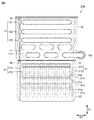
まず、図1を参照して、本発明の一実施の形態における熱源機100の構成について説明する。
First, with reference to FIG. 1, the structure of the heat-
図1に示されるように、本実施の形態の熱源機100は、点火プラグ1と、一次熱交換器(顕熱回収熱交換器)10と、二次熱交換器(潜熱回収熱交換器)20と、バーナ30と、チャンバ31と、送風装置32と、ダクト33と、ベンチュリ34、オリフィス35、ガスバルブ36、配管40と、バイパス配管41と、三方弁42と、筐体50と、接続管60とを主に有している。一次熱交換器10、二次熱交換器20および接続管60は熱交換装置200を構成している。筐体50の内部に、上記の部品のうち筐体50を除く全ての部品が配置されている。上記の部品は熱交換装置200を除いて従来公知のものと同様である。
As shown in FIG. 1, the
燃料ガスは、ガスバルブ36とオリフィス35とを通じてベンチュリ34に流れる。ベンチュリ34で混合された混合ガスは送風装置32に送られる。送風装置32は、混合ガスをバーナ30へ供給するためのものである。送風装置32はチャンバ31に接続されており、チャンバ31はバーナ30に接続されている。送風装置32から供給された混合ガスは、チャンバ31を通じてバーナ30に送られる。バーナ30は、一次熱交換器10に供給される加熱用気体(燃焼ガス)を発生させるためのものである。バーナ30から吹出される混合ガスは、点火プラグ1によって着火され、燃焼ガスとなる。
The fuel gas flows to the
燃焼ガスが一次熱交換器10および二次熱交換器20を順に通過して湯水と熱交換するように、バーナ30、一次熱交換器10および二次熱交換器20が接続されている。バーナ30は、一次熱交換器10に対して二次熱交換器20と反対側に配置されている。バーナ30は、一次熱交換器10および二次熱交換器20の順に燃焼ガスを供給可能に構成されている。本実施の形態では、バーナ30は一次熱交換器10の上方に配置されている。つまり、バーナ30は逆燃方式である。なお、バーナ30は正燃方式であってもよい。
A
二次熱交換器20にはダクト33が接続されており、ダクト33は筐体50の外部へ延びている。これにより、二次熱交換器20を通過した燃焼ガスは、ダクト33を通じて筐体50の外部へ排出される。一次熱交換器10よりも出湯側の配管40の部分とバイパス配管41とは三方弁42で接続されている。
A
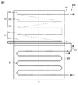
次に、図2〜図6を参照して、本実施の形態の熱交換装置200の構成について説明する。なお、説明の便宜のため、図2、図3および図5では接続管60は破線で図示されており、図4および図6では接続管60は図示されていない。図2および図3に示されるように、熱交換装置200は、燃焼ガスの顕熱および潜熱を回収可能なものである。熱交換装置200は、一次熱交換器10と、二次熱交換器20と、接続管60とを有している。
Next, the configuration of the
一次熱交換器10は、燃焼ガスの顕熱を回収するためのものである。二次熱交換器20は、燃焼ガスの潜熱を回収するためのものである。二次熱交換器20は、一次熱交換器10に対してバーナ30と反対側に配置されている。接続管60は、一次熱交換器10と二次熱交換器20とを接続する。接続管60は、たとえば、金属、樹脂などで構成されている。一次熱交換器10と二次熱交換器20とは第1方向D1に重なるように配置されている。二次熱交換器20は、熱交換装置200が設置された状態において一次熱交換器10に鉛直方向(上下方向)に重なるように配置されている。つまり、熱交換装置200が設置された状態において、第1方向D1は上下方向となる。
The
一次熱交換器10は、第1入水部10aと、第1出水部10bと、一次熱交換部11と、胴板12と、胴パイプ部13と、ヘッダ部材14と、ベンドパイプ15とを備えている。第1入水部10aは、一次熱交換器10に最初に湯水が入水する部分である。第1入水部10aは、胴パイプ部13に接続されている。また、第1入水部10aは接続管60に接続されている。第1出水部10bは、一次熱交換器10から最後に湯水が出湯する部分である。第1出水部10bは、一次熱交換部11に接続されている。また、第1出水部10bは、図示しない配管に接続されている。
The
一次熱交換部11は、複数のフィン11aと、複数のフィンパイプ11bとを含んでいる。複数のフィン11aおよび複数のフィンパイプ11bの各々は、SUS(ステンレス鋼)製であってもよい。一次熱交換部11は、複数のフィン11aおよび複数のフィンパイプ11bの外部を燃焼ガスが流れ、複数のフィンパイプ11bの内部を水が流れるように構成されている。複数のフィン11aは互いに積層されている。複数のフィンパイプ11bは複数のフィン11aを積層方向に貫通している。なお、図2、図3および図5においては、説明の便宜のため、複数のフィン11aのうち一部のみが図示されている。
The primary
複数のフィンパイプ11bは、第1方向D1に沿って二段に配列されている。つまり、一次熱交換部11は、第1方向D1に沿って二段に配列された第1伝熱管部111および第2伝熱管部112を含んでいる。二段のうち胴パイプ部13に対して近い段に配列された複数のフィンパイプ11bが第1伝熱管部111を構成している。二段のうち胴パイプ部13に対して離れた段に配列された複数のフィンパイプ11bが第2伝熱管部112を構成している。
The plurality of
第1伝熱管部111は、ベンドパイプ15を介して胴パイプ部13に接続されている。第2伝熱管部112は、ベンドパイプ15を介して第1伝熱管部111に接続されている。第2伝熱管部112は、第1伝熱管部111に対して胴パイプ部13と反対側に配置されている。第1出水部10bは、第2伝熱管部112に接続されている。胴パイプ部13、第1伝熱管部111および第2伝熱管部112は直列に接続されている。
The first heat
本実施の形態では、第1方向D1は上下方向であるため、第1伝熱管部111および第2伝熱管部112は、第1伝熱管部111、第2伝熱管部112の順に上下に配置されている。つまり、第1伝熱管部111は、上下方向において第2伝熱管部112よりも上方に配置されている。
In the present embodiment, since the first direction D1 is the vertical direction, the first heat
胴板12は、一次熱交換部11の周囲を取り囲んでいる。胴板12は、正面部12aと、一対の側面部12bと、背面部12cとを含んでいる。正面部12a、一対の側面部12bおよび背面部12cは四角の枠を構成している。胴板12は上下に開口を有している。胴板12は、上側の開口を通って胴板12の内側へ燃焼ガスを給気可能である。胴板12は、下側の開口を通って燃焼ガスを胴板12の外側へ排気可能である。
The
胴パイプ部13は、胴板12を冷却するためのものである。図6に示されるように、胴パイプ部13は、バーナ30に対して一次熱交換部11よりも近くに配置されている。胴パイプ部13は、接続管60に接続されている。胴パイプ部13は、胴板12の一対の側面部12bおよび背面部12cの内側面に沿うように配置されている。胴パイプ部13は、第1冷却パイプ131、第2冷却パイプ132および第3冷却パイプ133を含んでいる。第1冷却パイプ131、第2冷却パイプ132および第3冷却パイプ133は、第1方向D1に並んで設置されている。第1冷却パイプ131、第2冷却パイプ132および第3冷却パイプ133は、ヘッダ部材14を介して直列に接続されている。ヘッダ部材14は、胴板12の正面部12aに取り付けられている。ヘッダ部材14は、第1ヘッダ部材141と、第2ヘッダ部材142とを含んでいる。
The
第1冷却パイプ131の一方端は第1入水部10aに接続されており、第1冷却パイプ131の他方端は第1ヘッダ部材141に接続されている。第2冷却パイプ132の一方端は第1ヘッダ部材141に接続されており、第2冷却パイプ132の他方端は第2ヘッダ部材142に接続されている。第3冷却パイプ133の一方端は第2ヘッダ部材142に接続されており、第3冷却パイプ133の他方端は最も上方に配置されたベンドパイプ15に接続されている。また、一次熱交換部11の複数のフィンパイプ11bは互いにベンドパイプ15により直列に接続されている。
One end of the
二次熱交換器20は、第2入水部20aと、第2出水部20bと、二次熱交換部21と、胴板22と、ヘッダ部材23とを備えている。第2入水部20aは、二次熱交換器20に最初に湯水が入水する部分である。第2入水部20aは、二次熱交換器20に水を流入させる。第2入水部20aは、図示しない配管に接続されている。第2出水部20bは、二次熱交換器20から最後に湯水が出湯する部分である。第2出水部20bは、接続管60に接続されている。つまり、第2出水部20bは、第1入水部10aに接続管60を介して接続されている。図6に示されるように、第2出水部20bは、バーナ30に対して第2入水部20aよりも近くに配置されている。
The
第1入水部10a、第1出水部10b、第2入水部20aおよび第2出水部20bはいずれも同じ方向に向けて開口するように配置されている。本実施の形態では、第1入水部10a、第1出水部10b、第2入水部20aおよび第2出水部20bのすべてが第2方向D2に向けて開口するように配置されている。
The
図3〜図5に示されるように、二次熱交換部21は、複数の第1管21aと、複数の第2管21bとを含んでいる。複数の第1管21aおよび複数の第2管21bの各々は、SUS(ステンレス鋼)製であってもよい。二次熱交換部21は、複数の第1管21aおよび複数の第2管21bの各々の外部を燃焼ガスが流れ、複数の第1管21aおよび複数の第2管21bの内部を水が流れるように構成されている。
As shown in FIGS. 3 to 5, the secondary
複数の第1管21aおよび複数の第2管21bの各々は、蛇行管(ミアンダ)である。複数の第1管21aおよび複数の第2管21bの各々は、第1方向D1に直交する第2方向D2に交互に折り返すように構成されている。複数の第1管21aおよび複数の第2管21bの各々は、第1方向D1および第2方向D2の両方に直交する第3方向D3に互いに積層されている。複数の第1管21aの各々と複数の第2管21bの各々とは第1方向D1に互いにずれて配置されている。
Each of the plurality of
胴板22は、複数の第1管21aおよび複数の第2管21bを取り囲んでいる。胴板22は、正面部22aと、一対の側面部22bと、背面部22cとを含んでいる。正面部22a、一対の側面部22bおよび背面部22cは四角の枠を構成している。胴板22は上下に開口を有している。胴板22は、上側の開口を通って胴板22の内側へ燃焼ガスを給気可能である。胴板22は、下側の開口を通って燃焼ガスを胴板22の外側へ排気可能である。
The
ヘッダ部材23は、第1ヘッダ部材231と、第2ヘッダ部材232とを含んでいる。第1ヘッダ部材231と第2ヘッダ部材232とは第1方向D1に並んで配置されている。第2入水部20aは第1ヘッダ部材231に接続されている。第2出水部20bは第2ヘッダ部材232に接続されている。
The
図3〜図5に示されるように、複数の第1管21aおよび複数の第2管21bの各々は、複数の直線部21cと、複数の湾曲部21dとを有している。複数の直線部21cの各々は、第2方向D2に延びている。複数の湾曲部21dの各々は、第3方向D3に延びている。複数の湾曲部21dは、複数の直線部21c同士を接続する。複数の第1管21aおよび複数の第2管21bの各々は、複数の直線部21cと複数の湾曲部21dとが直列に接続されることにより蛇行しながら鉛直方向(第1方向D1)に延びている。
As shown in FIGS. 3 to 5, each of the plurality of
複数の第1管21aおよび複数の第2管21bの各々の一方端は第1ヘッダ部材231に接続されており、複数の第1管21aおよび複数の第2管21bの各々の他方端は第2ヘッダ部材232に接続されている。複数の第1管21aおよび複数の第2管21bの各々は第1ヘッダ部材231および第2ヘッダ部材232を介して並列に接続されている。
One end of each of the plurality of
次に、図2、図3、図5および図6を参照して、熱交換装置200における燃焼ガスの流れおよび水の流れについて説明する。なお、図6では、説明の便宜のため、バーナ30の熱交換装置200に接続された部分の周辺以外は図示されていない。
Next, the flow of combustion gas and the flow of water in the
まず、熱交換装置200における燃焼ガスの流れについて説明する。一次熱交換器10の上側の開口を通って燃焼ガスが熱交換装置200に給気され、二次熱交換器20の下側の開口を通って燃焼ガスが熱交換装置200から排気される。具体的には、一次熱交換器10の胴板12の上側に設けられた開口を通って一次熱交換器10に給気された燃焼ガスは、胴板12の下側に設けられた開口に向けて上方からに下方に流れる。このとき、胴パイプ部13の外側を流れる燃焼ガスと胴パイプ部13の内側を流れる水との間で熱交換が行われる。さらに、一次熱交換部11の複数のフィン11aおよび複数のフィンパイプ11bの外側を流れる燃焼ガスと、複数のフィンパイプ11bの内側を流れる水との間で熱交換が行われる。
First, the flow of combustion gas in the
一次熱交換器10を通過した燃焼ガスは、二次熱交換器20の胴板22の上側に設けられた開口を通って二次熱交換器20に給気される。二次熱交換器20に給気された燃焼ガスは、胴板22の下側に設けられた開口に向けて上方から下方に流れる。このとき、二次熱交換部21の複数の第1管21aおよび複数の第2管21bの外側を流れる燃焼ガスと、複数の第1管21aおよび複数の第2管21bの内側を流れる水との間で熱交換が行われる。
The combustion gas that has passed through the
続いて、熱交換装置200における水の流れについて説明する。二次熱交換器20の第2入水部20aから二次熱交換器20に流入した湯水は、二次熱交換部21において燃焼ガスとの間で熱交換された後に第2出水部20bから出湯する。二次熱交換器20の第2出水部20bから出湯した水は、接続管60を経由して、一次熱交換器10の第1入水部10aに入水する。一次熱交換器10の第1入水部10aから一次熱交換器10に入水した湯水は、一次熱交換部11において燃焼ガスとの間で熱交換された後に第1出水部10bから出湯する。
Next, the flow of water in the
さらに、一次熱交換器10の水の流れを詳しく説明する。第1入水部10aから一次熱交換器10に入水した湯水は、胴パイプ部13のうち最も上方に配置された第1冷却パイプ131に流入する。第1冷却パイプ131内に流入した湯水は、第1冷却パイプ131内を通り、第1ヘッダ部材141を経由して、第1冷却パイプ131の下方に配置された第2冷却パイプ132に流入する。第2冷却パイプ132内に流入した湯水は、第2冷却パイプ132内を通り、第2ヘッダ部材142を経由して、第2冷却パイプ132の下方に配置された第3冷却パイプ133に流入する。第3冷却パイプ133内に流入した湯水は、第3冷却パイプ133内を通り、最も上方に配置されたベンドパイプ15に流入する。最も上方に配置されたベンドパイプ15に流入した湯水は、複数のフィンパイプ11bと複数のベンドパイプ15とが直列に接続された一連の通水路を正面部12aと背面部12cとが対向する方向に折り返すように流れる。最後に、湯水は第1出水部10bから出湯する。
Furthermore, the flow of water in the
次に、本実施の形態の作用効果を比較例と対比して説明する。
図7を参照して、比較例1の熱交換装置200は、二次熱交換器20が接続管60を介して一次熱交換器10の第2伝熱管部112に接続されている点で、本実施の形態の熱交換装置200と主に異なっている。
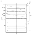
Next, the effect of this embodiment will be described in comparison with a comparative example.
Referring to FIG. 7, in the
比較例1の熱交換装置200では、二次熱交換器20から一次熱交換器10に流入した水は、第2伝熱管部112、第1伝熱管部111および胴パイプ部13の順に流れる。燃焼ガスと水との熱交換量は、胴パイプ部13よりも一次熱交換部11の方が大きい。したがって、二次熱交換器20から接続管60を介して一次熱交換部11の第2伝熱管部112および第1伝熱管部111に水が流入することにより一次熱交換器10において水は効果的に温められる。このため、熱交換効率を向上させることが可能となる。
In the
しかしながら、第1伝熱管部111および第2伝熱管部112における熱交換量が大きいため、第1伝熱管部111から胴パイプ部13に流入する水の温度は、出湯温度に近い高温になる。したがって、胴パイプ部13を流れる水の温度は、出湯温度に近い高温になる。この場合には、温度の高い水は管内部に缶石を発生させやすいため、胴パイプ部13の内部に缶石が発生しやすい。胴パイプ部13の内部に缶石が発生すると、缶石が胴パイプ部13を閉塞することにより胴パイプ部13に亀裂が発生するおそれがある。
However, since the amount of heat exchange in the first heat
図8を参照して、比較例2の熱交換装置200は、二次熱交換器20が接続管60を介して一次熱交換器10の第1伝熱管部111に接続されている点で、本実施の形態の熱交換装置200と主に異なっている。
With reference to FIG. 8, the
比較例2の熱交換装置200では、二次熱交換器20から一次熱交換器10に流入した水は、第1伝熱管部111、第2伝熱管部112および胴パイプ部13の順に流れる。比較例2の熱交換装置200においても第1伝熱管部111から胴パイプ部13に流入する水の温度は、出湯温度に近い高温になる。したがって、胴パイプ部13を流れる水の温度は、出湯温度に近い高温になる。よって、胴パイプ部13の内部に缶石が発生しやすい。
In the
また、比較例2の熱交換装置200では、第1伝熱管部111よりも下方に配置された第2伝熱管部112から接続管60を介して第1伝熱管部111よりも上方に配置された胴パイプ部13に水が流れる。そのため、一次熱交換器10から水を排出するときに、第2伝熱管部112に貯留された水を排出するために第2伝熱管部112に排出栓を設置する必要がある。これにより、コストが高くなるという問題がある。
Further, in the
比較例1および比較例2に対して、本実施の形態の熱交換装置200によれば、図6および図9に示されるように、バーナ30に対して一次熱交換部11よりも近くに配置された胴パイプ部13に第1伝熱管部111が接続されているため、胴パイプ部13で燃焼ガスと熱交換することにより温められた水が第1伝熱管部111に流入する。そのため、二次熱交換器20から胴パイプ部13を経由せずに第1伝熱管部111に水が流入する場合よりも第1伝熱管部111の熱交換効率は低下する。しかしながら、一次熱交換部11は、胴パイプ部13に接続された第1伝熱管部111と、第1伝熱管部111に接続されかつ第1伝熱管部111に対して胴パイプ部13と反対側に配置された第2伝熱管部112とを含んでいる。そのため、一次熱交換部11に伝熱管部が一段に配置されている場合よりも一次熱交換部11の熱交換量を向上させることができる。これにより、熱交換効率を向上させることができる。
In comparison with Comparative Example 1 and Comparative Example 2, according to the
さらに、胴パイプ部13は一次熱交換器10と二次熱交換器20とを接続する接続管60に接続されているため、二次熱交換器20から接続管60を経由して胴パイプ部13に水を流入させることができる。したがって、一次熱交換部11から胴パイプ部13に水が流入する場合よりも胴パイプ部13に流入する水の温度を低くすることができるため、胴パイプ部13を流れる水の温度を低くすることができる。これにより、胴パイプ部13の内部に缶石が発生することを抑制することができる。よって、本実施の形態の熱交換装置200によれば、熱交換効率を向上させるとともに胴パイプ部13の内部に缶石が発生することを抑制することができる。
Furthermore, since the
また、本実施の形態の熱交換装置200では、第1伝熱管部111は、上下方向において第2伝熱管部112よりも上方に配置されているため、上下方向において上方に配置された第1伝熱管部111から下方に配置された第2伝熱管部112に水が流れる。したがって、第1伝熱管部111および第2伝熱管部112から水を排出することが容易である。これにより、一次熱交換器10の排水性を向上させることができる。さらに、一次熱交換器10から水を排出するときに、第2伝熱管部112に貯留された水を排出するために第2伝熱管部112に排出栓を設置する必要がない。これにより、コストが高くなることを抑制することができる。
Moreover, in the
図2および図3に示されるように、本実施の形態の熱交換装置200では、第1入水部10a、第1出水部10b、第2入水部20aおよび第2出水部20bはいずれも同じ方向に向けて開口するように配置されている。このため、第1入水部10aと第2出水部20bとに接続される接続管60、第1出水部10bに接続される配管および第2入水部20aに接続される配管をそれぞれ同じ方向から接続することができる。したがって、熱交換装置200の組立性を向上させることができる。
As shown in FIGS. 2 and 3, in the
図2および図6に示されるように、本実施の形態の熱交換装置200では、第2出水部20bは、バーナ30に対して第2入水部20aよりも近くに配置されている。このため、二次熱交換器20において、バーナ30から供給される燃焼ガスが流れる方向と、第2入水部20aから第2出水部20bに向けて水が流れる方向とを反対にすることができる。したがって、二次熱交換器20において、第2入水部20aから第2出水部20bに向けて水の温度を徐々に高くしながら水と燃焼ガスとの間で熱交換することができる。これにより、二次熱交換器20の熱交換効率を向上させることができる。
As shown in FIG. 2 and FIG. 6, in the
図1および図6に示されるように、本実施の形態の熱源機100は、上記の熱交換装置200と、一次熱交換器10および二次熱交換器20の順に燃焼ガスを供給可能なバーナ30とを備えている。本実施の形態の熱源機100によれば、熱交換効率を向上させるとともに胴パイプ部13の内部に缶石が発生することを抑制することができる熱交換装置200を備えた熱源機100を提供することができる。
As shown in FIGS. 1 and 6, the
今回開示された実施の形態はすべての点で例示であって制限的なものではないと考えられるべきである。本発明の範囲は上記した説明ではなくて特許請求の範囲によって示され、特許請求の範囲と均等の意味および範囲内でのすべての変更が含まれることが意図される。 It should be understood that the embodiments disclosed herein are illustrative and non-restrictive in every respect. The scope of the present invention is indicated not by the above description but by the claims, and is intended to include all the modifications within the meaning and scope equivalent to the claims.
10 一次熱交換器、10a 第1入水部、10b 第1出水部、11 一次熱交換部、11a フィン、11b フィンパイプ、12,22 胴板、13 胴パイプ部、14,23 ヘッダ部材、15 ベンドパイプ、20 二次熱交換器、20a 第2入水部、20b 第2出水部、21 二次熱交換部、30 バーナ、60 接続管、100 熱源機、111 第1伝熱管部、112 第2伝熱管部、200 熱交換装置。
DESCRIPTION OF
Claims (5)
前記燃焼ガスの前記顕熱を回収するための一次熱交換器と、
前記一次熱交換器に対して前記バーナと反対側に配置され、かつ前記燃焼ガスの前記潜熱を回収するための二次熱交換器と、
前記一次熱交換器と前記二次熱交換器とを接続する接続管とを備え、
前記一次熱交換器は、一次熱交換部と、前記一次熱交換部の周囲を取り囲む胴板と、前記胴板を冷却するための胴パイプ部とを含み、
前記胴パイプ部は、前記バーナに対して前記一次熱交換部よりも近くに配置され、かつ前記接続管に接続されており、
前記一次熱交換部は、前記胴パイプ部に接続された第1伝熱管部と、前記第1伝熱管部に接続されかつ前記第1伝熱管部に対して前記胴パイプ部と反対側に配置された第2伝熱管部とを含む、熱交換装置。 A heat exchange device capable of recovering sensible heat and latent heat of combustion gas supplied from a burner,
A primary heat exchanger for recovering the sensible heat of the combustion gas;
A secondary heat exchanger disposed on the opposite side of the burner with respect to the primary heat exchanger and for recovering the latent heat of the combustion gas;
A connecting pipe connecting the primary heat exchanger and the secondary heat exchanger;
The primary heat exchanger includes a primary heat exchange portion, a shell surrounding the periphery of the primary heat exchange, and a trunk pipe portion for cooling the shell.
The trunk pipe part is disposed closer to the burner than the primary heat exchange part, and is connected to the connecting pipe,
The primary heat exchange portion is connected to the first heat transfer pipe portion connected to the body pipe portion, and the first heat transfer pipe portion, and disposed on the opposite side of the body heat pipe portion to the first heat transfer pipe portion And a second heat transfer tube portion.
前記二次熱交換器は、前記二次熱交換器に水を流入させる第2入水部と、前記第1入水部に前記接続管を介して接続された第2出水部とを含み、
前記第1入水部、前記第1出水部、前記第2入水部および前記第2出水部はいずれも同じ方向に向けて開口するように配置されている、請求項1または2に記載の熱交換装置。 The primary heat exchange part includes a first water inlet part connected to the trunk pipe part, and a first water outlet part connected to the second heat transfer pipe part,
The secondary heat exchanger includes a second water inlet section that allows water to flow into the secondary heat exchanger, and a second water outlet section that is connected to the first water inlet section via the connection pipe,
The heat exchange according to claim 1 or 2, wherein all of the first water inlet, the first water outlet, the second water inlet, and the second water outlet are arranged to open in the same direction. apparatus.
前記一次熱交換器および前記二次熱交換器の順に前記燃焼ガスを供給可能な前記バーナとを備えた、熱源機。 The heat exchange device according to any one of claims 1 to 4;
A heat source apparatus comprising: the burner capable of supplying the combustion gas in the order of the primary heat exchanger and the secondary heat exchanger.
Priority Applications (3)
| Application Number | Priority Date | Filing Date | Title |
|---|---|---|---|
| JP2018009328A JP7135325B2 (en) | 2018-01-24 | 2018-01-24 | Heat exchange device and heat source machine |
| CN201910006559.8A CN110068135A (en) | 2018-01-24 | 2019-01-04 | Heat-exchange device and heat source machine |
| US16/239,545 US10890356B2 (en) | 2018-01-24 | 2019-01-04 | Heat exchange device and heat source machine |
Applications Claiming Priority (1)
| Application Number | Priority Date | Filing Date | Title |
|---|---|---|---|
| JP2018009328A JP7135325B2 (en) | 2018-01-24 | 2018-01-24 | Heat exchange device and heat source machine |
Publications (2)
| Publication Number | Publication Date |
|---|---|
| JP2019128083A true JP2019128083A (en) | 2019-08-01 |
| JP7135325B2 JP7135325B2 (en) | 2022-09-13 |
Family
ID=67298196
Family Applications (1)
| Application Number | Title | Priority Date | Filing Date |
|---|---|---|---|
| JP2018009328A Active JP7135325B2 (en) | 2018-01-24 | 2018-01-24 | Heat exchange device and heat source machine |
Country Status (3)
| Country | Link |
|---|---|
| US (1) | US10890356B2 (en) |
| JP (1) | JP7135325B2 (en) |
| CN (1) | CN110068135A (en) |
Cited By (6)
| Publication number | Priority date | Publication date | Assignee | Title |
|---|---|---|---|---|
| KR20210070051A (en) * | 2019-12-04 | 2021-06-14 | 김홍일 | Exhaust gas purification apparatus |
| KR20210085397A (en) * | 2019-12-30 | 2021-07-08 | 주식회사 경동나비엔 | Heat exchanger unit and manufacturing method of the same |
| KR20210086431A (en) * | 2019-12-30 | 2021-07-08 | 주식회사 경동나비엔 | Heat exchanger unit and manufacturing method of the same |
| US11585572B2 (en) | 2018-06-05 | 2023-02-21 | Kyungdong Navien Co., Ltd. | Heat exchanger unit and condensing boiler using the same |
| KR20230043093A (en) * | 2020-07-08 | 2023-03-30 | 주식회사 경동나비엔 | Heat exchanger unit and manufacturing method of the same |
| US11835262B2 (en) | 2018-06-05 | 2023-12-05 | Kyungdong Navien Co., Ltd. | Heat exchanger unit |
Families Citing this family (2)
| Publication number | Priority date | Publication date | Assignee | Title |
|---|---|---|---|---|
| JP2020094769A (en) * | 2018-12-14 | 2020-06-18 | リンナイ株式会社 | Heat source machine |
| JP7293570B2 (en) * | 2019-03-25 | 2023-06-20 | 株式会社ノーリツ | Heat exchanger and manufacturing method thereof |
Citations (4)
| Publication number | Priority date | Publication date | Assignee | Title |
|---|---|---|---|---|
| JP2006105468A (en) * | 2004-10-04 | 2006-04-20 | Noritz Corp | Hot water supply device |
| JP2006207901A (en) * | 2005-01-26 | 2006-08-10 | Noritz Corp | Hot water apparatus |
| JP2011017477A (en) * | 2009-07-08 | 2011-01-27 | Noritz Corp | Heat exchanger and combustion device |
| JP2017116203A (en) * | 2015-12-25 | 2017-06-29 | リンナイ株式会社 | Combustion apparatus |
Family Cites Families (30)
| Publication number | Priority date | Publication date | Assignee | Title |
|---|---|---|---|---|
| US3656544A (en) * | 1970-08-05 | 1972-04-18 | Ingersoll Rand Co | Heat exchanger |
| CA1108499A (en) * | 1979-03-15 | 1981-09-08 | Canadian Gas Research Institute | Two-stage heat exchanger |
| CN100414208C (en) * | 2003-03-07 | 2008-08-27 | 株式会社庆东纳碧安 | Upward combustion type condensing boiler for recovering latent heat of condensation |
| US6820685B1 (en) * | 2004-02-26 | 2004-11-23 | Baltimore Aircoil Company, Inc. | Densified heat transfer tube bundle |
| US7882809B2 (en) * | 2006-11-07 | 2011-02-08 | L'air Liquide, Societe Anonyme Pour L'etude Et L'exploitation Des Procedes Georges Claude | Heat exchanger having a counterflow evaporator |
| US7681536B2 (en) * | 2007-03-22 | 2010-03-23 | Patrick A. Kaupp | Low maintenance fluid heater and method of firing same |
| JP5771519B2 (en) * | 2011-12-26 | 2015-09-02 | リンナイ株式会社 | Latent heat exchanger and hot water supply device |
| JP5629706B2 (en) * | 2012-02-17 | 2014-11-26 | リンナイ株式会社 | Drain discharge device |
| CN102944064B (en) * | 2012-10-13 | 2014-08-20 | 无锡锡州机械有限公司 | Tube-plate water-circulating heat exchanger |
| CN203518240U (en) * | 2013-10-11 | 2014-04-02 | 上海林内有限公司 | Strong-drum-type side-arranging single water pipe condensing type gas water heater |
| KR101597980B1 (en) * | 2014-03-18 | 2016-02-29 | 주식회사 경동나비엔 | Heat exchanger and method of the unit plate comprising the heat exchanger |
| JP5920410B2 (en) * | 2014-07-08 | 2016-05-18 | 株式会社ノーリツ | Water heater |
| CN106537059B (en) * | 2014-07-25 | 2019-08-09 | 株式会社能率 | Fin-tube heat exchanger and hot-water supply with the fin-tube heat exchanger |
| JP5884866B2 (en) * | 2014-07-28 | 2016-03-15 | 株式会社ノーリツ | Water heater |
| JP6598003B2 (en) * | 2015-07-28 | 2019-10-30 | 株式会社ノーリツ | Water heater |
| JP2017110887A (en) * | 2015-12-18 | 2017-06-22 | 株式会社ノーリツ | Plate type heat exchanger, water heating device, and plate type heat exchanger manufacturing method |
| KR101676993B1 (en) * | 2016-05-03 | 2016-11-16 | (주)귀뚜라미 | U-bend pipe type heat exchanger |
| JP6807265B2 (en) * | 2016-05-12 | 2021-01-06 | リンナイ株式会社 | Combustion device |
| CN106642692B (en) * | 2016-07-28 | 2022-08-19 | 艾欧史密斯(中国)热水器有限公司 | Condensation gas water heater and condensation heat exchanger |
| US20190203975A1 (en) * | 2016-08-25 | 2019-07-04 | Noritz Corporation | Heat exchanger and hot water apparatus |
| JP6874325B2 (en) * | 2016-10-27 | 2021-05-19 | 株式会社ノーリツ | Hot water device |
| JP6841673B2 (en) * | 2017-01-30 | 2021-03-10 | リンナイ株式会社 | Exhaust duct |
| JP6839556B2 (en) * | 2017-02-08 | 2021-03-10 | リンナイ株式会社 | Heat exchanger |
| JP2018176262A (en) * | 2017-04-21 | 2018-11-15 | リンナイ株式会社 | Manufacturing method of fin tube type heat exchanger and combustion device having fin tube heat exchanger |
| JP7035477B2 (en) * | 2017-11-21 | 2022-03-15 | 株式会社ノーリツ | Heat exchanger and hot water device |
| JP7052341B2 (en) * | 2017-12-26 | 2022-04-12 | 株式会社ノーリツ | Heat exchanger and heat source machine |
| JP2019207068A (en) * | 2018-05-29 | 2019-12-05 | 株式会社ノーリツ | Heat exchanger and water heating system including the same |
| JP7167501B2 (en) * | 2018-06-26 | 2022-11-09 | 株式会社ノーリツ | heat exchangers and water heaters |
| JP7243104B2 (en) * | 2018-09-27 | 2023-03-22 | 株式会社ノーリツ | Heat exchanger and manufacturing method thereof |
| JP7215156B2 (en) * | 2018-12-26 | 2023-01-31 | 株式会社ノーリツ | heat exchanger and water heater |
-
2018
- 2018-01-24 JP JP2018009328A patent/JP7135325B2/en active Active
-
2019
- 2019-01-04 CN CN201910006559.8A patent/CN110068135A/en active Pending
- 2019-01-04 US US16/239,545 patent/US10890356B2/en active Active
Patent Citations (4)
| Publication number | Priority date | Publication date | Assignee | Title |
|---|---|---|---|---|
| JP2006105468A (en) * | 2004-10-04 | 2006-04-20 | Noritz Corp | Hot water supply device |
| JP2006207901A (en) * | 2005-01-26 | 2006-08-10 | Noritz Corp | Hot water apparatus |
| JP2011017477A (en) * | 2009-07-08 | 2011-01-27 | Noritz Corp | Heat exchanger and combustion device |
| JP2017116203A (en) * | 2015-12-25 | 2017-06-29 | リンナイ株式会社 | Combustion apparatus |
Cited By (14)
| Publication number | Priority date | Publication date | Assignee | Title |
|---|---|---|---|---|
| US11585572B2 (en) | 2018-06-05 | 2023-02-21 | Kyungdong Navien Co., Ltd. | Heat exchanger unit and condensing boiler using the same |
| US11879666B2 (en) | 2018-06-05 | 2024-01-23 | Kyungdong Navien Co., Ltd. | Heat exchanger unit |
| US11835261B2 (en) | 2018-06-05 | 2023-12-05 | Kyungdong Navien Co., Ltd. | Heat exchanger unit |
| US11835262B2 (en) | 2018-06-05 | 2023-12-05 | Kyungdong Navien Co., Ltd. | Heat exchanger unit |
| KR102298053B1 (en) | 2019-12-04 | 2021-09-03 | 김홍일 | Exhaust gas purification apparatus |
| KR20210070051A (en) * | 2019-12-04 | 2021-06-14 | 김홍일 | Exhaust gas purification apparatus |
| KR20230042683A (en) * | 2019-12-30 | 2023-03-29 | 주식회사 경동나비엔 | Heat exchanger unit |
| KR102545625B1 (en) * | 2019-12-30 | 2023-06-21 | 주식회사 경동나비엔 | Heat exchanger unit |
| KR102546285B1 (en) * | 2019-12-30 | 2023-06-23 | 주식회사 경동나비엔 | Heat exchanger unit |
| KR20210086431A (en) * | 2019-12-30 | 2021-07-08 | 주식회사 경동나비엔 | Heat exchanger unit and manufacturing method of the same |
| KR20210085397A (en) * | 2019-12-30 | 2021-07-08 | 주식회사 경동나비엔 | Heat exchanger unit and manufacturing method of the same |
| KR102653738B1 (en) * | 2019-12-30 | 2024-04-03 | 주식회사 경동나비엔 | Heat exchanger unit |
| KR20230043093A (en) * | 2020-07-08 | 2023-03-30 | 주식회사 경동나비엔 | Heat exchanger unit and manufacturing method of the same |
| KR102647907B1 (en) * | 2020-07-08 | 2024-03-15 | 주식회사 경동나비엔 | Heat exchanger unit and manufacturing method of the same |
Also Published As
| Publication number | Publication date |
|---|---|
| JP7135325B2 (en) | 2022-09-13 |
| US20190226719A1 (en) | 2019-07-25 |
| US10890356B2 (en) | 2021-01-12 |
| CN110068135A (en) | 2019-07-30 |
Similar Documents
| Publication | Publication Date | Title |
|---|---|---|
| JP2019128083A (en) | Heat exchange device and heat source machine | |
| JP7052341B2 (en) | Heat exchanger and heat source machine | |
| JP6085967B2 (en) | Heat exchanger and water heater provided with the same | |
| US11287158B2 (en) | Heat exchanger and hot water apparatus | |
| JP2014532157A (en) | Gas-water pipe composite hybrid heat exchanger | |
| CN111380220A (en) | Heat exchanger and water heating device | |
| JPH0642812A (en) | Heat exchanger for gas boiler | |
| JP5790973B2 (en) | Water heater | |
| US6817319B1 (en) | Boiler | |
| JP2019128132A (en) | Heat exchange device and heat source machine | |
| RU2001132262A (en) | Hot water boiler | |
| JP7356024B2 (en) | Heat exchanger and hot water equipment | |
| RU2327083C1 (en) | Hot water boiler | |
| JP2006153375A (en) | Heat exchanging device and combustion device | |
| JP2023087370A (en) | Heat exchanger and water heating device | |
| JP7298877B2 (en) | Water heater | |
| JP2018112348A (en) | Water heater | |
| GB2416827A (en) | Condensing unit | |
| KR200352719Y1 (en) | Boiler | |
| JP7248275B2 (en) | Heat exchangers and combined water heaters | |
| JP7077078B2 (en) | Water heater and latent heat exchanger | |
| JP4716011B2 (en) | Hot water equipment | |
| JP2022090274A (en) | Heat exchanger and water heater | |
| JP2022090275A (en) | Heat exchanger and water heater | |
| KR101020772B1 (en) | separation type heat exchanger |
Legal Events
| Date | Code | Title | Description |
|---|---|---|---|
| A621 | Written request for application examination |
Free format text: JAPANESE INTERMEDIATE CODE: A621 Effective date: 20201211 |
|
| A977 | Report on retrieval |
Free format text: JAPANESE INTERMEDIATE CODE: A971007 Effective date: 20220113 |
|
| A131 | Notification of reasons for refusal |
Free format text: JAPANESE INTERMEDIATE CODE: A131 Effective date: 20220201 |
|
| A521 | Request for written amendment filed |
Free format text: JAPANESE INTERMEDIATE CODE: A523 Effective date: 20220330 |
|
| TRDD | Decision of grant or rejection written | ||
| A01 | Written decision to grant a patent or to grant a registration (utility model) |
Free format text: JAPANESE INTERMEDIATE CODE: A01 Effective date: 20220802 |
|
| A61 | First payment of annual fees (during grant procedure) |
Free format text: JAPANESE INTERMEDIATE CODE: A61 Effective date: 20220815 |
|
| R150 | Certificate of patent or registration of utility model |
Ref document number: 7135325 Country of ref document: JP Free format text: JAPANESE INTERMEDIATE CODE: R150 |