JP2019127085A - Brake control device, and failure detection method of brake control device - Google Patents
Brake control device, and failure detection method of brake control device Download PDFInfo
- Publication number
- JP2019127085A JP2019127085A JP2018008581A JP2018008581A JP2019127085A JP 2019127085 A JP2019127085 A JP 2019127085A JP 2018008581 A JP2018008581 A JP 2018008581A JP 2018008581 A JP2018008581 A JP 2018008581A JP 2019127085 A JP2019127085 A JP 2019127085A
- Authority
- JP
- Japan
- Prior art keywords
- fluid
- brake
- pressure
- connection
- liquid path
- Prior art date
- Legal status (The legal status is an assumption and is not a legal conclusion. Google has not performed a legal analysis and makes no representation as to the accuracy of the status listed.)
- Granted
Links
Images


Classifications
-
- B—PERFORMING OPERATIONS; TRANSPORTING
- B60—VEHICLES IN GENERAL
- B60T—VEHICLE BRAKE CONTROL SYSTEMS OR PARTS THEREOF; BRAKE CONTROL SYSTEMS OR PARTS THEREOF, IN GENERAL; ARRANGEMENT OF BRAKING ELEMENTS ON VEHICLES IN GENERAL; PORTABLE DEVICES FOR PREVENTING UNWANTED MOVEMENT OF VEHICLES; VEHICLE MODIFICATIONS TO FACILITATE COOLING OF BRAKES
- B60T13/00—Transmitting braking action from initiating means to ultimate brake actuator with power assistance or drive; Brake systems incorporating such transmitting means, e.g. air-pressure brake systems
- B60T13/10—Transmitting braking action from initiating means to ultimate brake actuator with power assistance or drive; Brake systems incorporating such transmitting means, e.g. air-pressure brake systems with fluid assistance, drive, or release
- B60T13/66—Electrical control in fluid-pressure brake systems
- B60T13/68—Electrical control in fluid-pressure brake systems by electrically-controlled valves
- B60T13/686—Electrical control in fluid-pressure brake systems by electrically-controlled valves in hydraulic systems or parts thereof
-
- B—PERFORMING OPERATIONS; TRANSPORTING
- B60—VEHICLES IN GENERAL
- B60T—VEHICLE BRAKE CONTROL SYSTEMS OR PARTS THEREOF; BRAKE CONTROL SYSTEMS OR PARTS THEREOF, IN GENERAL; ARRANGEMENT OF BRAKING ELEMENTS ON VEHICLES IN GENERAL; PORTABLE DEVICES FOR PREVENTING UNWANTED MOVEMENT OF VEHICLES; VEHICLE MODIFICATIONS TO FACILITATE COOLING OF BRAKES
- B60T13/00—Transmitting braking action from initiating means to ultimate brake actuator with power assistance or drive; Brake systems incorporating such transmitting means, e.g. air-pressure brake systems
- B60T13/10—Transmitting braking action from initiating means to ultimate brake actuator with power assistance or drive; Brake systems incorporating such transmitting means, e.g. air-pressure brake systems with fluid assistance, drive, or release
- B60T13/12—Transmitting braking action from initiating means to ultimate brake actuator with power assistance or drive; Brake systems incorporating such transmitting means, e.g. air-pressure brake systems with fluid assistance, drive, or release the fluid being liquid
- B60T13/14—Transmitting braking action from initiating means to ultimate brake actuator with power assistance or drive; Brake systems incorporating such transmitting means, e.g. air-pressure brake systems with fluid assistance, drive, or release the fluid being liquid using accumulators or reservoirs fed by pumps
- B60T13/142—Systems with master cylinder
- B60T13/145—Master cylinder integrated or hydraulically coupled with booster
- B60T13/146—Part of the system directly actuated by booster pressure
-
- B—PERFORMING OPERATIONS; TRANSPORTING
- B60—VEHICLES IN GENERAL
- B60T—VEHICLE BRAKE CONTROL SYSTEMS OR PARTS THEREOF; BRAKE CONTROL SYSTEMS OR PARTS THEREOF, IN GENERAL; ARRANGEMENT OF BRAKING ELEMENTS ON VEHICLES IN GENERAL; PORTABLE DEVICES FOR PREVENTING UNWANTED MOVEMENT OF VEHICLES; VEHICLE MODIFICATIONS TO FACILITATE COOLING OF BRAKES
- B60T13/00—Transmitting braking action from initiating means to ultimate brake actuator with power assistance or drive; Brake systems incorporating such transmitting means, e.g. air-pressure brake systems
- B60T13/10—Transmitting braking action from initiating means to ultimate brake actuator with power assistance or drive; Brake systems incorporating such transmitting means, e.g. air-pressure brake systems with fluid assistance, drive, or release
- B60T13/66—Electrical control in fluid-pressure brake systems
- B60T13/662—Electrical control in fluid-pressure brake systems characterised by specified functions of the control system components
-
- B—PERFORMING OPERATIONS; TRANSPORTING
- B60—VEHICLES IN GENERAL
- B60T—VEHICLE BRAKE CONTROL SYSTEMS OR PARTS THEREOF; BRAKE CONTROL SYSTEMS OR PARTS THEREOF, IN GENERAL; ARRANGEMENT OF BRAKING ELEMENTS ON VEHICLES IN GENERAL; PORTABLE DEVICES FOR PREVENTING UNWANTED MOVEMENT OF VEHICLES; VEHICLE MODIFICATIONS TO FACILITATE COOLING OF BRAKES
- B60T17/00—Component parts, details, or accessories of power brake systems not covered by groups B60T8/00, B60T13/00 or B60T15/00, or presenting other characteristic features
- B60T17/18—Safety devices; Monitoring
- B60T17/22—Devices for monitoring or checking brake systems; Signal devices
-
- B—PERFORMING OPERATIONS; TRANSPORTING
- B60—VEHICLES IN GENERAL
- B60T—VEHICLE BRAKE CONTROL SYSTEMS OR PARTS THEREOF; BRAKE CONTROL SYSTEMS OR PARTS THEREOF, IN GENERAL; ARRANGEMENT OF BRAKING ELEMENTS ON VEHICLES IN GENERAL; PORTABLE DEVICES FOR PREVENTING UNWANTED MOVEMENT OF VEHICLES; VEHICLE MODIFICATIONS TO FACILITATE COOLING OF BRAKES
- B60T7/00—Brake-action initiating means
- B60T7/02—Brake-action initiating means for personal initiation
- B60T7/04—Brake-action initiating means for personal initiation foot actuated
- B60T7/042—Brake-action initiating means for personal initiation foot actuated by electrical means, e.g. using travel or force sensors
-
- B—PERFORMING OPERATIONS; TRANSPORTING
- B60—VEHICLES IN GENERAL
- B60T—VEHICLE BRAKE CONTROL SYSTEMS OR PARTS THEREOF; BRAKE CONTROL SYSTEMS OR PARTS THEREOF, IN GENERAL; ARRANGEMENT OF BRAKING ELEMENTS ON VEHICLES IN GENERAL; PORTABLE DEVICES FOR PREVENTING UNWANTED MOVEMENT OF VEHICLES; VEHICLE MODIFICATIONS TO FACILITATE COOLING OF BRAKES
- B60T2270/00—Further aspects of brake control systems not otherwise provided for
- B60T2270/40—Failsafe aspects of brake control systems
- B60T2270/403—Brake circuit failure
Abstract
Description
本発明は、ブレーキ制御装置およびブレーキ制御装置の故障検出方法に関する。 The present invention relates to a brake control device and a failure detection method for the brake control device.
特許文献1には、マスタシリンダおよび各ホイルシリンダ間を接続する2つのブレーキ系統を連通液路で接続し、連通液路に2つの連通弁を設け、両連通弁間にポンプの吐出側を接続したブレーキ装置において、ポンプを作動させて両連通弁を交互に開閉動作させたときの両系統間の差圧に基づいて、両系統のうちホイルシリンダの液漏れ失陥が発生している液漏れ系統を検出しているブレーキ制御装置が開示されている。
特許文献2には、マスタシリンダおよび各ホイルシリンダ間を接続する2つのブレーキ系統を連通液路で接続し、連通液路に2つの連通弁を設け、両連通弁間にポンプの吐出側を接続したブレーキ装置において、両系統の液圧を所定の液圧まで高めてから両連通弁を閉じた後の両系統間の差圧に基づいて液漏れ系統を検出するブレーキ制御装置が開示されている。
In Patent Document 1, two brake systems connecting the master cylinder and each wheel cylinder are connected by a communication fluid passage, two communication valves are provided in the communication fluid passage, and the discharge side of the pump is connected between both communication valves. In the brake device, a fluid leakage failure occurs in the wheel cylinder of both systems based on the differential pressure between the two systems when the pump is operated to open and close both communication valves alternately. A brake control system detecting a system is disclosed.
In Patent Document 2, two brake systems connecting the master cylinder and each wheel cylinder are connected by a communicating fluid passage, two communicating valves are provided in the communicating fluid passage, and the discharge side of the pump is connected between the two communicating valves. There is disclosed a brake control device for detecting a fluid leak system based on a differential pressure between both systems after increasing the fluid pressure of both systems to a predetermined fluid pressure and closing the communication valve. .
しかしながら、上記従来技術にあっては、ブレーキ液漏れが少ない場合には、フィードバック制御により目標液圧通りに昇圧できてしまうため、ブレーキ液漏れによる故障を精度よく検出できないおそれがあった。
本発明の目的の一つは、故障検出精度を向上できるブレーキ制御装置およびブレーキ制御装置の故障検出方法を提供することにある。
However, in the above-mentioned prior art, when the brake fluid leak is small, the pressure can be increased according to the target fluid pressure by the feedback control, so there is a possibility that the failure due to the brake fluid leak can not be detected accurately.
One object of the present invention is to provide a brake control device and a failure detection method of the brake control device capable of improving the failure detection accuracy.
本発明の一実施形態におけるブレーキ制御装置の故障検出方法は、
モータの回転数に基づいて求められた接続液路の第1液圧と、接続液路の液圧を検出する液圧センサによって検出された第2液圧との差に基づいて故障の可能性を検出することを特徴とする。
A failure detection method of a brake control device according to an embodiment of the present invention is:
The possibility of failure based on the difference between the first hydraulic pressure of the connecting fluid path determined based on the number of revolutions of the motor and the second hydraulic pressure detected by the hydraulic pressure sensor that detects the hydraulic pressure of the connecting fluid path To detect.
よって、本発明にあっては、故障検出精度を向上できる。 Therefore, in the present invention, the failure detection accuracy can be improved.
〔実施形態1〕
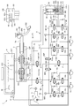
図1は、実施形態1のブレーキ制御装置の構成図である。
ブレーキ制御装置1は、電動車両に好適な液圧式ブレーキ制御装置である。電動車両は、車輪を駆動する動力源として、エンジン(内燃機関)のほかモータ・ジェネレータ(回転電機)を備えたハイブリッド車や、モータ・ジェネレータのみを備えた電気自動車等である。なお、エンジンのみを動力源とする車両にブレーキ制御装置1を適用してもよい。ブレーキ制御装置1は、車両の各車輪FL〜RRに設置されたホイルシリンダ8(8a〜8d)にブレーキ液を供給してブレーキ液圧(ホイルシリンダ圧Pw)を発生させる。このホイルシリンダ圧Pwにより摩擦部材を移動させ、摩擦部材を車輪側の回転部材に押付けることで、摩擦力を発生させる。これにより、各車輪FL〜RRに液圧制動トルクを付与する。ここで、ホイルシリンダ8は、ディスクブレーキ機構における油圧式ブレーキキャリパのシリンダのほか、ドラムブレーキ機構におけるホイルシリンダであってもよい。ブレーキ制御装置1は、2系統すなわちP(プライマリ)系統およびS(セカンダリ)系統のブレーキ配管を有しており、例えばX配管形式を採用している。なお、前後配管等、他の配管形式を採用してもよい。以下、P系統に対応する部材とS系統に対応する部材とを区別する場合は、それぞれの符号の末尾に添字P、Sを付す。
Embodiment 1
FIG. 1 is a block diagram of a brake control device according to a first embodiment.
The brake control device 1 is a hydraulic brake control device suitable for an electric vehicle. The electric vehicle is a hybrid vehicle provided with a motor / generator (a rotating electric machine) in addition to an engine (internal combustion engine) as a power source for driving a wheel, an electric vehicle provided with only the motor / generator, and the like. The brake control device 1 may be applied to a vehicle having only the engine as a power source. The brake control device 1 supplies brake fluid to the wheel cylinders 8 (8a to 8d) installed on the wheels FL to RR of the vehicle to generate a brake fluid pressure (wheel cylinder pressure Pw). The friction member is moved by the wheel cylinder pressure Pw and the friction member is pressed against the rotating member on the wheel side to generate a frictional force. As a result, a hydraulic braking torque is applied to each of the wheels FL to RR. Here, the wheel cylinder 8 may be a wheel cylinder in the drum brake mechanism, in addition to the cylinder of the hydraulic brake caliper in the disc brake mechanism. The brake control device 1 has brake piping of two systems, that is, a P (primary) system and an S (secondary) system, and employs, for example, an X piping system. In addition, you may employ | adopt other piping types, such as front and rear piping. In the following, when the member corresponding to the P system and the member corresponding to the S system are distinguished, subscripts P and S are added to the end of each code.
ブレーキペダル2は、運転者のブレーキ操作の入力を受けるブレーキ操作部材である。ブレーキペダル2はいわゆる吊下げ型であり、その基端が軸201によって回転可能に支持されている。ブレーキペダル2の先端には運転者が踏込む対象となるパッド202が固定されている。ブレーキペダル2の軸201とパッド202との間における基端側には、プッシュロッド2aの一端が、軸203によって回転可能に接続されている。マスタシリンダ3は、運転者によるブレーキペダル2の操作(ブレーキ操作)により作動し、ブレーキ液圧(マスタシリンダ圧Pm)を発生する。なお、ブレーキ制御装置1は、車両のエンジンが発生する吸気負圧を利用してブレーキ操作力(ブレーキペダル2の踏力F)を倍力または増幅する負圧式の倍力装置を備えていない。よって、ブレーキ制御装置1を小型化可能であり、かつ、負圧源(多くの場合はエンジン)を有さない電動車両に好適である。マスタシリンダ3は、プッシュロッド2aを介してブレーキペダル2に接続すると共に、リザーバタンク(リザーバ)4からブレーキ液を補給される。リザーバ4は、ブレーキ液を貯留するブレーキ液源であり、大気圧に開放される低圧部である。リザーバ4の内部における底部側(鉛直方向下側)は、所定の高さを有する複数の仕切部材により、プライマリ液圧室用空間41P、セカンダリ液圧室用空間41Sおよびポンプ吸入用空間42に区画されている。リザーバ4内には、リザーバ4内におけるブレーキ液量のレベルを検出する液面センサ94が設置されている。液面センサ94は、リザーバ4内の液面低下を警報するために用いられ、液面レベルを離散的に検出する。液面センサ94は、固定部材およびフロート部材を有する。固定部材は、リザーバ4の内壁に固定されており、スイッチを有している。スイッチは、液面レベルと略同一の高さとなる位置に設置されている。フロート部材は、ブレーキ液に対して浮力を有しており、ブレーキ液量(液面レベル)の増減に応じて固定部材に対し上下動するように設置されている。リザーバ4内のブレーキ液量が減少し、フロート部材が所定液面レベルまで低下するように移動すると、固定部材のスイッチがオフ状態からオン状態に切り替わる。これにより、液面レベルの低下を検出する。なお、液面センサ94の具体的な態様は上記のように液面レベルを離散的に検出するもの(スイッチ)に限定されず、液面レベルを連続的に検出するもの(アナログ検出)であってもよい。
The brake pedal 2 is a brake operation member that receives an input of a driver's brake operation. The brake pedal 2 is a so-called suspended type, and its proximal end is rotatably supported by a
マスタシリンダ3は、タンデム型であり、ブレーキ操作に応じて軸方向に移動するマスタシリンダピストンとして、プライマリピストン32Pおよびセカンダリピストン32Sを有する。両ピストン32P、32Sは直列に配置されている。プライマリピストン32Pはプッシュロッド2aに接続されている。セカンダリピストン32Sはフリーピストン型である。
ブレーキペダル2には、ストロークセンサ90が取り付けられている。ストロークセンサ90は、ブレーキペダル2の変位量(ペダルストロークS)を検出する。なお、ストロークセンサ90をプッシュロッド2aやプライマリピストン32Pに取り付けてピストンストロークSpを検出してもよい。このとき、ペダルストロークSは、プッシュロッド2aまたはプライマリピストン32Pの軸方向変位量(ストローク量)にブレーキペダルのペダル比Kを乗じたものに相当する。Kは、プライマリピストン32Pのストローク量に対するペダルストロークSの比率であり、所定の値に設定される。Kは、例えば、軸201から軸203までの距離に対する、軸201からパッド202までの距離の比により求められる。以下、プッシュロッド2aの移動方向にx軸を設定し、x軸方向のうちペダルストロークが増加する方向をx軸正方向とする。
ストロークシミュレータ5は、運転者のブレーキ操作に応じて作動する。ストロークシミュレータ5は、運転者のブレーキ操作に応じてマスタシリンダ3の内部から流出したブレーキ液がストロークシミュレータ5内に流入することにより、ペダルストロークSを発生させる。マスタシリンダ3から供給されたブレーキ液によりストロークシミュレータ5のピストン52がシリンダ50内を軸方向に作動する。これにより、ストロークシミュレータ5は運転者のブレーキ操作に伴う操作反力を生成する。
The master cylinder 3 is a tandem type, and has a
A
The
液圧ユニット6は、運転者によるブレーキ操作とは独立にブレーキ液圧を発生可能な制動制御ユニットである。電子制御ユニット(以下、ECUという)100は、液圧ユニット6の作動を制御するコントロールユニットである。液圧ユニット6は、リザーバ4またはマスタシリンダ3からブレーキ液の供給を受ける。液圧ユニット6は、ホイルシリンダ8とマスタシリンダ3との間に配置され、各ホイルシリンダ8a〜8dにマスタシリンダ圧Pmまたは制御液圧を個別に供給可能である。液圧ユニット6は、制御液圧を発生するための液圧機器(アクチュエータ)として、ポンプ7、モータ7aおよび複数の制御弁(電磁弁26等)を有する。ポンプ7は、マスタシリンダ3以外のブレーキ液源(リザーバ4等)からブレーキ液を吸入し、ホイルシリンダ8に向けて吐出する。ポンプ7は、例えばプランジャポンプやギヤポンプが用いられる。ポンプ7はPS両系統で共用され、駆動源としての電動式のモータ7aにより回転駆動される。モータ7aとして、例えばブラシ付き直流モータやブラシレスモータ等が用いられる。また、モータ7aは、回転数検出部としての回転数検出手段7bを有している。電磁弁26等は、制御信号に応じて開閉動作し、液路11等の連通状態を切り替える。これにより、ブレーキ液の流れを制御する。液圧ユニット6は、マスタシリンダ3とホイルシリンダ8との連通を遮断した状態で、ポンプ7が発生する液圧によりホイルシリンダ8を加圧することが可能である。また、液圧ユニット6は、ポン7の吐出圧やマスタシリンダ圧Pm等、各所の液圧を検出する液圧センサ91、92を備える。
The hydraulic unit 6 is a brake control unit capable of generating a brake fluid pressure independently of the driver's brake operation. An electronic control unit (hereinafter referred to as an ECU) 100 is a control unit that controls the operation of the hydraulic pressure unit 6. The hydraulic unit 6 receives the supply of the brake fluid from the
ECU100には、回転数検出手段7b、ストロークセンサ90、および各液圧センサ91、92から出力される検出値、並びに車両側から送られる走行状態に関する情報が入力される。ECU100は、これら各種情報に基づき、内蔵されるプログラムに従って情報処理を行う。また、この処理結果に従って液圧ユニット6の各アクチュエータに指令信号を出力し、これらを制御する。具体的には、電磁弁26等の開閉動作や、モータ7aの回転数(すなわちポンプ7の吐出量)を制御する。これにより各車輪FL〜RRのホイルシリンダ圧Pwを制御することで、各種ブレーキ制御を実現する。例えば、倍力制御や、アンチロック制御や、車両運動制御のためのブレーキ制御や、自動ブレーキ制御や、回生協調ブレーキ制御等を実現する。倍力制御は、運転者のブレーキ操作力(踏力)では不足する液圧制動力を発生してブレーキ操作を補助する。アンチロック制御は、制動による車輪FL〜RRのスリップ(ロック傾向)を抑制する。車両運動制御は、横滑り等を防止する車両挙動安定化制御である。自動ブレーキ制御は、先行車追従制御等である。回生協調ブレーキ制御は、回生ブレーキと協調して目標減速度を達成するようにホイルシリンダ圧Pwを制御する。
マスタシリンダ3の両ピストン32P、32Sの間にプライマリ液圧室31Pが画成される。プライマリ液圧室31Pには、圧縮コイルスプリング33Pが設置されている。ピストン32Sとマスタシリンダ3のx軸正方向端部との間にセカンダリ液圧室31Sが画成されている。セカンダリ液圧室31Sには、圧縮コイルスプリング33Sが設置されている。各液圧室31P、31Sには第1液路(接続液路)11が開口する。各液圧室31P、31Sは、第1液路(接続液路)11を介して、液圧ユニット6に接続すると共にホイルシリンダ8と連通可能である。
運転者によるブレーキペダル2の踏み込み操作によって両ピストン32P、32Sがx軸正方向側へストロークし、各液圧室31P、31Sの容積の減少に応じてマスタシリンダ圧Pmが発生する。両液圧室31P、31Sには同じマスタシリンダ圧Pmが発生する。これにより、各液圧室31P、31Sから第1液路11(接続液路)を介してホイルシリンダ8に向けてブレーキ液が供給される。マスタシリンダ3は、プライマリ液圧室31Pに発生したマスタシリンダ圧Pmにより第1液路(第1接続液路)11Pを介してP系統の第1ホイルシリンダ8a、8dを加圧可能である。また、マスタシリンダ3は、セカンダリ液圧室31Sに発生したマスタシリンダ圧Pmにより第1液路(第2接続液路)11Sを介してS系統の第2ホイルシリンダ8b、8cを加圧可能である。
A primary
Both the
次に、ストロークシミュレータ5の構成を説明する。
ストロークシミュレータ5は、シリンダ50、ピストン52およびスプリング53を有する。図1にはストロークシミュレータ5のシリンダ50の軸心を通る断面を示している。シリンダ50は筒状であり、円筒状の内周面を有している。シリンダ50はピストン収容部501およびスプリング収容部502を有する。ピストン収容部501はスプリング収容部502よりも小径である。ピストン52は、ピストン収容部501の内周側に、その内周面に沿ってシリンダ50の軸方向を移動可能である。ピストン52は、シリンダ50内を少なくとも2室(正圧室511と背圧室512)に分離する隔壁である。シリンダ50内において、ピストン52の一方側に正圧室511が画成され、他方側に背圧室512が画成されている。正圧室511は、ピストン52およびピストン収容部501により囲まれる空間である。正圧室511には、後述する第2液路12が常時開口する。背圧室512は、ピストン52、スプリング収容部502およびピストン収容部501により囲まれる空間である。背圧室512には、後述する液路13Aが常時開口する。
Next, the configuration of the
The
ピストン52の外周には、ピストン52の軸心の周り方向(周方向)に延びるようにピストンシール54が設置されている。ピストンシール54は、ピストン収容部501の内周面に摺接し、ピストン収容部501の内周面とピストン52の外周面との間をシールする。ピストンシール54は、正圧室511と背圧室512との間をシールすることで両者を液密に分離する分離シール部材であり、ピストン52の上記分離部材としての機能を補完する。スプリング53は、背圧室512内に設置された圧縮コイルスプリングであり、ピストン52を正圧室511の容積が縮小する方向に常時付勢する。スプリング53は、ピストン52の変位量に応じて反力を発生する。スプリング53は、第1スプリング531および第2スプリング532を有する。第1スプリング531は、第2スプリング532よりも小径かつ短尺であり、線径が小さい。第1スプリング531のばね定数は第2スプリング532よりも小さい。両スプリング531、532は、ピストン52とシリンダ50(スプリング収容部502)との間に、リテーナ部材530を介して直列に配置されている。
A
次に、液圧ユニット6の液圧回路を説明する。
各車輪FL〜RRに対応する部材には、その符号の末尾にそれぞれ添字a〜dを付して適宜区別する。接続液路としての第1液路(接続液路)11は、マスタシリンダ3の液圧室31とホイルシリンダ8とを接続する。第1液路(第1接続液路)11Pには第1遮断弁21Pが設置され、第1液路(第2接続液路)11Sには第2遮断弁21Sが設置されている。遮断弁21は、第1液路(接続液路)11に設置された常開型の(非通電状態で開弁する)電磁弁である。第1液路(接続液路)11は、遮断弁21によって、マスタシリンダ3側の第1液路(接続液路)11Aとホイルシリンダ8側の第1液路(接続液路)11Bとに分離される。ソレノイドイン弁SOL/V IN25は、第1液路(接続液路)11における遮断弁21よりもホイルシリンダ8側(第1液路11B)に、各車輪FL〜RRに対応して(液路11a〜11dに)設置された常開型の電磁弁である。SOL/V IN25をバイパスして第1液路(接続液路)11と並列にバイパス液路110が設置されている。バイパス液路110には、ホイルシリンダ8側からマスタシリンダ3側へのブレーキ液の流れのみを許容するチェック弁250が設置されている。
Next, the hydraulic circuit of the hydraulic unit 6 will be described.
The members corresponding to the wheels FL to RR are appropriately distinguished by adding suffixes a to d at the end of the reference numerals. The first fluid passage (connection fluid passage) 11 as the connection fluid passage connects the fluid pressure chamber 31 of the master cylinder 3 and the wheel cylinder 8. A
吸入液路15は、リザーバ4(ポンプ吸入用空間42)とポンプ7の吸入部70とを接続する液路である。吐出液路16は、ポンプ7の吐出部71と、第1液路(接続液路)11Bにおける遮断弁21とSOL/V IN25との間とを接続する。チェック弁160は、吐出液路16に設置され、ポンプ7の吐出部71の側(上流側)から第1液路(接続液路)11の側(下流側)へのブレーキ液の流れのみを許容する。チェック弁160は、ポンプ7が備える吐出弁である。吐出液路16は、チェック弁160の下流側でP系統の液路16PとS系統の液路16Sとに分岐する。各液路16P、16SはそれぞれP系統の第1液路(第1接続液路)11PとS系統の第1液路(第2接続液路)11Sに接続している。液路16P、16Sは、第1液路(第1接続液路)11P、第1液路(第2接続液路)11Sを互いに接続する連通液路として機能する。第1連通弁26Pは、液路16Pに設置された常閉型の(非通電状態で閉弁する)電磁弁である。第2連通弁26Sは、液路16Sに設置された常閉型の電磁弁である。ポンプ7は、リザーバ4から供給されるブレーキ液により第1液路11に液圧を発生させてホイルシリンダ圧Pwを発生可能な第2の液圧源である。ポンプ7は、上記連通液路(吐出液路16P、16S)および第1液路(第1接続液路)11P、第1液路(第2接続液路)11Sを介してホイルシリンダ8(8a〜8d)と接続し、上記連通液路(吐出液路16P、16S)にブレーキ液を吐出することにより、ホイルシリンダ8を加圧可能である。
The
第1減圧液路(還流液路)17は、吐出液路16におけるチェック弁160と連通弁26との間と、吸入液路15とを接続する。調圧弁27は、第1減圧液路(還流液路)17に設置された第1減圧弁としての常開型の電磁弁である。なお、調圧弁27は常閉型でもよい。第2減圧液路18は、第1液路(接続液路)11BにおけるSOL/V IN25よりもホイルシリンダ8側と、吸入液路15とを接続する。ソレノイドアウト弁SOL/V OUT28は、第2減圧液路18に設置された第2減圧弁としての常閉型の電磁弁である。なお、実施形態1では、調圧弁27よりも吸入液路15の側の第1減圧液路(還流液路)17と、SOL/V OUT28よりも吸入液路15の側の第2減圧液路18とが部分的に共通している。
The first depressurizing liquid path (refluxing liquid path) 17 connects the
第2液路(シミュレータ液路)12は、第1液路(接続液路)11Aから分岐してストロークシミュレータ5に接続する。第2液路12(シミュレータ液路)は、第1液路(接続液路)11Aと共に、マスタシリンダ3のプライマリ液圧室31Pとストロークシミュレータ5の正圧室511とを接続する。なお、第1液路(接続液路)11Aに代えて、プライマリ液圧室31Pと第2液路12(シミュレータ液路)を直接接続してもよい。第3液路13は、ストロークシミュレータ5の背圧室512と第1液路11とを接続する。具体的には、第3液路13は、第1液路(第1接続液路)11P(第1液路11B)における第1遮断弁21PとSOL/V IN25との間から分岐して背圧室512と接続する。ストロークシミュレータイン弁SS/V IN23は、第3液路13に設置された常閉型の電磁弁である。第3液路13は、SS/V IN23によって、背圧室512側の液路13Aと第1液路(接続液路)11側の液路13Bとに分離されている。SS/V IN23をバイパスして第3液路13と並列にバイパス液路130が設置されている。バイパス液路130は、液路13Aと液路13Bとを接続する。バイパス液路130にはチェック弁230が設置されている。チェック弁230は、背圧室512側(液路13A)から第1液路(接続液路)11側(液路13B)へ向うブレーキ液の流れを許容し、逆方向へのブレーキ液の流れを抑制する。
The second fluid path (simulator fluid path) 12 is branched from the first fluid path (connection fluid path) 11A and connected to the
第4液路14は、ストロークシミュレータ5の背圧室512とリザーバ4とを接続する。
第4液路14は、第3液路13における背圧室512とSS/V IN23との間(液路13A)と、吸入液路15(または調圧弁27よりも吸入液路15側の第1減圧液路(還流液路)17や、SOL/V OUT28よりも吸入液路15側の第2減圧液路18)とを接続する。なお、第4液路14を背圧室512やリザーバ4に直接的に接続してもよい。ストロークシミュレータアウト弁SS/V OUT24は、第4液路14に設置された常閉型の電磁弁である。SS/V OUT24をバイパスして、第4液路14と並列にバイパス液路140が設置されている。バイパス液路140には、チェック弁240が設置されている。チェック弁240は、リザーバ4(吸入液路15)側から第3液路13A側すなわち背圧室512側へ向うブレーキ液の流れを許容し、逆方向へのブレーキ液の流れを抑制する。
The fourth
The fourth
遮断弁21、SOL/V IN25および調圧弁27は、ソレノイドに供給される電流に応じて弁の開度が調整される比例制御弁である。他の弁、すなわちSS/V IN23、SS/V OUT24、連通弁26およびSOL/V OUT28は、弁の開閉が二値的に切り替え制御される2位置弁(オン・オフ弁)である。なお、上記他の弁に比例制御弁を用いることも可能である。第1液路(第1接続液路)11Pにおける第1遮断弁21Pとマスタシリンダ3との間(第1液路11A)には、この箇所の液圧(マスタシリンダ圧Pmおよびストロークシミュレータ5の正圧室511内の液圧)を検出する液圧センサ91が設置されている。第1液路(接続液路)11における遮断弁21とSOL/V IN25との間には、この箇所の液圧(ホイルシリンダ圧)を検出する液圧センサ92(プライマリ系統第1液圧センサ92P、セカンダリ系統第2液圧センサ92S)が設置されている。遮断弁21を開弁方向に作動させた状態で、マスタシリンダ3の液圧室31とホイルシリンダ8とを接続するブレーキ系統(第1液路11)は、第1の系統を構成する。第1の系統は、踏力Fを用いて発生させたマスタシリンダ圧Pmによりホイルシリンダ圧Pwを発生させることで、踏力ブレーキ(非倍力制御)を実現可能である。一方、遮断弁21を閉弁方向に作動させた状態で、ポンプ7を含み、リザーバ4とホイルシリンダ8を接続するブレーキ系統(吸入液路15、吐出液路16等)は、第2の系統を構成する。第2の系統は、ポンプ7を用いて発生させた液圧によりホイルシリンダ圧Pwを発生させる、いわゆるブレーキバイワイヤ装置を構成し、ブレーキバイワイヤ制御として倍力制御等を実現可能である。ブレーキバイワイヤ制御(以下、単にバイワイヤ制御という。)時、ストロークシミュレータ5は、運転者のブレーキ操作に応じた操作反力を生成する。
The shut-off valve 21, the SOL / VIN 25, and the
ECU100は、バイワイヤ制御部101、踏力ブレーキ部102およびフェールセーフ部103、電源操作部10xを有する。バイワイヤ制御部101は、運転者のブレーキ操作状態に応じて、遮断弁21を閉じ、ポンプ7によりホイルシリンダ8を加圧する。以下、具体的に説明する。バイワイヤ制御部101は、ブレーキ操作状態検出部101a、目標ホイルシリンダ圧算出部101bおよびホイルシリンダ圧制御部101cを有する。ブレーキ操作状態検出部101aは、ストロークセンサ90が検出した値の入力を受けて、運転者によるブレーキ操作量としてのペダルストロークSを検出する。また、ペダルストロークSに基づき、運転者のブレーキ操作中であるか否か(ブレーキペダル2の操作の有無)を検出する。なお、踏力Fを検出する踏力センサを設置し、その検出値に基づきブレーキ操作量を検出または推定してもよい。また、液圧センサ91の検出値に基づきブレーキ操作量を検出または推定してもよい。すなわち、制御に用いるブレーキ操作量として、ペダルストロークSに限らず、他の適当な変数を用いてもよい。
目標ホイルシリンダ圧算出部101bは、目標ホイルシリンダ圧Pw*を算出する。例えば、倍力制御時には、検出されたペダルストロークSに基づき、所定の倍力比に応じてペダルストロークSと運転者の要求ブレーキ液圧(運転者が要求する車両減速度)との間の理想の関係(ブレーキ特性)を実現する目標ホイルシリンダ圧Pw*を算出する。例えば、通常サイズの負圧式倍力装置を備えたブレーキ装置において、負圧式倍力装置の作動時に実現されるペダルストロークSとホイルシリンダ圧Pwとの間の所定の関係を、目標ホイルシリンダ圧Pw*を算出するための上記理想の関係とする。
The
The target wheel cylinder
ホイルシリンダ圧制御部101cは、遮断21を閉弁方向に作動させることにより、液圧ユニット6の状態を、ポンプ7(第2の系統)によりホイルシリンダ圧Pwを発生(加圧制御)可能な状態とする。この状態で、液圧ユニット6の各アクチュエータを制御して目標ホイルシリンダ圧Pw*を実現する液圧制御(例えば倍力制御)を実行する。具体的には、遮断弁21を閉弁方向に作動させ、連通弁26を開弁方向に作動させ、調圧弁27を閉弁方向に作動させると共に、ポンプ7を作動させる。このように制御することにより、リザーバ4側から所望のブレーキ液を吸入液路15、ポンプ7、吐出液路16、および第1液路(接続液路)11を経由してホイルシリンダ8に送ることが可能である。ポンプ7が吐出するブレーキ液は吐出液路16を介して第1液路(接続液路)11Bに流入する。このブレーキ液が各ホイルシリンダ8a〜8dに流入することによって、各ホイルシリンダ8a〜8dが加圧される。すなわち、ポンプ7により第1液路(接続液路)11Bに発生させた液圧を用いてホイルシリンダ8を加圧する。このとき、液圧センサ92の検出値が目標ホイルシリンダ圧Pw*に近づくようにポンプ7の回転数や調圧弁27の開弁状態(開度等)をフィードバック制御することにより、所望の制動力が得られる。すなわち、調圧弁27の開弁状態を制御し、吐出液路16または第1液路(接続液路)11から調圧弁27を介して吸入液路15へブレーキ液を適宜漏らすことで、ホイルシリンダ圧Pwを調節できる。このとき、遮断弁21を閉弁方向に作動させ、マスタシリンダ3側とホイルシリンダ8側とを遮断することにより、運転者のブレーキ操作から独立してホイルシリンダ圧を制御することが容易となる。
The wheel cylinder
一方、ホイルシリンダ圧制御部101cは、SS/V OUT24を開弁方向に作動させる。これにより、ストロークシミュレータ5の背圧室512と吸入液路15(リザーバ4)側とが連通する。よって、ブレーキペダル2の踏み込み操作に伴いマスタシリンダ3からブレーキ液が吐出され、このブレーキ液がストロークシミュレータ5の正圧室511に流入すると、ピストン52が作動する。これにより、ペダルストロークSpが発生する。このとき、正圧室511に流入する液量と同等の液量のブレーキ液が背圧室512から流出する。このブレーキ液は、第3液路13Aおよび第4液路14を介して吸入液路15(リザーバ4)側へ排出される。なお、第4液路14はブレーキ液が流入可能な低圧部に接続していればよく、必ずしもリザーバ4に接続している必要はない。また、ストロークシミュレータ5のスプリング53と背圧室512の液圧等がピストン52を押す力により、ブレーキペダル2に作用する操作反力(ペダル反力)が発生する。すなわち、ストロークシミュレータ5は、バイワイヤ制御時に、ブレーキペダル2の特性(F―S特性)を生成する。
踏力ブレーキ部102は、遮断弁21を開弁方向に作動させ、マスタシリンダ3によりホイルシリンダ8を加圧する。遮断弁21を開弁方向に作動させることにより、液圧ユニット6の状態を、マスタシリンダ圧Pm(第1の系統)によりホイルシリンダ圧Pwを発生可能な状態とし、踏力ブレーキを実現する。このとき、SS/V OUT24を閉弁方向に作動させることにより、運転者のブレーキ操作に対してストロークシミュレータ5を非作動とする。これにより、マスタシリンダ3からブレーキ液が効率的にホイルシリンダ8に向けて供給される。したがって、運転者が踏力Fにより発生させるホイルシリンダ圧の低下を抑制できる。具体的には、踏力ブレーキ部102は、液圧ユニット6における全アクチュエータを非作動状態とする。なお、SS/V IN23を開弁方向に作動させてもよい。
On the other hand, the wheel cylinder
The depression
つぎに、マスタシリンダ3の両ピストン32P、32Sのストローク寸法に関して説明する。ストロークシミュレータ5の最大吸収液量、すなわち正圧室511が吸収可能なブレーキ液の量を、Vssとする。踏力Fによるブレーキの目標ホイルシリンダ圧力をPw*として、その圧力を発生させるために、プライマリ液圧室31PからP系統の第1ホイルシリンダ8a、8dへ、及びセカンダリ液圧室31SからS系統の第2ホイルシリンダ8b、8cへ、それぞれ供給することが必要なブレーキ液の量を、Vfとする。このときストロークシミュレータ5が接続されているプライマリ液室31Pは、VssとVfの合計に対する容積を備える。一方、ストロークシミュレータ5と連通していないセカンダリ液圧室31Sは、Vfに対応する容積を備える。このため、実施形態1ではプライマリピストン32Pの最大ストローク量Lpはセカンダリピストン32Sの最大ストローク量Lsに比べ大きくなる。詳細な各寸法の設定については特開2016−150633を参照するとしてここでは省略する。
Next, stroke dimensions of both
フェールセーフ部103は、ブレーキ制御装置1における故障(ブレーキ液漏れ異常または昇圧不良異常、液圧センサ異常や、モータ異常、ポンプ異常、バルブ異常等のアクチュエータ異常)の発生を検出する。例えば、ブレーキ操作状態検出部101aからの信号や、各センサからの信号に基づき、液圧ユニット6におけるブレーキ液漏れ異常、昇圧不良異常、液圧センサ異常やアクチュエータ(ポンプ7またはモータ7aや調圧弁27等)異常の故障を検出する。または、ブレーキ制御装置1に電源を供給する車載電源(バッテリ)やECU100の故障(異常)を検出する。フェールセーフ部103は、バイワイヤ制御中に故障(ブレーキ液漏れまたは昇圧不良等の異常等)や車載電源(バッテリ)やECU100の故障(異常)の発生を検出すると、故障(異常)の状態に応じて制御を切り替える。
たとえば、バイワイヤ制御による圧力制御が継続不可能であると判断された場合は、踏力ブレーキ部102を作動させ、バイワイヤ制御から踏力ブレーキへ切替える。具体的には、液圧ユニット6における全アクチュエータを非作動状態とし、踏力ブレーキへ移行させる。遮断弁21は常開弁である。このため、電源失陥時には遮断弁21が開弁することで、踏力ブレーキを自動的に実現することが可能である。SS/V OUT24は常閉弁である。このため、電源失陥時にはSS/V OUT24が閉弁することで、ストロークシミュレータ5が自動的に非作動とされる。連通弁26は常閉型である。このため、電源失陥時に両系統のブレーキ液圧系を互いに独立とし、各系統で別々に踏力Fによるホイルシリンダ加圧が可能となる。電源操作部10xは車両のイグニッションがONからOFFされたときにECU100の電源をすぐに遮断せずに必要な処理を行ってから電源を自己遮断する自己保持機能と、イグニッションがOFFからONされる信号とは別の、ドアの開閉などの信号によって電源をONするウエイクアップ機能を有している。
第1液路(第1接続液路)11P、第1液路(第2接続液路)11S、第1遮断弁21P、第2遮断弁21S、吐出液路(連通通路)16P、16S、ポンプ7、モータ7a、第1連通弁26P、第2連通弁26S、調圧弁27およびECU100は、ブレーキ制御装置1を構成する。
The fail
For example, when it is determined that the pressure control by the by-wire control can not be continued, the depression
First fluid passage (first connection fluid passage) 11P, first fluid passage (second connection fluid passage) 11S,
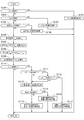
図2は、実施形態1の第1液圧の算出を示すブロック図である。
まず、回転数検出手段7bにて検出したモータ7aの回転数から単位時間当たりのポンプ7の吐出液量を算出する。すなわち、ブロック301にて、検出したモータ7aの回転数に1回転当たりの吐出液量を乗じ、さらに、ブロック302にて、ポンプ7の吐出効率を乗じることにより、ポンプ7の単位時間当たりの吐出容量を算出する。
なお、ポンプ7の吐出容量の算出は、モータ7aの回転位置を検出し、プランジャポンプが吐出した回数から算出してもよい。
つぎに、ブロック303で、調圧弁27を通過する流量を調圧弁27の制御電流と調圧弁27の上流・下流の差圧の関係(ブロック303に示すグラフ)から算出する。
ブロック304では、算出したポンプ7の単位時間当たりの吐出容量と調圧弁27の通過流量との差を算出する。すなわち、この差が、ホイルシリンダ8(8a〜8d)へ流入する液量となる。
ブロック305では、算出したポンプ7の単位時間当たりの吐出液量と調圧弁27の通過流量との差であるホイルシリンダ8(8a〜8d)への流入液量を積分して、ホイルシリンダ8(8a〜8d)内の液量を算出する。
ブロック306にて、ホイルシリンダ8(8a〜8d)内の液量と圧力の関係(ブロック306に示すグラフ)から、ホイルシリンダ8(8a〜8d)の第1液圧としての推定液圧Pestを算出する。
FIG. 2 is a block diagram showing the calculation of the first hydraulic pressure of the first embodiment.
First, the discharge amount of the pump 7 per unit time is calculated from the rotational speed of the
The displacement of the pump 7 may be calculated from the number of times the plunger pump has discharged by detecting the rotational position of the
Next, at
In
In
In
図3は、実施形態1のブレーキ液漏れ検出動作を示すフローチャートである。このフローチャートは、所定の演算周期で繰り返し実行される。
ステップS100では、モータ7aに異常が発生したか否かを判定する。もし、モータ7aに異常が発生しているときには、ステップS101へ進み、モータ異常時の処理を実行し、ステップS100へ戻る。モータ7aにが発生していないときには、ステップS102へ進む。
ステップ102では、バルブ(電磁弁26等)に異常が発生したか否かを判定する。もし、バルブ(電磁弁26等)に異常が発生しているときには、ステップS103へ進み、バルブ異常時の処理を実行し、ステップS100へ戻る。バルブ(電磁弁26等)に異常が発生していないときには、ステップS104へ進む。
ステップS104では、液圧センサ(91、92)に異常が発生したか否かを判定する。もし、液圧センサ(91、92)に異常が発生しているときには、ステップS105へ進み、液圧センサ異常時の処理を実行し、ステップS100へ戻る。液圧センサ(91、92)に異常が発生していないときには、ステップS106へ進む。
ステップS106では、図2にて説明した算出方法により、第1液圧としての推定液圧Pestの算出を行い、ステップS107へ進む。
ステップS107では、第1、第2液圧センサ92P、92Sより、P系統、S系統の第2液圧としてのセンサ圧力Psenを取り込み、ステップS108へ進む。
ステップS108では、推定液圧Pestとセンサ圧力Psenとの圧力差Pdiffを算出し、ステップS109へ進む。
ステップS109では、圧力差Pdiffの変化率ΔPdiffを算出し、ステップS110へ進む。
ステップS110では、算出した圧力差Pdiffが所定の圧力としての閾値Pthを越えているか否かを判定する。算出した圧力差Pdiffが閾値Pthを越えているときには、故障(ブレーキ液漏れ異常または昇圧不良の異常)の可能性ありと判断し、ステップS111へ進み、算出した圧力差Pdiffが閾値Pthを越えていないときには、正常と判断し、ステップS100へ戻る。
FIG. 3 is a flowchart showing the brake fluid leak detection operation of the first embodiment. This flowchart is repeatedly executed in a predetermined operation cycle.
In step S100, it is determined whether or not an abnormality has occurred in the
In
In step S104, it is determined whether or not an abnormality has occurred in the hydraulic pressure sensors (91, 92). If an abnormality occurs in the fluid pressure sensor (91, 92), the process proceeds to step S105 to execute a process for fluid pressure sensor abnormality, and the process returns to step S100. If no abnormality occurs in the hydraulic pressure sensors (91, 92), the process proceeds to step S106.
In step S106, the estimated hydraulic pressure Pest as the first hydraulic pressure is calculated by the calculation method described in FIG. 2, and the process proceeds to step S107.
In step S107, the sensor pressure Psen as the second hydraulic pressure of the P system and the S system is taken in from the first and second
In step S108, a pressure difference Pdiff between the estimated hydraulic pressure Pest and the sensor pressure Psen is calculated, and the process proceeds to step S109.
In step S109, a change rate ΔPdiff of the pressure difference Pdiff is calculated, and the process proceeds to step S110.
In step S110, it is determined whether the calculated pressure difference Pdiff exceeds a threshold Pth as a predetermined pressure. If the calculated pressure difference Pdiff exceeds the threshold value Pth, it is determined that there is a possibility of a failure (a brake fluid leak abnormality or a pressure increase failure abnormality), and the process proceeds to step S111, and the calculated pressure difference Pdiff exceeds the threshold Pth. If not, it is determined that the process is normal, and the process returns to step S100.
ステップS111では、リザーバ4の液面レベルが低下しているか否かを判定する。リザーバ4の液面レベルが低下しているときには、ステップS112へ進み、リザーバ4の液面レベルが低下していないときには、ステップS113へ進む。
ステップS113では、失陥(液漏れ)系統検出動作を実行し、ステップS114へ進む。
ここで、失陥(液漏れ)系統検出動作とは、ポンプ7を作動し、第1連通弁26P、第2連通弁26Sとを交互に複数回開閉作動させた後に、P、S両系統の第1、第2液圧センサ92P、92Sで検出したそれぞれのセンサ圧力Psenの差圧により、液漏れの検出を行う(詳細は、特開2014−151806号公報)か、または、ポンプ7を作動し、P、S両系統の液圧を所定の液圧まで高めてから、第1連通弁26P、第2連通弁26Sを閉じた後のP、S両系統の第1、第2液圧センサ92P、92Sで検出したそれぞれのセンサ圧力Psenの差圧に基づいて液漏れ系統を検出してもよい(特開2015−182631号公報)。
このようにすると、各系統を交互に増圧させるか、各系統を圧力保持させて、両系統の差圧を見るだけで、液漏れの判定が可能となる。
ステップS114では、失陥(液漏れ)系統を検出したか否かを判定する。失陥(液漏れ)系統を検出したときには、ステップS116へ進み、失陥(液漏れ)系統を検出しないときには、ステップS115へ進む。
ステップS115では、昇圧不良異常と判定するとともに昇圧不良異常時処理を実行し、ステップS100へ戻る。
ステップS112では、圧力差Pdiffの変化率ΔPdiffが所定の変化率としての閾値ΔPthを越えているか否かを判定する。圧力差Pdiffの変化率ΔPdiffが閾値ΔPthを越えているときには、ステップS117へ進み、圧力差Pdiffの変化率Δが閾値ΔPthを越えていないときには、ステップS113へ進む。
ステップS116では、液漏れ異常(内部液漏れ含む)と判定するとともに、液漏れ異常時処理を実行し、ステップS100へ戻る。
ここで、液漏れ異常時処理とは、例えば、S系統が失陥したとすると、第1連通弁26Pを開弁方向に作動させるとともに、第2連通弁26Sを閉弁方向に作動させることで、失陥したS系統を遮断し、正常なP系統のみバイワイヤ制御を行う、片系統倍力制御とする。
ステップS117では、液漏れ大異常と判定するとともに、液漏れ大異常時処理を実行し、ステップS100へ戻る。
ここで、液漏れ大異常時処理とは、ポンプ7による昇圧制御を停止し、運転者のブレーキ操作により発生したマスタシリンダ圧力Pmをホイルシリンダ8へ直接伝える両系統踏力制御とする。このため、第1遮断弁21P、第2遮断弁21Sを開弁方向に作動させるとともに、第1連通弁26P、第2連通弁26Sを閉弁方向に作動させ、調圧弁27の制御を中止して、モータ7aの駆動を停止する。
すなわち、運転者のブレーキ操作により発生したマスタシリンダ圧力Pmをホイルシリンダ8へ直接伝える両系統踏力制御とする。
In step S111, it is determined whether the liquid level of the
In step S113, a failure (liquid leakage) system detection operation is performed, and the process proceeds to step S114.
Here, in the failure (liquid leakage) system detection operation, after the pump 7 is operated to alternately open and close the
In this case, it is possible to determine the liquid leakage only by increasing the pressure in each system alternately or holding the pressure in each system and observing the differential pressure between the two systems.
In step S114, it is determined whether a failure (liquid leakage) system has been detected. When the failure (liquid leakage) system is detected, the process proceeds to step S116, and when the failure (liquid leakage) system is not detected, the process proceeds to step S115.
In step S115, it is determined that a boost failure is abnormal, and a boost failure abnormality processing is executed, and the process returns to step S100.
In step S112, it is determined whether the change rate ΔPdiff of the pressure difference Pdiff exceeds a threshold value ΔPth as a predetermined change rate. When the rate of change ΔPdiff of the pressure difference Pdiff exceeds the threshold value ΔPth, the process proceeds to step S117. When the rate of change Δ of the pressure difference Pdiff does not exceed the threshold value ΔPth, the process proceeds to step S113.
In step S116, the liquid leakage abnormality (including the internal liquid leakage) is determined, and the liquid leakage abnormality processing is executed, and the process returns to step S100.
Here, in the liquid leakage abnormality process, for example, assuming that the S system fails, the
In step S117, the liquid leakage large abnormality is determined, and the liquid leakage large abnormality processing is executed, and the process returns to step S100.
Here, the liquid leakage large abnormality processing refers to a dual system treading force control that stops the pressure increase control by the pump 7 and directly transmits the master cylinder pressure Pm generated by the driver's brake operation to the wheel cylinder 8. Therefore, the
That is, both system treading force control is performed to directly transmit the master cylinder pressure Pm generated by the driver's brake operation to the wheel cylinder 8.
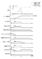
図4は、実施形態1のS系統の液漏れ時のブレーキ液漏れ検出動作を実行した場合のタイムチャートである。なお、本タイムチャートは、モータ7a、バルブ(電磁弁26等)、液圧センサ(91、92)に故障(異常)はなく、リザーバ4の液面低下はない状態である。
横軸は、時間であり、一番上が液圧、その下が圧力差Pdiff、リザーバ4の液面レベル低下検出、ブレーキ制御装置1の制御、調圧弁27指令、P系統の第1連通弁26P指令、S系統の第2連通弁26S指令、遮断弁21指令、モータ7a指令、P系統失陥フラグ、S系統失陥フラグの状態変化を示している。
FIG. 4 is a time chart when the brake fluid leak detection operation at the time of fluid leak in the S system of the first embodiment is performed. In this time chart, there is no failure (abnormality) in the
The horizontal axis is time, and the top is the fluid pressure, the bottom is the pressure difference Pdiff, the level difference detection of the
時刻t1にて、運転者がブレーキ操作を開始する。ここで、ブレーキ制御装置1は、算定した目標液圧(実線)を上昇させ、P系統とS系統でのバイワイヤ制御により昇圧が開始される。
時刻t2にて、目標液圧が一定となる。時刻t2までは、第1、第2液圧センサ92P、92Sで検出したセンサ圧力PsenはP系統とS系統ともに目標液圧通りに制御されている。しかし、S系統に液漏れが発生している影響により、回転数検出手段7bにて検出したモータ7aの回転数から算出した推定液圧Pestと第1、第2液圧センサ92P、92Sで検出したセンサ圧力Psenとの間に圧力差Pdiffが発生し始める。時刻t2から時刻t3の間に、推定液圧Pestとセンサ圧力Psenとの圧力差Pdiffが徐々に大きくなり、時刻t3にて、圧力差Pdiffが閾値Pthを上回るため、失陥(液漏れ)系統検出動作を開始する。すなわち、第1連通弁26P、第2連通弁26Sを閉弁し、液圧を両系統内に閉じ込める。
時刻t4にて、第2液圧センサ92Sで検出したセンサ圧力Psenが、液漏れによって一定値以上低下したので、S系統失陥フラグを立て、失陥(液漏れ)系統検出動作を終了する。
これにより、S系統の液漏れが検出されたため、故障(異常)としての液漏れ異常判定がなされる。これ以降は、液漏れ異常時処理として、第1連通弁26Pを開弁方向に作動させるとともに、第2連通弁26Sを閉弁方向に作動させることで、失陥したS系統を遮断し、正常なP系統のみバイワイヤ制御を行う、片系統倍力制御となる。
At time t1, the driver starts the brake operation. Here, the brake control device 1 raises the calculated target fluid pressure (solid line), and boosting is started by the by-wire control in the P system and the S system.
At time t2, the target fluid pressure becomes constant. Until time t2, the sensor pressure Psen detected by the first and second
At time t4, the sensor pressure Psen detected by the second
As a result, since the liquid leakage of the S system is detected, the liquid leakage abnormality determination as a failure (abnormality) is made. After that, as the liquid leakage abnormality process, the
図5は、実施形態1のS系統の大きな外部液漏れ時のブレーキ液漏れ検出動作を実行した場合のタイムチャートである。なお、本タイムチャートは、モータ7a、バルブ(電磁弁26等)、液圧センサ(91、92)に故障(異常)はない状態である。
横軸は、時間であり、一番上が液圧、その下が圧力差Pdiff、圧力差変化率ΔPdiff、リザーバ4の液面レベル低下検出、ブレーキ制御装置1の制御、調圧弁27指令、P系統の第1連通弁26P指令、S系統の第2連通弁26S指令、遮断弁21指令、モータ7a指令の状態変化を示している。
FIG. 5 is a time chart when the brake fluid leak detection operation at the time of a large external fluid leak in the S system of the first embodiment is performed. In this time chart, there is no failure (abnormality) in the
The horizontal axis is time, the top is the hydraulic pressure, the lower is the pressure difference Pdiff, the pressure difference change rate ΔPdiff, the detection of the liquid level decrease of the
時刻t1にて、運転者がブレーキ操作を開始する。ここで、ブレーキ制御装置1は、算定した目標液圧を上昇させ、P系統とS系統でのバイワイヤ制御により昇圧が開始される。
しかし、時刻t1以降、液漏れが大きいため、第1、第2液圧センサ92P、92Sで検出した両系統のセンサ圧力Psenは、目標液圧通りに昇圧を行うことができない。すなわち、昇圧している間に、ブレーキ液の外部流出が継続して発生している。
このため、ブレーキ制御装置1は、調圧弁27やモータ7aを、センサ圧力Psenが目標液圧に近づくように、正常時よりホイルシリンダ8への液量が大きくなるように制御を行うため、推定液圧の昇圧勾配は目標液圧の昇圧勾配よりも大きくなり、圧力差Pdiffの変化量が大きくなる。
時刻t2にて、ブレーキ液の大きな液漏れが継続した結果、リザーバ4内のブレーキ液が減少し、液面センサ94が液面レベルの低下を検出する。
さらに、時刻t3にて、圧力差Pdiffが閾値Pthを越える。このとき、リザーバ4内の液面レベルが低下かつ圧力差Pdiffの変化率Δが閾値ΔPthを越えているため、液漏れ大異常と判定する。
これ以降は、液漏れ大異常時処理として、ポンプ7による昇圧制御を停止し、運転者のブレーキ操作により発生したマスタシリンダ圧力Pmをホイルシリンダ8へ直接伝える両系統踏力制御とする。このため、第1遮断弁21P、第2遮断弁21Sを開弁方向に作動させるとともに、第1連通弁26P、第2連通弁26Sを閉弁方向に作動させ、調圧弁27の制御を中止して、モータ7aの駆動を停止する。
これにより、P系統、S系統が分離され、運転者の踏力によるマスタシリンダ圧力Pmが直接ホイルシリンダ8へ伝達される。S系統には、大きな液漏れが発生しているため、第2ホイルシリンダ8b、8cの圧力は、0に近づくが、P系統の第1ホイルシリンダ8a、8dの圧力はマスタシリンダの圧力と等しくなる。
このように、大きなブレーキ液漏れが発生した場合でも、確実に車両の制動力を発生する状態へ移行させることができる。
At time t1, the driver starts the brake operation. Here, the brake control device 1 raises the calculated target fluid pressure, and pressure increase is started by the by-wire control in the P system and the S system.
However, since the liquid leakage is large after time t1, the sensor pressures Psen of both systems detected by the first and second
Therefore, the brake control device 1 controls the
As a result of the large leakage of the brake fluid continuing at time t2, the brake fluid in the
Furthermore, at time t3, the pressure difference Pdiff exceeds the threshold Pth. At this time, since the liquid level in the
From this point on, as fluid leakage large abnormality processing, pressure boosting control by the pump 7 is stopped and master pressure of the master cylinder Pm generated by the driver's brake operation is directly transmitted to the wheel cylinder 8. Therefore, the
As a result, the P system and the S system are separated, and the master cylinder pressure Pm resulting from the driver's depression force is directly transmitted to the wheel cylinder 8. Since a large liquid leak occurs in the S system, the pressure of the
Thus, even when a large brake fluid leak occurs, it is possible to reliably shift to a state in which the vehicle braking force is generated.
実施形態1にあっては、以下の効果を奏する。
(1)回転数検出手段7bにて検出したモータ7aの回転数に基づいて求められた第1液路(接続液路)11(11P、11S)の推定液圧Pestと、第1、第2液圧センサ92P、92Sで検出したセンサ圧力Psenとの圧力差Pdiffを閾値Pthと比較することにより、故障(異常)の可能性を検出する。
よって、液漏れ等の故障(異常)検出精度を向上できる。また、リザーバ4の液面レベルの低下の有無にかかわらず、液漏れを検出できる。すなわち、内部漏れも検出可能である。さらに、特別な検出動作が不要なので、運転者に違和感を与えない。
The following effects are achieved in the first embodiment.
(1) The estimated fluid pressure Pest of the first fluid passage (connection fluid passage) 11 (11P, 11S) determined based on the number of rotations of the
Therefore, the failure (abnormality) detection accuracy such as liquid leakage can be improved. Moreover, regardless of the presence or absence of the drop in the liquid level of the
(2)ポンプ7の単位時間当たりの吐出容量と調圧弁27の通過流量との差であるホイルシリンダ8(8a〜8d)への流入液量を積分して、ホイルシリンダ8(8a〜8d)内の液量を算出し、ホイルシリンダ8(8a〜8d)の推定液圧Pestを算出する。
よって、故障(異常)検出精度を向上できる。
(2) Integral fluid volume to the wheel cylinder 8 (8a to 8d) which is the difference between the displacement per unit time of the pump 7 and the flow rate through the
Therefore, failure (abnormality) detection accuracy can be improved.
(3)故障(異常)の可能性は、ブレーキ液の液洩れ異常である。
よって、液漏れの故障(異常)検出精度を向上できる。
(3) The possibility of a failure (abnormality) is a brake fluid leakage abnormality.
Therefore, the failure (abnormality) detection accuracy of the liquid leak can be improved.
(4)モータ7aの回転数に基づいて求められた第1液路(接続液路)11(11P、11S)の推定液圧Pestと、第1、第2液圧センサ92P、92Sで検出したセンサ圧力Psenとの圧力差Pdiffが閾値Pthを上回るとき、故障(異常)の可能性を検出し、さらに、リザーバ4の液面レベルが所定液面レベルを上回るとき、失陥(液漏れ)系統検出動作を実行する。
よって、リザーバ4の液面レベルの低下の有無にかかわらず、故障(異常)が液漏れ(内部漏れ含む)異常なのか昇圧不良異常なのかを選別できる。
また、一方の系統が失陥した場合には、失陥した系統を遮断し、正常な他方の系統のみバイワイヤ制御を行う、片系統倍力制御へ移行することができる。
(4) The estimated fluid pressure Pest of the first fluid passage (connection fluid passage) 11 (11P, 11S) determined based on the rotational speed of the
Therefore, regardless of the presence or absence of the drop in the liquid level of the
In addition, when one system fails, the system which has failed can be shut off, and only the other normal system can be switched to one-system boost control in which the by-wire control is performed.
(5)故障(異常)の可能性を検出した場合に、リザーバ4の液面レベルが所定液面レベルを下回り、かつモータ7aの回転数に基づいて求められた第1液路(接続液路)11(11P、11S)の各系統の推定液圧Pestと第1、第2液圧センサ92P、92Sで検出したセンサ圧力Psenとの圧力差Pdiffの変化率ΔPdiffが所定の変化率としての閾値ΔPthを上回るとき、ブレーキ液の液漏れ大異常があると検出する。
よって、リザーバ4の液面レベルによって、液漏れ大異常の可能性がある場合には、液漏れ大異常処理として、即座に、安全状態(運転者のブレーキ操作により発生したマスタシリンダ圧力Pmをホイルシリンダ8へ直接伝える両系統踏力制御)へ移行することができる。
(5) When the possibility of failure (abnormality) is detected, the liquid level of the
Therefore, depending on the liquid level of the
(6)失陥(液漏れ)系統検出動作として、ポンプ7を駆動し、第1連通弁26P、第2連通弁26Sとを交互に複数回開閉駆動させた後に、第1、第2液圧センサ92P、92Sで検出したそれぞれのセンサ圧力Psenの差圧により、液漏れの検出を行うようにした。
よって、両系統を交互に増圧させて、その差圧により簡単に液漏れの検出ができる。
(6) As a failure (liquid leakage) system detection operation, the pump 7 is driven to alternately open and close the
Therefore, the pressure in both systems is alternately increased, and the differential pressure can easily detect the liquid leak.
(7)失陥(液漏れ)系統検出動作として、ポンプ7を駆動した後、第1連通弁26P、第2連通弁26Sを閉弁方向に作動し、その後の第1、第2液圧センサ92P、92Sで検出したそれぞれの系統のセンサ圧力Psenを比較して液漏れの検出を行うようにした。
よって、両系統を圧力保持させて、その差圧により簡単に液漏れの検出ができる。
(7) As a failure (liquid leakage) system detection operation, after driving the pump 7, the
Therefore, pressure can be maintained in both systems, and the liquid pressure can be detected easily by the differential pressure.
〔実施形態2〕
図6は、実施形態2のブレーキ液漏れ検出動作を示すフローチャートである。このフローチャートは、所定の演算周期で繰り返し実行される。
なお、実施形態2では、回転数検出手段を用いてポンプ回転に対して発生した圧力を、正常時に記憶した過去値と比較して差が発生していることに基き、故障(異常)の可能性ありを検出する制御(検出モード)を行う。
ステップS200では、車両状態やブレーキ制御装置1が作動可能か否かを確認し、検出モードを開始するか否かを判定する。検出モードが開始可能なときには、ステップS201へ進み、検出モードが開始不可能なときには、ステップS200へ戻る。
検出モードの作動開始条件としては、運転者が安全な状態で車両のイグニッション(IGN)をOFFした際に電源を電源操作部10xによる自己保持して実行する場合や車両がウエイクアップしてから、IGNをONする前に実施する場合である。この場合には、運転者のブレーキ操作と干渉することなく検出モードを実行することが可能となる。
ステップS201では、昇圧のための既定のバルブ(電磁弁26等)操作を行う。
すなわち、第1遮断弁21P、第2遮断弁21Sを閉弁方向に、第1連通弁26P、第2連通弁26Sを開弁方向に作動するとともに、調圧弁27は、発生圧力に対して完全に閉弁状態を保持できるように一定量を印加した制御を行う。
これにより、通過流量の製品バラつきの影響を避けて昇圧することができる。
ステップS202では、回転数検出手段7bを利用して、モータ7aを記憶された固定値である目標回転数だけ回転させる。例えば、5回転あるいは10回転である。この目標回転数はモータ回転角度と位置から、プランジャポンプの吐出回数から規定すると吐出回数の誤差の影響を避けることができる。
以上のバルブ(電磁弁26等)操作とモータ7aの操作によってホイルシリンダ8のP系統、S系統を昇圧する。
ステップS203では、モータ7aが目標回転数だけ回転した直後の第1、第2液圧センサ92P、92Sで、それぞれのセンサ圧力Psenを検出し、系統圧力センサ値Psen*を算出する。
この系統圧力センサ値Psen*は、それぞれのセンサ圧力Psenの平均値、あるいは、どちらかのセンサ圧力Psenを使用してもよい
ステップS204では、過去の検出モードの系統圧力センサ値Psen*が規定回数分記憶されているか否かを判定する。規定回数分記憶されていないときは、ステップS208へ進み、規定回数分記憶されているときは、ステップS205へ進む。
ステップS208では、今回の系統圧力センサ値Psen*を記憶し、ステップS210へ進む。
ステップS210では、検出モードを終了し、ステップS200へ戻る。
ステップS205では、過去に規定回数分記憶された系統圧力センサ値Psen*の平均値Pmem(第1液圧)を算出し、ステップS206へ進む。
ステップS206では、平均値Pmem(第1液圧)と今回の系統圧力センサ値Psen*(第2液圧)の圧力差Pdiff*を算出し、ステップS207へ進む。
ステップS207では、圧力差Pdiff*と閾値Pth1を比較する。圧力差Pdiff*が閾値Pth1を越えていないときは、正常なので、ステップS208へ進み、圧力差Pdiff*が閾値Pth1を越えているときは、故障(ブレーキ液漏れ異常または昇圧不良の異常)の可能性ありと判断し、ステップS209へ進む。
ステップS209では、「故障(ブレーキ液漏れ異常または昇圧不良の異常)の可能性あり」を記憶し、ステップS210へ進む。
その後、記憶された「故障(異常)の可能性あり」により、IGNがONされたときに、「故障(異常)の可能性あり」を運転者に報知するか、または、初回の運転者のブレーキ操作時に、実施形態1と同様の処理を行うことにより、故障(異常)を特定し、異常時処理を行う。
このように、規定の昇圧動作パターンを一定期間毎に実施しその履歴を記憶しそれを基準とすることによって、製品のバラツキの影響およびバルブ(電磁弁26等)の個体バラツキの影響を抑制でき、液漏れによる故障(異常)検出精度を向上できる。
Second Embodiment
FIG. 6 is a flowchart showing the brake fluid leak detection operation of the second embodiment. This flowchart is repeatedly executed in a predetermined operation cycle.
In the second embodiment, a failure (abnormality) is possible based on the difference between the pressure generated for the pump rotation using the rotation speed detection means and the past value stored in the normal state. Perform control (detection mode) to detect the presence of
In step S200, it is checked whether the vehicle state or the brake control device 1 can be operated, and it is determined whether the detection mode is to be started. If the detection mode can be started, the process proceeds to step S201. If the detection mode can not be started, the process returns to step S200.
As the operation start condition of the detection mode, when the driver turns off the ignition (IGN) of the vehicle in a safe state, the case where the power supply is held by the
In step S201, a predetermined valve (such as a solenoid valve 26) for boosting is operated.
That is, the first shut-off
As a result, the pressure can be increased while avoiding the influence of product variation of the passing flow rate.
In step S202, the
The P system and the S system of the wheel cylinder 8 are boosted by the above-described valve (electromagnetic valve 26 etc.) operation and the operation of the
In step S203, the sensor pressure Psen is detected by the first and second
The system pressure sensor value Psen * may use an average value of the respective sensor pressures Psen or either of the sensor pressure Psen. In step S204, the system pressure sensor value Psen * in the past detection mode is defined a number of times It is determined whether or not minutes are stored. If the specified number of times is not stored, the process proceeds to step S208. If the specified number of times is stored, the process proceeds to step S205.
In step S208, the current system pressure sensor value Psen * is stored, and the process proceeds to step S210.
In step S210, the detection mode is ended, and the process returns to step S200.
In step S205, an average value Pmem (first hydraulic pressure) of the system pressure sensor values Psen * stored in the past a predetermined number of times is calculated, and the process proceeds to step S206.
In step S206, a pressure difference Pdiff * between the average value Pmem (first hydraulic pressure) and the current system pressure sensor value Psen * (second hydraulic pressure) is calculated, and the process proceeds to step S207.
In step S207, the pressure difference Pdiff * is compared with the threshold value Pth1. When the pressure difference Pdiff * does not exceed the threshold value Pth1, so normal, the process proceeds to step S208, when the pressure difference Pdiff * exceeds the threshold value Pth1 is possible fault (brake fluid leakage abnormality, or the boost bad abnormal) The process proceeds to step S209.
In step S209, "a possibility of failure (a brake fluid leakage abnormality or an abnormality in pressure increase failure) is stored" is stored, and the process proceeds to step S210.
After that, when the IGN is turned on, the driver is notified of “possibility of failure (abnormality)” or “the first driver's By performing the same processing as in the first embodiment at the time of the brake operation, a failure (abnormality) is identified, and an abnormality processing is performed.
As described above, the effect of product variations and the effects of individual variations of valves (such as solenoid valves 26) can be suppressed by implementing a prescribed boosting operation pattern at regular intervals, storing the history, and using the history as a reference. The accuracy of failure (abnormality) detection due to liquid leakage can be improved.
図7は、実施形態2の液漏れが発生していない状態での検出モードを実行した場合のタイムチャートである。
横軸は、時間であり、一番上が液圧、その下が、モータ7aの回転数、モータ7a指令、調圧弁27指令、車両停車判定、IGNのON−OFF、電源自己保持指令、検出モード指令、第1連通弁26Pと第2連通弁26S指令、遮断弁21指令、異常判定の状態変化を示している。
FIG. 7 is a time chart in the case where the detection mode in the state where no liquid leakage has occurred according to the second embodiment is performed.
The horizontal axis is time, the top is the hydraulic pressure, the bottom is the rotation speed of the
時刻t1にて、車両は停車状態で、IGNがOFF状態なので、ECU100の電源自己保持を開始するとともに、検出モードを開始する。
昇圧を行うので、第1遮断弁21P、第2遮断弁21Sを閉弁方向に作動し、第1連通弁26P、第2連通弁26Sを開弁方向に作動させる。調圧弁27は、発生圧力に対して完全に閉弁状態を保持できるように一定量を印加した制御を行う。
また、モータ7aを目標回転数まで回転を開始させることにより、ポンプ7も回転し、昇圧を開始する。
時刻t2にて、モータ7aの回転数が目標回転数に到達したため、モータ7aの回転を停止させる。
この時点で、第1、第2液圧センサ92P、92Sで、それぞれのセンサ圧力Psenを検出し、系統圧力センサ値Psen*を算出する。
つぎに、過去に規定回数分記憶された系統圧力センサ値Psen*の平均値Pmemと算出した系統圧力センサ値Psen*の圧力差Pdiff*を算出し、圧力差Pdiff*を閾値Pth1とを比較し、圧力差Pdiff*が閾値Pth1を越えていないので、正常と判定し、検出モードを終了する。
At time t1, the vehicle is in a stopped state, and since the IGN is in an off state, the power source self-holding of the
Since pressure increase is performed, the
In addition, by starting the
At time t2, the number of rotations of the
At this time, the sensor pressure Psen is detected by the first and second
Next, calculate the past predetermined number of times stored system pressure sensor value Psen * average value Pmem the calculated system pressure sensor value Psen * of the pressure difference Pdiff *, the pressure difference Pdiff * is compared with the threshold value Pth1 Since the pressure difference Pdiff * does not exceed the threshold Pth1, it is determined that the pressure is normal, and the detection mode is ended.
図8は、実施形態2の液漏れが発生している状態での検出モードを実行した場合のタイムチャートである。
横軸は、時間であり、一番上が液圧、その下が、モータ7aの回転数、モータ7a指令、調圧弁27指令、車両停車判定、IGNのON−OFF、電源自己保持指令、検出モード指令、第1連通弁26Pと第2連通弁26S指令、遮断弁21指令、異常判定の状態変化を示している。
FIG. 8 is a time chart in the case where the detection mode in the state where liquid leakage has occurred according to the second embodiment is performed.
The horizontal axis is time, the top is the hydraulic pressure, the bottom is the rotation speed of the
時刻t1にて、車両は停車状態で、IGNがOFF状態なので、ECU100の電源操作部10xが電源自己保持を開始するとともに、検出モードを開始する。
昇圧を行うので、第1遮断弁21P、第2遮断弁21Sを閉弁方向に作動し、第1連通弁26P、第2連通弁26Sを開弁方向に作動させる。調圧弁27は、発生圧力に対して完全に閉弁状態を保持できるように一定量を印加した制御を行う。
また、モータ7aを目標回転数まで回転を開始させることにより、ポンプ7も回転し、昇圧を開始する。
時刻t2にて、モータ7aの回転数が目標回転数に到達したため、モータ7aの回転を停止させる。
この時点で、第1、第2液圧センサ92P、92Sで、それぞれのセンサ圧力Psenを検出し、系統圧力センサ値Psen*を算出する。
つぎに、過去に規定回数分記憶された系統圧力センサ値Psen*の平均値Pmemと算出した系統圧力センサ値Psen*の圧力差Pdiff*を算出し、圧力差Pdiff*を閾値Pth1とを比較し、圧力差Pdiff*が閾値Pth1を越えているので、故障(異常)の可能性ありと判定し、「故障(異常)の可能性あり」を記憶し、検出モードを終了する。
その後、記憶された「故障(異常)の可能性あり」により、IGNがONされたときに、「故障(異常)の可能性あり」を運転者に報知するか、または、初回の運転者のブレーキ操作時に、実施形態1と同様の処理を行うことにより、故障(異常)を特定し、異常時処理を行う。
At time t1, the vehicle is stopped and the IGN is off, so the power
Since pressure increase is performed, the
In addition, by starting the
At time t2, the number of rotations of the
At this time, the sensor pressure Psen is detected by the first and second
Next, calculate the past predetermined number of times stored system pressure sensor value Psen * average value Pmem the calculated system pressure sensor value Psen * of the pressure difference Pdiff *, the pressure difference Pdiff * is compared with the threshold value Pth1 Since the pressure difference Pdiff * exceeds the threshold value Pth1, it is determined that there is a possibility of a failure (abnormality), and “the possibility of a failure (abnormality)” is stored, and the detection mode is ended.
After that, when the IGN is turned on, the driver is notified of “possibility of failure (abnormality)” or “the first driver's By performing the same processing as in the first embodiment at the time of the brake operation, a failure (abnormality) is identified, and an abnormality processing is performed.
実施形態2にあっては、以下の効果を奏する。
(1)予め記憶された目標回転数をモータ7aが回転した直後に、第1、第2液圧センサ92P、92Sで、それぞれのセンサ圧力Psenを検出し、算出した系統圧力センサ値Psen*を規定回数分記憶して、その平均値Pmemを算出し、この平均値Pmemと今回算出した系統圧力センサ値Psen*との圧力差Pdiff*を算出し、この圧力差Pdiff*と閾値Pth1と比較する検出モードを実施することにより、故障(異常)の可能性を検出する。
よって、故障(異常)検出精度を向上できる。また、過去値との比較により、製品のバラツキの影響およびバルブ(電磁弁26等)の個体バラツキの影響を抑制でき、故障(異常)検出精度を向上できる。
The following effects are achieved in the second embodiment.
(1) Immediately after the
Therefore, failure (abnormality) detection accuracy can be improved. Further, by comparing with the past value, the influence of the variation of the product and the influence of the individual variation of the valve (such as the solenoid valve 26) can be suppressed, and the failure (abnormality) detection accuracy can be improved.
(2)検出モードの作動開始条件としては、運転者が安全な状態で車両のイグニッション(IGN)をOFFした際に電源を自己保持して実行するか、車両がウエイクアップしてから、IGNをONする前に実施する。
よって、運転者が操作していない状態で、検出モードを実施するので、運転者に違和感を与えない。
(2) As the operation start condition of the detection mode, when the driver turns off the ignition (IGN) of the vehicle in a safe state, the power is self-held and executed, or after the vehicle wakes up, the IGN is turned on. Carry out before turning on.
Therefore, since the detection mode is performed while the driver is not operating, the driver does not feel uncomfortable.
(3)予め記憶された目標回転数は、固定値(例えば、5回転あるいは10回転)である。
よって、同じ条件の下で、過去値と比較することができ、製品のバラツキの影響およびバルブ(電磁弁26等)の個体バラツキの影響を抑制でき、故障(異常)検出精度を向上できる。
(3) The target rotation speed stored in advance is a fixed value (for example, 5 rotations or 10 rotations).
Therefore, under the same conditions, it is possible to compare with the past value, and it is possible to suppress the influence of the product variation and the individual variation of the valve (such as the solenoid valve 26) and improve the failure (abnormality) detection accuracy.
(4)IGNがOFF時に実施された検出モードで記憶された「故障(異常)の可能性あり」により、IGNがONされたときに、「故障(異常)の可能性あり」を運転者に報知するか、または、次回の運転者のブレーキ操作時に、実施形態1と同様の処理を行うことにより、故障(異常)を特定し、異常時処理を行う。
よって、「故障(異常)の可能性あり」のままの走行を抑制できる。
また、走行が開始されたとしても、「故障(異常)の可能性」を初回のブレーキ操作時に特定できるので、安全な状態への移行が可能となる。
(4) When the IGN is turned ON by the "possibility of failure (abnormality)" stored in the detection mode implemented when the IGN is OFF, the driver is notified that "possibility of failure (abnormality)" By notifying the driver or performing the same processing as in the first embodiment at the time of the driver's next brake operation, a failure (abnormality) is identified and an abnormality processing is performed.
Therefore, it is possible to suppress traveling with "the possibility of failure (abnormality)".
In addition, even if traveling is started, “probability of failure (abnormality)” can be specified at the time of the first brake operation, so transition to a safe state is possible.
〔他の実施形態〕
以上、本発明を実施するための実施形態を説明したが、本発明の具体的な構成は実施形態の構成に限定されるものではなく、発明の要旨を逸脱しない範囲の設計変更等があっても本発明に含まれる。
例えば、マスタシリンダ3とは別の液圧源(第2の液圧源)として、ポンプ7にアキュムレータのような蓄圧装置を組み合わせた液圧源を用いてもよい。
液圧ユニットは、マスタシリンダ3、液圧ユニット6およびストロークシミュレータ5が一体化された一体型であってもよいし、いずれか1つが分割された分割型であってもよい。さらに、液圧ユニット6を分割型としてもよい。
Other Embodiments
As mentioned above, although the embodiment for carrying out the present invention was described, the concrete composition of the present invention is not limited to the composition of the embodiment, and there are design changes within the scope of the present invention. Also included in the present invention.
For example, as a fluid pressure source (second fluid pressure source) different from the master cylinder 3, a fluid pressure source in which the pump 7 is combined with an accumulator such as an accumulator may be used.
The hydraulic unit may be an integral type in which the master cylinder 3, the hydraulic unit 6, and the
以上説明した実施態様から把握しうる技術的思想について、以下に記載する。
ブレーキ制御装置およびブレーキ制御装置の故障検出方法は、その一つの態様において、ブレーキ装置であって、液圧ユニットと、コントロールユニットと、を備え、前記液圧ユニットは、ホイルシリンダ部に接続する接続液路と、モータにより駆動され、前記接続液路にブレーキ液を吐出するポンプと、前記モータの回転数を検出する回転数検出部と、前記接続液路の液圧を検出する液圧センサと、を備え、前記コントロールユニットは、前記モータの回転数に基づいて求められた前記接続液路の第1液圧と、前記液圧センサによって検出された第2液圧と、の差に基づいて故障の可能性を検出する。
より好ましい態様では、上記態様において、前記コントロールユニットは、前記推定液圧と前記実液圧との差が所定の圧力を上回るとき、前記ブレーキ液が貯留されるリザーバタンクの液面レベルに基づいて前記故障の可能性を検出する。
より好ましい態様では、上記態様において、前記コントロールユニットは、前記液面レベルが所定液面レベルを下回り、かつ前記第1液圧と前記第2液圧との差の変化率が所定の変化率を上回るとき、前記故障を前記ブレーキ液の液漏れと判定する。
さらに別の好ましい態様では、上記態様において、前記コントロールユニットは、前記液面レベルが所定液面レベルを上回るとき、前記ブレーキ液の液漏れを検出するための指令を前記液圧ユニットへ出力する。
より好ましい態様では、上記態様において、前記ホイルシリンダ部は第1ホイルシリンダと、第2ホイルシリンダと、を備え、前記液圧ユニットは、前記接続液路のうちの、前記第1のホイルシリンダと接続する第1接続液路と、前記接続液路のうちの、前記第2のホイルシリンダと接続する第2接続液路と、前記第1接続液路と、前記第2接続液路と、を接続する連通液路と、前記連通液路にあり、前記連通液路から前記第1接続液路へ向うブレーキ液の流れを抑制する第1連通弁と、前記連通液路にあり、前記連通液路から前記第2接続液路へ向うブレーキ液の流れを抑制する第2連通弁と、前記液圧センサのうちの、前記第1接続液路の液圧を検出する第1液圧センサと、前記液圧センサのうちの、前記第2接続液路の液圧を検出する第2液圧センサと、を備え、前記ポンプは前記連通液路のうちの、前記第1連通弁と、前記第2連通弁と、の間に前記ブレーキ液を吐出するように配置され、前記コントロールユニットは、前記ポンプを駆動させ、前記第1連通弁と前記第2連通弁とを交互に複数回開閉駆動させた後、前記第1液圧センサおよび前記第2液圧センサの検出値に基づいて前記ブレーキ液の液漏れの発生を検出する。
さらに別の好ましい態様では、上記態様において、前記ホイルシリンダ部は第1ホイルシリンダと、第2ホイルシリンダと、を備え、前記液圧ユニットは、前記接続液路のうちの、前記第1のホイルシリンダと接続する第1接続液路と、前記接続液路のうちの、前記第2のホイルシリンダと接続する第2接続液路と、前記第1接続液路と、前記第2接続液路と、を接続する連通液路と、前記連通液路にあり、前記連通液路から前記第1接続液路へ向うブレーキ液の流れを抑制する第1連通弁と、前記連通液路にあり、前記連通液路から前記第2接続液路へ向うブレーキ液の流れを抑制する第2連通弁と、前記液圧センサのうちの、前記第1接続液路の液圧を検出する第1液圧センサと、前記液圧センサのうちの、前記第2接続液路の液圧を検出する第2液圧センサと、を備え、前記ポンプは前記連通液路のうちの、前記第1連通弁と、前記第2連通弁と、の間に前記ブレーキ液を吐出するように配置され、前記コントロールユニットは、前記ポンプを駆動させ、前記第1連通弁と前記第2連通弁とを閉弁方向に駆動させた後、前記第1液圧センサおよび前記第2液圧センサの検出値に基づいて前記ブレーキ液の液漏れの発生を検出する。
さらに別の好ましい態様では、上記態様のいずれかにおいて、前記第1液圧は、前記回転数検出部により検出された前記モータの回転数に基づいて求められた前記接続液路の液圧である。
さらに別の好ましい態様では、上記態様のいずれかにおいて、前記第1液圧は、前記回転数検出部により検出された予め記憶された前記モータの回転数に基づいて求められた前記接続液路の液圧である。
さらに別の好ましい態様では、上記態様において、前記予め記憶された前記モータの回転数は、固定値である。
さらに別の好ましい態様では、上記態様のいずれかにおいて、前記ホイルシリンダ部は第1ホイルシリンダと、第2ホイルシリンダと、を備え、前記液圧ユニットは、前記接続液路のうちの、前記第1のホイルシリンダと接続する第1接続液路と、前記接続液路のうちの、前記第2のホイルシリンダと接続する第2接続液路と、前記第1接続液路と、前記第2接続液路と、を接続する連通液路と、前記連通液路にあり、前記連通液路から前記第1接続液路へ向うブレーキ液の流れを抑制する第1連通弁と、前記連通液路にあり、前記連通液路から前記第2接続液路へ向うブレーキ液の流れを抑制する第2連通弁と、前記連通液路のうちの、前記第1連通弁と、前記第2連通弁と、の間と、前記ブレーキ液が貯留されるリザーバタンクと、を接続する減圧液路と、前記減圧液路に配置される調圧弁と、前記液圧センサのうちの、前記第1接続液路の液圧を検出する第1液圧センサと、前記液圧センサのうちの、前記第2接続液路の液圧を検出する第2液圧センサと、を備え、前記ポンプは前記連通液路のうちの、前記第1連通弁と、前記第2連通弁と、の間に前記ブレーキ液を吐出するように配置され、前記第1液圧は、前記ポンプから吐出される前記ブレーキ液の吐出容量と、前記調圧弁を通過する前記ブレーキ液の通過液量と、に基づいて推定される。
さらに別の好ましい態様では、上記態様のいずれかにおいて、前記故障の可能性は前記ブレーキ液の液漏れである。
The technical ideas that can be grasped from the embodiments described above are described below.
In one aspect, the brake control device and the failure detection method of the brake control device are brake devices, each including a hydraulic unit and a control unit, and the hydraulic unit is connected to a wheel cylinder unit. A liquid path, a pump driven by a motor and discharging brake fluid to the connection liquid path, a rotation speed detection unit for detecting the rotation speed of the motor, and a hydraulic pressure sensor for detecting the liquid pressure of the connection liquid path; And the control unit is based on a difference between a first hydraulic pressure of the connection fluid path obtained based on a rotational speed of the motor and a second hydraulic pressure detected by the hydraulic pressure sensor. Detect the possibility of failure.
In a more preferred aspect, in the above aspect, when the difference between the estimated fluid pressure and the actual fluid pressure exceeds a predetermined pressure, the control unit is based on a fluid level of a reservoir tank in which the brake fluid is stored. The possibility of the failure is detected.
In a more preferred aspect, in the above aspect, the control unit is configured such that the liquid level is lower than a predetermined liquid level and the change rate of the difference between the first hydraulic pressure and the second hydraulic pressure is a predetermined change rate. When exceeded, the failure is determined as a leakage of the brake fluid.
In still another preferable aspect, in the above aspect, the control unit outputs a command for detecting a fluid leak of the brake fluid to the hydraulic pressure unit when the fluid level exceeds a predetermined fluid level.
In a more preferable aspect, in the above aspect, the wheel cylinder portion includes a first wheel cylinder and a second wheel cylinder, and the hydraulic unit is the first wheel cylinder of the connection fluid passage. A first connection liquid path to be connected; a second connection liquid path to be connected to the second wheel cylinder of the connection liquid paths; the first connection liquid path; and the second connection liquid path. A communication liquid path to be connected; a first communication valve that is in the communication liquid path and suppresses a flow of brake fluid from the communication liquid path to the first connection liquid path; and the communication liquid path; A second communication valve that suppresses the flow of brake fluid from the road to the second connection liquid path; a first hydraulic pressure sensor that detects a hydraulic pressure of the first connection liquid path among the hydraulic pressure sensors; Of the hydraulic pressure sensor, the hydraulic pressure of the second connecting fluid path is detected. A hydraulic pressure sensor, and the pump is disposed to discharge the brake fluid between the first communication valve and the second communication valve in the communication fluid passage, and the control The unit drives the pump to alternately open and close the first communication valve and the second communication valve a plurality of times, and then based on detection values of the first hydraulic pressure sensor and the second hydraulic pressure sensor. Thus, the occurrence of the leakage of the brake fluid is detected.
In still another preferred aspect, in the above aspect, the wheel cylinder portion includes a first wheel cylinder and a second wheel cylinder, and the hydraulic unit is the first foil in the connection liquid path. A first connection liquid path connected to the cylinder; a second connection liquid path connected to the second wheel cylinder of the connection liquid paths; the first connection liquid path; and the second connection liquid path. , A communication fluid path that connects to the first communication valve, the first communication valve that suppresses the flow of brake fluid from the communication fluid path to the first connection fluid path, and the communication fluid path, A second communication valve for suppressing the flow of the brake fluid from the communication fluid passage to the second connection fluid passage, and a first fluid pressure sensor for detecting the fluid pressure in the first connection fluid passage of the fluid pressure sensor And the fluid pressure of the second connection fluid path of the fluid pressure sensor is detected. A second hydraulic pressure sensor, and the pump is arranged to discharge the brake fluid between the first communication valve and the second communication valve in the communication fluid passage, The control unit drives the pump to drive the first communication valve and the second communication valve in the valve closing direction, and then uses the detection values of the first hydraulic pressure sensor and the second hydraulic pressure sensor. Based on the detection of the occurrence of the leakage of the brake fluid.
In still another preferred aspect, in any one of the above aspects, the first hydraulic pressure is a hydraulic pressure of the connection liquid path obtained based on a rotational speed of the motor detected by the rotational speed detection unit. .
In still another preferable aspect, in any of the above aspects, the first hydraulic pressure is obtained from the connection fluid path obtained based on the number of revolutions of the motor stored in advance detected by the revolution number detection unit. It is fluid pressure.
In still another preferred aspect, in the above aspect, the number of revolutions of the motor stored in advance is a fixed value.
In still another preferable aspect, in any of the above-mentioned aspects, the wheel cylinder portion includes a first wheel cylinder and a second wheel cylinder, and the hydraulic pressure unit is configured to operate in the first connection fluid passage. A first connection liquid path connected to one wheel cylinder; a second connection liquid path connected to the second wheel cylinder of the connection liquid paths; the first connection liquid path; and the second connection. A fluid passage that connects the fluid passage, a fluid passage that is in the fluid passage, a first communication valve that suppresses the flow of brake fluid from the fluid passage to the first fluid passage, and the fluid passage A second communication valve that suppresses a flow of brake fluid from the communication liquid path to the second connection liquid path; the first communication valve of the communication liquid path; and the second communication valve; And a reservoir tank in which the brake fluid is stored. A first pressure sensor that detects a fluid pressure in the first connection fluid path, and a pressure sensor that detects a fluid pressure in the first connection fluid path. And a second fluid pressure sensor for detecting a fluid pressure in the second connection fluid passage, wherein the pump includes the first fluid communication valve and the second fluid communication valve in the fluid communication fluid passage. Between the brake fluid discharged from the pump, the amount of brake fluid passing through the pressure regulating valve, and the first hydraulic pressure, It is estimated based on
In still another preferred aspect, in any of the above aspects, the possibility of the failure is a leak of the brake fluid.
1 ブレーキ制御装置
2 ブレーキペダル
3 マスタシリンダ
4 リザーバタンク
5 ストロークシミュレータ
6 液圧ユニット
7 ポンプ
7a モータ
7b 回転数検出手段(回転数検出部)
8 ホイルシリンダ
8a、8d ホイルシリンダ(第1ホイルシリンダ)
8b、8c ホイルシリンダ(第2ホイルシリンダ)
11 第1液路(接続液路)
11P 第1液路(第1接続液路)
11S 第1液路(第2接続液路)
12 第2液路(シミュレータ液路)
16P、16S 吐出液路(連通液路)
17 第1減圧液路(還流液路)
21 遮断弁
21P 遮断弁(第1遮断弁)
21S 遮断弁(第2遮断弁)
26 連通弁
26P 連通弁(第1連通弁)
26S 連通弁(第2連通弁)
27 調圧弁
31P プライマリ液圧室
31S セカンダリ液圧室(第2室)
32P プライマリピストン
32S セカンダリピストン
92 液圧センサ
92P 液圧センサ(第1液圧センサ)
92S 液圧センサ(第2液圧センサ)
94 液面センサ
100 ECU(コントロールユニット)
DESCRIPTION OF SYMBOLS 1 Brake control apparatus 2 Brake pedal 3
8
8b, 8c wheel cylinder (second wheel cylinder)
11 First fluid path (connection fluid path)
11P first fluid passage (first connection fluid passage)
11S first fluid passage (second connection fluid passage)
12 Second fluid path (simulator fluid path)
16P, 16S Discharge fluid passage (communication fluid passage)
17 First decompression liquid path (reflux liquid path)
21
21S shutoff valve (second shutoff valve)
26
26S communication valve (second communication valve)
27
92S hydraulic pressure sensor (second hydraulic pressure sensor)
94
Claims (12)
液圧ユニットと、コントロールユニットと、を備え、
前記液圧ユニットは、
ホイルシリンダ部に接続する接続液路と、
モータにより駆動され、前記接続液路にブレーキ液を吐出するポンプと、
前記モータの回転数を検出する回転数検出部と、
前記接続液路の液圧を検出する液圧センサと、
を備え、
前記コントロールユニットは、
前記モータの回転数に基づいて求められた前記接続液路の第1液圧と、前記液圧センサによって検出された第2液圧と、の差に基づいて故障の可能性を検出する、
ことを特徴とするブレーキ制御装置。 A brake device,
It has a hydraulic unit and a control unit,
The hydraulic unit
A connection fluid passage connected to the wheel cylinder portion;
A pump driven by a motor and discharging a brake fluid to the connection fluid passage;
A rotation number detection unit that detects the rotation number of the motor;
A fluid pressure sensor for detecting the fluid pressure in the connection fluid passage;
With
The control unit
Detecting the possibility of failure based on the difference between the first hydraulic pressure of the connecting fluid path determined based on the rotation speed of the motor and the second hydraulic pressure detected by the hydraulic pressure sensor;
A brake control device.
前記コントロールユニットは、前記推定液圧と前記実液圧との差が所定の圧力を上回るとき、前記ブレーキ液が貯留されるリザーバタンクの液面レベルに基づいて前記故障の可能性を検出する、
ことを特徴とするブレーキ制御装置。 In the brake control device according to claim 1,
The control unit detects the possibility of the failure based on a liquid level of a reservoir tank in which the brake fluid is stored when a difference between the estimated fluid pressure and the actual fluid pressure exceeds a predetermined pressure.
A brake control device.
前記コントロールユニットは、前記液面レベルが所定液面レベルを下回り、かつ前記第1液圧と前記第2液圧との差の変化率が所定の変化率を上回るとき、前記故障を前記ブレーキ液の液漏れと判定する、
ことを特徴とするブレーキ制御装置。 In the brake control device according to claim 2,
When the fluid level falls below a predetermined fluid level and the rate of change in the difference between the first hydraulic pressure and the second fluid pressure exceeds a predetermined rate of change, the control unit causes the failure to occur when the brake fluid is brake fluid. Judge as a leak of
A brake control device characterized in that.
前記コントロールユニットは、前記液面レベルが所定液面レベルを上回るとき、前記ブレーキ液の液漏れを検出するための指令を前記液圧ユニットへ出力する、
ことを特徴とするブレーキ制御装置。 In the brake control device according to claim 2,
The control unit outputs a command for detecting a leakage of the brake fluid to the hydraulic unit when the liquid level exceeds a predetermined level.
A brake control device.
前記ホイルシリンダ部は第1ホイルシリンダと、第2ホイルシリンダと、を備え、
前記液圧ユニットは、
前記接続液路のうちの、前記第1のホイルシリンダと接続する第1接続液路と、
前記接続液路のうちの、前記第2のホイルシリンダと接続する第2接続液路と、
前記第1接続液路と、前記第2接続液路と、を接続する連通液路と、
前記連通液路にあり、前記連通液路から前記第1接続液路へ向うブレーキ液の流れを抑制する第1連通弁と、
前記連通液路にあり、前記連通液路から前記第2接続液路へ向うブレーキ液の流れを抑制する第2連通弁と、
前記液圧センサのうちの、前記第1接続液路の液圧を検出する第1液圧センサと、
前記液圧センサのうちの、前記第2接続液路の液圧を検出する第2液圧センサと、
を備え、
前記ポンプは前記連通液路のうちの、前記第1連通弁と、前記第2連通弁と、の間に前記ブレーキ液を吐出するように配置され、
前記コントロールユニットは、前記ポンプを駆動させ、前記第1連通弁と前記第2連通弁とを交互に複数回開閉駆動させた後、前記第1液圧センサおよび前記第2液圧センサの検出値に基づいて前記ブレーキ液の液漏れの発生を検出する、
ことを特徴とするブレーキ制御装置。 In the brake control device according to claim 4,
The wheel cylinder portion includes a first wheel cylinder and a second wheel cylinder,
The hydraulic unit
Of the connection liquid paths, a first connection liquid path connected to the first wheel cylinder;
Of the connection liquid paths, a second connection liquid path connected to the second wheel cylinder;
A fluid communication passage connecting the first connection fluid passage and the second connection fluid passage;
A first communication valve that is in the communication liquid path and suppresses a flow of brake fluid from the communication liquid path to the first connection liquid path;
A second communication valve that is in the communication liquid path and suppresses a flow of brake fluid from the communication liquid path to the second connection liquid path;
Of the hydraulic pressure sensors, a first hydraulic pressure sensor that detects a hydraulic pressure of the first connection liquid path;
Of the hydraulic pressure sensors, a second hydraulic pressure sensor for detecting the hydraulic pressure of the second connection liquid path;
With
The pump is arranged to discharge the brake fluid between the first communication valve and the second communication valve in the communication liquid path,
The control unit drives the pump to alternately open and close the first communication valve and the second communication valve a plurality of times, and then the detected values of the first hydraulic pressure sensor and the second hydraulic pressure sensor To detect the occurrence of the leakage of the brake fluid based on
A brake control device.
前記ホイルシリンダ部は第1ホイルシリンダと、第2ホイルシリンダと、を備え、
前記液圧ユニットは、
前記接続液路のうちの、前記第1のホイルシリンダと接続する第1接続液路と、
前記接続液路のうちの、前記第2のホイルシリンダと接続する第2接続液路と、
前記第1接続液路と、前記第2接続液路と、を接続する連通液路と、
前記連通液路にあり、前記連通液路から前記第1接続液路へ向うブレーキ液の流れを抑制する第1連通弁と、
前記連通液路にあり、前記連通液路から前記第2接続液路へ向うブレーキ液の流れを抑制する第2連通弁と、
前記液圧センサのうちの、前記第1接続液路の液圧を検出する第1液圧センサと、
前記液圧センサのうちの、前記第2接続液路の液圧を検出する第2液圧センサと、
を備え、
前記ポンプは前記連通液路のうちの、前記第1連通弁と、前記第2連通弁と、の間に前記ブレーキ液を吐出するように配置され、
前記コントロールユニットは、前記ポンプを駆動させ、前記第1連通弁と前記第2連通弁とを閉弁方向に駆動させた後、前記第1液圧センサおよび前記第2液圧センサの検出値に基づいて前記ブレーキ液の液漏れの発生を検出する、
ことを特徴とするブレーキ制御装置。 In the brake control device according to claim 4,
The wheel cylinder portion includes a first wheel cylinder and a second wheel cylinder,
The hydraulic unit
Of the connection liquid paths, a first connection liquid path connected to the first wheel cylinder;
Of the connection liquid paths, a second connection liquid path connected to the second wheel cylinder;
A fluid communication passage connecting the first connection fluid passage and the second connection fluid passage;
A first communication valve that is in the communication liquid path and suppresses a flow of brake fluid from the communication liquid path to the first connection liquid path;
A second communication valve that is in the communication liquid path and suppresses a flow of brake fluid from the communication liquid path to the second connection liquid path;
Of the hydraulic pressure sensors, a first hydraulic pressure sensor that detects a hydraulic pressure of the first connection liquid path;
A second fluid pressure sensor for detecting the fluid pressure of the second connection fluid passage among the fluid pressure sensors;
With
The pump is arranged to discharge the brake fluid between the first communication valve and the second communication valve in the communication liquid path,
The control unit drives the pump to drive the first communication valve and the second communication valve in the valve closing direction, and then uses the detection values of the first hydraulic pressure sensor and the second hydraulic pressure sensor. Detecting the occurrence of the leakage of the brake fluid based on the
A brake control device characterized in that.
前記第1液圧は、前記回転数検出部により検出された前記モータの回転数に基づいて求められた前記接続液路の液圧である、
ことを特徴とするブレーキ制御装置。 In the brake control device according to claim 1,
The first hydraulic pressure is a hydraulic pressure of the connection liquid path obtained based on the rotational speed of the motor detected by the rotational speed detection unit.
A brake control device.
前記第1液圧は、前記回転数検出部により検出された予め記憶された前記モータの回転数に基づいて求められた前記接続液路の液圧である、
ことを特徴とするブレーキ制御装置。 In the brake control device according to claim 1,
The first hydraulic pressure is a hydraulic pressure of the connection liquid path obtained based on a pre-stored rotational speed of the motor detected by the rotational speed detector.
A brake control device.
前記予め記憶された前記モータの回転数は、固定値である、
ことを特徴とするブレーキ制御装置。 In the brake control device according to claim 8,
The number of rotations of the motor stored in advance is a fixed value.
A brake control device.
前記ホイルシリンダ部は第1ホイルシリンダと、第2ホイルシリンダと、を備え、
前記液圧ユニットは、
前記接続液路のうちの、前記第1のホイルシリンダと接続する第1接続液路と、
前記接続液路のうちの、前記第2のホイルシリンダと接続する第2接続液路と、
前記第1接続液路と、前記第2接続液路と、を接続する連通液路と、
前記連通液路にあり、前記連通液路から前記第1接続液路へ向うブレーキ液の流れを抑制する第1連通弁と、
前記連通液路にあり、前記連通液路から前記第2接続液路へ向うブレーキ液の流れを抑制する第2連通弁と、
前記連通液路のうちの、前記第1連通弁と、前記第2連通弁と、の間と、前記ブレーキ液が貯留されるリザーバタンクと、を接続する還流液路と、
前記減圧液路に配置される調圧弁と、
前記液圧センサのうちの、前記第1接続液路の液圧を検出する第1液圧センサと、
前記液圧センサのうちの、前記第2接続液路の液圧を検出する第2液圧センサと、
を備え、
前記ポンプは前記連通液路のうちの、前記第1連通弁と、前記第2連通弁と、の間に前記ブレーキ液を吐出するように配置され、
前記第1液圧は、前記ポンプから吐出される前記ブレーキ液の吐出容量と、前記調圧弁を通過する前記ブレーキ液の通過液量と、に基づいて推定される、
ことを特徴とするブレーキ制御装置。 In the brake control device according to claim 1,
The wheel cylinder portion includes a first wheel cylinder and a second wheel cylinder,
The hydraulic unit
Of the connection liquid paths, a first connection liquid path connected to the first wheel cylinder;
Of the connection liquid paths, a second connection liquid path connected to the second wheel cylinder;
A fluid communication passage connecting the first connection fluid passage and the second connection fluid passage;
A first communication valve that is in the communication liquid path and suppresses a flow of brake fluid from the communication liquid path to the first connection liquid path;
A second communication valve that is in the communication liquid path and suppresses a flow of brake fluid from the communication liquid path to the second connection liquid path;
A reflux liquid path connecting between the first communication valve and the second communication valve of the communication liquid path and a reservoir tank in which the brake fluid is stored;
A pressure control valve disposed in the pressure reducing fluid passage;
A first fluid pressure sensor for detecting the fluid pressure of the first connection fluid passage among the fluid pressure sensors;
A second fluid pressure sensor for detecting the fluid pressure of the second connection fluid passage among the fluid pressure sensors;
With
The pump is arranged to discharge the brake fluid between the first communication valve and the second communication valve in the communication liquid path,
The first hydraulic pressure is estimated based on a discharge capacity of the brake fluid discharged from the pump and a passing fluid amount of the brake fluid that passes through the pressure regulating valve.
A brake control device characterized in that.
前記故障の可能性は前記ブレーキ液の液漏れである、
ことを特徴とするブレーキ制御装置。 In the brake control device according to claim 1,
The possibility of the failure is a leakage of the brake fluid,
A brake control device characterized in that.
ことを特徴とするブレーキ制御装置の故障検出方法。 The number of rotations of a motor that drives a pump that discharges brake fluid to a connection fluid path that is connected to the wheel cylinder portion is detected, and the first fluid pressure of the connection fluid path that is obtained based on the number of revolutions of the motor; Detecting the possibility of failure based on the difference between the second hydraulic pressure detected by the hydraulic pressure sensor for detecting the hydraulic pressure of the connecting fluid path;
A failure detection method of a brake control device characterized in that.
Priority Applications (3)
| Application Number | Priority Date | Filing Date | Title |
|---|---|---|---|
| JP2018008581A JP7015179B2 (en) | 2018-01-23 | 2018-01-23 | Brake control device and failure detection method for brake control device |
| EP19743197.6A EP3744593B1 (en) | 2018-01-23 | 2019-01-09 | Brake control apparatus and method for detecting failure in brake control apparatus |
| PCT/JP2019/000320 WO2019146404A1 (en) | 2018-01-23 | 2019-01-09 | Brake control device and failure detection method for brake control device |
Applications Claiming Priority (1)
| Application Number | Priority Date | Filing Date | Title |
|---|---|---|---|
| JP2018008581A JP7015179B2 (en) | 2018-01-23 | 2018-01-23 | Brake control device and failure detection method for brake control device |
Publications (2)
| Publication Number | Publication Date |
|---|---|
| JP2019127085A true JP2019127085A (en) | 2019-08-01 |
| JP7015179B2 JP7015179B2 (en) | 2022-02-15 |
Family
ID=67396056
Family Applications (1)
| Application Number | Title | Priority Date | Filing Date |
|---|---|---|---|
| JP2018008581A Active JP7015179B2 (en) | 2018-01-23 | 2018-01-23 | Brake control device and failure detection method for brake control device |
Country Status (3)
| Country | Link |
|---|---|
| EP (1) | EP3744593B1 (en) |
| JP (1) | JP7015179B2 (en) |
| WO (1) | WO2019146404A1 (en) |
Families Citing this family (2)
| Publication number | Priority date | Publication date | Assignee | Title |
|---|---|---|---|---|
| CA3165157C (en) * | 2019-12-17 | 2023-04-18 | New York Air Brake, LLC | Improved system for train terminal test |
| KR20220056893A (en) * | 2020-10-28 | 2022-05-09 | 현대자동차주식회사 | Braking control system and method for vehicle |
Citations (4)
| Publication number | Priority date | Publication date | Assignee | Title |
|---|---|---|---|---|
| JPH09202231A (en) * | 1996-01-26 | 1997-08-05 | Aisin Seiki Co Ltd | Pressure generating device |
| JP2006175905A (en) * | 2004-12-21 | 2006-07-06 | Hitachi Ltd | Brake liquid pressure controlling device for vehicle |
| JP2016150633A (en) * | 2015-02-17 | 2016-08-22 | 日立オートモティブシステムズ株式会社 | Brake device |
| JP2018001973A (en) * | 2016-07-01 | 2018-01-11 | 日立オートモティブシステムズ株式会社 | Brake device and liquid leakage detection method of brake device |
Family Cites Families (4)
| Publication number | Priority date | Publication date | Assignee | Title |
|---|---|---|---|---|
| JP5969933B2 (en) | 2013-02-12 | 2016-08-17 | 日立オートモティブシステムズ株式会社 | Brake device |
| JP6296387B2 (en) | 2014-03-25 | 2018-03-20 | 日立オートモティブシステムズ株式会社 | Brake device |
| CN106232441B (en) * | 2014-04-24 | 2019-07-26 | 日立汽车系统株式会社 | Brake control, braking system and brake fluid pressure production method |
| JP6689692B2 (en) | 2016-07-12 | 2020-04-28 | 株式会社ジェイテクト | Tightening device and steering device |
-
2018
- 2018-01-23 JP JP2018008581A patent/JP7015179B2/en active Active
-
2019
- 2019-01-09 WO PCT/JP2019/000320 patent/WO2019146404A1/en unknown
- 2019-01-09 EP EP19743197.6A patent/EP3744593B1/en active Active
Patent Citations (4)
| Publication number | Priority date | Publication date | Assignee | Title |
|---|---|---|---|---|
| JPH09202231A (en) * | 1996-01-26 | 1997-08-05 | Aisin Seiki Co Ltd | Pressure generating device |
| JP2006175905A (en) * | 2004-12-21 | 2006-07-06 | Hitachi Ltd | Brake liquid pressure controlling device for vehicle |
| JP2016150633A (en) * | 2015-02-17 | 2016-08-22 | 日立オートモティブシステムズ株式会社 | Brake device |
| JP2018001973A (en) * | 2016-07-01 | 2018-01-11 | 日立オートモティブシステムズ株式会社 | Brake device and liquid leakage detection method of brake device |
Also Published As
| Publication number | Publication date |
|---|---|
| WO2019146404A1 (en) | 2019-08-01 |
| EP3744593A1 (en) | 2020-12-02 |
| EP3744593B1 (en) | 2023-03-08 |
| EP3744593A4 (en) | 2021-02-24 |
| JP7015179B2 (en) | 2022-02-15 |
Similar Documents
| Publication | Publication Date | Title |
|---|---|---|
| WO2018003539A1 (en) | Brake device and method for detecting fluid leakage in brake device | |
| EP3459803B1 (en) | Electric brake system and operating and diagnosing methods therof | |
| JP5969933B2 (en) | Brake device | |
| EP3461705A1 (en) | Electronic brake system and methods for operating the same | |
| JP5924416B2 (en) | Brake control device for vehicle | |
| WO2017006631A1 (en) | Brake control device and braking system | |
| WO2017068968A1 (en) | Brake control device | |
| JP6439170B2 (en) | Brake device | |
| KR102559463B1 (en) | Pedal stroke detection device for automobiles and control unit for automobiles | |
| EP3459802B1 (en) | Electronic brake system and methods for operating the same | |
| WO2019146404A1 (en) | Brake control device and failure detection method for brake control device | |
| JP2019085028A (en) | Brake control device, brake control method, and brake system | |
| JP2019209707A (en) | Brake control device and method of detecting error of brake control device | |
| JP2018176757A (en) | Brake device, brake system and method for controlling brake device | |
| JP6898884B2 (en) | Brake control device and abnormality detection method for brake control device | |
| JP2019135128A (en) | Brake control device | |
| JP2019156147A (en) | Brake control device, control method for controlling brake device and brake control system | |
| JP2020093656A (en) | Brake control device and method for detecting failure of brake control device | |
| KR20230065817A (en) | Electric Brake Apparatus for Vehicle And Control Method Therefor | |
| JP2018043613A (en) | Brake control device and method for controlling brake device | |
| JP2020090144A (en) | Brake control device | |
| JP2018058540A (en) | Brake device and control method of brake device | |
| JP2019018814A (en) | Braking device and brake control method | |
| JP2019018637A (en) | Brake device, brake control method, and brake system |
Legal Events
| Date | Code | Title | Description |
|---|---|---|---|
| A621 | Written request for application examination |
Free format text: JAPANESE INTERMEDIATE CODE: A621 Effective date: 20200918 |
|
| A131 | Notification of reasons for refusal |
Free format text: JAPANESE INTERMEDIATE CODE: A131 Effective date: 20210921 |
|
| A521 | Request for written amendment filed |
Free format text: JAPANESE INTERMEDIATE CODE: A523 Effective date: 20211105 |
|
| TRDD | Decision of grant or rejection written | ||
| A01 | Written decision to grant a patent or to grant a registration (utility model) |
Free format text: JAPANESE INTERMEDIATE CODE: A01 Effective date: 20211228 |
|
| A61 | First payment of annual fees (during grant procedure) |
Free format text: JAPANESE INTERMEDIATE CODE: A61 Effective date: 20220121 |
|
| R150 | Certificate of patent or registration of utility model |
Ref document number: 7015179 Country of ref document: JP Free format text: JAPANESE INTERMEDIATE CODE: R150 |