JP2019111663A - Pneumatic tire - Google Patents
Pneumatic tire Download PDFInfo
- Publication number
- JP2019111663A JP2019111663A JP2017244479A JP2017244479A JP2019111663A JP 2019111663 A JP2019111663 A JP 2019111663A JP 2017244479 A JP2017244479 A JP 2017244479A JP 2017244479 A JP2017244479 A JP 2017244479A JP 2019111663 A JP2019111663 A JP 2019111663A
- Authority
- JP
- Japan
- Prior art keywords
- tire
- bladder
- width direction
- pneumatic tire
- present
- Prior art date
- Legal status (The legal status is an assumption and is not a legal conclusion. Google has not performed a legal analysis and makes no representation as to the accuracy of the status listed.)
- Pending
Links
Images


Classifications
-
- B—PERFORMING OPERATIONS; TRANSPORTING
- B29—WORKING OF PLASTICS; WORKING OF SUBSTANCES IN A PLASTIC STATE IN GENERAL
- B29C—SHAPING OR JOINING OF PLASTICS; SHAPING OF MATERIAL IN A PLASTIC STATE, NOT OTHERWISE PROVIDED FOR; AFTER-TREATMENT OF THE SHAPED PRODUCTS, e.g. REPAIRING
- B29C33/00—Moulds or cores; Details thereof or accessories therefor
- B29C33/02—Moulds or cores; Details thereof or accessories therefor with incorporated heating or cooling means
-
- B—PERFORMING OPERATIONS; TRANSPORTING
- B29—WORKING OF PLASTICS; WORKING OF SUBSTANCES IN A PLASTIC STATE IN GENERAL
- B29C—SHAPING OR JOINING OF PLASTICS; SHAPING OF MATERIAL IN A PLASTIC STATE, NOT OTHERWISE PROVIDED FOR; AFTER-TREATMENT OF THE SHAPED PRODUCTS, e.g. REPAIRING
- B29C35/00—Heating, cooling or curing, e.g. crosslinking or vulcanising; Apparatus therefor
- B29C35/02—Heating or curing, e.g. crosslinking or vulcanizing during moulding, e.g. in a mould
-
- B—PERFORMING OPERATIONS; TRANSPORTING
- B60—VEHICLES IN GENERAL
- B60C—VEHICLE TYRES; TYRE INFLATION; TYRE CHANGING; CONNECTING VALVES TO INFLATABLE ELASTIC BODIES IN GENERAL; DEVICES OR ARRANGEMENTS RELATED TO TYRES
- B60C19/00—Tyre parts or constructions not otherwise provided for
- B60C19/12—Puncture preventing arrangements
-
- B—PERFORMING OPERATIONS; TRANSPORTING
- B60—VEHICLES IN GENERAL
- B60C—VEHICLE TYRES; TYRE INFLATION; TYRE CHANGING; CONNECTING VALVES TO INFLATABLE ELASTIC BODIES IN GENERAL; DEVICES OR ARRANGEMENTS RELATED TO TYRES
- B60C5/00—Inflatable pneumatic tyres or inner tubes
-
- B—PERFORMING OPERATIONS; TRANSPORTING
- B60—VEHICLES IN GENERAL
- B60C—VEHICLE TYRES; TYRE INFLATION; TYRE CHANGING; CONNECTING VALVES TO INFLATABLE ELASTIC BODIES IN GENERAL; DEVICES OR ARRANGEMENTS RELATED TO TYRES
- B60C5/00—Inflatable pneumatic tyres or inner tubes
- B60C5/12—Inflatable pneumatic tyres or inner tubes without separate inflatable inserts, e.g. tubeless tyres with transverse section open to the rim
- B60C5/14—Inflatable pneumatic tyres or inner tubes without separate inflatable inserts, e.g. tubeless tyres with transverse section open to the rim with impervious liner or coating on the inner wall of the tyre
Landscapes
- Engineering & Computer Science (AREA)
- Mechanical Engineering (AREA)
- Physics & Mathematics (AREA)
- Health & Medical Sciences (AREA)
- Oral & Maxillofacial Surgery (AREA)
- Thermal Sciences (AREA)
- Moulds For Moulding Plastics Or The Like (AREA)
- Tires In General (AREA)
- Heating, Cooling, Or Curing Plastics Or The Like In General (AREA)
Abstract
【課題】本発明は、ベアを低減し、且つ、タイヤ内面にタイヤ内面部材を容易に配置することができる、空気入りタイヤを提供することを目的とする。【解決手段】本発明の空気入りタイヤは、タイヤ内面の周上に、タイヤ幅方向に延びる複数本のブラダーリッヂが形成され、ハンプ部からビード部までの内面のみにおいて、前記ブラダーリッヂ間に、該ブラダーリッヂ間を接続する凸部が複数形成されており、前記タイヤの前記ハンプ部の間のタイヤ幅方向領域であるセンター部の少なくとも一部のタイヤ幅方向領域に、タイヤ内面部材が配置されたものである。【選択図】図2An object of the present invention is to provide a pneumatic tire capable of reducing a bear and easily arranging a tire inner surface member on a tire inner surface. In the pneumatic tire of the present invention, a plurality of bladder ridges extending in the tire width direction are formed on the circumference of the inner surface of the tire, and only on the inner surface from the hump portion to the bead portion, the bladder ridge is interposed between the bladder ridges. A plurality of convex portions are formed to connect each other, and a tire inner surface member is disposed in at least a part of the tire width direction region of the center portion that is a tire width direction region between the hump portions of the tire. is there. [Selection] Figure 2
Description
本発明は、空気入りタイヤに関するものである。 The present invention relates to a pneumatic tire.
空気入りタイヤ(以下、単にタイヤとも称する)の製造工程には、生タイヤ(未加硫のタイヤ)の加硫工程が含まれる。この加硫工程においては、通常、タイヤ構成部材が組み込まれた生タイヤがタイヤ加硫用金型に入れられ、さらに生タイヤの内腔にタイヤ加硫用ブラダー(以下、単にブラダーとも称する)と称される断面が円形状又は馬蹄形状の筒状リングからなるゴム製袋が挿入される。次いで、このブラダー内に、シェーピングガスが導入され、生タイヤの内面とブラダーとを密着させるシェーピングが実施され、その後、ブラダーの内部に高温のスチームや、高温の窒素ガス等の高温不活性ガスが導入される。その結果、生タイヤは加硫用金型の内面に強く押し付けられ、また、生タイヤの内側から加熱されることになる。また、同時に高温のスチーム等で加硫用金型を加熱することによって、生タイヤの外面からも加熱が行われて、タイヤの加硫成形が行われる。 The process of manufacturing a pneumatic tire (hereinafter, also simply referred to as a tire) includes a process of vulcanizing a green tire (unvulcanized tire). In this vulcanization process, a green tire incorporating a tire component is usually placed in a tire vulcanization mold, and the inner cavity of the green tire is further referred to as a tire vulcanization bladder (hereinafter simply referred to as a bladder). A rubber bag is inserted, which consists of a cylindrical ring of circular or horseshoe-shaped cross section. Next, a shaping gas is introduced into the bladder, shaping is performed to bring the inner surface of the green tire into close contact with the bladder, and then high temperature steam such as high temperature steam or high temperature inert gas such as high temperature nitrogen gas inside the bladder. be introduced. As a result, the green tire is strongly pressed against the inner surface of the vulcanizing mold and heated from the inside of the green tire. At the same time, heating is also performed from the outer surface of the green tire by heating the vulcanizing mold with high temperature steam or the like, and vulcanization molding of the tire is performed.
このようなタイヤ加硫用ブラダーとしては、ブチルゴムからなるブラダーを用いることが一般的である(例えば、特許文献1参照)。ここで、ブチルゴムは、ブラダーと接する生タイヤ内面部材のゴムと化学的に反応して密着する。このため、ブチルゴムからなるブラダーを用いて加硫工程を行う際には、シリコンやタルクを含む離型剤を生タイヤ内面に塗装することが行われている。 As such a tire vulcanizing bladder, it is common to use a bladder made of butyl rubber (see, for example, Patent Document 1). Here, butyl rubber chemically reacts with the rubber of the green tire inner surface member in contact with the bladder and adheres. For this reason, when performing a vulcanization | cure process using the bladder which consists of butyl rubber, coating the mold release agent containing a silicon | silicone and a talc on a green tire inner surface is performed.
しかしながら、生タイヤの内面に離型剤を塗装するのに塗装機を用いるため、その動作エネルギーや塗装液等の資材の消耗や、作業者の人手を確保する必要があること等の問題があった。 However, since a coating machine is used to coat a mold release agent on the inner surface of a green tire, there are problems such as the consumption of materials such as operation energy and coating liquid, and the need to secure an operator's hand. The
これに対し、フッ素ゴムからなるタイヤ加硫用ブラダーを用いることも提案されている。フッ素ゴムは、生タイヤ内面部材と化学的に反応しないため、生タイヤの内面に離型剤を塗装する必要がなくなる。 On the other hand, it has also been proposed to use a tire vulcanizing bladder made of fluorine rubber. Since the fluorine rubber does not react chemically with the green tire inner surface member, it is not necessary to coat the inner surface of the green tire with a release agent.
ここで、タイヤ加硫用ブラダーを用いてタイヤを加硫する場合には、図7、図8に示すように、加硫前に、ハンプ部からビード部までの間において、ブラダーと生タイヤとの間に大量の空気が残り、生タイヤとブラダーとの接触が不十分となって、加硫後のタイヤの内面にベアが発生する場合があることが判明した。特に、フッ素ゴムはブチルゴム対比で硬いため、図7に図8との対比で示すように、そのような傾向にある。また、加硫時にタイヤ加硫用ブラダーと当接するタイヤ内面には、制音体やパンク防止部材等のタイヤ内面部材が配置されることがある。 Here, when the tire is vulcanized using a tire vulcanizing bladder, as shown in FIGS. 7 and 8, before the vulcanization, the bladder and the green tire are provided between the hump portion and the bead portion. In the meantime, a large amount of air is left, and the contact between the green tire and the bladder becomes insufficient, and it has been found that a bear may be generated on the inner surface of the vulcanized tire. In particular, since fluororubber is harder as compared to butyl rubber, such tendency tends to occur as shown in comparison with FIG. 8 in FIG. In addition, tire inner surface members such as noise suppressing members and puncture preventing members may be disposed on the inner surface of the tire that abuts against the tire vulcanization bladder at the time of vulcanization.
本発明は、ベアを低減し、且つ、タイヤ内面にタイヤ内面部材を容易に配置することができる、空気入りタイヤを提供することを目的とする。 An object of the present invention is to provide a pneumatic tire in which the number of bears is reduced and the tire inner surface member can be easily disposed on the inner surface of the tire.
本発明の要旨構成は、以下の通りである。
本発明の空気入りタイヤは、タイヤ内面の周上に、タイヤ幅方向に延びる複数本のブラダーリッヂが形成され、
前記タイヤをリムに装着し、規定内圧を充填し、無負荷とした状態において、トレッド踏面からタイヤ最大幅位置までのタイヤ外輪郭線で曲率半径が最も小さい領域であるハンプ部からビード部までの内面のみにおいて、前記ブラダーリッヂ間に、該ブラダーリッヂ間を接続する凸部が複数形成されており、
前記ハンプ部の間のタイヤ幅方向領域であるセンター部の少なくとも一部のタイヤ幅方向領域に、タイヤ内面部材が配置されたことを特徴とする。
本発明の空気入りタイヤによれば、ベアを低減し、且つ、タイヤ内面にタイヤ内面部材を容易に配置することができる。
ここで、「ブラダーリッヂ」とは、大気圧下で高さ(最大高さ)が、0.3mm以上のものをいう。
また、「凸部」とは、大気圧下で高さ(最大高さ)が、0.1〜0.25mmであるものをいうものとする。
The essential features of the present invention are as follows.
According to the pneumatic tire of the present invention, a plurality of bladder ridges extending in the tire width direction are formed on the circumference of the inner surface of the tire,
The tire is mounted on a rim, filled with a prescribed internal pressure, and unloaded, from the hump portion to the bead portion which is the region with the smallest radius of curvature in the tire outer contour from the tread surface to the tire maximum width position. On the inner surface only, a plurality of convex portions connecting the bladder ridges are formed between the bladder ridges,
A tire inner surface member is disposed in a tire width direction area of at least a part of a center portion which is a tire width direction area between the hump portions.
According to the pneumatic tire of the present invention, the number of bears can be reduced, and the tire inner surface member can be easily disposed on the tire inner surface.
Here, "bladder ridge" refers to one having a height (maximum height) of 0.3 mm or more under atmospheric pressure.
Moreover, a "convex part" shall mean that whose height (maximum height) is 0.1-0.25 mm under atmospheric pressure.
本明細書において、「リム」とは、タイヤが生産され、使用される地域に有効な産業規格であって、日本ではJATMA(日本自動車タイヤ協会)のJATMA YEAR BOOK、欧州ではETRTO(The European Tyre and Rim Technical Organisation)のSTANDARDS MANUAL、米国ではTRA(The Tire and Rim Association, Inc.)のYEAR BOOK等に記載されている、または将来的に記載される適用サイズにおける標準リム(ETRTOのSTANDARDS MANUALではMeasuring Rim、TRAのYEAR BOOKではDesign Rim)を指す。(すなわち、上記の「リム」には、現行サイズに加えて将来的に上記産業規格に含まれ得るサイズも含む。「将来的に記載されるサイズ」の例としては、ETRTOのSTANDARDS MANUAL 2013年度版において「FUTURE DEVELOPMENTS」として記載されているサイズを挙げることができる。)が、上記産業規格に記載のないサイズの場合は、タイヤのビード幅に対応した幅のリムをいう。また、「規定内圧」は、適用サイズのタイヤにおける上記JATMA等の規格のタイヤ最大負荷能力に対応する空気圧(最高空気圧)をいう。なお、上記産業規格に記載のないサイズの場合は、「規定内圧」は、タイヤを装着する車両ごとに規定される最大負荷能力に対応する空気圧(最高空気圧)をいうものとする。 In the present specification, “rim” is an industrial standard effective for a region where tires are produced and used, and in Japan, JATMA (Japan Automobile Tire Association) JATMA YEAR BOOK, in Europe ETRTO (The European Tire STANDARDS MANUAL in STANDARDS AND RIM TECHNICAL ORGANIZATION), YEAR BOOK etc. in TRA (The Tire and Rim Association, Inc.) in the US, or standard rims in application sizes described in the future (STANDARDS MANUAL in ETRTO) Measurement Rim refers to Design Rim) in YEAR BOOK of TRA. (That is, the above-mentioned "rim" includes the size that can be included in the above-mentioned industry standard in addition to the current size. An example of "the size described in the future" is ETRTO STANDARDS MANUAL 2013) In the version, mention may be made of the sizes described as “FUTURE DEVELOPMENTS”), but in the case of a size not described in the above-mentioned industry standard, a rim of a width corresponding to the bead width of the tire. Also, the “specified internal pressure” refers to the air pressure (maximum air pressure) corresponding to the tire maximum load capacity of the standards such as the above-mentioned JATMA in the applicable size tire. In addition, in the case of the size which is not described in the said industrial standard, "prescribed internal pressure" shall mean the air pressure (maximum air pressure) corresponding to the maximum load capability specified for every vehicle equipped with a tire.
本発明の空気入りタイヤでは、前記タイヤ内面部材は、制音体であることが好ましい。
この構成によれば、空気入りタイヤの静音性を高めることができる。
In the pneumatic tire according to the present invention, the tire inner surface member is preferably a noise suppressing body.
According to this configuration, the quietness of the pneumatic tire can be enhanced.
本発明の空気入りタイヤでは、前記制音体は、スポンジ材からなることが好ましい。
この構成によれば、効果的に、空気入りタイヤの静音性を高めることができる。
In the pneumatic tire according to the present invention, the noise suppressing body is preferably made of a sponge material.
According to this configuration, the noiselessness of the pneumatic tire can be effectively improved.
本発明の空気入りタイヤでは、前記タイヤ内面部材は、パンク防止部材であることも好ましい。
この構成によれば、空気入りタイヤのパンクを防止することができる。
In the pneumatic tire according to the present invention, preferably, the tire inner surface member is a puncture preventing member.
According to this configuration, puncture of the pneumatic tire can be prevented.
本発明の空気入りタイヤでは、前記パンク防止部材は、シーラントからなることが好ましい。
この構成によれば、効果的に、空気入りタイヤのパンクを防止することができる。
In the pneumatic tire according to the present invention, the puncture-preventing member preferably comprises a sealant.
According to this configuration, the puncture of the pneumatic tire can be effectively prevented.
本発明によれば、ベアを低減し、且つ、タイヤ内面にタイヤ内面部材を容易に配置することができる、空気入りタイヤを提供することができる。 According to the present invention, it is possible to provide a pneumatic tire in which the number of bears can be reduced and the tire inner surface member can be easily disposed on the tire inner surface.
以下、本発明の実施形態について、図面を参照して詳細に例示説明する。なお、本明細書における寸法等は、特に断りのない限りは新品時のものである。 Hereinafter, embodiments of the present invention will be illustrated and described in detail with reference to the drawings. Incidentally, dimensions and the like in the present specification are as in the case of a new product unless otherwise noted.
<タイヤ加硫用ブラダー>
図1は、本発明の一実施形態にかかる空気入りタイヤの製造に用いることができる、タイヤ加硫用ブラダー1を示す、幅方向断面図である。図1は、未加硫タイヤの内面に押し当てた状態のタイヤ加硫用ブラダー1の概略的な断面形状を示すものである。図1に示すように、このタイヤ加硫用ブラダー1(以下、単にブラダーとも称する)は、断面が円形状又は馬蹄形状(図示例では、馬蹄形状)の筒状リングからなるゴム製袋である。この例では、ブラダー1は、フッ素ゴムからなるもの(ゴム組成物がフッ素ゴムを主成分とするもの)である。なお、ブラダー1は、ブチルゴムからなるもの等、他の材質のものを用いることもできる。
Tire bladders for vulcanizing tires
FIG. 1 is a cross-sectional view in the width direction showing a tire
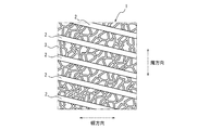
図2は、本発明の一実施形態にかかる空気入りタイヤの製造に用いることができる、タイヤ加硫用ブラダー1の外面の一部を示す展開図である。図2に示すように、ブラダー1の外面の周上に、幅方向に延びる複数本の溝部2が形成されている。なお、この例では、溝部2は、周方向に等間隔で配置されているが、間隔をずらして配置されていてもよい。また、この例では、溝部2は、幅方向に傾斜して延びているが、幅方向に沿って延びていてもよい。さらに、この例では、溝部2は、この展開視で直線状に延びているが、湾曲して延びていてもよい。また、この例では、溝部2は、連続して延びているが、不連続に延びていてもよい。
ここで、「溝部」とは、深さ(最大深さ)が、0.3mm以上のものをいうものとする。
FIG. 2 is a developed view showing a part of the outer surface of the
Here, the “groove” means one having a depth (maximum depth) of 0.3 mm or more.
ここで、このブラダー1においては、未加硫タイヤの内面に押し当てた状態において、溝部2は、外面における幅方向のいずれかの位置で、周方向1インチ当たり5本以上形成されている。また、このブラダー1においては、溝部2間に、該溝部2間を接続する凹部3が複数形成されている(なお、図3においては図示を省略している)。凹部3の深さは、0.1〜0.25mmである。凹部3は、図示のように、三つ又以上に分岐した部分を有するランダムな形状であり、いわゆるぺブル模様をなしている。なお、溝部2及び凹部3は、図1では図示を省略している。
Here, in the
このタイヤ加硫用ブラダー1では、図1に示すように、未加硫タイヤの内面に押し当てた状態において、溝部2は、外面における幅方向のいずれかの位置で、周方向1インチ当たり5本以上形成されていることが好ましい。1本の溝部2当たりの加硫時の応力を緩和することができ、該応力に起因して生じ得る亀裂の発生・進展を抑制することができるからである。
In this
また、このタイヤ加硫用ブラダー1では、溝部2は、外面における幅方向のいずれかの位置で、周方向1インチ当たり20本以下形成されていることが好ましい。加硫工程におけるゴム流れの不良を抑制することができるからである。
また、このタイヤ加硫用ブラダー1では、溝部2は、外面における幅方向のいずれかの位置で、周方向1インチ当たり8本以上15本以下形成されていることが好ましい。溝部2を、周方向1インチ当たり8本以上形成することにより、1本の溝部2当たりの応力の集中をより一層緩和することができ、一方で、溝部2を、周方向1インチ当たり15本以下形成することにより、加硫工程におけるゴム流れの不良をより一層抑制することができるからである。このタイヤ加硫用ブラダー1では、溝部2は、外面における幅方向のいずれかの位置で、周方向1インチ当たり10本以上形成されていることが好ましい。溝部2を、周方向1インチ当たり10本以上形成することにより、1本の溝部2当たりの応力の集中をさらに緩和することができるからである。
Further, in the
Further, in the
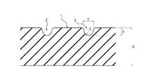
図3は、溝部2を示す断面図である。
タイヤ加硫用ブラダー1のゲージをA(mm)とし、溝部2の深さをB(mm)とするとき、比B/Aは、
0.03≦B/A≦0.15
を満たすことが好ましい。
比B/Aを0.03以上とすることにより、タイヤ内面の品質をさらに向上させることができ、一方で、比B/Aを0.15以下とすることにより、溝部2で生じる応力に対する剛性を確保して、ブラダー1の耐久性をさらに向上させることができるからである。
ここで、「ゲージ」は、最大ゲージをいうものとし、「深さ」は、最大深さをいうものとする。
FIG. 3 is a cross-sectional view showing the
Assuming that the gauge of the
0.03 ≦ B / A ≦ 0.15
It is preferable to satisfy
By setting the ratio B / A to 0.03 or more, the quality of the inner surface of the tire can be further improved. On the other hand, by setting the ratio B / A to 0.15 or less, the rigidity against the stress generated in the
Here, "gauge" refers to the largest gauge, and "depth" refers to the largest depth.
溝部2の幅をC(mm)とし、溝部2の深さをB(mm)とするとき、比B/Cは、
0.3≦B/C≦1.0
を満たすことが好ましい。
比B/Cを0.3以上とすることにより、タイヤ内面の品質をさらに向上させることができ、一方で、比B/Cを1.0以下とすることにより、溝部2で生じる応力に対する剛性を確保して、ブラダー1の耐久性をさらに向上させることができるからである。
ここで、「溝部の幅」とは、溝部の一方の側壁の2つの変曲点の延在方向の中点と、他方の側壁の2つの変曲点の延在方向の中点との幅方向の距離をいうものとする。
Assuming that the width of the
0.3 ≦ B / C ≦ 1.0
It is preferable to satisfy
By setting the ratio B / C to 0.3 or more, the quality of the inner surface of the tire can be further improved. On the other hand, by setting the ratio B / C to 1.0 or less, the rigidity against the stress generated in the
Here, "the width of the groove portion" means the width between the middle point of the extension direction of the two inflection points of one side wall of the groove portion and the middle point of the extension direction of the two inflection points of the other side wall. It refers to the distance in the direction.
周上全体での溝部2の本数をD(本)とし、溝部2の深さをB(mm)とするとき、比B/Dは、
0.001≦B/D≦0.006
を満たすことが好ましい。
比B/Dを0.001以上とすることにより、タイヤ内面の品質をさらに向上させることができ、一方で、比B/Dを0.006以下とすることにより、溝部2で生じる応力に対する剛性を確保して、ブラダー1の耐久性をさらに向上させることができるからである。
Assuming that the number of
0.001 ≦ B / D ≦ 0.006
It is preferable to satisfy
By setting the ratio B / D to 0.001 or more, the quality of the inner surface of the tire can be further improved. On the other hand, by setting the ratio B / D to 0.006 or less, the rigidity against the stress generated in the
溝部2の延在方向の断面における、溝部2の底部の角部の曲率半径をE(mm)とし、溝部2の深さをB(mm)とするとき、比B/Eは、
1.0≦B/E≦5.0
を満たすことが好ましい。
比B/Eを1.0以上とすることにより、タイヤ内面の品質をさらに向上させることができ、一方で、比B/Eを5.0以下とすることにより、溝部2で生じる応力に対する剛性を確保して、ブラダー1の耐久性をさらに向上させることができるからである。
Assuming that the curvature radius of the corner of the bottom of the
1.0 ≦ B / E ≦ 5.0
It is preferable to satisfy
By setting the ratio B / E to 1.0 or more, the quality of the inner surface of the tire can be further improved. On the other hand, by setting the ratio B / E to 5.0 or less, the rigidity against the stress generated in the
溝部2の深さBは、0.3〜0.5mmとすることが好ましい。
The depth B of the
このタイヤ加硫用ブラダーにおいては、凹部3は、ブラダー1のうち、生タイヤの、完成品となるタイヤのハンプ部からビード部まで(ハンプ部のタイヤ径方向最外側端からビード部のタイヤ径方向最内側端まで)に対応する部分の内面に当接する部分のみに設けられている。上述した応力が最も集中しやすい箇所において、該応力をさらに緩和することができ、また、ゴム流れの不良を抑制することができ、一方で、タイヤのセンター部においては、スポンジ材等の制音体やシーラント等のパンク防止部材など、タイヤ内面部材を貼り付けやすくすることができる。センター部に凸部(凹部3が転写される)が形成されると、タイヤ内面部材とタイヤ内面との接触面積が減少して接着力が低下するためである。
In the tire vulcanization bladder, the
このタイヤ加硫用ブラダーにおいては、凹部3は、ブラダー1の外面の周上のうち、少なくとも、生タイヤの、カーカスプライの周上の接合部(カーカスプライがオーバーラップする部分)に当接する位置及びその近傍に設けられていることが好ましい。当該位置において、最もエアが残りやすいため、効率的に、エアの残留を抑制して、加硫後のタイヤにおけるベアの発生を抑制することができるからである。例えば、凹部3は、ブラダー1の外面の周上全体にわたって設けることもできる。
In the tire vulcanizing bladder, the
上述したように、凹部3自体はランダムな形状で配置されているため、上記小陸部の形状もランダムとなっている。一方で、ブラダー1の外面の周上全体では、上記小陸部の個数密度は、周上で略一定とすることが好ましい。あるいは、ブラダー1の外面の周上のうち、少なくとも、生タイヤの、カーカスプライの周上の接合部(カーカスプライがオーバーラップする部分)に当接する位置及びその近傍において、個数密度を、周上の他の箇所より増大させることが好ましい。
As described above, since the
<空気入りタイヤ>
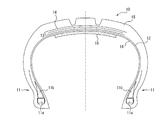
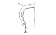
図4は、本発明の一実施形態にかかる空気入りタイヤ10を示す、タイヤ幅方向断面図である。図4に示すように、このタイヤ10は、一対のビード部11に埋設されたビードコア11aにトロイダル状に跨るカーカス12のタイヤ径方向外側に、1層以上(図示例で2層)のベルト層からなるベルト13と、1層以上(図示例で1層)のベルト保護層14と、トレッド15とを、この順に有している。また、ビードコア11aのタイヤ径方向外側には、断面三角形状のビードフィラ11bが配置されている。本発明のタイヤは、タイヤ内面16以外の構造については、特に限定されるものではない。例えば、ビードフィラ11bやベルト保護層14を有しない構成とすることもできる。また、カーカスプライの枚数やベルト層及びベルト保護層の層数やコードの材質等、カーカス構造やベルト構造も特に限定されない。
<Pneumatic tire>
FIG. 4 is a cross-sectional view in the tire width direction showing the
本実施形態の空気入りタイヤは、上記実施形態のタイヤ加硫用ブラダーを用いた加硫工程を経て製造されたものである。従って、本実施形態のタイヤは、タイヤ内面16の100μm2の領域当たりに、最大径1.0μm以上のフッ素を含む粒子を1つ以上有している。なお、本発明のタイヤは、上述したように、フッ素ゴムからなるブラダーの他、ブチルゴムからなるブラダー等も用いることができるため、タイヤ内面16にフッ素粒子を有しない(検出限界以下)ものとしてもよい。
The pneumatic tire of the present embodiment is manufactured through a vulcanization process using the tire vulcanization bladder of the above-described embodiment. Therefore, the tire of the present embodiment has one or more particles containing fluorine having a maximum diameter of 1.0 μm or more per 100 μm 2 area of the tire
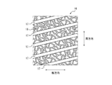
図5は、本発明の一実施形態にかかる空気入りタイヤのタイヤ内面16の一部を示す展開図である。図5に示すように、本実施形態のタイヤは、タイヤ内面16の周上に、タイヤ幅方向に延びる複数本のブラダーリッヂ17が形成されている。なお、この例では、溝部2は、タイヤ周方向に等間隔で配置されているが、間隔をずらして配置されていてもよい。また、この例では、ブラダーリッヂ17は、タイヤ幅方向に傾斜して延びているが、タイヤ幅方向に沿って延びていてもよい。さらに、この例では、ブラダーリッヂ17は、この展開視で直線状に延びているが、湾曲して延びていてもよい。また、この例では、ブラダーリッヂ17は、連続して延びているが、不連続に延びていてもよい。
FIG. 5 is a developed view showing a part of the tire
ブラダーリッヂ17は、タイヤ内面16のタイヤ幅方向のいずれかの位置で、タイヤ周方向1インチ当たり5本以上形成されている。また、図5に示すように、ブラダーリッヂ17間に、該ブラダーリッヂ17間を接続する凸部18が複数形成されている(なお、図6においては図示を省略している)。凸部18は、ハンプ部からビード部まで(ハンプ部のタイヤ径方向最外側端からビード部のタイヤ径方向最内側端)の内面のみに形成されており、その間の領域であるセンター部の内面には形成されていない。本実施形態において、凸部18の高さは、大気圧下で0.1〜0.25mmである。凸部18は、図示のように、三つ又以上に分岐した部分を有するランダムな形状であり、いわゆるぺブル模様をなしている。また、ブラダーリッヂ17は、特に、ビード部11の内面におけるタイヤ幅方向のいずれかの位置で、タイヤ周方向1インチ当たり5本以上形成されている。なお、ブラダーリッヂ17及び凸部18については、図4では、図示を省略している。
さらに、このタイヤ10は、ハンプ部間のタイヤ幅方向領域であるセンター部の少なくとも一部のタイヤ幅方向領域(本実施形態では、センター部のタイヤ内面のペリフェリ長さの中央80%の領域)に、タイヤ内面部材19(本実施形態では、スポンジ材からなる制音体)が配置されている。従って、センター部のタイヤ内面のペリフェリ長さの両端10%ずつの領域は、上記の凸部18が形成されておらず、且つ、タイヤ内面部材19が配置されていない。
以下、本実施形態の空気入りタイヤの作用効果について説明する。
Five or
Furthermore, in the
Hereinafter, the operation and effect of the pneumatic tire of the present embodiment will be described.
タイヤ加硫工程においては、ブラダー1と生タイヤの内面との間の空隙にエアが残る場合があることが判明した。
ここで、タイヤ10のブラダーリッヂ17は、ブラダー1の溝部2が転写されたものであり、タイヤ10の凸部18は、ブラダー1の凹部3が転写されたものである。
本実施形態の空気入りタイヤ10によれば、ブラダーリッヂ17間に、該ブラダーリッヂ17間を接続する凸部18が複数形成されているため、上記のエアが残った場合であっても、複数の凹部3を介してエアが溝部2へ抜けることができ、溝部2から残ったエアを排出することができたものである。従って、エアの残留が抑制されており、タイヤのベアが低減している。
特に、タイヤ10のハンプ部からビード部の内面は、加硫時にブラダー1が十分に押圧しない場合があるため、効果的に、エアの残留が抑制され、タイヤのベアが低減する。
さらに、本実施形態の空気入りタイヤ10では、ハンプ部からビード部の内面のみに凸部18が設けられており、センター部には凸部18が設けられていないため、タイヤ内面16にタイヤ内面部材19を配置(例えば接合や接着)させることが容易となる。センター部に凸部(凹部3が転写される)が形成されると、タイヤ内面部材19とタイヤ内面16との接触面積が減少して接着力が低下するためである。
特に、フッ素ゴムからなるブラダー1を用いた場合(すなわち、タイヤ内面16の100μm2の領域当たりに、最大径1.0μm以上のフッ素を含む粒子を1つ以上有している場合)、ハンプ部からビード部まで(ハンプ部のタイヤ径方向最外側端からビード部のタイヤ径方向最内側端)の内面において、上記のエアが残りやすく、このような場合に、特に有効にタイヤのベアが低減することができる。
以上のように、本実施形態の空気入りタイヤ10によれば、ベアを低減することができ、且つ、タイヤ内面16にタイヤ内面部材を容易に配置することができる。
It has been found that air may remain in the gap between the
Here, the
According to the
In particular, since the
Furthermore, in the
In particular, when the
As described above, according to the
ここで、本発明の空気入りタイヤ10では、上記の実施形態のように、ブラダーリッヂ17は、タイヤ内面16のタイヤ幅方向のいずれかの位置で、タイヤ周方向1インチ当たり5本以上形成されていることが好ましい。その加硫に用いたブラダー1の1本の溝部2当たりの加硫時の応力を緩和し、該応力に起因して生じ得る亀裂の発生・進展を抑制することができ、空気入りタイヤ10のタイヤ内面16の品質が優れたものとなるからである。
Here, in the
ここで、本発明の空気入りタイヤ10では、ブラダーリッヂ17は、タイヤ内面16のタイヤ幅方向のいずれかの位置で、タイヤ周方向1インチ当たり20本以下形成されていることが好ましい。加硫工程におけるゴム流れの不良を抑制された品質の高いタイヤとなるからである。
また、本発明の空気入りタイヤ10では、ブラダーリッヂ17は、タイヤ内面16のタイヤ幅方向のいずれかの位置で、タイヤ周方向1インチ当たり8本以上15本以下形成されていることが好ましい。ブラダーリッヂ17を、周方向1インチ当たり8本以上形成することにより、タイヤ内面16の品質をより優れたものとすることができ、一方で、ブラダーリッヂ17を、周方向1インチ当たり15本以下形成することにより、加硫工程におけるゴム流れの不良がより一層抑制されたものとすることができるからである。本発明の空気入りタイヤ10では、ブラダーリッヂ17は、周方向1インチ当たり10本以上形成されていることが好ましい。ブラダーリッヂ17を、周方向1インチ当たり10本以上形成することにより、タイヤ内面16の品質をさらに優れたものとすることができるからである。
本発明では、ビード部11の内面において、ブラダーリッヂ17は、周上のタイヤ周方向1インチ当たり5本以上形成されていることが好ましい。タイヤ内面16の品質をさらに優れたものとすることができるからである。
Here, in the
Further, in the
In the present invention, on the inner surface of the
図6は、ブラダーリッヂ17を示す断面図である。
本発明では、ブラダーリッヂ17の幅をC´(mm)とし、ブラダーリッヂ17の高さをB´(mm)とするとき、比B´/C´は、
0.3≦B´/C´≦1.0
を満たすことが好ましい。
比B´/C´を0.3以上とすることにより、タイヤ内面の品質をさらに向上させることができ、一方で、比B´/C´を1.0以下とすることによって、タイヤ内面16の品質をさらに向上させることができるからである。
ここで、「ブラダーリッジの幅」とは、大気圧下でのブラダーリッジの一方の側壁の2つの変曲点の延在方向の中点と、他方の側壁の2つの変曲点の延在方向の中点との幅方向の距離をいい、「高さ」とは、大気圧下での最大高さをいうものとする。
FIG. 6 is a cross-sectional view showing the
In the present invention, when the width of the
0.3 ≦ B ′ / C ′ ≦ 1.0
It is preferable to satisfy
By setting the ratio B '/ C' to be 0.3 or more, the quality of the inner surface of the tire can be further improved. On the other hand, by setting the ratio B '/ C' to be 1.0 or less, the tire
Here, "the width of the bladder ridge" means the middle point of the extension direction of the two inflection points of one side wall of the bladder ridge under the atmospheric pressure and the extension of the two inflection points of the other side wall It refers to the distance in the width direction from the middle point of the direction, and "height" shall mean the maximum height under atmospheric pressure.
本発明では、周上全体でのブラダーリッヂ17の本数をD´(本)とし、ブラダーリッヂ17の高さをB´(mm)とするとき、比B´/D´は、
0.001≦B´/D´≦0.006
を満たすことが好ましい。
比B´/D´を0.001以上とすることにより、タイヤ内面の品質をさらに向上させることができ、一方で、比B´/D´を0.006以下とすることにより、タイヤ内面16の品質をさらに向上させることができるからである。
In the present invention, assuming that the number of
0.001 ≦ B ′ / D ′ ≦ 0.006
It is preferable to satisfy
By setting the ratio B '/ D' to 0.001 or more, the quality of the inner surface of the tire can be further improved. On the other hand, by setting the ratio B '/ D' to 0.006 or less, the tire
本発明では、ブラダーリッヂ17の延在方向の断面における、ブラダーリッヂ17の頂部の角部の曲率半径をE´(mm)とし、ブラダーリッヂ17の高さをB´(mm)とするとき、比B´/E´は、
1.0≦B´/E´≦5.0
を満たすことが好ましい。
比B´/E´を1.0以上とすることにより、タイヤ内面の品質をさらに向上させることができ、一方で、比B´/E´を5.0以下とすることにより、タイヤ内面16の品質をさらに向上させることができるからである。
In the present invention, when the radius of curvature of the corner of the top of the
1.0 ≦ B ′ / E ′ ≦ 5.0
It is preferable to satisfy
By setting the ratio B '/ E' to 1.0 or more, the quality of the inner surface of the tire can be further improved. On the other hand, by setting the ratio B '/ E' to 5.0 or less, the
本発明では、ブラダーリッヂ17の高さB´は、例えば、乗用車用タイヤであれば、0.3〜0.5mmとすることが好ましい。
In the present invention, the height B ′ of the
本発明では、ブラダーリッヂ17間に、該ブラダーリッヂ17間を接続する凸部18が複数形成され、凸部18は、ハンプ部からビード部まで(ハンプ部のタイヤ径方向最外側端からビード部のタイヤ径方向最内側端まで)の内面のみに形成されている。
上述した応力が最も集中しやすいハンプ部及びビード部に対応する部分において、該応力をさらに緩和することができる。また、ゴム流れの不良を抑制することができ、タイヤの品質を優れたものとすることができる。さらに、エアが残りやすい箇所でもあり、残ったエアを、効果的に凹部3を介して溝部2から排出することができる。一方で、タイヤ10のセンター部においては、スポンジ材等の制音体やシーラント等のパンク防止部材など、タイヤ内面部材を貼り付けやすくすることができる。センター部に凸部18が形成されると、タイヤ内面部材19とタイヤ内面16との接触面積が減少して接着力が低下するためである。
In the present invention, a plurality of
The stress can be further relieved at the portion corresponding to the hump portion and the bead portion where the stress is most likely to be concentrated. Moreover, the defect of a rubber | gum flow can be suppressed and the quality of a tire can be made excellent. Furthermore, the air is likely to remain, and the remaining air can be effectively discharged from the
本発明の空気入りタイヤにおいては、凸部18は、タイヤ内面16の周上のうち、少なくともカーカスプライの周上の接合部の位置及びその近傍に設けられていることが好ましい。上述したのと同様に、ベアを効率的に低減することができるからである。例えば、凸部18は、タイヤ内面16の周上全体にわたって設けることもできる。
In the pneumatic tire according to the present invention, it is preferable that the
上述したように、凸部3自体はランダムな形状で配置されているため、上記小凹部の形状もランダムとなっている。一方で、タイヤ内面16の周上全体では、上記小凹部の個数密度は、周上で略一定とすることが好ましい。あるいは、タイヤ内面16の周上のうち、少なくとも、カーカスプライの周上の接合部の位置及びその近傍において、個数密度を、周上の他の箇所より増大させることが好ましい。
As described above, since the
本発明において、タイヤ内面部材19は、センター部のタイヤ内面16の少なくとも一部のタイヤ幅方向領域に配置することができる。
また、本発明において、タイヤ内面部材19は、タイヤ内面16の周上の少なくとも一部の領域に配置することができる。タイヤ内面部材19は、タイヤ内面16の周上全体に配置することが好ましい。
本実施形態では、タイヤ内面部材19は、スポンジ材からなる制音体である。スポンジ材は、海綿状の多孔構造体であり、例えばゴムや合成樹脂を発泡させた連続気泡を有する所謂スポンジを含む。また、スポンジ材は、上述のスポンジの他に、動物繊維、植物繊維又は合成繊維等を絡み合わせて一体に連結したウエブ状のものを含む。なお、上述の「多孔構造体」は、連続気泡を有する構造体に限らず、独立気泡を有する構造体も含む意味である。上述のようなスポンジ材は、表面や内部に形成される空隙が振動する空気の振動エネルギーを熱エネルギーに変換する。これにより、タイヤ内腔での空洞共鳴が抑制され、その結果、ロードノイズを低減することができる。またスポンジ材は、収縮、屈曲等の変形が容易である。そのため、スポンジ材で形成された制音体がトレッド内面16に固着されていても、走行時のタイヤ10の変形に実質的な影響を与えない。つまり、トレッド内面16に制音体を固着する構成としても操縦安定性等に悪影響を与え難い。スポンジ材の材料としては、例えば、エーテル系ポリウレタンスポンジ、エステル系ポリウレタンスポンジ、ポリエチレンスポンジなどの合成樹脂スポンジ、クロロプレンゴムスポンジ(CRスポンジ)、エチレンプロピレンゴムスポンジ(EPDMスポンジ)、ニトリルゴムスポンジ(NBRスポンジ)などのゴムスポンジが挙げられる。制音性、軽量性、発泡の調節可能性、耐久性などの観点を考慮すれば、エーテル系ポリウレタンスポンジを含むポリウレタン系又はポリエチレン系等のスポンジを用いることが好ましい。なお、制音体を構成する材料は、空洞共鳴エネルギーの緩和、吸収、別のエネルギー(例えば熱エネルギー)への変換、等によって、空洞共鳴エネルギーを低減するように制御できるものであればよく、上述したスポンジ材に限られるものではなく、例えば、ウレタンや不織布を用いることもできる。また、スポンジ材の比重は、タイヤ重量の増加と空洞共鳴を抑える効果との両方のバランスを考慮し、0.005〜0.06とすることが好ましく、0.01〜0.04とすることがより好ましく、0.01〜0.03とすることが特に好ましい。さらに、制音体の体積は、タイヤ内腔の全体積の0.4%〜20%とすることが好ましい。タイヤ内腔の全体積に対して制音体の体積を0.4%以上確保することにより、所望量(例えば2dB以上)の空洞共鳴エネルギーの低減効果を実現し易い。制音体は、タイヤ内腔の全体積の1%以上とすることがより好ましく、2%以上とすることが更に好ましく、4%以上とすることが特に好ましい。その一方、制音体の体積がタイヤ内腔の全体積の20%を超えるように構成しても空洞共鳴エネルギーの低減効果の向上が期待できない。むしろ組立体の重量バランスを悪化させる可能性がある。このような観点より、制音体の体積は、タイヤ内腔の全体積の16%以下とすることがより好ましく、10%以下とすることが特に好ましい。なお、上述の体積比は、制音体の数に関係しない。つまり、制音体が複数ある場合には、複数の制音体全ての体積の和が上述の体積比の関係を満足すれば、同様の効果を得ることができる。
さらに、本実施形態では、タイヤ内面部材19は、制音体であるが、他にもシーラント等のパンク防止部材等、様々な部材とすることができる。シーラントは、任意の既知の材料を用いることができる。
例えば、タイヤ内面部材19を制音体とした場合には、タイヤの静音性を向上させることができ、制音体をスポンジ材とした場合には、効果的にタイヤの静音性を向上させることができる。また、例えば、タイヤ内面部材19をパンク防止部材とした場合には、タイヤのパンクを防止することができ、パンク防止部材をシーラントとした場合には、効果的にタイヤのパンクを防止することができる。
In the present invention, the tire
Further, in the present invention, the tire
In the present embodiment, the tire
Furthermore, in the present embodiment, the tire
For example, when the tire
以上、本発明の実施形態について説明したが、本発明は上記の実施形態に何ら限定されるものではない。特に凹部3や凸部18については、ハンプ部からビード部において、溝部2間を接続するもの、ブラダーリッヂ17間を接続するものであれば、任意のぺブル模様とすることができ、形状、幅、本数等は、特に限定されない。また、例えば、上記の実施形態では、凹部3や凸部18は、ランダムな形状、配置としているが、一部又は全部について、規則性を持った形状、配置とすることもできる。また、凹部3同士や凸部18同士は、互いに連通することができ、その連通(分岐)の数も特に限定されることはない。
以下、本発明の実施例について説明するが、本発明は、以下の実施例に何ら限定されるものではない。
As mentioned above, although embodiment of this invention was described, this invention is not limited at all to said embodiment. In particular, the
Examples of the present invention will be described below, but the present invention is not limited to the following examples.
本発明の効果を確かめるため、発明例及び比較例にかかるフッ素ゴムからなるタイヤ加硫用ブラダーを試作した。各ブラダーの諸元及び該ブラダーを用いて製造されたタイヤの諸元を表1に示している。
上記発明例及び比較例について、タイヤのベアの発生について評価する試験を行った。
In order to confirm the effect of the present invention, a tire vulcanizing bladder made of fluororubber according to the invention example and the comparative example was made on a trial basis. Table 1 shows the specifications of each bladder and the specifications of a tire manufactured using the bladder.
About the above-mentioned invention example and comparative example, the test evaluated about the generation of the bear of a tire was done.
<ベアの発生率>
製造されたタイヤについて、目視にてタイヤ内面のベアを観察し、ベアが発生したタイヤをカウントした。なお、「ベア」とは、ゴム流れ不良により表面に凹みが残る不良をいう。
<Bear incidence>
About the manufactured tire, the bear of the tire inner surface was observed visually and the tire which the bear generate | occur | produced was counted. In addition, a "bear" means the defect which a dent remains on the surface by the rubber | gum flow defect.
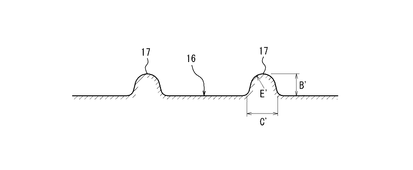
表1に示すように、発明例は、比較例よりも、ベアが低減していることがわかる。 As shown in Table 1, it can be seen that in the invention example, the bear is reduced more than in the comparative example.
1:タイヤ加硫用ブラダー、 2:溝部、 3:凹部、
10:空気入りタイヤ、 11:ビード部、 11a:ビードコア、
11b:ビードフィラ、 12:カーカス、 13:ベルト、 14:ベルト保護層、
15:トレッド、 16:タイヤ内面、 17:ブラダーリッヂ、 18:凸部、
19:タイヤ内面部材
1: Tire vulcanizing bladder, 2: Groove, 3: Recess,
10: pneumatic tire, 11: bead portion, 11a: bead core,
11b: bead filler, 12: carcass, 13: belt, 14: belt protective layer,
15: tread, 16: tire inner surface, 17: bladder ridge, 18: convex portion,
19: tire inner surface member
Claims (5)
前記タイヤをリムに装着し、規定内圧を充填し、無負荷とした状態において、トレッド踏面からタイヤ最大幅位置までのタイヤ外輪郭線で曲率半径が最も小さい領域であるハンプ部からビード部までの内面のみにおいて、前記ブラダーリッヂ間に、該ブラダーリッヂ間を接続する凸部が複数形成されており、
前記ハンプ部の間のタイヤ幅方向領域であるセンター部の少なくとも一部のタイヤ幅方向領域に、タイヤ内面部材が配置されたことを特徴とする、空気入りタイヤ。 A pneumatic tire in which a plurality of bladder ridges extending in the tire width direction are formed on the circumference of the inner surface of the tire,
The tire is mounted on a rim, filled with a prescribed internal pressure, and unloaded, from the hump portion to the bead portion which is the region with the smallest radius of curvature in the tire outer contour from the tread surface to the tire maximum width position. On the inner surface only, a plurality of convex portions connecting the bladder ridges are formed between the bladder ridges,
A pneumatic tire characterized in that a tire inner surface member is disposed in at least a part of a tire width direction area of a center part which is a tire width direction area between the hump parts.
The pneumatic tire according to claim 4, wherein the puncture preventing member comprises a sealant.
Priority Applications (2)
| Application Number | Priority Date | Filing Date | Title |
|---|---|---|---|
| JP2017244479A JP2019111663A (en) | 2017-12-20 | 2017-12-20 | Pneumatic tire |
| PCT/JP2018/021838 WO2019123684A1 (en) | 2017-12-20 | 2018-06-07 | Pneumatic tire |
Applications Claiming Priority (1)
| Application Number | Priority Date | Filing Date | Title |
|---|---|---|---|
| JP2017244479A JP2019111663A (en) | 2017-12-20 | 2017-12-20 | Pneumatic tire |
Publications (1)
| Publication Number | Publication Date |
|---|---|
| JP2019111663A true JP2019111663A (en) | 2019-07-11 |
Family
ID=66993316
Family Applications (1)
| Application Number | Title | Priority Date | Filing Date |
|---|---|---|---|
| JP2017244479A Pending JP2019111663A (en) | 2017-12-20 | 2017-12-20 | Pneumatic tire |
Country Status (2)
| Country | Link |
|---|---|
| JP (1) | JP2019111663A (en) |
| WO (1) | WO2019123684A1 (en) |
Family Cites Families (8)
| Publication number | Priority date | Publication date | Assignee | Title |
|---|---|---|---|---|
| JP2002137227A (en) * | 2000-11-06 | 2002-05-14 | Bridgestone Corp | Bladder for vulcanizing tire |
| JP4900608B2 (en) * | 2007-12-17 | 2012-03-21 | 横浜ゴム株式会社 | Tire vulcanization bladder, tire vulcanization molding method, and pneumatic tire |
| JP2011255597A (en) * | 2010-06-09 | 2011-12-22 | Yokohama Rubber Co Ltd:The | Tire vulcanizing bladder |
| JP2012025358A (en) * | 2010-07-28 | 2012-02-09 | Yokohama Rubber Co Ltd:The | Pneumatic tire |
| JP2013052582A (en) * | 2011-09-03 | 2013-03-21 | Yokohama Rubber Co Ltd:The | Bladder and method of manufacturing tire using the same |
| JP2014091272A (en) * | 2012-11-05 | 2014-05-19 | Sumitomo Rubber Ind Ltd | Tire vulcanizing bladder |
| JP2015020731A (en) * | 2013-07-24 | 2015-02-02 | 株式会社ブリヂストン | Pneumatic tire |
| JP2015202575A (en) * | 2014-04-11 | 2015-11-16 | 横浜ゴム株式会社 | Bladder for tire vulcanization |
-
2017
- 2017-12-20 JP JP2017244479A patent/JP2019111663A/en active Pending
-
2018
- 2018-06-07 WO PCT/JP2018/021838 patent/WO2019123684A1/en not_active Ceased
Also Published As
| Publication number | Publication date |
|---|---|
| WO2019123684A1 (en) | 2019-06-27 |
Similar Documents
| Publication | Publication Date | Title |
|---|---|---|
| JP6085940B2 (en) | Rehabilitation tire | |
| CN101903148A (en) | Tire vulcanization bladder, tire vulcanization molding method, and pneumatic tire | |
| JP2021095012A (en) | Tubeless tire for heavy load and manufacturing method | |
| JP2010280322A (en) | Pneumatic tire | |
| JP2021116044A (en) | Pneumatic tire, pneumatic tire manufacturing method, and tire vulcanization die | |
| JP2008273084A (en) | Tire vulcanization mold and pneumatic tire vulcanized by the same | |
| JP6056360B2 (en) | Rehabilitation tire | |
| JP2011235783A (en) | Retreaded tire, and method of manufacturing the same | |
| JP2012006451A (en) | Pneumatic tire | |
| WO2019123687A1 (en) | Bladder for tire vulcanization and pneumatic tire | |
| JP7209802B2 (en) | Bladder for tire vulcanization and pneumatic tire | |
| WO2014064896A1 (en) | Pneumatic tire, and method of manufacturing pneumatic tire | |
| JP7008496B2 (en) | Tire vulcanizing bladder and pneumatic tire | |
| JP2019111663A (en) | Pneumatic tire | |
| US12187083B2 (en) | Heavy duty tire and production method for heavy duty tire | |
| JP6934354B2 (en) | tire | |
| JP7372795B2 (en) | pneumatic tires | |
| JP6136131B2 (en) | Rehabilitation tire | |
| JP2021116043A (en) | Pneumatic radial tire, pneumatic radial tire manufacturing method, and tire vulcanization die | |
| JP7560285B2 (en) | Pneumatic tire and method for manufacturing pneumatic tire | |
| JP6269156B2 (en) | Rehabilitation tire | |
| JP2023140639A (en) | Heavy load tires and methods for manufacturing heavy load tires | |
| JP2023143748A (en) | Heavy load tires and methods for manufacturing heavy load tires | |
| JP2021046128A (en) | Pneumatic tire | |
| JP4410580B2 (en) | Tire vulcanizer |