JP2019098632A - Tire bead - Google Patents
Tire bead Download PDFInfo
- Publication number
- JP2019098632A JP2019098632A JP2017232337A JP2017232337A JP2019098632A JP 2019098632 A JP2019098632 A JP 2019098632A JP 2017232337 A JP2017232337 A JP 2017232337A JP 2017232337 A JP2017232337 A JP 2017232337A JP 2019098632 A JP2019098632 A JP 2019098632A
- Authority
- JP
- Japan
- Prior art keywords
- bead
- apex
- drum
- grooves
- groove
- Prior art date
- Legal status (The legal status is an assumption and is not a legal conclusion. Google has not performed a legal analysis and makes no representation as to the accuracy of the status listed.)
- Granted
Links
Images


Landscapes
- Tyre Moulding (AREA)
Abstract
Description
本発明は、タイヤの成形時に、タイヤの構成部材とされるビードに関する。 The present invention relates to a bead which is a component of a tire at the time of molding of the tire.
多くのタイヤは、そのサイド部に位置する一対のビード及び両ビードの間に架け渡されたカーカスを備えている。ビードはリング状である。ビードは、コアと、このコアから半径方向外向きに延びるエイペックスとを備えている。エイペックスは、高硬度な架橋ゴムからなる。カーカスは、ビードの周りで折り返されている。 Many tires have a pair of beads located on the side portions and a carcass bridged between the beads. The bead is ring shaped. The bead comprises a core and an apex extending radially outwardly from the core. Apex is made of highly hard crosslinked rubber. The carcass is folded around the bead.
このタイヤの製造では、成形工程において、フォーマーのドラムの周りに、カーカスプライが巻かれる。コアと未加硫のエイペックスとからなるビードが、このフォーマーの外周に沿うようにセットされる。エイペックスは、ドラムの周方向内向きに倒され、カーカスプライに密着される。トレッド、サイドウォール等の部材がさらに組み合わされ、ローカバーが得られる。加硫工程において、このローカバーがモールド内で加硫され、タイヤが得られる。 In the manufacture of this tire, a carcass ply is wound around a former drum in a molding process. A bead consisting of a core and an uncured apex is set along the periphery of the former. The apex is turned inward in the circumferential direction of the drum and is in close contact with the carcass ply. The members such as the tread and the sidewall are further combined to obtain a low cover. In the vulcanization step, the raw cover is vulcanized in a mold to obtain a tire.
成形工程において、エイペックスが倒れ込み難いと、タイヤの生産性が悪くなる。またビードとカーカスとが十分接合できないことが起こりうる。これは、タイヤのユニフォミティの低下の要因となりうる。エイペックスの倒れ込みを容易としたビードについての検討が、特開2014−124928公報で報告されている。このビードでは、エイペックスに周方向に延びる溝が設けられている。 If the apex is difficult to fall down in the molding process, the productivity of the tire is degraded. Moreover, it may happen that the bead and the carcass can not be sufficiently joined. This can be a factor in the deterioration of the tire uniformity. The examination about the bead which made it easy to fall in of an apex is reported by Unexamined-Japanese-Patent No. 2014-124928. In this bead, the apex is provided with a circumferentially extending groove.
未加硫のビードには、さらに、エイペックスの倒れ込みを容易にすることが求められている。一方、エイペックスに溝を設けた場合、倒れ込ませる前にエイペックスが折れることを防止することが課題となる。 Unvulcanized beads are also required to facilitate apex collapse. On the other hand, in the case where the groove is formed in the apex, it becomes an issue to prevent the apex from being broken before it falls down.
本発明の目的は、エイペックスの折れを防止しつつ、エイペックスの倒れ込みの容易性が向上された未加硫のビードの提供にある。 An object of the present invention is to provide an unvulcanized bead in which the ease of apex fall-in is improved while preventing the apex from being broken.
本発明は、ローカバーの成型時にフォーマーのドラムの外周の角に沿うようにセットされるリング状のビードに関する。このビードは、コアと、未加硫ゴムからなるエイペックスとを備えている。上記ビードの周方向に垂直な断面において、上記エイペックスは、コアと当接する底面と、このビードが上記ドラムにセットされたときこのドラムの軸方向内側を向く内側面及び外側を向く外側面とを有する三角形状を呈している。上記エイペックスのムーニー粘度(ML1+4、100℃)が45以上75以下である。このビードが、上記ドラムにセットされ上記ドラムの外周の角を基点にこのドラムの軸方向内側に向けて倒れ込んだときに、上記内側面の湾曲する位置に2本の周方向に延びる内溝が設けられており、上記外側面の湾曲する位置に1本又は2本の周方向に延びる外溝が設けられている。 The present invention relates to a ring-shaped bead which is set along a corner of an outer periphery of a former drum at the time of molding of a low cover. The bead comprises a core and an apex made of unvulcanized rubber. In a cross section perpendicular to the circumferential direction of the bead, the apex has a bottom surface in contact with the core, an inner side surface facing inward in the axial direction of the drum and an outer side surface facing outward when the bead is set on the drum. It has a triangular shape with The Mooney viscosity (ML 1 + 4 at 100 ° C.) of the apex is 45 or more and 75 or less. When the bead is set on the drum and falls down inward in the axial direction of the drum from the corner of the outer periphery of the drum, there are two circumferentially extending inner grooves at the curved position of the inner surface. One or two circumferentially extending outer grooves are provided at curved positions of the outer surface.
好ましくは、上記エイペックスのムーニー粘度(ML1+4、100℃)は60より小さく、上記外溝の数は1本である。このとき、好ましくは、上記外溝の底は、上記外側面の湾曲した部分の両端の中央に位置する。 Preferably, the Mooney viscosity (ML 1 +4 , 100 ° C.) of the apex is less than 60 and the number of the outer grooves is one. At this time, preferably, the bottom of the outer groove is located at the center of both ends of the curved portion of the outer side surface.
上記エイペックスのムーニー粘度(ML1+4、100℃)が60以上であり、上記外溝の数が2本であってもよい。このとき、好ましくは上記2本の外溝の中央の位置は、上記外側面の湾曲した部分の両端の中央の位置である。 The Mooney viscosity (ML 1 + 4 at 100 ° C.) of the apex may be 60 or more, and the number of the outer grooves may be two. At this time, preferably, the central position of the two outer grooves is the central position of both ends of the curved portion of the outer side surface.
好ましくは、このビードが上記フォーマーにセットされたとき、上記ドラムの半径方向において、ドラムの外周の角は上記2本の内溝の間に位置する。 Preferably, when the bead is set to the former, the corner of the outer periphery of the drum is located between the two inner grooves in the radial direction of the drum.
好ましくは、上記断面における上記内溝及び外溝の形状は、深さ方向に向けて幅が狭くなるV字状を呈している。 Preferably, the shapes of the inner groove and the outer groove in the cross section have a V-like shape whose width is narrowed in the depth direction.
好ましくは、上記外溝の幅は0.5mm以上1.5mm以下であり、上記外溝の深さは0.5mm以上1.5mm以下である。 Preferably, the width of the outer groove is 0.5 mm or more and 1.5 mm or less, and the depth of the outer groove is 0.5 mm or more and 1.5 mm or less.
好ましくは、上記内溝の幅は0.5mm以上1.5mm以下であり、上記内溝の深さは0.5mm以上1.5mm以下である。 Preferably, the width of the inner groove is 0.5 mm or more and 1.5 mm or less, and the depth of the inner groove is 0.5 mm or more and 1.5 mm or less.
このタイヤの製造方法は、
ローカバーの成型時にフォーマーのドラムの外周の角に沿うようにセットされるリング状のビードであって、コアと未加硫ゴムからなるエイペックスとを備えており、上記ビードの周方向に垂直な断面において、上記エイペックスが、コアと当接する底面と、このビードが上記ドラムにセットされたときこのドラムの軸方向内側を向く内側面及び外側を向く外側面とを有する三角形状を呈しており、上記エイペックスのムーニー粘度(ML1+4、100℃)が45以上75以下であり、このビードが上記ドラムにセットされ上記ドラムの外周の角を基点にこのドラムの軸方向内側に向けて倒れ込んだとき、上記内側面の湾曲する位置に2本の周方向に延びる内溝が設けられており、上記外側面の湾曲する位置に1本又は2本の周方向に延びる外溝が設けられているビードを、準備する工程、
上記ビードを上記ドラムの外周の角に沿うようにセットする工程、
及び
上記エイペックスを上記ドラムの外周の角を基点に内側に向けて倒れ込ませる工程
を含む。
The manufacturing method of this tire is
A ring-shaped bead set along the outer corner of the former drum at the time of molding of the low cover, comprising a core and an apex made of unvulcanized rubber, which is perpendicular to the circumferential direction of the bead In cross section, the apex has a triangular shape having a bottom surface in contact with the core, and an inner surface facing inward in the axial direction of the drum and an outer surface facing outward when the bead is set on the drum. And the Mooney viscosity (ML 1 + 4 at 100 ° C.) of the apex is 45 or more and 75 or less, and the bead is set on the drum and falls toward the inside in the axial direction of the drum from the corner of the outer periphery of the drum At the same time, two circumferentially extending inner grooves are provided at the curved position of the inner side surface, and one or two circumferentially extending inner grooves are provided at the curved position of the outer side surface. Step bead is prepared which outer groove is provided that,
Setting the bead along a corner of the outer periphery of the drum;
And a step of inclining the apex inwardly from a corner of the outer periphery of the drum.
本発明に係るビードでは、エイペックスのムーニー粘度(ML1+4、100℃)は、45以上75以下である。このビードが上記ドラムにセットされドラムの外周の角を基点にドラムの軸方向内側に向けて倒れ込んだときに、エイペックスの内側面の湾曲する位置に2本の周方向に延びる内溝が設けられており、外側面の湾曲する位置に1本又は2本の周方向に延びる外溝が設けられている。このエイペックスの粘度と、これらの内溝及び外溝との組み合わせにより、このビードでは、エイペックスの折れを防止しつつ、エイペックスの倒れ込みの容易性が向上されている。 In the bead according to the present invention, the Mooney viscosity (ML 1 +4 at 100 ° C.) of Apex is 45 or more and 75 or less. When the bead is set on the drum and falls down toward the axial direction of the drum from the corner of the outer periphery of the drum, two circumferentially extending inner grooves are provided at the curved position of the inner surface of the apex One or two circumferentially extending outer grooves are provided at curved positions of the outer surface. The combination of the viscosity of the apex and the inner groove and the outer groove makes it possible to prevent the apex from being broken and improve the ease of falling in the apex.
以下、適宜図面が参照されつつ、好ましい実施形態に基づいて本発明が詳細に説明される。 Hereinafter, the present invention will be described in detail based on preferred embodiments with reference to the drawings as appropriate.
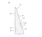
図1には、本発明に係るビード2が示されている。このビード2は、タイヤの成形工程において、構成部材として使用される。ビード2は、リング状を呈している。この図では、このリングの一部が示されている。図1の矢印Aで示されるのがこのビード2の周方向である。ビード2は、コア4とエイペックス6とからなる。
FIG. 1 shows a
コア4は、リング状である。図1に示されるように、コア4は、非伸縮性ワイヤーが巻き回わされて構成されている。ワイヤーの典型的な材質は、スチールである。この実施形態では、コア4の断面形状は、矩形である。このコア4の断面内には、ワイヤーの断面8が並んでいる。このコア4では、全部で16のワイヤーの断面8が並べられている。
The
エイペックス6は、リング状である。エイペックス6は、コア4の上面から、上方に延びている。エイペックス6は、コア4の上面と当接する底面10、このリングの内側を向く内側面12及びこのリングの外側を向く外側面14を備える。ビード2の周方向に垂直な断面において、エイペックス6の断面形状は、これらの面からなる三角形状である。
Apex 6 is ring-shaped. The
図1に示されるように、エイペックス6はその内側面12に2本の内溝16を備える。それぞれの内溝16は、このエイペックス6の周方向に延びている。エイペックス6はその外側面14に1本の外溝18を備える。外溝18は、このエイペックス6の周方向に延びている。ビード2の周方向に垂直な断面において、内溝16及び外溝18は、いずれも内向きに凹んだV字状を呈する。
As shown in FIG. 1, the
エイペックス6は、未加硫ゴムからなる。このエイペックス6のムーニー粘度(ML1+4、100℃)は、45以上75以下である。なお、この発明では、エイペックス6のムーニー粘度(ML1+4、100℃)は、「JIS K6300」の規定に準拠して、島津製作所社製の商品名「ムーニービスコメーターSMV200」を使用して計測される。
図1のビード2は、タイヤのローカバーの形成で使用される。以下では、このローカバーの形成方法が説明される。
The
図2は、ローカバーの形成の途中の状態が示された断面図である。ローカバーの形成には、フォーマー20が使用される。フォーマー20は円筒状である。この図2において、左右方向がフォーマー20の軸方向である。上下方向が、フォーマー20の半径方向である。紙面との垂直方向が、フォーマー20の周方向である。 FIG. 2 is a cross-sectional view showing a state in the middle of forming the low cover. A former 20 is used to form the low cover. The former 20 is cylindrical. In FIG. 2, the left and right direction is the axial direction of the former 20. The vertical direction is the radial direction of the former 20. The direction perpendicular to the paper surface is the circumferential direction of the former 20.
フォーマー20は、ドラム22と一対の側部24とを備えている。ドラム22は円筒状である。図示されていないが、このドラム22は、拡径しうるように構成されている。それぞれの側部24は、円筒状である。図1に示されるように、一方の側部24は、ドラム22の軸方向外側に位置している。図示されないが、ドラム22の他方の軸方向外側に、もう一方の側部24が位置している。ドラム22の側部24は、ドラム22の軸方向外側面26と接している。側部24の外径は、ドラム22のそれよりも小さい。このため、図2で示されるように、ドラム22の外周面28と側部24の外周面30との境界には、段差が存在する。
The former 20 comprises a
フォーマー20の周りに、タイヤの構成部材が積層される。例えばインナーライナーが積層され、さらに図2で示されるように、フォーマー20の回りにカーカスプライ32が巻回される。図2では、カーカスプライ32より内側の層は省略されている。カーカスプライ32は、ドラム22及び側部24の外周に巻き回されている。巻き回されたカーカスプライ32は筒状を呈している。
The components of the tire are stacked around the former 20. For example, an inner liner is laminated and, as shown in FIG. 2, the carcass ply 32 is wound around the former 20. In FIG. 2, the layers inside the carcass ply 32 are omitted. The carcass ply 32 is wound around the
ビード2が、フォーマー20にセットされる。図2に示されるように、ビード2は、カーカスプライ32の外側において、ドラム22の外周の角34に沿うように、セットされる。ビード2は、ドラム22の外周面28と側部24の外周面30との境界に位置する段差に、嵌め込まれる。このときビード2は、エイペックス6の内側面12がドラム22の軸方向内側を向くように、セットされる。カーカスプライ32を介して、ビード2のコア4の底面36が側部24の外周面30と当接する。カーカスプライ32を介して、コア4の側面及びエイペックス6の内側面12の一部が、ドラム22の軸方向外側面26と当接する。これにより、ビード2がフォーマー20に固定されている。
The
図3で示されるように、ビード2がフォーマー20にセットされた後、エイペックス6はドラム22の軸方向内側に向けて倒される。エイペックス6は、ドラム22の外周の角34を基点に、このドラム22の軸方向内側に向けて倒れ込む。エイペックス6の内側面12が、カーカスプライ32と当接する。これにより、エイペックス6は、カーカスプライ32と貼り合わされる。
As shown in FIG. 3, after the
図3で示されるように、エイペックス6の2本の内溝16は、エイペックス6が倒れ込んだとき、内側面12の湾曲する位置に設けられている。すなわち、エイペックス6の倒れ込みにより湾曲した内側面12の、この湾曲部分の両端の間に、それぞれの内溝16の少なくとも一部が位置している。エイペックス6の外溝18は、エイペックス6が倒れ込んだとき、外側面14の湾曲する位置に設けられている。すなわち、エイペックス6の倒れ込みにより湾曲した外側面14の、この湾曲した部分の両端の間に、外溝18の少なくとも一部が位置している。
As shown in FIG. 3, the two
ビード2が倒されると、次にカーカスプライ32の、ビード2の軸方向外側に位置する部分が、コア4の周りで折り返される。この折り返された部分が、エイペックス6の外側面14に当接される。ビード2はカーカスプライ32に包み込まれる。
When the
カーカスプライ32が折り返された後、フォーマー20のドラム22が拡径されつつ側部24が軸方向内向きに動かされ、カーカスプライ32の形状が整えられる。さらにサイドウォール、トレッド等の部材が組み合わされ、ローカバーが得られる。
After the carcass ply 32 is folded back, while the
上記の方法で形成されたローカバーは、加硫工程において、モールドに入れられる。ローカバーはモールド内で加圧および加熱される。加圧と加熱とにより、ローカバーのゴム組成物がキャビティ内を流動する。加熱によりゴムが架橋反応を起こし、タイヤが得られる。 The raw cover formed by the above method is put into a mold in a vulcanization step. The low cover is pressurized and heated in the mold. The pressure and heat cause the rubber composition of the low cover to flow in the cavity. By heating, the rubber undergoes a crosslinking reaction to obtain a tire.
図4には、得られたタイヤ38のビードの部分40の一例が示されている。図4において、上下方向がタイヤ38の半径方向であり、左右方向がタイヤ38の軸方向であり、紙面との垂直方向がタイヤ38の周方向である。この図では、サイドウォール42、ビード2、カーカスプライ32、インナーライナー44及びチェーファー46が示されている。図で示されるように、上述の製造方法により、ビード2はカーカスプライ32と接合されている。カーカスプライ32は、コア4の周りを折り返されている。
FIG. 4 shows an example of the
なお、図4のビード2は、図1のビード2が加硫されて形成されている。従って、図4のビード2のエイペックス6は、架橋ゴムよりなる。図4のカーカスプライ32は、図2のカーカスプライ32が加硫されて形成されている。従って、図4のカーカスプライ32のトッピングゴムは、架橋ゴムよりなる。これらは同じではないが、この明細書では同じ「ビード」及び「カーカスプライ」と称される。
In addition, the
以下では、本発明の作用効果が説明される。 Below, the effect of this invention is demonstrated.
本発明に係る加硫前のビード2では、エイペックス6のムーニー粘度(ML1+4、100℃)は、45以上75以下である。このビード2がドラム22にセットされドラム22の外周の角34を基点にドラム22の軸方向内側に向けて倒れ込んだときに、エイペックス6の内側面12の湾曲する位置に2本の周方向に延びる内溝16が設けられており、外側面14の湾曲する位置に1本の周方向に延びる外溝18が設けられている。エイペックス6のムーニー粘度(ML1+4、100℃)を45以上75以下とすることと、これらの内溝16及び外溝18との組み合わせにより、ローカバーを形成するとき、このエイペックス6を容易に倒れ込ませることができる。この組み合わせにより、このエイペックス6の折れが防止されている。
In the
このビード2では、エイペックス6を容易に倒れ込ませることができるため、ビード2を倒れ込ませる工程の速度を上げても、ビード2とカーカスプライ32とを密着させることができる。このビード2を使用することで、良好な生産性が実現されている。
In this
このビード2では、エイペックス6を容易に倒れ込ませることができるため、ビード2とカーカスプライ32との良好な接合性が実現されている。これはタイヤ38のユニフォミティに寄与する。このビード2を使用することで、タイヤ38の良好なユニフォミティが実現されている。
In the
特にエイペックス6のムーニー粘度(ML1+4、100℃)が60より小さいとき、エイペックス6が2本の内溝16と1本の外溝18を備えることで、このエスペックスは、さらに容易な倒れ込みと、効果的な折れ防止が実現されている。
In particular, when the Mooney viscosity (ML 1 + 4 at 100 ° C.) of
エイペックス6が倒れ込んだとき、外側面14の湾曲した部分の両端の中央の位置がPとされ、この湾曲の長さがLとされたとき、外溝18の底と位置P0との距離がLの0.2倍以下が好ましい。このようにすることで、エイペックス6をさらに容易に倒れ込ませることができる。この観点から、外溝18の底は、外側面14の湾曲した部分の両端の中央に位置しているのがより好ましい。ここで外溝18の底とは、外溝18の最深部を指す。図3の外溝18では、V字状の頂点の位置が底である。
When the apex 6 falls down, the central position of both ends of the curved portion of the
ビード2をフォーマー20にセットしたとき、ドラム22の半径方向において、ドラム22の外周の角34が2本の内溝16の間(下側に位置する内溝16の下端と上側に位置する内溝16の上端との間)に位置するように、これらの内溝16の位置が決められるのが好ましい。このようにすることで、エイペックス6をさらに容易に倒れ込ませることができる。この観点から、ドラム22の外周の角34が2本の内溝16の底の中央に位置するように、これらの内溝16の位置が決められているのがより好ましい。ここで内溝16の底とは、内溝16の最深部を指す。図3の内溝16では、V字状の頂点の位置が底である。
When the
図5は、エイペックス6が示された拡大断面図である。前述のとおり、内溝16の形状は、深さ方向に向けて幅が狭くなるV字状を呈しているのが好ましい。このようにすることで、エイペックス6をさらに容易に倒れ込ませることができる。また、外溝18の形状は、深さ方向に向けて幅が狭くなるV字状を呈しているのが好ましい。このようにすることで、エイペックス6をさらに容易に倒れ込ませることができる。
FIG. 5 is an enlarged sectional view in which the
図5において、両矢印Diは、内溝16の深さである。深さDiは、内溝16の開口の両端を結ぶ直線から内溝16の底までの距離である。深さDiは、0.5mm以上が好ましい。深さDiを0.5mm以上とすることで、この内溝16はエイペックス6の倒れ込みを容易にする。この観点から深さDiは、0.7mm以上がより好ましい。深さDiは、1.5mm以下が好ましい。深さDiを1.5mm以下とすることで、このエイペックス6の折れが防止されている。この観点から深さDiは、1.3mm以下がより好ましい。
In FIG. 5, the double arrow Di is the depth of the
図5において、両矢印Wiは、内溝16の幅である。幅Wiは、0.5mm以上が好ましい。幅Wiを0.5mm以上とすることで、この内溝16はエイペックス6の倒れ込みを容易にする。この観点から幅Wiは、0.7mm以上がより好ましい。幅Wiは、1.5mm以下が好ましい。幅Wiを1.5mm以下とすることで、このエイペックス6の折れが防止されている。この観点から幅Wiは、1.3mm以下がより好ましい。
In FIG. 5, the double arrow Wi is the width of the
図5において、両矢印Miは、二つの内溝16の底間の距離である。距離Miは、0.8mm以上1.5mm以下が好ましい。距離Miをこのようにすることで、これらの内溝16はエイペックス6の倒れ込みを容易にしつつ、このエイペックス6の折れが防止されている。この観点から距離Miは、1.0mm以上1.3mm以下がより好ましい。
In FIG. 5, the double arrow Mi is the distance between the bottoms of the two
図5において、両矢印Doは、外溝18の深さである。深さDoは、外溝18の開口の両端を結ぶ直線から外溝18の底までの距離である。深さDoは、0.5mm以上が好ましい。深さDoを0.5mm以上とすることで、この外溝18はエイペックス6の倒れ込みを容易にする。この観点から深さDoは、0.7mm以上がより好ましい。深さDoは、1.5mm以下が好ましい。深さDoを1.5mm以下とすることで、このエイペックス6の折れが防止されている。この観点から深さDoは、1.3mm以下がより好ましい。
In FIG. 5, the double arrow Do is the depth of the
図5において、両矢印Woは、外溝18の幅である。幅Woは、0.5mm以上が好ましい。幅Woを0.5mm以上とすることで、この外溝18はエイペックス6の倒れ込みを容易にする。この観点から幅Woは、0.7mm以上がより好ましい。幅Woは、1.5mm以下が好ましい。幅Woを1.5mm以下とすることで、このエイペックス6の折れが防止されている。この観点から深さ幅Woは、1.3mm以下がより好ましい。
In FIG. 5, the double arrow Wo is the width of the
図6には、本発明の他の実施形態に係るビード50のエイペックス52が拡大されて示されている。このビード50は、エイペックス52の内側面54に、2本の内溝56を備えている。このビード50は、エイペックス52の外側面58に、2本の外溝60を備えている。このビード50は、外溝60の構成を除いて、図1のビード2と同じである。
FIG. 6 is an enlarged view of an apex 52 of a
本発明に係る加硫前のビード50では、エイペックス52のムーニー粘度(ML1+4、100℃)は、45以上75以下である。このビード50がドラム22にセットされドラム22の角を基点にドラム22の軸方向内側に向けて倒れ込んだときに、上記内側面12の湾曲する位置に2本の周方向に延びる内溝56が設けられており、外側面58の湾曲する位置に2本の周方向に延びる外溝60が設けられている。エイペックス52のムーニー粘度(ML1+4、100℃)を45以上75以下とすることと、これらの内溝56と外溝60との組み合わせにより、ローカバーを形成するときこのエイペックス52を容易に倒れ込ませることができる。さらにこの組み合わせにより、このエイペックス52の折れが防止されている。
In the
特にエイペックス52のムーニー粘度(ML1+4、100℃)が60以上のとき、エイペックス52が2本の内溝56と2本の外溝60を備えることで、このエスペックスは、さらに容易な倒れ込みと、効果的な折れ防止が実現されている。
In particular, when the Mooney viscosity (ML 1 + 4 at 100 ° C.) of
エイペックス52が倒れ込んだとき、外側面58の湾曲した部分の両端の中央の位置がPとされ、この湾曲の長さがLとされたとき、二つの外溝60の底の中央の位置と、位置P0との距離がLの0.2倍以下が好ましい。このようにすることで、エイペックス52をさらに容易に倒れ込ませることができる。この観点から、二つの外溝60の底の中央の位置は、外側面58の湾曲した部分の両端の中央の位置Pであるのがより好ましい。
When the apex 52 falls down, the central position of both ends of the curved portion of the
図6において、両矢印Moは、二つの外溝60の底間の距離である。距離Moは、0.8mm以上1.5mm以下が好ましい。距離Moをこのようにすることで、これらの外溝60はエイペックス52の倒れ込みを容易にしつつ、このエイペックス52の折れが防止されている。この観点から距離Moは、1.0mm以上1.3mm以下がより好ましい。
In FIG. 6, the double arrow Mo is the distance between the bottoms of the two
以下、実施例によって本発明の効果が明らかにされるが、この実施例の記載に基づいて本発明が限定的に解釈されるべきではない。 Hereinafter, the effects of the present invention will be clarified by examples, but the present invention should not be interpreted in a limited manner based on the description of the examples.
[実施例1]
図1に示された構造のビードを用意し、これを用いてタイヤを作製した。タイヤのサイズは、285/60R18とされた。このエイペックスの仕様が表1に示されている。エイペックスのムーニー粘度(ML1+4、100℃)は、55とされた。内溝の幅Wiは1.0mm、深さDiは1.0mmとされた。内溝間の距離Miは1.0mmとされた。ドラムの半径方向において、2本の内溝の底の中央は、ドラムの外周の角と同じ位置とされた。外溝の幅Woは1.0mm、深さDoは1.0mmとされた。外溝の底は、外側面の湾曲した部分の両端の中央の位置とされた。
Example 1
The bead of the structure shown by FIG. 1 was prepared, and the tire was produced using this. The size of the tire was 285 / 60R18. The specifications of this Apex are shown in Table 1. Apex Mooney viscosity (ML 1 + 4 , 100 ° C.) was set to 55. The width Wi of the inner groove was 1.0 mm, and the depth Di was 1.0 mm. The distance Mi between the inner grooves was 1.0 mm. In the radial direction of the drum, the centers of the bottoms of the two inner grooves were at the same position as the corner of the outer periphery of the drum. The width Wo of the outer groove was 1.0 mm, and the depth Do was 1.0 mm. The bottom of the outer groove was centered between the ends of the curved portion of the outer surface.
[比較例1]
内溝の数を1本としたことの他は実施例1と同様にして、比較例1のビードが用意された。これを用いてタイヤを作製した。ドラムの半径方向において、この内溝の底は、ドラムの外周の角と同じ位置とされた。
Comparative Example 1
A bead of Comparative Example 1 was prepared in the same manner as Example 1 except that the number of inner grooves was one. The tire was produced using this. In the radial direction of the drum, the bottom of the inner groove was at the same position as the corner of the outer periphery of the drum.
[比較例2]
外溝の数を2本としたことの他は比較例1と同様にして、比較例2のビードが用意された。これを用いてタイヤを作製した。二つの外溝の底の中央の位置が、外側面の湾曲した部分の両端の中央の位置とされた。外溝間の距離Moは1.0mmとされた。
Comparative Example 2
A bead of Comparative Example 2 was prepared in the same manner as Comparative Example 1 except that the number of outer grooves was two. The tire was produced using this. The central position of the bottom of the two outer grooves was taken as the central position of both ends of the curved portion of the outer surface. The distance Mo between the outer grooves was 1.0 mm.
[実施例2]
外溝の数を2本としたことの他は実施例1と同様にして、実施例2のビードが用意された。これを用いてタイヤを作製した。二つの外溝の底の中央の位置が、外側面の湾曲した部分の両端の中央の位置とされた。外溝間の距離Moは1.0mmとされた。
Example 2
A bead of Example 2 was prepared in the same manner as Example 1 except that the number of outer grooves was two. The tire was produced using this. The central position of the bottom of the two outer grooves was taken as the central position of both ends of the curved portion of the outer surface. The distance Mo between the outer grooves was 1.0 mm.
[比較例3]
エイペックスのムーニー粘度(ML1+4、100℃)を表2の通りとした他は比較例1と同様にして、比較例3のビードが用意された。これを用いてタイヤを作製した。
Comparative Example 3
A bead of Comparative Example 3 was prepared in the same manner as Comparative Example 1 except that the Mooney viscosity (ML 1 +4 at 100 ° C.) of Apex was as shown in Table 2. The tire was produced using this.
[比較例4]
エイペックスのムーニー粘度(ML1+4、100℃)を表2の通りとした他は比較例2と同様にして、比較例4のビードが用意された。これを用いてタイヤを作製した。
Comparative Example 4
A bead of Comparative Example 4 was prepared in the same manner as Comparative Example 2 except that the Mooney viscosity (ML 1 +4 at 100 ° C.) of Apex was as shown in Table 2. The tire was produced using this.
[実施例3]
エイペックスのムーニー粘度(ML1+4、100℃)を表2の通りとした他は実施例1と同様にして、実施例3のビードが用意された。これを用いてタイヤを作製した。
[Example 3]
The bead of Example 3 was prepared in the same manner as Example 1 except that the Mooney viscosity (ML 1 +4 at 100 ° C.) of Apex was as shown in Table 2. The tire was produced using this.
[実施例4]
エイペックスのムーニー粘度(ML1+4、100℃)を表2の通りとした他は実施例2と同様にして、実施例4のビードが用意された。これを用いてタイヤを作製した。
Example 4
The bead of Example 4 was prepared in the same manner as Example 2 except that the Mooney viscosity (ML 1 +4 , 100 ° C.) of Apex was as shown in Table 2. The tire was produced using this.
[エイペックス折れ]
それぞれの実施例及び比較例について、それぞれ100本のタイヤが作製された。エイペックスの折れが発生せず、全行程を通過できたタイヤの数が、比較例3を100とした指数で表1−2に示されている。値が大きいほど好ましい。
[Apex broken]
One hundred tires were produced for each of the examples and comparative examples. The number of tires that can pass the entire stroke without occurrence of apex breakage is shown in Table 1-2 as an index with Comparative Example 3 being 100. The larger the value, the better.
[接合性]
エイペックス折れが多発した比較例1及び2を除き、エイペックス倒れ込み性の指標として、エイペックスを倒れ込ませたときのエイペックスとカーカスプライとの接合性を確認した。感圧紙をエイペックスとカーカスプライとの間に配置してエイペックスを倒れ込ませ、ブラダーで成形後にこの感圧紙を取り出し、エイペックスとカーカスプライとの間の圧力が確認された。結果が比較例3を100とした指数で表1−2に示されている。値が大きいほど好ましい。
[Sealability]
With the exception of Comparative Examples 1 and 2 in which apex breakage frequently occurred, as an index of apex collapse, connectivity between apex and carcass ply when apex was fallen was confirmed. A pressure-sensitive paper was placed between the apex and the carcass ply to make the apex fall down, and after molding with a bladder, the pressure-sensitive paper was taken out, and the pressure between the apex and the carcass ply was confirmed. The results are shown in Table 1-2 as indexes using Comparative Example 3 as 100. The larger the value, the better.
[サイクルタイム]
エイペックス折れが多発した比較例1及び2を除き、エイペックス倒れ込みの性の指標として、成形工程のサイクルタイムが計測された。結果が比較例3を100とした指数で表1−2に示されている。値が小さいほど好ましい。
[Cycle time]
The cycle time of the molding process was measured as an index of sex of apex collapse, except for Comparative Examples 1 and 2 in which apex breakage frequently occurred. The results are shown in Table 1-2 as indexes using Comparative Example 3 as 100. The smaller the value, the better.
[ユニフォミティ]
エイペックス折れが多発した比較例1及び2を除き、製造したタイヤについて、「JASO C607:2000」に規定されたユニフォーミティ試験方法」に準拠して、下記に示す条件にて、ラジアル・フォース・バリエーション(RFVOA)を測定した。この結果が比較例3を100とした指数で下記の表1−2に示されている。数値が小さいほど好ましい。
内圧:200kPa
荷重:5.46kN
速度:60rpm
[Uniformity]
With the exception of Comparative Examples 1 and 2 in which apex breakage frequently occurred, radial force ··· was produced for the manufactured tire under the conditions shown below according to the uniformity test method specified in “JASO C 607: 2000”. The variation (RFVOA) was measured. The results are shown in Table 1-2 below, with the index of Comparative Example 3 being 100. The smaller the number, the better.
Internal pressure: 200 kPa
Load: 5.46kN
Speed: 60 rpm

表1及び2に示されるように、実施例は比較例と比べて評価が高い。この評価結果から、本発明の優位性は明らかである。 As shown in Tables 1 and 2, the examples are evaluated higher than the comparative examples. The superiority of the present invention is clear from the evaluation results.
以上説明されたビードは、種々のタイヤの製造にも適用されうる。 The beads described above can also be applied to the manufacture of various tires.
2、50・・・ビード
4・・・コア
6、52・・・エイペックス
8・・・ワイヤーの断面
10・・・エイペックスの底面
12、54・・・エイペックスの内側面
14、58・・・エイペックスの外側面
16、56・・・内溝
18、60・・・外溝
20・・・フォーマー
22・・・ドラム
24・・・側部
26・・・ドラムの軸方向外側面
28・・・ドラムの外周面
30・・・側部の外周面
32・・・カーカスプライ
34・・・側部の外周面
36・・・コアの底面
38・・・タイヤ
40・・・ビードの部分
42・・・サイドウォール
44・・・インナーライナー
46・・・チェーファー
2, 50: bead 4:
Claims (10)
コアと、未加硫ゴムからなるエイペックスとを備えており、
上記ビードの周方向に垂直な断面において、上記エイペックスが、コアと当接する底面と、このビードが上記ドラムにセットされたときこのドラムの軸方向内側を向く内側面及び外側を向く外側面とを有する三角形状を呈しており、
上記エイペックスのムーニー粘度(ML1+4、100℃)が45以上75以下であり、
このビードが、上記ドラムにセットされ上記ドラムの外周の角を基点にこのドラムの軸方向内側に向けて倒れ込んだときに、上記内側面の湾曲する位置に2本の周方向に延びる内溝が設けられており、上記外側面の湾曲する位置に1本又は2本の周方向に延びる外溝が設けられているビード。 A ring-shaped bead that is set along the outer corner of the former drum when molding the low cover,
It has a core and an apex made of unvulcanized rubber,
In a cross section perpendicular to the circumferential direction of the bead, the apex has a bottom surface in contact with the core, an inner side surface facing the axial direction inner side of the drum and an outer side surface facing the outer side when the bead is set on the drum. It has a triangular shape with
The Mooney viscosity (ML 1 +4 , 100 ° C.) of the above apex is 45 or more and 75 or less,
When the bead is set on the drum and falls down inward in the axial direction of the drum from the corner of the outer periphery of the drum, there are two circumferentially extending inner grooves at the curved position of the inner surface. A bead provided and provided with one or two circumferentially extending outer grooves at curved positions of the outer surface.
上記ビードを上記ドラムの外周の角に沿うようにセットする工程、
及び
上記エイペックスを上記ドラムの外周の角を基点に内側に向けて倒れ込ませる工程
を含むタイヤの製造方法。 A ring-shaped bead set along the outer corner of the former drum at the time of molding of the low cover, comprising a core and an apex made of unvulcanized rubber, which is perpendicular to the circumferential direction of the bead In cross section, the apex has a triangular shape having a bottom surface in contact with the core, and an inner surface facing inward in the axial direction of the drum and an outer surface facing outward when the bead is set on the drum. And the Mooney viscosity (ML 1 + 4 at 100 ° C.) of the apex is 45 or more and 75 or less, and the bead is set on the drum and falls toward the inside in the axial direction of the drum from the corner of the outer periphery of the drum At the same time, two circumferentially extending inner grooves are provided at the curved position of the inner side surface, and one or two circumferentially extending inner grooves are provided at the curved position of the outer side surface. Step bead is prepared which outer groove is provided that,
Setting the bead along a corner of the outer periphery of the drum;
And a method of manufacturing a tire, including the step of inclining the apex inward with the corner of the outer periphery of the drum as a base point.
Priority Applications (1)
| Application Number | Priority Date | Filing Date | Title |
|---|---|---|---|
| JP2017232337A JP7006200B2 (en) | 2017-12-04 | 2017-12-04 | Tire beads |
Applications Claiming Priority (1)
| Application Number | Priority Date | Filing Date | Title |
|---|---|---|---|
| JP2017232337A JP7006200B2 (en) | 2017-12-04 | 2017-12-04 | Tire beads |
Publications (2)
| Publication Number | Publication Date |
|---|---|
| JP2019098632A true JP2019098632A (en) | 2019-06-24 |
| JP7006200B2 JP7006200B2 (en) | 2022-02-10 |
Family
ID=66975267
Family Applications (1)
| Application Number | Title | Priority Date | Filing Date |
|---|---|---|---|
| JP2017232337A Active JP7006200B2 (en) | 2017-12-04 | 2017-12-04 | Tire beads |
Country Status (1)
| Country | Link |
|---|---|
| JP (1) | JP7006200B2 (en) |
Citations (6)
| Publication number | Priority date | Publication date | Assignee | Title |
|---|---|---|---|---|
| JPS61160305A (en) * | 1985-01-09 | 1986-07-21 | Toyo Tire & Rubber Co Ltd | Radial tire having high hardness bead filler |
| JPH05200907A (en) * | 1992-01-27 | 1993-08-10 | Yokohama Rubber Co Ltd:The | Production of pneumatic tire |
| JPH07330962A (en) * | 1994-06-07 | 1995-12-19 | Ube Ind Ltd | Bead filler rubber composition |
| JP2008178987A (en) * | 2007-01-23 | 2008-08-07 | Bridgestone Corp | Manufacturing method of pneumatic radial tire |
| DE102010038052A1 (en) * | 2010-10-08 | 2012-04-12 | Continental Reifen Deutschland Gmbh | Vehicle tire, has tire beads comprising apex, where target bending point is provided on outer side of apex in axial direction so that apex has high flexibility in its lateral alignment and is flexibly deformed during packaging of tire |
| JP2014124928A (en) * | 2012-12-27 | 2014-07-07 | Sumitomo Rubber Ind Ltd | Bead core assembly for tire formation |
-
2017
- 2017-12-04 JP JP2017232337A patent/JP7006200B2/en active Active
Patent Citations (6)
| Publication number | Priority date | Publication date | Assignee | Title |
|---|---|---|---|---|
| JPS61160305A (en) * | 1985-01-09 | 1986-07-21 | Toyo Tire & Rubber Co Ltd | Radial tire having high hardness bead filler |
| JPH05200907A (en) * | 1992-01-27 | 1993-08-10 | Yokohama Rubber Co Ltd:The | Production of pneumatic tire |
| JPH07330962A (en) * | 1994-06-07 | 1995-12-19 | Ube Ind Ltd | Bead filler rubber composition |
| JP2008178987A (en) * | 2007-01-23 | 2008-08-07 | Bridgestone Corp | Manufacturing method of pneumatic radial tire |
| DE102010038052A1 (en) * | 2010-10-08 | 2012-04-12 | Continental Reifen Deutschland Gmbh | Vehicle tire, has tire beads comprising apex, where target bending point is provided on outer side of apex in axial direction so that apex has high flexibility in its lateral alignment and is flexibly deformed during packaging of tire |
| JP2014124928A (en) * | 2012-12-27 | 2014-07-07 | Sumitomo Rubber Ind Ltd | Bead core assembly for tire formation |
Also Published As
| Publication number | Publication date |
|---|---|
| JP7006200B2 (en) | 2022-02-10 |
Similar Documents
| Publication | Publication Date | Title |
|---|---|---|
| JP6285274B2 (en) | Bias tire and manufacturing method thereof | |
| JP5216110B2 (en) | Tire vulcanization mold | |
| JP6720539B2 (en) | Pneumatic tire | |
| JP6110702B2 (en) | Heavy duty radial tire | |
| JP2018099850A (en) | Method for manufacturing pneumatic tire | |
| JP2012135897A (en) | Tire vulcanizing mold, and method for manufacturing pneumatic tire | |
| JP2016107720A (en) | Pneumatic tire | |
| JP2019098632A (en) | Tire bead | |
| JP6193626B2 (en) | Pneumatic tire | |
| JP7251548B2 (en) | Heavy duty pneumatic tire and manufacturing method thereof | |
| JP5066220B2 (en) | Pneumatic tire and manufacturing method thereof | |
| JPH09315113A (en) | Tire bead assembly parts and manufacture thereof | |
| JP2008093952A (en) | Manufacturing method of pneumatic tire | |
| JP5952700B2 (en) | Rigid core and method for manufacturing pneumatic tire using the same | |
| WO2015190027A1 (en) | Pneumatic tire and mold for vulcanizing tire | |
| JP2019136969A (en) | Tire manufacturing method and tire | |
| JP5010017B2 (en) | Pneumatic tire manufacturing method and molding apparatus | |
| KR101982844B1 (en) | Pneumatic tire | |
| JP6567406B2 (en) | Pneumatic tire | |
| JP6920183B2 (en) | Unvulcanized tires and tires | |
| JP2017056596A (en) | Tire vulcanizing mold and pneumatic tire manufacturing method using the same | |
| JP5529563B2 (en) | Pneumatic tire | |
| JP6110761B2 (en) | Heavy duty tire manufacturing method | |
| JP2019001099A (en) | Production method of pneumatic tire, tire vulcanization mold and pneumatic tire | |
| JP6298351B2 (en) | Pneumatic tire assembly |
Legal Events
| Date | Code | Title | Description |
|---|---|---|---|
| A621 | Written request for application examination |
Free format text: JAPANESE INTERMEDIATE CODE: A621 Effective date: 20201015 |
|
| A977 | Report on retrieval |
Free format text: JAPANESE INTERMEDIATE CODE: A971007 Effective date: 20210730 |
|
| A131 | Notification of reasons for refusal |
Free format text: JAPANESE INTERMEDIATE CODE: A131 Effective date: 20210810 |
|
| A521 | Request for written amendment filed |
Free format text: JAPANESE INTERMEDIATE CODE: A523 Effective date: 20211005 |
|
| TRDD | Decision of grant or rejection written | ||
| A01 | Written decision to grant a patent or to grant a registration (utility model) |
Free format text: JAPANESE INTERMEDIATE CODE: A01 Effective date: 20211207 |
|
| A61 | First payment of annual fees (during grant procedure) |
Free format text: JAPANESE INTERMEDIATE CODE: A61 Effective date: 20211220 |
|
| R150 | Certificate of patent or registration of utility model |
Ref document number: 7006200 Country of ref document: JP Free format text: JAPANESE INTERMEDIATE CODE: R150 |