JP2019098044A - Game machine - Google Patents
Game machine Download PDFInfo
- Publication number
- JP2019098044A JP2019098044A JP2017234767A JP2017234767A JP2019098044A JP 2019098044 A JP2019098044 A JP 2019098044A JP 2017234767 A JP2017234767 A JP 2017234767A JP 2017234767 A JP2017234767 A JP 2017234767A JP 2019098044 A JP2019098044 A JP 2019098044A
- Authority
- JP
- Japan
- Prior art keywords
- display
- game
- big hit
- winning
- value
- Prior art date
- Legal status (The legal status is an assumption and is not a legal conclusion. Google has not performed a legal analysis and makes no representation as to the accuracy of the status listed.)
- Granted
Links
- 230000000694 effects Effects 0.000 claims description 993
- 238000012790 confirmation Methods 0.000 description 534
- 238000000034 method Methods 0.000 description 481
- 230000008569 process Effects 0.000 description 473
- 230000008859 change Effects 0.000 description 455
- 238000012545 processing Methods 0.000 description 268
- 238000003860 storage Methods 0.000 description 143
- 238000001514 detection method Methods 0.000 description 116
- 239000000758 substrate Substances 0.000 description 115
- 230000006870 function Effects 0.000 description 61
- 239000000872 buffer Substances 0.000 description 49
- 230000001186 cumulative effect Effects 0.000 description 41
- 230000015654 memory Effects 0.000 description 39
- 238000011084 recovery Methods 0.000 description 34
- 238000009877 rendering Methods 0.000 description 33
- 238000004364 calculation method Methods 0.000 description 32
- 238000003825 pressing Methods 0.000 description 31
- 238000004519 manufacturing process Methods 0.000 description 28
- 230000004048 modification Effects 0.000 description 27
- 238000012986 modification Methods 0.000 description 27
- 230000008901 benefit Effects 0.000 description 26
- 230000007246 mechanism Effects 0.000 description 18
- 230000004044 response Effects 0.000 description 18
- 230000001276 controlling effect Effects 0.000 description 17
- 230000005540 biological transmission Effects 0.000 description 13
- 230000014759 maintenance of location Effects 0.000 description 13
- 238000013461 design Methods 0.000 description 12
- 239000000725 suspension Substances 0.000 description 12
- 230000005856 abnormality Effects 0.000 description 10
- 238000009825 accumulation Methods 0.000 description 10
- 230000033001 locomotion Effects 0.000 description 10
- 238000004458 analytical method Methods 0.000 description 8
- 238000005034 decoration Methods 0.000 description 8
- 238000010586 diagram Methods 0.000 description 8
- 230000009467 reduction Effects 0.000 description 7
- 230000004913 activation Effects 0.000 description 6
- 238000007781 pre-processing Methods 0.000 description 6
- 238000004904 shortening Methods 0.000 description 6
- 239000003086 colorant Substances 0.000 description 5
- 230000007423 decrease Effects 0.000 description 5
- 238000004891 communication Methods 0.000 description 4
- 239000000463 material Substances 0.000 description 4
- 238000007789 sealing Methods 0.000 description 4
- 230000009471 action Effects 0.000 description 3
- 239000002131 composite material Substances 0.000 description 3
- 230000008878 coupling Effects 0.000 description 3
- 238000010168 coupling process Methods 0.000 description 3
- 238000005859 coupling reaction Methods 0.000 description 3
- 239000011521 glass Substances 0.000 description 3
- 238000009434 installation Methods 0.000 description 3
- 238000005259 measurement Methods 0.000 description 3
- 241000722921 Tulipa gesneriana Species 0.000 description 2
- 230000004397 blinking Effects 0.000 description 2
- 238000004590 computer program Methods 0.000 description 2
- 230000002844 continuous effect Effects 0.000 description 2
- 230000003247 decreasing effect Effects 0.000 description 2
- 238000009795 derivation Methods 0.000 description 2
- 238000003745 diagnosis Methods 0.000 description 2
- 238000005401 electroluminescence Methods 0.000 description 2
- 238000010304 firing Methods 0.000 description 2
- 230000014509 gene expression Effects 0.000 description 2
- 230000007774 longterm Effects 0.000 description 2
- 230000001151 other effect Effects 0.000 description 2
- 230000002093 peripheral effect Effects 0.000 description 2
- 238000012805 post-processing Methods 0.000 description 2
- 230000005855 radiation Effects 0.000 description 2
- 238000005096 rolling process Methods 0.000 description 2
- 238000004088 simulation Methods 0.000 description 2
- 239000007787 solid Substances 0.000 description 2
- 229920003002 synthetic resin Polymers 0.000 description 2
- 239000000057 synthetic resin Substances 0.000 description 2
- 238000012360 testing method Methods 0.000 description 2
- 230000000007 visual effect Effects 0.000 description 2
- 241000385223 Villosa iris Species 0.000 description 1
- 230000003213 activating effect Effects 0.000 description 1
- 230000002776 aggregation Effects 0.000 description 1
- 238000004220 aggregation Methods 0.000 description 1
- 238000013459 approach Methods 0.000 description 1
- OMFRMAHOUUJSGP-IRHGGOMRSA-N bifenthrin Chemical compound C1=CC=C(C=2C=CC=CC=2)C(C)=C1COC(=O)[C@@H]1[C@H](\C=C(/Cl)C(F)(F)F)C1(C)C OMFRMAHOUUJSGP-IRHGGOMRSA-N 0.000 description 1
- 239000013256 coordination polymer Substances 0.000 description 1
- 230000000994 depressogenic effect Effects 0.000 description 1
- 238000011161 development Methods 0.000 description 1
- 238000007599 discharging Methods 0.000 description 1
- 230000017525 heat dissipation Effects 0.000 description 1
- 238000002513 implantation Methods 0.000 description 1
- 230000006872 improvement Effects 0.000 description 1
- 238000007689 inspection Methods 0.000 description 1
- 239000004973 liquid crystal related substance Substances 0.000 description 1
- NJPPVKZQTLUDBO-UHFFFAOYSA-N novaluron Chemical compound C1=C(Cl)C(OC(F)(F)C(OC(F)(F)F)F)=CC=C1NC(=O)NC(=O)C1=C(F)C=CC=C1F NJPPVKZQTLUDBO-UHFFFAOYSA-N 0.000 description 1
- 230000000737 periodic effect Effects 0.000 description 1
- 230000002250 progressing effect Effects 0.000 description 1
- 230000001105 regulatory effect Effects 0.000 description 1
- 229920005989 resin Polymers 0.000 description 1
- 239000011347 resin Substances 0.000 description 1
- 230000000153 supplemental effect Effects 0.000 description 1
- 230000001360 synchronised effect Effects 0.000 description 1
- 230000007704 transition Effects 0.000 description 1
Images


Abstract
Description
本発明は、遊技者にとって有利な有利状態に制御可能な遊技機に関する。 The present invention relates to a gaming machine that can be controlled to an advantageous state for the player.
このような遊技機としては、表示手段としての画像表示装置の全体を隠蔽する演出が実行されるものがあった(特許文献1)。また、始動入賞の発生を契機として画像表示装置に表示されている飾り図柄を視認困難にする演出を実行するものがあった(特許文献2)。 As such a game machine, there is a game in which an effect of concealing the entire image display device as display means is executed (Patent Document 1). Further, there has been a case where an effect of making it difficult to visually recognize the decorative design displayed on the image display device in response to the occurrence of the start winning is performed (Patent Document 2).
しかし、前述した遊技機では、非隠蔽状態と表示手段全体を隠蔽状態として視認困難とするやり方しかないため面白みに欠けていた。 However, in the above-described gaming machine, there is only a way to make it difficult to view the non-hidden state and the entire display means as the hidden state, which is lacking in interest.
本発明は、かかる実情に鑑み考え出されたものであり、その目的は、表示手段を用いた演出の興趣を向上させることのできる遊技機を提供することである。 The present invention has been conceived in view of such circumstances, and an object thereof is to provide a gaming machine capable of improving the interest of presentation using display means.
(1)上記目的を達成するため、本願発明に係る遊技機は、
遊技者にとって有利な有利状態(大当り遊技状態等)に制御可能な遊技機(パチンコ遊技機1等)であって、
所定画像(背景画像211F005等)を表示可能な表示手段(画像表示装置5等)と、
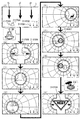
前記所定画像の表示領域のうち少なくとも一部の表示領域を除いた表示領域を視認困難または視認不能とする特定演出(図9−1に示すように、円形の表示領域以外をシャッター画像211F006により隠蔽する特定演出等)を実行可能な特定演出実行手段(演出制御用CPU120等)とを備え、
前記特定演出の実行中は、前記一部の表示領域が可変し(図9−1(D)〜(G)に示すように、特定演出の実行中は、シャッター画像211F006により囲まれた円形の表示領域が移動する等)、
可変する前記一部の表示領域において、前記有利状態に制御されるか否かを示唆する示唆演出を表示可能であり(図9−1(H)に示すように、シャッター画像211F006により囲まれた円形の表示領域において、大当り遊技状態に制御されるか否かを示唆する仮停止図柄211F008を表示する等)、
前記一部の表示領域の可変パターンは、複数設けられている(図9−2に示すように、円形の表示領域の動作パターンは右回りと左回りのパターンが設けられている等)。
(1) In order to achieve the above object, the gaming machine according to the present invention is:
A gaming machine (
Display means (
The specific effect of making the display area excluding at least a part of the display area of the display area of the predetermined image difficult to recognize or invisible (as shown in FIG. 9-1, concealing areas other than the circular display area by the shutter Specific effect executing means (such as
While the specific effect is being executed, the partial display area is variable (as shown in FIGS. 9-1D to G), while the specific effect is being executed, a circular image surrounded by the shutter image 211F006 is displayed. Display area moves, etc.),
In the partial display area that is variable, it is possible to display a suggestive effect that indicates whether or not control is performed in the advantageous state (as shown in FIG. 9-1 (H), surrounded by the shutter image 211F 006) In the circular display area, a temporary stop symbol 211F008 indicating whether or not to be controlled to the big hit gaming state is displayed, etc.),
A plurality of variable patterns of the partial display area are provided (as shown in FIG. 9-2, the operation pattern of the circular display area is provided with clockwise and counterclockwise patterns, etc.).
このような構成によれば、視認可能な一部の表示領域が可変するため、表示手段を用いた演出の興趣を向上させることができる。また、一部の表示領域の可変パターンに注目させることができる。 According to such a configuration, since a part of the visible display area is variable, it is possible to improve the enjoyment of the effect using the display means. In addition, attention can be paid to variable patterns of some display areas.
(2)上記(1)の遊技機において、
遊技媒体(遊技球等)が始動領域(第1始動入賞口,第2始動入賞口等)に進入したことに基づいて可変表示を行い、前記有利状態(大当り遊技状態等)に制御可能であって、
可変表示に関する情報を保留記憶情報として記憶可能な保留記憶手段(RAM102等)と、
可変表示を開始するときに、前記有利状態とするか否かを前記保留記憶情報に基づいて決定する決定手段(CPU103等)と、
前記決定手段の決定よりも前に、前記有利状態とするか否かを判定する判定手段(図5のS101で実行される始動入賞判定処理等)とをさらに備え、
前記特定演出実行手段は、前記始動領域に遊技媒体が進入したことによる前記判定手段の判定に基づく演出として前記特定演出の実行を開始する(始動入賞口に遊技球が入賞したことによる判定に基づいて特定演出の実行が開始される等)。
(2) In the gaming machine of (1),
Variable display is performed based on the fact that game media (game balls, etc.) enter the start area (first start winning opening, second start winning opening, etc.), and can be controlled to the advantageous state (big hit gaming state etc.) ,
Holding storage means (such as RAM 102) capable of storing information on variable display as holding storage information;
A determination unit (such as a CPU 103) that determines whether to set the advantageous state when starting variable display based on the pending storage information;
It further comprises a determination means (a start winning determination process or the like executed in S101 of FIG. 5) for determining whether or not to set the advantageous state before the determination of the determination means.
The specific effect execution means starts execution of the specific effect as an effect based on the determination of the determination means by the game medium entering the start area (based on the determination by the game ball having won the start winning opening) Execution of specific effects is started, etc.).
このような構成によれば、遊技媒体が始動領域に進入するタイミングに注目させることができる。 According to such a configuration, it is possible to pay attention to the timing when the game medium enters the start area.
(3)上記(1)または(2)の遊技機において、
前記特定演出は、前記一部の表示領域を除いた表示領域に視認困難または視認不能とする画像を表示させる演出である(特定演出は、円形の表示領域を除いた表示領域にシャッター画像211F006を表示させる演出である等)。
(3) In the gaming machine of (1) or (2) above,
The specific effect is an effect of displaying an image which makes visual recognition difficult or invisible in the display area excluding the partial display area (in the specific effect, the shutter image 211 F 006 is displayed in the display area excluding the circular display area) It is an effect to be displayed etc.).
このような構成によれば、一部の表示領域を除いた表示領域を画像により視認困難または視認不能とすることにより、視認可能な一部の表示領域が可変するため、表示手段を用いた演出の興趣を向上させることができる。 According to such a configuration, by making the display area excluding a part of the display area invisible or inconspicuous in the image, the visible part of the display area is variable. Can improve the interest of
(4)上記(1)から(3)のいずれかの遊技機において、
遊技者が操作可能な操作手段(プッシュボタン31B等)をさらに備え、
前記表示手段は、前記操作手段への操作を促す操作画像(ボタン画像211F007等)を表示可能であり、
前記特定演出実行手段は、前記操作画像が表示される期間において当該操作画像の少なくとも一部を前記一部の表示領域に常に表示されるように前記一部の表示領域を可変する(図9−1(F),(G)に示すように、ボタン画像211F007を円形の表示領域に常に表示されるように円形の表示領域を移動する等)。
(4) In the gaming machine according to any one of (1) to (3) above,
The game machine further comprises operation means (
The display means can display an operation image (such as a button image 211F 007) for prompting an operation to the operation means,
The specific effect execution means changes the display area of the part so that at least a part of the operation image is always displayed in the display area of the part during a period in which the operation image is displayed (FIG. 9- As shown in 1 (F) and (G), the circular display area is moved so that the button image 211 F 007 is always displayed in the circular display area, and the like).
このような構成によれば、操作画像が表示されていることを見逃さないようにすることができる。 According to such a configuration, it is possible not to overlook that the operation image is displayed.
(5)上記(1)から(4)のいずれかの遊技機において、
前記表示手段は、可変表示に関する情報を特定表示(アクティブ表示211F004等)として表示可能であり、
前記有利状態に制御されることを前記特定表示の表示態様を変化させることで示唆する変化演出(アクティブ表示211F004の色を変化させることで大当り期待度を示唆する変化演出等)を前記特定演出の実行中に実行可能な変化演出実行手段(演出制御用CPU120等)をさらに備え、
前記特定演出実行手段は、前記変化演出により前記特定表示の表示態様が変化した場合に、変化した前記特定表示が前記一部の表示領域に表示されるように前記一部の表示領域を可変する(アクティブ表示211F004の色が変化した場合に、変化したアクティブ表示211F004が円形の表示領域に表示されるように円形の表示領域を移動する等)。
(5) In the gaming machine according to any one of (1) to (4) above,
The display means can display information related to variable display as a specific display (such as an active display 211F004),
The change effect (the change effect etc. which suggests a big hit expectation by changing the color of the active display 211 F 004) by changing the display mode of the specific display to be controlled to the advantageous state It further comprises change effect execution means (such as
The specific effect execution means changes the partial display area such that the changed specific display is displayed in the partial display area when the display mode of the specific display changes due to the change effect. (For example, moving the circular display area so that the changed active display 211F004 is displayed in the circular display area when the color of the active display 211F004 changes).
このような構成によれば、変化演出が実行されたことを遊技者に気付かせることができ
る。
According to such a configuration, it is possible to make the player notice that the change effect has been executed.
このような構成によれば、一部の表示領域の可変パターンに注目させることができる。 According to such a configuration, it is possible to focus attention on the variable patterns of some display areas.
(6)上記(1)から(5)のいずれかの遊技機において、
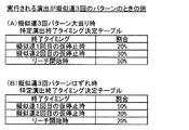
前記特定演出の終了タイミングは複数設けられ、終了タイミングにより前記有利状態に制御される割合が異なる(図9−5に示すように、特定演出の終了タイミングは複数設けられており、終了タイミングにより大当り遊技状態に制御される期待度が異なる等)。
(6) In the gaming machine according to any one of (1) to (5) above,
A plurality of termination timings of the specific effect are provided, and a ratio controlled to the advantageous state is different depending on the termination timing (as shown in FIG. The degree of expectation controlled to the game state is different, etc.).
このような構成によれば、特定演出の終了タイミングについて注目させることができる。 According to such a configuration, attention can be given to the end timing of the specific effect.
(7)上記(1)から(6)のいずれかの遊技機において、
前記特定演出の実行中においても常に視認可能な特殊表示(常時小図柄211F001、保留数表示211F002等)を表示する特殊表示手段(演出制御用CPU120等)をさらに備え、
前記特殊表示手段は、前記特定演出の実行中に前記特殊表示を変化させる(図9−1に示すように、特定演出の実行中に常時小図柄211F001や保留数表示211F002の表示態様を変化させる等)。
(7) In the gaming machine according to any one of (1) to (6) above,
The system further comprises special display means (such as
The special display means changes the special display while the specific effect is being executed (as shown in FIG. 9A, the display mode of the small symbol 211F001 and the number-of-holds display 211F002 is constantly changed while the specific effect is being performed) etc).
このような構成によれば、特定演出が実行されたときにも特殊表示については変化の様子が視認できるため、遊技の興趣を向上させることができる。 According to such a configuration, even when the specific effect is executed, the state of the change can be visually recognized with respect to the special display, so that the interest of the game can be improved.
(基本説明)
まず、パチンコ遊技機1の基本的な構成及び制御(一般的なパチンコ遊技機の構成及び制御でもある。)について説明する。
(Basic explanation)
First, the basic configuration and control of the pachinko gaming machine 1 (which is also the configuration and control of a general pachinko gaming machine) will be described.
(パチンコ遊技機1の構成等)
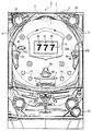
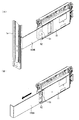
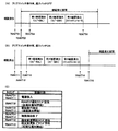
図1は、パチンコ遊技機1の正面図であり、主要部材の配置レイアウトを示す。パチンコ遊技機(遊技機)1は、大別して、遊技盤面を構成する遊技盤(ゲージ盤)2と、遊技盤2を支持固定する遊技機用枠(台枠)3とから構成されている。遊技盤2には、遊技領域が形成され、この遊技領域には、遊技媒体としての遊技球が、所定の打球発射装置から発射されて打ち込まれる。
(Configuration etc. of pachinko gaming machine 1)
FIG. 1 is a front view of the
遊技盤2の所定位置(図1に示す例では、遊技領域の右側方)には、複数種類の特別識別情報としての特別図柄(特図ともいう)の可変表示(特図ゲームともいう)を行う第1特別図柄表示装置4A及び第2特別図柄表示装置4Bが設けられている。これらは、それぞれ、7セグメントのLEDなどからなる。特別図柄は、「0」〜「9」を示す数字や「−」などの点灯パターンなどにより表される。特別図柄には、LEDを全て消灯したパターンが含まれてもよい。
At a predetermined position of the game board 2 (in the example shown in FIG. 1, on the right side of the game area), variable display (also referred to as a special figure game) of special symbols (also called special figures) as plural types of special identification information A first special
なお、特別図柄の「可変表示」とは、例えば、複数種類の特別図柄を変動可能に表示することである(後述の他の図柄についても同じ)。変動としては、複数の図柄の更新表示、複数の図柄のスクロール表示、1以上の図柄の変形、1以上の図柄の拡大/縮小などがある。特別図柄や後述の普通図柄の変動では、複数種類の特別図柄又は普通図柄が更新表示される。後述の飾り図柄の変動では、複数種類の飾り図柄がスクロール表示又は更新表示されたり、1以上の飾り図柄が変形や拡大/縮小されたりする。なお、変動には、ある図柄を点滅表示する態様も含まれる。可変表示の最後には、表示結果として所定の特別図柄が停止表示(導出又は導出表示などともいう)される(後述の他の図柄の可変表示についても同じ)。なお、可変表示を変動表示、変動と表現する場合がある。 In addition, "variable display" of a special symbol is, for example, variably displaying a plurality of types of special symbols (the same applies to other symbols described later). The variation includes update display of a plurality of symbols, scroll display of a plurality of symbols, deformation of one or more symbols, and enlargement / reduction of one or more symbols. In the special symbol and the variation of the ordinary symbol described later, a plurality of special symbols or ordinary symbols are updated and displayed. In the variation of the decorative symbol described later, a plurality of decorative symbols are scrolled or updated and one or more decorative symbols are deformed or enlarged / reduced. In addition, the aspect which blink-displays a certain symbol is also contained in a fluctuation | variation. At the end of the variable display, a predetermined special symbol is displayed as a stop as a display result (also referred to as derivation or derivation display, etc.) (the same applies to variable display of other symbols described later). Variable display may be expressed as variable display or fluctuation.
なお、第1特別図柄表示装置4Aにおいて可変表示される特別図柄を「第1特図」ともいい、第2特別図柄表示装置4Bにおいて可変表示される特別図柄を「第2特図」ともいう。また、第1特図を用いた特図ゲームを「第1特図ゲーム」といい、第2特図を用いた特図ゲームを「第2特図ゲーム」ともいう。なお、特別図柄の可変表示を行う特別図柄表示装置は1種類であってもよい。
The special symbol variably displayed in the first special
遊技盤2における遊技領域の中央付近には画像表示装置5が設けられている。画像表示装置5は、例えばLCD(液晶表示装置)や有機EL(Electro Luminescence)等から構成され、各種の演出画像を表示する。画像表示装置5は、プロジェクタ及びスクリーンから構成されていてもよい。画像表示装置5には、各種の演出画像が表示される。
An
例えば、画像表示装置5の画面上では、第1特図ゲームや第2特図ゲームと同期して、特別図柄とは異なる複数種類の装飾識別情報としての飾り図柄(数字などを示す図柄など)の可変表示が行われる。ここでは、第1特図ゲーム又は第2特図ゲームに同期して、「左」、「中」、「右」の各飾り図柄表示エリア5L、5C、5Rにおいて飾り図柄が可変表示(例えば上下方向のスクロール表示や更新表示)される。なお、同期して実行される特図ゲーム及び飾り図柄の可変表示を総称して単に可変表示ともいう。
For example, on the screen of the
画像表示装置5の画面上には、実行が保留されている可変表示に対応する保留表示や、実行中の可変表示に対応するアクティブ表示を表示するための表示エリアが設けられていてもよい。保留表示及びアクティブ表示を総称して可変表示に対応する可変表示対応表示ともいう。
On the screen of the
保留されている可変表示の数は保留記憶数ともいう。第1特図ゲームに対応する保留記憶数を第1保留記憶数、第2特図ゲームに対応する保留記憶数を第2保留記憶数ともいう。また、第1保留記憶数と第2保留記憶数との合計を合計保留記憶数ともいう。 The number of pending variable displays is also referred to as the number of pending storages. The number of pending storages corresponding to the first special view game is also referred to as a first pending storage number, and the number of pending storages corresponding to the second special view game is also referred to as a second pending storage number. The total of the first pending storage number and the second pending storage number is also referred to as the total pending storage number.
また、遊技盤2の所定位置には、複数のLEDを含んで構成された第1保留表示器25Aと第2保留表示器25Bとが設けられ、第1保留表示器25Aは、LEDの点灯個数によって、第1保留記憶数を表示し、第2保留表示器25Bは、LEDの点灯個数によって、第2保留記憶数を表示する。
In addition, a
画像表示装置5の下方には、入賞球装置6Aと、可変入賞球装置6Bとが設けられている。
Below the
入賞球装置6Aは、例えば所定の玉受部材によって常に遊技球が進入可能な一定の開放状態に保たれる第1始動入賞口を形成する。第1始動入賞口に遊技球が進入したときには、所定個(例えば3個)の賞球が払い出されるとともに、第1特図ゲームが開始され得る。
The winning
可変入賞球装置6B(普通電動役物)は、ソレノイド81(図2参照)によって閉鎖状態と開放状態とに変化する第2始動入賞口を形成する。可変入賞球装置6Bは、例えば、一対の可動翼片を有する電動チューリップ型役物を備え、ソレノイド81がオフ状態であるときに可動翼片が垂直位置となることにより、当該可動翼片の先端が入賞球装置6Aに近接し、第2始動入賞口に遊技球が進入しない閉鎖状態になる(第2始動入賞口が閉鎖状態になるともいう。)。その一方で、可変入賞球装置6Bは、ソレノイド81がオン状態であるときに可動翼片が傾動位置となることにより、第2始動入賞口に遊技球が進入できる開放状態になる(第2始動入賞口が開放状態になるともいう。)。第2始動入賞口に遊技球が進入したときには、所定個(例えば3個)の賞球が払い出されるとともに、第2特図ゲームが開始され得る。なお、可変入賞球装置6Bは、閉鎖状態と開放状態とに変化するものであればよく、電動チューリップ型役物を備えるものに限定されない。
The variable winning
遊技盤2の所定位置(図1に示す例では、遊技領域の左右下方4箇所)には、所定の玉受部材によって常に一定の開放状態に保たれる一般入賞口10が設けられる。この場合には、一般入賞口10のいずれかに進入したときには、所定個数(例えば10個)の遊技球が賞球として払い出される。
At a predetermined position of the game board 2 (in the example shown in FIG. 1, four places on the left and right lower sides of the game area), a general winning
入賞球装置6Aと可変入賞球装置6Bの下方には、大入賞口を有する特別可変入賞球装置7が設けられている。特別可変入賞球装置7は、ソレノイド82(図2参照)によって開閉駆動される大入賞口扉を備え、その大入賞口扉によって開放状態と閉鎖状態とに変化する特定領域としての大入賞口を形成する。
Below the winning
一例として、特別可変入賞球装置7では、大入賞口扉用(特別電動役物用)のソレノイド82がオフ状態であるときに大入賞口扉が大入賞口を閉鎖状態として、遊技球が大入賞口に進入(通過)できなくなる。その一方で、特別可変入賞球装置7では、大入賞口扉用のソレノイド82がオン状態であるときに大入賞口扉が大入賞口を開放状態として、遊技球が大入賞口に進入しやすくなる。
As an example, in the special variable winning
大入賞口に遊技球が進入したときには、所定個数(例えば14個)の遊技球が賞球として払い出される。大入賞口に遊技球が進入したときには、例えば第1始動入賞口や第2始動入賞口及び一般入賞口10に遊技球が進入したときよりも多くの賞球が払い出される。
When the game ball enters the special winning opening, a predetermined number (for example, 14) of game balls are paid out as winning balls. When the game ball enters the big winning opening, for example, more winning balls are paid out than when the game ball enters the first starting winning opening, the second starting winning opening, and the general winning
一般入賞口10を含む各入賞口に遊技球が進入することを「入賞」ともいう。特に、始動口(第1始動入賞口、第2始動入賞口始動口)への入賞を始動入賞ともいう。
It is also called "winning" that the game ball enters each winning opening including the general winning
遊技盤2の所定位置(図1に示す例では、遊技領域の左側方)には、普通図柄表示器20が設けられている。一例として、普通図柄表示器20は、7セグメントのLEDなどからなり、特別図柄とは異なる複数種類の普通識別情報としての普通図柄の可変表示を行う。普通図柄は、「0」〜「9」を示す数字や「−」などの点灯パターンなどにより表される。普通図柄には、LEDを全て消灯したパターンが含まれてもよい。このような普通図柄の可変表示は、普図ゲームともいう。
An
画像表示装置5の左方には、遊技球が通過可能な通過ゲート41が設けられている。遊技球が通過ゲート41を通過したことに基づき、普図ゲームが実行される。
On the left side of the
普通図柄表示器20の上方には、普図保留表示器25Cが設けられている。普図保留表示器25Cは、例えば4個のLEDを含んで構成され、実行が保留されている普図ゲームの数である普図保留記憶数をLEDの点灯個数により表示する。
Above the
遊技盤2の表面には、上記の構成以外にも、遊技球の流下方向や速度を変化させる風車及び多数の障害釘が設けられている。遊技領域の最下方には、いずれの入賞口にも進入しなかった遊技球が取り込まれるアウト口が設けられている。
On the surface of the
遊技機用枠3の左右上部位置には、効果音等を再生出力するためのスピーカ8L、8Rが設けられており、さらに遊技領域周辺部には、遊技効果用の遊技効果ランプ9が設けられている。遊技効果ランプ9は、LEDを含んで構成されている。
At the left and right upper positions of the
遊技盤2の所定位置(図1では図示略)には、演出に応じて動作する可動体32が設けられている。
At a predetermined position (not shown in FIG. 1) of the
遊技機用枠3の右下部位置には、遊技球を打球発射装置により遊技領域に向けて発射するために遊技者等によって操作される打球操作ハンドル(操作ノブ)30が設けられている。
At the lower right position of the
遊技領域の下方における遊技機用枠3の所定位置には、賞球として払い出された遊技球や所定の球貸機により貸し出された遊技球を、打球発射装置へと供給可能に保持(貯留)
する打球供給皿(上皿)が設けられている。上皿の下方には、上皿満タン時に賞球が払い出される打球供給皿(下皿)が設けられている。
At a predetermined position of the
The ball supply tray (upper plate) is provided. Below the upper plate, there is provided a hitting plate (lower plate) from which winning balls are dispensed when the upper plate is full.
遊技領域の下方における遊技機用枠3の所定位置には、遊技者が把持して傾倒操作が可能なスティックコントローラ31Aが取り付けられている。スティックコントローラ31Aには、遊技者が押下操作可能なトリガボタンが設けられている。スティックコントローラ31Aに対する操作は、コントローラセンサユニット35A(図2参照)により検出される。
At a predetermined position of the
遊技領域の下方における遊技機用枠3の所定位置には、遊技者が押下操作などにより所定の指示操作を可能なプッシュボタン31Bが設けられている。プッシュボタン31Bに対する操作は、プッシュセンサ35B(図2参照)により検出される。
At a predetermined position of the
パチンコ遊技機1では、遊技者の動作(操作等)を検出する検出手段として、スティックコントローラ31Aやプッシュボタン31Bが設けられるが、これら以外の検出手段が設けられていてもよい。
In the
(遊技の進行の概略)
パチンコ遊技機1が備える打球操作ハンドル30への遊技者による回転操作により、遊技球が遊技領域に向けて発射される。遊技球が通過ゲート41を通過すると、普通図柄表示器20による普図ゲームが開始される。なお、前回の普図ゲームの実行中の期間等に遊技球が通過ゲート41を通過した場合(遊技球が通過ゲート41を通過したが当該通過に基づく普図ゲームを直ちに実行できない場合)には、当該通過に基づく普図ゲームは所定の上限数(例えば4)まで保留される。
(Outline of the progress of the game)
The game ball is fired toward the game area by the player's rotation operation on the ball striking operation handle 30 provided in the
この普図ゲームでは、特定の普通図柄(普図当り図柄)が停止表示されれば、普通図柄の表示結果が「普図当り」となる。その一方、確定普通図柄として、普図当り図柄以外の普通図柄(普図ハズレ図柄)が停止表示されれば、普通図柄の表示結果が「普図ハズレ」となる。「普図当り」となると、可変入賞球装置6Bを所定期間開放状態とする開放制御が行われる(第2始動入賞口が開放状態になる)。
In this common-play game, when a specific normal symbol (per-flat symbol) is stopped and displayed, the display result of the normal symbol is "per common-word". On the other hand, if an ordinary symbol other than the symbol per common drawing (general drawing loss symbol) is stopped and displayed as the determined normal symbol, the display result of the normal symbol becomes "general drawing lost". When it becomes "per common plan", opening control is performed to open the variable winning
入賞球装置6Aに形成された第1始動入賞口に遊技球が進入すると、第1特別図柄表示装置4Aによる第1特図ゲームが開始される。
When the game ball enters the first starting winning opening formed in the winning
可変入賞球装置6Bに形成された第2始動入賞口に遊技球が進入すると、第2特別図柄表示装置4Bによる第2特図ゲームが開始される。
When the game ball enters the second starting winning opening formed in the variable winning
なお、特図ゲームの実行中の期間や、後述する大当り遊技状態や小当り遊技状態に制御されている期間に、遊技球が始動入賞口へ進入(入賞)した場合(始動入賞が発生したが当該始動入賞に基づく特図ゲームを直ちに実行できない場合)には、当該進入に基づく特図ゲームは所定の上限数(例えば4)までその実行が保留される。 In addition, when the game ball enters into the start winning opening (winning) during the period during execution of the special figure game, and the period controlled to the big hit gaming state and the small hit gaming state to be described later (start winning is generated When the special figure game based on the starting winning combination can not be executed immediately), the special figure game based on the entry is suspended from being executed up to a predetermined upper limit number (for example, 4).
特図ゲームにおいて、確定特別図柄として特定の特別図柄(大当り図柄、例えば「7」、後述の大当り種別に応じて実際の図柄は異なる。)が停止表示されれば、「大当り」となり、大当り図柄とは異なる所定の特別図柄(小当り図柄、例えば「2」)が停止表示されれば、「小当り」となる。また、大当り図柄や小当り図柄とは異なる特別図柄(ハズレ図柄、例えば「−」)が停止表示されれば「ハズレ」となる。 If special symbols (big hit symbols such as "7", the actual symbols differ according to the big hit type described later) are displayed as special symbols in the special figure game, they will be "big hits" and they will be big hit symbols If a predetermined special symbol (small hit symbol, for example, "2") different from that is displayed stopped, it becomes "small hit". Also, if a special symbol different from the big hit symbol or the small hit symbol (a lost symbol, for example, "-") is stopped and displayed, it is a "loss".
特図ゲームでの表示結果が「大当り」になった後には、遊技者にとって有利な有利状態として大当り遊技状態に制御される。特図ゲームでの表示結果が「小当り」になった後に
は、小当り遊技状態に制御される。
After the display result in the special figure game becomes "big hit", it is controlled to the big hit gaming state as an advantageous advantageous state for the player. After the display result in the special view game becomes "small hit", the small hit gaming state is controlled.
大当り遊技状態では、特別可変入賞球装置7により形成される大入賞口が所定の態様で開放状態となる。当該開放状態は、所定期間(例えば29秒間や1.8秒間)の経過タイミングと、大入賞口に進入した遊技球の数が所定個数(例えば9個)に達するまでのタイミングと、のうちのいずれか早いタイミングまで継続される。前記所定期間は、1ラウンドにおいて大入賞口を開放することができる上限期間であり、以下、開放上限期間ともいう。このように大入賞口が開放状態となる1のサイクルをラウンド(ラウンド遊技)という。大当り遊技状態では、当該ラウンドが所定の上限回数(15回や2回)に達するまで繰り返し実行可能となっている。
In the big hit game state, the big winning opening formed by the special variable winning
大当り遊技状態においては、遊技者は、遊技球を大入賞口に進入させることで、賞球を得ることができる。従って、大当り遊技状態は、遊技者にとって有利な状態である。大当り遊技状態におけるラウンド数が多い程、また、開放上限期間が長い程遊技者にとって有利となる。 In the jackpot gaming state, the player can obtain a winning ball by advancing the gaming ball into the big winning opening. Therefore, the jackpot gaming state is an advantageous state for the player. The greater the number of rounds in the jackpot gaming state, and the longer the open upper limit period, the more advantageous it is for the player.
なお、「大当り」には、大当り種別が設定されている。例えば、大入賞口の開放態様(ラウンド数や開放上限期間)や、大当り遊技状態後の遊技状態(後述の、通常状態、時短状態、確変状態など)を複数種類用意し、これらに応じて大当り種別が設定されている。大当り種別として、多くの賞球を得ることができる大当り種別や、賞球の少ない又はほとんど賞球を得ることができない大当り種別が設けられていてもよい。 In the "big hit", a big hit type is set. For example, a large winning opening opening mode (round number and opening upper limit period), a gaming state after the big hit gaming state (described later, normal state, time saving state, probability variation state, etc.) prepared a plurality of types, according to these The type is set. As the jackpot type, there may be provided a jackpot type capable of obtaining many prize balls, or a jackpot type with few prize balls or hardly capable of obtaining prize balls.
小当り遊技状態では、特別可変入賞球装置7により形成される大入賞口が所定の開放態様で開放状態となる。例えば、小当り遊技状態では、一部の大当り種別のときの大当り遊技状態と同様の開放態様(大入賞口の開放回数が上記ラウンド数と同じであり、かつ、大入賞口の閉鎖タイミングも同じ等)で大入賞口が開放状態となる。なお、大当り種別と同様に、「小当り」にも小当り種別を設けてもよい。
In the small hit gaming state, the special winning opening formed by the special variable winning
大当り遊技状態が終了した後は、上記大当り種別に応じて、時短状態や確変状態に制御されることがある。 After the big hit gaming state ends, depending on the big hit type, it may be controlled to the time saving state or the probability changing state.
時短状態では、平均的な特図変動時間(特図を変動させる期間)を通常状態よりも短縮させる制御(時短制御)が実行される。時短状態では、平均的な普図変動時間(普図を変動させる期間)を通常状態よりも短縮させたり、普図ゲームで「普図当り」となる確率を通常状態よりも向上させる等により、第2始動入賞口に遊技球が進入しやすくなる制御(高開放制御、高ベース制御)も実行される。時短状態は、特別図柄(特に第2特別図柄)の変動効率が向上する状態であるので、遊技者にとって有利な状態である。 In the short time state, control (time reduction control) is executed to shorten the average special figure fluctuation time (period in which the special figure changes) compared to the normal state. In the time saving state, by shortening the average spread map fluctuation time (period for changing the spread map) than in the normal state, or by improving the probability of being “per spread map” in the spread game game, than in the normal state, etc. Control (high opening control, high base control) that facilitates the game ball to enter the second start winning opening is also executed. Since the time saving state is a state in which the variation efficiency of the special symbol (in particular, the second special symbol) is improved, it is an advantageous state for the player.
確変状態(確率変動状態)では、時短制御に加えて、表示結果が「大当り」となる確率が通常状態よりも高くなる確変制御が実行される。確変状態は、特別図柄の変動効率が向上することに加えて「大当り」となりやすい状態であるので、遊技者にとってさらに有利な状態である。 In the probability variation state (probability variation state), in addition to the time saving control, probability variation control is performed in which the probability that the display result is a "big hit" is higher than that in the normal state. The probability change state is a state more advantageous to the player because the probability change state of the special symbol is likely to be a "big hit" in addition to the improvement of the variation efficiency of the special symbol.
時短状態や確変状態は、所定回数の特図ゲームが実行されたことと、次回の大当り遊技状態が開始されたこと等といった、いずれか1つの終了条件が先に成立するまで継続する。所定回数の特図ゲームが実行されたことが終了条件となるものを、回数切り(回数切り時短、回数切り確変等)ともいう。 The time saving state or the probability changing state continues until any one end condition such as the fact that the special figure game has been executed a predetermined number of times and the start of the next big hit gaming state is established first. It is also referred to as “the number of times cut (short in the number of times, short in the number of times definite change, etc.)” as the end condition that the special figure game has been executed a predetermined number of times is the end condition.
通常状態とは、遊技者にとって有利な大当り遊技状態等の有利状態、時短状態、確変状態等の特別状態以外の遊技状態のことであり、普図ゲームにおける表示結果が「普図当り
」となる確率及び特図ゲームにおける表示結果が「大当り」となる確率などのパチンコ遊技機1が、パチンコ遊技機1の初期設定状態(例えばシステムリセットが行われた場合のように、電源投入後に所定の復帰処理を実行しなかったとき)と同一に制御される状態である。
The normal state is a gaming state other than the special state such as an advantageous state such as a big hit gaming state which is advantageous for the player, a short time state, a definite change state, etc., and the display result in the common drawing game is "per common drawing". The
確変制御が実行されている状態を高確状態、確変制御が実行されていない状態を低確状態ともいう。時短制御が実行されている状態を高ベース状態、時短制御が実行されていない状態を低ベース状態ともいう。これらを組み合わせて、時短状態は低確高ベース状態、確変状態は高確高ベース状態、通常状態は低確低ベース状態などともいわれる。高確状態かつ低ベース状態は高確低ベース状態ともいう。 A state in which the probability change control is being performed is also referred to as a high probability state, and a state in which the probability variation control is not performed is also referred to as a low probability state. A state in which time saving control is being performed is also referred to as a high base state, and a state in which time saving control is not performed is also referred to as a low base state. In combination, the short time state is also referred to as a low probability high base state, the positive variation state is also referred to as a high probability high base state, and the normal state is a low probability low base state. The high certainty state and the low base state are also referred to as the high certainty base state.
小当り遊技状態が終了した後は、遊技状態の変更が行われず、特図ゲームの表示結果が「小当り」となる以前の遊技状態に継続して制御される(但し、「小当り」発生時の特図ゲームが、上記回数切りにおける上記所定回数目の特図ゲームである場合には、当然遊技状態が変更される)。なお、特図ゲームの表示結果として「小当り」がなくてもよい。 After the small hit gaming state ends, the change of the gaming state is not performed, and the control result of the special drawing game is continuously controlled to the previous gaming state to become the "small hit" (but the "small hit" occurs) When the special figure game at the time is the special figure game of the predetermined number of times in the above-mentioned number cut, the game state is naturally changed). In addition, it is not necessary to have a "small hit" as a display result of the special drawing game.
なお、遊技状態は、大当り遊技状態中に遊技球が特定領域(例えば、大入賞口内の特定領域)を通過したことに基づいて、変化してもよい。例えば、遊技球が特定領域を通過したとき、その大当り遊技状態後に確変状態に制御してもよい。 The gaming state may change based on the fact that the gaming ball has passed a specific area (for example, a specific area in the big winning opening) during the big hit gaming state. For example, when the gaming ball passes the specific area, it may be controlled to be in the positive changing state after the big hit gaming state.
(演出の進行など)
パチンコ遊技機1では、遊技の進行に応じて種々の演出(遊技の進行状況を報知したり、遊技を盛り上げたりする演出)が実行される。当該演出について以下説明する。なお、当該演出は、画像表示装置5に各種の演出画像を表示することによって行われるが、当該表示に加えて又は代えて、スピーカ8L、8Rからの音声出力、及び/又は、遊技効果ランプ9の点等/消灯、可動体32の動作等により行われてもよい。
(Progress of progress etc.)
In the
遊技の進行に応じて実行される演出として、画像表示装置5に設けられた「左」、「中」、「右」の飾り図柄表示エリア5L、5C、5Rでは、第1特図ゲーム又は第2特図ゲームが開始されることに対応して、飾り図柄の可変表示が開始される。第1特図ゲームや第2特図ゲームにおいて表示結果(確定特別図柄ともいう。)が停止表示されるタイミングでは、飾り図柄の可変表示の表示結果となる確定飾り図柄(3つの飾り図柄の組合せ)も停止表示(導出)される。
In the "left", "middle" and "right" decorative
飾り図柄の可変表示が開始されてから終了するまでの期間では、飾り図柄の可変表示の態様が所定のリーチ態様となる(リーチが成立する)ことがある。ここで、リーチ態様とは、画像表示装置5の画面上にて停止表示された飾り図柄が後述の大当り組合せの一部を構成しているときに未だ停止表示されていない飾り図柄については可変表示が継続している態様などのことである。
In a period from the start of the variable display of the decorative symbol to the end thereof, the aspect of the variable display of the decorative symbol may be a predetermined reach aspect (reach is established). Here, with the reach mode, when the decorative symbol stopped and displayed on the screen of the
また、飾り図柄の可変表示中に上記リーチ態様となったことに対応してリーチ演出が実行される。パチンコ遊技機1では、演出態様に応じて表示結果(特図ゲームの表示結果や飾り図柄の可変表示の表示結果)が「大当り」となる割合(大当り信頼度、大当り期待度とも呼ばれる。)が異なる複数種類のリーチ演出が実行される。リーチ演出には、例えば、ノーマルリーチと、ノーマルリーチよりも大当り信頼度の高いスーパーリーチと、がある。
In addition, reach production is executed corresponding to becoming the above-mentioned reach mode during the variable display of the decorative design. In the
特図ゲームの表示結果が「大当り」となるときには、画像表示装置5の画面上において、飾り図柄の可変表示の表示結果として、予め定められた大当り組合せとなる確定飾り図柄が導出される(飾り図柄の可変表示の表示結果が「大当り」となる)。一例として、「
左」、「中」、「右」の飾り図柄表示エリア5L、5C、5Rにおける所定の有効ライン上に同一の飾り図柄(例えば、「7」等)が揃って停止表示される。
When the display result of the special view game is "big hit", a finalized decoration pattern to be a predetermined big hit combination is derived as a display result of the variable display of the decoration pattern on the screen of the
The same decorative symbols (for example, "7" etc.) are aligned and stopped on predetermined effective lines in the decorative
大当り遊技状態の終了後に確変状態に制御される「確変大当り」である場合には、奇数の飾り図柄(例えば、「7」等)が揃って停止表示され、大当り遊技状態の終了後に確変状態に制御されない「非確変大当り(通常大当り)」である場合には、偶数の飾り図柄(例えば、「6」等)が揃って停止表示されるようにしてもよい。この場合、奇数の飾り図柄を確変図柄、偶数の飾り図柄を非確変図柄(通常図柄)ともいう。非確変図柄でリーチ態様となった後に、最終的に「確変大当り」となる昇格演出を実行するようにしてもよい。 If it is a "probable big hit" controlled to a definite change state after the end of the big hit gaming state, odd decorative symbols (for example, "7" etc.) are aligned and stop displayed, and after the end of the big hit gaming state In the case of "non-probable variation big hit (usually big hit)" which is not controlled, even-numbered decorative symbols (for example, "6" etc.) may be arranged to be stopped and displayed. In this case, an odd decorative pattern is also referred to as a probability variation pattern, and an even number decorative pattern is also referred to as a non-probability variation symbol (normal pattern). After reaching the reach mode with a non-deterministic symbol, a promotion effect that finally becomes a "possibly large hit" may be executed.
特図ゲームの表示結果が「小当り」となるときには、画像表示装置5の画面上において、飾り図柄の可変表示の表示結果として、予め定められた小当り組合せとなる確定飾り図柄(例えば、「1 3 5」等)が導出される(飾り図柄の可変表示の表示結果が「小当り」となる)。一例として、「左」、「中」、「右」の飾り図柄表示エリア5L、5C、5Rにおける所定の有効ライン上にチャンス目を構成する飾り図柄が停止表示される。なお、特図ゲームの表示結果が、一部の大当り種別(小当り遊技状態と同様の態様の大当り遊技状態の大当り種別)の「大当り」となるときと、「小当り」となるときとで、共通の確定飾り図柄が導出表示されてもよい。
When the display result of the special view game is "small hit", a finalized combination symbol (for example, "a small hit combination defined in advance as a display result of the variable display of the decorative symbol on the screen of the image display device 5). 1 3 5 "etc.) is derived (the display result of the variable display of the decorative pattern becomes" small hit "). As an example, the decorative symbols forming the chance eyes are stopped and displayed on predetermined effective lines in the decorative
特図ゲームの表示結果が「ハズレ」となる場合には、飾り図柄の可変表示の態様がリーチ態様とならずに、飾り図柄の可変表示の表示結果として、非リーチ組合せの確定飾り図柄(「非リーチハズレ」ともいう。)が停止表示される(飾り図柄の可変表示の表示結果が「非リーチハズレ」となる)ことがある。また、表示結果が「ハズレ」となる場合には、飾り図柄の可変表示の態様がリーチ態様となった後に、飾り図柄の可変表示の表示結果として、大当り組合せでない所定のリーチ組合せ(「リーチハズレ」ともいう)の確定飾り図柄が停止表示される(飾り図柄の可変表示の表示結果が「リーチハズレ」となる)こともある。 When the display result of the special view game is "loss", the display mode of the variable display of the decorative symbol does not become the reach mode, but the fixed decorative symbol of the non-reach combination is displayed as the display result of the variable display of the decorative symbol (" Sometimes it is stopped and displayed (the display result of the variable display of the decorative pattern becomes "non-reach loss"). Also, when the display result is "loss", a predetermined reach combination which is not a big hit combination ("reach loss") as a display result of the variable display of the decorative symbol after the variable display of the decorative symbol becomes the reach aspect. There is also a case where the finalized decorative pattern is displayed in a stopped state (the display result of the variable display of the decorative pattern becomes “reach loss”).
パチンコ遊技機1が実行可能な演出には、上記の可変表示対応表示(保留表示やアクティブ表示)を表示することも含まれる。また、他の演出として、例えば、大当り信頼度を予告する予告演出等が飾り図柄の可変表示中に実行される。予告演出には、実行中の可変表示における大当り信頼度を予告する予告演出や、実行前の可変表示(実行が保留されている可変表示)における大当り信頼度を予告する先読み予告演出がある。先読み予告演出として、可変表示対応表示(保留表示やアクティブ表示)の表示態様を通常とは異なる態様に変化させる演出が実行されるようにしてもよい。
The effects that can be executed by the
また、画像表示装置5において、飾り図柄の可変表示中に飾り図柄を一旦仮停止させた後に可変表示を再開させることで、1回の可変表示を擬似的に複数回の可変表示のように見せる擬似連演出を実行するようにしてもよい。
Further, in the
大当り遊技状態中にも、大当り遊技状態を報知する大当り中演出が実行される。大当り中演出としては、ラウンド数を報知する演出や、大当り遊技状態の価値が向上することを示す昇格演出が実行されてもよい。また、小当り遊技状態中にも、小当り遊技状態を報知する小当り中演出が実行される。なお、小当り遊技状態中と、一部の大当り種別(小当り遊技状態と同様の態様の大当り遊技状態の大当り種別で、例えばその後の遊技状態を高確状態とする大当り種別)での大当り遊技状態とで、共通の演出を実行することで、現在が小当り遊技状態中であるか、大当り遊技状態中であるかを遊技者に分からないようにしてもよい。そのような場合であれば、小当り遊技状態の終了後と大当り遊技状態の終了後とで共通の演出を実行することで、高確状態であるか低確状態であるかを識別できないよう
にしてもよい。
During the jackpot gaming state, a jackpot during the jackpot to notify the jackpot gaming state is executed. As the jackpot effect, an effect of informing the number of rounds or a promotion effect indicating that the value of the jackpot gaming state is improved may be executed. In addition, during the small hitting game state, during the small hitting during the small hitting game state which is notified the small hitting game state is executed. In addition, during the small hit gaming state, and some of the big hit type (big hit type of the big hit gaming state of the same manner as the small hit gaming state, for example, a big hit type that makes the subsequent gaming state highly probable) Depending on the state, the player may not know whether the present is in the small hit gaming state or the big hit gaming state by executing a common effect. In such a case, by performing a common effect after the end of the small hit gaming state and after the end of the big hit gaming state, it is not possible to distinguish whether it is a high probability state or a low probability state. May be
また、例えば特図ゲーム等が実行されていないときには、画像表示装置5にデモ(デモンストレーション)画像が表示される(客待ちデモ演出が実行される)。 Further, for example, when the special drawing game or the like is not executed, a demonstration (demonstration) image is displayed on the image display device 5 (a customer waiting demonstration effect is executed).
(基板構成)
パチンコ遊技機1には、例えば図2に示すような主基板11、演出制御基板12、音声制御基板13、ランプ制御基板14、中継基板15などが搭載されている。その他にも、パチンコ遊技機1の背面には、例えば払出制御基板、情報端子基板、発射制御基板、電源基板などといった、各種の基板が配置されている。
(Board configuration)
In the
主基板11は、メイン側の制御基板であり、パチンコ遊技機1における上記遊技の進行(特図ゲームの実行(保留の管理を含む)、普図ゲームの実行(保留の管理を含む)、大当り遊技状態、小当り遊技状態、遊技状態など)を制御する機能を有する。主基板11は、遊技制御用マイクロコンピュータ100、スイッチ回路110、ソレノイド回路111などを有する。
The
主基板11に搭載された遊技制御用マイクロコンピュータ100は、例えば1チップのマイクロコンピュータであり、ROM(Read Only Memory)101と、RAM(Random Access Memory)102と、CPU(Central Processing Unit)103と、乱数回路104と、I/O(Input/Output port)105とを備える。
The
CPU103は、ROM101に記憶されたプログラムを実行することにより、遊技の進行を制御する処理(主基板11の機能を実現する処理)を行う。このとき、ROM101が記憶する各種データ(後述の変動パターン、後述の演出制御コマンド、後述の各種決定を行う際に参照される各種テーブルなどのデータ)が用いられ、RAM102がメインメモリとして使用される。RAM102は、その一部または全部がパチンコ遊技機1に対する電力供給が停止しても、所定期間記憶内容が保存されるバックアップRAMとなっている。なお、ROM101に記憶されたプログラムの全部又は一部をRAM102に展開して、RAM102上で実行するようにしてもよい。
The
乱数回路104は、遊技の進行を制御するときに使用される各種の乱数値(遊技用乱数)を示す数値データを更新可能にカウントする。遊技用乱数は、CPU103が所定のコンピュータプログラムを実行することで更新されるもの(ソフトウェアで更新されるもの)であってもよい。
The
I/O105は、例えば各種信号(後述の検出信号)が入力される入力ポートと、各種信号(第1特別図柄表示装置4A、第2特別図柄表示装置4B、普通図柄表示器20、第1保留表示器25A、第2保留表示器25B、普図保留表示器25Cなどを制御(駆動)する信号、ソレノイド駆動信号)を伝送するための出力ポートとを含んで構成される。
The I /
スイッチ回路110は、遊技球検出用の各種スイッチ(ゲートスイッチ21、始動口スイッチ(第1始動口スイッチ22Aおよび第2始動口スイッチ22B)、カウントスイッチ23)からの検出信号(遊技球が通過又は進入してスイッチがオンになったことを示す検出信号など)を取り込んで遊技制御用マイクロコンピュータ100に伝送する。検出信号の伝送により、遊技球の通過又は進入が検出されたことになる。
The
ソレノイド回路111は、遊技制御用マイクロコンピュータ100からのソレノイド駆動信号(例えば、ソレノイド81やソレノイド82をオンする信号など)を、普通電動役物用のソレノイド81や大入賞口扉用のソレノイド82に伝送する。
The
主基板11(遊技制御用マイクロコンピュータ100)は、遊技の進行の制御の一部として、遊技の進行に応じて演出制御コマンド(遊技の進行状況等を指定(通知)するコマンド)を演出制御基板12に供給する。主基板11から出力された演出制御コマンドは、中継基板15により中継され、演出制御基板12に供給される。当該演出制御コマンドには、例えば主基板11における各種の決定結果(例えば、特図ゲームの表示結果(大当り種別を含む。)、特図ゲームを実行する際に使用される変動パターン(詳しくは後述))、遊技の状況(例えば、可変表示の開始や終了、大入賞口の開放状況、入賞の発生、保留記憶数、遊技状態)、エラーの発生等を指定するコマンド等が含まれる。
The main board 11 (
演出制御基板12は、主基板11とは独立したサブ側の制御基板であり、演出制御コマンドを受信し、受信した演出制御コマンドに基づいて演出(遊技の進行に応じた種々の演出であり、可動体32の駆動、エラー報知、電断復旧の報知等の各種報知を含む)を実行する機能を有する。
The
演出制御基板12には、演出制御用CPU120と、ROM121と、RAM122と、表示制御部123と、乱数回路124と、I/O125とが搭載されている。
On the
演出制御用CPU120は、ROM121に記憶されたプログラムを実行することにより、表示制御部123とともに演出を実行するための処理(演出制御基板12の上記機能を実現するための処理であり、実行する演出の決定等を含む)を行う。このとき、ROM121が記憶する各種データ(各種テーブルなどのデータ)が用いられ、RAM122がメインメモリとして使用される。
The
演出制御用CPU120は、コントローラセンサユニット35Aやプッシュセンサ35Bからの検出信号(遊技者による操作を検出したときに出力される信号であり、操作内容を適宜示す信号)に基づいて演出の実行を表示制御部123に指示することもある。
The
表示制御部123は、VDP(Video Display Processor)、CGROM(Character Generator ROM)、VRAM(Video RAM)などを備え、演出制御用CPU120からの演出の実行指示に基づき、演出を実行する。
The
表示制御部123は、演出制御用CPU120からの演出の実行指示に基づき、実行する演出に応じた映像信号を画像表示装置5に供給することで、演出画像を画像表示装置5に表示させる。表示制御部123は、さらに、演出画像の表示に同期した音声出力や、遊技効果ランプ9の点灯/消灯を行うため、音指定信号(出力する音声を指定する信号)を音声制御基板13に供給したり、ランプ信号(ランプの点灯/消灯態様を指定する信号)をランプ制御基板14に供給したりする。また、表示制御部123は、可動体32を動作させる信号を当該可動体32又は当該可動体32を駆動する駆動回路に供給する。
The
音声制御基板13は、スピーカ8L、8Rを駆動する各種回路を搭載しており、当該音指定信号に基づきスピーカ8L、8Rを駆動し、当該音指定信号が指定する音声をスピーカ8L、8Rから出力させる。
The
ランプ制御基板14は、遊技効果ランプ9を駆動する各種回路を搭載しており、当該ランプ信号に基づき遊技効果ランプ9を駆動し、当該ランプ信号が指定する態様で遊技効果ランプ9を点灯/消灯する。このようにして、表示制御部123は、音声出力、ランプの点灯/消灯を制御する。
The
なお、音声出力、ランプの点灯/消灯の制御(音指定信号やランプ信号の供給等)、可
動体32の制御(可動体32を動作させる信号の供給等)は、演出制御用CPU120が実行するようにしてもよい。
The
乱数回路124は、各種演出を実行するために使用される各種の乱数値(演出用乱数)を示す数値データを更新可能にカウントする。演出用乱数は、演出制御用CPU120が所定のコンピュータプログラムを実行することで更新されるもの(ソフトウェアで更新されるもの)であってもよい。
The
演出制御基板12に搭載されたI/O125は、例えば主基板11などから伝送された演出制御コマンドを取り込むための入力ポートと、各種信号(映像信号、音指定信号、ランプ信号)を伝送するための出力ポートとを含んで構成される。
The I /
演出制御基板12、音声制御基板13、ランプ制御基板14といった、主基板11以外の基板をサブ基板ともいう。パチンコ遊技機1のようにサブ基板が機能別に複数設けられていてもよいし、1のサブ基板が複数の機能を有するように構成してもよい。
Substrates other than the
(動作)
次に、パチンコ遊技機1の動作(作用)を説明する。
(Operation)
Next, the operation (action) of the
(主基板11の主要な動作)
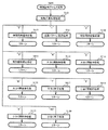
まず、主基板11における主要な動作を説明する。パチンコ遊技機1に対して電力供給が開始されると、遊技制御用マイクロコンピュータ100が起動し、CPU103によって遊技制御メイン処理が実行される。図3は、主基板11におけるCPU103が実行する遊技制御メイン処理を示すフローチャートである。
(Main operation of main board 11)
First, the main operation of the
図3に示す遊技制御メイン処理では、CPU103は、まず、割込禁止に設定する(ステップS1)。続いて、必要な初期設定を行う(ステップS2)。初期設定には、スタックポインタの設定、内蔵デバイス(CTC(カウンタ/タイマ回路)、パラレル入出力ポート等)のレジスタ設定、RAM102をアクセス可能状態にする設定等が含まれる。
In the game control main process shown in FIG. 3, first, the
次いで、クリアスイッチからの出力信号がオンであるか否かを判定する(ステップS3)。クリアスイッチは、例えば電源基板に搭載されている。クリアスイッチがオンの状態で電源が投入されると、出力信号(クリア信号)が入力ポートを介して遊技制御用マイクロコンピュータ100に入力される。クリアスイッチからの出力信号がオンである場合(ステップS3;Yes)、初期化処理(ステップS8)を実行する。初期化処理では、CPU103は、RAM102に記憶されるフラグ、カウンタ、バッファをクリアするRAMクリア処理を行い、作業領域に初期値を設定する。
Next, it is determined whether the output signal from the clear switch is on (step S3). The clear switch is mounted on, for example, a power supply substrate. When the power is turned on with the clear switch on, an output signal (clear signal) is input to the
また、CPU103は、初期化を指示する演出制御コマンドを演出制御基板12に送信する(ステップS9)。演出制御用CPU120は、当該演出制御コマンドを受信すると、例えば画像表示装置5において、遊技機の制御の初期化がなされたことを報知するための画面表示を行う。
Further, the
クリアスイッチからの出力信号がオンでない場合には(ステップS3;No)、RAM102(バックアップRAM)にバックアップデータが保存されているか否かを判定する(ステップS4)。不測の停電等(電断)によりパチンコ遊技機1への電力供給が停止したときには、CPU103は、当該電力供給の停止によって動作できなくなる直前に、電源供給停止時処理を実行する。この電源供給停止時処理では、RAM102にデータをバックアップすることを示すバックアップフラグをオンする処理、RAM102のデータ保護処理等が実行される。データ保護処理には、誤り検出符号(チェックサム、パリティビ
ット等)の付加、各種データをバックアップする処理が含まれる。バックアップされるデータには、遊技を進行するための各種データ(各種フラグ、各種タイマの状態等を含む)の他、前記バックアップフラグの状態や誤り検出符号も含まれる。ステップS4では、バックアップフラグがオンであるか否かを判定する。バックアップフラグがオフでRAM102にバックアップデータが記憶されていない場合(ステップS4;No)、初期化処理(ステップS8)を実行する。
If the output signal from the clear switch is not on (step S3; No), it is determined whether backup data is stored in the RAM 102 (backup RAM) (step S4). When the power supply to the
RAM102にバックアップデータが記憶されている場合(ステップS4;Yes)、CPU103は、バックアップしたデータのデータチェックを行い(誤り検出符号を用いて行われる)、データが正常か否かを判定する(ステップS5)。ステップS5では、例えば、パリティビットやチェックサムにより、RAM102のデータが、電力供給停止時のデータと一致するか否かを判定する。これらが一致すると判定された場合、RAM102のデータが正常であると判定する。
When backup data is stored in the RAM 102 (step S4; Yes), the
RAM102のデータが正常でないと判定された場合(ステップS5;No)、内部状態を電力供給停止時の状態に戻すことができないので、初期化処理(ステップS8)を実行する。
If it is determined that the data in the
RAM102のデータが正常であると判定された場合(ステップS5;Yes)、CPU103は、主基板11の内部状態を電力供給停止時の状態に戻すための復旧処理(ステップS6)を行う。復旧処理では、CPU103は、RAM102の記憶内容(バックアップしたデータの内容)に基づいて作業領域の設定を行う。これにより、電力供給停止時の遊技状態に復旧し、特別図柄の変動中であった場合には、後述の遊技制御用タイマ割込み処理の実行によって、復旧前の状態から特別図柄の変動が再開されることになる。
If it is determined that the data in the
そして、CPU103は、電断からの復旧を指示する演出制御コマンドを演出制御基板12に送信する(ステップS7)。これに合わせて、バックアップされている電断前の遊技状態を指定する演出制御コマンドや、特図ゲームの実行中であった場合には当該実行中の特図ゲームの表示結果を指定する演出制御コマンドを送信するようにしてもよい。これらコマンドは、後述の特別図柄プロセス処理で送信設定されるコマンドと同じコマンドを使用できる。演出制御用CPU120は、電断からの復旧時を特定する演出制御コマンドを受信すると、例えば画像表示装置5において、電断からの復旧がなされたこと又は電断からの復旧中であることを報知するための画面表示を行う。演出制御用CPU120は、前記演出制御コマンドに基づいて、適宜の画面表示を行うようにしてもよい。
Then, the
復旧処理または初期化処理を終了して演出制御基板12に演出制御コマンドを送信した後には、CPU103は、乱数回路104を初期設定する乱数回路設定処理を実行する(ステップS10)。そして、所定時間(例えば2ms)毎に定期的にタイマ割込がかかるように遊技制御用マイクロコンピュータ100に内蔵されているCTCのレジスタの設定を行い(ステップS11)、割込みを許可する(ステップS12)。その後、ループ処理に入る。以後、所定時間(例えば2ms)ごとにCTCから割込み要求信号がCPU103へ送出され、CPU103は定期的にタイマ割込み処理を実行することができる。
After completing the recovery process or the initialization process and transmitting the effect control command to the
こうした遊技制御メイン処理を実行したCPU103は、CTCからの割込み要求信号を受信して割込み要求を受け付けると、図4のフローチャートに示す遊技制御用タイマ割込み処理を実行する。図4に示す遊技制御用タイマ割込み処理を開始すると、CPU103は、まず、所定のスイッチ処理を実行することにより、スイッチ回路110を介してゲートスイッチ21、第1始動口スイッチ22A、第2始動口スイッチ22B、カウントスイッチ23といった各種スイッチからの検出信号の受信の有無を判定する(ステップS21)。続いて、所定のメイン側エラー処理を実行することにより、パチンコ遊技機1の異
常診断を行い、その診断結果に応じて必要ならば警告を発生可能とする(ステップS22)。この後、所定の情報出力処理を実行することにより、例えばパチンコ遊技機1の外部に設置されたホール管理用コンピュータに供給される大当り情報(大当りの発生回数等を示す情報)、始動情報(始動入賞の回数等を示す情報)、確率変動情報(確変状態となった回数等を示す情報)などのデータを出力する(ステップS23)。
When the
情報出力処理に続いて、主基板11の側で用いられる遊技用乱数の少なくとも一部をソフトウェアにより更新するための遊技用乱数更新処理を実行する(ステップS24)。この後、CPU103は、特別図柄プロセス処理を実行する(ステップS25)。CPU103がタイマ割込み毎に特別図柄プロセス処理を実行することにより、特図ゲームの実行及び保留の管理や、大当り遊技状態や小当り遊技状態の制御、遊技状態の制御などが実現される(詳しくは後述)。
Following the information output process, the game random number updating process for updating at least a part of the gaming random numbers used on the
特別図柄プロセス処理に続いて、普通図柄プロセス処理が実行される(ステップS26)。CPU103がタイマ割込み毎に普通図柄プロセス処理を実行することにより、ゲートスイッチ21からの検出信号に基づく(通過ゲート41に遊技球が通過したことに基づく)普図ゲームの実行及び保留の管理や、「普図当り」に基づく可変入賞球装置6Bの開放制御などを可能にする。普図ゲームの実行は、普通図柄表示器20を駆動することにより行われ、普図保留表示器25Cを点灯させることにより普図保留数を表示する。
Following the special symbol process process, a normal symbol process process is executed (step S26). The
普通図柄プロセス処理を実行した後、遊技制御用タイマ割込み処理の一部として、電断が発生したときの処理、賞球を払い出すための処理等などが行われてもよい。その後、CPU103は、コマンド制御処理を実行する(ステップS27)。CPU103は、上記各処理にて演出制御コマンドを送信設定することがある。ステップS27のコマンド制御処理では、送信設定された演出制御コマンドを演出制御基板12などのサブ側の制御基板に対して伝送させる処理が行われる。コマンド制御処理を実行した後には、割込みを許可してから、遊技制御用タイマ割込み処理を終了する。
After executing the normal symbol process processing, as part of the game control timer interrupt processing, processing when a power failure occurs, processing for paying out a prize ball, and the like may be performed. Thereafter, the
図5は、特別図柄プロセス処理として、図4に示すステップS25にて実行される処理の一例を示すフローチャートである。この特別図柄プロセス処理において、CPU103は、まず、始動入賞判定処理を実行する(ステップS101)。
FIG. 5 is a flowchart showing an example of the process executed in step S25 shown in FIG. 4 as the special symbol process process. In the special symbol process process, the
始動入賞判定処理では、始動入賞の発生を検出し、RAM102の所定領域に保留情報を格納し保留記憶数を更新する処理が実行される。始動入賞が発生すると、表示結果(大当り種別を含む)や変動パターンを決定するための乱数値が抽出され、保留情報として記憶される。また、抽出した乱数値に基づいて、表示結果や変動パターンを先読み判定する処理が実行されてもよい。保留情報や保留記憶数を記憶した後には、演出制御基板12に始動入賞の発生、保留記憶数、先読み判定等の判定結果を指定するための演出制御コマンドを送信するための送信設定が行われる。こうして送信設定された始動入賞時の演出制御コマンドは、例えば特別図柄プロセス処理が終了した後、図4に示すステップS27のコマンド制御処理が実行されることなどにより、主基板11から演出制御基板12に対して伝送される。
In the start winning determination process, processing for detecting the occurrence of the start winning, storing pending information in a predetermined area of the
S101にて始動入賞判定処理を実行した後、CPU103は、RAM102に設けられた特図プロセスフラグの値に応じて、ステップS110〜S120の処理のいずれかを選択して実行する。なお、特別図柄プロセス処理の各処理(ステップS110〜S120)では、各処理に対応した演出制御コマンドを演出制御基板12に送信するための送信設定が行われる。
After executing the start winning determination process in S101, the
ステップS110の特別図柄通常処理は、特図プロセスフラグの値が“0”(初期値)
のときに実行される。この特別図柄通常処理では、保留情報の有無などに基づいて、第1特図ゲーム又は第2特図ゲームを開始するか否かの判定が行われる。また、特別図柄通常処理では、表示結果決定用の乱数値に基づき、特別図柄や飾り図柄の表示結果を「大当り」または「小当り」とするか否かや「大当り」とする場合の大当り種別を、その表示結果が導出表示される以前に決定(事前決定)する。さらに、特別図柄通常処理では、決定された表示結果に対応して、特図ゲームにおいて停止表示させる確定特別図柄(大当り図柄や小当り図柄、ハズレ図柄のいずれか)が設定される。その後、特図プロセスフラグの値が“1”に更新され、特別図柄通常処理は終了する。なお、第2特図を用いた特図ゲームが第1特図を用いた特図ゲームよりも優先して実行されるようにしてもよい(特図2優先消化ともいう)。また、第1始動入賞口及び第2始動入賞口への遊技球の入賞順序を記憶し、入賞順に特図ゲームの開始条件を成立させるようにしてもよい(入賞順消化ともいう)。
In the special symbol normal processing of step S110, the value of the special processing process flag is "0" (initial value)
Is executed when In this special symbol normal processing, it is determined whether to start the first special view game or the second special view game based on the presence / absence of the hold information and the like. In addition, in the special symbol normal processing, based on the random number value for display result determination, whether the display result of the special symbol or the decorative pattern is "big hit" or "small hit" or "big hit" in the case of "big hit" Are determined (predetermined) before the display result is derived and displayed. Furthermore, in the special symbol normal processing, a determined special symbol (one of a big hit symbol, a small hit symbol, and a lost symbol) to be stopped and displayed in the special figure game is set according to the determined display result. Thereafter, the value of the special drawing process flag is updated to "1", and the special symbol normal processing ends. In addition, the special view game using the second special view may be executed with priority over the special view game using the first special view (also referred to as
乱数値に基づき各種の決定を行う場合には、ROM101に格納されている各種のテーブル(乱数値と比較される決定値が決定結果に割り当てられているテーブル)が参照される。主基板11における他の決定、演出制御基板12における各種の決定についても同じである。演出制御基板12においては、各種のテーブルがROM121に格納されている。
When various determinations are made based on random number values, various tables stored in the ROM 101 (tables in which determination values to be compared with random value are assigned to determination results) are referred to. The same applies to other determinations on the
ステップS111の変動パターン設定処理は、特図プロセスフラグの値が“1”のときに実行される。この変動パターン設定処理には、表示結果を「大当り」または「小当り」とするか否かの事前決定結果等に基づき、変動パターン決定用の乱数値を用いて変動パターンを複数種類のいずれかに決定する処理などが含まれている。変動パターン設定処理では、変動パターンを決定したときに、特図プロセスフラグの値が“2”に更新され、変動パターン設定処理は終了する。 The variation pattern setting process of step S111 is executed when the value of the special drawing process flag is "1". In this variation pattern setting process, one of a plurality of types of variation patterns is used using random value for variation pattern determination based on the result of prior determination of whether or not the display result is "big hit" or "small hit" or the like. The process of deciding on etc. is included. In the fluctuation pattern setting process, when the fluctuation pattern is determined, the value of the special drawing process flag is updated to “2”, and the fluctuation pattern setting process is ended.
変動パターンは、特図ゲームの実行時間(特図変動時間)(飾り図柄の可変表示の実行時間でもある)や、飾り図柄の可変表示の態様(リーチの有無等)、飾り図柄の可変表示中の演出内容(リーチ演出の種類等)を指定するものであり、可変表示パターンとも呼ばれる。 The variation pattern is the execution time of the special figure game (special figure variation time) (which is also the execution time of the variable display of the decorative symbol), the mode of the variable display of the decorative symbol (such as presence or absence of reach), and the variable display of the decorative symbol The content of the effect (type of reach effect, etc.) is designated, and is also called a variable display pattern.
ステップS112の特別図柄変動処理は、特図プロセスフラグの値が“2”のときに実行される。この特別図柄変動処理には、第1特別図柄表示装置4Aや第2特別図柄表示装置4Bにおいて特別図柄を変動させるための設定を行う処理や、その特別図柄が変動を開始してからの経過時間を計測する処理などが含まれている。また、計測された経過時間が変動パターンに対応する特図変動時間に達したか否かの判定も行われる。そして、特別図柄の変動を開始してからの経過時間が特図変動時間に達したときには、特図プロセスフラグの値が“3”に更新され、特別図柄変動処理は終了する。
The special symbol variation process of step S112 is executed when the value of the special drawing process flag is "2". In this special symbol variation process, a process to make settings for varying the special symbol in the first special
ステップS113の特別図柄停止処理は、特図プロセスフラグの値が“3”のときに実行される。この特別図柄停止処理には、第1特別図柄表示装置4Aや第2特別図柄表示装置4Bにて特別図柄の変動を停止させ、特別図柄の表示結果となる確定特別図柄を停止表示(導出)させるための設定を行う処理が含まれている。そして、表示結果が「大当り」である場合には特図プロセスフラグの値が“4”に更新される。その一方で、大当りフラグがオフであり、表示結果が「小当り」である場合には、特図プロセスフラグの値が“8”に更新される。また、表示結果が「ハズレ」である場合には、特図プロセスフラグの値が“0”に更新される。表示結果が「小当り」又は「ハズレ」である場合、時短状態や確変状態に制御されているときであって、回数切りの終了成立する場合には、遊技状態も更新される。特図プロセスフラグの値が更新されると、特別図柄停止処理は終了する。
The special symbol stopping process of step S113 is executed when the value of the special drawing process flag is "3". In this special symbol stop processing, the variation of the special symbol is stopped by the first special
ステップS114の大当り開放前処理は、特図プロセスフラグの値が“4”のときに実行される。この大当り開放前処理には、表示結果が「大当り」となったことなどに基づき、大当り遊技状態においてラウンドの実行を開始して大入賞口を開放状態とするための設定を行う処理などが含まれている。大入賞口を開放状態とするときには、大入賞口扉用のソレノイド82に対してソレノイド駆動信号を供給する処理が実行される。このときには、例えば大当り種別がいずれであるかに対応して、大入賞口を開放状態とする開放上限期間や、ラウンドの上限実行回数を設定する。これらの設定が終了すると、特図プロセスフラグの値が“5”に更新され、大当り開放前処理は終了する。
The big hit opening pre-processing of step S114 is executed when the value of the special processing process flag is "4". This big hit opening pre-processing includes, for example, a process to start the execution of the round in the big hit gaming state and set the big winning opening to the open state based on the display result becoming "big hit" etc. It is done. When the special winning opening is opened, processing for supplying a solenoid drive signal to the
ステップS115の大当り開放中処理は、特図プロセスフラグの値が“5”のときに実行される。この大当り開放中処理には、大入賞口を開放状態としてからの経過時間を計測する処理や、その計測した経過時間やカウントスイッチ23によって検出された遊技球の個数などに基づいて、大入賞口を開放状態から閉鎖状態に戻すタイミングとなったか否かを判定する処理などが含まれている。そして、大入賞口を閉鎖状態に戻すときには、大入賞口扉用のソレノイド82に対するソレノイド駆動信号の供給を停止させる処理などを実行した後、特図プロセスフラグの値が“6”に更新し、大当り開放中処理を終了する。
The big hit open processing of step S115 is executed when the value of the special processing process flag is “5”. The big hit opening process is based on the process of measuring the elapsed time from opening the big winning opening, the elapsed time measured, the number of gaming balls detected by the
ステップS116の大当り開放後処理は、特図プロセスフラグの値が“6”のときに実行される。この大当り開放後処理には、大入賞口を開放状態とするラウンドの実行回数が設定された上限実行回数に達したか否かを判定する処理や、上限実行回数に達した場合に大当り遊技状態を終了させるための設定を行う処理などが含まれている。そして、ラウンドの実行回数が上限実行回数に達していないときには、特図プロセスフラグの値が“5”に更新される一方、ラウンドの実行回数が上限実行回数に達したときには、特図プロセスフラグの値が“7”に更新される。特図プロセスフラグの値が更新されると、大当り解放後処理は終了する。 The big hit opening post process of step S116 is executed when the value of the special processing process flag is "6". In this big hit opening post-processing, processing to determine whether the number of executions of the round with the big winning opening opened has reached the set upper limit number of times, or when the upper limit number of times reached the big hit gaming state Includes the process of setting for terminating the program. When the number of round executions has not reached the upper limit number of executions, the value of the special figure process flag is updated to "5", while when the number of rounds has reached the upper limit number of executions, The value is updated to "7". When the value of the special drawing process flag is updated, the big hit release post-processing ends.
ステップS117の大当り終了処理は、特図プロセスフラグの値が“7”のときに実行される。この大当り終了処理には、大当り遊技状態の終了を報知する演出動作としてのエンディング演出が実行される期間に対応した待ち時間が経過するまで待機する処理や、大当り遊技状態の終了に対応して確変制御や時短制御を開始するための各種の設定を行う処理などが含まれている。こうした設定が行われたときには、特図プロセスフラグの値が“0”に更新され、大当り終了処理は終了する。 The big hit end processing of step S117 is executed when the value of the special processing process flag is "7". In this big hit end processing, processing to wait until waiting time corresponding to a period during which ending effect is executed as a rendering operation to notify the end of big hit gaming state, processing corresponding to the end of big hit gaming state It includes processing for performing various settings for starting control and short time control. When such setting is performed, the value of the special processing process flag is updated to “0”, and the big hit end processing ends.
ステップS118の小当り開放前処理は、特図プロセスフラグの値が“8”のときに実行される。この小当り開放前処理には、表示結果が「小当り」となったことに基づき、小当り遊技状態において大入賞口を開放状態とするための設定を行う処理などが含まれている。このときには、特図プロセスフラグの値が“9”に更新され、小当り開放前処理は終了する。 The small hit opening pre-processing of step S118 is executed when the value of the special processing process flag is "8". The small hit opening pre-processing includes, for example, a process for setting the large winning opening in the small hit gaming state based on the display result being "small hit". At this time, the value of the special drawing process flag is updated to “9”, and the small hit open pre-processing ends.
ステップS119の小当り開放中処理は、特図プロセスフラグの値が“9”のときに実行される。この小当り開放中処理には、大入賞口を開放状態としてからの経過時間を計測する処理や、その計測した経過時間などに基づいて、大入賞口を開放状態から閉鎖状態に戻すタイミングとなったか否かを判定する処理などが含まれている。大入賞口を閉鎖状態に戻して小当り遊技状態の終了タイミングとなったときには、特図プロセスフラグの値が“10”に更新され、小当り開放中処理は終了する。 The small hit open processing in step S119 is executed when the value of the special processing process flag is "9". In this small hit opening process, it is the timing to return the big winning opening from the open state to the closing state based on the process of measuring the elapsed time from opening the big winning opening and the measured elapsed time, etc. Processing for determining whether or not it is included is included. When the large winning opening is returned to the closed state and the small hit gaming state end timing comes, the value of the special processing process flag is updated to "10", and the small hit open processing is ended.
ステップS120の小当り終了処理は、特図プロセスフラグの値が“10”のときに実行される。この小当り終了処理には、小当り遊技状態の終了を報知する演出動作が実行される期間に対応した待ち時間が経過するまで待機する処理などが含まれている。ここで、小当り遊技状態が終了するときには、小当り遊技状態となる以前のパチンコ遊技機1にお
ける遊技状態を継続させる。小当り遊技状態の終了時における待ち時間が経過したときには、特図プロセスフラグの値が“0”に更新され、小当り終了処理は終了する。
The small hitting end process of step S120 is executed when the value of the special process process flag is "10". The small hit end process includes a process of waiting until a waiting time corresponding to a period in which the effect operation for notifying the end of the small hit gaming state is executed has elapsed. Here, when the small hit gaming state ends, the gaming state in the
(演出制御基板12の主要な動作)
次に、演出制御基板12における主要な動作を説明する。演出制御基板12では、電源基板等から電源電圧の供給を受けると、演出制御用CPU120が起動して、図6のフローチャートに示すような演出制御メイン処理を実行する。図6に示す演出制御メイン処理を開始すると、演出制御用CPU120は、まず、所定の初期化処理を実行して(ステップS71)、RAM122のクリアや各種初期値の設定、また演出制御基板12に搭載されたCTC(カウンタ/タイマ回路)のレジスタ設定等を行う。また、初期動作制御処理を実行する(ステップS72)。初期動作制御処理では、可動体32を駆動して初期位置に戻す制御、所定の動作確認を行う制御といった可動体32の初期動作を行う制御が実行される。
(Main operation of presentation control board 12)
Next, the main operation of the
その後、タイマ割込みフラグがオンとなっているか否かの判定を行う(ステップS73)。タイマ割込みフラグは、例えばCTCのレジスタ設定に基づき、所定時間(例えば2ミリ秒)が経過するごとにオン状態にセットされる。このとき、タイマ割込みフラグがオフであれば(ステップS73;No)、ステップS73の処理を繰り返し実行して待機する。 Thereafter, it is determined whether the timer interrupt flag is on (step S73). The timer interrupt flag is set to an on state each time a predetermined time (for example, 2 milliseconds) elapses based on, for example, the register setting of CTC. At this time, if the timer interrupt flag is off (step S73; No), the process of step S73 is repeatedly performed and the process waits.
また、演出制御基板12の側では、所定時間が経過するごとに発生するタイマ割込みとは別に、主基板11からの演出制御コマンドを受信するための割込みが発生する。この割込みは、例えば主基板11からの演出制御INT信号がオン状態となることにより発生する割込みである。演出制御INT信号がオン状態となることによる割込みが発生すると、演出制御用CPU120は、自動的に割込み禁止に設定するが、自動的に割込み禁止状態にならないCPUを用いている場合には、割込み禁止命令(DI命令)を発行することが望ましい。演出制御用CPU120は、演出制御INT信号がオン状態となることによる割込みに対応して、例えば所定のコマンド受信割込み処理を実行する。このコマンド受信割込み処理では、I/O125に含まれる入力ポートのうちで、中継基板15を介して主基板11から送信された制御信号を受信する所定の入力ポートより、演出制御コマンドを取り込む。このとき取り込まれた演出制御コマンドは、例えばRAM122に設けられた演出制御コマンド受信用バッファに格納する。その後、演出制御用CPU120は、割込み許可に設定してから、コマンド受信割込み処理を終了する。
Further, on the side of the
ステップS73にてタイマ割込みフラグがオンである場合には(ステップS73;Yes)、タイマ割込みフラグをクリアしてオフ状態にするとともに(ステップS74)、コマンド解析処理を実行する(ステップS75)。コマンド解析処理では、例えば主基板11の遊技制御用マイクロコンピュータ100から送信されて演出制御コマンド受信用バッファに格納されている各種の演出制御コマンドを読み出した後に、その読み出された演出制御コマンドに対応した設定や制御などが行われる。例えば、どの演出制御コマンドを受信したかや演出制御コマンドが特定する内容等を演出制御プロセス処理等で確認できるように、読み出された演出制御コマンドをRAM122の所定領域に格納したり、RAM122に設けられた受信フラグをオンしたりする。また、演出制御コマンドが遊技状態を特定する場合、遊技状態に応じた背景の表示を表示制御部123に指示してもよい。
If the timer interrupt flag is on at step S73 (step S73; Yes), the timer interrupt flag is cleared to be off (step S74), and command analysis processing is executed (step S75). In the command analysis process, for example, after reading various effect control commands transmitted from the
ステップS75にてコマンド解析処理を実行した後には、演出制御プロセス処理を実行する(ステップS76)。演出制御プロセス処理では、例えば画像表示装置5の表示領域における演出画像の表示動作、スピーカ8L、8Rからの音声出力動作、遊技効果ランプ9及び装飾用LEDといった装飾発光体における点灯動作、可動体32の駆動動作といった、各種の演出装置を動作させる制御が行われる。また、各種の演出装置を用いた演出動
作の制御内容について、主基板11から送信された演出制御コマンド等に応じた判定や決定、設定などが行われる。
After the command analysis process is performed in step S75, an effect control process process is performed (step S76). In the effect control process, for example, the display operation of the effect image in the display area of the
ステップS76の演出制御プロセス処理に続いて、演出用乱数更新処理が実行され(ステップS77)、演出制御基板12の側で用いられる演出用乱数の少なくとも一部がソフトウェアにより更新される。その後、ステップS73の処理に戻る。ステップS73の処理に戻る前に、他の処理が実行されてもよい。
Following the effect control process of step S76, an effect random number updating process is executed (step S77), and at least a portion of the effect random numbers used on the
図7は、演出制御プロセス処理として、図6のステップS76にて実行される処理の一例を示すフローチャートである。図7に示す演出制御プロセス処理において、演出制御用CPU120は、まず、先読予告設定処理を実行する(ステップS161)。先読予告設定処理では、例えば、主基板11から送信された始動入賞時の演出制御コマンドに基づいて、先読み予告演出を実行するための判定や決定、設定などが行われる。また、当該演出制御コマンドから特定される保留記憶数に基づき保留表示を表示するための処理が実行される。
FIG. 7 is a flowchart showing an example of the process executed in step S76 of FIG. 6 as the effect control process. In the effect control process shown in FIG. 7, the
ステップS161の処理を実行した後、演出制御用CPU120は、例えばRAM122に設けられた演出プロセスフラグの値に応じて、以下のようなステップS170〜S177の処理のいずれかを選択して実行する。
After executing the process of step S161, the
ステップS170の可変表示開始待ち処理は、演出プロセスフラグの値が“0”(初期値)のときに実行される処理である。この可変表示開始待ち処理は、主基板11から可変表示の開始を指定するコマンドなどを受信したか否かに基づき、画像表示装置5における飾り図柄の可変表示を開始するか否かを判定する処理などを含んでいる。画像表示装置5における飾り図柄の可変表示を開始すると判定された場合、演出プロセスフラグの値を“1”に更新し、可変表示開始待ち処理を終了する。
The variable display start waiting process of step S170 is a process executed when the value of the effect process flag is “0” (initial value). This variable display start waiting process is a process of determining whether or not to start variable display of the decorative symbol in the
ステップS171の可変表示開始設定処理は、演出プロセスフラグの値が“1”のときに実行される処理である。この可変表示開始設定処理では、演出制御コマンドにより特定される表示結果や変動パターンに基づいて、飾り図柄の可変表示の表示結果(確定飾り図柄)、飾り図柄の可変表示の態様、リーチ演出や各種予告演出などの各種演出の実行の有無やその態様や実行開始タイミングなどを決定する。そして、その決定結果等を反映した演出制御パターン(表示制御部123に演出の実行を指示するための制御データの集まり)を設定する。その後、設定した演出制御パターンに基づいて、飾り図柄の可変表示の実行開始を表示制御部123に指示し、演出プロセスフラグの値を“2”に更新し、可変表示開始設定処理を終了する。表示制御部123は、飾り図柄の可変表示の実行開始の指示により、画像表示装置5において、飾り図柄の可変表示を開始させる。
The variable display start setting process of step S171 is a process that is executed when the value of the effect process flag is "1". In this variable display start setting process, based on the display result and the fluctuation pattern specified by the effect control command, the display result of the variable display of the decorative symbol (decision decorative symbol), the mode of the variable display of the decorative symbol, reach effect and various types The presence or absence of execution of various effects such as advance notice effects and the manner and timing of execution start thereof are determined. Then, an effect control pattern (a set of control data for instructing the
ステップS172の可変表示中演出処理は、演出プロセスフラグの値が“2”のときに実行される処理である。この可変表示中演出処理において、演出制御用CPU120は、表示制御部123を指示することで、ステップS171にて設定された演出制御パターンに基づく演出画像を画像表示装置5の表示画面に表示させることや、可動体32を駆動させること、音声制御基板13に対する指令(効果音信号)の出力によりスピーカ8L、8Rから音声や効果音を出力させること、ランプ制御基板14に対する指令(電飾信号)の出力により遊技効果ランプ9や装飾用LEDを点灯/消灯/点滅させることといった、飾り図柄の可変表示中における各種の演出制御を実行する。こうした演出制御を行った後、例えば演出制御パターンから飾り図柄の可変表示終了を示す終了コードが読み出されたこと、あるいは、主基板11から確定飾り図柄を停止表示させることを指定するコマンドを受信したことなどに対応して、飾り図柄の表示結果となる確定飾り図柄を停止表示させる。確定飾り図柄を停止表示したときには、演出プロセスフラグの値が“3”に更新され、
可変表示中演出処理は終了する。
The variable display effect process of step S172 is a process executed when the value of the effect process flag is "2". In the variable display effect process, the
The variable display effect processing ends.
ステップS173の特図当り待ち処理は、演出プロセスフラグの値が“3”のときに実行される処理である。この特図当り待ち処理において、演出制御用CPU120は、主基板11から大当り遊技状態又は小当り遊技状態を開始することを指定する演出制御コマンドの受信があったか否かを判定する。そして、大当り遊技状態又は小当り遊技状態を開始することを指定する演出制御コマンドを受信したきに、そのコマンドが大当り遊技状態の開始を指定するものであれば、演出プロセスフラグの値を“6”に更新する。これに対して、そのコマンドが小当り遊技状態の開始を指定するものであれば、演出プロセスフラグの値を小当り中演出処理に対応した値である“4”に更新する。また、大当り遊技状態又は小当り遊技状態を開始することを指定するコマンドを受信せずに、当該コマンドの受信待ち時間が経過したときには、特図ゲームにおける表示結果が「ハズレ」であったと判定して、演出プロセスフラグの値を初期値である“0”に更新する。演出プロセスフラグの値を更新すると、特図当り待ち処理を終了する。
The process for waiting for a special figure in step S173 is a process that is executed when the value of the effect process flag is "3." In the waiting process for the special view, the
ステップS174の小当り中演出処理は、演出制御プロセスフラグの値が“4”のときに実行される処理である。この小当り中演出処理において、演出制御用CPU120は、例えば小当り遊技状態における演出内容に対応した演出制御パターン等を設定し、その設定内容に基づく小当り遊技状態における各種の演出制御を実行する。また、小当り中演出処理では、例えば主基板11から小当り遊技状態を終了することを指定するコマンドを受信したことに対応して、演出プロセスフラグの値を小当り終了演出に対応した値である“5”に更新し、小当り中演出処理を終了する。
The small hitting middle effect process of step S174 is a process executed when the value of the effect control process flag is "4". In this small hit medium effect processing, the CPU for
ステップS175の小当り終了演出処理は、演出制御プロセスフラグの値が“5”のときに実行される処理である。この小当り終了演出処理において、演出制御用CPU120は、例えば小当り遊技状態の終了などに対応した演出制御パターン等を設定し、その設定内容に基づく小当り遊技状態の終了時における各種の演出制御を実行する。その後、演出プロセスフラグの値を初期値である“0”に更新し、小当り終了演出処理を終了する。
The small hitting end effect process of step S175 is a process executed when the value of the effect control process flag is "5". In this small hitting end effect processing, the CPU for
ステップS176の大当り中演出処理は、演出プロセスフラグの値が“6”のときに実行される処理である。この大当り中演出処理において、演出制御用CPU120は、例えば大当り遊技状態における演出内容に対応した演出制御パターン等を設定し、その設定内容に基づく大当り遊技状態における各種の演出制御を実行する。また、大当り中演出処理では、例えば主基板11から大当り遊技状態を終了することを指定するコマンドを受信したことに対応して、演出制御プロセスフラグの値をエンディング演出処理に対応した値である“7”に更新し、大当り中演出処理を終了する。
The jackpot inside effect process of step S176 is a process executed when the value of the effect process flag is "6". In the big hit internal effect processing, the
ステップS177のエンディング演出処理は、演出プロセスフラグの値が“7”のときに実行される処理である。このエンディング演出処理において、演出制御用CPU120は、例えば大当り遊技状態の終了などに対応した演出制御パターン等を設定し、その設定内容に基づく大当り遊技状態の終了時におけるエンディング演出の各種の演出制御を実行する。その後、演出プロセスフラグの値を初期値である“0”に更新し、エンディング演出処理を終了する。
The ending effect process of step S177 is a process executed when the value of the effect process flag is "7". In this ending effect process, the CPU for
(基本説明の変形例)
この発明は、上記基本説明で説明したパチンコ遊技機1に限定されず、本発明の趣旨を逸脱しない範囲で、様々な変形及び応用が可能である。
(Modification of basic explanation)
The present invention is not limited to the
上記基本説明のパチンコ遊技機1は、入賞の発生に基づいて所定数の遊技媒体を景品として払い出す払出式遊技機であったが、遊技媒体を封入し入賞の発生に基づいて得点を付
与する封入式遊技機であってもよい。
The
特別図柄の可変表示中に表示されるものは1種類の図柄(例えば、「−」を示す記号)だけで、当該図柄の表示と消灯とを繰り返すことによって可変表示を行うようにしてもよい。さらに可変表示中に当該図柄が表示されるものも、可変表示の停止時には、当該図柄が表示されなくてもよい(表示結果としては「−」を示す記号が表示されなくてもよい)。 What is displayed during the variable display of the special symbol is only one type of symbol (for example, a symbol indicating "-"), and the variable display may be performed by repeating the display and the light-off of the symbol. Further, even when the symbol is displayed during variable display, the symbol may not be displayed when the variable display is stopped (a symbol indicating “−” may not be displayed as a display result).
上記基本説明では、遊技機としてパチンコ遊技機1を示したが、メダルが投入されて所定の賭け数が設定され、遊技者による操作レバーの操作に応じて複数種類の図柄を回転させ、遊技者によるストップボタンの操作に応じて図柄を停止させたときに停止図柄の組合せが特定の図柄の組み合わせになると、所定数のメダルが遊技者に払い出されるゲームを実行可能なスロット機(例えば、ビッグボーナス、レギュラーボーナス、RT、AT、ART、CZ(以下、ボーナス等)のうち1以上を搭載するスロット機)にも本発明を適用可能である。
In the above basic description, the
本発明を実現するためのプログラム及びデータは、パチンコ遊技機1に含まれるコンピュータ装置などに対して、着脱自在の記録媒体により配布・提供される形態に限定されるものではなく、予めコンピュータ装置などの有する記憶装置にインストールしておくことで配布される形態を採っても構わない。さらに、本発明を実現するためのプログラム及びデータは、通信処理部を設けておくことにより、通信回線等を介して接続されたネットワーク上の、他の機器からダウンロードすることによって配布する形態を採っても構わない。
The program and data for realizing the present invention are not limited to the form of being distributed / provided by a removable recording medium to the computer device etc. included in the
そして、ゲームの実行形態も、着脱自在の記録媒体を装着することにより実行するものだけではなく、通信回線等を介してダウンロードしたプログラム及びデータを、内部メモリ等に一旦格納することにより実行可能とする形態、通信回線等を介して接続されたネットワーク上における、他の機器側のハードウェア資源を用いて直接実行する形態としてもよい。さらには、他のコンピュータ装置等とネットワークを介してデータの交換を行うことによりゲームを実行するような形態とすることもできる。 And the execution form of the game is not limited to that executed by attaching the removable recording medium, but can be executed by temporarily storing the program and data downloaded via the communication line etc. in the internal memory etc. It may be executed directly using hardware resources of another device on the network connected via a communication line or the like. Furthermore, the game may be executed by exchanging data with another computer device or the like via a network.
なお、本明細書において、演出の実行割合などの各種割合の比較の表現(「高い」、「低い」、「異ならせる」などの表現)は、一方が「0%」の割合であることを含んでもよい。例えば、一方が「0%」の割合で、他方が「100%」の割合又は「100%」未満の割合であることも含む。 In the present specification, expressions of comparison of various proportions such as the execution proportion of the rendition (expressions such as “high”, “low”, “different”, etc.) indicate that one is a proportion of “0%”. May be included. For example, it also includes that one is a proportion of “0%” and the other is a proportion of “100%” or a proportion less than “100%”.
(他の特徴部に関する構成の説明)
次に本発明の形態における他の特徴部について説明する。この特徴部は、設定値にもとづいて遊技者にとって有利な大当り遊技状態などの有利状態の制御を実行可能とし、所定の設定変更操作にもとづいて設定値を変更可能にするための構成や、設定されている設定値を表示により確認可能にするための構成を備えている。そして、遊技球などの遊技媒体が所定領域に進入することにもとづいて付与される賞球などの遊技価値に関する情報を表示可能な構成により、設定されている設定値を表示可能にする。
(Description of the configuration regarding other features)
Next, other features in the embodiment of the present invention will be described. This feature makes it possible to execute control of an advantageous state such as a big hit gaming state which is advantageous for the player based on the set value, and a configuration for making the set value changeable based on a predetermined setting change operation, and setting It has a configuration for making it possible to confirm the set value being displayed by display. The set value can be displayed with a configuration capable of displaying information related to the game value such as a prize ball provided based on the game medium such as a game ball entering the predetermined area.
図8−1は、この特徴部に係るパチンコ遊技機1に搭載された各種の制御基板などを示す構成図である。上記実施の形態と共通する構成には、同一の符号が付されている。例えば出力回路111は、ソレノイド回路111と同様の構成を有するものであればよい。第1特別図柄表示器4Aや第2特別図柄表示器4Bは、第1特別図柄表示装置4Aや第2特別図柄表示装置4Bと同様の構成を有するものであればよい。演出表示装置5は、画像表示装置5と同様の構成を有するものであればよい。表示結果が「はずれ」(ひらがな)と
なる場合は、表示結果が「ハズレ」(カタカナ)となる場合と同様である。第1一般入賞口スイッチ26A、第2一般入賞口スイッチ26B、第3一般入賞口スイッチ26C、第4一般入賞口スイッチ26Dは、複数の一般入賞口10のいずれかを通過(進入)した遊技球を検出し、検出に基づいて所定個数(例えば10個)の遊技球が賞球として払い出される。
8-1 is a block diagram which shows the various control boards etc. which were mounted in the
演出制御基板12には、可動役物(可動演出装置)となる可動部材を駆動する動作用モータAK011〜AK014と、その可動部材の原点位置を検知する原点センサAK021〜AK024とが接続されている。動作用モータAK011〜AK014は、モータあるいは電磁ソレノイドなどを用いたものであればよい。原点センサAK021〜AK024は、マイクロスイッチなどの接触型のセンサやフォトセンサもしくは静電容量式センサなどの非接触型センサを用いて構成されていればよい。演出制御基板12には、時刻情報を出力可能なリアルタイムクロック(RTC)126が設けられている。
Connected to the
この実施例では、小当り遊技状態に制御された場合に、特別可変入賞球装置7により形成される大入賞口である第1大入賞口とは別個に設けられた第2大入賞口が、所定の開放態様で開放状態となる。例えば、小当り遊技状態において、所定の上限時間(例えば3秒間)が経過するまでの期間あるいは所定個数(例えば10個)の入賞球が発生するまでの期間にて、第2大入賞口を開放状態とする。本実施例では、小当り遊技状態において所定の上限時間(例えば3秒間)が経過するまで第2大入賞口が1回開放するように設定されているが、本発明はこれに限定されるものではなく、小当り遊技状態において複数回開放するようにしてもよい。第2大入賞口は、第2大入賞口扉用のソレノイド83がオン状態であるときに、第2大入賞口扉により開放状態となり、遊技球が第2大入賞口を通過(進入)しやすくなる。その一方で、第2大入賞口扉用のソレノイド83がオフ状態であるときに、第2大入賞口扉により第2大入賞口を閉鎖状態として、遊技球が第2大入賞口を通過(進入)できなくする。このように第2大入賞口は、遊技球が通過(進入)しやすく遊技者にとって有利な開放状態と、遊技球が通過(進入)できず遊技者にとって不利な閉鎖状態とに変化する。なお、遊技球が第2大入賞口を通過(進入)できない閉鎖状態に代えて、あるいは閉鎖状態の他に、遊技球が第2大入賞口を通過(進入)しにくい一部開放状態を設けてもよい。
In this embodiment, the second large winning opening provided separately from the first large winning opening, which is a large winning opening formed by the special variable winning
カウントスイッチ23は、第1大入賞口を通過(進入)した遊技球を検出する第1カウントスイッチとなる。第2大入賞口を通過(進入)する遊技球は、第2大入賞口内に設置された第2カウントスイッチを通過することで、第2カウントスイッチによって検出される。第2カウントスイッチによって遊技球が検出されたことに基づき、所定個数(例えば15個)の遊技球が賞球として払い出される。こうして、開放状態となった第2大入賞口を遊技球が通過(進入)したときには、例えば第1始動入賞口や第2始動入賞口といった、他の普通入賞口を遊技球が通過(進入)したときよりも多くの賞球が払い出される。したがって、第2大入賞口が開放状態となれば、第2大入賞口に遊技球が進入可能となり、遊技者にとって有利な第1状態となる。その一方で、第2大入賞口が閉鎖状態となれば、第2大入賞口に遊技球を通過(進入)させて賞球を得ることが不可能または困難になり、遊技者にとって不利な第2状態となる。
The
第2大入賞口の内部には、遊技球が通過可能な第3カウントスイッチと第4カウントスイッチとが設置されている。第2大入賞口を通過(進入)した遊技球は、第3カウントスイッチまたは第4カウントスイッチのいずれかを通過して、遊技盤2の背面側に誘導される。遊技球は、第3カウントスイッチを通過することで、第3カウントスイッチによって検出される。遊技球は、第4カウントスイッチを通過することで、第4カウントスイッチによって検出される。
A third count switch and a fourth count switch through which game balls can pass are installed inside the second large winning opening. The gaming ball having passed (entered) the second large winning opening passes either the third count switch or the fourth count switch, and is guided to the back side of the
本実施例では、小当り遊技中に第3カウントスイッチによって遊技球が検出されたことに基づき、小当り遊技終了後の遊技状態を大当り遊技状態に制御するようになっている。よって、小当り遊技中に第2大入賞口扉が開放している期間において、振動等を付加することよって遊技球の進路が変更されて第3カウントスイッチによって遊技球が検出されてしまうと、遊技者にとって有利な大当り遊技状態に制御されてしまう不正が可能となってしまうので、本実施例のパチンコ遊技機1では、このような場合に遊技を中止するようになっている。
In this embodiment, based on the fact that the game ball is detected by the third count switch during the small hitting game, the gaming state after the small hitting game is controlled to the big hit gaming state. Therefore, during the small hit game, when the second big winning opening door is open, if the course of the gaming ball is changed by adding vibration etc. and the gaming ball is detected by the third count switch, Since it becomes possible for the player to be injustified to be controlled to a big hit gaming state which is advantageous for the player, the
第2大入賞口の内部には、遊技球の第3カウントスイッチへ向けての流下を規制及び許容する規制部材が設けられている。規制部材は、遊技球の第3カウントスイッチへ向けての流下を規制する規制状態と、遊技球の第3カウントスイッチへ向けての流下を許容する許容状態と、に変化可能となるように設けられている。 Inside the second big winning opening, there is provided a regulating member that regulates and allows the flow of the gaming ball toward the third count switch. The restricting member is provided so as to be changeable between a restricting state for restricting the flow toward the third count switch of the gaming ball and an allowable state for permitting the flow toward the third count switch of the gaming ball. It is done.
小当り遊技状態において、第2大入賞口に入賞した遊技球が第3カウントスイッチを通過すると、遊技球の第3カウントスイッチの通過に基づく「大当り」となる(V入賞大当り)。つまり、CPU103は、第3カウントスイッチにより遊技球の通過を検出したことに基づき、遊技状態を大当り遊技状態に制御する。一方、小当り遊技状態において第2大入賞口に入賞した遊技球が第4カウントスイッチを通過した場合は、「大当り」とはならない。つまり、CPU103は、第4カウントスイッチにより遊技球の通過を検出したことに基づき、遊技状態を大当り遊技状態には制御しない。
In the small hit gaming state, when the game ball that has won the second large winning opening passes the third count switch, it becomes a "big hit" based on the passage of the third count switch of the game ball (V prize big hit). That is, the
そして、遊技球の第3カウントスイッチの通過に基づいて大当り遊技状態に制御されると、第2大入賞口扉が、所定の上限時間(例えば29秒間)が経過するまでの期間あるいは所定個数(例えば10個)の入賞球が発生するまでの期間にて、第2大入賞口を開放状態とする。これにより、第2大入賞口を遊技者にとって有利な第1状態(開放状態)とするラウンド遊技が実行される。なお、本実施例では、第3カウントスイッチの通過に基づいて大当り遊技状態に制御されると、第2大入賞口が第1状態に制御されるようになっているが、本発明はこれに限定されるものではなく、第1大入賞口が第1状態に制御されるようにしてもよい。 And, when being controlled to the big hit game state on the basis of the passage of the 3rd count switch of the game ball, the 2nd large winning a prize oral door, the period until the specified upper limit time (for example 29 seconds) elapse or specified number For example, the second large winning opening is opened in a period until 10) winning balls are generated. As a result, a round game in which the second large winning opening is set to the first state (opened state) advantageous to the player is executed. In the present embodiment, the second large winning opening is controlled to the first state when controlled to the big hit gaming state based on the passage of the third count switch, but the present invention It is not limited and the first big winning opening may be controlled to the first state.
第2大入賞口の開放サイクルであるラウンド遊技は、その実行回数が所定の上限回数(例えば「15」や「5」など)に達するまで、繰り返し実行可能となっている。なお、ラウンド遊技の実行回数が上限回数に達する前であっても、所定条件の成立(例えば第2大入賞口に遊技球が入賞しなかったことなど)によりラウンド遊技が終了するようにしてもよい。 The round game, which is the opening cycle of the second big winning opening, can be repeatedly executed until the number of times of execution reaches a predetermined upper limit (for example, “15”, “5”, etc.). It should be noted that even if the number of round game executions has not reached the upper limit number, the round game may end due to the establishment of a predetermined condition (for example, the fact that the game ball has not won the second big winning opening). Good.
図8−2は、パチンコ遊技機1に搭載された主基板11、演出制御基板12、電源基板17などを示す背面図である。主基板11は、基板ケース201に収納された状態でパチンコ遊技機1の背面に搭載される。主基板11には、パチンコ遊技機1の背面側から視認可能な表示モニタ29が設けられており、表示モニタ29に、入賞に関する各種の入賞情報を表示する機能も備えている。なお、表示モニタ29の左側方には表示切替スイッチ300が設けられており、表示切替スイッチ300の操作によって表示モニタ29に表示されている情報を切り替えることが可能となっている。
8-2 is a rear view showing the
主基板11には、遊技盤2の前面を開閉可能に覆うガラス扉枠の開放を検知する扉開放センサ90、第1大入賞口や第2大入賞口の開放を検知するための大入賞口扉センサ91、等の各種のセンサが接続されており、これらのセンサから出力される検知信号に基づいて、各種の異常(エラー)の発生を判定する機能も備えている。主基板11のスイッチ回路110には、電源基板17からのリセット信号、電源断信号、クリア信号が取り込まれ、遊技制御用マイクロコンピュータ100に伝送される。
The
主基板11は、透過性を有する合成樹脂材からなる基板ケース201に封入されており、主基板11の中央には表示モニタ29(例えば、7セグメント)が配置され、表示モニタ29の右側には表示切替スイッチ300が配置されている。表示モニタ29及び表示切替スイッチ300は、主基板11を視認する際の正面に配置されている。主基板11は、遊技機用枠3を開放していない状態では視認できないので、主基板11を視認する際の正面とは、遊技機用枠3を開放した状態における遊技盤2の裏面側を視認する際の正面であり、パチンコ遊技機1の正面とは異なる。ただし、主基板11を視認する際の正面とパチンコ遊技機1の正面とが共通するようにしてもよい。
The
主基板11(遊技制御用マイクロコンピュータ100)は、各入賞口(第1大入賞口、第2大入賞口、第2始動入賞口、第1始動入賞口、一般入賞口、以下、「進入領域」ともいう)への遊技球の進入数の集計を行い、集計による連比、役比などの各種の入賞情報が表示モニタ29に表示されるようになっており、これら入賞情報が表示されることで、遊技場に設置後における連比、役比などの各種の入賞情報を確認できる。パチンコ遊技機1のメーカ側においては、予め定められた頻度で一般入賞口に遊技球が進入するように(試験を通過するように)遊技盤面を設計することが通常である。また、試験を行う際には、予め定められた頻度で一般入賞口に遊技球が進入しているかが確認(検証)される。さらに、パチンコ遊技機1を設置した後においても、調整が行われたか否か、どのような調整が行われているか、その調整の結果、設計どおりの頻度で一般入賞口に遊技球が進入しているかなどが確認(検証)される。そこで、本実施例のパチンコ遊技機1においては、設置後における調整の有無や内容を認識できるようになっている。
The main board 11 (
電源基板17は、外部電源(商用電源)である交流電源(AC100V)からの電力を、主基板11や演出制御基板12などの各種制御基板を含めた電気部品に供給可能となるように構成されている。電源基板17は、透過性を有する合成樹脂材からなる基板ケース201に封入されており、電源基板17の背面右側上部には、設定変更状態または設定確認状態に切り替えるための錠スイッチ51と、設定変更状態において大当りの当選確率(出玉率)等の設定値を変更するための設定スイッチとして機能する設定切替スイッチ52が設けられている。また、電源基板17には、クリアスイッチAK001、電源スイッチAK002が設けられている。
The
錠スイッチ51および設定切替スイッチ52は、パチンコ遊技機1の背面側に設けられており、所定のキー操作により開放可能な遊技機用枠3を開放しない限り操作不可能であり、所定のキーを所持する係員のみが操作可能となる。また、錠スイッチ51はキー操作を要することから、遊技場の係員のなかでも、錠スイッチ51の操作を行うキーを所持する係員のみ操作が可能とされている。錠スイッチ51は、所定のキーによってONとOFFの切替操作を実行可能なスイッチであるとともに、切替操作とは異なる操作(例えば、押込み操作)を実行可能なスイッチでもある。
The
電源スイッチAK002を用いた電源投入の操作が行われるときには、錠スイッチ51におけるオンとオフの切替操作や、クリアスイッチAK001の押下操作といった、錠スイッチ51またはクリアスイッチAK001を用いた所定の動作が行われる場合がある。錠スイッチ51とクリアスイッチAK001は、電源スイッチAK002を用いた電源投入の動作に伴い、これらのスイッチを同時に用いた所定の動作が行われる場合もある。そこで、少なくとも、錠スイッチ51と、クリアスイッチAK001と、電源スイッチAK002は、遊技場の係員などにより同時操作が可能な位置に配置されていればよい。このように、錠スイッチ51、および、クリアスイッチAK001は、電源スイッチAK002を用いた電源投入の動作に伴い、遊技場の係員などによるオンとオフの切替操作や押下操作となる各種動作を検出可能に構成されている。
When the power on operation using the power switch AK002 is performed, a predetermined operation using the
パチンコ遊技機1の背面側の下部には、各入賞口に入賞した遊技球やアウト口に進入した遊技球をパチンコ遊技機1外に排出するためのノズル(排出口)が設けられ、ノズル内には、パチンコ遊技機1内から排出される遊技球を検出する(発射された遊技球を検出する)ための排出口スイッチ70が設けられている。排出口スイッチ70からの信号は、主基板11のスイッチ回路110に取り込まれる。
In the lower part on the back side of the
図8−3は、本実施例で用いられる演出制御コマンドの内容の一例を示す説明図である。演出制御コマンドは、例えば2バイト構成であり、1バイト目はMODE(コマンドの分類)を示し、2バイト目はEXT(コマンドの種類)を表す。MODEデータの先頭ビット(ビット7)は必ず「1」とされ、EXTデータの先頭ビットは「0」とされる。なお、このコマンド形態は一例であって、他のコマンド形態を用いてもよい。また、この例では、制御コマンドが2つの制御信号で構成されることになるが、制御コマンドを構成する制御信号数は、1であってもよいし、3以上の複数であってもよい。 FIG. 8C is an explanatory diagram of an example of the contents of a rendering control command used in the present embodiment. The effect control command has, for example, a 2-byte configuration, the first byte indicates MODE (classification of command), and the second byte indicates EXT (type of command). The first bit (bit 7) of the MODE data is always "1", and the first bit of the EXT data is "0". Note that this command form is an example, and another command form may be used. Further, in this example, the control command is configured by two control signals, but the number of control signals constituting the control command may be one, or may be three or more.
コマンド8001Hは、第1特別図柄表示器4Aにおける第1特図を用いた特図ゲームにおける変動開始を指定する第1変動開始コマンドである。コマンド8002Hは、第2特別図柄表示器4Bにおける第2特図を用いた特図ゲームにおける変動開始を指定する第2変動開始コマンドである。コマンド81XXHは、特図ゲームにおける特別図柄の変動表示に対応して演出表示装置5における「左」、「中」、「右」の各飾り図柄表示エリア5L、5C、5Rで変動表示される飾り図柄などの変動パターン(変動時間)を指定する変動パターン指定コマンドである。ここで、XXHは不特定の16進数であることを示し、演出制御コマンドによる指示内容に応じて任意に設定される値であればよい。変動パターン指定コマンドでは、指定する変動パターンなどに応じて、異なるEXTデータが設定される。
The command 8001H is a first change start command for specifying a change start in the special figure game using the first special view in the first
コマンド8CXXHは、特別図柄や演出図柄などの変動表示結果を指定する変動表示結果通知コマンドである。変動表示結果通知コマンドでは、変動表示結果が「はずれ」であるか「大当り」であるか「小当り」であるかの決定結果(事前決定結果)や、変動表示結果が「大当り」となる場合の大当り種別を複数種類のいずれとするかの決定結果(大当り種別決定結果)に応じて、異なるEXTデータが設定される。 The command 8CXXH is a variation display result notification command for specifying a variation display result such as a special symbol or a representation symbol. In the fluctuation display result notification command, when the fluctuation display result is "decision" or "big hit" or "small hit", the determination result (predetermined result) or the fluctuation display result is "big hit" Different EXT data are set according to the determination result (big hit type determination result) of which of the plural types the big hit type of.
変動表示結果通知コマンドは、例えばコマンド8C00H〜8C05Hを含んでいる。コマンド8C00Hは、変動表示結果が「はずれ」となる旨の事前決定結果を示す第1変動表示結果指定コマンドである。コマンド8C01Hは、変動表示結果が「大当り」で大当り種別が「大当りA」となる旨の事前決定結果及び大当り種別決定結果を通知する第2変動表示結果指定コマンドである。コマンド8C02Hは、変動表示結果が「大当り」で大当り種別が「大当りB」となる旨の事前決定結果及び大当り種別決定結果を通知する第3変動表示結果指定コマンドである。コマンド8C03Hは、変動表示結果が「大当り」で大当り種別が「大当りC」となる旨の事前決定結果及び大当り種別決定結果を通知する第4変動表示結果指定コマンドである。コマンド8C04Hは、変動表示結果が「小当りA」となる旨の事前決定結果を通知する第5変動表示結果指定コマンドである。コマンド8C05Hは、変動表示結果が「小当りB」となる旨の事前決定結果を通知する第6変動表示結果指定コマンドである。 The variable display result notification command includes, for example, commands 8C00H to 8C05H. The command 8C00H is a first variation display result specification command that indicates the result of the preliminary determination that the variation display result is "off". The command 8C01H is a second variable display result specification command for notifying of the preliminary determination result that the variable display result is “big hit” and the big hit type “big hit A”, and the big hit type determination result. The command 8C02H is a third variable display result specification command for notifying of the preliminary determination result that the variable display result is "big hit" and the big hit type "big hit B", and the big hit type determination result. The command 8C03H is a fourth variable display result specification command for notifying of the preliminary determination result that the variable display result is "big hit" and the big hit type is "big hit C", and the big hit type determination result. The command 8C04H is a fifth variable display result specification command for notifying of a result of the preliminary determination that the variable display result is "small hit A". The command 8C05H is a sixth variable display result specification command for notifying of a preliminary determination result that the variable display result is "small hit B".
コマンド8F00Hは、演出表示装置5における「左」、「中」、「右」の各飾り図柄表示エリア5L、5C、5Rで飾り図柄の変動停止(確定)を指定する図柄確定コマンドである。コマンド9000Hは、パチンコ遊技機1における電源投入による電力供給が開始されたときに、遊技制御用マイクロコンピュータ100での初期化に伴い、RAM102の記憶内容がクリアされたことを通知するRAMクリア通知コマンドである。コマンド
9100Hは、パチンコ遊技機1における電源投入による電力供給が開始されたときに、設定値を変更可能にする設定変更状態の開始を指定する設定変更開始コマンドである。コマンド9200Hは、停電復旧時に対応する停電復旧処理の実行を指定する停電復旧指定コマンドである。コマンド93XXHは、設定変更状態の終了を指定する設定変更終了コマンドである。
The command 8F00H is a symbol determination command for designating the stop of variation (decision) of the decorative symbol in the decorative
設定変更終了コマンドでは、例えば変更により新たに設定された設定値に対応するEXTデータが設定されてもよい。この場合には、設定変更状態における変更により新たに設定された設定値または変更されずに継続して設定される設定値に応じて、異なるEXTデータが設定される。設定値が1〜3の3段階からなる場合に、コマンド9300Hは設定値が「1」に設定されていることを指定し、コマンド9301Hは設定値が「2」に設定されていることを指定し、コマンド9302Hは設定値が「3」に設定されていることを指定すればよい。あるいは、設定変更終了コマンドは、EXTデータが00Hであるコマンド9300Hのみが用意され、変更により新たに設定された設定値にかかわらず、コマンド9300Hにより、設定変更状態の終了を指定してもよい。あるいは、設定変更終了コマンドとは異なる演出制御コマンドとして、パチンコ遊技機1にて設定されている設定値を指定する設定値指定コマンドが用意されてもよい。設定値指定コマンドは、設定変更終了コマンドの送信に伴い送信される場合の他にも、例えば第1変動開始コマンドや第2変動開始コマンドの送信に伴い、特図ゲームの各回における変動開始と対応して送信されてもよい。また、例えば特図ゲームにおける10回の変動開始ごとのように、所定回数の変動表示が実行されることに伴い、設定値指定コマンドが送信されてもよい。これらに代えて、あるいは、これらに加えて、当り開始指定コマンドや当り終了指定コマンドの送信に伴い、設定値指定コマンドが送信されてもよい。客待ちデモ指定コマンドの送信に伴い、設定値指定コマンドが送信されてもよい。
In the setting change end command, for example, EXT data corresponding to the setting value newly set by the change may be set. In this case, different EXT data is set according to the setting value newly set by the change in the setting change state or the setting value continuously set without being changed. When the setting value consists of three steps of 1 to 3, command 9300H specifies that the setting value is set to "1", and command 9301H specifies that the setting value is set to "2" The command 9302H may specify that the setting value is set to "3". Alternatively, only the command 9300H whose EXT data is 00H may be prepared as the setting change end command, and the end of the setting change state may be designated by the command 9300H regardless of the setting value newly set by the change. Alternatively, a setting value specification command for specifying a setting value set in the
コマンド9400Hは、パチンコ遊技機1における電源投入による電力供給が開始されたときに、設定値を確認可能にする設定確認状態の開始を指定する設定確認開始コマンドである。コマンド9401Hは、設定確認状態の終了を指定する設定確認終了コマンドである。コマンド95XXHは、パチンコ遊技機1における現在の遊技状態を指定する遊技状態指定コマンドである。遊技状態指定コマンドでは、例えばパチンコ遊技機1における現在の遊技状態に応じて、異なるEXTデータが設定される。具体的な一例として、コマンド9500Hを時短制御が行われない遊技状態(低ベース状態、通常状態)に対応した第1遊技状態指定コマンドとし、コマンド9501Hを時短制御が行われる遊技状態(高ベース状態、時短状態)に対応した第2遊技状態指定コマンドとする。
The command 9400 H is a setting confirmation start command for specifying the start of the setting confirmation state in which the setting value can be confirmed when the power supply by turning on the power in the
コマンド96XXHは、パチンコ遊技機1においてエラー(異常)の発生および発生したエラー(異常)の種別を指定するエラー(異常)指定コマンドである。エラー(異常)指定コマンドでは、例えば、各エラー(異常)に対応するEXTデータが設定されることにより、演出制御基板12側において、いずれのエラー(異常)の発生が判定されたのかを特定することができ、特定したエラー(異常)の発生が、エラー報知処理によって報知される。コマンド9F00Hは、客待ち状態における遊技の進行停止に対応した演出画像の表示などによる客待ちデモンストレーション画面の表示(デモ画面表示)を指定する客待ちデモ指定コマンドである。
The command 96XXH is an error (abnormality) specifying command for specifying the occurrence of an error (abnormality) and the type of the generated error (abnormality) in the
コマンドA0XXHは、大当り遊技状態または小当り遊技状態の開始を示す演出画像の表示を指定する当り開始指定コマンド(「ファンファーレコマンド」ともいう)である。コマンドA1XXHは、大当り遊技状態または小当り遊技状態において、大入賞口が開放状態となっている期間であることを指定する大入賞口開放中指定コマンドである。コマンドA2XXHは、大当り遊技状態または小当り遊技状態において、大入賞口が開放状態から閉鎖状態に変化した期間であることを指定する大入賞口開放後指定コマンドである。コ
マンドA3XXHは、大当り遊技状態または小当り遊技状態の終了時における演出画像の表示を指定する当り終了指定コマンドである。
The command A0XXH is a hit start designation command (also referred to as “fanfare command”) for designating the display of the effect image indicating the start of the big hit gaming state or the small hit gaming state. The command A1XXH is a large winning opening open designation command that specifies that the large winning opening is in an open state in the large hitting gaming state or the small hitting gaming state. The command A2XXH is a designated command after the opening of the big winning opening which specifies that the period in which the big winning opening has changed from the opening state to the closing state in the big hit gaming state or the small hitting gaming state. The command A3XXH is a hit end designation command which designates the display of the effect image at the end of the big hit gaming state or the small hit gaming state.
当り開始指定コマンドや当り終了指定コマンドでは、例えば変動表示結果通知コマンドと同様のEXTデータが設定されることなどにより、事前決定結果や大当り種別決定結果に応じて異なるEXTデータが設定されてもよい。あるいは、当り開始指定コマンドや当り終了指定コマンドでは、事前決定結果及び大当り種別決定結果と設定されるEXTデータとの対応関係を、変動表示結果通知コマンドにおける対応関係とは異ならせるようにしてもよい。大入賞口開放中通知コマンドや大入賞口開放後通知コマンドでは、大当り遊技状態または小当り遊技状態におけるラウンドの実行回数(例えば「1」〜「15」)に対応して、異なるEXTデータが設定される。 In the hit start designation command and the hit end designation command, different EXT data may be set according to the pre-decision result or the jackpot type determination result, for example, by setting the same EXT data as the variable display result notification command. . Alternatively, in the hit start designation command or the hit end designation command, the correspondence between the pre-decision result and the jackpot type decision result and the EXT data to be set may be made different from the correspondence in the variable display result notification command. . In the large winning opening open notification command and the large winning opening open notification command, different EXT data is set according to the number of rounds executed (for example, "1" to "15") in the big hit gaming state or the small hit gaming state Be done.
コマンドB100Hは、入賞球装置6Aが形成する第1始動入賞口を通過(進入)した遊技球が第1始動口スイッチ22Aにより検出されて始動入賞(第1始動入賞)が発生したことに基づき、第1特別図柄表示器4Aにおける第1特図を用いた特図ゲームを実行するための第1始動条件が成立したことを通知する第1始動口入賞指定コマンドである。コマンドB200Hは、普通可変入賞球装置6Bが形成する第2始動入賞口を通過(進入)した遊技球が第2始動口スイッチ22Bにより検出されて始動入賞(第2始動入賞)が発生したことに基づき、第2特別図柄表示器4Bにおける第2特図を用いた特図ゲームを実行するための第2始動条件が成立したことを通知する第2始動口入賞指定コマンドである。
The command B100H is based on the fact that the game ball which has passed (entered) the first starting winning opening formed by the winning
コマンドC1XXHは、第1特図保留記憶数を通知する第1保留記憶数通知コマンドである。コマンドC2XXHは、第2特図保留記憶数を通知する第2保留記憶数通知コマンドである。第1保留記憶数通知コマンドは、例えば第1始動入賞口を遊技球が通過(進入)して第1始動条件が成立したことに基づいて、第1始動口入賞指定コマンドが送信されるときに、主基板11から演出制御基板12に対して送信される。第2保留記憶数通知コマンドは、例えば第2始動入賞口を遊技球が通過(進入)して第2始動条件が成立したことに基づいて、第2始動口入賞指定コマンドが送信されるときに、主基板11から演出制御基板12に対して送信される。また、第1保留記憶数通知コマンドや第2保留記憶数通知コマンドは、第1開始条件と第2開始条件のいずれかが成立したとき(保留記憶数が減少したとき)に、特図ゲームの実行が開始されることなどに対応して送信されるようにしてもよい。
The command C1XXH is a first pending storage number notification command for reporting the first special view pending storage number. The command C2XXH is a second pending storage number notification command for reporting the second special view pending storage number. For example, when the first start opening winning combination designation command is transmitted based on the fact that the game ball passes (enters) the first start winning opening and the first start condition is satisfied, the first hold storage number notification command is transmitted. , And is transmitted from the
第1保留記憶数通知コマンドや第2保留記憶数通知コマンドに代えて、合計保留記憶数を通知する合計保留記憶数通知コマンドを送信するようにしてもよい。すなわち、合計保留記憶数の増加(または減少)を通知するための合計保留記憶数通知コマンドが用いられてもよい。 Instead of the first pending storage number notification command or the second pending storage number notification command, a total pending storage number notification command for reporting the total pending storage number may be transmitted. That is, a total pending storage number notification command may be used to notify the increase (or decrease) of the total pending storage number.
コマンドD100Hは、遊技球が第3カウントスイッチを通過したことで第3カウントスイッチがオンとなったこと、すなわち、V入賞したことを通知するV入賞通知指定コマンドである。演出制御基板12では、例えば演出制御用CPU120により、V入賞通知指定コマンドを受信したことに基づいて、V入賞したことを報知するV入賞報知演出を実行する制御が行われてもよい。V入賞報知演出では、パチンコ遊技機1において設定されている設定値に応じて、異なる演出パターンに決定可能としたり、複数の演出パターンの決定割合を異ならせてもよい。このように、V入賞報知演出の演出態様により設定値を示唆可能にしてもよい。例えばV入賞報知演出の演出態様として、「V」を示す演出画像が回転表示される場合に、その回転方向を右回りとする演出態様と、回転方向を左回りとする演出態様とが含まれていてもよい。あるいは、「V」を示す演出画像の表示色を異ならせた複数の演出態様が含まれていてもよい。そして、V入賞通知指定コマンドの送信に伴
い、設定値指定コマンドが送信されてもよい。これにより、V入賞報知演出が実行される場合に、設定値に応じた演出態様を適切に決定することができる。
The command D100H is a V-winner notification designating command for notifying that the third count switch has been turned on by the game ball passing the third count switch, that is, that the V winning is achieved. In the
図8−4は、主基板11の側においてカウントされる遊技用乱数となる乱数値を例示する説明図である。この実施例では、主基板11の側において、特図表示結果判定用の乱数値MR1の他、大当り種別判定用の乱数値MR2、変動パターン判定用の乱数値MR3、普図表示結果判定用の乱数値MR4、MR4の初期値決定用の乱数値MR5のそれぞれを示す数値データが、カウント可能に制御される。なお、遊技効果を高めるために、これら以外の乱数値が用いられてもよい。これらの乱数値MR1〜MR5は、CPU103にて、異なるランダムカウンタを用いて、ソフトウェアによる更新によってカウントするようにしてもよいし、乱数回路104によって更新されてもよい。乱数回路104は、遊技制御用マイクロコンピュータ100に内蔵されるものであってもよいし、遊技制御用マイクロコンピュータ100とは異なる乱数回路チップとして構成されるものであってもよい。
FIG. 8D is an explanatory view exemplifying a random number value to be a gaming random number counted on the
本実施例では各乱数値MR1〜MR5をそれぞれ図5に示す範囲の値として用いる形態を例示しているが、本発明はこれに限定されるものではなく、これら各乱数値MR1〜MR5の範囲は、パチンコ遊技機1に設定されている設定値に応じて異ならせてもよい。
In the present embodiment, the random numbers MR1 to MR5 are used as values in the range shown in FIG. 5, respectively. However, the present invention is not limited to this, and the range of these random numbers MR1 to MR5 May be varied according to the setting value set in the
図8−5は、本実施例における変動パターンを示している。以下では、非リーチハズレの変動パターンを非リーチ変動パターンとも称し、リーチハズレの変動パターンをリーチ変動パターンとも称する。また、表示結果が「大当り」となる変動パターンを大当り変動パターンとも称し、表示結果が「小当り」となる変動パターンを小当り変動パターンとも称する。 8-5 shows a variation pattern in the present embodiment. Hereinafter, the fluctuation pattern of non-reach loss is also referred to as non-reach fluctuation pattern, and the fluctuation pattern of reach loss is also referred to as reach fluctuation pattern. Further, a variation pattern in which the display result is "big hit" is also referred to as a big hit variation pattern, and a variation pattern in which the display result is "small hit" is also referred to as a small hit variation pattern.
大当り変動パターンやリーチ変動パターンには、ノーマルリーチのリーチ演出が実行されるノーマルリーチ変動パターンと、スーパーリーチα、スーパーリーチβといったスーパーリーチのリーチ演出が実行されるスーパーリーチ変動パターンとがある。本実施例では、ノーマルリーチ変動パターンを1種類のみしか設けていないが、本発明はこれに限定されるものではなく、スーパーリーチと同様に、ノーマルリーチα、ノーマルリーチβ、…のように、複数のノーマルリーチ変動パターンを設けてもよい。また、スーパーリーチ変動パターンでも、スーパーリーチαやスーパーリーチβに加えてスーパーリーチγ…といった3以上のスーパーリーチ変動パターンを設けてもよい。 The jackpot fluctuation pattern and the reach fluctuation pattern include a normal reach fluctuation pattern in which the reach effect of normal reach is executed, and a super reach fluctuation pattern in which the reach effect of super reach such as super reach α and super reach β is executed. In the present embodiment, only one type of normal reach fluctuation pattern is provided, but the present invention is not limited to this, and as in the case of super reach, a plurality of normal reach such as normal reach α, normal reach β,. A variation pattern may be provided. In addition to the super reach fluctuation pattern, three or more super reach fluctuation patterns such as super reach γ may be provided in addition to the super reach α and the super reach β.
ROM101には、例えば表示結果判定テーブル(設定値1)、表示結果判定テーブル(設定値2)、表示結果判定テーブル(設定値3)、大当り種別判定テーブル(第1特別図柄用)、大当り種別判定テーブル(第2特別図柄用)、小当り種別判定テーブルなどが記憶される。
In the
本実施例のパチンコ遊技機1は、設定値に応じて大当り及び小当りの当選確率(出玉率)が変わる構成とされている。例えば特別図柄プロセス処理の特別図柄通常処理において、設定値に応じた表示結果判定テーブル(当選確率)を用いることにより、大当り及び小当りの当選確率(出玉率)が変わるようになっている。設定値は1〜3の3段階からなり、1が最も出玉率が高く、1、2、3の順に値が大きくなるほど出玉率が低くなる。すなわち、設定値として1が設定されている場合には遊技者にとって最も有利度が高く、2、3の順に値が大きくなるほど有利度が段階的に低くなる。
The
図8−6は、表示結果判定テーブルを示す説明図である。表示結果判定テーブルには、MR1と比較される当り判定値が設定されている。表示結果判定テーブルでは、変動特図指定バッファが1(第1)である、つまり、第1特別図柄が変動表示の対象とされている場合と、変動特図指定バッファが2(第2)である、つまり、第2特別図柄が変動表示の
対象とされている場合のそれぞれについて、大当りとする判定値と、小当りとする判定値が設定されている。
8-6 is an explanatory view of a display result determination table. In the display result determination table, a hit determination value to be compared with MR1 is set. In the display result judgment table, the fluctuation special figure designation buffer is 1 (first), that is, when the first special symbol is targeted for fluctuation display, and the fluctuation special figure designation buffer is 2 (second) That is, for each of the cases where the second special symbol is subject to variable display, a judgment value for a big hit and a judgment value for a small hit are set.
図8−6(A)は、設定値1に対応する表示結果判定テーブルを示している。設定値1に対応する表示結果判定テーブルを用いるときに、変動特図指定バッファが第1である場合、つまり、第1特別図柄が変動表示の対象とされている場合には、設定値が「2」、「3」である場合よりも高い確率(1/99)で大当りに当選するとともに、これら判定値のうちの一部が小当りに対応する判定値として設定されていることで、設定値が「2」、「3」である場合よりも高い確率(1/50)で小当りに当選するようになっている。設定値1に対応する表示結果判定テーブルを用いるときに、変動特図指定バッファが第2である場合には、大当りに対応する判定値として、変動特図指定バッファが第1である場合と同様の判定値が設定されており、第2特別図柄が変動表示の対象とされている場合にも、第1特別図柄が変動表示の対象とされている場合と同じ確率(1/99)で大当りに当選するとともに、これら判定値のうちの半数が小当りに対応する判定値として設定されていることで、第1特別図柄が変動表示の対象とされている場合よりも高い確率(100/200)で小当りに当選するようになっている。
FIG. 8-6 (A) shows a display result determination table corresponding to the setting
図8−6(B)は、設定値2に対応する表示結果判定テーブルを示している。設定値2に対応する表示結果判定テーブルを用いるときに、変動特図指定バッファが第1である場合には、設定値が「1」である場合よりも低い確率(1/150)で大当りに当選するとともに、これら判定値のうちの一部が小当りに対応する判定値として設定されていることで、設定値が「1」である場合よりも低い確率(1/99)で小当りに当選するようになっている。設定値2に対応する表示結果判定テーブルを用いるときに、変動特図指定バッファが第2である場合には、大当りに対応する判定値として、変動特図指定バッファが第1である場合と同様の判定値が設定されており、第2特別図柄が変動表示の対象とされている場合にも、第1特別図柄が変動表示の対象とされている場合と同じ確率(1/150)で大当りに当選するとともに、これら判定値のうちの半数が小当りに対応する判定値として設定されていることで、第1特別図柄が変動表示の対象とされている場合よりも高い確率であり、かつ、設定値が「1」である場合と同じ確率(100/200)で小当りに当選するようになっている。
FIG. 8-6 (B) shows a display result determination table corresponding to the setting
図8−6(C)は、設定値3に対応する表示結果判定テーブルを示している。設定値3に対応する表示結果判定テーブルを用いるときに、変動特図指定バッファが第1である場合には、大当りに対応する判定値が設定されているが、小当りに対応する判定値は設定されておらず、よって、第1特別図柄が変動表示の対象とされている場合には、設定値が「1」、「2」である場合よりも低い確率(1/200)で大当りに当選するが、小当りは当選しない(当選確率:0)。設定値3に対応する表示結果判定テーブルを用いるときに、変動特図指定バッファが第2である場合には、大当りに対応する判定値として、変動特図指定バッファが第1である場合と同様の判定値が設定されており、第2特別図柄が変動表示の対象とされている場合にも、第1特別図柄が変動表示の対象とされている場合と同じ確率(1/200)で大当りに当選するとともに、これら判定値のうちの半数が小当りに対応する判定値として設定されていることで、第1特別図柄が変動表示の対象とされている場合よりも高い確率であり、かつ、設定値が「1」、「2」である場合と同じ確率(100/200)で小当りに当選するようになっている。
FIG. 8-6 (C) shows a display result determination table corresponding to the setting
CPU103は、その時点で設定されている設定値に対応する表示結果判定テーブルを参照して、MR1の値が大当りに対応するいずれかの当り判定値に一致すると、特別図柄に関して大当り(大当りA〜大当りC)とすることを決定する。また、MR1が小当りに対応するいずれかの当り判定値に一致すると、特別図柄に関して小当りとすることを決定する。すなわち、設定値に応じた確率で大当り及び小当りの当選を決定する。なお、「確
率」は、大当りになる確率(割合)並びに小当りになる確率(割合)を示す。大当りにするか否か決定するということは、大当り遊技状態に制御するか否か決定するということであるが、第1特別図柄表示器4Aまたは第2特別図柄表示器4Bにおける停止図柄を大当り図柄にするか否か決定するということでもある。また、小当りにするか否か決定するということは、小当り遊技状態に制御するか否か決定するということであるが、第1特別図柄表示器4Aまたは第2特別図柄表示器4Bにおける停止図柄を小当り図柄にするか否か決定するということでもある。このように、設定値に応じて、大当り遊技状態や小当り遊技状態に制御される確率が異なるので、設定値を変更すれば、遊技者にとっての有利度が異なる複数の設定において、1の設定が他の設定に変更されることになる。
The
なお、本実施例では、各表示結果判定テーブルにおいて、変動特図指定バッファが第2である場合における小当りの当選確率は全て同じとしているが、設定値1、2、3の順に小当りの当選確率が低くなるようにしてもよい。一方、変動特図指定バッファが第1である場合、設定値1、2、3の順に小当りの当選確率が低くなるようにしているが、変動特図指定バッファが第2である場合と同様に、全ての設定値で同じ当選確率としてもよい。 In the present embodiment, in each display result determination table, although the win probability of the small hit in the case where the variation special drawing designation buffer is the second is all the same, the set values 1, 2, 3 in the order of the small hits. The probability of winning may be lowered. On the other hand, when the variation special figure designation buffer is the first, the winning probability of the small hit is lowered in the order of the setting values 1, 2 and 3, but the same as the case where the variation special figure designation buffer is the second Alternatively, the same winning probability may be set for all setting values.
本実施例では、CPU103は、表示結果判定テーブルを用いて大当りまたは小当りとするか否かを判定するようになっているが、大当り判定テーブルと小当り判定テーブルとを別個に設け、大当りの判定は、変動特図指定バッファによらず第1特別図柄の変動表示である場合と第2特別図柄の変動表示である場合とで共通のテーブルを用いて行うようにし、小当りの判定は、変動特図指定バッファが第1である場合と第2である場合とで別個のテーブルを用いて行うようにしてもよい。
In the present embodiment, the
本実施例では、設定値3に対応する表示結果判定テーブルを用いるときに変動特図指定バッファが第1である場合、大当りに対応する判定値以外の判定値が小当りに対応する判定値として設定されていない、つまり、小当りが当選しないようになっていたが、大当りに対応する判定値以外の判定値の一部を小当りに対応する判定値として設定し、小当りが当選するようにしてもよい。つまり、設定されている設定値に応じて小当り確率の割合が異なることには、小当り確率が0%であることも含まれている。
In this embodiment, when the variation special view designation buffer is the first when using the display result determination table corresponding to the setting
なお、本実施例では、パチンコ遊技機1に設定可能な設定値として1〜3の計3個の設定値を設けているが、本発明はこれに限定されるものではなく、パチンコ遊技機1に設定可能な設定値は、2個または4個以上(例えば6個)であってもよい。また、設定値に応じた遊技者の有利度は、設定値が小さいほど遊技者にとって有利度が高くなるものに限定されず、設定値が大きいほど遊技者にとっての有利度も高くなるようにしてもよい。例えば設定値が1〜6の6段階からなる場合に、1が最も出玉率が低く、1、2、3、4、5、6の順に値が大きくなるほど出玉率が高くなり、6が最も出玉率が高くなるものであってもよい。このように、設定値として1が設定されている場合には遊技者にとって最も有利度が低く、6が設定されている場合には遊技者にとって最も有利度が高くなるように、値が大きくなるほど有利度が段階的に高くなるものでもよい。
In the present embodiment, a total of three setting values of 1 to 3 are provided as setting values that can be set to the
図8−7は、大当り種別判定テーブルと小当り種別判定テーブルを示す説明図である。大当り種別判定テーブルは、変動表示結果を大当り図柄にする旨の判定がなされたときに、当り種別判定用の乱数(MR2)に基づいて、大当りの種別を大当りA〜大当りCのうちのいずれかに決定するために参照される。小当り種別判定テーブルは、変動表示結果を小当り図柄にする旨の判定がなされたときに、当り種別判定用の乱数(MR2)に基づいて、小当りの種別を小当りAまたは小当りBに決定するために参照される。本実施例では、小当りAの小当り遊技中に遊技球が第3カウントスイッチを通過した場合、すなわちV入賞大当りが発生した場合は、大当り種別が大当りDの大当り遊技が実行されるようになっている。また、小当りBの小当り遊技中に遊技球が第3カウントスイッチを通過した場
合、すなわちV入賞大当りが発生した場合は、大当り種別が大当りEの大当り遊技が実行されるようになっている。これら大当りD及び大当りEは、始動入賞時に抽出される当り種別判定用の乱数値MR2によって決定される大当り種別ではなく、小当りAと小当りBのいずれの小当り遊技中に遊技球が第3カウントスイッチを通過したか否かによって決定される大当り種別である。
FIGS. 8-7 is explanatory drawing which shows a big hit classification determination table and a small hit classification determination table. The jackpot type determination table is one of the jackpot A to jackpot C based on the random number for determining the jackpot type (MR2) when it is judged that the variable display result is to be the jackpot symbol. Referenced to determine. The small hit type judgment table is based on the random number (MR2) for the hit type judgment when the variable display result is judged to be a small hit symbol, the small hit type is a small hit A or a small hit B. Referenced to determine. In this embodiment, when the game ball passes the third count switch during the small hit game of the small hit A, that is, when the V winning big hit occurs, the big hit type of the big hit type of the big hit D is executed It has become. In addition, when the game ball passes the 3rd count switch during the small hitting B small hitting game, namely when V winning big hit occurs, the big hit game of the big hit type big hit E is executed . These big hit D and big hit E are not the big hit type determined by the random number value MR2 for hit type judgment extracted at the start winning, but the game ball is the second during any small hit game of the small hit A and the small hit B It is a jackpot type determined by whether or not the 3 count switch has passed.
図8−7(A)は、大当り種別判定テーブル(第1特別図柄用)を示している。大当り種別判定テーブル(第1特別図柄用)は、遊技球が第1始動入賞口に入賞したことに基づく保留記憶を用いて(すなわち、第1特別図柄の変動表示が行われるとき)大当り種別を決定する場合に参照される。 8-7 (A) has shown the big hit classification determination table (for the first special symbol). The jackpot classification determination table (for the first special symbol) uses the hold storage based on the game ball having won the first start winning opening (that is, when the variable display of the first special symbol is performed) the jackpot type It is referred when deciding.
図8−7(B)は、大当り種別判定テーブル(第2特別図柄用)を示している。大当り種別判定テーブル(第2特別図柄用)は、遊技球が第2始動入賞口に入賞したことに基づく保留記憶を用いて(すなわち、第2特別図柄の変動表示が行われるとき)大当り種別を決定する場合に参照される。 8-7 (B) has shown the big hit classification determination table (for 2nd special symbol). The jackpot classification determination table (for the second special symbol) uses the hold memory based on the game ball having won the second start winning opening (that is, when the variable display of the second special symbol is performed) the jackpot type It is referred when deciding.
図8−7(C)は、小当り種別判定テーブルを示している。小当り種別判定テーブルは、遊技球が第1始動入賞口と第2始動入賞口のうちいずれに入賞したことに基づく保留記憶であるかにかかわらず、小当り種別を決定する場合に参照される。 8-7 (C) has shown the small hit classification determination table. The small hit classification determination table is referred to when the small hit classification is determined regardless of which of the first start winning opening and the second start winning opening the game ball is on hold storage based on winning in either .
図8−8は、本実施例における大当り種別を示す説明図である。本実施例では、大当り種別として、大当り遊技状態の終了後において時短制御が実行されない大当りA及び大当りDと、大当り遊技状態の終了後において時短制御が実行される大当りB、大当りC及び大当りEが設定されている。これら大当りA〜大当りEのうち、大当りCと大当りEは遊技者にとって最も有利な大当りとされ、大当りAと大当りDは遊技者にとって最も不利な大当りとされている。また、大当りEは大当りDよりも有利な大当りであるため、小当りBは小当りAよりも有利な小当りとされている。 8-8 is an explanatory view showing a jackpot type in the present embodiment. In this embodiment, as a big hit type, big hit A and big hit D where time saving control is not executed after the end of big hit gaming state, and big hit B, big hit C and big hit E where time saving control is executed after the end of big hit gaming state It is set. Of the big hit A to big hit E, the big hit C and the big hit E are regarded as the most advantageous big hit for the player, and the big hit A and the big hit D are considered as the most disadvantageous big hit for the player. Also, since the big hit E is a big hit that is more advantageous than the big hit D, the small hit B is considered to be a small hit that is more advantageous than the small hit A.
これら大当りA〜大当りEのうち、大当りAは、第1大入賞口を遊技者にとって有利な第2状態に変化させるラウンドが5回(いわゆる5ラウンド)、繰返し実行される大当りである。また、大当りAの大当り遊技状態の終了後は時短制御が実行されない。大当りBは、第1大入賞口を遊技者にとって有利な第2状態に変化させるラウンドが10回(いわゆる10ラウンド)、繰返し実行される大当りである。また、大当りBの大当り遊技状態の終了後は20回の特図ゲームが実行されるまで、または20回の特図ゲームが実行されるまでに再度大当りが発生するまで時短制御が実行される。大当りCは、第1大入賞口を遊技者にとって有利な第2状態に変化させるラウンドが15回(いわゆる15ラウンド)、繰返し実行される大当りである。また、大当りCの大当り遊技状態の終了後は100回の特図ゲームが実行されるまで、または100回の特図ゲームが実行されるまでに再度大当りが発生するまで時短制御が実行される。大当りDは、第2大入賞口を遊技者にとって有利な第2状態に変化させるラウンドが4回(いわゆる4ラウンド)、繰返し実行される大当りである。また、大当りDの大当り遊技状態の終了後は時短制御が実行されない。大当りEは、第2大入賞口を遊技者にとって有利な第2状態に変化させるラウンドが14回(いわゆる14ラウンド)、繰返し実行される大当りである。また、大当りEの大当り遊技状態の終了後は100回の特図ゲームが実行されるまで、または100回の特図ゲームが実行されるまでに再度大当りが発生するまで時短制御が実行される。 Among the big hit A to big hit E, the big hit A is a big hit repeated five times (so-called five rounds) of changing the first big winning opening to a second state advantageous to the player. Also, after the end of the jackpot gaming state of the jackpot A, time saving control is not executed. The jackpot B is a jackpot that is repeatedly executed 10 times (so-called 10 rounds) of changing the first jackpot to the second state advantageous to the player. In addition, after the end of the big hit game state of the big hit B, time saving control is executed until a special hit game is executed twenty times or until a special hit game is executed twenty times, a big hit occurs again. The jackpot C is a jackpot that is repeatedly executed 15 times (so-called 15 rounds) of changing the first jackpot to the second state advantageous to the player. In addition, after the end of the big hit game state of the big hit C, time saving control is executed until a special hit game is executed 100 times or until a special hit game is executed 100 times until a big hit occurs again. The big hit D is a big hit repeated four times (so-called four rounds) of changing the second big winning opening to a second state advantageous to the player. In addition, time saving control is not executed after the end of the big hit game state of big hit D. The big hit E is a big hit repeated 14 times (so-called 14 rounds) of changing the second big winning opening to a second state advantageous to the player. In addition, after the end of the big hit game state of the big hit E, time saving control is executed until a special hit game is executed 100 times or until a special hit game is played 100 times until a big hit occurs again.
なお、大当りDと大当りEは、開放対象の大入賞口を第2大入賞口としているが、本発明はこれに限定されるものではなく、大当りDと大当りEの開放対象の大入賞口は、第1大入賞口であってもよい。つまり、小当り遊技については第2大入賞口を開放し、小当り遊技中にV入賞が発生したことに基づく大当りDと大当りEについては、大当り遊技とし
て第2大入賞口に代えて第1大入賞口を開放すればよい。
In addition, big hit D and big hit E make the big winning opening of opening object the 2nd big winning opening, but this invention is not something which is limited to this, big winning opening of opening target of big hit D and big hit E , May be the first big winning opening. That is, for the small hit game, the second large winning opening is opened, and for the big hit D and the big hit E based on the occurrence of the V winning during the small hitting game, the first large winning hole is replaced with the first large winning hole. You just have to open the big winning opening.
時短状態においては、「普図当り」となる確率が上昇することで通常状態よりも小当りが発生しやすくなる。このため、時短状態では、第2特別図柄の変動表示結果として大当りが発生する場合と、遊技球が小当り遊技中にV入賞することにより大当りが発生する場合があるので、大当り遊技状態が通常状態を介すること無く連続的に発生しやすくなり、いわゆる連チャン状態となる。 In the time saving state, the probability of being "per common" increases, so that a small hit is more likely to occur than in the normal state. For this reason, in the time saving state, a big hit may occur because a big hit occurs as a result of the variable display of the second special symbol, and a big hit may occur due to the game ball winning a V during a small hit game. It becomes easy to generate continuously without passing through the state, and it becomes a so-called continuous channel state.
大当りBの大当り遊技終了後の時短状態では、時短制御が実行される特図ゲーム数が20回に設定されているため、20回の特図ゲーム中に小当りが発生し、遊技球が第3カウントスイッチを通過する割合(20回の特図ゲーム中に遊技球がV入賞して大当りが発生する割合)は約50%に設定されている。一方、大当りC及び大当りEの大当り遊技終了後の時短状態では、時短制御が実行される特図ゲーム数が100回に設定されているため、100回の特図ゲーム中に小当りが発生し、遊技球が第3カウントスイッチを通過する割合(100回の特図ゲーム中に遊技球がV入賞して大当りが発生する割合)はほぼ100%に設定されている。 In the time saving state after the big hit game of big hit B, since the number of special figure games for which time reduction control is executed is set to 20 times, a small hit occurs during the 20 special figure games, and the game ball is the second The ratio of passing the 3 count switch (the ratio of the game ball winning V and generating a big hit during the special figure game of 20 times) is set to about 50%. On the other hand, in the time saving state after the big hit game of big hit C and big hit E, since the number of special figure games for which time reduction control is executed is set to 100 times, a small hit occurs during 100 special figure games The rate at which the game ball passes the third count switch (the rate at which the game ball wins V and a big hit occurs during the special figure game of 100 times) is set to approximately 100%.
本実施例では大当り種別として大当りA〜大当りEの5種類が設けられているが、本発明はこれに限定されるものではなく、大当り種別は6種類以上設けられていてもよく、また、4種類以下が設けられていてもよい。 In the present embodiment, five types of big hit A to big hit E are provided as big hit types, but the present invention is not limited to this, six or more types of big hit types may be provided, and 4 Types or less may be provided.
大当り種別判定テーブル(第1特別図柄用)においては、設定値が「1」である場合、MR2の判定値の範囲0〜299のうち、0〜49までが大当りAに割り当てられており、50〜149までが大当りBに割り当てられており、150〜299までが大当りCに割り当てられている。また、設定値が「2」である場合、MR2の判定値の範囲0〜299のうち、0〜99までが大当りAに割り当てられており、100〜249までが大当りBに割り当てられており、250〜299までが大当りCに割り当てられている。また、設定値が「3」である場合、MR2の判定値の範囲0〜299のうち、0〜149までが大当りAに割り当てられており、150〜249までが大当りBに割り当てられており、250〜299までが大当りCに割り当てられている。このように、第1特別図柄の特図ゲームにおいて大当りが発生した場合に、大当り遊技終了に時短制御が実行される大当りBまたは大当りCを決定する割合が設定値1、2、3の順に低くなるようにしている。
In the jackpot type determination table (for the first special symbol), when the set value is “1”, 0 to 49 within the range of 0 to 299 of the judgment value of
大当り種別判定テーブル(第2特別図柄用)においては、設定値が「1」である場合、MR2の判定値の範囲0〜299のうち、0〜29までが大当りAに割り当てられており、30〜99までが大当りBに割り当てられており、100〜299までが大当りCに割り当てられている。また、設定値が「2」である場合、MR2の判定値の範囲0〜299のうち、0〜69までが大当りAに割り当てられており、70〜269までが大当りBに割り当てられており、270〜299までが大当りCに割り当てられている。また、設定値が「3」である場合、MR2の判定値の範囲0〜299のうち、0〜199までが大当りAに割り当てられており、200〜269までが大当りBに割り当てられており、270〜299までが大当りCに割り当てられている。このように、第2特別図柄の特図ゲームにおいて大当りが発生した場合に、大当り遊技終了に時短制御が実行される大当りB,Cを決定する割合が、第1特別図柄の特図ゲームにおいて大当りが発生した場合よりも高く、かつ、設定値1、2、3の順に低くなるようになっている。 In the jackpot type determination table (for the second special symbol), when the set value is “1”, 0 to 29 within the range of 0 to 299 of the judgment value of MR 2 are assigned to the big hit A, and 30 99 are assigned to the big hit B, and 100 to 299 are assigned to the big hit C. When the set value is “2”, 0 to 69 within the range 0 to 299 of the judgment value of MR 2 is assigned to the big hit A, and 70 to 269 is assigned to the big hit B, 270 to 299 are assigned to the big hit C. When the set value is “3”, 0 to 199 in the range 0 to 299 of the MR2 judgment values are assigned to the big hit A, and 200 to 269 are assigned to the big hit B, 270 to 299 are assigned to the big hit C. As described above, when a big hit occurs in the special symbol game of the second special symbol, the ratio for determining the big hit B, C for which time saving control is executed at the end of the big hit game is the big hit in the first special symbol game Is higher than when it occurs, and becomes lower in the order of setting values 1, 2, and 3.
本実施例においては、設定されている設定値が1である場合は、大当り種別を大当りCに決定する割合が最も高く、次いで、大当りBに決定する割合が高く、大当りAに決定する割合が最も低い(設定値1における大当り種別決定割合:大当りC>大当りB>大当りA)。また、設定されている設定値が2である場合は、大当り種別を大当りBに決定割合
が最も高く、次いで、大当りAに決定する割が高く、大当りCに決定する割合が最も低い(設定値2における大当り種別決定割合:大当りB>大当りA>大当りC)。さらに、設定されている設定値が3である場合は、大当り種別を大当りAに決定する割合が最も高く、次いで、大当りBに決定する割合が高く、大当りCに決定する割合が最も低くなっている(設定値3における大当り種別決定割合:大当りA>大当りB>大当りC)。
In the present embodiment, when the set value set is 1, the rate at which the big hit type is determined to be the big hit C is the highest, then the rate at which the big hit B is determined is the highest, and the rate determined to be the big hit A is The lowest (big hit type determination ratio at setting value 1: big hit C> big hit B> big hit A). Also, when the set value set is 2, the determination rate is the highest for the big hit type B. Then the rate for determining the big hit A is high, and the percentage determined for the big hit C is the lowest. Big hit classification decision ratio in 2: Big hit B> Big hit A> Big hit C). Furthermore, when the set value set is 3, the rate at which the jackpot type is determined to be the jackpot A is the highest, then the rate at which the jackpot B is determined is the highest, and the rate at which the jackpot C is determined is the lowest. There is a big hit type determination ratio at the setting value 3: big hit A> big hit B> big hit C).
なお、設定されている設定値によっては、大当りA、大当りB、大当りCのうち、決定されてない大当り種別が1つまたは複数あってもよい。つまり、設定されている設定値に応じて大当り種別の決定割合が異なることには、いずれかの大当り種別を決定しないこと(決定割合が0%である)や、特定の大当り種別を100%の割合で決定すること含まれている。 Note that depending on the set values that have been set, there may be one or more jackpot types that are not determined among the jackpot A, jackpot B, and jackpot C. That is, depending on the set value being set, the determination ratio of the jackpot type may differ by not determining any one of the jackpot types (the determination ratio is 0%) or 100% of the specific jackpot types. It is included to determine in proportions.
小当り種別判定テーブルにおいては、設定値が「1」である場合、MR2の判定値の範囲0〜299のうち、0〜99までが小当りAに割り当てられており、100〜299までが小当りBに割り当てられている。また、設定値が「2」である場合、MR2の判定値の範囲0〜299のうち、0〜149までが小当りAに割り当てられており、150〜299までが小当りBに割り当てられている。また、設定値が「3」である場合、MR2の判定値の範囲0〜299のうち、0〜199までが小当りAに割り当てられており、200〜299までが小当りBに割り当てられている。このように、小当り遊技中にV入賞大当りが発生した場合は、大当り遊技終了後に時短制御が実行される特図ゲームの回数が100回である大当りEを決定する割合が、20回である大当りDを決定する割合よりも高く、かつ、設定値1,2,3の順に低くなるようになっている。
In the small hit type judgment table, when the set value is “1”, 0 to 99 within the range of 0 to 299 of the judgment value of
本実施例においては、設定されている設定値が1である場合は、小当り種別として小当りBが小当りAよりも高い割合で決定されることにより、小当り遊技中にV入賞が発生することに基づいて大当り種別が大当りEに決定される割合が大当りDに決定される割合よりも高くなっている(設定値1におけるV入賞による大当り種別決定割合:大当りE>大当りD)。また、設定されている設定値が2である場合は、小当り種別として小当りAと小当りBとが同一の割合にて決定されることにより、小当り遊技中にV入賞が発生することに基づいて大当り種別が大当りDに決定される割合と大当りEに決定される割合が等しくなっている(設定値2におけるV入賞による大当り種別決定割合:大当りE=大当りD)。さらに、設定されている設定値が3である場合は、小当り種別として小当りAが小当りBよりも高い割合で決定されることにより、小当り遊技中にV入賞が発生することに基づいて大当り種別が大当りDに決定される割合が大当りEに決定される割合よりも高くなっている(設定値1におけるV入賞による大当り種別決定割合:大当りD>大当りE)。 In the present embodiment, when the set value set is 1, V prize is generated during the small hitting game by the small hitting B being determined as the small hitting type at a higher rate than the small hitting A. The rate at which the big hit type is determined to be the big hit E is higher than the rate at which the big hit is determined to be the big hit D. In addition, when the set value which is set is 2, by the small hitting A and the small hitting B being decided with the same ratio as the small hitting classification, V winning a prize occurs in the small hitting game The ratio that the big hit type is determined to be the big hit D and the percentage that is determined to be the big hit E are equal (based on the big hit type determination rate by V winning in setting value 2: big hit E = big hit D). Furthermore, if the set value set is 3, the small hit A is determined at a higher rate than the small hit B as the small hit type, based on the occurrence of the V winning in the small hit game. The rate at which the big hit type is determined to be the big hit D is higher than the rate at which the big hit E is determined (the big hit type determination rate by the V winning in the setting value 1: big hit D> big hit E).
このように、本実施例では、設定されている設定値に応じて変動表示結果が大当りとなった場合の大当り種別の決定割合や、V入賞が発生した場合の大当り種別の決定割合が異なっている、つまり、設定されている設定値に応じて制御される小当り遊技状態の種類が変化するとともに、V入賞が発生した場合に制御される大当り遊技状態の種類が変化することがあるので、遊技興趣を向上できるようになっている。 As described above, in this embodiment, the determination ratio of the big hit type when the variation display result is the big hit according to the set value set, and the determination ratio of the big hit type when the V winning is generated are different. That is, the type of the small hit gaming state controlled according to the set value set changes, and the type of the big hit gaming state controlled when the V winning is generated may change, It has become possible to improve the game interest.
なお、設定されている設定値によっては、小当りA、小当りBのうち、決定されない小当り種別があってもよい。つまり、設定されている設定値に応じて小当り種別の決定割合が異なることには、いずれかの一方小当り種別を決定しないこと(決定割合が0%である)、すなわち、他方の小当り種別を100%の割合で決定することも含まれている。また、小当り種別の決定割合は、変動特図が第1特図であるか第2特図であるかに応じて異なっていてもよい。小当り種別を変動特図に応じて異なる割合で決定する場合は、変動特図によっては、小当りA、小当りBのうち、決定されない小当り種別があってもよい。つまり、小当り種別を変動特図に応じて異なる割合で決定することには、いずれか一方の小当
り種別を決定しないこと(決定割合が0%である)、すなわち、他方の小当り種別を100%の割合で決定することも含まれている。大当り種別と小当り種別の少なくともどちらか一方は、特図表示結果判定用の乱数値であるMR1と用いて決定してもよい。パチンコ遊技機1に設定される設定値が大きいほど遊技者にとって有利となるようにしてもよい。設定されている設定値に応じて大当り種別や小当り種別の決定割合が異なるものに限定されず、全ての設定値で同じ決定割合により、大当り種別や小当り種別が決定されてもよい。
In addition, depending on the set value that is set, there may be a small hit type that is not determined among the small hit A and the small hit B. That is, in order for the determination ratio of the small hit type to be different according to the set value being set, one of the small hit types is not determined (the determination ratio is 0%), that is, the other small hit It also includes determining the type at a rate of 100%. Further, the determination ratio of the small hitting type may be different depending on whether the variation special figure is the first special figure or the second special figure. When the small hit type is determined at a different ratio according to the fluctuation special drawing, there may be small small hitting classifications which are not determined among the small hitting A and the small hitting B depending on the fluctuation special figure. That is, in order to determine the small hit type at a different ratio according to the fluctuation special figure, one of the small hit types is not determined (the determination ratio is 0%), that is, the other small hit type It is also included to make decisions at a rate of 100%. At least one of the big hit type and the small hit type may be determined using MR1 which is a random number value for the special view display result determination. The larger the setting value set in the
パチンコ遊技機1に設定される設定値にかかわらず遊技性自体は変化しないものに限定されず、パチンコ遊技機1に設定される設定値に応じて遊技性が変化するようにしてもよい。例えば、パチンコ遊技機1に設定される設定値が1である場合は、通常状態での大当り確率が1/320、確変状態が65%の割合でループする遊技性(いわゆる確変ループタイプ)とし、パチンコ遊技機1に設定されている設定値が2である場合は、通常状態での大当り確率が1/200、大当り遊技中に遊技球が第3カウントスイッチを通過することに基づいて大当り遊技終了後の遊技状態を確変状態に制御する一方で、変動特図に応じて大当り遊技中に遊技球が第3カウントスイッチを通過する割合が異なる遊技性(いわゆるV確変タイプ)とし、パチンコ遊技機1に設定されている設定値が3である場合は、大当り確率が1/320かつ小当り確率が1/50であり、高ベース中(時短制御中)に遊技球が第3カウントスイッチを通過することに基づいて大当り遊技状態に制御する遊技性(いわゆる1種2種混合タイプ)としてもよい。さらに、パチンコ遊技機1に設定されている設定値が1〜3と遊技性が同一であるが、これら設定値が1〜3のいずれかである場合よりも大当り確率や小当り確率が高い一方で大当り遊技中に獲得可能な賞球数が少ない設定(例えば、パチンコ遊技機1に設定されている設定値が4である場合)を設けてもよい。設定値に応じて遊技性を変化させる場合は、共通のスイッチを異なる用途に使用してもよい。具体的には、設定値が1や4の場合は、第3カウントスイッチを演出用スイッチ(遊技球が第3カウントスイッチを通過する毎に所定の演出を実行するためのスイッチ)として使用し、設定値が2や3の場合は、第3カウントスイッチを遊技用スイッチ(遊技球が第3カウントスイッチを通過したことに基づいて遊技状態を確変状態や大当り遊技状態に制御するためのスイッチ)として使用してもよい。
The game property itself is not limited to the one that does not change regardless of the setting value set for the
ROM101には、変動パターン判定用の乱数値MR3に基づいて変動パターンを決定するための変動パターン判定テーブルが記憶されている。変動パターン判定テーブルは、事前決定結果に応じて複数種類のうちのいずれかの変動パターンに決定するために用いられる。変動パターン判定テーブルとしては、変動表示結果を「大当り」にすることが事前決定されたときに使用される大当り用変動パターン判定テーブルと、変動表示結果を「小当り」にすることが事前決定されたときに使用される大当り用変動パターン判定テーブルと、変動表示結果を「はずれ」にすることが事前決定されたときに使用されるはずれ用変動パターン判定テーブルとが予め用意されている。
The
図8−9は、大当り用変動パターン判定テーブルと小当り用変動パターン判定テーブルを示す説明図である。大当り用変動パターン判定テーブルは、変動表示結果を大当り図柄にする旨の判定がなされたときに、変動パターン判定用の乱数値MR3に基づいて変動パターンを決定するために参照される。小当り用変動パターン判定テーブルは、変動表示結果を小当り図柄にする旨の判定がなされたときに、変動パターン判定用の乱数値MR3に基づいて変動パターンを決定するために参照される。 FIGS. 8-9 is explanatory drawing which shows the big hit variation pattern determination table and the small hit variation pattern determination table. The jackpot variation pattern determination table is referred to determine the variation pattern based on the random value MR3 for variation pattern determination when it is determined that the variation display result is to be the jackpot symbol. The small hit variation pattern determination table is referred to determine the variation pattern based on the random value MR3 for variation pattern determination when it is determined that the variation display result is to be a small hit symbol.
図8−9(A)は、大当り用変動パターン判定テーブル(大当りA用)を示している。大当り用変動パターン判定テーブル(大当りA用)は、大当り種別が大当りAである場合に参照される。大当り用変動パターン判定テーブル(大当りA用)においては、設定値が「1」である場合、MR3の判定値の範囲0〜997のうち、0〜300までがノーマル
リーチ大当りの変動パターン(PB1−1)に割り当てられており、301〜800までがスーパーリーチα大当りの変動パターン(PB1−2)に割り当てられており、801〜997までがスーパーリーチβ大当りの変動パターン(PB1−3)に割り当てられている。また、設定値が「2」である場合、MR3の判定値の範囲0〜997のうち、0〜350までがノーマルリーチ大当りの変動パターン(PB1−1)に割り当てられており、351〜825までがスーパーリーチα大当りの変動パターン(PB1−2)に割り当てられており、826〜997までがスーパーリーチβ大当りの変動パターン(PB1−3)に割り当てられている。また、設定値が「3」である場合、MR3の判定値の範囲0〜997のうち、0〜400までがノーマルリーチ大当りの変動パターン(PB1−1)に割り当てられており、401〜850までがスーパーリーチα大当りの変動パターン(PB1−2)に割り当てられており、851〜997までがスーパーリーチβ大当りの変動パターン(PB1−3)に割り当てられている。
FIG. 8-9 (A) shows a jackpot variation pattern determination table (for jackpot A). The jackpot variation pattern determination table (for jackpot A) is referred to when the jackpot type is jackpot A. In the big hit fluctuation pattern determination table (for big hit A), when the set value is “1”, the fluctuation pattern of normal reach big hit from 0 to 300 within the range of 0 to 997 of the judgment value of MR3 (PB1-1 Is assigned to the super reach α big hit fluctuation pattern (PB1-2), and 801 to 997 is assigned to the super reach β big hit fluctuation pattern (PB1-3). ing. When the set value is “2”, 0 to 350 within the
図8−9(B)は、大当り用変動パターン判定テーブル(大当りB、大当りC用)を示している。大当り用変動パターン判定テーブル(大当りB、大当りC用)は、大当り種別が大当りBまたは大当りCの場合に参照される。大当り用変動パターン判定テーブル(大当りB、大当りC用)においては、設定値が「1」である場合、MR3の判定値の範囲0〜997のうち、0〜100までがノーマルリーチ大当りの変動パターン(PB1−1)に割り当てられており、101〜350までがスーパーリーチα大当りの変動パターン(PB1−2)に割り当てられており、351〜997までがスーパーリーチβ大当りの変動パターン(PB1−3)に割り当てられている。また、設定値が「2」である場合、MR3の判定値の範囲0〜997のうち、0〜150までがノーマルリーチ大当りの変動パターン(PB1−1)に割り当てられており、151〜450までがスーパーリーチα大当りの変動パターン(PB1−2)に割り当てられており、451〜997までがスーパーリーチβ大当りの変動パターン(PB1−3)に割り当てられている。また、設定値が「3」である場合、MR3の判定値の範囲0〜997のうち、0〜200までがノーマルリーチ大当りの変動パターン(PB1−1)に割り当てられており、201〜550までがスーパーリーチα大当りの変動パターン(PB1−2)に割り当てられており、551〜997までがスーパーリーチβ大当りの変動パターン(PB1−3)に割り当てられている。
FIG. 8-9 (B) shows a variation pattern determination table for big hit (for big hit B, big hit C). The big hit variation pattern determination table (for big hit B and big hit C) is referred to when the big hit type is big hit B or big hit C. In the fluctuation pattern determination table for big hit (for big hit B, big hit C), when the set value is “1”, the variation pattern of normal reach big hit (from 0 to 997 within the judgment value range of MR3) Assigned to PB1-1), and assigned to the variation pattern of Super Reach α big hit (PB1-2) from 101 to 350, variation patterns from Super Reach β big hit to 351 to 997 (PB1-3) Assigned to When the set value is “2”, within 0 to 997 of the MR3 judgment value range, 0 to 150 are assigned to the fluctuation pattern (PB1-1) of the normal reach big hit, and 151 to 450 The super reach α big hit fluctuation pattern (PB1-2) is assigned, and 451 to 997 are assigned to the super reach β big hit fluctuation pattern (PB1-3). When the set value is “3”, 0 to 200 within the range of 0 to 997 of the judgment value of
大当り用変動パターン判定テーブル(大当りA用)と大当り用変動パターン判定テーブル(大当りB、大当りC用)には、ノーマルリーチ大当りの変動パターン(PB1−1)、スーパーリーチα大当りの変動パターン(PB1−2)、スーパーリーチβ大当りの変動パターン(PB1−3)の各変動パターンに対して、変動パターン判定用の乱数値MR3がとりうる範囲のうち所定の乱数値が判定値として割り当てられている。特図ゲームにおいて大当りAが当選した場合に、スーパーリーチα大当りの変動パターン(PB1−2)を決定する割合が、スーパーリーチβ大当りの変動パターン(PB1−3)を決定する割合よりも高く、かつ、設定値1,2,3の順に低くなるようになっている。また、特図ゲームにおいて大当りBまたは大当りCが当選した場合に、スーパーリーチβ大当りの変動パターン(PB1−3)を決定する割合が、スーパーリーチα大当りの変動パターン(PB1−2)を決定する割合よりも高く、かつ、設定値1,2,3の順に低くなるようになっている。本実施例では、大当りの種別が「大当りB」または「大当りC」である場合にはスーパーリーチβが決定され易く、大当りの種別が「大当りA」である場合には、スーパーリーチαが決定され易いように、判定値が割り当てられていることで、スーパーリーチβの変動パターンが実行されたときには、「大当りB」または「大当りC」となるのではないかという遊技者の期待感を高めることできる。
The fluctuation pattern judgment table for big hit (for big hit A) and the fluctuation pattern judgment table for big hit (for big hit B, big hit C), the fluctuation pattern of normal reach big hit (PB1-1), the fluctuation pattern of super reach α big hit (PB1- 2) For each fluctuation pattern of the fluctuation pattern (PB1-3) of the super reach β big hit, a predetermined random value is allocated as a judgment value within the range that can be taken by the random value MR3 for fluctuation pattern judgment. When the big hit A is won in the special figure game, the ratio determining the variation pattern (PB1-2) of the super reach α big hit is higher than the ratio determining the variation pattern of the super reach β big hit (PB1-3), And, the set values 1, 2, and 3 become lower in this order. In addition, when the big hit B or the big hit C is won in the special figure game, the ratio determining the variation pattern (PB1-3) of the super reach β big hit determines the variation pattern (PB1-2) of the super reach α big hit It is higher than the ratio, and lower in the order of setting
図8−9(C)は、小当り用変動パターン判定テーブルを示している。小当り用変動パターン判定テーブルにおいては、設定値が「1」、「2」、「3」のいずれである場合で
も、MR3の判定値の範囲0〜997のうち、0〜997までが小当りの変動パターン(PC1−1)に割り当てられている。小当り用変動パターン判定テーブルにおいては、小当りの変動パターン(PC1−1)の変動パターンに対して、変動パターン判定用の乱数値MR3がとりうる範囲のうち所定の乱数値が判定値として割り当てられている。なお、本実施における小当りの変動パターンとしてはPC1−1のみが設けられているが、本発明はこれに限定されるものではなく、小当りの変動パターンとしては2以上の変動パターンを設け、設定値「1」、「2」、「3」で小当りの変動パターンを複数の変動パターンから異なる割合で決定してもよい。
FIG. 8-9 (C) shows a small hit variation pattern determination table. In the small hit variation pattern determination table, 0 to 997 within the range of 0 to 997 of the MR3 determination value is a small hit, regardless of whether the set value is “1”, “2”, or “3”. Is assigned to the fluctuation pattern (PC1-1) of In the small hit variation pattern determination table, a predetermined random value is assigned as a determination value within the range that can be taken by random number value MR3 for variation pattern determination to the variation pattern of the small hit variation pattern (PC1-1). It is done. In addition, although only PC1-1 is provided as the variation pattern of the small hit in the present embodiment, the present invention is not limited to this, and two or more variation patterns are provided as the variation pattern of the small hit, The variation patterns of the small hitting may be determined at different rates from the plurality of variation patterns with the setting values “1”, “2”, and “3”.
図8−10は、はずれ用変動パターン判定テーブルを示す説明図である。はずれ用変動パターン判定テーブルは、変動表示図柄をはずれ図柄にする旨の判定がなされたときに、変動パターン判定用の乱数値MR3に基づいて変動パターンを決定するために参照される。 FIGS. 8-10 is an explanatory view of a variation pattern determination table for removal. When it is determined that the variation display pattern is to be a removal symbol, the variation pattern determination table for removal is referred to determine the variation pattern based on the random value MR3 for variation pattern determination.
図8−10(A)は、はずれ用変動パターン判定テーブルAを示している。はずれ用変動パターン判定テーブルAは、遊技状態が時短制御の実施されていない低ベース状態において保留記憶数が1個以下である場合に参照される。はずれ用変動パターン判定テーブルAにおいては、短縮なしの非リーチはずれの変動パターン(PA1−1)、ノーマルリーチはずれの変動パターン(PA2−1)、スーパーリーチαはずれの変動パターン(PA2−2)、スーパーリーチβはずれの変動パターン(PA2−3)に対して変動パターン判定用の乱数値MR3がとりうる範囲のうち所定の乱数値が判定値として割り当てられている。 8-10 (A) shows the out-of-order fluctuation pattern determination table A. FIG. The variation pattern determination table for release A is referred to when the number of memories to be stored is one or less in the low base state in which the game state is not under the time-saving control. In the outlier fluctuation pattern determination table A, the non-reach outlier fluctuation pattern without shortening (PA1-1), the normal reach deviation fluctuation pattern (PA2-1), the super reach α deviation fluctuation pattern (PA2-2), the super reach With respect to the fluctuation pattern (PA2-3) of the reach β deviation, a predetermined random value is allocated as a judgment value within the range that can be taken by the random value MR3 for fluctuation pattern judgment.
図8−10(B)は、はずれ用変動パターン判定テーブルBを示している。はずれ用変動パターン判定テーブルBは、低ベース状態において合計保留記憶数が2〜4個である場合に参照される。はずれ用変動パターン判定テーブルBにおいては、合計保留記憶数が2〜4個に対応する短縮の非リーチはずれの変動パターン(PA1−2)、ノーマルリーチはずれの変動パターン(PA2−1)、スーパーリーチαはずれの変動パターン(PA2−2)、スーパーリーチβはずれの変動パターン(PA2−3)に対して変動パターン判定用の乱数値MR3がとりうる範囲のうち所定の乱数値が判定値として割り当てられている。 8-10 (B) has shown the fluctuation | variation pattern determination table B for disconnection. The out-point variation pattern determination table B is referred to when the total number of pending storages is 2 to 4 in the low base state. In the fluctuation pattern determination table B for loss, a shortened non-reach loss fluctuation pattern (PA1-2), a normal reach loss fluctuation pattern (PA2-1), and a super reach α, corresponding to a total of 2 to 4 pending storages. A predetermined random value is assigned as a judgment value within the range that can be taken by the random value MR3 for fluctuation pattern judgment with respect to the fluctuation pattern of loss (PA2-2) and the fluctuation pattern of super reach β (PA2-3) There is.
図8−10(C)は、はずれ用変動パターン判定テーブルCを示している。はずれ用変動パターン判定テーブルCは、低ベース状態において合計保留記憶数が5〜8個である場合に参照される。はずれ用変動パターン判定テーブルCにおいては、合計保留記憶数が5〜8個に対応する短縮の非リーチはずれの変動パターン(PA1−3)、ノーマルリーチはずれの変動パターン(PA2−1)、スーパーリーチαはずれの変動パターン(PA2−2)、スーパーリーチβはずれの変動パターン(PA2−3)に対して変動パターン判定用の乱数値MR3がとりうる範囲のうち所定の乱数値が判定値として割り当てられている。 8-10 (C) shows the variation pattern determination table C for disconnection. The out-point variation pattern determination table C is referred to when the total number of pending storages is 5 to 8 in the low base state. In the fluctuation pattern determination table C for loss, the shortening non-reach loss fluctuation pattern (PA1-3) corresponding to the total number of pending storages of 5 to 8, the fluctuation pattern of normal reach loss (PA2-1), super reach α A predetermined random value is assigned as a judgment value within the range that can be taken by the random value MR3 for fluctuation pattern judgment with respect to the fluctuation pattern of loss (PA2-2) and the fluctuation pattern of super reach β (PA2-3) There is.
図8−10(D)は、はずれ用変動パターン判定テーブルDを示している。はずれ用変動パターン判定テーブルDは、遊技状態が時短制御の実施されている高ベース状態である場合に参照される。はずれ用変動パターン判定テーブルDにおいては、時短制御中に対応する短縮の非リーチはずれの変動パターン(PA1−4)、ノーマルリーチはずれの変動パターン(PA2−1)、スーパーリーチαはずれの変動パターン(PA2−2)、スーパーリーチβはずれの変動パターン(PA2−3)に対して変動パターン判定用の乱数値MR3がとりうる範囲のうち所定の乱数値が判定値として割り当てられている。 FIGS. 8-10 (D) have shown the fluctuation pattern determination table D for disconnection. The variation pattern determination table D for release is referred to when the gaming state is a high base state in which time saving control is performed. In the fluctuation pattern determination table for outliers, the shortening non-reach outlier fluctuation pattern (PA1-4), the normal reach outlier fluctuation pattern (PA2-1), and the super reach α deviation fluctuation pattern (PA2) corresponding to the time-shortening control -2) A predetermined random number value is assigned as a judgment value within the range that can be taken by the random value MR3 for fluctuation pattern judgment with respect to the fluctuation pattern (PA2-3) of the deviation of the super reach β.
はずれ用変動パターン判定テーブルA〜Dを用いる場合、非リーチ変動パターンまたは
ノーマルリーチ変動パターンを決定する割合が、スーパーリーチ変動パターンを決定するよりも高く、かつ、設定値1、2、3の順に低くなるようになっている。また、はずれ用変動パターン判定テーブルA〜Dを用いる場合は、変動パターン判定テーブルにかかわらず判定値のうち701〜900までがスーパーリーチαはずれの変動パターン、901〜997までがスーパーリーチβはずれの変動パターンにそれぞれ割り当てられている、つまり、変動表示結果がはずれである場合は、設定されている設定値にかかわらずスーパーリーチの変動パターンを共通の決定割合で決定するので、スーパーリーチの変動パターンによる変動表示が実行されないことにより演出効果が低下してしまうことを防ぐことができる。
In the case of using outlier fluctuation pattern determination tables A to D, the ratio for determining the non-reach fluctuation pattern or the normal reach fluctuation pattern is higher than that for determining the super reach fluctuation pattern and lower in the order of setting
なお、「共通の決定割合」とは、異なる設定値にて決定割合が完全に同一であるもの(本実施例)の他、異なる設定値にて決定割合が同一であるもの(例えば、設定値1〜設定値3間において、スーパーリーチの変動パターンの決定割合が1%程度異なるもの)を含んでいる。変動表示結果がはずれである場合は、設定されている設定値にかかわらずスーパーリーチの変動パターンの決定割合が同一である形態に限定されるものではなく、変動表示結果がはずれである場合は、設定されている設定値にかかわらず非リーチ、ノーマルリーチ、スーパーリーチの全ての変動パターンの決定割合が同一であってもよいし、また、非リーチ、ノーマルリーチのいずれかの変動パターンの決定割合のみが同一であってもよい。変動表示結果がはずれである場合は、設定されている設定値にかかわらずスーパーリーチαはずれの変動パターンの決定割合とスーパーリーチβはずれの変動パターンの決定割合の両方が設定されている設定値にかかわらず同一である形態に限定されるものではなく、変動表示結果がはずれである場合は、スーパーリーチαはずれの変動パターンの決定割合とスーパーリーチβはずれの変動パターンの決定割合のどちらか一方のみの決定割合が設定されている設定値にかかわらず同一であってもよい。変動表示結果がはずれである場合は、設定されている設定値にかかわらずスーパーリーチαはずれの変動パターンの決定割合とスーパーリーチβはずれの変動パターンの決定割合の両方が設定されている設定値にかかわらず同一である形態に限定されるものではなく、変動表示結果が大当りである場合においても、設定されている設定値にかかわらずスーパーリーチ大当りの変動パターンの決定割合が設定されている設定値にかかわらず同一であってもよい。変動表示結果がはずれである場合は、設定されている設定値に応じて非リーチやノーマルリーチの変動パターンの決定割合が異なる形態に限定されるものではなく、設定されている設定値によっては、非リーチの変動パターンとノーマルリーチの変動パターンのうち、決定されない変動パターンが1つまたは複数あってもよい。設定されている設定値に応じて変動パターンの決定割合が異なることには、いずれかの変動パターンを決定しないこと(決定割合が0%であること)や、特定の変動パターンを100%の割合で決定することも含まれている。合算保留記憶数に応じて異なるはずれ用変動パターン判定テーブルを用いて変動パターンを決定する形態に限定されるものではなく、変動対象の特別図柄における保留記憶数(例えば、第1特別図柄の変動表示を実行する場合は第1特別図柄の保留記憶数、第2特別図柄の変動表示を実行する場合は第2特別図柄の保留記憶数)に応じて異なるはずれ用変動パターン判定テーブルを用いて変動パターンを決定してもよい。
In addition to the “common determination ratio”, other than those having different setting values but having completely the same determination ratio (this embodiment), those having different setting values having the same determination ratio (for example, the setting value) Between 1 and the
各はずれ用変動パターン判定テーブルにおいては、パチンコ遊技機1に設定されている設定値が1〜3のいずれの数値であっても、スーパーリーチはずれの変動パターン(PA2−2及びPA2−3)に割り当てられている乱数値の範囲が同一となっている。しかしながら、大当り確率及びはずれ確率は、パチンコ遊技機1に設定されている設定値に応じて異なっているので、実際に変動表示がスーパーリーチはずれの変動パターンにて実行される割合(スーパーリーチはずれの変動パターンの出現率)は、パチンコ遊技機1に設定されている設定値に応じて異なっている。なお、パチンコ遊技機1に設定されている設定値に応じて変動表示がスーパーリーチはずれの変動パターンにて実行される割合が異なる形態に限定されるものではなく、各設定値毎の大当り確率及びはずれ確率を考慮し、パチ
ンコ遊技機1に設定されている設定値にかかわらず同一の割合で変動表示がスーパーリーチはずれの変動パターンにて実行されるようにしてもよい。
In each variation variation pattern determination table for outliers, the variation pattern of super reach variation (PA2-2 and PA2-3) regardless of whether the setting value set for the
図8−11は、遊技制御用データ保持エリア150を示している。遊技制御用データ保持エリア150は、遊技制御用マイクロコンピュータ100が備えるRAM102に設けられ、パチンコ遊技機1における遊技の進行などを制御するために用いられる各種のデータを保持する領域となる。遊技制御用データ保持エリア150は、第1特図保留記憶部151Aと、第2特図保留記憶部151Bと、普図保留記憶部151Cと、遊技制御フラグ設定部152と、遊技制御タイマ設定部153と、遊技制御カウンタ設定部154と、遊技制御バッファ設定部155とを備えている。
FIGS. 8-11 show the game control
第1特図保留記憶部151Aは、第1特別図柄表示器4Aにおける第1特図の可変表示に関する保留データを記憶する。一例として、第1特図保留記憶部151Aは、第1始動入賞口への入賞順(遊技球の検出順)に保留番号と関連付けて、その遊技球の通過(進入)による第1始動条件の成立に基づいてCPU103により乱数回路104等から抽出された変動表示結果判定用の乱数値MR1や大当り種別判定用の乱数値MR2、変動パターン判定用の乱数値MR3を示す数値データなどを保留データとして、その記憶数が所定の上限値(例えば「4」)に達するまで記憶する。第1始動条件は、入賞球装置6Aが形成する第1始動入賞口を遊技球が通過(進入)して始動入賞が発生することにより成立する。第1特図保留記憶部151Aに記憶された保留データは、第1特図を用いた特図ゲームの実行が未だ開始されずに保留されていることを示し、この特図ゲームにおける変動表示結果(特図表示結果)に基づき大当りとなるか否かなどを判定可能にする保留情報となる。
The first special view
第2特図保留記憶部151Bは、第2特別図柄表示器4Bにおける第2特図の可変表示に関する保留データを記憶する。一例として、第2特図保留記憶部151Bは、第2始動入賞口への入賞順(遊技球の検出順)に保留番号と関連付けて、その遊技球の通過(進入)による第2始動条件の成立に基づいてCPU103により乱数回路104等から抽出された変動表示結果判定用の乱数値MR1や大当り種別判定用の乱数値MR2、変動パターン判定用の乱数値MR3を示す数値データなどを保留データとして、その記憶数が所定の上限値(例えば「4」)に達するまで記憶する。第2始動条件は、可変入賞球装置6Bが形成する第2始動入賞口を遊技球が通過(進入)して始動入賞が発生することにより成立する。第2特図保留記憶部151Bに記憶された保留データは、第2特図を用いた特図ゲームの実行が未だ開始されずに保留されていることを示し、この特図ゲームにおける変動表示結果(特図表示結果)に基づき大当りとなるか否かなどを判定可能にする保留情報となる。
The second special view
なお、第1始動入賞口を遊技球が通過(進入)したことによる第1始動条件の成立に基づく保留情報(第1保留情報)と、第2始動入賞口を遊技球が通過(進入)したことによる第2始動入賞の成立に基づく保留情報(第2保留情報)とを、共通の保留記憶部にて保留番号と対応付けて記憶するようにしてもよい。この場合には、第1始動入賞口と第2始動入賞口のいずれを遊技球が通過(進入)したかを示す始動口データを保留情報に含め、保留番号と対応付けて記憶させればよい。 It should be noted that the game ball has passed (entered) the hold information (first hold information) based on the establishment of the first start condition by the game ball passing (entering) the first start winning opening and the second start winning opening The common hold storage unit may store the hold information (second hold information) based on the establishment of the second start winning combination in association with the hold number. In this case, the start information may be included in the hold information indicating which of the first start winning opening and the second start winning opening has passed (entered) in the hold information, and may be stored in association with the hold number. .
普図保留記憶部151Cは、通過ゲート41を通過した遊技球がゲートスイッチ21によって検出されたにもかかわらず、未だ普通図柄表示器20により開始されていない普図ゲームの保留情報を記憶する。例えば、普図保留記憶部151Cは、遊技球が通過ゲート41を通過した順に保留番号と対応付けて、その遊技球の通過に基づいてCPU103により乱数回路104等から抽出された普図表示結果判定用の乱数値MR4を示す数値データなどを保留データとして、その数が所定の上限値(例えば「4」)に達するまで記憶す
る。
The common drawing
遊技制御フラグ設定部152には、パチンコ遊技機1における遊技の進行状況などに応じて状態を更新可能な複数種類のフラグが設けられている。例えば、遊技制御フラグ設定部152には、複数種類のフラグそれぞれについて、フラグの値を示すデータや、オン状態あるいはオフ状態を示すデータが記憶される。遊技制御タイマ設定部153には、パチンコ遊技機1における遊技の進行を制御するために用いられる各種のタイマが設けられている。例えば、遊技制御タイマ設定部153には、複数種類のタイマそれぞれにおけるタイマ値を示すデータが記憶される。遊技制御カウンタ設定部154には、パチンコ遊技機1における遊技の進行を制御するために用いられるカウント値を計数するための複数種類のカウンタが設けられている。例えば、遊技制御カウンタ設定部154には、複数種類のカウンタそれぞれにおけるカウント値を示すデータが記憶される。ここで、遊技制御カウンタ設定部154には、遊技用乱数の一部または全部をCPU103がソフトウェアにより更新可能にカウントするためのランダムカウンタが設けられてもよい。遊技制御バッファ設定部155には、パチンコ遊技機1における遊技の進行を制御するために用いられるデータを一時的に記憶する各種のバッファが設けられている。例えば、遊技制御バッファ設定部155には、複数種類のバッファそれぞれにおけるバッファ値を示すデータが記憶される。
The game control
遊技制御カウンタ設定部154のランダムカウンタには、乱数回路104で生成されない乱数値、例えば、乱数値MR1〜MR4を示す数値データが、ランダムカウント値として記憶され、CPU103によるソフトウェアの実行に応じて、定期的あるいは不定期に、各乱数値を示す数値データが更新される。CPU103がランダムカウント値を更新するために実行するソフトウェアは、ランダムカウント値を乱数回路104における数値データの更新動作とは別個に更新するためのものであってもよいし、乱数回路104から抽出された数値データの全部又は一部にスクランブル処理や演算処理といった所定の処理を施すことによりランダムカウント値を更新するためのものであってもよい。
In the random counter of the game control
本実施例の主基板11における遊技球の集計および役物比率等の表示について説明する。主基板11には、遊技の入賞に関する情報、例えば、第1始動入賞口(ヘソ)への入賞による賞球数、第2始動入賞口(電チュー)への入賞による賞球数、第1大入賞口および第2大入賞口(アタッカー)への入賞による賞球数、賞球合計数が入力、発射球数が集計され、表示モニタ29は、賞球合計数のうち第1大入賞口および第2大入賞口(アタッカー)への入賞による賞球数が占める割合である連比(%)、賞球合計数のうち第2始動入賞口(電チュー)への入賞による賞球数と第1大入賞口および第2大入賞口(アタッカー)への入賞による賞球数が占める割合である役比(%)、打ち出した遊技球数に対する賞球合計数が占める割合であるベース(%)を表示するようになっている。連比とは、賞球合計数のうち第1大入賞口および第2大入賞口(アタッカー)への入賞による賞球数(下記の連続役物獲得球数)が占める割合である。役比とは、賞球合計数のうち第2始動入賞口(電チュー)への入賞による賞球数と第1大入賞口および第2大入賞口(アタッカー)への入賞による賞球数(下記の役物獲得球数)が占める割合である。ベースとは、賞球合計数に対する打ち出した遊技球数が占める割合である。賞球合計数(下記の総獲得球数)は、第1大入賞口および第2大入賞口(アタッカー)への入賞による賞球数と、第2始動入賞口(電チュー)への入賞による賞球数と、第1大入賞口および第2大入賞口(アタッカー)及び第2始動入賞口(電チュー)以外の入賞口(第1始動入賞口、一般入賞口)への入賞による賞球数と、の総和である。なお、第1大入賞口および第2大入賞口(アタッカー)及び第2始動入賞口(電チュー)は、可変役物であり、遊技球の通過可能幅が変動することで、遊技球の入賞想定割合が変動する役物である。また、第1大入賞口および第2大入賞口(アタッカー)及び第2始動入賞口(電チュー)以外の入賞口(第1始動入賞口、一般入賞口)は、固定役物であり、遊技球の通過可能幅が固定されており、遊技球の
入賞想定割合は一定の役物である。
A description will be given of tallying of game balls on the
遊技の入賞に関する情報の集計、計算方法としては、連比と役比については、6000個の賞球数における第1始動入賞口(ヘソ)及び一般入賞口(ソデ)への入賞による賞球数(一般賞球数)、第2始動入賞口(電チュー)への入賞による賞球数である普通電役賞球数(電チュー賞球数)、第1大入賞口および第2大入賞口(アタッカー)への入賞による賞球数である特別電役賞球数(アタッカー賞球数)を集計する。その集計を1セットとし、10セット分、すなわち60000個分の連比(%)、役比(%)を算出する。なお、集計する第1始動入賞口(ヘソ)及び一般入賞口(ソデ)への入賞による賞球数(一般賞球数)、普通電役賞球数(電チュー賞球数)、特別電役賞球数(アタッカー賞球数)は、設定値毎に設けられたリングバッファに記録されるようになっており、少なくとも11セット分の記録容量があり、1セット毎に更新するようになっている。つまり、6000個の11セット分の記憶を相当数量(例えば、数バイト分)記憶しており、それらの累計の連比(%)、役比(%)を算出することができる。また、ベースについては、60000個の賞球数に対する打ち出した遊技球数を集計する。その集計を1セットとし、打ち出した遊技球数に対する60000個の賞球の占める割合(ベース(%))を算出する。 As a tabulation and calculation method of information on winnings in a game, the winning ratio and winning ratio are determined by winning a first start winning opening (Heso) and a general winning opening (Sode) with 6000 winning balls. The number (general award ball number), the number of prize balls by winning in the second start winning hole (electric chew), the number of ordinary electric service prize balls (electric chew ball number), the first big winning hole and the second big winning The special electronic combination prize ball number (attacker prize ball number) which is the prize ball number by winning in the mouth (attacker) is totaled. The total is regarded as one set, and 10 sets, that is, a ratio (%) for 60000, and a ratio (%) are calculated. In addition, the number of prize balls (general prize ball number) by winning in the first starting winning opening (Heso) and general winning hole (Sode) to be counted, the number of regular electric circuit prize balls (electric chew prize ball number), special electric The award winning ball number (attacker winning ball number) is recorded in a ring buffer provided for each set value, has a recording capacity of at least 11 sets, and is updated for each set ing. That is, a considerable number (for example, several bytes) of storage for 11 sets of 6,000 sets is stored, and it is possible to calculate a running ratio (%) and a playing ratio (%) of their totals. In addition, with regard to the base, the number of game balls hit against the number of 60000 winning balls is counted. The count is regarded as one set, and the ratio (base (%)) of 60000 winning balls to the number of game balls hit is calculated.
表示モニタ29は、6000個分の連比(%)、役比(%)、及び累計の連比(%)、役比(%)及び前回の賞球60000個に基づいて算出されたベース(ベース1(%))、直前の賞球60000個に基づいて算出されたベース(ベース2(%))を所定時間(例えば、5秒)毎に切り替えて表示することができる。すなわち、一つの表示手段で6つの表示を切り替えて表示するようになっている。この場合、全て表示を行うのに30秒要するが、遊技が進行することで集計される第1始動入賞口(ヘソ)への入賞による賞球数、第2始動入賞口(電チュー)への入賞による賞球数、第1大入賞口および第2大入賞口(アタッカー)への入賞による賞球数が変化することになる。とすると、例えば、6000個分の連比(%)を表示した後に入賞した賞球数を、その後に表示される60000個分の役比(%)に反映してしまうと、6000個分の連比(%)と60000個分の役比(%)とで食い違いが生じてしまうおそれがある。そこで、第1始動入賞口(ヘソ)への入賞による賞球数、第2始動入賞口(電チュー)の入賞による賞球数、第1大入賞口および第2大入賞口(アタッカー)への入賞による賞球数、賞球合計数が入力、集計は、切替表示における所定のタイミング(例えば、6000個分の連比(%)の表示タイミングなど)で行うようにすれば、このような食い違いを防ぐことができる。 The display monitor 29 is a base calculated on the basis of a continuous ratio (%), a role ratio (%), and a continuous ratio (%), a role ratio (%), and 60000 winning balls in the previous time The base (base 2 (%)) calculated based on the base 1 (%) and the last 60000 winning balls can be switched and displayed at predetermined time intervals (for example, 5 seconds). That is, the six displays are switched and displayed by one display means. In this case, it takes 30 seconds to display everything, but the number of winning balls by winning on the first starting winning opening (Heso) counted up as the game progresses, to the second starting winning opening (electric chew) The number of winning balls by the winnings and the number of winning balls by the winnings at the first large winning opening and the second large winning opening (attacker) will change. If, for example, the number of winning balls won after displaying a ratio of 6,000 (%) is reflected in the ratio of 0000 (%) displayed after that, 6,000 will be displayed. Discrepancies may occur between the continuous ratio (%) and the duty ratio (%) of 60000. Therefore, the number of winning balls by the winning of the first start winning opening (heso), the number of winning balls by the winning of the second starting winning opening (electric chew), the first big winning opening and the second big winning opening (attacker) Such deviations can be made if the number of winning balls by winning and the total number of winning balls are input, and counting is performed at a predetermined timing (for example, display timing of a ratio (%) for 6,000 pieces) in switching display. You can prevent.
なお、本実施例における遊技の入賞に関する情報が記憶される記憶領域は、設定値毎に設けられており、一般入賞賞球や第1始動口賞球、普通電役賞球、特別電役賞球、賞球合計、打込合計は、設定されている設定値に応じた記憶領域(リングバッファ)に記憶されるようになっている。このため、本実施例の連比、役比、ベースは、設定値ごとに個別に算出可能となっている。 In addition, the storage area in which the information on the winning of the game in the present embodiment is stored is provided for each set value, and the general winning prize ball, the first starting mouth prize ball, the ordinary electric circuit winning ball, the special electric circuit winning prize The ball, the prize ball total, and the hit total are stored in a storage area (ring buffer) according to the set value set. For this reason, it is possible to separately calculate the coupling ratio, the combination ratio, and the base of the present embodiment for each set value.
以下に計算方法の一例として、賞球合計数が60000個であり、第2始動入賞口(電チュー)への入賞による賞球数と第1大入賞口および第2大入賞口(アタッカー)への入賞による賞球数との合計である役物獲得球数が42000個である場合の役物比率(役比(%))の計算方法を説明する。なお、以下の説明において、総獲得球数とは、パチンコ遊技機1から払い出された遊技媒体(賞球)の総累計数をいう。また、役物獲得球数とは、アタッカー及び電チューに遊技媒体が入賞することによって払い出された遊技媒体の累計数をいう。また、連続役物獲得球数とは、アタッカーに遊技媒体が入賞することによって払い出された遊技媒体の累計数をいう。打込合計とは、賞球数が60000個に達するまでにパチンコ遊技機1に打ち込まれた遊技媒体の累計数をいう。このため、連比は、下記(1)式で求めることができる。また、役比は、下記(2)式で求めることができる。また、ベースは下記(3)式で求めることができる。
As an example of the calculation method below, the total number of winning balls is 60000, and the number of winning balls by winning in the second starting winning opening (electric chew) and the first big winning opening and the second big winning opening (attacker) The method of calculating the character ratio (combination ratio (%)) in the case where the number of character acquisition balls is 42000 which is the sum of the number of winning balls and the number of prizes obtained by In the following description, the total winning ball number means the total cumulative number of gaming media (winning balls) paid out from the
連比=[連続役物獲得球数/総獲得数]×100 ・・・(1) Reciprocal ratio = [continuous character acquisition ball number / total acquisition number] x 100 (1)
役比=[(連続役物獲得球数+役物獲得球数)/総獲得数]×100 ・・・(2) Role ratio = [(continuous character acquisition ball number + character acquisition ball number) / total acquisition number] × 100 ... (2)
ベース=[60000(賞球合計数)/打込合計]×100・・・(3) Base = [60000 (total number of winning balls) / total hit number] × 100 (3)
賞球合計数が60000個であり、役物獲得球数が42000個である場合の役物比率は、42000を60000で除算することにより0.70(小数点以下3桁切り捨て)として求められる。しかしながら、パチンコ遊技機1に用いられるマイクロコンピュータは小数点以下の演算を行うことができないため、以下の手法での演算が必要となる。
When the total number of winning balls is 60000 and the number of obtained balls is 42000, the character ratio is obtained as 0.70 (three digits after the decimal point) by dividing 42000 by 60000. However, since the microcomputer used for the
まず、第1の演算方法を説明する。第1の演算方法において、まず、役物獲得球数を100倍して4200000とする。そしてこの4200000を60000で除算する。これにより商として70が求められる。ここで求められた70より役物比率が70%として求められる。つまり、被除数を100倍することにより、小数点以下2桁までの演算結果を求められるようにしている。ここで、小数点以下3桁までの演算結果を求める場合1000倍すればよい。 First, the first calculation method will be described. In the first calculation method, first, the number of balls obtained by the bonus is multiplied by 100 to obtain 4200000. And this 4200000 is divided by 60000. This gives 70 as the quotient. From 70 obtained here, the character ratio is calculated as 70%. In other words, by multiplying the dividend by 100, the calculation result up to two decimal places can be obtained. Here, in order to obtain an operation result up to three decimal places, it may be multiplied by 1000.
次に、第2の演算方法を説明する。第2の演算方法において、まず、賞球合計数を100で除算して600とする。そしてこの600で42000を除算する。これにより商として70が求められる。ここで求められた70より役物比率が70%として求められる。つまり、除数を100で除算することにより、小数点以下2桁までの演算結果を求められるようにしている。ここで、小数点以下3桁までの演算結果を求める場合1000で除算すればよい。 Next, the second calculation method will be described. In the second calculation method, first, the total number of winning balls is divided by 100 to obtain 600. And divide 42000 by 600. This gives 70 as the quotient. From 70 obtained here, the character ratio is calculated as 70%. That is, by dividing the divisor by 100, calculation results up to two decimal places can be obtained. Here, in order to obtain an operation result up to three decimal places, division by 1000 may be performed.
上記した例で賞球合計数は60000個であるが、長い期間の役物比率を算出するために、賞球合計数を格納するための領域として3バイトの領域が設けられている。つまり本例では3バイトの格納領域に00EA60hとして格納される。また、同様に役物獲得球数も3バイトの格納領域に00A410hが格納される。パチンコ遊技機1に用いられるマイクロコンピュータは最大2バイトの値同士の演算しか行うことができない。したがって、演算を容易にするために、下位1バイトについて切り捨てを行ってもよい。
Although the total number of winning balls is 60000 in the above-described example, a 3-byte area is provided as a region for storing the total number of winning balls in order to calculate the feature ratio of a long period. That is, in this example, it is stored as 00EA 60h in the 3-byte storage area. Similarly, 00A 410h is stored in the 3-byte storage area for the bonus item acquisition ball number as well. The microcomputer used in the
上記第2の演算方法を簡略化して行う第3の演算方法を説明する。第3の演算方法ではパチンコ遊技機1に用いられるマイクロコンピュータでの演算が容易になるように、賞球合計数の00EA60hに対し、下位1バイトの60hを切り捨て、賞球合計数を00EAh、つまり10進数表記で234を算出する。同じく、役物獲得球数の00A410hに対し、下位1バイトの10hを切り捨て、役物獲得球数を00A4h、つまり10進数表記で164を算出する。そして、上記第2の演算方法と同様に、賞球合計数を100で除算(273/100)して2を算出する。そして、この2で156を除算して、商として78が求められる。ここで求められた78より役物比率が78%として求められる。第3の演算方法ではパチンコ遊技機1で用いられるマイクロコンピュータでの演算が容易になる一方、+12%の誤差が生じる。ただし、賞球合計数および役物獲得球数がともに10倍の場合の誤差は+1%となる。つまり、役物比率を算出するための期間が長くなることにより誤差は縮小され、本来の数値に近似する。
A third calculation method will be described in which the second calculation method is simplified. In the third calculation method, the lower 1 byte 60h is rounded off with respect to 00EA 60h of the total number of prize balls so that calculation with the microcomputer used for the
役比(%)の計算は、例として総獲得球数を34321個、役物獲得球数を19876個とすると、19876個に対して34321個を除数として除算し、割合を計算する。19876/34321=0.57912・・・となり約57.9%の役比(%)であることが算出される。遊技制御用マイクロコンピュータ100において演算を行う場合には
小数点での計算を避けなければならないため、以下のような計算式に置き換える。19876/34321の除算において分母の34321を100で除算し、小数点を切り捨て、19876/343=57.9475・・・となる。小数点以下は切り捨てられるため57%の役比(%)であることが算出され、表示モニタ29に表示されることとなり、この例の場合には正確な計算によって算出した値とは表示上では誤差がないものとなる。
In the calculation of the duty ratio (%), for example, assuming that the total number of obtained balls is 34,321 and the number of obtained balls is 19876, the ratio is calculated by dividing 34,321 against 19876 as a divisor. 19876/34321 = 0.57912 and so on, which is calculated to be about 57.9% of the part ratio (%). In the case of performing calculations in the
16ビットにおける最小値は32768(最上位ビットの値以外が0)で誤差が最大となる値は総獲得球数および役物獲得球数がそれぞれ32799であるときである。これを上記の方法で計算すると、32799/32799=100%、遊技制御用マイクロコンピュータ100での計算に置き換えると32799/327=100.3%で+0.3%の誤差となる。小数点を切り捨てて計算を行った場合に、例えば、正確な値が69.9%、遊技制御用マイクロコンピュータの計算による値が70.1%となった場合に69%→70%で表示上1%の誤差が表示されることが考えられるが、1%の誤差という表示上においても非常に小さい誤差で役比(%)(又は連比(%))が表示できる。
The minimum value in 16 bits is 32768 (the value other than the value of the most significant bit is 0), and the value with the largest error is when the total number of acquired balls and the number of obtained objects are 32799, respectively. When this is calculated by the above method, 32799/32799 = 100%, and when converted to the calculation by the
また、上記の計算方法を用いる場合に、総獲得球数を100で除算するため、総獲得球数が100未満の場合には計算を行うことができない。さらに、32768未満である場合にも徐々に誤差が大きくなる。10000未満である場合には誤差が1%を超え、さらに大きな誤差となる場合がある。つまり、総獲得球数が少ないほど誤差が大きくなってしまう。このため特定の数以上の総獲得球数(例えば16ビットの最小値である32768)をカウンタによって集計するまでは、表示モニタに役比(%)、連比(%)の表示を行わなかったり、表示を行ったとしても誤差が大きい可能性があることを専用のLEDの発光や、報知音を出力したり、表示された値を点滅表示させるなどして報知してもよい。 Further, in the case of using the above calculation method, since the total number of obtained balls is divided by 100, the calculation can not be performed when the total number of obtained balls is less than 100. Furthermore, the error is gradually increased when it is less than 32768. If it is less than 10000, the error may exceed 1%, resulting in an even larger error. That is, the smaller the total number of balls acquired, the larger the error. For this reason, the display ratio (%) and the link ratio (%) are not displayed on the display monitor until the total number of acquired spheres (for example, 32768 which is the minimum value of 16 bits) is counted by a counter. Even if the display is performed, it may be notified that there is a possibility that the error may be large, by emitting a dedicated LED, outputting a notification sound, blinking the displayed value, or the like.
遊技の入賞に関する情報が記憶される記憶領域は、クリアスイッチAK001などが操作された場合に初期化は行われず、継続して記憶されてもよい。この記憶領域は、リングバッファを含み、最大2バイトのカウンタを10個備えるリングバッファに記憶された遊技の入賞に関する情報を合計した10セット合計バッファや賞球合計数バッファなどを構成してもよい。なお、記憶された値のチェックサムを算出し、異常が検出された場合に初期化を行ったり、記憶された賞球合計数の値よりも役物獲得球数の値が大きかったり、役物獲得球数の値よりも連続役物獲得球数の値が大きかったりした場合など、状況として起こりえない事象が検知された場合などには遊技の入賞に関する情報が記憶される記憶領域の初期化処理を行ってもよい。また、初期化処理を行うことなく、エラー表示や警告表示などを行ってもよいし、エラー表示や警告表示を行うとともに、あるいは行った後に初期化処理を行ってもよい。 The storage area in which the information regarding the winning of the game is stored may not be initialized when the clear switch AK001 or the like is operated, and may be continuously stored. This storage area may include a ring buffer, and may constitute, for example, a total of 10 sets of total buffers and a total number of prize balls buffer obtained by adding information on game winnings stored in the ring buffer having 10 counters of up to 2 bytes. . In addition, the checksum of the stored value is calculated, and initialization is performed when an abnormality is detected, or the value of the bonus ball acquisition ball number is larger than the stored value of the total ball number, or the character Initialization of the storage area where information on winning of the game is stored when an event that can not occur as a situation is detected, for example, when the value of the continuous winning object winning ball number is larger than the value of the winning ball number You may process. In addition, an error display or a warning display may be performed without performing the initialization processing, or the error processing or the warning display may be performed, or the initialization processing may be performed after the error display or the warning display.
なお、連比や役比の算出などに障害が生じた場合といった、連比や役比の算出をやり直さざるを得ない状態に陥った時に、クリアスイッチAK001とは異なる表示モニタクリア用スイッチを操作することにより、RAM102あるいはフラッシュメモリといった不揮発性の記憶装置に記憶された連比や役比に用いるデータがクリアされてもよい。表示モニタクリア用スイッチは、遊技盤2の裏側面において、例えば電源基板17の所定位置といった、遊技場の係員等が容易に操作できない位置に配置されていればよい。表示モニタクリア用スイッチを操作すると、クリア信号とは異なる表示モニタクリア信号が主基板11に送信される。
Note that when it is necessary to recalculate the ratio or ratio, such as when there is a problem in calculating the ratio or ratio, operate the display monitor clear switch different from the clear switch AK001. By doing this, the data used for the serial ratio or the duty ratio stored in the non-volatile storage device such as the
基板ケース201は、透光性を有する材質で形成されており、主基板11、及び表示モニタ29が視認可能になっている。基板ケース201には主基板11に接続される配線コネクタが挿通する図示しない孔部と、主基板11の電気部品の熱を放出するための放熱孔とが形成されている。主基板11に設けられた表示モニタ29は、放熱孔が真正面にはない位置に配置されている。このため放熱孔によって表示モニタ29の視認性が遮られない
ようにされている。なお、ここでの「真正面」とは、主基板11を視点としての真正面を意味し、主基板11を視認しようとする遊技場の係員等と主基板11との間を意味する。
The
表示モニタ29は役比(%)と、連比(%)と、ベース(%)を7セグメント上に表示するものであり、それぞれの値を所定期間毎(例えば5秒毎)に切り替えて表示する。この場合に、例えば役比(%)を5秒間表示している間に、電チューやアタッカーへ新たに遊技媒体が入賞するという事象が発生し、それに従い計算した値を5秒後に連比(%)の値として表示してしまうと、役比(%)と連役(%)との値が乖離してしまう虞がある。このため、役比(%)と連比(%)は同一割込み内で計算し算出された値を順次表示していくことが好ましい。7セグメントに表示可能な数値を2ケタとした場合(例えば7セグメントが2つ設けられている場合)に100%を100として表示ができなくなる。この場合には100の代わりに99を表示するようにしてもよい。表示モニタ29では、下位2桁に数値を表示可能としているが、この場合でも、上位2桁を使用することなく、数値を表示してもよい。あるいは、特定の条件の下で、上位2桁の一部に数値を表示してもよい。なお、アタッカーと電チューのそれぞれに設けられたセンサによって遊技媒体が入賞したことを検出し、その検出結果に基づいてそれぞれの賞球数を個別に集計する形態に限定されるものではなく、アタッカーに入賞した遊技媒体と電チューに入賞した遊技媒体とが排出される排出通路が合流した後に設けられたセンサとを使い、その検出結果に基づいて役物獲得球数、連続役物獲得球数を集計するようにしてもよい。 The display monitor 29 displays a combination ratio (%), a combination ratio (%), and a base (%) on seven segments, and switches each value every predetermined period (for example, every 5 seconds) and displays Do. In this case, for example, while displaying a part ratio (%) for 5 seconds, a phenomenon occurs that a game medium is newly awarded to the electric chew or the attacker, and the ratio calculated according to it is repeated ratio after 5 seconds ( If it is displayed as the value of%), there is a possibility that the value of the part ratio (%) and the value of the continuous part (%) may deviate. For this reason, it is preferable to sequentially display values calculated and calculated within the same interrupt as the duty ratio (%) and the coupling ratio (%). When the numerical value that can be displayed in 7 segments is 2 digits (for example, when 2 segments are provided), 100% can not be displayed as 100. In this case, 99 may be displayed instead of 100. Although the display monitor 29 can display numerical values in the lower two digits, even in this case, the numerical values may be displayed without using the upper two digits. Alternatively, under specific conditions, numerical values may be displayed in part of the upper two digits. In addition, it is not limited to the form which detects that a game medium has won by the sensor provided in each of the attacker and the electric Chu, and it is not limited to the form which totals the number of prize balls individually based on the detection result. Using the sensor provided after the discharge passage where the game medium that has won the prize and the game medium that has won the electric chow are discharged merges, and based on the detection result, the number of balls for winning things and the number of balls for continuous winning things May be counted.
主基板11は、遊技盤2の裏面側に設けられている。遊技盤2の裏面側には、主基板11以外の他、演出制御基板12などの各周辺基板も設けられている。主基板11におけるRAM102には、ゲート通過数カウンタ、第1始動入賞数カウンタ、第2始動入賞数カウンタ、第1一般入賞数カウンタ、第2一般入賞数カウンタ、第3一般入賞数カウンタ、第4一般入賞数カウンタ、大入賞数カウンタが設けられている。なお、第1大入賞口および第2大入賞口(アタッカー)の入賞数を大入賞数カウンタにて集計する形態に限定されるものではなく、これら第1大入賞口への入賞数を集計する第1大入賞数カウンタと、第2大入賞口への入賞数を集計する第2大入賞数カウンタとを個別に設けて、第1大入賞口への入賞数と第2大入賞口への入賞数とを個別に集計し、これらの各入賞数を合計してアタッカーへの入賞数とするようにしてもよい。
The
ゲート通過数カウンタは、ゲートスイッチ21が遊技球を検出した数を計数するカウンタである。第1始動入賞数カウンタは、第1始動口スイッチ22Aが遊技球を検出した数を計数するカウンタである。第2始動入賞数カウンタは、第2始動口スイッチ22Bが遊技球を検出した数を計数するカウンタである。第1一般入賞数カウンタは、第1一般入賞口スイッチ26Aが遊技球を検出した数を計数するカウンタである。第2一般入賞数カウンタは、第2一般入賞口スイッチ26Bが遊技球を検出した数を計数するカウンタである。第3一般入賞数カウンタは、第3一般入賞口スイッチ26Cが遊技球を検出した数を計数するカウンタである。第4一般入賞数カウンタは、第4一般入賞口スイッチ26Dが遊技球を検出した数を計数するカウンタである。大入賞数カウンタが、第1カウントスイッチ23と第2カウントスイッチ24Aとが遊技球を検出した数を計数するカウンタである。
The gate passage number counter is a counter that counts the number of game balls detected by the
図8−12は、表示モニタ29の配置と表示内容を示している。主基板11は、基板ケース201に収容されている。基板ケース201には、かしめピン11Bが取り付けられている。このかしめピン11Bが設けられていることにより、主基板11が基板ケース201に完全に封入された状態となり、主基板11に対する不正行為を防止するようになっている。基板ケース201は、かしめられた基板ケース(以下「かしめ基板ケース」ともいう)である。表示モニタ29は、主基板11上に設けられている。また、基板ケース201には、主基板11が封入されたことを証明するための封印シール11Sが貼られてい
る。封印シール11Sは例えば基板ケース201における取り外し部分をまたいで貼られている。封印シール11Sは、主基板11からは離れた位置に配置されており、表示モニタ29の真正面など、表示モニタ29の視認性が遮られる位置とは異なる位置に配置されている。このように、表示モニタ29は、封印シール11Sによって隠されない位置に配置されている。
FIGS. 8-12 show the arrangement of the
図8−12(A)に示すように、表示モニタ29は、第1表示部29A、第2表示部29B、第3表示部29C、第4表示部29D及び第5表示部29Eを備えている。第1表示部29A〜第5表示部29Eは、いずれも「8」の字を描く7つのセグメントによって構成される7セグメントと、7セグメントの右側方下部に配置されたドットによって構成されている。これらの第1表示部29A〜第5表示部29Eは、それぞれ種々の色、例えば赤色、青色、緑色、黄色、白色等で点灯、点滅可能とされている。また、これらの色を極短周期で変化させながら異なる色やいわゆるレインボーで表示させることもできる。
As shown in FIG. 8-12 (A), the display monitor 29 includes a
図8−12(B)に示すように、表示モニタ29には表示No1〜6の各項目が表示される。1桁目の第1表示部29Aには集計させた設定値(1〜3)が表示され、2桁目の第2表示部29Bと3桁目の第3表示部29Cには集計期間が表示され、4桁目の第4表示部29Dと5桁目の第5表示部29Eには数値が百分率で表示される。表示No1では、短期の連比が表示され、表示No2では、短期の役比が表示される。表示No3では、総累計の連比が表示され、表示No4では、総累計の役比が表示される。また、表示No5では、前回の賞球60000個に基づいて算出されたベース(ベース1)が表示され、表示No6では、直前の賞球60000個に基づいて算出されたベース(ベース2)が表示される。ここでの短期とは、払い出された賞球数(獲得球数)が6000個であった期間を意味する。総累計を求める期間は、連比、役比の算出を開始してからの通算、又は連比、役比の計算を一旦リセットしてからの通算の期間を意味する。なお、上記の例では、連比や役比、ベースは、遊技状態によらずに算出するが、遊技状態を考慮して算出してもよい。例えば、連比は、賞球合計数のうち、大当り遊技状態中の大入賞口への入賞による賞球数が占める割合としてもよい。また、役比は、賞球合計数のうち、高ベース状態中の第2始動入賞口への入賞による賞球数と大当り遊技状態中の大入賞口への入賞による賞球数が占める割合としてもよい。また、ベースは、低ベース状態と高ベース状態とで個別に算出してもよい。
As shown in FIG. 8-12 (B), the display monitor 29 displays items of display Nos. 1 to 6. The
表示No1の短期連比が表示される場合には、第2表示部29B及び第3表示部29Cに「y6.」が表示され、表示No2の短期役比が表示される場合には、第2表示部29B及び第3表示部29Cに「y7.」が表示される。表示No1の短期連比が表示される場合には、第4表示部29D及び第5表示部29Eには、短期連比が百分率表示(%表示)され、表示No2の短期役比が表示される場合には、第4表示部29D及び第5表示部29Eには、短期役比が百分率表示(%表示)される。表示No3の総累計連比が表示される場合には、第2表示部29B及び第3表示部29Cに「A6.」が表示され、表示No4の総累計役比が表示される場合には、第2表示部29B及び第3表示部29Cに「A7.」が表示される。表示No3の総累計連比が表示される場合には、第4表示部29D及び第5表示部29Eには、総累計連比が百分率表示(%表示)され、表示No4の総累計役比が表示される場合には、第4表示部29D及び第5表示部29Eには、総累計役比が百分率表示(%表示)される。表示No5のベース1が表示される場合には、第2表示部29B及び第3表示部29Cに「bL.」が表示され、表示No4のベース2が表示される場合には、第2表示部29B及び第3表示部29Cに「B6.」が表示される。表示No5のベース1が表示される場合には、第4表示部29D及び第5表示部29Eには、総累計連比が百分率表示(%表示)され、表示No6のベース2が表示される場合には、第4表示部29D及び第5表示部29Eには、総累計役比が百分率表示(%表示)される。
When the short-term linkage ratio of display No. 1 is displayed, “y6.” Is displayed on the
主基板11は、連比、役比及びベースを算出するにあたり、第1大入賞口および第2大入賞口(アタッカー)、第1始動入賞口、第2始動入賞口、及び第1一般入賞口から第4一般入賞口に進入した遊技球の進入数と、排出口から排出された遊技球数の集計を行っている。CPU103は、メイン処理において、ゲートスイッチ21、第1始動口スイッチ22A及び第2始動口スイッチ22B、第1カウントスイッチ23、第2カウントスイッチ24A、並びに、第1一般入賞口スイッチ26A〜第4一般入賞口スイッチ26D、排出口スイッチ70の各スイッチの状態(検出信号の有無)を確認するスイッチ処理を行っている。スイッチ処理において、各スイッチから出力される検出信号に基づいて、いずれの進入領域に遊技球が進入したのかを特定する。そして、ゲートスイッチ21から検出信号が出力された場合には、ゲート通過数カウンタの値を加算し、第1始動口スイッチ22A、第2始動口スイッチ22Bから検出信号が出力された場合には、第1始動入賞数カウンタ、第2始動入賞数カウンタの値を加算し、カウントスイッチ23から検出信号が出力された場合には、大入賞数カウンタの値を加算し、第1一般入賞口スイッチ26A、第2一般入賞口スイッチ26B、第3一般入賞口スイッチ26C、第4一般入賞口スイッチ26Dから検出信号が出力された場合には、第1一般入賞数カウンタ、第2一般入賞数カウンタ、第3一般入賞数カウンタ、第4一般入賞数カウンタの値を加算し、排出口スイッチ70から検出信号が出力された場合には、打込数カウンタの値を加算することで、各進入領域への遊技球の進入数(各入賞口への遊技球の入賞数)を集計する。なお、各カウンタの値はRAM102に記憶されている。このように、各進入領域への遊技球の進入数を集計するためのステップを、各進入領域に対応したスイッチの状態を確認する一連の処理において併せて実行する(スイッチの状態確認処理であるスイッチ処理に含める)ことにより、別途の集計プログラムを実行させることなく、すなわち、実行プログラムが増加することによる容量不足という問題を生じさせることなく、各進入領域への遊技球の進入数を集計可能となっている。
The
図8−13は、各入賞口への賞球数を記憶する記憶領域を示している。主基板11のCPU103は、集計した各入賞口への遊技球の入賞数に基づいて、各入賞口への入賞による賞球数を算出し、算出した賞球数を入賞口ごとにRAM102に記憶させる。遊技球の入賞による賞球数は、入賞口に対する1回の入賞で払い出される遊技球数と、当該入賞口への入賞回数を乗じた数で算出される。遊技球の入賞による賞球数は、入賞口毎にあらかじめ定められている。区分される入賞口ごとの賞球数は、一般入賞口賞球(第1一般入賞口〜第4一般入賞口(ソデ)への入賞による賞球)、第1始動入賞口賞球(第1始動入賞口(ヘソ)への入賞による賞球)、普通電役賞球(電チューへの入賞による賞球)、特別電役賞球(アタッカーへの入賞による賞球)の賞球数である。また、RAM102は、総賞球数や打ち込まれた遊技球数も記憶している。なお、CPU103では、一般入賞口への遊技球の入賞数及び第1始動入賞口への遊技球入賞数を個別に集計しているが、一般入賞口への遊技球の入賞数と第1始動入賞口への遊技球入賞数をまとめて集計してもよい。また、一般入賞口賞球の賞球数と、第1始動入賞口賞球の賞球数とを個別に算出しているが、一般入賞口賞球の賞球数と、第1始動入賞口賞球の賞球数とをまとめて算出してもよい。
FIGS. 8-13 show storage areas for storing the number of winning balls for each winning opening. The
RAM102は、これらの賞球数や打込数を記憶するためのリングバッファとアクティブバッファを備えている。リングバッファは、6000個の賞球数ごとの各入賞口への入賞による賞球数を記憶する最大2バイトのカウンタからなる10個の第1記憶領域〜第10記憶領域を備えている。このように、リングバッファでは、所定単位(最大2バイト)の記憶領域を備えている。また、アクティブバッファは、6000個の賞球数ごとの各入賞口への入賞による賞球数を記憶する最大2バイトのカウンタからなる第0記憶領域を備えている。第0記憶領域には、遊技の進行によって増加する入賞口毎の賞球数が加算される。第0記憶領域〜第10記憶領域の11個の記憶領域は、256×256=65536
のデータを記憶可能であり、6000個までのデータは余裕をもって記憶できる。また、RAM102には、入賞口毎に、第1記憶領域〜第10記憶領域に記憶された賞球数(10セット分)や打込数の総和と、総累計との記憶領域が設けられている。10セット分の総和及び総累計の記憶領域は、最大3バイトのカウンタで構成されている、このため、256×256×256=16777216のデータを記憶可能であり、60000個までのデータは余裕をもって記憶できる。
The
Data can be stored, and up to 6000 pieces of data can be stored with ease. In addition, the
RAM102には、10セット分及び総累計の役比及び連比を記憶する連比役比記憶領域と、10セット分のベース(ベース2)と前回の10セット分のベース(ベース1)を記憶するベース記憶領域とが設けられている。主基板11のCPU103では、10セット分及び総累計の各入賞口への遊技球の入賞数に基づく賞球数によって、10セット分及び総累計の役比及び連比を算出し、10セット分及び総累計の役比及び連比を記憶する連比役比記憶領域に記憶させる。10セット分及び総累計の役比及び連比を記憶する連比役比記憶領域は、いずれも最大1バイトのカウンタで構成されている。10セット分及び総累計の役比及び連比は、例えば整数で記憶させる場合には、最大1バイトのカウンタで余裕をもって記憶できる。主基板11のCPU103では、10セット分の各入賞口への遊技球の入賞数に対する打込数によって、10セット分のベースを算出し、算出された10セット分のベース(ベース2)と前回の10セット分の各入賞口への遊技球の入賞数に対する打込数によって算出したベース(ベース1)とをベース記憶領域に記憶させる。ベース1とベース2は、例えば整数で記憶させる場合には、最大1バイトのカウンタで余裕をもって記憶できる。
The
図8−14は、主基板11におけるCPU103のメモリマップを示している。CPU103は、内蔵レジスタ、ROM101、RAM102などにアクセスするためのメモリ空間を有している。ROM101のアドレス/データ信号線は、メモリ空間のROM領域(本実施形態では、0000H〜2FFFHのうち、0000H〜2FBFH。2FC0H〜2FFFHはプログラム管理エリア)である内蔵ROMエリアに割り当てられ、CPU103は、このROM領域を指定してROM101からのデータの読み出しを行う。また、本実施例では、ROM領域を第一領域〜第八領域の8つの領域に分けて管理を行っており、第一領域は0000Hから始まる領域としている。内蔵レジスタのアドレス/データ信号線は、メモリ空間の内蔵レジスタエリア(本実施形態では、FE00H〜FEBFH)に割り当てられ、CPU103は、この内蔵レジスタエリアを介して内蔵レジスタからのデータの読み出しやレジスタへのデータの書き込みを行う。RAM102のアドレス/データ信号線は、メモリ空間のRWM領域(本実施形態では、F000H〜F3FFH)である内蔵RAMエリアに割り当てられ、CPU103は、このRWM領域を指定してRAM102からのデータの読み出しやRAM102へのデータの書き込みを行う。なお、メモリ空間の他の領域(本実施形態では、3000H〜EFFFH、F400H〜FDFFH、FEC0H〜FFFFH)は非使用領域とされている。
FIGS. 8-14 show a memory map of the
図8−15は、内蔵RAMエリアとなるRWM領域を示している。RAM102の記憶領域に対応する内蔵RAMエリアは、RAM制御領域、非使用領域、RAMデータ領域及びその他領域で構成されている。RAM制御領域に対応するRAM102の記憶領域には、CPU103が実行する複数種類の命令それぞれに対応する命令データ(オペコード)、CPU103がそれぞれの命令を実行するために必要な補足データ(オペランド)によって構成される制御プログラム用のデータ(単に、制御プログラムデータと称する場合がある)が、一時的に記憶されている。RAMデータ領域に対応するRAM102の記憶領域には、制御プログラムによって参照される参照データ(例えば、各種抽選データ)が一時的に記憶される。
FIG. 8-15 shows an RWM area which is a built-in RAM area. The built-in RAM area corresponding to the storage area of the
連比や役比の表示に用いるデータは、非使用領域に対応するRAM102の記憶領域、
あるいは、その他領域に対応するRAM102の記憶領域に、一時的に記憶される。例えば、非使用領域に対応するRAM102の記憶領域には、入賞口毎の賞球数の総累計を記憶する記憶領域及び総累計の連比役比記憶領域が設けられている。その他領域に対応するRAM102の記憶領域には、入賞口毎の第0記憶領域を備えるアクティブバッファ、第1記憶領域〜第10記憶領域を備えるリングバッファ、入賞口毎の賞球数(10セット分)の総和の記憶領域、及び10セット分の連比役比記憶領域が設けられている。なお、非使用領域に対応するRAM102の記憶領域と、その他領域に対応するRAM102の記憶領域とには、サブルーチンの先頭アドレスが互いに異なるデータがそれぞれ記憶されている。内蔵RAMエリアにおける各々のアドレスに対応するRAM102の記憶領域には、1バイト(8ビット)のデータが記憶可能であり、各データ(命令データ、補足データ、参照データ、管理データ)が1バイトを超えるバイト数(例えば、2バイト)のデータである場合には、RAM制御領域の連続する複数のアドレスに対応するRAM102の記憶領域に、それらのデータを1バイト毎に分割して記憶している。
The data used to display the ratio and ratio are the storage area of the
Alternatively, it is temporarily stored in the storage area of the
図8−16は、表示モニタ29における表示の制御例を示している。主基板11は、表示モニタ29に対して、連比、役比、ベースを表示する制御を行う。表示モニタ29では、複数の項目が順次表示される。
8-16 show an example of control of display on the
図8−16(A)は、表示モニタ29における表示変化の態様を示すタイムチャートである。表示モニタ29に対する表示を開始すると、まず表示No1の短期連比が表示される。表示No1の短期連比の表示は、緑字で表示される。表示No1の表示が5秒間継続すると、表示No2の短期役比が表示される。表示No2の短期連比の表示は、赤字で表示される。表示No2の表示が5秒間継続すると、表示No3の総累計連比が表示される。表示No3の総累計連比の表示は、赤字で表示される。表示No3の表示が5秒間継続すると、表示No4の総累計役比が表示される。表示No4の総累計役比の表示は、赤字で表示される。表示No4の表示が5秒間継続すると、表示No5のベース1が表示される。表示No5のベース1の表示は、赤字で表示される。表示No5の表示が5秒間継続すると、表示No6のベース2が表示される。表示No6のベース2の表示は、赤字で表示される。そして、表示No6の表示が5秒間継続すると、表示No1の短期連比が表示される。以後、表示No1の短期連比から表示No6のベース2まで、各表示が5秒毎に順次変化して表示される。その表示の色は、表示No1の短期連比のみが緑色とされ、表示No2の短期役比〜表示No5のベース2は赤色とされる。このように、表示モニタ29は、短期連比、短期役比、総累計連比、総累計役比、ベース1、ベース2を5秒ごとに切り替えて表示する。
8-16 (A) is a time chart which shows the aspect of the display change in the
図8−16(B−1)には、表示No1の短期連比を表示する場合が示されている。この場合には、第1表示部29Aに設定値である「1」が表示され、第2表示部29Bに「y」の文字が表示され、第3表示部29Cに「6.」の文字が表示される。また、第4表示部29D及び第5表示部29Eには、短期連比が表示される。例えば、短期連比が41%の場合、第4表示部29Dに「4.」の文字が表示され、第5表示部29Eに「1.」の文字が表示される。
FIG. 8-16 (B-1) shows a case where the short-term continuous ratio of display No. 1 is displayed. In this case, the set value "1" is displayed on the
図8−16(B−2)には、表示No2の短期役比を表示する場合が示されている。この場合には、第1表示部29Aに設定値である「1」が表示され、第2表示部29Bに「y」の文字が表示され、第3表示部29Cに「7.」の文字が表示される。また、第4表示部29D及び第5表示部29Eには、短期役比が表示される。例えば、短期役比が63%の場合、第4表示部29Dに「4.」の文字が表示され、第5表示部29Eに「3.」の文字が表示される。
FIGS. 8-16 (B-2) show a case where the short-term-combination ratio of display No. 2 is displayed. In this case, the set value "1" is displayed on the
図8−16(B−3)には、表示No3の総累計連比を表示する場合が示されている。
この場合には、第1表示部29Aに設定値である「1」が表示され、第2表示部29Bに「A」の文字が表示され、第3表示部29Cに「6.」の文字が表示される。また、第4表示部29D及び第5表示部29Eには、総累計連比が表示される。例えば、総累計連比が58%の場合、第4表示部29Dに「5.」の文字が表示され、第5表示部29Eに「8.」の文字が表示される。
FIG. 8-16 (B-3) shows a case where the total cumulative link ratio of display No. 3 is displayed.
In this case, the set value "1" is displayed on the
図8−16(B−4)には、表示No4の総累計役比を表示する場合が示されている。この場合には、第1表示部29Aに設定値である「1」が表示され、第2表示部29Bに「A」の文字が表示され、第3表示部29Cに「7.」の文字が表示される。また、第4表示部29D及び第5表示部29Eには、総累計役比が表示される。例えば、総累計役比が68%の場合、第4表示部29Dに「6.」の文字が表示され、第5表示部29Eに「8.」の文字が表示される。
In FIG. 8-16 (B-4), there is shown a case where the total cumulative winning combination of display No. 4 is displayed. In this case, the set value "1" is displayed on the
図8−16(B−5)には、表示No5のベース1を表示する場合が示されている。この場合には、第1表示部29Aに設定値である「1」が表示され、第2表示部29Bに「b」の文字が表示され、第3表示部29Cに「L.」の文字が表示される。また、第4表示部29D及び第5表示部29Eには、前回の賞球60000個に基づいて算出したベース1が表示される。例えば、ベース1が40%の場合、第4表示部29Dに「4.」の文字が表示され、第5表示部29Eに「0.」の文字が表示される。
FIGS. 8-16 (B-5) show the case where the
図8−16(B−6)には、表示No6のベース2を表示する場合が示されている。この場合には、第1表示部29Aに設定値である「1」が表示され、第2表示部29Bに「b」の文字が表示され、第3表示部29Cに「6.」の文字が表示される。また、第4表示部29D及び第5表示部29Eには、直前の賞球60000個に基づいて算出したベース2が表示される。例えば、ベース2が42%の場合、第4表示部29Dに「4.」の文字が表示され、第5表示部29Eに「2」の文字が表示される。
FIGS. 8-16 (B-6) show a case where the
短期連比、短期役比、総累計連比、総累計役比、ベース1、ベース2の表示は、表示切替スイッチ300の操作に基づいて、設定値ごとに順次変更することが可能となっている。例えば、設定値が「1」の場合の短期連比、短期役比、総累計連比、総累計役比、ベース1、ベース2の表示が行われているときに、表示切替スイッチ300の操作により、第1表示部29Aに表示される数値が「2」に更新されるとともに、第4表示部29D及び第5表示部29Eに表示される短期連比、短期役比、総累計連比、総累計役比、ベース1、ベース2の表示が、設定値が「2」の場合に対応した表示に変更される。設定値が「2」の場合の短期連比、短期役比、総累計連比、総累計役比、ベース1、ベース2の表示が行われているときに、表示切替スイッチ300の操作により、第1表示部29Aに表示される数値が「3」に更新されるとともに、第4表示部29D及び第5表示部29Eに表示される短期連比、短期役比、総累計連比、総累計役比、ベース1、ベース2の表示が、設定値が「3」の場合に対応した表示に変更される。設定値が「3」の場合の短期連比、短期役比、総累計連比、総累計役比、ベース1、ベース2の表示が行われているときに、表示切替スイッチ300の操作により、第1表示部29Aに表示される数値が「1」に更新されるとともに、第4表示部29D及び第5表示部29Eに表示される短期連比、短期役比、総累計連比、総累計役比、ベース1、ベース2の表示が、設定値が「1」の場合に対応した表示に変更される。
The display of the short-term connection ratio, the short-term combination ratio, the total-accumulation ratio, the total-cum-combination ratio, the
なお、表示モニタ29においては、各設定値における連比、役比、ベースを表示可能な形態に限定されるものではなく、これら連比、役比、ベースのうち、1の数値のみ、あるいは、いずれか2の数値のみ表示可能であってもよい。付与された賞球数に基づく情報である連比、役比、ベースを算出し、これら連比、役比、ベースを表示モニタ29にて表示する形態に限定されるものではなく、連比、役比、ベースを算出せずに、表示モニタ29
には、付与された賞球数の履歴を表示するようにしてもよい。表示モニタ29において、短期連比のみ赤色で表示し、短期役比、総累計連比、総累計役比、ベース1、ベース2については緑色にて表示するものに限定されず、短期連比と短期役比、総累計連比及び総累計役比を同色にて表示し、ベース1とベース2とについては短期連比、短期役比、総累計連比、総累計役比とは異なる同一の色にて表示してもよい。
The display monitor 29 is not limited to a mode capable of displaying the ratio, the duty ratio, and the base at each set value, and only one numerical value or one of the ratio, the duty ratio, and the base is used. Only any two numerical values may be displayed. The present invention is not limited to a mode in which a ratio, a part ratio, and a base, which are information based on the number of awarded balls, is calculated, and the ratio, part ratio, and base are displayed on the
The history of the number of award balls may be displayed on the screen. In the
図8−17は、アクティブバッファおよびリングバッファにおける更新の実行例を示している。主基板11では、アクティブバッファにおける第0記憶領域の賞球合計が所定の容量である6000個に到達すると、リングバッファにおける第0記憶領域〜第10記憶領域の記憶を更新する。さらには、10セット分の総和及び総累計の記憶領域、10セット分及び総累計の役比及び連比を記憶する連比役比記憶領域の記憶をそれぞれ更新する。このときには、アクティブバッファの第0記憶領域に記憶されている数値をリングバッファの第1記憶領域に移動させ、リングバッファの第1記憶領域〜第9記憶領域に記憶されている数値をそれぞれ第2記憶領域〜第10記憶領域に移動させる。例えば、第0記憶領域〜第9記憶領域における一般入賞口賞球の賞球数がそれぞれ「27」「81」「120」「36」「225」「87」「66」「117」「45」「21」である。このとき、アクティブバッファの第0記憶領域における賞球合計が6000個に到達すると、第1憶領域〜第10記憶領域における一般入賞口賞球の賞球数をそれぞれ「27」「81」「120」「36」「225」「87」「66」「117」「45」「21」に更新する。これに伴い、第0記憶領域の賞球数を「0」とし、第10記憶領域の賞球数を消去する。第0記憶領域〜第10記憶領域に記憶される賞球数を更新する際には、記憶している賞球数を一旦消去してから新たな賞球数を記憶させてもよい。あるいは、記憶されている賞球数に上書きする形で新たな賞球数を記憶させてもよい。
Figures 8-17 show an example of the execution of updates in the active and ring buffers. In the
(他の特徴部に関する遊技制御の説明)
図8−18は、本実施例において、遊技制御用マイクロコンピュータ100のCPU103が実行するメイン処理の一例を示すフローチャートである。このメイン処理は、遊技制御メイン処理に代えて実行できればよい。メイン処理において、CPU103は、まず、割込禁止に設定する(ステップSa1)。次に、割込モードを割込モード2に設定し(ステップSa2)、スタックポインタにスタックポインタ指定アドレスを設定する(ステップSa3)。そして、内蔵デバイスの初期化(内蔵デバイス(内蔵周辺回路)であるCTC(カウンタ/タイマ)およびPIO(パラレル入出力ポート)の初期化など)を行った後(ステップSa4)、RAM102をアクセス可能状態に設定する(ステップSa5)。なお、割込モード2は、CPU103が内蔵する特定レジスタ(Iレジスタ)の値(1バイト)と内蔵デバイスが出力する割込ベクタ(1バイト:最下位ビット0)とから合成されるアドレスが、割込番地を示すモードである。
(Description of game control regarding other feature parts)
FIG. 8-18 is a flow chart showing an example of main processing executed by the
続いて、クリアスイッチAK001の出力信号であるクリア信号に基づき、クリアスイッチAK001がオンであるか否かを判定する(ステップSa6)。クリアスイッチAK001がオフであれば、電源断検出処理を実行したか否かを判定する(ステップSa7)。電源断検出処理を実行した場合には、パリティチェックの実行結果が正常であるか否かを判定する(ステップSa8)。チェック結果が正常であれば、バックアップ時設定テーブルの先頭アドレスをポインタに設定し(ステップSa41)、その内容に基づき作業領域に初期値を設定する(ステップSa42)。これにより、パチンコ遊技機1における遊技の進行に関する停電時の記憶内容が復旧される。
Subsequently, based on the clear signal which is the output signal of the clear switch AK001, it is determined whether the clear switch AK001 is on (step Sa6). If the clear switch AK001 is off, it is determined whether or not the power-off detection process has been performed (step Sa7). When the power-off detection process is performed, it is determined whether the execution result of the parity check is normal (step Sa8). If the check result is normal, the top address of the backup setting table is set as a pointer (step Sa41), and an initial value is set in the work area based on the contents (step Sa42). Thereby, the memory content at the time of the power failure regarding the progress of the game in the
ステップSa42にて停電復旧が行われたときには、錠スイッチ51の出力信号である錠スイッチ信号に基づき、錠スイッチ51がオンであるか否かを判定する(ステップAKS001)。ステップAKS001にて錠スイッチ51がオンである場合には、設定確認処理を実行することにより(ステップAKS002)、設定値を確認可能な状態となる。
設定確認処理においては、パチンコ遊技機1にて設定されている設定値を表示モニタ29の表示により確認することが可能となっている。ステップAKS001にて錠スイッチAK002がオフである場合や、ステップAKS002にて設定確認処理を実行した後には、ステップSa14に進む。なお、ステップAKS001にて錠スイッチAK002がオフである場合には、主基板11から演出制御基板12に対して、停電復旧指定コマンドとなるコマンド9200Hが送信されるようにすればよい。
When power failure recovery is performed in step Sa42, it is determined whether the
In the setting confirmation process, the setting value set in the
ステップAKS002にて設定確認処理の実行が開始されるときには、パチンコ遊技機1において設定されている設定値を確認可能な設定確認状態となり、主基板11から演出制御基板12に対して、設定確認開始コマンドとなるコマンド9400Hが送信される。パチンコ遊技機1が設定確認状態であるときには、パチンコ遊技機1における遊技の進行を停止させる遊技停止状態としてもよい。遊技停止状態であるときには、打球操作ハンドル30の操作による遊技球の発射、各種スイッチによる遊技球の検出などが停止され、また、第1特別図柄表示器4Aや第2特別図柄表示器4B、普通図柄表示器20において、はずれ図柄などを停止表示したり、はずれ図柄とは異なる遊技停止状態に対応した表示が行われたりするように制御すればよい。ステップAKS001における設定確認処理の実行が終了するときには、設定確認状態と、これに伴う遊技停止状態が終了し、主基板11から演出制御基板12に対して、設定確認終了コマンドとなるコマンド9401Hが送信される。
When execution of the setting confirmation process is started in step AKS002, the setting confirmation state in which the setting value set in the
ステップSa6にてクリアスイッチAK001がオンである場合、ステップSa7にて電源断検出処理を実行していなかった場合、あるいは、ステップSa8にてチェック結果が正常ではなかった場合には、所定のRAMクリア処理を実行し、RAM102のバックアップ格納領域に格納されている設定値以外のデータをクリアする(ステップSa9)。遊技の入賞に関する情報が記憶される記憶領域は、ステップSa9にてクリアされないようにしてもよい。ステップSa9に続いて、初期化時設定テーブルの先頭アドレスをポインタに設定し(ステップSa10)、その内容に基づき作業領域に初期値を設定する(ステップSa11)。これにより、パチンコ遊技機1における遊技の進行に関する記憶内容が初期化される。ステップSa6にてクリアスイッチAK001がオンである場合には、ステップSa9、Sa10によりRAM102の記憶内容が初期化(クリア)されるので、クリアスイッチAK001は、オンに押下操作する動作を検出することにより、パチンコ遊技機1の初期化に関する動作を検出することができる。
If the clear switch AK001 is on in step Sa6, the power failure detection process is not executed in step Sa7, or if the check result in step Sa8 is not normal, the predetermined RAM is cleared. The process is executed to clear data other than the setting value stored in the backup storage area of the RAM 102 (step Sa9). The storage area in which the information on the winning of the game is stored may not be cleared in step Sa9. Following step Sa9, the start address of the initialization setting table is set as a pointer (step Sa10), and an initial value is set in the work area based on the contents (step Sa11). As a result, the stored contents regarding the progress of the game in the
ステップSa11にて記憶内容が初期化されたときには、錠スイッチ信号に基づき、錠スイッチ51がオンであるか否かを判定する(ステップSa12)。ステップSa12にて錠スイッチ51がオンである場合には、設定変更処理を実行することにより(ステップSa13)、設定値を変更可能な状態となる。設定変更処理では、パチンコ遊技機1における設定値の変更状況を表示モニタ29の表示により確認することが可能となっている。ステップSa12にて錠スイッチ51がオフである場合や、ステップSa13にて設定変更処理を実行した後には、ステップSa14に進む。
When the stored contents are initialized in step Sa11, it is determined whether or not the
ステップSa12にて錠スイッチ51がオフである場合には、主基板11から演出制御基板12に対して、RAMクリア通知コマンドとなるコマンド9000Hが送信されるようにすればよい。なお、錠スイッチ51がオンであることを条件に設定変更処理を実行する形態に限定されるものではなく、さらに遊技機用枠3が開放されていることを条件として設定変更処理を実行し、パチンコ遊技機1に設定されている設定値を変更可能としてもよい。
If the
ステップSa13にて設定変更処理の実行が開始されるときには、パチンコ遊技機1において設定されている設定値を変更可能な変更許可状態としての設定変更状態となり、主
基板11から演出制御基板12に対して、設定変更開始コマンドとなるコマンド9100Hが送信される。パチンコ遊技機1が設定変更状態であるときには、設定確認状態であるときと同様に、パチンコ遊技機1を遊技停止状態としてもよい。ステップSa13における設定変更処理の実行が終了するときには、設定変更状態と、これに伴う遊技停止状態が終了し、主基板11から演出制御基板12に対して、設定変更終了コマンドとなるコマンド93XXHが送信される。なお、クリアスイッチAK001がオンである場合の他に、電源断検査処理を実行していなかった場合、あるいは、パリティチェックの実行結果が正常ではなかった場合に、錠スイッチ51がオンであれば設定変更処理を実行する形態に限定されるものではなく、クリアスイッチAK001がオンである場合にRAM102をクリアした場合のみ錠スイッチ51がオンであれば設定変更処理を実行してもよい。
When execution of the setting change process is started in step Sa13, the setting change state as the change permitting state in which the set value set in the
その後、RAM102のバックアップ領域に格納されている設定値を読み出し(ステップSa14)、その値をパチンコ遊技機1における設定値として使用する。このときには、乱数回路設定処理により、乱数回路104を初期設定する(ステップSa15)。また、所定時間(例えば2ms)ごとに定期的なタイマ割込を発生させる設定を行う(ステップSa16)。そして、割込禁止の設定(ステップSa17)、表示用乱数更新処理(ステップSa18)、初期値用乱数更新処理(ステップSa19)、割込許可の設定(ステップSa20)を繰り返し実行する。
Thereafter, the setting value stored in the backup area of the
CPU103は、特別図柄プロセス処理において特別図柄通常処理を実行するときに、設定されている設定値に応じた表示結果判定テーブルと、変動表示結果判定用の乱数値MR1を示す数値データに基づいて、特別図柄や演出図柄の変動表示結果を「大当り」や「小当り」とするか否かを、その変動表示結果が導出表示される前に決定(事前決定)する。また、変動パターン設定処理を実行するときに、設定されている設定値に応じた変動パターン判定テーブルと、変動パターン判定用の乱数値MR3を示す数値データを用いて、変動パターンを複数種類のいずれかに決定すればよい。このように、設定されている設定値に応じて異なる割合により、変動表示結果を決定することなどにより、遊技者にとっての有利度が異なるように遊技を進行させることができる。
When executing the special symbol normal processing in the special symbol process processing, the
なお、本実施例では、メイン処理のステップSa6にてクリアスイッチAK001がオンである場合に、ステップSa9〜Sa11にてRAM102の記憶内容を初期化(クリア)してから、ステップSa12、Sa13にて設定値を変更可能な状態になるが、本発明はこれに限定されるものではなく、設定値を変更可能な状態が終了してから、RAM102の記憶内容が初期化(クリア)されてもよい。すなわち、ステップSa6にてクリアスイッチAK001がオンである場合には、ステップSa12にて錠スイッチ51がオンであるか否かを判定し、オフであればステップSa9〜Sa11に進むことで、RAM102の記憶内容が初期化(クリア)され、これに対し、ステップSa12にて錠スイッチ51がオンである場合には、ステップSa13にて設定変更処理を実行し、その処理が終了してからステップSa9〜Sa11に進むようにしてもよい。例えばRAM102の記憶内容が初期化(クリア)されたことに対応してRAMクリア通知コマンドが送信される場合には、演出制御基板12において、RAMクリア通知コマンドの受信に伴い初期化報知が開始されることがある。そのため、ステップSa13よりも先にステップSa9〜Sa11が実行されてしまうと、ステップSa13にて設定変更処理が実行されて設定値を変更可能な状態になる場合に、初期化報知が実行されて設定値の変更作業に支障が生じるおそれがある。これに対し、ステップSa13の設定変更処理が終了してからステップSa9〜Sa11によりRAM102の記憶内容が初期化(クリア)されることにより、設定値の変更が完了した後に初期化報知などを開始させることができるので、設定値の変更作業に支障が生じることを防止できる。
In the present embodiment, when the clear switch AK001 is on in step Sa6 of the main processing, the stored contents of the
図8−19は、ステップSa13の設定変更処理における表示モニタ29の表示態様を
示している。図8−19(A)に示すように、表示モニタ29において連比や役比、ベース等が表示されているときに遊技場の係員などによって電源スイッチAK002が操作され、電源遮断により電力供給が停止されると、図8−19(B)に示すように、表示モニタ29での表示が終了する。その後、遊技場の係員などがクリアスイッチAK001を押下操作するとともに、錠スイッチ51をオンに切替操作しながら、電源スイッチAK002を操作することにより、電源投入により電力供給が開始されると、図8−19(C)に示すように、表示モニタ29では、第1表示部29AにおいてRAM102のバックアップ領域に格納されている設定値が表示される。この設定値が表示されている状態において、遊技場の係員などにより設定切替スイッチ52が押下操作されると、その操作が検出されるごとに第1表示部29Aに表示している数値を順次更新して表示する。例えば設定切替スイッチ52の押下操作が検出されたときに、第1表示部29Aに「1」が表示されていれば「2」に更新し、「2」が表示されていれば「3」に更新し、「3」が表示されていれば「1」に更新することにより、第1表示部29Aの表示を「1」〜「3」の間で循環的に順次更新できればよい。その後、遊技場の係員などにより錠スイッチ51が押込操作されると、その操作が検出されたことにより、第1表示部29Aに表示されている設定値をRAM102のバックアップ領域に格納(更新記憶)する。このときには、第1表示部29Aを点滅表示させることによって、新たな設定値が格納されたことを遊技場の係員などが認識可能に報知する。
FIGS. 8-19 show display modes of the display monitor 29 in the setting change process of step Sa13. As shown in FIG. 8-19 (A), when a ratio, a duty ratio, a base, etc. are displayed on the
ステップSa13にて設定変更処理が実行されるときには、ステップSa9によりRAM102の記憶内容が初期化されている。したがって、設定値の変更が行われるときには、第1特図保留記憶部151Aや第2特図保留記憶部151Bにおける保留データなどに基づく保留記憶が消去される。遊技場の係員などにより錠スイッチ51をオフとする切替操作がなされると、その操作が検出されたことにより、設定変更処理を終了する。CPU103は、メイン処理におけるステップSa14以降の処理を実行することによって遊技が可能な状態となる。これにより、例えば変動表示結果や大当り種別、変動パターンの決定抽選や、賞球の払出などが実行可能な状態となる。なお、設定変更処理では、表示モニタ29に表示する初期表示として、RAM102のバックアップ領域に格納されている格納値を表示する形態に限定されるものではなく、例えば遊技者にとって最も有利な設定値の「1」、あるいは、遊技者にとって最も不利な設定値の「3」など、予め定められた設定値を表示するようにしてもよい。
When the setting change process is executed in step Sa13, the storage content of the
設定変更処理において、表示モニタ29の第1表示部29Aに表示している数値を順次更新して表示する制御は、設定切替スイッチ52の押下操作が検出されるごとに更新する形態に限定されるものではなく、例えばクリアスイッチAK001の押下操作が検出されるごとに順次更新して表示するようにしてもよい。例えば、表示モニタ29では、第1表示部29AにおいてRAM102のバックアップ領域に格納されている設定値が表示されている状態において、クリアスイッチAK001が押下操作されると、第1表示部29Aに「1」が表示されていれば「2」に更新し、「2」が表示されていれば「3」に更新し、「3」が表示されていれば「1」に更新することにより、第1表示部29Aの表示を「1」〜「3」の間で循環的に順次更新できればよい。この場合には、RAM102の記憶内容を初期化するために用いられるクリアスイッチAK001を、パチンコ遊技機1における設定値の変更にも共通して使用することができる。これにより、パチンコ遊技機1における装置構成の増大による製造コストの増大を、防止することができる。
In the setting change process, control for sequentially updating and displaying the numerical values displayed on the
図8−20は、ステップAKS002の設定確認処理における表示モニタ29の表示態様を示している。図8−20(A)に示すように、表示モニタ29において連比や役比、ベース等が表示されているときに遊技場の係員などによって電源スイッチAK002が操作され、電源遮断により電力供給が停止されると、図8−20(B)に示すように、表示モニタ29での表示が終了する。その後、遊技場の係員などがクリアスイッチAK001
を押下操作することなく、錠スイッチ51をオンに切替操作しながら、電源スイッチAK002を操作することにより、電源投入により電力供給が開始されると、図8−20(C)に示すように、表示モニタ29では、第1表示部29AにおいてRAM102のバックアップ領域に格納されている設定値が表示される。この設定値が表示されている状態では、遊技場の係員などにより設定切替スイッチ52が押下操作されても、第1表示部29Aに表示している数値を更新表示することはできない。その後、遊技場の係員などにより錠スイッチ51をオフとする切替操作がなされると、その操作が検出されたことにより、設定確認処理を終了する。CPU103は、メイン処理におけるステップSa14以降の処理を実行することによって遊技が可能な状態となる。これにより、例えば変動表示結果や大当り種別、変動パターンの決定抽選や、賞球の払出などが実行可能な状態となる。
FIG. 8-20 shows the display mode of the display monitor 29 in the setting confirmation process of step AKS002. As shown in FIG. 8-20 (A), when a ratio, a duty ratio, a base, etc. are displayed on the
When power supply is started by operating the power switch AK002 by operating the power switch AK002 while switching the
このように、パチンコ遊技機1が備える表示モニタ29には、パチンコ遊技機1の設置後における賞球数の調整などが確認可能となる遊技価値に関する情報を表示可能である。この表示モニタ29には、パチンコ遊技機1において大当り遊技状態に制御される確率の変更などにより、遊技者にとっての有利度が異なるように遊技を進行させる設定値の情報を表示可能である。したがって、遊技価値に関する情報を表示する表示装置とは別個に、設定値を表示する表示装置を設ける必要がないので、パチンコ遊技機1における装置構成の増大による製造コストの増大を、防止することができる。
As described above, it is possible to display, on the display monitor 29 provided in the
なお、本実施例では、表示モニタ29を用いて、RAM102のバックアップ領域に格納されている設定値の表示や、連比、役比、ベース等の表示を行うものとしているが、本発明はこれに限定されるものではなく、表示モニタ29を用いて連比や役比、ベース等の表示を行う一方で、表示モニタ29とは異なる設定表示部を用いて設定値の表示を行うようにしてもよい。これにより、表示モニタ29を用いて連比や役比、ベース等の表示を行う制御と、設定表示部を用いて設定値の表示を行う制御とを、明確に分離することができるので、例えば制御プログラムなどによる処理を分散させて簡素化し、制御負担を軽減することができる。このように、表示モニタ29とは異なる設定表示部を用いる場合には、表示モニタ29が配置される基板とは異なる基板に設定表示部が配置されてもよいし、表示モニタ29が配置される基板と共通の基板に設定表示部が配置されてもよい。
In the present embodiment, the display monitor 29 is used to display the set values stored in the backup area of the
(他の特徴部における構成や遊技制御に関する変形例の説明)
図8−21は、遊技中に設定変更処理を実行可能な変形例における表示モニタ29の表示態様を示している。パチンコ遊技機1における設定値は、電源投入時に変更可能な形態に限定されるものではなく、設定値の変更は遊技中に実行可能であってもよい。この場合には、CPU103がメイン処理にてステップSa16より後の処理を開始した後、遊技場の係員などにより遊技機用枠3が開放され、錠スイッチ51をオンとする切替操作とともにクリアスイッチAK001をオンとする押下操作が行われると、それらの操作が検出されたことにより、表示モニタ29では、第1表示部29Aにおいて現在のパチンコ遊技機1に設定されている設定値を表示させる。この設定値が表示されている状態において、遊技場の係員などにより設定切替スイッチ52あるいはクリアスイッチAK001が押下操作されると、その操作が検出されるごとに第1表示部29Aに表示している数値を順次更新して表示する。そして、遊技場の係員などにより錠スイッチ51が押込操作されると、その操作が検出されたことにより、第1表示部29Aに表示されている設定値をパチンコ遊技機1の新たな設定値として、RAM102のバックアップ領域に格納(更新記憶)する。
(Description of the configuration in the other feature and a modification regarding game control)
FIGS. 8 to 21 show display modes of the display monitor 29 in a modification in which setting change processing can be executed during a game. The set value in the
パチンコ遊技機1における設定値は、錠スイッチ51をオンに切替操作する動作の検出と、クリアスイッチAK001をオンに押下操作する動作の検出とに基づいて、電源投入時に変更可能な形態に限定されるものではなく、少なくとも錠スイッチ51をオンに切替操作する動作の検出に基づいて、電源投入時に変更可能であってもよい。例えば電源投入
時にクリアスイッチAK001をオンに押下操作する動作の検出がない場合でも、錠スイッチ51をオンに切替操作する動作の検出に基づいて、RAM102の記憶内容を初期化(クリア)することなく停電時の記憶内容を復旧させ、その後にクリアスイッチAK001をオンに押下操作する動作の検出などに基づいて、パチンコ遊技機1において設定されている設定値を変更可能にしてもよい。このように、電源投入による電力供給の開始に伴い、RAM102の記憶内容を初期化(クリア)することによるパチンコ遊技機1の初期化が行われない場合でも、電源投入時のパチンコ遊技機1において設定されている設定値を変更する制御が行われてもよい。
The setting value in the
新たな設定値が格納されるときには、遊技制御用データ保持エリア150をクリアすることによって、特図保留記憶、普図保留記憶や遊技制御フラグ設定部152、遊技制御タイマ設定部153、遊技制御カウンタ設定部154、遊技制御バッファ設定部155などに記憶されている各種フラグやデータを消去してもよい。このように、遊技制御用データ保持エリア150をクリアすることによって、設定値の変更に伴い変動表示結果が大当りとなる保留記憶が新たに発生してしまうことや、新たに普通可変入賞球装置6Bが開放されること(普図当りが発生してしまうこと)、実行中の変動表示結果が不当に大当りとなってしまうことを防止することができる。さらに、遊技制御用データ保持エリア150をクリアすることによって、大当り遊技中であれば大入賞口を閉鎖させたり、普通可変入賞球装置6Bが開放中であれば普通可変入賞球装置6Bを閉鎖させることで遊技者が不適切な利益を得ることを防止することができる。さらに、新たな設定値が設定されずに設定変更処理が中断された場合に、新たな設定値が設定されていないにもかかわらず、保留記憶が消去されてしまうことを防ぐことができる。なお、パチンコ遊技機1に新たな設定値が設定されたことに基づいて保留記憶をクリアする形態に限定されるものではなく、元からパチンコ遊技機1に設定されていた設定値を再設定した場合においても保留記憶をクリアしてもよい。表示モニタ29にパチンコ遊技機1に設定されている設定値が表示されたタイミング、つまり、CPU103によって設定変更処理が実行されるときに保留記憶をクリアしてもよい。これにより、パチンコ遊技機1に設定値の変更が的確に反映されなくなってしまうことを確実に防ぐことができる。
When a new set value is stored, the game control
パチンコ遊技機1に新たな設定値が設定されたことに基づいて第1大入賞口や第2大入賞口が閉鎖される形態に限定されるものではなく、表示モニタ29にパチンコ遊技機1に設定されている設定値が表示されたタイミング、つまり、CPU103によって設定変更処理が実行されるときに第1大入賞口や第2大入賞口を閉鎖してもよい。これにより、パチンコ遊技機1に設定値の変更が的確に反映されなくなってしまうことを確実に防ぐことができる。
The present invention is not limited to a mode in which the first large winning opening and the second large winning opening are closed based on setting of a new setting value for the
図8−22は、表示モニタ29において設定値を表示可能な第1表示部29Aが設けられない変形例における表示態様を示している。表示モニタ29は、第1表示部29A〜第5表示部29Eまでの5つの表示部が設けられ、第2表示部29B〜第5表示部29Eにて表示中の連比、役比、ベースの設定値を第1表示部29Aにおいて表示する形態に限定されるものではなく、表示中の連比、役比、ベースの設定値を表示する表示部を設けなくともよい。図8−22(A)では、表示モニタ29の第2表示部29B〜第5表示部29Eに対応する表示部にて連比、役比、ベースの表示を行い、第1表示部29Aに対応する表示部による設定値の表示が行われない。
FIGS. 8-22 show display modes in a modification in which the
図8−22(B)は、設定値の表示を行う表示部が設けられない場合における連比、役比、ベースの表示制御例を示している。この場合には、設定値1での連比、役比、ベースを赤色、設定値2での連比、役比、ベースを緑色、設定値3での連比、役比、ベースを青色にて表示する。設定値に応じて異なる表示色により、連比、役比、ベースを表示することにより、いずれの設定値での数値であるかを把握しやすくすることができる。この表示
制御例でも、上記実施例と同様に、設定値1における連比、役比、ベースを5秒間隔ごとに切替表示が可能であり、表示切替スイッチ300の操作ごとに、設定値1における連比、役比、ベースの5秒間隔での切替表示を、設定値2における連比、役比、ベースの5秒間隔での切替表示へ、さらには、設定値3における連比、役比、ベースの5秒間隔での切替表示へと、循環的に変化させることができればよい。あるいは、設定値1における連比、設定値2における連比、設定値3における連比の5秒間隔での切替表示と、設定値1における役比、設定値2における役比、設定値3における役比の5秒間隔での切替表示と、設定値1におけるベース、設定値2におけるベース、設定値3におけるベースの5秒間隔での切替表示と、を表示切替スイッチ300の操作ごとに循環的な変化が可能であってもよい。
FIG. 8-22 (B) shows an example of display control of a ratio, a duty ratio, and a base in the case where the display unit for displaying the set value is not provided. In this case, the ratio at setting
表示モニタ29は、設定値ごとの連比、役比、ベースを表示可能な形態に限定されるものではなく、設定値1〜設定値3のいずれか1の設定値に応じた連比、役比、ベースのみを表示可能としてもよい。例えば、設定値1〜設定値3の各々で連比、役比、ベースを算出し、これら算出した連比、役比、ベースのうち、最も高いまたは低い値や、最も計測時間の長いまたは短い値などのみを表示モニタ29において表示可能とすればよい。さらに、これら算出した連比、役比、ベースのうち、最も高いまたは低い値や、最も計測時間の長いまたは短い値を表示モニタ29における初期表示とし、表示切替スイッチ300の操作によって初期表示から他の値に表示モニタ29の表示を切替可能としてもよい。
The display monitor 29 is not limited to a mode capable of displaying the ratio, the combination ratio, and the base for each set value, and the combination ratio according to any one set value of
表示モニタ29は、設定値1における連比、役比、ベースと、設定値2における連比、役比、ベースと、設定値3における連比、役比、ベースと、のうち、2以上の設定値における連比、役比、ベースを算出可能とし、各設定値毎の連比、役比、ベースに加えて、あるいは代えて、これら2以上の設定値における連比、役比、ベースを表示モニタ29にて表示可能としてもよい。このように、2以上の設定値における連比、役比、ベースを表示モニタ29において表示可能とすることで、パチンコ遊技機1の状態をより詳細に把握することが可能となる。なお、複合情報として、2以上の設定値において合算した連比、役比、ベースを算出して表示モニタ29に表示可能とする形態に限定されるものではなく、2以上の設定値における連比、役比、ベースの平均値を算出して表示モニタ29に表示可能としてもよい。
The display monitor 29 has two or more of the ratio, combination ratio, base at
表示モニタ29においては、設定されている設定値に応じた連比、役比、ベースのみを表示可能としてもよい。さらに、表示モニタ29においては、設定されている設定値に応じた連比、役比、ベースを初期表示として表示するとともに、表示切替スイッチ300の操作に応じて、初期表示から他の設定値における連比、役比、ベースの表示に切り替えてもよい。表示モニタ29においては、設定値に応じた所定情報として、所定時間(例えば、1時間)あたりの賞球数等、連比、役比、ベース以外の数値を表示可能としてもよい。
The display monitor 29 may be able to display only the ratio, the duty ratio, and the base according to the set value that has been set. Further, on the
例えば、大当り遊技終了直後や時短状態中等の特定条件下においては、通常時の変動パターン判定テーブルとは異なる特殊変動パターン判定テーブルを用いることによって、通常時よりも特定の変動パターンでの変動表示(例えば短縮非リーチの変動パターン(PA1−4))が実行されやすいようにしてもよい。特殊変動パターン判定テーブルを用いて変動パターンを決定可能とする場合は、設定されている設定値に応じて、特殊変動パターン判定テーブルを用いた変動パターンの決定を終了して通常時の決定に切り替えるタイミングを異ならせてもよい。具体的には、設定されている設定値が1である場合は、大当り遊技終了後の15回目の変動表示までを特殊変動パターン判定テーブルを用いて変動パターンを決定し、大当り遊技終了後の16回目以降は、通常時の変動パターン判定テーブルを用いて変動パターンを決定し、設定されている設定値が2である場合は、大当り遊技終了後の10回目の変動表示までを特殊変動パターン判定テーブルを用いて変動パターンを決定し、大当り遊技終了後の11回目以降は、通常時の変動パターン判定テーブルを用い
て変動パターンを決定し、設定されている設定値が3である場合は、大当り遊技終了後の5回目の変動表示までを特殊変動パターン判定テーブルを用いて変動パターンを決定し、大当り遊技終了後の6回目以降は、通常時の変動パターン判定テーブルを用いて変動パターンを決定すればよい。
For example, under a specific condition such as immediately after the end of a big hit game or during a time saving state, the fluctuation display with a specific fluctuation pattern than in a normal time by using a special fluctuation pattern judgment table different from the normal fluctuation pattern judgment table ( For example, a shortening non-reach fluctuation pattern (PA1-4) may be easily performed. When the variation pattern can be determined using the special variation pattern determination table, the determination of the variation pattern using the special variation pattern determination table is ended according to the set value set, and the determination is switched to the normal determination The timing may be different. Specifically, when the set value set is 1, the variation pattern is determined using the special variation pattern determination table up to the 15th variation display after the end of the big hit game, and 16 after the end of the big hit game After the third time, the fluctuation pattern is determined using the fluctuation pattern judgment table at the normal time, and when the set value set is 2, the special fluctuation pattern judgment table up to the 10th fluctuation display after the end of the big hit game Determine the fluctuation pattern using the game, and after the end of the big hit game, determine the fluctuation pattern using the normal fluctuation pattern determination table, and if the set value is 3, the big hit game The variation pattern is determined using the special variation pattern determination table up to the 5th variation display after the end, and after the end of the big hit game, the fluctuation patters in normal times are determined. It may be determined variation pattern using the determination table.
メイン処理におけるステップSa9でRAM102の初期化(クリア)が実行されてから、または、パチンコ遊技機1に設定されている設定値が変更されてから、最初の10変動目において特殊な変動パターンにて変動表示が実行されると、遊技者にとって有利な設定値(例えば、設定値1)が設定されていることを示唆し、RAM102の初期化(クリア)が実行されてから、または、パチンコ遊技機1に設定されている設定値が変更されてから、30変動目において特殊な変動パターンにて変動表示が実行されると、遊技者にとって有利な設定値(例えば、設定値1)が設定されていることが確定するなど、特定のタイミングや特定回数の変動表示において特殊な変動パターンにて変動表示が実行されるか否かに注目させるゲーム性としてもよい。なお、パチンコ遊技機1をこのようなゲーム性とする場合は、設定されている設定値が1のときに、RAM102の初期化(クリア)が実行されてから、または、パチンコ遊技機1に設定されている設定値が変更されてから、最初の10変動目において特殊な変動パターンにて変動が実行される割合が最も高く、設定されている設定値が3のときに、RAM102の初期化(クリア)が実行されてから、または、パチンコ遊技機1に設定されている設定値が変更されてから、最初の10変動目において特殊な変動パターンにて変動が実行される割合が最も低くなるようにするとともに、設定されている設定値が1の場合にのみ、RAM102の初期化(クリア)が実行されてから、または、パチンコ遊技機1に設定されている設定値が変更されてから、最初の30変動目において特殊な変動パターンにて変動が実行されるようにすればよい。
After the initialization (clearing) of the
変動パターンを決定するための変動パターン判定テーブルを特殊変動パターン判定テーブルから通常時の変動パターン判定テーブルに切り替える切替条件(テーブルを切り替えるまでの変動回数)は、設定されている設定値に応じて異なる割合にて決定してもよい。設定されている設定値に応じて変動パターンを決定するための変動パターン判定テーブルを切り替える切替条件が異なることによって、特定の変動パターン(例えば、短縮非リーチ(PA1−4))の決定割合が低下したタイミングに遊技者を注目させることができるので、変動パターンによる演出効果を高めることができる。 The switching condition (the number of changes before changing the table) for changing the change pattern determination table for determining the change pattern from the special change pattern determination table to the change pattern determination table at the normal time differs depending on the set value set. It may be determined by the ratio. By changing the switching condition to switch the fluctuation pattern determination table for determining the fluctuation pattern according to the set value being set, the determination ratio of a specific fluctuation pattern (for example, shortened non-reach (PA1-4) decreases. Since the player can be made to pay attention to the above timing, the rendering effect by the fluctuation pattern can be enhanced.
RAM102の初期化(クリア)が実行されてから、または、パチンコ遊技機1に設定されている設定値が変更されてから、所定時間(例えば、1時間)が経過するまで、または、所定回数(例えば、100回)の変動表示が実行されるまでの間は、特定の変動パターンの変動表示(例えば、スーパーリーチの変動パターンの変動表示)の決定割合が通常時の各変動パターン判定テーブルを用いて変動パターンを決定する場合よりも増加あるいは低下するようにしてもよい。この場合には、設定されている設定値が1である場合と2である場合、3である場合とで、それぞれ異なる決定割合にてスーパーリーチの変動パターンの変動表示の実行を決定してもよい。これにより、RAM102の初期化(クリア)が実行されてから、または、パチンコ遊技機1に設定されている設定値が変更されてから、所定時間(例えば、1時間)が経過するまで、または、所定回数(例えば、100回)の変動表示が実行されるまでの間においてスーパーリーチの変動パターンの変動表示回数に遊技者を注目させることができるので、スーパーリーチの変動パターンの変動表示による演出効果を高めることができる。さらに、RAM102の初期化(クリア)が実行されてから、または、パチンコ遊技機1に設定されている設定値が変更されてから、所定時間が経過するまで、または、所定回数の変動表示が実行されるまでの間においてのみ決定可能な変動パターンを設定値ごとに設け、これら設定値に応じた変動パターンによる変動表示の実行によってパチンコ遊技機1に設定されている設定値を遊技者に対して報知可能としてもよい。
After initialization (clearing) of the
RAM102の初期化(クリア)が実行されてから、または、パチンコ遊技機1に設定されている設定値が変更されてから、所定時間(例えば、1時間)が経過するまで、または、所定回数(例えば、100回)の変動表示が実行されるまでの間は、パチンコ遊技機1に設定されている設定値に応じて非リーチやノーマルリーチ等のスーパーリーチ以外の変動パターンの決定割合が異なっていてもよいし、パチンコ遊技機1に設定されている設定値に応じて非リーチやノーマルリーチ、スーパーリーチ等の通常の変動パターンとは異なる変動パターン(例えば、変動時間が0.1等の極端に短い変動パターンや、変動時間が10分等の極端に長い変動パターン)の決定割合が異なるようにしてもよい。
After initialization (clearing) of the
RAM102の初期化(クリア)が実行されてから、または、パチンコ遊技機1に設定されている設定値が変更されてから、所定時間(例えば、1時間)が経過するまで、または、所定回数(例えば、100回)の変動表示が実行されるまでの特定期間は、特定の演出が実行される割合でパチンコ遊技機1に設定されている設定値を示唆するようにしてもよい。例えば、パチンコ遊技機1に設定されている設定値が遊技者にとって有利な設定値であることを示唆する高設定示唆演出を実行可能とし、特定期間は、パチンコ遊技機1に設定されている設定値が1(最も遊技者にとって有利な設定値)である場合に高設定値示唆演出が最も実行されやすく、パチンコ遊技機1に設定されている設定値が3(最も遊技者にとって不利な設定値)である場合に高設定値示唆演出が最も実行されにくくすればよい。特定期間では、パチンコ遊技機1に設定されている設定値が前回パチンコ遊技機1への電源供給が停止したときから変更されたか否かに応じて非リーチ、ノーマルリーチ、スーパーリーチの少なくともいずれかの変動パターンの決定割合が異なるようにしてもよい。
After initialization (clearing) of the
パチンコ遊技機1は、大当り遊技終了後に遊技状態を確変状態に制御可能なパチンコ遊技機として構成され、大当り遊技中に第3カウントスイッチを遊技球が通過したことに基づいて大当り遊技終了後の遊技状態を確変状態に制御可能としてもよい。この場合は、大当り種別として、大当り遊技中に第2大入賞口を開放する大当り種別、つまり、遊技球が大当り遊技中に第3カウントスイッチを通過可能な大当り種別(以下、大当りX)と、大当り遊技中に第2大入賞口を開放しない、つまり、遊技球が大当り遊技中に第3カウントスイッチを通過不能な大当り種別(以下、大当りY)を設け、これら大当りXと大当りYの決定割合を設定値に応じて異ならせてもよい。このようにすることで、設定されている設定値に応じて大当り遊技終了後に遊技状態が確変状態に制御される割合を異ならせることができるので、遊技興趣を向上できる。
The
変動表示結果が大当りとなる割合や、大当り種別の決定割合が異なることに加えて、あるいは代えて、遊技球が各入賞口に入賞した際の賞球数や、大当り遊技中における各ラウンドにおける大入賞口への遊技球の上限入賞数を、設定されている設定値に応じて異ならせるようにしてもよい。さらに、大当り遊技中における第1大入賞口と第2大入賞口の開放パターンを、設定されている設定値に応じて異ならせるようにしてもよい。これにより、大当り遊技状態において付与される賞球数を、設定値に応じて異ならせることができるので、遊技興趣を向上できる。 In addition to or instead of the ratio that the variation display result is a big hit, or the determination ratio of the big hit type is different, or instead, the number of winning balls when the gaming ball is won in each winning opening, the large in each round during the big hit game The upper limit number of winnings of the gaming ball to the winning opening may be made to differ according to the set value which is set. Furthermore, the opening pattern of the first big winning opening and the second big winning opening during the big hit game may be made to differ according to the set value set. As a result, the number of winning balls to be awarded in the jackpot gaming state can be made different according to the set value, so that it is possible to improve the game interest.
パチンコ遊技機1に可動体を設け、この可動体を変動表示中や大当り遊技中といった遊技中に動作させる可動体演出を実行可能としてもよい。このような可動体を設ける場合は、第2大入賞口の内部における規制部材の進退動作確認などの可変入賞初期化制御を実行可能にするとともに、可動体の動作確認や可動体を初期位置に移動させる可動体初期化制御を演出制御用CPU120により実行可能とし、パチンコ遊技機1に新たな設定値が設定されるとき(例えば、パチンコ遊技機1に電源が投入されたときや、パチンコ遊技機1に新たな設定値が設定されたとき)に、可変入賞初期化制御と可動体初期化制御を実行す
るようにしてもよい。これにより、規制部材や可動体の動作に、新たな設定値を的確に反映させることができる。可変入賞初期化制御や可動体初期化制御は、メイン処理におけるステップSa13またはステップSa14の実行後に実行すればよい。例えば1回目のタイマ割込が発生したタイミングで、可変入賞初期化制御や可動体初期化制御を実行してもよい。可変入賞初期化制御と可動体初期化制御を実行可能である場合は、可変入賞初期化制御を可動体初期化制御よりも前のタイミングにて開始してもよい。あるいは、可変入賞初期化制御と可動体初期化制御を同時に開始するとともに、可変入賞初期化制御を可動体初期化制御よりも先に終了してもよい。これにより、遊技球の入賞にかかわる初期化制御を適切に行うことができる。
A movable body may be provided in the
設定されている設定値に応じてスーパーリーチ変動パターンの決定割合が異なっていてもよい。特定可変表示パターンは、スーパーリーチの変動パターンとは異なる変動パターンであってもよい。いずれの変動パターンを特定可変表示パターンとするかの設定は、パチンコ遊技機1の仕様に応じて任意に変更可能である。
The determination ratio of the super reach variation pattern may be different according to the set value set. The specific variable display pattern may be a variation pattern different from the variation pattern of the super reach. The setting of which variation pattern is to be the specific variable display pattern can be arbitrarily changed in accordance with the specification of the
図8−23および図8−24は、錠スイッチ51と設定切替スイッチ52の設置箇所を主基板11の側方とした変形例を示している。錠スイッチ51と設定切替スイッチ52をパチンコ遊技機1の背面側に設けることによって、遊技場の係員などが遊技機用枠3を開放しなければこれら錠スイッチ51と設定切替スイッチ52を操作不能である。これに加えて、遊技機用枠3の閉鎖時に錠スイッチ51と設定切替スイッチ52をパチンコ遊技機1の背面側から被覆するセキュリティーカバー500Aを設けることで、遊技機用枠3の閉鎖時におけるパチンコ遊技機1の不正な設定値の変更を防止できるようにしてもよい。
FIGS. 8-23 and 8-24 show modifications in which the installation positions of the
セキュリティーカバー500Aは、外枠1aの右側辺下部に取り付けられている。これにより、遊技機用枠3の閉鎖時には、セキュリティーカバー500Aがパチンコ遊技機1の背面側から錠スイッチ51と設定切替スイッチ52に近接することによって、錠スイッチ51と設定切替スイッチ52とを操作不能とすることができる。その一方で、遊技機用枠3の開放時には、セキュリティーカバー500Aが錠スイッチ51と設定切替スイッチ52とから離間することによって、錠スイッチ51と設定切替スイッチ52とを操作可能とすることができる。錠スイッチ51と設定切替スイッチ52とをパチンコ遊技機1の背面側からカバー体によって被覆するとともに、さらに遊技機用枠3の閉鎖時にパチンコ遊技機1の背面側からカバー体をセキュリティーカバー500Aによってパチンコ遊技機1の背面側から被覆する(セキュリティーカバー500Aによってカバー体を前方に向けて押圧する)ことにより、遊技機用枠3の閉鎖時におけるパチンコ遊技機1の不正な設定値の変更をより強力に防止できるようにしてもよい。設定切替スイッチ52がクリアスイッチAK001で代用される場合には、設定切替スイッチ52に代えて、クリアスイッチAK001をカバー体やセキュリティーカバー500Aによって被覆すればよい。
The
図8−25は、セキュリティーカバーを遊技機用枠3に設けた変形例を示している。具体的には、セキュリティーカバー500Bを遊技機用枠3に対して左右方向にスライド可能に設けてもよい。遊技機用枠3の閉鎖時には、セキュリティーカバー500Bの右端部を外枠1aの右側辺と遊技機用枠3との間で挟持し、セキュリティーカバー500Bを錠スイッチ51と設定切替スイッチ52とを背面側から被覆している状態から移動不能とすればよい。そして、遊技機用枠3の開放時には、セキュリティーカバー500Bをスライド移動させることによって錠スイッチ51と設定切替スイッチ52とを操作可能とすればよい。設定切替スイッチ52がクリアスイッチAK001で代用される場合には、設定切替スイッチ52に代えて、クリアスイッチAK001をセキュリティーカバー500Bによって被覆すればよい。
FIGS. 8-25 show a modification in which the security cover is provided on the
図8−26は、セキュリティカバーを回動可能に設けた変形例を示している。具体的に
は、セキュリティーカバー500Cの左端部を遊技機用枠3の背面側に設けられた上下方向を向く枢軸に対して回動可能に枢支してもよい。このような場合は、遊技機用枠3の閉鎖時に、セキュリティーカバー500Cの右端部を外枠1aの右側辺と遊技機用枠3との間で挟持し、セキュリティーカバー500Cを錠スイッチ51と設定切替スイッチ52とを背面側から被覆している状態から移動不能とすればよい。そして、遊技機用枠3の開放時には、セキュリティーカバー500Cを図示しない枢軸周りに回動させることによって錠スイッチ51と設定切替スイッチ52とを操作可能とすればよい。設定切替スイッチ52がクリアスイッチAK001で代用される場合には、設定切替スイッチ52に代えて、クリアスイッチAK001をセキュリティーカバー500Cによって被覆すればよい。
FIGS. 8-26 show the modification which provided the security cover rotatably. Specifically, the left end portion of the security cover 500C may be pivotally supported by a pivot which is provided on the back side of the
これらのセキュリティーカバーを主基板11に重複するように設ける場合には、セキュリティーカバーを透過性を有する樹脂材等によって構成し、主基板11の実装面や封印シールの視認性を妨げないようにしてもよい。
When these security covers are provided so as to overlap the
パチンコ遊技機1は、確変ループタイプやV確変タイプなど、異なる遊技性であってもよい。確変ループタイプやV確変タイプとする場合には、特定の大当り遊技終了後に第1大入賞口を開放対象とする小当りによりに持ち玉を増加させることが可能な機能(いわゆる小当りタイム)を有するようにしてもよい。小当りタイムの機能を有する遊技機とする場合は、設定値に応じて大当り確率を異ならせる(例えば、設定値1の場合は通常状態の大当り確率を1/200とするとともに確変状態の大当り確率を1/20とし、設定値2の場合は通常状態の大当り確率を1/300とするとともに確変状態の大当り確率を1/30とする)ことによって、一方の設定値が設定されている場合は、初当り確率が他の設定値が設定されている場合よりも高いことにより小当りタイムに突入しやすくなるが、確変制御中に大当りとなる確率も他の設定値が設定されている場合よりも高いので、小当りタイムが終了しやすくなる。つまり、確変制御を実行可能なパチンコ遊技機に小当りタイムの機能を搭載する場合は、通常状態における大当り確率が高い設定値が設定されているほど小当りタイムに突入する確率が高い一方で小当りタイムが継続しにくく、通常状態における大当り確率が低い設定値が設定されているほど小当りタイムに突入する確率が低い一方で小当りタイムが継続しやすくなる。このため、確変ループタイプやV確変タイプのパチンコ遊技機1にあっては、小当りタイムの機能を搭載することによって遊技の幅を広げることができるばかりか、大当り確率の低い設定値が設定されているパチンコ遊技機1であっても遊技者に対して遊技を行う意志を惹起させることができる。
The
V確変タイプのパチンコ遊技機1にあっては、確変制御決定用ラウンドにおける確変制御決定用大入賞口の開放パターンを長期開放パターン(遊技球が確変制御決定用大入賞口に入賞しやすい開放パターン)と短期開放パターン(遊技球が確変制御用大入賞口に入賞しにくい開放パターン)とから決定する場合、これら長期開放パターンと短期開放パターンをパチンコ遊技機1に設定されている設定値に応じて異なる割合にて決定することによって、実質的な確変突入確率(確変大当りの割合)を異ならせるようにしてもよい。
In the
遊技領域の所定位置(例えば、第2大入賞口の上方位置)に大当り種別決定用ゲートを設けるとともに、特別図柄が大当りを示す組み合わせで導出表示された後に遊技球が大当り種別決定用ゲートを通過したタイミングにて大当り種別判定用の乱数値MR2を抽出し、抽出したMR2の値に基づいて決定した大当り種別に応じた大当り遊技を開始するようにしてもよい。このように大当り種別決定用ゲートを設ける場合は、パチンコ遊技機1に設定されている設定値に応じて異なる割合で大当り種別を決定する(例えば、大当り種別として16ラウンド大当りと4ラウンド大当りが設けられている場合、パチンコ遊技機1に設定されている設定値が1である場合に、16ラウンド大当りの大当り遊技状態に制御される割合が最も高く、パチンコ遊技機1に設定されている設定値が3である場合に、16ラウンド大当りの大当り遊技状態に制御される割合が最も低い)ようにしてもよい。
While providing the jackpot determination gate at a predetermined position in the game area (for example, the upper position of the second big winning opening), the game ball passes through the jackpot determination gate after the special symbol is derived and displayed in a combination indicating a jackpot The random number value MR2 for jackpot type determination may be extracted at the above timing, and a big hit game may be started according to the jackpot type determined based on the extracted value of MR2. As described above, when providing the jack for determining the jackpot type, the jackpot type is determined at a different ratio according to the setting value set in the pachinko gaming machine 1 (for example, 16 rounds of big hit and 4 rounds of big hit are provided as big hit types. If the setting value set in the
錠スイッチ51や設定切替スイッチ52あるいはクリアスイッチAK001は、遊技機用枠3の前方側に設けてもよい。このように錠スイッチ51や設定切替スイッチ52あるいはクリアスイッチAK001を遊技機用枠3の前方側に設ける場合は、錠スイッチ51や設定切替スイッチ52あるいはクリアスイッチAK001を打球操作ハンドルや打球発射装置の近傍に設けることで、ガラス扉枠3aを開放しなければ操作不能なようにすればよい。
The
設定されている設定値に応じて異なる割合で決定されるのは、少なくとも大当り遊技状態といった、遊技者にとって有利な有利状態に制御するか否かを決定される場合であればよく、大当り種別や変動パターンについては、設定されている設定値にかかわらず共通の割合で決定されるものであってもよい。設定されている設定値に応じて異なる割合で変動表示結果を「大当り」や「小当り」とするか否かを決定する一方で、設定されている設定値にかかわらず共通の割合で大当り種別や変動パターンを決定する場合には、設定値が変更されても変動パターンの決定割合は変更されないので、遊技者などに設定値を示唆しない、または示唆しにくくなる。設定されている設定値に応じて異なる割合で変動表示結果だけでなく変動パターンなども決定する場合には、設定値が変更されると変動パターンの決定割合も変更されるので、遊技者などに設定値を示唆できる、または示唆しやすくなる。 What is determined at a different rate according to the set value may be determined as long as it is determined whether or not to control to an advantageous state advantageous to the player, such as at least a big hit gaming state, The variation pattern may be determined at a common rate regardless of the set value set. While determining whether or not the variable display result is to be a "big hit" or "small hit" at different rates according to the set value being set, the big hit type at a common rate regardless of the set value being set In the case of determining the fluctuation pattern, the determination ratio of the fluctuation pattern is not changed even if the set value is changed, so it does not indicate or difficult to indicate the set value to the player or the like. When not only the fluctuation display result but also the fluctuation pattern and the like are determined at a different ratio according to the set value which is set, the change ratio of the fluctuation pattern is also changed when the setting value is changed. It is possible to suggest or easily suggest the set value.
以上のように、主基板11に搭載された遊技制御用マイクロコンピュータ100では、電源投入による電力供給の開始に伴い、CPU103がメイン処理を実行することにより、錠スイッチ51やクリアスイッチAK001による動作の検出結果に応じて、設定変更状態、設定確認状態、初期化状態、停電復旧状態のいずれかに制御可能となる。設定変更状態は、設定切替スイッチ52あるいはクリアスイッチAK001の操作による設定値の変更を許可する変更許可状態である。設定確認状態は、表示モニタ29にて、設定されている設定値を確認可能な状態である。初期化状態は、設定変更状態や設定確認状態とは異なり、RAM102の記憶内容が初期化(クリア)された状態である。停電復旧状態は、RAM102の記憶内容が停電時の内容に復旧された状態である。
As described above, in the
図8−27は、電源投入時のスイッチ検出に応じた状態制御例を示している。電源スイッチAK002の操作に基づく電源投入により電力供給が開始されたときに、錠スイッチ51がオンであるとともに、クリアスイッチAK001がオンである場合には、メイン処理のステップSa13にて設定変更処理が実行されることで、設定変更状態の制御を行う。この場合には、メイン処理のステップSa9にてRAM102の記憶内容が初期化される。これに対し、電力供給が開始されたときに、錠スイッチ51がオンであり、クリアスイッチAK001がオフである場合には、メイン処理のステップAKS002にて設定確認処理が実行されることで、設定確認状態の制御を行う。この場合には、メイン処理のステップSa9が実行されず、ステップSa41、Sa42により、RAM102の記憶内容が停電時の内容に復旧される。電力供給が開始されたときに、錠スイッチ51がオフであり、クリアスイッチAK001がオンである場合には、メイン処理のステップSa9にてRAM102の記憶内容が初期化されることで、初期化状態の制御を行う。この場合には、メイン処理のステップSa12にて錠スイッチ51がオフであると判定されるので、ステップSa13の設定変更処理が実行されない。電力供給が開始されたときに、錠スイッチ51がオフであるとともに、クリアスイッチAK001がオフである場合には、メイン処理のステップSa41、Sa42により、RAM102の記憶内容が停電時の内容に復旧されることで、停電復旧状態の制御を行う。この場合には、メイン処理のステップAKS001にて錠スイッチ51がオフであると判定されるので、ステップAKS002の設定確認処理が実行されない。このように、電源スイッチAK002を用いた電源投入の動作に伴い、錠スイッチ51、および、クリアスイッチAK001により、遊技場の係員
などによるオンとオフの切替操作や押下操作となる各種動作を検出し、それらの検出結果に応じた状態の制御を行うことができる。
FIGS. 8-27 show an example of state control according to switch detection at power-on. If the
(上記特徴部に係る手段の説明)
上記実施例には、以下のような特徴部が含まれている。つまり、従来、設定値を設定可能なパチンコ遊技機として、例えば、特開2010−200902号公報に記載されているものがある。しかしながら、特開2010−200902号公報に記載の遊技機にあっては、設定されている設定値を表示するための専用の設定値表示手段が設けられており、遊技機のコスト増を防ぐことができないという問題があった。そこで、この問題を解決する特徴部に係る手段1の遊技機として、
遊技媒体(例えば、遊技球)を用いた遊技が可能であり、遊技者にとって有利な有利状態(例えば、大当り遊技状態)に制御可能な遊技機(例えば、パチンコ遊技機1)であって、
複数の設定値のうちのいずれかの設定値(例えば、設定値1〜設定値3のいずれか)に設定可能な設定手段(例えば、CPU103がSa13の設定変更処理を実行する部分)と、
設定された設定値にもとづいて前記有利状態の制御を実行可能な遊技制御手段(例えば、CPU103が特別図柄プロセス処理を実行する部分)と、
遊技媒体が所定領域(例えば、一般入賞口、第1始動入賞口、第2始動入賞口、第1大入賞口、第2大入賞口など)に進入することにもとづいて遊技価値を付与する遊技価値付与手段(例えば、CPU103が大当り開放中処理を実行する部分など)と、
前記遊技価値付与手段によって付与される遊技価値に関する情報を表示可能な情報表示手段(例えば、表示モニタ29など)と、
を備え、
前記情報表示手段は、前記設定手段にて設定されている設定値を表示可能である(例えば、表示モニタ29の第1表示部29Aによる表示など)
ことを特徴とする遊技機が記載されており、この手段1によれば、設定されている設定値を表示するための表示装置を個別に設ける必要がないので、遊技機のコスト増を防ぐことができる。
(Description of the means related to the above-mentioned characteristic part)
The above embodiment includes the following features. That is, as a pachinko game machine which can set a setting value conventionally, there exist some which are described in Unexamined-Japanese-Patent No. 2010-200902, for example. However, in the gaming machine described in Japanese Patent Laid-Open No. 2010-200902, a dedicated setting value display unit for displaying the setting value that has been set is provided to prevent an increase in the cost of the gaming machine. There was a problem that I could not Then, as a game machine of the
A gaming machine (eg, pachinko gaming machine 1) capable of playing a game using gaming media (eg, gaming balls) and capable of controlling in an advantageous state (eg, a big hit gaming state) advantageous to the player,
Setting means (for example, a portion where the
Game control means capable of executing control of the advantageous state based on the set value set (for example, a portion where the
A game where a game value is provided based on the game medium entering a predetermined area (for example, a general winning opening, a first starting winning opening, a second starting winning opening, a first large winning opening, a second large winning opening, etc.) Value giving means (for example, a portion where the
Information display means (for example, display monitor 29 etc.) capable of displaying information on the game value given by the game value giving means;
Equipped with
The information display unit can display the set value set by the setting unit (for example, display by the
The gaming machine is described, and according to the
上記特徴部の手段2の遊技機として、
前記情報表示手段は、設定値に応じた所定情報を表示可能である(例えば、表示モニタ29において連比、役比、ベースを表示可能な部分など)
ことを特徴とする手段1に記載の遊技機が記載されており、この手段2においては、遊技機の状態を把握しやすくできる。
As a game machine of
The information display means can display predetermined information according to the set value (for example, a portion capable of displaying a ratio, a winning ratio, a base on the
The gaming machine according to the
上記特徴部の手段3の遊技機として、
前記情報表示手段は、各設定値の所定情報を順次表示可能である(例えば、表示モニタ29は、短期連比、短期役比、総累計連比、総累計役比、ベース1、ベース2を5秒間隔で順次表示する部分など)
ことを特徴とする手段2に記載の遊技機が記載されており、この手段3においては、各設定値の所定情報を把握しやすくできる。
As a game machine of
The information display means can sequentially display predetermined information of each set value (for example, the display monitor 29 has a short-term link ratio, a short-term combination ratio, a total cumulative combination ratio, a total cumulative combination ratio, a
The gaming machine according to the
上記特徴部の手段4の遊技機として、
前記情報表示手段は、各設定値の所定情報を異なる表示態様により表示可能である(例えば、設定値1では、連比、役比、ベースを赤色で表示し、設定値2では、連比、役比、ベースを緑色で表示し、設定値3では、連比、役比、ベースを青色で表示する部分など)
ことを特徴とする手段2または手段3に記載の遊技機が記載されており、この手段4においては、各設定値の所定情報を把握しやすくできる。
As a game machine of the
The information display means can display predetermined information of each setting value in different display modes (for example, at setting
The gaming machine according to the
上記特徴部の手段5の遊技機として、
操作手段(例えば、表示切替スイッチ300など)を備え、
前記情報表示手段は、各設定値の所定情報を、前記操作手段の操作に応じて切替表示可能である(例えば、表示切替スイッチ300の操作によって、設定値1の連比、役比、ベースの表示を、設定値2の連比、役比、ベースの表示に切り替える部分や、設定値2の連比、役比、ベースの表示を、設定値3の連比、役比、ベースの表示に切り替える部分など)
ことを特徴とする手段2〜手段4のいずれかに記載の遊技機が記載されており、この手段5においては、各設定値の所定情報を把握しやすくできる。
As a game machine of
Operation means (for example,
The information display means can switch and display predetermined information of each setting value in accordance with the operation of the operation means (for example, by operating the
The gaming machine according to any one of
上記特徴部の手段6の遊技機として、
前記情報表示手段は、前記設定手段によって設定されている設定値に応じた所定情報を表示する(例えば、設定されている設定値に応じた連比、役比、ベースのみを表示可能とする部分など)
ことを特徴とする手段2〜手段5のいずれかに記載の遊技機が記載されており、この手段6においては、設定手段にて設定されている設定値の所定情報の確認作業を容易に行うことができる。
As a game machine of
The information display means displays predetermined information corresponding to the set value set by the setting means (for example, a portion capable of displaying only a ratio, a winning ratio, and a base according to the set value set) Such)
The gaming machine according to any one of the
上記特徴部の手段7の遊技機として、
前記遊技価値付与手段によって付与される遊技価値に関する情報を算出可能な算出手段(例えば、CPU103が6000個分の連比(%)、役比(%)、及び累計の連比(%)、役比(%)及び前回の賞球60000個に基づいて算出されたベース(ベース1(%))、直前の賞球60000個に基づいて算出されたベース(ベース2(%))を算出する部分など)を備え、
前記算出手段は、前記情報を各設定値毎に個別に算出可能であり(例えば、一般入賞賞球や第1始動口賞球、普通電役賞球、特別電役賞球、賞球合計、打込合計は、設定されている設定値に応じた記憶領域(リングバッファ)に記憶されることにより設定値ごとに個別に算出可能な部分など)、
前記情報表示手段は、設定値のうちのいずれか1の特定設定値に応じた前記情報のみを表示する(例えば、設定値1〜設定値3のいずれか1の設定値に応じた連比、役比、ベースのみを表示可能とする部分など)
ことを特徴とする手段1〜手段6のいずれかに記載の遊技機が記載されており、この手段7においては、情報の確認作業を容易に行うことができる。
As a game machine of the
Calculation means capable of calculating information on the game value to be provided by the game value giving means (for example, a ratio (%) of 6,000
The calculation means can calculate the information individually for each set value (for example, a general winning prize ball, a first starting winning ball, a regular electric winning ball, a special electric winning ball, a total winning ball, The total implantation is stored in a storage area (ring buffer) corresponding to the set value that has been set, such as a portion that can be calculated individually for each set value),
The information display means displays only the information according to any one specific setting value of the setting values (for example, a ratio according to any one setting value of setting
The gaming machine according to any one of the
上記特徴部の手段8の遊技機として、前記遊技価値付与手段によって付与される遊技価値に関する情報を算出可能な算出手段(例えば、CPU103が6000個分の連比(%)、役比(%)、及び累計の連比(%)、役比(%)及び前回の賞球60000個に基づいて算出されたベース(ベース1(%))、直前の賞球60000個に基づいて算出されたベース(ベース2(%))を算出する部分など)を備え、
前記算出手段は、各設定値に応じた前記情報である個別情報を個別に算出可能であるとともに、2以上の異なる設定値に応じた前記情報である複合情報を算出可能であって(例えば、2以上の設定値において合算した連比、役比、ベースを算出する部分など)、前記情報表示手段は、前記情報と前記複合情報とを表示可能である(例えば、2以上の設定値における連比、役比、ベースを算出して表示モニタ29に表示可能とする部分など)
ことを特徴とする手段1〜手段7のいずれかに記載の遊技機が記載されており、この手段8によれば、遊技機の状態を、より詳細に把握することができる。
Calculation means capable of calculating information on the game value given by the game value giving means as the gaming machine of
The calculation means can individually calculate the individual information which is the information corresponding to each setting value, and can calculate the composite information which is the information according to two or more different setting values (for example, The information display means can display the information and the composite information (for example, a series of two or more setting values). Calculate the ratio, part ratio, and base and make it possible to display it on the display monitor 29 etc.)
The gaming machine according to any one of the
(他の特徴部に関する演出制御の説明)
図8−28は、上記特徴部を備える実施例において、演出制御用CPU120が実行する演出制御メイン処理の一例を示すフローチャートである。この演出制御メイン処理は、
上記実施の形態における演出制御メイン処理に代えて実行できればよい。本実施例の演出制御メイン処理において、演出制御用CPU120は、上記実施の形態と同様の初期化処理(ステップAKS011)を実行した後、上記実施の形態とは異なり、電源投入時コマンド処理(ステップAKS012)を実行する。電源投入時コマンド処理を実行した後には、上記実施の形態と同様に、タイマ割込フラグがオンとなっているか否かを判定し(ステップAKS013)、オフであれば(ステップAKS013;No)、ステップAKS013の処理を繰り返し実行して待機する。これに対し、タイマ割込フラグがオンである場合には(ステップAKS013;Yes)、タイマ割込フラグをクリアしてオフ状態とし(ステップAKS014)、コマンド解析処理(ステップAKS015)、演出制御プロセス処理(ステップAKS016)、演出用乱数更新処理(ステップAKS017)を順に実行する。
(Description of production control regarding other features)
FIG. 8-28 is a flowchart showing an example of effect control main processing executed by the
It may be executed instead of the effect control main processing in the above embodiment. In the effect control main processing of the present embodiment, the
図8−29は、電源投入時コマンド処理として、ステップAKS012にて実行される処理の一例を示すフローチャートである。例えば、演出制御用CPU120は、電力供給の開始に伴い主基板11から送信された演出制御コマンドを、受信コマンドとして取得し、その内容を判定する。具体的には、受信コマンドがRAMクリア通知コマンドとなるコマンド9000Hであるか否かを判定する(ステップAKS021)。RAMクリア通知コマンドではない場合には(ステップAKS021;No)、受信コマンドが停電復旧指定コマンドとなるコマンド9200Hであるか否かを判定する(ステップAKS022)。停電復旧停止コマンドではない場合には(ステップAKS022;No)、受信コマンドが設定変更開始コマンドとなるコマンド9100Hであるか否かを判定する(ステップAKS023)。設定変更開始コマンドではない場合には(ステップAKS023;No)、受信コマンドが設定確認開始コマンドとなるコマンド9400Hであるか否かを判定する(ステップAKS024)。設定確認開始コマンドではない場合には(ステップAKS024;No)、ステップAKS021に戻り、受信コマンドを取得するまでステップAKS021〜AKS024を繰り返し実行して待機する。なお、受信コマンドを取得できずに予め定められたエラー判定時間が経過した場合には、受信コマンドのエラーが発生したことを報知してもよい。
FIG. 8-29 is a flowchart of an example of a process performed in step AKS012 as the power-on command process. For example, the
ステップAKS023にて受信コマンドが設定変更開始コマンドであると判定された場合には(ステップAKS023;Yes)、遊技停止状態開始時処理を実行する(ステップAKS025)。遊技停止状態開始時処理では、パチンコ遊技機1における遊技の進行を停止させる遊技停止状態となることに対応して、遊技の進行に伴う演出制御の進行を停止させる。ステップAKS025にて実行される遊技停止状態開始時処理では、例えば、主基板11から送信される演出制御コマンドのうち、設定変更終了コマンド以外のコマンドについては、受信を無効とする設定を行うようにすればよい。これにより、例えば演出図柄の可変表示や大当り中の演出表示といった、遊技の進行に伴う各種の演出が実行されないように規制すればよい。設定変更開始コマンドを受信した場合には、設定変更状態となることに対応した遊技停止状態であるときに、遊技停止状態ではないときに実行可能な遊技の進行に伴う各種の演出が、実行されないという範囲あるいは限界としての制限が設けられる。
When it is determined in step AKS 023 that the received command is a setting change start command (step AKS 023; Yes), a game stop state start process is executed (step AKS 025). In the game stop state start time process, in response to the game stop state in which the progression of the game in the
ステップAKS025にて遊技停止状態開始時処理を実行した後には、設定変更報知を開始する制御を行う(ステップAKS026)。例えば、演出制御用CPU120は、設定変更報知に対応して予め用意された制御データに基づき、演出表示装置5に設定変更報知画面を表示させ、スピーカ8L、8Rから設定変更報知音声を出力させるように、制御を行えばよい。こうして設定変更報知の制御が開始された後には、設定変更を終了するか否かを判定する(ステップAKS027)。ステップAKS027では、主基板11からの受信コマンドが設定変更終了コマンドとなるコマンド93XXHである場合に、設定変更を終了すると判定すればよい。設定変更終了コマンドの受信がなく、設定変更を終了し
ない場合には(ステップAKS027;No)、ステップAKS027を繰り返し実行して待機する。
After executing the game stop state start process at step AKS025, control to start setting change notification is performed (step AKS026). For example, the
ステップAKS027にて設定変更を終了すると判定した場合には(ステップAKS027;Yes)、設定変更報知を終了する制御を行う(ステップAKS028)。例えば、演出制御用CPU120は、演出表示装置5における設定変更報知画面の表示を終了させ、スピーカ8L、8Rによる設定変更報知音声の出力を終了させるように、制御を行えばよい。こうして設定変更報知の制御が終了した後には、遊技停止状態終了時処理を実行する(ステップAKS029)。遊技停止状態終了時処理では、無効とされていた主基板11からのコマンド受信を有効とする設定を行うようにすればよい。これにより、例えば演出図柄の可変表示や大当り中の演出表示といった、遊技の進行に伴う各種の演出が実行可能となるように規制を解除すればよい。
If it is determined in step AKS027 that the setting change is to be ended (step AKS027; Yes), control to end the setting change notification is performed (step AKS028). For example, the
その後、初期化報知を実行する制御を行う(ステップAKS030)。例えば、演出制御用CPU120は、初期化報知に対応して予め用意された制御データに基づき、予め定められた初期化報知時間が経過するまでの初期化報知期間において、演出表示装置5に初期化報知画面を表示させ、スピーカ8L、8Rから初期化報知音声を出力させるように、制御を行えばよい。ステップAKS021にて受信コマンドがRAMクリア通知コマンドであると判定した場合にも(ステップAKS021;Yes)、ステップAKS030に進むことで、初期化報知を実行できるようにすればよい。こうして、電源投入による電力供給の開始に伴いクリアスイッチAK001の押下操作となる動作が検出された場合に対応して、RAM102の記憶内容が初期化(クリア)されたことを報知できる。
Thereafter, control to execute initialization notification is performed (step AKS030). For example, based on the control data prepared in advance corresponding to the initialization notification, the
ステップAKS024にて受信コマンドが設定確認開始コマンドであると判定された場合には(ステップAKS024;Yes)、遊技停止状態開始時処理を実行する(ステップAKS031)。ステップAKS031にて実行される遊技停止状態開始時処理では、例えば、主基板11から送信される演出制御コマンドのうち、設定確認終了コマンド以外のコマンドについては、受信を無効とする設定を行うようにすればよい。これにより、例えば演出図柄の可変表示や大当り中の演出表示といった、遊技の進行に伴う各種の演出が実行されないように規制すればよい。設定確認開始コマンドを受信した場合には、設定確認状態となることに対応した遊技停止状態であるときに、遊技停止状態ではないときに実行可能な遊技の進行に伴う各種の演出が、実行されないという範囲あるいは限界としての制限が設けられる。
When it is determined in step AKS024 that the received command is a setting confirmation start command (step AKS024; Yes), processing at the start of the game stop state is executed (step AKS031). In the game stop state start time process executed in step AKS 031, for example, among the effect control commands transmitted from the
ステップAKS031にて遊技停止状態開始時処理を実行した後には、設定確認報知を開始する制御を行う(ステップAKS032)。例えば、演出制御用CPU120は、設定確認報知に対応して予め用意された制御データに基づき、演出表示装置5に設定確認報知画面を表示させ、スピーカ8L、8Rから設定確認報知音声を出力させるように、制御を行えばよい。こうして設定確認報知の制御が開始された後には、設定確認を終了するか否かを判定する(ステップAKS033)。ステップAKS033では、主基板11からの受信コマンドが設定確認終了コマンドとなるコマンド9401Hである場合に、設定確認を終了すると判定すればよい。設定確認終了コマンドの受信がなく、設定確認を終了しない場合には(ステップAKS033;No)、ステップAKS033を繰り返し実行して待機する。
After executing the game suspension state start process at step AKS031, control to start the setting confirmation notification is performed (step AKS032). For example, the
ステップAKS033にて設定確認を終了すると判定した場合には(ステップAKS033;Yes)、設定確認報知を終了する制御を行う(ステップAKS034)。例えば、演出制御用CPU120は、演出表示装置5における設定確認報知画面の表示を終了させ、スピーカ8L、8Rによる設定確認報知音声の出力を終了させるように、制御を行えばよい。こうして、設定確認報知の制御が終了した後には、遊技停止状態終了時処理を実
行する(ステップAKS035)。これにより、例えば演出図柄の可変表示や大当り中の演出表示といった、遊技の進行に伴う各種の演出が実行可能となるように規制を解除すればよい。
If it is determined in step AKS 033 that the setting confirmation is to be ended (step AKS 033; Yes), control to end the setting confirmation notification is performed (step AKS 034). For example, the
その後、停電復旧報知を実行する制御を行ってもよい。例えば、演出制御用CPU120は、停電復旧報知に対応して予め用意された制御データに基づき、演出表示装置5に停電復旧報知画面を表示させ、スピーカ8L、8Rから停電復旧報知音声を出力させるように、制御を行ってもよい。ステップAKS022にて受信コマンドが停電復旧指定コマンドであると判定した場合にも(ステップAKS022;Yes)、停電復旧報知を実行できるようにしてもよい。これらの場合には、電源投入による電力供給の開始に伴いクリアスイッチAK001の押下操作となる動作が検出されない場合に対応して、RAM102の記憶内容が停電時の内容に復旧されたことを報知できればよい。
Thereafter, control may be performed to execute a power failure recovery notification. For example, the
図8−30は、本実施例において、演出制御による報知や画面表示などに関し、制御の優先度を示している。パチンコ遊技機1では、電源投入による電力供給の開始に伴い、設定変更状態や設定確認状態に制御された場合に、パチンコ遊技機1における遊技の進行を停止させる遊技停止状態となる。これに対応して、演出制御用CPU120は、電源投入時コマンド処理のステップAKS025やステップAKS031にて、遊技停止状態開始時処理を実行する。遊技停止状態開始時処理が実行された後には、設定変更終了コマンドや設定確認終了コマンドとは異なるコマンドの受信が無効となり、通常の演出に関する制御が実行されないように規制される。そのため、設定変更報知や設定確認報知の優先度AKP01は、演出制御に関する優先度のうちで、最も高い優先度となる。例えば節電機能等設定画面などの優先度AKP02は、設定変更報知や設定確認報知の優先度AKP01よりも低い優先度となる。節電機能等設定画面は、パチンコ遊技機1(遊技機用枠3)の背面側に設けられた出力量切替スイッチのスイッチ位置を、特定位置として予め定められた位置とした場合に、節電機能の有無や種類、RTCによる現在日時の設定などを可能にするために、演出表示装置5にて表示可能な画面である。磁石エラー報知などの優先度AKP03は、節電機能等設定画面などの優先度AKP02よりも低い優先度となるので、設定変更報知や設定確認報知の優先度AKP01よりも低い優先度となる。通常時における遊技の進行に対応した通常遊技画面の優先度AKP0Zは、演出制御に関する優先度のうちで、最も低い優先度となるので、設定変更報知や設定確認報知の優先度AKP01よりも低い優先度となる。
FIGS. 8-30 show the priority of control in the present embodiment regarding notification by ontology control and screen display. In the
このように、設定変更報知や設定確認報知の優先度AKP01は、節電機能等設定画面などの優先度AKP02よりも高いので、電源投入時コマンド処理のステップAKS026により設定変更報知を開始する制御が行われた場合や、ステップAKS032により設定確認報知を開始する制御が行われた場合には、設定変更や設定確認の終了となる前に、仮に、出力量切替スイッチのスイッチ位置が特定位置に切り替えられたとしても、出力量切替スイッチを切り替えたことによる節電機能等設定画面の表示は開始されない。こうして、設定変更報知画面や設定確認報知画面といった、パチンコ遊技機1における設定値に関する表示を、節電機能等設定画面といった、演出の出力量あるいは出力制御に関する表示よりも優先して表示する。これにより、設定値に関する表示が適切に行われるので、設定値の変更作業に支障が生じることを防止できる。
As described above, since the priority AKP01 of the setting change notification and the setting confirmation notification is higher than the priority AKP02 of the setting screen of the power saving function and the like, the control for starting the setting change notification by step AKS026 of the command processing at power on If the control for starting the setting confirmation notification is performed in step AKS032 or if the setting change notification or the setting confirmation is ended, the switch position of the output amount changeover switch is temporarily switched to the specific position. Even if it does, the display of the setting screen of the power saving function etc. by switching the output amount changeover switch is not started. In this way, the display regarding the setting value in the
(他の特徴部における演出制御に関する変形例の説明)
図8−31は、遊技中に設定確認処理を実行可能な変形例において実行される演出制御メイン処理の一例を示すフローチャートである。パチンコ遊技機1における設定値は、電源投入時に確認可能な形態に限定されるものではなく、設定値の確認は遊技中に実行可能であってもよい。この場合には、CPU103がメイン処理にてステップSa16より後の処理を開始した後、遊技場の係員などにより遊技機用枠3が開放され、錠スイッチ51
をオンとする切替操作が行われると、その操作が検出されたことにより、表示モニタ29では、第1表示部29Aにおいて現在のパチンコ遊技機1に設定されている設定値を表示させる。この表示は、遊技場の係員などにより設定切替スイッチ52あるいはクリアスイッチAK001が押下操作されても変更されず、現在のパチンコ遊技機1で設定されている設定値を確認するための表示となっている。遊技中に設定確認処理の実行が開始されるときには、パチンコ遊技機1において設定されている設定値を確認可能な設定確認状態となり、主基板11から演出制御基板12に対して、設定確認開始コマンドとなるコマンド9400Hが送信される。設定確認処理の実行が終了するときには、設定確認状態が終了し、主基板11から演出制御基板12に対して、設定確認終了コマンドとなるコマンド9401Hが送信される。変形例における演出制御メイン処理では、ステップAKS017にて演出用乱数更新処理を実行した後に、進行中設定確認処理(ステップAKS01A)を実行してから、ステップAKS013に戻る。
(Description of the modification regarding effect control in other feature parts)
FIG. 8-31 is a flowchart showing an example of effect control main processing that is executed in a modification in which the setting confirmation processing can be executed during the game. The setting value in the
When the switching operation for turning on is performed, detection of the operation causes the display monitor 29 to display the setting value currently set in the
図8−32は、進行中設定確認処理として、ステップAKS01Aにて実行される処理の一例を示すフローチャートである。例えば、演出制御用CPU120は、表示モニタ29にて、設定されている設定値を確認可能に表示している設定確認中であるか否かを判定する(ステップAKS051)。ステップAKS051では、例えばステップAKS058における制御が行われた後、ステップAKS060における制御が行われるまでの期間において、設定確認中であると判定すればよい。設定確認中ではない場合には(ステップAKS051;No)、主基板11から送信された設定確認開始コマンドの受信があったか否かを判定する(ステップAKS052)。このとき、設定確認開始コマンドを受信した場合には(ステップAKS052;Yes)、パチンコ遊技機1における遊技の進行中であるか否かを判定する(ステップAKS053)。ステップAKS053では、主基板11から送信された客待ちデモ指定コマンドを受信した後、第1変動開始コマンドや第2変動開始コマンドを受信するまでの期間において、遊技の進行中ではないと判定し、それ以外の期間では、遊技の進行中であると判定すればよい。
FIG. 8-32 is a flowchart showing an example of a process executed in step AKS01A as the setting confirmation process in progress. For example, the
ステップAKS053にて遊技の進行中であると判定した場合には(ステップAKS053;Yes)、進行中設定確認フラグをオン状態にセットする(ステップAKS054)。進行中設定確認フラグは、遊技の進行中に設定確認開始コマンドを受信したことを示すフラグである。ステップAKS052にて設定確認開始コマンドを受信していないと判定した場合や(ステップAKS052;No)、ステップAKS054にて進行中設定確認フラグをオンとした後には、主基板11から送信された客待ちデモ指定コマンドの受信があったか否かを判定する(ステップAKS055)。このとき、客待ちデモ指定コマンドの受信がなければ(ステップAKS055;No)、進行中設定確認処理を終了する。
If it is determined in step AKS053 that the game is in progress (step AKS053; Yes), the setting confirmation flag in progress is set to the on state (step AKS054). The ongoing setting confirmation flag is a flag indicating that a setting confirmation start command has been received while the game is in progress. If it is determined in step AKS052 that the setting confirmation start command has not been received (step AKS052; No) or after the on-going setting confirmation flag is turned on in step AKS054, customer waiting transmitted from
ステップAKS055にて客待ちデモ指定コマンドを受信したと判定された場合には(ステップAKS055;Yes)、進行中設定確認フラグがオンであるか否かを判定する(ステップAKS056)。このとき、進行中設定確認フラグがオフであれば(ステップAKS056;No)、進行中設定確認処理を終了する。これに対し、進行中設定確認フラグがオンである場合には(ステップAKS056;Yes)、進行中設定確認フラグをクリアしてオフ状態としてから(ステップAKS057)、設定確認報知を開始する制御を行う(ステップAKS058)。ステップAKS053にて遊技の進行中ではないと判定された場合にも(ステップAKS053;No)、ステップAKS058に進み、設定確認報知を開始する制御を行う。これにより、遊技の進行中に設定確認開始コマンドを受信した場合には、客待ちデモ指定コマンドを受信してから、設定確認報知を開始することができる。 If it is determined in step AKS055 that a customer waiting demo specification command has been received (step AKS055; Yes), it is determined whether the ongoing setting confirmation flag is on (step AKS056). At this time, if the in-progress setting confirmation flag is off (step AKS056; No), the in-progress setting confirmation process is ended. On the other hand, if the setting confirmation flag in progress is on (step AKS056; Yes), the setting confirmation flag in progress is cleared to be in the off state (step AKS057), and control to start setting confirmation notification is performed. (Step AKS058). Even when it is determined in step AKS053 that the game is not in progress (step AKS053; No), the process proceeds to step AKS058, and control to start the setting confirmation notification is performed. Thus, when the setting confirmation start command is received during the progress of the game, the setting confirmation notification can be started after receiving the customer waiting demo specification command.
ステップAKS051にて設定確認中であると判定された場合には(ステップAKS051;Yes)、設定確認終了コマンドを受信したか否かを判定する(ステップAKS0
59)。このとき、設定確認終了コマンドを受信していなければ(ステップAKS059;No)、進行中設定確認処理を終了する。これに対し、設定確認終了コマンドを受信したと判定された場合には(ステップAKS059;Yes)、設定確認報知を終了する制御を行う(ステップAKS060)。
If it is determined in step AKS051 that the setting is being confirmed (step AKS051; Yes), it is determined whether a setting confirmation end command has been received (step AKS0).
59). At this time, if the setting confirmation end command has not been received (step AKS059; No), the ongoing setting confirmation process is ended. On the other hand, when it is determined that the setting confirmation end command has been received (step AKS059; Yes), control for ending the setting confirmation notification is performed (step AKS060).
このような進行中設定確認処理が実行されることにより、遊技中に設定確認処理が実行されて設定されている設定値が表示モニタ29に表示される場合に、演出制御基板12の側では、主基板11から送信された客待ちデモ表示コマンドを受信してから、設定確認報知画面の表示や設定確認報知音声の出力を開始することができる。これにより、遊技の進行に伴う演出の実行中に設定値が確認可能となった場合に、実行中の演出が中止されないようにして、設定値の確認による不都合を防止できる。
When the setting confirmation process is executed during the game and the setting value set is displayed on the display monitor 29 by executing such an ongoing setting confirmation process, the
なお、主基板11の側において、遊技中に設定確認処理を実行する場合には、客待ちデモ指定コマンドを送信可能になってから、設定確認状態の制御を行うようにしてもよい。この場合には、例えば、客待ちデモ指定コマンドとともに設定確認開始コマンドを、演出制御基板12に対して送信してもよい。あるいは、客待ちデモ指定コマンドとともに設定確認開始コマンドを送信するものに代えて、遊技中の設定確認に対応する専用のコマンドを送信して、遊技の進行が終了した後に、設定されている設定値を確認可能な状態の制御を行うようにしてもよい。
When the setting confirmation process is executed during the game on the side of the
あるいは、設定されている設定値は、パチンコ遊技機1の背面側に設けられた表示モニタ29にて表示され、演出表示装置5では設定値に対応する表示を行う必要がない。そこで、遊技中に設定確認処理を実行する場合には、主基板11から演出制御基板12に対して設定確認開始コマンドなどを送信せずに、表示モニタ29にて設定値を確認可能な表示を開始する制御を行うようにしてもよい。この場合には、演出制御基板12において、遊技の進行に伴う演出の実行が継続するように、演出制御用CPU120などによる制御を行うようにしてもよい。
Alternatively, the set value that has been set is displayed on the display monitor 29 provided on the back side of the
設定変更報知や設定確認報知に加えて、設定変更終了報知や設定確認終了報知を実行可能にしてもよい。例えば、電源投入時コマンド処理では、ステップAKS028での制御により、設定変更報知が終了するとともに、設定変更終了報知期間の開始に伴い設定変更終了報知が開始され、設定変更終了報知期間の終了に伴い設定変更終了報知を終了させてもよい。また、電源投入時コマンド処理では、ステップAKS034での制御により、設定確認報知が終了するとともに、設定確認終了報知期間の開始に伴い設定確認終了報知が開始され、設定確認終了報知期間の終了に伴い設定確認終了報知を終了させてもよい。 In addition to the setting change notification and the setting confirmation notification, the setting change end notification and the setting confirmation end notification may be executable. For example, in the power-on command processing, the control in step AKS028 ends the setting change notification, and the setting change end notification is started with the start of the setting change end notification period, and the setting change end notification period is ended. The setting change end notification may be ended. In the power-on command processing, the control in step AKS 034 ends the setting confirmation notification, and the setting confirmation end notification is started with the start of the setting confirmation end notification period, and the setting confirmation end notification period is ended. The setting confirmation end notification may be ended.
設定変更報知では、演出表示装置5に設定変更報知画面を表示することなく、スピーカ8L、8Rから設定変更報知音声を出力させるように、制御が行われてもよい。設定確認報知では、演出表示装置5に設定確認報知画面を表示することなく、スピーカ8L、8Rから設定確認報知音声を出力させるように、制御が行われてもよい。あるいは、設定変更報知では、設定変更報知画面の表示や設定変更報知音声の出力に加え、または一部もしくは全部に代えて、遊技効果ランプ9の一部もしくは全部の発光部材、または遊技効果ランプ9とは別個に設けられた報知ランプといった任意の発光部材を、予め定められた設定変更報知態様で発光させる制御が行われてもよい。設定確認報知では、設定確認報知画面の表示や設定確認報知音声の出力に加え、または一部もしくは全部に代えて、遊技効果ランプ9の一部もしくは全部に代えて、遊技効果ランプ9の一部もしくは全部の発光部材、または遊技効果ランプ9とは別個に設けられた報知ランプといった任意の発光部材を、予め定められた設定確認報知態様で発光させる制御が行われてもよい。このように、設定変更報知は、任意の演出装置あるいは演出装置とは異なる報知装置を用いて、設定値が変更可能な状態であることの報知を行うことができればよい。設定確認報知は、任意の演出装置
あるいは演出装置とは異なる報知装置を用いて、設定値が確認可能な状態であることの報知を行うことができればよい。なお、設定変更報知や設定確認報知が行われる形態に限定されるものではなく、設定変更報知や設定確認報知の一方または双方が行われないものであってもよい。
In the setting change notification, control may be performed so that the setting change notification sound is output from the
設定変更終了コマンドとなるコマンド93XXHと、設定確認終了コマンドとなる9401Hとが用意される形態に限定されるものではなく、設定変更終了コマンドおよび設定確認終了コマンドとして、共通の設定終了時コマンドが用いられるものであってもよい。この場合、電源投入時コマンド処理では、ステップAKS027にて、設定終了時コマンドを受信したときに設定変更を終了すると判定し、ステップAKS033にて、設定終了時コマンドを受信したときに設定確認を終了すると判定すればよい。 The present invention is not limited to a mode in which a command 93XXH serving as a setting change end command and a 9401H serving as a setting confirmation end command are prepared. A common setting end command is used as a setting change end command and a setting confirmation end command. It may be In this case, in the power-on command processing, it is determined in step AKS027 that the setting change is ended when the setting end command is received, and the setting confirmation is ended when the setting end command is received in step AKS033. Then, it may be determined.
(特徴部71AKに関する説明)
図8−33は、本実施例の特徴部71AKに関し、パチンコ遊技機1の背面側に設けられた出力量切替スイッチ71AK001の構成例を示している。出力量切替スイッチ71AK001は、パチンコ遊技機1の背面側において、演出制御用CPU120が搭載された演出制御基板12の右上部分に設けられていればよい。出力量切替スイッチ71AK001は、演出制御基板12を収容する基板ケースに形成された開口部を介して外部から操作可能となっている。出力量切替スイッチ71AK001は、所定の演出出力などを初期設定するためのスイッチ切替操作といった、所定の動作を検出可能な回転式のスイッチであればよい。出力量切替スイッチ71AK001により初期設定される演出出力には、少なくとも、スピーカ8L、8Rの音量が含まれていればよい。また、遊技効果ランプ9などの発光部材の発光量が含まれていてもよい。例えば遊技場の係員が遊技機用枠3を開放したときに、出力量切替スイッチ71AK001を操作可能な状態になる。このように、出力量切替スイッチ71AK001は、遊技機用枠3を開放することが、演出出力の初期設定を変更可能にする条件となっている。出力量切替スイッチ71AK001は、演出出力を複数段階のいずれかに初期設定する。また、出力量切替スイッチ71AK001のスイッチ位置に応じて、スティックコントローラ31Aなどを用いて遊技者による演出出力の変更調整を許可するか禁止するかが切り替えられる。演出制御用CPU120は、こうした演出出力の設定を示すデータを、出力設定情報としてRAM122の所定領域などに記憶させればよい。
(Description about feature part 71AK)
8-33 shows the example of a structure of output amount change-over switch 71AK001 provided in the back side of the
図8−33(B)に示すように、出力量切替スイッチ71AK001は、「0」から「F」までの計16個のチャンネルを備えており、ツマミ71AK002を回動操作する動作により、チャンネルに対応するスイッチ位置を切り替えることができる。本実施例では、出力量切替スイッチ71AK001のスイッチ位置が「0」〜「F」のいずれであるかに応じて、音量が6段階のいずれかに初期設定されるとともに、遊技者による音量調整を許可するか否かが切り替えられる。出力量切替スイッチ71AK001は直接または所定回路を介して演出制御用CPU120に接続され、出力量切替スイッチ71AK001のスイッチ位置を示す切替スイッチ信号が演出制御用CPU120に入力されることにより、チャンネルに対応するスイッチ位置を特定することができる。
As shown in FIG. 8-33 (B), the output amount changeover switch 71AK001 has a total of 16 channels from “0” to “F”, and by turning the knob 71AK002, the channel is switched to the channel. The corresponding switch position can be switched. In this embodiment, the volume is initially set to one of six levels depending on whether the switch position of the output amount changeover switch 71AK001 is “0” to “F”, and the volume adjustment by the player is performed. Whether to allow or not is switched. The output amount changeover switch 71AK001 is connected to the CPU for
図8−34は、出力量切替スイッチ71AK001のスイッチ位置に応じた演出出力などの初期設定制御71AKC01を示している。この初期設定制御71AKC01において、例えば、出力量切替スイッチ71AK001のスイッチ位置が「5」である場合には、スピーカ8L、8Rから出力される音声の音量について、「音量6(最大)」に応じて上限音量が「97.0」に初期設定され、遊技者による音量設定(調整)が可能(許可)に制御される。なお、スピーカ8L、8Rから出力される音声の音量に限定されず、例えば遊技効果ランプ9の光量といった、任意の演出装置の出力量を出力量切替スイッチ71AK001のスイッチ位置に応じて初期設定できればよい。出力量切替スイッチ71AK
001のスイッチ位置が「6」〜「F」のいずれかである場合には、遊技者による音量設定(調整)が不可(禁止)となるので、初期設定された演出出力により演出が実行される。また、出力量切替スイッチ71AK001のスイッチ位置が「F」である場合に対応して、演出表示装置5において節電機能等設定画面が表示可能となり、節電機能の有無や種類(節電モード)、および、RTC126により現在日時を示す値の設定(変更)を行うことができる。
FIG. 8-34 shows initial setting control 71AKC01 such as presentation output according to the switch position of the output amount changeover switch 71AK001. In the initial setting control 71AKC01, for example, when the switch position of the output amount changeover switch 71AK001 is "5", the volume of the sound outputted from the
When the switch position of 001 is any of “6” to “F”, the volume setting (adjustment) by the player is not possible (prohibited), so the effect is executed by the effect output set initially. . Further, in response to the switch position of the output amount changeover switch 71AK001 being "F", the power saving function setting screen can be displayed on the
このように、出力量切替スイッチ71AK001は、演出制御用CPU120が搭載された演出制御基板12に設けられ、演出出力の調整に関する動作をツマミ71AK002により受け付けて、スイッチ位置を切り替える動作の検出に基づいて、演出の出力量を複数段階のいずれかに制御することを可能にする。演出制御用CPU120では、出力量切替スイッチ71AK001のスイッチ位置を特定可能なスイッチ信号に基づいて、演出の出力量を複数段階のいずれかに制御するための処理が実行される。
As described above, the output amount changeover switch 71AK001 is provided on the
図8−35は、特徴部71AKに関して、設定変更報知、設定確認報知、初期化報知の実行例を示している。この実行例では、設定変更報知として、図8−35(A)に示すように、設定変更報知画面71AKD01が演出表示装置5に表示され、設定変更報知音声71AKE01がスピーカ8L、8Rから出力される。また、設定確認報知として、図8−35(B)に示すように、設定確認報知画面71AKD02が演出表示装置5に表示され、設定確認報知音声71AKE02がスピーカ8L、8Rから出力される。初期化報知として、図8−35(C)に示すように、初期化報知画面71AKD03が演出表示装置5に表示され、初期化報知音声71AKE03がスピーカ8L、8Rから出力される。特徴部71AKでは、上記実施例と同様に、演出制御メイン処理のステップAKS012にて電源投入時コマンド処理が実行される。この電源投入時コマンド処理では、ステップAKS026での制御により、設定変更報知が開始され、ステップAKS028での制御により、設定変更報知が終了する。また、ステップAKS032での制御により、設定確認報知が開始され、ステップAKS034での制御により、設定確認報知が終了する。さらに、ステップAKS030での制御により、初期化報知期間の開始に伴い初期化報知が開始され、初期化報知期間の終了に伴い初期化報知が終了する。なお、設定変更報知画面71AKD01、設定確認報知画面71AKD02、初期化報知画面71AKD03は、演出表示装置5における表示領域の全体に表示される態様に限定されず、演出表示装置5における表示領域の一部に表示される態様であってもよい。
FIG. 8-35 shows an example of execution of setting change notification, setting confirmation notification, and initialization notification regarding the characteristic part 71AK. In this execution example, the setting change notification screen 71AKD01 is displayed on the
特徴部71AKは、出力量切替スイッチ71AK001を備えて構成され、音量などの演出出力を、出力量切替スイッチ71AK001のスイッチ位置に対応した複数段階のいずれかとする初期設定ができる。その一方で、設定変更報知、設定確認報知、初期化報知における音声出力は、出力量切替スイッチ71AK001のスイッチ位置に対応した音量の初期設定にかかわらず、パチンコ遊技機1において出力可能な最大音量である「音量6(最大)」(上限音量「97.0」)にて、出力すればよい。例えば、設定変更報知では、「設定変更中です」というメッセージが報知される設定変更報知音声71AKE01を、スピーカ8L、8Rから最大音量で出力する。設定確認報知では、「設定確認中です」というメッセージが報知される設定確認報知音声71AKE02を、スピーカ8L、8Rから最大音量で出力する。初期化報知では、「初期化されました」というメッセージが報知される初期化報知音声71AKE03を、スピーカ8L、8Rから最大音量で出力する。
The characteristic part 71AK is configured to include the output amount changeover switch 71AK001, and can perform initial setting of rendering output such as volume as one of a plurality of stages corresponding to the switch position of the output amount changeover switch 71AK001. On the other hand, the voice output in the setting change notification, the setting confirmation notification, and the initialization notification is the maximum volume that can be output in the
このように、出力量切替スイッチ71AK001におけるスイッチ位置を切り替える動作に応じて、演出出力の調整に関する動作を検出し、その検出に基づいて演出の出力量を複数段階のいずれかに制御する一方で、パチンコ遊技機1における設定値の変更に関する報知となる設定変更報知では、設定変更報知音声71AKE01の出力として、演出出力
の調整に関する動作の検出にかかわらず共通の出力量となる最大音量により報知を行う。設定確認報知や初期化報知でも、設定確認報知音声71AKE02や初期化報知音声71AKE03の出力として、演出出力の調整に関する動作の検出にかかわらず共通の出力量となる最大音量により報知を行えばよい。このように、共通の出力量により報知を行うので、設定値の変更や確認、RAM102における記憶内容の初期化(クリア)に伴い、不正行為が行われることを防止できる。
As described above, according to the operation of switching the switch position in the output amount changeover switch 71AK001, the operation related to the adjustment of the effect output is detected, and the output amount of the effect is controlled to any one of a plurality of stages based on the detection. In the setting change notification, which is a notification regarding the change of the setting value in the
図8−36は、特徴部71AKに関して、遊技者音量調整や節電機能設定などが行われる場合の表示例を示している。例えば、出力量切替スイッチ71AK001のスイッチ位置が「0」であり、未だ遊技者による演出出力の調整が行われていない場合には、音量設定が「音量1(最小)」である。図8−36(A)は、この場合に対応して演出表示装置5に表示される遊技者音量調整画面71AKD11を示している。遊技者音量調整画面71AKD11は、6段階の音量に対応した6個のメモリを示す演出画像を含み、現在の音量に応じて、各メモリの表示色を異ならせる。例えば、音量設定が「音量1(最小)」であるときには、1つのメモリを第1表示色(例えば赤色)で表示する一方、残った5つのメモリを第2表示色(例えば白色)で表示する。このとき、スティックコントローラ31Aの操作桿(レバー)を右に傾倒操作する動作が検出されたことに対応して、音量設定を「音量2」に変更するとともに、遊技者音量調整画面71AKD11において第1表示色のメモリを1つ増加させる。このように、スティックコントローラ31Aの操作桿(レバー)を第1方向(右方向など)に傾倒操作する第1動作が検出されるごとに、演出出力の設定が最大に達するまで、複数段階の演出出力量を1段階ずつ増加させるように変更すればよい。一方、スティックコントローラ31Aの操作桿(レバー)を第2方向(左方向)に傾倒操作する第2動作が検出されるごとに、演出出力の設定が最小に達するまで、複数段階の演出出力量を1段階ずつ減少させるように変更すればよい。
FIGS. 8-36 show display examples in the case where the player's volume adjustment, the power saving function setting, etc. are performed with respect to the feature portion 71AK. For example, when the switch position of the output amount changeover switch 71AK001 is "0" and the effect output is not adjusted by the player yet, the volume setting is "volume 1 (minimum)". FIG. 8-36 (A) shows a player volume adjustment screen 71AKD11 displayed on the
出力量切替スイッチ71AK001のスイッチ位置が「F」である場合には、節電機能やRTC126の値を設定可能になる。図8−36(B)は、この場合に対応して演出表示装置5に表示される節電機能等設定画面71AKD12を示している。節電機能等設定画面71AKD12は、節電機能設定を行うための表示エリアと、RTC126による現在日時(現在時刻)の値を設定するための表示エリアとを含んでいる。節電機能等設定画面71AKD12が表示されたときに、遊技場の係員などがスティックコントローラ31Aやプッシュボタン31Bを操作する動作が検出されたことに応じて、節電機能の有無や種類(節電モード)、および、RTC126による現在日時を示す値の設定(変更)を実行する。演出制御用CPU120では、節電機能等設定画面71AKD12の表示や、各設定を変更する動作の検出に基づいて、節電機能などを設定(変更)するための処理が実行される。例えば節電機能等設定画面71AKD12の表示において「節電モードA」を選択することが設定された場合には、デモ画面表示が行われる客待ちデモ中であるときに限り、節電機能を発動させる制御が行われるものであればよい。また、節電機能等設定画面71AKD12の表示において「節電モードB」を選択することが設定された場合には、客待ちデモ中に加えて変動表示の実行中にも、例えば遊技効果ランプ9の輝度(発光量)を低下させるなど、節電機能を発動させる制御が行われるものであればよい。
When the switch position of the output amount changeover switch 71AK001 is "F", the power saving function and the value of the
図8−37は、特徴部71AKに関して、演出制御用CPU120により実行される演出制御メイン処理の一例を示すフローチャートである。この演出制御メイン処理は、上記実施例における演出制御メイン処理に代えて実行できればよい。特徴部71AKの演出制御メイン処理において、演出制御用CPU120は、上記実施例と同様に初期化処理(ステップ71AKS011)、電源投入時コマンド処理(ステップ71AKS012)を実行する。ステップ71AKS011の初期化処理は、上記実施例におけるステップAKS011の初期化処理に対応する処理であり、ステップ71AKS012の電源投入時コマンド処理は、上記実施例におけるステップAKS012の電源投入時処理に対応する処理
であればよい。ステップ71AKS012の電源投入時コマンド処理を実行した後、上記実施例とは異なり、開始時出力切替処理(ステップAKS013)を実行する。その後には、上記実施例と同様に、タイマ割込フラグがオンとなっているか否かを判定し(ステップ71AKS014)、オフであれば(ステップ71AKS014;No)、ステップ71AKS014の処理を繰り返し実行して待機する。これに対し、タイマ割込フラグがオンである場合には(ステップ71AKS014;Yes)、タイマ割込フラグをクリアしてオフ状態とし(ステップ71AKS015)、コマンド解析処理(ステップ71AKS016)、演出制御プロセス処理(ステップ71AKS017)、演出用乱数更新処理(ステップ71AKS018)を順に実行する。さらに、特徴部71AKの演出制御メイン処理では、進行中出力変更処理(ステップ71AKS019)を実行してから、ステップ71AKS014に戻る。
FIG. 8-37 is a flowchart illustrating an example of an effect control main process that is executed by the
図8−38は、開始時出力切替処理として、ステップ71AKS013にて実行される処理の一例を示すフローチャートである。開始時出力切替処理において、演出制御用CPU120は、出力量切替スイッチ71AK001からの切替スイッチ信号に基づいて、スイッチ位置を特定する(ステップ71AKS031)。このときには、特定されたスイッチ位置が「F」であるか否かを判定する(ステップ71AKS032)。そして、スイッチ位置が「F」以外である場合には(ステップ71AKS032;No)、スイッチ位置に応じた演出出力の調整により、出力量の初期設定を切り替える制御を行い(ステップ71AKS033)、開始時出力切替処理を終了する。ステップ71AKS033では、例えばチャンネルに対応するスイッチ位置を特定可能に示す初期出力設定データを、RAM122の所定領域に記憶させればよい。
FIG. 8-38 is a flowchart showing an example of a process executed in step 71AKS013 as the start output switching process. In the start output switching process, the
ステップ71AKS032にてスイッチ位置が「F」であると判定された場合には(ステップ71AKS032;Yes)、節電機能などの設定を開始する制御を行う(ステップ71AKS034)。例えば、演出制御用CPU120は、節電機能などの設定に対応して予め用意された制御データに基づき、演出表示装置5に節電機能等設定画面71AKD12を表示させるように、制御を行えばよい。こうして節電機能などを設定する制御が開始された後には、設定が完了したか否かを判定する(ステップ71AKS035)。ステップ71AKS035では、節電機能等設定画面71AKD12において、「終了」を示す項目の選択が確定した場合に、設定が完了したと判定すればよい。この設定が完了していない場合には(ステップ71AKS035;No)、節電機能などの設定中に対応する制御を行い(ステップ71AKS036)、ステップ71AKS035に戻る。ステップ71AKS036では、スティックコントローラ31Aの操作桿(レバー)を傾倒操作する動作の検出や、プッシュボタン31Bを押下操作する動作の検出などに応じて、節電機能等設定画面71AKD12における表示を変更可能となるように、制御を行えばよい。
If it is determined in step 71AKS032 that the switch position is "F" (step 71AKS032; Yes), control to start setting of the power saving function and the like is performed (step 71AKS034). For example, the
ステップ71AKS035にて設定が完了したと判定された場合には(ステップ71AKS035;Yes)、節電機能などの設定を終了する制御を行い(ステップ71AKS037)、開始時出力切替処理を終了する。ステップ71AKS037において、例えば、演出制御用CPU120は、節電機能の有無や種類(節電モード)を示す節電機能データを、RAM122の所定領域などに記憶させる。また、RTC126の値を変更する設定が行われた場合には、変更後の値を示すデータがRTC126にセットされる。
If it is determined in step 71AKS035 that the setting is completed (step 71AKS035; Yes), control to end the setting of the power saving function is performed (step 71AKS037), and the start output switching process is ended. In step 71AKS037, for example, the
図8−39は、進行中出力変更処理として、ステップ71AKS019にて実行される処理の一例を示すフローチャートである。進行中出力変更処理において、演出制御用CPU120は、切替許可条件が成立したか否かを判定する(ステップ71AKS051)。切替許可条件は、パチンコ遊技機1における遊技制御の進行に伴う演出制御の実行中に、出力量切替スイッチ71AK001を用いた演出出力の調整を許可する条件として、予め
定められていればよい。例えば、遊技機用枠3が開放された場合に、切替許可条件が成立するようにしてもよい。このような切替許可条件が成立した場合には(ステップ71AKS051;Yes)、出力量切替スイッチ71AK001からの切替スイッチ信号に基づいて、スイッチ位置を検出する(ステップ71AKS052)。この検出結果により、スイッチ位置の変更があったか否かを判定する(ステップ71AKS053)。例えば、演出制御用CPU120は、RAM122の所定領域に記憶されている初期出力設定データに示されるスイッチ位置と、切替スイッチ信号から特定されるスイッチ位置とを比較して、比較結果が合致しない場合に、スイッチ位置の変更があったと判定すればよい。
FIG. 8-39 is a flowchart showing an example of the process executed in step 71AKS019 as the output change process in progress. In the in-progress output change process, the CPU for
ステップ71AKS053にてスイッチ位置の変更があったと判定された場合には(ステップ71AKS053;Yes)、変更後のスイッチ位置が「F」であるか否かを判定する(ステップ71AKS054)。このとき、スイッチ位置が「F」以外である場合には(ステップ71AKS054;No)、スイッチ位置に応じた演出出力の調整により、出力量の初期設定を切り替える制御を行う(ステップ71AKS055)。ステップ71AKS055では、例えばチャンネルに対応するスイッチ位置を特定可能に示す初期出力設定データを、RAM122の所定領域に記憶(更新)させればよい。
If it is determined in step 71AKS053 that the switch position has been changed (step 71AKS053; Yes), it is determined whether the switch position after the change is "F" (step 71AKS054). At this time, if the switch position is other than "F" (step 71AKS054; No), control is performed to switch the initial setting of the output amount by adjusting the effect output according to the switch position (step 71AKS055). In step 71AKS055, for example, initial output setting data indicating the switch position corresponding to the channel can be stored (updated) in a predetermined area of the
ステップ71AKS054にてスイッチ位置が「F」であると判定された場合には(ステップ71AKS054;Yes)、節電機能などの設定を開始する制御を行う(ステップ71AKS056)。この場合には、開始時出力切換処理のステップ71AKS034〜71AKS037と同様の処理を実行すればよい。すなわち、設定が完了したか否かを判定し(ステップ71AKS057)、完了していない場合には(ステップ71AKS057;No)、節電機能などの設定中に対応する制御を行い(ステップ71AKS058)、ステップ71AKS057に戻る。その後、設定が完了した場合には(ステップ71AKS057;Yes)、節電機能などの設定を終了する制御を行う(ステップ71AKS058)。 If it is determined in step 71AKS054 that the switch position is "F" (step 71AKS054; Yes), control to start setting of the power saving function and the like is performed (step 71AKS056). In this case, the same process as steps 71AKS034 to 71AKS037 of the start output switching process may be executed. That is, it is determined whether the setting is completed (step 71AKS057), and if not completed (step 71AKS057; No), the corresponding control is performed during setting of the power saving function (step 71AKS058), step 71AKS057 Return to Thereafter, when the setting is completed (step 71AKS057; Yes), control to end the setting of the power saving function and the like is performed (step 71AKS058).
ステップ71AKS051にて切替許可条件が成立していない場合や(ステップ71AKS051;No)、ステップ71AKS053にてスイッチ位置の変更がない場合(ステップ71AKS053;No)、あるいは、ステップ71AKS055やステップ71AKS059にて制御を行った後には、出力量切替スイッチ71AK001のスイッチ位置に基づき、遊技者による音量などの調整が可能であるか否かを判定する(ステップ71AKS060)。ステップ71AKS060では、出力量切替スイッチ71AK001における現在のスイッチ位置が「0」〜「5」のいずれかである場合に、遊技者による音量設定(調整)が可能(許可)であることに対応して、遊技者による調整が可能であると判定すればよい。遊技者による調整が不可(禁止)である場合には(ステップ71AKS060;No)、進行中出力変更処理を終了する。なお、ステップ71AKS051にて切替許可条件が成立したか否かを判定するものに限定されず、ステップ71AKS051による判定を行うことなく、ステップ71AKS052によるスイッチ位置の検出が行われるものであってもよい。 If the switch permission condition is not satisfied at step 71AKS051 (step 71AKS051; No), or if the switch position is not changed at step 71AKS053 (step 71AKS053; No), or control is performed at step 71AKS055 or step 71AKS059. After the change, it is determined based on the switch position of the output amount changeover switch 71AK001 whether the player can adjust the volume or the like (step 71AKS060). In step 71AKS060, in the case where the current switch position in the output amount changeover switch 71AK001 is any of “0” to “5”, the player can set (adjust) the sound volume setting (adjustment). It may be determined that adjustment by the player is possible. If the adjustment by the player is not possible (prohibited) (step 71 AKS060; No), the on-going output change process is ended. The present invention is not limited to the one that determines whether or not the switching permission condition is satisfied in step 71AKS051, and the switch position may be detected in step 71AKS052 without performing the determination in step 71AKS051.
ステップ71AKS060にて遊技者による調整が可能であると判定された場合には(ステップ71AKS060;Yes)、演出の出力量を変更させる動作の検出があったか否かを判定する(ステップ71AKS061)。ステップ71AKS061では、例えば遊技者音量調整画面71AKD11を表示しているときに、スティックコントローラ31Aやプッシュボタン31Bを操作する動作の検出結果に基づいて、複数段階の演出出力量を変更させる動作の検出があったか否かを判定すればよい。このような動作の検出がない場合には(ステップ71AKS061;No)、進行中出力変更処理を終了する。これに対し、動作の検出があったと判定された場合には(ステップ71AKS061;Yes)、検出結果に応じた出力量を調整する制御を行い(ステップ71AKS062)、進行中
出力変更処理を終了する。ステップ71AKS062では、遊技者音量調整画面71AKD11において、プッシュボタン31Bを押下操作する動作が検出された場合に、変更後の音量設定などを示す更新出力設定データを、RAM122の所定領域に記憶(更新)させればよい。
If it is determined in step 71AKS060 that the player can adjust (step 71AKS060; Yes), it is determined whether or not there is a detection of an operation to change the output amount of effect (step 71AKS061). In step 71AKS061, for example, while the player volume adjustment screen 71AKD11 is displayed, detection of an operation for changing the effect output amount in multiple stages is performed based on the detection result of the operation for operating the
(特徴部71AKに関する変形例の説明)
図8−40は、特徴部71AKの変形例において、演出制御による報知や画面表示などに関し、制御の優先度を示している。パチンコ遊技機1では、電源投入による電力供給の開始に伴い、設定変更状態に制御された場合に、パチンコ遊技機1における遊技の進行を停止させる遊技停止状態となる。これに対し、電源投入による電力供給の開始に伴い、設定確認状態に制御された場合には、遊技停止状態とならないように制御してもよい。これに対応して、演出制御用CPU120は、電源投入時コマンド処理のステップAKS031における遊技停止状態開始時処理を実行しないようにして、設定確認状態である場合には、例えば出力量切替スイッチ71AK001のスイッチ位置を特定可能な切替スイッチ信号の入力を有効にしてもよい。この場合に、設定変更報知の優先度71AKP11は、演出制御に関する優先度のうちで、最も高い優先度となり、節電機能等設定画面などの優先度71AKP12よりも高い優先度となる。これに対し、設定確認報知の優先度71AKP13は、節電機能等設定画面などの優先度71AKP12よりも低い優先度となる。通常時における遊技の進行に対応した通常遊技画面の優先度71AKP1Zは、演出制御に関する優先度のうちで、最も低い優先度となるので、設定変更報知の優先度AKP11や節電機能等設定画面などの優先度71AKP12、さらには設定確認報知の優先度AKP13よりも、低い優先度となる。
(Description of Modification Example of Feature 71AK)
FIGS. 8-40 show control priorities with respect to notification by effect control, screen display, and the like in the modification of the characteristic part 71AK. In the
このように、設定変更報知の優先度71AKP11は、節電機能等設定画面などの優先度71AKP12よりも高いので、電源投入時コマンド処理のステップAKS026により設定変更報知を開始する制御が行われた場合には、設定変更の終了となる前に、仮に、出力量切替スイッチ71AK001のスイッチ位置が「F」の特定位置に切り替えられたとしても、出力量切替スイッチ71AK001のスイッチ位置を切り替える動作の検出にかかわらず節電機能等設定画面71AKD12の表示は開始されない。これに対し、設定確認報知の優先度71AKP13は、節電機能等設定画面などの優先度71AKP12よりも低いので、電源投入時コマンド処理のステップAKS032により設定確認報知を開始する制御が行われた場合には、設定確認の終了となる前に、出力量切替スイッチ71AK001のスイッチ位置が「F」の特定位置に切り替えられたときには、出力量切替スイッチ71AK001のスイッチ位置を切り替える動作の検出に基づいて、節電機能等設定画面71AKD12の表示が開始されてもよい。このように、設定値の変更を行うときには演出の出力量の初期設定を切り替える制御が実行されない一方で、設定値の確認を行うときには演出の出力量の初期設定を切り替える制御が実行されてもよい。これにより、設定値の変更作業に支障が生じることを防止する場合に、設定値の確認とともに演出の出力量の段階を適切に制御することができる。
As described above, since the priority 71AKP11 of the setting change notification is higher than the priority 71AKP12 of the setting screen of the power saving function, etc., when control to start the setting change notification is performed in step AKS026 of the command processing at power on. Even if the switch position of the output amount changeover switch 71AK001 is switched to the specific position of “F” before the setting change ends, the operation of switching the switch position of the output amount changeover switch 71AK001 is detected. The display of the power saving function setting screen 71
ステップ71AKS012にて電源投入時コマンド処理を実行してからステップ71AKS013にて開始時出力切替処理を実行することで、設定変更状態であるときには出力量切替スイッチ71AK001のスイッチ位置を変更する動作の検出にかかわらず演出の出力量の制御を実行しないように制限する形態に限定されるものではなく、電源投入時コマンド処理にて出力量切替スイッチ71AK001のスイッチ位置を変更する動作が検出されたか否かを判定可能とし、その動作が検出された場合には、スイッチ位置を特定可能に示す情報を記憶しておき、設定変更状態が終了してから、記憶情報に基づいて演出の出力量の制御を実行するものであってもよい。例えば、上記実施例の電源投入時コマンド処理において、ステップAKS027により設定変更の終了ではないと判定された場合に、出力量切替スイッチ71AK001からの切替スイッチ信号に基づいて、スイッチ位置を
特定する。このときには、スイッチ位置の特定結果を示す情報を、RAM122の所定領域に記憶させておく。その後、開始時出力切替処理のステップ71AKS031では、スイッチ位置の特定結果を示す情報に基づいて、出力量切替スイッチ71AK001のスイッチ位置を特定すればよい。この場合にも、設定変更状態であるときには、出力量切替スイッチ71AK001のスイッチ位置を変更する動作の検出にかかわらず演出の出力量の制御を実行しないように制限できる。
By executing command processing at power on in step 71AKS012 and then executing start output switching processing in step 71AKS013, detection of an operation for changing the switch position of the output amount changeover switch 71AK001 in the setting change state is performed. However, the present invention is not limited to a mode in which the control of the output amount of the effect is not executed, and whether or not the operation of changing the switch position of the output amount changeover switch 71AK001 is detected by the command processing at power on If the operation is detected, information indicating the switch position can be identified is stored, and control of the output amount of the effect is executed based on the stored information after the setting change state ends. It may be For example, when it is determined in step AKS027 that the setting change is not ended in the power-on command processing of the above embodiment, the switch position is specified based on the changeover switch signal from the output amount changeover switch 71AK001. At this time, information indicating the identification result of the switch position is stored in a predetermined area of the
あるいは、設定変更状態であるときには、例えば出力量切替スイッチ71AK001のスイッチ位置が「F」であるか否かといった、特定のスイッチ位置であるか否かの判定を行い、特定のスイッチ位置である場合には、節電機能等設定画面71AKD12を演出表示装置5に表示する制御よりも、設定変更報知画面71AKD01を演出表示装置5に表示する制御を優先して行うようにしてもよい。この場合には、電源投入時コマンド処理のステップAKS028における制御により、設定変更報知が終了すると、優先して行っていた設定変更報知画面71AKD01を演出表示装置5に表示する制御も終了するので、演出表示装置5において節電機能等設定画面71AKD12の表示を開始させることができればよい。
Alternatively, when in the setting change state, it is determined whether or not the switch position of the output amount changeover switch 71AK001 is a specific switch position, for example, whether the switch position is “F” or not. Instead of the control of displaying the power saving function setting screen 71AKD12 on the
スティックコントローラ31Aやプッシュボタン31Bとは異なり、遊技者が所定操作する動作を検出可能な検出装置を設け、この検出装置による動作の検出に基づいて、パチンコ遊技機1における設定値を変更可能にしてもよい。例えば錠スイッチ51やクリアスイッチAK001とともに、あるいは代えて、遊技者による切替操作や押下操作などの動作を検出可能な設定値変更スイッチを設け、設定値変更スイッチにより遊技者の動作が検出されたことに基づいて、クリアスイッチAK001により動作が検出されたときと同様に、パチンコ遊技機1における設定値を変更するものであってもよい。
Unlike the
以上のように、特徴部71AKの演出制御メイン処理では、ステップ71AKS012にて、上記実施例と同様に電源投入時コマンド処理を実行した後、ステップ71AKS013にて開始時出力切替処理を実行する。電源投入時コマンド処理では、例えばステップAKS025やステップAKS031にて、遊技停止状態開始時処理を実行する。遊技停止状態開始時処理が実行された後には、設定変更終了コマンドや設定確認終了コマンドとは異なるコマンドの受信が無効となり、通常の演出に関する制御が実行されないように規制される。この場合には、出力量切替スイッチ71AK001のスイッチ位置を特定可能な切替スイッチ信号の入力も無効となり、スイッチ位置に応じた演出出力の調整や節電機能等設定画面71AKD12の表示が行われないように、出力量切替スイッチ71AK001のスイッチ位置を変更する動作の検出に基づく制御が制限(禁止)される。こうして、電源投入による電力供給の開始に伴い、パチンコ遊技機1における設定値の変更を許可する設定変更状態に制御された場合には、演出の出力量の調整に関する動作の検出にかかわらず、演出の出力量の初期設定を切り替える制御の実行が制限(禁止)される。これにより、設定値を変更するための制御が、演出の出力量の初期設定を切り替える制御よりも優先されるので、設定値の変更作業に支障が生じることを防止できる。したがって、設定値の適切な設定が可能になる。
As described above, in the effect control main processing of the characteristic part 71AK, after the power-on command processing is executed in step 71AKS012 as in the above embodiment, the start output switching process is executed in step 71AKS013. In the power-on command processing, for example, in the step AKS025 and the step AKS031, a game stop state start process is executed. After the game stop state start process is executed, reception of a command different from the setting change end command and the setting confirmation end command is invalidated, and control is performed so that control relating to a normal effect is not performed. In this case, the input of the changeover switch signal that can specify the switch position of the output amount changeover switch 71AK001 is also invalidated, and the adjustment output of the rendering output according to the switch position and the display of the power saving function setting screen 71AKD12 are not performed. The control based on the detection of the operation of changing the switch position of the output amount changeover switch 71AK001 is restricted (prohibited). Thus, when control is made in the setting change state in which the change of the setting value in the
演出制御用CPU120は、パチンコ遊技機1における遊技の進行に応じた演出の実行を制御する。演出制御用CPU120は、演出制御基板に備えられている。出力量切替スイッチ71AK001は、演出制御用CPU120が搭載された演出制御基板12に設けられ、演出の出力量の調整に関する動作をツマミ71AK002により受け付ける。これにより、設定値の変更作業に支障が生じることを防止する場合に、演出の出力量の初期設定を適切に切り替えることができる。したがって、設定値の適切な設定が可能になる。
The
特徴部71AKの演出制御メイン処理では、ステップ71AKS012にて電源投入時
コマンド処理を実行した後に、ステップ71AKS013にて開始時出力切替処理を実行する。ステップ71AKS013の開始時出力切替処理では、ステップ71AKS033にて、スイッチ位置に応じた演出出力の初期設定を切り替える制御を行い、または、ステップ71AKS034〜71AKS037にて、節電機能などを設定する制御を行う。こうして、電力供給の開始に伴い変更許可状態としての設定変更状態に制御された場合には、設定変更状態が終了する前に出力量切替スイッチ71AK001のスイッチ位置を変更する動作の検出があると、設定変更状態が終了してから、出力量切替スイッチ71AK001のスイッチ位置を変更する動作の検出に基づいた演出の出力量の段階に制御する。これにより、設定値の変更作業に支障が生じることを防止する場合に、演出の出力量の初期設定を適切に切り替えることができる。したがって、設定値の適切な設定が可能になる。
In the effect control main processing of the characteristic part 71AK, after executing the power-on command processing in step 71AKS012, the start output switching processing is executed in step 71AKS013. In the start output switching process at step 71AKS013, at step 71AKS033, control is performed to switch the initial setting of rendering output according to the switch position, or at step 71AKS034 to 71AKS037, control is performed to set a power saving function and the like. Thus, when the setting change state as the change permission state is controlled with the start of the power supply, if there is detection of an operation of changing the switch position of the output amount changeover switch 71AK001 before the setting change state ends, After the setting change state ends, control is performed to the stage of the output amount of the effect based on the detection of the operation of changing the switch position of the output amount changeover switch 71AK001. Thereby, when preventing that a change work of a setting value arises, the initial setting of the output amount of an effect can be switched appropriately. Therefore, appropriate setting of setting values is possible.
演出表示装置5の表示画面やスピーカ8L、8Rからの音声出力により設定変更報知を行う場合に、設定変更報知音声71AKE01は、出力量切替スイッチ71AK001のスイッチ位置に対応した音量の初期設定にかかわらず、パチンコ遊技機1において出力可能な最大音量により出力される。このように、出力量切替スイッチ71AK001のスイッチ位置を変更する動作の検出にかかわらず共通の出力量により報知を行うことにより、設定値の変更作業に支障が生じることを防止する場合に、不正行為が行われることも防止できる。したがって、設定値の適切な設定が可能になる。
When the setting change notification is performed by the display screen of the
(特徴部71AKに係る手段の説明)
以上の特徴部71AKに関して、従来、遊技者にとっての有利度が異なる複数の設定に変更可能な遊技機として、例えば特開2010−200902号公報に記載されているものがある。また、演出に関する設定を変更可能な遊技機として、例えば特開2015−29614号公報に記載されているものがある。しかしながら、特開2010−200902号公報や特開2015−29614号公報に記載の技術では、有利度が異なる複数の設定を変更中に、演出の設定を変更するときの制御について、考慮されていなかった。そのため、遊技者にとっての有利度が異なる複数の設定値に変更する作業に支障が生じるおそれがあった。そこで、設定値の変更作業に支障が生じることを防止できる遊技機を提供するための特徴部71AKに係る手段1の遊技機として、
遊技を行い、遊技者にとって有利な有利状態(例えば大当り遊技状態など)に制御可能な遊技機(例えばパチンコ遊技機1など)であって、
複数の設定値のうちいずれかの設定値(例えば設定値1〜3のいずれかなど)に設定可能な設定手段(例えばステップSa13の設定変更処理を実行するCPU103など)と、
設定された設定値にもとづいて遊技者にとっての有利度が異なるように遊技を進行可能な遊技制御手段(例えばステップS25の特別図柄プロセス処理を実行するCPU103など)と、
電力供給の開始に伴い前記設定手段による設定値の変更を許可する変更許可状態に制御可能な設定制御手段(例えばステップSa6、Sa12を実行するCPU103など)と、
演出の出力量の調整に関する動作を検出可能な演出調整用検出手段(例えば出力量切替スイッチ71AK001など)と、
前記演出調整用検出手段による動作の検出にもとづいて演出の出力量を複数段階のいずれかに制御する出力量制御手段(例えばステップ71AKS013の開始時出力切替処理やステップ71AKS019の進行中出力変更処理を実行する演出制御用CPU120など)と、
前記変更許可状態であるときに、前記演出調整用検出手段による動作の検出にかかわらず前記出力量制御手段による制御の実行を制限する制限手段(例えばステップ71AKS012の電源投入時コマンド処理としてステップAKS012の処理を実行する演出制御用CPU120など)とを備える、
ことを特徴とする遊技機であってもよい。
このような構成によれば、変更許可状態であるときには出力量制御手段による制御の実行が制限されるので、設定値の変更作業に支障が生じることを防止できる。
(Description of means related to the characteristic part 71AK)
With regard to the above-described characterizing portion 71AK, there is a gaming machine which can be changed to a plurality of settings having different degrees of advantage for the player, as described in, for example, Japanese Patent Application Laid-Open No. 2010-200902. Moreover, as a gaming machine which can change the setting regarding an effect, there exists some which are described, for example in Unexamined-Japanese-Patent No. 2015-29614. However, the techniques described in Japanese Patent Application Laid-Open Nos. 2010-200902 and 2015-29614 do not consider control when changing the setting of the effect while changing a plurality of settings with different degrees of advantage. The Therefore, there is a possibility that trouble may occur in the operation of changing the setting value to a plurality of different degrees of advantage for the player. Therefore, as a gaming machine of the
A gaming machine (such as pachinko gaming machine 1) that can play a game and can be controlled to an advantageous state (such as a big hit gaming state) advantageous to the player,
Setting means (for example, the
Game control means (for example, the
Setting control means (for example, the
Detecting means for effect adjustment (for example, output amount changeover switch 71AK001 etc.) capable of detecting an operation related to adjustment of the output amount of effect;
Output amount control means (for example, the output switching process at the start of step 71AKS013 or the ongoing output change process at step 71AKS019) which controls the output amount of the effect to any one of plural stages based on the detection of the operation by the effect adjustment detection means Such as the
Limiting means for limiting the execution of the control by the output amount control means regardless of the detection of the operation by the effect adjustment detection means when in the change permission state (for example, as command processing at power on of step 71AKS012 of step AKS012 And (e.g., a
It may be a game machine characterized by.
According to such a configuration, since execution of control by the output amount control means is limited when in the change permitted state, it is possible to prevent trouble in the setting value changing operation.
特徴部71AKに係る手段2の遊技機として、
遊技の進行に応じた演出の実行を制御する演出制御手段(例えば演出制御用CPU120など)と、
前記演出制御手段が設けられた演出制御基板(例えば演出制御基板12など)とを備え、
前記演出制御基板に、前記演出調整用検出手段により検出可能な動作を受け付ける受付手段(例えば出力量切替スイッチ71AK001のツマミ71AK002など)をさらに備える、
ことを特徴とする特徴部71AKに係る手段1の遊技機であってもよい。
このような構成においては、演出の出力量を適切に制御しつつ、設定値の変更作業に支障が生じることを防止できる。
As a game machine of the
Effect control means (for example,
And an effect control board (for example,
The effect control board further includes receiving means (for example, a knob 71AK002 of the output amount changeover switch 71AK001, etc.) for receiving an operation detectable by the effect adjustment detection means,
It may be a gaming machine of the
In such a configuration, it is possible to prevent the trouble in the change operation of the setting value while appropriately controlling the output amount of the effect.
特徴部71AKに係る手段3の遊技機として、
前記出力量制御手段は、前記変更許可状態が終了する前に前記演出調整用検出手段による動作の検出があったときは、前記変更許可状態が終了してから、前記演出調整用検出手段による動作の検出にもとづいた演出の出力量の段階に制御する(例えばステップ71AKS013における開始時出力切替処理の実行など)、
ことを特徴とする特徴部71AKに係る手段1または手段2の遊技機であってもよい。
このような構成においては、演出の出力量の段階を適切に制御しつつ、設定値の変更作業に支障が生じることを防止できる。
As a game machine of the
When the output adjustment control unit detects the operation by the effect adjustment detection unit before the change permission state ends, the output amount control unit operates the operation by the effect adjustment detection unit after the change permission state ends. Control to the stage of the output amount of the effect based on the detection of (for example, execution of the start output switching process in step 71AKS013, etc.),
It may be the gaming machine of the
In such a configuration, it is possible to prevent the trouble in the setting value changing operation while appropriately controlling the stage of the output amount of the effect.
特徴部71AKに係る手段4の遊技機として、
遊技者による遊技中の動作とは異なり、遊技機の初期化に関する動作を検出可能な初期化用検出手段(例えばクリアスイッチAK001など)を備え、
前記変更許可状態であるときに、前記設定手段による設定値を、前記初期化用検出手段による動作の検出に応じて変更可能である(例えば設定切替スイッチ52に代えてクリアスイッチAK001を用いる場合など)、
ことを特徴とする特徴部71AKに係る手段1〜手段3のいずれかの遊技機であってもよい。
このような構成においては、設定値を変更するための構成を別個に設けることなく、設定値の変更作業に支障が生じることを防止できる。
As a game machine of the
Different from the operation during the game by the player, it comprises an initialization detection means (for example, a clear switch AK001 etc.) capable of detecting an operation related to the initialization of the gaming machine,
When in the change permission state, the setting value by the setting means can be changed according to the detection of the operation by the initialization detection means (for example, when the clear switch AK001 is used instead of the setting changeover switch 52) ),
The gaming machine according to any one of the
In such a configuration, it is possible to prevent the problem of changing the setting value without providing a separate configuration for changing the setting value.
特徴部71AKに係る手段5の遊技機として、
前記設定手段による設定値の変更に関する報知を行う変更報知手段(例えば演出表示装置5、スピーカ8L、8Rなど)を備え、
前記変更報知手段は、前記演出調整用検出手段による動作の検出にかかわらず共通の出力量により報知(例えば設定変更報知音声71AKE01の出力など)を行う、
ことを特徴とする特徴部71AKに係る手段1〜手段4のいずれかの遊技機であってもよい。
このような構成においては、不正行為による設定値の変更を防止しつつ、設定値の変更作業に支障が生じることを防止できる。
As a game machine of the
It comprises change notification means (for example,
The change notification unit performs notification (for example, output of the setting change notification sound 71AKE01) with a common output amount regardless of the detection of the operation by the effect adjustment detection unit.
The gaming machine according to any one of the
In such a configuration, it is possible to prevent a change in the setting value from being disturbed while preventing the setting value from being changed due to a wrongdoing.
特徴部71AKに係る手段6の遊技機として、
前記設定手段にて設定されている設定値を確認するための設定確認状態に制御可能な設定確認制御手段(例えばステップAKS002の設定確認処理を実行するCPU103など)を備え、
前記出力量制御手段は、
前記設定確認状態であるときに、前記演出調整用検出手段による動作の検出にもとづく演出の出力量の段階を制御可能であり(例えば設定確認報知の優先度71AKP13よりも高い節電機能等設定画面の優先度71AKP12など)、
前記変更許可状態であるときに、前記演出調整用検出手段による動作の検出にもとづく演出の出力量の段階を制御しない(例えば節電機能等設定画面の優先度71AKP12よりも高い設定変更報知の優先度71AKP11など)、
ことを特徴とする特徴部71AKに係る手段1〜手段5のいずれかの遊技機であってもよい。
このような構成においては、設定値の確認とともに演出の出力量の段階を制御することができる一方、設定値の変更を行うときには演出の出力量の段階が制御されないので、設定値の変更作業に支障が生じることを防止できる。
As a game machine of the
A setting confirmation control unit capable of controlling the setting confirmation state for confirming the setting value set by the setting unit (for example, the
The output amount control means
When in the setting confirmation state, it is possible to control the stage of the output amount of the effect based on the detection of the operation by the effect adjustment detection means (for example, the setting screen of the power saving function etc. higher than priority 71AKP13 of setting confirmation notification) Priority 71AKP12 etc),
While in the change permission state, the stage of the output amount of the effect based on the detection of the operation by the effect adjustment detection unit is not controlled (for example, priority of setting change notification higher than the priority 71AKP12 of the power saving function setting screen etc. 71 AKP11 etc),
The gaming machine according to any one of the
In such a configuration, it is possible to control the stage of the output amount of the effect together with the confirmation of the set value, but when the set value is changed, the stage of the output amount of the effect is not controlled. It can prevent that a trouble arises.
(特徴部72AKに関する説明)
図8−41は、動作用モータAK011〜AK014によって駆動される可動部材による電源投入時動作の実行例を示している。動作用モータAK011〜AK014によって駆動される可動部材には、第1可動演出装置となる第1可動部材と、第2可動演出装置となる第2可動部材とが含まれている。第1可動部材は、演出表示装置5の左下位置を原点位置(退避位置)として停止する。その退避位置から右斜め上に上昇して、演出表示装置5の表示画面の前方側に重複する進出位置で停止した後に、再び退避位置に戻る動作演出を行う。第1可動部材は、回動機構と、第1〜第3分裂片と、スライド機構とを含んでいる。回動機構の先端部には、第1〜第3分裂片が設けられている。第1〜第3分裂片は、合体した閉状態のときを原点位置として、このときに所定の図形を形成している。第1可動部材の回動機構は、動作用モータAK011によって原点位置である退避位置から演出表示装置5の表示画面中央部における進出位置まで回動される。これにより、第1可動部材が演出表示装置5の表示画面中央部まで進出した後には、動作用モータAK012によって第1〜第3分裂片が分裂する開状態となる。その一方で、第1可動部材が原点位置にあるときには、第1〜第3分裂片を開状態とすることができない。第1可動部材のスライド機構は、第1可動部材の回動機構および第1〜第3分裂片が進出位置まで回動された後、動作用モータAK013によって横方向にスライドさせる。第1可動部材のスライド機構は、第1可動部材が演出表示装置5の表示画面中央部にあるときを原点位置として、回動機構および第1〜第3分裂片を、演出表示装置5の左側位置と右側位置との間でスライドさせることができればよい。
(Description of feature part 72AK)
8 to 41 show an example of execution of the power-on operation by the movable members driven by the operation motors AK011 to AK014. The movable members driven by the operation motors AK011 to AK014 include a first movable member to be a first movable effect device and a second movable member to be a second movable effect device. The first movable member stops with the lower left position of the
第2可動部材は、演出表示装置5の上方位置を原点位置(退避位置)として停止する。その退避位置から下降して、演出表示装置5の表示画面の前方側に重複する進出位置で停止した後に、再び退避位置に戻る動作演出を行う。第2可動部材は、動作用モータAK014によって原点位置である退避位置から演出表示装置5の表示画面中央部やや上方における進出位置まで下降され、進出位置から退避位置まで上昇される。このように、第2可動部材は、動作用モータAK014の駆動力によって上下に単純往復する演出動作を行う。
The second movable member stops the upper position of the
第1可動部材の回動機構は、原点位置が原点センサAK021によって検出される。第1可動部材の第1〜第3分裂片は、原点位置が原点センサAK022によって検出される。第1可動部材のスライド機構は、原点位置が原点センサAK023によって検出される。第2可動部材は、原点位置が原点センサAK024によって原点位置が検出される。動作用モータAK011は、第1可動部材の回動機構を原点位置と進出位置との間で移動可能にする駆動力を提供する。動作用モータAK012は、第1可動部材の第1〜第3分裂片を原点位置の閉状態と開状態との間で移動可能にする駆動力を提供する。動作用モータAK013は、第1可動部材のスライド機構を原点位置と演出表示装置5の左側位置また
は右側位置との間で移動可能にする駆動力を提供する。動作用モータAK014は、第2可動部材を原点位置と進出位置との間で移動可能にする駆動力を提供する。
In the rotation mechanism of the first movable member, the origin position is detected by the origin sensor AK021. The origin position of the first to third split pieces of the first movable member is detected by the origin sensor AK022. In the slide mechanism of the first movable member, the origin position is detected by the origin sensor AK023. The origin position of the second movable member is detected by the origin sensor AK024. The operation motor AK011 provides a driving force that allows the rotation mechanism of the first movable member to move between the home position and the advanced position. The operation motor AK012 provides a driving force that allows the first to third split pieces of the first movable member to move between the closed state and the open state of the home position. The operation motor AK013 provides a driving force that allows the slide mechanism of the first movable member to move between the origin position and the left position or the right position of the
第1可動部材および第2可動部材による電源投入時動作には、ロングイニシャル動作と、ショートイニシャル動作とが含まれている。ロングイニシャル動作は、遊技の進行に伴う演出の実行中における通常の演出動作と同様の動作を行う初期動作である。ロングイニシャル動作を実行することにより、通常の演出動作において不具合が発生するか否かを確認できる。ショートイニシャル動作は、通常の演出動作における一部の動作を省略した動作であり、第1可動部材や第2可動部材を原点位置に復帰させる復帰動作である。 The power-on operation by the first movable member and the second movable member includes a long initial operation and a short initial operation. The long initial operation is an initial operation that performs the same operation as a normal effect operation during execution of effects accompanying the progress of a game. By performing the long initial operation, it is possible to confirm whether or not a problem occurs in the normal rendering operation. The short initial operation is an operation in which a part of the operation in the normal rendering operation is omitted, and is a return operation for returning the first movable member or the second movable member to the original position.
電源投入時動作としてロングイニシャル動作が実行される場合には、まず、実線矢印72KM01で示すように、第1可動部材の回動機構を、動作用モータAK011の駆動力により原点位置(退避位置)から進出位置である演出表示装置5における表示画面中央部の前方側にて重複する位置まで移動させる。続いて、破線矢印72AKM02で示すように、第1可動部材の第1〜第3分裂片を、動作用モータAK012の駆動力により原点位置の閉状態から開状態になるよう移動させる。その後、破線矢印72AKM03で示すように、第1可動部材の第1〜第3分裂片を、動作用モータAK012の駆動力により開状態から閉状態(原点位置)まで移動させる。次に、実線矢印72AKM04〜72AKM06で示すように、第1可動部材のスライド機構を、動作用モータAK013の駆動力により原点位置から右方向の可動位置まで移動させてから左方向の可動位置まで移動した後に原点位置に戻す。それから、実線矢印72AKM07で示すように、第1可動部材の回動機構を、動作用モータAK011の駆動力により進出位置から原点位置(退避位置)に復帰させる。その後、破線矢印72AKM08、72AKM09で示すように、第2可動部材を、動作用モータAK014の駆動力により原点位置(退避位置)から進出位置まで移動させてから原点位置(退避位置)に復帰させる。
When the long initial operation is executed as the power-on operation, first, as indicated by the solid line arrow 72KM01, the pivoting mechanism of the first movable member is moved to the home position (retracted position) by the driving force of the operation motor AK011. From the center to the overlapping position on the front side of the central portion of the display screen in the
電源投入時動作としてショートイニシャル動作が実行される場合には、ロングイニシャル動作の一部を省略した動作が行われるようにすればよい。例えば矢印72AKM01〜72AKM09で示される動作のうち、破線矢印72AKM02、72AKM03、72AKM08、72AKM09で示される動作を実行するための制御が行われる。この場合、第1可動部材の第1〜第3分裂片は、第1可動部材の回動機構が進出位置に移動しなければ、閉状態から開状態に移動させることができない。そのため、ショートイニシャル動作においても、実線矢印72AKM01、72AKM07で示される動作が必要になる。また、ロングイニシャル動作では、破線矢印72AKM02、72AKM03、72AKM08、72AKM09で示される動作よりも移動量が大きくなるように、第1可動部材の第1〜第3分裂片や第2可動部材の動作が行われてもよい。ショートイニシャル動作では、実線矢印72AKM04〜72AKM06で示される動作よりも移動量が小さくなるように、第1可動部材のスライド機構を移動させてもよい。
When the short initial operation is performed as the power-on operation, an operation in which a part of the long initial operation is omitted may be performed. For example, among the operations indicated by arrows 72AKM01 to 72AKM09, control is performed to execute the operations indicated by dashed arrows 72AKM02, 72AKM03, 72AKM08, and 72AKM09. In this case, the first to third split pieces of the first movable member can not be moved from the closed state to the open state unless the rotation mechanism of the first movable member moves to the advanced position. Therefore, even in the short initial operation, operations indicated by solid arrows 72
ショートイニシャル動作では、原点センサAK021〜AK024による検出結果に応じて、少なくとも一部の動作が省略されたり追加されたりしてもよい。例えば原点センサAK022がオフであり、その他の原点センサがオンである場合には、第1可動部材の第1〜第3分裂片を原点位置である閉状態に移動させる動作として、破線矢印72AKM03の方向に移動させるように、動作用モータAK012を駆動させる。そして、原点センサAK022がオンになったときに、動作用モータAK012の駆動を停止させればよい。その後、実線矢印72AKM01、72AKM07で示される移動量よりも小さくなるように、第1可動部材の回動機構を移動させることで、原点センサAK021を一旦オフにしてからオンとなるように、動作用モータAK021を駆動させる。また、第2可動部材については、破線矢印72AKM08、72AKM09で示されるように移動させることで、原点センサAK024を一旦オフにしてからオンとなるように、動作用モータAK
024を駆動させればよい。
In the short initial operation, at least a part of the operation may be omitted or added according to the detection result by the origin sensors AK021 to AK024. For example, when the origin sensor AK022 is off and the other origin sensors are on, the first to third split pieces of the first movable member are moved to the closed state which is the origin position. The operation motor AK012 is driven to move in the direction. Then, when the origin sensor AK022 is turned on, the driving of the operation motor AK012 may be stopped. Thereafter, by moving the rotation mechanism of the first movable member so as to be smaller than the movement amount indicated by the solid line arrows 72AKM01, 72AKM07, the origin sensor AK021 is temporarily turned off after turning off. The motor AK021 is driven. In addition, the second movable member is moved as indicated by the broken arrows 72AKM08, 72AKM09 so that the origin sensor AK024 is turned off once and then turned on.
It is sufficient to drive 024.
図8−42は、動作用モータAK011〜AK014によって可動部材を駆動するために用いられる制御パターンを示している。これらの制御パターンを構成するパターンデータは、演出制御基板12に搭載されたROM121の所定領域に予め記憶されていればよい。本実施例では、可動部材の制御パターンとして、ショートイニシャル制御パターン72AKP01と、ロングイニシャル制御パターン72AKP02と、演出用動作A制御パターン72AKP11と、演出用動作B制御パターン72AKP12とが予め用意されている。
FIG. 8-42 shows a control pattern used to drive the movable member by the operation motors AK011 to AK014. The pattern data constituting these control patterns may be stored in advance in a predetermined area of the
ショートイニシャル制御パターン72AKP01は、ショートイニシャル動作を実行するために用いられる制御パターンである。ロングイニシャル制御パターンAKP02は、ロングイニシャル動作を実行するために用いられる制御パターンである。演出用動作A制御パターン72AKP11は、例えばリーチ演出といった、遊技の進行に伴って実行される第1演出に含まれる可動部材の動作を実行するために用いられる制御パターンである。演出用動作B制御パターン72AKP12は、例えば予告演出といった、遊技の進行に伴って実行される第1演出とは異なる第2演出に含まれる可動部材の動作を実行するために用いられる制御パターンである。なお、可動部材の制御パターンとしては、より多くの制御パターンが用意されてもよいし、一部の制御パターンが用意されてもよい。演出制御用CPU120は、ROM121から読み出したパターンデータに基づいて、動作用モータAK011〜AK014の駆動内容を決定し、可動部材の動作を制御すればよい。
The short initial control pattern 72AKP01 is a control pattern used to execute the short initial operation. The long initial control pattern AKP02 is a control pattern used to execute the long initial operation. The effect operation A control pattern 72AKP11 is a control pattern used to execute the operation of the movable member included in the first effect performed along with the progress of the game, such as reach effect, for example. The effect operation B control pattern 72AKP12 is a control pattern used to execute the operation of the movable member included in the second effect different from the first effect performed along with the progress of the game, for example, the advance effect. . In addition, as a control pattern of a movable member, more control patterns may be prepared, and a part of control patterns may be prepared. The
図8−43は、本実施例の特徴部72AKに関し、演出制御用CPU120により実行される電源投入時コマンド処理の一例を示すフローチャートである。この電源投入時コマンド処理は、上記実施例における演出制御メイン処理のステップAKS012にて実行できればよい。特徴部72AKの電源投入時コマンド処理において、演出制御用CPU120は、上記実施例と同様に主基板11からの受信コマンドを判定する(ステップ72AKS001〜72AKS004)。ステップ72AKS003にて受信コマンドが設定変更開始コマンドであると判定された場合には(ステップ72AKS003;Yes)、上記実施例と同様に、遊技停止状態開始時処理を実行し(ステップ72AKS005)、設定変更報知を開始する制御を行う(ステップ72AKS006)。
FIG. 8-43 is a flowchart showing an example of the power-on command processing executed by the
ステップ72AKS006による制御を行った後には、上記実施例とは異なり、ショートイニシャル動作を実行する制御を行う(ステップ72AKS007)。例えば、演出制御用CPU120は、ショートイニシャル制御パターン72AKP01のパターンデータをROM121の所定領域から読み出し、読出データに基づいて動作用モータAK011〜AK014による可動部材の動作制御を実行する。ステップ72AKS007における制御が実行されることにより、変更許可状態としての設定変更状態であるときに、可動部材を原点位置に復帰させる復帰動作を実行する制御を行うことができる。なお、ステップ72AKS008以降に進んだ後の期間においても、ショートイニシャル動作期間が終了するまで、ステップ72AKS007における制御が継続して実行され、ショートイニシャル動作を実行する制御が行われてもよい。
Unlike the above embodiment, after the control in step 72AKS006, the control to execute the short initial operation is performed (step 72AKS007). For example, the
ステップ72AKS007による制御に続いて、上記実施例と同様に、設定変更を終了するか否かを判定する(ステップ72AKS008)。設定変更を終了しない場合には(ステップ72AKS008;No)、ステップ72AKS008を繰り返し実行して待機する。ステップ72AKS008にて設定変更を終了すると判定された場合には(ステップ72AKS008;Yes)、設定変更報知を終了する制御を行い(ステップ72AKS009)、遊技停止状態終了時処理を実行する(ステップ72AKS010)。 Following the control in step 72AKS007, as in the above embodiment, it is determined whether or not the setting change is to be ended (step 72AKS008). If the setting change is not completed (step 72AKS008; No), step 72AKS008 is repeatedly executed and the process waits. If it is determined in step 72AKS008 that the setting change is to be ended (step 72AKS008; Yes), control to end the setting change notification is performed (step 72AKS009), and the game stop state end processing is executed (step 72AKS010).
ステップ72AKS010にて遊技停止状態終了時処理を実行した後には、上記実施例とは異なり、ロングイニシャル動作を実行する制御を行い(ステップ72AKS011)、ステップ72AKS014に進む。ステップ72AKS011において、例えば、演出制御用CPU120は、ロングイニシャル制御バターン72AKP02のパターンデータをROM121の所定領域から読み出し、読出データに基づいて動作用モータAK011〜AK014による可動部材の動作制御を実行する。ステップ72AKS011における制御が実行されることにより、変更許可状態としての設定変更状態が終了してから、可動部材の初期動作となるロングイニシャル動作を実行する制御を行うことができる。また、ステップ72AKS011における制御によりロングイニシャル動作が実行可能になるので、変更許可状態としての設定変更状態であるときに、復帰動作となるショートイニシャル動作に続いて初期動作となるロングイニシャル動作を実行する制御を行わないようにすることができる。なお、ステップ72AKS014に進んだ後においても、ロングイニシャル動作期間が終了するまで、ステップ72AKS011における制御が継続して実行され、ショートイニシャル動作を実行する制御が行われてもよい。
After executing the game stop state end processing at step 72AKS010, control to execute the long initial operation is performed (step 72AKS011), unlike the above embodiment, and the process proceeds to step 72AKS014. In step 72AKS011, for example, the
ステップ72AKS001にて受信コマンドがRAMクリア通知コマンドであると判定された場合には(ステップ72AKS001;Yes)、ショートイニシャル動作を実行する制御を行い(ステップ72AKS012)、続いてロングイニシャル動作を実行する制御を行う(ステップ72AKS013)。ステップ72AKS013では、ステップ72AKS012での制御によるショートイニシャル動作が終了してから、ロングイニシャル動作を実行する制御が開始されればよい。ステップ72AKS012、72AKS013における制御が実行されることにより、電力供給の開始に伴い変更許可状態としての設定変更状態に制御されないときに、復帰動作となるショートイニシャル動作に続いて、初期動作となるロングイニシャル動作を実行する制御を行うことができる。なお、ステップ72AKS014に進んだ後においても、ロングイニシャル動作期間が終了するまで、ステップ72AKS013における制御が継続して実行され、ショートイニシャル動作を実行する制御が行われてもよい。ステップ72AKS011における制御と、ステップ72AKS013における制御は、共通のロングイニシャル制御パターン72AKP02を用いて、共通の処理により実行されてもよい。あるいは、ステップ72AKS011における制御と、ステップ72AKS013における制御は、共通のロングイニシャル制御パターン72AKP02を用いる一方で、異なる処理により実行されてもよい。 If it is determined in step 72AKS001 that the received command is the RAM clear notification command (step 72AKS001; Yes), control to execute the short initial operation is performed (step 72AKS012) and control to subsequently execute the long initial operation (Step 72AKS013). In step 72AKS013, after the short initial operation by the control in step 72AKS012 is finished, the control to execute the long initial operation may be started. Steps 72AKS012 and 72AKS013 are executed, and when the power supply is not controlled to the setting change state as the change permission state with the start of the power supply, the long initial becomes the initial operation following the short initial operation that becomes the return operation Control can be performed to execute the operation. Even after the process proceeds to step 72AKS014, the control in step 72AKS013 may be continued and the short initial operation may be performed until the long initial operation period ends. The control in step 72AKS011 and the control in step 72AKS013 may be executed by a common process using the common long initial control pattern 72AKP02. Alternatively, the control in step 72AKS011 and the control in step 72AKS013 may be executed by different processes while using the common long initial control pattern 72AKP02.
その後、初期化報知を実行する制御を行う(ステップ72AKS014)。なお、初期化報知を実行する制御を行ってから、ロングイニシャル動作を実行する制御を行うようにしてもよい。ステップ72AKS001にて受信コマンドがRAMクリア通知コマンドであると判定された場合には、ステップ72AKS012によりショートイニシャル動作を実行する制御が行われる前に、初期化報知を実行する制御が行われてもよい。 Thereafter, control is performed to execute initialization notification (step 72AKS014). The control to execute the long initialization operation may be performed after the control to execute the initialization notification. If it is determined in step 72AKS001 that the received command is the RAM clear notification command, control may be performed to execute initialization notification before control to execute the short initial operation is performed in step 72AKS012. .
ステップ72AKS004にて受信コマンドが設定確認開始コマンドであると判定された場合には(ステップ72AKS004;Yes)、上記実施例と同様に、遊技停止状態開始時処理を実行し(ステップ72AKS015)、設定確認報知を開始する制御を行う(ステップ72AKS016)。続いて、上記実施例とは異なり、ショートイニシャル動作を実行する制御を行う(ステップ72AKS017)。ステップ72AKS017における制御が実行されることにより、パチンコ遊技機1にて設定されている設定値を確認するための設定確認状態であるときに、可動部材を原点位置に復帰させる復帰動作を実行する制御を行うことができる。なお、ステップ72AKS018以降に進んだ後の期間においても、ショートイニシャル動作期間が終了するまで、ステップ72AKS017における制御が継続して実行され、ショートイニシャル動作を実行する制御が行われてもよい。
If it is determined in step 72AKS004 that the received command is the setting confirmation start command (step 72AKS004; Yes), the game stop state start processing is executed as in the above embodiment (step 72AKS015), and the setting confirmation is performed. Control to start notification is performed (step 72AKS016). Subsequently, unlike the above embodiment, control to execute the short initial operation is performed (step 72AKS017). By executing the control in step 72AKS017, when the setting confirmation state for confirming the set value set in the
ステップ72AKS017による制御に続いて、上記実施例と同様に、設定確認を終了
するか否かを判定する(ステップ72AKS018)。設定確認を終了しない場合には(ステップ72AKS018;No)、ステップ72AKS018を繰り返し実行して待機する。ステップ72AKS018にて設定確認を終了すると判定された場合には(ステップ72AKS018;Yes)、設定確認報知を終了する制御を行い(ステップ72AKS019)、遊技停止状態終了時処理を実行する(ステップ72AKS020)。
Following the control in step 72AKS017, it is determined whether or not the setting confirmation is to be ended, as in the above embodiment (step 72AKS018). If the setting confirmation is not completed (step 72AKS018; No), step 72AKS018 is repeatedly executed and the process waits. If it is determined in step 72AKS018 that the setting confirmation is to be ended (step 72AKS018; Yes), control to end the setting confirmation notification is performed (step 72AKS019), and the game stop state end processing is executed (step 72AKS020).
ステップ72AKS020にて遊技停止状態終了時処理を実行した後には、上記実施例とは異なり、ロングイニシャル動作を実行する制御を行い(ステップ72AKS021)、電源投入時コマンド処理を終了する。ステップ72AKS021における制御が実行されることにより、パチンコ遊技機1にて設定されている設定値を確認するための設定確認状態が終了してから、可動部材の初期動作となるロングイニシャル動作を実行する制御を行うことができる。また、ステップ72AKS021における制御によりロングイニシャル動作が実行可能になるので、設定値を確認するための設定確認状態であるときに、復帰動作となるショートイニシャル動作に続いて、初期動作となるロングイニシャル動作を実行する制御を行わないようにすることができる。なお、電源投入時コマンド処理が終了した後においても、ロングイニシャル動作期間が終了するまで、ステップ72AKS021における制御が継続して実行され、ロングイニシャル動作を実行する制御が行われてもよい。
After executing the game stop state end processing at step 72AKS020, unlike the above embodiment, control to execute the long initial operation is performed (step 72AKS021), and the power on command processing is ended. By executing the control in step 72AKS 021, after the setting confirmation state for confirming the setting value set in the
ステップ72AKS002にて受信コマンドが停電復旧指定コマンドであると判定された場合には(ステップ72AKS002;Yes)、ショートイニシャル動作を実行する制御を行い(ステップ72AKS022)、続いてロングイニシャル動作を実行する制御を行ってから(ステップ72AKS023)、電源投入時コマンド処理を終了する。ステップ72AKS023では、ステップ72AKS022での制御によるショートイニシャル動作が終了してから、ロングイニシャル動作を実行する制御が開始されればよい。ステップ72AKS022、72AKS023における制御が実行されることにより、電力供給の開始に伴い変更許可状態としての設定変更状態に制御されないときに、復帰動作となるショートイニシャル動作に続いて、初期動作となるロングイニシャル動作を実行する制御を行うことができる。なお、電源投入時コマンド処理が終了した後においても、ロングイニシャル動作期間が終了するまで、ステップ72AKS023における制御が継続して実行され、ロングイニシャル動作を実行する制御が行われてもよい。ステップ72AKS021における制御と、ステップ72AKS023における制御は、共通のロングイニシャル制御パターン72AKP02を用いて、共通の処理により実行されてもよい。あるいは、ステップ72AKS021における制御と、ステップ72AKS023における制御は、共通のロングイニシャル制御パターン72AKP02を用いる一方で、異なる処理により実行されてもよい。 If it is determined in step 72AKS002 that the received command is the power failure recovery designation command (step 72AKS002; Yes), control to execute the short initial operation is performed (step 72AKS022), and control to subsequently execute the long initial operation (Step 72AKS023), the power-on command processing ends. In step 72AKS023, after the short initial operation by the control in step 72AKS022 ends, control to execute the long initial operation may be started. Steps 72AKS 022 and 72AKS 023 are executed to perform the initial operation following the short initial operation, which is the return operation, when the control of the power supply is not controlled to the setting change state as the change permission state. Control can be performed to execute the operation. Even after the power-on command processing is completed, the control in step 72AKS 023 may be continued and the control for executing the long initial operation may be performed until the long initial operation period is completed. The control in step 72AKS021 and the control in step 72AKS023 may be executed by a common process using the common long initial control pattern 72AKP02. Alternatively, the control in step 72AKS021 and the control in step 72AKS023 may be executed by different processes while using the common long initial control pattern 72AKP02.
(特徴部72AKに関する変形例の説明)
図8−44は、特徴部72AKの変形例において実行される電源投入時コマンド処理の一例を示すフローチャートである。この変形例における電源投入時コマンド処理では、ステップ72AKS001にて受信コマンドがRAMクリア通知コマンドであると判定された場合と(ステップ72AKS001;Yes)、ステップ72AKS010にて遊技停止状態終了時処理を実行した後に、ショートイニシャル動作を実行する制御を行い(ステップ72AKS031)、続いてロングイニシャル動作を実行する制御を行ってから(ステップ72AKS032)、ステップ72AKS014に進み、初期化報知を実行する制御を行う。ステップ72AKS001にて受信コマンドがRAMクリア通知コマンドであると判定された場合は、電源投入による電力供給の開始に伴い、遊技制御用マイクロコンピュータ100のRAM102における記憶内容を初期化(クリア)したことに対応して、ステップ72AKS014における制御が実行されることにより、初期化報知を実行する。この初期化報知が実行されるときには、ステップ72AKS031、72AKS03
2における制御が実行されることにより、復帰動作となるショートイニシャル動作に続いて、初期動作となるロングイニシャル動作を実行する制御を行うことができる。また、ステップ72AKS010にて遊技停止状態終了時処理を実行した後にも、ステップ72AKS031、72AKS032における制御が実行されることにより、変更許可状態としての設定変更状態が終了してから、復帰動作となるショートイニシャル動作に続いて、初期動作となるロングイニシャル動作を実行する制御を行うことができる。このように、ステップ72AKS001にて受信コマンドがRAMクリア通知コマンドであると判定された場合と、ステップ72AKS010にて遊技停止状態終了時処理を実行した後とにおいて、共通のステップ72AKS031、72AKS032における制御により、ショートイニシャル動作に続いてロングイニシャル動作を実行する制御を行うことができる。
(Description of the modification regarding the characteristic part 72AK)
FIG. 8-44 is a flow chart showing an example of power-on command processing executed in a variation of the characteristic part 72AK. In the power-on command processing in this modification, when the received command is determined to be the RAM clear notification command in step 72AKS001 (step 72AKS001; Yes), the game stop state end processing is executed in step 72AKS010. Thereafter, control to execute the short initial operation is performed (step 72AKS031), and control to execute the long initial operation is subsequently performed (step 72AKS032), and then the process proceeds to step 72AKS014 to perform control to execute initialization notification. If it is determined in step 72AKS001 that the received command is the RAM clear notification command, the memory content in the
By executing the control in 2, it is possible to perform control to execute the long initial operation as the initial operation following the short initial operation as the return operation. In addition, even after the game stop state end processing is executed in step 72AKS010, the control in step 72AKS031 and 72AKS032 is executed, so that the setting change state as the change permission state is ended, and then the short circuit will be the return operation. Following the initial operation, control can be performed to execute a long initial operation, which is an initial operation. As described above, when it is determined in step 72AKS001 that the received command is the RAM clear notification command, and after the game stop state end processing is executed in step 72AKS010, the control in common steps 72AKS031 and 72AKS032 is performed. Control can be performed to execute the long initial operation following the short initial operation.
この変形例における電源投入時コマンド処理では、ステップ72AKS002にて受信コマンドが停電復旧指定コマンドであると判定された場合と(ステップ72AKS002;Yes)、ステップ72AKS020にて遊技停止状態終了時処理を実行した後に、ショートイニシャル動作を実行する制御を行い(ステップ72AKS033)、続いてロングイニシャル動作を実行する制御を行ってから(ステップ72AKS034)、電源投入時コマンド処理を終了する。ステップ72AKS002にて受信コマンドが停電復旧指定コマンドであると判定された場合は、電源投入による電力供給の開始に伴い、遊技制御用マイクロコンピュータ100のRAM102における記憶内容を停電時の記憶内容に復旧させる。このような停電復旧が実行されるときには、ステップ72AKS033、72AKS034における制御が実行されることにより、復帰動作となるショートイニシャル動作に続いて、初期動作となるロングイニシャル動作を実行する制御を行うことができる。また、ステップ72AKS020にて遊技停止状態終了時処理を実行した後にも、ステップ72AKS033、72AKS034における制御が実行されることにより、パチンコ遊技機1にて設定されている設定値を確認するための設定確認状態が終了してから、復帰動作となるショートイニシャル動作に続いて、初期動作となるロングイニシャル動作を実行する制御を行うことができる。このように、ステップ72AKS002にて受信コマンドが停電復旧通知コマンドであると判定された場合と、ステップ72AKS020にて遊技停止状態終了時処理を実行した後とにおいて、共通のステップ72AKS033、72AKS034における制御により、ショートイニシャル動作に続いてロングイニシャル動作を実行する制御を行うことができる。
In the power-on command processing in this modification, when the received command is determined to be a power failure recovery designation command in step 72AKS002 (step 72AKS002; Yes), the game stop state end processing is executed in step 72AKS020. Thereafter, control to execute the short initial operation is performed (step 72AKS033), and control to execute the long initial operation is subsequently performed (step 72AKS034), and then the power-on command processing ends. If it is determined in step 72AKS002 that the received command is the power failure recovery designation command, the stored content in the
ショートイニシャル動作やロングイニシャル動作は、初期化報知が行われることに伴い実行する制御が行われてもよいし、初期化報知が行われなくても実行する制御が行われてもよい。また、ショートイニシャル動作やロングイニシャル動作は、停電復旧報知が行われることに伴い実行する制御が行われてもよいし、停電復旧報知が行われなくても実行する制御が行われてもよい。また、遊技の進行に伴う演出を実行する制御が開始された後に、復帰動作条件が成立したことに基づいて、ショートイニシャル動作を実行する制御を行うようにしてもよい。遊技の進行に伴う演出を実行する制御が開始された後に、初期動作条件が成立したことに基づいて、ロングイニシャル動作を実行する制御を行うようにしてもよい。 The short initial operation and the long initial operation may be controlled as the initialization notification is performed, or may be controlled even if the initialization notification is not performed. In addition, the short initial operation and the long initial operation may be controlled as the power failure recovery notification is performed, or may be controlled even if the power failure recovery notification is not performed. In addition, after the control for executing the effect accompanying the progress of the game is started, the control for executing the short initial operation may be performed based on the fact that the return operation condition is satisfied. After the control for executing the effect according to the progress of the game is started, the control for executing the long initial operation may be performed based on the establishment of the initial operation condition.
可動部材の構成は、第1可動部材や第2可動部材を含む形態に限定されるものではなく、少なくとも、復帰動作となるショートイニシャル動作と、初期動作となるロングイニシャル動作を実行可能であり、遊技の進行に伴う演出において、予め定められた動作態様により動作可能なものであればよい。ショートイニシャル動作やロングイニシャル動作は、可動部材の構成にあわせて、任意に指定されたものであればよい。 The configuration of the movable member is not limited to the form including the first movable member and the second movable member, and at least a short initial operation as a return operation and a long initial operation as an initial operation can be performed. In the effect accompanying the progress of the game, any operation can be performed according to a predetermined operation mode. The short initial operation and the long initial operation may be arbitrarily designated according to the configuration of the movable member.
以上のように、特徴部72AKの電源投入時コマンド処理では、ステップ72AKS007にて、ショートイニシャル動作を実行する制御を行う。こうして、電源投入による電
力供給の開始に伴い、パチンコ遊技機1における設定値の変更を許可する設定変更状態に制御された場合には、第1可動部材や第2可動部材といった可動部材を原点位置に復帰させる復帰動作を実行する制御が行われる。これにより、設定値を変更するための制御が行われるときに、可動部材が原点位置に復帰されるので、設定値の変更作業などが可動部材によって妨げられないようにして、設定値の変更作業に支障が生じることを防止できる。したがって、設定値の適切な設定が可能になる。
As described above, in the power-on command processing of the characteristic part 72AK, control to execute the short initial operation is performed in step 72AKS007. In this way, when the setting change state in which the setting value change in the
特徴部72AKの電源投入時コマンド処理では、ステップ72AKS001にて受信コマンドがRAMクリア通知コマンドであると判定された場合に、ステップ72AKS012、72AKS013における制御が行われることで、復帰動作となるショートイニシャル動作に続いて初期動作となるロングイニシャル動作を実行する制御を行う。これに対し、ステップ72AKS007での制御によりショートイニシャル動作を実行した場合には、ステップ72AKS008にて設定変更を終了すると判定されるまで、ロングイニシャル動作を実行する制御を行わない。設定変更状態であるときに初期動作となるロングイニシャル動作が実行されると、設定変更報知の実行が妨げられ、適切な報知を行えなくなってしまうおそれがある。そこで、設定変更状態が終了してからロングイニシャル動作を実行する制御を行い、設定確認状態であるときにはロングイニシャル動作を実行する制御を行わないようにする。このように、変更許可状態としての設定変更状態であるときに、可動部材による初期動作となるロングイニシャル動作が実行されないようにして、設定値の変更作業が妨げられないようにすることで、設定値の変更作業に支障が生じることを防止できる。したがって、設定値の適切な変更が可能になる。 In the power-on command processing of the characteristic part 72AK, when it is determined in step 72AKS001 that the received command is the RAM clear notification command, the control in steps 72AKS012 and 72AKS013 is performed to perform the short initial operation which is the return operation. Subsequently, control is performed to execute a long initial operation which is an initial operation. On the other hand, when the short initial operation is performed by the control in step 72AKS007, the control to execute the long initial operation is not performed until it is determined in step 72AKS008 that the setting change is to be ended. If the long initial operation, which is the initial operation, is performed in the setting change state, execution of the setting change notification may be impeded, and appropriate notification may not be performed. Therefore, control to execute the long initial operation after completion of the setting change state is performed, and control to execute the long initial operation is not performed when the setting confirmation state is in effect. As described above, when the setting change state as the change permission state is set, the long initial operation as the initial operation by the movable member is not performed, and the setting value changing operation is not hindered. It is possible to prevent problems in changing the value. Therefore, appropriate change of setting values is possible.
ステップ72AKS008にて設定変更を終了すると判定された場合には、ステップ72AKS011にて、ロングイニシャル動作を実行する制御を行う。こうして、変更許可状態としての設定変更状態が終了してから、初期動作となるロングイニシャル動作のみを実行する制御を行う。これにより、設定値の変更作業に支障が生じることを防止する場合に、可動部材の無駄な動作を防止して、可動部材を動作させる制御負担を軽減することができる。したがって、設定値の適切な変更が可能になる。 If it is determined in step 72AKS008 that the setting change is to be ended, control to execute the long initial operation is performed in step 72AKS011. Thus, control is performed to execute only the long initial operation, which is the initial operation, after the setting change state as the change permission state ends. As a result, when preventing the setting value changing operation from being disturbed, unnecessary operation of the movable member can be prevented, and the control load for operating the movable member can be reduced. Therefore, appropriate change of setting values is possible.
特徴部72AKの変形例における電源投入時コマンド処理では、ステップ72AKS001にて受信コマンドがRAMクリア通知コマンドであると判定された場合に、ステップ72AKS031、72AKS032における制御が行われることで、復帰動作となるショートイニシャル動作に続いて初期動作となるロングイニシャル動作を実行する制御を行う。このときには、ステップ72AKS014における制御が行われることで、初期化報知を実行する制御を行う。こうして、電源投入による電力供給の開始に伴い、RAM102における記憶内容が初期化(クリア)されることで、パチンコ遊技機1における遊技の制御に関する初期化が行われた場合には、初期化報知が実行され、この初期化報知が実行されるときに、復帰動作となるショートイニシャル動作に続いて初期動作となるロングイニシャル動作を実行する制御を行う。また、ステップ72AKS008にて設定変更を終了すると判定された場合にも、ステップ72AKS031、72AKS032における制御が行われることで、復帰動作となるショートイニシャル動作に続いて初期動作となるロングイニシャル動作を実行する制御を行う。これにより、設定値の変更作業に支障が生じることを防止する場合に、可動部材の動作を共通化して、可動部材を動作させる制御負担を軽減することができる。したがって、設定値の適切な変更が可能になる。
In the power-on command processing in the modified example of the characteristic part 72AK, when it is determined in step 72AKS001 that the received command is the RAM clear notification command, the control in steps 72AKS031 and 72AKS032 is performed, and the return operation is performed. Following the short initial operation, control is performed to execute a long initial operation, which is an initial operation. At this time, the control in step 72 AKS 014 is performed to perform control to execute initialization notification. In this way, with the start of the power supply by turning on the power, when the initialization regarding control of the game in the
特徴部72AKの電源投入時コマンド処理では、ステップAKS017にて、ショートイニシャル動作を実行する制御を行う。こうして、電源投入による電力供給の開始に伴い、パチンコ遊技機1における設定値を確認するための設定確認状態に制御された場合には、第1可動部材や第2可動部材といった可動部材を原点位置に復帰させる復帰動作を実行する制御が行われる。その後、ステップ72AKS018にて設定確認を終了すると判定
された場合には、ステップ72AKS021にて、ロングイニシャル動作を実行する制御を行う。こうして、設定確認状態が終了してから、初期動作となるロングイニシャル動作を実行する制御を行う。設定確認状態であるときに初期動作となるロングイニシャル動作が実行されると、設定確認報知の実行が妨げられ、適切な報知を行えなくなってしまうおそれがある。そこで、設定確認状態が終了してからロングイニシャル動作を実行する制御を行い、設定確認状態であるときにはロングイニシャル動作を実行する制御を行わないようにする。これにより、設定値の変更作業に支障が生じることを防止する場合に、設定確認状態であるときには、可動部材による初期動作となるロングイニシャル動作が実行されないようにして、設定値を容易に確認できるようにする。したがって、設定値の適切な変更が可能になる。
In the power-on command processing of the characteristic part 72AK, control to execute a short initial operation is performed in step AKS017. In this way, when the setting confirmation state for confirming the setting value in the
(特徴部72AKに係る手段の説明)
以上の特徴部72AKに関して、従来、遊技者にとっての有利度が異なる複数の設定に変更可能な遊技機として、例えば特開2010−200902号公報に記載されているものがある。また、可動部材を原点位置に復帰させる遊技機として、例えば特開2016−221154号公報に記載されているものがある。しかしながら、特開2010−200902号公報や特開2016−221154号公報に記載の技術では、設定の変更と可動部材の動作が競合する場合について、考慮されていなかった。そのため、遊技者にとっての有利度が異なる複数の設定値に変更する作業に支障が生じるおそれがあった。そこで、設定値の変更作業に支障が生じることを防止できる遊技機を提供するための特徴部72AKに係る手段1の遊技機として、
遊技を行い、遊技者にとって有利な有利状態(例えば大当り遊技状態など)に制御可能な遊技機(例えばパチンコ遊技機1など)であって、
複数の設定値のうちいずれかの設定値(例えば設定値1〜3のいずれかなど)に設定可能な設定手段(例えばステップSa13の設定変更処理を実行するCPU103など)と、
設定された設定値にもとづいて遊技者にとっての有利度が異なるように遊技を進行可能な遊技制御手段(例えばステップS25の特別図柄プロセス処理を実行するCPU103など)と、
電力供給の開始に伴い前記設定手段による設定値の変更を許可する変更許可状態に制御可能な設定制御手段(例えばステップSa6およびステップSa12の処理を実行するCPU103など)と、
遊技の進行に応じて動作可能な可動部材(例えば動作用モータAK011〜AK013によって動作する第1可動部材、動作用モータAK014によって動作する第2可動部材など)と、
少なくとも、前記可動部材を原点位置に復帰させる復帰動作(例えばショートイニシャル動作など)の制御と、前記可動部材による初期動作(例えばロングイニシャル動作など)の制御とを実行可能な可動制御手段(例えばステップAKS012の電源投入時コマンド処理を実行する演出制御用CPU120など)とを備え、
前記可動制御手段は、前記変更許可状態であるときに、前記復帰動作を実行する制御を行う(例えばステップ72AKS007の実行など)、
ことを特徴とする遊技機であってもよい。
このような構成によれば、変更許可状態であるときに、可動部材を原点位置に復帰させる復帰動作が実行されるので、設定値の変更作業に支障が生じることを防止できる。
(Description of means related to the characteristic part 72AK)
Conventionally, as the above-mentioned characteristic part 72AK, as a game machine which can be changed into a plurality of settings with different degrees of advantage for the player, for example, there is one described in JP-A-2010-200902. Moreover, as a game machine which returns a movable member to an origin position, there exists some which are described, for example in Unexamined-Japanese-Patent No. 2016-221154. However, in the techniques described in Japanese Patent Application Laid-Open Nos. 2010-200902 and 2016-221154, the case where the change in setting and the operation of the movable member compete with each other has not been considered. Therefore, there is a possibility that trouble may occur in the operation of changing the setting value to a plurality of different degrees of advantage for the player. Therefore, as a gaming machine of the
A gaming machine (such as pachinko gaming machine 1) that can play a game and can be controlled to an advantageous state (such as a big hit gaming state) advantageous to the player,
Setting means (for example, the
Game control means (for example, the
Setting control means (for example, the
Movable members operable according to the progress of the game (for example, a first movable member operated by the operation motors AK01 1 to AK013, a second movable member operated by the operation motor AK 014, etc.);
Movable control means (for example, step) capable of executing at least control of return operation (for example, short initial operation) for returning the movable member to the home position and control of initial operation (for example, long initial operation) by the movable member And CPU for effect control that executes command processing at power-on of the AKS 012),
The movable control means performs control to execute the return operation when in the change permitted state (for example, execution of step 72AKS007).
It may be a game machine characterized by.
According to such a configuration, since the return operation for returning the movable member to the home position is performed when the change is permitted, it is possible to prevent the problem of changing the setting value.
特徴部72AKに係る手段2の遊技機として、
前記可動制御手段は、
電力供給の開始に伴い前記変更許可状態に制御されないときに、前記復帰動作に続いて前記初期動作を実行する制御を行い(例えばステップ72AKS012、72AKS013の実行など)、
前記変更許可状態であるときに、前記復帰動作に続いて前記初期動作を実行する制御を行わない(例えばステップ72AKS008の実行など)、
ことを特徴とする特徴部72AKに係る手段1の遊技機であってもよい。
このような構成においては、変更許可状態であるときに、可動部材による初期動作が実行されないようにして、設定値の変更作業に支障が生じることを防止できる。
As a game machine of the
The movable control means is
When not controlled to the change permission state with the start of the power supply, control is performed to execute the initial operation following the return operation (for example, execution of steps 72AKS012 and 72AKS013);
When in the change permitted state, control to execute the initial operation following the return operation is not performed (for example, execution of step 72AKS008).
It may be a gaming machine of the
In such a configuration, it is possible to prevent the setting value changing operation from being disturbed by preventing the movable member from executing the initial operation when in the change permission state.
特徴部72AKに係る手段3の遊技機として、
前記可動制御手段は、前記変更許可状態が終了してから、前記初期動作のみを実行する制御を行う(例えばステップ72AKS011の実行など)、
ことを特徴とする特徴部72AKに係る手段2の遊技機であってもよい。
このような構成においては、可動部材による無駄な動作を防止するとともに、設定値の変更作業に支障が生じることを防止できる。
As a game machine of the
The movable control means performs control to execute only the initial operation after the change permission state ends (for example, execution of step 72AKS011).
It may be a gaming machine of
In such a configuration, it is possible to prevent the useless operation of the movable member and to prevent the problem of changing the setting value.
特徴部72AKに係る手段4の遊技機として、
電力供給の開始に伴って遊技機の初期化が行われた場合に、初期化報知を実行する初期化報知手段(例えば演出表示装置5、スピーカ8L、8R、ステップ72AKS014を実行する演出制御用CPU120など)を備え、
前記可動制御手段は、
前記初期化報知が実行されるときに、前記復帰動作に続いて前記初期動作を実行する制御を行い(例えばステップ72AKS014の実行に伴うステップ72AKS031、72AKS032の実行など)、
前記変更許可状態が終了してから、前記復帰動作に続いて前記初期動作を実行する制御を行う(例えばステップ72AKS005〜72AKS010に続くステップ72AKS031、72AKS032の実行など)、
ことを特徴とする特徴部72AKに係る手段2の遊技機であってもよい。
このような構成においては、可動部材による動作を共通化して制御負担を軽減するとともに、設定値の変更作業に支障が生じることを防止できる。
As a game machine of the
Initialization notification means (for example,
The movable control means is
When the initialization notification is executed, control is performed to execute the initial operation following the return operation (for example, execution of steps 72AKS031 and 72AKS032 accompanying execution of step 72AKS014);
After the end of the change permission state, control is performed to execute the initial operation following the return operation (for example, execution of steps 72AKS031 and 72AKS032 following step 72AKS005 to 72AKS010);
It may be a gaming machine of
In such a configuration, the operation by the movable members can be made common to reduce the control load, and it is possible to prevent the problem of changing the setting value.
特徴部72AKに係る手段5の遊技機として、
前記設定手段にて設定されている設定値を確認するための設定確認状態に制御可能な設定確認制御手段(例えばステップAKS002の設定確認処理を実行するCPU103など)を備え、
前記可動制御手段は、
前記設定確認状態であるときに、前記復帰動作を実行する制御を行い(例えばステップ72AKS017の実行など)、
前記設定確認状態が終了してから、前記初期動作を実行する制御を行う(例えばステップ72AKS021の実行など)、
ことを特徴とする特徴部72AKに係る手段1〜手段4のいずれかの遊技機であってもよい。
このような構成においては、設定確認状態であるときに、可動部材による初期動作が実行されないようにして、設定値を容易に確認できるとともに、設定値の変更作業に支障が生じることを防止できる。
As a game machine of the
A setting confirmation control unit capable of controlling the setting confirmation state for confirming the setting value set by the setting unit (for example, the
The movable control means is
When in the setting confirmation state, control is performed to execute the return operation (for example, execution of step 72AKS017);
Control is performed to execute the initial operation after the setting confirmation state ends (for example, execution of step 72AKS021),
The gaming machine according to any one of the
In such a configuration, it is possible to easily confirm the set value by preventing the movable member from executing the initial operation when in the setting confirmation state, and it is possible to prevent the problem of changing the set value.
(特徴部73AKに関する説明)
図8−45は、本実施例の特徴部73AKに関し、演出制御用CPU120により実行される電源投入時コマンド処理の一例を示すフローチャートである。この電源投入時コマンド処理は、上記実施例における演出制御メイン処理のステップAKS012にて実行できればよい。特徴部73AKにおいても、ショートイニシャル動作やロングイニシャル動作の動作内容については、本実施例の特徴部72AKと同様の内容であればよい。特徴部73AKの電源投入時コマンド処理において、演出制御用CPU120は、上記実施例と
同様に主基板11からの受信コマンドを判定する(ステップ73AKS001〜73AKS004)。ステップ73AKS003にて受信コマンドが設定変更開始コマンドであると判定された場合には(ステップ73AKS003;Yes)、上記実施例と同様に、遊技停止状態開始時処理を実行し(ステップ73AKS005)、設定変更報知を開始する制御を行う(ステップ73AKS006)。
(Description of feature portion 73AK)
FIGS. 8-45 is a flowchart which shows an example of the command processing at the time of the power activation performed by CPU120 for production control regarding characteristic part 73AK of a present Example. This power-on command process may be performed at step AKS012 of the effect control main process in the above embodiment. Also in the characteristic portion 73AK, the operation content of the short initial operation and the long initial operation may be the same as that of the characteristic portion 72AK of the present embodiment. In the power-on command processing of the characterizing portion 73AK, the CPU for
ステップ73AKS006による制御を行った後には、設定変更を終了するか否かを判定する(ステップ73AKS007)。設定変更を終了しない場合には(ステップ73AKS007;No)、ステップ73AKS007を繰り返し実行して待機する。ステップ73AKS007にて設定変更を終了すると判定された場合には(ステップ73AKS007;Yes)、設定変更報知を終了する制御を行い(ステップ73AKS008)、遊技停止状態終了時処理を実行する(ステップ73AKS009)。このように、特徴部73AKの電源投入時コマンド処理では、変更許可状態としての設定変更状態であるときに、可動部材を原点位置に復帰させる復帰動作としてのショートイニシャル動作を実行する制御を行わない。 After the control in step 73AKS006, it is determined whether or not to end the setting change (step 73AKS007). If the setting change is not completed (step 73AKS 007; No), step 73AKS 007 is repeatedly executed and the process waits. If it is determined in step 73AKS007 that the setting change is to be ended (step 73AKS007; Yes), control to end the setting change notification is performed (step 73AKS008), and the game stop state end processing is executed (step 73AKS009). As described above, in the power-on command processing of the characteristic portion 73AK, the control for executing the short initial operation as the return operation for returning the movable member to the origin position is not performed in the setting change state as the change permitted state. .
ステップ73AKS001にて受信コマンドがRAMクリア通知コマンドであると判定された場合や(ステップ73AKS001;Yes)、ステップ73AKS009にて遊技停止状態終了時処理を実行した後には、ショートイニシャル動作を実行する制御を行い(ステップ73AKS010)、続いてロングイニシャル動作を実行する制御を行う(ステップ73AKS011)。ステップ73AKS011では、ステップ73AKS010での制御によるショートイニシャル動作が終了してから、ロングイニシャル動作を実行する制御が開始されればよい。ステップ73AKS010、73AKS011における制御が行われることにより、電力供給の開始に伴い変更許可状態としての設定変更状態に制御されないときに、復帰動作となるショートイニシャル動作に続いて、初期動作となるロングイニシャル動作を実行する制御を行うことができる。また、電力供給の開始に伴い変更許可状態としての設定変更状態に制御された場合に、その設定変更状態が終了してから、復帰動作となるショートイニシャル動作を実行する制御を行うことができる。あるいは、電力供給の開始に伴い変更許可状態としての設定変更状態に制御された場合に、その設定変更状態が終了してから、復帰動作となるショートイニシャル動作に続いて、初期動作となるロングイニシャル動作を実行する制御を行うことができる。 If it is determined in step 73AKS001 that the received command is the RAM clear notification command (step 73AKS001; Yes) or after the game stop state end processing is executed in step 73AKS009, control to execute the short initial operation is performed. Then (step 73AKS010), control is performed to execute the long initial operation (step 73AKS011). In step 73AKS011, after the short initial operation by the control in step 73AKS010 ends, control to execute the long initial operation may be started. Steps 73AKS010 and 73AKS011 are performed, and when the power supply is not controlled to the setting change state as the change permission state with the start of the power supply, the long initial operation becomes the initial operation following the short initial operation that becomes the return operation. Control can be performed. In addition, when the setting change state as the change permission state is controlled with the start of the power supply, it is possible to perform control to execute the short initial operation as the return operation after the setting change state ends. Alternatively, when the setting change state as the change permission state is controlled with the start of the power supply, after the setting change state ends, the long initial becomes the initial operation following the short initial operation that becomes the return operation. Control can be performed to execute the operation.
その後、初期化報知を実行する制御を行う(ステップ73AKS012)。なお、初期化報知を実行する制御を行ってから、ショートイニシャル動作やロングイニシャル動作を実行する制御を行うようにしてもよい。あるいは、ショートイニシャル動作を実行する制御を行ってから、初期化報知を実行する制御を行い、その後にロングイニシャル動作を実行する制御を行うようにしてもよい。 Thereafter, control is performed to execute initialization notification (step 73AKS012). The control to execute the initialization notification may be performed, and then the control to execute the short initial operation or the long initial operation may be performed. Alternatively, after performing control to execute the short initial operation, control to execute initialization notification may be performed, and then control to execute the long initial operation may be performed.
ステップ73AKS004にて受信コマンドが設定確認開始コマンドであると判定された場合には(ステップ73AKS004;Yes)、上記実施例と同様に、遊技停止状態開始時処理を実行し(ステップ73AKS013)、設定確認報知を開始する制御を行う(ステップ73AKS014)。続いて、ショートイニシャル動作を実行する制御を行う(ステップ73AKS015)。ステップ73AKS015における制御が実行されることにより、パチンコ遊技機1にて設定されている設定値を確認するための設定確認状態であるときに、可動部材を原点位置に復帰させる復帰動作を実行する制御を行うことができる。なお、ステップ73AKS016以降に進んだ後の期間においても、ショートイニシャル動作期間が終了するまで、ステップ73AKS015における制御が継続して実行され、ショートイニシャル動作を実行する制御が行われてもよい。
If it is determined in step 73AKS004 that the received command is the setting confirmation start command (step 73AKS004; Yes), the game stop state start processing is executed (step 73AKS013), as in the above embodiment. Control to start notification is performed (step 73AKS014). Subsequently, control is performed to execute the short initial operation (step 73AKS015). Step 73AKS015 executes the control to execute the return operation to return the movable member to the home position when in the setting confirmation state for confirming the setting value set in the
ステップ73AKS015による制御に続いて、設定確認を終了するか否かを判定する
(ステップ73AKS016)。設定確認を終了しない場合には(ステップ73AKS016;No)、ステップ73AKS016を繰り返し実行して待機する。ステップ73AKS016にて設定確認を終了すると判定された場合には(ステップ73AKS016;Yes)、設定確認報知を終了する制御を行い(ステップ73AKS017)、遊技停止状態終了時処理を実行する(ステップ73AKS018)。次に、ロングイニシャル動作を実行する制御を行い(ステップ73AKS019)、電源投入時コマンド処理を終了する。ステップ73AKS019における制御が実行されることにより、パチンコ遊技機1にて設定されている設定値を確認するための設定確認状態が終了してから、可動部材の初期動作となるロングイニシャル動作を実行する制御を行うことができる。また、ステップ73AKS019における制御によりロングイニシャル動作が実行可能になるので、設定値を確認するための設定確認状態であるときに、復帰動作となるショートイニシャル動作に続いて、初期動作となるロングイニシャル動作を実行する制御を行わないようにすることができる。なお、電源投入時コマンド処理が終了した後においても、ロングイニシャル動作期間が終了するまで、ステップ73AKS019における制御が継続して実行され、ロングイニシャル動作を実行する制御が行われてもよい。
Following the control in step 73AKS015, it is determined whether or not the setting confirmation is ended (step 73AKS016). If the setting confirmation is not completed (step 73AKS016; No), step 73AKS016 is repeatedly executed and the process waits. If it is determined in step 73AKS016 that the setting confirmation is to be ended (step 73AKS016; Yes), control to end the setting confirmation notification is performed (step 73AKS017), and the game stop state end processing is executed (step 73AKS018). Next, control is performed to execute the long initial operation (step 73AKS019), and the power-on command processing ends. Step 73AKS019 is executed to execute the long initial operation, which is the initial operation of the movable member, after the setting confirmation state for confirming the setting value set in the
ステップ73AKS002にて受信コマンドが停電復旧指定コマンドであると判定された場合には(ステップ73AKS002;Yes)、ショートイニシャル動作を実行する制御を行い(ステップ73AKS020)、続いてロングイニシャル動作を実行する制御を行ってから(ステップ73AKS021)、電源投入時コマンド処理を終了する。ステップ73AKS021では、ステップ73AKS020での制御によるショートイニシャル動作が終了してから、ロングイニシャル動作を実行する制御が開始されればよい。ステップ73AKS020、73AKS021における制御が実行されることにより、電力供給の開始に伴い変更許可状態としての設定変更状態に制御されないときに、復帰動作となるショートイニシャル動作に続いて、初期動作となるロングイニシャル動作を実行する制御を行うことができる。なお、電源投入時コマンド処理が終了した後においても、ロングイニシャル動作期間が終了するまで、ステップ73AKS021における制御が継続して実行され、ロングイニシャル動作を実行する制御が行われてもよい。ステップ73AKS019における制御と、ステップ73AKS021における制御は、特徴部72AKの場合と同様に、共通のロングイニシャル制御パターン72AKP02を用いて、共通の処理により実行されてもよい。あるいは、ステップ73AKS019における制御と、ステップ73AKS021における制御は、特徴部72AKの場合と同様に、共通のロングイニシャル制御パターン72AKP02を用いる一方で、異なる処理により実行されてもよい。 If it is determined in step 73AKS002 that the received command is a power failure recovery designation command (step 73AKS002; Yes), control to execute the short initial operation is performed (step 73AKS020) and control to subsequently execute the long initial operation (Step 73AKS021), the power-on command processing ends. In step 73AKS021, after the short initial operation by the control in step 73AKS020 ends, control to execute the long initial operation may be started. Steps 73AKS020 and 73AKS021 are executed, and when the power supply is not controlled to the setting change state as the change permission state with the start of the power supply, the long initial becomes the initial operation following the short initial operation that becomes the return operation. Control can be performed to execute the operation. Even after the power-on command processing is completed, the control in step 73AKS 021 may be continued and the control for executing the long initial operation may be performed until the long initial operation period is completed. The control in step 73AKS019 and the control in step 73AKS021 may be executed by common processing using the common long initial control pattern 72AKP02, as in the case of the feature portion 72AK. Alternatively, the control in step 73AKS019 and the control in step 73AKS021 may be executed by different processes while using the common long initial control pattern 72AKP02 as in the case of the feature portion 72AK.
図8−46は、特徴部73AKに関して、設定確認報知の実行中に表示される設定確認報知画面73AKD01を示している。設定確認報知画面73AKD01では、「設定確認中」というメッセージを報知するための文字画像が表示されるとともに、パチンコ遊技機1において設定された設定値の履歴が表示可能となる。設定値の履歴は、例えば演出制御基板12に搭載されたRAM122のバックアップ領域に設定値情報をRTC情報とともに記憶することにより、演出制御基板12の側において累積的に格納されてもよい。あるいは、設定値の履歴は、RAM122とは別個に設けられた不揮発性の記憶装置(例えばフラッシュメモリなど)にて、所定領域に設定値情報をRTC情報とともに記憶することにより、演出制御基板12の側において累積的に格納されてもよい。あるいは、設定値の履歴は、主基板11に搭載された遊技制御用マイクロコンピュータ100のRAM102にて、バックアップ領域に設定値情報をRTC情報とともに記憶しておき、設定確認開始コマンドが送信される場合に、設定値の履歴を特定可能な演出制御コマンドとして予め用意された設定値履歴コマンドを、主基板11から演出制御基板12に対して送信することにより、演出制御基板12の側では、電力供給の開始に伴い特定できるようにしてもよい。
FIG. 8-46 shows a setting confirmation notification screen 73AKD01 displayed during execution of the setting confirmation notification regarding the characteristic portion 73AK. In the setting confirmation notification screen 73AKD01, a character image for notifying a message of “setting confirmation in progress” is displayed, and a history of setting values set in the
設定確認報知画面73AKD01が表示される場合に、可動部材が原点位置から外れた位置で停止した状態になっていると、演出表示装置5の表示画面を視認しにくくなり、設定値の履歴を把握しにくくなる。そこで、特徴部73AKの電源投入時コマンド処理では、ステップ73AKS015における制御が実行されることにより、パチンコ遊技機1にて設定されている設定値を確認するための設定確認状態であるときに、可動部材を原点位置に復帰させる復帰動作となるショートイニシャル動作を実行する制御を行う。このように、電力供給の開始に伴い設定確認状態に制御される場合には、設定変更状態に制御される場合とは異なり、復帰動作となるショートイニシャル動作が実行されるので、設定確認報知画面73AKD01にて表示可能となる設定値の履歴を、遊技場の係員などが容易に把握することができる。その一方で、特徴部73AKの電源投入時コマンド処理では、ステップ73AKS018における制御によりロングイニシャル動作が実行可能になるので、パチンコ遊技機1にて設定されている設定値を確認するための設定確認状態であるときに、復帰動作となるショートイニシャル動作に続いて初期動作となるロングイニシャル動作を実行する制御を行わない。このように、電力供給の開始に伴い設定確認状態に制御される場合には、この設定確認状態であるときに、復帰動作となるショートイニシャル動作が実行される一方で、初期動作となるロングイニシャル動作が実行されないので、設定確認報知画面73AKD01にて表示可能となる設定値の履歴を、遊技場の係員などが容易に把握することができるようになってから、ロングイニシャル動作が実行されてしまう場合に可動部材により設定値の履歴が把握しにくくなってしまうことを防止できる。
When the setting confirmation notification screen 73AKD01 is displayed, if the movable member is stopped at a position deviated from the origin position, it becomes difficult to visually recognize the display screen of the
なお、設定変更状態に制御される場合にも、設定値の履歴が表示可能となるものであってもよい。この場合には、変更許可状態としての設定変更状態であるときに、可動部材を原点位置に復帰させるショートイニシャル動作を実行する制御を行えばよい。このように、電力供給の開始に伴い設定確認状態に制御されることで、設定値の履歴が表示可能となる場合には、復帰動作となるショートイニシャル動作が実行されるようにして、設定値の履歴を容易に把握することができるものであってもよい。 In addition, even when controlled to the setting change state, a history of setting values may be displayed. In this case, in the setting change state as the change permission state, control may be performed to execute a short initial operation for returning the movable member to the home position. As described above, when the history of the set value can be displayed by being controlled to the setting confirmation state with the start of the power supply, the short initial operation as the return operation is performed, and the set value is set. The history of can be easily grasped.
以上のように、特徴部73AKの電源投入時コマンド処理では、ステップ73AKS001にて受信コマンドがRAMクリア通知コマンドであると判定された場合に、ステップ73AKS010にて、ショートイニシャル動作を実行する制御を行う。これに対し、ステップ73AKS003にて受信コマンドが設定変更開始コマンドであると判定された場合には、ステップ73AKS007にて設定変更を終了すると判定されるまで、ショートイニシャル動作を実行する制御を行わない。これにより、設定値を変更するための制御が行われるときに、可動部材を原点位置に復帰させる復帰動作となるショートイニシャル動作が実行されないので、設定値の変更作業が復帰動作によって妨げられないようにして、設定値の変更作業に支障が生じることを防止できる。したがって、設定値の適切な設定が可能になる。 As described above, in the power-on command processing of the characteristic portion 73AK, when it is determined in step 73AKS001 that the received command is the RAM clear notification command, control to execute the short initial operation is performed in step 73AKS010. . On the other hand, when it is determined in step 73AKS003 that the received command is the setting change start command, control to execute the short initial operation is not performed until it is determined in step 73AKS007 that the setting change is ended. Thus, when the control for changing the set value is performed, the short initial operation as the return operation for returning the movable member to the home position is not performed, and therefore the change operation of the set value is not disturbed by the return operation. It is possible to prevent the trouble in changing the setting value. Therefore, appropriate setting of setting values is possible.
特徴部73AKの電源投入時コマンド処理では、ステップ73AKS007にて設定変更を終了すると判定された後に、ステップ73AKS010における制御が行われることで、復帰動作としてのショートイニシャル動作を実行する制御を行う。このように、変更許可状態としての設定変更状態が終了してから、復帰動作となるショートイニシャル動作を実行する制御を行うので、設定値の変更作業に支障が生じることを防止する場合に、可動部材を適切に原点位置に復帰させる動作が可能になる。 In the power-on command processing of the characteristic part 73AK, after it is determined in step 73AKS007 that the setting change is finished, the control in step 73AKS010 is performed to perform control to execute the short initial operation as the return operation. As described above, since control is performed to execute the short initial operation which is the return operation after the setting change state as the change permission state ends, the movable state is prevented in order to prevent trouble in the setting value changing operation. An operation to return the member appropriately to the home position is possible.
特徴部73AKの電源投入時コマンド処理では、ステップ73AKS001にて受信コマンドがRAMクリア通知コマンドであると判定された場合に、ステップ73AKS010、73AKS011における制御が行われることで、復帰動作となるショートイニシャル動作に続いて初期動作となるロングイニシャル動作を実行する制御を行う。このときに
は、ステップ73AKS012における制御が行われることで、初期化報知を実行する制御を行う。こうして、電源投入による電力供給の開始に伴い、RAM102における記憶内容が初期化(クリア)されることで、パチンコ遊技機1における遊技の制御に関する初期化が行われた場合には、初期化報知が実行され、この初期化報知が実行されるときに、復帰動作となるショートイニシャル動作に続いて初期動作となるロングイニシャル動作を実行する制御を行う。また、ステップ73AKS007にて設定変更を終了すると判定された場合にも、ステップ73AKS010、73AKS011における制御が行われることで、復帰動作となるショートイニシャル動作に続いて初期動作となるロングイニシャル動作を実行する制御を行う。これにより、設定値の変更作業に支障が生じることを防止する場合に、可動部材の動作を共通化して、可動部材を動作させる制御負担を軽減することができる。したがって、設定値の適切な変更が可能になる。
In the power-on command processing of the characteristic part 73AK, when it is determined in step 73AKS001 that the received command is the RAM clear notification command, the control in steps 73AKS010 and 73AKS011 is performed to perform the short initial operation which becomes the return operation. Subsequently, control is performed to execute a long initial operation which is an initial operation. At this time, the control in step 73AKS012 is performed to perform control to execute initialization notification. In this way, with the start of the power supply by turning on the power, when the initialization regarding control of the game in the
設定確認報知画面73AKD01では、パチンコ遊技機1において設定された設定値の履歴が表示可能となる。特徴部73AKの電源投入時コマンド処理では、ステップ73AK004にて受信コマンドが設定確認開始コマンドであると判定された場合に、ステップ73AKS015にて、ショートイニシャル動作を実行する制御を行う。こうして、設定値の履歴を表示可能な設定確認表示となる設定確認報知画面73AKD01の表示が実行されているときに、復帰動作となるショートイニシャル動作を実行する制御を行う。これにより、設定値の変更作業に支障が生じることを防止する場合に、設定確認表示を容易に把握することができる。したがって、設定値の適切な変更が可能になる。
On the setting confirmation notification screen 73AKD01, a history of setting values set in the
演出制御用CPU120は、主基板11から送信された演出制御コマンドに基づいて、パチンコ遊技機1における遊技の進行に応じた演出の実行を制御する。特徴部73AKの電源投入時コマンド処理では、ステップ73AKS003にて、設定変更開始コマンドとなるコマンド9100Hを受信したときに、受信コマンドが設定変更開始コマンドであると判定される。主基板11から送信される設定変更開始コマンドとなるコマンド9100Hは、RAMクリア通知コマンドとなるコマンド9000Hや停電復旧指定コマンドとなるコマンド9200H、設定確認開始コマンドとなるコマンド9400Hとは異なっている。こうして、電源投入による電力供給の開始に伴い、パチンコ遊技機1における設定値の変更を許可する設定変更状態に制御される場合に、設定変更状態に制御されない場合とは異なる情報としてのコマンドが送信される。これにより、設定値の変更作業に支障が生じることを防止する場合に、演出に関する制御負担を軽減することができる。したがって、設定値の適切な変更が可能になる。
Based on the effect control command transmitted from the
(特徴部73AKに係る手段の説明)
以上の特徴部73AKに関して、従来、遊技者にとっての有利度が異なる複数の設定に変更可能な遊技機として、例えば特開2010−200902号公報に記載されているものがある。また、可動部材を原点位置に復帰させる遊技機として、例えば特開2016−221154号公報に記載されているものがある。しかしながら、特開2010−200902号公報や特開2016−221154号公報に記載の技術では、設定の変更と可動部材の動作が競合する場合について、考慮されていなかった。そのため、遊技者にとっての有利度が異なる複数の設定値に変更する作業に支障が生じるおそれがあった。そこで、設定値の変更作業に支障が生じることを防止できる遊技機を提供するための特徴部73AKに係る手段1の遊技機として、
遊技を行い、遊技者にとって有利な有利状態(例えば大当り遊技状態など)に制御可能な遊技機(例えばパチンコ遊技機1など)であって、
複数の設定値のうちいずれかの設定値(例えば設定値1〜3のいずれかなど)に設定可能な設定手段(例えばステップSa13の設定変更処理を実行するCPU103など)と、
設定された設定値にもとづいて遊技者にとっての有利度が異なるように遊技を進行可能
な遊技制御手段(例えばステップS25の特別図柄プロセス処理を実行するCPU103など)と、
電力供給の開始に伴い前記設定手段による設定値の変更を許可する変更許可状態に制御可能な設定制御手段(例えばステップSa6およびステップSa12の処理を実行するCPU103など)と、
遊技の進行に応じて動作可能な可動部材(例えば動作用モータAK011〜AK013によって動作する第1可動部材、動作用モータAK014によって動作する第2可動部材など)と、
少なくとも、前記可動部材を原点位置に復帰させる復帰動作の制御を実行可能な可動制御手段(例えばステップAKS012の電源投入時コマンド処理を実行する演出制御用CPU120など)とを備え、
前記可動制御手段は、
電力供給の開始に伴い前記変更許可状態に制御されないときに、前記復帰動作を実行する制御を行い(例えばステップ73AKS010の実行など)、
前記変更許可状態であるときに、前記復帰動作を実行する制御を行わない(例えばステップ73AKS005〜73AKS009の実行など)、
ことを特徴とする遊技機であってもよい。
このような構成によれば、変更許可状態であるときに、可動部材を原点位置に復帰させる復帰動作が実行されないので、設定値の変更作業に支障が生じることを防止できる。
(Description of means related to the characteristic portion 73AK)
Conventionally, regarding the above-mentioned characteristic part 73AK, as a game machine which can be changed into a plurality of settings with different degrees of advantage for the player, for example, there is one described in Japanese Patent Application Laid-Open No. 2010-200902. Moreover, as a game machine which returns a movable member to an origin position, there exists some which are described, for example in Unexamined-Japanese-Patent No. 2016-221154. However, in the techniques described in Japanese Patent Application Laid-Open Nos. 2010-200902 and 2016-221154, the case where the change in setting and the operation of the movable member compete with each other has not been considered. Therefore, there is a possibility that trouble may occur in the operation of changing the setting value to a plurality of different degrees of advantage for the player. Therefore, as a gaming machine of the
A gaming machine (such as pachinko gaming machine 1) that can play a game and can be controlled to an advantageous state (such as a big hit gaming state) advantageous to the player,
Setting means (for example, the
Game control means (for example, the
Setting control means (for example, the
Movable members operable according to the progress of the game (for example, a first movable member operated by the operation motors AK01 1 to AK013, a second movable member operated by the operation motor AK 014, etc.);
A movable control unit capable of executing at least control of a return operation for returning the movable member to the origin position (for example,
The movable control means is
When the control is not controlled to the change permission state with the start of the power supply, control to execute the return operation is performed (for example, execution of step 73AKS010);
When in the change permitted state, control to execute the return operation is not performed (for example, execution of steps 73AKS005 to 73AKS009),
It may be a game machine characterized by.
According to such a configuration, since the return operation for returning the movable member to the home position is not performed when the change permission state is in effect, it is possible to prevent the problem of changing the setting value.
特徴部73AKに係る手段2の遊技機として、
前記可動制御手段は、前記変更許可状態が終了してから、前記復帰動作を実行する制御を行う(例えばステップ73AKS010の実行など)、
ことを特徴とする特徴部73AKに係る手段1の遊技機であってもよい。
このような構成においては、可動部材を適切に動作させ、設定値の変更作業に支障が生じることを防止できる。
As a game machine of the
The movable control means performs control to execute the return operation after the change permission state ends (for example, execution of step 73AKS010).
It may be a gaming machine of
In such a configuration, it is possible to operate the movable member appropriately and prevent troubles in changing the setting value.
特徴部73AKに係る手段3の遊技機として、
電力供給の開始に伴って遊技機の初期化が行われた場合に、初期化報知を実行する初期化報知手段(例えば演出表示装置5、スピーカ8L、8R、ステップ73AKS012を実行する演出制御用CPU120など)を備え、
前記可動制御手段は、
前記初期化報知が実行されるときに、前記復帰動作に続いて前記可動部材による初期動作を実行する制御を行い(例えばステップ73AKS010〜73AKS012の実行など)、
前記変更許可状態が終了してから、前記復帰動作に続いて前記初期動作を実行する制御を行う(例えばステップ73AKS005〜73AKS009に続くステップ73AKS010の実行など)、
ことを特徴とする特徴部73AKに係る手段1または手段2の遊技機であってもよい。
このような構成においては、可動部材による動作を共通化して制御負担を軽減するとともに、設定値の変更作業に支障が生じることを防止できる。
As a game machine of the
When initialization of the gaming machine is performed along with the start of power supply, initialization notification means (for example,
The movable control means is
When the initialization notification is executed, control is performed to execute an initial operation by the movable member following the return operation (for example, execution of steps 73AKS010 to 73AKS012);
After the end of the change permission state, control is performed to execute the initial operation following the return operation (for example, execution of step 73AKS010 following step 73AKS005 to 73AKS009);
It may be the gaming machine of the
In such a configuration, the operation by the movable members can be made common to reduce the control load, and it is possible to prevent the problem of changing the setting value.
特徴部73AKに係る手段4の遊技機として、
前記設定手段にて設定されている設定値を確認するための設定確認表示を実行可能な設定表示手段(例えば演出表示装置5など)を備え、
前記設定表示手段は、前記設定確認表示において前記設定手段にて設定された設定値の履歴を表示可能であり(例えば設定確認報知画面73AKD01の表示など)、
前記可動制御手段は、前記設定確認表示が実行されているときに、前記復帰動作を実行する制御を行い、前記初期動作を実行する制御を行わない(例えばステップ73AKS015、73AKS016の実行など)、
ことを特徴とする特徴部73AKに係る手段1〜手段3のいずれかの遊技機であってもよい。
このような構成においては、設定確認表示が実行されているときに、可動部材による初期動作が実行されないようにして、設定確認表示を容易に把握できるとともに、設定値の変更作業に支障が生じることを防止できる。
As a game machine of the
A setting display unit (such as the effect display device 5) capable of executing a setting confirmation display for confirming the setting value set by the setting unit;
The setting display unit can display a history of setting values set by the setting unit in the setting confirmation display (for example, display of a setting confirmation notification screen 73AKD01);
The movable control means performs control to execute the return operation when the setting confirmation display is being performed, and does not perform control to execute the initial operation (for example, execution of steps 73AKS015 and 73AKS016).
The gaming machine according to any one of the
In such a configuration, when the setting confirmation display is being performed, the initial operation by the movable member is prevented from being performed, so that the setting confirmation display can be easily grasped, and trouble occurs in the setting value changing operation. Can be prevented.
特徴部73AKに係る手段5の遊技機として、
前記遊技制御手段からの情報にもとづいて演出の実行を制御する演出制御手段(例えばAKS015のコマンド解析処理を実行する演出制御用CPU120など)を備え、
前記遊技制御手段は、電力供給の開始に伴い前記変更許可状態に制御される場合に、該変更許可状態に制御されない場合とは異なる情報(例えば設定変更開始コマンドとなるコマンド9100Hなど)を送信する、
ことを特徴とする特徴部73AKに係る手段1〜手段4のいずれかの遊技機であってもよい。
このような構成においては、演出制御手段による制御負担を軽減するとともに、設定値の変更作業に支障が生じることを防止できる。
As a game machine of the
It comprises effect control means (for example,
The game control means transmits information (for example, a command 9100H serving as a setting change start command) different from when not being controlled to the change permission state when being controlled to the change permission state along with the start of power supply. ,
The gaming machine according to any one of the
In such a configuration, it is possible to reduce the control load by the effect control means and to prevent the problem of changing the setting value.
(特徴部74AKに関する説明)
図8−47は、本実施例の特徴部74AKに関し、確認演出を実行するために用いられる演出制御パターン74AKP01の構成例を示している。演出制御パターン74AKP01を構成するパターンデータは、演出制御基板12に搭載されたROM121の所定領域に予め記憶されていればよい。確認演出は、電源投入により電力供給が開始された後、予め定められた確認演出条件の成立に基づいて実行可能に制御される。特徴部74AKの確認演出は、左のスピーカ8Lからラッパの音を2回出力する確認音の出力と、右のスピーカ8Rからドラムの音を2回出力する確認音の出力と、スティックコントローラ31Aの操作桿(レバー)に内蔵された振動用モータを所定パターンで2セット駆動する確認振動とを、含んでいる。演出制御パターン74AKP01には、確認演出プロセスタイマ初期値74AKJ00を示すデータが含まれ、例えばRAM122の所定領域に設けられた確認演出プロセスタイマの初期値を設定可能にする。また、演出制御パターン74AKP01には、確認演出プロセスタイマ判定値74AKJ01と対応付けられた第1確認演出制御データ74AKD01、確認演出プロセスタイマ判定値74AKJ02と対応付けられた第2確認演出制御データ74AKD02、確認演出プロセスタイマ判定値74AKJ03と対応付けられた第1確認演出制御データ74AKD03が、含まれている。第1確認演出制御データ74AKD01は、左のスピーカ8Lからラッパの音を2回出力する確認音の出力を制御するために用いられる。第2確認演出制御データ74AKD02は、右のスピーカ8Rからドラムの音を2回出力する確認音の出力を制御するために用いられる。第3確認演出制御データ74AKD03は、スティックコントローラ31Aの操作桿(レバー)に内蔵された振動用モータを所定パターンで2セット駆動する確認振動を制御するために用いられる。確認演出の実行を制御するときには、確認演出プロセスタイマのタイマ値が更新され、確認演出プロセスタイマ判定値74AKJ01〜74AKJ03のいずれかと合致したときに、合致した判定値に対応する第1〜第3確認演出制御データ74AKD03を用いた制御を行うことにより、確認音の出力や確認振動を実行することができる。
(Description of the characteristic part 74AK)
FIG. 8-47 shows a configuration example of the effect control pattern 74AKP01 used to execute the confirmation effect regarding the characterizing portion 74AK of the present embodiment. The pattern data constituting the effect control pattern 74
また、確認演出の実行中は、遊技効果ランプ9に含まれる一部または全部の発光部材を点灯させてもよい。例えば、確認演出が開始されると、発光部材の点灯が開始されるとともに、左のスピーカ8Lから確認音の出力が開始される。左のスピーカ8Lによる確認音の出力が終了すると、右のスピーカ8Rから確認音の出力が開始される。右のスピーカ8Rによる確認音の出力が終了すると、スティックコントローラ31Aの操作桿(レバー)に内蔵された振動用モータによる確認振動が開始される。そして、スティックコントロー
ラ31Aの操作桿(レバー)に内蔵された振動用モータによる確認振動が終了するとともに発光部材が消灯され、確認演出が終了する。確認演出は、パチンコ遊技機1における電源投入により電力供給が開始された後、予め定められた確認受付期間内に、プッシュボタン31Bを押下操作する動作が検出されることにより確認演出条件が成立して、実行が開始される。左のスピーカ8Lによる確認音の出力と、右のスピーカ8Rによる確認音の出力と、スティックコントローラ31Aの操作桿(レバー)に内蔵された振動用モータによる確認振動とのうち、いずれか1の演出を実行する制御が行われているときには、他の演出を実行する制御が行われない。このように、確認演出に含まれる確認音の出力および確認振動のうち、いずれか1の演出を実行するときには、他の演出を実行しないように、制御が行われるようにすればよい。このように、確認音の出力と確認振動が互いに異なるタイミングで実行されることにより、各演出装置を用いた演出を正常に実行できるか否かを、遊技場の係員などが容易に把握することができる。
In addition, while the confirmation effect is being performed, some or all of the light emitting members included in the
図8−48は、特徴部74AKに関して、演出制御用CPU120により実行される演出制御メイン処理の一例を示すフローチャートである。この演出制御メイン処理は、上記実施例における演出制御メイン処理に代えて実行できればよい。特徴部74AKの演出制御メイン処理において、演出制御用CPU120は、上記実施例と同様に初期化処理(ステップ74AKS011)、電源投入時コマンド処理(ステップ74AKS012)を実行した後、タイマ割込フラグがオンとなっているか否かを判定し(ステップ74AKS013)、オフであれば(ステップ74AKS013;No)、ステップ74AKS013を繰り返し実行して待機する。これに対し、タイマ割込フラグがオンである場合には(ステップ74AKS013;Yes)、タイマ割込フラグをクリアしてオフ状態とし(ステップ74AKS014)、コマンド解析処理(ステップ74AKS015)、演出制御プロセス処理(ステップ74AKS016)、演出用乱数更新処理(ステップ74AKS017)を順に実行する。さらに、特徴部74AKの演出制御メイン処理では、確認演出制御処理(ステップ74AKS018)を実行してから、ステップ74AKS013に戻る。
FIG. 8-48 is a flowchart illustrating an example of an effect control main process that is executed by the
図8−49は、確認演出制御処理として、ステップ74AKS018にて実行される処理の一例を示すフローチャートである。確認演出制御処理において、演出制御用CPU120は、初期化報知を開始したか否かを判定する(ステップ74AKS031)。例えば上記実施例の電源投入時コマンド処理では、ステップAKS030における制御が行われることで、初期化報知が開始される。この後、ステップ74AKS031における判定が最初に行われたときに、初期化報知の開始であると判定すればよい。RAM122の所定領域に初期化報知開始フラグを設け、この初期化報知開始フラグがオンであるときに、初期化報知の開始であると判定してもよい。
FIG. 8-49 is a flowchart showing an example of a process performed in step 74AKS018 as the confirmation effect control process. In the confirmation effect control process, the
ステップ74AKS031にて初期化報知の開始であると判定された場合には(ステップ74AKS031;Yes)、確認受付期間を開始する制御が行われる(ステップ74AKS032)。確認受付期間は、初期化報知の開始に伴い開始され、例えば30秒間あるいは1分間といった、予め定められた確認受付時間の経過に伴い終了すればよい。 If it is determined in step 74AKS031 that the start of initialization notification is started (step 74AKS031; Yes), control is performed to start the confirmation acceptance period (step 74AKS032). The confirmation reception period starts with the start of the initialization notification, and may end with a lapse of a predetermined confirmation reception time, such as 30 seconds or 1 minute.
ステップ74AKS031にて初期化報知の開始ではないと判定された場合には(ステップ74AKS031;No)、確認受付期間であるか否かを判定する(ステップ74AKS033)。ステップ74AKS032にて確認受付期間が開始された場合や、ステップ74AKS033にて確認受付期間であると判定された場合には(ステップ74AKS033;Yes)、可変表示が開始されたか否かを判定する(ステップ74AKS034)。例えば、演出制御用CPU120は、主基板11から送信された第1変動開始コマンドや第2変動開始コマンドを受信したことにより、可変表示が開始されたと判定すればよい。
If it is determined in step 74AKS031 that the start of initialization notification is not started (step 74AKS031; No), it is determined whether it is a confirmation acceptance period (step 74AKS033). If the confirmation acceptance period is started in step 74AKS032 or if it is determined that the confirmation acceptance period is in step 74AKS033 (step 74AKS033; Yes), it is determined whether or not variable display is started (step 74 AKS 034). For example, the
ステップ74AKS034にて可変表示の開始であると判定された場合には(ステップ74AKS034;Yes)、確認受付期間を中止する制御を行い(ステップ74AKS035)、確認演出制御処理を終了する。このように、確認受付期間であるときに可変表示が開始された場合には、確認受付期間を中止して、確認演出条件が成立しないように制限する。可変表示の開始に伴い確認受付期間を中止することで、遊技の進行に伴う演出の実行と確認演出の実行とが重複しないように制御して、確認演出を適切に実行することができる。 If it is determined in step 74AKS034 that the variable display is to be started (step 74AKS034; Yes), control is performed to cancel the confirmation acceptance period (step 74AKS035), and the confirmation effect control process is ended. As described above, when the variable display is started when the confirmation acceptance period is in progress, the confirmation acceptance period is stopped to limit the confirmation effect condition not to be satisfied. By canceling the confirmation reception period with the start of the variable display, it is possible to control so that the execution of the effect accompanying the progress of the game and the execution of the confirmation effect do not overlap, and the confirmation effect can be appropriately performed.
ステップ74AKS034にて可変表示の開始ではないと判定された場合には(ステップ74AKS034;No)、確認演出を開始させるための動作検出があったか否かを判定する(ステップ74AKS036)。ステップ74AKS036では、プッシュボタン31Bを押下する動作が検出された場合に、確認演出を開始させるための動作検出があったと判定すればよい。このとき、動作検出がない場合には(ステップ74AKS036;No)、確認演出制御処理を終了する。これに対し、動作検出があったと判定された場合には(ステップ74AKS036;Yes)、確認演出を実行するために用いられる演出制御パターン74AKP01をROM121の所定領域から読み出し(ステップ74AKS037)、確認演出プロセスタイマ初期値74AKJ00を確認演出プロセスタイマに設定する(ステップ74AKS038)。また、最初の確認演出プロセスタイマ判定値74AKD01によるタイマ値の判定が行われるように設定し(ステップ74AKS039)、ステップ74AKS046に進む。なお、ステップ74AKS036にて動作検出があったと判定され、確認演出を実行するための設定などが行われる場合には、確認受付期間を終了する制御を行ってもよい。
If it is determined in step 74AKS034 that the start of variable display is not determined (step 74AKS034; No), it is determined whether or not there is operation detection for starting the confirmation effect (step 74AKS036). In step 74AKS036, when the operation of pressing the
ステップ74AKS033にて確認受付期間ではないと判定された場合には(ステップ74AKS033;No)、確認演出中であるか否かを判定する(ステップ74AKS040)。ステップ74AKS040では、例えば確認演出プロセスタイマによる経過時間の計測がスタートしている場合に、確認演出中であると判定すればよい。このとき、確認演出中でなければ(ステップ74AKS040;No)、確認演出制御処理を終了する。これに対し、確認演出中であると判定された場合には(ステップ74AKS040;Yes)、可変表示が開始されたか否かを判定する(ステップ74AKS041)。そして、可変表示の開始であると判定された場合には(ステップ74AKS041;Yes)、確認演出を中止する制御を行い(ステップ74AKS042)、確認演出制御処理を終了する。このように、確認演出中に可変表示が開始された場合には、確認演出の実行を中止することで、遊技の進行に伴う演出の実行と確認演出の実行とが重複しないように制御して、確認演出を適切に実行することができる。 If it is determined in step 74AKS033 that the confirmation acceptance period is not in progress (step 74AKS033; No), it is determined whether a confirmation effect is being performed (step 74AKS040). In step 74AKS040, for example, when the measurement of the elapsed time by the confirmation effect process timer is started, it may be determined that the confirmation effect is being performed. At this time, if the confirmation effect is not in progress (step 74AKS040; No), the confirmation effect control process is ended. On the other hand, when it is determined that the confirmation effect is being performed (step 74AKS040; Yes), it is determined whether or not variable display has been started (step 74AKS041). Then, when it is determined that the start of the variable display (step 74AKS041; Yes), the control to cancel the confirmation effect is performed (step 74AKS042), and the confirmation effect control process is ended. As described above, when the variable display is started during the confirmation effect, the execution of the confirmation effect is stopped so that the execution of the effect accompanying the progress of the game and the execution of the confirmation effect do not overlap. The confirmation effect can be appropriately performed.
ステップ74AKS041にて可変表示の開始ではないと判定された場合には(ステップ74AKS041;No)、確認演出プロセスタイマの更新制御を行う(ステップ74AKS043)。次に、確認演出プロセスタイマのタイムアウトが発生したか否かを判定する(ステップ74AKS044)。このとき、タイムアウトが発生していれば(ステップ74AKS044;Yes)、確認演出を終了させる制御を行い(ステップ74AKS045)、確認演出制御処理を終了する。これに対し、タイムアウトが発生していないと判定された場合には(ステップ74AKS044;No)、確認演出プロセスタイマのタイマ値が判定値と合致したか否かを判定する(ステップ74AKS046)。判定値と合致しない場合には(ステップ74AKS046;No)、確認演出制御処理を終了する。 If it is determined in step 74AKS041 that the start of variable display is not started (step 74AKS041; No), update control of the confirmation effect process timer is performed (step 74AKS043). Next, it is determined whether a timeout of the confirmation effect process timer has occurred (step 74AKS044). At this time, if timeout has occurred (step 74AKS 044; Yes), control to end the confirmation effect is performed (step 74AKS045), and the confirmation effect control process ends. On the other hand, when it is determined that the time-out has not occurred (step 74AKS044; No), it is determined whether the timer value of the confirmation effect process timer matches the determination value (step 74AKS046). If it does not match the determination value (step 74AKS046; No), the confirmation effect control process ends.
ステップ74AKS046にて判定値と合致したと判定された場合には(ステップ74AKS046;Yes)、その判定値に対応する確認演出制御データを用いた演出を開始させる(ステップ74AKS047)。また、演出制御パターン74AKP01において
次に格納されている確認演出プロセスタイマ判定値によるタイマ値の判定が行われるように設定してから(ステップ74AKS048)、確認演出制御処理を終了する。
If it is determined in step 74AKS046 that the determination value is met (step 74AKS046; Yes), the effect using the confirmation effect control data corresponding to the determination value is started (step 74AKS047). Further, after setting in the effect control pattern 74AKP01 so that the timer value is determined by the confirmation effect process timer determination value stored next (step 74AKS048), the confirmation effect control process is ended.
図8−50は、特徴部74AKに関して、確認演出の制御例を示すタイミング図などである。図8−50(A)は、電源投入により電力供給が開始されたときに、クリアスイッチAK001を押下操作する動作の検出がある一方で、錠スイッチ51をオンに切替操作する動作の検出がないことに対応して、設定変更状態に制御されない場合を示している。図8−50(B)は、電源投入により電力供給が開始されたときに、クリアスイッチAK001を押下操作する動作の検出があるとともに、錠スイッチ51をオンに切替操作する動作の検出があることに対応して、設定変更状態に制御される場合を示している。図8−50(C)は、各タイミングにおける制御内容を示している。
FIGS. 8-50 are timing diagrams etc. which show the example of control of a confirmation production regarding the characteristic part 74AK. In FIG. 8-50 (A), when power supply is started by turning on the power, while there is detection of an operation of pressing clear switch AK001, there is no detection of an operation of switching
タイミング74AKT01での電源投入による電力供給の開始に伴い、設定変更状態に制御されない場合に、演出制御基板12では、例えば演出制御用CPU120が、タイミング74AKT02にてRAMクリア通知コマンドを受信したと判定する。上記実施例の電源投入時コマンド処理では、ステップAKS021にて受信コマンドがRAMクリア通知コマンドであると判定されたことにより、ステップAKS030での制御が行われ、初期化報知が開始される。そうすると、特徴部74AKの演出制御メイン処理に含まれるステップ74AKS018の確認演出制御処理では、ステップ74AKS031にて初期化報知の開始であると判定され、ステップ74AKS032での制御により、確認受付期間が開始される。この確認検出期間内のタイミング74AKT03にて、プッシュボタン31Bを押下操作する動作が検出されると、確認演出制御処理のステップ74AKS036にて確認演出の開始動作を検出したと判定され、確認演出制御処理のステップ74AKS037〜74AKS048といった、確認演出を実行する制御が開始される。こうして確認演出を実行する制御が開始されることにより、演出制御パターン74AKP01に含まれる第1〜第3確認演出制御データ74AKD01〜74AKD03などを用いて、第1〜第3確認演出となる複数種類の演出が順番に実行される。その後、タイミング74AKT04になると、確認演出制御処理のステップ74AKS044にて確認演出プロセスタイマがタイムアウトしたと判定され、ステップ74AKS045での制御が行われることにより、確認演出が終了する。
In the case of not being controlled to the setting change state along with the start of power supply by turning on the power at timing 74AKT01, in the
これに対し、タイミング74AKT11での電源投入による電力供給の開始に伴い、設定変更状態に制御される場合に、演出制御基板12では、例えば演出制御用CPU120が、タイミング74AKT12にて設定変更開始コマンドを受信したと判定する。上記実施例の電源投入時コマンド処理では、ステップAKS023にて受信コマンドが設定変更開始コマンドであると判定されたことにより、ステップAKS025の遊技停止状態開始時処理が実行された後に、ステップAKS026の制御が行われ、設定変更報知が開始される。このときには、設定変更終了コマンドを受信した場合の他は、設定変更報知を継続して実行する制御が行われ、初期化報知を実行する制御などが開始されない。その後、タイミング74AKT13にて、主基板11から送信された設定変更終了コマンドを受信すると、電源投入時コマンド処理のステップAKS027にて設定変更を終了すると判定されることで、ステップAKS028、AKS029に続いて、ステップAKS030の制御が行われ、初期化報知が開始される。
On the other hand, when it is controlled to the setting change state along with the start of power supply by turning on the power at timing 74AKT11, in the
このようにして、タイミング74AKT13にてステップAKS030の制御による初期化報知が開始されると、特徴部74AKの演出制御メイン処理に含まれるステップ74AKS018の確認演出制御処理では、ステップ74AKS031にて初期化報知の開始であると判定され、ステップ74AKS032での制御により、確認受付期間が開始される。したがって、タイミング74AKT13では、初期化報知の開始に伴い、確認受付期間が開始される。この確認受付期間内のタイミング74AKT14にて、プッシュボタン
31Bを押下操作する動作が検出されると、確認演出制御処理のステップ74AKS036にて確認演出の開始動作を検出したと判定され、確認演出制御処理のステップ74AKS037〜74AKS048といった、確認演出を実行する制御が開始される。こうして確認演出を実行する制御が開始されることにより、演出制御パターン74AKP01に含まれる第1〜第3確認演出制御データ74AKD01〜74AKD03などを用いて、第1〜第3確認演出となる複数種類の演出が順番に実行される。その後、タイミング74AKT15になると、確認演出制御処理のステップ74AKS044にて確認演出プロセスタイマがタイムアウトしたと判定され、ステップ74AKS045での制御が行われることにより、確認演出が終了する。
Thus, when initialization notification by control of step AKS 030 is started at timing 74AKT13, in confirmation effect control processing of step 74AKS018 included in effect control main processing of characteristic part 74AK, initialization notification is performed in step 74AKS031. It is determined that the start of the confirmation acceptance period is started by the control at step 74AKS 032. Therefore, at timing 74AKT13, the confirmation acceptance period starts with the start of the initialization notification. When the operation of pressing the
なお、確認演出に含まれる演出は、パチンコ遊技機1が備える任意の演出装置を用いた演出であればよい。例えば、スティックコントローラ31Aの操作桿(レバー)に内蔵された振動用モータを駆動することによる確認振動に加えて、あるいは代えて、プッシュボタン31Bに内蔵された振動用モータを駆動することによる確認振動を実行できるものであってもよい。
In addition, the effects included in the confirmation effect may be effects using any of the effect devices provided in the
以上のように、特徴部74AKの演出制御メイン処理では、ステップ74AKS012にて、上記実施例と同様に電源投入時コマンド処理を実行した後、ステップ74AKS018にて確認演出制御処理を実行する。電源投入時コマンド処理では、例えばステップAKS025やステップAKS031にて、遊技停止状態開始時処理を実行する。遊技停止状態開始時処理が実行された後には、設定変更終了コマンドや設定確認終了コマンドとは異なるコマンドの受信が無効となり、通常の演出に関する制御が実行されないように規制される。この場合には、確認演出を実行する制御も行われない。これに対し、ステップAKS021にて受信コマンドがRAMクリア通知コマンドであると判定された場合に、ステップAKS030にて、初期化報知を実行する制御を行う。その後、ステップ74AKS018の確認演出制御処理では、ステップ74AKS031にて初期化報知の開始であると判定されたことなどに基づいて、確認演出条件が成立したときに、ステップ74AKS037以降に進み、確認演出を実行する制御を行う。こうして、電源投入による電力供給の開始に伴い、パチンコ遊技機1における設定値の変更を許可する設定変更状態に制御された場合には、確認演出を実行する制御を行わない。これにより、設定値を変更するための制御が、確認演出を実行する制御よりも優先されるので、設定値の変更作業に支障が生じることを防止できる。したがって、設定値の適切な設定が可能になる。
As described above, in the effect control main process of the characteristic part 74AK, the command processing upon power-on is executed in step 74AKS012 as in the above embodiment, and then the confirmation effect control process is executed in step 74AKS018. In the power-on command processing, for example, in the step AKS025 and the step AKS031, a game stop state start process is executed. After the game stop state start process is executed, reception of a command different from the setting change end command and the setting confirmation end command is invalidated, and control is performed so that control relating to a normal effect is not performed. In this case, control to execute the confirmation effect is not performed. On the other hand, when it is determined in step AKS021 that the received command is the RAM clear notification command, in step AKS030, control to execute initialization notification is performed. Thereafter, in the confirmation effect control process of step 74AKS018, when the confirmation effect condition is satisfied based on the determination that the initialization notification is started in step 74AKS031, the process proceeds to step 74AKS037 or later, and the confirmation effect is displayed. Control to be executed. In this way, when the setting change state in which the change of the setting value in the
電源投入時コマンド処理では、設定変更状態に対応してステップAKS025〜AKS030における制御などが行われる。その後、演出制御メイン処理のステップ74AKS018にて確認演出制御処理を実行することで、変更許可状態としての設定変更状態が終了してから、確認演出条件の成立に応じて確認演出を実行する制御を行う。これにより、設定値の変更作業に支障が生じることを防止する場合に、確認演出を適切に実行できる。したがって、設定値の適切な設定が可能になる。 In the power-on command processing, control in steps AKS025 to AKS030 is performed according to the setting change state. After that, by executing the confirmation effect control process in step 74AKS018 of the effect control main process, after the setting change state as the change permission state is ended, the control for executing the confirmation effect according to the establishment of the confirmation effect condition is performed. Do. As a result, in the case of preventing a problem in changing the setting value, the confirmation effect can be appropriately performed. Therefore, appropriate setting of setting values is possible.
プッシュボタン31Bやプッシュセンサ35Bは、遊技者による押下操作などの動作を検出可能に構成されている。特徴部74AKの確認演出制御処理では、ステップ74AKS032における制御が実行されることにより、確認受付期間となり、その後にステップ74AKS036で開始動作の検出があったと判定されることにより、確認演出条件が成立する。これにより、設定値の変更作業に支障が生じることを防止する場合に、確認演出を適切に実行できる。したがって、設定値の適切な設定が可能になる。
The
特徴部74AKの演出制御メイン処理のステップ74AKS018にて確認演出制御処理を実行するときには、ステップ74AKS032における制御が実行されることにより、設定確認状態に制御されずにRAM102の記憶内容が初期化(クリア)された場合に
、設定確認状態が終了した場合と共通の確認受付期間となる。この確認受付期間における確認演出条件の成立に応じて、確認演出を実行する制御を行う。これにより、設定値の変更作業に支障が生じることを防止する場合に、確認演出の実行に関する制御を共通化して、確認演出の制御負担を軽減することができる。したがって、設定値の適切な設定が可能になる。
When the confirmation effect control process is executed at step 74AKS018 of the effect control main process of the characteristic part 74AK, the control at step 74AKS032 is executed, whereby the memory contents of the
特徴部74AKで用いられる演出制御パターン74AKP01は、第1確認演出制御データ74AKD01や第2確認演出制御データ74AKD02を含むことで、スピーカ8L、8Rから確認音を出力させる制御を可能にする。こうして、確認演出は、音出力手段となるスピーカ8L、8Rによる確認用の音声の出力を含む。これにより、設定値の変更作業に支障が生じることを防止する場合に、確認演出を適切に実行できる。したがって、設定値の適切な設定が可能になる。
The effect control pattern 74AKP01 used in the characteristic part 74AK includes the first confirmation effect control data 74AKD01 and the second confirmation effect control data 74AKD02 to enable control to output a confirmation sound from the
(特徴部74AKに係る手段の説明)
以上の特徴部74AKに関して、従来、遊技者にとっての有利度が異なる複数の設定に変更可能な遊技機として、例えば特開2010−200902号公報に記載されているものがある。また、確認音を出力させる制御を行う遊技機として、例えば特開2016−220833号公報に記載されているものがある。しかしながら、特開2010−200902号公報や特開2016−220833号公報に記載の技術では、設定の変更と確認用の演出が競合する場合について、考慮されていなかった。そのため、遊技者にとっての有利度が異なる複数の設定値に変更する作業に支障が生じるおそれがあった。そこで、設定値の変更作業に支障が生じることを防止できる遊技機を提供するための特徴部74AKに係る手段1の遊技機として、
遊技を行い、遊技者にとって有利な有利状態(例えば大当り遊技状態など)に制御可能な遊技機(例えばパチンコ遊技機1など)であって、
複数の設定値のうちいずれかの設定値(例えば設定値1〜3のいずれかなど)に設定可能な設定手段(例えばステップSa13の設定変更処理を実行するCPU103など)と、
設定された設定値にもとづいて遊技者にとっての有利度が異なるように遊技を進行可能な遊技制御手段(例えばステップS25の特別図柄プロセス処理を実行するCPU103など)と、
電力供給の開始に伴い前記設定手段による設定値の変更を許可する変更許可状態に制御可能な設定制御手段(例えばステップSa6およびステップSa12の処理を実行するCPU103など)と、
演出を実行可能な演出手段(例えば演出表示装置5、スピーカ8L、8Rなど)と、
電力供給が開始された後、確認演出条件の成立にもとづいて前記演出手段による確認演出の制御を実行可能な確認制御手段(例えばステップ74AKS018の確認演出制御処理を実行する演出制御用CPU120など)とを備え、
前記確認制御手段は、
電力供給の開始に伴い前記変更許可状態に制御されないときに、前記確認演出条件の成立に応じて前記確認演出を実行する制御を行い(例えばステップAKS021、AKS030を実行した後におけるステップ74AKS018の実行など)、
前記変更許可状態であるときに、前記確認演出を実行する制御を行わない(例えばステップAKS025〜AKS029の実行など)、
ことを特徴とする遊技機であってもよい。
このような構成によれば、変更許可状態であるときに、確認演出が実行されないので、設定値の変更作業に支障が生じることを防止できる。
(Description of means related to the characteristic portion 74AK)
Conventionally, as the above-mentioned characteristic part 74AK, as a game machine which can be changed into a plurality of settings with different degrees of advantage for the player, for example, there is one described in JP-A-2010-200902. Further, as a gaming machine that performs control to output a confirmation sound, there is one described in, for example, JP-A-2016-220833. However, in the techniques described in JP 2010-200902 A and JP 2016-220833 A, consideration is not given to the case where the setting change and the effect for confirmation are in competition. Therefore, there is a possibility that trouble may occur in the operation of changing the setting value to a plurality of different degrees of advantage for the player. Therefore, as a gaming machine of the
A gaming machine (such as pachinko gaming machine 1) that can play a game and can be controlled to an advantageous state (such as a big hit gaming state) advantageous to the player,
Setting means (for example, the
Game control means (for example, the
Setting control means (for example, the
Effect means capable of executing effects (for example,
Confirmation control means capable of executing control of confirmation effect by the effect means on the basis of satisfaction of the confirmation effect condition after power supply is started (for example, the
The confirmation control means
Control is performed to execute the confirmation effect according to the establishment of the confirmation effect condition when not controlled to the change permission state with the start of the power supply (for example, step AKS021, execution of step 74AKS018 after execution of AKS030, etc. ),
When the change permission state is set, the control to execute the confirmation effect is not performed (for example, execution of steps AKS025 to AKS029),
It may be a game machine characterized by.
According to such a configuration, since the confirmation effect is not executed when the change is permitted, it is possible to prevent the problem of changing the setting value.
特徴部74AKに係る手段2の遊技機として、
前記確認制御手段は、前記変更許可状態が終了してから、前記確認演出条件の成立に応
じて前記確認演出を実行する制御を行う(例えばステップAKS025〜AKS030を実行した後におけるステップ74AKS018の実行など)、
ことを特徴とする特徴部74AKに係る手段1の遊技機であってもよい。
このような構成においては、確認演出を適切に実行して、設定値の変更作業に支障が生じることを防止できる。
As a game machine of the
The confirmation control means performs control to execute the confirmation effect according to the establishment of the confirmation effect condition after the change permission state ends (for example, execution of step 74AKS018 after execution of steps AKS025 to AKS030, etc. ),
It may be a gaming machine of
In such a configuration, it is possible to appropriately execute the confirmation effect to prevent the setting value changing operation from being disturbed.
特徴部74AKに係る手段3の遊技機として、
遊技者による動作を検出可能な遊技用検出手段(例えばプッシュボタン31B、プッシュセンサ35Bなど)を備え 、
前記確認演出条件は、確認受付期間であるときに前記遊技用検出手段による動作の検出にもとづいて成立する(例えばステップ74AKS036の実行など)、
ことを特徴とする特徴部74AKに係る手段1または手段2の遊技機であってもよい。
このような構成においては、確認演出を適切に実行して、設定値の変更作業に支障が生じることを防止できる。
As a game machine of the
A game detection means (for example, a
The confirmation effect condition is satisfied based on the detection of the operation by the detection means for gaming when it is a confirmation reception period (for example, execution of step 74AKS036, etc.)
It may be the gaming machine of the
In such a configuration, it is possible to appropriately execute the confirmation effect to prevent the setting value changing operation from being disturbed.
特徴部74AKに係る手段4の遊技機として、
前記確認制御手段は、電力供給の開始に伴い前記変更許可状態に制御されずに初期化が行われた場合に、前記変更許可状態が終了した場合と共通の確認受付期間における前記確認演出条件の成立に応じて前記確認演出を実行する制御を行う(例えばステップ74AKS033、74AKS036の実行など)、
ことを特徴とする特徴部74AKに係る手段1〜手段3のいずれか遊技機であってもよい。
このような構成においては、確認演出の実行を共通化して、設定値の変更作業に支障が生じることを防止できる。
As a game machine of the
When the confirmation control means is initialized without being controlled to the change permission state along with the start of the power supply, the confirmation effect condition of the confirmation effect condition in the common confirmation acceptance period when the change permission state ends. Control to execute the confirmation effect according to the establishment (for example, execution of steps 74AKS033 and 74AKS036),
The gaming machine may be any one of the
In such a configuration, the execution of the confirmation effect can be made common, and it is possible to prevent the problem of changing the setting value.
特徴部74AKに係る手段5の遊技機として、
演出音を出力可能な音出力手段(例えばスピーカ8L、8Rなど)を備え、
前記確認演出は、前記音出力手段による確認用の音声の出力を含む(例えば第1確認演出制御データ74AKD01、第2確認演出制御データ74AKD02を用いたステップ74AKS047の実行など)、
ことを特徴とする特徴部74AKに係る手段1〜手段4のいずれかの遊技機であってもよい。
このような構成においては、確認演出を適切に実行して、設定値の変更作業に支障が生じることを防止できる。
As a game machine of the
And sound output means (for example,
The confirmation effect includes the output of a sound for confirmation by the sound output unit (for example, execution of step 74AKS047 using the first confirmation effect control data 74AKD01 and the second confirmation effect control data 74AKD02),
The gaming machine may be any one of the
In such a configuration, it is possible to appropriately execute the confirmation effect to prevent the setting value changing operation from being disturbed.
(特徴部75AKに関する説明)
図8−51は、本実施例の特徴部75AKに関し、演出制御用CPU120により実行される電源投入時コマンド処理の一例を示すフローチャートである。この電源投入時コマンド処理は、上記実施例の特徴部74AKにおける演出制御メイン処理のステップ74AKS012にて実行できればよい。特徴部75AKの電源投入時コマンド処理において、演出制御用CPU120は、上記実施例と同様に主基板11からの受信コマンドを判定する(ステップ75AKS001〜75AKS004)。ステップ75AK003にて受信コマンドが設定変更開始コマンドであると判定された場合には(ステップ75AKS003;Yes)、上記実施例と同様に、遊技停止状態開始時処理を実行し(ステップ75AKS005)、設定変更報知を開始する制御を行う(ステップ75AKS006)。
(Description of the feature portion 75AK)
FIG. 8-51 is a flowchart showing an example of the power-on command processing executed by the
ステップ75AKS006による制御を行った後には、設定変更を終了するか否かを判定する(ステップ75AKS007)。設定変更を終了しない場合には(ステップ75AKS007;No)、上記実施例とは異なり、設定変更中確認演出制御処理を実行してから(ステップ75AKS008)、ステップ75AKS007に戻る。このように、特徴
部75AKの電源投入時コマンド処理では、ステップ75AKS008にて設定変更中確認演出制御処理が実行されることにより、電力供給の開始に伴い変更許可状態としての設定変更状態に制御されたときに、確認演出を実行するための制御を行うことができる。ステップ75AKS007にて設定変更を終了すると判定された場合には(ステップ75AKS007;Yes)、設定変更報知を終了する制御を行い(ステップ75AKS009)、遊技停止状態終了時処理を実行する(ステップ75AKS010)。
After the control in step 75AKS006, it is determined whether or not to end the setting change (step 75AKS007). When the setting change is not finished (step 75AKS 007; No), unlike the above embodiment, after the setting change confirmation effect control process is executed (step 75AKS008), the process returns to step 75AKS 007. As described above, in the power-on command processing of the characteristic portion 75AK, by executing the confirmation effect control process during setting change in step 75AKS008, the setting change state as the change permission state is controlled with the start of the power supply. When it happens, control for performing confirmation production can be performed. If it is determined in step 75AKS007 that the setting change is to be ended (step 75AKS007; Yes), control to end the setting change notification is performed (step 75AKS009), and the game stop state end processing is executed (step 75AKS010).
ステップ75AKS001にて受信コマンドがRAMクリア通知コマンドであると判定された場合や(ステップ75AKS001;Yes)、ステップ75AKS010にて遊技停止状態終了時処理を実行した後には、初期化報知を実行する制御を行い(ステップ75AKS011)、電源投入時コマンド処理を終了する。 If it is determined in step 75AKS001 that the received command is the RAM clear notification command (step 75AKS001; Yes) or after the game stop state end processing is executed in step 75AKS010, control to execute initialization notification Then (step 75AKS011), the power-on command processing ends.
ステップ75AKS003にて受信コマンドが設定確認開始コマンドであると判定された場合には(ステップ75AKS003;Yes)、上記実施例と同様に、設定確認状態に対応する処理を実行した後(ステップ75AKS012〜75AKS016)、電源投入時コマンド処理を終了する。このように、特徴部75AKの電源投入時コマンド処理では、電力供給の開始に伴い、設定変更状態に制御されたときにはステップ75AKS008の設定変更中確認演出制御処理を実行する一方で、設定確認状態に制御されたときには設定変更中確認演出制御処理に相当する処理を実行しない。したがって、設定変更状態であるときに確認演出を実行可能とする制御を行う一方で、設定確認状態であるときには確認演出を実行可能とする制御を行わない。 If it is determined in step 75AKS003 that the received command is the setting confirmation start command (step 75AKS003; Yes), processing corresponding to the setting confirmation state is executed (steps 75AKS012 to 75AKS016) as in the above embodiment. ), End the power on command processing. As described above, in the power-on command processing of the characteristic portion 75AK, when the setting change state is controlled with the start of the power supply, the confirmation effect control process during the setting change of step 75AKS008 is executed while the setting confirmation state is set. When it is controlled, the process corresponding to the confirmation effect control process during setting change is not executed. Therefore, while the control for enabling the confirmation effect is performed in the setting change state, the control for enabling the confirmation effect is not performed in the setting confirmation state.
図8−52は、設定変更中確認演出制御処理として、ステップ75AKS008にて実行される処理の一例を示すフローチャートである。設定確認中確認演出制御処理において、演出制御用CPU120は、まず、確認演出済みであるか否かを判定する(ステップ75AKS031)。ステップ75AKS031では、例えばRAM122の所定領域に設けられた確認演出完了フラグがオンである場合に、確認演出済みであると判定すればよい。確認演出完了フラグは、確認演出の実行が完了したときに、オン状態にセットされればよい。ステップ75AKS031にて確認演出済みである場合には(ステップ75AKS031;Yes)、設定変更中確認演出制御処理を終了する。
FIG. 8-52 is a flowchart showing an example of a process executed in step 75AKS008 as confirmation effect control process during setting change. In the confirmation effect control process during setting confirmation, the
ステップ75AKS031にて確認演出済みではないと判定された場合には(ステップ75AKS031;No)、確認演出中であるか否かを判定する(ステップ75AKS032)。このとき、確認演出中でなければ(ステップ75AKS032;No)、確認演出を開始させるための動作検出があったか否かを判定する(ステップ75AKS033)。ステップ75AKS033にて動作検出がない場合には(ステップ75AKS033;No)、設定変更中確認演出制御処理を終了する。ステップ75AKS033にて動作検出があったと判定された場合には(ステップ75AKS033;Yes)、確認演出の実行を開始するための設定として、演出制御パターン74AKP01を読み出し(ステップ75AKS034)、確認演出プロセスタイマ初期値74AKJ00を設定し(ステップ75AKS035)、最初の確認演出プロセスタイマ判定値74AKD01を設定する(ステップ75AKS036)。このように、設定変更中確認演出制御処理では、ステップ75AKS033の判定が行われるので、変更許可状態としての設定変更状態であるときに、確認受付期間のような一定期間を設けることなく、任意のタイミングでプッシュボタン31Bを押下操作する動作が検出されたことなどにより、確認演出条件が成立して確認演出の実行を開始させることができる。
If it is determined in step 75AKS031 that the confirmation effect has not been made (step 75AKS031; No), it is determined whether a confirmation effect is in progress (step 75AKS032). At this time, if the confirmation effect is not being performed (step 75AKS032; No), it is determined whether or not there is an operation detection for starting the confirmation effect (step 75AKS033). If there is no motion detection at step 75AKS 033 (step 75AKS 033; No), the setting change confirmation effect control process ends. If it is determined in step 75AKS033 that motion has been detected (step 75AKS033; Yes), the effect control pattern 74AKP01 is read out (step 75AKS034) as a setting for starting the execution of the confirmation effect, and the confirmation effect process timer is initial A value 74AKJ00 is set (step 75AKS035), and a first confirmation effect process timer determination value 74AKD01 is set (step 75AKS036). As described above, in the setting change confirmation effect control process, the determination of step 75AKS 033 is performed. Therefore, in the setting change state as the change permission state, any setting period is not provided such as the confirmation reception period. By detecting the operation of pressing the
ステップ75AKS032にて確認演出中であると判定された場合には(ステップ75AKS032;Yes)、確認演出プロセスタイマの更新制御を行い(ステップ75AKS037)、タイムアウトが発生したか否かを判定する(ステップ75AKS038)。
このとき、タイムアウトが発生していれば(ステップ75AKS038;Yes)、確認演出を終了させる制御を行い(ステップ75AKS039)、確認演出制御処理を終了する。これに対し、タイムアウトが発生していないと判定された場合には(ステップ75AKS038;No)、確認演出プロセスタイマのタイマ値が判定値と合致したか否かを判定する(ステップ75AKS040)。判定値と合致しない場合には(ステップ75AKS040;No)、確認演出制御処理を終了する。
If it is determined in step 75AKS032 that the confirmation effect is being performed (step 75AKS032; Yes), update control of the confirmation effect process timer is performed (step 75AKS037), and it is determined whether a timeout has occurred (step 75AKS038) ).
At this time, if timeout has occurred (step 75AKS038; Yes), control to end the confirmation effect is performed (step 75AKS039), and the confirmation effect control process is ended. On the other hand, when it is determined that the time-out has not occurred (step 75AKS038; No), it is determined whether the timer value of the confirmation effect process timer matches the determination value (step 75AKS040). If it does not match the determination value (step 75AKS040; No), the confirmation effect control process ends.
ステップ75AKS040にて判定値と合致したと判定された場合には(ステップ75AKS040;Yes)、その判定値に対応する確認演出制御データを用いた演出を開始させる(ステップ75AKS041)。また、演出制御パターン74AKP01において次に格納されている確認演出プロセスタイマ判定値によるタイマ値の判定が行われるように設定してから(ステップ75AKS042)、確認演出制御処理を終了する。 If it is determined in step 75AKS040 that the determination value is met (step 75AKS040; Yes), the effect using the confirmation effect control data corresponding to the determination value is started (step 75AKS041). Further, after setting in the effect control pattern 74AKP01 so that the timer value is determined by the confirmation effect process timer determination value stored next (step 75AKS042), the confirmation effect control process is ended.
図8−53は、特徴部75AKに関して、確認演出の制御例を示すタイミング図などである。図8−53(A)は、電源投入により電力供給が開始されたときに、クリアスイッチAK001を押下操作する動作の検出がある一方で、錠スイッチ51をオンに切替操作する動作の検出がないことに対応して、設定変更状態に制御されない場合を示している。図8−53(B)は、電源投入により電力供給が開始されたときに、クリアスイッチAK001を押下操作する動作の検出があるとともに、錠スイッチ51をオンに切替操作する動作の検出があることに対応して、設定変更状態に制御される場合を示している。図8−53(C)は、各タイミングにおける制御内容を示している。
FIGS. 8-53 is a timing chart etc. which show the example of control of a confirmation production regarding the characteristic part 75AK. In FIG. 8-53 (A), when power supply is started by turning on the power, while there is detection of an operation of pressing clear switch AK001, there is no detection of an operation of switching
タイミング75AKT01での電源投入による電力供給の開始に伴い、設定変更状態に制御されない場合は、特徴部74AKで設定変更状態に制御されない場合と同様であり、タイミング74AKT02にてRAMクリア通知コマンドを受信したことにより、初期化報知が開始され、これに伴い、確認受付期間が開始される。この確認受付期間内のタイミング75AKT03にて、確認演出の開始動作を検出すると、確認演出を実行する制御が開始され、演出制御パターン74AKP01に含まれる第1〜第3確認演出制御データ74AKD01〜74AKD03などを用いて、第1〜第3確認演出となる複数種類の演出が順番に実行される。その後、タイミング75AKT04になると、確認演出が終了する。 When not controlled to the setting change state with the start of power supply by turning on the power at timing 75AKT01, it is the same as the case not controlled to the setting change state by the characteristic part 74AK, and the RAM clear notification command was received at timing 74AKT02. Thus, the initialization notification is started, and the confirmation acceptance period is started accordingly. When the start operation of the confirmation effect is detected at timing 75AKT03 in the confirmation acceptance period, control to execute the confirmation effect is started, and the first to third confirmation effect control data 74AKD01 to 74AKD03 and the like included in the effect control pattern 74AKP01, etc. A plurality of types of effects, which become first to third confirmation effects, are sequentially executed using. After that, when the timing 75AKT04 comes, the confirmation effect ends.
これに対し、タイミング75AKT11での電源投入による電力供給の開始に伴い、設定確認状態に制御される場合は、特徴部74AKで設定変更状態に制御される場合とは異なり、タイミング75AKT12にて設定変更開始コマンドを受信したことにより、電源投入時コマンド処理のステップ75AKS003にて受信コマンドが設定変更開始コマンドであると判定される。これにより、ステップ75AKS005、75AKS006に続いて、ステップ75AKS007にて設定変更を終了するか否かを判定するが、このとき終了しない場合には、ステップ75AKS008にて設定変更中確認演出制御処理が実行される。特徴部75AKの設定変更中確認演出制御処理では、ステップ75AKS032にて確認演出中ではないと判定された場合に、ステップ75AKS033にて開始動作の検出があったか否かを判定する。こうして、変更許可状態としての設定変更状態であるときに、プッシュボタン31Bを押下操作する動作の検出などにより、確認演出条件を成立させることができる。例えば設定変更状態であるときのタイミング75AKT13にて、プッシュボタン31Bを押下操作する動作が検出されると、設定変更中確認演出制御処理のステップ75AKS033にて確認演出の開始動作を検出したと判定され、設定変更中確認演出制御処理のステップ75AKS034〜75AKS042といった、確認演出を実行する制御が開始される。こうして、演出制御パターン74AKP01に含まれる第1〜第3確認演出制御データ74AKD01〜74AKD03などを用いて、第1〜第3確認演出となる複数種類の演出が順番に実行される。その後、タイミング75AKT14に
なると、確認演出が終了する。
On the other hand, when control is performed to the setting confirmation state when power supply is started by turning on the power at timing 75AKT11, the setting change is performed at timing 75AKT12 unlike when control is performed to the setting change state by the characteristic part 74AK Since the start command has been received, it is determined in step 75AKS003 of the power-on command processing that the received command is the setting change start command. Thus, following steps 75AKS005 and 75AKS006, it is determined whether or not the setting change is ended in step 75AKS007. If not ended at this time, the confirmation effect control process during setting change is executed in step 75AKS008. Ru. In the confirmation effect control process during setting change of the characteristic part 75AK, when it is determined in step 75AKS032 that the confirmation effect is not in progress, it is determined in step 75AKS033 whether or not the start operation has been detected. Thus, in the setting change state as the change permitted state, the confirmation effect condition can be established by detecting an operation of pressing the
タイミング75AKT14となった後、タイミング75AKT15にて、主基板11から送信された設定変更終了コマンドを受信すると、特徴部75AKの電源投入時コマンド処理では、ステップ75AKS007にて設定変更を終了すると判定されることで、ステップ75AKS009、75AKS010に続いて、ステップ75AKS011の制御が行われ、初期化報知が開始される。この初期化報知が開始されたときには、特徴部74AKの場合と同様に、演出制御メイン処理のステップ74AKS018にて確認演出制御処理が実行されることで、確認受付期間が開始されるように制御すればよい。そして、この確認受付期間にて確認演出の開始動作を検出した場合には、再び確認演出を実行する制御が開始されるようにすればよい。
After the timing 75AKT14 is reached, when the setting change end command transmitted from the
以上のように、特徴部75AKの電源投入時コマンド処理は、ステップ75AKS008にて実行される設定変更中確認演出制御処理を含み、設定変更中確認演出制御処理のステップ75AKS033にて開始動作の検出があったと判定された場合には、確認演出条件の成立により、ステップ74AKS037以降に進み、確認演出を実行する制御を行う。こうして、電源投入による電力供給の開始に伴い、パチンコ遊技機1における設定値の変更を許可する設定変更状態に制御された場合に、確認演出条件の成立に基づいて確認演出を実行する制御を行うので、変更許可状態としての設定変更状態であるときに、確認演出を実行可能とすることで、遊技機の状態を的確に確認して、遊技機の状態を確認する作業に支障が生じることを防止できる。
As described above, the power-on command processing of the characteristic portion 75AK includes the setting change confirmation effect control process executed in step 75AKS008, and the detection of the start operation is performed in step 75AKS033 of the setting change confirmation effect control process. If it is determined that there is, the process proceeds to step 74AKS037 and subsequent steps according to the establishment of the confirmation effect condition, and control to execute the confirmation effect is performed. In this way, when control is made in the setting change state in which the change of the setting value in the
特徴部75AKの電源投入時コマンド処理では、ステップ75AKS001にて受信コマンドがRAMクリア通知コマンドであると判定された場合に、特徴部74AKと同様の確認演出制御処理が実行されることで、確認受付期間が開始される。この確認受付期間であるときに、確認演出条件の成立に応じて確認演出を実行する制御を行う。これに対し、設定変更中確認演出制御処理では、確認受付期間を設けることなくステップ75AKS033にて開始動作の検出があったと判定された場合に、確認演出を実行する制御を行う。これにより、変更許可条件としての設定変更状態であるときには、いつでも確認演出を実行できるので、遊技機の状態を確認する作業に支障が生じることを防止する場合に、設定値の変更とともに確認演出を適切に実行できる。 In the power-on command processing of the characteristic portion 75AK, when it is determined in step 75AKS001 that the received command is the RAM clear notification command, the confirmation effect control processing similar to that of the characteristic portion 74AK is executed, whereby the confirmation acceptance is received. The period starts. During this confirmation reception period, control is performed to execute the confirmation effect according to the establishment of the confirmation effect condition. On the other hand, in the setting change confirmation effect control process, when it is determined in step 75AKS 033 that the start operation has been detected without providing a confirmation acceptance period, control to execute the confirmation effect is performed. As a result, when the setting change state as the change permission condition is in, the confirmation effect can be executed any time. Therefore, in order to prevent the trouble in the operation of confirming the state of the gaming machine, the confirmation effect can be performed together with the change of the setting value. It can run properly.
特徴部75AKの電源投入時コマンド処理では、設定変更状態に対応してステップ75AKS005〜75AKS011における制御などが行われる。その後、特徴部74AKと同様の確認演出制御処理が実行されることで、確認受付期間が開始される。こうして、変更許可状態としての設定変更状態が終了してから、確認受付期間における確認演出条件の成立に応じて確認演出を実行する制御を行うので、遊技機の状態を確認する作業に支障が生じることを防止する場合に、確認演出を適切に実行できる。 In the power-on command processing of the characterizing portion 75AK, control in steps 75AKS005 to 75AKS011 is performed according to the setting change state. Thereafter, the confirmation reception control process similar to that of the characteristic part 74AK is executed, whereby the confirmation acceptance period is started. In this way, since the control to execute the confirmation effect according to the establishment of the confirmation effect condition in the confirmation acceptance period is performed after the setting change state as the change permission state is ended, trouble occurs in the operation of confirming the state of the gaming machine In the case of preventing the problem, the confirmation effect can be appropriately performed.
プッシュボタン31Bやプッシュセンサ35Bは、遊技者による押下操作などの動作を検出可能に構成されている。例えば特徴部75AKの設定変更中確認演出制御処理では、ステップ75AKS033にて開始動作の検出があったと判定されることにより、確認演出条件が成立する。また、特徴部74AKと同様の確認演出制御処理が実行されることで、ステップ74AKS036にて開始動作の検出があったと判定されることにより、確認演出条件が成立する。これにより、遊技機の状態を確認する作業に支障が生じることを防止する場合に、確認演出を適切に実行できる。
The
(特徴部75AKに係る手段の説明)
以上の特徴部75AKに関して、従来、遊技者にとっての有利度が異なる複数の設定に変更可能な遊技機として、例えば特開2010−200902号公報に記載されているも
のがある。また、確認音を出力させる制御を行う遊技機として、例えば特開2016−220833号公報に記載されているものがある。しかしながら、特開2010−200902号公報や特開2016−220833号公報に記載の技術では、設定の変更と確認用の演出が競合する場合について、考慮されていなかった。そのため、遊技機の状態を確認する作業に支障が生じるおそれがあった。そこで、遊技機の状態の確認作業に支障が生じることを防止できる遊技機を提供するための特徴部75AKに係る手段1の遊技機として、
遊技を行い、遊技者にとって有利な有利状態(例えば大当り遊技状態など)に制御可能な遊技機(例えばパチンコ遊技機1など)であって、
複数の設定値のうちいずれかの設定値(例えば設定値1〜3のいずれかなど)に設定可能な設定手段(例えばステップSa13の設定変更処理を実行するCPU103など)と、
設定された設定値にもとづいて遊技者にとっての有利度が異なるように遊技を進行可能な遊技制御手段(例えばステップS25の特別図柄プロセス処理を実行するCPU103など)と、
電力供給の開始に伴い前記設定手段による設定値の変更を許可する変更許可状態に制御可能な設定制御手段(例えばステップSa6およびステップSa12の処理を実行するCPU103など)と、
演出を実行可能な演出手段(例えば演出表示装置5、スピーカ8L、8Rなど)と、
電力供給が開始された後、確認演出条件の成立にもとづいて前記演出手段による確認演出の制御を実行可能な確認制御手段(例えばステップ74AKS018の確認演出制御処理、ステップ75AKS008の設定変更中確認演出制御処理を実行する演出制御用CPU120など)とを備え、
前記確認制御手段は、
電力供給の開始に伴い前記変更許可状態に制御されないときに、確認受付期間における前記確認演出条件の成立に応じて前記確認演出を実行する制御を行い(例えばステップ74AKS018における確認演出制御処理の実行など)、
前記変更許可状態であるときに、前記確認演出条件の成立に応じて前記確認演出を実行する制御を行う(例えばステップ75AKS008における設定変更中確認演出制御処理の実行など)、
ことを特徴とする遊技機であってもよい。
このような構成によれば、変更許可状態であるときに、確認演出を実行できるので、遊技機の状態を的確に確認して、遊技機の状態を確認する作業に支障が生じることを防止できる。
(Description of means related to the feature portion 75AK)
Conventionally, as the above-mentioned characteristic part 75AK, as a game machine which can be changed to a plurality of settings with different degrees of advantage for the player, for example, there is one described in Japanese Patent Application Laid-Open No. 2010-200902. Further, as a gaming machine that performs control to output a confirmation sound, there is one described in, for example, JP-A-2016-220833. However, in the techniques described in JP 2010-200902 A and JP 2016-220833 A, consideration is not given to the case where the setting change and the effect for confirmation are in competition. Therefore, there is a possibility that trouble may occur in the operation of checking the state of the gaming machine. Therefore, as a gaming machine of the
A gaming machine (such as pachinko gaming machine 1) that can play a game and can be controlled to an advantageous state (such as a big hit gaming state) advantageous to the player,
Setting means (for example, the
Game control means (for example, the
Setting control means (for example, the
Effect means capable of executing effects (for example,
Confirmation control means (for example, confirmation effect control processing of step 74AKS018, change of setting of step 75AKS008 during confirmation effect control) capable of executing control of confirmation effect by the effect means after power supply is started. And an effect control CPU 120) that executes processing
The confirmation control means
Control is performed to execute the confirmation effect according to the establishment of the confirmation effect condition in the confirmation acceptance period when the change permission state is not controlled with the start of the power supply (for example, execution of the confirmation effect control process in step 74AKS018, etc. ),
Control is performed to execute the confirmation effect according to the establishment of the confirmation effect condition when in the change permission state (for example, execution of the confirmation effect control process during setting change in step 75AKS008, etc.)
It may be a game machine characterized by.
According to such a configuration, since the confirmation effect can be performed when the change permission state is set, it is possible to prevent the trouble in the operation of confirming the state of the gaming machine properly and confirming the state of the gaming machine. .
特徴部75AKに係る手段2の遊技機として、
前記確認制御手段は、
電力供給の開始に伴い前記変更許可状態に制御されずに初期化が行われた場合に、確認受付期間における前記確認演出条件の成立に応じて前記確認演出を実行する制御を行い(例えばステップ74AKS033、74AKS036の実行など)、
前記変更許可状態であるときに、確認受付期間を設けることなく前記確認演出条件の成立に応じて前記確認演出を実行する制御を行う(例えばステップ75AKS033の実行など)、
ことを特徴とする特徴部75AKに係る手段1の遊技機であってもよい。
このような構成においては、設定値の変更とともに確認演出を適切に実行して、遊技機の状態を確認する作業に支障が生じることを防止できる。
As a game machine of the
The confirmation control means
When initialization is performed without being controlled to the change permission state along with the start of power supply, control is performed to execute the confirmation effect according to the establishment of the confirmation effect condition in the confirmation acceptance period (for example, step 74AKS033 , 74AKS036, etc.),
Control is performed to execute the confirmation effect according to the establishment of the confirmation effect condition without providing a confirmation acceptance period when in the change permission state (for example, execution of step 75AKS 033).
It may be a gaming machine of
In such a configuration, it is possible to prevent the trouble in the operation of confirming the state of the gaming machine by appropriately executing the confirmation effect together with the change of the setting value.
特徴部75AKに係る手段3の遊技機として、
前記確認制御手段は、前記変更許可状態が終了してから、確認受付期間における前記確認演出条件の成立に応じて前記確認演出を実行する制御を行う(例えばステップ75AK
S005〜75AKS011を実行した後におけるステップ74AKS018の実行など)、
ことを特徴とする特徴部75AKに係る手段1または手段2の遊技機であってもよい。
このような構成においては、確認演出を適切に実行して、遊技機の状態を確認する作業に支障が生じることを防止できる。
As a gaming machine of
The confirmation control means performs control to execute the confirmation effect according to the establishment of the confirmation effect condition in the confirmation acceptance period after the change permission state ends (for example, step 75AK)
Execution of step 74AKS018 after execution of S005 to 75AKS011),
The gaming machine according to the
In such a configuration, it is possible to prevent the trouble in the operation of confirming the state of the gaming machine by appropriately executing the confirmation effect.
特徴部75AKに係る手段4の遊技機として、
遊技者による動作を検出可能な遊技用検出手段(例えばプッシュボタン31B、プッシュセンサ35Bなど)を備え、
前記確認演出条件は、前記遊技用検出手段による動作の検出にもとづいて成立する(例えばステップ75AKS033の実行など)、
ことを特徴とする特徴部75AKに係る手段1〜手段3のいずれかの遊技機であってもよい。
このような構成においては、確認演出を適切に実行して、遊技機の状態を確認する作業に支障が生じることを防止できる。
As a game machine of the
The game detection means (for example, the
The confirmation effect condition is satisfied based on the detection of the operation by the game detection means (for example, execution of step 75AKS033),
The gaming machine according to any one of the
In such a configuration, it is possible to prevent the trouble in the operation of confirming the state of the gaming machine by appropriately executing the confirmation effect.
(特徴部71AK〜75AKに共通する手段の説明)
特徴部71AK〜75AKに係る手段Aの遊技機として、
設定に関する動作を検出可能な設定用検出手段(例えば錠スイッチ51など)と、
遊技機の初期化に関する動作を検出可能な初期化用検出手段(例えばクリアスイッチAK001など)と、
電力供給の開始に伴い前記設定用検出手段による動作の検出にもとづいて設定確認状態に制御可能な設定確認制御手段と(例えばステップAKS001、AKS002を実行するCPU103など)、
電力供給の開始に伴い前記初期化用検出手段による動作の検出にもとづいて前記変更許可状態に制御可能な変更許可制御手段とを備える(例えばステップSa6、Sa13を実行するCPU103など)、
ことを特徴とする特徴部71AK〜75AKに係る遊技機であってもよい。
このような構成においては、設定確認状態と変更許可状態に適切に制御して、設定値の適切な設定が可能になる。
(Description of means common to features 71AK to 75AK)
As a gaming machine of means A related to the characteristic parts 71AK to 75AK,
Setting detection means (for example, a
An initialization detection unit (for example, a clear switch AK001 or the like) capable of detecting an operation related to initialization of the gaming machine;
A setting confirmation control unit capable of controlling the setting confirmation state based on the detection of the operation by the setting detection unit with the start of the power supply (for example, the
And a change permission control unit capable of controlling the change permission state based on the detection of the operation by the initialization detection unit with the start of the power supply (for example, the
The gaming machine according to the present invention may be the gaming machine according to the feature portions 71AK to 75AK.
In such a configuration, it is possible to appropriately set the setting values by appropriately controlling the setting confirmation state and the change permission state.
特徴部71AK〜75AKに係る手段Bの遊技機として、
設定に関する動作を検出可能な設定用検出手段(例えば錠スイッチ51など)と、
初期化に関する動作を検出可能な初期化用検出手段(例えばクリアスイッチAK001など)と、
電力供給の開始に伴い前記設定用検出手段により動作が検出されず前記初期化用検出手段により動作が検出された場合に、該電力供給の開始とともに初期化報知を実行する一方、電力供給の開始に伴い前記設定用検出手段により動作が検出された場合に、該動作が検出されなくなってから初期化報知を実行する初期化報知手段(例えばステップAKS012の電源投入時コマンド処理を実行する演出制御用CPU120など)とを備える、
ことを特徴とする特徴部71AK〜75AKに係る遊技機であってもよい。
このような構成においては、初期化報知を適切に実行して、設定値の適切な設定が可能になる。
As a game machine of the means B which concerns on the characteristic parts 71AK-75AK,
Setting detection means (for example, a
An initialization detection unit (eg, clear switch AK001 etc.) capable of detecting an operation related to initialization;
When the operation is not detected by the setting detection unit with the start of the power supply and the operation is detected by the initialization detection unit, the initialization notification is performed with the start of the power supply, while the start of the power supply is started. Initialization notification unit that executes initialization notification after the operation is not detected when the operation is detected by the setting detection unit along with (for effect control for executing the command processing at power on in step AKS012, for example) And the like)
The gaming machine according to the present invention may be the gaming machine according to the feature portions 71AK to 75AK.
In such a configuration, the initialization notification can be appropriately performed to enable the appropriate setting of the setting value.
特徴部71AK〜75AKに係る手段Cの遊技機として、
遊技媒体が所定領域に進入することにもとづいて付与される遊技価値に関する情報を表示可能な情報表示手段(例えば表示モニタ29など)を備え、
前記情報表示手段は、前記設定手段にて設定されている設定値を表示可能である(例えば第1表示部29Aによる表示など)、
ことを特徴とする特徴部71AK〜75AKに係る遊技機であってもよい。
このような構成においては、設定値を表示するための構成を別個に設けることなく、設定値の適切な設定が可能になる。
As a gaming machine of means C pertaining to the characteristic parts 71AK to 75AK,
The information display means (for example, display monitor 29 etc.) which can display the information regarding the game value provided based on game media entering into a predetermined field,
The information display means can display the set value set by the setting means (for example, display by the
The gaming machine according to the present invention may be the gaming machine according to the feature portions 71AK to 75AK.
In such a configuration, appropriate setting of setting values is possible without separately providing a configuration for displaying the setting values.
特徴部71AK〜75AKに係る手段Dの遊技機として、
演出の出力量に関する動作を検出可能な演出用検出手段(例えば出力量切替スイッチ71AK001など)と、
前記設定手段による設定値に関する表示を、演出の出力量に関する表示よりも優先して表示する表示制御手段(例えばステップAKS026を実行する演出制御用CPU120など)を備える、
ことを特徴とする特徴部71AK〜75AKに係る遊技機であってもよい。
このような構成においては、設定値に関する表示が適切に行われ、設定値の変更作業に支障が生じることを防止できる。
As a game machine of the means D which concerns on the characteristic parts 71AK-75AK,
Detection means for effect (for example, output amount changeover switch 71AK001 etc.) capable of detecting an operation related to the output amount of effect;
The display control means (for example,
The gaming machine according to the present invention may be the gaming machine according to the feature portions 71AK to 75AK.
In such a configuration, the display regarding the set value is appropriately performed, and it is possible to prevent the problem of changing the set value.
特徴部71AK〜75AKに係る手段Eの遊技機として、
遊技制御手段からの情報に基づいて演出の実行を制御する演出制御手段(例えばAKS015のコマンド解析処理を実行する演出制御用CPU120など)と、
前記演出制御手段は、前記変更許可状態であるときに、該変更許可状態の終了を通知する通知情報とは異なる情報にもとづく制御を制限する情報制限手段(例えばAKS027を実行する演出制御用CPU120など)とを備える、
ことを特徴とする特徴部71AK〜75AKに係る遊技機であってもよい。
このような構成においては、不具合の発生を防止して、設定値の適切な設定が可能になる。
As a game machine of the means E which concerns on the characteristic parts 71AK-75AK,
Effect control means (for example,
The effect control means, when in the change permitted state, restricts control based on information different from notification information for notifying the end of the change permitted state (for example, the
The gaming machine according to the present invention may be the gaming machine according to the feature portions 71AK to 75AK.
In such a configuration, occurrence of a failure can be prevented, and appropriate setting of setting values can be performed.
(特徴部の関連づけに係る説明)
特徴部71AK〜75AKに関する各構成は、他の特徴部に関する各構成の一部または全部と、適宜、組み合わせられてもよい。このように組み合わせられた特徴部、あるいは、組み合わせられていない個別の特徴部について、他の特徴部に関する各構成の一部または全部と、適宜、組み合わせられてもよい。例えば、特徴部71AKに関し、演出制御メイン処理のステップ71AKS013にて開始時出力切替処理を実行する演出制御用CPU120の構成、特徴部72AKに関し、電源投入時コマンド処理のステップ72AK007にてショートイニシャル動作を実行する制御を行う演出制御用CPU120の構成、特徴部73AKに関し、電源投入時コマンド処理のステップ73AKS007にて設定変更を終了すると判定されるまで、ショートイニシャル動作を実行する制御を行わない演出制御用CPU120の構成、特徴部74AKに関し、演出制御メイン処理のステップ74AKS018にて確認演出制御処理を実行する演出制御用CPU120の構成、特徴部75AKに関し、電源投入時コマンド処理のステップ75AKS008にて設定変更中確認演出制御処理を実行する演出制御用CPU120の構成は、一部または全部を、適宜、組合せたものであってもよい。
(Description related to relating feature parts)
Each configuration regarding the feature parts 71AK to 75AK may be appropriately combined with part or all of each configuration regarding the other feature parts. The features combined in this way or the individual features not combined may be combined with part or all of the configurations related to other features as appropriate. For example, with regard to the feature part 71AK, the configuration of the
(特徴部211Fに関する説明)
図9−1は、本実施例の特徴部211Fに関し、画像表示装置5において実行される演出例を示している。図9−1(A)〜(H)の順に演出が実行される。図9−1(A)では、表示手段としての画像表示装置5の画面上の図柄表示エリア5L、5C、5Rにおいて飾り図柄が可変表示している様子が下向きの矢印で示されている。また、画面の右下には、飾り図柄と同様に第1特図,第2特図と同期して可変表示する常時小図柄211F001が表示されている。常時小図柄211F001は、飾り図柄に対応した数字(同じ数字)により可変表示が実行される。
(Description of feature part 211F)
FIG. 9A shows an example of effects performed in the
(常時小図柄)
常時小図柄について詳細に説明する。常時小図柄の表示態様としては、飾り図柄の表示
態様を縮小した態様であればよく、例えば、飾り図柄が数字とキャラクタとで表示されている飾り図柄自体を縮小して表示すること、数字のみを縮小して表示することを含む。また、役物等の動作可能な可動物を備えた場合であっても、隠れない位置(遊技者から常時視認可能な位置)に表示することが好ましい。常時小図柄が常に表示されることにより、画像表示装置5で実行される各種演出や役物動作により飾り図柄の可変表示が視認し難くなったとしも図柄が可変表示している様子を容易に把握することができる。
(Always small symbol)
I always explain in detail the small design. As the display mode of the small symbol at any time, any mode may be used as long as the display mode of the decorative pattern is reduced. For example, the decorative pattern itself is displayed by being reduced by numbers and characters. Including shrinking and displaying. In addition, even when the movable object such as a character or the like is provided, it is preferable to display it at a position that is not hidden (a position that can be always viewed from the player). By always displaying a small symbol, it is easy to see that the symbol is variably displayed even if it becomes difficult to visually recognize the variable display of the decorative symbol by the various effects and feature operations performed by the
常時小図柄211F001の上には、現在の第1図柄と第2図柄とに対応する保留記憶数を数字で示す保留数表示211F002が表示されている。保留数表示211F002のうち左側の数字が第1特図の保留数を示し、右側の数字が第2特図の保留数を示している。また、画像表示装置5の画面の左下には、未だ開始されていない保留記憶に対応した丸型の保留表示211F003が表示されている。保留表示211F003の右側には現在実行されている可変表示に対応するアクティブ表示211F004が台座の上に表示されている。保留表示211F003やアクティブ表示211F004は、大当りとなる期待度に基づいて表示態様(例えば色)が変化することがある。
On the constantly small symbol 211F001, a number-of-retentions display 211F002 is displayed, which indicates the number of pending storages corresponding to the current first symbol and second symbol. The number on the left of the number-of-retentions display 211F002 indicates the number of reservations on the first special view, and the number on the right indicates the number of reservations on the second special view. Further, at the lower left of the screen of the
図9−1(A)の状態から、入賞球装置6Aに設けられた第1始動入賞口に遊技球が入賞すると、図5のS101に示す始動入賞判定処理が実行される。始動入賞の際にサブ基板に送信される演出制御コマンドに基づいて、特定演出の実行抽選が行われ、それに基づいて特定演出が開始される。ここで、特定演出とは、画像表示装置5の画面の表示領域のうち少なくとも一部の表示領域を除いた領域を視認不能な状態とする演出である。特定演出が実行される場合には、図9−1(B)に示すように画面の左右から出現したシャッター画像211F006によって、画像表示装置5の画面に表示されている背景画像211F005が瞬時に覆い隠される。なお、特定演出の契機となる保留記憶をターゲットの保留記憶と称する。図9−1(B)に示すように、ターゲットの保留記憶が発生したことにより、保留数表示211F002のうち第1特図に対応する数字が2に更新される。
When the gaming ball is won in the first starting winning opening provided in the winning
シャッター画像211F006によりシャッターが完全に閉まると、画像表示装置5の画面の表示領域のうち少なくとも一部の表示領域を除いた表示領域が視認不能となる。例えば、図9−1(C)に示すように、円形の表示領域以外をシャッター画像211F006により隠蔽することで、円形の表示領域以外の領域が視認不能となる。シャッター画像211F006により円形の表示領域以外が隠蔽されている状態で新たな始動入賞が生じたため、図9−1(C)では、保留数表示211F002のうち第1特図に対応する数字が3に更新される。
When the shutter is completely closed by the shutter image 211 F 006, the display area excluding at least a part of the display area of the display area of the screen of the
図9−1(C)から図9−1(D)にかけては、2回の可変表示の表示結果が停止される。その場合には、はずれ図柄の1つが可変する円形の表示領域から視認可能となる。なお、円形の表示領域から縮小した3つのはずれ図柄の組合せが視認可能となるようにしてもよい。 From FIG. 9-1 (C) to FIG. 9-1 (D), the display result of variable display of 2 times is stopped. In that case, it becomes possible to view from the circular display area where one of the out-of-designs is variable. The combination of three out-of-round symbols reduced from the circular display area may be visible.
その後、図9−1(D)においては、ターゲットの可変表示が実行される際中にシャッター画像211F006により囲まれた円形の表示領域が可変する。円形の表示領域の可変パターンは複数あるが、今回の可変表示では左回りに円形の表示領域が可変する。このように特定演出の実行中は、視認不能とはなっていない一部の表示領域が可変する。一部の表示領域の可変中には、図9−1(D)に示すように、保留表示211F003やアクティブ表示211F004が円形の表示領域を通して視認可能となる。なお、シャッター画像211F006により囲まれる表示領域は、四角等の円形以外の他の態様であってもよく、大当り期待度により態様が異なるようにしてもよい。
Thereafter, in FIG. 9D, while the variable display of the target is performed, the circular display area surrounded by the shutter image 211F006 changes. Although there are a plurality of variable patterns of the circular display area, the circular display area is variable counterclockwise in the current variable display. As described above, while the specific effect is being performed, some display areas that are not invisible are variable. While the display area is partially changed, as shown in FIG. 9-1 (D), the hold display 211 F 003 and the active display 211
円形の表示領域が画面の右上の位置に可変したときは、図9−1(E)に示すように、
円形の表示領域を通してミニキャラクタが視認可能となる。なお、円形の表示領域から視認可能なミニキャラクタの種類や表示態様によって、大当り期待度が示されるようにしてもよい。さらに、円形の表示領域が図9−1(F)の位置に可変したときに、円形の表示領域を通してボタン画像211F007が視認可能となる。ボタン画像211F007は、プッシュボタン31Bを模した画像である。ボタン画像211F007により、遊技者は、プッシュボタン31Bの操作を伴う演出が実行されることを知ることができる。また、ボタン画像211F007は背景画像211F005上を可変するように表示される。
When the circular display area is changed to the upper right position of the screen, as shown in FIG. 9-1 (E),
The mini character becomes visible through the circular display area. The big hit expectation may be indicated by the type and display mode of the mini character that can be visually recognized from the circular display area. Furthermore, when the circular display area is changed to the position of FIG. 9-1 (F), the button image 211F 007 becomes visible through the circular display area. The button image 211F007 is an image imitating the
図9−1(G)に示すように、ボタン画像211F007が可変したとしても、ボタン画像211F007を円形の表示領域に常に表示されるように円形の表示領域が可変する。そして、遊技者がプッシュボタン31Bを操作したことに基づいて、擬似連演出における仮停止図柄211F008が円形の表示領域に仮停止する。仮停止図柄211F008が円形の表示領域に仮停止した後すぐ、図9−1(H)に示すように、背景画像211F005を隠蔽していたシャッター画像211F006が画面の左右にはけシャッターが開く。これにより、仮停止図柄211F008が画面の中央に表示される。なお、シャッターが開くタイミングは、仮停止した後ではなく、仮停止する直前の期間であってもよい。
As shown in FIG. 9-1 (G), even if the button image 211F007 is varied, the circular display area is varied so that the button image 211F007 is always displayed in the circular display area. Then, based on the player operating the
ここで、擬似連演出は、飾り図柄の可変表示中に仮停止図柄を一旦仮停止させた後に可変表示を再開させることで、1回の可変表示を擬似的に複数回の可変表示のように見せる演出である。擬似連演出には、仮停止図柄が1回停止するパターンと2回停止するパターンとが設けられている。仮停止図柄が停止する回数が多い(擬似連変動が多い)程、大当り期待度が高くなるように設定されている。よって、仮停止図柄は、大当り遊技状態に制御されるか否かを示唆する画像であると言える。図9−1(H)では、擬似連1回目の仮停止タイミングで仮停止図柄が仮停止したときの様子が示されている。なお、擬似連演出には、擬似連図柄が仮停止せずにそのままはずれ図柄が表示されるパターン(擬似連煽りガセ)も設けられていてもよい。このようなパターンでは、ボタン画像211F007が表示されないようにすることが望ましい。また、仮停止図柄が特定回数(例えば、4回)停止することにより大当りとなることが確定するようにしてもよい。 Here, in the pseudo-series effect, by temporarily stopping the temporary stop symbol temporarily during the variable display of the decorative symbol and then resuming the variable display, one variable display can be simulated like a plurality of variable displays. It is a production to show. The pseudo sequential effect is provided with a pattern in which the temporary stop symbol stops once and a pattern in which the temporary stop symbol stops twice. It is set so that the big hit expectation will become high, so that the number of times that the temporary stop symbol stops is large (the number of pseudo continuous change is large). Therefore, it can be said that the temporary stop symbol is an image indicating whether or not the jackpot gaming state is controlled. FIG. 9-1 (H) shows a state in which the temporary stop symbol temporarily stops at the first temporary stop timing of the pseudo run. In addition, the pattern (pseudo continuous lashing set) in which the pseudo continuous symbol is displayed as it is without temporary stop may be provided in the pseudo continuous effect. In such a pattern, it is desirable not to display the button image 211F007. In addition, it may be decided that the temporary stop symbol will be a big hit by stopping a specific number of times (for example, four times).
図9−1に示すように、円形の表示領域以外をシャッター画像211F006により隠蔽する特定演出が実行される。そして、特定演出の実行中は、図9−1(D)〜(G)に示すように、シャッター画像211F006により囲まれた円形の表示領域が可変する。その後、図9−1(H)に示すように、シャッター画像211F006により囲まれた円形の表示領域において、大当り遊技状態に制御されるか否かを示唆する画像として仮停止図柄211F008が表示される。このようにすれば、視認可能な円形の表示領域が可変するため、画像表示装置5を用いた演出の興趣を向上させることができる。
As shown in FIG. 9A, a specific effect of concealing areas other than the circular display area with the shutter image 211F006 is executed. Then, during execution of the specific effect, as shown in FIGS. 9-1 (D) to (G), the circular display area surrounded by the shutter image 211 F 006 changes. After that, as shown in FIG. 9-1 (H), in the circular display area surrounded by the shutter image 211F006, the temporary stop symbol 211F008 is displayed as an image indicating whether or not to be controlled to the big hit gaming state . In this way, since the visible circular display area is variable, it is possible to improve the interest of the effect using the
図9−1(A),(B)に示すように、始動入賞口に遊技球が入賞したことによる判定に基づいて特定演出の実行が開始される。これにより、遊技球が始動入賞口に入賞するタイミングに注目させることができる。 As shown in FIGS. 9-1 (A) and (B), the execution of the specific effect is started based on the determination that the game ball has won the start winning opening. This makes it possible to pay attention to the timing at which the game ball wins the start winning opening.
図9−1に示すように、特定演出は、円形の表示領域を除いた表示領域にシャッター画像211F006を表示させる演出である。このようにすれば、円形の表示領域を除いた表示領域を画像により視認不能とすることにより、視認可能な円形の表示領域が可変するため、画像表示装置5を用いた演出の興趣を向上させることができる。
As shown in FIG. 9-1, the specific effect is an effect of causing the shutter image 211F006 to be displayed in the display area excluding the circular display area. In this way, by making the display area excluding the circular display area invisible by the image, the visible circular display area can be changed, so that the attraction of the effect using the
図9−1(F),(G)に示すように、ボタン画像211F007を円形の表示領域に常に表示されるように円形の表示領域が可変される。言い換えると、ボタン画像211F007が表示される場合には、円形の表示領域をボタン画像211F007が表示されるように移動させる。このようにすれば、ボタン画像211F007がシャッター画像21
1F006により隠蔽されないため、ボタン画像211F007が表示されていることを見逃さないようにすることができる。
As shown in FIGS. 9-1 (F) and (G), the circular display area is varied so that the button image 211F 007 is always displayed in the circular display area. In other words, when the button image 211 F 007 is displayed, the circular display area is moved so that the button image 211 F 007 is displayed. In this way, the button image 211 F 007 is the
Since it is not concealed by 1F006, it can be made to not overlook that button image 211F007 is displayed.
図9−1に示すように、特定演出の実行中に常時小図柄211F001や保留数表示211F002の表示態様が変化する。このようにすれば、特定演出が実行されたときにも常時小図柄211F001や保留数表示211F002については変化の様子が視認できるため、遊技の興趣を向上させることができる。 As shown in FIG. 9-1, the display mode of the small symbol 211F001 and the number-of-holds display 211F002 is constantly changed during the execution of the specific effect. In this way, even when the specific effect is executed, it is possible to visually recognize the state of the change in the small symbol 211F001 and the number-of-helds display 211F002 all the time, so it is possible to improve the interest of the game.
図9−2は、本実施例の特徴部211Fに関し、演出制御用CPU120が特定演出について決定する特定演出決定テーブルを示している。特定演出決定テーブルは、後述する先読予告設定処理において、特定演出の実行有無や実行する特定演出の内容を決定するために用いられる。図9−2(A)の大当り時特定演出決定テーブルは、対象となる可変表示が大当り表示結果となる場合に用いられ、図9−2(B)のはずれ時特定演出決定テーブルは、対象となる可変表示がはずれ表示結果となる場合に用いられる。これらのテーブルは、演出制御基板12に設けられたROM121に記憶されている。
FIG. 9-2 shows a specific effect determination table for the
対象となる可変表示の表示結果が大当り表示結果となる場合には、図9−2(A)に示す割合にしたがって、特定演出の内容が、特定演出無し、第1特定演出(右回り)、第2特定演出(左回り)のいずれかに決定される。例えば、特定演出無しに決定される割合は90%、第1特定演出(右回り)に決定される割合は4%、第2特定演出(左回り)に決定される割合は6%となるように設定されている。つまり、大当り時には、第1特定演出(右回り)<第2特定演出(左回り)の順に決定される割合が高くなるように設定されている。 When the display result of the target variable display is a big hit display result, according to the ratio shown in FIG. 9-2 (A), the content of the specific effect is no specific effect, the first specific effect (clockwise), It is determined to be one of the second specific effects (counterclockwise). For example, the ratio determined without a specific effect is 90%, the ratio determined for the first specified effect (clockwise) is 4%, and the ratio determined for the second specific effect (counterclockwise) is 6% It is set to. That is, at the time of the big hit, the ratio determined in the order of the first specific effect (clockwise) <the second specific effect (counterclockwise) is set to be high.
対象となる可変表示の表示結果がはずれ表示結果となる場合には、図9−2(B)に示す割合にしたがって、特定演出の内容が、特定演出無し、第1特定演出(右回り)、第2特定演出(左回り)のいずれかに決定される。例えば、特定演出無しに決定される割合は99%、第1特定演出(右回り)に決定される割合は0.6%、第2特定演出(左回り)に決定される割合は0.4%となるように設定されている。つまり、はずれ時には、第2特定演出(左回り)<第1特定演出(右回り)の順に決定される割合が高くなるように設定されている。 When the display result of the target variable display is an out display result, the content of the specific effect is no specific effect, the first specific effect (clockwise), according to the ratio shown in FIG. 9-2 (B) It is determined to be one of the second specific effects (counterclockwise). For example, the percentage determined with no specific effect is 99%, the percentage determined with the first specific effect (clockwise) is 0.6%, and the percentage determined with the second specific effect (counterclockwise) is 0.4 It is set to be%. That is, at the time of departure, the ratio determined in the order of the second specified effect (counterclockwise) <the first specified effect (clockwise) is set to be high.
図9−2(A),図9−2(B)に示すデータの設定により、選択される特定演出の内容により、大当りに対する期待度が異なっており、第1特定演出(右回り)よりも第2特定演出(左回り)方が大当り遊技状態に制御される期待度が高くなる。 9-2 (A), the setting of the data shown in FIG. 9-2 (B), the degree of expectation for the big hit differs depending on the content of the specific effect to be selected, and it is more than the first specific effect (clockwise) The second specific effect (counterclockwise) is more likely to be controlled to the big hit gaming state is high.
図9−2に示すように、円形の表示領域の動作パターンは右回りと左回りのパターンが設けられている。これにより、円形の表示領域の動作パターンに注目させることができる。特に、第1特定演出(右回り)よりも第2特定演出(左回り)方が大当り遊技状態に制御される期待度が高くなっているので、円形の表示領域がどのような動作をするかにより注目させることができる。なお、円形の表示領域の動作パターンはこれ以外の動きが実行されてもよく、途中で一旦停止し再度動き出すパターン等を設けてもよい。 As shown in FIG. 9-2, the operation pattern of the circular display area is provided with clockwise and counterclockwise patterns. Thereby, the operation pattern of the circular display area can be noticed. In particular, since the second specific effect (counterclockwise) is more likely to be controlled to the big hit gaming state than the first specific effect (clockwise), what kind of operation does the circular display area do? More attention can be paid. In addition, motions other than this may be performed for the operation pattern of the circular display area, and a pattern or the like may be provided which is temporarily stopped halfway and started again.
図9−3は、本実施例の特徴部211Fに関し、先読予告設定処理を示すフローチャートである。先読予告設定処理(S161)は、演出制御プロセス処理(S76)内の一部の処理として実行される。 FIG. 9C is a flowchart showing the prefetching advance notice setting process regarding the characterizing portion 211F of the present embodiment. The pre-reading notice setting process (S161) is executed as a part of the process in the effect control process (S76).
まず、演出制御用CPU120は、始動入賞時のコマンドを受信したか否かを判定する(211FS001)。演出制御用CPU120は、始動入賞時のコマンドを受信した場合には(211FS001でY)、211FS002へ移行する。一方、演出制御用CP
U120は、始動入賞時のコマンドを受信しなかった場合には(211FS001でN)、処理を終了する。始動入賞時のコマンドとしては、表示結果(大当り種別を含む)や変動パターンを決定するためのコマンド等がある。
First, the
When the
211FS002において、演出制御用CPU120は、特定演出フラグがセットされているか否かを判定する。演出制御用CPU120は、特定演出フラグがセットされていない場合には(211FS002でN)、211FS003へ移行する。一方、演出制御用CPU120は、特定演出フラグがセットされている場合には(211FS002でY)、処理を終了する。
At 211 FS 002, the
211FS003では、演出制御用CPU120は、新たな保留記憶がスーパーリーチの変動パターンであるか否かを判定する。演出制御用CPU120は、新たな保留記憶がスーパーリーチの変動パターンである場合には(211FS003でY)、特定演出決定テーブルにより特定演出の内容を決定し(211FS004)、211FS005へ移行する。一方、新たな保留記憶がスーパーリーチの変動パターンでない場合には(211FS003でN)、処理を終了する。
In 211FS003, the
211FS005では、演出制御用CPU120は、211FS004の処理において特定演出実行ありに決定されているか否かを判定する。演出制御用CPU120は、特定演出実行ありに決定されている場合には(211FS005でY)、決定された内容に基づいて特定演出を開始する(211FS006)。そして、特定演出フラグをセットし(211FS007)、処理を終了する。一方、演出制御用CPU120は、特定演出実行無しに決定されている場合には(211FS005でN)、処理を終了する。
In 211FS005, the
なお、211FS003の処理の対象は、新たな保留記憶の変動パターンがスーパーリーチの変動パターンの場合に限られず、たとえば、擬似連演出のガセの変動パターンやノーマルリーチハズレの変動パターンであってもよい。つまり、新たな保留記憶の変動パターンが、擬似連演出ガセやノーマルリーチハズレの場合であっても、特定演出が実行されるようにしてもよい。なお、これらの演出が実行される場合には、特定演出の実行される割合がスーパーリーチの変動パターンよりも低くするのが望ましい。 The target of the process of 211FS 003 is not limited to the case where the new reserve storage change pattern is the change pattern of the super reach, and may be, for example, the change pattern of the pseudo-series effect gusset or the change pattern of the normal reach loss. That is, the specific effect may be executed even if the new fluctuation pattern of the pending storage is the case of the pseudo connected effect cassette or the normal reach loss. In addition, when these effects are performed, it is desirable to make the ratio by which a specific effect is performed lower than the change pattern of a super reach.
また、特定演出の実行の有無のみを先に別テーブルにより決めるようにしてもよい。その場合には、211FS005の判定処理を先に行い、特定演出実行ありの場合にのみ特定演出の内容を決めるようにすればよい。その後、211FS006の処理へ移行すればよい。 In addition, only the presence or absence of the execution of the specific effect may be determined first by another table. In that case, the determination process of 211 FS 005 may be performed first, and the content of the specific effect may be determined only when the specific effect is performed. Thereafter, the process may proceed to the process of 211FS 006.
図9−4は、本実施例の特徴部211Fに関し、特定演出終了決定処理を示すフローチャートである。特定演出終了決定処理は、可変表示開始設定処理(S171)内の一部の処理として実行される。 FIG. 9-4 is a flowchart showing the specific effect end determination process with respect to the feature portion 211F of the present embodiment. The specific effect end determination process is executed as a part of the process in the variable display start setting process (S171).
まず、演出制御用CPU120は、特定演出フラグがセットされているか否かを判定する(211FS010)。演出制御用CPU120は、特定演出フラグがセットされていない場合には(211FS010でN)、処理を終了する。一方、演出制御用CPU120は、特定演出フラグがセットされている場合には(211FS010でY)、実行される演出に基づいた特定演出の終了タイミング決定テーブルにより、特定演出の終了タイミングを決定する(211FS011)。次いで、演出制御用CPU120は、決定されたタイミングで特定演出を終了するように設定する(211FS012)。そして、特定演出フラグをリセットし(211FS013)、処理を終了する。
First, the
なお、特定演出終了決定処理が実行されるタイミングは、可変表示の開始時のタイミン
グである可変表示開始設定処理(S171)の実行タイミング以外のタイミングであってもよい。例えば、先読予告設定処理(S161)において、特定演出の実行の有無および特定演出の種類を決定するときに特定演出終了決定処理が実行されるようにしてもよい。
Note that the timing at which the specific effect end determination process is executed may be a timing other than the execution timing of the variable display start setting process (S171), which is the timing at the start of the variable display. For example, in the advance notice setting process (S161), the specific effect end determination process may be executed when determining the presence or absence of the specific effect and the type of the specific effect.
図9−5は、本実施例の特徴部211Fに関し、演出制御用CPU120が特定演出の終了タイミングを決定するために用いる特定演出終了タイミング決定テーブルを示している。特に、図9−5は、今回実行される演出が擬似連3回のパターンにおける特定演出終了タイミング決定テーブルを示す図である。ここで、特定演出が実行されるときには、特定演出以外の演出も実行される。例えば、擬似連演出が実行される場合には、擬似連が2回実行される場合や擬似連が3回実行される場合があり、実行される演出によって特定演出終了タイミング決定テーブルが異なっている。
FIG. 9-5 shows a specific effect end timing determination table used by the
なお、特定演出とともに実行される演出は、擬似連演出以外の演出であってもよく、大当り期待度の高い背景への移行を示唆するゾーン図柄が停止することでゾーン背景へと移行する演出や、大当り期待度の高いSPリーチへ発展することを示唆するSP図柄が停止することでSPリーチへ移行する演出等であってもよい。そして、このような各種の図柄が隠蔽されていない視認可能な円形の表示領域に表示されるようにしてもよい。 In addition, the effects to be executed along with the specific effects may be effects other than the pseudo-series effects, and the effects to shift to the zone background by stopping the zone pattern that suggests the transition to the background having a high hit probability. The presentation may be such as transitioning to the SP reach by stopping the SP symbol that suggests development to the SP reach with a high hit probability. Then, such various symbols may be displayed in a visible circular display area which is not concealed.
ここでは、実行される演出が擬似連3回のパターンのときについて説明する。図9−5(A)の擬似連3回パターン大当り時特定演出終了タイミング決定テーブルは、擬似連3回パターンにおいて、対象となる可変表示の表示結果が大当り表示結果となる場合に用いられる。一方、図9−5(B)の擬似連3回パターンはずれ時特定演出終了タイミング決定テーブルは、擬似連3回パターンにおいて、対象となる可変表示の表示結果がはずれ表示結果となる場合に用いられる。これらのテーブルは、演出制御基板12に設けられたROM121に記憶されている。
Here, the case where the effect to be performed is a pattern of three pseudo reams will be described. The
擬似連3回パターンにおいて、対象となる可変表示の表示結果が大当り表示結果となる場合には、図9−5(A)に示す割合にしたがって、特定演出の終了タイミングが、擬似連1回目の仮停止時、擬似連2回目の仮停止時、リーチ開始時のいずれかに決定される。例えば、擬似連1回目の仮停止時に決定される割合は20%、擬似連2回目の仮停止時に決定される割合は30%、リーチ開始時に決定される割合は50%となるように設定されている。つまり、大当り時には、特定演出の終了タイミングとして、擬似連1回目の仮停止時<擬似連2回目の仮停止時<リーチ開始時の順に決定されやすくなっている。 When the display result of the target variable display is a big hit display result in the pseudo ream three times pattern, according to the ratio shown in FIG. 9-5 (A), the end timing of the specific effect is the pseudo ream first At the time of temporary stop, it is decided either at the time of the temporary stop second time of pseudo ream and the reach start. For example, the ratio determined at the first pseudo-stop temporary suspension is set to be 20%, the ratio determined at the pseudo-repeat second stop temporary is 30%, and the ratio determined at the reach start is 50%. ing. That is, at the time of the big hit, it is easy to be determined in the order of the pseudo-station first temporary stop <pseudo-series second stop temporary stop <reach start time as the ending timing of the specific effect.
擬似連3回パターンにおいて、対象となる可変表示の表示結果がはずれ表示結果となる場合には、図9−5(B)に示す割合にしたがって、特定演出の終了タイミングが、擬似連1回目の仮停止時、擬似連2回目の仮停止時、リーチ開始時のいずれかに決定される。例えば、擬似連1回目の仮停止時に決定される割合は50%、擬似連2回目の仮停止時に決定される割合は30%、リーチ開始時に決定される割合は20%となるように設定されている。つまり、はずれ時には、特定演出の終了タイミングとして、リーチ開始時<擬似連2回目の仮停止時<擬似連1回目の仮停止時の順に決定されやすくなっている。 When the display result of the target variable display is an out-of-order display result in the pseudo continuous three times pattern, the end timing of the specific effect is the pseudo continuous first time according to the ratio shown in FIG. 9-5 (B) At the time of temporary stop, it is decided either at the time of the temporary stop second time of pseudo ream and the reach start. For example, the percentage determined at the first pseudo-stop temporary suspension is set to 50%, the percentage determined at the second pseudo-repeat temporary stop is 30%, and the percentage determined at the reach start is 20%. ing. That is, at the time of the departure, it is easy to determine as the finish timing of the specific effect in the order of the reach start time <simulation run second temporary stop time <simulation run first temporary stop time.
図9−5(A),図9−5(B)に示すデータの設定により、選択される特定演出の終了タイミングにより、大当りに対する期待度が異なっており、擬似連1回目の仮停止時<擬似連2回目の仮停止時<リーチ開始時の順に大当りに対する期待度が高くなる。 The expectation for the big hit differs depending on the end timing of the specific effect to be selected by the setting of the data shown in FIG. 9-5 (A) and FIG. 9-5 (B). At the time of the temporary stop second time of pseudo ream <reach start the expectation for the big hit becomes high.
(特徴部211Fに関する変形例の説明)
特徴部211Fにおいては、背景が隠蔽されているときに視認可能な円形の表示領域の可変パターンが複数設けられていた。そして、いずれの可変パターンであっても、保留表示211F003やアクティブ表示211F004が表示されるようにしてもよい。ここ
で、保留表示211F003やアクティブ表示211F004は、大当り期待度によって異なる表示態様に変化することがある。このような変化の情報は、遊技者にとって重要な情報である。したがって、保留表示211F003やアクティブ表示211F004が変化しない場合も含めて、いずれの可変パターンであってもこれらの遊技者にとって重要な情報を示す表示は視認可能とすることが好ましい。なお、保留表示211F003やアクティブ表示211F004は、隠蔽されているときに変化すれば円形の表示領域が視認可能な位置に来たときに遊技者の驚きを与えることができる。また、保留表示211F003やアクティブ表示211F004が円形の表示領域から視認可能となったタイミングでこれらの表示を変化させる演出が実行された場合には、変化する演出に注目させることができる。
(Description of modification regarding feature section 211F)
In the feature portion 211F, a plurality of variable patterns of circular display areas visible when the background is concealed are provided. Then, with any of the variable patterns, the hold display 211F003 and the active display 211F004 may be displayed. Here, the hold display 211 F 003 and the active display 211
特徴部211Fにおいては、背景画像211F005がシャッター画像211F006により視認不能となる場合について説明した。しかしながら、視認不能とはならず、視認困難な状態となるようにしてもよい。視認困難であるとは、例えば、完全に見えなくなる訳ではないが、背景画像211F005が見え難くなっている状態のことである。 In the feature portion 211F, the case where the background image 211F005 is not visible due to the shutter image 211F006 has been described. However, it may not be invisible and may be difficult to view. “It is difficult to visually recognize” means, for example, a state in which the background image 211F005 is difficult to see, although it is not completely invisible.
また、背景画像211F005は、シャッター画像211F006のような画像で視認困難または視認不能となるのではなく、画面の前方を移動可能な役物により隠蔽されるようにしてもよい。 In addition, the background image 211F005 may be concealed by a movable object that can move in front of the screen, instead of being difficult to visually recognize or invisible with an image such as the shutter image 211F006.
特徴部211Fにおいては、1つの円形の表示領域のみが可変されることについて説明した。しかしながら、特定演出が実行されるときに視認可能となる領域は、2つ以上あってもよい。また、2つ以上の領域は、全てが可変してもよいし、一部は可変し残りは可変しないようにしてもよい。例えば、シャッター画像211F006により背景画像211F005が隠蔽されたとしても、保留表示211F003やアクティブ表示211F004は、視認可能な領域に表示されるようにし、当該領域は可変しないようにしてもよい。また、保留表示211F003やアクティブ表示211F004は、シャッター画像211F006よりも手前側で表示されるようにしてもよい。また、表示領域が複数ある場合には、視認可能となる表示領域の動かし方の組合せにより大当り期待度を異ならせてもよい。 In the feature section 211F, it has been described that only one circular display area is variable. However, there may be two or more areas that become visible when the specific effect is performed. In addition, all of the two or more regions may be variable, or some may be variable and the other may not be variable. For example, even if the background image 211F005 is concealed by the shutter image 211F006, the hold display 211F003 and the active display 211F004 may be displayed in a visible area, and the area may not be variable. Further, the hold display 211F003 and the active display 211F004 may be displayed in front of the shutter image 211F006. In addition, when there are a plurality of display areas, the jackpot expectation may be made different depending on the combination of how to move the display areas that can be viewed.
特徴部211Fにおいては、大当り遊技状態に制御されることを示唆する演出として擬似連演出を説明した。しかし、大当り遊技状態に制御されることを示唆する演出はそれ以外の演出であってもよい。例えば、単に期待度の高いキャラクタや文字を表示する演出、期待度の高い保留表示やアクティブ表示を表示する演出、複数設けられたボタン画像の態様が通常と異なる場合(例えばいつもより大きい場合)に期待度が高い演出等、大当り遊技状態に制御することを示唆する演出であればどのような演出であってもよい。 In the feature portion 211F, the pseudo-series effect is described as an effect that suggests that the game is controlled to the big hit game state. However, the effect indicating that the jackpot gaming state is controlled may be other effects. For example, when an effect for displaying a character or a character with a high expectation, an effect for displaying a suspension display or an active display with a high expectation, or a mode of a plurality of provided button images is different from normal (for example, always larger). It may be any effect that indicates control to the big hit gaming state, such as an effect with a high degree of expectation.
特徴部211Fにおいては、特定演出が先読み予告演出として実行される場合を説明した。しかしながら、特定演出は、可変表示の開始処理が実行されるタイミングにおいて実行の有無およびその内容が決定され、当該変動において実行されるようにしてもよい。 In the feature portion 211F, the case where the specific effect is executed as the advance notice effect is described. However, the specific effect may be determined at the timing when the start processing of the variable display is performed and the content thereof is determined, and may be performed in the variation.
特徴部211Fにおいては、特定演出は、始動入賞が発生したタイミングで実行されていた。しかしながら、特定演出は始動入賞が発生した後のタイミングで実行されるようにしてもよく、開始タイミングにより大当り期待度が異なるようにしてもよい。 In the feature portion 211F, the specific effect is performed at the timing when the start winning is generated. However, the specific effect may be performed at the timing after the start winning combination has occurred, or the big hit expectation may be different depending on the start timing.
特徴部211Fにおいては、ボタン画像211F007が円形の表示領域に常に表示されるような場合について説明した。しかしながら、ボタン画像211F007が円形の表示領域に常に表示されないようにしてもよい。また、ボタン画像211F007の一部のみが円形の表示領域から視認できるようにしてもよい。また、プッシュボタン31Bが操
作された場合には、ボタン画像211F007に作用する画像を表示することにより、ボタン画像211F007が押されている様子が分かるようにしてもよい。また、プッシュボタン31Bを操作しても何ら演出が実行されないガセのパターンを設けてもよい。
In the feature portion 211F, the case where the button image 211F007 is always displayed in the circular display area has been described. However, the button image 211 F 007 may not always be displayed in the circular display area. Alternatively, only a part of the button image 211F007 may be visible from the circular display area. In addition, when the
特徴部211Fにおいては、シャッター画像211F006により前方のレイヤーにおいて、何等かの演出が実行されるようにしてもよい。例えば、シャッター画像211F006の前方において操作手段を操作する演出が実行されるようにしてもよい。このような場合、操作手段を操作させる画像が複数個溜まっていく演出が実行され、その数が増減するようなときには、その様子が隠蔽されないようにすることができる。 In the feature portion 211F, some effect may be performed on the layer in front by the shutter image 211F006. For example, an effect of operating the operation unit may be performed in front of the shutter image 211F006. In such a case, an effect of accumulating a plurality of images for operating the operation means is executed, and when the number is increased or decreased, it is possible not to hide the situation.
特徴部211Fにおいては、円形の表示領域が可変するルートにより、大当り遊技状態に制御されることを示唆する画像の視認できる数や順番が異なるようにしてもよい。例えば、大当り遊技状態に制御されることを示唆する画像として、保留表示、キャラクタ表示、文字表示があるとする。このような場合に、円形の表示領域が可変するルートの違いにより、2つの表示が見える場合と3つの表示が見える場合とがあるようにしてもよい。また円形の表示領域が可変するルートの違いにより、保留表示、キャラクタ表示、文字表示の順に見える場合とキャラクタ表示、保留表示、文字表示の順に見える場合があってもよい。また、同じ表示が複数回見えるように円形の表示領域が可変するようにしてもよい。 In the feature portion 211F, the visible number and the order of images suggesting control to be in the big hit gaming state may be different depending on the route in which the circular display area is variable. For example, it is assumed that there is a hold display, a character display, and a character display as an image indicating that the game is controlled to the big hit gaming state. In such a case, there may be cases where two displays can be seen and three displays can be seen depending on the difference in the route in which the circular display area is variable. Further, depending on the difference in the route in which the circular display area is variable, there may be a case where the display can be viewed in the order of the hold display, the character display, and the character display or in the order of the character display, the hold display and the character display. In addition, the circular display area may be variable so that the same display can be seen multiple times.
また、図8における制御と図9における制御とは、互いに組合せて適用してもよい。つまり、特徴部71AK〜特徴部75AKの設定に関する制御と、特徴部211Fの演出に関する制御とを組合せてもよい。 Further, the control in FIG. 8 and the control in FIG. 9 may be applied in combination with each other. That is, the control relating to the setting of the characteristic portions 71AK to the characteristic portions 75AK may be combined with the control relating to the effects of the characteristic portion 211F.
例えば、設定値に応じて円形の表示領域の動作パターンが異なる(設定が良い程左回りが多い、右回りが多い等)ようにしてもよい。また、設定値に応じて円形の表示領域の大きさが異なる(設定が良い程領域が大きい、小さい等)ようにしてもよい。また、設定値に応じて特定演出の実行頻度が異なる(設定値が良い程大当りとはずれとを含む実行頻度が高いもの、設定値が良い程大当り時に実行すると決定される頻度が高いもの等)ようにしてもよい。 For example, the operation pattern of the circular display area may be different according to the set value (the more the setting is, the more counterclockwise, the more counterclockwise, etc.). Further, the size of the circular display area may be different according to the setting value (the area may be larger or smaller as the setting is better). In addition, the execution frequency of the specific effect differs according to the set value (such as the one with high execution frequency including the big hit and the other as the set value is good, the one with high frequency determined to be executed at the big hit as the set value is good) You may do so.
1 パチンコ遊技機、11 主基板、12 演出制御基板、100 遊技制御用マイクロコンピュータ、120 演出制御用CPU。 1 pachinko gaming machine, 11 main board, 12 effect control board, 100 microcomputer for game control, 120 CPU for effect control.
Claims (1)
所定画像を表示可能な表示手段と、
前記所定画像の表示領域のうち少なくとも一部の表示領域を除いた表示領域を視認困難または視認不能とする特定演出を実行可能な特定演出実行手段とを備え、
前記特定演出の実行中は、前記一部の表示領域が可変し、
可変する前記一部の表示領域において、前記有利状態に制御されるか否かを示唆する示唆演出を表示可能であり、
前記一部の表示領域の可変パターンは、複数設けられている、遊技機。 A gaming machine that can be controlled to an advantageous state advantageous to a player,
Display means capable of displaying a predetermined image;
And a specific effect execution unit capable of executing a specific effect of making it difficult to visually recognize or not visually recognize the display area excluding at least a part of the display area of the predetermined image.
While the specific effect is being performed, the partial display area is variable,
In the partial display area that is variable, it is possible to display an indication effect indicating whether or not to be controlled to the advantageous state,
A plurality of variable patterns of the partial display area are provided.
Priority Applications (1)
| Application Number | Priority Date | Filing Date | Title |
|---|---|---|---|
| JP2017234767A JP6947618B2 (en) | 2017-12-07 | 2017-12-07 | Pachinko machine |
Applications Claiming Priority (1)
| Application Number | Priority Date | Filing Date | Title |
|---|---|---|---|
| JP2017234767A JP6947618B2 (en) | 2017-12-07 | 2017-12-07 | Pachinko machine |
Publications (3)
| Publication Number | Publication Date |
|---|---|
| JP2019098044A true JP2019098044A (en) | 2019-06-24 |
| JP2019098044A5 JP2019098044A5 (en) | 2021-03-25 |
| JP6947618B2 JP6947618B2 (en) | 2021-10-13 |
Family
ID=66974852
Family Applications (1)
| Application Number | Title | Priority Date | Filing Date |
|---|---|---|---|
| JP2017234767A Active JP6947618B2 (en) | 2017-12-07 | 2017-12-07 | Pachinko machine |
Country Status (1)
| Country | Link |
|---|---|
| JP (1) | JP6947618B2 (en) |
Cited By (13)
| Publication number | Priority date | Publication date | Assignee | Title |
|---|---|---|---|---|
| JP2021078768A (en) * | 2019-11-19 | 2021-05-27 | 株式会社三共 | Game machine |
| JP2021078769A (en) * | 2019-11-19 | 2021-05-27 | 株式会社三共 | Game machine |
| JP2021115192A (en) * | 2020-01-24 | 2021-08-10 | 株式会社三共 | Game machine |
| JP2021115191A (en) * | 2020-01-24 | 2021-08-10 | 株式会社三共 | Game machine |
| JP2021115190A (en) * | 2020-01-24 | 2021-08-10 | 株式会社三共 | Game machine |
| JP2021129859A (en) * | 2020-02-21 | 2021-09-09 | 株式会社三共 | Game machine |
| JP2021129858A (en) * | 2020-02-21 | 2021-09-09 | 株式会社三共 | Game machine |
| JP2021129860A (en) * | 2020-02-21 | 2021-09-09 | 株式会社三共 | Game machine |
| JP2022023601A (en) * | 2020-07-27 | 2022-02-08 | 株式会社ニューギン | Game machine |
| JP2022023602A (en) * | 2020-07-27 | 2022-02-08 | 株式会社ニューギン | Game machine |
| JP7451220B2 (en) | 2020-02-18 | 2024-03-18 | 株式会社三共 | gaming machine |
| JP7451221B2 (en) | 2020-02-18 | 2024-03-18 | 株式会社三共 | gaming machine |
| JP7451219B2 (en) | 2020-02-18 | 2024-03-18 | 株式会社三共 | gaming machine |
Citations (6)
| Publication number | Priority date | Publication date | Assignee | Title |
|---|---|---|---|---|
| JP2002306723A (en) * | 2001-04-11 | 2002-10-22 | Maruhon Ind Co Ltd | Game machine, computer program, and recording medium |
| JP2006122265A (en) * | 2004-10-27 | 2006-05-18 | Daiichi Shokai Co Ltd | Game machine |
| JP2009125300A (en) * | 2007-11-22 | 2009-06-11 | Daito Giken:Kk | Game machine |
| JP2015092996A (en) * | 2013-11-11 | 2015-05-18 | 株式会社ソフイア | Game machine |
| JP2017074142A (en) * | 2015-10-13 | 2017-04-20 | 株式会社平和 | Game machine |
| JP2017093517A (en) * | 2015-11-18 | 2017-06-01 | 株式会社三共 | Game machine |
-
2017
- 2017-12-07 JP JP2017234767A patent/JP6947618B2/en active Active
Patent Citations (6)
| Publication number | Priority date | Publication date | Assignee | Title |
|---|---|---|---|---|
| JP2002306723A (en) * | 2001-04-11 | 2002-10-22 | Maruhon Ind Co Ltd | Game machine, computer program, and recording medium |
| JP2006122265A (en) * | 2004-10-27 | 2006-05-18 | Daiichi Shokai Co Ltd | Game machine |
| JP2009125300A (en) * | 2007-11-22 | 2009-06-11 | Daito Giken:Kk | Game machine |
| JP2015092996A (en) * | 2013-11-11 | 2015-05-18 | 株式会社ソフイア | Game machine |
| JP2017074142A (en) * | 2015-10-13 | 2017-04-20 | 株式会社平和 | Game machine |
| JP2017093517A (en) * | 2015-11-18 | 2017-06-01 | 株式会社三共 | Game machine |
Cited By (23)
| Publication number | Priority date | Publication date | Assignee | Title |
|---|---|---|---|---|
| JP2021078768A (en) * | 2019-11-19 | 2021-05-27 | 株式会社三共 | Game machine |
| JP2021078769A (en) * | 2019-11-19 | 2021-05-27 | 株式会社三共 | Game machine |
| JP7106509B2 (en) | 2019-11-19 | 2022-07-26 | 株式会社三共 | game machine |
| JP7106508B2 (en) | 2019-11-19 | 2022-07-26 | 株式会社三共 | game machine |
| JP7335828B2 (en) | 2020-01-24 | 2023-08-30 | 株式会社三共 | game machine |
| JP2021115190A (en) * | 2020-01-24 | 2021-08-10 | 株式会社三共 | Game machine |
| JP7335827B2 (en) | 2020-01-24 | 2023-08-30 | 株式会社三共 | game machine |
| JP2021115191A (en) * | 2020-01-24 | 2021-08-10 | 株式会社三共 | Game machine |
| JP2021115192A (en) * | 2020-01-24 | 2021-08-10 | 株式会社三共 | Game machine |
| JP7335829B2 (en) | 2020-01-24 | 2023-08-30 | 株式会社三共 | game machine |
| JP7451219B2 (en) | 2020-02-18 | 2024-03-18 | 株式会社三共 | gaming machine |
| JP7451221B2 (en) | 2020-02-18 | 2024-03-18 | 株式会社三共 | gaming machine |
| JP7451220B2 (en) | 2020-02-18 | 2024-03-18 | 株式会社三共 | gaming machine |
| JP2021129859A (en) * | 2020-02-21 | 2021-09-09 | 株式会社三共 | Game machine |
| JP7305579B2 (en) | 2020-02-21 | 2023-07-10 | 株式会社三共 | game machine |
| JP7277037B2 (en) | 2020-02-21 | 2023-05-18 | 株式会社三共 | game machine |
| JP7277038B2 (en) | 2020-02-21 | 2023-05-18 | 株式会社三共 | game machine |
| JP2021129860A (en) * | 2020-02-21 | 2021-09-09 | 株式会社三共 | Game machine |
| JP2021129858A (en) * | 2020-02-21 | 2021-09-09 | 株式会社三共 | Game machine |
| JP7291952B2 (en) | 2020-07-27 | 2023-06-16 | 株式会社ニューギン | game machine |
| JP7291953B2 (en) | 2020-07-27 | 2023-06-16 | 株式会社ニューギン | game machine |
| JP2022023602A (en) * | 2020-07-27 | 2022-02-08 | 株式会社ニューギン | Game machine |
| JP2022023601A (en) * | 2020-07-27 | 2022-02-08 | 株式会社ニューギン | Game machine |
Also Published As
| Publication number | Publication date |
|---|---|
| JP6947618B2 (en) | 2021-10-13 |
Similar Documents
| Publication | Publication Date | Title |
|---|---|---|
| JP2019098044A (en) | Game machine | |
| JP2019097983A (en) | Game machine | |
| JP2019098041A (en) | Game machine | |
| JP6735722B2 (en) | Amusement machine | |
| JP2019115385A (en) | Game machine | |
| JP2019072002A (en) | Game machine | |
| JP2019084179A (en) | Game machine | |
| JP2019111116A (en) | Game machine | |
| JP2019097984A (en) | Game machine | |
| JP6727180B2 (en) | Amusement machine | |
| JP2019122574A (en) | Game machine | |
| JP2019111133A (en) | Game machine | |
| JP2019118744A (en) | Game machine | |
| JP2019072005A (en) | Game machine | |
| JP2019098042A (en) | Game machine | |
| JP6738315B2 (en) | Amusement machine | |
| JP2019118748A (en) | Game machine | |
| JP2019118745A (en) | Game machine | |
| JP2019097985A (en) | Game machine | |
| JP2019115386A (en) | Game machine | |
| JP6918749B2 (en) | Pachinko machine | |
| JP2019080648A (en) | Game machine | |
| JP2019072003A (en) | Game machine | |
| JP2019072004A (en) | Game machine | |
| JP2019080744A (en) | Game machine |
Legal Events
| Date | Code | Title | Description |
|---|---|---|---|
| A621 | Written request for application examination |
Free format text: JAPANESE INTERMEDIATE CODE: A621 Effective date: 20201030 |
|
| A521 | Request for written amendment filed |
Free format text: JAPANESE INTERMEDIATE CODE: A523 Effective date: 20210208 |
|
| TRDD | Decision of grant or rejection written | ||
| A977 | Report on retrieval |
Free format text: JAPANESE INTERMEDIATE CODE: A971007 Effective date: 20210910 |
|
| A01 | Written decision to grant a patent or to grant a registration (utility model) |
Free format text: JAPANESE INTERMEDIATE CODE: A01 Effective date: 20210914 |
|
| A61 | First payment of annual fees (during grant procedure) |
Free format text: JAPANESE INTERMEDIATE CODE: A61 Effective date: 20210916 |
|
| R150 | Certificate of patent or registration of utility model |
Ref document number: 6947618 Country of ref document: JP Free format text: JAPANESE INTERMEDIATE CODE: R150 |