JP2019083743A - Manufacturing apparatus of cold confectionery - Google Patents
Manufacturing apparatus of cold confectionery Download PDFInfo
- Publication number
- JP2019083743A JP2019083743A JP2017214538A JP2017214538A JP2019083743A JP 2019083743 A JP2019083743 A JP 2019083743A JP 2017214538 A JP2017214538 A JP 2017214538A JP 2017214538 A JP2017214538 A JP 2017214538A JP 2019083743 A JP2019083743 A JP 2019083743A
- Authority
- JP
- Japan
- Prior art keywords
- conveyor
- cone
- transfer
- cup
- food
- Prior art date
- Legal status (The legal status is an assumption and is not a legal conclusion. Google has not performed a legal analysis and makes no representation as to the accuracy of the status listed.)
- Granted
Links
- 238000004519 manufacturing process Methods 0.000 title claims abstract description 16
- 235000009508 confectionery Nutrition 0.000 title abstract description 5
- 238000012546 transfer Methods 0.000 claims abstract description 112
- 235000013305 food Nutrition 0.000 claims abstract description 51
- 238000001816 cooling Methods 0.000 claims abstract description 20
- 239000011248 coating agent Substances 0.000 claims abstract description 9
- 238000000576 coating method Methods 0.000 claims abstract description 9
- 238000000034 method Methods 0.000 claims description 24
- 230000008569 process Effects 0.000 claims description 20
- 235000021185 dessert Nutrition 0.000 claims description 12
- 240000008042 Zea mays Species 0.000 claims description 11
- 235000005824 Zea mays ssp. parviglumis Nutrition 0.000 claims description 11
- 235000002017 Zea mays subsp mays Nutrition 0.000 claims description 11
- 235000005822 corn Nutrition 0.000 claims description 11
- 238000011144 upstream manufacturing Methods 0.000 claims description 9
- 239000012530 fluid Substances 0.000 claims description 8
- 239000007921 spray Substances 0.000 claims description 5
- 235000015243 ice cream Nutrition 0.000 abstract description 71
- 235000019219 chocolate Nutrition 0.000 abstract description 62
- 101150038956 cup-4 gene Proteins 0.000 abstract description 36
- 238000010924 continuous production Methods 0.000 abstract 1
- IJGRMHOSHXDMSA-UHFFFAOYSA-N Atomic nitrogen Chemical compound N#N IJGRMHOSHXDMSA-UHFFFAOYSA-N 0.000 description 14
- 230000003028 elevating effect Effects 0.000 description 11
- 239000000203 mixture Substances 0.000 description 10
- 238000003860 storage Methods 0.000 description 8
- 235000011850 desserts Nutrition 0.000 description 6
- 229910001873 dinitrogen Inorganic materials 0.000 description 6
- 230000001276 controlling effect Effects 0.000 description 5
- 230000004308 accommodation Effects 0.000 description 4
- 238000013461 design Methods 0.000 description 4
- 238000007599 discharging Methods 0.000 description 4
- 239000007788 liquid Substances 0.000 description 4
- 230000033001 locomotion Effects 0.000 description 4
- 229910052757 nitrogen Inorganic materials 0.000 description 4
- 230000000630 rising effect Effects 0.000 description 4
- 239000000126 substance Substances 0.000 description 4
- 229920003002 synthetic resin Polymers 0.000 description 4
- 239000000057 synthetic resin Substances 0.000 description 4
- 235000012431 wafers Nutrition 0.000 description 4
- 238000002347 injection Methods 0.000 description 3
- 239000007924 injection Substances 0.000 description 3
- 230000007246 mechanism Effects 0.000 description 3
- 230000002093 peripheral effect Effects 0.000 description 3
- 238000000926 separation method Methods 0.000 description 3
- 235000012773 waffles Nutrition 0.000 description 3
- 238000013459 approach Methods 0.000 description 2
- 238000007664 blowing Methods 0.000 description 2
- 230000001105 regulatory effect Effects 0.000 description 2
- 230000004044 response Effects 0.000 description 2
- 238000005507 spraying Methods 0.000 description 2
- 230000002411 adverse Effects 0.000 description 1
- 230000005540 biological transmission Effects 0.000 description 1
- 230000008859 change Effects 0.000 description 1
- 238000012790 confirmation Methods 0.000 description 1
- 238000011161 development Methods 0.000 description 1
- 230000000694 effects Effects 0.000 description 1
- 230000005611 electricity Effects 0.000 description 1
- 230000009969 flowable effect Effects 0.000 description 1
- 238000007710 freezing Methods 0.000 description 1
- 230000008014 freezing Effects 0.000 description 1
- 235000013611 frozen food Nutrition 0.000 description 1
- 239000000463 material Substances 0.000 description 1
- 238000000465 moulding Methods 0.000 description 1
- 239000003507 refrigerant Substances 0.000 description 1
- 238000007711 solidification Methods 0.000 description 1
- 230000008023 solidification Effects 0.000 description 1
- 238000001179 sorption measurement Methods 0.000 description 1
- 230000003068 static effect Effects 0.000 description 1
- 230000007704 transition Effects 0.000 description 1
Images


Landscapes
- Confectionery (AREA)
Abstract
Description
本発明は、錐型のコーンからなる可食容器の内面にチョコレートに代表される流動性を有する食品を付着させた後、アイスクリームに代表される粘性食品を充填した冷菓を連続して製造する装置に関するものである。 The present invention adheres a food having fluidity such as chocolate to the inner surface of a cone-shaped edible container, and continuously produces frozen desserts filled with viscous food such as ice cream. It relates to an apparatus.
ウエハースからなるモナカやウエハース又はワッフルからなる錐型のコーン等の内面にチョコレートを付着させて被覆し、更にアイスクリームを充填して冷凍した冷菓が提供されている。このような冷菓は、工場段階でモナカやコーン等の可食容器にチョコレートを被覆した後、アイスクリームを充填して冷凍保管し、冷凍した状態で流通させている。最近では、チョコレートとしての味覚と食感を出すために、モナカやコーン等の内面に被覆するチョコレートの厚さを厚くすることが要求されている。 There is provided a frozen frozen dessert in which chocolate is adhered to and coated on the inner surface of a monaca made of a wafer, a cone made of a wafer or a waffle, and ice cream is further filled. Such frozen desserts are coated with chocolate in an edible container such as monaca or corn at the factory stage, filled with ice cream, stored frozen, and distributed in a frozen state. Recently, in order to give taste and texture as chocolate, it is required to thicken the thickness of chocolate coated on the inner surface of monaca or corn.
皿型のモナカや錐型のコーン等の内面にチョコレートを被覆する場合、モナカやコーンの開口部が下向きになるように配置しておき、下方からチョコレートをシャワー状に噴き上げて付着させるようにしたものがある。このシャワー方式でチョコレートを被覆したモナカやコーンを、アイスクリームの充填工程等の次工程に搬送する場合、内面を上向きにする必要がある。即ち、チョコレート被覆ラインとアイスクリーム充填ラインとの間でモナカやコーン等を転回させることが必要となる。 When chocolate is coated on the inner surface of a dish-shaped monaca or cone-shaped cone, the opening of the monaca or cone is directed downward so that the chocolate is sprayed and attached from below. There is something. When the monaca or corn coated with chocolate by this shower method is transported to the next step such as a step of filling with ice cream, the inner surface needs to be upward. That is, it is necessary to roll monaca or corn between the chocolate coating line and the ice cream filling line.
例えば可食容器がコーンであり該コーンを転回させるような場合、チョコレート被覆ラインの端部にシュートを設けておき、コーンがシュートを落下する際に転回し得るように構成したものがある。この場合、シュートの下端部に対向させてコーンを受け入れる穴を形成したパレット状の搬送部材を設置しておき、シュートを落下する過程で転回したコーンを受け取るように構成するのが一般的である。しかし、コーンがシュートを落下する際に、転回して姿勢が変化するものの確実に穴に受け取ることができるという保証はないため、シュート部分に人手を配置して確認作業や手直し作業を行うことが必要となっている。 For example, if the edible container is a cone and the cone is to be turned, a chute may be provided at the end of the chocolate coating line so that the cone can be turned when the chute falls. In this case, it is a general practice to set up a pallet-like conveying member having a hole for receiving the cone, facing the lower end of the chute, and receiving the cone which has been turned in the process of dropping the chute. . However, there is no guarantee that when the cone falls down, it will turn and change its posture but it can not be reliably received in the hole, so it is necessary to place a hand on the chute to perform confirmation and rework. It is necessary.
このため、モナカやコーンを上向きにした状態で内面にチョコレートの被膜を形成する技術が提案されている(例えば特許文献1参照)。この技術は、コーンの開口部を上方に配置して間欠移送しつつ、内部に該コーンの容積と略等しい量のチョコレートを供給し、その後、コーンの内部に存在するチョコレートを吸引して残ったチョコレートによって内面を被覆するものである。 For this reason, there is proposed a technique for forming a chocolate film on the inner surface in a state in which monaca or corn is facing upward (see, for example, Patent Document 1). In this technique, while the cone opening is placed upward and intermittently transferred, chocolate is supplied to the inside in an amount substantially equal to the volume of the cone, and then the chocolate present inside the cone is sucked and left. The inner surface is covered with chocolate.
また、コーンにアイスクリームを充填する場合、コーンの開口部に対向して配置された吐出ノズルに圧力抜き装置を接続し、連続的に供給されるアイスクリームを圧力抜き装置に一時貯留しておくようにしている。そして、圧力抜き装置に貯留したアイスクリーム及び連続的に供給されるアイスクリームを吐出ノズルから吐出させると同時に上昇させることで、コーンの内部及び開口部から山のように盛り上げて充填している。 In addition, when the cone is filled with ice cream, a pressure release device is connected to the discharge nozzle disposed opposite to the opening of the cone, and the ice cream supplied continuously is temporarily stored in the pressure release device. It is like that. Then, the ice cream stored in the pressure release device and the ice cream supplied continuously are discharged from the discharge nozzle and simultaneously raised, whereby the inside of the cone and the opening are raised and filled like a mountain.
最近では、錐状のコーン自体の意匠性が重視され、例えば開口側の端面がコーンの軸に対して傾斜したもの、ワッフル状の模様のついた素材を手巻き寿司状に巻き付けたものなど種々の形状が提案されている。このような形状を有するコーンの場合、特許文献1に記載された技術では内面に均一なチョコレートの被膜を形成することが困難である。
Recently, the design of the cone-like cone itself is emphasized, for example, the end face on the opening side is inclined to the axis of the cone, the waffle-like material is wound in a hand-rolled sushi shape, etc. The shape of is proposed. In the case of a cone having such a shape, it is difficult for the technique described in
コーンの開口部を下方に向けておき、チョコレートをシャワー状に噴き上げる方式であると、コーンの形状や表面の模様などの影響を受けることなく、略均一なチョコレートの被覆を形成することができる。しかし、前述したように、アイスクリームを充填する次工程に移送する際に開口部を上方に向けて確実に転回させることが必要となり、人手を介在させざるを得ないという問題が生じる。 If the cone opening is directed downward and the chocolate is sprayed like a shower, a substantially uniform chocolate coating can be formed without being affected by the shape of the cone or the surface pattern. However, as described above, when transferring to the next step of filling the ice cream, it is necessary to reliably turn the opening upward and there is a problem that it is necessary to intervene manually.
このため、開口部を下方に向けたコーンの内面にチョコレートの被覆を形成する被覆ラインから、開口部を上方に向けたコーンにアイスクリームを充填する充填ラインに移行する際に、コーンを確実に展開させる装置の開発が要求されている。 For this reason, when moving from the coating line which forms the coating of chocolate on the inner surface of the cone whose opening is directed downward to the filling line where the cone whose opening is directed upward is filled with ice cream, There is a need to develop an apparatus for deployment.
また、コーンに充填されるアイスクリームの形状にも意匠性を求められるようになっており、このような要求に応えることができる充填装置の開発も望まれているのが実情である。 In addition, the design of the ice cream filled in the cone is also required, and the development of a filling apparatus capable of meeting such a demand is also desired.
本発明の目的は、錐状のコーンからなる可食容器の内面に流動性食品による被覆を形成した後、この可食容器を転回させて粘性食品を充填して冷菓を製造するための装置を提供することにある。 The object of the present invention is to form a coating with fluid food on the inner surface of a cone-like edible container and then to turn the edible container to fill viscous food to produce frozen desserts. It is to provide.
上記課題を解決するために本発明に係る冷菓の製造装置は、錐型のコーンからなる有底の可食容器の内面に流動性を有する食品を被覆すると共に粘性を有する食品を充填して冷菓を製造する装置であって、可食容器の開口部を下方に向けて支持する複数の支持アームを有し、該支持アームを間欠移送する第1コンベアと、前記第1コンベアの移送方向上流側に配置され、可食容器を開口部を下方に向けて該第1コンベアの支持アームに供給する可食容器供給装置と、前記可食容器供給装置よりも前記第1コンベアの移送方向下流側に配置され、開口部を下方に向けて移送される可食容器の内面に流動性を有する食品を噴射して付着させる流動性食品供給装置と、前記流動性食品供給装置よりも前記第1コンベアの移送方向下流側に配置され、開口部を下方に向けて移送される可食容器の上方からカップを供給して該可食容器の外周に被せるカップ供給装置と、前記第1コンベアの移送方向下流側の端部に接続され、外周にカップが被せられた複数の可食容器を開口部を上方に向けて支持する支持プレートを有する第2コンベアと、前記第1コンベアの下流側端部と前記第2コンベアの上流側端部の上方にわたって配置され、前記第1コンベアによって開口部を下方に向けて移送され外周にカップが被せられた可食容器を転回させて開口部を上方に向けて前記第2コンベアの支持プレートに移載する移載装置と、前記移載装置よりも前記第2コンベアの移送方向下流側に配置され、開口部を上方に向けて移送される可食容器に粘性を有する食品を充填する粘性食品充填装置と、前記粘性食品充填装置よりも前記第2コンベアの移送方向下流側に配置され、可食容器に充填された粘性食品を冷却する冷却装置と、前記冷却装置よりも第2コンベアの移送方向下流側に配置され、可食容器に充填されて冷却された粘性食品の上方からキャップを供給して被蓋するキャップ供給装置と、前記第2コンベアの移送方向下流側端部に配置され、内面に流動性食品が付着すると共に粘性食品が充填され且つ外周にカップが被せられると共にキャップによって被蓋された可食容器を、該第2コンベアから排出する排出装置と、を有するものである。 In order to solve the above problems, the apparatus for producing a frozen dessert according to the present invention comprises coating a food having fluidity with a food having viscosity and filling the inner surface of a bottomed edible container made of cone-shaped cone with a food having viscosity. A first conveyor having a plurality of support arms for supporting the opening of the edible container downward, and intermittently transferring the support arms, and an upstream side of the transport direction of the first conveyor And an edible container supply apparatus for supplying the edible containers with the opening downward to the support arm of the first conveyor, and the downstream side of the first conveyor in the transport direction with respect to the edible container supply apparatus. A fluid food supply apparatus for spraying and adhering a food having fluidity to the inner surface of the edible container which is disposed and transferred downward with the opening, and the first conveyer of the first conveyor than the fluid food supply apparatus. Arranged downstream in the transport direction, It is connected to a cup feeding device which feeds a cup from above the edible container transported with its mouth directed downward and covers the periphery of the edible container, and a downstream end of the first conveyor in the transfer direction, A second conveyor having a support plate supporting the plurality of edible containers whose outer periphery is covered with cups with the openings facing upward; a downstream end of the first conveyor and an upstream end of the second conveyor Of the food container, the food container is transferred by the first conveyor with the opening downward and the cup is covered on the outer periphery, and the food container is transferred to the support plate of the second conveyor with the opening facing upward. A transfer apparatus for loading, and a viscous food filling for filling a food having viscosity into an edible container which is disposed on the downstream side of the transfer direction of the second conveyor with respect to the transfer apparatus and whose opening is transferred upward. Device, and The cooling device is disposed downstream of the food filling device in the transfer direction of the second conveyor, and is configured to cool the viscous food filled in the edible container, and disposed downstream of the cooling device in the transfer direction of the second conveyor. A cap feeding device for feeding and capping a cap from above the viscous food which has been filled in the edible container and cooled, and a downstream end portion of the second conveyor in the transfer direction, the flowable food being disposed on the inner surface And a discharge device for discharging from the second conveyer the edible container which is attached and filled with the viscous food and is covered with a cup on the outer periphery and covered by a cap.
上記冷菓の製造装置に於いて、前記移載装置は、外周にカップが被せられた可食容器が前記第1コンベアの下流側の端部で開口部が下方に向けて支持された状態から水平状態に移行する過程で該カップの開口端部と係合して可食容器を受け取ると共に前記第2コンベアの移送方向に移動させて前記第1コンベアから取り出す取出部材と、前記取出部材による可食容器の取り出しに伴って開口部を上方に向けて転回した可食容器を前記第2コンベアの支持プレートに供給する供給部材と、を有して構成されていることが好ましい。 In the above-mentioned apparatus for manufacturing frozen desserts, the transfer apparatus is horizontal from the state in which the edible container having the cup covered on the outer periphery thereof is supported with the opening at the downstream end of the first conveyor downward. In the process of transitioning to the state, the open end of the cup engages with the cup to receive the edible container and move it in the transfer direction of the second conveyor to take it out of the first conveyor, and It is preferable to comprise the supply member which supplies the edible plate which turned the opening part upwards with taking-out of a container to the support plate of said 2nd conveyor.
また、上記何れかの冷菓の製造装置に於いて、前記充填装置は、前記第2コンベアによって移送される可食容器に粘性食品を充填する充填ノズルと、前記第2コンベアによる移送平面内に於いて、該第2コンベアの移送方向に沿って前記充填ノズルを往復移動させる移送方向往復部材と、前記第2コンベアによる移送平面内に於いて、該第2コンベアの移送方向に対し直交する方向に前記充填ノズルを往復移動させる直交方向往復部材と、前記第2コンベアによる移送平面内に対し、前記充填ノズルを昇降させる昇降部材と、を有することが好ましい。 Further, in any one of the above-mentioned apparatus for manufacturing frozen desserts, the filling apparatus includes a filling nozzle for filling viscous food in an edible container transferred by the second conveyor, and a transfer nozzle in the transfer plane by the second conveyor. A transfer direction reciprocating member for reciprocating the filling nozzle along the transfer direction of the second conveyor, and a direction perpendicular to the transfer direction of the second conveyor in a transfer plane by the second conveyor It is preferable to have the orthogonal direction reciprocating member which reciprocates the said filling nozzle, and the raising / lowering member which raises / lowers the said filling nozzle with respect to the inside of the transfer plane by the said 2nd conveyor.
本発明に係る冷菓の製造装置では、錐型のコーンからなる有底の可食容器(以下、単に「コーン」という)を開口部を下方に向けて第1コンベアに供給し、該第1コンベアよって間欠移送することができる。この第1コンベアによる移送過程で、内面に流動性を有する食品を被覆すると共に外周にカップを被せることができる。 In the apparatus for producing frozen dessert according to the present invention, a bottomed edible container (hereinafter simply referred to as "corn") consisting of a cone-shaped cone is supplied to the first conveyor with the opening facing downward, and the first conveyor is provided. Therefore, it can transfer intermittently. In the transfer process by the first conveyor, the inner surface can be coated with the fluid food and the outer periphery can be covered with a cup.
そして、第1コンベアの下流側の端部と第2コンベアの上流側端部の上方にわたって配置された移載装置によって、開口部を下方に向けて移送されたコーンを受け取って転回させて開口部を上方に向けて第2コンベアに移載することができる。従って、コーンを開放部を上方に向けた状態で第2コンベアに供給することができ、該第2コンベアによって間欠移送する過程で、粘性を有する粘性食品を充填することができる。 Then, the transfer device disposed over the downstream end of the first conveyor and the upstream end of the second conveyor receives the cone transferred with the opening directed downward and rotates it to open the opening Can be transferred upward onto the second conveyor. Therefore, the cone can be supplied to the second conveyor with the open portion directed upward, and can be filled with viscous food having viscosity in the process of intermittent transfer by the second conveyor.
更に、コーンに充填された粘性食品を冷却装置によって冷却することで、充填形状を保持させることができ、この形状を保持した状態で充填された粘性食品の上部をキャップによって被蓋することができる。そして、コーンの外周をカップによって覆われ、粘性食品を上部をキャップによって被蓋された冷菓を排出装置によって第2コンベアから排出することができる。 Furthermore, by cooling the viscous food filled in the cone by the cooling device, the filling shape can be maintained, and the upper portion of the filled viscous food can be covered with the cap while holding the shape. . Then, the outer periphery of the cone can be covered by the cup, and the frozen food covered with the cap can be discharged from the second conveyor by the discharging device.
特に、移載装置が、取出部材と供給部材と、を有するので、第1コンベアによって移送され、外周にカップが被せられたコーンを、取出部材によって第1コンベアの支持アームから取り出すことができる。そして、取出部材による取り出しに伴って開口部が上方になるように転回したコーンを供給部材によって第2コンベアの支持プレートに供給することができる。 In particular, since the transfer device includes the takeout member and the supply member, the cone transferred by the first conveyor and covered with the cup on the outer periphery can be taken out of the support arm of the first conveyor by the takeout member. And the cone rotated so that an opening may become upper side with the removal by a removal member can be supplied to the support plate of a 2nd conveyor by a supply member.
また、充填装置が、移送方向往復部材によって充填ノズルを移送方向に沿って往復移動させ、直交方向往復部材によって移送方向に対し直交する方向に往復移動させ、昇降部材によって充填ノズルを昇降させることができる。このため、各部材を同期させて駆動することで、充填ノズルをコーンの軸線を中心として回転させると共に昇降させることができ、所望の形状に粘性食品を充填することができる。 In addition, the filling device reciprocates the filling nozzle along the transfer direction by the transfer direction reciprocating member, reciprocates the direction orthogonal to the transfer direction by the orthogonal direction reciprocating member, and raises and lowers the filling nozzle by the elevating member. it can. Therefore, by driving the respective members in synchronization, the filling nozzle can be rotated and raised and lowered about the axis of the cone, and the viscous food can be filled in a desired shape.
以下、本発明に係る冷菓の製造装置について説明する。本発明に係る冷菓の製造装置は、ウエハースやワッフルからなるコーンのように有底の可食容器の内面に流動性を有する食品として代表的な例えばチョコレート(以下単に「チョコレート」という)を被覆すると共に、粘性食品として代表的な例えばアイスクリーム(以下単に「アイスクリーム」という)を充填した冷菓を連続した移送過程で製造し得るようにしたものである。 Hereinafter, the apparatus for producing frozen dessert according to the present invention will be described. The apparatus for producing frozen dessert according to the present invention covers, for example, chocolate (hereinafter simply referred to as "chocolate") as a food having fluidity on the inner surface of a bottomed edible container such as a cone made of wafers and waffles. In addition, frozen desserts filled with, for example, ice cream (hereinafter simply referred to as "ice cream"), which is a viscous food, can be produced in a continuous transfer process.
特に、コーンが、開口部の端部が該コーンの軸線に対して傾斜していたり、手巻き状の形状を有しているような場合であっても、確実に且つ充分な厚みを持ってチョコレートを付着させて被覆することが可能である。即ち、開口部を下方に向けて移送されるコーンの内面に対し、下方からシャワー状にチョコレートを噴射することで、コーンの形状や内面の凹凸の有無に関わらず付着させることが可能である。コーンの内面に付着した余分なチョコレートは、第1コンベアによる移送過程で下方に落下する。従って、コーンの形状の如何に関わらず、充分な厚みを持ったチョコレートを被覆することが可能となる。 In particular, even when the end of the opening is inclined with respect to the axis of the cone or has a hand-wound shape, the cone has a certain thickness with certainty. It is possible to deposit and coat the chocolate. That is, it is possible to adhere to the inner surface of the cone transferred downward with the opening, regardless of the shape of the cone and the presence or absence of unevenness on the inner surface, by injecting chocolate in the form of a shower from below. The excess chocolate adhering to the inner surface of the cone falls downward in the transfer process by the first conveyor. Therefore, regardless of the shape of the cone, it is possible to coat chocolate with a sufficient thickness.
また、コーンにアイスクリームを充填する際に、充填ノズルを三次元制御することで、所望の盛り形状を実現することが可能である。即ち、充填ノズルを第2コンベアの移送方向に沿った方向、移送方向に直交する方向、及び昇降方向の移動量と速度を制御することで、充填ノズルを三次元空間内で移動させると共にアイスクリームを吐出させることで意匠性を考慮して盛り付けることが可能である。 Moreover, when filling a cone | corn with an ice cream, it is possible to implement | achieve a desired heap shape by three-dimensionally controlling a filling nozzle. That is, the filling nozzle is moved in a three-dimensional space by controlling the moving amount and speed of the filling nozzle in the direction along the transfer direction of the second conveyor, the direction orthogonal to the transfer direction, and the elevation direction, and the ice cream Can be provided in consideration of the designability by discharging the
本発明に係る製造装置は、図1(a)に示すように、錐型に形成された有底の可食容器としてのコーン1の内面に流動性食品となるチョコレートの層2(チョコレート層2、同図(d))を形成した後、同図(e)に示すように粘性食品となるアイスクリーム3を充填して盛り付けた冷菓を製造するものである。
The manufacturing apparatus according to the present invention is, as shown in FIG. 1 (a), a chocolate layer 2 (chocolate layer 2) which becomes a fluid food on the inner surface of a
そして、この製造過程で、コーン1の外周に同図(b)に示す合成樹脂製のカップ4を被せることで、可食容器であるコーン1を保護することが可能である。更に、コーン1に盛り付けたアイスクリーム3の上部を同図(c)に示す合成樹脂製のキャップ5によって被蓋することで、アイスクリーム3を外気に触れさせることなく流通させることが可能である。
And in this manufacturing process, it is possible to protect the
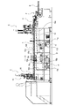
先ず本実施例に係る冷菓の製造装置の概略構成について図2を用いて説明する。本実施例に係る製造装置は、コーン1の開口部1aを下方に向けて矢印方向に間欠移送する第1コンベアAと、コーン1の開口部1aを上方に向けて間欠移送する第2コンベアBを有している。第1コンベアAと第2コンベアBは、コーン1に対するチョコレート層2の形成及びアイスクリーム3の盛り付けを連続して行うために連結されており、互いに同期して駆動されるように構成されている。
First, a schematic configuration of a frozen dessert manufacturing apparatus according to the present embodiment will be described with reference to FIG. The manufacturing apparatus according to the present embodiment includes a first conveyor A that intermittently transfers the
第1コンベアAの移送方向の最も上流側に可食容器供給装置となるコーン供給装置Cが配置され、該コーン供給装置Cよりも下流側にコーン1の内面に流動性食品供給装置となるチョコレート噴射装置Dが配置され、該チョコレート噴射装置Dよりも下流側にカップ供給装置Eが配置されている。
A corn feeder C serving as an edible container feeder is disposed most upstream in the transfer direction of the first conveyor A, and a chocolate serving as a fluid food feeder on the inner surface of the
また、第1コンベアAの下流側端部であって第2コンベアBとの連結部には移載装置Fが配置されており、該移載装置Fよりも下流側に粘性食品充填装置となるアイスクリーム充填装置Gが配置され、該アイスクリーム充填装置Gよりも下流側に冷却装置Hが配置され、該冷却装置Hよりも下流側にキャップ供給装置Iが配置されている。そして、第2コ
ンベアBの最も下流側に排出装置Jが配置されている。
Further, a transfer device F is disposed at the downstream end of the first conveyor A and at a connection portion with the second conveyor B, and becomes a viscous food filling device on the downstream side of the transfer device F. An ice cream filling device G is disposed, a cooling device H is disposed downstream of the ice cream filling device G, and a cap feeding device I is disposed downstream of the cooling device H. Then, the discharge device J is disposed on the most downstream side of the second conveyor B.
以下、製造装置を構成する各装置の構成を装置毎に説明する。 Hereinafter, the configuration of each device constituting the manufacturing device will be described for each device.
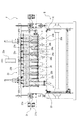
第1コンベアAは図3に示すように、開口部1aを下方に向けた(以下、単に「下向き」という)8個のコーン1を、一定のピッチで間欠移送し得るように構成されている。このため、第1コンベアAは、モーター11a、ゼネバ11bを有する間欠駆動機構11によって一定のピッチで間欠駆動される一対のチェン10を有している。
As shown in FIG. 3, the first conveyor A is configured to intermittently transfer eight
一対のチェン10には一定のピッチで複数のバー10aが配置されており、夫々のバー10aに8個の支持アーム10bが取り付けられている。支持アーム10bは下向きのコーン1の内面に接触して支持し得るように構成されており、チョコレート供給装置Dで噴射されたチョコレートによって形成されるチョコレート層2に対して悪影響を与えることがないような形状を有している。
A plurality of
第1コンベアAには、最も上流側にコーン供給装置Cが、その下流側にチョコレート噴射装置Dが、更に下流側にカップ供給装置Eが、下流側の端部に委細装置Fが配置される。特に、チョコレート噴射装置Dは間欠移送されるコーン1に向けて下方からチョコレートを噴射するため、第1コンベアAの移送レベルは、チョコレート噴射装置Dを設置するのに充分な高さを持って設定されている。
In the first conveyor A, the cone feeding device C is disposed most upstream, the chocolate jetting device D is disposed downstream thereof, the cup feeding device E is disposed further downstream, and the sorting device F is disposed at the downstream end. . In particular, since the chocolate jetting device D jets chocolate from below toward the
コーン供給装置Cは図4、図5に示すように、開口部1aを上方に向けて積層したコーン1を1個づつ取り出し、開口部1aが下方に向くように転回させて第1コンベアAの支持アーム10bに供給するものである。このため、コーン供給装置Cは、第1コンベアAのバー10aに取り付けられた支持アーム10bの数と同数のコーン収容部15と転回部16を有して構成されている。
As shown in FIGS. 4 and 5, the cone feeding device C takes out the
コーン収容部15は、複数のコーン1を収容する収容部15aと、収容部15aに収容されたコーン1を分離する分離部15bと、を有して構成されている。収容部15aは、開口部1aを上方に向けた複数のコーン1を積層した状態で収容するものであり、これらのコーン1を略垂直な状態で収容し得るように筒状に構成されている。
The
また、分離部15bは、収容部15aに収容されている複数のコーン1を下方から順に1個づつ分離するものであり、上下に配置された一対のシャッター15cを有している。そして、この一対のシャッター15cを転回部16の動作と同期して交互に開閉することで、積層された状態で収容されているコーン1を最も下方から順に分離し得るように構成されている。
Further, the separating
転回部16は、収容部15aに積層されて収容された最下端にあるコーン1を吸着して取り出し、転回させて開口部1aを下方に向け、第1コンベアAの支持アーム10bに接近させて吹き出すことで、該支持アーム10bに供給し得るように構成されている。このため、転回部16は、コーン1を吸着する吸着ヘッド16aと、吸着ヘッド16aを昇降させる昇降シリンダー16bと、吸着ヘッド16aを昇降させる過程でコーン1の開口部1aが下方に向くように転回させる転回部材16cと、を有して構成されている。
The turning
吸着ヘッド16aはコーン1の外形と略相似形に形成されており、第1コンベアAを横断する方向に配置されると共に昇降可能に構成された配管16dに取り付けられている。この吸着ヘッド16aは、配管16dに作用する負圧又は高圧に対応して、コーン1を吸着し又はコーン1を吹き出すように構成されている。このため、転回部16の上部には負圧が作用するバキュームホース16d1が配置されており、下部には高圧が作用するブローホース16d2が配置されている。
The
そして、吸着ヘッド16aが上昇したとき、配管16dはバキュームホース16d1と接続されて負圧が作用し、収容部15aに接近することでコーン1を吸着することが可能である。また、吸着ヘッド16aが下降したとき、配管16dはブローホース16d2と接続されて高圧が作用し、支持アーム10bに接近して吹き出すことでコーン1を供給することが可能である。
Then, when the
昇降シリンダー16bは吸着ヘッド16aを昇降ガイド16eに沿って昇降させるものである。この昇降シリンダー16bによる昇降過程で、吸着ヘッド16aは、収容部15aに接近させた上昇位置、支持アーム10bに接近させた下降位置、に位置し、上昇位置から下降位置に移行する間に中間部16fを通過する。特に、昇降シリンダー16bによって吸着カップ16aを中間部16fで昇降させる際に、転回部材16cによる吸着ヘッド16aの転回、及び配管16dに接続されるホース16d1、16d2の切り替えを行うように構成されている。
The raising and lowering
上記の如く構成されたコーン供給装置Cでは、昇降シリンダー16bによって吸着カップ16aを上昇位置に上昇させてバキュームホース16d1、配管16dを介して負圧を作用させることで、収容部15aに収容されたコーン1を取り出すことが可能である。そして、上昇位置から下降位置に移行する中間部16fを通過する間で、転回部材16cによって吸着ヘッド16aが転回してコーン1を上向きから下向きに転回させることが可能である。更に、中間部16fを通過したとき。配管16dにはブローホース16d2を介して高圧が作用し、第1コンベアAの支持アーム10bに対し、コーン1を下向きの状態で供給することが可能である。
In the cone supply device C configured as described above, the
チョコレート噴射装置Dは、第1コンベアAの支持アーム10bに支持されて移送されるコーン1の内面に、下方からチョコレートを噴射して付着させるものである。このチョコレート噴射装置Dから噴射されるチョコレートは保温されることで充分な流動性を有しており、コーン1の形状の如何に関わらず、万遍なく内面に付着することが可能であり、付着すると同時に固化を開始する。このため、コーン1の内面に充分に厚いチョコレート層2を形成することが可能である。
The chocolate spraying device D sprays and adheres chocolate from below onto the inner surface of the
チョコレート噴射装置Dは図3に示すように、コーン供給装置Cの下流側で第1コンベアAの移送レベルよりも下方で且つ上向きに配置された複数のノズル18aと、該ノズル18aよりも下方に配置されたチョコレートタンク18bを有している。ノズル18aとチョコレートタンク18bとは、ポンプ18c、配管18dによって接続されており、ポンプ18cを駆動することによってノズル18aからチョコレートを上方に噴射し得るように構成されている。
As shown in FIG. 3, the chocolate jetting device D is provided downstream of the cone feeding device C with a plurality of
ノズル18aから噴射されたチョコレートは流動性を有するため、第1コンベアAによって移送されている間に垂れることがある。このため、第1コンベアAの下方であってチョコレート噴射装置Dよりも下流側には、コーン1から垂れたチョコレートを回収する樋18eが配置されている。
Since the chocolate jetted from the
上記の如く構成されたチョコレート噴射装置Dでは、ポンプ18cを駆動することで、チョコレートタンク18bに貯留されているチョコレートをノズル18aから上方に向けて噴射してコーン1の内面に付着させることが可能である。そして、コーン1の内面に付着して固化することのない余分のチョコレートは、第1コンベアAによる移送中にコーン1から垂れて樋18eに落下し、チョコレートタンク18bに回収される。
In the chocolate injection device D configured as described above, by driving the
カップ供給装置Eは、第1コンベアAの支持アーム10bに下向きに支持されて内面にチョコレート層2が形成されたコーン1の外周に合成樹脂製のカップ4を被せるものである。カップ4は合成樹脂による成形品であるため、成形後、アイスクリームの製造装置までの搬送過程で異物が付着する虞がある。このため、コーン1の外周に被せる直前にカップ4の内部に付着した異物を除去し、その後、第1コンベアAによって移送されるコーン1の外周に被せるようにしている。
The cup supply device E is supported by the
カップ供給装置Eに於けるカップ4を下向きで移送されるコーン1の外周に被せるための構造は、前述したコーン供給装置Cと類似しているため、該コーン供給装置Cと類似した機能を有する部分には同一の符号を付して簡単に説明する。尚、カップ供給装置Eでは、収容した複数のカップ4を転回して供給する機構に加えて、カップ4に付着している虞のある異物を除去するための異物除去装置19が配置されている。
The structure for covering the
即ち、カップ供給装置Eは図6に示すように、第1コンベアAのバー10aに取り付けられた支持アーム10bの数と同数のカップ収容部15と転回部16、及び異物除去装置19を有して構成されている。
That is, as shown in FIG. 6, the cup supply device E has the same number of
カップ収容部15は、上向きで積層された複数のカップ4を収容する収容部15aと、積層されたカップ4を一対のシャッター15cによって下から順に1個づつ分離する分離部15bとを有して構成されている。
The
転回部16は、カップ4を吸着する吸着ヘッド16aと、吸着ヘッド16aを昇降させる昇降シリンダー16bと、吸着ヘッド16aを昇降させる過程でカップ4が下方に向くように転回させる転回部材16cと、を有して構成されている。この転回部16では、収容部15aの最下端にあるカップ4を吸着して取り出し、下向きに転回させて第1コンベアAによって移送されるコーン1の外周に被せることが可能である。
The turning
昇降シリンダー16bは吸着ヘッド16aを昇降ガイド16eに沿って昇降させるものである。この昇降シリンダー16bによる昇降過程で、吸着ヘッド16aは、収容部15aに接近させた上昇位置、支持アーム10bに接近させた下降位置、に位置し、上昇位置から下降位置に移行する間に中間部16fを通過する。特に、昇降シリンダー16bによって吸着カップ16aを中間部16fで昇降させる際に、転回部材16cによる吸着ヘッド16aの転回、及び配管16dに接続されるホース16d1、16d2の切り替えを行うように構成されている。
The raising and lowering
異物除去装置19は、カップ4が中間部16fを通過する際に略水平な姿勢となる位置に対向して配置されている。この異物除去装置19は空気をイオン化するイオナイザ19aと、イオン化した空気の噴射ノズル19bを有して構成されている。そして、イオナイザ19aでイオン化した空気を噴射ノズル19bから略水平なカップ4に噴射することで、カップ4に帯電した静電気を除電すると共に吹き飛ばして、該カップ4に付着した虞のある異物を除去することが可能である。
The foreign
上記の如く構成されたカップ供給装置Eでは、昇降シリンダー16bによって吸着カップ16aを上昇位置に上昇させてバキュームホース16d1、配管16dを介して負圧を作用させることで、収容部15aに収容されたカップ4を取り出すことが可能である。そして、上昇位置から下降位置に移行する中間部16fを通過する間で、転回部材16cによって吸着ヘッド16aが転回してコーン1を上向きから下向きに転回することが可能である。更に、中間部16fを通過したとき。配管16dにはブローホース16d2を介して高圧が作用し、第1コンベアAの支持アーム10bに対し、カップ4を上向きから下向きに転回させ、第1コンベアAによって移送されるコーン1と対向したとき、配管16dに高圧を作用させることで、コーン1の外周にカップ4を被せることが可能である。
In the cup supply device E configured as described above, the
そして、転回部16の中間部16fに於ける更なる転回によってカップ4を下向きに転回させ、該中間部16fを通過したとき。配管16dにはブローホース16d2を介して高圧が作用し、第1コンベアAの支持アーム10bに支持されたコーン1の外周にカップ4を被せることが可能である。
Then, when the
内面にチョコレート層2が形成され、外周にカップ4が被せられたコーン1は、第2コンベアBに移載されてアイスクリーム3が充填される。このため、第2コンベアBでは外周にカップ4が被せられたコーン1は、開口部1aを上方に向けた上向きの姿勢で移送され、この移送過程で、アイスクリーム3の充填、盛り付け、冷却、キャップ5の被害が行われ、下流側から排出される。
The
移載装置Fは、第1コンベアAによって下向きで移送された外周にカップ4が被せられたコーン1を、カップ4を含めて上向きになるように転回して第2コンベアBに移載する。このため、移載装置Fは第1コンベアAの移送方向下流端と、第2コンベアBの上流端との間に両コンベアA、Bを接続して配置されている。
The transfer device F transfers the
外周にカップ4が被せられたコーン1(以下単に「コーン1」ということがある)は、移載装置Fによって下向きから上向きに転回する。このため、第2コンベアBの移送レベルは、コーン1の転回に必要とされる高さ方向の寸法に対応させて、第1コンベアAの移送レベルよりも低く設定されている。
A cone 1 (hereinafter sometimes simply referred to as "
第2コンベアBは、図3、図8に示すように、一対のチェン20を有しており、このチェン20を横断して支持プレート20aが取り付けられている。そして、支持プレート20aには上向きに転回したコーン1(カップ4)を受け入れて支持するために複数の支持穴20bが形成されている。支持プレート20aに形成された支持穴20bは、第1コンベアAのバー10aに設けた支持アーム10bと同じ数で且つ同じピッチで形成されている。
As shown in FIGS. 3 and 8, the second conveyor B has a pair of
移載装置Fは、第1コンベアAによって移送されたコーン1が、該第1コンベアAの下流側端部で下向きの姿勢から略水平な姿勢に移行したとき、支持アーム10bから離脱させて第2コンベアBに移載するものである。そして、コーン1は、第1コンベアAの支持アーム10bから第2コンベアBの支持プレート20aに形成された支持穴20bに移載される過程で、開口部1aが上方にある上向き状態となる。
The transfer device F is disengaged from the
このため、移載装置Fは、図7、図8に示すように、第1コンベアAの下流側端部と対向して配置され該第1コンベアAによって移送されたコーン1を受け取って第2コンベアBの移送方向に移動させて取り出す取出部材21と、上向きに転回したコーン1を第2コンベアBの支持プレート20aに形成した支持穴20bに供給する供給部材23と、を有して構成されている。
For this reason, as shown in FIGS. 7 and 8, the transfer device F is disposed to face the downstream end of the first conveyor A, and receives the
取出部材21は、第2コンベアBを横断して配置された摺動板21aと、この摺動板21aを第2コンベアBの移送方向に沿って往復移動させる往復シリンダー21bと、コーン1を受け取る受取部材24を有している。
The take-
摺動板21aの上面には供給部材23を構成する供給シリンダー23aが配置されており、該供給シリンダー23aのシリンダーロッドにブラケット23bが取り付けられている。このブラケット23bには複数のロッド23cが配置され、これらのロッド23cに取出部材21を構成する受取部材24が取り付けられている。
The
受取部材24は、供給部材23を構成するロッド23cの下端部に取り付けた複数の保持プレート24aと、保持プレート24aの先端(第1コンベアA側の端部)の両側に取り付けたバー24bと、を有して構成されている。この受取部材24は、取出部材21によって第2コンベアBの移送方向に沿って往復移動可能に、且つ供給部材23によって昇降可能に構成されている。
The receiving
受取部材24の隣接する保持プレート24aの間隔は、カップ4の外径と略等しい寸法を有しており、コーン1をカップ4の外側を挟んで保持することが可能である。このため、保持プレート24aは、第1コンベアAのバー10aに設けた支持アーム10bの数よりも1個多い数に設定されている。
The distance between the
各保持プレート24aの先端(第1コンベアA側の端部)の両側には、夫々バー24bが略垂直に起立して取り付けられている。隣接する保持プレート24aの対向する位置に設けたバー24bどうしの間隔はコーン1の開口部1aの外径よりも僅かに小さい寸法を有している。従って、第1コンベアAによって移送されたコーン1の開口部1aと当接することが可能となる。
上記の如く構成された受取部材24では、バー24bによってコーン1を第1コンベアAの支持アーム10bから離脱させた(取り出した)とき、該コーン1は保持プレート24aに保持されて自由な転回が許容される。しかし、コーン1の自由な転回を許容したのでは、転回後の上向き姿勢を安定して実現することが困難となる虞がある。
In the receiving
このため、コーン1の転回を規制して確実に上向きになるように、取出部材21の摺動板21aの下面には、コーン1を取り出したときにカップ4の端部と接触し、該端部が下方に向かうように案内するガイドバー22aが設けられている。また、保持プレート24aにはコーン1に被せたカップ4の外周面と接触して確実に上向きに転回するように案内する三角形状のガイドプレート22bが設けられている。
For this reason, the lower surface of the sliding
上記の如く構成された移載装置Fによるコーン1の移載段階について図9〜図11により説明する。
The transfer stage of the
図9(a)は、移載装置Fの初期位置であり、受取部材24は取出部材21の往復シリンダー21bによって最も第1コンベアAに接近した位置にあり、且つ供給部材23の昇降シリンダー23aによって下降位置にある。このとき、第2コンベアBは停止しており、第1コンベアAが稼働している。
9A shows an initial position of the transfer device F, the receiving
第1コンベアAによる支持アーム10bの間欠移送に伴って、同図(b)に示すように、コーン1は下向きの姿勢から略水平の姿勢に変化する。コーン1の姿勢が下向きから水平に変化するのと同時に受取部材24が上昇し、受取部材24の隣接するバー24bの間にコーン1が入り込み、バー24bが開口部1aに係合する。
Along with the intermittent transfer of the
第1コンベアAの移送が停止すると、図10(a)に示すように、取出部材21の往復シリンダー21bによって摺動板21aが第2コンベアBの移送方向下流側に向かって移動する。この移動に伴って受取部材24も移動し、バー24bがコーン1の開口部1aに当接して該コーン1を支持アーム10bから離脱させる。従って、コーン1を第1コンベアAから取り出すこととなる。
When the transfer of the first conveyor A is stopped, as shown in FIG. 10A, the sliding
コーン1が支持アーム10bから取り出されたとき、該コーン1は自由に落下することとなる。例えば、カップ4が第2コンベアBの移送方向下流側に向けて勢いよく飛び出したような場合、端部がガイドバー22aに接触して規制される。また、下方に落下したときはカップ4の外周面の一部がガイドプレート22bに接触することで、該ガイドプレート24bの傾斜面に沿って転回する。
When the
そして、同図(b)に示すように、コーン1は開口部1aを上方にした上向き姿勢をとった状態で、隣接する保持プレート24aによってカップ4が挟まれ、安定した姿勢を保持することが可能である。
And as shown to the figure (b), the
次いで、図11(a)に示すように、供給部材23の昇降シリンダー23aによって受取部材24が下降し、待機していた第2コンベアBの支持プレート20aに形成された支持穴20bにコーン1を供給する。その後、同図(b)に示すように、受取部材24の下降位置を保持して第2コンベアBが間欠移送され、この移送過程で保持プレート24aに挟まれたコーン1は、該保持プレート24aから離脱する。
Next, as shown in FIG. 11A, the receiving
上記の如くして1サイクルが終了した後、取出部材21の往復シリンダー21bによって、受取部材24を第1コンベアAの下流側端部に接近させることで、受取部材24が初期位置に復帰する。
After one cycle is completed as described above, the receiving
移載装置Fよりも第1コンベアBの移送方向下流側にアイスクリーム充填装置Gが配置されている。このアイスクリーム充填装置Gは、充填ノズルを旋回させつつ上昇させることによって、上向きで移送されてきたコーン1にアイスクリーム3を充填すると共に開口部1aよりも上部に所望の形状で盛り上がるように盛り付けることが可能である。
An ice cream filling device G is disposed downstream of the transfer device F in the transfer direction of the first conveyor B. The ice cream filling device G fills the
充填ノズルの構造は特に限定するものではなく、1個の吐出口を有する構造であって良く、並列させた2個以上の吐出口、或いは同心円状に配置した2個以上の吐出口を有する構造であって良い。そして、充填ノズルを構成する吐出口の数及び旋回径、旋回速度、上昇速度、アイスクリームの充填速度等の条件を適宜設定することによって、コーン1にアイスクリームを渦巻状に、或いは円錐状に盛り付けることが可能である。
The structure of the filling nozzle is not particularly limited, and may be a structure having one discharge port, and a structure having two or more discharge ports arranged in parallel or two or more discharge ports arranged concentrically. It is good. Then, by appropriately setting the number of discharge ports constituting the filling nozzle and the conditions such as the turning diameter, turning speed, rising speed, filling speed of ice cream, etc., the ice cream is spirally or conically formed on the
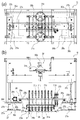
このため、アイスクリーム充填装置Gは、図12〜図14に示すように、充填ノズル26を第2コンベアBの移送方向(Y方向)に沿って往復移動させるY方向移動装置28と、第2コンベアBの移送方向に対し直交する方向(X方向)に往復移動させるX方向移動装置29と、上下方向に昇降させる昇降装置30と、を有して構成されている。
For this reason, as shown in FIGS. 12 to 14, the ice cream filling device G reciprocates the filling
上記したY方向移動装置28、X方向移動装置29、昇降装置30は、第2コンベアBを横断して構成されたフレーム27に配置されている。このフレーム27は、第2コンベアBを横断して両側に取り付けられたブラケット27aと、該ブラケット27aから垂直に起立して配置された4本のスタンド27bと、4本のスタンド27bの頂部を連結して第2コンベアBを横断して設けたプレート27cと、を有している。従って、フレーム27は第2コンベアBを横断する方向に門型に形成されている。
The Y-
フレーム27の夫々のブラケット27aに於ける第2コンベアBの移送方向に沿って配置された2本のスタンド27bの中間部には、昇降装置30を構成するねじ30aが垂直方向に起立して配置されている。このねじ30aは上端部がプレート27cを貫通して配置されており、該プレート27cに取り付けた昇降モータ30bと図示しないタイミングベルト等の伝動部材を介して接続されている。そして、ねじ30aは昇降モータ30bによって正回転駆動又は逆回転駆動される。
At an intermediate portion of two
また、スタンド27bには昇降台30cが昇降可能に取り付けられている。この昇降台30cは昇降装置30を構成するものであり、所定位置にねじ30aと螺合したナット30dが取り付けられている。従って、昇降台30cは昇降モータ30bの回転方向に対応して上昇又は下降することが可能である。
Further, a
上記の如くしてスタンド27bに昇降可能に取り付けられた昇降台30cに、Y方向移動装置28及びX方向移動装置29が夫々構成されている。
The Y-
昇降台30cは、図14に示すように、第2コンベアBによる移送方向であるY方向に沿って形成された平行部30c1と、第2コンベアBを横断する方向であるX方向に形成された横断部30c2と、からなる平面視がコ字状に形成されている。
As shown in FIG. 14, the
昇降台30cの平行部30c1及び横断部30c2には、X方向移動装置29を構成する複数のX方向直線ガイド29aがX方向に沿って、予め設定された位置に配置されている。前記複数のX方向直線ガイド29aを接続して、同図に二点鎖線で示すように平面視がコ字状に形成されたX方向移動台29bが配置されている。
On the parallel portion 30c1 and the transverse portion 30c2 of the
また、横断部30c2にはX方向に沿って正回転及び逆回転可能なX方向駆動モータ29cと、該X方向駆動モータ29cによって駆動されるねじ29dが配置されている。そして、ねじ29dに螺合したナット29eがX方向移動台29bと連結されている。
In addition, an
このため、X方向駆動モータ29cが正回転又は逆回転可したとき、X方向移動台29bがX方向直線移動ガイド29aに案内されてX方向、即ち、第2コンベアBの移送方向を横断する方向に移動することが可能である。従って、X方向駆動モータ29cの回転方向を適宜転換することによって、X方向移動台29bはX方向に沿って往復移動する。
For this reason, when the
X方向移動台29bにはY方向に沿って一対のY方向直線ガイド28aが配置されている。このY方向直線ガイド28aを接続して、同図に示すように平面視がコ字状のY方向移動台28bが配置されている。
A pair of Y-direction straight guides 28a are disposed along the Y-direction on the
また、X方向移動台29bにはY方向に沿って正回転及び逆回転可能なY方向駆動モータ28cと、該Y方向駆動モータ28cによって駆動されるねじ28dが配置されている。そして、ねじ28dに螺合したナット28eがY方向移動台28bと連結されている。従って、Y方向駆動モータ28bの回転方向を適宜転換することによって、Y方向移動台28bはY方向に沿って往復移動する。
Further, on the
上記構成に於いて、各モータ28c、29c、30b、ねじ28d、29d、30a、ナット28e、29e、30dの構造を限定するものではない。しかし、意匠性の高いアイスクリームの盛り付けを行うためには各モータ28c、29c、30bをサーボモータとし、各ねじ28d、29d、30aをボールねじとし、各ナット28e、29e、30dをボールナットとすることが好ましい。このように構成することで、動きの精度及び応答精度を向上させることが可能となる。
In the above configuration, the structures of the
前述したY方向移動台28bにはアイスクリーム3を吐出してコーン1に充填するための充填ノズル26が配置されている。この充填ノズル26は、第2コンベアBの支持プレート20aに形成された支持穴20bと同数で且つ各支持穴20bに対向し得る間隔で配置されている。
The filling
各充填ノズル26は、バルブ31aを構成する筒状の本体に取り付けられている。このバルブ31aには2系列の供給孔が形成されており、夫々の供給孔には弁シリンダー31bによって回動される回転式の弁部材が収容されている。また、バルブ31aには、夫々の充填ノズル26の位置に対応させて、アイスクリームを供給するための配管31cが接続されている。
Each filling
このため、2系列の配管31cを介して各供給孔に異なるアイスクリームを供給し、弁シリンダー31bによって弁部材を同時に、或いは選択的に回動させることでアイスクリームの吐出、停止を制御することが可能である。従って、各供給孔に供給された異なるアイスクリームを、充填ノズル26から同時に或いは選択的に吐出することが可能である。
For this reason, different ice cream is supplied to each supply hole via two series of
上記の如く構成されたアイスクリーム充填装置Gでは、配管31c、バルブ31aにアイスクリームを供給し、弁シリンダー31bを開放操作することによって、供給されたアイスクリームを充填ノズル26から吐出させてコーン1に充填することが可能である。そして、充填ノズル26からコーン1にアイスクリームを充填させつつ、各モータ28c、29c、30bを駆動することで、充填ノズル30は各モータ28c、29c、30bの回転に伴って旋回、或いはX方向又はY方向に往復移動しつつ上昇することが可能となる。
In the ice cream filling device G configured as described above, the ice cream is supplied to the
従って、予め設定された意匠に対応させて各モータ28c、29c、30bの回転を制御すると共に単独種の、或いは異なる種類のアイスクリームの吐出を制御することで、アイスクリームを渦巻状に或いは円錐状に盛り付けることが可能である。
Therefore, by controlling the rotation of each of the
アイスクリーム充填装置Gよりも第2コンベアBの移送方向下流側には、冷却装置Hが配置されている。この冷却装置Hは、アイスクリーム充填装置Gに於いてコーン1に盛り付けられたアイスクリーム4を冷却して形状を保持させるための装置である。尚、アイスクリーム4を冷却するための冷媒としては特に限定するものではないが、本実施例では液体窒素を利用している。
A cooling device H is disposed downstream of the ice cream filling device G in the transfer direction of the second conveyor B. The cooling device H is a device for cooling the
冷却装置Hは、図15に示すように、第2コンベアBを横断し且つ移送方向に沿って予め設定された長さを持って形成されたフード35を有している。フード35の上部には、液体窒素を収容すると共に収容された液体窒素の液面を管理することが可能で、且つ気化した窒素ガスの流量を調節し得るように構成したタンク36aが配置されている。また、フード35の内部には、第2コンベアBによって移送されるコーン1に盛り付けたアイスクリーム3に対して窒素ガスを噴射する複数のノズル36bが配置されている。そして、タンク36aとノズル36bを接続して配管36cが配置されている。
The cooling device H, as shown in FIG. 15, has a
フード35は内部に噴射された窒素ガスによる冷却効果を充分に発揮させるために、略密閉に近い空間として形成されている。このため、フード35の所定位置には排気ダクト37が構成されており、該フード35の内部に噴射された窒素ガスを排気ダクト37を介して大気中に排気し得るように構成されている。また、フード35に於ける移送方向上流側及び下流側には、第2コンベアBによって移送されるコーン1に盛り付けたアイスクリーム3を回避するための開口35aが形成されている。
The
上記の如く構成された冷却装置Hでは、第2コンベアBによって移送されるアイスクリーム3を盛り付けたコーン1をフード35の内部を通過させ、この過程でノズル36bから窒素ガスを噴射することによって、アイスクリーム3を冷却することが可能である。特に、タンク36aに収容した液体窒素から気化した極めて低温の窒素ガスを噴射することが可能であるため、アイスクリーム3の表面を固化させて盛り付けた形状を保持することが可能となる。
In the cooling device H configured as described above, the
冷却装置Hよりも第2コンベアBの移送方向下流側に、キャップ供給装置Iが配置されている。このキャップ供給装置Iは、第2コンベアBによって移送され、冷却装置Hによって冷却されて盛り付け形状を保持したアイスクリーム3の上部を、キャップ5によって被蓋するものである。
The cap supply device I is disposed downstream of the cooling device H in the transfer direction of the second conveyor B. The cap feeding device I is transferred by the second conveyor B, and is covered by the
キャップ供給装置Iの構造は前述したカップ供給装置Eの構造と略同一であるため、同一の部分又は類似の部分には同一の符号を付して説明を省略する。 Since the structure of the cap supply device I is substantially the same as the structure of the cup supply device E described above, the same parts or similar parts will be assigned the same reference numerals and descriptions thereof will be omitted.
キャップ供給装置Iは図16に示すように、第2コンベアBの支持プレート20aに形成された取り付けられた支持穴20bの数と同数のキャップ収容部15と転回部16、及び異物除去装置19を有して構成されている。
As shown in FIG. 16, the cap feeding device I includes the same number of
キャップ収容部15は、上向きで積層された複数のキャップ5を収容する収容部15aと、積層されたキャップ5を一対のシャッター15cによって下から順に1個ずつ分離する分離部15bとを有して構成されている。
The
転回部16は、キャップ5を吸着する吸着ヘッド16aと、吸着ヘッド16aを昇降させる昇降シリンダー16bと、吸着ヘッド16aを昇降させる過程でキャップ5が下方に向くように転回させる転回部材16cと、を有して構成されている。この転回部16では、収容部15aの最下端にあるキャップ5を吸着して取り出し、下向きに転回させて第2コンベアBによって移送されるコーン1に盛り付けられたアイスクリーム3の上部に被蓋することが可能である。
The turning
昇降シリンダー16bは、吸着ヘッド16aを、上昇位置及び下降位置、上昇位置から下降位置に移行する間を通過するように昇降させるものである。そしてこの昇降過程で、吸着ヘッド16aの転回、及び配管16dに作用する圧力の切り替え、更に異物除去装置19によるキャップ5に付着した虞のある異物の除去を行うように構成されている。
The raising and lowering
上記の如く構成されたキャップ供給装置Iでは、昇降シリンダー16bによって吸着カップ16aを上昇位置に上昇させて収容部15aに収容されたキャップ5を取り出すことが可能である。そして、中間部16fを通過する間で、コーン1を上向きから下向きに転回することが可能である。そして、キャップ5が略水平な姿勢を有する間に、異物除去装置19によって該キャップ5に付着している虞のある異物を除去することが可能である。
In the cap supply device I configured as described above, it is possible to lift the
更に、中間部16fを通過したとき、キャップ5を下向きに転回させ、第2コンベアBによって移送されるコーン1と対向したとき、該コーン1に盛り付けたアイスクリーム3にキャップ5によって被蓋することが可能である。
Furthermore, when passing through the
キャップ供給装置Iの第2コンベアBの移送方向下流側であって、該第2コンベアBの末端部には排出装置Jが配置されている。この排出装置Jは、外周にカップ4が被せられ、内部にチョコレート層2が形成されると共にアイスクリーム3が盛り付けられてキャップ5が被蓋されたコーン1(製造された氷菓)を次工程に排出するものである。排出装置Jの構造は特に限定するものではなく、第2コンベアBによって移送されたコーン1を該第2コンベアBから排出し得るものであれば良い。
A discharge device J is disposed at the end of the second conveyor B at the downstream side of the second conveyor B in the transfer direction of the cap supply device I. In this discharge device J, a
本実施例では、図17に示すように、第2コンベアBの移送方向下流側端部に、第3コンベア40を直交する方向に配置し、第2コンベアBと第3コンベア40を跨いで門型のフレーム41を構成している。
In the present embodiment, as shown in FIG. 17, the
フレーム41には第2コンベアBの移送方向と同方向に往復移動可能な移送ヘッド42が配置されている。この移送ヘッド42はフレーム41に第2コンベアBの移送方向と並行に設置した直線ガイド43aに搭載されており、該直線ガイド43aと平行にねじ43bが配置されている。ねじ43bは移送モータ43cによって正回転或いは逆回転駆動される。そして、ねじ43bに螺合したナット(図示せず)が移送ヘッド42に接続されることで、移送モータ43cの回転に伴って、第2コンベアBの移送方向と同方向に、或いは逆方向に移動することが可能である。
A
また、移送ヘッド42には複数の吸着カップ42aが配置されており、夫々の吸着カップ42aに負圧が作用し得るように構成されている。更に、移送ヘッド42は昇降シリンダー42bを有しており、該昇降シリンダー42bによって吸着カップ42aを昇降させることが可能なように構成されている。
Further, a plurality of
移送ヘッド42に配置した吸着カップ42aの数は限定するものではなく、第1コンベアA、第2コンベアBに於けるサイクルタイムを考慮して適宜設定することが好ましい。本実施例では、吸着カップ42aは一度に3枚の支持プレート20aからコーン1を排出し得るように、支持プレート20aに形成した支持穴20bの数8個との積である24個配置している。
The number of
上記の如く構成された製造装置では、コーン1の形状の如何に関わらず、第1コンベアAによる移送過程で下向きにしたコーン1の内面に充分な厚さのチョコレート層2を形成することが可能である。そして、第2コンベアBに移載する際には、両コンベアA、Bを跨いで配置された移載装置Fによって、第1コンベアAでは下向きに移送されてきたコーン1を確実に上向きに転回させて第2コンベアBに移載することが可能である。
In the manufacturing apparatus configured as described above, regardless of the shape of the
また、第2コンベアBによる移送過程で、アイスクリーム充填装置Gに於いて充填ノズル30を旋回させ、或いは旋回させることなく、アイスクリームを吐出してコーン1に充填すると共に盛り付けることが可能である。特に、アイスクリーム充填装置Gを構成する各モータ28c、29c、30bの回転方向及び回転数、バルブ31aの開閉動作を適宜制御することで高度な意匠性を発揮してアイスクリームを盛り付けることが可能である。
Further, in the transfer process by the second conveyor B, the ice cream can be discharged and filled into the
本発明に係る氷菓の製造装置は、ウエハースやワッフル等からなるコーンの内面にチョコレートに代表される流動性を有する食品層を形成すると共にアイスクリームに代表される粘性を有する食品を意匠性を考慮して盛り付けて製造する際に利用して有利である。 The apparatus for producing ice confectionery according to the present invention forms a food layer having fluidity such as chocolate on the inner surface of a cone made of wafers, waffles, etc., and takes into consideration the design of food having viscosity typified by ice cream. It is advantageous to use it when making and serving.
A 第1コンベア
B 第2コンベア
C コーン供給装置
D チョコレート噴射装置
E カップ供給装置
F 移載装置
G アイスクリーム充填装置
H 冷却装置
I キャップ供給装置
J 排出装置
1 コーン
1a 開口部
2 チョコレート層
3 アイスクリーム
4 カップ
5 キャップ
10 チェン
10a バー
10b 支持アーム
11 間欠駆動機構
11a モーター
11b ゼネバ
15 コーン収容部
15a 収容部
15b 分離部
15c シャッター
16 転回部
16a 吸着ヘッド
16b 昇降シリンダー
16c 転回部材
16d 配管
16d1 バキュームホース
16d2 ブローホース
16e 昇降ガイド
16f 中間部
18a ノズル
18b チョコレートタンク
18c ポンプ
18d 配管
18e 樋
19 異物除去装置
19a イオナイザ
19b 噴射ノズル
20 チェン
20a 支持プレート
20b 支持穴
21 取出部材
21a 摺動板
21b 往復シリンダー
22a ガイドバー
22b ガイドプレート
23 供給部材
23a 供給シリンダー
23b ブラケット
23c ロッド
24 受取部材
24a 保持プレート
24b バー
26 充填ノズル
27 フレーム
27a ブラケット
27b スタンド
27c プレート
28 Y方向移動装置
28a Y方向直線ガイド
28b Y方向移動台
28c Y方向駆動モータ
28d ねじ
28e ナット
29 X方向移動装置
29a X方向直線ガイド
29b X方向移動台
29c X方向駆動モータ
29d ねじ
29e ナット
30 昇降装置
30a ねじ
30b 昇降モータ
30c 昇降台
30c1 平行部
30c2 横断部
30d ナット
31a バルブ
31b 弁シリンダー
31c 配管
35 フード
36a タンク
36b ノズル
36c 配管
37 排気ダクト
40 第3コンベア
41 フレーム
42 移送ヘッド
42a 吸着カップ
42b 昇降シリンダー
43a 直線ガイド
43b ねじ
43c 移送モータ
A 1st conveyor B 2nd conveyor C cone supply device D chocolate injection device E cup supply device F transfer device G ice cream filling device H cooling device I cap supply device J discharge device 1 cone 1a opening 2 chocolate layer 3 ice cream 4 cup 5 cap 10 chain 10a bar 10b support arm 11 intermittent drive mechanism 11a motor 11b geneva 15 cone housing part 15a housing part 15b separating part 15c shutter 16 turning part 16a suction head 16b raising and lowering cylinder 16c turning member 16d piping 16d1 vacuum hose 16d2 blow Hose 16e Lifting guide 16f Middle part 18a Nozzle 18b Chocolate tank 18c Pump 18d Piping 18e 樋 19 Foreign matter removal device 19a Ionizer 19b Spray nozzle 20 chain 20a support plate 20b support hole 21 takeout member 21a slide plate 21b reciprocation cylinder 22a guide bar 22b guide plate 23 supply member 23a supply cylinder 23b bracket 23c rod 24 receiving member 24a holding plate 24b bar 26 filling nozzle 27 frame 27a bracket 27b stand 27c plate 28 Y direction moving device 28a Y direction linear guide 28b Y direction moving table 28c Y direction drive motor 28d screw 28e nut 29 X direction moving device 29a X direction linear guide 29b X direction movement stand 29c X direction drive motor 29d screw 29e Nut 30 Lifting device 30a Screw 30b Lifting motor 30c Lifting foot 30c1 Parallel part 30c2 Crossing part 30d Nut 31a Valve 31b Valve cylinder 31c piping 35 hood 36a tank 36b nozzle 36c piping 37 exhaust duct 40 third conveyor 41 frame 42 transfer head 42a suction cup 42b lifting cylinder 43a linear guide 43b screw 43c transfer motor
Claims (3)
可食容器の開口部を下方に向けて支持する複数の支持アームを有し、該支持アームを間欠移送する第1コンベアと、
前記第1コンベアの移送方向上流側に配置され、可食容器を開口部を下方に向けて該第1コンベアの支持アームに供給する可食容器供給装置と、
前記可食容器供給装置よりも前記第1コンベアの移送方向下流側に配置され、開口部を下方に向けて移送される可食容器の内面に流動性を有する食品を噴射して付着させる流動性食品供給装置と、
前記流動性食品供給装置よりも前記第1コンベアの移送方向下流側に配置され、開口部を下方に向けて移送される可食容器の上方からカップを供給して該可食容器の外周に被せるカップ供給装置と、
前記第1コンベアの移送方向下流側の端部に接続され、外周にカップが被せられた複数の可食容器を開口部を上方に向けて支持する支持プレートを有する第2コンベアと、
前記第1コンベアの下流側端部と前記第2コンベアの上流側端部の上方にわたって配置され、前記第1コンベアによって開口部を下方に向けて移送され外周にカップが被せられた可食容器を転回させて開口部を上方に向けて前記第2コンベアの支持プレートに移載する移載装置と、
前記移載装置よりも前記第2コンベアの移送方向下流側に配置され、開口部を上方に向けて移送される可食容器に粘性を有する食品を充填する粘性食品充填装置と、
前記粘性食品充填装置よりも前記第2コンベアの移送方向下流側に配置され、可食容器に充填された粘性食品を冷却する冷却装置と、
前記冷却装置よりも第2コンベアの移送方向下流側に配置され、可食容器に充填されて冷却された粘性食品の上方からキャップを供給して被蓋するキャップ供給装置と、
前記第2コンベアの移送方向下流側端部に配置され、内面に流動性食品が付着すると共に粘性食品が充填され且つ外周にカップが被せられると共にキャップによって被蓋された可食容器を、該第2コンベアから排出する排出装置と、
を有することを特徴とする冷菓の製造装置。 An apparatus for producing a frozen dessert by coating a food having fluidity and filling a food having viscosity with an inner surface of a bottomed edible container comprising cone-shaped corn, comprising:
A first conveyor having a plurality of support arms supporting the opening of the edible container downward, and intermittently transferring the support arms;
An edible container supply device, disposed upstream of the first conveyor in the transfer direction, for supplying the edible container with the opening downward to the support arm of the first conveyor;
Fluidity that is disposed on the downstream side of the transport direction of the first conveyor with respect to the edible container feeding device and sprays and adheres the food having fluidity to the inner surface of the edible container transported with the opening directed downward A food supply device,
The cup is provided from above the edible container which is disposed downstream of the fluid food supply device in the transfer direction of the first conveyor and the opening portion is directed downward, and the cup is covered on the outer periphery of the edible container A cup feeding device,
A second conveyor having a support plate connected to an end of the first conveyor on the downstream side in the transfer direction and supporting a plurality of edible containers with cups covered on the outer periphery with the openings facing upward;
The food container is disposed over the downstream end of the first conveyor and the upstream end of the second conveyor, and the opening is transferred downward by the first conveyor and the cup is covered on the outer periphery. A transfer device which transfers the load onto the support plate of the second conveyor with the opening directed upward by turning it;
A viscous food filling apparatus which is disposed on the downstream side of the transfer direction of the second conveyor with respect to the transfer apparatus, and which is provided with a food having viscosity in an edible container transported with the opening upward;
A cooling device disposed downstream of the viscous food filling device in the transfer direction of the second conveyor and cooling the viscous food filled in the edible container;
A cap feeding device disposed downstream of the cooling device in the transfer direction of the second conveyor and feeding a cap from above the viscous food filled in the edible container and cooled;
The edible container is disposed at the downstream end in the transfer direction of the second conveyor, has fluid food adhered to the inner surface, is filled with viscous food, is covered with a cup on the outer periphery, and is covered with a cap; 2 Ejection device to eject from the conveyor,
A manufacturing apparatus of frozen dessert characterized by having.
外周にカップが被せられた可食容器が前記第1コンベアの下流側の端部で開口部が下方に向けて支持された状態から水平状態に移行する過程で該カップの開口端部と係合して可食容器を受け取ると共に前記第2コンベアの移送方向に移動させて前記第1コンベアから取り出す取出部材と、
前記取出部材による可食容器の取り出しに伴って開口部を上方に向けて転回した可食容器を前記第2コンベアの支持プレートに供給する供給部材と、
を有して構成されていることを特徴とする請求項1に記載した冷菓の製造装置。 The transfer device is
The edible container having the cup covered on the outer periphery engages with the open end of the cup in the process of transitioning from the state where the opening is supported downward at the downstream end of the first conveyor to the horizontal state A pick-up member for receiving the edible container and moving it in the transfer direction of the second conveyor and taking it out of the first conveyor;
A feeding member configured to feed the edible container, the opening of which is turned upward with the removal of the edible container by the removal member, to the support plate of the second conveyor;
The manufacturing apparatus of the frozen dessert according to claim 1, characterized in that it is configured to have.
前記第2コンベアによって移送される可食容器に粘性食品を充填する充填ノズルと、
前記第2コンベアによる移送平面内に於いて、該第2コンベアの移送方向に沿って前記充填ノズルを往復移動させる移送方向往復部材と、
前記第2コンベアによる移送平面内に於いて、該第2コンベアの移送方向に対し直交する方向に前記充填ノズルを往復移動させる直交方向往復部材と、
前記第2コンベアによる移送平面内に対し、前記充填ノズルを昇降させる昇降部材と、
を有することを特徴とする請求項1又は2に記載した冷菓の製造装置。 The filling device is
A filling nozzle for filling sticky food into an edible container transported by the second conveyor;
A transfer direction reciprocating member configured to reciprocate the filling nozzle along a transfer direction of the second conveyor within a transfer plane by the second conveyor;
An orthogonal reciprocation member for reciprocating the filling nozzle in a direction perpendicular to a transfer direction of the second conveyor within a transfer plane by the second conveyor;
An elevation member for raising and lowering the filling nozzle with respect to a plane of transfer by the second conveyor;
The manufacturing apparatus of the frozen dessert according to claim 1 or 2 characterized by having.
Priority Applications (1)
| Application Number | Priority Date | Filing Date | Title |
|---|---|---|---|
| JP2017214538A JP7016143B2 (en) | 2017-11-07 | 2017-11-07 | Frozen dessert manufacturing equipment |
Applications Claiming Priority (1)
| Application Number | Priority Date | Filing Date | Title |
|---|---|---|---|
| JP2017214538A JP7016143B2 (en) | 2017-11-07 | 2017-11-07 | Frozen dessert manufacturing equipment |
Publications (2)
| Publication Number | Publication Date |
|---|---|
| JP2019083743A true JP2019083743A (en) | 2019-06-06 |
| JP7016143B2 JP7016143B2 (en) | 2022-02-04 |
Family
ID=66761487
Family Applications (1)
| Application Number | Title | Priority Date | Filing Date |
|---|---|---|---|
| JP2017214538A Active JP7016143B2 (en) | 2017-11-07 | 2017-11-07 | Frozen dessert manufacturing equipment |
Country Status (1)
| Country | Link |
|---|---|
| JP (1) | JP7016143B2 (en) |
Cited By (3)
| Publication number | Priority date | Publication date | Assignee | Title |
|---|---|---|---|---|
| CN113395905A (en) * | 2019-07-11 | 2021-09-14 | 株式会社日清制粉集团本社 | Surface receiving device |
| CN113602640A (en) * | 2021-08-12 | 2021-11-05 | 深圳市森屿鑫科技有限公司 | Constant-temperature damp-proof device for storage of electronic components |
| GB2603600A (en) * | 2020-11-30 | 2022-08-10 | R&R Ice Cream Uk Ltd | Apparatus and method for manufacturing a frozen confectionery product and product made thereby |
Citations (7)
| Publication number | Priority date | Publication date | Assignee | Title |
|---|---|---|---|---|
| JPH0662755A (en) * | 1992-08-19 | 1994-03-08 | Aisan Seisakusho:Kk | Apparatus for charging into square cup |
| EP0925721A2 (en) * | 1997-11-28 | 1999-06-30 | Tetra Pak Hoyer A/S | A method of handling ice-cream articles e.g. cornets and gripping aggregate therefor |
| JP2003291921A (en) * | 2002-04-05 | 2003-10-15 | Aisan Seisakusho:Kk | Cup inversion turret and printing apparatus |
| US20040231589A1 (en) * | 2001-06-21 | 2004-11-25 | Martin Fessler | Method and device for coating a product |
| US20050086961A1 (en) * | 2003-10-28 | 2005-04-28 | Mckay David | Modular and reconfigurable frozen cone confection manufacturing system and method |
| US20060280826A1 (en) * | 2005-05-25 | 2006-12-14 | Nestec S.A. | Pin-less socket for frozen confections |
| JP2014135907A (en) * | 2013-01-15 | 2014-07-28 | Aisan Seisakusho:Kk | Method and device for covering food in edible container |
-
2017
- 2017-11-07 JP JP2017214538A patent/JP7016143B2/en active Active
Patent Citations (7)
| Publication number | Priority date | Publication date | Assignee | Title |
|---|---|---|---|---|
| JPH0662755A (en) * | 1992-08-19 | 1994-03-08 | Aisan Seisakusho:Kk | Apparatus for charging into square cup |
| EP0925721A2 (en) * | 1997-11-28 | 1999-06-30 | Tetra Pak Hoyer A/S | A method of handling ice-cream articles e.g. cornets and gripping aggregate therefor |
| US20040231589A1 (en) * | 2001-06-21 | 2004-11-25 | Martin Fessler | Method and device for coating a product |
| JP2003291921A (en) * | 2002-04-05 | 2003-10-15 | Aisan Seisakusho:Kk | Cup inversion turret and printing apparatus |
| US20050086961A1 (en) * | 2003-10-28 | 2005-04-28 | Mckay David | Modular and reconfigurable frozen cone confection manufacturing system and method |
| US20060280826A1 (en) * | 2005-05-25 | 2006-12-14 | Nestec S.A. | Pin-less socket for frozen confections |
| JP2014135907A (en) * | 2013-01-15 | 2014-07-28 | Aisan Seisakusho:Kk | Method and device for covering food in edible container |
Cited By (4)
| Publication number | Priority date | Publication date | Assignee | Title |
|---|---|---|---|---|
| CN113395905A (en) * | 2019-07-11 | 2021-09-14 | 株式会社日清制粉集团本社 | Surface receiving device |
| GB2603600A (en) * | 2020-11-30 | 2022-08-10 | R&R Ice Cream Uk Ltd | Apparatus and method for manufacturing a frozen confectionery product and product made thereby |
| GB2603600B (en) * | 2020-11-30 | 2024-07-24 | Froneri Ice Cream Uk Ltd | Apparatus and method for manufacturing a frozen confectionery product and product made thereby |
| CN113602640A (en) * | 2021-08-12 | 2021-11-05 | 深圳市森屿鑫科技有限公司 | Constant-temperature damp-proof device for storage of electronic components |
Also Published As
| Publication number | Publication date |
|---|---|
| JP7016143B2 (en) | 2022-02-04 |
Similar Documents
| Publication | Publication Date | Title |
|---|---|---|
| JP2019083743A (en) | Manufacturing apparatus of cold confectionery | |
| CN213760518U (en) | Equipment for food production | |
| US4942910A (en) | Process and apparatus for making shaped confections | |
| CA1168927A (en) | Edible products | |
| CN101048337A (en) | Tubular hopper with synchronized tray and method | |
| US8789489B2 (en) | Process for preparing, prior to filling, a wafer cornet, cornet thus obtained and installation for implementing the process | |
| JPH08256697A (en) | Manufacture of molded frozen confectionery product,and its device | |
| WO2006045369A1 (en) | Method, apparatus, and system for coating food items | |
| US3580188A (en) | Apparatus for producing frozen coated ice-cream cones | |
| JPS6113781B2 (en) | ||
| EP0547183B1 (en) | An apparatus for making frozen edible products | |
| CN109730108B (en) | Wafer shell inlayer spraying device | |
| WO2003079803A2 (en) | Coating of food products | |
| US20080274236A1 (en) | Apparatus and a Method for Producing Ice Confection | |
| CN209965107U (en) | Wafer shell inner layer spraying device | |
| US7134386B2 (en) | Automatic bottom-filling injection system | |
| JP6130148B2 (en) | Equipment for coating edible containers with food | |
| EP2317866B1 (en) | Method and device for producing confectionery | |
| JP2002142682A (en) | Method for producing ice cream with surface decoration | |
| GB2084445A (en) | Processes and apparatus for producing confectionery articles | |
| LT4911B (en) | Apparatus for depositing granular food products on moving elements | |
| JP7069911B2 (en) | Accum system | |
| JP5851571B1 (en) | Product processing equipment and ice confectionery manufacturing equipment | |
| CN115088756B (en) | Meat preservation equipment and method capable of widening ice temperature zone | |
| RU2731066C2 (en) | Unit for filling portion reservoirs with food product |
Legal Events
| Date | Code | Title | Description |
|---|---|---|---|
| A621 | Written request for application examination |
Free format text: JAPANESE INTERMEDIATE CODE: A621 Effective date: 20200903 |
|
| A977 | Report on retrieval |
Free format text: JAPANESE INTERMEDIATE CODE: A971007 Effective date: 20210611 |
|
| A131 | Notification of reasons for refusal |
Free format text: JAPANESE INTERMEDIATE CODE: A131 Effective date: 20210629 |
|
| A521 | Request for written amendment filed |
Free format text: JAPANESE INTERMEDIATE CODE: A523 Effective date: 20210819 |
|
| A131 | Notification of reasons for refusal |
Free format text: JAPANESE INTERMEDIATE CODE: A131 Effective date: 20211130 |
|
| A521 | Request for written amendment filed |
Free format text: JAPANESE INTERMEDIATE CODE: A523 Effective date: 20211209 |
|
| TRDD | Decision of grant or rejection written | ||
| A01 | Written decision to grant a patent or to grant a registration (utility model) |
Free format text: JAPANESE INTERMEDIATE CODE: A01 Effective date: 20220106 |
|
| A61 | First payment of annual fees (during grant procedure) |
Free format text: JAPANESE INTERMEDIATE CODE: A61 Effective date: 20220118 |