JP2019082631A - Resin layer forming method - Google Patents
Resin layer forming method Download PDFInfo
- Publication number
- JP2019082631A JP2019082631A JP2017210951A JP2017210951A JP2019082631A JP 2019082631 A JP2019082631 A JP 2019082631A JP 2017210951 A JP2017210951 A JP 2017210951A JP 2017210951 A JP2017210951 A JP 2017210951A JP 2019082631 A JP2019082631 A JP 2019082631A
- Authority
- JP
- Japan
- Prior art keywords
- resin layer
- lens substrate
- coating solution
- lens
- forming
- Prior art date
- Legal status (The legal status is an assumption and is not a legal conclusion. Google has not performed a legal analysis and makes no representation as to the accuracy of the status listed.)
- Pending
Links
Images


Abstract
Description
本発明は、樹脂層形成方法に関し、詳細には、プラスチックレンズ用のレンズ基材の少なくとも一方の面に樹脂層を形成する樹脂層形成方法に関する。 The present invention relates to a method for forming a resin layer, and more particularly, to a method for forming a resin layer on at least one surface of a lens substrate for a plastic lens.
眼鏡等に用いられるプラスチックレンズの表面に樹脂層を設けて、プラスチックレンズに付加的な機能を付与する場合がある。このような樹脂層の形成方法として、プラスチックレンズに加工されるプラスチックレンズ基材の表面に、樹脂層の原料となる塗布液を塗布して硬化させる方法が挙げられる。 In some cases, a resin layer is provided on the surface of a plastic lens used for glasses and the like to provide an additional function to the plastic lens. As a method of forming such a resin layer, there is a method of applying and curing a coating liquid as a raw material of the resin layer on the surface of a plastic lens substrate to be processed into a plastic lens.
このような形成方法では、例えば、特許文献1に示すように、紫外線硬化性樹脂を含む塗布液をレンズ基材の表面にスピンコート法により塗布した後、塗布液に紫外線等を照射して塗布液を硬化させて、プラスチックレンズに耐擦傷性等の特定機能を付与する樹脂層をレンズ基材の表面に形成していた。
In such a forming method, for example, as shown in
耐擦傷性等の一般的な機能を付与するための樹脂層は、厚さ3μm程度で足りるが、レンズに特殊な機能等を付与するための樹脂層等では、厚さ5μm以上の比較的厚い厚さが必要とされる場合がある。例えば、レンズに調光機能を付与する樹脂層では、40μm程度の厚い厚さが必要とされる場合がある。 A resin layer for imparting general functions such as scratch resistance is sufficient with a thickness of about 3 μm, but with a resin layer or the like for imparting special functions to a lens, the thickness is relatively thick at 5 μm or more Thickness may be required. For example, in a resin layer that imparts a light control function to a lens, a thick thickness of about 40 μm may be required.
このような比較的厚い樹脂層を形成する場合、塗布液を、従来より厚い5μm以上の厚さ、さらに、調光機能を付与する場合には、40μm以上の厚さでレンズ基材面上に塗布する必要がある。 In the case of forming such a relatively thick resin layer, the coating solution is thicker than 5 μm, and in the case of providing a light control function, 40 μm or more on the lens substrate surface. It needs to be applied.
しかしながら、従来技術の方法で、このような厚さで塗布された塗布液を硬化させ、樹脂層を形成しようとすると、レンズ基材を回転させて塗布液の厚さを均一にする際に、厚く塗布された塗布液がレンズ基材の外縁部に寄せられ、外縁部に形成されリング状に視認される環状の肉厚部分(所謂「液だまり」)の寸法が大きくなってしまう、という問題があった。 However, when a coating solution applied with such a thickness is cured to form a resin layer by a method of the prior art, when the lens substrate is rotated to make the thickness of the coating solution uniform, The problem that the thickly applied coating liquid is moved to the outer edge portion of the lens substrate and the size of the annular thick portion (so-called "liquid pool") formed in the outer edge portion and visually recognized in a ring shape becomes large. was there.
また、このような液だまりの寸法を減少させるべく、レンズ基材の回転速度を高くすると、多量の塗布液がレンズ基材から外方に吹き飛ばされ、レンズ基材上に必要量の塗布液が残らず、所望の厚さの樹脂層が得られなくなる等の問題も生じていた。 Also, if the rotational speed of the lens substrate is increased to reduce the size of such a liquid pool, a large amount of coating solution is blown away from the lens substrate, and the necessary amount of coating solution is formed on the lens substrate. There is also a problem that all resin layers of desired thickness can not be obtained.
本発明はこのような点に鑑みてなされたものであり、樹脂層の所望の厚さを確保しつつ、外縁部に形成される液だまりの寸法を減少させることができる、樹脂層形成方法を提供することを目的としている。 The present invention has been made in view of such a point, and a resin layer forming method capable of reducing the size of a liquid pool formed at the outer edge while securing a desired thickness of the resin layer It is intended to be provided.
本発明によれば、
プラスチックレンズ用のレンズ基材の少なくとも一方の面に樹脂層を形成する樹脂層形成方法であって、
プラスチックレンズ用のレンズ基材の少なくとも一方の面に紫外線硬化性樹脂を含む塗布液を塗布するステップと、
前記レンズ基材上の塗布液を加熱するステップと、
前記塗布液に紫外線を照射して前記紫外線硬化性樹脂を硬化させ前記樹脂層を得るステップと、を備えている、
ことを特徴とする樹脂層形成方法が、提供される。
According to the invention
A resin layer forming method for forming a resin layer on at least one surface of a lens substrate for a plastic lens,
Applying a coating solution containing an ultraviolet curable resin to at least one surface of a lens substrate for a plastic lens;
Heating the coating solution on the lens substrate;
Irradiating the coating solution with ultraviolet light to cure the ultraviolet curable resin to obtain the resin layer;
A method of forming a resin layer is provided.
このような構成によれば、塗布液の塗布後、塗布液が加熱され、塗布液に含まれる成分等の一部が揮発させられるので、塗布液は流動性が低下して外縁部に移動し難くなり、樹脂層の形成に際し、塗布液の厚さを確保しつつ、液だまりの寸法が大きくなることを抑制できる。 According to such a configuration, after the application of the application liquid, the application liquid is heated, and a part of the components and the like contained in the application liquid is volatilized, so the flowability of the application liquid decreases and moves to the outer edge This becomes difficult, and in forming the resin layer, it is possible to suppress the increase in the size of the liquid pool while securing the thickness of the coating liquid.
本発明によれば、樹脂層の所望の厚さを確保しつつ、外縁部に形成される液だまりの寸法を減少させることができる樹脂層形成方法が提供される。 According to the present invention, there is provided a resin layer forming method capable of reducing the size of a liquid pool formed at the outer edge while securing a desired thickness of the resin layer.
以下、図面に沿って、本発明の好ましい実施形態の樹脂層形成方法について説明する。 Hereinafter, a resin layer forming method according to a preferred embodiment of the present invention will be described with reference to the drawings.
本実施形態の樹脂層形成方法は、眼鏡等に用いられるプラスチックレンズ用のレンズ基材の少なくとも一方の面に、調光機能を有する樹脂層を形成するための樹脂層形成方法である。 The resin layer forming method of the present embodiment is a resin layer forming method for forming a resin layer having a light control function on at least one surface of a lens base for a plastic lens used for eyeglasses and the like.
図1に示されているように、本実施形態の樹脂層形成方法では、まず、ステップS1で、プラスチックレンズ用の略円形のレンズ基材1の少なくとも一方の面(塗布面1a)に、紫外線硬化性樹脂を含む塗布液を塗布する塗布ステップが実施される。
As shown in FIG. 1, in the resin layer forming method of the present embodiment, first, in step S1, ultraviolet light is applied to at least one surface (coated
レンズ基材への塗布液の塗布は、ディップ法でも、スピンコート法でもよいが、本実施形態の樹脂層形成方法では、スピンコーターを使用したスピンコート法が選択されている。 The coating solution may be applied to the lens substrate by dip coating or spin coating. However, in the resin layer forming method of the present embodiment, spin coating using a spin coater is selected.
本実施態様の樹脂層形成方法では、塗布液は、レンズ基材の凸面に塗布されるが、塗布液が塗布される面は、凹面であってもよい。凸面であれば液溜まり解消効果をより良好に得ることができる。 In the resin layer forming method of the present embodiment, the coating liquid is applied to the convex surface of the lens substrate, but the surface to which the coating liquid is applied may be concave. If it is a convex surface, the solution elimination effect can be obtained better.
本実施態様の樹脂層形成方法におけるスピンコートでは、レンズ基材の表面(塗布面)が、水平方向に向いた状態、即ち光軸が水平方向に配向された状態(縦置き)でスピンコートを行った。しかしながら、レンズ基材の表面(塗布面)が、鉛直方向上方に向いた状態、即ち光軸が鉛直方向に配向された状態(横置き)でスピンコートを行なってもよい。 In spin coating in the resin layer forming method of this embodiment, spin coating is performed with the surface (coated surface) of the lens substrate facing in the horizontal direction, that is, with the optical axis oriented in the horizontal direction (longitudinal placement). went. However, spin coating may be performed with the surface (coated surface) of the lens substrate facing upward in the vertical direction, that is, with the optical axis oriented in the vertical direction (horizontal placement).
本実施形態で使用される プラスチックレンズ用のレンズ基材としては、例えば、メチルメタクリレートと一種以上の他のモノマーとの共重合体、ジエチレングリコールビスアリルカーボネートと一種以上の他のモノマーとの共重合体、ポリウレタンとポリウレアの共重合体、ポリカーボネート、ポリスチレン、ポリ塩化ビニル、不飽和ポリエステル、ポリエチレンテレフタレート、ポリウレタン、ポリチオウレタン、エン−チオール反応を利用したスルフィド樹脂、硫黄を含むビニル重合体等が挙げられる。ウレタン系が好ましいが、これらに限定されるものではない。 As a lens substrate for a plastic lens used in the present embodiment, for example, a copolymer of methyl methacrylate and one or more other monomers, and a copolymer of diethylene glycol bisallyl carbonate and one or more other monomers And copolymers of polyurethane and polyurea, polycarbonate, polystyrene, polyvinyl chloride, unsaturated polyester, polyethylene terephthalate, polyurethane, polythiourethane, sulfide resin utilizing ene-thiol reaction, vinyl polymer containing sulfur, etc. . Although a urethane type is preferable, it is not limited to these.
プラスチックレンズは、両凸レンズ、両凹レンズ、平凸レンズ、平凹レンズ、凸メニスカスレンズ、凹メニスカスレンズのいずれであってもよい。レンズ直径は特に限定されるものではないが、過度に大きなレンズでは塗布工程に長時間を要するため、直径が50〜100mm程度のレンズを使用することが好ましい。遠心力により液溜まりを効果的に防止するうえでは凸面を有するレンズであることが好ましい。また、レンズ凸面上に塗布液を安定に保持するためには、レンズ凸面が、表面カーブが−8〜+8の曲面であることが好ましい。 The plastic lens may be any of a biconvex lens, a biconcave lens, a planoconvex lens, a planoconcave lens, a convex meniscus lens, and a concave meniscus lens. Although the lens diameter is not particularly limited, it is preferable to use a lens with a diameter of about 50 to 100 mm because an excessively large lens requires a long time for the coating process. In order to effectively prevent liquid accumulation by centrifugal force, it is preferable that the lens has a convex surface. Moreover, in order to hold | maintain a coating liquid stably on a lens convex surface, it is preferable that a lens convex surface is a curved surface of -8 to +8.
本実施態様の樹脂層形成方法で使用される塗布液は、少なくとも紫外線硬化性樹脂成分と溶媒を含む塗布液である。 The coating liquid used in the resin layer forming method of the present embodiment is a coating liquid containing at least an ultraviolet curable resin component and a solvent.
塗布液に含まれる紫外線硬化性樹脂成分として、光カチオン重合開始剤を使用した。光カチオン重合開始剤としては、スルホニウム塩、ヨードニウム塩、ジアゾニウム塩等が挙げられる。これらの中でも、光カチオン重合開始剤は、好ましくはスルホニウム塩であり、より好ましくは、ジフェニル−4−(フェニルチオ)フェニルスルホニウム ヘキサフルオロホスフェート、又はジフェニル−4−(フェニルチオ)フェニルスルホニウム ヘキサフルオロアンチモネートである。 A photo cationic polymerization initiator was used as the ultraviolet curable resin component contained in the coating solution. As a photocationic polymerization initiator, a sulfonium salt, an iodonium salt, a diazonium salt etc. are mentioned. Among these, the photocationic polymerization initiator is preferably a sulfonium salt, more preferably diphenyl-4- (phenylthio) phenylsulfonium hexafluorophosphate or diphenyl-4- (phenylthio) phenylsulfonium hexafluoroantimonate. is there.
これらのなかでも、入手の容易性、硬化性の良さから(メタ)アクリロイル基または(メタ)アクリロイルオキシ基をラジカル重合性基として有する化合物が好ましい。なお、前記(メタ)アクリロイルは、アクリロイルとメタクリロイルの両方を示す。 Among these, a compound having a (meth) acryloyl group or a (meth) acryloyloxy group as a radically polymerizable group is preferable from the viewpoint of easy availability and good curability. In addition, the said (meth) acryloyl shows both acryloyl and methacryloyl.
本実施態様の樹脂層形成方法では、塗布ステップS1において、ディスペンサノズル2によって塗布液4を、レンズ基材1の塗布面に螺旋状に配置する方法が採用されている(図2)。塗布液を塗布面に螺旋状に配置する方法は、塗布液の粘度を問わず塗布の均一性を高めることができるため好ましい。本実施形態の樹脂層形成方法では、例えば、特開2009−285978号公報に記載されているような方法で、塗布液が螺旋状に配置される。
In the resin layer forming method of the present embodiment, a method of arranging the
本実施態様の樹脂層形成方法では、中速(例えば200rpm程度)で回転するレンズ基材の塗布面上で、スピンコーターの塗布液を吐出するディスペンサノズル2を、図2に矢印で示すように、レンズ基材1の中心から径方向外方に或いはレンズ基材1の周縁から径方向内方に移動させることによって、レンズ基材1の塗布面1a上に、塗布液が螺旋状に配置される。配置される塗布液は、径方向に隣接する塗布液と接触した状態でも、或いは間隔をおいた状態でも良い。螺旋状に配置された塗布液は、その後、径方向に流動することによって、なだらかな状態に均される。配置される塗布液の量は、塗布液が硬化したとき、所望の厚さの樹脂層となる量に設定される。
In the resin layer forming method of this embodiment, the
塗布液の配置が完了した後、レンズ基材1を、塗布液の配置時より高い回転速度(例えば300rpm程度)で回転させることにより、螺旋状に配置され、径方向に流動した塗布液の厚さをさらに均一化することが好ましい。
After the placement of the coating solution is completed, the
次いで、レンズ基材1の塗布面上の塗布液を加熱する加熱ステップS2が実施される。この加熱ステップでは、IRヒータによって、レンズ基材1の塗布面に螺旋状に配置された塗布液が加熱される。
Subsequently, heating step S2 which heats the application liquid on the application side of
詳細には、この加熱ステップでは、例えば、図3に示されているように、レンズ基材1を、光軸が略水平方向に向くように縦置きで配置してレンズ基材1の塗布面1aをIRヒータ6の面状の輻射部に対向させ、IRヒータ6からの赤外線で、塗布面上に螺旋状に配置され径方向に流動した塗布液2を所定時間、加熱する。IRヒータ6による加熱中にも、レンズ基材1は、光軸を中心に低速(例えば50rpm程度)で回転させられている。
Specifically, in this heating step, for example, as shown in FIG. 3, the
本実施態様では、IRヒータ4の設定温度は、雰囲気温度が摂氏150度乃至170度以上となるように、摂氏180度乃至200度程度に設定される。
In the present embodiment, the set temperature of the
この加熱によって、塗布液中の溶媒等の一部が揮発し、塗布液の粘度が高くなり、流動性が低下する。 By this heating, a part of the solvent and the like in the coating liquid is volatilized, the viscosity of the coating liquid is increased, and the fluidity is reduced.
次に、加熱ステップで加熱されたレンズ基材1の塗布面上の塗布液4を常温(室温)まで冷却する冷却ステップS3が実施される。
このステップでは、室温の雰囲気中で、レンズ基材を低速(例えば50rpm程度)で回転させることによって、レンズ基材1の塗布面1a上の塗布液4を常温(摂氏20度乃至30度程度)まで空冷する。
Next, a cooling step S3 of cooling the
In this step, the
次に、冷却ステップで塗布液が室温まで冷却されたレンズ基材1を高速で回転させ、レンズ基材1の塗布面1a上の塗布液をより均一な厚さにする高速回転ステップS4が実施される。この高速回転ステップS4では、レンズ基材1を、スピナー等によって、高速(例えば、1000rpm程度)で回転させることにより、遠心力で、レンズ基材1上の塗布液4の厚さをより均一にするとともに、場合によっては、過剰な塗布液4をレンズ基材1外に吹き飛ばす。
尚、この高速回転ステップS4を、冷却ステップS3に先立って行なう態様でもよい。さらに、この高速回転ステップS4を行なわない樹脂層形成方法も可能である。
Next, the
The high speed rotation step S4 may be performed prior to the cooling step S3. Furthermore, a resin layer forming method which does not perform this high-speed rotation step S4 is also possible.
次に、高速回転ステップS4で厚さがより均一にされた塗布液に紫外線を照射して塗布液に含まれる紫外線硬化性樹脂を硬化させ樹脂層を得るUV硬化ステップS5が実施される。 Next, a UV curing step S5 is carried out to obtain a resin layer by curing the UV curable resin contained in the coating solution by irradiating the coating solution having a uniform thickness in the high-speed rotation step S4 with ultraviolet rays.
このUV硬化ステップS5は、レンズ基材を低速(例えば50rpm程度)で回転させながら、従来技術における紫外線硬化ステップと同様に、UVランプが発生させた紫外線で塗布液1aを照射し、レンズ基材1の塗布面1a上の塗布液(詳細には、塗布液中の紫外線硬化樹脂)を硬化させ、レンズ基材1上の樹脂層を得る。
In this UV curing step S5, while rotating the lens substrate at a low speed (for example, about 50 rpm), the
さらに、UV硬化ステップS5で得られた樹脂層に熱を加えて更に硬化させる熱処理ステップS6が実施され、本実施態様の樹脂層形成方法を終了する。
このような方法によれば、液だまりの幅を10mm以下に抑制しつつ、厚さ20乃至40μm樹脂層を形成することが可能である。
Further, a heat treatment step S6 is performed in which heat is applied to the resin layer obtained in the UV curing step S5 to further cure the resin layer, and the resin layer forming method of the present embodiment is completed.
According to such a method, it is possible to form a resin layer having a thickness of 20 to 40 μm while suppressing the width of the liquid pool to 10 mm or less.
続いて、本発明の実施例について説明する。
本実施例では、レンズ基材としてプラスチックレンズ用の外径75φのレンズ基材を使用した。
Subsequently, examples of the present invention will be described.
In the present example, a lens base having an outer diameter of 75 mm for plastic lenses was used as the lens base.
まず、塗布ステップとして、レンズ基材を縦置き状態とし、レンズ基材を、光軸を中心に200rpmで1秒間回転させた後、さらに、200rpmで回転させながら、塗布液を塗布するノズルを、レンズ基材の塗布面上で径方向外方から中心に向けて移動させ、1〜2gの塗布液を、塗布面上に螺旋状に配置した。その後、200rpmで12秒間、続いて、300rpmで3秒間、レンズ基材の回転を継続した。 First, as a coating step, after the lens substrate is placed vertically and the lens substrate is rotated at 200 rpm for one second about the optical axis, the nozzle for applying the coating liquid while further rotating at 200 rpm is The coating was moved radially outward from the center on the coated surface of the lens substrate, and 1 to 2 g of the coating solution was spirally disposed on the coated surface. Thereafter, the lens substrate continued to rotate at 200 rpm for 12 seconds, and then at 300 rpm for 3 seconds.
なお、塗布液の組成は、コンポセランSQシリーズ(荒川化学工業株式会社製)、プロピレングリコールモノメチルエーテルアセテート、メタノール、CPI-210S(サンアプロ株式会社製)、Y-7006(東レ・ダウコーニング株式会社製)で、固形分濃度を60%とした。 The composition of the coating solution is Compoceran SQ Series (manufactured by Arakawa Chemical Industries, Ltd.), propylene glycol monomethyl ether acetate, methanol, CPI-210S (manufactured by San Apro Ltd.), Y-7006 (manufactured by Toray Dow Corning Co., Ltd.) The solid concentration was 60%.
本例では、螺旋状に配置された塗布液の直径(塗布範囲の外径)が異なる実施例を実施した。具体的には、螺旋状に配置された塗布液の直径が、68mm、70mm、および71mmである3種類の実施例を実施した。 In the present example, an example was implemented in which the diameters (the outer diameter of the application range) of the coating liquid disposed in a spiral shape were different. Specifically, three examples in which the diameter of the coating liquid arranged in a spiral shape was 68 mm, 70 mm, and 71 mm were performed.
次に、加熱ステップとして、雰囲気温度が摂氏170度より高くなるように、IRヒータの設定温度を摂氏200度に設定し、縦置き状態のレンズ基材を50rpmで回転させながら、IRヒータでレンズ基材上の塗布液を5分間加熱した。 Next, as a heating step, the setting temperature of the IR heater is set to 200 ° C. so that the atmosphere temperature becomes higher than 170 ° C., and the lens substrate is rotated by 50 rpm while the lens is mounted by the IR heater. The coating solution on the substrate was heated for 5 minutes.
次に、冷却ステップとして、縦置き状態のレンズ基材を、常温雰囲気中で、50rpmで180秒(3分)間、回転させ、レンズ基材上の塗布液を室温まで空冷した。 Next, as a cooling step, the lens substrate placed vertically was rotated at 50 rpm for 180 seconds (3 minutes) in a normal temperature atmosphere to air-cool the coating liquid on the lens substrate to room temperature.
更に、高速回転ステップとして、縦置き状態のレンズ基材を1000rpmで10秒間(または1500rpmで5秒間)、回転させ、レンズ基材上の塗布液をより均一な厚さとした。 Furthermore, as a high-speed rotation step, the lens substrate in the vertical state is rotated at 1000 rpm for 10 seconds (or 1500 rpm for 5 seconds) to make the coating liquid on the lens substrate more uniform in thickness.
次に、UV硬化ステップとして、縦置き状態のレンズ基材を50rpmで回転させながら、5秒間、紫外線(UV)を照射し、塗布液中の紫外線硬化樹脂を硬化させ、樹脂層を得た。 Next, as a UV curing step, ultraviolet light (UV) was irradiated for 5 seconds while rotating the lens base placed in the vertical state at 50 rpm, and the ultraviolet curable resin in the coating liquid was cured to obtain a resin layer.
最後に、熱処理ステップとして、レンズ基材を摂氏110度のオーブンで1時間加熱し、樹脂層形成方法を終了した。 Finally, as a heat treatment step, the lens substrate was heated in an oven at 110 ° C. for 1 hour to complete the resin layer forming method.
上記実施例によって形成した樹脂層の厚さ並びに液だまりのW幅を表1に示す。 Table 1 shows the thickness of the resin layer formed according to the above example and the W width of the liquid pool.
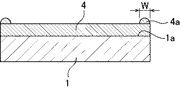
上記実施例に従って樹脂層を形成した例1ないし5では、いずれも、レンズ基材の中心部において所望の樹脂層の厚さである略30μmが得られ、さらに、樹脂だまりの幅W(図4)も、許容範囲の2.5mmを下回っている。
尚、例1ないし5は、塗布液の塗布範囲の外径、および高速回転時に回転の速度、継続時間が異なっている。
In each of Examples 1 to 5 in which the resin layer is formed according to the above-described embodiment, approximately 30 μm which is the desired thickness of the resin layer is obtained in the central portion of the lens base material. ) Is also below the tolerance of 2.5 mm.
In Examples 1 to 5, the outer diameter of the coating range of the coating solution and the speed and duration of rotation at high speed rotation are different.
また、参考例は、高速回転ステップを、冷却ステップの前に実施した例であり、この例でも、レンズ基材の中心部において所望の樹脂層の厚さである略30μmが得られ、さらに、レンズ基材1の塗布面1a上の塗布液4の樹脂だまり4aの幅W(図4)も、許容範囲の2.5mmを下回っている。
The reference example is an example in which the high speed rotation step is performed before the cooling step. Also in this example, a desired resin layer thickness of approximately 30 μm is obtained at the center of the lens substrate, and The width W (FIG. 4) of the
本発明の前記実施形態に限定されることなく、特許請求の範囲に記載された技術的思想の範囲内で種々の変更、変形が可能である。 Without being limited to the above-described embodiment of the present invention, various changes and modifications are possible within the scope of the technical idea described in the claims.
1:レンズ基材
1a:塗布面
2:ディスペンサノズル
4:塗布液
6:IRヒータ
1: Lens base material
1a: coating surface 2: dispenser nozzle 4: coating solution 6: IR heater
Claims (10)
プラスチックレンズ用のレンズ基材の少なくとも一方の面に紫外線硬化性樹脂を含む塗布液を塗布するステップと、
前記レンズ基材上の塗布液を加熱するステップと、
前記塗布液に紫外線を照射して前記紫外線硬化性樹脂を硬化させ前記樹脂層を得るステップと、を備えている、
ことを特徴とする樹脂層形成方法。 A resin layer forming method for forming a resin layer on at least one surface of a lens substrate for a plastic lens,
Applying a coating solution containing an ultraviolet curable resin to at least one surface of a lens substrate for a plastic lens;
Heating the coating solution on the lens substrate;
Irradiating the coating solution with ultraviolet light to cure the ultraviolet curable resin to obtain the resin layer;
A method of forming a resin layer characterized by
前記レンズ基材の少なくとも一方の面に塗布液を配置するステップと、
前記配置された塗布液を前記レンズ基材上で略均一な厚さにするステップと、を含んでいる、
請求項1に記載の樹脂層形成方法。 The step of applying the coating solution is
Placing a coating solution on at least one side of the lens substrate;
Making the disposed coating solution substantially uniform in thickness on the lens substrate,
The method for forming a resin layer according to claim 1.
請求項2に記載の樹脂層形成方法。 The step of disposing the coating solution includes the step of helically arranging the coating solution on at least one surface of the lens substrate while rotating the lens substrate.
The method for forming a resin layer according to claim 2.
請求項1ないし3のいずれか1項に記載の樹脂層形成方法。 The method further comprises a cooling step of cooling the coating liquid on the lens substrate to room temperature after the heating step.
The resin layer formation method of any one of Claims 1 thru | or 3.
請求項1ないし4のいずれか1項に記載の樹脂層形成方法。 Rotating the lens substrate at high speed after the heating step;
The method for forming a resin layer according to any one of claims 1 to 4.
請求項5に記載の樹脂層形成方法。 The high speed rotation step is performed prior to the cooling step.
The method for forming a resin layer according to claim 5.
請求項5に記載の樹脂層形成方法。 The high speed rotation step is performed after the cooling step.
The method for forming a resin layer according to claim 5.
請求項1ないし7のいずれか1項に記載の樹脂層形成方法。 The resin layer has a thickness of 20 to 40 μm,
The resin layer formation method of any one of Claims 1 thru | or 7.
請求項1ないし8のいずれか1項に記載の樹脂層形成方法。 The width of the liquid pool formed at the outer edge of the resin layer is 10 mm or less
A resin layer forming method according to any one of claims 1 to 8.
請求項1ないし9のいずれか1項に記載の樹脂層形成方法。 The heating in the heating step is performed by an infrared heater,
The resin layer forming method according to any one of claims 1 to 9.
Priority Applications (1)
| Application Number | Priority Date | Filing Date | Title |
|---|---|---|---|
| JP2017210951A JP2019082631A (en) | 2017-10-31 | 2017-10-31 | Resin layer forming method |
Applications Claiming Priority (1)
| Application Number | Priority Date | Filing Date | Title |
|---|---|---|---|
| JP2017210951A JP2019082631A (en) | 2017-10-31 | 2017-10-31 | Resin layer forming method |
Publications (1)
| Publication Number | Publication Date |
|---|---|
| JP2019082631A true JP2019082631A (en) | 2019-05-30 |
Family
ID=66670405
Family Applications (1)
| Application Number | Title | Priority Date | Filing Date |
|---|---|---|---|
| JP2017210951A Pending JP2019082631A (en) | 2017-10-31 | 2017-10-31 | Resin layer forming method |
Country Status (1)
| Country | Link |
|---|---|
| JP (1) | JP2019082631A (en) |
Cited By (1)
| Publication number | Priority date | Publication date | Assignee | Title |
|---|---|---|---|---|
| WO2023053653A1 (en) | 2021-09-28 | 2023-04-06 | ホヤ レンズ タイランド リミテッド | Spectacle optical article and method for manufacturing same |
-
2017
- 2017-10-31 JP JP2017210951A patent/JP2019082631A/en active Pending
Cited By (1)
| Publication number | Priority date | Publication date | Assignee | Title |
|---|---|---|---|---|
| WO2023053653A1 (en) | 2021-09-28 | 2023-04-06 | ホヤ レンズ タイランド リミテッド | Spectacle optical article and method for manufacturing same |
Similar Documents
| Publication | Publication Date | Title |
|---|---|---|
| JP4859463B2 (en) | Application method and light-control lens manufacturing method | |
| JP4229853B2 (en) | Application method and spectacle lens manufacturing method | |
| CA2700548C (en) | Method for manufacturing polarized ophthalmic lenses | |
| CN1142797A (en) | Photochromic lenses and method for manufacturing | |
| US8613982B2 (en) | Method of producing coated lenses | |
| JPWO2007072754A1 (en) | Spin coating method | |
| JP2019082631A (en) | Resin layer forming method | |
| JP2007072248A (en) | Coating method of hybrid lens | |
| WO2018168347A1 (en) | Method for manufacturing lens | |
| RU2395348C2 (en) | Method and device for controlling thickness of coating layer when applied through centrifugation | |
| JP5974632B2 (en) | Manufacturing method of coated film | |
| CN111867819B (en) | Primer for TAC films and laminates | |
| US8089697B2 (en) | Prismatic laminate and method for making the same | |
| US20180057705A1 (en) | Coating method | |
| JPWO2014034927A1 (en) | Manufacturing method of optical lens | |
| JP7286292B2 (en) | METHOD FOR MANUFACTURING COATED FILM OPTICAL LENS | |
| JP5974625B2 (en) | Method for producing antireflection film | |
| JP6983586B2 (en) | Hardcourt film for transparent conductive films | |
| JP2012068295A (en) | Photochromic lens and production method of the same | |
| KR20240006539A (en) | Method for coating lenses with lenslets with improved control of refractive power changes | |
| JP2004261973A (en) | Laminate and its manufacturing method | |
| JP2002210400A (en) | Shower flow coat application device and coating method using the device | |
| JP2011036847A (en) | Film-forming method and spin coater | |
| JP2013205597A (en) | Manufacturing method of photochromic spectacle lens and manufacturing apparatus for photochromic spectacle lens | |
| JPH03197106A (en) | Manufacture of composite optical element and its device |