JP2019065594A - Reinforcement structure of beam-column connection - Google Patents
Reinforcement structure of beam-column connection Download PDFInfo
- Publication number
- JP2019065594A JP2019065594A JP2017192487A JP2017192487A JP2019065594A JP 2019065594 A JP2019065594 A JP 2019065594A JP 2017192487 A JP2017192487 A JP 2017192487A JP 2017192487 A JP2017192487 A JP 2017192487A JP 2019065594 A JP2019065594 A JP 2019065594A
- Authority
- JP
- Japan
- Prior art keywords
- reinforcing
- web
- flanges
- column
- flange
- Prior art date
- Legal status (The legal status is an assumption and is not a legal conclusion. Google has not performed a legal analysis and makes no representation as to the accuracy of the status listed.)
- Withdrawn
Links
Images


Landscapes
- Joining Of Building Structures In Genera (AREA)
Abstract
Description
本発明は、柱梁接合部の補強構造に関する。 The present invention relates to a reinforcing structure of a beam-to-column joint.
住宅等に用いられる鉄骨プレハブ構造では、通し梁として水平方向に配置されたH形鋼の上方および下方の鉛直方向に柱がつながる柱梁接合部において、梁フランジおよび梁ウエブの変形を抑制するための補強が設けられることが多い。この補強構造として、梁の腹部にスチフナを溶接する構造が一般的であるが、スチフナの溶接にかかる加工手間が大きい、プレめっき材では溶接後の防錆処理にも手間がかかる、また、スチフナによる梁フランジの変形抑制には限界がある、といった課題がある。 In the steel frame prefabricated structure used for houses etc., in order to suppress deformation of the beam flange and the beam web at the beam-to-column joint where the columns are connected vertically in the upper and lower direction of H-shaped steel arranged horizontally as through beams Reinforcement is often provided. As this reinforcement structure, a structure in which stiffeners are welded to the abdomen of the beam is generally used, but the processing time required for welding of stiffeners is large, and in the case of pre-plating materials, it takes time for anticorrosion treatment after welding, and stiffeners. There is a problem that there is a limit in suppressing deformation of the beam flange due to
この課題に対し、溶接を用いない補強構造の例として特許文献1および特許文献2に記載のものが知られている。
特許文献1に記載の補強構造では、管柱を接続する横架材の腹材の両側にコ字状に形成した接続具を設け、この接続具のフランジに形成された接続孔を介してボルトにて管柱と横架材とを接続している。また、コ字状の接続具には上下のフランジとウエブとに三辺が溶接接合された縦片が設けられ、この縦片に形成された連結孔を介して別の横架材を接続している。
With respect to this problem, those described in
In the reinforcing structure described in
また、特許文献2に記載の補強構造では、柱と梁とが接合される鉄骨架構において、上下フランジとウエブとを有する梁の柱接合部に梁補剛ユニットを設けている。この梁補剛ユニットのユニット本体は、梁の上下各フランジの内側にそれぞれ接合される上下水平補剛プレートと、これらの水平補剛プレートを結合して梁のウエブ側面に当接しうる垂直補剛プレートとにより溝形状に形成され、このユニット本体の内側に、梁の上下それぞれに接合される柱の幅に対応した位置に少なくとも2本のリブが立設されている。
そして、このユニット本体が梁の上フランジと下フランジとの間に嵌め込まれるとともに、上下水平補剛プレートがそれぞれ梁の上下各フランジに接合されて、梁の柱接合部を補強している。
Moreover, in the reinforcement structure described in
Then, the unit body is fitted between the upper flange and the lower flange of the beam, and the upper and lower horizontal stiffening plates are respectively joined to the upper and lower flanges of the beam to reinforce the column joint of the beam.
しかしながら、上述した特許文献1に記載の従来の補強構造では、接続具がコ字状に形成されており、上下のフランジの一辺がその全長わたりウエブに接続されているので、上下のフランジの一辺間の距離が横架材の上下のフランジ間の距離より少しでも長いと、当該接続具を横架材の腹材に設置(挿入)するのが困難になる。このため、接続具に高い寸法精度が要求され、接続具の製作負荷が大きく、また、接続具を設置する際の施工誤差管理の手間も大きい。さらに、コ字状の接続具の上下のフランジとウエブとに縦片の三辺が溶接接合されているため、溶接の手間もかかる。
However, in the conventional reinforcing structure described in
また、特許文献2に記載の従来の補強構造では、梁のウエブの両側面を当該両側面側に配置された2つの梁補剛ユニットのそれぞれの垂直補剛プレートで補剛して柱梁接合部を構成しているので、柱梁接合部のパネルゾーンは剛性が過大となり、変形が抑制される。したがって、柱梁接合部が変形性能を発揮できなくなるため、柱や梁に変形および損傷が集中してしまう。
また、特許文献1の場合と同様に、梁補剛ユニットがコ字状に形成されているので、当該梁補剛ユニットを梁に設置(挿入)するのが困難になる。このため、梁補剛ユニットに高い寸法精度が要求され、梁補剛ユニットの製作負荷が大きく、また、梁補剛ユニットを設置する際の施工誤差管理の手間も大きい。さらにコ字状の梁補剛ユニットの上下のフランジとウエブとにリブの三辺が溶接接合されているため、溶接の手間もかかる。
Further, in the conventional reinforcing structure described in
Further, as in the case of
本発明は前記事情に鑑みてなされたもので、H形断面を有する梁と柱とを接合してなる柱梁接合部をスチフナの溶接によらず、補強金物によって容易かつ確実に補強できる柱梁接合部の補強構造を提供することを目的とする。 The present invention has been made in view of the above circumstances, and it is possible to easily and reliably reinforce a beam-to-column joint formed by joining a beam having a H-shaped cross section and a column by reinforcing metal instead of welding of stiffeners. It aims at providing a reinforcement structure of a junction.
前記目的を達成するために、本発明の柱梁接合部の補強構造は、H形断面を有する梁と柱とを接合してなる柱梁接合部を補強金物によって補強する柱梁接合部の補強構造であって、
前記補強金物は、略H形断面を有し、かつ上下一対の補強フランジと、当該一対の補強フランジを連結する補強ウエブとを備え、
前記梁の上下一対の梁フランジと梁ウエブとで囲まれた部分に、前記補強金物が前記補強ウエブを前記梁ウエブの面外方向に向けて挿入され、
上下一対の前記補強フランジが、それぞれ前記梁の上下一対の梁フランジの内面に当接されるとともに当該梁フランジに止着材によって接合され、
前記補強ウエブの一端部が前記梁ウエブに当接されていることを特徴とする。
In order to achieve the above object, the reinforcement structure of a beam-to-column joint according to the present invention is a reinforcement of a beam-to-column joint in which a beam-to-column joint formed by joining a beam having an H-shaped cross section and a column is reinforced by a reinforcing metal. The structure,
The reinforcing hardware has a substantially H-shaped cross section, and includes a pair of upper and lower reinforcing flanges and a reinforcing web connecting the pair of reinforcing flanges.
The reinforcing metal is inserted in a direction in which the reinforcing web is directed out of the plane of the beam web at a portion surrounded by a pair of upper and lower beam flanges of the beam and the beam web.
A pair of upper and lower reinforcing flanges are respectively in contact with the inner surfaces of the upper and lower beam flanges of the beam and joined to the beam flange by a fastening material.
One end of the reinforcing web is in contact with the beam web.
ここで、前記止着材としてはボルトやネジ(例えばドリルネジ)が好適に挙げられるが、これに限ることなく、補強フランジを梁フランジの内面に溶接以外の手段で接合できる部材であればよい。
また、梁は柱の上端部間に架け渡される通常の梁の他、基礎に設置されかつ柱の下端部が接合される床梁を含む。
Here, although a bolt and a screw (for example, a drill screw) are suitably mentioned as the fastening material, without being limited thereto, any member can be used as long as it can join the reinforcing flange to the inner surface of the beam flange by means other than welding.
In addition to ordinary beams that are bridged between the upper ends of the columns, the beams include floor beams installed on the foundation and joined at the lower ends of the columns.
本発明においては、略H形断面の補強金物の上下の補強フランジは、補強ウエブで連結されているので、相互の変形が抑制される。
そして、柱から梁に入力する引張力に対して、梁フランジが面外に変形しようとするが、この変形に対し、補強金物の補強フランジの曲げ抵抗で補剛する。
一方、柱から梁に入力する圧縮力に対して、梁ウエブが面外にはらみ出して座屈しようとするが、この変形に対し、補強金物の補強ウエブの一端部が梁ウエブに当接されることで、梁ウエブの面外変形を抑制して座屈を補剛する。さらに、補強ウエブそのものが柱から梁に入力する圧縮力に対して抵抗する効果も得られる。
また、補強金物は、上下一対の補強フランジが、それぞれ梁の上下一対の梁フランジの内面に当接されるとともに当該梁フランジにボルトやネジ等の止着材によって接合されることによって、梁の上下一対の梁フランジと梁ウエブとで囲まれた部分に固定されている。
したがって、H形断面を有する梁と柱とを接合してなる柱梁接合部をスチフナの溶接によらず、補強金物によって容易かつ確実に補強できる。
In the present invention, since the upper and lower reinforcing flanges of the substantially H-shaped cross section of the reinforcing hardware are connected by the reinforcing web, mutual deformation is suppressed.
Then, although the beam flange tries to be deformed out of plane with respect to the tensile force input from the column to the beam, this deformation is stiffened by the bending resistance of the reinforcing flange of the reinforcing hardware.
On the other hand, when the beam web is pushed out of the plane and tends to buckle due to the compressive force input from the column to the beam, one end of the reinforcing metal reinforcement web is abutted against the beam web against this deformation. Thus, the out-of-plane deformation of the beam web is suppressed to stiffen the buckling. Furthermore, the reinforcing web itself has an effect of resisting the compressive force applied from the column to the beam.
In addition, the reinforcement hardware is made by contacting the upper and lower pair of reinforcement flanges respectively to the inner surfaces of the upper and lower beam flanges of the beam and by joining the beam flange to the beam flange by a fastening material such as a bolt or a screw. It is fixed to a portion surrounded by a pair of upper and lower beam flanges and a beam web.
Therefore, it is possible to easily and surely reinforce the beam-to-column joint portion formed by joining the beam having the H-shaped cross section and the column by the reinforcing metal instead of welding the stiffener.
また、補強金物の上下の補強フランジは、当該補強フランジの中央部に設けられた補強ウエブのみで接続されているため、上下の補強フランジは弾性変形により相対位置を微調整できる。これより、補強金物を、梁の上下一対の梁フランジと梁ウエブとで囲まれた部分(梁の腹部)に容易に設置(挿入)できる。したがって、補強金物に高い寸法精度が要求されることもないので、補強金物の製作負荷も小さく、また、補強金物を設置する際の施工誤差管理の手間も小さい。
また、補強金物は、柱梁接合部のパネルゾーンの変形を抑制しないので、柱や梁に変形および損傷が集中することを避けられる。
Further, since the upper and lower reinforcing flanges of the reinforcing hardware are connected only by the reinforcing web provided at the central portion of the reinforcing flange, the upper and lower reinforcing flanges can finely adjust the relative position by elastic deformation. Thus, the reinforcing hardware can be easily installed (inserted) in a portion (a belly of the beam) surrounded by the pair of upper and lower beam flanges of the beam and the beam web. Therefore, since a high dimensional accuracy is not required for the reinforcing hardware, the manufacturing load of the reinforcing hardware is also small, and the time and effort for managing the construction error when installing the reinforcing hardware is also small.
Further, since the reinforcing metal does not suppress the deformation of the panel zone of the beam-to-column joint, concentration of deformation and damage on the column and the beam can be avoided.
また、本発明の前記構成において、前記補強フランジの一端部よりも前記補強ウエブの一端部が前記梁ウエブ側に突出していてもよい。 In the above-mentioned composition of the present invention, one end of the above-mentioned reinforcement web may project on the above-mentioned beam web side rather than one end of the above-mentioned reinforcement flange.
このような構成によれば、補強フランジの一端部よりも補強ウエブの一端部が梁ウエブ側に突出しているので、補強ウエブの一端部を梁ウエブに当接することによって、補強フランジの一端部と梁ウエブとの間に所定の隙間を設けることができる。したがって、この隙間に梁のフィレット部(梁フランジと梁ウェブの交差部)が配置されることによって、当該フィレット部と補強フランジとの干渉を避けることができる。また、当該干渉を避けたうえで、補強ウエブの一端部を梁ウエブに隙間なく確実に当接できるので、梁ウエブの座屈抑制の効果を高めることができる。 According to such a configuration, since one end of the reinforcing web projects more toward the beam web than the one end of the reinforcing flange, the one end of the reinforcing web abuts against the beam web to form one end of the reinforcing flange A predetermined gap can be provided between the beam web and the beam web. Therefore, by arranging the fillet portion of the beam (the intersection of the beam flange and the beam web) in this gap, interference between the fillet portion and the reinforcing flange can be avoided. Moreover, since the one end part of a reinforcement web can be contact | abutted reliably without clearance to a beam web after avoiding the said interference, the effect of buckling control of a beam web can be heightened.
また、本発明の前記構成において、前記補強フランジの厚さが前記梁のフィレット部の高さ寸法より厚くなっていてもよい。 In the configuration of the present invention, the thickness of the reinforcing flange may be greater than the height dimension of the fillet portion of the beam.
このような構成によれば、補強フランジの厚さが梁のフィレット部の高さ寸法より厚くなっているので、補強ウエブの上縁および下縁は、それぞれ上下のフィレット部より梁ウエブの上下方向中央部側に配置される。したがって、補強ウエブの一端部をフィレット部に干渉させることなく、梁ウエブに当接できるので、梁ウエブの座屈抑制の効果を高めることができる。 According to such a configuration, since the thickness of the reinforcing flange is larger than the height dimension of the fillet portion of the beam, the upper edge and the lower edge of the reinforcing web are respectively in the vertical direction of the beam web from the upper and lower fillet portions. It is placed on the center side. Therefore, the reinforcement web can be abutted against the beam web without interfering with one end of the reinforcement web, so that the effect of suppressing the buckling of the beam web can be enhanced.
また、本発明の前記構成において、前記補強ウエブの一端部に、当該一端部から前記梁ウエブに沿って延出する延出部が設けられていてもよい。 Further, in the above-mentioned configuration of the present invention, an end extending from the one end to the beam web may be provided at one end of the reinforcing web.
このような構成によれば、補強ウエブの一端部に、当該一端部から梁ウエブに沿って延出する延出部が設けられているので、補強ウエブの他端部に連結した直交梁から入力する曲げに対する補強金物の抵抗を高めることができる。また、補強ウエブの一端部に延出部を設けることで、柱から梁に入力する圧縮力に対して、補強ウエブの座屈に対する抵抗を高めることもできる。 According to such a configuration, since the extension portion extending along the beam web from the one end portion is provided at the one end portion of the reinforcement web, it is possible to input from the orthogonal beam connected to the other end portion of the reinforcement web Resistance of the reinforcing hardware to bending. Further, by providing an extension at one end of the reinforcing web, it is possible to increase the resistance to buckling of the reinforcing web against the compressive force input from the column to the beam.
本発明によればH形断面を有する梁と柱とを接合してなる柱梁接合部をスチフナの溶接によらず、補強金物によって容易かつ確実に補強できる。 According to the present invention, it is possible to easily and surely reinforce the beam-to-column joint portion formed by joining the beam having the H-shaped cross section and the column, by the reinforcing metal instead of welding the stiffener.
以下、図面を参照して本発明に係る柱梁接合部の補強構造の実施の形態について説明する。
(第1の実施の形態)
図1は第1の実施の形態の柱梁接合部の補強構造を示すもので、(a)は正面図、(b)は側面図、(c)は(a)におけるA−A線断面図、(d)は(c)の要部の拡大図である。
本実施の形態では、H形断面を有する鋼製の梁1と角形鋼管で形成された柱2とを接合してなる柱梁接合部を補強金物10によって補強している。
なお、梁1の上下の梁フランジ1aと梁ウエブ1bとの接続部にはフィレット部1cが設けられている。
Hereinafter, an embodiment of a reinforcing structure of a beam-to-column joint according to the present invention will be described with reference to the drawings.
First Embodiment
FIG. 1 shows a reinforcing structure of a beam-to-column joint according to the first embodiment, wherein (a) is a front view, (b) is a side view, and (c) is a sectional view taken along line AA in (a) (D) is an enlarged view of the main part of (c).
In the present embodiment, a reinforcement joint 10 reinforces a beam-to-column joint portion formed by joining a
A
すなわちまず、図1(a)および(b)に示すように、柱梁接合部において、梁1の上側の梁フランジ1aの上面と下側の梁フランジ1aの下面とにはそれぞれ接合部材11が設けられている。接合部材11は、矩形板状の上下の板材11a,11aと、当該板材11a,11aを連結する断面十字形の連結材11bとから構成されている。なお、このような接合部材11を梁1に固定する構造は後述する。
That is, first, as shown in FIGS. 1 (a) and 1 (b), the
補強金物10は、鋼製でかつ略H形断面を有しており、上下一対の補強フランジ10a,10aと、当該一対の補強フランジ10a,10aを連結する補強ウエブ10bとを備え、上下の補強フランジ10aと補強ウエブ10bとの接続部にはそれぞれフィレット部10cが設けられている。また、補強フランジ10aの厚さは例えば6.0〜16.0mmに設定され、補強ウエブ10bの厚さは例えば4.5mm〜16.0mm程度に設定され、それぞれの厚さは、適宜、必要な性能に応じて設定されている。
このような補強金物10は、図1(c)に示すように、梁1の梁ウエブ1bを挟んで前後方向(図1(a)において紙面と直交する方向、図1(b)において左右方向)に一対配置されている。
また、補強金物10は、断面略H形断面を有する鋼製の部材をそのフランジと直交する鉛直面で所定長さに切断することによって、当該部材から容易に得ることができる。
The reinforcing
As shown in FIG. 1 (c), such a reinforcing
Further, the reinforcing
図1(c)に示すように、補強金物10の長さ(補強ウエブ10bと平行な方向の長さ)L1は、梁1の梁フランジ1aの幅寸法をL、梁1の梁ウエブの厚みをtwとすると、(L―tw)/2より短くなっている。したがって、補強金物10を梁1の梁ウエブ1bの両側に配置した状態において、補強金物10の他端部は梁フランジ1aの長手方向に沿う縁部より内側に配置されている。つまり、補強金物10の他端部は梁1からその幅方向(梁ウエブ1bに直交する方向)に突出しておらず、梁1の腹部内に収められている。
また、図1(b)および(c)に示すように、補強フランジ10aの一端部10aeよりも補強ウエブ10bの一端部10beが所定寸法だけ突出しており、補強ウエブ10bの他端部10bfは補強フランジ10aの他端部10afと面一となっている。図1(d)に示すように、補強ウエブ10bの一端部10beの突出長さL2は、梁1のフィレット部1cの梁ウエブ1bの表面からの突出長さLcより長くなっている。
さらに、図1(b)に示すように、補強フランジ10aの厚さtは、梁1のフィレット部1cの高さ寸法tcより厚くなっている。なお、フィレット部1cの高さ寸法tcは、3.0mm〜8.0mmに設定されている。
As shown in FIG. 1C, the length (length in the direction parallel to the reinforcing
Further, as shown in FIGS. 1B and 1C, one end 10be of the reinforcing
Furthermore, as shown in FIG. 1 (b), the thickness t of the reinforcing
そして、梁1の上下一対の梁フランジ1a,1aと梁ウエブ1bとで囲まれた部分(梁1の腹部)に、補強金物10がその補強ウエブ10bを梁ウエブ1bの面外方向に向けて挿入されている。つまり、補強金物10は、その補強ウエブ10bを梁1の梁ウエブ1bと直交するようにして梁1の上下一対の梁フランジ1a,1aと梁ウエブ1bとで囲まれた部分(梁1の腹部)に挿入されている。
この状態において、補強金物10の補強ウエブ10bの一端部10beは梁1の梁ウエブ1bに溶接やボルトで接合されることなく当接されている。
また、補強金物10の上下の補強フランジ10a,10aは、それぞれ梁1の上下の梁フランジ1a,1aの内面に当接されるとともに、当該梁フランジ1a,1aにボルト接合されている。
すなわち、補強フランジ10aと梁フランジ1aと接合部材11の梁フランジ1aに当接している板材11aとにはボルト15aを挿通する孔が同軸に形成されており、これら孔にボルト15aが挿通されたうえで、このボルト15aにナット15bが螺合されて締め付けられている。これによって、補強金物10および接合部材11が梁1に固定されている。なお、接合部材11の梁フランジ1aの当接していない他方の板材11aには柱2が接合固定されている。
Then, in a portion (apart of the beam 1) surrounded by the pair of upper and
In this state, one end 10be of the reinforcing
The upper and lower reinforcing
That is, holes for inserting the
このような柱梁接合部の補強構造では、補強金物10の上下の補強フランジ10a,10aは、補強ウエブ10bで連結されているので、相互の変形が抑制される。
そして、柱2から梁1に入力する引張力に対して、梁フランジ1aが面外に変形しようとするが、この変形に対し、補強金物10の補強フランジ10aの曲げ抵抗で補剛する。
一方、柱2から梁1に入力する圧縮力に対して、梁ウエブ1bが面外にはらみ出して座屈しようとするが、この変形に対し、補強金物10の補強ウエブ10bの一端部10beが梁ウエブ1bに当接されることで、梁ウエブ1bの面外変形を抑制して座屈を補剛する。さらに、補強ウエブ10bそのものが柱2から梁1に入力する圧縮力に対して抵抗する効果も得られる。
また、補強金物10は、上下一対の補強フランジ10a,10aが、それぞれ梁1の上下一対の梁フランジ1a,1aの内面に当接されるとともに当該梁フランジ1aにボルト接合されることによって、梁1の上下一対の梁フランジ1a,1aと梁ウエブ1bとで囲まれた部分(梁1の腹部)に固定されている。
したがって、H形断面を有する梁1と柱2とを接合してなる柱梁接合部をスチフナの溶接によらず、補強金物10によって容易かつ確実に補強できる。
In such a reinforcing structure of the beam-to-column joint, the upper and lower reinforcing
Then, although the
On the other hand, although the
Further, the reinforcing
Therefore, the beam-to-column joint portion formed by joining the
また、補強金物10の上下の補強フランジ10a,10aは、当該補強フランジ10a,10aの中央部に設けられた補強ウエブ10bのみで接続されているため、上下の補強フランジ10a,10aは弾性変形により相対位置を微調整できる。これにより、補強金物10を、梁1の上下一対の梁フランジ1a,1aと梁ウエブ1bとで囲まれた部分(梁1の腹部)に容易に設置(挿入)できる。したがって、補強金物10に高い寸法精度が要求されることもないので、補強金物10の製作負荷も小さく、また、補強金物10を設置する際の施工誤差管理の手間も小さい。
Further, since the upper and lower reinforcing
また、補強フランジ10aの一端部10aeよりも補強ウエブ10bの一端部10beが梁ウエブ1b側に突出しているので、補強ウエブ10bの一端部10beを梁ウエブ1bに当接することによって、補強フランジ10aの一端部10aeと梁ウエブ1bとの間に所定の隙間を設けることができる。したがって、この隙間に梁1のフィレット部1cが配置されることによって、当該フィレット部1cと補強フランジ10aとの干渉を避けることができる。また、当該干渉を避けたうえで、補強ウエブ10bの一端部10beを梁ウエブ1bに隙間なく確実に当接できるので、梁ウエブ1bの座屈抑制の効果を高めることができる。
Further, since the one end 10be of the reinforcing
さらに、補強フランジ10aの厚さtが梁1のフィレット部1cの高さ寸法tcより厚くなっているので、補強ウエブ10bの上縁および下縁は、それぞれ上下のフィレット部1cより梁ウエブ1bの上下方向中央部側に配置される。したがって、補強ウエブ10bの一端部を梁1フィレット部1cに干渉させることなく、梁ウエブ1bに当接できるので、梁ウエブ1bの座屈抑制の効果を高めることができる。
Furthermore, since the thickness t of the reinforcing
なお、補強フランジ10aの厚さtが梁1のフィレット部1cの高さ寸法tcより薄い場合、補強ウエブ10bの一端部10beの上縁角部と下縁角部がそれぞれ上下のフィレット部1c,1cに干渉するので、この干渉を避けるために、補強ウエブ10bの一端部10beの上縁角部と下縁角部に切欠きを形成することによって、補強ウエブ10bの一端部10beを梁ウエブ1bに隙間なく確実に当接できる。このような梁1のフィレット部1cとの干渉を避けるための補強金物10の変形形態については、後述する。
When the thickness t of the reinforcing
(第2の実施の形態)
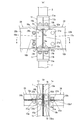
図2は第2の実施の形態の柱梁接合部の補強構造を示すもので、(a)は正面図、(b)は側面図、(c)は(a)におけるA−A線断面図である。
本実施の形態では、第1の実施の形態と同様に、H形断面を有する鋼製の梁1と角形鋼管で形成された柱2とを接合してなる柱梁接合部を補強金物10によって補強しているが、当該補強金物10の構成が第1の実施の形態と相違するので、以下ではこの相違点について説明し、第1の実施の形態と同一構成には同一符号を付してその説明を省略ないし簡略化する。
Second Embodiment
FIG. 2 shows the reinforcing structure of the beam-to-column joint according to the second embodiment, wherein (a) is a front view, (b) is a side view, and (c) is a sectional view taken along line A-A in (a) It is.
In the present embodiment, as in the first embodiment, a reinforcement joint 10 is used to connect a beam-to-column joint formed by joining a
本実施の形態では、補強金物10の補強ウエブ10bの一端部10beに、当該一端部から梁ウエブ1bに沿って延出する延出部10dが設けられている。
この延出部10dは、補強ウエブ10bを補強フランジ10aの一端部10aeから大きく突出させるとともに、上述した突出長さL2の部位で補強ウエブ10bを直角に折り曲げ成形することによって、補強ウエブ10bと一体的に形成されている。
延出部10dは梁ウエブ1bに沿って延出し、当該梁ウエブ1bに溶接やボルトで接合することなく当接している。また、延出部10dの長さは補強フランジ10aの長さL3の1/2とほぼ等しい長さとなっている。なお、延出部10dの長さは、適宜、設定することができる。
また、梁ウエブ1bを挟んで前後一対配置されている補強金物10,10では、延出部10d,10dの延出方向が互いに逆となっている。なお、延出方向を揃えて延出部10dで梁ウエブ1bを挟み込むこともでき、これにより延出部10dの長さにわたって梁ウエブ1bの変形を抑制する効果が得られる。
In the present embodiment, at one end 10be of the reinforcing
The
The extending
Further, in the reinforcing
本実施の形態では、第1の実施の形態と同様に効果を得ることができる他、補強ウエブ10bの一端部10beに、当該一端部から梁ウエブ1bに沿って延出する延出部10dが設けられているので、補強ウエブ10bの他端部10bfに直交梁を連結した場合に、当該直交梁から入力する曲げに対する補強金物10の抵抗を高めることができる。また、補強ウエブ10bの一端部10beに延出部10dを設けることで、柱2から梁1に入力する圧縮力に対して、補強ウェブ10bの座屈に対する抵抗を高めることもできる。
In the present embodiment, in addition to the same effects as in the first embodiment, an
(第3の実施の形態)
図3は第3の実施の形態の柱梁接合部の補強構造を示すもので、(a)は側面図、(b)は(a)におけるA−A線断面図である。
本実施の形態では、第2の実施の形態と同様に、H形断面を有する鋼製の梁1と角形鋼管で形成された柱2とを接合してなる柱梁接合部を補強金物10によって補強しているともに、補強ウエブ10bの他端部10bfに直交梁20を連結している。したがって、以下ではこの点について説明し、第2の実施の形態と同一構成には同一符号を付してその説明を省略ないし簡略化する。
Third Embodiment
FIG. 3: shows the reinforcement structure of the beam-to-column junction part of 3rd Embodiment, (a) is a side view, (b) is the sectional view on the AA line in (a).
In the present embodiment, as in the second embodiment, a reinforcement joint 10 is used to connect a beam-to-column joint formed by joining a
本実施の形態では、梁1に当該梁1と直交する直交梁20が補強金物10を介して連結されている。
すなわちまず、補強金物10の補強ウエブ10bの他端部10bfは梁1から所定長さだけ突出しており、この突出した部分が突出部10eとされている。
また、直交梁20は断面H形の鋼製の梁であり、その梁成は梁1の梁成と等しくなっている。このような直交梁20は、梁1に対して僅かな隙間をもって直角に配置されており、補強ウエブ10bの突出部10eが直交梁20に挿入されている。
この突出部10eは直交梁20の梁ウエブ20bに当接されたうえで、当該梁ウエブ20bにボルト接合されている。すなわち補強ウエブ10bの突出部10eと梁ウエブ20bとにはボルト21aを挿通する孔が同軸に形成されており、これら孔にボルト21aが挿通されたうえで、このボルト21aにナット21bが螺合されて締め付けられている。これによって、直交梁20が補強金物10を介して梁1に連結され、直交梁20から補強金物10にせん断力が伝達される。
In the present embodiment, an
That is, first, the other end 10bf of the reinforcing
Further, the
The projecting
なお、直交梁20は梁1の梁ウエブ1bを挟んで左右一対設けられており、一方の直交梁20の梁ウエブ20bが一方の補強金物10の補強ウエブ10bの突出部10eにボルト接合され、他方の直交梁20の梁ウエブ20bが他方の補強金物10の補強ウエブ10bの突出部10eにボルト接合されている。
また、左右一対の補強金物10,10の補強ウエブ10b,10bは一直線上に配置されておらず、梁1の長手方向(図3(b)において上下方向)にずれて配置されている。これによって、補強ウエブ10b,10bから突出する突出部10e,10eの梁ウエブ20b,20bが接合される面同士の間隔は、梁ウエブ20bの厚さと等しくなっている。これによって、左右の直交梁20の梁ウエブ20bは一直線上に配置される、つまり、直交梁20,20が一直線上に配置されている。
The
Further, the reinforcing
本実施の形態では、補強金物10の補強ウエブ10bは梁1から所定長さだけ突出する突出部10eを有するので、この突出部10eに直交梁20の梁ウエブ20bをボルト接合することによって、直交梁20を梁1に補強金物10を介して確実に連結できるとともに、第2の実施の形態と同様に、直交梁20から入力する曲げに対する補強金物10の抵抗を高めることができる。
In the present embodiment, since the reinforcing
(第4の実施の形態)
図4は第4の実施の形態の柱梁接合部の補強構造を示すもので、(a)は正面図、(b)は側面図、(c)は(a)におけるA−A線断面図である。
第1の実施の形態では、梁1に接合部材11を介して角形鋼管で形成された柱2を接合したが、本実施の形態では梁1にH形断面を有する鋼製の柱30を直接接合しているので、以下ではこの点について説明し、第1の実施の形態と同一構成には同一符号を付してその説明を省略する。
Fourth Embodiment
FIG. 4 shows the reinforcing structure of the beam-to-column joint according to the fourth embodiment, wherein (a) is a front view, (b) is a side view, and (c) is a sectional view taken along line AA in (a) It is.
In the first embodiment, the
本実施の形態では、図4(a)に示すように、正面視において、補強金物10が左右一対配置されるとともに、図4(b)に示すように、梁ウエブ1bを挟んで前後にも一対配置されているので、柱梁接合部において合計4個の補強金物10が配置されている。
また、第1の実施の形態と同様に、梁1の上下一対の梁フランジ1a,1aと梁ウエブ1bとで囲まれた部分(梁1の腹部)に、補強金物10がその補強ウエブ10bを梁ウエブ1bの面外方向に向けて挿入されている。つまり、補強金物10は、その補強ウエブ10bを梁1の梁ウエブ1bと直交するようにして梁1の上下一対の梁フランジ1a,1aと梁ウエブ1bとで囲まれた部分(梁1の腹部)に挿入されている。また、補強金物10の補強ウエブ10bの一端部10beは梁1の梁ウエブ1bに当接されている。
In the present embodiment, as shown in FIG. 4 (a), in the front view, the reinforcing metal fitting 10 is disposed in a pair, right and left, and as shown in FIG. 4 (b) Since a pair is arranged, a total of four reinforcing
In the same manner as in the first embodiment, in the portion (the abdomen of the beam 1) of the
また、柱30は断面H形に形成された柱本体31と、この柱本体31の端部に設けられた矩形板状の固定板32とを備えている。柱本体31は、左右一対の柱フランジ31a,31aと当該柱フランジ31a,31aを連結する柱ウエブ31bとを備えており、柱フランジ31a,31aおよび柱ウエブ31bの端部に固定板32が溶接等によって固定されている。
また、補強金物10の上下の補強フランジ10a,10aは、それぞれ梁1の上下の梁フランジ1a,1aの内面に当接されるとともに、当該梁フランジ1a,1aにボルト接合されている。
すなわち、補強フランジ10aと梁フランジ1aと柱30の固定板32とにはボルト15aを挿通する孔が同軸に形成されており、これら孔にボルト15aが挿通されたうえで、このボルト15aにナット15bが螺合されて締め付けられている。これによって、補強金物10および柱30が梁1に固定されている。
また、左右に離間して配置された補強金物10,10のそれぞれの補強ウエブ10b,10bと、梁1を挟んで上下に配置されている上下の柱30,30の柱フランジ31a,31aとは一直線上に配置されている。
The
The upper and lower reinforcing
That is, the holes through which the
Further, the reinforcing
本実施の形態では、第1の実施の形態と同様の効果が得られる他、柱梁接合部に合計4つの補強金物10が設けられているので、柱梁接合部をより強固に補強できる。また、補強金物10は、柱梁接合部のパネルゾーン10pの変形を抑制しないので、柱30や梁1に変形および損傷が集中することを避けられる。
In this embodiment, in addition to the same effects as in the first embodiment, since a total of four reinforcing
また、第1の実施の形態において、補強金物10を図5〜8に示すような形状としてもよい。なお、第1の実施の形態と同一構成には同一符号を付してその説明を省略ないし簡略化する。
Moreover, in the first embodiment, the reinforcing
図5に示す補強金物10では、補強フランジ10aの厚みtよりも補強ウエブ10bの厚みtbが大きくなっている。厚みtbを大きくすることで補強ウエブ10bの変形を抑制して梁ウエブ1bの座屈補剛の効果を高めることができる。
In the reinforcing
図6〜8には、補強金物10の補強フランジ10aの一端部10aeに対する補強ウエブ10bの一端部10beの突出に関する変形例を示す。
図6に示すように、補強フランジ10aの厚さtがフィレット部1cの高さ寸法tcよりも大きい場合は、補強フランジ10aの一端部10aeを補強フランジ10aの上面および下面に対して傾斜させた面とすることで、補強フランジ10aとフィレット部1cの干渉を避けながら、補強ウエブ10bを梁ウエブ1bに当接させることができる。
6-8, the modification regarding the protrusion of one end part 10be of
As shown in FIG. 6, when the thickness t of the reinforcing
また、図7に示すように、補強フランジ10aの厚さtがフィレット部1cの高さ寸法tcよりも小さい場合は、補強フランジ10aの一端部10aeから補強ウエブ10bに連なるように補強フランジ10aの上面および下面に対して傾斜させた面とすることで、補強フランジ10aとフィレット部1cの干渉を避けながら、補強ウエブ10bを梁ウエブ1bに当接させることができる。
さらに、図8に示すように、補強フランジ10aの厚さtがフィレット部1cの高さ寸法tcよりも小さい場合に、補強フランジ10aの一端部10aeは傾斜面とせずに、補強ウエブ10bの上縁部および下縁部において補強ウエブ10bの一端部10beを補強フランジ10aの上面および下面に対して傾斜させた面とすることで、フィレット部1cの干渉を避けながら、補強ウエブ10bを梁ウエブ1bに当接させることもできる。
Further, as shown in FIG. 7, when the thickness t of the reinforcing
Furthermore, as shown in FIG. 8, when the thickness t of the reinforcing
1 梁
1a 梁フランジ
1b 梁ウエブ
2,30 柱
10 補強金物
10a 補強フランジ
10b 補強ウエブ
10c フィレット部
10d 延出部
10e 突出部
10ae 補強フランジの一端部
10af 補強フランジの他端部
10be 補強ウエブの一端部
10bf 補強ウエブの他端部
DESCRIPTION OF
Claims (4)
前記補強金物は、略H形断面を有し、かつ上下一対の補強フランジと、当該一対の補強フランジを連結する補強ウエブとを備え、
前記梁の上下一対の梁フランジと梁ウエブとで囲まれた部分に、前記補強金物が前記補強ウエブを前記梁ウエブの面外方向に向けて挿入され、
上下一対の前記補強フランジが、それぞれ前記梁の上下一対の梁フランジの内面に当接されるとともに当該梁フランジに止着材によって接合され、
前記補強ウエブの一端部が前記梁ウエブに当接されていることを特徴とする柱梁接合部の補強構造。 A reinforcement structure for a beam-to-column joint, which reinforces a beam-to-column joint formed by joining a beam having an H-shaped cross section and a column with a reinforcing metal,
The reinforcing hardware has a substantially H-shaped cross section, and includes a pair of upper and lower reinforcing flanges and a reinforcing web connecting the pair of reinforcing flanges.
The reinforcing metal is inserted in a direction in which the reinforcing web is directed out of the plane of the beam web at a portion surrounded by a pair of upper and lower beam flanges of the beam and the beam web.
A pair of upper and lower reinforcing flanges are respectively in contact with the inner surfaces of the upper and lower beam flanges of the beam and joined to the beam flange by a fastening material.
The reinforcing structure of a beam-to-column joint, wherein one end of the reinforcing web is in contact with the beam web.
Priority Applications (1)
| Application Number | Priority Date | Filing Date | Title |
|---|---|---|---|
| JP2017192487A JP2019065594A (en) | 2017-10-02 | 2017-10-02 | Reinforcement structure of beam-column connection |
Applications Claiming Priority (1)
| Application Number | Priority Date | Filing Date | Title |
|---|---|---|---|
| JP2017192487A JP2019065594A (en) | 2017-10-02 | 2017-10-02 | Reinforcement structure of beam-column connection |
Publications (1)
| Publication Number | Publication Date |
|---|---|
| JP2019065594A true JP2019065594A (en) | 2019-04-25 |
Family
ID=66339272
Family Applications (1)
| Application Number | Title | Priority Date | Filing Date |
|---|---|---|---|
| JP2017192487A Withdrawn JP2019065594A (en) | 2017-10-02 | 2017-10-02 | Reinforcement structure of beam-column connection |
Country Status (1)
| Country | Link |
|---|---|
| JP (1) | JP2019065594A (en) |
Cited By (1)
| Publication number | Priority date | Publication date | Assignee | Title |
|---|---|---|---|---|
| CN111877569A (en) * | 2020-07-30 | 2020-11-03 | 中冶(上海)钢结构科技有限公司 | Assembled column structure system of steel structure and installation method thereof |
-
2017
- 2017-10-02 JP JP2017192487A patent/JP2019065594A/en not_active Withdrawn
Cited By (1)
| Publication number | Priority date | Publication date | Assignee | Title |
|---|---|---|---|---|
| CN111877569A (en) * | 2020-07-30 | 2020-11-03 | 中冶(上海)钢结构科技有限公司 | Assembled column structure system of steel structure and installation method thereof |
Similar Documents
| Publication | Publication Date | Title |
|---|---|---|
| US8973333B2 (en) | Connecting fitting, frame provided with same, and building using frame | |
| AU2016316135B2 (en) | Longitudinal joint structure for hat-type steel sheet piles, longitudinal joint hat-type steel sheet pile unit, and steel wall | |
| JP5486430B2 (en) | Strength frame structure | |
| JP2019065594A (en) | Reinforcement structure of beam-column connection | |
| JP6432108B2 (en) | Beam-column joining member and beam-column joining method | |
| JP5635734B2 (en) | Beam-column joints and reinforcement hardware for beam-column joints | |
| JP5967438B2 (en) | Brace seismic reinforcement structure | |
| JP2022025804A (en) | Beam joining structure, and building | |
| JP6359288B2 (en) | Joint structure of buckling-restrained brace | |
| JP2015209705A (en) | Floor beam and floor beam support structure | |
| JP6261976B2 (en) | Cross section beam | |
| JP2007217984A (en) | Column-beam joining structure | |
| JP5371390B2 (en) | Building unit reinforcement structure and unit building | |
| JP6268998B2 (en) | End structure of steel member | |
| JP6168036B2 (en) | Steel hardware and beam joints for steel structures | |
| JPH09189075A (en) | Connection structure of square tubular steel column to wide flange beam | |
| JP2021059837A (en) | Beam/joist jointing structure and joist | |
| JPH09125515A (en) | Pillar beam connection part structure | |
| KR20120103532A (en) | Structure connecting device and assembly type structure having the same | |
| JP7563676B2 (en) | Steel structural members and wooden boards connected together | |
| JP3161023U (en) | Steel column and steel beam joint structure | |
| JP5010406B2 (en) | Building unit and unit building | |
| CN109386525B (en) | Reinforcing structure and reinforcing member for structural body composed of column and beam | |
| JP2010255179A (en) | Combination steel sheet pile and steel sheet pile wall using the same | |
| JP5938274B2 (en) | Installation method of earthquake-resistant members, earthquake-resistant members |
Legal Events
| Date | Code | Title | Description |
|---|---|---|---|
| A621 | Written request for application examination |
Free format text: JAPANESE INTERMEDIATE CODE: A621 Effective date: 20200603 |
|
| A761 | Written withdrawal of application |
Free format text: JAPANESE INTERMEDIATE CODE: A761 Effective date: 20200904 |